
A Distributed Cooperative Framework for Continuous Multi-Projector Pose Estimation
8
A Distributed Cooperative Framework for Continuous Multi-Projector Pose Estimation Tyler Johnson, Greg Welch, Henry Fuchs, Eric La Force and Herman Towles * University of North Carolina at Chapel Hill Figure 1: A two-projector display after both projectors have been moved (left) and after roughly ten seconds of operation (middle,right). ABSTRACT We present a novel calibration framework for multi-projector dis- plays that achieves continuous geometric calibration by estimating and refining the poses of all projectors in an ongoing fashion dur- ing actual display use. Our framework provides scalability by op- erating as a distributed system of “intelligent” projector units: pro- jectors augmented with rigidly-mounted cameras, and paired with dedicated computers. Each unit interacts asynchronously with its peers, leveraging their combined computational power to coopera- tively estimate the poses of all of the projectors. In cases where the projection surface is static, our system is able to continuously refine all of the projector poses, even when they change simultaneously. Keywords: Projector displays, continuous calibration. Index Terms: I.3.3 [Computer Graphics]: Picture/Image Generation—Display Algorithms; I.3.7 [Computer Graphics]: Three-Dimensional Graphics and Realism—Virtual Reality; 1 I NTRODUCTION Projection-based displays have long been used in the creation of large, immersive environments for virtual reality (VR), simulation, and training. These displays have become increasingly useful due to advancements in automatic calibration that allow the images of multiple projectors to be registered together accurately on complex display surfaces, while simultaneously compensating for the sur- face shape. While these techniques have been shown to be accurate and robust, the geometric aspects of the calibration are typically only computed prior to display use. However even for “fixed” con- figurations of projectors, physical perturbations, electrical changes, and even gravity can cause the apparent or actual projector poses to change over time, decreasing display quality. Our goal is a system that continually and automatically adjusts to even the slightest change in projector poses, while the system is * tmjohns, welch, fuchs, elaforc, [email protected] in use. Such continuous pose estimation should increase the robust- ness of projection-based displays, while also offering new flexibil- ity. For example, the most suitable positioning of projectors may vary between applications due to certain field-of-view or spatial resolution requirements. In these situations it might be desirable to deliberately reposition the projectors without having to interrupt display use to perform a re- calibration of the entire system. In this paper, we present a novel technique allowing the poses of multiple projectors to be estimated continuously during actual dis- play use. Our framework is designed around “intelligent” projec- tor units (IPUs): a projector augmented with two rigidly-mounted cameras, and paired with a dedicated computer. (See Figure 2.) The IPUs operate in a distributed fashion, each cooperating with its neighbors to continuously estimate all of the poses. In cases where the projection surface is static, our system continuously refines all of the poses, even when they change (IPUs move) simultaneously. 2 RELATED WORK Our work is related to a number of approaches that have been de- veloped to deal with various aspects of continuous calibration in projection-based displays. Yang and Welch [18] describe how ap- plication imagery projected at display time can be used to auto- matically estimate the shape of the display surface and account for changes in its shape over time using a Kalman filter-based frame- work. Cotting et al. [4] describe how the shape of the display sur- face can be estimated over time by embedding imperceptible cali- bration patterns into projected imagery. Raij and Pollefeys [14] and Raskar et al. [15] describe techniques to automatically calibrate clusters of projectors displaying onto pla- nar display surfaces. PixelFlex [17, 13] provided a tiled display sys- tem for planar and near-planar surfaces that allowed each projectors image to be easily and quickly repositioned to create new display configurations that could be calibrated within minutes. Bhasker et al. [2] describes a distributed approach to automatic calibration of multi-projector tiled displays that is truly scalable. Our work is most closely related to techniques that use camera image measurements to recalibrate projectors at display time with- out interrupting the projection of user imagery. In [5], Cotting et al. describe how their imperceptible pattern embedding approach
-
Upload
independent -
Category
Documents
-
view
2 -
download
0
Transcript of A Distributed Cooperative Framework for Continuous Multi-Projector Pose Estimation

A Distributed Cooperative Framework for Continuous Multi-ProjectorPose Estimation
Tyler Johnson, Greg Welch, Henry Fuchs, Eric La Force and Herman Towles∗
University of North Carolina at Chapel Hill
Figure 1: A two-projector display after both projectors have been moved (left) and after roughly ten seconds of operation (middle,right).
ABSTRACT
We present a novel calibration framework for multi-projector dis-plays that achieves continuous geometric calibration by estimatingand refining the poses of all projectors in an ongoing fashion dur-ing actual display use. Our framework provides scalability by op-erating as a distributed system of “intelligent” projector units: pro-jectors augmented with rigidly-mounted cameras, and paired withdedicated computers. Each unit interacts asynchronously with itspeers, leveraging their combined computational power to coopera-tively estimate the poses of all of the projectors. In cases where theprojection surface is static, our system is able to continuously refineall of the projector poses, even when they change simultaneously.
Keywords: Projector displays, continuous calibration.
Index Terms: I.3.3 [Computer Graphics]: Picture/ImageGeneration—Display Algorithms; I.3.7 [Computer Graphics]:Three-Dimensional Graphics and Realism—Virtual Reality;
1 INTRODUCTION
Projection-based displays have long been used in the creation oflarge, immersive environments for virtual reality (VR), simulation,and training. These displays have become increasingly useful dueto advancements in automatic calibration that allow the images ofmultiple projectors to be registered together accurately on complexdisplay surfaces, while simultaneously compensating for the sur-face shape. While these techniques have been shown to be accurateand robust, the geometric aspects of the calibration are typicallyonly computed prior to display use. However even for “fixed” con-figurations of projectors, physical perturbations, electrical changes,and even gravity can cause the apparent or actual projector poses tochange over time, decreasing display quality.
Our goal is a system that continually and automatically adjuststo even the slightest change in projector poses, while the system is
∗tmjohns, welch, fuchs, elaforc, [email protected]
in use. Such continuous pose estimation should increase the robust-ness of projection-based displays, while also offering new flexibil-ity. For example, the most suitable positioning of projectors mayvary between applications due to certain field-of-view or spatialresolution requirements. In these situations it might be desirableto deliberately reposition the projectors without having to interruptdisplay use to perform a re- calibration of the entire system.
In this paper, we present a novel technique allowing the poses ofmultiple projectors to be estimated continuously during actual dis-play use. Our framework is designed around “intelligent” projec-tor units (IPUs): a projector augmented with two rigidly-mountedcameras, and paired with a dedicated computer. (See Figure 2.)The IPUs operate in a distributed fashion, each cooperating with itsneighbors to continuously estimate all of the poses. In cases wherethe projection surface is static, our system continuously refines allof the poses, even when they change (IPUs move) simultaneously.
2 RELATED WORK
Our work is related to a number of approaches that have been de-veloped to deal with various aspects of continuous calibration inprojection-based displays. Yang and Welch [18] describe how ap-plication imagery projected at display time can be used to auto-matically estimate the shape of the display surface and account forchanges in its shape over time using a Kalman filter-based frame-work. Cotting et al. [4] describe how the shape of the display sur-face can be estimated over time by embedding imperceptible cali-bration patterns into projected imagery.
Raij and Pollefeys [14] and Raskar et al. [15] describe techniquesto automatically calibrate clusters of projectors displaying onto pla-nar display surfaces. PixelFlex [17, 13] provided a tiled display sys-tem for planar and near-planar surfaces that allowed each projectorsimage to be easily and quickly repositioned to create new displayconfigurations that could be calibrated within minutes. Bhasker etal. [2] describes a distributed approach to automatic calibration ofmulti-projector tiled displays that is truly scalable.
Our work is most closely related to techniques that use cameraimage measurements to recalibrate projectors at display time with-out interrupting the projection of user imagery. In [5], Cotting etal. describe how their imperceptible pattern embedding approach

can be used to recalibrate projectors in a multi-projector displaythat have been moved. Johnson and Fuchs [8] provide a method forcontinuously estimating the pose of a single projector using onlyapplication image features, while Zhou et al. [19] describe how ap-plication image features can be used to continuously calibrate pro-jectors in a multi-projector display. In [20], Zollman et al. present ahybrid technique that can compensate for small changes in displayconfiguration using optical flow, and will resort to active structuredlight projection when the optical flow becomes unreliable.
3 SYSTEM DESIGN AND GOALS
In this section, we describe the philosophy behind the design ofour system, and describe how the use of “intelligent” projectorunits (projectors augmented with two rigidly-mounted cameras, andpaired with dedicated computers) supports our design goals.
3.1 Rapid Projector Recalibration During Display Use
The primary goal of our overall work is to support rapid set-up andreconfiguration of multi-projector displays. In this paper, we focuson the goal of achieving rapid projector recalibration during actualdisplay use by continuously estimating the poses of all projectors.
In order to estimate changes in projector pose over time, the useof an auxiliary measurement device is required. We have chosento use cameras for this purpose due to the inherent duality betweencameras and projectors—both use lenses to direct light, but one forthe purpose of sensing and the other for the purpose of display. Theutility of such combinations of projectors and cameras is describedin a variety of previous work [2, 15, 4, 19].
We have designed our system to be flexible enough to recover theposes of all projectors even in the case that all projectors have beenmoved. We believe this functionality is necessary because even indisplays where projectors are not intentionally moved, the posesof all projectors are likely to change slightly over time. Previouswork [19, 5] solves this problem only partially by using projector-camera pairs with known calibration as references in re-estimatingthe poses of other projector-camera pairs that have been moved.This approach fails when all projector-cameras pairs have beenmoved, and it is not clear how errors may accumulate over time asdevices are moved, recalibrated, and then used to recalibrate otherdevices.
In order to achieve the goal of allowing any and all projectors tobe moved simultaneously, we introduce the concept of using knowndisplay surface geometry as an additional reference in estimatingprojector pose. This allows us to eliminate the distinction betweencalibrated and uncalibrated projectors and instead refine the calibra-tion of all projectors continuously over time. In our current systemwe assume that the geometry of the entire display surface is knownapriori and does not change, but plan to relax these constraints infuture work.
Another important goal of our design is to allow continuous pro-jector pose estimation to take place without affecting the imageryprojected by the user. While techniques for embedding impercepti-ble patterns [4, 5, 6] into projected imagery ensure a steady supplyof features that can be used as camera image measurements, thesetechniques are currently limited in the types of projectors that canbe used, i.e. DLP or stereo, and the embedding process requiresthat some amount of image quality be sacrificed. For this reason,we have chosen to use the projected imagery itself as a source ofcamera image features that can be used to estimate projector poseduring display use.
3.2 Distributed Cooperative Operation
In order to be useful in large displays with many projectors, contin-uous calibration approaches must be scalable. As described in [2]a distributed calibration methodology has far greater potential for
scalability and fault tolerance than more traditional centralized ap-proaches where all calibration data is aggregated and processed ona single machine.
Our design allows for scalability by pairing computation witheach projector to create a number of self-contained, intelligent unitsthat act in a cooperative fashion, leveraging their combined compu-tational power to estimate the pose of each projector through theexchange of information over a local network.
3.3 Intelligent Projector UnitsIntelligent Projector Units (IPUs) are the basic building blocks ofour display. An IPU, as seen in Figure 2, consists of a projectoraugmented with rigidly-mounted cameras and computation that in-cludes network capability. While the computation component cur-rently consists of a separate PC, we have future plans to fully inte-grate the computation with the rest of the unit.
Figure 2: An Intelligent Projector Unit.
4 DISTRIBUTED COMPUTATIONAL FRAMEWORK
In this section, we describe our distributed computational frame-work for continuous calibration of projector pose in multi-projectordisplays.
4.1 Assumptions1. The internal calibration of each IPU is fixed and known. (The
internal calibration consists of the intrinsic parameters of theprojector and both cameras, such as focal lengths and princi-pal points, as well as the relative positions and orientations ofall three devices.)
2. The geometry of the display surface is static and known.
3. Projectors remain mostly stationary, however they may driftover time or occasionally be moved by the user.
4.2 General ApproachIn the distributed computational framework we develop here, eachIPU is tasked with the responsibility of estimating its own pose. Ingeneral, the pose of a camera or projector has six degrees of free-dom that correspond to its position and orientation. The three po-sition parameters x,y,z represent the device’s center-of-projection,while the three rotational parameters ψ,θ ,φ represent the orienta-tion of its principal axis.
When the internal calibration of an IPU is known (assumption1 in Section 4.1) knowledge of the pose of any one of the opticaldevices (projector or camera) that are part of the IPU is sufficient

to completely constrain the pose of all three devices. Taking advan-tage of this property, we arbitrarily choose one of the two camerasof an IPU to be its primary camera, whose pose will be continu-ously estimated, and designate the other its secondary camera. Wedefine the pose of an IPU to be equivalent to the pose of its primarycamera. The pose estimate of the IPU’s primary camera can then betransformed into a pose estimate of its projector, which is needed towarp its projected imagery to register it to the other projectors andcompensate for the shape of the display surface.
In our framework, each IPU estimates the pose of its primarycamera using image (feature) correspondences between cameras.An image correspondence between two cameras consists of a pixellocation in the image of each device that both correspond to thesame 3D point in the scene. In general, image correspondences be-tween cameras are a function of the intrinsic and extrinsic calibra-tion of both devices and the geometry of the scene that is observed.
4.2.1 Local and Remote CorrespondencesIn continuously estimating the pose of its primary camera, each IPUmakes use of two types of image correspondences. The first typeconsists of correspondences between its primary and secondarycameras. We refer to these as local correspondences since eachIPU can obtain these correspondences independently of the otherIPUs. The second type of correspondence used in our system is be-tween an IPU’s primary camera and the primary cameras of otherIPUs. We refer to these as remote correspondences.
Figure 3: The pose of an IPU Ul is constrained by image correspon-dences between its primary and secondary cameras Cp
l and Csl by
forcing the structure of the display surface that is currently observed(blue points) to coincide with the known display surface model.
Both local and remote correspondences produce constraints onan IPU’s pose. As seen in Figure 3, local correspondences constrainthe structure of the display surface that is currently observed by anIPU since its primary and secondary cameras are calibrated as astereo camera pair. The pose of the IPU is then constrained byrequiring that the currently observed surface geometry (shown asblue points) match the known model of the display surface.
Remote correspondences also provide constraints on the pose ofan IPU. In this case, correspondences are measured between theprimary camera Cp
l of an IPU Ul and the primary camera Cpr of
Figure 4: The pose estimate of IPU Ur is used as a reference inestimating the pose of IPU Ul via image correspondences betweentheir primary cameras.
another IPU Ur. To the extent that the pose of Cpr is known, it
can act a reference in computing the pose of Cpl as illustrated in
Figure 4. Using the estimated pose of Cpr , each correspondence
can be back-projected into a ray that, when intersected with theknown display surface model, produces a point on the surface. Theresulting set of surface points and their measured positions in Cp
l ’simage can be used to estimate the pose of Cp
l to the extent that thepose estimate of Cp
r is accurate.
4.3 Kalman filter-Based EstimationWhile various geometric algorithms could be used to estimate thepose of an IPU using local and remote correspondences, we chooseto use a Kalman filter [9] for this purpose. There are several advan-tages to this approach. First, temporal filtering allows the effectsof measurement noise on pose estimates to be mitigated. Withouttemporal filtering, measurement noise can cause small variations inthe estimated pose over time, ultimately resulting in small changesin the projected imagery that are quite distracting to the viewer.Second, with the Kalman filter it is straightforward to account foruncertainty in the pose estimates of other IPUs for which remotecorrespondences have been measured. This is due to the fact thatin addition to estimating the state of the process, the Kalman filteralso estimates the state error covariance—an indication of uncer-tainty in the state estimate due to the failure of measurements tofully constrain a solution.
4.3.1 Filter OperationIn our system, each IPU maintains a Kalman filter that processes thelocal and remote correspondences obtained at each time-step andproduces a filtered pose estimate. Because perspective projection isnon-linear, we use an extended Kalman filter.
In what follows, superscripts p and s are used to differentiateprimary and secondary cameras, while subscripts l and r are usedto denote local and remote. Since all IPUs operate identically,consider an arbitrary IPU Ul with primary and secondary camerasCp
l and Csl . Let xl and Pl be the pose and error covariance esti-
mates of Cpl and let local correspondences be denoted as zp
l ⇔ zsl ,
where zpl is measured in Cp
l and zsl is measured in Cs
l . Addition-ally, let Ur1 ,Ur2 , ...Urn be the set of IPUs with primary camerasCp
r1 ,Cpr2 , ...,C
prn , for which remote correspondences have been mea-
sured, and let their respective pose estimates and error covariances

be xr1 ,xr2 , ...,xrn and Pr1 ,Pr2 , ...,Prn . Finally, we will denote remotecorrespondences as zp
l,ri⇔ zp
ri,l, where zp
l,riis a set of feature mea-
surements in local primary camera Cpl that correspond to a set of
feature measurements zpri,l
in remote primary camera Cpri .
The state vector Xk that is estimated by our Kalman filter ateach timestep k aggregates the pose of Cp
l and the poses of theCp
r1 ,Cpr2 , ...,C
prn
Xk =
xlxr1
xr2...
xrn
. (1)
Formulating the state vector in this way allows the filter to takeinto account uncertainty in the poses of the Cp
r1 ,Cpr2 , ...,C
prn since
their individual error covariances appear in the overall error covari-ance Pk estimated by the filter
Pk =
Pl Pr1,l Pr2,l . . . Prn,lPl,r1 Pr1 0 . . . 0
Pl,r2 0 Pr2
......
.... . . 0
Pl,rn 0 . . . 0 Prn
. (2)
The individual error covariances of Cpl and the Cp
r1 ,Cpr2 , ...,C
prn
lie on the main diagonal while the covariances relating Cpl to the
Cpr1 ,C
pr2 , ...,C
prn lie in the first row and column. The 0s everywhere
else result from the property that at IPU Ul , there are no measure-ments relating the poses of the Cp
r1 ,Cpr2 , ...,C
prn to one another.
A Kalman filter acts as a predictor-corrector. At each time stepthe filter employs a time update and measurement update. Theseare described in the following sections.
Time Update
The time update phase is responsible for propagating the filter stateXk−1 and error covariance Pk−1 forward in time from the previousstep, to produce apriori state and error covariance estimates X−kand P−k at time k. Because we assume the IPUs are primarily sta-tionary (assumption 3 in Section 4.1) we employ “constant” motionmodels, with the following corresponding time update equations:
X−k = Xk−1
P−k = Pk−1 + Qk.
The term Qk added to Pk−1 models random variations betweenfilter updates. We allow a different process noise matrix for each ofthe xl ,xr1 ,xr2 , ...,xrn , but assume no correlation between them. Inour framework, each IPU estimates its own process noise covari-ance Ql using the technique described in [11].
Qk =
Ql 0 0 . . . 00 Qr1 0 . . . 0
0 0 Qr2
......
.... . . 0
0 0 . . . 0 Qrn
. (3)
Measurement Update
In the measurement update phase, the measurements Zk at time kare used in conjunction with a set of measurement predictions Zkto correct the apriori state X−k and error covariance P−k estimatesinto aposteriori state Xk and error covariance estimates Pk. Themeasurement update equations also require a measurement noisecovariance matrix R and a jacobian matrix Hk that indicates thesensitivity of the measurements to changes in the state parameters.
The measurement update equations that are used are
Kk = P−k HTk
(HkP−k HT
k +R)−1
Xk = X−k +Kk
(Zk− Zk
)Pk =
(I−KkHk
)P−k .
Using the jacobian Hk, the measurement covariance R, and theapriori error covariance P−k , the Kalman gain Kk is computed. TheKalman gain is used to weight the measurement residual betweenZk and Zk to produce a correction to the apriori state estimate.
In our filter, the measurement vector Zk aggregates all measure-ments in Cp
l into a single measurement vector
Zk =
zp
lzp
l,r1
zpl,r2...
zpl,rn
. (4)
The measurement prediction Zk is generated by a mathemati-cal function that predicts the measured values based on the currentapriori state estimate. In the case of local correspondences wherezp
l corresponds to zsl , we use the function hl to produce a prediction
zpl of zp
l using the following parameters
zpl = hl
(xl ;zs
l ,κpl ,κs
l ,∆I ,S), (5)
where xl is the pose of Cpl , κ
pl and κs
l are the intrinsics of Cpl and
Csl , ∆l is the coordinate transformation between Cp
l and Csl , and S is
the shape of the surface.The function hl performs the following operation. The pose xl of
Cpl is used in addition to κ
pl , κs
l , and ∆l to produce projection matri-ces for Cp
l and Csl . Each of the zs
l is back-projected into a ray usingthe projection matrix of Cs
l , and these rays are intersected with thesurface S to produce a set of surface points. The projection matrixof Cp
l is then applied to each of these surface points to produce zpl .
In the case of remote correspondences, where zpl,ri
correspondsto zp
ri,lfor remote IPU Uri , we use the measurement function hri to
produce zpl,ri
, the prediction of zpl,ri
,
zpl,ri
= hri
(xl ,xri ;zp
ri,l,κ
pl ,κ p
ri,S
), (6)
where xl is the pose of Cpl and xri is the pose of Cp
ri , κpl and κ
pri are
the intrinsics of Cpl and Cp
ri and S is the shape of the surface.The operation of hri is analogous to that of hl . The poses xl
and xri of Cpl and Cp
ri are used in conjunction with κpl and κ
pri to
produce projection matrices for Cpl and Cp
ri . Each of the zri,l is back-projected into a ray using the projection matrix of Cp
ri , and eachof these rays is intersected with the surface S to produce a set of

surface points. The projection matrix of Cpl is then applied to each
of these surface points to produce zpl,ri
.
The vector Zk is then
Zk =
hl(x−l ;zs
l , . . .)
hr1
(x−l ,x−r1
;zpr1,l
, . . .)
hr2
(x−l ,x−r2
;zpr2,l
, . . .)
...hrn
(x−l ,x−rn
;zprn,l
, . . .)
. (7)
The jacobian matrix Hk indicates the sensitivity of the measure-ments to changes in the state parameters. Since Zk is split betweenlocal and remote correspondences, so too is Hk,
Hk =
∂hl(x−l ;zsl ,...)
∂ X∂hr1 (x−l ,x−r1
;zpr1 ,l ,...)
∂ X∂hr2 (x−l ,x−r2
;zpr2 ,l ,...)
∂ X...
∂hrn (x−l ,x−rn ;zprn ,l ,...)
∂ X
, (8)
Due to the dependence of hl on only Cpl ’s pose and the depen-
dence of hri on only the poses of Cpl and Cp
ri , Hk has the followingblock structure
Hk =
Hl 0 0 . . . 0Hl,r1 Hr1,l 0 . . . 0
Hl,r2 0 Hr2,l...
......
. . . 0Hl,rn 0 . . . 0 Hrn,l
. (9)
where
Hl =∂hl(x−l ;zs
l ...)∂xl
(10)
Hl,ri =∂hri(x
−l ,x−ri
;zpri,l
, . . .)
∂xl(11)
Hri,l =∂hri(x
−l ,x−ri
;zpri,l
, . . .)
∂xri
. (12)
The final piece of the measurement update equations to discuss isthe measurement noise covariance matrix R. We assume that mea-surement noise is constant over time and independent across mea-surements, but that the noise level in local and remote correspon-dences may differ. The matrix R is then a diagonal matrix where thediagonal entries corresponding to local correspondences have valuerl and diagonal entries corresponding to remote correspondenceshave value rr.
5 IMPLEMENTATION
In this section we describe the distributed system that realizes thecomputational framework described in Section 4.
5.1 Pre-CalibrationBefore system operation, the internal calibration of each IPU andthe geometry of the display surface must be measured in additionto obtaining an initial estimate of each IPU’s pose.
Our process for estimating the internal calibration of each IPUconsists of first calibrating the IPU’s stereo camera pair using theMatlab Camera Calibration Toolbox. Once the cameras have beencalibrated, the projector calibration is estimated by projecting struc-tured light patterns onto a non-planar surface and capturing theprojected patterns with the IPU’s cameras. The resulting imagesare then decoded to produce three-way image correspondences be-tween the cameras and the projector. The correspondences betweenthe cameras are then triangulated into 3D points to produce a setof 3D-2D correspondences in the projector that is then used to cal-ibrate the projector using the DLT algorithm [1].
Once the internal calibration of each IPU has been estimated,they are arranged to form a display, and the display surface geome-try and initial pose of each IPU is estimated. In this pre-calibrationprocess, we require that the camera field-of-view of each IPU over-laps with the camera field-of-view of at least one other IPU. TheIPUs then take turns projecting encoded structured light patternswhile the cameras of all IPUs capture images. Decoding of thesestructured light patterns allows precise inter- and intra-IPU imagecorrespondences to be obtained.
The intra-IPU correspondences are used to reconstruct a point-cloud representation of the display surface from the perspective ofeach IPU. The inter-IPU correspondences are then used to stitchthese individual reconstructions together, resulting in a point-cloudrepresentation of the display surface and an estimate of the pose ofeach IPU together in a common coordinate system.
To construct a polygonal model from this point-cloud representa-tion, we use the RANSAC-based plane-fitting algorithm describedin Quirk [12] that is robust against noise and outlying points result-ing from false stereo matching. This algorithm extracts planes fromthe point cloud representation of the display surface and intersectsthem to produce a polygonal model of the surface.
5.2 Distributed ArchitectureIn order to continuously estimate its pose, each IPU must collect lo-cal and remote correspondences and process them using its Kalmanfilter. While local correspondences can be collected at each IPUwithout the need to communicate with other IPUs, a mechanism ofobtaining remote correspondences is required. The system we havedeveloped accomplishes this through inter-IPU communication ofcamera images over a local network.
We have developed a request/response architecture that allowsIPUs to operate asynchronously by requesting primary camera im-ages captured at a specified time from other IPUs. In order to syn-chronize the timestamps between cameras on different IPUs, we usea camera synchronization box from Point Grey Research.
To facilitate the ability of IPUs to respond to requests for cameraimages captured at a specified time, each IPU maintains a history ofrecently captured camera images in what we call a camera buffer.Each IPU maintains two camera buffers, one each for its primaryand secondary cameras. A special camera buffer thread is dedi-cated to updating the camera buffer by replacing the oldest imagein the buffer with a new image from the camera whenever one isavailable. In this way, a recent history of camera images is avail-able at each IPU that can be searched based on timestamp when animage request is received from another IPU.
5.2.1 Collection and Processing of Local CorrespondencesThe following process occurs asynchronously at each IPU to collecta set of local correspondences. First, the latest image is requestedfrom the camera buffer of the primary camera, call this image Ip
l .Once this image has been obtained, the corresponding image in timeIsl from the camera buffer of the secondary camera is requested.
The next step is to obtain correspondences between Ipl and Is
l .We do this by first detecting a set of features in Ip
l using theOpenCV implementation of Shi and Tomasi’s “Good Features to

Track” [16]. Correspondences for these features are then found in Isl
using OpenCV’s implementation of KLT tracking [10, 3]. Finally,each correspondence is checked against the epi-polar constraint be-tween the primary and secondary cameras to yield the zp
l ⇔ zsl .
Each IPU is provided with local access to its own fixed internalcalibration as well as the display surface model. In conjunction withthe zp
l ⇔ zsl , this provides all necessary information to compute Hl
from Equation 10 as well as zpl using Equation 5. We estimate the
jacobian Hl numerically using forward differences.
5.2.2 Collection and Processing of Remote Correspon-dences
Remote correspondences are collected by requesting camera im-ages from other IPUs that were captured by their primary camerasat the same time as Ip
l . When such a request is processed by anotherIPU Uri , its response includes not only the requested camera imageIpri , but also its intrinsics κ
pri , current pose estimate xri , and apriori
error covariance (Pri +Qri).Once the requested image Ip
ri has been received from anotherIPU, correspondences between Ip
l and Ipri are measured. We do this
using an approach that first finds a set of correspondences betweenIpri and Ip
ri , a prediction of Ipri generated on graphics hardware using
the current estimated calibration of Cpl and Cp
ri , and then transformsthese into a set of correspondences between Ip
l and Ipri . This ap-
proach greatly improves feature matching success for algorithmslike KLT when there are large perspective distortions between thetwo views, as is likely the case for camera images from differentIPUs. More details on this technique can be found in [8].
Once the correspondences zpl,ri⇔ zp
ri,l, between Ip
l and Ipri have
been measured, all information necessary to compute Hl,ri , Hri,l ,and zp
l,rifrom Equations 11, 12, and 6 is available. We compute Hl,ri
using the closed-form solution in [7] and estimate Hri,l numericallyusing forward differences.
5.2.3 Continuous OperationAlgorithms 2 and 3 summarize our implementation for collectingand processing local and remote correspondences and Algorithm 1illustrates how we have organized these processes into a continu-ous calibration loop that is executed by each IPU at display time.This loop is executed independently of the rendering in a separatecalibration thread. This calibration thread is implemented to runconcurrently with the rendering thread, but without causing render-ing performance to drop below a certain framerate.
In our current implementation, each IPU broadcasts its imagerequests to all IPUs in the display and processes each of their re-sponses as they are received. We acknowledge this as a limitingfactor in the scalability of our system and discuss our plans to im-prove this in Section 7.
In order to absorb network latency, each IPU collects and pro-cesses local correspondences while it waits to receive image re-sponses from the other IPUs. It then enters an inner loop where itprocesses camera image responses and requests until all IPU’s haveresponded or a timeout condition has been reached. This timeoutcondition provides fault tolerance by allowing system operation tocontinue should an IPU be unable to provide a response.
The final step is to update the Kalman filter to produce a newpose estimate that is communicated to the rendering process to al-low the new estimate to affect the image correction that takes place.
6 RESULTS
We have tested our framework for distributed cooperative pose esti-mation using a two-IPU display and two real-time applications. Thefirst application displays a rotating panorama of real-world imagerythat contains many strong features, while the second application isan open source flight simulator called Flight Gear, whose synthetic
Algorithm 1 CONTINUOUSPOSEESTIMATION
1: while true do2: [Ip
l , Isl ] = Get-Local-Camera-Images
3: BroadCast-Request(Ipl .time)
4: Process-Local5: repeat6: if responseReceived then7: Process-Remote;8: end if9: if requestReceived then
10: Process-Request11: end if12: until timeout ∨ allResponsesReceived13: Update-Kalman-Filter14: end while
Algorithm 2 PROCESS-LOCAL
1: Image Ipl ,Is
l2: Intrinsics κ
pl ,κs
l3: Extrinsics xl4: CoordinateTransform ∆l5: DisplaySurface S6: zp
l = Detect-Features(Ipl )
7: zsl = Match-Features(zp
l ,Ipl ,Is
l )8: [zp
l ,zsl ] = Verify-Epipolar-Constraint(zp
l ,zsl , κ
pl ,κs
l ,xl ,∆l)9: [Hl , z
pl ] = Compute-Filter-Mats-L(xl ,zs
l ,κpl ,κs
l ,∆l ,S)10: Add-Local-Correspondences-To-Filter(zp
l ,zsl ,Hl ,z
pl )
imagery contains far fewer features. Figure 1 shows the capabilityof our system to continuously estimate the poses of both projectorswhen both are moved simultaneously using the panorama applica-tion. Similar results for the flight simulator application are shown inFigure 5. Figure 6 shows a close-up of the projector image overlapas the projectors are moved and recalibrated using our technique.Since we currently do not re-estimate intensity blending masks forIPUs after they have been moved, bright bands are visible in theimages where the projectors overlap.
Figure 7 shows the results of pose estimation over time for oneIPU in a two-IPU display using the panorama application. In thissequence, captured over roughly four minutes, the IPU is movedonce about half-way through the sequence. We have extractedframes from the corresponding video sequence that show the dis-play configuration before, during, and after the movement of theprojector. Rotation of the panorama was disabled during this ex-periment for comparison purposes. The ringing effect in the plotsas the IPU is moved is a result of the temporary violation of our
Algorithm 3 PROCESS-REMOTE
1: Image Ipl , Ip
ri
2: Intrinsics κpl ,κ p
ri
3: Extrinsics xl ,xri
4: DisplaySurface S5: Ip
ri = Predict-Remote-Image(Ipl , κ
pl ,κ p
ri ,xl ,xri ,S)6: F = Detect-Features(Ip
ri )7: zp
ri,l= Match-Features(F ,Ip
ri ,Ipri )
8: zpl,ri
= Warp-Features(F , κpl ,κ p
ri ,xl ,xri ,S)9: [Hl,ri ,Hri,l , z
pl,ri
] = Compute-Filter-Mats-R(xl ,xri ,zpri,l
,κ pl ,κ p
ri ,S)10: Add-Remote-Measurements-To-Filter(zp
l,ri,zp
ri,l,Hl,ri , Hri,l , zp
l,ri)

Algorithm 4 PROCESS-REQUEST
1: Intrinsics κpl
2: Extrinsics xl3: Covariances Pl ,Ql4: Time-Stamp t5: I = Search-Camera-Buffer(t)6: Send-Response(I,κ p
l ,xl ,Pl +Ql)
assumption that the IPU is stationary. Also, a slight drift over timemay be observed in the y component of the IPU’s position. Dueto the vertical ambiguity in the shape of our display surface, whichcorresponds to the y axis, the y component of projector pose is un-constrained in our experimental set-up.
7 DISCUSSION AND FUTURE WORK
We have presented a novel distributed calibration framework formulti-projector displays where intelligent projector units interact tocooperatively re-estimate the poses of all projectors during actualdisplay use. By making use of features in the projected imageryitself, our technique can be applied to any type of projector and op-erates without altering the projected imagery or affecting its quality.
We believe our technique is amenable to stereoscopic projectionas well. In this situation, the offset left- and right-eye images willappear superimposed in the camera images, which would seem todegrade the sharpness of features. We have simulated this effect ina monoscopic two-projector display by overlapping the two projec-tors as completely as possible and moving one of them slightly tocreate a blurred-image effect. In all such experiments, the poses ofboth projectors were successfully recovered. We attribute this to therobustness of the feature matching algorithms used in our system.
While we have shown that our framework can operate success-fully when feature-sparse synthetic imagery is projected, it is pos-sible for calibration accuracy to be quite poor for some applicationswhere the imagery is too lacking in strong features for calibrationto be successful. In this case, since our computational frameworkimposes no requirements on the origin of the image measurements,it could be used in conjunction with techniques for embedding im-perceptible patterns into projected imagery [4, 5, 6].
It is also possible that the configuration of measured featurescannot fully constrain the pose of one or more projectors. Thereis such an ambiguity in the examples we have shown, where due tothe shape of the display surface, the vertical component of projectorlocation is unconstrained. When the pose of at least one IPU is con-strained in a direction that may be unobservable for others, this willbe reflected in its error covariance matrix and will allow the IPU topropagate constraints to other IPUs via remote correspondences.
When the poses of all IPUs are unconstrained in some direction,as in our examples, the behavior of our technique is to estimateposes for the IPUs that result in their projected imagery being reg-istered together. While this is a visually appealing result, it may notbe consistent with the viewing position, resulting in an inability ofthe system to correctly compensate for the shape of the display sur-face. This could be remedied by continuously estimating the viewerposition with respect to one of the projectors or adding a fiducial tothe display surface and continuously estimating its position.
Our framework can impose a significant amount of computa-tional overhead that competes with the rendering process for re-sources. We would like to overcome these performance implica-tions by fully integrating a computational unit with each IPU whosesole responsibility is to estimate its pose. The rendering applicationcould then operate on a separate machine that periodically receivesupdates as to the current pose of the IPU.
Except for additional computational load, we do not anticipatedifficulties in applying our framework to displays consisting of
more than two projectors. Since the cameras of any IPU are likelyto overlap with the cameras of only a small number of remote IPUs,we believe it is possible to mitigate the additional computation loadin larger displays to a great extent by limiting the number of remoteIPUs that each IPU communicates with to those whose camerashave an overlapping field-of-view.
REFERENCES
[1] Y. Abdel-Aziz and H. Karara. Direct linear transformation into objectspace coordinates in close-range photogrammetry. In Symposium onClose-Range Photogrammetry, pages 1–18, 1971.
[2] E. S. Bhasker, P. Sinha, and A. Majumder. Asynchronous dis-tributed calibration for scalable and reconfigurable multi-projectordisplays. IEEE Transactions on Visualization and Computer Graph-ics, 12(5):1101–1108, 2006.
[3] J.-Y. Bouguet. Pyramidal implementation of the lucas kanade featuretracker description of the algorithm. Technical report, Intel Corpora-tion, 1999.
[4] D. Cotting, M. Naef, M. Gross, and H. Fuchs. Embedding impercep-tible patterns into projected images for simultaneous acquisition anddisplay. In International Symposium on Mixed and Augmented Real-ity, pages 100–109, 2004.
[5] D. Cotting, R. Ziegler, M. Gross, and H. Fuchs. Adaptive instant dis-plays: Continuously calibrated projections using per-pixel light con-trol. In Eurographics, pages 705–714, 2005.
[6] A. Grundhofer, M. Seeger, F. Hantsch, and O. Bimber. Coded pro-jection and illumination for television studios. Technical Report 843,Bauhaus-University Weimar, 2007.
[7] R. Haralick and L. Shapiro. Computer and Robot Vision, volume 2.1993.
[8] T. Johnson and H. Fuchs. Real-time projector tracking on complexgeometry using ordinary imagery. In Workshop on Projector-CameraSystems (PROCAMS), 2007.
[9] R. Kalman. A new approach to linear filtering and prediction prob-lems. Transaction of the ASME - Journal of Basic Engineering, pages35–45, 1960.
[10] B. Lucas and T. Kanade. An iterative image registration techniquewith an application to stereo vision. In Proceedings of Imaging Un-derstanding Workshop, pages 121–130, 1981.
[11] K. Myers and B. Tapley. Adaptive sequential estimation with un-known noise statistics. IEEE Transactions on Automatic Control,21:520–523, 1976.
[12] P. Quirk, T. Johnson, R. Skarbez, H. Towles, F. Gyarfas, and H. Fuchs.Ransac-assisted display model reconstruction for projective display.In Emerging Display Technologies, 2006.
[13] A. Raij, G. Gill, A. Majumder, H. Towles, and H. Fuchs. Pixelflex2:A comprehensive, automatic, casually-aligned multi-projector dis-play. In IEEE International Workshop on Projector-Camera Systems(PROCAMS-2003), 2003.
[14] A. Raij and M. Pollefeys. Auto-calibration of multi-projector displaywalls. In International Conference on Pattern Recognition, 2004.
[15] R. Raskar, J. van Baar, P. Beardsley, T. Willwacher, S. Rao, and C. For-lines. ilamps: Geometrically aware and selfconfiguring projectors. InACM SIGGRAPH, 2003.
[16] J. Shi and C. Tomasi. Good features to track. In IEEE Conference onComputer Vision and Pattern Recognition (CVPR), June 1994.
[17] R. Yang, D. Gotz, J. Hensley, H. Towles, and M. Brown. Pixelflex: Areconfigurable multi-projector display system. In IEEE Visualization,2001.
[18] R. Yang and G. Welch. Automatic projector display surface estimationusing every-day imagery. In 9th International Conference in CentralEurope on Computer Graphics, Visualization and Computer Vision2001, 2001.
[19] J. Zhou, L. Wang, A. Akbarzadeh, and R. Yang. Multi-projectordisplay with continuous self-calibration. In Workshop on Projector-Camera Systems (PROCAMS), 2008.
[20] S. Zollmann, T. Langlotz, and O. Bimber. Passive-active geometriccalibration for view-dependent projections onto arbitrary surfaces. InWorkshop on Virtual and Augmented Reality of the GI-FachgruppeAR/VR, 2006.
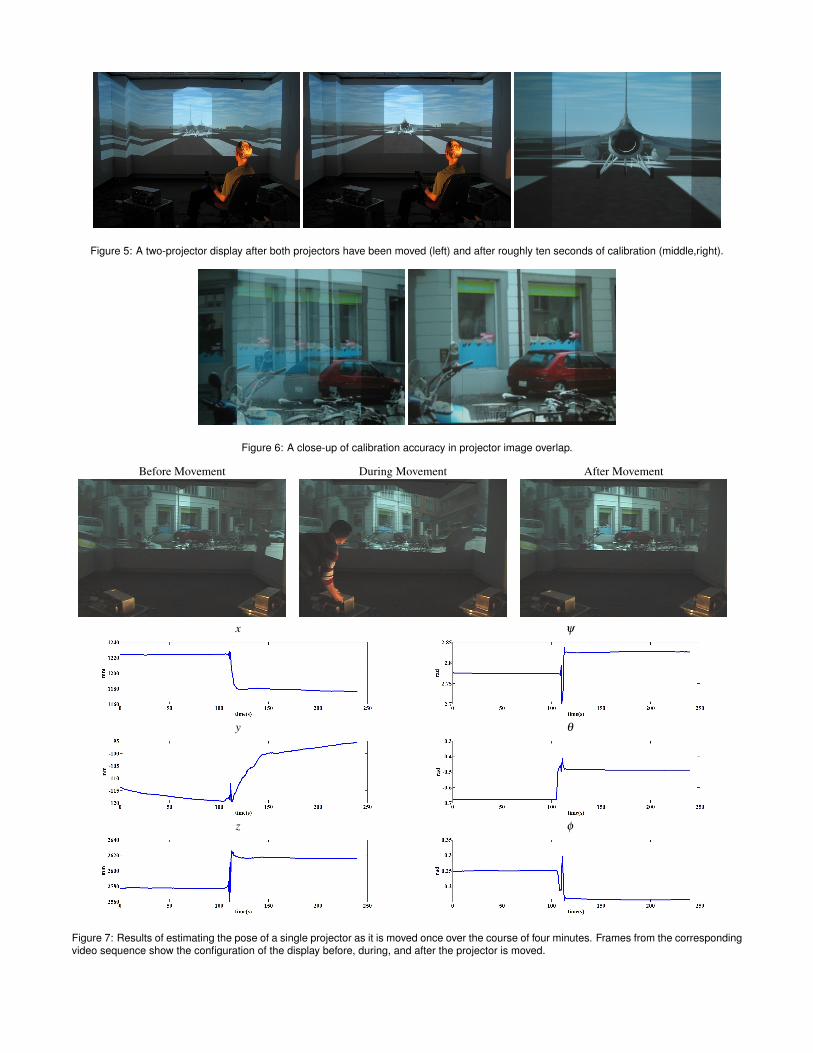
Figure 5: A two-projector display after both projectors have been moved (left) and after roughly ten seconds of calibration (middle,right).
Figure 6: A close-up of calibration accuracy in projector image overlap.
Before Movement During Movement After Movement
x ψ
y θ
z φ
Figure 7: Results of estimating the pose of a single projector as it is moved once over the course of four minutes. Frames from the correspondingvideo sequence show the configuration of the display before, during, and after the projector is moved.