A Computer Method to Evaluate the Vibration Response of ...
68
University of Central Florida University of Central Florida STARS STARS Retrospective Theses and Dissertations 1982 A Computer Method to Evaluate the Vibration Response of A Computer Method to Evaluate the Vibration Response of Stiffened Floor Systems to Impact Load Stiffened Floor Systems to Impact Load Michael E. Donahue University of Central Florida Part of the Engineering Commons Find similar works at: https://stars.library.ucf.edu/rtd University of Central Florida Libraries http://library.ucf.edu This Masters Thesis (Open Access) is brought to you for free and open access by STARS. It has been accepted for inclusion in Retrospective Theses and Dissertations by an authorized administrator of STARS. For more information, please contact [email protected]. STARS Citation STARS Citation Donahue, Michael E., "A Computer Method to Evaluate the Vibration Response of Stiffened Floor Systems to Impact Load" (1982). Retrospective Theses and Dissertations. 620. https://stars.library.ucf.edu/rtd/620
-
Upload
khangminh22 -
Category
Documents
-
view
0 -
download
0
Transcript of A Computer Method to Evaluate the Vibration Response of ...

University of Central Florida University of Central Florida
STARS STARS
Retrospective Theses and Dissertations
1982
A Computer Method to Evaluate the Vibration Response of A Computer Method to Evaluate the Vibration Response of
Stiffened Floor Systems to Impact Load Stiffened Floor Systems to Impact Load
Michael E. Donahue University of Central Florida
Part of the Engineering Commons
Find similar works at: https://stars.library.ucf.edu/rtd
University of Central Florida Libraries http://library.ucf.edu
This Masters Thesis (Open Access) is brought to you for free and open access by STARS. It has been accepted for
inclusion in Retrospective Theses and Dissertations by an authorized administrator of STARS. For more information,
please contact [email protected].
STARS Citation STARS Citation Donahue, Michael E., "A Computer Method to Evaluate the Vibration Response of Stiffened Floor Systems to Impact Load" (1982). Retrospective Theses and Dissertations. 620. https://stars.library.ucf.edu/rtd/620

A COMPUTER METHOD TO EVALUATE THE VIBRATION RESPONSE OF STIFFENED FLOOR SYSTEMS TO IMPACT LOADS
BY
MICHAEL E. DONAHUE, P.E. B.S.A.E., Parks College of St. Louis University, 1964
THESIS
Submitted in partial fulfillment of the requirements for the degree of Master of Science
in the Graduate Studies Program of the College of Engineering University of Central Florida
Orlando, Florida
Sunn:ner Term 1982

ABSTRACT
Composite construction of floor systems with steel joist or
I-beam stiffeners supporting a concrete slab have a tendency to sus
tain perceptible vibration due to small impacts. An engineering
design aid, utilizing a small micro-computer and a BASIC computer
program~ was developed to analyze rectangular floor systems for sus
ceptibility to sustain vibrations perceptible to humans. The analyti
cal method for the normal modes of vibration using the Rayleigh-Ritz
method and the superposition of the normal mode response is derived.
A vibration index is calculated to qualitatively rate the floor.
The computer method was validated using published data for an I-beam
supported concrete slab and a design application for a steel-joist
supported floor is demonstrated using a representative human induced
impact load.

TABLE OF CONTENTS
LIST OF TABLES.
LIST OF FIGURES •
Chapter
I. INTRODUCTION.
Background. Objective . •
II. ANALYTICAL APPROACH •
Rayleigh-Ritz Assumption .• Mass Coefficients . • . • Stiffness Coefficients .. Normal Modes of Vibration . Generalized Forces. Dynamic Response of Stiffened Plate
III.. COMPUTER PROGRAM DISCUSSION
Excitation Impulse. • . . Structural Property Data. • . Dynamic Response Solution • . Human Perception Criteria .
IV. METHOD VERIFICATION AND APPLICATION •
iv
v
1
1 3
4
6 6 8
10 12 13
16
17 19 21 22
25
I-Beam Stiffened Floor System . . . 25 Open-Web Steel Joist Stiffened Floor System • . 31
V. CONCLUSION. • • • • • • • • • • • • • • • • • 39
REFERENCES. 41
APPENDIX. . .
iii

LIST OF TABLES
1. I-Beam Stiffened Floor Ftm.da:mental Vinration Frequencies ••
2. I-Beam Stiffened Floor Maximum Impact Response . •
3. Steel Joist Stiffened Floor - Floor Structural Properties • • . . .
4.
5.
Steel Joist Properties .
Steel Joist Stiffened Floor - Impact Response Characteristics. . .. . • • • • • . . . • • •
1V
30
30
32
34
35

LIST OF' F'IGURES
1. Plate-stiffener Model. . 5
2. Human Heel-drop Function .. 18
3. Vibration Index Rating • 24
4. Case 1 - Steel Beam-Concrete Slab Floor. 27
5. Case 2 - Steel Beam-Concrete Slab Floor. 28
6. Case 3 - Steel Beam-Concrete Slab Floor. 29
7. Steel Joist-Concrete Floor Geometry .... 33
8 .. Steel Joist-Stiffened Floor Slab Thickness vs .. Vi-bration Index Rating . . . • . 38
v

CHAPTER I
INTRODUCTION
The contemporary structural design practic es incorporate the
use of composite c_onstruction methods utilizing concrete slab floors
supported by either steel beams or light weight open web steel
joists. This construction technique results in an efficient light
weight floor system with adequate static strength that may have a
tendency to respond to small impacts that produce a perceptible vi
bration. This thesis utilizes research previously done in the area
of floor vibration and adapts it into a convenient engineering de
sign aid that uses a small micro-computer to check floor system de
signs for susceptibility to transmit perceptible transient vibra
tions that may be annoying to occupants of the structure.
Background
Vibration excitation of a building can b e caused by machinery,
motors, or mechanical devices installed in the building. Such
sources of vibration are steady-state in nature and should be con
trolled by isolation of the equipment causing the vibration. Tran
sient vibration and impulses can also be induced into a structure
by light impact loads produced by the occupants of the building
Such loads could be caused b y jumping, dropping of an object, or
simply walking. These vibrations cannot be isolated but must be

2
controlled by the floor system structure. Stresses in the floor
structure resulting from these small impacts are normally well be
low the design values to which the floor would be designed using
standard design specifications. The vibration problem is mainly
one of psychological and physiological comfort of the human occu
pants of the structure.
Human perceptibility of transient vibration depends on the mag
nitude and duration of the applied impulse, the fundamental fre
quency of the floor system, the peak response amplitude and the
damping. Light weight construction methods tend to reduce the mass
of the floor, to have large open areas with moveable partitions,
and light weight ceiling systems that provide less damping to the
structure than older, less efficient, design practices. These char
acteristics combine to produce a mode~n floor .system that will re
spond with greater amplitude and longer lasting residual v .ibration;
therefore, increasing the human perceptibility of the transient vi
bration.
Existing codes and industry standards for composite steel
concrete construction do not explicitly define design parameters to
preclude annoying vibration from structures. Research projects,
especially those sponsored by the Steel Joist Institute (1,2,3),
and by the American Iron and Steel Institute (4), and directed by
Dr. K.H. Lenzen at the University of Kansas Center for Research in
Engineering Science, have investigated the vibration problem.
This research has established analytical methods and experimental

3
data that verify techniques for predicting floor system natural fre
quencies and response, and that address the criteria for human
perception of transient vibration.
Objective
The objective of this thesis is to provide a relatively sim
ple analytical method, using a small micro-computer and a BASIC
computer program, to predict the vibration and response character
istics of a composite floor system. The program output includes
the vibration modal frequencies, the peak response to an impulse
applied anywhere on the floor, and a vibration index that qualita
tively rates a floor as to its susceptibility to sustain annoying
vibration.
The computer program was written -to be used in the Computer
Aided Design (CAD) laboratory at the University of Central Florida
on a Tektronics 4051 micro-computer. The simple BASIC language
allows it to be easily adapted to any small micro-computer avail
able in any engineering design office.

CHAPTER II
ANALYTICAL APPROACH
The composite floor system, consisting of a concrete slab and
steel member stiffeners can be modeled by a simply supported rec
tangular, tsotropic, flat plate with uniform stiffeners parallel to
each other and located eccentric to the plate. This requires that
only one bay of the floor system be considered at a time. The
stiffeners are assumed to be of unit width and are tied to the bot
tom of the plate over the entire span of the stiffener& A diagram
of this model is shown in Figure 1.
The response of the stiffened plate to an applied time depen
dent forcing function is derived by using the superposition of
normal modes. In order to simplify the solution, zero modal damping
is assumed. The vibration modes are approximated using the Rayleigh-
Ritz Method. Employing the orthogonal property of the normal modes,
the time dependent response for each mode, or generalized coordin
ate, is independently calculated as if it were a single degree of
freedom system. By superimposing each modal response at any given
time, the solution for the stiffened plate response is obtained
which closely approximates the exact solution. A greater number
of modes included in the solution will increase the accuracy of the
results. Practically, the first few modes usually provide satis
factory results. This approach to the response of a stiffened
4

tx 5
I I I I
I I I
I I
I I I
I
A I
I I I I
I I I I
I I I
I I I ' I I y
• B
I I j
I I I
Fig. 1. Plate-stiffener model.

6
plate is similar to that of Ohmart (5).
Rayleigh-Ritz Assumption
The vibration modes and frequencies determined by the Rayleigh-
Ritz method requires the assumption of the mode shapes of the stif-
fened plate. The time dependent displacement is expressed in terms
of a set of assumed displacement shape functions or admissible
functions multiplied by a time dependent generalized amplitude co or-
dinate (6):
Z(X,Y,t) = L 0.(X,Y) q.(t) i 1 1
(1)
The d .isplacement admissible functions must satisfy the geometric
boundary conditions of the plate; therefore, at X = 0, X = A,
Y = 0, Y = B:
c/J. (X, Y) 1
0
For the case of the simply supported stiffened plat,e, the follow-
ing sine function was assumed:
0i (X, Y) = Sin m~X S. n1TY in -
B (2)
which represents half-sine functions along X and Y, and i represents
a particular combination of values for the integers m ~nd n .
Mass Coefficients
The kinetic energy of the system can be written in terms of
th-e time derivative of the displacement function (6):

7
,.A • . 2 T(t) = ~ r JB M(X,Y) Z(X,Y,t) dX dY
0 0
where from Equation 1:
·2 Z (X, Y, t) E 0. qi · L: ~- q.
i 1 j J J
The mass term consists of the distributed mass per unit area of the
plate, p, plus the sum of the individual stiffener masses, y:
M(X,Y) N
p + L y o(Y-bs) s=l
whe.re o (y-b ) is the Dirac delta function that allows a mass only s
at the bs stiffener locations for all N stiffeners.
Substituting into the kinetic energy expression and rearranging
terms:
AB AB T(t) = ~ 2: l:[pff r/J. f/J. dX dY + y ffl: o(Y-b ) 0. ~- dX dY]q. q.
1• . 00 1 J 00 s 1 J 1. J
J s
where the term in [ ] can be defined as the mass coefficients M •. 1]
such that:
T(t) ~ 2: L M .. q. q. 1. . lJ 1 J
J
(3)
Allowing the ith and jth admissible functions to be defined
as:
0.(X,Y) = S. ID TIX S. n TIY (4) 1
in--;:- in~
0. (X, Y) s· k TrX Sin f:rrY (5) - in---J A B

8
and substituting into the expression for the mass coefficients:
~1 .. = iJ JAB! S. m.rrX S. nrrY S. krrX si·n 4Y dX d p in A in in y +
oo B A B
AB y ff L:. 8 (Y-b ) Sin mrrX Sin IlffY Sin k;rX Sin bY dX dY
oo s A B A B s
Because the admissible functions are orthogonal, it can be shown
(8) that the first term of the equation is zero unless m = k and
n =£,which requires i = j, and that the second term is zero un-
less m = k. Therefore, the mass coefficients become:
for i = j
AB A 2 nnb
M .• + 2: Sin s
p- y-B i .i 4 2
(6) s
for i i= j
A nnb £nb
M .. 2: s· s Sin s
Y2 in-- --iJ B B
s (7)
Stiffness Coefficients
The potential or strain energy of the system is assumed to in-
elude only the bend.ing strains of the plate and stiffeners and can
be written (6,9):
V(t) = QE_ 2 0
A J
0
B J
where: Dp = plate rigidity, EI = stiffener rigidity
dX
Using the Dirac delta function to bring tt.e :::;tiffener term under
the double integral and substituting for Z(X, Y ,.t) from equation 1
yields:

V(t)
9
2 2 2 2 AB a 0. a 0. a 0. a 0.
1. 1 , , - 1/2 I I [Dpf J (-- + - -- ) (---L + ---'-) dX dY +
i j t>o ax2 ;w2 ax2 aY 2
2 2 AB a 0. a 0.
EI J f I o(Y-b ) (-.. -1 ___i) dX dY] o o s s ax2 ax2
q. q. i J
where the term in the [ ] can be defined as the stiffness coeffi-
cients k .. such that: 1.J
V(t) = 1/2 2:: l: i j
k .. q. q. iJ i J
(8)
The second derivatives of .r/J. and 0., see equations 4 and 5, i J
are substituted into the expression for the stiffness coefficients,
thus:
k .. i]
(s . mrrX S. nrrY ' in -- in --A B
0 AB . 22 22 Sin krrX Sin ·<.:TTY) · dX dY + EI J f L o (Y-b ) m 7T ~
A . B o o 5
s A2 B2
(s . mrrX S. n?TY S. k 7rX Si lrrY) dX· dY. in -- · in -- in -- 1 n --A I ' B A B
The first term is zero tmless m = k and n = l which requires i = j,
and the second term is zero nnless m = k. Therefore,, the stiffness
co·efficients become:

10
for i = j '- 2 2 2 2
k .. = 1/4 DpAB (!!!_11_ + !!.....!L_) + 11 A2 B2
4 4 nnb
2 s
1/2 E I m TI ! Sin B (9) s -3-,
A s
for i :-! j 4 4 m rb l nb
k .. = 1/2 EI~ I: s. s s. s (10) J..] A3
in -B- . in B s
Normal Modes of Vibration
The Lagrange equations of motion can be written in general as:
(11)
This represents i simultaneous differential equations or degrees
of freedom in the system where T is the kinetic energy, V is the
potential energy, q. are ·the generalized coordinates and Q. are the l 1
non-conservative tf:me dependent forces applied to the system. For
the homogeneous solution, the Q. 's are set to zero. Substituting 1
the kinetic energy, e ,quation 3, and the potential energy, equation
8, into the Lagrange equations and performing the indicated opera-
tions:
L: M .. .. + L: kij 0 q. qj =
j l.J J j
In matrix notation, this becomes:
[MJ{q.} + [K] {q .} = 0 J ]
(12)

11
This equation represents the equations of motion for free vibra-
tion of the system, and its solution is called the eigenfunction.
By assuming a time dependent harmonic solution for the generalized
coordinates
= eiWj t q. u. J J
thus
H. 2 iW • t 'i =-u. w. e J
J J J
where w. is the circu1ar natural frequency and u. is the amplitude, J J
the characteristic equation becomes
[ [K] - w: [M] ]{ u.} = 0 J J
(13)
There are many numerical techniques that are used to solve
this eigenproblem for the eigenvalues, 2 w., and the eigenvectors, J
u .. The method used in this thesis is a Jacobi solution method J
that operates directly on the mass and stiffness matrices using a
computer program (10,11). The method solves for all the eigenvalues
of the system; therefore, the resulting eigenvector matrix is square
and the order of the matrix is the same as that of the mass and
stiffness matrices and is equal to the number of degrees of freedom
included in the Rayleigh-Ritz assumptions.
Upon solving for the eigenvalues and eigenvectors, it is con-
venient to normalize the modal matrix fu] such that:
Iu]T[M][u] = [I] (14)

12
where [u]T is the transpose of [u] and the transformed mass matrix,
or generalized mass, is now the identity matrix [I].
Using the normalized modal matrix to transform the stiffness
matrix yields
T 2 [u] fK]fu] = [W ] (15)
where the generalized stiffness becomes a diagonal matrix of the
· eigenvalues.
Generalized Forces
To arrive at a general solution for the response of the stif-
fened plate to any type of transient loading, it is advantageous
to derive the response to a t.mit impulse applied at a given loading
point. A specific loading fnnction can be obtained by simply
scaling the response by the magnitude o-f the desired transient load
at time t. The unit impulse forcing function at X = X and Y = Y 0 0
is defined by
g(X,Y,t) = o(t) cS(X-X) o(Y-Y ) 0 0
where o( ) is the Dirac delta function and equals unity when the
quantity in the bracket is zero and equals zero for all other values.
The virtual work for the system can be written
W(t) = JAJBg(X,Y,t) Z.(X,Y,t) dX dY 0 0 J
Substituting for g above, and Z from equation 1, and rearranging t e r ms :
AB W(t) = L f f [o(t)o(X-X )o(Y-Y ) 0. dX dY] q.
.o 0 0 0 J J J

13
where the terms in the [ ] are defined as the generalized forces,
Q.. By substituting for 0. from equation 2 and integrating over J J
X and Y, the generalized forces become
Q. {t) = o(t) {6. (X 'y ) J J 0 0
(16)
where mrrX nrrY
0. (X , Y ) = s. 0 s. 0
J 0 0 in ---p::- in B
(17)
which is the admissible function evaluated at the discrete input
point (X ,Y ). 0 0
Dynamic Response of Stiffened Plate
The equations of motion for the stiffened plate were formulated
in equation 12 for a conservative system. By equating the inertial
and spring forces to the generalized fo~ces instead of zero,
equation 12 becomes
[M]{q.} + [K]{q} = {Q} J
(18)
The generalized coordinate can be described by the superposition of
the norm.al modes such that
{q} = [u]{~} (19)
where the colunm matrix{~} is ~ a new time dependent generalized co-
ordinate, and [u] is the m::>dal matrix. Similarly, for the acceler-
ation term
{Cf} = fuJ HJ (20)
Substituting q and q into equation 18,. multiplying the equation by
the transpose of the modal matrix yields

14
T .. T [u] fM][u] HJ+ [u] [K][u] HJ= [u]T {Q}
Utilizing the identities of equation 14 and equation 15, and in-
troducing a new column matrix of generalized forces such that
(21)
the equations of motion for the system become
(22)
This expression for the equations of motion represents a set
of uncoupled single degree of freedom systems. The response of each
mode to a unit impulse can be written in the form of the Duhamel
integral (7):
~. (t) J
1 t = - f N. Sin W-. (t-T) dT
w. 0 J J J
• where the initial conditions of ~(t) and ~(t) are zero.
(23)
The response is to be calculated at discrete points (X ,Y ) on r r
the stiffened plate. From equation 1, the displacement is
Z (X ,Y ,t) = L01 (X ,Yr) q~(t) r r r . r ..
1
Substituting for the generalized coordinate, q. (t), from equation i
19 and reversing the order of summation
Z (X ,Y ,t) = L: r r r
j
where
R. (X , Y ) sj ( t) J r r

15
R. (X ,,Y ) = E. ~ . (X , Y ) uiJ''' Jr r . 1 r r 1
(24)
The integral solution for ~- (t) from equation 23 can be substituted J
where the generalized force, N., is evaluated using equation 21 and J
equation 16. 'The displacement becomes
Z (X ,Y ~t) r r r
t 8 = ~ R. (X , Y ) L u. . 0 , , (X , Y ) f §J.!l Sin w. ( t-T) d T
J J r r Ji i o o o w. J
By defining
i J
P . (X , Y ) = 2: u . . ~ . (X , Y ) J 0 0 . Jl 1 0 0
1
(25)
the final solution for the undamped displacement response at point
(X , Y ) due to a unit impulse at point (X , Y ) is r r o o
R.P. t z (X ,Y ,t) = r _J_J_ f O(T) Sin w. (t-T) dT
r r r . w. o J J J
(26)
The Duhamel integral can be evaluated by using a numerical
method such as Simpson's rule (7) • For a specific forcing fune-
tion, the unit impulse o (T) would first be scaled by the magni-
tude of the forcing function at time T and then integrated numer-
ically.

CHAPTER III
COMPUTER PROGRAM DISCUSSION
To assist in the de~ign of steel stiffener-concrete
slab floor systems, a computer program was written to predict the
vibration and dynamic response characteristics of idealized floor
systems. The program uses the BASIC computer language, and
its relatively small computer memory requirement of about 30K bytes
allows it to be used on most small micro-computer systems. For this
study, a 'Tektronix 4051 micro-computer in the computer aided de
sign laboratory at the University of Central Florida was used. A
listing of the program with a definition of the input variables
is presented in the Appendix.
The program consists of four parts, each of which performs a
separate ftmction. In the first part, the excitation load data,
the structural data, and the selected output location data are read
into the computer, and the mass and st:iffness coeff·icients ar1e
calculated. The second part solves the ei.genproblem using the
Jacobi method and outputs the normal modes and frequencies. The
third part generates the normalized matrices to he used in the
response calculation. In the fourth part, the peak response is
calculated and the associated deflection at all selected response
points are printed out. Each part of the program is loaded into
16

17
the computer from magnetic tape and executed separately by using
a "LINK" command. This technique preserves computer memory by
storing in memory only that part of the program that is being used.
Excitation Impulse
The program allows any time dependent impulse load to be used
for analyzing a floor system. The selection of the input forcing
function is important for determining the susceptibility of a floor
system to sustain perceptible ~.ribration. The pulse duration, rise
time, peak load, and shape all affect the peak response of the
structure. For this reason, the excitation function should be
representative of :in:pacts the floor is expected to see in service.
For most floor systems, an excitation that represents "heavy"
walking by a human occupant would be applicable.. Such a forcing
function, derived from experimental measurements by L,enzen (4)
and Ohmart (S) and produced by a human heel drop onto a represen
tative structure, was selected as a suitable excitation for this
program. A time history plot of this forcing function is shown
in F'i.gure 2 •
The excitation function is input to the computer program by
a series of points from the force-time history curve selected for
use .in an analysis. Only enough points are required to adequately
define the force curve because the program interpolates to deter
mine force values between the times given as input.

18
700--
600--
500
,,........ 400 Cl)
'"O c:: ;:j 0 p..
'--"
<l) u 300 $-I 0
Ii-I
2 0 0 .,._...____
100 .,._ __
o ............................................................ m11 ...
10 20 30 40 50
T~me (milliseconds)
Fig. 2. Human heel-drop function.

19
Structural Property Data
There are four types of structural property data required to
formulate the stiffened plate structural dynamic model, namely
geometry, weight or mass properties, stiffness properties, and the
number of half-sine modal shapes assumed for the Rayleigh-Ritz
approximation.
The floor geometry is shown in Figure 1 where the span or
width is A, length is B, plate thickness is h and the stiffener lo-
cations are b • It is assumed that all stiffeners are parallel and s
uniformly spaced, and that the plate is rectangular.
The mass properties are required in terms of the plate weight
density or pounds per cubic foot, and the stiffener weight per lin-
ear foot. The mass matrix coefficients are calculated in the pro-
gram as shown previously in equations 6 and 7 using the assumed
half-sine shape functions defined in equation 2.
The greater number of deflection modes or shape functions in-
eluded in the analysis, the more accurate the results become. This
is especially true if the excitation function has a steep, rising
slope. In practice, the first few modes are sufficient to provide
reasonable results. This program limits the total number of assumed
mode shapes to about 20 because of the meroory available in the
Tektronix 4051 micro-computer. The total number of modes is deter-
mined by multiplying the number 0£ half-sine shapes assumed along
the X-axis by the number assumed along the Y axis. If only
two modes are assumed for X, then the program uses n = 1 and n = 3,

20
since a loading on the floor mid-span, which produces the maximum
deflection, will not excite the m = 2 mode. Good results for pl a tes
excited by the human heel drop, Figure 2, were obtained by allow-
ing 7 shapes along Y and 2 shapes along X.
The stiffness coefficients are calculated using equations 9
and 10 given earlier. The shape functions used for the mass coef-
ficients are also used here. The moment of inertia of the sti ffener
is input to the program; however, before it is used in the stiff-
ness coefficient equations, a transfer moment is added that repre-
sen ts the stiffener moment of inertia about a composite plate- stj_ffen-
er neutral axis:
where:
I h 2
I + A (Z - ~) s s 2
-
I = stiffener moment of inertia s
A = stiffener cross-sectional area s
h = stiffener depth s
and the composite neutral axis is located at:
E h + h
<Ts) ( p s) ~b • h . . s E 2 z =
(~) ~b ·h . + A s p E
s where:
~b = average stiffener spacing s
E = stiffener modulus of elasticity s
h = plate thickness p
E = plate modulus of elasticity p
(2 7)
h s + A . (-)
s 2 (28)
s

21
The eff.ect of this moment of inertia transfer is to account for
the full stiffness provided by the stiffener t:hat is eccentric to
the 'plate (5):
The plate rigidity is calculated in the program using:
E h 3
D = p p P 12 (1 - v 2 )
(29)
where Poisson's ratio, v, is taken as 0. 25.
Dynamic Respons 1e Solution
The dynamic response of the floor system is calculated using
the superposition of the normal modes of vibration. The displace-
ment response of each mode to the given excitation function is
determined as if it were a single degree of freedom system. The
system response at any time is calculated by summing the responses
for each of the normal modes.
The normal modes and frequencies are calculated using a gen-
eral Jacobi solution (10, 11). These modes and frequencies are
printed by the computer program as part of the results. Each mode
r ·epresents a tmique combination of the assumed shape functions
discussed earlier.
For calculating the response, it is necessary to define the
impact points at which the forcing function is to b 1e applied and
the response points at which the peak displacement is to be deter-
mined. This is done by inputing to the program the X and Y loca-
tions of the points. Because the stiffened plate is assumed

22
tmiform, rectangular, and simply supported on all edges, the maxi
mum deflection will occur at the center of the floor. For this
reason, the :impact points and response points should be located
on the mid-span of the stiffeners. However, the program allows any
location within the botmds of the floor to be selected ..
Using Simpson's rule (7) to integrate the equations of motion
with respect to time, the response at all response points is cal
culated for each impact point defined to the program. During the
integration, the peak response is saved, along with the time of
the peak response, to be printed after the integration is completed.
The time interval used in the integration should be sufficiently
small to adequately integrate the forcing function and the response.
Human Perception Criteria
The perception of transient vibration by humans is primarily
a physiological and psychological phenomenon.. Human response or
sensitivity to transient vibration depends on the vibrating fre
quency, amplitude of vibration, and system damping or duration of
the vibration. This was reported by Lenzen (2,3,4) wher·e human
subjects were subjected to transient motions and their r ·eactions
recorded. This research confirmed earlier investigations by Reiher
and Meister (12) and Wright and Gre.in (13).
A mean human response rating for transient vibration was for
mulated by investigators J.F. Wiss and R.A. Parmalee and reported
by Galambos (1). This formula was derived from tests that subjected

23
forty humans to short vibration impulses where frequency, ampli-
tude and damping were variables. The results of this research are
formulated by:
where:
[
FZ · ] 0 .265
R = 5.08 ~0. 2~J
R vibration index rating
F = fundamental frequency (H ) z
Z = maximum amplitude (in) 0
~ = damping ratio
(30)
The vibration index rating varies from one to five with the follow-
ing descriptive definitions:
R= 1 Imperceptible
R= 2 Barely perceptible
R = 3 Distinctly perceptible
R = 4 Strongly perceptible
R = 5 Severe
A log-log plot of the boundary lines separating the regions of per -
ceptibi.lity (e.g., R = 1.5, 2.5, 3.5), is shown in Figure 3 for a
damping ratio of 4 percent.
The computer program calculates the vibration index using equa-
tion 30. The assumption of 4 percent damping represents a conserva-
tive estimate for lightly damped structures. Depending on the na-
ture and use of a floor system, this value may be increased or de-
creased at the judgement of the analyst. The vibration index is
printed by the computer program for each impact point selected.

24
0.050
,,-.... U) Q.)
0.010 ,.c CJ ~
·r-1 '-"
<lJ '"d ~ .µ ·r-1 0.005 r-l 0.. s <
0.001 2 5 10 20 50
Frequency (H ) z
Fig. 3. Vibration index rating.

CHAPTER IV
METHOD VERIFICATION AND .APPLICATION
Two composite design floor sy"stems were analyzed for their vi-
bration response characteristics. The first floor system, an I-beam
supported concrete slab, was previously investigated experimentally
and theoretically by Ohmart (5). These published results were used
to verify the subject computer code and analytical method. The se-
cond floor system was selected to demonstrate the use of the method
for design of a steel joist-concrete floor system. For both type
floors, several design variations of each floor system were investi-
gated. Th.e impact used was the human heel-drop forcing function
(Figure 3) that was also derived by Ohmart in his experimental in-
vestigation. The impact points and response points were selected
primarily along the mid-span of the steel supporting members in or-
der to obtain the maximum response.
I-Beam Stiffened Floor System
The I-beam floor system consisted of a rectangular concrete
slab, simply supported at its edges, and stiffened by W6x12 steel
I-beams equally spaced four feet apart. The structural properties
of the floor system components are as follows:
E = 29 x 106
psi s
I = 21. 4 in s 2
A = 3.54 in s
w = 12 lb/ft s
25

26
h = 6 in s
E = 3.8 x 10⁶
psi p
w = 145 lb/ft 3 p
h_ 4 in p
Three geometric confLguration cases of the £lo.or system were
analyzed. Figures 4 through 6 show the geometry for each case. The
locations of the impact points are identified by number, and for
each floor case, three impact points were selected. All three floor
cases had a width or stiffener span of 14.67 feet (176 inches).
The vibration frequencies for each floor case were computed and
the results for the fl.lll.damental frequency are listed in Table 1.
Included in the list are theoretical and experimental data reported
by Ohm.art (5). His theoretical results were obtained using a GE635
mainframe computer and an analytical approach similar to that pre-
sented herein. The computed frequencies were within 8 to 12 per-
cent of the experimentally measured frequencies which is considered
very good correlation for an approximate solution.
For the human heel-drop impact, the maximum computed displace-
ment responses for each floor case and each impact location are pre-
sented in Table 2. The Ohmart data are again tabulated for compar-
ison. The computed maximum displacements occurred at or near the
point of impact and were largest when the impact was applied at the
floor center. The computed response was greater than the Ohm.art
experimental data by an average of 20 percent. This difference can
be attributed partially to the fact that the test floor did not have

27.
I I I I
I I
I
][ n I ~
.._ ~
._ -4 ._ 14~6 7'
l I I
I I
I I
20.0 1 -------
Fig. 4 .. Case 1 - Steel beam-concrete slab floor.
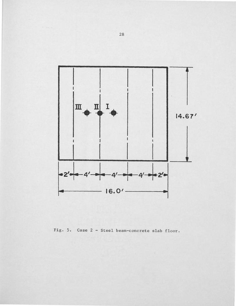
28
!
I I I I
,m n ._ 1. ·~
11
14.6 7 1
• I I •
I I
2'+-4'-+-4'-+-4'-+~ 16.0'-----.....
F'ig. 5. Case 2 - Steel beam-concrete slab floor.

29
.m II_.__ -4... -,..- 14. 67 I
12.0'-------lat
Fig. 6. Case 3 - Steel beam-concrete slab floor.

30
perfect hinges at its edges, and that some damping would exist in
the experimental floor.
Floor Case
No.
1
2
3
TABLE 1
I-BEAM STIFFENED FLOOR FUNDAMENTAL VIBRATION FREQUENCIES
Theoretical* Experimental* Frequency Frequency
(Hz) (Hz)
16.81 18.75
18.58 20.83
22.79 25. 86
Computed Frequency
(Hz)
17.31
19.03
23.13
* Theoretical and experimental data taken from Ohmart (5).
Floor Impact
Case No.
Location
1 I II
III
2 I II
III
3 I II
III
TABLE 2
I-BEAM STIFFENED FLOOR MAXIMUM IMPACT RESPONSE
Theoretical* Experimental* Response Response
(in) (in)
.0092 .0078
.0090 .0072
.0040 .0032
.0105 .0078
.0088 .0072
.0072 .. 0055
.0095 .0075 - -
.0033 .0030
Computed Vibration Response Index
(in) Rating I
.0088 3.7
.0086 3.6
.0038 2.9
.0098 3.9
.0088 3.8
.0068 3.5
.0091 4.0
.0078 3.8
.0037 3.3
* Theoretical and experimental data taken from Ohmart displacement curves (5).

31
The vibration index was computed for each ana1ys is. All
values for this floor system fell within the strongly perceptible
region of Figure 3 when the impact was applied at the center of the
floor. If 10% damping were used to calculate the vibration index,
the largest floor, Case-1, would classify at the upper bolllldary of
the barely perceptible region and would probably be considered an
acceptable design. The smaller floors, with fewer stiffeners, would
be marginal for design, at best.
The fundamental vibration frequencies calculated by the compu
ter code demonstrated a good correlation to the published experimen
tal data. The higher modal frequencies, for which no applicable
test data were available, probably would show less correlation. The
response displacements showed reasonable correlation. The computed
displacement was always on the conservative side.
Based on these analyses, the analytical method, and relatively
simple computer program, can reasonably estimate the vibration re
sponse characteristics of a stiffened floor system to impact loads.
The floor vibration index can be used to qualitatively rate a floor
design as to its susceptibility to sustain humanly perceptible vi
brations.
Open~Web Steel Joist Stiffened Floor System
A steel joist-concrete slab .floor system was used to demonstrate
the appl.ication of the computer method to a floor system design.
Nominally, the floor measures 32 feet by 20 feet. The concrete slab
is supported by five steel joists m:iiform.ly spaced at 4 foot inter-

32
vals along the 20 foot length and spanning 32 feet. Figure 7
shows the basic configuration of the floor.
Several properties of the floor system were varied to deter-
mine the effect on the floor vibration response characteristics for
an impact load. Eight separate floor cases were investigated with
the structural properties defined in Table 3. Floor Case 1 is the
baseline design. For subsequent cases, the steel joist stiffener
was varied and then the slab thickness was varied. Two cases inves-
tigated the effect of shortening the span of the slab and stiffeners,
and the last case considered the baseline desi gn with a 50 pound per
square foot live load. Properties considered constant for the
analysis are:
E = 3 x 10⁶ psi c w = 145 lb I ft 3
c E = 29 x 106 psi
s
The properties of the steel joists are shoivn in Table 4.
Floor Case
No.
1 2 3 4 5 6 7 8 9*
TABLE 3
STEEL JOIST STIFFENED FLOOR -FLOOR STRUCTURAL PROPERTIES
Span Length Slab A B Depth
(ft) (ft) (in)
32 20 4.125 32 20 4.125 32 20 4.125 32 20 5.00 32 20 6.00 32 20 7.00 28 20 4.125 24 20 4.125 32 20 4. l? C\
Steel Jois t
Stiffener
20H5 16H6 20H8
20H5 20H5 20H5 20H5 20H5 ?()Ht)
*Floor case 9 is the baseline case with 50 psf live load.

33
11
I I I I I
.. IMPACT1 ......
I I .... I I 32'
I I I I I -
.
-~~ - 4' ~ - 4' -- -- 4' ·-- - 4' ,~ ~~--- - - - - - - ·-
Fig. 7. Steel joist-concrete floor geometry.

34
TABLE 4
STEEL JOIST PROPERTIES
Steel Depth Weight Section Moment of
Joist hs w Area-A Inert ta-I (in) (lb, ft) Cin2 Y (in ) 8
20H5 20 8.4 2.4 107.7
16H6 16 8.6 2.5 81.3
20H8 20 12.2 3.5 179.6
In all floor cases analyzed, the human heel-drop impact ft.me-
tion was applied at the floor center where maximum response dis-
placement will occur. The results of the d~sign analysis are shown
in Table 5 where, for each floor case, the floor system fundamental
vibration frequency, maximum response displacement, and vibration
index rating are listed.
The baseline floor design, Case 1, produced a vibration index
of 3.33 in the analysis. The effect on this value, by changing
stiffener size, was examined with floor Cases 2 and 3. By substi-
tuting a lighter steel joist, the fundamental vibration frequency
reduced and the resulting response amplitude increased. This is
expected because the reduction in joist stiffness, I , has pros
duced a more flexible floor. However, the vibration index remained
nearly constant. Recalling equation 30, the vibration index is
a ftm.ction of frequency times amplitude; therefore, the changes

35
made in stiffener size did not produce a significant change in the
frequency-amplitude product and the vibration index rating remained
unchanged. For the heavier joist, the opposite occurred for fre-
quency and response; and again, the vibration index did not change.
Floor Case
No.
1
2
3
4
5
6
7
8
9
TABLE 5
STEEL JOIST STIFFENED FLOOR -IMPACT RESPONSE CHARACTERISTICS
Fundamental Maximum Frequency Response
(Hz) (in)
7.62 .0132
7. 08 .0139
8.32 .0120
8.31 .0093
9.26 .0068
10.33 .0051
9.16 .0123
11.63 .0103
5.45 .0102
Vibration Index Rating
3.33
3.31
3 .. 32
3.10
2.94
2.80
3. 43
3.48
2.84
In floor cases 4, 5, and 6, the slab thickness was gradually
increased to 7. 0 inches. The effect on the floor vibration char-
acteristics was significant. The floor frequency increased by 35
percent and the response displacement decreased by 61 percent;
thus, the vibration index rating was significantly reduced from
3 .. 33 for the baseline case to 2. 80 for case 6.

36
The effect of floor stiffener span changes was analyzed by de
creasing the 32 foot span to 28 feet for floor case 7, and to 24
feet for floor case 8. This produced an increase in floor frequen
cy and decrease in amplitude; however, the vibration index remained
essentially unchanged for the values analyzed.
Floor case 9 examined the baseline design, as defined in case
l; however, a live load of 50 pounds per square foot was included
with the weight of the concrete slab. The added mass lowered the
fundamental frequency by 28 percent and decreased the maximum re
sponse amplitude by 23 percent.. As a result, the vibration index
reduced by 15 percent to 2.84 as compared to the baseline design.
The greater mass of the system will not accelerate as readily for
the given input; thus, the peak response displacement is less than
for the unloaded floor.
For design purposes, the unloaded floor should be the condition
analyzed for evaluating the floor design since this represents a
worst case situation for most floors. The results of this analysis
indicate that the 3. 33 vibration index rating for the baseline floor
design can be most easily improved by increasing the floor slab
thickness. The curve shown in Figure 8 was canst ructed from the re
sults and relates slab thickness to vibration index rating. If it
was desired to have a vibration index rating of no greater than 3 .. 0,
a slab thickness of 5.5 inches would be required.
For all cases considered, there were 7 half-sine modes assumed
along the floor length and 2 modes assumed along the slab stiffener

37
span which produced 14 degrees-of-freedom. Computer run time on
the Tektronix 4051 micro-computer was approximately 20 minutes with
an integration time interval of 0.002 seconds used in the integra
tion by Simpson's Rule. More modes or a shorter integration time
interval will increase the run time proportionally; however, for
the cases considered, the calculated responses were effected only
in their fourth significant digit for eighteen degrees-of-freedom
and an integration interval of 0.0005 seconds.

38
3.4 ---
Floor Size: 20'x32'
3.3 Stiffener: 20H5
00 3.2 t:: ·n +J C1j
P::
K Q.)
'"Cl 3.1 i::::
H
i:::: 0 ·n +J rd ~
3.0 ..0 - • ·n ~
2.9
2.8
3 4 5 6 7
Slab Thickness
Fig. 8. Steel joist-stiffened floor slab thickness vs. vibration index rating.

CHAPTER V
CONCLUSION
The design of floor structures that utilize light weight con
struction methods has resulted in floors with sufficient structural
strength that may have a tendency to sustain perceptible vibrations
induced by small impacts. A computer method has been writ ten that
predicts the vibration response characteristics of concrete slab
steel stiffener floor systems. The analytical approach uses
the Rayleigh-Ritz method and the superposition of normal modes to
calculate the maximum response due to an impact load. A vibration
index rating is computed that qualitatively rates the floor for its
s-µ~ceptibility to transmit small impacts. Using analytical and
experimental data available in the literature, the computer method
was validated with computed results being on the conservative side.
A typical application of the method was demonstrated for a
concrete slab-steel joist floor design. Several parameters of the
baseline floor design were varied to optimize the floor design.
Slab depth provided the greatest change in the floor vibration index
rating and that parameter was used to optimize the design for a
given maximum vibration index.
As an engineering design aid, the computer method uses the BASIC
computer language and a small digit al micro-computer, both of which
39

40
are available to any engineering design office. The method pro
vides an easy to use and a relatively fast means to check and opti
mize the design of composite structure floor systems with regard
to minimizing vibration due to impacts.

REFERENCES
1. Galambos, T. V. "Vibratj_on of Steel Joist-Concrete Slah Floors." Technical Digest No. 5, Steel Joist Institute, Arlington, Virgina.
2. Lenzen, K.H. "Vibration of Steel Joist-Concrete Slab Floor Systems: Final Report." Report SEM-16, The University of Kansas Center for Research in Engineering Science, August 1962, Lawrence, Kansas.
3. Lenzen, K.H., and Dorsett, L.P. "Effect of the Variation of Structural Parameters on the Vibrational Characteristics of Steel Joist-Concrete Slab Floor Systems and Suggested Designs." Report SEM-32, The University of Kansas Center for Research in Engineering Science, August 1968, Lawrence, Kansas.
4. Lenzen, K.H., and Murray, T.M. "Vibration of Steel BeamConcret e Slab Floor Systems." Report SEM-29, The Uni versi ty of Kansas Center for Research in Engineering Science, April 1968, Lawrence, Kansas.
5. Ohmart, R.D. "An Approximate Method for the Response of Stiffened Plates to Aperiodic Excitation .. " Report SEM-30, The University of Kansas Center for Research in Engineering, April 1968, Lawrence, Kansas.
6. Bisplinghoff, R.L.; Ashley, H.; and Halfman, R.L. Aeroelasticity. Reading, Massachusetts: Addison-Wesley Publishing Company, 1965.
7. Clough, R.W., and Penzien, J. Dynamics of Structures. New York: McGraw-Hill Book Company,. 1975.
8. Rildebrand, F.B. Advanced Calculus for Applications. New Jersey: Prentice-Hall, 1962.
9. Jaeger, L. G. Elementary Theory of Elastic Plates. New York: MacMillan Company, 1964.
10. Paz, M. Structural Dynamics, Theory and Computation. New York: Van Nostrand-Reinhold Company, 1980.
41

42
11. Bathe, K.J., and Wilson, E.L. Nlimerical Methods in Finite Element Analysis. New Jersey: Prentice-Hall, 1976.
12. Reiher, H., and Meister,, F.J. "Effect of Vibration on People ,." Translation: Report No. F-TS-616-RE, Hq. Air Materi.al Cmmnand, Wright Field, Ohio, 1946.
13. Wright, D.T., and Green, R. "Human Sensitivity to Vibration." Report No. 7, Department of Civil Engineering, Queen's University, Kingston, Ontario, Canada, 1959.

APPENDIX

44
COMPUTER PROGRAM INPUT D~TA DEFINITIONS
Stiffened Plate - Normal Modes and Dynamic Response
NZ = Number of stiffeners
N3 = Number of assumed shapes along - Y
N4 = Number of assumed shapes along - X
R3 = Number of impact points
R4 - Number of response points
RS Number of excitation function points
Al = Plate and stiffener span (ft)
Bl = Plate width (ft)
Hl = Plate thickness (in)
Wl = Plate weight density (lb/ft3 )
El = Plate modulus of elasticity (psi)
H2 = Stiffener depth (in)
W2 = Stiffener weight (lb/ft)
2 .ff . (. 2) S = Sti ener section area in
12 = Stiffener moment of inertia (in4)
B2 = Average distance between stiffeners
E2 = Stiffener modulus of elasticity (psi)
X3 = X location - impact point
Y3 = Y location - impact point
X4 = X location - response point
Y4 Y location - response point
T¢ = Excitation function - time
Q¢ = Excitation function - force (lb)

45
100 REM ***************************************************** 110 REM **** STIFFENED PLATE - NORMAL MODES & DYN. RESPONSE
120 REM ***************************************************** 130 REM **** b~ M.E. DONAHUE
140 REM ***************************************************** 150 REM **** NOF~MAL MODE F<ESF'ONSE TO A PULSE L01~D I NG ON 160 REM **** STIFFENED PLATE USING RAYLEIGH-RITZ METHOD .170 REM **** WITH N3 MODES ALONG-Y AND N4 MODES ALONG-X 180 REM ***************************************************** 190 !NIT 200 PAGE 210 PRINT •************************************************** 220 PRINT • STIFFENED PLATE NORMAL MODES & RESPONSE 230 PRINT u************************************************** 240 DATA 5,7,2,3,7,15 250 READ N2,N3,N4,R3,R4,R5 300 NO=N3*N4 320 DIM KO<NO,NO),MOCNO,NO>,Y2CN2>1CCNO,NO>,VCN3,N2) 330 DIM K1<N3>vK2(N3),K3CN3),FO<N0>1D<NO),XO<N01NO) 340 DIM FCNO>,M1CNOYNO>,M2<NO,NO),X3<R3),y3(R3),X4CR4),Y4CR4) 350 DIM V3<NOvR3),V4<NOvR4),LJOCNO),U1CN0)1U2<N0>1R6CR31R4>,T6 360 DIM QOCR5>vTOCR5),RO<R4),R7CR4) 370 REM *********************** READ PLATE DATA <mu=0.25) 380 DATA 32,20,4.125,145,3000000 390 READ A1,B1,H1,W1vE1 400 REM *********************** READ STIFFNER DATA C5max) 410 DATA 20,9.4,2.4,107.7,49,3.0£+7 420 READ H21w2,s2,12,B2,E2 430 A1=A1*12 435 B1=B1*12 440 REM ****************** 450 DATA 24,72,120,168,216
READ STIFF Y2 <N2)
460 FOR I=1 TO N2 470 READ Y2<I> 480 NEXT I 500 REM ***** READ IMPACT POINT LOCATIONS 510 DATA 24,192,72,192,120,192 520 REM
Y3 , X3
*******
530 REM ********************** DATA ***************** 540 FOR !=1 TO R3 550 READ Y3CI),X3CI> 560 NEXT I 570 REM***** READ RESPONSE-LOCATIONS Y4 , X4 580 DATA 0,192,24,192,72,192,120,192 590 DATA 168,192,216,192,240,192

46
600 REM ********************* DATA ***************** 610 FOR !=1 TO R4 620 READ Y4CI>,X4Cil 630 NEXT 1 640 REM ***** READ FORCING FUNCTION - TIME ***** 650 DATA o,o.0024,o.004,o.0072,o.ooa6,o.01~0.0114,o.0132,o.c 660 DATA o.02s,o.03,o.04,o.045,o.05 670 REM ************************* DATA ***********
' 680 FOR !=1 TO R5 690 READ TOCI> 700 NEXT I 710 REM ***** READ FORCING FUNCTION - FORCE ***** 720 DATA o,200,400,600,655,660,655,600,500,410 730 DATA 300,225,125,75,0
740.REM ************************* DATA ************ 750 FOR I=l TO R5 760 READ QO(Ij 770 NEXT I 780 D1=E1*H1~3/11.25 790 R1=W1*H1/(12*12*12*386.4) 800 G2=W2/(12*386.4> 810 B3=B2/(E2/El) 820 HO=CB3*H1*CH2+H1/2>+S2*H2/2)/CS2+B3*H1> 830 IO=I2+S2*<HO-H2/2)~2 840 PRINT 850 PRINT • PROPERTIES OF STIFFENED PLATE • 852 PRINT •************************************************• 855 PRINT •NUMBER OF STIFFNERS =a;N2 860 PRINT •PLATE AND STIFFNER LENGTH CA1> =•;A1 870 PRINT •PLATE WIDTH <ACROSS STIFF> CB1> =·~Bl 872 PRINT •PLATE THICKNESS CIN> =•fHl 875 PRINT •PLATE MOD. OF ELASTICITY =•;£1 880 PRINT •PLATE FLEXURAL COEFF CDl) =•;01 890 PRINT •PLATE MASS PER AREA CMUGS/IN~2> =•;R1 892 PRINT •sTIFFNER DEPTH CIN> ="~H2
896 PRINT 1 STIFFNER CROSS-SECT AREA CIN~2> =";s2 900 PRINT •sTIFFNER MOD. OF ELASTICITY =•;E2 910 PRINT •sTIFFNER MASS PER INCH =•;G2 920 PRINT •sTIFFNER MOMENT OF INERTIA CI2> =•;12 950 REM ***** COMPUTE MASS AND STIFFNESS MATRICIES 970 FOR I=1 TO N3 980 FOR J=1 TO N2 990 V(I,J>=SIN<I*PI*Y2<J>/B1> 1000 NEXT J 1010 NEXT I

1020 FOR I=1 TO NO 1030 FOR J=l TO NO 1040 C<I,J)=O 1050 MO<I,.J)=O 1060 KO<I,J)=O 1070 NEXT .J 1080 NEXT I 1090 FOR I=l TO N3 1100 FOR .J=1 TO N3 1110 FOR K=1 TO N2
47
1120 C(!,J)=C(!,.J)+V<I,K)*V<JvK) 1130 NEXT K 1140 NEXT J 1150 NEXT I 1160 N9=0 1170 N9=N9+1 1180 IF N9=>N4 THEN 1270 1190 FOR I=l TO N3 1200 K=I+N9*N3 1210 FOR J=1 TO N3 1220 L==J+N9*N3 1230 C<K,L)=CCI,J> 1240 NEXT .J 1250 NEXT I 1260 GO TO 1170 1270 REM T • C CI,J>• 1280 REM PRINT C 1290 REM ********** COMPUTE MASS MATRIX -MO<NO,NO) **** * * 1300 R=R1*A1*B1/4 1.310 G=G2*A1/2 1320 FOR I=1 TO NO 1330 FOR ~=1 TO NO 1340 IF I=.J THEN 1370 1350 MO<I,.J)=G*C<I,J> 1360 GO TO 1380 1370 MOCI,.J)=R+G*C<I,.J) 1380 NEXT .J 1390 NEXT I 1400 PRINT 1410 PRINT • MASS MATRIX• 1420 F'RINT MO 1430 REM ****** COMPUTE STIFFNESS MAT RIX COEFF . KOCNO , NO> 1440 FOR I=l TO N3 1450 K1CI>=Dl*A1*B1/4*<<PI/A1>~2+<I*PI/B1>~2 ) ~2 1460 NEXT I

1470 IF N4=1 THEN 1550 1480 FOR I=l TO N3
48
1490 K3<I>=D1*A1*B1/4*C<3*PI/A1)~2+CI*PI/B1)~2)~2 1500 NEXT I 1510 IF N4=2 THEN 1550 1520 FOR I=l TO N3 1530 K2<I>=D1*A1*B1/4*<<2*PI/A1>~2+CI*PI/B1)~2>~2 1540 NEXT I 1550 K4=E2*I0/2*PI~4/A1~3 1560 K5=K4*2~4 1.570 K6=K4*3r'4 1580 FOR I=1 TO NO 1590 FOR J=l TO N3 1600 IF J=I THEN 1630 1610 KO<I,J>=K4*C(I,J> 1620 GO TO 1640 1630 KO(I,J>=K1<J)tK4*CCI,J) 1640 NEXT J 1650 NEXT I 1660 IF N4=1 THEN 1940 1670 K=N3+1 1680 L=N3+N3 1690 IF NO>L THEN 1810 1700 FOR I=1 TO NO 1710 M=O 1720 FOR J=K TO NO 1730 M=M+1 1740 IF I=J THEN 1770 1750 KO<I,J>=K6*C<I,J) 1760 GO TO 1780 1770 KO<I,J>=K3<M>+K6*C<I1J) 1780 NEXT J 1790 NEXT I 1800 GO TO 1940 1810 FOR !=1 TO NO 1820 M=O 1830 FOR J=K TO L 1840 M=M+l 1850 IF I=J THEN 1880 1860 KOCI,J>=K5*C<I1J) 1870 GO TO 1890 1880 KOCI,J>=K2<M>+K5*C<I,J> 1890 NEXT .J 1900 NEXT I 1910 K=Ltl

1920 GO TO 1700 1930 REM
49
1940 PRINT • STIFFNESS MATRIX• 1950 PRINT KO 1960 REM ************* TAPE **************************** 1970 FIND 11 1980 CALL •LINK•,2000
1990 REM ***************************************************
2000 REM *************************************************** 2010 REM ***** 2020 REM ***** JACOBI SOLUTION FOR EIGEN-VALUES AND -VECT 2030 REM ***** 2040 REM *************************************************** 2050 REM FOCNO> = EIGENVALUES Cw~2)
2060 REM XOCN01NO>D= EIGENVECTORS 2070 REM DOCNO) = DUMMY 2080 E9=0 2090 N6=1.0E-16 2100 N7=15 2110 N8=0 2120 FOR I=1 TO NO 2130 IF KOCI,I><=O THEN 2160 2140 IF Mocr,r><=O THEN 2160 2150 GO TO 2180 2160 PRINT • ******** ERROR - NEGATIVR ON DIAG --- STOP --2170 STOP 2180 D<I>=KOCI1Il/MOCI,I> 2190 FOCI>=D<I> 2200 FOR J=1 TO NO 2210 xocr,J>=O 2220 XO<I1I>=1 2230 NEXT J 2240 NEXT I 2250 IF NO=l THEN 3860 2260 N9=N0-1 2270 N8=N8+1 2280 PRINT 2290 PRINT • JACOBI SOLUTION SWEEP =•,Na 2300 REM ***** CHECK IF OFF-DIAG. ELEMENT IS LARGE 2310 P1=1.0E-6~N8~2 2320 FOR J=1 TO N9 2330 Jl=J+1 2340 FOR K=Jl TO NO

50
2350 P2=KO(J,K)~2/CKOCJ,J>*KOCK,K)) 2360 P3=MOCJ,K>~2/CMO(J,J>*MOCKvK)) 2370 L=O 2380 IF P2<P1 THEN 2400 2390 GO TO 2420 2400 IF P3<P1 THEN 3170 2410 REM***** IF ZEROING REQD.~ COMPUTE ROTATION ELEMENT 2420 AO=KOCK,K>*MOCJ,K>-MOCK,K>*KO(J,K> 2430 A2=KO(J,J)*MOCJ,K>-MOCJ,J>*KO(J,K> 2440 A3=KOCJ,J>*MOCK,K>-MOCJ,J)*KO(K,K> 2450 P4=CA3~2+4*AO*A2>/4 2460 IF P4=>0 THEN 2490 2470 .PRINT • ********** ERROR - MATRICIES NOT POS. DEFINITE 2480 STOF' 2490 F'5=SQR < F·4) 2500 F'6=A3/2tP5 2510 F'7=A3/2-P5 2520 P8=f'6 2530 IF ABSCP7>>ABSCP6) THEN 2550 2540 GO TO 2560 2550 P8=P7 2560 IF P8=0 THEN 2580 2570 GO TO 2610 2580 C1=0 2590 C2=-KO(J,K)/KOCK,K> 2600 GO TO 2630 2610 C1=AO/P8 2620 C2=-A2/P8 2630 REM ****** ROTATION TO ZERO THE OFF-It I AG • . ELEMENTS 2640 IF N0-2=0 THEN 3020 2650 J2=J+1 2660 J3=J-1 2670 J4=K+1 2680 J5=K-1 2690 IF J3-1-<0 THEN 2800 2700 FOR !=1 TO J3 2710 A4=KO<I,J) 2720 A5=MOCI1J) 2730 A6=KO<I,K> 2740 A7=MOCI,K> 2750 KO(I,J>=A4+C2*A6 2760 MOCI,J>=A5+C2*A7 2770 KO(I,K>=A6+C1*A4 2780 MOCI,K>=A7+C1*A5 2790 NEXT I

2800 IF J4-NO>O THEN 2910 2810 FOR I=J4 TO NO 2820 A4=t\0(J,I) 2830 A5=MO(J,I) 2840 A6=KO <!'(, I) 2850 A7=MO(K,I> 2860 KO<JrI>=A4tC2*A6 2870 MO(J,I)=A5+C2*A7 2880 KOCK,I>=A6+C1*A4 2890 MO<K,I>=A7+C1*A5 2900 NEXT I 2910 IF J2-J5)0 THEN 3020 2920 FOR I=J5 TO J5 2930 A4=KO<Jr!) 2940 A5=MO<Jr!) 2950 A6=KO(I,K) 2960 A'7=MO(I,K> 2970 KO(J,I)=A4+C2*A6 2980 MO<J,I>=A5+C2*A7 2990 KOCI1K>=A6tC1*A4 3000 MOCI,K>=A7+C1*A5 3010 NEXT I 3020 A6=KO<K1K> 3030 A7=MO(K,K>
51
3040 KOCK,K)=A6+2*C1*KOCJrK)tC1-2*KO(J,J) 3050 MO(K1K)=A7+2*C1*MOCJ1K>+C1~2*MO(J,J) 3060 KOCJ1J)=KO(J,J>+2*C2*KOCJ,K>+C2~2*A6 3070 MOCJ1J)=MO(J,,J)t2*C2*MOCJ1K)tC2~2*A7 3080 KOCJ1K)=O 3090 MOCJrl<)=O 3100 REM ******** UPDATE EIGENVECTOR AFTER ROTATION **** 3110 FOR I=l TO NO 3120 A8=XO(I1J) 3130 A9=XOCI,K> 3140 xoc1,J>=Ae+c2*A9 3150 XOCirK>=A9tC1*A8 3160 NEXT I 3170 NEXT K 3180 NEXT J 3190 REM ****** UPDATE EIGENVALUES FOCNO) ****** 3200 REM T 3210 REM T • EIGENVALUES FOCJ> - <rad/sec >-2• 3220 REM T 3230 FOR I=l TO NO 3240 IF KOCI,I><=O THEN 2470

3250 IF MOCI,I><=O THEN 2470 3260 FO<I>=KOCI,I>/MOCI,I> 3270 REM T r,FQCI) 3280 NEXT I.
52
3290 REM ****** CHECK CONVERGENCE ******************** 3300 FOR I=l TO NO 3310 P6=N6*DCI) 3320 P7=ABSCFO<I>-D<I>> 3330 IF P7>P6 THEN 3810 3340 NEXT I 3350 REM ****** CHECK OFF-DIAG. ELEMENTS 3360 P1=N6'"'2 3370 FOR J=1 TO N9 3380 J1=J+1 3390 FOR K=Jl TO NO 3400 P2=KOCJ,K>~2/CKOCJ,J>*KO<K,K>> 3410 P3=MOCJ,K)-2/CMOCJ,J>*MOCK,K>> 3420 IF P2=>P1 THEN 3810 3430 IF P3=>P1 THEN 3810 3440 NEXT K 3450 NEXT J 3460 REM ****** FILL LOWER TRIANGLE OF 1 .. 0 , MO AND SCALE 3470 FOR I=1 TO NO 3480 FOR J=1 TO NO 3490 IF I=J THEN 3570 3500 IF KO(I,J>>l.OE-6 THEN 3530 3510 IF MOCI,J>>l.OE-6 THEN 3530
GO TO 3550 IF E9=>1 THEN 3535
3520 3525 3530 3535 3540 3550 3560
PRINT • tttt# FINAL OFF-DIAG ELEMENT > E9=E9+1
3570 3580 3590 3600 3610 3620 363Q 3640 3650 3660 3670
GO TO 3570 KOCI,J>=O MOCI,J>=O KO(J,I)=KOCI1J) MO(J,I>=MO(I,J) NEXT J NEXT I Pl~INT REM T • EIGENVECTORS PRINT FOR J::::1 TO NO A3=SQRCMO<J,J)) REM T REM T ·Fo =·,FoCJ)
XOCI,J)•
1.0E- 6

3680 REM T 3690 FOR K=1 TO NO 3700 XOCK,J>=XOCK,J)/A3 3710 REM T K,J,XO(K,J) 3720 NEXT K 3730 NEXT J 3740 Pl~INT 3750 PRINT • KO (final)• 3760 PRINT KO 3770 PRINT • • 3780 PRINT • MO (final)• 3790 PRINT MO 3800 GO TO 3860 3810 FOR I=i TO NO 3820 D<I>=FO(I) 3830 NEXT I 3840 IF N8<N7 THEN 2270 3850 GO TO 3470 3860 REM
53
3870 REM ********* TAPE ******************************** 3880 FIND 12 3890 CALL •LINK•,4000
3900 REM ***************************************************
4000 REM *************************************************** 4010 REM ****** ************ 4020 REM ****** COMPUTE NORMALIZED MATRICIES ************ 4030 REM ****** ************ 4040 REM *************************************************** 4050 REM ****** REORDER FO AND XO ************************* 4060 L=NOt1 4070 FOR I=1 TO NO 4080 L=L-1 4090 FCI>=SQRCFOCL>> 4100 NEXT I 4110 L=N0+1 4120 FOR !=1 TO NO 4130 L=L-1 4140 FOR J=1 TO NO 4150 C(J,I>=XO(J,L) 4160 NEXT J 4170 NEXT I 4180 FOR I=1 TO NO 4190 [1(!)=1

· 4200 A4=ABS<CC1,!)) 4210 FOR J=2 TO NO 4220 A5=ABS<C(J,!)) 4230 IF A4·-A5>0 THEN 4260 4240 A4=A5 4250 D<I>=J 4260 NEXT J 4270 NEXT I 4280 FOR I=1 TO NO 4290 K=D<I> 4300 FO(K)=F<I> 4310 REM
54
4320 REM ****** FO = <RAD./SEC.> ************* 4330 FOR J=1 TO NO 4340 XO<J,K>=C(J,I> 4350 NEXT J 4360 NEXT I 4370 PRINT 4380 PRINT • NORMAL MODES • 4390 PRINT •************************************************ 4400 FOR !=1 TO NO 4410 REM ****** F = C CPS > **************** 4420 F<I>=FO(I)/(2*PI> 4425 GO TO 4510 4430 PRINT •MODE =•,r,•FREQ <HZ> =•,F<I> 4440 F'RINT 4445 GO TO 4510 4450 FOR J=3 TO NO STEP 3 4460 J1=J-1 4470 J2=J-2 4480 PRINT USING 4490:J2,xocJ2,r>,J1rXO(J1,I),j,X0CJ,I) 4490 IMAGE 3<4DrX,6E) 4500 NEXT J 4510 NEXT I 4520 REM ****** NORMALIZE MODES - XOT * MO * XO = IDENT. 4530 REM 4540 C=TRNCXO) 4550 REM 4560 M1=MO MPY XO 4570 REM 4580 FOR I=l TO NO 4590 D<I>=O 4600 FOR J=! TO NO 4610 D<I>=D<I>+ccr,J>*M1(J,I) 4620 NEXT J

4630 4640 4650 4660 4670 4680 4690 4700 4710 4720 4730 4740 4750 4760 4770 4780 4790 4800 4810 4820 4830 4840 4850 4860 4870 4880 4890 4900 4910 4920 4930 4940 4950 4960 4970 4980 4990 5000 5010 5020 5030
NEXT I FOR I=1 TO NO A4=SQRCABSC1/DCI))) DCI>=A4 FOR J=1 TO NO xocr,J>=XOCI,J>*DCI) NEXT J NEXT I F'RINT
55
REM • NORMALIZED MODAL MATRIX' FOR !=1 TO NO PRINT PRINT •MODE =•;r,• FREQ CHZ> = •;FCI> GO TO 4820 FOR J=3 TO NO STEP 3 .J1=J-1 .J2=J-2 REM T USING NEXT j NEXT I REM REM ****** REM Ml=MO MF'Y XO REM REM M2=C MPY Ml REM PRINT
CHECK C * MO * XO = !DENT. ***********·
PRINT •CHECK - XOT * MO * XO = 1• PRINT M2
REM ********** *********** REM ********** COMPUTE GENERALIZED FORCES *********** REM ********** *********** REM REM ****** ADMIS FUNCTION AT IMPACT POINTS *********** FOR J=1 TO R3 I=O FOR K=1 TO N4 FOR L=1 TO N3 I=I+1
5040 IF K<>2 THEN 5080 5050 IF N4<>2 THEN 5080 5060 A4=SIN<3*PI*X3CJ)/A1) 5070 GO TO 5090

56
5080 A4=SINCK*PI*X3(J)/A1> 5090 V3CI,J>=A4*SINCL*PI*Y3CJ)/B1> 5100 NEXT L 5110 NEXT I\ 5120 NEXT J 5130 REM ****** COMPUTE GENERALIZED UNIT FORCES V3 5140 REM 5150 C=TRN<XO) 5160 REM 5170 FOR J=1 TO R3 5180 FOR I=1 TO NO 5190 A4=0 5200 FOR K;1 TO NO 5210 A4=A4tCCI,K>*V3CK,J) 5220 NEXT K 5230 M2(J,,J)=A4 5240 NEXT I 5250 NEXT J 5260 FOR J=1 TO R3 5270 FOR I=1 TO NO 5280 V3CI,J>=M2(IpJ) 5290 NEXT I 5300 NEXT J 5310 REM ****** COMPUTE ADMIS FUNCTION AT RESP. POINTS 5320 FOR J=l TO R4 5330 I=O 5340 FOR K=1 TO N4 5350 FOR L=1 TO N3 5360 I=I+1 5370 IF K<>2 THEN 5410 5380 IF N4<>2 THEN 5410 5390 A4=SIN<3*PI*X4CJ)/A1) 5400 GO TO 5420 5410 A4=SIN<K*PI*X4CJ)/A1> 5420 V4CI,J>=A4*SIN<L*PI*Y4CJ)/B1) 5430 NEXT L 5440 NEXT K 5450 NEXT J 5460 REM ******COMPUTE V4 = V4 * XO 5470 FOR J=1 TO R4 5480 FOR I=1 TO NO 5490 A4=0 5500 FOR K=1 TO NO 5510 A4=A4tV4(K,J>*XOCK,I> 5520 NEXT K
5530 M2<I,.J>=:=A4 5540 NEXT I 5550 NEXT .J 5560 FOR J=l TO R4 5570 FOR I=l TO NO 5580 V4<I,.J>=M2(I,J> 5590 NEXT I 5600 NEXT J 5610 REM
57
5620 REM ************** TAPE *********************** 5630 FIND 13 5640 CALL •LINK.,6000 5650 REM 5660 REM ***********************************************
6000 REM *********************************************** 6010 REM **** 6020 REM **** COMPUTE COUPLED RESPONCE USING SUPERPOS 6030 REM **** SIMPSONS RULE 6040 REM **** 6050 REM *********************************************** 6070 T=O 6090 T1=7.5E-4 6100 T2=T1+T1 6110 T9=1/F(1)/2 6120 .J2=2 6130 IF T9>TO<R5> THEN 6150 61 ·40 T9==0. 05 6150 Q1=0 6160 Q2=0 6170 FOR !=1 TO NO 61'80 LJ1(!)=0 6190 U2<I>=O 6200 NEXT I 6210 FOR M=l TO R3 6220 FOR N=1 TO R4 6230 R6<M,N>=O 6235 R7<M>=O 6240 T6CM>=O 6250 NEXT N 6260 NEXT M 6270 REM PRINT •TIME•

58
6280 REM ************ LOOP ON TIME ***************** 6290 T=T+T :L+Tl 6300 REM 6310 REM 6320 REM 6330 IF T>T9 THEN 6770 6340 REM PRINT r;•,•; 6350 IF J2>R5 THEN 6390 6355 IF T<=TOCJ2) THEN 6410 6360 J2=J2+1 6365 GO TO 6350 6390 Q3=0 6400 GO TO 6430 6410 Jl=J2-1 6420 Q3=QOCJ1)f(QOCJ2)-QOCJ1>>*CT-TOCJ1))/CTO CJ2>-TOCJ1)) 6425 Q2=CQ3+Q1)/2 6430 FOR !=1 TO NO 6440 A4=Q1*COSC<T-2*Tl>*FOCI)) 6450 A5=Q2*4*COSCCT-T1>*FOCI>> 6460 A6=Q3*COS<T*FO<I>> 6470 U1CI>=U1CI>+A4+A5+A6 6480 A7=Q1*SIN<<T-2*T1>*FO<I>> 6490 A8=Q2*4*SINCCT-T1>*FOCI>> 6500 A9=Q3*SIN<T*FOCI>> 6510 U2CI)=U2<I>+A7+A8+A9 6520 UOCI>=T1/3*CU1<I>*SINCFO<I>*T>-U2CI>*COSCFOCI>*T>> 6530 NEXT I 6540 FOR M=l TO R3 6550 FOR N=1 TO R4 6560 RO<N>=O 6570 FOR I=l TO NO 6580 RO<N>=RO<N>+UOCI>*V3CI,M>*V4CI~N>/FO<I> 6590 NEXT I 6600 NEXT N 6610 E9=0 6620 FOR K=l TO R4 6630 IF ABSCE9l>ABSCRO<K>> THEN 6650 6640 E9=RO<K> 6650 NEXT K 6660 IF ABSCR7CM>>>ABSCE9> THEN 6720 6670 R7<M>=E9 6680 FOR K=l TO R4 6690 R6CM,K>=ROCK> 6700 T6CM>=T 6710 NEXT K
6720 NEXT M 6730 Q1=Q3 6750 GO TO 6290 6770 FIND 0 6775 STOP
59
6780 PRINT •************************************************ 6785 PRINT • MAXIMUM DISPLACEMENT RESPONSE • 6790 PRINT •************************************************ 6795 PRINT • dT =•;12 -6810 FOR M=1 TO R3 6815 PRINT 6820 PRINT •INPUT NODE =•;M;• Y3 =•;Y3<M>;• TIME =•;T6<M> 6822 PRINT 6825 E9=0 6830 FOR N=l TO R4 6840 PRINT • •,N,Y4<N>,R6CM,N> 6842 IF ABS<E9>>ABSCR6CM,N>> THEN 6850 6844 E9=ABSCR6CMrN>> 6850 NEXT N 6854 A9=5.08*CFC1>*E9/0.04~0.217>~0.265 6858 PRINT •t*t•tttt VIBRATION INDEX C 1 TO 5 ) = •;A9 6860 NEXT M 6870 REM *************************************************** 6890 STOP 6900 FIND 0 7510 REM *************************************************** 7520 REM ******* E N D OF P R -o G R A M ******** 7530 REM *************************************************** 7540 END

60
0 U T P Li T
************************************************ STIFFENED PLATE NORMAL MODES & RESPONSE
***************************~********************
PROPERTIES OF STIFFENED PLATE
************************************************ NUMBER OF STIFFNERS =5 PLATE AND STIFFNER LENGTH <Al> =384 PLATE WIDTH <ACROSS STIFF> <Bl> =240 PLATE THICKNESS CIN> =4.125 PLATE· MOD. OF ELASTICITY =3000000 PLATE FLEXURAL COEFF CDl> =1.87171875E+7 PLATE MASS PER AREA CMUGS/IN-2) =8.958000848E-4 STIFFNER DEPTH <IN> =20 STIFFNER CROSS-SECT AREA CIN~2) =2+4 STIFFNER MOD. OF ELASTICITY =3.0E+7 STIFFNER MASS PER INCH =0.0018115942029 STIFFNER MOMENT OF INERTIA <I2) =107+7

61
0 U T P U T
*********************************************** NOF\MAL. MODES
***********************************************
MODE :::::1. FF\EO <HZ ) ....... 7' + 6237 63B0~502
MODE •••• r) --4 .... Fl:;~EG <HZ ) ··- :J.7 .(1 79f.>949JOD:I.
MDDE .... "")." FF~EC~ ( HZ ) •.... ~i !.) + b62B2::~7 :I. 2~.) ... , . ....... )
MDDE :::::4 FREQ <HZ ) ·- f.>3 + ~5 :I. 3t:'>302:~~ 36
MODE -.1::· •... ,_, FF~EO ( HZ ) ..... 9 f.> + 4 :I. 33·71 EJ786
MODE :::: t.> Fr-<EO CHZ) ..... :I. 40 i' ? ~j 9 () ~3 :I. 2 lJ 6
MOD E ;:;;7 FF~EU <HZ ) ·- :I. <JO • 9 ~:5 2 () ? 4 :·5 7 :·~
MODE ::::B FF~EO ( HZ ) ····· !:=; :f. + 7326 :I. '796 '73
MODE :::: c;> FF~EO (HZ ) ··- ~.=; f.) + t>9t:> :I. 3 :I. BB2
MODE :::: l () Fi=~EO ( HZ ) ....... 6 /' + 7122954422
MODE :::: :L l Ft=;: En <HZ) ..... BB 0 3 <;7 6 6 ~593~5~::;
MODE :::::f.2 Fl=~E C~ ( HZ ) ... ... 1.27 + :532449:1.B?
MODE :::::f.3 FF~EC~ <HZ) .. ... 1..60 + 484~;5 9326
MODE :::::f.4 FREO ( HZ ) ·- 20B + 57 c,«;5·7~'.:iBD

:I. 2 ~3
4 t::' ,J
6 7
62
0 U T P U T
************************************************ MAX I Ml.JM DI SPLr:':)CEMENT 1;:1::~3F'CJNSE
************************************************ dT :::::Q. 002
INPUT NODE :::::f. Y3 =120 TIME =0.048
0 0 24 () • () 0 3 6 ()? 6 ~5 ~::j () :I. :·3 4 4 72 () + 0 :I. () l 9 2 ~j ~=.:; () 6 4 9 4 120 o. 0:1. 323404c>l l2<7 l6B o • o :1. o :1. <.» 2 ~:_:j !=.rn 6 4 9 4 2:1.6 0 + 0036076!5501. ~:S4ti 240 4 • 9 3 2 2 3 :-; 2 !5 l E ··- l 6
******* E N D OF P R Cl G f~ A M ******