A Camera Calibration Method using Concentric Circles for Vision Applications
6
ACCV2002: The 5th Asian Conference on Computer Vision, 23--25 January 2002, Melbourne, Australia 1 A Camera Calibration Method using Concentric Circles for Vision Applications Jun-Sik Kim, Ho-Won Kim, In So Kweon Department of Electrical Engineering and Computer Science, KAIST, Taejon, Korea [email protected], {imp97,iskweon}@kaist.ac.kr Abstract In this paper, we present a new method for camera calibration using concentric circles. We demonstrate that camera calibration is possible using two views of a concentric circle with known size. A new method to determine the position of the projected center of the circle is introduced. Based on the accurate estimation of the projected circle center of two sets of 3-D concentric circles, the proposed calibration method estimates the intrinsic camera parameters using two sets of 3-D concentric circles obtained from the same viewpoint. We validate the performance of the method using both synthetic and real images. Our method shows a comparable performance with respect to similar calibration methods using a plane. The use of concentric circles, however, greatly simplifies the calibration problem. We also demonstrate the feasibility of the proposed calibration method through the recovery of 3-D structure of an object, placed on a turntable, using a sequence of images taken from the static cameras. 1. Introduction Inferring 3-D information about the scene from 2-D images has been an important research issue in computer vision for the last two decades. Although there are techniques to estimate 3-D information from uncalibrated cameras, calibrated cameras have been extensively used to extract metric information from images. Camera calibration is to estimate the intrinsic and extrinsic parameters of the camera. Calibration methods can be generally categorized into two classes: the traditional methods using the calibration target[1, 2, 3] and the new self-calibration methods.[4, 5] In the traditional camera calibration approaches using the calibration target, the accuracy of calibration depends on the accuracy of the image measurements of the calibration pattern. Therefore, it is important to extract the correct image coordinates of the calibration pattern. Ellipses have been actively used for pose estimation as well as for camera calibration [6, 7, 8, 9]. Especially, a projected circle appears as an ellipse in the image plane, and the 3D position of the circle can be extracted from The support of HWRS-ERC is gratefully acknowledged. single image using the inverse projection model of the calibrated camera [6]. These ellipse-based techniques have been applied to some machine vision applications such as factory automation and automatic assembly. In this paper, we introduce a method to determine the exact position of the projected circle center using a set of concentric circles without radii information. With an accurate estimation of the projected circle center, we present a novel calibration algorithm based on the physical properties of the concentric circles. Unlike other plane based calibration approaches, the proposed method is not based on the concept of the absolute conic, but the other metric and Euclidean invariants such as angles, length ratio and length. With less information, the proposed method shows comparable performance with other calibration methods using planes. This paper is organized as follows: In section 2, we derive a method to find the exact position of the projected circle center with concentric circles using their imaged ellipses. Section 3 describes the proposed calibration method using two concentric circles. We present experimental results to show the feasibility of the method using both synthetic and real image data in section 4. In section 5, we apply the calibration method to the recovery of 3-D structure of an object from multiple images taken by static cameras. Finally, we conclude the paper in section 6. 2. Concentric circles 2.1 Ellipses and 3-D circles Let the origin of the world reference frame be located at the center of the 3-D concentric circles. The Z-axis is perpendicular to the 3-D circle plane. The coordinates of a circle point can be represented as [ ] T Y X 1 0 = m X . For the pixel coordinates of the corresponding image point [ ] T s sy sx = x , we have [ ] m X T R C x = (1) where s is a scale factor, R and T represent the relative rotation and translation between the world reference frame and the camera coordinate frame, respectively. C represents the camera intrinsic matrix and is denoted as
-
Upload
univ-ibnzohr -
Category
Documents
-
view
1 -
download
0
Transcript of A Camera Calibration Method using Concentric Circles for Vision Applications

ACCV2002: The 5th Asian Conference on Computer Vision, 23--25 January 2002, Melbourne, Australia
1
A Camera Calibration Method using Concentric Circles for Vision Applications
Jun-Sik Kim, Ho-Won Kim, In So Kweon Department of Electrical Engineering and Computer Science, KAIST, Taejon, Korea
[email protected], {imp97,iskweon}@kaist.ac.kr
Abstract
In this paper, we present a new method for camera calibration using concentric circles. We demonstrate that camera calibration is possible using two views of a concentric circle with known size. A new method to determine the position of the projected center of the circle is introduced. Based on the accurate estimation of the projected circle center of two sets of 3-D concentric circles, the proposed calibration method estimates the intrinsic camera parameters using two sets of 3-D concentric circles obtained from the same viewpoint.
We validate the performance of the method using both synthetic and real images. Our method shows a comparable performance with respect to similar calibration methods using a plane. The use of concentric circles, however, greatly simplifies the calibration problem. We also demonstrate the feasibility of the proposed calibration method through the recovery of 3-D structure of an object, placed on a turntable, using a sequence of images taken from the static cameras. 1. Introduction
Inferring 3-D information about the scene from 2-D images has been an important research issue in computer vision for the last two decades. Although there are techniques to estimate 3-D information from uncalibrated cameras, calibrated cameras have been extensively used to extract metric information from images. Camera calibration is to estimate the intrinsic and extrinsic parameters of the camera.
Calibration methods can be generally categorized into two classes: the traditional methods using the calibration target[1, 2, 3] and the new self-calibration methods.[4, 5] In the traditional camera calibration approaches using the calibration target, the accuracy of calibration depends on the accuracy of the image measurements of the calibration pattern. Therefore, it is important to extract the correct image coordinates of the calibration pattern.
Ellipses have been actively used for pose estimation as well as for camera calibration [6, 7, 8, 9]. Especially, a projected circle appears as an ellipse in the image plane, and the 3D position of the circle can be extracted from The support of HWRS-ERC is gratefully acknowledged.
single image using the inverse projection model of the calibrated camera [6]. These ellipse-based techniques have been applied to some machine vision applications such as factory automation and automatic assembly.
In this paper, we introduce a method to determine the exact position of the projected circle center using a set of concentric circles without radii information. With an accurate estimation of the projected circle center, we present a novel calibration algorithm based on the physical properties of the concentric circles. Unlike other plane based calibration approaches, the proposed method is not based on the concept of the absolute conic, but the other metric and Euclidean invariants such as angles, length ratio and length. With less information, the proposed method shows comparable performance with other calibration methods using planes.
This paper is organized as follows: In section 2, we derive a method to find the exact position of the projected circle center with concentric circles using their imaged ellipses. Section 3 describes the proposed calibration method using two concentric circles. We present experimental results to show the feasibility of the method using both synthetic and real image data in section 4. In section 5, we apply the calibration method to the recovery of 3-D structure of an object from multiple images taken by static cameras. Finally, we conclude the paper in section 6. 2. Concentric circles 2.1 Ellipses and 3-D circles
Let the origin of the world reference frame be located at the center of the 3-D concentric circles. The Z-axis is perpendicular to the 3-D circle plane. The coordinates of a circle point can be represented as [ ]TYX 10=mX . For the pixel coordinates of the corresponding image point
[ ]Tssysx=x , we have
[ ] mXTRCx = (1) where s is a scale factor, R and T represent the relative rotation and translation between the world reference frame and the camera coordinate frame, respectively. C represents the camera intrinsic matrix and is denoted as

2
=
=
1000
1000 0
0
0
0
vu
vfkufk
v
u
v
u
αγαγ
C (2)
where ku and kv are scale factors to convert from metric to pixel units, f represents the focal length, u0 and v0 are the coordinates of the principal point in pixels, and γ denotes the skewness of the CCD plane.
Eq (1) can be simplified as
[ ] PXXTrrCx 21 == (3) where r1 and r2 represent the first two columns of rotation matrix R, X represents [X,Y,1]T.
A 3-D circle centered at (X0, Y0) with the radius r is 22
02
0 )()( rYYXX =−+− and in a matrix form it becomes
01
1001
1 220
2000
0
0
==
−+−−−−
QXXTY
X
rYXYXYX
YX T
(4)
For the corresponding image ellipse, we have
0=AxxT (5) where A is a 3 x 3 matrix representing the image ellipse. From Eqs. (4) and (5), we obtain
1TQPPA −−=λ (6) where λ is the scale factor.
2.2 The projected center of 3-D circle
We introduced a new projective invariant related with the projected circle center and centers of the corresponding imaged ellipses [16]. We also proposed an algorithm to determine the position of the projected circle center with a set of the concentric circles using the proposed invariant property and cross ratio. However, this method needs the radii information of the concentric circles.
In this section, we derive a new algorithm to find the position of the projective circle centers using the concentric circles without radii information of them.
Assume that the concentric circle center is located at the origin of the world coordinate system. The circle Q is a diagonal matrix expressed as Eq. (4). Because we set the concentric circle center at the origin of the world coordinate system, CT describes the position of the projected circle center by Eq. (3).
With Eqs. (3) and (6), we have [ ]( ) [ ]( ) 1
21T
21 TrrCQTrrCA −−=λ (7)
If Q is the degenerated conic whose entities are all zero except the last one, we obtain CT up to scale from conic equation.
( ) ( ) 1T1T CTCTQPP −−−− = λ (8) For two ellipses from the same homography P. Eq (6)
becomes
1T PQPA −−= 111λ , 12
T2 PQPA −−=2λ (9)
Taking the inverse on Eq (7), we obtain
( ) ( ) TPQPA 11
11
1
1 −− =λ
, ( ) ( ) TPQPA 12
12
2
1 −− =λ
(10)
Subtracting the two equations, we have
T1∆
1∆ PPQA −− = (11)
where
( ) ( ) ( ) ( ) 12
11
12
11
1∆ AAAAA −−−−
∆− −=−= α
λλ
2
1 (12)
( ) ( )
=−= −−
∆−
β00000000
12
11
1∆ QQQ (13)
β is equal to 21
22
11rr
− .
From Eq. (13), we notice that both sides of the Eq. (11)
satisfy the rank 1 condition. From Eqs. (3) and (11), we finally obtain.
( )( )TT1∆ CTCTPPQ ~− (14)
The ratio of the scale factors in Eq. (12), α, is
determined to satisfy the rank 1 constraint of Eq. (12) with simple algebraic manipulations.
Overall procedures to find the position of the projected circle center consist of
(1) Finding two ellipses corresponding to concentric circles in the image
(2) Obtaining the inverse matrix of the ellipse matrices. (3) Determining the ratio of the scale factors,
21 / λλα = , using the rank 1 constraint. (4) Computing the rank 1 matrix of Eq. (12) (5) Decomposing the matrix with one vector and its
transpose. This vector expresses the position of the projected circle center in homogeneous coordinates.

3
2.3 Experiments for the projected circle center
Assume that we have identified a set of image points belonging to each ellipse by any existing ellipse fitting algorithms. Using the resulting parameters of ellipses, the centers of ellipses are determined by the algorithm presented in the previous section.
Figure 1 shows a result to determine the projected center of 3-D circle from a real image of two concentric circles. In Figure 1, the small white cross indicates the position of the projected circle center. This result demonstrates that the proposed method accurately estimates the position of the projected center without radii information of the concentric circles.
Figure 1. An experimental result to determine the
projected center of 3-D circle using a pair of concentric circles
3 Camera Calibration
In this section, we present an algorithm to calibrate the camera intrinsic parameters using an accurate estimation of the projected circle center. The basic assumptions of the proposed algorithm include that:
(1) The skew of camera is negligible; (2) The CCD sensor cell size is provided; and (3) The radii of 3-D circles are given.
Figure 2. The proposed camera calibration system using
two sets of concentric circles. A schematic of our camera calibration system is
depicted in Figure 2. The angle between planes 1 and 2 can be arbitrary. This means camera calibration is possible with two or more images of a single plane taken from different viewing directions.
If we have rough initial guesses for the intrinsic parameters with some knowledge about cameras such as sensor cell size, we can estimate the circle pose in 3D space. Using the circle pose estimation algorithm [6], we can find the 3-D position of the circle supporting plane, the normal vector and distance, denoted by in and di.
Naturally, the concentric circles are on the same plane. Therefore, the supporting plane of each circle must be identical in the case of the concentric circles. The same supporting plane is expressed with the same normal vector and the same distance from the origin. These two constraints are metric invariants, angle and length ratio.
In addition to these constraints, we can apply the Euclidean constraint using the known radius of each concentric circle. These are depicted in Figures 2 and 3. With erroneous estimates of the intrinsic parameters, the normal vector and distance to the circle-supporting plane are not the same in spite of the same plane like 1n , 2n in Figure 3.
Figure 3. Projected concentric circles and its supporting plane: 1n and 2n represent calculated normal vectors from ellipses C1, C2 using the wrong estimates of the
intrinsic parameters.
Figure 4. 3D reconstruction of the 3D points on the
circle-supporting plane.
With the plane normal 1n =(n1x ,n1y,n1z) and distance d1, the circle supporting plane is expressed as vector (n1x , n1y, n1z, d1). The reconstruction of the 3D position of conic point can be achieved by simple manipulations of the plane equation as shown in Figure 4. The proportional constant α is calculated as
fnynxnd
xxx 321
1
++−=α (15)
where f is the estimated focal length.

4
The cost function for minimization consists of the difference of the unit normal vectors of the circle-supporting plane, the distance to the plane from the origin of the camera coordinate system, and the radius estimation error which are able to calculate from the reconstructed 3D location of the conic points and the exact center points estimated by the method described in section 2.
Taking into account all the constraints discussed so far leads to a cost function
( ) ( ) ( ) ( )
∑∑∑∑
−+−+
−+−+
−+−+−+−=
444333
222111
243
221
22
00
),(),(
),(),(
),,(
43
21
RdRRdR
RdRRdR
ddddfvuf
CC
CC
43
21
4321
nn
nn
nnnn
ρρ
ρρ
λγβα (16)
where Ri is radius of the circle i, and Rci(ni,di) is radius estimation function on the points of the circle i using points on ellipses and estimated circle center. α, β, γ, λ, ρ1, ρ2, ρ3, and ρ4 are the weighting factors representing the confidence of each constraint.
Using a nonlinear minimization technique, the values of the intrinsic parameters are estimated, starting from rough initial guesses. The reconstruction of the 3D position of conic point can be achieved by simple manipulations of the plane equation. Depending upon the noise level of the images, we may achieve better performance by adjusting the weighting factors for a higher noise level.
The algorithm works in the following steps: (1) Find the ellipses of the projected concentric circles. (2) Calculate the projected center of the concentric
circles with the way of section 2. (3) Estimate the supporting plane of the concentric
circles with rough guess of the intrinsic parameters. (4) Find the normal vectors and distance to the circle-
supporting plane. (5) Calculate the estimated 3D position of the points on
the ellipses with result (4). (6) Make cost vector with result of (4) and (5). (7) Assign proper weight value to each element of the
cost vector. (8) Estimate the camera intrinsic parameters using
nonlinear minimization with Eq. (16).
4. Calibration experiments
Experiments with both synthetic data and real data are carried out. For the estimation of the 3D position of the projected circle, we use the Kanatani’s algorithm [6] for the calibrated cameras. Ellipses are fitted by a direct least square method of Fitzgibbon [10]. The well-known Levenberg-Marquardt algorithm is used for nonlinear minimization.
4.1 Experiment using synthetic image
For synthetic data, we set f=6.5mm, the principal point at (310, 220) pixels, and the radius of concentric circles of 40 and 80 mm, respectively. The physical cell size is assumed as (0.0068, 0.0067). Figure 5 shows the example synthetic images of the concentric circles.
The results of the experiment are summarized in Table 1. The algorithm converges well independent of the initial values and the resulting errors are very small.
To find out the noise characteristic of this algorithm, we have made the noise analysis using the synthetic data with the round-off error. Table 2 shows the round-off noise effect and at least half-pixel edge detection is needed for accurate calibration.
Figure 5. Synthetic concentric circles used for
calibration experiments.
Table 1. Intrinsic parameters using synthetic data U0 V0 αu αv
Real 310 220 960.7 965.9 Initial 320 240 1182.4 1188.9
Estimated 310 240 960.7 965.9 Error -0.73×10⁻⁶ -0.84×10⁻⁶ -1.2×10⁻⁴ -1.0×10⁻⁶
Table 2. Estimation error by round-off noise
Noise Level U0 V0 αu αv
1 33.0775 28.7837 86.4111 86.87931/2 5.1829 5.5378 2.9189 2.9347
1/10 3.9214 5.9354 4.8519 4.8782 1/100 0.0749 0.0195 0.1439 0.1447
4.2 Experiments using real images
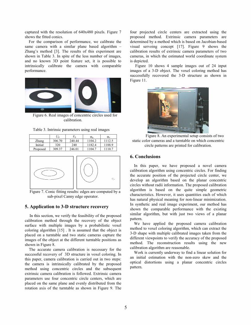
For a calibration target shown in Figure 6, the concentric circles with radius of 40 and 80mm are printed on a paper using a commercial laser printer. To find the ellipses in the image, we detect the edge in the image using a Canny operator [14] that finds edges with the sub-pixel accuracy.
Figure 6 shows an image taken by a SONY XC-003 color camera with 8 mm lens, and the physical cell size is provided by the manufacturer as (0.0068, 0.0067). Using a Matrox Corona color frame grabber, the images are
5
captured with the resolution of 640x480 pixels. Figure 7 shows the fitted conics.
For the comparison of performance, we calibrate the same camera with a similar plane based algorithm – Zhang’s method [3]. The results of this experiment are shown in Table 3. In spite of the less number of images, and no known 3D point feature set, it is possible to intrinsically calibrate the camera with comparable performance.
Figure 6. Real images of concentric circles used for
calibration.
Table 3. Intrinsic parameters using real images U0 V0 αu αv
Zhang 306.70 240.44 1104.2 1112.5 Initial 320 240 1182.4 1188.9
Proposed 309.37 246.01 1104.7 1110.7
Figure 7. Conic fitting results: edges are computed by a
sub-pixel Canny edge operator.
5. Application to 3-D structure recovery In this section, we verify the feasibility of the proposed
calibration method through the recovery of the object surface with multiple images by a probabilistic voxel coloring algorithm [15] . It is assumed that the object is placed on a turntable and two static cameras capture the images of the object at the different turntable positions as shown in Figure 8.
The accurate camera calibration is necessary for the successful recovery of 3D structure in voxel coloring. In this paper, camera calibration is carried out in two steps: the camera is intrinsically calibrated by the proposed method using concentric circles and the subsequent extrinsic camera calibration is followed. Extrinsic camera parameters use four concentric circle centers, which are placed on the same plane and evenly distributed from the rotation axis of the turntable as shown in Figure 9. The
four projected circle centers are extracted using the proposed method. Extrinsic camera parameters are determined by a method which is based on Jacobian-based visual servoing concept [17]. Figure 9 shows the calibration results of extrinsic camera parameters of two cameras, in which the estimated world coordinate system is depicted.
Figure 10 shows 4 sample images out of 24 input images of a 3-D object. The voxel coloring method has successfully recovered the 3-D structure as shown in Figure 11.
Figure 8. An experimental setup consists of two
static color cameras and a turntable on which concentric circle patterns are printed for calibration.
6. Conclusions
In this paper, we have proposed a novel camera calibration algorithm using concentric circles. For finding the accurate position of the projected circle center, we develop an algorithm based on the planar concentric circles without radii information. The proposed calibration algorithm is based on the quite simple geometric characteristics. However, it uses quantities each of which has natural physical meaning for non-linear minimization. In synthetic and real image experiment, our method has shown the comparable performance with the existing similar algorithm, but with just two views of a planar pattern.
We have applied the proposed camera calibration method to voxel coloring algorithm, which can extract the 3-D shape with multiple calibrated images taken from the different viewpoints to verify the accuracy of the proposed method. The reconstruction results using the new calibration algorithm are reasonable.
Work is currently underway to find a linear solution for an initial estimation with the non-zero skew and the optical distortions using a planar concentric circles pattern.

6
Figure 9. Results of extrinsic camera calibration of two
cameras: three white lines represent each calculated coordinate axis
Figure 10. Four sample images of a sequence of 24 input images for a test object.: left two images are from upper cameras and right two images are from lower cameras
(a) (b)
Figure 11. Rendered images from the recovered 3-D data with the same camera viewpoint of input image: (a) the
upper left image is rendered image, the upper right image is original input image, the lower left image is color
represented recovered voxel space, the lower right image is the depth map from the camera viewing position, (b) .
The rendered image with a new camera viewpoint.
References [1] R.Y. Tsai, “A Versatile camera calibration technique for high accuracy 3D machine vision metrology using off-the-shelf TV cameras and lenses,” IEEE Journal of
robotics and Automation, Vol. RA-3, No. 4, pp 323-344, August, 1987 [2] O. Faugeras, Three-Dimensional Computer Vision - A Geometric Viewpoint, Chapter 3, Modeling and calibration of cameras(p.33~68) , 1993 The MIT Press [3] Z. Zhang, “Flexible Camera Calibration by Viewing a Plane From Unknown Orientations”, In Proc. 7th International Conference on Computer Vision, Corfu, Greece, pages 666-673, September 1999., [4] B. Triggs, “Autocalibration and the absolute quadric”, In IEEE conf. CVPR, Puertorico, 1997 [5] O. Faugeras, Q.T. Luong and S.J. Maybank, “Camera Self Calibration : Theory and Experiments”, ECCV ’92. [6] K. Kanatani, and W. Liu, “3D Interpretation of Conics and Orthogonality”, CVGIP: Image Understanding, vol. 58, No. 3. November. Pp. 286-301, 1993 [7] Z. Chen, J. Huang, “A Vision-Based Method for the Circle Pose Determination With a Direct Geometric Interpretation”, IEEE trans. On Robotics and Automation,15(6),pp 1135-1140, Dec.1999, [8] M. Ferri, F. Mangli, and G. Viano, “Projective Pose Estimation of Linear and Quadratic Primitives in Monocular Computer Vision”, CVGIP: Image understanding, vol. 58, No. 1, July, pp. 66-84, 1993. [9] R. Hu, Q. Ji, “Camera Self-Calibration from Ellipse Correspondences”, In Proc. of the 2001 IEEE ICRA, Seoul, Korea, pages 2191-2196, May, 2001. [10] A. Fitzgibbon, Maurizio Pilu, and Robert B. Fisher, “Direct Least Square Fitting of Ellipses”, IEEE Trans. On PAMI, vol. 21, No. 5, May, 1999 [11] J.L. Mundy and A. Zisserman, “Projective Geometry for Machine Vision,” Geometric Invariance in Computer Vision, pp 463-519, The MIT Press, 1992. [12] D.H. Ballard and C.M. Brown, Computer Vision, Prentice Hall, 1982 [13] R. Hartley and A. Zisserman, Multiple View Geometry in Computer Vision, Cambridge University Press, 2000. [14] J. Canny, “A computational approach to edge detection”, IEEE Transactions on PAMI, vol. 8, no. 6, 1986,679-698 [15] H. W. Kim, Y. S. Chung, I. S. Kweon, “Probabilistic voxel coloring relaxing photo hull limitation”, Proceedings of Workshop on Image Processing and Image Understanding(IPIU),January,2001(InKorean) [16] J . S. Kim, I. S. Kweon, “A New Camera Calibration Method for Robotic Applications”, IEEE International Conference on Robots and Systems (IROS), October, 2001(to appear) [17] H. W. Kim, J.S. Cho, and I.S. Kweon. “A novel image-based control-law for the visual servoing system under large pose error”, IEEE International Conference on Robots and Systems (IROS), November 2000.