601ES-MANUAL-1.pdf - amptec research
21
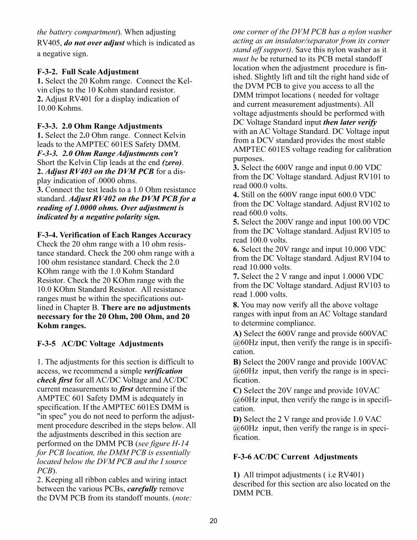
2 Wire 4 Wire MILLAMPERES + HIGH RESEARCH AMPTEC 601ES EXPLOSIVE SAFETY DIGITAL MULTIMETER STRAY CURRENT PRESS TO MEASURE milliammeter 0 - 10 mA DC PRESS TO MEASURE CASE GROUND LOW V I9999 >>> OR LO BAT V A .... POWER ON OFF STRAY CURRENT FUSE ( 5 AMPERE) V LO V HI 50mV - 5mA SIGNAL SOURCE DISPLAY BACKLIGHT RESEARCH AMPTEC CALIBRATED MODEL#. SER NO. DATE DUE Tamper ProofSeal/Sticker Calibrationvoidifremoved 601ES 601ES-503 05APR2005 05APR2006 I press/hold 2.0 KOHM 20 OHM 200 OHM 2.0 OHM 20 KOHM FUNCTION / RANGE 2 AMP AC/DC 600VRMS 200V AC/DC 20V AC/DC 2.0V AC/DC Battery Compartment 4 each "AA" Alkaline RESEARCH AMPTEC OPERATION/MAINTENANCE MANUAL Revision D PHONE (512) 858-4045; FAX(512)858-4340; TOLL FREE IN USA 800-350-5105 website http://www.amptec.com AMPTEC 601ES DMM Safety Digital Multimeter
-
Upload
khangminh22 -
Category
Documents
-
view
3 -
download
0
Transcript of 601ES-MANUAL-1.pdf - amptec research

2 Wire
4 Wire
MILLAMPERES
+ HIGH
RESEARCHAMPTEC
601ES EXPLOSIVE SAFETYDIGITAL MULTIMETER
STRAY CURRENTPRESS TO MEASURE
milliammeter0 - 10 mA DC
PRESS TO MEASURE
CASEGROUND
LOW
V
I9999>>> OR
LO BATVA
. . . .
POWERON
OFF
STRAY CURRENTFUSE ( 5 AMPERE)
VLO
VHI
50mV - 5mA
SIGNALSOURCE
DISPLAYBACKLIGHT
RESEARCHAMPTEC
CALIBRATED
MODEL#.SER NO.DATEDUE
Tamper ProofSeal/StickerCalibrationvoidifremoved
601ES601ES-503
05APR200505APR2006
I
press/hold
2.0 KOHM
20 OHM
200 OHM
2.0 OHM
20 KOHMFUNCTION / RANGE
2 AMPAC/DC
600VRMS
200VAC/DC
20VAC/DC
2.0VAC/DC
Battery Compartment4 each "AA" Alkaline
RESEARCHAMPTEC
OPERATION/MAINTENANCE MANUALRevision D
PHONE (512) 858-4045; FAX(512)858-4340; TOLL FREE IN USA 800-350-5105website http://www.amptec.com
AMPTEC 601ES DMMSafety Digital Multimeter
TABLE OF CONTENTS
SECTION A: Receiving and Initial Inspection
SECTION B: 601ES Explosive Safety DMM Specifications
SECTION C: Replacement, Optional andAccessory Items
SECTION D: Operation, Function and Use
SECTION E: General Operation and Design
A-1 Introduction to the AMPTEC 601ES Explosive Safety DMMA-2 Receiving, Unpacking and Initial InspectionA-3 Opening the 601ES Explosive Safety DMMA-4 Battery Replacement - Power RequirementsA-5 Setup and Use
B-1 Table B-1 & Specifications
C-1 Available Accessories and Options
D-1 GeneralD-2 Front Panel Features and OperationD-3 Complete 601ES Explosive Safety DMM Front Panel DiagramD-4 4-Wire Resistance Measurement (601ES DMM versions only)
Figure D-4. Igniter Tester Kelvin Block DiagramD-5 ConnectionsD-6 Fatigued Adapters and Loose Connections -
Common Sources of Measurement ErrorD-7 Battery Monitoring CircuitryD-8 Failsafe Operation Overview
E-1 GeneralE-2 TroubleshootingE-3 Localizing the ProblemE-4 Component ReplacementE-5 Circuit Descriptions
E-5.1 DVM IC 401 - MAX7129E-5.2 ResistanceE-5.3 Power SupplyE-5.4 Relay ControlE-5.5 MicroprocessorE-5.6 Digital Volt Meter
2
SECTION F: Routine Maintenance
F-1 GeneralF-2 Required Test EquipmentF-3 Calibration Procedure
F-3.1 Zero Offset AdjustmentF-3.2 Full Scale AdjustmentF-3.3 2.0 Ohm Range AdjustmentsF-3.4 Verification of Each Ranges AccuracyF-3.5 AC/DC Voltage AdjustmentsF-3.6 AC/DC Current AdjustmentsF-3.7 50mV/5mA Signal Source Adjustments
F-4 Battery Replacement Instructions
3
A-1. Introduction to the AMPTEC 601ESExplosive Safety DMM / Igniter Tester
Power On
The AMPTEC 620A, 630 , 640 series and nowthe AMPTEC 601 Series Explosive SafetyDMMs are designed to be the "
",and provide extremely safe and reliable voltage ,current and resistance measurement/testing ofexplosive or volatile devices. Safety Approvalsfrom various Safety Boards include, the U.S. AirForce ( 620A-4) for generic use on missilewarheads and the US NAVAL ORDNANCECENTER (630AN 630BN, 640N and otherversions pending). Some of the devices the601ES DMM Explosive Safety Meter may beused on include: fuses, squibs, igniters, EBW,explosive bolts, rocket motor squibs, to name afew.
The AMPTEC 601ES Explosive Safety DMMsupports safe ordnance testing. Many customersneed to safely measure stray voltage circuitry (RMS AC and DC), stray current and resistanceusing the failsafe output circuitry proprietary toAMPTEC RESEARCH insure that test currentlevels coming from the 601ES don’t exceed thespecified "failsafe current" even in a worst-casecomponent failure situation. The failsafe featureis tested in every instrument before shipment. Abuilt-in passive (analog) DC Milliammeter alsolets the user verify actual 601ES DMM currentoutput levels prior to connection to any EBW,squib or detonator.
- The AMPTEC 601ES DMMExplosive Safety Meter main "Power" switch
to turn themeter "ON" or "OFF". This feature helpsprevent the unwanted effect of bumping of thepower switch and accidentally turning the meter"OFF" or "ON".
Low or Dead batteries ( AA type Alkaline - 4each ) is the primary reason for the AMPTEC601ES DMM not powering up. If the batteriesreach a low energy level the unit's LCD Display"LO BAT" indicator appears on the display.
Standard in theExplosive Safety Igniter Circuit Test industry
,
must be held down for 2 seconds
The AMPTEC 601ES DMM SafetyMeter has acircuit that indicates when it is timeTo replace the batteries. They can be replacedwithout effecting the calibration of the meter.The batteries are housed in their owncompartment completely separate from anyactive electronic circuitry.
Should the AMPTEC shipping box appeardamaged upon arrival, request that the carrier'sagent (i.e. UPS) be present when the unit isunpacked. If the 601ES DMM Explosive SafetyMeter appears damaged, the carrier's agentshould authorize repairs before the unit isreturned to the factory. Even if the instrumentappears undamaged, it may have sufferedinternal damage in transit that may not beevident until the unit is operated or tested toverify conformance with its specifications. Youmay refer to the
(i.e Test leads etc.)
If the unit fails to operate or fails tomeet the performance specificationsof section B, notify the carrier'sagent and AMPTEC RESEARCH .Retain the shipping carton for thecarrier's inspection.
or any of its sales officesan (RMA) Return Material
Authorization number. We need to know who tocontact and how to contact (i.e. phone numberand FAX number) in order to properlycoordinate the return of the repaired AMPTECproduct.
We maypossibly be able to fix the problem over thephone and prevent you from having to return theunit to AMPTEC for repair.
battery monitoring
A-2. Receiving, Unpacking, and InitialInspection
DO NOT return equipment to AMPTECRESEARCH
By calling AMPTEC RESEARCHfirst, prior to just returning the 601ES DMMExplosive Safety Meter, we can often trouble-shoot (based on the symptoms you describe)and identify the problem over the phone (i.ebattery loose in the battery holder).
Trouble-Shooting section ofChapter D of this manual to help identify theproblem
withoutfirst obtaining
SECTION A - RECEIVING AND INITIAL INSPECTION
RMA
4

A-3. Opening the 601ES Explosive SafetyDigital Multimeter / Igniter Tester andRemoval of the Lid
A-4. DC Battery Power Requirements
AA
rechargeable
When closed, the 601ES DMM has two largeO-rings that provide a water resistant seal
. This makes it easier to flip up therelease latch. Repeat the palm press step on theother corner of the safety meter. At this point the601ES DMM lid will normally be able to beraised, and placed in an open lid state.
The 601ES Explosive Safety DMM should openafter flipping up the release latches, even after achange in atmospheric pressure since the unit isfitted with an automatic purge valve. You mightneed to press down of the corners of the closedcase with your palm then flip open the latch.
The AMPTEC 601ES Explosive Safety DMM canbe powered internally by a variety of heavy-dutyAA batteries. We recommend either an alkalinebattery pack (4 ea. cell - 1500 mAHr ea.,preferably Duracell MN1500 or better i.e. DuracellUltra). A set of 4 ea “AA” heavyduty Nickel Metal Hydride batteries such as the
. Bypressing down with your palm as shown inFig. A-3, you compress the O-ring in the lid ofthe 601ES
1.2V also work quitewell. Our tests show the Energizer 2500 mAHrlasted as long as the Duracell Ultra’s Alkaline.Since Nickel Metal Hydrides are re-chargeable,they offer a battery life cycle a hundred timesgreater than any alkaline. Be sure to charge theNickel Metal Hydride batteries when taken outof their original packaging for the full chargecycle prior to installing them in the AMPTEC601ES Safety DMM.
The battery compartment is completely isolatedfrom the unit's internal electronics. The usermay replace the 4 ea "AA" batteries as neededwithout effecting any internal 601ES DMMcircuitry or the unit's calibration. The AMPTEC601ES DMM battery life is diminished thelonger the backlight (heavy power drain) is usedand the longer the unit is left unattended.
“Low Battery level” is indicated by a “LO BAT”display. Replacing the (4) each ‘AA’ batteries inthe separate weatherized ‘AA’ battery compart-ment (sealed metal battery box) can be per-formed in the field
There is no “No Access” to anyAMPTEC 601ES Explosive Safety DMMinternal electronics from the unit’s separateinternal metal box battery compartment.
Energizer 2500 mAHr
“on”
without having to re-calibrate.
601ES DMM
Press Down with Palm hereWhile opening release Latch A
Press Down with Palm hereWhile opening release Latch B
A. Release Latch B. Release Latch
C. Automatic Air Pressure Equalization (Purge Valve)
Sect. A - Receiving and Initial Inspection
FIG. A-3
MADEINUSA
WWW.AMPTEC.COMTEL1-800-350-5105
RESEARCHAMPTEC
EXPLOSIVE SAFETYDIGITAL MULTI-METER
MODEL NUMBER 6 ES01SERIAL NUMBER 601ES-501
5
Avoid exposing the 601ES Explosive SafetyDMM to extremes of temperature which willaffect accuracy and shorten battery packlifespan.
Once the 601ES DMM main power switch isturned "ON" and following a (1) minutewarmup, (
) the AMPTEC 601ESExplosive Safety DMM should be ready forgeneral purpose testing and use.
The 601ES DMM operator may be asked toperform a series of tests (i.e. verify the testcurrent is less than 10mA with the unit's DCmilliammeter) prior to connection to anyexplosive device under test.
Test lead sets may also be placed in the pouchwhich holds the laminated AMPTEC 601ESDMM Operator Instruction Card.
provided there is No ‘LO BAT’Indicator shown
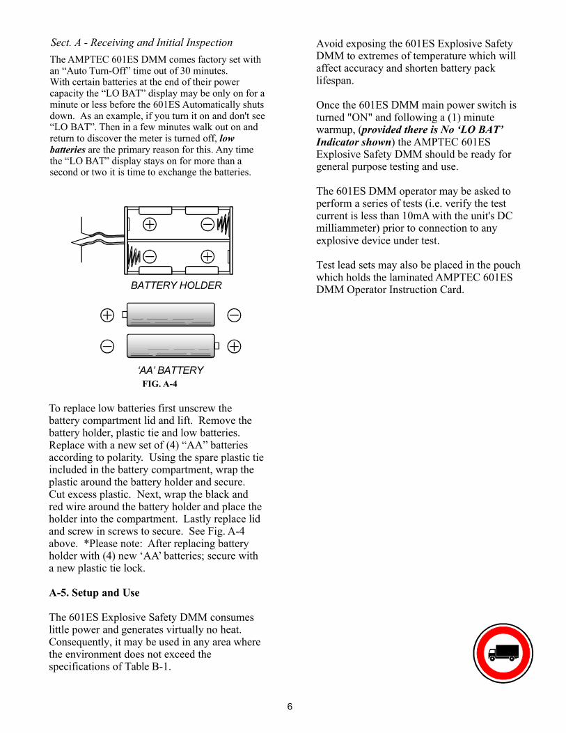
To replace low batteries first unscrew thebattery compartment lid and lift. Remove thebattery holder, plastic tie and low batteries.Replace with a new set of (4) “AA” batteriesaccording to polarity. Using the spare plastic tieincluded in the battery compartment, wrap theplastic around the battery holder and secure.Cut excess plastic. Next, wrap the black andred wire around the battery holder and place theholder into the compartment. Lastly replace lidand screw in screws to secure. See Fig. A-4above. *Please note: After replacing batteryholder with (4) new ‘AA’ batteries; secure witha new plastic tie lock.
The 601ES Explosive Safety DMM consumeslittle power and generates virtually no heat.Consequently, it may be used in any area wherethe environment does not exceed thespecifications of Table B-1.
A-5. Setup and Use
BATTERY HOLDER
‘AA’ BATTERYFIG. A-4
Sect. A - Receiving and Initial InspectionThe AMPTEC 601ES DMM comes factory set withan “Auto Turn-Off” time out of 30 minutes.With certain batteries at the end of their powercapacity the “LO BAT” display may be only on for aminute or less before the 601ES Automatically shutsdown. As an example, if you turn it on and don't see“LO BAT”. Then in a few minutes walk out on andreturn to discover the meter is turned off,
are the primary reason for this. Any timethe “LO BAT” display stays on for more than asecond or two it is time to exchange the batteries.
lowbatteries
6
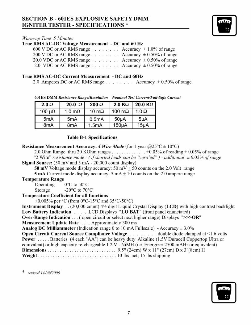
SECTION B - 601ES EXPLOSIVE SAFETY DMMIGNITER TESTER - SPECIFICATIONS *
Warm-up Time 5 Minutes
20.0 V2.0 V
(for 1 year @25°C ± 10°C)
Operating 0°C to 50°CStorage -20°C to 70°C
0.0 % per °C (from 0°C-15 C and 35°C-50°C). . (20,000 count) 4½ digit Liquid Crystal Display ( ) with high contrast backlight
. . . . LCD Displays " " (front panel enunciated). . . ( open circuit or select next higher range) Displays " "
. . . . . Approximately 300 ms(Indication range 0 to 10 mA Fullscale) - Accuracy ± 3.0%
. . . . . . . . double diode clamped at <1.6 volts. . Batteries (4 each "AA") can be
high capacity re-chargeable 1.2 V - NiMH (i.e. Energizer 2500 mAHr ). . . . . . . . . . . . . . . . . . . . . . . . . . . . 9.5" (24cm) W x 11" (27cm) D x 3"(8cm) H
. . . . . . . . . . . . . . . . . . . . . . . . . . . . . . . . 10 lbs net; 15 lbs shipping
True RMS AC-DC Voltage Measurement - DC and 60 Hz
True RMS AC-DC Current Measurement - DC and 60Hz
Signal Source:50 mV5 mA
200 V DC or AC RMS range . . . . . . . . Accuracy ± 0.50% of rangeDC or AC RMS range . . . . . . . . Accuracy ± 0.50% of rangeDC or AC RMS range . . . . . . . . Accuracy ± 0.50% of range
2.0 Amperes DC or AC RMS range . . . . . . . . Accuracy ± 0.50% of range
2.0 Ohm Range thru 20 KOhm ranges . . . . . . . . . . . . . . ±0.05% of reading ± 0.05% of range2 Wire” ± 0
(50 mV and 5 mA - 20,000 count display)Voltage mode display accuracy: 50 mV 50 counts on the 2.0 Volt range
Current mode display accuracy: 5 mA 10 counts on the 2.0 ampere range
± 05 °
. . . heavy duty Alkaline (1.5V Duracell Coppertop Ultra orequivalent) or or equivalent
Table B-1 Specifications
Resistance Measurement Accuracy:
Temperature Range
Temperature Coefficient for all functions
Instrument Display LCDLow Battery Indication LO BATOver-Range Indication >>>ORMeasurement Update RateAnalog DC MilliammeterOpen Circuit Current Source Compliance VoltagePower
DimensionsWeight
4 Wire Mode
“ resistance mode : ( if shorted leads can be “zero’ed” ) - additional 0. 5% of range
++
* revised 14JAN2006
600 V DC or AC RMS range . . . . . . . . Accuracy ± 1.0% of range
7

C-1. Available Accessories and Options
This manual does not list all possibleaccessories that AMPTEC RESEARCH iswilling to provide as a support items for theAMPTEC 601ES DMM. Contact the salesdepartment at AMPTEC RESEARCH if youhave a request for an item that is not describedhere. Listed below are some of the optionsavailable for use with the AMPTEC 601ESExplosive Safety DMM.
Option 401: Gold Plated Single Probe Leads
Option "401" is a handheld probe(one black probe & one red probe) lead set ter-minated in . The OP401 handheldprobes allow for easy access to connector socketwiring (i.e. drone parachute squib sockets),recessed surfaces and parts (i.e. flares) that alli-gator clip leads simply can’t access properly.
Option "401" plated a 4-wire lead set (up to theprobe tip, 2 and 2 style) is terminated with sin-gle handheld probe test points. The“401” also has dual banana leadsthat connect directly to the AMPTEC 601ESDMM measurement front panel jacks (red andwhite). 4-wire Kelvin is maintained up to thepoint of the probe tip connection, eliminating98% of the cable resistance. Gold plated tipsand banana jack ends provide an optimal lowthermal emf connection.
gold plated
single points
gold platedgold plated
Kelvin Leads, Probes Accessories andOptions
All AMPTEC series test lead and probe sets area minimum 48" length, dual bananatermination at the ohmmeter end (call theSales Department at AMPTEC RESEARCHfor any custom requirement).
Option 403 4 Terminal Kelvin Mini-probes:
with 0.18" separation, one red and oneblack handheld probe. Excellent general purpose4-Wire Kelvin Mini-Probe, and along with theOption "300" Kelvin Clip Leads easily fit insidethe AMPTEC test lead pouch.
Each probe has two spring loaded, gold plated,steel tips
Option 300: 4-Wire Kelvin Lead Set
Recommended for Calibration - Option "300" is afour wire Kelvin lead set for all
AMPTEC 601ES DMM. Option 300 is a shielded48" lead set terminating in ½" opening gold platedcopper Kelvin clips. The option "300" can clipeasily to wires, pins and medium size conductors(up to ½" diameter). The dual banana
gold plated
Option “300”Close-Up
Option "300"4-Wire Kelvin Clip Test Lead Set
(Gold Plated)
SECTION C - REPLACEMENT, OPTIONALAND ACCESSORY ITEMS
8
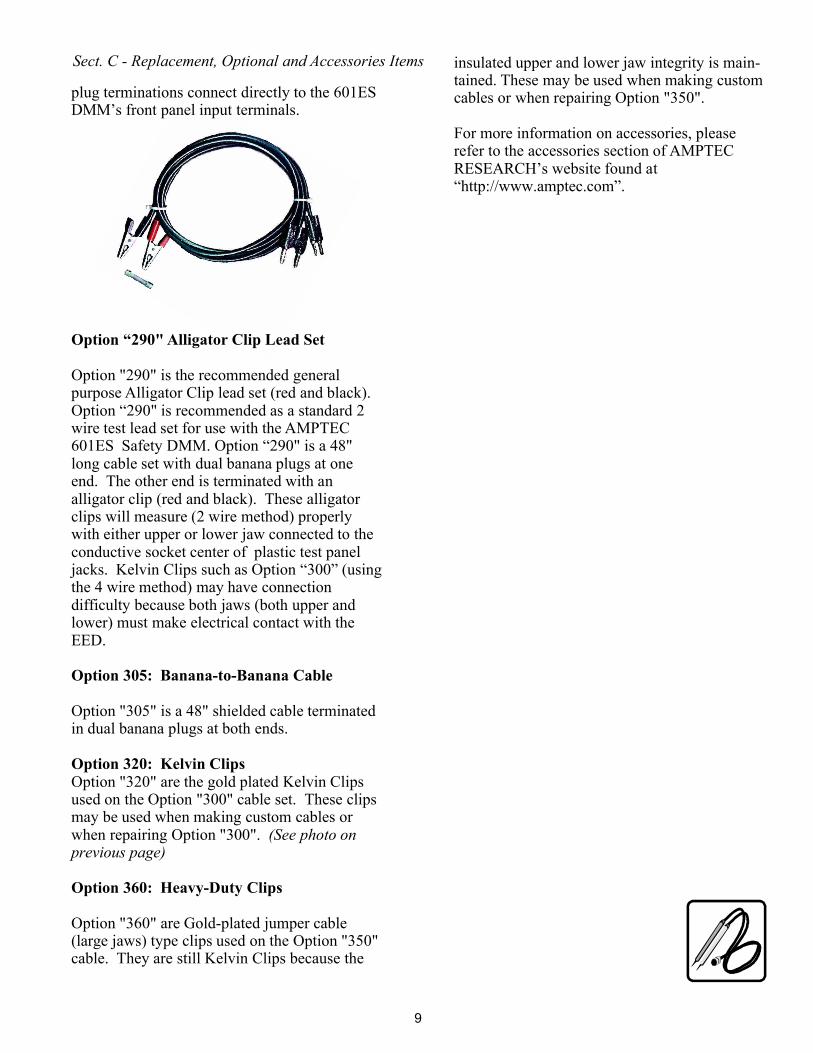
plug terminations connect directly to the 601ESDMM’s front panel input terminals.
Option "305" is a 48" shielded cable terminatedin dual banana plugs at both ends.
Option "320" are the gold plated Kelvin Clipsused on the Option "300" cable set. These clipsmay be used when making custom cables orwhen repairing Option "300".
Option "360" are Gold-plated jumper cable(large jaws) type clips used on the Option "350"cable. They are still Kelvin Clips because the
Option "290" is the recommended generalpurpose Alligator Clip lead set (red and black).Option “290" is recommended as a standard 2wire test lead set for use with the AMPTEC601ES Safety DMM. Option “290" is a 48"long cable set with dual banana plugs at oneend. The other end is terminated with analligator clip (red and black). These alligatorclips will measure (2 wire method) properlywith either upper or lower jaw connected to theconductive socket center of plastic test paneljacks. Kelvin Clips such as Option “300” (usingthe 4 wire method) may have connectiondifficulty because both jaws (both upper andlower) must make electrical contact with theEED.
Option “290" Alligator Clip Lead Set
Option 305: Banana-to-Banana Cable
Option 320: Kelvin Clips
Option 360: Heavy-Duty Clips
(See photo onprevious page)
insulated upper and lower jaw integrity is main-tained. These may be used when making customcables or when repairing Option "350".
For more information on accessories, pleaserefer to the accessories section of AMPTECRESEARCH’s website found at“http://www.amptec.com”.
Sect. C - Replacement, Optional and Accessories Items
9
D-1. General Operation
D-2. Front Panel Features and Operation
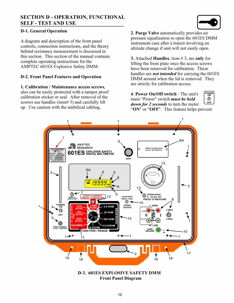
A diagram and description of the front panelcontrols, connection instructions, and the theorybehind resistance measurement is discussed inthis section. This section of the manual containscomplete operating instructions for theAMPTEC 601ES Explosive Safety DMM.
1. Calibration / Maintenance access screws,also can be easily protected with a tamper proofcalibration sticker or seal. After removal of thescrews use handles (item# 3) and carefully liftup. Use caution with the umbilical cabling.
SECTION D - OPERATION, FUNCTIONALSELF - TEST AND USE
2. Purge Valve
3. Handles only
ON OFF
automatically provides airpressure equalization to open the 601ES DMMinstrument case after a transit involving analtitude change if unit will not easily open.
Attached , item # 3, are forlifting the front plate once the access screwshave been removed for calibration. Thesehandles are for carrying the 601ESDMM around when the lid is removed. Theyare strictly for calibration access.
hemain “Power" switch
to turn the meter“ " or " ". This feature helps prevent
not intended
must be helddown for 2 seconds
4 Power On/Off switch. - T unit's
Front Panel DiagramD-3. 601ES EXPLOSIVE SAFETY DMM
2 Wire
4 Wire
MILLAMPERES
+ HIGH
RESEARCHAMPTEC
601ES EXPLOSIVE SAFETYDIGITAL MULTIMETER
STRAY CURRENTPRESS TO MEASURE
milliammeter0 - 10 mA DC
PRESS TO MEASURE
CASEGROUND
2.0 KOHM
20 OHM
200 OHM
2.0 OHM
20 KOHMLOW
V
I9999>>> OR
LO BATVA
. . . .
11
1
8
9
1
14
11
17
12
POWERON
OFF
STRAYCURRENTFUSE ( 5 AMPERE)
1
4
5
3
2
15
1616
13
13
6A
6A
7
1
1
3
1
10
VLO
VHI
50mV - 5mA
SIGNALSOURCE
DISPLAYBACKLIGHT
1
RESEARCHAMPTEC
CALIBRATED
MODEL#.SER NO.DATEDUE
TamperProofSeal/StickerCalibrationvoidifremoved
601ES601ES-503
05APR200505APR2006
I
FUNCTION / RANGE
2 AMPAC/DC
600VRMS
200VAC/DC
20VAC/DC
2.0VAC/DC
press/hold
Battery Compartment4 each "AA"Alkaline
1819
6 6
6
6
6
1
10
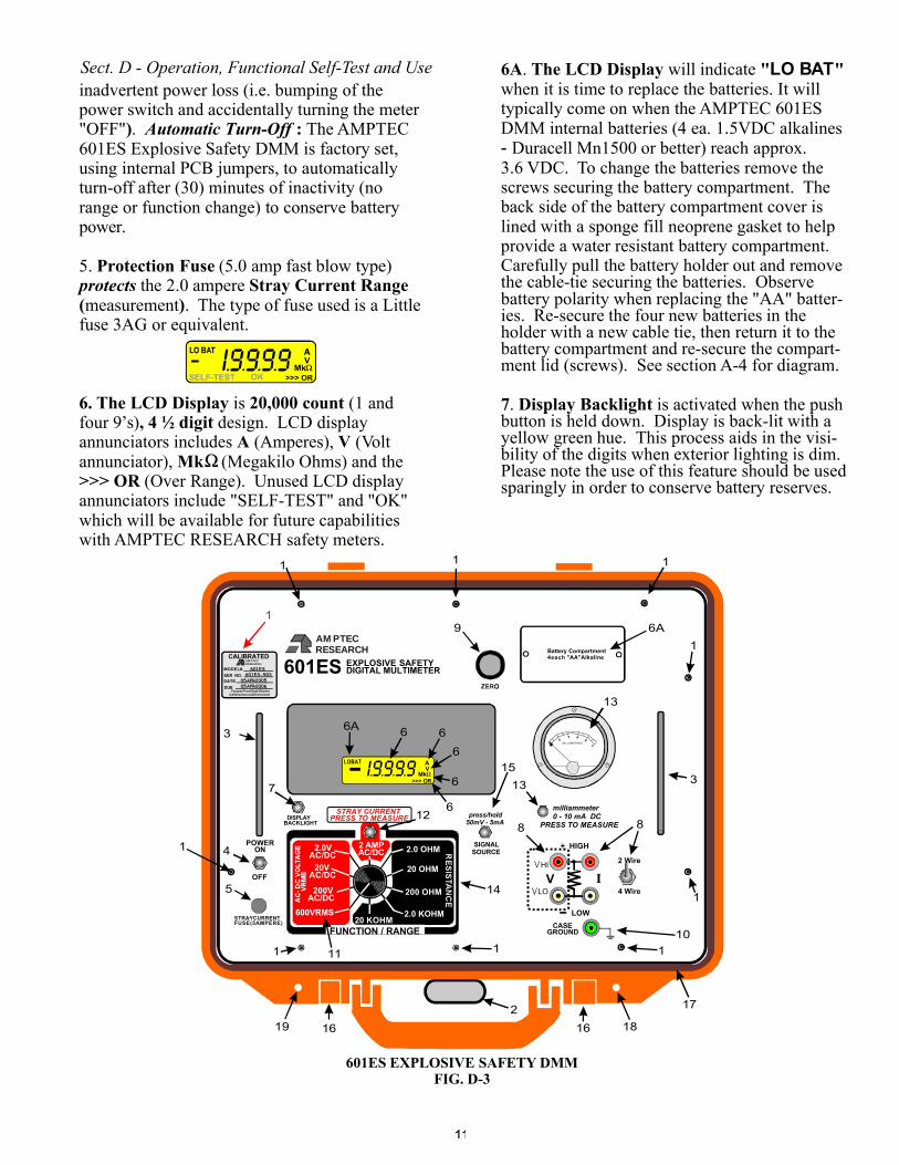
6A The LCD Display " "
7 Display Backlight
. will indicatewhen it is time to replace the batteries. It willtypically come on when the AMPTEC 601ESDMM internal batteries (4 ea. 1 5VDC alkalines
Duracell Mn1500 or better) reach approx.3.6 VDC. To change the batteries remove thescrews securing the battery compartment. Theback side of the battery compartment cover islined with a sponge fill neoprene gasket to helpprovide a water resistant battery compartment.Carefully pull the battery holder out and removethe cable-tie securing the batteries. Observebattery polarity when replacing the "AA" batter-ies. Re-secure the four new batteries in theholder with a new cable tie, then return it to thebattery compartment and re-secure the compart-ment lid (screws). See section A-4 for diagram.
. is activated when the pushbutton is held down. Display is back-lit with ayellow green hue. This process aids in the visi-bility of the digits when exterior lighting is dim.Please note the use of this feature should be usedsparingly in order to conserve battery reserves.
LO BAT
.-
inadvertent power loss (i.e. bumping of thepower switch and accidentally turning the meter"OFF" . The AMPTEC601ES Explosive Safety DMM is factory set,using internal PCB jumpers, to automaticallyturn-off after (30) minutes of inactivity (norange or function change) to conserve batterypower.
5.
) :Automatic Turn-Off
Protection FuseStray Current Range
( )
6. The LCD Display 20,000 count, 4 ½ digit
A VMk
>>> OR
(5.0 amp fast blow type)the 2.0 ampere
measurement . The type of fuse used is a Littlefuse 3AG or equivalent.
is (1 andfour 9’s) design. LCD displayannunciators includes (Amperes), (Voltannunciator), (Megakilo Ohms) and the
(Over Range). Unused LCD displayannunciators include "SELF-TEST" and "OK"which will be available for future capabilitieswith AMPTEC RESEARCH safety meters.
protects
MILLAMPERES
+ HIGH
RESEARCHAMPTEC
601ES EXPLOSIVE SAFETYDIGITAL MULTIMETER
STRAY CURRENTPRESS TO MEASURE
milliammeter0 - 10 mA DC
PRESS TO MEASURE
CASEGROUND
2.0 KOHM
20 OHM
200 OHM
2.0 OHM
20 KOHMLOW
V
I9999>>> OR
LOBATVA
. . . .
1 1
1
8
9
1
14
11
12
POWERON
OFF
STRAYCURRENTFUSE(5AMPERE)
1
4
13
13
3
2
15
1616
5
6A
6A
7
1
1
3
2 Wire
4 Wire
8
1
10
VLO
VHI
50mV - 5mA
SIGNALSOURCE
DISPLAYBACKLIGHT
1
RESEARCHAMPTEC
CALIBRATED
MODEL#.SER NO.DATEDUE
TamperProofSeal/StickerCalibrationvoidifremoved
601ES601ES-503
05APR200505APR2006
I
FUNCTION / RANGE
2 AMPAC/DC
600VRMS
200VAC/DC
20VAC/DC
2.0VAC/DC
press/hold
Battery Compartment4each "AA"Alkaline
18
17
19
1
6 6
6
6
6
601ES EXPLOSIVE SAFETY DMMFIG. D-3
Sect. D - Operation, Functional Self-Test and Use
11

8 Two Wire Four Wire
. two wire test leadconnections always use the far left inputjacks V V
mode switch in the 2 Wireposition should be used forall voltage, current and simple ohms
include all in-series wiring resistance
4 Wire Kelvin
. input or Kelvin mea-surement test lead connection inputs and modeselection switch For
both ‘red’ and ‘white’, whichare shown as a dotted line below in item # 8.The must also be
. Two wire modemea-
surements. 2 wire electrical resistance measure-mentsfrom the meter out to the "resistance under test"and back to the meter (connection/contact resis-tance, test lead length, harness wiring length andmore etc.). The "Four Wire" switch position isonly for 4 Wire Kelvin resistance measurementsonly. Basically the 4 Wire Kelvin connectionsminimize the impact of test lead length resis-tance and test lead contact resistance offsets. Adiscussion on may be foundfurther in this manual.
The
High Low
9. Zero
(for the lower 3 re-sistance ranges)
A.)
B.).0000 without a minus sign.
- The AMPTEC 601ES ExplosiveSafety DMM has a precision ten turn zero pot.
zero knob is turned to "null-out" most2 wire test lead resistance
. The zero adjust procedure in-volves:
Short the test leads at the “UUT” end to-gether while connected to the AMPTEC 601ESDMM then adjusting the zero knob until thedisplay shows Ifyou get a minus sign while adjusting the zero,you have over adjusted the zero knob. If this isthe case, turn the knob back the opposite direc-tion until the minus sign is no longer displayed.Once the zero is adjusted you can connect yourtest leads to the "device under test". Re-zeroing(2 wire mode) will be necessary only if youchange test leads. Do not force the zero knobwhen turning it, especially once the stops havebeen reached. Forcing the zero knob past thestops will severely damage the precision of theinstrument and violate the instruments warranty.
( 2, 20 ,and 200 ohm ranges)
10. Case/Chassis Ground Jack
(not tied to earth ground)
A.)
B.)
provides theuser access to the AMPTEC 601ES DMM’sFaraday Cage and Chassis ground. In some ap-plications (i.e. anti-static) the AMPTEC 601ESDMM user may want to connect your "In-Houselocal Earth Ground" to the AMPTEC 601ESDMM chassis ground. All appropriate internalgrounds of the AMPTEC 601ES DMM are con-nected to the front panel chassis ground jack.The unit's case ground jack accepts banana jacks,spade lugs and even bare wires for making anearth to case ground connection. In other appli-cations, the AMPTEC 601ES DMM user maywant the meter to be floating from the resistanceunder test and thecase ground jack may be left disconnected orignored.
The AMPTEC 601ES DMM has four differ-ent ranges for measuring AC/DC voltage. Themeter starts at the 600VRMS test level. Shouldthe user determine there is virtually no measur-able voltage on the high (600V) range thenselect the next lower range (200V).
Rotating the knob to the next (clockwise)range selects the 200V True RMS AC-DCVoltage measurement function (200 Voltsfullscale max.). This DC coupled voltage mea-surement function will therefore display any DCVoltage - up to 200 V max. This voltage mea-surement function also measures True RMS ACVoltage including distorted waveforms (band-width to 100 Hz). The process of stepping to thenext progressively lower voltage range wouldnormally continue until the lowest range of 2.0VDC- AC RMS. The 2.0 V range display
11. AC-DC Voltage VRMS Measurement
STRAY CURRENTPRESS TO MEASURE
2.0 KOHM
20 OHM
200 OHM
2.0 OHM
20 KOHMFUNCTION / RANGE
2 AMPAC/DC
600VRMS
200VAC/DC
20VAC/DC
2.0VAC/DC
+ HIGH
CASEGROUND
LOW
VVLO
VHI
I2 Wire
4 Wire
4 wire Kelvin ohmsuses all 4 terminals
+ HIGH
LOW
VVLO
VHI
I
Sect. D - Operation, Functional Self-Test and Use
12
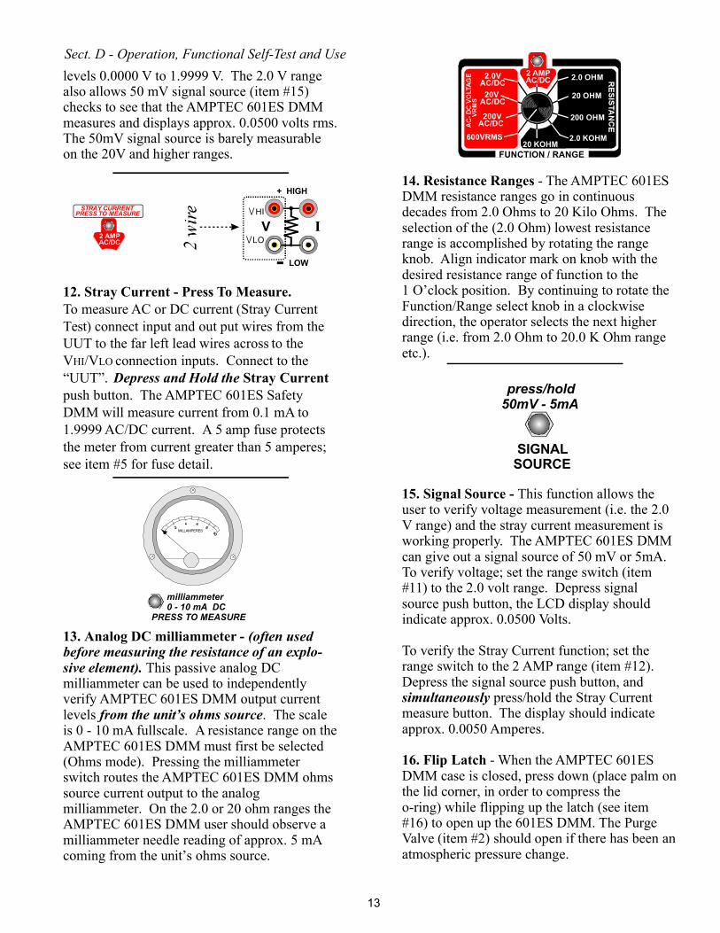
levels 0.0000 V to 1.9999 V. The 2.0 V rangealso allows 50 mV signal source (item #15)checks to see that the AMPTEC 601ES DMMmeasures and displays approx. 0.0500 volts rms.The 50mV signal source is barely measurableon the 20V and higher ranges.
To measure AC or DC current (Stray CurrentTest) connect input and out put wires from theUUT to the far left lead wires across to theV /V connection inputs. Connect to the“UUT”.push button. The AMPTEC 601ES SafetyDMM will measure current from 0.1 mA to1.9999 AC/DC current. A 5 amp fuse protectsthe meter from current greater than 5 amperes;see item #5 for fuse detail.
This passive analog DCmilliammeter can be used to independentlyverify AMPTEC 601ES DMM output currentlevels . The scaleis 0 - 10 mA fullscale. A resistance range on theAMPTEC 601ES DMM must first be selected(Ohms mode). Pressing the milliammeterswitch routes the AMPTEC 601ES DMM ohmssource current output to the analogmilliammeter. On the 2.0 or 20 ohm ranges theAMPTEC 601ES DMM user should observe amilliammeter needle reading of approx. 5 mAcoming from the unit’s ohms source.
HI LO
Depress and Hold the
(often usedbefore measuring the resistance of an explo-sive element).
from the unit’s ohms source
Stray Current
13. Analog DC milliammeter -
12. Stray Current - Press To Measure.
14. Resistance Ranges
15. Signal Source -
16. Flip Latch
- The AMPTEC 601ESDMM resistance ranges go in continuousdecades from 2.0 Ohms to 20 Kilo Ohms. Theselection of the (2.0 Ohm) lowest resistancerange is accomplished by rotating the rangeknob. Align indicator mark on knob with thedesired resistance range of function to the1 O’clock position. By continuing to rotate theFunction/Range select knob in a clockwisedirection, the operator selects the next higherrange (i.e. from 2.0 Ohm to 20.0 K Ohm rangeetc.).
This function allows theuser to verify voltage measurement (i.e. the 2.0V range) and the stray current measurement isworking properly. The AMPTEC 601ES DMMcan give out a signal source of 50 mV or 5mA.To verify voltage; set the range switch (item#11) to the 2.0 volt range. Depress signalsource push button, the LCD display shouldindicate approx. 0.0500 Volts.
To verify the Stray Current function; set therange switch to the 2 AMP range (item #12).Depress the signal source push button, and
press/hold the Stray Currentmeasure button. The display should indicateapprox. 0.0050 Amperes.
- When the AMPTEC 601ESDMM case is closed, press down (place palm onthe lid corner, in order to compress theo-ring) while flipping up the latch (see item#16) to open up the 601ES DMM. The PurgeValve (item #2) should open if there has been anatmospheric pressure change.
simultaneously
2.0 KOHM
20 OHM
200 OHM
2.0 OHM
20 KOHMFUNCTION / RANGE
2 AMPAC/DC
600VRMS
200VAC/DC
20VAC/DC
2.0VAC/DC
2 AMPAC/DC
STRAY CURRENTPRESS TO MEASURE
MILLAMPERES
milliammeter0 - 10 mA DC
PRESS TO MEASURE
+ HIGH
LOW
VVLO
VHI
I
50mV - 5mA
SIGNALSOURCE
press/hold
Sect. D - Operation, Functional Self-Test and Use
13
17. O-ring Water Tight Seal -
18. Padlock Holes
19. AMPTEC 601ES DMM Test Leads
Underneath theAMPTEC 601ES DMM main panel is a spongerubber o-ring. A second O-ring is located insidethe rim of the AMPTEC 601ES DMM lid. Whenthe lid is latched shut, the o-ring in the lid iscompressed and provides a dust tight and waterresistant seal.
- The AMPTEC 601ESExplosive Safety DMM can be locked (i.e.during transit) to help prevent tampering andprovide added security.
- AllAMPTEC series test lead and probe sets are aminimum 48" length, dual banana termination atthe ohmmeter end (call the Sales Department atAMPTEC RESEARCH for any custom require-ment).
IGNITER TESTER
*
* contact resistance
*
COMPLIANCEVOLTAGELIMITEDCONSTANTCURRENTSOURCE
LEAD RESISTANCE
LEAD RESISTANCE
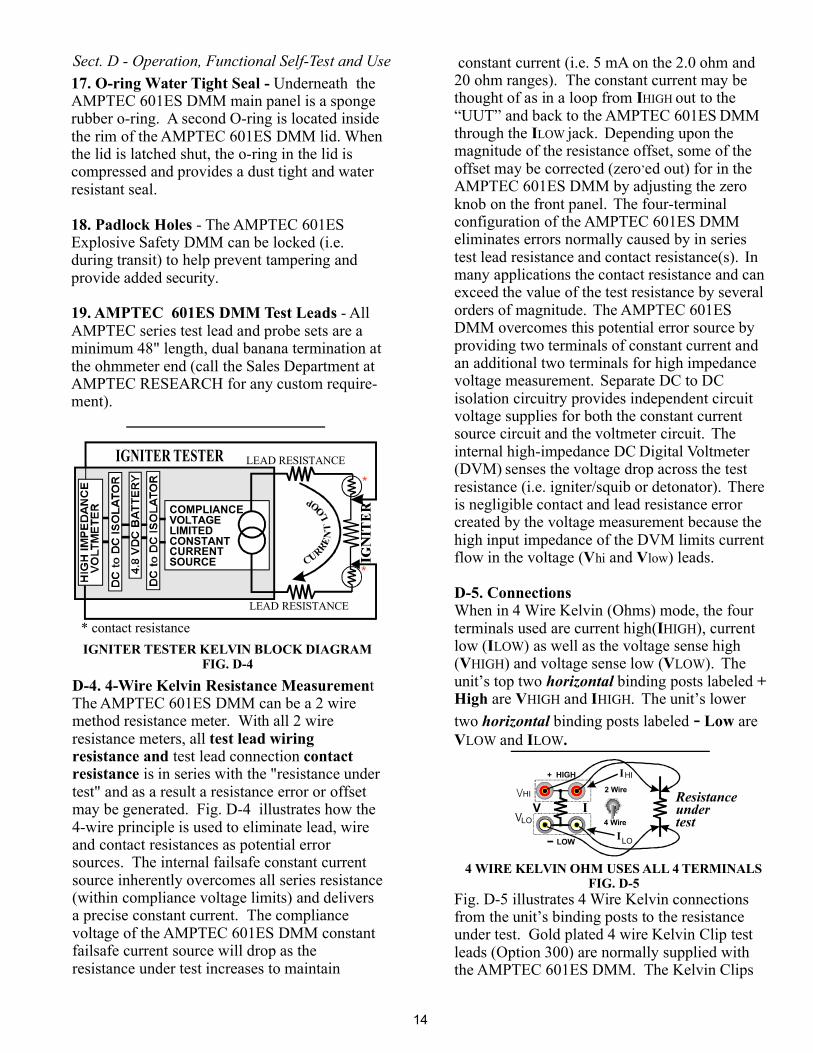
D-4. 4-Wire Kelvin Resistance Measuremen
test lead wiringresistance and contactresistance
tThe AMPTEC 601ES DMM can be a 2 wiremethod resistance meter. With all 2 wireresistance meters, all
test lead connectionis in series with the "resistance under
test" and as a result a resistance error or offsetmay be generated. Fig. D-4 illustrates how the4-wire principle is used to eliminate lead, wireand contact resistances as potential errorsources. The internal failsafe constant currentsource inherently overcomes all series resistance(within compliance voltage limits) and deliversa precise constant current. The compliancevoltage of the AMPTEC 601ES DMM constantfailsafe current source will drop as theresistance under test increases to maintain
IGNITER TESTER KELVIN BLOCK DIAGRAMFIG. D-4
constant current (i.e. 5 mA on the 2.0 ohm and20 ohm ranges). The constant current may bethought of as in a loop from out to the“UUT” and back to the AMPTEC 601ES DMMthrough the jack. Depending upon themagnitude of the resistance offset, some of theoffset may be corrected (zero ed out) for in theAMPTEC 601ES DMM by adjusting the zeroknob on the front panel. The four-terminalconfiguration of the AMPTEC 601ES DMMeliminates errors normally caused by in seriestest lead resistance and contact resistance(s). Inmany applications the contact resistance and canexceed the value of the test resistance by severalorders of magnitude. The AMPTEC 601ESDMM overcomes this potential error source byproviding two terminals of constant current andan additional two terminals for high impedancevoltage measurement. Separate DC to DCisolation circuitry provides independent circuitvoltage supplies for both the constant currentsource circuit and the voltmeter circuit. Theinternal high-impedance DC Digital Voltmeter(DVM) senses the voltage drop across the testresistance (i.e. igniter/squib or detonator). Thereis negligible contact and lead resistance errorcreated by the voltage measurement because thehigh input impedance of the DVM limits currentflow in the voltage ( and ) leads.
When in 4 Wire Kelvin (Ohms) mode, the fourterminals used are current high( ), currentlow ( ) as well as the voltage sense high( ) and voltage sense low ( ). Theunit’s top two binding posts labeled
are and . The unit’s lowertwo binding posts labeled are
and
Fig. D-5 illustrates 4 Wire Kelvin connectionsfrom the unit’s binding posts to the resistanceunder test. Gold plated 4 wire Kelvin Clip testleads (Option 300) are normally supplied withthe AMPTEC 601ES DMM. The Kelvin Clips
I
I
V V
D-5. Connections
II
V V+
High V ILow
V I .
HIGH
LOW
’
hi low
HIGHLOW
HIGH LOW
HIGH HIGH
LOW LOW
horizontal
horizontal -
2 Wire
4 Wire
Resistanceundertest
+ HIGH
LOW
VLO
LO
HI
HI
I
I
I
4 WIRE KELVIN OHM USES ALL 4 TERMINALSFIG. D-5
Sect. D - Operation, Functional Self-Test and Use
14
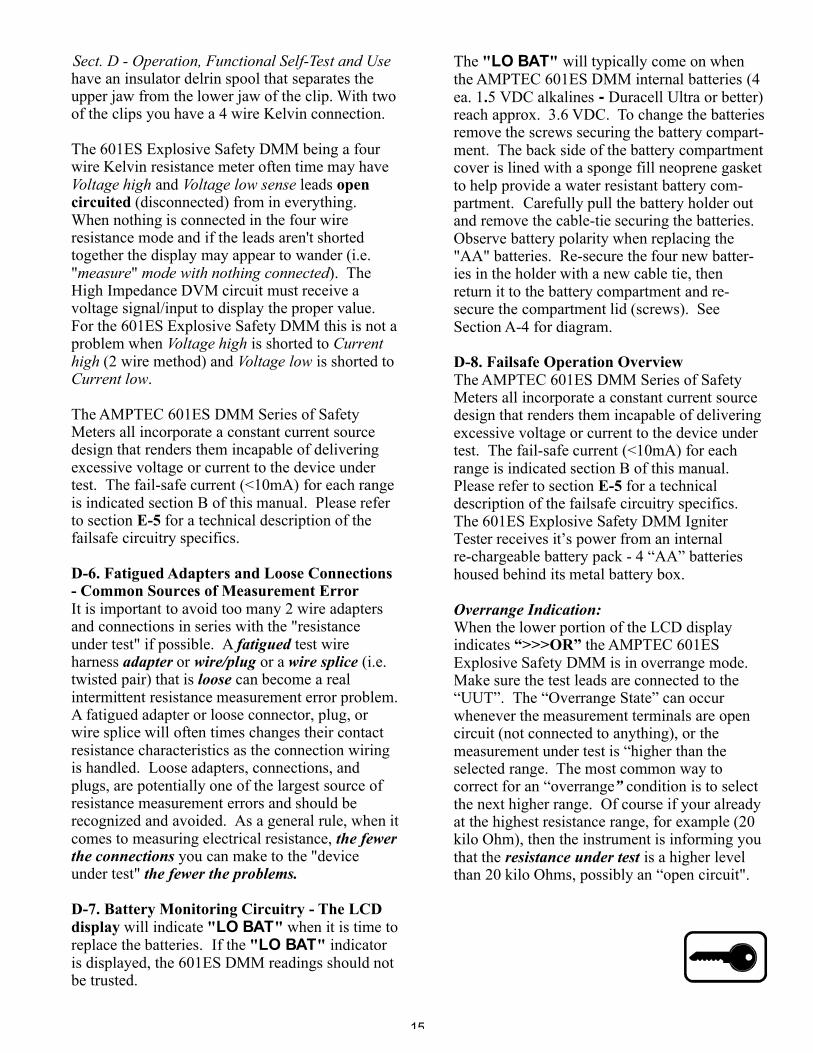
have an insulator delrin spool that separates theupper jaw from the lower jaw of the clip. With twoof the clips you have a 4 wire Kelvin connection.
The 601ES Explosive Safety DMM being a fourwire Kelvin resistance meter often time may have
and leads(disconnected) from in everything.
When nothing is connected in the four wireresistance mode and if the leads aren't shortedtogether the display may appear to wander (i.e." " ). TheHigh Impedance DVM circuit must receive avoltage signal/input to display the proper value.For the 601ES Explosive Safety DMM this is not aproblem when is shorted to
(2 wire method) and is shorted to.
The AMPTEC 601ES DMM Series of SafetyMeters all incorporate a constant current sourcedesign that renders them incapable of deliveringexcessive voltage or current to the device undertest. The fail-safe current (<10mA) for each rangeis indicated section B of this manual. Please referto section for a technical description of thefailsafe circuitry specifics.
It is important to avoid too many 2 wire adaptersand connections in series with the "resistanceunder test" if possible. A test wireharness or or a (i.e.twisted pair) that is can become a realintermittent resistance measurement error problem.A fatigued adapter or loose connector, plug, orwire splice will often times changes their contactresistance characteristics as the connection wiringis handled. Loose adapters, connections, andplugs, are potentially one of the largest source ofresistance measurement errors and should berecognized and avoided. As a general rule, when itcomes to measuring electrical resistance,
you can make to the "deviceunder test"
If the indicatoris displayed, the 601ES DMM readings should notbe trusted.
Voltage high Voltage low sense
measure mode with nothing connected
Voltage high Currenthigh Voltage lowCurrent low
opencircuited
E-5
D-6. Fatigued Adapters and Loose Connections- Common Sources of Measurement Error
D-7. Battery Monitoring Circuitry -
fatiguedadapter wire/plug wire splice
loose
the fewerthe connections
the fewer the problems.
The LCDdisplay " "
" "will indicate when it is time to
replace the batteries.LO BAT
LO BAT
The
The AMPTEC 601ES DMM Series of SafetyMeters all incorporate a constant current sourcedesign that renders them incapable of deliveringexcessive voltage or current to the device undertest. The fail-safe current (<10mA) for eachrange is indicated section B of this manual.Please refer to section for a technicaldescription of the failsafe circuitry specifics.The 601ES Explosive Safety DMM IgniterTester receives it’s power from an internalre-chargeable battery pack - 4 “AA” batterieshoused behind its metal battery box.
When the lower portion of the LCD displayindicates the AMPTEC 601ESExplosive Safety DMM is in overrange mode.Make sure the test leads are connected to the“UUT”. The “Overrange State” can occurwhenever the measurement terminals are opencircuit (not connected to anything), or themeasurement under test is “higher than theselected range. The most common way tocorrect for an “overrange condition is to selectthe next higher range. Of course if your alreadyat the highest resistance range, for example (20kilo Ohm), then the instrument is informing youthat the is a higher levelthan 20 kilo Ohms, possibly an “open circuit".
D-8. Failsafe Operation Overview
E-5
“>>>OR”
Overrange Indication:
”
resistance under test
" "LO BAT
. -
will typically come on whenthe AMPTEC 601ES DMM internal batteries (4ea. 1 5 VDC alkalines Duracell Ultra or better)reach approx. 3.6 VDC. To change the batteriesremove the screws securing the battery compart-ment. The back side of the battery compartmentcover is lined with a sponge fill neoprene gasketto help provide a water resistant battery com-partment. Carefully pull the battery holder outand remove the cable-tie securing the batteries.Observe battery polarity when replacing the"AA" batteries. Re-secure the four new batter-ies in the holder with a new cable tie, thenreturn it to the battery compartment and re-secure the compartment lid (screws). SeeSection A-4 for diagram.
Sect. D - Operation, Functional Self-Test and Use
15
CHAPTER E - GENERAL OPERATION AND DESIGN
E-1. General
All diagrams andinformation disclosed in this chapter isproprietary
E-2. Troubleshooting
The AMPTEC RESEARCH 601ES ExplosiveSafety DMM Igniter Tester is shown in blockdiagram form in Figure E-1.
and is included in order to maketroubleshooting to component level possible.
The AMPTEC 601ES Explosive Safety DMMSeries uses modern solid-state semiconductorsexclusively and digital CMOS circuits exten-sively to minimize power requirements andmake battery operation useful and practical.
AMPTEC RESEARCH also maintains a spareparts inventory of all components found in the601ES Explosive Safety DMM tester and it’scustomer service department can also provideadditional assistance in the trouble shootingprocess.
Since the AMPTEC 601ES Explosive SafetyDMM Igniter Tester is used to test potentialdeadly explosive force detonators and warheadsof missiles etc.,
.
Apparent AMPTEC 601ESalfunctions can sometimes be the result
of bad test lead/connection wiring, wrongconnections, misinterpretation of specifications,low battery levels and in rare cases due to anincomplete understanding of the instrument andhow to use it. A thorough review of the operat-ing instructions for this instrument is recom-mended prior to any component replacement.Check to be sure that cables and other testequipment are in good working order beforeattempting to troubleshoot the 601ES
series.
the AMPTEC 601ES ExplosiveSafety DMM ,it may indicate the batteries need changing.
personnel that are not qualifiedto make such electrical repairs on the 601ESExplosive Safety DMM should not evenattempt to remove the calibration access screwsor open the main panel or effect any repairwhatsoever
If you turn ondisplay does not come on
Explosive SafetyDMM m
AMPTECExplosive Safety DMM
and the
If the AMPTEC 601ES ExplosiveSafety DMM exhibits problemsthat cannot be eliminated byreviewing Chapters B and D, the followingguidelines have been established to help solvethe problem.
The key to successful troubleshooting is tolocalize the problem to a general electronicparameter as much as possible before trying topin the problem down to a specific component.Certain questions should be asked such as "Doesthe problem occur on all ranges or on a specificrange only?" If the AMPTEC 601ES ExplosiveSafety DMM does not come "on" when poweredup, did you check the obvious items such asdead batteries? Is there 5 mA of test currentcoming out of the units 20 ohm range? Thepower supplies for both the current source andthe digital voltmeter electronics are also one ofthe first things that should be tested.
Explosive SafetyDMM
as corrosion ofcomponents leads and PCB etch loss can occur.
E-3. Localizing the Problem
As it is not possible to anticipate all possiblefailure modes of the AMPTEC 601ES ExplosiveSafety DMM series igniter tester, servicepersonnel should become familiar with thissection to gain a complete understanding of theinternal workings of this safety meter.
If the malfunction is a faulty component, theaccuracy of the AMPTEC 601
igniter tester
and thefollowing precautions are taken:
Use only the specified component or its exactequivalent. Spare parts can be ordered fromAMPTEC RESEARCH by referring to theAMPTEC Stock Number listed in the Parts Listssection at the back of this manual.
The highest quality 63/37 grade rosin coreelectronic grade solder with a 50W or lowermaximum power soldering iron should be used.
E-4. Component Replacement
can be maintained only ifthe 601ES is re-calibrated following
component replacementAMPTEC
a (repair)
Never use an acid core solder
16

When soldering, heat the PCB pad and the lead of the component, not the solder. After several seconds of thecomponent lead in contact with the hot soldering iron apply solder smoothly and evenly onto the PCB padand component lead not the soldering iron. Do not touch or move the replacement part until the solder hascooled. Cold solder and bad solder joints can cause more problems.
Use the unit's chassis ground connection - i.e. connect to an earth ground to avoid a static discharge to a staticsensitive component. Handle all AMPTEC 601ES DMM internal components as if they are static sensitive ifyou are not sure.
E-5. Circuit Descriptions
E-5.1 Model 601ES IC 401 - DVM IC - MAX7129 - Detailed DescriptionThe MAX7129 is a uniquely designed single chip A/D converter. The AMPTEC 601ES Explosive SafetyMeter DVM measurement circuit features a new successive integration" technique to achieve 5µV resolutionon a 100mV full-scale range. To achieve this resolution a 10:1 improvement in noise performance over pre-vious monolithic CMOS A/D converters was used. Previous integrating converters used an external capacitorto store an offset correction voltage (dual slope integration). This technique worked well but greatly in-creased the equivalent noise bandwidth of the converter. The MAX7129 removed this source of error (noise)by not using an auto-zero capacitor. Offsets are cancelled using digital techniques instead. Savings in exter-nal parts cost are realized as well as improved noise performance and elimination of a source of electromag-netic and electrostatic pick-up.
In the overall Functional Block Diagram of the MAX7129 the heart of this A/D converter is the sequencecounter/decoder which drives the control logic and keeps track of the many separate phases required for eachconversion cycle. The sequence counter is constantly running and is a separate counter from the up/downresults counter which is activated only when the integrator is de-integrating. At the end of a conversion thedata remaining in the results counter is latched, decoded and multiplexed to the liquid crystal display.
The analog section block diagram shown in FIG. H-7 included all of the analog switches used to configurethe voltage sources and amplifiers in the different phases of the cycle. The input and reference switchingschemes are very similar to those in other less accurate integrating A/D converters. There are 5 basic config-urations used in the full conversion cycle.
FIG. H-9 illustrates a typical waveform on the integrator output. INT, INT1, and INT2 all refer to the signalintegrate phase where the input voltage is applied to the integrator amplifier via the buffer amplifier. In thisphase, the integrator ramps over a fixed period of time in a direction opposite polarity to the input voltage tothe display driver for decoding and multiplexing
DE1, DE2 and DE3 are the de-integrate phases where the reference capacitor is switched in series with thebuffer amplifier and the integrator ramps back down the level it started from before integrating. However,since the de-integration phase can terminate only at a clock pulse transition, there is always a small overshootof the integrator past the starting point. The ICL7129 amplifies this overshoot by 10 and DE2 begins.Similarly DE2's overshoot is amplified by 10 and DE3 begins. At the end of DE3 the results counter holds anumber with 5½ digits of resolution. This was obtained by feeding counts into the results counter at the 3½digit level during DE1, into the 4½ digit level during DE2 and the 5½ digit level for De3. The effects of off-set in the buffer, integrator, and comparator can now be cancelled by repeating this entire sequence with theinputs shorted and subtracting the results from the original reading. For this phase INT2 switch is closed togive the same common-mode voltage as the measurement cycle. This assures excellent CMRR. At the endOf the cycle the data in the up/down results counter is accurate to 0.02% of full scale and is sen.
Sect. E - General Operation and Design
17

E-5.2 AMPTEC 601ES Resistance
E-5.5 MICROPROCESSOR
E-5.6 DIGITAL VOLT METER
The AMPTEC 601ES resistance measurement function works using the principle of OHM'S LAW(V/I=R). It outputs a constant DC current through the unknown resistance then measures the voltage dropacross the resistance. The measurement circuit then scales magnitude and displays the V/I ratioas resistance. For example, the 2 Ohm range outputs a constant 5.0 mA . When 5.0 mA passes through a1.0 Ohm resistor the result is a 5.0 mV drop. We then route the measured voltage drop (i.e. 5.0 mV) into the
and get 50.0 mV, which is routed into the DVM chip (MAX7129) which drives theLCD display as 1.0000 Ohm. The 20 Ohm range also outputs 5mA of constant failsafe current. When 5 mAis routed through a 10 ohm resister, you get 50mV.
10.000 Ohms. The 200 Ohm range outputs 500uA. Put that across a 100Ohm resister and you get 50mV which put into the displays 100.00 Ohms. Asthe range resistance goes up by a factor of 10. The current goes down by a factor of 10 keeping thevoltage at 50mV.
IC101 is a 5 volt regulator with an enable pin 4. Pin 4 normally sits at +5V through RN101:3 and RN101:1.When the Power switch is pressed SW101 pin 4 is pulled to ground through D101, and +5 is turned onwhich then goes to IC102 a 5 volt regulator. Once the power is turned on the microprocessor wakes up andturns on TR101, which then holds pin 4 low keeping the power on. Even when the momentary power switchis released. When the power switch is pressed again to turn the unit off TR102 is turned on and a signal issent to the micro processor and it turns off TR101 which allows pin 4 to go high and turns the power off.The micro can also turn the unit off the same way after a certain time period has elapsed. This is to savebattery life See FIG. H-1.
The micro can turn on TR201-TR209 using IC201 and I 202. These fets are used to set and reset latchingrelays on the current board.
DMM
601ES ohmsDC
which is also routed into the DVM chip (MAX7129)which drives the LCD display as
DVM chip (MAX7129) it asDC
CThe connection is made through three ribbon connectors J201, J202, J203. A
signal also comes back through these connectors indicating which relay is on and this is used to control thedecimal point and K on the display. See FIG. H-2.
IC301 is the microprocessor it can be programed through P301 when JP301 is in the P position and operatewhen JP301 is in the N position. J302 comes from the front panel range switch to let the micro know whichrange has been selected. It then sends the necessary signal to IC201 and IC202 on sheet 2 to select theproper FET to turn on the range relay on the current board. JP303 is used to tell the micro which time delayis selected to automatically turn the unit off. It uses PTC1 to turn the power on and off and PTD7 to detectif the power switch was pressed. These lines go to sheet 1. Ic302 is used to tell if it safe to change ranges.See FIG. H-3.
IC402 is an X 10 Amplifier used for the 2 Ohm range. RL401 is used to switch the amplifier in and out.D401 is the reference Zener. RV401 is used to set the reference voltage to 500 milli volts. In the 100 mVmeasurement mode 50 mV in will display 10000. RL402 is used to switch in an offset in conjunction withthe front panel zero pot for the 2 and 20 Ohm ranges. RL403 is used for the 200 Ohm range. Above 200Ohms on offset is used. P401 is used to send the display information to the front panel LCD display. SeeFIG. H-4
x10 Amplifier circuit
E-5.3 POWER SUPPLY
E-5.4 RELAY CONTROL
.
Sect. E - General Operation and Design
18

CHAPTER F - CALIBRATION AND MAINTENANCE
F-1. GeneralThis section of the manual contains routinemaintenance information regarding theAMPTEC RESEARCH 601ES Safety DMM.Calibration should be performed on a regularbasis to ensure continued instrument accuracyor following a main PCB electronic componentrepair/replacement. The recommendedcalibration interval is 1 year.
in order to eliminate lead resistanceand contact resistance errors. The Option “300”is a gold plated 4 Wire Kelvin Clip Test Leadset that is available with the AMPTEC 601ESDMM.
AMPTEC 601ES DMM Calibration note:
verify @ 60Hz
For the resistance function, the AMPTEC601ES Safety DMM must be calibrated usingfour wire Kelvin connections to the resistancestandard
F-2. Required Test EquipmentFollowing standard resistors are required tocalibrate the 601ES Explosive Safety MeterIgniter Tester .
1 ohm ± 0.01% Accuracy10 ohms ± 0.005% Accuracy1000 ohms ± 0.005% Accuracy10 Kohms ± 0.01% Accuracy
600 V ± 0.05% or better accuracy100 V ± 0.05% or better accuracy10 V ± 0.05% or better accuracy1.0 V ± 0.05% or better accuracy
600 V ± 0.05% or better accuracy100 V ± 0.05% or better accuracy10 V ± 0.05% or better accuracy1.0 V ± 0.05% or better accuracy
1.0 ampere ± 0.05% or better accuracy
Precision Resistance Standards:
DC Voltage Standard:
AC Voltage Standard:
AC/DC Current Standard:
F-3. Calibration Procedure
F-3-1. Zero Offset Adjustment1.
2.
A.
DMM
Function andFollowing a full 15 minute warm-up
period
Only Out of SpecificationSection B
No adjustments are needed
-- Verify each function and range with the
appropriate calibration standards to determine ifthe AMPTEC 601ES DMM meets its publishedaccuracy specifications as published in Section B( p.7).
- If the 601ES meets the specifi-cations as compared with traceable standards thenit is ready to certify with a calibration sticker etc.and " ".
its the PCB directly under
the " " functions( ) need to be addressed with any adjust-ment procedure
The 601ESDMM requires fully charged batteries and a full 15minute warm-ip period prior to any adjustments.The calibration adjustments are accessed byremoving the 10 calibration access screws aroundthe perimeter of the 601ES front panel, thenlifting off the top plate by the handles. Thelocations of the adjustments are shown on drawingnumber 601ES Explosive Safety Meter-600 at theback of this manual.
Any zero offset greater than the specification (0.05% of range which is 00.10 on the 20 Kohmrange) then adjust as noted
(see figure H-14 in the back of the manual forthe DVM PCB location -
With the AMPTEC 601ES DMM in 4 Wire mode,select the 20 Kohm range. Short the four WireKelvin Leads together at the ends.
next. If the zero readingis >00.10 then adjust potentiometer RV405 to be asclose to 00.00 as possible ( its located on the DVMPCB)
Verification of Each RangesAccuracy
Use caution when lifting the601ES top panel up by the handles, as there isumbilical wiring that connects the top panelelectronics to battery pack wiring and chassis/caseground wiring mounted inside the bottom of the601ES case. Set the top panel on end resting on theunit’s bezel.
19
one corner of the DVM PCB has a nylon washeracting as an insulator/separator from its cornerstand off support)must be
. Save this nylon washer as itbe returned to its PCB metal standoff
location when the adjustment procedure is fin-ished. Slightly lift and tilt the right hand side ofthe DVM PCB to give you access to all theDMM trimpot locations ( needed for voltageand current measurement adjustments). Allvoltage adjustments should be performed withDC Voltage Standard inputwith an AC Voltage Standard. DC Voltage inputfrom a DCV standard provides the most stableAMPTEC 601ES voltage reading for calibrationpurposes.
Select the 600V range and input 0.00 VDCfrom the DC Voltage standard. Adjust RV101 toread 000.0 volts.
Still on the 600V range input 600.0 VDCfrom the DC Voltage standard. Adjust RV102 toread 600.0 volts.
Select the 200V range and input 100.00 VDCfrom the DC Voltage standard. Adjust RV105 toread 100.0 volts.
Select the 20V range and input 10.000 VDCfrom the DC Voltage standard. Adjust RV104 toread 10.000 volts.
Select the 2 V range and input 1.0000 VDCfrom the DC Voltage standard. Adjust RV103 toread 1.000 volts.
You may now verify all the above voltageranges with input from an AC Voltage standardto determine compliance.
Select the 600V range and provide 600VAC@60Hz input, then verify the range is in specifi-cation.
Select the 200V range and provide 100VAC@60Hz input, then verify the range is in speci-fication.
Select the 20V range and provide 10VAC@60Hz input, then verify the range is in specifi-cation.
Select the 2 V range and provide 1.0 VAC@60Hz input, then verify the range is in speci-fication.
All trimpot adjustments ( i.e RV401)described for this section are also located on theDMM PCB.
then later verify
3.
4.
5.
6.
7.
8.
A)
B)
C)
D)
F-3-6 AC/DC Current Adjustments
1)
the battery compartment). When adjustingRV405, which is indicated asa negative sign.
Select the 20 Kohm range. Connect the Kel-vin clips to the 10 Kohm standard resistor.
Select the 2 0 Ohm range. Connect Kelvinleads to the AMPTEC 601ES Safety DMM.
Short the Kelvin Clip leads at the end .
do not over adjust
F-3-3. 2.0 Ohm Range Adjustments con't(zero)
Adjust RV402 on the DVM PCB for areading of 1.0000 ohms. Over adjustment isindicated by a negative polarity sign.
F-3-2. Full Scale Adjustment1.
F-3-3. 2.0 Ohm Range Adjustments1. .
There are no adjustmentsnecessary for the 20 Ohm, 200 Ohm, and 20Kohm ranges.
2.
2.
3.
Adjust RV401 for a display indication of10.00 Kohms.
for a dis-play indication of .0000 ohms.
Connect the test leads to a 1.0 Ohm resistancestandard.
Check the 20 KOhm range with the10.0 KOhm Standard Resistor.
Adjust RV403 on the DVM PCB
F-3-4. Verification of Each Ranges Accuracy
F-3-5 AC/DC Voltage Adjustments
Check the 20 ohm range with a 10 ohm resis-tance standard. Check the 200 ohm range with a100 ohm resistance standard. Check the 2.0KOhm range with the 1.0 Kohm StandardResistor.
All resistanceranges must be within the specifications out-lined in Chapter B.
1. The adjustments for this section is difficult toaccess, we recommend a simple
for all AC/DC Voltage and AC/DCcurrent measurements to determine if theAMPTEC 601 Safety DMM is adequately inspecification. If the AMPTEC 601ES DMM is"in spec" you do not need to perform the adjust-ment procedure described in the steps below. Allthe adjustments described in this section areperformed on the DMM PCB (
).2. Keeping all ribbon cables and wiring intactbetween the various PCBs, removethe DVM PCB from its standoff mounts. (
verificationcheck first
first
carefully
see figure H-14for PCB location, the DMM PCB is essentiallylocated below the DVM PCB and the I sourcePCB
note:
20
F-3-6 AC/DC Current Adjustments con't
(should be outputting ~50 mV at thispoint)
2) Select the 2.0 amp range and provide 1.0ampere DC from the DC Current calibrator.Keep in mind, you have to press/hold the straycurrent pushbutton to measure AC/DC current.Adjust (located in the middle of theDMM PCB) to read 1.000 ampere. Verify ACcurrent with 1.0 amp@ 60Hz input from anAC/DC Current Calibrator to read within spec(see section B for specifications)
Since the voltage and current measurementshave just be calibrated in the previous steps, averification check of the and signalsource is to any signalsource adjustments (only adjust when neces-sary). Again, keep all ribbon cables and wiringintact between the PCBs, remove the
from its standoff mounts. Slightlylift and tilt the left hand side of the I-Source PCBto give you access to the trimpotsbelow it ( needed only for access to the signalsource adjustments).
Select the 2.0 V range.Press and hold the 50mV/5mA Signal Source
pushbutton.
Adjust located on the(underneath the I-Source PCB) to read .0500 V .4.) Next select the 2 amp range.5.) Press/hold the 50 mV/5mA Signal Sourcebutton at the same time as the 2.0 stray currentpress to measure button and
. Adjust RV502 and repeat this step 5dual button press operation until the AMPTEC601ES reads .0050 A ( 5 milliamperes).
Return both the and thes to their standoff PCB mounts. Return the
nylon washer/insulator to the DVM PCB cornerstandoff mount. With all ribbon cabling intact,re-secure both PCBs to their standoff mounts.Carefully replace the top panel and umbilical
RV401
F-3-7 50mV/5mA Signal Source Adjustments
50mV 5 mArecommended prior
I-Source PCB
DMM PCB
1.)2.)
3.) RV501 DMM PCB
note the displayreading
I-Source PCB DVMPCB
carefully
cabling to it's bezel mount and re-secure thecalibration access screws located around theperimeter of the 601ES top plate.
To replace low batteries first unscrew thebattery compartment lid and lift. Remove thebattery holder, plastic tie and low batteries.Replace with a new set of (4) “AA” batteriesaccording to polarity. Using the spare plastictie included in the battery compartment, wrapthe plastic around the battey holder and secure.Cut excess plastic. Next, wrap the black andred wire around the battery holder and place theholder into the compartment. Lastly replace lidand screw in screws to secure. See diagramabove. *Please note: After replacing batteryholder with (4) new ‘AA’ batteries; secure witha new plastic tie lock.
F-4. Battery Replacement InstructionsThe battery pack replacement process is:
21