4K Camcorder
231
Firmware ver. 1.0.1.1 4K Camcorder Instruction Manual PUB. DIE-0524-000B
-
Upload
khangminh22 -
Category
Documents
-
view
1 -
download
0
Transcript of 4K Camcorder
Firmware ver. 1.0.1.14K Camcorder
Instruction Manual
PUB. DIE-0524-000B
2
COPYRIGHT WARNING:Unauthorized recording of copyrighted materials may infringe on the rights of copyright owners and be contrary to copyright laws.
Trademark Acknowledgements• SD, SDHC and SDXC Logos are trademarks of SD-3C, LLC.• Microsoft and Windows are trademarks or registered trademarks of Microsoft Corporation in the United
States and/or other countries.• Apple, macOS are trademarks of Apple Inc., registered in the U.S. and other countries.• Avid and Media Composer are trademarks or registered trademarks of Avid Technology, Inc. or its
subsidiaries in the United States and/or other countries.• Wi-Fi is a registered trademark of the Wi-Fi Alliance.• Wi-Fi Certified, WPA, WPA2, and the Wi-Fi Certified logo are trademarks of the Wi-Fi Alliance.• WPS as used on the camcorder’s settings, onscreen displays and in this manual signifies Wi-Fi Protected
Setup.• The Wi-Fi Protected Setup Identifier Mark is a mark of the Wi-Fi Alliance.• JavaScript is a trademark or registered trademark of Oracle Corporation, its affiliates or subsidiaries in the
United States and other countries.• HDMI, the HDMI logo and High-Definition Multimedia Interface are trademarks or registered trademarks of
HDMI Licensing LLC in the United States and other countries.• Other names and products not mentioned above may be trademarks or registered trademarks of their
respective companies.• This device incorporates exFAT technology licensed from Microsoft.• This product is licensed under AT&T patents for the MPEG-4 standard and may be used for encoding
MPEG-4 compliant video and/or decoding MPEG-4 compliant video that was encoded only (1) for a personal and noncommercial purpose or (2) by a video provider licensed under the AT&T patents to provide MPEG-4 compliant video. No license is granted or implied for any other use for MPEG-4 standard.
• ANY USE OF THIS PRODUCT OTHER THAN CONSUMER PERSONAL USE IN ANY MANNER THAT COMPLIES WITH THE MPEG-2 STANDARD FOR ENCODING VIDEO INFORMATION FOR PACKAGED MEDIA IS EXPRESSLY PROHIBITED WITHOUT A LICENSE UNDER APPLICABLE PATENTS IN THE MPEG-2 PATENT PORTFOLIO, WHICH LICENSE IS AVAILABLE FROM MPEG LA, L.L.C., 250 STEELE STREET, SUITE 300, DENVER, COLORADO 80206.
3
Highlights of the XF705
The Canon XF705 4K Camcorder is a high-performance camcorder whose advanced functionality and versatile usability make it the perfect choice for a variety of 4K productions. The following are just some of the functions featured in the camcorder.
4K Recording System
Advanced sensor and image processorAt the heart of the camcorder is the type 1.0 (1.0 in.) single plate CMOS sensor with an 8,290,000 effective pixel count, and an image processing platform with two DIGIC DV 6 processors. Thanks to its advanced high-sensitivity and noise reduction technology, the camcorder can shoot nuanced images with little noise even in low-light situations.
High-efficiency encoding: XF-HEVC and XF-AVCYou can choose the movie format according to your workflow needs. You can record using the H.265/HEVC codec or MPEG-4 AVC/H.264 codec, both of which are recorded as MXF (Material eXchange Format) clips. MXF clips are compatible with all major non-linear (NLE) editing software, offering a smoother post-production workflow.With the H.265/HEVC codec, you can use YCC422, 10-bit color sampling and select 4K (3840x2160) or Full HD (1920x1080) resolution and a variety of frame rates and bit rates. With the MPEG-4 AVC/H.264 codec, you can record only at Full HD resolution using YCC420, 8-bit color sampling. In both cases, audio is recorded as 4-channel linear PCM (24 bit, 48 KHz) audio.
Operability and Adaptability
Versatile designThe camcorder was designed to be operated comfortably by a single camera operator. It features 3 separate rings for independent focus, zoom and iris operation. The camcorder also features 14 buttons to which you can assign a large number of functions (A 117) to personalize the camcorder to your needs and preferences.
Improved displaysThe camcorder features a 4.0-in. LCD display (equivalent to 1,230,000 dots) that offers 100% coverage and touch-to-focus functions. The LCD panel can open to the left or right. The viewfinder offers an OLED display (also with 100% coverage) and a large eye cup for a comfortable fit in various shooting conditions.
SD card recording optionsThe camcorder can record 4K video on SD cards, offering great cost-performance in terms of recording media. It is equipped with 2 card slots, allowing you to use double slot recording to record the same clip on two cards, or relay recording to automatically switch to the other card when the one being used is full (A 36).
Versatile Artistic Expression
Special recording modesThe special recording modes (A 113) give you more creative control over your recordings. You can change the shooting frame rate to achieve a slow motion effect1 or use pre-recording to record 3 seconds before you press the button, helping you capture those hard-to-catch opportunities.
Custom picture settings (A 63, 121)Select one of the preset color settings or set the combination of gamma curve, color space and color matrix that you wish to use. Then, you can adjust a number of other image-related parameters in detail. With wide color space options such as BT.2020 Gamut, the Canon Log 3 gamma curve, which keeps the characteristics of the Canon Log gamma while expanding the dynamic range, and two HDR options1 (HLG or PQ), you can be sure that the camcorder covers your creative needs.1 For XF-HEVC clips only.
Professional Functions and Flexibility
Network functionsConnect the camcorder to a Wi-Fi or wired (Ethernet) network to enjoy various network functions2. You can, for example, use a Wi-Fi capable mobile device to control the camcorder remotely with the Browser Remote application (A 162), stream live transmissions or breaking images via IP (A 173) and transfer recordings from an SD card to a remote server using the FTP protocol (A 176).2 Available functions depend on the network connection
used.
Software for aiding production workflowCanon XF Utility (A 151) lets you copy the clips you recorded from an SD card to a computer, play back the clips and organize them. You can also use the Canon XF plugins to work with the clips directly from non-linear editing (NLE) software made by Avid.
4
Pro-level connectivityThe camcorder is equipped with an SDI terminal compliant with the 12G-SDI standard that provides a greater bandwith and supports 4K video output at 59.94P or 50.00P frame rate. Meanwhile, the TIME CODE terminal and G-LOCK/SYNC terminal offer many synchronization options (A 92), allowing the camcorder to be part of any multi-camera shooting setup.
Infrared recordingRecord in darkness using infrared recording (A 116). With the built-in infrared light, you can record nocturnal animals in their natural environment or other such scenes.
Enhanced Focusing Options
Dual Pixel CMOS AFThe camcorder features Dual Pixel CMOS AF technology for improved autofocus functions (A 74). In addition to continuous AF, AF-boosted MF lets you focus manually most of the way and let the camcorder finish focusing automatically. With AF-boosted MF the camcorder does not perform unreliable focus adjustments, resulting in a more stable focusing operation than with continuous AF. The camcorder can also focus automatically on people's faces and track moving subjects while keeping them in focus (A 79).
Dual Pixel Focus Guide (A 75) The focus guide serves as a visual, intuitive guide that you can use to check if the image is in focus and the required adjustment, if it is not. This can be very helpful to ensure you always get amazingly sharp 4K video.
Other improved features• Direct setting mode (A 52)
Change main camcorder functions while checking the image on the screen using only the joystick.
• Assistance functionsYou can use assistance functions such as peaking and magnification (A 76), onscreen markers (A 85), zebra patterns (A 86), B&W image (A 30) and a waveform monitor (A 105) on the screen and viewfinder. You can also display them on an external monitor connected to the SDI terminal or HDMI OUT terminal3. Additionally, when using a logarithmic gamma curve, you can also apply a LUT (A 147) for easier monitoring.3 Available assistance functions depend on the screen/video
output used.
• Customizable onscreen displays (A 44).• Menu settings file that can be saved in the
camcorder or on an SD card to restore all the menu settings or replicate them on another XF705 camcorder (A 129).
• Battery packs compatible with Intelligent System for better remaining usage time information.
• INPUT terminals (XLR) compatible with analog or digital (AES/EBU) audio and +48 V phantom power supply (A 98).
• Improved clip name format with more information for easier identification and organization of clips (A 48).
• Metadata (A 108) and geotagging (A 110).• Color bars and test tone output and recording
(A 104).• Advanced remote operation using the optional
RC-V100 Remote Controller (A 39).
5
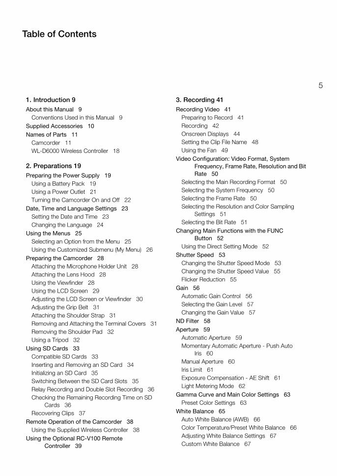
1. Introduction 9About this Manual 9
Conventions Used in this Manual 9Supplied Accessories 10Names of Parts 11
Camcorder 11WL-D6000 Wireless Controller 18
2. Preparations 19Preparing the Power Supply 19
Using a Battery Pack 19Using a Power Outlet 21Turning the Camcorder On and Off 22
Date, Time and Language Settings 23Setting the Date and Time 23Changing the Language 24
Using the Menus 25Selecting an Option from the Menu 25Using the Customized Submenu (My Menu) 26
Preparing the Camcorder 28Attaching the Microphone Holder Unit 28Attaching the Lens Hood 28Using the Viewfinder 28Using the LCD Screen 29Adjusting the LCD Screen or Viewfinder 30Adjusting the Grip Belt 31Attaching the Shoulder Strap 31Removing and Attaching the Terminal Covers 31Removing the Shoulder Pad 32Using a Tripod 32
Using SD Cards 33Compatible SD Cards 33Inserting and Removing an SD Card 34Initializing an SD Card 35Switching Between the SD Card Slots 35Relay Recording and Double Slot Recording 36Checking the Remaining Recording Time on SD
Cards 36Recovering Clips 37
Remote Operation of the Camcorder 38Using the Supplied Wireless Controller 38
Using the Optional RC-V100 Remote Controller 39
3. Recording 41Recording Video 41
Preparing to Record 41Recording 42Onscreen Displays 44Setting the Clip File Name 48Using the Fan 49
Video Configuration: Video Format, System Frequency, Frame Rate, Resolution and Bit Rate 50
Selecting the Main Recording Format 50Selecting the System Frequency 50Selecting the Frame Rate 50Selecting the Resolution and Color Sampling
Settings 51Selecting the Bit Rate 51
Changing Main Functions with the FUNC Button 52
Using the Direct Setting Mode 52Shutter Speed 53
Changing the Shutter Speed Mode 53Changing the Shutter Speed Value 55Flicker Reduction 55
Gain 56Automatic Gain Control 56Selecting the Gain Level 57Changing the Gain Value 57
ND Filter 58Aperture 59
Automatic Aperture 59Momentary Automatic Aperture - Push Auto
Iris 60Manual Aperture 60Iris Limit 61Exposure Compensation - AE Shift 61Light Metering Mode 62
Gamma Curve and Main Color Settings 63Preset Color Settings 63
White Balance 65Auto White Balance (AWB) 66Color Temperature/Preset White Balance 66Adjusting White Balance Settings 67Custom White Balance 67
Table of Contents
6
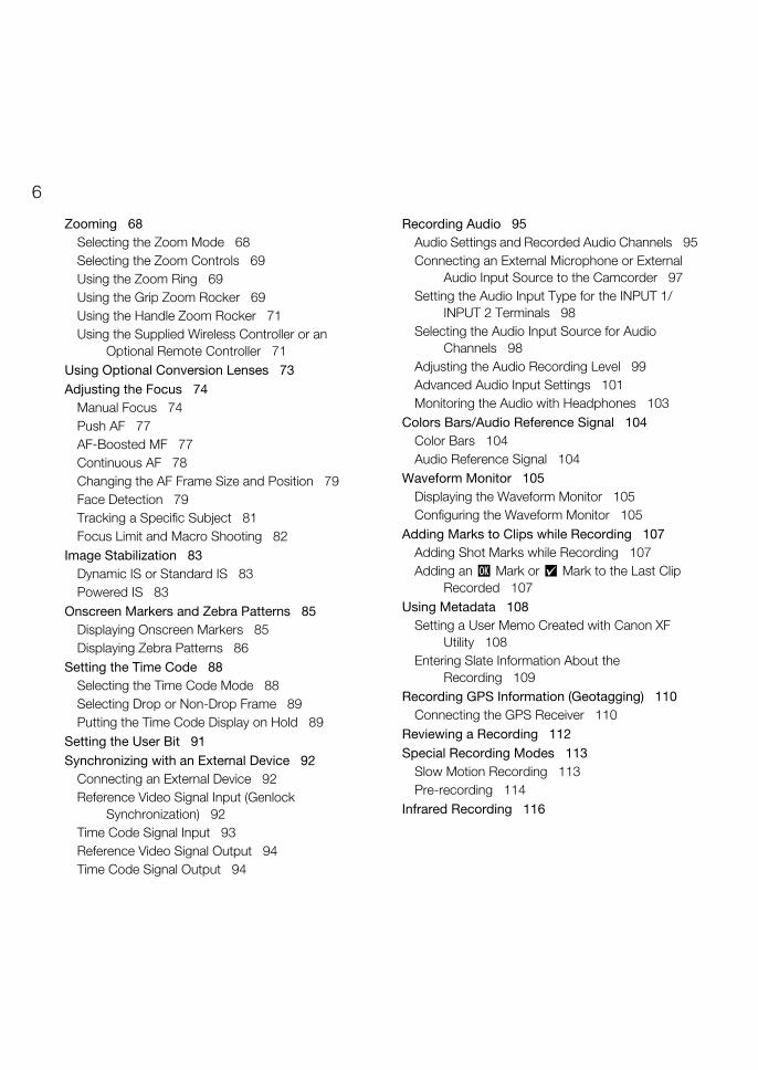
Zooming 68Selecting the Zoom Mode 68Selecting the Zoom Controls 69Using the Zoom Ring 69Using the Grip Zoom Rocker 69Using the Handle Zoom Rocker 71Using the Supplied Wireless Controller or an
Optional Remote Controller 71Using Optional Conversion Lenses 73Adjusting the Focus 74
Manual Focus 74Push AF 77AF-Boosted MF 77Continuous AF 78Changing the AF Frame Size and Position 79Face Detection 79Tracking a Specific Subject 81Focus Limit and Macro Shooting 82
Image Stabilization 83Dynamic IS or Standard IS 83Powered IS 83
Onscreen Markers and Zebra Patterns 85Displaying Onscreen Markers 85Displaying Zebra Patterns 86
Setting the Time Code 88Selecting the Time Code Mode 88Selecting Drop or Non-Drop Frame 89Putting the Time Code Display on Hold 89
Setting the User Bit 91Synchronizing with an External Device 92
Connecting an External Device 92Reference Video Signal Input (Genlock
Synchronization) 92Time Code Signal Input 93Reference Video Signal Output 94Time Code Signal Output 94
Recording Audio 95Audio Settings and Recorded Audio Channels 95Connecting an External Microphone or External
Audio Input Source to the Camcorder 97Setting the Audio Input Type for the INPUT 1/
INPUT 2 Terminals 98Selecting the Audio Input Source for Audio
Channels 98Adjusting the Audio Recording Level 99Advanced Audio Input Settings 101Monitoring the Audio with Headphones 103
Colors Bars/Audio Reference Signal 104Color Bars 104Audio Reference Signal 104
Waveform Monitor 105Displaying the Waveform Monitor 105Configuring the Waveform Monitor 105
Adding Marks to Clips while Recording 107Adding Shot Marks while Recording 107Adding an $ Mark or % Mark to the Last Clip
Recorded 107Using Metadata 108
Setting a User Memo Created with Canon XF Utility 108
Entering Slate Information About the Recording 109
Recording GPS Information (Geotagging) 110Connecting the GPS Receiver 110
Reviewing a Recording 112Special Recording Modes 113
Slow Motion Recording 113Pre-recording 114
Infrared Recording 116
7
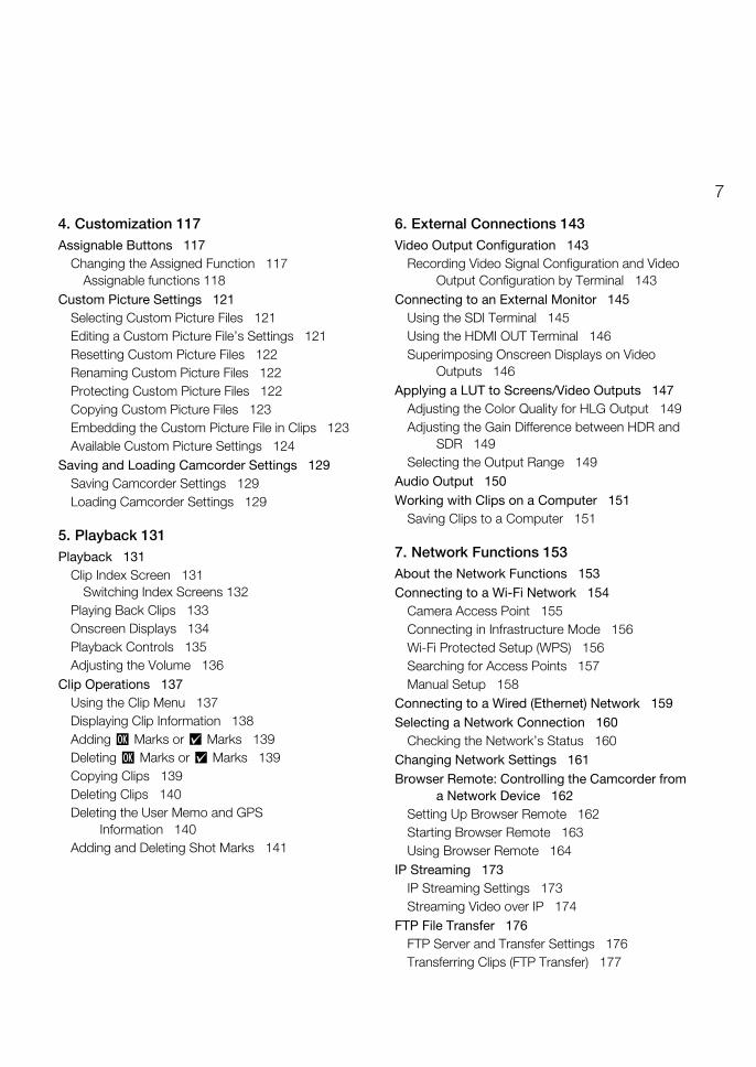
4. Customization 117Assignable Buttons 117
Changing the Assigned Function 117Assignable functions 118
Custom Picture Settings 121Selecting Custom Picture Files 121Editing a Custom Picture File’s Settings 121Resetting Custom Picture Files 122Renaming Custom Picture Files 122Protecting Custom Picture Files 122Copying Custom Picture Files 123Embedding the Custom Picture File in Clips 123Available Custom Picture Settings 124
Saving and Loading Camcorder Settings 129Saving Camcorder Settings 129Loading Camcorder Settings 129
5. Playback 131Playback 131
Clip Index Screen 131Switching Index Screens 132
Playing Back Clips 133Onscreen Displays 134Playback Controls 135Adjusting the Volume 136
Clip Operations 137Using the Clip Menu 137Displaying Clip Information 138Adding $ Marks or % Marks 139Deleting $ Marks or % Marks 139Copying Clips 139Deleting Clips 140Deleting the User Memo and GPS
Information 140Adding and Deleting Shot Marks 141
6. External Connections 143Video Output Configuration 143
Recording Video Signal Configuration and Video Output Configuration by Terminal 143
Connecting to an External Monitor 145Using the SDI Terminal 145Using the HDMI OUT Terminal 146Superimposing Onscreen Displays on Video
Outputs 146Applying a LUT to Screens/Video Outputs 147
Adjusting the Color Quality for HLG Output 149Adjusting the Gain Difference between HDR and
SDR 149Selecting the Output Range 149
Audio Output 150Working with Clips on a Computer 151
Saving Clips to a Computer 151
7. Network Functions 153About the Network Functions 153Connecting to a Wi-Fi Network 154
Camera Access Point 155Connecting in Infrastructure Mode 156Wi-Fi Protected Setup (WPS) 156Searching for Access Points 157Manual Setup 158
Connecting to a Wired (Ethernet) Network 159Selecting a Network Connection 160
Checking the Network’s Status 160Changing Network Settings 161Browser Remote: Controlling the Camcorder from
a Network Device 162Setting Up Browser Remote 162Starting Browser Remote 163Using Browser Remote 164
IP Streaming 173IP Streaming Settings 173Streaming Video over IP 174
FTP File Transfer 176FTP Server and Transfer Settings 176Transferring Clips (FTP Transfer) 177
8
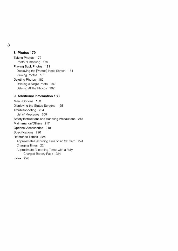
8. Photos 179Taking Photos 179
Photo Numbering 179Playing Back Photos 181
Displaying the [Photos] Index Screen 181Viewing Photos 181
Deleting Photos 182Deleting a Single Photo 182Deleting All the Photos 182
9. Additional Information 183Menu Options 183Displaying the Status Screens 195Troubleshooting 204
List of Messages 209Safety Instructions and Handling Precautions 213Maintenance/Others 217Optional Accessories 218Specifications 220Reference Tables 224
Approximate Recording Time on an SD Card 224Charging Times 224Approximate Recording Times with a Fully
Charged Battery Pack 224Index 226
19
Introduction
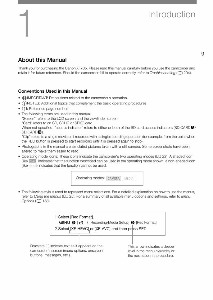
About this ManualThank you for purchasing the Canon XF705. Please read this manual carefully before you use the camcorder and retain it for future reference. Should the camcorder fail to operate correctly, refer to Troubleshooting (A 204).
Conventions Used in this Manual• IMPORTANT: Precautions related to the camcorder’s operation.• NOTES: Additional topics that complement the basic operating procedures.• A: Reference page number.• The following terms are used in this manual.
"Screen" refers to the LCD screen and the viewfinder screen."Card" refers to an SD, SDHC or SDXC card.When not specified, "access indicator" refers to either or both of the SD card access indicators (SD CARD2/SD CARD3)."Clip" refers to a single movie unit recorded with a single recording operation (for example, from the point when the REC button is pressed to start recording until it is pressed again to stop).
• Photographs in the manual are simulated pictures taken with a still camera. Some screenshots have been altered to make them easier to read.
• Operating mode icons: These icons indicate the camcorder's two operating modes (A 22). A shaded icon (like ) indicates that the function described can be used in the operating mode shown; a non-shaded icon (like ) indicates that the function cannot be used.
• The following style is used to represent menu selections. For a detailed explanation on how to use the menus, refer to Using the Menus (A 25). For a summary of all available menu options and settings, refer to Menu Options (A 183).
Operating modes:
Brackets [ ] indicate text as it appears on the camcorder's screen (menu options, onscreen buttons, messages, etc.).
This arrow indicates a deeper level in the menu hierarchy or the next step in a procedure.
1 Select [Rec Format]. > [Æ ! Recording/Media Setup] > [Rec Format]
2 Select [XF-HEVC] or [XF-AVC] and then press SET.
Supplied Accessories
10
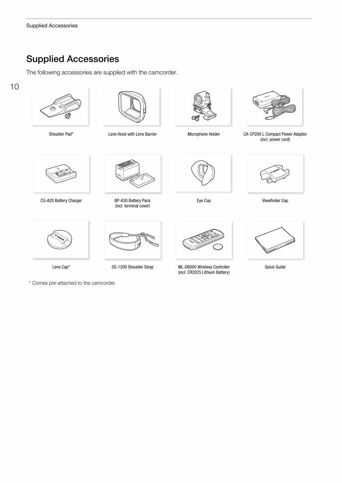
Supplied AccessoriesThe following accessories are supplied with the camcorder.
Shoulder Pad* Lens Hood with Lens Barrier Microphone Holder CA-CP200 L Compact Power Adapter(incl. power cord)
CG-A20 Battery Charger BP-A30 Battery Pack(incl. terminal cover)
Eye Cup Viewfinder Cap
Lens Cap* SS-1200 Shoulder Strap WL-D6000 Wireless Controller (incl. CR2025 Lithium Battery)
Quick Guide
* Comes pre-attached to the camcorder.
11
Names of Parts
Names of PartsCamcorder
1 3
4 5 6 7 8 9 10 11 12 13 14 15
2
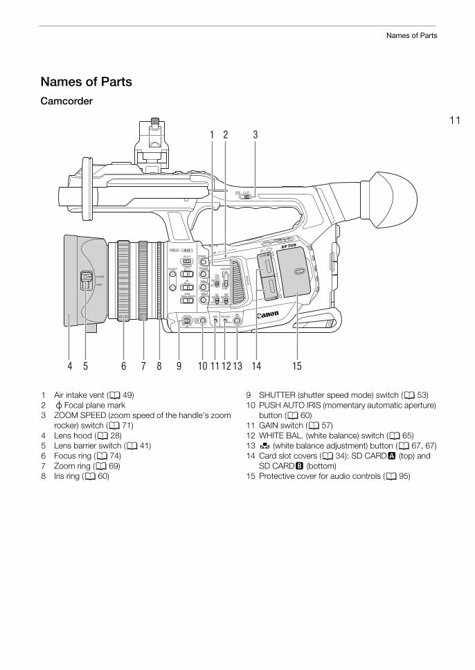
1 Air intake vent (A 49)2 Focal plane mark3 ZOOM SPEED (zoom speed of the handle's zoom
rocker) switch (A 71)4 Lens hood (A 28)5 Lens barrier switch (A 41)6 Focus ring (A 74)7 Zoom ring (A 69)8 Iris ring (A 60)
9 SHUTTER (shutter speed mode) switch (A 53)10 PUSH AUTO IRIS (momentary automatic aperture)
button (A 60)11 GAIN switch (A 57)12 WHITE BAL. (white balance) switch (A 65)13 Å (white balance adjustment) button (A 67, 67)14 Card slot covers (A 34): SD CARD2 (top) and
SD CARD3 (bottom)15 Protective cover for audio controls (A 95)
Names of Parts
12
1
2 3 4 5
678
14 15
16 17 18 19
9 10 111213
p15
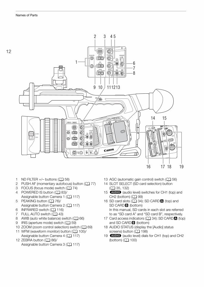
1 ND FILTER +/– buttons (A 58)2 PUSH AF (momentary autofocus) button (A 77)3 FOCUS (focus mode) switch (A 74)4 POWERED IS button (A 83)/
Assignable button Camera 1 (A 117)5 PEAKING button (A 76)/
Assignable button Camera 2 (A 117)6 INFRARED switch (A 116)7 FULL AUTO switch (A 43)8 AWB (auto white balance) switch (A 66)9 IRIS (aperture mode) switch (A 59)10 ZOOM (zoom control selection) switch (A 69)11 WFM (waveform monitor) button (A 105)/
Assignable button Camera 4 (A 117)12 ZEBRA button (A 86)/
Assignable button Camera 3 (A 117)
13 AGC (automatic gain control) switch (A 56)14 SLOT SELECT (SD card selection) button
(A 35, 132)15 – (audio level) switches for CH1 (top) and
CH2 (bottom) (A 99)16 SD card slots (A 34): SD CARD2 (top) and
SD CARD3 (bottom)In this manual, SD cards in each slot are referred to as “SD card A” and “SD card B”, respectively.
17 Card access indicators (A 34): SD CARD2 (top) and SD CARD3 (bottom)
18 AUDIO STATUS (display the [Audio] status screens) button (A 198)
19 – (audio level) dials for CH1 (top) and CH2 (bottom) (A 100)
13
Names of Parts
1
8 9 10 11 12
2 3 4 5 6 7
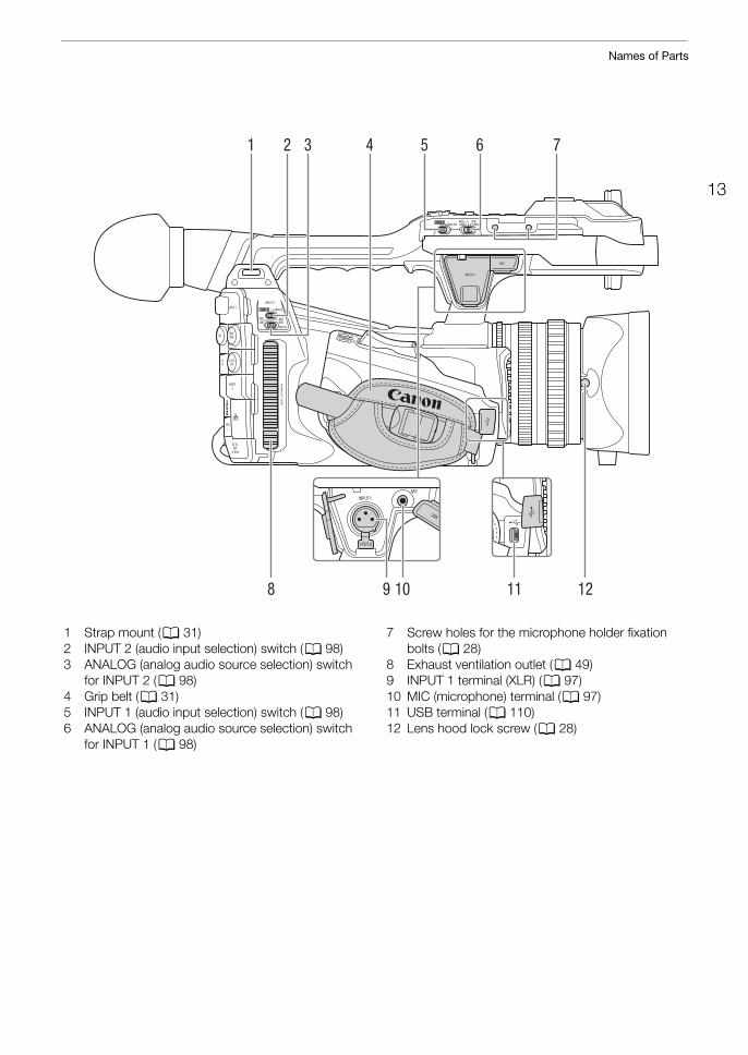
1 Strap mount (A 31)2 INPUT 2 (audio input selection) switch (A 98)3 ANALOG (analog audio source selection) switch
for INPUT 2 (A 98)4 Grip belt (A 31)5 INPUT 1 (audio input selection) switch (A 98)6 ANALOG (analog audio source selection) switch
for INPUT 1 (A 98)
7 Screw holes for the microphone holder fixation bolts (A 28)
8 Exhaust ventilation outlet (A 49)9 INPUT 1 terminal (XLR) (A 97)10 MIC (microphone) terminal (A 97)11 USB terminal (A 110)12 Lens hood lock screw (A 28)
Names of Parts
14
1 2 3 4 5 6
21
7 1314151617181920
891011
12
22 23 24 25
26
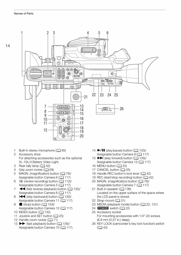
1 Built-in stereo microphone (A 95)2 Accessory shoe
For attaching accessories such as the optional VL-10Li II Battery Video Light.
3 Rear tally lamp (A 42)4 Grip zoom rocker (A 69)5 MAGN. (magnification) button (A 76)/
Assignable button Camera 6 (A 117)6 u (review recording) button (A 112)/
Assignable button Camera 5 (A 117)7 Ø (fast reverse playback) button (A 135)/
Assignable button Camera 8 (A 117)8 Ú (skip backward) button (A 135)/
Assignable button Camera 11 (A 117)9 Ñ (stop) button (A 133)/
Assignable button Camera 12 (A 117)10 INDEX button (A 132)11 Joystick and SET button (A 25)12 Handle zoom rocker (A 71)13 × (fast playback) button (A 135)/
Assignable button Camera 10 (A 117)
14 Ò (play/pause) button (A 133)/Assignable button Camera 9 (A 117)
15 Ù (skip forward) button (A 135)/Assignable button Camera 13 (A 117)
16 MENU button (A 25)17 CANCEL button (A 25)18 Handle REC button's lock lever (A 42)19 REC (start/stop recording) button (A 42)20 MAGN. (magnification) button (A 76)/
Assignable button Camera 7 (A 117)21 Built-in speaker (A 136)
Located on the upper surface of the space where the LCD panel is stored.
22 Strap mount (A 31)23 MEDIA (playback mode) button (A 22, 131)24 Q switch (A 22)25 Accessory socket
For mounting accessories with 1/4"-20 screws (6.9 mm (0.27 in.) deep).
26 KEY LOCK (camcorder's key lock function) switch (A 43)
15
Names of Parts
1 2
3 4
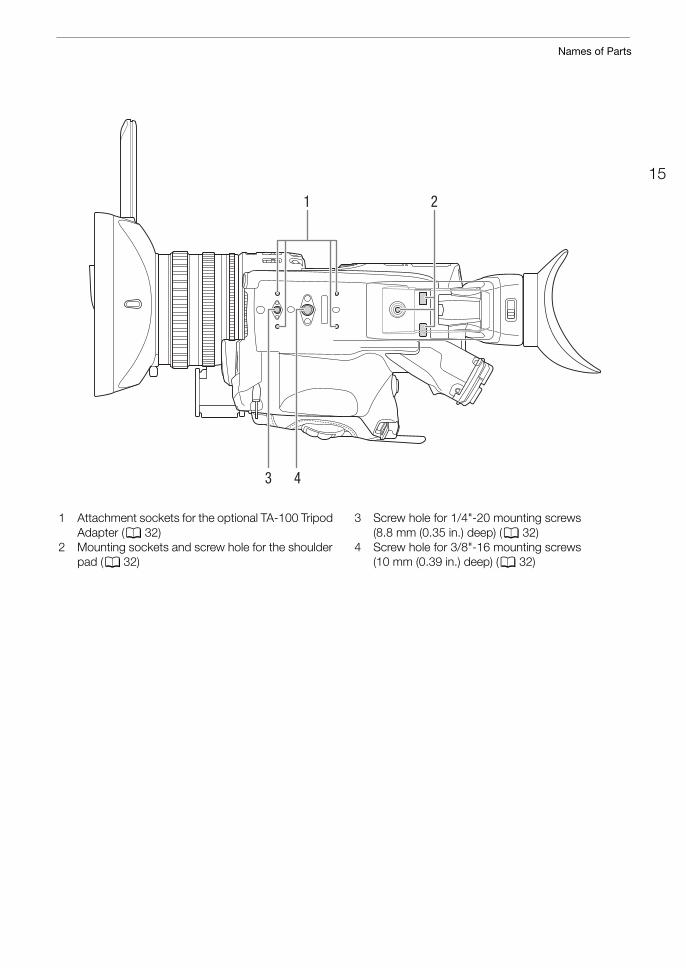
1 Attachment sockets for the optional TA-100 Tripod Adapter (A 32)
2 Mounting sockets and screw hole for the shoulder pad (A 32)
3 Screw hole for 1/4"-20 mounting screws (8.8 mm (0.35 in.) deep) (A 32)
4 Screw hole for 3/8"-16 mounting screws (10 mm (0.39 in.) deep) (A 32)
Names of Parts
16
1
2
3
5 6
4
7
9
8
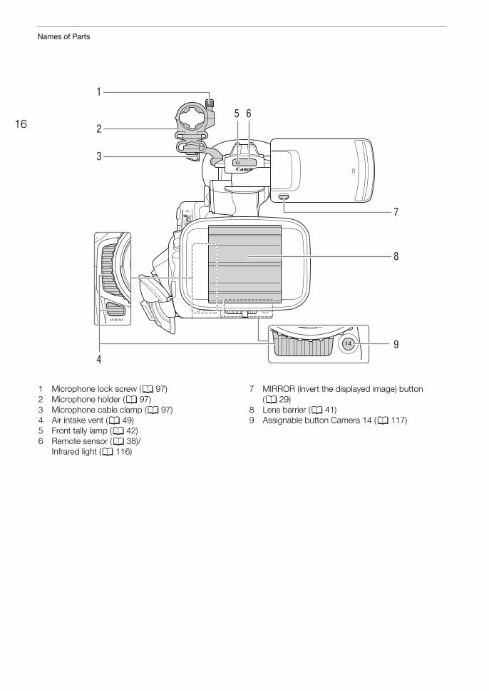
1 Microphone lock screw (A 97)2 Microphone holder (A 97)3 Microphone cable clamp (A 97)4 Air intake vent (A 49)5 Front tally lamp (A 42)6 Remote sensor (A 38)/
Infrared light (A 116)
7 MIRROR (invert the displayed image) button (A 29)
8 Lens barrier (A 41)9 Assignable button Camera 14 (A 117)
17
Names of Parts
1
13
14
15
161718
1920212223242526
2
3
4
5
6
789
1011
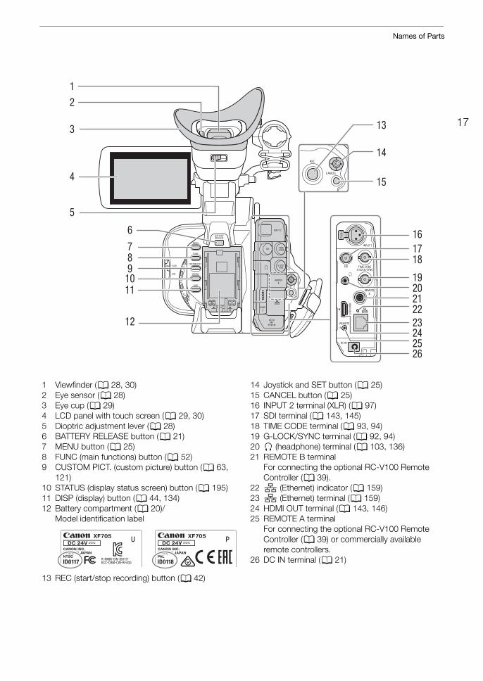
12
1 Viewfinder (A 28, 30)2 Eye sensor (A 28)3 Eye cup (A 29)4 LCD panel with touch screen (A 29, 30)5 Dioptric adjustment lever (A 28)6 BATTERY RELEASE button (A 21)7 MENU button (A 25)8 FUNC (main functions) button (A 52)9 CUSTOM PICT. (custom picture) button (A 63,
121)10 STATUS (display status screen) button (A 195)11 DISP (display) button (A 44, 134)12 Battery compartment (A 20)/
Model identification label
13 REC (start/stop recording) button (A 42)
14 Joystick and SET button (A 25)15 CANCEL button (A 25)16 INPUT 2 terminal (XLR) (A 97)17 SDI terminal (A 143, 145)18 TIME CODE terminal (A 93, 94)19 G-LOCK/SYNC terminal (A 92, 94)20 × (headphone) terminal (A 103, 136)21 REMOTE B terminal
For connecting the optional RC-V100 Remote Controller (A 39).
22 (Ethernet) indicator (A 159)23 (Ethernet) terminal (A 159)24 HDMI OUT terminal (A 143, 146)25 REMOTE A terminal
For connecting the optional RC-V100 Remote Controller (A 39) or commercially available remote controllers.
26 DC IN terminal (A 21)
Names of Parts
18
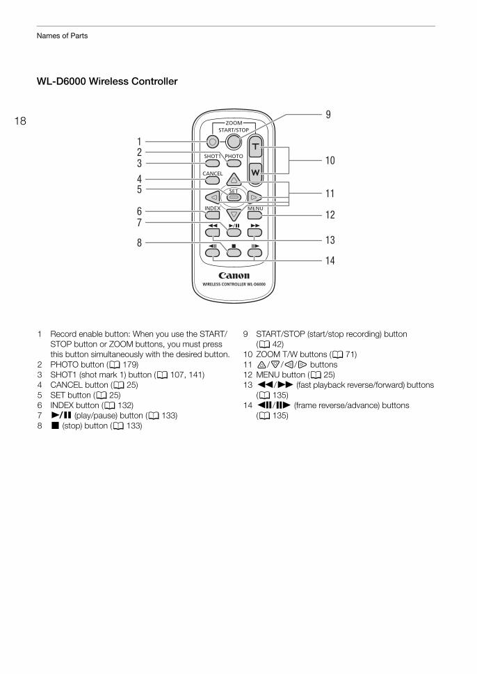
WL-D6000 Wireless Controller
1
9
10
11
12
13
14
2345
67
8
1 Record enable button: When you use the START/STOP button or ZOOM buttons, you must press this button simultaneously with the desired button.
2 PHOTO button (A 179)3 SHOT1 (shot mark 1) button (A 107, 141)4 CANCEL button (A 25)5 SET button (A 25)6 INDEX button (A 132)7 Ò (play/pause) button (A 133)8 Ñ (stop) button (A 133)
9 START/STOP (start/stop recording) button (A 42)
10 ZOOM T/W buttons (A 71)11 á/â/à/ß buttons12 MENU button (A 25)13 Ø/× (fast playback reverse/forward) buttons
(A 135)14 Ô/Ó (frame reverse/advance) buttons
(A 135)
219
Preparations
Preparing the Power SupplyYou can power the camcorder using a battery pack or directly using the compact power adapter. If you connect the compact power adapter to the camcorder while a battery pack is attached, the camcorder will draw power from the power outlet.
Using a Battery PackYou can power the camcorder using the supplied BP-A30 Battery Pack or the optional BP-A60 Battery Pack. Both battery packs are compatible with Intelligent System so you can check the approximate remaining battery usage time (in minutes) on the screen. For more accurate readings, when using a battery pack for the first time, charge it fully and then use the camcorder until the battery pack is completely exhausted.
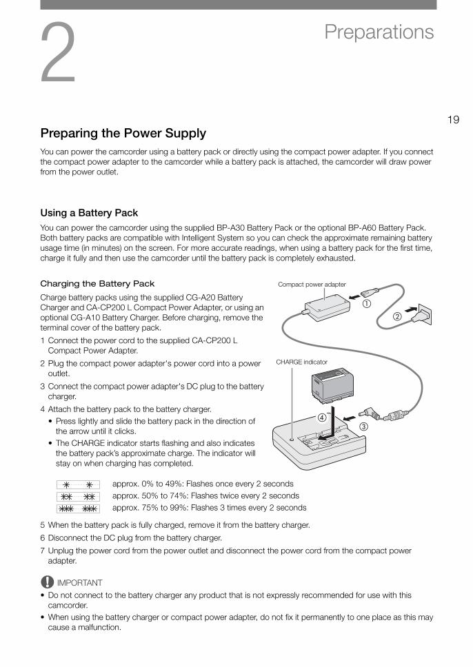
Charging the Battery Pack
Charge battery packs using the supplied CG-A20 Battery Charger and CA-CP200 L Compact Power Adapter, or using an optional CG-A10 Battery Charger. Before charging, remove the terminal cover of the battery pack.
1 Connect the power cord to the supplied CA-CP200 L Compact Power Adapter.
2 Plug the compact power adapter's power cord into a power outlet.
3 Connect the compact power adapter's DC plug to the battery charger.
4 Attach the battery pack to the battery charger.• Press lightly and slide the battery pack in the direction of
the arrow until it clicks.• The CHARGE indicator starts flashing and also indicates
the battery pack’s approximate charge. The indicator will stay on when charging has completed.
approx. 0% to 49%: Flashes once every 2 secondsapprox. 50% to 74%: Flashes twice every 2 secondsapprox. 75% to 99%: Flashes 3 times every 2 seconds
5 When the battery pack is fully charged, remove it from the battery charger.
6 Disconnect the DC plug from the battery charger.
7 Unplug the power cord from the power outlet and disconnect the power cord from the compact power adapter.
IMPORTANT
• Do not connect to the battery charger any product that is not expressly recommended for use with this camcorder.
• When using the battery charger or compact power adapter, do not fix it permanently to one place as this may cause a malfunction.
�
�
�
�
CHARGE indicator
Compact power adapter
Preparing the Power Supply
20
• We recommend charging the battery pack in temperatures between 10 ºC and 30 ºC (50 ºF and 86 ºF). Outside the temperature range of 0 ºC to 40 ºC (32 ºF to 104 ºF), charging will not start.
• To prevent equipment breakdowns and excessive heating, do not connect the supplied battery charger or compact power adapter to voltage converters for overseas travels or special power sources such as those on aircraft and ships, DC-AC inverters, etc.
NOTES
• If there is a malfunction with the battery charger, compact power adapter or battery pack, the charge indicator will go out and charging will stop.
• For handling precautions regarding the battery pack, refer to Battery Pack (A 214).• For approximate charging times and recording times with a fully charged battery pack, refer to the Reference
Tables (A 224).• Charged battery packs continue to discharge naturally. Therefore, charge them on the day of use, or the day
before, to ensure a full charge.• We recommend that you prepare battery packs to last 2 to 3 times longer than you think you might need.• Repeatedly charging and discharging the battery pack will eventually shorten its battery life. You can check the
battery life on the [Battery/Hour Meter] status screen (A 201). Fully charging the battery pack and then discharging it completely will give you a more accurate reading.
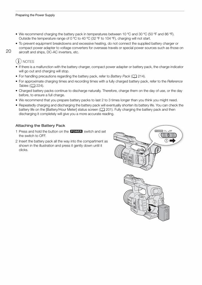
Attaching the Battery Pack
1 Press and hold the button on the Q switch and set the switch to OFF.
2 Insert the battery pack all the way into the compartment as shown in the illustration and press it gently down until it clicks.
�
�
21
Preparing the Power Supply
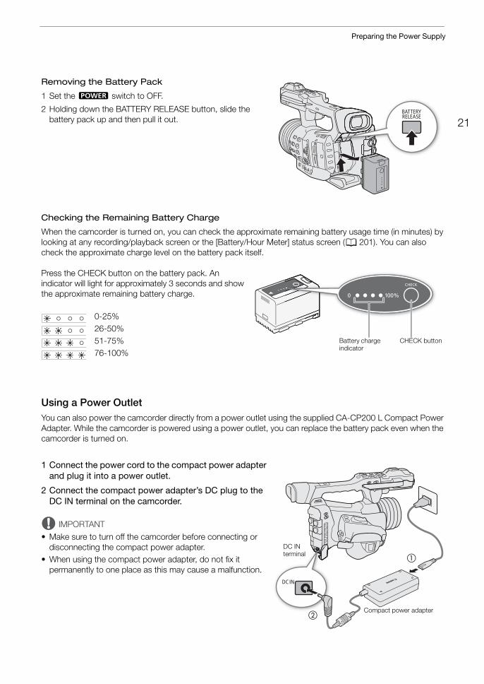
Removing the Battery Pack
1 Set the Q switch to OFF.
2 Holding down the BATTERY RELEASE button, slide the battery pack up and then pull it out.
Checking the Remaining Battery Charge
When the camcorder is turned on, you can check the approximate remaining battery usage time (in minutes) by looking at any recording/playback screen or the [Battery/Hour Meter] status screen (A 201). You can also check the approximate charge level on the battery pack itself.
Press the CHECK button on the battery pack. An indicator will light for approximately 3 seconds and show the approximate remaining battery charge.
0-25%26-50%51-75%76-100%
Using a Power OutletYou can also power the camcorder directly from a power outlet using the supplied CA-CP200 L Compact Power Adapter. While the camcorder is powered using a power outlet, you can replace the battery pack even when the camcorder is turned on.
1 Connect the power cord to the compact power adapter and plug it into a power outlet.
2 Connect the compact power adapter’s DC plug to the DC IN terminal on the camcorder.
IMPORTANT
• Make sure to turn off the camcorder before connecting or disconnecting the compact power adapter.
• When using the compact power adapter, do not fix it permanently to one place as this may cause a malfunction.
CHECK buttonBattery charge indicator
�
�
DC IN terminal
Compact power adapter
Preparing the Power Supply
22
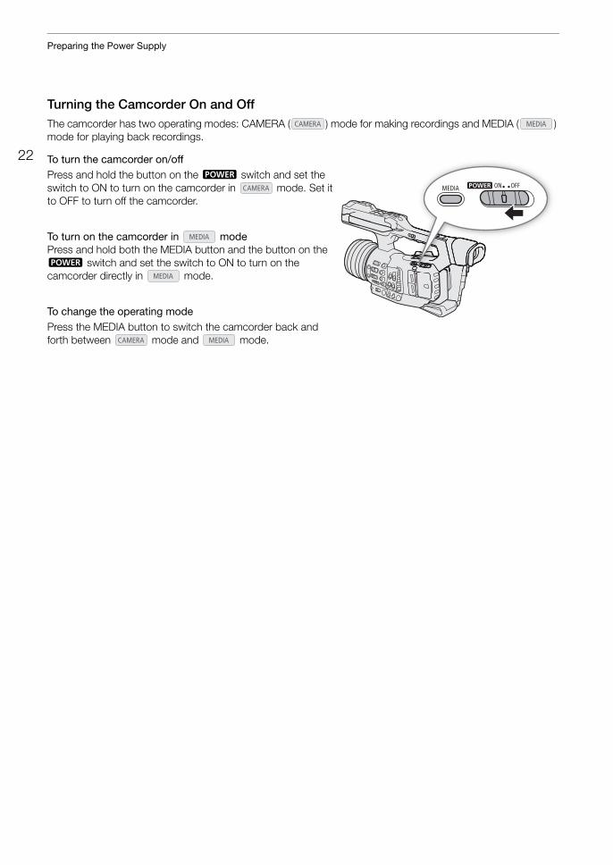
Turning the Camcorder On and OffThe camcorder has two operating modes: CAMERA ( ) mode for making recordings and MEDIA ( ) mode for playing back recordings.
To turn the camcorder on/offPress and hold the button on the Q switch and set the switch to ON to turn on the camcorder in mode. Set it to OFF to turn off the camcorder.
To turn on the camcorder in modePress and hold both the MEDIA button and the button on the Q switch and set the switch to ON to turn on the camcorder directly in mode.
To change the operating modePress the MEDIA button to switch the camcorder back and forth between mode and mode.
23
Date, Time and Language Settings
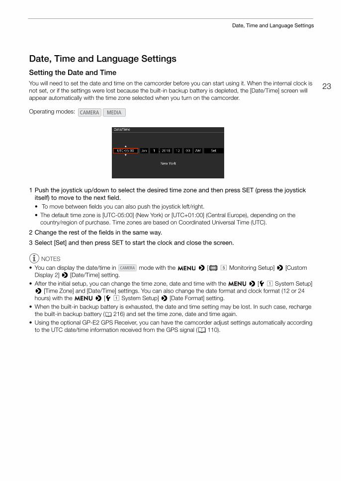
Date, Time and Language SettingsSetting the Date and TimeYou will need to set the date and time on the camcorder before you can start using it. When the internal clock is not set, or if the settings were lost because the built-in backup battery is depleted, the [Date/Time] screen will appear automatically with the time zone selected when you turn on the camcorder.
1 Push the joystick up/down to select the desired time zone and then press SET (press the joystick itself) to move to the next field.• To move between fields you can also push the joystick left/right.• The default time zone is [UTC-05:00] (New York) or [UTC+01:00] (Central Europe), depending on the
country/region of purchase. Time zones are based on Coordinated Universal Time (UTC).
2 Change the rest of the fields in the same way.
3 Select [Set] and then press SET to start the clock and close the screen.
NOTES
• You can display the date/time in mode with the > [¢ % Monitoring Setup] > [Custom Display 2] > [Date/Time] setting.
• After the initial setup, you can change the time zone, date and time with the > [B ! System Setup] > [Time Zone] and [Date/Time] settings. You can also change the date format and clock format (12 or 24 hours) with the > [B ! System Setup] > [Date Format] setting.
• When the built-in backup battery is exhausted, the date and time setting may be lost. In such case, recharge the built-in backup battery (A 216) and set the time zone, date and time again.
• Using the optional GP-E2 GPS Receiver, you can have the camcorder adjust settings automatically according to the UTC date/time information received from the GPS signal (A 110).
Operating modes:
Date, Time and Language Settings
24
Changing the LanguageThe camcorder’s default language is English. You can change it to German, Spanish, French, Italian, Polish, Portuguese, Russian, Simplified Chinese, Korean or Japanese. Please note that some settings and screens will be displayed in English, regardless of the language setting.
1 Press the MENU button.
2 Push the joystick up/down to select [B! System Setup] and then press SET.
3 Select [Language H] in a similar fashion and then press SET.
4 Push the joystick up/down to select a language.
5 Press SET to change the language and then press the MENU button to close the menu.
Operating modes:
25
Using the Menus
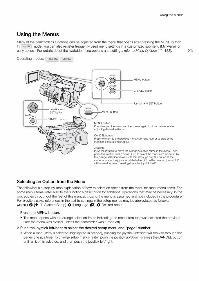
Using the MenusMany of the camcorder’s functions can be adjusted from the menu that opens after pressing the MENU button. In mode, you can also register frequently used menu settings in a customized submenu (My Menu) for easy access. For details about the available menu options and settings, refer to Menu Options (A 183).
Selecting an Option from the MenuThe following is a step-by-step explanation of how to select an option from the menu for most menu items. For some menu items, refer also to the function’s description for additional operations that may be necessary. In the procedures throughout the rest of this manual, closing the menu is assumed and not included in the procedure.For brevity's sake, references in the text to settings in the setup menus may be abbreviated as follows:
> [B ! System Setup] > [Language H] > Desired option
1 Press the MENU button.• The menu opens with the orange selection frame indicating the menu item that was selected the previous
time the menu was closed (unless the camcorder was turned off).
2 Push the joystick left/right to select the desired setup menu and "page" number.• When a menu item is selected (highlighted in orange), pushing the joystick left/right will browse through the
pages one at a time. To change setup menus faster, push the joystick up/down or press the CANCEL button until an icon is selected, and then push the joystick left/right.
Operating modes:
MENU buttonPress to open the menu and then press again to close the menu after adjusting desired settings.
CANCEL buttonPress to return to the previous menu/submenu level or to stop some operations that are in progress.
JoystickPush the joystick to move the orange selection frame in the menu. Then, press the joystick itself ("press SET") to select the menu item indicated by the orange selection frame. Note that although only the button at the center of one of the joysticks is labeled as SET, in the manual, "press SET" will be used to mean pressing down the joystick itself.
CANCEL button
MENU buttonJoystick and SET button
Joystick and SET button
MENU button
CANCEL button
Using the Menus
26
3 Push the joystick up/down to select the desired menu item and then press SET.• Setting options will appear with a Ð mark next to the currently selected option.• Some menu items may have an additional submenu level. Select the desired submenu and press SET to
display the setting options.• When a setup menu icon is highlighted in orange, you can also press SET to select the first menu item in the
setup menu page.
4 Push the joystick up/down to select the desired setting option and then press SET.
5 Press the MENU button to close the menu.
NOTES
• Unavailable items may appear grayed out.• Pressing the MENU button at any time closes the menu.• On some screens, the following icons may be displayed as a guide: , , . They refer, respectively,
to pressing the joystick (or SET button), the MENU button and the CANCEL button.• When using the supplied wireless controller, use the á, â, à, ß and SET buttons in the same way as the
camcorder’s joystick. Similarly, when an optional RC-V100 Remote Controller is connected to the camcorder, you can use the remote controller’s up/down/left/right/SET buttons. Pressing the SET button is equivalent to pressing the joystick on the camcorder.
• You can check most of the current settings on the status screens (A 195).
Using the Customized Submenu (My Menu)You can register up to 6 frequently used menu settings under a My Menu submenu for easy access. You can save up to 5 separate sets of My Menu settings so you can customize different options for different shooting situations. Furthermore, if you set an assignable button to [My Menu] (A 117), you can press the button to access your registered menu settings even faster and more easily.
Selecting a My Menu Set
1 Select the desired [My Menu] screen. > [¥ My Menu]
2 Push the joystick left/right to select the page corresponding to the desired My Menu set and then press SET.
Adding Menu Settings
1 Select [Register]. > [¥ My Menu]* > [Edit] > [Register]
* Each My Menu set appears on a different page. Select the page that corresponds to the desired set.
• A screen will appear where you can select the menu setting you want to add.• Press the CANCEL button to cancel the operation and return to the regular menu.
2 Navigate the menus to find the menu setting you want to add and then press SET.
3 Select [OK] and then press SET twice.• The menu setting you registered will now appear under the currently selected My Menu set.
27
Using the Menus
Rearranging Menu Settings
1 Select [Move]. > [¥ My Menu]* > [Edit] > [Move]
* Each My Menu set appears on a different page. Select the page that corresponds to the desired set.
2 Push the joystick up/down to select the setting you want to move and then press SET.• The ] icon will appear next to the setting you selected to move.
3 Push the joystick up/down to move the setting to the desired position and then press SET.
Removing Menu Settings
1 Select [Delete]. > [¥ My Menu]* > [Edit] > [Delete]
* Each My Menu set appears on a different page. Select the page that corresponds to the desired set.
2 Push the joystick up/down to select the setting you want to remove and then press SET.
3 Select [OK] and then press SET twice.
Resetting the My Menu Submenu
1 To reset all the menu settings registered to the My Menu set, select [Reset All]. > [¥ My Menu]* > [Edit] > [Reset All]
* Each My Menu set appears on a different page. Select the page that corresponds to the desired set.
2 Select [OK] and then press SET twice.
Renaming the Selected My Menu Set
You can give each of the 5 My Menu sets a more descriptive name to make them easier to identify.
1 Select [Rename]. > [¥ My Menu]* > [Edit] > [Rename]
* Each My Menu set appears on a different page. Select the page that corresponds to the desired set.
2 Enter the desired name (8 characters long) using the keyboard screen.
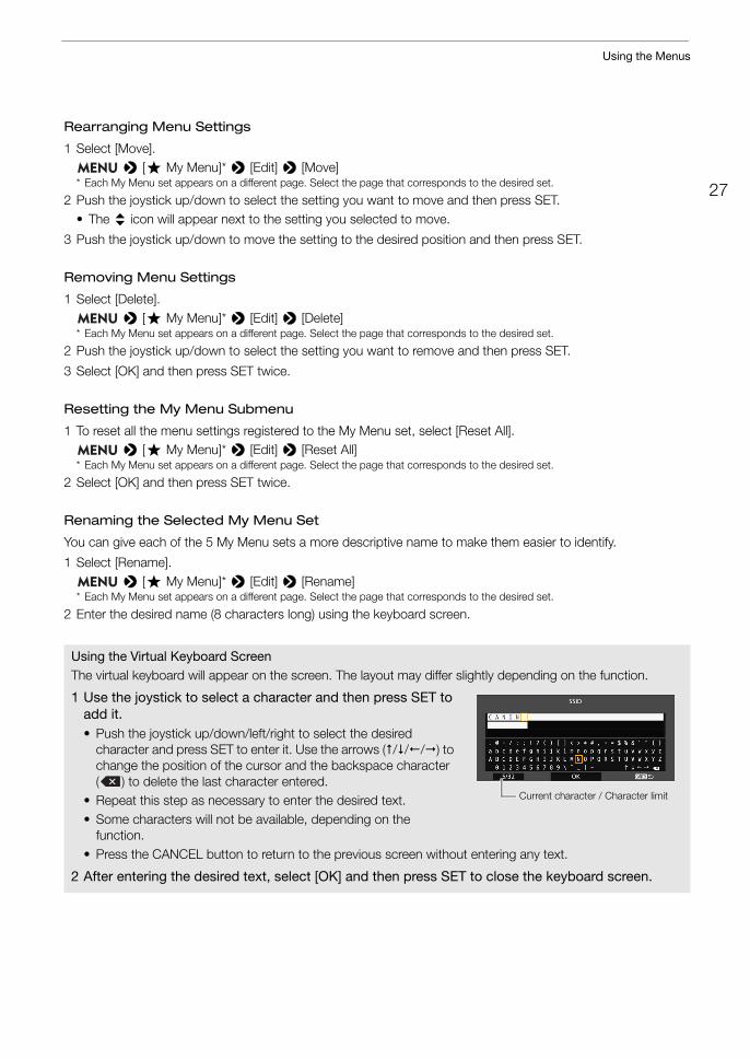
Using the Virtual Keyboard ScreenThe virtual keyboard will appear on the screen. The layout may differ slightly depending on the function.
1 Use the joystick to select a character and then press SET to add it.• Push the joystick up/down/left/right to select the desired
character and press SET to enter it. Use the arrows (///) to change the position of the cursor and the backspace character ( ) to delete the last character entered.
• Repeat this step as necessary to enter the desired text.• Some characters will not be available, depending on the
function.• Press the CANCEL button to return to the previous screen without entering any text.
2 After entering the desired text, select [OK] and then press SET to close the keyboard screen.
Current character / Character limit
Preparing the Camcorder
28
Preparing the CamcorderThis section outlines the basic preparations for the camcorder, such as attaching the microphone holder and lens hood and adjusting the LCD screen and viewfinder.
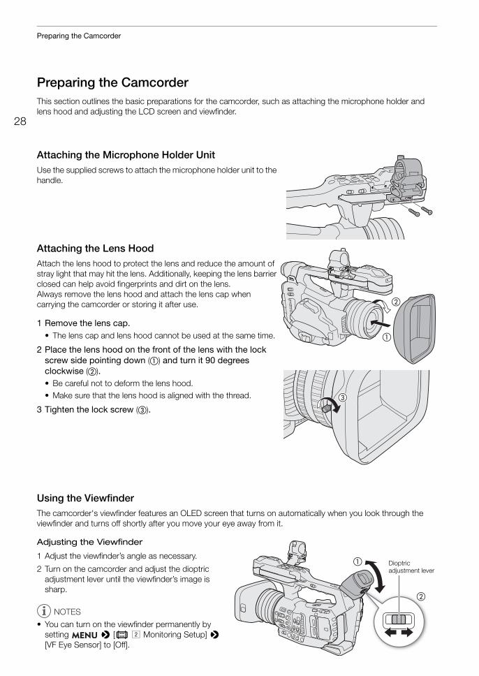
Attaching the Microphone Holder UnitUse the supplied screws to attach the microphone holder unit to the handle.
Attaching the Lens HoodAttach the lens hood to protect the lens and reduce the amount of stray light that may hit the lens. Additionally, keeping the lens barrier closed can help avoid fingerprints and dirt on the lens.Always remove the lens hood and attach the lens cap when carrying the camcorder or storing it after use.
1 Remove the lens cap.• The lens cap and lens hood cannot be used at the same time.
2 Place the lens hood on the front of the lens with the lock screw side pointing down (�) and turn it 90 degrees clockwise (�).• Be careful not to deform the lens hood.• Make sure that the lens hood is aligned with the thread.
3 Tighten the lock screw (�).
Using the ViewfinderThe camcorder's viewfinder features an OLED screen that turns on automatically when you look through the viewfinder and turns off shortly after you move your eye away from it.
Adjusting the Viewfinder
1 Adjust the viewfinder’s angle as necessary.
2 Turn on the camcorder and adjust the dioptric adjustment lever until the viewfinder’s image is sharp.
NOTES
• You can turn on the viewfinder permanently by setting > [¢ " Monitoring Setup] > [VF Eye Sensor] to [Off].
�
�
�
�
�
Dioptric adjustment lever
29
Preparing the Camcorder
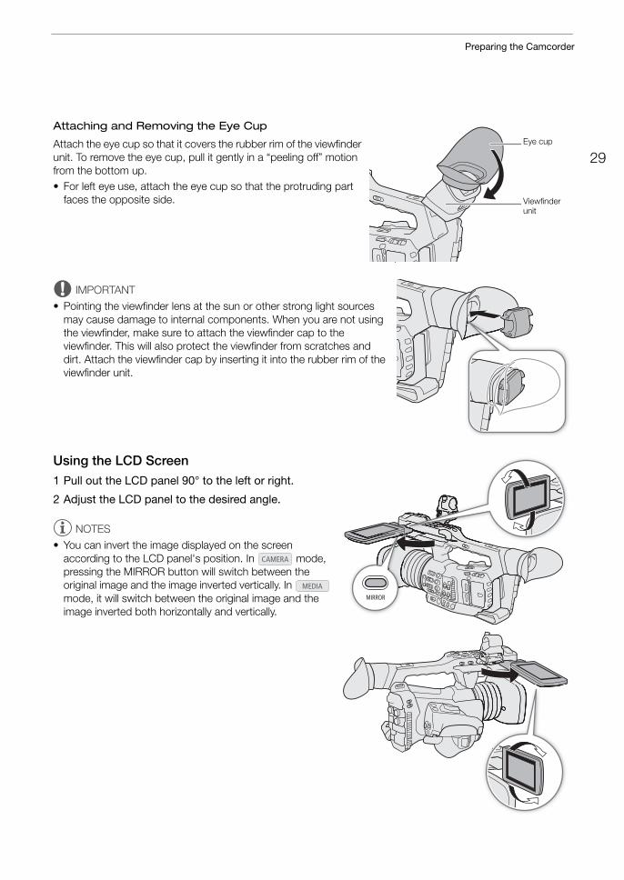
Attaching and Removing the Eye Cup
Attach the eye cup so that it covers the rubber rim of the viewfinder unit. To remove the eye cup, pull it gently in a “peeling off” motion from the bottom up.• For left eye use, attach the eye cup so that the protruding part
faces the opposite side.
IMPORTANT
• Pointing the viewfinder lens at the sun or other strong light sources may cause damage to internal components. When you are not using the viewfinder, make sure to attach the viewfinder cap to the viewfinder. This will also protect the viewfinder from scratches and dirt. Attach the viewfinder cap by inserting it into the rubber rim of the viewfinder unit.
Using the LCD Screen1 Pull out the LCD panel 90° to the left or right.
2 Adjust the LCD panel to the desired angle.
NOTES
• You can invert the image displayed on the screen according to the LCD panel's position. In mode, pressing the MIRROR button will switch between the original image and the image inverted vertically. In mode, it will switch between the original image and the image inverted both horizontally and vertically.
Eye cup
Viewfinder unit
Preparing the Camcorder
30
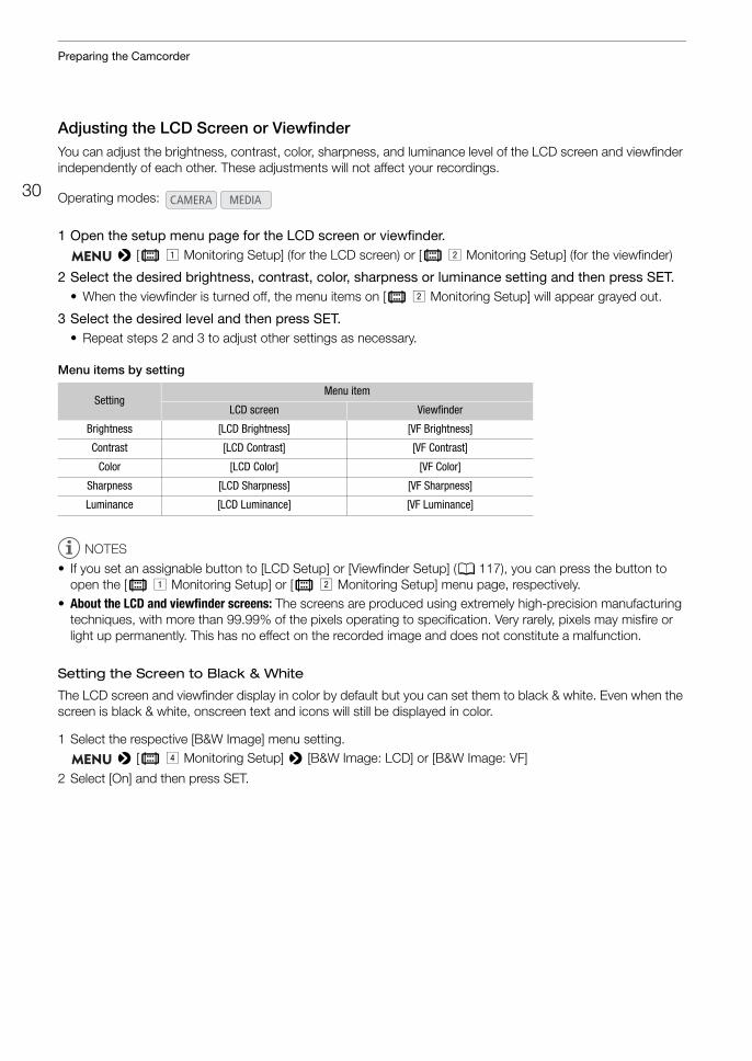
Adjusting the LCD Screen or ViewfinderYou can adjust the brightness, contrast, color, sharpness, and luminance level of the LCD screen and viewfinder independently of each other. These adjustments will not affect your recordings.
1 Open the setup menu page for the LCD screen or viewfinder. > [¢ ! Monitoring Setup] (for the LCD screen) or [¢ " Monitoring Setup] (for the viewfinder)
2 Select the desired brightness, contrast, color, sharpness or luminance setting and then press SET.• When the viewfinder is turned off, the menu items on [¢ " Monitoring Setup] will appear grayed out.
3 Select the desired level and then press SET.• Repeat steps 2 and 3 to adjust other settings as necessary.
Menu items by setting
NOTES
• If you set an assignable button to [LCD Setup] or [Viewfinder Setup] (A 117), you can press the button to open the [¢ ! Monitoring Setup] or [¢ " Monitoring Setup] menu page, respectively.
• About the LCD and viewfinder screens: The screens are produced using extremely high-precision manufacturing techniques, with more than 99.99% of the pixels operating to specification. Very rarely, pixels may misfire or light up permanently. This has no effect on the recorded image and does not constitute a malfunction.
Setting the Screen to Black & White
The LCD screen and viewfinder display in color by default but you can set them to black & white. Even when the screen is black & white, onscreen text and icons will still be displayed in color.
1 Select the respective [B&W Image] menu setting. > [¢ $ Monitoring Setup] > [B&W Image: LCD] or [B&W Image: VF]
2 Select [On] and then press SET.
Operating modes:
SettingMenu item
LCD screen Viewfinder
Brightness [LCD Brightness] [VF Brightness]
Contrast [LCD Contrast] [VF Contrast]
Color [LCD Color] [VF Color]
Sharpness [LCD Sharpness] [VF Sharpness]
Luminance [LCD Luminance] [VF Luminance]
31
Preparing the Camcorder
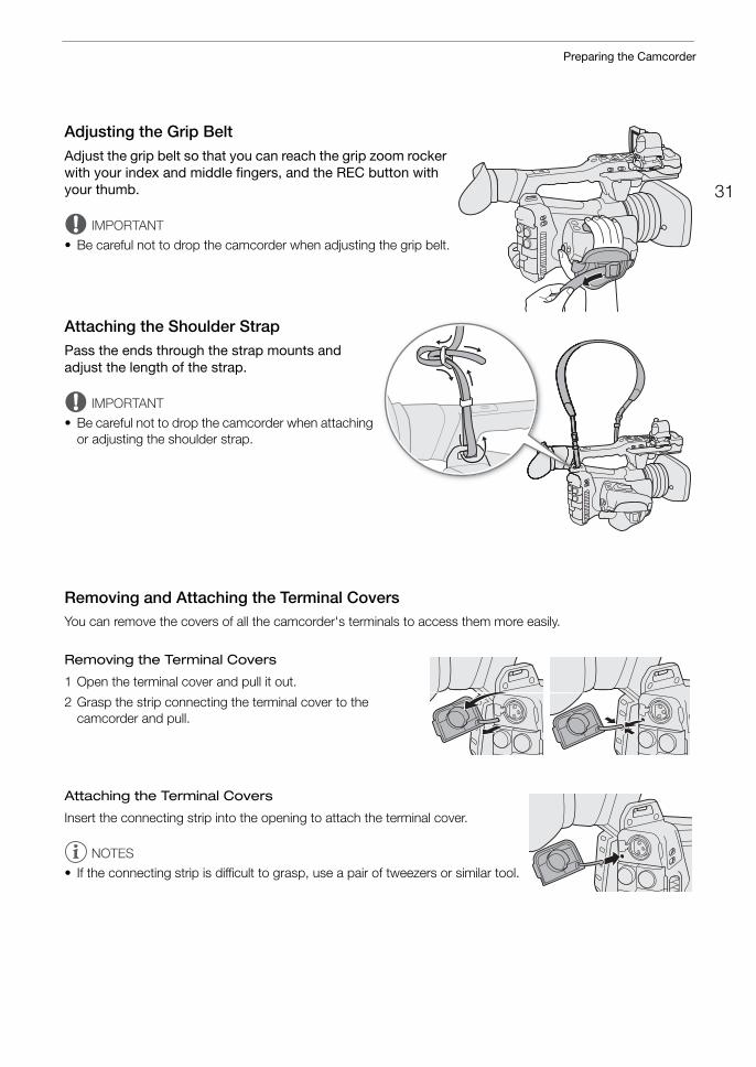
Adjusting the Grip BeltAdjust the grip belt so that you can reach the grip zoom rocker with your index and middle fingers, and the REC button with your thumb.
IMPORTANT
• Be careful not to drop the camcorder when adjusting the grip belt.
Attaching the Shoulder StrapPass the ends through the strap mounts and adjust the length of the strap.
IMPORTANT
• Be careful not to drop the camcorder when attaching or adjusting the shoulder strap.
Removing and Attaching the Terminal CoversYou can remove the covers of all the camcorder's terminals to access them more easily.
Removing the Terminal Covers
1 Open the terminal cover and pull it out.
2 Grasp the strip connecting the terminal cover to the camcorder and pull.
Attaching the Terminal Covers
Insert the connecting strip into the opening to attach the terminal cover.
NOTES
• If the connecting strip is difficult to grasp, use a pair of tweezers or similar tool.
Preparing the Camcorder
32
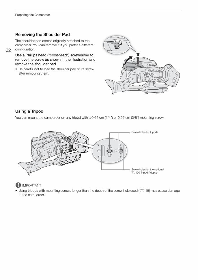
Removing the Shoulder PadThe shoulder pad comes originally attached to the camcorder. You can remove it if you prefer a different configuration.
Use a Phillips head ("crosshead") screwdriver to remove the screw as shown in the illustration and remove the shoulder pad.• Be careful not to lose the shoulder pad or its screw
after removing them.
Using a TripodYou can mount the camcorder on any tripod with a 0.64 cm (1/4") or 0.95 cm (3/8") mounting screw.
IMPORTANT
• Using tripods with mounting screws longer than the depth of the screw hole used (A 15) may cause damage to the camcorder.
Screw holes for tripods
Screw holes for the optional TA-100 Tripod Adapter
33
Using SD Cards
Using SD CardsThe camcorder records clips and photos on commercially available Secure Digital (SD) cards*. The camcorder has two SD card slots and you can use two SD cards to record on both simultaneously or to automatically switch to the other SD card when the SD card in use is full (A 36).Initialize SD cards (A 35) when you use them with this camcorder for the first time.* The SD card is used also to save custom picture files and menu settings files.
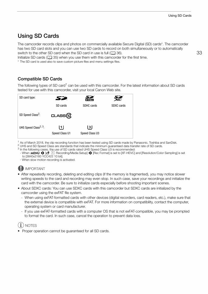
Compatible SD CardsThe following types of SD card1 can be used with this camcorder. For the latest information about SD cards tested for use with this camcorder, visit your local Canon Web site.
1 As of March 2018, the clip recording function has been tested using SD cards made by Panasonic, Toshiba and SanDisk.2 UHS and SD Speed Class are standards that indicate the minimum guaranteed data transfer rate of SD cards.3 In the following cases, the use of SD cards rated UHS Speed Class U3 is recommended:
- When > [3 ! Recording/Media Setup] > [Rec Format] is set to [XF-HEVC] and [Resolution/Color Sampling] is set to [3840x2160 YCC422 10 bit].
- When slow motion recording is activated.
IMPORTANT
• After repeatedly recording, deleting and editing clips (if the memory is fragmented), you may notice slower writing speeds to the card and recording may even stop. In such case, save your recordings and initialize the card with the camcorder. Be sure to initialize cards especially before shooting important scenes.
• About SDXC cards: You can use SDXC cards with this camcorder but SDXC cards are initialized by the camcorder using the exFAT file system.- When using exFAT-formatted cards with other devices (digital recorders, card readers, etc.), make sure that
the external device is compatible with exFAT. For more information on compatibility, contact the computer, operating system or card manufacturer.
- If you use exFAT-formatted cards with a computer OS that is not exFAT-compatible, you may be prompted to format the card. In such case, cancel the operation to prevent data loss.
NOTES
• Proper operation cannot be guaranteed for all SD cards.
SD card type: . / 0SD cards SDHC cards SDXC cards
SD Speed Class2:
UHS Speed Class2, 3:
Speed Class U1 Speed Class U3
Using SD Cards
34
Inserting and Removing an SD Card
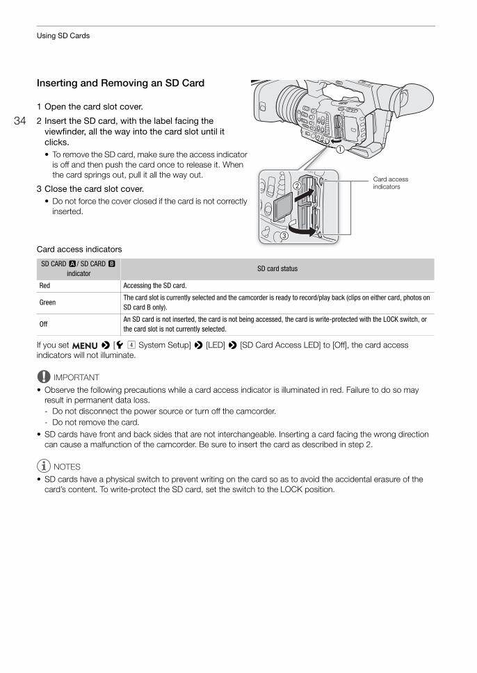
1 Open the card slot cover.
2 Insert the SD card, with the label facing the viewfinder, all the way into the card slot until it clicks.• To remove the SD card, make sure the access indicator
is off and then push the card once to release it. When the card springs out, pull it all the way out.
3 Close the card slot cover.• Do not force the cover closed if the card is not correctly
inserted.
Card access indicators
If you set > [B$ System Setup] > [LED] > [SD Card Access LED] to [Off], the card access indicators will not illuminate.
IMPORTANT
• Observe the following precautions while a card access indicator is illuminated in red. Failure to do so may result in permanent data loss.- Do not disconnect the power source or turn off the camcorder.- Do not remove the card.
• SD cards have front and back sides that are not interchangeable. Inserting a card facing the wrong direction can cause a malfunction of the camcorder. Be sure to insert the card as described in step 2.
NOTES
• SD cards have a physical switch to prevent writing on the card so as to avoid the accidental erasure of the card’s content. To write-protect the SD card, set the switch to the LOCK position.
SD CARD 2/ SD CARD 3
indicatorSD card status
Red Accessing the SD card.
GreenThe card slot is currently selected and the camcorder is ready to record/play back (clips on either card, photos on SD card B only).
OffAn SD card is not inserted, the card is not being accessed, the card is write-protected with the LOCK switch, or the card slot is not currently selected.
�
�
�
Card access indicators
35
Using SD Cards
Initializing an SD CardInitialize SD cards when you use them with this camcorder for the first time. You can also initialize a card to permanently delete all the recordings it contains.
1 Select [Initialize Media]. > [Æ ! Recording/Media Setup] > [Initialize Media]
2 Select [SD Card A] or [SD Card B] and then press SET.
3 Select [OK] and then press SET.
4 When the confirmation message appears, press SET.
IMPORTANT
• Initializing a card will permanently erase all data, including clips with an $ mark, photos and protected custom picture files. Lost data cannot be recovered. Make sure you save important recordings in advance.
• Depending on the SD card, the initialization may take up to a few minutes.
NOTES
• While recording on an SD card, you can initialize another SD card in the other SD card slot.• If you set an assignable button to [Initialize Media] (A 117), you can press the button to open the [Initialize
Media] submenu.
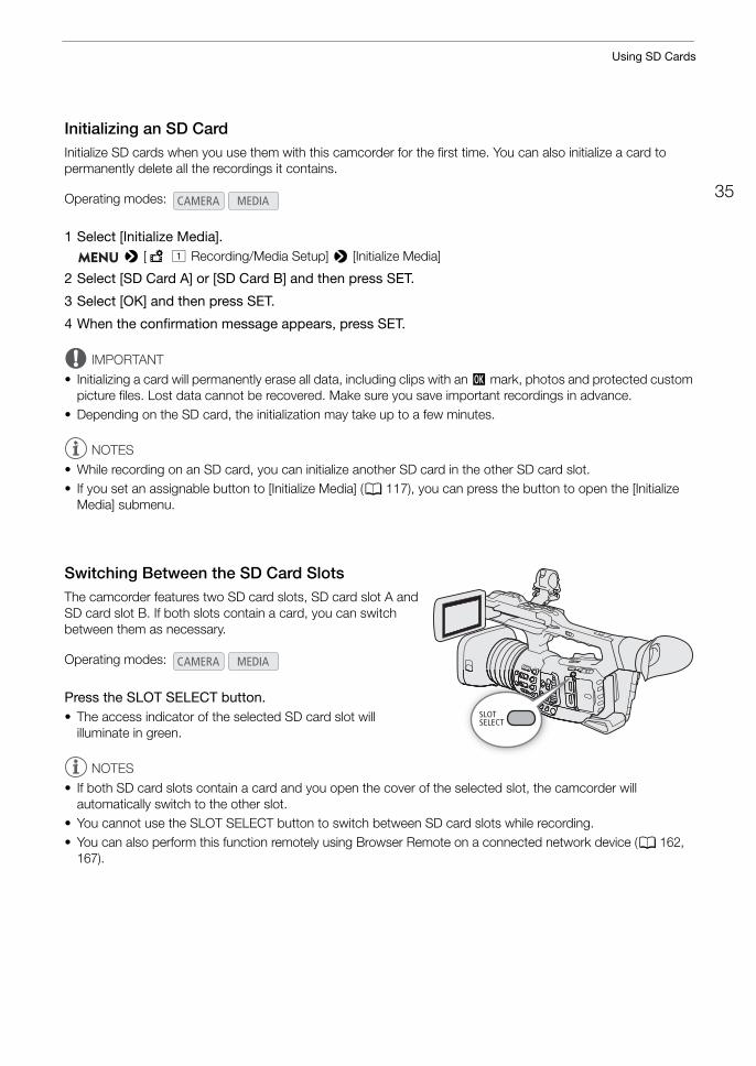
Switching Between the SD Card SlotsThe camcorder features two SD card slots, SD card slot A and SD card slot B. If both slots contain a card, you can switch between them as necessary.
Press the SLOT SELECT button.• The access indicator of the selected SD card slot will
illuminate in green.
NOTES
• If both SD card slots contain a card and you open the cover of the selected slot, the camcorder will automatically switch to the other slot.
• You cannot use the SLOT SELECT button to switch between SD card slots while recording.• You can also perform this function remotely using Browser Remote on a connected network device (A 162,
167).
Operating modes:
Operating modes:
Using SD Cards
36
Relay Recording and Double Slot RecordingThe camcorder features two convenient recording methods that can be used when both SD card slots contain a card: relay recording and double slot recording.
Relay recording: This function allows you to continue recording on the other card without interruption when the card you are using becomes full. Relay recording is available from SD card slot A to SD card slot B, and vice versa.
Double slot recording: This function records the same clip simultaneously to both cards, which is a convenient way to make a backup copy of your recording while you record.
To use relay recording
1 Select [Relay Recording]. > [Æ " Recording/Media Setup] > [Relay Recording]
2 Select [On] and then press SET.
To use double slot recording
1 Select [Double Slot Recording]. > [Æ " Recording/Media Setup] > [Double Slot Recording]
2 Select [On] and then press SET.• 4 appears at the top of the screen.
NOTES
• Relay recording is disabled (the camcorder will not switch to the other card) when slow motion recording is activated.
• If an SD card becomes full during double slot recording, recording on both cards will stop. On the other hand, if an error occurs with one of the SD cards, recording will continue on the other card.
• Double slot recording cannot be used together with relay recording or slow motion recording.
Checking the Remaining Recording Time on SD CardsIn mode, the display on the upper left of the screen shows the SD card icons and the remaining recording time* (in minutes) on each card (A 45).On the [Media] status screen (A 199), you can check the total space, used space, approximate remaining recording time* and speed class of each card. For SD card B only, the approximate remaining number of photos will be displayed as well.* Remaining recording times are approximate and calculated based on the current video configuration used.
Operating modes:
37
Using SD Cards
Recovering ClipsSome actions, such as suddenly turning off the camcorder or removing the SD card while data is being recorded, can cause data errors in the recorded clip.
1 Open the index screen with the clip you wish to recover (A 131).
2 Select the desired clip (a clip with a yellow icon instead of a thumbnail image) and then press SET to open the clip menu.
3 Select [Recover Clip] and then press SET.
4 Select [OK] and then press SET.• The camcorder will attempt to recover the corrupted data.
5 When the confirmation message appears, press SET.
NOTES
• This procedure may delete clips shorter than 1 second in length.• In some cases, it may not be possible to recover the data. This is more likely when the file system is corrupted
or the card is physically damaged.• Only clips recorded with this camcorder can be recovered. Photos cannot be recovered.
Operating modes:
Remote Operation of the Camcorder
38
Remote Operation of the CamcorderThe camcorder can be operated remotely in a number of different ways with varying degrees of control. First, you can use the supplied wireless controller as described below. You can also connect an optional RC-V100 Remote Controller for maximum control of your recordings at a professional level. Finally, you can connect a network device to the camcorder via Wi-Fi and use the Browser Remote application to control the camcorder (A 162).
Using the Supplied Wireless Controller
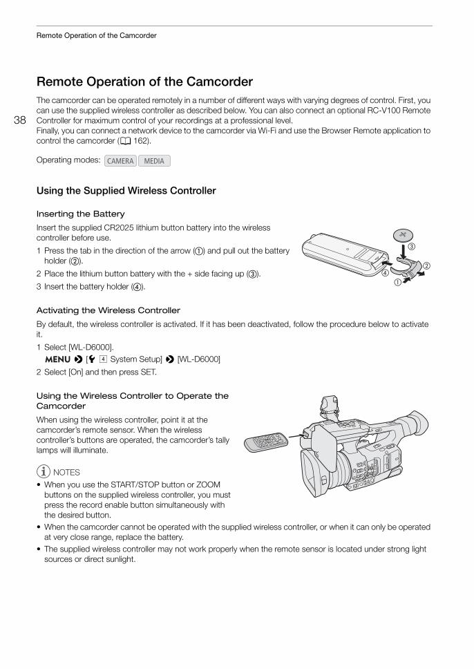
Inserting the Battery
Insert the supplied CR2025 lithium button battery into the wireless controller before use.
1 Press the tab in the direction of the arrow (�) and pull out the battery holder (�).
2 Place the lithium button battery with the + side facing up (�).
3 Insert the battery holder (�).
Activating the Wireless Controller
By default, the wireless controller is activated. If it has been deactivated, follow the procedure below to activate it.
1 Select [WL-D6000]. > [B $ System Setup] > [WL-D6000]
2 Select [On] and then press SET.
Using the Wireless Controller to Operate the Camcorder
When using the wireless controller, point it at the camcorder’s remote sensor. When the wireless controller’s buttons are operated, the camcorder’s tally lamps will illuminate.
NOTES
• When you use the START/STOP button or ZOOM buttons on the supplied wireless controller, you must press the record enable button simultaneously with the desired button.
• When the camcorder cannot be operated with the supplied wireless controller, or when it can only be operated at very close range, replace the battery.
• The supplied wireless controller may not work properly when the remote sensor is located under strong light sources or direct sunlight.
Operating modes:
�
��
�
39
Using the Optional RC-V100 Remote Controller
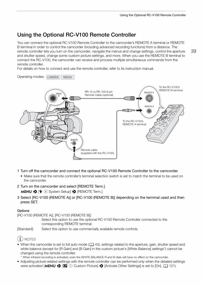
Using the Optional RC-V100 Remote ControllerYou can connect the optional RC-V100 Remote Controller to the camcorder’s REMOTE A terminal or REMOTE B terminal in order to control the camcorder (including advanced recording functions) from a distance. The remote controller lets you turn on the camcorder, navigate the menus and change settings, control the aperture and shutter speed, change some custom picture settings, and more. When you use the REMOTE B terminal to connect the RC-V100, the camcorder can receive and process multiple simultaneous commands from the remote controller.For details on how to connect and use the remote controller, refer to its instruction manual.
1 Turn off the camcorder and connect the optional RC-V100 Remote Controller to the camcorder.• Make sure that the remote controller’s terminal selection switch is set to match the terminal to be used on
the camcorder.
2 Turn on the camcorder and select [REMOTE Term.]. > [B $ System Setup] > [REMOTE Term.]
3 Select [RC-V100 (REMOTE A)] or [RC-V100 (REMOTE B)] depending on the terminal used and then press SET.
Options[RC-V100 (REMOTE A)], [RC-V100 (REMOTE B)]:
Select this option to use the optional RC-V100 Remote Controller connected to the corresponding REMOTE terminal.
[Standard]: Select this option to use commercially available remote controls.
NOTES
• When the camcorder is set to full auto mode (A 43), settings related to the aperture, gain, shutter speed and white balance (except for [R Gain] and [B Gain] in the custom picture's [White Balance] settings*) cannot be changed using the remote controller.* When infrared recording is activated, even the WHITE BALANCE R and B dials will have no effect on the camcorder.
• Adjusting picture-related settings with the remote controller can be performed only when the detailed settings were activated ( > [/ ! Custom Picture] > [Activate Other Settings] is set to [On], A 121).
Operating modes:
RR-10 or RR-100 8-pin Remote Cable (optional)
To the RC-V100’s REMOTE A terminal
To the RC-V100’s REMOTE B terminal
Remote cable (supplied with the RC-V100)

Using the Optional RC-V100 Remote Controller
40
• The REMOTE A and REMOTE B terminals cannot be used at the same time.• If you plan on connecting the remote controller to the camcorder using the optional RR-10 or RR-100 8-pin
Remote Cable, check the serial number of the RC-V100. If the serial number starts with “01 xxxx” (where xxxx represents other digits), you will need to update the remote controller’s firmware. Canon will perform this feature upgrade, and requires that the remote controller be sent to an accredited Canon Service Center. Shipping and handling charges may apply. Contact a Canon Customer Support Center for details.
341
Recording
Recording VideoThis section explains the basics of recording clips*. For details on recording audio, refer to Recording Audio (A 95). Before making important recordings for the first time, make test recordings using the video configuration(s) you plan to use to check that the camcorder operates correctly. Should the camcorder fail to operate correctly, refer to Troubleshooting (A 204).* “Clip” refers to a single movie unit recorded with a single recording operation. You can also include metadata with the clip.
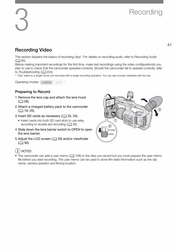
Preparing to Record1 Remove the lens cap and attach the lens hood
(A 28).
2 Attach a charged battery pack to the camcorder (A 19, 20).
3 Insert SD cards as necessary (A 33, 34).• Insert cards into both SD card slots to use relay
recording or double slot recording (A 36).
4 Slide down the lens barrier switch to OPEN to open the lens barrier.
5 Adjust the LCD screen (A 29) and/or viewfinder (A 30).
NOTESNOTES
• The camcorder can add a user memo (A 108) to the clips you record but you must prepare the user memo file before you start recording. The user memo can be used to store film slate information such as the clip name, camera operator and filming location.
Operating modes:
�
�
� �
�
�

Recording Video
42
Recording
1 Press and hold the button on the Q switch and set the switch to ON.• The camcorder turns on in mode and enters record standby mode.• The access indicators of card slots with a card inserted will illuminate momentarily in red. Then, the access
indicator of the card selected for recording will change to green.
2 Press the REC button to begin recording.• Recording starts. The tally lamps illuminate and the recording indicator [ÜREC] appears at the top of the
screen.• You can use the REC button on the grip or the one on the handle.• You can also perform this function remotely using Browser Remote on a connected network device (A 162,
167).• When you use the supplied wireless controller, press the START/STOP button and the record enable button
simultaneously.
3 Press the REC button to stop recording.• The clip is recorded and the camcorder enters record standby mode. The tally lamps will also go out.
IMPORTANT• Observe the following precautions while an access indicator is illuminated in red. Failure to do so may result in
permanent data loss.- Do not open the card slot cover of the card being accessed and do not remove the card.- Do not disconnect the power source or turn off the camcorder.
• Be sure to save your recordings regularly (A 151), especially after making important recordings. Canon shall not be liable for any loss or corruption of data.
NOTESNOTES
• The REC button on the handle has a lock lever to prevent accidental operation. Set the lock lever to C to prevent a recording from starting/stopping inadvertently or if you do not plan to use this REC button. Return the lever to its previous position to enable use of the REC button again.
• You can use the review function (A 112) to play back part or all of the last clip recorded without having to switch to mode.
• If you set an assignable button to [Add $ Mark] or [Add % Mark] (A 117), you can press the button to add an $ mark or % mark to the last clip recorded.
Card access indicators
Tally lamps
43
Recording Video
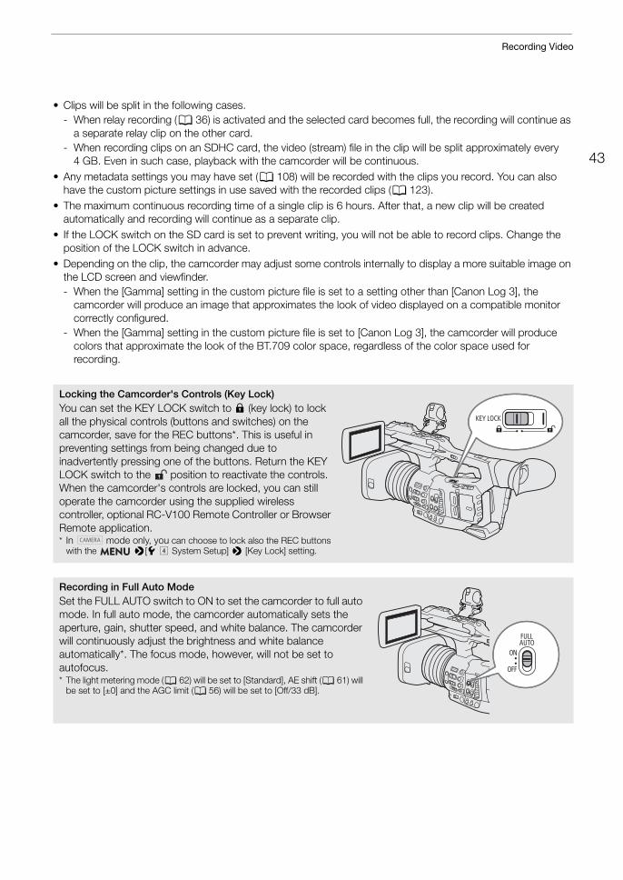
• Clips will be split in the following cases.- When relay recording (A 36) is activated and the selected card becomes full, the recording will continue as
a separate relay clip on the other card.- When recording clips on an SDHC card, the video (stream) file in the clip will be split approximately every
4 GB. Even in such case, playback with the camcorder will be continuous.• Any metadata settings you may have set (A 108) will be recorded with the clips you record. You can also
have the custom picture settings in use saved with the recorded clips (A 123).• The maximum continuous recording time of a single clip is 6 hours. After that, a new clip will be created
automatically and recording will continue as a separate clip.• If the LOCK switch on the SD card is set to prevent writing, you will not be able to record clips. Change the
position of the LOCK switch in advance.• Depending on the clip, the camcorder may adjust some controls internally to display a more suitable image on
the LCD screen and viewfinder.- When the [Gamma] setting in the custom picture file is set to a setting other than [Canon Log 3], the
camcorder will produce an image that approximates the look of video displayed on a compatible monitor correctly configured.
- When the [Gamma] setting in the custom picture file is set to [Canon Log 3], the camcorder will produce colors that approximate the look of the BT.709 color space, regardless of the color space used for recording.
Locking the Camcorder's Controls (Key Lock)You can set the KEY LOCK switch to C (key lock) to lock all the physical controls (buttons and switches) on the camcorder, save for the REC buttons*. This is useful in preventing settings from being changed due to inadvertently pressing one of the buttons. Return the KEY LOCK switch to the position to reactivate the controls. When the camcorder's controls are locked, you can still operate the camcorder using the supplied wireless controller, optional RC-V100 Remote Controller or Browser Remote application.* In mode only, you can choose to lock also the REC buttons
with the >[B$ System Setup] > [Key Lock] setting.
Recording in Full Auto ModeSet the FULL AUTO switch to ON to set the camcorder to full auto mode. In full auto mode, the camcorder automatically sets the aperture, gain, shutter speed, and white balance. The camcorder will continuously adjust the brightness and white balance automatically*. The focus mode, however, will not be set to autofocus.* The light metering mode (A 62) will be set to [Standard], AE shift (A 61) will
be set to [±0] and the AGC limit (A 56) will be set to [Off/33 dB].
Recording Video
44
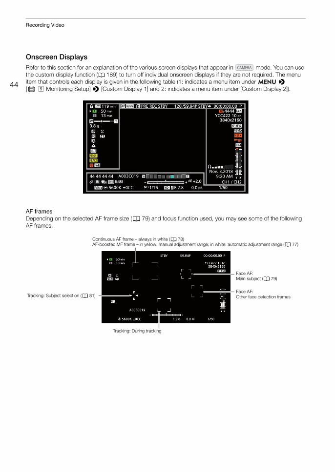
Onscreen DisplaysRefer to this section for an explanation of the various screen displays that appear in mode. You can use the custom display function (A 189) to turn off individual onscreen displays if they are not required. The menu item that controls each display is given in the following table (1: indicates a menu item under > [¢ % Monitoring Setup] > [Custom Display 1] and 2: indicates a menu item under [Custom Display 2]).
AF framesDepending on the selected AF frame size (A 79) and focus function used, you may see some of the following AF frames.
Continuous AF frame – always in white (A 78)AF-boosted MF frame – in yellow: manual adjustment range; in white: automatic adjustment range (A 77)
Face AF: Main subject (A 79)
Face AF: Other face detection framesTracking: Subject selection (A 81)
Tracking: During tracking
45
Recording Video
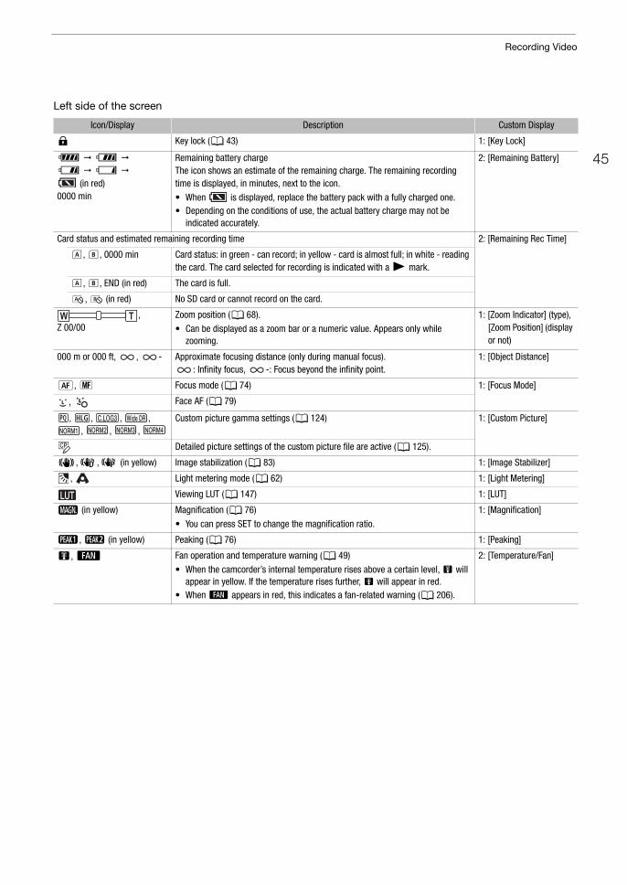
Left side of the screen
Icon/Display Description Custom Display
C Key lock (A 43) 1: [Key Lock]
è é ê ë
(in red)0000 min
Remaining battery chargeThe icon shows an estimate of the remaining charge. The remaining recording time is displayed, in minutes, next to the icon.
• When is displayed, replace the battery pack with a fully charged one.• Depending on the conditions of use, the actual battery charge may not be
indicated accurately.
2: [Remaining Battery]
Card status and estimated remaining recording time 2: [Remaining Rec Time]
6, 7, 0000 min Card status: in green - can record; in yellow - card is almost full; in white - reading the card. The card selected for recording is indicated with a Ð mark.
6, 7, END (in red) The card is full.
, (in red) No SD card or cannot record on the card.
,Z 00/00
Zoom position (A 68).
• Can be displayed as a zoom bar or a numeric value. Appears only while zooming.
1: [Zoom Indicator] (type), [Zoom Position] (display or not)
000 m or 000 ft, , - Approximate focusing distance (only during manual focus).: Infinity focus, -: Focus beyond the infinity point.
1: [Object Distance]
@, A Focus mode (A 74) 1: [Focus Mode]
, Face AF (A 79)
, , , , , , ,
Custom picture gamma settings (A 124) 1: [Custom Picture]
Detailed picture settings of the custom picture file are active (A 125).
¯,°,± (in yellow) Image stabilization (A 83) 1: [Image Stabilizer]
, Light metering mode (A 62) 1: [Light Metering]
Viewing LUT (A 147) 1: [LUT]
^ (in yellow) Magnification (A 76)
• You can press SET to change the magnification ratio.
1: [Magnification]
J, K (in yellow) Peaking (A 76) 1: [Peaking]
b, ` Fan operation and temperature warning (A 49)
• When the camcorder’s internal temperature rises above a certain level, b will appear in yellow. If the temperature rises further, b will appear in red.
• When ` appears in red, this indicates a fan-related warning (A 206).
2: [Temperature/Fan]
Recording Video
46
Top of the screen
Right side of the screen
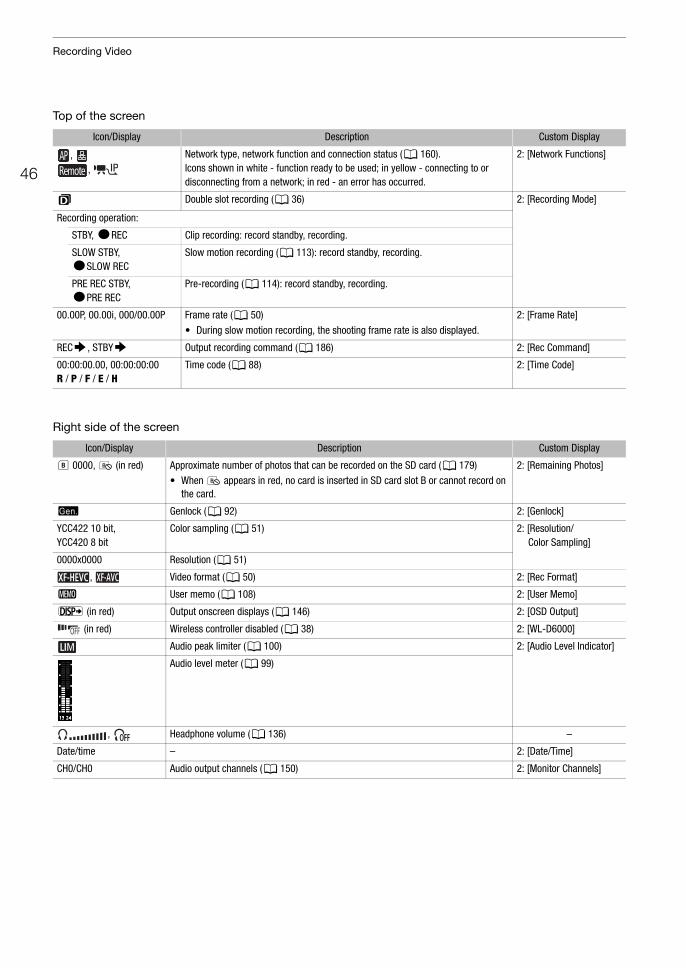
Icon/Display Description Custom Display
, ,
Network type, network function and connection status (A 160).Icons shown in white - function ready to be used; in yellow - connecting to or disconnecting from a network; in red - an error has occurred.
2: [Network Functions]
4 Double slot recording (A 36) 2: [Recording Mode]
Recording operation:
STBY, ÜREC Clip recording: record standby, recording.
SLOW STBY, ÜSLOW REC
Slow motion recording (A 113): record standby, recording.
PRE REC STBY, ÜPRE REC
Pre-recording (A 114): record standby, recording.
00.00P, 00.00i, 000/00.00P Frame rate (A 50)
• During slow motion recording, the shooting frame rate is also displayed.
2: [Frame Rate]
REC`, STBY` Output recording command (A 186) 2: [Rec Command]
00:00:00.00, 00:00:00:00 R / P / F / E / H
Time code (A 88) 2: [Time Code]
Icon/Display Description Custom Display
7 0000, (in red) Approximate number of photos that can be recorded on the SD card (A 179)
• When appears in red, no card is inserted in SD card slot B or cannot record on the card.
2: [Remaining Photos]
U Genlock (A 92) 2: [Genlock]
YCC422 10 bit, YCC420 8 bit
Color sampling (A 51) 2: [Resolution/Color Sampling]
0000x0000 Resolution (A 51)
, Video format (A 50) 2: [Rec Format]
Q User memo (A 108) 2: [User Memo]
T (in red) Output onscreen displays (A 146) 2: [OSD Output]
(in red) Wireless controller disabled (A 38) 2: [WL-D6000]
Audio peak limiter (A 100) 2: [Audio Level Indicator]
Audio level meter (A 99)
, Headphone volume (A 136) –
Date/time – 2: [Date/Time]
CH0/CH0 Audio output channels (A 150) 2: [Monitor Channels]
47
Recording Video
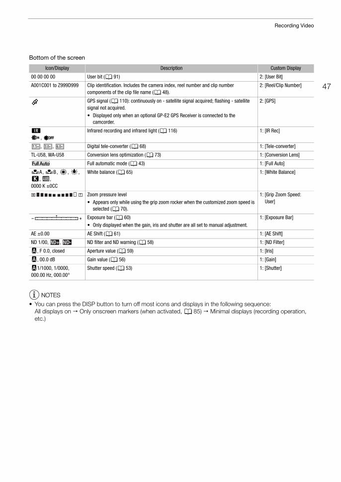
Bottom of the screen
NOTESNOTES
• You can press the DISP button to turn off most icons and displays in the following sequence: All displays on Only onscreen markers (when activated, A 85) Minimal displays (recording operation, etc.)
Icon/Display Description Custom Display
00 00 00 00 User bit (A 91) 2: [User Bit]
A001C001 to Z999D999 Clip identification. Includes the camera index, reel number and clip number components of the clip file name (A 48).
2: [Reel/Clip Number]
GPS signal (A 110): continuously on - satellite signal acquired; flashing - satellite signal not acquired.
• Displayed only when an optional GP-E2 GPS Receiver is connected to the camcorder.
2: [GPS]
;
, =Infrared recording and infrared light (A 116) 1: [IR Rec]
, , Digital tele-converter (A 68) 1: [Tele-converter]
TL-U58, WA-U58 Conversion lens optimization (A 73) 1: [Conversion Lens]
@ Full automatic mode (A 43) 1: [Full Auto]
ÅA , ÅB , ¼, É, È, , 0000 K ±0CC
White balance (A 65) 1: [White Balance]
Zoom pressure level
• Appears only while using the grip zoom rocker when the customized zoom speed is selected (A 70).
1: [Grip Zoom Speed: User]
Exposure bar (A 60)
• Only displayed when the gain, iris and shutter are all set to manual adjustment.
1: [Exposure Bar]
AE ±0.00 AE Shift (A 61) 1: [AE Shift]
ND 1/00, , ND filter and ND warning (A 58) 1: [ND Filter]
E, F 0.0, closed Aperture value (A 59) 1: [Iris]
E, 00.0 dB Gain value (A 56) 1: [Gain]
E1/1000, 1/0000, 000.00 Hz, 000.00°
Shutter speed (A 53) 1: [Shutter]
Recording Video
48
Setting the Clip File NameThe camcorder allows you to change several settings that determine the file name of the recorded clips. Personalize the clip file name according to your preferences or organizational conventions to create files that are easier to identify and organize.
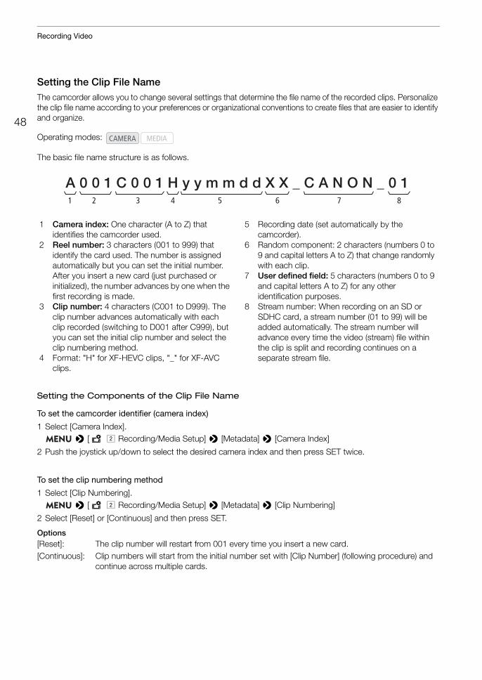
The basic file name structure is as follows.
Setting the Components of the Clip File Name
To set the camcorder identifier (camera index)
1 Select [Camera Index]. > [Æ " Recording/Media Setup] > [Metadata] > [Camera Index]
2 Push the joystick up/down to select the desired camera index and then press SET twice.
To set the clip numbering method
1 Select [Clip Numbering]. > [Æ " Recording/Media Setup] > [Metadata] > [Clip Numbering]
2 Select [Reset] or [Continuous] and then press SET.
Options[Reset]: The clip number will restart from 001 every time you insert a new card.[Continuous]: Clip numbers will start from the initial number set with [Clip Number] (following procedure) and
continue across multiple cards.
Operating modes:
A 0 0 1 C 0 0 1 H y y m m d d X X _ C A N O N _ 0 11 42 3 5 76 8
1 Camera index: One character (A to Z) that identifies the camcorder used.
2 Reel number: 3 characters (001 to 999) that identify the card used. The number is assigned automatically but you can set the initial number. After you insert a new card (just purchased or initialized), the number advances by one when the first recording is made.
3 Clip number: 4 characters (C001 to D999). The clip number advances automatically with each clip recorded (switching to D001 after C999), but you can set the initial clip number and select the clip numbering method.
4 Format: "H" for XF-HEVC clips, "_" for XF-AVC clips.
5 Recording date (set automatically by the camcorder).
6 Random component: 2 characters (numbers 0 to 9 and capital letters A to Z) that change randomly with each clip.
7 User defined field: 5 characters (numbers 0 to 9 and capital letters A to Z) for any other identification purposes.
8 Stream number: When recording on an SD or SDHC card, a stream number (01 to 99) will be added automatically. The stream number will advance every time the video (stream) file within the clip is split and recording continues on a separate stream file.
49
Recording Video
To set the reel number or initial clip numberThe initial clip number can only be set when [Clip Numbering] is set to [Continuous].
1 Select [Reel Number] or [Clip Number]. > [Æ " Recording/Media Setup] > [Metadata] > [Reel Number] or [Clip Number]
2 Select [Change] and then press SET.• To reset the reel/clip number to [001], select [Reset] instead.
3 Push the joystick up/down to select the first digit of the reel/clip number and then press SET to move to the next.• Change the rest of the digits in the same way.
4 Select [Set] and then press SET.
To set the user-defined field
1 Select [User Defined]. > [Æ " Recording/Media Setup] > [Metadata] > [User Defined]
2 Select [Change] and then press SET.• To reset the user-defined field to [CANON], select [Reset] instead.
3 Push the joystick up/down to select the first character and then press SET to move to the next.• Change the rest of the characters in the same way.
4 Select [Set] and then press SET.
Using the FanThe camcorder uses an internal cooling fan to reduce the camcorder’s internal heat. You can change the fan’s operation mode.
1 Select [Fan]. > [B% System Setup] > [Fan]
2 Select the desired option and then press SET.
Options[Automatic]: The fan runs while the camcorder is not recording and is automatically turned off while the
camcorder is recording. However, if the internal temperature of the camcorder is too high (b appears in red), the fan will be activated automatically (in that case, ` will appear next to the b icon). When the camcorder’s temperature has decreased sufficiently, the fan will be turned off. Use this setting when you do not want the camcorder to pick up the fan’s operating sound.
[Always On]: The fan runs at all times.
IMPORTANT
• While the fan is running, the exhaust vent will emit warm air.• Be careful not to obstruct in any way the fan’s air vents (A 11, 13, 16).
NOTESNOTES
• Depending on the ambient temperature and other shooting conditions, the fan may not turn off even if you set its operating mode to [Automatic].
• In mode the fan runs at all times.
Operating modes:
Video Configuration: Video Format, System Frequency, Frame Rate, Resolution and Bit Rate
50
Video Configuration: Video Format, System Frequency, Frame Rate, Resolution and Bit RateWith the following procedures you can set the video configuration used when recording clips. Select the video format, system frequency, frame rate, resolution (frame size) and color sampling settings that best match your creative needs. Available options for some settings may change depending on previous selections for other settings. See the tables following the procedures for a summary.
Selecting the Main Recording Format
1 Select [Rec Format]. > [Æ ! Recording/Media Setup] > [Rec Format]
2 Select [XF-HEVC] or [XF-AVC] and then press SET.• The icon of the selected format will appear at the top right of the screen.• Depending on the selected setting, the message [The following settings were changed] will appear. Review
the changes made automatically and press SET.
Selecting the System Frequency
1 Select [System Frequency]. > [Æ ! Recording/Media Setup] > [System Frequency]
2 Select the desired option and then press SET.• The camcorder will reset and restart in the selected mode.
Selecting the Frame Rate
1 Select [Frame Rate]. > [Æ ! Recording/Media Setup] > [Frame Rate]
2 Select the desired option and then press SET.• The selected frame rate will appear at the top of the screen.• Depending on the selected setting, the message [The following settings were changed] will appear. Review
the changes made automatically and press SET.
Operating modes:
Operating modes:
Operating modes:
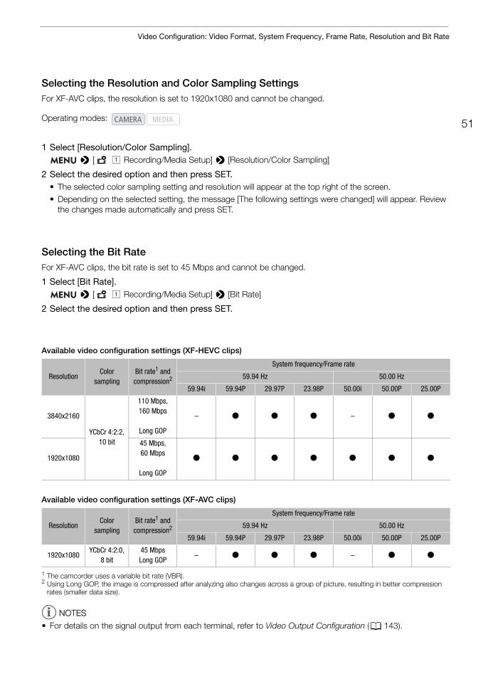
51
Video Configuration: Video Format, System Frequency, Frame Rate, Resolution and Bit Rate
Selecting the Resolution and Color Sampling SettingsFor XF-AVC clips, the resolution is set to 1920x1080 and cannot be changed.
1 Select [Resolution/Color Sampling]. > [Æ ! Recording/Media Setup] > [Resolution/Color Sampling]
2 Select the desired option and then press SET.• The selected color sampling setting and resolution will appear at the top right of the screen.• Depending on the selected setting, the message [The following settings were changed] will appear. Review
the changes made automatically and press SET.
Selecting the Bit RateFor XF-AVC clips, the bit rate is set to 45 Mbps and cannot be changed.
1 Select [Bit Rate]. > [Æ ! Recording/Media Setup] > [Bit Rate]
2 Select the desired option and then press SET.
Available video configuration settings (XF-HEVC clips)
Available video configuration settings (XF-AVC clips)
1 The camcorder uses a variable bit rate (VBR).2 Using Long GOP, the image is compressed after analyzing also changes across a group of picture, resulting in better compression
rates (smaller data size).
NOTESNOTES
• For details on the signal output from each terminal, refer to Video Output Configuration (A 143).
Operating modes:
ResolutionColor
samplingBit rate1 and compression2
System frequency/Frame rate
59.94 Hz 50.00 Hz
59.94i 59.94P 29.97P 23.98P 50.00i 50.00P 25.00P
3840x2160
YCbCr 4:2:2, 10 bit
110 Mbps,160 Mbps
Long GOP
– Ü Ü Ü – Ü Ü
1920x1080
45 Mbps, 60 Mbps
Long GOP
Ü Ü Ü Ü Ü Ü Ü
ResolutionColor
samplingBit rate1 and compression2
System frequency/Frame rate
59.94 Hz 50.00 Hz
59.94i 59.94P 29.97P 23.98P 50.00i 50.00P 25.00P
1920x1080YCbCr 4:2:0,
8 bit45 MbpsLong GOP
– Ü Ü Ü – Ü Ü
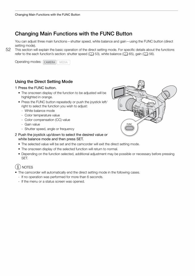
Changing Main Functions with the FUNC Button
52
Changing Main Functions with the FUNC ButtonYou can adjust three main functions—shutter speed, white balance and gain—using the FUNC button (direct setting mode).This section will explain the basic operation of the direct setting mode. For specific details about the functions refer to the each function’s section: shutter speed (A 53), white balance (A 65), gain (A 56).
Using the Direct Setting Mode1 Press the FUNC button.
• The onscreen display of the function to be adjusted will be highlighted in orange.
• Press the FUNC button repeatedly or push the joystick left/right to select the function you wish to adjust:- White balance mode- Color temperature value- Color compensation (CC) value- Gain value- Shutter speed, angle or frequency
2 Push the joystick up/down to select the desired value or white balance mode and then press SET.• The selected value will be set and the camcorder will exit the direct setting mode.• The onscreen display of the selected function will return to normal. • Depending on the function selected, additional adjustment may be possible or necessary before pressing
SET.
NOTESNOTES
• The camcorder will automatically end the direct setting mode in the following cases.- If no operation was performed for more than 6 seconds.- If the menu or a status screen was opened.
Operating modes:
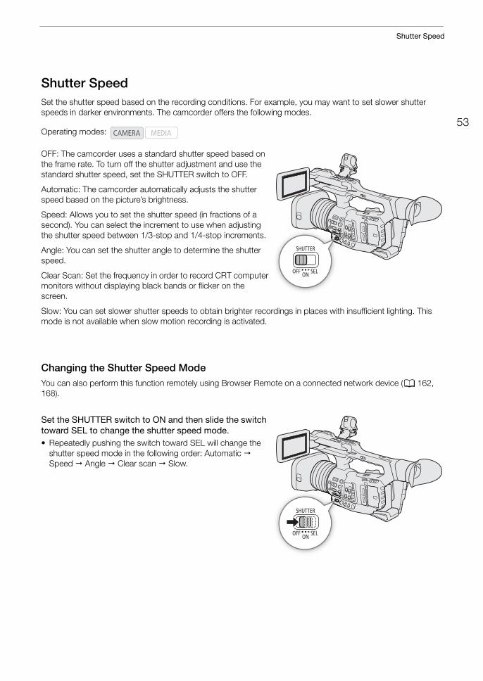
53
Shutter Speed
Shutter SpeedSet the shutter speed based on the recording conditions. For example, you may want to set slower shutter speeds in darker environments. The camcorder offers the following modes.
OFF: The camcorder uses a standard shutter speed based on the frame rate. To turn off the shutter adjustment and use the standard shutter speed, set the SHUTTER switch to OFF.
Automatic: The camcorder automatically adjusts the shutter speed based on the picture’s brightness.
Speed: Allows you to set the shutter speed (in fractions of a second). You can select the increment to use when adjusting the shutter speed between 1/3-stop and 1/4-stop increments.
Angle: You can set the shutter angle to determine the shutter speed.
Clear Scan: Set the frequency in order to record CRT computer monitors without displaying black bands or flicker on the screen.
Slow: You can set slower shutter speeds to obtain brighter recordings in places with insufficient lighting. This mode is not available when slow motion recording is activated.
Changing the Shutter Speed ModeYou can also perform this function remotely using Browser Remote on a connected network device (A 162, 168).
Set the SHUTTER switch to ON and then slide the switch toward SEL to change the shutter speed mode.• Repeatedly pushing the switch toward SEL will change the
shutter speed mode in the following order: Automatic Speed Angle Clear scan Slow.
Operating modes:
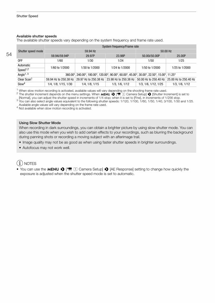
Shutter Speed
54
Available shutter speedsThe available shutter speeds vary depending on the system frequency and frame rate used.
1 When slow motion recording is activated, available values will vary depending on the shooting frame rate used.2 The shutter increment depends on the menu settings. When > [v ! Camera Setup] > [Shutter Increment] is set to
[Normal], you can adjust the shutter speed in increments of 1/4 stop; when it is set to [Fine], in increments of 1/256 stop.3 You can also select angle values equivalent to the following shutter speeds: 1/120, 1/100, 1/60, 1/50, 1/40, 3/100, 1/30 and 1/25.
Available angle values will vary depending on the frame rate used.4 Not available when slow motion recording is activated.
NOTESNOTES
• You can use the > [v ! Camera Setup] > [AE Response] setting to change how quickly the exposure is adjusted when the shutter speed mode is set to automatic.
Shutter speed modeSystem frequency/Frame rate
59.94 Hz 50.00 Hz59.94i/59.94P 29.97P 23.98P 50.00i/50.00P 25.00P
OFF 1/60 1/30 1/24 1/50 1/25Automatic
1/60 to 1/2000 1/30 to 1/2000 1/24 to 1/2000 1/50 to 1/2000 1/25 to 1/2000Speed1,2
Angle1, 3 360.00°, 240.00°, 180.00°, 120.00°, 90.00°, 60.00°, 45.00°, 30.00°, 22.50°, 15.00°, 11.25°Clear Scan1 59.94 Hz to 250.38 Hz 29.97 Hz to 250.38 Hz 23.98 Hz to 250.38 Hz 50.00 Hz to 250.40 Hz 25.00 Hz to 250.40 HzSlow4 1/4, 1/8, 1/15, 1/30 1/4, 1/8, 1/15 1/3, 1/6, 1/12 1/3, 1/6, 1/12, 1/25 1/3, 1/6, 1/12
Using Slow Shutter ModeWhen recording in dark surroundings, you can obtain a brighter picture by using slow shutter mode. You can also use this mode when you wish to add certain effects to your recordings, such as blurring the background during panning shots or recording a moving subject with an afterimage trail.• Image quality may not be as good as when using faster shutter speeds in brighter surroundings.• Autofocus may not work well.
55
Shutter Speed
Changing the Shutter Speed ValueWhen the shutter speed mode is set to a mode other than OFF or automatic, you can set the shutter speed manually as a speed value, angle or clear scan frequency.You can also perform this function remotely using Browser Remote on a connected network device (A 162, 168).
1 To change the shutter speed increment for Speed mode, select [Shutter Increment]. > [v ! Camera Setup] > [Shutter Increment]
2 Select [Normal] or [Fine] and then press SET.• If you select [Fine], you can adjust the shutter speed in increments of 1/256 stop.
3 After closing the menu, select a shutter speed mode other than OFF or Automatic (A 53).• The camera will enter direct setting mode with the shutter speed value highlighted in orange.• Alternatively, you can press the FUNC button repeatedly to highlight the current shutter speed value without
changing the current shutter speed mode.
4 Adjust the shutter speed, angle value or clear scan frequency using the direct setting mode.• For details refer to Using the Direct Setting Mode (A 52).• The selected shutter speed will appear at the bottom of the screen.
NOTESNOTES
• Closing down the aperture when recording under bright conditions may cause the picture to appear soft or out of focus. To avoid the loss of sharpness due to diffraction, use a denser ND filter (A 58), a faster shutter speed, or open up the aperture (A 59).
• When the gain and aperture are set to manual and the shutter speed mode is set to a mode other than OFF or automatic, the exposure bar will appear at the bottom of the screen (A 60).
• When the camcorder is set to full auto mode (A 43) or you activate infrared recording (A 116), the shutter speed mode will be set to automatic. If you activate both slow motion recording and infrared recording at the same time, the shutter speed will be set to 1/120 (59.94 Hz recordings) or automatically within the range 1/120 – 1/100 (50.00 Hz recordings).
• When an optional RC-V100 Remote Controller is connected to the camcorder, you can change the shutter speed mode with the remote controller’s SHUTTER SELECT button and the shutter speed value with the remote controller’s SHUTTER Í/Î buttons, regardless of the position of the camcorder's SHUTTER switch.
• If you set an assignable button to [Shutter] (A 117), you can press the button to enter the direct setting mode with the shutter speed highlighted.
Flicker Reduction You can perform the following procedure to have the camcorder automatically detect and reduce flicker.
1 Select [Flicker Reduction]. > [v ' Camera Setup] > [Flicker Reduction]
2 Select [Automatic] and then press SET.
NOTESNOTES
• When recording under artificial light sources such as fluorescent, mercury or halogen lamps, the screen may flicker depending on the shutter speed. You may be able to avoid flicker by setting the shutter speed mode to Speed and the shutter speed to a value matching the frequency of the local electrical system: 1/50* or 1/100 for 50 Hz systems, 1/60 or 1/120 for 60 Hz systems.
* May not be available depending on the frame rate.
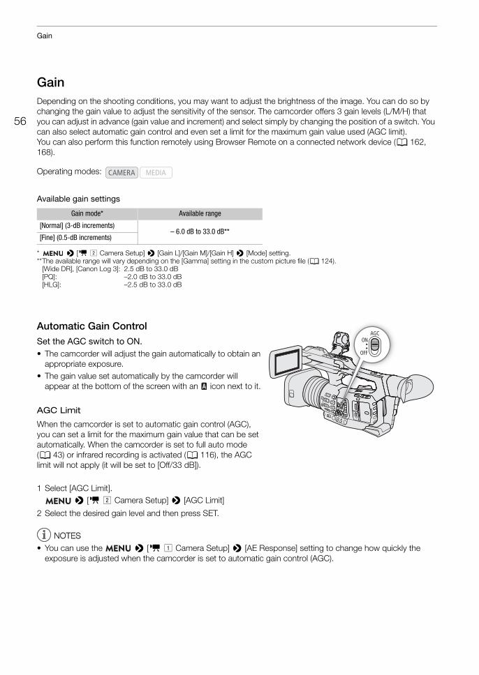
Gain
56
GainDepending on the shooting conditions, you may want to adjust the brightness of the image. You can do so by changing the gain value to adjust the sensitivity of the sensor. The camcorder offers 3 gain levels (L/M/H) that you can adjust in advance (gain value and increment) and select simply by changing the position of a switch. You can also select automatic gain control and even set a limit for the maximum gain value used (AGC limit).You can also perform this function remotely using Browser Remote on a connected network device (A 162, 168).
Available gain settings
* > [v " Camera Setup] > [Gain L]/[Gain M]/[Gain H] > [Mode] setting.**The available range will vary depending on the [Gamma] setting in the custom picture file (A 124).
[Wide DR], [Canon Log 3]: 2.5 dB to 33.0 dB[PQ]: –2.0 dB to 33.0 dB[HLG]: –2.5 dB to 33.0 dB
Automatic Gain ControlSet the AGC switch to ON.• The camcorder will adjust the gain automatically to obtain an
appropriate exposure.• The gain value set automatically by the camcorder will
appear at the bottom of the screen with an icon next to it.
AGC Limit
When the camcorder is set to automatic gain control (AGC), you can set a limit for the maximum gain value that can be set automatically. When the camcorder is set to full auto mode (A 43) or infrared recording is activated (A 116), the AGC limit will not apply (it will be set to [Off/33 dB]).
1 Select [AGC Limit]. > [v " Camera Setup] > [AGC Limit]
2 Select the desired gain level and then press SET.
NOTESNOTES
• You can use the > [v ! Camera Setup] > [AE Response] setting to change how quickly the exposure is adjusted when the camcorder is set to automatic gain control (AGC).
Operating modes:
Gain mode* Available range
[Normal] (3-dB increments)– 6.0 dB to 33.0 dB**
[Fine] (0.5-dB increments)
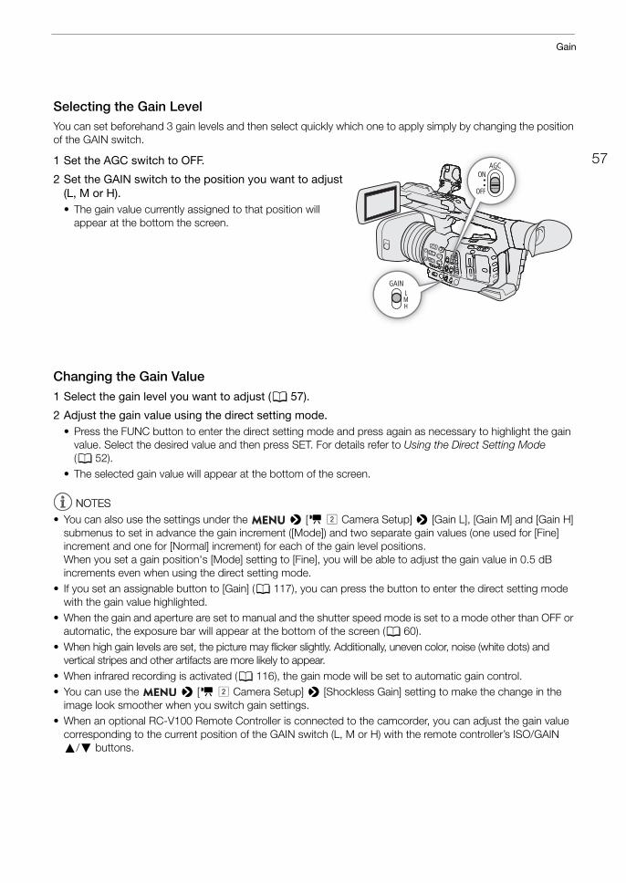
57
Gain
Selecting the Gain LevelYou can set beforehand 3 gain levels and then select quickly which one to apply simply by changing the position of the GAIN switch.
1 Set the AGC switch to OFF.
2 Set the GAIN switch to the position you want to adjust (L, M or H).• The gain value currently assigned to that position will
appear at the bottom the screen.
Changing the Gain Value1 Select the gain level you want to adjust (A 57).
2 Adjust the gain value using the direct setting mode.• Press the FUNC button to enter the direct setting mode and press again as necessary to highlight the gain
value. Select the desired value and then press SET. For details refer to Using the Direct Setting Mode (A 52).
• The selected gain value will appear at the bottom of the screen.
NOTESNOTES
• You can also use the settings under the > [v " Camera Setup] > [Gain L], [Gain M] and [Gain H] submenus to set in advance the gain increment ([Mode]) and two separate gain values (one used for [Fine] increment and one for [Normal] increment) for each of the gain level positions.When you set a gain position's [Mode] setting to [Fine], you will be able to adjust the gain value in 0.5 dB increments even when using the direct setting mode.
• If you set an assignable button to [Gain] (A 117), you can press the button to enter the direct setting mode with the gain value highlighted.
• When the gain and aperture are set to manual and the shutter speed mode is set to a mode other than OFF or automatic, the exposure bar will appear at the bottom of the screen (A 60).
• When high gain levels are set, the picture may flicker slightly. Additionally, uneven color, noise (white dots) and vertical stripes and other artifacts are more likely to appear.
• When infrared recording is activated (A 116), the gain mode will be set to automatic gain control.• You can use the > [v " Camera Setup] > [Shockless Gain] setting to make the change in the
image look smoother when you switch gain settings.• When an optional RC-V100 Remote Controller is connected to the camcorder, you can adjust the gain value
corresponding to the current position of the GAIN switch (L, M or H) with the remote controller’s ISO/GAIN Í/Î buttons.
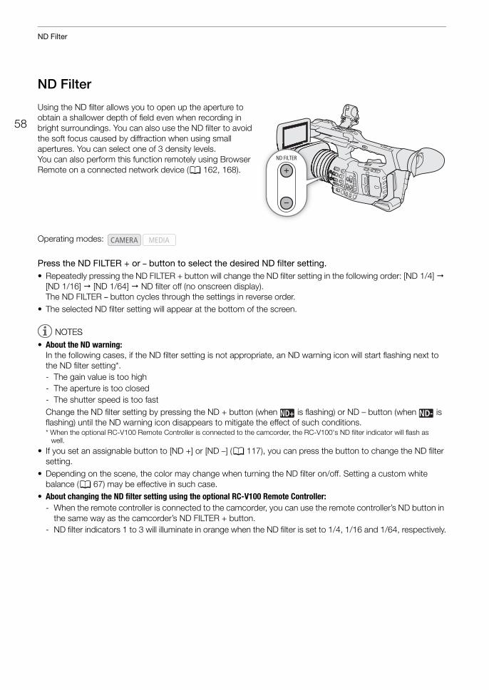
ND Filter
58
ND Filter
Using the ND filter allows you to open up the aperture to obtain a shallower depth of field even when recording in bright surroundings. You can also use the ND filter to avoid the soft focus caused by diffraction when using small apertures. You can select one of 3 density levels.You can also perform this function remotely using Browser Remote on a connected network device (A 162, 168).
Press the ND FILTER + or – button to select the desired ND filter setting. • Repeatedly pressing the ND FILTER + button will change the ND filter setting in the following order: [ND 1/4]
[ND 1/16] [ND 1/64] ND filter off (no onscreen display). The ND FILTER – button cycles through the settings in reverse order.
• The selected ND filter setting will appear at the bottom of the screen.
NOTESNOTES
• About the ND warning:In the following cases, if the ND filter setting is not appropriate, an ND warning icon will start flashing next to the ND filter setting*. - The gain value is too high- The aperture is too closed- The shutter speed is too fastChange the ND filter setting by pressing the ND + button (when is flashing) or ND – button (when is flashing) until the ND warning icon disappears to mitigate the effect of such conditions.* When the optional RC-V100 Remote Controller is connected to the camcorder, the RC-V100's ND filter indicator will flash as
well.
• If you set an assignable button to [ND +] or [ND –] (A 117), you can press the button to change the ND filter setting.
• Depending on the scene, the color may change when turning the ND filter on/off. Setting a custom white balance (A 67) may be effective in such case.
• About changing the ND filter setting using the optional RC-V100 Remote Controller:- When the remote controller is connected to the camcorder, you can use the remote controller’s ND button in
the same way as the camcorder’s ND FILTER + button.- ND filter indicators 1 to 3 will illuminate in orange when the ND filter is set to 1/4, 1/16 and 1/64, respectively.
Operating modes:
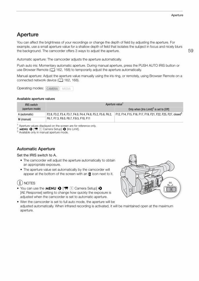
59
Aperture
ApertureYou can affect the brightness of your recordings or change the depth of field by adjusting the aperture. For example, use a small aperture value for a shallow depth of field that isolates the subject in focus and nicely blurs the background. The camcorder offers 3 ways to adjust the aperture.
Automatic aperture: The camcorder adjusts the aperture automatically.
Push auto iris: Momentary automatic aperture. During manual aperture, press the PUSH AUTO IRIS button or use Browser Remote (A 162, 168) to temporarily adjust the aperture automatically.
Manual aperture: Adjust the aperture value manually using the iris ring, or remotely, using Browser Remote on a connected network device (A 162, 168).
Available aperture values
1 Aperture values displayed on the screen are for reference only.2 > [v ! Camera Setup] > [Iris Limit].3 Available only in manual aperture mode.
Automatic ApertureSet the IRIS switch to A.
• The camcorder will adjust the aperture automatically to obtain an appropriate exposure.
• The aperture value set automatically by the camcorder will appear at the bottom of the screen with an icon next to it.
NOTESNOTES
• You can use the > [v ! Camera Setup] > [AE Response] setting to change how quickly the exposure is adjusted when the camcorder is set to automatic aperture.
• Wen the camcorder is set to full auto mode, the aperture will be adjusted automatically. When infrared recording is activated, it will be maintained open at the maximum aperture.
Operating modes:
IRIS switch(aperture mode)
Aperture value1
Only when [Iris Limit]2 is set to [Off]
A (automatic) F2.8, F3.2, F3.4, F3.7, F4.0, F4.4, F4.8, F5.2, F5.6, F6.2, F6.7, F7.3, F8.0, F8.7, F.9.5, F10, F11
F12, F14, F15, F16, F17, F19, F21, F22, F25, F27, closed3
M (manual)
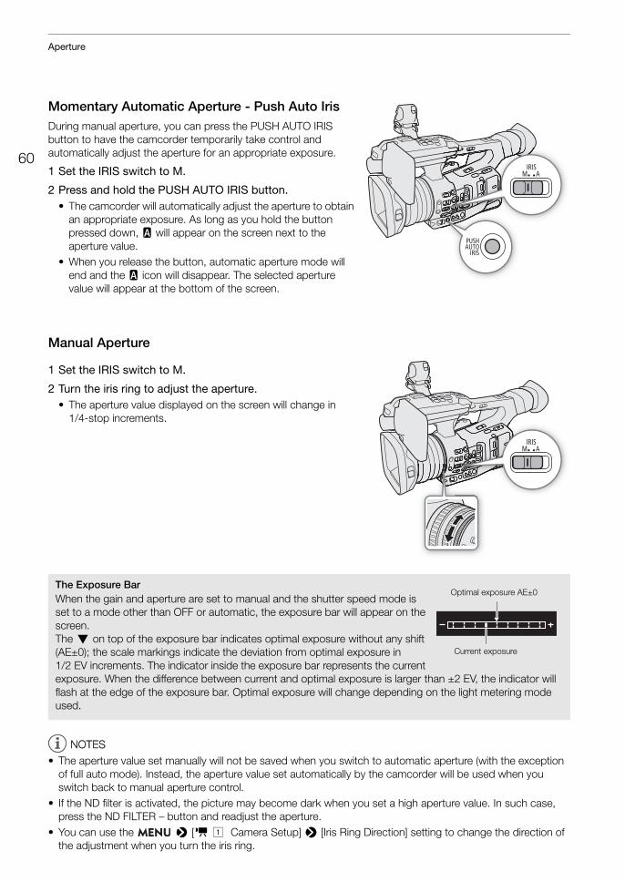
Aperture
60
Momentary Automatic Aperture - Push Auto IrisDuring manual aperture, you can press the PUSH AUTO IRIS button to have the camcorder temporarily take control and automatically adjust the aperture for an appropriate exposure.
1 Set the IRIS switch to M.
2 Press and hold the PUSH AUTO IRIS button.• The camcorder will automatically adjust the aperture to obtain
an appropriate exposure. As long as you hold the button pressed down, E will appear on the screen next to the aperture value.
• When you release the button, automatic aperture mode will end and the E icon will disappear. The selected aperture value will appear at the bottom of the screen.
Manual Aperture
1 Set the IRIS switch to M.
2 Turn the iris ring to adjust the aperture.• The aperture value displayed on the screen will change in
1/4-stop increments.
NOTESNOTES
• The aperture value set manually will not be saved when you switch to automatic aperture (with the exception of full auto mode). Instead, the aperture value set automatically by the camcorder will be used when you switch back to manual aperture control.
• If the ND filter is activated, the picture may become dark when you set a high aperture value. In such case, press the ND FILTER – button and readjust the aperture.
• You can use the > [v ! Camera Setup] > [Iris Ring Direction] setting to change the direction of the adjustment when you turn the iris ring.
The Exposure BarWhen the gain and aperture are set to manual and the shutter speed mode is set to a mode other than OFF or automatic, the exposure bar will appear on the screen. The Î on top of the exposure bar indicates optimal exposure without any shift (AE±0); the scale markings indicate the deviation from optimal exposure in 1/2 EV increments. The indicator inside the exposure bar represents the current exposure. When the difference between current and optimal exposure is larger than ±2 EV, the indicator will flash at the edge of the exposure bar. Optimal exposure will change depending on the light metering mode used.
Optimal exposure AE±0
Current exposure
61
Aperture
• You can operate the iris ring even the camcorder's controls are locked (A 43).• When an optional RC-V100 Remote Controller is connected to the camcorder, you can adjust the aperture
with the remote controller’s IRIS dial. At default settings, turn the dial right to open up the aperture and left to close the aperture.You can also switch between automatic and manual aperture with the remote controller's AUTO IRIS button.
Iris LimitBy default, the iris limit is set to prevent the aperture from closing below the diffraction limit of the lens (F11).
1 Select [Iris Limit]. > [v ! Camera Setup] > [Iris Limit]
2 Select the desired option and then press SET.
Options[On]: The maximum aperture value is [F11], the diffraction limit of the lens. [Off]: You can fully close the aperture ([closed]). Aperture values that exceed the diffraction limit will
appear in gray.
NOTESNOTES
• Using aperture values that exceed the lens's diffraction limit may affect the recorded image (for example, causing diffraction blur). Using aperture values within the lens's diffraction limit (iris limit) is recommended.
Exposure Compensation - AE ShiftUse AE shift to darken or lighten the image when you want to compensate the exposure that was set automatically (shutter, gain or aperture set to automatic mode or after using push auto iris to automatically set the aperture). AE shift is not available when the camcorder is set to full auto mode (A 43) or you activate infrared recording (A 116).You can also perform this function remotely using Browser Remote on a connected network device (A 162, 168).
1 Select [AE Shift]. > [v ! Camera Setup] > [AE Shift]
2 Select an AE shift level and then press SET.• You can select one of 17 AE shift levels from –2.0 to +2.0.
NOTESNOTES
• If you set an assignable button to [AE Shift +] or [AE Shift –] (A 117), you can press the button to adjust the AE shift level.
Aperture
62
Light Metering Mode
Select the light metering mode to match the recording conditions. Using the appropriate setting will ensure that the camcorder obtains the most suitable exposure level when the shutter speed, gain and aperture are adjusted automatically or when using push auto iris.
1 Select [Light Metering]. > [v ! Camera Setup] > [Light Metering]
2 Select the desired option and then press SET.• The icon of the selected mode ( or , no icon for [Standard]) appears on the left of the screen.
Options[Backlight]: Suitable when recording backlit scenes.[Standard]: Averages the light metered from the entire screen, giving more weight to the subject in the center.[Spotlight]: Use this option when recording a scene in which only a certain part of the picture is lit, for
example, when the subject is lit by a spotlight.
NOTESNOTES
• If you set an assignable button to [Backlight] or [Spotlight] (A 117), you can press the button to turn the respective light metering mode on and off.
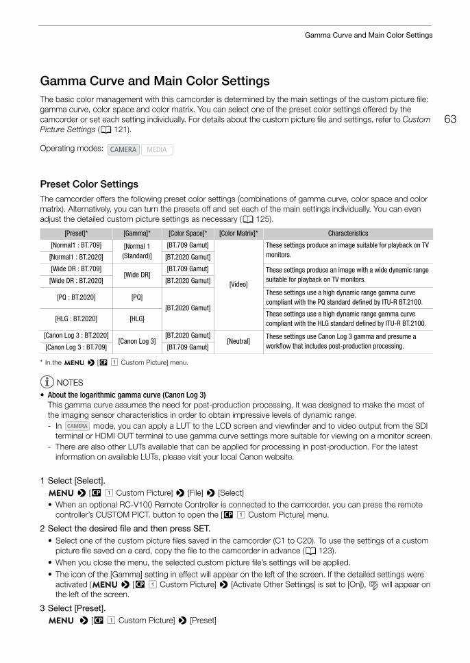
63
Gamma Curve and Main Color Settings
Gamma Curve and Main Color SettingsThe basic color management with this camcorder is determined by the main settings of the custom picture file: gamma curve, color space and color matrix. You can select one of the preset color settings offered by the camcorder or set each setting individually. For details about the custom picture file and settings, refer to Custom Picture Settings (A 121).
Preset Color SettingsThe camcorder offers the following preset color settings (combinations of gamma curve, color space and color matrix). Alternatively, you can turn the presets off and set each of the main settings individually. You can even adjust the detailed custom picture settings as necessary (A 125).
* In the > [/ ! Custom Picture] menu.
NOTESNOTES
• About the logarithmic gamma curve (Canon Log 3)This gamma curve assumes the need for post-production processing. It was designed to make the most of the imaging sensor characteristics in order to obtain impressive levels of dynamic range.- In mode, you can apply a LUT to the LCD screen and viewfinder and to video output from the SDI
terminal or HDMI OUT terminal to use gamma curve settings more suitable for viewing on a monitor screen.- There are also other LUTs available that can be applied for processing in post-production. For the latest
information on available LUTs, please visit your local Canon website.
1 Select [Select]. > [/ ! Custom Picture] > [File] > [Select]
• When an optional RC-V100 Remote Controller is connected to the camcorder, you can press the remote controller’s CUSTOM PICT. button to open the [/ ! Custom Picture] menu.
2 Select the desired file and then press SET.• Select one of the custom picture files saved in the camcorder (C1 to C20). To use the settings of a custom
picture file saved on a card, copy the file to the camcorder in advance (A 123).• When you close the menu, the selected custom picture file’s settings will be applied.• The icon of the [Gamma] setting in effect will appear on the left of the screen. If the detailed settings were
activated ( > [/ ! Custom Picture] > [Activate Other Settings] is set to [On]), will appear on the left of the screen.
3 Select [Preset]. > [/ ! Custom Picture] > [Preset]
Operating modes:
[Preset]* [Gamma]* [Color Space]* [Color Matrix]* Characteristics
[Normal1 : BT.709] [Normal 1 (Standard)]
[BT.709 Gamut]
[Video]
These settings produce an image suitable for playback on TV monitors.[Normal1 : BT.2020] [BT.2020 Gamut]
[Wide DR : BT.709][Wide DR]
[BT.709 Gamut] These settings produce an image with a wide dynamic range suitable for playback on TV monitors.[Wide DR : BT.2020] [BT.2020 Gamut]
[PQ : BT.2020] [PQ]
[BT.2020 Gamut]
These settings use a high dynamic range gamma curve compliant with the PQ standard defined by ITU-R BT.2100.
[HLG : BT.2020] [HLG]These settings use a high dynamic range gamma curve compliant with the HLG standard defined by ITU-R BT.2100.
[Canon Log 3 : BT.2020][Canon Log 3]
[BT.2020 Gamut][Neutral]
These settings use Canon Log 3 gamma and presume a workflow that includes post-production processing. [Canon Log 3 : BT.709] [BT.709 Gamut]
Gamma Curve and Main Color Settings
64
4 Select the desired setting and then press SET.• To select the gamma curve, color space or color matrix individually, select [Off] and continue the procedure
with step 5. To use one of the preset settings as is, the rest of the procedure is not necessary.
5 Select [Gamma]. > [/ ! Custom Picture] > [Gamma]
6 Select the desired gamma curve (A 124) and then press SET.• Repeat steps 5 and 6, selecting [Color Space] to select the color space, and/or [Color Matrix] to select the
color matrix in the same way.
NOTESNOTES
• When the [Gamma] setting in the custom picture file is set to [PQ] or [HLG], slow motion recording is not available.

65
White Balance
White BalanceThe camcorder uses an electronic white balance process to calibrate the picture and produce accurate colors under different lighting conditions. There are 4 methods of setting the white balance.You can also perform this function remotely using Browser Remote on a connected network device (A 162, 167).
Auto white balance (AWB): The camcorder automatically adjusts the white balance to the optimal level.
Preset white balance: Set the white balance to ¼ (daylight) or É (tungsten lamp). You can further adjust the color temperature (K) value and the color compensation (CC) value, which adjusts the color along the green/magenta gradation.
Color temperature: Allows you to set the color temperature between 2,000 K and 15,000 K, and further adjust the color compensation (CC) value.
Custom white balance: You can use a gray card or white object with no pattern to establish the white balance and set it to one of two custom white balance positions, ÅA or ÅB.
When recording under fluorescent lights, we recommend using auto white balance or setting a custom white balance.
Available white balance modes by WHITE BAL. switch position
NOTESNOTES
• When the camcorder is set to full auto mode, the white balance will be adjusted automatically (AWB). When infrared recording is activated, the white balance cannot be adjusted.
• The [White Balance] and [Color Matrix Tuning] settings in the custom picture file (A 127) take precedence over the white balance set with these procedures.
• You can use the > [v " Camera Setup] > [Shockless WB] setting to make the change in the image look smoother when you change white balance settings.
• When an optional RC-V100 Remote Controller is connected to the camcorder, you can adjust the white balance with the remote controller’s AWB button, A button, B button, PRESET button and Å button.
• The color temperatures displayed on the screen are approximate. Use them only as a reference.
Operating modes:
White balance modeWHITE BAL. switch position
B A PRESET
Preset white balance – – Ü
Color temperature – – Ü
Custom white balance Ü Ü –
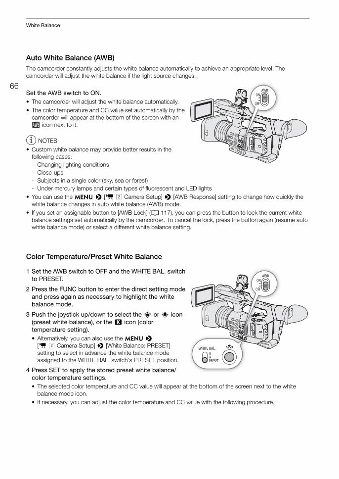
White Balance
66
Auto White Balance (AWB)The camcorder constantly adjusts the white balance automatically to achieve an appropriate level. The camcorder will adjust the white balance if the light source changes.
Set the AWB switch to ON.• The camcorder will adjust the white balance automatically.• The color temperature and CC value set automatically by the
camcorder will appear at the bottom of the screen with an icon next to it.
NOTESNOTES
• Custom white balance may provide better results in the following cases:- Changing lighting conditions- Close-ups- Subjects in a single color (sky, sea or forest)- Under mercury lamps and certain types of fluorescent and LED lights
• You can use the > [v " Camera Setup] > [AWB Response] setting to change how quickly the white balance changes in auto white balance (AWB) mode.
• If you set an assignable button to [AWB Lock] (A 117), you can press the button to lock the current white balance settings set automatically by the camcorder. To cancel the lock, press the button again (resume auto white balance mode) or select a different white balance setting.
Color Temperature/Preset White Balance
1 Set the AWB switch to OFF and the WHITE BAL. switch to PRESET.
2 Press the FUNC button to enter the direct setting mode and press again as necessary to highlight the white balance mode.
3 Push the joystick up/down to select the ¼ or É icon (preset white balance), or the È icon (color temperature setting).• Alternatively, you can also use the >
[v " Camera Setup] > [White Balance: PRESET] setting to select in advance the white balance mode assigned to the WHITE BAL. switch's PRESET position.
4 Press SET to apply the stored preset white balance/color temperature settings.• The selected color temperature and CC value will appear at the bottom of the screen next to the white
balance mode icon.• If necessary, you can adjust the color temperature and CC value with the following procedure.
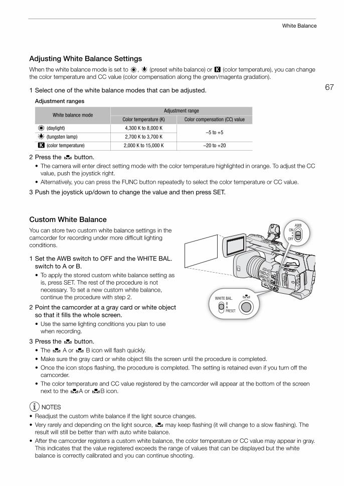
67
White Balance
Adjusting White Balance SettingsWhen the white balance mode is set to ¼, É (preset white balance) or È (color temperature), you can change the color temperature and CC value (color compensation along the green/magenta gradation).
1 Select one of the white balance modes that can be adjusted.
Adjustment ranges
2 Press the Å button.• The camera will enter direct setting mode with the color temperature highlighted in orange. To adjust the CC
value, push the joystick right.• Alternatively, you can press the FUNC button repeatedly to select the color temperature or CC value.
3 Push the joystick up/down to change the value and then press SET.
Custom White BalanceYou can store two custom white balance settings in the camcorder for recording under more difficult lighting conditions.
1 Set the AWB switch to OFF and the WHITE BAL. switch to A or B.• To apply the stored custom white balance setting as
is, press SET. The rest of the procedure is not necessary. To set a new custom white balance, continue the procedure with step 2.
2 Point the camcorder at a gray card or white object so that it fills the whole screen.• Use the same lighting conditions you plan to use
when recording.
3 Press the Å button.• The Å A or Å B icon will flash quickly.• Make sure the gray card or white object fills the screen until the procedure is completed.• Once the icon stops flashing, the procedure is completed. The setting is retained even if you turn off the
camcorder.• The color temperature and CC value registered by the camcorder will appear at the bottom of the screen
next to the ÅA or ÅB icon.
NOTESNOTES
• Readjust the custom white balance if the light source changes.• Very rarely and depending on the light source, Å may keep flashing (it will change to a slow flashing). The
result will still be better than with auto white balance.• After the camcorder registers a custom white balance, the color temperature or CC value may appear in gray.
This indicates that the value registered exceeds the range of values that can be displayed but the white balance is correctly calibrated and you can continue shooting.
White balance modeAdjustment range
Color temperature (K) Color compensation (CC) value
¼ (daylight) 4,300 K to 8,000 K–5 to +5
É (tungsten lamp) 2,700 K to 3,700 K
È (color temperature) 2,000 K to 15,000 K –20 to +20
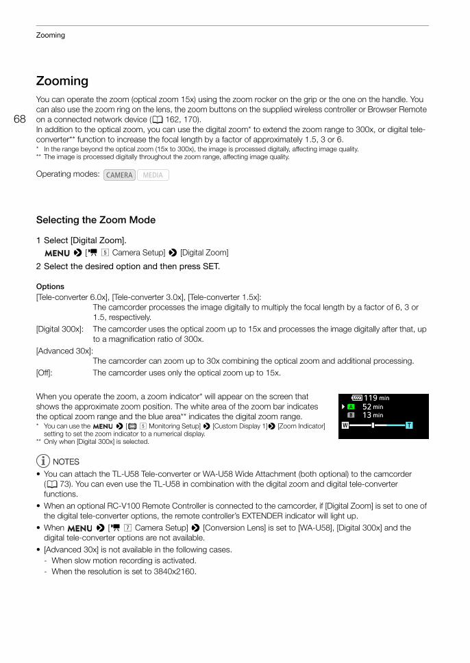
Zooming
68
ZoomingYou can operate the zoom (optical zoom 15x) using the zoom rocker on the grip or the one on the handle. You can also use the zoom ring on the lens, the zoom buttons on the supplied wireless controller or Browser Remote on a connected network device (A 162, 170).In addition to the optical zoom, you can use the digital zoom* to extend the zoom range to 300x, or digital tele-converter** function to increase the focal length by a factor of approximately 1.5, 3 or 6.* In the range beyond the optical zoom (15x to 300x), the image is processed digitally, affecting image quality.** The image is processed digitally throughout the zoom range, affecting image quality.
Selecting the Zoom Mode
1 Select [Digital Zoom]. > [v % Camera Setup] > [Digital Zoom]
2 Select the desired option and then press SET.
Options[Tele-converter 6.0x], [Tele-converter 3.0x], [Tele-converter 1.5x]:
The camcorder processes the image digitally to multiply the focal length by a factor of 6, 3 or 1.5, respectively.
[Digital 300x]: The camcorder uses the optical zoom up to 15x and processes the image digitally after that, up to a magnification ratio of 300x.
[Advanced 30x]: The camcorder can zoom up to 30x combining the optical zoom and additional processing.
[Off]: The camcorder uses only the optical zoom up to 15x.
When you operate the zoom, a zoom indicator* will appear on the screen that shows the approximate zoom position. The white area of the zoom bar indicates the optical zoom range and the blue area** indicates the digital zoom range.* You can use the > [¢ % Monitoring Setup] > [Custom Display 1]> [Zoom Indicator]
setting to set the zoom indicator to a numerical display.** Only when [Digital 300x] is selected.
NOTESNOTES
• You can attach the TL-U58 Tele-converter or WA-U58 Wide Attachment (both optional) to the camcorder (A 73). You can even use the TL-U58 in combination with the digital zoom and digital tele-converter functions.
• When an optional RC-V100 Remote Controller is connected to the camcorder, if [Digital Zoom] is set to one of the digital tele-converter options, the remote controller’s EXTENDER indicator will light up.
• When > [v ' Camera Setup] > [Conversion Lens] is set to [WA-U58], [Digital 300x] and the digital tele-converter options are not available.
• [Advanced 30x] is not available in the following cases.- When slow motion recording is activated.- When the resolution is set to 3840x2160.
Operating modes:
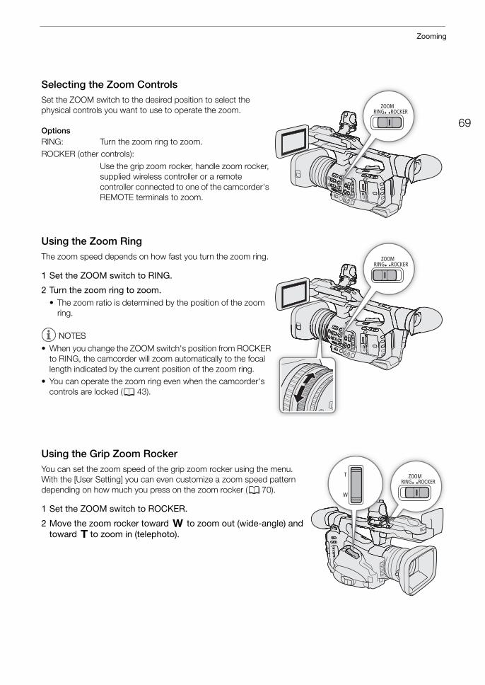
69
Zooming
Selecting the Zoom ControlsSet the ZOOM switch to the desired position to select the physical controls you want to use to operate the zoom.
OptionsRING: Turn the zoom ring to zoom.ROCKER (other controls):
Use the grip zoom rocker, handle zoom rocker, supplied wireless controller or a remote controller connected to one of the camcorder's REMOTE terminals to zoom.
Using the Zoom RingThe zoom speed depends on how fast you turn the zoom ring.
1 Set the ZOOM switch to RING.
2 Turn the zoom ring to zoom.• The zoom ratio is determined by the position of the zoom
ring.
NOTESNOTES
• When you change the ZOOM switch's position from ROCKER to RING, the camcorder will zoom automatically to the focal length indicated by the current position of the zoom ring.
• You can operate the zoom ring even when the camcorder's controls are locked (A 43).
Using the Grip Zoom RockerYou can set the zoom speed of the grip zoom rocker using the menu. With the [User Setting] you can even customize a zoom speed pattern depending on how much you press on the zoom rocker (A 70).
1 Set the ZOOM switch to ROCKER.
2 Move the zoom rocker toward T to zoom out (wide-angle) and toward S to zoom in (telephoto).
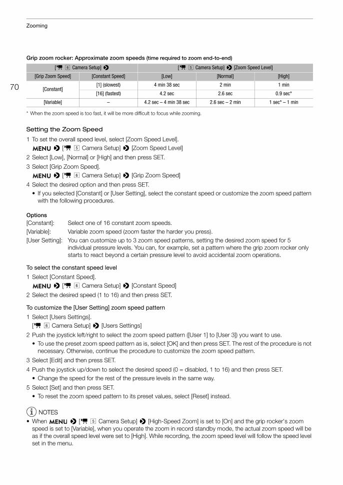
Zooming
70
Grip zoom rocker: Approximate zoom speeds (time required to zoom end-to-end)
* When the zoom speed is too fast, it will be more difficult to focus while zooming.
Setting the Zoom Speed
1 To set the overall speed level, select [Zoom Speed Level]. > [v % Camera Setup] > [Zoom Speed Level]
2 Select [Low], [Normal] or [High] and then press SET.
3 Select [Grip Zoom Speed]. > [v & Camera Setup] > [Grip Zoom Speed]
4 Select the desired option and then press SET.• If you selected [Constant] or [User Setting], select the constant speed or customize the zoom speed pattern
with the following procedures.
Options[Constant]: Select one of 16 constant zoom speeds.[Variable]: Variable zoom speed (zoom faster the harder you press).[User Setting]: You can customize up to 3 zoom speed patterns, setting the desired zoom speed for 5
individual pressure levels. You can, for example, set a pattern where the grip zoom rocker only starts to react beyond a certain pressure level to avoid accidental zoom operations.
To select the constant speed level
1 Select [Constant Speed]. > [v & Camera Setup] > [Constant Speed]
2 Select the desired speed (1 to 16) and then press SET.
To customize the [User Setting] zoom speed pattern
1 Select [Users Settings].[v & Camera Setup] > [Users Settings]
2 Push the joystick left/right to select the zoom speed pattern ([User 1] to [User 3]) you want to use.• To use the preset zoom speed pattern as is, select [OK] and then press SET. The rest of the procedure is not
necessary. Otherwise, continue the procedure to customize the zoom speed pattern.
3 Select [Edit] and then press SET.
4 Push the joystick up/down to select the desired speed (0 = disabled, 1 to 16) and then press SET.• Change the speed for the rest of the pressure levels in the same way.
5 Select [Set] and then press SET.• To reset the zoom speed pattern to its preset values, select [Reset] instead.
NOTESNOTES
• When > [v % Camera Setup] > [High-Speed Zoom] is set to [On] and the grip rocker's zoom speed is set to [Variable], when you operate the zoom in record standby mode, the actual zoom speed will be as if the overall speed level were set to [High]. While recording, the zoom speed level will follow the speed level set in the menu.
[v & Camera Setup] > [v % Camera Setup] > [Zoom Speed Level]
[Grip Zoom Speed] [Constant Speed] [Low] [Normal] [High]
[Constant][1] (slowest) 4 min 38 sec 2 min 1 min
[16] (fastest) 4.2 sec 2.6 sec 0.9 sec*
[Variable] – 4.2 sec – 4 min 38 sec 2.6 sec – 2 min 1 sec* – 1 min
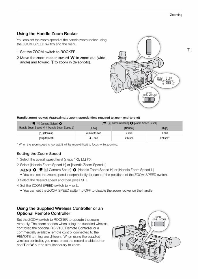
71
Zooming
Using the Handle Zoom RockerYou can set the zoom speed of the handle zoom rocker using the ZOOM SPEED switch and the menu.
1 Set the ZOOM switch to ROCKER.
2 Move the zoom rocker toward T to zoom out (wide-angle) and toward S to zoom in (telephoto).
Handle zoom rocker: Approximate zoom speeds (time required to zoom end-to-end)
* When the zoom speed is too fast, it will be more difficult to focus while zooming.
Setting the Zoom Speed
1 Select the overall speed level (steps 1-2, A 70).
2 Select [Handle Zoom Speed H] or [Handle Zoom Speed L]. > [v % Camera Setup] > [Handle Zoom Speed H] or [Handle Zoom Speed L]
• You can set the zoom speed independently for each of the positions of the ZOOM SPEED switch.
3 Select the desired speed and then press SET.
4 Set the ZOOM SPEED switch to H or L.• You can set the ZOOM SPEED switch to OFF to disable the zoom rocker on the handle.
Using the Supplied Wireless Controller or an Optional Remote ControllerSet the ZOOM switch to ROCKER to operate the zoom remotely. The zoom speeds when using the supplied wireless controller, the optional RC-V100 Remote Controller or a commercially available remote control connected to the REMOTE terminal are different. When using the supplied wireless controller, you must press the record enable button and T or W button simultaneously to zoom.
[v % Camera Setup] > [Handle Zoom Speed H] / [Handle Zoom Speed L]
[v % Camera Setup] > [Zoom Speed Level]
[Low] [Normal] [High]
[1] (slowest) 4 min 38 sec 2 min 1 min
[16] (fastest) 4.2 sec 2.6 sec 0.9 sec*
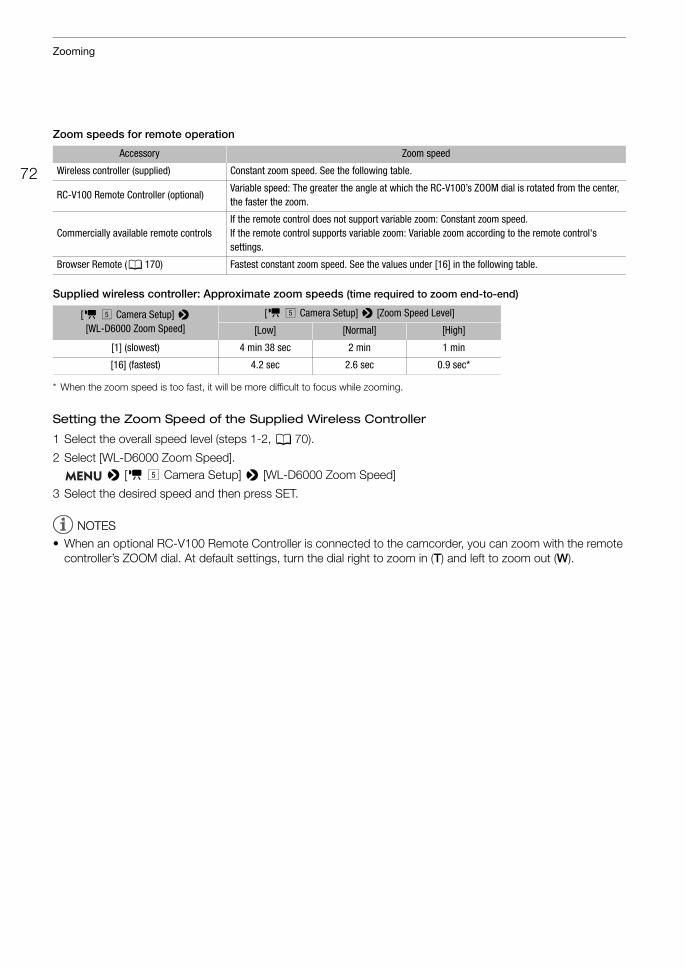
Zooming
72
Zoom speeds for remote operation
Supplied wireless controller: Approximate zoom speeds (time required to zoom end-to-end)
* When the zoom speed is too fast, it will be more difficult to focus while zooming.
Setting the Zoom Speed of the Supplied Wireless Controller
1 Select the overall speed level (steps 1-2, A 70).
2 Select [WL-D6000 Zoom Speed]. > [v % Camera Setup] > [WL-D6000 Zoom Speed]
3 Select the desired speed and then press SET.
NOTESNOTES
• When an optional RC-V100 Remote Controller is connected to the camcorder, you can zoom with the remote controller’s ZOOM dial. At default settings, turn the dial right to zoom in (T) and left to zoom out (W).
Accessory Zoom speed
Wireless controller (supplied) Constant zoom speed. See the following table.
RC-V100 Remote Controller (optional)Variable speed: The greater the angle at which the RC-V100’s ZOOM dial is rotated from the center, the faster the zoom.
Commercially available remote controlsIf the remote control does not support variable zoom: Constant zoom speed. If the remote control supports variable zoom: Variable zoom according to the remote control's settings.
Browser Remote (A 170) Fastest constant zoom speed. See the values under [16] in the following table.
[v % Camera Setup] > [WL-D6000 Zoom Speed]
[v % Camera Setup] > [Zoom Speed Level]
[Low] [Normal] [High]
[1] (slowest) 4 min 38 sec 2 min 1 min
[16] (fastest) 4.2 sec 2.6 sec 0.9 sec*
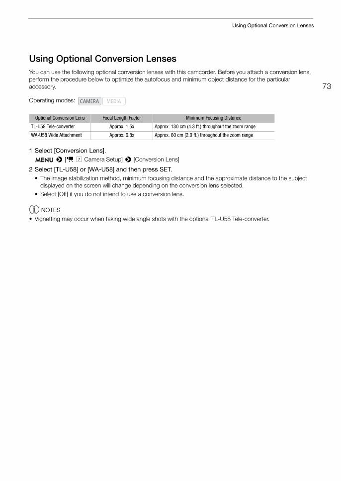
73
Using Optional Conversion Lenses
Using Optional Conversion LensesYou can use the following optional conversion lenses with this camcorder. Before you attach a conversion lens, perform the procedure below to optimize the autofocus and minimum object distance for the particular accessory.
1 Select [Conversion Lens]. > [v ' Camera Setup] > [Conversion Lens]
2 Select [TL-U58] or [WA-U58] and then press SET.• The image stabilization method, minimum focusing distance and the approximate distance to the subject
displayed on the screen will change depending on the conversion lens selected.• Select [Off] if you do not intend to use a conversion lens.
NOTESNOTES
• Vignetting may occur when taking wide angle shots with the optional TL-U58 Tele-converter.
Operating modes:
Optional Conversion Lens Focal Length Factor Minimum Focusing Distance
TL-U58 Tele-converter Approx. 1.5x Approx. 130 cm (4.3 ft.) throughout the zoom range
WA-U58 Wide Attachment Approx. 0.8x Approx. 60 cm (2.0 ft.) throughout the zoom range
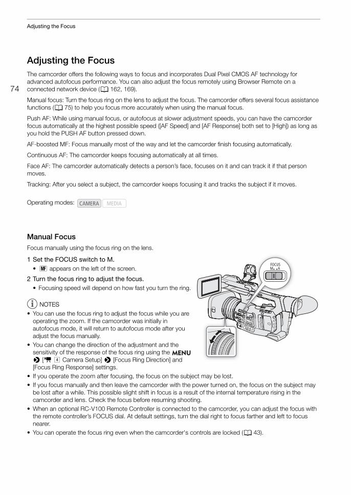
Adjusting the Focus
74
Adjusting the FocusThe camcorder offers the following ways to focus and incorporates Dual Pixel CMOS AF technology for advanced autofocus performance. You can also adjust the focus remotely using Browser Remote on a connected network device (A 162, 169).
Manual focus: Turn the focus ring on the lens to adjust the focus. The camcorder offers several focus assistance functions (A 75) to help you focus more accurately when using the manual focus.
Push AF: While using manual focus, or autofocus at slower adjustment speeds, you can have the camcorder focus automatically at the highest possible speed ([AF Speed] and [AF Response] both set to [High]) as long as you hold the PUSH AF button pressed down.
AF-boosted MF: Focus manually most of the way and let the camcorder finish focusing automatically.
Continuous AF: The camcorder keeps focusing automatically at all times.
Face AF: The camcorder automatically detects a person’s face, focuses on it and can track it if that person moves.
Tracking: After you select a subject, the camcorder keeps focusing it and tracks the subject if it moves.
Manual FocusFocus manually using the focus ring on the lens.
1 Set the FOCUS switch to M.• A appears on the left of the screen.
2 Turn the focus ring to adjust the focus.• Focusing speed will depend on how fast you turn the ring.
NOTESNOTES
• You can use the focus ring to adjust the focus while you are operating the zoom. If the camcorder was initially in autofocus mode, it will return to autofocus mode after you adjust the focus manually.
• You can change the direction of the adjustment and the sensitivity of the response of the focus ring using the > [v $ Camera Setup] > [Focus Ring Direction] and [Focus Ring Response] settings.
• If you operate the zoom after focusing, the focus on the subject may be lost.• If you focus manually and then leave the camcorder with the power turned on, the focus on the subject may
be lost after a while. This possible slight shift in focus is a result of the internal temperature rising in the camcorder and lens. Check the focus before resuming shooting.
• When an optional RC-V100 Remote Controller is connected to the camcorder, you can adjust the focus with the remote controller’s FOCUS dial. At default settings, turn the dial right to focus farther and left to focus nearer.
• You can operate the focus ring even when the camcorder's controls are locked (A 43).
Operating modes:
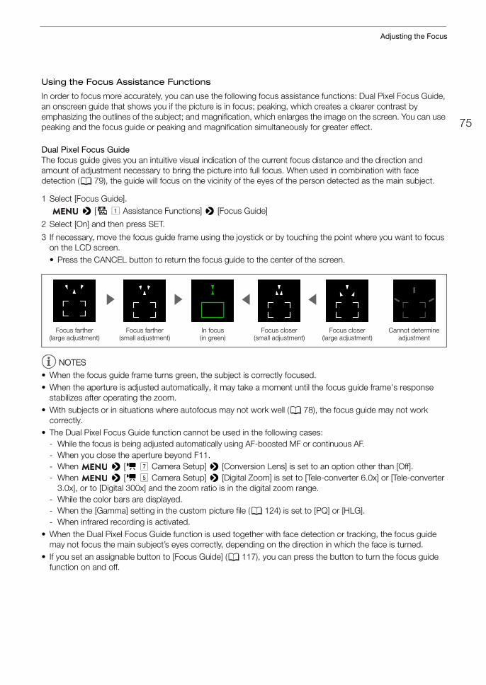
75
Adjusting the Focus
Using the Focus Assistance Functions
In order to focus more accurately, you can use the following focus assistance functions: Dual Pixel Focus Guide, an onscreen guide that shows you if the picture is in focus; peaking, which creates a clearer contrast by emphasizing the outlines of the subject; and magnification, which enlarges the image on the screen. You can use peaking and the focus guide or peaking and magnification simultaneously for greater effect.
Dual Pixel Focus GuideThe focus guide gives you an intuitive visual indication of the current focus distance and the direction and amount of adjustment necessary to bring the picture into full focus. When used in combination with face detection (A 79), the guide will focus on the vicinity of the eyes of the person detected as the main subject.
1 Select [Focus Guide]. > [A! Assistance Functions] > [Focus Guide]
2 Select [On] and then press SET.
3 If necessary, move the focus guide frame using the joystick or by touching the point where you want to focus on the LCD screen.• Press the CANCEL button to return the focus guide to the center of the screen.
NOTESNOTES
• When the focus guide frame turns green, the subject is correctly focused.• When the aperture is adjusted automatically, it may take a moment until the focus guide frame's response
stabilizes after operating the zoom.• With subjects or in situations where autofocus may not work well (A 78), the focus guide may not work
correctly.• The Dual Pixel Focus Guide function cannot be used in the following cases:
- While the focus is being adjusted automatically using AF-boosted MF or continuous AF. - When you close the aperture beyond F11.- When > [v ' Camera Setup] > [Conversion Lens] is set to an option other than [Off].- When > [v % Camera Setup] > [Digital Zoom] is set to [Tele-converter 6.0x] or [Tele-converter
3.0x], or to [Digital 300x] and the zoom ratio is in the digital zoom range.- While the color bars are displayed.- When the [Gamma] setting in the custom picture file (A 124) is set to [PQ] or [HLG].- When infrared recording is activated.
• When the Dual Pixel Focus Guide function is used together with face detection or tracking, the focus guide may not focus the main subject’s eyes correctly, depending on the direction in which the face is turned.
• If you set an assignable button to [Focus Guide] (A 117), you can press the button to turn the focus guide function on and off.
In focus(in green)
Focus farther (large adjustment)
Focus farther (small adjustment)
Focus closer (small adjustment)
Focus closer (large adjustment)
Cannot determine adjustment
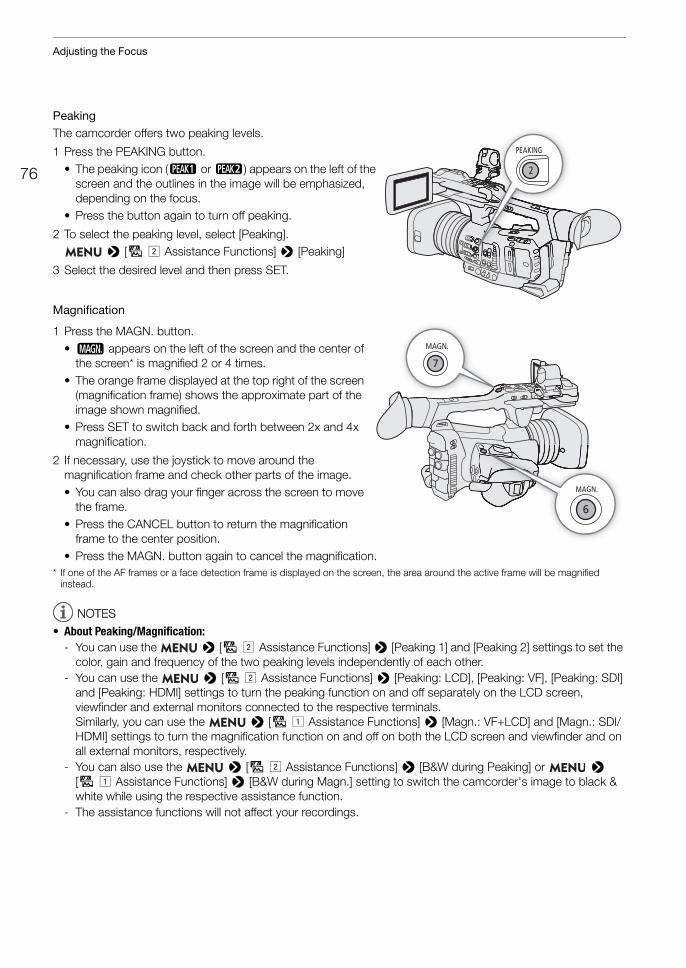
Adjusting the Focus
76
PeakingThe camcorder offers two peaking levels.
1 Press the PEAKING button.• The peaking icon (J or K) appears on the left of the
screen and the outlines in the image will be emphasized, depending on the focus.
• Press the button again to turn off peaking.
2 To select the peaking level, select [Peaking]. > [A" Assistance Functions] > [Peaking]
3 Select the desired level and then press SET.
Magnification
1 Press the MAGN. button.• ^ appears on the left of the screen and the center of
the screen* is magnified 2 or 4 times.• The orange frame displayed at the top right of the screen
(magnification frame) shows the approximate part of the image shown magnified.
• Press SET to switch back and forth between 2x and 4x magnification.
2 If necessary, use the joystick to move around the magnification frame and check other parts of the image.• You can also drag your finger across the screen to move
the frame.• Press the CANCEL button to return the magnification
frame to the center position.• Press the MAGN. button again to cancel the magnification.
* If one of the AF frames or a face detection frame is displayed on the screen, the area around the active frame will be magnified instead.
NOTESNOTES
• About Peaking/Magnification:- You can use the > [A" Assistance Functions] > [Peaking 1] and [Peaking 2] settings to set the
color, gain and frequency of the two peaking levels independently of each other.- You can use the > [A" Assistance Functions] > [Peaking: LCD], [Peaking: VF], [Peaking: SDI]
and [Peaking: HDMI] settings to turn the peaking function on and off separately on the LCD screen, viewfinder and external monitors connected to the respective terminals.Similarly, you can use the > [A! Assistance Functions] > [Magn.: VF+LCD] and [Magn.: SDI/HDMI] settings to turn the magnification function on and off on both the LCD screen and viewfinder and on all external monitors, respectively.
- You can also use the > [A" Assistance Functions] > [B&W during Peaking] or > [A! Assistance Functions] > [B&W during Magn.] setting to switch the camcorder's image to black & white while using the respective assistance function.
- The assistance functions will not affect your recordings.
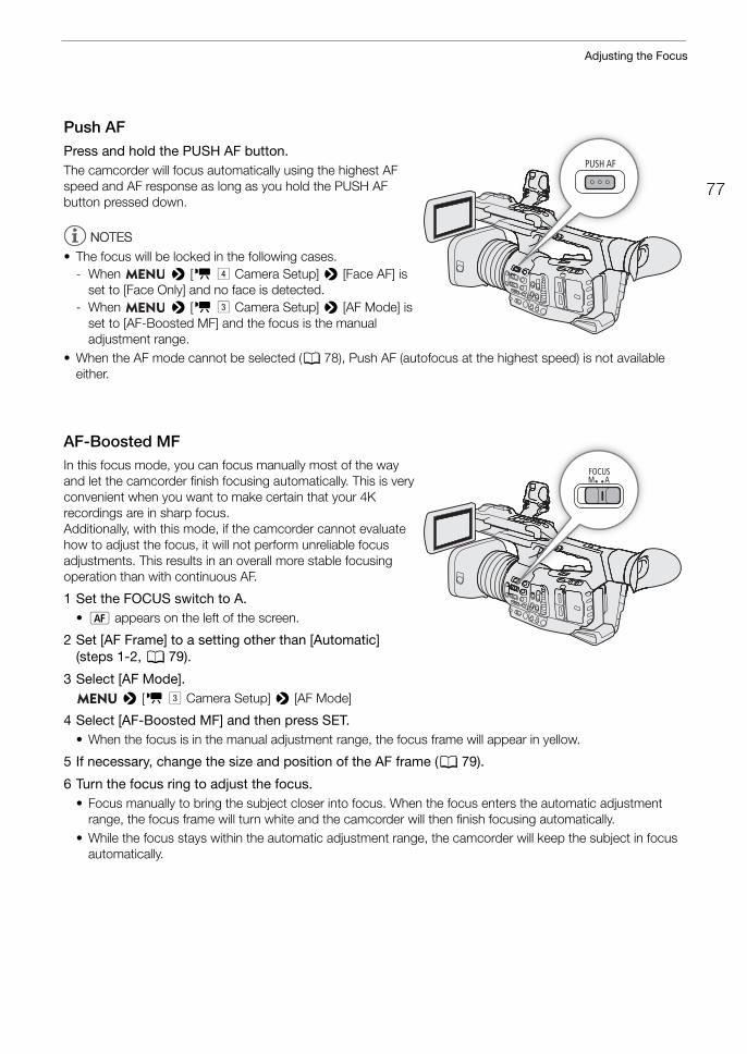
77
Adjusting the Focus
Push AFPress and hold the PUSH AF button.The camcorder will focus automatically using the highest AF speed and AF response as long as you hold the PUSH AF button pressed down.
NOTESNOTES
• The focus will be locked in the following cases.- When > [v $ Camera Setup] > [Face AF] is
set to [Face Only] and no face is detected.- When > [v # Camera Setup] > [AF Mode] is
set to [AF-Boosted MF] and the focus is the manual adjustment range.
• When the AF mode cannot be selected (A 78), Push AF (autofocus at the highest speed) is not available either.
AF-Boosted MFIn this focus mode, you can focus manually most of the way and let the camcorder finish focusing automatically. This is very convenient when you want to make certain that your 4K recordings are in sharp focus.Additionally, with this mode, if the camcorder cannot evaluate how to adjust the focus, it will not perform unreliable focus adjustments. This results in an overall more stable focusing operation than with continuous AF.
1 Set the FOCUS switch to A.• @ appears on the left of the screen.
2 Set [AF Frame] to a setting other than [Automatic] (steps 1-2, A 79).
3 Select [AF Mode]. > [v # Camera Setup] > [AF Mode]
4 Select [AF-Boosted MF] and then press SET.• When the focus is in the manual adjustment range, the focus frame will appear in yellow.
5 If necessary, change the size and position of the AF frame (A 79).
6 Turn the focus ring to adjust the focus.• Focus manually to bring the subject closer into focus. When the focus enters the automatic adjustment
range, the focus frame will turn white and the camcorder will then finish focusing automatically.• While the focus stays within the automatic adjustment range, the camcorder will keep the subject in focus
automatically.
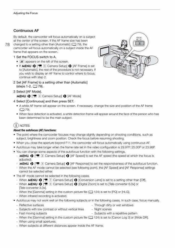
Adjusting the Focus
78
Continuous AF
By default, the camcorder will focus automatically on a subject at the center of the screen. If the AF frame size has been changed to a setting other than [Automatic] (A 79), the camcorder will focus automatically on a subject inside the AF frame that appears on the screen.
1 Set the FOCUS switch to A.• @ appears on the left of the screen.• If > [v # Camera Setup] > [AF Frame] is set
to [Automatic], the rest of the procedure is not necessary. If you wish to display an AF frame to control where to focus, continue with step 2.
2 Set [AF Frame] to a setting other than [Automatic] (steps 1-2, A 79).
3 Select [AF Mode]. > [v # Camera Setup] > [AF Mode]
4 Select [Continuous] and then press SET.• A white AF frame will appear on the screen. If necessary, change the size and position of the AF frame
(A 79).• When face detection is activated, a white detection frame will appear around the face of the person who has
been determined to be the main subject.
NOTESNOTES
About the autofocus (AF) functions: • The point where the camcorder focuses may change slightly depending on shooting conditions, such as
subject, brightness and zoom position. Check the focus before resuming shooting.• When you close the aperture beyond F11, the camcorder will focus automatically using continuous AF.• Autofocus may take longer when the frame rate set in the video configuration is 29.97P, 25.00P or 23.98P.• You can change some aspects of the autofocus function with the following settings.
- > [v # Camera Setup] > [AF Speed] to set the AF speed (the speed at which the focus is adjusted).
- > [v # Camera Setup] > [AF Response] to set the responsiveness of the autofocus function.- When the AF mode cannot be selected (see following point), the [AF Speed] and [AF Response] settings
cannot be selected either.• The AF mode cannot be selected in the following cases.
- When > [v ' Camera Setup] > [Conversion Lens] is set to a setting other than [Off].- When > [v % Camera Setup] > [Digital Zoom] is set to [Tele-converter 6.0x] or
[Tele-converter 3.0x].- When the [Gamma] setting in the custom picture file (A 124) is set to [PQ] or [HLG].- When infrared recording is activated.
• Autofocus may not work well on the following subjects or in the following cases. In such case, focus manually.
- When the [Gamma] setting in the custom picture file (A 124) is set to [Canon Log 3] or [Wide DR].- When using small apertures.- When subjects at different distances appear inside the AF frame.
- Reflective surfaces- Subjects with low contrast or without vertical lines- Fast moving subjects
- Through dirty or wet windows- Night scenes- Subjects with a repetitive pattern
79
Adjusting the Focus
Changing the AF Frame Size and PositionBy default, when autofocus is used, the camcorder focuses on a subject at the center of the screen and no AF frame is displayed. You can select to display an AF frame and change its size and position to focus on a specific area or subject.However, when the face detection or tracking function is activated, the AF frame's size and position will change automatically according to the subject being tracked.
1 Select [AF Frame]. > [v # Camera Setup] > [AF Frame]
2 Select the desired option and then press SET.
3 If you selected [Large] or [Small], select [AF Frame Position]. > [v # Camera Setup] > [AF Frame Position]
4 Select the desired option and then press SET.
Options for [AF Frame][Automatic]: No AF frame is displayed. The camcorder focuses automatically on a subject at the center of the
screen.[Large], [Small]: An AF frame is displayed. You can move the AF frame within 80% of the screen area and select
its size according to the subject you want to focus.
Options for [AF Frame Position]
[Selectable]: You can move the AF frame using the joystick or by touching the LCD screen. Press the CANCEL button to return the frame to the center of the screen.
[Center Frame]: A fixed AF frame appears at the center of the screen.
NOTESNOTES
• In the following cases you will not be able to change the AF frame's size or position.- When > [v % Camera Setup] > [Digital Zoom] is set to [Tele-converter 6.0x] or
[Tele-converter 3.0x].- When > [v ' Camera Setup] > [Conversion Lens] is set to an option other than [Off].- When the [Gamma] setting in the custom picture file (A 124) is set to [PQ] or [HLG].- While the color bars are displayed.- When infrared recording is activated.
Face DetectionWhen the face detection function is activated, the camcorder will detect people’s faces. When there are a number of people in the picture, one person will be determined to be the main subject but you have the option to select a different person as the main subject. The camcorder will keep tracking the main subject even when it moves.You can use face detection with one of the autofocus functions to let the camcorder focus on the main subject automatically (Face AF). You can also combine face detection with the Dual Pixel Focus Guide function (A 75) to help you focus on the main subject manually.
1 Select [Face Det. & Tracking]. > [v $ Camera Setup] > [Face Det. & Tracking]
2 Select [On] and then press SET.
3 Select [Face AF]. > [v $ Camera Setup] > [Face AF]
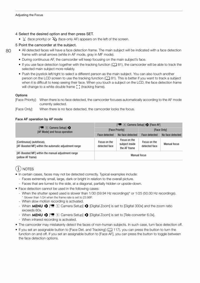
Adjusting the Focus
80
4 Select the desired option and then press SET.• (face priority) or (face-only AF) appears on the left of the screen.
5 Point the camcorder at the subject.• All detected faces will have a face detection frame. The main subject will be indicated with a face detection
frame with small arrows (white in AF mode, gray in MF mode).• During continuous AF, the camcorder will keep focusing on the main subject’s face.• If you use face detection together with the tracking function (A 81), the camcorder will be able to track the
selected main subject more reliably.• Push the joystick left/right to select a different person as the main subject. You can also touch another
person on the LCD screen to use the tracking function (A 81). This is better if you want to track a subject when it is difficult to keep seeing their face. When you touch a subject on the LCD, the face detection frame will change to a white double frame £ (tracking frame).
Options[Face Priority]: When there is no face detected, the camcorder focuses automatically according to the AF mode
currently selected.[Face Only]: When there is no face detected, the camcorder locks the focus.
Face AF operation by AF mode
NOTESNOTES
• In certain cases, faces may not be detected correctly. Typical examples include:- Faces extremely small, large, dark or bright in relation to the overall picture.- Faces that are turned to the side, at a diagonal, partially hidden or upside-down.
• Face detection cannot be used in the following cases:- When the shutter speed used is slower than 1/30 (59.94 Hz recordings)* or 1/25 (50.00 Hz recordings).
* Slower than 1/24 when the frame rate is set to 23.98P.- When slow motion recording is activated.- When > [v % Camera Setup] > [Digital Zoom] is set to [Digital 300x] and the zoom ratio
exceeds 60x.- When > [v % Camera Setup] > [Digital Zoom] is set to [Tele-converter 6.0x].- When infrared recording is activated.
• The camcorder may mistakenly detect the faces of non-human subjects. In such case, turn face detection off.• If you set an assignable button to [Face Det. and Tracking] (A 117), you can press the button to turn the
function on and off. If you set an assignable button to [Face AF], you can press the button to toggle between the face detection options.
[v # Camera Setup] > [AF Mode] and focus operation
[v $ Camera Setup] > [Face AF]
[Face Priority] [Face Only]
Face detected No face detected Face detected No face detected
[Continuous] (autofocus), [AF-Boosted MF] within the automatic adjustment range
Focus on the detected face
Focus on the subject inside the AF frame
Focus on the detected face
Manual focus
[AF-Boosted MF] within the manual adjustment range (yellow AF frame)
Manual focus
81
Adjusting the Focus
Tracking a Specific SubjectYou can have the camcorder track other moving subjects that are not faces and also combine the tracking function with one of the autofocus functions to let the camcorder focus on the desired subject automatically.
When no AF Frame is Displayed
When [AF Frame] is set to [Automatic] (A 79), you can simply use the touch screen to start tracking a subject.
Touch the desired subject on the LCD screen to start tracking it.• A white double frame £ (tracking frame) will appear around the selected subject. The camcorder will track the
subject as it moves.• Press the CANCEL button to remove the frame and cancel the tracking.
When an AF Frame is Displayed
When [AF Frame] is set to [Large] or [Small] (A 79), to use the tracking function, you will need to set an assignable button to [Tracking] in advance.
1 Set an assignable button to [Tracking] (A 117).
2 Press the assignable button.• If > [v $ Camera Setup] > [Face AF] is set to [Face Only], a double frame £ (tracking frame)
will appear around the selected main subject and the camcorder will track it as it moves. The rest of the procedure is not necessary.If > [v $ Camera Setup] > [Face AF] is set to [Face Priority], the subject selection mark I will appear on the screen. Continue with step 3.
• Press the assignable button again or the CANCEL button to exit the subject selection screen.
3 Select the subject you want to track.• Touch the desired subject on the LCD screen to start tracking it. You can also push the joystick up/down/
left/right or touch the desired subject on the LCD screen to place the center of the I mark on the desired subject and then press SET.
• If the tracking failed, the I mark will turn red momentarily. Select the subject again.
4 The I mark changes to a white double frame £ (tracking frame) and the camcorder will start tracking the selected subject.• During continuous AF, the camcorder will keep focusing on the selected subject.• Press SET or press the assignable button to return to the subject selection screen and select a different
subject, or press the CANCEL button to end the tracking function and return the camcorder to the focus mode that was used previously.
NOTESNOTES
• The camcorder may start tracking the incorrect subject if there is another subject in the picture with similar color/pattern characteristics. In that case, press SET to return to the selection screen and select the desired subject again.
• Tracking cannot be used when face detection cannot be used (A 80).
Adjusting the Focus
82
Focus Limit and Macro ShootingBy default, the camcorder’s focus range allows macro shooting. You can activate the focus limit to restrict the focus range. The focus range (1 cm (0.39 in.; at full wide-angle) to ) will be limited to 60 cm (2 ft.) to (throughout the entire zoom range).
1 Select [Focus Limit]. > [v $ Camera Setup] > [Focus Limit]
2 Select [On] and then press SET.
NOTESNOTES
• If you set an assignable button to [Focus Limit] (A 117), you can press the button to turn the focus limit on and off.
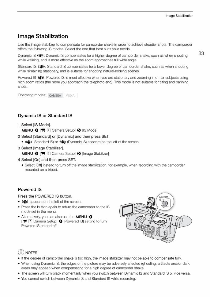
83
Image Stabilization
Image StabilizationUse the image stabilizer to compensate for camcorder shake in order to achieve steadier shots. The camcorder offers the following IS modes. Select the one that best suits your needs.
Dynamic IS Ä: Dynamic IS compensates for a higher degree of camcorder shake, such as when shooting while walking, and is more effective as the zoom approaches full wide angle.
Standard IS Å: Standard IS compensates for a lower degree of camcorder shake, such as when shooting while remaining stationary, and is suitable for shooting natural-looking scenes.
Powered IS È: Powered IS is most effective when you are stationary and zooming in on far subjects using high zoom ratios (the more you approach the telephoto end). This mode is not suitable for tilting and panning shots.
Dynamic IS or Standard IS
1 Select [IS Mode]. > [v ' Camera Setup] > [IS Mode]
2 Select [Standard] or [Dynamic] and then press SET.• Å (Standard IS) or Ä (Dynamic IS) appears on the left of the screen.
3 Select [Image Stabilizer]. > [v ' Camera Setup] > [Image Stabilizer]
4 Select [On] and then press SET.• Select [Off] instead to turn off the image stabilization, for example, when recording with the camcorder
mounted on a tripod.
Powered ISPress the POWERED IS button.• È appears on the left of the screen.• Press the button again to return the camcorder to the IS
mode set in the menu.• Alternatively, you can also use the >
[v ' Camera Setup] > [Powered IS] setting to turn Powered IS on and off.
NOTESNOTES
• If the degree of camcorder shake is too high, the image stabilizer may not be able to compensate fully.• When using Dynamic IS, the edges of the picture may be adversely affected (ghosting, artifacts and/or dark
areas may appear) when compensating for a high degree of camcorder shake.• The screen will turn black momentarily when you switch between Dynamic IS and Standard IS or vice versa.• You cannot switch between Dynamic IS and Standard IS while recording.
Operating modes:

Image Stabilization
84
• When using Dynamic IS, the angle of view will be narrower.• If you set an assignable button to [Image Stabilizer] (A 117), you can press the button to turn the image
stabilizer on and off.
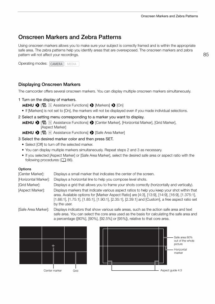
85
Onscreen Markers and Zebra Patterns
Onscreen Markers and Zebra PatternsUsing onscreen markers allows you to make sure your subject is correctly framed and is within the appropriate safe area. The zebra patterns help you identify areas that are overexposed. The onscreen markers and zebra pattern will not affect your recordings.
Displaying Onscreen MarkersThe camcorder offers several onscreen markers. You can display multiple onscreen markers simultaneously.
1 Turn on the display of markers. > [A% Assistance Functions] > [Markers] > [On]
• If [Markers] is not set to [On], the markers will not be displayed even if you made individual selections.
2 Select a setting menu corresponding to a marker you want to display. > [A% Assistance Functions] > [Center Marker], [Horizontal Marker], [Grid Marker],
[Aspect Marker] > [A& Assistance Functions] > [Safe Area Marker]
3 Select the desired marker color and then press SET.• Select [Off] to turn off the selected marker.• You can display multiple markers simultaneously. Repeat steps 2 and 3 as necessary.• If you selected [Aspect Marker] or [Safe Area Marker], select the desired safe area or aspect ratio with the
following procedures (A 86).
Options[Center Marker]: Displays a small marker that indicates the center of the screen.[Horizontal Marker]: Displays a horizontal line to help you compose level shots.[Grid Marker]: Displays a grid that allows you to frame your shots correctly (horizontally and vertically).[Aspect Marker]: Displays markers that indicate various aspect ratios to help you keep your shot within that
area. Available options for [Marker Aspect Ratio] are [4:3], [13:9], [14:9], [16:9], [1.375:1], [1.66:1], [1.75:1], [1.85:1], [1.90:1], [2.35:1], [2.39:1] and [Custom], a free aspect ratio set by the user.
[Safe Area Marker]: Displays indicators that show various safe areas, such as the action safe area and text safe area. You can select the core area used as the basis for calculating the safe area and a percentage ([80%], [90%], [92.5%] or [95%]), relative to that core area.
Operating modes:
Aspect guide 4:3Center marker Grid
Horizontal marker
Safe area 80% out of the whole picture
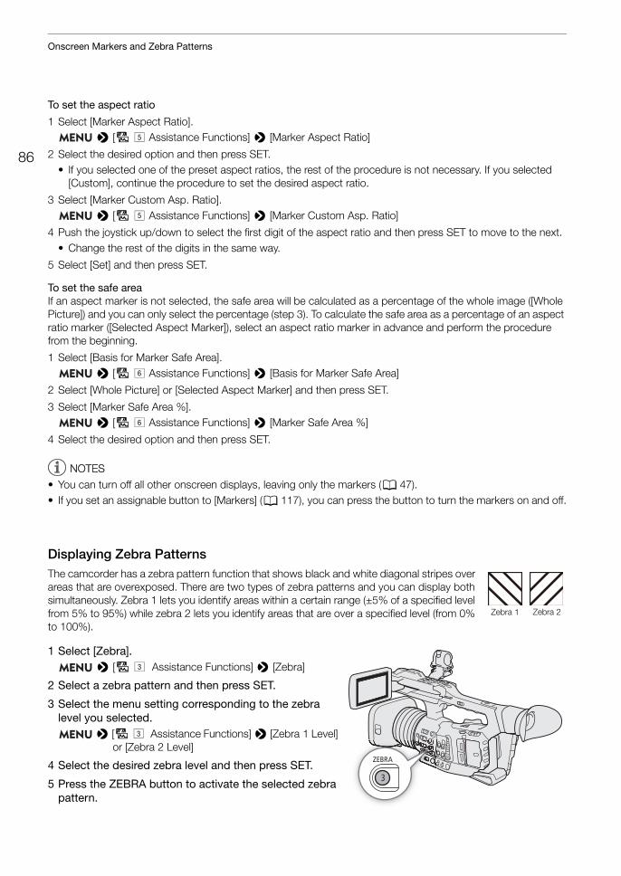
Onscreen Markers and Zebra Patterns
86
To set the aspect ratio
1 Select [Marker Aspect Ratio]. > [A% Assistance Functions] > [Marker Aspect Ratio]
2 Select the desired option and then press SET.• If you selected one of the preset aspect ratios, the rest of the procedure is not necessary. If you selected
[Custom], continue the procedure to set the desired aspect ratio.
3 Select [Marker Custom Asp. Ratio]. > [A% Assistance Functions] > [Marker Custom Asp. Ratio]
4 Push the joystick up/down to select the first digit of the aspect ratio and then press SET to move to the next.• Change the rest of the digits in the same way.
5 Select [Set] and then press SET.
To set the safe area If an aspect marker is not selected, the safe area will be calculated as a percentage of the whole image ([Whole Picture]) and you can only select the percentage (step 3). To calculate the safe area as a percentage of an aspect ratio marker ([Selected Aspect Marker]), select an aspect ratio marker in advance and perform the procedure from the beginning.
1 Select [Basis for Marker Safe Area]. > [A& Assistance Functions] > [Basis for Marker Safe Area]
2 Select [Whole Picture] or [Selected Aspect Marker] and then press SET.
3 Select [Marker Safe Area %]. > [A& Assistance Functions] > [Marker Safe Area %]
4 Select the desired option and then press SET.
NOTESNOTES
• You can turn off all other onscreen displays, leaving only the markers (A 47).• If you set an assignable button to [Markers] (A 117), you can press the button to turn the markers on and off.
Displaying Zebra PatternsThe camcorder has a zebra pattern function that shows black and white diagonal stripes over areas that are overexposed. There are two types of zebra patterns and you can display both simultaneously. Zebra 1 lets you identify areas within a certain range (±5% of a specified level from 5% to 95%) while zebra 2 lets you identify areas that are over a specified level (from 0% to 100%).
1 Select [Zebra]. > [A# Assistance Functions] > [Zebra]
2 Select a zebra pattern and then press SET.
3 Select the menu setting corresponding to the zebra level you selected.
> [A# Assistance Functions] > [Zebra 1 Level] or [Zebra 2 Level]
4 Select the desired zebra level and then press SET.
5 Press the ZEBRA button to activate the selected zebra pattern.
Zebra 1 Zebra 2

87
Onscreen Markers and Zebra Patterns
NOTESNOTES
• You can use the > [A# Assistance Functions] > [Zebra: LCD], [Zebra: VF], [Zebra: SDI] and [Zebra: HDMI] settings to turn the zebra pattern on and off separately on the LCD screen, viewfinder and external monitors connected to the respective terminals.
Setting the Time Code
88
Setting the Time CodeIn mode, the camcorder generates a time code signal and records it with the recorded clips. The time code signal can be output from the SDI terminal, HDMI OUT terminal and TIME CODE terminal. In mode, the time code embedded in the clip being played back can be output from the SDI terminal.Depending on the frame rate used, you may be able to select between a drop frame an non-drop frame time code signal (A 89). The default mode varies depending on the country/region of purchase and, though the time code display style is different for DF and NDF, in this section the NDF display style is used for simplicity’s sake.
Selecting the Time Code ModeYou can select the camcorder’s time code mode.
1 Select [Time Code Mode]. > [B# System Setup] > [Time Code Mode]
2 Select the desired option and then press SET.
Options
[Preset]: The time code starts from an initial value you can select in advance. The default initial time code is 00:00:00:00.See the following procedures to select the time code running mode and set the initial time code.
[Regen.]: The camcorder will read the selected SD card and the time code will continue from the last time code recorded on the card. The time code runs only while recording so clips recorded consecutively on the same card will have continuous time codes.
Setting the Time Code Running Mode
If you set the time code mode to [Preset], you can select the time code running mode.
1 Select [Time Code Run]. > [B# System Setup] > [Time Code Run]
2 Select the desired option and then press SET.
Options
[Rec Run]: The time code runs only while recording so clips recorded consecutively on the same card will have continuous time codes.
[Free Run]: The time code starts running the moment you press SET and keeps running regardless of the camcorder’s operation.
Operating modes:
89
Setting the Time Code
Setting the Time Code’s Initial Value
If you set the time code mode to [Preset], you can set the initial value of the time code.
1 Select [Set Time Code]. > [B# System Setup] > [Set Time Code]
2 Select [Change] and then press SET.• The time code setting screen appears with an orange selection frame indicating the hours.• To reset the time code to [00:00:00:00], select [Reset] instead. If the running mode is set to [Free Run], the
time code will be reset the moment you press SET and keep running continuously from 00:00:00:00.
3 Push the joystick up/down to set the hours and press SET to move to the minutes.• Change the rest of the fields (minutes, seconds, frame) in the same way.• Press the CANCEL button to return to the previous screen without setting the time code.
4 Select [Set] and press SET to close the screen.• If the running mode is set to [Free Run], the time code will start running from the selected time code the
moment you press SET.
Selecting Drop or Non-Drop FrameWhen the frame rate is set to 59.94P, 59.94i or 29.97P, you can select between a drop frame (DF) or non-drop frame (NDF) time code, depending on how you plan to use your recordings.With all other frame rates, the time code is set to non-drop frame (NDF) and cannot be changed.
1 Select [Time Code DF/NDF]. > [B# System Setup] > [Time Code DF/NDF]
2 Select [DF] or [NDF] and then press SET.• The time code display will differ depending on the setting. When you select [DF], the time code will appear
as [00:00:00.00]; when you select [NDF], it will appear as [00:00:00:00].
Putting the Time Code Display on HoldIf you set an assignable button to [Time Code Hold] (A 117), you can press the button to freeze the display of the time code*. While the time code display is put on hold, [H] will appear on the screen next to the time code.
The time code continues to run normally while the time code display is on hold. When you resume the time code display, the current time code will be displayed.* The time code signal output from the terminals will not be put on hold. However, the time code displayed on a monitor connected
to the SDI terminal or HDMI OUT terminal will be put on hold.
Operating modes:
Operating modes:
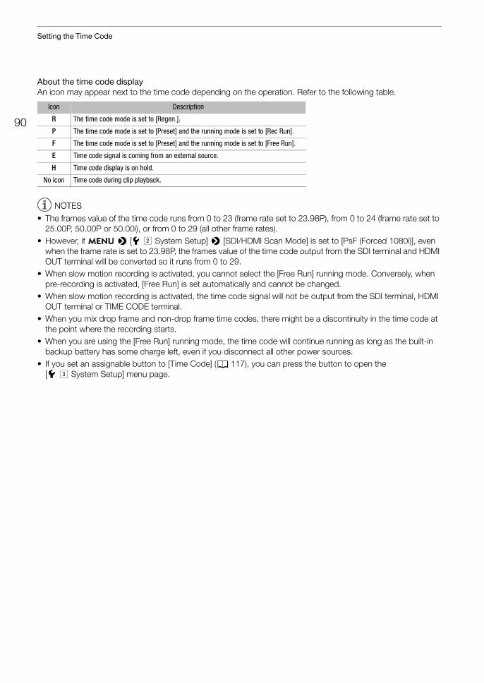
Setting the Time Code
90
About the time code displayAn icon may appear next to the time code depending on the operation. Refer to the following table.
NOTESNOTES
• The frames value of the time code runs from 0 to 23 (frame rate set to 23.98P), from 0 to 24 (frame rate set to 25.00P, 50.00P or 50.00i), or from 0 to 29 (all other frame rates).
• However, if > [B" System Setup] > [SDI/HDMI Scan Mode] is set to [PsF (Forced 1080i)], even when the frame rate is set to 23.98P, the frames value of the time code output from the SDI terminal and HDMI OUT terminal will be converted so it runs from 0 to 29.
• When slow motion recording is activated, you cannot select the [Free Run] running mode. Conversely, when pre-recording is activated, [Free Run] is set automatically and cannot be changed.
• When slow motion recording is activated, the time code signal will not be output from the SDI terminal, HDMI OUT terminal or TIME CODE terminal.
• When you mix drop frame and non-drop frame time codes, there might be a discontinuity in the time code at the point where the recording starts.
• When you are using the [Free Run] running mode, the time code will continue running as long as the built-in backup battery has some charge left, even if you disconnect all other power sources.
• If you set an assignable button to [Time Code] (A 117), you can press the button to open the [B# System Setup] menu page.
Icon Description
R The time code mode is set to [Regen.].
P The time code mode is set to [Preset] and the running mode is set to [Rec Run].
F The time code mode is set to [Preset] and the running mode is set to [Free Run].
E Time code signal is coming from an external source.
H Time code display is on hold.
No icon Time code during clip playback.
91
Setting the User Bit
Setting the User BitThe user bit display can be selected from the date or the time of recording, or an identification code consisting of 8 characters in the hexadecimal system. There are sixteen possible characters: the numbers 0 to 9 and the letters A to F.The user bit is recorded with clips and can be output from the TIME CODE terminal, SDI terminal or HDMI OUT terminal. It can be used freely to categorize and manage recordings or to keep additional information about them.
Setting an Hexadecimal Code
1 Open the user bit setting screen. > [B# System Setup] > [User Bit Type] > [Setting] > [Change]
• The user bit setting screen appears with an orange selection frame on the leftmost character.• To reset the user bit to [00 00 00 00], select [Reset] instead.
2 Push the joystick up/down to select the first character and press SET to move to the next.• Change the rest of the characters in the same way.• Press the CANCEL button to return to the previous screen without setting the user bit.
3 Select [Set] and press SET.
Using the Date or Time
1 Select [User Bit Type]. > [B# System Setup] > [User Bit Type]
2 Select [Date] or [Time] and then press SET.
Operating modes:
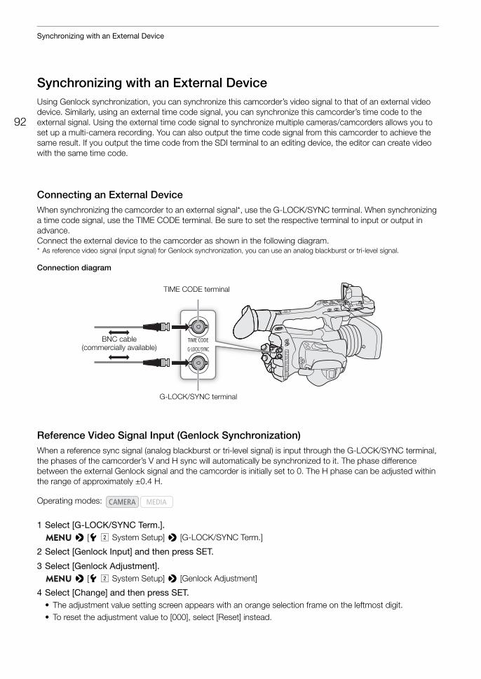
Synchronizing with an External Device
92
Synchronizing with an External DeviceUsing Genlock synchronization, you can synchronize this camcorder’s video signal to that of an external video device. Similarly, using an external time code signal, you can synchronize this camcorder’s time code to the external signal. Using the external time code signal to synchronize multiple cameras/camcorders allows you to set up a multi-camera recording. You can also output the time code signal from this camcorder to achieve the same result. If you output the time code from the SDI terminal to an editing device, the editor can create video with the same time code.
Connecting an External DeviceWhen synchronizing the camcorder to an external signal*, use the G-LOCK/SYNC terminal. When synchronizing a time code signal, use the TIME CODE terminal. Be sure to set the respective terminal to input or output in advance. Connect the external device to the camcorder as shown in the following diagram.* As reference video signal (input signal) for Genlock synchronization, you can use an analog blackburst or tri-level signal.
Connection diagram
Reference Video Signal Input (Genlock Synchronization)When a reference sync signal (analog blackburst or tri-level signal) is input through the G-LOCK/SYNC terminal, the phases of the camcorder’s V and H sync will automatically be synchronized to it. The phase difference between the external Genlock signal and the camcorder is initially set to 0. The H phase can be adjusted within the range of approximately ±0.4 H.
1 Select [G-LOCK/SYNC Term.]. > [B" System Setup] > [G-LOCK/SYNC Term.]
2 Select [Genlock Input] and then press SET.
3 Select [Genlock Adjustment]. > [B" System Setup] > [Genlock Adjustment]
4 Select [Change] and then press SET.• The adjustment value setting screen appears with an orange selection frame on the leftmost digit.• To reset the adjustment value to [000], select [Reset] instead.
Operating modes:
G-LOCK/SYNC terminal
TIME CODE terminal
BNC cable(commercially available)
93
Synchronizing with an External Device
5 Push the joystick up/down to select the first digit and press SET to move to the next.• Change the rest of the digits in the same way to adjust the H phase to the desired level (–1023 to 1023).• Press the CANCEL button to return to the previous screen without setting the Genlock adjustment value.
6 Select [Set] and then press SET.
NOTESNOTES
• When a suitable Genlock signal is input, the Genlock synchronization stabilizes after approximately 10 seconds.
• When a suitable Genlock signal is detected, the U icon will flash at the top right of the screen. When the camcorder locks on the external Genlock signal, the icon will stay on.
• If the external Genlock signal is incorrect, the synchronization may not be stable. In such case, the recorded time code may be incorrect.
Time Code Signal InputAn external SMPTE-standard LTC timing signal received from the TIME CODE terminal will be recorded as the time code. The user bit of the external timing signal can also be recorded with the clips. Before connecting the device, set the TIME CODE terminal to input. Also, you must set the running mode of the time code to [Free Run] (A 88).
1 Select [TC In/Out]. > [B# System Setup] > [TC In/Out]
2 Select [In] and then press SET.
Recording the User Bit of an External Signal
The user bit of an external time code signal can also be recorded with clips along with the time code itself.
1 Select [User Bit Recording Mode]. > [B# System Setup] > [User Bit Recording Mode]
2 Select [External] and then press SET.
NOTESNOTES
• When the frame rate is set to 23.98P, use a 24-frame time code signal as input signal. When it is set to 25.00P, 50.00i or 50.00P, use a 25-frame time code signal. For other frame rates, use a 30-frame time code signal.
• When a suitable time code signal is received, the camcorder’s own time code will be synchronized to it and the synchronization will be maintained even if you disconnect the cable from the TIME CODE terminal.
• If the external time code signal is incorrect or there is no input signal, the internal time code (as set with the menu settings in the [B# System Setup] menu page) will be recorded instead.
• While a time code signal is being received, the external time code’s drop-frame bit will be used.• Performing any of the following actions while the cable is not connected will cause the synchronization to be
disrupted; the correct time code will be restored once you reconnect the cable.- Turning the camcorder off/on- Changing the operating mode to mode- Changing the video configuration
Operating modes:
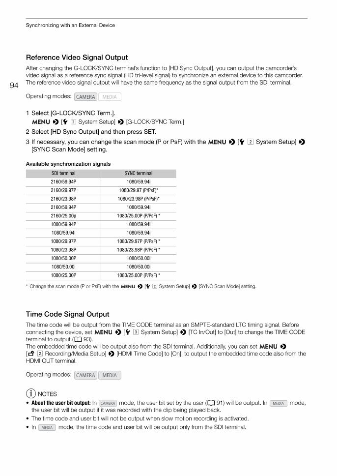
Synchronizing with an External Device
94
Reference Video Signal OutputAfter changing the G-LOCK/SYNC terminal’s function to [HD Sync Output], you can output the camcorder’s video signal as a reference sync signal (HD tri-level signal) to synchronize an external device to this camcorder. The reference video signal output will have the same frequency as the signal output from the SDI terminal.
1 Select [G-LOCK/SYNC Term.]. > [B" System Setup] > [G-LOCK/SYNC Term.]
2 Select [HD Sync Output] and then press SET.
3 If necessary, you can change the scan mode (P or PsF) with the > [B" System Setup] > [SYNC Scan Mode] setting.
Available synchronization signals
* Change the scan mode (P or PsF) with the > [B" System Setup] > [SYNC Scan Mode] setting.
Time Code Signal OutputThe time code will be output from the TIME CODE terminal as an SMPTE-standard LTC timing signal. Before connecting the device, set > [B# System Setup] > [TC In/Out] to [Out] to change the TIME CODE terminal to output (A 93).The embedded time code will be output also from the SDI terminal. Additionally, you can set > [3" Recording/Media Setup] > [HDMI Time Code] to [On], to output the embedded time code also from the HDMI OUT terminal.
NOTESNOTES
• About the user bit output: In mode, the user bit set by the user (A 91) will be output. In mode, the user bit will be output if it was recorded with the clip being played back.
• The time code and user bit will not be output when slow motion recording is activated.• In mode, the time code and user bit will be output only from the SDI terminal.
Operating modes:
SDI terminal SYNC terminal
2160/59.94P 1080/59.94i
2160/29.97P 1080/29.97 (P/PsF)*
2160/23.98P 1080/23.98P (P/PsF)*
2160/59.94P 1080/59.94i
2160/25.00p 1080/25.00P (P/PsF) *
1080/59.94P 1080/59.94i
1080/59.94i 1080/59.94i
1080/29.97P 1080/29.97P (P/PsF) *
1080/23.98P 1080/23.98P (P/PsF) *
1080/50.00P 1080/50.00i
1080/50.00i 1080/50.00i
1080/25.00P 1080/25.00P (P/PsF) *
Operating modes:
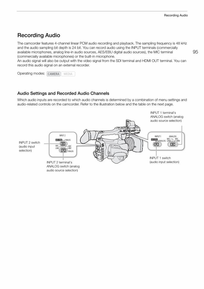
95
Recording Audio
Recording AudioThe camcorder features 4-channel linear PCM audio recording and playback. The sampling frequency is 48 kHz and the audio sampling bit depth is 24 bit. You can record audio using the INPUT terminals (commercially available microphones, analog line-in audio sources, AES/EBU digital audio sources), the MIC terminal (commercially available microphones) or the built-in microphone.An audio signal will also be output with the video signal from the SDI terminal and HDMI OUT terminal. You can record this audio signal on an external recorder.
Audio Settings and Recorded Audio ChannelsWhich audio inputs are recorded to which audio channels is determined by a combination of menu settings and audio-related controls on the camcorder. Refer to the illustration below and the table on the next page.
Operating modes:
INPUT 1 switch(audio input selection)
INPUT 1 terminal'sANALOG switch (analogaudio source selection)
INPUT 2 switch(audio input selection)
INPUT 2 terminal'sANALOG switch (analogaudio source selection)
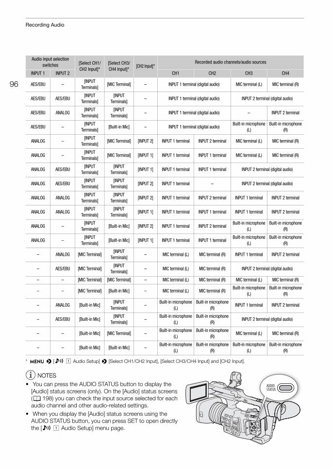
Recording Audio
96
* > [¡ ! Audio Setup] > [Select CH1/CH2 Input], [Select CH3/CH4 Input] and [CH2 Input].
NOTESNOTES
• You can press the AUDIO STATUS button to display the [Audio] status screens (only). On the [Audio] status screens (A 198) you can check the input source selected for each audio channel and other audio-related settings.
• When you display the [Audio] status screens using the AUDIO STATUS button, you can press SET to open directly the [¡ ! Audio Setup] menu page.
Audio input selection switches [Select CH1/
CH2 Input]*[Select CH3/CH4 Input]*
[CH2 Input]*Recorded audio channels/audio sources
INPUT 1 INPUT 2 CH1 CH2 CH3 CH4
AES/EBU –[INPUT
Terminals][MIC Terminal] – INPUT 1 terminal (digital audio) MIC terminal (L) MIC terminal (R)
AES/EBU AES/EBU[INPUT
Terminals][INPUT
Terminals]– INPUT 1 terminal (digital audio) INPUT 2 terminal (digital audio)
AES/EBU ANALOG[INPUT
Terminals][INPUT
Terminals]– INPUT 1 terminal (digital audio) – INPUT 2 terminal
AES/EBU –[INPUT
Terminals][Built-in Mic] – INPUT 1 terminal (digital audio)
Built-in microphone(L)
Built-in microphone(R)
ANALOG –[INPUT
Terminals][MIC Terminal] [INPUT 2] INPUT 1 terminal INPUT 2 terminal MIC terminal (L) MIC terminal (R)
ANALOG –[INPUT
Terminals][MIC Terminal] [INPUT 1] INPUT 1 terminal INPUT 1 terminal MIC terminal (L) MIC terminal (R)
ANALOG AES/EBU[INPUT
Terminals][INPUT
Terminals][INPUT 1] INPUT 1 terminal INPUT 1 terminal INPUT 2 terminal (digital audio)
ANALOG AES/EBU[INPUT
Terminals][INPUT
Terminals][INPUT 2] INPUT 1 terminal – INPUT 2 terminal (digital audio)
ANALOG ANALOG[INPUT
Terminals][INPUT
Terminals][INPUT 2] INPUT 1 terminal INPUT 2 terminal INPUT 1 terminal INPUT 2 terminal
ANALOG ANALOG[INPUT
Terminals][INPUT
Terminals][INPUT 1] INPUT 1 terminal INPUT 1 terminal INPUT 1 terminal INPUT 2 terminal
ANALOG –[INPUT
Terminals][Built-in Mic] [INPUT 2] INPUT 1 terminal INPUT 2 terminal
Built-in microphone(L)
Built-in microphone(R)
ANALOG –[INPUT
Terminals][Built-in Mic] [INPUT 1] INPUT 1 terminal INPUT 1 terminal
Built-in microphone(L)
Built-in microphone(R)
– ANALOG [MIC Terminal][INPUT
Terminals]– MIC terminal (L) MIC terminal (R) INPUT 1 terminal INPUT 2 terminal
– AES/EBU [MIC Terminal][INPUT
Terminals]– MIC terminal (L) MIC terminal (R) INPUT 2 terminal (digital audio)
– – [MIC Terminal] [MIC Terminal] – MIC terminal (L) MIC terminal (R) MIC terminal (L) MIC terminal (R)
– – [MIC Terminal] [Built-in Mic] – MIC terminal (L) MIC terminal (R)Built-in microphone
(L) Built-in microphone
(R)
– ANALOG [Built-in Mic][INPUT
Terminals]–
Built-in microphone(L)
Built-in microphone(R)
INPUT 1 terminal INPUT 2 terminal
– AES/EBU [Built-in Mic][INPUT
Terminals]–
Built-in microphone(L)
Built-in microphone(R)
INPUT 2 terminal (digital audio)
– – [Built-in Mic] [MIC Terminal] –Built-in microphone
(L) Built-in microphone
(R)MIC terminal (L) MIC terminal (R)
– – [Built-in Mic] [Built-in Mic] –Built-in microphone
(L) Built-in microphone
(R)Built-in microphone
(L) Built-in microphone
(R)
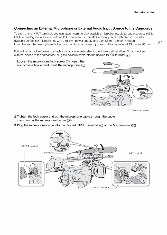
97
Recording Audio
Connecting an External Microphone or External Audio Input Source to the CamcorderTo each of the INPUT terminals you can attach commercially available microphones, digital audio sources (AES/EBU), or analog line in sources with an XLR connector. To the MIC terminal you can attach commercially available condenser microphones with their own power supply, and a 3.5 mm stereo mini plug.Using the supplied microphone holder, you can fix external microphones with a diameter of 19 mm to 20 mm.
Follow the procedure below to attach a microphone (refer also to the following illustration). To connect an external device to the camcorder, plug the device’s cable into the desired INPUT terminal (�).
1 Loosen the microphone lock screw (�), open the microphone holder and insert the microphone (�).
2 Tighten the lock screw and put the microphone cable through the cable clamp under the microphone holder (�).
3 Plug the microphone cable into the desired INPUT terminal (�) or the MIC terminal (�).
�
�
Microphone lock screw
�
��
�
MIC terminalCable clamp
INPUT 1 terminal
INPUT 2 terminal
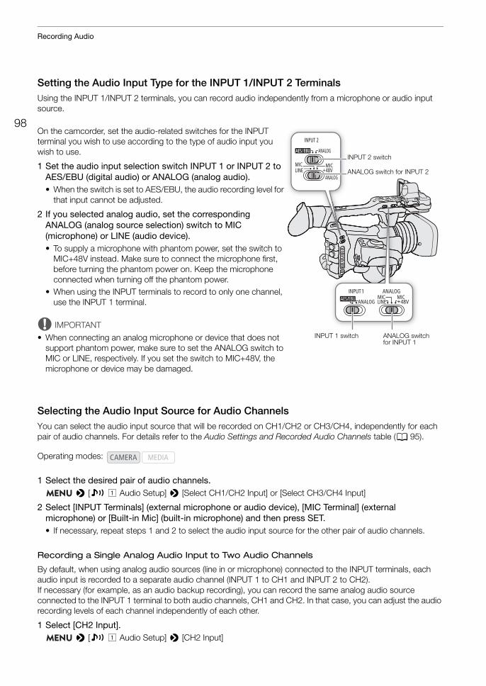
Recording Audio
98
Setting the Audio Input Type for the INPUT 1/INPUT 2 TerminalsUsing the INPUT 1/INPUT 2 terminals, you can record audio independently from a microphone or audio input source.
On the camcorder, set the audio-related switches for the INPUT terminal you wish to use according to the type of audio input you wish to use.
1 Set the audio input selection switch INPUT 1 or INPUT 2 to AES/EBU (digital audio) or ANALOG (analog audio).• When the switch is set to AES/EBU, the audio recording level for
that input cannot be adjusted.
2 If you selected analog audio, set the corresponding ANALOG (analog source selection) switch to MIC (microphone) or LINE (audio device).• To supply a microphone with phantom power, set the switch to
MIC+48V instead. Make sure to connect the microphone first, before turning the phantom power on. Keep the microphone connected when turning off the phantom power.
• When using the INPUT terminals to record to only one channel, use the INPUT 1 terminal.
IMPORTANT
• When connecting an analog microphone or device that does not support phantom power, make sure to set the ANALOG switch to MIC or LINE, respectively. If you set the switch to MIC+48V, the microphone or device may be damaged.
Selecting the Audio Input Source for Audio ChannelsYou can select the audio input source that will be recorded on CH1/CH2 or CH3/CH4, independently for each pair of audio channels. For details refer to the Audio Settings and Recorded Audio Channels table (A 95).
1 Select the desired pair of audio channels. > [¡ ! Audio Setup] > [Select CH1/CH2 Input] or [Select CH3/CH4 Input]
2 Select [INPUT Terminals] (external microphone or audio device), [MIC Terminal] (external microphone) or [Built-in Mic] (built-in microphone) and then press SET.• If necessary, repeat steps 1 and 2 to select the audio input source for the other pair of audio channels.
Recording a Single Analog Audio Input to Two Audio Channels
By default, when using analog audio sources (line in or microphone) connected to the INPUT terminals, each audio input is recorded to a separate audio channel (INPUT 1 to CH1 and INPUT 2 to CH2).If necessary (for example, as an audio backup recording), you can record the same analog audio source connected to the INPUT 1 terminal to both audio channels, CH1 and CH2. In that case, you can adjust the audio recording levels of each channel independently of each other.
1 Select [CH2 Input]. > [¡ ! Audio Setup] > [CH2 Input]
Operating modes:
INPUT 2 switch
INPUT 1 switch
ANALOG switch for INPUT 2
ANALOG switch for INPUT 1
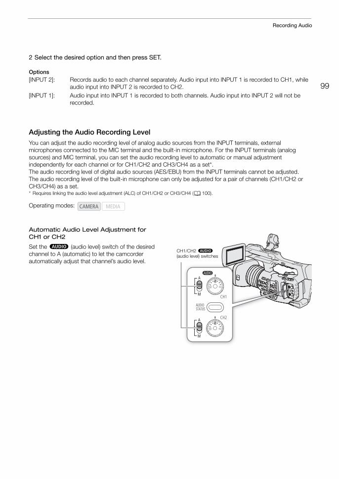
99
Recording Audio
2 Select the desired option and then press SET.
Options[INPUT 2]: Records audio to each channel separately. Audio input into INPUT 1 is recorded to CH1, while
audio input into INPUT 2 is recorded to CH2.[INPUT 1]: Audio input into INPUT 1 is recorded to both channels. Audio input into INPUT 2 will not be
recorded.
Adjusting the Audio Recording LevelYou can adjust the audio recording level of analog audio sources from the INPUT terminals, external microphones connected to the MIC terminal and the built-in microphone. For the INPUT terminals (analog sources) and MIC terminal, you can set the audio recording level to automatic or manual adjustment independently for each channel or for CH1/CH2 and CH3/CH4 as a set*.The audio recording level of digital audio sources (AES/EBU) from the INPUT terminals cannot be adjusted. The audio recording level of the built-in microphone can only be adjusted for a pair of channels (CH1/CH2 or CH3/CH4) as a set.* Requires linking the audio level adjustment (ALC) of CH1/CH2 or CH3/CH4 (A 100).
Automatic Audio Level Adjustment for CH1 or CH2
Set the – (audio level) switch of the desired channel to A (automatic) to let the camcorder automatically adjust that channel’s audio level.
Operating modes:
CH1/CH2 – (audio level) switches
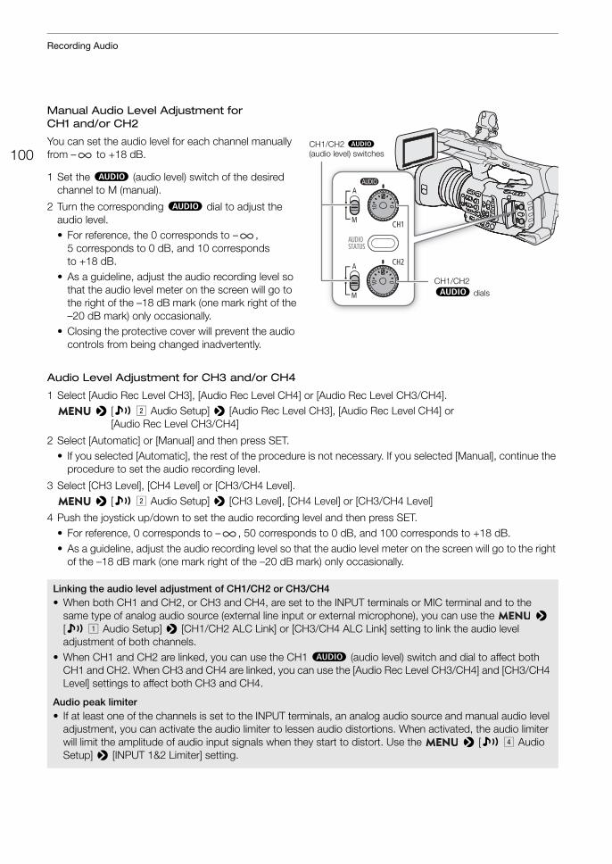
Recording Audio
100
Manual Audio Level Adjustment for CH1 and/or CH2
You can set the audio level for each channel manually from – to +18 dB.
1 Set the – (audio level) switch of the desired channel to M (manual).
2 Turn the corresponding – dial to adjust the audio level.• For reference, the 0 corresponds to – ,
5 corresponds to 0 dB, and 10 corresponds to +18 dB.
• As a guideline, adjust the audio recording level so that the audio level meter on the screen will go to the right of the –18 dB mark (one mark right of the –20 dB mark) only occasionally.
• Closing the protective cover will prevent the audio controls from being changed inadvertently.
Audio Level Adjustment for CH3 and/or CH4
1 Select [Audio Rec Level CH3], [Audio Rec Level CH4] or [Audio Rec Level CH3/CH4]. > [¡ " Audio Setup] > [Audio Rec Level CH3], [Audio Rec Level CH4] or
[Audio Rec Level CH3/CH4]
2 Select [Automatic] or [Manual] and then press SET.• If you selected [Automatic], the rest of the procedure is not necessary. If you selected [Manual], continue the
procedure to set the audio recording level.
3 Select [CH3 Level], [CH4 Level] or [CH3/CH4 Level]. > [¡ " Audio Setup] > [CH3 Level], [CH4 Level] or [CH3/CH4 Level]
4 Push the joystick up/down to set the audio recording level and then press SET.• For reference, 0 corresponds to – , 50 corresponds to 0 dB, and 100 corresponds to +18 dB. • As a guideline, adjust the audio recording level so that the audio level meter on the screen will go to the right
of the –18 dB mark (one mark right of the –20 dB mark) only occasionally.
Linking the audio level adjustment of CH1/CH2 or CH3/CH4• When both CH1 and CH2, or CH3 and CH4, are set to the INPUT terminals or MIC terminal and to the
same type of analog audio source (external line input or external microphone), you can use the > [¡ ! Audio Setup] > [CH1/CH2 ALC Link] or [CH3/CH4 ALC Link] setting to link the audio level adjustment of both channels.
• When CH1 and CH2 are linked, you can use the CH1 – (audio level) switch and dial to affect both CH1 and CH2. When CH3 and CH4 are linked, you can use the [Audio Rec Level CH3/CH4] and [CH3/CH4 Level] settings to affect both CH3 and CH4.
Audio peak limiter• If at least one of the channels is set to the INPUT terminals, an analog audio source and manual audio level
adjustment, you can activate the audio limiter to lessen audio distortions. When activated, the audio limiter will limit the amplitude of audio input signals when they start to distort. Use the > [¡ $ Audio Setup] > [INPUT 1&2 Limiter] setting.
CH1/CH2 – (audio level) switches
CH1/CH2– dials
101
Recording Audio
NOTESNOTES
• We recommend using headphones when adjusting the audio level. If the input level is too high, audio may become distorted even if the audio level indicator shows an appropriate level.
• If you set an assignable button to [Audio Level Indicator] (A 117), you can press the button to turn the onscreen audio level indicator on and off.
Advanced Audio Input Settings
Low-Cut Filter (Built-in Microphone)
If you selected [Built-in Mic] as the audio input for an audio channel (A 95), you can activate the built-in microphone's low-cut filter.
1 Select [Built-in Mic Low Cut]. > [¡ # Audio Setup] > [Built-in Mic Low Cut]
2 Select the desired option and then press SET.
Options[Off]: For recording audio under usual conditions.[LC1]: For recording mainly people’s voices.[LC2]: For reducing the background sound of wind when recording outdoors in windy surroundings (for
example, on a beach or close to buildings). Note that when you use this setting some low-frequency sounds may be suppressed along with the sound of wind.
Microphone Sensitivity (Built-in Microphone)
If you selected [Built-in Mic] as the audio input for an audio channel (A 95), you can adjust select the built-in microphone's sensitivity.
1 Select [Built-in Mic Sensitivity]. > [¡ # Audio Setup] > [Built-in Mic Sensitivity]
2 Select the desired option and then press SET.
Options[Normal]: For recording audio under usual conditions.[High]: For recording audio at a higher volume (+6 dB).
Microphone Attenuator (Built-in Microphone)
If you selected [Built-in Mic] as the audio input for an audio channel (A 95), you can activate the built-in microphone's attenuator (12 dB).
1 Select [Built-in Mic Att.]. > [¡ # Audio Setup] > [Built-in Mic Att.]
2 Select [On] and then press SET.
Operating modes:
Recording Audio
102
Microphone Sensitivity (INPUT Terminals)
If you selected [INPUT Terminals] as the audio input for an audio channel (A 95), one of the INPUT switches is set to ANALOG, and the corresponding ANALOG switch is set to MIC or MIC+48V, you can select the external microphone’s sensitivity.
1 Select the menu setting for the INPUT terminal used. > [¡ $ Audio Setup] > [INPUT 1 Mic Trimming] or [INPUT 2 Mic Trimming]
2 Select the desired level and then press SET.• You can select one of 5 sensitivity levels from –12 dB to +12 dB.
Microphone Attenuator (INPUT Terminals)
If you selected [INPUT Terminals] as the audio input for an audio channel (A 95), one of the INPUT switches is set to ANALOG, and the corresponding ANALOG switch is set to MIC or MIC+48V, you can activate the external microphone’s attenuator (20 dB).
1 Select the menu setting for the INPUT terminal used. > [¡ $ Audio Setup] > [INPUT 1 Mic Att.] or [INPUT 2 Mic Att.]
2 Select [On] and then press SET.
Microphone Attenuator (MIC Terminal)
If you selected [MIC Terminal] as the audio input for an audio channel (A 95), you can activate the external microphone's attenuator (20 dB).
1 Select [MIC Att.]. > [¡ $ Audio Setup] > [MIC Att.]
2 Select [On] and then press SET.
Low-Cut Filter (MIC Terminal)
If you selected [MIC Terminal] as the audio input for an audio channel (A 95), you can activate the external microphone's low-cut filter.
1 Select [MIC Low Cut]. > [¡ $ Audio Setup] > [MIC Low Cut]
2 Select [On] and then press SET.• When you activate the low-cut filter, some low-frequency sounds may be suppressed along with the sound
of wind.
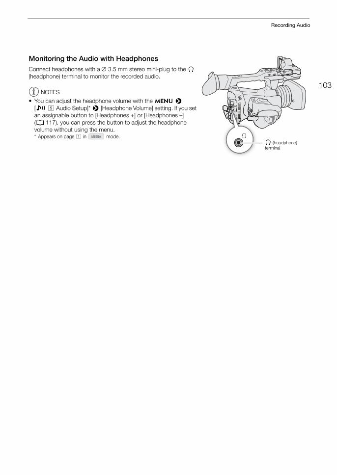
103
Recording Audio
Monitoring the Audio with HeadphonesConnect headphones with a 3.5 mm stereo mini-plug to the × (headphone) terminal to monitor the recorded audio.
NOTESNOTES
• You can adjust the headphone volume with the > [¡ % Audio Setup]* > [Headphone Volume] setting. If you set an assignable button to [Headphones +] or [Headphones –] (A 117), you can press the button to adjust the headphone volume without using the menu.* Appears on page ! in mode.
× (headphone) terminal
Colors Bars/Audio Reference Signal
104
Colors Bars/Audio Reference SignalYou can have the camcorder generate color bars and a 1 kHz audio reference signal and output them from the SDI terminal, HDMI OUT terminal and × (headphone) terminal*.* Audio reference signal only.
Color BarsThe camcorder offers 3 types of color bars (SMPTE, EBU or ARIB).
1 Select [Color Bar Type]. > [v ' Camera Setup] > [Color Bar Type]
2 Select the type of color bars and then press SET.
3 To activate the color bars, select [Color Bars]. > [v ' Camera Setup] > [Color Bars]
4 Select [On] and then press SET.• The selected color bars appear on the screen and will be recorded when you press the REC button.• Turning off the camcorder or changing the operating mode to mode will deactivate the color bars.
NOTESNOTES
• You cannot change the type of color bars while recording or when pre-recording is activated.• You cannot turn the color bars on and off while recording.• If you set an assignable button to [Color Bars] (A 117), you can press the button to turn the color bars on/off.
Audio Reference SignalThe camcorder can output a 1 kHz audio reference signal with the color bars.
1 Select [1 kHz Tone]. > [¡ % Audio Setup] > [1 kHz Tone]
2 Select the desired level and then press SET.• You can select one of three audio levels (–12 dB, –18 dB, –20 dB) or [Off] to turn off the signal.• The reference signal will be output at the selected level when you display the color bars, and will be recorded
when you press the REC button.
Operating modes:
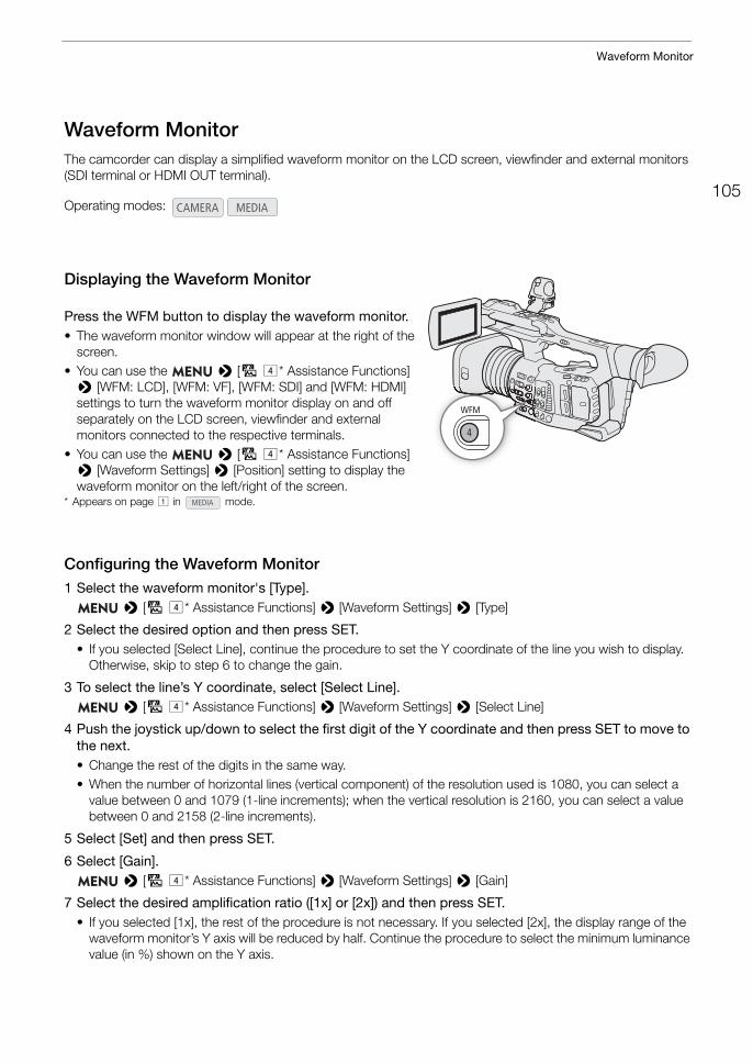
105
Waveform Monitor
Waveform MonitorThe camcorder can display a simplified waveform monitor on the LCD screen, viewfinder and external monitors (SDI terminal or HDMI OUT terminal).
Displaying the Waveform Monitor
Press the WFM button to display the waveform monitor.• The waveform monitor window will appear at the right of the
screen.• You can use the > [A$* Assistance Functions]
> [WFM: LCD], [WFM: VF], [WFM: SDI] and [WFM: HDMI] settings to turn the waveform monitor display on and off separately on the LCD screen, viewfinder and external monitors connected to the respective terminals.
• You can use the > [A$* Assistance Functions] > [Waveform Settings] > [Position] setting to display the waveform monitor on the left/right of the screen.
* Appears on page ! in mode.
Configuring the Waveform Monitor1 Select the waveform monitor's [Type].
> [A$* Assistance Functions] > [Waveform Settings] > [Type]
2 Select the desired option and then press SET.• If you selected [Select Line], continue the procedure to set the Y coordinate of the line you wish to display.
Otherwise, skip to step 6 to change the gain.
3 To select the line’s Y coordinate, select [Select Line]. > [A$* Assistance Functions] > [Waveform Settings] > [Select Line]
4 Push the joystick up/down to select the first digit of the Y coordinate and then press SET to move to the next.• Change the rest of the digits in the same way.• When the number of horizontal lines (vertical component) of the resolution used is 1080, you can select a
value between 0 and 1079 (1-line increments); when the vertical resolution is 2160, you can select a value between 0 and 2158 (2-line increments).
5 Select [Set] and then press SET.
6 Select [Gain]. > [A$* Assistance Functions] > [Waveform Settings] > [Gain]
7 Select the desired amplification ratio ([1x] or [2x]) and then press SET.• If you selected [1x], the rest of the procedure is not necessary. If you selected [2x], the display range of the
waveform monitor’s Y axis will be reduced by half. Continue the procedure to select the minimum luminance value (in %) shown on the Y axis.
Operating modes:
Waveform Monitor
106
8 Select [Y Position]. > [A$* Assistance Functions] > [Waveform Settings] > [Y Position]
9 Select the desired percentage and then press SET.* Appears on page ! in mode.
Options for [Type][Line]: Sets the waveform monitor to line display mode.[Line+Spot]: The waveform of the area in the red frame is displayed in red on top of the [Line] mode
waveform.[Select Line]: The selected horizontal line will be displayed along with its waveform.[Field]: Sets the waveform monitor to field display mode.[RGB]: Functions like an RGB parade scope.[YPbPr]: Functions like a YPbPr parade scope.
NOTESNOTES
• The waveform monitor will not be affected even if a LUT is applied to the LCD screen, viewfinder or video output from the SDI terminal or HDMI OUT terminal.
• The waveform monitor cannot be displayed while the color bars are displayed or magnification is activated.• If the [Knee] settings in the custom picture file (A 126) were changed, a horizontal line will appear on the
waveform monitor indicating the luminance (Y) level corresponding to the knee point.
107
Adding Marks to Clips while Recording
Adding Marks to Clips while RecordingWhen recording clips, you can flag an important shot in a clip by adding a “shot mark” (!). You can also add an OK mark ($) or check mark (%) to the entire clip to flag clips you want to set apart.You can also add an delete shot marks (A 141), $ marks and % marks (A 139) in mode.
Adding Shot Marks while RecordingTo add a shot mark to a clip while recording, you must first set in advance an assignable button to [Add Shot Mark].
1 Set an assignable button to [Add Shot Mark] (A 117).
2 While you are recording, press the assignable button at the beginning of the shot you wish to mark.• A message indicating the shot mark will appear and the selected shot mark will be added to the current
frame of the clip.
NOTESNOTES
• You can also press the SHOT1 button on the wireless controller to add a shot mark.• Up to 100 shot marks can be added to a single clip.• There may be up to a 1 second delay from when you press the button to when the camcorder adds the shot
mark.• When a clip contains a shot mark, ! will appear next to the clip’s thumbnail in the playback index screen.• A shot mark cannot be added while pre-recording (before you press the REC button to start recording).
Adding an $ Mark or % Mark to the Last Clip RecordedAfter recording an important clip, you can add an OK mark ($) or check mark (%) to the clip to set it apart. $ marks can also be used to protect important clips, as clips with an $ mark cannot be deleted with the camcorder.To add an $ mark or % mark to the last clip recorded in mode, you must first set in advance an assignable button to [Add $ Mark] or [Add % Mark].
1 Set an assignable button to [Add $ Mark] or [Add % Mark] (A 117).• To add both types of clip marks (to different clips), set one assignable button to [Add $ Mark] and another
assignable button to [Add % Mark].
2 After recording a clip, press the assignable button.• A message indicating the clip mark will appear and the selected clip mark will be added to the clip.
NOTESNOTES
• A clip cannot have both an $ mark and a % mark at the same time. • When a clip has an $ mark or % mark, the respective icon will appear next to the clip's thumbnail in the
playback index screen.
Operating modes:
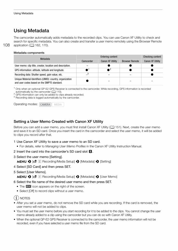
Using Metadata
108
Using MetadataThe camcorder automatically adds metadata to the recorded clips. You can use Canon XF Utility to check and search for specific metadata. You can also create and transfer a user memo remotely using the Browser Remote application (A 162, 170).
Metadata components
1 Only when an optional GP-E2 GPS Receiver is connected to the camcorder. While recording, GPS information is recorded automatically by the camcorder (A 110).
2 GPS information can only be added to clips already recorded.3 Recording data is logged automatically by the camcorder.
Setting a User Memo Created with Canon XF UtilityBefore you can add a user memo, you must first install Canon XF Utility (A 151). Next, create the user memo and save it to an SD card. Once you insert the card in the camcorder and select the user memo, it will be added to clips you record after that.
1 Use Canon XF Utility to save a user memo to an SD card.• For details, refer to Managing User Memo Profiles in the Canon XF Utility Instruction Manual.
2 Insert the card into the camcorder’s SD card slot 3.
3 Select the user memo [Setting]. > [3" Recording/Media Setup] > [Metadata] > [Setting]
4 Select [SD Card] and then press SET.
5 Select [User Memo]. > [3" Recording/Media Setup] > [Metadata] > [User Memo]
6 Select the file name of the desired user memo and then press SET.• The Q icon appears on the right of the screen.• Select [Off] to record clips without a user memo.
NOTESNOTES
• After you set a user memo, do not remove the SD card while you are recording. If the card is removed, the user memo will not be added to clips.
• You must set the user memo before you start recording for it to be added to the clips. You cannot change the user memo already added to a clip using the camcorder but you can do so with Canon XF Utility.
• When the optional GP-E2 GPS Receiver is connected to the camcorder, the user memo information will not be recorded, even if you have selected a user memo file from the SD card.
MetadataEntering content Checking content
Camcorder Canon XF Utility Browser Remote Canon XF Utility
User memo: clip title, creator, location and description. – Ü Ü Ü
GPS information: altitude, latitude and longitude. Ü1 Ü2 Ü Ü
Recording data: Shutter speed, gain value, etc. –3 – – Ü
Unique Material Identifiers (UMID): country, organization and user codes based on the SMPTE standard.
Ü – – –
Operating modes:

109
Using Metadata
Entering Slate Information About the RecordingYou can enter scene and take information to help identify the recording later on.
1 Select [Scene] or [Take]. > [3" Recording/Media Setup] > [Metadata] > [Scene] or [Take]
2 Select [Change] and then press SET.• Enter the desired information (scene, up to 16 characters; take, up to 8 characters) using the keyboard
screen (A 27).• To clear the scene/take information, select [Reset] instead.
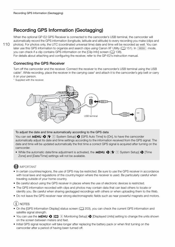
Recording GPS Information (Geotagging)
110
Recording GPS Information (Geotagging)When the optional GP-E2 GPS Receiver is connected to the camcorder’s USB terminal, the camcorder will automatically record the GPS information (longitude, latitude and altitude) to every recording you make (clips and photos). For photos only, the UTC (coordinated universal time) date and time will be recorded as well. You can later use this GPS information to organize and search clips using Canon XF Utility (A 151). In mode, you can check if a clip contains GPS information on the [Clip Info] screen (A 138).For details about attaching and configuring the receiver, refer to the GP-E2’s instruction manual.
Connecting the GPS ReceiverTurn off the camcorder and the receiver. Connect the receiver to the camcorder’s USB terminal using the USB cable*. While recording, place the receiver in the carrying case* and attach it to the camcorder’s grip belt or carry it on your person.* Supplied with the receiver.
IMPORTANT
• In certain countries/regions, the use of GPS may be restricted. Be sure to use the GPS receiver in accordance with local laws and regulations of the country/region where the receiver is used. Be particularly careful when traveling outside of your home country.
• Be careful about using the GPS receiver in places where the use of electronic devices is restricted.• The GPS information recorded with clips and photos may contain data that can lead others to locate or
identify you. Be careful when sharing geotagged recordings with others or when uploading them to the Web.• Do not leave the GPS receiver near strong electromagnetic fields such as near powerful magnets and motors.
NOTESNOTES
• On the [GPS Information Display] status screen (A 203), you can check the current GPS information and satellite signal strength.
• You can use the > [¢ % Monitoring Setup] > [Displayed Units] setting to change the units shown on the screen between meters and feet.
• Initial GPS signal reception will take longer after replacing the battery pack or when first turning on the camcorder after a period of having been turned off.
To adjust the date and time automatically according to the GPS dataYou can set > [B! System Setup] > [GPS Auto Time] to [On], to have the camcorder automatically adjust its date and time settings according to the information received from the GPS signal. The date and time will be updated automatically the first time a correct GPS signal is acquired after turning on the camcorder.• While the automatic date/time adjustment is activated, the > [B! System Setup] > [Time
Zone] and [Date/Time] settings will not be available.
USB terminal

111
Recording GPS Information (Geotagging)
• Do not place cables connected to the SDI terminal or HDMI OUT terminal near the GPS receiver as doing so may interfere with the GPS signal.
• The GPS information recorded with clips corresponds to the location at the start of the recording.• The camcorder is not compatible with the GPS receiver’s digital compass and positioning interval functions.
Also, the [Set now] option is not available for the [GPS Auto Time] setting.
Reviewing a Recording
112
Reviewing a RecordingIf you set an assignable button to [Review Recording] in advance, you can review all or part of the last clip recorded even with the camcorder set to mode.
1 Set an assignable button to [Review Recording] in advance (A 117).
2 To set the review length, select [Review Recording]. > [B% System Setup] > [Review Recording]
3 Select the desired option and then press SET.
4 After you finish recording a clip, press the assignable button.• The last clip that was recorded is played back for the selected duration. [Ð REVIEW] appears at the top of
the screen.• While the clip is reviewed, there will be no sound from the built-in speaker but the audio will be output from
the × (headphone) terminal, HDMI OUT terminal and SDI terminal.• You can use the joystick to jump back/forward within the clip (A 135).• Press the CANCEL button to stop reviewing the clip and return the camcorder to record standby mode.• After the clip finishes playing back, the camcorder returns to record standby mode.
Options[Entire Clip]: Allows you to review the entire clip.[Last 4 sec]: Allows you to review just the last 4 seconds of the clip.
NOTESNOTES
• If the camcorder switched SD cards during a recording, the camcorder will play back the clip on the card most recently recorded on.
Operating modes:
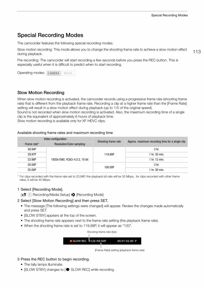
113
Special Recording Modes
Special Recording ModesThe camcorder features the following special recording modes.
Slow motion recording: This mode allows you to change the shooting frame rate to achieve a slow motion effect during playback.
Pre-recording: The camcorder will start recording a few seconds before you press the REC button. This is especially useful when it is difficult to predict when to start recording.
Slow Motion RecordingWhen slow motion recording is activated, the camcorder records using a progressive frame rate (shooting frame rate) that is different from the playback frame rate. Recording a clip at a higher frame rate than the [Frame Rate] setting will result in a slow motion effect during playback (up to 1/5 of the original speed).Sound is not recorded when slow motion recording is activated. Also, the maximum recording time of a single clip is the equivalent of approximately 6 hours of playback time.Slow motion recording is available only for XF-HEVC clips.
Available shooting frame rates and maximum recording time
* For clips recorded with the frame rate set to 23.98P, the playback bit rate will be 35 Mbps; for clips recorded with other frame rates, it will be 45 Mbps.
1 Select [Recording Mode].[3! Recording/Media Setup] > [Recording Mode]
2 Select [Slow Motion Recording] and then press SET.• The message [The following settings were changed] will appear. Review the changes made automatically
and press SET.• [SLOW STBY] appears at the top of the screen. • The shooting frame rate appears next to the frame rate setting (the playback frame rate). • When the shooting frame rate is set to 119.88P, it will appear as "120".
3 Press the REC button to begin recording.• The tally lamps illuminate.• [SLOW STBY] changes to [Ü SLOW REC] while recording.
Operating modes:
Video configurationShooting frame rate Approx. maximum recording time for a single clip
Frame rate* Resolution/Color sampling
59.94P
1920x1080, YCbCr 4:2:2, 10 bit
119.88P
3 hr.
29.97P 1 hr. 30 min.
23.98P 1 hr. 12 min.
50.00P100.00P
3 hr.
25.00P 1 hr. 30 min.
Shooting frame rate (fps)
[Frame Rate] setting (playback frame rate)
Special Recording Modes
114
4 Press the REC button again to stop recording.• The clip is recorded at the selected frame rate.• The tally lamps go out and [SLOW STBY] appears at the top of the screen.
5 When you have finished recording, turn off the special recording mode.• Repeat steps 1 and 2 selecting [Normal Recording] instead.
NOTESNOTES
• Slow motion recording cannot be used together with pre-recording.• When slow motion recording is activated, the [PQ] and [HLG] options in the custom picture file ([Gamma] and
[Preset]) and their corresponding LUTs will not be available.• The shooting frame rate cannot be changed while recording.• The time code signal will not be output from the SDI terminal, HDMI OUT terminal or TIME CODE terminal.• If the video format or system frequency is changed, slow motion recording will be canceled and the shooting
frame rate will be reset to its default value.• About the time code when slow motion recording is activated:
- The time code mode can be set to [Regen.], or to [Preset] with [Rec Run] running mode. - If the time code running mode was set to [Free Run], the time code running mode will be changed
automatically to [Rec Run] when slow motion recording is activated. - When the special recording mode is turned off, the time code running mode will return to its previous setting.
Pre-recordingWhen pre-recording is activated, the camcorder starts recording continuously into a temporary memory (approx. 3 seconds) so when you press the REC button, the clip will contain also a few seconds of video and audio recorded before you pressed the button.
1 Select [Recording Mode]. > [Æ ! Recording/Media Setup] > [Recording Mode]
2 Select [Pre-Recording] and then press SET.• [PRE REC STBY] appears at the top of the screen.
3 Press the REC button to begin recording.• The tally lamps illuminate.• [PRE REC STBY] changes to [Ü PRE REC] while recording.
4 Press the REC button again to stop recording.• The clip is recorded. The recorded clip will include a few seconds of video and audio recorded before the
REC button was pressed.• The tally lamps go out and [PRE REC STBY] appears at the top of the screen.
5 When you have finished recording, turn off the special recording mode.• Repeat steps 1 and 2 selecting [Normal Recording] instead.
NOTESNOTES
• Pre-recording cannot be used together with slow motion recording.• If the video format or system frequency is changed, pre-recording will be canceled.

115
Special Recording Modes
• About the time code when pre-recording is activated:- The time code of the clip will start a few seconds before the REC button was pressed.- The time code will be recorded with the running mode set to [Free Run].- If the time code mode was set to [Regen.], or to [Preset] with [Rec Run] running mode, the time code
running mode will be changed automatically to [Free Run] when pre-recording is activated.- When the special recording mode is turned off, the time code running mode will return to its previous
setting.
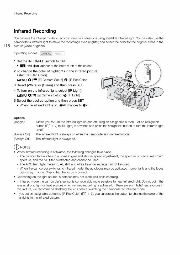
Infrared Recording
116
Infrared RecordingYou can use the infrared mode to record in very dark situations using available infrared light. You can also use the camcorder's infrared light to make the recordings even brighter, and select the color for the brighter areas in the picture (white or green).
1 Set the INFRARED switch to ON. • ; and = appear at the bottom left of the screen.
2 To change the color of highlights in the infrared picture, select [IR Rec Color].
> [v ( Camera Setup] > [IR Rec Color]
3 Select [White] or [Green] and then press SET.
4 To turn on the infrared light, select [IR Light]. >[v ( Camera Setup] > [IR Light]
5 Select the desired option and then press SET.• When the infrared light is on, = changes to .
Options[Toggle]: Allows you to turn the infrared light on and off using an assignable button. Set an assignable
button (A 117) to [IR Light] in advance and press the assignable button to turn the infrared light on/off.
[Always On]: The infrared light is always on while the camcorder is in infrared mode.[Always Off]: The infrared light is always off.
NOTESNOTES
• When infrared recording is activated, the following changes take place.- The camcorder switches to automatic gain and shutter speed adjustment, the aperture is fixed at maximum
aperture, and the ND filter is retracted and cannot be used.- The AGC limit, light metering, AE shift and white balance settings cannot be used.- When the camcorder switches to infrared mode, the autofocus may be activated momentarily and the focus
point may change. Check that the focus is correct.• Depending on the light source, autofocus may not work well while zooming.• In infrared mode the camcorder's sensor is considerably more sensitive to near-infrared light. Do not point the
lens at strong light or heat sources when infrared recording is activated. If there are such light/heat sources in the picture, we recommend shielding the lens before switching the camcorder to infrared mode.
• If you set an assignable button to [IR Rec Color] (A 117), you can press the button to change the color of the highlights in the infrared picture.
Operating modes:
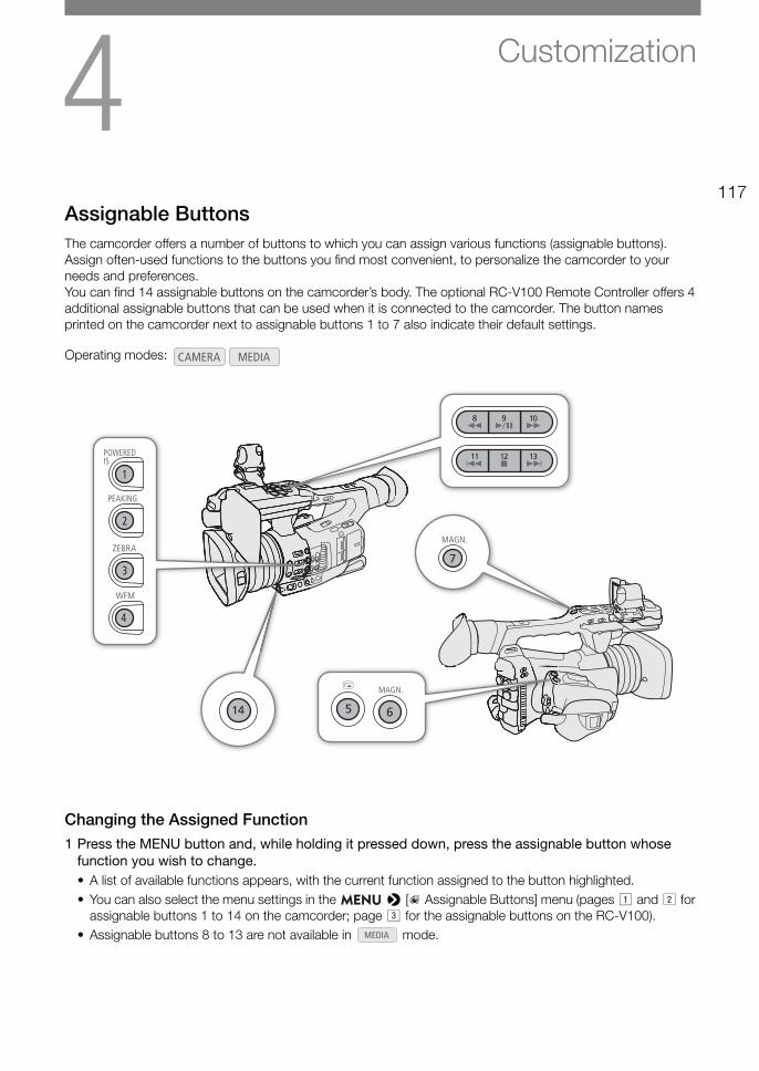
4117
Customization
Assignable ButtonsThe camcorder offers a number of buttons to which you can assign various functions (assignable buttons). Assign often-used functions to the buttons you find most convenient, to personalize the camcorder to your needs and preferences. You can find 14 assignable buttons on the camcorder’s body. The optional RC-V100 Remote Controller offers 4 additional assignable buttons that can be used when it is connected to the camcorder. The button names printed on the camcorder next to assignable buttons 1 to 7 also indicate their default settings.
Changing the Assigned Function1 Press the MENU button and, while holding it pressed down, press the assignable button whose
function you wish to change.• A list of available functions appears, with the current function assigned to the button highlighted.• You can also select the menu settings in the > [ Assignable Buttons] menu (pages ! and " for
assignable buttons 1 to 14 on the camcorder; page # for the assignable buttons on the RC-V100).• Assignable buttons 8 to 13 are not available in mode.
Operating modes:
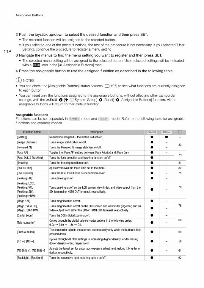
Assignable Buttons
118
2 Push the joystick up/down to select the desired function and then press SET.• The selected function will be assigned to the selected button.• If you selected one of the preset functions, the rest of the procedure is not necessary. If you selected [User
Setting], continue the procedure to register a menu setting.
3 Navigate the menus to find the menu setting you want to register and then press SET.• The selected menu setting will be assigned to the selected button. User-selected settings will be indicated
with a icon in the [ Assignable Buttons] menu.
4 Press the assignable button to use the assigned function as described in the following table.
NOTES
• You can check the [Assignable Buttons] status screens (A 197) to see what functions are currently assigned to each button.
• You can reset only the functions assigned to the assignable buttons, without affecting other camcorder settings, with the > [B! System Setup] > [Reset] > [Assignable Buttons] function. All the assignable buttons will return to their default function.
Assignable functionsFunctions can be set separately in mode and mode. Refer to the following table for assignable functions and available modes.
Function name Description A
[(NONE)] No function assigned – the button is disabled. Ü Ü –
[Image Stabilizer] Turns image stabilization on/off. Ü –83
[Powered IS] Turns the Powered IS image stabilizer on/off. Ü –
[Face AF] Toggles the [Face AF] setting between [Face Priority] and [Face Only]. Ü –79
[Face Det. & Tracking] Turns the face detection and tracking function on/off. Ü –
[Tracking] Turns the tracking function on/off. Ü – 81
[Focus Limit] Applies/removes the focus limit set in the menu. Ü – 82
[Focus Guide] Turns the Dual Pixel Focus Guide function on/off. Ü – 75
[Peaking: All] Turns peaking on/off. Ü –
76[Peaking: LCD], [Peaking: VF], [Peaking: SDI], [Peaking: HDMI]
Turns peaking on/off on the LCD screen, viewfinder, and video output from the SDI terminal or HDMI OUT terminal, respectively.
Ü –
[Magn.: All] Turns magnification on/off. Ü –
76[Magn.: VF+LCD], [Magn.: SDI/HDMI]
Turns magnification on/off on the LCD screen and viewfinder (together) and on video output from either the SDI or HDMI OUT terminal, respectively.
Ü –
[Digital Zoom] Turns the 300x digital zoom on/off. Ü –
68[Tele-converter]
Cycles through the digital tele-converter options in the following order: 6.0x 3.0x 1.5x Off.
Ü –
[Push Auto Iris]The camcorder adjusts the aperture automatically only while the button is held pressed down.
Ü – 60
[ND +], [ND –]Cycles through ND filter settings in increasing (higher density) or decreasing (lower density) order, respectively.
Ü – 58
[AE Shift +], [AE Shift –]Adjusts the target set for automatic exposure adjustment making it brighter or darker, respectively.
Ü – 61
[Backlight], [Spotlight] Turns the respective light metering option on/off. Ü – 62
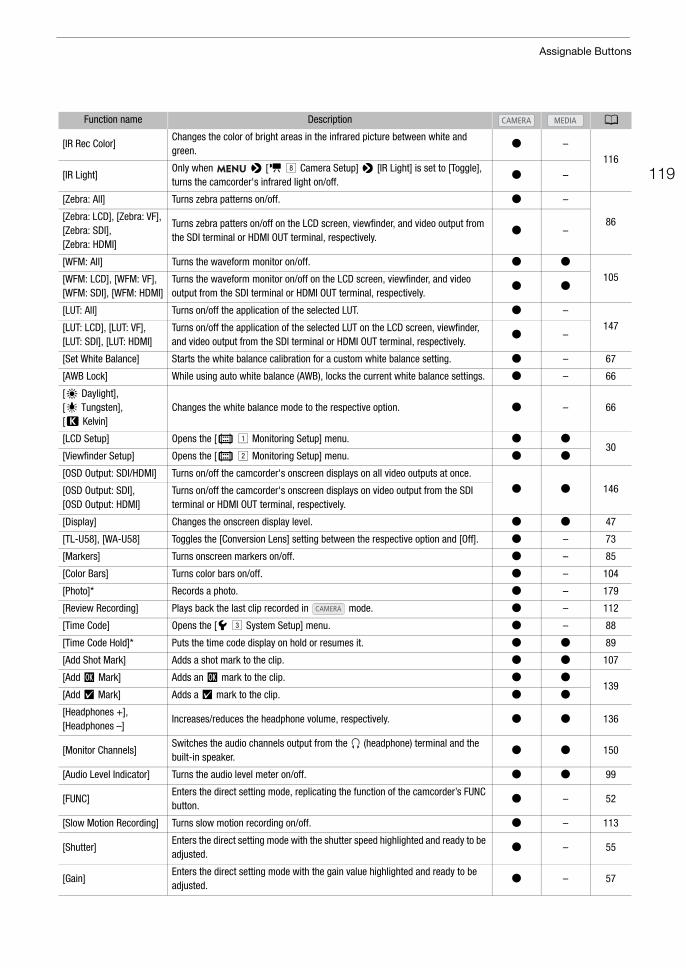
119
Assignable Buttons
[IR Rec Color]Changes the color of bright areas in the infrared picture between white and green.
Ü –
116
[IR Light]Only when > [v ( Camera Setup] > [IR Light] is set to [Toggle], turns the camcorder's infrared light on/off.
Ü –
[Zebra: All] Turns zebra patterns on/off. Ü –
86[Zebra: LCD], [Zebra: VF], [Zebra: SDI], [Zebra: HDMI]
Turns zebra patters on/off on the LCD screen, viewfinder, and video output from the SDI terminal or HDMI OUT terminal, respectively.
Ü –
[WFM: All] Turns the waveform monitor on/off. Ü Ü
105[WFM: LCD], [WFM: VF], [WFM: SDI], [WFM: HDMI]
Turns the waveform monitor on/off on the LCD screen, viewfinder, and video output from the SDI terminal or HDMI OUT terminal, respectively.
Ü Ü
[LUT: All] Turns on/off the application of the selected LUT. Ü –
147[LUT: LCD], [LUT: VF], [LUT: SDI], [LUT: HDMI]
Turns on/off the application of the selected LUT on the LCD screen, viewfinder, and video output from the SDI terminal or HDMI OUT terminal, respectively.
Ü –
[Set White Balance] Starts the white balance calibration for a custom white balance setting. Ü – 67
[AWB Lock] While using auto white balance (AWB), locks the current white balance settings. Ü – 66
[¼ Daylight], [É Tungsten], [È Kelvin]
Changes the white balance mode to the respective option. Ü – 66
[LCD Setup] Opens the [¢ ! Monitoring Setup] menu. Ü Ü30
[Viewfinder Setup] Opens the [¢ " Monitoring Setup] menu. Ü Ü
[OSD Output: SDI/HDMI] Turns on/off the camcorder's onscreen displays on all video outputs at once.
Ü Ü 146[OSD Output: SDI], [OSD Output: HDMI]
Turns on/off the camcorder's onscreen displays on video output from the SDI terminal or HDMI OUT terminal, respectively.
[Display] Changes the onscreen display level. Ü Ü 47
[TL-U58], [WA-U58] Toggles the [Conversion Lens] setting between the respective option and [Off]. Ü – 73
[Markers] Turns onscreen markers on/off. Ü – 85
[Color Bars] Turns color bars on/off. Ü – 104
[Photo]* Records a photo. Ü – 179
[Review Recording] Plays back the last clip recorded in mode. Ü – 112
[Time Code] Opens the [B# System Setup] menu. Ü – 88
[Time Code Hold]* Puts the time code display on hold or resumes it. Ü Ü 89
[Add Shot Mark] Adds a shot mark to the clip. Ü Ü 107
[Add $ Mark] Adds an $ mark to the clip. Ü Ü139
[Add % Mark] Adds a % mark to the clip. Ü Ü
[Headphones +], [Headphones –]
Increases/reduces the headphone volume, respectively. Ü Ü 136
[Monitor Channels]Switches the audio channels output from the × (headphone) terminal and the built-in speaker.
Ü Ü 150
[Audio Level Indicator] Turns the audio level meter on/off. Ü Ü 99
[FUNC]Enters the direct setting mode, replicating the function of the camcorder’s FUNC button.
Ü – 52
[Slow Motion Recording] Turns slow motion recording on/off. Ü – 113
[Shutter]Enters the direct setting mode with the shutter speed highlighted and ready to be adjusted.
Ü – 55
[Gain]Enters the direct setting mode with the gain value highlighted and ready to be adjusted.
Ü – 57
Function name Description A
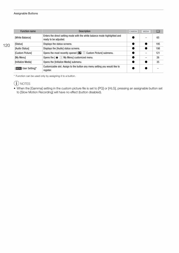
Assignable Buttons
120
* Function can be used only by assigning it to a button.
NOTES
• When the [Gamma] setting in the custom picture file is set to [PQ] or [HLG], pressing an assignable button set to [Slow Motion Recording] will have no effect (button disabled).
[White Balance]Enters the direct setting mode with the white balance mode highlighted and ready to be adjusted.
Ü – 65
[Status] Displays the status screens. Ü Ü 195
[Audio Status] Displays the [Audio] status screens. Ü Ü 198
[Custom Picture] Opens the most recently opened [/ ! Custom Picture] submenu. Ü – 121
[My Menu] Opens the [¥ ! My Menu] customized menu. Ü – 26
[Initialize Media] Opens the [Initialize Media] submenu. Ü Ü 35
[ User Setting]*Customizable slot. Assign to the button any menu setting you would like to register.
Ü Ü –
Function name Description A
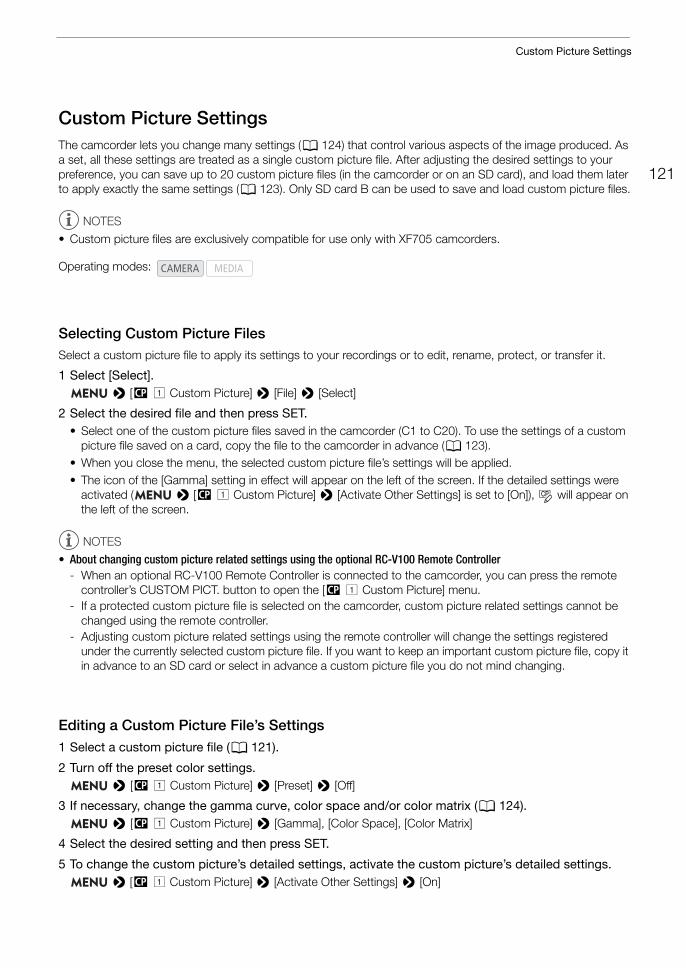
121
Custom Picture Settings
Custom Picture SettingsThe camcorder lets you change many settings (A 124) that control various aspects of the image produced. As a set, all these settings are treated as a single custom picture file. After adjusting the desired settings to your preference, you can save up to 20 custom picture files (in the camcorder or on an SD card), and load them later to apply exactly the same settings (A 123). Only SD card B can be used to save and load custom picture files.
NOTES
• Custom picture files are exclusively compatible for use only with XF705 camcorders.
Selecting Custom Picture FilesSelect a custom picture file to apply its settings to your recordings or to edit, rename, protect, or transfer it.
1 Select [Select]. > [/ ! Custom Picture] > [File] > [Select]
2 Select the desired file and then press SET.• Select one of the custom picture files saved in the camcorder (C1 to C20). To use the settings of a custom
picture file saved on a card, copy the file to the camcorder in advance (A 123).• When you close the menu, the selected custom picture file’s settings will be applied.• The icon of the [Gamma] setting in effect will appear on the left of the screen. If the detailed settings were
activated ( > [/ ! Custom Picture] > [Activate Other Settings] is set to [On]), will appear on the left of the screen.
NOTES
• About changing custom picture related settings using the optional RC-V100 Remote Controller- When an optional RC-V100 Remote Controller is connected to the camcorder, you can press the remote
controller’s CUSTOM PICT. button to open the [/ ! Custom Picture] menu.- If a protected custom picture file is selected on the camcorder, custom picture related settings cannot be
changed using the remote controller.- Adjusting custom picture related settings using the remote controller will change the settings registered
under the currently selected custom picture file. If you want to keep an important custom picture file, copy it in advance to an SD card or select in advance a custom picture file you do not mind changing.
Editing a Custom Picture File’s Settings1 Select a custom picture file (A 121).
2 Turn off the preset color settings. > [/ ! Custom Picture] > [Preset] > [Off]
3 If necessary, change the gamma curve, color space and/or color matrix (A 124). > [/ ! Custom Picture] > [Gamma], [Color Space], [Color Matrix]
4 Select the desired setting and then press SET.
5 To change the custom picture’s detailed settings, activate the custom picture’s detailed settings. > [/ ! Custom Picture] > [Activate Other Settings] > [On]
Operating modes:
Custom Picture Settings
122
6 Open the [Other Settings] submenu. > [/ ! Custom Picture] > [Other Settings]
7 Select a custom picture setting and then press SET.
8 Change the setting to the desired level and then press SET.• Refer to Available Custom Picture Settings (A 125) for details on the various settings.• Repeat steps 7 and 8 for other settings, as necessary.• When you close the menu, the new custom picture settings will be applied.
Resetting Custom Picture Files1 Select a custom picture file (A 121).
2 Select [Reset]. > [/ ! Custom Picture] > [File] > [Reset]
3 Select [OK] and then press SET.
Renaming Custom Picture Files1 Select a custom picture file (A 121).
2 Select [Rename]. > [/ ! Custom Picture] > [File] > [Rename]
3 Select [Input] and then press SET.• Enter the desired file name (up to 8 characters) using the keyboard screen (A 27).
Protecting Custom Picture FilesProtecting a custom picture file prevents its settings from being accidentally changed.
1 Select a custom picture file (A 121).
2 Select [Protect]. > [/ ! Custom Picture] > [File] > [Protect]
3 Select [Protect] and then press SET.• In the custom picture file selection screen, i will appear next to the file name.• To remove protection settings, select [Unprotect] instead.
123
Custom Picture Settings
Copying Custom Picture FilesYou can transfer custom picture files between the camcorder and SD card B.
Copying a File from the Camcorder to SD Card B
1 Insert a card into the camcorder’s SD card slot B.
2 Select a custom picture file (A 121).
3 Select [Copy to SD Card B]. > [/ ! Custom Picture] > [File] > [Copy to SD Card B]
4 Select the destination file and then press SET.• Select an existing custom picture file to overwrite it or [New File] to save the settings as a new custom
picture file on the card.
5 Select [OK] and then press SET.• The file on SD card B will be overwritten or a new file will be created on the card.
6 When the confirmation message appears, press SET.
Replacing a File in the Camcorder with a File on SD Card B
1 Insert the card with the desired custom picture file into the camcorder’s SD card slot B.
2 Select an unprotected custom picture file that you wish to replace (A 121).
3 Select [Load from SD Card B]. > [/ ! Custom Picture] > [File] > [Load from SD Card B]
4 Select the file with the settings that you want to replicate and then press SET.
5 Select [OK] and then press SET.• The file in the camcorder will be overwritten by the one on SD card B.
6 When the confirmation message appears, press SET.
Embedding the Custom Picture File in ClipsAfter adjusting the various settings, you can record the custom picture file in use together with the clip’s metadata. When a clip has an embedded custom picture file, you can check the settings used to record the clip on the [Clip Info] screen (A 138).
1 Select [Add / File]. > [3" Recording/Media Setup] > [Metadata] > [Add / File]
2 Select [On] and then press SET.• When [Off] is selected, the custom picture file is not recorded with the clips.
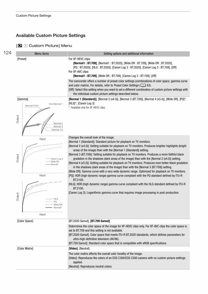
Custom Picture Settings
124
Available Custom Picture Settings
[/ ! Custom Picture] Menu
Menu items Setting options and additional information
[Preset] For XF-HEVC clips:[Normal1 : BT.709], [Normal1 : BT.2020], [Wide DR : BT.709], [Wide DR : BT.2020], [PQ : BT.2020], [HLG : BT.2020], [Canon Log 3 : BT.2020], [Canon Log 3 : BT.709], [Off]
For XF-AVC clips:[Normal1 : BT.709], [Wide DR : BT.709], [Canon Log 3 : BT.709], [Off]
The camcorder offers a number of preset color settings (combinations of color space, gamma curve and color matrix). For details, refer to Preset Color Settings (A 63).[Off]: Select this setting when you want to set a different combination of custom picture settings with
the individual custom picture settings described below.
[Gamma] [Normal 1 (Standard)], [Normal 2 (x4.0)], [Normal 3 (BT.709)], [Normal 4 (x5.0)], [Wide DR], [PQ]*, [HLG]*, [Canon Log 3]* Available only for XF-HEVC clips.
Changes the overall look of the image.[Normal 1 (Standard)]: Standard picture for playback on TV monitors.[Normal 2 (x4.0)]: Setting suitable for playback on TV monitors. Produces brighter highlights (bright
areas of the image) than with the [Normal 1 (Standard)] setting.[Normal 3 (BT.709)]: Setting suitable for playback on TV monitors. Produces a more faithful black
gradation in the shadows (dark areas of the image) than with the [Normal 2 (x4.0)] setting.[Normal 4 (x5.0)]: Setting suitable for playback on TV monitors. Produces even better black gradation
in the shadows (dark areas of the image) than with the [Normal 3 (BT.709)] setting.[Wide DR]: Gamma curve with a very wide dynamic range. Optimized for playback on TV monitors.[PQ]: HDR (high dynamic range) gamma curve compliant with the PQ standard defined by ITU-R
BT.2100.[HLG]: HDR (high dynamic range) gamma curve compliant with the HLG standard defined by ITU-R
BT.2100.[Canon Log 3]: Logarithmic gamma curve that requires image processing in post-production.
[Color Space] [BT.2020 Gamut], [BT.709 Gamut]
Determines the color space of the image for XF-HEVC clips only. For XF-AVC clips the color space is set to BT.709 and this setting is not available.[BT.2020 Gamut]: Color space that meets ITU-R BT.2020 standards, which defines parameters for
ultra-high-definition television (4K/8K).[BT.709 Gamut]: Standard color space that is compatible with sRGB specifications.
[Color Matrix] [Video], [Neutral]
The color matrix affects the overall color tonality of the image.[Video]: Reproduces the colors of an EOS C300/EOS C500 camera with no custom picture settings
applied.[Neutral]: Reproduces neutral colors.
Normal 4
Normal 2/3/4
Normal 3Normal 1/2
Normal 1
Input
Out
put
Normal1Wide DRCanon Log 3
Input
Out
put
PQHLG
Wide DRNormal1
Input
Out
put
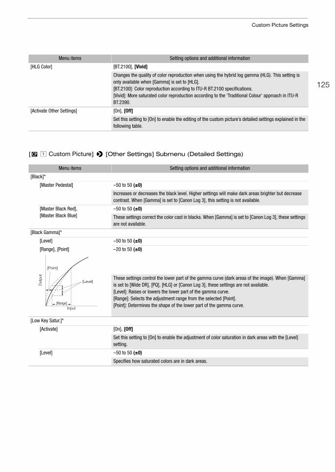
125
Custom Picture Settings
[/ ! Custom Picture] > [Other Settings] Submenu (Detailed Settings)
[HLG Color] [BT.2100], [Vivid]
Changes the quality of color reproduction when using the hybrid log gamma (HLG). This setting is only available when [Gamma] is set to [HLG].[BT.2100]: Color reproduction according to ITU-R BT.2100 specifications.[Vivid]: More saturated color reproduction according to the 'Traditional Colour' approach in ITU-R BT.2390.
[Activate Other Settings] [On], [Off]
Set this setting to [On] to enable the editing of the custom picture’s detailed settings explained in the following table.
Menu items Setting options and additional information
[Black]*
[Master Pedestal] –50 to 50 (±0)
Increases or decreases the black level. Higher settings will make dark areas brighter but decrease contrast. When [Gamma] is set to [Canon Log 3], this setting is not available.
[Master Black Red], [Master Black Blue]
–50 to 50 (±0)
These settings correct the color cast in blacks. When [Gamma] is set to [Canon Log 3], these settings are not available.
[Black Gamma]*
[Level] –50 to 50 (±0)
[Range], [Point] –20 to 50 (±0)
These settings control the lower part of the gamma curve (dark areas of the image). When [Gamma] is set to [Wide DR], [PQ], [HLG] or [Canon Log 3], these settings are not available.[Level]: Raises or lowers the lower part of the gamma curve. [Range]: Selects the adjustment range from the selected [Point].[Point]: Determines the shape of the lower part of the gamma curve.
[Low Key Satur.]*
[Activate] [On], [Off]
Set this setting to [On] to enable the adjustment of color saturation in dark areas with the [Level] setting.
[Level] –50 to 50 (±0)
Specifies how saturated colors are in dark areas.
Menu items Setting options and additional information
Input
Out
put
[Point]
[Range]
[Level]
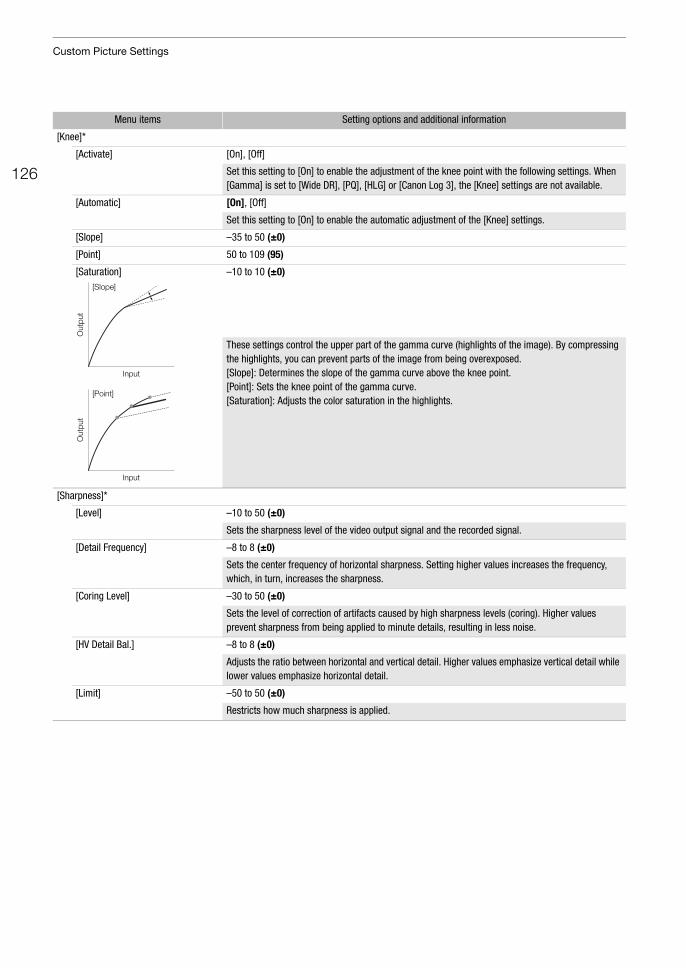
Custom Picture Settings
126
[Knee]*
[Activate] [On], [Off]
Set this setting to [On] to enable the adjustment of the knee point with the following settings. When [Gamma] is set to [Wide DR], [PQ], [HLG] or [Canon Log 3], the [Knee] settings are not available.
[Automatic] [On], [Off]
Set this setting to [On] to enable the automatic adjustment of the [Knee] settings.
[Slope] –35 to 50 (±0)
[Point] 50 to 109 (95)
[Saturation] –10 to 10 (±0)
These settings control the upper part of the gamma curve (highlights of the image). By compressing the highlights, you can prevent parts of the image from being overexposed.[Slope]: Determines the slope of the gamma curve above the knee point.[Point]: Sets the knee point of the gamma curve.[Saturation]: Adjusts the color saturation in the highlights.
[Sharpness]*
[Level] –10 to 50 (±0)
Sets the sharpness level of the video output signal and the recorded signal.
[Detail Frequency] –8 to 8 (±0)
Sets the center frequency of horizontal sharpness. Setting higher values increases the frequency, which, in turn, increases the sharpness.
[Coring Level] –30 to 50 (±0)
Sets the level of correction of artifacts caused by high sharpness levels (coring). Higher values prevent sharpness from being applied to minute details, resulting in less noise.
[HV Detail Bal.] –8 to 8 (±0)
Adjusts the ratio between horizontal and vertical detail. Higher values emphasize vertical detail while lower values emphasize horizontal detail.
[Limit] –50 to 50 (±0)
Restricts how much sharpness is applied.
Menu items Setting options and additional information
Input
Out
put
Out
put
Input
[Slope]
[Point]
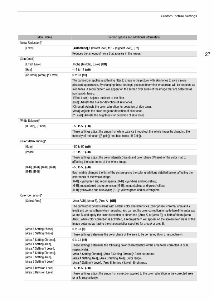
127
Custom Picture Settings
[Noise Reduction]*
[Level] [Automatic],1 (lowest level) to 12 (highest level), [Off]
Reduces the amount of noise that appears in the image.
[Skin Detail]*
[Effect Level] [High], [Middle], [Low], [Off]
[Hue] –16 to 16 (±0)
[Chroma], [Area], [Y Level] 0 to 31 (16)
The camcorder applies a softening filter to areas in the picture with skin tones to give a more pleasant appearance. By changing these settings, you can determine what areas will be detected as skin tones. A zebra pattern will appear on the screen over areas of the image that are detected as having skin tones.[Effect Level]: Adjusts the level of the filter. [Hue]: Adjusts the hue for detection of skin tones. [Chroma]: Adjusts the color saturation for detection of skin tones. [Area]: Adjusts the color range for detection of skin tones.[Y Level]: Adjusts the brightness for detection of skin tones.
[White Balance]*
[R Gain], [B Gain] –50 to 50 (±0)
These settings adjust the amount of white balance throughout the whole image by changing the intensity of red tones ([R gain]) and blue tones ([B Gain]).
[Color Matrix Tuning]*
[Gain] –50 to 50 (±0)
[Phase] –18 to 18 (±0)
These settings adjust the color intensity ([Gain]) and color phase ([Phase]) of the color matrix, affecting the color tones of the whole image.
[R-G], [R-B], [G-R], [G-B], [B-R], [B-G]
–50 to 50 (±0)
Each matrix changes the tint of the picture along the color gradations detailed below, affecting the color tones of the whole image.[R-G]: cyan/green and red/magenta; [R-B]: cyan/blue and red/yellow; [G-R]: magenta/red and green/cyan; [G-B]: magenta/blue and green/yellow;[B-R]: yellow/red and blue/cyan; [B-G]: yellow/green and blue/magenta.
[Color Correction]*
[Select Area] [Area A&B], [Area B], [Area A], [Off]
The camcorder detects areas with certain color characteristics (color phase, chroma, area and Y level) and corrects them when recording. You can set the color correction for up to two different areas (A and B) and apply the color correction to either one ([Area A] or [Area B]) or both of them ([Area A&B]). While color correction is activated, a zebra pattern will appear on the screen over areas of the image detected as having the characteristics specified for area A or area B.
[Area A Setting Phase],[Area B Setting Phase]
0 to 31 (0)
These settings determine the color phase of the area to be corrected (A or B, respectively).
[Area A Setting Chroma],[Area A Setting Area], [Area A Setting Y Level],[Area B Setting Chroma],[Area B Setting Area],[Area B Setting Y Level]
0 to 31 (16)
These settings determine the following color characteristics of the area to be corrected (A or B, respectively).[Area A Setting Chroma], [Area B Setting Chroma]: Color saturation. [Area A Setting Area], [Area B Setting Area]: Color range. [Area A Setting Y Level], [Area B Setting Y Level]: Brightness.
[Area A Revision Level],[Area B Revision Level]
–50 to 50 (±0)
These settings adjust the amount of correction applied to the color saturation in the corrected area (A or B, respectively).
Menu items Setting options and additional information
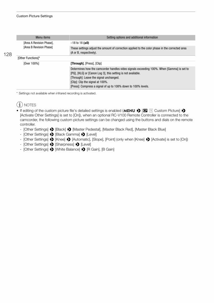
Custom Picture Settings
128
* Settings not available when infrared recording is activated.
NOTES
• If editing of the custom picture file's detailed settings is enabled ( > [/ ! Custom Picture] > [Activate Other Settings] is set to [On]), when an optional RC-V100 Remote Controller is connected to the camcorder, the following custom picture settings can be changed using the buttons and dials on the remote controller.- [Other Settings] > [Black] > [Master Pedestal], [Master Black Red], [Master Black Blue]- [Other Settings] > [Black Gamma] > [Level]- [Other Settings] > [Knee] > [Automatic], [Slope], [Point] (only when [Knee] > [Activate] is set to [On])- [Other Settings] > [Sharpness] > [Level]- [Other Settings] > [White Balance] > [R Gain], [B Gain]
[Area A Revision Phase],[Area B Revision Phase]
–18 to 18 (±0)
These settings adjust the amount of correction applied to the color phase in the corrected area (A or B, respectively).
[Other Functions]*
[Over 100%] [Through], [Press], [Clip]
Determines how the camcorder handles video signals exceeding 100%. When [Gamma] is set to [PQ], [HLG] or [Canon Log 3], this setting is not available.[Through]: Leave the signal unchanged.[Clip]: Clip the signal at 100%.[Press]: Compress a signal of up to 108% down to 100% levels.
Menu items Setting options and additional information
129
Saving and Loading Camcorder Settings
Saving and Loading Camcorder Settings
After you adjust settings in the various menus, you can save those settings in the camcorder or on an SD card. Only SD card B can be used to save and load camcorder settings files. You can load those settings at a later date or on another XF705 camcorder so that you can use that camcorder in the same way.
Saving Camcorder Settings1 To save the camcorder’s settings on an SD card, insert a card into the camcorder’s SD card slot B.
2 Select [Save].[B! System Setup] > [Transfer Menu//] > [Save]
3 Select [To Camera] or [To SD Card B] and then press SET.
4 Select [OK] and press SET.• The camcorder’s menu settings will be saved to the selected destination. If menu settings were previously
saved, the old file will be overwritten by the current menu settings.
5 When the confirmation message appears, press SET.
Loading Camcorder Settings1 To load menu settings from a card, insert the card with the desired camcorder settings file into the
camcorder’s SD card slot B.
2 Select [Load].[B! System Setup] > [Transfer Menu//] > [Load]
3 Select [From Camera] or [From SD Card B] and then press SET.
4 Select [OK] and press SET.• The camcorder’s menu settings will be replaced by the settings saved on the selected source. Then, the
screen will turn black momentarily and the camcorder will restart.
NOTES
• The following menu settings and any passwords that were set by the user are not saved with this operation.- >[v ' Camera Setup] > [Color Bars]- >[3 " Recording/Media Setup] > [Metadata] > [User Memo]- >[A ! Assistance Functions] > [Magn.: VF+LCD] and [Magn.: SDI/HDMI]- >[7 ! Network Settings] > [Network Functions]- Encryption keys/passwords under >[7! Network Settings] > [Connection Settings]- Browser Remote passwords under >[7! Network Settings] > [Browser Remote Settings] >
[Full: Password], [Camera: Password] and [Meta: Password]- The password under >[7! Network Settings] > [FTP Transfer Settings] > [FTP: Password]
• When menu settings are loaded with this operation, even protected custom picture files in the camcorder will be replaced.
• Camcorder settings files are exclusively compatible for use only with XF705 camcorders.
Operating modes:

Saving and Loading Camcorder Settings
130
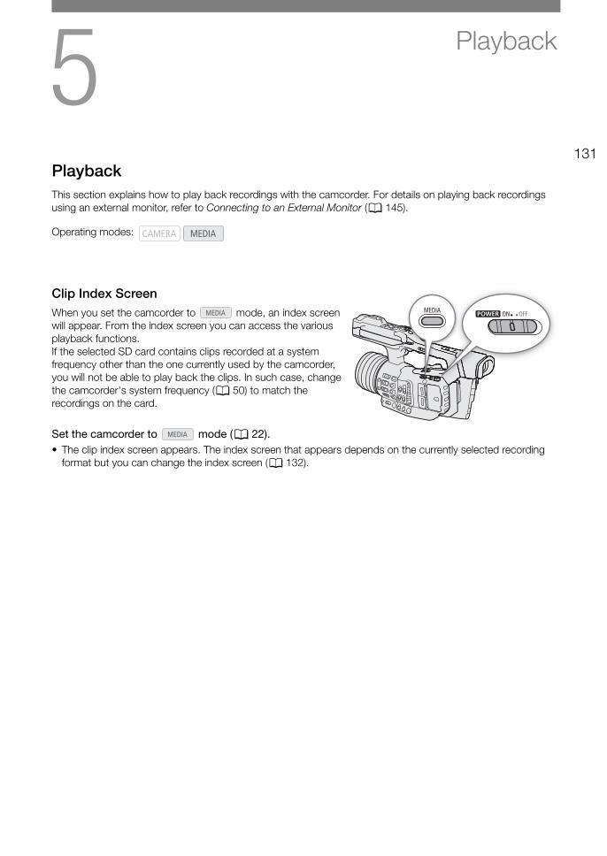
5131
Playback
PlaybackThis section explains how to play back recordings with the camcorder. For details on playing back recordings using an external monitor, refer to Connecting to an External Monitor (A 145).
Clip Index ScreenWhen you set the camcorder to mode, an index screen will appear. From the index screen you can access the various playback functions.If the selected SD card contains clips recorded at a system frequency other than the one currently used by the camcorder, you will not be able to play back the clips. In such case, change the camcorder's system frequency (A 50) to match the recordings on the card.
Set the camcorder to mode (A 22).• The clip index screen appears. The index screen that appears depends on the currently selected recording
format but you can change the index screen (A 132).
Operating modes:
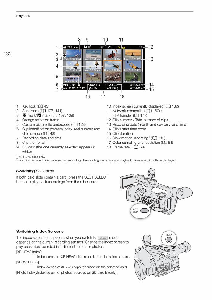
Playback
132
1 XF-HEVC clips only. 2 For clips recorded using slow motion recording, the shooting frame rate and playback frame rate will both be displayed.
Switching SD Cards
If both card slots contain a card, press the SLOT SELECT button to play back recordings from the other card.
Switching Index Screens
The index screen that appears when you switch to mode depends on the current recording settings. Change the index screen to play back clips recorded in a different format or photos.[XF-HEVC Index]:
Index screen of XF-HEVC clips recorded on the selected card.
[XF-AVC Index]:Index screen of XF-AVC clips recorded on the selected card.
[Photo Index]:Index screen of photos recorded on SD card B (only).
8 109
1415
4
5
1
7
12
13
6
32
1716 18
11
1 Key lock (A 43)2 Shot mark (A 107, 141)3 $ mark/% mark (A 107, 139)4 Orange selection frame 5 Custom picture file embedded (A 123)6 Clip identification (camera index, reel number and
clip number) (A 48)7 Recording date and time8 Clip thumbnail9 SD card (the one currently selected appears in
white)
10 Index screen currently displayed (A 132)11 Network connection (A 160) /
FTP transfer (A 177)12 Clip number / Total number of clips13 Recording date (month and day only) and time14 Clip’s start time code15 Clip duration16 Slow motion recording1 (A 113)17 Color sampling and resolution (A 51)18 Frame rate2 (A 50)
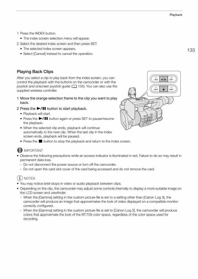
133
Playback
1 Press the INDEX button.• The index screen selection menu will appear.
2 Select the desired index screen and then press SET.• The selected index screen appears.• Select [Cancel] instead to cancel the operation.
Playing Back ClipsAfter you select a clip to play back from the index screen, you can control the playback with the buttons on the camcorder or with the joystick and onscreen joystick guide (A 135). You can also use the supplied wireless controller.
1 Move the orange selection frame to the clip you want to play back.
2 Press the Ò button to start playback.• Playback will start.• Press the Ò button again or press SET to pause/resume
the playback.• When the selected clip ends, playback will continue
automatically to the next clip. When the last clip in the index screen ends, playback will be paused.
• Press the Ñ button to stop the playback and return to the index screen.
IMPORTANT
• Observe the following precautions while an access indicator is illuminated in red. Failure to do so may result in permanent data loss.- Do not disconnect the power source or turn off the camcorder.- Do not open the card slot cover of the card being accessed and do not remove the card.
NOTES
• You may notice brief stops in video or audio playback between clips.• Depending on the clip, the camcorder may adjust some controls internally to display a more suitable image on
the LCD screen and viewfinder.- When the [Gamma] setting in the custom picture file is set to a setting other than [Canon Log 3], the
camcorder will produce an image that approximates the look of video displayed on a compatible monitor correctly configured.
- When the [Gamma] setting in the custom picture file is set to [Canon Log 3], the camcorder will produce colors that approximate the look of the BT.709 color space, regardless of the color space used for recording.
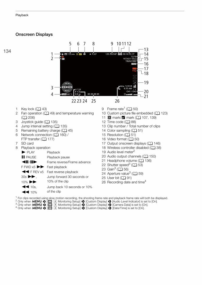
Playback
134
Onscreen Displays
1 For clips recorded using slow motion recording, the shooting frame rate and playback frame rate will both be displayed.2 Only when > [¢ $ Monitoring Setup] > [Custom Display] > [Audio Level Indicator] is set to [On].3 Only when > [¢ $ Monitoring Setup] > [Custom Display] > [Camera Data] is set to [On].4 Only when > [¢ $ Monitoring Setup] > [Custom Display] > [Date/Time] is set to [On].
65 7 8
252322 24 26
12119 10
19
2034
12
1718
16
131415
21
1 Key lock (A 43)2 Fan operation (A 49) and temperature warning
(A 206)3 Joystick guide (A 135)4 Jump interval setting (A 135)5 Remaining battery charge (A 45)6 Network connection (A 160) /
FTP transfer (A 177)7 SD card8 Playback operation
9 Frame rate1 (A 50)10 Custom picture file embedded (A 123)11 $ mark/% mark (A 107, 139) 12 Time code (A 88)13 Clip number / Total number of clips14 Color sampling (A 51)15 Resolution (A 51)16 Video format (A 50)17 Output onscreen displays (A 146)18 Wireless controller disabled (A 38)19 Audio level meter2
20 Audio output channels (A 150)21 Headphone volume (A 136)22 Shutter speed3 (A 53)23 Gain3 (A 56)24 Aperture value3 (A 59)25 User bit (A 91)26 Recording date and time4
Ð PLAY Playback
Ý PAUSE Playback pauseÔ/Ó Frame reverse/Frame advanceF FWD x5 × Fast playback
Ø F REV x5 Fast reverse playback30s ×,
10% ×
Jump forward 30 seconds or 10% of the clip
Ø 10s,
Ø 10%
Jump back 10 seconds or 10% of the clip
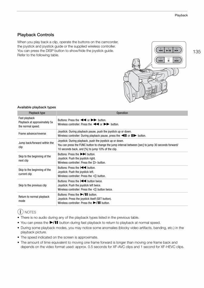
135
Playback
Playback Controls
When you play back a clip, operate the buttons on the camcorder, the joystick and joystick guide or the supplied wireless controller. You can press the DISP button to show/hide the joystick guide. Refer to the following table.
Available playback types
NOTES
• There is no audio during any of the playback types listed in the previous table.• You can press the Ò button during fast playback to return to playback at normal speed.• During some playback modes, you may notice some anomalies (blocky video artifacts, banding, etc.) in the
playback picture.• The speed indicated on the screen is approximate.• The amount of time equivalent to moving one frame forward is longer than moving one frame back and
depends on the video format used: approx. 0.5 seconds for XF-AVC clips and 1 second for XF-HEVC clips.
Playback type Operation
Fast playbackPlayback at approximately 5x the normal speed.
Buttons: Press the Ø or × button.Wireless controller: Press the Ø or × button.
Frame advance/reverseJoystick: During playback pause, push the joystick up or down.Wireless controller: During playback pause, press the Ô or Ó button.
Jump back/forward within the clip
Joystick: During playback, push the joystick up or down.You can press the FUNC button to change the jump interval between [sec] to jump 30 seconds forward/10 seconds back, and [%] to jump 10% of the clip.
Skip to the beginning of the next clip
Buttons: Press the Ù button.Joystick: Push the joystick right.Wireless controller: Press the ß button.
Skip to the beginning of the current clip
Buttons: Press the Ú button.Joystick: Push the joystick left.Wireless controller: Press the à button.
Skip to the previous clipButtons: Press the Ú button twice.Joystick: Push the joystick left twice.Wireless controller: Press the à button twice.
Return to normal playback mode
Buttons: Press the Ò button.Joystick: Press the joystick itself (SET button).Wireless controller: Press the Ò button.
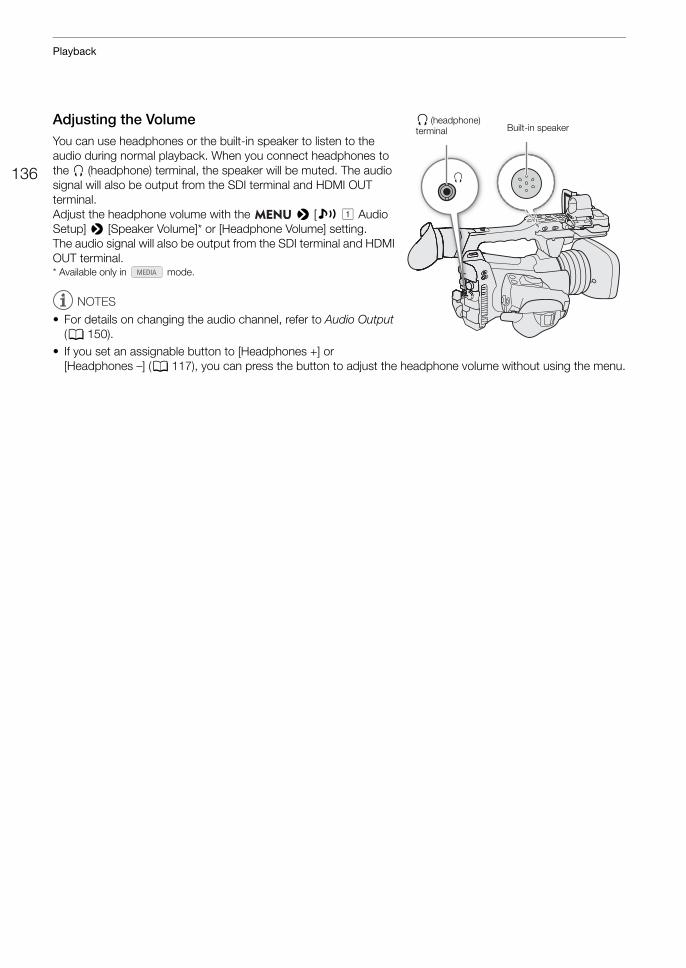
Playback
136
Adjusting the VolumeYou can use headphones or the built-in speaker to listen to the audio during normal playback. When you connect headphones to the × (headphone) terminal, the speaker will be muted. The audio signal will also be output from the SDI terminal and HDMI OUT terminal. Adjust the headphone volume with the > [¡ ! Audio Setup] > [Speaker Volume]* or [Headphone Volume] setting.The audio signal will also be output from the SDI terminal and HDMI OUT terminal.* Available only in mode.
NOTES
• For details on changing the audio channel, refer to Audio Output (A 150).
• If you set an assignable button to [Headphones +] or [Headphones –] (A 117), you can press the button to adjust the headphone volume without using the menu.
× (headphone) terminal Built-in speaker
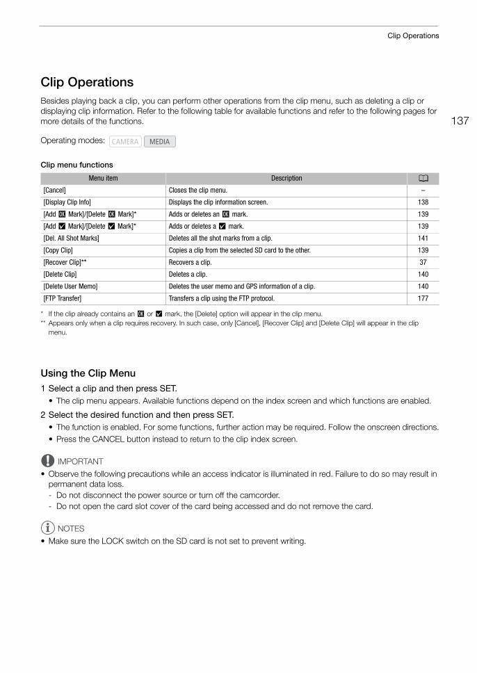
137
Clip Operations
Clip OperationsBesides playing back a clip, you can perform other operations from the clip menu, such as deleting a clip or displaying clip information. Refer to the following table for available functions and refer to the following pages for more details of the functions.
Clip menu functions
* If the clip already contains an $ or % mark, the [Delete] option will appear in the clip menu.** Appears only when a clip requires recovery. In such case, only [Cancel], [Recover Clip] and [Delete Clip] will appear in the clip
menu.
Using the Clip Menu1 Select a clip and then press SET.
• The clip menu appears. Available functions depend on the index screen and which functions are enabled.
2 Select the desired function and then press SET.• The function is enabled. For some functions, further action may be required. Follow the onscreen directions.• Press the CANCEL button instead to return to the clip index screen.
IMPORTANT
• Observe the following precautions while an access indicator is illuminated in red. Failure to do so may result in permanent data loss.- Do not disconnect the power source or turn off the camcorder.- Do not open the card slot cover of the card being accessed and do not remove the card.
NOTES
• Make sure the LOCK switch on the SD card is not set to prevent writing.
Operating modes:
Menu item Description A
[Cancel] Closes the clip menu. –
[Display Clip Info] Displays the clip information screen. 138
[Add $ Mark]/[Delete $ Mark]* Adds or deletes an $ mark. 139
[Add % Mark]/[Delete % Mark]* Adds or deletes a % mark. 139
[Del. All Shot Marks] Deletes all the shot marks from a clip. 141
[Copy Clip] Copies a clip from the selected SD card to the other. 139
[Recover Clip]** Recovers a clip. 37
[Delete Clip] Deletes a clip. 140
[Delete User Memo] Deletes the user memo and GPS information of a clip. 140
[FTP Transfer] Transfers a clip using the FTP protocol. 177
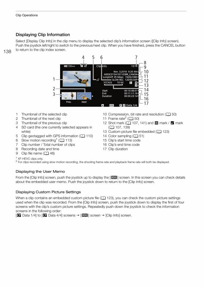
Clip Operations
138
Displaying Clip InformationSelect [Display Clip Info] in the clip menu to display the selected clip’s information screen ([Clip Info] screen). Push the joystick left/right to switch to the previous/next clip. When you have finished, press the CANCEL button to return to the clip index screen.
1 XF-HEVC clips only. 2 For clips recorded using slow motion recording, the shooting frame rate and playback frame rate will both be displayed.
Displaying the User Memo
From the [Clip Info] screen, push the joystick up to display the [Q] screen. In this screen you can check details about the embedded user memo. Push the joystick down to return to the [Clip Info] screen.
Displaying Custom Picture Settings
When a clip contains an embedded custom picture file (A 123), you can check the custom picture settings used when the clip was recorded. From the [Clip Info] screen, push the joystick down to display the first of four screens with the clip’s custom picture settings. Repeatedly push down the joystick to check the information screens in the following order: [/ Data 1/4] to [/ Data 4/4] screens [Q] screen [Clip Info] screen.
9
54 6
1
32
8
10
141312
151617
11
7
1 Thumbnail of the selected clip2 Thumbnail of the next clip3 Thumbnail of the previous clip4 SD card (the one currently selected appears in
white)5 Clip geotagged with GPS information (A 110)6 Slow motion recording1 (A 113)7 Clip number / Total number of clips8 Recording date and time9 Clip file name (A 48)
10 Compression, bit rate and resolution (A 50)11 Frame rate2 (A 50)12 Shot mark (A 107, 141) and $ mark / % mark
(A 107, 139)13 Custom picture file embedded (A 123)14 Color sampling (A 51)15 Clip’s start time code16 Clip’s end time code17 Clip duration
139
Clip Operations
Adding $ Marks or % MarksYou can add an OK mark ($) or check mark (%) to a clip during playback or from the index screen.
Adding an $ Mark or % Mark during Playback
To add an $ mark or % mark to a clip during playback or playback pause, you must first set an assignable button to [Add $ Mark] or [Add % Mark] in advance.
1 Set an assignable button to [Add $ Mark] or [Add % Mark] (A 117).• To add both types of clip marks (to different clips), set one assignable button to [Add $ Mark] and another
assignable button to [Add % Mark].
2 During playback or playback pause, press the assignable button to add the clip mark.• A message indicating the clip mark will appear and the selected clip mark will be added to the clip.• Adding a clip mark to a clip during playback will pause the playback.• An $ mark or % mark appears at the top right of the playback screen.
Adding an $ Mark or % Mark from the Index Screen
1 Select the desired clip and then press SET to open the clip menu.
2 Select [Add $ Mark] or [Add % Mark] and then press SET.
3 Select [OK] and then press SET.• An $ mark or % appears next to the selected clip’s thumbnail.
NOTES
• If you set an assignable button to [Add $ Mark] or [Add % Mark] (A 117), you can add an $ mark or % mark to clips also from the index screen.
• A clip cannot have both an $ mark and % mark at the same time. When you add a % mark to a clip with an $ mark, the $ mark will be deleted. Similarly, when you add an $ mark to a clip with a % mark, the % mark will be deleted.
Deleting $ Marks or % Marks1 Select the desired clip from the index screen and then press SET to open the clip menu.
2 Select [Delete $ Mark] or [Delete % Mark] and then press SET.
3 Select [OK] and then press SET.• The selected mark is deleted.
Copying ClipsYou can copy clips from one card to the other.
Copying a Single Clip
1 Select the desired clip and then press SET to open the clip menu.
2 Select [Copy Clip] and then press SET.
3 Select [OK] and then press SET.• The clip is copied to the other SD card. While the clip is being copied, you can press SET to cancel.
4 When the confirmation message appears, press SET.
Clip Operations
140
Copying All the Clips
1 Select [Copy All Clips]. > [3! Recording/Media Setup] > [Clips] > [Copy All Clips]
2 Select [OK] and then press SET.• The clips are copied to the other SD card. While clips are being copied, you can press SET to interrupt the
operation.
3 When the confirmation message appears, press SET.
NOTES
• Clips cannot be copied if either card slot cover is open.• If the destination card already contains a clip with the same clip number, the clip being copied will be renamed
to the number following the largest clip number in the card.
Deleting ClipsYou can delete clips as long as they don't have an $ mark. To delete such clips, delete the $ mark beforehand.
Deleting a Single Clip
1 Select the desired clip and then press SET to open the clip menu.
2 Select [Delete Clip] and then press SET.
3 Select [OK] and then press SET.• While the clip is being deleted, the operation cannot be canceled.
4 When the confirmation message appears, press SET.
Deleting All the Clips
1 Select [Delete All Clips]. > [3! Recording/Media Setup] > [Clips] > [Delete All Clips]
2 Select [OK] and then press SET.• While clips are being deleted, you can press SET to interrupt the operation. Clips deleted before you press
SET will be deleted permanently.
3 When the confirmation message appears, press SET.
Deleting the User Memo and GPS Information1 Select the desired clip and then press SET to open the clip menu.
2 Select [Delete User Memo] and then press SET.
3 Select [OK] and then press SET.• The user memo and GPS information are deleted from the clip.
141
Clip Operations
Adding and Deleting Shot MarksYou can add shot marks to shots in a clip you want to set apart.
Adding Shot Marks during Playback
To add a shot mark to a clip during playback or playback pause, you must first set an assignable button to [Add Shot Mark] in advance.
1 Set an assignable button to [Add Shot Mark] (A 117).
2 During playback or playback pause, press the assignable button at the point in the clip where you want to add the shot mark.• A message indicating the shot mark appears on the screen and the shot mark is added to the clip.• Adding a shot mark to a clip during playback will pause the playback.• When a clip contains a shot mark, a ! mark appears in the index screen next to the clip's thumbnail.
Deleting All the Shot Marks from a Clip
1 Select the desired clip and then press SET to open the clip menu.
2 Select [Del. All Shot Marks] and then press SET.
3 Select [OK] and then press SET.• All the shot marks will be deleted from the clip.

Clip Operations
142
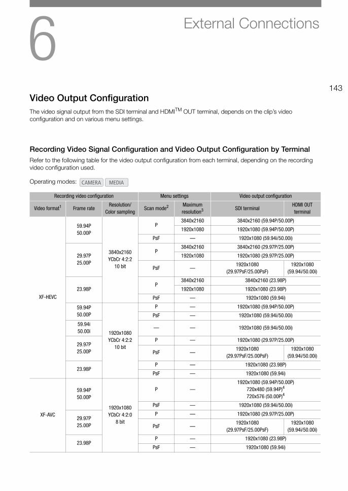
6143
External Connections
Video Output ConfigurationThe video signal output from the SDI terminal and HDMITM OUT terminal, depends on the clip’s video configuration and on various menu settings.
Recording Video Signal Configuration and Video Output Configuration by TerminalRefer to the following table for the video output configuration from each terminal, depending on the recording video configuration used.
Operating modes:
Recording video configuration Menu settings Video output configuration
Video format1 Frame rateResolution/
Color samplingScan mode2 Maximum
resolution3 SDI terminalHDMI OUT terminal
XF-HEVC
59.94P50.00P
3840x2160YCbCr 4:2:2
10 bit
P3840x2160 3840x2160 (59.94P/50.00P)
1920x1080 1920x1080 (59.94P/50.00P)
PsF — 1920x1080 (59.94i/50.00i)
29.97P25.00P
P3840x2160 3840x2160 (29.97P/25.00P)
1920x1080 1920x1080 (29.97P/25.00P)
PsF —1920x1080
(29.97PsF/25.00PsF)1920x1080
(59.94i/50.00i)
23.98PP
3840x2160 3840x2160 (23.98P)
1920x1080 1920x1080 (23.98P)
PsF — 1920x1080 (59.94i)
59.94P50.00P
1920x1080YCbCr 4:2:2
10 bit
P — 1920x1080 (59.94P/50.00P)
PsF — 1920x1080 (59.94i/50.00i)
59.94i50.00i
— — 1920x1080 (59.94i/50.00i)
29.97P25.00P
P — 1920x1080 (29.97P/25.00P)
PsF —1920x1080
(29.97PsF/25.00PsF)1920x1080
(59.94i/50.00i)
23.98PP — 1920x1080 (23.98P)
PsF — 1920x1080 (59.94i)
XF-AVC
59.94P50.00P
1920x1080YCbCr 4:2:0
8 bit
P —1920x1080 (59.94P/50.00P)
720x480 (59.94P)4
720x576 (50.00P)4
PsF — 1920x1080 (59.94i/50.00i)
29.97P25.00P
P — 1920x1080 (29.97P/25.00P)
PsF —1920x1080
(29.97PsF/25.00PsF)1920x1080
(59.94i/50.00i)
23.98PP — 1920x1080 (23.98P)
PsF — 1920x1080 (59.94i)
Video Output Configuration
144
1 > [3! Recording/Media Setup] > [Rec Format].2 > [B" System Setup] > [SDI/HDMI Scan Mode].3 > [B" System Setup] > [SDI/HDMI Max Res.].4 When > [B" System Setup] > [SDI Output] is set to [Off], the output signal will change automatically depending on
the capabilities of the external monitor.
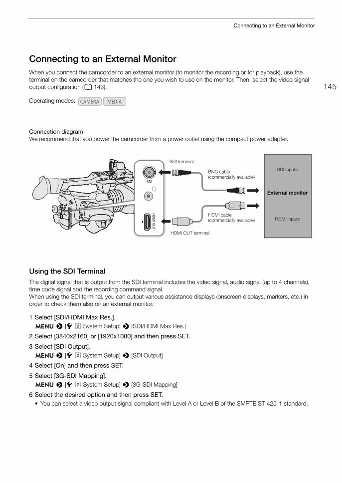
145
Connecting to an External Monitor
Connecting to an External MonitorWhen you connect the camcorder to an external monitor (to monitor the recording or for playback), use the terminal on the camcorder that matches the one you wish to use on the monitor. Then, select the video signal output configuration (A 143).
Connection diagramWe recommend that you power the camcorder from a power outlet using the compact power adapter.
Using the SDI TerminalThe digital signal that is output from the SDI terminal includes the video signal, audio signal (up to 4 channels), time code signal and the recording command signal.When using the SDI terminal, you can output various assistance displays (onscreen displays, markers, etc.) in order to check them also on an external monitor.
1 Select [SDI/HDMI Max Res.]. > [B" System Setup] > [SDI/HDMI Max Res.]
2 Select [3840x2160] or [1920x1080] and then press SET.
3 Select [SDI Output]. > [B" System Setup] > [SDI Output]
4 Select [On] and then press SET.
5 Select [3G-SDI Mapping]. > [B" System Setup] > [3G-SDI Mapping]
6 Select the desired option and then press SET.• You can select a video output signal compliant with Level A or Level B of the SMPTE ST 425-1 standard.
Operating modes:
HDMI OUT terminal
HDMI cable (commercially available)
BNC cable (commercially available)
SDI inputs
External monitor
HDMI inputs
SDI terminal
Connecting to an External Monitor
146
Using the HDMI OUT TerminalThe digital signal that is output from the HDMI OUT terminal includes the video signal and audio signal. You can output also the time code signal and some assistance displays (onscreen displays, markers, etc.) in order to check them also on an external monitor.The audio output signal will be 2-channel linear PCM audio (16-bit, 48 kHz sampling). You can select which audio channels to output (A 150).
1 Select [SDI/HDMI Max Res.]. > [B" System Setup] > [SDI/HDMI Max Res.]
2 Select [3840x2160] or [1920x1080] and then press SET.
3 mode only: To output the time code signal, select [HDMI Time Code]. > [3" Recording/Media Setup] > [HDMI Time Code]
4 Select [On] and then press SET.
NOTES
• The HDMI OUT terminal is for output only. Do not connect the camcorder to another device’s output terminal using the HDMI OUT terminal as this will cause a malfunction.
• Correct operation cannot be guaranteed when connecting the camcorder to DVI monitors.• Video may not be output correctly depending on the monitor. In such case, use another terminal.• You can set both > [3" Recording/Media Setup] > [Rec Command] and [HDMI Time Code] to
[On] to use the camcorder’s REC button to control also the recording operation of an external recorder connected to the HDMI OUT terminal. The camcorder’s time code signal will be output as well.
Superimposing Onscreen Displays on Video OutputsYou can choose to output the camcorder's onscreen displays along with the video output from the SDI terminal or HDMI OUT terminal to check the onscreen displays on an external monitor. This setting will not affect your recordings.
1 Select the menu setting corresponding to the desired terminal. > [¢ %* Monitoring Setup] > [OSD Output: SDI] or [OSD Output: HDMI]
* Appears on page $ in mode.
2 Select [On] and then press SET.• In mode, T appears on the right of the screen (only if [¢ % Monitoring Setup] > [Custom
Display 2] > [OSD Output] is set to [On]). In mode, the icon appears on the right of the screen in the playback screen.
NOTES
• If you set an assignable button to [OSD Output: SDI/HDMI] (A 117), you can press the button to turn on and off the superimposing of onscreen displays on all video outputs.
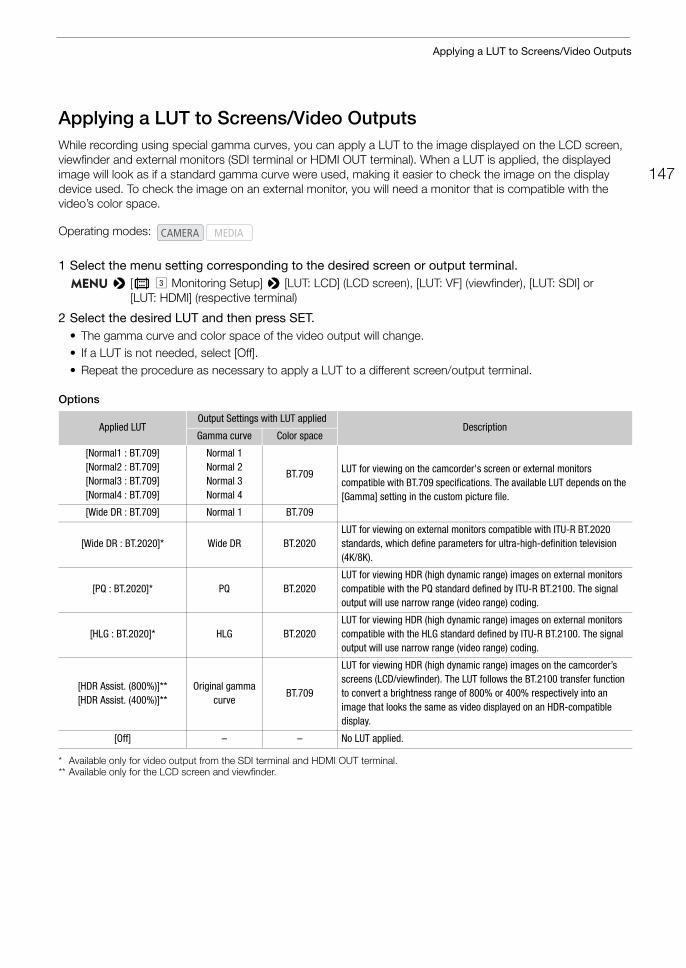
147
Applying a LUT to Screens/Video Outputs
Applying a LUT to Screens/Video OutputsWhile recording using special gamma curves, you can apply a LUT to the image displayed on the LCD screen, viewfinder and external monitors (SDI terminal or HDMI OUT terminal). When a LUT is applied, the displayed image will look as if a standard gamma curve were used, making it easier to check the image on the display device used. To check the image on an external monitor, you will need a monitor that is compatible with the video’s color space.
1 Select the menu setting corresponding to the desired screen or output terminal. > [¢ # Monitoring Setup] > [LUT: LCD] (LCD screen), [LUT: VF] (viewfinder), [LUT: SDI] or
[LUT: HDMI] (respective terminal)
2 Select the desired LUT and then press SET.• The gamma curve and color space of the video output will change.• If a LUT is not needed, select [Off].• Repeat the procedure as necessary to apply a LUT to a different screen/output terminal.
Options
* Available only for video output from the SDI terminal and HDMI OUT terminal.** Available only for the LCD screen and viewfinder.
Operating modes:
Applied LUTOutput Settings with LUT applied
DescriptionGamma curve Color space
[Normal1 : BT.709][Normal2 : BT.709][Normal3 : BT.709][Normal4 : BT.709]
Normal 1Normal 2Normal 3Normal 4
BT.709 LUT for viewing on the camcorder's screen or external monitors compatible with BT.709 specifications. The available LUT depends on the [Gamma] setting in the custom picture file.
[Wide DR : BT.709] Normal 1 BT.709
[Wide DR : BT.2020]* Wide DR BT.2020LUT for viewing on external monitors compatible with ITU-R BT.2020 standards, which define parameters for ultra-high-definition television (4K/8K).
[PQ : BT.2020]* PQ BT.2020LUT for viewing HDR (high dynamic range) images on external monitors compatible with the PQ standard defined by ITU-R BT.2100. The signal output will use narrow range (video range) coding.
[HLG : BT.2020]* HLG BT.2020LUT for viewing HDR (high dynamic range) images on external monitors compatible with the HLG standard defined by ITU-R BT.2100. The signal output will use narrow range (video range) coding.
[HDR Assist. (800%)]**[HDR Assist. (400%)]**
Original gamma curve
BT.709
LUT for viewing HDR (high dynamic range) images on the camcorder’s screens (LCD/viewfinder). The LUT follows the BT.2100 transfer function to convert a brightness range of 800% or 400% respectively into an image that looks the same as video displayed on an HDR-compatible display.
[Off] – – No LUT applied.
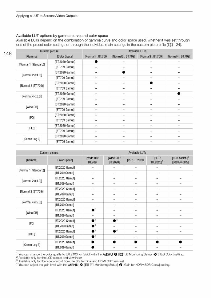
Applying a LUT to Screens/Video Outputs
148
Available LUT options by gamma curve and color spaceAvailable LUTs depend on the combination of gamma curve and color space used, whether it was set through one of the preset color settings or through the individual main settings in the custom picture file (A 124).
1 You can change the color quality to [BT.2100] or [Vivid] with the > [¢ # Monitoring Setup] > [HLG Color] setting.2 Available only for the LCD screen and viewfinder.3 Available only for the video output from the SDI terminal and HDMI OUT terminal.4 You can adjust the gain level with the > [¢ # Monitoring Setup] > [Gain for HDRSDR Conv.] setting.
Custom picture Available LUTs
[Gamma] [Color Space] [Normal1 : BT.709] [Normal2 : BT.709] [Normal3 : BT.709] [Normal4 : BT.709]
[Normal 1 (Standard)][BT.2020 Gamut] Ü – – –
[BT.709 Gamut] – – – –
[Normal 2 (x4.0)][BT.2020 Gamut] – Ü – –
[BT.709 Gamut] – – – –
[Normal 3 (BT.709)][BT.2020 Gamut] – – Ü –
[BT.709 Gamut] – – – –
[Normal 4 (x5.0)][BT.2020 Gamut] – – – Ü
[BT.709 Gamut] – – – –
[Wide DR][BT.2020 Gamut] – – – –
[BT.709 Gamut] – – – –
[PQ][BT.2020 Gamut] – – – –
[BT.709 Gamut] – – – –
[HLG][BT.2020 Gamut] – – – –
[BT.709 Gamut] – – – –
[Canon Log 3][BT.2020 Gamut] – – – –
[BT.709 Gamut] – – – –
Custom picture Available LUTs
[Gamma] [Color Space][Wide DR :
BT.709][Wide DR : BT.2020]
[PQ : BT.2020][HLG :
BT.2020]1[HDR Assist.]2
(800%/400%)
[Normal 1 (Standard)][BT.2020 Gamut] – – – – –
[BT.709 Gamut] – – – – –
[Normal 2 (x4.0)][BT.2020 Gamut] – – – – –
[BT.709 Gamut] – – – – –
[Normal 3 (BT.709)][BT.2020 Gamut] – – – – –
[BT.709 Gamut] – – – – –
[Normal 4 (x5.0)][BT.2020 Gamut] – – – – –
[BT.709 Gamut] – – – – –
[Wide DR][BT.2020 Gamut] Ü3 – – – –
[BT.709 Gamut] – – – – –
[PQ][BT.2020 Gamut] Ü4 Ü4 – – –
[BT.709 Gamut] Ü4 – – – –
[HLG][BT.2020 Gamut] Ü4 Ü4 – – –
[BT.709 Gamut] Ü4 – – – –
[Canon Log 3][BT.2020 Gamut] Ü Ü Ü Ü Ü
[BT.709 Gamut] Ü – – – –
149
Applying a LUT to Screens/Video Outputs
Adjusting the Color Quality for HLG OutputYou can change the quality of the color reproduction when the [HLG : BT.2020] LUT is used.
1 Select [HLG Color]. > [¢ # Monitoring Setup] > [HLG Color]
2 Select the desired setting and then press SET.
Options[BT.2100]: Color reproduction according to ITU-R BT.2100 specifications.[Vivid]: More saturated color reproduction according to the 'Traditional Colour' approach in ITU-R
BT.2390.
Adjusting the Gain Difference between HDR and SDRWhen a LUT that allows gain adjustment is selected, you can adjust the difference in gain between the SDR output relative to the HDR image.
1 Select [Gain for HDRSDR Conv.]. > [¢ # Monitoring Setup] > [Gain for HDRSDR Conv.]
2 Select the desired setting and then press SET.
Selecting the Output RangeYou can select the output range for video output from the SDI terminal or HDMI OUT terminal.
1 Select the range setting according to the terminal you want to use. > [¢ # Monitoring Setup] > [Range: SDI] (SDI terminal) or [Range: HDMI] (HDMI OUT terminal)
2 Select [During Canon Log 3 Output] or [During HDR Output] and then press SET.
3 Select the desired option and then press SET.• Repeat the procedure as necessary to select the output range for other terminals/video outputs.
Options[Full Range]: Video output in full range. Available only for the SDI terminal.[Full Range Priority]:
Priority will be given to output video in full range whenever possible. Available only for the HDMI OUT terminal.
[Narrow Range]:Video output in narrow range (video range).
NOTES
• If you activate slow motion recording while a LUT was set to [PQ : BT.2020] or [HLG : BT.2020], the LUT will be reset to [Off].
• If you set an assignable button to [LUT] (A 117), you can press the button to turn on and off the LUTs applied to all screens/output terminals at once.
• If you change the [Preset] or [Gamma] setting in the custom picture file, the LUTs applied to all screens/output terminals will be reset to [Off].
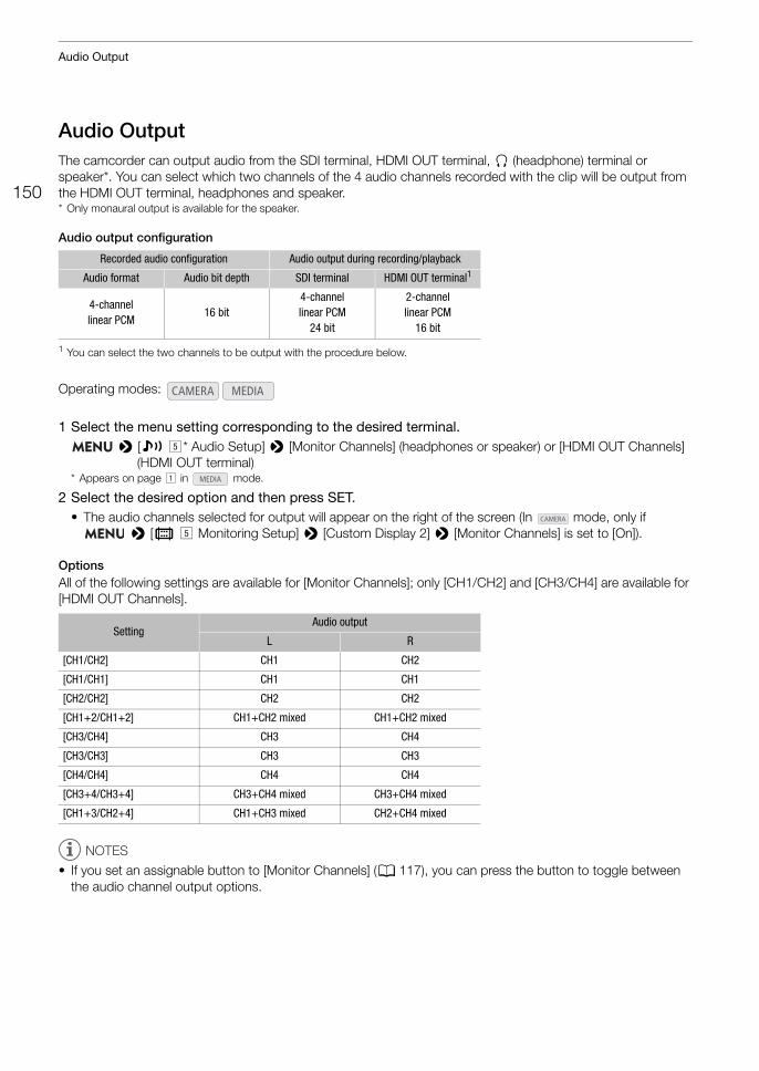
Audio Output
150
Audio OutputThe camcorder can output audio from the SDI terminal, HDMI OUT terminal, × (headphone) terminal or speaker*. You can select which two channels of the 4 audio channels recorded with the clip will be output from the HDMI OUT terminal, headphones and speaker.* Only monaural output is available for the speaker.
Audio output configuration
1 You can select the two channels to be output with the procedure below.
1 Select the menu setting corresponding to the desired terminal. > [¡ %* Audio Setup] > [Monitor Channels] (headphones or speaker) or [HDMI OUT Channels]
(HDMI OUT terminal)* Appears on page ! in mode.
2 Select the desired option and then press SET.• The audio channels selected for output will appear on the right of the screen (In mode, only if
> [¢ % Monitoring Setup] > [Custom Display 2] > [Monitor Channels] is set to [On]).
OptionsAll of the following settings are available for [Monitor Channels]; only [CH1/CH2] and [CH3/CH4] are available for [HDMI OUT Channels].
NOTES
• If you set an assignable button to [Monitor Channels] (A 117), you can press the button to toggle between the audio channel output options.
Recorded audio configuration Audio output during recording/playback
Audio format Audio bit depth SDI terminal HDMI OUT terminal1
4-channel linear PCM
16 bit4-channel linear PCM
24 bit
2-channel linear PCM
16 bit
Operating modes:
SettingAudio output
L R
[CH1/CH2] CH1 CH2
[CH1/CH1] CH1 CH1
[CH2/CH2] CH2 CH2
[CH1+2/CH1+2] CH1+CH2 mixed CH1+CH2 mixed
[CH3/CH4] CH3 CH4
[CH3/CH3] CH3 CH3
[CH4/CH4] CH4 CH4
[CH3+4/CH3+4] CH3+CH4 mixed CH3+CH4 mixed
[CH1+3/CH2+4] CH1+CH3 mixed CH2+CH4 mixed
151
Working with Clips on a Computer
Working with Clips on a Computer
Saving Clips to a ComputerUse Canon XF Utility to save and organize clips on a computer. You can use the Canon XF plugins to easily use clips directly from non-linear editing (NLE) software made by Avid. To be able to use XF-HEVC clips in Canon XF Utility or the Canon XF plugins, you will need to download and install also the Canon XF-HEVC Decoder. The software, plugins and decoder are available as free downloads from your local Canon Web site. Check the download page for the system requirements and latest information. You will find detailed instructions about installing and uninstalling the software in the "Read This First" file (Install-XF Utility.pdf) included in the compressed file you will download from the Web site. For details about using the software, refer to the instruction manual (PDF file) that is installed with the software.
Canon XF Utility (for Windows/macOS): Software application that allows you to save clips on a computer, check, play back and organize clips and grab still frames from clips.
Canon XF Plugin for Avid Media Access (for Windows/macOS): Plugin that allows you to easily import clips from an SD card or a local folder in the computer to the compatible version of Avid Media Composer (an NLE application compatible with Avid Media Access), directly from within the application.
Canon XF-HEVC Decoder (for Windows/macOS): Decoder that allows you to play back XF-HEVC clips using Canon XF Utility or the Canon XF plugins. The decoder is required to use XF-HEVC clips on a computer.

Working with Clips on a Computer
152
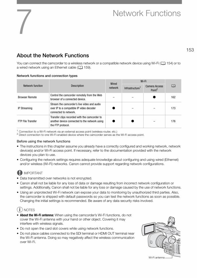
7153
Network Functions
About the Network FunctionsYou can connect the camcorder to a wireless network or a compatible network device using Wi-Fi (A 154) or to a wired network using an Ethernet cable (A 159).
Network functions and connection types
1 Connection to a Wi-Fi network via an external access point (wireless router, etc.)2 Direct connection to one Wi-Fi-enabled device where the camcorder serves as the Wi-Fi access point.
Before using the network functions• The instructions in this chapter assume you already have a correctly configured and working network, network
device(s) and/or Wi-Fi access point. If necessary, refer to the documentation provided with the network devices you plan to use.
• Configuring the network settings requires adequate knowledge about configuring and using wired (Ethernet) and/or wireless (Wi-Fi) networks. Canon cannot provide support regarding network configurations.
IMPORTANT
• Data transmitted over networks is not encrypted.• Canon shall not be liable for any loss of data or damage resulting from incorrect network configuration or
settings. Additionally, Canon shall not be liable for any loss or damage caused by the use of network functions.• Using an unprotected Wi-Fi network can expose your data to monitoring by unauthorized third parties. Also,
the camcorder is shipped with default passwords so you can test the network functions as soon as possible. Changing the initial settings is recommended. Be aware of any data security risks involved.
NOTES
• About the Wi-Fi antenna: When using the camcorder’s Wi-Fi functions, do not cover the Wi-Fi antenna with your hand or other object. Covering it may interfere with wireless signals.
• Do not open the card slot covers while using network functions.• Do not place cables connected to the SDI terminal or HDMI OUT terminal near
the Wi-Fi antenna. Doing so may negatively affect the wireless communication over Wi-Fi.
Network function DescriptionWired
network
Wi-Fi
AInfrastructure1 Camera Access
Point2
Browser RemoteControl the camcorder remotely from the Web browser of a connected device.
– – Ü 162
IP StreamingStream the camcorder’s live video and audio over IP to a compatible IP video decoder connected to network.
Ü – – 173
FTP File TransferTransfer clips recorded with the camcorder to another device connected to the network using the FTP protocol.
Ü Ü – 176
Wi-Fi antenna
Connecting to a Wi-Fi Network
154
Connecting to a Wi-Fi NetworkThe camcorder is Wi-Fi certified and can connect to access points (wireless router, etc.) and network devices compliant with the 802.11a/b/g/n protocol and that are Wi-Fi certified (bear the logo shown on the right). The Wi-Fi connection's functionality and applicable restrictions may vary depending on the Wi-Fi network used. Note that using an unprotected Wi-Fi connection can expose your data to monitoring by unauthorized third parties. Be aware of the risks involved.You can connect the camcorder to a Wi-Fi network in Infrastructure mode (using an access point), or directly to one network device in Camera Access Point mode. The type of connection you can use depends on the network function you wish to use (A 153). For an Infrastructure connection, the camcorder offers 4 ways to configure an access point and the method you use will depend on the type and specifications of the access point and network you plan to use.
Camera Access Point: When shooting in a location where there are no access points available, the camcorder can serve as a wireless access point*. Wi-Fi enabled devices will be able to connect to the camcorder directly.* Limited only to the connection between the camcorder and supported Wi-Fi enabled devices. The functionality is not the same
as that of commercially available access points.
Infrastructure connection: WPS (button): If your wireless router supports Wi-Fi Protected Setup (WPS), setup will be easy and require minimal configuring and no passwords. To check if your wireless router has a WPS button and for details about how to activate the Wi-Fi protected setup, refer to the instruction manual of your wireless router.
WPS (PIN code): Even if your wireless router does not have a dedicated WPS button, it may support WPS using a PIN code instead. For setup using a PIN code, you will need to know in advance how to activate the wireless router’s WPS function. For details refer to the instruction manual of your wireless router.
Searching for Access Points: If your access point does not support the WPS function or you cannot activate it, you can have the camcorder search for access points in the area.
Manual Setup: If the access point you want to use has stealth mode activated and it cannot be automatically detected by the camcorder, you can enter all the necessary settings manually. This requires more advanced knowledge of Wi-Fi and network settings.
IMPORTANT
• Depending on the country/region of use, some restrictions on outdoor use or Camera Access Point connections may apply when operating the IEEE802.11a/n wireless standard in the 5 GHz band. For details about areas of use and restrictions, refer to the Specifications (A 221).
155
Connecting to a Wi-Fi Network
Camera Access PointIn this mode the camcorder itself serves as a wireless access point to which other Wi-Fi-enabled devices can connect. Initially, basic settings for a Camera Access Point connection (network name (SSID): [XF705-xxxx_Canon0C], password: [12345678]) are already saved under network configuration profile [1:]. You can use the default settings to connect immediately to the camcorder or follow the procedure below if you wish to change the settings.
1 Select [Connection Settings]. > [ ! Network Settings] > [Connection Settings]
2 Select the desired network configuration profile and then select [Camera Access Point].Network configuration profile ([1:] to [4:]) > [Edit] > [Camera Access Point]• You can save up to 4 network configuration profiles in the camcorder. Push the joystick up/down to select
the desired profile.
3 Enter the SSID (network name) the camcorder will use as a Wi-Fi access point.[Input] > Enter the desired network name using the keyboard screen (A 27) > [OK]
4 Select the frequency band for the Wi-Fi connection ([5 GHz] or [2.4 GHz]) and then press SET.• For users of model ID0118 PAL (A 17): Because only the 2.4 GHz frequency band is available for Camera
Access Point mode, skip to step 5.
5 Select the channel and then press SET.• Available channels will differ depending on the selected frequency band. (Not applicable depending on the
model.)
6 Select the encryption method and then press SET.• If you selected [Open/No encryption], skip to step 8.
7 Enter the encryption key (password).[Input] > Enter the desired password using the keyboard screen (A 27) > [OK]• This password is needed to connect the network device to the camcorder. If necessary, write it down.
8 Continue with the procedure to configure the IP address assignment (A 155).
Configuring the IP Address Settings
At this point you need to configure the TCP/IP settings. If you need to configure the TCP/IP settings manually, consult the network administrator to obtain the relevant information.
1 Select the method for assigning the IP address ([Automatic] or [Manual]) and then press SET.• If you selected [Automatic], the IP address will be assigned automatically. Continue with the procedure to
review and save the configuration (A 156).
2 Enter the IP address.• Push the joystick up/down to select a value for the first field and then press SET to move to the next field. After
completing the four fields of the address, select [Set] and then press SET.
3 Enter the rest of the necessary TCP/IP settings in the same way.• Camera Access Point connections: Enter the [Subnet Mask].• Infrastructure/Ethernet connections: Enter the [Subnet Mask], [Default Gateway], [Primary DNS Server] and
[Secndry DNS Server]. If necessary, touch [Í]/[Î] to scroll up/down.
4 After completing the necessary settings, continue with the procedure to review and save the configuration (A 156).
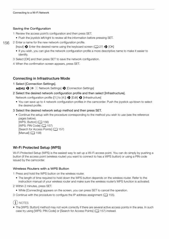
Connecting to a Wi-Fi Network
156
Saving the Configuration
1 Review the access point’s configuration and then press SET.• Push the joystick left/right to review all the information before pressing SET.
2 Enter a name for the new network configuration profile.[Input] > Enter the desired name using the keyboard screen (A 27) > [OK]• If you wish, you can give the network configuration profile a more descriptive name to make it easier to
identify.
3 Select [OK] and then press SET to save the network configuration.
4 When the confirmation screen appears, press SET.
Connecting in Infrastructure Mode1 Select [Connection Settings].
> [ ! Network Settings] > [Connection Settings]
2 Select the desired network configuration profile and then select [Infrastructure].Network configuration profile ([1:] to [4:]) > [Edit] > [Infrastructure]• You can save up to 4 network configuration profiles in the camcorder. Push the joystick up/down to select
the desired profile.
3 Select the desired network setup method and then press SET.• Continue the setup with the procedure corresponding to the method you wish to use (see the reference
pages below).[WPS: Button] (A 156)[WPS: PIN Code] (A 157)[Search for Access Points] (A 157) [Manual] (A 158)
Wi-Fi Protected Setup (WPS)Wi-Fi Protected Setup (WPS) is the easiest way to set up a Wi-Fi access point. You can do simply by pushing a button (if the access point (wireless router) you want to connect to has a WPS button) or using a PIN code issued by the camcorder.
Wireless Routers with a WPS Button
1 Press and hold the WPS button on the wireless router.• The length of time required to hold down the WPS button depends on the wireless router. Refer to the
instruction manual of your wireless router and make sure the wireless router’s WPS function is activated.
2 Within 2 minutes, press SET.• While [Connecting] appears on the screen, you can press SET to cancel the operation.
3 Continue with the procedure to configure the IP address assignment (A 155).
NOTES
• The [WPS: Button] method may not work correctly if there are several active access points in the area. In such case try using [WPS: PIN Code] or [Search for Access Points] (A 157) instead.
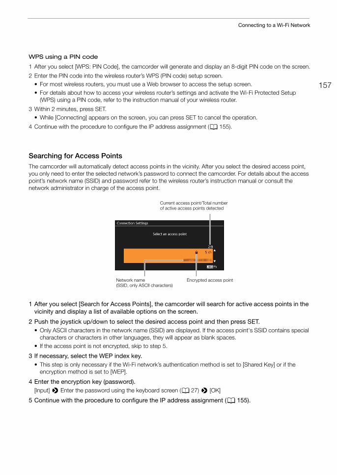
157
Connecting to a Wi-Fi Network
WPS using a PIN code
1 After you select [WPS: PIN Code], the camcorder will generate and display an 8-digit PIN code on the screen.
2 Enter the PIN code into the wireless router’s WPS (PIN code) setup screen.• For most wireless routers, you must use a Web browser to access the setup screen.• For details about how to access your wireless router’s settings and activate the Wi-Fi Protected Setup
(WPS) using a PIN code, refer to the instruction manual of your wireless router.
3 Within 2 minutes, press SET.• While [Connecting] appears on the screen, you can press SET to cancel the operation.
4 Continue with the procedure to configure the IP address assignment (A 155).
Searching for Access PointsThe camcorder will automatically detect access points in the vicinity. After you select the desired access point, you only need to enter the selected network’s password to connect the camcorder. For details about the access point’s network name (SSID) and password refer to the wireless router’s instruction manual or consult the network administrator in charge of the access point.
1 After you select [Search for Access Points], the camcorder will search for active access points in the vicinity and display a list of available options on the screen.
2 Push the joystick up/down to select the desired access point and then press SET.• Only ASCII characters in the network name (SSID) are displayed. If the access point's SSID contains special
characters or characters in other languages, they will appear as blank spaces.• If the access point is not encrypted, skip to step 5.
3 If necessary, select the WEP index key.• This step is only necessary if the Wi-Fi network’s authentication method is set to [Shared Key] or if the
encryption method is set to [WEP].
4 Enter the encryption key (password).[Input] > Enter the password using the keyboard screen (A 27) > [OK]
5 Continue with the procedure to configure the IP address assignment (A 155).
Network name (SSID, only ASCII characters)
Current access point/Total number of active access points detected
Encrypted access point
Connecting to a Wi-Fi Network
158
Manual SetupIf you prefer, you can enter manually the details of the Wi-Fi network you want to connect to. Follow the instructions on the screen to complete the procedure.
1 Enter the access point's SSID (network name).[Input] > Enter the network name using the keyboard screen (A 27) > [OK]
2 Select the authentication method and then press SET.• If you selected [Open], select [WEP], press SET and continue the procedure, or select [No Encryption], press
SET and continue with the procedure to configure the IP address assignment (A 155).
3 Select the WEP index or encryption method, depending on the selected authentication mode.• [Shared Key]/[WEP]: Select the WEP index and then press SET.• [WPA-PSK]/[WPA2-PSK]: Select [TKIP] or [AES] and then press SET.
4 Enter the encryption key (password).[Input] > Enter the password using the keyboard screen (A 27) > [OK]
5 Continue with the procedure to configure the IP address assignment (A 155).
NOTES
Valid passwords vary depending on the encryption method.64-bit WEP encryption: 5 ASCII characters or 10 hexadecimal characters.128-bit WEP encryption: 13 ASCII characters or 26 hexadecimal characters.AES / TKIP encryption: 8 to 63 ASCII characters or 64 hexadecimal characters.* Note: ASCII characters include the numbers 0 to 9, the letters a to z and A to Z and some punctuation marks and special
symbols. Hexadecimal characters comprise the numbers 0 to 9 and the letters a to f and A to F.
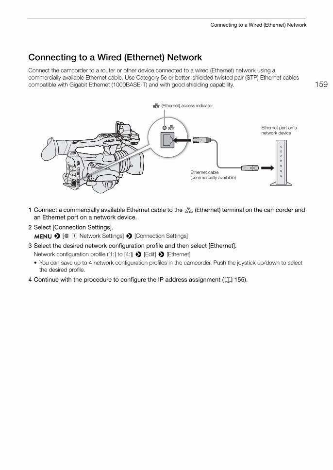
159
Connecting to a Wired (Ethernet) Network
Connecting to a Wired (Ethernet) NetworkConnect the camcorder to a router or other device connected to a wired (Ethernet) network using a commercially available Ethernet cable. Use Category 5e or better, shielded twisted pair (STP) Ethernet cables compatible with Gigabit Ethernet (1000BASE-T) and with good shielding capability.
1 Connect a commercially available Ethernet cable to the (Ethernet) terminal on the camcorder and an Ethernet port on a network device.
2 Select [Connection Settings]. > [ ! Network Settings] > [Connection Settings]
3 Select the desired network configuration profile and then select [Ethernet].Network configuration profile ([1:] to [4:]) > [Edit] > [Ethernet]• You can save up to 4 network configuration profiles in the camcorder. Push the joystick up/down to select
the desired profile.
4 Continue with the procedure to configure the IP address assignment (A 155).
(Ethernet) access indicator
Ethernet cable (commercially available)
Ethernet port on a network device
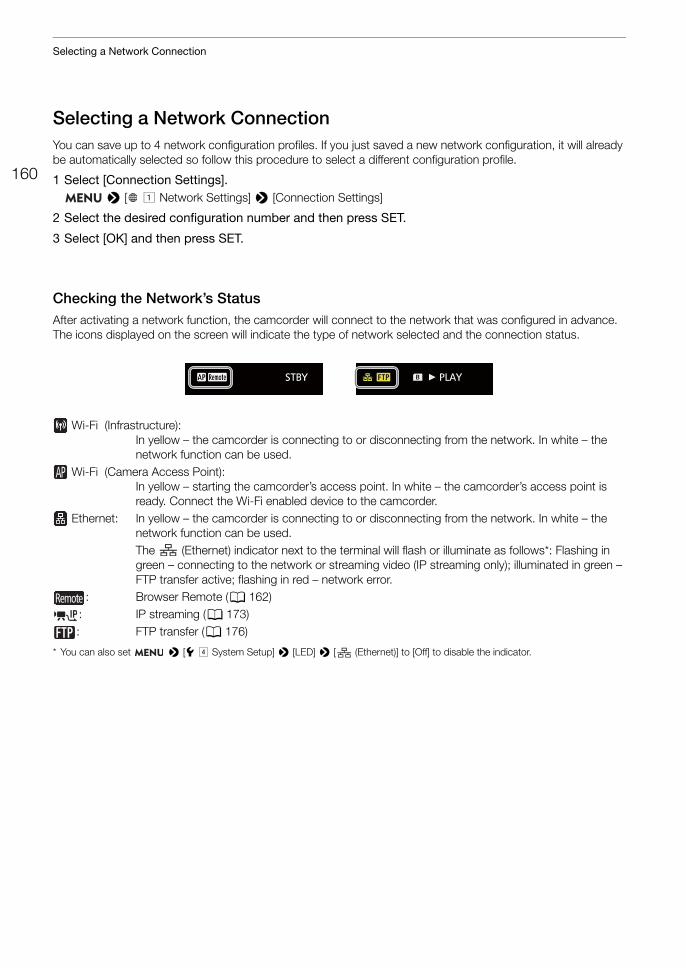
Selecting a Network Connection
160
Selecting a Network ConnectionYou can save up to 4 network configuration profiles. If you just saved a new network configuration, it will already be automatically selected so follow this procedure to select a different configuration profile.
1 Select [Connection Settings]. > [ ! Network Settings] > [Connection Settings]
2 Select the desired configuration number and then press SET.
3 Select [OK] and then press SET.
Checking the Network’s StatusAfter activating a network function, the camcorder will connect to the network that was configured in advance. The icons displayed on the screen will indicate the type of network selected and the connection status.
Wi-Fi (Infrastructure): In yellow – the camcorder is connecting to or disconnecting from the network. In white – the network function can be used.
Wi-Fi (Camera Access Point): In yellow – starting the camcorder’s access point. In white – the camcorder’s access point is ready. Connect the Wi-Fi enabled device to the camcorder.
Ethernet: In yellow – the camcorder is connecting to or disconnecting from the network. In white – the network function can be used.The (Ethernet) indicator next to the terminal will flash or illuminate as follows*: Flashing in green – connecting to the network or streaming video (IP streaming only); illuminated in green – FTP transfer active; flashing in red – network error.
: Browser Remote (A 162): IP streaming (A 173): FTP transfer (A 176)
* You can also set > [B $ System Setup] > [LED] > [ (Ethernet)] to [Off] to disable the indicator.
161
Changing Network Settings
Changing Network SettingsYou can check and, if necessary, edit the settings of the currently selected network configuration profile even after the initial setup. Changing settings manually requires more advanced knowledge of Wi-Fi and network settings.
1 Select [Connection Settings]. > [ ! Network Settings] > [Connection Settings]
2 Select the network configuration profile you want to check and then press SET.
3 To change the network settings, select [Edit] and then press SET.
4 Select [Infrastructure], [Camera Access Point] or [Ethernet].• Change the network settings as described in the previous sections.
- Infrastrucure connections (A 156, from step 3)- Camera Access Point connections (A 155, from step 3)- Ethernet connections: Connect the network device (step 1, A 159) and change the IP settings (A 155).
Browser Remote: Controlling the Camcorder from a Network Device
162
Browser Remote: Controlling the Camcorder from a Network DeviceAfter connecting a network device to the camcorder via Wi-Fi, you can operate the camcorder remotely using Browser Remote, a Web browser application that can be accessed using the Web browser on network devices*. Using Browser Remote, you can check the camcorder’s live view image and control various recording settings. On the Browser Remote screen, you can also check the remaining recording time on the card, remaining battery charge and the camcorder’s time code.* For details about compatible devices, operating systems, Web browsers, etc., please visit your local Canon website.
Setting Up Browser RemoteYou can set a unique camcorder identification code and designate the port that the Browser Remote application should use when accessing the camcorder through the network. The port number (HTTP protocol) used by Browser Remote is usually set to port 80, but you can change it if necessary. The camcorder ID will appear on the Browser Remote screen, making it easy to identify which camcorder the application is controlling in case of a multi-camera shooting setup.
Camcorder Settings
1 Select [Browser Remote Settings]. > [ ! Network Settings] > [Browser Remote Settings]
2 To change the port number, select [Port No.].• To enter the port number, push the joystick left/right to select the digit to change and then up/down to select
a value for the selected digit. After completing the five digits of the port number, select [Set] and then press SET.
3 To change the camcorder ID, select [Camera ID].• Enter the desired camcorder ID using the keyboard screen (A 27).
User Settings
A user name and password are required to log in to the Browser Remote application. You can set up to three different users and select whether you want to allow single-user operation (full control) or two-user operation (one controlling camcorder functions and another in charge of metadata input for clips).
[Full] Can access all 3 Browser Remote screens: [v] (main recording screen), [ ] (metadata screen) and [ ] (basic screen).
[Camera] Can access only the [v] (main recording) screen. This would be the main operator controlling the camcorder.
[Meta] Can access only the [ ] (metadata) screen. This would be the person in charge of keeping the clip information up to date.
1 Select [Browser Remote Settings] > [ ! Network Settings] > [Browser Remote Settings]
2 To select the number of Browser Remote users, select [Users Settings].
3 Select the desired option and then press SET.• If you selected [One User (Full)], perform steps 4-5 to enter the user name and password for the [Full] user. If
you selected [Two Users (Camera/Meta)], perform steps 4-5 twice, once for the [Camera] user and again for the [Meta] user.
Operating modes:
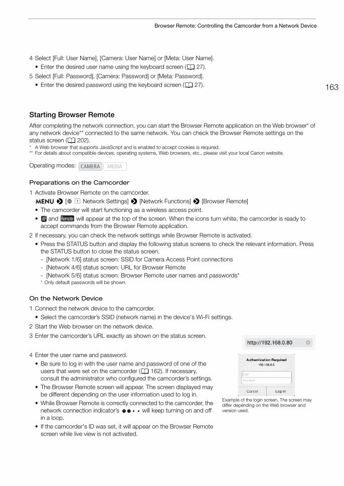
163
Browser Remote: Controlling the Camcorder from a Network Device
4 Select [Full: User Name], [Camera: User Name] or [Meta: User Name].• Enter the desired user name using the keyboard screen (A 27).
5 Select [Full: Password], [Camera: Password] or [Meta: Password].• Enter the desired password using the keyboard screen (A 27).
Starting Browser RemoteAfter completing the network connection, you can start the Browser Remote application on the Web browser* of any network device** connected to the same network. You can check the Browser Remote settings on the status screen (A 202).* A Web browser that supports JavaScript and is enabled to accept cookies is required.** For details about compatible devices, operating systems, Web browsers, etc., please visit your local Canon website.
Preparations on the Camcorder
1 Activate Browser Remote on the camcorder. > [ ! Network Settings] > [Network Functions] > [Browser Remote]
• The camcorder will start functioning as a wireless access point.• and will appear at the top of the screen. When the icons turn white, the camcorder is ready to
accept commands from the Browser Remote application.
2 If necessary, you can check the network settings while Browser Remote is activated.• Press the STATUS button and display the following status screens to check the relevant information. Press
the STATUS button to close the status screen.- [Network 1/6] status screen: SSID for Camera Access Point connections- [Network 4/6] status screen: URL for Browser Remote- [Network 5/6] status screen: Browser Remote user names and passwords** Only default passwords will be shown.
On the Network Device
1 Connect the network device to the camcorder.• Select the camcorder’s SSID (network name) in the device's Wi-Fi settings.
2 Start the Web browser on the network device.
3 Enter the camcorder’s URL exactly as shown on the status screen.
4 Enter the user name and password.• Be sure to log in with the user name and password of one of the
users that were set on the camcorder (A 162). If necessary, consult the administrator who configured the camcorder’s settings.
• The Browser Remote screen will appear. The screen displayed may be different depending on the user information used to log in.
• While Browser Remote is correctly connected to the camcorder, the network connection indicator’s will keep turning on and off in a loop.
• If the camcorder's ID was set, it will appear on the Browser Remote screen while live view is not activated.
Operating modes:
Example of the login screen. The screen may differ depending on the Web browser and version used.
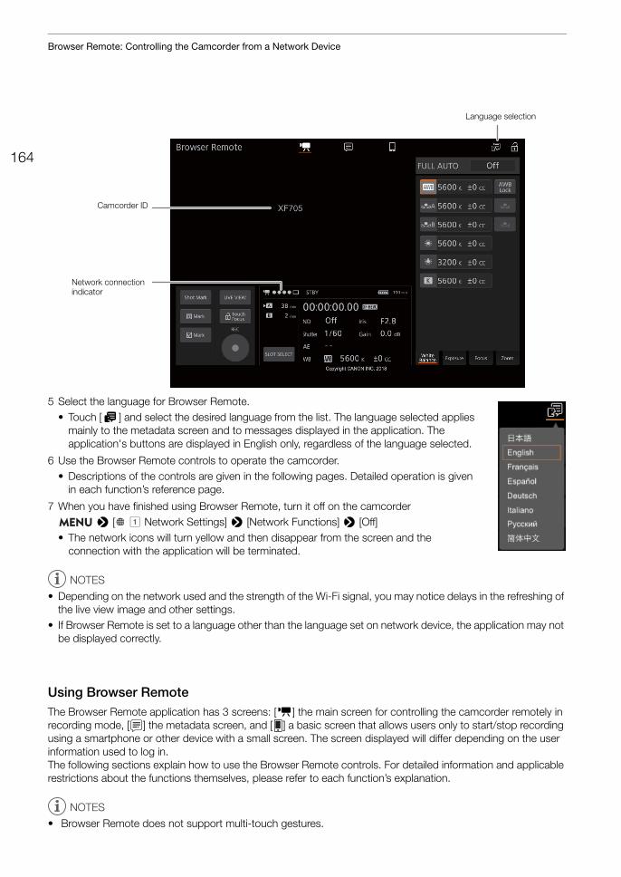
Browser Remote: Controlling the Camcorder from a Network Device
164
5 Select the language for Browser Remote.• Touch [H] and select the desired language from the list. The language selected applies
mainly to the metadata screen and to messages displayed in the application. The application's buttons are displayed in English only, regardless of the language selected.
6 Use the Browser Remote controls to operate the camcorder.• Descriptions of the controls are given in the following pages. Detailed operation is given
in each function’s reference page.
7 When you have finished using Browser Remote, turn it off on the camcorder > [ ! Network Settings] > [Network Functions] > [Off]
• The network icons will turn yellow and then disappear from the screen and the connection with the application will be terminated.
NOTES
• Depending on the network used and the strength of the Wi-Fi signal, you may notice delays in the refreshing of the live view image and other settings.
• If Browser Remote is set to a language other than the language set on network device, the application may not be displayed correctly.
Using Browser RemoteThe Browser Remote application has 3 screens: [v] the main screen for controlling the camcorder remotely in recording mode, [ ] the metadata screen, and [ ] a basic screen that allows users only to start/stop recording using a smartphone or other device with a small screen. The screen displayed will differ depending on the user information used to log in.The following sections explain how to use the Browser Remote controls. For detailed information and applicable restrictions about the functions themselves, please refer to each function’s explanation.
NOTES
• Browser Remote does not support multi-touch gestures.
Language selection
Camcorder ID
Network connection indicator
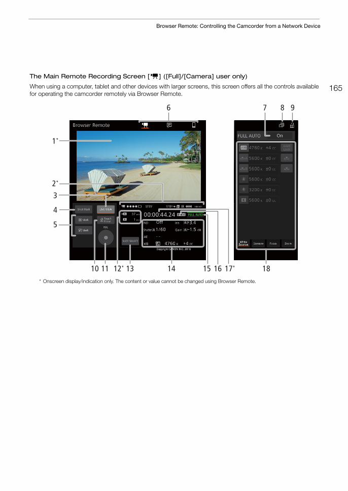
165
Browser Remote: Controlling the Camcorder from a Network Device
The Main Remote Recording Screen [v] ([Full]/[Camera] user only)
When using a computer, tablet and other devices with larger screens, this screen offers all the controls available for operating the camcorder remotely via Browser Remote.
* Onscreen display/indication only. The content or value cannot be changed using Browser Remote.
876 9
12* 1311 14 1815 1610 17*
1*
4
3
5
2*
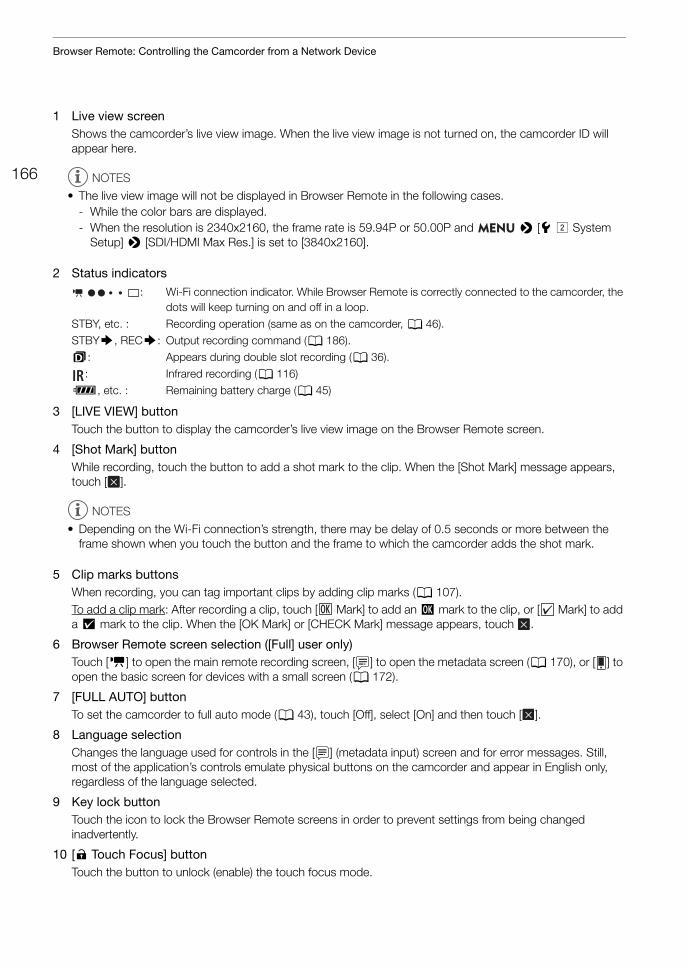
Browser Remote: Controlling the Camcorder from a Network Device
166
1 Live view screenShows the camcorder’s live view image. When the live view image is not turned on, the camcorder ID will appear here.
2 Status indicators
3 [LIVE VIEW] buttonTouch the button to display the camcorder’s live view image on the Browser Remote screen.
4 [Shot Mark] buttonWhile recording, touch the button to add a shot mark to the clip. When the [Shot Mark] message appears, touch [ ].
5 Clip marks buttonsWhen recording, you can tag important clips by adding clip marks (A 107).To add a clip mark: After recording a clip, touch [ Mark] to add an $ mark to the clip, or [ Mark] to add a % mark to the clip. When the [OK Mark] or [CHECK Mark] message appears, touch .
6 Browser Remote screen selection ([Full] user only)Touch [v] to open the main remote recording screen, [ ] to open the metadata screen (A 170), or [ ] to open the basic screen for devices with a small screen (A 172).
7 [FULL AUTO] buttonTo set the camcorder to full auto mode (A 43), touch [Off], select [On] and then touch [ ].
8 Language selectionChanges the language used for controls in the [ ] (metadata input) screen and for error messages. Still, most of the application’s controls emulate physical buttons on the camcorder and appear in English only, regardless of the language selected.
9 Key lock buttonTouch the icon to lock the Browser Remote screens in order to prevent settings from being changed inadvertently.
10 [D Touch Focus] buttonTouch the button to unlock (enable) the touch focus mode.
NOTES
• The live view image will not be displayed in Browser Remote in the following cases.- While the color bars are displayed.- When the resolution is 2340x2160, the frame rate is 59.94P or 50.00P and > [B" System
Setup] > [SDI/HDMI Max Res.] is set to [3840x2160].
: Wi-Fi connection indicator. While Browser Remote is correctly connected to the camcorder, the dots will keep turning on and off in a loop.
STBY, etc. : Recording operation (same as on the camcorder, A 46).STBY`, REC`: Output recording command (A 186).4: Appears during double slot recording (A 36).
: Infrared recording (A 116)è, etc. : Remaining battery charge (A 45)
NOTES
• Depending on the Wi-Fi connection’s strength, there may be delay of 0.5 seconds or more between the frame shown when you touch the button and the frame to which the camcorder adds the shot mark.
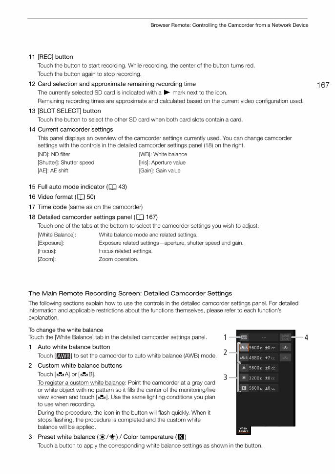
167
Browser Remote: Controlling the Camcorder from a Network Device
11 [REC] buttonTouch the button to start recording. While recording, the center of the button turns red.Touch the button again to stop recording.
12 Card selection and approximate remaining recording timeThe currently selected SD card is indicated with a Ð mark next to the icon. Remaining recording times are approximate and calculated based on the current video configuration used.
13 [SLOT SELECT] buttonTouch the button to select the other SD card when both card slots contain a card.
14 Current camcorder settingsThis panel displays an overview of the camcorder settings currently used. You can change camcorder settings with the controls in the detailed camcorder settings panel (18) on the right.
15 Full auto mode indicator (A 43)
16 Video format (A 50)
17 Time code (same as on the camcorder)
18 Detailed camcorder settings panel (A 167)Touch one of the tabs at the bottom to select the camcorder settings you wish to adjust:
The Main Remote Recording Screen: Detailed Camcorder Settings
The following sections explain how to use the controls in the detailed camcorder settings panel. For detailed information and applicable restrictions about the functions themselves, please refer to each function’s explanation.
To change the white balanceTouch the [White Balance] tab in the detailed camcorder settings panel.
1 Auto white balance buttonTouch [ ] to set the camcorder to auto white balance (AWB) mode.
2 Custom white balance buttonsTouch [ÅA] or [ÅB].To register a custom white balance: Point the camcorder at a gray card or white object with no pattern so it fills the center of the monitoring/live view screen and touch [Å]. Use the same lighting conditions you plan to use when recording.During the procedure, the icon in the button will flash quickly. When it stops flashing, the procedure is completed and the custom white balance will be applied.
3 Preset white balance (¼/É) / Color temperature (È)Touch a button to apply the corresponding white balance settings as shown in the button.
[ND]: ND filter [WB]: White balance[Shutter]: Shutter speed [Iris]: Aperture value
[AE]: AE shift [Gain]: Gain value
[White Balance]: White balance mode and related settings.
[Exposure]: Exposure related settings—aperture, shutter speed and gain.[Focus]: Focus related settings.[Zoom]: Zoom operation.
1 4
2
3
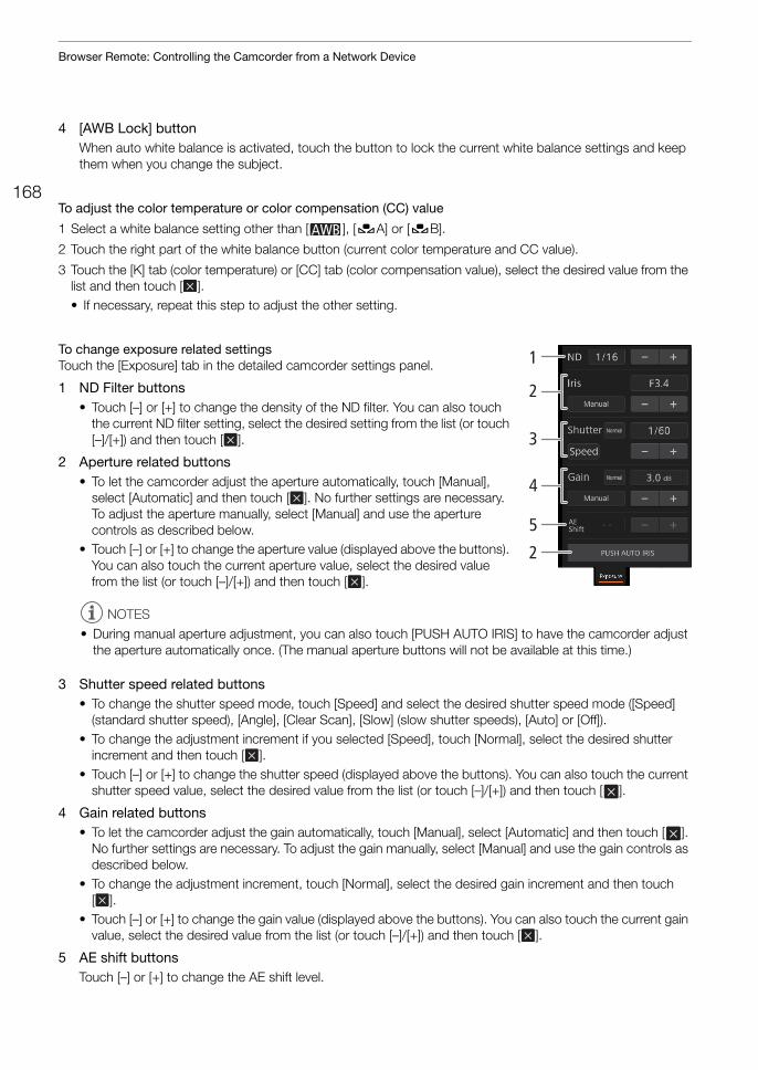
Browser Remote: Controlling the Camcorder from a Network Device
168
4 [AWB Lock] buttonWhen auto white balance is activated, touch the button to lock the current white balance settings and keep them when you change the subject.
To adjust the color temperature or color compensation (CC) value
1 Select a white balance setting other than [ ], [ÅA] or [ÅB].
2 Touch the right part of the white balance button (current color temperature and CC value).
3 Touch the [K] tab (color temperature) or [CC] tab (color compensation value), select the desired value from the list and then touch [ ].• If necessary, repeat this step to adjust the other setting.
To change exposure related settingsTouch the [Exposure] tab in the detailed camcorder settings panel.
1 ND Filter buttons• Touch [–] or [+] to change the density of the ND filter. You can also touch
the current ND filter setting, select the desired setting from the list (or touch [–]/[+]) and then touch [ ].
2 Aperture related buttons• To let the camcorder adjust the aperture automatically, touch [Manual],
select [Automatic] and then touch [ ]. No further settings are necessary. To adjust the aperture manually, select [Manual] and use the aperture controls as described below.
• Touch [–] or [+] to change the aperture value (displayed above the buttons). You can also touch the current aperture value, select the desired value from the list (or touch [–]/[+]) and then touch [ ].
3 Shutter speed related buttons• To change the shutter speed mode, touch [Speed] and select the desired shutter speed mode ([Speed]
(standard shutter speed), [Angle], [Clear Scan], [Slow] (slow shutter speeds), [Auto] or [Off]).• To change the adjustment increment if you selected [Speed], touch [Normal], select the desired shutter
increment and then touch [ ].• Touch [–] or [+] to change the shutter speed (displayed above the buttons). You can also touch the current
shutter speed value, select the desired value from the list (or touch [–]/[+]) and then touch [ ].
4 Gain related buttons• To let the camcorder adjust the gain automatically, touch [Manual], select [Automatic] and then touch [ ].
No further settings are necessary. To adjust the gain manually, select [Manual] and use the gain controls as described below.
• To change the adjustment increment, touch [Normal], select the desired gain increment and then touch [ ].
• Touch [–] or [+] to change the gain value (displayed above the buttons). You can also touch the current gain value, select the desired value from the list (or touch [–]/[+]) and then touch [ ].
5 AE shift buttonsTouch [–] or [+] to change the AE shift level.
NOTES
• During manual aperture adjustment, you can also touch [PUSH AUTO IRIS] to have the camcorder adjust the aperture automatically once. (The manual aperture buttons will not be available at this time.)
5
2
1
2
3
4
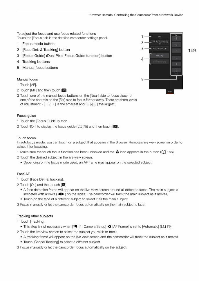
169
Browser Remote: Controlling the Camcorder from a Network Device
To adjust the focus and use focus related functionsTouch the [Focus] tab in the detailed camcorder settings panel.
1 Focus mode button
2 [Face Det. & Tracking] button
3 [Focus Guide] (Dual Pixel Focus Guide function) button
4 Tracking buttons
5 Manual focus buttons
Manual focus
1 Touch [AF].
2 Touch [MF] and then touch [ ].
3 Touch one of the manual focus buttons on the [Near] side to focus closer or one of the controls on the [Far] side to focus farther away. There are three levels of adjustment - [ ]/[ ] is the smallest and [ ]/[ ] the largest.
Focus guide
1 Touch the [Focus Guide] button.
2 Touch [On] to display the focus guide (A 75) and then touch [ ].
Touch focusIn autofocus mode, you can touch on a subject that appears in the Browser Remote’s live view screen in order to select it for focusing.
1 Make sure the touch focus function has been unlocked and the D icon appears in the button (A 166).
2 Touch the desired subject in the live view screen.• Depending on the focus mode used, an AF frame may appear on the selected subject.
Face AF
1 Touch [Face Det. & Tracking].
2 Touch [On] and then touch [ ].• A face detection frame will appear on the live view screen around all detected faces. The main subject is
indicated with arrows (Þ) on the sides. The camcorder will track the main subject as it moves.• Touch on the face of a different subject to select it as the main subject.
3 Focus manually or let the camcorder focus automatically on the main subject's face.
Tracking other subjects
1 Touch [Tracking].• This step is not necessary when [v # Camera Setup] > [AF Frame] is set to [Automatic] (A 79).
2 Touch the live view screen to select the subject you wish to track.• A tracking frame will appear on the live view screen and the camcorder will track the subject as it moves.• Touch [Cancel Tracking] to select a different subject.
3 Focus manually or let the camcorder focus automatically on the subject.
123
4
5
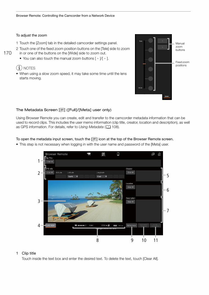
Browser Remote: Controlling the Camcorder from a Network Device
170
To adjust the zoom
1 Touch the [Zoom] tab in the detailed camcorder settings panel.
2 Touch one of the fixed zoom position buttons on the [Tele] side to zoom in or one of the buttons on the [Wide] side to zoom out.• You can also touch the manual zoom buttons [ ]/[ ].
NOTES
• When using a slow zoom speed, it may take some time until the lens starts moving.
The Metadata Screen [ ] ([Full]/[Meta] user only)
Using Browser Remote you can create, edit and transfer to the camcorder metadata information that can be used to record clips. This includes the user memo information (clip title, creator, location and description), as well as GPS information. For details, refer to Using Metadata (A 108).
To open the metadata input screen, touch the [ ] icon at the top of the Browser Remote screen.• This step is not necessary when logging in with the user name and password of the [Meta] user.
1 Clip titleTouch inside the text box and enter the desired text. To delete the text, touch [Clear All].
Manual zoom buttons
Fixed zoom positions
5
6
7
8 119 10
1
4
3
2
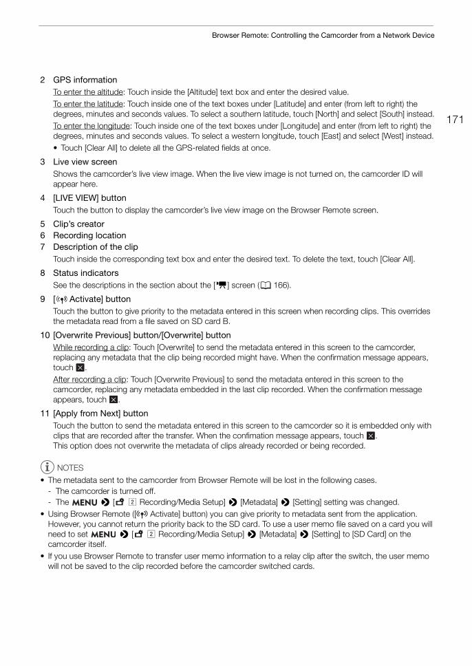
171
Browser Remote: Controlling the Camcorder from a Network Device
2 GPS informationTo enter the altitude: Touch inside the [Altitude] text box and enter the desired value.To enter the latitude: Touch inside one of the text boxes under [Latitude] and enter (from left to right) the degrees, minutes and seconds values. To select a southern latitude, touch [North] and select [South] instead.To enter the longitude: Touch inside one of the text boxes under [Longitude] and enter (from left to right) the degrees, minutes and seconds values. To select a western longitude, touch [East] and select [West] instead.• Touch [Clear All] to delete all the GPS-related fields at once.
3 Live view screenShows the camcorder’s live view image. When the live view image is not turned on, the camcorder ID will appear here.
4 [LIVE VIEW] buttonTouch the button to display the camcorder’s live view image on the Browser Remote screen.
5 Clip’s creator6 Recording location7 Description of the clip
Touch inside the corresponding text box and enter the desired text. To delete the text, touch [Clear All].
8 Status indicatorsSee the descriptions in the section about the [v] screen (A 166).
9 [ Activate] button Touch the button to give priority to the metadata entered in this screen when recording clips. This overrides the metadata read from a file saved on SD card B.
10 [Overwrite Previous] button/[Overwrite] buttonWhile recording a clip: Touch [Overwrite] to send the metadata entered in this screen to the camcorder, replacing any metadata that the clip being recorded might have. When the confirmation message appears, touch .After recording a clip: Touch [Overwrite Previous] to send the metadata entered in this screen to the camcorder, replacing any metadata embedded in the last clip recorded. When the confirmation message appears, touch .
11 [Apply from Next] buttonTouch the button to send the metadata entered in this screen to the camcorder so it is embedded only with clips that are recorded after the transfer. When the confimation message appears, touch . This option does not overwrite the metadata of clips already recorded or being recorded.
NOTES
• The metadata sent to the camcorder from Browser Remote will be lost in the following cases.- The camcorder is turned off.- The > [3" Recording/Media Setup] > [Metadata] > [Setting] setting was changed.
• Using Browser Remote ([ Activate] button) you can give priority to metadata sent from the application. However, you cannot return the priority back to the SD card. To use a user memo file saved on a card you will need to set > [3" Recording/Media Setup] > [Metadata] > [Setting] to [SD Card] on the camcorder itself.
• If you use Browser Remote to transfer user memo information to a relay clip after the switch, the user memo will not be saved to the clip recorded before the camcorder switched cards.
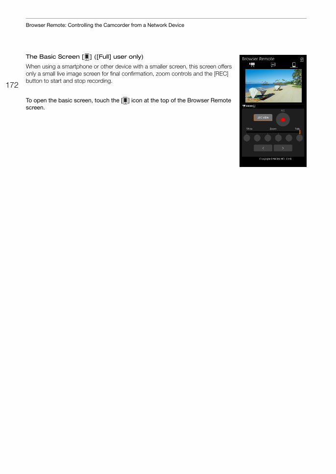
Browser Remote: Controlling the Camcorder from a Network Device
172
The Basic Screen [ ] ([Full] user only)
When using a smartphone or other device with a smaller screen, this screen offers only a small live image screen for final confirmation, zoom controls and the [REC] button to start and stop recording.
To open the basic screen, touch the [ ] icon at the top of the Browser Remote screen.
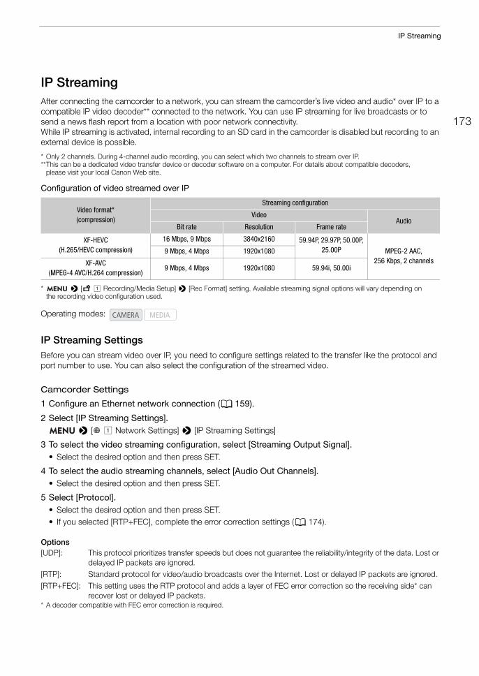
173
IP Streaming
IP StreamingAfter connecting the camcorder to a network, you can stream the camcorder’s live video and audio* over IP to a compatible IP video decoder** connected to the network. You can use IP streaming for live broadcasts or to send a news flash report from a location with poor network connectivity.While IP streaming is activated, internal recording to an SD card in the camcorder is disabled but recording to an external device is possible.
* Only 2 channels. During 4-channel audio recording, you can select which two channels to stream over IP.**This can be a dedicated video transfer device or decoder software on a computer. For details about compatible decoders,
please visit your local Canon Web site.
Configuration of video streamed over IP
* > [3 ! Recording/Media Setup] > [Rec Format] setting. Available streaming signal options will vary depending on the recording video configuration used.
IP Streaming SettingsBefore you can stream video over IP, you need to configure settings related to the transfer like the protocol and port number to use. You can also select the configuration of the streamed video.
Camcorder Settings
1 Configure an Ethernet network connection (A 159).
2 Select [IP Streaming Settings]. > [ ! Network Settings] > [IP Streaming Settings]
3 To select the video streaming configuration, select [Streaming Output Signal].• Select the desired option and then press SET.
4 To select the audio streaming channels, select [Audio Out Channels].• Select the desired option and then press SET.
5 Select [Protocol].• Select the desired option and then press SET.• If you selected [RTP+FEC], complete the error correction settings (A 174).
Options[UDP]: This protocol prioritizes transfer speeds but does not guarantee the reliability/integrity of the data. Lost or
delayed IP packets are ignored.[RTP]: Standard protocol for video/audio broadcasts over the Internet. Lost or delayed IP packets are ignored.
[RTP+FEC]: This setting uses the RTP protocol and adds a layer of FEC error correction so the receiving side* can recover lost or delayed IP packets.
* A decoder compatible with FEC error correction is required.
Video format*(compression)
Streaming configuration
VideoAudio
Bit rate Resolution Frame rate
XF-HEVC(H.265/HEVC compression)
16 Mbps, 9 Mbps 3840x2160 59.94P, 29.97P, 50.00P, 25.00P MPEG-2 AAC,
256 Kbps, 2 channels9 Mbps, 4 Mbps 1920x1080
XF-AVC(MPEG-4 AVC/H.264 compression)
9 Mbps, 4 Mbps 1920x1080 59.94i, 50.00i
Operating modes:
IP Streaming
174
Receiver Settings
1 Select [IP Streaming Settings]. > [ ! Network Settings] > [IP Streaming Settings]
2 Select [Dest. IP Address] and enter the IP address assigned to the decoder.• Push the joystick up/down to select a value for the first field of the address and then press SET to move to
the next field. After completing the four fields of the address, select [Set] and then press SET.
3 To change the port number, select [Dest. Port No.].• To enter the port number, push the joystick left/right to select the digit to change and then up/down to select
a value for the selected digit. After completing the five digits of the port number, select [Set] and then press SET.
• Using the default port number is recommended.
FEC Error Correction Settings
1 Select [IP Streaming Settings]. > [ ! Network Settings] > [IP Streaming Settings]
2 To enter the port number used for FEC packets, select [FEC Port No.].• To enter the port number, push the joystick left/right to select the digit to change and then up/down to select
a value for the selected digit. After completing the five digits of the port number, select [Set] and then press SET.
• Using the default port number is recommended.
3 To change the interval for FEC packets, select [FEC Interval]. • Select the desired option and then press SET.
Streaming Video over IP1 Connect the decoder to the network and complete any necessary configurations on the receiving
side so the decoder is ready to receive video over IP.• For details refer to the instruction manual of the decoder device or software you will use.
2 Select the desired network (A 160).• Use an Ethernet connection (A 159) and connect the camcorder to the desired network using an Ethernet
cable.
3 Activate IP streaming on the camcorder. > [ ! Network Settings] > [Network Functions] > [IP Streaming]
4 When the confirmation message appears, select [OK] and then press SET.• and will appear at the top of the screen. When the icons turn white, the camcorder will start
streaming video over the selected network.
5 When you have finished streaming the desired video, turn off the network functions. > [ ! Network Settings] > [Network Functions] > [Off]
• The network icons will turn yellow and then disappear from the screen.
NOTES
• While IP streaming is activated, the camcorder will continue to broadcast video and audio data over the IP network, regardless of the status of the receiver. The streamed data is not encoded. Be careful to set up the correct IP address and test in advance that the receiving decoder can indeed receive the signals.
• Depending on the network used and the connection conditions, you may experience lost or delayed IP packets.

175
IP Streaming
• After streaming video continuously for 24 hours, the camcorder will stop the IP streaming momentarily and then restart it automatically.
FTP File Transfer
176
FTP File TransferYou can transfer clips from the camcorder to another device connected to the network, using the FTP protocol.The following explanations assume that the FTP server is on, ready and correctly configured.
FTP Server and Transfer SettingsBefore you can transfer clips to a connected device, you need to configure the FTP server settings and other settings related to the handling of folders and files. If necessary, consult the network administrator in charge of the FTP server.
1 Select [FTP Transfer Settings]. > [ ! Network Settings] > [FTP Transfer Settings]
2 To enter the destination FTP server, select [FTP Server] and then press SET.• Enter the FTP server’s IP address or host name using the keyboard screen (A 27).
3 Enter the [FTP: User Name], [FTP: Password], and [Destination Folder] in the same way.
4 To change the port number, select [Port No.] and then press SET.• To enter the port number, push the joystick left/right to select the digit to change and then up/down to select
a value for the selected digit. After completing the five digits of the port number, select [Set] and then press SET.
5 To activate the passive mode, select [Passive Mode].• Select the desired option and then press SET.• [Off] is the standard setting for most cases. [On] (passive mode) is more appropriate for FTP transfers from
behind a firewall.
6 To select whether to create a new folder for every transfer date, select [New Folder by Date].• Select the desired option and then press SET.
7 To select how to handle file transfers when a file with the same name already exists, selects [Same Named Files].• Select the desired option and then press SET.
Options for [New Folder by Date][On]: A new subfolder under the transfer destination folder “YYYYMMDD\HHMMSS” will be created
for every transfer operation.[Off]: All the files will be transferred to the folder set as [Destination Folder] in the FTP server settings.
Options for [Same Named Files][Skip]: If a file with the same name already exists in the destination folder, the file will not be transferred.[Overwrite]: Even if a file with the same name already exists in the destination folder, the file will be
transferred, overwriting any file with the same name in the destination folder.
NOTES
• You can check the current FTP settings on the [Network 4/6] to [Network 6/6] status screens.
Operating modes:
177
FTP File Transfer
Transferring Clips (FTP Transfer)
Transferring a Single Clip
1 Select the desired network (A 160).• Use an Infrastructure connection (A 154) or Ethernet connection (A 159). • With Ethernet connections, connect the camcorder to the desired network using an Ethernet cable.
2 Select the desired clip and then press SET to open the clip menu.
3 Select [FTP Transfer] and then press SET.
4 Select [OK] and then press SET.• The camcorder will connect to the FTP server and the selected clip will be transferred. When using an
Ethernet connection, the Ethernet access lamp will flash while files are transmitted.• Press the CANCEL button to cancel the operation.
5 When the confirmation message appears, press SET.
Transferring All the Clips
1 Open the index screen with the clips you want to transfer (A 131).
2 Select the desired network (A 160).• Use an Infrastructure connection (A 154) or Ethernet connection (A 159). • With Ethernet connections, connect the camcorder to the desired network using an Ethernet cable.
3 Select [FTP Transfer].[ ! Network Settings] > [FTP Transfer]
4 Select [OK] and then press SET.• The camcorder will connect to the FTP server and all the clips in the index screen will be transferred. When
using an Ethernet connection, the Ethernet access lamp will flash while files are transmitted.• Press the CANCEL button to cancel the operation.
5 When the confirmation message appears, press SET.
IMPORTANT
• Observe the following precautions when transferring files. Failing to do so may interrupt the transfer and incomplete files may remain at the transfer destination.- Do not open the card slot covers.- Do not disconnect the power source or turn off the camcorder.
• If incomplete files remain at the transfer destination, check the content and make sure they are safe to delete before deleting them.
NOTES
• Depending on the access point’s settings and capabilities, it may take some time to transfer files.

FTP File Transfer
178
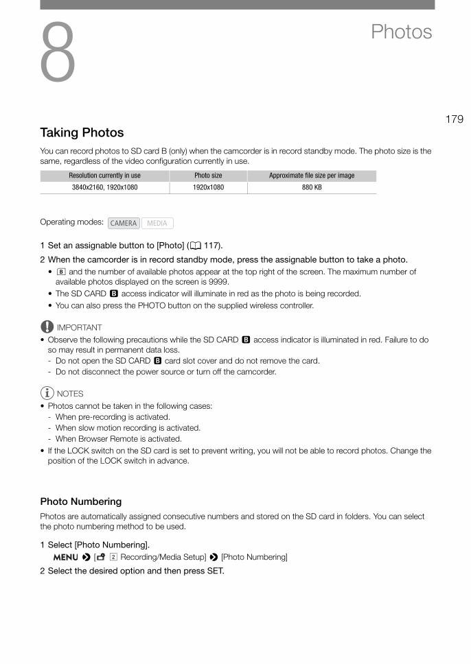
8179
Photos
Taking PhotosYou can record photos to SD card B (only) when the camcorder is in record standby mode. The photo size is the same, regardless of the video configuration currently in use.
1 Set an assignable button to [Photo] (A 117).
2 When the camcorder is in record standby mode, press the assignable button to take a photo.• 7 and the number of available photos appear at the top right of the screen. The maximum number of
available photos displayed on the screen is 9999.• The SD CARD 3 access indicator will illuminate in red as the photo is being recorded.• You can also press the PHOTO button on the supplied wireless controller.
IMPORTANT
• Observe the following precautions while the SD CARD 3 access indicator is illuminated in red. Failure to do so may result in permanent data loss.- Do not open the SD CARD 3 card slot cover and do not remove the card.- Do not disconnect the power source or turn off the camcorder.
NOTES
• Photos cannot be taken in the following cases:- When pre-recording is activated.- When slow motion recording is activated.- When Browser Remote is activated.
• If the LOCK switch on the SD card is set to prevent writing, you will not be able to record photos. Change the position of the LOCK switch in advance.
Photo NumberingPhotos are automatically assigned consecutive numbers and stored on the SD card in folders. You can select the photo numbering method to be used.
1 Select [Photo Numbering]. > [3 " Recording/Media Setup] > [Photo Numbering]
2 Select the desired option and then press SET.
Resolution currently in use Photo size Approximate file size per image
3840x2160, 1920x1080 1920x1080 880 KB
Operating modes:
Taking Photos
180
Options[Reset]: Photo numbers will restart from 100-0001 every time you insert a new card. If a card already
contains previous recordings, photo numbers will continue from the number following that of the last photo on the card.
[Continuous]: Photo numbers will continue from the number following that of the last photo recorded with the camcorder. This setting is the most convenient for managing files on a computer. We recommend using the [Continuous] setting.
NOTES
• Each folder can contain up to 500 files. When that number is exceeded, a new folder is created automatically.
Understanding folder names • An example folder name is “101_1103”. The first 3 digits indicate the folder number (from 100 to 999) and
the last 4 digits indicate the month and day when the folder was created. In the example, the folder numbered 101 was created on November 3.
Understanding photo numbers• An example photo number is “101-0107”. The first 3 digits indicate the folder number where the photo is
stored and the last 4 digits indicate the consecutive number assigned to the photo (from 0001 to 9999). • The photo number also indicates the name and location of the file on the card. For example, a photo
numbered 101-0107 that was recorded on November 3, is located in the “DCIM\101_1103” folder as the file “IMG_0107.JPG”.

181
Playing Back Photos
Playing Back PhotosYou can view the photos you recorded on SD card B.
Displaying the [Photos] Index Screen1 Set the camcorder in mode (A 22).
2 Open the [Photos] index screen (A 132).
Viewing Photos1 Move the orange selection frame to the desired photo.
2 Press the Ò button to view the photo.• The photo playback screen appears and the selected photo is
displayed.• Use the Ú/Ù buttons or push the joystick left/right to
switch to the previous/next photo.• Press the DISP button to hide/show the onscreen displays.• Press the Ñ button to return to the [Photos] index screen.
IMPORTANT
• Observe the following precautions while an access indicator is illuminated in red. Failure to do so may result in permanent data loss.- Do not disconnect the power source or turn off the camcorder.- Do not open the card slot cover of the card being accessed and do not remove the card.
NOTES
• The following photos may not be displayed correctly.- Photos not recorded with this camcorder.- Photos created or edited on a computer.- Photos whose file names have been changed.
Operating modes:
Deleting Photos
182
Deleting PhotosYou can delete photos you are not interested in keeping.
Deleting a Single Photo1 Display the photo to be deleted or select it in the [Photos] index screen (A 132) and then press
SET.
2 Select [Delete] and then press SET.
3 Select [OK] and then press SET.
4 When the confirmation message appears, press SET.
Deleting All the PhotosYou can delete all the photos in the [Photos] index screen.
1 Select [Delete All Photos]. > [3! Recording/Media Setup] > [Delete All Photos]
2 Select [OK] and then press SET.
3 When the confirmation message appears, press SET.
IMPORTANT
• Be careful when deleting photos. Deleted photos cannot be recovered.
Operating modes:
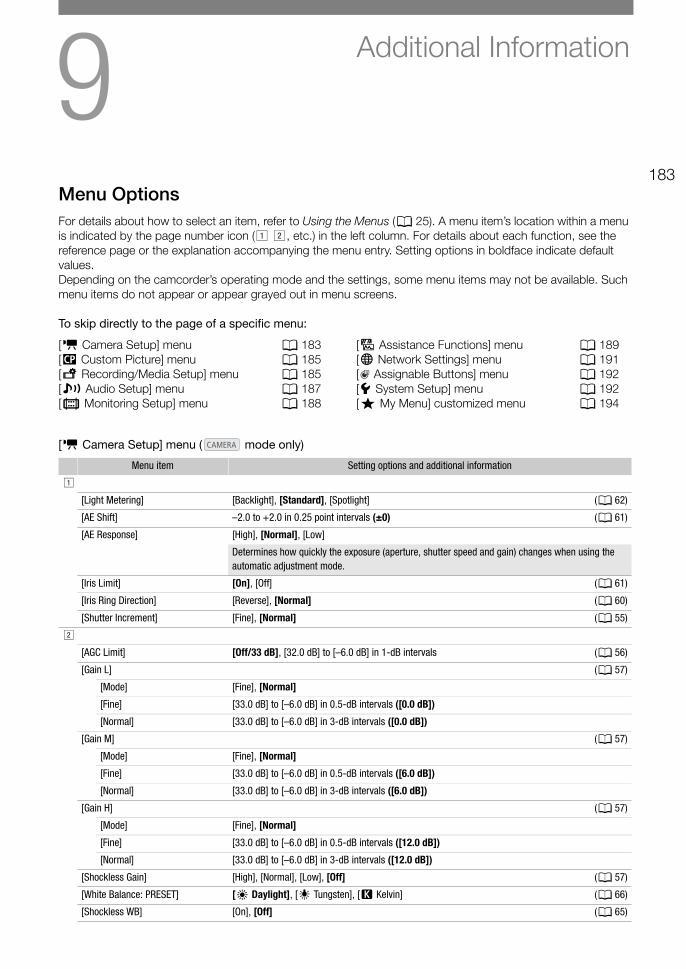
9183
Additional Information
Menu OptionsFor details about how to select an item, refer to Using the Menus (A 25). A menu item’s location within a menu is indicated by the page number icon (! ", etc.) in the left column. For details about each function, see the reference page or the explanation accompanying the menu entry. Setting options in boldface indicate default values.Depending on the camcorder’s operating mode and the settings, some menu items may not be available. Such menu items do not appear or appear grayed out in menu screens.
To skip directly to the page of a specific menu:
[v Camera Setup] menu ( mode only)
[v Camera Setup] menu A 183[/ Custom Picture] menu A 185[3 Recording/Media Setup] menu A 185[¡ Audio Setup] menu A 187[¢ Monitoring Setup] menu A 188
[A Assistance Functions] menu A 189[7 Network Settings] menu A 191[ Assignable Buttons] menu A 192[B System Setup] menu A 192[¥ My Menu] customized menu A 194
Menu item Setting options and additional information
!
[Light Metering] [Backlight], [Standard], [Spotlight] (A 62)
[AE Shift] –2.0 to +2.0 in 0.25 point intervals (±0) (A 61)
[AE Response] [High], [Normal], [Low]
Determines how quickly the exposure (aperture, shutter speed and gain) changes when using the automatic adjustment mode.
[Iris Limit] [On], [Off] (A 61)
[Iris Ring Direction] [Reverse], [Normal] (A 60)
[Shutter Increment] [Fine], [Normal] (A 55)
"
[AGC Limit] [Off/33 dB], [32.0 dB] to [–6.0 dB] in 1-dB intervals (A 56)
[Gain L] (A 57)
[Mode] [Fine], [Normal]
[Fine] [33.0 dB] to [–6.0 dB] in 0.5-dB intervals ([0.0 dB])
[Normal] [33.0 dB] to [–6.0 dB] in 3-dB intervals ([0.0 dB])
[Gain M] (A 57)
[Mode] [Fine], [Normal]
[Fine] [33.0 dB] to [–6.0 dB] in 0.5-dB intervals ([6.0 dB])
[Normal] [33.0 dB] to [–6.0 dB] in 3-dB intervals ([6.0 dB])
[Gain H] (A 57)
[Mode] [Fine], [Normal]
[Fine] [33.0 dB] to [–6.0 dB] in 0.5-dB intervals ([12.0 dB])
[Normal] [33.0 dB] to [–6.0 dB] in 3-dB intervals ([12.0 dB])
[Shockless Gain] [High], [Normal], [Low], [Off] (A 57)
[White Balance: PRESET] [¼ Daylight], [É Tungsten], [È Kelvin] (A 66)
[Shockless WB] [On], [Off] (A 65)
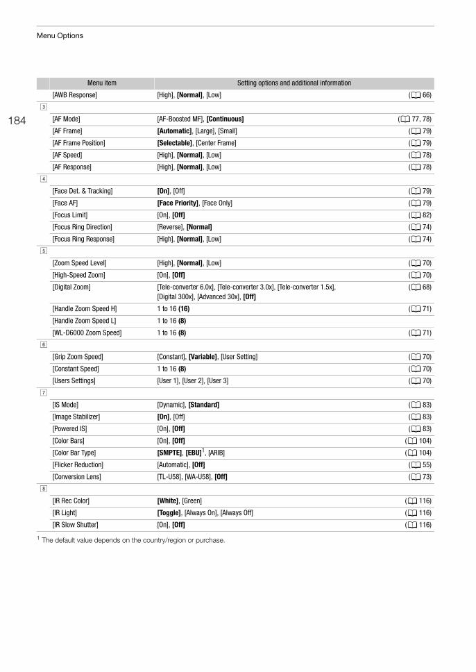
Menu Options
184
1 The default value depends on the country/region or purchase.
[AWB Response] [High], [Normal], [Low] (A 66)
#
[AF Mode] [AF-Boosted MF], [Continuous] (A 77, 78)
[AF Frame] [Automatic], [Large], [Small] (A 79)
[AF Frame Position] [Selectable], [Center Frame] (A 79)
[AF Speed] [High], [Normal], [Low] (A 78)
[AF Response] [High], [Normal], [Low] (A 78)
$
[Face Det. & Tracking] [On], [Off] (A 79)
[Face AF] [Face Priority], [Face Only] (A 79)
[Focus Limit] [On], [Off] (A 82)
[Focus Ring Direction] [Reverse], [Normal] (A 74)
[Focus Ring Response] [High], [Normal], [Low] (A 74)
%
[Zoom Speed Level] [High], [Normal], [Low] (A 70)
[High-Speed Zoom] [On], [Off] (A 70)
[Digital Zoom] [Tele-converter 6.0x], [Tele-converter 3.0x], [Tele-converter 1.5x], [Digital 300x], [Advanced 30x], [Off]
(A 68)
[Handle Zoom Speed H] 1 to 16 (16) (A 71)
[Handle Zoom Speed L] 1 to 16 (8)
[WL-D6000 Zoom Speed] 1 to 16 (8) (A 71)
&
[Grip Zoom Speed] [Constant], [Variable], [User Setting] (A 70)
[Constant Speed] 1 to 16 (8) (A 70)
[Users Settings] [User 1], [User 2], [User 3] (A 70)
'
[IS Mode] [Dynamic], [Standard] (A 83)
[Image Stabilizer] [On], [Off] (A 83)
[Powered IS] [On], [Off] (A 83)
[Color Bars] [On], [Off] (A 104)
[Color Bar Type] [SMPTE], [EBU]1, [ARIB] (A 104)
[Flicker Reduction] [Automatic], [Off] (A 55)
[Conversion Lens] [TL-U58], [WA-U58], [Off] (A 73)
(
[IR Rec Color] [White], [Green] (A 116)
[IR Light] [Toggle], [Always On], [Always Off] (A 116)
[IR Slow Shutter] [On], [Off] (A 116)
Menu item Setting options and additional information
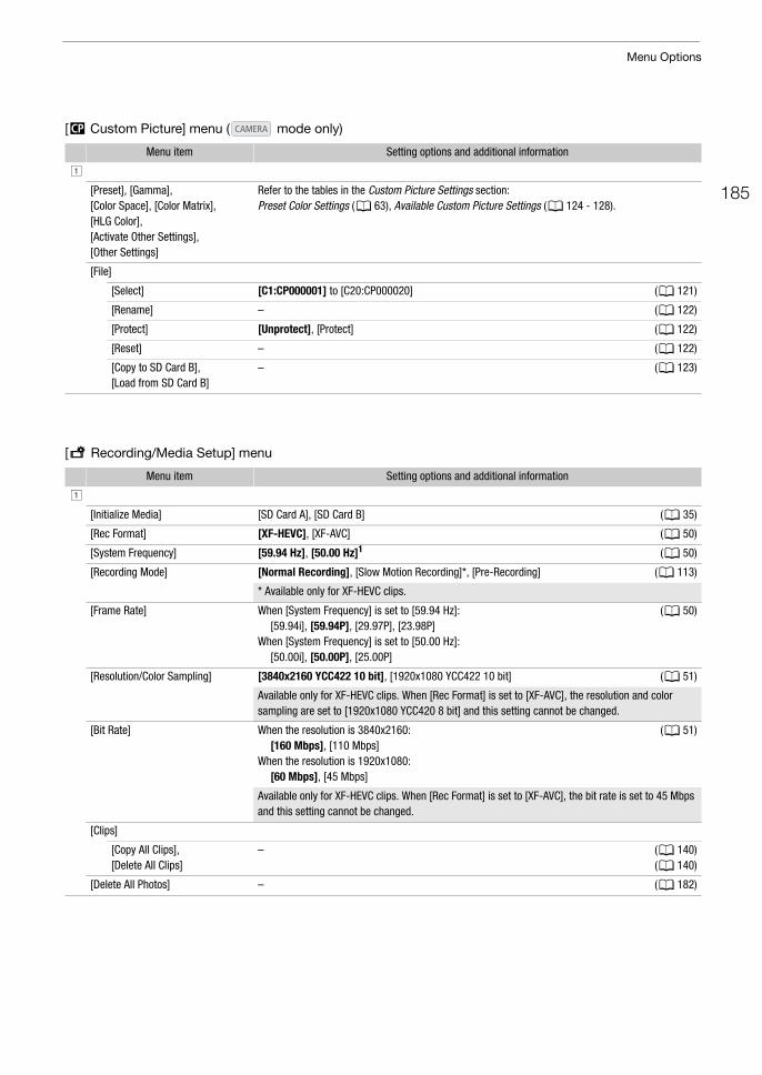
185
Menu Options
[/ Custom Picture] menu ( mode only)
[3 Recording/Media Setup] menu
Menu item Setting options and additional information
!
[Preset], [Gamma], [Color Space], [Color Matrix], [HLG Color], [Activate Other Settings], [Other Settings]
Refer to the tables in the Custom Picture Settings section:Preset Color Settings (A 63), Available Custom Picture Settings (A 124 - 128).
[File]
[Select] [C1:CP000001] to [C20:CP000020] (A 121)
[Rename] – (A 122)
[Protect] [Unprotect], [Protect] (A 122)
[Reset] – (A 122)
[Copy to SD Card B], [Load from SD Card B]
– (A 123)
Menu item Setting options and additional information
!
[Initialize Media] [SD Card A], [SD Card B] (A 35)
[Rec Format] [XF-HEVC], [XF-AVC] (A 50)
[System Frequency] [59.94 Hz], [50.00 Hz]1 (A 50)
[Recording Mode] [Normal Recording], [Slow Motion Recording]*, [Pre-Recording] (A 113)
* Available only for XF-HEVC clips.
[Frame Rate] When [System Frequency] is set to [59.94 Hz]:[59.94i], [59.94P], [29.97P], [23.98P]
When [System Frequency] is set to [50.00 Hz]:[50.00i], [50.00P], [25.00P]
(A 50)
[Resolution/Color Sampling] [3840x2160 YCC422 10 bit], [1920x1080 YCC422 10 bit] (A 51)
Available only for XF-HEVC clips. When [Rec Format] is set to [XF-AVC], the resolution and color sampling are set to [1920x1080 YCC420 8 bit] and this setting cannot be changed.
[Bit Rate] When the resolution is 3840x2160:[160 Mbps], [110 Mbps]
When the resolution is 1920x1080:[60 Mbps], [45 Mbps]
(A 51)
Available only for XF-HEVC clips. When [Rec Format] is set to [XF-AVC], the bit rate is set to 45 Mbps and this setting cannot be changed.
[Clips]
[Copy All Clips], [Delete All Clips]
– (A 140)(A 140)
[Delete All Photos] – (A 182)
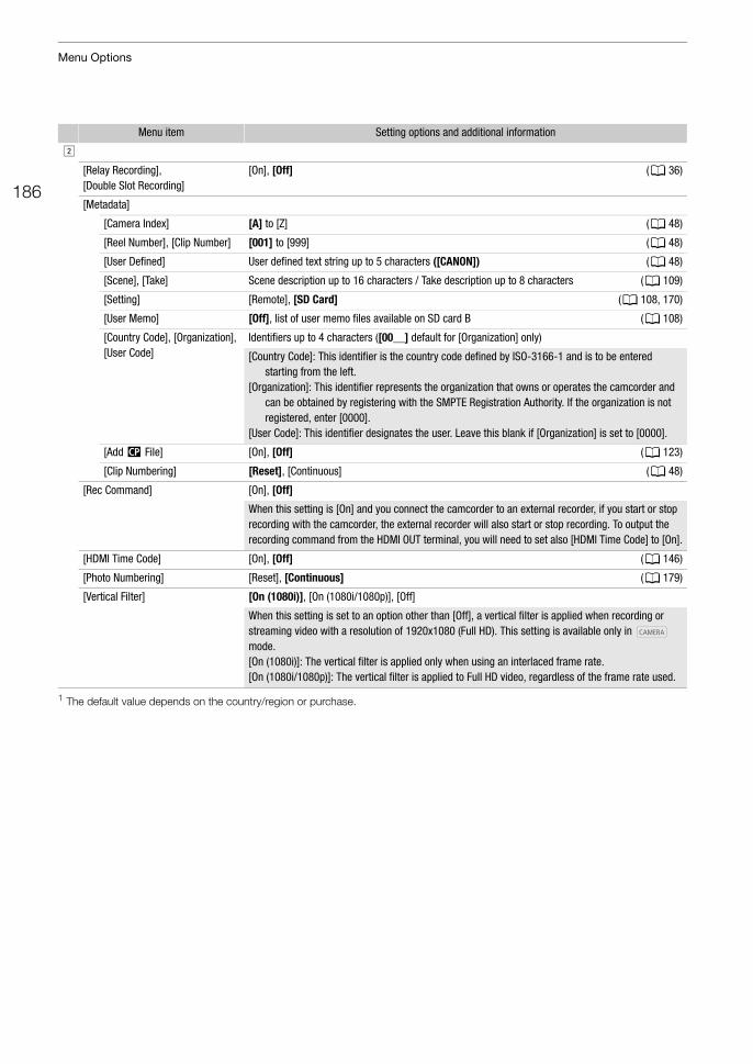
Menu Options
186
1 The default value depends on the country/region or purchase.
"
[Relay Recording], [Double Slot Recording]
[On], [Off] (A 36)
[Metadata]
[Camera Index] [A] to [Z] (A 48)
[Reel Number], [Clip Number] [001] to [999] (A 48)
[User Defined] User defined text string up to 5 characters ([CANON]) (A 48)
[Scene], [Take] Scene description up to 16 characters / Take description up to 8 characters (A 109)
[Setting] [Remote], [SD Card] (A 108, 170)
[User Memo] [Off], list of user memo files available on SD card B (A 108)
[Country Code], [Organization], [User Code]
Identifiers up to 4 characters ([00__] default for [Organization] only)
[Country Code]: This identifier is the country code defined by ISO-3166-1 and is to be entered starting from the left.
[Organization]: This identifier represents the organization that owns or operates the camcorder and can be obtained by registering with the SMPTE Registration Authority. If the organization is not registered, enter [0000].
[User Code]: This identifier designates the user. Leave this blank if [Organization] is set to [0000].
[Add / File] [On], [Off] (A 123)
[Clip Numbering] [Reset], [Continuous] (A 48)
[Rec Command] [On], [Off]
When this setting is [On] and you connect the camcorder to an external recorder, if you start or stop recording with the camcorder, the external recorder will also start or stop recording. To output the recording command from the HDMI OUT terminal, you will need to set also [HDMI Time Code] to [On].
[HDMI Time Code] [On], [Off] (A 146)
[Photo Numbering] [Reset], [Continuous] (A 179)
[Vertical Filter] [On (1080i)], [On (1080i/1080p)], [Off]
When this setting is set to an option other than [Off], a vertical filter is applied when recording or streaming video with a resolution of 1920x1080 (Full HD). This setting is available only in mode.[On (1080i)]: The vertical filter is applied only when using an interlaced frame rate.[On (1080i/1080p)]: The vertical filter is applied to Full HD video, regardless of the frame rate used.
Menu item Setting options and additional information
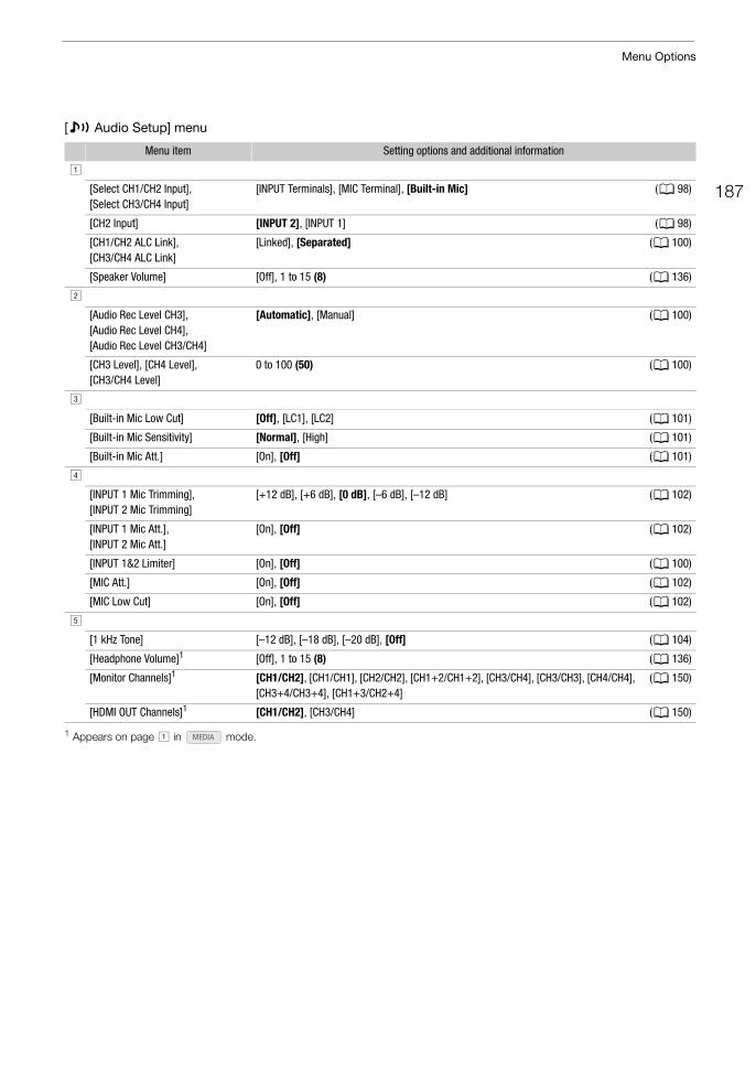
187
Menu Options
[¡ Audio Setup] menu
1 Appears on page ! in mode.
Menu item Setting options and additional information
!
[Select CH1/CH2 Input], [Select CH3/CH4 Input]
[INPUT Terminals], [MIC Terminal], [Built-in Mic] (A 98)
[CH2 Input] [INPUT 2], [INPUT 1] (A 98)
[CH1/CH2 ALC Link], [CH3/CH4 ALC Link]
[Linked], [Separated] (A 100)
[Speaker Volume] [Off], 1 to 15 (8) (A 136)
"
[Audio Rec Level CH3],[Audio Rec Level CH4],[Audio Rec Level CH3/CH4]
[Automatic], [Manual] (A 100)
[CH3 Level], [CH4 Level],[CH3/CH4 Level]
0 to 100 (50) (A 100)
#
[Built-in Mic Low Cut] [Off], [LC1], [LC2] (A 101)
[Built-in Mic Sensitivity] [Normal], [High] (A 101)
[Built-in Mic Att.] [On], [Off] (A 101)
$
[INPUT 1 Mic Trimming], [INPUT 2 Mic Trimming]
[+12 dB], [+6 dB], [0 dB], [–6 dB], [–12 dB] (A 102)
[INPUT 1 Mic Att.], [INPUT 2 Mic Att.]
[On], [Off] (A 102)
[INPUT 1&2 Limiter] [On], [Off] (A 100)
[MIC Att.] [On], [Off] (A 102)
[MIC Low Cut] [On], [Off] (A 102)
%
[1 kHz Tone] [–12 dB], [–18 dB], [–20 dB], [Off] (A 104)
[Headphone Volume]1 [Off], 1 to 15 (8) (A 136)
[Monitor Channels]1 [CH1/CH2], [CH1/CH1], [CH2/CH2], [CH1+2/CH1+2], [CH3/CH4], [CH3/CH3], [CH4/CH4], [CH3+4/CH3+4], [CH1+3/CH2+4]
(A 150)
[HDMI OUT Channels]1 [CH1/CH2], [CH3/CH4] (A 150)
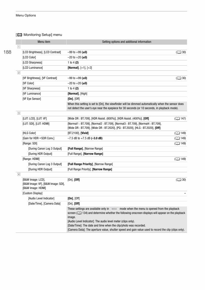
Menu Options
188
[¢ Monitoring Setup] menu
Menu item Setting options and additional information
!
[LCD Brightness], [LCD Contrast] –99 to +99 (±0) (A 30)
[LCD Color] –20 to +20 (±0)
[LCD Sharpness] 1 to 4 (2)
[LCD Luminance] [Normal], [+1], [+2]
"
[VF Brightness], [VF Contrast] –99 to +99 (±0) (A 30)
[VF Color] –20 to +20 (±0)
[VF Sharpness] 1 to 4 (2)
[VF Luminance] [Normal], [High]
[VF Eye Sensor] [On], [Off]
When this setting is set to [On], the viewfinder will be dimmed automatically when the sensor does not detect the user’s eye near the eyepiece for 30 seconds (or 10 seconds, in playback mode).
#
[LUT: LCD], [LUT: VF] [Wide DR : BT.709], [HDR Assist. (800%)], [HDR Assist. (400%)], [Off] (A 147)
[LUT: SDI], [LUT: HDMI] [Normal1 : BT.709], [Normal2 : BT.709], [Normal3 : BT.709], [Normal4 : BT.709], [Wide DR : BT.709], [Wide DR : BT.2020], [PQ : BT.2020], [HLG : BT.2020], [Off]
[HLG Color] [BT.2100], [Vivid] (A 149)
[Gain for HDRSDR Conv.] –7.5 dB to +7.5 dB (–3.0 dB) (A 149)
[Range: SDI] (A 149)
[During Canon Log 3 Output] [Full Range], [Narrow Range]
[During HDR Output] [Full Range], [Narrow Range]
[Range: HDMI] (A 149)
[During Canon Log 3 Output] [Full Range Priority], [Narrow Range]
[During HDR Output] [Full Range Priority], [Narrow Range]
$
[B&W Image: LCD], [B&W Image: VF], [B&W Image: SDI], [B&W Image: HDMI]
[On], [Off] (A 30)
[Custom Display] –
[Audio Level Indicator] [On], [Off]
[Date/Time], [Camera Data] [On], [Off]
These settings are available only in mode when the menu is opened from the playback screen (A 134) and determine whether the following onscreen displays will appear on the playback image.[Audio Level Indicator]: The audio level meter (clips only).[Date/Time]: The date and time when the clip/photo was recorded.[Camera Data]: The aperture value, shutter speed and gain value used to record the clip (clips only).
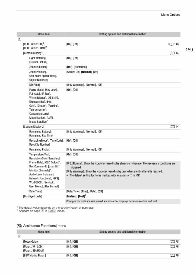
189
Menu Options
1 The default value depends on the country/region or purchase.2 Appears on page $ in mode.
[A Assistance Functions] menu
%
[OSD Output: SDI]2, [OSD Output: HDMI]2
[On], [Off] (A 146)
[Custom Display 1] (A 44)
[Light Metering], [Custom Picture]
[On], [Off]
[Zoom Indicator] [Bar], [Numerical]
[Zoom Position], [Grip Zoom Speed: User], [Object Distance]
[Always On], [Normal], [Off]
[ND Filter] [Only Warnings], [Normal], [Off]
[Focus Mode], [Key Lock], [Full Auto], [IR Rec],[White Balance], [AE Shift], [Exposure Bar], [Iris], [Gain], [Shutter], [Peaking], [Tele-converter],[Conversion Lens], [Magnification], [LUT], [Image Stabilizer]
[On], [Off]
[Custom Display 2] (A 44)
[Remaining Battery], [Remaining Rec Time]
[Only Warnings], [Normal], [Off]
[Recording Mode], [Time Code], [Reel/Clip Number]
[On], [Off]
[Remaining Photos] [Only Warnings], [Normal], [Off]
[Temperature/Fan], [Resolution/Color Sampling], [Frame Rate], [OSD Output]*, [Rec Command], [User Bit]*, [Monitor Channels]*, [Audio Level Indicator], [Network Functions], [GPS], [WL-D6000], [Genlock], [User Memo], [Rec Format]
[On], [Off]
[On], [Normal]: Show the icon/onscreen display always or whenever the necessary conditions are triggered.
[Only Warnings]: Show the icon/onscreen display only when a critical level is reached.• The default setting for items marked with an asterisk (*) is [Off].
[Date/Time] [Date/Time], [Time], [Date], [Off]
[Displayed Units] [Meters], [Feet]1
Changes the distance units used in camcorder displays between meters and feet.
Menu item Setting options and additional information
!
[Focus Guide] [On], [Off] (A 75)
[Magn.: VF+LCD],[Magn.: SDI/HDMI]
[On], [Off] (A 76)
[B&W during Magn.] [On], [Off] (A 76)
Menu item Setting options and additional information
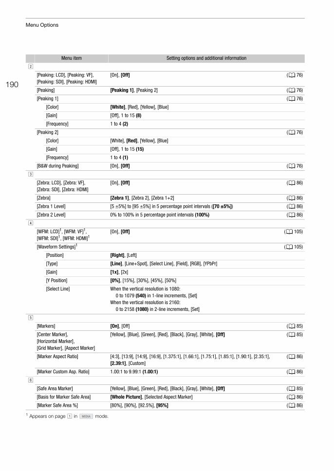
Menu Options
190
1 Appears on page ! in mode.
"
[Peaking: LCD], [Peaking: VF], [Peaking: SDI], [Peaking: HDMI]
[On], [Off] (A 76)
[Peaking] [Peaking 1], [Peaking 2] (A 76)
[Peaking 1] (A 76)
[Color] [White], [Red], [Yellow], [Blue]
[Gain] [Off], 1 to 15 (8)
[Frequency] 1 to 4 (2)
[Peaking 2] (A 76)
[Color] [White], [Red], [Yellow], [Blue]
[Gain] [Off], 1 to 15 (15)
[Frequency] 1 to 4 (1)
[B&W during Peaking] [On], [Off] (A 76)
#
[Zebra: LCD], [Zebra: VF], [Zebra: SDI], [Zebra: HDMI]
[On], [Off] (A 86)
[Zebra] [Zebra 1], [Zebra 2], [Zebra 1+2] (A 86)
[Zebra 1 Level] [5 ±5%] to [95 ±5%] in 5 percentage point intervals ([70 ±5%]) (A 86)
[Zebra 2 Level] 0% to 100% in 5 percentage point intervals (100%) (A 86)
$
[WFM: LCD]1, [WFM: VF]1, [WFM: SDI]1, [WFM: HDMI]1
[On], [Off] (A 105)
[Waveform Settings]1 (A 105)
[Position] [Right], [Left]
[Type] [Line], [Line+Spot], [Select Line], [Field], [RGB], [YPbPr]
[Gain] [1x], [2x]
[Y Position] [0%], [15%], [30%], [45%], [50%]
[Select Line] When the vertical resolution is 1080:0 to 1079 (540) in 1-line increments, [Set]
When the vertical resolution is 2160:0 to 2158 (1080) in 2-line increments, [Set]
%
[Markers] [On], [Off] (A 85)
[Center Marker], [Horizontal Marker],[Grid Marker], [Aspect Marker]
[Yellow], [Blue], [Green], [Red], [Black], [Gray], [White], [Off] (A 85)
[Marker Aspect Ratio] [4:3], [13:9], [14:9], [16:9], [1.375:1], [1.66:1], [1.75:1], [1.85:1], [1.90:1], [2.35:1], [2.39:1], [Custom]
(A 86)
[Marker Custom Asp. Ratio] 1.00:1 to 9.99:1 (1.00:1) (A 86)
&
[Safe Area Marker] [Yellow], [Blue], [Green], [Red], [Black], [Gray], [White], [Off] (A 85)
[Basis for Marker Safe Area] [Whole Picture], [Selected Aspect Marker] (A 86)
[Marker Safe Area %] [80%], [90%], [92.5%], [95%] (A 86)
Menu item Setting options and additional information
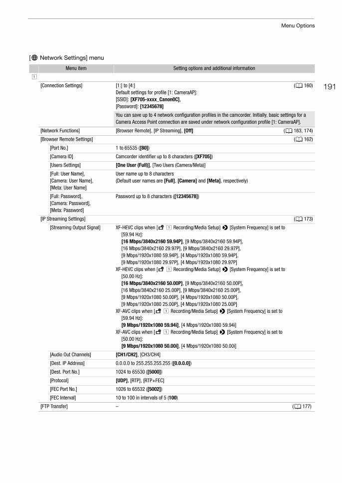
191
Menu Options
[7 Network Settings] menu
Menu item Setting options and additional information
!
[Connection Settings] [1:] to [4:]Default settings for profile [1: CameraAP]: [SSID]: [XF705-xxxx_Canon0C], [Password]: [12345678]
(A 160)
You can save up to 4 network configuration profiles in the camcorder. Initially, basic settings for a Camera Access Point connection are saved under network configuration profile [1: CameraAP].
[Network Functions] [Browser Remote], [IP Streaming], [Off] (A 163, 174)
[Browser Remote Settings] (A 162)
[Port No.] 1 to 65535 ([80])
[Camera ID] Camcorder identifier up to 8 characters ([XF705])
[Users Settings] [One User (Full)], [Two Users (Camera/Meta)]
[Full: User Name], [Camera: User Name], [Meta: User Name]
User name up to 8 characters (Default user names are [Full], [Camera] and [Meta], respectively)
[Full: Password], [Camera: Password], [Meta: Password]
Password up to 8 characters ([12345678])
[IP Streaming Settings] (A 173)
[Streaming Output Signal] XF-HEVC clips when [3! Recording/Media Setup] > [System Frequency] is set to [59.94 Hz]:[16 Mbps/3840x2160 59.94P], [9 Mbps/3840x2160 59.94P], [16 Mbps/3840x2160 29.97P], [9 Mbps/3840x2160 29.97P],[9 Mbps/1920x1080 59.94P], [4 Mbps/1920x1080 59.94P], [9 Mbps/1920x1080 29.97P], [4 Mbps/1920x1080 29.97P]
XF-HEVC clips when [3! Recording/Media Setup] > [System Frequency] is set to [50.00 Hz]:[16 Mbps/3840x2160 50.00P], [9 Mbps/3840x2160 50.00P], [16 Mbps/3840x2160 25.00P], [9 Mbps/3840x2160 25.00P],[9 Mbps/1920x1080 50.00P], [4 Mbps/1920x1080 50.00P], [9 Mbps/1920x1080 25.00P], [4 Mbps/1920x1080 25.00P]
XF-AVC clips when [3! Recording/Media Setup] > [System Frequency] is set to [59.94 Hz]:[9 Mbps/1920x1080 59.94i], [4 Mbps/1920x1080 59.94i]
XF-AVC clips when [3! Recording/Media Setup] > [System Frequency] is set to [50.00 Hz]:[9 Mbps/1920x1080 50.00i], [4 Mbps/1920x1080 50.00i]
[Audio Out Channels] [CH1/CH2], [CH3/CH4]
[Dest. IP Address] 0.0.0.0 to 255.255.255.255 ([0.0.0.0])
[Dest. Port No.] 1024 to 65530 ([5000])
[Protocol] [UDP], [RTP], [RTP+FEC]
[FEC Port No.] 1026 to 65532 ([5002])
[FEC Interval] 10 to 100 in intervals of 5 (100)
[FTP Transfer] – (A 177)
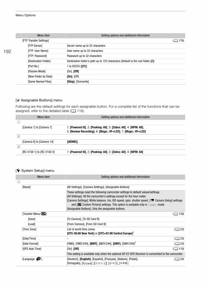
Menu Options
192
[ Assignable Buttons] menu
Following are the default settings for each assignable button. For a complete list of the functions that can be assigned, refer to the detailed table (A 118).
[B System Setup] menu
[FTP Transfer Settings] (A 176)
[FTP Server] Server name up to 32 characters
[FTP: User Name] User name up to 32 characters
[FTP: Password] Password up to 32 characters
[Destination Folder] Destination folder’s path up to 152 characters (Default is the root folder [/])
[Port No.] 1 to 65535 ([21])
[Passive Mode] [On], [Off]
[New Folder by Date] [On], [Off]
[Same Named Files] [Skip], [Overwrite]
Menu item Setting options and additional information
!
[Camera 1] to [Camera 7] 1: [Powered IS], 2: [Peaking: All], 3: [Zebra: All], 4: [WFM: All], 5: [Review Recording], 6: [Magn.: VF+LCD], 7: [Magn.: VF+LCD]
"
[Camera 8] to [Camera 14] [(NONE)]
#
[RC-V100 1] to [RC-V100 4] 1: [Powered IS], 2: [Peaking: All], 3: [Zebra: All], 4: [WFM: All]
Menu item Setting options and additional information
!
[Reset] [All Settings], [Camera Settings], [Assignable Buttons]
These settings reset the following camcorder settings to default values/settings.[All Settings]: All the camcorder’s settings except for the hour meter.[Camera Settings]: White balance, iris, ISO speed, gain, shutter speed, [v Camera Setup] settings
and [/ Custom Picture] settings. This option is available only in mode.[Assignable Buttons]: Only the assignable buttons.
[Transfer Menu//] (A 129)
[Save] [To Camera], [To SD Card B]
[Load] [From Camera], [From SD Card B]
[Time Zone] List of world time zones. [UTC-05:00 New York] or [UTC+01:00 Central Europe]1
(A 23)
[Date/Time] – (A 23)
[Date Format] [YMD], [YMD/24H], [MDY], [MDY/24H], [DMY], [DMY/24H]1 (A 23)
[GPS Auto Time] [On], [Off] (A 110)
This setting is available only when the optional GP-E2 GPS Receiver is connectted to the camcorder.
[Language H] [Deutsch], [English], [Español], [Français], [Italiano], [Polski], [Português], [ ], [ ], [ ], [ ]
(A 24)
Menu item Setting options and additional information
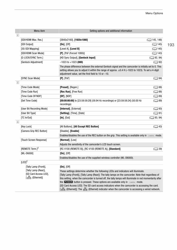
193
Menu Options
"
[SDI/HDMI Max. Res.] [3840x2160], [1920x1080] (A 145, 146)
[SDI Output] [On], [Off] (A 145)
[3G-SDI Mapping] [Level A], [Level B] (A 145)
[SDI/HDMI Scan Mode] [P], [PsF (Forced 1080i)] (A 143)
[G-LOCK/SYNC Term.] [HD Sync Output], [Genlock Input] (A 92, 94)
[Genlock Adjustment] –1023 to +1023 (000) (A 92)
The phase difference between the external Genlock signal and the camcorder is initially set to 0. This setting allows you to adjust it within the range of approx. ±0.4 H (–1023 to 1023). To set a 4-digit adjustment value, set the first field to 10 or –10.
[SYNC Scan Mode] [P], [PsF] (A 94)
#
[Time Code Mode] [Preset], [Regen.] (A 88)
[Time Code Run] [Rec Run], [Free Run] (A 88)
[Time Code DF/NDF] [DF], [NDF] (A 89)
[Set Time Code] [00:00:00:00] to [23:59:59:29] (59.94 Hz recordings) or [23:59:59:24] (50.00 Hz recordings)
(A 89)
[User Bit Recording Mode] [Internal], [External] (A 93)
[User Bit Type] [Setting], [Time], [Date] (A 91)
[TC In/Out] [In], [Out] (A 93, 94)
$
[Key Lock] [All Buttons], [All Except REC Button] (A 43)
[Camera Grip REC Button] [Disable], [Enable]
Enables/disables the use of the REC button on the grip. This setting is available only in mode.
[Touch Screen Response] [Normal], [Low]
Adjusts the sensitivity of the camcorder’s LCD touch screen.
[REMOTE Term.]2 [RC-V100 (REMOTE B)], [RC-V100 (REMOTE A)], [Standard] (A 39)
[WL-D6000] [On], [Off]
Enables/disables the use of the supplied wireless controller (WL-D6000).
[LED]2
[Tally Lamp (Front)], [Tally Lamp (Rear)], [SD Card Access LED], [ (Ethernet)]
[On], [Off]
These settings determine whether the following LEDs and indicators will illuminate.[Tally Lamp (Front)], [Tally Lamp (Rear)]: The tally lamps on the camcorder. Note that regardless of this setting, when the camcorder is turned off, the tally lamps will illuminate in red momentarily after the Q button is pressed. These options are available only in mode.[SD Card Access LED]: The SD card access indicators when the camcorder is accessing the card.[ (Ethernet)]: The (Ethernet) indicator when the camcorder is accessing a wired network.
Menu item Setting options and additional information
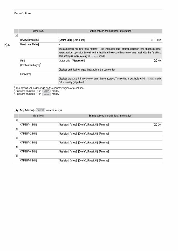
Menu Options
194
1 The default value depends on the country/region or purchase.2 Appears on page # in mode.3 Appears on page $ in mode.
[¥ My Menu] ( mode only)
%
[Review Recording] [Entire Clip], [Last 4 sec] (A 112)
[Reset Hour Meter] –
The camcorder has two “hour meters” – the first keeps track of total operation time and the second keeps track of operation time since the last time the second hour meter was reset with this function. This setting is available only in mode.
[Fan] [Automatic], [Always On] (A 49)
[Certification Logos]3 –
Displays certification logos that apply to the camcorder.
[Firmware] –
Displays the current firmware version of the camcorder. This setting is available only in mode but is usually grayed out.
Menu item Setting options and additional information
!
[CAMERA-1 Edit] [Register], [Move], [Delete], [Reset All], [Rename] (A 26)
"
[CAMERA-2 Edit] [Register], [Move], [Delete], [Reset All], [Rename]
#
[CAMERA-3 Edit] [Register], [Move], [Delete], [Reset All], [Rename]
$
[CAMERA-4 Edit] [Register], [Move], [Delete], [Reset All], [Rename]
%
[CAMERA-5 Edit] [Register], [Move], [Delete], [Reset All], [Rename]
Menu item Setting options and additional information
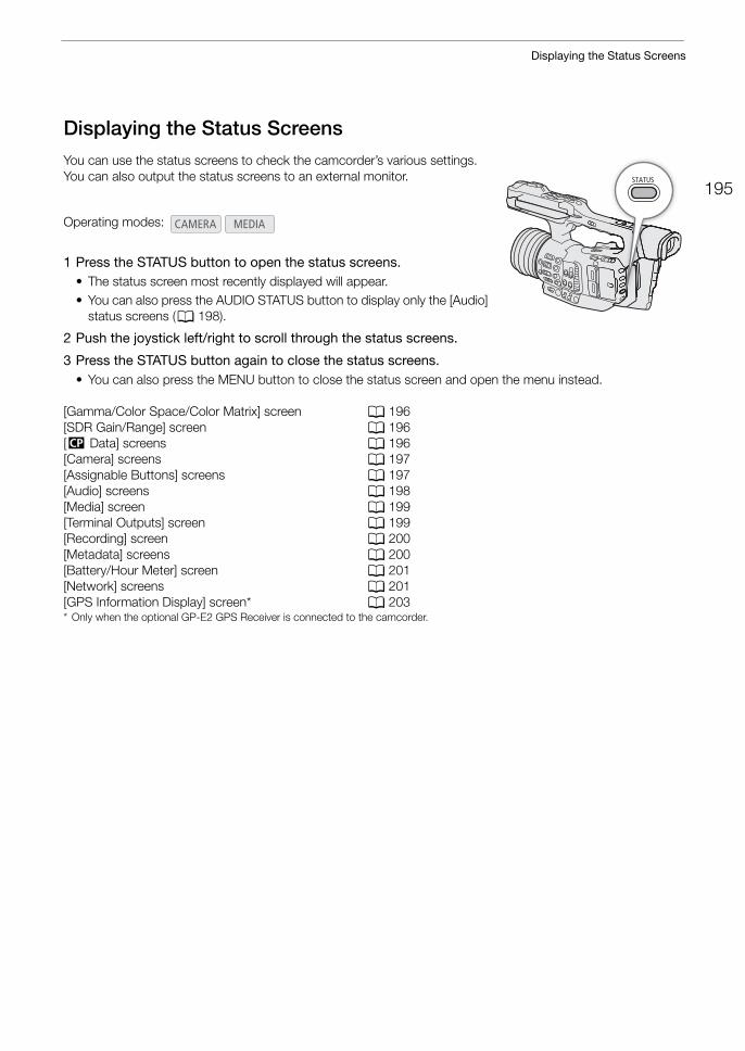
195
Displaying the Status Screens
Displaying the Status Screens
You can use the status screens to check the camcorder’s various settings. You can also output the status screens to an external monitor.
1 Press the STATUS button to open the status screens.• The status screen most recently displayed will appear.• You can also press the AUDIO STATUS button to display only the [Audio]
status screens (A 198).
2 Push the joystick left/right to scroll through the status screens.
3 Press the STATUS button again to close the status screens.• You can also press the MENU button to close the status screen and open the menu instead.
[Gamma/Color Space/Color Matrix] screen A 196[SDR Gain/Range] screen A 196 [/ Data] screens A 196[Camera] screens A 197[Assignable Buttons] screens A 197[Audio] screens A 198[Media] screen A 199[Terminal Outputs] screen A 199[Recording] screen A 200[Metadata] screens A 200[Battery/Hour Meter] screen A 201[Network] screens A 201 [GPS Information Display] screen* A 203* Only when the optional GP-E2 GPS Receiver is connected to the camcorder.
Operating modes:
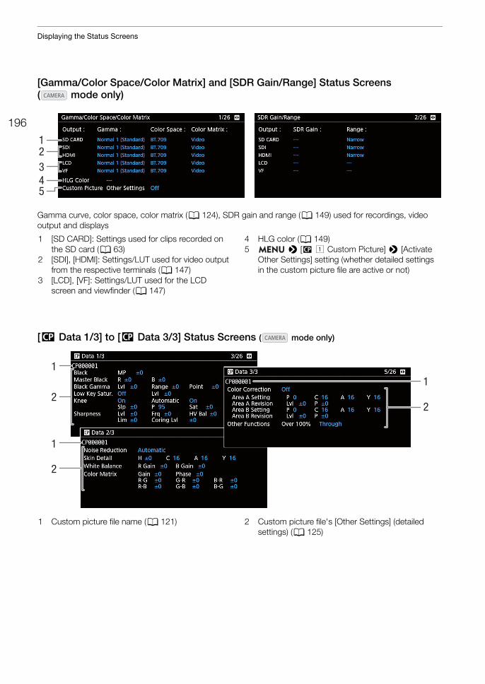
Displaying the Status Screens
196
[Gamma/Color Space/Color Matrix] and [SDR Gain/Range] Status Screens ( mode only)
Gamma curve, color space, color matrix (A 124), SDR gain and range (A 149) used for recordings, video output and displays
[/ Data 1/3] to [/ Data 3/3] Status Screens ( mode only)
54
123
1 [SD CARD]: Settings used for clips recorded on the SD card (A 63)
2 [SDI], [HDMI]: Settings/LUT used for video output from the respective terminals (A 147)
3 [LCD], [VF]: Settings/LUT used for the LCD screen and viewfinder (A 147)
4 HLG color (A 149)5 > [/ ! Custom Picture] > [Activate
Other Settings] setting (whether detailed settings in the custom picture file are active or not)
2
1
2
11
2
1 Custom picture file name (A 121) 2 Custom picture file's [Other Settings] (detailed settings) (A 125)
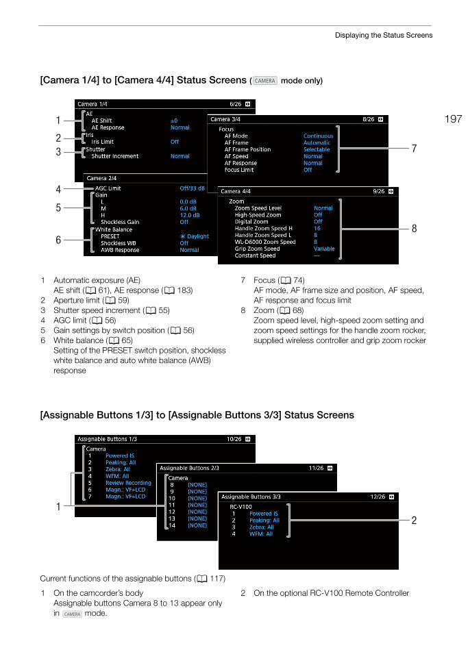
197
Displaying the Status Screens
[Camera 1/4] to [Camera 4/4] Status Screens ( mode only)
[Assignable Buttons 1/3] to [Assignable Buttons 3/3] Status Screens
Current functions of the assignable buttons (A 117)
7
8
4
5
1
23
6
1 Automatic exposure (AE)AE shift (A 61), AE response (A 183)
2 Aperture limit (A 59)3 Shutter speed increment (A 55) 4 AGC limit (A 56) 5 Gain settings by switch position (A 56)6 White balance (A 65)
Setting of the PRESET switch position, shockless white balance and auto white balance (AWB) response
7 Focus (A 74)AF mode, AF frame size and position, AF speed, AF response and focus limit
8 Zoom (A 68)Zoom speed level, high-speed zoom setting and zoom speed settings for the handle zoom rocker, supplied wireless controller and grip zoom rocker
21
1 On the camcorder’s bodyAssignable buttons Camera 8 to 13 appear only in mode.
2 On the optional RC-V100 Remote Controller
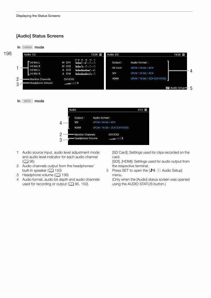
Displaying the Status Screens
198
[Audio] Status Screens
41
23
5
32
4
In mode
In mode
1 Audio source input, audio level adjustment mode and audio level indicator for each audio channel (A 95)
2 Audio channels output from the headphones/built-in speaker (A 150)
3 Headphone volume (A 136)4 Audio format, audio bit depth and audio channels
used for recording or output (A 95, 150).
[SD Card]: Settings used for clips recorded on the card.[SDI], [HDMI]: Settings used for audio output from the respective terminal.
5 Press SET to open the [¡ ! Audio Setup] menu.(Only when the [Audio] status screen was opened using the AUDIO STATUS button.)
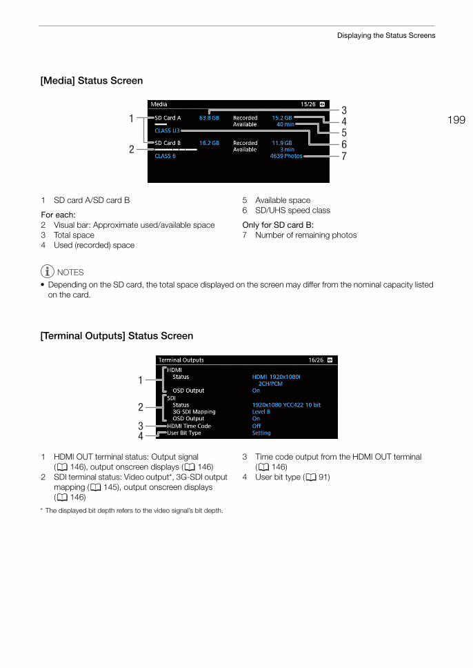
199
Displaying the Status Screens
[Media] Status Screen
NOTES
• Depending on the SD card, the total space displayed on the screen may differ from the nominal capacity listed on the card.
[Terminal Outputs] Status Screen
* The displayed bit depth refers to the video signal’s bit depth.
43
51
276
1 SD card A/SD card B
For each:2 Visual bar: Approximate used/available space3 Total space4 Used (recorded) space
5 Available space6 SD/UHS speed class
Only for SD card B:7 Number of remaining photos
2
1
43
1 HDMI OUT terminal status: Output signal (A 146), output onscreen displays (A 146)
2 SDI terminal status: Video output*, 3G-SDI output mapping (A 145), output onscreen displays (A 146)
3 Time code output from the HDMI OUT terminal (A 146)
4 User bit type (A 91)
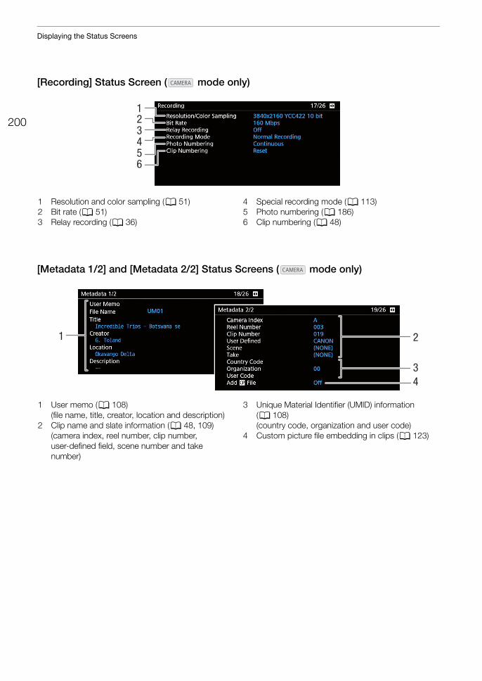
Displaying the Status Screens
200
[Recording] Status Screen ( mode only)
[Metadata 1/2] and [Metadata 2/2] Status Screens ( mode only)
34
1
5
2
6
1 Resolution and color sampling (A 51)2 Bit rate (A 51)3 Relay recording (A 36)
4 Special recording mode (A 113)5 Photo numbering (A 186)6 Clip numbering (A 48)
2
34
1
1 User memo (A 108)(file name, title, creator, location and description)
2 Clip name and slate information (A 48, 109)(camera index, reel number, clip number, user-defined field, scene number and take number)
3 Unique Material Identifier (UMID) information (A 108)(country code, organization and user code)
4 Custom picture file embedding in clips (A 123)
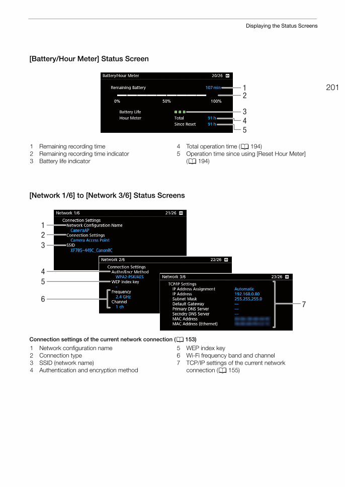
201
Displaying the Status Screens
[Battery/Hour Meter] Status Screen
[Network 1/6] to [Network 3/6] Status Screens
Connection settings of the current network connection (A 153)
12
345
1 Remaining recording time2 Remaining recording time indicator3 Battery life indicator
4 Total operation time (A 194)5 Operation time since using [Reset Hour Meter]
(A 194)
6
123
45
7
1 Network configuration name2 Connection type3 SSID (network name)4 Authentication and encryption method
5 WEP index key6 Wi-Fi frequency band and channel7 TCP/IP settings of the current network
connection (A 155)
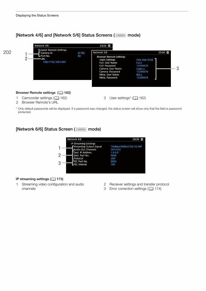
Displaying the Status Screens
202
[Network 4/6] and [Network 5/6] Status Screens ( mode)
Browser Remote settings (A 162)
* Only default passwords will be displayed. If a password was changed, the status screen will show only that the field is password protected.
[Network 6/6] Status Screen ( mode)
IP streaming settings (A 173)
3
12
1 Camcorder settings (A 162)2 Browser Remote's URL
3 User settings* (A 162)
3
1
2
1 Streaming video configuration and audio channels
2 Receiver settings and transfer protocol3 Error correction settings (A 174)
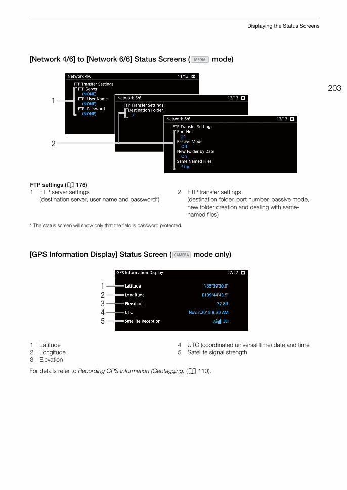
203
Displaying the Status Screens
[Network 4/6] to [Network 6/6] Status Screens ( mode)
* The status screen will show only that the field is password protected.
[GPS Information Display] Status Screen ( mode only)
For details refer to Recording GPS Information (Geotagging) (A 110).
1
2
FTP settings (A 176)1 FTP server settings
(destination server, user name and password*)2 FTP transfer settings
(destination folder, port number, passive mode, new folder creation and dealing with same-named files)
12345
1 Latitude2 Longitude3 Elevation
4 UTC (coordinated universal time) date and time5 Satellite signal strength
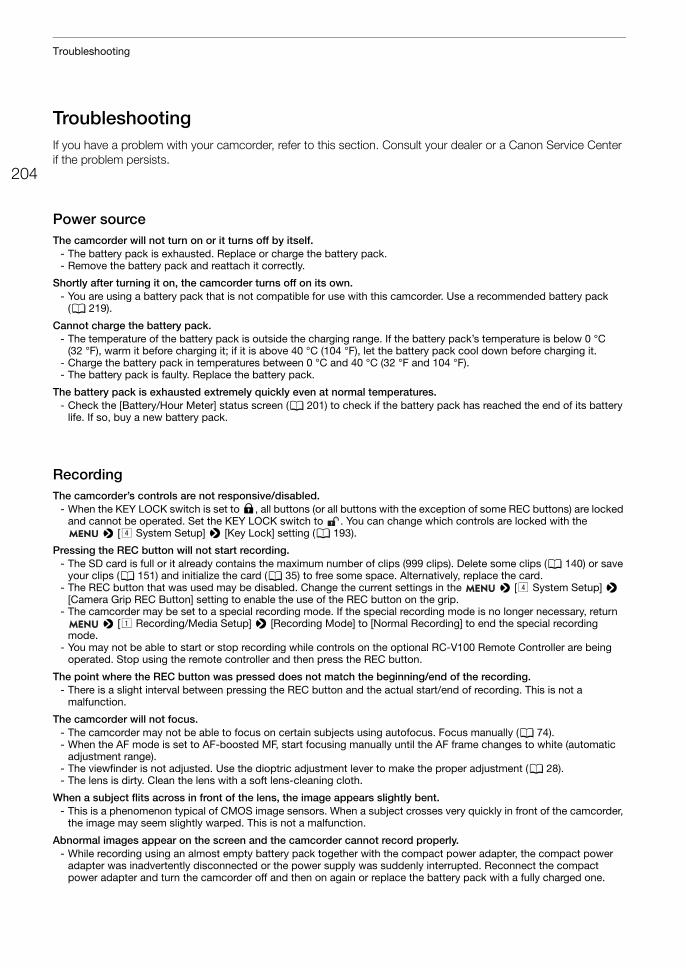
Troubleshooting
204
TroubleshootingIf you have a problem with your camcorder, refer to this section. Consult your dealer or a Canon Service Center if the problem persists.
Power sourceThe camcorder will not turn on or it turns off by itself.
- The battery pack is exhausted. Replace or charge the battery pack.- Remove the battery pack and reattach it correctly.
Shortly after turning it on, the camcorder turns off on its own.- You are using a battery pack that is not compatible for use with this camcorder. Use a recommended battery pack
(A 219).
Cannot charge the battery pack.- The temperature of the battery pack is outside the charging range. If the battery pack’s temperature is below 0 °C
(32 °F), warm it before charging it; if it is above 40 °C (104 °F), let the battery pack cool down before charging it.- Charge the battery pack in temperatures between 0 °C and 40 °C (32 °F and 104 °F).- The battery pack is faulty. Replace the battery pack.
The battery pack is exhausted extremely quickly even at normal temperatures.- Check the [Battery/Hour Meter] status screen (A 201) to check if the battery pack has reached the end of its battery
life. If so, buy a new battery pack.
RecordingThe camcorder’s controls are not responsive/disabled.
- When the KEY LOCK switch is set to C, all buttons (or all buttons with the exception of some REC buttons) are locked and cannot be operated. Set the KEY LOCK switch to . You can change which controls are locked with the
> [$ System Setup] > [Key Lock] setting (A 193).
Pressing the REC button will not start recording.- The SD card is full or it already contains the maximum number of clips (999 clips). Delete some clips (A 140) or save
your clips (A 151) and initialize the card (A 35) to free some space. Alternatively, replace the card.- The REC button that was used may be disabled. Change the current settings in the > [$ System Setup] >
[Camera Grip REC Button] setting to enable the use of the REC button on the grip.- The camcorder may be set to a special recording mode. If the special recording mode is no longer necessary, return
> [! Recording/Media Setup] > [Recording Mode] to [Normal Recording] to end the special recording mode.
- You may not be able to start or stop recording while controls on the optional RC-V100 Remote Controller are being operated. Stop using the remote controller and then press the REC button.
The point where the REC button was pressed does not match the beginning/end of the recording.- There is a slight interval between pressing the REC button and the actual start/end of recording. This is not a
malfunction.
The camcorder will not focus.- The camcorder may not be able to focus on certain subjects using autofocus. Focus manually (A 74).- When the AF mode is set to AF-boosted MF, start focusing manually until the AF frame changes to white (automatic
adjustment range).- The viewfinder is not adjusted. Use the dioptric adjustment lever to make the proper adjustment (A 28). - The lens is dirty. Clean the lens with a soft lens-cleaning cloth.
When a subject flits across in front of the lens, the image appears slightly bent.- This is a phenomenon typical of CMOS image sensors. When a subject crosses very quickly in front of the camcorder,
the image may seem slightly warped. This is not a malfunction.
Abnormal images appear on the screen and the camcorder cannot record properly.- While recording using an almost empty battery pack together with the compact power adapter, the compact power
adapter was inadvertently disconnected or the power supply was suddenly interrupted. Reconnect the compact power adapter and turn the camcorder off and then on again or replace the battery pack with a fully charged one.
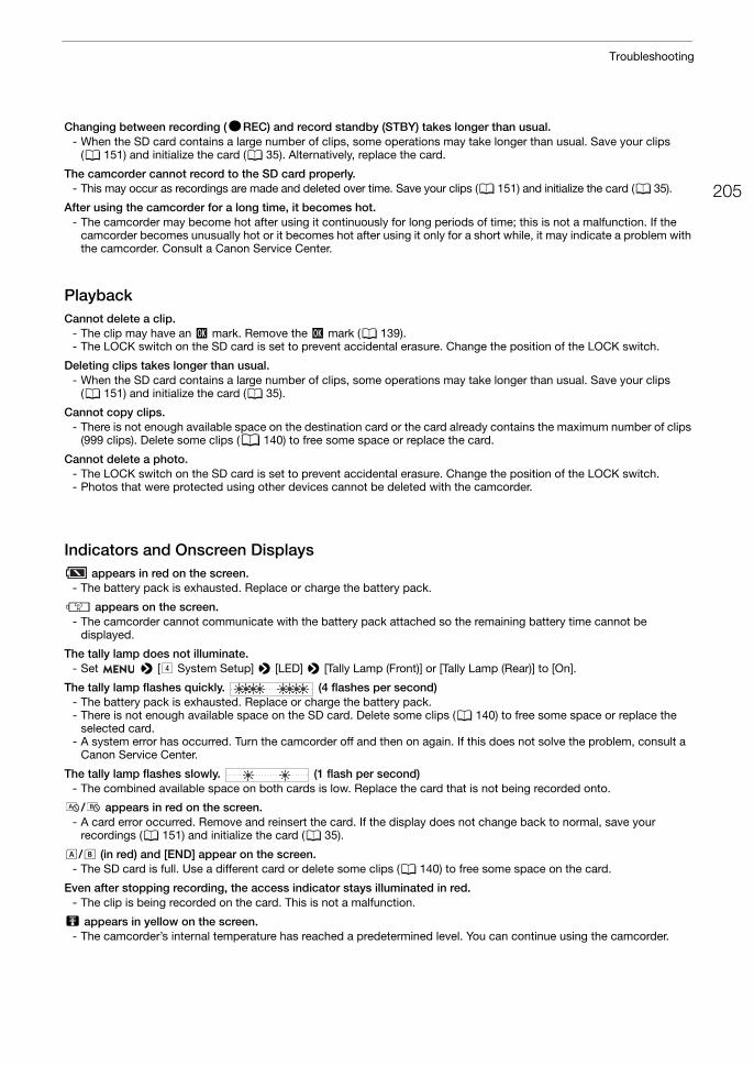
205
Troubleshooting
Changing between recording (ÜREC) and record standby (STBY) takes longer than usual.- When the SD card contains a large number of clips, some operations may take longer than usual. Save your clips
(A 151) and initialize the card (A 35). Alternatively, replace the card.
The camcorder cannot record to the SD card properly.- This may occur as recordings are made and deleted over time. Save your clips (A 151) and initialize the card (A 35).
After using the camcorder for a long time, it becomes hot.- The camcorder may become hot after using it continuously for long periods of time; this is not a malfunction. If the
camcorder becomes unusually hot or it becomes hot after using it only for a short while, it may indicate a problem with the camcorder. Consult a Canon Service Center.
PlaybackCannot delete a clip.
- The clip may have an $ mark. Remove the $ mark (A 139).- The LOCK switch on the SD card is set to prevent accidental erasure. Change the position of the LOCK switch.
Deleting clips takes longer than usual.- When the SD card contains a large number of clips, some operations may take longer than usual. Save your clips
(A 151) and initialize the card (A 35).
Cannot copy clips.- There is not enough available space on the destination card or the card already contains the maximum number of clips
(999 clips). Delete some clips (A 140) to free some space or replace the card.
Cannot delete a photo.- The LOCK switch on the SD card is set to prevent accidental erasure. Change the position of the LOCK switch.- Photos that were protected using other devices cannot be deleted with the camcorder.
Indicators and Onscreen Displays appears in red on the screen.
- The battery pack is exhausted. Replace or charge the battery pack.
í appears on the screen.- The camcorder cannot communicate with the battery pack attached so the remaining battery time cannot be
displayed.
The tally lamp does not illuminate.- Set > [$ System Setup] > [LED] > [Tally Lamp (Front)] or [Tally Lamp (Rear)] to [On].
The tally lamp flashes quickly. (4 flashes per second)- The battery pack is exhausted. Replace or charge the battery pack.- There is not enough available space on the SD card. Delete some clips (A 140) to free some space or replace the
selected card.- A system error has occurred. Turn the camcorder off and then on again. If this does not solve the problem, consult a
Canon Service Center.
The tally lamp flashes slowly. (1 flash per second)- The combined available space on both cards is low. Replace the card that is not being recorded onto.
/ appears in red on the screen.- A card error occurred. Remove and reinsert the card. If the display does not change back to normal, save your
recordings (A 151) and initialize the card (A 35).
6/7 (in red) and [END] appear on the screen.- The SD card is full. Use a different card or delete some clips (A 140) to free some space on the card.
Even after stopping recording, the access indicator stays illuminated in red.- The clip is being recorded on the card. This is not a malfunction.
b appears in yellow on the screen.- The camcorder’s internal temperature has reached a predetermined level. You can continue using the camcorder.
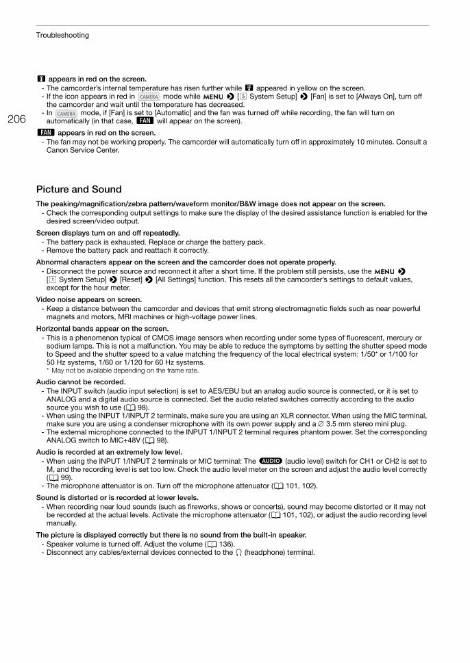
Troubleshooting
206
b appears in red on the screen.- The camcorder’s internal temperature has risen further while b appeared in yellow on the screen.- If the icon appears in red in mode while > [% System Setup] > [Fan] is set to [Always On], turn off
the camcorder and wait until the temperature has decreased.- In mode, if [Fan] is set to [Automatic] and the fan was turned off while recording, the fan will turn on
automatically (in that case, ` will appear on the screen).
` appears in red on the screen.- The fan may not be working properly. The camcorder will automatically turn off in approximately 10 minutes. Consult a
Canon Service Center.
Picture and SoundThe peaking/magnification/zebra pattern/waveform monitor/B&W image does not appear on the screen.
- Check the corresponding output settings to make sure the display of the desired assistance function is enabled for the desired screen/video output.
Screen displays turn on and off repeatedly.- The battery pack is exhausted. Replace or charge the battery pack.- Remove the battery pack and reattach it correctly.
Abnormal characters appear on the screen and the camcorder does not operate properly.- Disconnect the power source and reconnect it after a short time. If the problem still persists, use the >
[! System Setup] > [Reset] > [All Settings] function. This resets all the camcorder’s settings to default values, except for the hour meter.
Video noise appears on screen.- Keep a distance between the camcorder and devices that emit strong electromagnetic fields such as near powerful
magnets and motors, MRI machines or high-voltage power lines.
Horizontal bands appear on the screen.- This is a phenomenon typical of CMOS image sensors when recording under some types of fluorescent, mercury or
sodium lamps. This is not a malfunction. You may be able to reduce the symptoms by setting the shutter speed mode to Speed and the shutter speed to a value matching the frequency of the local electrical system: 1/50* or 1/100 for 50 Hz systems, 1/60 or 1/120 for 60 Hz systems.* May not be available depending on the frame rate.
Audio cannot be recorded.- The INPUT switch (audio input selection) is set to AES/EBU but an analog audio source is connected, or it is set to
ANALOG and a digital audio source is connected. Set the audio related switches correctly according to the audio source you wish to use (A 98).
- When using the INPUT 1/INPUT 2 terminals, make sure you are using an XLR connector. When using the MIC terminal, make sure you are using a condenser microphone with its own power supply and a 3.5 mm stereo mini plug.
- The external microphone connected to the INPUT 1/INPUT 2 terminal requires phantom power. Set the corresponding ANALOG switch to MIC+48V (A 98).
Audio is recorded at an extremely low level.- When using the INPUT 1/INPUT 2 terminals or MIC terminal: The – (audio level) switch for CH1 or CH2 is set to
M, and the recording level is set too low. Check the audio level meter on the screen and adjust the audio level correctly (A 99).
- The microphone attenuator is on. Turn off the microphone attenuator (A 101, 102).
Sound is distorted or is recorded at lower levels.- When recording near loud sounds (such as fireworks, shows or concerts), sound may become distorted or it may not
be recorded at the actual levels. Activate the microphone attenuator (A 101, 102), or adjust the audio recording level manually.
The picture is displayed correctly but there is no sound from the built-in speaker.- Speaker volume is turned off. Adjust the volume (A 136).- Disconnect any cables/external devices connected to the × (headphone) terminal.
207
Troubleshooting
Cards and AccessoriesCannot insert the SD card.
- The card you are trying to insert is not facing the correct direction. Turn it over and insert it.
Cannot record on the SD card.- A compatible card must be used (A 33).- Initialize the card (A 35) when you use it with the camcorder for the first time.- The LOCK switch on the SD card is set to prevent accidental erasure. Change the position of the LOCK switch.- Photos can be recorded only to SD card B. Insert a card into SD card slot B.- The card is full or it already contains the maximum number of clips (999 clips). Delete some clips (A 140) to free some
space or replace the card.- The folder and file numbers have reached their maximum value. Set the > [" Recording/Media Setup] >
[Photo Numbering] setting to [Reset] and insert a new card.
Recording to and playing back from an SD card is slow.- This may occur as clips and photos are recorded/deleted over time. Save your recordings (A 151) and initialize the
card (A 35).
The optional RC-V100 Remote Controller or commercially available remote control does not work.- Make sure that > [$ System Setup] > [REMOTE Term.] is set to [RC-V100 (REMOTE B)] or [RC-V100
(REMOTE A)] when using the optional RC-V100 Remote Controller or [Standard] when using a commercially available remote control.
- Turn off the camcorder, reconnect the remote controller and then turn the camcorder back on again.- When > [! Custom Picture] > [Activate Other Settings] is set to [Off] or the currently selected custom
picture file is protected, detailed custom picture settings cannot be adjusted using the RC-V100. Set [Activate Other Settings] to [On] after selecting a custom picture file that is not protected (A 121).
Connections with External DevicesVideo noise appears on a nearby TV screen.
- When using the camcorder in a room where a TV is located, keep a distance between the compact power adapter and the power or antenna cables of the TV.
Playback looks fine on the camcorder but there is no image on the external monitor.- The camcorder is not connected correctly to the external monitor. Make sure you are using the correct connection
(A 145).- The video input on the external monitor is not set to the video terminal to which you connected the camcorder. Select
the correct video input.
The computer does not recognize the camcorder even though the camcorder is connected correctly.- Disconnect the USB cable and turn off the camcorder. After a short while, turn it on again and restore the connection.- Connect the camcorder to a different USB port on the computer.- Establish the USB connection while the [Photos] index screen is displayed (A 132).
Cannot transfer clips or photos to the computer.- The SD card contains too many clips and photos. Delete clips or photos until the card contains a combined total of
2,500 (Windows)/1,000 (macOS) or fewer and then use a card reader to transfer the recordings from the card.
There is no picture or sound from an external monitor connected to the SDI terminal- Make sure the connected external device is compatible with 12G-SDI and the frame rate used.- Check that the external monitor’s settings match the configuration of the output signal selected on the camcorder
(A 143).
There is no picture or sound from an external monitor connected to the HDMI OUT terminal- Disconnect the HDMI cable and then restore the connection or turn the camcorder off and then on again.- Make sure the external monitor is compatible with the output signal selected on the camcorder (A 143).
Peaking/B&W image/magnification/zebra patterns/waveform monitor do not appear on the viewfinder.- Check that the display of desired assistance function is enabled for the viewfinder ([B&W Image: VF] (A 188),
[Magn.: VF+LCD], [Peaking: VF], [Zebra: VF], [WFM: VF] (A 189)).
Peaking/B&W image/magnification/zebra patterns/waveform monitor do not appear in the video output from the SDI terminal.
- Check that that display of the desired assistance function is enabled for the SDI terminal ([B&W Image: SDI] (A 188), [Magn.: SDI/HDMI], [Peaking: SDI], [Zebra: SDI], [WFM: SDI] (A 189)).
Troubleshooting
208
Peaking/B&W image/magnification/zebra patterns/waveform monitor do not appear in the video output from the HDMI OUT terminal.
- Check that that display of the desired assistance function is enabled for the HDMI OUT terminal ([B&W Image: HDMI] (A 188), [Magn.: SDI/HDMI], [Peaking: HDMI], [Zebra: HDMI], [WFM: HDMI] (A 189)).
Network Functions
Check This First
Cannot connect with an access point.- There are other devices in the vicinity interfering with the wireless signal. Refer to Precautions Regarding Wi-Fi
Networks (A 208).- Password information is not saved with the camcorder settings. When you load onto the camcorder settings from a
previously saved camcorder settings file, all the passwords in the network-related settings are reset. Set up the network-related settings as necessary (A 153).
- When using a Wi-Fi network, the camcorder cannot detect an access point if its stealth function is activated. Set up the network connection manually (A 158) or turn off the stealth function of the access point.
Cannot establish a Camera Access Point connection with a network device.- There are other devices in the vicinity interfering with the wireless signal. Refer to Precautions Regarding Wi-Fi
Networks (A 208).- When you reset all the camcorder’s settings, all network settings are lost as well. Connect using the default settings or
set up the Camera Access Point settings again (A 155).
Cannot connect with a wired (Ethernet) network.- Use a category 5e or better shielded twisted pair (STP) Ethernet cable.- Try replacing the Ethernet cable.- When you reset all the camcorder’s settings, all network settings are lost as well. Set up the network settings again
(A 153).- Check that the network device to which the camcorder is connected is on and functioning properly. To use
1000BASE-T connection speeds, make sure to use network devices compatible with Gigabit Ethernet (1000BASE-T).
The Browser Remote application will not start on the Web browser.- Make sure Browser Remote is activated (A 163).- The URL entered into the Web browser’s address bar is incorrect. Be sure to use the URL exactly as it appears in the
mode’s [Network 4/6] status screen (A 202).
The Browser Remote screen is not displayed correctly on the Web browser.- The device, operating system or Web browser used may not be supported. For the latest information about supported
systems, visit your local Canon Web site.- Enable JavaScript and cookies in your Web browser’s settings. For details, refer to the help modules or online
documentation of the Web browser used.- Delete the cache and cookies for Browser Remote's URL in your Web browser and restart Browser Remote.
Precautions Regarding Wi-Fi NetworksWhen using a Wi-Fi network, try the following corrective actions if the transmission rate drops, the connection is lost, or other problems occur.
Positioning a network device (access point, mobile device, etc.)- When using a Wi-Fi network indoors, place the network device in the same room as the camcorder.- Place the network device in an open, unobstructed location, where people or objects do not come between it and the
camcorder.- Place the network device as close as possible to the camcorder and change the network device’s height or orientation
as necessary.
• Are the access point (wireless router), camcorder, computer or other network devices all turned on?• Is the network working and correctly configured?• Are all network devices correctly connected to the same network as the camcorder?• Are there any obstructions between the camcorder and the access point or between the network device
used and the access point?
209
Troubleshooting
Nearby electronic devices- If the transmission rate over a Wi-Fi network drops because of interference from the following electronic devices,
switching to the 5 GHz band or to a different channel may solve the problem.- Wi-Fi networks using the IEEE 802.11b/g/n protocol operate in the 2.4 GHz band. For this reason, the transmission
rate may drop if there are nearby microwave ovens, cordless telephones, microphones, or similar devices operating on the same frequency band.
- If another access point operating on the same frequency band as the camcorder is used nearby, the transmission rate may drop.
Using multiple camcorders/wireless transmitters/access points - Check that there are no IP address conflicts among the devices connected to the same network.- If multiple XF705 camcorders are connected to a single access point, connection speeds may be reduced.- To reduce radio wave interference when there are multiple access points using IEEE 802.11b/g or IEEE 802.11n (in the
2.4 GHz band), leave a gap of four channels between each wireless access point. For example, use channels 1, 6, and 11, channels 2, 7, and 12, or channels 3, 8, and 13. If you can use IEEE 802.11a/n (in the 5 GHz band), switch to IEEE 802.11a/n and specify a different channel.
List of MessagesRefer to this section if a message appears on the screen. The messages in this section appear in alphabetical order. Note that for some messages, an indication of the card involved (SD card A, SD card B, or both) may appear above the message itself.
Accessing SD Card A/SD Card B Do not remove- You opened the card slot cover while the camcorder was accessing the card. Close the card slot cover.
Battery communication error. Does this battery display the Canon logo?- You attached a battery pack that is not recommended by Canon for use with this camcorder.- If you are using a battery pack recommended by Canon for use with this camcorder, there may be a problem with the
battery pack or camcorder. Consult a Canon Service Center.
Buffer overflow. Recording was stopped.- The data transfer rate was too high for the card in use and the recording was stopped. Use a recommended card
(A 33).
Cannot play back- The card contains clips that were recorded using a system frequency different from the one currently used by the
camcorder. To play back the recordings on the card, change the > [! Recording/Media Setup] > [System Frequency] setting to match the recordings on the card.
- The file control information is corrupted or there was a decoder error. Turn the camcorder off and then on again. If this does not solve the problem, consult a Canon Service Center.
Cannot switch SD card slots- The SLOT SELECT button was pressed while the camcorder is recording. Wait until recording is finished to change the
selected SD card slot.
Change the battery pack- The battery pack is exhausted. Replace or charge the battery pack.
Cover is open- The SD card slot cover was open when the camcorder was switched to or turned on in mode. Insert a card
and close the card slot cover.
Fan error- The cooling fan may not be working properly. Consult a Canon Service Center.
File name error- You attempted to record a clip while clip numbers are at their maximum value. Save your clips (A 151) and initialize
the card (A 35) or delete all the clips (A 140).- You attempted to take a photo while photo numbers are at their maximum value. Set > [" Recording/Media
Setup] > [Photo Numbering] to [Reset] and delete all the photos on the card (A 182) or initialize it (A 35).
INFRARED switch position changed (ON/OFF). Check the focus.- The focus may change when you turn the infrared mode on or off. Check that the focus is correct.
Troubleshooting
210
Invalid operation- The following are not valid operations and cannot be performed.
• Trying to add a shot mark to a frame that already has one.• Trying to add an $ mark and a % mark to the same clip.• Pressing the REC button when no cards are inserted in the camcorder.
Management file error- Cannot record because the camcorder cannot write to the file control information. This may occur if the files on the
card were accessed using another device. Save your clips (A 151) and initialize the card (A 35).
May not be possible to record clips on this media- The card selected for recording has a Speed Class rating lower than 10. Use a recommended card (A 33).
Media full- The SD card is full. Replace the card or delete some recordings (A 140, 182) to free some space on the card.
Media is almost full- The amount of available space on the SD card is low. Replace the card or delete some recordings (A 140, 182) to free
some space.- The amount of available space on SD card A and SD card B combined is low. Replace the card that is not selected.
Media is not supported- 512 MB or smaller SD cards cannot be used with the camcorder. Use a recommended card (A 33).
Memory card is write-protected- The LOCK switch on the SD card is set to prevent accidental erasure. Change the position of the LOCK switch.
Number of clips already at maximum- The card selected for recording already contains the maximum number of clips (999 clips). Replace the card.
Number of Shot Marks at maximum- The shot mark could not be added because the clip already contains 100 shot marks.
Recorded at 50.00 Hz/59.94 Hz SD Card A / SD Card B: Recommend checking the data and initializing- The card contains clips that were recorded using a system frequency different from the one currently used by the
camcorder. Save the content of the card if necessary and initialize the card with this camcorder (A 35).
Recording was stopped.- The file control information is corrupted or there was an encoder error. Turn the camcorder off and then on again.
Then, remove the card being used and reinsert it. Alternatively, replace the card. If this does not solve the problem, consult a Canon Service Center.
SD Card A / SD Card B: Check the data.- Cannot access the card. Check the card and make sure it is inserted correctly.- A card error occurred. The camcorder cannot record or display the image. Try removing and reinserting the card, or
use a different card.- You inserted a MultiMedia Card (MMC) into the camcorder. Use a recommended SD card (A 33).- If after the message disappears, or appears in red, perform the following: Turn off the camcorder and remove
and reinsert the card. If 6 or 7 turns back to green you can resume recording/playback. If the problem persists, save your clips (A 151) and initialize the card (A 35).
SD Card A / SD Card B: Recommend checking the data and initializing- The card cannot be used for any of the following reasons. Save your clips (A 151) and initialize the card (A 35).
• A problem has occurred with the card.• The camcorder cannot read the data on the card.• The card was initialized using a computer.• The card is partitioned.
- The card was initialized using a camcorder with a different firmware version. To be able to record on the card, save the recordings it contains and then initialize it using this camcorder.
SD Card ASD Card B / SD Card BSD Card A Switched- The camcorder switched to recording on the other card after you pressed the SLOT SELECT button or automatically
due to relay recording.
SD Card ASD Card B / SD Card BSD Card A Will switch in a moment- The selected card is almost full so the camcorder will switch to recording on the other card in approximately 1 minute
(relay recording).
Some clips require data recovery.- The power may have been suddenly turned off or the card may have been removed while the camcorder was
recording. As a result, one or more clips contain corrupted data. You can try to recover the clips (A 37).
211
Troubleshooting
Network Functions
Along with this list, refer also to the instruction manuals of the access point or other external devices you are using.
The following settings were changed.- The settings displayed on the screen were changed automatically due to a change in one of the [Recording/Media
Setup] settings. Check the settings before you continue recording.- LUT options that were set to [PQ : BT.2020] or [HLG : BT.2020] will be reset to [Off] automatically when you activate
slow motion recording.
The memory card is not compatible with the current recording settings.- The video configuration settings are set to record XF-HEVC clips with a resolution of 3840x2160 but the card selected
for recording does not have a UHS Speed Class rating of U3. Replace the card with one rated UHS Speed Class U3 or set > [! Recording/Media Setup] > [Resolution/Color Sampling] to [1920x1080 YCC422 10 bit].
- Slow motion recording was activated but the card selected for recording does not have a UHS Speed Class rating of U3. Replace the card with one rated UHS speed class U3.
Too many photos. Disconnect the USB cable.- Disconnect the USB cable. Try using a card reader or decrease the number of photos on the card to fewer than 2,500
(Windows) or 1,000 (macOS) and then restore the connection.
Unable to recover data- Could not recover the selected clip. Save your clips (A 151) and delete the clips that could not be recovered
(A 140).- The camcorder may not be able to recover clips when there is not enough space on the card. Delete some clips
(A 140) to free some space.
A User is already accessing the server. Try again later. - This message appears on the screen of the connected device. Another device connected to the network is already
operating the camcorder. To use this device, first end the connection on the device accessing the camcorder and then touch Retry.
Cannot log in to FTP server.- Check the user name and password information in the FTP server settings (A 176).
Cannot transfer files to FTP server.- Check that there is enough available space in the data storage device (hard disk, etc.) that contains the destination
folder on the FTP server.
FTP transfer error. File transfer was not completed.- An error occurred while transferring files to the FTP server. Turn then camcorder and the FTP server off and then on
again and try again the FTP transfer.
IP address conflict- Another device on the same network has the same IP address assigned to the camcorder. Change the IP address of
the conflicting device or the camcorder.
LAN cable not connected.- You attempted to connect to a wired network but the Ethernet cable is not connected. Check that the Ethernet cable is
correctly connected to the camcorder’s (Ethernet) terminal and to the LAN/Ethernet port on the network device.
Multiple access points detected. Try the operation again.- There are multiple access points sending out a WPS signal at the same time. Try the operation again later or perform
setup using the [WPS: PIN Code] or [Search for Access Points] option (A 157).
Network functions malfunction.- There’s a hardware problem with the camcorder’s network related circuitry. Try turning the camcorder off and then on
again. If the problem persists, consult a Canon Service Center.
No access points found- The camcorder searched for active Wi-Fi networks (access points) in the area but none were found. Make sure the
access point is working correctly and try connecting again.- The access point is operating in stealth mode. Deactivate the stealth function in the wireless router (access point)
settings.- The camcorder may not be able to find the access point if MAC address filtering is activated. Check the [Network 3/6]
status screen (A 201) and make sure to add the camcorder’s MAC address to the list of approved wireless devices in the wireless router (access point) settings.
Troubleshooting
212
Reached the end of the adjustment range- This message appears on the screen of the connected device. When focusing with Browser Remote, this message will
appear when a focus adjustment would push the focus out of the lens’s available range.
Some files could not be transferred.- The file system is corrupted or you attempted to transfer clips not recorded with this camcorder. Delete those clips
from the SD card and then transfer the files again (A 176).- The destination folder contains files with the same file name as those to be transferred. Rename the files or set
> [! Network Settings] > [FTP Transfer Settings] > [Same Named Files] to [Overwrite] to overwrite the files in the destination folder.
Unable to complete WPS. Try the operation again.- More than 2 minutes passed between activating WPS on the access point and selecting [OK] on the camcorder. Start
over the WPS procedure from the beginning.- The WPS button was not held down long enough. Refer to the instruction manual of your wireless router. When using
WPS to make a wireless connection, keep the WPS button held down until the wireless router’s WPS function is activated.
- The access point’s encryption method is set to [WEP]. Wi-Fi Protected Setup (WPS) cannot connect to access points set to this encryption method. Change the access point’s encryption method or use another connection method (A 156).
Unable to connect- Could not connect to the access point or network device selected.- Cordless phones, microwave ovens, refrigerators and other appliances may interfere with the wireless signal. Try using
the camcorder in a location farther away from such appliances.
Unable to connect to FTP server.- Could not connect to the FTP server. Check the FTP server settings (A 176).
Unable to obtain an IP address- If you are not using a DHCP server, connect using the [Manual] option and enter the IP address using the [Manual]
option (A 158).- Turn on the DHCP server. If it is already on, make sure it is functioning properly.- Make sure the address range for the DHCP server is sufficient.- If you are not using a DNS server, set the DNS address to one other than [0.0.0.0].- Set the DNS server’s IP address in the camcorder.- Turn on the DNS server. If it is already on, make sure it is functioning properly.- Make sure that the DNS server’s IP address and the name for that address are correctly configured.- If you are using a wireless gateway router, make sure all of the devices in the network, including the camcorder, are
configured with the correct gateway address.
Wi-Fi connection terminated- An error occurred on the access point or connected device. Check the network or connected device and try
connecting again.- The Wi-Fi signal became too weak and the wireless connection was lost. Wait a moment or turn off other devices in
the area that may be interfering with the Wi-Fi signal and then try connecting again.
Wi-Fi error. Incorrect authentication method.- Make sure the camcorder and access point are using the same authentication/encryption method and encryption key.
Wi-Fi error. Incorrect encryption key.- When the authentication mode was set to [WPA-PSK], [WPA2-PSK] or [Shared Key], or the encryption method was set
to [WEP], the encryption key (WEP key or AES/TKIP password) entered or its length (number of characters) is incorrect. • Valid passwords vary depending on the encryption method:
- AES / TKIP encryption: 8 to 63 ASCII characters or 64 hexadecimal characters. - 64-bit WEP encryption: 5 ASCII characters or 10 hexadecimal characters. - 128-bit WEP encryption: 13 ASCII characters or 26 hexadecimal characters.
Wi-Fi error. Incorrect encryption method.- Make sure the camcorder and access point are using the same authentication/encryption method and encryption key.
213
Safety Instructions and Handling Precautions
Safety Instructions and Handling PrecautionsBe sure to read these instructions in order to operate the product safely. Follow these instructions to prevent injury or harm to the operator of the product or others.
WARNINGDenotes the risk of serious injury or death.• Stop using the product in any case of unusual circumstances such as the presence of smoke or a strange
smell.• Do not touch any exposed internal parts.• Do not get the product wet. Do not insert foreign objects or liquids into the product.• Do not touch the product connected to a power outlet during lightning storms. This may cause electric shock.• Do not disassemble or modify the product.• Do not expose the product to strong shocks or vibration.• Use only power sources specified in this instruction manual for use with the product.• Observe the following instructions when using a battery charger or compact power adapter.
- Do not touch the battery charger or compact power adapter connected to a power outlet during lightning storms.
- Do not use the product if the power plug is not fully inserted into the power outlet.- Do not unplug the product by pulling the power cord.- Do not plug in or unplug the product with wet hands.- Do not place heavy objects on the power cord. Do not damage, break or modify the power cord.- Do not leave the product connected to a power source for long periods of time.
• Do not expose the power plug and terminals to dirt or let them come into contact with metallic pins or other metal objects.
• Do not charge batteries/battery packs at temperatures outside the range of 0 - 40 °C (32 - 104 °F).• Observe the following instructions when using commercially available batteries or provided battery packs.
- Do not use leaking batteries/battery packs. If a battery/battery pack leaks and the material contacts your skin or clothing, flush the exposed area thoroughly with running water. In case of eye contact, flush thoroughly with copious amounts of clean running water and seek immediate medical assistance.
- Use batteries/battery packs only with their specified product.- Do not heat batteries/battery packs or expose them to fire. - Do not charge batteries/battery packs using non-authorized battery chargers.- Do not expose the terminals to dirt or let them come into contact with metallic pins or other metal objects.- When disposing of batteries/battery packs, insulate the terminals with tape or other means.
• Do not look through the viewfinder at strong light sources such as the sun on a bright day or lasers and other strong artificial light sources.
• Do not leave the lens exposed without the lens cap attached. The lens may concentrate the light and cause fire.
• Do not wrap the product in cloth or other materials when in use or shortly after use when the product is still warm in temperature.
• Do not allow the product to maintain contact with the same area of skin for extended periods of time during use. This may result in low-temperature contact burns, including skin redness and blistering, even if the product does not feel hot. The use of a tripod or similar equipment is recommended when using the product in hot places and for people with circulation problems or less sensitive skin.
• Keep the product out of the reach of young children.• A strap wrapped around a person’s neck may result in strangulation.• Periodically remove any dust buildup from the power plug and power outlet using a dry cloth.• Follow any indications to turn off the product in places where its use is forbidden. Not doing so may cause
other equipment to malfunction due to the effect of electromagnetic waves and even result in accidents.
Safety Instructions and Handling Precautions
214
CAUTIONDenotes the risk of injury.• Strap is intended for use on the body only. Hanging the strap with any product attached on a hook or other
object may damage the product. Also, do not shake the product or expose the product to strong impacts. This may cause injury or damage to the product.
• Do not leave the product in places exposed to extremely high or low temperatures. The product may become extremely hot/cold and cause burns or injury when touched.
• Only mount the product on a tripod that is sufficiently sturdy.
CamcorderBe sure to observe the following precautions to ensure maximum performance. • Do not use or store the camcorder in dusty or sandy places. The camcorder is not waterproof – avoid also
water, mud or salt. If any of the above should get into the camcorder it may damage the camcorder and/or the lens. Consult a Canon Service Center as soon as possible.
• Be careful to avoid dust and dirt particles accumulating on the lens or entering the camcorder. When you finish using the camcorder, make sure to remove the lens hood and attach the lens cap to the lens.
• Do not use the camcorder near strong electromagnetic fields such as near powerful magnets and motors, MRI machines or high-voltage power lines. Using the camcorder in such places may cause anomalies in the video, or audio or video noise to appear.
• Do not point the camcorder or viewfinder toward an intense light source, such as the sun on a sunny day or an intense artificial light source. Doing so may damage the image sensor or the camcorder’s internal components. Be careful especially when using a tripod or shoulder strap. When not using the camcorder, remove the lens hood and attach the lens cap to the lens. When not using the viewfinder, attach the viewfinder cap to the viewfinder.
• Do not carry the camcorder by the LCD panel. Be careful when closing the LCD panel.
Long-term storage If you do not intend to use the camcorder for a long time, store it in a place free of dust, in low humidity, and at temperatures not higher than 30 °C (86 °F).
Battery Pack
• Dirty terminals may cause a poor contact between the battery pack and the camcorder. Wipe the terminals with a soft cloth.
DANGER!
Treat the battery pack with care.• Keep it away from fire (or it might explode).• Do not expose the battery pack to temperature higher than 60 °C (140 °F). Do not leave it near a heater or
inside a car in hot weather.• Do not try to disassemble or modify it.• Do not drop it or subject it to shocks.• Do not get it wet.
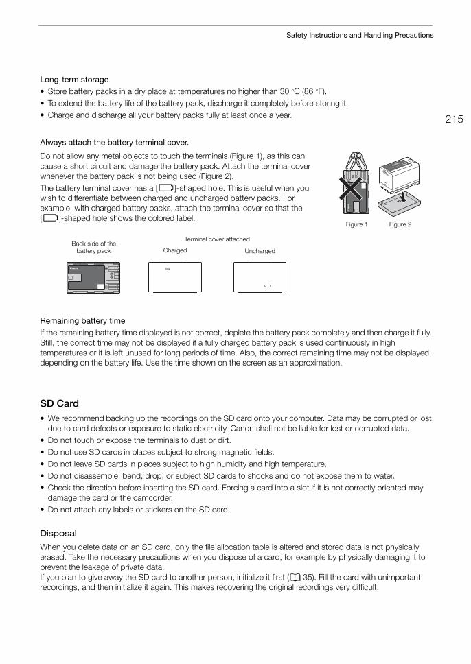
215
Safety Instructions and Handling Precautions
Long-term storage • Store battery packs in a dry place at temperatures no higher than 30 °C (86 °F). • To extend the battery life of the battery pack, discharge it completely before storing it.• Charge and discharge all your battery packs fully at least once a year.
Always attach the battery terminal cover.
Do not allow any metal objects to touch the terminals (Figure 1), as this can cause a short circuit and damage the battery pack. Attach the terminal cover whenever the battery pack is not being used (Figure 2).The battery terminal cover has a [ð]-shaped hole. This is useful when you wish to differentiate between charged and uncharged battery packs. For example, with charged battery packs, attach the terminal cover so that the [ð]-shaped hole shows the colored label.
Remaining battery timeIf the remaining battery time displayed is not correct, deplete the battery pack completely and then charge it fully. Still, the correct time may not be displayed if a fully charged battery pack is used continuously in high temperatures or it is left unused for long periods of time. Also, the correct remaining time may not be displayed, depending on the battery life. Use the time shown on the screen as an approximation.
SD Card• We recommend backing up the recordings on the SD card onto your computer. Data may be corrupted or lost
due to card defects or exposure to static electricity. Canon shall not be liable for lost or corrupted data.• Do not touch or expose the terminals to dust or dirt.• Do not use SD cards in places subject to strong magnetic fields.• Do not leave SD cards in places subject to high humidity and high temperature.• Do not disassemble, bend, drop, or subject SD cards to shocks and do not expose them to water.• Check the direction before inserting the SD card. Forcing a card into a slot if it is not correctly oriented may
damage the card or the camcorder.• Do not attach any labels or stickers on the SD card.
Disposal
When you delete data on an SD card, only the file allocation table is altered and stored data is not physically erased. Take the necessary precautions when you dispose of a card, for example by physically damaging it to prevent the leakage of private data.If you plan to give away the SD card to another person, initialize it first (A 35). Fill the card with unimportant recordings, and then initialize it again. This makes recovering the original recordings very difficult.
Figure 1 Figure 2
Back side of the battery pack Uncharged
Terminal cover attached
Charged
Safety Instructions and Handling Precautions
216
Built-in Rechargeable Lithium BatteryThe camcorder has a built-in rechargeable lithium battery to keep the date/time and other settings. The built-in lithium battery is recharged while you use the camcorder; however, it will discharge completely if you do not use the camcorder for about 3 months.To recharge the built-in lithium battery: Connect the DC cable and compact power adapter to the camcorder and use a power outlet to power the camcorder for 24 hours while it is turned off.
Lithium Button Battery
• Do not pick up the battery using tweezers or other metal tools, as this will cause a short circuit.• Wipe the battery with a clean dry cloth to ensure proper contact.
WARNING!
• The battery used in this device may present a fire or chemical burn hazard if mishandled.• Do not disassemble, modify, immerse in water, heat above 100 °C (212 °F) or incinerate the battery.• Do not insert the battery into the mouth. If swallowed, seek medical assistance immediately. The battery
case may break and the battery fluids may cause internal injuries.• Keep the battery out of the reach of children.• Do not recharge, short-circuit or insert the battery in the wrong direction.• Dispose of the used battery according to applicable recycling regulations. In Europe, the used battery
should be returned to the supplier for safe disposal.
217
Maintenance/Others
Maintenance/OthersCleaning
Camcorder Body• Use a soft, dry cloth to clean the camcorder’s body. Never use chemically treated cloths or volatile solvents
such as paint thinner.
Lens• Remove any dust or dirt particles using a non-aerosol type blower brush.• Use a clean, soft lens-cleaning cloth to gently wipe the lens. Never use tissue paper.
LCD Screen• Clean the LCD screen using a clean, soft lens-cleaning cloth and commercially available cleaning fluid for
eyeglasses.• Condensation may form on the surface of the screen when the temperature changes suddenly. Wipe it with a
soft dry cloth.
CondensationMoving the camcorder rapidly between hot and cold temperatures may cause condensation (water droplets) to form on its internal surfaces. Stop using the camcorder if condensation is detected. Continued use may damage the camcorder.
Condensation may form in the following cases:• When the camcorder is moved quickly from cold to warm places• When the camcorder is left in a humid room• When a cold room is heated rapidly
To avoid condensation • Do not expose the camcorder to sudden or extreme changes in temperature.• Remove the SD cards and battery pack. Then, place the camcorder in an airtight plastic bag and let it adjust
gradually to temperature changes before removing it from the bag.
When condensation is detected The precise time required for water droplets to evaporate will vary depending on the location and weather conditions. As a general rule, wait for 2 hours before resuming use of the camcorder.
Using the Camcorder Abroad
Power SourcesYou can use the compact power adapter to operate the camcorder and the battery charger to charge battery packs in any country/region with power supply between 100 and 240 V AC, 50/60 Hz. Consult a Canon Service Center for information on plug adapters for overseas use.
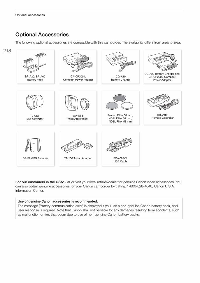
Optional Accessories
218
Optional AccessoriesThe following optional accessories are compatible with this camcorder. The availability differs from area to area.
For our customers in the USA: Call or visit your local retailer/dealer for genuine Canon video accessories. You can also obtain genuine accessories for your Canon camcorder by calling: 1-800-828-4040, Canon U.S.A. Information Center.
Use of genuine Canon accessories is recommended.The message [Battery communication error] is displayed if you use a non-genuine Canon battery pack, and user response is required. Note that Canon shall not be liable for any damages resulting from accidents, such as malfunction or fire, that occur due to use of non-genuine Canon battery packs.
BP-A30, BP-A60
Battery PackCA-CP200 L
Compact Power AdapterCG-A10
Battery Charger
TL-U58 Tele-converter
Protect Filter 58 mm, ND4L Filter 58 mm, ND8L Filter 58 mm
RC-V100 Remote Controller
TA-100 Tripod AdapterGP-E2 GPS Receiver
CG-A20 Battery Charger andCA-CP200B Compact
Power Adapter
WA-U58 Wide Attachment
IFC-400PCU USB Cable
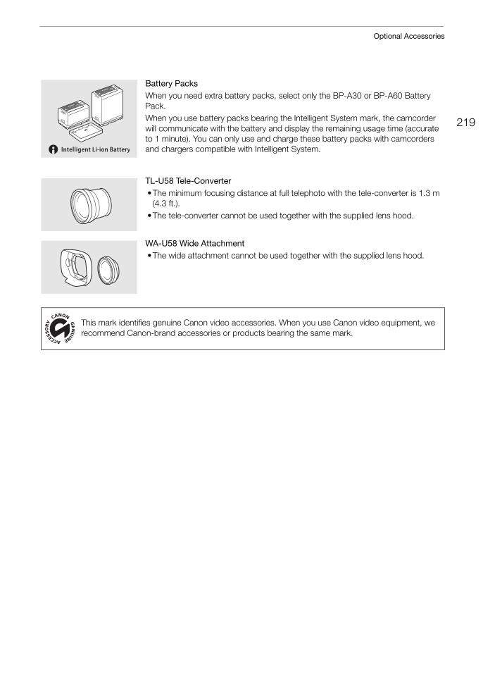
219
Optional Accessories
Battery PacksWhen you need extra battery packs, select only the BP-A30 or BP-A60 Battery Pack.When you use battery packs bearing the Intelligent System mark, the camcorder will communicate with the battery and display the remaining usage time (accurate to 1 minute). You can only use and charge these battery packs with camcorders and chargers compatible with Intelligent System.
TL-U58 Tele-Converter•The minimum focusing distance at full telephoto with the tele-converter is 1.3 m
(4.3 ft.).•The tele-converter cannot be used together with the supplied lens hood.
WA-U58 Wide Attachment•The wide attachment cannot be used together with the supplied lens hood.
This mark identifies genuine Canon video accessories. When you use Canon video equipment, we recommend Canon-brand accessories or products bearing the same mark.
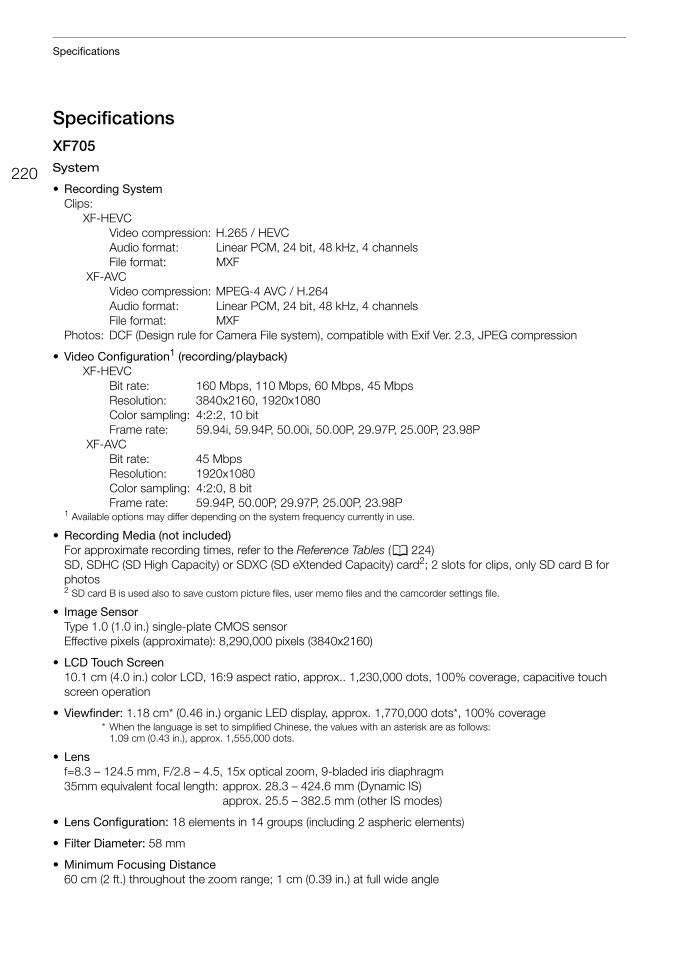
Specifications
220
SpecificationsXF705System
• Recording SystemClips:
XF-HEVCVideo compression: H.265 / HEVCAudio format: Linear PCM, 24 bit, 48 kHz, 4 channelsFile format: MXF
XF-AVCVideo compression: MPEG-4 AVC / H.264Audio format: Linear PCM, 24 bit, 48 kHz, 4 channelsFile format: MXF
Photos: DCF (Design rule for Camera File system), compatible with Exif Ver. 2.3, JPEG compression
• Video Configuration1 (recording/playback)XF-HEVC
Bit rate: 160 Mbps, 110 Mbps, 60 Mbps, 45 MbpsResolution: 3840x2160, 1920x1080Color sampling: 4:2:2, 10 bitFrame rate: 59.94i, 59.94P, 50.00i, 50.00P, 29.97P, 25.00P, 23.98P
XF-AVCBit rate: 45 MbpsResolution: 1920x1080Color sampling: 4:2:0, 8 bitFrame rate: 59.94P, 50.00P, 29.97P, 25.00P, 23.98P
1 Available options may differ depending on the system frequency currently in use.
• Recording Media (not included)For approximate recording times, refer to the Reference Tables (A 224)SD, SDHC (SD High Capacity) or SDXC (SD eXtended Capacity) card2; 2 slots for clips, only SD card B for photos2 SD card B is used also to save custom picture files, user memo files and the camcorder settings file.
• Image SensorType 1.0 (1.0 in.) single-plate CMOS sensorEffective pixels (approximate): 8,290,000 pixels (3840x2160)
• LCD Touch Screen10.1 cm (4.0 in.) color LCD, 16:9 aspect ratio, approx.. 1,230,000 dots, 100% coverage, capacitive touch screen operation
• Viewfinder: 1.18 cm* (0.46 in.) organic LED display, approx. 1,770,000 dots*, 100% coverage* When the language is set to simplified Chinese, the values with an asterisk are as follows:
1.09 cm (0.43 in.), approx. 1,555,000 dots.
• Lensf=8.3 – 124.5 mm, F/2.8 – 4.5, 15x optical zoom, 9-bladed iris diaphragm35mm equivalent focal length: approx. 28.3 – 424.6 mm (Dynamic IS)
approx. 25.5 – 382.5 mm (other IS modes)
• Lens Configuration: 18 elements in 14 groups (including 2 aspheric elements)
• Filter Diameter: 58 mm
• Minimum Focusing Distance60 cm (2 ft.) throughout the zoom range; 1 cm (0.39 in.) at full wide angle
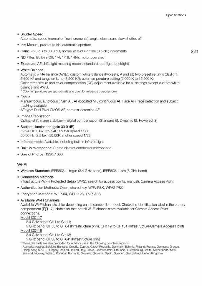
221
Specifications
• Shutter Speed Automatic, speed (normal or fine increments), angle, clear scan, slow shutter, off
• Iris: Manual, push auto iris, automatic aperture
• Gain: –6.0 dB to 33.0 dB, normal (3.0-dB) or fine (0.5-dB) increments
• ND Filter: Built-in (Off, 1/4, 1/16, 1/64), motor operated
• Exposure: AE shift, light metering modes (standard, spotlight, backlight)
• White BalanceAutomatic white balance (AWB); custom white balance (two sets, A and B); two preset settings (daylight, 5,600 K3 and tungsten lamp, 3,200 K3); color temperature setting (2,000 K to 15,000 K)Color temperature and color compensation (CC) adjustment available for all settings except custom white balance and AWB.3 Color temperatures are approximate and given for reference purposes only.
• FocusManual focus, autofocus (Push AF, AF-boosted MF, continuous AF, Face AF); face detection and subject tracking availableAF type: Dual Pixel CMOS AF, contrast-detection AF
• Image StabilizationOptical-shift image stabilizer + digital compensation (Standard IS, Dynamic IS, Powered IS)
• Subject Illumination (gain 33.0 dB)59.94 Hz: 3 lux (59.94P, shutter speed 1/30)50.00 Hz: 2.5 lux (50.00P, shutter speed 1/25)
• Infrared mode: Available, including built-in infrared light
• Built-in microphone: Stereo electret condenser microphone
• Size of Photos: 1920x1080
Wi-Fi
• Wireless Standard: IEEE802.11b/g/n (2.4 GHz band), IEEE802.11a/n (5 GHz band)
• Connection Methods Infrastructure (Wi-Fi Protected Setup (WPS), search for access points, manual), Camera Access Point
• Authentication Methods: Open, shared key, WPA-PSK, WPA2-PSK
• Encryption Methods: WEP-64, WEP-128, TKIP, AES
• Available Wi-Fi ChannelsAvailable Wi-Fi channels differ depending on the camcorder model. Check the identification label in the battery compartment (A 17). Note also that not all Wi-Fi channels are available for Camera Access Point connections.Model ID0117
2.4 GHz band: CH1 to CH11; 5 GHz band: CH56 to CH64 (Infrastructure only), CH149 to CH161 (Infrastructure/Camera Access Point)
Model ID01182.4 GHz band: CH1 to CH13; 5 GHz band: CH36 to CH64* (Infrastructure only)
* These channels are also prohibited for outdoor use in the following countries/regions:Australia, Austria, Belgium, Bulgaria, Croatia, Cyprus, Czech Republic, Denmark, Estonia, Finland, France, Germany, Greece, Hong Kong S.A.R., Hungary, Iceland, Ireland, Italy, Latvia, Liechtenstein, Lithuania, Luxembourg, Malta, Netherlands, New Zealand, Norway, Poland, Portugal, Romania, Slovakia, Slovenia, Spain, Sweden, Switzerland, United Kingdom
Specifications
222
Terminals
• SDI TerminalBNC jack, output only, 0.8 Vp-p / 75 , unbalancedHD-SDI: SMPTE 292, SMPTE ST 299-13G-SDI: SMPTE 424, SMPTE 425, SMPTE ST 299-26G-SDI: SMPTE ST 208112G-SDI: SMPTE ST 2082
Embedded audio, time code (VITC/LTC)Supplemental displays (superimposed onscreen displays, peaking, zebra pattern, magnification, waveform monitor) can also be output.
• HDMI OUT TerminalHDMI connector, output onlyTime code and supplemental displays (superimposed onscreen displays, peaking, zebra pattern, magnification, waveform monitor) can also be output.
• INPUT Terminals (INPUT 1 and INPUT 2)XLR 3-pin jack (pin1: shield, pin2: hot, pin3: cold), 2 sets, balancedAnalog Inputs
MIC setting: –60 dBu (volume center, full scale –18 dB) / 600 , microphone attenuator: 20 dBLINE setting: 4 dBu (volume center, full scale –18 dB) / 10 k
Digital Inputs (AES/EBU)AES3 standard (48 kHz, 24 bit, 2ch) / 110
• MIC Terminal 3.5 mm stereo mini-jack, –72 dBV (manual volume center, full scale –18 dB) / 5.6 kMicrophone attenuator: 20 dB
• × (headphone) Terminal 3.5 mm stereo mini-jack, - to –8 dBV (16 load, volume range Min to Max) / 50 or less
• USB Terminal: mini-B receptacle, Hi-Speed USB, output only
• G-LOCK/SYNC TerminalBNC jack, 1.0 Vp-p / 75 GENLOCK setting: input only; SYNC OUT setting: output only, tri-level HD signal
• TIME CODE TerminalBNC jack, input/outputInput setting: 0.5 Vp-p to 18 Vp-p / 100 k;Output setting: 1.3 Vp-p / 50 or less
• REMOTE A Terminal, REMOTE B TerminalREMOTE A: 2.5 mm stereo sub-mini jackREMOTE B: Circular 8-pin jack (for the optional RC-V100 Remote Controller, RS-422 interface)
• (Ethernet) Terminal: Ethernet, 1000BASE-T compatible
Power/Others
• Power Supply (rated): 14.4 V DC (battery pack), 24.0 V DC (DC IN)
• Power Consumption (recording using the LCD screen with SDI terminal output enabled (3G-SDI))XF-HEVC clips, 3840x2160, 160 Mbps: 21.5 W (59.94P), 20.8 W (50.00P)XF-HEVC clips, 1920x1080, 60 Mbps: 20.6 W (59.94P), 19.9 W (50.00P)XF-AVC clips, 1920x1080, 45 Mbps: 19.1 W (59.94P), 18.8 W (50.00P)
• Operating Temperature: 0 – 40 °C (32 – 104 °F)
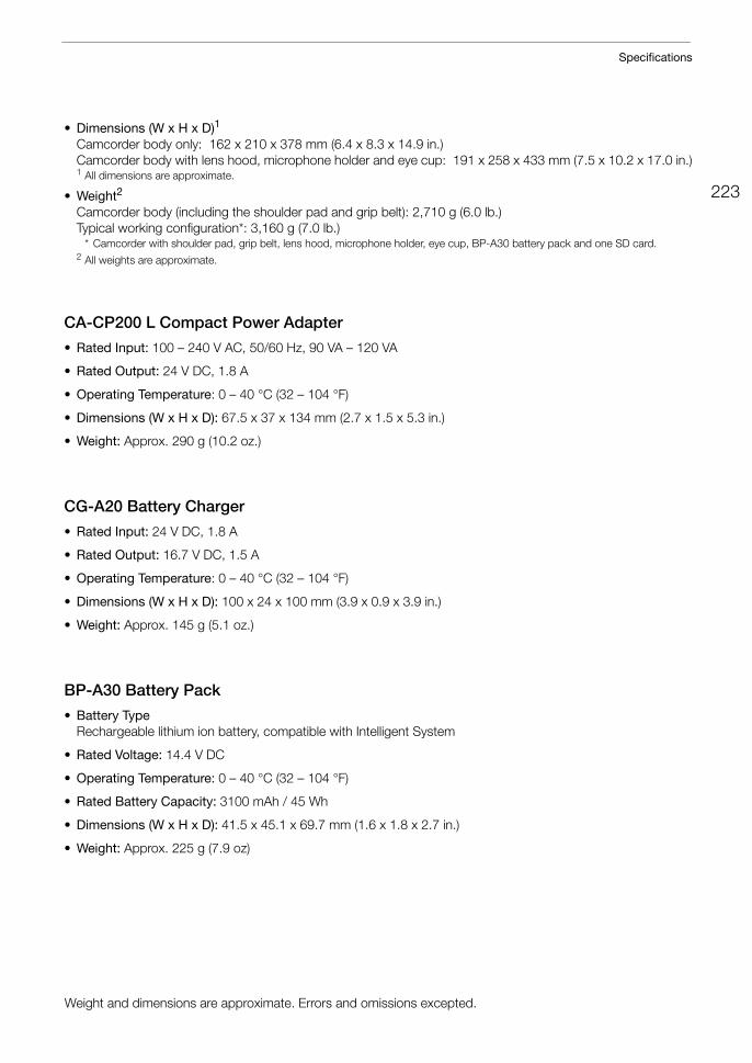
223
Specifications
• Dimensions (W x H x D)1
Camcorder body only: 162 x 210 x 378 mm (6.4 x 8.3 x 14.9 in.)Camcorder body with lens hood, microphone holder and eye cup: 191 x 258 x 433 mm (7.5 x 10.2 x 17.0 in.)1 All dimensions are approximate.
• Weight2
Camcorder body (including the shoulder pad and grip belt): 2,710 g (6.0 lb.)Typical working configuration*: 3,160 g (7.0 lb.)
* Camcorder with shoulder pad, grip belt, lens hood, microphone holder, eye cup, BP-A30 battery pack and one SD card.2 All weights are approximate.
CA-CP200 L Compact Power Adapter
• Rated Input: 100 – 240 V AC, 50/60 Hz, 90 VA – 120 VA
• Rated Output: 24 V DC, 1.8 A
• Operating Temperature: 0 – 40 °C (32 – 104 °F)
• Dimensions (W x H x D): 67.5 x 37 x 134 mm (2.7 x 1.5 x 5.3 in.)
• Weight: Approx. 290 g (10.2 oz.)
CG-A20 Battery Charger
• Rated Input: 24 V DC, 1.8 A
• Rated Output: 16.7 V DC, 1.5 A
• Operating Temperature: 0 – 40 °C (32 – 104 °F)
• Dimensions (W x H x D): 100 x 24 x 100 mm (3.9 x 0.9 x 3.9 in.)
• Weight: Approx. 145 g (5.1 oz.)
BP-A30 Battery Pack
• Battery TypeRechargeable lithium ion battery, compatible with Intelligent System
• Rated Voltage: 14.4 V DC
• Operating Temperature: 0 – 40 °C (32 – 104 °F)
• Rated Battery Capacity: 3100 mAh / 45 Wh
• Dimensions (W x H x D): 41.5 x 45.1 x 69.7 mm (1.6 x 1.8 x 2.7 in.)
• Weight: Approx. 225 g (7.9 oz)
Weight and dimensions are approximate. Errors and omissions excepted.
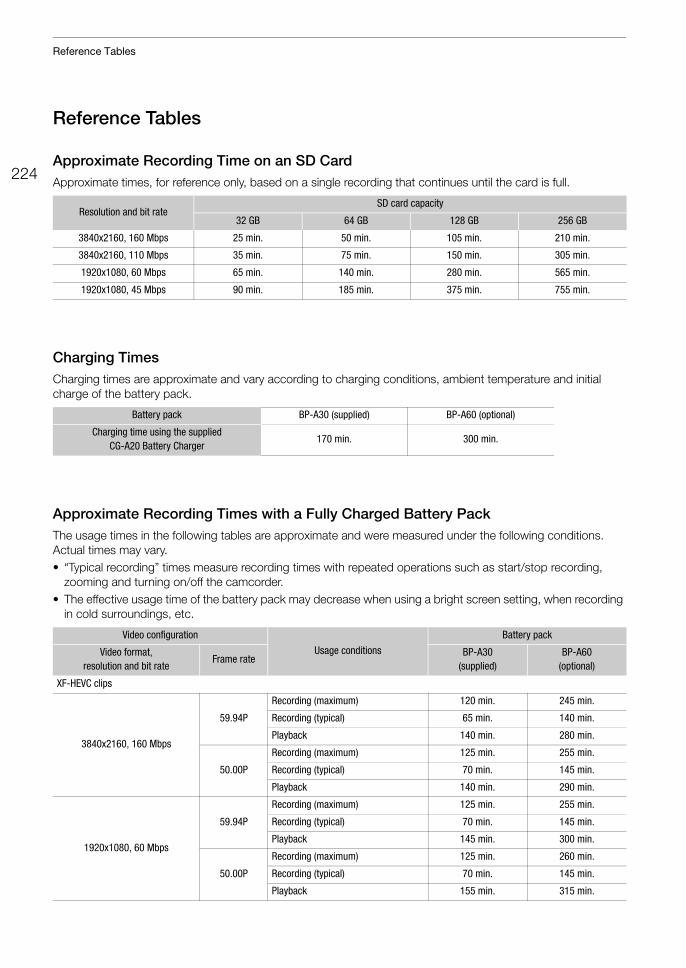
Reference Tables
224
Reference Tables
Approximate Recording Time on an SD CardApproximate times, for reference only, based on a single recording that continues until the card is full.
Charging TimesCharging times are approximate and vary according to charging conditions, ambient temperature and initial charge of the battery pack.
Approximate Recording Times with a Fully Charged Battery PackThe usage times in the following tables are approximate and were measured under the following conditions. Actual times may vary.• “Typical recording” times measure recording times with repeated operations such as start/stop recording,
zooming and turning on/off the camcorder.• The effective usage time of the battery pack may decrease when using a bright screen setting, when recording
in cold surroundings, etc.
Resolution and bit rateSD card capacity
32 GB 64 GB 128 GB 256 GB
3840x2160, 160 Mbps 25 min. 50 min. 105 min. 210 min.
3840x2160, 110 Mbps 35 min. 75 min. 150 min. 305 min.
1920x1080, 60 Mbps 65 min. 140 min. 280 min. 565 min.
1920x1080, 45 Mbps 90 min. 185 min. 375 min. 755 min.
Battery pack BP-A30 (supplied) BP-A60 (optional)
Charging time using the supplied CG-A20 Battery Charger
170 min. 300 min.
Video configuration
Usage conditions
Battery pack
Video format, resolution and bit rate
Frame rateBP-A30
(supplied)BP-A60
(optional)
XF-HEVC clips
3840x2160, 160 Mbps
59.94P
Recording (maximum) 120 min. 245 min.
Recording (typical) 65 min. 140 min.
Playback 140 min. 280 min.
50.00P
Recording (maximum) 125 min. 255 min.
Recording (typical) 70 min. 145 min.
Playback 140 min. 290 min.
1920x1080, 60 Mbps
59.94P
Recording (maximum) 125 min. 255 min.
Recording (typical) 70 min. 145 min.
Playback 145 min. 300 min.
50.00P
Recording (maximum) 125 min. 260 min.
Recording (typical) 70 min. 145 min.
Playback 155 min. 315 min.

225
Reference Tables
XF-AVC clips
1920x1080, 45 Mbps
59.94P
Recording (maximum) 135 min. 280 min.
Recording (typical) 80 min. 165 min.
Playback 155 min. 325 min.
50.00P
Recording (maximum) 135 min. 285 min.
Recording (typical) 80 min. 165 min.
Playback 160 min. 340 min.
Video configuration
Usage conditions
Battery pack
Video format, resolution and bit rate
Frame rateBP-A30
(supplied)BP-A60
(optional)
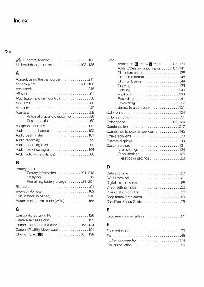
226
(Ethernet) terminal . . . . . . . . . . . . . . . . . . .159× (headphone) terminal . . . . . . . . . . . . .103, 136
AAbroad, using the camcorder . . . . . . . . . . . . .217Access point . . . . . . . . . . . . . . . . . . . . . .153, 156Accessories . . . . . . . . . . . . . . . . . . . . . . . . . . .218AE shift . . . . . . . . . . . . . . . . . . . . . . . . . . . . . . .61AGC (automatic gain control) . . . . . . . . . . . . . . .56AGC limit . . . . . . . . . . . . . . . . . . . . . . . . . . . . . .56Air vents . . . . . . . . . . . . . . . . . . . . . . . . . . . . . .49Aperture . . . . . . . . . . . . . . . . . . . . . . . . . . . . . .59
Automatic aperture (auto iris) . . . . . . . . .59Push auto iris . . . . . . . . . . . . . . . . . . . . .60
Assignable buttons . . . . . . . . . . . . . . . . . . . . .117Audio output channels . . . . . . . . . . . . . . . . . . .150Audio peak limiter . . . . . . . . . . . . . . . . . . . . . .101Audio recording . . . . . . . . . . . . . . . . . . . . . . . . .95Audio recording level . . . . . . . . . . . . . . . . . . . . .99Audio reference signal . . . . . . . . . . . . . . . . . . .104AWB (auto white balance) . . . . . . . . . . . . . . . . .66
BBattery pack
Battery information . . . . . . . . . . . .201, 219Charging . . . . . . . . . . . . . . . . . . . . . . . .19Remaining battery charge . . . . . . . .21, 201
Bit rate . . . . . . . . . . . . . . . . . . . . . . . . . . . . . . . .51Browser Remote . . . . . . . . . . . . . . . . . . . . . . .162Built-in backup battery . . . . . . . . . . . . . . . . . . .216Button connection mode (WPS) . . . . . . . . . . . .156
CCamcorder settings file . . . . . . . . . . . . . . . . . .129Camera Access Point . . . . . . . . . . . . . . . . . . .155Canon Log 3 (gamma curve) . . . . . . . . . . .63, 124Canon XF Utility (download) . . . . . . . . . . . . . . .151Check marks (%) . . . . . . . . . . . . . . . . . .107, 139
ClipsAdding an $ mark/% mark . . . .107, 139Adding/Deleting shot marks . . . . .107, 141Clip information . . . . . . . . . . . . . . . . . .138Clip name format . . . . . . . . . . . . . . . . . .48Clip numbering . . . . . . . . . . . . . . . . . . . .48Copying . . . . . . . . . . . . . . . . . . . . . . . .139Deleting . . . . . . . . . . . . . . . . . . . . . . . .140Playback . . . . . . . . . . . . . . . . . . . . . . .133Recording . . . . . . . . . . . . . . . . . . . . . . .41Recovering . . . . . . . . . . . . . . . . . . . . . . .37Saving to a computer . . . . . . . . . . . . . .151
Color bars . . . . . . . . . . . . . . . . . . . . . . . . . . . .104Color sampling . . . . . . . . . . . . . . . . . . . . . . . . .51Color space . . . . . . . . . . . . . . . . . . . . . . . .63, 124Condensation . . . . . . . . . . . . . . . . . . . . . . . . .217Connection to external devices . . . . . . . . . . . .145Conversion lens . . . . . . . . . . . . . . . . . . . . . . . . .73Custom displays . . . . . . . . . . . . . . . . . . . . . . . .44Custom picture . . . . . . . . . . . . . . . . . . . . . . . .121
Main settings . . . . . . . . . . . . . . . . . . . .124Other settings . . . . . . . . . . . . . . . . . . . .125Preset color settings . . . . . . . . . . . . . . . .63
DDate and time . . . . . . . . . . . . . . . . . . . . . . . . . .23DC IN terminal . . . . . . . . . . . . . . . . . . . . . . . . . .21Digital tele-converter . . . . . . . . . . . . . . . . . . . . .68Direct setting mode . . . . . . . . . . . . . . . . . . . . . .52Double slot recording . . . . . . . . . . . . . . . . . . . . .36Drop frame (time code) . . . . . . . . . . . . . . . . . . .89Dual Pixel Focus Guide . . . . . . . . . . . . . . . . . . .75
EExposure compensation . . . . . . . . . . . . . . . . . .61
FFace detection . . . . . . . . . . . . . . . . . . . . . . . . . .79Fan . . . . . . . . . . . . . . . . . . . . . . . . . . . . . . . . . .49FEC error correction . . . . . . . . . . . . . . . . . . . .174Flicker reduction . . . . . . . . . . . . . . . . . . . . . . . .55
Index
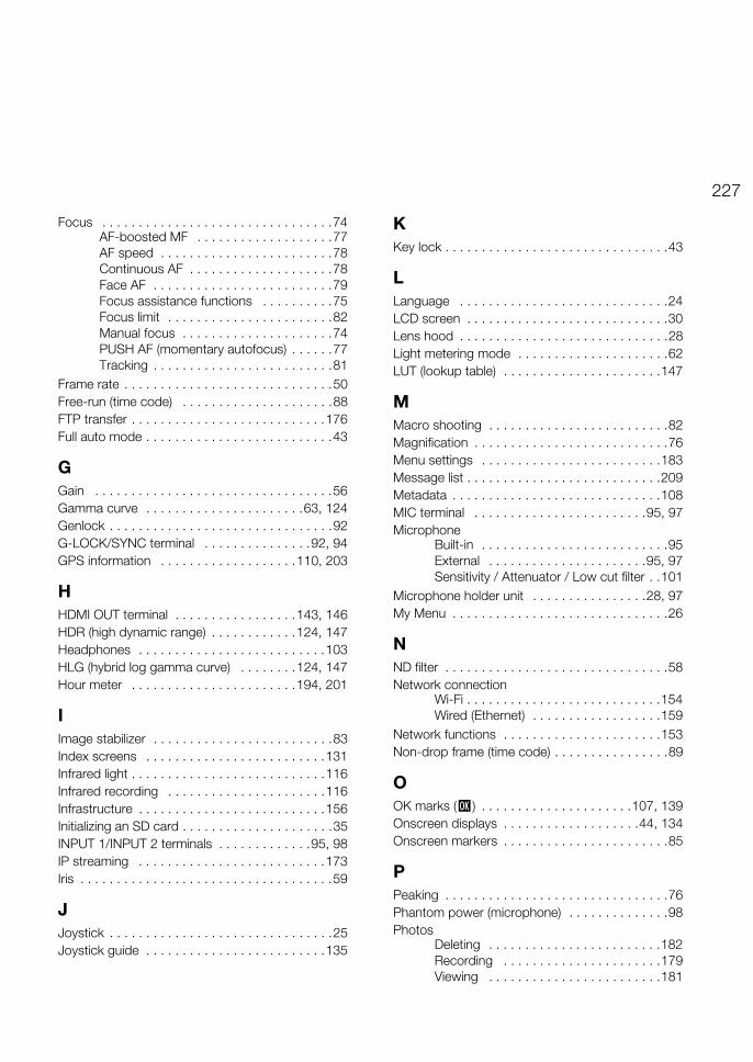
227
Focus . . . . . . . . . . . . . . . . . . . . . . . . . . . . . . . .74AF-boosted MF . . . . . . . . . . . . . . . . . . .77AF speed . . . . . . . . . . . . . . . . . . . . . . . .78Continuous AF . . . . . . . . . . . . . . . . . . . .78Face AF . . . . . . . . . . . . . . . . . . . . . . . . .79Focus assistance functions . . . . . . . . . .75Focus limit . . . . . . . . . . . . . . . . . . . . . . .82Manual focus . . . . . . . . . . . . . . . . . . . . .74PUSH AF (momentary autofocus) . . . . . .77Tracking . . . . . . . . . . . . . . . . . . . . . . . . .81
Frame rate . . . . . . . . . . . . . . . . . . . . . . . . . . . . .50Free-run (time code) . . . . . . . . . . . . . . . . . . . . .88FTP transfer . . . . . . . . . . . . . . . . . . . . . . . . . . .176Full auto mode . . . . . . . . . . . . . . . . . . . . . . . . . .43
GGain . . . . . . . . . . . . . . . . . . . . . . . . . . . . . . . . .56Gamma curve . . . . . . . . . . . . . . . . . . . . . .63, 124Genlock . . . . . . . . . . . . . . . . . . . . . . . . . . . . . . .92G-LOCK/SYNC terminal . . . . . . . . . . . . . . .92, 94GPS information . . . . . . . . . . . . . . . . . . .110, 203
HHDMI OUT terminal . . . . . . . . . . . . . . . . .143, 146HDR (high dynamic range) . . . . . . . . . . . .124, 147Headphones . . . . . . . . . . . . . . . . . . . . . . . . . .103HLG (hybrid log gamma curve) . . . . . . . .124, 147Hour meter . . . . . . . . . . . . . . . . . . . . . . .194, 201
IImage stabilizer . . . . . . . . . . . . . . . . . . . . . . . . .83Index screens . . . . . . . . . . . . . . . . . . . . . . . . .131Infrared light . . . . . . . . . . . . . . . . . . . . . . . . . . .116Infrared recording . . . . . . . . . . . . . . . . . . . . . .116Infrastructure . . . . . . . . . . . . . . . . . . . . . . . . . .156Initializing an SD card . . . . . . . . . . . . . . . . . . . . .35INPUT 1/INPUT 2 terminals . . . . . . . . . . . . .95, 98IP streaming . . . . . . . . . . . . . . . . . . . . . . . . . .173Iris . . . . . . . . . . . . . . . . . . . . . . . . . . . . . . . . . . .59
JJoystick . . . . . . . . . . . . . . . . . . . . . . . . . . . . . . .25Joystick guide . . . . . . . . . . . . . . . . . . . . . . . . .135
KKey lock . . . . . . . . . . . . . . . . . . . . . . . . . . . . . . .43
LLanguage . . . . . . . . . . . . . . . . . . . . . . . . . . . . .24LCD screen . . . . . . . . . . . . . . . . . . . . . . . . . . . .30Lens hood . . . . . . . . . . . . . . . . . . . . . . . . . . . . .28Light metering mode . . . . . . . . . . . . . . . . . . . . .62LUT (lookup table) . . . . . . . . . . . . . . . . . . . . . .147
MMacro shooting . . . . . . . . . . . . . . . . . . . . . . . . .82Magnification . . . . . . . . . . . . . . . . . . . . . . . . . . .76Menu settings . . . . . . . . . . . . . . . . . . . . . . . . .183Message list . . . . . . . . . . . . . . . . . . . . . . . . . . .209Metadata . . . . . . . . . . . . . . . . . . . . . . . . . . . . .108MIC terminal . . . . . . . . . . . . . . . . . . . . . . . .95, 97Microphone
Built-in . . . . . . . . . . . . . . . . . . . . . . . . . .95External . . . . . . . . . . . . . . . . . . . . . .95, 97Sensitivity / Attenuator / Low cut filter . .101
Microphone holder unit . . . . . . . . . . . . . . . .28, 97My Menu . . . . . . . . . . . . . . . . . . . . . . . . . . . . . .26
NND filter . . . . . . . . . . . . . . . . . . . . . . . . . . . . . . .58Network connection
Wi-Fi . . . . . . . . . . . . . . . . . . . . . . . . . . .154Wired (Ethernet) . . . . . . . . . . . . . . . . . .159
Network functions . . . . . . . . . . . . . . . . . . . . . .153Non-drop frame (time code) . . . . . . . . . . . . . . . .89
OOK marks ($) . . . . . . . . . . . . . . . . . . . . .107, 139Onscreen displays . . . . . . . . . . . . . . . . . . .44, 134Onscreen markers . . . . . . . . . . . . . . . . . . . . . . .85
PPeaking . . . . . . . . . . . . . . . . . . . . . . . . . . . . . . .76Phantom power (microphone) . . . . . . . . . . . . . .98Photos
Deleting . . . . . . . . . . . . . . . . . . . . . . . .182Recording . . . . . . . . . . . . . . . . . . . . . .179Viewing . . . . . . . . . . . . . . . . . . . . . . . .181
228
PIN code connection mode (WPS) . . . . . . . . . .157Playback
Clips . . . . . . . . . . . . . . . . . . . . . . . . . . .133Photos . . . . . . . . . . . . . . . . . . . . . . . . .181
Power supply . . . . . . . . . . . . . . . . . . . . . . . . . . .19POWER switch . . . . . . . . . . . . . . . . . . . . . . . . .22Powered IS . . . . . . . . . . . . . . . . . . . . . . . . . . . .83Pre-recording . . . . . . . . . . . . . . . . . . . . . . . . .114
RRec run (time code) . . . . . . . . . . . . . . . . . . . . . .88Recording
Clips . . . . . . . . . . . . . . . . . . . . . . . . . . . .41Photos . . . . . . . . . . . . . . . . . . . . . . . . .179
Reference tables (charging, usage and recording times, etc.) . . . . . . . . . . . . . . . . .224
Relay recording . . . . . . . . . . . . . . . . . . . . . . . . .36REMOTE A, REMOTE B terminals . . . . . . . . . . .39Remote controller . . . . . . . . . . . . . . . . . . . . . . .39Remote operation . . . . . . . . . . . . . . . .38, 39, 162Resetting all camcorder settings . . . . . . . . . . .192Resolution (frame size) . . . . . . . . . . . . . . . . . . . .51Reviewing a clip . . . . . . . . . . . . . . . . . . . . . . . .112Running mode (time code) . . . . . . . . . . . . . . . . .88
SSafe area . . . . . . . . . . . . . . . . . . . . . . . . . . . . . .85SD card
Compatible SD cards . . . . . . . . . . . . . . .33Initializing . . . . . . . . . . . . . . . . . . . . . . . .35Inserting/Removing . . . . . . . . . . . . . . . .34Recording method . . . . . . . . . . . . . . . . .36Switching SD card slots . . . . . . . . .35, 132
SDI terminal . . . . . . . . . . . . . . . . . . . . . . . . . . .145Search for access points . . . . . . . . . . . . . . . . .157Shooting frame rate . . . . . . . . . . . . . . . . . . . . .113Shot marks . . . . . . . . . . . . . . . . . . . . . . .107, 141Shoulder pad . . . . . . . . . . . . . . . . . . . . . . . . . . .32Shoulder strap . . . . . . . . . . . . . . . . . . . . . . . . . .31Shutter speed . . . . . . . . . . . . . . . . . . . . . . . . . .53Slow motion recording . . . . . . . . . . . . . . . . . . .113Special recording modes . . . . . . . . . . . . . . . . .113
Specifications . . . . . . . . . . . . . . . . . . . . . . . . .220Status screens . . . . . . . . . . . . . . . . . . . . . . . . .195Synchronization . . . . . . . . . . . . . . . . . . . . . . . . .92System frequency . . . . . . . . . . . . . . . . . . . . . . .50
TTally lamps . . . . . . . . . . . . . . . . . . . . . . . . . . . . .42Terminal covers . . . . . . . . . . . . . . . . . . . . . . . . .31Time code . . . . . . . . . . . . . . . . . . . . . . . . . . . . .88Time code synchronization . . . . . . . . . . . . .93, 94TIME CODE terminal . . . . . . . . . . . . . . . . . .93, 94Tripod . . . . . . . . . . . . . . . . . . . . . . . . . . . . . . . .32Troubleshooting . . . . . . . . . . . . . . . . . . . . . . . .204Turning the camcorder on/off . . . . . . . . . . . . . .22
UUSB terminal . . . . . . . . . . . . . . . . . . . . . . . . . .110User bit . . . . . . . . . . . . . . . . . . . . . . . . . . . . . . .91User memo . . . . . . . . . . . . . . . . . . . . . . . . . . .108User settings (user names/passwords
for Browser Remote) . . . . . . . . . . . . . . . . .162
VVideo configuration . . . . . . . . . . . . . . . . . . . . . .50Video format (XF-HEVC, XF-AVC) . . . . . . . . . . .50Video output configuration . . . . . . . . . . . . . . . .143Viewfinder . . . . . . . . . . . . . . . . . . . . . . . . . .28, 30Volume . . . . . . . . . . . . . . . . . . . . . . . . . . . . . .136
WWaveform monitor . . . . . . . . . . . . . . . . . . . . . .105White balance . . . . . . . . . . . . . . . . . . . . . . . . . .65Wide DR . . . . . . . . . . . . . . . . . . . . . . . . . .63, 124Wireless controller . . . . . . . . . . . . . . . . . . . . . . .38WPS (Wi-Fi Protected Setup) . . . . . . . . . . . . . .156
ZZebra pattern . . . . . . . . . . . . . . . . . . . . . . . . . . .86Zoom . . . . . . . . . . . . . . . . . . . . . . . . . . . . . . . . .68
Customizable grip zoom speed patterns . . . . . . . . . . . . . . . . .70
229
CANON PROFESSIONAL DIGITAL VIDEO EQUIPMENT LIMITED WARRANTY FOR PRODUCTS PURCHASED IN THE UNITED STATESThe limited warranty set forth below is given by Canon U.S.A., Inc. ('Canon USA') with respect to Canon Professional Digital Video Equipment (the 'Equipment') packaged with this limited warranty and purchased in the United States. This limited warranty is only effective upon presentation of your Bill of Sale or other proof of purchase. The Equipment is warranted to the original end-user purchaser, when delivered in new condition in its original container, under normal use against defective materials or workmanship as follows: Parts: Defective parts will be exchanged for new parts or comparable rebuilt parts for a period of ONE YEAR from the date of original purchase. Labor: For a period of ONE YEAR from the date of original purchase, labor will be provided free of charge by Canon USA's factory service centers or designated service facilities located in the United States. When returning Equipment under this warranty, you must pre-pay the shipping charges, and you must enclose a copy of the Bill of Sale or other proof of purchase with a complete explanation of the problem. During the ONE-YEAR warranty period, repairs will be made and the Equipment will be return-shipped to you free of charge. For repairs after the warranty period is over, you will be given an estimate of the cost of repair and an opportunity to approve or disapprove of the repair expense before it is incurred. If you approve, repairs will be made and the Equipment will be returned to you at your risk and expense. If you disapprove, we will return-ship the Equipment to you at no charge to you to an address within the United States.
This limited warranty only applies if the Equipment is used in conjunction with compatible computer equipment and compatible software, as to which items Canon USA will have no responsibility. Canon USA shall have no responsibility under this limited warranty for use of the Equipment in conjunction with incompatible peripheral equipment and/or incompatible software. Non-Canon brand peripheral equipment and software which may be distributed with, or factory loaded on, the Equipment, are sold 'AS IS' without warranty of any kind by Canon USA, including any implied warranty regarding merchantability or fitness for a particular purpose. The sole warranty with respect to such non-Canon brand items is given by the manufacturer or producer thereof. If the Equipment contains a hard disk drive, Canon USA recommends that data stored on that drive be duplicated or backed up to prevent its loss in the event of failure or other malfunction of such drive.
In order to obtain warranty service, please contact the authorized Canon retail dealer from whom you purchased the Equipment or contact the CANON INFORMATION CENTER AT 855-CINE-EOS (855-246-3367) or on the Internet at pro.usa.canon.com/support. You will be directed to the nearest service facility for your Equipment.
This Limited Warranty covers all defects encountered in normal use of the Equipment and does not apply in the following cases:
A. Loss or damage to the Equipment due to abuse, mishandling, accident, improper maintenance, use of non-Canon accessories or failure to follow operating, maintenance or environmental instructions prescribed in Canon USA's user's manual;
B. If the Equipment is defective as a result of leaking batteries, sand, dirt or water damage;C. If defects or damages are caused by the use of parts or supplies (other than those sold by Canon USA) that cause damage to the Equipment or
that cause abnormally frequent service calls or service problems;D. If defects or damages are caused by service other than Canon USA's factory service centers or authorized service facilities;E. Any internal modification to product hardware or firmware;F. Any applicable fee for Maintenance of the Equipment;G. If the Equipment has had its serial number or dating altered or removed.
This Limited Warranty does not apply to Equipment purchased outside the United States. This Limited Warranty does not apply to accessories or consumables for the Equipment, which are sold "AS IS", without warranty of any kind by Canon USA. Please retain this warranty card and your Bill of Sale as a permanent record of your purchase. This card ensures that you are contacted promptly should there be a safety inspection, modification or product recall under applicable laws or regulations.
NO IMPLIED WARRANTY, INCLUDING MERCHANTABILITY AND FITNESS FOR A PARTICULAR PURPOSE APPLIES TO THIS EQUIPMENT AFTER THE APPLICABLE PERIOD OF EXPRESS WARRANTY OR GUARANTY (EXCEPT AS MENTIONED ABOVE) GIVEN BY ANY PERSON, FIRM OR CORPORATION WITH RESPECT TO THIS EQUIPMENT SHALL BIND THE UNDERSIGNED (SOME STATES DO NOT ALLOW LIMITATIONS ON HOW LONG AN IMPLIED WARRANTY LASTS, SO THE ABOVE LIMITATION OR EXCLUSION MAY NOT APPLY TO YOU). CANON USA SHALL NOT BE LIABLE FOR LOSS OF REVENUES OR PROFITS, EXPENSE FOR SUBSTITUTE EQUIPMENT OR SERVICE, STORAGE CHARGES, LOSS OR CORRUPTION OF DATA, INCLUDING WITHOUT LIMITATION, LOSS OR CORRUPTION OF DATA STORED ON THE EQUIPMENT'S HARD DRIVE, OR ANY OTHER SPECIAL, INCIDENTAL OR CONSEQUENTIAL DAMAGES CAUSED BY THE USE, MISUSE OR INABILITY TO USE THE EQUIPMENT, REGARDLESS OF THE LEGAL THEORY ON WHICH THE CLAIM IS BASED, AND EVEN IF CANON USA HAS BEEN ADVISED OF THE POSSIBILITY OF SUCH DAMAGES. NOR SHALL RECOVERY OF ANY KIND AGAINST CANON USA BE GREATER THAN THE PURCHASE PRICE OF THE EQUIPMENT SOLD BY CANON USA AND CAUSING THE ALLEGED DAMAGE. WITHOUT LIMITING THE FOREGOING, YOU ASSUME ALL RISK AND LIABILITY FOR LOSS, DAMAGE OR INJURY TO YOU AND YOUR PROPERTY AND TO OTHERS AND THEIR PROPERTY ARISING OUT OF USE, MISUSE OR INABILITY TO USE THE EQUIPMENT NOT CAUSED DIRECTLY BY THE NEGLIGENCE OF CANON USA (SOME STATES DO NOT ALLOW THE EXCLUSION OR LIMITATION OF INCIDENTAL OR CONSEQUENTIAL DAMAGES, SO THE ABOVE LIMITATION MAY NOT APPLY TO YOU).THIS WARRANTY SHALL NOT EXTEND TO ANYONE OTHER THAN THE ORIGINAL PURCHASER OF THIS EQUIPMENT OR THE PERSON FOR WHOM IT WAS PURCHASED AS A GIFT.
This warranty gives you specific legal rights, and you may also have other rights which vary from state to state.
CANON U.S.A., INC.
USA&
230
CANON PROFESSIONAL DIGITAL VIDEO EQUIPMENT LIMITED WARRANTY FOR PRODUCTS PURCHASED IN CANADAThe limited warranty set forth below is given by Canon Canada Inc. ('Canon Canada') with respect to Canon Professional Digital Video Equipment (the 'Equipment') packaged with this limited warranty and purchased in Canada. This limited warranty is only effective upon presentation of your Bill of Sale or other proof of purchase. The Equipment is warranted to the original end-user purchaser, when delivered in new condition in its original container, under normal use against defective materials or workmanship as follows: Parts: Defective parts will be exchanged for new parts or comparable rebuilt parts for a period of ONE YEAR from the date of original purchase. Labor: For a period of ONE YEAR from the date of original purchase, labor will be provided free of charge by Canon Canada's factory service center or designated service facilities located in Canada. When returning Equipment under this warranty, you must pre-pay the shipping charges, and you must enclose a copy of the Bill of Sale or other proof of purchase with a complete explanation of the problem. During the ONE-YEAR warranty period, repairs will be made and the Equipment will be return-shipped to you free of charge. For repairs after the warranty period is over, you will be given an estimate of the cost of repair and an opportunity to approve or disapprove of the repair expense before it is incurred. If you approve, repairs will be made and the Equipment will be returned to you at your risk and expense. If you disapprove, we will return-ship the Equipment to you at no charge to you to an address within Canada.
This limited warranty only applies if the Equipment is used in conjunction with compatible computer equipment and compatible software, as to which items Canon Canada will have no responsibility. Canon Canada shall have no responsibility under this limited warranty for use of the Equipment in conjunction with incompatible peripheral equipment and/or incompatible software. Non-Canon brand peripheral equipment and software which may be distributed with, or factory loaded on, the Equipment, are sold 'AS IS' without warranty of any kind by Canon Canada, including any implied warranty or condition regarding merchantability or fitness for a particular purpose. The sole warranty with respect to such non-Canon brand items is given by the manufacturer or producer thereof. If the Equipment contains a hard disk drive, Canon Canada recommends that data stored on that drive be duplicated or backed up to prevent its loss in the event of failure or other malfunction of such drive.
In order to obtain warranty service, please contact the authorized Canon retail dealer from whom you purchased the Equipment or contact the CANON PROFESSIONAL SERVICE CENTRE 1-800-667-2666 or on the Internet at www.canon.ca/pro. You will be directed to the nearest service facility for your Equipment.
This Limited Warranty covers all defects encountered in normal use of the Equipment and does not apply in the following cases:
A. Loss or damage to the Equipment due to abuse, mishandling, accident, improper maintenance, use of non-Canon accessories or failure to follow operating, maintenance or environmental instructions prescribed in Canon Canada's user's manual;
B. If the Equipment is defective as a result of leaking batteries, sand, dirt or water damage;C. If defects or damages are caused by the use of parts or supplies (other than those sold by Canon Canada) that cause damage to the Equipment
or that cause abnormally frequent service calls or service problems;D. If defects or damages are caused by service other than Canon Canada's factory service centers or authorized service facilities;E. Any internal modification to product hardware or firmware;F. Any applicable fee for Maintenance of the Equipment;G. If the Equipment has had its serial number or dating altered or removed.
This Limited Warranty does not apply to Equipment purchased outside Canada. This Limited Warranty does not apply to accessories or consumables for the Equipment, which are sold "AS IS", without warranty of any kind by Canon Canada. Please retain this warranty card and your Bill of Sale as a permanent record of your purchase. This card ensures that you are contacted promptly should there be a safety inspection, modification or product recall under applicable laws or regulations.
NO IMPLIED WARRANTY OR CONDITION, INCLUDING MERCHANTABILITY AND FITNESS FOR A PARTICULAR PURPOSE APPLIES TO THIS EQUIPMENT AFTER THE APPLICABLE PERIOD OF EXPRESS WARRANTY OR GUARANTY (EXCEPT AS MENTIONED ABOVE) GIVEN BY ANY PERSON, FIRM OR CORPORATION WITH RESPECT TO THIS EQUIPMENT SHALL BIND THE UNDERSIGNED (SOME PROVINCES DO NOT ALLOW LIMITATIONS ON HOW LONG AN IMPLIED WARRANTY OR CONDITION LASTS, SO THE ABOVE LIMITATION OR EXCLUSION MAY NOT APPLY TO YOU). CANON CANADA SHALL NOT BE LIABLE FOR LOSS OF REVENUES OR PROFITS, EXPENSE FOR SUBSTITUTE EQUIPMENT OR SERVICE, STORAGE CHARGES, LOSS OR CORRUPTION OF DATA, INCLUDING WITHOUT LIMITATION, LOSS OR CORRUPTION OF DATA STORED ON THE EQUIPMENT'S HARD DRIVE, OR ANY OTHER SPECIAL, INCIDENTAL OR CONSEQUENTIAL DAMAGES CAUSED BY THE USE, MISUSE OR INABILITY TO USE THE EQUIPMENT, REGARDLESS OF THE LEGAL THEORY ON WHICH THE CLAIM IS BASED, AND EVEN IF CANON CANADA HAS BEEN ADVISED OF THE POSSIBILITY OF SUCH DAMAGES. NOR SHALL RECOVERY OF ANY KIND AGAINST CANON CANADA BE GREATER THAN THE PURCHASE PRICE OF THE EQUIPMENT SOLD BY CANON CANADA AND CAUSING THE ALLEGED DAMAGE. WITHOUT LIMITING THE FOREGOING, YOU ASSUME ALL RISK AND LIABILITY FOR LOSS, DAMAGE OR INJURY TO YOU AND YOUR PROPERTY AND TO OTHERS AND THEIR PROPERTY ARISING OUT OF USE, MISUSE OR INABILITY TO USE THE EQUIPMENT NOT CAUSED DIRECTLY BY THE NEGLIGENCE OF CANON CANADA (SOME PROVINCES DO NOT ALLOW THE EXCLUSION OR LIMITATION OF INCIDENTAL OR CONSEQUENTIAL DAMAGES, SO THE ABOVE LIMITATION MAY NOT APPLY TO YOU). THIS WARRANTY SHALL NOT EXTEND TO ANYONE OTHER THAN THE ORIGINAL PURCHASER OF THIS EQUIPMENT OR THE PERSON FOR WHOM IT WAS PURCHASED AS A GIFT.
This warranty gives you specific legal rights, and you may also have other rights which vary from province to province.
CANON CANADA INC.
CANADA& l
PUB. DIE-0524-000B© CANON INC. 2019
The information in this document is verified as of February 2019. Subject to change without notice.Visit your local Canon website to download the latest version.
USA http://pro.usa.canon.com CANON U.S.A., INC.http://pro.usa.canon.com/support
(855) CINE-EOS (855-246-3367) (USA only)
UNITED KINGDOMCanon UK LtdUnit 160, Centennial Park, Centennial Avenue,Elstree, Hertfordshire, WD6 3SG
020-7660-0186
Canon Inc. 30-2, Shimomaruko 3-chome, Ohta-ku, Tokyo 146-8501, JapanCanon Europa N.V. Bovenkerkerweg 59, 1185 XB Amstelveen, The Netherlands http://www.canon-europe.com