42-300, 304, 308, 312, 313 Series Press - Global Industrial
15
Model 42 Series air operated 3/14 1 724 Robbins Road Grand Haven, MI 49417 Phone: 616-842-7110 800-937-3253 Fax: 616-842-0859 800-846-3253 Web: www.dakecorp.com E-mail: [email protected] [email protected] INSTRUCTIONS AND PARTS LIST FOR 42 Series Press for Models 300, 304, 308, 312, 313 25 ton 50 ton 75 ton 150 ton Air-Draulic Press 8-075 shown electdraulic II
-
Upload
khangminh22 -
Category
Documents
-
view
0 -
download
0
Transcript of 42-300, 304, 308, 312, 313 Series Press - Global Industrial

Model 42 Series air operated 3/14 1
724 Robbins Road Grand Haven, MI 49417 Phone: 616-842-7110 800-937-3253 Fax: 616-842-0859 800-846-3253 Web: www.dakecorp.com E-mail: [email protected] [email protected]
INSTRUCTIONS AND PARTS LIST FOR 42 Series Press for Models
300, 304, 308, 312, 313 25 ton 50 ton 75 ton 150 ton
Air-Draulic Press
8-075 shown electdraulic II

Model 42 Series air operated 3/14 2
INSTRUCTIONS AND PARTS LIST FOR Model 42 Series Air-Draulic Presses
WARNING LABELS
To the left is the safety Alert symbol. When you see these safety alert symbols on your press, be alert to the potential for personal injury. Follow recommended precautions and safe operating practices.
SETTING UP THE PRESS FOR OPERATION
NOTE: The press should set on a level floor with t he base angles touching the floor at all points. Use shims where necessary.
1. Connect airline into street elbow (Item No. 136) at right hand side of control block. NOTE: Avoid restrictions in air supply line to ins ure ample air-to-air motor. To ensure maximum performance the air supply line should be ½ ” pipe line if the distance from the compressor to press is 0-30 feet, ¾” line 30-60 fee t, and 1” if greater than 60 feet. NOTE: AIR MUST BE MOISTURE FREE. WATER IN AIR LIN E WILL CORRODE THIS PRESS BEYOND REPAIR.
2. Oil Requirements: Fill reservoir with Mobil DTE 24 or equivalent oil thru pipeline in back of press at pipe coupling by removing pipe plug. NOTE: Make sure the air-source is removed from the reservoir prior to removal of plug. Oil level may be checked (with ram up) by removing the pipe plug on the right side of reservoir near the f ront. Replace plug before operating the press.
Model 42-301 25-ton presses use 6 quarts Model 42-304 50-ton presses use 8 quarts Model 42-308 75-ton presses use 10 quarts Model 42-312 150-ton presses use 20 quarts.
3. Attach nose piece to ram by inserting shank into ram and tightening the set screw.
4. CAUTION! Place the hoist crank on the lift drum shaft. Turn the hoist crank to relieve the pressure on the table pins. Keeping tension on the hoist crank, remove the table pins one at a time. After removing the tables pins, turn the crank running the table channels from top to bottom. Check to make sure the cable is tracking correctly. The cable should be on each of the two upper pulleys and should track back and forth on the cable drum. Always place table pins under the table channels before releasing the hoist crank when positioning the table channels for cable tracking, servicing, or set-up for desired work opening. If a tracking problem exists, contact the Dake factory for instructions. Be sure all table pins are fully inserted in place before applying pressure. Always remove or release pressure on the cable before pressure is applied.
Model 42 Series air operated 3/14 3
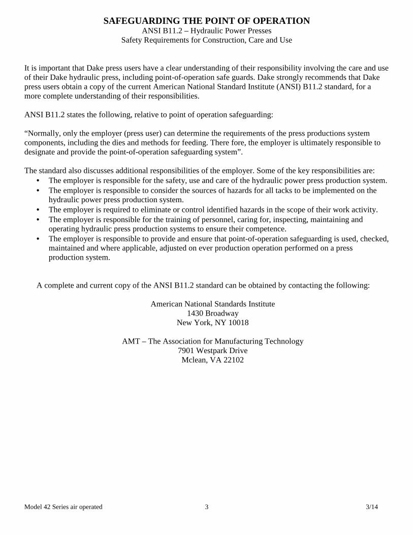
SAFEGUARDING THE POINT OF OPERATION ANSI B11.2 – Hydraulic Power Presses
Safety Requirements for Construction, Care and Use
It is important that Dake press users have a clear understanding of their responsibility involving the care and use of their Dake hydraulic press, including point-of-operation safe guards. Dake strongly recommends that Dake press users obtain a copy of the current American National Standard Institute (ANSI) B11.2 standard, for a more complete understanding of their responsibilities. ANSI B11.2 states the following, relative to point of operation safeguarding: “Normally, only the employer (press user) can determine the requirements of the press productions system components, including the dies and methods for feeding. There fore, the employer is ultimately responsible to designate and provide the point-of-operation safeguarding system”. The standard also discusses additional responsibilities of the employer. Some of the key responsibilities are:
• The employer is responsible for the safety, use and care of the hydraulic power press production system. • The employer is responsible to consider the sources of hazards for all tacks to be implemented on the
hydraulic power press production system. • The employer is required to eliminate or control identified hazards in the scope of their work activity. • The employer is responsible for the training of personnel, caring for, inspecting, maintaining and
operating hydraulic press production systems to ensure their competence. • The employer is responsible to provide and ensure that point-of-operation safeguarding is used, checked,
maintained and where applicable, adjusted on ever production operation performed on a press production system.
A complete and current copy of the ANSI B11.2 standard can be obtained by contacting the following:
American National Standards Institute 1430 Broadway
New York, NY 10018
AMT – The Association for Manufacturing Technology 7901 Westpark Drive Mclean, VA 22102
Model 42 Series air operated 3/14 4
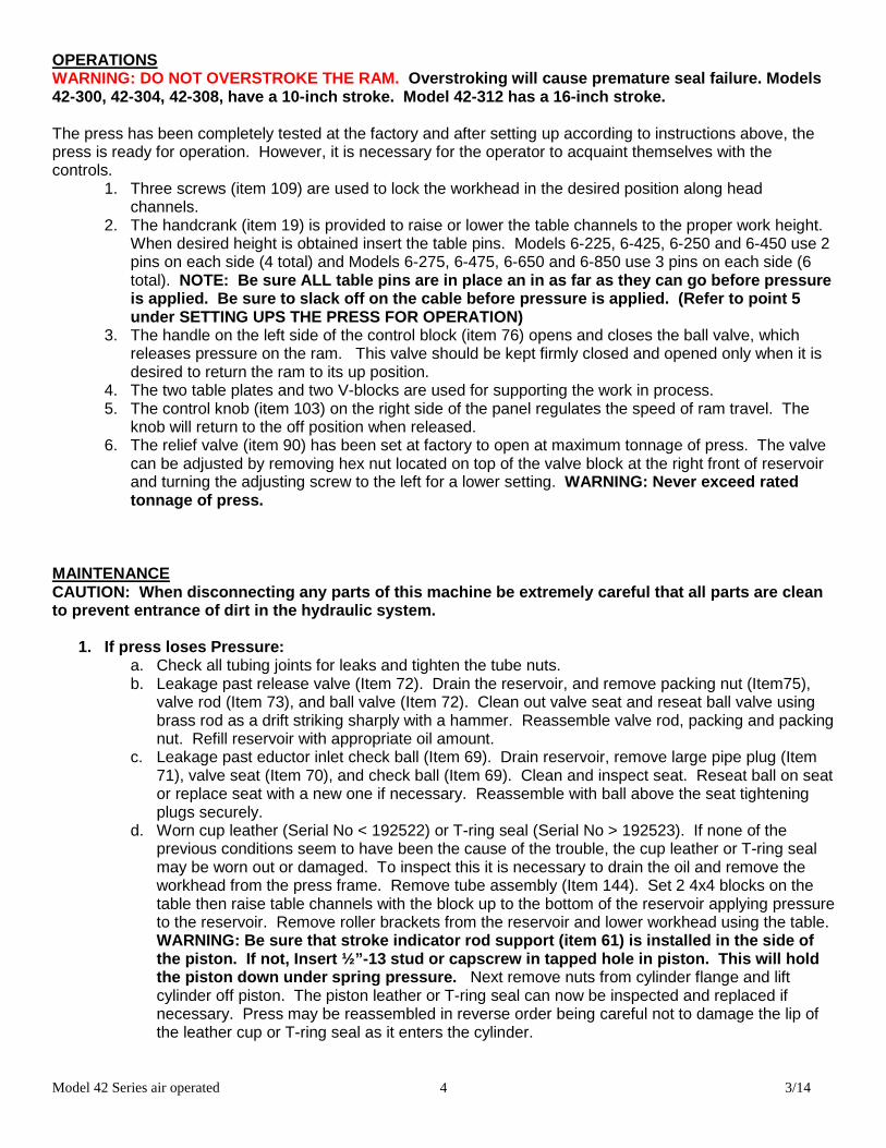
OPERATIONS WARNING: DO NOT OVERSTROKE THE RAM. Overstroking will cause premature seal failure. Models 42-300, 42-304, 42-308, have a 10-inch stroke. Model 42-312 has a 16-inch stroke. The press has been completely tested at the factory and after setting up according to instructions above, the press is ready for operation. However, it is necessary for the operator to acquaint themselves with the controls.
1. Three screws (item 109) are used to lock the workhead in the desired position along head channels.
2. The handcrank (item 19) is provided to raise or lower the table channels to the proper work height. When desired height is obtained insert the table pins. Models 6-225, 6-425, 6-250 and 6-450 use 2 pins on each side (4 total) and Models 6-275, 6-475, 6-650 and 6-850 use 3 pins on each side (6 total). NOTE: Be sure ALL table pins are in place an in as far as they can go before pressure is applied. Be sure to slack off on the cable befo re pressure is applied. (Refer to point 5 under SETTING UPS THE PRESS FOR OPERATION)
3. The handle on the left side of the control block (item 76) opens and closes the ball valve, which releases pressure on the ram. This valve should be kept firmly closed and opened only when it is desired to return the ram to its up position.
4. The two table plates and two V-blocks are used for supporting the work in process. 5. The control knob (item 103) on the right side of the panel regulates the speed of ram travel. The
knob will return to the off position when released. 6. The relief valve (item 90) has been set at factory to open at maximum tonnage of press. The valve
can be adjusted by removing hex nut located on top of the valve block at the right front of reservoir and turning the adjusting screw to the left for a lower setting. WARNING: Never exceed rated tonnage of press.
MAINTENANCE CAUTION: When disconnecting any parts of this mach ine be extremely careful that all parts are clean to prevent entrance of dirt in the hydraulic system .
1. If press loses Pressure: a. Check all tubing joints for leaks and tighten the tube nuts. b. Leakage past release valve (Item 72). Drain the reservoir, and remove packing nut (Item75),
valve rod (Item 73), and ball valve (Item 72). Clean out valve seat and reseat ball valve using brass rod as a drift striking sharply with a hammer. Reassemble valve rod, packing and packing nut. Refill reservoir with appropriate oil amount.
c. Leakage past eductor inlet check ball (Item 69). Drain reservoir, remove large pipe plug (Item 71), valve seat (Item 70), and check ball (Item 69). Clean and inspect seat. Reseat ball on seat or replace seat with a new one if necessary. Reassemble with ball above the seat tightening plugs securely.
d. Worn cup leather (Serial No < 192522) or T-ring seal (Serial No > 192523). If none of the previous conditions seem to have been the cause of the trouble, the cup leather or T-ring seal may be worn out or damaged. To inspect this it is necessary to drain the oil and remove the workhead from the press frame. Remove tube assembly (Item 144). Set 2 4x4 blocks on the table then raise table channels with the block up to the bottom of the reservoir applying pressure to the reservoir. Remove roller brackets from the reservoir and lower workhead using the table. WARNING: Be sure that stroke indicator rod support (item 61) is installed in the side of the piston. If not, Insert ½”-13 stud or capscrew in tapped hol e in piston. This will hold the piston down under spring pressure. Next remove nuts from cylinder flange and lift cylinder off piston. The piston leather or T-ring seal can now be inspected and replaced if necessary. Press may be reassembled in reverse order being careful not to damage the lip of the leather cup or T-ring seal as it enters the cylinder.
Model 42 Series air operated 3/14 5
2. If press will not develop rated tonnage.
a. Dirt under valve balls. Refer to MAINTENANCE 1 – c above. b. Worn cup leather. Refer to MAINTENANCE 1 – d above. c. Relief valve not set properly. This valve is located on the top side near the right end of the
control block at the front of the reservoir. The valve is set at the factory to bypass oil from the pump back to the reservoir when the press reaches its rated capacity. The load on the spring (Item 91), which governs the pressure at which the valve will bypass oil, is adjusted by turning the screw (Item 90) in to increase pressure or out to decrease pressure. Replace seal (Item 89) and cap nut (Item 88). NOTE: We advise that the relief valve not be tampe red with after it is once set at the capacity of the press.
3. If nothing happens when press is operated.
a. Release valve open. Be sure to have release valve firmly closed when using press. b. If the ram will come down only a fraction of its rated stroke, check the oil level in the reservoir
with the ram at the top of its stroke. It should be visible in the sight window at the side of the reservoir.
4. If press is operating slow.
a. Check air supply line for restrictions to determine if air motors are getting ample supply of air. b. Release valve not closed properly. Release valve must be firmly closed when using the press. c. Wrong hydraulic fluid. After considerable research and tests made with the cooperation of the
pump manufacturer, we recommend Mobil DTE 24 oil or equivalent.
5. If Oil is coming out of the air vent. Drain out the spring chamber by removing the 1/8” pipe plug, which is put in the hub or boss that contains the oil seal where the ram extends out of the reservoir. Once oil is drained, run the press up to full tonnage with pipe plug still out. Excessive oil is a sign that the head seal has been damaged. Refer to Maintenance section 1 item d to replace seal. Replace pipe plug.
6. Excessive leakage around the ram. Drain out the spring chamber as instructed in Maintenance section 5. A small amount of oil in this chamber facilitates lubricating the bushing the ram passes thru and prevents scoring. However, if operation performed on press is spoiled due to slight leakage of oil, remove pipe plug as described in MAINTENANCE 5 and connect tube line to continually drain this chamber.

Mo
del 4
2 S
eries air operated
3/1
4 6
84487 All pins must be inserted before applying any pressure. Read instructions. Mount centered on channel to right of table pins as shown.
84400 Guard workplace to prevent projectiles from reaching operator. Mount ½” below stop block or at eye level centered on flange as shown
67881 Release table rollers before applying pressure. Mount in center of table channel as shown.
84399 Keep fingers out of pin holes. Mount centered on channel to left of table pins as shown.
27823 Mount ½” below block.
84396 Keep hands away from point of operation
84401 Establish solid footing to prevent falls.
84395 High voltage.
76462 Lockout procedure
Model 42 Series air operated 3/14 7
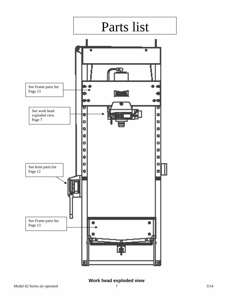
Work head exploded view
Parts list
See hoist parts list Page 12
See work head exploded view Page 7
See Frame parts list Page 13
See Frame parts list Page 13

Model 42 Series air operated 3/14 8
Model 42 Series air operated 3/14 9
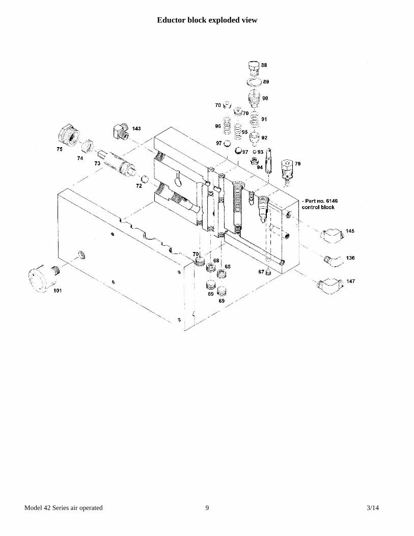
Eductor block exploded view
Model 42 Series air operated 3/14 10
Item Part Name Model 6-225 6-425
Model 6-250 6-450
Model 6-275 6-475
Model 6-650 6-850
Qty
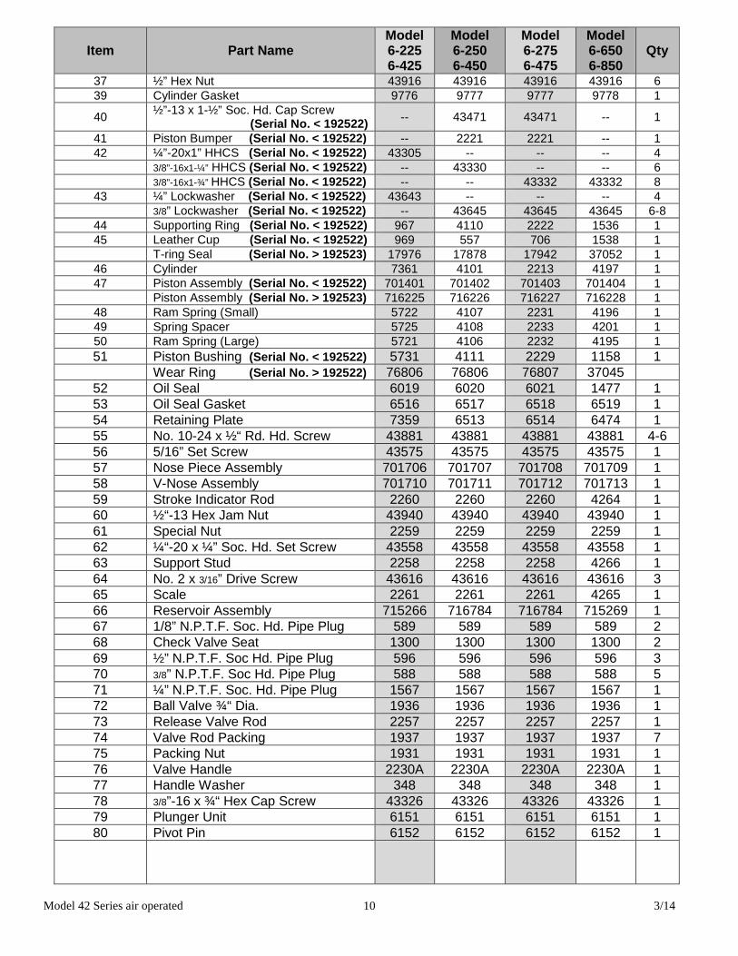
37 ½” Hex Nut 43916 43916 43916 43916 6 39 Cylinder Gasket 9776 9777 9777 9778 1
40 ½”-13 x 1-½” Soc. Hd. Cap Screw (Serial No. < 192522) -- 43471 43471 -- 1
41 Piston Bumper (Serial No. < 192522) -- 2221 2221 -- 1 42 ¼”-20x1” HHCS (Serial No. < 192522) 43305 -- -- -- 4 3/8”-16x1-¼” HHCS (Serial No. < 192522) -- 43330 -- -- 6 3/8”-16x1-¾” HHCS (Serial No. < 192522) -- -- 43332 43332 8
43 ¼” Lockwasher (Serial No. < 192522) 43643 -- -- -- 4 3/8” Lockwasher (Serial No. < 192522) -- 43645 43645 43645 6-8
44 Supporting Ring (Serial No. < 192522) 967 4110 2222 1536 1 45 Leather Cup (Serial No. < 192522) 969 557 706 1538 1 T-ring Seal (Serial No. > 192523) 17976 17878 17942 37052 1
46 Cylinder 7361 4101 2213 4197 1 47 Piston Assembly (Serial No. < 192522) 701401 701402 701403 701404 1 Piston Assembly (Serial No. > 192523) 716225 716226 716227 716228 1
48 Ram Spring (Small) 5722 4107 2231 4196 1 49 Spring Spacer 5725 4108 2233 4201 1 50 Ram Spring (Large) 5721 4106 2232 4195 1 51 Piston Bushing (Serial No. < 192522) 5731 4111 2229 1158 1 Wear Ring (Serial No. > 192522) 76806 76806 76807 37045
52 Oil Seal 6019 6020 6021 1477 1 53 Oil Seal Gasket 6516 6517 6518 6519 1 54 Retaining Plate 7359 6513 6514 6474 1 55 No. 10-24 x ½“ Rd. Hd. Screw 43881 43881 43881 43881 4-6 56 5/16” Set Screw 43575 43575 43575 43575 1 57 Nose Piece Assembly 701706 701707 701708 701709 1 58 V-Nose Assembly 701710 701711 701712 701713 1 59 Stroke Indicator Rod 2260 2260 2260 4264 1 60 ½“-13 Hex Jam Nut 43940 43940 43940 43940 1 61 Special Nut 2259 2259 2259 2259 1 62 ¼“-20 x ¼” Soc. Hd. Set Screw 43558 43558 43558 43558 1 63 Support Stud 2258 2258 2258 4266 1 64 No. 2 x 3/16” Drive Screw 43616 43616 43616 43616 3 65 Scale 2261 2261 2261 4265 1 66 Reservoir Assembly 715266 716784 716784 715269 1 67 1/8” N.P.T.F. Soc. Hd. Pipe Plug 589 589 589 589 2 68 Check Valve Seat 1300 1300 1300 1300 2 69 ½” N.P.T.F. Soc Hd. Pipe Plug 596 596 596 596 3 70 3/8” N.P.T.F. Soc Hd. Pipe Plug 588 588 588 588 5 71 ¼” N.P.T.F. Soc. Hd. Pipe Plug 1567 1567 1567 1567 1 72 Ball Valve ¾“ Dia. 1936 1936 1936 1936 1 73 Release Valve Rod 2257 2257 2257 2257 1 74 Valve Rod Packing 1937 1937 1937 1937 7 75 Packing Nut 1931 1931 1931 1931 1 76 Valve Handle 2230A 2230A 2230A 2230A 1 77 Handle Washer 348 348 348 348 1 78 3/8”-16 x ¾“ Hex Cap Screw 43326 43326 43326 43326 1 79 Plunger Unit 6151 6151 6151 6151 1 80 Pivot Pin 6152 6152 6152 6152 1
Model 42 Series air operated 3/14 11
Item Part Name Model 6-225 6-425
Model 6-250 6-450
Model 6-275 6-475
Model 6-650 6-850
Qty
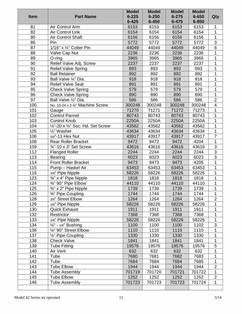
81 Air Control Arm 6153 6153 6153 6153 1 82 Air Control Link 6154 6154 6154 6154 1 85 Air Control Shaft 6156 6156 6156 6156 1 86 Pin 5772 5772 5772 5772 3 87 1/16” x ½” Cotter Pin 44049 44049 44049 44049 6 88 Valve Cap Nut 2236 2236 2236 2236 1 89 O-ring 3965 3965 3965 3965 1 90 Relief Valve Adj, Screw 2237 2237 2237 2237 1 91 Relief Valve Spring 893 893 893 893 1 92 Ball Retainer 892 892 892 892 1 93 Ball Valve ¼” Dia. 918 918 918 918 1 94 Relief Valve Seat 891 891 891 891 1 95 Check Valve Spring 579 579 579 579 1 96 Check Valve Spring 890 890 890 890 1 97 Ball Valve ½” Dia. 586 586 586 586 2 100 No. 10-24 x 2-¾” Machine Screw 300248 300248 300248 300248 4 101 Gauge 71270 71271 71272 71273 1 102 Control Pannel 80743 80743 80743 80743 1 103 Control Knob 2250A 2250A 2250A 2250A 1 104 ¼”-20 x ½” Soc. Hd. Set Screw 43562 43562 43562 43562 1 105 ½” Washer 43634 43634 43634 43634 1 106 5/8”-11 Hex Nut 43917 43917 43917 43917 7 108 Rear Roller Bracket 9472 9472 9472 4204 1 109 ¾”-10 x 3” Set Screw 43616 43616 43616 43616 3 112 Flanged Roller 2244 2244 2244 2244 3 113 Bearing 6023 6023 6023 6023 3 114 Front Roller Bracket 9473 9473 9473 4205 1 115 Pump – Haskel Air 63453 63453 63453 63453 1 116 3/8” Pipe Nipple 58226 58226 58226 58226 1 123 ¾” x 4” Pipe Nipple 1818 1818 1818 1818 1 124 ¾“ 90° Pipe Elbow 44110 44110 44110 44110 1 125 ¾“ x 2” Pipe Nipple 1739 1739 1739 1739 1 126 ¾“ Pipe Coupling 1744 1744 1744 1744 1 128 3/8” Street Elbow 1264 1264 1264 1264 2 129 3/8” Pipe Nipple 58226 58226 58226 58226 1 130 Quick Exhaust 1911 1911 1911 1911 1 132 Restrictor 7368 7368 7368 7368 1 133 3/8” Pipe Nipple 58226 58226 58226 58226 1 134 ¼“ - 1/8” Bushing 1100 1100 1100 1102 3 136 ¼“ 90° Street Elbow 1110 1110 1110 1110 1 137 ¼“ Pipe Coupling 1330 1330 1330 1330 1 138 Check Valve 1841 1841 1841 1841 1 139 Tube Fitting 19576 19576 19576 19576 5 140 Air Vent 632 632 632 632 1 141 Tube 7680 7681 7682 7683 1 142 Tube 7684 7684 7684 7685 1 143 Tube Elbow 1944 1944 1944 1944 2 144 Tube Assembly 701719 701720 701721 701722 1 145 Tube Elbow 1252 1252 1252 1252 2 146 Tube Assembly 701723 701723 701723 701724 1
Model 42 Series air operated 3/14 12
Item Part Name Model 6-225 6-425
Model 6-250 6-450
Model 6-275 6-475
Model 6-650 6-850
Qty
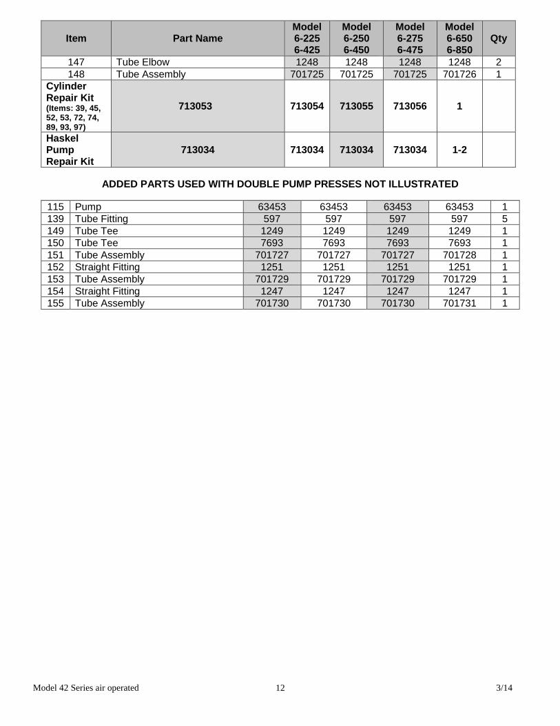
147 Tube Elbow 1248 1248 1248 1248 2 148 Tube Assembly 701725 701725 701725 701726 1
Cylinder Repair Kit (Items: 39, 45, 52, 53, 72, 74, 89, 93, 97)
713053 713054 713055 713056 1
Haskel Pump Repair Kit
713034 713034 713034 713034 1-2
ADDED PARTS USED WITH DOUBLE PUMP PRESSES NOT ILLUSTRATED
115 Pump 63453 63453 63453 63453 1 139 Tube Fitting 597 597 597 597 5 149 Tube Tee 1249 1249 1249 1249 1 150 Tube Tee 7693 7693 7693 7693 1 151 Tube Assembly 701727 701727 701727 701728 1 152 Straight Fitting 1251 1251 1251 1251 1 153 Tube Assembly 701729 701729 701729 701729 1 154 Straight Fitting 1247 1247 1247 1247 1 155 Tube Assembly 701730 701730 701730 701731 1

Model 42 Series air operated 3/14 13
Item Part Name Model 25 ton
Model 50 ton
Model 75 ton
Model 150 ton Qty
N/A Cable 45954 45954 726 726 17 N/A Cable clamp 583 583 991 991 4 19 Hand crank assembly 701653 701653 701653 701653 1 20 Worm shaft 742 742 1598 1598 1
21A Retaining ring 43982 43982 43992 43992 2 21B Retaining ring 43983 43983 43983 43983 2 22 Worm key 746 746 1602 1602 1 23 Worm 744 744 1600 1600 1 24 Hoist frame 739 739 1595 1595 1 25 Hex cap screw 43335 43335 43335 43335 3 26 Hex nut 43912 43912 43912 43912 4 27 Drum shaft 741 741 1597 1597 1 28 Drum key 745 745 1601 1601 1 29 Worm gear 743 743 1599 1599 1 30 Cable drum 740 740 1596 1596 1 N/A Ratchet handle assembly - - 75582 75582 1
Complete Table Hoist Assembly (Items 20, 21A, 21B, 22, 23, 24, 27, 28, 29,30)
700111-S 700111-S 700104-S 700104-S 1
Figure 1

Model 42 Series air operated 3/14 14
Table and frame part numbers No picture available
Part Name Model 5-025
Model 5-050
Model 5-075
Model 5-150 Qty
1 Pulley, Cable 1639 - - - 1 1 Pulley, Cable - 1639 - - 6 1 Pulley, Cable - - 1639 1639 4 2 Shaft, Cable Pulley 1641 1641 1641 1641 1 3 Block Stop 3/4x2x3-1/2” 1819 1819 1819 1819 8 4 Pin, Table 2256 2256 - - 4 4 Pin, Table - - 2256 - 6 4 Pin, Table - - - 1555 6 5 Shaft, Cable Pulley 2698 2698 1640 29510 2 6 Screw, Hex Cap ½ - 13 x 1-1/4” 43348 43348 43348 43348 8 7 Screw, Hex Cap ½-13x 3-1/4 43356 - 43356 - 8 7 Screw, Hex Cap ½-13x1-3/4 H300 43350 - - - 2 8 Screw, 3/4x10-1 ½ SHCS 43371 43371 12 9 Screw, Soc Cap 5/16 – 18 x 3/4” 43433 43433 43433 43433 8
10 Screw, Soc Cap 3/8 – 16 x 1” 43449 43449 8 11 Screw, Soc Cap 3/8 – 16 1-3/4” 43452 43452 43452 2 12 Screw, Soc Set ½ -13 x ¾ cup pt. 43600 43600 43600 12 33 Lock Washer 3/8” 43645 - - - 10 33 Lock Washer ½” - 43647 - - 16 33 Lock Washer ½” - - 43650 - 12 33 Lock Washer 1” - - - 43647 24 13 Lock Washer ½” 43647 43647 43647 16 14 Screw, Soc cap ½-13x3/4” 43648 43648 43648 20 15 Lock Washer, ¾ H300 43649 43649 43649 - 12 15 Lock Washer ¾” H300 - - - 43649 16 16 Nut, Hex ½-13 (Heavy) 43916 43916 43916 43916 8 17 Nut, Hex 5/8-11 (Heavy) 43917 43917 43917 20 17 Nut, Hex ¾-10 H300 - - - 43919 16 18 Nut, Hex Jam, 7/8-14 43947 43947 43917 43947 4 19 Ring, Retaining 43982 43982 43982 43982 6 20 Cable 45954 45954 24 20 Cable - - 45933 - 26 20 Cable - - - 45933 42 21 Clamp, Cable 583 583 1607 1607 4 22 Bearing, Camrol 60900 60900 60900 - 4 22 - - - - 4 22 - - - 4 23 Clamp, Toggle 60901 60901 60901 2 24 Block, Lifting 60903 60903 60903 2 25 Bracket, Clamp 63381 63381 60809 2 26 Lever, Rolling Table 63382 63382 9928 4 27 Channel, Rolling Table 63383 63383 - - 2 27 Channel, Rolling Table - - 60811 - 2 27 Channel, Rolling Table - - - 2 28 Support, Rolling Table RH 63384 63384 60813 - 1 28 - - - 1
Model 42 Series air operated 3/14 15
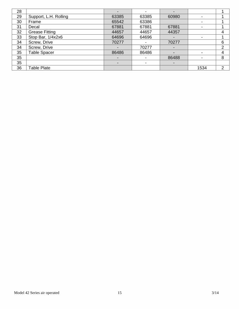
28 - - - 1 29 Support, L.H. Rolling 63385 63385 60980 - 1 30 Frame 65542 63386 - 1 31 Decal 67881 67881 67881 - 1 32 Grease Fitting 44657 44657 44357 4 33 Stop Bar, 1/4x2x6 64696 64696 - - 1 34 Screw, Drive 70277 - 70277 6 34 Screw, Drive - 70277 - 2 35 Table Spacer 86486 86486 - - 4 35 - - 86488 - 8 35 - - - 36 Table Plate 1534 2


![308 PARTS 83–84 [RESERVED] - GovInfo.gov](https://static.fdokumen.com/doc/165x107/631ee2ee17cd32be4e046b9b/308-parts-8384-reserved-govinfogov.jpg)