3/3/14 2:39 PM Shapeoko2 -Electronics
18
3/3/14 2:39 PM Shapeoko2 - Electronics Page 1 of 18 http://docs.shapeoko.com/electronics.html Testing Electronics Overview Before we get all crazy bolting our new machine together, let's give our electronics a test run. It's frustrating to have the machine fully assembled, only to find there is a problem with your electronics that may require disassembly! Let's cut that off at the pass and give everything a thorough checking first. For reference, the image below shows the concept of wiring Shapeoko 2.
-
Upload
independent -
Category
Documents
-
view
2 -
download
0
Transcript of 3/3/14 2:39 PM Shapeoko2 -Electronics

3/3/14 2:39 PMShapeoko2 - Electronics
Page 1 of 18http://docs.shapeoko.com/electronics.html
Testing Electronics
Overview
Before we get all crazy bolting our new machine together, let's give our electronics a test run. It's
frustrating to have the machine fully assembled, only to find there is a problem with your electronics
that may require disassembly! Let's cut that off at the pass and give everything a thorough checking
first.
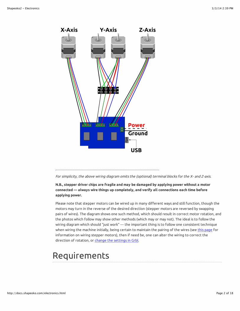
For reference, the image below shows the concept of wiring Shapeoko 2.
3/3/14 2:39 PMShapeoko2 - Electronics
Page 2 of 18http://docs.shapeoko.com/electronics.html
For simplicity, the above wiring diagram omits the (optional) terminal blocks for the X- and Z-axis.
N.B., stepper driver chips are fragile and may be damaged by applying power without a motor
connected --- always wire things up completely, and verify all connections each time before
applying power.
Please note that stepper motors can be wired up in many different ways and still function, though the
motors may turn in the reverse of the desired direction (stepper motors are reversed by swapping
pairs of wires). The diagram shows one such method, which should result in correct motor rotation, and
the photos which follow may show other methods (which may or may not). The ideal is to follow the
wiring diagram which should "just work" --- the important thing is to follow one consistent technique
when wiring the machine initially, being certain to maintain the pairing of the wires (see this page for
information on wiring stepper motors), then if need be, one can alter the wiring to correct the
direction of rotation, or change the settings in Grbl.
Requirements

3/3/14 2:39 PMShapeoko2 - Electronics
Page 3 of 18http://docs.shapeoko.com/electronics.html
Arduino with Grbl firmware (contains an AVR processor, USB connector and I/O pins)
(Arduino) gShield (formerly GrblShield, takes the signals Grbl generates and drives the steppers.
Small pots are used to adjust)
Stepper motors x 4 pcs
Power Supply with wall plug
Barrel Connector (for connecting the power supply to the gShield)
Computer with a Grbl Communication/Control program installed
USB Cable (A to B)
Patience (just a little bit)
Please note that the photos depict using terminal blocks to connect the wiring --- this is optional and
included to cover the case of motors with short lead wires which would require them. The 4-conductor
cable should be 18 or 20 gauge and shielded. Note that in addition to the 4 color-coded copper
conductors there is a steel "drain wire" which may optionally be connected to ground at the controller
end, but should be trimmed off with the shielding at the motor end.
Tools

3/3/14 2:39 PMShapeoko2 - Electronics
Page 4 of 18http://docs.shapeoko.com/electronics.html
Screw Driver 2.0mm blade
razor blade
(optional shown) Wire strippers

3/3/14 2:39 PMShapeoko2 - Electronics
Page 5 of 18http://docs.shapeoko.com/electronics.html
(optional and not shown) Multimeter for testing continuity
The terminal blocks use a combination screw which will accept either a Phillips or flat blade screwdriver.
Connect Arduino
Now that we have everything gathered up, you should find yourself with a setup similar to this:
First thing that we do is plug our Arduino into the computer and test it. If this has already been done
(see Software skip to Hook Stuff Up below.

3/3/14 2:39 PMShapeoko2 - Electronics
Page 6 of 18http://docs.shapeoko.com/electronics.html
Remember, the big end of the cable goes into the Arduino. Loading the driver for the Arduino is
documented in Software
Communication / Control Program
Launch your selected Communication/Control program on your computer. Connect to the Arduino and
ensure that it works (see the Software page for details). Once you are certain your controller works,
disconnect it.
Hook Stuff Up
3/3/14 2:39 PMShapeoko2 - Electronics
Page 7 of 18http://docs.shapeoko.com/electronics.html
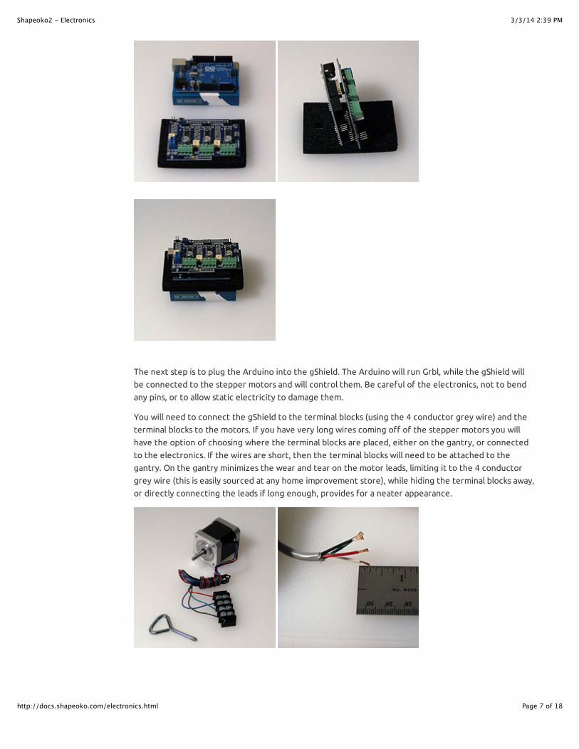
The next step is to plug the Arduino into the gShield. The Arduino will run Grbl, while the gShield will
be connected to the stepper motors and will control them. Be careful of the electronics, not to bend
any pins, or to allow static electricity to damage them.
You will need to connect the gShield to the terminal blocks (using the 4 conductor grey wire) and the
terminal blocks to the motors. If you have very long wires coming off of the stepper motors you will
have the option of choosing where the terminal blocks are placed, either on the gantry, or connected
to the electronics. If the wires are short, then the terminal blocks will need to be attached to the
gantry. On the gantry minimizes the wear and tear on the motor leads, limiting it to the 4 conductor
grey wire (this is easily sourced at any home improvement store), while hiding the terminal blocks away,
or directly connecting the leads if long enough, provides for a neater appearance.

3/3/14 2:39 PMShapeoko2 - Electronics
Page 8 of 18http://docs.shapeoko.com/electronics.html
Start by cutting the grey wire to length (either equal thirds, or some proportion which takes into
account the wire for the Y-axis having a slightly shorter run than the X- and Z-axes). If you have long
leads, it is best to defer cutting the wire until it is mounted on the machine --- that will allow you to
make a run with the un-trimmed wire and then cut it to the exact length. If you make a mistake and
need more wire, this may be ordered from Inventables or sourced from any hardware store (just buy 4
conductor 20 (or 18) gauge security wire).
Next, strip all of the wire ends. The ends which will attach to the terminal block should be
approximately 3/8" so as to be twisted into a hook so as to wrap around the terminal block screws (trim
away all of the shielding and the steel drain wire at this end). The other end of the grey wire should be
stripped approximately 1/4" of an inch so as to fit into the gShield. Be careful of stripping too much
and leaving wire unnecessarily exposed which could create the possibility of a short. If you wish to
ground the drain wires you will need to strip off enough of the coverings to connect them to ground

3/3/14 2:39 PMShapeoko2 - Electronics
Page 9 of 18http://docs.shapeoko.com/electronics.html
and trim any excess of the other wires.
Next, loosen up all the screws on one terminal block, then begin making connections by twisting the
wire ends into hooks, hooking them onto the screws oriented so that the turning of the screw will
tighten them and tighten the wire.
Make all connections in the same colour order. Shown in the wiring diagram is:
Black (swap this first pair to reverse the second Y-axis motor)
Green
Red
Blue/White

3/3/14 2:39 PMShapeoko2 - Electronics
Page 10 of 18http://docs.shapeoko.com/electronics.html
Since the ShapeOko 2 uses two motors on the Y-Axis and the gShield only has 3 stepper drivers, it is
necessary to wire the two motors to one terminal block as shown below. Note that it is necessary to
reverse one pair of wires so that the motors will run in opposite directions when placed on the gantry
in opposite orientations.

3/3/14 2:39 PMShapeoko2 - Electronics
Page 11 of 18http://docs.shapeoko.com/electronics.html
(red and blue to make purple was selected was selected for the photo, but green and black are
reversed in the wiring diagram)
Carefully make each connection. Be careful not to lose any screws. If necessary, trim wires and re-strip
so as to achieve a good connection.

3/3/14 2:39 PMShapeoko2 - Electronics
Page 12 of 18http://docs.shapeoko.com/electronics.html
Next, connect the grey wires from the terminal blocks to the stepper motors. Make all of the
connections initially in the same order. Later, when configuring the machine, it may be necessary to
swap wires around so as to achieve the desired direction of rotation.

3/3/14 2:39 PMShapeoko2 - Electronics
Page 13 of 18http://docs.shapeoko.com/electronics.html
Please note the gShield takes two different sizes of screwdriver. 1/8" for the screws in the blue power
connector, 3/32" for the screws in the green stepper motor connectors.
The green stepper motor connectors should be unscrewed so as to open them up as the right-most
connector is below.

3/3/14 2:39 PMShapeoko2 - Electronics
Page 14 of 18http://docs.shapeoko.com/electronics.html
Connect the grey wires from the stepper motors. Lastly one must connect the power. Note that each
green block represents one axis. Be certain to connect the dual-motor Y-Axis to the correct block.
Once completed, all wires will be connected and none will be loose. It is important that the wires be
connected securely since the various parts will be in motion, and applying power to a stepper driver
which is not connected to a motor may damage the driver.
If you have a multimeter you may wish to test the connections for continuity.
PowerBe careful with the power supply, and don't work on power wires when the power supply is plugged in.
Caution: Please note that the 12V power supply has a connector which matches the Arduino's 5V
power supply connection --- it must not be plugged into said connector. The Arduino is able to draw its
power over the USB connection, so the power connector on the Arduino is not used.
First, strip the leads from the raw end of the barrel connector plug, it may also be necessary to split the
lead at the end so as to allow it to neatly connect to the power connector on the gShield.

3/3/14 2:39 PMShapeoko2 - Electronics
Page 15 of 18http://docs.shapeoko.com/electronics.html
Connect it to the gShield (which is attached to the top of the Arduino). There are two leads, one a solid
black wire, the other black w/ a white stripe.
black == (-)
black/white == (+) (or red)
Please connect each lead to the appropriate side of the gShield's blue power connector (it may also be
green as in the photos above).

3/3/14 2:39 PMShapeoko2 - Electronics
Page 16 of 18http://docs.shapeoko.com/electronics.html
Plug the barrel connector into the matching connector from the power supply, plug the power supply's
power connector into a grounded outlet. Your gShield should light up blue and be ready for operation.

3/3/14 2:39 PMShapeoko2 - Electronics
Page 17 of 18http://docs.shapeoko.com/electronics.html
Testing
Attaching tape to the motor shafts makes it easier to see the rotation when testing before the
machine is assembled, or you could attach the pulleys (these are mounted so that the flat portion is at
the end of the shaft and the set screw is closer to the motor housing). Once the machine is assembled,
it is a good idea to retest so as to verify the connections and direction of rotation. When initially
testing a machine, place it in a neutral position with space to move up, down and to all four sides, so as
to prevent a crash if it should move in the wrong direction or farther than expected.
Load up a Communication / Control program and use its jog functionality to test each Axis. For the
Universal GcodeSender, this would typically involve opening the connection on the correct COM port,
selecting baud rate of 9600, then switching to the "Machine Control" tab, and using the buttons to
move the X, Y, and Z axes.
If one or more motors don't move smoothly, you may need to adjust the trim pots on the gShield, see
the wiki.
As viewed with the shaft pointing toward you, when moving the respective axis in the positive
direction, the motors of a Shapeoko 2 should turn counterclockwise with the exception of the Y-axis
right motor which should turn clockwise.
Note that once the machine is assembled, the positive direction for X is right, for Y it's away from you,
and for Z it's up.
Go For a SpinZ-Axis. Note that when testing, the Z-axis should turn for a longer duration than the other axes since
the screw requires more revolutions to move a given distance than the belts used on the X- and Y-axes.
With the standard drive (M8 on Z, 20-tooth GT2 on X and Y), for the same distance travelled, the Z
motor turns 32 times more than the X and Y motors.
Another SpinX-Axis --- the X- and Y-axis should move for the same duration for a given degree of movement.
And a Final SpinY-Axis --- make certain that the two motors for the Y-axis are rotating in opposite directions.
Once everything has been successfully tested you should dismantle at least the terminal block
connections and carefully set everything aside until it's needed.
Once everything has been successfully assembled you should re-test jogging all the axes to ensure that
movement is properly calibrated in terms of direction/rotation and distanfe travelled/number of
steps/revolutions.

3/3/14 2:39 PMShapeoko2 - Electronics
Page 18 of 18http://docs.shapeoko.com/electronics.html
Next step Wheels & IdlersTo express concerns, post on the forums, to suggest improvements without using github, edit this wiki
page.