2.8 SINE BAR - Rohini College of Engineering & Technology
12
ROHINI COLLEGE OF ENGINEERING & TECHNOLOGY Mr.P. Navin Jass, AP/MECH ME 8501 METROLOGY & MEASUREMENTS 2.8 SINE BAR A sine bar is used to measure angles based on the sine principle. Its upper surface forms the hypotenuse of a triangle formed by a steel bar terminating in a cylinder near each end. When one of the cylinders, called a roller, is resting on a flat surface, the bar can be set at any desired angle by simply raising the second cylinder. The required angle is obtained when the difference in height between the two rollers is equal to the sine of the angle multiplied by the distance between the centres of the rollers. Fig. 2.81 Sine bar [source: “Engineering Metrology & Measurements”, N.V. Raghavendra., page-123] Sine bars are made of corrosion-resistant steel, and are hardened, ground, and stabilized. The size is specified by the distance between the centres of the cylinders, which is 100, 200, or 300 mm. The upper surface has a high degree of flatness of up to 0.001 mm for a 100 mm length and is perfectly parallel to the axis joining the centres of 0.001 mm for a 100 mm length. Relief holes are sometimes provided to reduce the weight of the sine bar. This by itself is not a complete measuring instrument. Accessories such as a surface plate and slip gauges are needed to perform the measurement process. He sine of angle θ formed between the upper surface of a sine bar and the surface plate (datum) is given by Sin (θ) = h/L where h is the height difference between the two rollers and L is the distance between the centres of the rollers.
-
Upload
khangminh22 -
Category
Documents
-
view
6 -
download
0
Transcript of 2.8 SINE BAR - Rohini College of Engineering & Technology
ROHINI COLLEGE OF ENGINEERING & TECHNOLOGY
Mr.P. Navin Jass, AP/MECH ME 8501 METROLOGY & MEASUREMENTS
2.8 SINE BAR
A sine bar is used to measure angles based on the sine principle. Its upper surface
forms the hypotenuse of a triangle formed by a steel bar terminating in a cylinder near
each end. When one of the cylinders, called a roller, is resting on a flat surface, the bar
can be set at any desired angle by simply raising the second cylinder. The required angle
is obtained when the difference in height between the two rollers is equal to the sine of
the angle multiplied by the distance between the centres of the rollers.
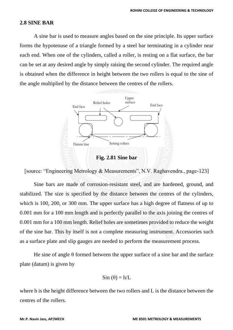
Fig. 2.81 Sine bar
[source: “Engineering Metrology & Measurements”, N.V. Raghavendra., page-123]
Sine bars are made of corrosion-resistant steel, and are hardened, ground, and
stabilized. The size is specified by the distance between the centres of the cylinders,
which is 100, 200, or 300 mm. The upper surface has a high degree of flatness of up to
0.001 mm for a 100 mm length and is perfectly parallel to the axis joining the centres of
0.001 mm for a 100 mm length. Relief holes are sometimes provided to reduce the weight
of the sine bar. This by itself is not a complete measuring instrument. Accessories such
as a surface plate and slip gauges are needed to perform the measurement process.
He sine of angle θ formed between the upper surface of a sine bar and the surface
plate (datum) is given by
Sin (θ) = h/L
where h is the height difference between the two rollers and L is the distance between the
centres of the rollers.
ROHINI COLLEGE OF ENGINEERING & TECHNOLOGY
Mr.P. Navin Jass, AP/MECH ME 8501 METROLOGY & MEASUREMENTS
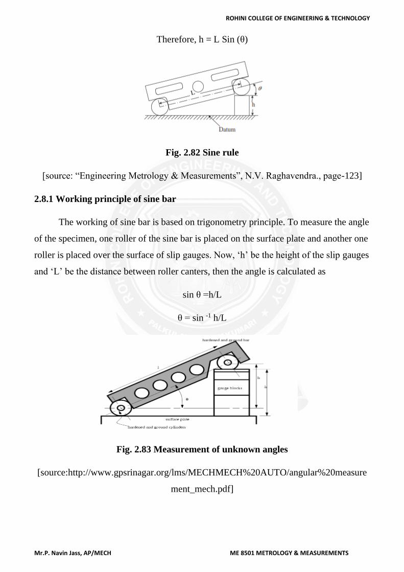
Therefore, h = L Sin (θ)
Fig. 2.82 Sine rule
[source: “Engineering Metrology & Measurements”, N.V. Raghavendra., page-123]
2.8.1 Working principle of sine bar
The working of sine bar is based on trigonometry principle. To measure the angle
of the specimen, one roller of the sine bar is placed on the surface plate and another one
roller is placed over the surface of slip gauges. Now, ‘h’ be the height of the slip gauges
and ‘L’ be the distance between roller canters, then the angle is calculated as
sin θ =h/L
θ = sin -1 h/L
Fig. 2.83 Measurement of unknown angles
[source:http://www.gpsrinagar.org/lms/MECHMECH%20AUTO/angular%20measure
ment_mech.pdf]
ROHINI COLLEGE OF ENGINEERING & TECHNOLOGY
Mr.P. Navin Jass, AP/MECH ME 8501 METROLOGY & MEASUREMENTS
Use of sine bar
Sine bar are used for
I. Locating any work to a given angle.
II. To check unknown angle.
III. Measurement of unknown angles for heavier components
IV. Measurement of unknown angles of heavier components with more accurate
readings.
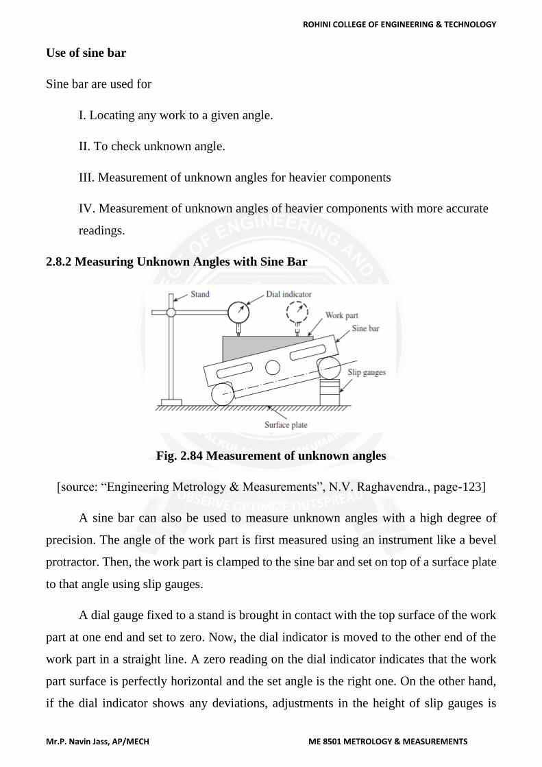
2.8.2 Measuring Unknown Angles with Sine Bar
Fig. 2.84 Measurement of unknown angles
[source: “Engineering Metrology & Measurements”, N.V. Raghavendra., page-123]
A sine bar can also be used to measure unknown angles with a high degree of
precision. The angle of the work part is first measured using an instrument like a bevel
protractor. Then, the work part is clamped to the sine bar and set on top of a surface plate
to that angle using slip gauges.
A dial gauge fixed to a stand is brought in contact with the top surface of the work
part at one end and set to zero. Now, the dial indicator is moved to the other end of the
work part in a straight line. A zero reading on the dial indicator indicates that the work
part surface is perfectly horizontal and the set angle is the right one. On the other hand,
if the dial indicator shows any deviations, adjustments in the height of slip gauges is
ROHINI COLLEGE OF ENGINEERING & TECHNOLOGY
Mr.P. Navin Jass, AP/MECH ME 8501 METROLOGY & MEASUREMENTS
necessary to ensure that the work part surface is horizontal. The difference in height
corresponding to the dial gauge reading is incorporated in the slip gauges, and the
procedure is repeated until the dial indicators show zero deviation. The actual angle is
calculated using the total height of the slip gauges.
Instead of a dial gauge, a high-amplification comparator can be used for better
accuracy. Whether setting a sine bar to a known angle or for measuring unknown angles,
a few guidelines should be followed to ensure proper usage of the instrument:
1. It is not recommended to use sine bars for angles greater than 45° because any
error in the sine bar or height of slip gauges gets accentuated.
2. Sine bars provide the most reliable measurements for angles less than 15°.
3. The longer the sine bar, the better the measurement accuracy.
4. It is preferable to use the sine bar at a temperature recommended by the supplier.
The accuracy of measurement is influenced by the ambient temperature.
5.It is recommended to clamp the sine bar and the work part against an angle plate.
This prevents misalignment of the workpiece with the sine bar while making
measurements.
6. One should always keep in mind that the sine principle can be put to use provided
the sine bar is used along with a high-quality surface plate and set of slip gauges.
2.8.3 Sine Blocks, Sine Plates, and Sine Tables
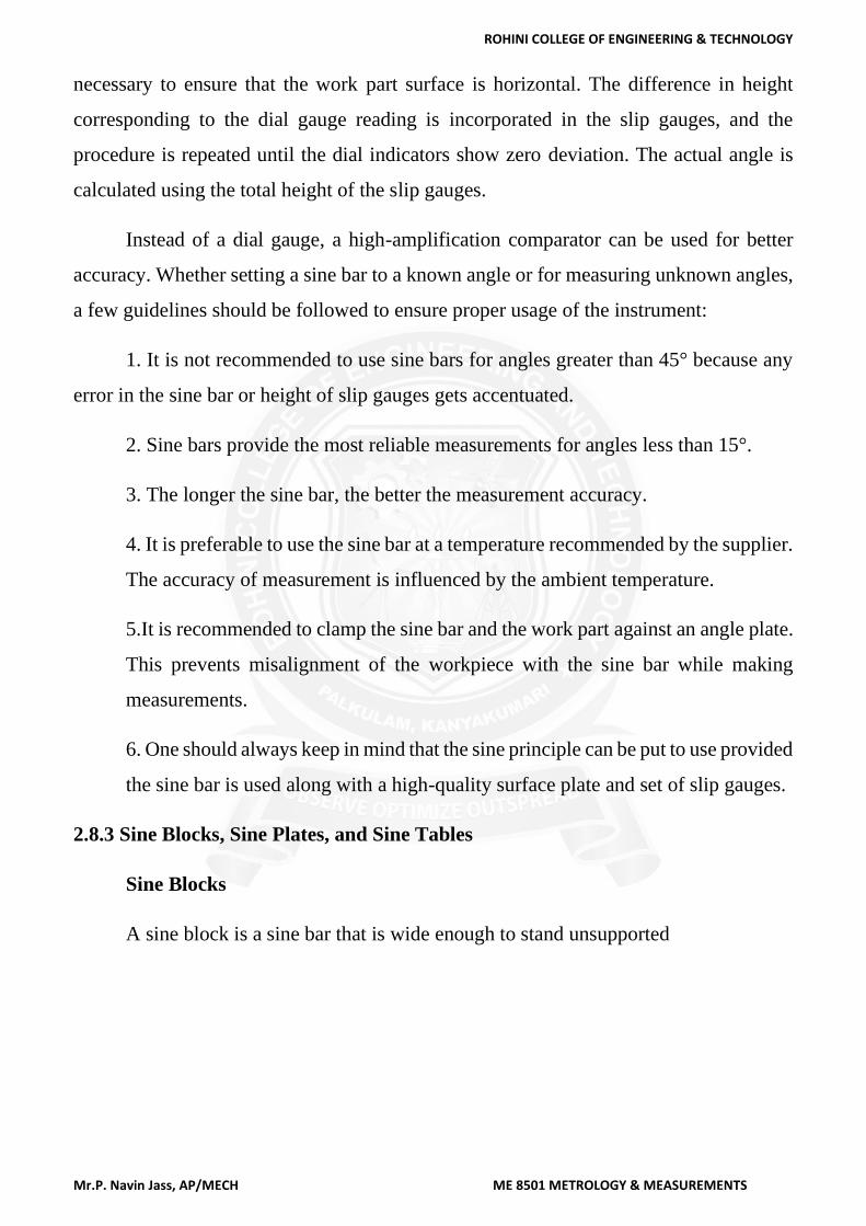
Sine Blocks
A sine block is a sine bar that is wide enough to stand unsupported
ROHINI COLLEGE OF ENGINEERING & TECHNOLOGY
Mr.P. Navin Jass, AP/MECH ME 8501 METROLOGY & MEASUREMENTS
Fig. 2.85 Sine Blocks
[source: “Engineering Metrology & Measurements”, N.V. Raghavendra., page-126]
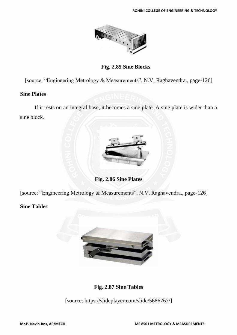
Sine Plates
If it rests on an integral base, it becomes a sine plate. A sine plate is wider than a
sine block.
Fig. 2.86 Sine Plates
[source: “Engineering Metrology & Measurements”, N.V. Raghavendra., page-126]
Sine Tables
Fig. 2.87 Sine Tables
[source: https://slideplayer.com/slide/5686767/]
ROHINI COLLEGE OF ENGINEERING & TECHNOLOGY
Mr.P. Navin Jass, AP/MECH ME 8501 METROLOGY & MEASUREMENTS
A heavy-duty sine plate is rugged enough to hold work parts for machining or
inspection of angles. If a sine plate is an integral part of another device, for example, a
machine tool, it is called a sine table.
In all these three devices, the work part rests on them. They are often used like a fixture
to keep the work part at a particular orientation, so that the required angle is machined.
The instruments have attachments to raise and lock the block to the required angle, and
to also fasten work parts. The sine table is the most rugged device, which may be swung
to any angle from 0° to 90° by pivoting about the hinged end.
There are many instances where compound angles need to be machined or
inspected. While simple angles lie on one plane, compound angles of a surface lie on
more than one plane. In a surface formed by the intersections of planes, the angles on the
surface planes are called face angles. A compound sine plate can conveniently measure
or set itself to this face angle. In a typical compound sine plate, there are two sine plates:
a base plate creates one plane, while the top plate creates the second plane. Compound
sine plates are usually used for finishing operations, for example, a finish grinding
operation.
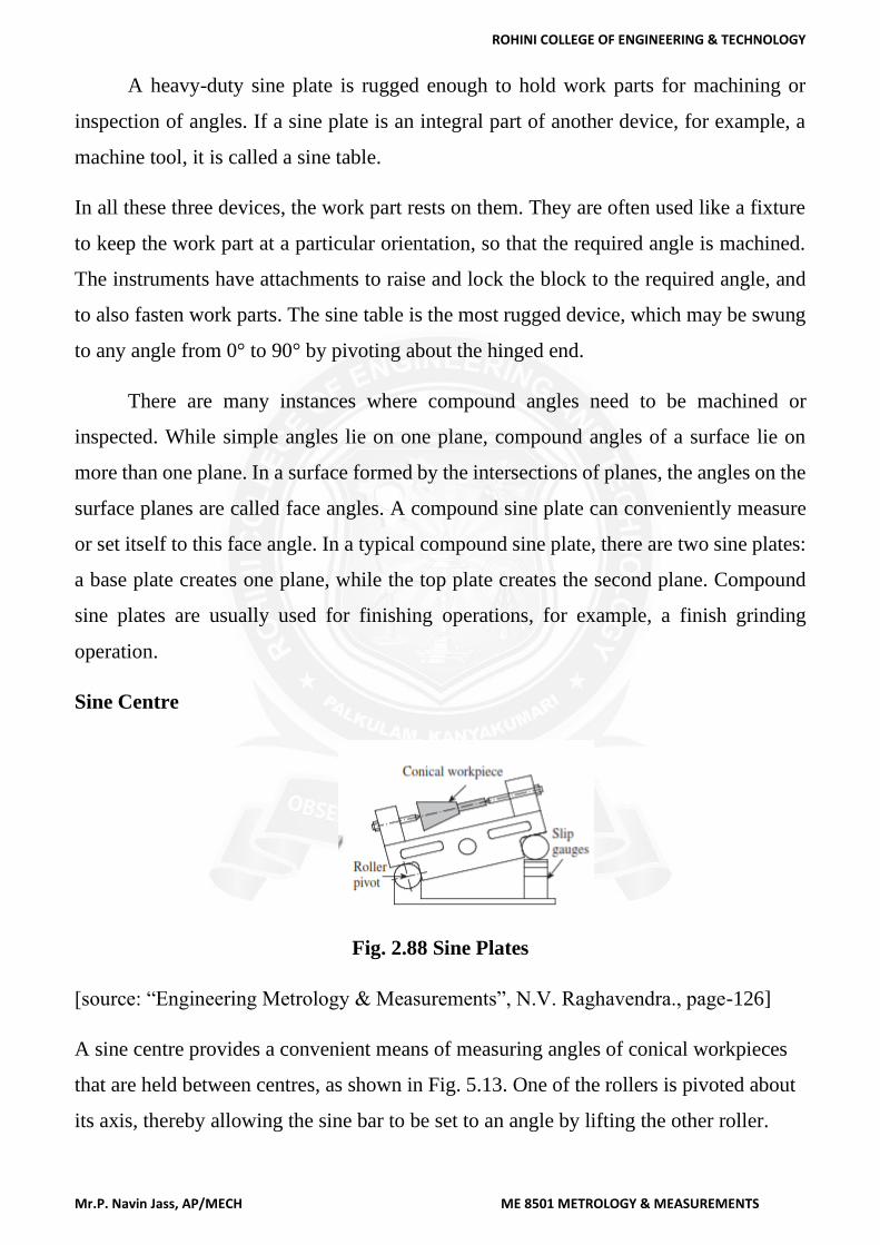
Sine Centre
Fig. 2.88 Sine Plates
[source: “Engineering Metrology & Measurements”, N.V. Raghavendra., page-126]
A sine centre provides a convenient means of measuring angles of conical workpieces
that are held between centres, as shown in Fig. 5.13. One of the rollers is pivoted about
its axis, thereby allowing the sine bar to be set to an angle by lifting the other roller.
ROHINI COLLEGE OF ENGINEERING & TECHNOLOGY
Mr.P. Navin Jass, AP/MECH ME 8501 METROLOGY & MEASUREMENTS
The base of the sine centre has a high degree of flatness, and slip gauges are
wrung and placed on it to set the sine bar at the required angle. Conical workpieces
that need to be inspected are placed between the centres. The sine centre is used for
measuring angles up to 60°.
A dial gauge clamped to a stand is set against the conical workpiece. The sine bar
is set to an angle such that the dial gauge registers no deviation when moved from one
end of the workpiece to the other. The angle is determined by applying the sine rule.
2.8.4 Auto- collimator
➢ An autocollimator is an optical instrument for non-contact measurement of angles.
➢ It’s used for the measurement of small angular differences, changes or deflection,
plane surface inspection etc.
➢ For small angular measurements, autocollimator provides a very sensitive and
accurate approach.
➢ An auto-collimator is essentially an infinity telescope and a collimator combined
into one instrument.
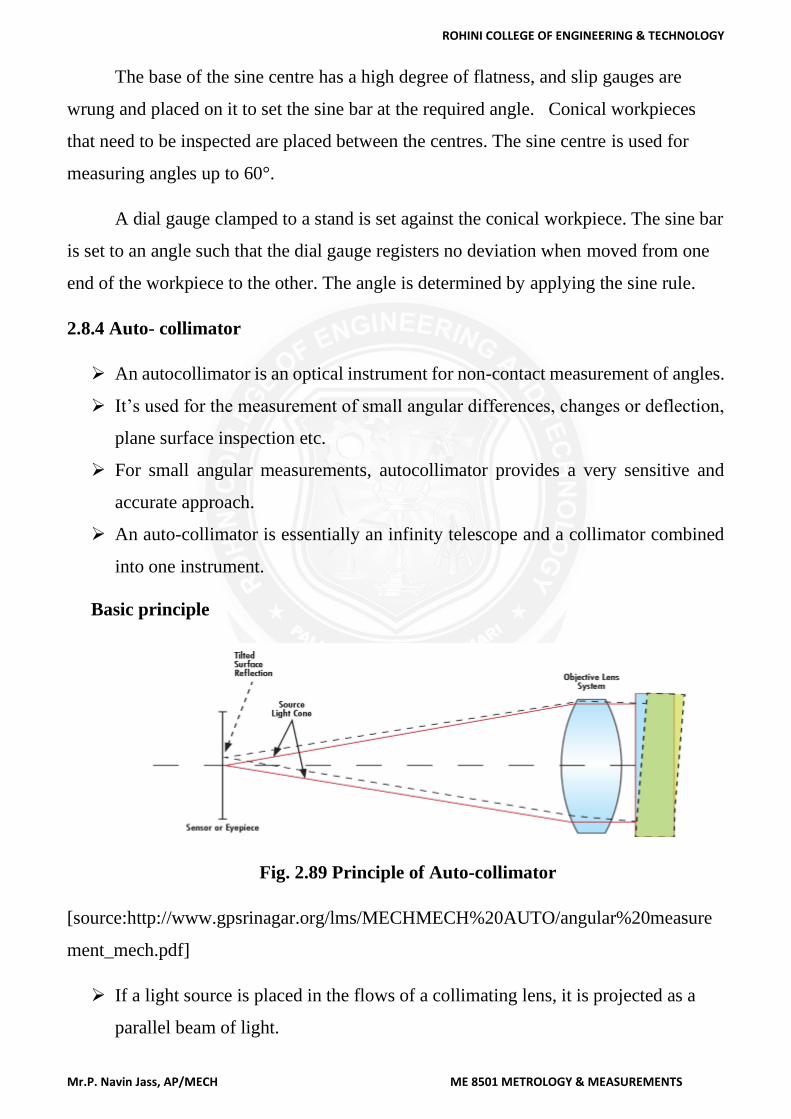
Basic principle
Fig. 2.89 Principle of Auto-collimator
[source:http://www.gpsrinagar.org/lms/MECHMECH%20AUTO/angular%20measure
ment_mech.pdf]
➢ If a light source is placed in the flows of a collimating lens, it is projected as a
parallel beam of light.
ROHINI COLLEGE OF ENGINEERING & TECHNOLOGY
Mr.P. Navin Jass, AP/MECH ME 8501 METROLOGY & MEASUREMENTS
➢ If this beam is made to strike a plane reflector, kept normal to the optical axis, it
is reflected back along its own path and is brought to the same focus.
➢ If the reflector is tilted through a small angle ‘θ’. Then the parallel beam is
deflected twice the angle and is brought to focus in the same plane as the light
source.
➢ The distance of focus from the object is given by
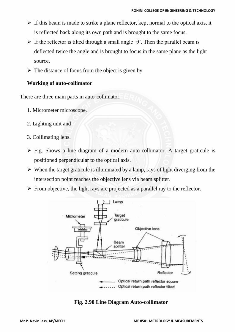
Working of auto-collimator
There are three main parts in auto-collimator.
1. Micrometer microscope.
2. Lighting unit and
3. Collimating lens.
➢ Fig. Shows a line diagram of a modern auto-collimator. A target graticule is
positioned perpendicular to the optical axis.
➢ When the target graticule is illuminated by a lamp, rays of light diverging from the
intersection point reaches the objective lens via beam splitter.
➢ From objective, the light rays are projected as a parallel ray to the reflector.
Fig. 2.90 Line Diagram Auto-collimator
ROHINI COLLEGE OF ENGINEERING & TECHNOLOGY
Mr.P. Navin Jass, AP/MECH ME 8501 METROLOGY & MEASUREMENTS
[source:http://www.gpsrinagar.org/lms/MECHMECH%20AUTO/angular%20measure
ment_mech.pdf]
➢ A flat reflector placed in front of the objective and exactly normal to the optical
axis reflects the parallel rays of light back along their original paths.
➢ They are then brought to the target graticule and exactly coincide with its
intersection.
➢ A portion of the returned light passes through the beam splitter and is visible
through the eyepiece.
➢ If the reflector is tilted through a small angle (θ), the reflected beam will be
changed its path at twice the angle.
➢ It can also be brought to target graticule but linearly displaced from the actual
target by the amount 2θ*f.
➢ Linear displacement of the graticule image in the plane tilted angle of eyepiece is
directly proportional to the reflector. This can be measured by optical micrometer.
➢ The photoelectric auto- collimator is particularly suitable for calibrating polygons,
for checking angular indexing and for checking small linear displacements.
Applications of auto-collimator
Auto-collimators are used for
➢ Measuring the difference in height of length standards.
➢ Checking the flatness and straightness of surfaces.
➢ Checking squareness of two surfaces.
➢ Precise angular indexing in conjunction with polygons.
➢ Checking alignment or parallelism.
➢ Measurement of small linear dimensions.
➢ For machine tool adjustment testing.
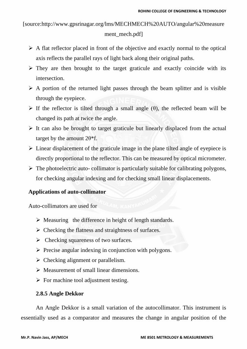
2.8.5 Angle Dekkor
An Angle Dekkor is a small variation of the autocollimator. This instrument is
essentially used as a comparator and measures the change in angular position of the
ROHINI COLLEGE OF ENGINEERING & TECHNOLOGY
Mr.P. Navin Jass, AP/MECH ME 8501 METROLOGY & MEASUREMENTS
reflector in two planes. It has an illuminated scale, which receives light directed through
a prism. The light beam carrying the image of the illuminated scale passes through the
collimating lens, and falls onto the reflecting surface of the workpiece. After getting
reflected from the workpiece, it is refocused by the lens in field view of the eyepiece.
While doing so, the image of the illuminated scale would have undergone a rotation of
90° with respect to the optical axis. Now, the light beam will pass through the datum
scale fixed across the path of the light beam. When viewed through the eyepiece, the
reading on the illuminated scale measures angular deviations from one axis at 90° to the
optical axis, and the reading on the fixed datum scale measures the deviation about an
axis mutually perpendicular to this.
Fig. 2.91 Angle Dekkor
[source: “Engineering Metrology & Measurements”, N.V. Raghavendra., page-123]
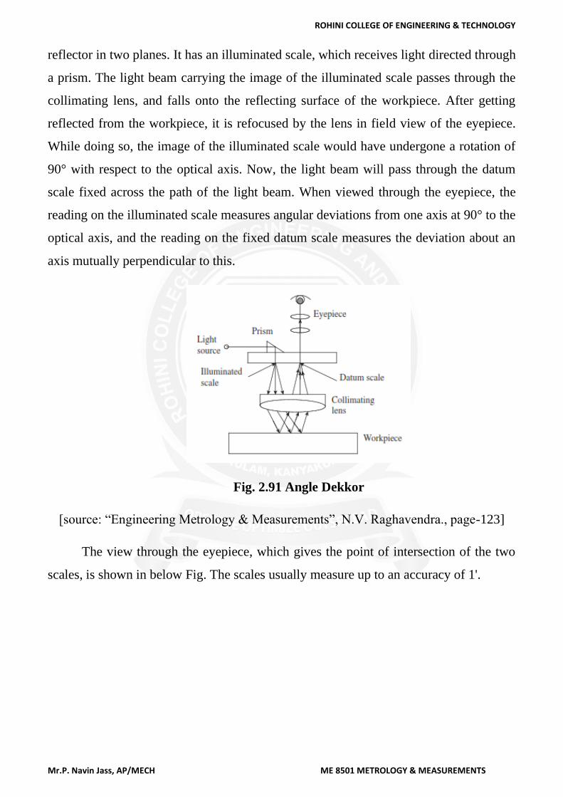
The view through the eyepiece, which gives the point of intersection of the two
scales, is shown in below Fig. The scales usually measure up to an accuracy of 1'.
ROHINI COLLEGE OF ENGINEERING & TECHNOLOGY
Mr.P. Navin Jass, AP/MECH ME 8501 METROLOGY & MEASUREMENTS
Fig. 2.92 Intersection of two scales
[source: “Engineering Metrology & Measurements”, N.V. Raghavendra., page 123]
This reading actually indicates changes in angular position of the reflector in two
planes. In other words, the initial reading of the angle dekkor corresponds to the reading
on the two scales before shifting the position of the reflector. After the reflector undergoes
an angular tilt, the second reading is noted down by recording the point of intersection
on both scales. The difference in readings on the two scales indicates the tilt of the
reflector in two planes at 90° to each other.
The optical system in an angle dekkor is enclosed in a tube, which is mounted on
an adjustable bracket. It has a wide range of applications, as angular variations can be
directly read through the eyepiece of the instrument. Some of the typical applications are
as follows:
1. Measurement of sloping angle of V-blocks
2. Calibration of taper gauges
3. Measurement of angles of conical parts
4. Measurement of angles of work part surfaces, which are simultaneously inclined
in two planes
5. Determination of a precise angular setting for machining operations, for
example, milling a slot at some precise angle to a previously machined datum
surface.
ROHINI COLLEGE OF ENGINEERING & TECHNOLOGY
Mr.P. Navin Jass, AP/MECH ME 8501 METROLOGY & MEASUREMENTS
2.8.6 Angle alignment of telescope
Alignment telescope is used for aligning of bores, surfaces and checks
squareness, straightness, flatness, parallelism, vertically and level. One of the
important types of alignment telescope is Taylor-Hobson alignment telescope.
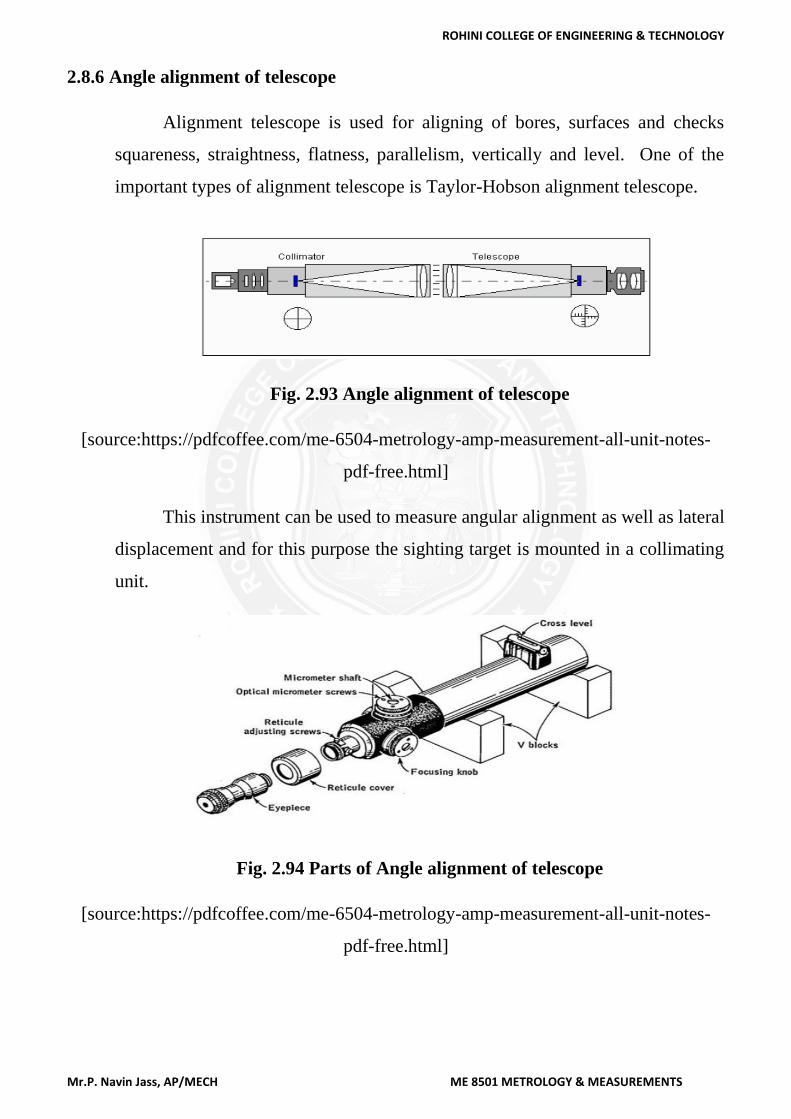
Fig. 2.93 Angle alignment of telescope
[source:https://pdfcoffee.com/me-6504-metrology-amp-measurement-all-unit-notes-
pdf-free.html]
This instrument can be used to measure angular alignment as well as lateral
displacement and for this purpose the sighting target is mounted in a collimating
unit.
Fig. 2.94 Parts of Angle alignment of telescope
[source:https://pdfcoffee.com/me-6504-metrology-amp-measurement-all-unit-notes-
pdf-free.html]