
27 Angle Measurem
22
Metrology Prof. Dr Kanakuppi Sadashivappa Bapuji Institute of Engineering and Technology Davangere Lecture – 27 Angle Measurement-1 I welcome you all for the series of lectures on metrology. Now we will start the module 8 in this module, we will learn about the taper measurement, tilt measurement, angle measurement and the radius measurement. (Refer Slide Time: 00:41) In a first lecture, we will be covering about The introduction to taper tilt and angle. what is the meaning of these terminologies and then what are the various instruments used for the measurement of taper tilt and angle. We will study about the instruments like combination set vernier bevel protractor, optical bevel the protractor, sin bar, sin center and sin table in between we will also conduct some experiments to understand that the measurement of these taper tilt and angle. (Refer Slide Time: 01:27)
-
Upload
khangminh22 -
Category
Documents
-
view
0 -
download
0
Transcript of 27 Angle Measurem

MetrologyProf. Dr Kanakuppi Sadashivappa
Bapuji Institute of Engineering and Technology Davangere
Lecture – 27Angle Measurement-1
I welcome you all for the series of lectures on metrology. Now we will start the module 8 in this
module, we will learn about the taper measurement, tilt measurement, angle measurement and
the radius measurement.
(Refer Slide Time: 00:41)
In a first lecture, we will be covering about The introduction to taper tilt and angle. what is the
meaning of these terminologies and then what are the various instruments used for the
measurement of taper tilt and angle. We will study about the instruments like combination set
vernier bevel protractor, optical bevel the protractor, sin bar, sin center and sin table in between
we will also conduct some experiments to understand that the measurement of these taper tilt and
angle.
(Refer Slide Time: 01:27)

Now let us start the introduction to taper tilt and angle in our daily life we come across with
these terminologies tapered it means to become narrower towards one end you can see here there
is a component here the length of this particular portion of the component is 40 millimeter and
from here to here the diameter is 40 millimeter.
Now it is the towards one end towards other end the diameter is the reducing at this particular
location the diameter is the 30 millimeter that means the size is getting narrowed towards the one
end such components are called tapered components. We can see one example here a tapered
roller beings and then we will tilt a sloping position our moment so one simple example is shown
here.
We have a solar panel its inclination is change with the tilt or the orientation of the solar panel is
change that means this position sloping position our sloping moment is known as tilt and then
we have the turn angle it is a space between 2 intersecting lines or surfaces at or close to the
point where they meet that means if you take the 2 lines 0A and 0B. These 2 lines are there
getting intersected at this point O.
Now this space is known as angle similarly we can have 2 surfaces. So we have 1 surface like
this and another surface. So this space between these 2 the surfaces is called angle. You can see

some examples here, we have machine tool the guide way, this is slide and it is a guide way we
have the sloping surface here the inclination between these 2 surfaces is the angle.
Similarly we can have a have a sloping surface here and we have a flat surface so the inclination
between these 2 surfaces is there is some angle and this angle tilt and taper.
(Refer Slide Time: 04:29)
They are normally measured in terms of degrees or radians that means there are 2 commonly
used units of measurement for angle or taper or tilt the more familiar unit is degrees a circle is
divided into 360 equal degrees, so that a right angle is 90 degree. Degrees may further be divided
into minutes and seconds each degree is divided into 60 equal parts each part is called a minute.
So seven and a half degree can be called 7 degrees 30 minutes written as 7 degree 30 minutes
each minute is for well divided into 60 equal parts each small part is called 1 second, so for
instance 2 degrees 5 minutes and 30 seconds is written as shown here. Now parts of a degree are
now usually referred to decimally. For instance 7 and a half degree is now usually written as 7.5
degrees, so this indicates that it is 7 degree 30 minutes.
(Refer Slide Time: 05:52)

Now the other common measurement of angle is radius for this measurement consider a unit
circle a circle of radius 1 unit whose center is the vertex of the angle in question if you see this
diagram this is a vertex and will be circle with 1 unit radius then the angle cuts off an arc of the
circle and the length of that arc is the radian measure of the angle .Now you can see here we
have a line here we have another line here these 2 lines they cut the circle.
So this length of arc is the radian, radian. It is easy to convert between the degree measurement
and Radian measurement the circumference of the entire circle is 2 pi the circumference to the
entire circle is 2 pi so that 360 degree equals 2 pi radians and 1 degree equals pi/180.
(Refer Slide Time: 06:59)

Now there is another term cone angle which is frequently used it is an included angle between
generic tricks as measured in the axial plane section. Now you can see here we have a conical
part here we have multiple generators we can have multiple generators like this. Now the
included angle between 2 generators is called corner angle, which is measured in the axial plane
section.
The method of dimensioning and tolerancing conical surfaces on drawings is covered in the ISO
304:1990 standard.
(Refer Slide Time: 07:55)
Now various instruments are used for measurement of angle or tilt or taper now we have a
combination set we can see here we have a steel rule and then we have a centre head and then we
have a square head and then as this is the protractor part. We have a body so this is the body
blade which is a which can be rotated and we have the scale here rotary scale here this is a
simple protractor varying there is no vernier it can see the details of a simple protractor we have
a rotary scale we can see the markings with 0 to 90,100,110 up to 180.
The least count of the simple protractor is 1 degree we have a reference mark here. You can see 0
is marked here. This is a reference and there is a clamp to clamp the blade on the screen rule at
any of orientation, now what we have to do is we have to insert the work piece whose angle is to
be measure.

For example this is the work piece this angle between this particular surface and this particular
surface we want to measure now the work piece is placed between the steel rule and the blade
and then there should be intimate contact between the work piece surfaces and the blade surfaces
and then, what is the reading of the protractor?
So this 0 is a reference with respect to this what is the angle indicated as shown by the protractor
that we have to see that indicates the inclination in this particular case it is showing 4045 degree
that means the angle between this particular surface and this particular surface is 45 degrees now
we shall conduct a simple experiment to show how to use a combination set for the measurement
of angle.
(Video Starts: 10:35)
Now we can see I am trying to measure this yeah this is the guide way the slight slide of the
RAM of a shaper. I am trying to measure the inclination and angle between this particular
surface and this particular surface. So I am using a simple protractor for measurement of the
angle between these 2 processes.
We should the case steel rule should the intimately contact this particular surface and the blade of
the protractor should contact intimately with this particular surface and then we can read this
scale okay with reference to this particular reference mark. Now you can see the reading it is
showing 0 degree, 10 degree, 20 30 40 50 and 55 degree so inclination between the 2 surfaces of
the slide he is 55 degrees.
Yeah, can see reading 55 degree so a clamp is provided here we can clamp the steel rule with the
protractor and we can remove and then we can read the protractor.
(Video Ends: 12:42)
(Refer Slide Time: 12:47)
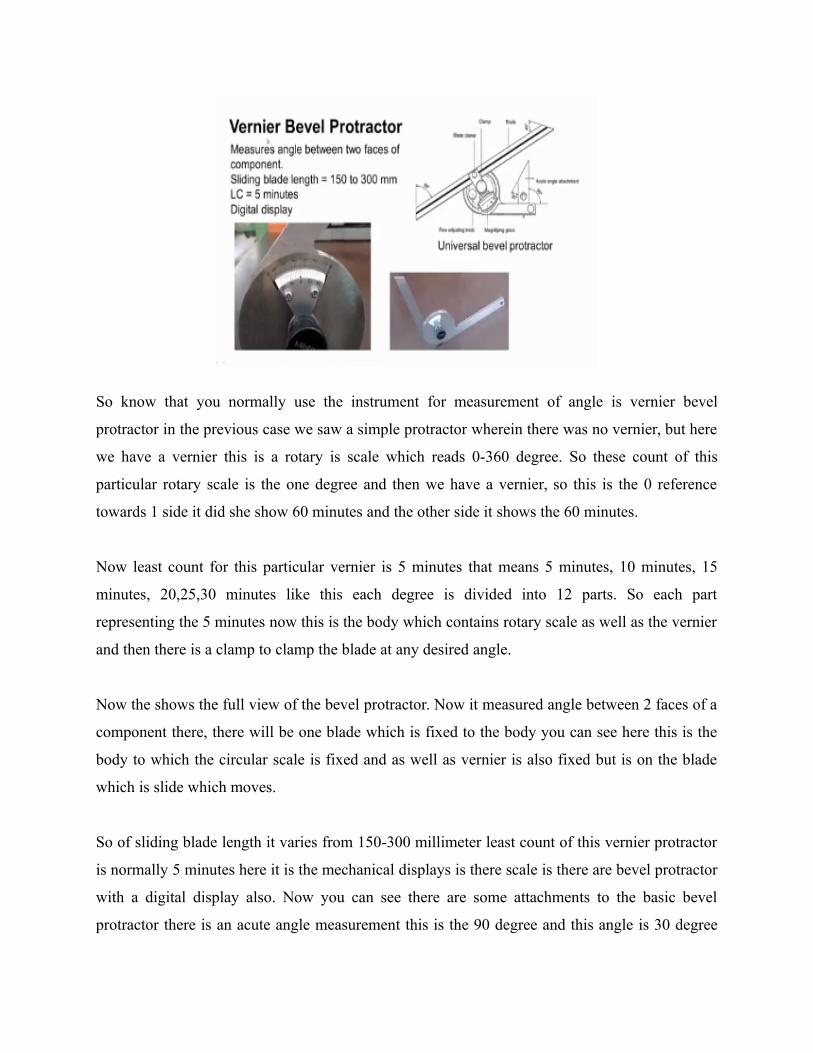
So know that you normally use the instrument for measurement of angle is vernier bevel
protractor in the previous case we saw a simple protractor wherein there was no vernier, but here
we have a vernier this is a rotary is scale which reads 0-360 degree. So these count of this
particular rotary scale is the one degree and then we have a vernier, so this is the 0 reference
towards 1 side it did she show 60 minutes and the other side it shows the 60 minutes.
Now least count for this particular vernier is 5 minutes that means 5 minutes, 10 minutes, 15
minutes, 20,25,30 minutes like this each degree is divided into 12 parts. So each part
representing the 5 minutes now this is the body which contains rotary scale as well as the vernier
and then there is a clamp to clamp the blade at any desired angle.
Now the shows the full view of the bevel protractor. Now it measured angle between 2 faces of a
component there, there will be one blade which is fixed to the body you can see here this is the
body to which the circular scale is fixed and as well as vernier is also fixed but is on the blade
which is slide which moves.
So of sliding blade length it varies from 150-300 millimeter least count of this vernier protractor
is normally 5 minutes here it is the mechanical displays is there scale is there are bevel protractor
with a digital display also. Now you can see there are some attachments to the basic bevel
protractor there is an acute angle measurement this is the 90 degree and this angle is 30 degree

and we have a sliding blade so this is again beveled at 45 degree and this shows this angle is 60
degree.
We can use these ends of the blade to check 45 degree and 60 degrees there is a magnifying lens
for easy reading and there is a fine adjustment knob for proper adjustment of the blades and use a
clamp to clamp the blade to the body. So with these additional attachments the simple dual
protractor is called Universal bevel protractor.
(Refer Slide Time: 15:55)
Now other important thing when we use protractor is intimate there should be a intimate contact
between blade with the beveled surfaces. You can see here this is the sliding the blade and this is
a blade, which is fixed to the body the surface of the fixed blade and the sliding the blade should
contact the surface of the work piece intimately. Then only the proper reading can be taken we
can see here in the picture deep, We have intimate contact here but there is no proper contact at
this place.
So the reading shown is > the actual angle here. It is showing 55 degree which is a correct angle
here it is showing more than 55 degree because of this error so sometimes the 1 blade sliding
blade is in contact with the work piece but here fixed blade is not in contact its actually the
protractor is climbing on the work piece so there is no contact here so the angle shown is 54
degree which is < the actual angle.

So again see when we 1 blade should come in contact with 1 perfect to the work piece and then
we should the slide the protractor like this till the other blade comes in contact with the beveled
surface and then further we should push the instrument so that there is the proper contact at this
place then we should take the reading we should clamp for the blade and then we should take out
then we can read the instrument.
If you if we further push the instrument you can see here when we push there will be a proper
contact like this and if we try to push further again the sliding bit further rotate and then there
will be the there will be error in the reading such things should not be there. So while the using
direct the bevel protractor the surfaces of the work piece should be properly clean and surface of
the blades of the protractor bevel protractor should be properly clean and then we should
carefully use the instrument.
(Video Starts: 18:41)
Now we will conduct a simple experiment to learn how to use a protractor now you can see here
I am using a bevel protractor with vernier and this will be work piece B block and I want to
measure the inclination angle between this particular surface and this surface you can see how to
keep the blades we should see that 1 blade is in contact with this particular surface and the other
blade should properly contact the other surface.
I can see the proper contact, so if necessary we can take a piece of paper or a feeler gauge and we
should try to insert here to see whether there is proper contact or not between the work surface
and the blade. So now you can see the contact on this particular place. Yeah, now we can read the
instrument now please be circular the scale and then we have the vernier here.
Now you can see the pressure the read from one end the reading is 20 degree, 30 degree 40
degree, okay 40 degree and then we should see which mark is coinciding with the main scale
main scale reading is 40, 41 degree, 42 degree, 43 degree, 44 degree main scale reading is 44
degree and then we should see the coinciding division in the same direction that is you can see
here.

This particular mark on the vernier is coinciding with this 50 degree line. So the vernier reading
is 5 minutes, 10 minutes, 50 minutes, so the angle is 44 degrees and 15 minutes. So that is a
angle.
(Video Ends: 21:53)
(Refer Slide Time: 21:54)
So another variation of bevel protractor instrument is optical bevel protractor here we can see
there is a body which houses a circular glass scale which leads from 0-360 degrees again least
count in this particular case is 5 minutes. You can see the peeping hole here so we have to keep
the work piece between these 2 blades so this is the work piece and we want to measure this
angle between these 2 surfaces.
So this surface should contact with displayed and the other surface should contact the other blade
and then we should establish intimate contact between the surfaces and then by operating this
lever we can clamp it we can flap the blades and then we can remove the protractor from the
work piece and then by peeping through this peeping hole or we can read a scale inside. There is
a glass circular scale so like this so which reads 0 degree, 10 degree ,20 degree like this and then
with a 1 degree marks.
So this is5 degree again 6,7,8,9,10 this and then there will be a vernier there will be vrenier so
with 5 minutes 5 minutes least count, so with reference to this 0 on the vernier which we should

take the main scale reading as well as the vernier reading and then where we can note down the
inclination their angle.
So this is the back side view of for the bevel protractor you can see a groove here so we can
move inside is inside the body there is a projection and over that this movable slide blade slide so
at any desired position we can clamp the blade.
(Refer Slide Time: 24:34)
Now this picture shows the full set we have the body clamp peeping holes and then sliding blade
with the 60 degree bevel on one side and 45 degree bevel on the other side and this is the blade
which is fixed to the body and blade, which is slide. There is a spare a longer blade is provided
so wherever necessary we can remove this smaller removal blade and we can insert this blade
and we can use it.
(Video Starts: 25:21)
Now we will see we will conduct an experiment to show how to use the optical protractor now
you can see how this milling table I am trying to measure the inclination so this is the guide way
we have the top surface of the guide way and then we have an incline surface of the guide way I
am trying to measure the inclination between these 2 surfaces using is optical bevel protractor, so
we have this slide blade and the blade this is the body clamp for clamping the blade and peeping
hole.

So which we can take the readings the back side view of the optical protector, now you can see
the one blade one blade should come in contact with the top surface of the guide way and the
other blade should contact this sloping surface ,so intimate contact is very essential to get the
proper readings now you can see the contact intimate contact between the surfaces and the blade
surfaces.
(Video Ends: 27:27)
(Refer Slide Time: 27:29)
Another very common instrument used for measurement of angles and tapers is a sine bar this
photograph shows a sine bar with the body of the sign box and we have 2 rollers very precise
very precisely measuring the rotor fixed to the 2 ends of the sign bar and we have the circular
holes here to reduce the weight of the sign bar.
So this is a very high precision and most accurate angle measuring the instrument we can
measure the angles even to an accuracy of a few seconds, so these sine bars are they are made of
high carbon high chromium steel they are hardened stabilized and ground under lab they are
available in various size of 100 millimeter length, 200 millimeter length and 300 millimeter
length.

This length means the distance between centre of this roller and this Center the distance between
the Centers of the roller is the size of sine bar so these relief holes are provided to make it light
and for easy handling the diameters of these 2 cylinders are rollers attached to the 2 ends.
Diameters are equal, equal diameter rollers the axis of these 2 cylinders are rollers are mutually
parallel to each other and also parallel to and at equal distance on the upper and lower surfaces
facing but that means the axis of this roller and access objects roller should be parallel to each
other should be parallel to the top surface resign bar under parallel to the bottom surface will be
sine bar.
(Refer Slide Time: 29:45)
Now sine bar it is used in combination with slip gauges for precise angular measurement. It is
used either to measure angle very accurately or to locate any work piece to a given angle
accuracy up to0.01 millimeter per meter length of sine bar can be obtained these sine bars are
made as per Indian Standards 5359-1969.
(Refer Slide Time: 30:14)

Now accuracy requirement and tolerance is specified in Indian Standard 5359-1969 for a 100
millimeter sine bar as follows: Flatness of upper and lower surfaces should be 0.001 millimeter
and the flatness of side faces should be 0.005 millimeter, squareness of size faces to upper
surface that means if this is the very sine bar squareness of the side surfaces to the upper surface
should be within this 0.003/25 millimeter.
Similarly squareness of end faces to upper faces surface should be within this 0.003/25mm and
the straightness and circularity of rollers should be < 0.002 millimeter, variation in distance
between roller axis should be less than +/-0.003 millimeter.
(Refer Slide Time: 31:38)

Now these were sign bar should not be used for angles > 60 degrees for smaller angles these can
be used to get the precise the angular value to measure unknown angles or tapers of small work
pieces these are preferred these sine bars are preferred and you can see the arrangement how we
can use a sine bar for measurement of taper angle you can see here this is the work piece and we
need to measure the taper or the angle between this surface and this surface.
So this is angle that is to be measured we have to keep the work piece on there to clean the
surface of the work piece and we should keep the work piece on the clean the surface plate and
then over that we have to mount the sine bar as shown in picture we can take the help of may be
the angle plate or magnetic stand to mount the sine bar over the work piece.
Now you can see here one roller is in contact with a surface plate and then the gap between the
roller under the surface plate is filled with the slip gauge which indicates an height of H and the
distance between the Centers of rollers is L this is the length of sine bar. Now by knowing the
value of H and knowing the value of L they can find out the angle theta using this relationship
sine theta=(h1-h2)/L where in this case h2is 0 and this is the h1.
If we have the arrangement like this so this is the surface plate and then this is the component the
taper of which is to be measured and then we have 2 mounted a sine bar like this and now this is
a roller and we have another roller here. So in this case we have to fill this gap between roller
and surface plate using slip gauges, so in this case this is h1 and here it is h2 and this is L so now
this theta is theta can be calculated using relationship so theta =sin(h1-h2)/L.
(Video Starts: 34:50)
Now we will conduct a simple experiment to learn how to measure the angle using the sine bar.
Now you can see the arrangement for the measurement of taper angle of this particular tapered
component, now we have the surface plate we have to clean the surface of the surface plate and
then we have to keep the cleaned work piece on the surface plate.
We can take the help of an angle plate for proper mounting of the sine bar this the sine bar these
are the relief holes and we have 2 rollers of equal diameter 2 cylinders of equal diameter fixed to

the sine bar and then this is the magnetic stand and then we have the slip gauge box to fill the
gap between roller and the surface plate.
You can see the close view of the tapered component is dead center of plate. Yeah this taper or
cone angle we want to measure angle plate the tops surface of sine bar and then side surface of
sine bar until a relief hole they have the slip gauge box. Now we have to mount the sine bar on
the work piece that is tapered component and then we have to keep the magnetic stand in front of
the sine bar.
So that it will not fall the backside on the other side. We have the angle plate and from the front
side we have magnetic stand to support the sine bar and then magnetic stand is switched on now
you can see the component taper component below the sine bar and then this gap, gap between
the cylinder and the surface plate should be filled using slip gauges.
So that will give h1 height h1 and the other side also we should fill the gap between this cylinder
and the surface plate using slip gauge slip gauges so that will give h2 knowing the values of
h1,h2and L. We can find out the tapper angle theta that theta=sin(h1-h2)/L.
(Video Ends: 38:36)
(Refer Slide Time: 38:54)
Sometimes the work piece will be very heavy so checking of unknown angles of heavy
component in that case how do we use the sine bar so we can place the sine bar as shown here
you can see the top surface is in contact with the component heavy component in cylinder are on
the other side now we can use the vernier height gauges to check where the h1 and h2.
So we can always use vernier height gauge to check this height h1 and here this height is h2 and
then L is the length of the sine bar knowing h1 h2 and L we can find out the angle theta this
angle theta using the relationship sine theta=h2-h1/L so using this relationship we can find the tip
taper angle of the in component.
(Refer Slide Time: 40:50)
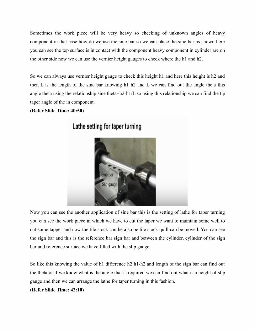
Now you can see the another application of sine bar this is the setting of lathe for taper turning
you can see the work piece in which we have to cut the taper we want to maintain some well to
cut some tapper and now the tile stock can be also be tile stock quill can be moved. You can see
the sign bar and this is the reference bar sign bar and between the cylinder, cylinder of the sign
bar and reference surface we have filled with the slip gauge.
So like this knowing the value of h1 difference h2 h1-h2 and length of the sign bar can find out
the theta or if we know what is the angle that is required we can find out what is a height of slip
gauge and then we can arrange the lathe for taper turning in this fashion.
(Refer Slide Time: 42:10)

Now another variation of sign bar is a sine center you can see here we have the body of the sign
Center these are the relief holes and then we have cylinders fixed to the body of the Science
Center and then here we have 2 centers these the center they are slidable you can see the slot
here we can loosen the clamp and then we can move the centers axially like this to accommodate
the work piece of a different length.
So this sliding arrangement is provided so these sign centers they are used in situations where it
is difficult to mount the sine bar on the component so what they can do is we can mount the work
piece between the centers like this and then using a dial indicator we have to keep the slip gauges
here so this is a surface plate so this is h1 and this is the h2 okay.
Now we should find what should be the value of h1-h2 okay h2 - h1 h2-h1/L. We know what is
the size of the sign bar and say we have a tapered component so we should the place the tapered
component here between centers and then we should adjust this height h1-, h2-h1 the difference
height we should adjust till the dial indicator reads 0 so we can always change this theta by
varying this height difference.
So that the dial indicator we have to move the dial indicator on the generator of the tapered
component okay when they move the dial indicator on the generator of the work piece this
should reach 0 like that we should adjust this inclination so when it reads 0 then there will be a

particular value of theta so that is the cone angle of the tapered component so like this we can
use the sine center for measurement of angles taper angles.
(Refer Slide Time: 45:51)
Now you can see and advance the sine center this is the base and then this is the sine table so it is
pivot here okay. So this sign table can be tilted in this fashion. We can tilt the table and we can
place here there is a roller and this is a surface design table, so here after lifting it after tilting it
we have to fill this gap using the slip gauges.
You can see in this picture the slip gauges are placed so we should calculate the measures the slip
gauge height till the dial indicator reads 0 we have to mount the tapered component between the
centre can see the centers now the body which contains the centre can be moved horizontally like
this to accommodate this also can be slided to accommodate the work piece of different then
these 2 can be slided.
You can see yet the type of component is mounted between center and then there is an
attachment here there is a arrangement for mounting the dial indicator you can see the dial
indicator is mounted and this head can be moved up and down, you can see the guide base here
so this head can be moved up and down again that accommodate the work pieces of different
sizes so then the dial indicator is moved horizontally ok till it reads 0 throughout.

So like that we should adjust slip gauge height and then the angle can be calculated that will be
the angle of taper angle of the work piece.
(Refer Slide Time: 48:12)
Now another variation of sine table sine center a variation of sine center we can see here. This is
called the sign that table so this is the base of the sign table and you can see the table, table can
be tilted so this table can be tilted we can see the pivot here a roller fixed sine table and between
the roller and the base surface top surface we have to insert the slip gauge, so and there is another
this is a basically a compound the sine table.
So this table can be tilted like this there is another table mounted over this table which can be
tilted in this fashion. so in 2 planes we can tilt the plates these 2 plates again you can see the
pivot here and there is a roller fixed to the bottom surface of this top plate so here we have to
keep the slip gauge for adjusting they require the angle you can see the holes are provided for
mounting the component on this particular table.
So these sine tables are heavy duty tables they are very rugged to hold the defaults for machining
of for measurement of angle as well as for machining of angles work pieces can be mounted on
this table and it can be machine you can see the clamp for the 2 plates or 2 tables okay using
these clamps the tables, the angles can be rigidly clamped the tables can be clamped.
(Refer Slide Time: 50:18)

Now these are the Schematic views of simple sine table here we have only one the availing the
table pivot and roller which is fixed to the bottom of prevailing table and this is a reference
surface on which slip gauge they should be placed, so between roller and the reference surface
the slip gauge can be place and then required angle can be maintained and this is the schematic
diagram of compound the sine table.
We have 2 plates here this is one plate which can be tilted there the change in this fashion and
there is another table which can be tilted in this manner, so we have 1 the pivote for this filling
the table and this is the pivot for another table you can see the T slots for mounting being for
work pieces on the top of swivel table.
(Video Starts: 51:25)
So we will see a simple sine table you can see the top surface of the sine table. We can also see
the T slots you can see the pivot work here pivot roller there is a provision to put a rod here using
that rod we can tilt it so that required angle can be maintained I can clearly see the T slots here
for mounting the work pieces and we can see the slots here for mounting this sine table on the
table of machine, machine tools.
A rod can be placed here and then if this pivot work can be rotated to change the angle slots for
mounting design table, machine table. Now this is the surface or bitch slip gauges should be a
place we should clean the surface and then we should keep the work pieces ah slip gauges we

can also see the roller fix to the bottom surface of the swiveling plate so between the roller and
this surface we should keep the slip gauges.
(Video Ends: 53:43)
We can also see the pivot out roller, so now let me summarize the topics covered in this lecture
we discussed about the meanings of taper, tilt and angle we also learnt about the various
instruments used for measurement of taper and angle we learnt about the combination set and
then vernier beveled protector, optical bevel protractor. We also studied about the sine bar, sine
center and sine table of different types that is the simple sine table and compound time sine table.
We also conducted some experiments to learn about how to use these instruments, so we will
stop the lecture at this point and we will continue this in the next lecture. Thank you.