24-1 electric potential - UF Physics
32
685 C H A P T E R 2 4 Electric Potential 24-1 ELECTRIC POTENTIAL After reading this module, you should be able to . . . 24.01 Identify that the electric force is conservative and thus has an associated potential energy. 24.02 Identify that at every point in a charged object’s electric field, the object sets up an electric potential V, which is a scalar quantity that can be positive or negative depending on the sign of the object’s charge. 24.03 For a charged particle placed at a point in an object’s electric field, apply the relationship between the object’s electric potential V at that point, the particle’s charge q, and the potential energy U of the particle–object system. 24.04 Convert energies between units of joules and electron-volts. 24.05 If a charged particle moves from an initial point to a final point in an electric field, apply the relationships between the change V in the potential, the particle’s charge q, the change U in the potential energy, and the work W done by the electric force. 24.06 If a charged particle moves between two given points in the electric field of a charged object, identify that the amount of work done by the electric force is path independent. 24.07 If a charged particle moves through a change V in electric potential without an applied force acting on it, relate V and the change K in the particle’s kinetic energy. 24.08 If a charged particle moves through a change V in electric potential while an applied force acts on it, relate V, the change K in the particle’s kinetic energy, and the work W app done by the applied force. ● The electric potential V at a point P in the electric field of a charged object is V where is the work that would be done by the electric force on a positive test charge q 0 were it brought from an infinite distance to P, and U is the electric potential energy that would then be stored in the test charge–object system. ● If a particle with charge q is placed at a point where the electric potential of a charged object is V, the electric potential energy U of the particle–object system is U qV. ● If the particle moves through a potential difference V, the change in the electric potential energy is W W q 0 U q 0 , U q V q(V f V i ). ● If a particle moves through a change V in electric potential without an applied force acting on it, applying the conservation of mechanical energy gives the change in kinetic energy as K q V. ● If, instead, an applied force acts on the particle, doing work W app , the change in kinetic energy is K q V W app . ● In the special case when K 0, the work of an applied force involves only the motion of the particle through a potential difference: W app q V. Learning Objectives Key Ideas What Is Physics? One goal of physics is to identify basic forces in our world, such as the electric force we discussed in Chapter 21. A related goal is to determine whether a force is conservative—that is, whether a potential energy can be associated with it.The motivation for associating a potential energy with a force is that we can then
-
Upload
khangminh22 -
Category
Documents
-
view
0 -
download
0
Transcript of 24-1 electric potential - UF Physics

685
C H A P T E R 2 4
Electric Potential
24-1 ELECTRIC POTENTIAL
After reading this module, you should be able to . . .
24.01 Identify that the electric force is conservative and thushas an associated potential energy.
24.02 Identify that at every point in a charged object’s electricfield, the object sets up an electric potential V, which is ascalar quantity that can be positive or negative dependingon the sign of the object’s charge.
24.03 For a charged particle placed at a point in an object’selectric field, apply the relationship between the object’selectric potential V at that point, the particle’s charge q,and the potential energy U of the particle–object system.
24.04 Convert energies between units of joules and electron-volts.
24.05 If a charged particle moves from an initial point to a final point in an electric field, apply the relationships
between the change V in the potential, the particle’scharge q, the change U in the potential energy, and thework W done by the electric force.
24.06 If a charged particle moves between two given pointsin the electric field of a charged object, identify that theamount of work done by the electric force is pathindependent.
24.07 If a charged particle moves through a change V inelectric potential without an applied force acting on it, relate
V and the change K in the particle’s kinetic energy.24.08 If a charged particle moves through a change V in
electric potential while an applied force acts on it, relate V, the change K in the particle’s kinetic energy, and the
work Wapp done by the applied force.!!
!!!
!
!!
! The electric potential V at a point P in the electric field of acharged object is
V "
where is the work that would be done by the electric force on a positive test charge q0 were it brought from an infinite distance to P, and U is the electric potential energythat would then be stored in the test charge–object system.! If a particle with charge q is placed at a point where theelectric potential of a charged object is V, the electric potential energy U of the particle–object system is
U " qV.
! If the particle moves through a potential difference !V, thechange in the electric potential energy is
W#
$W#
q0"
Uq0
,
!U " q !V " q(Vf $ Vi).
! If a particle moves through a change !V in electric potential without an applied force acting on it, applyingthe conservation of mechanical energy gives the change in kinetic energy as
!K " $q !V.
! If, instead, an applied force acts on the particle, doing workWapp, the change in kinetic energy is
!K " $q !V % Wapp.
! In the special case when !K " 0, the work of an appliedforce involves only the motion of the particle through apotential difference:
Wapp " q !V.
Learning Objectives
Key Ideas
What Is Physics?One goal of physics is to identify basic forces in our world, such as the electricforce we discussed in Chapter 21. A related goal is to determine whether a forceis conservative—that is, whether a potential energy can be associated with it. Themotivation for associating a potential energy with a force is that we can then

686 CHAPTER 24 ELECTRIC POTENTIAL
apply the principle of the conservation of mechanical energy to closed systemsinvolving the force. This extremely powerful principle allows us to calculate theresults of experiments for which force calculations alone would be very difficult.Experimentally, physicists and engineers discovered that the electric force isconservative and thus has an associated electric potential energy. In this chapterwe first define this type of potential energy and then put it to use.
For a quick taste, let’s return to the situation we considered in Chapter 22:In Figure 24-1, particle 1 with positive charge q1 is located at point P near parti-cle 2 with positive charge q2. In Chapter 22 we explained how particle 2 is ableto push on particle 1 without any contact. To account for the force (which is avector quantity), we defined an electric field (also a vector quantity) that isset up at P by particle 2. That field exists regardless of whether particle 1 is at P.If we choose to place particle 1 there, the push on it is due to charge q1 and thatpre-existing field .
Here is a related problem. If we release particle 1 at P, it begins to move andthus has kinetic energy. Energy cannot appear by magic, so from where does itcome? It comes from the electric potential energy U associated with the force be-tween the two particles in the arrangement of Fig. 24-1. To account for the poten-tial energy U (which is a scalar quantity), we define an electric potential V (also ascalar quantity) that is set up at P by particle 2. The electric potential existsregardless of whether particle 1 is at P. If we choose to place particle 1 there, thepotential energy of the two-particle system is then due to charge q1 and that pre-existing electric potential V.
Our goals in this chapter are to (1) define electric potential, (2) discuss howto calculate it for various arrangements of charged particles and objects, and(3) discuss how electric potential V is related to electric potential energy U.
Electric Potential and Electric Potential EnergyWe are going to define the electric potential (or potential for short) in terms ofelectric potential energy, so our first job is to figure out how to measure that po-tential energy. Back in Chapter 8, we measured gravitational potential energy Uof an object by (1) assigning U " 0 for a reference configuration (such as the ob-ject at table level) and (2) then calculating the work W the gravitational forcedoes if the object is moved up or down from that level. We then defined the po-tential energy as being
U " $W (potential energy). (24-1)
Let’s follow the same procedure with our new conservative force, the electricforce. In Fig. 24-2a, we want to find the potential energy U associated with a posi-tive test charge q0 located at point P in the electric field of a charged rod. First, weneed a reference configuration for which U " 0. A reasonable choice is for thetest charge to be infinitely far from the rod, because then there is no interactionwith the rod. Next, we bring the test charge in from infinity to point P to form theconfiguration of Fig. 24-2a. Along the way, we calculate the work done by theelectric force on the test charge. The potential energy of the final configuration isthen given by Eq. 24-1, where W is now the work done by the electric force. Let’suse the notation to emphasize that the test charge is brought in from infinity.The work and thus the potential energy can be positive or negative depending onthe sign of the rod’s charge.
Next, we define the electric potential V at P in terms of the work done by theelectric force and the resulting potential energy:
(electric potential). (24-2)V "$W#
q0"
Uq0
W#
E:
E:
F:
+ +q1 q2
+
Test charge q0at point P
Chargedobject
(a)
+++
++++
++++
Electric potentialV at point P
(b)
+++
++++
++++
P
The rod sets up anelectric potential, which determines the potential energy.
Figure 24-1 Particle 1 is located at point P inthe electric field of particle 2.
Figure 24-2 (a) A test charge has beenbrought in from infinity to point P in theelectric field of the rod. (b) We define anelectric potential V at P based on the potential energy of the configuration in (a).

68724-1 ELECTRIC POTENTIAL
That is, the electric potential is the amount of electric potential energy per unitcharge when a positive test charge is brought in from infinity. The rod sets up thispotential V at P regardless of whether the test charge (or anything else) happensto be there (Fig. 24-2b). From Eq. 24-2 we see that V is a scalar quantity (becausethere is no direction associated with potential energy or charge) and can be posi-tive or negative (because potential energy and charge have signs).
Repeating this procedure we find that an electric potential is set up at everypoint in the rod’s electric field. In fact, every charged object sets up electricpotential V at points throughout its electric field. If we happen to place a particlewith, say, charge q at a point where we know the pre-existing V, we can immedi-ately find the potential energy of the configuration:
(electric potential energy) " (particle’s charge)
or U " qV, (24-3)
where q can be positive or negative.Two Cautions. (1) The (now very old) decision to call V a potential was un-
fortunate because the term is easily confused with potential energy. Yes, the twoquantities are related (that is the point here) but they are very different and notinterchangeable. (2) Electric potential is a scalar, not a vector. (When you cometo the homework problems, you will rejoice on this point.)
Language. A potential energy is a property of a system (or configuration) ofobjects, but sometimes we can get away with assigning it to a single object. For ex-ample, the gravitational potential energy of a baseball hit to outfield is actually apotential energy of the baseball–Earth system (because it is associated with theforce between the baseball and Earth). However, because only the baseball no-ticeably moves (its motion does not noticeably affect Earth), we might assign thegravitational potential energy to it alone. In a similar way, if a charged particle isplaced in an electric field and has no noticeable effect on the field (or the chargedobject that sets up the field), we usually assign the electric potential energy to theparticle alone.
Units. The SI unit for potential that follows from Eq. 24-2 is the joule percoulomb. This combination occurs so often that a special unit, the volt (abbrevi-ated V), is used to represent it.Thus,
1 volt " 1 joule per coulomb.
With two unit conversions, we can now switch the unit for electric field from new-tons per coulomb to a more conventional unit:
The conversion factor in the second set of parentheses comes from our definitionof volt given above; that in the third set of parentheses is derived from the defini-tion of the joule. From now on, we shall express values of the electric field in voltsper meter rather than in newtons per coulomb.
Motion Through an Electric FieldChange in Electric Potential. If we move from an initial point i to a second point fin the electric field of a charged object, the electric potential changes by
!V " Vf $ Vi.
" 1 V/m.
1 N/C " !1NC " ! 1 V
1 J/C " ! 1 J1 N&m "
! electric potential energyunit charge ",

688 CHAPTER 24 ELECTRIC POTENTIAL
If we move a particle with charge q from i to f, then, from Eq. 24-3, the potentialenergy of the system changes by
!U " q !V " q(Vf $ Vi). (24-4)
The change can be positive or negative, depending on the signs of q and !V. Itcan also be zero, if there is no change in potential from i to f (the points have thesame value of potential). Because the electric force is conservative, the change inpotential energy !U between i and f is the same for all paths between thosepoints (it is path independent).
Work by the Field. We can relate the potential energy change !U to thework W done by the electric force as the particle moves from i to f by applyingthe general relation for a conservative force (Eq. 8-1):
W " $!U (work, conservative force). (24-5)
Next, we can relate that work to the change in the potential by substituting fromEq. 24-4:
W " $!U " $q !V " $q(Vf $ Vi). (24-6)
Up until now, we have always attributed work to a force but here can also saythat W is the work done on the particle by the electric field (because it, of course,produces the force). The work can be positive, negative, or zero. Because !Ubetween any two points is path independent, so is the work W done by the field.(If you need to calculate work for a difficult path, switch to an easier path—youget the same result.)
Conservation of Energy. If a charged particle moves through an electricfield with no force acting on it other than the electric force due to the field, thenthe mechanical energy is conserved. Let’s assume that we can assign the electricpotential energy to the particle alone. Then we can write the conservation of me-chanical energy of the particle that moves from point i to point f as
Ui % Ki " Uf % Kf , (24-7)
or !K " $!U. (24-8)
Substituting Eq. 24-4, we find a very useful equation for the change in the particle’skinetic energy as a result of the particle moving through a potential difference:
!K " $q !V " $q(Vf $ Vi). (24-9)
Work by an Applied Force. If some force in addition to the electric forceacts on the particle, we say that the additional force is an applied force or externalforce, which is often attributed to an external agent. Such an applied force can dowork on the particle, but the force may not be conservative and thus, in general,we cannot associate a potential energy with it. We account for that work Wapp bymodifying Eq. 24-7:
(initial energy) % (work by applied force) " (final energy)
or Ui % Ki % Wapp " Uf % Kf . (24-10)
Rearranging and substituting from Eq. 24-4, we can also write this as
!K " $!U % Wapp " $q !V % Wapp. (24-11)
The work by the applied force can be positive, negative, or zero, and thus the en-ergy of the system can increase, decrease, or remain the same.
In the special case where the particle is stationary before and after the move,the kinetic energy terms in Eqs. 24-10 and 24-11 are zero and we have
Wapp " q !V (for Ki " Kf). (24-12)
In this special case, the work Wapp involves the motion of the particle throughthe potential difference !V and not a change in the particle’s kinetic energy.

68924-1 ELECTRIC POTENTIAL
where u is the angle between the directions of and .The field is directed downward and the displacement is directed upward; so u " 180'. We can now evaluate thework as
Equation 24-5 then yields
!U " $W " $1.2 ( 10$14 J. (Answer)
This result tells us that during the 520 m ascent, the electric potential energy of the electron decreases by 1.2 ( 10$14 J.To find the change in electric potential, we apply Eq. 24-4:
(Answer)
This tells us that the electric force does work to move theelectron to a higher potential.
" 4.5 ( 104 V " 45 kV.
!V "!U$q
"$1.2 ( 10$14 J$1.6 ( 10$19 C
" 1.2 ( 10$14 J.
W " ($1.6 ( 10$19 C)(150 N/C)(520 m) cos 180'
d:
E:
d:
E:
Sample Problem 24.01 Work and potential energy in an electric field
Electrons are continually being knocked out of air mole-cules in the atmosphere by cosmic-ray particles coming infrom space. Once released, each electron experiences anelectric force due to the electric field that is producedin the atmosphere by charged particles already on Earth.Near Earth’s surface the electric field has the magnitudeE " 150 N/C and is directed downward. What is the change!U in the electric potential energy of a released electronwhen the electric force causes it to move vertically upwardthrough a distance d " 520 m (Fig. 24-3)? Through whatpotential change does the electron move?
KEY IDEAS
(1) The change !U in the electric potential energy of theelectron is related to the work W done on the electron by theelectric field. Equation 24-5 (W !U) gives the relation.(2) The work done by a constant force on a particle under-going a displacement is
(3) The electric force and the electric field are related by theforce equation where here q is the charge of anelectron ( 1.6 10$19 C).
Calculations: Substituting the force equation into the workequation and taking the dot product yield
W " qE:
! d:
" qEd cos u,
(" $F:
" qE:
,
W " F:
! d:
.
d:
F:
" $
E:
F:
Additional examples, video, and practice available at WileyPLUS
By comparing Eqs. 24-6 and 24-12, we see that in this special case, the work by theapplied force is the negative of the work by the field:
Wapp " $W (for Ki " Kf). (24-13)
Electron-volts. In atomic and subatomic physics, energy measures in the SIunit of joules often require awkward powers of ten. A more convenient (but non-SI unit) is the electron-volt (eV), which is defined to be equal to the work requiredto move a single elementary charge e (such as that of an electron or proton)through a potential difference !V of exactly one volt. From Eq. 24-6, we see thatthe magnitude of this work is q !V.Thus,
1 eV " e(1 V)
" (1.602 ( 10$19 C)(1 J/C) " 1.602 ( 10$19 J. (24-14)
Checkpoint 1In the figure, we move a proton from point i to point f in a uniform electric field. Is positive or negativework done by (a) the electric field and (b) our force? (c) Does the electric potential energy increase ordecrease? (d) Does the proton move to a point of higher or lower electric potential?
E
+f i
Figure 24-3 An electron in the atmosphere is moved upward throughdisplacement by an electric force due to an electric field .E
:F:
d:
–e
E F d

690 CHAPTER 24 ELECTRIC POTENTIAL
Equipotential SurfacesAdjacent points that have the same electric potential form an equipotentialsurface, which can be either an imaginary surface or a real, physical surface. Nonet work W is done on a charged particle by an electric field when the particlemoves between two points i and f on the same equipotential surface. This followsfrom Eq. 24-6, which tells us that W must be zero if Vf " Vi. Because of the pathindependence of work (and thus of potential energy and potential), W " 0 forany path connecting points i and f on a given equipotential surface regardless ofwhether that path lies entirely on that surface.
Figure 24-4 shows a family of equipotential surfaces associated with the elec-tric field due to some distribution of charges. The work done by the electric fieldon a charged particle as the particle moves from one end to the other of paths
24-2 EQUIPOTENTIAL SURFACES AND THE ELECTRIC FIELD
After reading this module, you should be able to . . .
24.09 Identify an equipotential surface and describe how it isrelated to the direction of the associated electric field.
24.10 Given an electric field as a function of position, calcu-late the change in potential !V from an initial point to afinal point by choosing a path between the points andintegrating the dot product of the field and a lengthelement along the path.d s:
E:
24.11 For a uniform electric field, relate the field magnitudeE and the separation !x and potential difference !Vbetween adjacent equipotential lines.
24.12 Given a graph of electric field E versus position alongan axis, calculate the change in potential !V from an initialpoint to a final point by graphical integration.
24.13 Explain the use of a zero-potential location.
Learning Objectives
! The points on an equipotential surface all have the sameelectric potential. The work done on a test charge in moving itfrom one such surface to another is independent of the loca-tions of the initial and final points on these surfaces and of thepath that joins the points. The electric field is always directedperpendicularly to corresponding equipotential surfaces.! The electric potential difference between two points i and f is
where the integral is taken over any path connecting thepoints. If the integration is difficult along any particular path,
Vf $ Vi " $#f
iE:
! d s:,
E:
we can choose a different path along which the integrationmight be easier. ! If we choose Vi " 0, we have, for the potential at a particu-lar point,
! In a uniform field of magnitude E, the change in potentialfrom a higher equipotential surface to a lower one, separatedby distance !x, is
!V " $E !x.
V " $#f
iE:
! d s:.
Key Ideas
I
II
III IV
V1
V2
V3
V4
Equal work is done alongthese paths between thesame surfaces.
No work is done alongthis path on anequipotential surface.
No work is done along this path that returns to the same surface.
Figure 24-4 Portions of four equipotentialsurfaces at electric potentials V1 " 100 V,V2 " 80 V, V3 " 60 V, and V4 " 40 V. Fourpaths along which a test charge may moveare shown.Two electric field lines are alsoindicated.

69124-2 EQUIPOTENTIAL SURFACES AND THE ELECTRIC FIELD
I and II is zero because each of these paths begins and ends on the sameequipotential surface and thus there is no net change in potential. The workdone as the charged particle moves from one end to the other of paths III andIV is not zero but has the same value for both these paths because the initialand final potentials are identical for the two paths; that is, paths III and IVconnect the same pair of equipotential surfaces.
From symmetry, the equipotential surfaces produced by a charged particle ora spherically symmetrical charge distribution are a family of concentric spheres.For a uniform electric field, the surfaces are a family of planes perpendicular tothe field lines. In fact, equipotential surfaces are always perpendicular to electricfield lines and thus to , which is always tangent to these lines. If were not per-pendicular to an equipotential surface, it would have a component lying alongthat surface. This component would then do work on a charged particle as itmoved along the surface. However, by Eq. 24-6 work cannot be done if thesurface is truly an equipotential surface; the only possible conclusion is that must be everywhere perpendicular to the surface. Figure 24-5 shows electric fieldlines and cross sections of the equipotential surfaces for a uniform electric fieldand for the field associated with a charged particle and with an electric dipole.
Calculating the Potential from the FieldWe can calculate the potential difference between any two points i and f in anelectric field if we know the electric field vector all along any path connectingthose points. To make the calculation, we find the work done on a positive testcharge by the field as the charge moves from i to f, and then use Eq. 24-6.
Consider an arbitrary electric field, represented by the field lines in Fig. 24-6,and a positive test charge q0 that moves along the path shown from point i topoint f. At any point on the path, an electric force acts on the charge as itmoves through a differential displacement . From Chapter 7, we know that thedifferential work dW done on a particle by a force during a displacement isgiven by the dot product of the force and the displacement:
(24-15)
For the situation of Fig. 24-6, and Eq. 24-15 becomes
(24-16)
To find the total work W done on the particle by the field as the particle movesfrom point i to point f, we sum—via integration—the differential works done onthe charge as it moves through all the displacements along the path:
(24-17)
If we substitute the total work W from Eq. 24-17 into Eq. 24-6, we find
(24-18)Vf $ Vi " $#f
iE:
! d s:.
W " q0 #f
iE:
! d s:.
d s:
dW " q0E:
! d s:.
F:
" q0E:
dW " F:
! d s:.
d s:F:
d s:q0E
:
E:
E:
E:
E:
Equipotential surface
Field line
(a)
(c)
+
(b)
+
Figure 24-5 Electric field lines (purple) andcross sections of equipotential surfaces(gold) for (a) a uniform electric field,(b) the field due to a charged particle,and (c) the field due to an electric dipole.
i
f
dsq0
q0E
Field line Path
+
Figure 24-6 A test charge q0 moves from point ito point f along the path shown in a nonuni-form electric field. During a displacement ,an electric force acts on the test charge.This force points in the direction of the fieldline at the location of the test charge.
q0E:
d s:

692 CHAPTER 24 ELECTRIC POTENTIAL
Checkpoint 2The figure here shows a family of parallel equipotential surfaces (in cross section) andfive paths along which we shall move an electron from one surface to another. (a)What is the direction of the electric field associated with the surfaces? (b) For eachpath, is the work we do positive, negative, or zero? (c) Rank the paths according to thework we do, greatest first.
90 V 80 V 70 V 60 V 50 V 40 V
5
34
2
1
The electric field vector points from higher potential toward lower potential.
Thus, the potential difference Vf $ Vi between any two points i and f in an electricfield is equal to the negative of the line integral (meaning the integral along aparticular path) of from i to f. However, because the electric force is con-servative, all paths (whether easy or difficult to use) yield the same result.
Equation 24-18 allows us to calculate the difference in potential between anytwo points in the field. If we set potential Vi " 0, then Eq. 24-18 becomes
(24-19)
in which we have dropped the subscript f on Vf . Equation 24-19 gives us thepotential V at any point f in the electric field relative to the zero potential at point i.If we let point i be at infinity, then Eq. 24-19 gives us the potential V at any point frelative to the zero potential at infinity.
Uniform Field. Let’s apply Eq. 24-18 for a uniform field as shown in Fig. 24-7. We start at point i on an equipotential line with potential Vi and move topoint f on an equipotential line with a lower potential Vf. The separation betweenthe two equipotential lines is !x. Let’s also move along a path that is parallel to theelectric field (and thus perpendicular to the equipotential lines). The angle be-tween and in Eq. 24-18 is zero, and the dot product gives us
" E ds cos 0 " E ds.
Because E is constant for a uniform field, Eq. 24-18 becomes
Vf $ Vi " $E . (24-20)
The integral is simply an instruction for us to add all the displacement elementsds from i to f, but we already know that the sum is length !x. Thus we can writethe change in potential Vf $ Vi in this uniform field as
!V " $E !x (uniform field). (24-21)
This is the change in voltage !V between two equipotential lines in a uniform fieldof magnitude E, separated by distance !x. If we move in the direction of the fieldby distance !x, the potential decreases. In the opposite direction, it increases.
#f
ids
E:
! d s:d s:E
:E:
V " $#f
iE:
! d s:,
E:
! d s:
Field line
Higherpotential Lower
potential
Path
E!x
i fx
Figure 24-7 We move betweenpoints i and f, between adja-cent equipotential lines in auniform electric field ,parallel to a field line.
E:
69324-2 EQUIPOTENTIAL SURFACES AND THE ELECTRIC FIELD
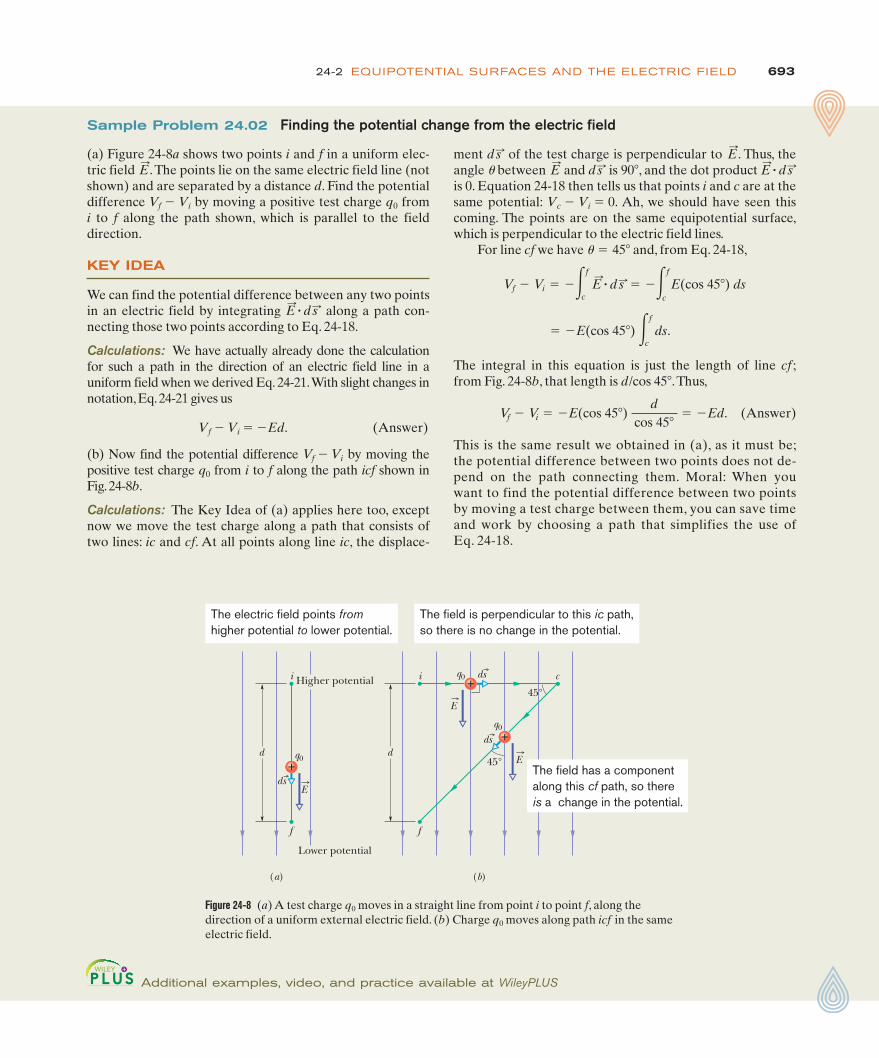
Figure 24-8 (a) A test charge q0 moves in a straight line from point i to point f, along thedirection of a uniform external electric field. (b) Charge q0 moves along path icf in the sameelectric field.
ment of the test charge is perpendicular to . Thus, theangle u between and is 90 , and the dot product is 0. Equation 24-18 then tells us that points i and c are at thesame potential: Vc $ Vi " 0. Ah, we should have seen thiscoming. The points are on the same equipotential surface,which is perpendicular to the electric field lines.
For line cf we have u 45 and, from Eq. 24-18,
The integral in this equation is just the length of line cf ;from Fig. 24-8b, that length is d/cos 45'.Thus,
(Answer)
This is the same result we obtained in (a), as it must be;the potential difference between two points does not de-pend on the path connecting them. Moral: When youwant to find the potential difference between two pointsby moving a test charge between them, you can save timeand work by choosing a path that simplifies the use ofEq. 24-18.
Vf $ Vi " $E(cos 45')d
cos 45'" $Ed.
" $E(cos 45') #f
cds.
Vf $ Vi " $#f
cE:
! d s: " $#f
cE(cos 45') ds
'"
E:
! d s:'d s:E:
E:
d s:
Sample Problem 24.02 Finding the potential change from the electric field
(a) Figure 24-8a shows two points i and f in a uniform elec-tric field .The points lie on the same electric field line (notshown) and are separated by a distance d. Find the potentialdifference Vf $ Vi by moving a positive test charge q0 fromi to f along the path shown, which is parallel to the fielddirection.
KEY IDEA
We can find the potential difference between any two pointsin an electric field by integrating along a path con-necting those two points according to Eq. 24-18.
Calculations: We have actually already done the calculationfor such a path in the direction of an electric field line in auniform field when we derived Eq. 24-21.With slight changes innotation,Eq.24-21 gives us
Vf $ Vi " $Ed. (Answer)
(b) Now find the potential difference Vf $ Vi by moving thepositive test charge q0 from i to f along the path icf shown inFig.24-8b.
Calculations: The Key Idea of (a) applies here too, exceptnow we move the test charge along a path that consists oftwo lines: ic and cf. At all points along line ic, the displace-
E:
! d s:
E:
(a) (b)
d
i
f
q0d
i
f
q0
q0
c
45°
45°+
+
+
ds
ds
ds
E
E
E
The electric field points fromhigher potential to lower potential.
The field is perpendicular to this ic path, so there is no change in the potential.
The field has a componentalong this cf path, so thereis a change in the potential.
Higher potential
Lower potential
Additional examples, video, and practice available at WileyPLUS

694 CHAPTER 24 ELECTRIC POTENTIAL
q0
r
R
P
q
+
+
dsE
To find the potential ofthe charged particle,we move this test chargeout to infinity.
Figure 24-9 The particle with positive chargeq produces an electric field and an elec-tric potential V at point P. We find thepotential by moving a test charge q0 fromP to infinity. The test charge is shown atdistance r from the particle, during differ-ential displacement .d s:
E:
24-3 POTENTIAL DUE TO A CHARGED PARTICLE
After reading this module, you should be able to . . .
24.14 For a given point in the electric field of a charged parti-cle, apply the relationship between the electric potential V,the charge of the particle q, and the distance r from theparticle.
24.15 Identify the correlation between the algebraic signs of thepotential set up by a particle and the charge of the particle.
24.16 For points outside or on the surface of a spherically
symmetric charge distribution, calculate the electricpotential as if all the charge is concentrated as a particleat the center of the sphere.
24.17 Calculate the net potential at any given point due toseveral charged particles, identifying that algebraic addi-tion is used, not vector addition.
24.18 Draw equipotential lines for a charged particle.
Learning Objectives
! The electric potential due to a single charged particle at adistance r from that charged particle is
where V has the same sign as q.
V "1
4p´0
qr
,
! The potential due to a collection of charged particles is
Thus, the potential is the algebraic sum of the individual po-tentials, with no consideration of directions.
V " $n
i"1Vi "
14p´0
$n
i"1
qi
ri.
Key Ideas
Potential Due to a Charged ParticleWe now use Eq. 24-18 to derive, for the space around a charged particle, anexpression for the electric potential V relative to the zero potential at infinity.Consider a point P at distance R from a fixed particle of positive charge q (Fig. 24-9).To use Eq. 24-18, we imagine that we move a positive test charge q0 from point P toinfinity. Because the path we take does not matter, let us choose the simplest one—a line that extends radially from the fixed particle through P to infinity.
To use Eq. 24-18, we must evaluate the dot product
(24-22)
The electric field in Fig. 24-9 is directed radially outward from the fixed particle.Thus, the differential displacement of the test particle along its path hasthe same direction as . That means that in Eq. 24-22, angle u 0 and cos u 1.Because the path is radial, let us write ds as dr.Then, substituting the limits R and #,we can write Eq. 24-18 as
(24-23)
Next, we set Vf " 0 (at #) and Vi " V (at R). Then, for the magnitude of theelectric field at the site of the test charge, we substitute from Eq. 22-3:
(24-24)
With these changes, Eq. 24-23 then gives us
(24-25)" $1
4p´0
qR
.
0 $ V " $q
4p´0##
R
1r2 dr "
q4p´0
% 1r &
#
R
E "1
4p´0
qr2 .
Vf $ Vi " $##
RE dr.
""E:
d s:E:
E:
! d s: " E cos ) ds.

69524-3 POTENTIAL DUE TO A CHARGED PARTICLE
Solving for V and switching R to r, we then have
(24-26)
as the electric potential V due to a particle of charge q at any radial distancer from the particle.
Although we have derived Eq. 24-26 for a positively charged particle, thederivation holds also for a negatively charged particle, in which case, q is a nega-tive quantity. Note that the sign of V is the same as the sign of q:
V "1
4p´0
qr
A positively charged particle produces a positive electric potential. A negativelycharged particle produces a negative electric potential.
Figure 24-10 A computer-generated plot ofthe electric potential V(r) due to a positive-ly charged particle located at the origin ofan xy plane. The potentials at points in thexy plane are plotted vertically. (Curvedlines have been added to help you visual-ize the plot.) The infinite value of V pre-dicted by Eq. 24-26 for r " 0 is not plotted.
x
y
V(r)
Figure 24-10 shows a computer-generated plot of Eq. 24-26 for a positivelycharged particle; the magnitude of V is plotted vertically. Note that the magni-tude increases as r : 0. In fact, according to Eq. 24-26, V is infinite at r " 0,although Fig. 24-10 shows a finite, smoothed-off value there.
Equation 24-26 also gives the electric potential either outside or on the exter-nal surface of a spherically symmetric charge distribution. We can prove this byusing one of the shell theorems of Modules 21-1 and 23-6 to replace the actualspherical charge distribution with an equal charge concentrated at its center.Then the derivation leading to Eq. 24-26 follows, provided we do not considera point within the actual distribution.
Potential Due to a Group of Charged ParticlesWe can find the net electric potential at a point due to a group of charged parti-cles with the help of the superposition principle. Using Eq. 24-26 with the plus orminus sign of the charge included, we calculate separately the potential resultingfrom each charge at the given point. Then we sum the potentials. Thus, for ncharges, the net potential is
(n charged particles). (24-27)
Here qi is the value of the ith charge and ri is the radial distance of the given pointfrom the ith charge. The sum in Eq. 24-27 is an algebraic sum, not a vector sumlike the sum that would be used to calculate the electric field resulting froma group of charged particles. Herein lies an important computational advantageof potential over electric field: It is a lot easier to sum several scalar quantitiesthan to sum several vector quantities whose directions and components mustbe considered.
V " $n
i"1Vi "
14p´0
$n
i"1
qi
ri
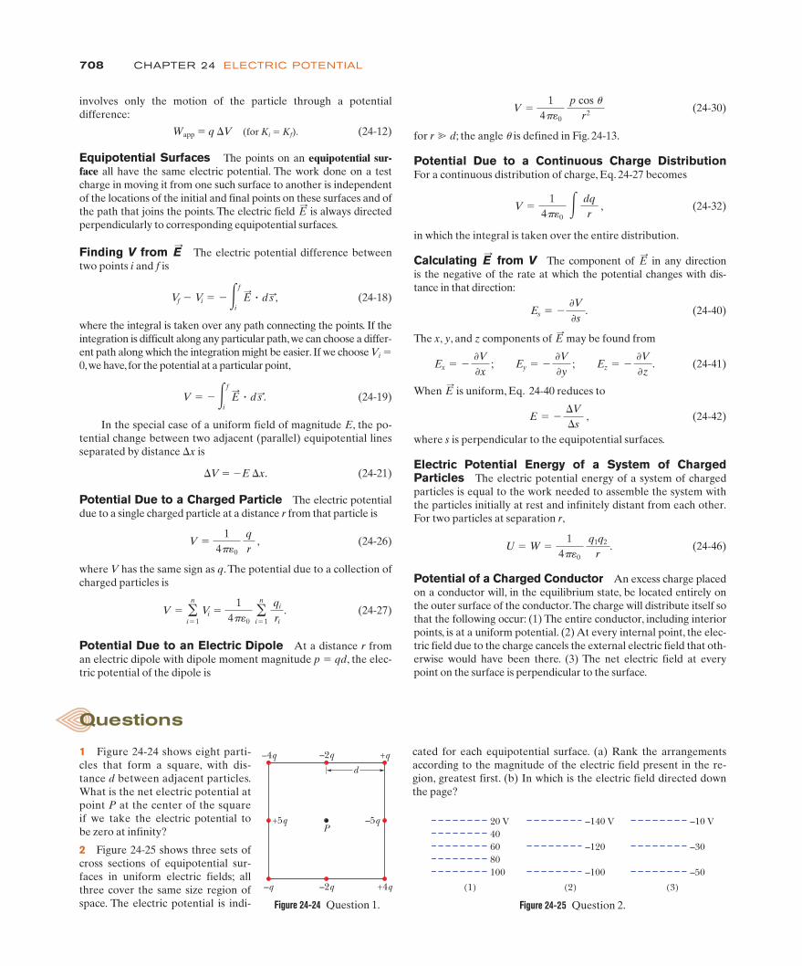
Checkpoint 3The figure here shows three arrangements of two protons. Rank the arrangements ac-cording to the net electric potential produced at point P by the protons, greatest first.
Pd
D
(b)P
DdD
d
P(a) (c)

696 CHAPTER 24 ELECTRIC POTENTIAL
electric potential is a scalar, the orientations of the electronsdo not matter. (2) The electric field at C is a vector quantityand thus the orientation of the electrons is important.
Calculations: Because the electrons all have the same nega-tive charge $e and are all the same distance R from C, Eq.24-27 gives us
(Answer) (24-28)
Because of the symmetry of the arrangement in Fig. 24-12a,the electric field vector at C due to any given electron iscanceled by the field vector due to the electron that is dia-metrically opposite it.Thus, at C,
(Answer)
(b) The electrons are moved along the circle until they arenonuniformly spaced over a 120' arc (Fig. 24-12b).At C, findthe electric potential and describe the electric field.
Reasoning: The potential is still given by Eq. 24-28, becausethe distance between C and each electron is unchanged andorientation is irrelevant. The electric field is no longer zero,however, because the arrangement is no longer symmetric.A net field is now directed toward the charge distribution.
E:
" 0.
V " $121
4p´0
eR
.
Sample Problem 24.04 Potential is not a vector, orientation is irrelevant
(a) In Fig. 24-12a, 12 electrons (of charge e) are equallyspaced and fixed around a circle of radius R. Relative to V " 0 at infinity, what are the electric potential and electricfield at the center C of the circle due to these electrons?
KEY IDEAS
(1) The electric potential V at C is the algebraic sum of theelectric potentials contributed by all the electrons. Because
$
Additional examples, video, and practice available at WileyPLUS
Figure 24-12 (a) Twelve electrons uniformly spaced around a circle.(b)The electrons nonuniformly spaced along an arc of the original circle.
R
CR
C
(a) (b)
120°
Potential is a scalar and orientation is irrelevant.
(Because electric potential is a scalar, the orientations of theparticles do not matter.)
Calculations: From Eq. 24-27, we have
The distance r is , which is 0.919 m, and the sum of thecharges is
Thus,
(Answer)
Close to any of the three positively charged particles inFig. 24-11a, the potential has very large positive values.Close to the single negative charge, the potential has verylarge negative values.Therefore, there must be points withinthe square that have the same intermediate potential as thatat point P.The curve in Fig. 24-11b shows the intersection ofthe plane of the figure with the equipotential surface thatcontains point P.
' 350 V.
V "(8.99 ( 109 N &m2/C2)(36 ( 10$9 C)
0.919 m
" 36 ( 10$9 C.
q1 % q2 % q3 % q4 " (12 $ 24 % 31 % 17) ( 10$9 C
d/1 2
V " $4
i"1Vi "
14p´0
! q1
r%
q2
r%
q3
r%
q4
r ".
Sample Problem 24.03 Net potential of several charged particles
What is the electric potential at point P, located at the cen-ter of the square of charged particles shown in Fig. 24-11a?The distance d is 1.3 m, and the charges are
KEY IDEA
The electric potential V at point P is the algebraic sum ofthe electric potentials contributed by the four particles.
q2 " $24 nC, q4 " %17 nC.
q1 " %12 nC, q3 " %31 nC,
Figure 24-11 (a) Four charged particles. (b) The closed curve is a(roughly drawn) cross section of the equipotential surface thatcontains point P.
d d
d
d
P
q1 q2
q3 q4
P
q1 q2
q3 q4
V = 350 V
(a) (b)

69724-4 POTENTIAL DUE TO AN ELECTRIC DIPOLE
24-4 POTENTIAL DUE TO AN ELECTRIC DIPOLE
After reading this module, you should be able to . . .
24.19 Calculate the potential V at any given point due to anelectric dipole, in terms of the magnitude p of the dipolemoment or the product of the charge separation d and themagnitude q of either charge.
24.20 For an electric dipole, identify the locations of positivepotential, negative potential, and zero potential.
24.21 Compare the decrease in potential with increasing dis-tance for a single charged particle and an electric dipole.
Learning Objectives
! At a distance r from an electric dipole with dipole moment magnitude p qd, the electric potential of the dipole is
for ; the angle u lies between the dipole moment vector and a line extending from the dipole midpoint to the point ofmeasurement.
r * d
V "1
4p´0
p cos ur2
"
Key Idea
z
d O
!
+q
–q
r(–) – r(+)
r(–)
r(+)
r
P
(a)
+
z
d!
r(–) – r(+)
r(–)
r(+)
(b)
++q
–q
Figure 24-13 (a) Point P is a distance r fromthe midpoint O of a dipole. The line OPmakes an angle u with the dipole axis.(b) If P is far from the dipole, the lines oflengths r(%) and r($) are approximatelyparallel to the line of length r, and thedashed black line is approximately per-pendicular to the line of length r($).
Potential Due to an Electric DipoleNow let us apply Eq. 24-27 to an electric dipole to find the potential at an arbitrary point P in Fig. 24-13a. At P, the positively charged particle (at distancer(%)) sets up potential V(%) and the negatively charged particle (at distance r($))sets up potential V($).Then the net potential at P is given by Eq. 24-27 as
(24-29)
Naturally occurring dipoles — such as those possessed by many mole-cules — are quite small; so we are usually interested only in points that are rel-atively far from the dipole, such that , where d is the distance betweenthe charges and r is the distance from the dipole’s midpoint to P. In that case,we can approximate the two lines to P as being parallel and their length dif-ference as being the leg of a right triangle with hypotenuse d (Fig. 24-13b).Also, that difference is so small that the product of the lengths is approxi-mately r 2. Thus,
r($) $ r(%) ' d cos u and r($)r(%) ' r 2.
If we substitute these quantities into Eq. 24-29, we can approximate V to be
where u is measured from the dipole axis as shown in Fig. 24-13a. We can nowwrite V as
(electric dipole), (24-30)
in which p (" qd) is the magnitude of the electric dipole moment defined inModule 22-3. The vector is directed along the dipole axis, from the negative tothe positive charge. (Thus, u is measured from the direction of .) We use thisvector to report the orientation of an electric dipole.
p:p:
p:
V "1
4p´0
p cos ur2
V "q
4p´0
d cos )r2 ,
r * d
"q
4p´0
r($) $ r(%)
r($)r(%).
V " $2
i"1Vi " V(%) % V($) "
14p´0
! qr(%)
%$qr($)
"

698 CHAPTER 24 ELECTRIC POTENTIAL
Potential Due to a Continuous Charge DistributionWhen a charge distribution q is continuous (as on a uniformly charged thin rodor disk), we cannot use the summation of Eq. 24-27 to find the potential V at a pointP. Instead, we must choose a differential element of charge dq, determine thepotential dV at P due to dq, and then integrate over the entire charge distribution.
Let us again take the zero of potential to be at infinity. If we treat the element ofcharge dq as a particle, then we can use Eq. 24-26 to express the potential dV at pointP due to dq:
(positive or negative dq). (24-31)
Here r is the distance between P and dq. To find the total potential V at P, we
dV "1
4p´0
dqr
+
(a)
+
(b)
p
E
The electric field shifts the positive and negative charges, creating a dipole.
Figure 24-14 (a) An atom, showing the posi-tively charged nucleus (green) and thenegatively charged electrons (goldshading). The centers of positive and nega-tive charge coincide. (b) If the atom isplaced in an external electric field , theelectron orbits are distorted so that thecenters of positive and negative charge nolonger coincide. An induced dipolemoment appears. The distortion is great-ly exaggerated here.
p:
E:
24-5 POTENTIAL DUE TO A CONTINUOUS CHARGE DISTRIBUTION
After reading this module, you should be able to . . .
24.22 For charge that is distributed uniformly along a line or over a surface, find the net potential at a given point by splitting thedistribution up into charge elements and summing (by integration) the potential due to each one.
Learning Objective
! For a continuous distribution of charge (over an extendedobject), the potential is found by (1) dividing the distributioninto charge elements dq that can be treated as particles andthen (2) summing the potential due to each element by inte-grating over the full distribution:
V "1
4p+0# dq
r.
! In order to carry out the integration, dq is replaced with theproduct of either a linear charge density l and a length ele-ment (such as dx), or a surface charge density s and area ele-ment (such as dx dy).! In some cases where the charge is symmetrically distrib-uted, a two-dimensional integration can be reduced to a one-dimensional integration.
Key Ideas
Induced Dipole MomentMany molecules, such as water, have permanent electric dipole moments. In othermolecules (called nonpolar molecules) and in every isolated atom, the centers ofthe positive and negative charges coincide (Fig. 24-14a) and thus no dipolemoment is set up. However, if we place an atom or a nonpolar molecule in anexternal electric field, the field distorts the electron orbits and separates the centersof positive and negative charge (Fig. 24-14b). Because the electrons are negativelycharged, they tend to be shifted in a direction opposite the field.This shift sets up adipole moment that points in the direction of the field. This dipole moment issaid to be induced by the field, and the atom or molecule is then said to be polar-ized by the field (that is, it has a positive side and a negative side).When the field isremoved, the induced dipole moment and the polarization disappear.
p:
Checkpoint 4Suppose that three points are set at equal (large) distances r from the center of thedipole in Fig. 24-13: Point a is on the dipole axis above the positive charge, point b is onthe axis below the negative charge, and point c is on a perpendicular bisector throughthe line connecting the two charges. Rank the points according to the electric potentialof the dipole there, greatest (most positive) first.

69924-5 POTENTIAL DUE TO A CONTINUOUS CHARGE DISTRIBUTION
integrate to sum the potentials due to all the charge elements:
(24-32)
The integral must be taken over the entire charge distribution. Note that becausethe electric potential is a scalar, there are no vector components to consider inEq. 24-32.
We now examine two continuous charge distributions, a line and a disk.
Line of ChargeIn Fig. 24-15a, a thin nonconducting rod of length L has a positive charge ofuniform linear density l. Let us determine the electric potential V due to the rodat point P, a perpendicular distance d from the left end of the rod.
We consider a differential element dx of the rod as shown in Fig. 24-15b. This(or any other) element of the rod has a differential charge of
dq " l dx. (24-33)
This element produces an electric potential dV at point P, which is a distance r " (x2 % d 2)1/2 from the element (Fig. 24-15c). Treating the element as a pointcharge, we can use Eq. 24-31 to write the potential dV as
(24-34)dV "1
4p´0
dqr
"1
4p´0
l dx(x2 % d 2)1/2 .
V " # dV "1
4p´0# dq
r.
(b)
d
P
xdxL
d
P
x
(a)
d = r
P
x
(d )
(c)
x
d
P
xdx
r
x = 0
d r
P
x
(e)
x = L
This charged rodis obviously not aparticle.
Our job is to add thepotentials due to allthe elements.
Here is the leftmostelement.
Here is the rightmostelement.
But we can treat thiselement as a particle.
Here is how to finddistance r from theelement.
Figure 24-15 (a) A thin, uniformly charged rod produces an electric potential V at point P. (b) Anelement can be treated as a particle. (c) The potential at P due to the element depends on thedistance r. We need to sum the potentials due to all the elements, from the left side (d) to theright side (e).
A

700 CHAPTER 24 ELECTRIC POTENTIAL
Since the charge on the rod is positive and we have taken V " 0 at infinity, weknow from Module 24-3 that dV in Eq. 24-34 must be positive.
We now find the total potential V produced by the rod at point P by integrat-ing Eq. 24-34 along the length of the rod, from x " 0 to x " L (Figs. 24-15d and e),using integral 17 in Appendix E.We find
We can simplify this result by using the general relation ln A ln B ln(A/B).We then find
(24-35)
Because V is the sum of positive values of dV, it too is positive, consistent withthe logarithm being positive for an argument greater than 1.
Charged DiskIn Module 22-5, we calculated the magnitude of the electric field at points on thecentral axis of a plastic disk of radius R that has a uniform charge density s onone surface. Here we derive an expression for V(z), the electric potential at anypoint on the central axis. Because we have a circular distribution of charge on thedisk, we could start with a differential element that occupies angle du and radialdistance dr. We would then need to set up a two-dimensional integration.However, let’s do something easier.
In Fig. 24-16, consider a differential element consisting of a flat ring of radiusR, and radial width dR,. Its charge has magnitude
dq " s(2pR,)(dR,),
in which (2pR,)(dR,) is the upper surface area of the ring. All parts of thischarged element are the same distance r from point P on the disk’s axis. With theaid of Fig. 24-16, we can use Eq. 24-31 to write the contribution of this ring tothe electric potential at P as
(24-36)
We find the net potential at P by adding (via integration) the contributions of allthe rings from R, " 0 to R, " R:
(24-37)
Note that the variable in the second integral of Eq. 24-37 is R, and not z, whichremains constant while the integration over the surface of the disk is carried out.(Note also that, in evaluating the integral, we have assumed that z - 0.)
V " #dV "s
2´0#R
0
R, dR,2z2 % R,2"
s
2´0 (2z2 % R2 $ z).
dV "1
4p´0
dqr
"1
4p´0
s(2pR,)(dR,)2z2 % R,2.
V "l
4p´0 ln % L % (L2 % d 2)1/2
d &.
"$
"l
4p´0%ln!L % (L2 % d2)1/2" $ ln d&.
"l
4p´0%ln!x % (x2 % d 2)1/2"&
0
L
"l
4p´0#L
0
dx(x2 % d 2)1/2
V " #dV " #L
0
14p´0
l
(x2 % d 2)1/2 dx
zr
P
R'
RdR'
Every charge elementin the ring contributesto the potential at P.
Figure 24-16 A plastic disk of radius R,charged on its top surface to a uniformsurface charge density s. We wish tofind the potential V at point P on thecentral axis of the disk.

70124-6 CALCULATING THE FIELD FROM THE POTENTIAL
Calculating the Field from the PotentialIn Module 24-2, you saw how to find the potential at a point f if you knowthe electric field along a path from a reference point to point f. In this module,we propose to go the other way—that is, to find the electric field when we knowthe potential. As Fig. 24-5 shows, solving this problem graphically is easy: If weknow the potential V at all points near an assembly of charges, we can draw ina family of equipotential surfaces. The electric field lines, sketched perpendicularto those surfaces, reveal the variation of .What we are seeking here is the math-ematical equivalent of this graphical procedure.
Figure 24-17 shows cross sections of a family of closely spaced equipo-tential surfaces, the potential difference between each pair of adjacent surfacesbeing dV.As the figure suggests, the field at any point P is perpendicular to theequipotential surface through P.
Suppose that a positive test charge q0 moves through a displacement from one equipotential surface to the adjacent surface. From Eq. 24-6, we see thatthe work the electric field does on the test charge during the move is $q0 dV.From Eq. 24-16 and Fig. 24-17, we see that the work done by the electric field mayalso be written as the scalar product or q0E(cos u) ds. Equating thesetwo expressions for the work yields
$q0 dV " q0E(cos u) ds, (24-38)
or (24-39)
Since E cos u is the component of in the direction of Eq. 24-39 becomes
(24-40)
We have added a subscript to E and switched to the partial derivative symbolsto emphasize that Eq. 24-40 involves only the variation of V along a specified axis(here called the s axis) and only the component of along that axis. In words,Eq. 24-40 (which is essentially the reverse operation of Eq. 24-18) states:
E:
Es " $.V.s
.
d s:,E:
E cos u " $dVds
.
(q0E:
) ! d s:,
d s:
E:
E:
sq0
P !
Twoequipotential
surfaces
+ds
E
Figure 24-17 A test charge q0 moves a distance from one equipotential sur-face to another. (The separation betweenthe surfaces has been exaggerated for clar-ity.) The displacement makes an angleu with the direction of the electric field .E
:ds:
ds:
24-6 CALCULATING THE FIELD FROM THE POTENTIAL
After reading this module, you should be able to . . .
24.23 Given an electric potential as a function of positionalong an axis, find the electric field along that axis.
24.24 Given a graph of electric potential versus positionalong an axis, determine the electric field along the axis.
24.25 For a uniform electric field, relate the field magnitude E
and the separation x and potential difference Vbetween adjacent equipotential lines.
24.26 Relate the direction of the electric field and the directions in which the potential decreases and increases.
!!
Learning Objectives
! The component of in any direction is the negative of the rate atwhich the potential changes with distance in that direction:
! The x, y, and z components of may be found from
Ex " $.V.x
; Ey " $.V.y
; Ez " $.V.z
.
E:
Es " $.V.s
.
E:
When is uniform, all this reduces to
where s is perpendicular to the equipotential surfaces. ! The electric field is zero parallel to an equipotential surface.
E " $!V!s
,
E:
Key Ideas

702 CHAPTER 24 ELECTRIC POTENTIAL
Checkpoint 5The figure showsthree pairs of parallelplates with the sameseparation, and theelectric potential ofeach plate.The elec-tric field between theplates is uniform andperpendicular to the plates. (a) Rank the pairs according to the magnitude of the elec-tric field between the plates, greatest first. (b) For which pair is the electric field point-ing rightward? (c) If an electron is released midway between the third pair of plates,does it remain there, move rightward at constant speed, move leftward at constantspeed, accelerate rightward, or accelerate leftward?
–50 V +150 V –20 V +200 V –200 V –400 V (1) (2) (3)
about that axis. Thus, we want the component Ez of in thedirection of z. This component is the negative of the rate atwhich the electric potential changes with distance z.
Calculation: Thus, from the last of Eqs. 24-41, we can write
(Answer)
This is the same expression that we derived in Module 22-5by integration, using Coulomb’s law.
"s
2´0!1 $
z2z2 % R2 ".
Ez " $.V.z
" $s
2´0
ddz
(2z2 % R2 $ z)
E:
Sample Problem 24.05 Finding the field from the potential
The electric potential at any point on the central axis of auniformly charged disk is given by Eq. 24-37,
Starting with this expression, derive an expression for theelectric field at any point on the axis of the disk.
KEY IDEAS
We want the electric field as a function of distance z alongthe axis of the disk. For any value of z, the direction of mustbe along that axis because the disk has circular symmetry
E:
E:
V "s
2´0 (2z2 % R2 $ z).
Additional examples, video, and practice available at WileyPLUS
If we take the s axis to be, in turn, the x, y, and z axes, we find that the x, y, andz components of at any point are
(24-41)
Thus, if we know V for all points in the region around a charge distribution—thatis, if we know the function V(x, y, z)—we can find the components of , and thus
itself, at any point by taking partial derivatives.For the simple situation in which the electric field is uniform, Eq. 24-40
becomes(24-42)
where s is perpendicular to the equipotential surfaces. The component of theelectric field is zero in any direction parallel to the equipotential surfaces becausethere is no change in potential along the surfaces.
E " $!V!s
,
E:
E:
E:
Ex " $.V.x
; Ey " $.V.y
; Ez " $.V.z
.
E:
The component of in any direction is the negative of the rate at which theelectric potential changes with distance in that direction.
E:

70324-7 ELECTRIC POTENTIAL ENERGY OF A SYSTEM OF CHARGED PARTICLES
Electric Potential Energy of a System of Charged ParticlesIn this module we are going to calculate the potential energy of a system of twocharged particles and then briefly discuss how to expand the result to a system ofmore than two particles. Our starting point is to examine the work we must do (asan external agent) to bring together two charged particles that are initially infi-nitely far apart and that end up near each other and stationary. If the two parti-cles have the same sign of charge, we must fight against their mutual repulsion.Our work is then positive and results in a positive potential energy for the finaltwo-particle system. If, instead, the two particles have opposite signs of charge,our job is easy because of the mutual attraction of the particles. Our work is thennegative and results in a negative potential energy for the system.
Let’s follow this procedure to build the two-particle system in Fig. 24-18, whereparticle 1 (with positive charge q1) and particle 2 (with positive charge q2) have sep-aration r. Although both particles are positively charged, our result will apply alsoto situations where they are both negatively charged or have different signs.
We start with particle 2 fixed in place and particle 1 infinitely far away, withan initial potential energy Ui for the two-particle system. Next we bring particle 1to its final position, and then the system’s potential energy is Uf. Our workchanges the system’s potential energy by !U " Uf $ Ui.
With Eq. 24-4 (!U " q(Vf $ Vi)), we can relate !U to the change in potentialthrough which we move particle 1:
Uf $ Ui " q1(Vf $ Vi). (24-43)
Let’s evaluate these terms.The initial potential energy is Ui " 0 because the parti-cles are in the reference configuration (as discussed in Module 24-1). The twopotentials in Eq. 24-43 are due to particle 2 and are given by Eq. 24-26:
(24-44)
This tells us that when particle 1 is initially at distance r " #, the potential at itslocation is Vi " 0. When we move it to the final position at distance r, the poten-tial at its location is
(24-45)Vf "1
4p´0
q2
r.
V "1
4p´0
q2
r.
rq1 q2+ +
Figure 24-18 Two charges held a fixeddistance r apart.
24-7 ELECTRIC POTENTIAL ENERGY OF A SYSTEM OF CHARGED PARTICLES
After reading this module, you should be able to . . .
24.27 Identify that the total potential energy of a system ofcharged particles is equal to the work an applied forcemust do to assemble the system, starting with the particlesinfinitely far apart.
24.28 Calculate the potential energy of a pair of chargedparticles.
24.29 Identify that if a system has more than two charged parti-
cles, then the system’s total potential energy is equal to thesum of the potential energies of every pair of the particles.
24.30 Apply the principle of the conservation of mechanicalenergy to a system of charged particles.
24.31 Calculate the escape speed of a charged particle from a system of charged particles (the minimum initialspeed required to move infinitely far from the system).
Learning Objectives
! The electric potential energy of a system of charged particles is equal to the work needed to assemble the system with theparticles initially at rest and infinitely distant from each other. For two particles at separation r,
U " W "1
4p´0
q1q2
r.
Key Idea

704 CHAPTER 24 ELECTRIC POTENTIAL
Substituting these results into Eq. 24-43 and dropping the subscript f, we find thatthe final configuration has a potential energy of
(two-particle system). (24-46)
Equation 24-46 includes the signs of the two charges. If the two charges have thesame sign, U is positive. If they have opposite signs, U is negative.
If we next bring in a third particle, with charge q3, we repeat our calculation,starting with particle 3 at an infinite distance and then bringing it to a final posi-tion at distance r31 from particle 1 and distance r32 from particle 2. At the finalposition, the potential Vf at the location of particle 3 is the algebraic sum of thepotential V1 due to particle 1 and the potential V2 of particle 2. When we workout the algebra, we find that
U "1
4p´0
q1q2
r
place. The work that we must do in this last step is equal tothe sum of the work we must do to bring q3 near q1 and thework we must do to bring it near q2. From Eq. 24-46, with dsubstituted for r, that sum is
The total potential energy U of the three-charge system is thesum of the potential energies associated with the three pairs ofcharges. This sum (which is actually independent of the orderin which the charges are brought together) is
W13 % W23 " U13 % U23 "1
4p´0
q1q3
d%
14p´0
q2q3
d.
Sample Problem 24.06 Potential energy of a system of three charged particles
Figure 24-19 shows three charged particles held in fixedpositions by forces that are not shown. What is the electricpotential energy U of this system of charges? Assume thatd " 12 cm and that
q1 " %q, q2 " $4q, and q3 " %2q,
in which q " 150 nC.
KEY IDEA
The potential energy U of the system is equal to the workwe must do to assemble the system, bringing in each chargefrom an infinite distance.
Calculations: Let’s mentally build the system of Fig. 24-19,starting with one of the charges, say q1, in place and theothers at infinity. Then we bring another one, say q2, in frominfinity and put it in place. From Eq. 24-46 with d substitutedfor r, the potential energy U12 associated with the pair ofcharges q1 and q2 is
We then bring the last charge q3 in from infinity and put it in
U12 "1
4p´0
q1q2
d.
Figure 24-19 Three charges are fixed at the vertices of an equilateraltriangle.What is the electric potential energy of the system?
dq1 q3
d d
q2
+ +
Energy is associatedwith each pair ofparticles.
The total potential energy of a system of particles is the sum of the potentialenergies for every pair of particles in the system.
This result applies to a system for any given number of particles.Now that we have an expression for the potential energy of a system of par-
ticles, we can apply the principle of the conservation of energy to the system asexpressed in Eq. 24-10. For example, if the system consists of many particles, wemight consider the kinetic energy (and the associated escape speed) required ofone of the particles to escape from the rest of the particles.

705
Additional examples, video, and practice available at WileyPLUS
r
Alphaparticle
Goldnucleus
Figure 24-20 An alpha particle, traveling head-on toward the center ofa gold nucleus,comes to a momentary stop (at which time all its ki-netic energy has been transferred to electric potential energy) andthen reverses its path.
As the incoming alpha particle is slowed by this repul-sive force, its kinetic energy is transferred to electric poten-tial energy of the system. The transfer is complete when thealpha particle momentarily stops and the kinetic energy isKf " 0.
Calculations: The principle of conservation of mechanicalenergy tells us that
Ki % Ui " Kf % Uf. (24-47)
We know two values: Ui " 0 and Kf " 0. We also know thatthe potential energy Uf at the stopping point is given by theright side of Eq. 24-46, with q1 " 2e, q2 " 79e (in which e isthe elementary charge, 1.60 ( 10$19 C), and r " 9.23 fm.Thus, we can rewrite Eq. 24-47 as
(Answer)" 3.94 ( 10$12 J " 24.6 MeV.
"(8.99 ( 109 N&m2/C2)(158)(1.60 ( 10$19 C)2
9.23 ( 10$15 m
Ki "1
4p´0
(2e)(79e)9.23 fm
Sample Problem 24.07 Conservation of mechanical energy with electric potential energy
An alpha particle (two protons, two neutrons) moves into astationary gold atom (79 protons, 118 neutrons), passingthrough the electron region that surrounds the gold nucleuslike a shell and headed directly toward the nucleus (Fig. 24-20). The alpha particle slows until it momentarilystops when its center is at radial distance r " 9.23 fm fromthe nuclear center. Then it moves back along its incomingpath. (Because the gold nucleus is much more massivethan the alpha particle, we can assume the gold nucleusdoes not move.) What was the kinetic energy Ki of the al-pha particle when it was initially far away (hence externalto the gold atom)? Assume that the only force acting be-tween the alpha particle and the gold nucleus is the (elec-trostatic) Coulomb force and treat each as a single chargedparticle.
KEY IDEA
During the entire process, the mechanical energy of the alpha particle % gold atom system is conserved.
Reasoning: When the alpha particle is outside the atom,the system’s initial electric potential energy Ui is zero be-cause the atom has an equal number of electrons and pro-tons, which produce a net electric field of zero. However,once the alpha particle passes through the electron regionsurrounding the nucleus on its way to the nucleus, the elec-tric field due to the electrons goes to zero.The reason is thatthe electrons act like a closed spherical shell of uniform neg-ative charge and, as discussed in Module 23-6, such a shellproduces zero electric field in the space it encloses. Thealpha particle still experiences the electric field of theprotons in the nucleus, which produces a repulsive force onthe protons within the alpha particle.
(Answer)" $1.7 ( 10$2 J " $17 mJ.
" $(8.99 ( 109 N&m2/C2)(10)(150 ( 10$9 C)2
0.12 m
" $10q2
4p´0d
"1
4p´0! (%q)($4q)
d%
(%q)(%2q)d
%($4q)(%2q)
d "U " U12 % U13 % U23 The negative potential energy means that negative
work would have to be done to assemble this structure,starting with the three charges infinitely separated and atrest. Put another way, an external agent would have to do 17mJ of positive work to disassemble the structure completely,ending with the three charges infinitely far apart.
The lesson here is this: If you are given an assembly ofcharged particles, you can find the potential energy of the as-sembly by finding the potential of every possible pair of theparticles and then summing the results.
24-7 ELECTRIC POTENTIAL ENERGY OF A SYSTEM OF CHARGED PARTICLES

706 CHAPTER 24 ELECTRIC POTENTIAL
Potential of a Charged Isolated ConductorIn Module 23-3, we concluded that for all points inside an isolated conduc-tor.We then used Gauss’ law to prove that an excess charge placed on an isolatedconductor lies entirely on its surface. (This is true even if the conductor has anempty internal cavity.) Here we use the first of these facts to prove an extensionof the second:
E:
" 0
An excess charge placed on an isolated conductor will distribute itself on the sur-face of that conductor so that all points of the conductor—whether on the surfaceor inside—come to the same potential. This is true even if the conductor has aninternal cavity and even if that cavity contains a net charge.
Our proof follows directly from Eq. 24-18, which is
Since for all points within a conductor, it follows directly that Vf " Vi forall possible pairs of points i and f in the conductor.
Figure 24-21a is a plot of potential against radial distance r from the centerfor an isolated spherical conducting shell of 1.0 m radius, having a charge of1.0 mC. For points outside the shell, we can calculate V(r) from Eq. 24-26because the charge q behaves for such external points as if it were concentrated atthe center of the shell.That equation holds right up to the surface of the shell. Nowlet us push a small test charge through the shell—assuming a small hole exists—toits center. No extra work is needed to do this because no net electric force acts onthe test charge once it is inside the shell. Thus, the potential at all points inside theshell has the same value as that on the surface, as Fig. 24-21a shows.
E:
" 0
Vf $ Vi " $#f
iE:
! ds:.
12
V (k
V) 8
4
00 1 2 3 4
r (m)
(a)
(b)
12
E (k
V/m
) 8
4
00 1 2 3 4
r (m)
Figure 24-21 (a) A plot of V(r) both insideand outside a charged spherical shell ofradius 1.0 m. (b) A plot of E(r) for thesame shell.
! An excess charge placed on a conductor will, in the equilib-rium state, be located entirely on the outer surface of theconductor.! The entire conductor, including interior points, is at auniform potential.! If an isolated charged conductor is placed in an external
electric field, then at every internal point, the electric field dueto the charge cancels the external electric field that otherwisewould have been there.! Also, the net electric field at every point on the surface isperpendicular to the surface.
Key Ideas
24-8 POTENTIAL OF A CHARGED ISOLATED CONDUCTOR
After reading this module, you should be able to . . .
24.32 Identify that an excess charge placed on an isolatedconductor (or connected isolated conductors) will distrib-ute itself on the surface of the conductor so that all pointsof the conductor come to the same potential.
24.33 For an isolated spherical conducting shell, sketchgraphs of the potential and the electric field magnitudeversus distance from the center, both inside and outsidethe shell.
24.34 For an isolated spherical conducting shell, identify thatinternally the electric field is zero and the electric potential
has the same value as the surface and that externally theelectric field and the electric potential have values asthough all of the shell’s charge is concentrated as aparticle at its center.
24.35 For an isolated cylindrical conducting shell, identifythat internally the electric field is zero and the electricpotential has the same value as the surface and that exter-nally the electric field and the electric potential have valuesas though all of the cylinder’s charge is concentrated as aline of charge on the central axis.
Learning Objectives

707
Figure 24-21b shows the variation of electric field with radial distance for thesame shell. Note that E " 0 everywhere inside the shell.The curves of Fig. 24-21bcan be derived from the curve of Fig. 24-21a by differentiating with respect to r,using Eq. 24-40 (recall that the derivative of any constant is zero). The curve ofFig. 24-21a can be derived from the curves of Fig. 24-21b by integrating withrespect to r, using Eq. 24-19.
Spark Discharge from a Charged ConductorOn nonspherical conductors, a surface charge does not distribute itself uniformlyover the surface of the conductor. At sharp points or sharp edges, the surfacecharge density—and thus the external electric field, which is proportional to it—may reach very high values. The air around such sharp points or edges maybecome ionized, producing the corona discharge that golfers and mountaineerssee on the tips of bushes, golf clubs, and rock hammers when thunderstormsthreaten. Such corona discharges, like hair that stands on end, are often theprecursors of lightning strikes. In such circumstances, it is wise to enclose yourselfin a cavity inside a conducting shell, where the electric field is guaranteed tobe zero. A car (unless it is a convertible or made with a plastic body) is almostideal (Fig. 24-22).
Isolated Conductor in an External Electric FieldIf an isolated conductor is placed in an external electric field, as in Fig. 24-23, allpoints of the conductor still come to a single potential regardless of whether theconductor has an excess charge. The free conduction electrons distribute them-selves on the surface in such a way that the electric field they produce at interiorpoints cancels the external electric field that would otherwise be there.Furthermore, the electron distribution causes the net electric field at all points onthe surface to be perpendicular to the surface. If the conductor in Fig. 24-23 couldbe somehow removed, leaving the surface charges frozen in place, the internaland external electric field would remain absolutely unchanged.
Figure 24-22 A large spark jumps to a car’sbody and then exits by moving across theinsulating left front tire (note the flashthere), leaving the person inside unharmed.
Courtesy Westinghouse Electric Corporation
REVIEW & SUMMARY
Figure 24-23 An uncharged conductor is suspended in an external electric field.The freeelectrons in the conductor distribute themselves on the surface as shown, so as to reducethe net electric field inside the conductor to zero and make the net field at the surfaceperpendicular to the surface.
E = 0
+
++
++
++++
+ + ++++–––––––––– –
––––
Electric Potential The electric potential V at a point P in theelectric field of a charged object is
(24-2)
where is the work that would be done by the electric force on apositive test charge were it brought from an infinite distance to P,and U is the potential energy that would then be stored in the testcharge–object system.
Electric Potential Energy If a particle with charge q isplaced at a point where the electric potential of a charged object isV, the electric potential energy U of the particle–object system is
U " qV. (24-3)
W#
V "$W#
q0"
Uq0
,
Review & Summary
If the particle moves through a potential difference !V, the changein the electric potential energy is
!U " q !V " q(Vf $ Vi). (24-4)
Mechanical Energy If a particle moves through a change !Vin electric potential without an applied force acting on it, applyingthe conservation of mechanical energy gives the change in kineticenergy as
!K " $q !V. (24-9)
If, instead, an applied force acts on the particle, doing work Wapp,the change in kinetic energy is
!K " $q !V % Wapp. (24-11)
In the special case when , the work of an applied force!K " 0
708 CHAPTER 24 ELECTRIC POTENTIAL
20 V 406080100
–140 V
–120
–100
–10 V
–30
–50(1) (2) (3)
Figure 24-25 Question 2.
1 Figure 24-24 shows eight parti-cles that form a square, with dis-tance d between adjacent particles.What is the net electric potential atpoint P at the center of the squareif we take the electric potential tobe zero at infinity?
2 Figure 24-25 shows three sets ofcross sections of equipotential sur-faces in uniform electric fields; allthree cover the same size region ofspace. The electric potential is indi-
Questions
Figure 24-24 Question 1.
–4q
+5q
–q
+q
–5q
+4q–2q
–2q
P
d
involves only the motion of the particle through a potentialdifference:
Wapp " q !V (for Ki " Kf). (24-12)
Equipotential Surfaces The points on an equipotential sur-face all have the same electric potential. The work done on a testcharge in moving it from one such surface to another is independentof the locations of the initial and final points on these surfaces and ofthe path that joins the points. The electric field is always directedperpendicularly to corresponding equipotential surfaces.
Finding V from The electric potential difference betweentwo points i and f is
(24-18)
where the integral is taken over any path connecting the points. If theintegration is difficult along any particular path,we can choose a differ-ent path along which the integration might be easier. If we choose Vi "0,we have, for the potential at a particular point,
(24-19)
In the special case of a uniform field of magnitude E, the po-tential change between two adjacent (parallel) equipotential linesseparated by distance !x is
!V " $E !x. (24-21)
Potential Due to a Charged Particle The electric potentialdue to a single charged particle at a distance r from that particle is
(24-26)
where V has the same sign as q.The potential due to a collection ofcharged particles is
(24-27)
Potential Due to an Electric Dipole At a distance r froman electric dipole with dipole moment magnitude p " qd, the elec-tric potential of the dipole is
V " $n
i"1Vi "
14p´0
$n
i"1
qi
ri.
V "1
4p´0
qr
,
V " $#f
iE:
! d s:.
Vf $ Vi " $#f
iE:
! d s:,
E:
E:
(24-30)
for ; the angle u is defined in Fig. 24-13.
Potential Due to a Continuous Charge DistributionFor a continuous distribution of charge, Eq. 24-27 becomes
(24-32)
in which the integral is taken over the entire distribution.
Calculating from V The component of in any directionis the negative of the rate at which the potential changes with dis-tance in that direction:
(24-40)
The x, y, and z components of may be found from
(24-41)
When is uniform, Eq. 24-40 reduces to
(24-42)
where s is perpendicular to the equipotential surfaces.
Electric Potential Energy of a System of ChargedParticles The electric potential energy of a system of chargedparticles is equal to the work needed to assemble the system withthe particles initially at rest and infinitely distant from each other.For two particles at separation r,
(24-46)
Potential of a Charged Conductor An excess charge placedon a conductor will, in the equilibrium state, be located entirely onthe outer surface of the conductor.The charge will distribute itself sothat the following occur: (1) The entire conductor, including interiorpoints, is at a uniform potential. (2) At every internal point, the elec-tric field due to the charge cancels the external electric field that oth-erwise would have been there. (3) The net electric field at everypoint on the surface is perpendicular to the surface.
U " W "1
4p´0
q1q2
r.
E " $!V!s
,
E:
Ex " $.V.x
; Ey " $.V.y
; Ez " $.V.z
.
E:
Es " $.V.s
.
E:E
:
V "1
4p´0# dq
r,
r * d
V "1
4p´0
p cos ur2
cated for each equipotential surface. (a) Rank the arrangementsaccording to the magnitude of the electric field present in the re-gion, greatest first. (b) In which is the electric field directed downthe page?

709QUESTIONS
Figure 24-26 Questions 3 and 9.
–2q +6q(1)
+3q –4q(2)
+12q +q(3)
–6q –2q(4)
x
x
x
x
3 Figure 24-26 shows four pairs of charged particles. For each pair, letV " 0 at infinity and consider Vnet at points on the x axis. For whichpairs is there a point at which Vnet 0 (a) between the particles and(b) to the right of the particles? (c) At such a point is due to the par-ticles equal to zero? (d) For each pair, are there off-axis points (otherthan at infinity) where Vnet " 0?
E:
net
"
4 Figure 24-27 gives the electricpotential V as a function of x.(a) Rank the five regions accordingto the magnitude of the x compo-nent of the electric field withinthem, greatest first. What is the di-rection of the field along the x axisin (b) region 2 and (c) region 4?
V
x1 2 3 4 5
Figure 24-27 Question 4.
5 Figure 24-28 shows three pathsalong which we can move the posi-tively charged sphere A closer topositively charged sphere B, whichis held fixed in place. (a) Wouldsphere A be moved to a higher orlower electric potential? Is the workdone (b) by our force and (c) by theelectric field due to B positive, negative, or zero? (d) Rank thepaths according to the work our force does, greatest first.
Figure 24-29 Question 6.
(a) (b) (c) (d)
–2q
–q
–2q
–2q
–7q
+2q +2q–4q–2q
–3q–9q
+2q
Figure 24-28 Question 5.
+ + AB 2
3
1
6 Figure 24-29 shows four arrangements of charged particles, allthe same distance from the origin. Rank the situations according tothe net electric potential at the origin, most positive first. Take thepotential to be zero at infinity.
7 Figure 24-30 shows a system of three charged particles. If youmove the particle of charge %q from point A to point D, are thefollowing quantities positive, negative, or zero: (a) the change inthe electric potential energy of the three-particle system, (b) thework done by the net electric force on the particle you moved (thatis, the net force due to the other two particles), and (c) the workdone by your force? (d) What are the answers to (a) through (c) if,instead, the particle is moved from B to C?
+q
A +Q B C +Q D
d d d d d
Figure 24-30 Questions 7 and 8.
8 In the situation of Question 7, is the work done by your forcepositive, negative, or zero if the particle is moved (a) from A to B,(b) from A to C, and (c) from B to D? (d) Rank those movesaccording to the magnitude of the work done by your force,greatest first.
9 Figure 24-26 shows four pairs of charged particles with identi-cal separations. (a) Rank the pairs according to their electricpotential energy (that is, the energy of the two-particle system),greatest (most positive) first. (b) For each pair, if the separation be-tween the particles is increased,does the potential energy of the pairincrease or decrease?
10 (a) In Fig. 24-31a, what is thepotential at point P due to chargeQ at distance R from P? Set V " 0at infinity. (b) In Fig. 24-31b, thesame charge Q has been spreaduniformly over a circular arc of ra-dius R and central angle 40'. Whatis the potential at point P, the cen-ter of curvature of the arc? (c) InFig. 24-31c, the same charge Q hasbeen spread uniformly over a circleof radius R. What is the potential atpoint P, the center of the circle?(d) Rank the three situationsaccording to the magnitude of theelectric field that is set up at P,greatest first.
11 Figure 24-32 shows a thin, uni-formly charged rod and three pointsat the same distance d from the rod. Rank the magnitude of the elec-tric potential the rod produces at those three points, greatest first.
(a)
Q
PR
(b)
Q
PR
(c)
40°(full angle)
Q PR+
Figure 24-31 Question 10.
a b
cd
x
y
L/2 L/2 d
Figure 24-32 Question 11.
A
100 V
B
Figure 24-33Question 12.
12 In Fig. 24-33, a particle is to be released at rest at point Aand then is to be accelerated directly through point B by an elec-tric field. The potential difference between points A and B is 100V. Which point should be at higher electric potential if the parti-cle is (a) an electron, (b) a proton, and (c) an alpha particle (anucleus of two protons and two neutrons)? (d) Rank the kineticenergies of the particles at point B, greatest first.

84 A &h (ampere-hours) through a circuit, from one terminal to theother. (a) How many coulombs of charge does this represent?(Hint: See Eq. 21-3.) (b) If this entire charge undergoes a change inelectric potential of 12 V, how much energy is involved?
•2 The electric potential difference between the ground and acloud in a particular thunderstorm is 1.2 ( 109 V. In the unitelectron-volts, what is the magnitude of the change in the electricpotential energy of an electron that moves between the groundand the cloud?
•3 Suppose that in a lightning flash the potential difference be-tween a cloud and the ground is 1.0 109 V and the quantity ofcharge transferred is 30 C. (a) What is the change in energy of thattransferred charge? (b) If all the energy released could be used toaccelerate a 1000 kg car from rest, what would be its final speed?
Module 24-2 Equipotential Surfaces and the Electric Field•4 Two large, parallel, conducting plates are 12 cm apart and havecharges of equal magnitude and opposite sign on their facing sur-faces. An electric force of 3.9 ( 10$15 N acts on an electron placedanywhere between the two plates. (Neglect fringing.) (a) Find theelectric field at the position of the electron. (b) What is the poten-tial difference between the plates?
•5 An infinite nonconducting sheet has a surface chargedensity s 0.10 mC/m2 on one side. How far apart are equipoten-tial surfaces whose potentials differ by 50 V?
•6 When an electron moves fromA to B along an electric field line inFig. 24-34, the electric field does3.94 10$19 J of work on it. Whatare the electric potential differences(a) VB VA, (b) VC VA, and (c)VC VB?
••7 The electric field in a region ofspace has the components Ey
Ez 0 and Ex (4.00 N/C)x. PointA is on the y axis at y 3.00 m, andpoint B is on the x axis at x 4.00 m. What is the potential differ-ence VB VA?
••8 A graph of the x component of the electric field as a functionof x in a region of space is shown in Fig. 24-35.The scale of the verti-cal axis is set by Exs 20.0 N/C. The y and z components of theelectric field are zero in this region. If the electric potential at the
"
$"
"""
"
$$$
(
"SSM
(
710 CHAPTER 24 ELECTRIC POTENTIAL
B A q
(a)
d2
B
Aq
(b)
d1
d2
d1+ +
Figure 24-36 Problem 14.
••9 An infinite nonconducting sheet has a surface charge densitys 5.80 pC/m2. (a) How much work is done by the electric fielddue to the sheet if a particle of charge q " %1.60 ( 10$19 C ismoved from the sheet to a point P at distance d " 3.56 cm from thesheet? (b) If the electric potential V is defined to be zero on thesheet, what is V at P?
•••10 Two uniformly charged, infinite, nonconducting planes areparallel to a yz plane and positioned at x 50 cm and x 50cm. The charge densities on the planes are 50 nC/m2 and 25nC/m2, respectively. What is the magnitude of the potential differ-ence between the origin and the point on the x axis at x " %80 cm?(Hint: Use Gauss’ law.)
•••11 A nonconducting sphere has radius R " 2.31 cm and uni-formly distributed charge q " %3.50 fC. Take the electric potentialat the sphere’s center to be V0 0. What is V at radial distance(a) r " 1.45 cm and (b) r " R. (Hint: See Module 23-6.)
Module 24-3 Potential Due to a Charged Particle•12 As a space shuttle moves through the dilute ionized gas ofEarth’s ionosphere, the shuttle’s potential is typically changed by$1.0 V during one revolution. Assuming the shuttle is a sphere ofradius 10 m, estimate the amount of charge it collects.
•13 What are (a) the charge and (b) the charge density on thesurface of a conducting sphere of radius 0.15 m whose potential is200 V (with V " 0 at infinity)?
•14 Consider a particle with charge q " 1.0 mC, point A at distanced1 " 2.0 m from q, and point B at distance d2 " 1.0 m. (a) If A and Bare diametrically opposite each other, as in Fig. 24-36a, what is theelectric potential difference VA $ VB? (b) What is that electricpotential difference if A and B are located as in Fig. 24-36b?
"
%$" %" $
%"
Tutoring problem available (at instructor’s discretion) in WileyPLUS and WebAssign
SSM Worked-out solution available in Student Solutions Manual
• – ••• Number of dots indicates level of problem difficulty
Additional information available in The Flying Circus of Physics and at flyingcircusofphysics.com
WWW Worked-out solution is at
ILW Interactive solution is at http://www.wiley.com/college/halliday
Problems
Module 24-1 Electric Potential•1 A particular 12 V car battery can send a total charge ofSSM
Electricfieldline
Equipotentials
A
B
C
Figure 24-34 Problem 6.
Figure 24-35 Problem 8.
E x (
N/C
)
–Exs
Exs
0
x (m)
1 2 3 4 5 6
••15 A spherical drop of water carrying a charge of 30pC has a potential of 500 V at its surface (with V 0 at infinity).(a) What is the radius of the drop? (b) If two such drops of thesame charge and radius combine to form a single spherical drop,what is the potential at the surfaceof the new drop?
••16 Figure 24-37 shows a rec-tangular array of charged particlesfixed in place, with distance a 39.0cm and the charges shown as integermultiples of q1 " 3.40 pC and q2 "6.00 pC. With V " 0 at infinity, what
"
"ILWSSM
a
a
a
a
a a
–q1 +4q2 +2q1
+2q1 +4q2 –3q1
Figure 24-37 Problem 16.
origin is 10 V, (a) what is the electricpotential at x 2.0 m, (b) what isthe greatest positive value of the elec-tric potential for points on the x axisfor which 0 / x / 6.0 m, and (c) forwhat value of x is the electric poten-tial zero?
"

711PROBLEMS
an electric dipole, on the positive side of the dipole. (The origin of zis at the center of the dipole.) The particle is then moved along acircular path around the dipole center until it is at coordinate z "$20 nm, on the negative side of the dipole axis. Figure 24-41b givesthe work Wa done by the force moving the particle versus the angle uthat locates the particle relative to the positive direction of the zaxis. The scale of the vertical axis is set by Was " 4.0 ( 10$30 J. Whatis the magnitude of the dipole moment?
Module 24-5 Potential Due to a Continuous Charge Distribution•23 (a) Figure 24-42a shows a nonconducting rod of length L "6.00 cm and uniform linear charge density l " %3.68 pC/m.Assumethat the electric potential is defined to be V " 0 at infinity.What is Vat point P at distance d " 8.00 cm along the rod’s perpendicular bi-sector? (b) Figure 24-42b shows an identical rod except that one halfis now negatively charged. Both halves have a linear charge densityof magnitude 3.68 pC/m.With V " 0 at infinity, what is V at P?
is the net electric potential at therectangle’s center? (Hint: Thought-ful examination of the arrangementcan reduce the calculation.)
••17 In Fig. 24-38, what is the netelectric potential at point P due tothe four particles if V 0 at infinity,q 5.00 fC, and d 4.00 cm?
••18 Two charged particles areshown in Fig. 24-39a. Particle 1, withcharge q1, is fixed in place at distance d. Particle 2, with charge q2,can be moved along the x axis. Figure 24-39b gives the net electricpotential V at the origin due to the two particles as a function ofthe x coordinate of particle 2. The scale of the x axis is set by xs
16.0 cm. The plot has an asymptote of V " 5.76 ( 10$7 V as x : #.What is q2 in terms of e?
"
"""
dd
d
d+q
P
+q
–q
–q
+
+
Figure 24-38 Problem 17.
Figure 24-39 Problem 18.
x (cm) xs
4
0
–10
V (1
0–7 V
)
1 2
y
xd
(a) (b)
Figure 24-40 Problems 19and 20.
••19 In Fig. 24-40, particles withthe charges q1 " %5e and q2 " $15eare fixed in place with a separation ofd " 24.0 cm. With electric potentialdefined to be V 0 at infinity, whatare the finite (a) positive and (b) neg-ative values of x at which the net elec-tric potential on the x axis is zero?
"
Figure 24-41 Problem 22.
Figure 24-42 Problem 23.
+ + + + + + + + + + + + +L/2 L/2
P
d
+ + + + + + + – – – – – – –L/2 L/2
P
d
(a) (b)
Q
" RP
Figure 24-43Problem 24.
q1
d
x
y
q2
(a) (b)
0
–Was
! !
Wa (
10–3
0 J)
z
+–
+e
•24 In Fig. 24-43, a plastic rod having a uni-formly distributed charge Q " $25.6 pChas been bent into a circular arc of radius R " 3.71 cm and central angle f " 120'.WithV " 0 at infinity, what is the electric potentialat P, the center of curvature of the rod?
•25 A plastic rod has been bent into a circleof radius R " 8.20 cm. It has a charge Q1 "%4.20 pC uniformly distributed along one-quarter of its circumference and a chargeQ2 " $6Q1 uniformly distributed along therest of the circumference (Fig. 24-44). With
••20 Two particles, of charges q1 and q2, are separated by distanced in Fig. 24-40. The net electric field due to the particles is zero at x " d/4. With V " 0 at infinity, locate (in terms of d) any point onthe x axis (other than at infinity) at which the electric potential dueto the two particles is zero.
Module 24-4 Potential Due to an Electric Dipole•21 The ammonia molecule NH3 has a permanent electricdipole moment equal to 1.47 D, where 1 D 1 debye unit3.34 10$30 C &m. Calculate the electric potential due to an am-monia molecule at a point 52.0 nm away along the axis of thedipole. (Set V " 0 at infinity.)
(""
ILW
••22 In Fig. 24-41a, a particle of elementary charge %e is initiallyat coordinate z " 20 nm on the dipole axis (here a z axis) through
V " 0 at infinity, what is the electric potential at (a) the center C ofthe circle and (b) point P, on the central axis of the circle at dis-tance D " 6.71 cm from the center?
••26 Figure 24-45 shows a thinrod with a uniform charge densityof 2.00 mC/m. Evaluate the electricpotential at point P if d D "L/4.00. Assume that the potential iszero at infinity.
"
C
D
P
Q 2
R
Q 1
Figure 24-44 Problem 25.
d
DL
P
xRod
Figure 24-45 Problem 26.

712 CHAPTER 24 ELECTRIC POTENTIAL
••30 The smiling face of Fig. 24-49 consists of three items:
1. a thin rod of charge $3.0 mC thatforms a full circle of radius 6.0 cm;
2. a second thin rod of charge 2.0 mCthat forms a circular arc of radius4.0 cm, subtending an angle of 90'about the center of the full circle;
3. an electric dipole with a dipole Figure 24-49 Problem 30.
y
x
Q 1
Q3
Q 2
2.00RR
R
!
Figure 24-48 Problem 29.
Figure 24-47 Problems 28, 33,38, and 40.
0.2 0.4
!2Vs
x (m)
V (V
)
Vs
00.2 0.4
y (m)
V (V
)
!Vs
0
Figure 24-51 Problem 39.
••27 In Fig. 24-46, three thin plas-tic rods form quarter-circles with acommon center of curvature at theorigin. The uniform charges on thethree rods are Q1 " %30 nC, Q2 "%3.0Q1, and Q3 " $8.0Q1. What isthe net electric potential at the ori-gin due to the rods?
••28 Figure 24-47 shows a thinplastic rod of length L 12.0 cmand uniform positive charge Q56.1 fC lying on an x axis.With V " 0at infinity, find the electric potentialat point P1 on the axis, at distance d " 2.50 cm from the rod.
••29 In Fig. 24-48, what is the netelectric potential at the origin dueto the circular arc of charge Q1 "%7.21 pC and the two particles of
""
x (cm)
y (cm) 4.0
2.01.0
Q 2Q 3
Q 1
Figure 24-46 Problem 27.
charges Q2 " 4.00Q1 and Q3 " $2.00Q1? The arc’s center of curva-ture is at the origin and its radius is R " 2.00 m; the angle indicatedis u " 20.0'.
•••32 A nonuniform linear charge distribution given by l "bx, where b is a constant, is located along an x axis from x 0 tox 0.20 m. If b " 20 nC/m2 and V " 0 at infinity, what is theelectric potential at (a) the origin and (b) the point y " 0.15 mon the y axis?
•••33 The thin plastic rod shown in Fig. 24-47 has length L12.0 cm and a nonuniform linear charge density l cx, where c 28.9 pC/m2. With V " 0 at infinity, find the electric potentialat point P1 on the axis, at distance d " 3.00 cm from one end.
Module 24-6 Calculating the Field from the Potential•34 Two large parallel metal plates are 1.5 cm apart and havecharges of equal magnitudes but opposite signs on their facing sur-faces. Take the potential of the negative plate to be zero. If thepotential halfway between the plates is then %5.0 V, what is theelectric field in the region between the plates?
•35 The electric potential at points in an xy plane is given by V " (2.0 V/m2)x2 $ (3.0 V/m2)y2. In unit-vector notation, what isthe electric field at the point (3.0 m, 2.0 m)?
•36 The electric potential V in the space between two flat parallelplates 1 and 2 is given (in volts) by V " 1500x2, where x (in meters)is the perpendicular distance from plate 1. At x " 1.3 cm, (a) whatis the magnitude of the electric field and (b) is the field directed to-ward or away from plate 1?
••37 What is the magnitude of the electric field at the pointif the electric potential in the region is
given by V 2.00xyz2, where V is in volts and coordinates x, y,and z are in meters?
••38 Figure 24-47 shows a thin plastic rod of length L " 13.5 cmand uniform charge 43.6 fC. (a) In terms of distance d, find an ex-pression for the electric potential at point P1. (b) Next, substitutevariable x for d and find an expression for the magnitude of thecomponent Ex of the electric field at P1. (c) What is the direction ofEx relative to the positive direction of the x axis? (d) What is thevalue of Ex at P1 for x " d " 6.20 cm? (e) From the symmetry inFig. 24-47, determine Ey at P1.
••39 An electron is placed in an xy plane where the electric po-tential depends on x and y as shown, for the coordinate axes, inFig. 24-51 (the potential does not depend on z). The scale of thevertical axis is set by Vs 500 V. In unit-vector notation, what isthe electric force on the electron?
"
"(3.00i $ 2.00j % 4.00k) m
SSM
""
"
""
moment that is perpendicular to aradial line and has a magnitude of1.28 ( 10$21 C &m.
What is the net electric potential atthe center?
••31 A plastic disk ofradius R 64.0 cm is charged onone side with a uniform surfacecharge density s 7.73 fC/m2,and then three quadrants of the disk
"
"WWWSSM
D
P
R
Figure 24-50 Problem 31.
+ + + + + + + + + +L
x
P2
D
y
d
P1
are removed. The remaining quadrant is shown in Fig. 24-50. WithV " 0 at infinity, what is the potential due to the remaining quad-rant at point P, which is on the central axis of the original disk atdistance D " 25.9 cm from the original center?
•••40 The thin plastic rod of length L " 10.0 cm in Fig. 24-47has a nonuniform linear charge density l cx, where c49.9 pC/m2. (a) With V " 0 at infinity, find the electric potential atpoint P2 on the y axis at y " D " 3.56 cm. (b) Find the electric fieldcomponent Ey at P2. (c) Why cannot the field component Ex at P2
be found using the result of (a)?
""

713PROBLEMS
infinity to the indicated point neartwo fixed particles of charges q1 "%4e and q2 " $q1/2? Distance d "1.40 cm, u1 " 43', and u2 " 60'.
••51 In the rectangle of Fig. 24-55, the sides have lengths 5.0 cm and15 cm, q1 " $5.0 mC, and q2 " %2.0mC.With V " 0 at infinity, what is theelectric potential at (a) corner A and(b) corner B? (c) How much work isrequired to move a charge q3 " %3.0mC from B to A along a diagonal ofthe rectangle? (d) Does this work in-crease or decrease the electric po-tential energy of the three-chargesystem? Is more, less, or the samework required if q3 is moved along apath that is (e) inside the rectangle but not on a diagonal and (f)outside the rectangle?
••52 Figure 24-56a shows anelectron moving along an electricdipole axis toward the negativeside of the dipole. The dipole isfixed in place. The electron wasinitially very far from the dipole,with kinetic energy 100 eV. Figure24-56b gives the kinetic energy Kof the electron versus its distancer from the dipole center. Thescale of the horizontal axis is setby rs " 0.10 m.What is the magni-tude of the dipole moment?
••53 Two tiny metal spheres A and B, mass mA " 5.00 g and mB "10.0 g, have equal positive charge q " 5.00 mC. The spheres are con-nected by a massless nonconducting string of length d " 1.00 m,which is much greater than the radii of the spheres. (a) What is theelectric potential energy of the system? (b) Suppose you cutthe string.At that instant, what is the acceleration of each sphere? (c)A long time after you cut the string, what is the speed of each sphere?
••54 A positron (charge %e,mass equal to the electron mass) ismoving at 1.0 107 m/s in the posi-tive direction of an x axis when, at x " 0, it encounters an electric fielddirected along the x axis.The electricpotential V associated with the fieldis given in Fig. 24-57.The scale of thevertical axis is set by Vs " 500.0 V.(a) Does the positron emerge fromthe field at x " 0 (which means its motion is reversed) or at x " 0.50m (which means its motion is not reversed)? (b) What is its speedwhen it emerges?
••55 An electron is projected with an initial speed of 3.2 ( 105 m/sdirectly toward a proton that is fixed in place. If the electron is ini-tially a great distance from the proton, at what distance from theproton is the speed of the electron instantaneously equal to twicethe initial value?
••56 Particle 1 (with a charge of %5.0 mC) and particle 2 (witha charge of %3.0 mC) are fixed in place with separation d " 4.0 cm
(
Module 24-7 Electric Potential Energy of a System of Charged Particles•41 A particle of charge %7.5 mC is released from rest at thepoint x " 60 cm on an x axis. The particle begins to move due tothe presence of a charge Q that remains fixed at the origin.What isthe kinetic energy of the particle at the instant it has moved 40 cmif (a) Q " %20 mC and (b) Q " $20 mC?
•42 (a) What is the electric potential energy of two electronsseparated by 2.00 nm? (b) If the separation increases, does the po-tential energy increase or decrease?
•43 How much work isrequired to set up the arrangement of Fig. 24-52 if q 2.30 pC, a 64.0 cm, andthe particles are initially infinitely far apartand at rest?
•44 In Fig. 24-53, seven charged particles arefixed in place to form a square with an edgelength of 4.0 cm. How much work must we doto bring a particle of charge %6e initially atrest from an infinite distance to the center ofthe square?
""
WWWILWSSM
–q +q
a+q –q
a
a a
+
+
Figure 24-52Problem 43.
Figure 24-54 Problem 50.
2.00dq1 Q
q2
d1
#
+ +! 2!
B
Aq1
q2+
Figure 24-55 Problem 51.
Figure 24-56 Problem 52.
rs
+ – –e
100
50
0r (m)
K (
eV)
(a)
(b)
Figure 24-53 Problem 44.
x
–e
+3e
–3e
+e+3e
–2e
+2e
y
••45 A particle of charge q is fixed at point P, and a secondparticle of mass m and the same charge q is initially held a distancer1 from P.The second particle is then released. Determine its speedwhen it is a distance r2 from P. Let q " 3.1 mC, m " 20 mg, r1 "0.90 mm, and r2 " 2.5 mm.
••46 A charge of $9.0 nC is uniformly distributed around a thinplastic ring lying in a yz plane with the ring center at the origin. A$6.0 pC particle is located on the x axis at x " 3.0 m. For a ring ra-dius of 1.5 m, how much work must an external force do on theparticle to move it to the origin?
••47 What is the escape speed for an electron initially at rest onthe surface of a sphere with a radius of 1.0 cm and a uniformly dis-tributed charge of 1.6 ( 10$15 C? That is, what initial speed mustthe electron have in order to reach an infinite distance from thesphere and have zero kinetic energy when it gets there?
••48 A thin, spherical, conducting shell of radius R is mountedon an isolating support and charged to a potential of $125 V. Anelectron is then fired directly toward the center of the shell, frompoint P at distance r from the center of the shell . What ini-tial speed v0 is needed for the electron to just reach the shell beforereversing direction?
••49 Two electrons are fixed 2.0 cm apart. Another electron isshot from infinity and stops midway between the two. What is itsinitial speed?
••50 In Fig. 24-54, how much work must we do to bring a particle,of charge Q " %16e and initially at rest, along the dashed line from
(r * R)
ILW
Vs
V (V)
200 50x (cm)
Figure 24-57 Problem 54.

714 CHAPTER 24 ELECTRIC POTENTIAL
on the x axis shown in Fig. 24-58a. Particle 3 can be moved alongthe x axis to the right of particle 2. Figure 24-58b gives the electricpotential energy U of the three-particle system as a function of thex coordinate of particle 3. The scale of the vertical axis is set byUs " 5.0 J.What is the charge of particle 3?
the circle. (b) With that addition of the electron to the system of 12charged particles, what is the change in the electric potential en-ergy of the system?
••57 Identical 50 mC charges are fixed on an x axis at SSM
x (cm)
Us
0
–Us
U (
J)10 20
d
y
x321
(a) (b)
Figure 24-58 Problem 56.
–e –e
Q
R
(a) (b)
Figure 24-61 Problem 60.
x ! "3.0 m.A particle of charge q ! #15 mC is then released fromrest at a point on the positive part of the y axis. Due to the symme-try of the situation, the particle moves along the y axis and has ki-netic energy 1.2 J as it passes through the point x ! 0, y ! 4.0 m.(a) What is the kinetic energy of the particle as it passes throughthe origin? (b) At what negative value of y will the particle mo-mentarily stop?
••58 Proton in awell. Figure 24-59shows electric poten-tial V along an x axis.The scale of the ver-tical axis is set byVs 10.0 V. A pro-ton is to be releasedat x ! 3.5 cm withinitial kinetic energy 4.00 eV. (a) If it is initially moving in the neg-ative direction of the axis, does it reach a turning point (if so, whatis the x coordinate of that point) or does it escape from the plottedregion (if so, what is its speed at x ! 0)? (b) If it is initially movingin the positive direction of the axis, does it reach a turning point (ifso, what is the x coordinate of that point) or does it escape from theplotted region (if so, what is its speed at x ! 6.0 cm)? What are the(c) magnitude F and (d) direction (positive or negative direction ofthe x axis) of the electric force on the proton if the proton movesjust to the left of x 3.0 cm? What are (e) F and (f) the direction ifthe proton moves just to the right of x ! 5.0 cm?
!
!
••59 In Fig. 24-60, a charged particle(either an electron or a proton) is movingrightward between two parallel chargedplates separated by distance d ! 2.00 mm.The plate potentials are V1 ! #70.0 V andV2 ! #50.0 V. The particle is slowing froman initial speed of 90.0 km/s at the leftplate. (a) Is the particle an electron or aproton? (b) What is its speed just as itreaches plate 2?
••60 In Fig. 24-61a, we move an electron from an infinite distanceto a point at distance R ! 8.00 cm from a tiny charged ball. Themove requires work W ! 2.16 $ 10#13 J by us. (a) What is thecharge Q on the ball? In Fig. 24-61b, the ball has been sliced up andthe slices spread out so that an equal amount of charge is at thehour positions on a circular clock face of radius R ! 8.00 cm. Nowthe electron is brought from an infinite distance to the center of
d
V1 V2
Figure 24-60Problem 59.
V (V
)
Vs
0 41 52 63 7x (cm)
Figure 24-59 Problem 58.
•••61 Suppose N electrons can be placed in either of twoconfigurations. In configuration 1, they are all placed on the cir-cumference of a narrow ring of radius R and are uniformly distrib-uted so that the distance between adjacent electrons is the sameeverywhere. In configuration 2, N # 1 electrons are uniformlydistributed on the ring and one electron is placed in the center of thering. (a) What is the smallest value of N for which the second config-uration is less energetic than the first? (b) For that value of N, con-sider any one circumference electron—call it e0. How many othercircumference electrons are closer to e0 than the central electron is?
Module 24-8 Potential of a Charged Isolated Conductor•62 Sphere 1 with radius R1 has positive charge q. Sphere 2 withradius 2.00R1 is far from sphere 1 and initially uncharged.After theseparated spheres are connected with a wire thin enough to retainonly negligible charge, (a) is potential V1 of sphere 1 greater than,less than, or equal to potential V2 of sphere 2? What fraction of qends up on (b) sphere 1 and (c) sphere 2? (d) What is the ratios1/s2 of the surface charge densities of the spheres?
•63 Two metal spheres, each of radius 3.0 cm, have acenter-to-center separation of 2.0 m. Sphere 1 has charge 1.0 10#8 C; sphere 2 has charge #3.0 $ 10#8 C. Assume that the sepa-ration is large enough for us to say that the charge on each sphereis uniformly distributed (the spheres do not affect each other).With V ! 0 at infinity, calculate (a) the potential at the pointhalfway between the centers and the potential on the surface of(b) sphere 1 and (c) sphere 2.
•64 A hollow metal sphere has a potential of %400 V with respectto ground (defined to be at V ! 0) and a charge of 5.0 $ 10#9 C. Findthe electric potential at the center of the sphere.
•65 What is the excess charge on a conducting sphere ofradius r 0.15 m if the potential of the sphere is 1500 V and V 0 at infinity?
••66 Two isolated, concentric, conducting spherical shells haveradii R1 ! 0.500 m and R2 ! 1.00 m, uniform charges q1 ! %2.00 mCand q2 ! %1.00 mC, and negligible thicknesses. What is the magni-tude of the electric field E at radial distance (a) r ! 4.00 m, (b) r !0.700 m, and (c) r ! 0.200 m? With V ! 0 at infinity, what is V at(d) r ! 4.00 m, (e) r ! 1.00 m, (f) r ! 0.700 m, (g) r ! 0.500 m,(h) r ! 0.200 m, and (i) r ! 0? ( j) Sketch E(r) and V(r).
••67 A metal sphere of radius 15 cm has a net charge of 3.0 $10#8 C. (a) What is the electric field at the sphere’s surface? (b) If V ! 0 at infinity, what is the electric potential at the sphere’s sur-face? (c) At what distance from the sphere’s surface has the elec-tric potential decreased by 500 V?
!!
SSM
$%WWWSSM

715PROBLEMS
Additional Problems68 Here are the charges and coordinates of two charged parti-cles located in an xy plane: q1 ! %3.00 $ 10#6 C, x ! %3.50 cm,y ! %0.500 cm and q2 !#4.00 $ 10#6 C, x ! #2.00 cm, y !%1.50 cm. How much work must be done to locate these chargesat their given positions, starting from infinite separation?
69 A long, solid, conducting cylinder has a radius of 2.0 cm.The electric field at the surface of the cylinder is 160 N/C, directedradially outward. Let A, B, and C be points that are 1.0 cm, 2.0 cm,and 5.0 cm, respectively, from the central axis of the cylinder. Whatare (a) the magnitude of the electric field at C and the electric po-tential differences (b) VB#VC and (c) VA#VB?
70 The chocolate crumb mystery. This story begins withProblem 60 in Chapter 23. (a) From the answer to part (a) of thatproblem, find an expression for the electric potential as a functionof the radial distance r from the center of the pipe. (The electricpotential is zero on the grounded pipe wall.) (b) For the typicalvolume charge density r ! #1.1 $ 10#3 C/m3, what is the differ-ence in the electric potential between the pipe’s center and its in-side wall? (The story continues with Problem 60 in Chapter 25.)
71 Starting from Eq. 24-30, derive an expression for theelectric field due to a dipole at a point on the dipole axis.
72 The magnitude E of an electric field depends on the radial dis-tance r according to E ! A/r4, where A is a constant with the unitvolt–cubic meter. As a multiple of A, what is the magnitude of theelectric potential difference between r ! 2.00 m and r ! 3.00 m?
73 (a) If an isolated conducting sphere 10 cm in radius has a netcharge of 4.0 mC and if V ! 0 at infinity, what is the potential on thesurface of the sphere? (b) Can this situation actually occur, given thatthe air around the sphere undergoes electricalbreakdown when the field exceeds 3.0 MV/m?
74 Three particles, charge q1 ! %10 mC,q2 ! #20 mC, and q3 ! %30 mC, are posi-tioned at the vertices of an isosceles triangleas shown in Fig. 24-62. If a ! 10 cm and b !6.0 cm, how much work must an externalagent do to exchange the positions of (a) q1
and q3 and, instead, (b) q1 and q2?
75 An electric field of approximately100 V/m is often observed near the surface ofEarth. If this were the field over the entire
SSM
SSM
pC, q2 ! #2.00q1, q3 ! %3.00q1. With V ! 0 at infinity, what is the netelectric potential of the arcs at the common center of curvature?
79 An electron is released from rest on the axis of an electric di-pole that has charge e and charge separation d ! 20 pm and that isfixed in place.The release point is on the positive side of the dipole,at distance 7.0d from the dipole center. What is the electron’sspeed when it reaches a point 5.0d from the dipole center?
80 Figure 24-64 shows a ring ofouter radius R ! 13.0 cm, inner radiusr ! 0.200R, and uniform surfacecharge density s ! 6.20 pC/m2. WithV ! 0 at infinity, find the electric po-tential at point P on the central axis ofthe ring, at distance z ! 2.00R fromthe center of the ring.
81 Electron in a well. Figure 24-65 shows electric potentialV along an x axis. The scaleof the vertical axis is set byVs 8.0 V. An electron isto be released at x ! 4.5cm with initial kinetic en-ergy 3.00 eV. (a) If it is ini-tially moving in the nega-tive direction of the axis,does it reach a turning point (if so, what is the x coordinate of thatpoint) or does it escape from the plotted region (if so, what is its speedat x ! 0)? (b) If it is initially moving in the positive direction of theaxis, does it reach a turning point (if so, what is the x coordinate of thatpoint) or does it escape from the plotted region (if so, what is its speedat x ! 7.0 cm)? What are the (c) magnitude F and (d) direction (posi-tive or negative direction of the x axis) of the electric force on the elec-tron if the electron moves just to the left of x ! 4.0 cm? What are (e) Fand (f) the direction if it moves just to the right of x ! 5.0 cm?
82 (a) If Earth had a uniform surface charge density of 1.0 electron/m2 (a very artificial assumption), what would itspotential be? (Set V ! 0 at infinity.) What would be the (b) magni-tude and (c) direction (radially inward or outward) of the electricfield due to Earth just outside its surface?
83 In Fig. 24-66, point P is at distanced1 4.00 m from particle 1 (q1 2e)and distance d2 2.00 m from particle2 (q2 2e), with both particles fixedin place. (a) With V 0 at infinity, whatis V at P? If we bring a particle ofcharge q3 2e from infinity to P,(b) how much work do we do and(c) what is the potential energy of the three-particle system?
84 A solid conducting sphere of radius 3.0 cm has a charge of 30 nCdistributed uniformly over its surface. Let A be a point 1.0 cm fromthe center of the sphere, S be a point on the surface of the sphere,and B be a point 5.0 cm from the cen-ter of the sphere. What are the electricpotential differences (a) VS#VB and(b) VA#VB?
85 In Fig. 24-67, we move a particle ofcharge %2e in from infinity to the x axis.How much work do we do? Distance Dis 4.00 m.
! %
!! %
!! #!
!
b
a a
q2
q3
q1
Figure 24-62Problem 74.
z
P
R r
$
Figure 24-64 Problem 80.
V (V
)
Vs
0 3 71 62 54x (cm)
Figure 24-65 Problem 81.
q1
q2
Pd1
d2
Figure 24-66 Problem 83.
+2e
+2e
+e
D D
#
x
Figure 24-67 Problem 85.
surface, what would be the electric potential of a point on the sur-face? (Set V ! 0 at infinity.)
76 A Gaussian sphere of radius 4.00 cm is centered on a ball that hasa radius of 1.00 cm and a uniform charge distribution. The total (net)electric flux through the surface of theGaussian sphere is %5.60 $ 104 N &m2/C.What is the electric potential 12.0 cmfrom the center of the ball?
77 In a Millikan oil-drop experiment(Module 22-6), a uniform electric fieldof 1.92 $ 105 N/C is maintained in theregion between two plates separatedby 1.50 cm. Find the potential differ-ence between the plates.
78 Figure 24-63 shows three circular,nonconducting arcs of radius R ! 8.50cm.The charges on the arcs are q1 ! 4.52
R
45.0° 45.0°
q2
q3
q1
x
y
Figure 24-63 Problem 78.

98 In Fig. 24-71, a metal spherewith charge q ! 5.00 mC and radiusr 3.00 cm is concentric with alarger metal sphere with charge Q !15.0 mC and radius R ! 6.00 cm. (a)What is the potential difference be-tween the spheres? If we connect thespheres with a wire, what then is thecharge on (b) the smaller sphere and(c) the larger sphere?
99 (a) Using Eq. 24-32, show thatthe electric potential at a point onthe central axis of a thin ring (ofcharge q and radius R) and at dis-tance z from the ring is
(b) From this result, derive an expression for the electric field mag-nitude E at points on the ring’s axis; compare your result with thecalculation of E in Module 22-4.
100 An alpha particle (which has two protons) is sent directly to-ward a target nucleus containing 92 protons. The alpha particle hasan initial kinetic energy of 0.48 pJ. What is the least center-to-centerdistance the alpha particle will be from the target nucleus, assum-ing the nucleus does not move?
101 In the quark model of fundamental particles, a proton iscomposed of three quarks: two “up” quarks, each having charge%2e/3, and one “down” quark, having charge #e/3. Suppose thatthe three quarks are equidistant from one another. Take that sepa-ration distance to be 1.32 $ 10#15 m and calculate the electricpotential energy of the system of (a) only the two up quarks and(b) all three quarks.
102 A charge of 1.50 $ 10#8 C lies on an isolated metal sphere ofradius 16.0 cm. With V ! 0 at infinity, what is the electric potentialat points on the sphere’s surface?
103 In Fig. 24-72, two particles ofcharges q1 and q2 are fixed to an xaxis. If a third particle, of charge%6.0 mC, is brought from an infinitedistance to point P, the three-parti-cle system has the same electric potential energy as the originaltwo-particle system.What is the charge ratio q1/q2?
V !1
4p´0
q2z2 % R2.
!
716 CHAPTER 24 ELECTRIC POTENTIAL
86 Figure 24-68 shows a hemi-sphere with a charge of 4.00 mC dis-tributed uniformly through its vol-ume. The hemisphere lies on an xyplane the way half a grapefruit mightlie face down on a kitchen table.Point P is located on the plane, along a radial line from the hemi-sphere’s center of curvature, at radial distance 15 cm. What is theelectric potential at point P due to the hemisphere?
87 Three %0.12 C charges form an equilateral triangle 1.7 mon a side. Using energy supplied at the rate of 0.83 kW, how manydays would be required to move one of the charges to the midpointof the line joining the other two charges?
88 Two charges q ! %2.0 mC arefixed a distance d ! 2.0 cm apart (Fig.24-69). (a) With V ! 0 at infinity, what isthe electric potential at point C? (b)You bring a third charge q ! %2.0 mCfrom infinity to C. How much workmust you do? (c) What is the potentialenergy U of the three-charge configura-tion when the third charge is in place?
89 Initially two electrons are fixed in place with a separation of2.00 mm. How much work must we do to bring a third electron infrom infinity to complete an equilateral triangle?
90 A particle of positive charge Q is fixed at point P. A secondparticle of mass m and negative charge #q moves at constantspeed in a circle of radius r1, centered at P. Derive an expressionfor the work W that must be done by an external agent onthe second particle to increase the radius of the circle ofmotion to r2.
91 Two charged, parallel, flat conducting surfaces are spaced d !1.00 cm apart and produce a potential difference 'V ! 625 V be-tween them. An electron is projected from one surface directly to-ward the second. What is the initial speed of the electron if it stopsjust at the second surface?
92 In Fig. 24-70, point P is at thecenter of the rectangle. With V ! 0 atinfinity, q1 ! 5.00 fC, q2 ! 2.00 fC,q3 ! 3.00 fC, and d ! 2.54 cm, what isthe net electric potential at P due tothe six charged particles?
93 A uniform charge of 16.0mC is on a thin circular ring lying inan xy plane and centered on the origin.The ring’s radius is 3.00 cm.If point A is at the origin and point B is on the z axis at z ! 4.00cm, what is VB # VA?
94 Consider a particle with charge q ! 1.50 $ 10#8 C, and take V ! 0 at infinity. (a) What are the shape and dimensions of anequipotential surface having a potential of 30.0 V due to q alone?(b) Are surfaces whose potentials differ by a constant amount(1.0 V, say) evenly spaced?
95 A thick spherical shell of charge Q and uniform volumecharge density r is bounded by radii r1 and r2 r1. With V 0 atinfinity, find the electric potential V as a function of distance r fromthe center of the distribution, considering regions (a) r ( r2,(b) r2 ( r ( r1, and (c) r ) r1. (d) Do these solutions agree witheach other at r ! r2 and r ! r1? (Hint: See Module 23-6.)
!(SSM
%SSM
SSM
96 A charge q is distributed uniformly throughout a sphericalvolume of radius R. Let V ! 0 at infinity. What are (a) V at radialdistance r ) R and (b) the potential difference between points at r ! R and the point at r ! 0?
97 A solid copper sphere whose radius is 1.0 cm has a verythin surface coating of nickel. Some of the nickel atoms areradioactive, each atom emitting an electron as it decays. Halfof these electrons enter the copper sphere, each depositing 100 keVof energy there.The other half of the electrons escape, each carryingaway a charge #e.The nickel coating has an activity of 3.70 $ 108 ra-dioactive decays per second. The sphere is hung from a long, non-conducting string and isolated from its surroundings. (a) How longwill it take for the potential of the sphere to increase by 1000 V? (b)How long will it take for the temperature of the sphere to increaseby 5.0 K due to the energy deposited by the electrons? The heatcapacity of the sphere is 14 J/K.
SSM
Figure 24-70 Problem 92.
d+q3
d
d
dd
d
–q2 +q1
+q1 –q2 –q3
P
x
y
P
Figure 24-68 Problem 86.
Figure 24-69 Problem 88.
q q
C
d/2 d/2
d/2
+ +Q
qr
R
Isolatingstand
Figure 24-71 Problem 98.
dx
1.5d
P21
Figure 24-72 Problem 103.