
21m000-17.pdf - Manchester Particle Physics
85
® Embedded Solutions MDIS4™ under Linux MEN Driver Interface System 21M000-17 E3 – 2007-03-20 User Manual
-
Upload
khangminh22 -
Category
Documents
-
view
3 -
download
0
Transcript of 21m000-17.pdf - Manchester Particle Physics
®
Embed
ded
Sol
utio
ns
MDIS4™ under LinuxMEN Driver Interface System
21M000-17 E3 – 2007-03-20
User Manual

About this Document
MEN Mikro Elektronik GmbH 221M000-17 E3 – 2007-03-20
About this Document
This manual is a complete documentation of MDIS4 under Linux.
History
Conventions
This sign marks important notes or warnings concerning proper functionality of theproduct described in this document. You should read them in any case.
Folder, file and function names are printed in italics.
Bold type is used for emphasis.
A monospaced font type is used for hexadecimal numbers, listings, C functiondescriptions or wherever appropriate. Hexadecimal numbers are preceded by "0x".
Hyperlinks are printed in blue color.
The globe will show you where hyperlinks lead directly to the Internet, so you canlook for the latest information online.
Signal names followed by "#" or preceded by a slash ("/") indicate that this signal iseither active low or that it becomes active at a falling edge.
Signal directions in signal mnemonics tables generally refer to the correspondingboard or component, "in" meaning "to the board or component", "out" meaning"coming from it".
Vertical lines on the outer margin signal technical changes to the previous edition ofthe document.
Edition Comments Technical Content Date of Issue
E1 First edition K. Popp 2004-06-24
E2 RTAI extensions added; minor corrections
K. Popp, T. Schnürer 2004-12-08
E3 General update, changes for release 3.5
T. Schnürer 2007-03-20
!italics
bold
monospace
hyperlink
IRQ#/IRQ
in/out

About this Document
MEN Mikro Elektronik GmbH 321M000-17 E3 – 2007-03-20
Legal Information
MEN Mikro Elektronik reserves the right to make changes without further notice to any products herein. MEN makes nowarranty, representation or guarantee regarding the suitability of its products for any particular purpose, nor does MEN assumeany liability arising out of the application or use of any product or circuit, and specifically disclaims any and all liability,including without limitation consequential or incidental damages."Typical" parameters can and do vary in different applications. All operating parameters, including "Typicals" must bevalidated for each customer application by customer's technical experts.MEN does not convey any license under its patent rights nor the rights of others.Unless agreed otherwise, MEN products are not designed, intended, or authorized for use as components in systems intendedfor surgical implant into the body, or other applications intended to support or sustain life, or for any other application in whichthe failure of the MEN product could create a situation where personal injury or death may occur. Should Buyer purchase oruse MEN products for any such unintended or unauthorized application, Buyer shall indemnify and hold MEN and its officers,employees, subsidiaries, affiliates, and distributors harmless against all claims, costs, damages, and expenses, and reasonableattorney fees arising out of, directly or indirectly, any claim of personal injury or death associated with such unintended orunauthorized use, even if such claim alleges that MEN was negligent regarding the design or manufacture of the part.
Unless agreed otherwise, the products of MEN Mikro Elektronik are not suited for use in nuclear reactors and for applicationin medical appliances used for therapeutical purposes. Application of MEN products in such plants is only possible after theuser has precisely specified the operation environment and after MEN Mikro Elektronik has consequently adapted andreleased the product.
ESM™, MDIS™, MDIS4™, MENMON™, M-Module™, M-Modules™, SA-Adapter™, SA-Adapters™ and UBox™ aretrademarks of MEN Mikro Elektronik GmbH. PC-MIP® is a registered trademark of MEN Micro, Inc. and SBS Technologies,Inc. MEN Mikro Elektronik® and the MEN logo are registered trademarks of MEN Mikro Elektronik GmbH.
PowerPC® is a registered trademark of IBM Corp.CompactPCI® is a registered trademark of PCI Industrial Computer Manufacturers Group.Microsoft® and Windows® are registered trademarks of Microsoft Corp.OS-9®, OS-9000® and SoftStax® are registered trademarks of RadiSys Microware Communications Software Division, Inc.FasTrak™ and Hawk™ are trademarks of RadiSys Microware Communications Software Division, Inc. RadiSys® is aregistered trademark of RadiSys Corporation.QNX® is a registered trademark of QNX Ltd.Tornado® and VxWorks® are registered trademarks of Wind River Systems, Inc.
All other products or services mentioned in this publication are identified by the trademarks, service marks, or product namesas designated by the companies who market those products. The trademarks and registered trademarks are held by thecompanies producing them. Inquiries concerning such trademarks should be made directly to those companies. All other brandor product names are trademarks or registered trademarks of their respective holders.
Information in this document has been carefully checked and is believed to be accurate as of the date of publication; however,no responsibility is assumed for inaccuracies. MEN Mikro Elektronik accepts no liability for consequential or incidentaldamages arising from the use of its products and reserves the right to make changes on the products herein without notice toimprove reliability, function or design. MEN Mikro Elektronik does not assume any liability arising out of the application oruse of the products described in this document.
Copyright © 2007 MEN Mikro Elektronik GmbH. All rights reserved.
Please recycle
GermanyMEN Mikro Elektronik GmbHNeuwieder Straße 5-790411 NurembergPhone +49-911-99 33 5-0Fax +49-911-99 33 5-901E-mail [email protected]
FranceMEN Mikro Elektronik SA18, rue René CassinZA de la Châtelaine74240 GaillardPhone +33 (0) 450-955-312Fax +33 (0) 450-955-211E-mail [email protected]
USAMEN Micro, Inc.24 North Main StreetAmbler, PA 19002Phone (215) 542-9575Fax (215) 542-9577E-mail [email protected]

Contents
MEN Mikro Elektronik GmbH 421M000-17 E3 – 2007-03-20
Contents
Part A MDIS4 under Linux
A 1 General . . . . . . . . . . . . . . . . . . . . . . . . . . . . . . . . . . . . . . . . . . . . . . . . . . . . . 7A 1.1 Introduction to MDIS . . . . . . . . . . . . . . . . . . . . . . . . . . . . . . . . . . . 7A 1.2 Prerequisites . . . . . . . . . . . . . . . . . . . . . . . . . . . . . . . . . . . . . . . . . . 8
A 1.2.1 Host Prequisites. . . . . . . . . . . . . . . . . . . . . . . . . . . . . . . . . . . . 8A 1.2.2 Target Prequisites . . . . . . . . . . . . . . . . . . . . . . . . . . . . . . . . . . 8
A 2 Installation on Host . . . . . . . . . . . . . . . . . . . . . . . . . . . . . . . . . . . . . . . . . . . 9A 2.1 Installing the MDIS4 System Package for Linux. . . . . . . . . . . . . . 9
A 3 Creating a System Configuration . . . . . . . . . . . . . . . . . . . . . . . . . . . . . . . 10
A 4 Starting Up MDIS on Selfhosted Systems . . . . . . . . . . . . . . . . . . . . . . . . 17A 4.1 Loading the Drivers . . . . . . . . . . . . . . . . . . . . . . . . . . . . . . . . . . . 17A 4.2 Testing the Drivers . . . . . . . . . . . . . . . . . . . . . . . . . . . . . . . . . . . . 17A 4.3 Automatic Loading of Drivers . . . . . . . . . . . . . . . . . . . . . . . . . . . 19
A 5 Using MDIS Devices from Your Program . . . . . . . . . . . . . . . . . . . . . . . . 20A 5.1 MDIS API . . . . . . . . . . . . . . . . . . . . . . . . . . . . . . . . . . . . . . . . . . 20
A 5.1.1 Devices using MBUF Library . . . . . . . . . . . . . . . . . . . . . . . . 21A 5.2 Device-Specific APIs . . . . . . . . . . . . . . . . . . . . . . . . . . . . . . . . . . 22A 5.3 Further Userland Libraries . . . . . . . . . . . . . . . . . . . . . . . . . . . . . . 22A 5.4 Native Example Program . . . . . . . . . . . . . . . . . . . . . . . . . . . . . . . 22
A 6 Appendix. . . . . . . . . . . . . . . . . . . . . . . . . . . . . . . . . . . . . . . . . . . . . . . . . . . 23A 6.1 Installation of Kernel Sources . . . . . . . . . . . . . . . . . . . . . . . . . . . 23
A 6.1.1 SuSE 9.0/10.x . . . . . . . . . . . . . . . . . . . . . . . . . . . . . . . . . . . . 23A 6.1.2 Ubuntu 6.06 (and Other Debian based Distributions). . . . . . 24A 6.1.3 Useful Commands for Dealing with Kernel and Module Build
Problems . . . . . . . . . . . . . . . . . . . . . . . . . . . . . . . . . . . . . . . . 27A 6.2 Using MDIS with ELinOS . . . . . . . . . . . . . . . . . . . . . . . . . . . . . . 28A 6.3 Using MDIS with VMEbus . . . . . . . . . . . . . . . . . . . . . . . . . . . . . 29
A 7 More About mdiswiz . . . . . . . . . . . . . . . . . . . . . . . . . . . . . . . . . . . . . . . . . 30A 7.1 Use Cases . . . . . . . . . . . . . . . . . . . . . . . . . . . . . . . . . . . . . . . . . . . 30
A 7.1.1 Changing Initial Settings. . . . . . . . . . . . . . . . . . . . . . . . . . . . 30A 7.1.2 Changing the Software Modules to Build. . . . . . . . . . . . . . . 31A 7.1.3 Modifying Descriptor Parameters . . . . . . . . . . . . . . . . . . . . . 31A 7.1.4 Embedded System Modules and ESM Carrier Boards . . . . . 32A 7.1.5 Chameleon FPGA Devices . . . . . . . . . . . . . . . . . . . . . . . . . . 33A 7.1.6 Non-MDIS Devices. . . . . . . . . . . . . . . . . . . . . . . . . . . . . . . . 33
A 7.2 MDISWIZ Troubleshooting . . . . . . . . . . . . . . . . . . . . . . . . . . . . . 34A 7.2.1 Cannot Resolve Host Names into IP Addresses . . . . . . . . . . 34A 7.2.2 My Hardware is Not Supported . . . . . . . . . . . . . . . . . . . . . . 34
A 7.3 Build MDISWIZ from Source Code . . . . . . . . . . . . . . . . . . . . . . 34

Contents
MEN Mikro Elektronik GmbH 521M000-17 E3 – 2007-03-20
A 7.4 Output Files Created by Build Process. . . . . . . . . . . . . . . . . . . . . 35A 7.4.1 Kernel Modules . . . . . . . . . . . . . . . . . . . . . . . . . . . . . . . . . . . 35A 7.4.2 User Mode Libraries . . . . . . . . . . . . . . . . . . . . . . . . . . . . . . . 35A 7.4.3 Executable Programs. . . . . . . . . . . . . . . . . . . . . . . . . . . . . . . 35A 7.4.4 Descriptors . . . . . . . . . . . . . . . . . . . . . . . . . . . . . . . . . . . . . . 35
Part B MDIS4 under Linux/RTAI
B 1 General . . . . . . . . . . . . . . . . . . . . . . . . . . . . . . . . . . . . . . . . . . . . . . . . . . . . 36B 1.1 Purpose of RTAI . . . . . . . . . . . . . . . . . . . . . . . . . . . . . . . . . . . . . . 36B 1.2 Features . . . . . . . . . . . . . . . . . . . . . . . . . . . . . . . . . . . . . . . . . . . . 36B 1.3 Restrictions. . . . . . . . . . . . . . . . . . . . . . . . . . . . . . . . . . . . . . . . . . 36
B 2 RTAI vs. Linux: Interrupt Handling . . . . . . . . . . . . . . . . . . . . . . . . . . . . 37B 2.1 Interrupt Sharing between Linux and RTAI . . . . . . . . . . . . . . . . . 37B 2.2 Sharing Real-Time Interrupts within RTAI . . . . . . . . . . . . . . . . . 37
B 3 Installation . . . . . . . . . . . . . . . . . . . . . . . . . . . . . . . . . . . . . . . . . . . . . . . . . 39B 3.1 Required RTAI Modules for MDIS . . . . . . . . . . . . . . . . . . . . . . . 39B 3.2 Configuration of MDIS . . . . . . . . . . . . . . . . . . . . . . . . . . . . . . . . 40B 3.3 Setting Up the Target for MDIS/RTAI . . . . . . . . . . . . . . . . . . . . . 42B 3.4 Creating MDIS/RTAI Devices . . . . . . . . . . . . . . . . . . . . . . . . . . . 42B 3.5 Testing Drivers in RTAI Mode . . . . . . . . . . . . . . . . . . . . . . . . . . . 43B 3.6 Rules Applying to the Usage of MDIS/BBIS Devices. . . . . . . . . 44
B 4 MDIS Example Program Execution Environment (MEXE) . . . . . . . . . 45B 4.1 Purpose of MEXE . . . . . . . . . . . . . . . . . . . . . . . . . . . . . . . . . . . . 45B 4.2 Components of MEXE . . . . . . . . . . . . . . . . . . . . . . . . . . . . . . . . . 45B 4.3 Communication between MEXE and mdis_rtagent. . . . . . . . . . . 46B 4.4 Using MDIS from an RTAI Task without MEXE . . . . . . . . . . . . 47B 4.5 Service Descriptions and Parameter Usage . . . . . . . . . . . . . . . . . 48
Part C Common MDIS Reference
C 1 MBUF Device I/O. . . . . . . . . . . . . . . . . . . . . . . . . . . . . . . . . . . . . . . . . . . . 49C 1.1 Channels . . . . . . . . . . . . . . . . . . . . . . . . . . . . . . . . . . . . . . . . . . . . 49C 1.2 Channel I/O . . . . . . . . . . . . . . . . . . . . . . . . . . . . . . . . . . . . . . . . . 49
C 1.2.1 Channel I/O Modes . . . . . . . . . . . . . . . . . . . . . . . . . . . . . . . . 49C 1.2.2 Channel Direction . . . . . . . . . . . . . . . . . . . . . . . . . . . . . . . . . 50
C 1.3 Block I/O . . . . . . . . . . . . . . . . . . . . . . . . . . . . . . . . . . . . . . . . . . . 50C 1.3.1 Driver Buffers . . . . . . . . . . . . . . . . . . . . . . . . . . . . . . . . . . . . 50C 1.3.2 Block I/O Modes . . . . . . . . . . . . . . . . . . . . . . . . . . . . . . . . . . 52
C 1.4 Buffer Events . . . . . . . . . . . . . . . . . . . . . . . . . . . . . . . . . . . . . . . . 56
Contents
MEN Mikro Elektronik GmbH 621M000-17 E3 – 2007-03-20
C 2 Status Codes . . . . . . . . . . . . . . . . . . . . . . . . . . . . . . . . . . . . . . . . . . . . . . . . 58C 2.1 Status Code Types . . . . . . . . . . . . . . . . . . . . . . . . . . . . . . . . . . . . 58C 2.2 Common Status Codes . . . . . . . . . . . . . . . . . . . . . . . . . . . . . . . . . 58
C 2.2.1 MDIS Kernel Status Codes . . . . . . . . . . . . . . . . . . . . . . . . . . 59C 2.2.2 Input Buffer Management Status Codes . . . . . . . . . . . . . . . . 61C 2.2.3 Output Buffer Management Status Codes. . . . . . . . . . . . . . . 63C 2.2.4 Device Driver Status Codes . . . . . . . . . . . . . . . . . . . . . . . . . 65C 2.2.5 Board Handler Status Codes . . . . . . . . . . . . . . . . . . . . . . . . . 66
C 3 Error Codes . . . . . . . . . . . . . . . . . . . . . . . . . . . . . . . . . . . . . . . . . . . . . . . . 67C 3.1 Operating System Specific Errors . . . . . . . . . . . . . . . . . . . . . . . . 67C 3.2 MDIS Kernel Errors . . . . . . . . . . . . . . . . . . . . . . . . . . . . . . . . . . . 67C 3.3 Device Driver Errors . . . . . . . . . . . . . . . . . . . . . . . . . . . . . . . . . . 68C 3.4 Board Handler Errors . . . . . . . . . . . . . . . . . . . . . . . . . . . . . . . . . . 68C 3.5 Descriptor Errors . . . . . . . . . . . . . . . . . . . . . . . . . . . . . . . . . . . . . 69C 3.6 ID PROM Errors. . . . . . . . . . . . . . . . . . . . . . . . . . . . . . . . . . . . . . 69C 3.7 Operating System Service Errors . . . . . . . . . . . . . . . . . . . . . . . . . 69
C 3.7.1 PCI System Specific Error Codes . . . . . . . . . . . . . . . . . . . . . 70C 3.7.2 VMEbus Specific Error Codes . . . . . . . . . . . . . . . . . . . . . . . 71
C 3.8 Buffer Management Errors. . . . . . . . . . . . . . . . . . . . . . . . . . . . . . 71C 3.9 PLD Loader Errors . . . . . . . . . . . . . . . . . . . . . . . . . . . . . . . . . . . . 71C 3.10 CPU Handler (Bus Mapper) Errors . . . . . . . . . . . . . . . . . . . . . . . 72C 3.11 BBIS Kernel Errors . . . . . . . . . . . . . . . . . . . . . . . . . . . . . . . . . . . 72
C 4 MDIS Device Descriptors . . . . . . . . . . . . . . . . . . . . . . . . . . . . . . . . . . . . . 73C 4.1 General . . . . . . . . . . . . . . . . . . . . . . . . . . . . . . . . . . . . . . . . . . . . . 73
C 4.1.1 Devices and Device Descriptors . . . . . . . . . . . . . . . . . . . . . . 73C 4.1.2 Boards and Board Descriptors . . . . . . . . . . . . . . . . . . . . . . . 74
C 4.2 Descriptor Format. . . . . . . . . . . . . . . . . . . . . . . . . . . . . . . . . . . . . 75C 4.3 Device Descriptor Keys . . . . . . . . . . . . . . . . . . . . . . . . . . . . . . . . 76
C 4.3.1 Additional Descriptor Keys for PCI Devices (PC-MIP Modules) . . . . . . . . . . . . . . . . . . . . . . . . . . . . . . . . . . . . . . . . 77
C 4.4 Board Descriptor Keys . . . . . . . . . . . . . . . . . . . . . . . . . . . . . . . . . 78C 4.4.1 VMEbus M-Module Carrier Boards . . . . . . . . . . . . . . . . . . . 79C 4.4.2 CompactPCI M-Module Carrier Boards . . . . . . . . . . . . . . . . 80C 4.4.3 Standard PCI M-Module Carrier Boards . . . . . . . . . . . . . . . 81C 4.4.4 PC-MIP Carrier Boards. . . . . . . . . . . . . . . . . . . . . . . . . . . . . 82
C 4.5 Driver Debugging . . . . . . . . . . . . . . . . . . . . . . . . . . . . . . . . . . . . . 84C 4.5.1 Debug Level . . . . . . . . . . . . . . . . . . . . . . . . . . . . . . . . . . . . . 84C 4.5.2 Debug Settings . . . . . . . . . . . . . . . . . . . . . . . . . . . . . . . . . . . 85

General
MEN Mikro Elektronik GmbH 721M000-17 E3 – 2007-03-20
Part A MDIS4 under Linux
A 1 General
This document is valid for the MDIS4/2004 system package for Linux revision 3.x(article number 13M000-13).
Further documentation can be found in directory MDIS_DOCS in the MDIS systempackage:
• Copying Contains the license conditions(GNU General Public License)
• Implnotes Details of implementation
• Todo Open issues
• mdis.html Start page for online documents(HTML pages generated from source code)
• Releasenotes3.0 What's new in release 3.0
• Vmeimplnotes How VME devices can be supported under MDIS for Linux
• NonMdisIf Interface description for non-MDIS devices
• Rtaiman.txt Manual for users of RTAI
A 1.1 Introduction to MDIS
MDIS, the MEN Driver Interface System, is a framework to develop device driversfor almost any kind of I/O hardware. A properly written driver runs on all operatingsystems supported by MDIS. Operating systems currently supported includeWindows, VxWorks, Linux, QNX and OS-9.
MDIS4 is the fourth major revision of MDIS and is the first revision that offers fullplatform independence. Earlier revisions were limited to run under MS-DOS andOS-9 and were fixed to support M-Module mezzanines.
Typical I/O hardware supported by MDIS device drivers:
• Binary I/O
• Analog I/O
• Motion controllers
• Fieldbus controllers (CAN, Profibus etc.)
• Other specialized hardware like watchdogs, hardware monitors, etc.
And this hardware is typically located on:
• M-Module mezzanines
• PC-MIP mezzanines
• PMC Modules
• Other PCI hardware
• Chips on CPU boards and FPGA units

General
MEN Mikro Elektronik GmbH 821M000-17 E3 – 2007-03-20
MDIS drivers can be used for all the types of hardware listed above, because inthese cases the driver function can be presented to the application using the MDISstandard API. There are some device types, like network and disk I/O, where theMDIS API cannot be used because the operating system already supports this kindof device. For these devices, you still need to develop a specific driver for eachoperating system.
A 1.2 Prerequisites
Before you begin installation, make sure that you can fulfill the followingprequisites. Of course, the host and target system may be the same system.
A 1.2.1 Host Prequisites
• x86 Linux host running a recent Linux Distribution (SuSE ≥ 8.0, Debian ≥ 3.0,RedHat ≥ 8)
• X-Window System to run MDIS configuration wizard
• Tools required: Host and target gcc toolchain, awk, unzip
• Optional tools: kdesu
• Installed Kernel sources for target (see Chapter A 6.1 Installation of KernelSources on page 23)
A 1.2.2 Target Prequisites
• X86 or PowerPC target
• Target kernel must be 2.4.x or 2.6 kernel version (≥ 2.6.4).
- Loadable module support enabled

Installation on Host
MEN Mikro Elektronik GmbH 921M000-17 E3 – 2007-03-20
A 2 Installation on Host
The MDIS driver package for Linux consists of at least two ZIP files:
• Operating-system-specific ZIP file 13m00013.zip. It also contains one very sim-ple example driver for an M43 M-Module.
• Device-specific low-level driver ZIP file, e. g. 13m06606.zip for an M66 M-Module. Normally you will have multiple low-level drivers in your configura-tion.
The operating-system-specific ZIP file 13m00013.zip contains all system-dependentfiles and shared libraries, the carrier board handlers, and the MDIS configurationwizard (see tree.txt in 13m00013.zip for a list of files).
You have to execute the following steps to install the MDIS4 system package. Eachstep will be described later in this document.
Install the MDIS system package to the hard disk of your development plat-form.
Define the system configuration used in your project.
Install low-level driver packages.
Compile (build) the MDIS components.
A 2.1 Installing the MDIS4 System Package for Linux
The MDIS4 System Package for Linux is contained in a single ZIP file named13m00013.zip. All files will be installed under /opt/menlinux.
For the installation process, you will have to log in as the "root" user (because mostinstallations won't allow normal users to create directories under /opt).
For installation, proceed as follows. (We assume that you have saved the packageunder /tmp/13m00013.zip.)
After installing the package, please continue as a normal user.
$ suPassword: *******# cd /tmp# unzip 13m00013.zip
# cd mdis4linux# ./INSTALL# exit$
Creating a System Configuration
MEN Mikro Elektronik GmbH 1021M000-17 E3 – 2007-03-20
A 3 Creating a System Configuration
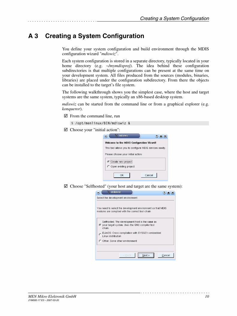
You define your system configuration and build environment through the MDISconfiguration wizard "mdiswiz".
Each system configuration is stored in a separate directory, typically located in yourhome directory (e.g. ~/mymdisproj). The idea behind these configurationsubdirectories is that multiple configurations can be present at the same time onyour development system. All files produced from the sources (modules, binaries,libraries) are placed under the configuration subdirectory. From there the objectscan be installed to the target’s file system.
The following walkthrough shows you the simplest case, where the host and targetsystems are the same system, typically an x86-based desktop system.
mdiswiz can be started from the command line or from a graphical explorer (e.g.konqueror).
From the command line, run
Choose your "initial action":
Choose "Selfhosted" (your host and target are the same system):
$ /opt/menlinux/BIN/mdiswiz &

Creating a System Configuration
MEN Mikro Elektronik GmbH 1121M000-17 E3 – 2007-03-20
Choose a directory where to store the system configuration. This must be a non-existent or empty directory.
Select the directory where the kernel sources (for the target) are installed. Thisis an important step! You must make sure
- that the kernel sources have been installed. Very few Linux distributionswill install the kernel sources by default.
- that the kernel sources exactly match the kernel binary that will be usedon the target system.
See Chapter A 6.1 Installation of Kernel Sources on page 23 for more info.
After selecting the kernel source, you have to enter some more directories (e.g.where to install the compiled example programs and libraries). You can justaccept the defaults in most cases.
Note: For Debian or RedHat, select /usr/lib rather than /usr/local/lib as the defaultlibrary installation path.
!

Creating a System Configuration
MEN Mikro Elektronik GmbH 1221M000-17 E3 – 2007-03-20
As the end of the initial dialog, select the CPU platform you want to use:
"STANDARD_PC" will create a platform with standard PCI slots. After clicking"Finish" you see an almost empty system configuration, where only the CPU hasbeen defined.
To add further devices, click on the "+" button (or right click on cpu and select"Add component to PCI bus"):

Creating a System Configuration
MEN Mikro Elektronik GmbH 1321M000-17 E3 – 2007-03-20
Select one board from the list of standard PCI carrier boards:
To complete the carrier board configuration you have to enter the PCI bus anddevice number:
Look up the values using "lspci" or "cat /proc/pci" on your target. For the C203/C204, attempt to find a "PLX brigde device".
Note: Depending on the bus system and carrier board, you will have to enter differ-ent parameters.

Creating a System Configuration
MEN Mikro Elektronik GmbH 1421M000-17 E3 – 2007-03-20
At this point, you could add M-Modules to your system configuration. Beforeyou can do this, the corresponding MDIS low-level driver packages must beinstalled. Here, it is assumed that you have downloaded the driver package fromMEN’s website and stored the ZIP File (13m07906.zip) in a directory /home/kp/tmp. To install this package, select Package Install Driver:
After the package has been installed, you can add the installed device to yoursystem configuration (right click on c203_1).
Select "Add Component to M-Module slot 0":

Creating a System Configuration
MEN Mikro Elektronik GmbH 1521M000-17 E3 – 2007-03-20
Select "M79" and "OK":
You will see the devices properties dialog. In most cases, you can just acceptthe default settings by clicking "OK". You can later modify the properties anytime through the device’s context menu.

Creating a System Configuration
MEN Mikro Elektronik GmbH 1621M000-17 E3 – 2007-03-20
You have now defined the platform, build environment and included devices ofyour platform. To build the project now, select Build Build. This will build
- all required kernel modules - userland libraries - userland example programs
After the build has been completed successfully, all software components arestill under the configuration's home directory (~/mymdisproj). To install it intothe target tree, select Build Install.
Note: The installation step is not required for ELinOS.
Since installation requires root permissions, you will be asked for the "root"password.
Note for non-KDE users:mdiswiz calls "kdesu" to run installation process as root. "kdesu" is available onlywhen your graphical environment is KDE. If you don't use KDE, you must installthe binaries from the command line:
$ cd ~/mymdisproj$ suPassword: *******# make install

Starting Up MDIS on Selfhosted Systems
MEN Mikro Elektronik GmbH 1721M000-17 E3 – 2007-03-20
A 4 Starting Up MDIS on Selfhosted Systems
A 4.1 Loading the Drivers
After the kernel modules have been installed, you should test if they can beloaded sucessfully. You must load all low-level driver modules and the BBISdriver module, for example:
All dependent modules will be loaded automatically.
You should see the start-up messages of the modules:
A 4.2 Testing the Drivers
At load time, the drivers do not access the hardware. The first hardware access ismade when the device is being opened for the first time. The m_open utility willperform little more than calling the C-function M_open().
If the directory where you have installed your MDIS binaries is not included in your$PATH environment variable, you must specifiy the full path name, e.g. /usr/local/bin/m_open.
If m_open does not issue any error messages, you can be almost sure that you havedefined your configuration correctly and that MDIS works on your target.
target:# modprobe men_ll_m79target:# modprobe men_bb_c203
target:# dmesgMEN men_oss init_moduleMEN men_id init_moduleMEN men_desc init_moduleMEN BBIS Kernel init_moduleMEN MDIS Kernel init_moduleMEN men_ll_m43 init_module MEN men_pld init_module MEN men_bb_d201 init_module
target:# m_open m79_1open m79_1path=3 openedclose path
Starting Up MDIS on Selfhosted Systems
MEN Mikro Elektronik GmbH 1821M000-17 E3 – 2007-03-20
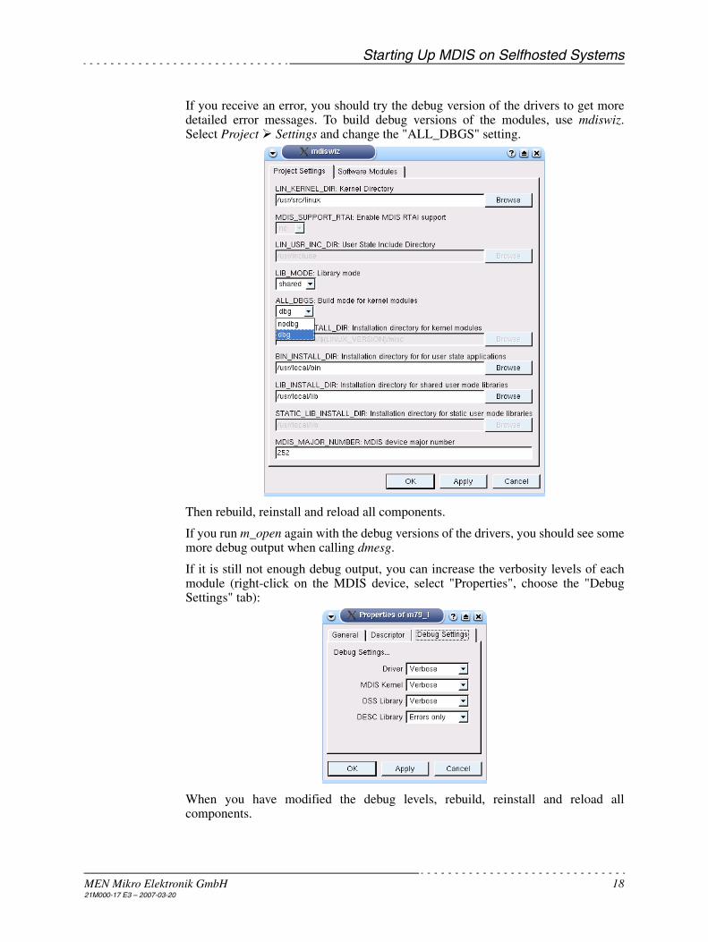
If you receive an error, you should try the debug version of the drivers to get moredetailed error messages. To build debug versions of the modules, use mdiswiz.Select Project Settings and change the "ALL_DBGS" setting.
Then rebuild, reinstall and reload all components.
If you run m_open again with the debug versions of the drivers, you should see somemore debug output when calling dmesg.
If it is still not enough debug output, you can increase the verbosity levels of eachmodule (right-click on the MDIS device, select "Properties", choose the "DebugSettings" tab):
When you have modified the debug levels, rebuild, reinstall and reload allcomponents.

Starting Up MDIS on Selfhosted Systems
MEN Mikro Elektronik GmbH 1921M000-17 E3 – 2007-03-20
A 4.3 Automatic Loading of Drivers
If your target's kernel has "kernel module loader" (CONFIG_KMOD) supportenabled, the kernel can load all modules automatically when /dev/mdis is accessedfor the first time.
In order to get this working, prepare /etc/modules.conf. (This is valid for kernel 2.4only. Kernel 2.6 uses modprobe.conf with a different syntax.) For MDIS, we justneed to add one line (replace the 252 by your chosen major number in mdiswiz):
alias char-major-252 men_mdis_kernel

Using MDIS Devices from Your Program
MEN Mikro Elektronik GmbH 2021M000-17 E3 – 2007-03-20
A 5 Using MDIS Devices from Your Program
The following shows the block diagram for MDIS under Linux:
Figure A1. Module Overview for Linux
A 5.1 MDIS API
MDIS devices are accessed through a simple C-Programming Interface, the MDISAPI. It provides a standard driver interface to any kind of MDIS device drivers, e.g.for M-Modules, PC-MIP or onboard devices.
For Linux, the MDIS API is either a static library (libmdis_api.a) or shared library(libmdis_api.so) linked to the application program. Your program must include theheader files
• #include <MEN/men_typs.h>
• #include <MEN/mdis_api.h>
Application
libmdis_api.a
Linux I/O System
BBIS Kernelmen_bbis_kernel.o
BoardHardware
men_oss.o
men_desc.o
men_dbg.o
libusr_utl.a (optional)
libusr_oss.a (optional)User Mode
MDIS Kernelmen_mdis_kernel.o
Board Drivermen_bb_xxx.o
Device Drivermen_ll_xxx.o
DeviceHardware
men_id.o
men_pld.o
men_mbuf.o
Kernel Mode
Using MDIS Devices from Your Program
MEN Mikro Elektronik GmbH 2121M000-17 E3 – 2007-03-20
MDIS API provides the following routines:
• Open and close path to device: M_open(), M_close()
• Exchange 32-bit value with driver: M_read(), M_write()
• Exchange larger data blocks with driver: M_getblock(), M_setblock()
• Status calls: M_getstat(), M_setstat()
• Get formatted error string: M_errstringTs(), M_errstring()
All MDIS functions return a negative value when an error occurs. The appropriateerror code is stored in the global system variable errno. The error number can beeasily converted to an error message string using M_errstringTs().
The exact behavior of each call to the device is device-specific. Please read thedocumentation delivered with each MDIS low-level driver for more details.
All MDIS drivers have the following features:
• Each device can have multiple logical channels, one channel is the "current chan-nel", selectable through M_setstat( M_MK_CH_CURRENT ).
• Several paths can be opened for each device and each path can have a different"current channel" and "I/O mode".
• Signal conditions can be installed, which allows a programmable signal to besent to the application when a specific condition becomes true.
• Status calls are provided for starting specific actions and setting or queryingparameters, making it possible to access functions specific to a device driver aswell as the standardized MDIS functions.
• All calls can be blocking or non-blocking, depending on the device driver.
• The same device can be accessed at the same time by multiple processes. TheMDIS kernel manages these situations.
A 5.1.1 Devices using MBUF Library
Some devices use the MBUF (MDIS buffer manager) kernel library, especiallysimple I/O devices. If a device driver uses MBUF, the MDIS API handles a set ofstandardized MBUF SetStat/GetStat calls and the M_read, M_write, M_getblockand M_setblock routines have the behavior defined by MBUF. A detaileddescription of MBUF can be found in the reference section Chapter C 1 MBUFDevice I/O on page 49.
For a detailed documentation of the MDIS API, please read the online documen-tation under LIBSRC/MDIS_API/DOC/html/index.html.
Using MDIS Devices from Your Program
MEN Mikro Elektronik GmbH 2221M000-17 E3 – 2007-03-20
A 5.2 Device-Specific APIs
Some drivers provide their own APIs on top of the MDIS API to facilitate access tothe device.
You must both link the driver-specific API and the MDIS API library to yourprogram, e.g.:
Please read the documentation delivered with each MDIS low-level driver for moredetails.
A 5.3 Further Userland Libraries
Two further userland libraries are delivered with MDIS: USR_OSS and USR_UTL.Both are not required for Linux. They are only present to make the exampleprograms OS independent.
The documentation of both libraries is available under MDIS_DOCS/mdis.html.
If you want to use these libraries, you must link them to your program, e.g.:
For USR_OSS and USR_UTL, you must include MEN/usr_oss.h and MEN/usr_utl.h, respectively.
A 5.4 Native Example Program
There is an example under TOOLS/MDIS_NATIVE_EX to show you how to use theMDIS API without using the MDIS build environment.
In order to be able to compile this example
• the MDIS user libraries must have been installed in the system default locations(with mdiswiz or using make install / installlibs).
• you must either add /opt/menlinux/INCLUDE/COM and /opt/menlinux/INCLUDE/NATIVE to your include path or copy all include files under thesepaths into /usr/include or /usr/local/ include.
For ELinOS, proceed as follows:
Create a subdirectory in your ELinOS project src/native_ex.
Copy Makefile.elinos and mdis_native_ex.c from TOOLS/MDIS_NATIVE_EXto src/native_ex.
Then mdis_native_ex will be built automatically when you execute Bootfiles Create Files in elk.
Note: If you create a subdirectory under src/ with your application sources, makesure that the directory name is lexically sorted after the mdis directory. E.g.src/sample is ok, while src/app is not.
LDFLAGS = -lprofi_api -lmdis_api
LDFLAGS = -lusr_oss -lusr_utl -lmdis_api

Appendix
MEN Mikro Elektronik GmbH 2321M000-17 E3 – 2007-03-20
A 6 Appendix
A 6.1 Installation of Kernel Sources
It is very important that MDIS modules are built to the correctly installed andconfigured kernel sources that match the kernel running on your target. If you buildMDIS modules to a differently configured kernel or to a different kernel version,MDIS modules will not work!
Most modern Linux distributions only install a precompiled binary kernel and notthe kernel source. Unfortunately, installation of kernel sources differs betweendistributions. The following gives a couple of example kernel source installations.
A 6.1.1 SuSE 9.0/10.x
From KDE launch menu, select System Yast.
In Yast, select "Install and Remove Software". Make sure that you have alsoinstalled gcc and make packages. These can be selected at once when selecting"Development Packages".
Select and install package kernel-source.
After installation, you find the kernel source tree in /usr/src/linux. However, thekernel is unconfigured. To take over the configuration of the precompiled ker-nel, copy the configuration file from /boot. Then rebuild the kernel.
For 2.4 kernels:
From 2.6 kernels on, the build system has changed. There it is just necessary todo the following:
With the steps above, we have reconfigured the kernel in the hope that the currentlyrunning kernel matches the configured one. If you are unsure, compile and installthe kernel sources (see the distribution specific manuals).
# cd /usr/src/linux# cp /boot/config-2.4.21-144-default .config# make oldconfig# make dep
# cd /usr/src/linux# cp /boot/config-2.6.13-15-default .config# make
!

Appendix
MEN Mikro Elektronik GmbH 2421M000-17 E3 – 2007-03-20
A 6.1.2 Ubuntu 6.06 (and Other Debian based Distributions)
If you use this distribution, the central package management is by default doneusing the Synaptic Package Manager. There the development packages areorganized in a similar way as in Yast. The screen shot below shows which packageswere selected for building a selfhosted MDIS project.
Appendix
MEN Mikro Elektronik GmbH 2521M000-17 E3 – 2007-03-20
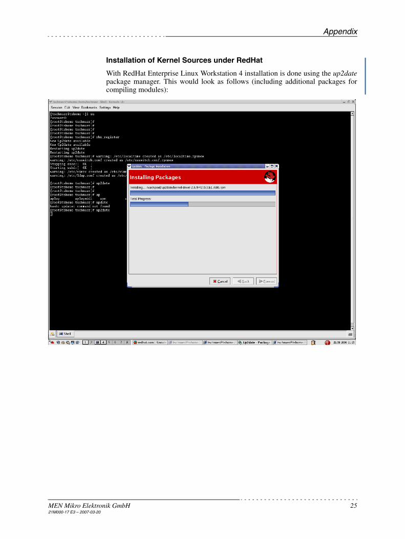
Installation of Kernel Sources under RedHat
With RedHat Enterprise Linux Workstation 4 installation is done using the up2datepackage manager. This would look as follows (including additional packages forcompiling modules):

Appendix
MEN Mikro Elektronik GmbH 2621M000-17 E3 – 2007-03-20
With the steps above, we have reconfigured the kernel in the hope that the currentlyrunning kernel matches the configured one. If you are unsure, compile and installthe kernel sources (see the distribution specific manuals).

Appendix
MEN Mikro Elektronik GmbH 2721M000-17 E3 – 2007-03-20
A 6.1.3 Useful Commands for Dealing with Kernel and Module Build Problems
uname
The uname command prints system information and can be invoked with
It shows the exact version of the currently running kernel.
modinfo
The modinfo tool from the modutils package helps to find out version informationand more from a certain kernel module. It is invoked as shown in the followingexample:
tschnuer@tshome:~/mdisubuntu$ uname -a
tschnuer@tshome:~/mdisubuntu$ modinfo ./OBJ/dbg/men_mdis_kernel/men_mdis_kernel.kofilename: ./OBJ/dbg/men_mdis_kernel/men_mdis_kernel.kodescription: MEN MDIS kernelauthor: <[email protected]>license: GPLvermagic: 2.6.15.7-ubuntu1 preempt 486 gcc-4.0depends: men_oss,men_bbis_kernel,men_desc,men_dbgsrcversion: 4365ADC51D77F73931EB570parm: mk_dbglevel:MDIS kernel debug level (ulong)parm: mk_nbufs:number of static users buffers to allocate (int)parm: mk_major:MDIS major number (int)tschnuer@tshome:~/mdisubuntu$

Appendix
MEN Mikro Elektronik GmbH 2821M000-17 E3 – 2007-03-20
A 6.2 Using MDIS with ELinOS
If you use ELinOS (2.2 to 4.1) as the cross development system, MDIS is integratedsmoothly into the ELinOS project. Proceed as follows:
Clone a default ELinOS project using elinos-cloneproject or elk and name it ~/elinosMdis. (See ELinOS manual.) We use ~/elinosMdis in this example.
Using elk,
- enable loadable module support (check all options):Features General System Configuration Add support for loadable module.
- enable Features Utilities Module Utilities.
Important note on ELinOS 4.1
Starting with version 4.1 of ELinOS, the internal build system was changed inthe way that the linux kernel tree which usually was located in<$ELINOS_PROJECT>/linux is no longer generated.
This causes a build failure because MDIS seeks for certain files in this treewhich are by default no longer placed there. To have ELinOS set up the kerneltree as in previous versions, make sure the option "Force linking kernel sourcesinto project tree" in Tools Configure the build process is selected, see the fol-lowing screen shot.
Enabling this feature does not consume a lot of space on the host’s disk becausethe kernel source is not copied into the project tree, only symlinks are gener-ated.
Change your current directory to ~/elinosMdis in our example.
- Start /opt/menlinux/BIN/mdiswiz. - Choose "New Project" and select "ELinOS" as the development environ-
ment.
!
Appendix
MEN Mikro Elektronik GmbH 2921M000-17 E3 – 2007-03-20
- Accept the "ELinOS project directory" (~/elinosMdis in our example).
- When asked for LIB_INSTALL_DIR, enter $(ELINOS_PROJECT)/app.rootfs/lib (rather than …/usr/lib).
- Define your CPU, carrier boards and MDIS devices as described inChapter A 3 Creating a System Configuration on page 10.
- Build your MDIS components by selecting Build Build. - Don't run Build Install, this is done automatically by the ELinOS
build process.
If your device is on the VMEbus, make sure that the default MEN VME driveris not included in your kernel configuration, i.e. MEN PCI to VME bridge sup-port is not checked in Kernel Configuration Character Devices. The MDISsystem package provides a newer version of the VME driver.Check Kernel Configuration Character Devices MEN PCI to VME bridgesupport.
In elk, select Bootfiles Create Files to create the boot files.
Notes:
• mdiswiz creates the subdirectory src/mdis within the ELinOS project directory tostore the MDIS configuration.
• When mdiswiz detects the $ELINOS_PROJECT environment variable or a fileELINOS.sh in the current directory, it will try to use this project by default.
• If the ELinOS project contains an autonode.sh file, mdiswiz will rename this fileto autonode.sh.bak before replacing the file. Please merge the contents of bothfiles manually in this case.
A 6.3 Using MDIS with VMEbus
This MDIS system package ships with VME support for the MEN boards A12, A13(= EM2 + A500), A15 and B11.(See DRIVERS/VME4LX/DRIVER_K24/README_VME4L.txt for more info.)
As soon as you select one of these boards in mdiswiz, the VME drivers are added tothe list of driver modules to build.
After building and installing the MDIS modules, you will find two new drivers:
• men_vme4l-core.o
• men_pldz002.o
Please note that men_pldz002 is not loaded automatically by the Linux kernel, evenif you are using the kernel module loader, so you should execute
to ensure that the driver is loaded.
If you have a CPU from another vendor, you must create a little VME bridge driverthat conforms to the MEN VME kernel interface (see MDIS_DOCS/Vmeimplnotes).
# cd /usr/src/linux# cp /boot/config-2.4.21-144-default .config# make oldconfig# make dep# find . -exec chmod a+r {} \;
# modprobe men_pldz002

More About mdiswiz
MEN Mikro Elektronik GmbH 3021M000-17 E3 – 2007-03-20
A 7 More About mdiswiz
A 7.1 Use Cases
A 7.1.1 Changing Initial Settings
If you want to change a setting that you have made during the initial dialog, you cando this at any time by selecting Project Settings (Project Settings tab):

More About mdiswiz
MEN Mikro Elektronik GmbH 3121M000-17 E3 – 2007-03-20
A 7.1.2 Changing the Software Modules to Build
If you have problems to build some driver modules or example programs, you canselectively disable each module by selecting Project Settings (Software Modulestab):
A 7.1.3 Modifying Descriptor Parameters
In some cases, you may wish to overwite the driver’s default parameters. To changethe parameters for a device, double-click on the device.

More About mdiswiz
MEN Mikro Elektronik GmbH 3221M000-17 E3 – 2007-03-20
Values printed in grey are the default values used by the driver (i.e. those values arenot overwritten by the user). To overwrite a value, double-click on it and select"Activate key".
After rebuilding the device descriptors (Build Build and Build Install), yourtarget will use the new parameters when the device is opened for the next time.
A 7.1.4 Embedded System Modules and ESM Carrier Boards
mdiswiz supports any combination of ESM CPUs and carrier boards. First, you mustselect the ESM CPU module and add the ESM carrier board afterwards to form acomplete system:
In this example, we have defined an MEN A13 system (ESM CPU EM02+carrierA500).
Sometimes, the official MEN product names do not reflect the names of the ESMCPU and carrier (as in the example above). If you are unsure, please [email protected].

More About mdiswiz
MEN Mikro Elektronik GmbH 3321M000-17 E3 – 2007-03-20
A 7.1.5 Chameleon FPGA Devices
mdiswiz also supports the FPGA units present on some MEN boards (currentlyEM04/EM05). The "FPGA" pseudo carrier board is automatically created once sucha CPU is selected.
The device drivers for the FPGA’s units are available as separate packages fromMEN's website (e.g. 13z01506.zip for MSCAN FPGA unit).
When right clicking on the "FPGA" carrier board item, you will see that mdiswizhandles 16 "internal slots". It is not important in which "internal slot" you installwhich FPGA device driver. The slots are only required internally in MDIS.
A 7.1.6 Non-MDIS Devices
You can also build and partly configure non-MDIS devices with mdiswiz. This isrequired, e.g. for M-Modules like the M77 (a quad UART). The M77 driver is anative Linux device driver, accessible through the standard Linux TTY interface.Although it is not an MDIS driver, it is built with the MDIS build environment.
Non-MDIS driver packages (e.g. 13m07790.zip) are installed like normal packagesthrough Package Install.
You can then add the native device to your configuration tree. Once this is done, thenative driver will be built together with the rest of the MDIS modules.
Althouhg mdiswiz builds an MDIS device descriptor for the native device, thedevice descriptor is not used by most native drivers. See the driver specificdocumentation for more info.

More About mdiswiz
MEN Mikro Elektronik GmbH 3421M000-17 E3 – 2007-03-20
A 7.2 MDISWIZ Troubleshooting
A 7.2.1 Cannot Resolve Host Names into IP Addresses
If the X-Server is not running on the same machine as mdiswiz, mdiswiz may have aproblem to connect to the remote X-server.
Whether the problem occurs or not depends on the shared libraries installed on thehost that runs mdiswiz.
Workaround
Replace the host name in the DISPLAY environment variable by the host IP address.
Solution
Recompile mdiswiz from sources (see below).
A 7.2.2 My Hardware is Not Supported
All CPUs and BBIS models known by mdiswiz are implemented as C++ classes inthe mdiswiz source code. If you want your CPU/carrier board to be supported bymdiswiz you can add your model to the mdiswiz source code or request MEN to do itfor you.
Alternatively, you can do it without mdiswiz and create the Makefile and descriptorfiles manually. See Chapter C 4 MDIS Device Descriptors on page 73 for more info.
MDIS models are not hardcoded in the mdiswiz source code. They are dynamicallyread from the XML files provided with each MDIS low-level driver package. Seethe "MDIS developer guide" for more info.
A 7.3 Build MDISWIZ from Source Code
mdiswiz sources ship with the MDIS system package for Linux. It is installed under/opt/menlinux/TOOLS/MDISWIZ.
To rebuild mdiswiz, you must have the QT library development version installed.(Either package qt-devel or the package from www.trolltech.com.)
Enter /opt/menlinux/TOOLS/MDISWIZ/NATIVE/DEVEL.
Adapt the builddist.env file to your needs and source it ( ". ./builddist.env").
Create Makefile:
Build mdiswiz:
qmake mdiswiz.pro
make

More About mdiswiz
MEN Mikro Elektronik GmbH 3521M000-17 E3 – 2007-03-20
A 7.4 Output Files Created by Build Process
When make has finished, you will find the following components in theconfiguration’s root directory (~/mymdisproj in our example):
A 7.4.1 Kernel Modules
For Kernel 2.4, the kernel modules are placed in subdirectory MODULES. Thedebug versions are put in MODULES/dbg and the non-debug versions inMODULES/nodbg.
For Kernel 2.6, the kernel modules are placed in subdirectory OBJ/dbg or OBJ/nodbg and have the extension ".ko".
• men_mdis_kernel The MDIS kernel module
• men_bbis_kernel The BBIS kernel module
• men_dbg Debug string routines
• men_oss Kernel Mode Operating System Services abstraction
• men_desc Descriptor parser routines
• men_pld FPGA/PLD loader routines
• men_id Serial EEPROM routines
• men_mbuf Buffer routines for simple I/O modules
• men_ll_xxx Low-level driver modules
• men_bb_xxx Carrier board driver modules
A 7.4.2 User Mode Libraries
Depending on the LIB_MODE switch in the Makefile either static or shared librariesare created in subdirectory LIB.
Static libraries have the prefix .a while shared libraries will have prefix .so.
• libmdis_api.so MDIS API library
• libusr_oss.so Operating system services abstraction for user mode programs
• libusr_utl.so Some utility routines
A 7.4.3 Executable Programs
All low-level driver example programs as well as common example programs areplaced in subdirectory BIN. Depending on the LIB_MODE switch in the Makefilethe programs are linked against the libraries in LIB either statically or "shared".
A 7.4.4 Descriptors
The binary-form descriptors are placed in subdirectory DESC. They are copied tothe target's /etc/mdis directory when installed.

General
MEN Mikro Elektronik GmbH 3621M000-17 E3 – 2007-03-20
Part B MDIS4 under Linux/RTAI
B 1 General
B 1.1 Purpose of RTAI
Since RTAI (Real-Time Application Interface) became one of the most widely usedsolutions for support of real-time tasks within a Linux environment, it is supportedalso in the MDIS package. The basic RTAI function is to maintain a scheduler thatruns Linux as the least prior task and serve all peripheral interrupts before Linuxdoes. Figure B1, Basic Architecture of RTAI, on page 36 shows the HAL that runsbetween the hardware and Linux. You can visit www.rtai.org for further details anda complete documentation. However, it should be mentioned that many of thedocuments available there are already outdated.
Figure B1. Basic Architecture of RTAI
B 1.2 Features
• Provides MDIS API fully compatible with other MDIS implementations
• Operates in RTAI kernel mode
• Supports x86 and PowerPC targets
• Supports RTAI 24.1.9 to RTAI 3.0r2
• Provides execution environment (MEXE) for MDIS examples/tools, includingemulation of most stdio calls
B 1.3 Restrictions
• No LXRT support yet — MDIS applications must execute in Linux kernel space
• MDIS RTAI support is untested on SMP systems
Applications
Scheduler Comm IPC
HW Management
Hardware
Linux
Processor Peripherals
A1 A2
Tasks
RTAI
T1 T2
Comm/IPC Scheduler
Interrupt Dispatcher

RTAI vs. Linux: Interrupt Handling
MEN Mikro Elektronik GmbH 3721M000-17 E3 – 2007-03-20
B 2 RTAI vs. Linux: Interrupt Handling
This chapter describes which points related to interrupt handling are to be kept inmind to get properly working interrupt processing. If not mentioned otherwise, theRTAI version referred to here is 3.0r2.
B 2.1 Interrupt Sharing between Linux and RTAI
In the current standard distribution of RTAI (release 3.0r2) it is only possible toshare interrupts with the standard Linux environment when the IRQ is forwarded tothe interrupt processing of Linux by using the RTAI function rt_pend_linux_irq().
Warning: This works only for edge-triggered interrupts and should be used withcaution.
B 2.2 Sharing Real-Time Interrupts within RTAI
The standard RTAI distribution does not support the sharing of interrupts. When ahandler is installed through rt_request_global_irq(), it exclusively owns this IRQ,and further request calls to this function return with an error.
To overcome this limitation, MEN provides a kernel module that is providedtogether with the standard RTAI modules. The men_rtai_shirq module internallyregisters a handler in RTAI from which all shared handlers are called. This is usedfor example in the pldz002 and MDIS driver module to register the RTAI handler.The source code is available under /LIBSRC/RTAI_SHARE_IRQ.
The interrupt sharing module is needed when IRQ requirements of a user device tobe served under RTAI collide with those of an MDIS device that also should rununder RTAI. There are basically just two functions that a user needs:
Requesting a shared RTAI handler
Releasing a shared handler
The argument data is stored internally for each handler function and passed to thathandler when interrupt irq occurs. This is important e.g. for private data or handlesto devices, since the original IRQ handler in RTAI receives just the IRQ number,because it is the exclusive IRQ handler in normal RTAI.
int MDIS_RequestSharedIrq( unsigned int irq, char *name, void(*handler)(unsigned int, void *), void *data)
int MDIS_RemoveSharedIrqHandler( unsigned int irq, void(*handler)(unsigned int, void *), void *data)
!

RTAI vs. Linux: Interrupt Handling
MEN Mikro Elektronik GmbH 3821M000-17 E3 – 2007-03-20
To give the user information which handlers are currently registered as shared RTAIhandlers the /proc file /proc/rtai/shared can be output, e.g. using cat:
/#cat /proc/rtai/shared
RTAI_MDIS IRQ share module build Nov 17 2004 10:24:55(NR_IRQS=256) shared IRQs registered:
IRQ10 handlers:'PldZ002Irq'(0xc502308c)
/#

Installation
MEN Mikro Elektronik GmbH 3921M000-17 E3 – 2007-03-20
B 3 Installation
RTAI support for MDIS is integrated in the MDIS for Linux system package(13M000-13 revision >= 3.0). It is installed exactly as described in Chapter A 2Installation on Host on page 9. Before you can use the RTAI extensions, your kernelmust be configured for use with RTAI. Either download the standard RTAIdistribution from www.rtai.org or use a Linux distribution that has integrated RTAIsupport, such as SYSGO’s ELinOS 3.0. ELinOS also contains an RTAI exampleproject.
In any case, before trying to build the MDIS RTAI modules, you should test theexamples shipped with the original RTAI distribution in order to make sure thatRTAI operates correctly on your target. If ELinOS is used, refer to chapter 'RTAI'from the demo examples.
B 3.1 Required RTAI Modules for MDIS
MDIS needs the following RTAI modules:
• the core scheduler module (for single processor boards!): rtai_up.o
• the HAL module to capture IRQ events: rtai_hal.o
• the module to support communication FIFOs: rtai_fifos.o
• the memory management module: rtai_malloc.o
Some modules are shared between the standard MDIS for Linux and MDIS forRTAI. These modules exist only once in the system.
• men_mdis_kernel (provides the MDIS API calls for RTAI)
• men_bbis_kernel
• men_ll_xxx (low-level drivers)
• men_bb_xxx (base board drivers)
• men_dbg, men_oss, men_desc, men_id, men_pld, men_mbuf.o
men_oss plays a special role. An instance of this module is created for each device,either for standard Linux or RTAI mode. Since all other modules perform operatingsystem services only through the OSS module, the same binary code of thosemodules can be used, regardless whether they operate in Linux or RTAI mode.
In addition to the modules mentioned above, MDIS example programs for RTAI arebuilt as kernel modules, named men_xxx, (e.g. men_m99_latency). See below formore info.

Installation
MEN Mikro Elektronik GmbH 4021M000-17 E3 – 2007-03-20
B 3.2 Configuration of MDIS
Configuration is initially done as described in Chapter A 3 Creating a SystemConfiguration on page 10. There is no difference in the creation of device or boarddescriptors compared to standard Linux. Whether a device is being used underLinux or RTAI is determined at runtime. However, to enable RTAI support in MDIS,you must change your configurations Makefile. This is done again using the MDISconfiguration wizard "mdiswiz". Simply select "yes" in the project properties for"MDIS_SUPPORT_RTAI: Enable MDIS RTAI support". The following figuresshow the settings, in this example the modules are built with debugging.
Keep in mind that the example programs are built two times when RTAI support isselected: once as standard user programs and then as kernel modules to be called bymdis_rtagent.
Figure B2. Settings for RTAI Module Build

Installation
MEN Mikro Elektronik GmbH 4121M000-17 E3 – 2007-03-20
Figure B3. Additional RTAI Module Selection

Installation
MEN Mikro Elektronik GmbH 4221M000-17 E3 – 2007-03-20
B 3.3 Setting Up the Target for MDIS/RTAI
First, follow the instructions in Chapter A 3 Creating a System Configuration onpage 10. There is no difference in loading the device drivers compared to standardLinux mode. However, drivers that shall be used by RTAI applications cannot beloaded automatically by the kernel module loader (since RTAI applications do notaccess /dev/mdis). Therefore you must load drivers manually, e.g:
In addition, you should create the device nodes for the RTAI FIFOs, at least twonodes should be created in order to run the MDIS example programs:
• If your target does not use the device file system (CONFIG_DEVFS_FS):
• If your target uses the device file system (CONFIG_DEVFS_FS), create sym-bolic links:
B 3.4 Creating MDIS/RTAI Devices
Before an MDIS device can be accessed from an RTAI application, the MDIS kernelmust be informed about the parameters of that device. This is done by the Linuxutility mdis_createdev. It reads the specified MDIS device descriptor from /etc/mdis/and passes it to the MDIS kernel. mdis_createdev must be called for every devicethat is to be used by RTAI applications, for example:
This creates the MDIS device m99_1. The -r flag tells the MDIS kernel that thesedevices will be used in RTAI mode. See /proc/mdis to see which devices are knownby the MDIS kernel. Devices created for RTAI mode cannot be opened by standardLinux applications anymore.
mdis_createdev must be run at every system start. It can be included e.g. into /etc/inittab or an appropriate start-up script.
Notes:
• You don't need to specify the carrier board devices to mdis_createdev. Carrierboard devices are created automatically.
• Specify the device names to mdis_createdev without the leading "/". If in doubtabout the name, just check the file names in /etc/mdis/.
target:# modprobe men_ll_m43target:# modprobe men_bb_d201
# mknod <target-tree>/dev/rtf0 c 150 0# mknod <target-tree>/dev/rtf1 c 150 1
# ln -s <target-tree>/dev/rtf/0 <target-tree>/dev/rtf0# ln -s <target-tree>/dev/rtf/1 <target-tree>/dev/rtf1
target:# mdis_createdev -r m99_1create device m99_1 for RTAItarget:#

Installation
MEN Mikro Elektronik GmbH 4321M000-17 E3 – 2007-03-20
B 3.5 Testing Drivers in RTAI Mode
You can now start one of the compiled RTAI applications (one of those listed inALL_RTAIK_LL_TOOLS or ALL_RTAIK_COM_TOOLS). These applications havebeen compiled to kernel modules (named men_<appname>) which use the "MDISexample program execution environment" (MEXE).
Figure B4. Data Flow between RT Application and mdis_rtagent
Those RTAI application modules have to be loaded by the Linux utilitymdis_rtagent. The standard I/O of the application is redirected through the RTAIFIFOs /dev/rtf[0-1] to the mdis_rtagent which does the actual I/O on its standard I/O paths. Figure B4, Data Flow between RT Application and mdis_rtagent, on page43 illustrates this. The standard usermode functions like printf() in the programs aresubstituted by appropriate RTAI functions located in /LIBSRC/RTAI_USR_OSS.
Examples
1) To run the m43_simp example program, just type
mdis_rtagent shall then display all output strings issued by printf() statementswithin m43_simp.
2) The M99 interrupt test program m99_latency is compiled as a kernel modulenamed men_m99_latency.o. It can also be invoked with
Warning: Pressing ^C (SIGINT) will immediately terminate the running RTAIapplication task. Resources allocated by the application (semaphores,memory etc.) may not have been released correctly. Therefore ^C shallonly be used in emergency situations! Kernel crashes may occur.
target:$ mdis_rtagent men_m43_simp m43_1
target:$ mdis_rtagent men_m99_latency
User Space
Kernel Space
mdis_rtagent
RT Application(rtai_mexe.c +MDIS standard
program)
FIFOs maintained by rtai_fifo module /dev/rtf 1 /dev/rtf 0
!

Installation
MEN Mikro Elektronik GmbH 4421M000-17 E3 – 2007-03-20
B 3.6 Rules Applying to the Usage of MDIS/BBIS Devices
• BBIS devices can be shared between standard Linux and RTAI
• MDIS devices can't be shared between standard Linux and RTAI
• MDIS RTAI needs standard Linux MDIS
• The same LL/BB driver binary is used for RTAI and Linux
• RTAI and the standard OSS module use the same OSS handle
MDIS Example Program Execution Environment (MEXE)
MEN Mikro Elektronik GmbH 4521M000-17 E3 – 2007-03-20
B 4 MDIS Example Program Execution Environment (MEXE)
B 4.1 Purpose of MEXE
MEXE has been created mainly to run example programs shipped with MDIS devicedrivers unchanged in the RTAI context. However, MEXE can be useful also for"real" applications, for example to read configuration files from the Linux filesystem. Of course, running real-time applications under LXRT would solve theproblem immediately. But as long as LXRT is not available for all platforms (e.g.PowerPC), MEXE has to be used.
B 4.2 Components of MEXE
MEXE consists of the following key components:
• A set of standard header files (INCLUDE/NATIVE/MEN/RTAI_STDC/stdio.h,stdlib.h, string.h) adapted for RTAI kernel mode.
• A startup code (LIBSRC/MDIS_COMPONENT_COMMON/rtai_mexe.c) thatincludes the module’s init/clean-up function. In the module’s init function, theRTAI scheduler is started, and a bidirectional FIFO is created to communicatewith mdis_rtagent.
• A set of library routines, located in lib-rtaik-usr_oss.a (sources in LIBSRC/RTAI_USR_OSS), providing the most commonly used C-library calls, such as:
- stdio calls: printf, fprintf, fgets, getc, fopen, fwrite, fseek, freedSee INCLUDE/NATIVE/MEN/RTAI_STDC/stdio.h.
- stdlib calls, not provided by the Linux kernel: atoi, strtol, strtoul, iss-pace, malloc, free
• In addition INCLUDE/NATIVE/MEN/RTAI_STDC/stdio.h includes linux/ker-nel.h which imports many C-standard routines such as strlen, memcpy, etc.
Note: Not every MDIS program will run under that environment.
These items together allow to compile and execute most MDIS example programsand tools. However, there will still be some programs that will not compile/execute,for the following common reasons:
• An application uses a library call not provided by MEXE. In this case you willprobably be able to compile the application, but modprobing fails (modprobe orinsmod will report unresolved symbols).
• An application requires huge amounts of memory. Since MEXE uses rt_mallocfor malloc(), the amount of allocatable memory is very limited. See the docu-mentation of rtai_mallocs to see how the memory size can be increased.

MDIS Example Program Execution Environment (MEXE)
MEN Mikro Elektronik GmbH 4621M000-17 E3 – 2007-03-20
B 4.3 Communication between MEXE and mdis_rtagent
All stdio routines provided by MEXE (printf, fopen etc.) are executed with the helpof the Linux utility mdis_rtagent. When an RTAI application wants to execute astdio call, it puts a message into /dev/rtf1. mdis_rtagent will then execute the requestand write its result into /dev/rtf0.
In addition, mdis_rtagent passes command line parameters to the RTAI applicationwhen the application is started.
Warning: All stdio calls executed by means of mdis_rtagent are non-deterministic(not executed in real time), since mdis_rtagent runs in Linux user space!Therefore stdio calls should be used with care.
Default behavior:
• /dev/rtf0 is used to send messages from mdis_rtagent to RT application.
• /dev/rtf1 is used to send messages from RT application to mdis_rtagent.
Both FIFOs have a size of 1072 bytes. Only one request/response may be pendingfrom each side.
Each request/response has two parts:
• Standard service description block (RTA_SDB)
• Optional data; max. 512 bytes
For example, to send a service request from RT application to mdis_rtagent:
Put the filled SDB into /dev/rtf1.
Put any service specific data (if required) into /dev/rtf1.
Wait for response SDB in /dev/rtf0.
If SDB.dataLen != 0, wait for data in /dev/rtf0.
!

MDIS Example Program Execution Environment (MEXE)
MEN Mikro Elektronik GmbH 4721M000-17 E3 – 2007-03-20
B 4.4 Using MDIS from an RTAI Task without MEXE
Using MDIS without the MEXE environment is also easy. The following exampledemonstrates opening a device from within an RTAI task, writing the return value ofM_open() into a FIFO. The file and an appropriate ELinOS Makefile can be found infolder /LINUX/TOOLS/RTAI_NATIVE_EX. As shown, the user OSS library forRTAI is initialized using UOS_RtaiInit prior to usage.
/********************************************* Example RTAI module using MDIS without MEXE *********************************************/
/* stdio.h from /INCLUDE/NATIVE/MEN/RTAI_STDC, defines UOS_FOR_RTAI*/#include <stdio.h> #include <MEN/men_typs.h>#include <MEN/mdis_api.h>#include <linux/module.h>#include <linux/init.h>#include <MEN/usr_os.h>
#define FIFO 0static char *device = "m99_1";static int G_path = 0;
static int __init init_rtai_task(void){ UOS_RtaiInit(); rtf_create(FIFO, 1024); /* 1024 byte deep */
if ((G_path = M_open(device)) < 0) {rt_printk("cant open device %s. Forgot 'mdis_createdev -r %s' ?\n",
device, device);return( -ENODEV );
}rtf_put(FIFO, &G_path, sizeof(G_path) );
return 0;}
static void __exit cleanup_rtai_task(void){
M_close( G_path );UOS_RtaiExit();
rtf_destroy(FIFO);}module_init(init_rtai_task);module_exit(cleanup_rtai_task);MODULE_LICENSE("GPL");

MDIS Example Program Execution Environment (MEXE)
MEN Mikro Elektronik GmbH 4821M000-17 E3 – 2007-03-20
B 4.5 Service Descriptions and Parameter Usage
The userland mdis_rtagent program uses the RtServiceKick function to put a servicerequest into the /dev/rtf1 FIFO. Its declaration is:
The rtagent.c file is located in /LINUX/TOOLS/MDIS_RTAGENT.
In kernel mode, the rtai_mexe.c file receives the service request. rtai_mexe islocated in /LINUX/LIBSRC/MDIS_COMPONENT_COMMON. There the functionMexeService puts service requests into FIFO /dev/rtf0.
The available services are shown in the table below. For details the source codeshould be consulted.
Table B1. Available Services
int RtServiceKick( const RTA_SDB *reqSdb,const void *reqData)
int MexeService( const RTA_SDB *reqSdb, const void *reqData, RTA_SDB *rspSdb, void *rspData)
Service Description
RTA_FPRINTF Print a formatted string to either stdout or stderr (nothing else). Formatting is done in the RT application. Includes "fflushing" the specified stream.
RTA_FGETS Read a line from a stream
RTA_GETC Read a char from a stream
RTA_FOPEN Open/create a file
RTA_FCLOSE Close a file
RTA_FREAD Binary stream input
RTA_FWRITE Binary stream output
RTA_FEOF Test EOF flag on stream
RTA_FERROR Test error flag on stream
RTA_CLEARERR Clear error flag on stream
RTA_FSEEK Position in stream
RTA_FTELL Tell position in stream
RTA_WAITKEY Wait until key pressed
RTA_CHECKKEY Check if key pressed.
RTA_START Start RT application and pass command line
RTA_STOP Stop RT application (when RT agent exits)
RTA_DONE Tell agent that RT application has finished

MBUF Device I/O
MEN Mikro Elektronik GmbH 4921M000-17 E3 – 2007-03-20
Part C Common MDIS Reference
C 1 MBUF Device I/O
Some devices use the MBUF (MDIS buffer manager) kernel library, especiallysimple I/O devices. If a device driver uses MBUF, the MDIS API handles a set ofstandardized MBUF SetStat/GetStat calls and the M_read, M_write, M_getblockand M_setblock routines have the behavior defined by MBUF.
C 1.1 Channels
Each device is logically divided into several channels. Every channel I/O access viaM_read() and M_write() and some of the status calls refer to the current channel.
You can obtain the total number of device channels using GetStat callM_MK_LL_CH_NUMBER.
C 1.2 Channel I/O
The functions M_read() and M_write() can be used to read from the current channelof a device or to write a value to it.
C 1.2.1 Channel I/O Modes
The M_MK_IO_MODE status code is used to define/query the mode in which allchannel I/O to the device is executed. This only affects functions M_read() andM_write().
Table C1. Channel I/O Modes
In M_IO_EXEC mode, I/O is directly done to the current channel of the device.
M_IO_EXEC_INC mode is the same as M_IO_EXEC but with subsequentincrementation of the current channel.
I/O Mode Description
M_IO_EXEC I/O without increment1
1 Default mode
M_IO_EXEC_INC I/O with auto-increment
MBUF Device I/O
MEN Mikro Elektronik GmbH 5021M000-17 E3 – 2007-03-20
C 1.2.2 Channel Direction
Each I/O channel has a specific I/O direction as
• input channel
• output channel
• input/output channel.
The I/O direction may be fixed or changeable depending on the hardware and thedevice driver implementation. If the direction is changeable, you can use theM_LL_CH_DIR SetStat call to change it. If it is not, an error is returned. The currentchannels direction can always be queried with the M_LL_CH_DIR GetStat call.
Each access using M_read() or M_write() is checked for I/O direction and an error isreturned if the direction is illegal.
C 1.3 Block I/O
To read or write blocks of data to the device or to the I/O buffers, you must usefunctions M_getblock() and M_setblock(). Depending on the device driverimplementation, block I/O may be used to
• read/write a block of data directly from/to the hardware
• read/write a block of data from/to a device driver’s buffer.
Both block I/O functions return the count of bytes transferred. If the block sizerequested by the application is too small, the function returns an error.
The following chapter describes the handling of device driver buffers. If the driversupports only hardware access, the described functionality is not available.
C 1.3.1 Driver Buffers
Driver buffers are allocated and controlled by the device driver. Depending on thedevice driver implementation a buffer may contain data for a single channel or formultiple channels. At most each channel may have its own input and/or outputbuffer.
!

MBUF Device I/O
MEN Mikro Elektronik GmbH 5121M000-17 E3 – 2007-03-20
Figure C1. Buffer Structure
The buffer size may be specified in the device descriptor. Otherwise a default size isused. The driver rounds-down the specified size if needed.
Each buffer has a specific buffer width which describes the minimum amount ofdata bytes that can be read from or written into the buffer. This can be seen as thesize of one "entry" in the buffer.
The buffer counter reports the amount of available data bytes in input buffers andthe free space in output buffers.
The buffer counter is updated each time an application or the interrupt serviceroutine read data from or write data into the buffer. Handling of the counter dependson the selected block I/O mode and is described with the corresponding buffermode.
Buffer size, width and counter can be queried through GetStat calls.
The buffer can be reset (logically cleared) and for debug purposes also filled withzero (physically cleared) using SetStat calls.
For ring buffers further parameters can be set or queried as described with thecorresponding buffer mode:
• Overflow/underrun error handling
• Read/write timeout
• High/lowwater marks
• Input buffer high/lowwater signal
• Output buffer high/lowwater signal
The structure of a buffer and the available block I/O modes always depend on thedevice driver implementation. It is described in the respective device driver usermanual.
width [bytes]
size
[byt
es]
0 1 2 3
4 5 6 7
size-4 size-3 size-2 size-1
entry 0
entry 1
entry (size/width)-1

MBUF Device I/O
MEN Mikro Elektronik GmbH 5221M000-17 E3 – 2007-03-20
C 1.3.2 Block I/O Modes
For all block I/O done with the M_getblock() and M_setblock() functions theselected block I/O mode defines the action to be performed and the type of buffer tobe used.
The block I/O mode can be selected
• via the M_BUF_RD_MODE SetStat call for each input buffer and
• via the M_BUF_WR_MODE SetStat call for each output buffer.
If the driver does not support the specified block mode, it will return an error.
If separate buffers are available for more than one channel, the above status callsrefer to the buffer of the current channel.
The number of buffers and the supported buffer modes are device-dependent anddescribed in the respective device driver user manual.
Table C2. Block I/O Modes
M_BUF_USRCTRL mode allows direct I/O to the device, i.e. you can bypass the I/O buffers.
Note: In all other buffer modes, driver-internal buffers are used for I/O. The block I/O functions copy data from the driver’s buffer into the application’s buffer orvice versa.
M_BUF_CURRBUF mode uses only the first entry of a buffer. This buffer can becontinuously overwritten and therefore always contains the currently valid, i.e. thelast, recently read/written I/O values.
In M_BUF_RINGBUF mode the input or output buffer behaves as an endless ringbuffer. Input/output is blocked, i.e. if the requested block is not available a sleep/wake-up mechanism takes effect.
M_BUF_RINGBUF_OVERWR mode is similar to the ring buffer; but if the bufferis full, the oldest entries will be overwritten.
Changing the block I/O mode will always reset the buffers.
Block I/O Mode Description Buffer Location Blocked
M_BUF_USRCTRL User-controlled buffer1
1 Default mode
Application No
M_BUF_CURRBUF MDIS-controlled current buffer
Driver No
M_BUF_RINGBUF MDIS-controlled ring buffer Driver Yes
M_BUF_RINGBUF_OVERWR
MDIS-controlled ring buffer (self-overwriting)
Driver No

MBUF Device I/O
MEN Mikro Elektronik GmbH 5321M000-17 E3 – 2007-03-20
C 1.3.2.1 User Control Mode
In User Control Mode, the MDIS-controlled buffers are not used. The buffer isprovided by the application and reading/writing to/from the device is directly doneinto these user buffer.
• Use M_getblock() to read directly from the device into the application buffer.
• Use M_setblock() to write from the application buffer directly to the device.
The structure of the buffer is device-dependent and is described in the respectivedevice driver user manual.
C 1.3.2.2 Current Buffer Mode
In Current Buffer Mode, MDIS allocates and manages the buffer. The buffer isprovided by the driver and reading/writing to/from the device is doneasynchronously via the buffer.
The Current Buffer is a self-overwriting buffer providing space for one bufferentry. The remaining buffer space is not used in this mode:
• An input buffer is filled with data by the driver’s interrupt service. This processis interrupt-triggered. Asynchronously the application can read data from thebuffer using M_getblock(). The buffer is not blocked, i.e. if there is no (new) datain the buffer, the getblock call doesn’t wait, but returns with the old data.
• An output buffer is filled with data using M_setblock(). Asynchronously thedata is written to the device by the driver’s interrupt service. This process isinterrupt-triggered. The buffer is not blocked, i.e. if the last written value has notbeen written to the device, the setblock call doesn’t wait, but overwrites the olddata.
Figure C2. Current Input Buffer
DeviceInput Buffer
Interrupt ServiceM_getblock
(unused)
Application Buffer

MBUF Device I/O
MEN Mikro Elektronik GmbH 5421M000-17 E3 – 2007-03-20
Figure C3. Current Output Buffer
The buffer counter is zero after initialization or after reset of the buffer. As soon asthe first value is written to the buffer the buffer counter switches to ’1’ and remainsat this value until the buffer is reset.
C 1.3.2.3 Ring Buffer Mode
In Ring Buffer Mode, MDIS allocates and manages the buffer. The buffer isprovided by the driver and reading/writing to/from the device is doneasynchronously via the buffer.
The Ring Buffer is a blocking, quasi-endless buffer providing space for severalbuffer entries:
• An input buffer is filled with data by the driver’s interrupt service. This processis interrupt-triggered. Asynchronously the application can read data from it usingM_getblock(). The buffer is blocked, i.e. if there is no more data in the buffer, thegetblock call is put to sleep until the requested data is available or a timeout hasoccurred.
• An output buffer is filled with data using M_setblock(). Asynchronously thedata is written to the device by the driver’s interrupt service. This process isinterrupt-triggered. The buffer is blocked, i.e. if there is no more space in thebuffer for new data, the setblock call is put to sleep until the required space isavailable or a timeout has occurred.
Figure C4. Ring Input Buffer
DeviceOutput Buffer
Interrupt ServiceM_setblock
(unused)
Application Buffer
Device
Input Buffer
Interrupt Service
M_getblock
Application Buffer
fillin
g

MBUF Device I/O
MEN Mikro Elektronik GmbH 5521M000-17 E3 – 2007-03-20
Figure C5. Ring Output Buffer
The buffer counter is zero after initialization or after reset of the buffer. Each timedata is written to the buffer the counter is incremented. Each time data is read fromthe buffer, the counter is decremented.
Buffer overflow and underrun conditions cause errors if error handling wasenabled via the M_BUF_RD/WR_ERR SetStat calls. By default, error handling isdisabled:
• If the driver’s interrupt service cannot write new data to an input buffer becausethe buffer is full, a buffer overflow has occurred. In this case this data is lost andthe overflow error counter is incremented. If overflow error handling is enabled,the next or currently executed getblock call returns anERR_MBUF_OVERFLOW error. The overflow error counter can be queriedusing the M_BUF_RD_ERR_COUNT GetStat call. It can be reset to zero via theappropriate SetStat call.
• If the drivers interrupt service cannot read new data from the output bufferbecause the buffer is empty, a buffer underrun has occurred. In this case no datais written to the device and the underrun error counter is incremented. If under-run error handling is enabled, the next or currently executed setblock call returnsan ERR_MBUF_UNDERRUN error. The underrun error counter can be queriedusing the M_BUF_WR_ERR_COUNT GetStat call. It can be reset to zero via theappropriate SetStat call.
It is possible to read or write blocks exceeding the size of the input or output buffer.This applies to both M_getblock() and M_setblock(). In this case the applicationprocess is put to sleep several times within the function and the application buffer isfilled with the requested data one part at a time.
You can limit the maximum time during which a process may stay asleep bydefining a timeout period in the device descriptor or via the M_BUF_RD/WR_TIMEOUT SetStat calls.
If this time is exceeded the process returns from the sleeping state with anERR_OSS_TIMEOUT error. Setting the timeout period to zero disables the timeout.
Device
Output Buffer
Interrupt Service
M_setblock
Application Buffer
fillin
g

MBUF Device I/O
MEN Mikro Elektronik GmbH 5621M000-17 E3 – 2007-03-20
C 1.3.2.4 Ring Buffer Mode (Self-Overwriting)
The Self-Overwriting Ring Buffer Mode is identical with the normal Ring BufferMode, with the exception that this buffer is never blocked on "full" or "empty"conditions.
MDIS allocates and manages the buffer. The buffer is provided by the driver andreading/writing to/from the device is done asynchronously via the buffer.
The Self-Overwriting Ring Buffer is a non-blocking, quasi-endless bufferproviding space for several buffer entries:
• An input buffer is filled with data by the driver’s interrupt service. This processis interrupt-triggered. Asynchronously the application can read data from it usingM_getblock(). The buffer is not blocked, i.e. if there is no more new data in thebuffer, the getblock call returns the oldest data again.
• An output buffer is filled with data using M_setblock(). Asynchronously thedata is written to the device by the driver’s interrupt service. This process isinterrupt-triggered. The buffer is not blocked, i.e. if there is no more space in thebuffer for new data, the setblock call overwrites old data that has currently notbeen written to the device. This data is lost.
The buffer counter is zero after initialization or after reset of the buffer. Each timedata is written to the buffer the counter is incremented until the buffer is full. Eachtime data is read from the buffer, the counter is decremented until the buffer isempty.
Buffer overflow and underrun conditions never occur in this buffer mode. The buffertimeout is not used since the getblock/setblock calls never sleep.
C 1.4 Buffer Events
MDIS allows a user-definable signal to be sent to the application process whencertain buffer levels have been reached:
• The input buffer counter has reached the highwater mark when up-counting
• The output buffer counter has reached the lowwater mark when down-counting
The application can activate the highwater signal condition via theM_BUF_RD_SIGSET_HIGH SetStat call and deactivate it using theM_BUF_RD_SIGCLR_HIGH SetStat call:
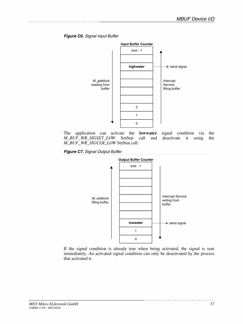
MBUF Device I/O
MEN Mikro Elektronik GmbH 5721M000-17 E3 – 2007-03-20
Figure C6. Signal Input Buffer
The application can activate the lowwater signal condition via theM_BUF_WR_SIGSET_LOW SetStat call and deactivate it using theM_BUF_WR_SIGCLR_LOW SetStat call:
Figure C7. Signal Output Buffer
If the signal condition is already true when being activated, the signal is sentimmediately. An activated signal condition can only be deactivated by the processthat activated it.
size - 1
highwater
2
1
0
M_getblockreading from
buffer
InterruptServicefilling buffer
send signal
Input Buffer Counter
size - 1
lowwater
1
0
M_setblockfilling buffer
Interrupt Servicewriting frombuffer
send signal
Output Buffer Counter
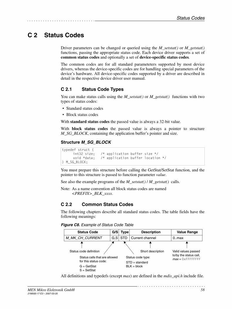
Status Codes
MEN Mikro Elektronik GmbH 5821M000-17 E3 – 2007-03-20
C 2 Status Codes
Driver parameters can be changed or queried using the M_setstat() or M_getstat()functions, passing the appropriate status code. Each device driver supports a set ofcommon status codes and optionally a set of device-specific status codes.
The common codes are for all standard parameteters supported by most devicedrivers, whereas the device-specific codes are for handling special parameters of thedevice’s hardware. All device-specific codes supported by a driver are described indetail in the respective device driver user manual.
C 2.1 Status Code Types
You can make status calls using the M_setstat() or M_getstat() functions with twotypes of status codes:
• Standard status codes
• Block status codes
With standard status codes the passed value is always a 32-bit value.
With block status codes the passed value is always a pointer to structureM_SG_BLOCK, containing the application buffer’s pointer and size.
Structure M_SG_BLOCK
You must prepare this structure before calling the GetStat/SetStat function, and thepointer to this structure is passed to function parameter value.
See also the example programs of the M_setstat() / M_getstat() calls.
Note: As a name convention all block status codes are named<PREFIX>_BLK_xxxx.
C 2.2 Common Status Codes
The following chapters describe all standard status codes. The table fields have thefollowing meanings:
Figure C8. Example of Status Code Table
All definitions and typedefs (except max) are defined in the mdis_api.h include file.
typedef struct {int32 size; /* application buffer size */void *data; /* application buffer location */
} M_SG_BLOCK;
Status Code G/S Type Description Value Range
M_MK_CH_CURRENT G,S STD Current channel 0..max
Status code definition
Status calls that are allowed for this status code:
G = GetStatS = SetStat
Status code type:
STD = standardBLK = block
Short description Valid values passed to/by the status call, max = 0xFFFFFFFF

Status Codes
MEN Mikro Elektronik GmbH 5921M000-17 E3 – 2007-03-20
C 2.2.1 MDIS Kernel Status Codes
Some of the following codes are optional. They are not supported by all MDISimplementations. Optional codes are shown with a grey background .
Table C3. MDIS Kernel Status Codes
Status Code G/S Type Description Value Range
M_MK_CH_CURRENT G,S STD Current channel 0..max
M_MK_CH_CURRENT_OLD G,S STD Current channel (MDIS 3.x com-patible)
1..max
M_MK_IO_MODE G,S STD Channel I/O mode M_IO_EXEC,M_IO_EXEC_INC
M_MK_IRQ_ENABLE G,S STD Device interrupt enable 0 = disable, 1 = enable
M_MK_IRQ_COUNT G,S STD Global interrupt counter 0..max
M_MK_IRQ_INFO G STD Board interrupt capabilities BBIS_IRQ_DEVIRQ, BBIS_IRQ_EXPIRQ
M_MK_IRQ_MODE G STD Board interrupt mode flag(s) BBIS_IRQ_NONE, BBIS_IRQ_EXCEPTION, BBIS_IRQ_EXCLUSIVE, BBIS_IRQ_SHARED
M_MK_IRQ_INSTALLED G STD Interrupt service installed 0..1
M_MK_TICKRATE G STD System tick rate [tics/s]
M_MK_NBR_ADDR_SPACE G STD Number of device address spaces 0..max
M_MK_BLK_PHYSADDR G BLK Physical address and size (of given space)
See below
M_MK_BLK_VIRTADDR G BLK Virtual address and size (of given space)
See below
M_MK_BLK_BB_HANDLER G BLK Board handler name See below
M_MK_BLK_BRD_NAME G BLK Board name See below
M_MK_BLK_LL_HANDLER G BLK Device driver name See below
M_MK_BLK_DEV_NAME G BLK Device name See below
M_MK_BLK_HW_NAME G BLK Hardware name
M_MK_BLK_REV_ID G BLK Software revision ID string See below
M_MK_REV_SIZE G STD Software revision ID string size [bytes]
See below
M_MK_DEBUG_LEVEL G,S STD Debug level of MDIS kernel See dbg.h
M_MK_API_DEBUG_LEVEL G,S STD Debug level of MDIS API See dbg.h
M_MK_OSS_DEBUG_LEVEL G,S STD Debug level of operating system services
See dbg.h
M_MK_LOCKMODE G STD Process lock mode LL_LOCK_NONE, LL_LOCK_CALL, LL_LOCK_CHAN
M_MK_PATHCNT G STD Opened paths on device 1..max
M_MK_DEV_SLOT G STD Device slot of board 0..max
M_MK_DEV_ADDRMODE G STD Device addr mode flag(s) MDIS_MA08, MDIS_MA24

Status Codes
MEN Mikro Elektronik GmbH 6021M000-17 E3 – 2007-03-20
M_MK_CH_CURRENT sets and queries the current channel. Channel numbersstart with 0. M_MK_CH_CURRENT_OLD exists only for compatibility with MDISV3.x, where channel numbers start with 1.
M_MK_IO_MODE sets and queries the I/O mode for the read/write calls.
M_MK_IRQ_ENABLE enables or disables the device interrupt at runtime.
M_MK_IRQ_COUNT reads (G) or clears (S) the global interrupt counter.
M_MK_IRQ_INFO queries the board's interrupt capabilities. The returned flag(s)show if the board supports a device interrupt (BBIS_IRQ_DEVIRQ) and/or a boardexception interrupt (BBIS_IRQ_EXPIRQ). See board's interrupt definitions inbb_defs.h.
M_MK_IRQ_MODE queries the board's interrupt mode. The returned flag(s) show,if the device interrupt is exclusive for the device slot (BBIS_IRQ_EXCLUSIVE), orif it is shared with device interrupts of other board slots (BBIS_IRQ_SHARED).Also, it shows if the device interrupt is shared with a board exception interrupt. Seeboard's interrupt definitions in bb_defs.h.
M_MK_IRQ_INSTALLED shows if the interrupt service routine for the device isinstalled (1) or not (0).
M_MK_TICKRATE returns system’s ticker rate in ticks per second.
M_MK_NBR_ADDR_SPACE returns the number of address spaces required by thedevice. For all of the returned address spaces, subsequent calls of theM_MK_BLK_PHYS/VIRTADDR GetStats are possible.
M_MK_BLK_PHYSADDR queries the physical address and requested size of agiven address space (index). The structure M_ADDRSPACE is passed via parameterdata of the M_SG_BLOCK structure. Before the GetStat call can be made,parameter space of the M_ADDRSPACE structure must be set to the address spacewhich should be queried. After the GetStat call the addr and size parameters of theM_ADDRSPACE structure are initialized with the resulting values:
Note: All parameters of the M_ADDRSPACE structure represent the target system’snative integer format, being declared as native_int.
M_MK_DEV_DATAMODE G STD Device data mode flag(s) MDIS_MD08, MDIS_MD16, MDIS_MD32
M_MK_BUSTYPE G STD Board bus system OSS_BUSTYPE_NONE, OSS_BUSTYPE_VME, OSS_BUSTYPE_PCI, OSS_BUSTYPE_ISA
Status Code G/S Type Description Value Range
typedef struct {native_int space; /* in: address space (index) */native_int addr; /* out: start address of address space */native_int size; /* out: size of address space [bytes] */
} M_ADDRSPACE;

Status Codes
MEN Mikro Elektronik GmbH 6121M000-17 E3 – 2007-03-20
M_MK_BLK_VIRTADDR queries the virtual address and available (mapped) sizeof a given address space (index) in the same way as M_MK_BLK_PHYSADDR (seeabove). For systems without virtual address management, the code will return thesame values as M_MK_BLK_PHYSADDR.
Getstats M_MK_BLK_BB_HANDLER, M_MK_BLK_BRD_NAME,M_MK_BLK_LL_HANDLER, M_MK_BLK_DEV_NAME andM_MK_BLK_HW_NAME can be used to query the name of boards/devices and thecorresponding board handler/drivers. A character array of size M_MAX_NAME ispassed via parameter data of the M_SG_BLOCK structure. After the GetStat call thearray contains a zero-terminated name string:
M_MK_BLK_REV_ID queries the revision ID strings of all driver modules whichare used by the driver. A character array is passed via parameter data of theM_SG_BLOCK structure. After the GetStat call the array contains multiple linesterminated with the system’s native carriage return character. The last line is zero-terminated. The required size of the character array can be queried by theM_MK_REV_SIZE GetStat call.
The resulting lines consist of the driver module’s name and description and the IDstring of the revision control system in the following format:
M_MK_DEBUG_LEVEL, M_MK_API_DEBUG_LEVEL andM_MK_OSS_DEBUG_LEVEL define the debug level of a debug driver. Thisinfluences the number of debug messages which are produced. See debug leveldefinitions in dbh.h and Chapter C 4.5 Driver Debugging on page 84.
M_MK_LOCKMODE queries the process lock mode (none, call or channellocking) of the driver. See lock mode definitions in ll_defs.h.
M_MK_PATHCNT queries how many processes have an opened path to a device.
M_MK_DEV_SLOT queries which slot on the board is used by the device.
M_MK_DEV_ADDRMODE and M_MK_DEV_DATAMODE query the hardwarecharacteristics of the device. The returned flag(s) show which address and datamodes are supported from the device. For local devices (directly connected to theCPU), no flags are returned. See address/data mode definitions in mdis_com.h.
M_MK_BUSTYPE queries the board's bus system type: OSS_BUSTYPE_NONEspecifies a local device (directly connected to the CPU), OSS_BUSTYPE_VMEspecifies VMEbus and OSS_BUSTYPE_ISA PC ISA bus. See bus system definitionsin oss.h.
C 2.2.2 Input Buffer Management Status Codes
If more than one input buffer is supported by the driver, the following status callsrefer to the input buffer of the current channel.
char namestr[M_MAX_NAME];
<mod_name> - <mod_description>: <rcs_id>
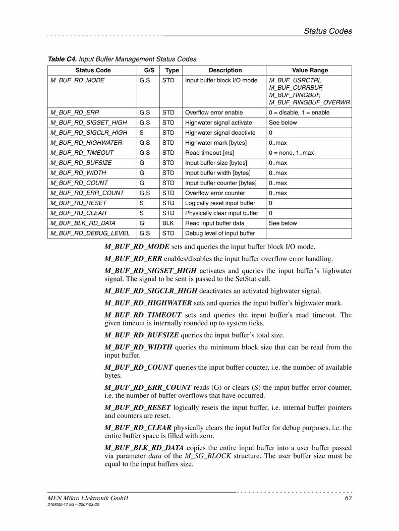
Status Codes
MEN Mikro Elektronik GmbH 6221M000-17 E3 – 2007-03-20
Table C4. Input Buffer Management Status Codes
M_BUF_RD_MODE sets and queries the input buffer block I/O mode.
M_BUF_RD_ERR enables/disables the input buffer overflow error handling.
M_BUF_RD_SIGSET_HIGH activates and queries the input buffer’s highwatersignal. The signal to be sent is passed to the SetStat call.
M_BUF_RD_SIGCLR_HIGH deactivates an activated highwater signal.
M_BUF_RD_HIGHWATER sets and queries the input buffer’s highwater mark.
M_BUF_RD_TIMEOUT sets and queries the input buffer’s read timeout. Thegiven timeout is internally rounded up to system ticks.
M_BUF_RD_BUFSIZE queries the input buffer’s total size.
M_BUF_RD_WIDTH queries the minimum block size that can be read from theinput buffer.
M_BUF_RD_COUNT queries the input buffer counter, i.e. the number of availablebytes.
M_BUF_RD_ERR_COUNT reads (G) or clears (S) the input buffer error counter,i.e. the number of buffer overflows that have occurred.
M_BUF_RD_RESET logically resets the input buffer, i.e. internal buffer pointersand counters are reset.
M_BUF_RD_CLEAR physically clears the input buffer for debug purposes, i.e. theentire buffer space is filled with zero.
M_BUF_BLK_RD_DATA copies the entire input buffer into a user buffer passedvia parameter data of the M_SG_BLOCK structure. The user buffer size must beequal to the input buffers size.
Status Code G/S Type Description Value Range
M_BUF_RD_MODE G,S STD Input buffer block I/O mode M_BUF_USRCTRL, M_BUF_CURRBUF, M_BUF_RINGBUF, M_BUF_RINGBUF_OVERWR
M_BUF_RD_ERR G,S STD Overflow error enable 0 = disable, 1 = enable
M_BUF_RD_SIGSET_HIGH G,S STD Highwater signal activate See below
M_BUF_RD_SIGCLR_HIGH S STD Highwater signal deactivte 0
M_BUF_RD_HIGHWATER G,S STD Highwater mark [bytes] 0..max
M_BUF_RD_TIMEOUT G,S STD Read timeout [ms] 0 = none, 1..max
M_BUF_RD_BUFSIZE G STD Input buffer size [bytes] 0..max
M_BUF_RD_WIDTH G STD Input buffer width [bytes] 0..max
M_BUF_RD_COUNT G STD Input buffer counter [bytes] 0..max
M_BUF_RD_ERR_COUNT G,S STD Overflow error counter 0..max
M_BUF_RD_RESET S STD Logically reset input buffer 0
M_BUF_RD_CLEAR S STD Physically clear input buffer 0
M_BUF_BLK_RD_DATA G BLK Read input buffer data See below
M_BUF_RD_DEBUG_LEVEL G,S STD Debug level of input buffer

Status Codes
MEN Mikro Elektronik GmbH 6321M000-17 E3 – 2007-03-20
M_BUF_RD_DEBUG_LEVEL defines the debug level of the input bufferfunctions of a debug driver. This influences the number of debug messages whichare produced. See debug level definitions in dbh.h and Chapter C 4.5 DriverDebugging on page 84.
C 2.2.3 Output Buffer Management Status Codes
If more than one output buffer is supported by the driver, the following status callsrefer to the output buffer of the current channel.
Table C5. Output Buffer Management Status Codes
M_BUF_WR_MODE sets and queries the output buffer block I/O mode.
M_BUF_WR_ERR enables/disables the output buffer underrun error handling.
M_BUF_WR_SIGSET_LOW activates and queries the output buffers lowwatersignal. The signal to be sent is passed to the SetStat call.
M_BUF_WR_SIGCLR_LOW deactivates an activated lowwater signal.
M_BUF_WR_LOWWATER sets and queries the output buffer’s lowwater mark.
M_BUF_WR_TIMEOUT sets and queries the output buffer’s read timeout. Thegiven timeout is internally rounded up to system ticks.
M_BUF_WR_BUFSIZE queries the output buffer’s total size.
M_BUF_WR_WIDTH queries the minimum block size that can be written to theoutput buffer.
M_BUF_WR_COUNT queries the output buffer counter, i.e. the number of freebytes.
Status Code G/S Type Description Value Range
M_BUF_WR_MODE G,S STD Output buffer block I/O mode M_BUF_USRCTRL, M_BUF_CURRBUF, M_BUF_RINGBUF, M_BUF_RINGBUF_OVERWR
M_BUF_WR_ERR G,S STD Underrun error enable 0 = disable, 1 = enable
M_BUF_WR_SIGSET_LOW G,S STD Lowwater signal activate See below
M_BUF_WR_SIGCLR_LOW S STD Lowwater signal deactivte 0
M_BUF_WR_LOWWATER G,S STD Lowwater mark [bytes] 0..max
M_BUF_WR_TIMEOUT G,S STD Write timeout [ms] 0 = none, 1..max
M_BUF_WR_BUFSIZE G STD Output buffer size [bytes] 0..max
M_BUF_WR_WIDTH G STD Output buffer width [bytes] 0..max
M_BUF_WR_COUNT G STD Output buffer counter [bytes] 0..max
M_BUF_WR_ERR_COUNT G,S STD Underrun error counter 0..max
M_BUF_WR_RESET S STD Logically reset output buffer 0
M_BUF_WR_CLEAR S STD Physically clear output buffer 0
M_BUF_BLK_WR_DATA G BLK Read output buffer data See below
M_BUF_WR_DEBUG_LEVEL G,S STD Debug level of write buffer

Status Codes
MEN Mikro Elektronik GmbH 6421M000-17 E3 – 2007-03-20
M_BUF_WR_ERR_COUNT reads (G) or clears (S) the output buffer error counter,i.e. the number of buffer underruns that have occurred.
M_BUF_WR_RESET logically resets the output buffer, i.e. internal buffer pointersand counters are reset.
M_BUF_WR_CLEAR physically clears the output buffer for debug purposes, i.e.the entire buffer space is filled with zero.
M_BUF_BLK_WR_DATA copies the entire output buffer into a user buffer passedvia parameter data of the M_SG_BLOCK structure. The user buffer size must beequal to the output buffer’s size.
M_BUF_WR_DEBUG_LEVEL defines the debug level of the output bufferfunctions of a debug driver. This influences the number of debug messages whichare produced. See debug level definitions in dbh.h and Chapter C 4.5 DriverDebugging on page 84.

Status Codes
MEN Mikro Elektronik GmbH 6521M000-17 E3 – 2007-03-20
C 2.2.4 Device Driver Status Codes
Table C6. Device Driver Status Codes
M_LL_CH_NUMBER queries the total number of device channels.
M_LL_CH_DIR queries the current channel’s direction. If supported by the driver,the channel direction can also be changed at runtime using this call.
M_LL_CH_LEN is for channel information purposes and returns the physical bitwidth of the current channel.
M_LL_CH_TYP is for channel information purposes and returns the type ofhardware of the current channel.
M_LL_IRQ_COUNT reads (G) or clears (S) the device interrupt counter.
M_LL_ID_CHECK returns if the device’s ID PROM was checked at deviceinitialization.
M_LL_DEBUG_LEVEL allows to define the debug level for the driver’s functionsin debug drivers. See definitions in dbg.h and Chapter C 4.5 Driver Debugging onpage 84.
M_LL_BLK_ID_DATA reads the raw device ID PROM data (M_LL_ID_SIZEbytes) from a device into a buffer passed via parameter data of the M_SG_BLOCKstructure. The ID PROM data size can be queried by the M_LL_ID_SIZE GetStatcall. If no ID PROM exists an ERR_LL_UNK_CODE error is returned.
Status Code G/S Type Description Value Range
M_LL_CH_NUMBER G STD Number of device channels 1..max
M_LL_CH_DIR G,S STD Device channel direction M_CH_IN, M_CH_OUT, M_CH_INOUT
M_LL_CH_LEN G STD Device channel length [bits] 0..max
M_LL_CH_TYP G STD Device channel type M_CH_UNKNOWN, M_CH_BINARY, M_CH_ANALOG, M_CH_SERIAL
M_LL_IRQ_COUNT G,S STD Device interrupt counter 0..max
M_LL_ID_CHECK G STD Device ID check enabled 0 = disabled, 1 = enabled
M_LL_DEBUG_LEVEL G,S STD Debug level of device driver See dbg.h
M_LL_ID_SIZE G STD Device ID PROM size [bytes] See below
M_LL_BLK_ID_DATA G BLK Read device ID PROM See below
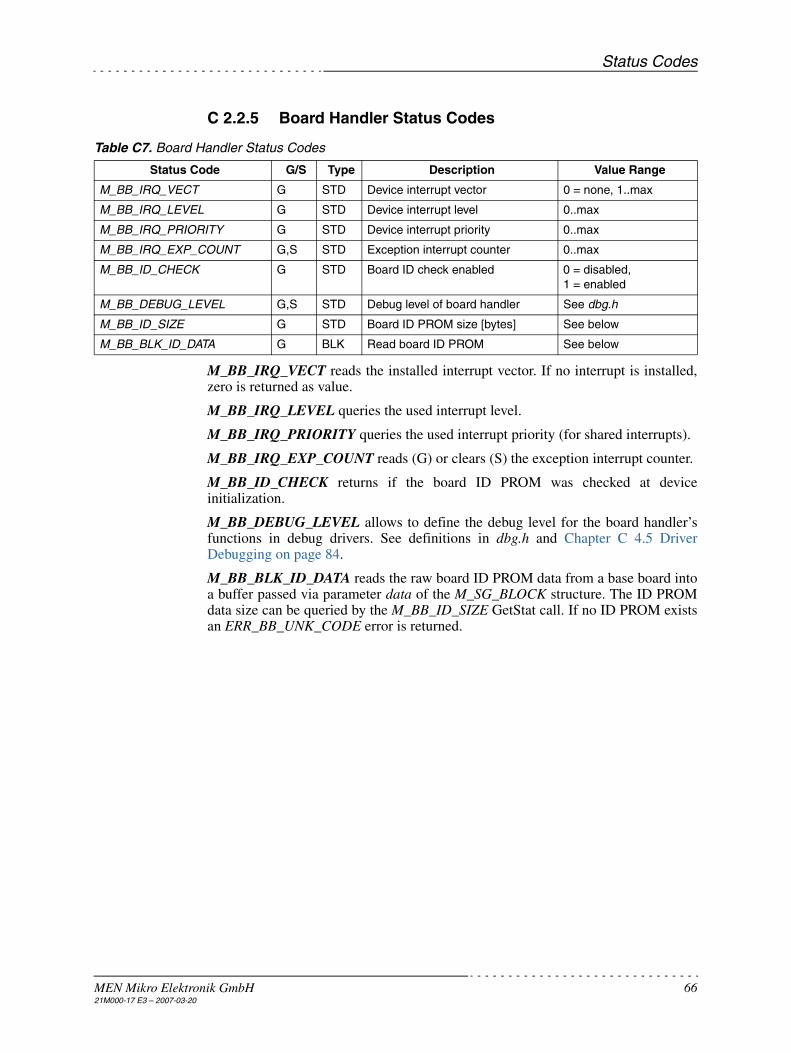
Status Codes
MEN Mikro Elektronik GmbH 6621M000-17 E3 – 2007-03-20
C 2.2.5 Board Handler Status Codes
Table C7. Board Handler Status Codes
M_BB_IRQ_VECT reads the installed interrupt vector. If no interrupt is installed,zero is returned as value.
M_BB_IRQ_LEVEL queries the used interrupt level.
M_BB_IRQ_PRIORITY queries the used interrupt priority (for shared interrupts).
M_BB_IRQ_EXP_COUNT reads (G) or clears (S) the exception interrupt counter.
M_BB_ID_CHECK returns if the board ID PROM was checked at deviceinitialization.
M_BB_DEBUG_LEVEL allows to define the debug level for the board handler’sfunctions in debug drivers. See definitions in dbg.h and Chapter C 4.5 DriverDebugging on page 84.
M_BB_BLK_ID_DATA reads the raw board ID PROM data from a base board intoa buffer passed via parameter data of the M_SG_BLOCK structure. The ID PROMdata size can be queried by the M_BB_ID_SIZE GetStat call. If no ID PROM existsan ERR_BB_UNK_CODE error is returned.
Status Code G/S Type Description Value Range
M_BB_IRQ_VECT G STD Device interrupt vector 0 = none, 1..max
M_BB_IRQ_LEVEL G STD Device interrupt level 0..max
M_BB_IRQ_PRIORITY G STD Device interrupt priority 0..max
M_BB_IRQ_EXP_COUNT G,S STD Exception interrupt counter 0..max
M_BB_ID_CHECK G STD Board ID check enabled 0 = disabled, 1 = enabled
M_BB_DEBUG_LEVEL G,S STD Debug level of board handler See dbg.h
M_BB_ID_SIZE G STD Board ID PROM size [bytes] See below
M_BB_BLK_ID_DATA G BLK Read board ID PROM See below

Error Codes
MEN Mikro Elektronik GmbH 6721M000-17 E3 – 2007-03-20
C 3 Error Codes
Note: Please see mdis_err.h for error numbers. The file’s location depends on theoperating system.
C 3.1 Operating System Specific Errors
Table C8. Operating System Specific Errors
C 3.2 MDIS Kernel Errors
Table C9. MDIS Kernel Errors
Error Code Error Message Error Description
ERR_BAD_PATH bad path number The given path number is unknown to the system’s path table.
ERR_PATH_FULL path table full The path table is full (too many open paths).
ERR_BUSERR bus error occurred An exception error occurred when the hard-ware was accessed.
Error Code Error Message Error Description
ERR_MK general error A general error occurred.
ERR_MK_USERBUF user buffer too small The user buffer for a block status call is too small.
ERR_MK_UNK_CODE unknown status code The status code is not known.
ERR_MK_ILL_PARAM illegal parameter General error for illegal parameters.
ERR_MK_ILL_DESC illegal descriptor type An illegal descriptor type was detected in the device descriptor.
ERR_MK_ILL_MSIZE address space size conflict The board slot’s address space is not large enough for the device’s requirements.
ERR_MK_NO_LLDESC device descriptor not found The device descriptor does not exist.
ERR_MK_NO_BBISDESC board descriptor not found The board descriptor does not exist.
ERR_MK_NO_LLDRV device driver not found The device driver does not exist or cannot be linked.
ERR_MK_NO_BBISDRV board handler not found The board handler does not exist or cannot be linked.
ERR_MK_NO_IRQ board does not support interrupts The board has no interrupt capabilities.
ERR_MK_NO_IRQ board doesn't support interrupt The device needs an interrupt, but the board slot is not able to handle device interrupts.
ERR_MK_IRQ_INSTALL can't install interrupt The interrupt cannot be installed in the sys-tem.
ERR_MK_IRQ_REMOVE can't remove interrupt An installed interrupt cannot be removed from the system.
ERR_MK_IRQ_ENABLE can't enable/disable interrupt An installed interrupt cannot be enabled/dis-abled.
ERR_MK_DESC_PARAM descriptor values out of range An illegal descriptor value was detected in the device descriptor.
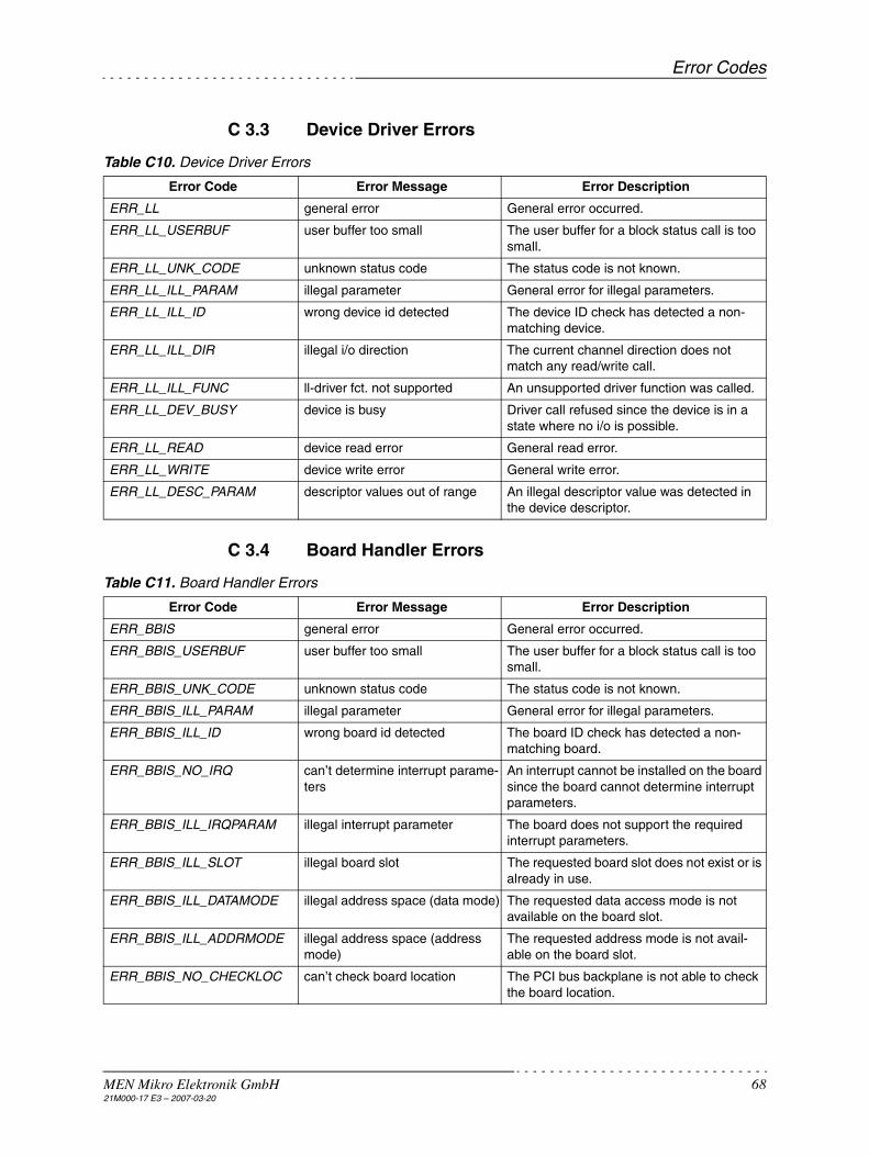
Error Codes
MEN Mikro Elektronik GmbH 6821M000-17 E3 – 2007-03-20
C 3.3 Device Driver Errors
Table C10. Device Driver Errors
C 3.4 Board Handler Errors
Table C11. Board Handler Errors
Error Code Error Message Error Description
ERR_LL general error General error occurred.
ERR_LL_USERBUF user buffer too small The user buffer for a block status call is too small.
ERR_LL_UNK_CODE unknown status code The status code is not known.
ERR_LL_ILL_PARAM illegal parameter General error for illegal parameters.
ERR_LL_ILL_ID wrong device id detected The device ID check has detected a non-matching device.
ERR_LL_ILL_DIR illegal i/o direction The current channel direction does not match any read/write call.
ERR_LL_ILL_FUNC ll-driver fct. not supported An unsupported driver function was called.
ERR_LL_DEV_BUSY device is busy Driver call refused since the device is in a state where no i/o is possible.
ERR_LL_READ device read error General read error.
ERR_LL_WRITE device write error General write error.
ERR_LL_DESC_PARAM descriptor values out of range An illegal descriptor value was detected in the device descriptor.
Error Code Error Message Error Description
ERR_BBIS general error General error occurred.
ERR_BBIS_USERBUF user buffer too small The user buffer for a block status call is too small.
ERR_BBIS_UNK_CODE unknown status code The status code is not known.
ERR_BBIS_ILL_PARAM illegal parameter General error for illegal parameters.
ERR_BBIS_ILL_ID wrong board id detected The board ID check has detected a non-matching board.
ERR_BBIS_NO_IRQ can’t determine interrupt parame-ters
An interrupt cannot be installed on the board since the board cannot determine interrupt parameters.
ERR_BBIS_ILL_IRQPARAM illegal interrupt parameter The board does not support the required interrupt parameters.
ERR_BBIS_ILL_SLOT illegal board slot The requested board slot does not exist or is already in use.
ERR_BBIS_ILL_DATAMODE illegal address space (data mode) The requested data access mode is not available on the board slot.
ERR_BBIS_ILL_ADDRMODE illegal address space (address mode)
The requested address mode is not avail-able on the board slot.
ERR_BBIS_NO_CHECKLOC can’t check board location The PCI bus backplane is not able to check the board location.

Error Codes
MEN Mikro Elektronik GmbH 6921M000-17 E3 – 2007-03-20
C 3.5 Descriptor Errors
Table C12. Descriptor Errors
C 3.6 ID PROM Errors
Table C13. ID PROM Errors
C 3.7 Operating System Service Errors
Table C14. Operating System Service Errors
ERR_BBIS_ILL_FUNC board handler function not sup-ported
A not supported board handler function was called.
ERR_BBIS_DESC_PARAM descriptor values out of range An illegal descriptor value was detected in the board descriptor.
Error Code Error Message Error Description
Error Code Error Message Error Description
ERR_DESC general error General error occurred.
ERR_DESC_CORRUPTED descriptor data corrupted The descriptor has a wrong format.
ERR_DESC_KEY_NOTFOUND descriptor key not found The requested descriptor key is not defined in the descriptor.
ERR_DESC_BUF_TOOSMALL descriptor buffer too small Internal error when reading descriptor.
Error Code Error Message Error Description
ERR_ID general error General error occurred.
ERR_ID_NOTFOUND id prom not found The ID PROM does not exist.
ERR_ID_CORRUPTED id prom data corrupted The ID PROM contains invalid data.
ERR_ID_ILL_PARAM id prom illegal parameter Internal error when reading ID PROM.
Error Code Error Message Error Description
ERR_OSS general error General error occurred.
ERR_OSS_ILL_PARAM illegal parameter General error for illegal parameters.
ERR_OSS_UNK_BUSTYPE unknown bus type The bus type required for a base board is not supported.
ERR_OSS_TIMEOUT timeout occured A timeout has occurred while waiting for data or device response.
ERR_OSS_NO_PERM no permission accessing memory There is no permission to access a given user buffer.
ERR_OSS_NO_SYSCLOCK no system ticker available There is no systems ticker available for timer functions.
ERR_OSS_ILL_HANDLE illegal OSS handle Internal error.
ERR_OSS_SIG_OCCURED signal occured A deadly signal has been received while waiting for data or device response.
ERR_OSS_SIG_SEND can't send signal Internal error.
ERR_OSS_SIG_SET can't install signal A user defined signal cannot be installed.
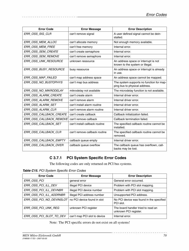
Error Codes
MEN Mikro Elektronik GmbH 7021M000-17 E3 – 2007-03-20
C 3.7.1 PCI System Specific Error Codes
The following codes are only returned on PCI bus systems.
Table C15. PCI System Specific Error Codes
Note: The PCI specific errors do not exist on all systems!
ERR_OSS_SIG_CLR can't remove signal A user defined signal cannot be dein-stalled.
ERR_OSS_MEM_ALLOC can't allocate memory Not enough memory available.
ERR_OSS_MEM_FREE can't free memory Internal error.
ERR_OSS_SEM_CREATE can't create semaphore Internal error.
ERR_OSS_SEM_REMOVE can't remove semaphore Internal error.
ERR_OSS_UNK_RESOURCE unknown ressource An address space or interrupt is not known to the system or illegal.
ERR_OSS_BUSY_RESOURCE busy ressource An address space or interrupt is already in use.
ERR_OSS_MAP_FAILED can't map address space An address space cannot be mapped.
ERR_OSS_NO_BUSTOPHYS can’t map bus address The system supports no function for map-ping bus to physical address.
ERR_OSS_NO_MIKRODELAY mikrodelay not available The microdelay function is not available.
ERR_OSS_ALARM_CREATE can't create alarm Internal driver error.
ERR_OSS_ALARM_REMOVE can't remove alarm Internal driver error.
ERR_OSS_ALARM_SET can't install alarm routine Internal driver error.
ERR_OSS_ALARM_CLR can't remove alarm routine Internal driver error.
ERR_OSS_CALLBACK_CREATE can't create callback Callback initialization failed.
ERR_OSS_CALLBACK_REMOVE can't remove callback Callback termination failed.
ERR_OSS_CALLBACK_SET can't install callback routine The specified callback routine cannot be installed.
ERR_OSS_CALLBACK_CLR can't remove callback routine The specified callback routine cannot be removed.
ERR_OSS_CALLBACK_EMPTY callback queue empty Internal driver error.
ERR_OSS_CALLBACK_OVER callback queue overflow The callback queue has overflown, call-backs may be lost.
Error Code Error Message Error Description
Error Code Error Message Error Description
ERR_OSS_PCI general error General error occurred.
ERR_OSS_PCI_ILL_DEV illegal PCI device Problem with PCI slot mapping.
ERR_OSS_PCI_ILL_DEVNBR illegal PCI device number Problem with PCI slot mapping.
ERR_OSS_PCI_ILL_ADDRNBR illegal PCI address number Unsupported PCI address.
ERR_OSS_PCI_NO_DEVINSLOT no PCI device found in slot No PCI device was found in the specified PCI slot.
ERR_OSS_PCI_UNK_REG unknown PCI register The board handler tried to read an unknown PCI register.
ERR_OSS_PCI_SLOT_TO_DEV can’t map PCI slot to device Internal error.

Error Codes
MEN Mikro Elektronik GmbH 7121M000-17 E3 – 2007-03-20
C 3.7.2 VMEbus Specific Error Codes
The following codes are only returned on VMEbus systems.
Table C16. VMEbus Specific Error Codes
Note: The VMEbus specific errors do not exist on all systems!
C 3.8 Buffer Management Errors
Table C17. Buffer Management Errors
C 3.9 PLD Loader Errors
Table C18. PLD Loader Errors
Error Code Error Message Error Description
ERR_OSS_VME general error General error occurred.
ERR_OSS_VME_ILL_SPACE illegal address space The VMEbus address space required for the board is not available on the CPU board.
ERR_OSS_VME_ILL_SIZE illegal address space size The CPU board’s VMEbus address space is not large enough for the board’s require-ments.
Error Code Error Message Error Description
ERR_MBUF general error General error occurred.
ERR_MBUF_USERBUF user buffer too small The user buffer for a block I/O call is smaller than buffer width.
ERR_MBUF_UNK_CODE unknown status code The status code is not known.
ERR_MBUF_ILL_PARAM illegal parameter General error for illegal parameters.
ERR_MBUF_OVERFLOW buffer overflow occured A block read function has been aborted after an input buffer overflow occurred.
ERR_MBUF_UNDERRUN buffer underrun occured A block write function has been aborted after an output buffer underrun occurred.
ERR_MBUF_NO_BUF no buffer installed There is no buffer available.
ERR_MBUF_ILL_SIZE illegal buffer size The buffer size specified in the device descriptor is not possible.
ERR_MBUF_ILL_DIR illegal buffer direction Internal error.
Error Code Error Message Error Description
ERR_PLD general error General error occurred.
ERR_PLD_NOTFOUND no response from PLD The PLD does not respond.
ERR_PLD_INIT error initializing PLD An error has occurred in the PLD initializing sequence.
ERR_PLD_LOAD error loading PLD An error has occurred while PLD was loaded.
ERR_PLD_TERM error terminating PLD An error has occurred in the PLD terminat-ing sequence.
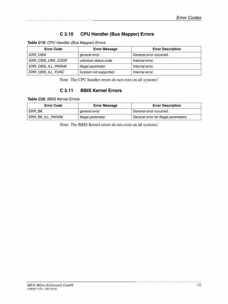
Error Codes
MEN Mikro Elektronik GmbH 7221M000-17 E3 – 2007-03-20
C 3.10 CPU Handler (Bus Mapper) Errors
Table C19. CPU Handler (Bus Mapper) Errors
Note: The CPU handler errors do not exist on all systems!
C 3.11 BBIS Kernel Errors
Table C20. BBIS Kernel Errors
Note: The BBIS Kernel errors do not exist on all systems!
Error Code Error Message Error Description
ERR_CBIS general error General error occurred.
ERR_CBIS_UNK_CODE unknown status code Internal error.
ERR_CBIS_ILL_PARAM illegal parameter Internal error.
ERR_CBIS_ILL_FUNC function not supported Internal error.
Error Code Error Message Error Description
ERR_BK general error General error occurred.
ERR_BK_ILL_PARAM illegal parameter General error for illegal parameters.

MDIS Device Descriptors
MEN Mikro Elektronik GmbH 7321M000-17 E3 – 2007-03-20
C 4 MDIS Device Descriptors
C 4.1 General
C 4.1.1 Devices and Device Descriptors
A device is a piece of hardware located on a "base board" (see below). This may be
• a controller, located on a CPU board
• a mezzanine I/O device, plugged on a carrier board, e.g. M-Module or PC-MIP.
Each device is described by a so-called device descriptor. The name of the devicedescriptor is usually called device name.
The device descriptor describes all logical parameters of the device:
• Device driver name
• Board name (name of the board descriptor)
• Device location (slot of the board on which the device is mounted, or logical slotfor on-board devices)
• Device/driver specific parameters
All physical characteristics of a device are hard-coded in the (low-level) driver andcan be queried by GetStat calls:
• Required address spaces
• Info about ID PROM
• Number of channels
• Characteristics of channels
Although it may be useful to know some details about device descriptors, you nor-mally won’t need to know such details, especially if you use the MDIS installation wizard. We recommend to use the comfortable tools provided in the MDIS distri-bution. If you cannot make use of such tools, this chapter gives you any informa-tion you need.

MDIS Device Descriptors
MEN Mikro Elektronik GmbH 7421M000-17 E3 – 2007-03-20
C 4.1.2 Boards and Board Descriptors
A board, or base board, is a piece of hardware that controls access to a device andthe interrupts from this device. The base board can be
• the CPU board that contains or implements the controlled device
• a carrier board for mezzanine I/O devices, e.g. M-Module or PC-MIP carrier.
Each base board is described by a so-called board descriptor. The name of theboard descriptor is usually called board name. This name is defined as a string inthe device descriptor.
The board descriptor describes all logical characteristics of the board:
• Board handler name
• Board location (geographical location or physical address)
• Interrupt configuration
• Board/handler specific parameters
All physical characteristics of a base board are hard-coded in the board handler andcan be queried by GetStat calls:
• Info about ID PROM
• Number of board slots
• Available address spaces of a board slot
• Interrupt parameters of a board slot
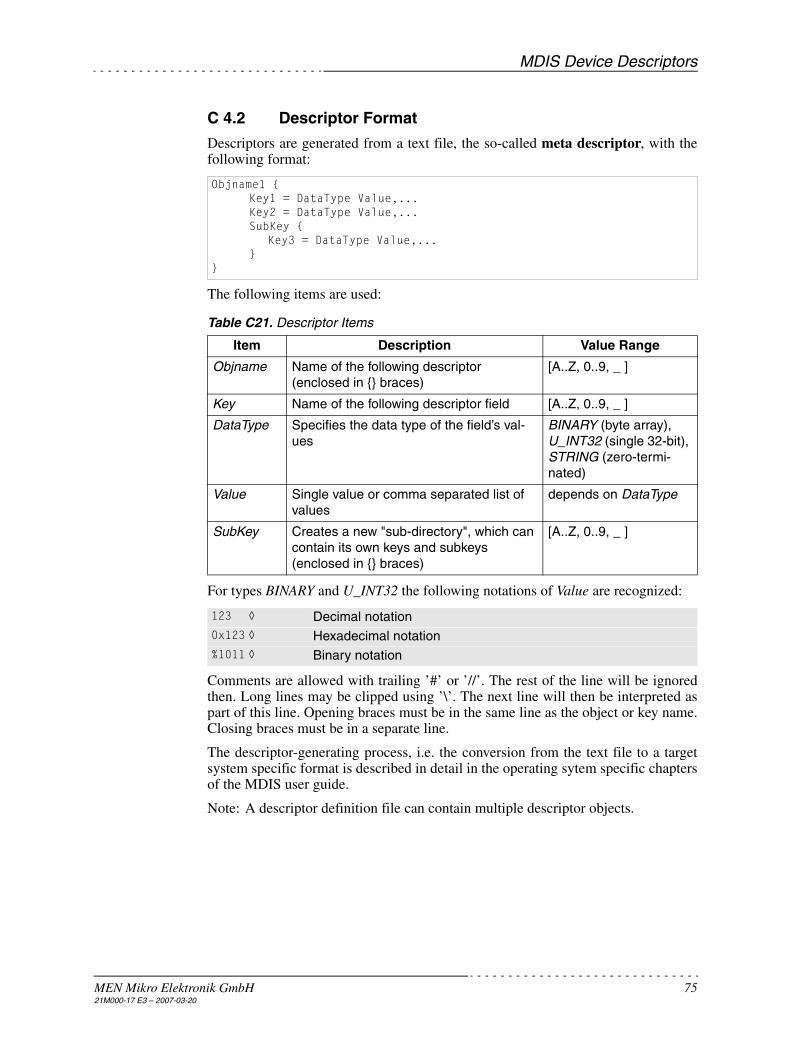
MDIS Device Descriptors
MEN Mikro Elektronik GmbH 7521M000-17 E3 – 2007-03-20
C 4.2 Descriptor Format
Descriptors are generated from a text file, the so-called meta descriptor, with thefollowing format:
The following items are used:
Table C21. Descriptor Items
For types BINARY and U_INT32 the following notations of Value are recognized:
Comments are allowed with trailing ’#’ or ’//’. The rest of the line will be ignoredthen. Long lines may be clipped using ’\’. The next line will then be interpreted aspart of this line. Opening braces must be in the same line as the object or key name.Closing braces must be in a separate line.
The descriptor-generating process, i.e. the conversion from the text file to a targetsystem specific format is described in detail in the operating sytem specific chaptersof the MDIS user guide.
Note: A descriptor definition file can contain multiple descriptor objects.
Objname1 {Key1 = DataType Value,... Key2 = DataType Value,...SubKey {
Key3 = DataType Value,...}
}
Item Description Value Range
Objname Name of the following descriptor (enclosed in {} braces)
[A..Z, 0..9, _ ]
Key Name of the following descriptor field [A..Z, 0..9, _ ]
DataType Specifies the data type of the field’s val-ues
BINARY (byte array), U_INT32 (single 32-bit), STRING (zero-termi-nated)
Value Single value or comma separated list of values
depends on DataType
SubKey Creates a new "sub-directory", which can contain its own keys and subkeys (enclosed in {} braces)
[A..Z, 0..9, _ ]
123 ◊ Decimal notation0x123 ◊ Hexadecimal notation%1011 ◊ Binary notation

MDIS Device Descriptors
MEN Mikro Elektronik GmbH 7621M000-17 E3 – 2007-03-20
C 4.3 Device Descriptor Keys
The device descriptor defines the following parameters:
• Name of the hardware
• Name of the base board
• Geographical location on the board
• Further device-specific parameters
For these standard parameters the following descriptor keys are defined:
Table C22. Device Descriptor Keys
LegendReq: required configuration keys, must be definedFix: fixed keys, should not be changed by users
See also Chapter C 4.5 Driver Debugging on page 84.
DESC_TYPE defines the type of the descriptor object. For device descriptors thevalue 1 must be used.
HW_TYPE specifies the name of the device. From this name the matching devicedriver name is built internally.
DEVICE_SLOT defines at which slot on the board the device is mounted. Slotnumbers begin with 0.
BOARD_NAME defines the name of the board descriptor.
ID_CHECK decides if the device ID PROM is read and checked at initialization.
IRQ_ENABLE specifies if the interrupt should implicitly be enabled duringinitialization.
DEBUG_LEVEL_xxx enable debug output from the driver functions. This onlytakes effect on debug drivers (see Chapter C 4.5 Driver Debugging on page 84).
Key DataType Description Value Range Req Fix
DESC_TYPE U_INT32 Descriptor type1 = device, 2 = board
1• •
HW_TYPE STRING Hardware type (name of the device) [A..Z, 0..9, _ ] • •
DEVICE_SLOT U_INT32 Base board slot where device is mounted
0..0xFFFFFFFF•
BOARD_NAME STRING Base board name (descriptor name) [A..Z, 0..9, _ ] •
ID_CHECK U_INT32 Read and check the device ID0 = disable, 1 = enable
0, 1
IRQ_ENABLE U_INT32 Enable interrupt immediately (after init)0 = no, 1 = yes
0, 1
DEBUG_LEVEL U_INT32 Debug level of device driver see dbg.h
DEBUG_LEVEL_MK U_INT32 Debug level of MDIS kernel
DEBUG_LEVEL_DESC U_INT32 Debug level of descriptor decoder
DEBUG_LEVEL_MBUF U_INT32 Debug level of buffer manager
DEBUG_LEVEL_OSS U_INT32 Debug level of system services
SUBDEVICE_OFFSET_x U_INT32 Subdevice offset 0..0xFFFFFFFF
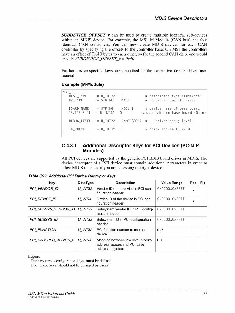
MDIS Device Descriptors
MEN Mikro Elektronik GmbH 7721M000-17 E3 – 2007-03-20
SUBDEVICE_OFFSET_x can be used to create multiple identical sub-deviceswithin an MDIS device. For example, the M51 M-Module (CAN bus) has fouridentical CAN controllers. You can now create MDIS devices for each CANcontroller by specifying the offsets to the controller base. On M51 the controllershave an offset of 0x40 bytes to each other, so for the second CAN chip, one wouldspecify SUBDEVICE_OFFSET_x = 0x40.
Further device-specific keys are described in the respective device driver usermanual.
Example (M-Module)
C 4.3.1 Additional Descriptor Keys for PCI Devices (PC-MIP Modules)
All PCI devices are supported by the generic PCI BBIS board driver in MDIS. Thedevice descriptor of a PCI device must contain additional parameters in order toallow MDIS to check if you are accessing the right device.
Table C23. Additional PCI Device Descriptor Keys
LegendReq: required configuration keys, must be definedFix: fixed keys, should not be changed by users
M31_1 { DESC_TYPE = U_INT32 1 # descriptor type (1=device) HW_TYPE = STRING M031 # hardware name of device
BOARD_NAME = STRING A201_1 # device name of base board DEVICE_SLOT = U_INT32 0 # used slot on base board (0..n)
DEBUG_LEVEL = U_INT32 0xc0008007 # LL driver debug level
ID_CHECK = U_INT32 1 # check module ID PROM}
Key DataType Description Value Range Req Fix
PCI_VENDOR_ID U_INT32 Vendor ID of the device in PCI con-figuration header
0x0000..0xFFFF•
PCI_DEVICE_ID U_INT32 Device ID of the device in PCI con-figuration header
0x0000..0xFFFF•
PCI_SUBSYS_VENDOR_ID U_INT32 Subsystem vendor ID in PCI config-uration header
0x0000..0xFFFF
PCI_SUBSYS_ID U_INT32 Subsystem ID in PCI configuration header
0x0000..0xFFFF
PCI_FUNCTION U_INT32 PCI function number to use on device
0..7
PCI_BASEREG_ASSIGN_x U_INT32 Mapping between low-level driver’s address spaces and PCI base address registers
0..5

MDIS Device Descriptors
MEN Mikro Elektronik GmbH 7821M000-17 E3 – 2007-03-20
PCI_VENDOR_ID and PCI_DEVICE_ID must match the values in the device’sPCI configuration header.
PCI_SUBSYS_VENDOR_ID and PCI_SUBSYS_ID - if specified - must match thecorresponding fields in the device’s PCI configuration header.
PCI_FUNCTION defines the PCI function number to use within the devices. A PCIdevice can have up to 7 subfunctions. If this key is not present, the first function(number 0) is used.
PCI_BASEREG_ASSIGN_x: A low-level driver may request multiple addressspaces from the MDIS kernel. This key defines the mapping between the low-leveldriver’s address spaces and the PCI base address register 0..5. For example to usethe PCI base address register #3 for the low-level driver’s first address space setPCI_BASEREG_ASSIGN_0 = U_INT32 3. See the low-level driver documentationfor further details.If this key is not defined for the corresponding low-level driver’s address space, a1:1 mapping is used (i.e. PCI base address register #0 is used for the low-leveldriver’s first address space).
C 4.4 Board Descriptor Keys
The board descriptor defines the following parameters:
• Name of the hardware• Address or location on the bus system• Further board-specific parameters • Further bus-specific parameters
For these standard parameters the following descriptor keys are defined:
Table C24. Board Descriptor Keys
LegendReq: required configuration keys, must be definedFix: fixed keys, should not be changed by users
See also Chapter C 4.5 Driver Debugging on page 84.
DESC_TYPE defines the type of the descriptor object. For board descriptors thevalue 2 must be used.
HW_TYPE specifies the name of the base board. From this name the matchingboard handler name is built internally.
DEBUG_LEVEL enables debug output from the board handler functions. This onlytakes effect on debug board handlers (see Chapter C 4.5 Driver Debugging on page84).
Key DataType Description Value Range Req Fix
DESC_TYPE U_INT32 Descriptor type1 = device, 2 = board
2• •
HW_TYPE STRING Hardware type (name of the board) [A..Z, 0..9, _ ] • •
DEBUG_LEVEL U_INT32 Debug level for the board handler func-tions
0..0xFFFFFFFF
DEBUG_LEVEL_BK U_INT32 Debug level of BBIS kernel
DEBUG_LEVEL_DESC U_INT32 Debug level of descriptor decoder
DEBUG_LEVEL_OSS U_INT32 Debug level of system services
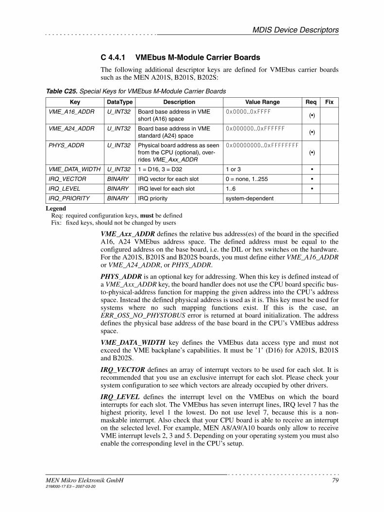
MDIS Device Descriptors
MEN Mikro Elektronik GmbH 7921M000-17 E3 – 2007-03-20
C 4.4.1 VMEbus M-Module Carrier Boards
The following additional descriptor keys are defined for VMEbus carrier boardssuch as the MEN A201S, B201S, B202S:
Table C25. Special Keys for VMEbus M-Module Carrier Boards
LegendReq: required configuration keys, must be definedFix: fixed keys, should not be changed by users
VME_Axx_ADDR defines the relative bus address(es) of the board in the specifiedA16, A24 VMEbus address space. The defined address must be equal to theconfigured address on the base board, i.e. the DIL or hex switches on the hardware.For the A201S, B201S and B202S boards, you must define either VME_A16_ADDRor VME_A24_ADDR, or PHYS_ADDR.
PHYS_ADDR is an optional key for addressing. When this key is defined instead ofa VME_Axx_ADDR key, the board handler does not use the CPU board specific bus-to-physical-address function for mapping the given address into the CPU’s addressspace. Instead the defined physical address is used as it is. This key must be used forsystems where no such mapping functions exist. If this is the case, anERR_OSS_NO_PHYSTOBUS error is returned at board initialization. The addressdefines the physical base address of the base board in the CPU’s VMEbus addressspace.
VME_DATA_WIDTH key defines the VMEbus data access type and must notexceed the VME backplane’s capabilities. It must be ’1’ (D16) for A201S, B201Sand B202S.
IRQ_VECTOR defines an array of interrupt vectors to be used for each slot. It isrecommended that you use an exclusive interrupt for each slot. Please check yoursystem configuration to see which vectors are already occupied by other drivers.
IRQ_LEVEL defines the interrupt level on the VMEbus on which the boardinterrupts for each slot. The VMEbus has seven interrupt lines, IRQ level 7 has thehighest priority, level 1 the lowest. Do not use level 7, because this is a non-maskable interrupt. Also check that your CPU board is able to receive an interrupton the selected level. For example, MEN A8/A9/A10 boards only allow to receiveVME interrupt levels 2, 3 and 5. Depending on your operating system you must alsoenable the corresponding level in the CPU’s setup.
Key DataType Description Value Range Req Fix
VME_A16_ADDR U_INT32 Board base address in VME short (A16) space
0x0000..0xFFFF(•)
VME_A24_ADDR U_INT32 Board base address in VME standard (A24) space
0x000000..0xFFFFFF(•)
PHYS_ADDR U_INT32 Physical board address as seen from the CPU (optional), over-rides VME_Axx_ADDR
0x00000000..0xFFFFFFFF(•)
VME_DATA_WIDTH U_INT32 1 = D16, 3 = D32 1 or 3 •
IRQ_VECTOR BINARY IRQ vector for each slot 0 = none, 1..255 •
IRQ_LEVEL BINARY IRQ level for each slot 1..6 •
IRQ_PRIORITY BINARY IRQ priority system-dependent

MDIS Device Descriptors
MEN Mikro Elektronik GmbH 8021M000-17 E3 – 2007-03-20
IRQ_PRIORITY is only used for shared interrupts. Some systems (OS-9) maintaina linked list of handlers in a priority-based manner. However, since VME interruptsharing is not recommended, this key is not required.
C 4.4.2 CompactPCI M-Module Carrier Boards
The following describes how to configure the D201, F201 and F202 CompactPCIM-Module carrier boards.
First you must tell MDIS the PCI bus number of the CompactPCI backplane. Sincethis depends on the CPU and may even vary depending on the system configuration,it is recommended to configure a PCI_BUS_PATH in the descriptor. The PCI buspath allows to address an exact geographical location within a PCI system,indepedently of which PCI devices are present in the system. PCI_BUS_PATH is anarray of device IDs of PCI-to-PCI bridges starting from PCI bus 0.
For example, to address the Compact PCI backplane on a MEN D2 CPU, you mustenter PCI_BUS_PATH = BINARY 0x08, because the CompactPCI bridge has deviceID 0x08 on PCI bus 0. See D201/DOC/pcibuspath.txt for a list of currently knownbus paths.
If you don’t know the device IDs of your system’s bridges, you can alternativelyenter the PCI bus number of the CompactPCI backplane directly usingPCI_BUS_NUMBER.
Note: With VxWorks you can use the pciscanner tool to find out the PCI bus path(sysPciScan()).
Table C26. Special Keys for CompactPCI M-Module Carrier Boards - PCI Bus Keys
LegendReq: required configuration keys, must be definedFix: fixed keys, should not be changed by users
Additionally, you must tell MDIS the CompactPCI slot in which your carrier boardis plugged. Again you have two alternatives:
If you have a standard CompactPCI backplane you should use PCI_BUS_SLOT.This is the geographical slot number within the CompactPCI rack (slot 1 = systemslot). MDIS will compute the PCI device number from this value. SomeCompactPCI racks support encoding on each slot connector (signals GA[0..4]) thatallows a board to check its geographical location. You can advice your board driverto check if PCI_BUS_SLOT and the actual geographical location match usingdescriptor key PCI_CHECK_LOCATION.
Alternatively you can specify the PCI device number on the CompactPCI busdirectly using PCI_DEVICE_ID (note that this key exists also in the devicedescriptor of PCI devices but has a different meaning there).
Key DataType Description Value Range Req Fix
PCI_BUS_PATH BINARY Device IDs of bridges to CompactPCI backplane (see text)
0x00..0x1F, ....(•)
PCI_BUS_NUMBER U_INT32 Alternative to PCI_BUS_PATH. Specify PCI bus number directly.
0x00..0xFF(•)

MDIS Device Descriptors
MEN Mikro Elektronik GmbH 8121M000-17 E3 – 2007-03-20
Table C27. Special Keys for CompactPCI M-Module Carrier Boards - PCI Device Keys
LegendReq: required configuration keys, must be definedFix: fixed keys, should not be changed by users
C 4.4.3 Standard PCI M-Module Carrier Boards
The M-Module carrier boards for standard PCI bus, C203 and C204, are handled bya variant of the D201 board driver. As opposed to CompactPCI, the PCI bus indesktop PCs usually has always PCI bus number 0, so you do not need to specify aPCI_BUS_PATH. On the other hand the PCI slots have no standard numbering ofdevice IDs. So you need to find out the device number of the C203/C204 boardusing a PCI viewer utility and enter this value in PCI_DEVICE_ID.
Table C28. Special Keys for Standard PCI M-Module Carrier Boards
LegendReq: required configuration keys, must be definedFix: fixed keys, should not be changed by users
Key DataType Description Value Range Req Fix
PCI_BUS_SLOT U_INT32 CompactPCI bus slot (1 = system slot) 2..n (•)
PCI_DEVICE_ID U_INT32 PCI device number of board on Com-pactPCI bus, overrides PCI_BUS_SLOT
0x00..0x1F(•)
PCI_CHECK_LOCATION U_INT32 0 = don’t check location1 = check location
If key not present, defaults to 1!
0,1
Key DataType Description Value Range Req Fix
PCI_BUS_NUMBER U_INT32 Specify PCI bus number (always 0 in desktop PCs)
0•
PCI_DEVICE_ID U_INT32 PCI device number of board on PCI bus 0
0x00..0x1F•
PCI_CHECK_LOCATION U_INT32 Must be 0, since GA[0..4] not avail-able on standard PCI bus
0•

MDIS Device Descriptors
MEN Mikro Elektronik GmbH 8221M000-17 E3 – 2007-03-20
C 4.4.4 PC-MIP Carrier Boards
For PC-MIP modules, the F203 and D202 boards are available for CompactPCIsystems. Additionally PC-MIP modules can reside directly on the on-board PC-MIPslots of the MEN CPUs D2, F1, F2 and A11.
All of these boards are handled by the generic PCI board handler. Again, aPCI_BUS_PATH key should be present in the descriptor to allow an exactgeographical addressing of a specific PC-MIP module (see also Chapter C 4.4.2CompactPCI M-Module Carrier Boards on page 80). As opposed to the M-Modulecarriers, you must include the device number of the CompactPCI backplane in thePCI_BUS_PATH. For example, to address a D202 carrier board in CompactPCI slot#3 of a D2 system, enter PCI_BUS_PATH = BINARY 0x08,0x0e, because theCompactPCI bridge on the D2 has device ID 0x08 on PCI bus 0, and slot #3 hasdevice ID 0x0E on the CompactPCI bus.
A carrier board usually has multiple PC-MIP slots. The device numbers of each PC-MIP slot must be entered in the descriptor keys DEVICE_SLOT_x.
Table C29. Special Keys for PC-MIP Carrier Boards
LegendReq: required configuration keys, must be definedFix: fixed keys, should not be changed by users
The following table lists the PCI_BUS_PATHs on some CompactPCI carriers andCPUs.
Table C30. PCI_BUS_PATH Values on MEN CompactPCI CPUs and PC-MIP Carrier Boards
The following table lists the DEVICE_SLOT_x assignments for some carrier boards:
Key DataType Description Value Range Req Fix
PCI_BUS_PATH BINARY Device IDs of bridges to carrier board 0x00..0x1F, ... (•)
PCI_BUS_NUMBER U_INT32 Optionally overrides PCI_BUS_PATH 0x00..0xFF (•)
DEVICE_SLOT_x U_INT32 Specify the PCI device number of PC-MIP slot n on the carrier board
0x00..0x1F•
CPU/Carrier Board (Slot 1)
PCI_BUS_PATH Values for PC-MIP Carrier Board in Compact PCI Slot
2 3 4 5 6 7
D1 0x14,0x0F 0x14,0x0E 0x14,0x0D 0x14,0x0C 0x14,0x0B 0x14,0x0A
D2 0x08,0x0F 0x08,0x0E 0x08,0x0D 0x08,0x0C 0x08,0x0B 0x08,0x0A
F1, D3 0x1E,0x0F 0x1E,0x0E 0x1E,0x0D 0x1E,0x0C 0x1E,0x0B 0x1E,0x0A
F2 0x08,0x0F 0x08,0x0E 0x08,0x0D 0x08,0x0C 0x08,0x0B 0x08,0x0A
F3 0x1F 0x1E 0x1D 0x1C 0x1B 0x1A
F7 0x1E,0x06,0x0F
0x1E,0x06,0x0E
0x1E,0x06,0x0D
0x1E,0x06,0x0C
0x1E,0x06,0x0B
0x1E,0x06,0x0A

MDIS Device Descriptors
MEN Mikro Elektronik GmbH 8321M000-17 E3 – 2007-03-20
Table C31. DEVICE_SLOT_x for PC-MIP Slots on MEN PC-MIP Carrier Boards
Note: The labels of slot A and B are swapped on Rev. 00 of the F203, compared tolater revisions.
Example of a D202 Base Board Descriptor
The D202 resides in Compact PCI slot #3 of a D2 system.
CPU/Carrier BoardDEVICE_SLOT_x for PC-MIP Slot
0 (A) 1 (B) 2 (C) 3 (D) 4 (E) 5 (F)
A11 0x00 0x01
D2 0x0C 0x0B - - 0x0E
D202 0x0C 0x0D 0x0E 0x0F 0x0A 0x0B
F1, B11 0x1A 0x1D
F2 0x0D
F203 Note 1) 0x0F 0x0E 0x0D
A12a, D3a, SC13a 0x00 0x01 0x02
A12c, D3c, SC13c (PMC slots)
0x03 0x04
D202_1 {
DESC_TYPE = U_INT32 2 # descriptor type (2=board) HW_TYPE = STRING PCI # hardware name of device
PCI_BUS_PATH = BINARY 0x08,0x0e DEVICE_SLOT_0 = U_INT32 0x0C DEVICE_SLOT_1 = U_INT32 0x0D DEVICE_SLOT_2 = U_INT32 0x0E DEVICE_SLOT_3 = U_INT32 0x0F DEVICE_SLOT_4 = U_INT32 0x0A DEVICE_SLOT_5 = U_INT32 0x0B}

MDIS Device Descriptors
MEN Mikro Elektronik GmbH 8421M000-17 E3 – 2007-03-20
C 4.5 Driver Debugging
All MDIS driver modules (Kernel, low-level driver, board handler etc.) can becompiled as debug drivers for problem fixing purposes.
The debug messages produced by a debug driver can be scaled via descriptor entriesor via SetStat calls at runtime by defining a "debug level" for a specific module orfunctionality:
Note: Refer to the operating system specific part of the MDIS User Guide fordetails about viewing the debug messages.
C 4.5.1 Debug Level
The debug level is a 32-bit word containing several flags:
INTR enable Enables debug output within interrupt service routine
NORM enable Enables debug output for all other (non-interrupt) routines
ERROR enable Enables debug output for error messages and warnings
LEV1 enable Enables debug output level 1 (function names)
LEV2 enable Enables debug output level 2 (additional infos)
LEV3 enable Enables debug output level 2 (verbose)
Examples
• 0xC0008000 Only error messages and warnings
• 0xC0008001 Only function names
• 0xC0008002 Only additional infos
• 0xC0008007 All messages
(See also defintions in dbg.h.)
31 30 29..16 15 14..3 2 1 0
INTR enable
NORM enable
-ERROR enable
-LEV3 enable
LEV2 enable
LEV1 enable
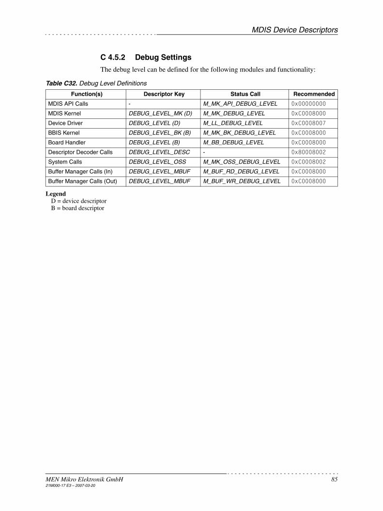
MDIS Device Descriptors
MEN Mikro Elektronik GmbH 8521M000-17 E3 – 2007-03-20
C 4.5.2 Debug Settings
The debug level can be defined for the following modules and functionality:
Table C32. Debug Level Definitions
LegendD = device descriptorB = board descriptor
Function(s) Descriptor Key Status Call Recommended
MDIS API Calls - M_MK_API_DEBUG_LEVEL 0x00000000
MDIS Kernel DEBUG_LEVEL_MK (D) M_MK_DEBUG_LEVEL 0xC0008000
Device Driver DEBUG_LEVEL (D) M_LL_DEBUG_LEVEL 0xC0008007
BBIS Kernel DEBUG_LEVEL_BK (B) M_MK_BK_DEBUG_LEVEL 0xC0008000
Board Handler DEBUG_LEVEL (B) M_BB_DEBUG_LEVEL 0xC0008000
Descriptor Decoder Calls DEBUG_LEVEL_DESC - 0x80008002
System Calls DEBUG_LEVEL_OSS M_MK_OSS_DEBUG_LEVEL 0xC0008002
Buffer Manager Calls (In) DEBUG_LEVEL_MBUF M_BUF_RD_DEBUG_LEVEL 0xC0008000
Buffer Manager Calls (Out) DEBUG_LEVEL_MBUF M_BUF_WR_DEBUG_LEVEL 0xC0008000