2008 PT Cruiser Owner's Guide
491
PT Cruiser OWNER’S MANUAL 2008 Sedan/Convertible
-
Upload
khangminh22 -
Category
Documents
-
view
5 -
download
0
Transcript of 2008 PT Cruiser Owner's Guide

PT CruiserO W N E R ’ S M A N U A L
2 0 0 8
20
08
PT
Cru
iser
Se
da
n/C
on
vertib
le
81-026-0844 First Edition Printed in U.S.A.
S e d a n / C o n v e r t i b l e
VEHICLES SOLD IN CANADA
With respect to any Vehicles Sold in Canada, the nameChrysler LLC shall be deemed to be deleted and thename Chrysler Canada Inc. used in substitution therefor.DRIVING AND ALCOHOLDrunken driving is one of the most frequent causes ofaccidents.Your driving ability can be seriously impaired with bloodalcohol levels far below the legal minimum. If you aredrinking, don’t drive. Ride with a designated non-drinkingdriver, call a cab, a friend, or use public transportation.
WARNING!
Driving after drinking can lead to an accident. Yourperceptions are less sharp, your reflexes are slower,and your judgment is impaired when you have beendrinking. Never drink and then drive.
This manual illustrates and describes the operation offeatures and equipment that are either standard or op-tional on this vehicle. This manual may also include adescription of features and equipment that are no longeravailable or were not ordered on this vehicle. Pleasedisregard any features and equipment described in thismanual that are not on this vehicle.
Chrysler LLC reserves the right to make changes indesign and specifications, and/or make additions to orimprovements to its products without imposing anyobligation upon itself to install them on products previ-ously manufactured.
Copyright © 2007 Chrysler LLC
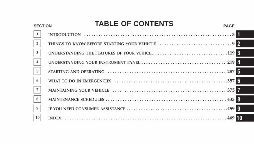
TABLE OF CONTENTSSECTION PAGE
1 INTRODUCTION . . . . . . . . . . . . . . . . . . . . . . . . . . . . . . . . . . . . . . . . . . . . . . . . . . . . . . . . . . . . . 3
2 THINGS TO KNOW BEFORE STARTING YOUR VEHICLE . . . . . . . . . . . . . . . . . . . . . . . . . . . . . . . 9
3 UNDERSTANDING THE FEATURES OF YOUR VEHICLE . . . . . . . . . . . . . . . . . . . . . . . . . . . . . . 119
4 UNDERSTANDING YOUR INSTRUMENT PANEL . . . . . . . . . . . . . . . . . . . . . . . . . . . . . . . . . . . 219
5 STARTING AND OPERATING . . . . . . . . . . . . . . . . . . . . . . . . . . . . . . . . . . . . . . . . . . . . . . . . . 287
6 WHAT TO DO IN EMERGENCIES . . . . . . . . . . . . . . . . . . . . . . . . . . . . . . . . . . . . . . . . . . . . . . .357
7 MAINTAINING YOUR VEHICLE . . . . . . . . . . . . . . . . . . . . . . . . . . . . . . . . . . . . . . . . . . . . . . . 375
8 MAINTENANCE SCHEDULES . . . . . . . . . . . . . . . . . . . . . . . . . . . . . . . . . . . . . . . . . . . . . . . . . . 433
9 IF YOU NEED CONSUMER ASSISTANCE . . . . . . . . . . . . . . . . . . . . . . . . . . . . . . . . . . . . . . . . . .459
10 INDEX . . . . . . . . . . . . . . . . . . . . . . . . . . . . . . . . . . . . . . . . . . . . . . . . . . . . . . . . . . . . . . . . . . . . 469
1
2
3
4
5
6
7
8
9
10

INTRODUCTION
CONTENTS
� Introduction . . . . . . . . . . . . . . . . . . . . . . . . . . . 4
� How To Use This Manual . . . . . . . . . . . . . . . . . . 4
� Warnings And Cautions . . . . . . . . . . . . . . . . . . . 6
� Vehicle Identification Number . . . . . . . . . . . . . . . 6
� Vehicle Modifications/Alterations . . . . . . . . . . . . 7
1
INTRODUCTIONThis Owner’s Manual has been prepared with the assis-tance of service and engineering specialists to acquaintyou with the operation and maintenance of your vehicle.It is supplemented by a Warranty Information Bookletand various customer-oriented documents. You areurged to read these publications carefully. Following theinstructions and recommendations in this manual willhelp assure safe and enjoyable operation of your vehicle.
NOTE: After you read the manual, it should be storedin the vehicle for convenient reference and remain withthe vehicle when sold, so that the new owner will beaware of all safety warnings.
When it comes to service, remember that your authorizeddealer knows your vehicle best, has the factory-trainedtechnicians and genuine Mopar� parts, and is interestedin your satisfaction.
HOW TO USE THIS MANUALConsult the table of contents to determine which sectioncontains the information you desire.
The detailed index, at the rear of this manual, contains acomplete listing of all subjects.
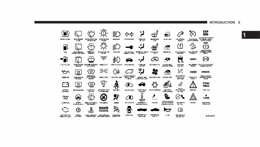
Consult the following table for a description of thesymbols that may be used on your vehicle or throughoutthis owner’s manual:
4 INTRODUCTION
INTRODUCTION 5
1
WARNINGS AND CAUTIONSThis manual contains WARNINGS against operatingprocedures that could result in an accident or bodilyinjury. It also contains CAUTIONS against proceduresthat could result in damage to your vehicle. If you do notread this entire manual you may miss important infor-mation. Observe all Warnings and Cautions.
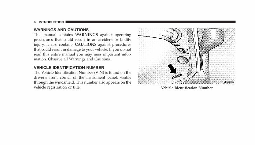
VEHICLE IDENTIFICATION NUMBERThe Vehicle Identification Number (VIN) is found on thedriver’s front corner of the instrument panel, visiblethrough the windshield. This number also appears on thevehicle registration or title. Vehicle Identification Number
6 INTRODUCTION
VEHICLE MODIFICATIONS/ALTERATIONS
WARNING!
Any modifications or alterations to this vehicle couldseriously affect its roadworthiness and safety andmay lead to an accident resulting in serious injury ordeath.
INTRODUCTION 7
1

THINGS TO KNOW BEFORE STARTING YOUR VEHICLE
CONTENTS
� A Word About Your Keys . . . . . . . . . . . . . . . . . .13
▫ Ignition Key Removal . . . . . . . . . . . . . . . . . . .13
▫ Locking Doors With A Key . . . . . . . . . . . . . . .14
▫ Key-In-Ignition Reminder . . . . . . . . . . . . . . . .15
� Sentry Key� — If Equipped . . . . . . . . . . . . . . . .15
▫ Replacement Keys . . . . . . . . . . . . . . . . . . . . . .16
▫ Sentry Key� Programming . . . . . . . . . . . . . . . .17
▫ General Information . . . . . . . . . . . . . . . . . . . .18
� Steering Wheel Lock — If Equipped . . . . . . . . . .18
▫ If You Wish To Manually Lock The SteeringWheel . . . . . . . . . . . . . . . . . . . . . . . . . . . . . .18
▫ To Release The Steering Wheel Lock . . . . . . . . .18
▫ Automatic Transaxle Ignition Interlock System . .19
� Door Locks . . . . . . . . . . . . . . . . . . . . . . . . . . . .19
▫ Manual Door Locks . . . . . . . . . . . . . . . . . . . . .19
▫ Power Door Locks — If Equipped . . . . . . . . . .20
▫ Child Protection Door Lock System —If Equipped . . . . . . . . . . . . . . . . . . . . . . . . . .22
� Remote Keyless Entry (Sedan) . . . . . . . . . . . . . . .24
2
▫ To Unlock The Doors And Liftgate . . . . . . . . . .24
▫ To Lock The Doors And Liftgate — If EquippedWith Power Options . . . . . . . . . . . . . . . . . . . .25
▫ Panic Alarm . . . . . . . . . . . . . . . . . . . . . . . . . .26
▫ To Turn Off “Flash Lights With Lock” . . . . . . . .26
▫ To Program Additional Transmitters . . . . . . . . .27
▫ General Information . . . . . . . . . . . . . . . . . . . .28
▫ Transmitter Battery Service . . . . . . . . . . . . . . .29
� Remote Keyless Entry (Convertible) . . . . . . . . . . .30
▫ To Unlock The Doors . . . . . . . . . . . . . . . . . . .31
▫ To Lock The Doors . . . . . . . . . . . . . . . . . . . . .32
▫ To Unlatch The Deck Lid . . . . . . . . . . . . . . . . .32
▫ Panic Alarm . . . . . . . . . . . . . . . . . . . . . . . . . .32
▫ To Turn Off “Flash Lights With Lock” . . . . . . . .33
▫ To Program Additional Transmitters . . . . . . . . .33
▫ General Information . . . . . . . . . . . . . . . . . . . .34
▫ Transmitter Battery Service . . . . . . . . . . . . . . .35
� Security Alarm System — If Equipped . . . . . . . . .36
▫ To Set The Alarm . . . . . . . . . . . . . . . . . . . . . .36
▫ To Disarm The System . . . . . . . . . . . . . . . . . . .37
▫ Security System Manual Override . . . . . . . . . . .37
� Liftgate (Sedan) . . . . . . . . . . . . . . . . . . . . . . . . .37
▫ Opening The Liftgate While The Security AlarmIs Activated . . . . . . . . . . . . . . . . . . . . . . . . . .38
� Deck Lid (Convertible) . . . . . . . . . . . . . . . . . . . .39
▫ Power Deck Lid Release (Convertible) . . . . . . . .39
10 THINGS TO KNOW BEFORE STARTING YOUR VEHICLE
� Emergency Seat Back Release (Sedan) . . . . . . . . .40
� Emergency Deck Lid Release Latch(Convertible) . . . . . . . . . . . . . . . . . . . . . . . . . . .41
� Power Windows . . . . . . . . . . . . . . . . . . . . . . . .42
▫ Auto Down Feature . . . . . . . . . . . . . . . . . . . .43
▫ Rear Window Switches . . . . . . . . . . . . . . . . . .43
▫ Wind Buffeting . . . . . . . . . . . . . . . . . . . . . . . .44
� Occupant Restraints (Sedan) . . . . . . . . . . . . . . . .44
▫ Lap/Shoulder Belts . . . . . . . . . . . . . . . . . . . . .45
▫ Lap/Shoulder Seat Belt Untwisting Procedure . .52
▫ Adjustable Upper Shoulder Seat BeltAnchorage . . . . . . . . . . . . . . . . . . . . . . . . . . .52
▫ Seat Belt Pretensioners . . . . . . . . . . . . . . . . . . .53
▫ Enhanced Seat Belt Reminder System(BeltAlert�) . . . . . . . . . . . . . . . . . . . . . . . . . .54
▫ Seat Belts And Pregnant Women . . . . . . . . . . . .54
▫ Driver And Front Passenger SupplementalRestraint System (SRS) - Airbag . . . . . . . . . . . .55
▫ Child Restraint . . . . . . . . . . . . . . . . . . . . . . . .72
� Occupant Restraints (Convertible) . . . . . . . . . . . .81
▫ Lap/Shoulder Belts . . . . . . . . . . . . . . . . . . . . .82
▫ Lap/Shoulder Seat Belt Untwisting Procedure . .88
▫ Seat Belt Pretensioners . . . . . . . . . . . . . . . . . . .88
▫ Enhanced Seat Belt Reminder System(BeltAlert�) . . . . . . . . . . . . . . . . . . . . . . . . . .89
▫ Seat Belts And Pregnant Women . . . . . . . . . . . .89
THINGS TO KNOW BEFORE STARTING YOUR VEHICLE 11
2
▫ Driver And Front Passenger SupplementalRestraint System (SRS) . . . . . . . . . . . . . . . . . . .90
▫ Child Restraint . . . . . . . . . . . . . . . . . . . . . . . 107
� Engine Break-In Recommendations . . . . . . . . . . 115
� Safety Tips . . . . . . . . . . . . . . . . . . . . . . . . . . . 115
▫ Exhaust Gas . . . . . . . . . . . . . . . . . . . . . . . . . 115
▫ Safety Checks You Should Make Inside TheVehicle . . . . . . . . . . . . . . . . . . . . . . . . . . . . . 116
▫ Periodic Safety Checks You Should MakeOutside The Vehicle . . . . . . . . . . . . . . . . . . . 117
12 THINGS TO KNOW BEFORE STARTING YOUR VEHICLE
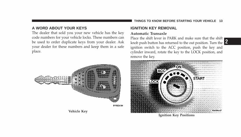
A WORD ABOUT YOUR KEYSThe dealer that sold you your new vehicle has the keycode numbers for your vehicle locks. These numbers canbe used to order duplicate keys from your dealer. Askyour dealer for these numbers and keep them in a safeplace.
IGNITION KEY REMOVALAutomatic TransaxlePlace the shift lever in PARK and make sure that the shiftknob push button has returned to the out position. Turn theignition switch to the ACC position, push the key andcylinder inward, rotate the key to the LOCK position, andremove the key.
Vehicle KeyIgnition Key Positions
THINGS TO KNOW BEFORE STARTING YOUR VEHICLE 13
2
NOTE: If you try to remove the key before you place thelever in PARK, the key may become trapped temporarilyin the ignition cylinder. If this occurs, rotate the key to theright slightly, then remove the key as described. If amalfunction occurs, the system will trap the key in theignition cylinder to warn you that this safety feature isinoperable. The engine can be started and stopped butthe key cannot be removed until you obtain service.
WARNING!
Never leave children alone in a vehicle. Leavingchildren in a vehicle unattended is dangerous for anumber of reasons. A child or others could be seri-ously or fatally injured. Don’t leave the keys in theignition. A child could operate power windows,other controls, or move the vehicle.
CAUTION!
An unlocked car is an invitation to thieves. Alwaysremove key from the ignition and lock all doorswhen leaving the vehicle unattended.
Manual Transaxle—If EquippedTurn the ignition switch to the ACC position, push thekey and cylinder inward, rotate the key to the LOCKposition, and remove the key.
LOCKING DOORS WITH A KEYYou can insert the key with either side up. To lock thedoor, turn the key rearward, to unlock the door, turn thekey forward. See Section 7 of this manual for door locklubrication.
14 THINGS TO KNOW BEFORE STARTING YOUR VEHICLE
KEY-IN-IGNITION REMINDEROpening the driver’s door when the key is in the ignition,sounds a signal to remind you to remove the key.
NOTE: With the driver’s door open, and the key in theignition, both the power door locks and Remote KeylessEntry (RKE) will not function.
SENTRY KEY� — IF EQUIPPEDThe Sentry Key� Immobilizer System prevents unautho-rized operation of the vehicle by disabling the engine.The system will shut the engine off after two seconds ofrunning if an invalid key is used to start the vehicle. Thissystem utilizes ignition keys, which have an electronicchip (transponder) embedded into them. Only keys thathave been programmed to the vehicle can be used to startand operate the vehicle.
The Sentry Key� Immobilizer System does not need to bearmed or activated. Operation of the system is automaticregardless of whether or not the vehicle is locked or
unlocked. During normal operation, the Theft Alarm/Immobilizer Light will come on for three seconds imme-diately after the ignition switch is turned on for a bulbcheck. Afterwards, if the bulb remains on, this indicates aproblem with the electronics.
If the bulb begins to flash after the bulb check, thisindicates that an invalid key has been used to start thevehicle. Both of these conditions will result in the enginebeing shut off after two seconds of running.
Keep in mind that a key, which has not been pro-grammed is also considered an invalid key even if it iscut to fit the ignition lock cylinder for that vehicle.
If the Theft Alarm/Immobilizer Light comes on duringnormal vehicle operation, (the vehicle has been runningfor longer than 10 seconds), a fault has been detected inthe electronics and the vehicle should be serviced as soonas possible.
THINGS TO KNOW BEFORE STARTING YOUR VEHICLE 15
2
NOTE:• The Sentry Key� Immobilizer System is not compat-
ible with remote starting systems. Use of these systemsmay result in vehicle starting problems and loss ofsecurity protection.
• Exxon/Mobil Speed Pass,™ additional Sentry Keys, orany other transponder equipped components on thesame keychain will not cause a key-related (transpon-der) fault unless the additional part is physically heldagainst the ignition key being used when starting thevehicle. Cell phones, pagers, or other RF electronicswill not cause interference with this system.
All of the keys provided with your new vehicle havebeen programmed to the vehicle electronics.
Replacement Keys
NOTE: Only keys that have been programmed to thevehicle electronics can be used to start the vehicle. Oncea Sentry Key� has been programmed to a vehicle, itcannot be programmed to any other vehicle.
CAUTION!
Always remove Sentry Keys from the vehicle andlock all doors when leaving the vehicle unattended.
At the time of purchase, the original owner is providedwith a four digit Personal Identification Number (PIN).This PIN is required for replacement of keys by anauthorized dealer. Duplication of keys must be per-formed at an authorized dealer. This procedure consistsof programming a blank key to the vehicle electronics. Ablank key is one which has never been programmed.
16 THINGS TO KNOW BEFORE STARTING YOUR VEHICLE
NOTE: When having the Sentry Key� ImmobilizerSystem serviced, bring all vehicle keys with you to thedealer.
Sentry Key� ProgrammingIf you have two valid sentry keys, you can program newsentry keys to the system by performing the followingprocedure:
1. Cut the additional Sentry Key� Transponder blank(s)to match the ignition switch lock cylinder key code.
2. Insert the first valid key into the ignition switch. Turnthe ignition switch to the “ON” position for at least threeseconds, but no longer than 15-seconds. Then, turn theignition switch to the “LOCK” position and remove thefirst key.
3. Insert the second valid key into the ignition switch.Turn the ignition switch to the “ON” position within 15seconds. After ten seconds, a chime will sound. Inaddition, the Vehicle Security Alarm Indicator Light willbegin to flash. Turn the ignition switch to the “LOCK”position and remove the second key.
4. Insert a blank Sentry Key� into the ignition switch.Turn the ignition switch to the “ON” position within 60seconds. After 10 seconds, a single chime will sound. Inaddition, the Vehicle Security Alarm Indicator Light willstop flashing. To indicate that programming is complete,the indicator light will turn on again for three secondsand then turn off.
The new Sentry Key� has been programmed. The Key-less Entry Transmitter will also be programmed duringthis procedure. Repeat this procedure to program up to atotal of 8 keys. If you do not have a programmed SentryKey�, contact your dealer for details.
THINGS TO KNOW BEFORE STARTING YOUR VEHICLE 17
2
NOTE: If a programmed key is lost, see your dealer tohave all remaining keys erased from the systemsmemory. This will prevent the lost key from starting yourvehicle. The remaining keys must then be repro-grammed. All vehicle keys must be taken to the dealer atthe time of service to be reprogrammed.
General InformationThe Sentry Key� system complies with FCC rules part 15and with RSS-210 of Industry Canada. Operation issubject to the following conditions:
• This device may not cause harmful interference.
• This device must accept any interference that may bereceived, including interference that may cause undes-ired operation.
STEERING WHEEL LOCK — IF EQUIPPEDYour vehicle may be equipped with a passive steeringwheel lock. This lock prevents steering the vehicle with-out the ignition key. If the steering wheel is moved nomore than one—half turn in either direction and the keyis not in the ignition switch, the steering wheel will lock.
If You Wish To Manually Lock The SteeringWheel:With the engine running, turn the steering wheel upsidedown, turn off the engine and remove the key. Turn thesteering wheel slightly in either direction until the lockengages.
To Release The Steering Wheel Lock:Insert the key in the ignition switch and start the engine.If the key is difficult to turn, move the wheel slightly tothe right or left to disengage the lock.
18 THINGS TO KNOW BEFORE STARTING YOUR VEHICLE
NOTE: If you turned the wheel to the right to engagethe lock, you must turn the wheel slightly to the right todisengage it. If you turned the wheel to the left to engagethe lock, turn the wheel slightly to the left to disengage it.
Automatic Transaxle Ignition Interlock SystemThis system prevents the key from being removed unlessthe shift lever is in PARK and the shift knob push-buttonis out. It also prevents shifting out of PARK unless thekey is in the ACC, or ON positions, and the brake pedalis depressed.
DOOR LOCKS
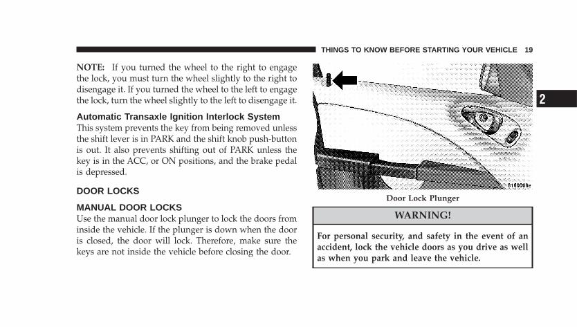
MANUAL DOOR LOCKSUse the manual door lock plunger to lock the doors frominside the vehicle. If the plunger is down when the dooris closed, the door will lock. Therefore, make sure thekeys are not inside the vehicle before closing the door.
WARNING!
For personal security, and safety in the event of anaccident, lock the vehicle doors as you drive as wellas when you park and leave the vehicle.
Door Lock Plunger
THINGS TO KNOW BEFORE STARTING YOUR VEHICLE 19
2
WARNING!
When leaving the vehicle always remove the keyfrom the ignition lock, and lock your vehicle. Do notleave children unattended in the vehicle, or withaccess to an unlocked vehicle. Unsupervised use ofvehicle equipment may cause severe personal inju-ries and death.
CAUTION!
An unlocked vehicle is an invitation to thieves.Always remove the key from the ignition and lock allof the doors when leaving the vehicle unattended.
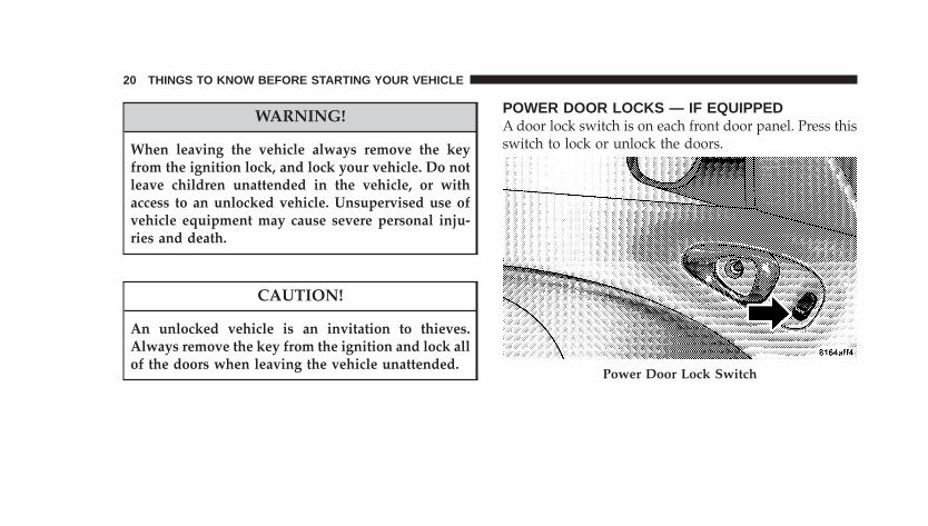
POWER DOOR LOCKS — IF EQUIPPEDA door lock switch is on each front door panel. Press thisswitch to lock or unlock the doors.
Power Door Lock Switch
20 THINGS TO KNOW BEFORE STARTING YOUR VEHICLE
AUTOMATIC DOOR LOCKS — IF EQUIPPEDThe doors will lock automatically on vehicles with powerdoor locks if all of the following conditions are met:
1. The Auto Lock feature is enabled.
2. The transmission is in gear.
3. All doors are closed.
4. The throttle is pressed.
5. The vehicle speed is above 15 mph (24 km/h).
6. The doors were not previously locked using the powerdoor lock switch or remote keyless entry transmitter.
The Automatic Door Lock feature can be enabled ordisabled. Refer to “Personal Settings” (Customer Pro-grammable Features) in the Electronic Vehicle Informa-tion Center (EVIC) — if equipped section of this manualfor details.
For vehicles not equipped with the EVIC the AutomaticDoor Locks can be enabled or disabled by performing thefollowing procedure:
1. Close all doors and place the key in the ignition.
2. Cycle the ignition switch between LOCK and ON andback to LOCK four times ending up in the LOCKposition.
3. Depress the power door lock switch to lock the doors.
4. A single chime will indicate the completion of theprogramming.
Auto UnlockThe doors will unlock automatically on vehicles withpower door locks if:
1. The Auto Unlock feature is enabled.
2. The transmission was in gear and the vehicle speedreturned to 0 mph (0 km/h).
THINGS TO KNOW BEFORE STARTING YOUR VEHICLE 21
2
3. The transmission is in NEUTRAL or PARK.
4. The driver door is opened.
5. The doors were not previously unlocked.
6. The vehicle speed is 0 mph (0 km/h).
The Auto Unlock feature can be enabled or disabled.Refer to “Personal Settings” (Customer ProgrammableFeatures) in the Electronic Vehicle Information Center(EVIC) — if equipped section of this manual.
For vehicles not equipped with the EVIC the AutoUnlock Feature can be enabled or disabled by performingthe following procedure:
1. Close all doors and place the key in the ignition.
2. Cycle the ignition switch between LOCK and ON andback to LOCK four times ending up in the LOCKposition.
3. Depress the power door unlock switch to unlock thedoors.
4. Verify reprogramming by driving the vehicle.
NOTE: Use the Auto Door Locks and Auto Unlockfeatures in accordance with local laws.
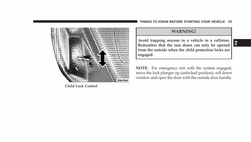
CHILD PROTECTION DOOR LOCK SYSTEM — IFEQUIPPEDTo provide a safer environment for children riding in therear seat, the rear doors have the “child-protection” doorlock system.
To use the system, open each rear door and move thecontrol UP to engage. When the system on a door isengaged, that door can only be opened by using theoutside door handle even if the inside door lock is in theunlocked position.
22 THINGS TO KNOW BEFORE STARTING YOUR VEHICLE
WARNING!
Avoid trapping anyone in a vehicle in a collision.Remember that the rear doors can only be openedfrom the outside when the child protection locks areengaged.
NOTE: For emergency exit with the system engaged,move the lock plunger up (unlocked position), roll downwindow and open the door with the outside door handle.
Child Lock Control
THINGS TO KNOW BEFORE STARTING YOUR VEHICLE 23
2
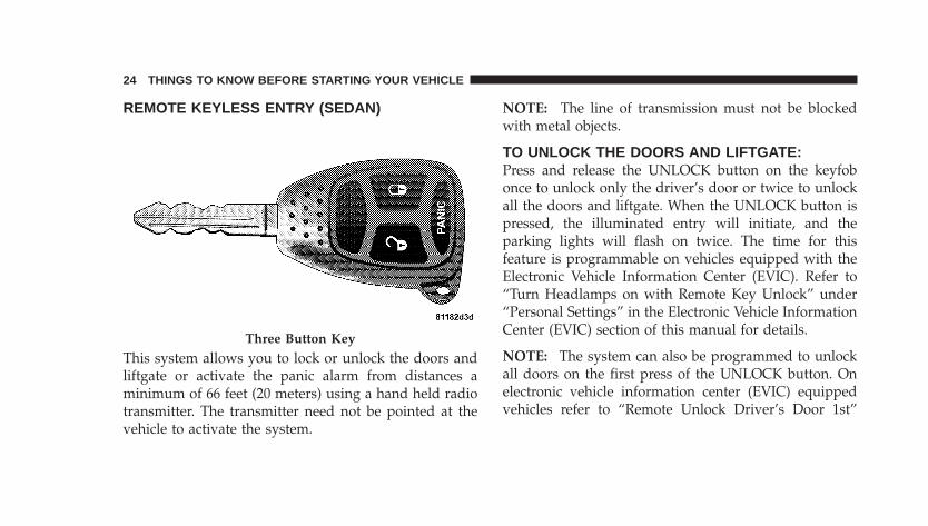
REMOTE KEYLESS ENTRY (SEDAN)
This system allows you to lock or unlock the doors andliftgate or activate the panic alarm from distances aminimum of 66 feet (20 meters) using a hand held radiotransmitter. The transmitter need not be pointed at thevehicle to activate the system.
NOTE: The line of transmission must not be blockedwith metal objects.
TO UNLOCK THE DOORS AND LIFTGATE:Press and release the UNLOCK button on the keyfobonce to unlock only the driver’s door or twice to unlockall the doors and liftgate. When the UNLOCK button ispressed, the illuminated entry will initiate, and theparking lights will flash on twice. The time for thisfeature is programmable on vehicles equipped with theElectronic Vehicle Information Center (EVIC). Refer to“Turn Headlamps on with Remote Key Unlock” under“Personal Settings” in the Electronic Vehicle InformationCenter (EVIC) section of this manual for details.
NOTE: The system can also be programmed to unlockall doors on the first press of the UNLOCK button. Onelectronic vehicle information center (EVIC) equippedvehicles refer to “Remote Unlock Driver’s Door 1st”
Three Button Key
24 THINGS TO KNOW BEFORE STARTING YOUR VEHICLE
under “Personal Settings” in the EVIC section of thismanual. On non EVIC – equipped vehicles perform thefollowing steps:
The system can be programmed to unlock all the doorsupon the first UNLOCK button press by using thefollowing procedure:
1. Press and hold the LOCK button on a programmedkeyfob.
2. Continue to hold the LOCK button at least fourseconds, but not longer than 10 seconds, then press andhold the UNLOCK button. A single chime will sound toindicate that this feature has changed.
3. Release both buttons at the same time.
4. Test the feature while outside of the vehicle, bypressing the LOCK/UNLOCK button on the keyfob.
NOTE: Pressing the LOCK button on the keyfob whileyou are inside the vehicle will activate the SecurityAlarm. Opening a door with the Security Alarm activatedwill cause the alarm to sound. Press the UNLOCK buttonto deactivate the Security Alarm.
5. If the desired programming was not achieved or toreactivate this feature, repeat the above steps.
TO LOCK THE DOORS AND LIFTGATE — IFEQUIPPED WITH POWER OPTIONS:Press and release the LOCK button on the transmitter tolock all doors. The turn signal lights will flash and thehorn will chirp once to acknowledge the lock signal. Ifdesired, the “Sound Horn On Lock” and “Flash LampsWith Lock” feature can be turned on or off. On electronicvehicle information center (EVIC) equipped vehicles re-fer to “Personal Settings” in the “Electronic Vehicle
THINGS TO KNOW BEFORE STARTING YOUR VEHICLE 25
2

Information Center (EVIC)” section of this manual. Onnon EVIC – equipped vehicles perform the followingsteps:
1. Press the LOCK button for four to ten seconds.
2. While the LOCK button is pressed (after four seconds),press the PANIC button. Release both buttons.
The “Sound Horn On Lock” and “Flash Lamps WithLock” feature can be reactivated by repeating this proce-dure.
PANIC ALARMThe panic mode flashes the park lights, and sounds thehorn for about three minutes or until the alarm is turnedoff.
Using The Panic Alarm:To turn the panic alarm feature ON or OFF, press andhold the PANIC button on the transmitter for at least onesecond and release. When the panic alarm is on, the
headlights and park lights will flash, the horn will pulseon and off and the interior lights will turn on.
The panic alarm will stay on for three minutes unless youturn it off by pressing the PANIC button a second time orif the vehicle speed is 5 mph (8 km/h) or greater.
NOTE: When you turn off the panic alarm by pressingthe PANIC button a second time, you may have to becloser to the vehicle due to the radio frequency noises ofthe system.
TO TURN OFF “FLASH LIGHTS WITH LOCK”:
NOTE: The Flash Lights With Lock feature can beturned on or off. On Electronic Vehicle InformationCenter (EVIC) equipped vehicles refer to �Personal Set-tings� in the EVIC section of this manual. On non EVIC -equipped vehicles perform the following steps:
1. Press the UNLOCK button for four to ten seconds.
26 THINGS TO KNOW BEFORE STARTING YOUR VEHICLE
2. While the UNLOCK button is pressed, (after fourseconds) press the LOCK button. Release both buttons.
3. Test the flash lamps with LOCK feature while outsideof the vehicle, by pressing the LOCK button on thekeyfob with the ignition in the LOCK position, and thekey removed.
NOTE: Pressing the LOCK button on the keyfob, whileyou are in the vehicle, will activate the Security Alarm.Opening a door with the Security Alarm activated willcause the alarm to sound. Press the UNLOCK button todeactivate the Security Alarm.
The “Flash Lights On Lock/Unlock” feature can bereactivated by repeating this procedure.
TO PROGRAM ADDITIONAL TRANSMITTERS:Vehicles will be shipped from the assembly plants withtwo keyfob transmitters programmed only for that ve-hicle. A total of eight fobs can be programmed for yourvehicle. Additional fobs can be programmed to yourvehicle through the use of a currently programmed fob.
NOTE: When entering program mode using that fob, allother programmed fobs will be erased and you will haveto reprogram them for your vehicle.
Use the Following procedure to program additional keyfobs if the vehicle is not equipped with Sentry Key�:
1. Enter your vehicle and close all doors.
2. Fasten your seat belt (Fastening the seatbelt will cancelany chiming that may confuse you during this program-ming procedure).
3. Place the key into the ignition.
THINGS TO KNOW BEFORE STARTING YOUR VEHICLE 27
2
4. Turn the ignition to the ON position Do not start theengine.
5. Press and hold the UNLOCK button on the keyfob.
6. After holding the UNLOCK button for four seconds,also press the PANIC button within six seconds.
7. When a single chime is heard release both buttons. Thechime is an indication that you have successfully enteredprogram mode. All fobs that are to be programmed mustbe done so within 60 seconds of when the chime washeard.
8. Using the fob to be programmed, press and releaseboth the LOCK and UNLOCK buttons, simultaneously.
9. A single chime will be heard.
10. Within four seconds of hearing the chime, press andrelease the UNLOCK button on the fob.
11. A single chime will be heard.
12. Repeat steps eight through ten to program up to sixadditional fobs.
13. Turn the ignition to the OFF position.
14. Your vehicle will remain in program mode up to 60seconds from when the original chime was heard. After60 seconds, all programmed fobs function normally.
NOTE: If you do not have a programmed transmitter,contact your dealer for details.
GENERAL INFORMATIONThis device complies with part 15 of FCC rules and withRS-210 of Industry Canada. Operation is subject to thefollowing conditions:
1. This device may not cause harmful interference.
2. This device must accept any interference that may bereceived including interference that may cause undesiredoperation.
28 THINGS TO KNOW BEFORE STARTING YOUR VEHICLE
NOTE: Changes or modifications not expressly ap-proved by the party responsible for compliance couldvoid the user’s authority to operate the equipment.
If your Remote Lock Control fails to operate from anormal distance, check for these two conditions.
1. Weak batteries in transmitter. The expected life ofbatteries is five years.
2. Closeness to a radio transmitter such as a radio stationtower, airport transmitter, military base, and some mobileor CB radios.
TRANSMITTER BATTERY SERVICE
NOTE: Perchlorate Material – special handling may ap-ply, See www.dtsc.ca.gov/hazardouswaste/perchlorate.
The recommended replacement battery is CR2032.
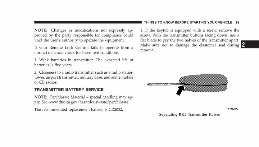
1. If the keyfob is equipped with a screw, remove thescrew. With the transmitter buttons facing down, use aflat blade to pry the two halves of the transmitter apart.Make sure not to damage the elastomer seal duringremoval.
Separating RKE Transmitter Halves
THINGS TO KNOW BEFORE STARTING YOUR VEHICLE 29
2
2. Remove and replace the batteries. Avoid touching thenew batteries with your fingers. Skin oils may causebattery deterioration. If you touch a battery, clean it withrubbing alcohol.
3. To assemble the transmitter case, snap the two halvestogether.
NOTE: If the keyfob is equipped with a screw, reinstalland tighten the screw until snug.
REMOTE KEYLESS ENTRY (CONVERTIBLE)
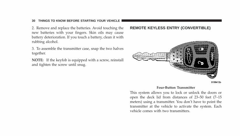
This system allows you to lock or unlock the doors oropen the deck lid from distances of 23–50 feet (7–15meters) using a transmitter. You don’t have to point thetransmitter at the vehicle to activate the system. Eachvehicle comes with two transmitters.
Four-Button Transmitter
30 THINGS TO KNOW BEFORE STARTING YOUR VEHICLE
TO UNLOCK THE DOORS:Press and release the UNLOCK button on the keyfobonce to unlock only the driver’s door or twice to unlockall the doors and liftgate. When the UNLOCK button ispressed, the illuminated entry will initiate, and theparking lights will flash on twice. The time for thisfeature is programmable on vehicles equipped with theElectronic Vehicle Information Center (EVIC). Refer to“Turn Headlamps on with Remote Key Unlock” under“Personal Settings” in the Electronic Vehicle InformationCenter (EVIC) section of this manual for details.
NOTE: The system can also be programmed to unlockall doors on the first press of the UNLOCK button. Onelectronic vehicle information center (EVIC) equippedvehicles refer to “Remote Unlock Driver’s Door 1st”under “Personal Settings” in the EVIC section of thismanual. On non EVIC – equipped vehicles perform thefollowing steps:
The system can be programmed to unlock all the doorsupon the first UNLOCK button press by using thefollowing procedure:
1. Press and hold the LOCK button on a programmedkeyfob.
2. Continue to hold the LOCK button at least fourseconds, but not longer than ten seconds, then press andhold the UNLOCK button. A single chime will sound toindicate that this feature has changed.
3. Release both buttons at the same time.
4. Test the feature while outside of the vehicle, bypressing the LOCK/UNLOCK button on the keyfob.
NOTE: Pressing the LOCK button on the keyfob whileyou are inside the vehicle will activate the SecurityAlarm. Opening a door with the Security Alarm activatedwill cause the alarm to sound. Press the UNLOCK buttonto deactivate the Security Alarm.
THINGS TO KNOW BEFORE STARTING YOUR VEHICLE 31
2
5. If the desired programming was not achieved or toreactivate this feature, repeat the above steps.
TO LOCK THE DOORS:Press and release the LOCK button on the transmitter tolock all doors. The turn signal lights will flash and thehorn will chirp once to acknowledge the lock signal. Ifdesired, the “Sound Horn On Lock” and “Flash LampsWith Lock” feature can be turned on or off. On electronicvehicle information center (EVIC) equipped vehicles re-fer to “Personal Settings” in the “Electronic VehicleInformation Center (EVIC)” section of this manual. Onnon EVIC – equipped vehicles perform the followingsteps:
1. Press the LOCK button for four to ten seconds.
2. While the LOCK button is pressed (after four seconds),press the PANIC button. Release both buttons.
The “Sound Horn On Lock” and “Flash Lamps WithLock” feature can be reactivated by repeating this proce-dure.
TO UNLATCH THE DECK LID:Press the “Rear Release” button twice to unlatch the decklid.
PANIC ALARMThe panic mode flashes the park lights, and sounds thehorn for about three minutes or until the alarm is turnedoff.
Using The Panic Alarm:To turn the panic alarm feature ON or OFF, press andhold the PANIC button on the transmitter for at least onesecond and release. When the panic alarm is on, theheadlights and park lights will flash, the horn will pulseon and off and the interior lights will turn on.
32 THINGS TO KNOW BEFORE STARTING YOUR VEHICLE
The panic alarm will stay on for three minutes unless youturn it off by pressing the PANIC button a second time orif the vehicle speed is 5 mph (8 km/h) or greater.
NOTE: When you turn off the panic alarm by pressingthe PANIC button a second time, you may have to becloser to the vehicle due to the radio frequency noises ofthe system.
TO TURN OFF “FLASH LIGHTS WITH LOCK”:
NOTE: The Flash Lights With Lock feature can beturned on or off. On electronic vehicle information center(EVIC) equipped vehicles refer to �Personal Settings� inthe EVIC section of this manual. On non EVIC - equippedvehicles perform the following steps:
1. Press the UNLOCK button for four to ten seconds.
2. While the UNLOCK button is pressed, (after fourseconds) press the LOCK button. Release both buttons.
3. Test the flash lamps with LOCK feature while outsideof the vehicle, by pressing the LOCK button on thekeyfob with the ignition in the LOCK position, and thekey removed.
NOTE: Pressing the LOCK button on the keyfob, whileyou are in the vehicle, will activate the Security Alarm.Opening a door with the Security Alarm activated willcause the alarm to sound. Press the UNLOCK button todeactivate the Security Alarm.
The “Flash Lights On Lock/Unlock” feature can bereactivated by repeating this procedure.
TO PROGRAM ADDITIONAL TRANSMITTERS:
NOTE: If vehicle is equipped with the optional Elec-tronic Vehicle Information Center (EVIC) in the instru-ment cluster, the transmitters may also be programmedthrough the EVIC display.
THINGS TO KNOW BEFORE STARTING YOUR VEHICLE 33
2
Up to eight transmitters can be programmed to your vehicle.To obtain additional transmitters, contact your authorizeddealer. To program a transmitter (within 23–50 ft/7–15 m ofthe vehicle), perform the following procedure:
1. Gather every transmitter that is to be used with thevehicle including any transmitters that are currentlyprogrammed.
2. Enter Program Mode: Turn the ignition to the ONposition, and using a currently programmed transmitter;press and hold the �Unlock� button on the transmitter.Continue to hold the “Unlock” button, wait at least fourbut no longer than 10 seconds, then press and hold thePANIC button for at least one second. Release bothbuttons simultaneously.
3. Program Each Transmitter: All transmitters to be usedwith your vehicle must be programmed as follows:
Press and release the �Lock� and �Unlock� buttons simulta-neously, followed by a press and release of ANY button on
each transmitter to be programmed. You will hear a chimewhen a transmitter has been successfully programmed.
GENERAL INFORMATIONThis transmitter complies with FCC rules part 15 andwith RSS-210 of Industry Canada. Operation is subject tothe following two conditions:
1. This device may not cause harmful interference.
2. This device must accept any interference that may bereceived, including interference that may cause undes-ired operation.
If your Remote Keyless Entry� fails to operate from anormal distance, check for these two conditions:
1. Weak batteries in transmitter. The expected life ofbatteries is from one to two years
2. Closeness to a radio transmitter such as a radio stationtower, airport transmitter, and some mobile or CB radios.
34 THINGS TO KNOW BEFORE STARTING YOUR VEHICLE
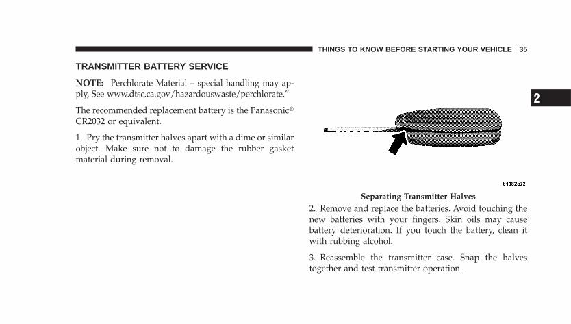
TRANSMITTER BATTERY SERVICE
NOTE: Perchlorate Material – special handling may ap-ply, See www.dtsc.ca.gov/hazardouswaste/perchlorate.”
The recommended replacement battery is the Panasonic�CR2032 or equivalent.
1. Pry the transmitter halves apart with a dime or similarobject. Make sure not to damage the rubber gasketmaterial during removal.
2. Remove and replace the batteries. Avoid touching thenew batteries with your fingers. Skin oils may causebattery deterioration. If you touch the battery, clean itwith rubbing alcohol.
3. Reassemble the transmitter case. Snap the halvestogether and test transmitter operation.
Separating Transmitter Halves
THINGS TO KNOW BEFORE STARTING YOUR VEHICLE 35
2
NOTE: If the keyfob is equipped with a screw, reinstalland tighten the screw until snug.
SECURITY ALARM SYSTEM — IF EQUIPPEDThe system monitors the doors, liftgate, and ignitionswitch for unauthorized operation.
If something triggers the alarm, the system will signal forabout 18 minutes. For the first three minutes the horn willsound and the headlights, park lights, tail lights and theindicator light in the cluster will flash. Then the exteriorlights will flash for another 15 minutes.
If the monitored system, which triggered the alarm isdeactivated the alarm will continue to sound until threeminutes of alarm time is reached. If the monitoredsystem, which triggered the alarm is deactivated after thealarm has been on for three minutes the alarm will shutoff immediately.
To set the alarm:
1. Remove the keys from the ignition switch and get outof the vehicle.
2. Lock the door using either the power door lock switch,or the Keyless Entry Transmitter and close all doors.
3. The indicator light in the instrument cluster will flashrapidly for 16 seconds. This shows that the system isarming. During this period, if a door is opened, theignition switch is turned ON, or the power door locks areunlocked by either the power door lock switch or theremote keyless entry transmitter, the system will auto-matically disarm. After 16 seconds the indicator light willflash slowly. This shows that the system is fully armed.
36 THINGS TO KNOW BEFORE STARTING YOUR VEHICLE
To disarm the system:Unlock a front door using the Keyless Entry Transmitter.
Starting the vehicle with a valid Sentry key will disarmthe system. A valid key is one that is programmed to thatparticular vehicle. A valid key will disarm the system, aninvalid key will trigger the alarm.
Tamper AlertIf the horn sounds three times when you unlock a frontdoor using the Keyless Entry Transmitter, the alarm hasbeen activated. Check the vehicle for tampering.
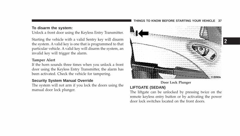
Security System Manual OverrideThe system will not arm if you lock the doors using themanual door lock plunger.
LIFTGATE (SEDAN)The liftgate can be unlocked by pressing twice on theremote keyless entry button or by activating the powerdoor lock switches located on the front doors.
Door Lock Plunger
THINGS TO KNOW BEFORE STARTING YOUR VEHICLE 37
2
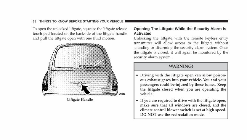
To open the unlocked liftgate, squeeze the liftgate releasetouch pad located on the backside of the liftgate handleand pull the liftgate open with one fluid motion.
Opening The Liftgate While the Security Alarm IsActivatedUnlocking the liftgate with the remote keyless entrytransmitter will allow access to the liftgate withoutsounding or disarming the security alarm system. Oncethe liftgate is closed, it will again be monitored by thesecurity alarm system.
WARNING!
• Driving with the liftgate open can allow poison-ous exhaust gases into your vehicle. You and yourpassengers could be injured by these fumes. Keepthe liftgate closed when you are operating thevehicle.
• If you are required to drive with the liftgate open,make sure that all windows are closed, and theclimate control blower switch is set at high speed.DO NOT use the recirculation mode.
Liftgate Handle
38 THINGS TO KNOW BEFORE STARTING YOUR VEHICLE
Gas props support the liftgate in the open position.However, because the gas pressure drops with tempera-ture, it may be necessary to assist the props whenopening the liftgate in cold weather.
DECK LID (CONVERTIBLE)Gas props support the deck lid in the open position.However, because the gas pressure drops with tempera-ture, it may be necessary to assist the props whenopening the deck lid in cold weather.
POWER DECK LID RELEASE (Convertible)You can open the deck lid by pressing the RemoteKeyless Entry Button or from inside the vehicle, using theswitch located inside the glove box. On vehiclesequipped with a manual transmission, the power decklid release switch is disabled if the doors are locked, or ifvehicle speed exceeds 0 mph (0 km/h), or when theclutch pedal is depressed. On vehicles equipped with an
automatic transmission, the power deck lid releaseswitch is disabled if the doors are locked, or the trans-mission is out of PARK.
WARNING!
• Driving with the deck lid open can allow poison-ous exhaust gases into your vehicle. You and yourpassengers could be injured by these fumes. Keepthe deck lid closed when you are operating thevehicle.
• If you are required to drive with the deck lid open,make sure that all windows are closed, and theclimate control blower switch is set at high speed.DO NOT use the recirculation mode.
THINGS TO KNOW BEFORE STARTING YOUR VEHICLE 39
2
EMERGENCY SEAT BACK RELEASE (SEDAN)
WARNING!
Do not allow children to have access to the liftgatearea with the rear shelf panel in position 1 (Top) orposition 2 (Middle), either by climbing into theliftgate from outside, or through the inside of thevehicle. Always close the liftgate when your vehicleis unattended. Once in the liftgate area, young chil-dren may not be able to escape, even if they enteredthrough the rear seat. If trapped in the liftgate,children can die from suffocation or heat stroke.
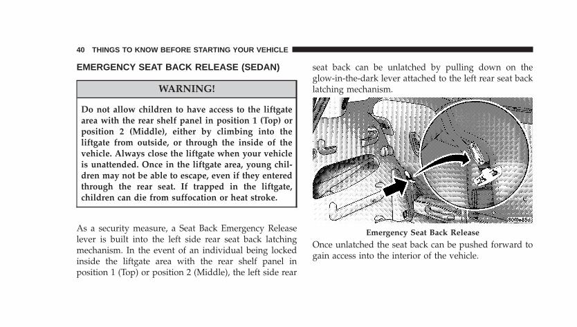
As a security measure, a Seat Back Emergency Releaselever is built into the left side rear seat back latchingmechanism. In the event of an individual being lockedinside the liftgate area with the rear shelf panel inposition 1 (Top) or position 2 (Middle), the left side rear
seat back can be unlatched by pulling down on theglow-in-the-dark lever attached to the left rear seat backlatching mechanism.
Once unlatched the seat back can be pushed forward togain access into the interior of the vehicle.
Emergency Seat Back Release
40 THINGS TO KNOW BEFORE STARTING YOUR VEHICLE
NOTE: Make sure that the elastic loop is around theemergency release handle at all times. If the handle ispulled downward, entirely through the elastic loop, thehandle will not return to its original position and the seatback may not operate properly.
EMERGENCY DECK LID RELEASE LATCH(CONVERTIBLE)
WARNING!
Do not allow children to have access to the trunk,either by climbing into the trunk from outside, orthrough the inside of the vehicle. Always close thedeck lid when your vehicle is unattended. Once inthe trunk, young children may not be able to escape,even if they entered through the rear seat. If trappedin the trunk, children can die from suffocation orheat stroke.
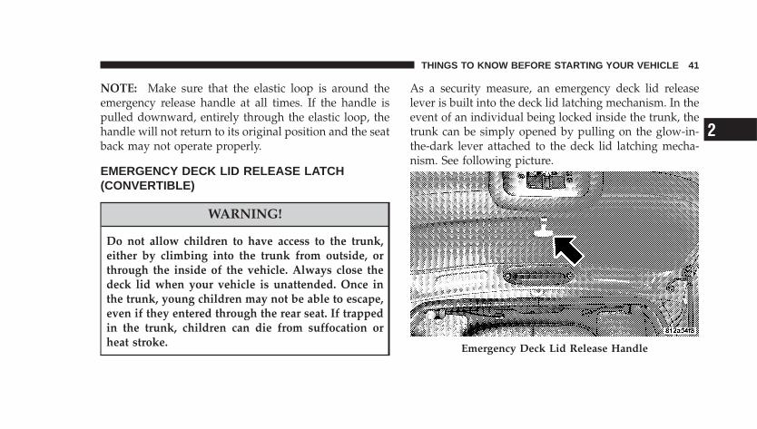
As a security measure, an emergency deck lid releaselever is built into the deck lid latching mechanism. In theevent of an individual being locked inside the trunk, thetrunk can be simply opened by pulling on the glow-in-the-dark lever attached to the deck lid latching mecha-nism. See following picture.
Emergency Deck Lid Release Handle
THINGS TO KNOW BEFORE STARTING YOUR VEHICLE 41
2
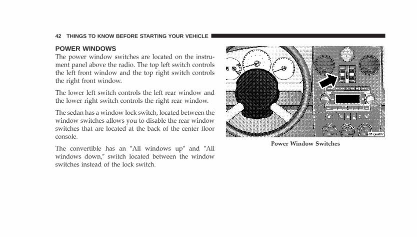
POWER WINDOWSThe power window switches are located on the instru-ment panel above the radio. The top left switch controlsthe left front window and the top right switch controlsthe right front window.
The lower left switch controls the left rear window andthe lower right switch controls the right rear window.
The sedan has a window lock switch, located between thewindow switches allows you to disable the rear windowswitches that are located at the back of the center floorconsole.
The convertible has an �All windows up� and �Allwindows down,� switch located between the windowswitches instead of the lock switch.
Power Window Switches
42 THINGS TO KNOW BEFORE STARTING YOUR VEHICLE
WARNING!
Never leave children in a vehicle, with the keys inthe ignition switch. Occupants, particularly unat-tended children, can become entrapped by the win-dows while operating the power window switches.Such entrapment may result in serious injury ordeath.
AUTO DOWN FEATUREThe driver’s and passenger’s front window switcheshave an auto down feature. Press the window switch pastthe detent, release, and the window will go down auto-matically. Press the switch a second time in either direc-tion to stop the window.
To open the window part way, press the window switchpart way and release it when you want the window tostop.
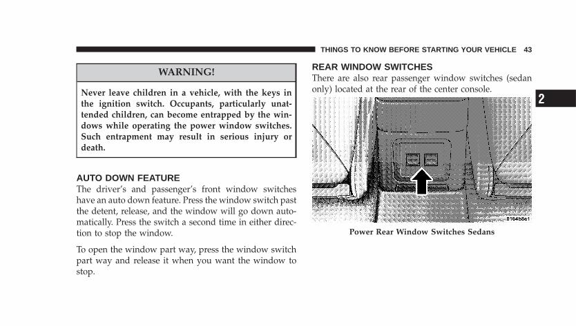
REAR WINDOW SWITCHESThere are also rear passenger window switches (sedanonly) located at the rear of the center console.
Power Rear Window Switches Sedans
THINGS TO KNOW BEFORE STARTING YOUR VEHICLE 43
2
WIND BUFFETINGWind buffeting can be described as the perception ofpressure on the ears or a helicopter type sound in theears. Your vehicle may exhibit wind buffeting with thewindows down, or the sunroof (if equipped) in certainopen or partially open positions. This is a normal occur-rence and can be minimized. If the buffeting occurs withthe rear windows open, open the front and rear windowstogether to minimize the buffeting. If the buffeting occurswith the sunroof open, adjust the sunroof opening tominimize the buffeting.
OCCUPANT RESTRAINTS (SEDAN)Some of the most important safety features in yourvehicle are the restraint systems. These include:
• Front and rear seat belts for all passengers
• Front airbags for both the driver and front passenger
• Pretensioning and load-limiting retractors for the frontseat belts.
• Knee Impact Blocker panels for front seat occupants.
• Supplemental front seat mounted side Head/Thoraxairbags for both the driver and front passenger (ifequipped).
• Front seat belt retractors that incorporate pretension-ers to enhance occupant protection by managing oc-cupant energy during an impact event.
If you will be carrying children too small for adult-sizeseat belts, your seat belts or the LATCH feature also, canbe used to hold infant and child restraint systems.
Please pay close attention to the information in thissection. It tells you how to use your restraint systemproperly to keep you and your passengers as safe aspossible.
44 THINGS TO KNOW BEFORE STARTING YOUR VEHICLE
WARNING!
In a collision, you and your passengers can suffermuch greater injuries if you are not properly buckledup. You can strike the interior of your vehicle or otherpassengers, or you can be thrown out of the vehicle.Always be sure you and others in your vehicle arebuckled up properly.
Buckle up even though you are an excellent driver, evenon short trips. Someone on the road may be a poor driverand cause a collision that includes you. This can happenfar away from home or on your own street.
Research has shown that seat belts save lives, and theycan reduce the seriousness of injuries in a collision. Someof the worst injuries happen when people are thrownfrom the vehicle. Seat belts reduce the possibility ofejection and the risk of injury caused by striking theinside of the vehicle. Everyone in a motor vehicle shouldbe belted at all times.
LAP/SHOULDER BELTSAll the seats in your vehicle are equipped with Lap/Shoulder Belts.
The belt webbing retractor is designed to lock duringvery sudden stops or collisions. This feature allows theshoulder part of the belt to move freely with you undernormal conditions. But in a collision, the belt will lockand reduce the risk of your striking the inside of thevehicle or being thrown out.
THINGS TO KNOW BEFORE STARTING YOUR VEHICLE 45
2
WARNING!
• It is extremely dangerous to ride in a cargo area,inside or outside of a vehicle. In a collision, peopleriding in these areas are more likely to be seri-ously injured or killed.
• Do not allow people to ride in any area of yourvehicle that is not equipped with seats and seatbelts.
• Be sure everyone in your vehicle is in a seat andusing a seat belt properly.
WARNING!
• Wearing a seat belt incorrectly is dangerous. Seatbelts are designed to go around the large bones ofyour body. These are the strongest parts of yourbody and can take the forces of a collision the best.
• Wearing your belt in the wrong place could makeyour injuries in a collision much worse. You mightsuffer internal injuries, or you could even slide outof part of the belt. Follow these instructions towear your seat belt safely and to keep your pas-sengers safe, too.
46 THINGS TO KNOW BEFORE STARTING YOUR VEHICLE
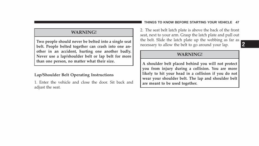
WARNING!
Two people should never be belted into a single seatbelt. People belted together can crash into one an-other in an accident, hurting one another badly.Never use a lap/shoulder belt or lap belt for morethan one person, no matter what their size.
Lap/Shoulder Belt Operating Instructions
1. Enter the vehicle and close the door. Sit back andadjust the seat.
2. The seat belt latch plate is above the back of the frontseat, next to your arm. Grasp the latch plate and pull outthe belt. Slide the latch plate up the webbing as far asnecessary to allow the belt to go around your lap.
WARNING!
A shoulder belt placed behind you will not protectyou from injury during a collision. You are morelikely to hit your head in a collision if you do notwear your shoulder belt. The lap and shoulder beltare meant to be used together.
THINGS TO KNOW BEFORE STARTING YOUR VEHICLE 47
2
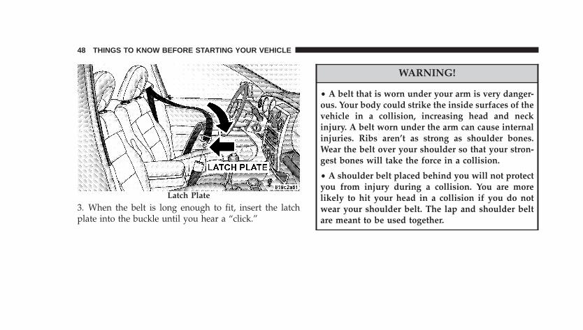
3. When the belt is long enough to fit, insert the latchplate into the buckle until you hear a “click.”
WARNING!
• A belt that is worn under your arm is very danger-ous. Your body could strike the inside surfaces of thevehicle in a collision, increasing head and neckinjury. A belt worn under the arm can cause internalinjuries. Ribs aren’t as strong as shoulder bones.Wear the belt over your shoulder so that your stron-gest bones will take the force in a collision.
• A shoulder belt placed behind you will not protectyou from injury during a collision. You are morelikely to hit your head in a collision if you do notwear your shoulder belt. The lap and shoulder beltare meant to be used together.
Latch Plate
48 THINGS TO KNOW BEFORE STARTING YOUR VEHICLE
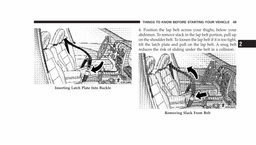
4. Position the lap belt across your thighs, below yourabdomen. To remove slack in the lap belt portion, pull upon the shoulder belt. To loosen the lap belt if it is too tight,tilt the latch plate and pull on the lap belt. A snug beltreduces the risk of sliding under the belt in a collision.
Inserting Latch Plate Into Buckle
Removing Slack From Belt
THINGS TO KNOW BEFORE STARTING YOUR VEHICLE 49
2
WARNING!
• A lap belt worn too high can increase the risk ofinternal injury in a collision. The belt forces won’t beat the strong hip and pelvic bones, but across yourabdomen. Always wear the lap belt as low as pos-sible and keep it snug.
• A twisted belt can’t do its job as well. In a collisionit could even cut into you. Be sure the belt is straight.If you can’t straighten a belt in your vehicle, take it toyour dealer and have it fixed.
5. Position the shoulder belt on your chest so that it iscomfortable and not resting on your neck. The retractorwill withdraw any slack in the belt.
WARNING!
• A belt that is buckled into the wrong buckle willnot protect you properly. The lap portion could ridetoo high on your body, possibly causing internalinjuries. Always buckle your belt into the bucklenearest you.
• A belt that is too loose will not protect you as well.In a sudden stop you could move too far forward,increasing the possibility of injury. Wear your seatbelt snugly.
6. To release the belt, push the red button on the buckle.The belt will automatically retract to its stowed position.If necessary, slide the latch plate down the webbing toallow the belt to retract fully.
50 THINGS TO KNOW BEFORE STARTING YOUR VEHICLE
WARNING!
A frayed or torn belt could rip apart in a collision andleave you with no protection. Inspect the belt systemperiodically, checking for cuts, frays, or loose parts.Damaged parts must be replaced immediately. Donot disassemble or modify the system. Seat beltassemblies must be replaced after a collision if theyhave been damaged (bent retractor, torn webbing,etc.).
Rear Center Lap/Shoulder Belt Retractor Lock-OutThis feature is designed to lock the retractor wheneverthe rear seat back is not fully latched. This preventssomeone from wearing the rear center lap/shoulder beltwhen the rear seat back is not fully latched.
NOTE:• If the rear center lap/shoulder belt can not be pulled
out, check that the rear seat back is fully latched.
• If the rear seat back is properly latched and the rearcenter lap/shoulder belt still can not be pulled out, theAutomatic-Locking Retractor (ALR) system may beactivated. To reset this feature you must let all of thebelt webbing return into the retractor. You will not beable to pull out more webbing until all of the webbinghas been returned back into the retractor.
THINGS TO KNOW BEFORE STARTING YOUR VEHICLE 51
2
WARNING!
The rear center lap/shoulder belt is equipped with alockout feature to ensure that the rear seat back is inthe fully upright and locked position when occupied.If the rear seat back is not fully upright and lockedand the rear center lap/shoulder belt can be pulledout of the retractor, the vehicle should immediatelybe taken to your dealer for service. Failure to followthis warning could result in serious or fatal injury.
LAP/SHOULDER SEAT BELT UNTWISTINGPROCEDUREUse the following procedure to untwist a twisted lap/shoulder belt.
1. Position the latch plate as close as possible to theanchor point.
2. At about six to twelve inches (15 to 30 cm) above thelatch plate, grasp and twist the belt webbing 180° tocreate a fold that begins immediately above the latchplate.
3. Slide the latch plate upward over the folded webbing.The folded webbing must enter the slot at the top of thelatch plate.
4. Continue to slide the latch plate up until it clears thefolded webbing.
ADJUSTABLE UPPER SHOULDER SEAT BELTANCHORAGEIn the front seat, the shoulder belt can be adjustedupward or downward to position the belt away fromyour neck. Push up or down on the anchorage button torelease the anchorage, and move it up or down to theposition that serves you best.
52 THINGS TO KNOW BEFORE STARTING YOUR VEHICLE
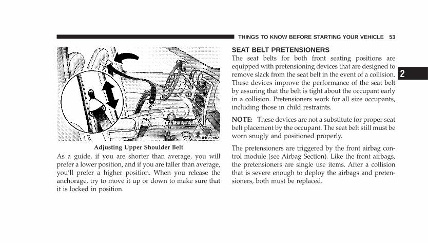
As a guide, if you are shorter than average, you willprefer a lower position, and if you are taller than average,you’ll prefer a higher position. When you release theanchorage, try to move it up or down to make sure thatit is locked in position.
SEAT BELT PRETENSIONERSThe seat belts for both front seating positions areequipped with pretensioning devices that are designed toremove slack from the seat belt in the event of a collision.These devices improve the performance of the seat beltby assuring that the belt is tight about the occupant earlyin a collision. Pretensioners work for all size occupants,including those in child restraints.
NOTE: These devices are not a substitute for proper seatbelt placement by the occupant. The seat belt still must beworn snugly and positioned properly.
The pretensioners are triggered by the front airbag con-trol module (see Airbag Section). Like the front airbags,the pretensioners are single use items. After a collisionthat is severe enough to deploy the airbags and preten-sioners, both must be replaced.
Adjusting Upper Shoulder Belt
THINGS TO KNOW BEFORE STARTING YOUR VEHICLE 53
2
ENHANCED SEAT BELT REMINDER SYSTEM(BELTALERT�)If the driver’s or front passenger’s seat belt has not beenbuckled within 60 seconds of starting the vehicle and ifthe vehicle speed is greater than 5 mph (8 km/h), theEnhanced Warning System (BeltAlert�) will alert thedriver or front passenger to buckle their seat belt. Thedriver should also instruct all other occupants to buckletheir seat belts. If the driver unbuckles the seat belt whilethe vehicle is in motion an immediate chime will be heardand, the Enhanced Warning System (BeltAlert�) willcontinue to chime and flash the Seat Belt Warning Lightfor 96 seconds or until the driver’s seat belt is buckled.The Enhanced Warning System (BeltAlert�) will be reac-tivated if the driver’s or front passenger’s seat belt isunbuckled for more than 10 seconds and the vehiclespeed is greater than 5 mph (8 km/h).
NOTE:• The Enhanced Warning System (BeltAlert�) can be
enabled or disabled by your authorized dealer.
• DaimlerChrysler does not recommend deactivatingthe Enhanced Warning System (BeltAlert�).
If the Enhanced Warning System (BeltAlert�) is deacti-vated, the Seat Belt Warning Light will continue toilluminate while the driver seat belt remains unfastened.
SEAT BELTS AND PREGNANT WOMENWe recommend that pregnant women use the seat beltsthroughout their pregnancy. Keeping the mother safe isthe best way to keep the baby safe.
Pregnant women should wear the lap part of the beltacross the thighs and as snug across the hips as possible.Keep the belt low so that it does not come across theabdomen. That way the strong bones of the hips will takethe force if there is a collision.
54 THINGS TO KNOW BEFORE STARTING YOUR VEHICLE
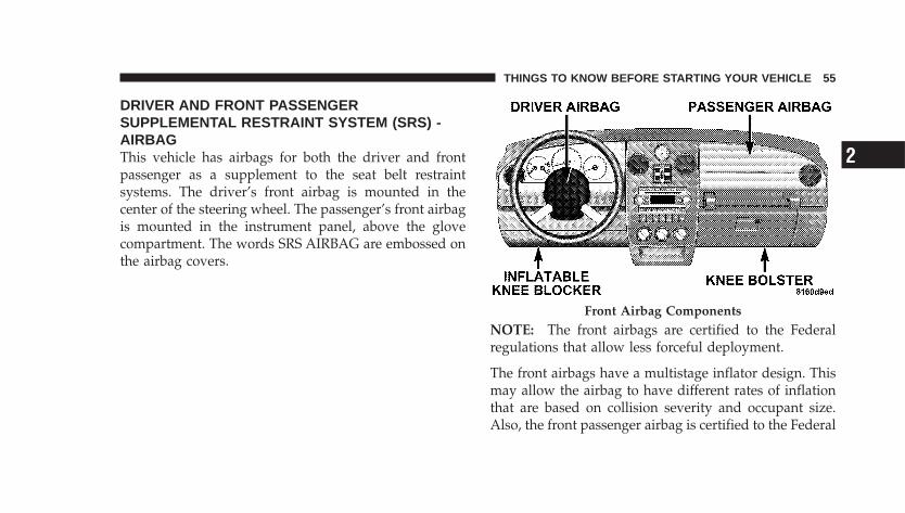
DRIVER AND FRONT PASSENGERSUPPLEMENTAL RESTRAINT SYSTEM (SRS) -AIRBAGThis vehicle has airbags for both the driver and frontpassenger as a supplement to the seat belt restraintsystems. The driver’s front airbag is mounted in thecenter of the steering wheel. The passenger’s front airbagis mounted in the instrument panel, above the glovecompartment. The words SRS AIRBAG are embossed onthe airbag covers.
NOTE: The front airbags are certified to the Federalregulations that allow less forceful deployment.
The front airbags have a multistage inflator design. Thismay allow the airbag to have different rates of inflationthat are based on collision severity and occupant size.Also, the front passenger airbag is certified to the Federal
Front Airbag Components
THINGS TO KNOW BEFORE STARTING YOUR VEHICLE 55
2
regulations that define Occupant Classification (Refer to�Occupant Classification System� in this section).
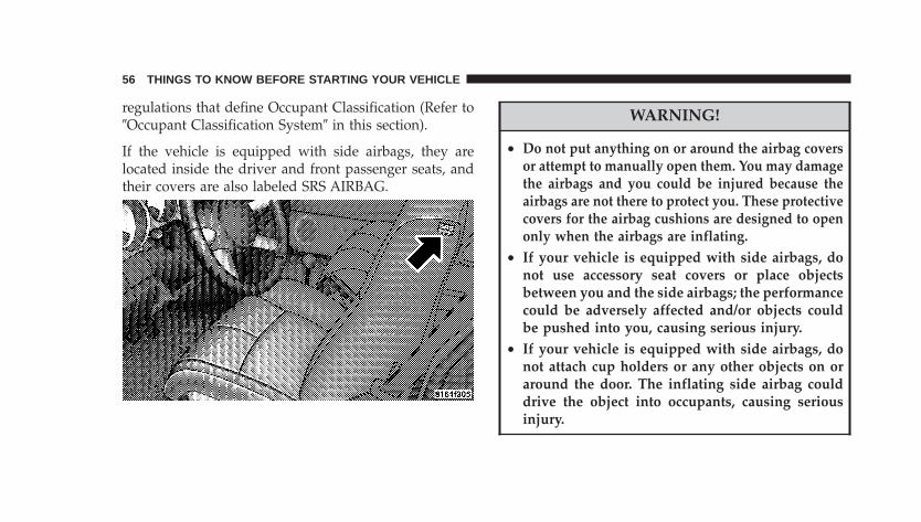
If the vehicle is equipped with side airbags, they arelocated inside the driver and front passenger seats, andtheir covers are also labeled SRS AIRBAG.
WARNING!
• Do not put anything on or around the airbag coversor attempt to manually open them. You may damagethe airbags and you could be injured because theairbags are not there to protect you. These protectivecovers for the airbag cushions are designed to openonly when the airbags are inflating.
• If your vehicle is equipped with side airbags, donot use accessory seat covers or place objectsbetween you and the side airbags; the performancecould be adversely affected and/or objects couldbe pushed into you, causing serious injury.
• If your vehicle is equipped with side airbags, donot attach cup holders or any other objects on oraround the door. The inflating side airbag coulddrive the object into occupants, causing seriousinjury.
56 THINGS TO KNOW BEFORE STARTING YOUR VEHICLE
Airbags inflate in moderate to high speed impacts. Alongwith seat belts and pretensioners, front airbags work withthe driver inflatable knee blocker to provide improvedprotection for the driver and front passenger. Side airbagsalso work with seat belts to improve occupant protection.
The seat belts are designed to protect you in many typesof collisions. The front airbags deploy in moderate tosevere frontal collisions. If your vehicle is equipped, theside airbag on the crash side of the vehicle is triggered inmoderate to severe side collisions. In certain types ofcollisions, both the front and side airbags may be trig-gered. But even in collisions where the airbags work, youneed the seat belts to keep you in the right position forthe airbags to protect you properly.
NOTE: The passenger front airbag may not deploy evenwhen the driver front airbag has if the Occupant Classi-fication System (refer to �Occupant Classification System�in this section) has determined the passenger seat is
empty or is occupied by someone that is classified in the“child� category. This could be a child, a teenager, or evena small adult.Here are some simple steps you can take to minimize therisk of harm from a deploying airbag.1. Children 12 years old and under should always ridebuckled up in a rear seat.
Infants in rear facing child restraints should NEVER ridein the front seat of a vehicle with a passenger front airbag.An airbag deployment can cause severe injury or death toinfants in that position.Children that are not big enough to properly wear thevehicle seat belt (see Section on Child Restraints) shouldbe secured in the rear seat in child restraints or belt-positioning booster seats. Older children who do not usechild restraints or belt-positioning booster seats shouldride properly buckled up in the rear seat. Never allowchildren to slide the shoulder belt behind them or undertheir arm.
THINGS TO KNOW BEFORE STARTING YOUR VEHICLE 57
2
If a child from 1 to 12 years old must ride in the frontpassenger seat because the vehicle is crowded, move theseat as far back as possible, and use the proper childrestraint. Refer to the section on Child Restraint.
You should read the instructions provided with yourchild restraint to make sure that you are using it properly.
2. All occupants should wear their lap and shoulderbelts properly.
3. The driver and front passenger seats should bemoved back as far as practical to allow the front airbagsroom to inflate.
4. If your vehicle has side airbags, do not lean againstthe door, airbags will inflate forcefully into the spacebetween you and the door.
5. If the airbag system in this vehicle needs to bemodified to accomodate a disabled person, contact theCustomer Center. Phone numbers are provided under �IfYou Need Assistance� in Section 9 of this manual.
WARNING!
• Relying on the airbags alone could lead to moresevere injuries in a collision. The airbags workwith your seat belt to restrain you properly. Insome collisions the airbags won’t deploy at all.Always wear your seat belts even though you haveairbags.
• Being too close to the steering wheel or instrumentpanel during front airbag deployment could causeserious injury. Airbags need room to inflate. Sitback, comfortably extending your arms to reachthe steering wheel or instrument panel.
• If the vehicle has side airbags, they also need roomto inflate. Do not lean against the door. Sit uprightin the center of the seat.
58 THINGS TO KNOW BEFORE STARTING YOUR VEHICLE
The front airbag system consists of the following:
• Occupant Restraint Controller
• Side Remote Acceleration Sensors (If equipped)
• Airbag Warning Light
• Driver Airbag
• Passenger Airbag
• Front Seat Mounted Side Airbags (If equipped)
• Steering Wheel and Column
• Instrument Panel
• Interconnecting Wiring
• Knee Impact Bolsters
• Driver Inflatable Knee Blocker
• Front Acceleration Sensors
• Driver and Front Passenger Seat Belt Pretensioners
• Occupant Classification System (OCS) for the FrontPassenger Seat
− Occupant Classification Module
− Passenger Airbag Disable (PAD) Indicator Light
− Weight Sensors
How The Airbag System Works
• The Occupant Restraint Controller (ORC) determinesif a frontal collision is severe enough to require theairbags to inflate. The front airbag inflators are de-signed to provide different rates of airbag inflationfrom direction provided by the ORC. The ORC mayalso modify the rate of inflation based on the occupantsize provided by the Occupant Classification Module.The ORC will not detect roll over.
THINGS TO KNOW BEFORE STARTING YOUR VEHICLE 59
2
The ORC also monitors the readiness of the electronicparts of the system whenever the ignition switch is inthe START or RUN positions. These include all of theitems listed above except the steering wheel andcolumn, and knee bolsters. If the key is in the OFFposition, in the ACC position, or not in the ignition,the airbags are not on and will not inflate.
During a moderate-to-severe rear impact the ORC maydeploy the seat belt pretensioners alone.
Also, the ORC turns on the AIRBAG warninglight and PAD indicator light in the instrumentpanel for 6 to 8 seconds for a self-check whenthe ignition is first turned on. After the self-
check, the AIRBAG warning light will turn off. The PADindicator light will function normally (Refer to �Passen-ger Airbag Disable (PAD) Indicator Light� in this section).If the ORC detects a malfunction in any part of thesystem, it turns on the AIRBAG warning light eithermomentarily or continuously. A single chime will soundif the light comes on again after initial start up.
WARNING!
Ignoring the AIRBAG light in your instrument panelcould mean you won’t have the airbags to protect youin a collision. If the light does not come on, stays onafter you start the vehicle, or if it comes on as youdrive, have the airbag system checked right away.
• The Occupant Classification System (OCS) is part ofa Federally regulated safety system required for thisvehicle. It is designed to turn off the front passengerairbag for occupants that weigh less than a very smalladult.
NOTE: Children 12 years and under should always ridebuckled up in a rear seat in an appropriate child restraint.
• The OCS classifies an occupant using weight sensorsmounted in the base of the front passenger seat. Any
60 THINGS TO KNOW BEFORE STARTING YOUR VEHICLE
weight on the seat will be sensed by the system.Objects hanging on the seat or other passengers push-ing down on the seat will also be sensed. The weight ofan adult will cause the system to turn the airbag on. Inthis case, the OCS has classified the occupant of theseat as an adult. An adult occupant needs to sit in anormal position (with their feet on or near the floor) inorder to be properly classified. Reclining the seat backtoo far may change how an occupant is classified bythe OCS.
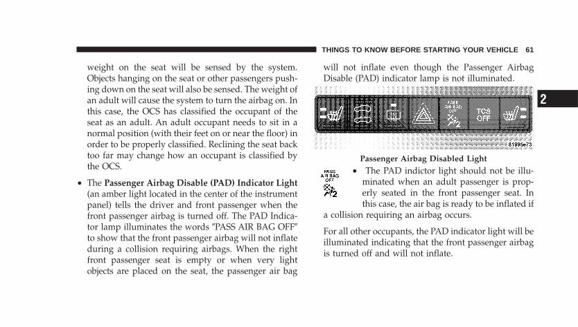
• The Passenger Airbag Disable (PAD) Indicator Light(an amber light located in the center of the instrumentpanel) tells the driver and front passenger when thefront passenger airbag is turned off. The PAD Indica-tor lamp illuminates the words �PASS AIR BAG OFF�to show that the front passenger airbag will not inflateduring a collision requiring airbags. When the rightfront passenger seat is empty or when very lightobjects are placed on the seat, the passenger air bag
will not inflate even though the Passenger AirbagDisable (PAD) indicator lamp is not illuminated.
• The PAD indictor light should not be illu-minated when an adult passenger is prop-erly seated in the front passenger seat. Inthis case, the air bag is ready to be inflated if
a collision requiring an airbag occurs.
For all other occupants, the PAD indicator light will beilluminated indicating that the front passenger airbagis turned off and will not inflate.
Passenger Airbag Disabled Light
THINGS TO KNOW BEFORE STARTING YOUR VEHICLE 61
2
NOTE: Even though this vehicle is equipped with anoccupant classification system, children 12 years andunder should always ride buckled up in a rear seat in anappropriate child restraint (see section on child re-straints).
WARNING!
Never place a rear facing infant seat in front of anairbag. A deploying passenger airbag can cause deathor serious injury to a child in a rear facing infant seat.
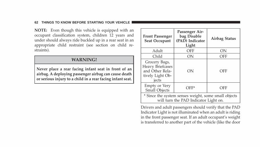
Front PassengerSeat Occupant
Passenger Air-bag Disable
(PAD) IndicatorLight
Airbag Status
Adult OFF ONChild ON OFF
Grocery Bags,Heavy Briefcasesand Other Rela-tively Light Ob-
jects
ON OFF
Empty or VerySmall Objects OFF* OFF
* Since the system senses weight, some small objectswill turn the PAD Indicator Light on.
Drivers and adult passengers should verify that the PADIndicator Light is not illuminated when an adult is ridingin the front passenger seat. If an adult occupant’s weightis transferred to another part of the vehicle (like the door
62 THINGS TO KNOW BEFORE STARTING YOUR VEHICLE
or instrument panel), the weight sensors in the seat maynot properly classify the occupant. Objects lodged underthe seat or between the seat and the center console canprevent the occupant’s weight from being measuredproperly and may result in the occupant being improp-erly classified. Ensure that the front passenger seat backdoes not touch anything placed on the second row ofseats because this can also affect occupant classification.Also, if you fold down the seats in the second row checkto be sure they don’t touch the front passenger seat.
If the front passenger seat is damaged in any way, itshould only be serviced by an authorized dealer. If theseat is removed (or even if the seat attachment bolts areloosened or tightened in any way), take the vehicle to anauthorized dealer.
If there is a fault present in the OCS, the Airbag WarningLight (a red light located in the center of the instrumentcluster directly in front of the driver) will be turned on.
This indicates that you should take the vehicle to anauthorized dealer. The Airbag Warning Light is turned onwhenever there is fault that can affect the operation of theairbag system. If there is a fault present in the OCS, boththe PAD Indicator Light and the Airbag Warning Lightare illuminated to show that the passenger airbag isturned off until the fault is cleared. If an object is lodgedunder the seat and interferes with operation of the weightsensors, a fault will occur which turns on both the PADIndicator Light and the Airbag Warning Light. Once thelodged object is removed, the fault will be automaticallycleared after a short period of time.
• The Driver and Passenger Airbag/Inflator Units arelocated in the center of the steering wheel and the rightside of the instrument panel. When the ORC detects acollision requiring the airbags, it signals the inflatorunits. A large quantity of nontoxic gas is generated toinflate the front airbags. Different airbag inflation rates
THINGS TO KNOW BEFORE STARTING YOUR VEHICLE 63
2
may be possible based on collision severity and occu-pant size. The steering wheel hub trim cover and theupper right side of the instrument panel separate andfold out of the way as the bags inflate to their full size.The bags fully inflate in about 50 - 70 milliseconds.This is about half of the time it takes to blink your eyes.The bags then quickly deflate while helping to restrainthe driver and front passenger. The driver’s frontairbag gas is vented through vent holes in the sides ofthe airbag. The passenger’s front airbag gas is ventedthrough vent holes in the sides of the airbag. In thisway the airbags do not interfere with your control ofthe vehicle.
• The Occupant Classification Module (OCM) is lo-cated beneath the front passenger seat. The OCMclassifies the occupant into categories based on themeasurements made by the seat weight sensors. TheOCM communicates with the Occupant Restraint Con-troller (ORC). The ORC uses the occupant category to
determine whether the front passenger airbag shouldbe turned off. It also determines the rate of airbaginflation during a collision.
• Your vehicle has four Weight Sensors located betweenthe seat and the floor pan. The weight sensors measureapplied weight and transfers that information to theOCM.
• The Side Impact (SRS) Seat Mounted Side Airbags(If equipped) are designed to activate only in certainside collisions.
The ORC module determines if a side collision issevere enough to require the side airbags to inflate.The side airbag control module will not detect rollover, front or rear collisions.
64 THINGS TO KNOW BEFORE STARTING YOUR VEHICLE
The ORC Module monitors the readiness of the electronicparts of the system whenever the ignition switch is in theSTART or ON positions. These include all of the itemspreviously mentioned.
In moderate to severe side collisions, the side airbaginflator on the crash side of the vehicle is triggered,releasing a quantity of nontoxic gas. The inflating sideairbag exits through the seat seam into the space betweenthe occupant and the door. The side airbag moves at avery high speed and with such a high force, that it couldinjure you if you are not seated properly, or if items arepositioned in the area where the side airbag inflates. Thisespecially applies to children.
NOTE: If your vehicle is equipped with left and rightside curtain air bags, do not install a clothing barmounted to the coat hooks (or similarly mounted). Aclothing bar will impede the proper performance of thebags.
• When the ORC and the impact sensors detect acollision requiring the Driver Inflatable KneeBlocker, it signals the inflator unit. A quantity ofnontoxic gas is generated to inflate the Driver Inflat-able Knee Blocker. The Driver Inflatable Knee Blockerinflates rearward towards the driver’s knees to helpprotect the knees and position you for the best inter-action with the front airbag. The Driver InflatableKnee Blocker fully inflates in about 50 milliseconds,this is only about half of the time it takes you to blinkyour eyes. It then quickly deflates while helping toprotect the driver’s knees.
• The Knee Impact Bolsters help protect the knees, andposition everyone for the best interaction with thefront airbag.
THINGS TO KNOW BEFORE STARTING YOUR VEHICLE 65
2
The front passenger seat assembly contains critical com-ponents that affect the front passenger airbag deploy-ment. Correctly functioning front passenger seat compo-nents are critical for the Occupant Classification System(OCS) to properly classify the front passenger and calcu-late the proper airbag deployment. Do not make anymodifications to the front passenger seat components,assembly, or to the seat cover.
The following requirements must be strictly adhered to:
• Do not modify the front passenger seat assembly orcomponents in any way.
• Do not modify the front seat center console or centerposition seat in any way.
• Do not use prior or future model year seat covers notdesignated for the specific model being repaired. Al-ways use the correct seat cover specified for the vehicle.
• Do not replace the seat cover with an aftermarket seatcover.
• Do not add a secondary seat cover other than thoseapproved by DaimlerChrysler/Mopar.
• At no time should any supplemental restraint system(SRS) component or SRS related component or fastenerbe modified or replaced with any part except thosewhich are approved by DaimlerChrysler/Mopar.
WARNING!
Unapproved modifications or service procedures tothe front passenger seat assembly, its related compo-nents, or seat cover may inadvertently change theairbag deployment in case of a frontal crash. Thiscould result in death or serious injury to the frontseat passenger if the vehicle is involved in an acci-dent. A modified vehicle may not comply with re-quired Federal Motor Vehicle Safety Standards(FMVSS).
66 THINGS TO KNOW BEFORE STARTING YOUR VEHICLE
If A Deployment OccursThe airbag systems are designed to deploy when theairbag control modules detect a moderate-to-severe col-lision, to help restrain the driver and front passenger, andthen immediately deflate.
NOTE: A frontal collision that is not severe enough toneed airbag protection will not activate the system. Thisdoes not mean something is wrong with the airbag system.
If you do have a collision which deploys the airbags, anyor all of the following may occur:
• The nylon airbag material may sometimes cause abra-sions and/or skin reddening to the driver and frontpassenger as the airbags deploy and unfold. Theabrasions are similar to friction rope burns or thoseyou might get sliding along a carpet or gymnasiumfloor. They are not caused by contact with chemicals.They are not permanent and normally heal quickly.However, if you haven’t healed significantly within a
few days, or if you have any blistering, see your doctorimmediately. As the airbags deflate you may see somesmoke-like particles. The particles are a normal by-product of the process that generates the nontoxic gasused for airbag inflation. These airborne particles mayirritate the skin, eyes, nose, or throat. If you have skinor eye irritation, rinse the area with cool water. Fornose or throat irritation, move to fresh air. If theirritation continues, see your doctor. If these particlessettle on your clothing, follow the garment manufac-turer’s instructions for cleaning.
• It is not advisable to drive your vehicle after theairbags have deployed. If you are involved in anothercollision, the airbags will not be in place to protect you.
THINGS TO KNOW BEFORE STARTING YOUR VEHICLE 67
2
WARNING!
Deployed airbags and seat belt pretensioners cannotprotect you in another collision. Have the airbags,seat belt pretensioners, and the front passenger seatbelt retractor assembly, replaced by an authorizeddealer as soon as possible. Also, have the OccupantClassification System serviced as well.
Maintaining Your Airbag System
WARNING!
Modifications to any part of the airbag system couldcause it to fail when you need it. You could beinjured if the airbag system is not there to protectyou. Do not modify the components or wiring, in-cluding adding any kind of badges or stickers to thesteering wheel hub trim cover or the upper right sideof the instrument panel. Do not modify the frontbumper, vehicle body structure, or add aftermarketside steps or running boards.
68 THINGS TO KNOW BEFORE STARTING YOUR VEHICLE
WARNING!
Do not attempt to modify any part of your advancedairbag system. The airbag may inflate accidentally ormay not function properly if modifications are made.Take your vehicle to an authorized dealer for anyadvanced airbag system service. If your seat includ-ing your trim cover and cushion needs to be servicedin any way (including removal or loosening/tightening of seat attachment bolts), take the vehicleto your authorized dealer. Only manufacturer ap-proved seat accessories may be used. If it is necessaryto modify an advanced airbag system for personswith disabilities, contact your authorized dealer.
WARNING!
• Do not place or hang any items such as add-onvideo players on the front seat backs. The addi-tional weight may cause the Occupant Classifica-tion System to be unable to correctly classify theright front occupant. This could allow the passen-ger frontal airbag to inflate when it is not desired.
• You need proper knee impact protection in acollision. Do not mount or locate any aftermarketequipment on or behind the knee blocker panel.
• It is dangerous to try to repair any part of theairbag system yourself. Be sure to tell anyone whoworks on your vehicle that it has an airbag system.
NOTE: Perchlorate Material – special handling may apply,See www.dtsc.ca.gov/hazardouswaste/perchlorate.”
THINGS TO KNOW BEFORE STARTING YOUR VEHICLE 69
2

Airbag LightYou will want to have the airbags ready to inflate for yourprotection in a collision. While the airbag system isdesigned to be maintenance free, if any of the followingoccurs, have an authorized dealer service the systemimmediately.
• The AIRBAG light does not come on during the six toeight seconds when the ignition switch is first turnedon.
• The light remains on after the six to eight secondinterval.
• The light comes on and remains on while driving.
Event Data Recorder (EDR)In the event of an accident, your vehicle is designed torecord up to five - seconds of specific vehicle dataparameters (see list below) in an event data recorder
prior to the moment of airbag deployment, or near-deployment, and up to a quarter second of high-speeddeceleration data during and/or after airbag deploymentor near-deployment. EDR data are ONLY recorded if anairbag deploys, or nearly deploys, and are otherwiseunavailable.
NOTE:1. A near-deployment event occurs when the airbagsensor detects severe vehicle deceleration usually indica-tive of a crash, but not severe enough to warrant airbagdeployment.
2. Under certain circumstances, EDR data may not berecorded (e.g., loss of battery power).
In conjunction with other data gathered during a com-plete accident investigation, the electronic data may beused by DaimlerChrysler and others to learn more aboutthe possible causes of crashes and associated injuries inorder to assess and improve vehicle performance. In
70 THINGS TO KNOW BEFORE STARTING YOUR VEHICLE
addition to crash investigations initiated byDaimlerChrysler, such investigations may be requestedby customers, insurance carriers, government officials,and professional crash researchers, such as those associ-ated with universities, and with hospital and insuranceorganizations.
In the event that an investigation is undertaken byDaimlerChrysler (regardless of initiative), the companyor its designated representative will first obtain permis-sion of the appropriate custodial entity for the vehicle(usually the vehicle owner or lessee) before accessing theelectronic data stored, unless ordered to download databy a court with legal jurisdiction (i.e., pursuant to awarrant). A copy of the data will be provided to thecustodial entity upon request. General data that does notidentify particular vehicles or crashes may be released forincorporation in aggregate crash databases, such as thosemaintained by the US government and various states.Data of a potentially sensitive nature, such as would
identify a particular driver, vehicle, or crash, will betreated confidentially. Confidential data will not be dis-closed by DaimlerChrysler to any third party exceptwhen:
1. Used for research purposes, such as to match datawith a particular crash record in an aggregate database,provided confidentiality of personal data is thereafterpreserved
2. Used in defense of litigation involving aDaimlerChrysler product
3. Requested by police under a legal warrant
4. Otherwise required by law
Data Parameters that May Be Recorded:
• Diagnostic trouble code(s) and warning lamp statusfor electronically-controlled safety systems, includingthe airbag system
THINGS TO KNOW BEFORE STARTING YOUR VEHICLE 71
2
• Airbag disable lamp status (if equipped)
• �Time� of airbag deployment (in terms of ignitioncycles and vehicle mileage)
• Airbag deployment level (if applicable)
• Impact acceleration and angle
• Seatbelt status
• Brake status (service and parking brakes)
• Accelerator status (including vehicle speed)
• Engine control status (including engine speed)
• Transmission gear selection
• Cruise control status
• Traction/stability control status
• Tire pressure monitoring system status
CHILD RESTRAINTEveryone in your vehicle needs to be buckled up at alltimes — babies and children, too. Every state in theUnited States and all Canadian provinces require thatsmall children ride in proper restraint systems. This is thelaw, and you can be prosecuted for ignoring it.
Children 12 years and under should ride properly buck-led up in a rear seat, if available. According to crashstatistics, children are safer when properly restrained inthe rear seats, rather than in the front.
72 THINGS TO KNOW BEFORE STARTING YOUR VEHICLE
WARNING!
In a collision, an unrestrained child, even a tiny baby,can become a missile inside the vehicle. The forcerequired to hold even an infant on your lap couldbecome so great that you could not hold the child, nomatter how strong you are. The child and otherscould be badly injured. Any child riding in yourvehicle should be in a proper restraint for the child’ssize.
Infants And Small ChildrenThere are different sizes and types of restraints forchildren from newborn size to the child almost largeenough for an adult safety belt. Always check the childseat owner’s manual to ensure you have the correct seatfor your child. Use the restraint that is correct for yourchild:
• Safety experts recommend that children riderearward-facing in the vehicle until they are at leastone year old and weigh at least 20 lbs (9 kg). Two typesof child restraints can be used rearward-facing: infantcarriers and �convertible� child seats. Both types ofchild restraints are held in the vehicle by the lap/shoulder belt or the LATCH child restraint anchoragesystem.
• This vehicle is not capable of accommodating theinstallation of a car bed used for carrying newbornbabies at the right front passenger seat position. If a carbed must be used to transport a newborn baby, the carbed must be installed in the second seating row only.
• The infant carrier is only used rearward-facing in thevehicle. It is recommended for children who weigh upto about 20 lbs (9 kg). �Convertible� child seats can beused either rearward-facing or forward-facing in thevehicle. Convertible child seats often have a higher
THINGS TO KNOW BEFORE STARTING YOUR VEHICLE 73
2
weight limit in the rearward-facing direction thaninfant carriers do, so they can be used rearward-facingby children who weigh more than 9 kg (20 lbs) but areless than one year old.
• Rearward-facing child seats must NEVER be used inthe front seat of a vehicle with a front passengerairbag. An airbag deployment could cause severeinjury or death to infants in this position.
• Children who weigh more than 20 lbs (9 kg) and whoare older than one year can ride forward-facing in thevehicle. Forward-facing child seats and convertiblechild seats used in the forward-facing direction are forchildren who weigh 20 to 40 lbs (9 to 18 kg) and whoare older than one year. These child seats are also heldin the vehicle by the lap/shoulder belt or the LATCHchild restraint anchorage system.
• The belt-positioning booster seat is for children weigh-ing more than 40 lbs (18 kg), but who are still too smallto fit the vehicle’s seat belts properly. If the childcannot sit with knees bent over the vehicle’s cushionwhile the child’s back is against the seat back; theyshould use a Belt Positioning Booster Seat. The childand booster seat are held in the vehicle by the lap/shoulder belt. (Some booster seats are equipped with afront shield and are held in the vehicle by the lapportion.)
NOTE: For additional information refer towww.nhtsa.gov or www.seatcheck.org.
74 THINGS TO KNOW BEFORE STARTING YOUR VEHICLE
WARNING!
• Improper installation can lead to failure of aninfant or child restraint. It could come loose in acollision. The child could be badly injured orkilled. Follow the manufacturer’s directions ex-actly when installing an infant or child restraint.
• A rearward facing child restraint should only beused in a rear seat. A rearward facing child re-straint in the front seat may be struck by a deploy-ing passenger airbag which may cause severe orfatal injury to the infant.
Here are some tips on getting the most out of your childrestraint:
• Before buying any restraint system, make sure that ithas a label certifying that it meets all applicable SafetyStandards. We also recommend that you make sure
that you can install the child restraint in the vehiclewhere you will use it, before you buy it.
• The restraint must be appropriate for your child’sweight and height. Check the label on the restraint forweight and height limits.
• Carefully follow the instructions that come with therestraint. If you install the restraint improperly, it maynot work when you need it.
The passenger seat belts are equipped with eithercinching latch plates or seat belt retractors that can beswitched to an automatic locking mode, which aredesigned to keep the lap portion tight around the childrestraint so that it is not necessary to use a locking clip.If the seat belt has a cinching latch plate, pulling up onthe shoulder portion of the lap/shoulder belt willtighten the belt. The cinching latch plate will keep thebelt tight, however, any seat belt system will loosenwith time, so check the belt occasionally and pull ittight if necessary.
THINGS TO KNOW BEFORE STARTING YOUR VEHICLE 75
2
If the seat belt has a switchable retractor, please refer toAutomatic-Locking Retractor (ALR) in this section.
• In the rear seat, you may have trouble tightening thelap/shoulder belt on the child restraint because thebuckle or latch plate is too close to the belt pathopening on the restraint. Disconnect the latch platefrom the buckle and twist the short buckle end of thebelt several times to shorten it. Insert the latch plateinto the buckle with the release button facing out.
• If the belt still can’t be tightened, or if by pulling andpushing on the restraint loosens the belt, disconnectthe latch plate from the buckle, turn the latch platearound, and insert the latch plate into the buckleagain. If you still can’t make the child restraint secure,try a different seating position.
• Buckle the child into the seat according to the childrestraint manufacturer’s directions.
• When your child restraint is not in use, secure it in thevehicle with the seat belt or remove it from the vehicle.Don’t leave it loose in the vehicle. In a sudden stop orcollision, it could strike the occupants or seat backsand cause serious personal injury.
Automatic-Locking Retractor (ALR)To operate the switchable retractor, pull the belt from theretractor until there is enough to allow you to passthrough the child restraint and slide the latch plate intothe buckle. Then pull on the belt until it is all removedfrom the retractor. Allow the belt to return into theretractor, pulling on the excess webbing to tighten the lapportion about the child restraint. Follow the instructionsof the child restraint manufacture.
NOTE: To reset this feature you must let all of the beltwebbing return into the retractor. You will not be able topull out more webbing until all of the webbing has beenreturned back into the retractor.
76 THINGS TO KNOW BEFORE STARTING YOUR VEHICLE
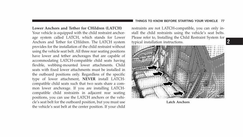
Lower Anchors and Tether for CHildren (LATCH)Your vehicle is equipped with the child restraint anchor-age system called LATCH, which stands for LowerAnchors and Tether for CHildren. The LATCH systemprovides for the installation of the child restraint withoutusing the vehicle seat belt. All three rear seating positionshave lower and tether anchorages that are capable ofaccommodating LATCH-compatible child seats havingflexible, webbing-mounted lower attachments. Childseats with fixed lower attachments must be installed inthe outboard positions only. Regardless of the specifictype of lower attachment, NEVER install LATCH-compatible child seats such that two seats share a com-mon lower anchorage. If you are installing LATCH-compatible child restraints in adjacent rear seatingpositions, you can use the LATCH anchors or the vehi-cle’s seat belt for the outboard position, but you must usethe vehicle’s seat belt at the center position. If your child
restraints are not LATCH-compatible, you can only in-stall the child restraints using the vehicle’s seat belts.Please refer to, Installing the Child Restraint System fortypical installation instructions.
Latch Anchors
THINGS TO KNOW BEFORE STARTING YOUR VEHICLE 77
2
Child restraints systems having attachments designed toconnect to the lower anchorages are now available. Childrestraints having tether straps and hooks for connectionto the top tether anchorage have been available for sometime. In fact, many child restraint manufacturers willprovide add-on tether strap kits for some of their olderproducts. Tether anchorage kits are also available formost older vehicles.
Because the lower anchorages are to be introduced topassenger carrying vehicles over a period of years, childrestraint systems having attachments for those anchor-ages will continue to have features for installation invehicles using the lap or lap/shoulder belt. They will alsohave tether straps, and you are urged to take advantageof all of the available attachments provided with yourchild restraint in any vehicle.
NOTE: When using the LATCH attaching system toinstall a child restraint, please ensure that all seat belts
not being used for occupant restraints are stowed and outof reach of children. It is recommended that beforeinstalling the child restraint, buckle the seat belt so theseat belt is tucked behind the child restraint and out ofreach. If the buckled seat belt interferes with the childrestraint installation, instead of tucking the seat beltbehind the child restraint, route the seat belt through thechild restraint belt path and then buckle it. This shouldstow the seat belt out of the reach of an inquisitive child.Remind all children in the vehicle that the seat belts arenot toys and should not be played with, and never leaveyour child unattended in the vehicle.
Installing the Child Restraint SystemWe urge that you carefully follow the directions of themanufacturer when installing your child restraint. Many,but not all, restraint systems will be equipped withseparate straps on each side, with each having a hook orconnector and a means for adjusting the tension in thestrap. Forward-facing toddler restraints and some
78 THINGS TO KNOW BEFORE STARTING YOUR VEHICLE
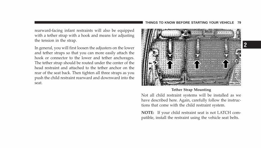
rearward-facing infant restraints will also be equippedwith a tether strap with a hook and means for adjustingthe tension in the strap.
In general, you will first loosen the adjusters on the lowerand tether straps so that you can more easily attach thehook or connector to the lower and tether anchorages.The tether strap should be routed under the center of thehead restraint and attached to the tether anchor on therear of the seat back. Then tighten all three straps as youpush the child restraint rearward and downward into theseat.
Not all child restraint systems will be installed as wehave described here. Again, carefully follow the instruc-tions that come with the child restraint system.
NOTE: If your child restraint seat is not LATCH com-patible, install the restraint using the vehicle seat belts.
Tether Strap Mounting
THINGS TO KNOW BEFORE STARTING YOUR VEHICLE 79
2
WARNING!
An incorrectly anchored tether strap could lead toincreased head motion and possible injury to thechild. Use only the anchor position directly behindthe child seat to secure a child restraint top tetherstrap.
Children Too Large For Booster SeatsChildren who are large enough to wear the shoulder beltcomfortably, and whose legs are long enough to bendover the front of the seat when their back is against theseat back, should use the lap/shoulder belt in a rear seat.
• Make sure that the child is upright in the seat.
• The lap portion should be low on the hips and as snugas possible.
• Check belt fit periodically. A child’s squirming orslouching can move the belt out of position.
• If the shoulder belt contacts the face or neck, move thechild closer to the center of the vehicle. Never allow achild to put the shoulder belt under an arm or behindtheir back.
Transporting PetsAirbags deploying in the front seat could harm your pet.An unrestrained pet will be thrown about and possiblyinjured, or injure a passenger during panic braking or ina collision.
Pets should be restrained in the rear seat in pet harnessesor pet carriers that are secured by seat belts.
80 THINGS TO KNOW BEFORE STARTING YOUR VEHICLE
OCCUPANT RESTRAINTS (CONVERTIBLE)Some of the most important safety features in yourvehicle are the restraint systems. These include:
• Front and rear seat belts for all passengers
• Front airbags for both the driver and front passenger
• Pretensioning and load-limiting retractors for the frontseat belts.
• Knee Blocker panels for front seat occupants.
• Supplemental front seat mounted side Head/Thoraxairbags for both the driver and front passenger (ifequipped).
• Front seat belt retractors that incorporate pretension-ers to enhance occupant protection by managing oc-cupant energy during an impact event.
If you will be carrying children too small for adult-sizeseat belts, your seat belts or the LATCH feature also, canbe used to hold infant and child restraint systems.
Please pay close attention to the information in thissection. It tells you how to use your restraint systemproperly to keep you and your passengers as safe aspossible.
WARNING!
In a collision, you and your passengers can suffermuch greater injuries if you are not properly buckledup. You can strike the interior of your vehicle or otherpassengers, or you can be thrown out of the vehicle.Always be sure you and others in your vehicle arebuckled up properly.
THINGS TO KNOW BEFORE STARTING YOUR VEHICLE 81
2
Buckle up even though you are an excellent driver, evenon short trips. Someone on the road may be a poor driverand cause a collision that includes you. This can happenfar away from home or on your own street.
Research has shown that seat belts save lives, and theycan reduce the seriousness of injuries in a collision. Someof the worst injuries happen when people are thrownfrom the vehicle. Seat belts reduce the possibility ofejection and the risk of injury caused by striking theinside of the vehicle. Everyone in a motor vehicle shouldbe belted at all times.
LAP/SHOULDER BELTSAll the seats in your vehicle are equipped with Lap/Shoulder Belts.
The belt webbing retractor is designed to lock duringvery sudden stops or collisions. This feature allows theshoulder part of the belt to move freely with you under
normal conditions. But in a collision, the belt will lockand reduce the risk of your striking the inside of thevehicle or being thrown out.
WARNING!
• It is extremely dangerous to ride in a cargo area,inside or outside of a vehicle. In a collision, peopleriding in these areas are more likely to be seri-ously injured or killed.
• Do not allow people to ride in any area of yourvehicle that is not equipped with seats and seatbelts.
• Be sure everyone in your vehicle is in a seat andusing a seat belt properly.
82 THINGS TO KNOW BEFORE STARTING YOUR VEHICLE
WARNING!
• Wearing a seat belt incorrectly is dangerous. Seatbelts are designed to go around the large bones ofyour body. These are the strongest parts of yourbody and can take the forces of a collision the best.
• Wearing your belt in the wrong place could makeyour injuries in a collision much worse. You mightsuffer internal injuries, or you could even slide outof part of the belt. Follow these instructions towear your seat belt safely and to keep your pas-sengers safe, too.
WARNING!
Two people should never be belted into a single seatbelt. People belted together can crash into one an-other in an accident, hurting one another badly.Never use a lap/shoulder belt or lap belt for morethan one person, no matter what their size.
Lap/Shoulder Belt Operating Instructions
1. Enter the vehicle and close the door. Sit back andadjust the seat.
2. The seat belt latch plate is above the back of the frontseat, next to your arm. Grasp the latch plate and pull outthe belt. Slide the latch plate up the webbing as far asnecessary to allow the belt to go around your lap.
THINGS TO KNOW BEFORE STARTING YOUR VEHICLE 83
2
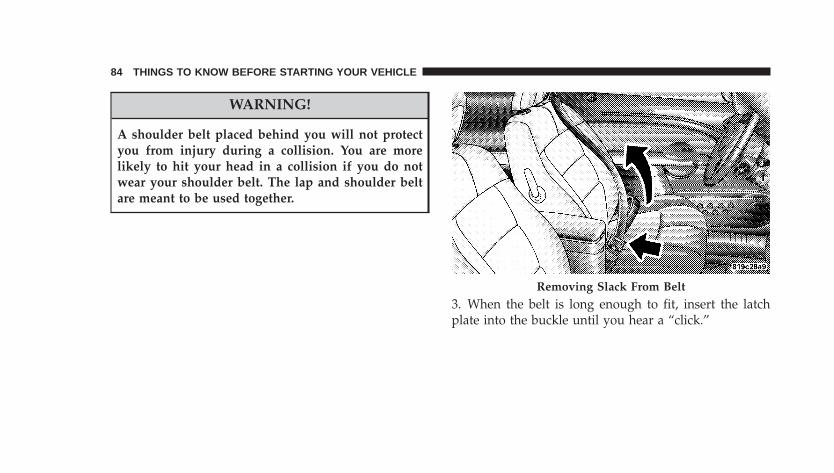
WARNING!
A shoulder belt placed behind you will not protectyou from injury during a collision. You are morelikely to hit your head in a collision if you do notwear your shoulder belt. The lap and shoulder beltare meant to be used together.
3. When the belt is long enough to fit, insert the latchplate into the buckle until you hear a “click.”
Removing Slack From Belt
84 THINGS TO KNOW BEFORE STARTING YOUR VEHICLE
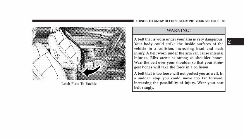
WARNING!
A belt that is worn under your arm is very dangerous.Your body could strike the inside surfaces of thevehicle in a collision, increasing head and neckinjury. A belt worn under the arm can cause internalinjuries. Ribs aren’t as strong as shoulder bones.Wear the belt over your shoulder so that your stron-gest bones will take the force in a collision.
A belt that is too loose will not protect you as well. Ina sudden stop you could move too far forward,increasing the possibility of injury. Wear your seatbelt snugly.
Latch Plate To Buckle
THINGS TO KNOW BEFORE STARTING YOUR VEHICLE 85
2
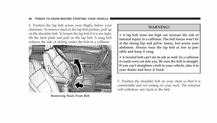
4. Position the lap belt across your thighs, below yourabdomen. To remove slack in the lap belt portion, pull upon the shoulder belt. To loosen the lap belt if it is too tight,tilt the latch plate and pull on the lap belt. A snug beltreduces the risk of sliding under the belt in a collision.
WARNING!
• A lap belt worn too high can increase the risk ofinternal injury in a collision. The belt forces won’t beat the strong hip and pelvic bones, but across yourabdomen. Always wear the lap belt as low as pos-sible and keep it snug.
• A twisted belt can’t do its job as well. In a collisionit could even cut into you. Be sure the belt is straight.If you can’t straighten a belt in your vehicle, take it toyour dealer and have it fixed.
5. Position the shoulder belt on your chest so that it iscomfortable and not resting on your neck. The retractorwill withdraw any slack in the belt.
Removing Slack From Belt
86 THINGS TO KNOW BEFORE STARTING YOUR VEHICLE
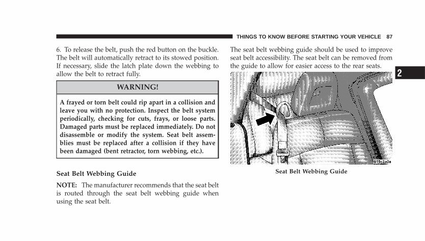
6. To release the belt, push the red button on the buckle.The belt will automatically retract to its stowed position.If necessary, slide the latch plate down the webbing toallow the belt to retract fully.
WARNING!
A frayed or torn belt could rip apart in a collision andleave you with no protection. Inspect the belt systemperiodically, checking for cuts, frays, or loose parts.Damaged parts must be replaced immediately. Do notdisassemble or modify the system. Seat belt assem-blies must be replaced after a collision if they havebeen damaged (bent retractor, torn webbing, etc.).
Seat Belt Webbing Guide
NOTE: The manufacturer recommends that the seat beltis routed through the seat belt webbing guide whenusing the seat belt.
The seat belt webbing guide should be used to improveseat belt accessibility. The seat belt can be removed fromthe guide to allow for easier access to the rear seats.
Seat Belt Webbing Guide
THINGS TO KNOW BEFORE STARTING YOUR VEHICLE 87
2
LAP/SHOULDER SEAT BELT UNTWISTINGPROCEDUREUse the following procedure to untwist a twisted lap/shoulder belt.
1. Position the latch plate as close as possible to theanchor point.
2. At about six to twelve inches (15 to 30 cm) above thelatch plate, grasp and twist the belt webbing 180° tocreate a fold that begins immediately above the latchplate.
3. Slide the latch plate upward over the folded webbing.The folded webbing must enter the slot at the top of thelatch plate.
4. Continue to slide the latch plate up until it clears thefolded webbing.
SEAT BELT PRETENSIONERSThe seat belts for both front seating positions areequipped with pretensioning devices that are designed toremove slack from the seat belt in the event of a collision.These devices improve the performance of the seat beltby assuring that the belt is tight about the occupant earlyin a collision. Pretensioners work for all size occupants,including those in child restraints.
NOTE: These devices are not a substitute for proper seatbelt placement by the occupant. The seat belt still must beworn snugly and positioned properly.
The pretensioners are triggered by the front airbag con-trol module (see Airbag Section). Like the front airbags,the pretensioners are single use items. After a collisionthat is severe enough to deploy the airbags and preten-sioners, both must be replaced.
88 THINGS TO KNOW BEFORE STARTING YOUR VEHICLE
ENHANCED SEAT BELT REMINDER SYSTEM(BELTALERT�)If the driver’s or front passenger’s seat belt has not beenbuckled within 60 seconds of starting the vehicle and ifthe vehicle speed is greater than 5 mph (8 km/h), theEnhanced Warning System (BeltAlert�) will alert thedriver or front passenger to buckle their seat belt. Thedriver should also instruct all other occupants to buckletheir seat belts. Once the warning is triggered, theEnhanced Warning System (BeltAlert�) will continue tochime and flash the Seat Belt Warning Light for 96seconds or until the driver’s or front passenger’s seat beltis buckled. The Enhanced Warning System (BeltAlert�)will be reactivated if the driver’s or front passenger’s seatbelt is unbuckled for more than 10 seconds and thevehicle speed is greater than 5 mph (8 km/h).
NOTE:• The Enhanced Warning System (BeltAlert�) can be
enabled or disabled by your authorized dealer.
• DaimlerChrysler does not recommend deactivatingthe Enhanced Warning System (BeltAlert�).
If the Enhanced Warning System (BeltAlert�) is deacti-vated, the Seat Belt Warning Light will continue toilluminate while the driver seat belt remains unfastened.
SEAT BELTS AND PREGNANT WOMENWe recommend that pregnant women use the seat beltsthroughout their pregnancy. Keeping the mother safe isthe best way to keep the baby safe.
Pregnant women should wear the lap part of the beltacross the thighs and as snug across the hips as possible.Keep the belt low so that it does not come across theabdomen. That way the strong bones of the hips will takethe force if there is a collision.
THINGS TO KNOW BEFORE STARTING YOUR VEHICLE 89
2
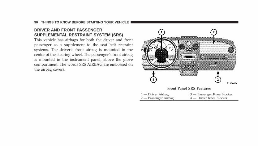
DRIVER AND FRONT PASSENGERSUPPLEMENTAL RESTRAINT SYSTEM (SRS)This vehicle has airbags for both the driver and frontpassenger as a supplement to the seat belt restraintsystems. The driver’s front airbag is mounted in thecenter of the steering wheel. The passenger’s front airbagis mounted in the instrument panel, above the glovecompartment. The words SRS AIRBAG are embossed onthe airbag covers.
Front Panel SRS Features
1 — Driver Airbag 3 — Passenger Knee Blocker2 — Passenger Airbag 4 — Driver Knee Blocker
90 THINGS TO KNOW BEFORE STARTING YOUR VEHICLE
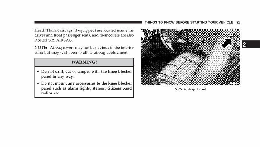
Head/Thorax airbags (if equipped) are located inside thedriver and front passenger seats, and their covers are alsolabeled SRS AIRBAG.
NOTE: Airbag covers may not be obvious in the interiortrim; but they will open to allow airbag deployment.
WARNING!
• Do not drill, cut or tamper with the knee blockerpanel in any way.
• Do not mount any accessories to the knee blockerpanel such as alarm lights, stereos, citizens bandradios etc.
SRS Airbag Label
THINGS TO KNOW BEFORE STARTING YOUR VEHICLE 91
2
WARNING!
• Do not put anything on or around the airbagcovers or attempt to manually open them. You maydamage the airbags and you could be injuredbecause the airbags are not there to protect you.These protective covers for the airbag cushions aredesigned to open only when the airbags are inflat-ing.
• If your vehicle is equipped with Head/Thoraxairbags, do not use accessory seat covers or placeobjects between you and the side airbags; theperformance could be adversely affected and/orobjects could be pushed into you, causing seriousinjury.
Airbags inflate in moderate to high speed impacts. Alongwith seat belts and pretensioners, front airbags work withknee impact blocker panels to provide improved protec-tion for the driver and front passenger.
The seat belts are designed to protect you in many typesof collisions. The front airbags deploy in moderate tosevere frontal collisions. If your vehicle is equipped, theHead/Thorax airbag on the crash side of the vehicle istriggered in moderate to severe side collisions. In certaintypes of collisions, both the front seat and Head/Thoraxairbags may be triggered. But even in collisions wherethe airbags work, you need the seat belts to keep you inthe right position for the airbags to protect you properly.
NOTE: The passenger front airbag may not deploy evenwhen the driver front airbag has if the Occupant Classi-fication System (refer to �Occupant Classification System�in this section) has determined the passenger seat is
92 THINGS TO KNOW BEFORE STARTING YOUR VEHICLE
empty or is occupied by someone that is classified in the“child” category. This could be a child, a teenager, oreven a small adult.
Here are some simple steps you can take to minimize therisk of harm from a deploying airbag.
1. Children 12 years old and under should always ridebuckled up in a rear seat.
Infants in rear facing child restraints should NEVER ridein the front seat of a vehicle with a passenger front airbag.An airbag deployment can cause severe injury or death toinfants in that position.
Children that are not big enough to properly wear thevehicle seat belt (see Section on Child Restraints) shouldbe secured in the rear seat in child restraints or belt-positioning booster seats. Older children who do not usechild restraints or belt-positioning booster seats should
ride properly buckled up in the rear seat. Never allowchildren to slide the shoulder belt behind them or undertheir arm.
You should read the instructions provided with yourchild restraint to make sure that you are using it properly.
2. All occupants should wear their lap and shoulder beltsproperly.
3. The driver and front passenger seats should be movedback as far as practical to allow the front airbags room toinflate.
4. If your vehicle has side airbags, do not lean against thedoor, airbags will inflate forcefully into the space be-tween you and the door.
5. If the airbag system in this vehicle needs to bemodified to accommodate a disabled person, contact theCustomer Center. Phone numbers are provided under �IfYou Need Assistance� in Section 9 of this manual.
THINGS TO KNOW BEFORE STARTING YOUR VEHICLE 93
2
WARNING!
• Relying on the airbags alone could lead to moresevere injuries in a collision. The airbags workwith your seat belt to restrain you properly. Insome collisions the airbags won’t deploy at all.Always wear your seat belts even though you haveairbags.
• Being too close to the steering wheel or instrumentpanel during front airbag deployment could causeserious injury. Airbags need room to inflate. Sitback, comfortably extending your arms to reachthe steering wheel or instrument panel.
• If the vehicle has Head/Thorax airbags, they alsoneed room to inflate. Do not lean against the door.Sit upright in the center of the seat.
The front airbag system consists of the following:• Occupant Restraint Controller
• Side Remote Acceleration Sensors (If Equipped)
• Airbag Warning Light
• Driver Airbag
• Passenger Airbag
• Front Seat Mounted Head/Thorax Airbags (ifequipped)
• Steering Wheel and Column
• Instrument Panel
• Driver and Front Passenger Knee Impact Blockers
• Front Acceleration Sensors
• Driver and Front Passenger Seat Belt Pretensioners
• Passenger Airbag Disable (PAD) Indicator Light
94 THINGS TO KNOW BEFORE STARTING YOUR VEHICLE
The Head/Thorax airbag system (if equipped) consistsof the following:
• AIRBAG Readiness Light (shared with the front airbagsystem)
• Front Seat— side mounted Head/Thorax Airbags — ifequipped
• Airbag Control Module (shared with the front airbagsystem)
• Side impact sensors
How The Airbag System Works
• The Occupant Restraint Controller (ORC) determinesif a frontal collision is severe enough to require theairbags to inflate. The front airbag inflators are de-signed to provide different rates of airbag inflationfrom direction provided by the ORC. The ORC may
also modify the rate of inflation based on the occupantsize provided by the Occupant Classification Module.The ORC will not detect roll over.
The ORC also monitors the readiness of the electronicparts of the system whenever the ignition switch is inthe START or RUN positions. These include all of theitems listed above except the steering wheel andcolumn, and knee impact blockers. If the key is in theOFF position, in the ACC position, or not in theignition, the airbags are not on and will not inflate.
During a moderate-to-severe rear impact the ORC maydeploy the seat belt pretensioners alone.
Also, the ORC turns on the AIRBAG warninglight and PAD indicator light in the instrumentpanel for six to eight seconds for a self-checkwhen the ignition is first turned on. After the
self-check, the AIRBAG warning light will turn off. ThePAD indicator light will function normally (Refer to
THINGS TO KNOW BEFORE STARTING YOUR VEHICLE 95
2
�Passenger Airbag Disable (PAD) Indicator Light� in thissection). If the ORC detects a malfunction in any part ofthe system, it turns on the AIRBAG warning light eithermomentarily or continuously. A single chime will soundif the light comes on again after initial start up.
WARNING!
Ignoring the AIRBAG light in your instrument panelcould mean you won’t have the airbags to protect youin a collision. If the light does not come on, stays onafter you start the vehicle, or if it comes on as youdrive, have the airbag system checked right away.
NOTE: Children 12 years and under should always ridebuckled up in a rear seat in an appropriate child restraint.
• When the front airbag control module detects a colli-sion requiring the front airbags, it signals the inflator
units. A large quantity of nontoxic gas is generated toinflate the front airbags. The front airbag covers sepa-rate and fold out of the way as the front airbags inflateto their full size. The front airbags fully inflate in about50 milliseconds. This is only about half of the time ittakes you to blink your eyes. The front airbags thenquickly deflate while helping to restrain the driver andfront passenger. The driver’s and passenger’s frontairbag gas is vented through holes in the sides of theairbag. In this way the front airbags do not interferewith your control of the vehicle.
• The Passenger Airbag Disable (PAD) Indicator Light(an amber light located in the center of the instrumentpanel) tells the driver and front passenger when thefront passenger airbag is turned off. The PAD Indica-tor lamp illuminates the words �PASS AIR BAG OFF�to show that the front passenger airbag will not inflateduring a collision requiring airbags. When the rightfront passenger seat is empty or when very light
96 THINGS TO KNOW BEFORE STARTING YOUR VEHICLE
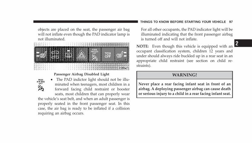
objects are placed on the seat, the passenger air bagwill not inflate even though the PAD indicator lamp isnot illuminated.
• The PAD indictor light should not be illu-minated when teenagers, most children in aforward facing child restraint or boosterseats, most children that can properly wear
the vehicle’s seat belt, and when an adult passenger isproperly seated in the front passenger seat. In thiscase, the air bag is ready to be inflated if a collisionrequiring an airbag occurs.
For all other occupants, the PAD indicator light will beilluminated indicating that the front passenger airbagis turned off and will not inflate.
NOTE: Even though this vehicle is equipped with anoccupant classification system, children 12 years andunder should always ride buckled up in a rear seat in anappropriate child restraint (see section on child re-straints).
WARNING!
Never place a rear facing infant seat in front of anairbag. A deploying passenger airbag can cause deathor serious injury to a child in a rear facing infant seat.
Passenger Airbag Disabled Light
THINGS TO KNOW BEFORE STARTING YOUR VEHICLE 97
2
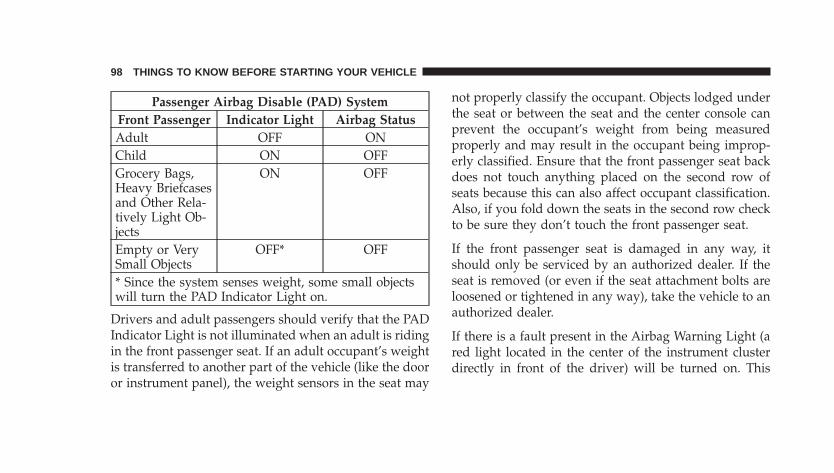
Passenger Airbag Disable (PAD) SystemFront Passenger Indicator Light Airbag StatusAdult OFF ONChild ON OFFGrocery Bags,Heavy Briefcasesand Other Rela-tively Light Ob-jects
ON OFF
Empty or VerySmall Objects
OFF* OFF
* Since the system senses weight, some small objectswill turn the PAD Indicator Light on.
Drivers and adult passengers should verify that the PADIndicator Light is not illuminated when an adult is ridingin the front passenger seat. If an adult occupant’s weightis transferred to another part of the vehicle (like the dooror instrument panel), the weight sensors in the seat may
not properly classify the occupant. Objects lodged underthe seat or between the seat and the center console canprevent the occupant’s weight from being measuredproperly and may result in the occupant being improp-erly classified. Ensure that the front passenger seat backdoes not touch anything placed on the second row ofseats because this can also affect occupant classification.Also, if you fold down the seats in the second row checkto be sure they don’t touch the front passenger seat.
If the front passenger seat is damaged in any way, itshould only be serviced by an authorized dealer. If theseat is removed (or even if the seat attachment bolts areloosened or tightened in any way), take the vehicle to anauthorized dealer.
If there is a fault present in the Airbag Warning Light (ared light located in the center of the instrument clusterdirectly in front of the driver) will be turned on. This
98 THINGS TO KNOW BEFORE STARTING YOUR VEHICLE
indicates that you should take the vehicle to an autho-rized dealer. The Airbag Warning Light is turned onwhenever there is fault that can affect the operation of theairbag system. If there is a fault present in the PADIndicator Light the Airbag Warning Light remains illu-minated to show that the passenger airbag is turned offuntil the fault is cleared. If an object is lodged under theseat and interferes with operation of the weight sensors,a fault will occur which turns on both the PAD IndicatorLight and the Airbag Warning Light. Once the lodgedobject is removed, the fault will be automatically clearedafter a short period of time.
• The Driver and Passenger Airbag/Inflator Units arelocated in the center of the steering wheel and the rightside of the instrument panel. When the ORC detects acollision requiring the airbags, it signals the inflatorunits. A large quantity of nontoxic gas is generated toinflate the front airbags. Different airbag inflation rates
may be possible based on collision severity and occu-pant size. The steering wheel hub trim cover and theupper right side of the instrument panel separate andfold out of the way as the bags inflate to their full size.The bags fully inflate in about 50 - 70 milliseconds.This is about half of the time it takes to blink your eyes.The bags then quickly deflate while helping to restrainthe driver and front passenger. The driver’s and pas-senger’s front airbag gas is vented through holes in thesides of the airbag. In this way the airbags do notinterfere with your control of the vehicle.
• The Occupant Classification Module (OCM) is lo-cated beneath the front passenger seat. The OCMclassifies the occupant into categories based on themeasurements made by the seat weight sensors. TheOCM communicates with the ORC. The ORC uses theoccupant category to determine whether the frontpassenger airbag should be turned off. It also deter-mines the rate of airbag inflation during a collision.
THINGS TO KNOW BEFORE STARTING YOUR VEHICLE 99
2
• Your vehicle has four Weight Sensors located betweenthe seat and the floor pan. The weight sensors measureapplied weight and transfers that information to theOCM.
• The Head/Thorax Airbag and Supplemental Re-straint Systems are designed to activate only in certainside collisions. The ORC module determines if a sidecollision is severe enough to require the Head/Thoraxairbags to inflate. The side airbag control module willnot detect roll over, front or rear collisions.
The ORC Module monitors the readiness of the elec-tronic parts of the system whenever the ignition switchis in the START or ON positions. These include all ofthe items listed under “The Side Airbag System”, onvehicles equipped, consists of the following”.
In moderate to severe side collisions, the side airbaginflator on the crash side of the vehicle is triggered,releasing a quantity of nontoxic gas. The inflating Head/
Thorax Airbags exit through the seat seam into the spacebetween the occupant and the door. The Head/Thoraxairbags moves at a very high speed and with such a highforce, that it could injure you if you are not seatedproperly, or if items are positioned in the area where theside airbag inflates. This especially applies to children.
The following requirements must be strictly adhered to:
• Do not modify the front passenger seat assembly orcomponents in any way.
• Do not modify the front seat center console or centerposition seat in any way.
• Do not use prior or future model year seat covers notdesignated for the specific model being repaired. Al-ways use the correct seat cover specified for thevehicle.
• Do not replace the seat cover with an aftermarket seatcover.
100 THINGS TO KNOW BEFORE STARTING YOUR VEHICLE
• Do not add a secondary seat cover other than thoseapproved by DaimlerChrysler/Mopar.
• At no time should any supplemental restraint system(SRS) component or SRS related component or fas-tener be modified or replaced with any part exceptthose which are approved by DaimlerChrysler/Mopar.
WARNING!
Unapproved modifications or service procedures to thefront passenger seat assembly, its related components,or seat cover may inadvertently change the airbagdeployment in case of a frontal crash. This could resultin death or serious injury to the front seat passenger ifthe vehicle is involved in an accident. A modifiedvehicle may not comply with required Federal MotorVehicle Safety Standards (FMVSS).
If A Deployment OccursThe airbag systems are designed to deploy when theairbag control modules detect a moderate-to-severe col-lision, to help restrain the driver and front passenger, andthen immediately deflate.
NOTE: A collision that is not severe enough to needairbag protection will not activate the system. This doesnot mean something is wrong with the airbag system.
If you do have a collision which deploys the airbags, anyor all of the following may occur:
• The nylon airbag material may sometimes cause abra-sions and/or skin reddening to the driver and frontpassenger as the airbags deploy and unfold. Theabrasions are similar to friction rope burns or thoseyou might get sliding along a carpet or gymnasiumfloor. They are not caused by contact with chemicals.They are not permanent and normally heal quickly.
THINGS TO KNOW BEFORE STARTING YOUR VEHICLE 101
2
However, if you haven’t healed significantly within afew days, or if you have any blistering, see your doctorimmediately.
• As the airbags deflate you may see some smoke-likeparticles. The particles are a normal by-product of theprocess that generates the nontoxic gas used for airbaginflation. These airborne particles may irritate the skin,eyes, nose, or throat. If you have skin or eye irritation,rinse the area with cool water. For nose or throatirritation, move to fresh air. If the irritation continues,see your doctor. If these particles settle on yourclothing, follow the garment manufacturer’s instruc-tions for cleaning.
• It is not advisable to drive your vehicle after theairbags have deployed. If you are involved in anothercollision, the airbags will not be in place to protect you.
WARNING!
Deployed airbags and seat belt pretensioners cannotprotect you in another collision. Have the airbags,seat belt pretensioners, front passenger seat beltretractor assembly, and Occupant Classification Sys-tem replaced and/or serviced by an authorized dealeras soon as possible.
102 THINGS TO KNOW BEFORE STARTING YOUR VEHICLE
Maintaining Your Airbag System
WARNING!
Modifications to any part of the airbag system couldcause it to fail when you need it. You could beinjured if the airbag system is not there to protectyou. Do not modify the components or wiring, in-cluding adding any kind of badges or stickers to thesteering wheel hub trim cover or the upper right sideof the instrument panel. Do not modify the frontbumper, vehicle body structure, or add aftermarketside steps or running boards.
WARNING!
Do not attempt to modify any part of your advancedairbag system. The airbag may inflate accidentally ormay not function properly if modifications are made.Take your vehicle to an authorized dealer for anyadvanced airbag system service. If your seat includ-ing your trim cover and cushion needs to be servicedin any way (including removal or loosening/tightening of seat attachment bolts), take the vehicleto your authorized dealer. Only manufacturer ap-proved seat accessories may be used. If it is necessaryto modify an advanced airbag system for personswith disabilities, contact your authorized dealer.
THINGS TO KNOW BEFORE STARTING YOUR VEHICLE 103
2
WARNING!
• Do not place or hang any items such as add-onvideo players on the right front passenger seatback. The additional weight may cause the Occu-pant Classification System to be unable to cor-rectly classify the right front occupant. This couldallow the passenger frontal airbag to inflate whenit is not desired.
• You need proper knee impact protection in acollision. Do not mount or locate any aftermarketequipment on or behind the knee impact blockerpanels.
• It is dangerous to try to repair any part of theairbag system yourself. Be sure to tell anyone whoworks on your vehicle that it has an airbag system.
NOTE: Perchlorate Material – special handling may ap-ply, See www.dtsc.ca.gov/hazardouswaste/perchlorate.”
Airbag LightYou will want to have the airbags ready to inflate for yourprotection in a collision. While the airbag system isdesigned to be maintenance free, if any of the followingoccurs, have an authorized dealer service the systemimmediately.
• The AIRBAG light does not come on during the six toeight seconds when the ignition switch is first turnedon.
• The light remains on after the six to eight secondinterval.
• The light comes on and remains on while driving.
104 THINGS TO KNOW BEFORE STARTING YOUR VEHICLE
Event Data Recorder (EDR)In the event of an accident, your vehicle is designed torecord up to five seconds of specific vehicle data param-eters (see list below) in an event data recorder prior to themoment of airbag deployment, or near-deployment, andup to a quarter second of high-speed deceleration dataduring and/or after air bag deployment or near-deployment. EDR data are ONLY recorded if an airbagdeploys, or nearly deploys, and are otherwise unavail-able.
NOTE:1. A near-deployment event occurs when the airbagsensor detects severe vehicle deceleration usually indica-tive of a crash, but not severe enough to warrant airbagdeployment.
2. Under certain circumstances, EDR data may not berecorded (e.g., loss of battery power).
In conjunction with other data gathered during a com-plete accident investigation, the electronic data may beused by DaimlerChrysler and others to learn more aboutthe possible causes of crashes and associated injuries inorder to assess and improve vehicle performance. Inaddition to crash investigations initiated byDaimlerChrysler, such investigations may be requestedby customers, insurance carriers, government officials,and professional crash researchers, such as those associ-ated with universities, and with hospital and insuranceorganizations.
In the event that an investigation is undertaken byDaimlerChrysler (regardless of initiative), the companyor its designated representative will first obtain permis-sion of the appropriate custodial entity for the vehicle(usually the vehicle owner or lessee) before accessing theelectronic data stored, unless ordered to download databy a court with legal jurisdiction (i.e., pursuant to awarrant). A copy of the data will be provided to the
THINGS TO KNOW BEFORE STARTING YOUR VEHICLE 105
2

custodial entity upon request. General data that does notidentify particular vehicles or crashes may be released forincorporation in aggregate crash databases, such as thosemaintained by the US government and various states.Data of a potentially sensitive nature, such as wouldidentify a particular driver, vehicle, or crash, will betreated confidentially. Confidential data will not be dis-closed by DaimlerChrysler to any third party exceptwhen:
1. Used for research purposes, such as to match datawith a particular crash record in an aggregate database,provided confidentiality of personal data is thereafterpreserved
2. Used in defense of litigation involving aDaimlerChrysler product
3. Requested by police under a legal warrant
4. Otherwise required by law
Data Parameters that May Be Recorded:
• Diagnostic trouble code(s) and warning lamp statusfor electronically-controlled safety systems, includingthe airbag system
• Airbag disable lamp status (if equipped)
• �Time� of airbag deployment (in terms of ignitioncycles and vehicle mileage)
• Airbag deployment level (if applicable)
• Impact acceleration and angle
• Seatbelt status
• Brake status (service and parking brakes)
• Accelerator status (including vehicle speed)
• Engine control status (including engine speed)
• Transmission gear selection
106 THINGS TO KNOW BEFORE STARTING YOUR VEHICLE
• Cruise control status
• Traction/stability control status
• Tire pressure monitoring system status
CHILD RESTRAINTEveryone in your vehicle needs to be buckled up at alltimes — babies and children, too. Every state in theUnited States and all Canadian provinces require thatsmall children ride in proper restraint systems. This is thelaw, and you can be prosecuted for ignoring it.
Children 12 years and under should ride properly buck-led up in a rear seat, if available. According to crashstatistics, children are safer when properly restrained inthe rear seats, rather than in the front.
WARNING!
In a collision, an unrestrained child, even a tiny baby,can become a missile inside the vehicle. The forcerequired to hold even an infant on your lap couldbecome so great that you could not hold the child, nomatter how strong you are. The child and otherscould be badly injured. Any child riding in yourvehicle should be in a proper restraint for the child’ssize.
Infants And Small ChildrenThere are different sizes and types of restraints forchildren from newborn size to the child almost largeenough for an adult safety belt. Always check the childseat owner’s manual to ensure you have the correct seatfor your child. Use the restraint that is correct for yourchild:
THINGS TO KNOW BEFORE STARTING YOUR VEHICLE 107
2
• Safety experts recommend that children riderearward-facing in the vehicle until they are at leastone year old and weigh at least 20 lbs (9 kg). Two typesof child restraints can be used rearward-facing: infantcarriers and �convertible� child seats. Both types ofchild restraints are held in the vehicle by the lap/shoulder belt or the LATCH child restraint anchoragesystem.
• This vehicle is not capable of accommodating theinstallation of a car bed used for carrying newbornbabies at the right front passenger seat position. If a carbed must be used to transport a newborn baby, the carbed must be installed in the second seating row only.
• The infant carrier is only used rearward-facing in thevehicle. It is recommended for children who weigh upto about 20 lbs (9 kg). �Convertible� child seats can beused either rearward-facing or forward-facing in thevehicle. Convertible child seats often have a higher
weight limit in the rearward-facing direction thaninfant carriers do, so they can be used rearward-facingby children who weigh more than 9 kg (20 lbs) but areless than one year old.
• Rearward-facing child seats must NEVER be used inthe front seat of a vehicle with a front passengerairbag. An airbag deployment could cause severeinjury or death to infants in this position.
• Children who weigh more than 20 lbs (9 kg) and whoare older than one year can ride forward-facing in thevehicle. Forward-facing child seats and convertiblechild seats used in the forward-facing direction are forchildren who weigh 20 to 40 lbs (9 to 18 kg) and whoare older than one year. These child seats are also heldin the vehicle by the lap/shoulder belt or the LATCHchild restraint anchorage system.
108 THINGS TO KNOW BEFORE STARTING YOUR VEHICLE
• The belt-positioning booster seat is for children weigh-ing more than 40 lbs (18 kg), but who are still too smallto fit the vehicle’s seat belts properly. If the childcannot sit with knees bent over the vehicle’s cushionwhile the child’s back is against the seat back; theyshould use a Belt Positioning Booster Seat. The childand booster seat are held in the vehicle by the lap/shoulder belt. (Some booster seats are equipped with afront shield and are held in the vehicle by the lapportion.)
NOTE: For additional information refer towww.nhtsa.gov or www.seatcheck.org.
WARNING!
• Improper installation can lead to failure of aninfant or child restraint. It could come loose in acollision. The child could be badly injured orkilled. Follow the manufacturer’s directions ex-actly when installing an infant or child restraint.
• A rearward facing child restraint should only beused in a rear seat. A rearward facing child re-straint in the front seat may be struck by a deploy-ing passenger airbag which may cause severe orfatal injury to the infant.
Here are some tips on getting the most out of your childrestraint:
• Before buying any restraint system, make sure that ithas a label certifying that it meets all applicable Safety
THINGS TO KNOW BEFORE STARTING YOUR VEHICLE 109
2
Standards. We also recommend that you make surethat you can install the child restraint in the vehiclewhere you will use it, before you buy it.
• The restraint must be appropriate for your child’sweight and height. Check the label on the restraint forweight and height limits.
• Carefully follow the instructions that come with therestraint. If you install the restraint improperly, it maynot work when you need it.
The passenger seat belts are equipped with seat beltretractors that can be switched to an automatic lockingmode, which are designed to keep the lap portion tightaround the child restraint so that it is not necessary touse a locking clip.
Pull the belt from the retractor until there is enough toallow you to pass through the child restraint and slide thelatch plate into the buckle. Then pull on the belt until it is
all removed from the retractor. Allow the belt to returninto the retractor, as the belt retracts, you will hear aclicking sound. This indicates that the seat belt is now inthe automatic locking mode. Pull on the excess webbingto tighten the lap portion about the child restraint. Followthe instructions of the child restraint manufacture.
NOTE: To reset this feature you must let all of the beltwebbing return into the retractor. You will not be able topull out more webbing until all of the webbing has beenreturned back into the retractor.
• In the rear seat, you may have trouble tightening thelap/shoulder belt on the child restraint because thebuckle or latch plate is too close to the belt pathopening on the restraint. Disconnect the latch platefrom the buckle and twist the short buckle end of thebelt several times to shorten it. Insert the latch plateinto the buckle with the release button facing out.
110 THINGS TO KNOW BEFORE STARTING YOUR VEHICLE
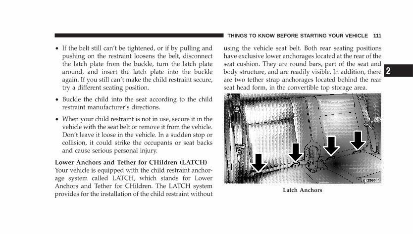
• If the belt still can’t be tightened, or if by pulling andpushing on the restraint loosens the belt, disconnectthe latch plate from the buckle, turn the latch platearound, and insert the latch plate into the buckleagain. If you still can’t make the child restraint secure,try a different seating position.
• Buckle the child into the seat according to the childrestraint manufacturer’s directions.
• When your child restraint is not in use, secure it in thevehicle with the seat belt or remove it from the vehicle.Don’t leave it loose in the vehicle. In a sudden stop orcollision, it could strike the occupants or seat backsand cause serious personal injury.
Lower Anchors and Tether for CHildren (LATCH)Your vehicle is equipped with the child restraint anchor-age system called LATCH, which stands for LowerAnchors and Tether for CHildren. The LATCH systemprovides for the installation of the child restraint without
using the vehicle seat belt. Both rear seating positionshave exclusive lower anchorages located at the rear of theseat cushion. They are round bars, part of the seat andbody structure, and are readily visible. In addition, thereare two tether strap anchorages located behind the rearseat head form, in the convertible top storage area.
Latch Anchors
THINGS TO KNOW BEFORE STARTING YOUR VEHICLE 111
2

Child restraints systems having attachments designed toconnect to the lower anchorages are now available. Childrestraints having tether straps and hooks for connectionto the top tether anchorage have been available for sometime. In fact, many child restraint manufacturers willprovide add-on tether strap kits for some of their olderproducts. Tether anchorage kits are also available formost older vehicles.
Because the lower anchorages are to be introduced topassenger carrying vehicles over a period of years, childrestraint systems having attachments for those anchor-ages will continue to have features for installation invehicles using the lap or lap/shoulder belt. They will alsohave tether straps, and you are urged to take advantageof all of the available attachments provided with yourchild restraint in any vehicle.
NOTE: When using the LATCH attaching system toinstall a child restraint, please ensure that all seat belts
not being used for occupant restraints are stowed and outof reach of children. It is recommended that beforeinstalling the child restraint, buckle the seat belt so theseat belt is tucked behind the child restraint and out ofreach. If the buckled seat belt interferes with the childrestraint installation, instead of tucking the seat beltbehind the child restraint, route the seat belt through thechild restraint belt path and then buckle it. This shouldstow the seat belt out of the reach of an inquisitive child.Remind all children in the vehicle that the seat belts arenot toys and should not be played with, and never leaveyour child unattended in the vehicle.
Installing the Child Restraint SystemWe urge that you carefully follow the directions of themanufacturer when installing your child restraint. Many,but not all, restraint systems will be equipped withseparate straps on each side, with each having a hook orconnector and a means for adjusting the tension in thestrap. Forward-facing toddler restraints and some
112 THINGS TO KNOW BEFORE STARTING YOUR VEHICLE
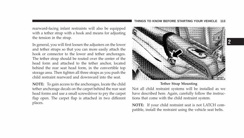
rearward-facing infant restraints will also be equippedwith a tether strap with a hook and means for adjustingthe tension in the strap.
In general, you will first loosen the adjusters on the lowerand tether straps so that you can more easily attach thehook or connector to the lower and tether anchorages.The tether strap should be routed over the center of thehead form and attached to the tether anchor, locatedbehind the rear seat head form, in the convertible topstorage area. Then tighten all three straps as you push thechild restraint rearward and downward into the seat.
NOTE: To gain access to the anchorages, locate the childtether anchorage decals on the carpet behind the rear seathead forms and use a small screwdriver to pry the carpetflap open. The carpet flap is attached in two differentplaces.
Not all child restraint systems will be installed as wehave described here. Again, carefully follow the instruc-tions that come with the child restraint system.
NOTE: If your child restraint seat is not LATCH com-patible, install the restraint using the vehicle seat belts.
Tether Strap Mounting
THINGS TO KNOW BEFORE STARTING YOUR VEHICLE 113
2

WARNING!
An incorrectly anchored tether strap could lead toincreased head motion and possible injury to thechild. Use only the anchor position directly behindthe child seat to secure a child restraint top tetherstrap.
Children Too Large For Booster SeatsChildren who are large enough to wear the shoulder beltcomfortably, and whose legs are long enough to bendover the front of the seat when their back is against theseat back, should use the lap/shoulder belt in a rear seat.
• Make sure that the child is upright in the seat.
• The lap portion should be low on the hips and as snugas possible.
• Check belt fit periodically. A child’s squirming orslouching can move the belt out of position.
• If the shoulder belt contacts the face or neck, move thechild closer to the center of the vehicle. Never allow achild to put the shoulder belt under an arm or behindtheir back.
Transporting PetsAirbags deploying in the front seat could harm your pet.An unrestrained pet will be thrown about and possiblyinjured, or injure a passenger during panic braking or ina collision.
Pets should be restrained in the rear seat in pet harnessesor pet carriers that are secured by seat belts.
114 THINGS TO KNOW BEFORE STARTING YOUR VEHICLE
ENGINE BREAK-IN RECOMMENDATIONSA long break-in period is not required for the engine inyour vehicle.
Drive moderately during the first 300 mi (500 km). Afterthe initial 60 mi (100 km), speeds up to 50 or 55 mph (80or 90 km/h) are desirable.
While cruising, brief full-throttle acceleration, within thelimits of local traffic laws, contributes to a good break-in.Wide-open throttle acceleration in low gear can be detri-mental and should be avoided.
The engine oil installed in the engine at the factory is ahigh-quality energy-conserving type lubricant. Oilchanges should be consistent with anticipated climateconditions under which vehicle operations will occur. Forthe recommended viscosity and quality grades, refer to“Maintenance Procedures” in Section 7 of this manual.NON-DETERGENT OR STRAIGHT MINERAL OILSMUST NEVER BE USED.
A new engine may consume some oil during its first fewthousand miles (kilometers) of operation. This should beconsidered as a normal part of the break-in and notinterpreted as an indication of difficulty.
SAFETY TIPS
Exhaust Gas
WARNING!
Exhaust gases can injure or kill. They contain carbonmonoxide (CO) which is colorless and odorless.Breathing it can make you unconscious and caneventually poison you. To avoid breathing (CO)follow the safety tips below.
Do not run the engine in a closed garage or in confinedareas any longer than needed to move your vehicle in orout of the area.
THINGS TO KNOW BEFORE STARTING YOUR VEHICLE 115
2
If it is necessary to sit in a parked vehicle with the enginerunning, adjust your heating or cooling controls to forceoutside air into the vehicle. Set the blower at high speed.
WARNING!
If you are required to drive with the deck lid/liftgateopen, make sure that all windows are closed, and theclimate control blower switch is set at high speed.DO NOT use the recirculation mode.
Safety Checks You Should Make Inside TheVehicle
Seat BeltsInspect the belt system periodically, checking for cuts,frays and loose parts. Damaged parts must be replacedimmediately. Do not disassemble or modify the system.
Front seat belt assemblies must be replaced after acollision. Rear seat belt assemblies must be replaced aftera collision if they have been damaged (bent retractor, tornwebbing, etc. If there is any question regarding belt orretractor condition, replace the belt.
Airbag LightThe light should come on and remain on for 6 to 8seconds as a bulb check when the ignition switch is firstturned ON. If the LED is not lit during starting, have itchecked. If the light stays on or comes on while driving,have the system checked by an authorized dealer.
DefrosterCheck operation by selecting the defrost mode and placethe blower control on high speed. You should be able tofeel the air directed against the windshield.
116 THINGS TO KNOW BEFORE STARTING YOUR VEHICLE
Periodic Safety Checks You Should Make OutsideThe Vehicle
TiresExamine tires for excessive tread wear or uneven wearpatterns. Check for stones, nails, glass, or other objectslodged in the tread. Inspect tread and sidewall for cuts orcracks. Check wheel nuts for tightness, and tires (includ-ing spare) for proper pressure.
LightsHave someone observe the operation of exterior lightswhile you work the controls. Check turn signal and highbeam indicator lights on the instrument panel.
Fluid LeaksCheck area under vehicle after overnight parking for fuel,engine coolant, oil or other fluid leaks. Also, if gasolinefumes are detected or fuel, power steering fluid or brakefluid leaks are suspected, the cause should be located andcorrected immediately.
THINGS TO KNOW BEFORE STARTING YOUR VEHICLE 117
2

UNDERSTANDING THE FEATURES OF YOUR VEHICLE
CONTENTS
� Convertible Top Operation . . . . . . . . . . . . . . . . 123
▫ To Lower The Top . . . . . . . . . . . . . . . . . . . . . 123
▫ To Raise The Top . . . . . . . . . . . . . . . . . . . . . 126
▫ Convertible Top Boot Cover Installation–IfEquipped . . . . . . . . . . . . . . . . . . . . . . . . . . . 128
▫ Convertible Top Boot Cover Removal AndStorage . . . . . . . . . . . . . . . . . . . . . . . . . . . . 132
▫ Convertible Top Manual Override . . . . . . . . . 134
� Mirrors . . . . . . . . . . . . . . . . . . . . . . . . . . . . . . 135
▫ Inside Day/Night Mirror — If Equipped . . . . . 135
▫ Outside Mirror—Driver’s Side . . . . . . . . . . . . 136
▫ Outside Mirror—Passenger’s Side . . . . . . . . . . 136
▫ Electric Remote-Control Mirrors —If Equipped . . . . . . . . . . . . . . . . . . . . . . . . . 137
▫ Illuminated Vanity Mirrors — If Equipped . . . 138
▫ Sun Visor Sliding Feature . . . . . . . . . . . . . . . 138
� Hands–Free Communication (UConnect™) — IfEquipped . . . . . . . . . . . . . . . . . . . . . . . . . . . . 138
▫ Operations . . . . . . . . . . . . . . . . . . . . . . . . . . 140
▫ Phone Call Features . . . . . . . . . . . . . . . . . . . 147
3
▫ UConnect™ System Features . . . . . . . . . . . . . 149
▫ Advanced Phone Connectivity . . . . . . . . . . . . 154
▫ Things You Should Know About YourUConnect™ System . . . . . . . . . . . . . . . . . . . . 155
▫ General Information . . . . . . . . . . . . . . . . . . . 163
� Seats . . . . . . . . . . . . . . . . . . . . . . . . . . . . . . . . 164▫ Front Seat Adjustment . . . . . . . . . . . . . . . . . . 164
▫ Power Seat Adjuster — If Equipped . . . . . . . . 165
▫ Manual Lumbar — If Equipped . . . . . . . . . . . 166
▫ Folding Front Passenger Seat — If Equipped . . 167
▫ Driver’s Seat Back Tilt — If Equipped . . . . . . . 167
▫ Passenger Seat Back Tilt (Easy Entry System) —Convertible . . . . . . . . . . . . . . . . . . . . . . . . . 168
▫ Adjustable Head Restraints . . . . . . . . . . . . . . 169
▫ Heated Seats — If Equipped . . . . . . . . . . . . . 169
▫ Folding Rear Seat (Sedan) . . . . . . . . . . . . . . . 171
▫ Folding Rear Seat (Convertible) . . . . . . . . . . . 173
▫ Tumbling Rear Seat (Sedan) . . . . . . . . . . . . . . 175
▫ Tumbling Rear Seat (Convertible) . . . . . . . . . . 177
▫ Rear Seat Removal (Sedan) . . . . . . . . . . . . . . 181
� To Open And Close The Hood . . . . . . . . . . . . . 183
� Lights . . . . . . . . . . . . . . . . . . . . . . . . . . . . . . . 184
▫ Map/Reading Lights (Sedan) . . . . . . . . . . . . . 184
▫ Map/Reading Lights (Convertible) . . . . . . . . . 185
▫ Multi-Function Control Lever . . . . . . . . . . . . . 186
▫ Headlights, Parking Lights, Instrument PanelLights . . . . . . . . . . . . . . . . . . . . . . . . . . . . . 186
▫ Daytime Running Lights (DRL) —If Equipped . . . . . . . . . . . . . . . . . . . . . . . . . 187
120 UNDERSTANDING THE FEATURES OF YOUR VEHICLE
▫ Lights-On Reminder . . . . . . . . . . . . . . . . . . . 187
▫ Fog Lights — If Equipped . . . . . . . . . . . . . . . 188
▫ Turn Signals . . . . . . . . . . . . . . . . . . . . . . . . . 188
▫ Highbeam/Lowbeam Select Switch . . . . . . . . . 189
▫ Passing Light . . . . . . . . . . . . . . . . . . . . . . . . 190
� Windshield Wipers And Washers . . . . . . . . . . . 190
▫ Windshield Washers . . . . . . . . . . . . . . . . . . . 191
▫ Mist Feature . . . . . . . . . . . . . . . . . . . . . . . . . 191
▫ Windshield Wiper Operation . . . . . . . . . . . . . 192
▫ Intermittent Wiper System . . . . . . . . . . . . . . . 192
� Tilt Steering Column . . . . . . . . . . . . . . . . . . . . 193
� Electronic Speed Control — If Equipped . . . . . . 194
▫ To Activate . . . . . . . . . . . . . . . . . . . . . . . . . . 194
▫ To Set At A Desired Speed . . . . . . . . . . . . . . . 195
▫ To Deactivate . . . . . . . . . . . . . . . . . . . . . . . . 195
▫ To Resume Speed . . . . . . . . . . . . . . . . . . . . . 195
▫ To Vary The Speed Setting . . . . . . . . . . . . . . . 195
▫ Manual Transaxle . . . . . . . . . . . . . . . . . . . . . 196
▫ To Accelerate For Passing . . . . . . . . . . . . . . . 196
� Garage Door Opener — If Equipped . . . . . . . . . 197
▫ Programming HomeLink� . . . . . . . . . . . . . . . 198
▫ Gate Operator/Canadian Programming . . . . . 201
▫ Using HomeLink� . . . . . . . . . . . . . . . . . . . . . 202
▫ Reprogramming A Single HomeLink�Button . . . . . . . . . . . . . . . . . . . . . . . . . . . . . 202
▫ Security . . . . . . . . . . . . . . . . . . . . . . . . . . . . 202
UNDERSTANDING THE FEATURES OF YOUR VEHICLE 121
3
▫ Troubleshooting Tips . . . . . . . . . . . . . . . . . . . 203
▫ General Information . . . . . . . . . . . . . . . . . . . 203
� Power Sunroof (Sedan Only) — If Equipped . . . . 204
▫ Express Open Feature . . . . . . . . . . . . . . . . . . 204
▫ Wind Buffeting . . . . . . . . . . . . . . . . . . . . . . . 205
▫ Sunroof Maintenance . . . . . . . . . . . . . . . . . . . 206
� Electrical Power Outlets . . . . . . . . . . . . . . . . . . 206
▫ Electrical Outlet Use With Engine Off . . . . . . . 208
� Console Features . . . . . . . . . . . . . . . . . . . . . . . 208
� Storage . . . . . . . . . . . . . . . . . . . . . . . . . . . . . . 209
▫ Center Console/Armrest Storage Bin . . . . . . . 209
▫ Storage Pockets . . . . . . . . . . . . . . . . . . . . . . . 210
� Rear Shelf Panel— If Equipped . . . . . . . . . . . . . 210
▫ Position 1 (Top) . . . . . . . . . . . . . . . . . . . . . . 211
▫ Position 2 (Middle) . . . . . . . . . . . . . . . . . . . . 212
▫ Position 3 (Floor) . . . . . . . . . . . . . . . . . . . . . 212
▫ Position 4 (Vertical) . . . . . . . . . . . . . . . . . . . . 212
▫ Position 5 (Table) . . . . . . . . . . . . . . . . . . . . . 213
� Roof Luggage Rack — If Equipped . . . . . . . . . . 215
� Rear Window Features . . . . . . . . . . . . . . . . . . . 217
▫ Electric Rear Window Defroster . . . . . . . . . . . 217
▫ Rear Wiper/Washer Switch (Sedan ModelsOnly) — If Equipped . . . . . . . . . . . . . . . . . . . 217
▫ Adding Washer Fluid . . . . . . . . . . . . . . . . . . 218
122 UNDERSTANDING THE FEATURES OF YOUR VEHICLE
CONVERTIBLE TOP OPERATION
WARNING!
The convertible top does not provide the structuralprotection that a reinforced metal roof does, and thefabric top cannot be expected to prevent the ejectionof the occupants of a vehicle in a collision. Thereforeit is important that all occupants wear their seat beltsat all times when riding in a convertible. Studieshave shown that it is generally safer to remain insidea vehicle during a collision, than to be ejected fromthe vehicle.
To Lower The Top:
NOTE: Thoroughly dry the convertible top and topstorage area, prior to leaving the top lowered for anextended period of time. This will help prevent possiblemildew build-up.
CAUTION!
To avoid damage to the convertible top or its compo-nents, your vehicle is equipped with a feature thatprevents convertible top operation at speeds over 10mph (16 km/h).
UNDERSTANDING THE FEATURES OF YOUR VEHICLE 123
3
CAUTION!
To fully insure that no damage occurs, be sure thatthe vehicle is at a complete stop with the gear selectorin the Park position (automatic transaxle) or in theNeutral position (manual transaxle) before loweringor raising the top.
CAUTION!
Do not operate the convertible top with ice or snowbuild-up on the top. Damage to the top may occur.
CAUTION!
To avoid damage to either the top or the rear window,check the top storage area at the rear of the vehicleinterior to be sure that it is clear of debris or otheritems. Be sure that child seat flip up bars are lowered.Do not use the top storage area for other storagepurposes.
NOTE: When closing the convertible top all windowswill drop slightly from the full up position.
1. Turn the ignition key to the ON position.
2. Release the top from the windshield header by pullingdown on the latch handle and turning the latch handleclockwise until it stops.
124 UNDERSTANDING THE FEATURES OF YOUR VEHICLE
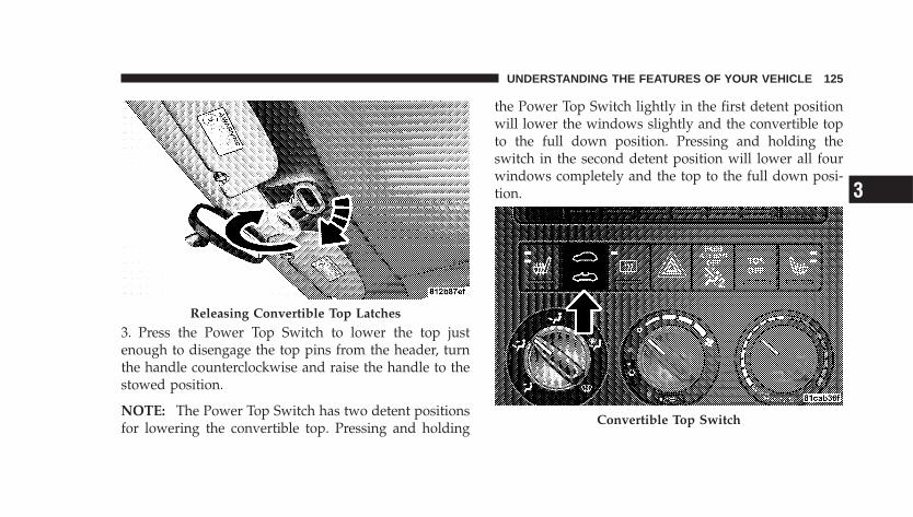
3. Press the Power Top Switch to lower the top justenough to disengage the top pins from the header, turnthe handle counterclockwise and raise the handle to thestowed position.
NOTE: The Power Top Switch has two detent positionsfor lowering the convertible top. Pressing and holding
the Power Top Switch lightly in the first detent positionwill lower the windows slightly and the convertible topto the full down position. Pressing and holding theswitch in the second detent position will lower all fourwindows completely and the top to the full down posi-tion.
Releasing Convertible Top Latches
Convertible Top Switch
UNDERSTANDING THE FEATURES OF YOUR VEHICLE 125
3
4. Continue pressing the Power Top Switch until theconvertible top is lowered completely.
5. Install the Convertible Top Boot Cover, if equipped.Refer to Convertible Top Boot Cover Installation–IfEquipped, in this section.
CAUTION!
Damage to the convertible top boot cover could resultif the latch handle is not completely closed when thetop is lowered. The convertible top boot cover cannotbe installed while the latch handle is open.
To Raise The Top:
CAUTION!
To avoid damage to the convertible top or its compo-nents, your vehicle is equipped with a feature thatprevents convertible top operation at speeds over 10mph (16 km/h).
CAUTION!
To fully insure that no damage occurs, be sure thatthe vehicle is at a complete stop with the gear selectorin the Park position (automatic transaxle) or in theNeutral position (manual transaxle) before loweringor raising the top.
126 UNDERSTANDING THE FEATURES OF YOUR VEHICLE
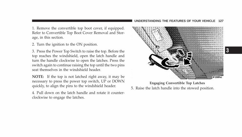
1. Remove the convertible top boot cover, if equipped.Refer to Convertible Top Boot Cover Removal and Stor-age, in this section.
2. Turn the ignition to the ON position.
3. Press the Power Top Switch to raise the top. Before thetop reaches the windshield, open the latch handle andturn the handle clockwise to open the latches. Press theswitch again to continue raising the top until the two pinsseat themselves in the windshield header.
NOTE: If the top is not latched right away, it may benecessary to press the power top switch, UP or DOWNquickly, to align the pins to the windshield header.
4. Pull down on the latch handle and rotate it counter-clockwise to engage the latches.
5. Raise the latch handle into the stowed position.Engaging Convertible Top Latches
UNDERSTANDING THE FEATURES OF YOUR VEHICLE 127
3
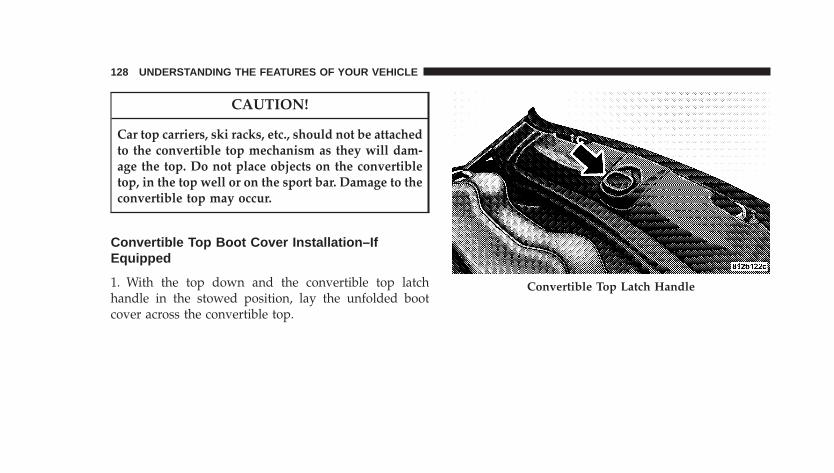
CAUTION!
Car top carriers, ski racks, etc., should not be attachedto the convertible top mechanism as they will dam-age the top. Do not place objects on the convertibletop, in the top well or on the sport bar. Damage to theconvertible top may occur.
Convertible Top Boot Cover Installation–IfEquipped
1. With the top down and the convertible top latchhandle in the stowed position, lay the unfolded bootcover across the convertible top.
Convertible Top Latch Handle
128 UNDERSTANDING THE FEATURES OF YOUR VEHICLE
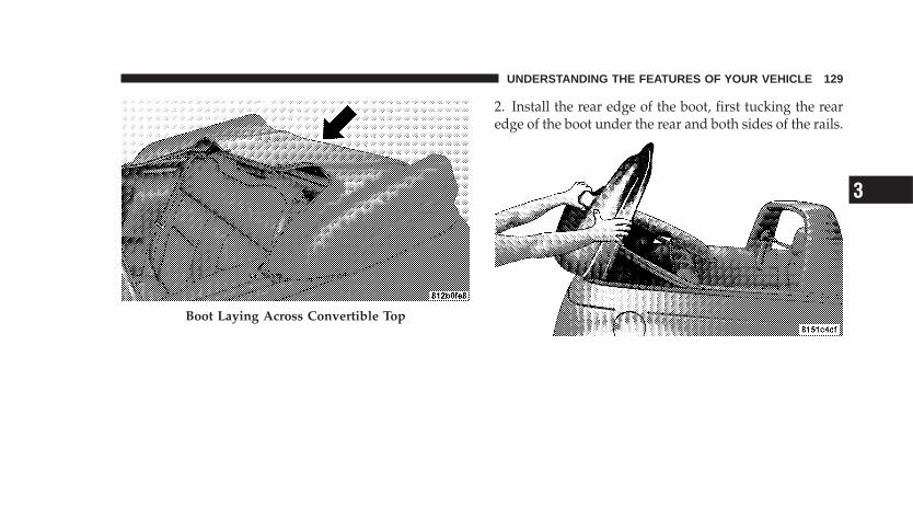
2. Install the rear edge of the boot, first tucking the rearedge of the boot under the rear and both sides of the rails.
Boot Laying Across Convertible Top
UNDERSTANDING THE FEATURES OF YOUR VEHICLE 129
3
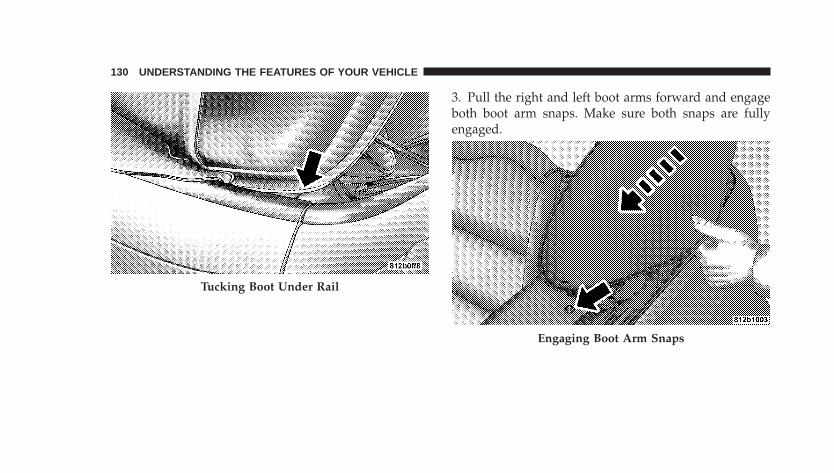
3. Pull the right and left boot arms forward and engageboth boot arm snaps. Make sure both snaps are fullyengaged.
Tucking Boot Under Rail
Engaging Boot Arm Snaps
130 UNDERSTANDING THE FEATURES OF YOUR VEHICLE
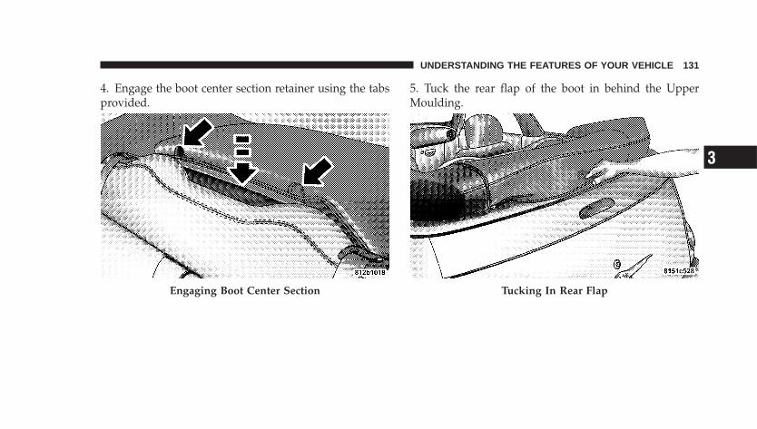
4. Engage the boot center section retainer using the tabsprovided.
5. Tuck the rear flap of the boot in behind the UpperMoulding.
Engaging Boot Center Section Tucking In Rear Flap
UNDERSTANDING THE FEATURES OF YOUR VEHICLE 131
3
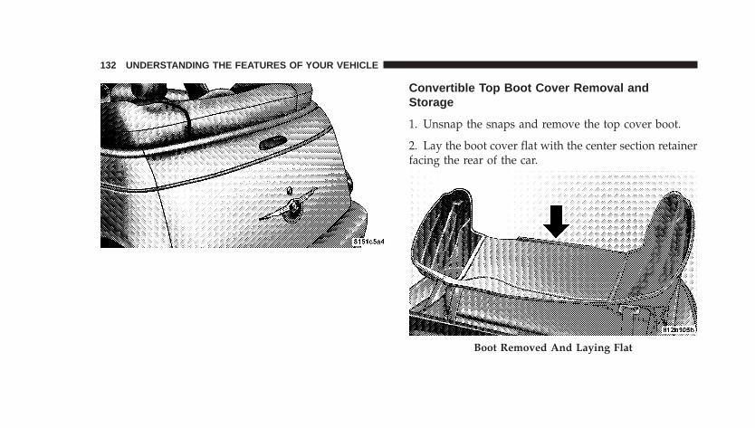
Convertible Top Boot Cover Removal andStorage
1. Unsnap the snaps and remove the top cover boot.
2. Lay the boot cover flat with the center section retainerfacing the rear of the car.
Boot Removed And Laying Flat
132 UNDERSTANDING THE FEATURES OF YOUR VEHICLE
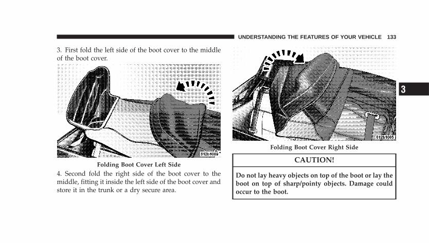
3. First fold the left side of the boot cover to the middleof the boot cover.
4. Second fold the right side of the boot cover to themiddle, fitting it inside the left side of the boot cover andstore it in the trunk or a dry secure area.
CAUTION!
Do not lay heavy objects on top of the boot or lay theboot on top of sharp/pointy objects. Damage couldoccur to the boot.
Folding Boot Cover Left Side
Folding Boot Cover Right Side
UNDERSTANDING THE FEATURES OF YOUR VEHICLE 133
3
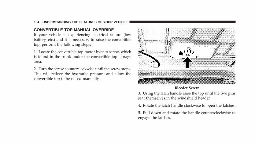
CONVERTIBLE TOP MANUAL OVERRIDEIf your vehicle is experiencing electrical failure (lowbattery, etc.) and it is necessary to raise the convertibletop, perform the following steps:
1. Locate the convertible top motor bypass screw, whichis found in the trunk under the convertible top storagearea.
2. Turn the screw counterclockwise until the screw stops.This will relieve the hydraulic pressure and allow theconvertible top to be raised manually.
3. Using the latch handle raise the top until the two pinsseat themselves in the windshield header.
4. Rotate the latch handle clockwise to open the latches.
5. Pull down and rotate the handle counterclockwise toengage the latches.
Bleeder Screw
134 UNDERSTANDING THE FEATURES OF YOUR VEHICLE
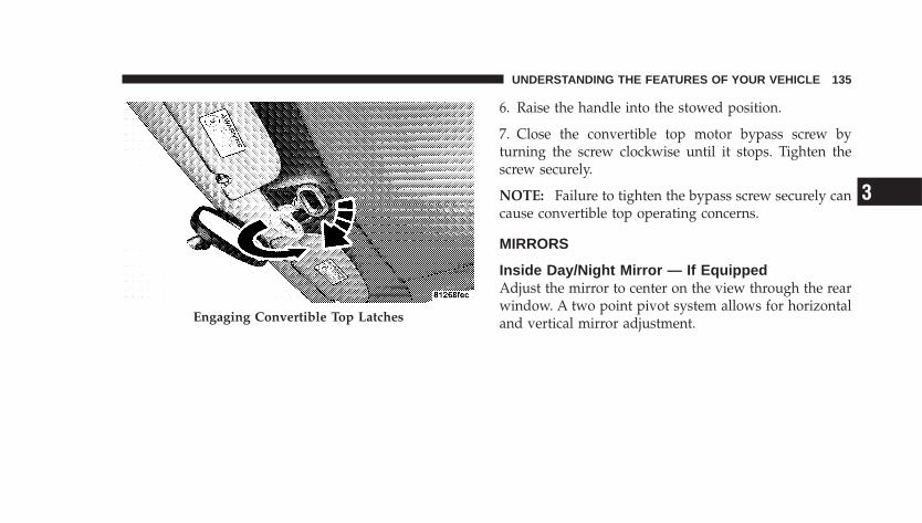
6. Raise the handle into the stowed position.
7. Close the convertible top motor bypass screw byturning the screw clockwise until it stops. Tighten thescrew securely.
NOTE: Failure to tighten the bypass screw securely cancause convertible top operating concerns.
MIRRORS
Inside Day/Night Mirror — If EquippedAdjust the mirror to center on the view through the rearwindow. A two point pivot system allows for horizontaland vertical mirror adjustment.Engaging Convertible Top Latches
UNDERSTANDING THE FEATURES OF YOUR VEHICLE 135
3
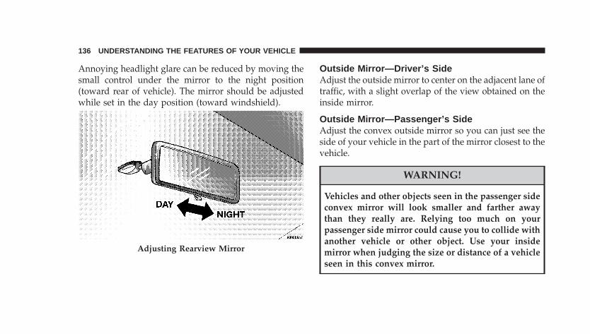
Annoying headlight glare can be reduced by moving thesmall control under the mirror to the night position(toward rear of vehicle). The mirror should be adjustedwhile set in the day position (toward windshield).
Outside Mirror—Driver’s SideAdjust the outside mirror to center on the adjacent lane oftraffic, with a slight overlap of the view obtained on theinside mirror.
Outside Mirror—Passenger’s SideAdjust the convex outside mirror so you can just see theside of your vehicle in the part of the mirror closest to thevehicle.
WARNING!
Vehicles and other objects seen in the passenger sideconvex mirror will look smaller and farther awaythan they really are. Relying too much on yourpassenger side mirror could cause you to collide withanother vehicle or other object. Use your insidemirror when judging the size or distance of a vehicleseen in this convex mirror.
Adjusting Rearview Mirror
136 UNDERSTANDING THE FEATURES OF YOUR VEHICLE
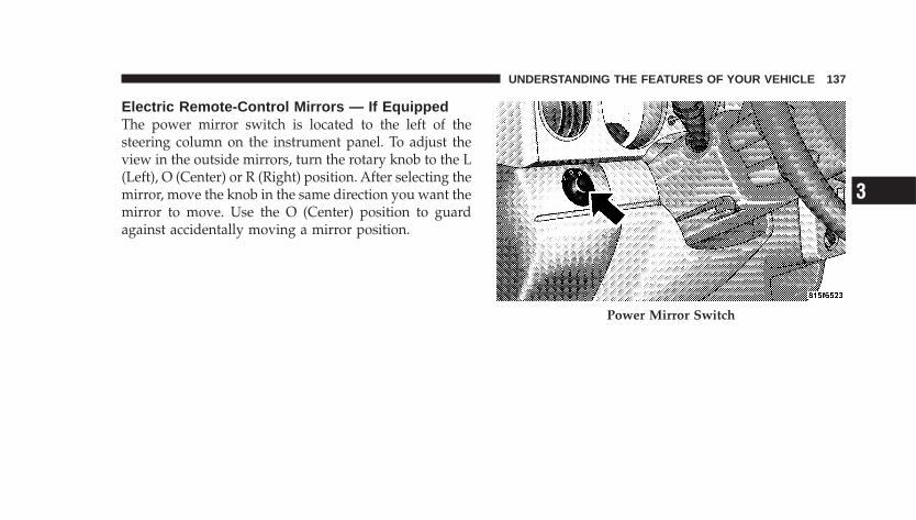
Electric Remote-Control Mirrors — If EquippedThe power mirror switch is located to the left of thesteering column on the instrument panel. To adjust theview in the outside mirrors, turn the rotary knob to the L(Left), O (Center) or R (Right) position. After selecting themirror, move the knob in the same direction you want themirror to move. Use the O (Center) position to guardagainst accidentally moving a mirror position.
Power Mirror Switch
UNDERSTANDING THE FEATURES OF YOUR VEHICLE 137
3
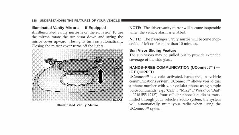
Illuminated Vanity Mirrors — If EquippedAn illuminated vanity mirror is on the sun visor. To usethe mirror, rotate the sun visor down and swing themirror cover upward. The lights turn on automatically.Closing the mirror cover turns off the lights.
NOTE: The driver vanity mirror will become inoperablewhen the vehicle alarm is enabled.
NOTE: The passenger vanity mirror will become inop-erable if left on for more than 10 minutes.
Sun Visor Sliding FeatureThe sun visors may be pulled out to provide extendedcoverage of the side glass.
HANDS–FREE COMMUNICATION (UConnect™) —IF EQUIPPEDUConnect™ is a voice-activated, hands-free, in- vehiclecommunications system. UConnect™ allows you to diala phone number with your cellular phone using simplevoice commands (e.g., �Call” � “Mike” �”Work� or �Dial”� “248-555-1212�). Your cellular phone’s audio is trans-mitted through your vehicle’s audio system; the systemwill automatically mute your radio when using theUConnect™ system.
Illuminated Vanity Mirror
138 UNDERSTANDING THE FEATURES OF YOUR VEHICLE
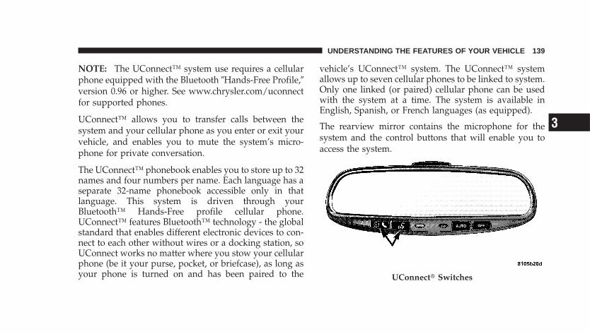
NOTE: The UConnect™ system use requires a cellularphone equipped with the Bluetooth �Hands-Free Profile,�version 0.96 or higher. See www.chrysler.com/uconnectfor supported phones.
UConnect™ allows you to transfer calls between thesystem and your cellular phone as you enter or exit yourvehicle, and enables you to mute the system’s micro-phone for private conversation.
The UConnect™ phonebook enables you to store up to 32names and four numbers per name. Each language has aseparate 32-name phonebook accessible only in thatlanguage. This system is driven through yourBluetooth™ Hands-Free profile cellular phone.UConnect™ features Bluetooth™ technology - the globalstandard that enables different electronic devices to con-nect to each other without wires or a docking station, soUConnect works no matter where you stow your cellularphone (be it your purse, pocket, or briefcase), as long asyour phone is turned on and has been paired to the
vehicle’s UConnect™ system. The UConnect™ systemallows up to seven cellular phones to be linked to system.Only one linked (or paired) cellular phone can be usedwith the system at a time. The system is available inEnglish, Spanish, or French languages (as equipped).
The rearview mirror contains the microphone for thesystem and the control buttons that will enable you toaccess the system.
UConnect� Switches
UNDERSTANDING THE FEATURES OF YOUR VEHICLE 139
3
The UConnect™ system can be used with any Hands-Free Profile certified Bluetooth™ cellular phone. Seewww.chrysler.com/uconnect for supported phones. Ifyour cellular phone supports a different profile (e.g.,Headset Profile), you may not be able to use anyUConnect™ features. Refer to your cellular service pro-vider or the phone manufacturer for details.
The UConnect™ system is fully integrated with thevehicle’s audio system. The volume of the UConnect™system can be adjusted either from the radio volumecontrol knob, or from the steering wheel radio control(right switch), if so equipped.
The radio display will be used for visual prompts fromthe UConnect™ system such as �CELL� or caller ID oncertain radios.
OperationsVoice commands can be used to operate the UConnect™system and to navigate through the UConnect™ menustructure. Voice commands are required after mostUConnect™ system prompts. You will be prompted for aspecific command and then guided through the availableoptions.
• Prior to giving a voice command, one must wait forthe voice on beep, which follows the �Ready� promptor another prompt.
• For certain operations, compound commands can beused. For example, instead of saying �Setup� and then�Phone Pairing,� the following compound commandcan be said: �Setup Phone Pairing.�
• For each feature explanation in this section, only thecombined form of the voice command is given. Youcan also break the commands into parts and say eachpart of the command, when you are asked for it. For
140 UNDERSTANDING THE FEATURES OF YOUR VEHICLE
example, you can use the combined form voice com-mand �Phonebook New Entry,� or you can break thecombined form command into two voice commands:�Phonebook� and �New Entry.� Please remember, theUConnect™ system works best when you talk in anormal conversational tone, as if speaking to some onesitting eight feet away from you.
Voice Command TreeRefer to “Voice Tree” at the end of this section.
Help CommandIf you need assistance at any prompt, or if you want toknow your options at any prompt, say �Help� followingthe voice on beep. The UConnect™ system will play allthe options at any prompt if you ask for help.
To activate the UConnect™ system from idle, simplypress the ’Phone’ button and follow audible prompts fordirections. All UConnect™ system sessions begin with apress of the ’Phone’ button on the mirror.
Cancel CommandAt any prompt, after the voice on beep, you can say�Cancel� and you will be returned to the main menu.However, in a few instances the system will take youback to the previous menu.
Pair (Link) UConnect™ System to a Cellular PhoneTo begin using your UConnect™ system, you must pairyour compatible Bluetooth™ enabled cellular phone.
NOTE: The UConnect™ system use requires a cellularphone equipped with the Bluetooth �Hands-Free Profile,�version 0.96 or higher. See www.chrysler.com/uconnectfor supported phones.
To complete the pairing process, you will need to refer-ence your cellular phone owner’s manual. One of thefollowing vehicle specific websites may also providedetailed instructions for pairing with the brand of phonethat you have:
UNDERSTANDING THE FEATURES OF YOUR VEHICLE 141
3
NOTE:• www.chrysler.com/uconnect
• www.dodge.com/uconnect
• www.jeep.com/uconnect
The following are general phone to UConnect™ Systempairing instructions:
• Press the ’Phone’ button to begin.
• After the �Ready� prompt and the following beep, say�Setup Phone Pairing� and follow the audible prompts.
• When prompted, after the voice on beep, say �Pair aPhone� and follow the audible prompts.
• You will be asked to say a four-digit pin number,which you will later need to enter into your cellular.You can enter any four-digit pin number. You will notneed to remember this pin number after the initialpairing process.
• For identification purposes, you will be prompted togive the UConnect™ system a name for your cellularphone. Each cellular phone that is paired should begiven a unique phone name.
• You will then be asked to give your cellular phone apriority level between 1 and 7, 1 being the highestpriority. You can pair up to seven cellular phones toyour UConnect™ system. However, at any given time,only one cellular phone can be in use, connected toyour UConnect™ System. The priority allows theUConnect™ system to know which cellular phone touse if multiple cellular phones are in the vehicle at thesame time. For example, if priority 3 and priority 5phones are present in the vehicle, the UConnect™system will use the priority 3 cellular phone when youmake a call. You can select to use a lower prioritycellular phone at any time (refer to �Advanced PhoneConnectivity�).
142 UNDERSTANDING THE FEATURES OF YOUR VEHICLE
Call/Dial by Saying a Number
• Press the ’Phone’ button to begin.
• After the �Ready� prompt and the following beep, say�Dial.�
• System will prompt you to say the number you wantcall.
• For example, you can say “234-567-8901.” The phonenumber that you enter must be of valid length andcombination. Based on the Country in which thevehicle was purchased, the UConnect™ limits the userfrom dialing invalid combination of numbers. Forexample, in USA, 234-567-890 is nine digits long,which is not a valid USA phone number - the closestvalid phone number has ten digits.
• The UConnect™ system will confirm the phone num-ber and then dial. The number will appear in thedisplay of certain radios.
Call/Dial by Saying a Name
• Press the “Phone” button to begin.
• After the �Ready� prompt and the following beep, say“Dial” or Call.�
• System will prompt you to say the name of the personyou want call.
• After the �Ready� prompt and the following beep, saythe name of the person you want to call. For example,you can say �John Doe,� where John Doe is a previ-ously stored name entry in the UConnect™ phone-book. Refer to �Add Names to Your UConnect™Phonebook,� to learn how to store a name in thephonebook.
• The UConnect™ system will confirm the name andthen dial the corresponding phone number, whichmay appear in the display of certain radios.
UNDERSTANDING THE FEATURES OF YOUR VEHICLE 143
3
Add Names to Your UConnect™ Phonebook
NOTE: Adding names to phonebook is recommendedwhen vehicle is not in motion.
• Press the “Phone” button to begin.
• After the �Ready� prompt and the following beep, say�Phonebook New Entry.�
• When prompted, say the name of the new entry. Use oflong names helps the voice recognition and is recom-mended. For example, say �Robert Smith� or �Robert�instead of �Bob.�
• When prompted, enter the number designation (e.g.,�Home,� �Work,� �Mobile,� or �Pager�). This will allowyou to store multiple numbers for each phonebookentry, if desired.
• When prompted, recite the phone number for thephonebook entry that you are adding.
After you are finished adding an entry into the phone-book, you will be given the opportunity to add morephone numbers to the current entry or to return to themain menu.
The UConnect™ system will allow you to enter up to 32names in the phonebook with each name having up tofour associated phone numbers and designations. Eachlanguage has a separate 32-name phonebook accessibleonly in that language.
Edit Entries in the UConnect™ Phonebook
NOTE: Editing phonebook entries is recommendedwhen vehicle is not in motion.
• Press the ’Phone’ button to begin.
• After the �Ready� prompt and the following beep, say�Phonebook Edit.�
144 UNDERSTANDING THE FEATURES OF YOUR VEHICLE
• You will then be asked for the name of the phonebookentry that you wish to edit.
• Next, choose the number designation (home, work,mobile, or pager) that you wish to edit.
• When prompted, recite the new phone number for thephonebook entry that you are editing.
After you are finished editing an entry in the phonebook,you will be given the opportunities to edit another entryin the phonebook, call the number you just edited, orreturn to the main menu.
�Phonebook Edit� can be used to add another phonenumber to a name entry that already exists in thephonebook. For example, the entry John Doe may have amobile and a home number, but you can add John Doe’swork number later using the �Phonebook Edit� feature.
Delete Entries in the UConnect™ Phonebook
NOTE: Editing phonebook entries is recommendedwhen vehicle is not in motion.
• Press the ’Phone’ button to begin.
• After the �Ready� prompt and the following beep, say�Phonebook Delete.�
• After you enter the Phonebook Delete menu, you willthen be asked for the name of the entry that you wishto delete. You can either say the name of a phonebookentry that you wish to delete or you can say �ListNames� to hear a list of the entries in the phonebookfrom which you choose. To select one of the entriesfrom the list, press the �Voice Recognition� buttonwhile the UConnect™ system is playing the desiredentry and say �Delete.�
UNDERSTANDING THE FEATURES OF YOUR VEHICLE 145
3
• After you enter the name, the UConnect™ system willask you which designation you wish to delete, home,work, mobile, or pager. Say the designation you wishto delete.
• Note that only the phonebook entry in the currentlanguage is deleted.
After confirmation, the phonebook entries will be de-leted. Note that only the phonebook in the currentlanguage is deleted.
Delete All Entries in the UConnect™ Phonebook
• Press the ’Phone’ button to begin.
• After the �Ready� prompt and the following beep, say�Phonebook Erase All.�
• The UConnect™ system will ask you to verify that youwish to delete all the entries from the phonebook.
• After confirmation, the phonebook entries will bedeleted.
List All Names in the UConnect™ Phonebook
• Press the ’Phone’ button to begin.
• After the �Ready� prompt and the following beep, say�Phonebook List Names.�
• The UConnect™ system will play the names of all thephonebook entries.
• To call one of the names in the list, press the �VoiceRecognition’ button during the playing of the desiredname, and then say �Call.� NOTE: the user can alsoexercise �Edit� or �Delete� operations at this point.
• The UConnect™ system will then prompt you as tonumber designation you wish to call.
• The selected number will be dialed.
146 UNDERSTANDING THE FEATURES OF YOUR VEHICLE
Phone Call FeaturesThe following features can be accessed through theUConnect™ system if the feature(s) are available on yourcellular service plan. For example, if your cellular serviceplan provides three-way calling, this feature can beaccessed through the UConnect™ system. Check withyour cellular service provider for the features that youhave.
Answer or Reject an Incoming Call - No CallCurrently in ProgressWhen you receive a call on your cellular phone, theUConnect™ system will interrupt the vehicle audiosystem, if on, and will ask if you would like to answer thecall. To reject the call, press and hold the ’Phone’ buttonuntil you hear a single beep indicating that the incomingcall was rejected.
Answer or Reject an Incoming Call - CallCurrently in ProgressIf a call is currently in progress and you have anotherincoming call, you will hear the same network tones forcall waiting that you normally hear when using your cellphone. Press the ’Phone’ button to place the current callon hold and answer the incoming call.
NOTE: The UConnect™ system compatible phones inmarket today do not support rejecting an incoming callwhen another call is in progress. Therefore, the user canonly either answer an incoming call or ignore it.
Making a Second Call while Current Call inProgressTo make a second call while you are currently in a call,press the ’Voice Recognition’ button and say �Dial� or�Call� followed by the phone number or phonebook entryyou wish to call. The first call will be on hold while the
UNDERSTANDING THE FEATURES OF YOUR VEHICLE 147
3
second call is in progress. To go back to the first call, referto �Toggling Between Calls.� To combine two calls, referto �Conference Call.�
Place/Retrieve a Call from HoldTo put a call on hold, press the �Phone’ button until youhear a single beep. This indicates that the call is on hold.To bring the call back from hold, press and hold the�Phone’ button until you hear a single beep.
Toggling Between CallsIf two calls are in progress (one active and one on hold),press the ’Phone’ button until you hear a single beepindicating that the active and hold status of the two callshave switched. Only one call can be placed on hold at onetime.
Conference CallWhen two calls are in progress (one active and one onhold), press and hold the ’Phone’ button until you hear adouble beep indicating that the two calls have beenjoined into one conference call.
Three-Way CallingTo initiate three-way calling, press the ’Voice Recogni-tion’ button while a call is in progress and make a secondphone call as described under �Making a Second Callwhile Current Call in Progress.� After the second call hasestablished, press and hold the ’Phone’ button until youhear a double beep indicating that the two calls havebeen joined into one conference call.
Call TerminationTo end a call in progress, momentarily press the �Phone’button. Only the active call(s) will be terminated and ifthere is a call on hold, it will become the new active call.If the active call is terminated by the far end, a call on
148 UNDERSTANDING THE FEATURES OF YOUR VEHICLE

hold may not become active automatically. This is cellphone dependent. To bring the call back from hold, pressand hold the ‘Phone’ button until you hear a single beep.
Redial
• Press the ’Phone’ button to begin.
• After the �Ready� prompt and the following beep, say�Redial.�
• The UConnect™ system will call the last number thatwas dialed on your cellular phone. Note: this may notbe the last number dialed from the UConnect™ sys-tem.
Call ContinuationCall continuation is progression of a phone call onUConnect™ system after the vehicle ignition key hasbeen switched to off. Call continuation functionalityavailable on the vehicle can be any one of three types:
• After ignition key is switched off, a call can continueon the UConnect™ system either until the call ends oruntil the vehicle battery condition dictates cessation ofthe call on the UConnect™ system and transfer of thecall to the mobile phone.
• After ignition key is switched to off, a call can continueon the UConnect™ system for certain duration, afterwhich the call is automatically transferred from theUConnect™ system to the mobile phone.
• An active call is automatically transferred to themobile phone after ignition key is switched to off.
UConnect™ System Features
Language SelectionTo change the language that the UConnect™ system isusing,
• Press the ’Phone’ button to begin.
UNDERSTANDING THE FEATURES OF YOUR VEHICLE 149
3
• After the �Ready� prompt and the following beep, saythe name of the language you wish to switch to(English, Espanol, or Francais, if so equipped).
• Continue to follow the system prompts to completelanguage selection.
After selecting one of the languages, all prompts andvoice commands will be in that language.
NOTE: After every UConnect™ language change op-eration, only the language specific 32-name phonebook isusable. The paired phone name is not language specificand usable across all languages.
For command translations and alternate commands insupported languages, refer to “Command Translations”at the end of this section.
Emergency AssistanceIf you are in an emergency and the mobile phone isreachable:
• Pick up the phone and manually dial the emergencynumber for your area.
If the phone is not reachable and the UConnect™ systemis operational, you may reach the emergency number asfollows:
• Press the ’Phone’ button to begin.
• After the �Ready� prompt and the following beep, say�Emergency� and the UConnect™ system will instructthe paired cellular phone to call the emergency num-ber. This feature is only supported in the USA.
NOTE: The emergency number dialed is based on theCountry where the vehicle is purchased (911 for USA andCanada and 060 for Mexico). The number dialed may notbe applicable with the available cellular service and area.
The UConnect™ system does slightly lower your chancesof successfully making a phone call as compared to thatfor the cell phone directly.
150 UNDERSTANDING THE FEATURES OF YOUR VEHICLE
Your phone must be turned on and paired to theUConnect™ system to allow use of this vehicle feature inemergency situations when the cell phone has networkcoverage and stays paired to the UConnect™ system.
Towing AssistanceIf you need towing assistance,
• Press the ’Phone’ button to begin.
• After the �Ready� prompt and the following beep, say�Towing Assistance.�
NOTE: The Towing Assistance number dialed is basedon the Country where the vehicle is purchased (1-800-528-2069 for USA, 1-877-213-4525 for Canada, 55-14-3454for Mexico city and 1-800-712-3040 for outside Mexicocity in Mexico).
Please refer to the 24-Hour “Towing Assistance” cover-age details in the Warranty information booklet and onthe 24–Hour Towing Assistance Card.
PagingTo learn how to page, refer to �Working with AutomatedSystems.� Paging works properly except for pagers ofcertain companies which time-out a little too soon towork properly with the UConnect™ system.
Voice Mail CallingTo learn how to access your voice mail, refer to �Workingwith Automated Systems.�
Working with Automated SystemsThis method is designed to be used in instances whereone generally has to press numbers on the cellular phonekeypad while navigating through an automated tele-phone system.
You can use your UConnect™ system to access a voice-mail system or an automated service, such as, pagingservice or automated customer service. Some servicesrequire immediate response selection, in some instances,that may be too quick for use of UConnect™ system.
UNDERSTANDING THE FEATURES OF YOUR VEHICLE 151
3
When calling a number with your UConnect™ systemthat normally requires you to enter in a touch-tonesequence on your cellular phone keypad, you can pushthe ’Voice Recognition’ button and say the sequence youwish to enter followed by the word �Send.� For example,if required to enter your pin number followed with apound 3 7 4 6 #, you can press the ’Voice Recognition’button and say �3 7 4 6 # Send.� Saying a number, orsequence of numbers, followed by �Send� is also to beused to navigate through an automated customer servicecenter menu structure and to leave a number on a pager.
Barge In - Overriding PromptsThe ’Voice Recognition’ button can be used when youwish to skip part of a prompt and issue your voicerecognition command immediately. For example, if aprompt is playing �Would you like to pair a phone, cleara�,� you could press the ’Voice Recognition’ button andsay �Pair a Phone� to select that option without having tolisten to the rest of the voice prompt.
Turning Confirmation Prompts On/OffTurning confirmation prompts off will stop the systemfrom confirming your choices (e.g., the UConnect™system will not repeat a phone number before you dialit).
• Press the ’Phone’ button to begin.
• After the �Ready� prompt and the following beep, say�Setup Confirmations.� The UConnect™ system willplay the current confirmation prompt status and youwill be given the choice to change it.
Phone and Network Status IndicatorsIf available on the radio and/or on a premium displaysuch as the instrument panel cluster, and supported byyour cell phone, the UConnect™ system will providenotification to inform you of your phone and networkstatus when you are attempting to make a phone callusing UConnect™. The status is given for roaming net-work signal strength, phone battery strength, etc.
152 UNDERSTANDING THE FEATURES OF YOUR VEHICLE
Dialing Using the Cellular Phone KeypadYou can dial a phone number with your cellular phonekeypad and still use the UConnect™ system (whiledialing via the cell phone keypad, the user must exercisecaution and take precautionary safety measures). Bydialing a number with your paired Bluetooth™ cellularphone, the audio will be played through your vehicle’saudio system. The UConnect™ system will work thesame as if you dial the number using voice recognition.
NOTE: Certain brands of mobile phones do not send thedial ring to the UConnect™ system to play it on thevehicle audio system, so you will not hear it. Under thissituation, after successfully dialing a number, the usermay feel that the call did not go through even though thecall is in progress. Once your call is answered, you willhear the audio.
Mute/Un-mute (Mute off)When you mute the UConnect™ system, you will still beable to hear the conversation coming from the otherparty, but the other party will not be able to hear you. Inorder to mute the UConnect™ system:
• Press the ’Voice Recognition’ button.
• After the �Ready� prompt and the following beep, say�Mute.�
In order to un-mute the UConnect™ system:
• Press the ’Voice Recognition’ button.
• After the �Ready� prompt and the following beep, say�Mute-off.�
UNDERSTANDING THE FEATURES OF YOUR VEHICLE 153
3
Information ServiceWhen using AT&T Wireless Service, dialing to phonenumber �#121,� you can access voice activated automatedsystem to receive news, weather, stocks, traffic, etc.related information.
Advanced Phone Connectivity
Transfer Call to and from Cellular PhoneThe UConnect™ system allows on going calls to betransferred from your cellular phone to the UConnect™system without terminating the call. To transfer an ongo-ing call from your UConnect™ paired cellular phone tothe UConnect™ system or vice-versa, press the ’VoiceRecognition’ button and say �Transfer Call.�
Connect or Disconnect Link Between theUConnect™ System and Cellular PhoneYour cellular phone can be paired with many differentelectronic devices, but can only be actively �connected�with one electronic device at a time.
If you would like to connect or disconnect theBluetooth™ connection between a UConnect™ pairedcellular phone and the UConnect™ system, then followthe instruction described in your cellular phone user’smanual.
List Paired Cellular Phone Names
• Press the ’Phone’ button to begin.
• After the “Ready” prompt and the following beep, say“Setup Phone pairing”.
• When prompted, say �List Phones.�
• The UConnect™ system will play the phone names ofall paired cellular phones in order from the highest tothe lowest priority. To “select” or “delete” a pairedphone being announced, press the �Voice recognition’button and say “Select” or “Delete.” Also, see the nexttwo sections for an alternate way to “select” or “de-lete” a paired phone.
154 UNDERSTANDING THE FEATURES OF YOUR VEHICLE
Select another Cellular PhoneThis feature allows you to select and start using anotherphone with the UConnect™ system. The phone musthave been previously paired to the UConnect™ systemthat you want to use it with.
• Press the ’Phone’ button to begin.
• After the �Ready� prompt and the following beep, say�Setup Select Phone� and follow the prompts.
• You can also press the �Voice Recognition’ buttonanytime while the list is being played, and then choosethe phone that you wish to select.
• The selected phone will be used for the next phonecall. If the selected phone is not available, theUConnect™ system will return to using the highestpriority phone present in or near (approximately within 30 feet) the vehicle.
Delete UConnect™ Paired Cellular Phones
• Press the ’Phone’ button to begin.
• After the �Ready� prompt and the following beep, say�Setup Phone Pairing.�
• At the next prompt, say �Delete� and follow theprompts.
• You can also press the �Voice Recognition’ buttonanytime while the list is being played and then choosethe phone you wish to delete.
Things You Should Know About Your UConnect™System
Voice TrainingFor users experiencing difficulty with the system recog-nizing their voice commands or numbers, the UConnectsystem Voice Training feature may be used. To enter this
UNDERSTANDING THE FEATURES OF YOUR VEHICLE 155
3
training mode, follow one of the two procedures: Fromoutside the UConnect mode (e.g. from radio mode),
• Press and hold the ‘Voice Recognition’ button for 5seconds until the session begins, or
• Press the ‘Voice Recognition’ button and say �Setup,Voice Training� command.
Repeat the words and phrases when prompted by theUConnect System. For best results, the Voice Trainingsession should be completed when the vehicle is parked,engine running, all windows closed, and the blower fanswitched off.
This procedure may be repeated with a new user. Thesystem will adapt to the last trained voice only.
To restore the Voice recognition system to factory defaultsettings, enter the Voice Training session via the aboveprocedure and follow the prompts.
Voice Recognition (VR)
• Always wait for the beep before speaking.
• Speak normally, without pausing, just as you wouldspeak to a person sitting approximately eight (8) feetaway from you.
• Make sure that no one other than you is speakingduring a voice recognition period.
• Performance is maximized under:
• low-to-medium blower setting,
• low-to-medium vehicle speed,
• low road noise,
• smooth road surface,
• fully closed windows,
• dry weather condition.
156 UNDERSTANDING THE FEATURES OF YOUR VEHICLE
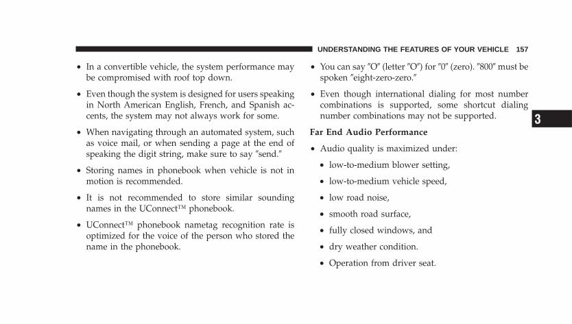
• In a convertible vehicle, the system performance maybe compromised with roof top down.
• Even though the system is designed for users speakingin North American English, French, and Spanish ac-cents, the system may not always work for some.
• When navigating through an automated system, suchas voice mail, or when sending a page at the end ofspeaking the digit string, make sure to say �send.�
• Storing names in phonebook when vehicle is not inmotion is recommended.
• It is not recommended to store similar soundingnames in the UConnect™ phonebook.
• UConnect™ phonebook nametag recognition rate isoptimized for the voice of the person who stored thename in the phonebook.
• You can say �O� (letter �O�) for �0� (zero). �800� must bespoken �eight-zero-zero.�
• Even though international dialing for most numbercombinations is supported, some shortcut dialingnumber combinations may not be supported.
Far End Audio Performance
• Audio quality is maximized under:
• low-to-medium blower setting,
• low-to-medium vehicle speed,
• low road noise,
• smooth road surface,
• fully closed windows, and
• dry weather condition.
• Operation from driver seat.
UNDERSTANDING THE FEATURES OF YOUR VEHICLE 157
3
• In a convertible vehicle, the system performance maybe compromised with roof top down.
• Performance, such as audio clarity, echo, and loudnessto a large degree rely on the phone and network, andnot the UConnect™ system.
• Echo at far end can sometime be reduced by loweringthe in-vehicle audio volume.
Bluetooth Communication LinkOccasionally, Cellular phones have been found to loseconnection to the UConnect™ system. When this hap-pens, the connection can generally be re-established byswitching the phone off/on. Your cell phone is recom-mended to remain in Bluetooth �on� mode.
Power-UpAfter switching the ignition key from OFF to either ONor ACC position, or after a reset, you must wait at leastfive (5) seconds prior to using the system.
158 UNDERSTANDING THE FEATURES OF YOUR VEHICLE
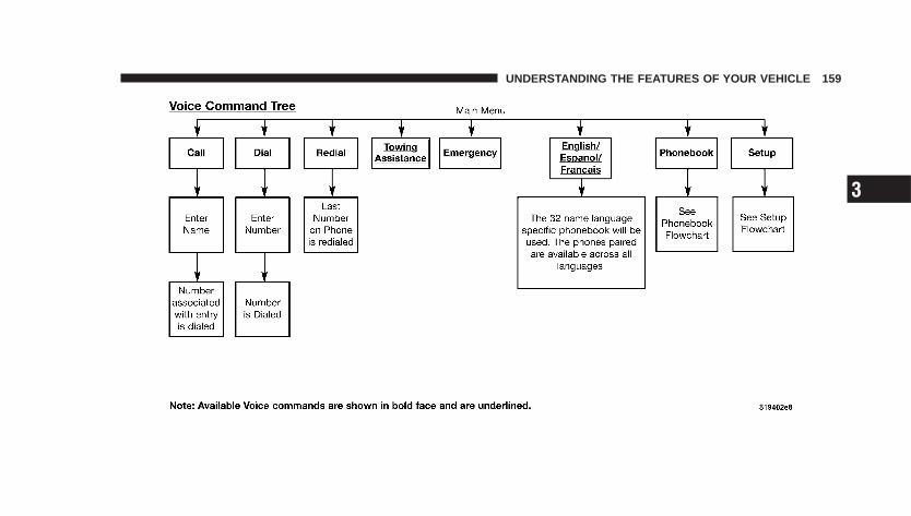
UNDERSTANDING THE FEATURES OF YOUR VEHICLE 159
3
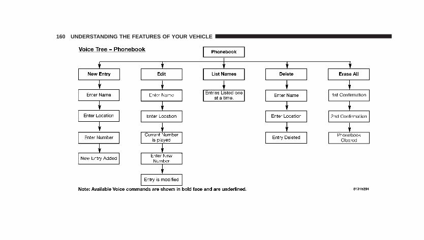
160 UNDERSTANDING THE FEATURES OF YOUR VEHICLE
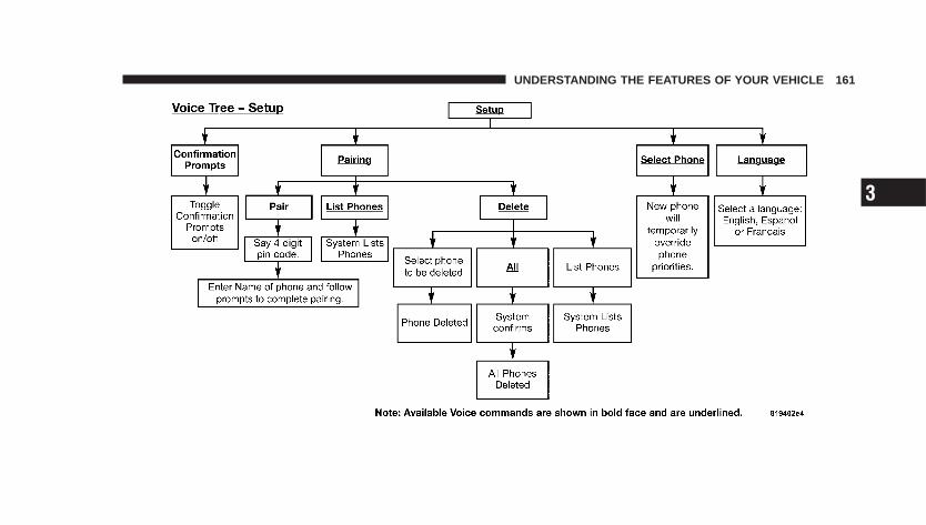
UNDERSTANDING THE FEATURES OF YOUR VEHICLE 161
3
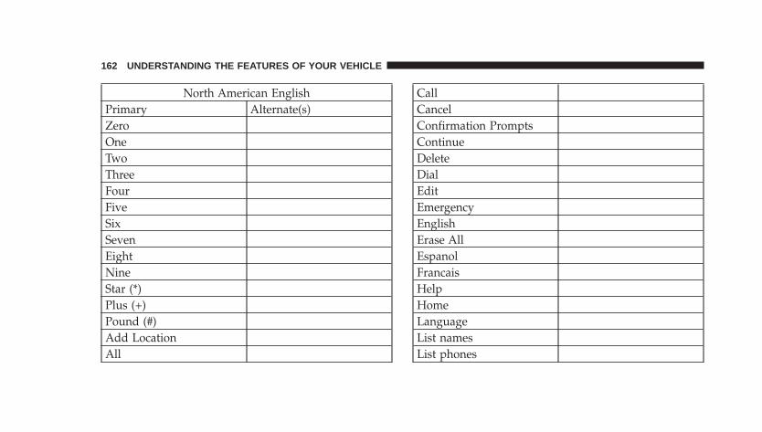
North American EnglishPrimary Alternate(s)ZeroOneTwoThreeFourFiveSixSevenEightNineStar (*)Plus (+)Pound (#)Add LocationAll
CallCancelConfirmation PromptsContinueDeleteDialEditEmergencyEnglishErase AllEspanolFrancaisHelpHomeLanguageList namesList phones
162 UNDERSTANDING THE FEATURES OF YOUR VEHICLE
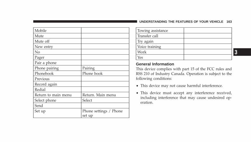
MobileMuteMute offNew entryNoPagerPair a phonePhone pairing PairingPhonebook Phone bookPreviousRecord againRedialReturn to main menu Return. Main menuSelect phone SelectSendSet up Phone settings / Phone
set up
Towing assistanceTransfer callTry againVoice trainingWorkYes
General InformationThis device complies with part 15 of the FCC rules andRSS 210 of Industry Canada. Operation is subject to thefollowing conditions:
• This device may not cause harmful interference.
• This device must accept any interference received,including interference that may cause undesired op-eration.
UNDERSTANDING THE FEATURES OF YOUR VEHICLE 163
3
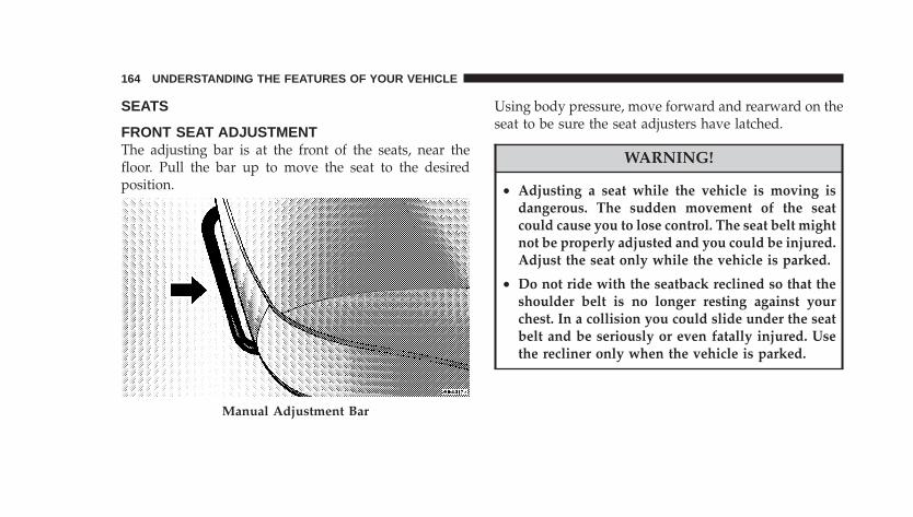
SEATS
FRONT SEAT ADJUSTMENTThe adjusting bar is at the front of the seats, near thefloor. Pull the bar up to move the seat to the desiredposition.
Using body pressure, move forward and rearward on theseat to be sure the seat adjusters have latched.
WARNING!
• Adjusting a seat while the vehicle is moving isdangerous. The sudden movement of the seatcould cause you to lose control. The seat belt mightnot be properly adjusted and you could be injured.Adjust the seat only while the vehicle is parked.
• Do not ride with the seatback reclined so that theshoulder belt is no longer resting against yourchest. In a collision you could slide under the seatbelt and be seriously or even fatally injured. Usethe recliner only when the vehicle is parked.
Manual Adjustment Bar
164 UNDERSTANDING THE FEATURES OF YOUR VEHICLE
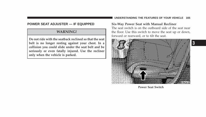
POWER SEAT ADJUSTER — IF EQUIPPED
WARNING!
Do not ride with the seatback reclined so that the seatbelt is no longer resting against your chest. In acollision you could slide under the seat belt and beseriously or even fatally injured. Use the reclineronly when the vehicle is parked.
Six-Way Power Seat with Manual ReclinerThe seat switch is on the outboard side of the seat nearthe floor. Use this switch to move the seat up or down,forward or rearward, or to tilt the seat.
Power Seat Switch
UNDERSTANDING THE FEATURES OF YOUR VEHICLE 165
3
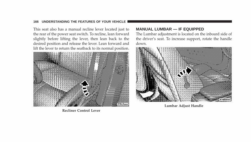
This seat also has a manual recline lever located just tothe rear of the power seat switch. To recline, lean forwardslightly before lifting the lever, then lean back to thedesired position and release the lever. Lean forward andlift the lever to return the seatback to its normal position.
MANUAL LUMBAR — IF EQUIPPEDThe Lumbar adjustment is located on the inboard side ofthe driver’s seat. To increase support, rotate the handledown.
Recliner Control LeverLumbar Adjust Handle
166 UNDERSTANDING THE FEATURES OF YOUR VEHICLE
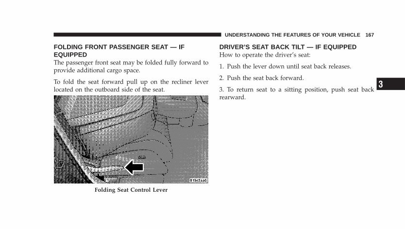
FOLDING FRONT PASSENGER SEAT — IFEQUIPPEDThe passenger front seat may be folded fully forward toprovide additional cargo space.
To fold the seat forward pull up on the recliner leverlocated on the outboard side of the seat.
DRIVER’S SEAT BACK TILT — IF EQUIPPEDHow to operate the driver’s seat:
1. Push the lever down until seat back releases.
2. Push the seat back forward.
3. To return seat to a sitting position, push seat backrearward.
Folding Seat Control Lever
UNDERSTANDING THE FEATURES OF YOUR VEHICLE 167
3
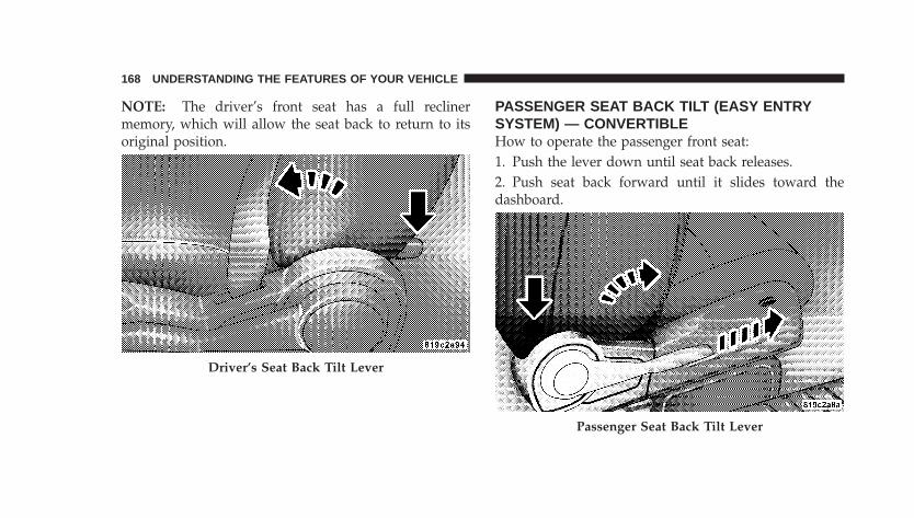
NOTE: The driver’s front seat has a full reclinermemory, which will allow the seat back to return to itsoriginal position.
PASSENGER SEAT BACK TILT (EASY ENTRYSYSTEM) — CONVERTIBLEHow to operate the passenger front seat:1. Push the lever down until seat back releases.2. Push seat back forward until it slides toward thedashboard.
Driver’s Seat Back Tilt Lever
Passenger Seat Back Tilt Lever
168 UNDERSTANDING THE FEATURES OF YOUR VEHICLE
3. To return seat to a sitting position, rotate seat backupright until it locks.
4. Push seat rearward until the track locks.
NOTE: The passenger front seat has a full reclinermemory, which will allow the seat back to returned to itsoriginal position.
NOTE: The passenger front seat has a track memory,which returns the seat to just past the half way point ofthe track regardless of original position.
ADJUSTABLE HEAD RESTRAINTSHead restraints can reduce the risk of whiplash injury inthe event of impact from the rear. Pull up or push downon the head restraints so that the upper edge is as high aspractical. To raise the head restraint, pull up on the headrestraint. To lower the head restraint, push in the buttonthat is part of the head restraint rod guide, and pushdown on the head restraint.
HEATED SEATS — IF EQUIPPED
WARNING!
Persons who are unable to feel pain to the skinbecause of advanced age, chronic illness, diabetes,spinal cord injury, medication, alcohol use, exhaus-tion or other physical condition must exercise carewhen using the seat heater. It may cause burns evenat low temperatures, especially if used for longperiods of time. Do not place anything on the seatthat insulates against heat, such as a blanket orcushion. This may cause the seat heater to overheat.
UNDERSTANDING THE FEATURES OF YOUR VEHICLE 169
3
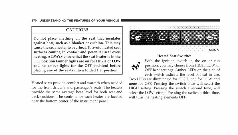
CAUTION!
Do not place anything on the seat that insulatesagainst heat, such as a blanket or cushion. This maycause the seat heater to overheat. To avoid heated seatsurfaces coming in contact and potential seat over-heating, ALWAYS ensure that the seat heater is in theOFF position (amber lights are on for HIGH or LOWand no amber lights for the OFF position) beforeplacing any of the seats into a folded flat position.
Heated seats provide comfort and warmth when neededfor the front driver’s and passenger’s seats. The heatersprovide the same average heat level for both seat andback cushions. The controls for each heater are locatednear the bottom center of the instrument panel.
With the ignition switch in the on or runposition, you may choose from HIGH, LOW, orOFF heat settings. Amber LEDs on the side ofeach switch indicate the level of heat in use.
Two LEDs are illuminated for HIGH, one for LOW, andnone for OFF. Pressing the switch once will select theHIGH setting. Pressing the switch a second time, willselect the LOW setting. Pressing the switch a third time,will turn the heating elements OFF.
Heated Seat Switches
170 UNDERSTANDING THE FEATURES OF YOUR VEHICLE
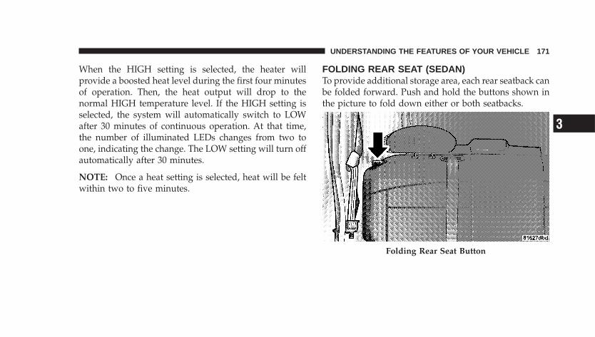
When the HIGH setting is selected, the heater willprovide a boosted heat level during the first four minutesof operation. Then, the heat output will drop to thenormal HIGH temperature level. If the HIGH setting isselected, the system will automatically switch to LOWafter 30 minutes of continuous operation. At that time,the number of illuminated LEDs changes from two toone, indicating the change. The LOW setting will turn offautomatically after 30 minutes.
NOTE: Once a heat setting is selected, heat will be feltwithin two to five minutes.
FOLDING REAR SEAT (SEDAN)To provide additional storage area, each rear seatback canbe folded forward. Push and hold the buttons shown inthe picture to fold down either or both seatbacks.
Folding Rear Seat Button
UNDERSTANDING THE FEATURES OF YOUR VEHICLE 171
3
WARNING!
• It is extremely dangerous to ride in a cargo area,inside or outside of a vehicle. In a collision, peopleriding in these areas are more likely to be seri-ously injured or killed.
• Do not allow people to ride in any area of yourvehicle that is not equipped with seats and seatbelts
• Be sure that everyone in your vehicle is in a seatand using a seat belt properly.
NOTE:• If the rear center lap/shoulder belt appears to be
locked into place, check to verify that the seatback isfully latched.
• If the seatback is properly latched and the rear centerlap/shoulder belt still does not operate properly checkand see if the Automatic Locking retractor (ALR)system is activated.
WARNING!
The rear center lap/shoulder belt is equipped with alock-out feature to ensure that the seatback is in thefully upright and locked position when occupied. Ifthe rear seatback is not fully upright and locked andthe rear center lap/shoulder belt can be pulled out ofthe retractor, the vehicle should immediately betaken to your dealer for service. Failure to follow thiswarning could result in serious or fatal injury.
172 UNDERSTANDING THE FEATURES OF YOUR VEHICLE
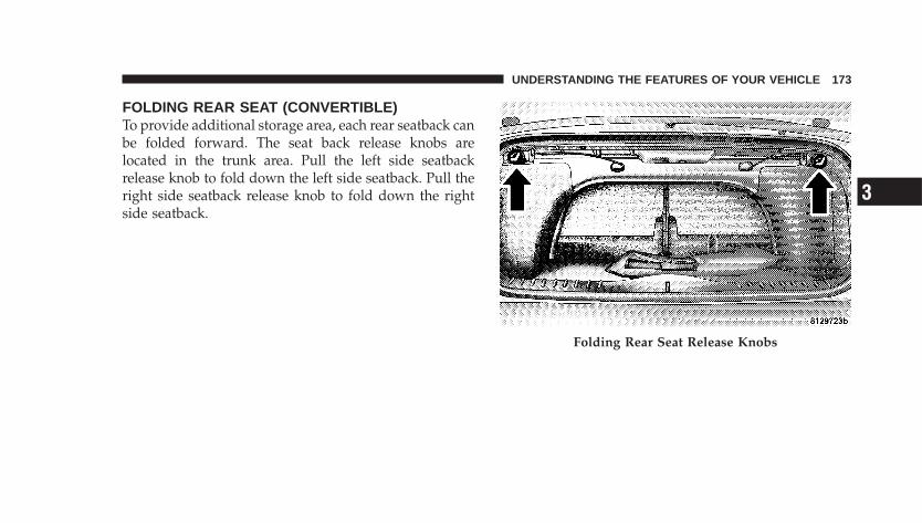
FOLDING REAR SEAT (CONVERTIBLE)To provide additional storage area, each rear seatback canbe folded forward. The seat back release knobs arelocated in the trunk area. Pull the left side seatbackrelease knob to fold down the left side seatback. Pull theright side seatback release knob to fold down the rightside seatback.
Folding Rear Seat Release Knobs
UNDERSTANDING THE FEATURES OF YOUR VEHICLE 173
3
WARNING!
• It is extremely dangerous to ride in a cargo area,inside or outside of a vehicle. In a collision, peopleriding in these areas are more likely to be seri-ously injured or killed.
• Do not allow people to ride in any area of yourvehicle that is not equipped with seats and seatbelts.
• Be sure that everyone in your vehicle is in a seatand using a seat belt properly.
NOTE: Prior to lifting either seatback to the uprightposition, be sure that the seat belt is brought forward toavoid trapping it behind the seatback.
CAUTION!
Ensure that the seat back is latched with a hard pushto engage the latch, noting the presence of seat backrubber-overslam bumpers that need to be overcome.Check that the seat back release knobs are pushedfully forward in order to allow the latch to engage.
174 UNDERSTANDING THE FEATURES OF YOUR VEHICLE
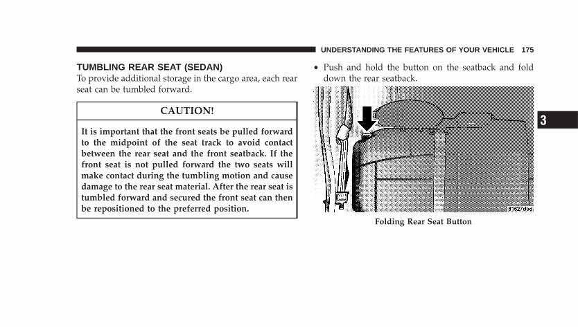
TUMBLING REAR SEAT (SEDAN)To provide additional storage in the cargo area, each rearseat can be tumbled forward.
CAUTION!
It is important that the front seats be pulled forwardto the midpoint of the seat track to avoid contactbetween the rear seat and the front seatback. If thefront seat is not pulled forward the two seats willmake contact during the tumbling motion and causedamage to the rear seat material. After the rear seat istumbled forward and secured the front seat can thenbe repositioned to the preferred position.
• Push and hold the button on the seatback and folddown the rear seatback.
Folding Rear Seat Button
UNDERSTANDING THE FEATURES OF YOUR VEHICLE 175
3
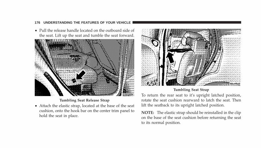
• Pull the release handle located on the outboard side ofthe seat. Lift up the seat and tumble the seat forward.
• Attach the elastic strap, located at the base of the seatcushion, onto the hook bar on the center trim panel tohold the seat in place.
To return the rear seat to it’s upright latched position,rotate the seat cushion rearward to latch the seat. Thenlift the seatback to its upright latched position.
NOTE: The elastic strap should be reinstalled in the clipon the base of the seat cushion before returning the seatto its normal position.
Tumbling Seat Release Strap
Tumbling Seat Strap
176 UNDERSTANDING THE FEATURES OF YOUR VEHICLE
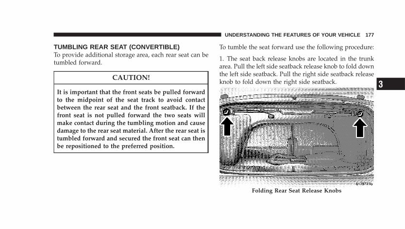
TUMBLING REAR SEAT (CONVERTIBLE)To provide additional storage area, each rear seat can betumbled forward.
CAUTION!
It is important that the front seats be pulled forwardto the midpoint of the seat track to avoid contactbetween the rear seat and the front seatback. If thefront seat is not pulled forward the two seats willmake contact during the tumbling motion and causedamage to the rear seat material. After the rear seat istumbled forward and secured the front seat can thenbe repositioned to the preferred position.
To tumble the seat forward use the following procedure:
1. The seat back release knobs are located in the trunkarea. Pull the left side seatback release knob to fold downthe left side seatback. Pull the right side seatback releaseknob to fold down the right side seatback.
Folding Rear Seat Release Knobs
UNDERSTANDING THE FEATURES OF YOUR VEHICLE 177
3
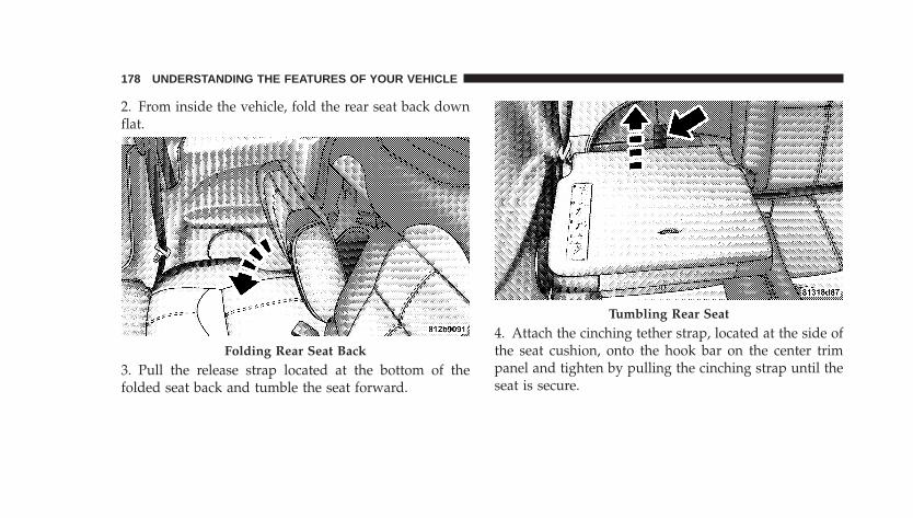
2. From inside the vehicle, fold the rear seat back downflat.
3. Pull the release strap located at the bottom of thefolded seat back and tumble the seat forward.
4. Attach the cinching tether strap, located at the side ofthe seat cushion, onto the hook bar on the center trimpanel and tighten by pulling the cinching strap until theseat is secure.
Folding Rear Seat Back
Tumbling Rear Seat
178 UNDERSTANDING THE FEATURES OF YOUR VEHICLE
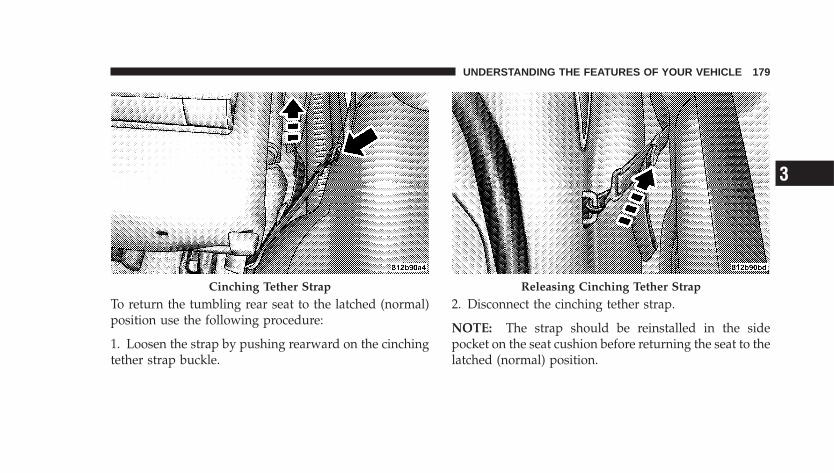
To return the tumbling rear seat to the latched (normal)position use the following procedure:
1. Loosen the strap by pushing rearward on the cinchingtether strap buckle.
2. Disconnect the cinching tether strap.
NOTE: The strap should be reinstalled in the sidepocket on the seat cushion before returning the seat to thelatched (normal) position.
Cinching Tether Strap Releasing Cinching Tether Strap
UNDERSTANDING THE FEATURES OF YOUR VEHICLE 179
3
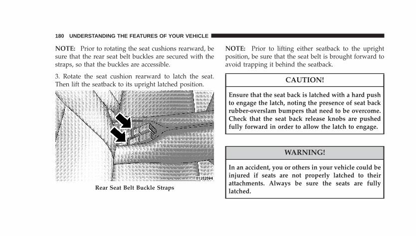
NOTE: Prior to rotating the seat cushions rearward, besure that the rear seat belt buckles are secured with thestraps, so that the buckles are accessible.
3. Rotate the seat cushion rearward to latch the seat.Then lift the seatback to its upright latched position.
NOTE: Prior to lifting either seatback to the uprightposition, be sure that the seat belt is brought forward toavoid trapping it behind the seatback.
CAUTION!
Ensure that the seat back is latched with a hard pushto engage the latch, noting the presence of seat backrubber-overslam bumpers that need to be overcome.Check that the seat back release knobs are pushedfully forward in order to allow the latch to engage.
WARNING!
In an accident, you or others in your vehicle could beinjured if seats are not properly latched to theirattachments. Always be sure the seats are fullylatched.Rear Seat Belt Buckle Straps
180 UNDERSTANDING THE FEATURES OF YOUR VEHICLE

REAR SEAT REMOVAL (SEDAN)The rear seats can be removed to provide more cargospace.
• Push and hold the button on the seatback and folddown the rear seatback.
• Pull the release lever located on the outboard side ofthe seat. Lift up the seat and tumble the seat forward.
Folding Rear Seat Button
Tumbling Seat Release Strap
UNDERSTANDING THE FEATURES OF YOUR VEHICLE 181
3
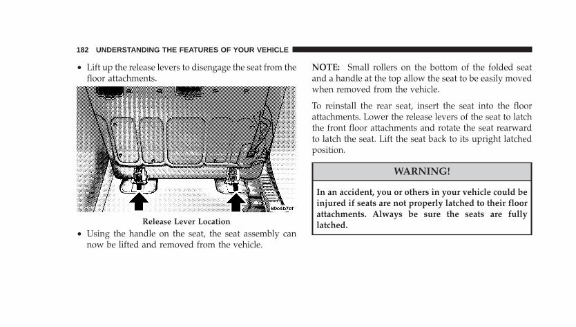
• Lift up the release levers to disengage the seat from thefloor attachments.
• Using the handle on the seat, the seat assembly cannow be lifted and removed from the vehicle.
NOTE: Small rollers on the bottom of the folded seatand a handle at the top allow the seat to be easily movedwhen removed from the vehicle.
To reinstall the rear seat, insert the seat into the floorattachments. Lower the release levers of the seat to latchthe front floor attachments and rotate the seat rearwardto latch the seat. Lift the seat back to its upright latchedposition.
WARNING!
In an accident, you or others in your vehicle could beinjured if seats are not properly latched to their floorattachments. Always be sure the seats are fullylatched.Release Lever Location
182 UNDERSTANDING THE FEATURES OF YOUR VEHICLE
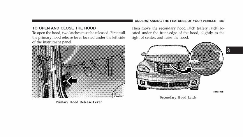
TO OPEN AND CLOSE THE HOODTo open the hood, two latches must be released. First pullthe primary hood release lever located under the left sideof the instrument panel.
Then move the secondary hood latch (safety latch) lo-cated under the front edge of the hood, slightly to theright of center, and raise the hood.
Primary Hood Release LeverSecondary Hood Latch
UNDERSTANDING THE FEATURES OF YOUR VEHICLE 183
3
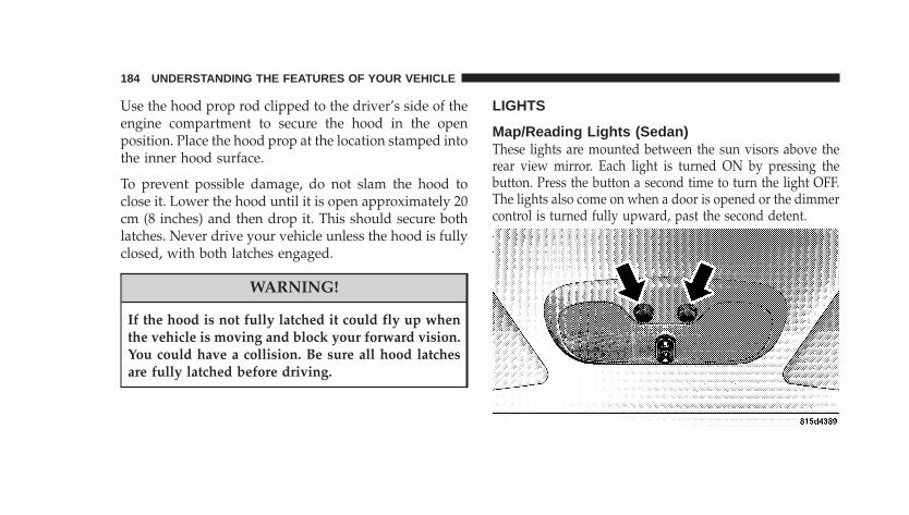
Use the hood prop rod clipped to the driver’s side of theengine compartment to secure the hood in the openposition. Place the hood prop at the location stamped intothe inner hood surface.
To prevent possible damage, do not slam the hood toclose it. Lower the hood until it is open approximately 20cm (8 inches) and then drop it. This should secure bothlatches. Never drive your vehicle unless the hood is fullyclosed, with both latches engaged.
WARNING!
If the hood is not fully latched it could fly up whenthe vehicle is moving and block your forward vision.You could have a collision. Be sure all hood latchesare fully latched before driving.
LIGHTS
Map/Reading Lights (Sedan)These lights are mounted between the sun visors above therear view mirror. Each light is turned ON by pressing thebutton. Press the button a second time to turn the light OFF.The lights also come on when a door is opened or the dimmercontrol is turned fully upward, past the second detent.
184 UNDERSTANDING THE FEATURES OF YOUR VEHICLE
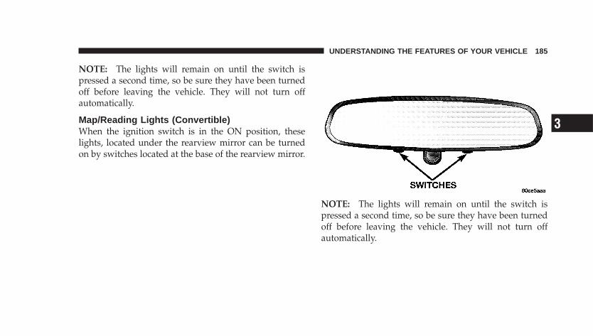
NOTE: The lights will remain on until the switch ispressed a second time, so be sure they have been turnedoff before leaving the vehicle. They will not turn offautomatically.
Map/Reading Lights (Convertible)When the ignition switch is in the ON position, theselights, located under the rearview mirror can be turnedon by switches located at the base of the rearview mirror.
NOTE: The lights will remain on until the switch ispressed a second time, so be sure they have been turnedoff before leaving the vehicle. They will not turn offautomatically.
UNDERSTANDING THE FEATURES OF YOUR VEHICLE 185
3
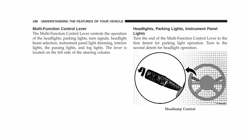
Multi-Function Control LeverThe Multi-Function Control Lever controls the operationof the headlights, parking lights, turn signals, headlightbeam selection, instrument panel light dimming, interiorlights, the passing lights, and fog lights. The lever islocated on the left side of the steering column.
Headlights, Parking Lights, Instrument PanelLightsTurn the end of the Multi-Function Control Lever to thefirst detent for parking light operation. Turn to thesecond detent for headlight operation.
Headlamp Control
186 UNDERSTANDING THE FEATURES OF YOUR VEHICLE
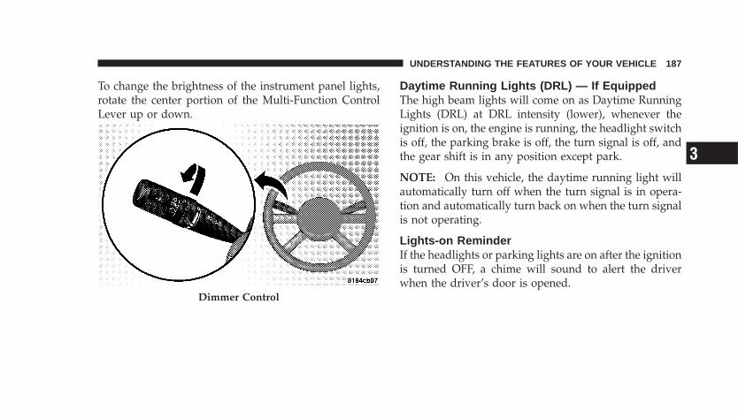
To change the brightness of the instrument panel lights,rotate the center portion of the Multi-Function ControlLever up or down.
Daytime Running Lights (DRL) — If EquippedThe high beam lights will come on as Daytime RunningLights (DRL) at DRL intensity (lower), whenever theignition is on, the engine is running, the headlight switchis off, the parking brake is off, the turn signal is off, andthe gear shift is in any position except park.
NOTE: On this vehicle, the daytime running light willautomatically turn off when the turn signal is in opera-tion and automatically turn back on when the turn signalis not operating.
Lights-on ReminderIf the headlights or parking lights are on after the ignitionis turned OFF, a chime will sound to alert the driverwhen the driver’s door is opened.
Dimmer Control
UNDERSTANDING THE FEATURES OF YOUR VEHICLE 187
3
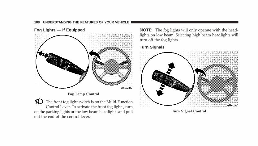
Fog Lights — If Equipped
The front fog light switch is on the Multi-FunctionControl Lever. To activate the front fog lights, turn
on the parking lights or the low beam headlights and pullout the end of the control lever.
NOTE: The fog lights will only operate with the head-lights on low beam. Selecting high beam headlights willturn off the fog lights.
Turn Signals
Fog Lamp Control
Turn Signal Control
188 UNDERSTANDING THE FEATURES OF YOUR VEHICLE
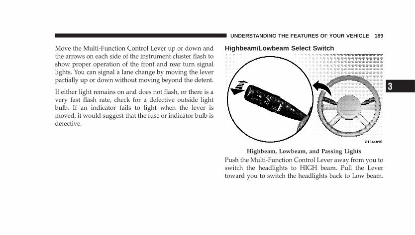
Move the Multi-Function Control Lever up or down andthe arrows on each side of the instrument cluster flash toshow proper operation of the front and rear turn signallights. You can signal a lane change by moving the leverpartially up or down without moving beyond the detent.
If either light remains on and does not flash, or there is avery fast flash rate, check for a defective outside lightbulb. If an indicator fails to light when the lever ismoved, it would suggest that the fuse or indicator bulb isdefective.
Highbeam/Lowbeam Select Switch
Push the Multi-Function Control Lever away from you toswitch the headlights to HIGH beam. Pull the Levertoward you to switch the headlights back to Low beam.
Highbeam, Lowbeam, and Passing Lights
UNDERSTANDING THE FEATURES OF YOUR VEHICLE 189
3
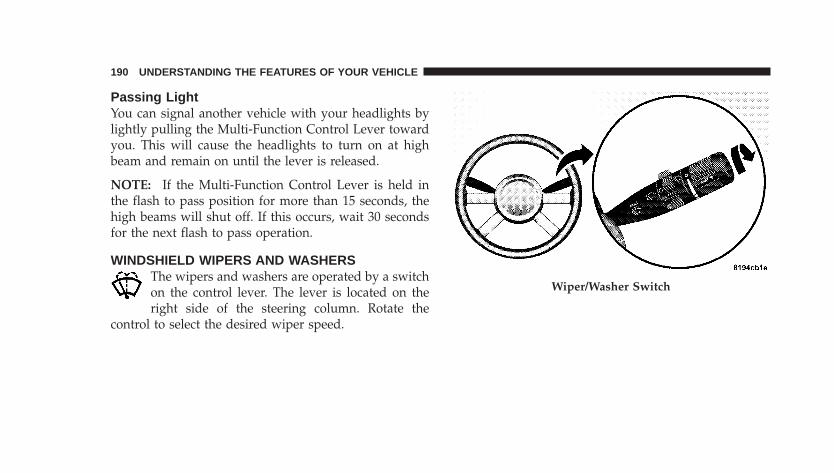
Passing LightYou can signal another vehicle with your headlights bylightly pulling the Multi-Function Control Lever towardyou. This will cause the headlights to turn on at highbeam and remain on until the lever is released.
NOTE: If the Multi-Function Control Lever is held inthe flash to pass position for more than 15 seconds, thehigh beams will shut off. If this occurs, wait 30 secondsfor the next flash to pass operation.
WINDSHIELD WIPERS AND WASHERSThe wipers and washers are operated by a switchon the control lever. The lever is located on theright side of the steering column. Rotate the
control to select the desired wiper speed.
Wiper/Washer Switch
190 UNDERSTANDING THE FEATURES OF YOUR VEHICLE
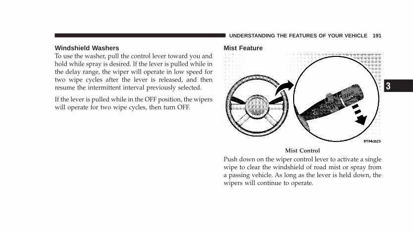
Windshield WashersTo use the washer, pull the control lever toward you andhold while spray is desired. If the lever is pulled while inthe delay range, the wiper will operate in low speed fortwo wipe cycles after the lever is released, and thenresume the intermittent interval previously selected.
If the lever is pulled while in the OFF position, the wiperswill operate for two wipe cycles, then turn OFF.
Mist Feature
Push down on the wiper control lever to activate a singlewipe to clear the windshield of road mist or spray froma passing vehicle. As long as the lever is held down, thewipers will continue to operate.
Mist Control
UNDERSTANDING THE FEATURES OF YOUR VEHICLE 191
3
CAUTION!
In cold weather, always turn off the wiper switch andallow the wipers to return to the park position beforeturning off the engine. If the wiper switch is left onand the wipers freeze to the windshield, damage tothe wiper motor may occur when the vehicle isrestarted.
Windshield Wiper OperationRotate the control to the second detent for Low speedwiper operation, or to the third detent for High speedoperation
Intermittent Wiper SystemThe intermittent feature of this system was designed foruse when weather conditions make a single wiping cycle,with a variable pause between cycles, desirable. Formaximum delay between cycles, rotate the control knobinto the upper end of the delay range.
The delay interval decreases as you rotate the knob untilit enters the LO continual speed position.
WARNING!
Sudden loss of visibility through the windshieldcould lead to an accident. You might not see othervehicles or other obstacles. To avoid sudden icing ofthe windshield during freezing weather, warm thewindshield with defroster before and during wind-shield washer use.
192 UNDERSTANDING THE FEATURES OF YOUR VEHICLE
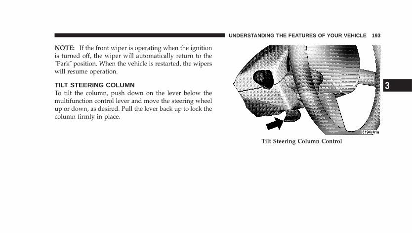
NOTE: If the front wiper is operating when the ignitionis turned off, the wiper will automatically return to the�Park� position. When the vehicle is restarted, the wiperswill resume operation.
TILT STEERING COLUMNTo tilt the column, push down on the lever below themultifunction control lever and move the steering wheelup or down, as desired. Pull the lever back up to lock thecolumn firmly in place.
Tilt Steering Column Control
UNDERSTANDING THE FEATURES OF YOUR VEHICLE 193
3
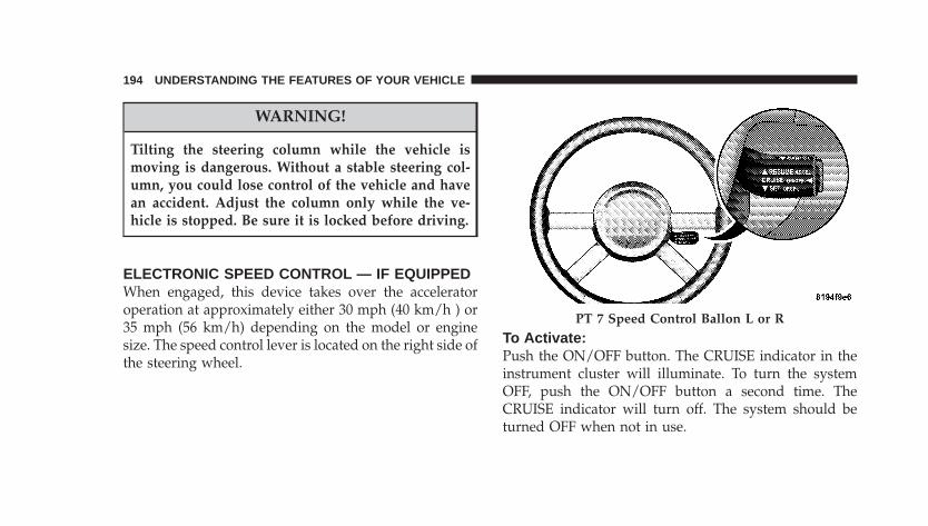
WARNING!
Tilting the steering column while the vehicle ismoving is dangerous. Without a stable steering col-umn, you could lose control of the vehicle and havean accident. Adjust the column only while the ve-hicle is stopped. Be sure it is locked before driving.
ELECTRONIC SPEED CONTROL — IF EQUIPPEDWhen engaged, this device takes over the acceleratoroperation at approximately either 30 mph (40 km/h ) or35 mph (56 km/h) depending on the model or enginesize. The speed control lever is located on the right side ofthe steering wheel.
To Activate:Push the ON/OFF button. The CRUISE indicator in theinstrument cluster will illuminate. To turn the systemOFF, push the ON/OFF button a second time. TheCRUISE indicator will turn off. The system should beturned OFF when not in use.
PT 7 Speed Control Ballon L or R
194 UNDERSTANDING THE FEATURES OF YOUR VEHICLE
WARNING!
Leaving the Electronic Speed Control system onwhen not in use is dangerous. You could accidentallyset the system or cause it to go faster than you want.You could lose control and have an accident. Alwaysleave the system OFF when you are not using it.
To Set At A Desired Speed:When the vehicle has reached the desired speed, pressdown on the lever and release. Release the acceleratorand the vehicle will operate at the selected speed.
NOTE: The vehicle should be traveling at a steadyspeed and on level ground before pressing the SET lever.
While in the AutoStick mode, speed control will onlyoperate in third and fourth gear.
To Deactivate:A soft tap on the brake pedal, pulling the speed controllever towards you CANCEL, or normal brake or clutchpressure while slowing the vehicle will deactivate speedcontrol without erasing the set speed memory. Pressingthe ON/OFF button or turning off the ignition switcherases the set speed memory.
To Resume Speed:To resume a previously set speed, push the RESUMEACCEL lever up and release. Resume can be used at anyspeed above 20 mph (32 km/h).
To Vary The Speed Setting:When the speed control is ON, speed can be increased bypushing up and holding RESUME ACCEL. Release thelever when the desired speed is reached, and the newspeed will be set.
UNDERSTANDING THE FEATURES OF YOUR VEHICLE 195
3
Tapping RESUME ACCEL once will result in a 2 mph (3km/h) speed increase. Each time the lever is tapped,speed increases so that tapping the lever three times willincrease speed by 6 mph (10 km/h), etc.
To decrease speed while speed control is ON, push downand hold SET DECEL. Release the lever when the desiredspeed is reached, and the new speed will be set.
Tapping the SET DECELbutton once will result in a 1mph (2 km/h) speed decrease. Each time the button istapped, speed decreases.
Manual Transaxle:Depressing the clutch pedal will disengage the speedcontrol. A slight increase in engine RPM before the speedcontrol disengages is normal.
Vehicles equipped with manual transaxles may need tobe shifted into a lower gear to climb hills without speedloss.
WARNING!
Speed Control can be dangerous where the systemcan’t maintain a constant speed. Your vehicle couldgo too fast for the conditions, and you could losecontrol. An accident could be the result. Don’t useSpeed Control in heavy traffic or on roads that arewinding, icy, snow-covered, or slippery.
To Accelerate For Passing:Depress the accelerator as you would normally. When thepedal is released, the vehicle will return to the set speed.
Using Speed Control On Hills
NOTE: The speed control system maintains speed upand down hills. A slight speed change on moderate hillsis normal.
196 UNDERSTANDING THE FEATURES OF YOUR VEHICLE
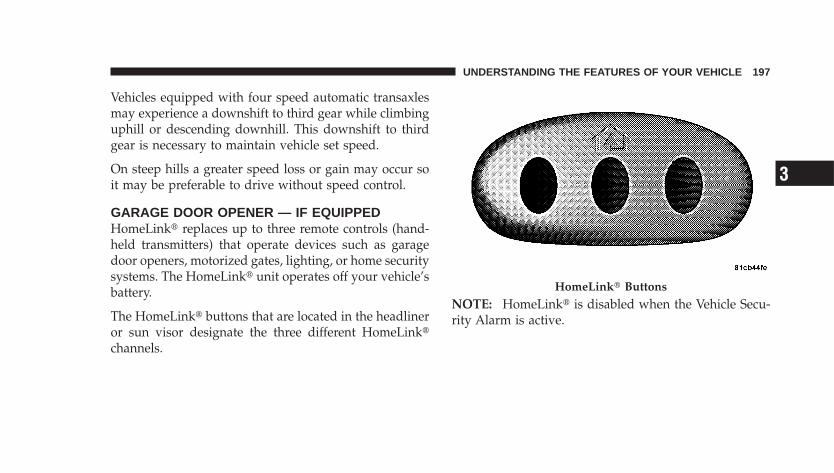
Vehicles equipped with four speed automatic transaxlesmay experience a downshift to third gear while climbinguphill or descending downhill. This downshift to thirdgear is necessary to maintain vehicle set speed.
On steep hills a greater speed loss or gain may occur soit may be preferable to drive without speed control.
GARAGE DOOR OPENER — IF EQUIPPEDHomeLink� replaces up to three remote controls (hand-held transmitters) that operate devices such as garagedoor openers, motorized gates, lighting, or home securitysystems. The HomeLink� unit operates off your vehicle’sbattery.
The HomeLink� buttons that are located in the headlineror sun visor designate the three different HomeLink�channels.
NOTE: HomeLink� is disabled when the Vehicle Secu-rity Alarm is active.
HomeLink� Buttons
UNDERSTANDING THE FEATURES OF YOUR VEHICLE 197
3
WARNING!
Your motorized door or gate will open and closewhile you are training the Universal Transceiver. Donot train the transceiver if people or pets are in thepath of the door or gate. Only use this transceiverwith a garage door opener that has a “stop andreverse” feature as required by Federal safety stan-dards. This includes most garage door opener modelsmanufactured after 1982. Do not use a garage dooropener without these safety features. Call toll-free1–800–355–3515 or, on the Internet atwww.HomeLink.com for safety information orassistance.
WARNING!
Vehicle exhaust contains carbon monoxide, a danger-ous gas. Do not run your vehicle in the garage whiletraining the transceiver. Exhaust gas can cause seri-ous injury or death.
PROGRAMMING HOMELINK�
Before You BeginIf you have not trained any of the HomeLink� buttons,erase all channels before you begin training.
To do this, press and hold the two outside buttons for 20seconds until the red indicator flashes.
It is recommended that a new battery be placed in thehand-held transmitter of the device being programmedto HomeLink� for more efficient training and accuratetransmission of the radio-frequency signal.
198 UNDERSTANDING THE FEATURES OF YOUR VEHICLE
Your vehicle should be parked outside of the garagewhen programming.
1. Turn the ignition switch to the ON/RUN position.
2. Hold the battery side of the hand-held transmitteraway from the HomeLink� button you wish to program.
Place the hand-held transmitter 1–3 in (3-8 cm) awayfrom the HomeLink� button you wish to program whilekeeping the indicator light in view.
3. Simultaneously press and hold both the chosenHomeLink� button and the hand-held transmitter buttonuntil the HomeLink� indicator changes from a slow to arapidly blinking light, then release both the HomeLink�and hand-held transmitter buttons.
Watch for the HomeLink� indicator to change flash rates.When it changes, it is programmed. It may take up to 30seconds, or longer in rare cases. The garage door mayopen and close while you train.
NOTE:• Some gate operators and garage door openers may
require you to replace Step 3 with procedures noted inthe “Gate Operator/Canadian Programming” section.
• After training a HomeLink� channel, if the garagedoor does not operate with HomeLink� and the ga-rage door opener was manufactured after 1995, thegarage door opener may have a rolling code. If so,proceed to the heading “Programming A Rolling CodeSystem.”
4. Press and hold the just-trained HomeLink� buttonand observe the indicator light.
If the indicator light stays on constantly, programming iscomplete and the garage door (or device) should activatewhen the HomeLink� button is pressed.
UNDERSTANDING THE FEATURES OF YOUR VEHICLE 199
3
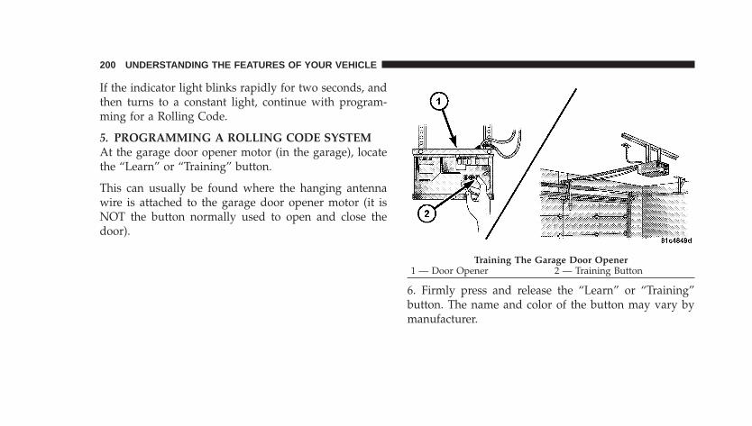
If the indicator light blinks rapidly for two seconds, andthen turns to a constant light, continue with program-ming for a Rolling Code.
5. PROGRAMMING A ROLLING CODE SYSTEMAt the garage door opener motor (in the garage), locatethe “Learn” or “Training” button.
This can usually be found where the hanging antennawire is attached to the garage door opener motor (it isNOT the button normally used to open and close thedoor).
6. Firmly press and release the “Learn” or “Training”button. The name and color of the button may vary bymanufacturer.
Training The Garage Door Opener1 — Door Opener 2 — Training Button
200 UNDERSTANDING THE FEATURES OF YOUR VEHICLE
NOTE: There are 30 seconds in which to initiate the nextstep after the “Learn” button has been pressed.
7. Return to the vehicle and press the programmedHomeLink� button twice (holding the button for twoseconds each time). If the device is plugged in andactivates, programming is complete.
If the device does not activate, press the button a thirdtime (for two seconds) to complete the training.
If you have any problems, or require assistance, pleasecall toll-free 1–800–355–3515 or, on the Internet atwww.HomeLink.com for information or assistance.
To program the remaining two HomeLink� buttons,repeat each step for each remaining button. DO NOTerase the channels.
GATE OPERATOR/CANADIAN PROGRAMMINGCanadian radio-frequency laws require transmitter sig-nals to “time-out” (or quit) after several seconds oftransmission – which may not be long enough forHomeLink� to pick up the signal during programming.Similar to this Canadian law, some U.S. gate operators aredesigned to “time-out” in the same manner.
It may be helpful to unplug the device during the cyclingprocess to prevent possible overheating of the garagedoor or gate motor.
If you are having difficulties programming a garage dooropener or a gate operator, replace “ProgrammingHomeLink�” Step 3 with the following:
3. Continue to press and hold the HomeLink� buttonwhile you press and release - every two seconds(“cycle”) your hand-held transmitter until HomeLink�
UNDERSTANDING THE FEATURES OF YOUR VEHICLE 201
3
has successfully accepted the frequency signal. Theindicator light will flash slowly and then rapidly whenfully trained.
If you unplugged the device for training, plug it back inat this time.
Then proceed with Step 4 under “ProgrammingHomeLink�” earlier in this section.
USING HOMELINK�To operate, simply press and release the programmedHomeLink� button. Activation will now occur for thetrained device (i.e., garage door opener, gate operator,Security system, entry door lock, home/office lighting,etc. The hand-held transmitter of the device may also beused at any time.
REPROGRAMMING A SINGLE HOMELINK�BUTTONTo re-program a channel that has been previouslytrained, follow these steps:
1. Turn the ignition switch to the ON/RUN position.
2. Press and hold the desired HomeLink� button untilthe indicator light begins to flash after 20 seconds. Do notrelease the button.
3. Without releasing the button, proceed with Program-ming Homelink� Step 2 and follow all remaining steps.
SECURITYIt is advised to erase all channels before you sell or turnin your vehicle.
To do this, press and hold the two outside buttons for 20seconds until the red indicator flashes. Note that allchannels will be erased. Individual channels cannot beerased.
202 UNDERSTANDING THE FEATURES OF YOUR VEHICLE
The HomeLink� Universal Transceiver is disabled whenthe Vehicle Security Alarm is active.
TROUBLESHOOTING TIPSIf you are having trouble programming HomeLink�, hereare some of the most common solutions:
• Replace the battery in the original transmitter.
• Press the “Learn” button on the Garage Door Openerto complete the training for a Rolling Code.
• Did you unplug the device for training, and rememberto plug it back in?
If you have any problems, or require assistance, pleasecall toll-free 1–800–355–3515 or, on the Internet atwww.HomeLink.com for information or assistance.
GENERAL INFORMATIONThis device complies with FCC rules Part 15 and IndustryCanada RSS-210. Operation is subject to the followingtwo conditions:
1. This device may not cause harmful interference
2. This device must accept any interference that may bereceived including interference that may cause undesiredoperation
NOTE: The transmitter has been tested and it complieswith FCC and IC rules. Changes or modifications notexpressly approved by the party responsible for compli-ance could void the user’s authority to operate thedevice.
The term IC before the certification/registration numberonly signifies that Industry Canada technical specifica-tions were met.
UNDERSTANDING THE FEATURES OF YOUR VEHICLE 203
3

POWER SUNROOF (SEDAN ONLY) — IFEQUIPPEDThe power sunroof switch is located in the reading lamp.
Turn the Ignition Key to the ACC or ON position, pressand hold the switch rearward to fully open the sunroof.The sunroof can be stopped at any position betweenclosed and full open. Momentarily pressing the switchrearward will activate the Express Open Feature, causingthe sunroof to open automatically.
Press and hold the button in the center of the sunroofswitch to open the vent. The sunroof can be stopped atany position between closed and full vent. To close thesunroof from the vent position, press and hold the switchforward. Releasing the switch will stop the movement ofthe sunroof and the sunroof will remain in the partialvent position until the switch is pushed forward again.
Express Open FeatureDuring the Express Open operation, any movement ofthe switch will stop the sunroof and it will remain in apartial open position. Again, momentarily pressing theswitch rearward will activate the Express Open Feature.
Power Sunroof Switch
204 UNDERSTANDING THE FEATURES OF YOUR VEHICLE
To close the sunroof, hold the switch in the forwardposition. Again, any release of the switch will stop themovement and the sunroof will remain in a partial opencondition until the switch is pushed forward again.
The sunshade can be opened manually. It will also openas the sunroof opens. The sunshade cannot be closed ifthe sunroof is open.
WARNING!
Never leave children in a vehicle, with the keys inthe ignition switch. Occupants, particularly unat-tended children, can become entrapped by the powersunroof while operating the power sunroof switch.Such entrapment may result in serious injury ordeath.
WARNING!
In an accident, there is a greater risk of being thrownfrom a vehicle with an open sunroof. You could alsobe seriously injured or killed. Always fasten yourseat belt properly and make sure all passengers areproperly secured too.
Do not allow small children to operate the sunroof.Never allow fingers or other body parts, or any objectto project through the sunroof opening. Injury mayresult.
Wind BuffetingWind buffeting can be described as the perception ofpressure on the ears or a helicopter type sound in theears. Your vehicle may exhibit wind buffeting with thewindows down, or the sunroof (if equipped) in certain
UNDERSTANDING THE FEATURES OF YOUR VEHICLE 205
3
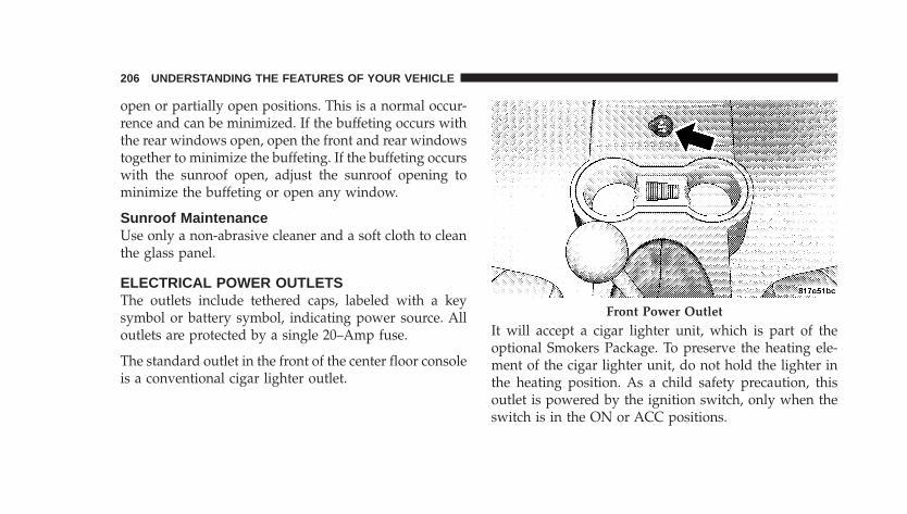
open or partially open positions. This is a normal occur-rence and can be minimized. If the buffeting occurs withthe rear windows open, open the front and rear windowstogether to minimize the buffeting. If the buffeting occurswith the sunroof open, adjust the sunroof opening tominimize the buffeting or open any window.
Sunroof MaintenanceUse only a non-abrasive cleaner and a soft cloth to cleanthe glass panel.
ELECTRICAL POWER OUTLETSThe outlets include tethered caps, labeled with a keysymbol or battery symbol, indicating power source. Alloutlets are protected by a single 20–Amp fuse.
The standard outlet in the front of the center floor consoleis a conventional cigar lighter outlet.
It will accept a cigar lighter unit, which is part of theoptional Smokers Package. To preserve the heating ele-ment of the cigar lighter unit, do not hold the lighter inthe heating position. As a child safety precaution, thisoutlet is powered by the ignition switch, only when theswitch is in the ON or ACC positions.
Front Power Outlet
206 UNDERSTANDING THE FEATURES OF YOUR VEHICLE
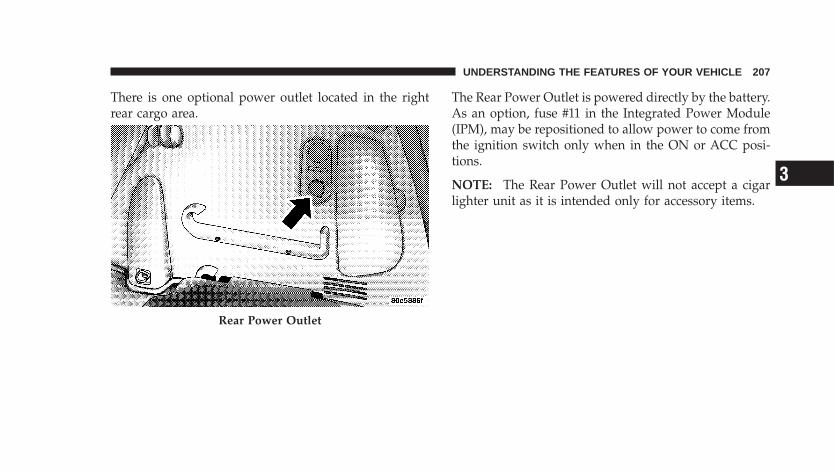
There is one optional power outlet located in the rightrear cargo area.
The Rear Power Outlet is powered directly by the battery.As an option, fuse #11 in the Integrated Power Module(IPM), may be repositioned to allow power to come fromthe ignition switch only when in the ON or ACC posi-tions.
NOTE: The Rear Power Outlet will not accept a cigarlighter unit as it is intended only for accessory items.
Rear Power Outlet
UNDERSTANDING THE FEATURES OF YOUR VEHICLE 207
3
Electrical Outlet Use With Engine Off
CAUTION!
• Many accessories that can be plugged in drawpower from the vehicle’s battery, even when not inuse (i.e., cellular phones, etc.). Eventually, ifplugged in long enough, the vehicle’s battery willdischarge sufficiently to degrade battery lifeand/or prevent engine starting.
• Accessories that draw higher power (i.e., coolers,vacuum cleaners, lights, etc.), will degrade thebattery even more quickly. Only use these inter-mittently and with greater caution.
• After the use of high power draw accessories, orlong periods of the vehicle not being started (withaccessories still plugged in), the vehicle must bedriven a sufficient length of time to allow thegenerator to recharge the vehicle’s battery.
CONSOLE FEATURESThe console has two front cup holders, a removable coinholder, 12 volt power outlet and a front storage tray.There are three additional cup holders; one is molded inthe center of the console to hold large cups and the othersare in the rear of the console to serve passengers in therear seat. The floor console power outlet will also operatea conventional cigar lighter unit (if equipped with anoptional Smoker’s Package).
208 UNDERSTANDING THE FEATURES OF YOUR VEHICLE
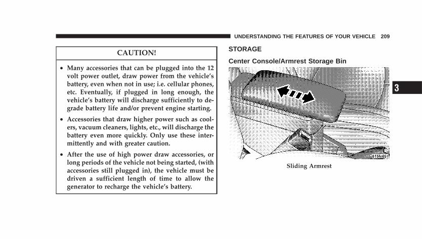
CAUTION!
• Many accessories that can be plugged into the 12volt power outlet, draw power from the vehicle’sbattery, even when not in use; i.e. cellular phones,etc. Eventually, if plugged in long enough, thevehicle’s battery will discharge sufficiently to de-grade battery life and/or prevent engine starting.
• Accessories that draw higher power such as cool-ers, vacuum cleaners, lights, etc., will discharge thebattery even more quickly. Only use these inter-mittently and with greater caution.
• After the use of high power draw accessories, orlong periods of the vehicle not being started, (withaccessories still plugged in), the vehicle must bedriven a sufficient length of time to allow thegenerator to recharge the vehicle’s battery.
STORAGE
Center Console/Armrest Storage Bin
Sliding Armrest
UNDERSTANDING THE FEATURES OF YOUR VEHICLE 209
3
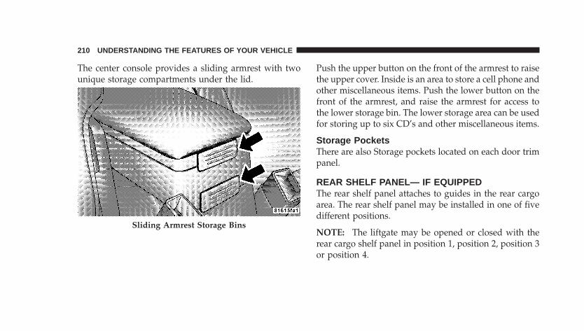
The center console provides a sliding armrest with twounique storage compartments under the lid.
Push the upper button on the front of the armrest to raisethe upper cover. Inside is an area to store a cell phone andother miscellaneous items. Push the lower button on thefront of the armrest, and raise the armrest for access tothe lower storage bin. The lower storage area can be usedfor storing up to six CD’s and other miscellaneous items.
Storage PocketsThere are also Storage pockets located on each door trimpanel.
REAR SHELF PANEL— IF EQUIPPEDThe rear shelf panel attaches to guides in the rear cargoarea. The rear shelf panel may be installed in one of fivedifferent positions.
NOTE: The liftgate may be opened or closed with therear cargo shelf panel in position 1, position 2, position 3or position 4.
Sliding Armrest Storage Bins
210 UNDERSTANDING THE FEATURES OF YOUR VEHICLE
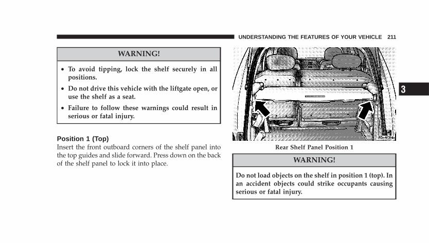
WARNING!
• To avoid tipping, lock the shelf securely in allpositions.
• Do not drive this vehicle with the liftgate open, oruse the shelf as a seat.
• Failure to follow these warnings could result inserious or fatal injury.
Position 1 (Top)Insert the front outboard corners of the shelf panel intothe top guides and slide forward. Press down on the backof the shelf panel to lock it into place. WARNING!
Do not load objects on the shelf in position 1 (top). Inan accident objects could strike occupants causingserious or fatal injury.
Rear Shelf Panel Position 1
UNDERSTANDING THE FEATURES OF YOUR VEHICLE 211
3
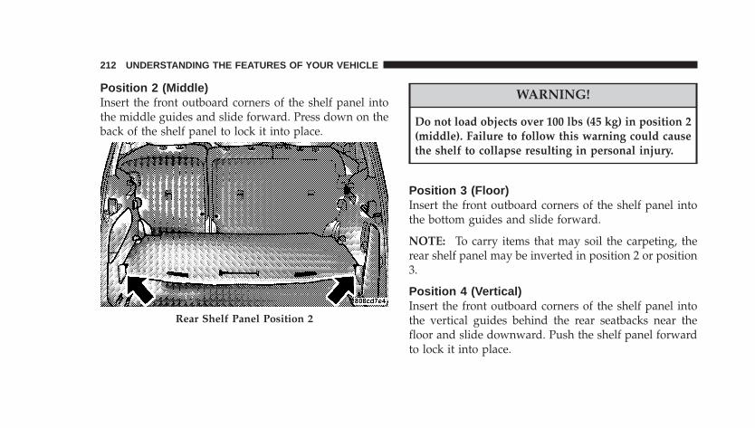
Position 2 (Middle)Insert the front outboard corners of the shelf panel intothe middle guides and slide forward. Press down on theback of the shelf panel to lock it into place.
WARNING!
Do not load objects over 100 lbs (45 kg) in position 2(middle). Failure to follow this warning could causethe shelf to collapse resulting in personal injury.
Position 3 (Floor)Insert the front outboard corners of the shelf panel intothe bottom guides and slide forward.
NOTE: To carry items that may soil the carpeting, therear shelf panel may be inverted in position 2 or position3.
Position 4 (Vertical)Insert the front outboard corners of the shelf panel intothe vertical guides behind the rear seatbacks near thefloor and slide downward. Push the shelf panel forwardto lock it into place.
Rear Shelf Panel Position 2
212 UNDERSTANDING THE FEATURES OF YOUR VEHICLE
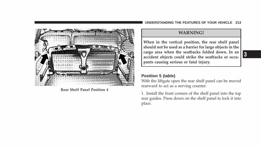
WARNING!
When in the vertical position, the rear shelf panelshould not be used as a barrier for large objects in thecargo area when the seatbacks folded down. In anaccident objects could strike the seatbacks or occu-pants causing serious or fatal injury.
Position 5 (table)With the liftgate open the rear shelf panel can be movedrearward to act as a serving counter.
1. Install the front corners of the shelf panel into the toprear guides. Press down on the shelf panel to lock it intoplace.
Rear Shelf Panel Position 4
UNDERSTANDING THE FEATURES OF YOUR VEHICLE 213
3
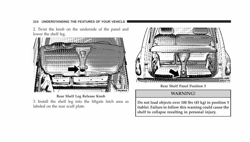
2. Twist the knob on the underside of the panel andlower the shelf leg.
3. Install the shelf leg into the liftgate latch area aslabeled on the rear scuff plate.
WARNING!
Do not load objects over 100 lbs (45 kg) in position 5(table). Failure to follow this warning could cause theshelf to collapse resulting in personal injury.
Rear Shelf Leg Release Knob
Rear Shelf Panel Position 5
214 UNDERSTANDING THE FEATURES OF YOUR VEHICLE
ROOF LUGGAGE RACK — IF EQUIPPEDThe crossbars and siderails are designed to carry theweight on vehicles equipped with a luggage rack. Theload must not exceed 150 lbs (68 kg), and should beuniformly distributed over the luggage rack crossbars.
Use both adjustable crossbars assemblies to support theload and distribute the load as evenly as possible.
To adjust the crossbars with latch-style releases (ifequipped), release the latches on the inboard side of thecrossbar supports on each side of the vehicle, then movethe crossbars to the desired position. Once the crossbar isin the desired position, return both latches to the lockedposition.
To adjust the crossbars with bottom-style releases (ifequipped), depress the button and slide the crossbar tothe next locking position. Alternate sides until the cross-bars are positioned correctly for your cargo and thestanchions are locked square to the slide rails.
External racks do not increase the total load carryingcapacity of the vehicle. Be sure that the total occupantand luggage load inside the vehicle, plus the load on theluggage rack, do not exceed the rated vehicle capacity.
NOTE: When the luggage rack is not in use, place thecrossbars together at the rear of the vehicle. In thisposition they are designed to improve the vehicle aero-dynamics and reduce wind noise.
UNDERSTANDING THE FEATURES OF YOUR VEHICLE 215
3
CAUTION!
To avoid damage to the roof rack and vehicle, do notexceed the maximum roof rack load capacity of 150lbs (68 kg). Always distribute heavy loads as evenlyas possible and secure the load appropriately.
Long loads which extend over the windshield, suchas wood panels or surfboards, should be secured toboth the front and rear of the vehicle.
Travel at reduced speeds and turn corners carefullywhen carrying large or heavy loads on the roof rack.Wind forces, due to natural causes or nearby trucktraffic, can add sudden upward loads. This is espe-cially true on large flat loads and may result indamage to the cargo or your vehicle.
WARNING!
Cargo must be securely tied before driving yourvehicle. Improperly secured loads can fly off thevehicle, particularly at high speeds, resulting in per-sonal injury or property damage. Follow the roof rack“Cautions” when carrying cargo on your roof rack.
216 UNDERSTANDING THE FEATURES OF YOUR VEHICLE
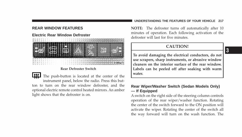
REAR WINDOW FEATURES
Electric Rear Window Defroster
The push-button is located at the center of theinstrument panel, below the radio. Press this but-
ton to turn on the rear window defroster, and theoptional electric remote control heated mirrors. An amberlight shows that the defroster is on.
NOTE: The defroster turns off automatically after 10minutes of operation. Each following activation of thedefroster will last for five minutes.
CAUTION!
To avoid damaging the electrical conductors, do notuse scrapers, sharp instruments, or abrasive windowcleaners on the interior surface of the rear window.Labels can be peeled off after soaking with warmwater.
Rear Wiper/Washer Switch (Sedan Models Only)— If EquippedA switch on the right side of the steering column controlsoperation of the rear wiper/washer function. Rotatingthe center of the switch forward to the ON position willactivate the wiper. Rotating the center of the switch allthe way forward will turn on the wash function. The
Rear Defroster Switch
UNDERSTANDING THE FEATURES OF YOUR VEHICLE 217
3
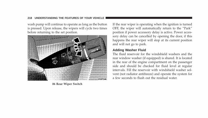
wash pump will continue to operate as long as the buttonis pressed. Upon release, the wipers will cycle two timesbefore returning to the set position.
If the rear wiper is operating when the ignition is turnedOFF, the wiper will automatically return to the “Park”position if power accessory delay is active. Power acces-sory delay can be cancelled by opening the door, if thishappens the rear wiper will stop at its current positionand will not go to park.
Adding Washer FluidThe fluid reservoir for the windshield washers and therear window washer (if equipped) is shared. It is locatedin the rear of the engine compartment on the passengerside and should be checked for fluid level at regularintervals. Fill the reservoir with windshield washer sol-vent (not radiator antifreeze) and operate the system fora few seconds to flush out the residual water.
06 Rear Wiper Switch
218 UNDERSTANDING THE FEATURES OF YOUR VEHICLE
UNDERSTANDING YOUR INSTRUMENT PANEL
CONTENTS
� Instrument Panel Features . . . . . . . . . . . . . . . . . 222
� Instrument Cluster—Base . . . . . . . . . . . . . . . . . 223
� Instrument Cluster—Premium . . . . . . . . . . . . . . 224
� Instrument Cluster—Turbo . . . . . . . . . . . . . . . . 225
� Instrument Cluster Descriptions . . . . . . . . . . . . 226
� Compass Mini Trip Computer (CMTC) — IfEquipped . . . . . . . . . . . . . . . . . . . . . . . . . . . . 235
▫ Compass Mini Trip Computer Reset Button . . . 235
▫ Compass/Temperature Display . . . . . . . . . . . 236
▫ Odometer Display . . . . . . . . . . . . . . . . . . . . . 239
▫ Trip Odometer (ODO) . . . . . . . . . . . . . . . . . . 239
� Electronic Vehicle Information Center (EVIC) – IfEquipped . . . . . . . . . . . . . . . . . . . . . . . . . . . . 240
▫ EVIC Functions . . . . . . . . . . . . . . . . . . . . . . . 242
▫ Compass/Temperature/Audio . . . . . . . . . . . . 243
▫ Average Fuel Economy . . . . . . . . . . . . . . . . . 243
▫ Distance To Empty (DTE) . . . . . . . . . . . . . . . 243
▫ Elapsed Time . . . . . . . . . . . . . . . . . . . . . . . . 244
4
▫ Tire Pressure Monitor (TPM) . . . . . . . . . . . . . 244
▫ Personal Settings (Customer ProgrammableFeatures) . . . . . . . . . . . . . . . . . . . . . . . . . . . 244
� Setting The Analog Clock . . . . . . . . . . . . . . . . . 250
� Radio General Information . . . . . . . . . . . . . . . . 250
▫ Radio Broadcast Signals . . . . . . . . . . . . . . . . . 250
▫ Two Types Of Signals . . . . . . . . . . . . . . . . . . 250
▫ Electrical Disturbances . . . . . . . . . . . . . . . . . . 251
▫ AM Reception . . . . . . . . . . . . . . . . . . . . . . . 251
▫ FM Reception . . . . . . . . . . . . . . . . . . . . . . . . 251
� Sales Code REF — AM/FM/CD (Single Disc)Radio With Optional Satellite Radio And HandsFree Phone Capability . . . . . . . . . . . . . . . . . . . 251
▫ Operating Instructions - Radio Mode . . . . . . . 252
▫ Operating Instructions - CD Mode . . . . . . . . . 255
▫ Operating Instructions - Auxiliary Mode . . . . . 257
▫ Operating Instructions - Hands-Free Phone —If Equipped . . . . . . . . . . . . . . . . . . . . . . . . . 258
▫ Operating Instructions - Satellite Radio — IfEquipped . . . . . . . . . . . . . . . . . . . . . . . . . . . 258
� Sales Code RAQ – AM/FM/CD (6-Disc) RadioWith Optional Satellite Radio, Hands-Free Phone,And Video Entertainment Systems (VES™)Capabilities . . . . . . . . . . . . . . . . . . . . . . . . . . . 259
▫ Operating Instructions - Radio Mode . . . . . . . 259
▫ Operating Instructions - (CD Mode For CDAudio Play) . . . . . . . . . . . . . . . . . . . . . . . . . 265
▫ Load/Eject Button (CD Mode For CD AudioPlay) . . . . . . . . . . . . . . . . . . . . . . . . . . . . . . 266
220 UNDERSTANDING YOUR INSTRUMENT PANEL
▫ Notes On Playing MP3 Files . . . . . . . . . . . . . 268
▫ Operating Instructions - (CD Mode For MP3Audio Play) . . . . . . . . . . . . . . . . . . . . . . . . . 270
▫ Load/Eject Button (CD Mode For MP3 Play) . . 271
� Satellite Radio — If Equipped . . . . . . . . . . . . . . 273
▫ System Activation . . . . . . . . . . . . . . . . . . . . . 273
▫ Electronic Serial Number/Sirius IdentificationNumber (ESN/SID) . . . . . . . . . . . . . . . . . . . . 273
▫ Selecting Satellite Mode In REF, And RAQ,Radios . . . . . . . . . . . . . . . . . . . . . . . . . . . . . 274
▫ Selecting a Channel . . . . . . . . . . . . . . . . . . . . 274
▫ Storing And Selecting Pre-Set Channels . . . . . . 275
▫ Using The PTY (Program Type) Button (IfEquipped) . . . . . . . . . . . . . . . . . . . . . . . . . . 275
▫ PTY Button �Scan� . . . . . . . . . . . . . . . . . . . . . 275
▫ PTY Button �Seek� . . . . . . . . . . . . . . . . . . . . . 276
▫ Satellite Antenna . . . . . . . . . . . . . . . . . . . . . . 276
▫ Reception Quality . . . . . . . . . . . . . . . . . . . . . 276
� CD/DVD Disc Maintenance . . . . . . . . . . . . . . . 277
� Radio Operation And Cellular Phones . . . . . . . . 277
� Climate Controls . . . . . . . . . . . . . . . . . . . . . . . 277
▫ Climate Controls . . . . . . . . . . . . . . . . . . . . . . 277
▫ Operating Tips . . . . . . . . . . . . . . . . . . . . . . . 283
UNDERSTANDING YOUR INSTRUMENT PANEL 221
4
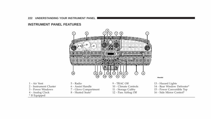
INSTRUMENT PANEL FEATURES
1 - Air Vent 5 - Radio 9 - TRAC Off 13 - Hazard Lights2 - Instrument Cluster 6 - Assist Handle 10 - Climate Controls 14 - Rear Window Defroster*3 - Power Windows 7 - Glove Compartment 11 - Storage Cubby 15 - Power Convertible Top4 - Analog Clock 8 - Heated Seats* 12 - Pass Airbag Off 16 - Side Mirror Control** If Equipped
222 UNDERSTANDING YOUR INSTRUMENT PANEL
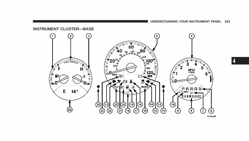
INSTRUMENT CLUSTER—BASE
UNDERSTANDING YOUR INSTRUMENT PANEL 223
4
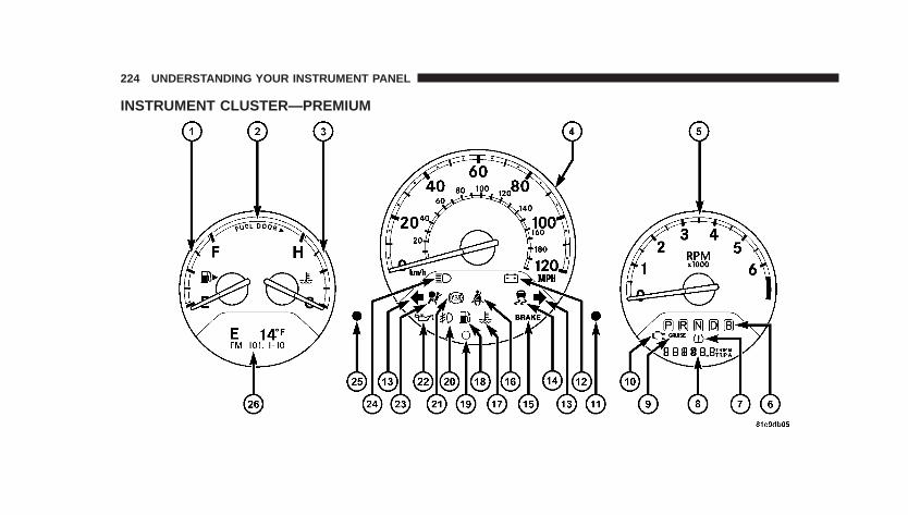
INSTRUMENT CLUSTER—PREMIUM
224 UNDERSTANDING YOUR INSTRUMENT PANEL
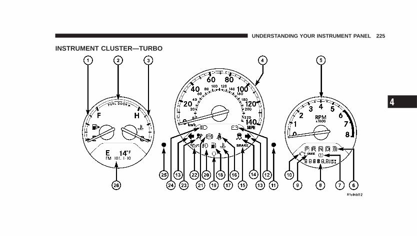
INSTRUMENT CLUSTER—TURBO
UNDERSTANDING YOUR INSTRUMENT PANEL 225
4
INSTRUMENT CLUSTER DESCRIPTIONS
1. Fuel GaugeWhen the ignition switch is in the ON position, thepointer will show the level of fuel remaining in thefuel tank.
2. Fuel Door ReminderThis is a reminder that the Fuel Filler Door is located onthe front passenger’s (right) side of the vehicle.
3. Temperature GaugeThe temperature gauge shows engine coolant tem-perature. Any reading below the red area of thegauge shows that the engine cooling system is
operating properly. The gauge pointer may show ahigher than normal temperature when driving in hotweather, up mountain grades, in heavy stop and gotraffic, or when towing a trailer.
If the pointer rises to the H (red) mark, the instrumentcluster will sound a chime. Pull over and stop the vehicle.Idle the vehicle with the air conditioner turned off untilthe pointer drops back into the normal range. If thepointer remains on the H (red) mark, turn the engine offimmediately and call for service.
There are steps that you can take to slow down animpending overheat condition. If your air conditioning ison, turn it off. The air conditioning system adds heat tothe engine cooling system and turning off the A/Cremoves this heat. You can also turn the Temperaturecontrol to maximum heat, the Mode control to Floor andthe Fan control to High. This allows the heater core to actas a supplement to the radiator and aids in removing heatfrom the engine cooling system.
4. SpeedometerIndicates vehicle speed.
226 UNDERSTANDING YOUR INSTRUMENT PANEL
5. TachometerThe white area of the scale shows the permissible enginerevolutions-per-minute (rpm x 1000) for each gear range.Before reaching the red area, ease up on the accelerator toprevent engine damage.
6. Transmission Range IndicatorThis display indicator shows the automatic transmissiongear selection.
7. Tire Pressure Monitor LightEach tire, including the spare (if provided),should be checked monthly when cold andinflated to the inflation pressure recommendedby the vehicle manufacturer on the vehicle
placard or tire inflation pressure label. (If your vehiclehas tires of a different size than the size indicated on thevehicle placard or tire inflation pressure label, you shoulddetermine the proper tire inflation pressure for thosetires.)
As an added safety feature, your vehicle has beenequipped with a Tire Pressure Monitoring System(TPMS) that illuminates a low tire pressure telltale whenone or more of your tires is significantly under-inflated.Accordingly, when the low tire pressure telltale illumi-nates, you should stop and check your tires as soon aspossible, and inflate them to the proper pressure. Drivingon a significantly under-inflated tire causes the tire tooverheat and can lead to tire failure. Under-inflation alsoreduces fuel efficiency and tire tread life, and may affectthe vehicle’s handling and stopping ability.
NOTE: Please note that the TPMS is not a substitute forproper tire maintenance, and it is the driver’s responsi-bility to maintain correct tire pressure, even if under-inflation has not reached the level to trigger illuminationof the TPMS low tire pressure telltale.
UNDERSTANDING YOUR INSTRUMENT PANEL 227
4
Your vehicle has also been equipped with a TPMSmalfunction indicator to indicate when the system is notoperating properly. The TPMS malfunction indicator iscombined with the low tire pressure telltale. When thesystem detects a malfunction, the telltale will flash forapproximately one minute and then remain continuouslyilluminated. This sequence will continue upon subse-quent vehicle start-ups as long as the malfunction exists.When the malfunction indicator is illuminated, the sys-tem may not be able to detect or signal low tire pressureas intended. TPMS malfunctions may occur for a varietyof reasons, including the installation of replacement oralternate tires or wheels on the vehicle that prevent theTPMS from functioning properly. Always check theTPMS malfunction telltale after replacing one or moretires or wheels on your vehicle to ensure that the replace-ment or alternate tires and wheels allow the TPMS tocontinue to function properly.
CAUTION!
The TPMS has been optimized for the originalequipment tires and wheels. TPMS pressures andwarning have been established for the tire sizeequipped on your vehicle. Undesirable system opera-tion or sensor damage may result when using re-placement equipment that is not of the same size,type, and/or style. Aftermarket wheels can causesensor damage. Do not use aftermarket tire sealantsor balance beads if your vehicle is equipped with aTPMS, as damage to the sensors may result.
(Refer to “Tire Inflation Pressures” under “Tires — Gen-eral Information” and to “Tire Pressure Monitor System(TPMS)” in Section 5 of this manual for more informa-tion).
228 UNDERSTANDING YOUR INSTRUMENT PANEL
8. Odometer/Trip OdometerA vacuum fluorescent display indicates the total distancethe vehicle has been driven. Also, the cluster will display,replacing the odometer/trip odometer, vehicle warningmessages such as: door/deck/hatch/gate ajar and loosegas cap. Loose gas cap will be displayed from theOdometer/Trip Odometer on all models.
NOTE: If vehicle is equipped with the optional Elec-tronic Vehicle Information Center (EVIC) in the instru-ment cluster, all warnings including “door”, “dECK”,“hATCh”, and “gATE” will only be displayed in theEVIC display. For additional information, refer to “Elec-tronic Vehicle Information Center — If Equipped” inSection 3.
U.S. federal regulations require that upon transfer ofvehicle ownership, the seller certify to the purchaser thecorrect mileage that the vehicle has been driven. There-fore, if the odometer reading is changed during repair or
replacement, be sure to keep a record of the readingbefore and after the service so that the correct mileage canbe determined.
9. Cruise Indicator — If EquippedThis indicator shows that the Speed ControlSystem is ON.
NOTE: The word “SET” will not illuminate when theSpeed Control System is on.
10. Malfunction Indicator LightThis light is part of an onboard diagnostic systemcalled OBD that monitors emissions, engine, andautomatic transmission control systems. The light
will illuminate when the key is in the ON/RUN positionbefore engine start. If the bulb does not come on whenturning the key from OFF to ON/RUN, have the condi-tion checked promptly.
UNDERSTANDING YOUR INSTRUMENT PANEL 229
4
Certain conditions such as a loose or missing gas cap,poor fuel quality, etc. may illuminate the light afterengine start. The vehicle should be serviced if the lightstays on through several of your typical driving cycles. Inmost situations the vehicle will drive normally and willnot require towing.
If the Malfunction Indicator Light flashes when theengine is running, serious conditions may exist thatcould lead to immediate loss of power or severe catalyticconverter damage. The vehicle should be serviced assoon as possible if this occurs.
11. Odometer/Trip Odometer Reset KnobPress this button to change the display from odometer toeither of the two trip odometer settings. Trip A or Trip Bwill appear when in the trip odometer mode. Push in andhold the button for two seconds to reset the trip odometerto 0 miles or kilometers. The odometer must be in tripmode to reset.
12. Charging System LightThis light shows the status of the electrical charg-ing system. The light should come on briefly when
the ignition switch is first turned ON and remain onbriefly as a bulb check. If the light stays on or comes onwhile driving, it means that there is a problem with thecharging system. Obtain SERVICE IMMEDIATELY.
13. Turn Signal IndicatorsThe arrows will flash in unison with the exteriorturn signal, when using the turn signal lever.
NOTE: Turn signal bulbs are located in the InstrumentPanel.
230 UNDERSTANDING YOUR INSTRUMENT PANEL
14. Electronic Stability Program (ESP) IndicatorLight/Traction Control System (TCS) Indicator Light —If Equipped
If this indicator light flashes during accelera-tion, apply as little throttle as possible. Whiledriving, ease up on the accelerator. Adapt yourspeed and driving to the prevailing road con-
ditions, and do not switch off the ESP, or TCS — ifequipped.
15. Brake System Warning LightThis light monitors various brake functions,including brake fluid level and parking brakeapplication. If the brake light turns on, it mayindicate that the parking brake is applied, there
is a low brake fluid level or there is a problem with theanti-lock brake system.
The dual brake system provides a reserve braking capac-ity in the event of a failure to a portion of the hydraulicsystem. Failure of either half of the dual brake system isindicated by the Brake Warning Light which will turn onwhen the brake fluid level in the master cylinder hasdropped below a specified level.
The light will remain on until the cause is corrected.
NOTE: The light may flash momentarily during sharpcornering maneuvers which change fluid level condi-tions. The vehicle should have service performed, andthe brake fluid level checked.
If brake failure is indicated, immediate repair is neces-sary.
UNDERSTANDING YOUR INSTRUMENT PANEL 231
4
WARNING!
Driving a vehicle with the brake light on is danger-ous. Part of the brake system may have failed. It willtake longer to stop the vehicle. You could have anaccident. Have the vehicle checked immediately.
Vehicles equipped with Anti-Lock brakes (ABS), are alsoequipped with Electronic Brake Force Distribution (EBD).In the event of an EBD failure, the Brake Warning Lightwill turn on along with the ABS Light. Immediate repairto the ABS system is required.
The operation of the Brake Warning Light can be checkedby turning the ignition switch from the OFF position tothe ON position. The light should illuminate for approxi-mately two seconds. The light should then turn off unless
the parking brake is applied or a brake fault is detected.If the light does not illuminate, have the light inspectedby an authorized dealer.
The light also will turn on when the parking brake isapplied with the ignition switch in the ON position.
NOTE: This light shows only that the parking brake isapplied. It does not show the degree of brake application.
16. Seat Belt Reminder LightWhen the ignition switch is first turned ON, thislight will come on for about six seconds. A chimewill sound if you have not pulled the shoulder belt
out of the retractor. This is a reminder to “buckle up”. Ifyou do not buckle up, the light will remain on.
17. Engine Temperature Warning LightThis light warns of an overheated engine condi-tion. If the engine is critically hot, a warning chime
232 UNDERSTANDING YOUR INSTRUMENT PANEL
will sound 10 times. After the chime turns off, the enginewill still be critically hot until the light goes out.
18. Low Fuel LightWhen the fuel level drops to 2 gallons, the fuelsymbol will light and a single chime will sound.
19. Theft Alarm Light — If EquippedThis light will flash rapidly for several seconds when thealarm system is arming. The light will begin to flashslowly indicating that the system is armed.
20. Front Fog Light Indicator — If EquippedThis light shows when the front fog lights are ON.
21. Anti-Lock Warning Light (ABS) — If EquippedThis light monitors the Anti-Lock Brake System(ABS) described elsewhere in this manual. This
light will come on when the ignition key is turned to theON position and may stay on for as long as four seconds.
If the ABS light remains on or comes on during driving,it indicates that the Anti-Lock portion of the brake systemis not functioning and that service is required, however,the conventional brake system will continue to operatenormally provided that the BRAKE warning light is noton.
If the ABS light is on, the brake system should be servicedas soon as possible to restore the benefit of Anti-LockBrakes.
The warning light should be checked frequently to assurethat it is operating properly. Turn the ignition key to theon position, but do not start the vehicle. The light shouldcome on. If the light does not come on, have the systemchecked by an authorized dealer.
UNDERSTANDING YOUR INSTRUMENT PANEL 233
4
22. Oil Pressure LightShows low engine oil pressure. The light will comeon and remain on when the ignition switch is
turned from the OFF to the ON position, and the lightwill turn off after the engine is started. If the bulb doesnot come on during starting, have the system checked byan authorized dealer.
If the light comes on and remains on while driving, stopthe vehicle and shut off the engine. DO NOT OPERATETHE VEHICLE UNTIL THE CAUSE IS CORRECTED.
The light does not show the quantity of oil in the engine.This can be determined using the procedure shown inSection 7.
23. Airbag LightThe light comes on and remains on for 6 to 8seconds as a bulb check when the ignitionswitch is first turned ON. If the light does not
come on during starting, stays on, or comes on whiledriving, have the system checked by an authorizeddealer.
24. High Beam IndicatorThis light shows that the headlights are on highbeam. Pull the turn signal lever toward the steer-
ing wheel to switch the headlights from high or lowbeam.
25. Compass Mini-Trip Computer (CMTC) or ElectronicVehicle Information Center (EVIC) Button—If EquippedPushing this button will switch between the differentEVIC functions.
Press the CMTC reset button to scroll through sub menus(i.e. Trip Functions: AVG. Fuel Economy, DTE, ElapsedTime, and Units.
234 UNDERSTANDING YOUR INSTRUMENT PANEL
26. Compass Mini-Trip Computer (CMTC) or ElectronicVehicle Information Center (EVIC) Display — IfEquippedOn vehicles equipped with Electronic Vehicle Informa-tion Center (EVIC), when the appropriate conditionsexist, this display shows the EVIC messages. Refer to“Electronic Vehicle Information Center” later in thissection.
On vehicles equipped with Compass Mini Trip Computer(CMTC) the display provides the outside temperature,one of eight compass headings to indicate the directionthe vehicle is facing and the current radio station. Refer to“Compass Mini Trip Computer” later in this section.
COMPASS MINI TRIP COMPUTER (CMTC) — IFEQUIPPED
NOTE: The compass on your vehicle is self-calibrating,eliminating the need to manually calibrate the compass.
The Compass Mini Trip Computer features a driver-interactive display (displays information on outside tem-perature, compass direction, and trip information). Thedisplay is located on the lower left part of the clusterbelow the fuel and engine temperature gauge.
Compass Mini Trip Computer Reset Button
CMTC Reset Button — Secondary Reset ButtonPress the left compass/temperature reset button to scrollthrough sub menus (i.e. Trip Functions: AVG. FuelEconomy, DTE, Elapsed Time, and Units (U.S. or Metric).
UNDERSTANDING YOUR INSTRUMENT PANEL 235
4
When the appropriate conditions exist, the followingmessages will display in the window below the fuel andengine temperature gauge:
E . . . . . . . . Eight-point compass headings are displayed(N, S, E, W, NE, NW, SE, SW)
14°F . . . . . . . . . . . . Temperature (Fahrenheit or Celsius)AVG . . . . . . . . . Average Fuel Economy (U.S. or Metric)DTE . . . . . . . . . . . . . . . . . . . . . . . Distance to EmptyET . . . . . . . . . . . . . . . . . . . . . . . . . . . . Elapsed Time
NOTE: Temperature and Average Fuel Economy can bechanged from U.S. or Metric. by pressing and holding the(left) secondary push button.
Compass/Temperature Display
Compass VarianceCompass Variance is the difference between magneticNorth and Geographic North. In some areas of thecountry, the difference between magnetic and geographicNorth is great enough to introduce some compass error.In order to ensure compass accuracy, the compass vari-ance should be properly set according to the compassvariance zone map for the vehicle’s current location. Thecompass in your vehicle will now automatically compen-sate for this difference.
236 UNDERSTANDING YOUR INSTRUMENT PANEL
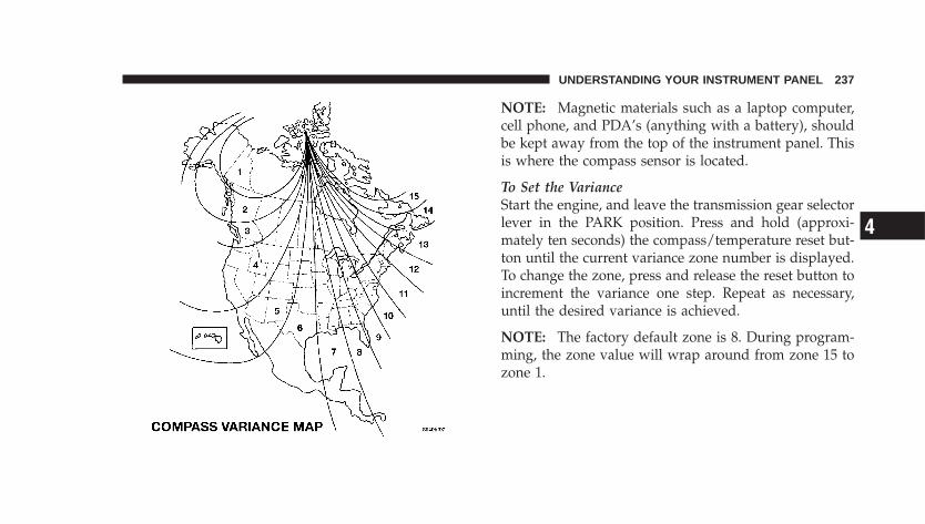
NOTE: Magnetic materials such as a laptop computer,cell phone, and PDA’s (anything with a battery), shouldbe kept away from the top of the instrument panel. Thisis where the compass sensor is located.
To Set the VarianceStart the engine, and leave the transmission gear selectorlever in the PARK position. Press and hold (approxi-mately ten seconds) the compass/temperature reset but-ton until the current variance zone number is displayed.To change the zone, press and release the reset button toincrement the variance one step. Repeat as necessary,until the desired variance is achieved.
NOTE: The factory default zone is 8. During program-ming, the zone value will wrap around from zone 15 tozone 1.
UNDERSTANDING YOUR INSTRUMENT PANEL 237
4
Automatic Compass CalibrationThe compass on your vehicle is self-calibrating, eliminat-ing the need to manually calibrate the compass. Whenthe vehicle is new, the compass may appear erratic andthe CAL indicator message will flash in the EVIC untilthe calibration is complete.
A good calibration requires a level surface and an envi-ronment free from large metallic objects such as build-ings, bridges, underground cables, railroad tracks, etc.
Calibrate the compass by driving slowly, under 5 mph (8km/h) in one or more complete circles in a area free fromlarge metallic objects, until the CAL indicator in the EVICturns off. The compass will now function normally.
NOTE: Keep all magnetic objects, such as laptop com-puters, cell phones and PDAs (anything with a battery)away from the compass sensor which is located in the topof the instrument panel. These devices can interfere withcompass accuracy and performance.
Manual Compass CalibrationIf the compass appears to be inaccurate, you may wish tomanually calibrate the compass. Prior to calibrating thecompass, make sure the proper compass variance value(zone) is selected (refer to the above “Compass Variance”for additional information. Then continue to calibrate thecompass as follows:
1. Start the engine, and leave the transmission in thePARK position.
2. Press and hold (approximately 10 seconds) theCompass/Temperature reset button until the currentvariance zone number is displayed.
3. Release the reset button, then press and hold again(approximately 10 seconds), until the direction is dis-played with the “CAL” indicator on continuously in thedisplay.
238 UNDERSTANDING YOUR INSTRUMENT PANEL
4. To complete the compass calibration, drive the vehiclein one or more complete 360 degree circles under 5 mph(8 km/h) in an area free from power lines, large metallicobjects, until the “CAL” indicator turns off. The compasswill now function normally.
Odometer DisplayWhen the appropriate conditions exist, the followingodometer messages will display:
CRUISE . . . . . . . . . . . . . . . . . . . . . . Cruise ActivatedgASCAP . . . . . . . . . . . . . . . . . . . . . . . Fuel Cap FaultnoFUSE . . . . . . . . . . . . . . . . . . . . . . . . . . Fuse Fault
These messages can be manually turned off by pressingthe right reset button (on the instrument cluster).
Trip Odometer (ODO)This display shows the distance traveled since the lastreset. Press and release the right button (on the instru-ment cluster) to switch from odometer, to trip A or trip B.Press and hold the right button while the odometer/tripodometer is displayed to reset.
Trip AShows the total distance traveled for trip A since the lastreset.
Trip BShows the total distance traveled for trip B since the lastreset.
UNDERSTANDING YOUR INSTRUMENT PANEL 239
4
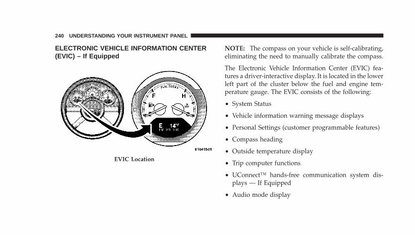
ELECTRONIC VEHICLE INFORMATION CENTER(EVIC) – If Equipped
NOTE: The compass on your vehicle is self-calibrating,eliminating the need to manually calibrate the compass.
The Electronic Vehicle Information Center (EVIC) fea-tures a driver-interactive display. It is located in the lowerleft part of the cluster below the fuel and engine tem-perature gauge. The EVIC consists of the following:
• System Status
• Vehicle information warning message displays
• Personal Settings (customer programmable features)
• Compass heading
• Outside temperature display
• Trip computer functions
• UConnect™ hands-free communication system dis-plays — If Equipped
• Audio mode display
EVIC Location
240 UNDERSTANDING YOUR INSTRUMENT PANEL
When the appropriate conditions exist, the ElectronicVehicle Information Center (EVIC) displays the followingmessages.
• Turn Signal On (with a continuous warning chime)
• Left Front Turn Signal Lamp Out (with a single chime)
• Left Rear Turn Signal Lamp Out (with a single chime)
• Right Front Turn Signal Lamp Out (with a singlechime)
• Right Rear Turn Signal Lamp Out (with a singlechime)
• RKE Battery Low (with a single chime)
• Personal Settings Not Available – Vehicle Not in (au-tomatic transmissions) or vehicle is in motion (manualtransmissions).
• Left/Right Front Door Ajar (one or more, with a singlechime if speed is above 1 mph)
• Left/Right Rear Door Ajar (one or more, with a singlechime if speed is above 1 mph)
• Door (S) Ajar (with a single chime if vehicle is inmotion)
• Trunk Ajar (with a single chime)
• Headlamps On
• Key In Ignition
UNDERSTANDING YOUR INSTRUMENT PANEL 241
4
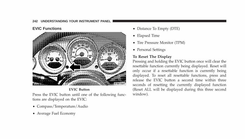
EVIC Functions
Press the EVIC button until one of the following func-tions are displayed on the EVIC:
• Compass/Temperature/Audio
• Average Fuel Economy
• Distance To Empty (DTE)
• Elapsed Time
• Tire Pressure Monitor (TPM)
• Personal Settings
To Reset The DisplayPressing and holding the EVIC button once will clear theresettable function currently being displayed. Reset willonly occur if a resettable function is currently beingdisplayed. To reset all resettable functions, press andrelease the EVIC button a second time within threeseconds of resetting the currently displayed function(Reset ALL will be displayed during this three secondwindow).
EVIC Button
242 UNDERSTANDING YOUR INSTRUMENT PANEL
Compass/Temperature/Audio
Press and release the EVIC button to display one of eightcompass headings to indicate the direction the vehicle isfacing, the outside temperature and the current radiostation.
For additional information regarding the compass, referto Personal Settings (Customer Programmable Features)in this section.
Average Fuel EconomyShows the average fuel economy since the last reset.When the fuel economy is reset, the display will read“RESET” or show dashes for two seconds. Then, thehistory information will be erased, and the averaging willcontinue from where it was before the reset.
Distance To Empty (DTE)Shows the estimated distance that can be travelled withthe fuel remaining in the tank. This estimated distance isdetermined by a weighted average of the instantaneousand average fuel economy, according to the current fueltank level. This is not resettable.
NOTE: Significant changes in driving style or vehicleloading will greatly affect the actual drivable distance ofthe vehicle, regardless of the DTE displayed value.
When the DTE value is less than 30 miles estimateddriving distance, the DTE display will change to a textdisplay of �LOW FUEL�. This display will continue untilthe vehicle runs out of fuel. Adding a significant amountof fuel to the vehicle will turn off the �LOW FUEL� textand a new DTE value will be displayed, based on thecurrent values in the DTE calculation and the current fueltank level.
UNDERSTANDING YOUR INSTRUMENT PANEL 243
4
Elapsed TimeShows the total elapsed time of travel since the last resetwhen the ignition switch is in the ACC position. Elapsedtime will increment when the ignition switch is in the ONor START position.
Tire Pressure Monitor (TPM)Refer to Section 5, “Tire Pressure Monitoring System(TPMS) for system operation.
Personal Settings (Customer ProgrammableFeatures)This allows the driver to set and recall features when thetransmission is in PARK (automatic transmission) or thevehicle is stopped (manual transmissions).
Press and release the EVIC button until Personal Settingsis displayed in the EVIC.
Use the EVIC button to display one of the followingchoices:
LanguageWhen in this display you may select different languagesfor all display nomenclature, including the trip functions.Pressing the EVIC button while in this display selectsEnglish, Espanol, Deutsch, Italiano, or Francais depend-ing on availability. As you continue the displayed infor-mation will be shown in the selected language.
NOTE: UConnect™ language will not change using theEVIC. Please refer to “Language Selection” in theHANDS–FREE COMMUNICATION (UConnect™) — IFEQUIPPED section of this manual for details.
Lock Doors Automatically at 15 MPH (24 Km/h)When ON is selected all doors lock automatically whenthe speed of the vehicle reaches 15 mph (24 km/h). Pressand hold the EVIC button when in this display until ONor OFF appears to make your selection.
244 UNDERSTANDING YOUR INSTRUMENT PANEL
Auto Unlock On ExitWhen ON is selected all the vehicle’s doors will unlockwhen the driver’s door is opened if the vehicle is stopped(manual transmissions) or the vehicle is stopped and thetransmission is in PARK or NEUTRAL position (auto-matic transmissions). Press and hold the EVIC buttonwhen in this display until ON or OFF appears to makeyour selection.
Remote Unlock Driver’s Door 1stWhen DRIVER’S DOOR 1st is selected only the driver’sdoor will unlock on the first press of the remote keylessentry unlock button and require a second press to unlockthe remaining locked doors. When REMOTE UNLOCKALL DOORS is selected all of the doors will unlock atthe first press of the remote keyless entry unlock button.Press and hold the EVIC button when in this display untilDRIVER’S DOOR 1st or ALL DOORS appears to makeyour selection.
Sound Horn with Remote Key LockWhen ON is selected a short horn sound will occur whenthe remote keyless entry LOCK button is pressed. Thisfeature may be selected with or without the flash lightson LOCK/UNLOCK feature. Press and hold the EVICbutton when in this display until ON or OFF appears tomake your selection.
Flash Lights with Remote Key LockWhen ON is selected, the front and rear turn signals willflash when the doors are locked or unlocked using theremote keyless entry transmitter. This feature may beselected with or without the sound horn on lock featureselected. Press and hold the EVIC button when in thisdisplay until ON or OFF appears to make your selection.
Delay Turning Headlamps OffWhen this feature is selected the driver can choose tohave the headlamps remain on for 0, 30, 60, or 90 seconds
UNDERSTANDING YOUR INSTRUMENT PANEL 245
4
when exiting the vehicle. Press and hold the EVIC buttonwhen in this display until 0, 30, 60, or 90 appears to makeyour selection.
Headlamps On With Wipers (Available with AutoHeadlights Only)When ON is selected and the headlight switch is in theAUTO position, the headlights will turn on approxi-mately 10 seconds after the wipers are turned on. Theheadlights will also turn off when the wipers are turnedoff if they were turned on by this feature. Press and holdthe EVIC button when in this display until ON or OFFappears to make your selection.
NOTE: Turning the headlights on during the daytimecauses the instrument panel lights to dim. To increase thebrightness, refer to “Lights” in this section.
Delay Power Off to Accessories Until ExitWhen this feature is selected, the power windowswitches, radio, hands–free system, DVD video system,
power sunroof, and power outlets will remain active forup to 60 minutes after the ignition switch has been turnedoff. Opening a vehicle door will cancel this feature. Pressand hold the EVIC button when in this display until“Off”, “45 sec.”, “5 min.”, or “10 min.” appears to makeyour selection.
Turn Headlamps on with Remote Key UnlockWhen this feature is selected the headlamps will activateand remain on for up to 90 seconds when the doors areunlocked using the remote keyless entry transmitter.Press and hold the EVIC button when in this display until“OFF”, “30 sec.”, “60 sec.”, or “90 sec.” appears to makeyour selection.
Confirmation of Voice Commands — If EquippedWhen ON is selected all voice commands from theU-Connect™ system are confirmed. Press and hold theEVIC button when in this display until ON or OFFappears to make your selection.
246 UNDERSTANDING YOUR INSTRUMENT PANEL
Display English or MetricThe EVIC, odometer, and navigation system units can bechanged between English and Metric.
Press and hold the EVIC button when in this display until“US” or “METRIC” appears to make your selection.
Automatic Compass CalibrationThe compass on your vehicle is self-calibrating, eliminat-ing the need to manually calibrate the compass. Whenthe vehicle is new, the compass may appear erratic andthe “CAL” indicator message will flash in the EVIC untilthe calibration is complete.
A good calibration requires a level surface and an envi-ronment free from large metallic objects such as build-ings, bridges, underground cables, railroad tracks, etc.
Calibrate the compass by driving slowly, under 5 mph (8km/h) in one or more complete circles in a area free from
large metallic objects, until the “CAL” indicator in theEVIC turns off. The compass will now function normally.
NOTE: Keep all magnetic objects, such as laptop com-puters, cell phones and PDA’s (anything with a battery)away from the compass sensor which is located in the topof the instrument panel. These devices can interfere withcompass accuracy and performance.
Manual Compass CalibrationIf the compass appears to be inaccurate, you may wish tomanually calibrate the compass. Prior to calibrating thecompass, make sure the proper Compass Variance Valueis selected (Refer to “Compass Variance” for additionalinformation). Then continue to calibrate the compass asfollows:
1. Start the engine and leave the transmission in thePARK position.
UNDERSTANDING YOUR INSTRUMENT PANEL 247
4
2. Press and release the EVIC button several times untilthe EVIC displays the Personal Settings (Customer Pro-grammable Features) menu.
3. Press and release the EVIC button several times until“Calibrate Compass (Yes)” is displayed. A long (longerthan two seconds) EVIC button Press will place theCompass in calibration mode.
4. The “CAL” indicator will come on continuously in theEVIC display to indicate that the compass is now in thecalibration mode and that the vehicle can now be drivento calibrate. Press the EVIC button from the �CalibrateCompass (Yes)� screen will exit the EVIC CustomerProgrammable features, and return it to its normal oper-ating mode).
5. Drive the vehicle slowly, under 5 mph (8 km/h),completing one or more circles (in an area free from largemetal or metallic objects) until the “CAL” indicator turnsoff. The compass will now function normally.
Compass VarianceCompass Variance is the difference between magneticNorth and Geographic North. In some areas of thecountry, the difference between magnetic and geographicNorth is great enough to introduce some compass error.In order to ensure compass accuracy, the compass vari-ance should be properly set according to the variancezone map for the vehicle’s current location. The compassin your vehicle will now automatically compensate forthis difference.
NOTE: Magnetic materials such as a laptop computer,cell phone, and PDA’s (anything with a battery), shouldbe kept away from the top of the instrument panel. Thisis where the compass sensor is located.
248 UNDERSTANDING YOUR INSTRUMENT PANEL
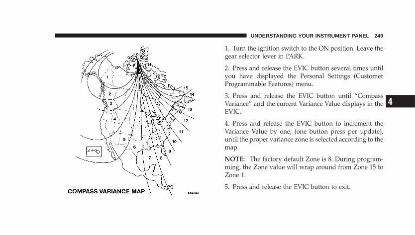
1. Turn the ignition switch to the ON position. Leave thegear selector lever in PARK.
2. Press and release the EVIC button several times untilyou have displayed the Personal Settings (CustomerProgrammable Features) menu.
3. Press and release the EVIC button until “CompassVariance” and the current Variance Value displays in theEVIC.
4. Press and release the EVIC button to increment theVariance Value by one, (one button press per update),until the proper variance zone is selected according to themap.
NOTE: The factory default Zone is 8. During program-ming, the Zone value will wrap around from Zone 15 toZone 1.
5. Press and release the EVIC button to exit.
UNDERSTANDING YOUR INSTRUMENT PANEL 249
4
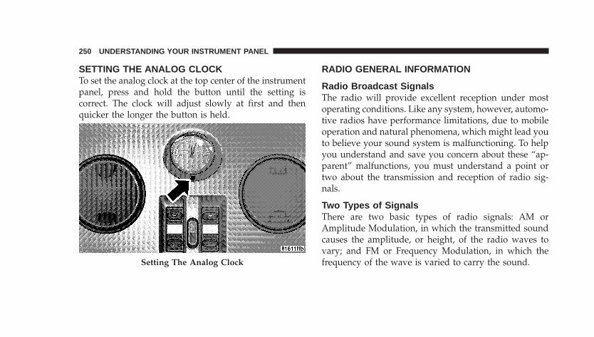
SETTING THE ANALOG CLOCKTo set the analog clock at the top center of the instrumentpanel, press and hold the button until the setting iscorrect. The clock will adjust slowly at first and thenquicker the longer the button is held.
RADIO GENERAL INFORMATION
Radio Broadcast SignalsThe radio will provide excellent reception under mostoperating conditions. Like any system, however, automo-tive radios have performance limitations, due to mobileoperation and natural phenomena, which might lead youto believe your sound system is malfunctioning. To helpyou understand and save you concern about these “ap-parent” malfunctions, you must understand a point ortwo about the transmission and reception of radio sig-nals.
Two Types of SignalsThere are two basic types of radio signals: AM orAmplitude Modulation, in which the transmitted soundcauses the amplitude, or height, of the radio waves tovary; and FM or Frequency Modulation, in which thefrequency of the wave is varied to carry the sound.Setting The Analog Clock
250 UNDERSTANDING YOUR INSTRUMENT PANEL
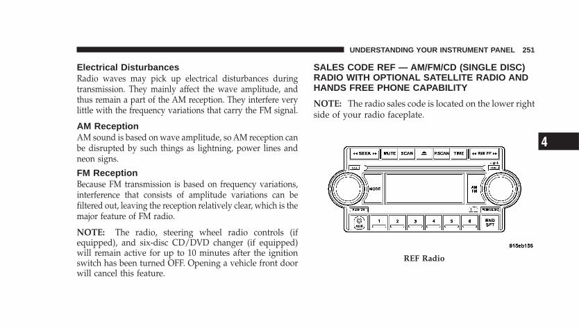
Electrical DisturbancesRadio waves may pick up electrical disturbances duringtransmission. They mainly affect the wave amplitude, andthus remain a part of the AM reception. They interfere verylittle with the frequency variations that carry the FM signal.
AM ReceptionAM sound is based on wave amplitude, so AM reception canbe disrupted by such things as lightning, power lines andneon signs.
FM ReceptionBecause FM transmission is based on frequency variations,interference that consists of amplitude variations can befiltered out, leaving the reception relatively clear, which is themajor feature of FM radio.
NOTE: The radio, steering wheel radio controls (ifequipped), and six-disc CD/DVD changer (if equipped)will remain active for up to 10 minutes after the ignitionswitch has been turned OFF. Opening a vehicle front doorwill cancel this feature.
SALES CODE REF — AM/FM/CD (SINGLE DISC)RADIO WITH OPTIONAL SATELLITE RADIO ANDHANDS FREE PHONE CAPABILITY
NOTE: The radio sales code is located on the lower rightside of your radio faceplate.
REF Radio
UNDERSTANDING YOUR INSTRUMENT PANEL 251
4
Operating Instructions - Radio Mode
NOTE: The ignition switch must be in the ON or ACCposition to operate the radio.
Power Switch/Volume Control (Rotary)Press the ON/VOL control to turn the radio ON. Pressthe ON/VOL a second time to turn OFF the radio.
Electronic Volume ControlThe electronic volume control turns continuously (360degrees) in either direction without stopping. Turning thevolume control to the right increases the volume and tothe left decreases it.
When the audio system is turned on, the sound will beset at the same volume level as last played.
For your convenience, the volume can be turned down,but not up, when the audio system is off and the ignitionis ON.
Mode Button (Radio Mode)Press the MODE button repeatedly to select between theCD player and Satellite Radio (if equipped).
SEEK Button (Radio Mode)Press and release the SEEK button to search for the nextlistenable station in either AM/FM or Satellite (ifequipped) mode. Press the right side of the button to seekup and the left side to seek down. The radio will remaintuned to the new station until you make another selec-tion. Holding the button will bypass stations withoutstopping until you release it.
MUTE Button (Radio Mode)Press the MUTE button to cancel the sound from thespeakers. MUTE will display. Press the MUTE button asecond time and the sound from the speakers will return.Rotating the volume control, turning the radio ON/OFF,or turning ON/OFF the ignition, will cancel the MUTEfeature.
252 UNDERSTANDING YOUR INSTRUMENT PANEL
NOTE: In Hands-Free Phone (if equipped) mode, theMUTE button mutes the microphone.
SCAN Button (Radio Mode)Pressing the SCAN button causes the tuner to search forthe next listenable station in either, AM, FM, or Satellite(if equipped) frequencies, pausing for five seconds ateach listenable station before continuing to the next. Tostop the search, press SCAN a second time.
PSCAN Button (Radio Mode)Pressing the PSCAN button causes the tuner to scanthrough preset stations in either, AM, FM, or Satellite (ifequipped) frequencies, pausing for five seconds at eachpreset station before continuing to the next. To stop thesearch, press PSCAN a second time.
TIME ButtonPress the TIME button and the time of day will displayfor five seconds.
Clock Setting Procedure
1. Press and hold the TIME button until the hours blink.
2. Adjust the hours by turning the TUNE/AUDIO con-trol.
3. After the hours are adjusted, press the TUNE/AUDIOcontrol to set the minutes. The minutes will begin toblink.
4. Adjust the minutes using the TUNE/AUDIO control.
5. To exit, press any button/knob or wait five seconds.
RW/FF (Radio Mode)Pressing the Rewind/Fast Forward button causes thetuner to search for the next frequency in the direction ofthe arrows. This feature operates in either AM, FM orSatellite (if equipped) frequencies.
UNDERSTANDING YOUR INSTRUMENT PANEL 253
4
TUNE Control (Radio Mode)Turn the rotary TUNE control clockwise to increase orcounterclockwise to decrease the frequency.
AM/FM Button (Radio Mode)Press the button to select AM or FM modes.
Setting the Tone, Balance, and FadePress the rotary TUNE control, and BASS will display.Turn the TUNE control to the right or left to increase ordecrease the Bass tones.
Press the rotary TUNE control a second time and MIDwill display. Turn the TUNE control to the right or left toincrease or decrease the Mid-Range tones.
Press the rotary TUNE control a third time and TREB willdisplay. Turn the TUNE control to the right or left toincrease or decrease the Treble tones.
Press the rotary TUNE control a fourth time and BAL willdisplay. Turn the TUNE control to the right or left toadjust the sound level from the right or left side speakers.
Press the rotary TUNE control a fifth time and FADE willdisplay. Turn the TUNE control to the left or right to adjustthe sound level between the front and rear speakers.
Press the tune control again or wait five seconds to exitsetting tone, balance, and fade.
RND/SET Button (Radio Mode) To Set ThePushbutton MemoryWhen you are receiving a station that you wish tocommit to pushbutton memory, press the SET button.The symbol SET 1 will now show in the display window.Select the button (1-6) you wish to lock onto this stationand press and release that button. If a button is notselected within five seconds after pressing the SET but-ton, the station will continue to play but will not bestored into pushbutton memory.
254 UNDERSTANDING YOUR INSTRUMENT PANEL
You may add a second station to each pushbutton byrepeating the above procedure with this exception: Pressthe SET button twice and SET 2 will show in the displaywindow. Each button can be set for SET 1 and SET 2 inboth AM and FM. This allows a total of 12 AM, 12 FM,and 12 Satellite (if equipped) stations to be stored intopushbutton memory. The stations stored in SET 2memory can be selected by pressing the pushbuttontwice.
Every time a preset button is used, a correspondingbutton number will display.
Preset Buttons 1 - 6 (Radio Mode)These buttons tune the Radio to the stations that youcommit to pushbutton memory, 12 AM, 12 FM, and 12Satellite (if equipped) stations.
Operating Instructions - CD Mode
NOTE: The ignition switch must be in the ON or ACCposition to operate the radio.
Inserting The Compact Disc (Single CD Player)Gently insert one CD into the CD player with the CDlabel facing up. The CD will automatically be pulled intothe CD Player and the CD icon will illuminate on theradio display.
If the volume control is ON, the unit will switch to CDmode and begin to play. The display will show the tracknumber and play time in minutes and seconds. Play willbegin at the start of track one.
NOTE:• On some vehicles, you may insert or eject a disc with
the radio or ignition switch OFF.
UNDERSTANDING YOUR INSTRUMENT PANEL 255
4
• If you insert a disc with the ignition ON and the radioOFF, the CD will automatically be pulled into the CDplayer.
• This radio does not play discs with MP3 tracks.
SEEK Button (CD Mode)Press the right side of the SEEK button for the next trackon the CD. Press the left side of the button to return to thebeginning of the current track, or return to the beginningof the previous track if the CD is within the first 10seconds of the current selection.
MUTE Button (CD Mode)Press the MUTE button to cancel the sound from thespeakers. �MUTE� will display. Press the MUTE button asecond time and the sound from the speakers will return.Rotating the volume control or turning OFF the ignitionwill also return the sound from the speakers.
SCAN Button (CD Mode)Press this button to play the first 10 seconds of each track.To stop the scan function, press the button a second time.
EJECT Button (CD Mode)Press this button and the disc will unload andmove to the entrance for easy removal. Theunit will switch to the last selected mode.
If you do not remove the disc within 15 seconds, it will bereloaded. The radio mode will continue to appear.
TIME Button (CD Mode)Press this button to change the display from elapsed CDplaying time to time of day. The time of day will displayfor five seconds.
RW/FF (CD Mode)Press and hold the FF (Fast Forward) and the CD playerwill begin to fast forward until FF is released. The RW(Reverse) button works in a similar manner.
256 UNDERSTANDING YOUR INSTRUMENT PANEL
Press and hold the FF button to fast forward through thetracks. Release the FF button to stop the fast forwardfeature. If the RW button is pressed, the current track willreverse to the beginning of the track and begin playing.
RND/SET Button (Random Play Button) (CDMode)Press this button while the CD is playing to activateRandom play. This feature plays the selections on thecompact disc in random order to provide an interestingchange of pace.
Press the SEEK button to move to the next randomlyselected track.
Press the RND button a second time to stop Randomplay.
Operating Instructions - Auxiliary ModeThe auxiliary (AUX) jack is an audio input jack, whichallows the user to plug in a portable device such as anMP3 player, cassette player, or microphone and utilizethe vehicle’s audio system to amplify the source and playthrough the vehicle speakers.
The auxiliary mode becomes active when an electricaldevice is plugged into the AUX jack using a standard 3.5mm stereo audio cable and the user presses and releasesthe MODE button until AUX appears on the display.
NOTE: The radio will return to the last stored mode ifthe ignition switch is turned from the OFF/LOCK posi-tion to the ACC position, the radio is turned on, and theradio was previously in the AUX mode.
SEEK Button (Auxiliary Mode)No function.
UNDERSTANDING YOUR INSTRUMENT PANEL 257
4
MUTE Button (Auxiliary Mode)Press the MUTE button to cancel the sound from thespeakers. �MUTE� will display. Press the MUTE button asecond time and the sound from the speakers will return.Rotating the volume control or turning off the ignitionwill also return the sound from the speakers.
SCAN Button (Auxiliary Mode)No function.
EJECT Button (Auxiliary Mode)No function.
PSCAN Button (Auxiliary Mode)No function.
TIME Button (Auxiliary Mode)Press this button to change the display from elapsedplaying time to time of day. The time of day will displayfor five seconds.
RW/FF (Auxiliary Mode)No function.
RND/SET Button (Auxiliary Mode)No function.
Mode Button (Auxiliary Mode)Press the MODE button repeatedly to select between theCD player and Satellite Radio (if equipped).
Operating Instructions - Hands-Free Phone — IfEquippedRefer to the “Hands-Free Phone (UConnect�)” section ofthis Owner’s Manual.
Operating Instructions - Satellite Radio — IfEquippedRefer to the “Satellite Radio” section of this Owner’sManual.
258 UNDERSTANDING YOUR INSTRUMENT PANEL
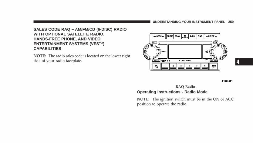
SALES CODE RAQ – AM/FM/CD (6-DISC) RADIOWITH OPTIONAL SATELLITE RADIO,HANDS-FREE PHONE, AND VIDEOENTERTAINMENT SYSTEMS (VES™)CAPABILITIES
NOTE: The radio sales code is located on the lower rightside of your radio faceplate.
Operating Instructions - Radio Mode
NOTE: The ignition switch must be in the ON or ACCposition to operate the radio.
RAQ Radio
UNDERSTANDING YOUR INSTRUMENT PANEL 259
4
Power Switch/Volume Control (Rotary)Press the ON/VOL control to turn the radio ON. Pressthe ON/VOL a second time to turn off the radio.
Electronic Volume ControlThe electronic volume control turns continuously (360degrees) in either direction without stopping. Turning thevolume control to the right increases the volume and tothe left decreases it.
When the audio system is turned on, the sound will beset at the same volume level as last played.
For your convenience, the volume can be turned down,but not up, when the audio system is off and the ignitionis ON.
Mode Button (Radio Mode)Press the MODE button repeatedly to select between theCD player, Satellite Radio, or Video Entertainment Sys-tem (VES)™ (if equipped).
SEEK Button (Radio Mode)Press and release the SEEK button to search for the nextlistenable station in either AM/FM or Satellite (ifequipped) mode. Press the right side of the button to seekup and the left side to seek down. The radio will remaintuned to the new station until you make another selec-tion. Holding the button will bypass stations withoutstopping until you release it.
MUTE Button (Radio Mode)Press the MUTE button to cancel the sound from thespeakers. �MUTE� will be displayed. Press the MUTEbutton a second time and the sound from the speakerswill return. Rotating the volume control, turning theradio ON/OFF, or turning OFF the ignition will alsoreturn the sound from the speakers
NOTE: In Hands-Free Phone (if equipped) mode, theMUTE button mutes the microphone.
260 UNDERSTANDING YOUR INSTRUMENT PANEL
SCAN Button (Radio Mode)Pressing the SCAN button causes the tuner to search forthe next listenable station, in either AM, FM or Satellite (ifequipped) frequencies, pausing for five seconds at eachlistenable station before continuing to the next. To stopthe search, press SCAN a second time.
MSG or INFO Button (Radio Mode)Press the MSG or INFO button for an RBDS station (onewith call letters displayed). The radio will return a RadioText message broadcast from an FM station (FM modeonly).
TIME ButtonPress the TIME button and the time of day will bedisplayed for five seconds.
Clock Setting Procedure
1. Press and hold the time button until the hours blink.
2. Adjust the hours by turning the TUNE/AUDIO con-trol.
3. After the hours are adjusted, press the TUNE/AUDIOcontrol to set the minutes. The minutes will begin toblink.
4. Adjust the minutes by turning the TUNE/AUDIOcontrol.
5. To exit, press any button/knob or wait five seconds.
RW/FF (Radio Mode)Pressing the Rewind/Fast Forward button causes thetuner to search for the next frequency in the direction ofthe arrows. This feature operates in either AM, FM orSatellite (if equipped) frequencies.
TUNE Control (Radio Mode)Turn the rotary TUNE control clockwise to increase orcounterclockwise to decrease the frequency.
UNDERSTANDING YOUR INSTRUMENT PANEL 261
4
AM/FM Button (Radio Mode)Press the button to select AM or FM Modes.
Setting the Tone, Balance, and FadePress the rotary TUNE control, and BASS will display.Turn the TUNE control to the right or left to increase ordecrease the Bass tones.
Press the rotary TUNE control a second time and MIDwill display. Turn the TUNE control to the right or left toincrease or decrease the Mid Range tones.
Press the rotary TUNE control a third time and TREBLEwill display. Turn the TUNE control to the right or left toincrease or decrease the Treble tones.
Press the rotary TUNE control a fourth time and BAL-ANCE will display. Turn the TUNE control to the right orleft to adjust the sound level from the right or left sidespeakers.
Press the rotary TUNE control a fifth time and FADE willdisplay. Turn the TUNE control to the left or right toadjust the sound level between the front and rear speak-ers.
Press the rotary TUNE control again to exit setting tone,balance and fade.
RND/PTY Button (Radio Mode)Pressing this button once will turn on the PTY mode forfive seconds. If no action is taken during the five secondtime out the PTY icon will turn off. Pressing the PTYbutton or turning the TUNE rotary knob within fiveseconds will allow the program format type to be se-lected. Many radio stations do not currently broadcastPTY information.
262 UNDERSTANDING YOUR INSTRUMENT PANEL

Toggle the PTY button to select the following formattypes:
Program Type 16 Digit-Character DisplayNo program type or
undefined None
Adult Hits Adult_HitsAlert Alert Alert AlertClassical Classical
Classic Rock Classic_RockCollege CollegeCountry Country
Emergency Test Emergency TestForeign Language Foreign_Language
Information InformationJazz Jazz
News NewsNostalgia Nostalgia
Program Type 16 Digit-Character DisplayOldies Oldies
Personality PersonalityPublic Public
Rhythm and Blues Rhythm_and_BluesReligious Music Religious_MusicReligious Talk Religious_Talk
Rock RockSoft Soft
Soft Rock Soft_RockSoft Rhythm and Blues Soft_R_&_B
Sports SportsTalk Talk
Top 40 Top_40Weather Weather
UNDERSTANDING YOUR INSTRUMENT PANEL 263
4
By pressing the SEEK button when the PTY icon isdisplayed, the radio will be tuned to the next frequencystation with the same selected PTY name. The PTYfunction only operates when in the FM mode.
If a preset button is activated while in the PTY (ProgramType) mode, the PTY mode will be exited and the radiowill tune to the preset station.
SET/DIR Button (Radio Mode) — To Set thePushbutton MemoryWhen you are receiving a station that you wish tocommit to pushbutton memory, press the SET/DIR but-ton. The symbol SET 1 will now show in the displaywindow. Select the button (1-6) you wish to lock onto thisstation and press and release that button. If a button isnot selected within five seconds after pressing the SET/DIR button, the station will continue to play but will notbe stored into pushbutton memory.
You may add a second station to each pushbutton byrepeating the above procedure with this exception: Pressthe SET/DIR button twice and SET 2 will show in thedisplay window. Each button can be set for SET 1 andSET 2 in both AM and FM. This allows a total of 12 AM,12 FM and 12 Satellite (if equipped) stations to be storedinto pushbutton memory. The stations stored in SET 2memory can be selected by pressing the pushbuttontwice.
Every time a preset button is used, a correspondingbutton number will be displayed.
Buttons 1 - 6 (Radio Mode)These buttons tune the Radio to the stations that youcommit to pushbutton memory, 12AM, 12 FM, and 12Satellite (if equipped) stations.
264 UNDERSTANDING YOUR INSTRUMENT PANEL
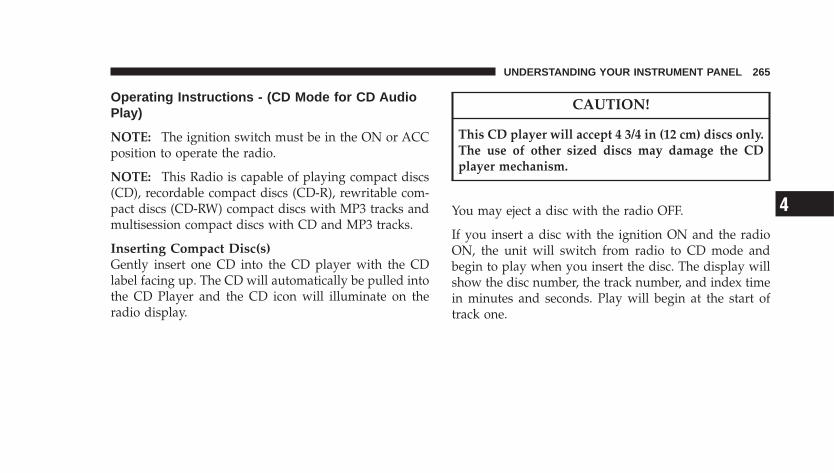
Operating Instructions - (CD Mode for CD AudioPlay)
NOTE: The ignition switch must be in the ON or ACCposition to operate the radio.
NOTE: This Radio is capable of playing compact discs(CD), recordable compact discs (CD-R), rewritable com-pact discs (CD-RW) compact discs with MP3 tracks andmultisession compact discs with CD and MP3 tracks.
Inserting Compact Disc(s)Gently insert one CD into the CD player with the CDlabel facing up. The CD will automatically be pulled intothe CD Player and the CD icon will illuminate on theradio display.
CAUTION!
This CD player will accept 4 3/4 in (12 cm) discs only.The use of other sized discs may damage the CDplayer mechanism.
You may eject a disc with the radio OFF.
If you insert a disc with the ignition ON and the radioON, the unit will switch from radio to CD mode andbegin to play when you insert the disc. The display willshow the disc number, the track number, and index timein minutes and seconds. Play will begin at the start oftrack one.
UNDERSTANDING YOUR INSTRUMENT PANEL 265
4
SEEK Button (CD Mode for CD Audio Play)Press the right side of the SEEK button for the nextselection on the CD. Press the left side of the button toreturn to the beginning of the current selection, or returnto the beginning of the previous selection if the CD iswithin the first 10 seconds of the current selection.
MUTE Button (CD Mode for CD Audio Play)Press the MUTE button to cancel the sound from thespeakers. �MUTE� will be displayed. Press the MUTEbutton a second time and the sound from the speakerswill return. Rotating the volume control, turning theradio ON/OFF, or turning OFF the ignition will alsoreturn the sound from the speakers.
SCAN Button (CD Mode for CD Audio Play)Press the SCAN button to scan through each track on theCD currently playing.
LOAD/EJECT Button (CD Mode for CD AudioPlay)
LOAD/ EJECT - LoadPress the LOAD/EJECT button and the push-button with the corresponding number wherethe CD is being loaded. The radio will displayPLEASE WAIT and prompt when to INSERT
DISC. After the radio displays �LOAD DISC� insert theCD into the player.
Radio display will show �LOADING DISC� when the discis loading, and “READING DISC” when the radio isreading the disc.
LOAD / EJT - EjectPress the LOAD/ EJT button and the push-button with the corresponding number wherethe CD was loaded and the disc will unloadand move to the entrance for easy removal.
266 UNDERSTANDING YOUR INSTRUMENT PANEL
Radio display will show �EJECTING DISC� when the discis being ejected and prompt the user to remove the disc.
Press and hold the LOAD/ EJT button for five secondsand all CDs will be ejected from the radio.
If you have ejected a disc and have not removed it within15 seconds, it will be reloaded. If the CD is not removed,the radio will continue to play the non-removed CD. Ifthe CD is removed and there are other CDs in the radio,the radio will play the next CD after a two minutetimeout. If the CD is removed and there are no other CDsin the radio, the radio will remain in CD mode anddisplay �INSERT DISC” for 10 seconds. If no discs areinserted within 10 seconds “NO DISCS LOADED” willbe displayed.
On some vehicles a disc can be ejected with the radio andignition OFF.
TIME Button (CD Mode for CD Audio Play)Press this button to change the display from a large CDplaying time display to a small CD playing time display.
RW/FF (CD Mode for CD Audio Play)Press and hold FF (Fast Forward) and the CD player willbegin to fast forward until FF is released or RW oranother CD button is pressed. The RW (Reverse) buttonworks in a similar manner.
Press and hold the FF button to fast forward through thetracks. Release the FF button to stop the fast forwardfeature.
TUNE Control (CD Mode for CD Audio Play)Pressing the TUNE control allows the setting of the Tone,Fade, and Balance. See Radio Mode.
AM/FM Button (CD Mode for CD Audio Play)Switches the Radio to the Radio mode.
UNDERSTANDING YOUR INSTRUMENT PANEL 267
4
RND/PTY Button (Random Play Button) (CD Modefor CD Audio Play)Press this button while the CD is playing to activateRandom Play. This feature plays the selections on thecompact disc in random order to provide an interestingchange of pace.
Press the SEEK button to move to the next randomlyselected track.
Press the RND button a second time to stop Randomplay.
Buttons 1 - 6 (CD Mode for CD Audio Play)Selects disc positions 1 - 6 for Play/Load/Eject.
Notes On Playing MP3 FilesThe radio can play MP3 files, however, acceptable MP3file recording media and formats are limited. Whenwriting MP3 files, pay attention to the following restric-tions.
Supported Media (Disc Types)The MP3 file recording media supported by the radio areCD-ROM, CD-R and CD-RW.
Supported Medium Formats (File Systems)The medium formats supported by the radio are ISO 9660Level 1 and Level 2 and includes the Joliet extension.When reading discs recorded using formats other thanISO 9660 Level 1 and Level 2, the radio may fail to readfiles properly and may be unable to play the file nor-mally. UDF and Apple HFS formats are not supported.
The radio uses the following limits for file systems:
• Maximum number of directory levels: 15
• Maximum number of files: 255
• Maximum number of folders: 100
268 UNDERSTANDING YOUR INSTRUMENT PANEL
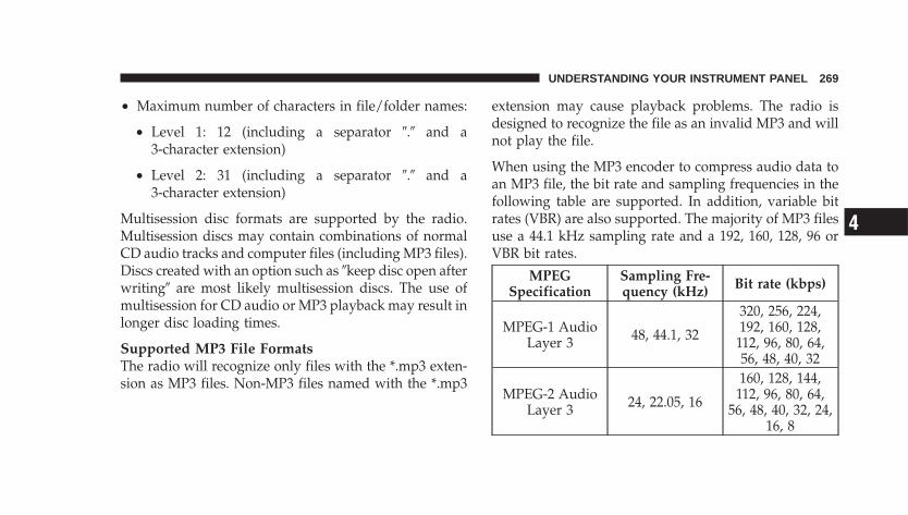
• Maximum number of characters in file/folder names:
• Level 1: 12 (including a separator �.� and a3-character extension)
• Level 2: 31 (including a separator �.� and a3-character extension)
Multisession disc formats are supported by the radio.Multisession discs may contain combinations of normalCD audio tracks and computer files (including MP3 files).Discs created with an option such as �keep disc open afterwriting� are most likely multisession discs. The use ofmultisession for CD audio or MP3 playback may result inlonger disc loading times.
Supported MP3 File FormatsThe radio will recognize only files with the *.mp3 exten-sion as MP3 files. Non-MP3 files named with the *.mp3
extension may cause playback problems. The radio isdesigned to recognize the file as an invalid MP3 and willnot play the file.
When using the MP3 encoder to compress audio data toan MP3 file, the bit rate and sampling frequencies in thefollowing table are supported. In addition, variable bitrates (VBR) are also supported. The majority of MP3 filesuse a 44.1 kHz sampling rate and a 192, 160, 128, 96 orVBR bit rates.
MPEGSpecification
Sampling Fre-quency (kHz) Bit rate (kbps)
MPEG-1 AudioLayer 3 48, 44.1, 32
320, 256, 224,192, 160, 128,
112, 96, 80, 64,56, 48, 40, 32
MPEG-2 AudioLayer 3 24, 22.05, 16
160, 128, 144,112, 96, 80, 64,
56, 48, 40, 32, 24,16, 8
UNDERSTANDING YOUR INSTRUMENT PANEL 269
4
ID3 Tag information for artist, song title and album titleare supported for version 1 ID3 tags. ID3 version 2 is notsupported by the radios.
Playlist files are not supported. MP3 Pro files are notsupported.
Playback of MP3 FilesWhen a medium containing MP3 data is loaded, theradio checks all files on the medium. If the mediumcontains a lot of folders or files, the radio will take moretime to start playing the MP3 files.
Loading times for playback of MP3 files may be affectedby the following:
• Media - CD-RW media may take longer to load thanCD-R media
• Medium formats - Multisession discs may take longerto load than non-multisession discs
• Number of files and folders - Loading times willincrease with more files and folders
To increase the speed of disc loading, it is recommendedto use CD-R media and single-session discs. To create asingle-session disc, enable the Disc at Once option beforewriting to the disc.
Operating Instructions - (CD Mode for MP3 AudioPlay)
SEEK Button (CD Mode for MP3 Play)Pressing the right side of the SEEK button plays the nextMP3 File. Pressing the left side of the SEEK button playsthe beginning of the MP3 file. Pressing the button withinthe first ten seconds plays the previous file.
270 UNDERSTANDING YOUR INSTRUMENT PANEL
LOAD/EJECT Button (CD Mode for MP3 Play)
LOAD/EJECT - LoadPress the LOAD/ EJECT button and the push-button with the corresponding number wherethe CD is being loaded. The radio will displayPLEASE WAIT and prompt when to INSERT
DISC. After the radio displays �LOAD DISC� insert theCD into the player.
Radio display will show �LOADING DISC� when the discis loading.
LOAD/EJECT - EjectPress the LOAD/ EJECT button and the push-button with the corresponding number wherethe CD was loaded and the disc will unloadand move to the entrance for easy removal.
Radio display will show �EJECTING DISC� when the discis being ejected and prompt the user to remove the disc.
If you have ejected a disc and have not removed it within15 seconds, it will be reloaded. If the CD is not removed,the radio will continue to play the non-removed CD. Ifthe CD is removed and there are other CDs in the radio,the radio will play the next CD after a two minutetimeout. If the CD is removed and there are no other CD’sin the radio, the radio will remain in CD mode anddisplay �INSERT DISC” for two minutes. After twominutes the radio will go to the previous tuner mode.
MSG or INFO Button (CD Mode for MP3 Play)Press and MSG or INFO button while playing MP3 disc.The radio scrolls through the following TAG information:Song Title, Artist, File Name, and Folder Name (if avail-able).
Press the MSG or INFO button once more to return to�elapsed time� priority mode.
UNDERSTANDING YOUR INSTRUMENT PANEL 271
4
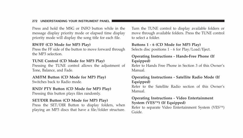
Press and hold the MSG or INFO button while in themessage display priority mode or elapsed time displaypriority mode will display the song title for each file.
RW/FF (CD Mode for MP3 Play)Press the FF side of the button to move forward throughthe MP3 selection.
TUNE Control (CD Mode for MP3 Play)Pressing the TUNE control allows the adjustment ofTone, Balance, and Fade.
AM/FM Button (CD Mode for MP3 Play)Switches back to Radio mode.
RND/ PTY Button (CD Mode for MP3 Play)Pressing this button plays files randomly.
SET/DIR Button (CD Mode for MP3 Play)Press the SET/DIR Button to display folders, whenplaying an MP3 discs that have a file/folder structure.
Turn the TUNE control to display available folders ormove through available folders. Press the TUNE controlto select a folder.
Buttons 1 - 6 (CD Mode for MP3 Play)Selects disc positions 1 - 6 for Play/Load/Eject.
Operating Instructions - Hands-Free Phone (IfEquipped)Refer to Hands Free Phone in Section 3 of this Owner’sManual.
Operating Instructions - Satellite Radio Mode (IfEquipped)Refer to the Satellite Radio section of this Owner’sManual.
Operating Instructions - Video EntertainmentSystem (VES™) (If Equipped)Refer to separate Video Entertainment System (VES™)Guide.
272 UNDERSTANDING YOUR INSTRUMENT PANEL
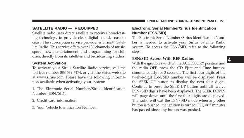
SATELLITE RADIO — IF EQUIPPEDSatellite radio uses direct satellite to receiver broadcast-ing technology to provide clear digital sound, coast tocoast. The subscription service provider is Sirius™ Satel-lite Radio. This service offers over 130 channels of music,sports, news, entertainment, and programming for chil-dren, directly from its satellites and broadcasting studios.
System ActivationTo activate your Sirius Satellite Radio service, call thetoll-free number 888-539-7474, or visit the Sirius web siteat www.sirius.com. Please have the following informa-tion available when activating your system:
1. The Electronic Serial Number/Sirius IdentificationNumber (ESN/SID).
2. Credit card information.
3. Your Vehicle Identification Number.
Electronic Serial Number/Sirius IdentificationNumber (ESN/SID)The Electronic Serial Number/Sirius Identification Num-ber is needed to activate your Sirius Satellite Radiosystem. To access the ESN/SID, refer to the followingsteps:
ESN/SID Access With REF RadiosWith the ignition switch in the ACCESSORY position andthe radio OFF, press the CD Eject and Time buttonssimultaneously for 3 seconds. The first four digits of thetwelve-digit ESN/SID number will be displayed. Pressthe SEEK UP button to display the next four digits.Continue to press the SEEK UP button until all twelveESN/SID digits have been displayed. The SEEK DOWNwill page down until the first four digits are displayed.The radio will exit the ESN/SID mode when any otherbutton is pushed, the ignition is turned OFF, or 5 minuteshas passed since any button was pushed.
UNDERSTANDING YOUR INSTRUMENT PANEL 273
4
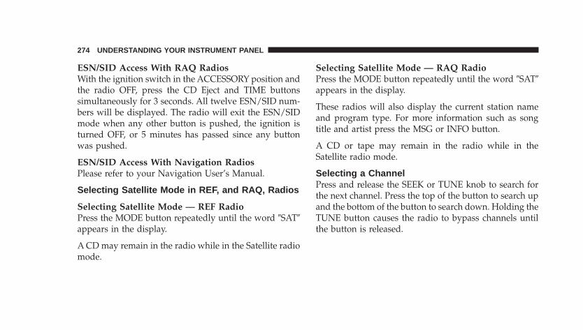
ESN/SID Access With RAQ RadiosWith the ignition switch in the ACCESSORY position andthe radio OFF, press the CD Eject and TIME buttonssimultaneously for 3 seconds. All twelve ESN/SID num-bers will be displayed. The radio will exit the ESN/SIDmode when any other button is pushed, the ignition isturned OFF, or 5 minutes has passed since any buttonwas pushed.
ESN/SID Access With Navigation RadiosPlease refer to your Navigation User’s Manual.
Selecting Satellite Mode in REF, and RAQ, Radios
Selecting Satellite Mode — REF RadioPress the MODE button repeatedly until the word �SAT�appears in the display.
A CD may remain in the radio while in the Satellite radiomode.
Selecting Satellite Mode — RAQ RadioPress the MODE button repeatedly until the word �SAT�appears in the display.
These radios will also display the current station nameand program type. For more information such as songtitle and artist press the MSG or INFO button.
A CD or tape may remain in the radio while in theSatellite radio mode.
Selecting a ChannelPress and release the SEEK or TUNE knob to search forthe next channel. Press the top of the button to search upand the bottom of the button to search down. Holding theTUNE button causes the radio to bypass channels untilthe button is released.
274 UNDERSTANDING YOUR INSTRUMENT PANEL
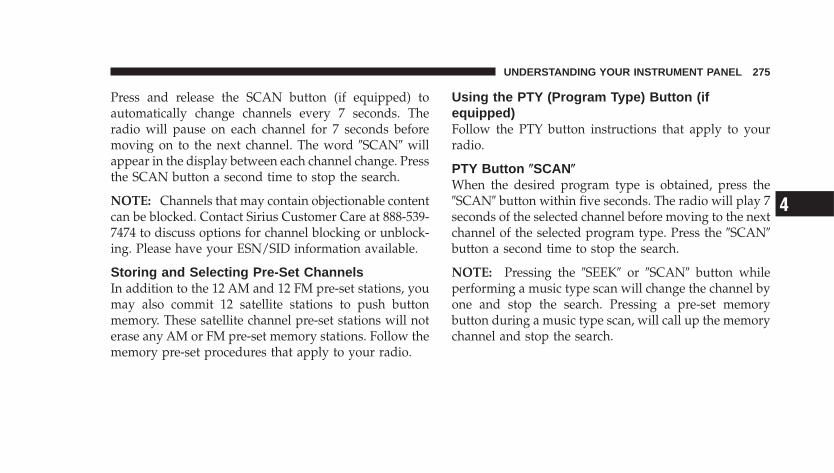
Press and release the SCAN button (if equipped) toautomatically change channels every 7 seconds. Theradio will pause on each channel for 7 seconds beforemoving on to the next channel. The word �SCAN� willappear in the display between each channel change. Pressthe SCAN button a second time to stop the search.
NOTE: Channels that may contain objectionable contentcan be blocked. Contact Sirius Customer Care at 888-539-7474 to discuss options for channel blocking or unblock-ing. Please have your ESN/SID information available.
Storing and Selecting Pre-Set ChannelsIn addition to the 12 AM and 12 FM pre-set stations, youmay also commit 12 satellite stations to push buttonmemory. These satellite channel pre-set stations will noterase any AM or FM pre-set memory stations. Follow thememory pre-set procedures that apply to your radio.
Using the PTY (Program Type) Button (ifequipped)Follow the PTY button instructions that apply to yourradio.
PTY Button SCANWhen the desired program type is obtained, press the�SCAN� button within five seconds. The radio will play 7seconds of the selected channel before moving to the nextchannel of the selected program type. Press the �SCAN�button a second time to stop the search.
NOTE: Pressing the �SEEK� or �SCAN� button whileperforming a music type scan will change the channel byone and stop the search. Pressing a pre-set memorybutton during a music type scan, will call up the memorychannel and stop the search.
UNDERSTANDING YOUR INSTRUMENT PANEL 275
4
PTY Button SEEKWhen the desired program is obtained, press the �SEEK�button within five seconds. The channel will change tothe next channel that matches the program type selected.
Satellite AntennaTo ensure optimum reception, do not place items on theroof around the rooftop antenna location. Metal objectsplaced within the line of sight of the antenna will causedecreased performance. Larger luggage items should beplaced as far forward as possible. Do not place itemsdirectly on or above the antenna. The luggage rack (ifequipped), should also not be positioned directly abovethe antenna.
Reception QualitySatellite reception may be interrupted due to one of thefollowing reasons.
• The vehicle is parked in an underground parkingstructure or under a physical obstacle.
• Dense tree coverage may interrupt reception in theform of short audio mutes.
• Driving under wide bridges or along tall buildings cancause intermittent reception.
• Placing objects over or too close to the antenna cancause signal blockage.
276 UNDERSTANDING YOUR INSTRUMENT PANEL

CD/DVD DISC MAINTENANCETo keep the CD/DVD discs in good condition, take thefollowing precautions:
1. Handle the disc by its edge; avoid touching thesurface.
2. If the disc is stained, clean the surface with a soft cloth,wiping from center to edge.
3. Do not apply paper, paper CD labels, or tape to thedisc; avoid scratching the disc.
4. Do not use solvents such as benzine, thinner, cleaners,or antistatic sprays.
5. Store the disc in its case after playing.
6. Do not expose the disc to direct sunlight.
7. Do not store the disc where temperatures may becometoo high.
8. Do not play discs that are small in size or haveirregular shapes.
RADIO OPERATION AND CELLULAR PHONESUnder certain conditions, the cellular phone being ON inyour vehicle can cause erratic or noisy performance fromyour radio. This condition may be lessened or eliminatedby relocating the cellular phone antenna. This conditionis not harmful to the radio. If your radio performancedoes not satisfactorily “clear” by the repositioning of theantenna, it is recommended that the radio volume beturned down or off during cellular phone operation.
CLIMATE CONTROLS
Climate ControlsThe Climate Control System allows you to balance thetemperature, amount, and direction of air circulatingthroughout the vehicle. The controls are located in thecenter instrument panel, below the radio.
UNDERSTANDING YOUR INSTRUMENT PANEL 277
4
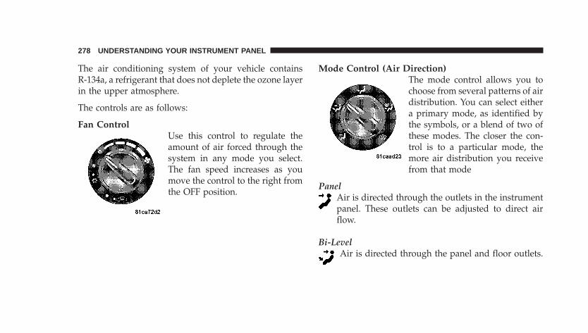
The air conditioning system of your vehicle containsR-134a, a refrigerant that does not deplete the ozone layerin the upper atmosphere.
The controls are as follows:
Fan ControlUse this control to regulate theamount of air forced through thesystem in any mode you select.The fan speed increases as youmove the control to the right fromthe OFF position.
Mode Control (Air Direction)The mode control allows you tochoose from several patterns of airdistribution. You can select eithera primary mode, as identified bythe symbols, or a blend of two ofthese modes. The closer the con-trol is to a particular mode, themore air distribution you receivefrom that mode
PanelAir is directed through the outlets in the instrumentpanel. These outlets can be adjusted to direct airflow.
Bi-LevelAir is directed through the panel and floor outlets.
278 UNDERSTANDING YOUR INSTRUMENT PANEL
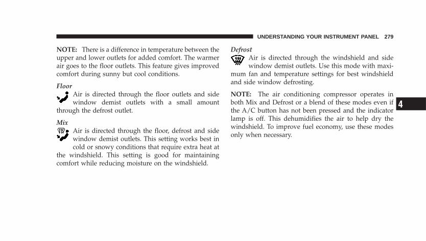
NOTE: There is a difference in temperature between theupper and lower outlets for added comfort. The warmerair goes to the floor outlets. This feature gives improvedcomfort during sunny but cool conditions.
FloorAir is directed through the floor outlets and sidewindow demist outlets with a small amount
through the defrost outlet.
MixAir is directed through the floor, defrost and sidewindow demist outlets. This setting works best incold or snowy conditions that require extra heat at
the windshield. This setting is good for maintainingcomfort while reducing moisture on the windshield.
DefrostAir is directed through the windshield and sidewindow demist outlets. Use this mode with maxi-
mum fan and temperature settings for best windshieldand side window defrosting.
NOTE: The air conditioning compressor operates inboth Mix and Defrost or a blend of these modes even ifthe A/C button has not been pressed and the indicatorlamp is off. This dehumidifies the air to help dry thewindshield. To improve fuel economy, use these modesonly when necessary.
UNDERSTANDING YOUR INSTRUMENT PANEL 279
4
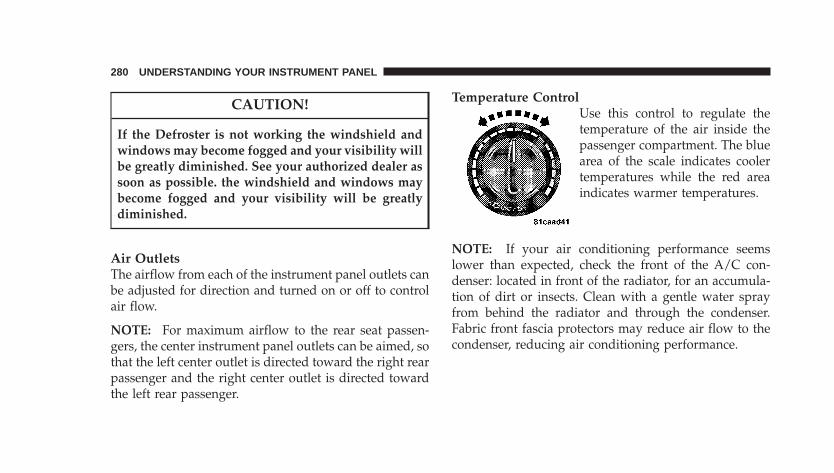
CAUTION!
If the Defroster is not working the windshield andwindows may become fogged and your visibility willbe greatly diminished. See your authorized dealer assoon as possible. the windshield and windows maybecome fogged and your visibility will be greatlydiminished.
Air OutletsThe airflow from each of the instrument panel outlets canbe adjusted for direction and turned on or off to controlair flow.
NOTE: For maximum airflow to the rear seat passen-gers, the center instrument panel outlets can be aimed, sothat the left center outlet is directed toward the right rearpassenger and the right center outlet is directed towardthe left rear passenger.
Temperature ControlUse this control to regulate thetemperature of the air inside thepassenger compartment. The bluearea of the scale indicates coolertemperatures while the red areaindicates warmer temperatures.
NOTE: If your air conditioning performance seemslower than expected, check the front of the A/C con-denser: located in front of the radiator, for an accumula-tion of dirt or insects. Clean with a gentle water sprayfrom behind the radiator and through the condenser.Fabric front fascia protectors may reduce air flow to thecondenser, reducing air conditioning performance.
280 UNDERSTANDING YOUR INSTRUMENT PANEL
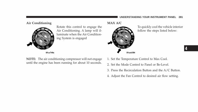
Air ConditioningRotate this control to engage theAir Conditioning. A lamp will il-luminate when the Air Condition-ing System is engaged
NOTE: The air conditioning compressor will not engageuntil the engine has been running for about 10 seconds.
MAX A/CTo quickly cool the vehicle interiorfollow the steps listed below:
1. Set the Temperature Control to Max Cool.
2. Set the Mode Control to Panel or Be-Level.
3. Press the Recirculation Button and the A/C Button.
4. Adjust the Fan Control to desired air flow setting.
UNDERSTANDING YOUR INSTRUMENT PANEL 281
4
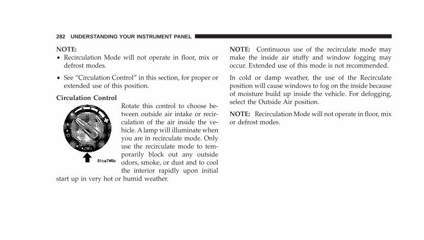
NOTE:• Recirculation Mode will not operate in floor, mix or
defrost modes.
• See “Circulation Control” in this section, for proper orextended use of this position.
Circulation ControlRotate this control to choose be-tween outside air intake or recir-culation of the air inside the ve-hicle. A lamp will illuminate whenyou are in recirculate mode. Onlyuse the recirculate mode to tem-porarily block out any outsideodors, smoke, or dust and to coolthe interior rapidly upon initial
start up in very hot or humid weather.
NOTE: Continuous use of the recirculate mode maymake the inside air stuffy and window fogging mayoccur. Extended use of this mode is not recommended.
In cold or damp weather, the use of the Recirculateposition will cause windows to fog on the inside becauseof moisture build up inside the vehicle. For defogging,select the Outside Air position.
NOTE: Recirculation Mode will not operate in floor, mixor defrost modes.
282 UNDERSTANDING YOUR INSTRUMENT PANEL
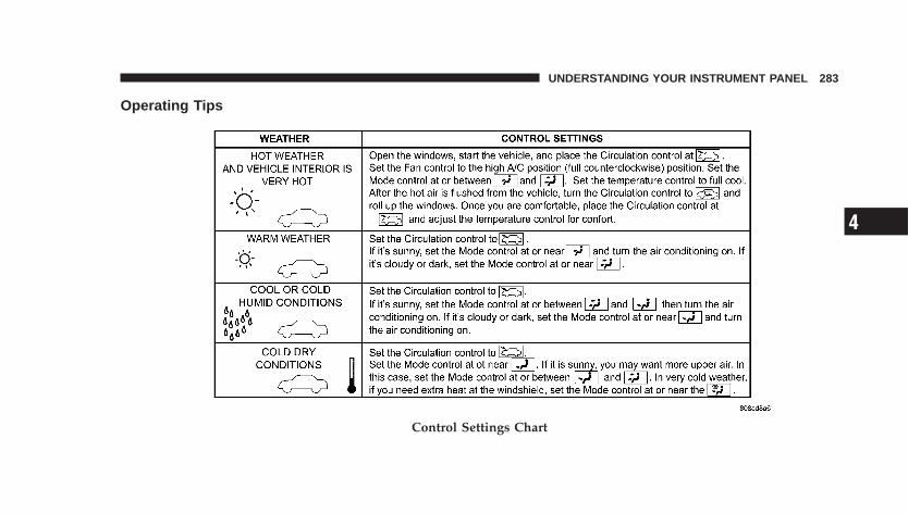
Operating Tips
Control Settings Chart
UNDERSTANDING YOUR INSTRUMENT PANEL 283
4
Window FoggingVehicle side windows tend to fog on the inside in mildrainy or humid weather. To clear the windows, use theA/C, PANEL and blower controls. Direct the paneloutlets toward the side windows. Do not use recirculatewithout A/C for long periods as fogging may occur.
Interior fogging on the windshield can be quickly re-moved by using the defrost position.
If the fogging problem persists, clean the inside windowsurfaces. The cause of undue fogging may be dirt collect-ing on the inside surface of the glass
NOTE: In cold weather, the use of the recirculateposition will cause windows to fog on the inside becauseof moisture build up inside the vehicle. For maximumdefogging, use the Outside Air position.
Summer OperationVehicles must be protected with a high-quality antifreezecoolant to provide proper corrosion protection and toraise the boiling point of the coolant for protectionagainst overheating. A 50% concentration is recom-mended.
Outside Air IntakeWhen operating the system, make sure the air intake,directly in front of the windshield, is free of ice, slush,snow or other obstructions such as leaves. Leaves col-lected in the air-intake plenum may reduce air flow andplug the plenum water drains.
The blower air will heat faster in cold weather if you useonly a low blower speed for the first few minutes ofvehicle operation.
284 UNDERSTANDING YOUR INSTRUMENT PANEL
Side Window DemistersA side window demister outlet is at each end of theinstrument panel. These nonadjustable outlets direct airtoward the side windows when the system is in either theFLOOR, MIX, or DEFROST mode. The air is directed atthe area of the windows through which you view theoutside mirrors.
UNDERSTANDING YOUR INSTRUMENT PANEL 285
4

STARTING AND OPERATING
CONTENTS
� Starting Procedures . . . . . . . . . . . . . . . . . . . . . 291
▫ Automatic Transaxle . . . . . . . . . . . . . . . . . . . 291
▫ Manual Transaxle . . . . . . . . . . . . . . . . . . . . . 292
▫ Normal Starting . . . . . . . . . . . . . . . . . . . . . . 292
▫ Extremely Cold Weather (Below �20°F Or�29°C) . . . . . . . . . . . . . . . . . . . . . . . . . . . . . 292
▫ If The Engine Fails To Start . . . . . . . . . . . . . . 293
▫ After Starting . . . . . . . . . . . . . . . . . . . . . . . . 293
▫ Turbocharger �Cool-Down� . . . . . . . . . . . . . . . 293
� Automatic Transaxle — If Equipped . . . . . . . . . 294
▫ Brake/Transmission Interlock System . . . . . . . 295
▫ Automatic Transaxle Ignition InterlockSystem . . . . . . . . . . . . . . . . . . . . . . . . . . . . . 295
▫ Four-Speed Automatic Transaxle . . . . . . . . . . . 296
▫ Reset Mode . . . . . . . . . . . . . . . . . . . . . . . . . 296
▫ Gear Ranges For The Four-Speed AutomaticTransaxle . . . . . . . . . . . . . . . . . . . . . . . . . . . 297
5
� AutoStick — If Equipped . . . . . . . . . . . . . . . . . 299
▫ AutoStick Operation . . . . . . . . . . . . . . . . . . . 300
▫ AutoStick General Information . . . . . . . . . . . . 300
� Manual Transaxle Operation — If Equipped . . . . 301
▫ 2.4 Liter Turbo — If Equipped . . . . . . . . . . . . 303
▫ Manual Transaxle — Recommended ShiftSpeeds . . . . . . . . . . . . . . . . . . . . . . . . . . . . . 304
▫ Downshifting . . . . . . . . . . . . . . . . . . . . . . . . 304
� Parking Brake . . . . . . . . . . . . . . . . . . . . . . . . . 305
� Brake System . . . . . . . . . . . . . . . . . . . . . . . . . . 307
▫ Anti-Lock Brake System (ABS) —If Equipped . . . . . . . . . . . . . . . . . . . . . . . . . 308
� Power Steering . . . . . . . . . . . . . . . . . . . . . . . . 310
� Traction Control System — If Equipped . . . . . . . 311
� Tire Safety Information . . . . . . . . . . . . . . . . . . . 313
▫ Tire Markings . . . . . . . . . . . . . . . . . . . . . . . . 313
▫ Tire Identification Number (TIN) . . . . . . . . . . 316
▫ Tire Loading And Tire Pressure . . . . . . . . . . . 317
� Tires — General Information . . . . . . . . . . . . . . . 321
▫ Tire Pressure . . . . . . . . . . . . . . . . . . . . . . . . . 321
▫ Tire Inflation Pressures . . . . . . . . . . . . . . . . . 322
▫ Radial Ply Tires . . . . . . . . . . . . . . . . . . . . . . 324
▫ Compact Spare Tire — If Equipped . . . . . . . . . 325
▫ Limited-Use Spare — If Equipped . . . . . . . . . 325
▫ Tire Spinning . . . . . . . . . . . . . . . . . . . . . . . . 326
▫ Tread Wear Indicators . . . . . . . . . . . . . . . . . . 327
▫ Life Of Tire . . . . . . . . . . . . . . . . . . . . . . . . . 327
288 STARTING AND OPERATING
▫ Replacement Tires . . . . . . . . . . . . . . . . . . . . . 328
▫ Alignment And Balance . . . . . . . . . . . . . . . . . 329
� Tire Chains . . . . . . . . . . . . . . . . . . . . . . . . . . . 330
� Snow Tires . . . . . . . . . . . . . . . . . . . . . . . . . . . 330
� Tire Rotation Recommendations . . . . . . . . . . . . 331
� Tire Pressure Monitor System (TPMS) —If Equipped . . . . . . . . . . . . . . . . . . . . . . . . . . . 332
▫ Base System — If Equipped . . . . . . . . . . . . . . 334
▫ General Information . . . . . . . . . . . . . . . . . . . 336
� Fuel Requirements — Gasoline Engines . . . . . . . 337
▫ 2.4L And 2.4L Standard Turbo Engines . . . . . . 337
▫ Reformulated Gasoline . . . . . . . . . . . . . . . . . 337
▫ Gasoline/Oxygenate Blends . . . . . . . . . . . . . . 337
▫ MMT In Gasoline . . . . . . . . . . . . . . . . . . . . . 338
▫ Materials Added To Fuel . . . . . . . . . . . . . . . . 338
▫ Fuel System Cautions . . . . . . . . . . . . . . . . . . 338
▫ Carbon Monoxide Warnings . . . . . . . . . . . . . . 339
� Adding Fuel . . . . . . . . . . . . . . . . . . . . . . . . . . 340
▫ Fuel Filler Cap (Gas Cap) . . . . . . . . . . . . . . . 340
▫ Loose Fuel Filler Cap Message . . . . . . . . . . . . 342
� Vehicle Loading . . . . . . . . . . . . . . . . . . . . . . . . 342
� Trailer Towing . . . . . . . . . . . . . . . . . . . . . . . . . 343
▫ Common Towing Definitions . . . . . . . . . . . . . 343
▫ Trailer Hitch Classification . . . . . . . . . . . . . . . 345
▫ Trailer Towing Weights (Maximum TrailerWeight Ratings) . . . . . . . . . . . . . . . . . . . . . . 347
STARTING AND OPERATING 289
5
▫ Trailer And Tongue Weight . . . . . . . . . . . . . . 348
▫ Towing Requirements . . . . . . . . . . . . . . . . . . 349
▫ Towing Tips . . . . . . . . . . . . . . . . . . . . . . . . . 354
� Recreational Towing (Behind Motorhome, Etc.) . . 356
▫ Towing This Vehicle Behind Another Vehicle(Flat Towing With All Four Wheels On TheGround) . . . . . . . . . . . . . . . . . . . . . . . . . . . . 356
290 STARTING AND OPERATING
STARTING PROCEDURESBefore starting your vehicle, adjust your seat, adjust bothinside and outside mirrors, and fasten your seat belts.
WARNING!
Never leave children alone in a vehicle. Leavingchildren in a vehicle unattended is dangerous for anumber of reasons. A child or others could be seri-ously or fatally injured. Don’t leave the keys in theignition. A child could operate power windows,other controls, or move the vehicle.
WARNING!
Be sure to turn off the engine if you want to rest orsleep in your car. Accidents can be caused by inad-vertently moving the gear selector lever or by press-ing the accelerator pedal. This may cause excessiveheat in the exhaust system, resulting in overheatingand vehicle fire which may cause serious or fatalinjuries.
AUTOMATIC TRANSAXLEThe gear selector lever must be in the NEUTRAL orPARK position before you can start the engine. Apply thebrakes and depress the gear selector lever knob buttonbefore shifting to any driving gear.
NOTE: You must press the brake pedal before shiftingout of PARK.
STARTING AND OPERATING 291
5

MANUAL TRANSAXLEBefore starting the engine fully apply the parking brake,press the clutch pedal to the floor and shift the gearselector lever in NEUTRAL.
NOTE: The engine will not start unless the clutch pedalis pressed to the floor.
NORMAL STARTINGNormal starting of either a cold or a warm engine doesnot require pumping or depressing the accelerator pedal.Simply turn the ignition switch to the START positionand release when the engine starts. If the engine has notstarted within three seconds, slightly depress the accel-erator pedal while continuing to crank. If the engine failsto start within 15 seconds, turn the ignition switch to theOFF position, wait 10 to 15 seconds, then repeat the“NORMAL STARTING” procedure above.
WARNING!
Do not attempt to push or tow your vehicle to get itstarted. Vehicles equipped with an automatic trans-axle cannot be started this way. Unburned fuel couldenter the catalytic converter and once the engine hasstarted, ignite and damage the converter and vehicle.If the vehicle has a discharged battery, booster cablesmay be used to obtain a start from another vehicle.This type of start can be dangerous if done improp-erly, so follow the procedure carefully. See Section 6of this manual for jump starting instructions.
EXTREMELY COLD WEATHER (BELOW �20°F or�29°C)To insure reliable starting at these temperatures, use of anexternally powered electric engine block heater (availablefrom your authorized dealer) is recommended.
292 STARTING AND OPERATING
IF THE ENGINE FAILS TO STARTIf the engine fails to start after you have followed the“NORMAL STARTING” procedure, it may be flooded.Push the accelerator pedal all the way to the floor andhold it there. Crank the engine for no more than 15seconds. This should clear any excess fuel in case theengine is flooded. Leave the ignition key in the ONposition, release the accelerator pedal and repeat the“NORMAL STARTING” procedure.
WARNING!
Never pour fuel or other flammable liquid into thethrottle body air inlet opening in an attempt to startthe vehicle. This could result in flash fire causingserious personal injury.
CAUTION!
To prevent damage to the starter, do not crank theengine for more than 15 seconds at a time. Wait 10 to15 seconds before trying again.
AFTER STARTINGThe idle speed will automatically decrease as the enginewarms up.
TURBOCHARGER COOL-DOWN
NOTE: Letting the engine idle after severe operationallows the turbine housing to cool to normal operatingtemperature. Do not increase the idle speed manually.
STARTING AND OPERATING 293
5
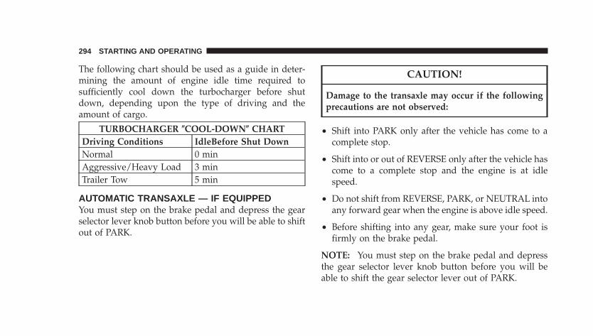
The following chart should be used as a guide in deter-mining the amount of engine idle time required tosufficiently cool down the turbocharger before shutdown, depending upon the type of driving and theamount of cargo.
TURBOCHARGER COOL-DOWN CHARTDriving Conditions IdleBefore Shut DownNormal 0 minAggressive/Heavy Load 3 minTrailer Tow 5 min
AUTOMATIC TRANSAXLE — IF EQUIPPEDYou must step on the brake pedal and depress the gearselector lever knob button before you will be able to shiftout of PARK.
CAUTION!
Damage to the transaxle may occur if the followingprecautions are not observed:
• Shift into PARK only after the vehicle has come to acomplete stop.
• Shift into or out of REVERSE only after the vehicle hascome to a complete stop and the engine is at idlespeed.
• Do not shift from REVERSE, PARK, or NEUTRAL intoany forward gear when the engine is above idle speed.
• Before shifting into any gear, make sure your foot isfirmly on the brake pedal.
NOTE: You must step on the brake pedal and depressthe gear selector lever knob button before you will beable to shift the gear selector lever out of PARK.
294 STARTING AND OPERATING
WARNING!
It is dangerous to shift the gear selector lever out ofPARK, or NEUTRAL if the engine speed is higherthan idle speed. If your foot is not firmly on thebrake pedal, the vehicle could accelerate quicklyforward or in REVERSE. You could lose control of thevehicle and hit someone or something. Only shift thegear selector lever into gear when the engine is idlingnormally and when your right foot is firmly on thebrake pedal.
BRAKE/TRANSMISSION INTERLOCK SYSTEMThis system prevents you from shifting the gear selectorlever out of PARK and into any gear unless the brakepedal is pressed. This system is active only while theignition switch is in the ON or ACC positions. Always
step on the brake pedal and depress the gear selectorlever knob button before shifting out of PARK.
NOTE: If a malfunction occurs, the system will functionnormally, except you may be able to shift the vehicle fromPARK, without depressing the brake pedal. If this occursobtain service from an authorized dealer as soon aspossible.
AUTOMATIC TRANSAXLE IGNITION INTERLOCKSYSTEMThis system prevents the key from being removed unlessthe gear selector lever is in PARK and the gear selectorlever knob push button is out. It also prevents shiftingout of PARK unless the key is in the ACC or ONpositions, and the brake pedal is depressed.
NOTE: If a malfunction occurs, the system will trap thekey in the ignition cylinder to warn you that this safety
STARTING AND OPERATING 295
5

feature is inoperable. The engine can be started andstopped but the key cannot be removed until you obtainservice.
FOUR-SPEED AUTOMATIC TRANSAXLEThe electronically controlled transaxle provides a preciseshift schedule. The transaxle electronics are self calibrat-ing; therefore, the first few shifts on a new vehicle may besomewhat abrupt. This is a normal condition, and preci-sion shifts will develop within a few shift cycles.
RESET MODEThe transaxle is monitored electronically for abnormalconditions. If a condition is detected that could causedamage, the transaxle shifts automatically into secondgear. The transaxle remains in second gear despite theforward gear selected. PARK, REVERSE, and NEUTRALwill continue to operate. This second gear limp-in featureallows the vehicle to be driven to a dealer for servicewithout damaging the transaxle.
In the event that the problem has been momentary, thetransaxle can be reset to regain all forward gears.
Stop the vehicle and shift the gear selector lever intoPARK.
Turn the Key to OFF then restart the engine.
Shift the gear selector lever into DRIVE and resumedriving.
If the transaxle cannot be reset, authorized dealer serviceis required.
NOTE: Even if the transaxle can be reset, it is recom-mended that you visit an authorized dealer at yourearliest possible convenience. Your authorized dealer hasdiagnostic equipment to determine if the problem couldrecur.
296 STARTING AND OPERATING
GEAR RANGES FOR THE FOUR-SPEEDAUTOMATIC TRANSAXLEDO NOT race the engine when shifting from PARK orNEUTRAL positions into another gear range.
PARKPARK supplements the parking brake by locking thetransmission. The engine can be started in this range.Never use PARK while the vehicle is in motion. Applythe parking brake when leaving the vehicle in this range.Always apply the parking brake first, and then shift thegear selector lever into the PARK position.
WARNING!
Unintended movement of a vehicle could injurethose in and near the vehicle. As with all vehicles,you should never exit a vehicle while the engine isrunning. Before exiting a vehicle, you should alwaysshift the vehicle into PARK, remove the key from theignition, and apply the parking brake. Once the keyis removed from the ignition, the transmission gearselector lever is locked in the PARK position, secur-ing the vehicle against unwanted movement. Further-more, you should never leave children unattendedinside a vehicle.
STARTING AND OPERATING 297
5
The following indicators should be used to ensure thatyou have engaged the transmission gear selector leverinto the PARK position:
• When shifting the gear selector lever into PARK,depress the button on the gear selector lever knob andfirmly move the lever all the way forward until itstops.
• Look at the shift indicator window on the console toensure it is in the PARK position.
• When engaged in PARK, you will not be able to movethe gear selector lever rearward without depressingthe gear selector lever knob button
CAUTION!
Before shifting the gear selector lever out of PARK,you must turn the ignition from LOCK to ON so thesteering wheel and gear selector lever are released.Otherwise, damage to the steering column or gearselector lever could result.
REVERSEShift into this range only after the vehicle has come to acomplete stop.
NEUTRALThe engine may be started in this range.
DRIVE / OVERDRIVEThis range should be used for most city and highwaydriving. It provides smoothest upshifts and downshifts,and best fuel economy.
298 STARTING AND OPERATING
When frequent transaxle shifting occurs while using theDRIVE/OVERDRIVE range, such as when operating thevehicle under heavy loading conditions (in hilly terrain,traveling into strong head winds, or while towing trail-ers), use the [3] range.
[3] DRIVEThis range eliminates shifts into OVERDRIVE. The trans-axle will operate normally in first and second while inthis range.
NOTE: Using the [3] range while operating the vehicleunder heavy operating conditions will improve perfor-mance, fuel economy, and extend transaxle life by reduc-ing excessive shifting and heat build up.
Use the [3] range when descending steep grades toprevent brake system distress.
[1] LowThis range should be used for maximum engine brakingwhen descending steep grades. In this range, up shiftswill occur only to prevent engine over speed while downshifts from [2] to [1] will occur as early as possible.
AUTOSTICK — IF EQUIPPEDAUTOSTICK is a driver-interactive transmission thatoffers manual gear shifting capability to provide youwith more control. AUTOSTICK allows you to maximizeengine braking, eliminate undesirable upshifts anddownshifts, and improve overall vehicle performance.This system can also provide you with more controlduring passing, city driving, cold slippery conditions,mountain driving, trailer towing, and many other situa-tions.
STARTING AND OPERATING 299
5
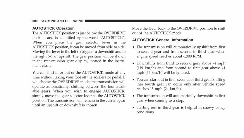
AUTOSTICK OperationThe AUTOSTICK position is just below the OVERDRIVEposition and is identified by the word “AUTOSTICK”.When you place the gear selector lever in theAUTOSTICK position, it can be moved from side to side.Moving the lever to the left (-) triggers a downshift and tothe right (+) an upshift. The gear position will be shownin the transmission gear display, located in the instru-ment cluster.
You can shift in or out of the AUTOSTICK mode at anytime without taking your foot off the accelerator pedal. Ifyou choose the OVERDRIVE mode, the transmission willoperate automatically; shifting between the four avail-able gears. When you wish to engage AUTOSTICK,simply move the gear selector lever to the AUTOSTICKposition. The transmission will remain in the current gearuntil an upshift or downshift is chosen.
Move the lever back to the OVERDRIVE position to shiftout of the AUTOSTICK mode.
AUTOSTICK General Information
• The transmission will automatically upshift from firstto second gear and from second to third gear whenengine speed reaches about 6,300 RPM.
• Downshifts from third to second gear above 74 mph(119 km/h) and from second to first gear above 41mph (66 km/h) will be ignored.
• You can start out in first, second, or third gear. Shiftinginto fourth gear can occur only after vehicle speedreaches 15 mph (24 km/h).
• The transmission will automatically downshift to firstgear when coming to a stop.
• Starting out in third gear is helpful in snowy or icyconditions.
300 STARTING AND OPERATING
• While in the AUTOSTICK mode, Speed Control willonly function in third or fourth gear.
Downshifting out of third gear will turn off the speedcontrol.
• If the system detects powertrain overheating, thetransmission will revert to the automatic shift modeand remain in that mode until the powertrain cools off.
• If the system detects a problem it will disable theAUTOSTICK mode and the transmission will return tothe automatic mode until the problem is corrected.
MANUAL TRANSAXLE OPERATION — IFEQUIPPED
WARNING!
You or others could be injured if you leave thevehicle unattended without having the parkingbrake fully applied. The parking brake should al-ways be applied when the driver is not in the vehicle,especially on an incline.
STARTING AND OPERATING 301
5
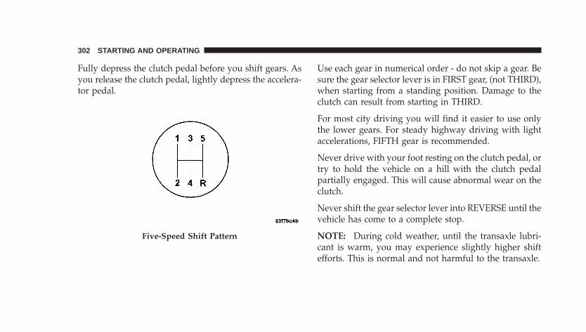
Fully depress the clutch pedal before you shift gears. Asyou release the clutch pedal, lightly depress the accelera-tor pedal.
Use each gear in numerical order - do not skip a gear. Besure the gear selector lever is in FIRST gear, (not THIRD),when starting from a standing position. Damage to theclutch can result from starting in THIRD.
For most city driving you will find it easier to use onlythe lower gears. For steady highway driving with lightaccelerations, FIFTH gear is recommended.
Never drive with your foot resting on the clutch pedal, ortry to hold the vehicle on a hill with the clutch pedalpartially engaged. This will cause abnormal wear on theclutch.
Never shift the gear selector lever into REVERSE until thevehicle has come to a complete stop.
NOTE: During cold weather, until the transaxle lubri-cant is warm, you may experience slightly higher shiftefforts. This is normal and not harmful to the transaxle.
Five-Speed Shift Pattern
302 STARTING AND OPERATING
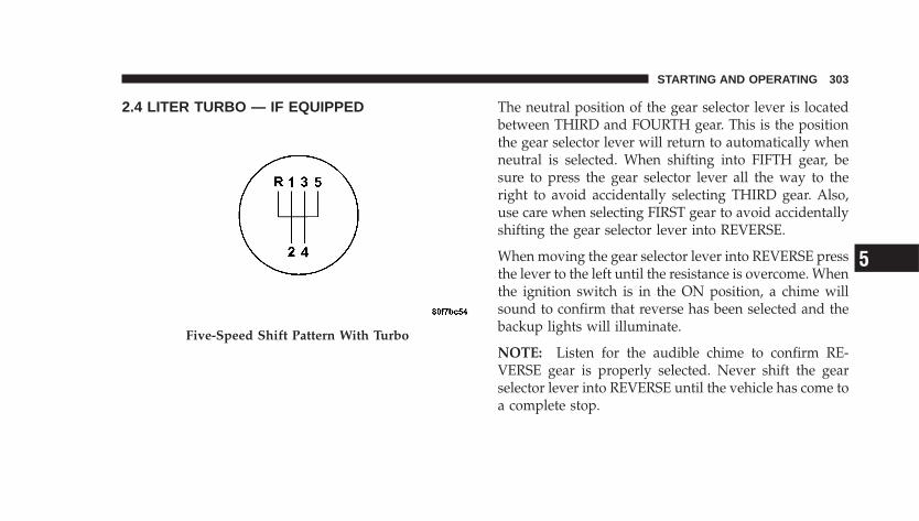
2.4 LITER TURBO — IF EQUIPPED The neutral position of the gear selector lever is locatedbetween THIRD and FOURTH gear. This is the positionthe gear selector lever will return to automatically whenneutral is selected. When shifting into FIFTH gear, besure to press the gear selector lever all the way to theright to avoid accidentally selecting THIRD gear. Also,use care when selecting FIRST gear to avoid accidentallyshifting the gear selector lever into REVERSE.
When moving the gear selector lever into REVERSE pressthe lever to the left until the resistance is overcome. Whenthe ignition switch is in the ON position, a chime willsound to confirm that reverse has been selected and thebackup lights will illuminate.
NOTE: Listen for the audible chime to confirm RE-VERSE gear is properly selected. Never shift the gearselector lever into REVERSE until the vehicle has come toa complete stop.
Five-Speed Shift Pattern With Turbo
STARTING AND OPERATING 303
5

MANUAL TRANSAXLE — RECOMMENDED SHIFTSPEEDSTo use your manual transaxle for optimal fuel economy,it should be upshifted as listed in Table 1.
Table 1 - Manual Transaxle Normal AccelerationAnd Cruise Shift Speeds In mph (km/h)
Engine Mode 1 to 2 2 to 3 3 to 4 4 to 5
2.4LTurbo
Accel-eration 15 (24) 25 (40) 40 (65) 45 (72)
Cruise 15 (24) 25 (40) 42 (68) 45 (72)2.4LNon-Turbo
Accel-eration 15 (24) 25 (40) 40 (65) 45 (72)
Cruise 15 (24) 25 (40) 42 (68) 45 (72)
For improved performance, your manual transaxle maybe upshifted up to the maximum speeds listed in Table 2(within legal speed limits).
Table 2 - Manual Transaxle Maximum PerformanceShift Speeds In mph (km/h)
Engine 1 to 2 2 to 3 3 to 4 4 to 52.4L 30 (48) 60 (97) 85 (136) 115 (185)
If you exceed these speeds, you may notice the engine cutin and out. This is caused by an electronic limiter in theengine computer. The engine will run normally whenyou reduce engine speed.
DownshiftingProper downshifting will improve fuel economy andprolong engine life.
CAUTION!
If you skip a gear while downshifting or downshiftat too high an engine speed, you could damage theengine, transmission, or clutch.
304 STARTING AND OPERATING
To maintain a safe speed and prolong brake life, shiftdown to SECOND or FIRST gear when descending asteep grade.
When turning a corner, or driving up a steep grade,downshift early so that the engine will not be overbur-dened.
PARKING BRAKEWhen the parking brake is applied with theignition on, the BRAKE Light in the instrumentcluster will come on.
NOTE: This light only shows that the parking brake ison. It does not show the degree of brake application.
If the parking brake is applied while the vehicle ismoving, a chime will sound to alert the driver. The chimewill sound up to 10 times or until the vehicle hasreturned to a stop.
Before leaving the vehicle, make sure that the parkingbrake is set. To set the parking brake, pull up firmly onthe lever. Always shift the gear selector lever into thePARK position (automatic transaxle) or into the RE-VERSE position (manual transaxle). To release the park-ing brake, apply the brake pedal, pull up slightly on thelever, then depress the button on the end of the lever andpush the lever fully down toward the floor.
STARTING AND OPERATING 305
5
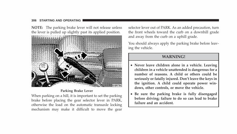
NOTE: The parking brake lever will not release unlessthe lever is pulled up slightly past its applied position.
When parking on a hill, it is important to set the parkingbrake before placing the gear selector lever in PARK,otherwise the load on the automatic transaxle lockingmechanism may make it difficult to move the gear
selector lever out of PARK. As an added precaution, turnthe front wheels toward the curb on a downhill gradeand away from the curb on a uphill grade.
You should always apply the parking brake before leav-ing the vehicle.
WARNING!
• Never leave children alone in a vehicle. Leavingchildren in a vehicle unattended is dangerous for anumber of reasons. A child or others could beseriously or fatally injured. Don’t leave the keys inthe ignition. A child could operate power win-dows, other controls, or move the vehicle.
• Be sure the parking brake is fully disengagedbefore driving; failure to do so can lead to brakefailure and an accident.
Parking Brake Lever
306 STARTING AND OPERATING
BRAKE SYSTEMYour vehicle is equipped with power assisted brakes asstandard equipment. In the event power assist is lost forany reason (for example, repeated brake applicationswith the engine off), the brakes will still function. How-ever, the effort required to brake the vehicle will be muchgreater than that required with the power system oper-ating.
WARNING!
Riding the brakes can lead to brake failure andpossibly an accident. Driving with your foot restingor riding on the brake pedal can result in abnormallyhigh brake temperatures, excessive lining wear, andpossible brake damage. You wouldn’t have your fullbraking capacity in an emergency.
If either of the two hydraulic systems lose normal capa-bility, the remaining system will still function with someloss of overall braking effectiveness. This will be evidentby increased pedal travel during application and greaterpedal force required to slow or stop. In addition, if themalfunction is caused by an internal leak, as the brakefluid in the master cylinder drops, the brake warningindicator will light.
WARNING!
Driving a vehicle with the brake light on is danger-ous. A significant decrease in braking performance orvehicle stability during braking may occur. It willtake you longer to stop the vehicle or will make yourvehicle harder to control. You could have an accident.Have the vehicle checked immediately.
STARTING AND OPERATING 307
5
ANTI-LOCK BRAKE SYSTEM (ABS) — IFEQUIPPEDThe ABS provides increased vehicle stability and brakeperformance under most braking conditions. The systemautomatically “pumps” the brakes during severe brakingconditions to prevent wheel lock-up.
WARNING!
Pumping of the ABS will diminish their effective-ness and may lead to an accident. Pumping makesthe stopping distance longer. Just press firmly onyour brake pedal when you need to slow down orstop.
WARNING!
• The ABS cannot prevent the natural laws of phys-ics from acting on the vehicle, nor can it increasebraking or steering efficiency beyond that af-forded by the condition of the vehicle brakes andtires or the traction afforded.
• An ABS cannot prevent accidents, including thoseresulting from excessive speed in turns, followinganother vehicle too closely, or hydroplaning. Onlya safe, attentive, and skillful driver can preventaccidents.
• The capabilities of an ABS equipped vehicle mustnever be exploited in a reckless or dangerousmanner which could jeopardize the user’s safetyor the safety of others.
308 STARTING AND OPERATING
The ABS telltale light monitors the Anti-LockBrake System. The light will come on when theignition switch is turned to the ON positionand may stay on for as long as four seconds.
If the ABS light remains on or comes on while driving, itindicates that the Anti-Lock portion of the brake systemis not functioning and that service is required. However,the conventional brake system will continue to operatenormally if the BRAKE warning light is not on.
If the ABS light is on, the brake system should be servicedas soon as possible to restore the benefits of Anti-Lockbrakes. If the ABS light does not come on when theIgnition switch is turned to the ON position, have thebulb repaired as soon as possible.
If both the Brake Warning Light and the ABS Lightremain on, the Anti-Lock brakes (ABS) and ElectronicBrake Force Distribution (EBD) systems are not function-ing properly. Immediate repair to the ABS system at anauthorized dealer is required.
When the vehicle is driven over 7 mph (11 km/h), youmay also hear a slight clicking sound as well as somerelated motor noises. These noises are the system per-forming its self check cycle to ensure that the ABS systemis working properly. This self-check occurs each time thevehicle is started and accelerated past 7 mph (11 km/h).
ABS is activated during braking under certain road orstopping conditions. ABS-inducing conditions can in-clude ice, snow, gravel, bumps, railroad tracks, loosedebris, or panic stops.
You also may experience the following when the brakesystem goes into Anti-Lock:
• The ABS motor running (it may continue to run for ashort time after the stop).
• A clicking sound of solenoid valves.
• Brake pedal pulsations.
STARTING AND OPERATING 309
5
• A slight drop or fall away of the brake pedal at the endof the stop.
These are all normal characteristics of ABS.
WARNING!
The Anti-Lock Brake System contains sophisticatedelectronic equipment that may be susceptible tointerference caused by improperly installed or highoutput radio transmitting equipment. This interfer-ence can cause possible loss of Anti-Lock brakingcapability. Installation of such equipment should beperformed by qualified dealership professionals.
All vehicle wheels and tires must be the same size andtype and tires must be properly inflated to produceaccurate signals for the computer.
POWER STEERINGThe standard power steering system will give you goodvehicle response and increased ease of maneuverabilityin tight spaces. The system will provide mechanicalsteering capability if power assist is lost.
If for some reason the power assist is interrupted, it willstill be possible to steer your vehicle. Under these condi-tions, you will observe a substantial increase in steeringeffort, especially at very low vehicle speeds and duringparking maneuvers.
NOTE: Increased noise levels at the end of the steeringwheel travel are considered normal and do not indicatethat there is a problem with the power steering system.
Upon initial start-up in cold weather, the power steeringpump may make noise for a short amount of time. This isdue to the cold, thick fluid in the steering system. Thisnoise should be considered normal, and it does not in anyway damage the steering system.
310 STARTING AND OPERATING
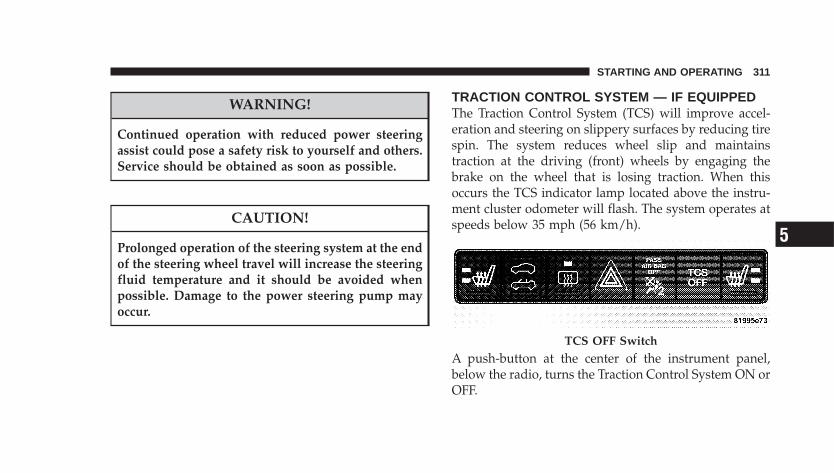
WARNING!
Continued operation with reduced power steeringassist could pose a safety risk to yourself and others.Service should be obtained as soon as possible.
CAUTION!
Prolonged operation of the steering system at the endof the steering wheel travel will increase the steeringfluid temperature and it should be avoided whenpossible. Damage to the power steering pump mayoccur.
TRACTION CONTROL SYSTEM — IF EQUIPPEDThe Traction Control System (TCS) will improve accel-eration and steering on slippery surfaces by reducing tirespin. The system reduces wheel slip and maintainstraction at the driving (front) wheels by engaging thebrake on the wheel that is losing traction. When thisoccurs the TCS indicator lamp located above the instru-ment cluster odometer will flash. The system operates atspeeds below 35 mph (56 km/h).
A push-button at the center of the instrument panel,below the radio, turns the Traction Control System ON orOFF.
TCS OFF Switch
STARTING AND OPERATING 311
5
The system is always in the “ON” mode unless:
• The TCS OFF switch has been used to turn the systemoff;
• There is a Anti-Lock Brake System malfunction;
• There is a Traction Control System malfunction;
• The system has been automatically deactivated toprevent damage to the brake system due to overheatedbrake temperatures.
NOTE: Extended heavy use of Traction Control maycause the system to deactivate and turn on the TCSindicator lamp located in the instrument cluster.
This is to prevent overheating of the brake system and isa normal condition. The system will remain disabled forabout 4 minutes until the brakes have cooled. The systemwill automatically reactivate and turn off the TCS indi-cator lamp.
If your vehicle becomes stuck in mud, ice, or snow, turnthe Traction Control System Off before attempting to“rock” the vehicle free.
312 STARTING AND OPERATING
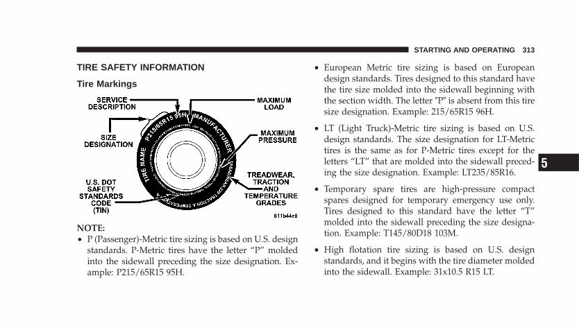
TIRE SAFETY INFORMATION
Tire Markings
NOTE:• P (Passenger)-Metric tire sizing is based on U.S. design
standards. P-Metric tires have the letter “P” moldedinto the sidewall preceding the size designation. Ex-ample: P215/65R15 95H.
• European Metric tire sizing is based on Europeandesign standards. Tires designed to this standard havethe tire size molded into the sidewall beginning withthe section width. The letter �P� is absent from this tiresize designation. Example: 215/65R15 96H.
• LT (Light Truck)-Metric tire sizing is based on U.S.design standards. The size designation for LT-Metrictires is the same as for P-Metric tires except for theletters “LT” that are molded into the sidewall preced-ing the size designation. Example: LT235/85R16.
• Temporary spare tires are high-pressure compactspares designed for temporary emergency use only.Tires designed to this standard have the letter “T”molded into the sidewall preceding the size designa-tion. Example: T145/80D18 103M.
• High flotation tire sizing is based on U.S. designstandards, and it begins with the tire diameter moldedinto the sidewall. Example: 31x10.5 R15 LT.
STARTING AND OPERATING 313
5
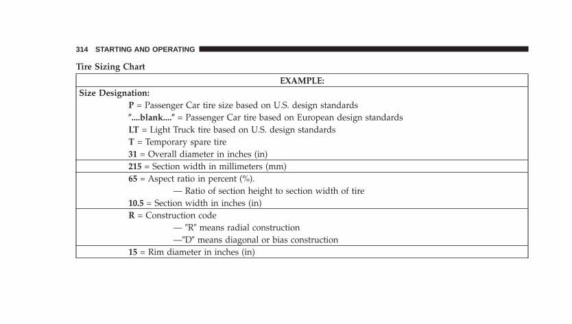
Tire Sizing Chart
EXAMPLE:Size Designation:
P = Passenger Car tire size based on U.S. design standards....blank.... = Passenger Car tire based on European design standardsLT = Light Truck tire based on U.S. design standardsT = Temporary spare tire31 = Overall diameter in inches (in)215 = Section width in millimeters (mm)65 = Aspect ratio in percent (%).
— Ratio of section height to section width of tire10.5 = Section width in inches (in)R = Construction code
— �R� means radial construction—�D� means diagonal or bias construction
15 = Rim diameter in inches (in)
314 STARTING AND OPERATING
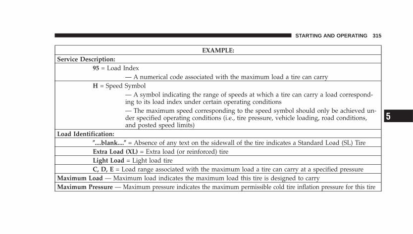
EXAMPLE:Service Description:
95 = Load Index— A numerical code associated with the maximum load a tire can carry
H = Speed Symbol— A symbol indicating the range of speeds at which a tire can carry a load correspond-ing to its load index under certain operating conditions— The maximum speed corresponding to the speed symbol should only be achieved un-der specified operating conditions (i.e., tire pressure, vehicle loading, road conditions,and posted speed limits)
Load Identification:....blank.... = Absence of any text on the sidewall of the tire indicates a Standard Load (SL) TireExtra Load (XL) = Extra load (or reinforced) tireLight Load = Light load tireC, D, E = Load range associated with the maximum load a tire can carry at a specified pressure
Maximum Load — Maximum load indicates the maximum load this tire is designed to carryMaximum Pressure — Maximum pressure indicates the maximum permissible cold tire inflation pressure for this tire
STARTING AND OPERATING 315
5
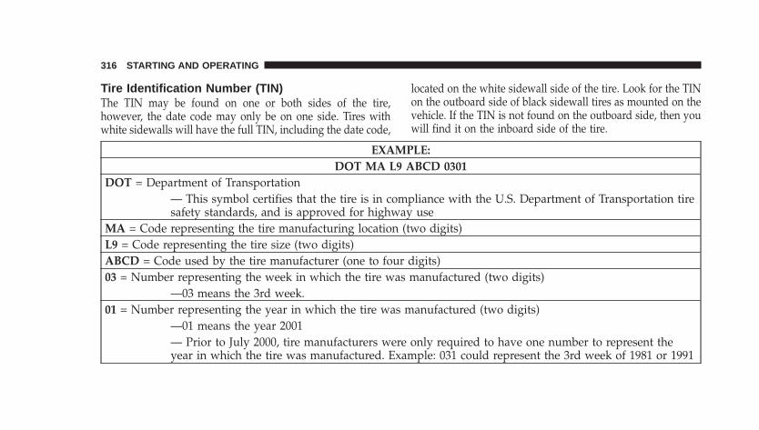
Tire Identification Number (TIN)The TIN may be found on one or both sides of the tire,however, the date code may only be on one side. Tires withwhite sidewalls will have the full TIN, including the date code,
located on the white sidewall side of the tire. Look for the TINon the outboard side of black sidewall tires as mounted on thevehicle. If the TIN is not found on the outboard side, then youwill find it on the inboard side of the tire.
EXAMPLE:DOT MA L9 ABCD 0301
DOT = Department of Transportation— This symbol certifies that the tire is in compliance with the U.S. Department of Transportation tiresafety standards, and is approved for highway use
MA = Code representing the tire manufacturing location (two digits)L9 = Code representing the tire size (two digits)ABCD = Code used by the tire manufacturer (one to four digits)03 = Number representing the week in which the tire was manufactured (two digits)
—03 means the 3rd week.01 = Number representing the year in which the tire was manufactured (two digits)
—01 means the year 2001— Prior to July 2000, tire manufacturers were only required to have one number to represent theyear in which the tire was manufactured. Example: 031 could represent the 3rd week of 1981 or 1991
316 STARTING AND OPERATING
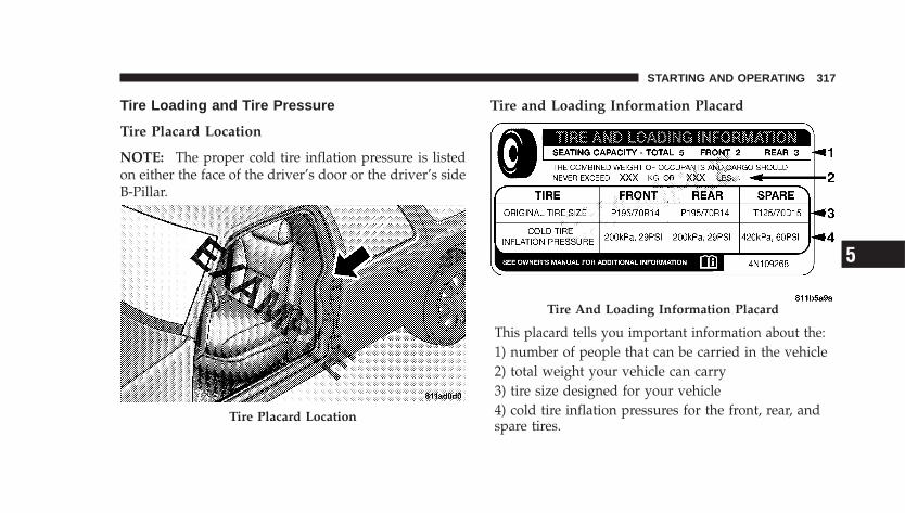
Tire Loading and Tire Pressure
Tire Placard Location
NOTE: The proper cold tire inflation pressure is listedon either the face of the driver’s door or the driver’s sideB-Pillar.
Tire and Loading Information Placard
This placard tells you important information about the:1) number of people that can be carried in the vehicle2) total weight your vehicle can carry3) tire size designed for your vehicle4) cold tire inflation pressures for the front, rear, andspare tires.
Tire Placard Location
Tire And Loading Information Placard
STARTING AND OPERATING 317
5
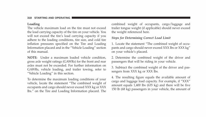
LoadingThe vehicle maximum load on the tire must not exceedthe load carrying capacity of the tire on your vehicle. Youwill not exceed the tire’s load carrying capacity if youadhere to the loading conditions, tire size, and cold tireinflation pressures specified on the Tire and LoadingInformation placard and in the “Vehicle Loading” sectionof this manual.
NOTE: Under a maximum loaded vehicle condition,gross axle weight ratings (GAWRs) for the front and rearaxles must not be exceeded. For further information onGAWRs, vehicle loading, and trailer towing, refer to“Vehicle Loading” in this section.
To determine the maximum loading conditions of yourvehicle, locate the statement “The combined weight ofoccupants and cargo should never exceed XXX kg or XXXlbs.” on the Tire and Loading Information placard. The
combined weight of occupants, cargo/luggage andtrailer tongue weight (if applicable) should never exceedthe weight referenced here.
Steps for Determining Correct Load Limit
1. Locate the statement “The combined weight of occu-pants and cargo should never exceed XXX lbs or XXX kg”on your vehicle’s placard.
2. Determine the combined weight of the driver andpassengers that will be riding in your vehicle.
3. Subtract the combined weight of the driver and pas-sengers from XXX kg or XXX lbs.
4. The resulting figure equals the available amount ofcargo and luggage load capacity. For example, if “XXX”amount equals 1,400 lbs (635 kg) and there will be five150 lb (68 kg) passengers in your vehicle, the amount of
318 STARTING AND OPERATING
available cargo and luggage load capacity is 650 lbs (295kg) {(since 5 x 150 = 750, and 1400 – 750 = 650 lbs (295kg)}.
5. Determine the combined weight of luggage and cargobeing loaded on the vehicle. That weight may not safelyexceed the available cargo and luggage load capacitycalculated in Step 4.
6. If your vehicle will be towing a trailer, load from yourtrailer will be transferred to your vehicle. Consult thismanual to determine how this reduces the availablecargo and luggage load capacity of your vehicle.
NOTE: The following table shows examples on how tocalculate total load, cargo/luggage, and towing capaci-ties of your vehicle with varying seating configurationsand number and size of occupants. This table is forillustration purposes only and may not be accurate forthe seating and load carry capacity of your vehicle.
NOTE: For the following example, the combined weightof occupants and cargo should never exceed 865 lbs (392kg).
STARTING AND OPERATING 319
5
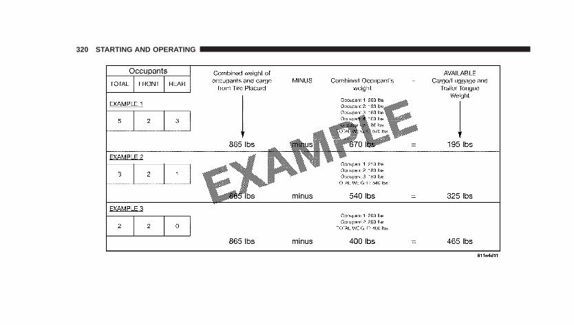
320 STARTING AND OPERATING
WARNING!
Overloading of your tires is dangerous. Overloadingcan cause tire failure, affect vehicle handling, andincrease your stopping distance. Use tires of therecommended load capacity for your vehicle. Neveroverload them.
TIRES — GENERAL INFORMATION
Tire PressureProper tire inflation pressure is essential to the safe andsatisfactory operation of your vehicle. Three primaryareas are affected by improper tire pressure:
1. Safety—
WARNING!
• Improperly inflated tires are dangerous and can causeaccidents.
• Under-inflation increases tire flexing and can result intire failure.
• Over-inflation reduces a tire’s ability to cushionshock. Objects on the road and chuckholes can causedamage that result in tire failure.
• Unequal tire pressures can cause steering problems.You could lose control of your vehicle.
• Over-inflated or under-inflated tires can affect vehiclehandling and can fail suddenly, resulting in loss ofvehicle control.
• Unequal tire pressures from one side of the vehicle tothe other can cause the vehicle to drift to the right or left.
• Always drive with each tire inflated to the recom-mended cold tire inflation pressure.
STARTING AND OPERATING 321
5
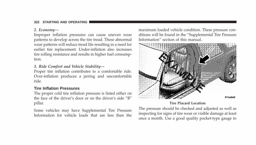
2. Economy—Improper inflation pressures can cause uneven wearpatterns to develop across the tire tread. These abnormalwear patterns will reduce tread life resulting in a need forearlier tire replacement. Under-inflation also increasestire rolling resistance and results in higher fuel consump-tion.
3. Ride Comfort and Vehicle Stability—Proper tire inflation contributes to a comfortable ride.Over-inflation produces a jarring and uncomfortableride.
Tire Inflation PressuresThe proper cold tire inflation pressure is listed either onthe face of the driver’s door or on the driver’s side “B”pillar.
Some vehicles may have Supplemental Tire PressureInformation for vehicle loads that are less than the
maximum loaded vehicle condition. These pressure con-ditions will be found in the “Supplemental Tire PressureInformation” section of this manual.
The pressure should be checked and adjusted as well asinspecting for signs of tire wear or visible damage at leastonce a month. Use a good quality pocket-type gauge to
Tire Placard Location
322 STARTING AND OPERATING
check tire pressure. Do not make a visual judgementwhen determining proper inflation. Radial tires may lookproperly inflated even when they are under-inflated.
CAUTION!
After inspecting or adjusting the tire pressure, al-ways reinstall the valve stem cap (if equipped). Thiswill prevent moisture and dirt from entering thevalve stem, which could damage the valve stem.
Inflation pressures specified on the placard are always“cold tire inflation pressure.” Cold tire inflation pressureis defined as the tire pressure after the vehicle has notbeen driven for at least three hours, or driven less than 1mi (1.6 km) after a three hour period. The cold tireinflation pressure must not exceed the maximum infla-tion pressure molded into the tire sidewall.
Check tire pressures more often if subject to a wide rangeof outdoor temperatures, as tire pressures vary withtemperature changes.
Tire pressures change by approximately 1 psi (7 kPa) per12°F (7°C) of air temperature change. Keep this in mindwhen checking tire pressure inside a garage, especially inthe Winter.
Example: If garage temperature = 68°F (20°C) and theoutside temperature = 32°F (0°C) then the cold tireinflation pressure should be increased by 3 psi (21 kPa),which equals 1 psi (7 kPa) for every 12°F (7°C) for thisoutside temperature condition.
Tire pressure may increase from 2 to 6 psi (13 to 40 kPa)during operation. DO NOT reduce this normal pressurebuild up or your tire pressure will be too low.
STARTING AND OPERATING 323
5
Tire Pressures for High Speed OperationThe manufacturer advocates driving at safe speedswithin posted speed limits. Where speed limits or condi-tions are such that the vehicle can be driven at highspeeds, maintaining correct tire inflation pressure is veryimportant. Increased tire pressure and reduced vehicleloading may be required for high-speed vehicle opera-tion. Refer to original equipment or an authorized tiredealer for recommended safe operating speeds, loadingand cold tire inflation pressures.
WARNING!
High speed driving with your vehicle under maxi-mum load is dangerous. The added strain on yourtires could cause them to fail. You could have aserious accident. Don’t drive a vehicle loaded to themaximum capacity at continuous speeds above 75mph (120 km/h).
Radial Ply Tires
WARNING!
Combining radial ply tires with other types of tireson your vehicle will cause your vehicle to handlepoorly. The instability could cause an accident. Al-ways use radial ply tires in sets of four (or six, in caseof trucks with dual rear wheels). Never combinethem with other types of tires.
Cuts and punctures in radial tires are repairable only inthe tread area because of sidewall flexing. Consult yourauthorized tire dealer for radial tire repairs.
324 STARTING AND OPERATING
Compact Spare Tire — If EquippedThe compact spare is for temporary emergency use withradial tires. It is engineered to be used on your stylevehicle only. Since this tire has limited tread life, theoriginal tire should be repaired (or replaced) and rein-stalled at the first opportunity.
WARNING!
Temporary use spare tires are for emergency use only.With these tires, do not drive more than 50 mph (80km/h). Temporary use spare tires have limited treadlife. When the tread is worn to the tread wearindicators, the temporary use spare tire needs to bereplaced. Be sure to follow the warnings, whichapply to your spare. Failure to do so could result inspare tire failure and loss of vehicle control.
Do not install a wheel cover or attempt to mount aconventional tire on the compact spare wheel, since thewheel is designed specifically for the compact spare.
Do not install more than one compact spare tire/wheelon the vehicle at any given time.
CAUTION!
Because of the reduced ground clearance, do not takeyour vehicle through an automatic car wash with thecompact spare installed. Damage to the vehicle mayresult.
Limited-Use Spare — If EquippedThe limited-use spare tire is for temporary emergencyuse on your vehicle. This tire is identified by a limited-use spare tire warning label located on the limited-usespare tire and wheel assembly. This tire may look like the
STARTING AND OPERATING 325
5
original equipped tire on the front or rear axle of yourvehicle, but it is not. Installation of this limited-use sparetire affects vehicle handling. Since it is not the same tire,replace (or repair) the original tire and reinstall on thevehicle at the first opportunity.
WARNING!
The limited-use spare tires are for emergency useonly. Installation of this limited-use spare tire affectsvehicle handling. With this tire, do not drive morethan 50 mph (80 km/h). Keep inflated to the cold tireinflation pressure listed on either your tire placard orlimited-use spare tire and wheel assembly. Replace(or repair) the original tire at the first opportunityand reinstall it on your vehicle. Failure to do so couldresult in loss of vehicle control.
Tire SpinningWhen stuck in mud, sand, snow, or ice conditions, do notspin your vehicle’s wheels faster than 30 mph (48 km/h)or for longer than 30 seconds continuously withoutstopping when you are stuck.
For additional information, refer to “Freeing A StuckVehicle” in Section 6.
WARNING!
Fast spinning tires can be dangerous. Forces gener-ated by excessive wheel speeds may cause tire dam-age or failure. A tire could explode and injure some-one. Do not spin your vehicle’s wheels faster than 30mph (48 km/h) or for more than 30 seconds continu-ously when you are stuck, and don’t let anyone neara spinning wheel, no matter what the speed.
326 STARTING AND OPERATING
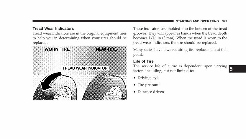
Tread Wear IndicatorsTread wear indicators are in the original equipment tiresto help you in determining when your tires should bereplaced.
These indicators are molded into the bottom of the treadgrooves. They will appear as bands when the tread depthbecomes 1/16 in (2 mm). When the tread is worn to thetread wear indicators, the tire should be replaced.
Many states have laws requiring tire replacement at thispoint.
Life of TireThe service life of a tire is dependent upon varyingfactors including, but not limited to:
• Driving style
• Tire pressure
• Distance driven
STARTING AND OPERATING 327
5
WARNING!
Tires and the spare tire should be replaced after sixyears, regardless of the remaining tread. Failure tofollow this warning can result in sudden tire failure.You could lose control and have an accident resultingin serious injury or death.
Keep dismounted tires in a cool, dry place with as littleexposure to light as possible. Protect tires from contactwith oil, grease, and gasoline.
Replacement TiresThe tires on your new vehicle provide a balance of manycharacteristics. They should be inspected regularly forwear and correct cold tire inflation pressure. The manu-facturer strongly recommends that you use tires equiva-lent to the originals in size, quality and performancewhen replacement is needed. (Refer to the paragraph on“Tread Wear Indicators”). Refer to the “Tire and LoadingInformation” placard for the size designation of your tire.The service description and load identification will befound on the original equipment tire. Failure to useequivalent replacement tires may adversely affect thesafety, handling, and ride of your vehicle. We recommendthat you contact your original equipment or an autho-rized tire dealer with any questions you may have on tirespecifications or capability.
328 STARTING AND OPERATING
WARNING!
• Do not use a tire, wheel size or rating other than thatspecified for your vehicle. Some combinations ofunapproved tires and wheels may change suspensiondimensions and performance characteristics, result-ing in changes to steering, handling, and braking ofyour vehicle. This can cause unpredictable handlingand stress to steering and suspension components.You could lose control and have an accident resultingin serious injury or death. Use only the tire and wheelsizes with load ratings approved for your vehicle.
• Never use a tire with a smaller load index or capacity,other than what was originally equipped on yourvehicle. Using a tire with a smaller load index couldresult in tire overloading and failure. You could losecontrol and have an accident.
• Failure to equip your vehicle with tires having ad-equate speed capability can result in sudden tirefailure and loss of vehicle control.
CAUTION!
Replacing original tires with tires of a different sizemay result in false speedometer and odometerreadings.
Alignment and BalancePoor suspension alignment may result in:
• Fast tire wear.
• Uneven tire wear, such as feathering and one-sidedwear.
• Vehicle pull to right or left.
Tires may also cause the vehicle to pull to the left or right.Alignment will not correct this condition. See yourauthorized dealer for proper diagnosis.
STARTING AND OPERATING 329
5
Improper alignment will not cause vehicle vibration.Vibration may be a result of tire and wheel out-of-balance. Proper balancing will reduce vibration andavoid tire cupping and spotty wear.
TIRE CHAINSDue to limited clearance, tire chains are not recom-mended.
CAUTION!
Damage to the vehicle may result if tire chains areused.
SNOW TIRESSome areas of the country require the use of snow tiresduring Winter. Standard tires are of the all-season typeand satisfy this requirement as indicated by the M+Sdesignation on the tire sidewall.
If you need snow tires, select tires equivalent in size andtype to the original equipment tires. Use snow tires onlyin sets of four; failure to do so may adversely affect thesafety and handling of your vehicle.
Snow tires generally have lower speed ratings than whatwas originally equipped with your vehicle and shouldnot be operated at sustained speeds over 75 mph (120km/h).
330 STARTING AND OPERATING
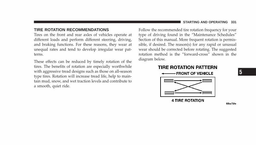
TIRE ROTATION RECOMMENDATIONSTires on the front and rear axles of vehicles operate atdifferent loads and perform different steering, driving,and braking functions. For these reasons, they wear atunequal rates and tend to develop irregular wear pat-terns.
These effects can be reduced by timely rotation of thetires. The benefits of rotation are especially worthwhilewith aggressive tread designs such as those on all-seasontype tires. Rotation will increase tread life, help to main-tain mud, snow, and wet traction levels and contribute toa smooth, quiet ride.
Follow the recommended tire rotation frequency for yourtype of driving found in the “Maintenance Schedules”Section of this manual. More frequent rotation is permis-sible, if desired. The reason(s) for any rapid or unusualwear should be corrected before rotating. The suggestedrotation method is the “forward-cross” shown in thediagram below.
STARTING AND OPERATING 331
5
TIRE PRESSURE MONITOR SYSTEM (TPMS) — IFEQUIPPED
• The Tire Pressure Monitor System (TPMS) will warnthe driver of a low tire pressure based on the vehiclerecommended cold placard pressure.
• The tire pressure will vary with temperature by about1 psi (7 kPa) for every 12°F (7°C). This means thatwhen the outside temperature decreases, the tire pres-sure will decrease. Tire pressure should always be setbased on cold inflation tire pressure. This is defined asthe tire pressure after the vehicle has not been drivenfor at least three hours, or driven less than 1 mi (1.6km) after a three hour period. The cold tire inflationpressure must not exceed the maximum inflationpressure molded into the tire sidewall. Refer to the“Tires – General Information” in this section forinformation on how to properly inflate the vehicle’s
tires. The tire pressure will also increase as the vehicleis driven - this is normal and there should be noadjustment for this increased pressure.
• TPMS will warn the driver of a low tire pressure if thetire pressure falls below the low-pressure warninglimit for any reason, including low temperature effectsand natural pressure loss through the tire.
• TPMS will continue to warn the driver of low tirepressure as long as the condition exists, and will notturn off until the tire pressure is at or above therecommended cold placard pressure. Once the low tirepressure warning has been illuminated, you mustincrease the tire pressure to the recommended coldplacard pressure in order for the TPM Light to turn off.The system will automatically update and the TPMLight will turn off once the system receives the up-dated tire pressures. The vehicle may need to be
332 STARTING AND OPERATING
driven for up to 10 minutes above 15 mph (25 km/h)in order for the TPMS to receive this information.
− For example, your vehicle may have a recom-mended cold (parked for more than three hours)placard pressure of 33 psi (227 kPa). If the ambienttemperature is 68° F (20° C) and the measured tirepressure is 28 psi (193 kPa), a temperature drop to20° F (-7° C) will decrease the tire pressure toapproximately 24 psi (165 kPa). This tire pressure issufficiently low enough to turn ON the TPM Light.Driving the vehicle may cause the tire pressure torise to approximately 28 psi (193 kPa), but the TPMLight will still be ON. In this situation, the TPMLight will turn OFF only after the tires are inflated tothe vehicle’s recommended cold placard pressurevalue.
CAUTION!
• The TPMS has been optimized for the originalequipment tires and wheels. TPMS pressures andwarning have been established for the tire sizeequipped on your vehicle. Undesirable systemoperation or sensor damage may result when us-ing replacement equipment that is not of the samesize, type, and/or style. Aftermarket wheels cancause sensor damage. Do not use aftermarket tiresealants or balance beads if your vehicle isequipped with a TPMS, as damage to the sensorsmay result.
• After inspecting or adjusting the tire pressure,always reinstall the valve stem cap. This willprevent moisture and dirt from entering the valvestem, which could damage the Tire Pressure Moni-toring Sensor.
STARTING AND OPERATING 333
5
NOTE:• TPMS is not intended to replace normal tire care and
maintenance, or to provide warning of a tire failure orcondition.
• TPMS should not be used as a tire pressure gaugewhile adjusting your tire pressure.
• Driving on a significantly under-inflated tire causesthe tire to overheat and can lead to tire failure.Under-inflation also reduces fuel efficiency and tiretread life, and may affect the vehicle’s handling andstopping ability.
• TPMS is not a substitute for proper tire maintenance,and it is the driver’s responsibility to maintain correcttire pressure using an accurate tire pressure gauge,even if under-inflation has not reached the level totrigger illumination of the TPM Light.
• Seasonal temperature changes will affect tire pressure,and the TPMS will monitor the actual tire pressure inthe tire.
BASE SYSTEM — IF EQUIPPEDThe Tire Pressure Monitor System (TPMS) uses wirelesstechnology with wheel rim mounted electronic sensors tomonitor tire pressure levels. Sensors, mounted to eachwheel as part of the valve stem, transmit tire pressurereadings to the Receiver Module.
NOTE: It is particularly important for you to check thetire pressure in all of the tires on your vehicle monthlyand to maintain the proper pressure.
The TPMS consists of the following components:
• Receiver Module
• Four Tire Pressure Monitoring Sensors
• Tire Pressure Monitoring Telltale Light
334 STARTING AND OPERATING
Tire Pressure Monitoring Low Pressure WarningsThe TPM Light will illuminate in the instrumentcluster and a chime will sound when tire pressureis low in one or more of the four active road tires.
Should this occur, you should stop as soon as possible,check the inflation pressure of each tire on your vehicle,and inflate each tire to the vehicle’s recommended coldplacard pressure value. Once the system receives theupdated tire pressures, the system will automaticallyupdate and the TPM Light will turn off. The vehicle mayneed to be driven for up to 10 minutes above 15 mph (25km/h) in order for the TPMS to receive this information.
Check TPMS WarningThe TPM Light will flash on and off for 75 seconds andthen remain on solid when a system fault is detected. Thesystem fault will also sound a chime. If the ignition key iscycled, this sequence will repeat, providing the system
fault still exists. The TPM Light will turn off when thefault condition no longer exists. A system fault can occurdue to any of the following:
1. Signal interference due to electronic devices or drivingnext to facilities emitting the same Radio Frequencies asthe TPM sensors.
2. Installing aftermarket window tinting that containsmaterials which may block radio wave signals.
3. Excessive accumulation of snow or ice around thewheels or wheel housings.
4. Using tire chains on the vehicle.
5. Using wheels/tires not equipped with TPM sensors.
NOTE:1. The compact spare tire (if so equipped) does not havea tire pressure monitoring sensor. Therefore, the TPMSwill not monitor the pressure in the compact spare tire.
STARTING AND OPERATING 335
5
2. If you install the compact spare tire in place of a roadtire that has a pressure below the low-pressure warninglimit, upon the next ignition key cycle, a chime willsound and the TPM Telltale Light will turn ON due to thelow tire.
3. After driving the vehicle for up to 10 minutes above 15mph (25 km/h), the TPM Telltale Light will flash on andoff for 75 seconds and then remain on solid.
4. For each subsequent ignition key cycle, a chime willsound and the TPM Telltale Light will flash on and off for75 seconds and then remain on solid.
5. Once you repair or replace the original road tire, andreinstall it on the vehicle in place of the compact spare,the TPMS will update automatically and the TPM TelltaleLight will turn OFF, as long no tire pressure is below thelow-pressure warning limit in any of the four active road
tires. The vehicle may need to be driven for up to 10minutes above 15 mph (25 km/h) in order for the TPMSto receive this information.
GENERAL INFORMATIONThis device complies with part 15 of the FCC rules andRSS 210 of Industry Canada. Operation is subject to thefollowing conditions:
• This device may not cause harmful interference.
• This device must accept any interference received,including interference that may cause undesired op-eration.
The tire pressure sensors are covered under one of thefollowing licenses:
United States . . . . . . . . . . . . . . . . . . . . . KR5S120123Canada . . . . . . . . . . . . . . . . . . . . . . . . 2671-S120123
336 STARTING AND OPERATING
FUEL REQUIREMENTS — GASOLINE ENGINES
2.4L AND 2.4L STANDARD TURBO ENGINES2.4L standard engines are designed to meetall emission regulations and provide excel-lent fuel economy and performance whenusing high quality unleaded “regular”gasolines having an octane rating of 87.The use of premium gasoline is not recom-
mended. Under normal conditions, the use of premiumgasoline will not provide a benefit over high qualityunleaded “regular” gasolines, and in some circumstancesmay result in poorer performance.
REFORMULATED GASOLINEMany areas of the country require the use of cleanerburning gasoline referred to as “Reformulated Gasoline”.
Reformulated gasolines contain oxygenates, and are spe-cifically blended to reduce vehicle emissions and im-prove air quality.
The manufacturer supports the use of reformulated gaso-lines. Properly blended reformulated gasolines will pro-vide excellent performance and durability of engine andfuel system components.
GASOLINE/OXYGENATE BLENDSSome fuel suppliers blend unleaded gasoline with oxy-genates such as 10% ethanol, MTBE, and ETBE. Oxygen-ates are required in some areas of the country during thewinter months to reduce carbon monoxide emissions.Fuels blended with these oxygenates may be used inyour vehicle.
CAUTION!
DO NOT use gasoline containing Methanol or E85Ethanol. Use of these blends may result in startingand driveability problems and may damage criticalfuel system components.
STARTING AND OPERATING 337
5
Problems that result from using methanol/gasoline orE85 Ethanol blends are not the responsibility of themanufacturer. While MTBE is an oxygenate made fromMethanol, it does not have the negative effects of Metha-nol.
MMT IN GASOLINEMMT is a manganese containing metallic additive that isblended into some gasoline to increase the octane num-ber. Gasolines blended with MMT offer no performanceadvantage beyond gasolines of the same octane numberwithout MMT. Gasolines blended with MMT have shownto reduce spark plug life and reduce emission systemperformance in some vehicles. The manufacturer recom-mends using gasolines without MMT. Since the MMTcontent of gasoline may not be indicated on the pump,you should ask your gasoline retailer whether or nothis/her gasoline contains MMT.
It is even more important to look for gasolines withoutMMT in Canada, because MMT can be used at levelshigher than those allowed in the United States.
MMT is prohibited in Federal and California reformu-lated gasolines.
MATERIALS ADDED TO FUELAll gasoline sold in the United States is required tocontain effective detergent additives. Use of additionaldetergents or other additives is not needed under normalconditions and would result in additional cost. Thereforeyou should not have to add anything to the fuel.
FUEL SYSTEM CAUTIONS
CAUTION!
Follow these guidelines to maintain your vehicle’sperformance:
338 STARTING AND OPERATING
• The use of leaded gas is prohibited by Federal law.Using leaded gasoline can impair engine performance,damage the emission control system.
• An out-of-tune engine, or certain fuel or ignitionmalfunctions, can cause the catalytic converter tooverheat. If you notice a pungent burning odor orsome light smoke, your engine may be out of tune ormalfunctioning and may require immediate service.Contact your dealer for service assistance.
• The use of fuel additives which are now being sold asoctane enhancers is not recommended. Most of theseproducts contain high concentrations of methanol.Fuel system damage or vehicle performance problemsresulting from the use of such fuels or additives is notthe responsibility of the manufacturer.
NOTE: Intentional tampering with emissions controlsystems can result in civil penalties being assessedagainst you.
CARBON MONOXIDE WARNINGS
WARNING!
Carbon monoxide (CO) in exhaust gases is deadly.Follow the precautions below to prevent carbonmonoxide poisoning:
• Do not inhale exhaust gases. They contain carbonmonoxide, a colorless and odorless gas which can kill.Never run the engine in a closed area, such as agarage, and never sit in a parked vehicle with theengine running for an extended period. If the vehicle isstopped in an open area with the engine running formore than a short period, adjust the ventilation systemto force fresh, outside air into the vehicle.
• Guard against carbon monoxide with proper mainte-nance. Have the exhaust system inspected every time
STARTING AND OPERATING 339
5
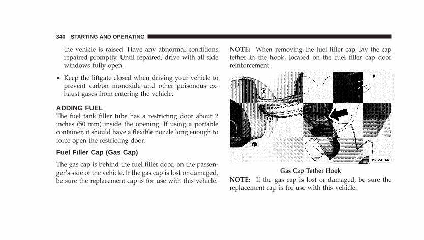
the vehicle is raised. Have any abnormal conditionsrepaired promptly. Until repaired, drive with all sidewindows fully open.
• Keep the liftgate closed when driving your vehicle toprevent carbon monoxide and other poisonous ex-haust gases from entering the vehicle.
ADDING FUELThe fuel tank filler tube has a restricting door about 2inches (50 mm) inside the opening. If using a portablecontainer, it should have a flexible nozzle long enough toforce open the restricting door.
Fuel Filler Cap (Gas Cap)
The gas cap is behind the fuel filler door, on the passen-ger’s side of the vehicle. If the gas cap is lost or damaged,be sure the replacement cap is for use with this vehicle.
NOTE: When removing the fuel filler cap, lay the captether in the hook, located on the fuel filler cap doorreinforcement.
NOTE: If the gas cap is lost or damaged, be sure thereplacement cap is for use with this vehicle.
Gas Cap Tether Hook
340 STARTING AND OPERATING
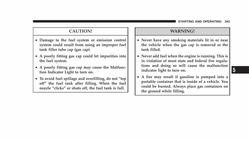
CAUTION!
• Damage to the fuel system or emission controlsystem could result from using an improper fueltank filler tube cap (gas cap).
• A poorly fitting gas cap could let impurities intothe fuel system.
• A poorly fitting gas cap may cause the Malfunc-tion Indicator Light to turn on.
• To avoid fuel spillage and overfilling, do not “topoff” the fuel tank after filling. When the fuelnozzle “clicks” or shuts off, the fuel tank is full.
WARNING!
• Never have any smoking materials lit in or nearthe vehicle when the gas cap is removed or thetank filled.
• Never add fuel when the engine is running. This isin violation of most state and federal fire regula-tions and doing so will cause the malfunctionindicator light to turn on.
• A fire may result if gasoline is pumped into aportable container that is inside of a vehicle. Youcould be burned. Always place gas containers onthe ground while filling.
STARTING AND OPERATING 341
5
NOTE:• Tighten the gas cap until you hear a “clicking” sound.
This is an indication that the gas cap is tightenedproperly. The Malfunction Indicator Light in the in-strument cluster may turn on if the gas cap is notsecured properly. Make sure that the gas cap is tight-ened each time the vehicle is refueled.
• When the fuel nozzle “clicks” or shuts off, the fueltank is full.
Loose Fuel Filler Cap MessageIf the vehicle diagnostic system determines that the fuelfiller cap is loose, improperly installed, or damaged, a“gASCAP” message will be displayed in the Odometer/Trip Odometer in the instrument cluster. Refer to “Instru-ment Cluster Description” in Section 4 of this manual.Tighten the fuel filler cap properly and press theodometer/trip odometer reset button to turn the messageoff. If the problem continues, the message will appear the
next time the vehicle is started. This might indicate adamaged cap. If the problem is detected twice in a row,the system will turn on the Malfunction Indicator Light(MIL). Resolving the problem will turn the MIL lightoff.Refer to “Onboard Diagnostic System — OBDII” inSection 7 of this manual for more information.
VEHICLE LOADING
Vehicle Loading CapacitiesFront Seat Occupants . . . . . . . . . . . . . . . . . . . . . . . 2Rear Seat Occupants (sedan) . . . . . . . . . . . . . . . . . . 3Rear Seat Occupants (convertible) . . . . . . . . . . . . . . 2Luggage . . . . . . . . . . . . . . . . . . . . . . . 115 lbs (52 kg)Rated Vehicle Capacity (sedan) . . . . . . . 865 lb (392 kg)Rated Vehicle Capacity (convertible) . . . 715 lb (324 kg)
342 STARTING AND OPERATING
TRAILER TOWINGIn this section you will find safety tips and informationon limits to the type of towing you can reasonably dowith your vehicle. Before towing a trailer carefully re-view this information to tow your load as efficiently andsafely as possible.
To maintain warranty coverage, follow the requirementsand recommendations in this manual concerning ve-hicles used for trailer towing.
COMMON TOWING DEFINITIONSThe following trailer towing related definitions will assistyou in understanding the following information:
Gross Vehicle Weight Rating (GVWR)The GVWR is the total allowable weight of your vehicle.This includes driver, passengers, cargo and tongueweight. The total load must be limited so that you do notexceed the GVWR.
Gross Trailer Weight (GTW)The gross trailer weight (GTW) is the weight of the trailerplus the weight of all cargo, consumables and equipment(permanent or temporary) loaded in or on the trailer in its�loaded and ready for operation� condition. The recom-mended way to measure GTW is to put your fully loadedtrailer on a vehicle scale. The entire weight of the trailermust be supported by the scale.
Gross Combination Weight Rating (GCWR)The gross combination weight rating (GCWR) is the totalpermissible weight of your vehicle and trailer whenweighed in combination. (Note that GCWR ratings in-clude a 68 kg (150 lbs) allowance for the presence of adriver).
STARTING AND OPERATING 343
5
Gross Axle Weight Rating (GAWR)The GAWR is the maximum capacity of the front and rearaxles. Distribute the load over the front and rear axlesevenly. Make sure that you do not exceed either front orrear GAWR.
WARNING!
It is important that you do not exceed the maximumfront or rear GAWR. A dangerous driving conditioncan result if either rating is exceeded. You could losecontrol of the vehicle and have an accident.
Tongue Weight (TW)The downward force exerted on the hitch ball by thetrailer. In most cases it should not be less than 10% ormore than 15% of the trailer load. You must consider thisas part of the load on your vehicle.
Frontal AreaThe maximum height and maximum width of the front ofa trailer.
Trailer Sway ControlThe trailer sway control is a telescoping link that can beinstalled between the hitch receiver and the trailer tonguethat typically provides adjustable friction associated withthe telescoping motion to dampen any unwanted trailerswaying motions while traveling.
Weight-Carrying HitchA weight-carrying hitch supports the trailer tongueweight, just as if it were luggage located at a hitch ball orsome other connecting point of the vehicle. These kind ofhitches are the most popular on the market today andthey’re commonly used to tow small- and medium-sizedtrailers.
344 STARTING AND OPERATING
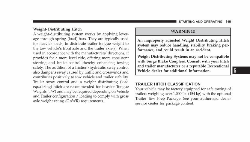
Weight-Distributing HitchA weight-distributing system works by applying lever-age through spring (load) bars. They are typically usedfor heavier loads, to distribute trailer tongue weight tothe tow vehicle’s front axle and the trailer axle(s). Whenused in accordance with the manufacturers’ directions, itprovides for a more level ride, offering more consistentsteering and brake control thereby enhancing towingsafety. The addition of a friction/hydraulic sway controlalso dampens sway caused by traffic and crosswinds andcontributes positively to tow vehicle and trailer stability.Trailer sway control and a weight distributing (loadequalizing) hitch are recommended for heavier TongueWeights (TW) and may be required depending on Vehicleand Trailer configuration / loading to comply with grossaxle weight rating (GAWR) requirements.
WARNING!
An improperly adjusted Weight Distributing Hitchsystem may reduce handling, stability, braking per-formance, and could result in an accident.
Weight Distributing Systems may not be compatiblewith Surge Brake Couplers. Consult with your hitchand trailer manufacturer or a reputable RecreationalVehicle dealer for additional information.
TRAILER HITCH CLASSIFICATIONYour vehicle may be factory equipped for safe towing oftrailers weighing over 1,000 lbs (454 kg) with the optionalTrailer Tow Prep Package. See your authorized dealerservice center for package content.
STARTING AND OPERATING 345
5

The following chart provides the industry standard forthe maximum trailer weight a given trailer hitch class cantow and should be used to assist you in selecting thecorrect trailer hitch for your intended towing condition.Refer to the Trailer Towing Weights (Maximum TrailerWeight Ratings) chart for the Max. GTW towable for yourgiven drivetrain.
TRAILER HITCH CLASSIFICATION
Class Max. GTW(Gross Trailer Wt.)
Class I - Light Duty 2,000 lbs (907 kg)Class II - Medium Duty 3,500 lbs (1 587 kg)
All trailer hitches should be professionally installed onyour vehicle.
346 STARTING AND OPERATING
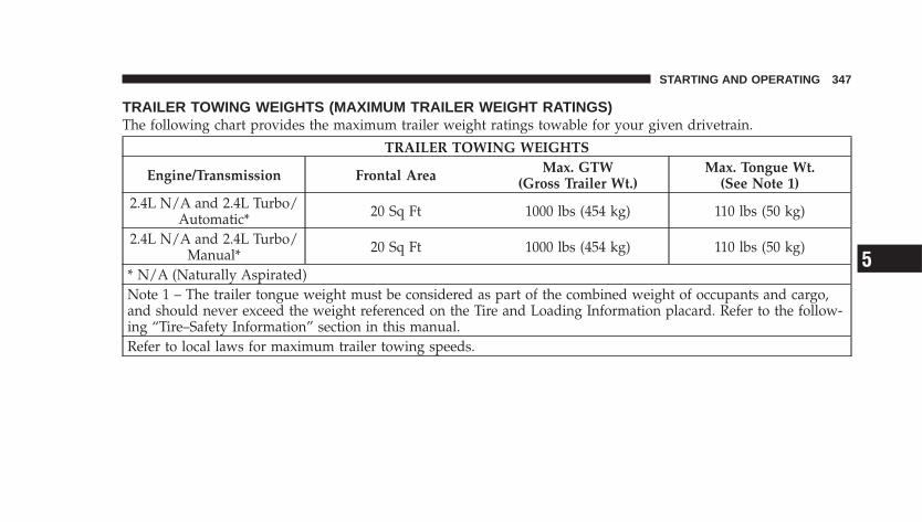
TRAILER TOWING WEIGHTS (MAXIMUM TRAILER WEIGHT RATINGS)The following chart provides the maximum trailer weight ratings towable for your given drivetrain.
TRAILER TOWING WEIGHTS
Engine/Transmission Frontal Area Max. GTW(Gross Trailer Wt.)
Max. Tongue Wt.(See Note 1)
2.4L N/A and 2.4L Turbo/Automatic* 20 Sq Ft 1000 lbs (454 kg) 110 lbs (50 kg)
2.4L N/A and 2.4L Turbo/Manual* 20 Sq Ft 1000 lbs (454 kg) 110 lbs (50 kg)
* N/A (Naturally Aspirated)Note 1 – The trailer tongue weight must be considered as part of the combined weight of occupants and cargo,and should never exceed the weight referenced on the Tire and Loading Information placard. Refer to the follow-ing “Tire–Safety Information” section in this manual.Refer to local laws for maximum trailer towing speeds.
STARTING AND OPERATING 347
5
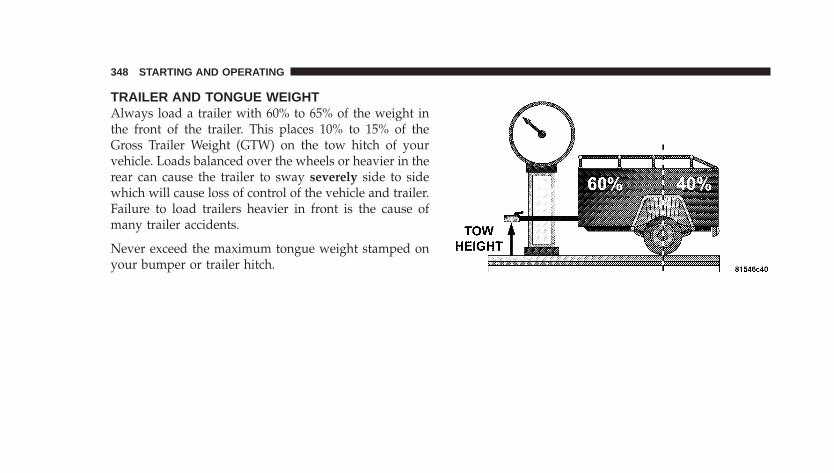
TRAILER AND TONGUE WEIGHTAlways load a trailer with 60% to 65% of the weight inthe front of the trailer. This places 10% to 15% of theGross Trailer Weight (GTW) on the tow hitch of yourvehicle. Loads balanced over the wheels or heavier in therear can cause the trailer to sway severely side to sidewhich will cause loss of control of the vehicle and trailer.Failure to load trailers heavier in front is the cause ofmany trailer accidents.
Never exceed the maximum tongue weight stamped onyour bumper or trailer hitch.
348 STARTING AND OPERATING
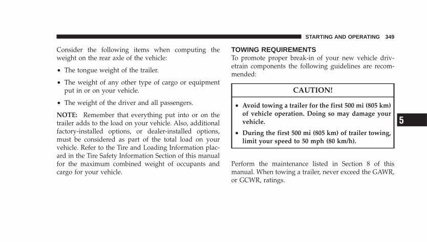
Consider the following items when computing theweight on the rear axle of the vehicle:
• The tongue weight of the trailer.
• The weight of any other type of cargo or equipmentput in or on your vehicle.
• The weight of the driver and all passengers.
NOTE: Remember that everything put into or on thetrailer adds to the load on your vehicle. Also, additionalfactory-installed options, or dealer-installed options,must be considered as part of the total load on yourvehicle. Refer to the Tire and Loading Information plac-ard in the Tire Safety Information Section of this manualfor the maximum combined weight of occupants andcargo for your vehicle.
TOWING REQUIREMENTSTo promote proper break-in of your new vehicle driv-etrain components the following guidelines are recom-mended:
CAUTION!
• Avoid towing a trailer for the first 500 mi (805 km)of vehicle operation. Doing so may damage yourvehicle.
• During the first 500 mi (805 km) of trailer towing,limit your speed to 50 mph (80 km/h).
Perform the maintenance listed in Section 8 of thismanual. When towing a trailer, never exceed the GAWR,or GCWR, ratings.
STARTING AND OPERATING 349
5
WARNING!
• Improper towing can lead to an injury accident.
• Make certain that the load is secured in the trailerand will not shift during travel. When traileringcargo that is not fully secured, dynamic load shiftscan occur that may be difficult for the driver tocontrol. You could lose control of your vehicle andhave an accident.
• When hauling cargo or towing a trailer, do not over-load your vehicle or trailer. Overloading can cause aloss of control, poor performance or damage to brakes,axle, engine, transmission, steering, suspension, chas-sis structure or tires.
• Safety chains must always be used between yourvehicle and trailer. Always connect the chains to theframe or hook retainers of the vehicle hitch. Cross thechains under the trailer tongue and allow enoughslack for turning corners.
• Vehicles with trailers should not be parked on a grade.When parking, apply the parking brake on the towvehicle. Put the tow vehicle automatic transmission inPARK. Always, block or �chock� the trailer wheels.
• GCWR must not be exceeded.
• Total weight must be distributed between the towvehicle and the trailer such that the following fourratings are not exceeded:
1. GVWR
2. GTW
3. GAWR
350 STARTING AND OPERATING
4. Tongue weight rating for the trailer hitch utilized(This requirement may limit the ability to alwaysachieve the 10% to 15% range of tongue weight as apercentage of total trailer weight).
Towing Requirements — Tires
• Do not attempt to tow a trailer while using a compactspare tire.
• Proper tire inflation pressures are essential to the safeand satisfactory operation of your vehicle. Refer to theTires–General Information section of this manual onTire Pressures for proper tire inflation procedures.
• Also, check the trailer tires for proper tire inflationpressures before trailer usage.
• Check for signs of tire wear or visible tire damagebefore towing a trailer. Refer to the Tires–GeneralInformation section of this manual on Tread WearIndicators for the proper inspection procedure.
• When replacing tires refer to the Tires–General Infor-mation section of this manual on Replacement Tiresfor proper tire replacement procedures. Replacing tireswith a higher load carrying capacity will not increasethe vehicle’s GVWR and GAWR limits.
Towing Requirements — Trailer Brakes
• Do not interconnect the hydraulic brake system orvacuum system of your vehicle with that of the trailer.This could cause inadequate braking and possiblepersonal injury.
• An electronically actuated trailer brake controller isrequired when towing a trailer with electronicallyactuated brakes. When towing a trailer equipped witha hydraulic surge actuated brake system, an electronicbrake controller is not required.
STARTING AND OPERATING 351
5
• Trailer brakes are recommended for trailers over 1,000lbs (454 kg) and required for trailers in excess of 2,000lbs (907 kg).
CAUTION!
If the trailer weighs more than 1,000 lbs (454 kg)loaded, it should have its own brakes and theyshould be of adequate capacity. Failure to do thiscould lead to accelerated brake lining wear, higherbrake pedal effort, and longer stopping distances.
WARNING!
Do not connect trailer brakes to your vehicle’s hy-draulic brake lines. It can overload your brake sys-tem and cause it to fail. You might not have brakeswhen you need them and could have an accident.
Towing any trailer will increase your stopping dis-tance. When towing you should allow for additionalspace between your vehicle and the vehicle in frontof you. Failure to do so could result in an accident.
352 STARTING AND OPERATING
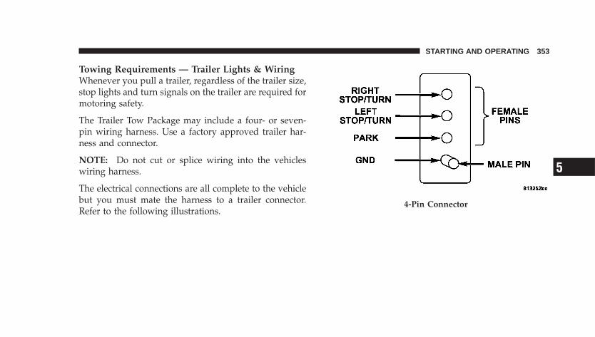
Towing Requirements — Trailer Lights & WiringWhenever you pull a trailer, regardless of the trailer size,stop lights and turn signals on the trailer are required formotoring safety.
The Trailer Tow Package may include a four- or seven-pin wiring harness. Use a factory approved trailer har-ness and connector.
NOTE: Do not cut or splice wiring into the vehicleswiring harness.
The electrical connections are all complete to the vehiclebut you must mate the harness to a trailer connector.Refer to the following illustrations.
4-Pin Connector
STARTING AND OPERATING 353
5
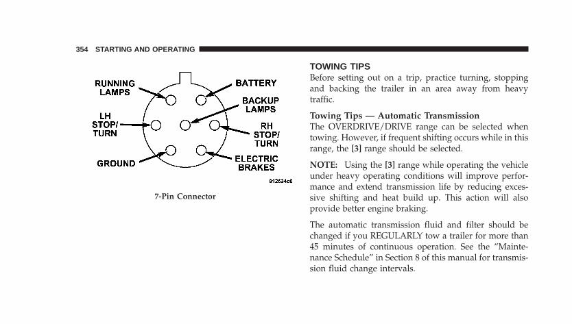
TOWING TIPSBefore setting out on a trip, practice turning, stoppingand backing the trailer in an area away from heavytraffic.
Towing Tips — Automatic TransmissionThe OVERDRIVE/DRIVE range can be selected whentowing. However, if frequent shifting occurs while in thisrange, the [3] range should be selected.
NOTE: Using the [3] range while operating the vehicleunder heavy operating conditions will improve perfor-mance and extend transmission life by reducing exces-sive shifting and heat build up. This action will alsoprovide better engine braking.
The automatic transmission fluid and filter should bechanged if you REGULARLY tow a trailer for more than45 minutes of continuous operation. See the “Mainte-nance Schedule” in Section 8 of this manual for transmis-sion fluid change intervals.
7-Pin Connector
354 STARTING AND OPERATING
NOTE: Check the automatic transmission fluid levelbefore towing.
Towing Tips — Electronic Speed Control (IfEquipped)
• Don’t use in hilly terrain or with heavy loads.
• When using the speed control, if you experience speeddrops greater than 10 mph (16 km/h), disengage untilyou can get back to cruising speed.
• Use speed control in flat terrain and with light loads tomaximize fuel efficiency.
Towing Tips — Cooling SystemTo reduce potential for engine and transmission over-heating, take the following actions:
• City DrivingWhen stopped for short periods of time, put transmissionin NEUTRAL but do not increase engine idle speed.
• Highway DrivingReduce speed.
• Air ConditioningTurn off temporarily.
• Refer to Cooling System Operating information in theMaintenance Section of this manual for more informa-tion.
STARTING AND OPERATING 355
5
RECREATIONAL TOWING (BEHINDMOTORHOME, ETC.)
Towing This Vehicle Behind Another Vehicle (Flattowing with all four wheels on the ground)
CAUTION!
Recreational towing on vehicle’s equipped with au-tomatic transaxle’s is not recommended.
NOTE: If the vehicle requires towing make sure all fourwheels are off the ground.
If your vehicle is equipped with a manual transaxle, itmay be towed with all four wheels on the ground, in aforward direction, at any legal highway speed, for anydistance, if the transaxle is in NEUTRAL.
356 STARTING AND OPERATING
WHAT TO DO IN EMERGENCIES
CONTENTS
� Hazard Warning Flasher . . . . . . . . . . . . . . . . . . 358
� If Your Engine Overheats . . . . . . . . . . . . . . . . . 358
� Jacking And Tire Changing . . . . . . . . . . . . . . . . 360
▫ Jack Location . . . . . . . . . . . . . . . . . . . . . . . . 361
▫ Spare Tire Stowage . . . . . . . . . . . . . . . . . . . . 361
▫ Preparations For Jacking . . . . . . . . . . . . . . . . 362
▫ Jacking Instructions . . . . . . . . . . . . . . . . . . . . 363
� Jump-Starting Procedures Due To A LowBattery . . . . . . . . . . . . . . . . . . . . . . . . . . . . . . 367
� Driving On Slippery Surfaces . . . . . . . . . . . . . . 369
▫ Acceleration . . . . . . . . . . . . . . . . . . . . . . . . . 369
▫ Traction . . . . . . . . . . . . . . . . . . . . . . . . . . . . 370
� Freeing A Stuck Vehicle . . . . . . . . . . . . . . . . . . 370
� Towing A Disabled Vehicle . . . . . . . . . . . . . . . . 371
▫ With Ignition Key . . . . . . . . . . . . . . . . . . . . . 371
▫ Without The Ignition Key . . . . . . . . . . . . . . . 372
� Convertible Top Manual Override . . . . . . . . . . . 373
6
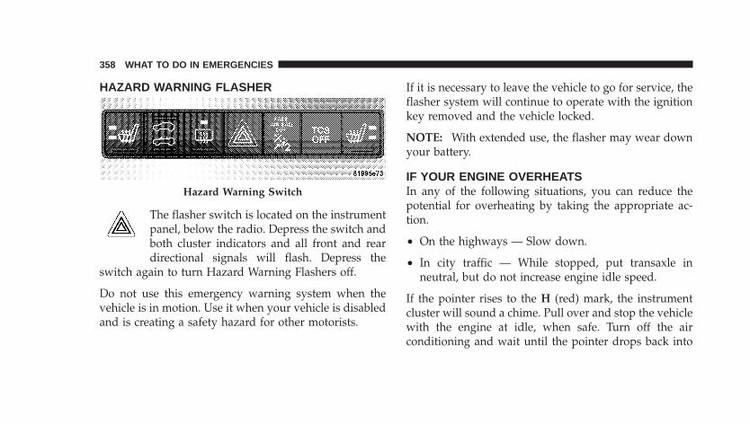
HAZARD WARNING FLASHER
The flasher switch is located on the instrumentpanel, below the radio. Depress the switch andboth cluster indicators and all front and reardirectional signals will flash. Depress the
switch again to turn Hazard Warning Flashers off.
Do not use this emergency warning system when thevehicle is in motion. Use it when your vehicle is disabledand is creating a safety hazard for other motorists.
If it is necessary to leave the vehicle to go for service, theflasher system will continue to operate with the ignitionkey removed and the vehicle locked.
NOTE: With extended use, the flasher may wear downyour battery.
IF YOUR ENGINE OVERHEATSIn any of the following situations, you can reduce thepotential for overheating by taking the appropriate ac-tion.
• On the highways — Slow down.
• In city traffic — While stopped, put transaxle inneutral, but do not increase engine idle speed.
If the pointer rises to the H (red) mark, the instrumentcluster will sound a chime. Pull over and stop the vehiclewith the engine at idle, when safe. Turn off the airconditioning and wait until the pointer drops back into
Hazard Warning Switch
358 WHAT TO DO IN EMERGENCIES
the normal range. If the pointer remains on the H (red)mark for more than a minute, turn the engine off imme-diately and call for service.
NOTE: There are steps that you can take to slow downan impending overheat condition. If your air conditioneris on, turn it off. The air conditioning system adds heat tothe engine cooling system and turning off the A/Cremoves this heat. You can also turn the Temperaturecontrol to maximum heat, the Mode control to floor, andthe fan control to High. This allows the heater core to actas a supplement to the radiator and aids in removing heatfrom the engine cooling system.
CAUTION!
Driving with a hot cooling system could damageyour vehicle. If temperature gauge reads “H”, pullover and stop the vehicle with the engine at idle,when safe. Turn the air conditioner off and wait untilthe pointer drops back into the normal range. Afterappropriate action has been taken, if the pointerremains on the “H”, turn the engine off immediately,and call for service.
WHAT TO DO IN EMERGENCIES 359
6
WARNING!
A hot engine cooling system is dangerous. You orothers could be badly burned by steam or boilingcoolant. You may want to call a service center if yourvehicle overheats. If you decide to look under thehood yourself, refer to Section 7, Maintenance, of thismanual. Follow the warnings under the CoolingSystem Pressure Cap paragraph.
JACKING AND TIRE CHANGING
WARNING!
• Being under a jacked-up vehicle is dangerous. Thevehicle could slip off the jack and fall on you. Youcould be crushed. Never put any part of your bodyunder a vehicle that is on a jack. Never start or runthe engine while the vehicle is on a jack. If youneed to get under a raised vehicle, take it to aservice center where it can be raised on a lift.
• The jack is designed to use as a tool for changingtires only. The jack should not be used to lift thevehicle for service purposes. The vehicle shouldbe jacked on a firm level surface only. Avoid ice orslippery areas.
360 WHAT TO DO IN EMERGENCIES
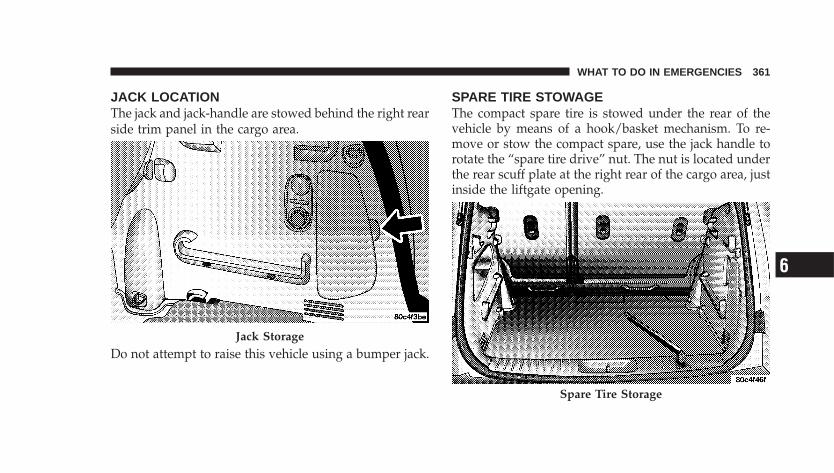
JACK LOCATIONThe jack and jack-handle are stowed behind the right rearside trim panel in the cargo area.
Do not attempt to raise this vehicle using a bumper jack.
SPARE TIRE STOWAGEThe compact spare tire is stowed under the rear of thevehicle by means of a hook/basket mechanism. To re-move or stow the compact spare, use the jack handle torotate the “spare tire drive” nut. The nut is located underthe rear scuff plate at the right rear of the cargo area, justinside the liftgate opening.
Jack Storage
Spare Tire Storage
WHAT TO DO IN EMERGENCIES 361
6
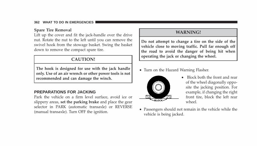
Spare Tire RemovalLift up the cover and fit the jack-handle over the drivenut. Rotate the nut to the left until you can remove theswivel hook from the stowage basket. Swing the basketdown to remove the compact spare tire.
CAUTION!
The hook is designed for use with the jack handleonly. Use of an air wrench or other power tools is notrecommended and can damage the winch.
PREPARATIONS FOR JACKINGPark the vehicle on a firm level surface, avoid ice orslippery areas, set the parking brake and place the gearselector in PARK (automatic transaxle) or REVERSE(manual transaxle). Turn OFF the ignition.
WARNING!
Do not attempt to change a tire on the side of thevehicle close to moving traffic. Pull far enough offthe road to avoid the danger of being hit whenoperating the jack or changing the wheel.
• Turn on the Hazard Warning Flasher.
• Block both the front and rearof the wheel diagonally oppo-site the jacking position. Forexample, if changing the rightfront tire, block the left rearwheel.
• Passengers should not remain in the vehicle while thevehicle is being jacked.
362 WHAT TO DO IN EMERGENCIES
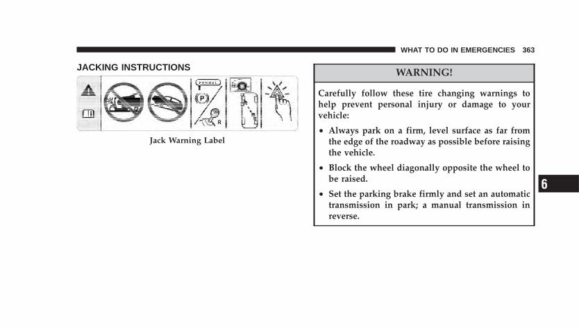
JACKING INSTRUCTIONS WARNING!
Carefully follow these tire changing warnings tohelp prevent personal injury or damage to yourvehicle:
• Always park on a firm, level surface as far fromthe edge of the roadway as possible before raisingthe vehicle.
• Block the wheel diagonally opposite the wheel tobe raised.
• Set the parking brake firmly and set an automatictransmission in park; a manual transmission inreverse.
Jack Warning Label
WHAT TO DO IN EMERGENCIES 363
6
WARNING!
Carefully follow these tire changing warnings tohelp prevent personal injury or damage to yourvehicle:
• Never start or run the engine with the vehicle on ajack.
• Do not let anyone sit in the vehicle when it is on ajack.
• Do not get under the vehicle when it is on a jack.
• Only use the jack in the positions indicated andfor lifting this vehicle during a tire change.
WARNING!
Carefully follow these tire changing warnings tohelp prevent personal injury or damage to yourvehicle:
• If working on or near a roadway, be extremelycareful of motor traffic.
• To assure that spare tires, flat or inflated aresecurely stowed, spares must be stowed with thevalve stem facing the ground.
• Turn on the Hazard warning flasher.
1. Remove the scissors jack and lug wrench from thestowage bag.
364 WHAT TO DO IN EMERGENCIES
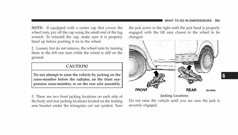
NOTE: If equipped with a center cap that covers thewheel nuts, pry off the cap using the small end of the lugwrench. To reinstall the cap, make sure it is properlylined up before pushing it on to the wheel.
2. Loosen, but do not remove, the wheel nuts by turningthem to the left one turn while the wheel is still on theground.
CAUTION!
Do not attempt to raise the vehicle by jacking on thecross-member below the radiator, on the front sus-pension cross-member, or on the rear axle assembly.
3. There are two front jacking locations on each side ofthe body and rear jacking locations located on the trailingarm bracket under the triangular cut out symbol. Turn
the jack screw to the right until the jack head is properlyengaged with the lift area closest to the wheel to bechanged.
Do not raise the vehicle until you are sure the jack issecurely engaged.
Jacking Locations
WHAT TO DO IN EMERGENCIES 365
6
4. Raise the vehicle by turning the jack screw to the right,using the swivel wrench. Raise the vehicle only until thetire just clears the surface and enough clearance isobtained to install the spare tire. Minimum tire liftprovides maximum stability.
WARNING!
Raising the vehicle higher than necessary can makethe vehicle less stable. It could slip off the jack andhurt someone near it. Raise the vehicle only enoughto remove the tire.
5. Remove the wheel nuts and pull the wheel and wheelcovers where applicable off the hub. Install the sparewheel and wheel nuts with the cone shaped end of thenuts toward the wheel. Lightly tighten the nuts. To avoidthe risk of forcing the vehicle off the jack, do not tightenthe nuts fully until the vehicle has been lowered.
WARNING!
To avoid possible personal injury, handle the wheelcovers with care to avoid contact with any sharpedges.
NOTE: The wheel cover is held on the wheel by thewheel nuts. When reinstalling original wheel, properlyalign the wheel cover to the valve stem, place the wheelcover onto the wheel, then install the wheel nuts.
6. Lower the vehicle by turning the jack screw to the left.
7. Finish tightening the nuts. Push down on the wrenchwhile tightening the wheel nuts. Alternate nuts until eachnut has been tightened twice. Correct wheel nut torque is100 ft. lbs (135 N·m). If you doubt that you havetightened the nuts correctly, have them checked with atorque wrench by your dealer or at a service station.
366 WHAT TO DO IN EMERGENCIES
8. Remove the wheel blocks and lower the jack until it isfree. Stow the lug wrench, and jack in their designatedlocation. Secure all parts using the means provided.
WARNING!
A loose tire or jack thrown forward in a collision orhard stop could endanger the occupants of the ve-hicle. Always stow the jack parts and the spare tire inthe places provided. Have the deflated (flat) tirerepaired or replaced immediately.
9. Place the deflated (flat) tire in the cargo area, have thetire repaired or replaced as soon as possible.
10. Check the tire pressure as soon as possible. Correctpressure as required.
JUMP-STARTING PROCEDURES DUE TO A LOWBATTERY
WARNING!
Take care to avoid the radiator cooling fan wheneverthe hood is raised. It can start anytime the ignitionswitch is on. You can be hurt by the fan.
WHAT TO DO IN EMERGENCIES 367
6
WARNING!
Do not attempt to push or tow your vehicle to get itstarted. Vehicles equipped with an automatic trans-axle cannot be started this way. Unburned fuel couldenter the catalytic converter and once the engine hasstarted, ignite and damage the converter and vehicle.If the vehicle has a discharged battery, booster cablesmay be used to obtain a start from another vehicle.This type of start can be dangerous if done improp-erly, so follow this procedure carefully.
1. Wear eye protection and remove any metal jewelrysuch as watch bands or bracelets that might make aninadvertent electrical contact.
2. When boosting from a battery in another vehicle, parkthat vehicle within booster cable reach but withoutletting the vehicles touch. Set parking brake, place auto-matic transaxle in PARK (manual transaxle in NEU-TRAL) and turn ignition to OFF for both vehicles.
3. Turn off the heater, radio and all unnecessary electricalloads.
4. Connect one end of a jumper cable to the positiveterminal of the booster battery. Connect the other end ofthe jumper cable to the positive terminal of the dis-charged battery.
368 WHAT TO DO IN EMERGENCIES
WARNING!
Battery fluid is a corrosive acid solution; do not allowbattery fluid to contact eyes, skin or clothing. Don’tlean over battery when attaching clamps or allow theclamps to touch each other. If acid splashes in eyes oron skin, flush the contaminated area immediatelywith large quantities of water.
A battery generates hydrogen gas which is flam-mable and explosive. Keep flame or spark away fromthe vent holes. Do not use a booster battery or anyother booster source with an output that exceeds 12volts.
5. Connect the other cable, first to the negative terminalof the booster battery and then to the negative terminal ofthe discharged battery. Make sure you have a goodcontact.
6. If the vehicle is equipped with Sentry Key Immobi-lizer, turn the ignition switch to the ON position for 3seconds before moving the ignition switch to the STARTposition.
7. Start the engine in the vehicle that has the boosterbattery, let the engine idle a few minutes, then start theengine in the vehicle with the discharged battery.
8. When removing the jumper cables, reverse the se-quence exactly. Be careful of the moving belts and fan.
DRIVING ON SLIPPERY SURFACES
ACCELERATIONRapid acceleration on snow covered, wet, or other slip-pery surfaces may cause the front wheels to pull errati-cally to the right or left. This phenomenon occurs whenthere is a difference in the surface traction under the front(driving) wheels.
WHAT TO DO IN EMERGENCIES 369
6
WARNING!
Rapid acceleration on slippery surfaces is dangerous.Unequal traction can cause sudden pulling of thefront wheels. You could lose control of the vehicleand possibly have an accident. Accelerate slowly andcarefully whenever there is likely to be poor traction(ice, snow, wet, mud, loose sand, etc.).
TRACTIONWhen driving on wet or slushy roads, it is possible for awedge of water to build up between the tire and roadsurface. This is hydroplaning and may cause partial orcomplete loss of vehicle control and stopping ability. Toreduce this possibility, the following precautions shouldbe observed:
1. Slow down during rainstorms or when roads areslushy.
2. Slow down if the road has standing water or puddles.
3. Replace the tires when tread wear indicators firstbecome visible.
4. Keep the tires properly inflated.
5. Maintain enough distance between your vehicle and thevehicle in front of you to avoid a collision in a sudden stop.
FREEING A STUCK VEHICLE
NOTE: If your vehicle is equipped with Traction Control,turn the system OFF before attempting to “rock” the vehicle.
If your vehicle becomes stuck in mud, sand or snow, itcan often be moved by a rocking motion. Turn yoursteering wheel right and left to clear the area around thefront wheels. Then shift back and forth between Reverseand First gear. Usually the least accelerator pedal pres-sure to maintain the rocking motion without spinning thewheels is most effective.
370 WHAT TO DO IN EMERGENCIES
WARNING!
Fast spinning tires can be dangerous. Forces gener-ated by excessive wheel speeds may cause tire dam-age or failure. A tire could explode and injure some-one. Do not spin your vehicle’s wheels faster than 30mph (48 km/h) when you are stuck. And don’t letanyone near a spinning wheel, no matter what thespeed.
CAUTION!
Racing the engine or spinning the wheels too fastmay lead to transaxle overheating and failure. It canalso damage the tires. Do not spin the wheels above30 mph (48 km/h).
TOWING A DISABLED VEHICLE
With Ignition Key
Four Speed Automatic TransaxleYour vehicle may be towed under the following condi-tions: The steering column must be unlocked and thegear selector must be in NEUTRAL, the distance to betowed must not exceed 100 miles (160 km), and thetowing speed must not exceed 44 mph (72 km/h). If thetransaxle is not operative, or if the vehicle is to be towedmore than 100 miles (160 km), the vehicle must be towedwith the front wheels off the ground to avoid damage tothe transaxle.
Manual TransaxleYour vehicle may be towed in a forward direction, withall 4 wheels on the ground, and the gearshift lever is inNEUTRAL. If the transaxle is not operative, the vehiclemust be towed with the front wheels off the ground.
WHAT TO DO IN EMERGENCIES 371
6
All Transaxles
CAUTION!
If the vehicle being towed requires steering, theignition switch must be in the ACC position, not inthe LOCK positions.
Do not attempt to use sling type equipment whentowing. When securing vehicle to flat bed truck, donot attach to front or rear suspension components.Damage to your vehicle may result from impropertowing.
If it is necessary to use the accessories while being towed(wipers, defrosters, etc.), the key must be in the ONposition, not the ACC position. Make certain the trans-axle remains in NEUTRAL.
Without The Ignition KeySpecial care must be taken when the vehicle is towedwith the ignition in the LOCK position. A dolly should beused under the front wheels if the rear wheels are raised.Proper towing equipment is necessary to prevent dam-age to the vehicle.
Towing This Vehicle Behind Another Vehicle (FlatTowing With All Four Wheels On The Ground)If your vehicle is equipped with a manual transaxle, itmay be towed in a forward direction, at any legalhighway speed, for any distance, if the transaxle is inNEUTRAL.
If the ignition key is not available, vehicles with auto-matic transaxles can not be flat towed at any time.
372 WHAT TO DO IN EMERGENCIES
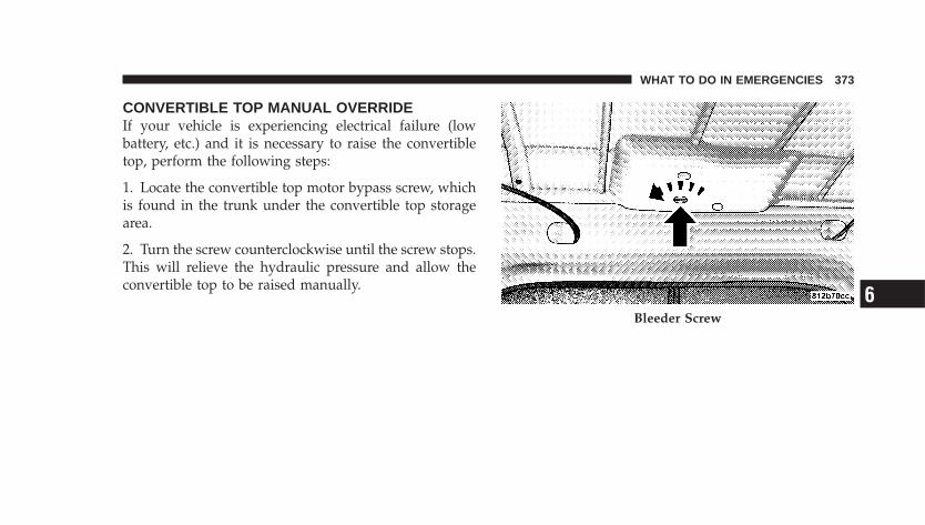
CONVERTIBLE TOP MANUAL OVERRIDEIf your vehicle is experiencing electrical failure (lowbattery, etc.) and it is necessary to raise the convertibletop, perform the following steps:
1. Locate the convertible top motor bypass screw, whichis found in the trunk under the convertible top storagearea.
2. Turn the screw counterclockwise until the screw stops.This will relieve the hydraulic pressure and allow theconvertible top to be raised manually.
Bleeder Screw
WHAT TO DO IN EMERGENCIES 373
6
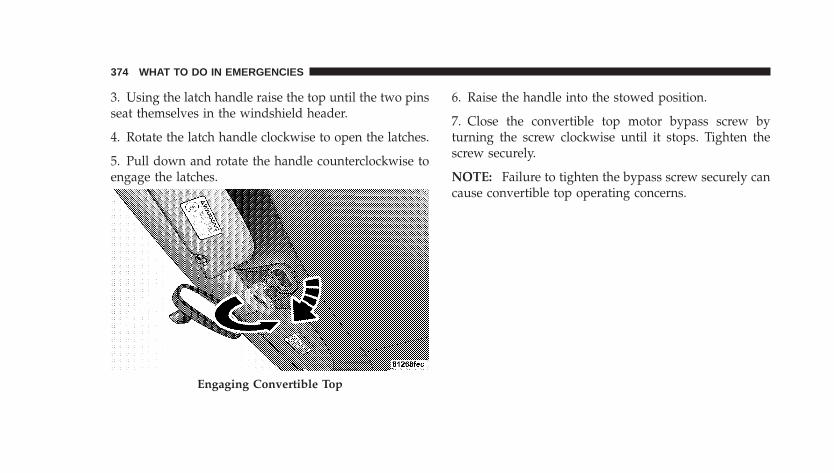
3. Using the latch handle raise the top until the two pinsseat themselves in the windshield header.
4. Rotate the latch handle clockwise to open the latches.
5. Pull down and rotate the handle counterclockwise toengage the latches.
6. Raise the handle into the stowed position.
7. Close the convertible top motor bypass screw byturning the screw clockwise until it stops. Tighten thescrew securely.
NOTE: Failure to tighten the bypass screw securely cancause convertible top operating concerns.
Engaging Convertible Top
374 WHAT TO DO IN EMERGENCIES
MAINTAINING YOUR VEHICLE
CONTENTS
� 2.4L Turbo Engine Compartment . . . . . . . . . . . . 378
� 2.4L Engine Compartment . . . . . . . . . . . . . . . . 379
� Onboard Diagnostic System — OBD II . . . . . . . . 380
▫ Loose Fuel Filler Cap Message . . . . . . . . . . . . 381
� Emissions Inspection And MaintenancePrograms . . . . . . . . . . . . . . . . . . . . . . . . . . . . 381
� Replacement Parts . . . . . . . . . . . . . . . . . . . . . . 383
� Authorized Dealer Service . . . . . . . . . . . . . . . . 383
� Maintenance Procedures . . . . . . . . . . . . . . . . . . 384
▫ Engine Oil . . . . . . . . . . . . . . . . . . . . . . . . . . 384
▫ Drive Belts — Check Condition And Tension . . 388
▫ Spark Plugs . . . . . . . . . . . . . . . . . . . . . . . . . 388
▫ Ignition Wiring System . . . . . . . . . . . . . . . . . 388
▫ Catalytic Converter . . . . . . . . . . . . . . . . . . . . 389
▫ Engine Timing Belt . . . . . . . . . . . . . . . . . . . . 390
▫ Crankcase Emission Control System . . . . . . . . 390
▫ Fuel Filter . . . . . . . . . . . . . . . . . . . . . . . . . . 391
▫ Air Cleaner Element (Air Filter) . . . . . . . . . . . 391
7
▫ Maintenance-Free Battery . . . . . . . . . . . . . . . . 392
▫ Air Conditioner Maintenance . . . . . . . . . . . . . 393
▫ Power Steering – Fluid Check . . . . . . . . . . . . 394
▫ Front Suspension Ball Joints . . . . . . . . . . . . . . 395
▫ Steering Linkage . . . . . . . . . . . . . . . . . . . . . . 395
▫ Body Lubrication . . . . . . . . . . . . . . . . . . . . . 395
▫ Windshield Wiper Blades . . . . . . . . . . . . . . . . 396
▫ Windshield Washer Reservoir . . . . . . . . . . . . . 396
▫ Exhaust System . . . . . . . . . . . . . . . . . . . . . . 397
▫ Cooling System . . . . . . . . . . . . . . . . . . . . . . . 398
▫ Hoses And Vacuum/Vapor Harnesses . . . . . . . 403
▫ Fuel System Connections . . . . . . . . . . . . . . . . 404
▫ Brake System . . . . . . . . . . . . . . . . . . . . . . . . 404
▫ Automatic Transaxle . . . . . . . . . . . . . . . . . . . 408
▫ Manual Transaxle . . . . . . . . . . . . . . . . . . . . . 410
▫ Appearance Care And Protection FromCorrosion . . . . . . . . . . . . . . . . . . . . . . . . . . . 411
� Convertible Top Care . . . . . . . . . . . . . . . . . . . . 416
▫ Washing . . . . . . . . . . . . . . . . . . . . . . . . . . . . 416
▫ General Cleaning . . . . . . . . . . . . . . . . . . . . . 417
▫ Cloth Top Additional Cleaning Procedure . . . . 418
▫ Cloth Top Protection . . . . . . . . . . . . . . . . . . . 418
▫ Weather Strip Care . . . . . . . . . . . . . . . . . . . . 418
� Integrated Power Module (IPM) . . . . . . . . . . . . 419
� Vehicle Storage . . . . . . . . . . . . . . . . . . . . . . . . 423
� Replacement Bulbs . . . . . . . . . . . . . . . . . . . . . . 424
376 MAINTAINING YOUR VEHICLE
� Bulb Replacement . . . . . . . . . . . . . . . . . . . . . . 425
▫ Headlights . . . . . . . . . . . . . . . . . . . . . . . . . . 425
▫ Front Park/Turn Signal/Side Marker Lights . . 426
▫ Front Fog Lights — If Equipped . . . . . . . . . . . 426
▫ Tail/Stop, And Rear Turn Signal Lights . . . . . . 427
▫ Back Up Lights . . . . . . . . . . . . . . . . . . . . . . . 427
▫ Center High Mounted Stop Light . . . . . . . . . . 428
� Fluids And Capacities . . . . . . . . . . . . . . . . . . . 429
� Fluids, Lubricants And Genuine Parts . . . . . . . . 430
▫ Engine . . . . . . . . . . . . . . . . . . . . . . . . . . . . . 430
▫ Chassis . . . . . . . . . . . . . . . . . . . . . . . . . . . . 431
MAINTAINING YOUR VEHICLE 377
7
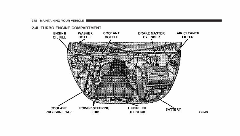
2.4L TURBO ENGINE COMPARTMENT
378 MAINTAINING YOUR VEHICLE
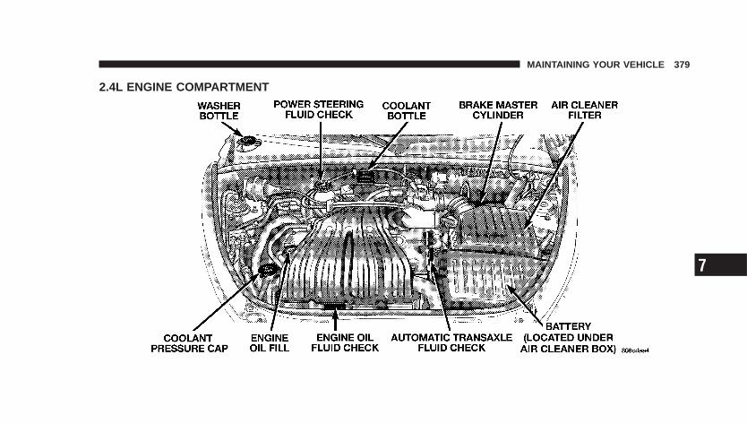
2.4L ENGINE COMPARTMENT
MAINTAINING YOUR VEHICLE 379
7
ONBOARD DIAGNOSTIC SYSTEM — OBD IIYour vehicle is equipped with a sophisticated onboarddiagnostic system called OBD II. This system monitorsthe performance of the emissions, engine, and automatictransmission control systems. When these systems areoperating properly, your vehicle will provide excellentperformance and fuel economy, as well as engine emis-sions well within current government regulations.
If any of these systems require service, the OBD II systemwill turn on the “Malfunction Indicator Light.” It willalso store diagnostic codes and other information toassist your service technician in making repairs. Al-though your vehicle will usually be drivable and notneed towing, see your dealer for service as soon aspossible.
CAUTION!
• Prolonged driving with the “Malfunction Indica-tor Light” on could cause further damage to theemission control system. It could also affect fueleconomy and driveability. The vehicle must beserviced before any emissions tests can be per-formed.
• If the “Malfunction Indicator Light” is flashingwhile the engine is running, severe catalytic con-verter damage and power loss will soon occur.Immediate service is required.
380 MAINTAINING YOUR VEHICLE
Loose Fuel Filler Cap MessageAfter fuel is added, the vehicle diagnostic system candetermine if the fuel filler cap is loose, improperlyinstalled, or damaged. A gASCAP message will be dis-played in the instrument cluster. Tighten the gas cap untila �clicking� sound is heard. This is an indication that thegas cap is properly tightened. Press the odometer resetbutton to turn the message off. If the problem persists,the message will appear the next time the vehicle isstarted. This might indicate a damaged cap. If the prob-lem is detected twice in a row, the system will turn on theMalfunction Indicator Light (MIL). Resolving the prob-lem will turn the MIL light off.
EMISSIONS INSPECTION AND MAINTENANCEPROGRAMSIn some localities, it may be a legal requirement to passan inspection of your vehicle’s emissions control system.Failure to pass could prevent vehicle registration.
For states that require an Inspection and Mainte-nance (I/M), this check verifies the MalfunctionIndicator Light (MIL) is functioning and is not on
when the engine is running, and that the OBD II systemis ready for testing.
Normally, the OBD II system will be ready. The OBD IIsystem may not be ready if your vehicle was recentlyserviced, recently had a dead battery, or a battery replace-ment. If the OBD II system should be determined notready for the I/M test, your vehicle may fail the test.
MAINTAINING YOUR VEHICLE 381
7
Your vehicle has a simple ignition key-actuated test,which you can use prior to going to the test station. Tocheck if your vehicle’s OBD II system is ready, you mustdo the following:
1. Insert your ignition key into the ignition switch.
2. Turn the ignition to the ON position, but do not crankor start the engine.
3. If you crank or start the engine, you will have to startthis test over.
4. As soon as you turn your key to the ON position, youwill see the MIL symbol come on as part of a normal bulbcheck.
5. Approximately 15 seconds later, one of two things willhappen:
a. The MIL will flash for about 10 seconds and thenreturn to being fully illuminated until you turn OFF
the ignition key or start the engine. This means thatyour vehicle’s OBD II system is not ready and youshould not proceed to the I/M station.
b. The MIL will not flash at all and will remain fullyilluminated until you turn OFF the ignition key or startthe engine. This means that your vehicle’s OBD IIsystem is ready , and you can proceed to the I/Mstation.
If your OBD II system is not ready, you should see yourauthorized dealer or repair facility. If your vehicle wasrecently serviced or had a battery failure or replacement,you may need to do nothing more than drive yourvehicle as you normally would in order for your OBD IIsystem to update. A recheck with the above test routinemay then indicate that the system is now ready.
Regardless of whether your vehicle’s OBD II system isready or not ready, if the MIL is illuminated duringnormal vehicle operation, you should have your vehicle
382 MAINTAINING YOUR VEHICLE
serviced before going to the I/M station. The I/M stationcan fail your vehicle because the MIL is on with theengine running.
REPLACEMENT PARTSUse of genuine Mopar� parts for normal/scheduledmaintenance and repairs is highly recommended to en-sure the designed performance. Damage or failurescaused by the use of non-Mopar� parts for maintenanceand repairs will not be covered by the manufacturer’swarranty.
AUTHORIZED DEALER SERVICEYour authorized dealer has the qualified service person-nel, special tools, and equipment to perform all serviceoperations in an expert manner. Service manuals areavailable which include detailed service information foryour vehicle. Refer to these Service manuals beforeattempting any procedure yourself.
NOTE: Intentional tampering with emissions controlsystems can result in civil penalties being assessedagainst you.
WARNING!
You can be badly injured working on or around amotor vehicle. Only do service work for which youhave the knowledge and the proper equipment. Ifyou have any doubt about your ability to perform aservice job, take your vehicle to a competentmechanic.
MAINTAINING YOUR VEHICLE 383
7
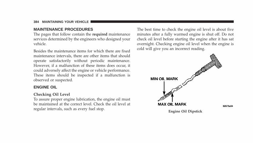
MAINTENANCE PROCEDURESThe pages that follow contain the required maintenanceservices determined by the engineers who designed yourvehicle.
Besides the maintenance items for which there are fixedmaintenance intervals, there are other items that shouldoperate satisfactorily without periodic maintenance.However, if a malfunction of these items does occur, itcould adversely affect the engine or vehicle performance.These items should be inspected if a malfunction isobserved or suspected.
ENGINE OIL
Checking Oil LevelTo assure proper engine lubrication, the engine oil mustbe maintained at the correct level. Check the oil level atregular intervals, such as every fuel stop.
The best time to check the engine oil level is about fiveminutes after a fully warmed engine is shut off. Do notcheck oil level before starting the engine after it has satovernight. Checking engine oil level when the engine iscold will give you an incorrect reading.
Engine Oil Dipstick
384 MAINTAINING YOUR VEHICLE
Checking the oil while the vehicle is on level ground, willimprove the accuracy of the oil level readings. Maintainthe oil level between the MIN and MAX markings on thedipstick. Adding one quart of oil when the reading is atthe MIN mark will result in a MAX reading on theseengines.
CAUTION!
Overfilling the crankcase as indicated by an oil levelabove the “Max” mark on the engine oil dipstick willcause oil aeration, which can lead to loss of oilpressure and an increase in oil temperature. Thiscould damage your engine.
Change Engine OilRoad conditions and your kind of driving affects theinterval at which your oil should be changed. Check thefollowing list to decide if any apply to you.
• Day and night temperatures are below 32°F (0°C).
• Stop and Go driving.
• Extensive engine idling.
• Driving in dusty conditions.
• Short trips of less than 10 miles (16 km).
• More than 50% of your driving is at sustained highspeeds during hot weather, above 90°F (32°C).
• Trailer towing.
• Taxi, Police or delivery service (commercial service).
• Off-Road or desert operation.
• If equipped for and operating with E-85 (ethanol)fuel.
NOTE: If ANY of these apply to you then change yourengine oil every 3,000 miles (5 000 km) or three months,
MAINTAINING YOUR VEHICLE 385
7
whichever comes first, and follow schedule “B—AllEngines” of the �Maintenance Schedules� section of thismanual.
If none of these apply to you, and your vehicle isequipped with a Non–Turbo Charged Engine thenchange your engine oil at every interval shown onschedule “A”—NON TURBO in the maintenance sched-ule section of this manual.
If none of these apply to you, and your vehicle isequipped with a Turbo Charged Engine change yourengine oil at every interval shown on schedule“A”—TURBO in the maintenance schedule section of thismanual.
NOTE: Under no circumstances should oil change in-tervals exceed 6000 miles (10 000 km) or 6 monthswhichever comes first.
Engine Oil SelectionFor best performance and maximum protection under alltypes of operating conditions, the manufacturer onlyrecommends engine oils that are API certified and meetthe requirements of DaimlerChrysler Material StandardMS-6395.
American Petroleum Institute (API) Engine OilIdentification Symbol
This symbol means that the oil hasbeen certified by the AmericanPetroleum Institute (API). Themanufacturer only recommendsAPI Certified engine oils.
386 MAINTAINING YOUR VEHICLE
Engine Oil Viscosity (SAE Grade) — 2.4L and 2.4LTurbo EnginesSAE 5W-30 engine oil is recommended for all operatingtemperatures. This engine oil improves low temperaturestarting and vehicle fuel economy.
The engine oil filler cap also shows the recommendedengine oil viscosity for your engine. For information onengine oil filler cap location, refer to the “Engine Com-partment” illustration in this section.
Lubricants which do not have both, the engine oil certi-fication mark and the correct SAE viscosity grade num-ber should not be used.
Synthetic Engine OilsYou may use synthetic engine oils provided the recom-mended oil quality requirements are met, and the recom-mended maintenance intervals for oil and filter changesare followed.
Materials Added To Engine OilsThe manufacture strongly recommends against the addi-tion of any additives (other than leak detection dyes) tothe engine oil. Engine oil is an engineered product andit’s performance may be impaired by supplemental ad-ditives.
Disposing of Used Engine OilCare should be taken in disposing of used engine oil fromyour vehicle. Used oil, indiscriminately discarded, canpresent a problem to the environment. Contact yourdealer, service station, or governmental agency for adviceon how and where used oil can be safely discarded inyour area.
Engine Oil FilterThe engine oil filter should be replaced at every engineoil change.
MAINTAINING YOUR VEHICLE 387
7
Engine Oil Filter SelectionAll of this manufacturers engines have a full-flow typedisposable oil filter. Use a filter of this type for replace-ment. The quality of replacement filters varies consider-ably. Only high quality filters should be used to assuremost efficient service. Mopar Engine Oil Filters are highquality oil filters and are recommended.
DRIVE BELTS — CHECK CONDITION ANDTENSIONAt the mileage shown in the maintenance schedules,check all drive belts for condition and proper tension.Improper belt tension can cause belt slippage and failure.
Inspect the drive belts for evidence of cuts, cracks, orglazing and replace them if there is any sign of damagewhich could result in belt failure. If adjustment is re-quired, see your authorized dealer for service.
Special tools are required to properly measure tensionand to restore belt tension to factory specifications. Also,check belt routing to make sure there is no interferencebetween the belts and other engine components.
SPARK PLUGSSpark plugs must fire properly to assure engine perfor-mance and emission control. New plugs should be in-stalled at the specified mileage. The entire set should bereplaced if there is any malfunction due to a faulty sparkplug. Refer to “Fluids, Lubricants, and Genuine Parts” inthis section for the proper type of spark plug for use inyour vehicle.
IGNITION WIRING SYSTEMThe ignition cables should be kept clean and properlyconnected. Terminals should be fully seated. Cracked,damaged, or faulty cables should be replaced.
388 MAINTAINING YOUR VEHICLE
CATALYTIC CONVERTERThe catalytic converter requires the use of unleaded fuelonly. Leaded gasoline will destroy the effectiveness of thecatalyst as an emission control device.
Under normal operating conditions, the catalytic con-verter will not require maintenance. However, it is im-portant to keep the engine properly tuned to assureproper catalyst operation and prevent possible catalystdamage.
CAUTION!
Damage to the catalytic converter can result if yourvehicle is not kept in proper operating condition. Inthe event of engine malfunction, particularly involv-ing engine misfire or other apparent loss of perfor-mance, have your vehicle serviced promptly. Contin-ued operation of your vehicle with a severemalfunction could cause the converter to overheat,resulting in possible damage to the converter and thevehicle.
NOTE: Intentional tampering with emissions controlsystems can result in civil penalties being assessedagainst you.
MAINTAINING YOUR VEHICLE 389
7
WARNING!
A hot exhaust system can start a fire if you park overmaterials that can burn. Such materials might begrass or leaves coming into contact with your exhaustsystem. Do not park or operate your vehicle in areaswhere your exhaust system can contact anything thatcan burn.
In unusual situations involving grossly malfunctioningengine operation, a scorching odor may suggest severeand abnormal catalyst overheating. If this occurs, stopthe vehicle, turn off the engine and allow it to cool.Service, including a tune up to manufacturers specifica-tions, should be obtained immediately.
To minimize the possibility of catalyst damage:
• Do not shut off the engine or interrupt the ignitionwhen the transaxle is in gear and the vehicle is inmotion.
• Do not try to start the engine by pushing or towing thevehicle.
• Do not idle the engine with any spark plug wiresdisconnected for prolonged period.
ENGINE TIMING BELTReplace the engine timing belt at the intervals describedin the appropriate maintenance schedule.
CRANKCASE EMISSION CONTROL SYSTEMProper operation of this system depends on freedomfrom sticking or plugging due to deposits. As vehiclemileage builds up, the PCV valve and passages mayaccumulate deposits. If a valve is not working properly,replace it with a new valve. DO NOT ATTEMPT TOCLEAN THE OLD PCV VALVE!
390 MAINTAINING YOUR VEHICLE
Check ventilation hose for indication of damage orplugging deposits. Replace if necessary.
FUEL FILTERA plugged fuel filter can cause hard starting or limit thespeed at which a vehicle can be driven. Should anexcessive amount of dirt accumulate in the fuel tank,frequent filter replacement may be necessary. The fuelfilters are located inside the fuel tank. See your dealer forservice.
AIR CLEANER ELEMENT (AIR FILTER)Under normal driving conditions, replace the filter at theintervals shown on Schedule “A”. If, however, you drivethe vehicle frequently under dusty or severe conditions,the filter element should be inspected periodically andreplaced if necessary at the intervals shown on Schedule“B”.
NOTE: For vehicles with a Turbo engine, a smallamount of oil accumulation in the air cleaner box isnormal. The amount will depend on driving style. The aircleaner box should be cleaned out and a new make-up-air filter element should be installed during the normalair filter maintenance procedure.
WARNING!
The air cleaner can provide a measure of protectionin the case of engine backfire. Do not remove the aircleaner unless such removal is necessary for repair ormaintenance. Make sure that no one is near theengine compartment before starting the vehicle withthe air cleaner removed. Failure to do so can result inserious personal injury.
MAINTAINING YOUR VEHICLE 391
7
MAINTENANCE-FREE BATTERYYou will never have to add water, nor is periodic main-tenance required.
CAUTION!
When servicing the battery, always reinstall the bat-tery thermowrap. The thermowrap provides batteryheat protection and will extend overall battery life.Failure to reinstall the thermowrap can result inevaporative loss of the battery fluid.
WARNING!
Battery fluid is a corrosive acid solution and can burnor even blind you. Don’t allow battery fluid tocontact your eyes, skin or clothing. Don’t lean over abattery when attaching clamps. If acid splashes ineyes or on skin, flush the area immediately withlarge amounts of water.
Battery gas is flammable and explosive. Keep flameor sparks away from the battery. Don’t use a boosterbattery or any other booster source with an outputgreater than 12 volts. Don’t allow cable clamps totouch each other.
Battery posts, terminals and related accessories con-tain lead and lead compounds. Wash hands afterhandling.
392 MAINTAINING YOUR VEHICLE
CAUTION!
It is essential when replacing the cables on thebattery that the positive cable is attached to thepositive post and the negative cable is attached to thenegative post. Battery posts are marked positive (+)and negative (-) and identified on the battery case.Cable clamps should be tight on the terminal postsand free of corrosion. Apply grease to posts andclamps after tightening.
If a “fast charger” is used while the battery is in thevehicle, disconnect both vehicle battery cables beforeconnecting the charger to battery. Do not use a “fastcharger” to provide starting voltage as battery dam-age can result.
AIR CONDITIONER MAINTENANCEFor best possible performance, your air conditionershould be checked and serviced by an Authorized Dealerat the start of each warm season. This service shouldinclude cleaning of the condenser fins and a performancetest. Drive belt tension should also be checked at thistime.
MAINTAINING YOUR VEHICLE 393
7
WARNING!
• Use only refrigerants and compressor lubricantsapproved by the manufacturer for your air condi-tioning system. Some unapproved refrigerants areflammable and can explode, injuring you. Otherunapproved refrigerants or lubricants can causethe system to fail, requiring costly repairs. Refer toSection 3 of the Warranty Information book forfurther warranty information.
• The air conditioning system contains refrigerantunder high pressure. To avoid risk of personalinjury or damage to the system, adding refrigerantor any repair requiring lines to be disconnectedshould be done by an experienced repairman.
Refrigerant Recovery and RecyclingR-134a Air Conditioning Refrigerant is a hydrofluoro-carbon (HFC) that is endorsed by the EnvironmentalProtection Agency and is an ozone-saving product. How-ever, the manufacturer recommends that air conditioningservice be performed by dealers or other service facilitiesusing recovery and recycling equipment.
NOTE: Use only manufacturer approved A/C SystemSealers, Stop Leak Products, Seal Conditioners, Compres-sor Oil, or Refrigerants.
POWER STEERING – FLUID CHECKChecking the power steering fluid level at a definedservice interval is not required. The fluid should only bechecked if a leak is suspected, abnormal noises areapparent, and/or the system is not functioning as antici-pated. Coordinate inspection efforts through a certifiedDaimlerChrysler Dealership.
394 MAINTAINING YOUR VEHICLE
WARNING!
Fluid level should be checked on a level surface andwith the engine off to prevent injury from movingparts and to insure accurate fluid level reading. Donot overfill. Use only manufacturers recommendedpower steering fluid.
If necessary, add fluid to restore to the proper indicatedlevel. With a clean cloth, wipe any spilled fluid from allsurfaces. Refer to Fluids, Lubricants, and Genuine Partsfor correct fluid types.
FRONT SUSPENSION BALL JOINTSThere are two front suspension lower ball joints that arepermanently lubricated. Inspect these ball joints when-ever under vehicle service is done. Damaged seals andtheir corresponding potentially damaged ball joints mustbe replaced.
STEERING LINKAGEThe tie rod end ball joints should be inspected forexternal leakage and damage when other maintenance isperformed.
BODY LUBRICATIONLocks and all body pivot points, including such items asseat tracks, doors, liftgate and hood hinges, should belubricated periodically to assure quiet, easy operationand to protect against rust and wear. Prior to the appli-cation of any lubricant, the parts concerned should bewiped clean to remove dust and grit; after lubricatingexcess oil and grease should be removed. Particularattention should also be given to hood latching compo-nents to insure proper function. When performing otherunderhood services, the hood latch, release mechanismand safety catch should be cleaned and lubricated.
The external lock cylinders should be lubricated twice ayear, preferably in the fall and spring. Apply a small
MAINTAINING YOUR VEHICLE 395
7
amount of a high quality lubricant such as Mopar� LockCylinder Lubricant directly into the lock cylinder.
WINDSHIELD WIPER BLADESClean the rubber edges of the wiper blades and thewindshield periodically with a sponge or soft cloth and amild non abrasive cleaner or use the washer solvent. Thiswill remove accumulations of salt, waxes or road filmand help reduce streaking and smearing.
Operation of the wipers on dry glass for long periodsmay cause deterioration of the wiper blades. Always usewasher fluid when using the wipers to remove salt or dirtfrom a dry windshield. Avoid using the wiper blades toremove frost or ice from the windshield. make sure thatthey are not frozen to the glass before turning them on toavoid damaging the blade. Keep the blade rubber out ofcontact with petroleum products such as engine oil,gasoline, etc.
Windshield Wiper Blade Replacement
1. Lift the wiper arm away from the glass.
2. Push the release tab shown in the illustration and slidethe wiper blade assembly down along the arm. Gentlyplace the wiper arm on the windshield.
3. Install the new blade assembly onto the wiper arm tipuntil it locks in place.
NOTE: Always refer to the wiper blade packaging forspecific installation instructions. Many wiper blade re-placements fit multiple vehicles.
WINDSHIELD WASHER RESERVOIR
NOTE: Always refer to the wiper blade packaging forspecific installation instructions. Many wiper blade re-placements fit multiple vehicles.
The washer fluid reservoir is located in the rear of theengine compartment on the passenger side and should be
396 MAINTAINING YOUR VEHICLE
checked for fluid level at regular intervals. Fill thereservoir with windshield washer solvent (not radiatorantifreeze) and operate the system for a few seconds toflush out the residual water.
WARNING!
Commercially available windshield washer solventsare flammable. They could ignite and burn you. Caremust be exercised when filling or working aroundthe washer solution.
EXHAUST SYSTEMThe best protection against carbon monoxide entry intothe vehicle body is a properly maintained engine exhaustsystem.
If you notice a change in the sound of the exhaust system,or if exhaust fumes can be detected inside the vehicle, or
when the underside or rear of the vehicle is damaged;have a competent technician inspect the complete ex-haust system and adjacent body areas for broken, dam-aged, deteriorated, or mispositioned parts. Open seamsor loose connections could permit exhaust fumes to seepinto the passenger compartment. In addition, inspect theexhaust system each time the vehicle is raised for an oilchange or lubrication. Replace as required.
WARNING!
Exhaust gases can injure or kill. They contain carbonmonoxide (CO) which is colorless and odorless.Breathing it can make you unconscious and caneventually poison you. To avoid breathing CO, referto Exhaust Gas in the Safety Tips section of thismanual.
MAINTAINING YOUR VEHICLE 397
7
COOLING SYSTEM
WARNING!
• When working near the radiator cooling fan, dis-connect the fan motor lead or turn the ignitionswitch to the OFF position. The fan is temperaturecontrolled and can start at any time the ignitionswitch is in the ON position.
• You or others can be badly burned by hot coolantor steam from your radiator. If you see or hearsteam coming from under the hood, don’t open thehood until the radiator has had time to cool. Nevertry to open a cooling system pressure cap when theradiator is hot.
Coolant ChecksCheck engine coolant (antifreeze) protection every 12months (before the onset of freezing weather, whereapplicable). If coolant is dirty or rusty in appearance, thesystem should be drained, flushed and refilled with freshcoolant. Check the front of the A/C condenser for anyaccumulation of bugs, leaves, etc. If dirty, clean by gentlyspraying water from a garden hose vertically down theface of the condenser.
Check the coolant recovery bottle tubing for brittle rub-ber, cracking, tears, cuts and tightness of the connectionat the bottle and radiator. Inspect the entire system forleaks.
398 MAINTAINING YOUR VEHICLE
Cooling System — Drain, Flush and RefillThe system should be drained, flushed, and refilled at theintervals shown in the “Maintenance Schedules” in Sec-tion 8 of this manual.
If the solution is dirty or contains a considerable amountof sediment, clean and flush with a reliable coolingsystem cleaner. Follow with a thorough rinsing to removeall deposits and chemicals. Properly dispose of oldantifreeze solution.
Selection Of CoolantUse only the manufacturers recommended coolant, referto Fluids, Lubricants and Genuine Parts for correctcoolant type.
CAUTION!
Mixing of coolants other than specified HOAT en-gine coolants, may result in engine damage and maydecrease corrosion protection. If a non-HOAT coolantis introduced into the cooling system in an emer-gency, it should be replaced with the specified cool-ant as soon as possible.
Do not use plain water alone or alcohol base enginecoolant (antifreeze) products. Do not use additionalrust inhibitors or antirust products, as they may notbe compatible with the radiator engine coolant andmay plug the radiator.
This vehicle has not been designed for use withPropylene Glycol based coolants. Use of PropyleneGlycol based coolants is not recommended.
MAINTAINING YOUR VEHICLE 399
7
Adding CoolantYour vehicle has been built with an improved enginecoolant that allows extended maintenance intervals. Thiscoolant can be used up to five Years or 100,000 milesbefore replacement. To prevent reducing this extendedmaintenance period, it is important that you use the samecoolant throughout the life of your vehicle. Please reviewthese recommendations for using Hybrid Organic Addi-tive Technology (HOAT) coolant.
When adding coolant:
• The manufacturer recommends using Mopar�Antifreeze/Coolant five Year/100,000 Mile FormulaHOAT (Hybrid Organic Additive Technology).
• Mix a minimum solution of 50% HOAT engine coolantand distilled water. Use higher concentrations (not toexceed 70%) if temperatures below �34° F (�37° C)are anticipated.
• Use only high purity water such as distilled or deion-ized water when mixing the water/engine coolantsolution. The use of lower quality water will reducethe amount of corrosion protection in the enginecooling system.
Please note that it is the owner’s responsibility to main-tain the proper level of protection against freezing ac-cording to the temperatures occurring in the area wherethe vehicle is operated.
NOTE: Mixing coolant types will decrease the life of theengine coolant and will require more frequent coolantchanges.
Cooling System Pressure CapThe cap must be fully tightened to prevent loss ofcoolant, and to insure that coolant will return to theradiator from the coolant recovery bottle.
400 MAINTAINING YOUR VEHICLE
The cap should be inspected and cleaned if there is anyaccumulation of foreign material on the sealing surfaces.
WARNING!
• The warning words “DO NOT OPEN HOT” onthe cooling system pressure cap are a safety pre-caution. Never add coolant when the engine isoverheated. Do not loosen or remove the cap tocool an overheated engine. Heat causes pressure tobuild up in the cooling system. To prevent scald-ing or injury, do not remove the pressure cap whilethe system is hot or under pressure.
• Do not use a pressure cap other than the onespecified for your vehicle. Personal injury or en-gine damage may result.
Disposal of Used Engine CoolantUsed ethylene glycol based engine coolant is a regulatedsubstance requiring proper disposal. Check with yourlocal authorities to determine the disposal rules for yourcommunity. To prevent ingestion by humans and animalsdo not store ethylene glycol based engine coolant in opencontainers or allow it to remain in puddles on theground. If ethylene glycol engine coolant is ingested byanyone, contact a physician immediately. Clean up anyground spills immediately.
Coolant LevelThe coolant bottle provides a quick visual method fordetermining that the coolant level is adequate. With theengine idling, and warm to normal operating tempera-ture, the level of the coolant in the bottle should bebetween the ranges indicated on the bottle.
MAINTAINING YOUR VEHICLE 401
7
The radiator normally remains completely full, so there isno need to remove the radiator cap unless checking forcoolant freeze point or replacing coolant. Advise yourservice attendant of this. As long as the engine operatingtemperature is satisfactory, the coolant bottle need onlybe checked once a month.
When additional coolant is needed to maintain theproper level, it should be added to the coolant bottle. Donot overfill.
Points To Remember
NOTE: When the vehicle is stopped after a few miles (afew kilometers) of operation, you may observe vaporcoming from the front of the engine compartment. This isnormally a result of moisture from rain, snow, or highhumidity accumulating on the radiator and being vapor-ized when the thermostat opens, allowing hot coolant toenter the radiator.
If an examination of your engine compartment shows noevidence of radiator or hose leaks, the vehicle may besafely driven. The vapor will soon dissipate.
• Do not overfill the coolant recovery bottle.
• Check coolant freeze point in the radiator and in thecoolant recovery bottle. If antifreeze needs to beadded, contents of coolant recovery bottle must also beprotected against freezing.
• If frequent coolant additions are required, or if thelevel in the coolant recovery bottle does not drop whenthe engine cools, the cooling system should be pres-sure tested for leaks.
• Maintain coolant concentration at 50% HOAT enginecoolant (minimum) and distilled water for propercorrosion protection of your engine which containsaluminum components.
402 MAINTAINING YOUR VEHICLE
• Make sure that the radiator and coolant recoverybottle overflow hoses are not kinked or obstructed.
• Keep the front of the radiator clean. If your vehicle isequipped with air conditioning, keep the front of thecondenser clean, also.
• Do not change the thermostat for summer or winteroperation. If replacement is ever necessary, installONLY the correct type thermostat. Other designs mayresult in unsatisfactory coolant performance, poor gasmileage, and increased emissions.
HOSES AND VACUUM/VAPOR HARNESSESInspect surfaces of hoses and nylon tubing for evidenceof heat and mechanical damage. Hard or soft spots,brittle rubber, cracking, tears, cuts, abrasions, and exces-sive swelling indicate deterioration of the rubber
Pay particular attention to the hoses nearest to high heatsources such as the exhaust manifold. Inspect hose rout-ing to be sure hoses do not touch any heat source ormoving component that may cause heat damage ormechanical wear.
Insure nylon tubing in these areas has not melted orcollapsed
Inspect all hose connections such as clamps and cou-plings to make sure they are secure and no leaks arepresent.
Components should be replaced immediately if there isany evidence of degradation that could cause failure.
MAINTAINING YOUR VEHICLE 403
7
FUEL SYSTEM CONNECTIONSElectronic Fuel Injection high pressure fuel systems aredesigned with tubes and special connects, connectionsand clamps which have unique material characteristics toprovide adequate sealing and resist attack by deterio-rated gasoline.
You are urged to use only the manufactures-specifiedtubes, connections and clamps, or their equivalent inmaterial and specification, in any fuel system servicing.
BRAKE SYSTEMIn order to assure brake system performance, all brakesystem components should be inspected periodically.Suggested service intervals can be found in the “Mainte-nance Schedule” in this manual.
WARNING!
Riding the brakes can lead to brake failure andpossibly an accident. Driving with your foot restingor riding on the brake pedal can result in abnormallyhigh brake temperatures, excessive lining wear, andpossible brake damage. You wouldn’t have your fullbraking capacity in an emergency.
Brake, Power Steering and Oil Cooler SystemHosesWhen servicing the vehicle for scheduled maintenance,inspect the surface of the hoses and nylon tubing forevidence of heat and mechanical damage. Hard and
404 MAINTAINING YOUR VEHICLE
brittle rubber, cracking, tears, cuts, abrasions, and exces-sive swelling suggest deterioration of the rubber. Particu-lar attention should be made to examining those hosesurfaces nearest to high heat sources, such as the exhaustmanifold.
Inspect all hose clamps and couplings to make sure theyare secure and no leaks are present.
Insure nylon tubing in these areas has not melted orcollapsed.
NOTE: Often, fluids such as oil, power steering fluid,and brake fluid are used during assembly plant opera-tions to ease the assembly of hoses to couplings. There-fore, oil wetness at the hose-coupling area is not neces-sarily an indication of leakage. Actual dripping of hotfluid when systems are under pressure (during vehicleoperation) should be noted before a hose is replacedbased on leakage.
NOTE: Inspection of brake hoses should be done when-ever the brake system is serviced and at every engine oilchange. Inspect hydraulic brake hoses for surface crack-ing, scuffing, or worn spots. If there is any evidence ofcracking, scuffing, or worn spots, the hose should bereplaced immediately! Eventual deterioration of the hosecan take place resulting in a possibility of a burst failure.
WARNING!
Worn brake hoses can burst and cause brake failure.You could have an accident. If you see any signs ofcracking, scuffing, or worn spots, have the brakehoses replaced immediately.
MAINTAINING YOUR VEHICLE 405
7
Master Cylinder - Brake Fluid Level CheckCheck the fluid level in the master cylinder immediatelyif the brake system warning light indicates system fail-ure.
Check the fluid level in the master cylinder when per-forming underhood services.
Clean the top of the master cylinder area before removingthe cap. If necessary, add fluid to bring the fluid level upto the requirements described on the brake fluid reser-voir.
Overfilling of fluid is not recommended because it maycause leaking in the system.
Fluid level can be expected to fall as the brake pads wear.Brake fluid level should be checked when pads arereplaced. However, low fluid level may be caused by aleak and a checkup may be needed.
Use only manufacturers recommended brake fluid. Referto “Fluids, Lubricants, and Genuine Parts” for the correctfluid type.
NOTE: If your vehicle is equipped with a Manualtransaxle , the Brake Fluid Reservoir supplies fluid toboth the Brake System and the Clutch Release System.The two systems are separated in the reservoir and a leakin one system will not affect the other system. TheManual Transaxle Clutch Release System should notrequire fluid replacement during the life of the vehicle. Ifthe Brake Fluid Reservoir is low, and the brake systemdoes not indicate any leaks or other problems, it may bea result of a leak in the Hydraulic Clutch Release System.See your local authorized dealer for service.
Use only manufacturers recommended brake fluid, referto Fluids, Lubricants and Genuine Parts for correct fluidtype.
406 MAINTAINING YOUR VEHICLE
WARNING!
Use of a brake fluid that has a lower initial boilingpoint than the recommended MOPAR� DOT 3 prod-uct or a brake fluid that is unidentified as to FMVSSspecification may result in sudden brake failureduring hard prolonged braking. You could have anaccident.
CAUTION!
Use of improper brake fluids will affect overallclutch system performance. Improper brake fluidsmay damage the clutch system resulting in loss ofclutch function and the ability to shift the transaxle.
WARNING!
Overfilling the brake fluid reservoir can result inspilling brake fluid on hot engine parts and thebrake fluid catching fire.
Use only brake fluid that has been in a tightly closedcontainer to avoid contamination from foreign matter.
CAUTION!
Do not allow petroleum base fluid to contaminate thebrake fluid, all brake seal components could bedamaged causing partial or complete brake failure.
MAINTAINING YOUR VEHICLE 407
7
AUTOMATIC TRANSAXLEThe automatic transaxle and differential assembly arecontained within a single housing.
The fluid level in the automatic transaxle should bechecked whenever the vehicle is serviced. Operation withan improper fluid level will greatly reduce the life of thetransaxle and the fluid.
FLUID LEVEL CHECK — FOUR-CYLINDERENGINESUse the following procedure to check the automatictransaxle fluid level properly:
1. Park the vehicle on level ground.
2. Run the engine at curb idle speed for a minimum of 60seconds.
3. Apply the parking brake fully.
4. Place the gear selector momentarily in each gearposition ending with the lever in “P” (Park).
5. Wipe the area around the dipstick clean to eliminatethe possibility of dirt entering the transaxle.
6. Remove the dipstick and determine if the fluid is hotor cold. Hot fluid is approximately 180° F (82° C), whichis the normal operating temperature after the vehicle isdriven at least 15 miles (24 km). Hot fluid cannot be heldcomfortably between the fingertips. Cold fluid is at atemperature below 80°F (27°C).
7. Wipe the dipstick clean and reinsert until seated. Then,remove dipstick and note the reading.
a. If the fluid is hot, the reading should be in thecrosshatched area marked “HOT” (between the uppertwo holes in the dipstick).
b. If the fluid is cold, the fluid level should be betweenthe lower two holes in the area marked “COLD.”
408 MAINTAINING YOUR VEHICLE
If the fluid level is low, add sufficient fluid through thefiller (dipstick) tube to bring it to the proper level. Do notoverfill.
CAUTION!
• Using a transmission fluid other than the manu-facturer’s recommended fluid may cause deterio-ration in transmission shift quality and/or torqueconverter shudder. Using a transmission fluidother than that recommended by the manufacturerwill result in more frequent fluid and filterchanges. Refer to “Fluids, Lubricants, and Genu-ine Parts” for the correct fluid type.
• Dirt and water in the transaxle can cause seriousdamage. To prevent dirt and water from enteringthe transaxle after checking or replenishing fluid,make certain that the dipstick cap is re-seatedproperly.
Fluid And Filter ChangesAutomatic transmission fluid and filter should bechanged as follows:
Maintenance schedule “A”—Non Turbo Charged En-gines – No change necessary.
Maintenance schedule “A”—Turbo Charged Engines –No change necessary.
Maintenance schedule “B”—All Engines – Every 60,000miles (100 000 km) change fluid and filter under thefollowing conditions:
• Police, taxi, limousine, commercial type operation, ortrailer towing where the vehicle is driven regularly formore than 45 minutes of continuous operation.
NOTE: Refer to Section 8 of this manual for mainte-nance schedules.
MAINTAINING YOUR VEHICLE 409
7
If the transaxle is disassembled for any reason, the fluidand filter should be changed.
Special AdditivesAutomatic Transmission Fluid (ATF) is an engineeredproduct and its performance may be impaired by supple-mental additives. Therefore, do not add any fluid addi-tives to the transaxle. The only exception to this policy isthe use of special dyes to aid in detecting fluid leaks. Inaddition, avoid using transmission sealers as they mayadversely affect seals.
MANUAL TRANSAXLE
Lubricant SelectionUse only manufacturers recommended transmissionfluid. Refer to Fluids, Lubricants and Genuine Parts forthe correct fluid type.
Fluid Level CheckCheck the fluid level by removing the fill plug. The fluidlevel should be between the bottom of the fill hole and apoint not more that 3/16” (4.7 mm) below the bottom ofthe hole.
Add fluid, if necessary, to maintain the proper level.
Frequency Of Fluid ChangeUnder normal operating conditions, the fluid installed atthe factory will give satisfactory lubrication for the life ofthe vehicle. Fluid changes are not necessary unless thefollowing conditions exist:
• The lubricant has become contaminated with water. Ifcontaminated with water, the fluid should be changedimmediately.
• If severe usage has occurred, refer to MaintenanceSchedule “B” in Section 8 of this manual.
410 MAINTAINING YOUR VEHICLE
APPEARANCE CARE AND PROTECTION FROMCORROSION
Protection Of Body And Paint from CorrosionVehicle body care requirements vary according to geo-graphic locations and usage. Chemicals that make roadspassable in snow and ice, and those that are sprayed ontrees and road surfaces during other seasons, are highlycorrosive to the metal in your vehicle. Outside parking,which exposes your vehicle to airborne contaminants,road surfaces on which the vehicle is operated, extremehot or cold weather and other extreme conditions willhave an adverse effect on paint, metal trim, and under-body protection.
The following maintenance recommendations will enableyou to obtain maximum benefit from the corrosionresistance built into your vehicle.
What Causes Corrosion?Corrosion is the result of deterioration or removal ofpaint and protective coatings from your vehicle.
The most common causes are:
• Road salt, dirt and moisture accumulation.
• Stone and gravel impact.
• Insects, tree sap and tar.
• Salt in the air near sea coast localities.
• Atmospheric fallout/industrial pollutants.
Washing
• Wash your vehicle regularly. Always wash your ve-hicle in the shade using Mopar� Car Wash or a mildcar wash soap, and rinse the panels completely withclear water.
MAINTAINING YOUR VEHICLE 411
7
• If insects, tar, or other similar deposits have accumu-lated on your vehicle, use Mopar� Super Kleen Bugand Tar Remover to remove.
• Use Mopar� Cleaner Wax to remove road film, stainsand to protect your paint finish. Take care never toscratch the paint.
• Avoid using abrasive compounds and power buffingthat may diminish the gloss or thin out the paintfinish.
CAUTION!
Do not use abrasive or strong cleaning materials suchas steel wool or scouring powder, which will scratchmetal and painted surfaces.
Special Care
• If you drive on salted or dusty roads or if you drivenear the ocean, hose off the undercarriage at least oncea month.
• It is important that the drain holes in the lower edgesof the doors, rocker panels and trunk be kept clear andopen.
• If you detect any stone chips or scratches in the paint,touch them up immediately. The cost of such repairs isconsidered the responsibility of the owner.
• If your vehicle is damaged due to an accident orsimilar cause which destroys the paint and protectivecoating, have your vehicle repaired as soon as pos-sible. The cost of such repairs is considered the respon-sibility of the owner.
412 MAINTAINING YOUR VEHICLE
• If you carry special cargo such as chemicals, fertilizers,de-icer salt, etc., be sure that such materials are wellpackaged and sealed.
• If a lot of driving is done on gravel roads, considermud or stone shields behind each wheel.
• Use Mopar touch up paint on scratches as soon aspossible. Your dealer has touch up paint to match thecolor of your vehicle.
Wheel and Wheel Trim CareAll wheels and wheel trim, especially aluminum andchrome plated wheels should be cleaned regularly with amild soap and water to prevent corrosion. To removeheavy soil and/or excessive brake dust, use Mopar�Wheel Cleaner (05066247AB) or equivalent or select anonabrasive, non-acidic cleaner. Do not use scouringpads, steel wool, a bristle brush, or metal polishes. OnlyMopar� or equivalent is recommended. Do not use oven
cleaner. Avoid automatic car washes that use acidicsolutions or harsh brushes that may damage the wheels’protective finish.
Interior Care
Instrument Panel CoverThe instrument panel cover has a low glare surface,which minimizes reflections in the windshield. Do notuse protectants or other products, which may causeundesirable reflections. Use soap and warm water torestore the low glare surface.
Cleaning Interior TrimInterior Trim should be cleaned starting with a dampcloth, a damp cloth with Mopar� Total Clean, thenMopar� Spot & Stain Remover if absolutely necessary. Donot use harsh cleaners or Armorall. Use Mopar� TotalClean to clean vinyl upholstery
MAINTAINING YOUR VEHICLE 413
7
Cleaning Leather UpholsteryMopar� Total Clean is specifically recommended forleather upholstery.
Your leather upholstery can be best preserved by regularcleaning with a damp soft cloth. Small particles of dirtcan act as an abrasive and damage the leather upholsteryand should be removed promptly with a damp cloth.Stubborn soils can be removed easily with a soft clothand Mopar� Total Clean. Care should be taken to avoidsoaking your leather upholstery with any liquid. Pleasedo not use polishes, oils, cleaning fluids, solvents, deter-gents, or ammonia-based cleaners to clean your leatherupholstery. Application of a leather conditioner is notrequired to maintain the original condition.
WARNING!
Do not use volatile solvents for cleaning purposes.Many are potentially flammable, and if used inclosed areas they may cause respiratory harm.
YES Essentials� Fabric Cleaning Procedure – IfEquippedYES Essentials� seats may be cleaned in the followingmanner:
• Remove as much of the stain as possible by blottingwith a clean, dry towel.
• Blot any remaining stain with a clean, damp towel.
• For tough stains, apply Mopar� Total Clean or a mildsoap solution to a clean, damp cloth and remove stain.Use a fresh, damp towel to remove soap residue.
414 MAINTAINING YOUR VEHICLE
• For grease stains, apply Mopar� Multi-PurposeCleaner to a clean, damp cloth and remove stain. Usea fresh, damp towel to remove soap residue.
• Do not use any solvents or protectants on Yes Essen-tials� products.
Cleaning HeadlightsYour vehicle has plastic headlights that are lighter andless susceptible to stone breakage than glass headlights.
Plastic is not as scratch resistant as glass and thereforedifferent lens cleaning procedures must be followed.
To minimize the possibility of scratching the lenses andreducing light output, avoid wiping with a dry cloth. Toremove road dirt, wash with a mild soap solution fol-lowed by rinsing.
Do not use abrasive cleaning components, solvents, steelwool or other aggressive material to clean the lenses.
Glass SurfacesAll glass surfaces should be cleaned on a regular basiswith Mopar Glass Cleaner or any commercial household-type glass cleaner. Never use an abrasive type cleaner.Use caution when cleaning the inside rear windowequipped with electric defrosters or the right rear quarterwindow equipped with the radio antenna. Do not usescrapers or other sharp instruments which may scratchthe elements. When cleaning the rear view mirror, spraycleaner on the towel or rag that you are using. Do notspray cleaner directly on the mirror.
Instrument Panel CoverThe instrument panel cover has a low glare surface whichminimizes reflections in the windshield. Do not useprotectants or other products which may cause undesir-able reflections. Use soap and warm water to restore thelow glare surface.
MAINTAINING YOUR VEHICLE 415
7
Cleaning Plastic Instrument Cluster LensesThe lenses in front of the instruments in this vehicle aremolded in clear plastic. When cleaning the lenses, caremust be taken to avoid scratching the plastic.
1. Clean with a wet soft rag. A mild soap solution may beused, but do not use high alcohol content or abrasivecleaners. If soap is used, wipe clean with a clean damprag.
2. Dry with a soft tissue.
Seat Belt MaintenanceDo not bleach, dye or clean the belts with chemicalsolvents or abrasive cleaners. This will weaken the fabric.Sun damage can also weaken the fabric.
If the belts need cleaning, use a mild soap solution orlukewarm water. Do not remove the belts from the car towash them.
Replace the belts if they appear frayed or worn or if thebuckles do not work properly.
Dry with a soft tissue.
CONVERTIBLE TOP CAREImmediate removal of any contaminant is recommended.Regular washing of the top will enhance its life andappearance, and make successive cleanings easier. Do notsubject the top to excessive heat. Frequently vacuum thetop and storage compartment.
WashingHand washing is highly recommended. Automatic carwashing equipment can damage the top material. If youmust use an automatic car wash, soft cloth systems arepreferred.
416 MAINTAINING YOUR VEHICLE
CAUTION!
Avoid high pressure car washes, as they can damagethe top material. Also, increased water pressure mayforce water past the weather strips.
General CleaningCareful vacuuming of the top before washing is helpfulin removing dust and other foreign particles. Wash inpartial shade instead of direct sun. Wet the entire vehiclebefore washing the top. The top should be washed witha soft, natural bristle scrub brush, and Mopar Car Washor a mild soap solution. Do not use detergent.
CAUTION!
Never use an abrasive type cleaner or bleaches.Cleaners should not contain silicones, organic sol-vents, petroleum distillates or plasticizers. alwayswait until the top is thoroughly dry before loweringit into the storage area.
Scrub in all directions, covering an area of about twosquare feet at a time. Avoid heavy scrubbing. Rinse theentire vehicle with water to remove all soap and dirt fromthe top fabric and to prevent streaking on painted andchrome surfaces. Allow the top to dry before lowering.Vacuuming the top with a wet/dry shop vacuum willdecrease the top’s drying time, ensure removal of all dirt,and delete streaks in the material. Multiple cleanings maybe necessary to remove stubborn stains. If stains persist,contact your local dealership for further suggestions.
MAINTAINING YOUR VEHICLE 417
7
Cloth Top Additional Cleaning ProcedureFor additional cleaning assistance in removing stubbornstains, apply Mopar Convertible Cloth Top Cleaner (partnumber 05012245AA) to the complete stain, extending 2inches (50 mm) beyond the stain. With a soft bristlebrush, scrub in all directions over the stain. Avoid heavyscrubbing. Rinse the area with warm water. If the stain isstill apparent, repeat the cleaning procedure. When thestain is no longer showing, rinse the complete top withwarm water. Let the top dry before lowering it. 7
Cloth Top ProtectionFor appearance purposes, you may wish to protect yourTwillfast™ (cloth) top periodically. Use Mopar Convert-ible Cloth Top Treatment or a fabric protectant such asScotchguard_ is suggested. The top should be clean anddry before application of the protectant.
CAUTION!
Avoid getting Scotchguard_ on the surroundingweather strips, moldings, paint, or glass. Damage tothese items might occur.
Weather Strip CareLubricate all top and door glass weather strips periodi-cally with Mopar Weather Strip Lubricant (part number4773427), to keep them soft and pliable.
418 MAINTAINING YOUR VEHICLE
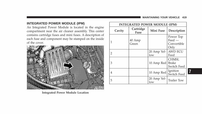
INTEGRATED POWER MODULE (IPM)An Integrated Power Module is located in the enginecompartment near the air cleaner assembly. This centercontains cartridge fuses and mini fuses. A description ofeach fuse and component may be stamped on the insideof the cover.
INTEGRATED POWER MODULE (IPM)
Cavity CartridgeFuse Mini Fuse Description
1 40 AmpGreen
Power TopFeed —ConvertibleOnly
2 20 Amp Yel-low
AWD ECUFeed
3 10 Amp RedCHMSLBrakeSwitch Feed
4 10 Amp Red IgnitionSwitch Feed
5 20 Amp Yel-low Trailer Tow
Integrated Power Module Location
MAINTAINING YOUR VEHICLE 419
7
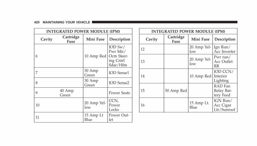
INTEGRATED POWER MODULE (IPM)
Cavity CartridgeFuse Mini Fuse Description
6 10 Amp Red
IOD Sw/Pwr Mir/Ocm Steer-ing CntrlSdar/Hfm
7 30 AmpGreen IOD Sense1
8 30 AmpGreen IOD Sense2
9 40 AmpGreen Power Seats
10 20 Amp Yel-low
CCN,PowerLocks
11 15 Amp LtBlue
Power Out-let
INTEGRATED POWER MODULE (IPM)
Cavity CartridgeFuse Mini Fuse Description
12 20 Amp Yel-low
Ign Run/Acc Inverter
13 20 Amp Yel-low
Pwr run/Acc OutletRR
14 10 Amp RedIOD CCN/InteriorLighting
15 50 Amp RedRAD FanRelay Bat-tery Feed
16 15 Amp Lt.Blue
IGN Run/Acc CigarLtr/Sunroof
420 MAINTAINING YOUR VEHICLE
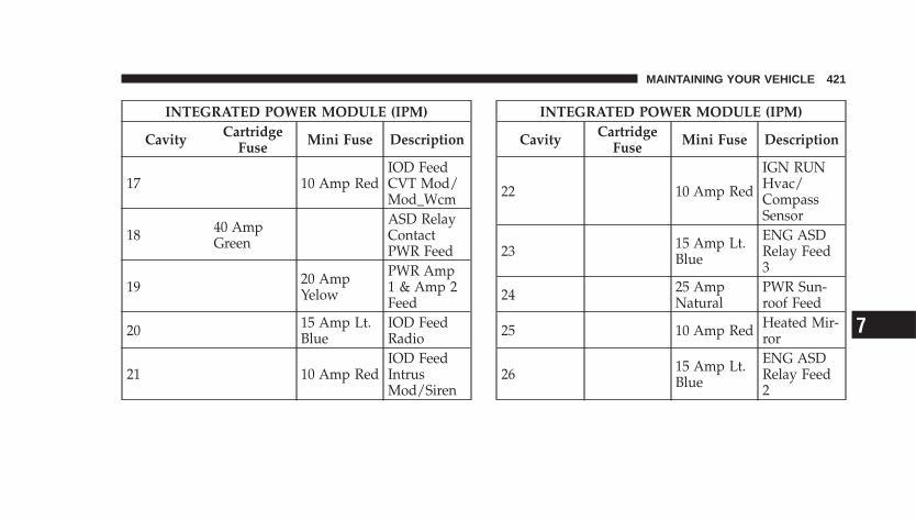
INTEGRATED POWER MODULE (IPM)
Cavity CartridgeFuse Mini Fuse Description
17 10 Amp RedIOD FeedCVT Mod/Mod_Wcm
18 40 AmpGreen
ASD RelayContactPWR Feed
19 20 AmpYelow
PWR Amp1 & Amp 2Feed
20 15 Amp Lt.Blue
IOD FeedRadio
21 10 Amp RedIOD FeedIntrusMod/Siren
INTEGRATED POWER MODULE (IPM)
Cavity CartridgeFuse Mini Fuse Description
22 10 Amp Red
IGN RUNHvac/CompassSensor
23 15 Amp Lt.Blue
ENG ASDRelay Feed3
24 25 AmpNatural
PWR Sun-roof Feed
25 10 Amp Red Heated Mir-ror
26 15 Amp Lt.Blue
ENG ASDRelay Feed2
MAINTAINING YOUR VEHICLE 421
7
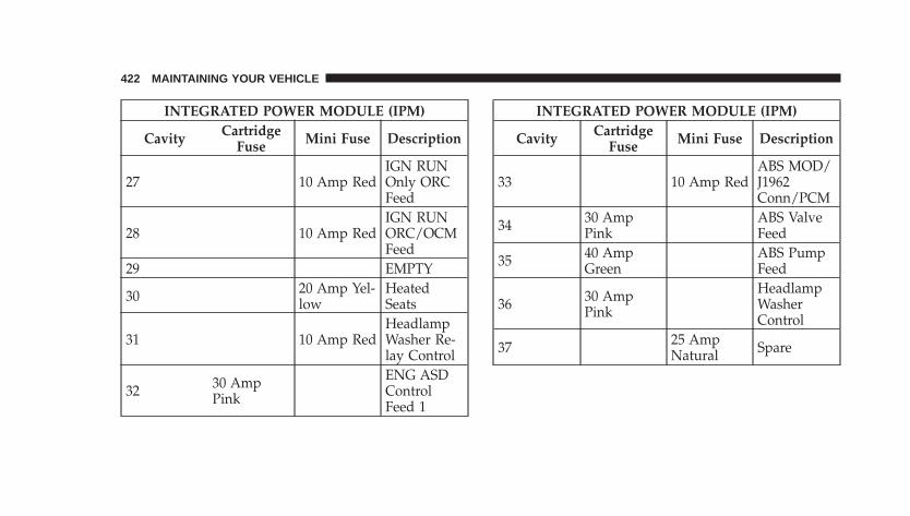
INTEGRATED POWER MODULE (IPM)
Cavity CartridgeFuse Mini Fuse Description
27 10 Amp RedIGN RUNOnly ORCFeed
28 10 Amp RedIGN RUNORC/OCMFeed
29 EMPTY
30 20 Amp Yel-low
HeatedSeats
31 10 Amp RedHeadlampWasher Re-lay Control
32 30 AmpPink
ENG ASDControlFeed 1
INTEGRATED POWER MODULE (IPM)
Cavity CartridgeFuse Mini Fuse Description
33 10 Amp RedABS MOD/J1962Conn/PCM
34 30 AmpPink
ABS ValveFeed
35 40 AmpGreen
ABS PumpFeed
36 30 AmpPink
HeadlampWasherControl
37 25 AmpNatural Spare
422 MAINTAINING YOUR VEHICLE
CAUTION!
• When installing the Integrated Power Modulecover, it is important to ensure the cover is prop-erly positioned and fully latched. Failure to do somay allow water to get into the Integrated PowerModule, and possibly result in a electrical systemfailure.
• When replacing a blown fuse, it is important touse only a fuse having the correct amperage rating.The use of a fuse with a rating other than indicatedmay result in a dangerous electrical system over-load. If a properly rated fuse continues to blow, itindicates a problem in the circuit that must becorrected.
VEHICLE STORAGEIf you will not be using your vehicle for more than 21days, you may want to take steps to preserve yourbattery. You may:
• Disengage the mini-fuse in the Power DistributionCenter labeled IOD (Ignition Off-Draw).
• Or, disconnect the negative cable from the battery.
MAINTAINING YOUR VEHICLE 423
7
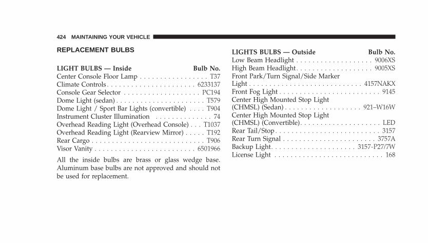
REPLACEMENT BULBS
LIGHT BULBS — Inside Bulb No.Center Console Floor Lamp . . . . . . . . . . . . . . . . . T37Climate Controls . . . . . . . . . . . . . . . . . . . . . . 6233137Console Gear Selector . . . . . . . . . . . . . . . . . . . PC194Dome Light (sedan) . . . . . . . . . . . . . . . . . . . . . . T579Dome Light / Sport Bar Lights (convertible) . . . . T904Instrument Cluster Illumination . . . . . . . . . . . . . . 74Overhead Reading Light (Overhead Console) . . . T1037Overhead Reading Light (Rearview Mirror) . . . . . T192Rear Cargo . . . . . . . . . . . . . . . . . . . . . . . . . . . . T906Visor Vanity . . . . . . . . . . . . . . . . . . . . . . . . . 6501966
All the inside bulbs are brass or glass wedge base.Aluminum base bulbs are not approved and should notbe used for replacement.
LIGHTS BULBS — Outside Bulb No.Low Beam Headlight . . . . . . . . . . . . . . . . . . . 9006XSHigh Beam Headlight . . . . . . . . . . . . . . . . . . . 9005XSFront Park/Turn Signal/Side MarkerLight . . . . . . . . . . . . . . . . . . . . . . . . . . . . 4157NAKXFront Fog Light . . . . . . . . . . . . . . . . . . . . . . . . . 9145Center High Mounted Stop Light(CHMSL) (Sedan) . . . . . . . . . . . . . . . . . . . 921–W16WCenter High Mounted Stop Light(CHMSL) (Convertible) . . . . . . . . . . . . . . . . . . . . LEDRear Tail/Stop . . . . . . . . . . . . . . . . . . . . . . . . . . 3157Rear Turn Signal . . . . . . . . . . . . . . . . . . . . . . . 3757ABackup Light. . . . . . . . . . . . . . . . . . . . . 3157-P27/7WLicense Light . . . . . . . . . . . . . . . . . . . . . . . . . . . 168
424 MAINTAINING YOUR VEHICLE
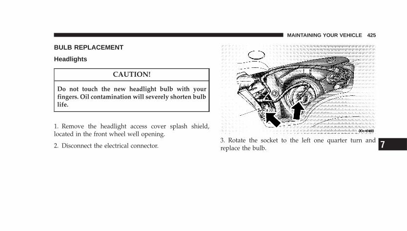
BULB REPLACEMENT
Headlights
CAUTION!
Do not touch the new headlight bulb with yourfingers. Oil contamination will severely shorten bulblife.
1. Remove the headlight access cover splash shield,located in the front wheel well opening.
2. Disconnect the electrical connector.3. Rotate the socket to the left one quarter turn andreplace the bulb.
MAINTAINING YOUR VEHICLE 425
7
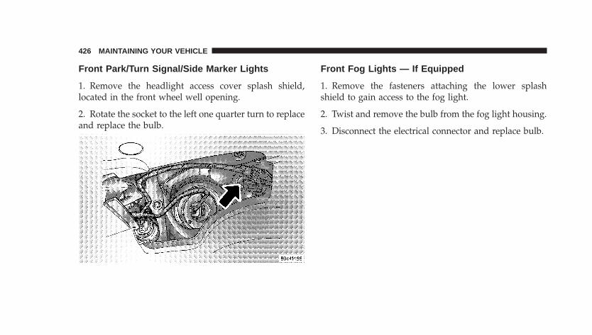
Front Park/Turn Signal/Side Marker Lights
1. Remove the headlight access cover splash shield,located in the front wheel well opening.
2. Rotate the socket to the left one quarter turn to replaceand replace the bulb.
Front Fog Lights — If Equipped
1. Remove the fasteners attaching the lower splashshield to gain access to the fog light.
2. Twist and remove the bulb from the fog light housing.
3. Disconnect the electrical connector and replace bulb.
426 MAINTAINING YOUR VEHICLE
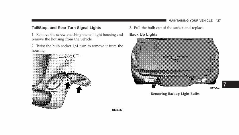
Tail/Stop, and Rear Turn Signal Lights
1. Remove the screw attaching the tail light housing andremove the housing from the vehicle.
2. Twist the bulb socket 1/4 turn to remove it from thehousing.
3. Pull the bulb out of the socket and replace.
Back Up Lights
Removing Backup Light Bulbs
MAINTAINING YOUR VEHICLE 427
7
1. To remove the backup lamp, you must take a fiberstick and slide it along the inboard side of the lamp andcompress a spring clip to allow it to partially �pop� out tothe secondary catch.
2. Fully compress the clip to get the lamp to come outcompletely.
3. Remove the socket from the housing.
4. Pull the bulb out of the socket and replace.
Center High Mounted Stop Light
1. Open the liftgate and remove the liftgate CHMSLcover.
2. Remove CHMSL lens from the housing by unlatchingthe two side latches.
3. Pull the bulb out of the socket and replace.
428 MAINTAINING YOUR VEHICLE
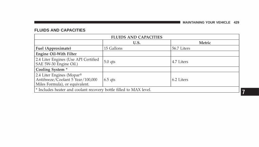
FLUIDS AND CAPACITIES
FLUIDS AND CAPACITIESU.S. Metric
Fuel (Approximate) 15 Gallons 56.7 LitersEngine Oil-With Filter2.4 Liter Engines (Use API CertifiedSAE 5W-30 Engine Oil.) 5.0 qts 4.7 Liters
Cooling System *2.4 Liter Engines (Mopar�Antifreeze/Coolant 5 Year/100,000Miles Formula), or equivalent.
6.5 qts 6.2 Liters
* Includes heater and coolant recovery bottle filled to MAX level.
MAINTAINING YOUR VEHICLE 429
7
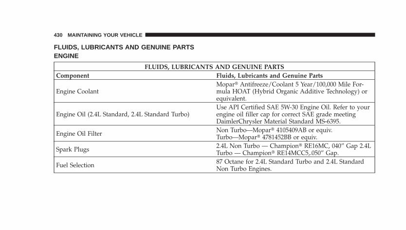
FLUIDS, LUBRICANTS AND GENUINE PARTSENGINE
FLUIDS, LUBRICANTS AND GENUINE PARTSComponent Fluids, Lubricants and Genuine Parts
Engine CoolantMopar� Antifreeze/Coolant 5 Year/100,000 Mile For-mula HOAT (Hybrid Organic Additive Technology) orequivalent.
Engine Oil (2.4L Standard, 2.4L Standard Turbo)Use API Certified SAE 5W-30 Engine Oil. Refer to yourengine oil filler cap for correct SAE grade meetingDaimlerChrysler Material Standard MS-6395.
Engine Oil Filter Non Turbo—Mopar� 4105409AB or equiv.Turbo—Mopar� 4781452BB or equiv.
Spark Plugs 2.4L Non Turbo — Champion� RE16MC, 040” Gap 2.4LTurbo — Champion� RE14MCC5,.050” Gap.
Fuel Selection 87 Octane for 2.4L Standard Turbo and 2.4L StandardNon Turbo Engines.
430 MAINTAINING YOUR VEHICLE
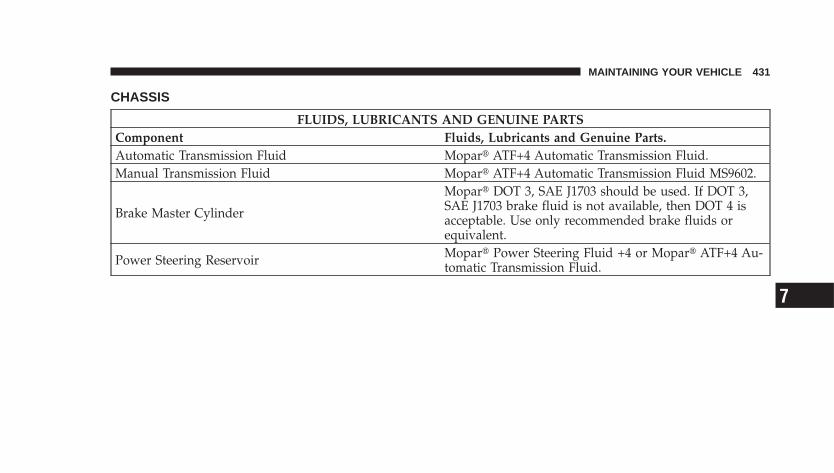
CHASSIS
FLUIDS, LUBRICANTS AND GENUINE PARTSComponent Fluids, Lubricants and Genuine Parts.Automatic Transmission Fluid Mopar� ATF+4 Automatic Transmission Fluid.Manual Transmission Fluid Mopar� ATF+4 Automatic Transmission Fluid MS9602.
Brake Master Cylinder
Mopar� DOT 3, SAE J1703 should be used. If DOT 3,SAE J1703 brake fluid is not available, then DOT 4 isacceptable. Use only recommended brake fluids orequivalent.
Power Steering Reservoir Mopar� Power Steering Fluid +4 or Mopar� ATF+4 Au-tomatic Transmission Fluid.
MAINTAINING YOUR VEHICLE 431
7

MAINTENANCE SCHEDULES
CONTENTS
� Emissions Control System Maintenance . . . . . . . 434
� Maintenance Schedule . . . . . . . . . . . . . . . . . . . 434
▫ Schedule “B”—All Engines . . . . . . . . . . . . . . 437
▫ Schedule “A”—Non Turbo . . . . . . . . . . . . . . . 448
▫ Schedule “A”—Turbo . . . . . . . . . . . . . . . . . . 453
8
MAINTENANCE
SCHEDULES
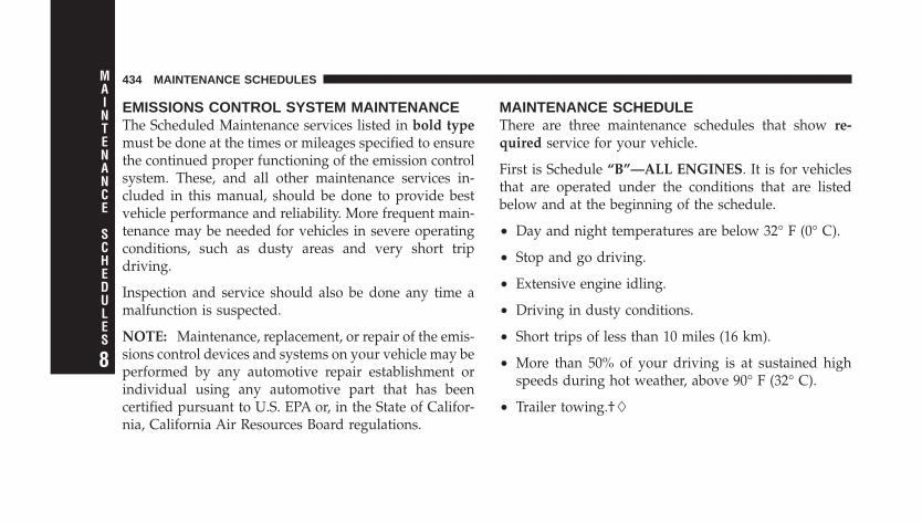
EMISSIONS CONTROL SYSTEM MAINTENANCEThe Scheduled Maintenance services listed in bold typemust be done at the times or mileages specified to ensurethe continued proper functioning of the emission controlsystem. These, and all other maintenance services in-cluded in this manual, should be done to provide bestvehicle performance and reliability. More frequent main-tenance may be needed for vehicles in severe operatingconditions, such as dusty areas and very short tripdriving.
Inspection and service should also be done any time amalfunction is suspected.
NOTE: Maintenance, replacement, or repair of the emis-sions control devices and systems on your vehicle may beperformed by any automotive repair establishment orindividual using any automotive part that has beencertified pursuant to U.S. EPA or, in the State of Califor-nia, California Air Resources Board regulations.
MAINTENANCE SCHEDULEThere are three maintenance schedules that show re-quired service for your vehicle.
First is Schedule “B”—ALL ENGINES. It is for vehiclesthat are operated under the conditions that are listedbelow and at the beginning of the schedule.
• Day and night temperatures are below 32° F (0° C).
• Stop and go driving.
• Extensive engine idling.
• Driving in dusty conditions.
• Short trips of less than 10 miles (16 km).
• More than 50% of your driving is at sustained highspeeds during hot weather, above 90° F (32° C).
• Trailer towing.†
434 MAINTENANCE SCHEDULES
8
MAINTENANCE
SCHEDULES
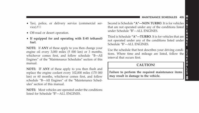
• Taxi, police, or delivery service (commercial ser-vice).†
• Off-road or desert operation.
• If equipped for and operating with E-85 (ethanol)fuel.
NOTE: If ANY of these apply to you then change yourengine oil every 3,000 miles (5 000 km) or 3 months,whichever comes first, and follow schedule “B—AllEngines” of the �Maintenance Schedules� section of thismanual.
NOTE: IF ANY of these apply to you then flush andreplace the engine coolant every 102,000 miles (170 000km) or 60 months, whichever comes first, and followschedule “B—All Engines” of the �Maintenance Sched-ules� section of this manual.
NOTE: Most vehicles are operated under the conditionslisted for Schedule �B�—ALL ENGINES.
Second is Schedule “A”—NON TURBO. It is for vehiclesthat are not operated under any of the conditions listedunder Schedule �B�—ALL ENGINES.
Third is Schedule “A”—TURBO. It is for vehicles that arenot operated under any of the conditions listed underSchedule �B�—ALL ENGINES.
Use the schedule that best describes your driving condi-tions. Where time and mileage are listed, follow theinterval that occurs first.
CAUTION!
Failure to perform the required maintenance itemsmay result in damage to the vehicle.
MAINTENANCE SCHEDULES 435
8
MAINTENANCE
SCHEDULES
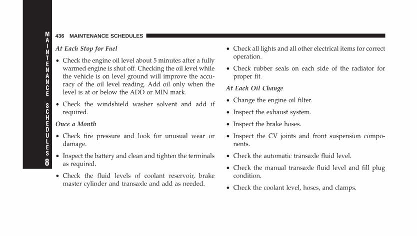
At Each Stop for Fuel
• Check the engine oil level about 5 minutes after a fullywarmed engine is shut off. Checking the oil level whilethe vehicle is on level ground will improve the accu-racy of the oil level reading. Add oil only when thelevel is at or below the ADD or MIN mark.
• Check the windshield washer solvent and add ifrequired.
Once a Month
• Check tire pressure and look for unusual wear ordamage.
• Inspect the battery and clean and tighten the terminalsas required.
• Check the fluid levels of coolant reservoir, brakemaster cylinder and transaxle and add as needed.
• Check all lights and all other electrical items for correctoperation.
• Check rubber seals on each side of the radiator forproper fit.
At Each Oil Change
• Change the engine oil filter.
• Inspect the exhaust system.
• Inspect the brake hoses.
• Inspect the CV joints and front suspension compo-nents.
• Check the automatic transaxle fluid level.
• Check the manual transaxle fluid level and fill plugcondition.
• Check the coolant level, hoses, and clamps.
436 MAINTENANCE SCHEDULES
8
MAINTENANCE
SCHEDULES
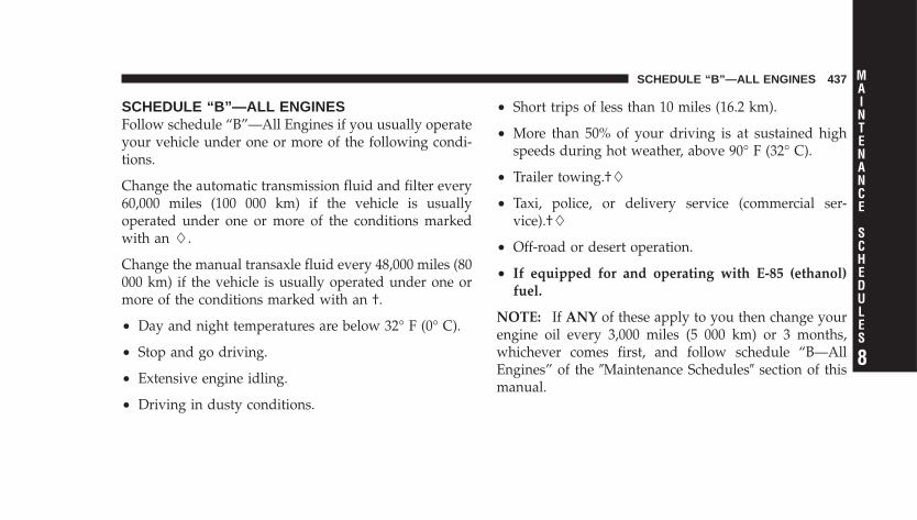
SCHEDULE “B”—ALL ENGINESFollow schedule “B”—All Engines if you usually operateyour vehicle under one or more of the following condi-tions.
Change the automatic transmission fluid and filter every60,000 miles (100 000 km) if the vehicle is usuallyoperated under one or more of the conditions markedwith an .
Change the manual transaxle fluid every 48,000 miles (80000 km) if the vehicle is usually operated under one ormore of the conditions marked with an †.
• Day and night temperatures are below 32° F (0° C).
• Stop and go driving.
• Extensive engine idling.
• Driving in dusty conditions.
• Short trips of less than 10 miles (16.2 km).
• More than 50% of your driving is at sustained highspeeds during hot weather, above 90° F (32° C).
• Trailer towing.†
• Taxi, police, or delivery service (commercial ser-vice).†
• Off-road or desert operation.
• If equipped for and operating with E-85 (ethanol)fuel.
NOTE: If ANY of these apply to you then change yourengine oil every 3,000 miles (5 000 km) or 3 months,whichever comes first, and follow schedule “B—AllEngines” of the �Maintenance Schedules� section of thismanual.
SCHEDULE “B”—ALL ENGINES 437
8
MAINTENANCE
SCHEDULES

NOTE: IF ANY of these apply to you then flush andreplace the engine coolant every 102,000 miles (170 000km) or 60 months, whichever comes first, and followschedule “B—All Engines” of the �Maintenance Sched-ules� section of this manual.
If none of these apply to you, and your vehicle isequipped with a Non–Turbo Charged Engine thenchange your engine oil at every interval shown on
schedule “A”—NON TURBO in the maintenance sched-ule section of this manual.
If none of these apply to you, and your vehicle isequipped with a Turbo Charged Engine change yourengine oil at every interval shown on schedule“A”—TURBO in the maintenance schedule section of thismanual.
438 SCHEDULE “B”—ALL ENGINES
8
MAINTENANCE
SCHEDULES

Miles 3,000 6,000 9,000 12,000 15,000 18,000(Kilometers) (5 000) (10 000) (15 000) (20 000) (25 000) (30 000)Change engine oil and engine oil filter, if notreplaced at 3 months.
X X X X X X
Rotate tires. X X XInspect the brake linings. XInspect the engine air cleaner filter, replace asnecessary.*
X
Inspect the Make-up air filter, replace as nec-essary. X
SCHEDULE “B”—ALL ENGINES 439
8
MAINTENANCE
SCHEDULES
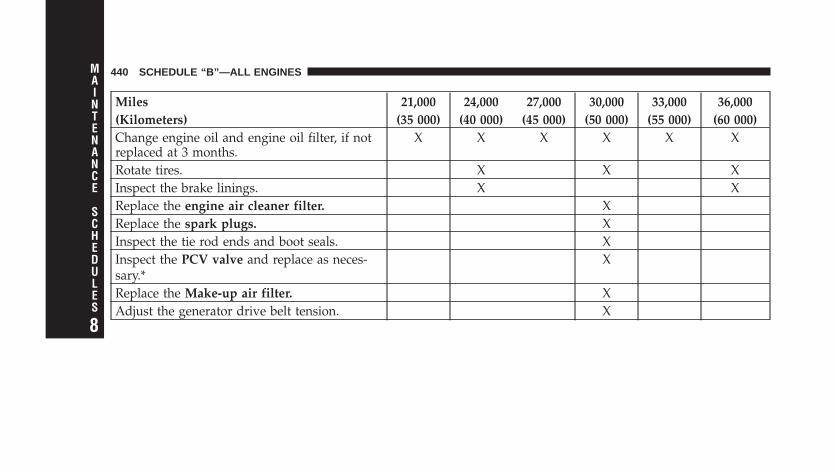
Miles 21,000 24,000 27,000 30,000 33,000 36,000(Kilometers) (35 000) (40 000) (45 000) (50 000) (55 000) (60 000)Change engine oil and engine oil filter, if notreplaced at 3 months.
X X X X X X
Rotate tires. X X XInspect the brake linings. X XReplace the engine air cleaner filter. XReplace the spark plugs. XInspect the tie rod ends and boot seals. XInspect the PCV valve and replace as neces-sary.*
X
Replace the Make-up air filter. XAdjust the generator drive belt tension. X
440 SCHEDULE “B”—ALL ENGINES
8
MAINTENANCE
SCHEDULES
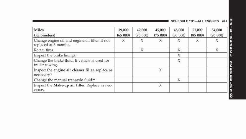
Miles 39,000 42,000 45,000 48,000 51,000 54,000(Kilometers) (65 000) (70 000) (75 000) (80 000) (85 000) (90 000)Change engine oil and engine oil filter, if notreplaced at 3 months.
X X X X X X
Rotate tires. X X XInspect the brake linings. XChange the brake fluid. If vehicle is used fortrailer towing.
X
Inspect the engine air cleaner filter, replace asnecessary.*
X
Change the manual transaxle fluid.† XInspect the Make-up air filter. Replace as nec-essary.
X
SCHEDULE “B”—ALL ENGINES 441
8
MAINTENANCE
SCHEDULES
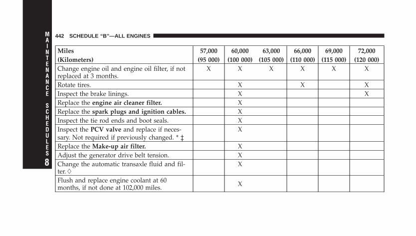
Miles 57,000 60,000 63,000 66,000 69,000 72,000(Kilometers) (95 000) (100 000) (105 000) (110 000) (115 000) (120 000)Change engine oil and engine oil filter, if notreplaced at 3 months.
X X X X X X
Rotate tires. X X XInspect the brake linings. X XReplace the engine air cleaner filter. XReplace the spark plugs and ignition cables. XInspect the tie rod ends and boot seals. XInspect the PCV valve and replace if neces-sary. Not required if previously changed. * ‡
X
Replace the Make-up air filter. XAdjust the generator drive belt tension. XChange the automatic transaxle fluid and fil-ter.
X
Flush and replace engine coolant at 60months, if not done at 102,000 miles. X
442 SCHEDULE “B”—ALL ENGINES
8
MAINTENANCE
SCHEDULES
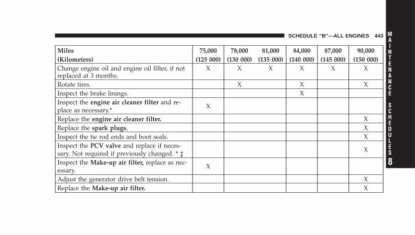
Miles 75,000 78,000 81,000 84,000 87,000 90,000(Kilometers) (125 000) (130 000) (135 000) (140 000) (145 000) (150 000)Change engine oil and engine oil filter, if notreplaced at 3 months.
X X X X X X
Rotate tires. X X XInspect the brake linings. XInspect the engine air cleaner filter and re-place as necessary.* X
Replace the engine air cleaner filter. XReplace the spark plugs. XInspect the tie rod ends and boot seals. XInspect the PCV valve and replace if neces-sary. Not required if previously changed. * ‡ X
Inspect the Make-up air filter, replace as nec-essary. X
Adjust the generator drive belt tension. XReplace the Make-up air filter. X
SCHEDULE “B”—ALL ENGINES 443
8
MAINTENANCE
SCHEDULES
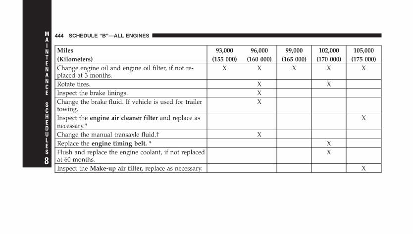
Miles 93,000 96,000 99,000 102,000 105,000(Kilometers) (155 000) (160 000) (165 000) (170 000) (175 000)Change engine oil and engine oil filter, if not re-placed at 3 months.
X X X X X
Rotate tires. X XInspect the brake linings. XChange the brake fluid. If vehicle is used for trailertowing.
X
Inspect the engine air cleaner filter and replace asnecessary.*
X
Change the manual transaxle fluid.† XReplace the engine timing belt. * XFlush and replace the engine coolant, if not replacedat 60 months.
X
Inspect the Make-up air filter, replace as necessary. X
444 SCHEDULE “B”—ALL ENGINES
8
MAINTENANCE
SCHEDULES
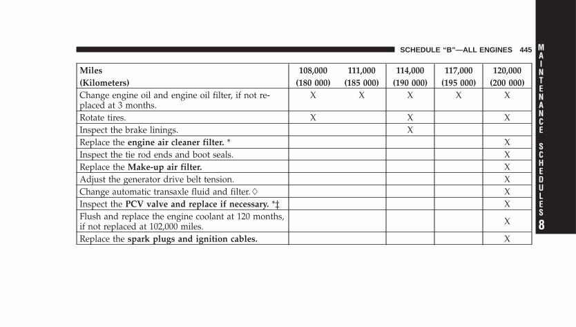
Miles 108,000 111,000 114,000 117,000 120,000(Kilometers) (180 000) (185 000) (190 000) (195 000) (200 000)Change engine oil and engine oil filter, if not re-placed at 3 months.
X X X X X
Rotate tires. X X XInspect the brake linings. XReplace the engine air cleaner filter. * XInspect the tie rod ends and boot seals. XReplace the Make-up air filter. XAdjust the generator drive belt tension. XChange automatic transaxle fluid and filter. XInspect the PCV valve and replace if necessary. *‡ XFlush and replace the engine coolant at 120 months,if not replaced at 102,000 miles. X
Replace the spark plugs and ignition cables. X
SCHEDULE “B”—ALL ENGINES 445
8
MAINTENANCE
SCHEDULES
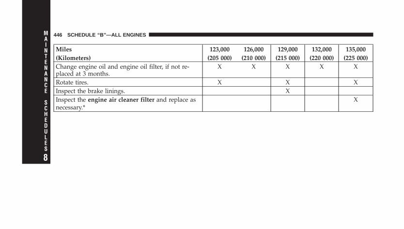
Miles 123,000 126,000 129,000 132,000 135,000(Kilometers) (205 000) (210 000) (215 000) (220 000) (225 000)Change engine oil and engine oil filter, if not re-placed at 3 months.
X X X X X
Rotate tires. X X XInspect the brake linings. XInspect the engine air cleaner filter and replace asnecessary.*
X
446 SCHEDULE “B”—ALL ENGINES
8
MAINTENANCE
SCHEDULES
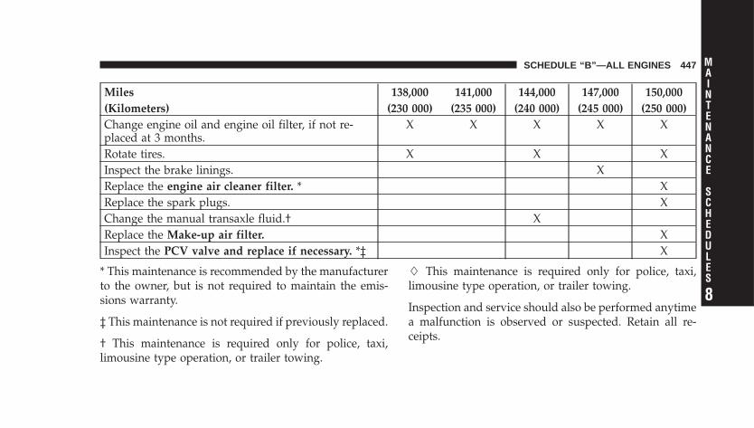
Miles 138,000 141,000 144,000 147,000 150,000(Kilometers) (230 000) (235 000) (240 000) (245 000) (250 000)Change engine oil and engine oil filter, if not re-placed at 3 months.
X X X X X
Rotate tires. X X XInspect the brake linings. XReplace the engine air cleaner filter. * XReplace the spark plugs. XChange the manual transaxle fluid.† XReplace the Make-up air filter. XInspect the PCV valve and replace if necessary. *‡ X
* This maintenance is recommended by the manufacturerto the owner, but is not required to maintain the emis-sions warranty.
‡ This maintenance is not required if previously replaced.
† This maintenance is required only for police, taxi,limousine type operation, or trailer towing.
This maintenance is required only for police, taxi,limousine type operation, or trailer towing.
Inspection and service should also be performed anytimea malfunction is observed or suspected. Retain all re-ceipts.
SCHEDULE “B”—ALL ENGINES 447
8
MAINTENANCE
SCHEDULES
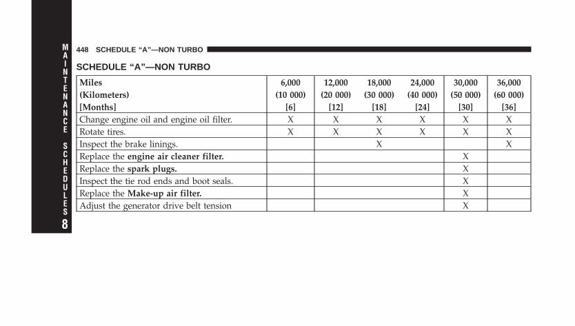
SCHEDULE “A”—NON TURBO
Miles 6,000 12,000 18,000 24,000 30,000 36,000(Kilometers) (10 000) (20 000) (30 000) (40 000) (50 000) (60 000)[Months] [6] [12] [18] [24] [30] [36]Change engine oil and engine oil filter. X X X X X XRotate tires. X X X X X XInspect the brake linings. X XReplace the engine air cleaner filter. XReplace the spark plugs. XInspect the tie rod ends and boot seals. XReplace the Make-up air filter. XAdjust the generator drive belt tension X
448 SCHEDULE “A”—NON TURBO
8
MAINTENANCE
SCHEDULES
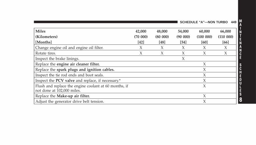
Miles 42,000 48,000 54,000 60,000 66,000(Kilometers) (70 000) (80 000) (90 000) (100 000) (110 000)[Months] [42] [48] [54] [60] [66]Change engine oil and engine oil filter. X X X X XRotate tires. X X X X XInspect the brake linings. XReplace the engine air cleaner filter. XReplace the spark plugs and ignition cables. XInspect the tie rod ends and boot seals. XInspect the PCV valve and replace, if necessary.* XFlush and replace the engine coolant at 60 months, ifnot done at 102,000 miles.
X
Replace the Make-up air filter. XAdjust the generator drive belt tension. X
SCHEDULE “A”—NON TURBO 449
8
MAINTENANCE
SCHEDULES
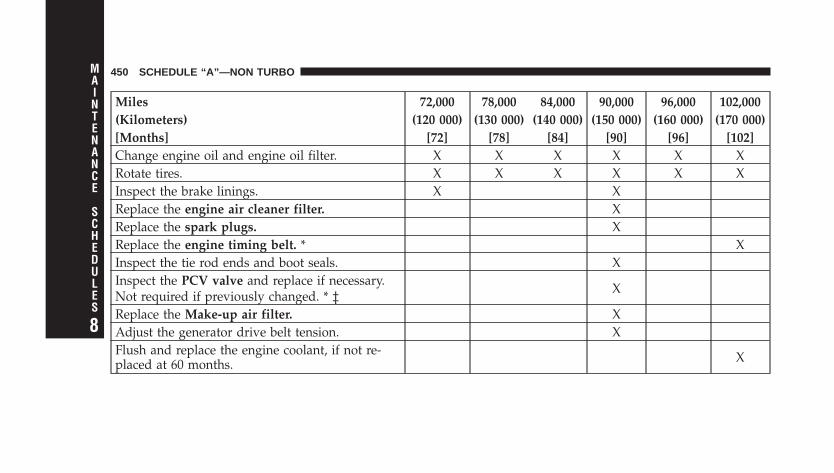
Miles 72,000 78,000 84,000 90,000 96,000 102,000(Kilometers) (120 000) (130 000) (140 000) (150 000) (160 000) (170 000)[Months] [72] [78] [84] [90] [96] [102]Change engine oil and engine oil filter. X X X X X XRotate tires. X X X X X XInspect the brake linings. X XReplace the engine air cleaner filter. XReplace the spark plugs. XReplace the engine timing belt. * XInspect the tie rod ends and boot seals. XInspect the PCV valve and replace if necessary.Not required if previously changed. * ‡ X
Replace the Make-up air filter. XAdjust the generator drive belt tension. XFlush and replace the engine coolant, if not re-placed at 60 months. X
450 SCHEDULE “A”—NON TURBO
8
MAINTENANCE
SCHEDULES

Miles 108,000 114,000 120,000 126,000 132,000 138,000(Kilometers) (180 000) (190 000) (200 000) (210 000) (220 000) (230 000)[Months] [108] [114] [120] [126] [132] [138]Change engine oil and engine oil filter. X X X X X XRotate tires. X X X X X XInspect the PCV valve and replace if necessary. * ‡ XReplace the air cleaner filter. XFlush and replace the engine coolant at 120months, if not done at 102,000 miles. X
Replace the spark plugs and ignition cables. XReplace the Make-up air filter. X
SCHEDULE “A”—NON TURBO 451
8
MAINTENANCE
SCHEDULES
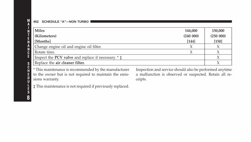
Miles 144,000 150,000(Kilometers) (240 000) (250 000)[Months] [144] [150]Change engine oil and engine oil filter. X XRotate tires. X XInspect the PCV valve and replace if necessary. * ‡ XReplace the air cleaner filter. X
* This maintenance is recommended by the manufacturerto the owner but is not required to maintain the emis-sions warranty.
‡ This maintenance is not required if previously replaced.
Inspection and service should also be performed anytimea malfunction is observed or suspected. Retain all re-ceipts.
452 SCHEDULE “A”—NON TURBO
8
MAINTENANCE
SCHEDULES
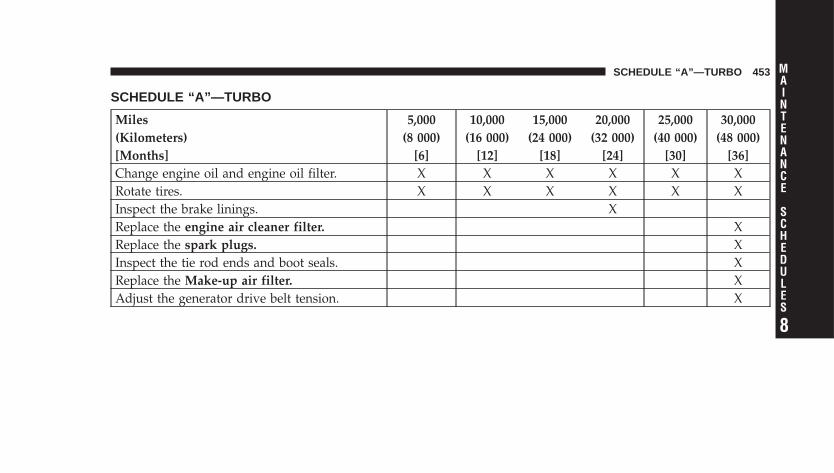
SCHEDULE “A”—TURBO
Miles 5,000 10,000 15,000 20,000 25,000 30,000(Kilometers) (8 000) (16 000) (24 000) (32 000) (40 000) (48 000)[Months] [6] [12] [18] [24] [30] [36]Change engine oil and engine oil filter. X X X X X XRotate tires. X X X X X XInspect the brake linings. XReplace the engine air cleaner filter. XReplace the spark plugs. XInspect the tie rod ends and boot seals. XReplace the Make-up air filter. XAdjust the generator drive belt tension. X
SCHEDULE “A”—TURBO 453
8
MAINTENANCE
SCHEDULES
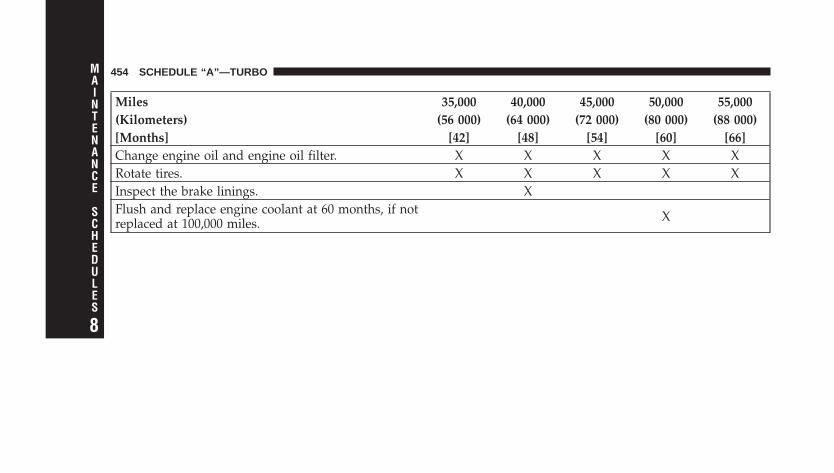
Miles 35,000 40,000 45,000 50,000 55,000(Kilometers) (56 000) (64 000) (72 000) (80 000) (88 000)[Months] [42] [48] [54] [60] [66]Change engine oil and engine oil filter. X X X X XRotate tires. X X X X XInspect the brake linings. XFlush and replace engine coolant at 60 months, if notreplaced at 100,000 miles. X
454 SCHEDULE “A”—TURBO
8
MAINTENANCE
SCHEDULES
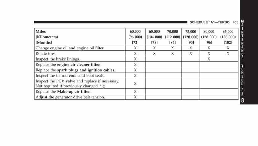
Miles 60,000 65,000 70,000 75,000 80,000 85,000(Kilometers) (96 000) (104 000) (112 000) (120 000) (128 000) (136 000)[Months] [72] [78] [84] [90] [96] [102]Change engine oil and engine oil filter. X X X X X XRotate tires. X X X X X XInspect the brake linings. X XReplace the engine air cleaner filter. XReplace the spark plugs and ignition cables. XInspect the tie rod ends and boot seals. XInspect the PCV valve and replace if necessary.Not required if previously changed. * ‡ X
Replace the Make-up air filter. XAdjust the generator drive belt tension. X
SCHEDULE “A”—TURBO 455
8
MAINTENANCE
SCHEDULES
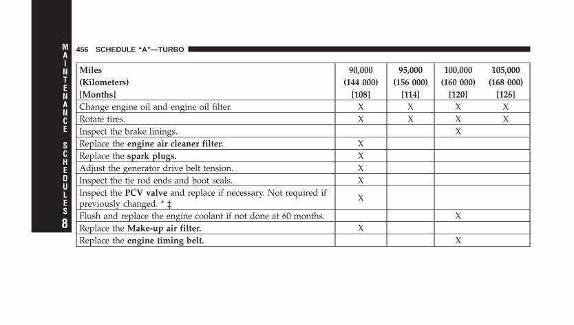
Miles 90,000 95,000 100,000 105,000(Kilometers) (144 000) (156 000) (160 000) (168 000)[Months] [108] [114] [120] [126]Change engine oil and engine oil filter. X X X XRotate tires. X X X XInspect the brake linings. XReplace the engine air cleaner filter. XReplace the spark plugs. XAdjust the generator drive belt tension. XInspect the tie rod ends and boot seals. XInspect the PCV valve and replace if necessary. Not required ifpreviously changed. * ‡ X
Flush and replace the engine coolant if not done at 60 months. XReplace the Make-up air filter. XReplace the engine timing belt. X
456 SCHEDULE “A”—TURBO
8
MAINTENANCE
SCHEDULES
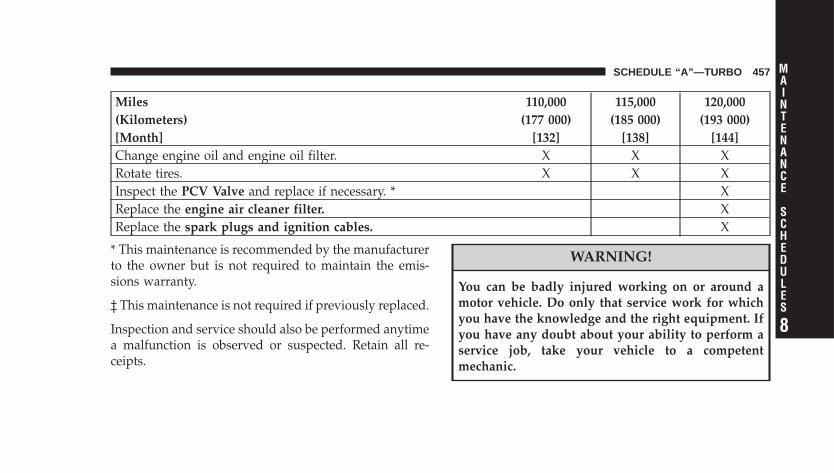
Miles 110,000 115,000 120,000(Kilometers) (177 000) (185 000) (193 000)[Month] [132] [138] [144]Change engine oil and engine oil filter. X X XRotate tires. X X XInspect the PCV Valve and replace if necessary. * XReplace the engine air cleaner filter. XReplace the spark plugs and ignition cables. X
* This maintenance is recommended by the manufacturerto the owner but is not required to maintain the emis-sions warranty.
‡ This maintenance is not required if previously replaced.
Inspection and service should also be performed anytimea malfunction is observed or suspected. Retain all re-ceipts.
WARNING!
You can be badly injured working on or around amotor vehicle. Do only that service work for whichyou have the knowledge and the right equipment. Ifyou have any doubt about your ability to perform aservice job, take your vehicle to a competentmechanic.
SCHEDULE “A”—TURBO 457
8
MAINTENANCE
SCHEDULES

IF YOU NEED CONSUMER ASSISTANCE
CONTENTS
� Suggestions For Obtaining Service For YourVehicle . . . . . . . . . . . . . . . . . . . . . . . . . . . . . . 461
▫ Prepare For The Appointment . . . . . . . . . . . . 461
▫ Prepare A List . . . . . . . . . . . . . . . . . . . . . . . . 461
▫ Be Reasonable With Requests . . . . . . . . . . . . . 461
� If You Need Assistance . . . . . . . . . . . . . . . . . . . 461
▫ DaimlerChrysler Motors Corporation CustomerCenter . . . . . . . . . . . . . . . . . . . . . . . . . . . . . 462
▫ DaimlerChrysler Canada Inc. CustomerCenter . . . . . . . . . . . . . . . . . . . . . . . . . . . . . 462
▫ In Mexico Contact . . . . . . . . . . . . . . . . . . . . . 462
▫ Customer Assistance For The Hearing OrSpeech Impaired (TDD/TTY) . . . . . . . . . . . . . 463
▫ Service Contract . . . . . . . . . . . . . . . . . . . . . . 463
� Warranty Information (U.S. Vehicles Only) . . . . . 464
� Mopar� Parts . . . . . . . . . . . . . . . . . . . . . . . . . 464
� Reporting Safety Defects . . . . . . . . . . . . . . . . . . 464
▫ In The 50 United States And Washington,D.C. . . . . . . . . . . . . . . . . . . . . . . . . . . . . . . . 464
▫ In Canada . . . . . . . . . . . . . . . . . . . . . . . . . . 465
9
� Publication Order Forms . . . . . . . . . . . . . . . . . . 465
� Department Of Transportation Uniform TireQuality Grades . . . . . . . . . . . . . . . . . . . . . . . . 467
▫ Treadwear . . . . . . . . . . . . . . . . . . . . . . . . . . 467
▫ Traction Grades . . . . . . . . . . . . . . . . . . . . . . 467
▫ Temperature Grades . . . . . . . . . . . . . . . . . . . 468
460 IF YOU NEED CONSUMER ASSISTANCE
SUGGESTIONS FOR OBTAINING SERVICE FORYOUR VEHICLE
Prepare For The AppointmentIf you’re having warranty work done, be sure to have theright papers with you. Take your warranty folder. Allwork to be performed may not be covered by thewarranty. Discuss additional charges with the servicemanager. Keep a maintenance log of your vehicle’sservice history. This can often provide a clue to thecurrent problem.
Prepare A ListMake a written list of your vehicle’s problems or thespecific work you want done. If you’ve had an accidentor work done that is not on your maintenance log, let theservice advisor know.
Be Reasonable With RequestsIf you list a number of items and you must have yourvehicle by the end of the day, discuss the situation withthe service advisor and list the items in order of priority.At many authorized dealers, you may obtain a rentalvehicle at a minimal daily charge. If you need a rental, itis advisable to make these arrangements when you callfor an appointment.
IF YOU NEED ASSISTANCEThe manufacturer and its authorized dealers are vitallyinterested in your satisfaction. We want you to be happywith our products and services.
Warranty service must be done by an authorized dealer.We strongly recommend that you take your vehicle toyour authorized selling dealer. They know you and yourvehicle best, and are most concerned that you get promptand high quality service. The manufacturer’s authorizeddealers have the facilities, factory-trained technicians,
IF YOU NEED CONSUMER ASSISTANCE 461
9
special tools, and the latest information to ensure yourvehicle is fixed correctly and in a timely manner.
This is why you should always talk to your authorizeddealer’s service manager first. Most matters can be re-solved with this process.
• If for some reason you are still not satisfied, talk to thegeneral manager or owner of the authorized dealer-ship. They want to know if you need assistance.
• If your authorized dealership is unable to resolve theconcern, you may contact the Manufacturer’s Cus-tomer Center.
Any communication to the Manufacturer’s CustomerCenter should include the following information:
• Owner’s name and address
• Owner’s telephone number (home and office)
• Authorized dealership name
• Vehicle Identification Number (VIN)
• Vehicle delivery date and mileage
DaimlerChrysler Motors Corporation CustomerCenterP.O. Box 21–8004Auburn Hills, MI 48321–8004Phone: (800) 992-1997
DaimlerChrysler Canada Inc. Customer CenterP.O. Box 1621Windsor, Ontario N9A 4H6Phone: (800) 465–2001
In Mexico contact:Av. Prolongacion Paseo de la Reforma, 1240Sante Fe C.P. 05109Mexico, D. F.In Mexico: (915) 729–1248 or 729–1240Outside Mexico: (525) 729–1248 or 729–1240
462 IF YOU NEED CONSUMER ASSISTANCE
Customer Assistance For The Hearing Or SpeechImpaired (TDD/TTY)To assist customers who have hearing difficulties, themanufacturer has installed special TDD (Telecommuni-cation Devices for the Deaf) equipment at its CustomerCenter. Any hearing or speech impaired customer, whohas access to a TDD or a conventional teletypewriter(TTY) in the United States, can communicate with themanufacturer by dialing 1–800–380–CHRY.
Service ContractYou may have purchased a service contract for yourvehicle to help protect you from the high cost of unex-pected repairs after your manufacturer’s New VehicleLimited Warranty expires. The manufacturer stands be-hind only the manufacturer’s Service Contracts. If youpurchased a manufacturer’s Service Contract, you willreceive Plan Provisions and an Owner Identification Cardin the mail within three weeks of your vehicle deliverydate. If you have any questions about your service
contract, call the manufacturer’s Service Contract Na-tional Customer Hotline at 1-800-521-9922.
The manufacturer will not stand behind any servicecontract that is not the manufacturer’s Service Contract. Itis not responsible for any service contract other than themanufacturer’s Service Contract. If you purchased aservice contract that is not a manufacturer’s ServiceContract, and you require service after your manufactur-er’s New Vehicle Limited Warranty expires, please referto your contract documents, and contact the person listedin those documents.
We appreciate that you have made a major investmentwhen you purchased your vehicle. Your authorizeddealer has also made a major investment in facilities,tools, and training to assure that you are absolutelydelighted with your ownership experience. You’ll bepleased with their sincere efforts to resolve any warrantyissues or related concerns.
IF YOU NEED CONSUMER ASSISTANCE 463
9
WARNING!
Engine exhaust, some of its constituents, and certainvehicle components contain, or emit, chemicalsknown to the State of California to cause cancer andbirth defects or other reproductive harm. In addition,certain fluids contained in vehicles and certain prod-ucts of component wear contain, or emit, chemicalsknown to the State of California to cause cancer andbirth defects or other reproductive harm.
WARRANTY INFORMATION (U.S. Vehicles Only)See the Warranty Information Booklet for the terms andprovisions of DaimlerChrysler’s warranties applicable tothis vehicle.
MOPAR� PARTSMopar� fluids, lubricants, parts, and accessories areavailable from your authorized dealer. They will helpyou keep your vehicle operating at its best.
REPORTING SAFETY DEFECTS
In The 50 United States And Washington, D.C.If you believe that your vehicle has a defect that couldcause a crash or cause injury or death, you shouldimmediately inform the National Highway Traffic SafetyAdministration (NHTSA) in addition to notifying themanufacturer.
If NHTSA receives similar complaints, it may open aninvestigation, and if it finds that a safety defect exists ina group of vehicles, it may order a recall and remedycampaign. However, NHTSA cannot become involved inindividual problems between you, your authorizeddealer, and the manufacturer.
464 IF YOU NEED CONSUMER ASSISTANCE
To contact NHTSA, you may either call the Auto SafetyHotline toll free at 1–888–327–4236 (TTY: 1–800–424– 9153),or go to http://www.safercar.gov; or write to: Administra-tor, NHTSA, 400 Seventh Street, SW., Washington, D.C.20590. You can also obtain other information about motorvehicle safety from http://www.safercar.gov.
In CanadaIf you believe that your vehicle has a safety defect, youshould contact the Customer Service Department imme-diately. Canadian customers who wish to report a safetydefect to the Canadian government should write to:Transport Canada, Motor Vehicle Defect Investigationsand Recalls, 2780 Sheffield Road, Ottawa, Ontario K1B3V9.
PUBLICATION ORDER FORMSTo order the following manuals, you may use either thewebsite or the phone numbers listed below. Visa, Mas-tercard, American Express, and Discover orders are ac-cepted. If you prefer mailing your payment, please callfor an order form.
NOTE: A street address is required when orderingmanuals (no P.O. Boxes).
• Service Manuals
These comprehensive Service Manuals provide theinformation that students and professional techniciansneed in diagnosing/troubleshooting, problem solving,maintaining, servicing, and repairing DaimlerChryslerCorporation vehicles. A complete working knowledgeof the vehicle, system, and/or components is writtenin straightforward language with illustrations, dia-grams, and charts.
IF YOU NEED CONSUMER ASSISTANCE 465
9

• Diagnostic Procedure Manuals
Diagnostic Procedure Manuals are filled with dia-grams, charts and detailed illustrations. These practi-cal manuals make it easy for students and techniciansto find and fix problems on computer-controlled ve-hicle systems and features. They show exactly how tofind and correct problems the first time, using step-by-step troubleshooting and drivability procedures,proven diagnostic tests and a complete list of all toolsand equipment.
• Owner’s Manuals
These Owner’s Manuals have been prepared with theassistance of service and engineering specialists toacquaint you with specific DaimlerChryslerCorporation vehicles. Included are starting, operating,emergency and maintenance procedures as well asspecifications, capabilities and safety tips.
Call toll free at:
• 1–800–890–4038 (U.S.)
• 1–800–387–1143 (Canada)
Or
Visit us on the Worldwide Web at:
• www.techauthority.daimlerchrysler.com
• www.daimlerchrysler.ca/manuals
466 IF YOU NEED CONSUMER ASSISTANCE
DEPARTMENT OF TRANSPORTATION UNIFORMTIRE QUALITY GRADESThe following tire grading categories were established bythe National Highway Traffic Safety Administration. Thespecific grade rating assigned by the tire’s manufacturerin each category is shown on the sidewall of the tires onyour vehicle.
All passenger car tires must conform to Federal safetyrequirements in addition to these grades.
TreadwearThe treadwear grade is a comparative rating, based onthe wear rate of the tire when tested under controlledconditions on a specified government test course. Forexample, a tire graded 150 would wear 1-1/2 times aswell on the government course as a tire graded 100. Therelative performance of tires depends upon the actual
conditions of their use, however, and may depart signifi-cantly from the norm due to variations in driving habits,service practices, and differences in road characteristicsand climate.
Traction GradesThe traction grades, from highest to lowest, are AA, A, B,and C. These grades represent the tire’s ability to stop onwet pavement, as measured under controlled conditionson specified government test surfaces of asphalt andconcrete. A tire marked C may have poor traction perfor-mance.
WARNING!
The traction grade assigned to this tire is based onstraight-ahead braking traction tests, and does notinclude acceleration, cornering, hydroplaning, orpeak traction characteristics.
IF YOU NEED CONSUMER ASSISTANCE 467
9
Temperature GradesThe temperature grades are A (the highest), B, and C,representing the tire’s resistance to the generation of heatand its ability to dissipate heat, when tested undercontrolled conditions on a specified indoor laboratorytest wheel. Sustained high temperature can cause thematerial of the tire to degenerate and reduce tire life, andexcessive temperature can lead to sudden tire failure. Thegrade C corresponds to a level of performance, which allpassenger car tires must meet under the Federal MotorVehicle Safety Standard No. 109. Grades B and A repre-sent higher levels of performance on the laboratory testwheel, than the minimum required by law.
WARNING!
The temperature grade for this tire is established fora tire that is properly inflated and not overloaded.Excessive speed, under-inflation, or excessive load-ing, either separately or in combination, can causeheat buildup and possible tire failure.
468 IF YOU NEED CONSUMER ASSISTANCE

INDEX
10
ABS (Anti-Lock Brake System) . . . . . . . . . . . . . . 308Adding Engine Coolant (Antifreeze) . . . . . . . . . . 400Adding Fuel . . . . . . . . . . . . . . . . . . . . . . . . . . . 340Adding Washer Fluid . . . . . . . . . . . . . . . . . . . . . 218Additives, Fuel . . . . . . . . . . . . . . . . . . . . . . . . . 338Air Cleaner, Engine (Engine Air Cleaner Filter) . . . 391Air Conditioner Maintenance . . . . . . . . . . . . . . . 393Air Conditioning Controls . . . . . . . . . . . . . . . . . 277Air Conditioning, Operating Tips . . . . . . . . . . . . 283Air Conditioning Refrigerant . . . . . . . . . . . . . 393,394Air Conditioning System . . . . . . . . . . . . . . . . 277,393Air Pressure, Tires . . . . . . . . . . . . . . . . . . . . . . . 322Airbag . . . . . . . . . . . . . . . . . . . . . . . . . . . . . . 55,90Airbag Deployment . . . . . . . . . . . . . . . . . . . . 67,101Airbag Light . . . . . . . . . . . . . . . . . . . . 70,104,116,234Airbag Maintenance . . . . . . . . . . . . . . . . . . . . 68,103Airbag, Side . . . . . . . . . . . . . . . . . . . . . . . . . 64,100Alarm, Panic . . . . . . . . . . . . . . . . . . . . . . . . . . 26,32Alarm System (Security Alarm) . . . . . . . . . . . . 36,233
Alignment and Balance . . . . . . . . . . . . . . . . . . . 329Alterations/Modifications, Vehicle . . . . . . . . . . . . . 7Antenna, Satellite Radio . . . . . . . . . . . . . . . . . . . 276Antifreeze (Engine Coolant) . . . . . . . . 399,400,429,430
Capacities . . . . . . . . . . . . . . . . . . . . . . . . . . . 429Disposal . . . . . . . . . . . . . . . . . . . . . . . . . . . . 401
Anti-Lock Brake System (ABS) . . . . . . . . . . . . . . 308Anti-Lock Warning Light . . . . . . . . . . . . . . . . . . 233Anti-Theft Security Alarm (Theft Alarm) . . . . . . . . 36Appearance Care . . . . . . . . . . . . . . . . . . . . . . . . 411Auto Down Power Windows . . . . . . . . . . . . . . . . 43Automatic Door Locks . . . . . . . . . . . . . . . . . . . . . 21Automatic Transaxle . . . . . . . . . . . . . . 13,291,294,408
Adding Fluid . . . . . . . . . . . . . . . . . . . . . . . . . 408Filter . . . . . . . . . . . . . . . . . . . . . . . . . . . . . . . 409Fluid and Filter Changes . . . . . . . . . . . . . . . . . 409Fluid Level Check . . . . . . . . . . . . . . . . . . . . . . 408Interlock System . . . . . . . . . . . . . . . . . . . . . 19,295Reset Mode . . . . . . . . . . . . . . . . . . . . . . . . . . 296
470 INDEX
Shifting . . . . . . . . . . . . . . . . . . . . . . . . . . . . . 297Special Additives . . . . . . . . . . . . . . . . . . . . . . 410
Autostick . . . . . . . . . . . . . . . . . . . . . . . . . . . . . 299
Back-Up Lights . . . . . . . . . . . . . . . . . . . . . . . . . 427Ball Joints . . . . . . . . . . . . . . . . . . . . . . . . . . . . . 395Battery . . . . . . . . . . . . . . . . . . . . . . . . . . . . . . . 392
Keyless Transmitter Replacement (RKE) . . . . . 29,35Belts, Drive . . . . . . . . . . . . . . . . . . . . . . . . . . . . 388Belts, Engine . . . . . . . . . . . . . . . . . . . . . . . . . . . 390Body Mechanism Lubrication . . . . . . . . . . . . . . . 395Boot, Convertible Top . . . . . . . . . . . . . . . . . . 128,132B-Pillar Location . . . . . . . . . . . . . . . . . . . . . . . . 317Brake Fluid . . . . . . . . . . . . . . . . . . . . . . . . . . . . 431Brake, Parking . . . . . . . . . . . . . . . . . . . . . . . . . . 305Brake System . . . . . . . . . . . . . . . . . . . . . . . . 307,404
Anti-Lock (ABS) . . . . . . . . . . . . . . . . . . . . . . . 308Fluid Check . . . . . . . . . . . . . . . . . . . . . . . . . . 406Hoses . . . . . . . . . . . . . . . . . . . . . . . . . . . . . . 404
Master Cylinder . . . . . . . . . . . . . . . . . . . . . . . 406Parking . . . . . . . . . . . . . . . . . . . . . . . . . . . . . 305Warning Light . . . . . . . . . . . . . . . . . . . . . . . . 231
Brakes . . . . . . . . . . . . . . . . . . . . . . . . . . . . . 307,404Brake/Transmission Interlock . . . . . . . . . . . . . . . 295Break-In Recommendations, New Vehicle . . . . . . . 115Bulb Replacement . . . . . . . . . . . . . . . . . . . . . 424,425Bulbs, Light . . . . . . . . . . . . . . . . . . . . . . . . . . . . 424
Calibration, Compass . . . . . . . . . . . . . . . 238,247,248Capacities, Antifreeze (Engine Coolant) . . . . . . . . 429Capacities, Fluid . . . . . . . . . . . . . . . . . . . . . . . . 429Caps, Filler
Fuel . . . . . . . . . . . . . . . . . . . . . . . . . . . . . . . . 340Oil (Engine) . . . . . . . . . . . . . . . . . . . . 378,379,387Radiator (Coolant Pressure) . . . . . . . . . . . . . . . 400
Car Washes . . . . . . . . . . . . . . . . . . . . . . . . . . . . 411Carbon Monoxide Warning . . . . . . . . . . . . . . . . . 339
INDEX 471
10
Cargo CompartmentLuggage Carrier . . . . . . . . . . . . . . . . . . . . . . . 215
Carrier, Luggage . . . . . . . . . . . . . . . . . . . . . . . . 215Catalytic Converter . . . . . . . . . . . . . . . . . . . . . . 389Caution, Exhaust Gas . . . . . . . . . . . . . . . . . . . . . 115CD (Compact Disc) Player . . . . . . . . . . . . . . . 251,259CD (Compact Disc) Player Maintenance . . . . . . . . 277Cellular Phone . . . . . . . . . . . . . . . . . . . . . . . 138,277Center High Mounted Stop Light . . . . . . . . . . . . 428Chains, Tire . . . . . . . . . . . . . . . . . . . . . . . . . . . . 330Changing A Flat Tire . . . . . . . . . . . . . . . . . . . . . 360Chart, Tire Sizing . . . . . . . . . . . . . . . . . . . . . . . . 314Check Engine Light (Malfunction IndicatorLight) . . . . . . . . . . . . . . . . . . . . . . . . . . . . . . . . 381Child Restraint . . . . . . . . . . . . . . . . . . . . . . . 72,107Child Restraint Tether Anchors . . . . . . . . . . . . 77,111Child Restraint with Automatic Belts . . . . . . . . . . . 76Child Safety Locks . . . . . . . . . . . . . . . . . . . . . . . . 22Child Seat . . . . . . . . . . . . . . . . . . . . . . . . . . . 78,112
Clean Air Gasoline . . . . . . . . . . . . . . . . . . . . . . . 337Cleaning
Wheels . . . . . . . . . . . . . . . . . . . . . . . . . . . . . 413Climate Control . . . . . . . . . . . . . . . . . . . . . . . . . 277Clock . . . . . . . . . . . . . . . . . . . . . . . . . . . 250,253,261Clutch . . . . . . . . . . . . . . . . . . . . . . . . . . . . . . . 406Clutch Fluid . . . . . . . . . . . . . . . . . . . . . . . . . . . 406Coin Holder . . . . . . . . . . . . . . . . . . . . . . . . . . . 208Compact Disc (CD) Maintenance . . . . . . . . . . . . . 277Compact Spare Tire . . . . . . . . . . . . . . . . . . . . . . 325Compass . . . . . . . . . . . . . . . . . . . . . 234,235,238,248Compass Calibration . . . . . . . . . . . . . . . . 238,247,248Compass Variance . . . . . . . . . . . . . . . . . . . . . . . 236Computer, Trip/Travel . . . . . . . . . . . . . . . . . 234,235Console . . . . . . . . . . . . . . . . . . . . . . . . . . . . . . 208Contract, Service . . . . . . . . . . . . . . . . . . . . . . . . 463Convertible . . . . . . . . . . . . . . . . . . . . . . . . . . . . 123Convertible Boot . . . . . . . . . . . . . . . . . . . . . 128,132Convertible Top . . . . . . . . . . . . . . . . . . . . . . . . . 123
472 INDEX

Convertible Top Maintenance . . . . . . . . . . . . . . . 416Convertible Top Manual Override . . . . . . . . . 134,373Cool Down, Turbo . . . . . . . . . . . . . . . . . . . . . . . 293Coolant (Antifreeze) . . . . . . . . . . . . . . . . . . . 429,430Coolant Pressure Cap (Radiator Cap) . . . . . . . . . . 400Cooling System . . . . . . . . . . . . . . . . . . . . . . . . . 398
Adding Coolant (Antifreeze) . . . . . . . . . . . . . . 400Coolant Level . . . . . . . . . . . . . . . . . . . . . . 398,401Disposal of Used Coolant . . . . . . . . . . . . . . . . 401Drain, Flush, and Refill . . . . . . . . . . . . . . . . . . 399Inspection . . . . . . . . . . . . . . . . . . . . . . . . . . . 401Points to Remember . . . . . . . . . . . . . . . . . . . . 402Pressure Cap . . . . . . . . . . . . . . . . . . . . . . . . . 400Radiator Cap . . . . . . . . . . . . . . . . . . . . . . . . . 400Selection of Coolant (Antifreeze) . . . . . . . . . . . 399
Corrosion Protection . . . . . . . . . . . . . . . . . . . . . . 411Crankcase Emission Control System . . . . . . . . . . 390Cruise Light . . . . . . . . . . . . . . . . . . . . . . . . . . . 229Cup Holder . . . . . . . . . . . . . . . . . . . . . . . . . . . . 208
Customer Assistance . . . . . . . . . . . . . . . . . . . . . 461
Data Recorder, Event . . . . . . . . . . . . . . . . . . . 70,105Dealer Service . . . . . . . . . . . . . . . . . . . . . . . . . . 383Deck Lid (Convertible) . . . . . . . . . . . . . . . . . . . . . 39Deck Lid, Emergency Release Latch (Convertible) . . 41Deck Lid, Power Release (Convertible) . . . . . . . . . 39Defroster, Rear Window . . . . . . . . . . . . . . . . . . . 217Defroster, Windshield . . . . . . . . . . . . . . . . . . 116,279Delay (Intermittent) Wipers . . . . . . . . . . . . . . . . . 192Diagnostic System, Onboard . . . . . . . . . . . . . . . . 380Dimmer Switch, Headlight . . . . . . . . . . . . . . . . . 189Dipsticks
Automatic Transaxle . . . . . . . . . . . . . . . . . . . . 408Disposal
Antifreeze (Engine Coolant) . . . . . . . . . . . . . . . 401Engine Oil . . . . . . . . . . . . . . . . . . . . . . . . . . . 387
Door Locks . . . . . . . . . . . . . . . . . . . . . . . . . . . . . 19Door Locks, Automatic . . . . . . . . . . . . . . . . . . . . 21
INDEX 473
10
Door Opener, Garage . . . . . . . . . . . . . . . . . . . . . 197Downshifting . . . . . . . . . . . . . . . . . . . . . . . . . . 304Drive Belts . . . . . . . . . . . . . . . . . . . . . . . . . . . . 388Driver’s Seat Back Tilt . . . . . . . . . . . . . . . . . . . . 167Driving
On Slippery Surfaces . . . . . . . . . . . . . . . . . . . . 369
Electric Rear Window Defrost . . . . . . . . . . . . . . . 217Electric Remote Mirrors . . . . . . . . . . . . . . . . . . . 137Electrical Power Outlets . . . . . . . . . . . . . . . . . . . 206Electronic Speed Control (Cruise Control) . . . . . . 194Electronic Vehicle Information Center(EVIC) . . . . . . . . . . . . . . . . . . . . . . . . . . 234,235,240Emergency Deck Lid Release Latch (Convertible) . . 41Emergency, In Case of
Jacking . . . . . . . . . . . . . . . . . . . . . . . . . . . . . 360Jump Starting . . . . . . . . . . . . . . . . . . . . . . . . . 367Towing . . . . . . . . . . . . . . . . . . . . . . . . . . . . . 371
Emergency Seat Back Release (Sedan) . . . . . . . . . . 40
Emission Control System Maintenance . . . . . . 381,434Engine . . . . . . . . . . . . . . . . . . . . . . . . . . 115,378,379
Break-In Recommendations . . . . . . . . . . . . . . . 115Checking Oil Level . . . . . . . . . . . . . . . . . . . . . 384Coolant (Antifreeze) . . . . . . . . . . . . . . . . . . . . 398Cooling . . . . . . . . . . . . . . . . . . . . . . . . . . . . . 398Exhaust Gas Caution . . . . . . . . . . . . . . . . . . . . 339Fuel Requirements . . . . . . . . . . . . . . . . . . . . . 337Jump Starting . . . . . . . . . . . . . . . . . . . . . . . . . 367Oil . . . . . . . . . . . . . . . . . . . . . . . . . . . 384,429,430Oil Change Interval . . . . . . . . . . . . . . . . . . . . 385Oil Filler Cap . . . . . . . . . . . . . . . . . . . 378,379,387Oil Filter . . . . . . . . . . . . . . . . . . . . . . . . . . . . 430Oil Selection . . . . . . . . . . . . . . . . . . . . . . . . . . 386Oil Synthetic . . . . . . . . . . . . . . . . . . . . . . . . . 387Operation . . . . . . . . . . . . . . . . . . . . . . . . . . . . 115Overheating . . . . . . . . . . . . . . . . . . . . . . . . . . 358Temperature Gauge . . . . . . . . . . . . . . . . . . . . . 226Timing Belt . . . . . . . . . . . . . . . . . . . . . . . . . . 390
474 INDEX
Ethanol . . . . . . . . . . . . . . . . . . . . . . . . . . . . . . . 337Event Data Recorder . . . . . . . . . . . . . . . . . . . 70,105Exhaust Gas Caution . . . . . . . . . . . . 38,39,115,339,397Exhaust System . . . . . . . . . . . . . . . . . . . . . . . . . 397
Fabric Care . . . . . . . . . . . . . . . . . . . . . . . . . 413,414Filler Location Fuel . . . . . . . . . . . . . . . . . . . . 226,340Filters
Air Cleaner . . . . . . . . . . . . . . . . . . . . . . . . . . 391Automatic Transaxle . . . . . . . . . . . . . . . . . . . . 409Engine Fuel . . . . . . . . . . . . . . . . . . . . . . . . . . 391Engine Oil . . . . . . . . . . . . . . . . . . . . . . . . 387,430
Flashers . . . . . . . . . . . . . . . . . . . . . . . . . . . . . . 358Hazard Warning . . . . . . . . . . . . . . . . . . . . . . . 358
Flat Tire Stowage . . . . . . . . . . . . . . . . . . . . . . . . 367Flooded Engine Starting . . . . . . . . . . . . . . . . . . . 293Fluid, Brake . . . . . . . . . . . . . . . . . . . . . . . . . . . 431Fluid Capacities . . . . . . . . . . . . . . . . . . . . . . . . . 429Fluid Leaks . . . . . . . . . . . . . . . . . . . . . . . . . . . . 117
Fluid Level ChecksAutomatic Transaxle . . . . . . . . . . . . . . . . . . . . 408Brake . . . . . . . . . . . . . . . . . . . . . . . . . . . . . . . 406Cooling System . . . . . . . . . . . . . . . . . . . . . . . 398Power Steering . . . . . . . . . . . . . . . . . . . . . . . . 394
Fluids . . . . . . . . . . . . . . . . . . . . . . . . . . . . . . . . 430Fluids, Lubricants and Genuine Parts . . . . . . . . . . 430Fog Light Service . . . . . . . . . . . . . . . . . . . . . . . . 426Fog Lights . . . . . . . . . . . . . . . . . . . . . . . . . . 188,233Folding Front Passenger Seat . . . . . . . . . . . . . . . 167Folding Rear Seat . . . . . . . . . . . . . . . . . . . . . 171,173Folding Rear Seat (Convertible) . . . . . . . . . . . . . . 173Folding Rear Seat (Sedan) . . . . . . . . . . . . . . . . . . 171Freeing A Stuck Vehicle . . . . . . . . . . . . . . . . . . . 370Fuel . . . . . . . . . . . . . . . . . . . . . . . . . . . . . . 337,430
Adding . . . . . . . . . . . . . . . . . . . . . . . . . . . . . 340Additives . . . . . . . . . . . . . . . . . . . . . . . . . . . . 338Capacity . . . . . . . . . . . . . . . . . . . . . . . . . . . . 429Clean Air . . . . . . . . . . . . . . . . . . . . . . . . . . . . 337
INDEX 475
10
Ethanol . . . . . . . . . . . . . . . . . . . . . . . . . . . . . 337Filler Cap (Gas Cap) . . . . . . . . . . . . . . . . . 226,340Filler Door (Gas Cap) . . . . . . . . . . . . . . . . . . . 226Filter . . . . . . . . . . . . . . . . . . . . . . . . . . . . . . . 391Gasoline . . . . . . . . . . . . . . . . . . . . . . . . . . . . 337Gauge . . . . . . . . . . . . . . . . . . . . . . . . . . . . . . 226Hoses . . . . . . . . . . . . . . . . . . . . . . . . . . . . . . 404Light . . . . . . . . . . . . . . . . . . . . . . . . . . . . . . . 233Materials Added . . . . . . . . . . . . . . . . . . . . . . . 338Methanol . . . . . . . . . . . . . . . . . . . . . . . . . . . . 337Octane Rating . . . . . . . . . . . . . . . . . . . . . . . . 337Requirements . . . . . . . . . . . . . . . . . . . . . . . . . 337Tank Capacity . . . . . . . . . . . . . . . . . . . . . . . . 429
Fuel System Caution . . . . . . . . . . . . . . . . . . . . . 341Fueling . . . . . . . . . . . . . . . . . . . . . . . . . . . . . . . 340Fuses . . . . . . . . . . . . . . . . . . . . . . . . . . . . . . . . 419
Garage Door Opener (HomeLink�) . . . . . . . . . . . 197Gas Cap (Fuel Filler Cap) . . . . . . . . . . . . 340,342,381
Gasoline, Clean Air . . . . . . . . . . . . . . . . . . . . . . 337Gasoline (Fuel) . . . . . . . . . . . . . . . . . . . . . . . 337,429Gasoline, Reformulated . . . . . . . . . . . . . . . . . . . 337Gauges
Coolant Temperature . . . . . . . . . . . . . . . . . . . . 226Fuel . . . . . . . . . . . . . . . . . . . . . . . . . . . . . . . . 226Odometer . . . . . . . . . . . . . . . . . . . . . . . . . . . 229Tachometer . . . . . . . . . . . . . . . . . . . . . . . . . . 227
Gearshift . . . . . . . . . . . . . . . . . . . . . . . . . . . . . . 297General Information . . . . . . . . . . . . . . . . . 18,163,336General Maintenance . . . . . . . . . . . . . . . . . . . . . 384Glass Cleaning . . . . . . . . . . . . . . . . . . . . . . . . . . 415Gross Axle Weight Rating . . . . . . . . . . . . . . . . . . 344Gross Vehicle Weight Rating . . . . . . . . . . . . . . . . 343
Hands-Free Phone (UConnect™) . . . . . . . . . . . . . 138Hazard Warning Flasher . . . . . . . . . . . . . . . . . . . 358Head Restraints . . . . . . . . . . . . . . . . . . . . . . . . . 169
476 INDEX
HeadlightsBulb Replacement . . . . . . . . . . . . . . . . . . . . . . 425Cleaning . . . . . . . . . . . . . . . . . . . . . . . . . . . . 415High Beam . . . . . . . . . . . . . . . . . . . . . . . . 189,234High Beam/Low Beam Select Switch . . . . . . . . 189Passing . . . . . . . . . . . . . . . . . . . . . . . . . . . . . 190Switch . . . . . . . . . . . . . . . . . . . . . . . . . . . . . . 186
Heated Seats . . . . . . . . . . . . . . . . . . . . . . . . . . . 169Hitches
Trailer Towing . . . . . . . . . . . . . . . . . . . . . . . . 345HomeLink� (Garage Door Opener) Transmitter . . . 197Hood Release . . . . . . . . . . . . . . . . . . . . . . . . . . 183Hoses . . . . . . . . . . . . . . . . . . . . . . . . . . . . . 403,404
Ignition . . . . . . . . . . . . . . . . . . . . . . . . . . . . . . . 13Key . . . . . . . . . . . . . . . . . . . . . . . . . . . . . . . . . 13Wiring System (Spark Plug Wires) . . . . . . . . . . 388
Ignition Key Removal . . . . . . . . . . . . . . . . . . . . . 13Immobilizer (Sentry Key) . . . . . . . . . . . . . . . . . 15,37
Infant Restraint . . . . . . . . . . . . . . . . . . . . . . . 73,107Information Center, Vehicle . . . . . . . . . . . . . . . . . 240Inside Rearview Mirror . . . . . . . . . . . . . . . . . . . 135Instrument Cluster . . . . . . . . . . . . . . . . . . . . 223,226Instrument Panel and Controls . . . . . . . . . . . . . . 222Instrument Panel Cover . . . . . . . . . . . . . . . . 413,415Instrument Panel Lens Cleaning . . . . . . . . . . . . . 416Integrated Power Module (Fuses) . . . . . . . . . . . . 419Interior Appearance Care . . . . . . . . . . . . . . . . . . 413Intermittent Wipers (Delay Wipers) . . . . . . . . . . . 192Introduction . . . . . . . . . . . . . . . . . . . . . . . . . . . . . 4
Jack Location . . . . . . . . . . . . . . . . . . . . . . . . . . . 361Jack Operation . . . . . . . . . . . . . . . . . . . . . . . 360,363Jacking Instructions . . . . . . . . . . . . . . . . . . . . . . 363Jump Starting . . . . . . . . . . . . . . . . . . . . . . . . . . 367
Key, Programming . . . . . . . . . . . . . . . . . . . . . . . . 17Key, Replacement . . . . . . . . . . . . . . . . . . . . . . . . 16
INDEX 477
10
Key, Sentry (Immobilizer) . . . . . . . . . . . . . . . . . . . 15Key-In Reminder . . . . . . . . . . . . . . . . . . . . . . . . . 15Keyless Entry System (Convertible) . . . . . . . . . . . . 30Keyless Entry System (Sedan) . . . . . . . . . . . . . . . . 24Keys . . . . . . . . . . . . . . . . . . . . . . . . . . . . . . . . . 13
Lane Change and Turn Signals . . . . . . . . . . . . . . 230Lap/Shoulder Belts . . . . . . . . . . . . . . . . . . . . . 45,82Latches
Hood . . . . . . . . . . . . . . . . . . . . . . . . . . . . . . . 183Lead Free Gasoline . . . . . . . . . . . . . . . . . . . . . . 337Life of Tires . . . . . . . . . . . . . . . . . . . . . . . . . . . . 327Liftgate (Sedan) . . . . . . . . . . . . . . . . . . . . . . . . . . 37Light Bulbs . . . . . . . . . . . . . . . . . . . . . . . . . 424,425Lights . . . . . . . . . . . . . . . . . . . . . . . . . . . . . 117,184
Airbag . . . . . . . . . . . . . . . . . . . . . . 70,104,116,234Anti-Lock . . . . . . . . . . . . . . . . . . . . . . . . . . . 233Back-Up . . . . . . . . . . . . . . . . . . . . . . . . . . . . . 427Brake Warning . . . . . . . . . . . . . . . . . . . . . . . . 231
Center Mounted Stop . . . . . . . . . . . . . . . . . . . 428Daytime Running . . . . . . . . . . . . . . . . . . . . . . 187Dimmer Switch, Headlight . . . . . . . . . . . . . . . 186Engine Temperature Warning . . . . . . . . . . . . . . 232Fog . . . . . . . . . . . . . . . . . . . . . . . . . . 188,233,426Front Replacement . . . . . . . . . . . . . . . . . . . . . 425Headlight Switch . . . . . . . . . . . . . . . . . . . . . . 186Headlights . . . . . . . . . . . . . . . . . . . . . . . . . . . 186High Beam Indicator . . . . . . . . . . . . . . . . . . . . 234Instrument Cluster . . . . . . . . . . . . . . . . . . . . . 186Lights On Reminder . . . . . . . . . . . . . . . . . . . . 187Low Fuel . . . . . . . . . . . . . . . . . . . . . . . . . . . . 233Malfunction Indicator (Check Engine) . . . . . . . . 229Map Reading . . . . . . . . . . . . . . . . . . . . . . 184,185Oil Pressure . . . . . . . . . . . . . . . . . . . . . . . . . . 234Rear Servicing . . . . . . . . . . . . . . . . . . . . . . . . 427Seat Belt Reminder . . . . . . . . . . . . . . . . . . . . . 232Security Alarm (Theft Alarm) . . . . . . . . . . . . . . 36Service . . . . . . . . . . . . . . . . . . . . . . . . . . . . . . 425
478 INDEX
Theft Alarm (Security Alarm) . . . . . . . . . . . . . . 233Tire Pressure Monitoring (TPMS) . . . . . . . . . . . 332Traction Control . . . . . . . . . . . . . . . . . . . . . . . 312Turn Signal . . . . . . . . . . . . . . . . . . 186,189,230,426Voltage . . . . . . . . . . . . . . . . . . . . . . . . . . . . . 230Warning (Instrument Cluster Description) . . . . . 226
Loading Vehicle . . . . . . . . . . . . . . . . . . . . . . . . . 342Tires . . . . . . . . . . . . . . . . . . . . . . . . . . . . . . . 317
LocksChild Protection . . . . . . . . . . . . . . . . . . . . . . . . 22Door . . . . . . . . . . . . . . . . . . . . . . . . . . . . . . . . 19Power Door . . . . . . . . . . . . . . . . . . . . . . . . . . . 20Steering Wheel . . . . . . . . . . . . . . . . . . . . . . . . . 18
Low Tire Pressure System . . . . . . . . . . . . . . . . . . 332Lubrication, Body . . . . . . . . . . . . . . . . . . . . . . . 395Luggage Rack (Roof Rack) . . . . . . . . . . . . . . . . . 215Lumbar Support . . . . . . . . . . . . . . . . . . . . . . . . 166
Maintenance Free Battery . . . . . . . . . . . . . . . . . . 392
Maintenance, General . . . . . . . . . . . . . . . . . . . . . 384Maintenance Procedures . . . . . . . . . . . . . . . . . . . 384Maintenance Schedule
Schedule “A”-Non Turbo . . . . . . . . . . . . . . . . . 448Schedule “A”-Turbo . . . . . . . . . . . . . . . . . . . . 453Schedule “B” . . . . . . . . . . . . . . . . . . . . . . . . . 437Schedule “B”-All Engines . . . . . . . . . . . . . . . . 437
Maintenance Schedules . . . . . . . . . . . . . . . . . . . . 434Malfunction Indicator Light (Check Engine) . . 229,381Manual Override, Convertible Top . . . . . . . . . 134,373Manual, Service . . . . . . . . . . . . . . . . . . . . . . . . . 465Manual Transaxle . . . . . . . . . . . . . . . . . . 292,301,410
Downshifting . . . . . . . . . . . . . . . . . . . . . . . . . 304Fluid Level Check . . . . . . . . . . . . . . . . . . . . . . 410Frequency of Fluid Change . . . . . . . . . . . . . . . 410Lubricant Selection . . . . . . . . . . . . . . . . . . . . . 410
Map/Reading Lights . . . . . . . . . . . . . . . . . . 184,185Master Cylinder (Brakes) . . . . . . . . . . . . . . . . . . 406Methanol . . . . . . . . . . . . . . . . . . . . . . . . . . . . . 337
INDEX 479
10
Mini-Trip Computer . . . . . . . . . . . . . . . . . . . . . . 235Mirrors . . . . . . . . . . . . . . . . . . . . . . . . . . . . . . . 135
Electric Remote . . . . . . . . . . . . . . . . . . . . . . . 137Outside . . . . . . . . . . . . . . . . . . . . . . . . . . . . . 136Rearview . . . . . . . . . . . . . . . . . . . . . . . . . . . . 135Vanity . . . . . . . . . . . . . . . . . . . . . . . . . . . . . . 138
Modifications/Alterations, Vehicle . . . . . . . . . . . . . 7Monitor, Tire Pressure System . . . . . . . . . . . . . . . 332Mopar Parts . . . . . . . . . . . . . . . . . . . . . . . . . 383,464MTBE/ETBE . . . . . . . . . . . . . . . . . . . . . . . . . . . 337Multi-Function Control Lever . . . . . . . . . . . . . . . 186
New Vehicle Break-In Period . . . . . . . . . . . . . . . . 115
Occupant Classification System (OCS) . . . . . . . . . . 60Occupant Restraints (Convertible) . . . . . . . . . . . . . 81Occupant Restraints (Sedan) . . . . . . . . . . . . . . . . . 44Octane Rating, Gasoline (Fuel) . . . . . . . . . . . . . . 337Odometer . . . . . . . . . . . . . . . . . . . . . . . . . . . . . 229
Trip . . . . . . . . . . . . . . . . . . . . . . . . . . . . . 229,230
Oil, Engine . . . . . . . . . . . . . . . . . . . . . . . . . 384,429Capacity . . . . . . . . . . . . . . . . . . . . . . . . . . . . 429Change Interval . . . . . . . . . . . . . . . . . . . . . . . 385Checking . . . . . . . . . . . . . . . . . . . . . . . . . . . . 384Disposal . . . . . . . . . . . . . . . . . . . . . . . . . . . . 387Filter . . . . . . . . . . . . . . . . . . . . . . . . . . . . . . . 387Identification Logo . . . . . . . . . . . . . . . . . . . . . 386Materials Added to . . . . . . . . . . . . . . . . . . . . . 387Quality . . . . . . . . . . . . . . . . . . . . . . . . . . . . . 386Recommendation . . . . . . . . . . . . . . . . . . . 386,429Synthetic . . . . . . . . . . . . . . . . . . . . . . . . . . . . 387Viscosity . . . . . . . . . . . . . . . . . . . . . . . . . . . . 387
Oil Filter, Selection . . . . . . . . . . . . . . . . . . . . . . . 388Oil Pressure Light . . . . . . . . . . . . . . . . . . . . . . . 234Onboard Diagnostic System . . . . . . . . . . . . . . 380,381Opener, Garage Door (HomeLink�) . . . . . . . . . . . 197Operator Manual (Owner’s Manual) . . . . . . . . . . . . 4Outside Air Intake . . . . . . . . . . . . . . . . . . . . . . . 284Overdrive . . . . . . . . . . . . . . . . . . . . . . . . . . . . . 298
480 INDEX
Overheating, Engine . . . . . . . . . . . . . . . . . . . . . . 358Owner’s Manual (Operator Manual) . . . . . . . . . 4,465
Paint Care . . . . . . . . . . . . . . . . . . . . . . . . . . . . . 411Panel Rear Shelf . . . . . . . . . . . . . . . . . . . . . . . . 210Panic Alarm . . . . . . . . . . . . . . . . . . . . . . . . . . 26,32Parking Brake . . . . . . . . . . . . . . . . . . . . . . . . . . 305Passenger Seat Back Tilt (Easy Entry System) . . . . 168Passing Light . . . . . . . . . . . . . . . . . . . . . . . . . . . 190Personal Settings . . . . . . . . . . . . . . . . . . . . . . . . 244Pets . . . . . . . . . . . . . . . . . . . . . . . . . . . . . . . 80,114Phone, Cellular . . . . . . . . . . . . . . . . . . . . . . . . . 138Phone, Hands-Free (UConnect™) . . . . . . . . . . . . 138Placard, Tire and Loading Information . . . . . . . . . 317Power
Deck Lid Release . . . . . . . . . . . . . . . . . . . . . . . 39Distribution Center (Fuses) . . . . . . . . . . . . . . . 419Door Locks . . . . . . . . . . . . . . . . . . . . . . . . . . . 20Outlet (Auxiliary Electrical Outlet) . . . . . . . . . . 206
Seats . . . . . . . . . . . . . . . . . . . . . . . . . . . . . . . 165Steering . . . . . . . . . . . . . . . . . . . . . . . . . . 310,394Steering, Checking . . . . . . . . . . . . . . . . . . . . . 394Sunroof . . . . . . . . . . . . . . . . . . . . . . . . . . . . . 204Windows . . . . . . . . . . . . . . . . . . . . . . . . . . . . . 42
Power Steering Fluid . . . . . . . . . . . . . . . . . . 394,431Pregnant Women and Seat Belts . . . . . . . . . . . . 54,89Preparation for Jacking . . . . . . . . . . . . . . . . . . . . 362Pretensioners
Seat Belts . . . . . . . . . . . . . . . . . . . . . . . . . . . 53,88Programmable Electronic Features . . . . . . . . . . . . 244Programming Transmitters (Remote KeylessEntry) . . . . . . . . . . . . . . . . . . . . . . . . . . . . . . . 27,33
Radial Ply Tires . . . . . . . . . . . . . . . . . . . . . . . . . 324Radiator Cap (Coolant Pressure Cap) . . . . . . . . . . 400Radio Broadcast Signals . . . . . . . . . . . . . . . . . . . 250Radio Operation . . . . . . . . . . . . . . . . . . . 251,259,277Radio, Satellite . . . . . . . . . . . . . . . . . . . . . . . . . . 273
INDEX 481
10
Radio (Sound Systems) . . . . . . . . . . . . . . . . . 251,259Rear Liftgate (Sedan) . . . . . . . . . . . . . . . . . . . . . . 37Rear Seat, Folding . . . . . . . . . . . . . . . 171,173,175,177Rear Seat Removal . . . . . . . . . . . . . . . . . . . . . . . 181Rear Shelf Panel . . . . . . . . . . . . . . . . . . . . . . . . 210Rear Window . . . . . . . . . . . . . . . . . . . . . . . . . . . 43Rear Window Defroster . . . . . . . . . . . . . . . . . . . 217Rear Window Features . . . . . . . . . . . . . . . . . . . . 217Rear Wiper/Washer . . . . . . . . . . . . . . . . . . . . . . 217Recorder, Event Data . . . . . . . . . . . . . . . . . . . 70,105Recreational Towing . . . . . . . . . . . . . . . . . . . . . . 356Reformulated Gasoline . . . . . . . . . . . . . . . . . . . . 337Refrigerant . . . . . . . . . . . . . . . . . . . . . . . . . . . . 394Reminder, Seat Belt . . . . . . . . . . . . . . . . . . . . . 54,89Remote Keyless Entry (Convertible) . . . . . . . . . . . 30Remote Keyless Entry (Sedan) . . . . . . . . . . . . . . . 24Replacement Bulbs . . . . . . . . . . . . . . . . . . . . . . . 424Replacement Keys . . . . . . . . . . . . . . . . . . . . . . . . 16Replacement Parts . . . . . . . . . . . . . . . . . . . . . . . 383
Replacement Tires . . . . . . . . . . . . . . . . . . . . . . . 328Reporting Safety Defects . . . . . . . . . . . . . . . . . . . 464Restraints, Child . . . . . . . . . . . . . . . . . . 72,78,107,112Restraints, Infant . . . . . . . . . . . . . . . . . . . . . . 73,107Roof Rack (Luggage Rack) . . . . . . . . . . . . . . . . . 215Rotation, Tires . . . . . . . . . . . . . . . . . . . . . . . . . . 331
Safety Checks Inside Vehicle . . . . . . . . . . . . . . . . 116Safety Checks Outside Vehicle . . . . . . . . . . . . . . . 117Safety Defects, Reporting . . . . . . . . . . . . . . . . . . 464Safety Information, Tire . . . . . . . . . . . . . . . . . . . 313Safety Tips . . . . . . . . . . . . . . . . . . . . . . . . . . . . 115Satellite Radio . . . . . . . . . . . . . . . . . . . . . . . . . . 273Satellite Radio Antenna . . . . . . . . . . . . . . . . . . . 276Schedule, Maintenance . . . . . . . . . . . . . . . . . . . . 434Seat Belt Maintenance . . . . . . . . . . . . . . . . . . . . 416Seat Belt Reminder . . . . . . . . . . . . . . . . . . . . . 54,89Seat Belts
Adjustable Shoulder Belt . . . . . . . . . . . . . . . . . . 52
482 INDEX
Adjustable Upper Shoulder Anchorage . . . . . . . . 52And Pregnant Women . . . . . . . . . . . . . . . . . 54,89Child Restraint . . . . . . . . . . . . . . . . . . . . . . 72,107Front Seat . . . . . . . . . . . . . . . . . . . . . . . . . . 45,82Pretensioners . . . . . . . . . . . . . . . . . . . . . . . . 53,88Rear Seat . . . . . . . . . . . . . . . . . . . . . . . . . . . 45,82Reminder . . . . . . . . . . . . . . . . . . . . . . . . . . . . 232Untwisting Procedure . . . . . . . . . . . . . . . . . . 52,88
Seat Belts (Convertible) . . . . . . . . . . . . . . . . . . . . 81Seat Belts (Sedan) . . . . . . . . . . . . . . . . . . . . . . . . 44Seats . . . . . . . . . . . . . . . . . . . . . . . . . . . . . . . . . 164
Adjustment . . . . . . . . . . . . . . . . . . . . . . . . . . 164Cleaning . . . . . . . . . . . . . . . . . . . . . . . . . . . . 414Easy Entry . . . . . . . . . . . . . . . . . . . . . . . . . . . 168Emergency Seat Back Release (Sedan) . . . . . . . . . 40Folding Front Passenger . . . . . . . . . . . . . . . . . 167Head Restraints . . . . . . . . . . . . . . . . . . . . . . . 169Heated . . . . . . . . . . . . . . . . . . . . . . . . . . . . . 169Lumbar Support . . . . . . . . . . . . . . . . . . . . . . . 166
Power . . . . . . . . . . . . . . . . . . . . . . . . . . . . . . 165Rear Folding . . . . . . . . . . . . . . . . . 171,173,175,177Rear Folding (Convertible) . . . . . . . . . . . . . . . . 173Rear Folding (Sedan) . . . . . . . . . . . . . . . . . . . . 171Removal . . . . . . . . . . . . . . . . . . . . . . . . . . . . 181Seatback Release . . . . . . . . . . . . . . . . . . . . 167,168Tilting . . . . . . . . . . . . . . . . . . . . . . . . . . . 167,168Tumbling Rear (Convertible) . . . . . . . . . . . . . . 177Tumbling Rear (Sedan) . . . . . . . . . . . . . . . . . . 175
Security Alarm (Theft Alarm) . . . . . . . . . . . . . . . . 36Selection of Coolant (Antifreeze) . . . . . . . . . . . . . 399Sentry Key (Immobilizer) . . . . . . . . . . . . . . . . . 15,37Sentry Key Programming . . . . . . . . . . . . . . . . . . . 17Service and Maintenance . . . . . . . . . . . . . . . . . . 434Service Assistance . . . . . . . . . . . . . . . . . . . . . . . 461Service Contract . . . . . . . . . . . . . . . . . . . . . . . . . 463Service Manuals . . . . . . . . . . . . . . . . . . . . . . . . 465Setting the Clock . . . . . . . . . . . . . . . . . . 250,253,261Settings, Personal . . . . . . . . . . . . . . . . . . . . . . . . 244
INDEX 483
10

Severe Service . . . . . . . . . . . . . . . . . . . . . . . . . . 437Shift Speeds, Manual Transaxle . . . . . . . . . . . . . . 304Shoulder Belts . . . . . . . . . . . . . . . . . . . . . . . . . 45,82Side Airbag . . . . . . . . . . . . . . . . . . . . . . . . . . 64,100Side Window Demisters (Defrosters) . . . . . . . . . . 285Slippery Surfaces, Driving On . . . . . . . . . . . . . . . 369Snow Chains (Tire Chains) . . . . . . . . . . . . . . . . . 330Snow Tires . . . . . . . . . . . . . . . . . . . . . . . . . . . . 330Spare Tire . . . . . . . . . . . . . . . . . . . . . . . . . . 325,361Spark Plugs . . . . . . . . . . . . . . . . . . . . . . . . . . . . 388Speed Control (Cruise Control) . . . . . . . . . . . 194,229Speedometer . . . . . . . . . . . . . . . . . . . . . . . . . . . 226Speedometer and Odometer . . . . . . . . . . . . . . . . 223Starting . . . . . . . . . . . . . . . . . . . . . . . . . . . . 291,292
Automatic Transmission . . . . . . . . . . . . . . . . . 291Engine Fails to Start . . . . . . . . . . . . . . . . . . . . 293Manual Transmission . . . . . . . . . . . . . . . . . . . 292
Starting and Operating . . . . . . . . . . . . . . . . . 291,292Starting Procedures . . . . . . . . . . . . . . . . . . . . . . 291
SteeringLinkage . . . . . . . . . . . . . . . . . . . . . . . . . . . . . 395Power . . . . . . . . . . . . . . . . . . . . . . . . . . . 310,394Tilt Column . . . . . . . . . . . . . . . . . . . . . . . . . . 193Wheel Lock . . . . . . . . . . . . . . . . . . . . . . . . . . . 18
Storage . . . . . . . . . . . . . . . . . . . . . . . . . . . . 209,423Stuck, Freeing . . . . . . . . . . . . . . . . . . . . . . . . . . 370Sun Roof . . . . . . . . . . . . . . . . . . . . . . . . . . . . . . 204Sun Visor Extension . . . . . . . . . . . . . . . . . . . . . . 138Supplemental Restraint System - Airbag . . . . . . 55,90Synthetic Engine Oil . . . . . . . . . . . . . . . . . . . . . . 387
Tachometer . . . . . . . . . . . . . . . . . . . . . . . . . . . . 227Temperature Gauge, Engine Coolant . . . . . . . 226,359Tether Anchor, Child Restraint . . . . . . . . . . . . . 77,111Theft Alarm (Security Alarm) . . . . . . . . . . . . . . . . 36Theft System (Security Alarm) . . . . . . . . . . . . . . . 36Tilt Steering Column . . . . . . . . . . . . . . . . . . . . . 193Tire and Loading Information Placard . . . . . . . . . 317
484 INDEX
Tire Identification Number (TIN) . . . . . . . . . . . . . 316Tire Markings . . . . . . . . . . . . . . . . . . . . . . . . . . 313Tire Safety Information . . . . . . . . . . . . . . . . . . . . 313Tires . . . . . . . . . . . . . . . . . . . . . . . . . . . 117,321,467
Aging (Life of Tires) . . . . . . . . . . . . . . . . . . . . 327Air Pressure . . . . . . . . . . . . . . . . . . . . . . . . . . 321Alignment . . . . . . . . . . . . . . . . . . . . . . . . . . . 329Chains . . . . . . . . . . . . . . . . . . . . . . . . . . . . . . 330Changing . . . . . . . . . . . . . . . . . . . . . . . . . . . . 360Compact Spare . . . . . . . . . . . . . . . . . . . . . . . . 325Flat Changing . . . . . . . . . . . . . . . . . . . . . . . . 367General Information . . . . . . . . . . . . . . . . . . . . 321High Speed . . . . . . . . . . . . . . . . . . . . . . . . . . 324Inflation Pressures . . . . . . . . . . . . . . . . . . . . . 322Jacking . . . . . . . . . . . . . . . . . . . . . . . . . . . . . 360Life of Tires . . . . . . . . . . . . . . . . . . . . . . . . . . 327Load Capacity . . . . . . . . . . . . . . . . . . . . . 317,318Pressure Monitor System (TPMS) . . . . . . . . 227,332Quality Grading . . . . . . . . . . . . . . . . . . . . . . . 467
Radial . . . . . . . . . . . . . . . . . . . . . . . . . . . . . . 324Replacement . . . . . . . . . . . . . . . . . . . . . . . . . 328Rotation . . . . . . . . . . . . . . . . . . . . . . . . . . . . . 331Safety . . . . . . . . . . . . . . . . . . . . . . . . . . . 313,321Sizes . . . . . . . . . . . . . . . . . . . . . . . . . . . . . . . 314Snow Tires . . . . . . . . . . . . . . . . . . . . . . . . . . . 330Spare Tire . . . . . . . . . . . . . . . . . . . . . . . . . . . 361Spinning . . . . . . . . . . . . . . . . . . . . . . . . . . . . 326Tread Wear Indicators . . . . . . . . . . . . . . . . . . . 327
Tongue Weight/Trailer Weight . . . . . . . . . . . . . . 348Top Cover . . . . . . . . . . . . . . . . . . . . . . . . . . . . . 128Towing . . . . . . . . . . . . . . . . . . . . . . . . . . . . . . . 343
Disabled Vehicle . . . . . . . . . . . . . . . . . . . . . . . 371Guide . . . . . . . . . . . . . . . . . . . . . . . . . . . . . . 347Recreational . . . . . . . . . . . . . . . . . . . . . . . . . . 356Weight . . . . . . . . . . . . . . . . . . . . . . . . . . . . . . 347
Traction . . . . . . . . . . . . . . . . . . . . . . . . . . . . . . 370Traction Control . . . . . . . . . . . . . . . . . . . . . . . . . 311Traction Control Switch . . . . . . . . . . . . . . . . . . . 311
INDEX 485
10
Trailer Towing . . . . . . . . . . . . . . . . . . . . . . . . . . 343Cooling System Tips . . . . . . . . . . . . . . . . . . . . 355Hitches . . . . . . . . . . . . . . . . . . . . . . . . . . . . . 345Minimum Requirements . . . . . . . . . . . . . . . . . 349Trailer and Tongue Weight . . . . . . . . . . . . . . . . 348Wiring . . . . . . . . . . . . . . . . . . . . . . . . . . . . . . 353
Trailer Towing Guide . . . . . . . . . . . . . . . . . . . . . 347Trailer Weight . . . . . . . . . . . . . . . . . . . . . . . . . . 347Transaxle . . . . . . . . . . . . . . . . . . . . . . . . . . . . . 294
Additives . . . . . . . . . . . . . . . . . . . . . . . . . . . . 410Automatic . . . . . . . . . . . . . . . . . . . . 13,291,294,408Autostick . . . . . . . . . . . . . . . . . . . . . . . . . . . . 299Filter . . . . . . . . . . . . . . . . . . . . . . . . . . . . . . . 409Maintenance . . . . . . . . . . . . . . . . . . . . . . . . . . 408Manual . . . . . . . . . . . . . . . . . . . . . . . . 14,292,301Operation . . . . . . . . . . . . . . . . . . . . . . . . . . . 294Overdrive . . . . . . . . . . . . . . . . . . . . . . . . . . . 298
TransmissionRange Indicator . . . . . . . . . . . . . . . . . . . . . . . 227
Transmitter Battery Service (Remote KeylessEntry) . . . . . . . . . . . . . . . . . . . . . . . . . . . . . . . 29,35Transmitter, Garage Door Opener (HomeLink�) . . 197Transmitter Programming (Remote KeylessEntry) . . . . . . . . . . . . . . . . . . . . . . . . . . . . . . . 27,33Transporting Pets . . . . . . . . . . . . . . . . . . . . . . 80,114Tread Wear Indicators . . . . . . . . . . . . . . . . . . . . 327Trip Computer . . . . . . . . . . . . . . . . . . . . . . . . . . 235Trip Odometer . . . . . . . . . . . . . . . . . . . . . . . . . . 229Trip Odometer Reset Button . . . . . . . . . . . . . . . . 230Trunk Lid, Deck Lid (Convertible) . . . . . . . . . . . . . 39Tumbling Rear Seat (Convertible) . . . . . . . . . . . . 177Tumbling Rear Seat (Sedan) . . . . . . . . . . . . . . . . 175Turbo Cool Down . . . . . . . . . . . . . . . . . . . . . . . 293Turn Signals . . . . . . . . . . . . . . . . . . . . . . . . . 189,230
UConnect™ (Hands-Free Phone) . . . . . . . . . . . . . 138Understanding Your Instrument Panel . . . . . . . . . 222Uniform Tire Quality Grades . . . . . . . . . . . . . . . . 467
486 INDEX
Universal Transmitter . . . . . . . . . . . . . . . . . . . . . 197Unleaded Gasoline . . . . . . . . . . . . . . . . . . . . . . . 337Untwisting Procedure, Seat Belt . . . . . . . . . . . . 52,88Upholstery Care . . . . . . . . . . . . . . . . . . . . . . . . 413
Vacuum/Vapor Harnesses . . . . . . . . . . . . . . . . . 403Vanity Mirrors . . . . . . . . . . . . . . . . . . . . . . . . . . 138Variance, Compass . . . . . . . . . . . . . . . . . . . . . . . 236Vehicle Identification Number (VIN) . . . . . . . . . . . . 6Vehicle Loading . . . . . . . . . . . . . . . . . . . . . . 318,342Vehicle Modifications/Alterations . . . . . . . . . . . . . . 7Vehicle Storage . . . . . . . . . . . . . . . . . . . . . . . . . 423Vehicle Theft Alarm (Security Alarm) . . . . . . . . . . 36
Warning Lights (Instrument ClusterDescription) . . . . . . . . . . . . . . . . . . . . . . . . . . . 226Warnings and Cautions . . . . . . . . . . . . . . . . . . . . . 6Warranty Information . . . . . . . . . . . . . . . . . . . . . 464Washer, Adding Fluid . . . . . . . . . . . . . . . . . . . . . 218
Washer, Rear . . . . . . . . . . . . . . . . . . . . . . . . . . . 217Washers, Windshield . . . . . . . . . . . . . . . . . . . . . 191Washing Vehicle . . . . . . . . . . . . . . . . . . . . . . . . . 411Wheel Alignment and Balance . . . . . . . . . . . . . . . 329Wheel and Wheel Trim . . . . . . . . . . . . . . . . . . . . 413Wheel and Wheel Trim Care . . . . . . . . . . . . . . . . 413Wind Buffeting . . . . . . . . . . . . . . . . . . . . . . . 44,205Window Fogging . . . . . . . . . . . . . . . . . . . . . . . . 284Windows . . . . . . . . . . . . . . . . . . . . . . . . . . . . . . 42Windshield Washers . . . . . . . . . . . . . . . . . . . 190,191Windshield Wipers . . . . . . . . . . . . . . . . . . . . 190,396Wiper Blade Replacement . . . . . . . . . . . . . . . . . . 396Wiper, Rear . . . . . . . . . . . . . . . . . . . . . . . . . . . . 217Wipers, Intermittent . . . . . . . . . . . . . . . . . . . . . . 192
YES Essentials� Fabric Cleaning Procedure . . . . . . 414
INDEX 487
10
INSTALLATION OF RADIO TRANSMITTINGEQUIPMENTSpecial design considerations are incorporated into thisvehicle’s electronic system to provide immunity to radiofrequency signals. Mobile two-way radios and telephoneequipment must be installed properly by trained person-nel. The following must be observed during installation.
The positive power connection should be made directlyto the battery and fused as close to the battery as possible.The negative power connection should be made to bodysheet metal adjacent to the negative battery connection.This connection should not be fused.
Antennas for two-way radios should be mounted on theroof or the rear area of the vehicle. Care should be usedin mounting antennas with magnet bases. Magnets mayaffect the accuracy or operation of the compass onvehicles so equipped.
The antenna cable should be as short as practical androuted away from the vehicle wiring when possible. Useonly fully shielded coaxial cable.
Carefully match the antenna and cable to the radio toensure a low Standing Wave Ratio (SWR).
Mobile radio equipment with output power greater thannormal may require special precautions.
All installations should be checked for possible interfer-ence between the communications equipment and thevehicle’s electronic systems.
PT CruiserO W N E R ’ S M A N U A L
2 0 0 8
20
08
PT
Cru
iser
Se
da
n/C
on
vertib
le
81-026-0844 First Edition Printed in U.S.A.
S e d a n / C o n v e r t i b l e