2 Modelling forces acting on bodies
16
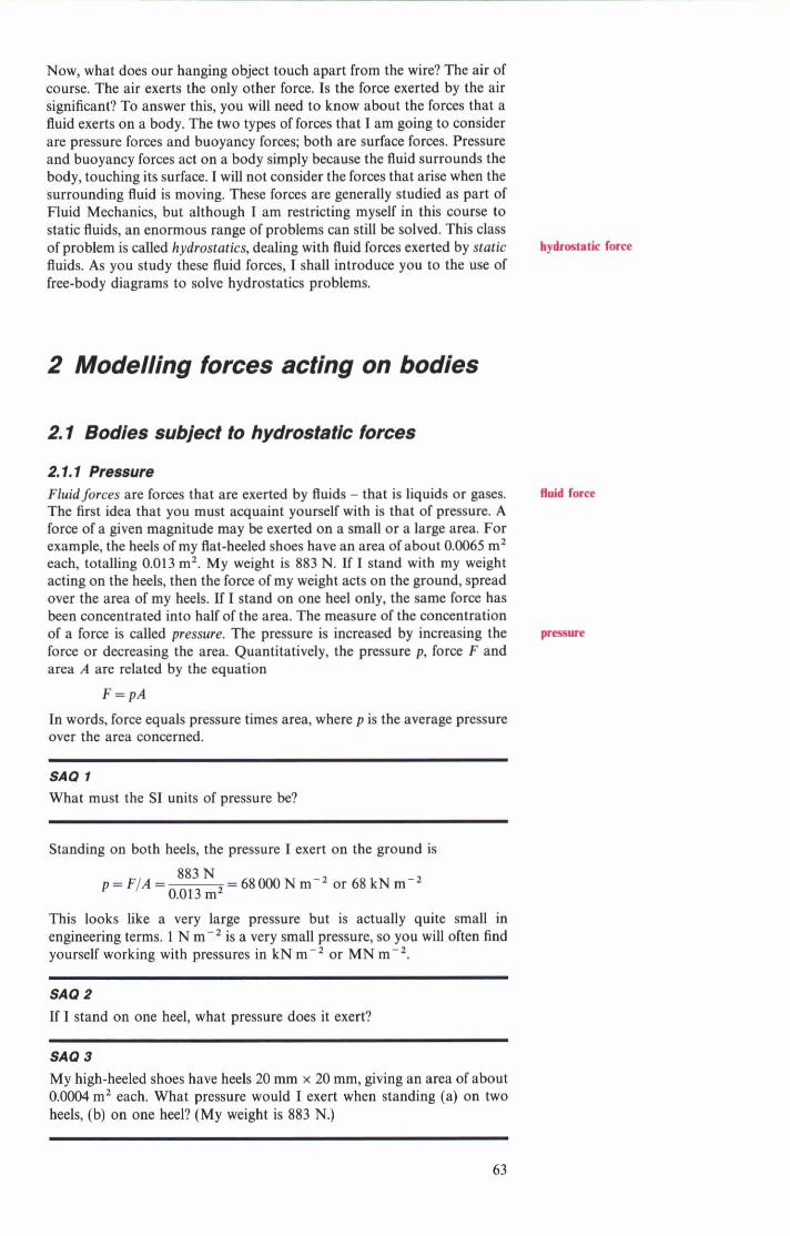
Now, what does our hanging object touch apart from the wire? The air of course. The air exerts the only other force. Is the force exerted by the air significant? To answer this, you will need to know about the forces that a fluid exerts on a body. The two types of forces that I am going to consider are pressure forces and buoyancy forces; both are surface forces. Pressure and buoyancy forces act on a body simply because the fluid surrounds the body, touching its surface. I will not consider the forces that arise when the surrounding fluid is moving. These forces are generally studied as part of Fluid Mechanics, but although I am restricting myself in this course to static fluids, an enormous range of problems can still be solved. This class of problem is called hydrostatics, dealing with fluid forces exerted by static fluids. As you study these fluid forces, I shall introduce you to the use of free-body diagrams to solve hydrostatics problems. 2 Modelling forces acting on bodies 2. l Bodies subject to hydrostatic tomes 2.1.1 Pressure Fluid forces are forces that are exerted by fluids - that is liquids or gases. hY EDne The first idea that you must acquaint yourself with is that of pressure. A force of a given magnitude may be exerted on a small or a large area. For example, the heels of my flat-heeled shoes have an area of about 0.0065 m' each, totalling 0.013 m2. My weight is 883 N. If I stand with my weight acting on the heels, then the force of my weight acts on the ground, spread over the area of my heels. If I stand on one heel only, the same force has been concentrated into half of the area. The measure of the concentration of a force is called pressure. The pressure is increased by increasing the m force or decreasing the area. Quantitatively, the pressure p, force F and area A are related by the equation In words, force equals pressure times area, where p is the average pressure over the area concerned. SA0 l What must the S1 units of pressure be? Standing on both heels, the pressure I exert on the ground is This looks like a very large pressure but is actually quite small in engineering terms. 1 N m-' is a very small pressure, so you will often find yourself working with pressures in kN m-' or MN m-'. SA0 2 If I stand on one heel, what pressure does it exert? My high-heeled shoes have heels 20 mm X 20 mm, giving an area of about 0.0004 m2 each. What pressure would I exert when standing (a) on two heels, (b) on one heel? (My weight is 883 N.)
-
Upload
khangminh22 -
Category
Documents
-
view
1 -
download
0
Transcript of 2 Modelling forces acting on bodies
Now, what does our hanging object touch apart from the wire? The air of course. The air exerts the only other force. Is the force exerted by the air significant? To answer this, you will need to know about the forces that a fluid exerts on a body. The two types of forces that I am going to consider are pressure forces and buoyancy forces; both are surface forces. Pressure and buoyancy forces act on a body simply because the fluid surrounds the body, touching its surface. I will not consider the forces that arise when the surrounding fluid is moving. These forces are generally studied as part of Fluid Mechanics, but although I am restricting myself in this course to static fluids, an enormous range of problems can still be solved. This class of problem is called hydrostatics, dealing with fluid forces exerted by static fluids. As you study these fluid forces, I shall introduce you to the use of free-body diagrams to solve hydrostatics problems.
2 Modelling forces acting on bodies
2. l Bodies subject to hydrostatic tomes
2.1.1 Pressure Fluid forces are forces that are exerted by fluids - that is liquids or gases. hY EDne The first idea that you must acquaint yourself with is that of pressure. A force of a given magnitude may be exerted on a small or a large area. For example, the heels of my flat-heeled shoes have an area of about 0.0065 m' each, totalling 0.013 m2. My weight is 883 N. If I stand with my weight acting on the heels, then the force of my weight acts on the ground, spread over the area of my heels. If I stand on one heel only, the same force has been concentrated into half of the area. The measure of the concentration of a force is called pressure. The pressure is increased by increasing the m force or decreasing the area. Quantitatively, the pressure p, force F and area A are related by the equation
In words, force equals pressure times area, where p is the average pressure over the area concerned.
SA0 l What must the S1 units of pressure be?
Standing on both heels, the pressure I exert on the ground is
This looks like a very large pressure but is actually quite small in engineering terms. 1 N m-' is a very small pressure, so you will often find yourself working with pressures in kN m-' or MN m-'.
SA0 2
If I stand on one heel, what pressure does it exert?
My high-heeled shoes have heels 20 mm X 20 mm, giving an area of about 0.0004 m2 each. What pressure would I exert when standing (a) on two heels, (b) on one heel? (My weight is 883 N.)

Estimate the pressure that I can exert in pushing a pin with a flat end of diameter 0.1 mm with a force of 1 N.
You will note from the last SAQ that a small force can give a high pressure. Remember that pressure is a measure of the concentration or intensity of force, and that a large force does not necessarily mean a high pressure because the area may also be large. The physical implications of pressure should be fairly obvious to you. For example, soh ground can only support a fairly small pressure so although I could walk across it, a smaller weight on a very small area would be more likely to sink in. Vehicles that arc designed to travel across soh ground must sprtad their weight, so they use tracks instead of wheels. An earth-mover of say, 30000 kg, will not get bogged down on muddy ground provided its tracks are appropriately chosen. Although its mass is more than 300 times larger than mine, it could traverse ground which I would find quite impassable.
You are designing a bulldozer. The expected mass is SOOO kg. It must be able to work on soh ground for which the pressure exerted by the tracks must not excad 12 kN m-'. The track-to-ground contact length will be 4 m. How wide must the tracks be?
So far I have been writing about pressures exerted by solid materials. Gases and liquids also exert pressures. A 1 m' piece of ground supports the weight of a column of air of 1 m' cross-sectional area up into the sky. The total mass of atmosphere is about 10300 kg for each square metre of the Earth's surface. The weight of this amount of air results in a pressure at the Earth's surface. This atmospheric pressure naturally corresponds to the force mg on one square metre where m is 10 300 kg.
The average atmospheric pressure at sea level is about 101.3 kN m-', and this value is used as a unit in some systems of measurement (although not in SI). Air has a low density so it takes a very tall column to build up significant pressure. If you go up in an aircraft the pressure and density changes can be significant, but within the range of the height of buildings there is little variation with height. Ressure does, however, vary by several per cent with atmospheric conditions, so it is convenient to take a value of 100 kN m-' as a round number for the mean pressure. Use this value unless told otherwise.
There a n two very useful features of static fluid pressure that you must know. 1 It is equal in all directions. More accurately, I should say that the
pressure is a scalar, and does not have a direction associated with it. The vector force arises when the pressure is associated with a specific surface area and orientation.
2 The force exerted on a surface by a static fluid acts exactly per- pendicular to the surface.
It may seem strange that atmospheric pressure exerts forces upwards and sideways and at any angle just as well as downwards, but consider holding a d iner plate level on your hand. B the area is 0.05 m', then the force acting down on it is
F=pA=100000Nm-'xO.O5m'=5000N
compared with typically less than 5 N for its weight. However, the air pushing up underneath balances the pressure force down, leaving your

hand to support just the weight. Because this atmospheric pressure is all pervading and we have never experienced Me in any other way, we are unaware of it. It also means that in most eases we are interested not in absolute pressure, but pressures relative to the atmospheric pressure of LOO kN m-,. The relative pressure is called gauge pressure because it is the one that most pressure gauges indicate. Absolute pressure is the total pressure including the atmospheric one:
In this course, pressure will always be given as gauge pressure, unless the term 'absolute pressure' is used explicitly.
SA0 8 The correct gauge pressure for my car's front tyres is 190 kN m-'. What absolute pressure is that?
You have seen that for most engineering purposes (excluding obviously the aerospace industry) atmospheric pressure can be regarded as constant. However, underwater, we 5 d that pressure increases rapidly with depth. You would expect this because water has a density of about 1000 kg m-3, eight hundred times that of air. For a static liquid of density p the pressure at a depth h can be estimated from p = phg. I say 'estimated' because our static constant-density liquid is only a model of the real liquid. In reality the fluid density is likely to vary because of temperature changes or impurities (salt in seawater), the surface may not be exactly de5ed (because of waves) and the fluid will not be in perfect equilibrium. However, if we model the complexity of the real world with a static uniform fluid of density p, then p = pgh.
We can gain greater physical insight into this by examining Figure 3. This shows a tank of fluid which I shall model as having constant density and being static. How is the pressure at P , related to that at P,? Consider the point P , which is at the same level as P , but below P, . I can draw a FBD to represent a cylinder of fluid from P , to P , (Figure 4).
Remember that the second important static-fluid force property was that the force acts perpendicular to a surface. The forces acting on the curved walls of the FBD have no vertical component. The force acting down at P , is p, A and acting up at P , is p, A, where A is the cross-sectional area of the cylinder. The free body is in equilibrium in the vertically downward direction, so the vertical resultant is
R,=F,+ W - F , = O
. . F , = F , + W
acting upwards. The volume of the cylinder is Ah, so m = p A h and W = pAhg
.'. p2A = p, A + pAhg
P2 = P I + pgh
where h is the depth difference. (The forces acting horizontally have zero resultant in all directions.)
This simple use of the free-body diagram and equilibrium analysis shows why the pressure increases by pgh when the depth increases by h going straight down. At the surface the gauge pressure is zero. Thus if the depth is measured from the surface then we have p = pgh as a very good model of the static gauge pressure of liquids. What about the point P , which is underneath a solid protruding shelf?
Figure 3
Figure 4

SA0 7 Figure 5 shows a cylindrical frct body from P , to P,.
X
PS (a) Do the foms on the curved surface have any horizontal resultant? Why is this?
(b) Use equilibrium to relate p, and p,. F i W 5 Horizontal Com~ne*s (c) If I removcd the shell, would p, change?
From the previous SAQ you should see that the pressure is not changed by horizontal change of position. This gives us a very simple rule:
This very simple rule means that to relate the pressure at various points in a fluid you no longer need to draw any fnc-body diagrama - in future you can b p that step by remembering the dt. This rule applies even if the two points an a long way apatt, or only connected by thin pipes, provided the h i d is static. In Figure 6 you know straight away that provided the two points am p r t of one wntinuous volume of static fluid, then p,==p, +p& the details of tanks a d pipes betwan and the
Figure 6 System of tanks and plpes horizontal position have no efIsct wha t~ver .
540 1 For each of the following estimate: (a) the gauge pressure (p,), (b) the absolute pressure (p , ) , and (c) the ratio of absolute pressure to atmm pheric pressure (p,/p,). Usc the values p, = 100 kN m-2, p, = lO9 kgm-'for water, and g=9.81 N kg-'. 1 The bottom of your bath under 0.3 m of water. 2 Aqualung diving at 30 m. 3 Deep ocean bathyscape research vessel 3 km deep. 4 What depth of water corresponds to the atmospheric pressure? (It is
useful to remember this Rgure.)
Hydraulically-operated machinery is quite common - the most familiar example may be the brakes on your car. Other good examples arc the hydraulic jack and the use of hydraulic rams to operate the arms of earth- working machinery. A pump mates high liquid pressures which an applied to the object to be moved or supported, In such devices the pressures used an quite high, typically up to U) MN m-2. The advantage of a high pressure is that a large forcc can be produmd on a wonably small piston.
SA0 S (a) How many atmospheres of pressure is 20 MN m-=? (b) You are selecting a hydraulic ram to produce a fom of 100 kN (the
weight of about ten typical oars) at a maximum presure of 2OMNm-'. Specify the minimum piston area.
When these large pressures arc deliberately created, then the pressure of the gravity term pgh becomes relatively insignificant In such problems you eau neglect thegravity term, although I susgat that you note that you an doing so at the time.
On a hydraulically-operated earth-moving digger the pump produces about 16 MN m-,, using oil of density 800 kg m-'. The rams achieve a maximum height of about 10 m above the pump. (a) Estimate the maximum gravity pressure. (b) Express the gravity pressure as a fraction of the supply pressure. (c) Do you think the gravity pressure can be neglected for this sort of
problem?
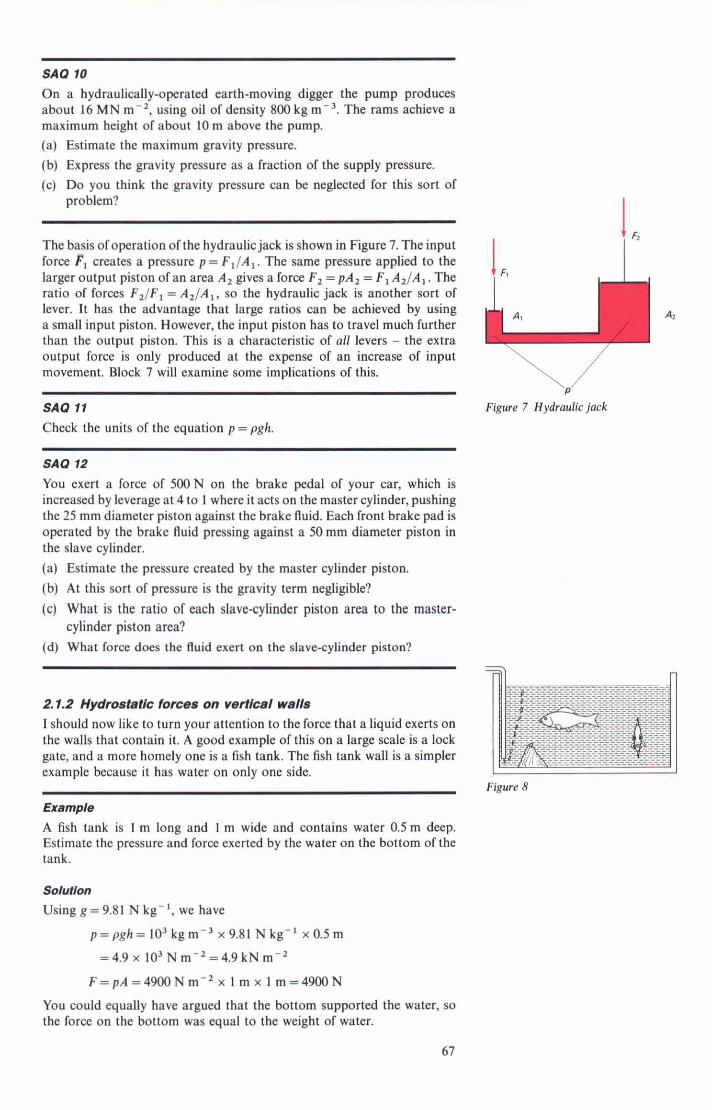
The basis of operation of the hydraulic jack is shown in Figure 7. The input force F, creates a pressure p = F1/A1. The same pressure applied to the larger output piston of an area A, gives a force F, = pA, =F1 A2/Al. The ratio of forces F2/Fl = A2/A1, so the hydraulic jack is another sort of lever. It has the advantage that large ratios can be achieved by using a small input piston. However, the input piston has to travel much further than the output piston. This is a characteristic of all levers - the extra output force is only produced at the expense of an increase of input movement. Block 7 will examine some implications of this.
Check the units of the equation p = pgh. Figure 7 Hydraulic jack
SA0 72
You exert a force of 500N on the brake pedal of your car, which is increased by leverage at 4 to 1 where it acts on the master cylinder, pushing the 25 mm diameter piston against the brake fluid. Each front brake pad is operated by the brake 0uid pressing against a 50 mm diameter piston in the slave cylinder. (a) Estimate the pressure created by the master cylinder piston. (b) At this sort of pressure is the gravity term negligible? (c) What is the ratio of each slave-cylinder piston area to the master-
cylinder piston area? (d) What fora does the fluid exert on the slave-cylinder piston?
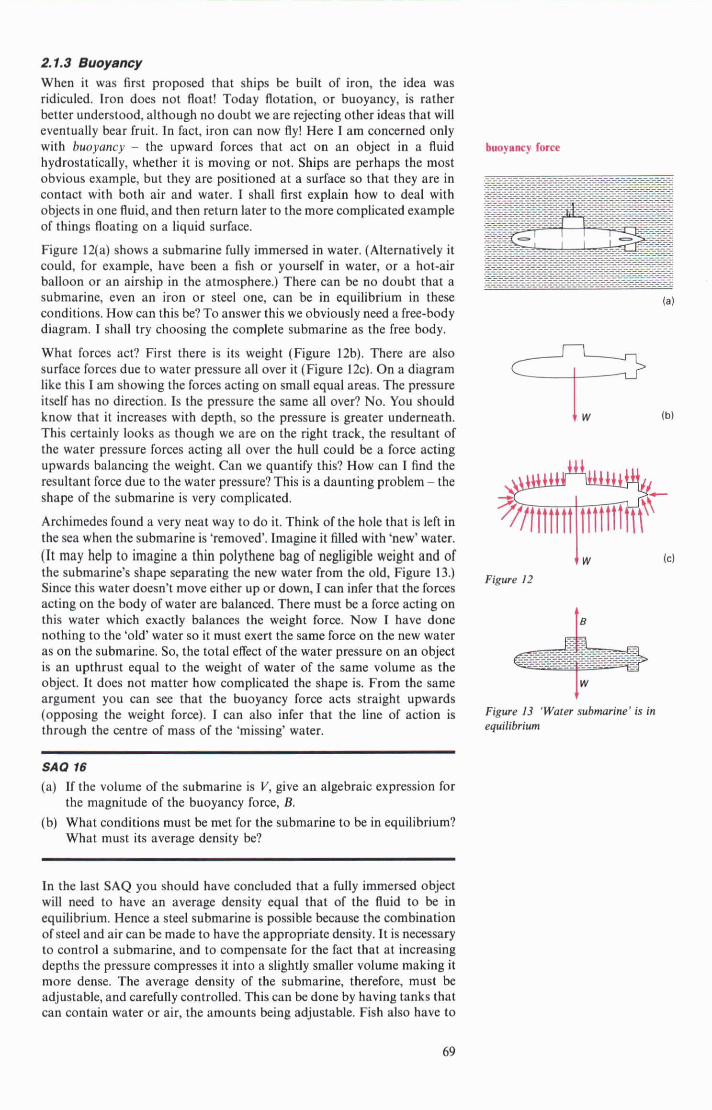
2.1.2 Hyd~vstaNc knce8 on verUml wall8 I should now like to turn your attention to the force that a liquid exerts on the walls that contain it. A good example of this on a large scale is a lock gate, and a more homely one is a fish tank. The fish tank wall is a simpler example because it has water on only one side.
Example A fish tank is 1 m long and l m wide and wntains water 0.5m deep. Estimate the pressure and force exerted by the water on the bottom of the tank.
SoIullon
Using g = 9.81 N kg-', we have
p = p g h = l O ' k g m - ' ~ 9 . 8 l N k g - ~ x0.5m
=4.9x 10"mm-2=4.9kNm-2
F=pA=4900Nm-2x 1 m x 1 m = 4 9 0 0 N
You wuld equally have argued that the bottom supported the water, so the force on the bottom was equal to the weight of water.
Figure 8

SA4 19 If the latter approach was used. (a) What was the free body used? (b) What other knowledge did you use?
Whichever argument was used, you were neglecting the presence of the fish, the rocks, the air bubbles, the water weed, and so on. I hope that this thought was in your head. Try to be aware of the things you are ignoring in your free-body model.
Now, what about the pressure and force acting on the side walls?
PO First, how do I represent the pressure? We have the expression p = pgh. The small variations in p are neglected so the pressure is proportional to h, the depth. The pressure distribution is therefore triangular. Remember that
---------------- i pressure itself has no direction, so it is difficult to illustrate. Figure 9 shows 3-=-=-=-=-7-7-=-= the force acting on small, equal, areas at different depths. How do you find
PI - pgh, the total force acting on the wall? Mathematically speaking this requires
Figwe 9 Pressure distribution an integration of the pressure over the wall area, but because the pressure distribution is so simple you can easily avoid the formal approach. The force acting on the wall is equal to the area times the average pressure. In this case with a rectangular wall, the average pressure is what you expect it to be: f (p, + p,). However, p, = 0 (gauge), so the average gauge pressure p = fp, = fpgh,. The force is, therefore, F = pA = fpgh, A. What about the line of action of the force? And where is it located?
Its position can be found by taking moments of the distributed pressure force - it turns out to be at a depth equal to the centre of area of the pressure triangle: jh, from the s u d m (Figure 10). These then are the results that you need, to cope with problems involving the force on vertical rectangular platei supporting liquids. Where h is the depth, F = fpghA
Figure 10 and the line of action is at depth jh.
If you remember the triangular pressure distribution you should be able to remember the 'half and the 'two-thirds' because they correspond to a triangle's area (half base times height) and centre of area ( j down from vertex).
SA4 14 For the original fish tank example, evaluate the force (including line of action) acting on one side.
Figure 11 shows a cross-section view of a water control gate which is 3 m wide. (a) Estimate the force exerted by the water on the deep side, its line of
--------- -- . - --. - -. -- -. action and its moment about A, the horizontal pivot axis of the gate. --------- -- ............ --------- -- ............ --------- -- .-----W - -- ---- - -- - - - - - - --- -- (b) Repeat for the shallow side. ........... . - - - - - - - - - - - -- .- - - - - - - -- -- ?--A-------------- ---- --------- -- ............ --------- -- .- - -- - --. (c) Find the total moment exerted by the water. - - - - - - - - L-.-----.-.-.=-4 m 8 . - - - - - - -. ........... - - ............................. -- --.. The gate is intended to begin opening when the water levels are as shown. -- --- -----.-.------ --------- -- --- -- --- -.------------- --------- -- --- ---------.-.--. -- --- ------W-------- ............................. . --------- . -- -- -- Opening is opposed by the counterweight m at an average moment arm of .W---- ---- -- --.Z ---..---- -- -- ............................ --------- -- --- ----..-W------. --- --- ----------W---- .- - - - .--- - - - - - - - - - - - . 3 m. Find: -- --- -----------.-.- ............................. - - - - -.-. -- - ----- - -. . -. -- - -- - - - .--. .-................ -- --- -------------- g F i v e 11 (d) (e) The The necessary mass.
weight.
(Q The volume of the counterweight if it is made of concreted rubble of average density 2200 kg m-'.
2.7.3 Buoyancy When it was first proposed that ships be built of iron, the idea was ridiculed. Iron does not float! Today flotation, or buoyancy, is rather better understood, although no doubt we are rejecting other ideas that will eventually bear fruit. In fact, iron can now fly! Here I am concerned only with buoyancy - the upward forces that act on an object in a fluid hydrostatically, whether it is moving or not. Ships are perhaps the most obvious example, but they art positioned at a surface so that they are in contact with both air and water. I shall h t explain how to deal with objects in one fluid, and then return later to the more complicated example of things floating on a liquid surface.
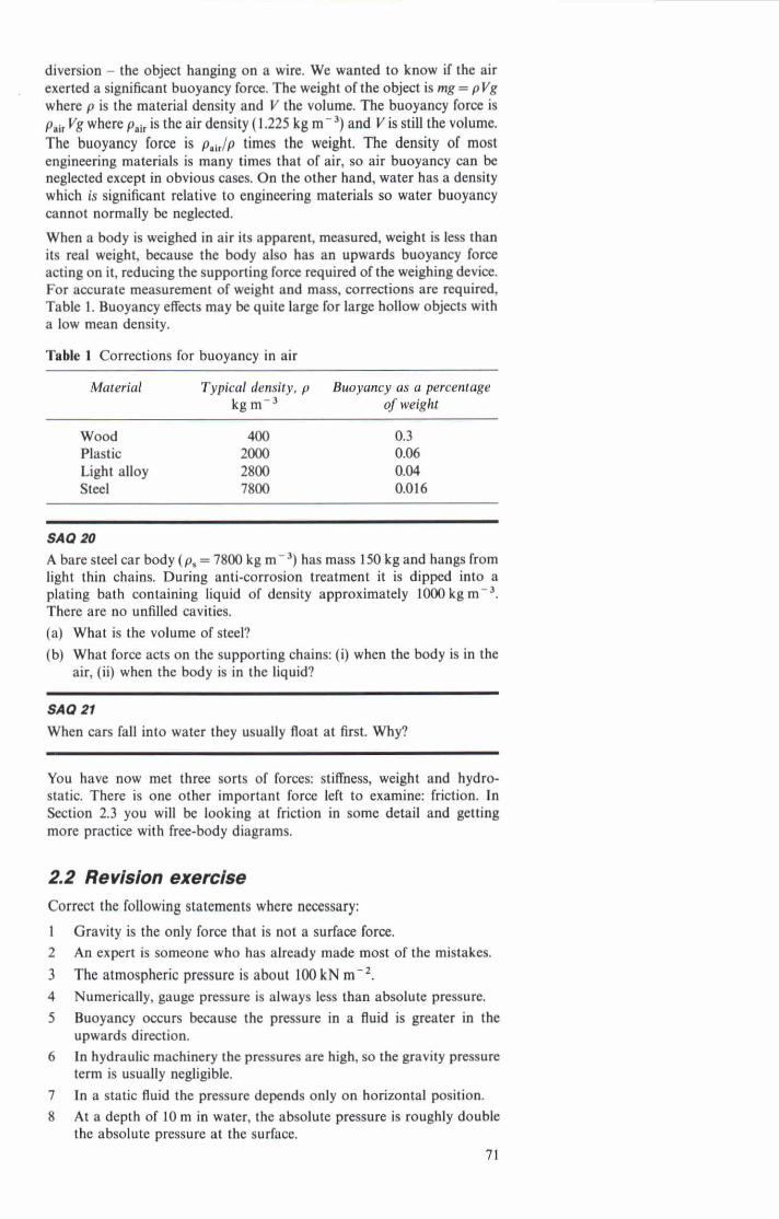
Figure 12(a) shows a submarine idly immersed in water. (Alternatively it could, for example, have been a fish or yourself in water, or a hot-air balloon or an airship in the atmosphere.) There can be no doubt that a submarine, even an iron or steel one, can be in equilibrium in these conditions. How can this be? To answer this we obviously need a free-body diagram. I shall try choosing the complete submarine as the free body.
What forces act? First there is its weight (Figure 12b). There are also surface forces due to water pressure all over it (Figure 12c). On a diagram like this I am showing the forces acting on small equal areas. The pressure itself has no direction. Is the pressure the same all over? No. You should know that it increases with depth, so the pressure is greater underneath. This certainly looks as though we are on the right track, the resultant of the water pressure forces acting all over the hull could be a force acting upwards balancing the weight. Can we quantify this? How can I find the resultant force due to the water pressure? This is a daunting problem - the shape of the submarine is very complicated.
Archimedes found a very neat way to do it. Think of the hole that is left in the sea when the submarine is 'removed'. Imagine it filled with 'new' water. (It may help to imagine a thin polythene bag of negligible weight and of the submarine's shape separating the new water from the old, Figure 13.) Since this water doesn't move either up or down, I can infer that the forces acting on the body of water are balanced. There must be a fora acting on this water which exactly balanm the weight force. Now I have done nothing to the 'old' water so it must exert the same force on the new water as on the submarine. So, the total effect of the water pressure on an object is an upthrust equal to the weight of water of the same volume as the object. It does not matter how complicated the shape is. From the same argument you can see that the buoyancy force acts straight upwards (opposing the weight force). I can also infer that the line of action is through the centre of mass of the 'missing' water.
SAQ 16 (a) If the volume of the submarine is V, give an algebraic expression for
the magnitude of the buoyancy force, B. (b) What conditions must be met for the submarine to be in equilibrium?
What must its average density be?
In the last SAQ you should have concluded that a fully immersed object will need to have an average densitv eaual that of the fluid to be in equilibrium. Hence a steel submarine possible because the combination of steel and air can be made to have the appropriate density. It is necessary to control a submarine, and to compensate for the fact that at increasing depths the pressure compresses it into a slightly smaller volume making it
+ W (c)
Figure 12
Figure 13 'Water submarine' b in equilibrium
more dense. The average density of the submarine, therefore, must be adjustable, and carefully controlled. This can be done by having tanks that can contain water or air, the amounts being adjustable. Fish also have to

obey the laws of physics. To avoid having to use excessive muscle power in swimming they keep their density close to that of water with a swim- bladder of controUablc volume which contains gas.
So far we have considered translational equilibrium. How about rotation? The buoyancy fora must be on the samc line of action as the weight, so submarines have buoyancy tanks front and rear to achieve the required balance. When a fish dics it l o w the ability to maintain comct balance and hence lies at an unusual angle and floats to the surface.
Objects floating in air follow the same rules as those in water or any other fluid,although naturally their average density must be very much Lower. A balloon or airship will have a load-g capability depending upon the difference between its buoyancy and its minimum weight. One might expect the weight to be a minimum if the volume was completely empty, i.e. a vacuum. However, a vacuum exerts ZMO absolute pnssure; so the atmosphere will try to crush a container with a vacuum inside. A very strong and henee heavy structure is required to resist the atmospheric pressure and so vacuum is not a realistic proposition. Instead it is better to use a light gas at atmospheric pressure. Early airship used hydrogen, but this is highly in9ammable and there were nasty dden t s . Helium is heavier but safe. Hot-air ballons are now popular as a sport: heating the air causes it to exert the name pressure at a lower density.
It has been suggested that airship be used for cargo transport. In a proposed dcsign the total structural mass is 6000 kg, and the displaced volume is 17500 m3. (a) What is the magnitude of the buoyancy for& (p,, = 1.225 kg m-3). (b) What is the weight of the helium filling the balloon? (p,,,=
0.17 kgm-' for helium at atmoapberic temperature and pressure.) (c) If 8 kN of ballast must be carried for trim puqmcs, what is the cargo-
-8
Finally, we can examine the buoyancy of objects at the junction of two fluids. Of course the common one is between air and water. Now that you know that the buoyancy depends on the density of the fluid you should agree that the effect of the air can be neglected here because its denaity is amall relative to that of water. Hence a ship will float at such a level that the volume of water displaced by the hull gives the appropriate buoyancy. If you put more load on, within its total capability, it will sinL a little deeper until fhe appropriate buoyancy is achieved.
SA0 18 My weight is 883 N. I can float in a vertical 'standing' position with the water up to my chin. I estimate the volume of my head to be 0,003 m'. Estimate my total volume.
A diver is lowered by a thin cable over the side of a boat into sea water of M ~ t y p, = l020 kg m-'. Complete with all equipment he has a mass of 180 kg and a volume of 0.12 m3. (3 What is his weight? (b) He is hanging on the cable underwater. h a w his frw-body diagram.
What is the tension in the cable?
That completes what you need to know about fluid static i o m in this course. Now we can return to the original problem which prompted our
70
diversion - the object hanging on a wire. We wanted to know if the air exerted a signi6cant buoyancy force. The weight of the object is mg = pVg where p is the material density and V the volume. The buoyancy force is p,,, Vg where p,,, is the air density (1.225 kg m-3) and V is still the volume. The buoyancy force is p,,/p timca the weight. The density of most engineering materials is many times that of air, so air buoyancy can be neglected except in obvious cases. On the other hand, water has a density which is signi6cant relative to engineering materials so water buoyancy cannot normally be neglected.
When a body is weighed in air its apparent, measured, weight is leas than its real weight, because the body also has an upwards buoyancy force acting on it, reducing the supporting force required of the weighing device. For accurate measurement of weight and mass, corrections are required, Table 1. Buoyancy effects may be quite law for large hollow o b j e with a IOW mean density.
Table 1 Corrections for buoyancy in air
Material Typical density, p Buoyancy as a percentage kg m-' of weiaht
wood 400 Plastic MOO Light alloy 2800 Steel 7800
SAOW A bare steel car body (p, = 7800 kg m-=) has mass 150 kg and hangs from light thin chains. During anticorrosion treatment it is dipped into a plating bath containing liquid of density approximately 1000kgm-'. There are no unfilled cavities. (a) What is the volume of steel? (b) What force acts on the supporting chains: (i) when the body is in the
air, (ii) when the body is in the liquid?
SAO n When cars fall into water they usually float at first. Why7
You have now met three sorts of forces: stiffness, weight and hydro- static. There is one other important force left to examine: friction. In Section 2.3 you will be looking at friction in some detail and getting more practice with tree-body diagrams.
2.2 Revlslon exerclse Correct the following statements where necessary:
l Gravity is the only force that is not a surface force. 2 An expert is someone who has already made most of the mistakes. 3 The atmospheric pressure is about 100 kN m-'. 4 Numerically, gauge pressure is always less than absolute pressure. 5 Buoyancy occurs bccsusc the pressure in a fluid is greater in the
upwards direction. 6 In hydraulic machinery the pressures are hi& so the gravity pressure
tenn is usually negligibk. 7 In a static fluid the pressure depends only on horizontal position. 8 At a depth of 10 m in water, the absolute pressure is roughly double
the absolute pressure at the surface. 71

I Ill
U
2, 3.4, 6 and 8 are all true. l No, but it is the only one dealt with in this course. 2 True. Do the SAQs. Make your mistakes now, not in the
Examination. 5 No. Pressure does not have direction. Pressure increases with depth. 7 No. It depends on vertical position, but not horizontal position.
2.3 Boclles subject to lrlcNon toms When one object is capable of sliding on another then there can be forces, along the contact surfaces, which oppose motion between the surfaces. This component of the contact force is known as the friction force. Previously you have been neglecting friction, in which case there were no force components along the contacting surfacas; the force of one body on the other was considered to be perpendicular to the surfaces. Sometimes this is an acceptable approximation. Often it is not. In the remainder of this section you will study friction forces and how they can be modelled using free-body diagrams.
Friction forces are often beneficial. Walking on ice, or driving a car on ice, is distinctly dangerous, the reason being that in these cases the friction forces available are rather small. On the other hand friction can be detrimental, and major eBorts a n made to minimize it, in machinery for example. Friction can be kept to low levels by separating the sliding surfaces by a layer of lubricant, usually oil. In this course, small friction forces will generally be neglected. We are only interested in the large ones that occur when the surfaces are actually in contact. Thii is t e d 'dry friction', although the surfaces do not have to be literally dry.
In this course the forces between two bodies will be considered in two components, perpendicular to the contact surfaces and parallel to them. The first is catled the normal force, the second is called the friction force. If the friction is neglected then there is only the normal force. (Surfam at which friction is negligible a n often called 'smooth'. However, surfaces which are physically smooth can actually have high friction so I shall avoid the term in this course.) F rabody d i i a m s for problems involving friction are like t h a that neglect it, except that the frictional force tangential to the contact surface must be included.
To draw correct FBDs and solve problems involving friction, it is necessary for you to be able to mark friction forces on to the f m body wrrcctly. This requires that you should be able to determine: 1 the line of action, 2 the sense, 3 the magnitude of the friction force.
The line of action of the friction force is always along the contacting surfaces. If these are curved then it is along the tangent at the wntact point (Figure 14).
The sense of the force is such that it opposes motion or tendency to motion between the contacting surfaces. Note that the friction force is naturally subject to Newton's Third Law, so that the objects exert equal and opposite friction (and normal) forces on each other. If you push a box along the Boor with force R(Figun 15a). then the box 'wants' to move to the left. Therefore, the 0001 exerts a force to the right on the box to try to prevent any motion (Figure 15b). Newton's Third Law tells us that the box, therefore, exerts a friction force on the 0001 to the left (Figure 1%). This cnates a certain danger of confusion. Try to remember that the friction force acting on an object tries to prevent, or opposes, sliding of that object.

SA0 22 Figure 16 shows a stationary slider pulled by two springs. Give the Line of action and sense of the friction force on the slider if tension T, is greater than T,.
SA0 29
Repeat SAQ 22 for T, greater than T,.
SA0 24
A circus monocyclist holds himself stationary on a sloping plank, Figure 17. Draw the FBD for the man-pluscycle showing the weight, normal reaction, and friction forces.
SA0 25
My car is parked on a hill, Figure 18. The handbrake locks the rear wheel+ the front wheels are free and exert negligible friction. (a) Draw the FBD for the car. (b) Sketch the forces exerted by the car on the ground.
Were you confused by the wheels in SAQs 24 and 25? Although you know from experience that the wheels can rotate separately from the motion of the rest of the body, it is nonetheless possible to treat monocyclist and wheel, and car body and wheels, as free bodies. This is what you are asked to do in the SAQs, so the free-body diagrams must show only those forces acting on the free body and not any internal forces, that is, forces acting between different parts of the free body. If these forces are an important part of the problem, then you have to use a free-body diagram that will allow you to show them. In Statics problems concerned with, for example, the forces acting on a stationary vehicle, you can include the wheels as part of the free-body diagram of the vehicle. You will need to take into account the forces between the wheels and the road but, in this case, the forces between the wheel and the rest of the vehicle do not need to be considered. This is easier to grasp if you remind yourself that there is no relative motion between wheels and vehicle if the vehicle as a whole is stationary.
The magnitude of the friction force is determined in different ways according to the type of problem. You will know from experience (or you can easily try it) that when you try to slide an object along, there is a certain force below which no movement occurs. If you apply a force less than this, the object remains in equilibrium. This is because friction opposes your efforts, and successfully preserves equilibrium. Note that the friction force automatically adjusts itself to be just sufficient to provide the balancing force. However, there is an upper limit to the friction force. If the friction required is greater than this limit then friction cannot preserve equilibrium, and the object wiU move. The condition when an object has on it the maximum force(s) which does not cause movement, is called impending motion. Even the slightest further increase of the driving force will cause movement. The smallest force that will initiate movement is, therefore, effectively the same as the maximum force that will not cause movement. For purposes of calculation both of these phrases and also 'impending motion' refer to the condition when the friction force has reached its limit.
It is a matter of considerable practical importance for an engineer to be able to predict the maximum friction force in any particular case. Because the force is the result of the interaction of surfaces which have a very complicated shape on a microscopic level, an accurate model of friction would be very complicated. However, a large number of frictional
Figure 16
Figure 17
Figure 18
experiments have been performed and from these friction is found to be representable for most engineering purposes by a very simple model: 1 The maximum friction force is usually almost independent of the area
of contact. 2 The maximum friction fora is directly proportional to the normal
force acting. 3 The materials and surface condition have a major effect.
Expressing this friction modd mathematically, the maximum friction form is
F - P P R when R is the normal force. The Greek letter p (mu) is the coeficient of limitingfrletion (not to be confused with the S1 prefix p, which means 10+).
SA0 What units must the coefficient of friction have?
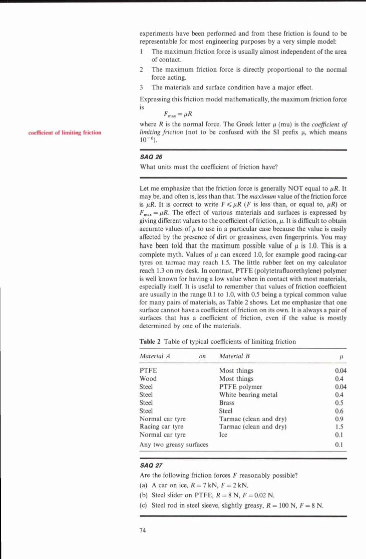
Let me emphasize that the friction force is generally NOT equal to pR. It may be, and often is, less than that. The muximum value of the friction force is a. It is correct to write F G pR ( F is less than, or equal to, pR) or F- = pR. The effect of various materials and surfaces is expressed by giving differcat values to the coefficient of friction, p. It is difficult to obtain accurate values of p to use in a particular case because the value is easily affected by the presence of dirt or greasiness, even fingerprints. You may have been told that the maximum possible value of p is 1.0. This is a complete myth. Values of p can exceed 1.0, for example good racinger tyres on tarmac may reach 1.5. The little rubber feet on my calculator reach 1.3 on my desk. In contrast, FTFE (polytetratluorethylene) polymer is well known for having a low value when in contact with most materials, especially itself. It is useful to remember that values of friction coefficient are usually in the range 0.1 to 1.0, with 0.5 being a typical common value for many pairs of materials, as Table 2 shows. Let me emphasize that one a d a c e - cannot have a cocfscient offriction on ita own. It is always a pair of surlaces that has a ccdcient of friction, even if the value is mostly determined by one of the materials.
Table 2 Table of typical coefficients of limiting friction
Material A on Material B 1
PTFE Most things 0.04 Wood Most things 0.4 Steel FTFE polymer 0.04 Steel White bearing metal 0.4 Steel Brass 0.5 Steel Steel 0.6 Normal car tyre Tarmac (clean and dry) 0.9 Racing car tyre Tarmac (cl- and dry) 1.5 Normal car tyre Ice 0.1 Any two greasy surface 0.1
SA0 27
Are the following friction forces F reasonably possible? (a) A car on ice, R = 7 kN, F = 2 kN. (b) Steel slider on FTFE, R = 8 N, F = 0.02 N.
(c) Steel rod in steel sleeve, slightly greasy, R = 100 N, F = 8 N.
SA0 28
A spring of stiffness 2.5 kN m-' is attached at one end to a wooden table of 400N weight as a temporary fixture. I want to stretch the spring horizontally by 0.2 m. (a) Is the table likely to be an adequate fixture? In other words, compare
the friction force needed with the one likely to be available. (b) How could I quickly improve the friction force available?
SA0 Zg
An empty toolbox of 10 N weight resting on a bench requires a horizontal force of 6 N to just initiate movement.
(a) What is the coefficient of friction? (b) 40 N weight of tools are inserted in the box. Estimate the force that
will now be needed.
Static friction problems can be divided into two main types: Type 1: Will the known forces applied move the object? Type2: What force do 1 need to apply to just move the object (impending motion)?
The approach to these two types of problem is rather different, so you should be clear about the procedure for each one.
Type 1: Will the object move? It is nor known that friction is limiting, so you can not use F = F,.
Procedure 1 Assume equilibrium. 2 Use equilibrium to find the 'equilibrium friction force' F. and the
normal reaction R. 3 Find F,., = P R . 4 Compare F , with F,,,.
Let me emphasize that F. is the friction force required to maintain equilibrium. If F . is less than or equal to F,.., then the equilibrium assumption was reasonable. If F , is greater than F,, then it was not reasonable, and the object will move.
Type 2: What applied force is needed for impending motion? For impending motion, friction is limiting, so F = F,, = P R .
Procedure 1 Use equilibrium to find the normal force. 2 Use F = F,.. = pR to find the friction force. 3 Use equilibrium to find the applied force.
(More complicated problems may require the equilibrium equations and F,, = pR to be solved simultaneously.)
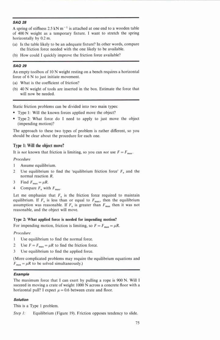
Example The maximum force that I can exert by pulling a rope is 900 N. Will I succeed in moving a crate of weight 1000 N across a concrete floor with a horizontal pull? I expect p = 0.6 between crate and floor.
Solullon This is a Type 1 problem.
Step I: Equilibrium (Figure 19). Friction opposes tendency to slide.
Step 2: Along X: H - F. = 0
X . F , = H = W N The friction force requid for aquilibrium is F, = 900 N. Along% R-W=O . R = W = 1000 N
Step3: F-=fl=600N The maximum possible friction fora is F,, = 600 N.
Figure 19
Figure 21
Step 4: The friction force required for equilibrium exceeds the m e imum possible. Therefore, I expect to be able to move the crate.
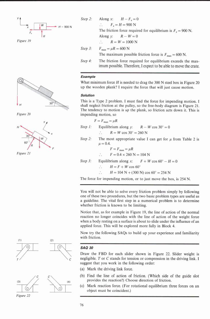
What minimum force H is needed to drag the 300 N steel box in Figure 20 up the wooden plank? I require the force that will just cause motion.
This is a Type 2 problem. I must find the force for impending motion. I shaU neglect friction at the pulley, so the free-body diagram is Figure 21. The tendency to motion is up the plank, so friction acts down it. This is impending motion, so
F=F-=PR Step 1: Equilibrium along y: R - W cos M" = 0
. R=Wcos3O0=260N Step 6 The most appropriate valw I can get for p from Table 2 is
p = 0.4. F=F-=PR
. F=0.4x260N=104N
Step 3: F!quilibrium along X: F + W cos 60" - H = 0 . H=F+Wcos60" . H=lWN+(300N)~os60~=254N
The force for impcnding motion, or to just move the box, is 254 N.
You will not be able to solve every friction problem simply by following one of thee two procedures, but the two basic problem types are useful as a guideline, The-vital first step in a numericil probl&>s to determine whether friction is known to be limiting.
Notice that, as for example in Figure 19, the Line of action of the nonnal reaction no longer coincides with the line of action of the weight force when a body resting on a surface is about to sli& under the influence of an applied force. Tbia will be explored more fully in Block 4.
Now try the following SAQs to build up your experience and familiarity with friction.
(21
SA0 90
Draw the FBD for each lide er sbown in Figure 22 Slider weight is negligible. T o t C stands for tension or compression in the driving link. I suggent that you work in the following order: (a) Mark the driving l i i force.
(b) Find the line of action of friction. (Which side of the guide slot provides the reaction?) Choose direction of friction.
(c) Mark reaction force. (For rotational equilibrium three forces on an object must be coincident.)

SA0 81 A useful way to obtain an estimate ofa friction coefficient is to place a block of one material on a sheet of the other, and to increase the angle of the sheet until the block first slides, at the angle 0 (Figure 23). Draw a FBD for the block and obtain algebraic expressions for (a) normal reaction R, (b) friction force F, (c) friction coefficient p. Note that for problems involving inclined planes it is best to use axes parallel and perpendicular to the plane. (d) My calculator on wood starts to slide at about 0 = M". What is the value of p? Figure 23
SA0 S2 Figure 24 shows a block of weight 2 N resting on a board (p = 0.5). The spring can exert tension or compression forces and has stiffness k = 100 N m-'. In such an arrangement it is found that the block will remain in equilibrium over a range of positions. (a) Explain this. (b) What are the maximum friction forces that can act in either direction? (c) Draw FBDs for each end of the equilibrium range. (d) How large is the range?
Up till now we have assumed that movement of an object will follow translational, rather than rotational, equilibrium failure. In this particular question, I want you to consider the other possibility - tipping over instead of slipping. When I push the wardrobe (Figure 25a), the applied force and friction form a couple trying to make it fall over. A restoring couple is provided because the line of action of the floor reaction moves away from that of the weight force (Figure 25b). (a) What is the furthest point the reaction could move to? (b) If the weight acts in the middle, what is the maximum restoring
couple? (C) What is the algebraic expression for the horizontal applied force at
height a which will cause tipping? (d) What values of p will allow sliding first? (c) To discourage tipping, should a be small or large?
SA0 S4 In Figure 26, will the counterweight W, = 160 N pull the packing case up the plank?
A car wheel of 0.65 m diameter (rubber tyre on tarmac), carries a weight of 1800 N. Estimate the maximum torque that the axle can apply without causing wheel spin.
SA0 30 In Figure 27, S is the force required to move block 2. (a) Draw FBDs for each block. (Be careful to check for all forces.) (b) Estimate S.
2.4 Summaty of Sections 1 and 2 So far in this Unit we have looked at two new forces: hydrostatic forces (including buoyancy forces) and friction forces. These arc all surface forces. A free-body diagram is an essential 6rst step in most Statics problems. To summarize, there are four steps in constructing a free-body diagram:
p L 0.5
Figure 24
Figure 25
W,=lsON
Figure 26
,, - 0.6
Figure 27
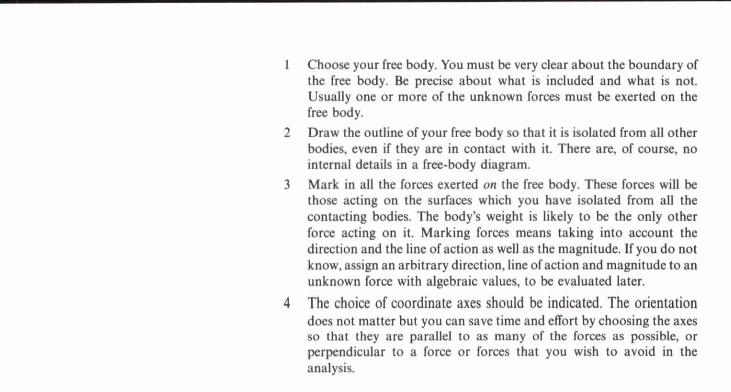
l Choose your free body. You must be very clear about the boundary of the free body. Be precise about what is included and what is not. Usually one or more of the unknown foras must be exerted on the free body.
2 Draw the outline of your free body so that it is isolated from all other bodies, even if they are in contact with it. There are, of course, no internal details in a free.-body diagram.
3 Mark in all the forces exerted on the free body. These forces will be those acting on the surfaces which you have isolated from all the contacting bodies. The body's weight is likely to be the only other force acting on it. Marking forces means taking into account the direction and the l i e of action as well as the magnitude. U you do not know, assign an arbitrary d i i i o n , l i e of action and magnitude to an unknown force with algebraic values, to be evaluated later.
4 The choice of coordinate axes should be indicated. The orientation does not matter but you can save time and effort by choosing the axes so that they arc parallel to as many of the foras as possible, or perpendicular to a force or forces that you wish to avoid in the analysis.
3 Modeiling structures: the pin-jointed model
In this Scction I want to look at a di&rent kind of free-body diagram and to use free-body diagrams to look at parts of things rather than whole objects. The principle is the same - a clear boundary is drawn and the forces arc identified but this time the boundary of the free-body does not coincide with the physical boundary of the object.
You have already met some simple pin-jointed structures, or structures that can usefully be modelled as pin-jointed. In this section I want to
A B - B C - A C = l m concentrate on this type of Statics problem. You have seen bow to use
F W c 28 equilibrium conditions on a single pin to find two unknown forces exerted on it. When a PIS is 'solved' by workiig through it pin by pin in this way,
FA you are said to be using the hethods ofjoints'. If the foras in only one or two members an needed, rather than all of them, then it is often quicker to
X. choose a free body comprising several members and pins all together. You cut out a free body which is not just a single pin but a larger portion of the PJS. This latter method is called the 'method of sections'. The best choice of free body depends upon the problem in hand.
Remember that in these problems we are neglecting friction at the pins. Also the weight of the members is neglected, although for some purposes it
Plgure 29 Pin A can be incorporated by adding forces at the pins if necessary.
3.1 The medhod of Jolnb
F1
Figure 30 Ptn A
I shall start by considering the simple example of Figure 28. This is a triangular truss. It is planar, as will be the other ones you see in this course.
You sbould know h m Unit 3 how to usc the equilibrium of pin A to find the forces in members 1 and 2. Figure 29 shows the fr&-body diagram for pin A. Note that F, and F, are given a positive direction corresponding to tension in the members. Now I must add axes, x along one unknown, say F,, and y perpendicular to X (Figure 30).
Along y F, cos 75" - F, cos 30' = 0 F, = FA cos 75'/cos 30"
= 2000 cos 75"/cos 30"
= t598N