1996 TOYOTA T100 Factory Service Manual
2062
1996 TOYOTA T100 Factory Service Manual https://www.truck-manuals.net/
-
Upload
khangminh22 -
Category
Documents
-
view
0 -
download
0
Transcript of 1996 TOYOTA T100 Factory Service Manual
1996 TOYOTA T100
Factory Service Manual
https://www.truck-manuals.net/

INDEX
IN Introduction MA Maintenance PP Preparation SS Service Specifications DI Diagnostics EM Engine Mechanical (3RZ-FE) Engine Mechanical (5VZ-FE) EC Emissions Control (3RZ-FE) Emissions Control (5VZ-FE) MF MFI System (3RZ-FE) SF SFI System (5VZ-FE) CO Cooling (3RZ-FE) Cooling (5VZ-FE) LU Lubrication (3RZ-FE) Lubrication (5VZ-FE) IG Ignition (3RZ-FE) Ignition (5VZ-FE) ST Starting (3RZ-FE) Starting (5VZ-FE) CH Charging (3RZ-FE) Charging (5VZ-FE) CL Clutch MT Manual Transmission (R150, R150F) Manual Transmission (W59) AT Automatic Transmission TR Transfer PR Propeller Shaft SA Suspension and Axle BR Brake SR Steering RS Supplemental Restraint System BE Body Electrical BO Body AC Air Conditioning
https://www.truck-manuals.net/

IN – INTRODUCTION
HOW TO USE THIS MANUAL IN-1 IDENTIFICATION INFORMATION IN-3 REPAIR INSTRUCTIONS IN-4 FOR ALL OF VEHICLES IN-9 HOW TO TROUBLESHOOT ECU CONTROLLED SYSTEMS
IN-15
TERMS IN-31
https://www.truck-manuals.net/

IN02D−02
N17080
Filler Cap
Float
Reservoir Tank
� Grommet
Clip
Slotted Spring Pin
N·m (kgf·cm, ft·lbf) : Specified torque
� Non−reusable part
Cylinder
PistonPush Rod
WasherSnap Ring
Boot
� Gasket
Lock Nut
Clevis Pin
Clevis12 ( 120, 9)
15 ( 155, 11)
−INTRODUCTION HOW TO USE THIS MANUALIN−1
1Author�: Date�:
1996 TOYOTA T100 (RM449U)
HOW TO USE THIS MANUALGENERAL INFORMATION1. INDEXAn INDEX is provided on the first page of each section to guide you to the item to be repaired. To assist youin finding your way through the manual, the Section Title and major heading are given at the top of everypage.2. PRECAUTIONAt the beginning of each section, a PRECAUTION is given that pertains to all repair operations containedin that section.Read these precautions before starting any repair task.3. TROUBLESHOOTINGTROUBLESHOOTING tables are included for each system to help you diagnose the problem and find thecause. The fundamentals of how to proceed with troubleshooting are described on page IN−16.Be sure to read this before performing troubleshooting.4. PREPARATIONPreparation lists the SST (Special Service Tools), recommended tools, equipment, lubricant and SSM (Spe-cial Service Materials) which should be prepared before beginning the operation and explains the purposeof each one.5. REPAIR PROCEDURESMost repair operations begin with an overview illustration. It identifies the components and shows how theparts fit together.Example:
https://www.truck-manuals.net/

Illustration:what to do and where
21. CHECK PISTON STROKE OF OVERDRIVE BRAKE
(a) Place SST and a dial indicator onto the overdrive brakepiston as shown in the illustration.
Task heading : what to do
SST 09350−30020 (09350−06120)
Set part No. Component part No.
Detailed text : how to do task
(b) Measure the stroke applying and releasing the compressed
Piston stroke: 1.40 � 1.70 mm (0.0551 � 0.0669 in.)
Specification
air (392 − 785 kPa, 4 − 8 kgf.cm2 or 57 − 114 psi) asshown in the illustration.
IN−2−INTRODUCTION HOW TO USE THIS MANUAL
2Author�: Date�:
1996 TOYOTA T100 (RM449U)
The procedures are presented in a step−by−step format:� The illustration shows what to do and where to do it.� The task heading tells what to do.� The detailed text tells how to perform the task and gives other information such as specifications
and warnings.Example:
This format provides the experienced technician with a FAST TRACK to the information needed. The uppercase task heading can be read at a glance when necessary, and the text below it provides detailed informa-tion. Important specifications and warnings always stand out in bold type.6. REFERENCESReferences have been kept to a minimum. However, when they are required you are given the page to referto.7. SPECIFICATIONSSpecifications are presented in bold type throughout the text where needed. You never have to leave theprocedure to look up your specifications. They are also found in Service Specifications section for quick ref-erence.8. CAUTIONS, NOTICES, HINTS:� CAUTIONS are presented in bold type, and indicate there is a possibility of injury to you or other
people.� NOTICES are also presented in bold type, and indicate the possibility of damage to the components
being repaired.� HINTS are separated from the text but do not appear in bold. They provide additional information to
help you perform the repair efficiently.9. SI UNITThe UNITS given in this manual are primarily expressed according to the SI UNIT (International System ofUnit), and alternately expressed in the metric system and in the English System.Example:
Torque: 30 N·m (310 kgf·cm, 22 ft·lbf)
https://www.truck-manuals.net/

IN02E−02
A
B13830
−INTRODUCTION IDENTIFICATION INFORMATIONIN−3
3Author�: Date�:
1996 TOYOTA T100 (RM449U)
IDENTIFICATION INFORMATIONVEHICLE IDENTIFICATION ANDENGINE SERIAL NUMBER
1. VEHICLE IDENTIFICATION NUMBERThe vehicle identification number is stamped on the vehicleidentification number plate and certification label, as shown inthe illustration.
A: Vehicle Identification Number PlateB: Certification Label
2. ENGINE SERIAL NUMBERThe engine serial number is stamped on the engine block asshown, in the illustration.
https://www.truck-manuals.net/

FI1066
IN0IL−01
Z11554
Seal Lock Adhesive
IN−4−INTRODUCTION REPAIR INSTRUCTIONS
4Author�: Date�:
1996 TOYOTA T100 (RM449U)
REPAIR INSTRUCTIONSGENERAL INFORMATIONBASIC REPAIR HINT(a) Use fender, seat and floor covers to keep the vehicle
clean and prevent damage.(b) During disassembly, keep parts in the appropriate order
to facilitate reassembly.(c) Observe the following operations:
(1) Before performing electrical work, disconnect thenegative (−) terminal cable from the battery.
(2) If it is necessary to disconnect the battery for in-spection or repair, always disconnect the negative(−) terminal cable which is grounded to the vehiclebody.
(3) To prevent damage to the battery terminal, loosenthe cable nut and raise the cable straight up withouttwisting or prying it.
(4) Clean the battery terminals and cable ends with aclean shop rag. Do not scrape them with a file or oth-er abrasive objects.
(5) Install the cable ends to the battery terminals withthe nut loose, and tighten the nut after installation.Do not use a hammer to tap the cable ends onto theterminals.
(6) Be sure the cover for the positive (+) terminal isproperly in place.
(d) Check hose and wiring connectors to make sure that theyare secure and correct.
(e) Non−reusable parts(1) Always replace cotter pins, gaskets, O−rings and oil
seals etc. with new ones.(2) Non−reusable parts are indicated in the component
illustrations by the ”�” symbol.
(f) Precoated partsPrecoated parts are bolts and nuts, etc. that are coatedwith a seal lock adhesive at the factory.(1) If a precoated part is retightened, loosened or
caused to move in any way, it must be recoated withthe specified adhesive.
(2) When reusing precoated parts, clean off the oldadhesive and dry with compressed air. Then applythe specified seal lock adhesive to the bolt, nut orthreads.
https://www.truck-manuals.net/

BE1367
Medium Current Fuse and High Current FuseEqual Amperage Rating
V00076
AbbreviationPart NameSymbolIllustration
FUSE
MEDIUM CURRENT FUSE
HIGH CURRENT FUSE
FUSIBLE LINK
CIRCUIT BREAKER
FUSE
M−FUSE
H−FUSE
FL
CB
−INTRODUCTION REPAIR INSTRUCTIONSIN−5
5Author�: Date�:
1996 TOYOTA T100 (RM449U)
(3) Precoated parts are indicated in the component il-lustrations by the ”�” symbol.
(g) When necessary, use a sealer on gaskets to preventleaks.
(h) Carefully observe all specifications for bolt tighteningtorques. Always use a torque wrench.
(i) Use of special service tools (SST) and special service ma-terials (SSM) may be required, depending on the natureof the repair. Be sure to use SST and SSM where speci-fied and follow the proper work procedure. A list of SSTand SSM can be found in the preparation part at the frontof each section in this manual.
(j) When replacing fuses, be sure the new fuse has the cor-rect amperage rating. DO NOT exceed the rating or useone with a lower rating.
https://www.truck-manuals.net/

IN0253
WRONG CORRECT
IN0252
WRONG CORRECT
IN0002
Example
IN−6−INTRODUCTION REPAIR INSTRUCTIONS
6Author�: Date�:
1996 TOYOTA T100 (RM449U)
(k) Care must be taken when jacking up and supporting thevehicle. Be sure to lift and support the vehicle at the prop-er locations (See page IN−8).(1) If the vehicle is to be jacked up only at the front or
rear end, be sure to block the wheels at the oppositeend in order to ensure safety.
(2) After the vehicle is jacked up, be sure to support iton stands. It is extremely dangerous to do any workon a vehicle raised on a jack alone, even for a smalljob that can be finished quickly.
(l) Observe the following precautions to avoid damage to thefollowing parts:(1) Do not open the cover or case of the ECU, ECM,
PCM or TCM unless absolutely necessary. (If the ICterminals are touched, the IC may be destroyed bystatic electricity.)
(2) To disconnect vacuum hoses, pull off the end, notthe middle of the hose.
(3) To pull apart electrical connectors, pull on the con-nector itself, not the wires.
(4) Be careful not to drop electrical components, suchas sensors or relays. If they are dropped on a hardfloor, they should be replaced and not reused.
(5) When steam cleaning an engine, protect the elec-tronic components, air filter and emission−relatedcomponents from water.
(6) Never use an impact wrench to remove or installtemperature switches or temperature sensors.
(7) When checking continuity at the wire connector, in-sert the tester probe carefully to prevent terminalsfrom bending.
(8) When using a vacuum gauge, never force the hoseonto a connector that is too large. Use a step−downadapter for adjustment. Once the hose has beenstretched, it may leak.
(m) Tag hoses before disconnecting them:(1) When disconnecting vacuum hoses, use tags to
identify how they should be reconnected to.(2) After completing a job, double check that the vacu-
um hoses are properly connected. A label under thehood shows the proper layout.
https://www.truck-manuals.net/

−INTRODUCTION REPAIR INSTRUCTIONSIN−7
7Author�: Date�:
1996 TOYOTA T100 (RM449U)
(n) Unless otherwise stated, all resistance is measured at anambient temperature of 20°C (68°F). Because the resis-tance may be outside specifications if measured at hightemperatures immediately after the vehicle has been run-ning, measurement should be made when the engine hascooled down.
https://www.truck-manuals.net/

IN02G−02
B01123
[2WD]
[4WD]
JACK POSITION
SUPPORT POSITION
Front Center of crossmember
Rear Under the rear differential
Safety stand
. . . . . . . . . . . . . . . . . . . . . . . . . . . . . . . . . . . . . . .
. . . . . . . . . . . . . . .
. . . . . . . . . . . . . . .
. . . . . . . . . . . . . . . . . . . . . . . . . . . . . . . . . . . . . .
IN−8−INTRODUCTION REPAIR INSTRUCTIONS
1996 TOYOTA T100 (RM449U)
VEHICLE LIFT AND SUPPORT LOCATIONS
https://www.truck-manuals.net/

IN02H−03
BO4111
Negative Cable
−INTRODUCTION FOR ALL OF VEHICLESIN−9
9Author�: Date�:
1996 TOYOTA T100 (RM449U)
FOR ALL OF VEHICLESPRECAUTION1. FOR VEHICLES EQUIPPED WITH SRS AIRBAG(a) The TOYOTA T100 is equipped with an SRS (Supple-
mental Restraint System), such as the driver airbag.Failure to carry out service operations in the correct se-quence could cause the supplemental restraint system tounexpectedly deploy during servicing, possibly leading toa serious accident.Further, if a mistake is made in servicing the supplementalrestraint system, it is possible the SRS may fail to operatewhen required. Before servicing (including removal orinstallation of parts, inspection or replacement), be sureto read the following items carefully, then follow the cor-rect procedure described in this manual.
(b) GENERAL NOTICE(1) Malfunction symptoms of the supplemental re-
straint system are difficult to confirm, so the diag-nostic trouble codes become the most importantsource of information when troubleshooting. Whentroubleshooting the supplemental restraint system,always inspect the diagnostic trouble codes beforedisconnecting the battery (See page DI−365).
(2) Work must be started after 90 seconds from thetime the ignition switch is turned to the ”LOCK” posi-tion and the negative (−) terminal cable is discon-nected from the battery.(The supplemental restraint system is equippedwith a back−up power source so that if work isstarted within 90 seconds of disconnecting the neg-ative (−) terminal cable from the battery, the SRSmay deploy.)When the negative (−) terminal cable is discon-nected from the battery, memory of the clock andaudio systems will be cancelled. So before startingwork, make a record of the contents memorized bythe each memory system. Then when work is fin-ished, reset the clock and audio systems as before.To avoid erasing the memory of each memory sys-tem, never use a back−up power supply from out-side the vehicle.
(3) Even in cases of a minor collision where the SRSdoes not deploy, the steering wheel pad should beinspected (See page RS−9).
https://www.truck-manuals.net/

B01124
Front
IN−10−INTRODUCTION FOR ALL OF VEHICLES
10Author�: Date�:
1996 TOYOTA T100 (RM449U)
(4) Never use SRS parts from another vehicle. Whenreplacing parts, replace them with new parts.
(5) Before repairs, remove the center airbag sensor ifshocks are likely to be applied to the sensor duringrepairs.
(6) Never disassemble and repair the center airbagsensor assembly, steering wheel pad in order to re-use it.
(7) If the center airbag sensor assembly, steeringwheel pad have been dropped, or if there arecracks, dents or other defects in the case, bracketor connector, replace them with new ones.
(8) Do not expose the center airbag sensor assembly,steering wheel pad directly to hot air or flames.
(9) Use a volt/ohmmeter with high impedance (10 kΩ/Vminimum) for troubleshooting of the electrical cir-cuit.
(10) Information labels are attached to the periphery ofthe SRS components. Follow the instructions on thenotices.
(11) After work on the supplemental restraint system iscompleted, check the SRS warning light (See pageDI−365).
(c) FRONT AIRBAG SENSOR(1) Never reuse the front airbag sensors involved in a
collision that activated the supplemental restraintsystem. (Replace both left and right airbag sen-sors.)
(2) Install the front airbag sensor with the arrow on thesensor facing toward the front of the vehicle.The front airbag sensor set bolts have been anti−rust treated. When the sensor is removed, alwaysreplace the set bolts with new ones.
(3) The front airbag sensor is equipped with an electri-cal connection check mechanism. Be sure to lockthis mechanism securely when connecting the con-nector.
(4) If connector is not securely locked, a malfunctioncode will be the diagnosis system (See page RS−2).
https://www.truck-manuals.net/

R11910Red Mark
−INTRODUCTION FOR ALL OF VEHICLESIN−11
11Author�: Date�:
1996 TOYOTA T100 (RM449U)
(d) SPIRAL CABLE (in Combination Switch)The steering wheel must be fitted correctly to the steeringcolumn with the spiral cable at the neutral position, other-wise cable disconnection and other troubles may result.Refer to SR−33 of this manual concerning correct steer-ing wheel installation.
https://www.truck-manuals.net/

Z13953
Example:Correct Wrong
Z13950
Example:
IN−12−INTRODUCTION FOR ALL OF VEHICLES
12Author�: Date�:
1996 TOYOTA T100 (RM449U)
(e) STEERING WHEEL PAD (with Airbag)(1) When removing the steering wheel pad or handling
a new steering wheel pad, it should be placed withthe pad top surface facing up.In this case, the twin−lock type connector lock levershould be in the locked state and care should betaken to place it so the connector will not be dam-aged. In addition do not store a steering wheel padon top of another one. Storing the pad withits metal-lic surface facing upward may lead to a serious acci-dent if the airbag inflates for some reason.
(2) Never measure the resistance of the airbag squib.(This may cause the airbag to deploy, which is verydangerous.)
(3) Grease should not be applied to the steering wheelpad and the pad should not be cleaned with deter-gents of any kind.
(4) Store the steering wheel pad where the ambienttemperature remains below 93°C (200°F), withouthigh humidity and away from electrical noise.
(5) When using electric welding, first disconnect the air-bag connector (yellow color and 2 pins) under thesteering column near the combination switch con-nector before starting work.
(6) When disposing of a vehicle or the steering wheelpad alone, the airbag should be deployed using anSST before disposal (See page RS−11).Carry out the operation in a safe place away fromelectrical noise.
https://www.truck-manuals.net/

−INTRODUCTION FOR ALL OF VEHICLESIN−13
13Author�: Date�:
1996 TOYOTA T100 (RM449U)
(f) CENTER AIRBAG SENSOR ASSEMBLY(1) Never reuse the center airbag sensor assembly in-
volved in a collision when the SRS has deployed.(2) The connectors to the center airbag sensor assem-
bly should be connected or disconnected with thesensor mounted on the floor. If the connectors areconnected or disconnected while the center airbagsensor assembly is not mounted to the floor, it couldcause undesired ignition of the supplemental re-straint system.
(3) Work must be started after 90 seconds from thetime the ignition switch is turned to the ”LOCK” posi-tion and the negative (−) terminal cable is discon-nected from the battery, even if only loosening theset bolts of the center airbag sensor assembly.
(g) WIRE HARNESS AND CONNECTORThe SRS wire harness is integrated with the cowl wire har-ness assembly and floor wire harness assembly. Thewires for the SRS wire harness are encased in a yellowcorrugated tube. All the connectors for the system arealso a standard yellow color. If the SRS wire harness be-comes disconnected or the connector becomes brokendue to an accident, etc., repair or replace it.
2. FOR VEHICLES EQUIPPED WITH A CATALYTIC CONVERTERCAUTION:If large amount of unburned gasoline flows into the converter, it may overheat and create a fire haz-ard. To prevent this, observe the following precautions and explain them to your customer.(a) Use only unleaded gasoline.(b) Avoid prolonged idling.
Avoid running the engine at idle speed for more than 20 minutes.(c) Avoid spark jump test.
(1) Perform spark jump test only when absolutely necessary. Perform this test as rapidly as possible.(2) While testing, never race the engine.
(d) Avoid prolonged engine compression measurement.Engine compression tests must be done as rapidly as possible.
(e) Do not run engine when fuel tank is nearly empty.This may cause the engine to misfire and create an extra load on the converter.
(f) Avoid coasting with ignition turned off and prolonged braking.(g) Do not dispose of used catalyst along with parts contaminated with gasoline or oil.
https://www.truck-manuals.net/

IN−14−INTRODUCTION FOR ALL OF VEHICLES
14Author�: Date�:
1996 TOYOTA T100 (RM449U)
3. IF VEHICLE IS EQUIPPED WITH MOBILE COMMUNICATION SYSTEMFor vehicles with mobile communication systems such as two−way radios and cellular telephones, observethe following precautions.
(1) Install the antenna as far as possible away from the ECU and sensors of the vehicle’s electronicsystem.
(2) Install the antenna feeder at least 20 cm (7.87 in.) away from the ECU and sensors of the ve-hicle’s electronics systems. For details about ECU and sensors locations, refer to the section onthe applicable component.
(3) Avoid winding the antenna feeder together with the other wiring as much as possible, and alsoavoid running the antenna feeder parallel with other wire harnesses.
(4) Confirm that the antenna and feeder are correctly adjusted.(5) Do not install powerful mobile communications system.
https://www.truck-manuals.net/

IN02I−02
−INTRODUCTION HOW TO TROUBLESHOOT ECU CONTROLLED SYSTEMS
IN−15
15Author�: Date�:
1996 TOYOTA T100 (RM449U)
HOW TO TROUBLESHOOT ECU CONTROLLED SYSTEMSGENERAL INFORMATIONA large number of ECU controlled systems are used in the TOYOTA T100. In general, the ECU controlledsystem is considered to be a very intricate system requiring a high level of technical knowledge and expertskill to troubleshoot. However, the fact is that if you proceed to inspect the circuits one by one, troubleshoot-ing of these systems is not complex. If you have adequate understanding of the system and a basic knowl-edge of electricity, accurate diagnosis and necessary repair can be performed to locate and fix the problem.This manual is designed through emphasis of the above standpoint to help service technicians perform ac-curate and effective troubleshooting, and is compiled for the following major ECU controlled systems:
System Page
1. 3RZ−FE Engine DI−1
2. 5VZ−FE Engine DI−127
3. Automatic Transmission DI−263
4. Anti−Lock Brake system DI−319
5. Supplemental Restraint System DI−363
6. Cruise Control DI−408
The troubleshooting procedure and how to make use of it are described on the above pages.
https://www.truck-manuals.net/

IN02J−03
Vehicle Brought Workshop
Customer ProblemAnalysis
Symptom Confirmationand Diagnostic TroubleCode Check
Symptom Simulation
Diagnostic Trouble Code Chart
Matrix Chart of ProblemSymptoms
Circuit Inspection or PartsInspection
Repair
Confirmation Test
End
1
2
4
3
5
6
7
8
Ask the customer about the conditions and theenvironment when the problem occurred.
1
Confirm the symptoms and the problem conditions,and check the diagnostic trouble codes.(When the problem symptoms do not appear during confirmation, use the symptom simulationmethod described later on.)
2, 3
Check the results obtained in Step 2, then confirm the inspection procedure for the system or the partwhich should be checked using the diagnostictrouble code chart or the matrix chart of problemsymptoms.
4, 5, 6
Check and repair the affected system or part in accordance with the instructions in Step 6.
7
After completing repairs, confirm that the problem has been eliminated.(If the problem is not reproduced, perform theconfirmation test under the same conditions andin the same environment as when it occurred forthe first time.)
8
IN−16 −INTRODUCTION HOW TO TROUBLESHOOT ECU CONTROLLED SYSTEMS
1996 TOYOTA T100 (RM449U)
HOW TO PROCEED WITH TROUBLESHOOTINGCarry out troubleshooting in accordance with the procedure on the following page. Here, only the basic pro-cedure is shown. Details are provided in each section, showing the most effective methods for each circuit.Confirm the troubleshooting procedures first for the relevant circuit before beginning troubleshooting of thatcircuit.
https://www.truck-manuals.net/

Important Points in the Customer Problem Analysis
� What −−−−− Vehicle model, system name� When −−−−− Date, time, occurrence frequency� Where −−−−− Road conditions� Under what conditions? −−−−− Running conditions, driving conditions, weather conditions
� How did it happen? −−−−− Problem symptoms
(Sample) Engine control system check sheet.
ENGINE CONTROL SYSTEM Check Sheet
Customer’s Name
Driver’s Name
Data VehicleBrought in
License No.
Model and ModelYear
Frame No.
Engine Model
Odometer Readingkmmiles
Pro
ble
m S
ymp
tom
s
Engine doesnot Start
Difficult toStart
Poor Idling
PoorDrive ability
Engine Stall
Others
Engine does not crank No initial combustion No complete combustion
Engine cranks slowlyOther
Incorrect first idle Idling rpm is abnormal High ( rpm) Low ( rpm)Rough idling Other
Hesitation Back fire Muffler explosion (after−fire) SurgingKnocking Other
Soon after starting After accelerator pedal depressedAfter accelerator pedal released During A/C operationShifting from N to D Other
Datas Problem
Constant Sometimes ( times per day/month)
Inspector’sName
CUSTOMER PROBLEM ANALYSIS CHECK
−INTRODUCTION HOW TO TROUBLESHOOT ECU CONTROLLED SYSTEMS
IN−17
1996 TOYOTA T100 (RM449U)
1. CUSTOMER PROBLEM ANALYSISIn troubleshooting, the problem symptoms must be confirmed accurately and all preconceptions must becleared away in order to give an accurate judgement. To ascertain just what the problem symptoms are, itis extremely important to ask the customer about the problem and the conditions at the time it occurred.Important Point in the Problem Analysis:The following 5 items are important points in the problem analysis. Past problems which are thought to beunrelated and the repair history, etc. may also help in some cases, so as much information as possible shouldbe gathered and its relationship with the problem symptoms should be correctly ascertained for referencein troubleshooting. A customer problem analysis table is provided in the troubleshooting section for eachsystem for your use.
https://www.truck-manuals.net/

DIAGNOSTIC TROUBLE CODE CHECK PROCEDURE
Diagnostic Trouble Code Check (Make anote of and then clear)
Confirmationof Symptoms
Diagnostic TroubleCode Check
Problem Condition
Diagnostic Trouble Code Display
Problem symptomsexist
Same diagnostictrouble code isdisplayed
Problem is still occurring in the diagnosticcircuit.
Normal code isdisplayed
The problem is still occurring in a placeother than in the diagnostic circuit.(The diagnostic trouble code displayedfirst is either for a past problem or it is asecondary problem.)
No problem symptoms exist
The problem occurred in the diagnosticcircuit in the past.
Normal Code Display Problem symptomsexist
Normal code is displayed
The problem is still occurring in a placeother than in the diagnostic circuit.
No problem symptoms exist
Normal code is displayed
The problem occurred in a place otherthan in the diagnostic circuit in the past.
IN−18 −INTRODUCTION HOW TO TROUBLESHOOT ECU CONTROLLED SYSTEMS
1996 TOYOTA T100 (RM449U)
2. SYMPTOM CONFIRMATION AND DIAGNOSTIC TROUBLE CODE CHECKThe diagnostic system in the TOYOTA T100 fulfills various functions. The first function is the DiagnosticTrouble Code Check in which a malfunction in the signal circuits to the ECU is stored in code in the ECUmemory at the time of occurrence, to be output by the technician during troubleshooting. Another functionis the Input Signal Check which checks if the signals from various switches are sent to the ECU correctly.By using these check functions, the problem areas can be narrowed down quickly and troubleshooting canbe performed effectively. Diagnostic functions are incorporated in the following systems in the TOYOTAT100.
SystemDiagnostic Trouble
Code Check
Input Signal Check
(Sensor Check)
Other Diagnosis
Function
Engine (3RZ−FE, 5VZ−FE)
Automatic Transmission
Anti−Lock Brake system
Supplemental Restraint System
Cruise Control
� (with Test Mode)
� (with Test Mode)
�
�
�
�
�
�
� Cancel Signal
Check
In diagnostic trouble code check, it is very important to determine whether the problem indicated by the diag-nostic trouble code is still occurring or occurred in the past but returned to normal at present. In addition,it must be checked in the problem symptom check whether the malfunction indicated by the diagnostictrouble code is directly related to the problem symptom or not. For this reason, the diagnostic trouble codesshould be checked before and after the symptom confirmation to determine the current conditions, as shownin the table below. If this is not done, it may, depending on the case, result in unnecessary troubleshootingfor normally operating systems, thus making it more difficult to locate the problem, or in repairs not pertinentto the problem. Therefore, always follow the procedure in correct order and perform the diagnostic troublecode check.
https://www.truck-manuals.net/

Diagnostic trouble code check
Making a note of and clearing of the diagnostic trouble codes displayed
Symptom confirmation
No problem symptomsexist
Problem symptoms exist
Simulation test using the symptom simulation methods
� Normal code displayed� Problem symptoms exist
� Normal code displayed� No problem symptoms exist
Diagnostic trouble code check
Troubleshooting of problem indicatedby diagnostic trouble code
� Diagnostic trouble code displayed� Problem symptoms exist
System NormalTroubleshooting of each problem symptom
If a diagnostic trouble code was displayed in the initial diagnostictrouble code check, it indicatesthat the trouble may have occurredin a wire harness or connector inthat circuit in the past. Therefore,check the wire harness and con-nectors (See page IN−26).
−INTRODUCTION HOW TO TROUBLESHOOT ECU CONTROLLED SYSTEMS
IN−19
1996 TOYOTA T100 (RM449U)
Taking into account the points on the previous page, a flow chart showing how to proceed with troubleshoot-ing using the diagnostic trouble code check is shown below. This flow chart shows how to utilize the diagnos-tic trouble code check effectively, then by carefully checking the results, indicates how to proceed either todiagnostic trouble code troubleshooting or to troubleshooting of problem symptoms.
https://www.truck-manuals.net/

V07268
VIBRATION METHOD: When vibration seems to be the major cause.
CONNECTORS
WIRE HARNESS
PARTS AND SENSOR
1
Slightly shake the connector vertically and horizontally.
Slightly shake the wire harness vertically and horizontally.The connector joint, fulcrum of the vibration, and bodythrough portion are the major areas to be checked thorough-ly.
Apply slight vibration with a finger to the part of the sensorconsidered to be the problem cause and check if the malfunction occurs.
Shake Slightly
Swing Slightly
Vibrate Slightly
HINT: Applying strong vibration to relays may result in openrelays.
IN−20 −INTRODUCTION HOW TO TROUBLESHOOT ECU CONTROLLED SYSTEMS
1996 TOYOTA T100 (RM449U)
3. SYMPTOM SIMULATIONThe most difficult case in troubleshooting is when there are no problem symptoms occurring. In such cases,a thorough customer problem analysis must be carried out, then simulate the same or similar conditions andenvironment in which the problem occurred in the customer’s vehicle. No matter how much experience atechnician has, or how skilled he may be, if he proceeds to troubleshoot without confirming the problemsymptoms he will tend to overlook something important in the repair operation and make a wrong guesssomewhere, which will only lead to a standstill. For example, for a problem which only occurs when the en-gine is cold, or for a problem which occurs due to vibration caused by the road during driving, etc., the prob-lem can never be determined so long as the symptoms are confirmed with the engine hot condition or thevehicle at a standstill. Since vibration, heat or water penetration (moisture) is likely cause for problem whichis difficult to reproduce, the symptom simulation tests introduced here are effective measures in that the ex-ternal causes are applied to the vehicle in a stopped condition.Important Points in the Symptom Simulation Test:In the symptom simulation test, the problem symptoms should of course be confirmed, but the problem areaor parts must also be found out. To do this, narrow down the possible problem circuits according to the symp-toms before starting this test and connect a tester beforehand. After that, carry out the symptom simulationtest, judging whether the circuit being tested is defective or normal and also confirming the problem symp-toms at the same time. Refer to the matrix chart of problem symptoms for each system to narrow down thepossible causes of the symptom.
https://www.truck-manuals.net/

V07469
HEAT METHOD: When the problem seems to occur when the suspect area is heated.2
NOTICE:(1) Do not heat to more than 60 °C (140 °F). (Temperatureis limited not to damage the components.)(2) Do not apply heat directly to parts in the ECU.
3 WATER SPRINKLING METHOD:
NOTICE:(1) Never sprinkle water directly into the engine compartment, but indirectly change the temperature and humidity by applying water spray onto the radiator front surface.(2) Never apply water directly onto the electronic components.
4 OTHER: When a malfunction seems to occur when electrical load is excessive.
When the malfunction seems to occur on a rainy day or in ahigh−humidity condition.
Heat the component that is the likely cause of the malfunctionwith a hair dryer or similar object. Check to see if the malfunctionoccurs.
Sprinkle water onto the vehicle and check to see if the malfunc-tion occurs.
Turn on all electrical loads including the heater blower, headlights, rear window defogger, etc. and check to see if the mal-function occurs.
ON
(Service hint)If a vehicle is subject to water leakage, the leaked water may contaminate the ECU. When testing a vehicle with a water leak-age problem, special caution must be taken.
M a l f u n c-tion
−INTRODUCTION HOW TO TROUBLESHOOT ECU CONTROLLED SYSTEMS
IN−21
1996 TOYOTA T100 (RM449U)
https://www.truck-manuals.net/

� DTC No. Indicates the diagnostic trouble code.� Page or Instructions Indicates the page where the inspection procedure for each circuit is to be found, or gives instructions for checking and repairs.
� Detection Item Indicates the system of the problem or contents of the problem.
� Trouble Area Indicates the suspect area of the problem.
Mass Air Flow Circuit Malfunction
Detection Item
� Open or short in mass air flow meter circuit� Mass air flow meter� ECM
DTC No.(See page)
Trouble Area MIL* Memory
P0100(DI − 26)
P0101(DI − 31)
Mass Air Flow Circuit Range/Performance Problem
� Mass air flow meter
P0115(DI − 37)
� Open or short in intake air temp. sensor circuit� Intake air temp. sensor� ECM
Intake Air Temp. Circuit MalfunctionP0110(DI − 32)
Engine Coolant Temp. Circuit Range/Performance Problem
� Open or short in engine coolant temp. sensor circuit� Engine coolant temp. sensor� ECM
P0120(DI − 43)
Throttle/ Pedal Position Sensor/Switch”A” Circuit Range/Performance
P0116(DI − 41)
Throttle/Pedal Position Sensor/Switch”A” Circuit Malfunction
Insufficient Coolant Temp. for Closed
� Engine coolant temp. sensor� Cooling system
Engine Coolant Temp. Circuit Malfunction
� Open or short in throttle position sensor circuit� Throttle position sensor� ECM
� Throttle position sensor
� Open or short in heated oxygen sensor circuit� Heated oxygen sensor
DTC CHART (SAE Controlled)
HINT: Parameters listed in the chart may not be exactly the same as your reading due to the type of instrumentor other factors.
If a malfunction code is displayed during the DTC check mode, check the circuit for that code listed in the tablebelow. For details of each code, turn to the page referred to under the ”See page” for the respective ”DTC No.”in the DTC chart.
IN−22 −INTRODUCTION HOW TO TROUBLESHOOT ECU CONTROLLED SYSTEMS
1996 TOYOTA T100 (RM449U)
4. DIAGNOSTIC TROUBLE CODE CHARTThe inspection procedure is shown in the table below. This table permits efficient and accurate troubleshoot-ing using the diagnostic trouble codes displayed in the diagnostic trouble code check. Proceed with trouble-shooting in accordance with the inspection procedure given in the diagnostic chart corresponding to thediagnostic trouble codes displayed. The engine diagnostic trouble code chart is shown below as an example.
https://www.truck-manuals.net/

−INTRODUCTION HOW TO TROUBLESHOOT ECU CONTROLLED SYSTEMS
IN−23
1996 TOYOTA T100 (RM449U)
5. PROBLEM SYMPTOMS TABLEThe suspect circuits or parts for each problem symptom are shown in the table below. Use this table to trou-bleshoot the problem when a ”Normal” code is displayed in the diagnostic trouble code check but the prob-lem is still occurring. Numbers in the table indicate the inspection order in which the circuits or parts shouldbe checked.HINT:When the problem is not detected by the diagnostic system even though the problem symptom is present,it is considered that the problem is occurring outside the detection range of the diagnostic system, or thatthe problem is occurring in a system other than the diagnostic system.
Symptom Suspect Area See page
Engine does not crank (Does not start)
No initial combustion (Does not start)
No complete combustion (Does not start)
1. Starter and starter relay
1. ECM power source circuit2. Fuel pump control circuit3. Engine control module (ECM)
1. Starter signal circuit2. Fuel pump control circuit
1. Fuel pump control circuit
ST − 2, ST − 17
DI − 101DI − 104IN − 28
PROBLEM SYMPTOMS TABLE
1. Compression2. Fuel pump control circuit
1. A/C signal circuit2. Fuel pump control circuit
1. A/C signal circuit (Compressor circuit)2. ECM power source circuit
1. Starter signal circuit2. Fuel pump control circuit
1. Starter signal circuit2. Fuel pump control circuit3. Compression
idling)
High engine idle speed (Poor idling)
Hot engine
Cold engine (Difficult to start)
Engine cranks normally (Difficult to start)
DI − 101
DI − 173DI − 104
DI − 173DI − 104
DI − 104
DI − 173DI − 104
� Problem Symptom
� Page Indicates the page where the flow chart for each circuit is located.
� Circuit Inspection, Inspection Order Indicates the circuit which needs to be checked for each problem symptom. Check in the order indicated by the numbers.
� Circuit or Part Name Indicates the circuit or part which needs to be checked.
AC − 85
EM − 3
https://www.truck-manuals.net/

V08423
Knock Sensor 1
GR
ECM
KNK
E1
12E6
WIRING DIAGRAM� Wiring Diagram
DTC P0325 Knock Sensor 1 Circuit Malfunction
CIRCUIT DESCRIPTIONKnock sensor is fitted to the cylinder block to detect engine knocking. This sensor contains a piezoelectric element which
generates a voltage when it becomes deformed, which occurs when the cylinder block vibrates due to knocking. If engine
knocking occurs, ignition timing is retarded to suppress it.
DTC No. DTC Detecting Condition Trouble Area
P0325No knock sensor 1 signal to ECM with engine speed,
1,200 rpm or more.
� Open or short in knock sensor1 circuit
� Knock sensor 1 (looseness)
� ECM
If the ECM detects the above diagnosis conditions, it operates the fall safe function in which the corrective retard angle
value is set to the maximum value.
� Diagnostic Trouble Code No. and Detection Item
� Circuit Description The major role and operation, etc. of the circuit and its component parts are explained.
� Indicates the diagnostic trouble code, diagnostic trouble code set parameter and suspect area of the problem.
This shows a wring diagram of the circuit.Use the diagram together with ELECTRICALWIRING DIAGRAM to thoroughly understand thecircuit.Wiring colors are indicated by an alphabetical code.B = Black, L = Blue, R = Red, BR = Brown,LG = Light Green, V = Violet, G = Green,O = Orange, W = White, GR = Gray, P = Pink,Y = YellowThe first letter indicates the basic wire color andthe second letter indicates the color of the stripe.
IN−24 −INTRODUCTION HOW TO TROUBLESHOOT ECU CONTROLLED SYSTEMS
1996 TOYOTA T100 (RM449U)
6. CIRCUIT INSPECTIONHow to read and use each page is shown below.
https://www.truck-manuals.net/

V08425
LOCK
KNK
E6 Connector
(a) Remove the glove compartment (See page SF − 37).(b) Disconnect the E6 connector of ECM.
INSPECTION PROCEDURE
Replace knock sensor.
1 Check continuity between terminal KNK of ECM connector and body ground.
OK:
Check knock sensor (See page SF − 34).
Measure resistance between terminal KNK of ECM connector and body ground.
Resistance: 1 MΩ or higher
Connector being checked is connected.
� Indicates the condition of the connector of ECU during the check.
PREPARATION:
CHECK:
2
Go to step 3.
OK
OK
NG
� Indicates the position of the ignition switch during the check.
Check from the connector back side.(with harness)
Ignition Switch LOCK (OFF)
Ignition Switch START
LOCKIgnition Switch ON
Ignition Switch ACCSTART
ON
ACC
� Inspection Procedure
� Indicates the place to check the voltage or resistance.� Indicates the connector position to checked, from the front or back side.
Connector being checked is disconnected.
Check from the connector front side. (without harness)In this case, care must be taken not to bend the terminals.
E6 Connector
KNK
Wire Harness
E6 Connector
KNK
A00255AB0117A00265
Use the inspection procedure to determineif the circuit is normal or abnormal, and, ifit is abnormal, use it to determine whetherthe problem is located in the sensors,actuators, wire harness or ECU.
−INTRODUCTION HOW TO TROUBLESHOOT ECU CONTROLLED SYSTEMS
IN−25
1996 TOYOTA T100 (RM449U)
https://www.truck-manuals.net/

FI0046
FI0047
FI0048
IN02K−03
IN−26 −INTRODUCTION HOW TO TROUBLESHOOT ECU CONTROLLED SYSTEMS
1996 TOYOTA T100 (RM449U)
HOW TO USE THE DIAGNOSTICCHART AND INSPECTIONPROCEDURE1. CONNECTOR CONNECTION AND TERMINAL IN-
SPECTION� For troubleshooting, diagnostic trouble code charts or
problem symptom table are provided for each circuit withdetailed inspection procedures on the following pages.
� When all the component parts, wire harnesses and con-nectors of each circuit except the ECU are found to benormal in troubleshooting, then it is determined that theproblem is in the ECU. Accordingly, if diagnosis is per-formed without the problem symptoms occurring,refer tostep 8 to replace the ECU, even if the problem is not in theECU. So always confirm that the problem symptoms areoccurring, or proceed with inspection while using thesymptom simulation method.
� The instructions ”Check wire harness and connector” and”Check and replace ECU” which appear in the inspectionprocedure, are common and applicable to all diagnostictrouble codes. Follow the procedure outlined belowwhenever these instructions appear.
OPEN CIRCUIT:This could be due to and a disconnected wire harness, faultycontact in the connector, a connector terminal pulled out, etc.HINT:� It is rarely the case that a wire is broken in the middle of
it. Most cases occur at the connector. In particular, care-fully check the connectors of sensors and actuators.
� Faulty contact could be due to rusting of the connectorterminals, to foreign materials entering terminals or a de-formation of connector terminals between the male andfemale terminals of the connector. Simply disconnectingand reconnecting the connectors once changes thecondition of the connection and may result in a return tonormal operation. Therefore, in troubleshooting, if no ab-normality is found in the wire harness and connectorcheck, but the problem disappears after the check, thenthe cause is considered to be in the wire harness or con-nectors.
SHORT CIRCUIT:This could be due to a connect between the wire harness andthe body ground or to a short occurred inside the switch etc.HINT:When there is a short circuit between the wire harness and bodyground, check thoroughly whether the wire harness is caughtin the body or is clamped properly.
https://www.truck-manuals.net/

IN0379
Sensor SideECU Side
IN0378
Sensor Side
ECU Side
IN0380
Sensor Side
ECU Side
IN0381
Pull LightlyLooseness of Crimping
−INTRODUCTION HOW TO TROUBLESHOOT ECU CONTROLLED SYSTEMS
IN−27
1996 TOYOTA T100 (RM449U)
2. CONTINUITY CHECK (OPEN CIRCUIT CHECK)(a) Disconnect the connectors at both ECU and sensor
sides.(b) Measure the resistance between the applicable terminals
of the connectors.HINT:� Measure the resistance while lightly shaking the wire har-
ness vertically and horizontally.� When tester probes are inserted into a connector, insert
the probes from the back. For waterproof connectors inwhich the probes cannot be inserted from the back, becareful not to bend the terminals when inserting the testerprobes.
3. RESISTANCE CHECK (SHORT CIRCUIT CHECK)(a) Disconnect the connectors on both ends.(b) Measure the resistance between the applicable terminals
of the connectors and body ground. Be sure to carry outthis check on the connectors on both ends.Resistance: 1 MΩ or higher
HINT:Measure the resistance while lightly shaking the wire harnessvertically and horizontally.
4. VISUAL CHECK AND CONTACT PRESSURE CHECK(a) Disconnect the connectors at both ends.(b) Check for rust or foreign material, etc. in the terminals of
the connectors.(c) Check crimped portions for looseness or damage and
check if the terminals are secured in lock portion.HINT:The terminals should not come out when pulled lightly.(d) Prepare a test male terminal and insert it in the female ter-
minal, then pull it out.NOTICE:When testing a gold−plated female terminal, always use agold−plated male terminal.HINT:When the test terminal is pulled out more easily than others,there may be poor contact in that section.
https://www.truck-manuals.net/

FI7187
Z17004
C B AOPENSensor
Fig. 1 ECU
1
2
1
2
1
2 2
1
Z17005
Fig. 2
Sensor
ECU
C BA
12
12
12
B04722
Fig. 3
ECU
Sensor
21
AB1C1 1
2 212
B2
IN−28 −INTRODUCTION HOW TO TROUBLESHOOT ECU CONTROLLED SYSTEMS
1996 TOYOTA T100 (RM449U)
5. CONNECTOR HANDLINGWhen inserting tester probes into a connector, insert them fromthe rear of the connector. When necessary, use mini test leads.For water resistant connectors which cannot be accessed frombehind, take good care not to deform the connector terminals.
6. CHECK OPEN CIRCUITFor the open circuit in the wire harness in Fig.1, perform ”(a)Continuity Check” or ”(b) Voltage Check” to locate the section.
(a) Check the continuity.(1) Disconnect connectors ”A” and ”C” and measure
the resistance between them.In the case of Fig.2,Between terminal 1 of connector ”A” and terminal 1of connector ”C” → No continuity (open)Between terminal 2 of connector ”A” and terminal 2of connector ”C” → ContinuityTherefore, it is found out that there is an open circuitbetween terminal 1 of connector ”A” and terminal 1of connector ”C”.
(2) Disconnect connector ”B” and measure the resis-tance between the connectors.In the case of Fig.3,Between terminal 1 of connector ”A” and terminal 1of connector ”B1” → ContinuityBetween terminal 1 of connector ”B2” and terminal1 of connector ”C” → No continuity (open)Therefore, it is found out that there is an open circuitbetween terminal 1 of connector ”B2” and terminal1 of connector ”C”.
https://www.truck-manuals.net/

Z17007
Fig. 4
Sensor CA
12
12
12
ECU
B
5 V
5 V0 V
5 V
Z17008
C B ASHORT
Fig. 5
12
12 2
1
Z17009
Fig. 6
Sensor
ECUC B A1
212
12
−INTRODUCTION HOW TO TROUBLESHOOT ECU CONTROLLED SYSTEMS
IN−29
1996 TOYOTA T100 (RM449U)
(b) Check the voltage.In a circuit in which voltage is applied (to the ECU connec-tor terminal), an open circuit can be checked for by con-ducting a voltage check.As shown in Fig.4, with each connector still connected,measure the voltage between body ground and terminal1 of connector ”A” at the ECU 5V output terminal, terminal1 of connector ”B”, and terminal 1 of connector ”C”, in thatorder.
If the results are:5V: Between Terminal 1 of connector ”A” and Body Ground5V: Between Terminal 1 of connector ”B” and Body Ground0V: Between Terminal 1 of connector ”C” and Body GroundThen it is found out that there is an open circuit in the wire har-ness between terminal 1 of ”B” and terminal 1 of ”C”.
7. CHECK SHORT CIRCUITIf the wire harness is ground shorted as in Fig.5, locate the sec-tion by conducting a ”continuity check with ground”.
Check the continuity with ground.(1) Disconnect connectors ”A” and ”C” and measure
the resistance between terminal 1 and 2 of connec-tor ”A” and body ground.In the case of Fig.6Between terminal 1 of connector ”A” and bodyground → Continuity (short)Between terminal 2 of connector ”A” and bodyground → No continuityTherefore, it is found out that there is a short circuitbetween terminal 1 of connector ”A” and terminal 1of connector ”C”.
https://www.truck-manuals.net/

Z17808
Fig. 7
Sensor
ECUC A1
212
12 2
1B2 B1
IN0383
Example
Ground
IN0384
ECU Side
Ground
W/H Side
Ground
IN−30 −INTRODUCTION HOW TO TROUBLESHOOT ECU CONTROLLED SYSTEMS
1996 TOYOTA T100 (RM449U)
(2) Disconnect connector ”B” and measure the resis-tance between terminal 1 of connector ”A” and bodyground, and terminal 1 of connector ”B2” and bodyground.Between terminal 1 of connector ”A” and bodyground → No continuityBetween terminal 1 of connector ”B2” and bodyground → Continuity (short)Therefore, it is found out that there is a short circuitbetween terminal 1 of connector ”B2” and terminal1 of connector ”C”.
8. CHECK AND REPLACE ECUFirst check the ECU ground circuit. If it is faulty, repair it. If it isnormal, the ECU could be faulty, so replace the ECU with a nor-mal functioning one and check that the symptoms appear.
(1) Measure the resistance between the ECU groundterminal and the body ground.
Resistance: 1 Ω or less
(2) Disconnect the ECU connector, check the groundterminals on the ECU side and the wire harnessside for bend and check the contact pressure.
https://www.truck-manuals.net/

IN02L−01
−INTRODUCTION TERMSIN−31
31Author�: Date�:
1996 TOYOTA T100 (RM449U)
TERMSABBREVIATIONS USED IN THIS MANUAL
Abbreviations Meaning
ABS Anti−Lock Brake System
A.D.D. Automatic Disconnecting Differential
A/T Automatic Transmission
ATF Automatic Transmission Fluid
BTDC Before Top Dead Center
Calif. California
CB Circuit Breaker
Diff.Lock Differential Locking System
DP Dash Pot
ECU Electronic Control Unit
E/G Engine
ELR Emergency Locking Retractor
ESA Electronic Spark Advance
EX Exhaust (Manifold, Valve)
FIPG Formed in Place Gasket
FL Fusible Link
FPU Fuel Pressure Up
Fr Front
IG Ignition
IN Intake (Manifold, Valve)
J/B Junction Block
LH Left−Hand
LLC Long Life Coolant (Year Around Coolant)
LSPV Load Sensing Proportioning Valve
Max. Maximum
Min. Minimum
MP Multipurpose
M/T Manual Transmission
O/D, OD Overdrive
OHC Over Head Camshaft
O/S Oversize
PCV Positive Crankcase Ventilation
PS Power Steering
RH Right−Hand
Rr Rear
SRS Supplemental Restraint System
SSM Special Service Materials
SST Special Service Tools
STD Standard
SW Switch
TDC Top Dead Center
TEMP. Temperature
https://www.truck-manuals.net/

IN−32−INTRODUCTION TERMS
32Author�: Date�:
1996 TOYOTA T100 (RM449U)
T/M Transmission
U/S Undersize
VCV Vacuum Control Valve
VSV Vacuum Switching Valve
VTV Vacuum Transmitting Valve
w/ With
w/o Without
2WD Two Wheel Drive Vehicles (4x2)
4WD Four Wheel Drive Vehicles (2x2)
https://www.truck-manuals.net/

IN02M−01
−INTRODUCTION TERMSIN−33
1996 TOYOTA T100 (RM449U)
GLOSSARY OF SAE AND TOYOTA TERMSThis glossary lists all SAE−J1930 terms and abbreviations used in this manual in compliance with SAE rec-ommendations, as well as their Toyota equivalents.
SAE
ABBREVIATIONSSAE TERMS
TOYOTA TERMS
( )−−ABBREVIATIONS
A/C Air Conditioning Air Conditioner
ACL Air Cleaner Air Cleaner
AIR Secondary Air Injection Air Injection (AI)
AP Accelerator Pedal −
B+ Battery Positive Voltage +B, Battery Voltage
BARO Barometric Pressure −
CAC Charge Air Cooler Intercooler
CARB Carburetor Carburetor
CFI Continuous Fuel Injection −
CKP Crankshaft Position Crank Angle
CL Closed Loop Closed Loop
CMP Camshaft Position Cam Angle
CPP Clutch Pedal Position −
CTOX Continuous Trap Oxidizer −
CTP Closed Throttle Position −
DFI Direct Fuel Injection (Diesel) Direct Injection (DI)
DI Distributor Ignition −
DLC1
DLC2
DLC3
Data Link Connector 1
Data Link Connector 2
Data Link Connector 3
1: Check Connector
2: Total Diagnosis Comunication Link (TDCL)
3: OBD II Diagnostic Connector
DTC Diagnostic Trouble Code Diagnostic Code
DTM Diagnostic Test Mode −
ECL Engine Control Level −
ECM Engine Control Module Engine ECU (Electronic Control Unit)
ECT Engine Coolant Temperature Coolant Temperature, Water Temperature (THW)
EEPROM Electrically Erasable Programmable Read Only Memory
Electrically Erasable Programmable Read Only Memory
(EEPROM),
Erasable Programmable Read Only Memory (EPROM)
EFE Early Fuel Evaporation Cold Mixture Heater (CMH), Heat Control Valve (HCV)
EGR Exhaust Gas Recirculation Exhaust Gas Recirculation (EGR)
EI Electronic Ignition Distributorless Ignition (DI)
EM Engine Modification Engine Modification (EM)
EPROM Erasable Programmable Read Only Memory Programmable Read Only Memory (PROM)
EVAP Evaporative Emission Evaporative Emission Control (EVAP)
FC Fan Control −
FEEPROMFlash Electrically Erasable Programmable
Read Only Memory−
FEPROM Flash Erasable Programmable Read Only Memory −
FF Flexible Fuel −
FP Fuel Pump Fuel Pump
GEN Generator Alternator
GND Ground Ground (GND)
https://www.truck-manuals.net/

IN−34−INTRODUCTION TERMS
1996 TOYOTA T100 (RM449U)
HO2S Heated Oxygen Sensor Heated Oxygen Sensor (HO2S)
IAC Idle Air Control Idle Speed Control (ISC)
IAT Intake Air Temperature Intake or Inlet Air Temperature
ICM Ignition Control Module −
IFI Indirect Fuel Injection Indirect Injection
IFS Inertia Fuel−Shutoff −
ISC Idle Speed Control −
KS Knock Sensor Knock Sensor
MAF Mass Air Flow Air Flow Meter
MAP Manifold Absolute PressureManifold Pressure
Intake Vacuum
MC Mixture Control
Electric Bleed Air Control Valve (EBCV)
Mixture Control Valve (MCV)
Electric Air Control Valve (EACV)
MDP Manifold Differential Pressure −
MFI Multiport Fuel Injection Electronic Fuel Injection (EFI)
MIL Malfunction Indicator Lamp Check Engine Light
MST Manifold Surface Temperature −
MVZ Manifold Vacuum Zone −
NVRAM Non−Volatile Random Access Memory −
O2S Oxygen Sensor Oxygen Sensor, O2 Sensor (O2S)
OBD On−Board Diagnostic On−Board Diagnostic (OBD)
OC Oxidation Catalytic Converter Oxidation Catalyst Converter (OC), CCo
OP Open Loop Open Loop
PAIR Pulsed Secondary Air Injection Air Suction (AS)
PCM Powertrain Control Module −
PNP Park/Neutral Position −
PROM Programmable Read Only Memory −
PSP Power Steering Pressure −
PTOX Periodic Trap OxidizerDiesel Particulate Filter (DPF)
Diesel Particulate Trap (DPT)
RAM Random Access Memory Random Access Memory (RAM)
RM Relay Module −
ROM Read Only Memory Read Only Memory (ROM)
RPM Engine Speed Engine Speed
SC Supercharger Supercharger
SCB Supercharger Bypass −
SFI Sequential Multiport Fuel Injection Electronic Fuel Injection (EFI), Sequential Injection
SPL Smoke Puff Limiter −
SRI Service Reminder Indicator −
SRT System Readiness Test −
ST Scan Tool −
TB Throttle Body Throttle Body
TBI Throttle Body Fuel InjectionSingle Point Injection
Central Fuel Injection (Ci)
TC Turbocharger Turbocharger
TCC Torque Converter Clutch Torque Converter
https://www.truck-manuals.net/

−INTRODUCTION TERMSIN−35
1996 TOYOTA T100 (RM449U)
TCM Transmission Control Module Transmission ECU (Electronic Control Unit)
TP Throttle Position Throttle Position
TR Transmission Range −
TVV Thermal Vacuum ValveBimetallic Vacuum Switching Valve (BVSV)
Thermostatic Vacuum Switching Valve (TVSV)
TWC Three−Way Catalytic ConverterThree−Way Catalytic (TWC)
CCRO
TWC+OC Three−Way + Oxidation Catalytic Converter CCR + CCo
VAF Volume Air Flow Air Flow Meter
VR Voltage Regulator Voltage Regulator
VSS Vehicle Speed Sensor Vehicle Speed Sensor (Read Switch Type)
WOT Wide Open Throttle Full Throttle
WU−OC Warm Up Oxidation Catalytic Converter −
WU−TWC Warm Up Three−Way Catalytic Converter Manifold Converter
3GR Third Gear −
4GR Fourth Gear −
https://www.truck-manuals.net/

MA – MAINTENANCE
OUTSIDE VEHICLE MA-1 INSIDE VEHICLE MA-2 UNDER HOOD MA-4 ENGINE MA-5 BRAKE MA-7 CHASSIS MA-8
https://www.truck-manuals.net/

MA001−28
−MAINTENANCE OUTSIDE VEHICLEMA−1
36Author�: Date�:
1996 TOYOTA T100 (RM449U)
OUTSIDE VEHICLEGENERAL MAINTENANCEThe owners are responsible for these maintenance and inspection items.They can be done by the owner or they can have them done at a service shop.These items include those which should be checked on a daily basis, those which, in most cases, do notrequire (special) tools and those which are considered to be reasonable for the owner to do.Items and procedures for general maintenance are as follows.1. GENERAL NOTES� Maintenance items may vary from country to country. Check the owner’s manual supplement in which
the maintenance schedule is shown.� Every service item in the periodic maintenance schedule must be performed.� Periodic maintenance service must be performed according to whichever interval in the periodic main-
tenance schedule occurs first, the odometer reading (miles) or the time interval (months).� Maintenance service after the last period should be performed at the same interval as before unless
otherwise noted.� Failure to do even one item can cause the engine to run poorly and increase exhaust emissions.
2. TIRES(a) Check the pressure with a gauge.If necessary, adjust.(b) Check for cuts, damage or excessive wear.3. WHEEL NUTSWhen checking the tires, check the nuts for looseness or for missing nuts.If necessary, tighten them.4. TIRE ROTATIONCheck the owner’s manual supplement in which the maintenance schedule is shown.5. WINDSHIELD WIPER BLADESCheck for wear or cracks whenever they do not wipe clean.If necessary, replace.6. FLUID LEAKS(a) Check underneath for leaking fuel, oil, water or other fluid.(b) If you smell gasoline fumes or notice any leak, have the cause found and corrected.7. DOORS AND ENGINE HOOD(a) Check that all doors and the tailgate operate smoothly, and that all latches lock securely.(b) Check that the engine hood secondary latch secures the hood from opening when the primary latch
is released.
https://www.truck-manuals.net/

MA002−05
MA−2−MAINTENANCE INSIDE VEHICLE
37Author�: Date�:
1996 TOYOTA T100 (RM449U)
INSIDE VEHICLEGENERAL MAINTENANCEThese are maintenance and inspection items which are considered to be the owner’s responsibility.They can be done by the owner or they can have them done at a service shop.These items include those which should be checked on a daily basis, those which, in most cases, do notrequire (special) tools and those which are considered to be reasonable for the owner to do.Items and procedures for general maintenance are as follows.1. GENERAL NOTES� Maintenance items may vary from country to country. Check the owner’s manual supplement in which
the maintenance schedule is shown.� Every service item in the periodic maintenance schedule must be performed.� Periodic maintenance service must be performed according to whichever interval in the periodic main-
tenance schedule occurs first, the odometer reading (miles) or the time interval (months).� Maintenance service after the last period should be performed at the same interval as before unless
otherwise noted.� Failure to do even one item can cause the engine to run poorly and increase exhaust emissions.
2. LIGHTS(a) Check that the headlights, stop lights, taillights, turn signal lights, and other lights are all working.(b) Check the headlight aim.3. WARNING LIGHTS AND BUZZERSCheck that all warning lights and buzzers function properly.4. HORNCheck that it is working.5. WINDSHIELD GLASSCheck for scratches, pits or abrasions.6. WINDSHIELD WIPER AND WASHER(a) Check operation of the wipers and washer.(b) Check that the wipers do not streak.7. WINDSHIELD DEFROSTERCheck that air comes out from the defroster outlet when operating the heater or air conditioner.8. REAR VIEW MIRRORCheck that it is mounted securely.9. SUN VISORSCheck that they move freely and are mounted securely.10. STEERING WHEELCheck that it has the specified freeplay. Be alert for changes in steering condition, such as hard steering,excessive freeplay or strange noises.11. SEATS(a) Check that the seat adjusters operate smoothly.(b) Check that all latches lock securely in any position.(c) Check that the head restraints move up and down smoothly and that the locks hold securely in any
latch position.(d) For fold−down seat backs, check that the latches lock securely.12. SEAT BELTS(a) Check that the seat belt system such as the buckles, retractors and anchors operate properly and
smoothly.(b) Check that the belt webbing is not cut, frayed, worn or damaged.
https://www.truck-manuals.net/

−MAINTENANCE INSIDE VEHICLEMA−3
38Author�: Date�:
1996 TOYOTA T100 (RM449U)
13. ACCELERATOR PEDALCheck the pedal for smooth operation and uneven pedal effort or catching.14. CLUTCH PEDAL
(See page CL−2)(a) Check the pedal for smooth operation.(b) Check that the pedal has the proper freeplay.15. BRAKE PEDAL
(See page BR−6)(a) Check the pedal for smooth operation.(b) Check that the pedal has the proper reserve distance and freeplay.(c) Check the brake booster function.16. BRAKESAt a safe place, check that the brakes do not pull to one side when applied.17. PARKING BRAKE
(See page BR−8)(a) Check that the lever has the proper travel.(b) On a safe incline, check that the vehicle is held securely with only the parking brake applied.18. AUTOMATIC TRANSMISSION ”PARK” MECHANISM(a) Check the lock release button of the selector lever for proper and smooth operation.(b) On a safe incline, check that the vehicle is held securely with the selector lever in ”P” position and all
brakes released.
https://www.truck-manuals.net/

MA003−05
MA−4−MAINTENANCE UNDER HOOD
39Author�: Date�:
1996 TOYOTA T100 (RM449U)
UNDER HOODGENERAL MAINTENANCE1. GENERAL NOTES� Maintenance items may vary from country to country. Check the owner’s manual supplement in which
the maintenance schedule is shown.� Every service item in the periodic maintenance schedule must be performed.� Periodic maintenance service must be performed according to whichever interval in the periodic main-
tenance schedule occurs first, the odometer reading (miles) or the time interval (months).� Maintenance service after the last period should be performed at the same interval as before unless
otherwise noted.� Failure to do even one item can cause the engine to run poorly and increase exhaust emissions.
2. WINDSHIELD WASHER FLUIDCheck that there is sufficient fluid in the tank.3. ENGINE COOLANT LEVELCheck that the coolant level is between the FULL and LOW lines on the see−through reservoir.4. RADIATOR AND HOSES(a) Check that the front of the radiator is clean and not blocked with leaves, dirt or bugs.(b) Check the hoses for cracks, kinks, rot or loose connections.5. BATTERY ELECTROLYTE LEVELCheck that the electrolyte level of all battery cells is between the upper and lower level lines on the case.6. BRAKE AND CLUTCH FLUID LEVELSCheck that the brake and clutch fluid levels are near the upper level line on the see−through reservoirs.7. ENGINE DRIVE BELTSCheck all drive belts for fraying, cracks, wear or oiliness.8. ENGINE OIL LEVELCheck the level on the dipstick with the engine turned off.9. POWER STEERING FLUID LEVEL(a) Check the level on the dipstick.(b) The level should be in the HOT or COLD range depending on the fluid temperature.10. AUTOMATIC TRANSMISSION FLUID LEVEL(a) Park the vehicle on a level surface.(b) With the engine idling and the parking brake applied, shift the selector into all positions from the P to
L, and then shift into the P position.(c) Pull out the dipstick and wipe off the fluid with a clean rag. Re−insert the dipstick and check that the
fluid level is in the HOT range.(d) Do this check with the fluid at normal driving temperature (70 − 80°C, 158 − 176°F).HINT:Wait until the engine cools down (approx. 30 min.) before checking the fluid level after extended driving athigh speeds, in hot weather, in heavy traffic or pulling a trailer.11. EXHAUST SYSTEM(a) Visually inspect for cracks, holes or loose supports.(b) If any change in the sound of the exhaust or smell of the exhaust fumes is noticed, have the cause
located and corrected.
https://www.truck-manuals.net/

MA004−03
P08488
Back
Front
−MAINTENANCE ENGINEMA−5
40Author�: Date�:
1996 TOYOTA T100 (RM449U)
ENGINEINSPECTIONHINT:Inspect these items when the engine is cold.1. (5VZ−FE ENGINE)
REPLACE TIMING BELT(See page EM−11)
2. INSPECT DRIVE BELTSGENERATOR:(3RZ−FE: See page CH−2)(5VZ−FE: See page CH−1)PS:(3RZ−FE: See page SR−3)(5VZ−FE: See page SR−3)A/C:(3RZ−FE: See page AC−14)(5VZ−FE: See page AC−14)
3. REPLACE SPARK PLUGS(3RZ−FE: See page IG−1)(5VZ−FE: See page IG−1)
4. INSPECT AIR FILTER(a) Visually check that the air cleaner element is not exces-
sively dirty, damaged or oily.HINT:Oiliness may indicate a stuck PCV valve.If necessary, replace the air cleaner element.
(b) Clean the element with compressed air.First blow from back side thoroughly, then blow off thefront side of the element.
5. REPLACE AIR FILTERReplace the used air cleaner element with a new one.6. REPLACE ENGINE OIL AND OIL FILTER
(3RZ−FE: See page LU−3)(5VZ−FE: See page LU−3)
7. REPLACE ENGINE COOLANT(3RZ−FE: See page CO−2)(5VZ−FE: See page CO−2)
8. CALIFORNIA, MASSACHUSETTS, MAIN, VERMONT,RHODE ISLAND and NEW HAMPSHIRE:INSPECT CHARCOAL CANISTER(3RZ−FE: See page EC−5)(5VZ−FE: See page EC−5)
9. REPLACE GASKET IN FUEL TANK CAP(3RZ−FE: See page EC−5)(5VZ−FE: See page EC−5)
https://www.truck-manuals.net/

MA−6−MAINTENANCE ENGINE
41Author�: Date�:
1996 TOYOTA T100 (RM449U)
10. INSPECT FUEL LINES AND CONNECTIONSVisually inspect the fuel lines for cracks, leakage loose connec-tions, deformation or tank band looseness.11. INSPECT EXHAUST PIPES AND MOUNTINGSVisually inspect the pipes, hangers and connections for severecorrosion, leaks or damage.12. ADJUST VALVE CLEARANCE
(3RZ−FE: See page EM−5)(5VZ−FE: See page EM−4)
https://www.truck-manuals.net/

MA0055
MA014−01
−MAINTENANCE BRAKEMA−7
42Author�: Date�:
1996 TOYOTA T100 (RM449U)
BRAKEINSPECTION1. INSPECT BRAKE LINE PIPES AND HOSESHINT:Inspect in a well−lighted area. Inspect the entire circumferenceand length of the brake hoses using a mirror as required. Turnthe front wheels fully right or left before inspecting the frontbrake.(a) Check all brake lines and hoses for:
� Damage� Wear� Deformation� Cracks� Corrosion� Leaks� Bends� Twists
(b) Check all clamps for tightness and connections for leak-age.
(c) Check that the hoses and lines are clear of sharp edges,moving parts and the exhaust system.
(d) Check that the lines installed in grommets pass throughthe center of the grommets.
2. INSPECT FRONT BRAKE PADS AND DISCS(2WD: See page BR−22)(4WD: See page BR−25)
HINT:If a squealing or scraping noise occurs from the brake duringdriving, check the pad wear indicator.If there are traces of the indicator contacting the disc rotor, thedisc pad should be replaced.3. INSPECT REAR BRAKE LININGS AND DRUMS
(2WD: See page BR−42)(4WD: See page BR−48)
https://www.truck-manuals.net/

B02088
MA015−02
B02089
B02090
MA−8−MAINTENANCE CHASSIS
43Author�: Date�:
1996 TOYOTA T100 (RM449U)
CHASSISINSPECTION1. INSPECT STEERING LINKAGE(a) Check the steering wheel freeplay (See page SR−9).(b) Check the steering linkage for looseness or damage.
Check that:� Tie rod ends and relay rod ends do not have exces-
sive play.� Dust seals are not damaged.� 2WD:
Boot clamps are not loose.2. INSPECT SRS AIRBAG (See page RS−2)3. INSPECT STEERING GEAR HOUSING OILCheck the steering gear housing for oil leaks.If leakage is found, check for cause and repair.
4. 4WD:INSPECT DRIVE SHAFT BOOTS
Inspect the drive shaft boots for clamp looseness, grease leak-age or damage.
5. INSPECT BALL JOINTS AND DUST COVERS(a) Inspect the ball joints for excessive looseness.(b) Inspect the dust cover for damage.
https://www.truck-manuals.net/

B02091
Z04824
A/T
OK if cool
OK if hot
Add if cool
Add if hot
B02092
B02093
−MAINTENANCE CHASSISMA−9
44Author�: Date�:
1996 TOYOTA T100 (RM449U)
6. 2WD:CHECK OIL LEVEL IN MANUAL TRANSMISSION, AU-TOMATIC TRANSMISSION AND DIFFERENTIAL
(a) Manual transmission:Remove the filler plug and feel inside the hole with yourfinger. Check that the oil comes to within 5 mm (0.20 in.)of the bottom edge of the hole. If the level is low, add oiluntil it begins to run out of the filler hole.Transmission oil (M/T):R150: See page MT−5W59: See page MT−5
(b) Automatic transmission:Check that the fluid level is in the ”HOT” range at the nor-mal operating temperature (70 − 80°C or 158 − 176°F)and add as necessary.
NOTICE:Do not overfill.
Transmission fluid (A/T): See page DI−265
(c) Differential:Remove the filler plug and feel inside the hole with yourfinger. Check that the oil comes to within 5 mm (0.20 in.)of the bottom edge of the hole. If the level is low, add oiluntil it begins to run out of the filler hole.Differential oil: See page SA−154
7. 5VZ−FE (4WD):CHECK OIL LEVEL IN MANUAL TRANSMISSION, AU-TOMATIC TRANSMISSION, TRANSFER AND DIFFER-ENTIAL
(a) Manual transmission:Remove the filler plug and feel inside the hole with yourfinger. Check that the oil comes to within 5 mm (0.20 in.)of the bottom edge of the hole. If the level is low, add oiluntil it begins to run out of the filler hole.Transmission oil (M/T):R150F: See page MT−10
https://www.truck-manuals.net/

Z04824
A/T
OK if cool
OK if hot
Add if cool
Add if hot
B02094
B02095
MA−10−MAINTENANCE CHASSIS
45Author�: Date�:
1996 TOYOTA T100 (RM449U)
(b) Automatic transmission:Check that the fluid level is in the ”HOT” range at the nor-mal operating temperature (70 − 80°C or 158 − 176°F)and add as necessary.
NOTICE:Do not overfill.
Transmission fluid (A/T): See page DI−265
(c) Transfer:Remove the filler plug and feel inside the hole with yourfinger. Check that the oil comes to within 5 mm (0.20 in.)of the bottom edge of the hole. If the level is low, add oiluntil it begins to run out of the filler hole.Transfer oil: See page TR−3
(d) Differential:Remove the filler plug and feel inside the hole with yourfinger. Check that the oil comes to within 5 mm (0.20 in.)of the bottom edge of the hole. If the level is low, add oiluntil it begins to run out of the filler hole.Front differential oil: See page SA−43Rear differential oil: See page SA−154
8. REPLACE MANUAL TRANSMISSION, TRANSFER(5VZ−FE: 4WD) AND DIFFERENTIAL OIL
(a) Transfer:Remove the transfer cover.
(b) Remove the drain plug and drain the oil.(c) Reinstall drain plug securely.(d) Add new oil until it begins to run out of the filler hole.
(2WD) Transmission oil (M/T): R150: See page MT−5 W59: See page MT−5
https://www.truck-manuals.net/

B02096
B02097
B02098
2WD
4WD
−MAINTENANCE CHASSISMA−11
46Author�: Date�:
1996 TOYOTA T100 (RM449U)
(5VZ−FE: 4WD) Transmission oil (M/T): R150F: See page MT−10Transfer oil: See page TR−3
Front differential oil: See page SA−43Rear differential oil: See page SA−154
9. REPLACE AUTOMATIC TRANSMISSION FLUID(a) Remove the drain plug(s) and drain the fluid.(b) Reinstall the drain plug(s) securely.(c) With the engine OFF, add new fluid through the dipstick
tube.Transmission fluid (A/T): See page DI−265
(d) Start the engine and shift the selector into all positionsfrom ”P” through ”L” and then shift into ”P”.
(e) With the engine idling, check the fluid level.Add fluid up to the ”COOL” level on the dipstick.
https://www.truck-manuals.net/

MA0099
OK if cool
OK if hot
Add if cool
Add if hot
MA−12−MAINTENANCE CHASSIS
47Author�: Date�:
1996 TOYOTA T100 (RM449U)
(f) Check that the fluid level is in the ”HOT” range at the nor-mal operating temperature (70 − 80°C or 158 − 176°F)and add as necessary.
NOTICE:Do not overfill.
10. REPACK FRONT WHEEL BEARINGS AND THRUSTBUSH
(a) Change the front wheel bearing grease.(2WD: See page SA−19)(4WD: See page SA−25)
(b) Repack the drive shaft thrust bush grease (See page SA−41).
11. 4WD:LUBRICATE PROPELLER SHAFT
Lubricate propeller shaft, referring to the lubrication chart. Be-fore pumping in grease, wipe off any mud and dust on thegrease fitting.
Grease grade: Propeller shaft (Except Double−cardan joint) Lithium base chassis grease NLGI No.2 Double−cardan joint Molybdenum disulphide lithium base chassis grease NLGI No.2
https://www.truck-manuals.net/

MA0568
B02099
B02100
−MAINTENANCE CHASSISMA−13
48Author�: Date�:
1996 TOYOTA T100 (RM449U)
12. TIGHTEN BOLTS AND NUTS ON CHASSIS AND BODY(a) Tighten these parts:
� Seat mounting boltsTorque: 37 N·m (375 kgf·cm, 27 ft·lbf)
� 2WD:Strut bar bracket−to−frame mounting bolts
Torque: 52 N·m (530 kgf·cm, 38 ft·lbf)
� Leaf spring U−bolt mounting nutsTorque: 133 N·m (1,350 kgf·cm, 98 ft·lbf )
(b) Under Severe Conditions:In addition to the above maintenance items, check forloose or missing bolts and nuts on the following.� Steering system� Drive train� Suspension system� Fuel tank mounts� Engine mounts, etc.
13. FINAL INSPECTION(a) Check operation of body parts:
� Hood:� Auxiliary catch operates properly� Hood locks securely when closed
� Doors:� Door locks operate properly� Doors close properly
� Seats:� Seat adjusts easily and locks securely in any
positions� Seat backs lock securely at any angle� Fold−down seat backs lock securely
(b) Road test:� Engine and chassis parts do not have abnormal
noises.� Vehicle does not wander or pull to one side.� Brakes work properly and do not drag.
https://www.truck-manuals.net/

MA−14−MAINTENANCE CHASSIS
49Author�: Date�:
1996 TOYOTA T100 (RM449U)
(c) Be sure to deliver a clean vehicle and especially check:� Steering wheel� Shift lever knob� All switch knobs� Door handles� Seats
https://www.truck-manuals.net/

PP – PREPARATION
MAINTENANCE PP-1 ENGINE MECHANICAL (3RZ-FE) PP-2 ENGINE MECHANICAL (5VZ-FE) PP-8 EMISSION CONTROL (3RZ-FE) PP-14 EMISSION CONTROL (5VZ-FE) PP-16 MFI (3RZ-FE) PP-19 SFI (5VZ-FE) PP-22 COOLING (3RZ-FE) PP-25 COOLING (5VZ-FE) PP-28 LUBRICATION (3RZ-FE) PP-33 LUBRICATION (5VZ-FE) PP-38 IGNITION (3RZ-FE) PP-43 IGNITION (5VZ-FE) PP-46 STARTING (3RZ-FE) PP-48 STARTING (5VZ-FE) PP-51 CHARGING (3RZ-FE) PP-54 CHARGING (5VZ-FE) PP-57 CLUTCH PP-60 MANUAL TRANSMISSION (R150, R150F)
PP-63
MANUAL TRANSMISSION (W59) PP-69 AUTOMATIC TRANSMISSION PP-75 TRANSFER PP-80 PROPELLER SHAFT PP-86 SUSPENSION AND AXLE PP-88 BRAKE PP-98 STEERING PP-103 SUPPLEMENTAL RESTRAINT SYSTEM PP-113 BODY ELECTRICAL PP-116 BODY PP-119 AIR CONDITIONING PP-122
https://www.truck-manuals.net/

PP0G5−01
−PREPARATION MAINTENANCEPP−1
50Author�: Date�:
1996 TOYOTA T100 (RM449U)
MAINTENANCEEQUIPMENTMirror Brake hose
Torque wrench
https://www.truck-manuals.net/

PP0G6−01
PP−2−PREPARATION ENGINE MECHANICAL (3RZ−FE)
51Author�: Date�:
1996 TOYOTA T100 (RM449U)
ENGINE MECHANICAL (3RZ−FE)SST (Special Service Tools)
09032−00100 Oil Pan Seal Cutter
09201−10000 Valve Guide Bushing Remover &
Replacer Set
(09201−01060) Valve Guide Bushing Remover &
Replacer 6
09202−70020 Valve Spring Compressor
09207−76010 Rocker Arm Bushing
09213−54015 Crankshaft Pulley Holding Tool
09223−15030 Oil Seal & Bearing Replacer Crankshaft rear oil seal
09223−50010 Crankshaft Front oil Seal
Replacer
09236−00101 Water Pump Overhaul Tool Set
(09236−15010) Bearing Stay Valve stem oil seal
09248−55040 Valve Clearance Adjust Tool Set
(09248−05410) Valve Lifter Press
https://www.truck-manuals.net/

−PREPARATION ENGINE MECHANICAL (3RZ−FE)PP−3
52Author�: Date�:
1996 TOYOTA T100 (RM449U)
(09248−05420) Valve Lifter Stopper
09325−20010 Transmission Oil Plug
09330−00021 Companion Flange Holding Tool Crankshaft pulley
09550−10012 Replacer Set ”B”
(09252−10010) No. 1 Replacer Handle− Valve guide busing
09608−30012 Front Hub & Drive Pinion Bearing
Tool Set−
(09951−07100) Handle 100 Crankshaft rear oil seal
09636−20010 Upper Ball Joint Dust Cover
Replacer
Crankshaft timing gear
09816−30010 Oil Pressure Switch Socket Knock sensor
09843−18020 Diagnosis Check Wire
09950−40010 Puller B Set
(09951−04010) Hanger 150
(09952−04010) Slide Arm
https://www.truck-manuals.net/
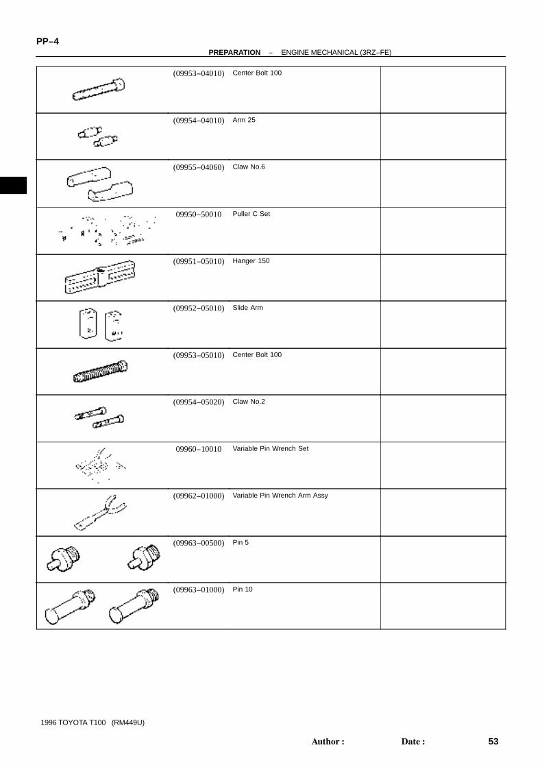
PP−4−PREPARATION ENGINE MECHANICAL (3RZ−FE)
53Author�: Date�:
1996 TOYOTA T100 (RM449U)
(09953−04010) Center Bolt 100
(09954−04010) Arm 25
(09955−04060) Claw No.6
09950−50010 Puller C Set
(09951−05010) Hanger 150
(09952−05010) Slide Arm
(09953−05010) Center Bolt 100
(09954−05020) Claw No.2
09960−10010 Variable Pin Wrench Set
(09962−01000) Variable Pin Wrench Arm Assy
(09963−00500) Pin 5
(09963−01000) Pin 10
https://www.truck-manuals.net/

PP0G7−02
−PREPARATION ENGINE MECHANICAL (3RZ−FE)PP−5
1996 TOYOTA T100 (RM449U)
RECOMMENDED TOOLS09082−00050 TOYOTA Electrical Tester Set.
09200−00010 Engine Adjust Kit .
09258−00030 Hose Plug Set . Plug for the vacuum hose, fuel
hose etc.
https://www.truck-manuals.net/

PP0G8−01
PP−6−PREPARATION ENGINE MECHANICAL (3RZ−FE)
1996 TOYOTA T100 (RM449U)
EQUIPMENTCaliper gauge
CO/HC meter
Compression gauge
Connecting rod aligner
Cylinder gauge
Dial indicator
Dye penetrant
Engine tune−up tester
Heater
Magnetic finger
Micrometer
Piston ring compressor
Piston ring expander
Plastigage
Precision straight edge
Soft brush
Spring tester Valve spring
Steel square Valve spring
Thermometer
Torque wrench
V−block
Valve seat cutter
Vernier calipers
https://www.truck-manuals.net/

PP3M8−01
−PREPARATION ENGINE MECHANICAL (3RZ−FE)PP−7
1996 TOYOTA T100 (RM449U)
SSM (Special Service Materials)08826−00080 Seal Packing Black or equivalent
(FIPG)
Over the space between the cylinder
head and timing chain cover
08826−00080 Seal Packing Black or equivalent
(FIPG)
Semi−circular plug
Oil pan
Rear oil seal retainer
08833−00070 Adhesive 1324,
THREE BOND 1324 or equivalent
Spark plug tube
https://www.truck-manuals.net/

PP32X−01
PP−8−PREPARATION ENGINE MECHANICAL (5VZ−FE)
57Author�: Date�:
1996 TOYOTA T100 (RM449U)
ENGINE MECHANICAL (5VZ−FE)SST (Special Service Tools)
09201−10000 Valve Guide Bushing Remover &
Replacer Set
(09201−01060) Valve Guide Bushing Remover &
Replacer 6
09201−41020 Valve Stem Oil Seal Replacer
09202−70020 Valve Spring Compressor
(09202−00010) Attachment
09213−54015 Crankshaft Pulley Holding Tool
(90119−08216) Bolt
09222−30010 Connecting Rod Bushing Remover
& Replacer
09223−15030 Oil Seal & Bearing Replacer Crankshaft rear oil seal
09228−07501 Oil Filter Wrench
09248−55040 Valve Clearance Adjust Tool Set
(09248−05410) Valve Lifter Press
https://www.truck-manuals.net/

−PREPARATION ENGINE MECHANICAL (5VZ−FE)PP−9
58Author�: Date�:
1996 TOYOTA T100 (RM449U)
(09248−05420) Valve Lifter Stopper
09330−00021 Companion Flange Holding Tool Crankshaft pulley
09816−30010 Oil Pressure Switch Socket Oil pressure switch
09843−18020 Diagnosis Check Wire
09950−50010 Puller C Set
(09951−05010) Hanger 150 Crankshaft pulley
Crankshaft timing pulley
(09952−05010) Slide Arm Crankshaft pulley
Crankshaft timing pulley
(09953−05020) Center Bolt 150 Crankshaft pulley
Crankshaft timing pulley
(09954−05010) Claw No.1 Crankshaft timing pulley
(09954−05030) Claw No.3 Crankshaft pulley
09950−70010 Handle Set
(09951−07150) Handle 150 Crankshaft rear oil seal
Valve guide bushing
09960−10010 Variable Pin Wrench Set
https://www.truck-manuals.net/

PP−10−PREPARATION ENGINE MECHANICAL (5VZ−FE)
59Author�: Date�:
1996 TOYOTA T100 (RM449U)
(09962−01000) Variable Pin Wrench Arm Assy Camshaft timing pulley
Camshaft sub−gear
(09963−01000) Pin 10 Camshaft timing pulley
(09963−00600) Pin 6 Camshaft sub−gear
https://www.truck-manuals.net/

PP017−03
−PREPARATION ENGINE MECHANICAL (5VZ−FE)PP−11
1996 TOYOTA T100 (RM449U)
RECOMMENDED TOOLS09040−00010 Hexagon Wrench Set .
09090−04010 Engine Sling Device . For suspending engine
09200−00010 Engine Adjust Kit .
09258−00030 Hose Plug Set . Plug for the vacuum hose, fuel hose
etc.
09904−00010 Expander Set .
https://www.truck-manuals.net/

PP018−03
PP−12−PREPARATION ENGINE MECHANICAL (5VZ−FE)
1996 TOYOTA T100 (RM449U)
EQUIPMENTCaliper gauge
CO/HC meter
Compression gauge
Connecting rod aligner
Cylinder gauge
Dial indicator
Dye penetrant
Timing light Ignition timing
OBDII scan tool Engine speed
Heater
Magnetic finger
Micrometer
Piston ring compressor
Piston ring expander
Plastigage
Precision straight edge
Soft brush
Spring tester Valve spring
Steel square Valve spring
Thermometer
Torque wrench
Valve seat cutter
Vernier calipers
https://www.truck-manuals.net/

PP3M9−01
−PREPARATION ENGINE MECHANICAL (5VZ−FE)PP−13
1996 TOYOTA T100 (RM449U)
SSM (Special Service Materials)08826−00080 Seal Packing Black or equivalent
(FIPG)
08826−00100 Seal Packing 1282B,
THREE BOND 1282B or equivalent
(FIPG)
08833−00070 Adhesive 1324,
THREE BOND 1324 or equivalent
08833−00080 Adhesive 1344
THREE BOND 1344
LOCTITE 242 or equivalent
https://www.truck-manuals.net/

PP0GA−02
PP−14−PREPARATION EMISSION CONTROL (3RZ−FE)
63Author�: Date�:
1996 TOYOTA T100 (RM449U)
EMISSION CONTROL (3RZ−FE)RECOMMENDED TOOLS
09082−00050 TOYOTA Electrical Tester Set.
https://www.truck-manuals.net/

PP0GB−01
−PREPARATION EMISSION CONTROL (3RZ−FE)PP−15
1996 TOYOTA T100 (RM449U)
EQUIPMENTTachometer
Torque wrench
Vacuum gauge
https://www.truck-manuals.net/

PP32Z−01
PP−16−PREPARATION EMISSION CONTROL (5VZ−FE)
65Author�: Date�:
1996 TOYOTA T100 (RM449U)
EMISSION CONTROL (5VZ−FE)SST (Special Service Tools)
09843−18020 Diagnosis Check Wire
https://www.truck-manuals.net/

PP014−04
−PREPARATION EMISSION CONTROL (5VZ−FE)PP−17
1996 TOYOTA T100 (RM449U)
RECOMMENDED TOOLS09082−00040 TOYOTA Electrical Tester.
https://www.truck-manuals.net/

PP018−04
PP−18−PREPARATION EMISSION CONTROL (5VZ−FE)
1996 TOYOTA T100 (RM449U)
EQUIPMENTOBDII scan tool Engine speed
Torque wrench
Vacuum gauge
https://www.truck-manuals.net/

PP0GC−02
−PREPARATION MFI (3RZ−FE)PP−19
68Author�: Date�:
1996 TOYOTA T100 (RM449U)
MFI (3RZ−FE)SST (Special Service Tools)
09268−41046 Injection Measuring Tool Set
(09268−41091) NO.7 Union
(90405−09015) No.1 Union
09268−45012 EFI Fuel Pressure Gauge
09631−22020 Power Steering Hose Nut
14 x 17 mm Wrench Set
Fuel line flare nut
09816−30010 Oil Pressure Switch Socket Knock sensor
09842−30070 Wiring ”F” EFI Inspection
09843−18020 Diagnosis Check Wire
https://www.truck-manuals.net/

PP0GD−02
PP−20−PREPARATION MFI (3RZ−FE)
1996 TOYOTA T100 (RM449U)
RECOMMENDED TOOLS09200−00010 Engine Adjust Kit .
09258−00030 Hose Plug Set . Plug for vacuum hose, fuel hose
etc.
09082−00050 TOYOTA Electrical Tester Set.
https://www.truck-manuals.net/

PP0GE−02
−PREPARATION MFI (3RZ−FE)PP−21
1996 TOYOTA T100 (RM449U)
EQUIPMENTCarburetor cleaner Throttle body
Graduated cylinder Injector
Heater
Soft brush Throttle body
Sound scope Injector
Tachometer
Thermometer
Torque wrench
https://www.truck-manuals.net/

PP330−01
PP−22−PREPARATION SFI (5VZ−FE)
71Author�: Date�:
1996 TOYOTA T100 (RM449U)
SFI (5VZ−FE)SST (Special Service Tools)
09268−41046 Injection Measuring Tool Set
(09268−41091) NO.7 Union
(09268−52011) Injection Measuring Attachment
09268−45012 EFI Fuel Pressure Gauge
09631−22020 Power Steering Hose Nut
14 x 17 mm Wrench Set
Fuel line flare nut
09816−30010 Oil Pressure Switch Socket
09842−30070 Wiring ”F” EFI Inspection
09843−18020 Diagnosis Check Wire
https://www.truck-manuals.net/

PP01E−04
−PREPARATION SFI (5VZ−FE)PP−23
1996 TOYOTA T100 (RM449U)
RECOMMENDED TOOLS09082−00050 TOYOTA Electrical Tester Set.
09200−00010 Engine Adjust Kit .
09258−00030 Hose Plug Set . Plug for the vacuum hose, fuel hose
etc.
https://www.truck-manuals.net/

PP01F−02
PP−24−PREPARATION SFI (5VZ−FE)
1996 TOYOTA T100 (RM449U)
EQUIPMENTOBDII scan tool Engine speed
Graduated cylinder Injector
Carburetor cleaner Throttle body
Sound scope Injector
Torque wrench
Soft brush Throttle body
https://www.truck-manuals.net/

PP3MA−01
−PREPARATION COOLING (3RZ−FE)PP−25
74Author�: Date�:
1996 TOYOTA T100 (RM449U)
COOLING (3RZ−FE)SST (Special Service Tools)
09230−00010 Radiator Service Tool Set
(09231−00010) Lock Plate Bender
(09231−00020) Lock Plate Bender
(09231−00030) Plug Handle
(09231−00040) No.1 Plug
(09231−00050) No.2 Plug
09230−01010 Radiator Service Tool Set
(09231−01010) Overhaul Handle
(09231−01020) Punch Assembly
(09231−01030) Claw
(09231−00060) No.3 Plug
https://www.truck-manuals.net/

PP0GF−02
PP−26−PREPARATION COOLING (3RZ−FE)
1996 TOYOTA T100 (RM449U)
EQUIPMENTHeater Thermostat
Radiator cap tester
Thermometer Thermostat
Torque wrench
https://www.truck-manuals.net/

PP0GG−01
−PREPARATION COOLING (3RZ−FE)PP−27
1996 TOYOTA T100 (RM449U)
COOLANTItem Capacity Classification
Engine coolant
(w/ Heater)
8.7 liters (9.2 US qts, 7.7 lmp. qts) Ethylene−glycol base
https://www.truck-manuals.net/

PP3MB−01
PP−28−PREPARATION COOLING (5VZ−FE)
77Author�: Date�:
1996 TOYOTA T100 (RM449U)
COOLING (5VZ−FE)SST (Special Service Tools)
09843−18020 Diagnosis Check Wire
https://www.truck-manuals.net/

PP3MC−01
−PREPARATION COOLING (5VZ−FE)PP−29
1996 TOYOTA T100 (RM449U)
RECOMMENDED TOOLS09042−00010 Torx Socket T30 .
https://www.truck-manuals.net/

PP01J−02
PP−30−PREPARATION COOLING (5VZ−FE)
1996 TOYOTA T100 (RM449U)
EQUIPMENTHeater
Radiator cap tester
Thermometer
Torque wrench
https://www.truck-manuals.net/

PP336−02
−PREPARATION COOLING (5VZ−FE)PP−31
1996 TOYOTA T100 (RM449U)
COOLANTItem Capacity Classification
2WD
M/T
A/T
4WD
M/T
A/T
10.0 liters (10.6 US qts, 8.8 lmp. qts)
9.9 liters (10.5 US qts, 8.7 lmp. qts)
10.0 liters (10.6 US qts, 8.8 lmp. qts)
10.2 liters (10.8 US qts, 9.0 lmp. qts)
Ethylene−glycol base
https://www.truck-manuals.net/

PP337−01
PP−32−PREPARATION COOLING (5VZ−FE)
1996 TOYOTA T100 (RM449U)
SSM (Special Service Materials)08826−00100 Seal Packing 1282B,
THREE BOND 1282B or equivalent
(FIPG)
https://www.truck-manuals.net/

PP0GH−01
−PREPARATION LUBRICATION (3RZ−FE)PP−33
82Author�: Date�:
1996 TOYOTA T100 (RM449U)
LUBRICATION (3RZ−FE)SST (Special Service Tools)
09228−07501 Oil Filter Wrench
https://www.truck-manuals.net/

PP0GI−01
PP−34−PREPARATION LUBRICATION (3RZ−FE)
1996 TOYOTA T100 (RM449U)
RECOMMENDED TOOLS09200−00010 Engine Adjust Kit .
https://www.truck-manuals.net/

PP0GJ−02
−PREPARATION LUBRICATION (3RZ−FE)PP−35
1996 TOYOTA T100 (RM449U)
EQUIPMENTOil pressure gauge
Precision straight edge Oil pump
Torque wrench
https://www.truck-manuals.net/

PP0GK−01
PP−36−PREPARATION LUBRICATION (3RZ−FE)
1996 TOYOTA T100 (RM449U)
LUBRICANTItem Capacity Classification
Engine oil
Dry fill
Drain and refill
w/ Oil filter change
w/o Oil filter change
6.0 liters (6.3 US qts, 5.3 lmp. qts)
5.3 liters (5.6 US qts, 4.7 lmp. qts)
5.0 liters (5.3 US qts, 4.4 lmp. qts)
API grade SH, Energy−Conserving II multigrade
engine oil or ILSAC multigrade engine oil and
recommended viscosity oil, with SAE 5W−30
being preferred engine oil
https://www.truck-manuals.net/
PP33E−01
−PREPARATION LUBRICATION (3RZ−FE)PP−37
1996 TOYOTA T100 (RM449U)
SSM (Special Service Materials)08833−00080 Adhesive 1344
THREE BOND 1344
LOCTITE 242 or equivalent
https://www.truck-manuals.net/
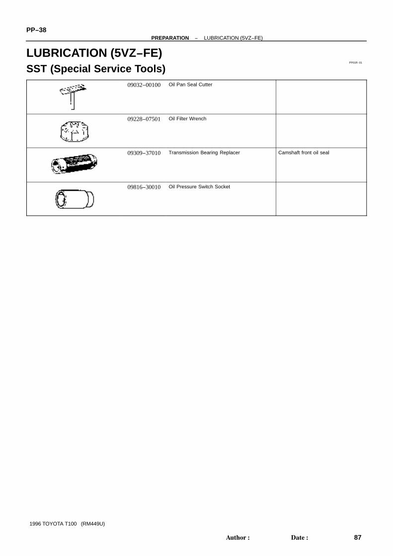
PP01R−01
PP−38−PREPARATION LUBRICATION (5VZ−FE)
87Author�: Date�:
1996 TOYOTA T100 (RM449U)
LUBRICATION (5VZ−FE)SST (Special Service Tools)
09032−00100 Oil Pan Seal Cutter
09228−07501 Oil Filter Wrench
09309−37010 Transmission Bearing Replacer Camshaft front oil seal
09816−30010 Oil Pressure Switch Socket
https://www.truck-manuals.net/

PP01S−02
−PREPARATION LUBRICATION (5VZ−FE)PP−39
1996 TOYOTA T100 (RM449U)
RECOMMENDED TOOLS09200−00010 Engine Adjust Kit .
https://www.truck-manuals.net/

PP01T−02
PP−40−PREPARATION LUBRICATION (5VZ−FE)
1996 TOYOTA T100 (RM449U)
EQUIPMENTOil pressure gauge
Precision straight edge Oil pump
Torque wrench
https://www.truck-manuals.net/

PP01U−07
−PREPARATION LUBRICATION (5VZ−FE)PP−41
1996 TOYOTA T100 (RM449U)
LUBRICANTItem Capacity Classification
Engine oil
2WD
Dry fill
Drain and refill
w/ Oil filter change
w/o Oil filter change
4WD
Dry fill
Drain and refill
w/ Oil filter change
w/o Oil filter change
5.9 liters (6.2 US qts, 5.2 lmp. qts)
5.2 liters (5.5 US qts, 4.6 lmp. qts)
5.2 liters (5.5 US qts, 4.6 lmp. qts)
4.9 liters (5.2 US qts, 4.3 lmp. qts)
5.5 liters (5.8 US qts, 4.8 lmp. qts)
4.7 liters (5.0 US qts, 4.1 lmp. qts)
4.4 liters (4.7 US qts, 3.9 lmp. qts)
API grade SH, Energy−Conserving II multigrade
engine oil or ILSAC multigrade engine oil and
recommended viscosity oil, with SAE 5W−30
being preferred engine oil
https://www.truck-manuals.net/
PP33F−01
PP−42−PREPARATION LUBRICATION (5VZ−FE)
1996 TOYOTA T100 (RM449U)
SSM (Special Service Materials)08826−00080 Seal Packing Black or equivalent
(FIPG)
08833−00080 Adhesive 1344
THREE BOND 1344
LOCTITE 242 or equivalent
https://www.truck-manuals.net/

PP0GM−02
−PREPARATION IGNITION (3RZ−FE)PP−43
92Author�: Date�:
1996 TOYOTA T100 (RM449U)
IGNITION (3RZ−FE)RECOMMENDED TOOLS
09082−00050 TOYOTA Electrical Tester Set.
09200−00010 Engine Adjust Kit .
https://www.truck-manuals.net/
PP0GN−03
PP−44−PREPARATION IGNITION (3RZ−FE)
1996 TOYOTA T100 (RM449U)
EQUIPMENTSpark plug cleaner
Torque wrench
https://www.truck-manuals.net/

PP3MD−01
−PREPARATION IGNITION (3RZ−FE)PP−45
1996 TOYOTA T100 (RM449U)
SSM (Special Service Materials)08826−00080 Seal Packing Black or equivalent
(FIPG)
https://www.truck-manuals.net/

PP01Z−03
PP−46−PREPARATION IGNITION (5VZ−FE)
95Author�: Date�:
1996 TOYOTA T100 (RM449U)
IGNITION (5VZ−FE)RECOMMENDED TOOLS
09082−00050 TOYOTA Electrical Tester Set.
09200−00010 Engine Adjust Kit .
https://www.truck-manuals.net/

PP020−02
−PREPARATION IGNITION (5VZ−FE)PP−47
1996 TOYOTA T100 (RM449U)
EQUIPMENTSpark plug cleaner
https://www.truck-manuals.net/

PP0GO−01
PP−48−PREPARATION STARTING (3RZ−FE)
97Author�: Date�:
1996 TOYOTA T100 (RM449U)
STARTING (3RZ−FE)SST (Special Service Tools)
09286−46011 Injection Pump Spline Shaft
Puller
Armature bearing
09810−38140 Starter Magnet Switch Nut Wrench
14
Terminal nut
09820−00030 Alternator Rear Bearing Replacer Armature rear bearing
https://www.truck-manuals.net/

PP0GP−02
−PREPARATION STARTING (3RZ−FE)PP−49
1996 TOYOTA T100 (RM449U)
RECOMMENDED TOOLS09082−00050 TOYOTA Electrical Tester Set.
https://www.truck-manuals.net/

PP0GQ−01
PP−50−PREPARATION STARTING (3RZ−FE)
1996 TOYOTA T100 (RM449U)
EQUIPMENTDial indicator Commutator
Magnetic finger Steel ball
Press Magnetic switch terminal kit
Pull scale Brush spring
Sandpaper Commutator
Torque wrench
V−block Commutator
Vernier calipers Commutator, Brush
https://www.truck-manuals.net/
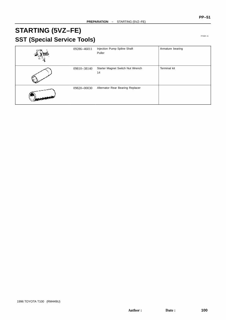
PP3ME−01
−PREPARATION STARTING (5VZ−FE)PP−51
100Author�: Date�:
1996 TOYOTA T100 (RM449U)
STARTING (5VZ−FE)SST (Special Service Tools)
09286−46011 Injection Pump Spline Shaft
Puller
Armature bearing
09810−38140 Starter Magnet Switch Nut Wrench
14
Terminal kit
09820−00030 Alternator Rear Bearing Replacer
https://www.truck-manuals.net/

PP025−04
PP−52−PREPARATION STARTING (5VZ−FE)
1996 TOYOTA T100 (RM449U)
RECOMMENDED TOOLS09082−00050 TOYOTA Electrical Tester Set.
https://www.truck-manuals.net/

PP026−02
−PREPARATION STARTING (5VZ−FE)PP−53
1996 TOYOTA T100 (RM449U)
EQUIPMENTDial indicator Commutator
Magnetic finger Steel ball
Press Magnetic switch terminal kit
Pull scale Brush spring
Sandpaper Commutator
Torque wrench
V−block Commutator
Vernier calipers Commutator, Brush
https://www.truck-manuals.net/

PP0GR−01
PP−54−PREPARATION CHARGING (3RZ−FE)
103Author�: Date�:
1996 TOYOTA T100 (RM449U)
CHARGING (3RZ−FE)SST (Special Service Tools)
09285−76010 Injection Pump Camshaft Bearing
Cone Replacer
Rotor rear bearing cover
09286−46011 Injection Pump Spline Shaft
Puller
Rectifier end frame
09820−00021 Alternator Rear Bearing Puller
09820−00030 Alternator Rear Bearing Replacer
09820−63010 Alternator Pulley Set Nut Wrench
Set
09950−60010 Replacer Set
(09951−00260) Replacer 26 Rotor front bearing
(09951−00500) Replacer 50 Rotor front bearing
(09952−06010) Adapter Rotor front bearing
https://www.truck-manuals.net/
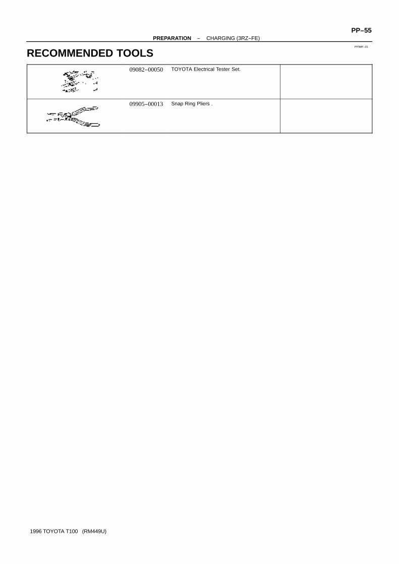
PP3MF−01
−PREPARATION CHARGING (3RZ−FE)PP−55
1996 TOYOTA T100 (RM449U)
RECOMMENDED TOOLS09082−00050 TOYOTA Electrical Tester Set.
09905−00013 Snap Ring Pliers .
https://www.truck-manuals.net/

PP0GT−02
PP−56−PREPARATION CHARGING (3RZ−FE)
1996 TOYOTA T100 (RM449U)
EQUIPMENTAmmeter (A)
Belt tension gauge
Torque wrench
Vernier calipers Rotor (Slip ring), Brush
https://www.truck-manuals.net/

PP33H−02
−PREPARATION CHARGING (5VZ−FE)PP−57
106Author�: Date�:
1996 TOYOTA T100 (RM449U)
CHARGING (5VZ−FE)SST (Special Service Tools)
09285−76010 Injection Pump Camshaft Bearing
Cone Replacer
Rotor rear bearing cover
09286−46011 Injection Pump Spline Shaft
Puller
Rectifier end frame
09820−00021 Alternator Rear Bearing Puller
09820−00030 Alternator Rear Bearing Replacer
09820−63010 Alternator Pulley Set Nut Wrench
Set
09950−60010 Replacer Set
(09951−00260) Replacer 26 Rotor front bearing
(09952−06010) Adapter Rotor front bearing
(09951−00500) Replacer 50 Rotor front bearing
https://www.truck-manuals.net/

PP3MG−01
PP−58−PREPARATION CHARGING (5VZ−FE)
1996 TOYOTA T100 (RM449U)
RECOMMENDED TOOLS09082−00050 TOYOTA Electrical Tester Set.
09905−00013 Snap Ring Pliers .
https://www.truck-manuals.net/

PP02C−04
−PREPARATION CHARGING (5VZ−FE)PP−59
1996 TOYOTA T100 (RM449U)
EQUIPMENTAmmeter (A)
Belt tension gauge
Torque wrench
Vernier calipers Rotor (Slip ring), Brush
https://www.truck-manuals.net/

PP0EN−03
PP−60−PREPARATION CLUTCH
109Author�: Date�:
1996 TOYOTA T100 (RM449U)
CLUTCHSST (Special Service Tools)
09023−00100 Union Nut Wrench 10 mm Clutch line
09301−00110 Clutch Guide Tool
09303−35011 Input Shaft Front Bearing Puller
09304−30012 Input Shaft Front Bearing
Replacer
09333−00013 Clutch Diaphragm Spring Aligner
https://www.truck-manuals.net/

PP0EO−03
−PREPARATION CLUTCHPP−61
1996 TOYOTA T100 (RM449U)
RECOMMENDED TOOLS09082−00050 TOYOTA Electrical Tester Set.
09905−00013 Snap Ring Pliers .
https://www.truck-manuals.net/

PP0EP−01
PP−62−PREPARATION CLUTCH
1996 TOYOTA T100 (RM449U)
EQUIPMENTCaliper
Dial indicator
Torque wrench
https://www.truck-manuals.net/

PP3LR−01
−PREPARATION MANUAL TRANSMISSION (R150, R150F)PP−63
112Author�: Date�:
1996 TOYOTA T100 (RM449U)
MANUAL TRANSMISSION (R150, R150F)SST (Special Service Tools)
09201−10000 Valve Guide Bushing Remover &
Replacer Set
2WD:
Speedometer driven gear oil seal
(09201−01080) Valve Guide Bushing Remover &
Replacer 8
09309−35010 Transmission Rear Bearing
Replacer
2WD:
Output shaft rear bearing
Output shaft center bearing
09316−60011 Transmission & Transfer Bearing
Replacer
(09316−00011) Replacer Pipe Output shaft rear bearing
Gear spline piece No.5
(09316−00031) Replacer ”B” 5th gear
(09316−00071) Replacer ”F” 4WD:
Output shaft rear bearing
Output shaft center bearing
09506−35010 Differential Drive Pinion Rear
Bearing Replacer
Input shaft bearing
09921−00010 Spring Tension Tool 2WD:
Speedometer driven gear oil seal
09950−00020 Bearing Remover
09950−60010 Replacer Set
(09951−00510) Replacer 51 Front bearing retainer oil seal
https://www.truck-manuals.net/

PP−64−PREPARATION MANUAL TRANSMISSION (R150, R150F)
113Author�: Date�:
1996 TOYOTA T100 (RM449U)
(09951−00570) Replacer 57 Extension housing oil seal
Transfer adaptor oil seal
(09951−00620) Replacer 62 Counter rear bearing
09950−70010 Handle Set
(09951−07150) Handle 150
https://www.truck-manuals.net/

PP3LS−01
−PREPARATION MANUAL TRANSMISSION (R150, R150F)PP−65
1996 TOYOTA T100 (RM449U)
RECOMMENDED TOOLS09031−00030 Pin Punch .
09042−00020 Torx Socket T40 .
09905−00012 Snap Ring No.1 Expander .
https://www.truck-manuals.net/

PP0ES−01
PP−66−PREPARATION MANUAL TRANSMISSION (R150, R150F)
1996 TOYOTA T100 (RM449U)
EQUIPMENTDial indicator
Micrometer
Torque wrench
Feeler gauge
Magnetic finger
https://www.truck-manuals.net/

PP0ET−01
−PREPARATION MANUAL TRANSMISSION (R150, R150F)PP−67
1996 TOYOTA T100 (RM449U)
LUBRICANTItem Capacity Classification
Manual transmission oil 2WD:
4WD:
2.6 liters (2.7 US qts, 2.3 Imp. qts)
2.2 liters (2.3 US qts, 1.9 Imp. qts)
API GL−4 or GL−5
SAE 75W−90
https://www.truck-manuals.net/

PP33I−01
PP−68−PREPARATION MANUAL TRANSMISSION (R150, R150F)
1996 TOYOTA T100 (RM449U)
SSM (Special Service Materials)08826−00090 Seal Packing 1281,
THREE BOND 1281 or equivalent
(FIPG)
08833−00080 Adhesive 1344
THREE BOND 1344
LOCTITE 242 or equivalent
https://www.truck-manuals.net/

PP3LP−01
−PREPARATION MANUAL TRANSMISSION (W59)PP−69
118Author�: Date�:
1996 TOYOTA T100 (RM449U)
MANUAL TRANSMISSION (W59)SST (Special Service Tools)
09201−10000 Valve Guide Bushing Remover &
Replacer Set
Speedometer driven gear oil seal
(09201−01080) Valve Guide Bushing Remover &
Replacer 8
09308−00010 Oil Seal Puller Output shaft rear bearing outer race
09308−10010 Oil Seal Puller Extension housing oil seal
09312−20011 Transmission Gear Remover &
Replacer
5th gear
Output shaft rear bearing
Reverse gear
(09313−00010) Reverse Gear Remover
(09313−00030) Rear Bearing Replacer
(09313−00040) Plate ”A”
(09313−00050) Plate ”B”
09316−60011 Transmission & Transfer Bearing
Replacer
No.3 clutch hub
Counter gear center bearing outer
race
(09316−00011) Replacer Pipe
(09316−00071) Replacer ”F”
https://www.truck-manuals.net/

PP−70−PREPARATION MANUAL TRANSMISSION (W59)
119Author�: Date�:
1996 TOYOTA T100 (RM449U)
09506−35010 Differential Drive Pinion Rear
Bearing Replacer
Input shaft bearing
Output shaft center bearing
09921−00010 Spring Tension Tool Speedometer driven gear oil seal
09950−00020 Bearing Remover
09950−60010 Replacer Set
(09951−00440) Replacer 44 Front bearing retainer oil seal
(09951−00510) Replacer 51 Counter gear center bearing outer
race
(09951−00560) Replacer 56 Output shaft rear bearing outer race
Extension housing oil seal
09950−70010 Handle Set
(09951−07150) Handle 150
https://www.truck-manuals.net/

PP3LQ−01
−PREPARATION MANUAL TRANSMISSION (W59)PP−71
1996 TOYOTA T100 (RM449U)
RECOMMENDED TOOLS09031−00030 Pin Punch .
09042−00020 Torx Socket T40 .
09905−00012 Snap Ring No.1 Expander .
https://www.truck-manuals.net/

PP0BG−01
PP−72−PREPARATION MANUAL TRANSMISSION (W59)
1996 TOYOTA T100 (RM449U)
EQUIPMENTDial indicator
Calipers
Micrometer
Torque wrench
Feeler gauge
Magnetic finger
https://www.truck-manuals.net/

PP0BH−01
−PREPARATION MANUAL TRANSMISSION (W59)PP−73
1996 TOYOTA T100 (RM449U)
LUBRICANTItem Capacity Classification
Manual transmission oil 2.6 liters (2.7 US qts, 2.3 Imp. qts)API GL−4 or GL−5
SAE 75W−90
https://www.truck-manuals.net/

PP33J−01
PP−74−PREPARATION MANUAL TRANSMISSION (W59)
1996 TOYOTA T100 (RM449U)
SSM (Special Service Materials)08826−00090 Seal Packing 1281,
THREE BOND 1281 or equivalent
(FIPG)
08833−00080 Adhesive 1344
THREE BOND 1344
LOCTITE 242 or equivalent
https://www.truck-manuals.net/

PP33K−01
−PREPARATION AUTOMATIC TRANSMISSIONPP−75
124Author�: Date�:
1996 TOYOTA T100 (RM449U)
AUTOMATIC TRANSMISSIONSST (Special Service Tools)
09032−00100 Oil Pan Seal Cutter
09201−10000 Valve Guide Bushing Remover &
Replacer Set
Speedometer driven gear oil seal
(09201−01080) Valve Guide Bushing Remover &
Replacer 8
09308−10010 Oil Seal Puller
09325−40010 Transmission Oil Plug
09350−30020 TOYOTA Automatic Transmission
Tool Set
(09351−32010) One−way Clutch Test Tool
(09351−32020) Stator Stopper
09921−00010 Spring Tension Tool Speedometer driven gear oil seal
https://www.truck-manuals.net/

PP0FM−03
PP−76−PREPARATION AUTOMATIC TRANSMISSION
1996 TOYOTA T100 (RM449U)
RECOMMENDED TOOLS09031−00030 Pin Punch .
09082−00040 TOYOTA Electrical Tester.
09905−00012 Snap Ring No.1 Expander .
https://www.truck-manuals.net/

PP0FN−02
−PREPARATION AUTOMATIC TRANSMISSIONPP−77
1996 TOYOTA T100 (RM449U)
EQUIPMENTOBD II scan tool
Ohmmeter
Voltmeter
Vernier calipers Torque converter clutch
Dial indicator or dial indicator with magnetic base Drive plate
Straight edge Torque converter clutch
Torque wrench
https://www.truck-manuals.net/

PP0FO−06
PP−78−PREPARATION AUTOMATIC TRANSMISSION
1996 TOYOTA T100 (RM449U)
LUBRICANTItem Capacity Classification
Automatic transmission fluid
(A340E)
Dry fill
Drain and refill
(A340E)
Dry fill
Drain and refill
7.2 liters (7.6 US qts, 6.3 Imp.qts)
1.6 liters (1.7 US qts, 1.4 Imp.qts)
7.6 liters (8.0 US qts, 6.7 Imp.qts)
2.0 liters (2.1 US qts, 1.8 Imp.qts)
ATF DEXRON ®II
https://www.truck-manuals.net/
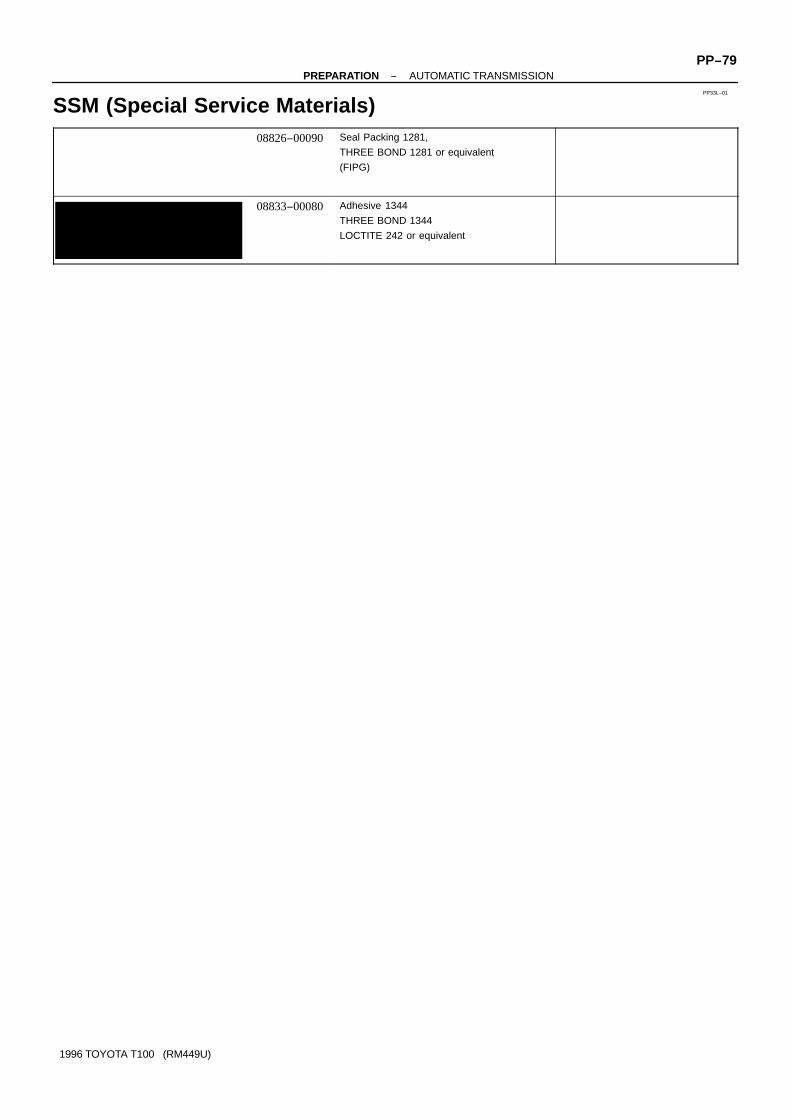
PP33L−01
−PREPARATION AUTOMATIC TRANSMISSIONPP−79
1996 TOYOTA T100 (RM449U)
SSM (Special Service Materials)08826−00090 Seal Packing 1281,
THREE BOND 1281 or equivalent
(FIPG)
08833−00080 Adhesive 1344
THREE BOND 1344
LOCTITE 242 or equivalent
https://www.truck-manuals.net/

PP3M7−01
PP−80−PREPARATION TRANSFER
129Author�: Date�:
1996 TOYOTA T100 (RM449U)
TRANSFERSST (Special Service Tools)
09223−15020 Oil Seal & Bearing Replacer Planetary gear outer bearing
09223−22010 Crankshaft Front Oil Seal
Replacer
Front retainer oil seal
09304−12012 Input Shaft Front Bearing
Replacer
Shift fork shaft oil seal
09316−60011 Transmission & Transfer Bearing
Replacer
(09316−00011) Replacer Pipe High and low clutch hub
Rear output shaft bearing
Front case oil seal
(09316−00071) Replacer ”F” Rear output shaft bearing
09330−00021 Companion Flange Holding Tool Companion flange
09515−30010 Rear Wheel Bearing Replacer Planetary gear outer bearing
(09252−10010) No. 1 Replacer Handle
09550−00032 Replacer
09554−30011 Differential Oil Seal Replacer Planetary gear outer bearing
09555−55010 Differential Drive Pinion
Bearing Replacer
Planetary gear outer bearing
https://www.truck-manuals.net/

−PREPARATION TRANSFERPP−81
130Author�: Date�:
1996 TOYOTA T100 (RM449U)
09921−00010 Spring Tension Tool
09950−00020 Bearing Remover Driven sprocket rear beating
Front drive clutch sleeve
Rear output shaft bearing
https://www.truck-manuals.net/

PP33M−01
PP−82−PREPARATION TRANSFER
1996 TOYOTA T100 (RM449U)
RECOMMENDED TOOLS09031−00030 Pin Punch .
09905−00012 Snap Ring No.1 Expander .
https://www.truck-manuals.net/

PP0G2−01
−PREPARATION TRANSFERPP−83
1996 TOYOTA T100 (RM449U)
EQUIPMENTCalipers
Dial indicator
Micrometer
Torque wrench
Feeler gauge
https://www.truck-manuals.net/

PP0G3−01
PP−84−PREPARATION TRANSFER
1996 TOYOTA T100 (RM449U)
LUBRICANTItem Capacity Classification
Transfer oil 1.1 liters (1.2 US qts, 1.0 lmp.qts)API GL−4 or GL−5
SAE 75W−90
https://www.truck-manuals.net/

PP33N−01
−PREPARATION TRANSFERPP−85
1996 TOYOTA T100 (RM449U)
SSM (Special Service Materials)08826−00090 Seal Packing 1281,
THREE BOND 1281 or equivalent
(FIPG)
08833−00080 Adhesive 1344
THREE BOND 1344
LOCTITE 242 or equivalent
https://www.truck-manuals.net/

PP3LO−01
PP−86−PREPARATION PROPELLER SHAFT
135Author�: Date�:
1996 TOYOTA T100 (RM449U)
PROPELLER SHAFTSST (Special Service Tools)
09325−40010 Transmission Oil Plug Transmission to prevent oil leakage
09330−00021 Companion Flange Holding Tool Companion flange holding
09332−25010 Universal Joint Bearing Remover
& Replacer
Spider bearing removal and installa-
tion
https://www.truck-manuals.net/
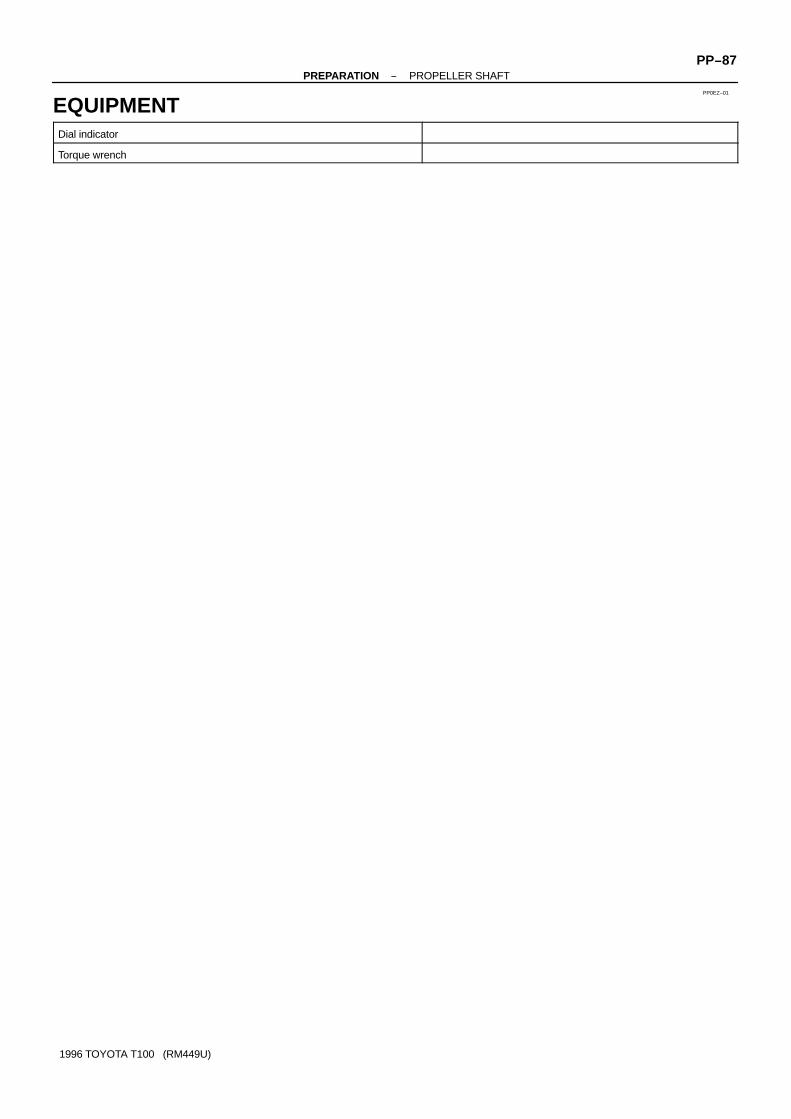
PP0EZ−01
−PREPARATION PROPELLER SHAFTPP−87
1996 TOYOTA T100 (RM449U)
EQUIPMENTDial indicator
Torque wrench
https://www.truck-manuals.net/

PP3K7−01
PP−88−PREPARATION SUSPENSION AND AXLE
137Author�: Date�:
1996 TOYOTA T100 (RM449U)
SUSPENSION AND AXLESST (Special Service Tools)
09223−56010 Crankshaft Rear Oil Seal
Replacer
Rear axle
09226−10010 Crankshaft Front & Rear Bearing
Replacer
Front differential
09308−00010 Oil Seal Puller Front axle (4WD)
Front differential
Rear axle
Rear differential
09316−12010 Transfer Bearing Replacer Rear differential
09316−20011 Transfer Bearing Replacer Front differential
09316−60011 Transmission & Transfer Bearing
Replacer
Front deifferentian
Rear axle
(09316−00041) Replacer ”C” Front differential
(09316−00051) Replacer ”D” Rear axle
09330−00021 Companion Flange Holding Tool Front differential
Rear differential
09350−20015 TOYOTA Automatic Transmission
Tool Set
Front differential
(09369−20040) Piston Spring Compressor Set
09308−10010 Oil Seal Puller Front differential
Rear differential
https://www.truck-manuals.net/

−PREPARATION SUSPENSION AND AXLEPP−89
138Author�: Date�:
1996 TOYOTA T100 (RM449U)
09504−22011 Differential Side Bearing
Replacer
Front differential
Rear differential
09506−30012 Differential Drive Pinion Rear
Bearing Cone Replacer
Front differential
09506−35010 Differential Drive Pinion Rear
Bearing Replacer
Rear differential
09521−25011 Rear Axle Shaft Puller Rear axle
09523−36010 Rear Axle Hub Guide Tool Rear differential
(09558−10010) Rear Axle Shaft Oil Seal
Replacer−
09554−14010 Differential Oil Seal Replacer Front differential
09554−30011 Differential Oil Seal Replacer Front differential
09556−22010 Drive Pinion Front Bearing
Remover
Front differential
Rear differential
09556−30010 Drive Pinion Front Bearing
Remover
Front differential
09607−60020 Front Wheel Adjusting Nut Wrench Front axle (4WD)
09628−62011 Ball Joint Puller Front axle
Front suspension (4WD)
09636−20010 Upper Ball Joint Dust Cover
Replacer
Front differential
https://www.truck-manuals.net/

PP−90−PREPARATION SUSPENSION AND AXLE
139Author�: Date�:
1996 TOYOTA T100 (RM449U)
09649−17010 Steering Knuckle Tool Rear differential
09650−17011 Hub Bolt Remover Rear axle
09710−26011 Front Suspension Bushing Tool
Set
Front suspension (4WD)
(09710−05041) Gate
(09710−05051) Remover
(09710−05061) Replacer
(09710−05081) Rear Base
09710−30021 Suspension Bushing Tool Set Front suspension (2WD)
(09710−03031) Bushing Remover
(09710−03041) Bushing Remover Base
(09710−03051) Bushing Replacer
(09710−03061) Bushing Replacer Base
09710−30055 Suspension Arm Bushing Remover Front differential
https://www.truck-manuals.net/

−PREPARATION SUSPENSION AND AXLEPP−91
140Author�: Date�:
1996 TOYOTA T100 (RM449U)
09726−27012 Front Suspension Arm Bushing
Remover & Replacer
Front suspension (4WD)
(09726−02041) Replacer
(09726−02051) Remover & Replacer
(09726−02061) No.2 Base
09726−35011 Front Lower Arm Bushing Remover
& Replacer
Front suspension (2WD)
09751−36011 Brake Line Union Nut 10 x 12 mm
Wrench
Rear axle
09910−00015 Puller Set Front differential
(09911−00011) Puller Clamp
(09912−00010) Puller Slide Hammer
(09914−00011) Rear Axle Shaft Puller
Attachment
09950−00020 Bearing Remover Front differential
Rear differential
09950−30010 Puller A Set Front differential
Rear differential
09950−40010 Puller B Set
https://www.truck-manuals.net/

PP−92−PREPARATION SUSPENSION AND AXLE
141Author�: Date�:
1996 TOYOTA T100 (RM449U)
09950−60010 Replacer Set Front differential
Rear differential
Front axle
Rear axle
(09951−00360) Replacer 36 Front axle (4WD)
(09951−00370) Replacer 37 Front differential
(09951−00450) Replacer 45 Rear differential
(09951−00480) Replacer 48 Front axle (2WD)
Front differential
Rear differential
(09951−00500) Replacer 50 Front axle (4WD)
(09951−00530) Replacer 53 Front suspension (4WD)
(09951−00560) Replacer 56 Rear axle
(09951−00610) Replacer 61 Rear axle
09950−60020 Replacer Set No.2 Front axle (4WD)
Front differential
Rear differrential
(09951−00710) Replacer 71 Front axle (2WD)
Front differential
Rear differential
(09951−00720) Replacer 72 Front axle (4WD)
(09951−00790) Replacer 79 Front differential
https://www.truck-manuals.net/

−PREPARATION SUSPENSION AND AXLEPP−93
142Author�: Date�:
1996 TOYOTA T100 (RM449U)
(09951−00810) Replacer 81 Front axle (4WD)
(09951−00890) Replacer 89 Rear axle
(09951−00910) Replacer 91 Front axle (4WD)
Rear differential
09950−70010 Handle Set Front axle
Front differential
Rear differential
Rear axle
(09951−07100) Handle 100 Front axle (4WD)
(09951−07150) Handle 150 Front axle
Front differential
Rear axle
Rear differential
(09951−07200) Handle 200 Front suspension(4WD)
https://www.truck-manuals.net/

PP0F6−01
PP−94−PREPARATION SUSPENSION AND AXLE
1996 TOYOTA T100 (RM449U)
RECOMMENDED TOOLS09905−00012 Snap Ring No.1 Expander .
09905−00013 Snap Ring Pliers .
09025−00010 Torque Wrench (30 kgf−cm)
09031−00030 Pin Punch .
09044−00010 Torx Socket E14 .
09082−00040 TOYOTA Electrical Tester.
https://www.truck-manuals.net/

PP0F7−01
−PREPARATION SUSPENSION AND AXLEPP−95
1996 TOYOTA T100 (RM449U)
EQUIPMENTDial indicator
Torque wrench
Drill
Spring tension gauge
Micrometer
https://www.truck-manuals.net/

PP0F8−02
PP−96−PREPARATION SUSPENSION AND AXLE
1996 TOYOTA T100 (RM449U)
LUBRICANTItem Capacity Classification
Drive shaft
Outboard joint grease 176 − 186 g (6.21 − 6.56 oz.)
Inboard joint grease270 − 280 g (9.52 − 9.88 oz.)
Front differential 1.86 liters (1.97 US qts, 1.64 lmp.qts)Hypoid gear oil API GL−5
75W−90
Rear differential2.35 liter (2.22 US qts, 2.67 lmp.qts)
Hypoid gear oil API GL−5
Above − 18 °C (0°F)
SAE 90
Below − 18 °C (0°F)
SAE 80W − 90 or 80W
https://www.truck-manuals.net/

PP33P−01
−PREPARATION SUSPENSION AND AXLEPP−97
1996 TOYOTA T100 (RM449U)
SSM (Special Service Materials)08826−00090 Seal Packing 1281,
THREE BOND 1281 or equivalent
(FIPG)
08833−00070 Adhesive 1324,
THREE BOND 1324 or equivalent
08833−00100 THREE BOND 1360K or equivalent
https://www.truck-manuals.net/

PP0FA−03
PP−98−PREPARATION BRAKE
147Author�: Date�:
1996 TOYOTA T100 (RM449U)
BRAKESST (Special Service Tools)
09023−00100 Union Nut Wrench 10 mm
09703−30010 Brake Shoe Return Spring Tool
09709−29017 LSPV Gauge Set <mk2>
09718−00010 Shoe Hold Down Spring Driver
09737−00010 Brake Booster Push Rod Gauge
09751−36011 Brake Line Union Nut 10 x 12 mm
Wrench
09843−18020 Diagnosis Check Wire
09990−00150 ABS Actuator Checker and
Sub−harness
09990−00200 ABS Actuator Checker Sub−harness
”C”
09990−00310 ABS Actuator Checker Sub−harness
”J”
09990−00370 ABS Actuator Checker Sheet ”L”
https://www.truck-manuals.net/

PP0FB−03
−PREPARATION BRAKEPP−99
1996 TOYOTA T100 (RM449U)
RECOMMENDED TOOLS09082−00050 TOYOTA Electrical Tester Set.
09905−00013 Snap Ring Pliers .
https://www.truck-manuals.net/

PP0FC−01
PP−100−PREPARATION BRAKE
1996 TOYOTA T100 (RM449U)
EQUIPMENTTorque wrench
Micrometor Brake disc
Dial indicator Brake disc
Vernier calipers Brake drum
https://www.truck-manuals.net/

PP0FD−01
−PREPARATION BRAKEPP−101
1996 TOYOTA T100 (RM449U)
LUBRICANTItem Capacity Classification
Brake fluid − SAE J1703 or FMVSS No.116 DOT 3
Power steering fluid − ATF DEXRON® II
https://www.truck-manuals.net/

PP33Q−01
PP−102−PREPARATION BRAKE
1996 TOYOTA T100 (RM449U)
SSM (Special Service Materials)08833−00070 Adhesive 1324,
THREE BOND 1324 or equivalent
https://www.truck-manuals.net/

PP3K3−01
−PREPARATION STEERINGPP−103
152Author�: Date�:
1996 TOYOTA T100 (RM449U)
STEERINGSST (Special Service Tools)
09223−46011 Crankshaft Front Oil Seal
Replacer
Idler arm
09236−00101 Water Pump Overhaul Tool Set
(09237−00010) Water Pump Bearing Remover &
Replacer
PS gear (2WD)
09608−04031 Front Hub Inner Bearing Cone
Replacer
PS vane pump (3RZ−FE)
09610−20012 Pitman Arm Puller Steering linkage
09611−22012 Tie Rod End Puller Steering linkage
09612−00012 Rack & Pinion Steering Rack
Housing Stand
PS gear (2WD)
09612−22011 Tilt Handle Bearing Replacer PS gear (2WD)
09612−24014 Steering Gear Housing Overhaul
Tool Set
(09613−22011) Steering Rack Shaft Bushing
Puller
PS gear (2WD)
09612−65014 Steering Worm Bearing Puller
(09612−01030) Claw ”C” PS gear (4WD)
https://www.truck-manuals.net/

PP−104−PREPARATION STEERING
153Author�: Date�:
1996 TOYOTA T100 (RM449U)
(09612−01060) Claw ”E” PS gear (2WD)
09616−00010 Steering Worm Bearing Adjusting
Socket
PS gear (2WD, 4WD)
09623−30011 Steering Worm Bearing & Oil Seal
Replacer
PS gear (2WD)
09628−62011 Ball Joint Puller PS gear (4WD)
Steering linkage
09630−00014 Power Steering Gear Housing
Overhaul Tool Set
(09631−00051) No.3 Wrench PS gear (4WD)
(09631−00121) Teflon Ring Former PS gear (4WD)
(09631−00142) Overhaul Stand PS gear (4WD)
09631−10021 Rack Stopper Wrench PS gear (2WD)
09631−10030 Oil Seal Remover PS vane pump (3RZ−FE)
09631−12071 Steering Rack Oil Seal Test Tool PS gear (2WD)
09631−20070 Seal Ring Guide PS gear (2WD)
09631−20081 Seal Ring Tool PS gear (2WD)
https://www.truck-manuals.net/

−PREPARATION STEERINGPP−105
154Author�: Date�:
1996 TOYOTA T100 (RM449U)
09631−22020 Power Steering Hose Nut
14 x 17 mm Wrench Set
PS gear (2WD, 4WD)
09631−33010 Steering Rack Cover ”I” PS gear (2WD)
09633−00020 Power Steering Hose Nut Wrench PS gear (2WD)
09640−10010 Power Steering Pressure Gauge
Set
(09641−01010) Gauge Assy On−vehicle inspection
(09641−01030) Attachment B On−vehicle inspection
(09641−01060) Attachment E On−vehicle inspection
09910−00015 Puller Set
(09911−00011) Puller Clamp Tilt steering column
(09912−00010) Puller Slide Hammer Tilt steering column
09922−10010 Variable Open Wrench PS gear (2WD)
09950−40010 Puller B Set
(09957−04010) Attachment Tilt steering column
https://www.truck-manuals.net/

PP−106−PREPARATION STEERING
155Author�: Date�:
1996 TOYOTA T100 (RM449U)
(09958−04010) Holder Tilt steering column
09950−50010 Puller C Set
(09951−05010) Hanger 150 Non−tilt steering column
Tilt steering column
(09952−05010) Slide Arm Non−tilt steering column
Tilt steering column
(09953−05020) Center Bolt 150 Non−tilt steering column
Tilt steering column
(09954−05020) Claw No.2 Non−tilt steering column
Tilt steering column
09950−60010 Replacer Set
(09951−00180) Replacer 18 PS gear (2WD)
(09951−00240) Replacer 24 PS gear (2WD)
(09951−00250) Replacer 25 PS gear (2WD)
(09951−00260) Replacer 26 PS gear (2WD)
(09951−00300) Replacer 30 Idler arm
(09951−00310) Replacer 31 PS gear (2WD)
https://www.truck-manuals.net/

−PREPARATION STEERINGPP−107
156Author�: Date�:
1996 TOYOTA T100 (RM449U)
(09951−00320) Replacer 32 PS gear (2WD)
(09951−00340) Replacer 34 PS gear (2WD, 4WD)
(09951−00360) Replacer 36 PS gear (4WD)
(09951−00410) Replacer 41 PS gear (2WD)
(09951−00420) Replacer 42 PS gear (4WD)
(09951−00430) Replacer 43 PS gear (2WD, 4WD)
(09952−06010) Adapter PS gear (2WD, 4WD)
09950−70010 Handle Set
(09951−07150) Handle 150 PS gear (2WD)
(09951−07200) Handle 200 PS gear (2WD, 4WD)
Idler arm
(09951−07360) Handle 360 PS gear (2WD)
09960−10010 Variable Pin Wrench Set
(09962−01000) Variable Pin Wrench Arm Assy PS vane pump (3RZ−FE, 5VZ−FE)
https://www.truck-manuals.net/

PP−108−PREPARATION STEERING
157Author�: Date�:
1996 TOYOTA T100 (RM449U)
(09963−01000) Pin 10 PS vane pump (3RZ−FE, 5VZ−FE)
https://www.truck-manuals.net/

PP0FV−01
−PREPARATION STEERINGPP−109
1996 TOYOTA T100 (RM449U)
RECOMMENDED TOOLS09025−00010 Torque Wrench (30 <kgfcm>) . PS vane pump (3RZ−FE, 5VZ−FE)
PS gear (2WD, 4WD)
Idler arm
09042−00010 Torx Socket T30 . Non−tilt steering column
Tilt steering column
09043−38100 Hexagon 10 mm Wrench PS gear (4WD)
09904−00010 Expander Set .
(09904−00050) No. 4 Claw
09905−00012 Snap Ring No.1 Expander .
09905−00013 Snap Ring Pliers .
https://www.truck-manuals.net/

PP0FW−01
PP−110−PREPARATION STEERING
1996 TOYOTA T100 (RM449U)
EQUIPMENTBelt tension gauge On−vehicle inspection
Caliper gauge PS vane pump (3RZ−FE, 5VZ−FE)
Calipers PS vane pump (3RZ−FE, 5VZ−FE)
Dial indicator PS gear (2WD, 4WD)
Feeler gauge PS vane pump (3RZ−FE, 5VZ−FE)
Micrometer PS vane pump (3RZ−FE, 5VZ−FE)
Torque wrench
https://www.truck-manuals.net/
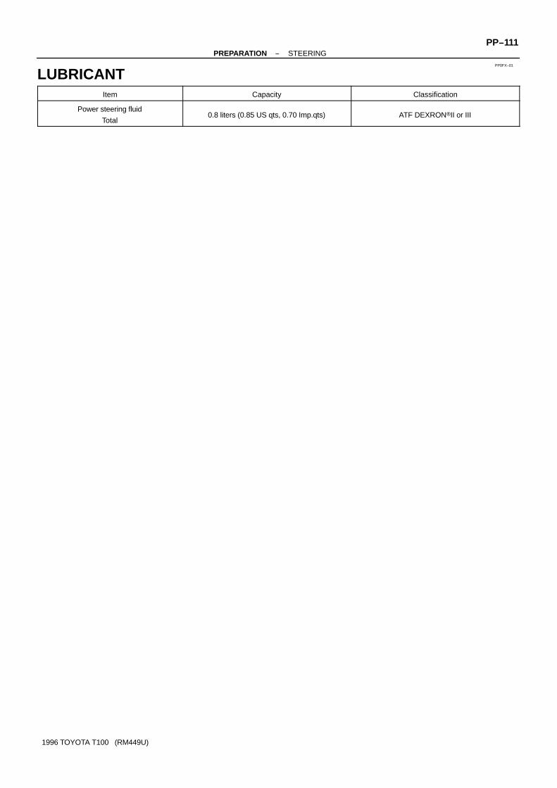
PP0FX−01
−PREPARATION STEERINGPP−111
1996 TOYOTA T100 (RM449U)
LUBRICANTItem Capacity Classification
Power steering fluid
Total0.8 liters (0.85 US qts, 0.70 Imp.qts) ATF DEXRON®II or III
https://www.truck-manuals.net/

PP33R−01
PP−112−PREPARATION STEERING
1996 TOYOTA T100 (RM449U)
SSM (Special Service Materials)08833−00080 Adhesive 1344
THREE BOND 1344
LOCTITE 242 or equivalent
PS gear (2WD)
08826−00090 Seal Packing 1281,
THREE BOND 1281 or equivalent
(FIPG)
Idler arm
https://www.truck-manuals.net/

PP0FR−01
−PREPARATION SUPPLEMENTAL RESTRAINT SYSTEMPP−113
162Author�: Date�:
1996 TOYOTA T100 (RM449U)
SUPPLEMENTAL RESTRAINT SYSTEMSST (Special Service Tools)
09082−00700 SRS Airbag Deployment Tool
09843−18020 Diagnosis Check Wire
https://www.truck-manuals.net/

PP0FS−02
PP−114−PREPARATION SUPPLEMENTAL RESTRAINT SYSTEM
1996 TOYOTA T100 (RM449U)
RECOMMENDED TOOLS09042−00020 Torx Socket T40 . Center aribag sensor assembly
09082−00040 TOYOTA Electrical Tester.
https://www.truck-manuals.net/

PP0FT−01
−PREPARATION SUPPLEMENTAL RESTRAINT SYSTEMPP−115
1996 TOYOTA T100 (RM449U)
EQUIPMENTTorque wrench
Bolt: Length: 35mm (1.38 in.) Pitch: 1.0 mm (0.039 in.)
Diam.: 6.0 mm (0.236 in.)Airbag disposal
Tire Width: 185 mm (7.28 in.) Inner diam.: 360 mm (14.17 in.) Airbag disposal
Tire with disc wheel Width: 185 mm (7.28 in.)
Inner diam.: 360 mm (14.17 in.)Airbag disposal
vinyl bag Airbag disposal
https://www.truck-manuals.net/

PP06F−09
PP−116−PREPARATION BODY ELECTRICAL
165Author�: Date�:
1996 TOYOTA T100 (RM449U)
BODY ELECTRICALSST (Special Service Tools)
09843−18020 Diagnosis Check Wire
https://www.truck-manuals.net/

PP06G−08
−PREPARATION BODY ELECTRICALPP−117
1996 TOYOTA T100 (RM449U)
RECOMMENDED TOOLS09082−00040 TOYOTA Electrical Tester.
09041−00030 Torx Driver T30 . For removing and installing steering
wheel pad
09042−00010 Torx Socket T30 . For removing and installing steering
wheel pad
https://www.truck-manuals.net/

PP06H−01
PP−118−PREPARATION BODY ELECTRICAL
1996 TOYOTA T100 (RM449U)
EQUIPMENTVoltmeter
Ammeter
Ohmmeter
Test lead
Syphon Brake fluid level warning switch
Bulb (3W) Fuel sender gauge
Bulb (3.4W) Seat belt warning relay
Bulb (21W) Turn signal flasher relay
Dry cell battery Fuel sender gauge
Torque wrench
https://www.truck-manuals.net/

PP0FZ−02
−PREPARATION BODYPP−119
168Author�: Date�:
1996 TOYOTA T100 (RM449U)
BODYSST (Special Service Tools)
09806−30010 Windshield Moulding Remover
09812−00010 Door Hinge Set Bolt Wrench
https://www.truck-manuals.net/
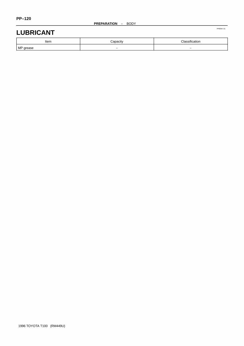
PP0EW−01
PP−120−PREPARATION BODY
1996 TOYOTA T100 (RM449U)
LUBRICANTItem Capacity Classification
MP grease − −
https://www.truck-manuals.net/

PP33S−02
−PREPARATION BODYPP−121
1996 TOYOTA T100 (RM449U)
SSM (Special Service Materials)08833−00030 Three cement black or equivalent Windshield Moulding
Windshield
Back Window Glass
08833−00070 Adhesive 1324,
THREE BOND 1324 or equivalent
Front Door
08850−00070 Windshield glass adhesive set
No.15 or equivalent
Windshield
Back WindowGlass
(0−15 °C or 32 − 59 °F)
08850−00080 Windshield glass adhesive set
No.35 or equivalent
Windshield
Back WindowGlass
(35 − 45 °C or 59 − 95 °F)
08850−00090 Windshield glass adhesive set
No.45 or equivalent
Windshield
Back WindowGlass
(35−45 °C or 95 − 95 °F)
08850−00801 Windshield Glass Adhesive Set
or equivalent
Windshield
https://www.truck-manuals.net/

PP3LT−01
PP−122−PREPARATION AIR CONDITIONING
171Author�: Date�:
1996 TOYOTA T100 (RM449U)
AIR CONDITIONINGSST (Special Service Tools)
07110−58060 Air Conditioner Service Tool Set
(07117−58060) Refrigerant Drain Service Valve
(07117−58070) T−Joint
(07117−58080) Quick Disconnect Adapter Discharge (diam. 16 mm)
(07117−58090) Quick Disconnect Adapter Suction (diam. 13 mm)
(07117−78050) Refrigerant Charging Gauge
(07117−88060) Refrigerant Charging Hose Discharge (Red)
(07117−88070) Refrigerant Charging Hose Suction (Blue)
(07117−88080) Refrigerant Charging Hose Utility (Green)
07112−66040 Magnetic Clutch Remover
07112−76060 Magnetic Clutch Stopper
07116−38360 Gas Leak Detector Assembly
https://www.truck-manuals.net/

PP3LU−01
−PREPARATION AIR CONDITIONINGPP−123
1996 TOYOTA T100 (RM449U)
RECOMMENDED TOOLS09082−00050 TOYOTA Electrical Tester Set.
https://www.truck-manuals.net/

PP0E4−02
PP−124−PREPARATION AIR CONDITIONING
1996 TOYOTA T100 (RM449U)
EQUIPMENTVoltmeter
Ammeter
Ohmmeter
Test lead
Thermometer Thermistor
Torque wrench
Dial indicator Magnetic clutch
Plastic hammer Magnetic clutch
Hexagon wrench Expansion valve
https://www.truck-manuals.net/
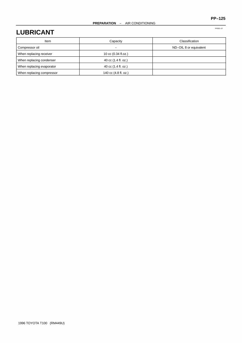
PP0E5−07
−PREPARATION AIR CONDITIONINGPP−125
1996 TOYOTA T100 (RM449U)
LUBRICANTItem Capacity Classification
Compressor oil − ND−OIL 8 or equivalent
When replacing receiver 10 cc (0.34 fl.oz.)
When replacing condenser 40 cc (1.4 fl. oz.)
When replacing evaporator 40 cc (1.4 fl. oz.)
When replacing compressor 140 cc (4.8 fl. oz.)
https://www.truck-manuals.net/

SS – SERVICE SPECIFICATIONS
STANDARD BOLT SS-1 MAINTENANCE SS-3 ENGINE MECHANICAL (3RZ-FE) SS-4 ENGINE MECHANICAL (5VZ-FE) SS-9 EMISSION CONTROL (3RZ-FE) SS-14 EMISSION CONTROL (5VZ-FE) SS-16 MFI (3RZ-FE) SS-17 SFI (5VZ-FE) SS-19 COOLING (3RZ-FE) SS-21 COOLING (5VZ-FE) SS-23 LUBRICATION (3RZ-FE) SS-25 LUBRICATION (5VZ-FE) SS-27 IGNITION (3RZ-FE) SS-29 IGNITION (5VZ-FE) SS-31 STARTING (3RZ-FE) SS-33 STARTING (5VZ-FE) SS-35 CHARGING (3RZ-FE) SS-37 CHARGING (5VZ-FE) SS-39 CLUTCH SS-41 MANUAL TRANSMISSION (R150, R150F)
SS-43
MANUAL TRANSMISSION (W59) SS-46 AUTOMATIC TRANSMISSION SS-49 TRANSFER SS-53 PROPELLER SHAFT SS-56 SUSPENSION AND AXLE SS-58 BRAKE SS-69 STEERING SS-71 SUPPLEMENTAL RESTRAINT SYSTEM SS-75 BODY ELECTRICAL SS-77 BODY SS-80 AIR CONDITIONING SS-82
https://www.truck-manuals.net/

SS00F−01
V06821
Mark MarkClass Class
Hexagon head bolt
Bolt head No.
4−
5−
6−
7−
8−
9−10−
11−
4T
5T
6T
7T
8T
9T
10T
11T
No mark
No mark
Hexagonflange bolt
w/ washer hexagon bolt
4T
4T
5T
6T
7T
8T
Hexagon headbolt
Hexagonflange bolt
w/ washer hexagon bolt
Hexagon headbolt
Hexagon headbolt
2Protrudinglines
2Protrudinglines
3Protrudinglines
4Protrudinglines
Hexagonflange bolt
w/ washer hexagon bolt
Hexagonflange bolt
w/ washer hexagon bolt
Hexagonflange bolt
w/ washer hexagon bolt
Stud bolt
Welded bolt
4Protrudinglines
5Protrudinglines
6Protrudinglines
No mark
Grooved
9T
10T
11T
4T
6T
4T
−SERVICE SPECIFICATIONS STANDARD BOLTSS−1
175Author�: Date�:
1996 TOYOTA T100 (RM449U)
STANDARD BOLTHOW TO DETERMINE BOLT STRENGTH
https://www.truck-manuals.net/

SS00G−01
V00079
ClassDiameter
mmPitchmm
Specified torqueHexagon head bolt Hexagon flange bolt
N·m kgf·cm ft·lbf N·m kgf·cm ft·lbf
in.·lbf
in.·lbf
in.·lbf
in.·lbf
in.·lbf
in.·lbf
SS−2−SERVICE SPECIFICATIONS STANDARD BOLT
1996 TOYOTA T100 (RM449U)
SPECIFIED TORQUE FOR STANDARD BOLTS
https://www.truck-manuals.net/
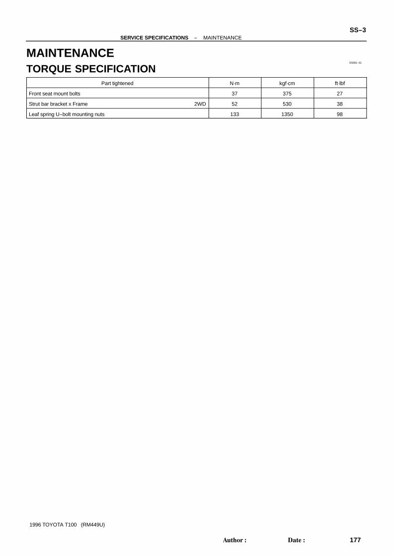
SS091−01
−SERVICE SPECIFICATIONS MAINTENANCESS−3
177Author�: Date�:
1996 TOYOTA T100 (RM449U)
MAINTENANCETORQUE SPECIFICATION
Part tightened N·m kgf·cm ft·lbf
Front seat mount bolts 37 375 27
Strut bar bracket x Frame 2WD 52 530 38
Leaf spring U−bolt mounting nuts 133 1350 98
https://www.truck-manuals.net/

SS092−01
SS−4−SERVICE SPECIFICATIONS ENGINE MECHANICAL (3RZ−FE)
178Author�: Date�:
1996 TOYOTA T100 (RM449U)
ENGINE MECHANICAL (3RZ−FE)SERVICE DATAValve
clearance
(Cold)
Intake
Exhaust
0.15 − 0.25 mm (0.006 − 0.010 in.)
0.25 − 0.35 mm (0.010 − 0.014 in.)
Ignition timing 3 − 7° BTDC @ idle
Idle speed 650 − 750 rpm
Compression
pressure
at 250 rpm STD
Minimum
Difference of pressure between each cylinder
1,230 kPa (12.5 kgf/cm2, 178 psi) or more
880 kPa (9.0 kgf/cm2, 127 psi)
98 kPa (1.0 kgf/cm2, 14 psi) or less
Cylinder head Warpage
Cylinder block side Maximum
Manifold side Maximum
Valve seat
Refacing angle Intake
Exhaust
Contacting angle
Contacting width
Valve guide bushing bore diameter STD
O/S 0.05
Cylinder head bolt outside diameter STD
Minimum
0.05 mm (0.0020 in.)
0.10 mm (0.0039 in.)
30°, 45°, 60°
45°, 60°
45°
1.0 − 1.4 mm (0.039 − 0.055 in.)
11.000 − 11.027 mm (0.4331 − 0.4341 in.)
11.050 − 11.077 mm (0.4350 − 0.4361 in.)
10.76 − 10.97 mm (0.4236 − 0.4319 in.)
10.40 mm (0.4094 in.)
Valve guide
bushing
Inside diameter
Protrusion height
Replacing temperature (Cylinder head side)
6.010 − 6.030 mm (0.2366 − 0.2374 in.)
8.2 − 8.6 mm (0.323 − 0.339 in.)
80 − 100°C (176 −212°F)
Valve Valve overall length STD Intake
Exhaust
Minimum Intake
Exhaust
Valve face angle
Stem diameter Intake
Exhaust
Stem oil clearance STD Intake
Exhaust
Minimum Intake
Exhaust
Margin thickness STD
Minimum
103.45 mm (4.0728 in.)
103.60 mm (4.0787 in.)
102.95 mm (4.0531 in.)
103.10 mm (4.0590 in.)
44.5°
5.970 − 5.985 mm (0.2350 − 0.2356 in.)
5.965 − 5.980 mm (0.2348 − 0.2354 in.)
0.025 − 0.060 mm (0.0010 − 0.0024 in.)
0.030 − 0.065 mm (0.0012 − 0.0026 in.)
0.08 mm (0.0031 in.)
0.10 mm (0.0039 in.)
1.0 mm (0.039 in.)
0.5 mm (0.020 in.)
Valve spring Deviation Maximum
Installed tension at 37.5 mm (1.406 in.)
2.0 mm (0.079 in.)
177 − 204 N (18.0 − 20.0 kgf, 45.9 − 39.7 lbf)
Valve lifter Lifter diameter
Lifter bore diameter
Oil clearance STD
Maximum
30.966 − 30.976 mm (1.1578 − 1.2195 in.)
31.000 − 31.016 mm (1.2205 − 1.2211 in.)
0.024 − 0.055 mm (0.0009 − 0.0022 in.)
0.07 mm (0.0028 in.)
Manifold Warpage Maximum Intake
Exhaust
0.20 mm (0.0078 in.)
0.50 mm (0.0197 in.)
Air intake
chamber
Warpage Maximum 0.20 mm (0.0078 in.)
https://www.truck-manuals.net/

−SERVICE SPECIFICATIONS ENGINE MECHANICAL (3RZ−FE)SS−5
179Author�: Date�:
1996 TOYOTA T100 (RM449U)
Camshaft Thrust clearance STD
Maximum
Journal oil clearance STD
Maximum
Journal diameter
Circle runout Maximum
Cam lobe height Intake
Exhaust
Camshaft gear backlash STD
Maximum
Camshaft gear spring end free distance
0.040 − 0.095 mm (0.0016 − 0.0037 in.)
0.12 mm (0.0047 in.)
0.025 − 0.062 mm (0.0010 − 0.0024 in.)
0.08 mm (0.0031 in.)
26.959 − 26.975 mm (1.0614 − 1.0620 in.)
0.06 mm (0.0024 in.)
45.31 − 45.41 mm (1.7839 − 1.7878 in.)
45.06 − 45.16 mm (1.7740 − 1.7779 in.)
0.020 − 0.200 mm (0.0008 − 0.0079 in.)
0.30 mm (0.0188 in.)
22.5 − 22.9 mm (0.886 − 0.902 in.)
Spark plug
tube
Protrusion 47.0 mm (1.850 in.)
Chain and
timing gear
Chain length at 16 links Maximum No.1
No.2
Crankshaft timing gear wear Minimum
Camshaft timing gear wear Minimum
Balance shaft drive gear wear Minimum
No.2 crankshaft timing
sprocket wear Maximum
147.5 mm (5.807 in.)
123.6 mm (4.866 in.)
59.4 mm (2.339 in.)
113.8 mm (4.480 in.)
75.9 mm (2.988 in.)
96.7 mm (3.807 in.)
Chain
tensioner
slipper and
vibration
damper
Wear Maximum 1.0 mm (0.039 in.)
Cylinder block Cylinder head surface warpage Maximum
Cylinder bore diameter STD
Maximum
Main bearing bolt outside diameter STD
Minimum
Cylinder block main journal bore diameter
STD Mark 1
Mark 2
Mark 3
U/S 0.25
0.05 mm (0.0020 in.)
94.990 − 95.003 mm (3.7398 − 3.7403 in.)
95.06 mm (3.7425 in.)
10.76 − 10.97 mm (0.4236 − 0.4319 in.)
10.40 mm (0.4094 in.)
64.004 − 64.010 mm (2.5198 − 2.5201 in.)
64.011 − 64.016 mm (2.5201 − 2.5203 in.)
64.017 − 64.022 mm (2.5203 − 2.5205 in.)
64.000 − 64.024 mm (2.5197 − 2.5206 in.)
Piston and
piston ring
Piston diameter STD
O/S 0.50
Piston oil clearance
Piston ring groove clearance No.1
No.2
Piston ring end gap STD No.1
STD No.2 mark ”T”
”N”
Maximum No.1
No.2
Piston pin installing temperature
94.933 − 94.943 mm (3.7375 − 3.7379 in.)
95.433 − 95.443 mm (3.7572 − 3.7575 in.)
0.047 − 0.070 mm (0.0019 − 0.0028 in.)
0.020 − 0.070 mm (0.0008 − 0.0028 in.)
0.030 − 0.070 mm (0.0012 − 0.0028 in.)
0.300 − 0.400 mm (0.0118 − 0.0157 in.)
0.400 − 0.500 mm (0.0157 − 0.0194 in.)
0.400 − 0.500 mm (0.0157 − 0.0194 in.)
0.40 mm (0.0157 in.)
0.50 mm (0.0196 in.)
80 − 90°C (176 − 194°F)
https://www.truck-manuals.net/

SS−6−SERVICE SPECIFICATIONS ENGINE MECHANICAL (3RZ−FE)
180Author�: Date�:
1996 TOYOTA T100 (RM449U)
Connecting
rod
Thrust clearance STD
Maximum
Connecting rod bearing center wall thickness
STD Mark 4
Mark 5
Mark 6
U/S 0.25
Connecting rod big end inside diameter
STD Mark 4
Mark 5
Mark 6
U/S 0.25
Connecting rod oil clearance
STD
U/S 0.25
Maximum
Rod out−of−alignment
Maximum per 100 mm (3.94 in.)
Rod twist Maximum per 100 mm (3.94 in.)
Bushing inside diameter
Piston pin diameter
Piston pin oil clearance STD
Maximum
Connecting rod bolt outside diameter STD
Minimum
0.160 − 0.312 mm (0.0063 − 0.0123 in.)
0.350 mm (0.0138 in.)
1.482 − 1.485 mm (0.0583 − 0.0585 in.)
1.485 − 1.488 mm (0.0585 − 0.0586 in.)
1.488 − 1.491 mm (0.0586 − 0.0587 in.)
1.601 − 1.607 mm (0.0630 − 0.0633 in.)
56.000 − 56.006 mm (2.2047 − 2.2050 in.)
56.006 − 56.012 mm (2.2050 − 2.2052 in.)
56.012 − 56.018 mm (2.2052 − 2.2054 in.)
56.000 − 56.018 mm (2.2047 − 2.2054 in.)
0.030 − 0.055 mm (0.0012 − 0.0022 in.)
0.031 − 0.071 mm (0.0012 − 0.0026 in.)
0.10 mm (0.0039 in.)
0.05 mm (0.0020 in.)
0.15 mm (0.0059 in.)
24.008 − 24.017 mm (0.9452 − 0.9455 in.)
24.000 − 24.009 mm (0.9449 − 0.9452 in.)
0.005 − 0.011 mm (0.0002 − 0.0004 in.)
0.015 mm (0.0006 in.)
7.80 − 7.90 mm (0.3071 − 0.3110 in.)
7.60 mm (0.2992 in.)
Crankshaft Thrust clearance STD
Maximum
Thrust washer thickness
Main journal oil clearance STD No.3
Others
U/S 0.25 No.3
Others
Maximum
Main journal diameter STD No.3
Others
U/S 0.25 No.3
Others
Main bearing center wall thickness
STD Mark 1
Mark 2
Mark 3
U/S 0.25
Crank pin diameter STD
U/S 0.25
Circle runout Maximum
Main journal taper and out−of−round Maximum
Crank pin taper and out−of−round Maximum
0.020 − 0.0220 mm (0.0008 − 0.0087 in.)
0.30 mm (0.0118 in.)
2.440 − 2.490 mm (0.0961 − 0.0980 in.)
0.030 − 0.055 mm (0.0012 − 0.0022 in.)
0.024 − 0.049 mm (0.0009 − 0.0019 in.)
0.030 − 0.070 mm (0.0012 − 0.0028 in.)
0.025 − 0.065 mm (0.0010 − 0.0026 in.)
0.10 mm (0.0039 in.)
59.981 − 59.994 mm (2.2615 − 2.3620 in.)
59.987 − 60.000 mm (2.3617 − 2.3622 in.)
59.740 − 59.750 mm (2.3520 − 2.3524 in.)
59.745 − 59.755 mm (2.3522 − 2.3526 in.)
1.987 − 1.990 mm (0.0782 − 0.0783 in.)
1.991 − 1.993 mm (0.0784 − 0.0785 in.)
1.994 − 1.996 mm (0.0785 − 0.0786 in.)
2.106 − 2.112 mm (0.0829 − 0.0831 in.)
52.987 − 53.000 mm (2.0861 − 2.0866 in.)
52.745 − 52.755 mm (2.0766 − 2.0770 in.)
0.03 mm (0.0012 in.)
0.005 mm (0.0002 in.)
0.005 mm (0.0002 in.)
Balance shaft Thrust clearance STD
Maximum
Bearing inside diameter No.1
No.2
Journal diameter No.1
No.2
Journal oil clearance STD No.1
STD No.2
Maximum No.1
No.2
0.07 − 0.13 mm (0.0027 − 0.0051 in.)
0.2 mm (0.0079 in.)
38.025 − 38.045 mm (1.4970 − 1.4978 in.)
37.525 − 37.545 mm (1.4774 − 1.4781 in.)
37.969 − 37.985 mm (1.4948 − 1.4955 in.)
37.449 − 37.465 mm (1.4744 − 1.4750 in.)
0.040 − 0.076 mm (0.0016 − 0.0031 in.)
0.060 − 0.096 mm (0.0024 − 0.0038 in.)
0.15 mm (0.0059 in.)
0.15 mm (0.0059 in.)
https://www.truck-manuals.net/

SS093−02
−SERVICE SPECIFICATIONS ENGINE MECHANICAL (3RZ−FE)SS−7
1996 TOYOTA T100 (RM449U)
TORQUE SPECIFICATIONPart tightened N·m kgf·cm ft·lbf
Throttle body x Air intake chamber 20 200 14
Spark plug x Cylinder head 19 200 14
Cylinder head x Cylinder block 1st
2nd
3rd
39
Turn 90°
Turn 90°
400 29
Cylinder head x Timing chain cover 21 210 15
Camshaft bearing cap x Cylinder head 15.5 160 12
Camshaft timing gear x Camshaft 73.5 750 54
Distributor gear x Camshaft 46 465 34
Chain tensioner x Cylinder head 21 210 15
Engine hanger x Cylinder head 42 420 30
Exhaust manifold x Cylinder head 49 500 36
Heat insulator x Exhaust manifold 5.5 55 48 in.·lbf
Front exhaust pipe x Exhaust manifold 62 630 46
No.1 support bracket x Transmission 39 400 29
No.1 support bracket clamp bolt 19 195 14
Front exhaust pipe x TWC 39 400 29
Intake manifold x Cylinder head 29 300 22
Delivery pipe x Intake manifold 21 210 15
Fuel inlet tube x Fuel filter 29 300 22
Fuel inlet tube x Delivery pipe 29 300 22
EGR valve x Air intake chamber, EGR pipe 19 195 14
EGR vacuum modulator x Air intake chamber 8.5 85 74 in.·lbf
EGR pipe x Exhaust manifold 20 200 15
EGR pipe x Cylinder head 18 185 14
Cylinder head rear cover x Cylinder head 13.5 135 10
Water outlet x Cylinder head 20 200 14
PS pump bracket x Cylinder head 20 200 14
PS pump bracket x PS pump 58 590 43
PS pump x PS pump pulley 43 440 32
PS pump idler pulley x Cylinder head 20 200 14
Balance shaft drive gear x Balance shaft 25 250 18
No.2 chain tensioner, No.3 vibration damper x Cylinder block 18 185 13
No.2 vibration damper x Cylinder block 27 270 20
No.1 vibration damper x Cylinder block 18 185 13
No.1 timing chain tensioner slipper x Cylinder block 27 270 20
Timing chain cover x Cylinder block Bolt A
Bolt B
Bolt C
Nut D
20
24.5
44
20
200
250
440
200
14
18
32
14
Timing chain cover mounting bolt 18 185 13
No.1 water bypass pipe mounting nut 20 200 14
Crankshaft pulley x Crankshaft 260 2,650 193
No.2 and No.3 crankshaft pulley x Crankshaft pulley 25 250 18
https://www.truck-manuals.net/

SS−8−SERVICE SPECIFICATIONS ENGINE MECHANICAL (3RZ−FE)
1996 TOYOTA T100 (RM449U)
Oil strainer x Cylinder block 18 185 13
Oil pan x Cylinder block 12.5 130 9
Crankshaft position sensor x Timing chain cover 8.5 85 74 in.·lbf
Generator bracket x Cylinder block 74.5 760 55
Generator bracket x Timing chain cover 18 185 13
Generator adjusting bar x Timing chain cover 63.5 650 47
A/C compressor bracket x Cylinder block 44 440 32
A/C compressor x A/C compressor bracket 25 250 18
Water pump pulley x Water pump 21 210 16
Connecting rod cap x Connecting rod 1st
2nd
45
Turn 90°460 33
Main bearing cap x Cylinder block 1st
2nd
39
Turn 90°400 29
No.1 balance shaft x Timing gear 36 365 26
No.2 balance shaft x Timing sprocket 36 365 26
Balance shaft x Cylinder block 18 185 13.4
Rear oil seal retainer x Cylinder block 13.5 135 9.7
RH, LH engine mounting bracket x Cylinder block 45 450 34
Oil dipstick guide x LH engine mounting bracket 20 200 14
Oil filter bracket union, Engine coolant drain plug x Cylinder block 25 250 18
Oil filter bracket x Cylinder block 28 290 21
Water bypass pipe x Cylinder block 20 200 14
Knock sensor x Cylinder block 37 380 27
Fuel filter x Cylinder block 20 200 14
Rear end plate x Cylinder block 18 185 13
Rear end plate x Water bypass pipe 20 200 14
Flywheel x Crankshaft 1st
2nd
26.5
Turn 90°270 19
Front crossmember x Engine rear mounting bracket 25 260 19
Front exhaust pipe clamp x Exhaust manifold 62 630 46
Exhaust support bracket x Transmission 39 400 29
Front exhaust pipe clamp 19 195 14
Front exhaust pipe x TWC 39 400 29
Engine rear mounting bracket x Engine rear mounting insulator 18 183 13
Engine front mounting insulator x Frame 38 387 28
Clutch release cylinder bracket x Transmission 39 400 29
Clutch release cylinder x Transmission 13 130 9
Stabilizer bar bracket mounting bolt 30 306 22
Stabilizer bar x Lower suspension arm 13 130 9
Intake air connector x Cylinder head 18 185 13
Radiator x Body 18 185 13
https://www.truck-manuals.net/

SS00O−07
−SERVICE SPECIFICATIONS ENGINE MECHANICAL (5VZ−FE)SS−9
183Author�: Date�:
1996 TOYOTA T100 (RM449U)
ENGINE MECHANICAL (5VZ−FE)SERVICE DATACompression
pressure
at 250 rpm STD
Minimum
Difference of pressure between each cylinder
1,200 kPa (12.2 kgf/cm2, 174 psi)
1,000 kPa (10.2 kgf/cm2, 145 psi)
100 kPa (1.0 kgf/cm2, 15 psi) or less
Valve
clearance
at cold Intake
Exhaust
Adjusting shim for repair part Mark 2.500
Mark 2.550
Mark 2.600
Mark 2.650
Mark 2.700
Mark 2.750
Mark 2.800
Mark 2.850
Mark 2.900
Mark 2.950
Mark 3.000
Mark 3.050
Mark 3.100
Mark 3.150
Mark 3.200
Mark 3.250
Mark 3.300
0.13 − 0.23 mm (0.006 − 0.009 in.)
0.27 − 0.37 mm (0.011 − 0.014 in.)
2.500 mm (0.0984 in.)
2.550 mm (0.1004 in.)
2.600 mm (0.1024 in.)
2.650 mm (0.1043 in.)
2.700 mm (0.1063 in.)
2.750 mm (0.1083 in.)
2.800 mm (0.1102 in.)
2.850 mm (0.1122 in.)
2.900 mm (0.1142 in.)
2.950 mm (0.1161 in.)
3.000 mm (0.1181 in.)
3.050 mm (0.1201 in.)
3.100 mm (0.1220 in.)
3.150 mm (0.1240 in.)
3.200 mm (0.1260 in.)
3.250 mm (0.1280 in.)
3.300 mm (0.1299 in.)
Ignition timing w/ Terminals TE1 and E1 connected of DLC1 8 − 12° BTDC @ idle
Idle speed − 700 ± 50 rpm
Intake manifold
vacuum
at idle speed 60 kPa (450 mmHg, 17.7 in.Hg) or more
Timing belt
tensioner
Protrusion from housing side 10.0 − 10.8 mm (0.394 − 0.425 in.)
Cylinder head Warpage Maximum
Valve seat
Refacing angle
Contacting angle
Contacting width
Valve guide bushing bore diameter STD
O/S 0.05
0.10 mm (0.039 in.)
30°, 45°, 60°
45°
1.0 − 1.4 mm (0.039 − 0.055 in.)
10.985 − 11.027 mm (0.4325 − 0.4341 in.)
11.050 − 11.077 mm (0.4350 − 0.4361 in.)
Valve guide
bushing
Inside diameter
Outside diameter for repair part STD
O/S 0.05
6.010 − 6.030 mm (0.2366 − 0.2374 in.)
11.033 − 11.044 mm (0.4344 − 0.4348 in.)
11.083 − 11.094 mm (0.4363 − 0.4368 in.)
Valve Valve overall length STD Intake
Exhaust
Minimum Intake
Exhaust
Valve face angle
Stem diameter Intake
Exhaust
Stem oil clearance STD Intake
Exhaust
Maximum Intake
Exhaust
Margin thickness STD
Minimum
95.15 mm (3.7461 in.)
94.90 mm (3.7362 in.)
94.60 mm (3.7244 in.)
94.40 mm (3.7165 in.)
44.5°
5.970 − 5.985 mm (0.2350 − 0.2356 in.)
5.965 − 5.980 mm (0.2348 − 0.2354 in.)
0.025 − 0.060 mm (0.0010 − 0.0024 in.)
0.030 − 0.065 mm (0.0012 − 0.0026 in.)
0.08 mm (0.0031 in.)
0.10 mm (0.0039 in.)
1.0 mm (0.039 in.)
0.5 mm (0.020 in.)
https://www.truck-manuals.net/

SS−10−SERVICE SPECIFICATIONS ENGINE MECHANICAL (5VZ−FE)
184Author�: Date�:
1996 TOYOTA T100 (RM449U)
Valve spring Deviation Maximum
Free length
Installed tension at 33.3 mm (1.311 in.)
2.0 mm (0.079 in.)
44.78 mm (1.7630 in.)
186 − 206 N (19.0 − 21.0 kgf, 41.9 − 46.3 lbf)
Valve lifter Lifter diameter
Lifter bore diameter
Oil clearance STD
Maximum
30.966 − 30.976 mm (1.2191 − 2.2195 in.)
31.000 − 31.018 mm (1.2205 − 1.2212 in.)
0.024 − 0.052 mm (0.0009 − 0.0020 in.)
0.08 mm (0.0031 in.)
Camshaft Thrust clearance STD
Maximum
Journal oil clearance STD
Maximum
Journal diameter
Circle runout Maximum
Cam lobe height STD Intake
Exhaust
Minimum Intake
Exhaust
Camshaft gear backlash STD
Maximum
Camshaft gear spring end free distance
0.033 − 0.080 mm (0.0013 − 0.0031 in.)
0.12 mm (0.0047 in.)
0.035 − 0.072 mm (0.0014 − 0.0028 in.)
0.10 mm (0.0039 in.)
26.949 − 26.965 mm (1.0610 − 1.0616 in.)
0.06 mm (0.0024 in.)
42.31 − 42.41 mm (1.6657 − 1.6697 in.)
41.96 − 42.06 mm (1.6520 − 1.6559 in.)
42.16 mm (1.6598 in.)
41.81 mm (1.6461 in.)
0.020 − 0.200 mm (0.0008 − 0.0079 in.)
0.30 mm (0.0188 in.)
18.2 − 18.8 mm (0.712 − 0.740 in.)
Air intake
chamber
Warpage Maximum 0.10 mm (0.0039 in.)
Intake air
connector
Warpage Maximum 0.10 mm (0.0039 in.)
Intake
manifold
Warpage Maximum 0.10 mm (0.0039 in.)
Exhaust
manifold
Warpage Maximum 1.00 mm (0.0394 in.)
Cylinder block Cylinder head surface warpage Maximum
Cylinder bore diameter STD Mark 1
Mark 2
Mark 3
Maximum STD
O/S 0.50
0.05 mm (0.0020 in.)
93.500 − 93.510 mm (3.6811 − 3.6815 in.)
93.510 − 93.520 mm (3.6815 − 3.6819 in.)
93.520 − 93.530 mm (3.6819 − 3.6823 in.)
93.730 mm (3.6902 in.)
94.230 mm (3.7098 in.)
Piston and
piston ring
Piston diameter STD Mark 1
Mark 2
Mark 3
O/S 0.50
Piston oil clearance STD
Maximum
Piston ring groove clearance No.1
No.2
Piston ring end gap STD No.1
No.2
Oil
Maximum No.1
No.2
Oil
93.356 − 93.366 mm (3.6754 − 3.6758 in.)
93.367 − 93.376 mm (3.6759 − 3.6762 in.)
93.377 − 93.386 mm (3.6763 − 3.6766 in.)
93.856 − 93.886 mm (3.6951 − 3.6963 in.)
0.134 − 0.154 mm (0.0053 − 0.0060 in.)
0.174 mm (0.0069 in.)
0.040 − 0.080 mm (0.0016 − 0.0031 in.)
0.030 − 0.070 mm (0.0012 − 0.0028 in.)
0.300 − 0.500 mm (0.0118 − 0.0197 in.)
0.400 − 0.600 mm (0.0157 − 0.0236 in.)
0.150 − 0.550 mm (0.0059 − 0.0217 in.)
1.100 mm (0.0433 in.)
1.200 mm (0.0472 in.)
1.150 mm (0.0453 in.)
https://www.truck-manuals.net/

−SERVICE SPECIFICATIONS ENGINE MECHANICAL (5VZ−FE)SS−11
185Author�: Date�:
1996 TOYOTA T100 (RM449U)
Connecting
rod
Thrust clearance STD
Maximum
Connecting rod bearing center wall thickness
Reference Mark 1
Mark 2
Mark 3
Connecting rod oil clearance STD
O/S 0.25
Maximum
Rod bend Maximum per 100 mm (3.94 in.)
Rod twist Maximum per 100 mm (3.94 in.)
Bushing inside diameter
Piston pin diameter
Bushing oil clearance STD
Maximum
Connecting rod bolt outer diameter STD
Minimum
0.150 − 0.330 mm (0.0059 − 0.0130 in.)
0.380 mm (0.0150 in.)
1.484 − 1.488 mm (0.0584 − 0.0586 in.)
1.488 − 1.492 mm (0.0586 − 0.0587 in.)
1.492 − 1.496 mm (0.0587 − 0.0589 in.)
0.024 − 0.053 mm (0.0009 − 0.0021 in.)
0.023 − 0.069 mm (0.0009 − 0.0027 in.)
0.08 mm (0.0031 in.)
0.05 mm (0.0020 in.)
0.15 mm (0.0059 in.)
22.005 − 22.017 mm (0.8663 − 0.8668 in.)
21.997 − 22.009 mm (0.8660 − 0.8665 in.)
0.005 − 0.011 mm (0.0002 − 0.0004 in)
0.05 mm (0.0020 in.)
7.860 − 8.000 mm (0.3094 − 0.3150 in.)
7.600 mm (0.2992 in.)
Crankshaft Thrust clearance STD
Maximum
Thrust washer thickness
Main journal oil clearance No.1 STD
U/S 0.25
Others STD
U/S 0.25
Maximum
Main journal diameter STD
U/S 0.25
Main bearing center wall thickness
Reference No.1 Mark 1
Mark 2
Mark 3
Mark 4
Mark 5
Others Mark 1
Mark 2
Mark 3
Mark 4
Mark 5
Crank pin diameter STD
U/S 0.25
Circle runout Maximum
Main journal taper and out−of−round Maximum
Crank pin taper and out−of−round Maximum
0.020 − 0.220 mm (0.0008 − 0.0087 in.)
0.300 mm (0.0118 in.)
2.440 − 2.490 mm (0.0961 − 0.0980 in.)
0.020 − 0.038 mm (0.0008 − 0.0015 in.)
0.019 − 0.059 mm (0.0007 − 0.0023 in.)
0.024 − 0.042 mm (0.0009 − 0.0017 in.)
0.023 − 0.063 mm (0.0009 − 0.0025 in.)
0.08 mm (0.0031 in.)
63.985 − 64.000 mm (2.5191 − 2.5197 in.)
63.745 − 63.755 mm (2.5096 − 2.5100 in.)
1.991 − 1.994 mm (0.0784 − 0.0785 in.)
1.994 − 1.997 mm (0.0785 − 0.0786 in.)
1.997 − 2.000 mm (0.0786 − 0.0787 in.)
2.000 − 2.003 mm (0.0787 − 0.0789 in.)
2.003 − 2.006 mm (0.0789 − 0.0790 in.)
1.989 − 1.992 mm (0.0783 − 0.0784 in.)
1.992 − 1.995 mm (0.0784 − 0.0785 in.)
1.995 − 1.998 mm (0.0785 − 0.0787 in.)
1.998 − 2.001 mm (0.0787 − 0.0788 in.)
2.001 − 2.004 mm (0.0788 − 0.0789 in.)
54.987 − 55.000 mm (2.1648 − 2.1654 in.)
54.745 − 54.755 mm (2.1553 − 2.1557 in.)
0.06 mm (0.0024 in.)
0.02 mm (0.0008 in.)
0.02 mm (0.0008 in.)
https://www.truck-manuals.net/

SS00P−11
SS−12−SERVICE SPECIFICATIONS ENGINE MECHANICAL (5VZ−FE)
1996 TOYOTA T100 (RM449U)
TORQUE SPECIFICATIONPart tightened N·m kgf·cm ft·lbf
No.1 idler pulley x Oil pump 35 350 26
No.2 idler pulley x No.2 idler pulley bracket 40 400 30
No.1 timing belt cover x Oil pump 9 90 80 in.·lbf
Crankshaft pulley x Crankshaft 250 2,500 184
Camshaft timing pulley x Camshaft 110 1,100 81
Timing belt tensioner x Oil pump 27 270 20
No.2 timing belt cover x No.3 timing belt cover 9 90 80 in.·lbf
Oil dipstick guide x Generator bracket 8 80 71 in.·lbf
Fluid coupling x Fan bracket 5.4 54 48 in.·lbf
Camshaft bearing cap x Cylinder head 16 160 12
Rear plate x Cylinder head 8 80 71 in.·lbf
Cylinder head x Cylinder block 12 pointed head 1st
2nd
3rd
Recessed head
34
Turn 90°
Turn 90°
18
350
Turn 90°
Turn 90°
185
25
Turn 90°
Turn 90°
13
Cylinder head cover x Cylinder head 6 60 53 in.·lbf
Exhaust manifold x Cylinder head 40 400 30
Exhaust manifold heat insulator x Exhaust manifold 8 80 71 in.·lbf
Exhaust crossover pipe x Exhaust manifold 45 450 33
Generator bracket x LH cylinder head 18.5 185 14
PS pump bracket x RH cylinder head 44 440 32
Intake manifold x Cylinder head 18 180 13
Intake manifold stay x Intake manifold 18.5 185 13
Intake manifold stay x No. 2 idler pulley bracket 18.5 185 13
No.3 timing belt cover x Cylinder head 9 90 80 in.·lbf
Camshaft position sensor x RH cylinder head 8 80 71 in.·lbf
Intake air connector x Intake manifold 18.5 185 13
Air intake chamber x Intake air connector 18.5 185 13
Air intake chamber stay x LH cylinder head, Air intake chamber 40 400 30
EGR pipe x LH exhaust manifold 18.5 185 13
EGR pipe x EGR valve 18.5 185 13
EGR pipe x Cylinder head 8 80 71 in.·lbf
Engine hanger No.2 x RH cylinder head 40 400 30
Frame crossmember x Engine rear mounting bracket 58 590 43
Engine rear mounting bracket x Engine rear mounting insulator 18 185 13
Engine front mounting insulator x Frame 38 387 28
Connecting rod cap x Connecting rod 1st
2nd
25
Turn 90°
250
Turn 90°
18
Turn 90°
Main bearing cap x Cylinder block 1st
2nd
61
Turn 90°
625
Turn 90°
45
Turn 90°
Rear oil seal retainer x Cylinder block 8 80 71 in.·lbf
Oil cooler union x Cylinder block 30 300 22
Oil hole cover plate x Cylinder block 60 600 44
Engine coolant drain cock x Cylinder block 39 400 29
https://www.truck-manuals.net/

−SERVICE SPECIFICATIONS ENGINE MECHANICAL (5VZ−FE)SS−13
1996 TOYOTA T100 (RM449U)
Engine mounting bracket x Cylinder block 44 440 32
Oil filter union x Cylinder block 25 250 18
Oil pressure switch x Cylinder block 15 150 11
Generator adjusting bar x Cylinder block 42 420 31
Knock sensor x Cylinder block 39 400 29
No.2 idler pulley bracket x Cylinder block 38 380 28
Water bypass pipe x Cylinder block 8.5 85 75 in.·lbf
Rear end plate x Cylinder block 7.5 75 66 in.·lbf
Drive plate x Crankshaft 83 850 63
Flywheel x Crankshaft 85 850 63
Clutch release cylinder x Transmission 12 120 9
Stabilizer bar bracket mounting bolt 30 306 22
Stabilizer bar x Lower suspension arm 13 130 9
Front exhaust pipe x Exhaust crossover pipe 62 630 46
Front exhaust pipe x Center exhaust pipe 48 490 35
Front exhaust pipe support bracket x Front exhaust pipe 44 450 33
Front exhaust pipe support bracket x Transmission 44 450 33
Center exhaust pipe x Tailpipe 48 490 35
Center exhaust pipe support bracket x Body 29 300 21
https://www.truck-manuals.net/

SS094−01
SS−14−SERVICE SPECIFICATIONS EMISSION CONTROL (3RZ−FE)
188Author�: Date�:
1996 TOYOTA T100 (RM449U)
EMISSION CONTROL (3RZ−FE)SERVICE DATAVSV for EVAP Resistance at 20°C (68°F) 30 − 34 Ω
VSV for EGR Resistance at 20°C (68°F) 33 − 39 Ω
https://www.truck-manuals.net/

SS095−01
−SERVICE SPECIFICATIONS EMISSION CONTROL (3RZ−FE)SS−15
1996 TOYOTA T100 (RM449U)
TORQUE SPECIFICATIONPart tightened N·m kgf·cm ft·lbf
Charcoal canister x Charcoal canister bracket 31 310 23
EGR valve x Air intake chamber 19 195 14
EGR valve x EGR pipe 19 195 14
EGR pipe x Exhaust manifold 20 200 15
EGR pipe x Cylinder head 18 185 13
Heated oxygen sensor x Center exhaust pipe 20 200 14
Front exhaust pipe x Center pipe 48 490 35
Center pipe x Tail pipe 48 490 35
https://www.truck-manuals.net/

SS00R−11
SS−16−SERVICE SPECIFICATIONS EMISSION CONTROL (5VZ−FE)
190Author�: Date�:
1996 TOYOTA T100 (RM449U)
EMISSION CONTROL (5VZ−FE)TORQUE SPECIFICATION
Part tightened N·m kgf·cm ft·lbf
Charcoal canister x Charcoal canister bracket 18 180 13
EGR valve x Air intake chamber 18.5 185 14
EGR valve x EGR pipe 18.5 185 14
EGR pipe x LH exhaust manifold 18.5 185 14
EGR pipe stay x Cylinder head 8.0 80 71 in.·lbf
Heated oxygen sensor x Center exhaust pipe 20 200 14
Front exhaust pipe x Center exhaust pipe 48 490 35
Center exhaust pipe x Tailpipe 48 490 35
https://www.truck-manuals.net/

SS096−02
−SERVICE SPECIFICATIONS MFI (3RZ−FE)SS−17
191Author�: Date�:
1996 TOYOTA T100 (RM449U)
MFI (3RZ−FE)SERVICE DATAFuel pressure
regulator
Fuel pressure at no vacuum 265 − 304 kPa
(2.7 − 3.1 kgf/cm2, 38 − 44 psi)
Fuel pump Resistance at 20°C (68°F) 0.2 − 3.0 Ω
Injector Resistance at 20°C (68°F)
Injection volume
Difference between each cylinder
Fuel leakage
12 − 16 Ω69 − 88 cm3 (4.2 − 5.3 cu in.) per 15 seconds
5 cm3 (0.3 cu in.) or less
One drop or less per minutes
Throttle body Throttle valve fully closed angle
Throttle opener setting speed
6°
1,200 − 1,400 rpm
TP sensor Clearance between stop screw and lever Terminals Resistance
0 mm (0 in.) VTA − E2
0.50 mm (0.020 in.) IDL − E2
0.75 mm (0.030 in.) IDL − E2
Throttle valve fully open VTA − E2
− VC − E2
0.2 − 5.7 kΩ2.3 kΩ or less
Infinity
2.0 − 10.2 kΩ2.5 − 5.9 kΩ
IAC valve Resistance +B − RSC or RSO 17.0 − 24.5 Ω (−10 − 50°C)
21.5 − 28.5 Ω ( 50 − 100°C)
VSV for EVAP Resistance at 20°C (68°F) 30 − 34 Ω
VSV for EGR Resistance at 20°C (68°F) 33 − 39 Ω
VSV for Vapor
pressure sensor
Resistance at 20°C (68°F) 37 − 44 Ω
Vapor pressure
sensor
Power source voltage 4.5 − 5.5 V
ECT sensor Resistance at −20°C (−4°F)
at 0°C (32°F)
at 20°C (68°F)
at 40°C (104°F)
at 60°C (140°F)
at 80°C (176°F)
10 − 20 kΩ4 − 7 kΩ2 − 3 kΩ0.9 − 1.3 kΩ0.4 − 0.7 kΩ0.2 − 0.4 kΩ
MAF meter Resistance (THA − E2) at −20°C (−4°F)
at 0°C (32°F)
at 20°C (68°F)
at 40°C (104°F)
at 60°C (140°F)
at 80°C (176°F)
10 − 20 kΩ4 − 7 kΩ2 − 3 kΩ0.9 − 1.3 kΩ0.4 − 0.7 kΩ0.2 − 0.4 kΩ
EGR gas temp.
sensor
Resistance at 50°C (122°F)
at 100°C (212°F)
at 150°C (302°F)
64 − 97 kΩ11 − 16 kΩ2 − 4 kΩ
Heated
oxygen sensor
Heater coil resistance
Bank 1 sensor 1 at 20°C (68°F)
Bank 1 sensor 2 at 20°C (68°F)
11 − 16 Ω11 − 16 Ω
Fuel cut RPM Fuel return rpm M/T
A/T
1,400 rpm
1,500 rpm
https://www.truck-manuals.net/

SS097−02
SS−18−SERVICE SPECIFICATIONS MFI (3RZ−FE)
1996 TOYOTA T100 (RM449U)
TORQUE SPECIFICATIONPart tightened N·m kgf·cm ft·lbf
Fuel line (Union bolt type) 29 300 22
Fuel line (Flare nut type) 30 310 22
Fuel pump bracket assembly x Fuel tank 3.9 40 35 in.·lbf
Fuel filter x Cylinder block 20 200 15
Fuel pressure regulator x Delivery pipe 8.8 90 78 in.·lbf
Delivery pipe x Cylinder head 21 210 15
Fuel inlet tube x Fuel filter 29 300 22
Fuel inlet tube x Delivery pipe 29 300 22
Air intake chamber x Intake manifold 21 210 15
Throttle body x Air intake chamber 20 200 14
Fuel evaporation tube x Fuel tank 1.5 15 13 in.·lbf
Fuel tank filler pipe x Fuel tank 3.5 35 31 in.·lbf
Fuel inlet pipe x Body 5.4 55 47 in.·lbf
Fuel tank band x Body 39 400 29
MAF meter x Air cleaner cap 10 100 7
ECT sensor x Cylinder head 20 200 14
Knock sensor x Cylinder block 44 450 33
https://www.truck-manuals.net/

SS00U−11
−SERVICE SPECIFICATIONS SFI (5VZ−FE)SS−19
193Author�: Date�:
1996 TOYOTA T100 (RM449U)
SFI (5VZ−FE)SERVICE DATAFuel pressure
regulator
Fuel pressure at no vacuum 265 − 304 kPa (2.7 − 3.1 kgf/cm2, 38 − 44 psi)
Fuel pump Resistance at 20 °C (68 °F) 0.2 − 3.0 Ω
Injector Resistance
Injection volume
Difference between each cylinder
Fuel leakage
Approx. 13.8 Ω56 − 69 cm3 (3.4 − 4.2 cu in.) per 15 sec.
6 cm3 (0.31 cu in.) or less
1 drop or less per minute
MAF meter Resistance (THA − E2) at −20 °C (−4 °F)
at 0 °C (32 °F)
at 20 °C (68 °F)
at 40 °C (104 °F)
at 60 °C (140 °F)
at 80 °C (176 °F)
10 − 20 kΩ4 − 7 kΩ2 − 3 kΩ0.9 − 1.3 kΩ0.4 − 0.7 kΩ0.2 − 0.4 kΩ
Throttle body Throttle valve fully closed angle
DP setting speed (M/T)
Throttle opener setting speed
10°
1,800 − 2,200 rpm
900 − 1,950 rpm
Throttle position
sensor
Clearance between stop screw and lever
0 mm (0 in.) VTA − E2
0.32 mm (0.013 in.) IDL − E2
0.54 mm (0.021 in.) IDL − E2
Throttle valve fully open VTA − E2
VC − E2
0.28 − 6.4 kΩ0.5 kΩ or less
Infinity
2.0 − 11.6 kΩ2.7 − 7.7 kΩ
IAC valve Resistance (+B − RSO or RSC) at cold
at hot
17.0 − 24.5 Ω21.5 − 28.5 Ω
VSV for fuel pres-
sure control
Resistance at 20 °C (68 °F) 33 − 39 Ω
VSV for EGR
(2WD 0.5 ton)
Resistance at 20 °C (68 °F) 33 − 39 Ω
VSV for EVAP Resistance at 20 °C (68 °F) 29 − 33 Ω
A/C idle−up valve
(w/ A/C)
Resistance at 20 °C (68 °F) 30 − 34 Ω
ECT sensor Resistance at −20 °C (−4 °F)
at 0 °C (32 °F)
at 20 °C (68 °F)
at 40 °C (104 °F)
at 60 °C (140 °F)
at 80 °C (176 °F)
10 − 20 kΩ4 − 7 kΩ2 − 3 kΩ0.9 − 1.3 kΩ0.4 − 0.7 kΩ0.2 − 0.4 kΩ
EGR gas temper-
ature sensor
(2WD 0.5 ton)
Resistance at 50 °C (122 °F)
at 100 °C (212 °F)
at 150 °C (302 °F)
64 − 97 kΩ11 − 16 κΩ2 − 4 kΩ
Heated oxygen
sensor
Heater coil resistance
M/T Bank 1 Sensor 1 at 20 °C (68 °F)
Others at 20 °C (68 °F)
5 − 7 Ω11 − 16 Ω
Fuel cut rpmFuel return rpm M/T
A/T
1,000 rpm
1,200 rpm
https://www.truck-manuals.net/

SS00V−11
SS−20−SERVICE SPECIFICATIONS SFI (5VZ−FE)
1996 TOYOTA T100 (RM449U)
TORQUE SPECIFICATIONPart tightened N·m kgf·cm ft·lbf
Fuel line (Union bolt type) 34.3 350 25
Fuel line (Flare nut type) 34.3 350 25
Fuel line (Flare nut type) using SST 28 285 21
No. 2 timing belt cover x No. 3 timing belt cover 9 90 80 in.·lbf
Fuel inlet pipe x Intake manifold 8 80 71 in.·lbf
Delivery pipe x Intake manifold 13 130 10
Fuel pump bracket assembly x Fuel tank 3.9 40 35 in.·lbf
Fuel tank band x Body 43 440 32
Fuel tank filler pipe x Fuel tank 3.9 40 35 in.·lbf
Fuel evaporation vent tube x Fuel tank 1.5 15 13 in.·lbf
Fuel pressure regulator x LH delivery pipe 8 80 71 in.·lbf
MAF meter x Air cleaner cap 6.9 72 61 in.·lbf
VSV assembly x Air intake connector 8 80 71 in.·lbf
A/C idle−up valve x Intake air connector 20 200 14
ECT sensor x Intake manifold 20 200 14
Knock sensor x Cylinder block 39 400 29
EGR gas temperature sensor x EGR valve 20 200 14
Heated oxygen sensor x Front exhaust pipe, Center exhaust pipe 20 200 14
https://www.truck-manuals.net/

SS098−01
−SERVICE SPECIFICATIONS COOLING (3RZ−FE)SS−21
195Author�: Date�:
1996 TOYOTA T100 (RM449U)
COOLING (3RZ−FE)SERVICE DATAThermostat
Valve opening temperature
Valve lift at 95°C (203°F)
80 − 84°C (176 − 183°F)
8 mm (0.31 in.) or more
Radiator cap Relief valve opening pressure STD
Minimum
74 − 103 kPa (0.75 − 1.05 kgf/cm2, 10.7 − 14.9 psi)
59 kPa (0.6 kgf/cm2, 8.5 psi)
https://www.truck-manuals.net/

SS099−01
SS−22−SERVICE SPECIFICATIONS COOLING (3RZ−FE)
1996 TOYOTA T100 (RM449U)
TORQUE SPECIFICATIONPart tightened N·m kgf·cm ft·lbf
Cylinder block x Drain plug 24 250 18
Fluid coupling x Fan 5.5 55 49 in.·lbf
Water pump x Cylinder block expect bolt A
for bolt A
8.9
24.5
90
250
78 in.·lbf
18
Water inlet x Water inlet housing 20 200 15
Radiator support x Radiator tank M/T
A/T
13
5.5
130
56
9
49 in.·lbf
Radiator mounting bolt 31 310 23
https://www.truck-manuals.net/

SS00Y−03
−SERVICE SPECIFICATIONS COOLING (5VZ−FE)SS−23
197Author�: Date�:
1996 TOYOTA T100 (RM449U)
COOLING (5VZ−FE)SERVICE DATAThermostat Valve opening pressure
Valve lift at 95°C (203°F)
80 − 84°C (176 − 183°F)
8.5 mm (0.335 in .) or more
Radiator cap Relief valve opening pressure STD
Minimum
74 − 103 kPa (0.75 − 1.05 kgf/cm2, 10.7 − 14.9 psi)
59 kPa (0.6 kgf/cm2, 8.5 psi)
https://www.truck-manuals.net/
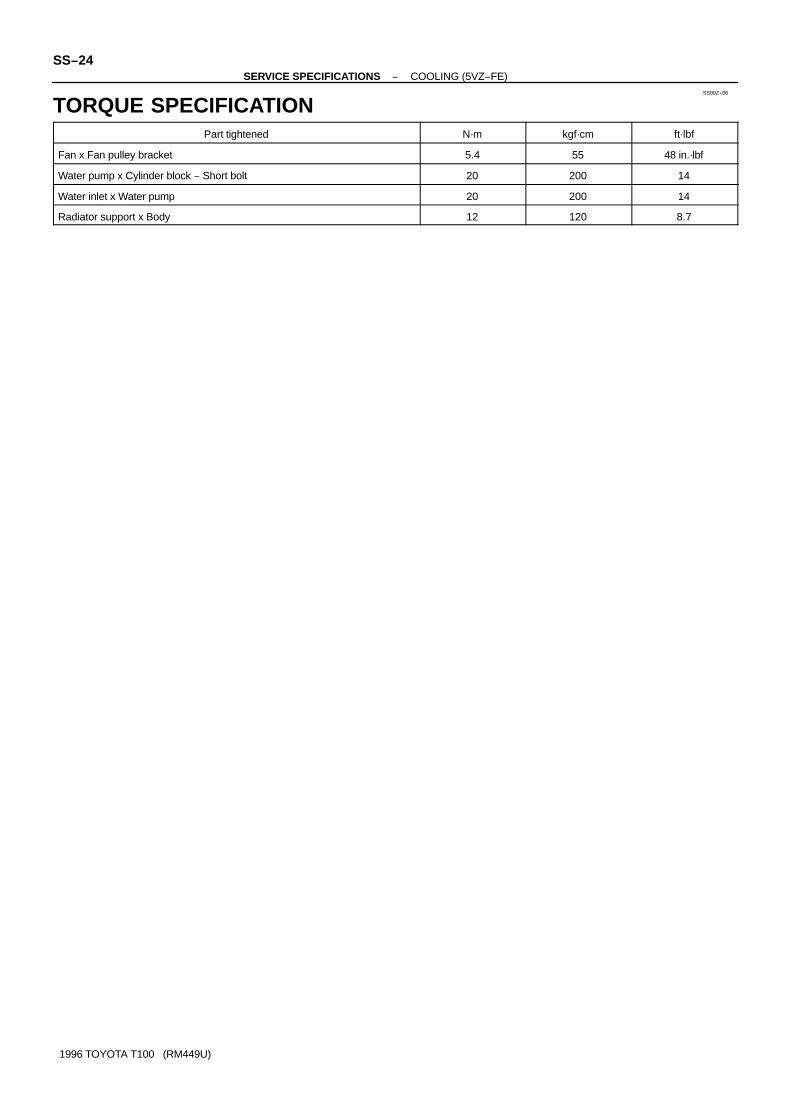
SS00Z−06
SS−24−SERVICE SPECIFICATIONS COOLING (5VZ−FE)
1996 TOYOTA T100 (RM449U)
TORQUE SPECIFICATIONPart tightened N·m kgf·cm ft·lbf
Fan x Fan pulley bracket 5.4 55 48 in.·lbf
Water pump x Cylinder block − Short bolt 20 200 14
Water inlet x Water pump 20 200 14
Radiator support x Body 12 120 8.7
https://www.truck-manuals.net/

SS09A−01
−SERVICE SPECIFICATIONS LUBRICATION (3RZ−FE)SS−25
199Author�: Date�:
1996 TOYOTA T100 (RM449U)
LUBRICATION (3RZ−FE)SERVICE DATAOil pressure
At idle speed (normal operating temperature)
At 3,000 rpm (normal operating temperature)
29 kPa (0.3 kgf/cm2, 4.3 psi) or more
245 − 490 kPa (2.5 − 5.0 kgf/cm2, 36 − 71 psi)
Oil pump
Body clearance STD
Maximum
Tip clearance STD
Maximum
Side clearance STD
Maximum
0.100 − 0.175 mm (0.0039 − 0.0069 in.)
0.30 mm (0.0118 in.)
0.011 − 0.240mm (0.0043 − 0.0094 in.)
0.25 mm (0.0098 in.)
0.030 − 0.090 mm (0.0012 − 0.0035 in.)
0.15 mm (0.0059 in.)
https://www.truck-manuals.net/

SS09B−02
SS−26−SERVICE SPECIFICATIONS LUBRICATION (3RZ−FE)
1996 TOYOTA T100 (RM449U)
TORQUE SPECIFICATIONPart tightened N·m kgf·cm ft·lbf
Oil pan x Drain plug 25 250 18
https://www.truck-manuals.net/

SS012−01
−SERVICE SPECIFICATIONS LUBRICATION (5VZ−FE)SS−27
201Author�: Date�:
1996 TOYOTA T100 (RM449U)
LUBRICATION (5VZ−FE)SERVICE DATAOil pressure Normal operating temperature at idle speed
at 3,000 rpm
29 kPa (0.3 kgf/cm2, 4.3 psi) or more
245 − 520 kPa (2.5 − 5.3 kgf/cm2, 36 − 75 psi)
Oil pump Body clearance STD
Maximum
Tip clearance STD
Maximum
Side clearance STD
Maximum
0.10 − 0.18 mm (0.0039 − 0.0069 in.)
0.30 mm (0.0118 in.)
0.11 − 0.24 mm (0.0043 − 0.0094 in.)
0.35 mm (0.0138 in.)
0.03 − 0.09 mm (0.0012 − 0.0035 in.)
0.15 mm (0.0059 in.)
https://www.truck-manuals.net/
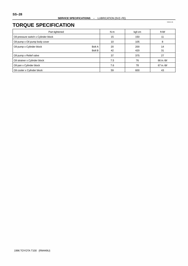
SS013−05
SS−28−SERVICE SPECIFICATIONS LUBRICATION (5VZ−FE)
1996 TOYOTA T100 (RM449U)
TORQUE SPECIFICATIONPart tightened N·m kgf·cm ft·lbf
Oil pressure switch x Cylinder block 15 150 11
Oil pump x Oil pump body cover 10 105 8
Oil pump x Cylinder block Bolt A
Bolt B
20
42
200
420
14
31
Oil pump x Relief valve 37 375 27
Oil strainer x Cylinder block 7.5 76 66 in.·lbf
Oil pan x Cylinder block 7.6 78 67 in.·lbf
Oil cooler x Cylinder block 59 600 43
https://www.truck-manuals.net/

SS09C−03
−SERVICE SPECIFICATIONS IGNITION (3RZ−FE)SS−29
203Author�: Date�:
1996 TOYOTA T100 (RM449U)
IGNITION (3RZ−FE)SERVICE DATAFiring order − 1 − 3 − 4 − 2
High−tension
cord
Resistance Maximum 25 kΩ per cord
Spark plug Recommended spark plug ND
Recommended spark plug NGK
Correct electrode gap
K16R−U
BKR5EYA
0.8 mm (0.031 in.)
Ignition coil
Resistance
Primary coil Cold
Hot
Secondary coil Cold
Hot
0.36 − 0.55 Ω0.45 − 0.65 Ω9.0 − 15.4 kΩ11.4 − 18.1 kΩ
Distributor
Air gap
Signal generator (pick up coil) Resistance
at cold G+ − G−
at hot G+ − G−
0.2 − 0.4 mm (0.008 − 0.016 in.)
185 − 275 Ω240 − 325 Ω
Crankshaft
position
sensor
Resistance at cold NE+ − NE−
at hot NE+ − NE−
1,630 − 2,740 Ω2,065 − 3,225 Ω
https://www.truck-manuals.net/

SS09D−03
SS−30−SERVICE SPECIFICATIONS IGNITION (3RZ−FE)
1996 TOYOTA T100 (RM449U)
TORQUE SPECIFICATIONPart tightened N·m kgf·cm ft·lbf
Spark plug x Cylinder head 20 200 14
Distributor x Cylinder head 19 195 14
Crankshaft position sensor x Timing chain cover 8.5 85 74 in.·lbf
Generator bracket x Cylinder block 74.5 760 55
Generator bracket x Timing chain cover 18 180 13
https://www.truck-manuals.net/

SS016−04
−SERVICE SPECIFICATIONS IGNITION (5VZ−FE)SS−31
205Author�: Date�:
1996 TOYOTA T100 (RM449U)
IGNITION (5VZ−FE)SERVICE DATAFiring order − 1 − 2 − 3 − 4 − 5 − 6
Spark plug Recommended spark plug ND
NGK
Correct electrode gap for new plug
K16TR11
BKR5EKB−11
1.1 mm (0.043 in.)
Ignition coil Primary coil resistance Cold
Hot
Secondary coil resistance Cold
Hot
0.67 − 1.05 Ω0.85 − 1.23 Ω9.3 −16.0 kΩ11.7 − 18.8 kΩ
Camshaft position
sensor
Resistance Cold
Hot
835 − 1,400 Ω1,060 − 1,645 Ω
Crankshaft posi-
tion sensor
Resistance Cold
Hot
1,630 − 2,740 Ω2,065 − 3,225 Ω
https://www.truck-manuals.net/

SS017−01
SS−32−SERVICE SPECIFICATIONS IGNITION (5VZ−FE)
1996 TOYOTA T100 (RM449U)
TORQUE SPECIFICATIONPart tightened N·m kgf·cm ft·lbf
Spark plug x Cylinder head 18 180 13
Ignition coil x Cylinder head 7.8 80 69 in.·lbf
Camshaft position sensor x Cylinder head 7.8 80 69 in.·lbf
Crankshaft position sensor x Oil pump 7.8 80 69 in.·lbf
https://www.truck-manuals.net/

SS09E−02
−SERVICE SPECIFICATIONS STARTING (3RZ−FE)SS−33
207Author�: Date�:
1996 TOYOTA T100 (RM449U)
STARTING (3RZ−FE)SERVICE DATAStarter
(1.2 kW,
1.4 kW type)
Rated voltage and output power
No−load characteristics Current
rpm
Brush length STD
Minimum
Spring installed load
1.2 kW type STD
Minimum
1.4 kW type STD
Minimum
Commutator
Diameter STD
Minimum
Undercut depth STD
Minimum
Circle runout Maximum
Magnetic switch
Contact plate for wear Maximum
12 V 1.2 kW, 1.4 kW
90 A or less at 11.5 V
3,000 rpm or more
15.5 mm (0.610 in.)
10.0 mm (0.394 in.)
13.7 − 19.6 N (1.40 − 2.00 kgf, 3.1 − 4.4 lbf)
9.8 N (1.00 kgf, 2.2 lbf)
17.6 − 23.5 N (1.80 − 2.40 kgf, 4.0 − 5.3 lbf)
11.8 N (1.20 kgf, 2.6 lbf)
30.0 mm (1.18 in.)
29.0 mm (1.14 in.)
0.6 mm (0.024 in.)
0.2 mm (0.008 in.)
0.05 mm (0.0020 in.)
0.9 mm (0.035 in.)
Starter
(1.8 kW,
2.0 kW type)
Rated voltage and output power
No−load characteristics Current
rpm
Brush length STD
Minimum
Spring installed load STD
Minimum
Commutator
Diameter STD
Minimum
Undercut depth STD
Minimum
Circle runout Maximum
Magnetic switch
Contact plate for wear Maximum
12 V 1.8 kW, 2.0 kW
100 A or less at 11.5 V
2,500 rpm or more
15.0 mm (0.591 in.)
9.0 mm (0.354 in.)
21.5 − 27.5 N (2.20 − 2.80 kgf, 4.9 − 6.2 lbf)
12.7 N (1.30 kgf, 2.7 lbf)
35.0 mm (1.38 in.)
34.0 mm (1.34 in.)
0.7 mm (0.028 in.)
0.2 mm (0.008 in.)
0.05 mm (0.0020 in.)
0.9 mm (0.035 in.)
https://www.truck-manuals.net/

SS09F−02
SS−34−SERVICE SPECIFICATIONS STARTING (3RZ−FE)
1996 TOYOTA T100 (RM449U)
TORQUE SPECIFICATIONPart tightened N·m kgf·cm ft·lbf
Starter mounting bolt 39 400 29
Starter wire mounting nut 8.8 90 78 in.·lbf
Lead wire x Terminal C of starter 5.9 60 52 in.·lbf
Field frame x Starter housing 1.2 kW, 1.4 kW type
1.8 kW, 2.0 kW type
5.9
9.3
60
95
52 in.·lbf
82 in.·lbf
Starter housing x Magnetic switch 1.2 kW, 1.4 kW type
1.8 kW, 2.0 kW type
5.9
9.3
60
95
52 in.·lbf
82 in.·lbf
End cover x Field frame 1.2 kW, 1.4 kW type
1.8 kW, 2.0 kW type
1.5
3.8
15
39
13 in.·lbf
34 in.·lbf
Terminal nut x Terminal 30 of starter 17 170 12
Terminal nut x Terminal C of starter 17 170 12
Magnetic switch end cover x Magnetic switch 1.2 kW, 1.4 kW type
1.8 kW, 2.0 kW type
2.5
3.6
25
35
22
30
https://www.truck-manuals.net/

SS01A−11
−SERVICE SPECIFICATIONS STARTING (5VZ−FE)SS−35
209Author�: Date�:
1996 TOYOTA T100 (RM449U)
STARTING (5VZ−FE)SERVICE DATA
Starter
(1.4 kW type)
Rated voltage and output power
No−load characteristics Current
rpm
Brush length STD
Minimum
Spring installed load
1.2 kW type STD
Minimum
1.4 kW type STD
Minimum
Commutator
Diameter STD
Minimum
Undercut depth STD
Minimum
Circle runout Maximum
Magnetic switch
Contact plate for wear Maximum
12 V 1.2 kW 1.4 kW
90 A or less at 11.5 V
3,000 rpm or more
15.5 mm (0.610 in.)
10.0 mm (0.394 in.)
13.7 − 19.6 N (1.40 − 2.00 kgf, 3.1 − 4.4 lbf)
9.8 N (1.00 kgf, 2.2 lbf)
17.6 − 23.5 N (1.80 − 2.40 kgf, 4.0 − 5.3 lbf)
11.8 N (1.20 kgf, 2.6 lbf)
30 mm (1.180 in.)
29 mm (1.140 in.)
0.6 mm (0.024 in.)
0.2 mm (0.008 in.)
0.05 mm (0.0020 in.)
0.9 mm (0.035 in.)
Starter
(1.8 kW type)Rated voltage and output power
No−load characteristics Current
rpm
Brush length STD
Minimum
Spring installed load STD
Minimum
Commutator
Diameter STD
Minimum
Undercut depth STD
Minimum
Circle runout Maximum
Magnetic switch
Contact plate for wear Maximum
12 V 1.8 kW
100 A or less at 11.5 V
2,500 rpm or more
15.0 mm (0.591 in.)
9.0 mm (0.354 in.)
21.5 − 27.5 N (2.20 − 2.80 kgf, 4.9 − 6.2 lbf)
12.7 N (1.30 kgf, 2.7 lbf)
35 mm (1.380 in.)
34 mm (1.340 in.)
0.7 mm (0.028 in.)
0.2 mm (0.008 in.)
0.05 mm (0.0020 in.)
0.9 mm (0.035 in.)
https://www.truck-manuals.net/

SS01B−08
SS−36−SERVICE SPECIFICATIONS STARTING (5VZ−FE)
1996 TOYOTA T100 (RM449U)
TORQUE SPECIFICATIONPart tightened N·m kgf·cm ft·lbf
Starter wire mounting nut 8.8 90 78 in.·lbf
Starter mounting bolt 39 400 29
Lead wire x Terminal C of starter 5.9 60 52 in.·lbf
Field frame, Magnetic switch x Starter housing 1.2 kW, 1.4 kW type
1.8 kW type
5.9
9.3
60
95
52 in.·lbf
82 in.·lbf
End cover x Field frame 1.2 kW, 1.4 kW type
1.8 kW type
1.5
3.8
15
39
13 in.·lbf
34 in.·lbf
Terminal nut x Terminal C of starter, Terminal 30 of starter 17 170 12
Magnetic switch end cover x Magnetic switch 1.2 kW, 1.4 kW type
1.8 kW type
2.5
3.6
25
35
22 in.·lbf
30 in.·lbf
https://www.truck-manuals.net/

SS09G−02
−SERVICE SPECIFICATIONS CHARGING (3RZ−FE)SS−37
211Author�: Date�:
1996 TOYOTA T100 (RM449U)
CHARGING (3RZ−FE)SERVICE DATABattery Standard voltage at 20°C (68°F) 12.5 −12.9 V
Drive belt
Tension
New belt
Used belt
175 ± 51 lbf
115 ± 20 lbf
Generator Rated output
Rotor coil resistance
Slip ring diameter STD
Minimum
Brush exposed length STD
Minimum
12 V − 60 A
2.8 − 3.0 Ω14.2 mm − 14.4 mm (0.559 − 0.567 in.)
12.8 mm (0.504 in.)
10.5 mm (0.413 in.)
1.5 mm (0.059 in.)
Voltage
regulator
Regulating voltage at 25 °C (77 °F)
at 115 °C (239 °F)
14.0 − 15.0 V
13.5 − 14.3 V
https://www.truck-manuals.net/

SS09H−02
SS−38−SERVICE SPECIFICATIONS CHARGING (3RZ−FE)
1996 TOYOTA T100 (RM449U)
TORQUE SPECIFICATIONPart tightened N·m kgf·cm ft·lbf
Drive end frame x Rectifier end frame 4.5 46 40 in.·lbf
Generator pulley x Rotor 110 1,125 81
Rectifier holder x Coil lead on rectifier end frame 2.0 20 17 in.·lbf
Rear end cover x Rectifier holder 4.5 46 40 in.·lbf
Terminal insulator x Rectifier holder 4.1 41.5 36 in.·lbf
Pivot bolt (For generator) Generator x Generator bracket 59 600 43
Lock bolt (For generator) Generator x Adjusting bar 29 300 21
Bearing retainer x Drive end frame 2.6 27 23 in.·lbf
Voltage regulator and brush holder x Rectifier end frame 2.0 20 17 in.·lbf
https://www.truck-manuals.net/

SS01A−12
−SERVICE SPECIFICATIONS CHARGING (5VZ−FE)SS−39
213Author�: Date�:
1996 TOYOTA T100 (RM449U)
CHARGING (5VZ−FE)SERVICE DATABattery Voltage at 20 °C (68 °F) 12.7 − 12.9 V
Drive belt Tension
New belt 3RZ−FE
5VZ−FE
used belt 3RZ−FE
5VZ−FE
175 ± 5 lbf
160 ± 20 lbf
115 ± 20 lbf
100 ± 20 lbf
Generator Rated output
Rotor coil resistance
Slip ring diameter STD
Minimum
Brush exposed length STD
Minimum
12 V − 60 A
2.8 − 3.0 Ω14.2 mm − 14.4 mm (0.559 − 0.567 in.)
12.8 mm (0.504 in.)
10.5 mm (0.413 in.)
1.5 mm (0.059 in.)
Voltage regulator Regulating voltage at 25 °C (77 °F)
at 115 °C (239 °F)
14.0 − 15.0 V
13.5 − 14.3 V
https://www.truck-manuals.net/

SS01B−09
SS−40−SERVICE SPECIFICATIONS CHARGING (5VZ−FE)
1996 TOYOTA T100 (RM449U)
TORQUE SPECIFICATIONPart tightened N·m kgf·cm ft·lbf
Bearing retainer x Drive end frame 2.6 27 23 in.·lbf
Rectifier end frame x Drive end frame 4.5 46 40 in.·lbf
Generator pulley x Rotor 110 1,125 81
Rectifier holder x Coil lead on rectifier end frame 2.0 20 17 in.·lbf
Voltage regulator and brush holder x Rectifier end frame 2.0 20 17 in.·lbf
Rear end cover x Rectifier holder 4.5 46 40 in.·lbf
Terminal insulator x Rectifier holder 4.1 41.5 36 in.·lbf
Generator x Generator bracket (3RZ−FE) 59 600 43
Generator x Adjusting bar (3RZ−FE) 29 300 21
Generator x Generator bracket (5VZ−FE) 51 520 38
Generator x Adjusting bar (5VZ−FE) 18.5 185 14
https://www.truck-manuals.net/

SS07T−01
−SERVICE SPECIFICATIONS CLUTCHSS−41
215Author�: Date�:
1996 TOYOTA T100 (RM449U)
CLUTCHSERVICE DATAPedal height from flower panel 154.6 − 164.6 mm (6.087 − 6.480 in.)
Pedal height from asphalt sheet Extra Cab (4WD) 150.1 − 160.1 mm (5.909 − 6.303 in.)
Pedal height from asphalt sheet Others 153.1 − 163.1 mm (6.027 − 6.421 in.)
Push rod play at pedal top 1.0 − 5.0 mm (0.039 − 0.197 in.)
Pedal freeplay 5.0 − 15.0 mm (0.197 − 0.591 in.)
Clutch release point from pedal full stroke end position 25 mm (0.98 in.) or more
Clutch start switch ON−OFF Stroke 5.0 ± 0.5 mm (0.197 ± 0.020 in.)
Slotted spring pin protrusion 1.5 − 3.5 mm (0.059 − 0.138 in.)
Disc rivet head depth Min. 0.3 mm (0.012 in.)
Disc runout Max. 0.8 mm (0.031 in.)
Flywheel runout Max. 0.1 mm (0.004 in.)
Diaphragm spring finger wear Max. depth 0.6 mm (0.024 in.)
Diaphragm spring finger wear Max. width 5.0 mm (0.197 in.)
Diaphragm spring tip non−alignment Max. 0.5 mm (0.020 in.)
https://www.truck-manuals.net/

SS07U−03
SS−42−SERVICE SPECIFICATIONS CLUTCH
1996 TOYOTA T100 (RM449U)
TORQUE SPECIFICATIONPart tightened N·m kgf·cm ft·lbf
Clutch line union 15 155 11
Master cylinder installation nut 13 130 9
Bleeder plug 11 110 8
Clutch cover x Flywheel 19 195 14
Release cylinder installation bolt 12 120 9
Release fork support 5VZ−FE 47 480 35
Release fork support 3RZ−FE 39 400 29
https://www.truck-manuals.net/
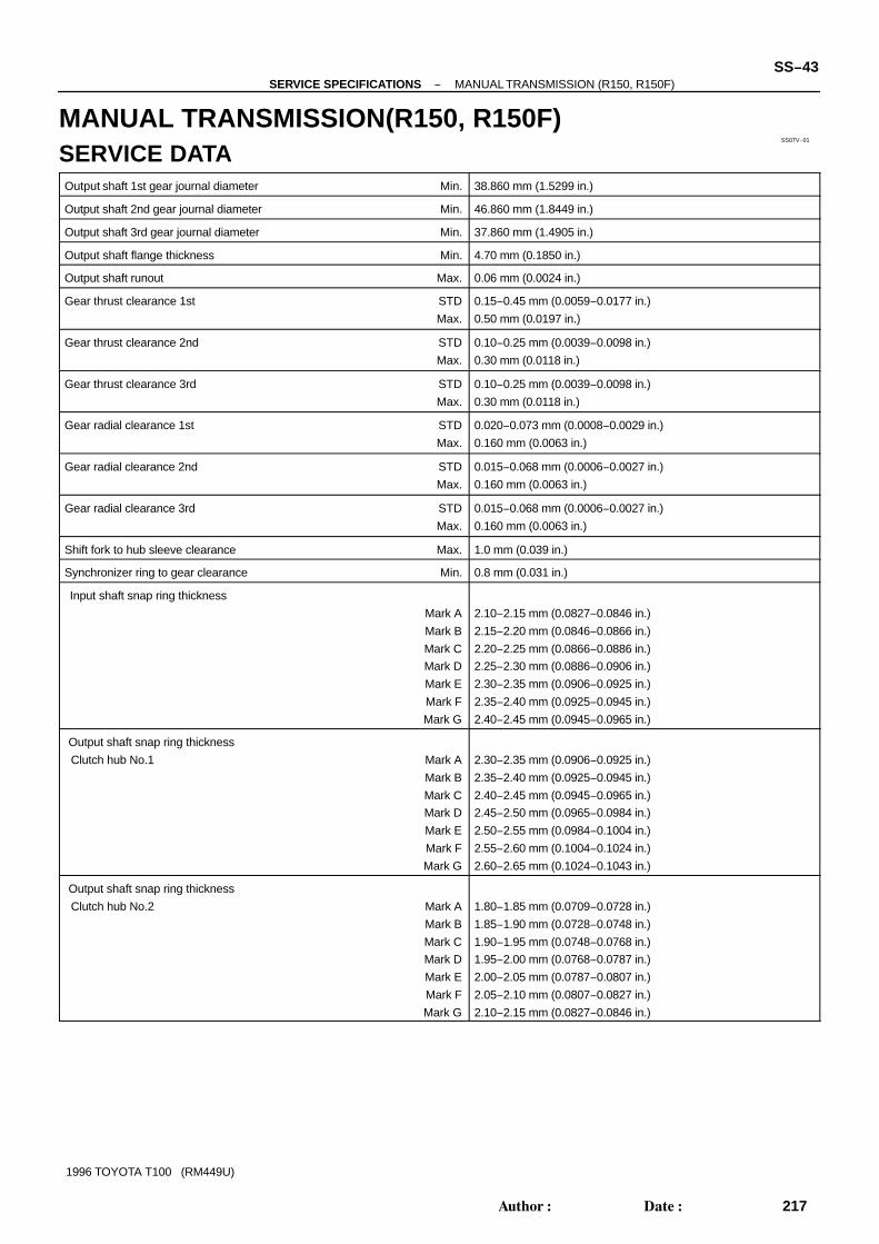
SS07V−01
−SERVICE SPECIFICATIONS MANUAL TRANSMISSION (R150, R150F)SS−43
217Author�: Date�:
1996 TOYOTA T100 (RM449U)
MANUAL TRANSMISSION(R150, R150F)SERVICE DATAOutput shaft 1st gear journal diameter Min. 38.860 mm (1.5299 in.)
Output shaft 2nd gear journal diameter Min. 46.860 mm (1.8449 in.)
Output shaft 3rd gear journal diameter Min. 37.860 mm (1.4905 in.)
Output shaft flange thickness Min. 4.70 mm (0.1850 in.)
Output shaft runout Max. 0.06 mm (0.0024 in.)
Gear thrust clearance 1st STD
Max.
0.15−0.45 mm (0.0059−0.0177 in.)
0.50 mm (0.0197 in.)
Gear thrust clearance 2nd STD
Max.
0.10−0.25 mm (0.0039−0.0098 in.)
0.30 mm (0.0118 in.)
Gear thrust clearance 3rd STD
Max.
0.10−0.25 mm (0.0039−0.0098 in.)
0.30 mm (0.0118 in.)
Gear radial clearance 1st STD
Max.
0.020−0.073 mm (0.0008−0.0029 in.)
0.160 mm (0.0063 in.)
Gear radial clearance 2nd STD
Max.
0.015−0.068 mm (0.0006−0.0027 in.)
0.160 mm (0.0063 in.)
Gear radial clearance 3rd STD
Max.
0.015−0.068 mm (0.0006−0.0027 in.)
0.160 mm (0.0063 in.)
Shift fork to hub sleeve clearance Max. 1.0 mm (0.039 in.)
Synchronizer ring to gear clearance Min. 0.8 mm (0.031 in.)
Input shaft snap ring thickness
Mark A
Mark B
Mark C
Mark D
Mark E
Mark F
Mark G
2.10−2.15 mm (0.0827−0.0846 in.)
2.15−2.20 mm (0.0846−0.0866 in.)
2.20−2.25 mm (0.0866−0.0886 in.)
2.25−2.30 mm (0.0886−0.0906 in.)
2.30−2.35 mm (0.0906−0.0925 in.)
2.35−2.40 mm (0.0925−0.0945 in.)
2.40−2.45 mm (0.0945−0.0965 in.)
Output shaft snap ring thickness
Clutch hub No.1 Mark A
Mark B
Mark C
Mark D
Mark E
Mark F
Mark G
2.30−2.35 mm (0.0906−0.0925 in.)
2.35−2.40 mm (0.0925−0.0945 in.)
2.40−2.45 mm (0.0945−0.0965 in.)
2.45−2.50 mm (0.0965−0.0984 in.)
2.50−2.55 mm (0.0984−0.1004 in.)
2.55−2.60 mm (0.1004−0.1024 in.)
2.60−2.65 mm (0.1024−0.1043 in.)
Output shaft snap ring thickness
Clutch hub No.2 Mark A
Mark B
Mark C
Mark D
Mark E
Mark F
Mark G
1.80−1.85 mm (0.0709−0.0728 in.)
1.85−1.90 mm (0.0728−0.0748 in.)
1.90−1.95 mm (0.0748−0.0768 in.)
1.95−2.00 mm (0.0768−0.0787 in.)
2.00−2.05 mm (0.0787−0.0807 in.)
2.05−2.10 mm (0.0807−0.0827 in.)
2.10−2.15 mm (0.0827−0.0846 in.)
https://www.truck-manuals.net/

SS−44−SERVICE SPECIFICATIONS MANUAL TRANSMISSION (R150, R150F)
218Author�: Date�:
1996 TOYOTA T100 (RM449U)
Output shaft snap ring thickness
Rear Mark A
Mark B
Mark C
Mark D
Mark E
Mark F
Mark G
Mark H
Mark J
Mark K
Mark L
Mark M
Mark N
Mark P
Mark Q
Mark R
Mark S
2.65−2.70 mm (0.1043−0.1063 in.)
2.70−2.75 mm (0.1063−0.1083 in.)
2.75−2.80 mm (0.1083−0.1102 in.)
2.80−2.85 mm (0.1102−0.1122 in.)
2.85−2.90 mm (0.1122−0.1142 in.)
2.90−2.95 mm (0.1142−0.1161 in.)
2.95−3.00 mm (0.1161−0.1181 in.)
3.00−3.05 mm (0.1181−0.1201 in.)
3.05−3.10 mm (0.1201−0.1220 in.)
3.10−3.15 mm (0.1220−0.1240 in.)
3.15−3.20 mm (0.1240−0.1260 in.)
3.20−3.25 mm (0.1260−0.1280 in.)
3.25−3.30 mm (0.1280−0.1299 in.)
3.30−3.35 mm (0.1299−0.1319 in.)
3.35−3.40 mm (0.1319−0.1339 in.)
3.40−3.45 mm (0.1339−0.1358 in.)
3.45−3.50 mm (0.1358−0.1378 in.)
Counter gear roller bearing journal diameter Min. 27.860 mm (1.0968 in.)
Counter 5th gear thrust clearance STD
Max.
0.10−0.35 mm (0.0039−0.0138 in.)
0.40 mm (0.0157 in.)
Counter 5th radial clearance STD
Max.
0.015−0.068 mm (0.0006−0.0027 in.)
0.160 mm (0.0063 in.)
Reverse idler gear radial clearance STD
Max.
0.040−0.082 mm (0.0016−0.0032 in.)
0.130 mm (0.0051 in.)
Reverse idler gear to shift arm clearance STD
Max.
0.05−0.35 mm (0.0020−0.0138 in.)
0.50 mm (0.0197 in.)
Counter gear snap ring thickness
Front Mark A
Mark B
Mark C
Mark D
Mark E
Mark F
2.00−2.05 mm (0.0787−0.0807 in.)
2.05−2.10 mm (0.0807−0.0827 in.)
2.10−2.15 mm (0.0827−0.0846 in.)
2.15−2.20 mm (0.0846−0.0866 in.)
2.20−2.25 mm (0.0866−0.0886 in.)
2.25−2.30 mm (0.0886−0.0906 in.)
Counter gear snap ring thickness
Rear Mark A
Mark B
Mark C
Mark D
Mark E
Mark F
Mark G
2.80−2.85 mm (0.1102−0.1122 in.)
2.85−2.90 mm (0.1122−0.1142 in.)
2.90−2.95 mm (0.1142−0.1161 in.)
2.95−3.00 mm (0.1161−0.1181 in.)
3.00−3.05 mm (0.1181−0.1201 in.)
3.05−3.10 mm (0.1201−0.1220 in.)
3.10−3.15 mm (0.1220−0.1240 in.)
Oil seal drive in depth
Speedometer driven gear
Front bearing retainer (from retainer end)
Extension housing
Transfer adaptor
25 mm (0.98 in.)
11.7 ± 0.5 mm (0.461 ± 0.020 in.)
0 ± 0.5 mm (0 ± 0.020 in.)
45.6 ± 0.5 mm (1.795 ± 0.020 in.)
https://www.truck-manuals.net/

SS07W−01
−SERVICE SPECIFICATIONS MANUAL TRANSMISSION (R150, R150F)SS−45
1996 TOYOTA T100 (RM449U)
TORQUE SPECIFICATIONPart tightened N·m kgf·cm ft·lbf
Transmission x Engine 72 730 53
Stiffener plate x Engine (4WD) 37 380 27
Stiffener plate x Transmission (4WD) 37 380 27
Starter x Transmission 39 400 29
Engine rear mounting x Transmission 65 660 48
Rear end plate x Transmission (2WD) 18 185 13
Clutch release cylinder x Transmission 12 120 9
Front exhaust pipe x TWC 48 490 35
Front exhaust pipe support bracket 44 450 33
Front exhaust pipe x Exhaust manifold 62 630 46
Crossmember x Engine rear mounting (4WD) 18 180 13
Engine rear mounting bracket x Engine rear mounting (2WD) 18 180 13
Engine rear mounting bracket x Frame (2WD) 58 590 43
Crossmember x Frame (4WD) 95 970 70
Transmission x Transfer (4WD) 37 380 27
Reverse shift arm bracket set bolt 18 185 13
Rear bearing retainer x Intermediate plate 18 185 13
Shift fork x Shift fork shaft 20 200 14
Straight screw plug 19 190 14
Front bearing retainer x Transmission case 17 170 12
Transmission case x Transfer adaptor 37 380 27
Transmission case x Extension housing 37 380 27
Shift lever housing set bolt 38 390 28
Clutch housing x Transmission case 36 370 27
Oil receiver x Extension housing 11 115 8
Back−up light switch 44 450 32
Restrict pin 37 380 27
Control shift lever retainer x Transfer adaptor 18 185 13
Control shift lever retainer x Extension housing 18 185 13
Filler and drain plug 37 380 27
Speedometer driven gear (2WD) 11 115 8
https://www.truck-manuals.net/

SS05Z−03
SS−46−SERVICE SPECIFICATIONS MANUAL TRANSMISSION (W59)
220Author�: Date�:
1996 TOYOTA T100 (RM449U)
MANUAL TRANSMISSION (W59)SERVICE DATAOutput shaft 2nd gear journal diameter Min. 42.975 mm (1.6919 in.)
Output shaft 3rd gear journal diameter Min. 31.969 mm (1.2586 in.)
Output shaft flange thickness Min. 5.60 mm (0.2205 in.)
Output shaft runout Max. 0.06 mm (0.0024 in.)
1st gear inner race flange thickness Min. 4.78 mm (0.1881 in.)
1st gear inner race outer diameter Min. 42.975 mm (1.6919 in.)
Counter gear bearing journal diameter Min. 29.950 mm (1.1791 in.)
Counter 5th gear journal diameter Min. 26.975 mm (1.0620 in.)
1st, 2nd and 3rd gear thrust clearance STD
Max.
0.10 − 0.25 mm (0.0039 − 0.0098 in.)
0.30 mm (0.0118 in.)
Counter 5th gear thrust clearance STD
Max.
0.10 − 0.41 mm (0.0039 − 0.0161 in.)
0.46 mm (0.0181 in.)
1st, 2nd and counter 5th gear radial clearance STD
Max.
0.009 − 0.060 mm (0.0004 − 0.0024 in.)
0.150 mm (0.0059 in.)
3rd gear radial clearance STD
Max.
0.015 − 0.066 mm (0.0006 − 0.0026 in.)
0.200 mm (0.0079 in.)
Reverse idler gear radial clearance STD
Max.
0.041 − 0.074 mm (0.0016 − 0.0029 in.)
0.194 mm (0.0076 in.)
Reverse idler gear to shift arm shoe clearance STD
Max.
0.20 − 0.41 mm (0.0080 − 0.0161 in.)
0.90 mm (0.0354 in.)
Shift fork to hub sleeve clearance Max. 1.0 mm (0.039 in.)
Synchronizer ring to 1st and 4th gear clearance Min. 0.5 mm (0.020 in.)
Synchronizer ring to 2nd and 3rd gear clearance Min. 0.7 mm (0.028 in.)
Input shaft snap ring thickness
Mark 1
Mark 2
Mark 3
Mark 4
Mark 5
Mark 11
Mark 12
2.05 − 2.10 mm (0.0807 − 0.0827 in.)
2.10 − 2.15 mm (0.0827 − 0.0846 in.)
2.15 − 2.20 mm (0.0846 − 0.0866 in.)
2.20 − 2.25 mm (0.0866 − 0.0886 in.)
2.25 − 2.30 mm (0.0886 − 0.0906 in.)
2.30 − 2.35 mm (0.0906 − 0.0925 in.)
2.35 − 2.40 mm (0.0925 − 0.0945 in.)
Output shaft snap ring thickness
No.2 clutch hub Mark C−1
Mark D
Mark 11
Mark 12
Mark 13
Mark 14
Mark 15
1.75 − 1.80 mm (0.0689 − 0.0709 in.)
1.80 − 1.85 mm (0.0709 − 0.0728 in.)
1.86 − 1.91 mm (0.0732 − 0.0752 in.)
1.92 − 1.97 mm (0.0756 − 0.0776 in.)
1.98 − 2.03 mm (0.0780 − 0.0799 in.)
2.04 − 2.09 mm (0.0803 − 0.0823 in.)
2.10 − 2.15 mm (0.0827 − 0.0846 in.)
Output shaft snap ring thickness
Rear bearing Mark 8
Mark 9
Mark 10
Mark 11
Mark 12
Mark 13
Mark 14
Mark 15
2.31 − 2.36 mm (0.0909 − 0.0929 in.)
2.37 − 2.42 mm (0.0933 − 0.0953 in.)
2.43 − 2.48 mm (0.0957 − 0.0976 in.)
2.49 − 2.54 mm (0.0980 − 0.1000 in.)
2.55 − 2.60 mm (0.1004 − 0.1024 in.)
2.61 − 2.66 mm (0.1028 − 0.1047 in.)
2.68 − 2.73 mm (0.1055 − 0.1075 in.)
2.74 − 2.79 mm (0.1079 − 0.1098 in.)
https://www.truck-manuals.net/

−SERVICE SPECIFICATIONS MANUAL TRANSMISSION (W59)SS−47
221Author�: Date�:
1996 TOYOTA T100 (RM449U)
Output shaft snap ring thickness
Reverse gear Mark 5
Mark 11
Mark 12
Mark 13
Mark 14
Mark 15
Mark 16
Mark 17
Mark 18
Mark 19
Mark 20
Mark 21
Mark 22
Mark 23
2.25 − 2.30 mm (0.0886 − 0.0906 in.)
2.30 − 2.35 mm (0.0906 − 0.0925 in.)
2.35 − 2.40 mm (0.0925 − 0.0945 in.)
2.40 − 2.45 mm (0.0945 − 0.0965 in.)
2.45 − 2.50 mm (0.0965 − 0.0984 in.)
2.50 − 2.55 mm (0.0984 − 0.1004 in.)
2.55 − 2.60 mm (0.1004 − 0.1024 in.)
2.61 − 2.66 mm (0.1028 − 0.1047 in.)
2.67 − 2.72 mm (0.1051 − 0.1071 in.)
2.73 − 2.78 mm (0.1075 − 0.1094 in.)
2.79 − 2.84 mm (0.1098 − 0.1118 in.)
2.85 − 2.90 mm (0.1122 − 0.1142 in.)
2.91 − 2.96 mm (0.1146 − 0.1165 in.)
2.97 − 3.02 mm (0.1169 − 0.1189 in.)
Coutner gear snap ring thickness
Front bearing Mark A
Mark B
Mark C
Mark D
Mark E
Mark F
Mark G
2.05 − 2.10 mm (0.0807 − 0.0827 in.)
2.10 − 2.15 mm (0.0827 − 0.0846 in.)
2.15 − 2.20 mm (0.0846 − 0.0866 in.)
2.20 − 2.25 mm (0.0866 − 0.0886 in.)
2.25 − 2.30 mm (0.0886 − 0.0906 in.)
2.30 − 2.35 mm (0.0906 − 0.0925 in.)
2.35 − 2.40 mm (0.0925 − 0.0945 in.)
Counter gear snap ring thickness
No.3 clutch hub Mark 2
Mark 3
Mark 4
Mark 5
2.06 − 2.11 mm (0.0811 − 0.0831 in.)
2.12 − 2.17 mm (0.0835 − 0.0854 in.)
2.18 − 2.23 mm (0.0858 − 0.0878 in.)
2.24 − 2.29 mm (0.0882 − 0.0902 in.)
Counter gear snap ring thickness
Rear bearing Mark 1
Mark 2
Mark 3
Mark 4
Mark 5
Mark 6
Mark 7
1.90 − 1.95 mm (0.0748 − 0.0768 in.)
1.96 − 2.01 mm (0.0772 − 0.0791 in.)
2.02 − 2.07 mm (0.0795 − 0.0815 in.)
2.08 − 2.13 mm (0.0819 − 0.0839 in.)
2.14 − 2.19 mm (0.0843 − 0.0862 in.)
2.20 − 2.25 mm (0.0866 − 0.0886 in.)
2.26 − 2.31 mm (0.0890 − 0.0909 in.)
Oil seal drive in depth
Front bearing retainer (from retainer end)
Extension housing
Speedometer drive gear
12.2 ± 0.5 mm (0.480 ± 0.020 in.)
0 ± 0.5 mm (0 ± 0.020 in.)
25 mm (0.98 in.)
https://www.truck-manuals.net/

SS060−03
SS−48−SERVICE SPECIFICATIONS MANUAL TRANSMISSION (W59)
1996 TOYOTA T100 (RM449U)
TORQUE SPECIFICATIONPart tightened N·m kgf·cm ft·lbf
Transmission x Engine 72 730 53
Transmission x Starter 39 400 29
Rear end plate x Clutch housing 37 380 27
Shift fork set bolt 20 200 14
Straight screw plug 25 250 18
Reverse idler gear shaft stopper bolt 25 250 18
Oil separator x Intermediate plate 18 185 13
Front bearing retainer set bolt 25 250 18
Extension housing x Intermediate plate 37 380 27
Restrict pin 40 410 30
Shift lever housing x Shift and select lever shaft 39 400 29
Control shift lever retainer x Extension housing 18 185 13
Drain and filler plugs 37 380 27
Back−up light switch 40 410 30
Clutch housing x Transmission case 37 380 27
Rear bearing retainer x Intermediate plate 18 185 13
Speedometer driven gear 13 130 9
https://www.truck-manuals.net/

SS089−02
−SERVICE SPECIFICATIONS AUTOMATIC TRANSMISSIONSS−49
223Author�: Date�:
1996 TOYOTA T100 (RM449U)
AUTOMATIC TRANSMISSIONSERVICE DATALine pressure (Wheel locked)
(3RZ−FE)
Engine idling
D position
R position
at stall (Throttle valve fully opened)
D position
R position
(5VZ−FE)
Engine idling
D position
R position
at stall (Throttle valve fully opened)
D position
R position
363 − 422 kPa (3.7 − 4.2 kgf/cm2, 53 − 61 psi)
490 − 588 kPa (5.0 − 6.0 kgf/cm2, 71 − 85 psi)
932 − 1,177 kPa (9.5 − 12.0 kgf/cm2, 135 − 171 psi)
1,294 − 1,638 kPa (13.2 − 16.7 kgf/cm2, 188 − 238 psi)
363 − 422 kPa (3.7 − 4.2 kgf/cm2, 53 − 61 psi)
608 − 696 kPa (6.2 − 7.1 kgf/cm2, 88 − 101 psi)
902 − 1,147 kPa (9.2 − 11.7 kgf/cm2, 131 − 166 psi)
1,432 − 1,942 kPa (14.6 − 19.8 kgf/cm2, 208 − 282 psi)
Engine stall revolution (D and R positions) 3RZ−FE
5VZ−FE
1,950 ± 150 rpm
2,150 ± 150 rpm
Time lag N → D position
N → R position
Less than 1.2 seconds
Less than 1.5 seconds
Engine idle speed
(A/C OFF and N position) 700 ± 50 rpm
Throttle cable adjustment
(Throttle valve fully opened)
Between boot end face and inner cable stopper
0 − 1 mm (0 − 0.04 in.)
Drive plate runout Max.
Torque converter runout Max.
Torque converter installation distance 3R−FE
5VZ−FE
0.20 mm (0.0079 in.)
0.30 mm (0.0118 in.)
More than 31.75 mm (1.2500 in.)
More than 17.95 mm (0.7067 in.)
Speedometer driven gear oil seal drive in depth 3RZ−FE
5VZ−FE
20 mm (0.79 in.)
20 mm (0.79 in.)
Lock−up point
(3RZ−FE / A340E)
D position
(Throttle valve opening 5%) Lock−up ON
Lock−up OFF
(5VZ−FE / A340E)
D position
(Throttle valve opening 5%) Lock−up ON
Lock−up OFF
(5VZ−FE / A340F)
(Throttle valve opening 5%) Lock−up ON
Lock−up OFF
83 − 88 km/h (52 − 55 mph)
70 − 75 km/h (44 − 47 mph)
79 − 84 km/h (49 − 52 mph)
72 − 77 km/h (45 − 48 mph)
75 − 80 km/h (47 − 50 mph)
68 − 73 km/h (42 − 45 mph)
https://www.truck-manuals.net/

SS−50−SERVICE SPECIFICATIONS AUTOMATIC TRANSMISSION
224Author�: Date�:
1996 TOYOTA T100 (RM449U)
Shift schedule
(3RZ−FE / A340E)
D position
(Throttle valve fully opened) 1 → 2
2 → 3
3 → O/D
O/D → 3
3 → 2
2 → 1
(Throttle valve fully closed) 3 → O/D
O/D → 3
2 position
(Throttle valve fully opened) 1 → 2
3 → 2
2 → 1
L position
(Throttle valve fully opened) 2 → 1
(5VZ−FE / A340E)
D position
(Throttle valve fully opened) 1 → 2
2 → 3
3 → O/D
O/D → 3
3 → 2
2 → 1
(Throttle valve fully closed) 3 → O/D
O/D → 3
2 position
(Throttle valve fully opened) 1 → 2
3 → 2
2 → 1
L position
(Throttle valve fully opened) 2 → 1
(5VZ−FE / A340F)
D position
(Throttle valve fully opened) 1 → 2
2 → 3
3 → O/D
O/D → 3
3 → 2
2 → 1
(Throttle valve fully closed) 3 → O/D
O/D → 3
2 position
(Throttle valve fully opened) 1 → 2
3 → 2
2 → 1
L position
(Throttle valve fully opened) 2 → 1
55 − 60 km/h (34 − 37 mph)
99 − 108 km/h (62 − 67 mph)
127 − 136 km/h (79 − 85 mph)
120 − 130 km/h (75 − 81 mph)
92 − 98 km/h (57 − 61 mph)
44 − 48 km/h (27 − 30 mph)
34 − 39 km/h (21 − 24 mph)
25 − 30 km/h (16 − 19 mph)
55 − 60 km/h (34 − 37 mph)
110 − 120 km/h (68 − 75 mph)
44 − 48 km/h (27 − 30 mph)
53 − 58 km/h (33 − 36 mph)
57 − 62 km/h (35 − 39 mph)
108 − 117 km/h (67 − 73 mph)
146 − 155 km/h (91 − 96 mph)
139 − 148 km/h (86 − 92 mph)
99 − 108 km/h (62 − 67 mph)
46 − 51 km/h (29 − 32 mph)
44 − 49 km/h (27 − 30 mph)
22 − 27 km/h (14 − 17 mph)
57 − 62 km/h (35 − 39 mph)
115 − 124 km/h (71 − 77 mph)
46 − 51 km/h (29 − 32 mph)
52 − 58 km/h (32 − 36 mph)
55 − 59 km/h (35 − 39 mph)
103 − 111 km/h (64 − 69 mph)
139 − 147 km/h (86 − 91 mph)
133 − 141 km/h (83 − 88 mph)
95 − 103 km/h (59 − 64 mph)
44 − 48 km/h (27 − 30 mph)
42 − 47 km/h (26 − 29 mph)
21 − 26 km/h (13 − 16 mph)
55 − 59 km/h (34 − 37 mph)
110 − 118 km/h (68 − 73 mph)
44 − 48 km/h (27 − 30 mph)
53 − 58 km/h (33 − 36 mph)
https://www.truck-manuals.net/

SS08A−03
−SERVICE SPECIFICATIONS AUTOMATIC TRANSMISSIONSS−51
1996 TOYOTA T100 (RM449U)
TORQUE SPECIFICATIONPart tightened N·m kgf·cm ft·lbf
Valve body x Transmission case 10 100 7
Oil strainer x Valve body (A340E) 5.4 55 48 in.·lbf
Oil strainer case x Valve body (A340F) 10 100 7
Oil strainer x Valve body (A340F) 6.9 70 61 in.·lbf
Oil pan 7.4 75 65 in.·lbf
Drain plug 20 205 15
Parking lock pawl bracket x Transmission case 7.4 75 65 in.·lbf
Extension housing x Transmission case (A340E) 36 370 27
Extension housing x Rear mounting insulator 25 250 18
Rear support member x Rear mounting insulator (A340F) 18 180 13
Rear support member x Body (A340F) 95 970 70
Rear mounting insulator x Rear mounting bracket (A340E) 18 180 13
Rear mounting bracket x Frame (A340E) 58 590 42
Propeller shaft x Rear differential (A340E) 74 750 54
Front propeller shaft x Front differential (A340F) 74 750 54
Front propeller shaft x Transfer (A340F) 74 750 54
Rear propeller shaft x Transfer (A340F) 74 750 54
Rear propeller shaft x Rear differential (A340F) 74 750 54
Center support bearing x Body 36 370 27
Drive plate x Crankshaft 83 850 61
Torque converter clutch x Drive plate 41 420 30
Stiffener plate x Engine (A340F) 37 380 27
Stiffener plate x Transmission 37 380 27
Front exhaust pipe x Exhaust manifold 62 630 46
Front exhaust pipe x TWC 48 490 35
Rear support member x Dynamic damper 61 620 44
Oil cooler pipe 34 350 25
Transmission x Engine 71 730 53
Rear end plate x Transmission 37 380 27
Rear support member x Transfer under cover 29 300 21
Cross shaft x Frame 28 290 21
Cross shaft x Transmission 13 130 9
Cross shaft x No.1 gear shifting rod 13 130 9
Exhaust pipe clamp (3RZ−FE) 19 195 14
Exhaust pipe support bracket x Transmission (3RZ−FE) 71 730 53
Exhaust pipe support bracket x Transmission (5VZ−FE) 44 450 33
Exhaust pipe support bracket x Exhaust pipe (5VZ−FE) 44 450 33
Park/neutral position switch (Nut) 3.9 40 35 in.·lbf
Park/neutral position switch (Bolt) 13 130 9
No.2 vehicle speed sensor 5.4 55 48 in.·lbf
Speedometer driven gear sleeve x Locking plate 16 160 12
ATF temperature sensor x Transmission 15 150 11
Shift lever assembly x Steering column assembly 29 300 22
https://www.truck-manuals.net/

SS−52−SERVICE SPECIFICATIONS AUTOMATIC TRANSMISSION
1996 TOYOTA T100 (RM449U)
Shift lever sub−assembly x Control shaft assembly 19 195 14
Casing cap x Control shaft support sub−assembly 50 510 37
https://www.truck-manuals.net/

SS08Z−02
−SERVICE SPECIFICATIONS TRANSFERSS−53
227Author�: Date�:
1996 TOYOTA T100 (RM449U)
TRANSFERSERVICE DATAOil pump body
Body clearance STD
Maximum
Tip clearance STD
Maximum
Side clearance STD
Maximum
0.10 − 0.16 mm (0.0039 − 0.0063 in.)
0.16 mm (0.0063 in.)
0.08 − 0.15 mm (0.0031 − 0.0059 in.)
0.16 mm (0.0063 in.)
0.03 − 0.08 mm (0.0012 − 0.0031 in.)
0.08 mm (0.0031 in.)
Rear output shaft assembly
Drive sprocket thrust clearance STD
Maximum
Rear output shaft journal diameter
(part A) Minimum
(part B) Minimum
Drive sprocket radial clearance STD
Maximum
Front drive shift fork to hub sleeve clearance Maximum
High and low shift fork to hub sleeve clearance Maximum
Rear output shaft snap ring thickness Mark
A
B
C
D
E
F
G
H
J
K
L
0.10 − 0.25 mm (0.0039 − 0.0098 in.)
0.25 mm (0.0098 in.)
27.98 mm (1.1016 in.)
36.99 mm (1.4563 in.)
0.010 − 0.055 mm (0.0004 − 0.0022 in.)
0.055 mm (0.0022 in.)
1.0 mm (0.039 in.)
1.0 mm (0.039 in.)
2.10 − 2.15 mm (0.0827 − 0.0846 in.)
2.15 − 2.20 mm (0.0846 − 0.0866 in.)
2.20 − 2.25 mm (0.0866 − 0.0886 in.)
2.25 − 2.30 mm (0.0886 − 0.0906 in.)
2.30 − 2.35 mm (0.0906 − 0.0925 in.)
2.35 − 2.40 mm (0.0925 − 0.0945 in.)
2.40 − 2.45 mm (0.0945 − 0.0965 in.)
2.45 − 2.50 mm (0.0965 − 0.0984 in.)
2.50 − 2.55 mm (0.0984 − 0.1004 in.)
2.00 − 2.05 mm (0.0787 − 0.0807 in.)
2.05 − 2.10 mm (0.0807 − 0.0827 in.)
Input shaft
Input shaft journal outer diameter Minimum
Input shaft bushing diameter Maximum
Synchronizer ring to sprocket clearance STD
Minimum
Input shaft snap ring thickness Mark
A
B
C
D
E
F
G
H
J
K
L
M
N
P
Q
R
S
T
U
47.59 mm (1.8736 in.)
39.14 mm (1.5409 in.)
1.15 − 1.85 mm (0.0453 − 0.0728 in.)
0.80 mm (0.0315 in.)
2.10 − 2.15 mm (0.0827 − 0.0846 in.)
2.15 − 2.20 mm (0.0846 − 0.0866 in.)
2.20 − 2.25 mm (0.0866 − 0.0886 in.)
2.25 − 2.30 mm (0.0886 − 0.0906 in.)
2.30 − 2.35 mm (0.0906 − 0.0925 in.)
2.35 − 2.40 mm (0.0925 − 0.0945 in.)
2.40 − 2.45 mm (0.0945 − 0.0965 in.)
2.45 − 2.50 mm (0.0965 − 0.0984 in.)
2.50 − 2.55 mm (0.0984 − 0.1004 in.)
2.55 − 2.60 mm (0.1004 − 0.1024 in.)
2.60 − 2.65 mm (0.1024 − 0.1043 in.)
2.65 − 2.70 mm (0.1043 − 0.1063 in.)
2.70 − 2.75 mm (0.1063 − 0.1083 in.)
2.75 − 2.80 mm (0.1083 − 0.1102 in.)
2.80 − 2.85 mm (0.1102 − 0.1122 in.)
2.85 − 2.90 mm (0.1122 − 0.1142 in.)
2.90 − 2.95 mm (0.1142 − 0.1161 in.)
2.95 − 3.00 mm (0.1161 − 0.1181 in.)
3.00 − 3.05 mm (0.1181 − 0.1201 in.)
https://www.truck-manuals.net/

SS−54−SERVICE SPECIFICATIONS TRANSFER
228Author�: Date�:
1996 TOYOTA T100 (RM449U)
Planetary gear
Pinion gear thrust clearance STD
Maximum
Pinion gear radial clearance STD
Maximum
Outer bearing snap ring thickness Mark
1
2
3
4
5
Inner bearing depth
0.11 − 0.86 mm (0.0043 − 0.0339 in.)
0.86 mm (0.0339 in.)
0.009 − 0.038 mm (0.0004 − 0.0015 in.)
0.038 mm (0.0015 in.)
1.45 − 1.50 mm (0.0571 − 0.0591 in.)
1.50 − 1.55 mm (0.0591 − 0.0610 in.)
1.55 − 1.60 mm (0.0610 − 0.0630 in.)
1.60 − 1.65 mm (0.0630 − 0.0650 in.)
1.65 − 1.70 mm (0.0650 − 0.0669 in.)
5.0 − 5.6 mm (0.197 − 0.220 in.)
Oil seal
Shift fork shaft oil seal depth
Speedometer driven gear oil seal depth
−0.5 − 0.5 mm (−0.020 − 0.020 in.)
25 mm (0.98 in.)
https://www.truck-manuals.net/
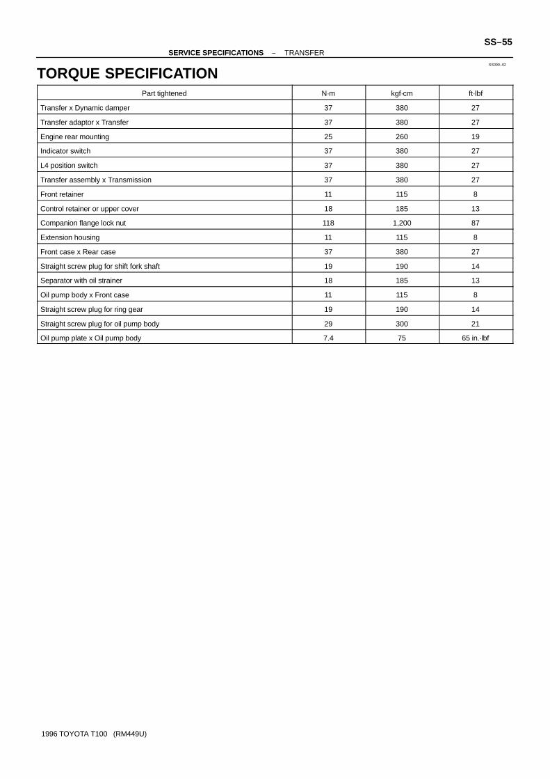
SS090−02
−SERVICE SPECIFICATIONS TRANSFERSS−55
1996 TOYOTA T100 (RM449U)
TORQUE SPECIFICATIONPart tightened N·m kgf·cm ft·lbf
Transfer x Dynamic damper 37 380 27
Transfer adaptor x Transfer 37 380 27
Engine rear mounting 25 260 19
Indicator switch 37 380 27
L4 position switch 37 380 27
Transfer assembly x Transmission 37 380 27
Front retainer 11 115 8
Control retainer or upper cover 18 185 13
Companion flange lock nut 118 1,200 87
Extension housing 11 115 8
Front case x Rear case 37 380 27
Straight screw plug for shift fork shaft 19 190 14
Separator with oil strainer 18 185 13
Oil pump body x Front case 11 115 8
Straight screw plug for ring gear 19 190 14
Straight screw plug for oil pump body 29 300 21
Oil pump plate x Oil pump body 7.4 75 65 in.·lbf
https://www.truck-manuals.net/

SS07Y−01
SS−56−SERVICE SPECIFICATIONS PROPELLER SHAFT
230Author�: Date�:
1996 TOYOTA T100 (RM449U)
PROPELLER SHAFTSERVICE DATAPropeller shaft runout Maximum runout 0.8 mm (0.031 in.)
Spider bearing axial play 0.05 mm (0.0020 in.)
Snap ring thickness 2WD (TMC−made) and 4WD Mark Color
1 − 2.100 − 2.150 mm (0.0827 − 0.0846 in.)
2 − 2.150 − 2.200 mm (0.0846 − 0.0866 in.)
3 − 2.200 − 2.250 mm (0.0866 − 0.0886 in.)
− Brown 2.250 − 2.300 mm (0.0886 − 0.0906 in.)
− Bule 2.300 − 2.350 mm (0.0906 − 0.0925 in.)
6 − 2.350 − 2.400 mm (0.0925 − 0.0945 in.)
7 − 2.400 − 2.450 mm (0.0945 − 0.0965 in.)
8 − 2.450 − 2.500 mm (0.0965 − 0.0984 in.)
Snap ring thickness 2WD (DANA−made) Color
Green 1.384 mm (0.0545 in.)
Red 1.435 mm (0.0565 in.)
Black 1.486 mm (0.0585 in.)
Copper 1.511 mm (0.0895 in.)
Silver 1.537 mm (0.0605 in.)
Yellow 1.588 mm (0.0625 in.)
Blue 1.638 mm (0.0645 in.)
https://www.truck-manuals.net/

SS07Z−04
−SERVICE SPECIFICATIONS PROPELLER SHAFTSS−57
1996 TOYOTA T100 (RM449U)
TORQUE SPECIFICATIONPart tightened N·m kgf·cm ft·lbf
Propeller shaft x Differential 2WD 74 750 54
Intermediate shaft x Propeller shaft 2WD 74 750 54
Front propeller shaft x Front differential 4WD 74 750 54
Front propeller shaft x Transfer 4WD 74 750 54
Rear propeller shaft x Rear differential 4WD 76 780 56
Rear propeller shaft x Transfer 4WD 76 780 56
Intermediate shaft x Propeller shaft 4WD 76 780 56
Center support bearing x Body 36 370 27
Intermediate shaft x Center support bearing x Joint flange
1st 181 1,850 134
Loosen nut
2WD (TMC−made) and 4WD 2nd 69 700 51
2WD (DANA−made) 2nd 81 830 60
Front propeller shaft No.2 dust cover set bolts 17 175 13
Front propeller shaft No.2 dust cover set nuts 13 135 10
Front propeller shaft dust cover bracket x Bracket 23 230 17
Front propeller shaft dust cover bracket x Transfer 36 370 27
https://www.truck-manuals.net/

SS082−02
SS−58−SERVICE SPECIFICATIONS SUSPENSION AND AXLE
232Author�: Date�:
1996 TOYOTA T100 (RM449U)
SUSPENSION AND AXLESERVICE DATA
Cold tire inflation
pressure (2WD)
P215/75R15 Front 230 kPa (2.3 kgf/cm2, 33 psi)
Rear 240 kPa (2.4 kgf/cm2, 35 psi)
P235/75R15 (0.5 ton) Front 180 kPa (1.8 kgf/cm2, 26 psi)
Rear 200 kPa (2.0 kgf/cm2, 29 psi)
P235/75R15 (1.0 ton)Front 180 kPa (1.8 kgf/cm2, 26 psi)
Rear 280 kPa (2.8 kgf/cm2, 41 psi)
Cold tire inflation
pressure (4WD)
P235/75R15 STD cab Front 180 kPa (1.8 kgf/cm2, 26 psi)
Rear 200 kPa (2.0 kgf/cm2, 29 psi)31x10.5R15LT STD cab
P235/75R15 Extra cabFront 180 kPa (1.8 kgf/cm2, 26 psi)
Rear 240 kPa (2.4 kgf/cm2, 35 psi)
31x10.5R15LT Extra cabFront 200 kPa (2.0 kgf/cm2, 29 psi)
Rear 240 kPa (2.4 kgf/cm2, 35 psi)
Wheel alignment
(Standard loaded
vehicle condition)
(2WD)
Vehicle height STD cab 0.5 ton
STD cab 1.0 ton
Extra cab
Front *1 74.0 mm (2.913 in.)
Rear *2 122.0 mm (4.803 in.)
Front *1 74.0 mm (2.913 in.)
Rear *2 107.0 mm (4.213 in.)
Front *1 74.0 mm (2.913 in.)
Rear *2 115.5 mm (4.547 in.)
Camber
Left−right error
0°00’ ± 45’ (0° ± 0.75°)
45’ (0.75°) or less
Caster
Left−right error
4°00’ ± 45’ (4° ± 0.75°)
45’ (0.75°) or less
Steering axis inclination
Left−right error
12°30’ ± 45’ (12.5° ± 0.75°)
45’ (0.75°) or less
Toe−in (Total) STD cab
Extra cab (P215/75R15)
Extra cab (P235/75R15)
Rack end length difference
0° ± 12’ (0° ± 0.2°, 0 ± 2 mm, 0 ± 0.08 in.)
−0°22’ ± 12’ (−0.36° ± 0.2°, −4.7 ± 2 mm, −0.18 ± 0.08 in.)
−0°22’ ± 12’ (−0.36° ± 0.2°, −4.9 ± 2 mm, −0.19 ± 0.08 in.)
3.0 mm (0.118 in.) or less
Wheel angle
STD cab 0.5 ton Inside wheel
Outside wheel
STD cab 1.0 ton Inside wheel
Outside wheel
Extra cab Inside wheel
Outside wheel
Left−right error
40°42’ ± 2° (40.7° ± 2°)
34°23’ (34.38°)
39°55’ ± 2° (39.92° ± 2°)
34°37’ (34.62°)
40°10’ ± 2° (40.17° ± 2°)
34°25’ (34.42°)
30’ (0.5°) or less
*1: A − BA: Ground clearance of spindle center.B: Ground clearance of lower suspension arm bolt center.*2: C − DC: Ground clearance of rear axle shaft center.D: Ground clearance of leaf spring front hanger pin center.
https://www.truck-manuals.net/

−SERVICE SPECIFICATIONS SUSPENSION AND AXLESS−59
233Author�: Date�:
1996 TOYOTA T100 (RM449U)
Wheel alignment
(Non−loaded
vehicle condition)
(2WD)
Vehicle height
RCK10L−TRMRKA P215/75R15 Front*1 45.4 mm (1.787 in.)
Rear*2 62.5 mm (2.460 in.)
RCK10L−TRMRKA P235/75R15 Front*1 45.4 mm (1.787 in.)
Rear*2 61.4 mm (2.417 in.)
RCK10L−TRSRKA P215/75R15 Front*1 45.4 mm (1.787 in.)
Rear*2 63.5 mm (2.500 in.)
VCK11L−TRMDKA P215/75R15 Front*1 48.0 mm (1.890 in.)
Rear*2 62.2 mm (2.449 in.)
VCK11L−TRMDKA P235/75R15 Front*1 48.0 mm (1.890 in.)
Rear*2 63.3 mm (2.492 in.)
VCK11L−THMDKA 5VZ−FE Engine (1.0 ton) Front*1 49.4 mm (1.945 in.)
Rear*2 32.3 mm (1.272 in.)
VCK11L−TRSDKA P215/75R15 Front*1 49.9 mm (1.965 in.)
Rear*2 63.5 mm (2.500 in.)
VCK11L−TRSDKA P235/75R15 Front*1 49.9 mm (1.965 in.)
Rear*2 64.6 mm (2.543 in.)
VCK11L−THSDKA 5VZ−FE Engine (1.0 ton) Front*1 49.9 mm (1.965 in.)
Rear*2 33.0 mm (1.299 in.)
VCK11L−CRMDKA P215/75R15 Front*1 38.8 mm (1.528 in.)
Rear*2 45.6 mm (1.795 in.)
VCK11L−CRMSKA P235/75R15 Front*1 38.8 mm (1.528 in.)
Rear*2 45.8 mm (1.803 in.)
VCK11L−CRSDKA P215/75R15 Front*1 38.8 mm (1.528 in.)
Rear*2 46.6 mm (1.835 in.)
VCK11L−CRSDKA P235/75R15 Front*1 38.8 mm (1.528 in.)
Rear*2 45.5 mm (1.791 in.)
VCK11L−CRSSKA P235/75R15 Front*1 38.8 mm (1.528 in.)
Rear*2 46.7 mm (1.839 in.)
VCK11L−CRMDKA P235/75R15 Front*1 38.8 mm (1.528 in.)
Rear*2 44.6 mm (1.756 in.)
*1: A − BA: Ground clearance of spindle center.B: Ground clearance of lower suspension arm bolt center.*2: C − DC: Ground clearance of rear axle shaft center.D: Ground clearance of leaf spring front hanger pin center.
https://www.truck-manuals.net/

SS−60−SERVICE SPECIFICATIONS SUSPENSION AND AXLE
234Author�: Date�:
1996 TOYOTA T100 (RM449U)
Wheel alignment
(Non−loaded
vehicle condition)
(2WD)
Camber
STD cab 3RZ−FE, 5VZ−FE engine (0.5 ton)
STD cab 5VZ−FE engine (1.0 ton)
Extra cab
Left−right error
0°24’ ± 45’ (0.4° ± 0.75°)
0°22’ ± 45’ (0.37° ± 0.75°)
0°28’ ± 45’ (0.47° ± 0.75°)
45’ (0.75°) or less
Caster
STD cab 3RZ−FE, 5VZ−FE engine (0.5 ton)
STD cab 5VZ−FE engine 1.0 ton
Extra cab
Left−right error
2°28’ ± 45’ (2.47° ± 0.75°)
1°38’ ± 45’ (1.63° ± 0.75°)
2°04’ ± 45’ (2.06° ± 0.75°)
45’ (0.75°) or less
Steering axis inclination STD cab 0.5 ton
STD cab 1.0 ton
Extra cab
Left−right error
12°05’ ± 45’ (12.08° ± 0.75°)
12°10’ ± 45’ (12.17° ± 0.75°)
12°00’ ± 45’ (12° ± 0.75°)
45’ (0.75°) or less
Toe−in (Total)
STD cab 3RZ−FE, 5VZ−FE engine (0.5 ton)
STD cab 5VZ−FE engine (1.0 ton)
Extra cab
Rack end length difference
0°11’ ± 12’ (0.19° ± 0.2°, 2.4 ± 2 mm, 0.09 ± 0.08 in.)
0°33’ ± 12’ (0.55° ± 0.2°, 7.0 ± 2 mm, 0.28 ± 0.08 in.)
0°20’ ± 12’ (0.33° ± 0.2°, 6.1 ± 2 mm, 0.24 ± 0.08 in.)
3.0 mm (0.118 in.) or less
Wheel angle
STD cab 3RZ−FE, 5VZ−FE engine (0.5 ton)
Inside wheel
Outside wheel
STD cab 5VZ−FE engine (1.0 ton) Inside wheel
Outside wheel
Extra cab Inside wheel
Outside wheel
Left−right error
40°42’ ± 2° (40.7° ± 2°)
35°07’ (35.12°)
40°23’ ± 2° (40.38° ± 2°)
35°31’ (35.52°)
40°50’ ± 2° (40.83° ± 2°)
35°41’ (35.68°)
30’ (0.5°) or less
https://www.truck-manuals.net/

−SERVICE SPECIFICATIONS SUSPENSION AND AXLESS−61
235Author�: Date�:
1996 TOYOTA T100 (RM449U)
Wheel alignment
(Standard loaded
vehicle condition)
(4WD)
Vehicle height STD cab
Extra cab
Front *1 58.0 mm (2.283 in.)
Rear *2 23.0 mm (0.906 in.)
Front *1 58.0 mm (2.283 in.)
Rear *2 28.0 mm (1.102 in.)
Camber
Left−right error
0°45’ ± 45’ (0.75° ± 0.75°)
45’ (0.75°) or less
Caster STD cab
Extra cab
Left−right error
1°30’ ± 45’ (1.5° ± 0.75°)
1°20’ ± 45’ (1.33° ± 0.75°)
45’ (0.75°) or less
Steering axis inclination
Left−right error
11°50’ ± 45’ (11.83° ± 0.75°)
45’ (0.75°) or less
Toe−in (Total) STD cab
Extra cab (P235/75R15)
Extra cab (31x10.5R15)
Rack end length difference
0°05’ ± 12’ (0.08° ± 0.2°, 1.0 ± 2 mm, 0.04 ± 0.08 in.)
−0°08’ ± 12’ (−0.14° ± 0.2°, −1.9 ± 2 mm, −0.07 ± 0.08 in.)
−0°08’ ± 12’ (−0.14° ± 0.2°, −2.0 ± 2 mm, −0.08 ± 0.08 in.)
3.0 mm (0.118 in.) or less
Wheel angle
STD cab Inside wheel
Outside wheel
Extra cab Inside wheel
Outside wheel
Left−right error
32°01’ ± 2° (32.02° ± 2°)
30°12’ (30.2°)
32°14’ ± 2° (32.23° ± 2°)
29°59’ (29.99°)
30’ (0.5°) or less
Wheel alignment
(Non−loaded
vehicle condition)
(4WD)
Vehicle height
VCK21L−TRMDKA P235/75R15 Front*1 38.3 mm (1.508 in.)
Rear*2 70.7 mm (2.783 in.)
VCK21L−TRMDKA 31x10.5R15 Front*1 38.3 mm (1.508 in.)
Rear*2 72.6 mm (2.858 in.)
VCK21L−TRSDKA P235/75R15 Front*1 40.0 mm (1.575 in.)
Rear*2 69.5 mm (2.736 in.)
VCK21L−TRSDKA 31x10.5R15 Front*1 40.0 mm (1.575 in.)
Rear*2 71.4 mm (2.811 in.)
VCK21L−CRM#KA P235/75R15 Front*1 32.3 mm (1.272 in.)
Rear*2 77.2 mm (3.039 in.)
VCK21L−CRM#KA 31x10.5R15 Front*1 32.3 mm (1.272 in.)
Rear*2 79.4 mm (3.126 in.)
VCK21L−CRS#KA P235/75R15 Front*1 32.3 mm (1.272 in.)
Rear*2 76.2 mm (3.000 in.)
VCK21L−CRS#KA 31x10.5R15 Front*1 32.3 mm (1.272 in.)
Rear*2 78.3 mm (3.083 in.)
#: Any letter is applicable.*1: A − BA: Ground clearance of spindle center.B: Ground clearance of lower suspension arm bolt center.*2: C − DC: Ground clearance of leaf spring front bushing center.D: Ground clearance of rear axle shaft center.
https://www.truck-manuals.net/

SS−62−SERVICE SPECIFICATIONS SUSPENSION AND AXLE
236Author�: Date�:
1996 TOYOTA T100 (RM449U)
Wheel alignment
(Non−loaded
vehicle condition)
(4WD)
Camber STD cab
Extra cab
Left−right error
0°35’ ± 45’ (0.59° ± 0.75°)
0°40’ ± 45’ (0.66° ± 0.75°)
45’ (0.75°) or less
Caster STD cab
Extra cab
Left−right error
0°59’ ± 45’ (0.98° ± 0.75°)
1°10’ ± 45’ (1.17° ± 0.75°)
45’ (0.75°) or less
Steering axis inclination
Left−right error
12°00’ ± 45’ (12° ± 0.75°)
45’ (0.75°) or less
Toe−in (Total) STD cab
Extra cab (P235/75R15)
Extra cab (31x10.5R15)
0°12’ ± 12’ (0.2° ± 0.2°, 2.7 ± 2 mm, 0.11 ± 0.08 in.)
0°08’ ± 12’ (0.14° ± 0.2°, 1.9 ± 2 mm, 0.07 ± 0.08 in.)
0°08’ ± 12’ (0.14° ± 0.2°, 2.0 ± 2 mm, 0.08 ± 0.08 in.)
Wheel angle
STD cab Inside wheel
Outside wheel <Reference>
Extra cab Inside wheel
Outside wheel <Reference>
32°45’ ± 2° (32.75° ± 2°)
30°31’ (30.52°)
33°07’ ± 2° (33.12° ± 2°)
30°31’ (30.52°)
Front axle (2WD)
Axle hub axial play Maximum 0.05 mm (0.0020 in.)
Axle hub preload (at starting) Friction force plus
5.0 − 14.0 N (0.5 − 1.4 kgf, 1.1 − 3.1 in.)
Front axle (4WD)Axle hub preload (at starting) 25 − 53 N (2.6 − 5.4 kgf, 5.7 − 11.9 lbf)
Front drive shaft thrust clearance Standard 0.1 − 0.5 mm (0.0039 − 0.0197 in.)
Front drive shaft
(4WD)Drive shaft length 481.2 − 491.2 mm (18.945 − 19.339 in.)
Front suspension
(2WD)
Upper ball joint turning torque 2.0 − 3.9 N·m (20 − 40 kgf·cm, 17 − 34 in.·lbf)
Lower ball joint turning torque 2.0 − 7.0 N·m (20 − 70 kgf·cm, 17 − 61 in.·lbf)
Front suspension
(4WD)
Upper ball joint turning torque 0.5 − 2.4 N·m (5 − 25 kgf·cm, 4 − 22 in.·lbf)
Lower ball joint turning torque 2.0 − 3.9 N·m (20 − 40 kgf·cm, 17 − 34 in.·lbf)
Rear axleShaft runout Maximum 2.0 mm (0.079 in.)
Flange runout Maximum 0.1 mm (0.004 in.)
Front differential
(4WD)
Companion flange vertical runout Maximum 0.10 mm (0.0039 in.)
Companion flange lateral runout Maximum 0.10 mm (0.0039 in.)
Drive pinion bearing preload (at starting)
New bearing
Reused bearing
1.2 − 1.9 N·m (12 − 19 kgf·cm, 10.4 − 16.5 in.·lbf)
0.6 − 1.0 N·m (6 − 10 kgf·cm, 5.2 − 8.7 in.·lbf)
Total preload (at starting) In addition to drive pinion preload
0.4 − 0.6 N·m (4 − 6 kgf·cm, 3.5 − 5.2 in.·lbf)
Pinion gear to side gear backlash 0.05 − 0.20 mm (0.0020 − 0.0079 in.)
Drive pinion to ring gear backlash 0.13 − 0.18 mm (0.0051 − 0.0070 in.)
Ring gear runout Maximum 0.07 mm (0.0028 in.)
Rear oil seal drive in depth 1.5 mm (0.059 in.)
Side gear shaft tube LH side oil seal drive in depth 2.5 mm (0.098 in.)
A.D.D. sleeve fork to clutch sleeve clearance 0.35 mm (0.0138 in.)
Differential bearing press in depth 2.0 mm (0.079 in.)
https://www.truck-manuals.net/

−SERVICE SPECIFICATIONS SUSPENSION AND AXLESS−63
237Author�: Date�:
1996 TOYOTA T100 (RM449U)
Front differential
(4WD)
Side gear thrust washer thickness
0.96 − 1.04 mm (0.0378 − 0.0409 in.)
1.06 − 1.14 mm (0.0417 − 0.0449 in.)
1.16 − 1.24 mm (0.0457 − 0.0488 in.)
1.26 − 1.34 mm (0.0496 − 0.0528 in.)
Side gear bearing adjusting washer thickness
2.57 − 2.59 mm (0.1012 − 0.1020 in.)
2.60 − 2.62 mm (0.1024 − 0.1031 in.)
2.63 − 2.65 mm (0.1035 − 0.1043 in.)
2.66 − 2.68 mm (0.1047 − 0.1055 in.)
2.69 − 2.71 mm (0.1059 − 0.1067 in.)
2.72 − 2.74 mm (0.1071 − 0.1079 in.)
2.75 − 2.77 mm (0.1083 − 0.1091 in.)
2.78 − 2.80 mm (0.1094 − 0.1102 in.)
2.81 − 2.83 mm (0.1106 − 0.1114 in.)
2.84 − 2.86 mm (0.1118 − 0.1126 in.)
2.87 − 2.89 mm (0.1130 − 0.1138 in.)
2.90 − 2.92 mm (0.1142 − 0.1150 in.)
2.93 − 2.95 mm (0.1154 − 0.1161 in.)
2.96 − 2.98 mm (0.1165 − 0.1173 in.)
2.99 − 3.01 mm (0.1177 − 0.1185 in.)
3.02 − 3.04 mm (0.1189 − 0.1197 in.)
3.05 − 3.07 mm (0.1201 − 0.1209 in.)
3.08 − 3.10 mm (0.1213 − 0.1220 in.)
3.11 − 3.13 mm (0.1224 − 0.1232 in.)
3.14 − 3.16 mm (0.1236 − 0.1244 in.)
3.17 − 3.19 mm (0.1248 − 0.1256 in.)
3.20 − 3.22 mm (0.1260 − 0.1268 in.)
3.23 − 3.25 mm (0.1272 − 0.1280 in.)
Drive pinion bearing washer thickness
2.27 mm (0.0894 in.)
2.30 mm (0.0906 in.)
2.33 mm (0.0917 in.)
2.36 mm (0.0929 in.)
2.39 mm (0.0941 in.)
2.42 mm (0.0953 in.)
2.45 mm (0.0965 in.)
2.48 mm (0.0976 in.)
2.51 mm (0.0988 in.)
2.54 mm (0.1000 in.)
2.57 mm (0.1012 in.)
2.60 mm (0.1024 in.)
2.63 mm (0.1035 in.)
2.66 mm (0.1047 in.)
2.69 mm (0.1059 in.)
https://www.truck-manuals.net/

SS−64−SERVICE SPECIFICATIONS SUSPENSION AND AXLE
238Author�: Date�:
1996 TOYOTA T100 (RM449U)
Rear differential
Companion flange vertical runout Maximum 0.09 mm (0.0035 in.)
Companion flange lateral runout Maximum 0.09 mm (0.0035 in.)
Drive pinion bearing preload (at starting)
New bearing
Reused bearing
1.0 − 1.6 N·m (10 − 16 kgf·cm, 8.7 − 13.9 in.·lbf)
0.5 − 0.8 N·m (5 − 8 kgf·cm, 4.3 − 6.9 in.·lbf)
Total preload (at starting) In addition to drive pinion preload
0.4 − 0.6 N·m (4 − 6 kgf·cm, 3.5 − 5.2 in.·lbf)
Pinion gear to side gear backlash 0.05 − 0.20 mm (0.0020 − 0.0079 in.)
Drive pinion to ring gear backlash 2WD
4WD
0.08 − 0.13 mm (0.0031 − 0.0051 in.)
0.13 − 0.18 mm (0.0051 − 0.0071 in.)
Ring gear runout Maximum 0.05 mm (0.0020 in.)
Differential case runout Maximum 0.04 mm (0.0016 in.)
Differential side gear thrust washer thickness
1.50 mm (0.0590 in.)
1.55 mm (0.0610 in.)
1.60 mm (0.0630 in.)
1.65 mm (0.0650 in.)
1.70 mm (0.0669 in.)
1.75 mm (0.0689 in.)
1.80 mm (0.0709 in.)
1.85 mm (0.0728 in.)
1.90 mm (0.0748 in.)
Side bearing adjusting washer thickness
58 2.58 mm (0.1015 in.)
60 2.60 mm (0.1024 in.)
62 2.62 mm (0.1031 in.)
64 2.64 mm (0.1039 in.)
66 2.66 mm (0.1047 in.)
68 2.68 mm (0.1055 in.)
70 2.70 mm (0.1063 in.)
72 2.72 mm (0.1071 in.)
74 2.74 mm (0.1079 in.)
76 2.76 mm (0.1087 in.)
78 2.78 mm (0.1094 in.)
80 2.80 mm (0.1102 in.)
82 2.82 mm (0.1110 in.)
84 2.84 mm (0.1118 in.)
86 2.86 mm (0.1126 in.)
88 2.88 mm (0.1134 in.)
90 2.90 mm (0.1142 in.)
92 2.92 mm (0.1150 in.)
94 2.94 mm (0.1157 in.)
96 2.96 mm (0.1165 in.)
98 2.98 mm (0.1173 in.)
00 3.00 mm (0.1181 in.)
02 3.02 mm (0.1189 in.)
04 3.04 mm (0.1197 in.)
06 3.06 mm (0.1205 in.)
08 3.08 mm (0.1213 in.)
https://www.truck-manuals.net/

−SERVICE SPECIFICATIONS SUSPENSION AND AXLESS−65
239Author�: Date�:
1996 TOYOTA T100 (RM449U)
Rear differential
Side bearing adjusting washer thickness
10 3.10 mm (0.1220 in.)
12 3.12 mm (0.1228 in.)
14 3.14 mm (0.1236 in.)
16 3.16 mm (0.1244 in.)
18 3.18 mm (0.1252 in.)
20 3.20 mm (0.1260 in.)
22 3.22 mm (0.1268 in.)
24 3.24 mm (0.1276 in.)
26 3.26 mm (0.1283 in.)
28 3.28 mm (0.1291 in.)
30 3.30 mm (0.1299 in.)
32 3.32 mm (0.1307 in.)
34 3.34 mm (0.1315 in.)
36 3.36 mm (0.1323 in.)
38 3.38 mm (0.1331 in.)
40 3.40 mm (0.1339 in.)
42 3.42 mm (0.1346 in.)
44 3.44 mm (0.1354 in.)
46 3.46 mm (0.1362 in.)
48 3.48 mm (0.1370 in.)
Drive pinion bearing adjusting washer thickness
87 1.87 mm (0.0736 in.)
88 1.88 mm (0.0740 in.)
89 1.89 mm (0.0744 in.)
90 1.90 mm (0.0748 in.)
91 1.91 mm (0.0752 in.)
92 1.92 mm (0.0756 in.)
93 1.93 mm (0.0760 in.)
94 1.94 mm (0.0764 in.)
95 1.95 mm (0.0768 in.)
96 1.96 mm (0.0772 in.)
97 1.97 mm (0.0776 in.)
98 1.98 mm (0.0780 in.)
99 1.99 mm (0.0783 in.)
00 2.00 mm (0.0787 in.)
01 2.01 mm (0.0791 in.)
02 2.02 mm (0.0795 in.)
03 2.03 mm (0.0799 in.)
04 2.04 mm (0.0803 in.)
05 2.05 mm (0.0807 in.)
06 2.06 mm (0.0811 in.)
07 2.07 mm (0.0815 in.)
08 2.08 mm (0.0819 in.)
09 2.09 mm (0.0823 in.)
10 2.10 mm (0.0827 in.)
11 2.11 mm (0.0831 in.)
https://www.truck-manuals.net/

SS−66−SERVICE SPECIFICATIONS SUSPENSION AND AXLE
240Author�: Date�:
1996 TOYOTA T100 (RM449U)
Rear differential Drive pinion bearing adjusting washer thickness
12 2.12 mm (0.0835 in.)
13 2.13 mm (0.0839 in.)
14 2.14 mm (0.0843 in.)
15 2.15 mm (0.0846 in.)
16 2.16 mm (0.0850 in.)
17 2.17 mm (0.0854 in.)
18 2.18 mm (0.0858 in.)
19 2.19 mm (0.0862 in.)
20 2.20 mm (0.0866 in.)
21 2.21 mm (0.0870 in.)
22 2.22 mm (0.0874 in.)
23 2.23 mm (0.0878 in.)
24 2.24 mm (0.0882 in.)
25 2.25 mm (0.0886 in.)
26 2.26 mm (0.0890 in.)
27 2.27 mm (0.0894 in.)
28 2.28 mm (0.0898 in.)
https://www.truck-manuals.net/

SS083−02
−SERVICE SPECIFICATIONS SUSPENSION AND AXLESS−67
1996 TOYOTA T100 (RM449U)
TORQUE SPECIFICATIONPart tightened N·m kgf·cm ft·lbf
Front (2WD)
Tie rod end lock nut 56 570 41
Steering knuckle x Upper ball joint 108 1,100 80
Steering knuckle x Lower ball joint 142 1,450 105
Steering knuckle x Brake caliper 108 1,100 80
Steering knuckle x Steering knuckle arm 183 1,870 135
Dust cover x Steering knuckle 19 195 14
Disc x Axle hub 64 650 47
Upper suspension arm x Upper ball joint 31 320 23
Lower suspension arm x Lower ball joint 75 760 55
Torque arm x Lower suspension arm 49 500 36
Shock absorber x Frame 25 250 18
Lower suspension arm x Shock absorber 18 185 13
Lower suspension arm x Stabilizer bar 13 130 9
Lower suspension arm shaft nut 206 2,100 152
Upper suspension arm shaft x Frame 96 980 71
Upper suspension arm shaft x Upper suspension arm 126 1,280 93
Lower ball joint x Strut bar 75 760 55
Strut bar x Frame 123 1,250 90
Stabilizer bar link set nut 13 130 9
Stabilizer bar bracket x Frame 30 306 22
Hub nut 103 1,050 76
ABS speed sensor x Steering knuckle 8.0 82 71 in.·lbf
ABS Speed sensor wire harness x Upper suspension arm 5.0 51 44 in.·lbf
Front (4WD)
Knuckle stopper bolt lock nut 47 480 35
Tie rod clamp bolt 22 225 16
Steering knuckle x Upper ball joint 142 1,450 105
Steering knuckle x Lower ball joint 58 590 43
Steering knuckle x Brake caliper 123 1,250 90
Flange x Axle hub 31 315 23
Flange x Front drive shaft 18 185 13
Axle hub bearing lock nut 47 480 35
Oil seal x Dust cover 18 185 13
Upper suspension arm x Upper ball joint 33 340 25
Lower suspension arm x Lower ball joint 142 1,450 105
Steering knuckle arm x Steering knuckle 183 1,870 135
Upper suspension arm x Torque arm 87 890 64
Upper suspension arm shaft lock nut 226 2,300 166
Shock absorber x Frame 25 250 18
Lower suspension arm x Shock absorber 137 1,400 101
Lower suspension arm x Stabilizer bar 25 260 19
Stabilizer bar bracket x Frame 29 300 22
https://www.truck-manuals.net/

SS−68−SERVICE SPECIFICATIONS SUSPENSION AND AXLE
1996 TOYOTA T100 (RM449U)
Part tightened N·m kgf·cm ft·lbf
Front drive shaft x Side gear shaft 83 845 61
Lower suspension arm x Frame 196 2,000 145
Upper suspension arm shaft x Frame 178 1,810 131
Hub nut 103 1,050 76
ABS speed sensor x Steering knuckle 8.0 82 71 in.·lbf
ABS speed sensor wire harness 5.0 51 44 in.·lbf
Companion flange x Front differential assembly 108 1,100 80
Drain plug 49 500 36
Filler plug 39 400 29
Crossmember x Frame 126 1,280 93
Front mounting bolt 147 1,500 108
Rear mounting bolt 167 1,700 123
Actuator x Clutch case cover 21 210 15
Screw plug x Clutch case cover 20 200 14
A.D.D. indicator switch x Clutch case cover 40 410 30
Carrier cover x Oil deflector 7.4 75 65 in.·lbf
Ring gear x Differential case 97 985 71
Differential carrier x Bearing cap 78 800 58
Clutch case x Tube 78 800 58
Clutch case x Differential carrier 78 800 500
Differential x Front propeller shaft 74 750 54
Clutch case cover x Clutch case 21 210 15
Differential carrier cover x Differential carrier 47 475 34
Tube x Bearing retainer 12 120 9
Rear
Ring gear x Differential case 125 1,270 92
Bearing cap x Differential carrier 113 1,150 83
Differential carrier x Axle housing 73 740 54
Rear axle housing x Rear brake assembly 69 700 51
Rear shock absorber x Spring seat 26 260 19
Rear shock absorber x Frame 26 260 19
U−bolt x Spring seat 132 1,350 97
Shackle pin x Leaf spring 91 930 67
Differential x Propeller shaft 76 780 56
Hanger pin x Leaf spring 91 930 67
Hanger pin lock bolt 26 260 19
Leaf spring center bolt 44 450 33
Hub nut 103 1,050 76
Spring bumper seat set bolt 29 300 22
ABS speed sensor x Rear axle housing 8.0 82 71 in.·lbf
Brake line 15 155 11
Parking brake set bolt 25 260 19
Drain plug 49 500 36
Filler plug 39 400 29
https://www.truck-manuals.net/

SS084−01
−SERVICE SPECIFICATIONS BRAKESS−69
243Author�: Date�:
1996 TOYOTA T100 (RM449U)
BRAKESERVICE DATABrake pedal height (from asphalt sheet) Extra cab 4WD 146.7−156.7 mm (5.776−6.169 in.)
Except extra cab 4WD 149.7−159.7 mm (5.894−6.287 in.)
Brake pedal freeplay 3−6 mm (0.12−0.24 in.)
Brake pedal reserve distance at 490 N (50 kgf, 110.2 lbf)
2WD 1 ton (STD cab) More than 78 mm (3.07 in.)
2WD 0.5 ton / 4WD (STD cab) More than 73 mm (2.87 in.)
4WD (Extra cab) More than 70 mm (2.76 in.)
Brake booster push rod to piston clearance (w/ SST) 0 mm (0 in.)
Front brake pad thickness 2WD 1.0 ton STD 9.5 mm (0.374 in.)
2WD 0.5 ton STD 11.0 mm (0.433 in.)
4WD STD 9.5 mm (0.374 in.)
Minimum 1.0 mm (0.039 in.)
Disc thickness STD 25.0 mm (0.984 in.)
Minimum 23.0 mm (0.906 in.)
Disc runout Maximum 0.07 mm (0.0028 in.)
Rear brake drum inside diameter STD 295.0 mm (11.614 in.)
Rear brake drum inside diameter Maximum 297.0 mm (11.693 in.)
Rear brake shoe lining thickness STD 6.0 mm (0.236 in.)
Rear brake shoe lining thickness Minimum 1.0 mm (0.039 in.)
Rear brake drum to shoe clearance 0.6 mm (0.024 in.)
Parking brake lever travel at 196 N (20 kgf, 44 lbf) 11 − 17 clicks
https://www.truck-manuals.net/
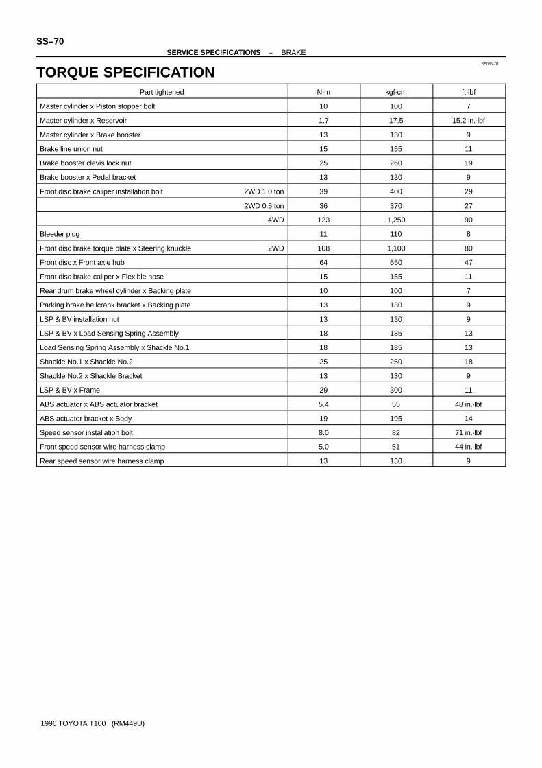
SS085−01
SS−70−SERVICE SPECIFICATIONS BRAKE
1996 TOYOTA T100 (RM449U)
TORQUE SPECIFICATIONPart tightened N·m kgf·cm ft·lbf
Master cylinder x Piston stopper bolt 10 100 7
Master cylinder x Reservoir 1.7 17.5 15.2 in.·lbf
Master cylinder x Brake booster 13 130 9
Brake line union nut 15 155 11
Brake booster clevis lock nut 25 260 19
Brake booster x Pedal bracket 13 130 9
Front disc brake caliper installation bolt 2WD 1.0 ton 39 400 29
2WD 0.5 ton 36 370 27
4WD 123 1,250 90
Bleeder plug 11 110 8
Front disc brake torque plate x Steering knuckle 2WD 108 1,100 80
Front disc x Front axle hub 64 650 47
Front disc brake caliper x Flexible hose 15 155 11
Rear drum brake wheel cylinder x Backing plate 10 100 7
Parking brake bellcrank bracket x Backing plate 13 130 9
LSP & BV installation nut 13 130 9
LSP & BV x Load Sensing Spring Assembly 18 185 13
Load Sensing Spring Assembly x Shackle No.1 18 185 13
Shackle No.1 x Shackle No.2 25 250 18
Shackle No.2 x Shackle Bracket 13 130 9
LSP & BV x Frame 29 300 11
ABS actuator x ABS actuator bracket 5.4 55 48 in.·lbf
ABS actuator bracket x Body 19 195 14
Speed sensor installation bolt 8.0 82 71 in.·lbf
Front speed sensor wire harness clamp 5.0 51 44 in.·lbf
Rear speed sensor wire harness clamp 13 130 9
https://www.truck-manuals.net/

SS08W−01
−SERVICE SPECIFICATIONS STEERINGSS−71
245Author�: Date�:
1996 TOYOTA T100 (RM449U)
STEERINGSERVICE DATAON−VEHICLE INSPECTION
Steering wheel freeplay Maximum 30 mm (1.18 in.)
3RZ−FE:
Drive belt tension New belt 135−185 lbf
Drive belt tension Used belt 80−120 lbf
Oil level rise Maximum Below 5 mm (0.20 in.)
5VZ−FE:
Drive belt tension New belt 135−180 lbf
Drive belt tension Used belt 85−120 lbf
Oil level rise Maximum Below 5 mm (0.20 in.)
3RZ−FE and 5VZ−FE (2WD):
Oil pressure at idle speed with valve closed Minimum 7,845 kPa (80 kgf/cm2, 1,138 psi)
5VZ−FE (4WD):
Oil pressure at idle speed with valve closed Minimum 8,336 kPa (85 kgf/cm2, 1,209 psi)
Steering effort at idle speed Maximum 8.3 N·m (85 kgf·cm, 73 in.·lbf)
TILT STEERING COLUMN
Pawl stopper
1 or A 12.68 − 12.74 mm (0.4992 − 0.5016 in.)
2 or B 12.61 − 12.67 mm (0.4965 − 0.4988 in.)
3 or C 12.54 − 12.60 mm (0.4937 − 0.4961 in.)
4 or D 12.47 − 12.53 mm (0.4909 − 0.4933 in.)
5 or E 12.40 − 12.46 mm (0.4882 − 0.4906 in.)
6 or F 12.33 − 12.39 mm (0.4854 − 0.4878 in.)
7 or G 12.26 − 12.32 mm (0.4827 − 0.4850 in.)
PS VANE PUMP
3RZ−FE and 5VZ−FE:
Pump shaft and front housing bushing oil clearance STD 0.03−0.05 mm (0.0012−0.0020 in.)
Pump shaft and front housing bushing oil clearance Maximum 0.07 mm (0.0028 in.)
Vane plate height Minimum 8.6 mm (0.339 in.)
Vane plate thickness Minimum 1.397 mm (0.0550 in.)
Vane plate length Minimum 14.991 mm (0.5902 in.)
Vane plate and pump rotor groove clearance Maximum 0.035 mm (0.0014 in.)
Vane plate length Pump rotor and cam ring mark
None 14.999−15.001 mm (0.59051−0.59059 in.)
1 14.997−14.999 mm (0.59043−0.59051 in.)
2 14.995−14.997 mm (0.59035−0.59043 in.)
3 14.993−14.995 mm (0.59027−0.59035 in.)
4 14.991−14.993 mm (0.59020−0.59027 in.)
Flow control valve spring length Minimum 32.3 mm (1.272 in.)
Pump rotating torque Maximum 0.25 N·m (2.5 kgf·cm, 2.2 in.·lbf) or less
PS GEAR
2WD:
Steering rack runout Maximum 0.3 mm (0.0118 in.)
https://www.truck-manuals.net/

SS−72−SERVICE SPECIFICATIONS STEERING
246Author�: Date�:
1996 TOYOTA T100 (RM449U)
Total preload 0.5−1.4 N·m (5−14 kgf·cm, 4.3−12.2 in.·lbf)
4WD:
Worm gear valve body ball clearance 0.15 mm (0.059 in.)
Cross shaft adjusting screw thrust clearance STD 0.03−0.05 mm (0.0012−0.0020 in.)
Cross shaft adjusting screw thrust clearance Maximum 0.05 mm (0.0020 in.)
Worm gear preload 0.3−0.5 N·m (3−5.5 kgf·cm, 2.6−4.8 in.·lbf)
Total preload 0.5−0.9 N·m (5−9.5 kgf·cm, 4.3−8.3 in.·lbf)
STEERING LINKAGE
Tie rod length Approximately 329.2 mm (12.961 in.)
Idler arm rotating torque 0.5−2.9 N·m (5−30 kgf·cm, 5−26 in.·lbf)
https://www.truck-manuals.net/

SS08X−01
−SERVICE SPECIFICATIONS STEERINGSS−73
1996 TOYOTA T100 (RM449U)
TORQUE SPECIFICATIONPart tightened N·m kgf·cm ft·lbf
STEERING COLUMN
NON−TILT STEERING COLUMN:
Steering wheel set nut 35 360 26
Steering wheel pad set screw (Torx screw) 9.0 90 78 in.·lbf
Steering column assembly set bolt and nut 25 260 19
Control shaft lever x Control shaft assembly AT 35 360 26
Intermediate shaft x Control valve assembly 2WD 35 360 26
Intermediate shaft x Worm gear valve assembly 4WD 35 360 26
Sliding w/shaft york sub−assembly x Intermediate shaft 35 360 26
Main shaft assembly x Sliding w/shaft york sub−assembly 35 360 26
TILT STEERING COLUMN:
Steering wheel set nut 35 360 26
Steering wheel pad set screw (Torx screw) 9.0 90 78 in.·lbf
Steering column assembly set bolt and nut 25 260 19
Control shaft lever x Control shaft assembly AT 35 360 26
Intermediate shaft x Control valve assembly 2WD 35 360 26
Intermediate shaft x Worm gear valve assembly 4WD 35 360 26
Sliding w/shaft york sub−assembly x Intermediate shaft 35 360 26
Sliding york sub−assembly x Sliding w/shaft york sub−assembly 35 360 26
Main shaft assembly x Sliding york sub−assembly 35 360 26
Turn signal bracket set bolt 7.8 80 69 in.·lbf
Tilt lever assembly set bolt 2 20 17 in.·lbf
Tilt sub lever side pawl set bolt x nut 5.9 60 52 in.·lbf
Tilt lever retainer set nut 15 150 11
Compression spring set bolt 7.8 80 69 in.·lbf
PS VANE PUMP
3RZ−FE and 5VZ−FE:
Union bolt x Pressure feed tube 47 475 34
Pressure port union x Pump housing 83 850 61
Bracket x Pump assembly 5VZ−FE 43 440 32
Rear housing set bolt 24 240 17
Oil reservoir set bolt Front 13 130 9
Rear 24 240 17
Vane pump pulley set nut 43 440 32
Vane pump assembly set bolt 3RZ−FE 39 400 29
Vane pump assembly with bracket set bolt and nut 5VZ−FE 39 400 29
PS GEAR
2WD:
Control valve housing x Rack housing 18 185 13
Self−locking nut 25 250 18
Rack housing cap 69 700 51
Rack guide spring cap lock nut 51 (60) 521 (700) 38 (51)
Rack x Rack end 61 (83) 618 (850) 45 (62)
https://www.truck-manuals.net/

SS−74−SERVICE SPECIFICATIONS STEERING
1996 TOYOTA T100 (RM449U)
Tie rod end lock nut 56 570 41
Turn pressure tube union nut 10 (13) 102 (130) 7 (9)
PS gear assembly set bolt and nut 88 900 65
Mount bracket x Suspension crossmember 88 900 65
Control valve shaft x Intermediate shaft 35 360 26
Pressure feed tube x Control valve housing 19 (25) 195 (250) 14 (18)
Return tube x Control valve housing 19 (25) 195 (250) 14 (18)
Tie rod end x Steering knuckle 90 920 67
4WD:
Pressure feed tube x PS gear assembly 36 (44) 365 (450) 26 (33)
Return tube x PS gear assembly 36 (44) 365 (450) 26 (33)
PS gear assembly x Body 142 1450 105
Pitman arm x Cross shaft 177 1800 130
Cross shaft adjusting screw set nut 46 470 34
Side cover x Gear housing 61 620 45
Plunger guide nut 20 205 15
Worm gear valve body assembly x Gear housing 61 620 45
Worm gear valve body assembly x Intermediate shaft 35 360 26
STEERING LINKAGE
Pitman arm x Cross shaft 177 1800 130
Pitman arm x Relay rod 90 920 67
Tie rod clamp bolt 22 225 16
Tie rod assembly x Relay rod 90 920 67
Tie rod assembly x Knuckle arm 90 920 67
Idler arm assembly x Frame 142 1450 105
Relay rod x Idler arm assembly 59 600 43
Steering damper set bolt and nut 25 260 19
Relay rod x Steering damper 59 600 43
IDLER ARM
Idler arm x Idler arm bracket 78 800 58
( ): For use without SST
https://www.truck-manuals.net/

SS08E−01
−SERVICE SPECIFICATIONS SUPPLEMENTAL RESTRAINT SYSTEMSS−75
249Author�: Date�:
1996 TOYOTA T100 (RM449U)
SUPPLEMENTAL RESTRAINT SYSTEMSERVICE DATAFRONT AIRBAG SENSOR
�S − �A Less then 1 Ω
�S − �S 1 MΩ or Higher
�S − �A 755 − 885 Ω
https://www.truck-manuals.net/

SS08D−01
SS−76−SERVICE SPECIFICATIONS SUPPLEMENTAL RESTRAINT SYSTEM
1996 TOYOTA T100 (RM449U)
TORQUE SPECIFICATIONPart tightened N·m kgf·cm ft·lbf
Steering wheel 34 350 25
Steering wheel pad 8.8 90 78 in.·lbf
Airbag sensor assembly 21 210 15
Front airbag sensor 29 300 22
https://www.truck-manuals.net/

SS03A−03
−SERVICE SPECIFICATIONS BODY ELECTRICALSS−77
251Author�: Date�:
1996 TOYOTA T100 (RM449U)
BODY ELECTRICALSERVICE DATADAYTIME RUNNING LIGHT MAIN RELAY (Wire Harness Side)
2 − Ground (Ignition Switch LOCK or ACC) No voltage
2 − Ground (Ignition Switch ON or START) Battery positive voltage
6 − Ground (Constant) Battery positive voltage
11 − Ground (Engine Stop) No voltage
11 − Ground (Engine Running) Battery positive voltage
DAYTIME RUNNING LIGHT MAIN RELAY (Connector connected)
17 − Ground (Headlight dimmer switch LOW beam) No voltage
17 − Ground (Headlight dimmer switch HIGH beam or Flash) Battery positive voltage
TURN SIGNAL FLASHER
Flashes/ Minute 60 − 120
SPEEDOMETER (Using a speedmeter tester)
Standard indication (mph) Allowable range (mph)
20 18 − 24
40 38 − 44
60 58 − 66
80 78 − 88
100 98 − 110
120 118 − 132
Standard indication (km/h) Allowable range (km/h)
20 17 − 24
40 38 − 46
60 57.5 − 67
80 77 − 88
100 96 − 109
120 115 − 130
140 134 − 151.5
160 153 − 173
TACHOMETER (On−Vehicle) / DC 13.5 V 20 °C at (68 °F)
Standard indication Allowable range
700 610 − 750
3,000 2,850 − 3,150
5,000 4,850 − 5,150
7,000 6,790 − 7,210
VOLT GAUGE Resistance (Ω)
A − B Approx. 347.0 Ω
FUEL RECEIVER GAUGE (w/ Tachometer) Resistance (Ω)
A − B Approx. 137.0 Ω
A − C Approx. 123.0 Ω
B − C Approx. 260.0 Ω
FUEL RECEIVER GAUGE (w/o Tachometer) Resistance (Ω)
A − B Approx. 150.0 Ω
A − C Approx. 80.0 Ω
https://www.truck-manuals.net/
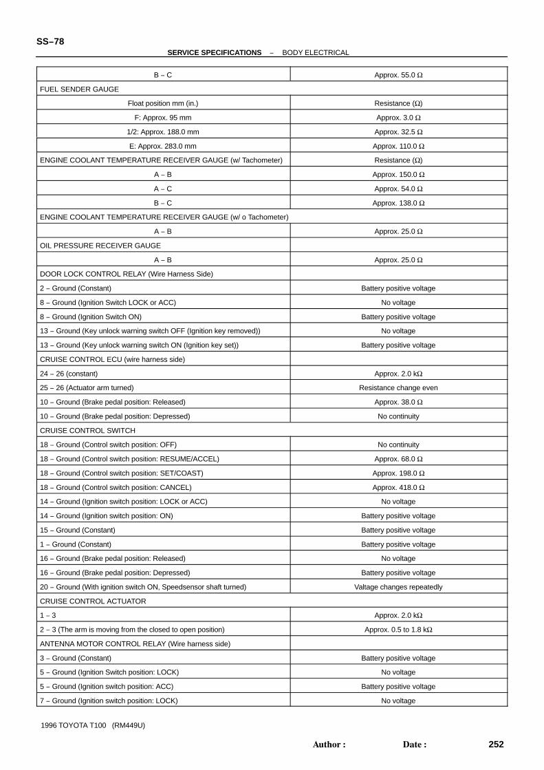
SS−78−SERVICE SPECIFICATIONS BODY ELECTRICAL
252Author�: Date�:
1996 TOYOTA T100 (RM449U)
B − C Approx. 55.0 Ω
FUEL SENDER GAUGE
Float position mm (in.) Resistance (Ω)
F: Approx. 95 mm Approx. 3.0 Ω
1/2: Approx. 188.0 mm Approx. 32.5 Ω
E: Approx. 283.0 mm Approx. 110.0 Ω
ENGINE COOLANT TEMPERATURE RECEIVER GAUGE (w/ Tachometer) Resistance (Ω)
A − B Approx. 150.0 Ω
A − C Approx. 54.0 Ω
B − C Approx. 138.0 Ω
ENGINE COOLANT TEMPERATURE RECEIVER GAUGE (w/ o Tachometer)
A − B Approx. 25.0 Ω
OIL PRESSURE RECEIVER GAUGE
A − B Approx. 25.0 Ω
DOOR LOCK CONTROL RELAY (Wire Harness Side)
2 − Ground (Constant) Battery positive voltage
8 − Ground (Ignition Switch LOCK or ACC) No voltage
8 − Ground (Ignition Switch ON) Battery positive voltage
13 − Ground (Key unlock warning switch OFF (Ignition key removed)) No voltage
13 − Ground (Key unlock warning switch ON (Ignition key set)) Battery positive voltage
CRUISE CONTROL ECU (wire harness side)
24 − 26 (constant) Approx. 2.0 kΩ
25 − 26 (Actuator arm turned) Resistance change even
10 − Ground (Brake pedal position: Released) Approx. 38.0 Ω
10 − Ground (Brake pedal position: Depressed) No continuity
CRUISE CONTROL SWITCH
18 − Ground (Control switch position: OFF) No continuity
18 − Ground (Control switch position: RESUME/ACCEL) Approx. 68.0 Ω
18 − Ground (Control switch position: SET/COAST) Approx. 198.0 Ω
18 − Ground (Control switch position: CANCEL) Approx. 418.0 Ω
14 − Ground (Ignition switch position: LOCK or ACC) No voltage
14 − Ground (Ignition switch position: ON) Battery positive voltage
15 − Ground (Constant) Battery positive voltage
1 − Ground (Constant) Battery positive voltage
16 − Ground (Brake pedal position: Released) No voltage
16 − Ground (Brake pedal position: Depressed) Battery positive voltage
20 − Ground (With ignition switch ON, Speedsensor shaft turned) Valtage changes repeatedly
CRUISE CONTROL ACTUATOR
1 − 3 Approx. 2.0 kΩ
2 − 3 (The arm is moving from the closed to open position) Approx. 0.5 to 1.8 kΩ
ANTENNA MOTOR CONTROL RELAY (Wire harness side)
3 − Ground (Constant) Battery positive voltage
5 − Ground (Ignition Switch position: LOCK) No voltage
5 − Ground (Ignition switch position: ACC) Battery positive voltage
7 − Ground (Ignition switch position: LOCK) No voltage
https://www.truck-manuals.net/

−SERVICE SPECIFICATIONS BODY ELECTRICALSS−79
253Author�: Date�:
1996 TOYOTA T100 (RM449U)
7 − Ground (Ignition switch position: ACC or ON)
(Radio switch and cassette OFF)No voltage
7 − Ground (Ignition switch position: ACC or ON)
(Radio switch and cassette ON)Battery positive voltage
8 − Ground (Ignition switch position: LOCK) No voltage
8 − Ground (Ignition switch position: ACC or ON)
(Radio switch ON and cassette ON)No voltage
8 − Ground (Ignition switch position: ACC or ON)
(Radio switch ON and cassette OFF)Battery positive voltage
4 − Ground (Ignition switch position: LOCK or ACC) No voltage
4 − Ground (Ignition switch position: ON) Battery positive voltage
https://www.truck-manuals.net/

SS08Y−02
SS−80−SERVICE SPECIFICATIONS BODY
254Author�: Date�:
1996 TOYOTA T100 (RM449U)
BODYTORQUE SPECIFICATION
Part tightened N·m kgf·cm ft·lbf
FRONT BUMPER − − −
Front bumper arm x Body 61 620 45
Bumper side support x Bumper arm 13 130 9
HOOD − − −
Hood hinge x Hood 14 145 10
Hood lock x Body 19 195 14
FRONT DOOR − − −
Door hinge x Body 25 260 19
Door hinge x Door panel 25 260 19
Door lock x Door panel 5.9 60 52 in.·lbf
Window regulator x Door panel 5.4 55 48 in.·lbf
FRONT WIPER AND WASHER − − −
Wiper arm x Wiper link 20 204 15
TAIL GATE − − −
Tail gate lock striker x Body 12 120 9
Tail gate lock x Tail gate 12 120 9
Tail gate hinge x Tail gate 18 185 13
FRONT SEAT (Bench Type) − − −
Seat track x Body 37 375 27
Seat track x Seatback 18 185 13
Outer track x Seat cushion frame 18 185 13
Inner track x Seat cushion frame 18 185 13
FRONT SEAT (Split Bench Type) − − −
Seat track x Body 37 375 27
Seat adjuster x Seatback 18 185 13
Outer track x Seat cushion frame 18 185 13
Inner track x Seat cushion frame 18 185 13
Seat adjuster x Seat cushion frame 18 185 13
Inner track x Seat back frame 12.5 130 9.5
REAR SEAT − − −
Back panel trim x Body 9.8 100 7
Seat cushion x Body 9.8 100 7
SEAT BELT − − −
Front Seat Belt − − −
Adjustable anchor x Body 43 440 32
Shoulder anchor x Adjustable anchor 43 440 32
ELR x Body 43 440 32
Lap outer anchor x Body 43 440 32
Inner belt x Body 43 440 32
Rear Seat Belt − − −
Shoulder anchor x Body 43 440 32
ELR x Body 43 440 32
https://www.truck-manuals.net/

−SERVICE SPECIFICATIONS BODYSS−81
255Author�: Date�:
1996 TOYOTA T100 (RM449U)
Part tightened N·m kgf·cm ft·lbf
Lap outer anchor x Body 43 440 32
Inner belt x Body 43 440 32
https://www.truck-manuals.net/

SS08B−03
SS−82−SERVICE SPECIFICATIONS AIR CONDITIONING
256Author�: Date�:
1996 TOYOTA T100 (RM449U)
AIR CONDITIONINGSERVICE DATARefrigerant charge volume 650 ± 50 g (22.92 ± 1.76 oz.)
Drive belt tension −
New belt 160 ± 25 lbf
Used belt 100 ± 20 lbf
Idle−up speed −
3RZ − FE 900 rpm
5VZ − FE 850 rpm
Magnetic clutch clearance 0.5 ± 0.15 mm (0.020 ± 0.0059 in.)
https://www.truck-manuals.net/

SS08C−03
−SERVICE SPECIFICATIONS AIR CONDITIONINGSS−83
1996 TOYOTA T100 (RM449U)
TORQUE SPECIFICATIONPart tightened N·m kgf·cm ft·lbf
Compressor x Compressor Bracket 25 250 18
Compressor bracket x Engine 47 475 34
Idle pulley lock nut 39 400 29
Compressor x Discharge hose 10 100 7
Compressor x Suction hose 10 100 7
Cooling unit x Suction tube 32 330 24
Cooling unit x Liquid tube 14 140 10
Expansion valve x Evaporator 22 225 16
Expansion valve x Liquid tube 14 140 10
Receiver x Liquied tube 5.4 55 48 in.·lbf
Condenser x Liquid tube 10 100 7
Condenser x Discharge hose 10 100 7
Pressure switch x Liquied tube 10 100 7
Pressure plate x Compressor 13.2 135 9
https://www.truck-manuals.net/

DI – DIAGNOSTICS
ENGINE (3RZ-FE) DI-1 ENGINE (5VZ-FE) DI-127 AUTOMATIC TRANSMISSION DI-263 ANTI-LOCK BRAKE SYSTEM DI-319 SUPPLEMENTAL RESTRAINT SYSTEM DI-363 CRUISE CONTROL SYSTEM DI-408
https://www.truck-manuals.net/

DI0T5−02
Vehicle Brought to Workshop
Customer Problem Analysis P. DI−2
Problem Symptom ConfirmationIf the engine does not start perform steps 10 and 12 first
Connect the OBD II scan tool or TOYOTA hand−held tester to DLC3 P. DI−3If the display indicates a communication fault in the tool, inspect DLC3 P. DI−3
Check DTC and Freezed Frame Data (Precheck)
Record or Print DTC and Freezed Frame Data P. DI−3
Clear DTC and Freezed Frame Data P. DI−3
Visual Inspection
Setting the Check Mode Diagnosis P. DI−3
Symptom Simulation P.IN−16
Basic Inspection P. DI−3 DTC Chart P. DI−13
Problem Symptoms Table P. DI−21
Circuit Inspection P. DI−22
Adjustment, Repair
DTC Check P. DI−3
Titles inside are titles of pages in
in the bottom portion. See the indicatedpages for detailed explanations.
this manual with the page number indicated
Malfunctionoccurs.
Malfunction does not occur.
Parts Inspection
Check for Intermittent Problems P. DI−3
Identification of Problem
Confirmation Test
End
1
2
3
4
5
6
7
10
8
9
11
12
13
15
14
16
Normal Malfunction code.
17
−DIAGNOSTICS ENGINE (3RZ−FE)DI−1
258Author�: Date�:
1996 TOYOTA T100 (RM449U)
ENGINE (3RZ−FE)HOW TO PROCEED WITH TROUBLESHOOTINGTroubleshoot in accordance with the procedure on the following page.
https://www.truck-manuals.net/

DI0T6−01
ENGINE CONTROL SYSTEM Check Sheet
Customer’s Name
Driver’s Name
Data VehicleBrought in
License No.
Model and ModelYear
Frame No.
Engine Model
Odometer Readingkmmiles
Pro
ble
m S
ymp
tom
s
Engine doesnot Start
Difficult toStart
Poor Idling
PoorDriveability
Engine Stall
Others
Engine does not crank No initial combustion No complete combustion
Engine cranks slowlyOther
Incorrect first idle Idling rpm is abnormal High ( rpm) Low ( rpm)Rough idling Other
Hesitation Back fire Muffler explosion (after−fire) SurgingKnocking Other
Soon after starting After accelerator pedal depressedAfter accelerator pedal released During A/C operationShifting from N to D Other
Datas ProblemOccurred
Problem Frequency
Co
nd
itio
n W
hen
Pro
ble
m O
ccu
rs
Weather
Engine Operation
Engine Temp.
Place
Outdoor Temp.
Constant Sometimes ( times per day/month) Once onlyOther
Fine Cloudy Rainy Snowy Various/Other
Hot Warm Cool Cold (approx. °F/ °C)
Highway Suburbs Inner city Uphill DownhillRough road Other
Cold Warming up After warming up Any temp. Other
Starting Just after starting ( min.) Idling RacingDriving Constant speed Acceleration DecelerationA/C switch ON/OFF Other
Condition of MIL Remains on Sometimes lights up Does not light up
Normal Malfunction code(s) (code )Freezed frame data ( )
Normal Malfunction code(s) (code )Freezed frame data ( )
Normal Mode(Precheck)
Check Mode
DTC Inspection
Inspector’sName
DI−2−DIAGNOSTICS ENGINE (3RZ−FE)
1996 TOYOTA T100 (RM449U)
CUSTOMER PROBLEM ANALYSIS CHECK
https://www.truck-manuals.net/
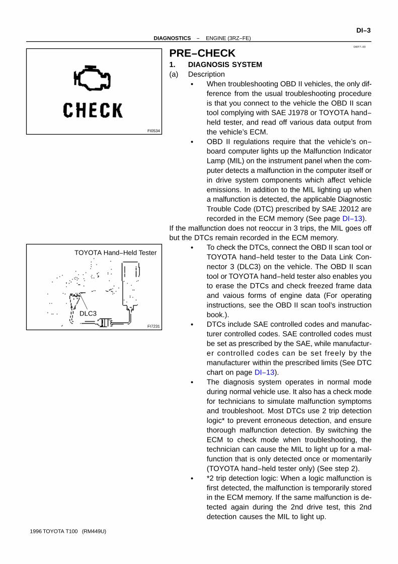
FI0534
DI0T7−03
FI7231
TOYOTA Hand−Held Tester
DLC3
−DIAGNOSTICS ENGINE (3RZ−FE)DI−3
1996 TOYOTA T100 (RM449U)
PRE−CHECK1. DIAGNOSIS SYSTEM(a) Description
� When troubleshooting OBD II vehicles, the only dif-ference from the usual troubleshooting procedureis that you connect to the vehicle the OBD II scantool complying with SAE J1978 or TOYOTA hand−held tester, and read off various data output fromthe vehicle’s ECM.
� OBD II regulations require that the vehicle’s on−board computer lights up the Malfunction IndicatorLamp (MIL) on the instrument panel when the com-puter detects a malfunction in the computer itself orin drive system components which affect vehicleemissions. In addition to the MIL lighting up whena malfunction is detected, the applicable DiagnosticTrouble Code (DTC) prescribed by SAE J2012 arerecorded in the ECM memory (See page DI−13).
If the malfunction does not reoccur in 3 trips, the MIL goes offbut the DTCs remain recorded in the ECM memory.
� To check the DTCs, connect the OBD II scan tool orTOYOTA hand−held tester to the Data Link Con-nector 3 (DLC3) on the vehicle. The OBD II scantool or TOYOTA hand−held tester also enables youto erase the DTCs and check freezed frame dataand vaious forms of engine data (For operatinginstructions, see the OBD II scan tool’s instructionbook.).
� DTCs include SAE controlled codes and manufac-turer controlled codes. SAE controlled codes mustbe set as prescribed by the SAE, while manufactur-er controlled codes can be set freely by themanufacturer within the prescribed limits (See DTCchart on page DI−13).
� The diagnosis system operates in normal modeduring normal vehicle use. It also has a check modefor technicians to simulate malfunction symptomsand troubleshoot. Most DTCs use 2 trip detectionlogic* to prevent erroneous detection, and ensurethorough malfunction detection. By switching theECM to check mode when troubleshooting, thetechnician can cause the MIL to light up for a mal-function that is only detected once or momentarily(TOYOTA hand−held tester only) (See step 2).
� *2 trip detection logic: When a logic malfunction isfirst detected, the malfunction is temporarily storedin the ECM memory. If the same malfunction is de-tected again during the 2nd drive test, this 2nddetection causes the MIL to light up.
https://www.truck-manuals.net/

N09214
DLC3
DI−4−DIAGNOSTICS ENGINE (3RZ−FE)
1996 TOYOTA T100 (RM449U)
� The 2 trip repeats the same mode a 2nd time (How-ever, the ignition switch must be turned OFF be-tween the 1st trip and 2nd trip.).
� Freeze frame data:Freeze frame data records the engine conditionwhen a misfire (DTCs P0300 − P0304) or fuel trimmalfunction (DTCs P0171, P0172) or other mal-function (first malfunction only), is detected.
� Because freeze frame data records the engineconditions (fuel system, calculator load, enginecoolant temperature, fuel trim, engine speed, ve-hicle speed, etc.) when the malfunction is detected,when troubleshooting it is useful for determiningwhether the vehicle was running or stopped, the en-gine warmed up or not, the air−fuel ratio lean or rich,etc. at the time of the malfunction.
Priorities for troubleshooting:If troubleshooting priorities for multiple DTCs are given in theapplicable DTC chart, these should be followed.If no instructions are given troubleshoot DTCs according to thefollowing priorities.
(1) DTCs other than fuel trim malfunction (DTCsP0171, P0172), EGR (DTCs P0401, P0402), andmisfire (DTC P0300 − P0304).
(2) Fuel trim malfunction (DTCs P0171, P0172), andEGR (DTCs P0401, P0402).
(3) Misfire (DTCs P0300 ∼ P0304).(b) Check the DLC3.
The vehicle’s ECM uses V.P.W. (Variable Pulse Width) forcommunication to comply with SAE J1850. The terminalarrangement of DLC3 complies with SAE J1962 andmatches the V.P.W. format.
Terminal No. Connection / Voltage or Resistance Condition
2 Bus � Line / Pulse generation During transmission
4 Chassis Ground ↔ Body Ground / 1 Ω or less Always
5 Signal Ground ↔ Body Ground / 1 Ω or less Always
16 Battery Positive ↔ Body Ground / 9 − 14 V Always
https://www.truck-manuals.net/

A00653
w/o Tachometer
w/ Tachometer
−DIAGNOSTICS ENGINE (3RZ−FE)DI−5
1996 TOYOTA T100 (RM449U)
HINT:If your display shows ”UNABLE TO CONNECT TO VEHICLE”when you have connected the cable of the OBD II scan tool orTOYOTA hand−held tester to DLC3, turned the ignition switchON and operated the scan tool, there is a problem on the ve-hicle side or tool side.� If communication is normal when the tool is connected to
another vehicle, inspect DLC3 on the original vehicle.� If communication is still not possible when the tool is con-
nected to another vehicle, the problem is probably in thetool itself, so consult the Service Department listed in thetool’s instruction manual.
2. INSPECT DIAGNOSIS (Normal Mode)(a) Check the MIL.
(1) The MIL comes on when the ignition switch is turnedON and the engine is not running.
HINT:If the MIL does not light up, troubleshoot the combination meter.
(2) When the engine started, the MIL should go off. Ifthe lamp remains on, the diagnosis system has de-tected a malfunction or abnormality in the system.
(b) Check the DTC.NOTICE:TOYOTA hand−held tester only: When the diagnosis sys-tem is switched from normal mode to check mode, iterases all DTCs and freezed frame data recorded in normalmode. So before switching modes, always check the DTCsand freezed frame data, and note them down.
(1) Prepare the OBD II scan tool (complying with SAEJ1978) or TOYOTA hand−held tester.
(2) Connect the OBD II scan tool or TOYOTA hand−held tester to the DLC3 at the lower of the instru-ment panel.
(3) Turn the ignition switch ON and turn the OBD II scantool or TOYOTA hand−held tester switch ON.
(4) Use the OBD II scan tool or TOYOTA hand−heldtester to check the DTCs and freezed frame data,note them down. (For operating instructions, seethe OBD II scan tool’s instruction book.)
(5) See page DI−13 to confirm the details of the DTCs.
https://www.truck-manuals.net/

FI3605
ON
OFF
Flashing
0.13 Second
DI−6−DIAGNOSTICS ENGINE (3RZ−FE)
1996 TOYOTA T100 (RM449U)
NOTICE:When simulating symptoms with an OBD II scan tool (ex-cluding TOYOTA hand−held tester) to check the DTCs, usenormal mode. For code on the DTC chart subject to ”2 tripdetection logic”, turn the ignition switch OFF after thesymptom is simulated the 1st time. Then repeat the simula-tion process again. When the problem has been simulatedtwice, the MIL lights up and the DTCs are recorded in theECM.
3. INSPECT DIAGNOSIS (Check Mode)HINT:TOYOTA hand−held tester only: Compared to the normal mode, the check mode has an in-creased sensitivity to detect malfunctions.Furthermore, the same diagnostic items which are detected inthe normal mode can also be detected in the check mode.
(a) Check the DTC.(1) Initial conditions
� Battery positive voltage 11 V or more� Throttle valve fully closed� Transmission in ”P” or ”N” position� Air conditioning switched OFF
(2) Turn the ignition switch OFF.(3) Prepare the TOYOTA hand−held tester.(4) Connect the TOYOTA hand−held tester to DLC3 at
the lower of the instrument panel.(5) Turn the ignition switch ON and switch the TOYOTA
hand−held tester ON.(6) Switch the TOYOTA hand−held tester normal mode
to check mode (Check that the MIL flashes.).(7) Start the engine (The MIL goes out after the engine
start.).(8) Simulate the conditions of the malfunction de-
scribed by the customer.NOTICE:Leave the ignition switch ON until you have checked theDTCs, etc.
(9) After simulating the malfunction conditions, use theTOYOTA hand−held tester diagnosis selector tocheck the DTCs and freezed frame data, etc.
HINT:Take care not to turn the ignition switch OFF. Turning the ignitionswitch OFF switches the diagnosis system from check mode tonormal mode. so all DTCs, etc. are erased.
(10) After checking the DTC, inspect the applicable cir-cuit.
https://www.truck-manuals.net/

−DIAGNOSTICS ENGINE (3RZ−FE)DI−7
1996 TOYOTA T100 (RM449U)
(b) Clear the DTC.The following actions will erase the DTCs and freezedframe data.(1) Operating the OBD II scan tool (complying with SAE
J1978) or TOYOTA hand−held tester to erase thecodes. (See the OBD II scan tool’s instruction bookfor operating instructions.)
(2) Disconnecting the battery terminals or EFI fuse.NOTICE:If the TOYOTA hand−held tester switches the ECM fromnormal mode to check mode or vice−versa, or if the igni-tion switch is turned from ON to ACC or OFF during checkmode, the DTCs and freezed frame data will be erased.
4. FAIL−SAFE CHARTIf any of the following codes is recorded, the ECM enters fail−safe mode.
DTC No. Fail−Safe Operation Fail−Safe Deactivation Conditions
P0100
Ignition timing fixed at 5° BTDC
Injection time fixed
Starting − − − − − − − − 11.6 msec.
CTP switch ON − − − − 3.2 msec.
CTP switch OFF − − − − 6.0 msec.
Returned to normal condition
P0110 Intake air temp. is fixed at 20°C (68°F) Returned to normal condition
P0115 Engine coolant temp. is fixed at 80°(176°F) Returned to normal condition
P0120 VTA is fixed at 0°
Following condition must be repeated at least 2 times
consecutively
When closed throttle position switch is ON:
0.1 V � VTA � 0.95 V
P0135
P0141
Heater circuit in which an abnormality is detected is
turned offIgnition switch OFF
P0325 Max. timing retardation Ignition switch OFF
P0336 Fuel cut Returned to normal condition
P1300 Fuel cut Returned to normal condition
5. CHECK FOR INTERMITTENT PROBLEMSHINT:TOYOTA HAND−HELD TESTER only:By putting the vehicle’s ECM in check mode, 1 trip detection logic is possible instead of 2 trip detection logicand sensitivity to detect open circuits is increased. This makes it easier to detect intermittent problems.(a) Clear the DTC (See step 3).(b) Set the check mode (See step 3).(c) Perform a simulation test (See page IN−16).(d) Check the connector and terminal (See page IN−26).(e) Handle the connector (See page IN−26).
https://www.truck-manuals.net/

P00495
Outside
Inside
DI−8−DIAGNOSTICS ENGINE (3RZ−FE)
1996 TOYOTA T100 (RM449U)
6. BASIC INSPECTIONWhen the malfunction code is not confirmed in the DTC check, troubleshooting should be performed in theorder for all possible circuits to be considered as the causes of the problems. In many cases, by carryingout the basic engine check shown in the following flow chart, the location causing the problem can be foundquickly and efficiently. Therefore, use of this check is essential in engine troubleshooting.
1 Is battery positive voltage 11 V or more when engine is stopped?
NO Charge or replace battery.
YES
2 Is engine cranked?
NO Proceed to page ST−15 and continue to trouble-shoot.
YES
3 Does engine start?
NO Go to step 7.
YES
4 Check air filter.
PREPARATION:Remove the air filter.CHECK:Visual check that the air filter is not dirty or excessive oily.HINT:If necessary, clean the filter with compressed air. First blow frominside thoroughly, then blow from outside of the filter.
NG Repair or replace.
OK
https://www.truck-manuals.net/

A00654
DLC1
E1
TE1 SST
−DIAGNOSTICS ENGINE (3RZ−FE)DI−9
1996 TOYOTA T100 (RM449U)
5 Check idle speed.
PREPARATION:(a) Warm up the engine to normal operating temperature.(b) Switch off all the accessories.(c) Switch off the air conditioning.(d) Shift the transmission into ”N” position.(e) Connect the OBD II scan tool or TOYOTA hand−held tester to the DLC3 on the vehicle.CHECK:Use CURRENT DATA to check the idle speed.OK:
Idle speed: 750 ± 50 rpm
NG Proceed to problem symptoms table on pageDI−21.
OK
6 Check ignition timing.
PREPARATION:(a) Warm up the engine to normal operating temperature.(b) Shift the transmission into ”N” position.(c) Keep the engine speed at idle.(d) Using SST, connect terminals TE1 and E1 of the DLC1.
SST 09843−18020(e) Using a timing light, connect the tester to the No.1 high−
tension cord.CHECK:Check the ignition timing.OK:
Ignition timing: Approx. 5° BTDC at idle
NG Proceed to IGNITION and continue to trouble-shoot.
OK
Proceed to problem symptoms table on pageDI−21.
https://www.truck-manuals.net/

A00770
ON
Fuel Return Hose
P25086
DI−10−DIAGNOSTICS ENGINE (3RZ−FE)
1996 TOYOTA T100 (RM449U)
7 Check fuel pressure.
PREPARATION:(a) Be sure that enough fuel is in the tank.(b) Connect the TOYOTA hand−held tester to the DLC3.(c) Turn the ignition switch ON and push the TOYOTA hand−
held tester main switch ON.(d) Use ”ACTIVE TEST” mode to operate the fuel pump.CHECK:Check for fuel pressure in the fuel return hose when it is pinchedoff.HINT:At this time, you will hear a fuel flowing noise.
NG Proceed to page MF−1 and continue to trouble-shoot.
OK
8 Check for spark.
PREPARATION:(a) Disconnect the high−tension cord from the spark plug.(b) Remove the spark plug.(c) Install the spark plug to the high−tension cord.(d) Disconnect the injector connector.(e) Ground the spark plug.CHECK:Check if the spark occurs while engine is being cranked.NOTICE:To prevent excess fuel being injected from the injectorsduring this test, don’t crank the engine for more than 5 ∼ 10seconds at a time.
NG Proceed to page IG−1 and continue to trouble-shoot.
OK
Proceed to problem symptoms table on pageDI−21.
https://www.truck-manuals.net/

−DIAGNOSTICS ENGINE (3RZ−FE)DI−11
1996 TOYOTA T100 (RM449U)
7. ENGINE OPERATING CONDITIONNOTICE:The values given below for ”Normal Condition” are representative values, so a vehicle may still benormal even if its value varies from those listed here. So do not decide whether a part is faulty or notsolely according to the ”Normal Condition” here.(a) CARB mandated signals.
TOYOTA hand−held tester display Measurement Item Normal Condition*
FUEL SYS #1
Fuel System Bank 1
OPEN: Air−fuel ratio feedback stopped
CLOSED: Air−fuel ratio feedback operating
Idling after warming up: CLOSED
CALC LOAD
Calculator Load:
Current intake air volume as a proportion of max.
intake air volume
Idling: 15.4 − 22.1 %
Racing without load (2,500 rpm): 14.7 − 21.5 %
COOLANT TEMP. Engine Coolant Temp. Sensor Value After warming up: 80 ∼ 95°C (176 ∼ 203°F)
SHORT FT #1 Short−term Fuel Trim Bank 1 0 ± 20 %
LONG FT #1 Long−term Fuel Trim Bank 1 0 ± 20 %
ENGINE SPD Engine Speed Idling: 650 − 750 rpm
VEHICLE SPD Vehicle Speed Vehicle Stopped: 0 km/h (0 mph)
IGN ADVANCEIgnition Advance:
Ignition Timing of Cylinder No.1Idling: BTDC 7 − 13°
INTAKE AIR Intake Air Temp. Sensor Value Equivalent to Ambient Temp.
MAF Air Flow Rate Through Mass Air Flow Meter
Idling: 2.7 − 3.9 gm/sec.
Racing without load (2,500 rpm):
9.2 − 13.3 gm/sec.
THROTTLE POS
Voltage Output of Throttle Position Sensor
Calculated as a percentage:
0 V → 0 %, 5 V → 100 %
Throttle Fully Closed: 7 − 11 %
Throttle Fully Open: 65 − 75 %
O2S B1, S1Voltage Output of Oxygen Sensor
Bank 1, Sensor 1Idling: 0.1 − 0.9 V
O2FT B1, S1Oxygen Sensor Fuel Trim Bank 1, Sensor 1
(Same as SHORT FT #1)0 ± 20 %
O2S B1, S2Voltage Output of Oxygen Sensor
Bank 1, Sensor 2Driving (50 km/h, 31 mph): 0.1 − 0.9 V
*: If no conditions are specifically stated for ”ldling”, it means the shift lever is at N or P position, the A/C switchis OFF and all accessory switches are OFF.
https://www.truck-manuals.net/

DI−12−DIAGNOSTICS ENGINE (3RZ−FE)
1996 TOYOTA T100 (RM449U)
(b) TOYOTA Enhanced Signals.
TOYOTA hand−held tester display Measurement Item Normal Condition*
MISFIRE RPM Engine RPM for first misfire range Misfire 0: 0 rpm
MISFIRE LOAD Engine load for first misfire range Misfire 0: 0 g/r
INJECTOR Fuel injection time for cylinder No.1 Idling: 2.5 − 4.3 ms
IAC DUTY RATIOIntake Air Control Valve Duty Ratio
Opening ratio rotary solenoid type IAC valveIdling: 24.8 − 50.0 %
STARTER SIG Starter Signal Cranking: ON
CTP SW Closed Throttle Position Switch Signal Throttle Fully Closed: ON
A/C SIG A/C Switch Signal A/C ON: ON
STOP LIGHT SW Stop Light Switch Signal Stop light switch ON: ON
FC IDLFuel Cut Idle: Fuel cut when throttle valve fully
closed, during decelerationFuel cut operating: ON
FC TAU Fuel Cut TAU: Fuel cut during very light load Fuel cut operating: ON
CYL #1, CYL #2, CYL #3, CYL #4 Abnormal revolution variation for each cylinder 0 %
IGNITIONTotal number of ignition for every 1,000
revolutions0 − 2,000
EGRT GAS EGR Gas Temp. Sensor ValueEGR not operating: Temp. between intake air
temp. and engine coolant temp.
EGR SYSTEM EGR System Operating Condition Idling: OFF
A/C CUT SIG A/C Cut Signal A/C S/W OFF: ON
FUEL PUMP Fuel Pump Signal Idling: ON
EVAP (PURGE) VSV EVAP VSV Signal Idling: OFF
TOTAL FT B1Total Fuel Trim Bank 1: Average value for fuel
trim system of bank 1Idling: 0.8 − 1.2 V
O2 LR B1, S1
Oxygen Sensor Lean Rich Bank 1, Sensor 1 Re-
sponse time for oxygen sensor output to switch
from lean to rich
Idling after warming up: 0 − 1,000 msec.
O2 RL B1, S1
Oxygen Sensor Rich Lean Bank 1, Sensor 1 Re-
sponse time for oxygen sensor output to switch
from rich to lean
Idling after warming up: 0 − 1,000 msec.
*: If no conditions are specifically stated for ”ldling”, it means the shift lever is at N or P position, the A/C switchis OFF and all accessory switches are OFF.
https://www.truck-manuals.net/

DI0T8−03
−DIAGNOSTICS ENGINE (3RZ−FE)DI−13
1996 TOYOTA T100 (RM449U)
DIAGNOSTIC TROUBLE CODE CHARTSAE CONTROLLEDHINT:Parameters listed in the chart may not be exactly the same as your reading due to the type of instrumentor other factors.If a malfunction code is displayed during the DTC check in check mode, check the circuit for that code listedin the table below. For details of each code, turn to the page referred to under the ’’See Page ’’ for the respec-tive ’’DTC No.’’ in the DTC chart.
DTC No.
(See Page)Detection Item Trouble Area MIL* Memory
P0100
(DI−22)
Mass Air Flow Circuit
Malfunction
�Open or short in mass air flow meter circuit
�Mass air flow meter
�ECM
� �
P0101
(DI−26)
Mass Air Flow Circuit
Range/Performance
Problem
�Mass air flow meter � �
P0110
(DI−27)
Intake Air Temp. Circuit
Malfunction
�Open or short in intake air temp. sensor circuit
� Intake air temp. sensor
�ECM
� �
P0115
(DI−33)
Engine Coolant Temp. Circuit
Malfunction
�Open or short in engine coolant temp. sensor circuit
�Engine coolant temp. sensor
�ECM
� �
P0116
(DI−38)
Engine Coolant Temp. Circuit
Range/Performance Problem
�Engine coolant temp. sensor
�Cooling system� �
P0120
(DI−39)
Throttle/Pedal Position
Sensor/Switch ”A” Circuit
Malfunction
�Open or short in throttle position sensor circuit
�Throttle position sensor
�ECM
� �
P0121
(DI−43)
Throttle/Pedal Position
Sensor/Switch ”A” Circuit
Range/Performance Problem
�Throttle position sensor � �
P0125
(DI−44)
Insufficient Coolant Temp. for
Closed Loop Fuel Control
�Open or short in heated oxygen sensor (bank 1 sensor 1)
circuit
�Heated oxygen sensor (bank 1 sensor 1)
� �
P0130
(DI−47)
Heated Oxygen Sensor Circuit
Malfunction (Bank 1 Sensor 1)
�Heated oxygen sensor
�Fuel trim malfunction� �
P0133
(DI−50)
Heated Oxygen Sensor Circuit
Slow Response
(Bank 1 Sensor 1)
�Heated oxygen sensor � �
P0135
(DI−51)
Heated Oxygen Sensor Heater
Circuit Malfunction
(Bank 1 Sensor 1)
�Open or short in heater circuit of heated oxygen sensor
�Heated oxygen sensor heater
� ECM
� �
P0136
(DI−53)
Heated Oxygen Sensor Circuit
Malfunction
(Bank 1 Sensor 2)
�Heated oxygen sensor � �
P0141
(DI−51)
Heated Oxygen Sensor Heater
Circuit Malfunction
(Bank 1 Sensor 2)
�Same as DTC No. P0135 � �
*: ���� MIL lights up
https://www.truck-manuals.net/

DI−14−DIAGNOSTICS ENGINE (3RZ−FE)
1996 TOYOTA T100 (RM449U)
DTC No.
(See Page)Detection Item Trouble Area MIL* Memory
P0171
(DI−55)
System too Lean
(Fuel Trim)
�Air intake (hose loose)
�Fuel line pressure
� Injector blockage
�Heated oxygen sensor (bank 1 sensor 1) malfunction
�Mass air flow meter
�Engine coolant temp. sensor
� �
P0172
(DI−55)
System too Rich
(Fuel Trim)
�Fuel line pressure
� Injector leak, blockage
�Heated oxygen sensor (bank 1 sensor 1) malfunction
�Mass air flow meter
�Engine coolant temp. sensor
� �
P0300
(DI−58)
Random/Multiple Cylinder
Misfire Detected
� Ignition system
� Injector
�Fuel line pressure
�EGR
�Compression pressure
�Valve clearance not to specification
�Valve timing
�Mass air flow meter
�Engine coolant temp. sensor
� �P0301
P0302
P0303
P0304
(DI−58)
Misfire Detected
− Cylinder 1
− Cylinder 2
− Cylinder 3
− Cylinder 4
P0325
(DI−63)
Knock Sensor 1 Circuit
Malfunction
�Open or short in knock sensor 1 circuit
�Knock sensor 1 (looseness)
�ECM
� �
P0335
(DI−66)
Crankshaft Position Sensor
”A” Circuit Malfunction
�Open or short in crankshaft position sensor circuit
�Crankshaft position sensor
�Starter
�ECM
� �
P0336
(DI−69)
Crankshaft Position Sensor
”A” Circuit
Range/Performance
�Valve timing
�Distributor installation
�ECM
� �
P0340
(DI−70)
Camshaft Position Sensor
Circuit Malfunction
�Open or short in camshaft position sensor circuit
�Camshaft position sensor
�Distoributor
�Starter
�ECM
� �
P0401
(DI−72)
Exhaust Gas Recirculation
Flow Insufficient Detected
�EGR valve stuck closed
�Short in VSV circuit for EGR
�Open in EGR gas temp. sensor circuit
�EGR hose disconnected
�ECM
� �
P0402
(DI−82)
Exhaust Gas Recirculation
Flow Excessive Detected
�EGR valve stuck open
�VSV for EGR open malfunction
�Open in VSV circuit for EGR
�Short in EGR gas temp. sensor circuit
�ECM
� �
P0420
(DI−86)
Catalyst System Efficiency
Below Threshold
�Three−way catalytic convertor
�Open or short in heated oxygen sensor circuit
�Heated oxygen sensor
� �
*: ���� MIL lights up
https://www.truck-manuals.net/

−DIAGNOSTICS ENGINE (3RZ−FE)DI−15
1996 TOYOTA T100 (RM449U)
DTC No.
(See Page)Detection Item Trouble Area MIL* Memory
P0441
(DI−88)
Evaporative Emission Control
System Incorrect Purge Flow
�Open or short in VSV circuit for EVAP
�VSV for EVAP
�ECM
�Vacuum hose damaged, blocked or disconnected
�Charcoal canister
� �
P0500
(DI−92)
Vehicle Speed Sensor
Malfunction
�Open or short in No.1 vehicle speed sensor circuit
�No.1 vehicle speed sensor
�ECM
�Speedometer cable
� �
P0505
(DI−94)
Idle Control System
Malfunction
� IAC valve is stuck or closed
�Open or short in IAC valve circuit
�Air intake (hose loose)
� �
P0510
(DI−97)
Closed Throttle Position
Switch Malfunction
�Open in closed throttle position switch circuit
�Closed throttle position switch
�ECM
� �
*: ���� MIL lights upMANUFACTURER CONTROLLED
DTC No.
(See Page)Detection Item Trouble Area MIL* Memory
P1300
(DI−103)Igniter Circuit Malfunction
�Open or short in IGF or IGT circuit from igniter to ECM
� Igniter
�ECM
� �
P1335
(DI−109)
Crankshaft Position Sensor
Circuit Malfunction
(during engine running)
�Open or short in crankshaft position sensor circuit
�Crankshaft position sensor
�ECM
− �
P1500
(DI−110)Starter Signal Malfunction
�Open or short in starter signal
�Open or short in ignition switch or starter relay circuit
�ECM
− �
P1600
(DI−112)ECM BATT Malfunction
�Open in back up power source circuit
�ECM� �
P1780
(DI−114)
Park/Neutral Position Switch
Malfunction
�Short in park/neutral position switch circuit
�Park/neutral position switch
�ECM
� �
*: − ��� MIL does not light up, ���� MIL lights up
https://www.truck-manuals.net/

DI0T9−02
P24451
Camshaft PositionSensor(Built into Distributor)
DI−16−DIAGNOSTICS ENGINE (3RZ−FE)
1996 TOYOTA T100 (RM449U)
PARTS LOCATION
https://www.truck-manuals.net/

DI0TA−03
P19559
E7 E6 E4
13 1234567891011141516171819202122 1213
12345678141516 1213 91011
1234567891011141516171819202122
1223242526
ECM Terminals
−DIAGNOSTICS ENGINE (3RZ−FE)DI−17
1996 TOYOTA T100 (RM449U)
TERMINALS OF ECMFor M/T
Symbols (Terminals No.) Wiring Color Condition STD Voltage (V)
BATT (E4−1) − E1 (E7−14) B−G ↔ BR Always 9 − 14
+B (E4−12) − E1 (E7−14) W−R ↔ BR IG switch ON 9 − 14
VCC (E6−1) − E2 (E6−9) G−Y ↔ BR−B IG switch ON 4.5 − 5.5
IDL (E6−12) − E2 (E6−9) Y−L↔BR−B
IG switch ON, Apply vacuum to throttle opener
Throttle valve fully closed0 − 3.0
IG switch ON, Throttle valve fully open 9 − 14
VTA (E6−11) − E2 (E6−9) Y ↔ BR−B
IG switch ON, Apply vacuum to throttle opener
Throttle valve fully closed0.3 − 0.8
IG switch ON, Throttle valve fully open 3.2 − 4.9
VG (E6−2) − E3 (E6−16) Y−R ↔ BR Idling, N position, A/C switch OFF 1.1 − 1.5
THA (E6−7) − E2 (E6−9) Y−G ↔ BR−B Idling, Intake air temp. 20°C (68°F) 0.5 − 3.4
THW (E6−4) − E2 (E6−9) G−Y ↔ BR−B Idling, Engine coolant temp. 80°C (176°F) 0.2 − 1.0
STA (E4−11) − E1 (E7−14) B−W ↔ BR Cranking 6.0 or more
#10 (E7−12) − E01 (E7−13) W−R ↔ BR
IG switch ON 9 − 14
IdlingPulse generation
(See page DI−58)
#20 (E7−11) − E01 (E7−13) W ↔ BR
IG switch ON 9 − 14
IdlingPulse generation
(See page DI−58)
IGT (E7−20) − E1 (E7−14) B−L ↔ BR IdlingPulse generation
(See page DI−103)
IGF (E7−3) − E1 (E7−14) B−Y ↔ BR
IG switch ON, Disconnect igniter connector Below 2.0
IdlingPulse generation
(See page DI−103)
G (E7−5) − G− (E7−18) B ↔ G IdlingPulse generation
(See page DI−66)
NE (E7−4) − NE− (E7−17) W ↔ B IdlingPulse generation
(See page DI−66)
FC (E4−14) − E1 (E7−14) G−Y ↔ BR IG switch ON 9 − 14
EGR (E7−6) − E1 (E7−14) P ↔ BR IG switch ON 9 − 14
EVP (E7−23) − E1 (E7−14) W−G ↔ BR IG switch ON 9 − 14
RSC (E7−9) − E1 (E7−14) V−Y ↔ BR IG switch ON, Disconnect E7 of ECM connector 9 − 14
RSO (E7−10) − E1 (E7−14) V−R ↔ BR IG switch ON, Disconnect E7 of ECM connector 9 − 14
OX1 (E6−6) − E1 (E7−14) B ↔ BRMaintain engine speed at 2,500 rpm for 2 min. after
warming upPulse generation
https://www.truck-manuals.net/

DI−18−DIAGNOSTICS ENGINE (3RZ−FE)
1996 TOYOTA T100 (RM449U)
HT1 (E7−2) − E03 (E7−25) P−G ↔ BRIdling Below 3.0
IG switch ON 9 − 14
HT2 (E7−15) − E03 (E7−25) R−G ↔ BRIdling Below 3.0
IG switch ON 9 − 14
KNK (E6−13) − E1 (E7−14) B ↔ BR IdlingPulse generation
(See page DI−63)
SP1 (E4−9) − E1 (E7−14) G ↔ BR IG switch ON, Rotate driving wheel slowlyPulse generation
(See page DI−92)
TE1 (E6−15) − E1 (E7−14) V−W ↔ BR IG switch ON 9 − 14
W (E4−5) − E1 (E7−14) V ↔ BRIdling 9 − 14
IG switch ON Below 3.0
ACT (E4−8) − E1 (E7−14) L−B ↔ BRA/C switch OFF at idling 9 − 14
A/C switch ON at idling Below 2.0
AC1 (E4−10) − E1 (E7−14) B−R ↔ BRA/C switch ON at idling Below 2.0
A/C switch OFF idling 9 − 14
https://www.truck-manuals.net/

FI6526
12345678910111213
14151617181920212223242526
12345678
910111213141516
123456
7891011121234567891011
141516171819202122 1213
E7 E6 E5 E4
ECM Terminals
−DIAGNOSTICS ENGINE (3RZ−FE)DI−19
1996 TOYOTA T100 (RM449U)
For A/T
Symbols (Terminals No.) Wiring Color Condition STD Voltage (V)
BATT (E4−2) − E1 (E7−24) B−G ↔ BR Always 9 − 14
+B (E4−12) − E1 (E7−24) W−R ↔ BR IG switch ON 9 − 14
VCC (E6−1) − E2 (E6−9) G−Y ↔ BR−B IG switch ON 4.5 − 5.5
IDL (E6−11) − E2 (E6−9) Y−L ↔ BR−B
IG switch ON, Apply vacuum to throttle opener
Throttle valve fully closed0 − 3.0
IG switch ON, Throttle valve fully open 9 − 14
VTA (E6−10) − E2 (E6−9) Y ↔ BR−B
IG switch ON, Apply vacuum to throttle opener
Throttle valve fully closed0.3 − 0.8
IG switch ON, Throttle valve fully open 3.2 − 4.9
VG (E6−2) − E3 (E6−3) Y−R ↔ BR Idling, A/C switch OFF 1.0 − 1.5
THA (E6−12) − E2 (E6−9) Y−G ↔ BR−B Idling, Intake air temp. 20°C (68°F) 0.5 − 3.4
THW (E6−4) − E2 (E6−9) G−Y ↔ BR−B Idling, Engine coolant temp. 80°C (176°F) 0.2 − 1.0
STA (E4−11) − E1 (E7−24) B−W ↔ BR Cranking 6.0 or more
#10 (E7−12) − E01 (E7−13) W−R ↔ BR
IG switch ON 9 − 14
IdlingPulse generation
(See page DI−58)
#20 (E7−11) − E01 (E7−13) W ↔ BR
IG switch ON 9 − 14
IdlingPulse generation
(See page DI−58)
IGT (E7−23) − E1 (E7−24) B−L ↔ BR IdlingPulse generation
(See page DI−103)
IGF (E7−17) − E1 (E7−24) B−Y ↔ BR
IG switch ON, Disconnect igniter connector Below 2.0
IdlingPulse generation
(See page DI−103)
G (E5−11) − G− (E5−5) B ↔ G IdlingPulse generation
(See page DI−66)
NE (E5−12) − NE− (E5−6) W ↔ B IdlingPulse generation
(See page DI−66)
FC (E7−14) − E1 (E7−24) G−Y ↔ BR IG switch ON 9 − 14
EGR (E7−22) − E1 (E7−24) P ↔ BR IG switch ON 9 − 14
PRG (E5−1) − E1 (E7−24) W−G ↔ BR IG switch ON 9 − 14
RSC (E7−6) − E1 (E7−24) V−Y ↔ BR IG switch ON, Disconnect E7 of ECM connector 9 − 14
RSO (E7−7) − E1 (E7−24) V−R ↔ BR IG switch ON, Disconnect E7 of ECM connector 9 − 14
OX1 (E6−5) − E1 (E7−24) B ↔ BRMaintain engine speed at 2,500 rpm for 2 min. after
warming upPulse generation
https://www.truck-manuals.net/

DI−20−DIAGNOSTICS ENGINE (3RZ−FE)
1996 TOYOTA T100 (RM449U)
FPU (E7−4) − E1 (E7−24) G ↔ BR
IG switch ON 9 − 14
Restarting at high engine
coolant temp.0 − 3
HT1 (E7−3) − E03 (E7−25) P−G ↔ BRIdling Below 3.0
IG switch ON 9 − 14
HT2 (E7−16) − E03 (E7−25) R−G ↔ BRIdling Below 3.0
IG switch ON 9 − 14
KNK (E6−6) − E1 (E7−24) B ↔ BR IdlingPulse generation
(See page DI−63)
NSW (E4−22) − E1 (E7−24) B−Y ↔ BRIG switch ON, Other shift position in ”P”, ”N” position 9 − 14
IG switch ON, Shift position in ”P”, ”N” position 0 − 3.0
SP1 (E4−8) − E1 (E7−24) G ↔ BRIG switch ON
Rotate driving wheel slowly
Pulse generation
(See page DI−92)
TE1 (E6−7) − E1 (E7−14) V−W ↔ BR IG switch ON 9 − 14
W (E4−4) − E1 (E7−24) V ↔ BRIdling 9 − 14
IG switch ON Below 3.0
ACT (E4−6) − E1 (E7−24) L−B ↔ BRA/C switch OFF at idling 9 − 14
A/C switch ON at idling Below 2.0
AC1 (E4−7) − E1 (E7−24) B−R ↔ BRA/C switch ON at idling Below 2.0
A/C switch OFF idling 9 − 14
https://www.truck-manuals.net/

DI0TB−03
−DIAGNOSTICS ENGINE (3RZ−FE)DI−21
1996 TOYOTA T100 (RM449U)
PROBLEM SYMPTOMS TABLESymptom Suspect Area See page
Engine does not crank (Does not start) 1. Starter and starter relay ST−15
No initial combustion (Does not start)1. ECM power source circuit
2. Fuel pump control circuit
DI−115
DI−118
No complete combustion (Does not start) 1. Fuel pump control circuit DI−118
Engine cranks normally (Difficult to start)
1. Starter signal circuit
2. Fuel pump control circuit
3. Compression
DI−110
DI−118
EM−3
Cold engine (Difficult to start)1. Starter signal circuit
2. Fuel pump control circuit
DI−110
DI−118
Hot engine (Difficult to start)1. Starter signal circuit
2. Fuel pump control circuit
DI−110
DI−118
High engine idle speed (Poor idling)1. A/C signal circuit (Compressor circuit)
2. ECM power source circuit
AC−79
DI−115
Low engine idle speed (Poor idling)1. A/C signal circuit (Compressor circuit)
2. Fuel pump control circuit
AC−79
DI−118
Rough idling (Poor idling)1. Compression
2. Fuel pump control circuit
EM−3
DI−118
Hunting (Poor idling)1. ECM power source circuit
2. Fuel pump control circuit
DI−115
DI−118
Hesitation/Poor acceleration (Poor driveability)1. Fuel pump control circuit
2. A/T faulty
DI−118
DI−282
Surging (Poor driveability) 1. Fuel pump control circuit DI−118
Soon after starting (Engine stall) 1. Fuel pump control circuit DI−118
During A/C operation (Engine stall)1. A/C signal circuit (Compressor circuit)
2. Engine control module (ECM)
AC−79
IN−26
https://www.truck-manuals.net/

DI0TC−03
FI6929 FI7109
A00043
B+
Power Transistor
Platinum Hot Wire
Output VoltageA B
ThermistorThermistor
Platinum Hot Wire
DI−22−DIAGNOSTICS ENGINE (3RZ−FE)
1996 TOYOTA T100 (RM449U)
CIRCUIT INSPECTION
DTC P0100 Mass Air Flow Circuit Malfunction
CIRCUIT DESCRIPTIONThe mass air flow meter uses a platinum hot wire. The hot wire air flow meter consists of a platinum hot wire,thermistor and a control circuit installed in a plastic housing. The hot wire air flow meter works on the principlethat the hot wire and thermistor located in the intake air bypass of the housing detect any changes in theintake air temp.The hot wire is maintained at the set temp. by controlling the current flow through the hot wire. This currentflow is ten measured as the output voltage of the air flow meter.The circuit is constructed so that the platinum hot wire and thermistor provide a bridge circuit, with the powertransistor controlled so that the potential of ”A” and ”B” remains equal to maintain the set temp.
DTC No. DTC Detecting Condition Trouble Area
P0100Open or short in mass air flow meter circuit with engine
speed 4,000 rpm or less (2 trip detection logic)
�Open or short in mass air flow meter circuit
�Mass air flow meter
�ECM
If the ECM detects DTC ”P0100” it operates the fail safe function, keeping the ignition timing and injectionvolume constant and making it possible to drive the vehicle.
HINT:After confirming DTC P0100 use the OBD II scan tool or TOYOTA hand−held tester to confirm the mass airflow ratio from ”CURRENT DATA”.
Mass Air Flow Value (gm/sec.) Malfunction
0.5�Mass air flow meter power source circuit open
�VG circuit open or short
202.2 or more �E3 circuit open
https://www.truck-manuals.net/

P19917
FromIG Switch
Bat
tery
R/B No.2
J/B No.1
B−W
W−R
B−YEFI
IGN
EFI Relay
W−R
B−
Y
W−
B
EA1
EA1
IE1
W−
RW−
R
1A
1C
EA
2
2
2 2
2
22
3
4
17
3
1
2
2E6 E6
E6 E6
2
16 3
Y−R
BR
(M/T)(A/T)
VG
E3
E1
W
9
9
ECM
Mass Air Flow Meter
5
1
3
−DIAGNOSTICS ENGINE (3RZ−FE)DI−23
1996 TOYOTA T100 (RM449U)
WIRING DIAGRAM
INSPECTION PROCEDURE
1 Connect OBD II scan tool or TOYOTA hand−held tester and read value of massair flow rate.
PREPARATION:(a) Connect the OBD II scan tool or TOYOTA hand−held tester to the DLC3.(b) Turn the ignition switch ON and push the OBD II scan tool or TOYOTA hand−held tester main switch
ON.(c) Start the engine.CHECK:Read mass air flow rate on the OBD II scan tool or TOYOTA hand−held tester.RESULT:
Type I Type II
Mass air flow rate (gm/sec.) 0.5 gm/sec. 202.2 gm/sec. or more
Type I Go to step 2.
Type II Go to step 5.
https://www.truck-manuals.net/

BE6653P23803 A00055
ON
1 (+)
P23804
P23805 A00044
VG (+)
For A/T
For M/T
VG (+)
DI−24−DIAGNOSTICS ENGINE (3RZ−FE)
1996 TOYOTA T100 (RM449U)
2 Check voltage of mass air flow meter power source.
PREPARATION:(a) Disconnect the mass air flow meter connector.(b) Turn the ignition switch ON.CHECK:Measure voltage between terminal 1 of mass air flow meter con-nector and body ground.OK:
Voltage: 9 − 14 V
NG Check for open in harness and connector be-tween EFI main relay (Marking : EFI) and massair flow meter (See page IN−26).
OK
3 Check voltage between terminals VG of ECM connector and body ground.
PREPARATION:(a) Remove the right cowl side trim (See page MF−50).(b) Start the engine.CHECK:Measure voltage between terminal VG of ECM connector andbody ground while engine is idling.OK:
Voltage:1.0 − 1.5 V (A/C switch OFF)
OK Check and replace ECM (See page IN−26).
NG
https://www.truck-manuals.net/

P23806
P23807
A00045
For A/T
For M/T E3
E3
−DIAGNOSTICS ENGINE (3RZ−FE)DI−25
1996 TOYOTA T100 (RM449U)
4 Check for open and short in harness and connector between mass air flow meterand ECM (See page IN−26).
NG Repair or replace harness or connector.
OK
Replace mass air flow meter.
5 Check continuity between terminal E3 of ECM connector and body ground.
PREPARATION:Remove the right cowl side trim (See page MF−50).CHECK:Check continuity between terminal E3 of ECM connector andbody ground.OK:
Continuity (1 Ω or less)
NG Check and replace ECM (See page IN−26).
OK
6 Check for open in harness and connector between mass air flow meter and ECM(See page IN−26).
NG Repair or replace harness or connector.
OK
Replace mass air flow meter.
https://www.truck-manuals.net/

DI−26−DIAGNOSTICS ENGINE (3RZ−FE)
1996 TOYOTA T100 (RM449U)
DTC P0101 Mass Air Flow Circuit Range/PerformanceProblem
CIRCUIT DESCRIPTIONRefer to DTC P0100 on page DI−22.
DTC No. DTC Detecting Condition Trouble Area
P0101
Conditions (a), (b) and (c) continue with engine speed 900
rpm or less:
(2 trip detection logic)
(a) Closed throttle position switch: ON
(b) Mass air flow meter output > 2.2 V
(c) THW � 70°C (158°F) �Mass air flow meter
Conditions (a) and (b) continue with engine speed 1,850 rpm or
more:
(a) VTA � 0.75 V
(b) Mass air flow meter output < 1.0 V
WIRING DIAGRAMRefer to DTC P0110 (Intake Air Temp Circuit Malfunction) on page DI−27 for the WIRING DIAGRAM.
INSPECTION PROCEDURE
1 Are there any other codes (besides DTC P0101) being output?
YES Go to relevant DTC chart.
NO
Replace mass air flow meter.
DI0TD−02
https://www.truck-manuals.net/

FI4741
(fig.1)
Acceptable
Res
ista
nce
kΩ
− 20 0 20 40 60 80 100(− 4) 32 68 104 140 176 212
30
20
10
5
3
2
1
0.5
0.3
0.2
0.1
Temp.°C (F°)
−DIAGNOSTICS ENGINE (3RZ−FE)DI−27
1996 TOYOTA T100 (RM449U)
DTC P0110 Intake Air Temp. Circuit Malfunction
CIRCUIT DESCRIPTIONThe intake air temp. sensor is built into the air cleaner cap andsensors the intake air temp.A thermistor built in the sensor changes the resistance valueaccording to the intake air temp. The lower the intake air temp.,the greater the thermistor resistance value, and the higher theintake air temp., the lower the thermistor resistance value (Seefig.1).The intake air temp. sensor is connected to the ECM (See be-low). The 5 V power source voltage in the ECM is applied to theintake air temp. sensor from the terminal THA via a resistor R.That is, the resistor R and the intake air temp. sensor are con-nected in series. When the resistance value of the intake airtemp. sensor changes in accordance with changes in the intakeair temp., the potential at terminal THA also changes. Based onthis signal, the ECM increases the fuel injection volume to im-prove driveability during cold engine operation. If the ECM detects the DTC ”P0110”, it operates the fail safefunction in which the intake air temp. is assumed to be 20°C(68°F).
DTC No. DTC Detecting Condition Trouble Area
P0110 Open or short in intake air temp. sensor circuit
�Open or short in intake air temp. sensor circuit
� Intake air temp. sensor
�ECM
HINT:After confirming DTC P110 use the OBD II scan tool or TOYOTA nand−held tester to confirm the intake airtemp. from ”CURRENT DATA”.
Temp. Displayed Malfunction
− 40°C (− 40°F) Open circuit
140°C (284°F) or more Short circuit
DI0TE−03
https://www.truck-manuals.net/

P19561
Intake Air Temp. Sensor
E6
E6
7
9
ECM
5 V
THA
E2
RY−G
BR−B
2
1
E6
E69
12
E1(M/T) (A/T)
(M/T) (A/T)
DI−28−DIAGNOSTICS ENGINE (3RZ−FE)
1996 TOYOTA T100 (RM449U)
WIRING DIAGRAM
INSPECTION PROCEDUREHINT:If DTCs P0110, P0115 and P0120 are output simultaneously, E2 (Sensor Ground) may be open.
1 Connect OBD II scan tool or TOYOTA hand−held tester and read value of intakeair temp.
PREPARATION:(a) Connect the OBD II scan tool or TOYOTA hand−held tester to DLC3.(b) Turn the ignition switch ON and push the OBD II scan tool or TOYOTA hand−held tester main switch
ON.CHECK:Read temp. value on the OBD II scan tool or TOYOTA hand−held tester.OK:
Same as actual intake air temp.HINT:� If there is open circuit, OBD II scan tool or TOYOTA hand−held tester indicates − 40°C (− 40°F).
� If there is short circuit, OBD II scan tool or TOYOTA hand−held tester indicates 140°C (284°F) or more.
NG − 40°C (− 40°F) ... Go to step 2. 140°C (284°F) or more ... Go to step 4.
OK
Check for intermittent problems (See pageDI−3).
https://www.truck-manuals.net/

BE6653P19555 A00046
Intake Air Temp.Sensor
7
1
ECM
12
9E6
E6
THA
E2
5 V
E1
ON
E6
E69
2
(M/T)(A/T)
−DIAGNOSTICS ENGINE (3RZ−FE)DI−29
1996 TOYOTA T100 (RM449U)
2 Check for open in harness or ECM.
PREPARATION:(a) Disconnect the intake air temp. sensor connector.(b) Connect the sensor wire harness terminals together.(c) Turn the ignition switch ON.CHECK:Read temp. value on the OBD II scan tool or TOYOTA hand−held tester.OK:
Temp. value: 140°C (284°F) or more
OK Confirm good connection at sensor.If OK, replace intake air temp. sensor.
NG
https://www.truck-manuals.net/
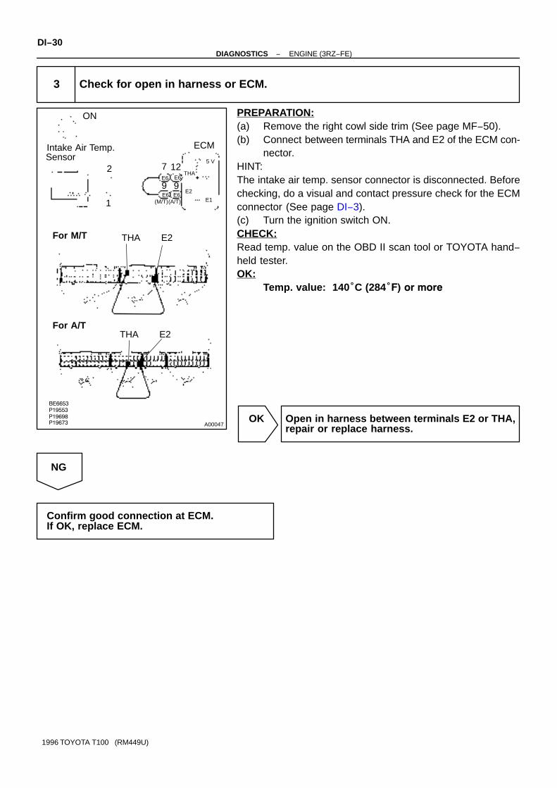
BE6653P19553P19698P19673 A00047
Intake Air Temp.Sensor
1
2
ON
7
9 9
12
THA E2
THA E2
ECM
(M/T)(A/T)
THA
E2
5 V
E1
E6
For M/T
For A/T
E6 E6
E6
DI−30−DIAGNOSTICS ENGINE (3RZ−FE)
1996 TOYOTA T100 (RM449U)
3 Check for open in harness or ECM.
PREPARATION:(a) Remove the right cowl side trim (See page MF−50).(b) Connect between terminals THA and E2 of the ECM con-
nector.HINT:The intake air temp. sensor connector is disconnected. Beforechecking, do a visual and contact pressure check for the ECMconnector (See page DI−3).(c) Turn the ignition switch ON.CHECK:Read temp. value on the OBD II scan tool or TOYOTA hand−held tester.OK:
Temp. value: 140°C (284°F) or more
OK Open in harness between terminals E2 or THA,repair or replace harness.
NG
Confirm good connection at ECM.If OK, replace ECM.
https://www.truck-manuals.net/

BE6653P19554 A00048
Intake Air Temp.Sensor
7
1
ECM
12
9E6
E6
THA
E2
5 V
E1
ON
E69
2E6
(M/T)(A/T)
−DIAGNOSTICS ENGINE (3RZ−FE)DI−31
1996 TOYOTA T100 (RM449U)
4 Check for short in harness and ECM.
PREPARATION:(a) Disconnect the intake air temp. sensor connector.(b) Turn the ignition switch ON.CHECK:Read temp. value on the OBD II scan tool or TOYOTA hand−held tester.OK:
Temp. value: − 40°C (− 40°F)
OK Replace intake air temp. sensor.
NG
https://www.truck-manuals.net/

BE6653FI7056P19785P19798 A00049
Intake Air Temp.Sensor
ON
ECM
THA
E2
5 V
E1
For M/T
For A/T E6 Connector
E6 Connector
DI−32−DIAGNOSTICS ENGINE (3RZ−FE)
1996 TOYOTA T100 (RM449U)
5 Check for short in harness or ECM.
PREPARATION:(a) Remove the right cowl side trim (See page MF−50).(b) Disconnect the E6 connector of the ECM.HINT:The intake air temp. sensor connector is disconnected.(c) Turn the ignition switch ON.CHECK:Read temp. value on the OBD II scan tool or TOYOTA hand−held tester.OK:
Temp. value: − 40°C (− 40°F)
OK Repair or replace harness or connector.
NG
Check and replace ECM (See page IN−26 ).
https://www.truck-manuals.net/

P19561
Engine Coolant Temp.Sensor
E6
E6
4
9
ECM
5 V
THW
E2
G−Y
BR−B
2
1
E6
E69
4
E1(M/T) (A/T)
(M/T) (A/T)
−DIAGNOSTICS ENGINE (3RZ−FE)DI−33
1996 TOYOTA T100 (RM449U)
DTC P0115 Engine Coolant Temp. Circuit Malfunction
CIRCUIT DESCRIPTIONA thermistor built into the engine coolant temp. sensor changes the resistance value according to the enginecoolant temp.The structure of the sensor and connection to the ECM is the same as in the intake air temp. circuit malfunc-tion shown on page DI−27.If the ECM detects the DTC P0115, it operates the fail safe function in which the engine coolant temp. isassumed to be 80°C (176°F).
DTC No. Detection Item Trouble Area
P0115 Open or short in engine coolant temp. sensor circuit
�Open or short in engine coolant temp. sensor circuit
�Engine coolant temp. sensor
�ECM
HINT:After confirming DTC P0115 use the OBD II scan tool or TOYOTA hand−held tester to confirm the enginecoolant temp. from ”CURRENT DATA”.
Temp. Displayed Malfunction
− 40°C (− 40°F) Open circuit
140°C (284°F) or more Short circuit
WIRING DIAGRAM
DI0TF−03
https://www.truck-manuals.net/

BE6653P19555 A00046
Engine CoolantTemp. Sensor
1
ECM
E6
THW
E2
5 V
E1
ON
E6
2
(M/T)(A/T)
E6E64 4
9 9
DI−34−DIAGNOSTICS ENGINE (3RZ−FE)
1996 TOYOTA T100 (RM449U)
INSPECTION PROCEDUREHINT:If DTCs P0110, P0115 and P0120 are output simultaneously, E2 (Sensor Ground) may be open.
1 Connect OBD II scan tool or TOYOTA hand−held tester and read value of enginecoolant temp.
PREPARATION:(a) Connect the OBD II scan tool or TOYOTA hand−held tester to the DLC3.(b) Turn the ignition switch ON and push the OBD II scan tool or TOYOTA hand−held tester main switch
ON.CHECK:Read temp. value on the OBD II scan tool or TOYOTA hand−held tester.OK:
Same as actual engine coolant temp.HINT:� If there is open circuit, OBD II scan tool or TOYOTA hand−held tester indicates − 40°C (− 40°F).
� If there is open circuit, OBD II scan tool or TOYOTA hand−held tester indicates 140°C (284°F) or more.
NG − 40°C (− 40°F) ... Go to step 2.140°C (284°F) or more ... Go to step 4.
OK
Check for intermittent problems (See pageDI−3).
2 Check for open in harness or ECM.
PREPARATION:(a) Disconnect the engine coolant temp. sensor connector.(b) Connect the sensor wire harness terminals together.(c) Turn the ignition switch ON.CHECK:Read temp. value on the OBD II scan tool or TOYOTA hand−held tester.OK:
Temp. value: 140°C (284°F) or more
OK Confirm good connection at sensor.If OK, replace engine coolant temp. sensor.
NG
https://www.truck-manuals.net/

BE6653P19553P19699P19674 A00050
1
2
ON
4
THW E2
THW E2
ECM
(M/T)(A/T)
THW
E2
5 V
E1
E6
For M/T
For A/T
E6
E6
Engine CoolantTemp. Sensor
E69
4
9
−DIAGNOSTICS ENGINE (3RZ−FE)DI−35
1996 TOYOTA T100 (RM449U)
3 Check for open in harness or ECM.
PREPARATION:(a) Remove the right cowl side trim (See page MF−50).(b) Connect between terminals THW and E2 of the ECM con-
nector.HINT:The engine coolant temp. sensor connector is disconnected.Before checking, do a visual and contact pressure check for theECM connector (See page DI−3).(c) Turn the ignition switch ON.CHECK:Read temp. value on the OBD II scan tool or TOYOTA hand−held tester.OK:
Temp. value: 140°C (284°F) or more
OK Open in harness between terminals E2 or THW,repair or replace harness.
NG
Confirm good connection at ECM.If OK, replace ECM.
https://www.truck-manuals.net/

BE6653P19554 A00048
1
2
ON
4
ECM
THW
E2
5 V
E1
E6 E6
Engine CoolantTemp. Sensor
4
9E6 E6
9
(M/T)(A/T)
DI−36−DIAGNOSTICS ENGINE (3RZ−FE)
1996 TOYOTA T100 (RM449U)
4 Check for open in harness or ECM.
PREPARATION:(a) Disconnect the engine coolant temp. sensor connector.(b) Turn the ignition switch ON.CHECK:Read temp. value on the OBD II scan tool or TOYOTA hand−held tester.OK:
Temp. value: − 40°C (− 40°F)
OK Replace engine coolant temp. sensor.
NG
https://www.truck-manuals.net/

BE6653FI7056P19785P19798 A00049
ON
THW
E2
For M/T
For A/T
Engine CoolantTemp. Sensor
E1
5 V
E6 Connector
E6 Connector
ECM
−DIAGNOSTICS ENGINE (3RZ−FE)DI−37
1996 TOYOTA T100 (RM449U)
5 Check for short in harness or ECM.
PREPARATION:(a) Remove the right cowl side trim (See page MF−50).(b) Disconnect the E6 connector of the ECM.HINT:The engine coolant temp. sensor connector is disconnected.(c) Turn the ignition switch ON.CHECK:Read temp. value on the OBD II scan tool or TOYOTA hand−held tester.OK:
Temp. value: − 40°C (− 40°F)
OK Repair or replace harness or connector.
NG
Check and replace ECM (See page IN−26).
https://www.truck-manuals.net/

DI−38−DIAGNOSTICS ENGINE (3RZ−FE)
1996 TOYOTA T100 (RM449U)
DTC P0116 Engine Coolant Temp. Circuit Range/Performance Problem
CIRCUIT DESCRIPTIONRefer to DTC P0115 on page DI−33.
DTC No. DTC Detecting Condition Trouble Area
P0116
When engine starts, water temp. is − 7°C (20°F) or less
And, 20 min. or more after engine starts, engine coolant
temp. sensor value is 20°C (68°F) or less
(2 trip detection logic)
�Engine coolant temp. sensor
�Cooling system
When engine starts, water temp. is between − 7°C (19.4°F)
and 10°C (50°F)
And, 5 min. or more after engine starts, engine coolant temp.
sensor value is 20°C (68°F) or less
(2 trip detection logic)
When engine starts, water temp. is 10°C (50°F) or more
And, 2 min. or more after engine starts, engine coolant temp.
sensor value is 20°C (68°F) or less
(2 trip detection logic)
INSPECTION PROCEDUREHINT:If DTCs P0115 and P0116 are output simultaneously, engine coolant temp. sensor circuit may be open.Perform troubleshooting of DTC P0115 first.
1 Are there any other codes (besides DTC P0116) being output?
YES Go to relevant DTC chart.
NO
2 Check thermostat (See page CO−9).
NG Replace thermostat.
OK
Replace engine coolant temp. sensor (Seepage MF−45).
DI0TG−03
https://www.truck-manuals.net/

FI6571
Throttle PositionSensor ECM
VCC
VTA
IDL
E2
5 V
B+
−DIAGNOSTICS ENGINE (3RZ−FE)DI−39
1996 TOYOTA T100 (RM449U)
DTC P0120 Throttle/Pedal Position Sensor/Switch ”A”Circuit Malfunction
CIRCUIT DESCRIPTIONThe throttle position sensor is mounted in the throttle body anddetects the throttle valve opening angle. When the throttle valveis fully closed, the IDL contacts in the throttle position sensorare on, so the voltage at terminal IDL of the ECM becomes 0 V. At this time, a voltage of approximately 0.3 − 0.8 V is appliedto terminal VTA of the ECM. When the throttle valve is opened,the IDL contacts go off and thus the power source voltage ofapproximately 12 V in the ECM is applied to terminal IDL of theECM. The voltage applied to terminal VTA of the ECM in-creases in proportion to the opening angle of the throttle valveand becomes approximately 3.2 − 4.9 V when the throttle valveis fully opened. The ECM judges the vehicle driving conditionsfrom these signals input from terminals VTA and IDL, and usesthem as one of the conditions for deciding the air−fuel ratiocorrection, power increase correction and fuel−cut control etc.
DTC No. DTC Detecting Condition Trouble Area
P0120
Condition (a) or (b) continues:
(a) VTA < 0.1 V, and closed throttle position switch is OFF
(b) VTA > 4.9 V
�Open or short in throttle position sensor circuit
�Throttle position sensor
�ECM
HINT:� If there is open circuit in IDL line, DTC P0120 does not indicate.� After confirming DTC P0120 use the OBD II scan tool or TOYOTA hand−held tester to confirm the
throttle valve opening percentage and closed throttle position switch condition.
Throttle valve opening position
expressed as percentage Trouble Area
Throttle valve fully closed Throttle valve fully open
0 % 0 %VCC line open
VTA line open or short
100 % 100 % E2 line open
DI0TH−03
https://www.truck-manuals.net/

P19610
Throttle Position Sensor
G−Y11
2
3
4
Y−L
BR−B
Y
1
E6 E6
E6 E6
E6 E6
E6 E6
11 10
12 11
9 9
5 V
B+
VCC
VTA
IDL
E2
E1(M/T) (A/T)
* Closed Throttle Position Switch
*
FI7052
DI−40−DIAGNOSTICS ENGINE (3RZ−FE)
1996 TOYOTA T100 (RM449U)
WIRING DIAGRAM
INSPECTION PROCEDUREHINT:If DTCs P0110, P0115 and P0120 are output simultaneously, E2 (Sensor Ground) may be open.
1 Connect OBD II scan tool or TOYOTA hand−held tester and read the throttlevalve opening percentage.
PREPARATION:(a) Connect the OBD II scan tool or TOYOTA hand−held tester to DLC3.(b) Turn the ignition switch ON and push the OBD II scan tool or TOYOTA hand−held tester main switch
ON.CHECK:Read the throttle valve opening percentage.
OK:
Throttle valveThrottle valve opening position
expressed as percentage
Fully open Approx. 75 %
Fully closed Approx. 10 %
OK Check for intermittent problems (See page DI−3).
https://www.truck-manuals.net/

BE6653
P23808 A00051
ON
1 (+)
P23809
Throttle PositionSensor
12
4
−DIAGNOSTICS ENGINE (3RZ−FE)DI−41
1996 TOYOTA T100 (RM449U)
NG
2 Check voltage between terminal 1 of wire harness side connector and bodyground.
PREPARATION:(a) Disconnect the throttle position sensor connector.(b) Turn the ignition switch ON.CHECK:Measure voltage between terminals 1 of wire harness side con-nector and body ground.OK:
Voltage: 4.5 − 5.5 V
NG Go to step 5.
OK
3 Check throttle position sensor.
PREPARATION:Disconnect the throttle position sensor connector.CHECK:Measure voltage between terminals 1, 2 and 4 of throttle posi-tion sensor.OK:
Terminals Throttle valve Resistance
1 − 4 ⎯ 2.5 − 5.9 kΩ
2 − 4 Fully closed 0.2 − 5.7 kΩ
2 − 4 Fully open 2.0 − 10.2 kΩ
NG Replace throttle position sensor.
OK
https://www.truck-manuals.net/

BE6653
P23810
P23811 A00052
For M/T
ON
For A/T
VTA (+) E2 (−)
VTA (+) E2 (−)
BE6653
P23812
P23813A00028
For M/T
ON
For A/T
VCC (+)
VCC (+) E2 (−)
E2 (−)
DI−42−DIAGNOSTICS ENGINE (3RZ−FE)
1996 TOYOTA T100 (RM449U)
4 Check voltage between terminals VTA and E2 of ECM connector.
PREPARATION:(a) Remove the right cowl side trim (See page MF−50).(b) Turn the ignition switch ON.CHECK:Measure voltage between terminals VTA and E2 of ECM con-nector.OK:
Throttle valve Voltage
Fully closed 0.3 − 0.8 V
Fully open 2.7 − 5.2 V
NG Check for open and short in harness andconnector between ECM and throttle positionsensor (VTA line) (See page IN−26).
OK
Check and replace ECM (See page IN−26).
5 Check voltage between terminals VCC and E2 of ECM connector.
PREPARATION:(a) Remove the right cowl side trim (See page MF−50).(b) Turn the ignition switch ON.CHECK:Measure voltage between terminals VCC and E2 of ECM con-nector.OK:
Voltage: 4.5 − 5.5 V
NG Check and replace ECM (See page IN−26).
OK
Check for open in harness and connector be-tween ECM and sensor (VCC line) (See pageIN−26).
https://www.truck-manuals.net/

−DIAGNOSTICS ENGINE (3RZ−FE)DI−43
1996 TOYOTA T100 (RM449U)
DTC P0121 Throttle/Pedal Position Sensor/Switch ”A”Circuit Range/Performance Problem
CIRCUIT DESCRIPTIONRefer to DTC P0120 on page DI−39.
DTC No. Detection Item Trouble Area
P0121
After vehicle speed has been exceeded 30 km/h (19 mph)
even once, output value of throttle position sensor is out of
applicable range while vehicle speed between 30 km/h (19
mph and 0 km/h (0 mph)
�Throttle position sensor
INSPECTION PROCEDURE
1 Are there any other codes (besides DTC P0121) being output?
YES Go to relevant DTC chart.
NO
Replace throttle position sensor.
DI0TI−01
https://www.truck-manuals.net/

P21242 FI7210 A00027
Atmosphere
FlangePlatinum ElectrodeSolid Electrolyte(Zirconia Element)Platinum ElectrodeHeaterCoating (Ceramic)
Exhaust GasCover
Ideal Air−Fuel Mixture
Out
put
Vol
tage
Richer − Air Fuel Ratio − Leaner
DI−44−DIAGNOSTICS ENGINE (3RZ−FE)
1996 TOYOTA T100 (RM449U)
DTC P0125 Insufficient Coolant Temp. for Closed LoopFuel Control
CIRCUIT DESCRIPTIONTo obtain a high purification rate for the CO, HC and NOx components of the exhaust gas, a three−waycatalytic converter is used, but for the most efficient use of the three−way catalytic converter, the air−fuelratio must be precisely controlled so that it is always close to the stoichiometric air−fuel ratio.The oxygen sensor has the characteristic where by its output voltage changes suddenly in the vicinity of thestoichiometric air−fuel ratio. This is used to detect the oxygen concentration in the exhaust gas and providefeedback to the computer for control of the air−fuel ratio.When the air−fuel ratio becomes LEAN, the oxygen concentration in the exhaust increases and the oxygensensor informs the ECM of the LEAN condition (small electromotive force: 0 V).When the air−fuel ratio is RICHER than the stoichiometric air−fuel ratio the oxygen concentration in the ex-haust gas is reduced and the oxygen sensor informs the ECM of the RICH condition (large electromotiveforce: 1 V). The ECM judges by the electromotive force from the oxygen sensor whether the air−fuel ratiois RICH or LEAN and controls the injection time accordingly. However, if malfunction of the oxygen sensorcauses output of abnormal electromotive force, the ECM is unable to perform accurate air−fuel ratio control.The heated oxygen sensors include a heater which heats the zirconia element. The heater is controlled bythe ECM. When the intake air volume is low (the temp. of the exhaust gas is low) current flows to the heaterto heat the sensor for accurate oxygen concentration detection.
DTC No. DTC Detecting Condition Trouble Area
P0125
After engine is warmed up, heated oxygen sensor output
does not indicate RICH even once when conditions (a), (b),
(c) and (d) continue for at least 1.5 min.:
(a) Engine speed: 1,500 rpm or more
(b) Vehicle speed: 40 ∼ 100 km/h (25 ∼ 62 mph)
(c) Closed throttle position switch: OFF
(d) 140 sec. or more after starting engine
�Open or short in heated oxygen sensor (bank 1 sensor 1)
circuit
�Heated oxygen sensor (bank 1 sensor 1)
HINT:After confirming DTC P0125 use the OBD II scan tool or TOYOTA hand−held tester to confirm voltage output
of heated oxygen sensor from "CURRENT DATA".
If voltage output of heated oxygen sensor is 0 V, heated oxygen sensor circuit may be open or short.
DI0TJ−02
https://www.truck-manuals.net/

P19611
R/B No.2
B−
W2 2
E6 E6
E6 E6
BR
E1
E1
EB
2
2
2 2
From Battery
FromIG Switch
EF
I R
elay
W−
RE
FI
2
1
5
1 3
EA1 IE1W−R W−R W−R
9 9
W−
R
HeatedOxygenSensor(Bank 1Sensor 2)
2
1
3
4
2 3
1 4
HeatedOxygenSensor(Bank 1Sensor 1)
P−G E7 E7
E7 E7
E7 E7R−G
W
ECM
OX1
HT1
OX2
E1
HT2
E03
E03(M/T)(A/T)
6
2
5
14
15
5
3
13
24
16
B
To Body Ground
−DIAGNOSTICS ENGINE (3RZ−FE)DI−45
1996 TOYOTA T100 (RM449U)
WIRING DIAGRAM
INSPECTION PROCEDURE
1 Connect OBD II scan tool or TOYOTA hand−held tester and read value for volt-age output of heated oxygen sensor (Bank 1 sensor 1).
PREPARATION:(a) Connect the OBD II scan tool or TOYOTA hand−held tester to the DLC3.(b) Warm up the engine to normal operating temp.CHECK:Read voltage output of heated oxygen sensor (bank 1 sensor 1) when engine is suddenly raced.HINT:Perform quick racing to 4,000 rpm 3 times using the accelerator pedal.OK:
Heated oxygen sensor (bank 1 sensor 1) output a RICH signal (0.45 V or more) at least once
OK Check and replace ECM (See page IN−26).
NG
https://www.truck-manuals.net/

DI−46−DIAGNOSTICS ENGINE (3RZ−FE)
1996 TOYOTA T100 (RM449U)
2 Check for open and short in harness and connector between ECM and heatedoxygen sensor (bank 1 sensor 1) (See page IN−26).
NG Repair or replace harness or connector.
OK
Replace heated oxygen sensor(bank 1 sensor 1).
https://www.truck-manuals.net/

FI7130
Vehicle Speed
50 ∼ 65 km/h(31 ∼ 40 mph)
IdlingIG SW OFF
1 ∼ 3 min. 1 min. Time
(1)(2)
(3)
(4)
(5)
−DIAGNOSTICS ENGINE (3RZ−FE)DI−47
1996 TOYOTA T100 (RM449U)
DTC P0130 Heated Oxygen Sensor Circuit Malfunction(Bank 1 Sensor 1)
CIRCUIT DESCRIPTIONRefer to DTC P0125 on page DI−44.
DTC No. Detection ItemDTC Detecting Condition Trouble AreaTrouble Area
P0130
Voltage output of heated oxygen sensor remains at 0.4 V or
more or 0.55 V or less, during idling after engine is warmed
up (2 trip detection logic)
�Heated oxygen sensor
�Fuel trim malfunction
HINT:Sensor 1 refers to the sensor closer to the engine body.The heated oxygen sensor’s output voltage and the short−term fuel trim value can be read using the OBD II scan tool or TOYOTA hand−held tester.
WIRING DIAGRAMRefer to DTC P0125 on page DI−44.
CONFIRMATION DRIVING PATTERN
(1) Connect the TOYOTA hand−held tester to the DLC3.(2) Switch the TOYOTA hand−held tester from normal mode to check mode (See page DI−13).(3) Start the engine and warm it up with all the accessory switches OFF.(4) Drive the vehicle at 50 − 65 km/h (31 − 40 mph) for 1 − 3 min. to warm up the heated oxygen sensor.(5) Let the engine idle for 1 min.HINT:If a malfunction exists, the MIL will light up during step (5).NOTICE:If the conditions in this test are not strictly followed, detection of the malfunction will not be possible.If you do not have a TOYOTA hand−held tester, turn the ignition switch OFF after performing steps(3) to (5), then perform steps (3) to (5) again.
DI0TK−02
https://www.truck-manuals.net/

DI−48−DIAGNOSTICS ENGINE (3RZ−FE)
1996 TOYOTA T100 (RM449U)
INSPECTION PROCEDURE
1 Check for open and short in harness and connector between ECM and heatedoxygen sensor (See page IN−26).
NG Repair or replace harness or connector.
OK
2 Check for heated oxygen sensor data.
PREPARATION:(a) Connect the OBD II scan tool or TOYOTA hand−held tester to the DLC3.(b) Warm up the engine to normal operating temp.CHECK:Read heated oxygen sensor output voltage and short−term fuel trim.HINT:Read the values for the same bank.RESULT:
Pattern Heated oxygen sensor output voltage Short−term fuel trim
1 Lean condition (Changes at 0.55 V or less) Changes at about + 20 %
2 Rich condition (Changes at 0.4 V or more) Changes at about − 20 %
3 Except 1 and 2
1, 2 Check fuel trim system (See page DI−55).
3
https://www.truck-manuals.net/

P18349
−DIAGNOSTICS ENGINE (3RZ−FE)DI−49
1996 TOYOTA T100 (RM449U)
3 Check output voltage of heated oxygen sensor during idling.
PREPARATION:Warm up the heated oxygen sensor with the engine at 2,500 rpm for approx. 90 sec.CHECK:Use the OBD II scan tool or TOYOTA hand−held tester read the output voltage of the heated oxygen sensorduring idling.OK:
Heated oxygen sensor output voltage:Alternates repeatedly between less than 0.4 V and more than 0.55 V (See the following table)
OK Perform confirmation driving pattern.
NG
Replace heated oxygen sensor.
https://www.truck-manuals.net/

DI−50−DIAGNOSTICS ENGINE (3RZ−FE)
1996 TOYOTA T100 (RM449U)
DTC P0133 Heated Oxygen Sensor Circuit SlowResponse (Bank 1 Sensor 1)
CIRCUIT DESCRIPTIONRefer to DTC P0125 on page DI−44.
DTC No. DTC Detecting Condition Trouble Area
P0133
Response time for heated oxygen sensor’s voltage output to
change from rich to lean, or from lean to rich, is 1 sec. or
more during idling after engine is warmed up
(2 trip detection logic)
�Heated oxygen sensor
HINT:Sensor 1 refers to the sensor closer to the engine body.
INSPECTION PROCEDURE
1 Are there any other codes (besides DTC P0133) being output?
YES Go to relevant DTC chart.
NO
Replace heated oxygen sensor.
DI0TL−01
https://www.truck-manuals.net/

−DIAGNOSTICS ENGINE (3RZ−FE)DI−51
1996 TOYOTA T100 (RM449U)
DTC P0135 Heated Oxygen Sensor Heater Circuit Malfunction (Bank 1 Sensor 1)
DTC P0141 Heated Oxygen Sensor Heater Circuit Malfunction (Bank 1 Sensor 2)
CIRCUIT DESCRIPTIONRefer to DTC P0125 on page DI−44.
DTC No. DTC Detecting Condition Trouble Area
P0135
P0141
When heater operates, heater current exceeds 2 A
(2 trip detection logic) �Open or short in heater circuit of heated oxygen sensor
�Heated oxygen sensor heater
�ECMHeater current of 0.2 A or less when heater operates
(2 trip detection logic)
HINT:� Sensor 1 refers to the sensor closer to the engine body.� Sensor 2 refers to the sensor farther away from the engine body.
WIRING DIAGRAMRefer to DTC P0125 on page DI−44.
DI0TM−03
https://www.truck-manuals.net/

BE6653P23814P23815
A00056
ON
For M/T
For M/T
HT1 (+) HT2 (+)
HT1 (+) HT2 (+)
DI−52−DIAGNOSTICS ENGINE (3RZ−FE)
1996 TOYOTA T100 (RM449U)
INSPECTION PROCEDURE
1 Check voltage between terminals HT1, HT2 of ECM connector and body ground.
PREPARATION:(a) Remove the right cowl side trim (See page MF−50).(b) Turn the ignition switch ON.CHECK:Measure voltage between terminals HT1, HT2 of ECM connec-tor and body ground.HINT:� Connect terminal HT1 to bank 1 sensor 1.� Connect terminal HT2 to bank 1 sensor 2.
OK:Voltage: 9 − 14 V
OK Check and replace ECM (See page IN−26).
NG
2 Check resistance of heated oxygen sensor heater.
NG Replace heated oxygen sensor.
OK
Check and repair harness or connector be-tween EFI main relay, heated oxygen sensorand ECM.
https://www.truck-manuals.net/

−DIAGNOSTICS ENGINE (3RZ−FE)DI−53
1996 TOYOTA T100 (RM449U)
DTC P0136 Heated Oxygen Sensor Circuit Malfunction(Bank 1 Sensor 2)
CIRCUIT DESCRIPTIONRefer to DTC P0125 on page DI−44.
DTC No. DTC Detecting Condition Trouble Area
P0136
Voltage output of heated oxygen sensor (bank 1 Sensor 2)
remains at 0.4 V or more or 0.5 V or less when vehicle is driv-
en at 50 km/h
(31 mph) or more after engine is warmed up
(2 trip detection logic)
�Heated oxygen sensor
HINT:Sensor 2 refers to the sensor farther away from the engine body.
WIRING DIAGRAMRefer to DTC P0125 on page DI−44.
INSPECTION PROCEDURE
1 Are there any other codes (besides DTC P0136) being output?
YES Go to relevant DTC chart.
NO
2 Check for open and short in harness and connector between ECM and heatedoxygen sensor (See page IN−26).
NG Repair or replace harness or connector.
OK
DI0TN−02
https://www.truck-manuals.net/

DI−54−DIAGNOSTICS ENGINE (3RZ−FE)
1996 TOYOTA T100 (RM449U)
3 Check output voltage of heated oxygen sensor (bank 1 sensor 2).
PREPARATION:(a) Connect the OBD II scan tool or TOYOTA hand−held tester to the DLC3.(b) Warm up the engine to normal operating temp.CHECK:Read voltage output of the heated oxygen sensor (bank 1 sensor 2) when the engine suddenly raced.HINT:Perform quick racing to 4,000 rpm 3 min. using the accelerator pedal.OK:
Heated oxygen sensor output voltage: Alternates from 0.4 V or less to 0.5 V or more
OK Check that each connector is properly connected.
NG
Replace heated oxygen sensor.
https://www.truck-manuals.net/

−DIAGNOSTICS ENGINE (3RZ−FE)DI−55
1996 TOYOTA T100 (RM449U)
DTC P0171 System too Lean (Fuel Trim)
DTC P0172 System too Rich (Fuel Trim)
CIRCUIT DESCRIPTIONFuel trim refers to the feedback compensation value compared against the basic injection time. Fuel trimincludes short−term fuel trim and long−term fuel trim.Short−term fuel trim is the short−term fuel compensation used to maintain the air−fuel ratio at its idealtheoretical value. The signal from the heated oxygen sensor indicates whether the air−fuel ratio is RICH orLEAN compared to the ideal theoretical value, triggering a reduction in fuel volume if the air−fuel ratio is rich,and an increase in fuel volume if it is lean.Long−term fuel trim is overall fuel compensation carried out long−term to compensate for continual deviationof the short−term fuel trim from the central value due to individual engine differences, wear over time andchanges in the usage environment.If both the short−term fuel trim and long−term fuel trim are LEAN or RICH beyond a certain value, it is de-tected as a malfunction and the MIL lights up.
DTC No. DTC Detecting Condition Trouble Area
P0171
When air fuel ratio feedback is stable after engine warming
up, fuel trim is considerably in error on RICH side
(2 trip detection logic)
�Air intake (hose loose)
�Fuel line pressure
� Injector blockage
�Heated oxygen sensor (bank 1 sensor 1) malfunction
�Mass air flow meter
�Engine coolant temp. sensor
P0172
When air fuel ratio feedback is stable after engine warming
up, fuel trim is considerably in error on LEAN side
(2 trip detection logic)
�Fuel line pressure
� Injector leak, blockage
�Heated oxygen sensor (bank 1 sensor 1) malfunction
�Mass air flow meter
�Engine coolant temp. sensor
HINT:� When the DTC P0171 is recorded, the actual air−fuel ratio is on the LEAN side. When DTC P0172 is
recorded, the actual air−fuel ratio is on the RICH side.� If the vehicle runs out of fuel, the air−fuel ratio is LEAN and DTC P0171 is recorded. The MIL then
comes on.� If the total of the short−term fuel trim value and long−term fuel trim value is within ± 25 %, the system
is functioning normally.
INSPECTION PROCEDURE
1 Check air induction system (See page MF−1).
NG Repair or replace.
OK
DI0TO−03
https://www.truck-manuals.net/

DI−56−DIAGNOSTICS ENGINE (3RZ−FE)
1996 TOYOTA T100 (RM449U)
2 Check for heated oxygen sensor (bank 1 sensor 1 ) data.
PREPARATION:(a) Connect the OBD II scan tool or TOYOTA hand−held tester to the DLC3.(b) Warm up the engine to normal operating temp.CHECK:Read heated oxygen sensor output voltage and short−term fuel trim.RESULT:
Pattern Heated oxygen sensor output voltage Short−term fuel trim
1 Lean condition (Changes at 0.55 V or less) Changes at about + 20 %
2 Rich condition (Changes at 0.4 V or more) Changes at about − 20 %
3 Except 1 and 2
3 Check for heated oxygen sensor (bank 1 sensor1) (See page MF−49).
1, 2
3 Check fuel pressure (See page MF−5).
NG Check and repair fuel pump, pressure regulator,fuel pipe line and filter (See page MF−10).
OK
4 Check injector injection (See page MF−16).
NG Replace injector.
OK
https://www.truck-manuals.net/

−DIAGNOSTICS ENGINE (3RZ−FE)DI−57
1996 TOYOTA T100 (RM449U)
5 Check mass air flow meter and engine coolant temp. sensor (See page DI−22,DI−33).
NG Repair or replace.
OK
6 Check for spark and ignition (See page IG−1).
NG Repair or replace.
OK
Check and replace ECM (See page IN−26).
https://www.truck-manuals.net/

DI−58−DIAGNOSTICS ENGINE (3RZ−FE)
1996 TOYOTA T100 (RM449U)
DTC P0300 Random/Multiple Cylinder Misfire Detected
DTC P0301 Cylinder 1 Misfire Detected
DTC P0302 Cylinder 2 Misfire Detected
DTC P0303 Cylinder 3 Misfire Detected
DTC P0304 Cylinder 4 Misfire Detected
CIRCUIT DESCRIPTIONMisfire: The ECM uses the crankshaft position sensor and camshaft position sensor to monitor changes inthe crankshaft rotation for each cylinder.The ECM counts the number of times the engine speed change rate indicates that misfire has occurred. Andwhen the misfire rate equals or exceeds the count indicating that the engine condition has deteriorated, theMIL lights up.If the misfire rate is high enough and the driving conditions will cause catalyst overheating, the MIL blinkswhen misfiring occurs.
DTC No. DTC Detecting Condition Trouble Area
P0300Misfiring of random cylinders is detected during any
particular 200 or 1,000 revolutions
� Ignition system
� Injector
�Fuel line pressure
�EGR
�Compression pressure
�Valve clearance not to specification
�Valve timing
�Mass air flow meter
�Engine coolant temp. sensor
P0301
P0302
P0303
P0304
For any particular 200 revolutions for engine, misfiring is
detected which can cause catalyst overheating
(This causes MIL to blink)
For any particular 1,000 revolutions for engine, misfiring is
detected which causes a deterioration in emissions
(2 trip detection logic)
HINT:When the 2 more codes for a misfiring cylinder are recorded repeatedly but no random misfire code is re-corded, it indicates that the misfires were detected and recorded at different times.
DI0TP−03
https://www.truck-manuals.net/

S00877
W−R W−RIA3
R/B No.2
Bat
tery
R−
LW
IgnitionSwitch
AM
2
2
2
8
8
7
B−R IE114
B−R
B−R
B−R
B−R
B−R
EB
2
2
2
2
Injector
No.1
No.3
No.2
No.4
W−R
W
W−R
W−R
W
W
BR
BR
1
1
1
1
12 12
11 11
E7 E7
E7 E7
E7 E7
E7 E7
13 13
26 26
(M/T)(A/T)
#10
#20
E01
E02
ECM
FI6588 FI6538
A00064
10 V/ Division
GND
10 V/ Division
100 msec./Division (Idling)
GND
(Magnification)
1 msec./Division (Idling)Injection duration
−DIAGNOSTICS ENGINE (3RZ−FE)DI−59
1996 TOYOTA T100 (RM449U)
WIRING DIAGRAM
Reference: INSPECTION USING OSCILLOSCOPEINJECTOR SIGNAL WAVEFORMWith the engine idling, measure between terminals #10, #20 and E01 of ECM.HINT:The correct waveform is as shown.
https://www.truck-manuals.net/

P03792
P25086 A00065
DI−60−DIAGNOSTICS ENGINE (3RZ−FE)
1996 TOYOTA T100 (RM449U)
INSPECTION PROCEDURE
1 Check spark plug and spark of misfiring cylinder.
PREPARATION:(a) Disconnect the high−tension cord.(b) Remove the spark plug.CHECK:(a) Check the carbon deposits electrode.(b) Check the electrode gap.OK:
(1) No large carbon deposit present. Not wet with gas-oline or oil.(2) Electrode gap: 0.8 mm (0.031 in.)
PREPARATION:(a) Install the spark plug to the high−tension code.(b) Disconnect the injector connector.(c) Ground the spark plug.CHECK:Check if the spark occurs while the engine is being craked.NOTICE:To prevent excess fuel being injected from the injectorsduring this test, don’t crank the engine for more than 5 − 10seconds at a time.OK:
Spark jumps across electrode gap.
NG Replace or check ignition system (See pageIG−1).
OK
https://www.truck-manuals.net/

BE6653
P23816
P23817 A00066
For M/T #10 (+) #20 (+)
#10 (+) #20 (+)For A/T
−DIAGNOSTICS ENGINE (3RZ−FE)DI−61
1996 TOYOTA T100 (RM449U)
2 Check voltage of ECM terminal for injector of failed cylinder.
PREPARATION:(a) Remove the right cowl side trim (See page MF−50).(b) Turn the ignition switch ON.CHECK:Measure voltage between applicable terminal of ECM connec-tor and body ground.OK:
Voltage: 9 − 14 V
OK Go to step 4.
NG
3 Check resistance of injector of misfiring cylinder (See page MF−16).
NG Replace injector.
OK
Check for open and short in harness and con-nector between injector and ECM (See pageIN−26).
4 Check fuel pressure (See page MF−5).
NG Check and repair fuel pump, pressure regulator,fuel pipe line and filter (See page MF−10).
OK
https://www.truck-manuals.net/

DI−62−DIAGNOSTICS ENGINE (3RZ−FE)
1996 TOYOTA T100 (RM449U)
5 Check injector injection (See page MF−16).
NG Replace injector.
OK
6 Check EGR system (See page EC−7).
NG Repair EGR system.
OK
7 Check mass air flow meter and engine coolant temp. sensor (See page DI−22,DI−33).
NG Repair or replace.
OK
Check compression pressure, valve clear-ance and valve timing.
https://www.truck-manuals.net/

P19613
Knock Sensor 1
(M/T) (A/T)
13 6
E6 E6
E1
KNK
ECM
B1
−DIAGNOSTICS ENGINE (3RZ−FE)DI−63
1996 TOYOTA T100 (RM449U)
DTC P0325 Knock Sensor 1 Circuit Malfunction
CIRCUIT DESCRIPTIONKnock sensor is fitted to the cylinder block to detect engine knocking. This sensor contains a piezoelectricelement which generates a voltage when it becomes deformed, which occurs when the cylinder block vi-brates due to knocking. If engine knocking occurs, ignition timing is retarded to suppress it.
DTC No. DTC Detecting Condition Trouble Area
P0325No knock sensor 1 signal to ECM with engine speed 1,200 rpm
or more
�Open or short in knock sensor 1 circuit
�Knock sensor 1 (looseness)
�ECM
If the ECM detects the above diagnosis conditions, it operates the fail safe function in which the correctiveretard angle value is set to the maximum value.
WIRING DIAGRAM
DI0TQ−03
https://www.truck-manuals.net/
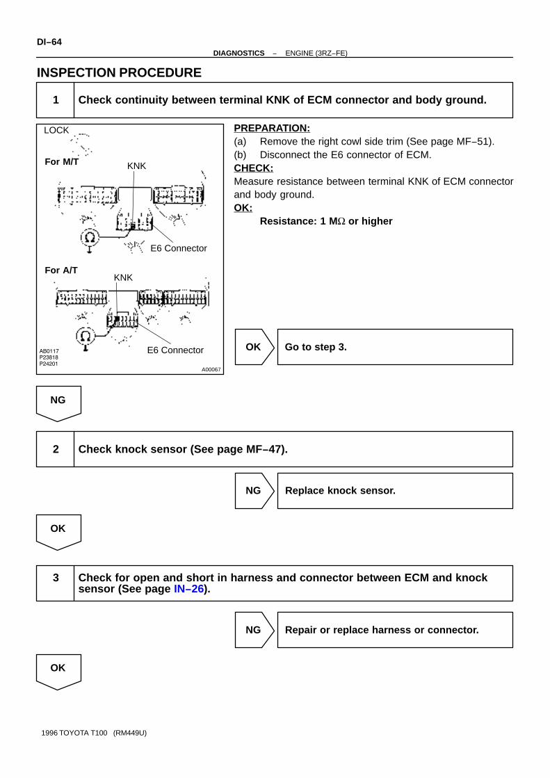
AB0117
P23818
P24201
A00067
LOCK
For M/T
For A/T
KNK
KNK
E6 Connector
E6 Connector
DI−64−DIAGNOSTICS ENGINE (3RZ−FE)
1996 TOYOTA T100 (RM449U)
INSPECTION PROCEDURE
1 Check continuity between terminal KNK of ECM connector and body ground.
PREPARATION:(a) Remove the right cowl side trim (See page MF−51).(b) Disconnect the E6 connector of ECM.CHECK:Measure resistance between terminal KNK of ECM connectorand body ground.OK:
Resistance: 1 MΩ or higher
OK Go to step 3.
NG
2 Check knock sensor (See page MF−47).
NG Replace knock sensor.
OK
3 Check for open and short in harness and connector between ECM and knocksensor (See page IN−26).
NG Repair or replace harness or connector.
OK
https://www.truck-manuals.net/

A00068
KNK signal waveform0.5 V/ Division
0.5 V/ Division
0 V
0 V
5 msec./Division
100 μsec./Division
−DIAGNOSTICS ENGINE (3RZ−FE)DI−65
1996 TOYOTA T100 (RM449U)
4 Does malfunction disappear when a good knock sensor is installed?
YES Replace knock sensor.
NO
Check and replace ECM (See page IN−26).
Reference: INSPECTION USING OSCILLOSCOPE� With the engine racing (4,000 rpm), measure between
terminal KNK of ECM and body ground.HINT:The correct waveform is as shown.
� Spread the time on the horizontal axis, and confirm thatperiod of the wave is 151 μsec (Normal mode vibrationfrequency of knock sensor: 6.6 kHz).
HINT:If normal mode vibration frequency is not 6.6 kHz the sensor ismalfunctioning.
https://www.truck-manuals.net/

A00059
ECM
411
3
1
2
R
G
W
B
5
18
12
17
5
4
6
E7
E7
E7
E7
E5
E5
E5
E5
G
NE−
NE
G−
E1(M/T)(A/T)
Camshaft Position Sensor(Built into distributor)
Crankshaft Position Sensor
DI−66−DIAGNOSTICS ENGINE (3RZ−FE)
1996 TOYOTA T100 (RM449U)
DTC P0335 Crankshaft Position Sensor ”A” Circuit Malfunction
CIRCUIT DESCRIPTIONCrankshaft position sensor (NE signal) consist of a signal plate and pickup coil.The NE signal plate has 34 teeth and is mounted on the crankshaft. The NE signal sensor generates 34signals of every engine revolution. The ECM detects the standard crankshaft angle based on the G signals,and the actual crankshaft angle the engine speed by the NE signals.
DTC No. DTC Detecting Condition Trouble Area
P0335
No crankshaft position sensor signal to ECM during cranking
(2 trip detection logic)�Open or short in crankshaft position sensor circuit
�Crankshaft position sensor
�Starter
�ECMNo crankshaft position sensor signal to ECM with engine
speed 600 rpm or more (2 trip detection logic)
WIRING DIAGRAM
DI0TR−03
https://www.truck-manuals.net/

FI7059
FI7060 A00069
G, NE signal waveform 5 V/ Division
5 V/ Division
G
NE
G
NE
20 msec./Division (Idling)
10 msec./Division (Idling)
−DIAGNOSTICS ENGINE (3RZ−FE)DI−67
1996 TOYOTA T100 (RM449U)
INSPECTION PROCEDURE
1 Check resistance of crankshaft position sensor (See page IG−14).
Reference: INSPECTION USING OSCILLOSCOPEDuring cranking or idling, check between terminals G and G−,NE and NE− of ECMHINT:The correct waveforms are as shown.
NG Replace crankshaft position sensor.
OK
2 Check for open and short in harness and connector between ECM and crank-shaft position sensor (See page IN−26).
NG Repair or replace harness or connector.
OK
https://www.truck-manuals.net/

DI−68−DIAGNOSTICS ENGINE (3RZ−FE)
1996 TOYOTA T100 (RM449U)
3 Inspect sensor installation and teeth of signal plate.
NG Tighten the sensor. Replace signal plate.
OK
Check and replace ECM (See page IN−26).
https://www.truck-manuals.net/

−DIAGNOSTICS ENGINE (3RZ−FE)DI−69
1996 TOYOTA T100 (RM449U)
DTC P0336 Crankshaft Position Sensor ”A” CircuitRange/Performance
CIRCUIT DESCRIPTIONRefer to DTC P0335 on page DI−66.If the ECM records the DTC P0336, it operates the fail safe function, stopping the fuel injection.
DTC No. DTC Detecting Condition Trouble Area
P0336Deviation on crankshaft position sensor signal and camshaft
position sensor signal
�Valve timing
�Distributor installation
�ECM
INSPECTION PROCEDURE
1 Check valve timing (See page EM−38).
NG Adjust valve timing.
OK
2 Check distributor installation (See page EM−5).
NG Reinstall distributor.
OK
Check and replace ECM (See page IN−26).
DI0TS−02
https://www.truck-manuals.net/

DI−70−DIAGNOSTICS ENGINE (3RZ−FE)
1996 TOYOTA T100 (RM449U)
DTC P0340 Camshaft Position Sensor CircuitMalfunction
CIRCUIT DESCRIPTIONCamshaft position sensor (G signal) consist of signal plate and pickup coil. The G signal plate has one toothon its outer circumference and is built into the distributor.When the camshafts rotate, the protrusion on the signal plate and the air gap on the pickup coil change,causing fluctuations in the magnetic field and generating an electromotive force in the pickup coil.The NE signal plate has 34 teeth and is mounted on the crankshaft. The NE signal sensor generates 34signals for every engine revolution. The ECM detects the standard crankshaft angle based on the G signalsand the actual crankshaft angle and the engine speed by the NE signals.
DTC No. DTC Detecting Condition Trouble Area
P0340
No camshaft position sensor signal to ECM during cranking
(2 trip detection logic)
�Open or short in camshaft position sensor circuit
�Camshaft position sensor
�Distributor
�Starter
�ECM
No camshaft position sensor signal to ECM during engine run-
ning
WIRING DIAGRAMRefer to DTC P0335 on page DI−66.
INSPECTION PROCEDURE
1 Check resistance of camshaft position sensor (See page EM−3).
Reference: INSPECTION USING OSCILLOSCOPERefer to DTC P0335 on page DI−66.
NG Replace distributor housing.
OK
2 Check for open and short in harness and connector between ECM anddistributor (See page IN−26).
NG Repair or replace harness or connector.
OK
DI0TT−03
https://www.truck-manuals.net/

−DIAGNOSTICS ENGINE (3RZ−FE)DI−71
1996 TOYOTA T100 (RM449U)
3 Check air gap (See page EM−1).
NG Replace distributor housing.
OK
Check and replace ECM (See page IN−26).
https://www.truck-manuals.net/

P19893
ECM
Throttle Body
ThrottleValve
Check Valve (for A/T)
EGR Vacuum Modulator
VSV EGRValve
P19921
R/B No.2
IG Switch
E7 E7
(M/T)(A/T)
E01
E1
ECM
E2
EGR
THGE6 E6
E6 E6
6 22
143
9 9
1
BR−B
G−W
P2
2
1
99
EA
W−RW−R
5 V
IE1W−R
EA1
W−
B
23
22
2 2
2
2
5
B−W
EFI
EFI Relay VSV for EGR
EGR GasTemp. Sensor
B−YEA14B
−Y
1C17
1A3
W−
R
IGNJ/B
No.1
FromFrom Battery
5
1
DI−72−DIAGNOSTICS ENGINE (3RZ−FE)
1996 TOYOTA T100 (RM449U)
DTC P0401 Exhaust Gas Recirculation Flow InsufficientDetected
CIRCUIT DESCRIPTIONThe EGR system recirculates exhaust gas, which is controlled to the proper quantity to suit the driving condi-tions, into the intake air mixture to slow down combustion, reduce the combustion temp. and reduce NOxemissions. The amount of EGR is regulated by the EGR vacuum modulator according to the engine load.
If even one of the following conditions is fulfilled, the VSV isturned ON by a signal from the ECM.This results in atmospheric air acting on the EGR valve, closingthe EGR valve and shutting off the exhaust gas (EGR cut−off).Under the following conditions, EGR is cut to maintain driveabil-ity:
� Before the engine is warmed up� During deceleration (throttle valve closed)� Light engine load (amount of intake air very small)� Engine racing
DTC No. DTC Detecting Condition Trouble Area
P0401
After engine is warmed up and run at 80 km/h (50 mph)
for 3 to 5 min., EGR gas temp. sensor value does not exceed
35°C (95°F) above ambient air temp.
(2 trip detection logic)
�EGR valve stuck closed
�Short in VSV circuit for EGR
�Open in EGR gas temp. sensor circuit
�EGR hose disconnected
�ECM
WIRING DIAGRAM
DI0TU−03
https://www.truck-manuals.net/

S06906
(3)
(5)
(4) (6)(2)
(1)
Warm up
IG SW OFF
Iding
Vehicle Speed70 − 90 km/h(43 − 56 mph)
3 − 5 min. 3 − 5 min.2 min. 2 min. Time
−DIAGNOSTICS ENGINE (3RZ−FE)DI−73
1996 TOYOTA T100 (RM449U)
SYSTEM CHECK DRIVING PATTERN
(1) Connect the OBD II scan tool or TOYOTA hand−held tester to the DLC3.(2) Start and warm up the engine with all the accessories switched OFF.(3) Run the vehicle at 70 − 90 km/h (43 − 56 mph) for 3 min. or more.(4) Idle the engine for about 2 min.(5) Do steps (3) and (4) again.(6) Check the ”READINESS TESTS” mode on the OBD II scan tool or TOYOTA hand−held tester.If ”COMPL” is displayed and the MIL does not light up, the system is normal.If ”INCMPL” is displayed and the MIL does not light up, run the vehicle step (5) from somes times and checkit.HINT:”INCMPL” is displayed when either condition (a) or (b) exists.(a) The system check is incomplete.(b) There is a malfunction in the system.If there is a malfunction in the system, the MIL will light up after steps (2) to (5) above are done.
https://www.truck-manuals.net/

BE6653
P19555 A00046
EGR Gas Temp.Sensor
ECM
143
9 9
2
1
E6
E6
THG
E2
5 V
E1
E6
E6(M/T)(A/T)
ON
DI−74−DIAGNOSTICS ENGINE (3RZ−FE)
1996 TOYOTA T100 (RM449U)
INSPECTION PROCEDURETOYOTA hand−held tester:
1 Connect TOYOTA hand−held tester and read value of EGR gas temp. value.
PREPARATION:(a) Connect the TOYOTA hand−held tester to the DLC3.(b) Turn the ignition switch ON and push the TOYOTA hand−held tester main switch ON.CHECK:Read EGR gas temp. on the TOYOTA hand−held tester.OK:
EGR gas temp.: 10°C (50°F) or moreHINT:If there is an open circuit, the TOYOTA hand−held tester indicates 3.1°C (37.6°F).
OK Go to step 4.
NG
2 Check for open in harness or ECM.
PREPARATION:(a) Disconnect the EGR gas temp. sensor connector.(b) Connect the sensor wire harness terminals together.(c) Turn the ignition switch ON.CHECK:Read EGR gas temp. on the TOYOTA hand−held tester.OK:
EGR gas temp.: 159.3°C (318.7°F)
OK Confirm good connection at sensor.If OK, replace EGR gas temp. sensor.
NG
https://www.truck-manuals.net/

BE6653
P19553
P19705
P19681 A00070
EGR Gas Temp.Sensor
ECM
143
9 9
2
1
THG
E2
5 V
E1
E6
(M/T)(A/T)E6
E6
E6
ON
THG E2
THG E2
For M/T
For A/T
−DIAGNOSTICS ENGINE (3RZ−FE)DI−75
1996 TOYOTA T100 (RM449U)
3 Check for open in harness or ECM.
PREPARATION:(a) Remove the right cowl side trim (See page MF−50).(b) Connect between terminals THG and E2 of the ECM con-
nector.HINT:The EGR gas temp. sensor connector is disconnected. Beforechecking, do a visual check and contact pressure check for theECM connector (See page IN−26).CHECK:Read EGR gas temp. on the TOYOTA hand−held tester.OK:
EGR gas temp.: 159.3°C (318.7°F)
OK Open in harness between terminals E2 or THG.Repair or replace harness.
NG
Confirm connection at ECM. If OK, replace ECM.
4 Check connection of vacuum hose and EGR hose (See page EC−2).
NG Repair or replace.
OK
https://www.truck-manuals.net/

BE6653
FI7205 FI7206
A00071
ON
System is OFF System is ON
Air
FE FE
Air
DI−76−DIAGNOSTICS ENGINE (3RZ−FE)
1996 TOYOTA T100 (RM449U)
5 Check VSV for EGR.
PREPARATION:Select the ”ACTIVE TEST” mode on the TOYOTA hand−heldtester.CHECK:Check operation of VSV when it is operated by the TOYOTAhand−held tester.OK:
EGR system is OFF:Air flows from port E to port F.EGR system is ON:Air does not flow from port E to port F.
OK Go to step 7.
NG
6 Check operation of VSV for EGR (See page MF−44).
NG Replace VSV for EGR.
OK
Check for short in harness and connector be-tween VSV and ECM (See page IN−26).
7 Check EGR vacuum modulator (See page MF−44).
NG Repair or replace.
OK
https://www.truck-manuals.net/

−DIAGNOSTICS ENGINE (3RZ−FE)DI−77
1996 TOYOTA T100 (RM449U)
8 Check EGR valve (See page MF−44).
NG Repair or replace.
OK
9 Check value of EGR gas temp. sensor.
PREPARATION:(a) Connect the TOYOTA hand−held tester to the DLC3.(b) Turn the ignition switch ON and push the TOYOTA hand−held tester main switch ON.(c) Select the ”ACTIVE TEST” mode on the TOYOTA hand−held tester (EGR system ON).(d) Race the engine at 4,000 rpm for 3 min.CHECK:Measure EGR gas temp. while racing engine at 4,000 rpm.OK:
EGR gas temp. after 3 min.: 140°C (284°F) or more
NG Replace EGR gas temp. sensor.
OK
Check and replace ECM (See page IN−26).
https://www.truck-manuals.net/

P24322
EGR Gas Temp. SensorConnector
BE6653P24204 A00072
ON
Wire Harness Side
1 (−) 2 (+)
DI−78−DIAGNOSTICS ENGINE (3RZ−FE)
1996 TOYOTA T100 (RM449U)
OBD II scan tool (excluding TOYOTA hand−held tester):
1 Check resistance of EGR gas temp. sensor.
PREPARATION:Disconnect the EGR gas temp. sensor connector.CHECK:Measure resistance between terminals of EGR gas temp. sen-sor connector.OK:
Resistance: 600 kΩ or lessHINT:If there is open circuit, ohmmeter indicates 720 kΩ or more.
NG Check and replace EGR gas temp. sensor (Seepage MF−48).
OK
2 Check for open in harness or ECM.
PREPARATION:(a) Disconnect the EGR gas temp. sensor connector.(b) Turn the ignition switch ON.CHECK:Measure voltage between terminals of EGR gas temp. sensorwire harness side connector.OK:
Voltage: 4.5 − 5.5 V
OK Go to step 4.
NG
https://www.truck-manuals.net/

BE6653
P24202
P24203
A00073
THG (+)
THG (+)
ON
For M/TE2 (−)
E2 (−)For A/T
−DIAGNOSTICS ENGINE (3RZ−FE)DI−79
1996 TOYOTA T100 (RM449U)
3 Check for open in harness or ECM.
PREPARATION:(a) Remove the right cowl side trim (See page MF−50).(b) Turn the ignition switch ON.CHECK:Measure voltage between terminals of THG and E2 of ECMconnector.HINT:The EGR gas temp. sensor connector is disconnected.OK:
Voltage: 4.5 − 5.5 V
OK Open in harness between terminals E2 or THG.Repair or replace harness.
NG
Confirm connection at ECM.If OK, replace ECM.
4 Check connection of vacuum hose and EGR hose (See page EC−2).
NG Repair or replace.
OK
https://www.truck-manuals.net/

BE6653
P21086
P21087
FI7205
FI7206
A00074
ON
For M/TE7 Connector
EGR
For A/T
OFFON
E7 Connector
OFF
ONVSV is ON VSV is OFF
Air Air
E F E F
EGR
DI−80−DIAGNOSTICS ENGINE (3RZ−FE)
1996 TOYOTA T100 (RM449U)
5 Check VSV for EGR.
PREPARATION:(a) Remove the right cowl side trim (See page MF−50).(b) Disconnect the E7 connector of ECM.(c) Turn the ignition switch ON.CHECK:Check VSV function:
(1) Connect between terminal EGR of ECM and bodyground (ON).
(2) Disconnect between terminal EGR of ECM andbody ground (OFF).
OK:(1) VSV is ON:Air flows from port E to port F.(2) VSV is OFF:Air does not flow from port E to port F.
OK Go to step 7.
NG
6 Check operation for VSV for EGR (See page MF−44).
NG Replace VSV for EGR.
OK
Check for open in harness and connector be-tween R/B NO.2 and ECM (See page IN−26).
https://www.truck-manuals.net/

P24228
EGR Gas Temp. SensorConnector
−DIAGNOSTICS ENGINE (3RZ−FE)DI−81
1996 TOYOTA T100 (RM449U)
7 Check EGR vacuum modulator (See page EC−7).
NG Repair or replace.
OK
8 Check EGR valve (See page EC−7).
NG Repair or replace.
OK
9 Check resistance of EGR gas temp. sensor.
PREPARATION:(a) Disconnect the EGR gas temp. sensor connector.(b) Start the engine and warm it up.(c) Disconnect the VSV connector for EGR.(d) Race the engine at 4,000 rpm or 3 min.CHECK:Measure resistance of the EGR gas temp. sensor while racingthe engine at 4,000 rpm.OK:
Resistance of EGR gas temp. sensor after 3 min.:4.3 kΩ or less
HINT:Resistance: 188.6 − 439.0 kΩ at 20°C (68°F)
NG Replace EGR gas temp. sensor.
OK
Check and replace ECM (See page IN−26).
https://www.truck-manuals.net/

DI−82−DIAGNOSTICS ENGINE (3RZ−FE)
1996 TOYOTA T100 (RM449U)
DTC P0402 Exhaust Gas Recirculation Flow ExcessiveDetected
CIRCUIT DESCRIPTIONRefer to DTC P0401 on page DI−72.
DTC No. DTC Detecting Condition Trouble Area
P0402
EGR gas temp. sensor value is high during EGR cut−off when
engine is cold and vacuum is applied to port E
(2 trip detection logic)
�EGR valve stuck open
�VSV for EGR open malfunction
�Open in VSV circuit for EGR
�Short in EGR gas temp. sensor circuit
�ECMEGR valve is always open (2 trip detection logic)
WIRING DIAGRAMRefer to DTC P0401 on page DI−72.
SYSTEM CHECK DRIVING PATTERNRefer to DTC P0401 on page DI−72.
INSPECTION PROCEDURETOYOTA hand−held tester:
1 Connect TOYOTA hand−held tester and read EGR gas temp. value.
PREPARATION:(a) Connect the TOYOTA hand−held tester to the DLC3.(b) Turn the ignition switch ON and push the TOYOTA hand−held tester main switch ON.CHECK:Read EGR gas temp. on the TOYOTA hand−held tester.OK:
EGR gas temp.: 150°C (302°F) or less (Not immediately after driving)HINT:If there is a short circuit, the TOYOTA hand−held tester indicates 159.3°C (318.7°F).
OK Go to step 4.
NG
DI0TV−03
https://www.truck-manuals.net/

BE6653
P19554 A00048
EGR Gas Temp.Sensor
ECM
THG
E2
5 V
E1
ON
E6 E6
E6 E6
2
1
3 14
9 9
(M/T)(A/T)
BE6653
FI7056
P19785
P19798 A00049
EGR Gas Temp.Sensor
ECM
THG
E2
5 V
E1
For M/T
For A/TE6 Connector
E6 Connector
−DIAGNOSTICS ENGINE (3RZ−FE)DI−83
1996 TOYOTA T100 (RM449U)
2 Check for short in harness and ECM.
PREPARATION:Disconnect the EGR gas temp. sensor connector.CHECK:Read EGR gas temp. on the TOYOTA hand−held tester.OK:
EGR gas temp.: 3.1°C (37.6°F)
OK Replace EGR gas temp. sensor.
NG
3 Check for short in harness or ECM.
PREPARATION:(a) Remove the glove compartment (See page MF−50).(b) Disconnect the E6 connector of the ECM.HINT:The EGR gas temp. sensor is disconnected.CHECK:Read EGR gas temp. on the TOYOTA hand−held tester.OK:
EGR gas temp.: 3.1°C (37.6°F)
OK Repair or replace harness or connector.
NG
Check and replace ECM (See page IN−26).
https://www.truck-manuals.net/

P24228
EGR Gas Temp. SensorConnector
DI−84−DIAGNOSTICS ENGINE (3RZ−FE)
1996 TOYOTA T100 (RM449U)
4 Check VSV for EGR (See page MF−44).
OK Check EGR valve (See page EC−7).
NG
5 Check operation of VSV for EGR (See page EC−7).
NG Replace VSV for EGR.
OK
Check for open in harness and connector be-tween R/B No.2 and ECM (See page IN−26).
OBD II scan tool (excluding TOYOTA hand−held tester):
1 Check resistance of EGR gas temp. sensor.
PREPARATION:Disconnect the EGR gas temp. sensor connector.CHECK:Measure resistance between terminals of EGR gas temp. sen-sor connector.OK:
Resistance: 2.5 kΩ or more (Not immediately after driving)
HINT:If there is short circuit, ohmmeter indicates 200 Ω or less.
NG Replace EGR gas temp. sensor.
OK
https://www.truck-manuals.net/
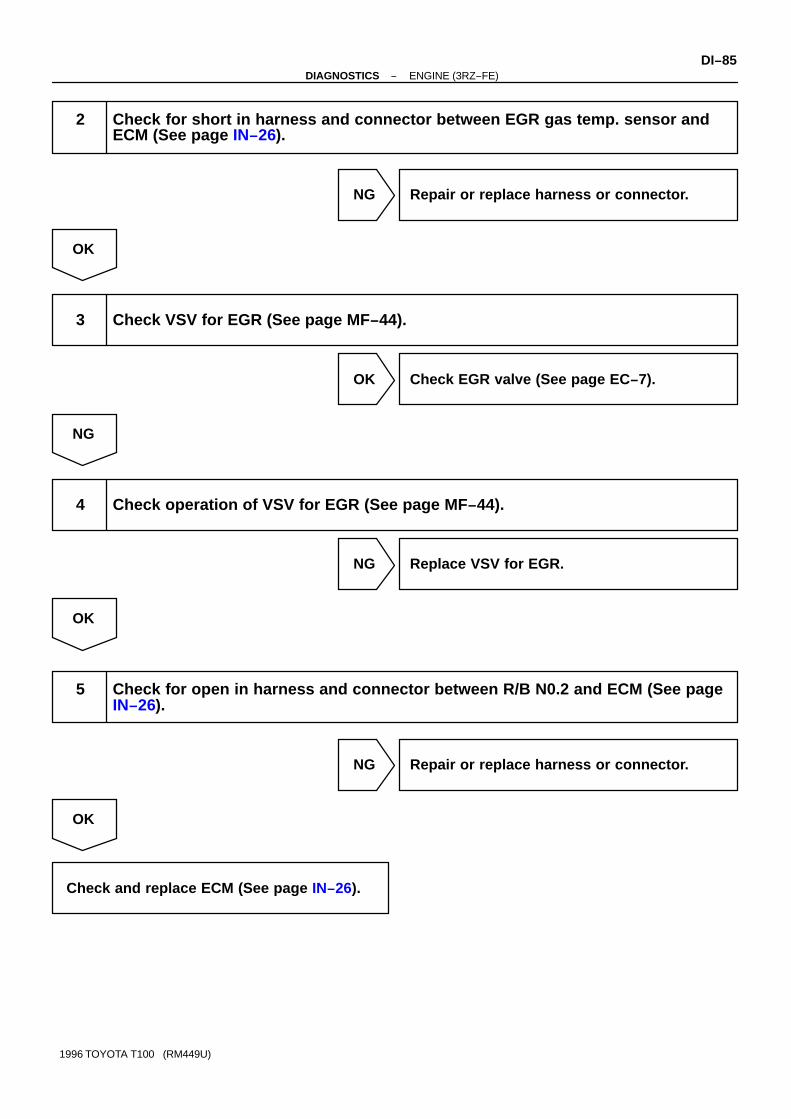
−DIAGNOSTICS ENGINE (3RZ−FE)DI−85
1996 TOYOTA T100 (RM449U)
2 Check for short in harness and connector between EGR gas temp. sensor andECM (See page IN−26).
NG Repair or replace harness or connector.
OK
3 Check VSV for EGR (See page MF−44).
OK Check EGR valve (See page EC−7).
NG
4 Check operation of VSV for EGR (See page MF−44).
NG Replace VSV for EGR.
OK
5 Check for open in harness and connector between R/B N0.2 and ECM (See pageIN−26).
NG Repair or replace harness or connector.
OK
Check and replace ECM (See page IN−26).
https://www.truck-manuals.net/

FI7081
Waveform of Oxygen Sensorbefore Catalyst Normal Catalyst Waveform of Oxygen Sensor
after Catalyst
P25762
Engine Speed
2500 − 3000 rpm
Idling
IG SW OFFWarmed up 3 minutes Check
Time(1)
(3) (4)
(2)
DI−86−DIAGNOSTICS ENGINE (3RZ−FE)
1996 TOYOTA T100 (RM449U)
DTC P0420 Catalyst System Efficiency Below Threshold
CIRCUIT DESCRIPTIONThe ECM compares the waveform of the oxygen sensor located before the catalyst with the waveform ofthe oxygen sensor located after the catalyst to determine whether or not catalyst performance has deterio-rated.Air−fuel ratio feedback compensation keeps the waveform of the oxygen sensor before the catalyst repeat-edly changing back and forth from rich to lean.If the catalyst is functioning normally, the waveform of the oxygen sensor after the catalyst switches backand forth between rich and lean much more slowly than the waveform of the oxygen sensor before the cata-lyst.But when both waveforms change at a similar rate, it indicates that catalyst performance has deteriorated.
DTC No. DTC Detecting Condition Trouble Area
P0420
After engine and catalyst are warmed up, and while vehicle is
driven within set vehicle and engine speed range, waveforms
of heated oxygen sensors (bank 1 sensor 1, 2) have same
amplitude (2 trip detection logic)
�TWC (Three−way catalytic converter)
�Heated oxygen sensor (bank 1 sensor 1, 2)
CONFIRMATION ENGINE RACING PATTERN
DI0TW−02
https://www.truck-manuals.net/

FI6514
OX Signal Waveform (Oscilloscope)
1.0 V
0 V
200 msec. /Division
−DIAGNOSTICS ENGINE (3RZ−FE)DI−87
1996 TOYOTA T100 (RM449U)
(1) Connect the OBD ll scan tool or TOYOTA hand−held tester to the DLC3.(2) Start engine and warm it up with all accessories switched OFF until the water temperature is stable.(3) Race the engine at 2500 − 3000 rpm for about 3 min.(4) After confirming that the waveform of the heated oxygen sensor, bank 1 sensor 1 (OX1), oscillate around0.5 V during feedback to the ECM, check the waveform of the heated oxygen sensor bank 1 sensor 2 (OX2).
HINT:If there is a malfunction in the system, the waveform of theheated oxygen sensor bank 1 sensor 2 (OX2) is almost thesame as that of the heated oxygen sensor bank 1 sensor 1(OX1) on the left.There are some cases where, even though a malfunctionexists, the MIL may either light up or not light up.
INSPECTION PROCEDURE
1 Are there any other codes (besides DTC P0420) being output?
YES Go to relevant DTC chart.
NO
2 Check heated oxygen sensor (bank 1 sensor 1) (See page DI−47).
NG Repair or replace.
OK
3 Check heated oxygen sensor (bank 1 sensor 2) (See page DI−53).
NG Repair or replace.
OK
Replace TWC (three−way catalytic convert-er) (See page EM−104).
https://www.truck-manuals.net/

A00652
ECM
VSV for EVAP ThrottleValve
Fuel TankCharcoalCanister
Fig 1
A00647
IG Switch
(M/T)(A/T)
23W−G
2
1
EF
IE
FI
Rel
ay
VSV for
ECMFrom From
Battery
2 2
2
2
2 2
32
E7 E5
EA
W−
B
IE2W−G
1
R/B No.2
PRG
E01
4EVAP5
EA1
W−R
W−R
9
2 1
B−
W
DI−88−DIAGNOSTICS ENGINE (3RZ−FE)
1996 TOYOTA T100 (RM449U)
DTC P0441 Evaporative Emission Control System Incorrect Purge Flow
CIRCUIT DESCRIPTIONTo reduce HC emissions, evaporated fuel from the fuel tank isrouted through the charcoal canister to the intake manifold forcombustion in the cylinders.The ECM changes the duty signal to the VSV for EVAP so thatthe intake quantity of HC emissions is appropriate for the drivingconditions (engine load, engine speed, vehicle speed, etc.) af-ter the engine is warmed up.
DTC No. DTC Detecting Condition Trouble Area
P0441Proper response to computer command does not occur
(2 trip detection logic)
�Open or short in VSV circuit for EVAP
�VSV for EVAP
�ECM
�Vacuum hose cracks, hole, blocked, damaged or
disconnected
�Charcoal canister
WIRING DIAGRAM
DI0TX−03
https://www.truck-manuals.net/

BE6653
FI7205 FI7206
A00071
VSV is ON VSV is OFF
ON
Air
E FAir
E F
−DIAGNOSTICS ENGINE (3RZ−FE)DI−89
1996 TOYOTA T100 (RM449U)
INSPECTION PROCEDURETOYOTA hand−held tester:
1 Connect TOYOTA hand−held tester and check operation of VSV for EVAP.
PREPARATION:(a) Connect the TOYOTA hand−held tester to the DLC3.(b) Turn the ignition switch ON and TOYOTA hand−held tes-
ter main switch ON.(c) Select the ”ACTIVE TEST” mode on the TOYOTA hand−
held tester.CHECK:Check operation of VSV when it is operated by the TOYOTAhand−held tester.OK:
(1) VSV is ON:Air flows from port E to port F.(2) VSV is OFF:Air does not flow from port E to port F.
OK Go to step 4.
NG
2 Check operation of VSV for EVAP (See page MF−44).
NG Replace VSV for EVAP.
OK
3 Check for open and short in harness and connector between EFI main relay(Marking: EFI) and ECM (See page IN−26).
NG Repair or replace harness or connector.
OK
Check and replace ECM (See page IN−26).
https://www.truck-manuals.net/

A00771
ON
For M/T
For A/T
PRG (+)
PRG (+)
DI−90−DIAGNOSTICS ENGINE (3RZ−FE)
1996 TOYOTA T100 (RM449U)
4 Check connection of vacuum hose (See Fig 1 in circuit description).
NG Repair or replace.
OK
Check and repair charcoal canister (Seepage EC−5).
OBD II scan tool (excluding TOYOTA hand−held tester):
1 Check operation of VSV for EVAP (See page MF−43).
NG Replace VSV for EVAP.
OK
2 Check voltage between terminal PRG of ECM connector and body ground.
PREPARATION:(a) Remove the right cowl side trim (See page MF−50).(b) Turn the ignition switch ON.CHECK:Measuve voltage between terminal PRG of ECM connector andbody ground.OK:
Voltage: 9 − 14 V
NG Check and repair harness or connector.
OK
https://www.truck-manuals.net/

−DIAGNOSTICS ENGINE (3RZ−FE)DI−91
1996 TOYOTA T100 (RM449U)
3 Check connection of vacuum hose (See Fig 1 in circuit description).
NG Repair or replace.
OK
4 Check charcoal canister (See page EC−5).
NG Repair or replace.
OK
Check and replace ECM (See page IN−26).
https://www.truck-manuals.net/

FI7112 FI7166A00081
Cable
To Speedometer Cable
T/M4−pulse
ECM
Magnet Reed Switch
No.1 Vehicle Speed Sensor
CombinationMeter
P19617
ECMFrom CruiseControl ECU
Combination Meter
5 V
E1
SP1E4E4
(M/T)(A/T)
G (M/T)G (M/T)
G (A/T)
IE1
9 810No.1VehicleSpeedSensor
6G
G
C11
DI−92−DIAGNOSTICS ENGINE (3RZ−FE)
1996 TOYOTA T100 (RM449U)
DTC P0500 Vehicle Speed Sensor Malfunction
CIRCUIT DESCRIPTIONThis No.1 vehicle speed sensor is mounted in the combination meter. It contains a magnet which is rotatedby the speed meter cable.Turning the reed switch ON and OFF 4 times for every revolution of the speedmeter.It is then transmitted to the ECM. The ECM determines the vehicle speed based on the frequency of thesepluse signals.
DTC No. DTC Detecting Condition Trouble Area
P0500
No vehicle speed sensor signal to ECM under conditions (a)
(2 trip detection logic)
(a) Vehicle is being driven
�Open or short in No.1 vehicle speed sensor circuit
�No.1 vehicle speed sensor
�ECM
�Speedometer cable
WIRING DIAGRAM
DI0TY−05
https://www.truck-manuals.net/
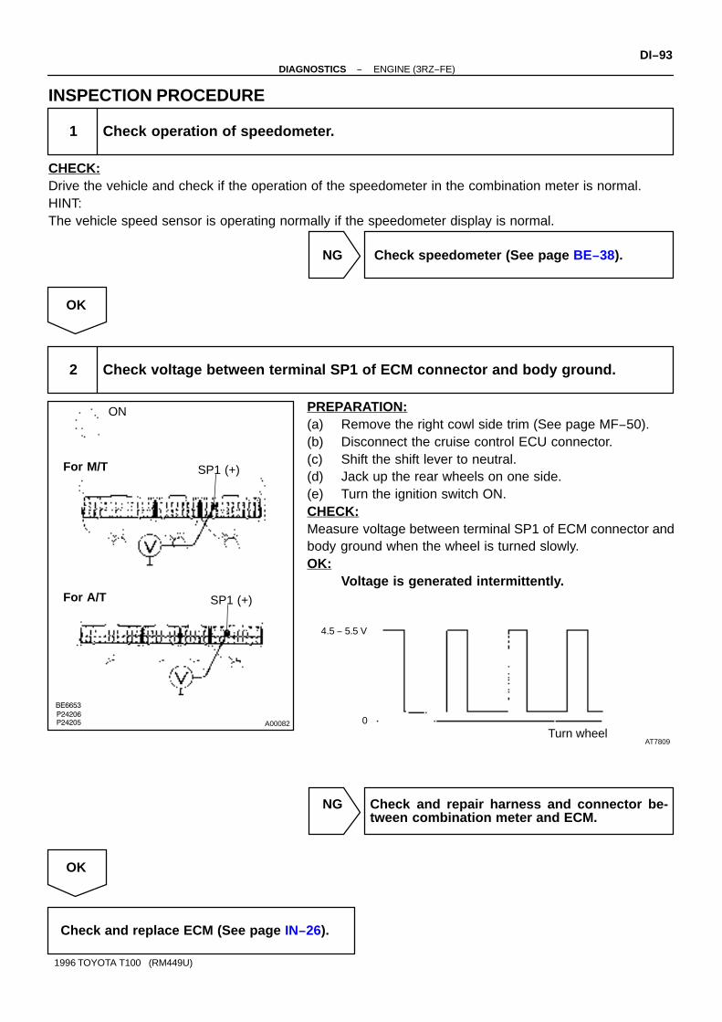
P24206
P24205
BE6653
A00082
ON
For M/T
For A/T
SP1 (+)
SP1 (+)
AT7809
4.5 − 5.5 V
0Turn wheel
−DIAGNOSTICS ENGINE (3RZ−FE)DI−93
1996 TOYOTA T100 (RM449U)
INSPECTION PROCEDURE
1 Check operation of speedometer.
CHECK:Drive the vehicle and check if the operation of the speedometer in the combination meter is normal.HINT:The vehicle speed sensor is operating normally if the speedometer display is normal.
NG Check speedometer (See page BE−38).
OK
2 Check voltage between terminal SP1 of ECM connector and body ground.
PREPARATION:(a) Remove the right cowl side trim (See page MF−50).(b) Disconnect the cruise control ECU connector.(c) Shift the shift lever to neutral.(d) Jack up the rear wheels on one side.(e) Turn the ignition switch ON.CHECK:Measure voltage between terminal SP1 of ECM connector andbody ground when the wheel is turned slowly.OK:
Voltage is generated intermittently.
NG Check and repair harness and connector be-tween combination meter and ECM.
OK
Check and replace ECM (See page IN−26).
https://www.truck-manuals.net/

P01559
Throttle Valve
To Cylinder
ECMSignal
From AirCleaner
ValveIAC Valve
Intake AirChamber
P19957
ECM
RSC
RSOE01
E01
V−Y
V−R
9 6
10 7
E7 E7
E7 E7(M/T)(A/T)
3
1
IACValve
W−RIG SwitchFrom
From Battery
R/B No.2
EFI Relay
EFI
2IE1
EA1
W−
R
9
9
EA
W−R
W−B
2
22
B−W
2 2
1
52
2B−Y
EA1
W−
R
B−
Y
4
IGN
J/BNo.1
1A
1C
3
17
3
DI−94−DIAGNOSTICS ENGINE (3RZ−FE)
1996 TOYOTA T100 (RM449U)
DTC P0505 Idle Control System Malfunction
CIRCUIT DESCRIPTIONThe rotary solenoid type IAC valve is located in front of the in-take air chamber and intake air bypassing the throttle valve isdirected to the IAC valve through a passage.In this way the intake air volume bypassing the throttle valve isregulated, controlling the engine speed.The ECM operates only the IAC valve to perform idle−up andprovide feedback for the target idling speed.
DTC No. DTC Detecting Condition Trouble Area
P0505Idle speed continues to vary greatly from target speed
(2 trip detection logic)
� IAC valve is stuck or closed
�Open or short in IAC valve circuit
�Air intake (hose loose)
WIRING DIAGRAM
DI0TZ−03
https://www.truck-manuals.net/

BE6653
P24207
P24208 A00083
ON
For M/TRSO (+) RSC (+)
For A/TRSO (+) RSC (+)
E7 Connector
E7 Connector
−DIAGNOSTICS ENGINE (3RZ−FE)DI−95
1996 TOYOTA T100 (RM449U)
INSPECTION PROCEDURE
1 Check air induction system (See page MF−1).
NG Repair or replace.
OK
2 Check voltage between terminals RSO and RSC of ECM connector and bodyground.
PREPARATION:(a) Remove the right cowl side trim (See page MF−50).(b) Disconnect the E7 connector of the ECM.(c) Turn the ignition switch ON.CHECK:Measure voltage between terminals RSO and RSC of ECMconnector and body ground.OK:
Voltage: 9 − 14 V
OK Go to step 4.
NG
https://www.truck-manuals.net/

DI−96−DIAGNOSTICS ENGINE (3RZ−FE)
1996 TOYOTA T100 (RM449U)
3 Check IAC valve (See page MF−31).
NG Replace IAC valve.
OK
Check for open and short in harness and con-nector between R/B No.2 and IAC valve, IACvalve and ECM (See page IN−26).
4 Check operation of IAC valve (See page MF−31).
NG Repair or replace IAC valve.
OK
Check and replace ECM (See page IN−26).
https://www.truck-manuals.net/

−DIAGNOSTICS ENGINE (3RZ−FE)DI−97
1996 TOYOTA T100 (RM449U)
DTC P0510 Closed Throttle Position Switch Malfunction
CIRCUIT DESCRIPTIONRefer to DTC P0120 on page DI−39.
DTC No. DTC Detecting Condition Trouble Area
P0510
Closed throttle position switch does not turn ON even once
when vehicle is driven
(2 trip detection logic)
�Open in closed throttle position switch circuit
�Closed throttle position switch
�ECM
HINT:After confirming DTC P0510 use the TOYOTA hand−held tester to confirm the closed throttle position switchsignal from ”CURRENT DATA”.
Throttle Valve Closed Throttle Position Switch Signal Malfunction
Fully closed OFF Open circuit
Fully open ON Short circuit
WIRING DIAGRAMRefer to DTC P0120 on page DI−39.
INSPECTION PROCEDUREHINT:If DTC P0110, P0115 and P0120 are output simultaneously, E2 (sensor ground) may be open.
TOYOTA hand−held tester:
1 Connect TOYOTA hand−held tester and read CTP switch signal.
PREPARATION:(a) Connect the TOYOTA hand−held tester to the DLC3.(b) Turn the ignition switch ON and push the TOYOTA hand−held tester main switch ON.CHECK:Read CTP switch signal on the TOYOTA hand−held tester.RESULT:
Throttle Valve Closed Throttle Position Switch Signal Malfunction
Fully closed OFF Open circuit: Go to step 2
Fully open ON Short circuit: Go to step 4
DI0U0−03
https://www.truck-manuals.net/

P19557
BE6653
A00084
ON
ECM1
2
3
4
1 1
11 10
12 11
9 9
Throttle PositionSensor
E6 E6
(M/T)(A/T)
5 V
VCC
VTA
IDL
E2
B+
E1
E6 E6
E6 E6
E6 E6
DI−98−DIAGNOSTICS ENGINE (3RZ−FE)
1996 TOYOTA T100 (RM449U)
2 Check for open in harness or ECM.
PREPARATION:(a) Connect the TOYOTA hand−held tester to the DLC3.(b) Disconnect the throttle position sensor connector.(c) Connect the sensor wire harness terminals between ter-
minals 3 and 4.(d) Turn the ignition switch ON.CHECK:Read CTP switch signal on the TOYOTA hand−held tester.OK:
CTP switch signal: ON
OK Confirm good connection at sensor.If OK, replace throttle position sensor.
NG
https://www.truck-manuals.net/

BE6653
P19556
P19711
P19687 A00085
ON
ECM1
2
3
4
1 1
11 10
11
9 9
Throttle PositionSensor
E6E6
(M/T)(A/T)
5 V
VCC
VTA
IDL
E2
B+
E1
12
For M/T
For A/T
E2
E2
IDL (+)
IDL (+)
E6E6
E6E6
E6 E6
−DIAGNOSTICS ENGINE (3RZ−FE)DI−99
1996 TOYOTA T100 (RM449U)
3 Check for open in harness or ECM.
PREPARATION:(a) Remove the right cowl side trim (See page MF−50).(b) Connect between terminals IDL and E2 of the ECM con-
nector.HINT:Throttle position sensor connector is disconnected.Before checking, do a visual check and contact pressure checkfor the connector (See page IN−26).(c) Turn the ignition switch ON.CHECK:Read CTP switch signal on the TOYOTA hand−held tester.OK:
CTP switch signal: ON
OK Open in harness between ECM and throttleposition sensor, repair or replace harness.
NG
Confirm connection at ECM.If OK, replace ECM.
https://www.truck-manuals.net/

A00682
ON
ECM1
2
3
4
1 1
11 10
12 11
9 9
Throttle PositionSensor
E6 E6
(M/T)(A/T)
5 VVCCVTA
IDL
E2
B+
E1
E6 E6
E6 E6
E6 E6
DI−100−DIAGNOSTICS ENGINE (3RZ−FE)
1996 TOYOTA T100 (RM449U)
4 Check for short in harness or ECM.
PREPARATION:(a) Connect the TOYOTA hand−held tester to the DLC3.(b) Disconnect the throttle position sensor connector.(c) Turn the ignition switch ON.CHECK:Read CTP switch signal on the TOYOTA hand−held tester.OK:
CTP switch signal: OFF
OK Confirm good connection at sensor.If OK, replace throttle position sensor.
NG
https://www.truck-manuals.net/

A00683
1
2
3
4
1 1
11 10
12 11
9 9
E6 E6
(M/T)(A/T)
5 VVCCVTA
IDL
E2
B+
E1
E6 E6
E6 E6
E6 E6
ON
For M/T
For A/T E6 Connector
E6 Connector
−DIAGNOSTICS ENGINE (3RZ−FE)DI−101
1996 TOYOTA T100 (RM449U)
5 Check for short in harness or ECM.
PREPARATION:(a) Remove right cowl side trim (See page MF−50).(b) Disconnect the E6 connector of the ECM.(c) Turn the ignition switch ON.HINT:Throttle position sensor connector is disconnected.CHECK:Read CTP switch signal on TOYOTA hand−held tester.OK:
CTP switch signal: OFF
OK Short in harness between ECM and throttleposition sensor, repair or replace harness.
NG
Confirm connection at ECM.If OK, replace ECM.
https://www.truck-manuals.net/
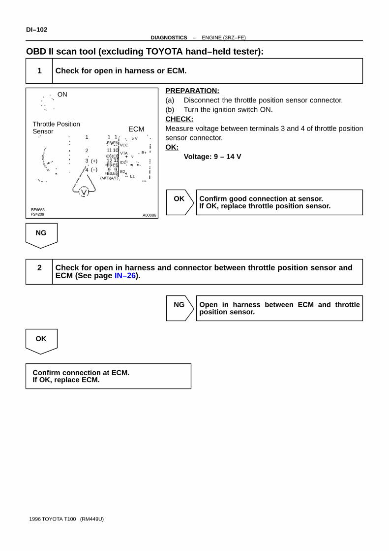
BE6653
P24209 A00086
ON
ECM1
2
3
4
1 1
1110
11
9 9
Throttle PositionSensor
E6E6
(M/T)(A/T)
5 V
VCC
VTA
IDL
E2
B+
E1
12(+)
(−)
E6E6
E6E6
E6E6
DI−102−DIAGNOSTICS ENGINE (3RZ−FE)
1996 TOYOTA T100 (RM449U)
OBD II scan tool (excluding TOYOTA hand−held tester):
1 Check for open in harness or ECM.
PREPARATION:(a) Disconnect the throttle position sensor connector.(b) Turn the ignition switch ON.CHECK:Measure voltage between terminals 3 and 4 of throttle positionsensor connector.OK:
Voltage: 9 − 14 V
OK Confirm good connection at sensor.If OK, replace throttle position sensor.
NG
2 Check for open in harness and connector between throttle position sensor andECM (See page IN−26).
NG Open in harness between ECM and throttleposition sensor.
OK
Confirm connection at ECM.If OK, replace ECM.
https://www.truck-manuals.net/

S00874
IG Switch
(M/T)(A/T)
23
ECM
E7 E71
AM
2
IA38
W−R W−R
82
2
7 B−R
R−
LW
Bat
tery
IE1R/B No.2 B−R
B−
R
2
5 V
Tr1
20
3 17E7 E7
14
B−L
B−Y
2
1
Tr2
34
TachometerToTo
Spark plug
B−W
IgniterIgnitionCoil
IGT
IGF
5
−DIAGNOSTICS ENGINE (3RZ−FE)DI−103
1996 TOYOTA T100 (RM449U)
DTC P1300 Ignition Circuit Malfunction
CIRCUIT DESCRIPTIONThe ECM determines the ignition timing, turns on Tr1 at a predetermined angle (°CA) before the desired igni-tion timing and outputs an ignition signal (IGT) ”1” to the igniter.Since the width of the IGT signal is constant, the dwell angle control circuit in the igniter determines the timethe control circuit starts primary current flow to the ignition coil based on the engine rpm and ignition timingone revolution ago, that is, the time the Tr2 turns on.When it reaches the ignition timing, the ECM turns Tr1 off and outputs the IGT signal ”0”.This turns Tr2 off, interrupting the primary current flow and generating a high voltage in the secondary coilwhich causes the spark plug to spark. Also, by the counter electromotive force generated when the primarycurrent is interrupted, the igniter sends an ignition confirmation signal (IGF) to the ECM. The ECM stops fuelinjection as a fail safe function when the IGF signal is not input to the ECM.
DTC No. DTC Detecting Condition Trouble Area
P1300No IGF signal to ECM for 4 consecutive IGT signal during
engine running
�Open or short in IGF or IGT circuit from igniter to ECM
� Igniter
�ECM
WIRING DIAGRAM
DI0U1−03
https://www.truck-manuals.net/

DI−104−DIAGNOSTICS ENGINE (3RZ−FE)
1996 TOYOTA T100 (RM449U)
INSPECTION PROCEDURE
1 Check spark plug and spark (See page IG−1).
NG Go to step 4.
OK
2 Check for open and short in harness and connector in IGF signal circuit betweenECM and igniter (See page IN−26).
NG Repair or replace harness or connector.
OK
https://www.truck-manuals.net/

BE6653
P24210
P24211 A00087
ON
IGF (+)For M/T
For A/TIGF (+)
−DIAGNOSTICS ENGINE (3RZ−FE)DI−105
1996 TOYOTA T100 (RM449U)
3 Disconnect igniter connector and check voltage between terminal IGF of ECMconnector and body ground.
PREPARATION:(a) Disconnect the igniter connector.(b) Remove the right cowl side trim (See page MF−50).(c) Turn the ignition switch ON.CHECK:Measure voltage between terminal IGF of ECM connector andbody ground.OK:
Voltage: 4.5 − 5.5 V
OK Replace igniter.
NG
Check and replace ECM (See page IN−26).
4 Check for open and short in harness and connector in IGT signal circuit betweenECM and igniter (See page IN−26).
NG Repair or replace harness or connector.
OK
https://www.truck-manuals.net/

BE6653
P24212
P24213 A00088
START
IGT (+)For M/T
For A/T IGT (+)
FI6680
IGT
IGF
0 V
0 V
10 msec./Division (Iding)
IGT signal waveform2 V/Division
DI−106−DIAGNOSTICS ENGINE (3RZ−FE)
1996 TOYOTA T100 (RM449U)
5 Check voltage between terminals IGT of ECM connector and body ground.
PREPARATION:Remove the right cowl side trim (See page MF−50).CHECK:Measure voltage between terminals IGT of ECM connector andbody ground when engine is cranked.OK:
Voltage: More than 0.1 V and less than 4.5 V
Reference: INSPECTION USING OSCILLOSCOPEDuring cranking or idling, check waveform between terminalsIGT and E1 of ECM.HINT:The correct waveforms are as shown.
NG Check and replace ECM (See page IN−26).
OK
https://www.truck-manuals.net/

BE6653
P24212
P24213 A00088
START
IGT (+)For M/T
For A/T IGT (+)
BE6653
P24215 A00089
ON
START
3 (+)
−DIAGNOSTICS ENGINE (3RZ−FE)DI−107
1996 TOYOTA T100 (RM449U)
6 Disconnect igniter connector and check voltage between terminals IGT of ECMconnector and body ground.
PREPARATION:Disconnect the igniter connector.CHECK:Measure voltage between terminals IGT of ECM connector andbody ground when engine is cranked.OK:
Voltage: More than 0.1 V and less than 4.5 V
NG Check and replace ECM (See page IN−26).
OK
7 Check voltage between terminal 3 of igniter connector and body ground.
PREPARATION:Disconnect the igniter connector.CHECK:When the ignition switch is turned to ”ON” and ”STA” position,measure voltage between terminal 3 of igniter connector andbody ground.OK:
Voltage: 9 − 14 V
NG Check and repair igniter power source circuit.
OK
https://www.truck-manuals.net/

DI−108−DIAGNOSTICS ENGINE (3RZ−FE)
1996 TOYOTA T100 (RM449U)
8 Check for open and short in harness and connector between ignition switch andignition coil, ignition coil and igniter (See page IN−26).
NG Repair or replace harness or connector.
OK
9 Check ignition coil (See page IG−1).
NG Replace ignition coil.
OK
Replace igniter.
https://www.truck-manuals.net/

−DIAGNOSTICS ENGINE (3RZ−FE)DI−109
1996 TOYOTA T100 (RM449U)
DTC P1335 Crankshaft Position Sensor Circuit Malfunction (during engine running)
CIRCUIT DESCRIPTIONRefer to DTC P0335 on page DI−66.
DTC No. DTC Detecting Condition Trouble Area
P1335No crankshaft position sensor signal to ECM with engine
speed 1,000 rpm or more
�Open or short in crankshaft position sensor circuit
�Crankshaft position sensor
�ECM
WIRING DIAGRAMRefer to DTC P0335 on page DI−66.
INSPECTION PROCEDURERefer to DTC P0335 on page DI−66.
DI0U2−01
https://www.truck-manuals.net/

P19741
ECM
STA
E1
E4(M/T)(A/T)
11E411
B−R
Starter
IE1
B−
RB−
RB−
R
B−
R (
M/T
)
21
3
5StarterRelay
1
2
W−
B (
A/T
)
IC
B (A/T)
W
Park/NeutralPosition Switch
15B56
B−Y22
IA3
AM
1
W
ALT
Battery
R/B No. 2
W−
B (
M/T
)
ClutchStartSwtich
IE1
B (M/T)
B−Y
63W
WW
14
IE1
2
2
2
2
W
DI−110−DIAGNOSTICS ENGINE (3RZ−FE)
1996 TOYOTA T100 (RM449U)
DTC P1500 Starter Signal Circuit Malfunction
CIRCUIT DESCRIPTIONWhen the engine is cranked, the intake air flow is slow, so fuel vaporazation is poor. A rich mixture is thereforenecessary in order to achieve good startability. While the engine is being cranked, the battery voltage is ap-plied to terminal STA of the ECM. The starter signal is mainly used to increase the fuel injection volume forthe starting injection control and after−start injection control.
DTC No. DTC Detecting Condition Trouble Area
P1500 No starter signal to ECM
�Open or short in starter signal circuit
�Open or short in ignition swtich or starter relay circuit
�ECM
HINT:In this circuit, diagnosis can only be made in the check mode.
WIRING DIAGRAM
DI984−01
https://www.truck-manuals.net/

−DIAGNOSTICS ENGINE (3RZ−FE)DI−111
1996 TOYOTA T100 (RM449U)
INSPECTION PROCEDUREHINT:This inspection procedure is based on the premise that the engine is cranked normally. If the engine is notcranked, proceed to the matrix chart of problem symptoms on page DI−21.
1 Connect the TOYOTA hand−held tester and check STA signal.
PREPARATION:(a) Connect the TOYOTA hand−held tester to the DLC3.(b) Turn ignition switch ON and TOYOTA hand−held tester main switch ON.CHECK:Read STA signal on the TOYOTA hand−held tester while starter operates.OK:
Ignition switch position ON START
STA signal OFF ON
OK Proceed to next circuit inspection shown onmatrix chart (See page DI−21)
NG
2 Check for open in harness and connector between ECM and starter relay (See page IN−26).
NG Repair or replace harness and sconnector.
OK
Check and replace ECM (See page IN−26).
https://www.truck-manuals.net/

S00876
W−R B−G
EFI
R/B No.2
2 2
W
8
EA1 IE1
B−G(M/T)
17
B−G (A/T)
B−G(M/T) E4 E4
21
(M/T)(A/T)
ECM
BATT
Battery
DI−112−DIAGNOSTICS ENGINE (3RZ−FE)
1996 TOYOTA T100 (RM449U)
DTC P1600 ECM BATT Malfunction
CIRCUIT DESCRIPTIONBattery positive voltage is supplied to terminal BATT of the ECM even when the ignition switch is OFF foruse by the DTC memory and air−fuel ratio adaptive control value memory, etc.
DTC No. DTC Detecting Condition Trouble Area
P1600 Open in back up power source circuit�Open in back up power source circuit
�ECM
HINT:If DTC P1600 appear, the ECM does not store another DTC.
WIRING DIAGRAM
DI0U4−03
https://www.truck-manuals.net/

AB0117
P24216
P24217 A00090
LOCK
BATT (+)
BATT (+)
For M/T
For A/T
FI7107
EFI Fuse
R/B No.2
−DIAGNOSTICS ENGINE (3RZ−FE)DI−113
1996 TOYOTA T100 (RM449U)
INSPECTION PROCEDURE
1 Check voltage between terminal BATT of ECM connector and body ground.
PREPARATION:Remove the right cowl side trim (See page MF−50).CHECK:Measure voltage between terminal BATT of ECM connectorand body ground.OK:
Voltage: 9 − 14 V
OK Check and replace ECM (See page IN−26).
NG
2 Check EFI fuse.
PREPARATION:Remove the EFI fuse from the R/B No2.CHECK:Check continuity of EFI fuse.OK:
Continuity
NG Check for short in all the harness and compo-nents connected to EFI fuse.
OK
Check and repair harness or connector be-tween battery, EFI fuse and ECM.
https://www.truck-manuals.net/
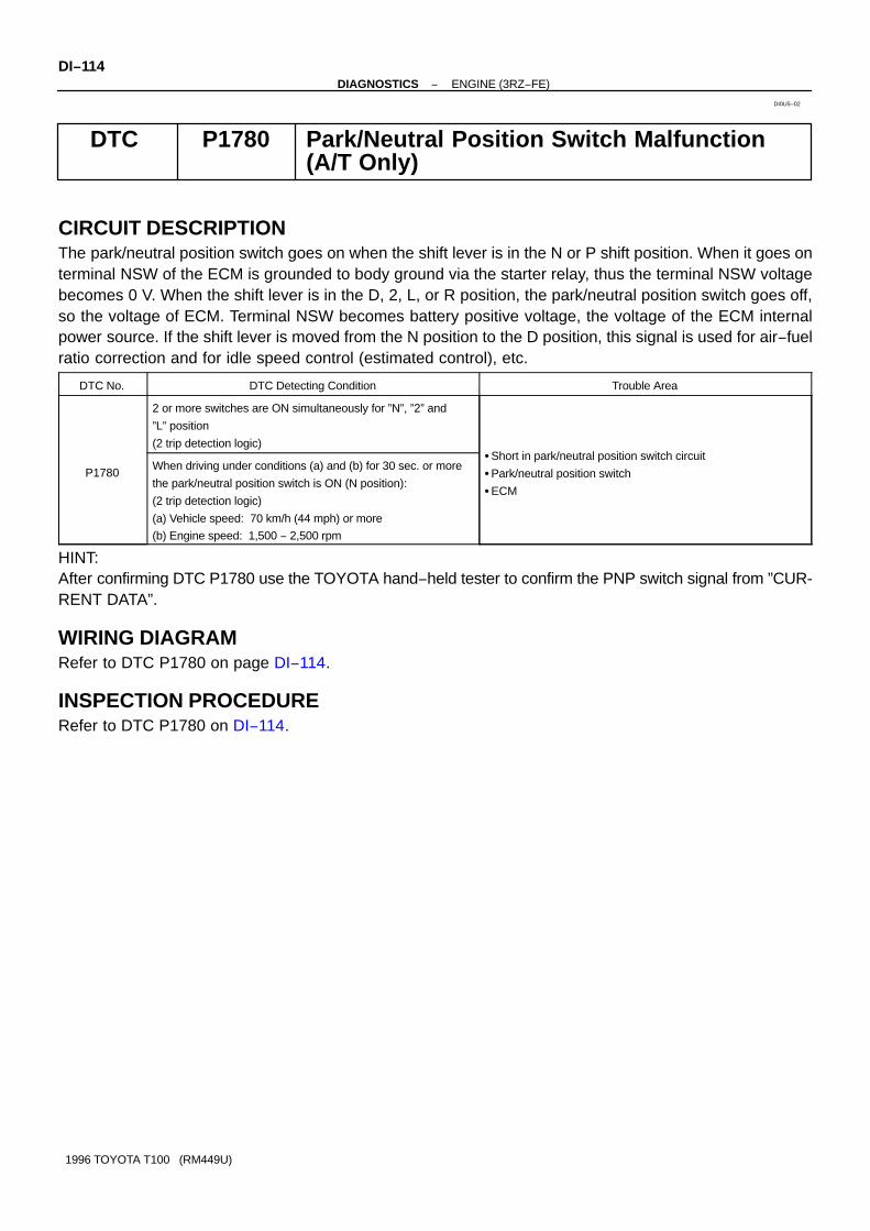
DI−114−DIAGNOSTICS ENGINE (3RZ−FE)
1996 TOYOTA T100 (RM449U)
DTC P1780 Park/Neutral Position Switch Malfunction(A/T Only)
CIRCUIT DESCRIPTIONThe park/neutral position switch goes on when the shift lever is in the N or P shift position. When it goes onterminal NSW of the ECM is grounded to body ground via the starter relay, thus the terminal NSW voltagebecomes 0 V. When the shift lever is in the D, 2, L, or R position, the park/neutral position switch goes off,so the voltage of ECM. Terminal NSW becomes battery positive voltage, the voltage of the ECM internalpower source. If the shift lever is moved from the N position to the D position, this signal is used for air−fuelratio correction and for idle speed control (estimated control), etc.
DTC No. DTC Detecting Condition Trouble Area
P1780
2 or more switches are ON simultaneously for ”N”, ”2” and
”L” position
(2 trip detection logic)�Short in park/neutral position switch circuit
�Park/neutral position switch
�ECM
When driving under conditions (a) and (b) for 30 sec. or more
the park/neutral position switch is ON (N position):
(2 trip detection logic)
(a) Vehicle speed: 70 km/h (44 mph) or more
(b) Engine speed: 1,500 − 2,500 rpm
HINT:After confirming DTC P1780 use the TOYOTA hand−held tester to confirm the PNP switch signal from ”CUR-RENT DATA”.
WIRING DIAGRAMRefer to DTC P1780 on page DI−114.
INSPECTION PROCEDURERefer to DTC P1780 on DI−114.
DI0U5−02
https://www.truck-manuals.net/

A00646
J/B No.1EA1
37
2
IGN1A
8
21
W
Battery
W−R
W−R
4
B−R1C17
B−Y
IGSwitch
B−
Y
IA3
W−R
4
AM232R−L
W−R
R/B No.2
EFI
2 2 2 2 25
B−W
2 2 13
EFIRelay
W−
B
EA EB
EA19 W−R
(M/T)IE1
W−R(M/T)
W−R (A/T)
12 12E4 E4
14 24E7 E7BR
(A/T)(M/T)E1
+B
ECM
8
−DIAGNOSTICS ENGINE (3RZ−FE)DI−115
1996 TOYOTA T100 (RM449U)
ECM Power Source Circuit
CIRCUIT DESCRIPTIONWhen the ignition switch is turned ON, battery positive voltage is applied to the coil, closing the contacts ofthe EFI main relay (Making: EFI) and supplying power to terminal +B of the ECM.
WIRING DIAGRAM
DI0U7−03
https://www.truck-manuals.net/

BE6653
P24220
P24221 A00092
ON
E1 (−) +B (+)
E1 (−) +B (+)
For M/T
For A/T
DI−116−DIAGNOSTICS ENGINE (3RZ−FE)
1996 TOYOTA T100 (RM449U)
INSPECTION PROCEDURE
1 Check voltage between terminals + B and E1 of ECM connector.
PREPARATION:(a) Remove the right cowl side trim (See page MF−50).(b) Turn the ignition switch ON.CHECK:Measure voltage between terminals + B and E1 of ECM con-nector.OK:
Voltage: 9 − 14 V
OK Proceed to next circuit inspection shown onproblem symptoms table (See page DI−21).
NG
2 Check for open in harness and connector between terminal E1 of ECM and bodyground (See page IN−26).
NG Repair or replace harness or connector.
OK
3 Check EFI main relay (Marking: EFI) (See page MF−40).
NG Replace EFI main relay.
OK
https://www.truck-manuals.net/

FI7106
IGN Fuse
J/B No.1
−DIAGNOSTICS ENGINE (3RZ−FE)DI−117
1996 TOYOTA T100 (RM449U)
4 Check EFI fuse (See page DI−114, step 2).
NG Check for short in all harness and componentsconnected to EFI fuse.
OK
5 Check for open in harness and connector between EFI main relay (Marking: EFI)and battery, EFI main relay (Marking: EFI) and ECM (See page IN−26).
NG Repair or replace harness or connector.
OK
6 Check IGN fuse.
PREPARATION:Remove the IGN fuse from the J/B No.1.CHECK:Check continuity of IGN fuse.OK:
Continuity
NG Check for short in all the harness and compo-nents connected to IGN fuse.
OK
7 Check ignition switch (See page BE−12).
NG Replace ignition switch.
OK
Check for open in harness and connector be-tween IG switch and EFI main relay, EFI mainrelay and body ground (See page IN−26).
https://www.truck-manuals.net/

A00650
EFI Relay
EFI
AM2
AM1
ALT
Battery
IG Switch
IG
ST
IGN
Park/NeutralPosition Switch(A/T)
StarterRelay
ClutchStartSwitch(M/T)
Starter
Circuit Opening Relay
L2
L1
Fuel Pump
ECM
FC Tr
STA
NE(STA Signal)
(NE Signal)
FromCrankshaftPositionSensor
DI−118−DIAGNOSTICS ENGINE (3RZ−FE)
1996 TOYOTA T100 (RM449U)
Fuel Pump Control Circuit
CIRCUIT DESCRIPTIONIn the diagram below, when the engine is cranked, current flows from terminal ST of the ignition switch tothe starter relay coil, the starter relay switches on and current flows to coil L1 of the circuit opening relay.Thus the circuit opening relay switches on, power is supplied to the fuel pump and the fuel pump operates.When the STA signal and NE signal are input to the ECM, Tr is turned ON, current flows to coil L2 of the circuitopening relay, the relay witches on and the fuel pump operates.While the NE signal is generated (engine running), the ECM keeps Tr ON (circuit opening relay ON) and thefuel pump also keeps operating.
DI0U8−03
https://www.truck-manuals.net/

A00649
EC
ME
FI
AM
2
AM
1A
LT
Bat
tery
Sw
itch
Par
k/
Sw
itch
Sta
rter
Rel
ay
Clu
tch
Sta
rtS
witc
h
E01
FC
1414 E
4E
7(M
/T)(
A/T
)
G−
Y16 IE
1G−
Y
L1 4 6
Circ
uit
Ope
ning
BJ1
8
L
W−B
W−B BJ1
11
W−B ICIC
2W−
RW−
R
W−
B
EA
1
9
EA
3
B−WB−W
B−WIE1
21
Sta
rter
Rel
ay
IC
(M/T
)B−
W
15
23
1 2
B−R W−B
W−B (A/T)
W B
B−
W
32 2
2
Rel
ayE
FI
22
5 1
22
22
2
R/B
No.
2
2 2 2
W
W
B−Y
W−R
W
148
IA3
IA3
W−R
W
8
EA
1IG
67
1A 1C
3 17
IGN
J/B
No.
2
B−
YB−
Y(A
/T)
(M/T
)B
IE1
415
B
5 6
B−Y IE1
22Neu
tral
Pos
ition
(A/T
)
Fue
lP
ump
−DIAGNOSTICS ENGINE (3RZ−FE)DI−119
1996 TOYOTA T100 (RM449U)
WIRING DIAGRAM
https://www.truck-manuals.net/

A00770
ON
Fuel Return Hose
DI−120−DIAGNOSTICS ENGINE (3RZ−FE)
1996 TOYOTA T100 (RM449U)
INSPECTION PROCEDURETOYOTA hand−held tester:
1 Connect TOYOTA hand−held tester and check operation of fuel pump.
PREPARATION:(a) Connect the TOYOTA hand−held tester to the DLC3.(b) Turn the ignition switch ON and push the TOYOTA hand−
held tester main switch ON.(c) Use ”ACTIVE TEST” mode to operate the fuel pump.CHECK:Check for fuel pressure in the fuel return hose when it is pinchedoff.OK:
There is pressure in the fuel return hose.HINT:At this time, you will hear a fuel flowing noise.
OK Go to step 7.
NG
2 Check for ECM power source circuit (See page DI−115).
NG Repair or replace.
OK
https://www.truck-manuals.net/

A00685
2 (+) 1 (+)
4 (−)
2 1
34
6
BE6653
P24224
P24225
A00095
ON
FC (+)
FC (+)
For M/T
For A/T
−DIAGNOSTICS ENGINE (3RZ−FE)DI−121
1996 TOYOTA T100 (RM449U)
3 Check circuit opening relay.
PREPARATION:Remove the circuit opening relay (See page MF−42).CHECK:(a) Apply battery voltage between terminals 2 and 4.(b) Measure voltage between terminals 1 and 4.OK:
Terminals 1 and 4 Same as battery
NG Replace circuit opening relay.
OK
4 Check voltage between terminal FC of ECM connector and body ground.
PREPARATION:(a) Remove the right cowl side trim (See page MF−50).(b) Turn the ignition switch ON.CHECK:Measure voltage between terminal FC of ECM connector andbody ground.OK:
Voltage: 9 − 14 V
NG Check for open in harness and connector be-tween EFI main relay and circuit opening relay,circuit opening relay and ECM.
OK
https://www.truck-manuals.net/

A00686
3 (+)
6 (−)
1
2
12
346
DI−122−DIAGNOSTICS ENGINE (3RZ−FE)
1996 TOYOTA T100 (RM449U)
5 Check fuel pump (See page MF−5).
NG Repair or replace fuel pump.
OK
6 Check for open in harness and connector between circuit opening relay and fuelpump, fuel pump and body ground (See page IN−26).
NG Repair or replace harness or connector.
OK
Check and replace ECM.
7 Check circuit opening relay.
PREPARATION:Remove the circuit opening relay (See page MF−42).CHECK:(a) Apply battery voltage between terminals 3 and 6.(b) Check continuity between terminal 1 and 2.OK:
Terminals 1 and 2 Continuity
NG Replace circuit opening relay.
OK
https://www.truck-manuals.net/

A00687
START3
−DIAGNOSTICS ENGINE (3RZ−FE)DI−123
1996 TOYOTA T100 (RM449U)
8 Check voltage between terminal 3 of circuit opening relay connector and bodyground.
CHECK:Measure voltage between terminal 3 of circuit opening relayconnector and body ground when engine is cranked.OK:
Voltage: 9 − 14 V
NG Check for starter signal circuit (See page DI−110).
OK
Check for open in harness and connector between terminal 6 of circuit opening relay connectorand body ground (See page IN−26).
https://www.truck-manuals.net/

A00688
ON
For M/T
For A/T
FC (+)
FC (+)
Fuel Return Hose
DI−124−DIAGNOSTICS ENGINE (3RZ−FE)
1996 TOYOTA T100 (RM449U)
OBD II scan tool (excluding TOYOTA hand−held tester):
1 Check operation of fuel pump.
PREPARATION:(a) Remove the right cowl side trim (See page MF−50).(b) Turn the ignition switch ON.CHECK:(a) Connect between terminal FC of ECM connector and
body ground.(b) Check for fuel pressure in the fuel return hose when it is
pinched off.OK:
There is pressure in the fuel return hose.HINT:At this time, you will hear a fuel return flowing noise.
OK Go to step 7.
NG
2 Check for ECM power source circuit (See page DI−115).
NG Repair or replace.
OK
https://www.truck-manuals.net/

−DIAGNOSTICS ENGINE (3RZ−FE)DI−125
1996 TOYOTA T100 (RM449U)
3 Check circuit opening relay (See page MF−42).
NG Replace circuit opening relay.
OK
4 Check voltage between terminal FC of ECM connector and body ground (Seepage MF−42).
NG Check for open in harness and connector be-tween EFI main relay and circuit opening relay,circuit opening relay and ECM.
OK
5 Check fuel pump (See page IG−1).
NG Repair or replace fuel pump.
OK
6 Check for open in harness and connector between circuit opening relay and fuelpump, fuel pump and body ground (See page IN−26).
NG Repair or replace harness or connector.
OK
Check and replace ECM.
https://www.truck-manuals.net/

DI−126−DIAGNOSTICS ENGINE (3RZ−FE)
1996 TOYOTA T100 (RM449U)
7 Check circuit opening relay (See page MF−42).
NG Replace circuit opening relay.
OK
8 Check voltage between terminal 3 of circuit opening relay connector and bodyground (See page MF−42).
NG Check for starter signal circuit (See page DI−110).
OK
Check for open in harness and connector be-tween terminal 6 of circuit opening relay con-nector and body ground (See page IN−26).
https://www.truck-manuals.net/

DI0U9−01
Vehicle Brought to Workshop
Customer Problem Analysis P. DI−128
Problem Symptom ConfirmationIf the engine does not start, perform steps 10 and 12 first
Connect the OBD II scan tool or TOYOTA hand−held tester to DLC3 P. DI−129If the display indicates a communication fault in the tool, inspect DLC3 P. DI−129
Check DTC and Freezed Frame Data (Precheck)Record or Print DTC and Freezed Frame Data P. DI−129
Clear DTC and Freezed Frame Data P. DI−129
Visual Inspection
Setting the Check Mode Diagnosis P. DI−129
Symptom Simulation P. IN−16
DTC Chart P. DI−140
Problem Symptoms Table P. DI−148
Circuit Inspection P. DI−149
Adjustment, Repair
DTC Check P. DI−129
Titles inside are titles of pages in
in the bottom portion. See the indicatedpages for detailed explanations.
this manual with the page number indicated
Malfunctionoccurs.
Malfunction does not occur.
Parts Inspection
Check for Intermittent Problems P. DI−129
Identification of Problem
Confirmation Test
End
1
2
3
4
5
6
7
10
8
9
11
12
13
15
14
16
Normal Malfunction code.
17
Basic Inspection P. DI−129
−DIAGNOSTICS ENGINE (5VZ−FE)DI−127
384Author�: Date�:
1996 TOYOTA T100 (RM449U)
ENGINE (5VZ−FE)HOW TO PROCEED WITH TROUBLESHOOTINGTroubleshoot in accordance with the procedure on the following page.
https://www.truck-manuals.net/

DI0UA−01
ENGINE CONTROL SYSTEM Check Sheet
Customer’s Name
Driver’s Name
Date VehicleBrought in
License No.
Model and ModelYear
Frame No.
Engine Model
Odometer Readingkmmiles
Pro
ble
m S
ymp
tom
s
Engine doesnot Start
Difficult toStart
Poor Idling
PoorDriveability
Engine Stall
Others
Engine does not crank No initial combustion No complete combustion
Engine cranks slowlyOther
Incorrect first idle Idling rpm is abnormal High ( rpm) Low ( rpm)Rough idling Other
Hesitation Back fire Muffler explosion (after−fire) SurgingKnocking Other
Soon after starting After accelerator pedal depressedAfter accelerator pedal released During A/C operationShifting from N to D Other
Dates ProblemOccurred
Problem Frequency
Co
nd
itio
n W
hen
Pro
ble
m O
ccu
rs
Weather
Engine Operation
Engine Temp.
Place
Outdoor Temp.
Constant Sometimes ( times per day/month) Once onlyOther
Fine Cloudy Rainy Snowy Various/Other
Hot Warm Cool Cold (approx. °F/ °C)
Highway Suburbs Inner city Uphill DownhillRough road Other
Cold Warming up After warming up Any temp. Other
Starting Just after starting ( min.) Idling RacingDriving Constant speed Acceleration DecelerationA/C switch ON/OFF Other
Condition of MIL Remains on Sometimes lights up Does not light up
Normal Malfunction code(s) (code )Freezed frame data ( )
Normal Malfunction code(s) (code )Freezed frame data ( )
Normal Mode(Precheck)
Check Mode
DTC Inspection
Inspector’sName
DI−128−DIAGNOSTICS ENGINE (5VZ−FE)
1996 TOYOTA T100 (RM449U)
CUSTOMER PROBLEM ANALYSIS CHECK
https://www.truck-manuals.net/

FI0534
DI0UB−02
FI7231
TOYOTA Hand−Held Tester
DLC 3
−DIAGNOSTICS ENGINE (5VZ−FE)DI−129
1996 TOYOTA T100 (RM449U)
PRE−CHECK1. DIAGNOSIS SYSTEM(a) Description
� When troubleshooting OBD II vehicles, the only dif-ference from the usual troubleshooting procedureis that you connect to the vehicle the OBD II scantool complying with SAE J1978 or TOYOTA hand−held tester, and read off various data output fromthe vehicle’s ECM.
� OBD II regulations require that the vehicle’s on−board computer lights up the Malfunction IndicatorLamp (MIL) on the instrument panel when the com-puter detects a malfunction in the computer itself orin drive system components which affect vehicleemissions. In addition to the MIL lighting up whena malfunction is detected, the applicable DiagnosticTrouble Codes (DTCs) prescribed by SAE J2012are recorded in the ECM memory (See page DI−140).
If the malfunction does not reoccur in 3 trips, the MIL goes offbut the DTCs remain recorded in the ECM memory.
� To check the DTCs, connect the OBD II scan tool orTOYOTA hand−held tester to the Data Link Con-nector 3 (DLC3) on the vehicle. The OBD II scantool or TOYOTA hand−held tester also enables youto erase the DTCs and check freezed frame dataand various forms of engine data (For operatinginstructions, see the OBD II scan tool’s instructionbook.).
� DTCs include SAE controlled codes and manufac-turer controlled codes. SAE controlled codes mustbe set as prescribed by the SAE, while manufactur-er controlled codes can be set freely by themanufacturer within the prescribed limits (See DTCchart on page DI−140).
https://www.truck-manuals.net/

N09214
DLC3
DI−130−DIAGNOSTICS ENGINE (5VZ−FE)
1996 TOYOTA T100 (RM449U)
� The diagnosis system operates in normal modeduring normal vehicle use. It also has a check modefor technicians to simulate malfunction symptomsand troubleshoot. Most DTCs use 2 trip detectionlogic* to prevent erroneous detection, and ensurethorough malfunction detection. By switching theECM to check mode when troubleshooting, thetechnician can cause the MIL to light up for a mal-function that is only detected once or momentarily(TOYOTA hand−held tester only).
� *2 trip detection logic: When a logic malfunction isfirst detected, the malfunction is temporarily storedin the ECM memory. If the same malfunction is de-tected again during the 2nd drive test, this 2nddetection causes the MIL to light up.
� The 2 trip repeats the same mode a 2nd time. (How-ever, the ignition switch must be turned OFF be-tween the 1st trip and 2nd trip.)
� Freeze frame data:Freeze frame data records the engine conditionwhen a misfire (DTCs P0300 − P0306) or fuel trimmalfunction (DTCs P0171, P0172) or other mal-function (first malfunction only), is detected.
� Because freeze frame data records the engineconditions (fuel system, calculator load, enginecoolant temperature, fuel trim, engine speed, ve-hicle speed, etc.) when the malfunction is detected,when troubleshooting it is useful for determiningwhether the vehicle was running or stopped, the en-gine warmed up or not, the air−fuel ratio lean or rich,etc. at the time of the malfunction.
Priorities for troubleshooting:If troubleshooting priorities for multiple DTCs are given in theapplicable DTC chart, these should be followed.If no instructions are given troubleshoot DTCs according to thefollowing priorities.
(1) DTCs other than fuel trim malfunction (DTCsP0171, P0172), EGR (DTCs P0401, P0402) andmisfire (DTCs P0300 − P0306).
(2) Fuel trim malfunction (DTCs P0171, P0172) andEGR (DTCs P0401, P0402).
(3) Misfire (DTCs P0300 − P0306).(b) Check the DLC3
The vehicle’s ECM uses V.P.W. (Variable Pulse Width) forcommunication to comply with SAE J1850. The terminalarrangement of DLC3 complies with SAE J1962 andmatches the V.P.W. format.
https://www.truck-manuals.net/

A00653
w/o Tachometer
w/ Tachometer
−DIAGNOSTICS ENGINE (5VZ−FE)DI−131
1996 TOYOTA T100 (RM449U)
Terminal No. Connection / Voltage or Resistance Condition
2 Bus � Line / Pulse generation During transmission
4 Chassis Ground ↔ Body Ground / 1 Ω or less Always
5 Signal Ground ↔ Body Ground / 1 Ω or less Always
16 Battery Positive ↔ Body Ground / 9 − 14 V Always
HINT:If your display shows ”UNABLE TO CONNECT TO VEHICLE”when you have connected the cable of the OBD II scan tool orTOYOTA hand−held tester to DLC3, turned the ignition switchON and operated the scan tool, there is a problem on the ve-hicle side or tool side.� If communication is normal when the tool is connected to
another vehicle, inspect DLC3 on the original vehicle.� If communication is still not possible when the tool is con-
nected to another vehicle, the problem is probably in thetool itself, so consult the Service Department listed in thetool’s instruction manual.
2. INSPECT DIAGNOSIS (Normal Mode)(a) Check the MIL
(1) The MIL comes on when the ignition switch is turnedON and the engine is not running.
HINT:If the MIL does not light up, troubleshoot the combination meter(See page BE−36).
(2) When the engine started, the MIL should go off. Ifthe lamp remains on, the diagnosis system has de-tected a malfunction or abnormality in the system.
(b) Check the DTC.NOTICE:TOYOTA hand−held tester only: When the diagnosis sys-tem is switched from normal mode to check mode, it erasesall DTCs and freezed frame data recorded in normal mode.So before switching modes, always check the DTCs andfreezed frame data, and note them down.
(1) Prepare the OBD II scan tool (complying with SAEJ1978) or TOYOTA hand−held tester.
(2) Connect the OBD II scan tool or TOYOTA hand−held tester to the DLC3 at the lower of the instru-ment panel.
(3) Turn the ignition switch ON and push the OBD IIscan tool or TOYOTA hand−held tester switch ON.
(4) Use the OBD II scan tool or TOYOTA hand−heldtester to check the DTCs and freezed frame data,note them down. (For operating instructions, seethe OBD II scan tool’s instruction book.)
(5) See page DI−129 to confirm the details of the DTCs.
https://www.truck-manuals.net/

FI3605
Flashing
ON
OFF
0.13 Seconds
DI−132−DIAGNOSTICS ENGINE (5VZ−FE)
1996 TOYOTA T100 (RM449U)
NOTICE:When simulating symptoms with an OBD II scan tool (ex-cluding TOYOTA hand−held tester) to check the DTCs, usenormal mode. For code on the DTC chart subject to ”2 tripdetection logic”, turn the ignition switch OFF after thesymptom is simulated the 1st time. Then repeat the simula-tion process again. When the problem has been simulatedtwice, the MIL lights up and the DTCs are recorded in theECM.
3. INSPECT DIAGNOSIS (Check Mode)HINT:TOYOTA hand−held tester only: Compared to the normal mode, the check mode has an in-creased sensitivity to detect malfunctions.Furthermore, the same diagnostic items which are detected inthe normal mode can also be detected in the check mode.(a) Check the DTC.
(1) Initial conditions� Battery positive voltage 11 V or more� Throttle valve fully closed� Transmission in ”P” or ”N” position� Air conditioning switched OFF
(2) Turn the ignition switch OFF.(3) Prepare the TOYOTA hand−held tester.(4) Connect the TOYOTA hand−held tester to DLC3 at
the lower of the instrument panel.(5) Turn the ignition switch ON and push the TOYOTA
hand−held tester switch ON.(6) Switch the TOYOTA hand−held tester normal mode
to check mode (Check that the MIL flashes.).(7) Start the engine. (The MIL goes out after the engine
start.)(8) Simulate the conditions of the malfunction de-
scribed by the customer.NOTICE:Leave the ignition switch ON until you have checked theDTCs, etc.
(9) After simulating the malfunction conditions, use theTOYOTA hand−held tester diagnosis selector tocheck the DTCs and freezed frame data, etc.
HINT:Take care not to turn the ignition switch OFF. Turning the ignitionswitch OFF switches the diagnosis system from check mode tonormal mode. so all DTCs, etc. are erased.
(10) After checking the DTC, inspect the applicable cir-cuit.
https://www.truck-manuals.net/

−DIAGNOSTICS ENGINE (5VZ−FE)DI−133
1996 TOYOTA T100 (RM449U)
(b) Clear the DTC.The following actions will erase the DTCs and freezedframe data.(1) Operating the OBD II scan tool (complying with SAE
J1978) or TOYOTA hand−held tester to erase thecodes (See the OBD II scan tool’s instruction bookfor operating instructions.).
(2) Disconnecting the battery terminals or EFI fuse.NOTICE:If the TOYOTA hand−held tester switches the ECM fromnormal mode to check mode or vice−versa, or if the igni-tion switch is turned from ON to ACC or OFF during checkmode, the DTCs and freezed frame data will be erased.
4. FAIL−SAFE CHARTIf any of the following codes is recorded, the ECM enters fail−safe mode.
DTC No. Fail−Safe Operation Fail−Safe Deactivation Conditions
P0100 Ignition timing fixed at 10° BTDC Returned to normal condition
P0110 Intake air temp. is fixed at 20°C (68°F) Returned to normal condition
P0115 Engine coolant temp. is fixed at 80°(176°F) Returned to normal condition
P0120 VTA is fixed at 0°
Following condition must be repeated at least 2 times
consecutively
0.1 V � VTA � 0.95 V
P0135
P0141
Heater circuit in which an abnormality is detected is
turned offIgnition switch OFF
P0325
P0330Max. timing retardation Ignition switch OFF
P1300 Fuel cut IGF signal is detected for 6 consective ignitions
5. CHECK FOR INTERMITTENT PROBLEMSHINT:TOYOTA HAND−HELD TESTER only:By putting the vehicle’s ECM in check mode, 1 trip detection logic is possible instead of 2 trip detection logicand sensitivity to detect open circuits is increased. This makes it easier to detect intermittent problems.(a) Clear the DTCs (See step 3).(b) Set the check mode (See step 3).(c) Perform a simulation test (See page IN−16).(d) Check the connector and terminal (See page IN−26).(e) Handle the connector (See page IN−26).6. BASIC INSPECTIONWhen the malfunction code is not confirmed in the DTC check, troubleshooting should be performed in theorder for all possible circuits to be considered as the causes of the problems. In many cases, by carryingout the basic engine check shown in the following flow chart, the location causing the problem can be foundquickly and efficiently. Therefore, use of this check is essential in engine troubleshooting.
1 Is battery positive voltage 11 V or more when engine is stopped?
NO Charge or replace battery.
https://www.truck-manuals.net/

P00495
Outside
Inside
DI−134−DIAGNOSTICS ENGINE (5VZ−FE)
1996 TOYOTA T100 (RM449U)
YES
2 Is engine cranked?
NO Proceed to page ST−6 and continue to trouble-shoot.
YES
3 Does engine start?
NO Go to step 7.
YES
4 Check air filter.
PREPARATION:Remove the air filter.CHECK:Visual check that the air filter is not dirty or excessive oily.HINT:If necessary, clean the filter with compressed air. First blow frominside thoroughly, then blow from outside of the filter.
NG Repair or replace.
OK
https://www.truck-manuals.net/

P19970P21121 A00097
SST
DLC1
E1
TE1
DLC1
−DIAGNOSTICS ENGINE (5VZ−FE)DI−135
1996 TOYOTA T100 (RM449U)
5 Check idle speed.
PREPARATION:(a) Warm up the engine to normal operating temperature.(b) Switch off all the accessories.(c) Switch off air conditioning.(d) Shift the transmission into ”N” position.(e) Connect the OBD II scan tool or TOYOTA hand−held tester to the DLC3 on the vehicle.CHECK:Use ”CURRENT DATA” to check the idle speed.OK:
Idle speed: 650 − 750 rpm
NG Proceed to problem symptoms table on pageDI−148.
OK
6 Check ignition timing.
PREPARATION:(a) Warm up the engine to normal operating temperature.(b) Shift the transmission into ”N” position.(c) Keep the engine speed at idle.(d) Using SST, connect terminals TE1 and E1 of the DLC1.
SST 09843−18020(e) Using a timing light, connect the tester to the No.1 high−
tension cord.CHECK:Check the ignition timing.OK:
Ignition timing: 8 − 12° BTDC at idle
NG Proceed to page Ignition system and continueto troubleshoot.
OK
Proceed to problem symptoms table on pageDI−148.
https://www.truck-manuals.net/

BE6653A00773 A00788
ON
Fuel Inlet Hose
DI−136−DIAGNOSTICS ENGINE (5VZ−FE)
1996 TOYOTA T100 (RM449U)
7 Check fuel pressure.
PREPARATION:(a) Be sure that enough fuel is in the tank.(b) Connect the TOYOTA hand−held tester to the DLC3.(c) Turn the ignition switch ON and push the TOYOTA hand−
held tester main switch ON.(d) Use ”ACTIVE TEST” mode to operate the fuel pump.(e) Please refer to the TOYOTA hand−held tester operator’s
manual for further details.(f) If you have no TOYOTA hand−held tester, connect the
positive (+) and negative (−) leads from the battery to thefuel pump connector (See page SF−5).
CHECK:Check for fuel pressure in the fuel inlet hose when it is pinchedoff.HINT:At this time, you will hear a fuel flowing noise.
NG Proceed to page SF−5 and continue to trouble-shoot.
OK
https://www.truck-manuals.net/

P21163
−DIAGNOSTICS ENGINE (5VZ−FE)DI−137
1996 TOYOTA T100 (RM449U)
8 Check for spark.
PREPARATION:(a) Remove the ignition coil or disconnect the high−tension
cord from the spark plug.(b) Remove the spark plug.(c) Install the spark plug to the ignition coil or high−tension
cord.(d) Disconnect the injector connector.(e) Hold the end about 12.5 mm (0.61 in.) from the ground.CHECK:Check if the spark occurs while engine is being cranked.NOTICE:To prevent excess fuel being injected from the injectorsduring this test, don’t crank the engine for more than 5 − 10seconds at a time.
NG Proceed to page IG−1 and continue to trouble-shoot.
OK
Proceed to problem symptoms table on pageDI−148.
https://www.truck-manuals.net/

DI−138−DIAGNOSTICS ENGINE (5VZ−FE)
1996 TOYOTA T100 (RM449U)
7. ENGINE OPERATING CONDITIONNOTICE:The values given below for ”Normal Condition” are representative values, so a vehicle may still benormal even if its value varies from those listed here. So do not decide whether a part is faulty ornot solely according to the ”Normal Condition” here.(a) CARB mandated signals.
TOYOTA hand−held tester display Measurement Item Normal Condition*
FUEL SYS #1
Fuel System Bank 1
OPEN: Air−fuel ratio feedback stopped
CLOSED: Air−fuel ratio feedback operating
Idling after warming up: CLOSED
CALC LOAD
Calculator Load:
Current intake air volume as a proportion of max.
intake air volume
Idling: 14.9 − 21.3 %
Racing without load (2,500rpm): 16.5 ∼ 23.5%
COOLANT TEMP. Engine Coolant Temp. Sensor Value After warming up: 80 − 95°C (176 − 203°F)
SHORT FT #1 Short−term Fuel Trim Bank 1 0 ± 20 %
LONG FT #1 Long−term Fuel Trim Bank 1 0 ± 20 %
ENGINE SPD Engine Speed Idling: 650 − 750 rpm
VEHICLE SPD Vehicle Speed Vehicle stopped: 0 km/h (0 mph)
IGN ADVANCEIgnition Advance:
Ignition Timing of Cylinder No.1Idling: BTDC 12.5 − 22.0°
INTAKE AIR Intake Air Temp. Sensor Value Equivalent to Ambient Temp.
MAF Air Flow Rate Through Mass Air Flow Meter
Idling: 3.2 − 4.6 gm/sec.
Racing without load (2,500 rpm):
12.9 − 18.3 gm/sec.
THROTTLE POS
Voltage Output of Throttle Position Sensor
Calculated as a percentage:
0 V → 0 %, 5 V → 100 %
Throttle valve fully closed: 7 − 11 %
Throttle valve fully open: 65 − 75 %
O2S B1, S1Voltage Output of Oxygen Sensor
Bank 1, Sensor 1Idling: 0.1 − 0.9 V
O2FT B1, S1Oxygen Sensor Fuel Trim Bank 1, Sensor 1
(Same as SHORT FT #1)0 ± 20 %
O2S B1, S2Voltage Output of Oxygen Sensor
Bank 1, Sensor 2Driving 50 km/h (31 mph): 0.1 − 0.9 V
*: If no conditions are specifically stated for ”ldling”, it means the shift lever is at N or P position, the A/C switchis OFF and all accessory switches are OFF.
https://www.truck-manuals.net/

−DIAGNOSTICS ENGINE (5VZ−FE)DI−139
1996 TOYOTA T100 (RM449U)
(b) TOYOTA Enhanced Signals.
TOYOTA hand−held tester display Measurement Item Normal Condition*1
MISFIRE RPM Engine RPM for first misfire range Misfire 0: 0 rpm
MISFIRE LOAD Engine load for first misfire range Misfire 0: 0 g/r
INJECTOR Fuel injection time for cylinder No.1 Idling: 1.82 − 3.15 ms
IAC DUTY RATIOIntake Air Control Valve Duty Ratio
Opening ratio rotary solenoid type IAC valveIdling: 22 − 46 %
STARTER SIG Starter Signal Cranking: ON
A/C SIG A/C Switch Signal A/C ON: ON
PNP SW Park/Neutral Position Switch Signal P or N position: ON
STOP LIGHT SW Stop Light Switch Signal Stop light switch ON: ON
FC IDLFuel Cut Idle: Fuel cut when throttle valve fully
closed, during decelerationFuel cut operating: ON
FC TAU Fuel Cut TAU: Fuel cut during very light load Fuel cut operating: ON
CYL #1 − CYL #6 Abnormal revolution variation for each cylinder 0 %
IGNITIONTotal number of ignition for every 1,000
revolutions0 − 3,000
EGRT GAS*2 EGR Gas Temp. Sensor Value
EGR not operating:
Temp. between intake air temp. and engine
coolant temp.
EGR SYSTEM*2 EGR System Operating Condition Idling: OFF
A/C CUT SIG A/C Cut Signal A/C S/W OFF: ON
FUEL PUMP Fuel Pump Signal Idling: ON
EVAP (PURGE) VSV EVAP VSV Signal VSV operating: ON
VAPOR PRESS VSV Vapor Pressure VSV Signal VSV operating: ON
TOTAL FT B1Total Fuel Trim Bank 1: Average value for fuel
trim system of bank 1Idling: 0.8 − 1.2 V
O2 LR B1, S1
Oxygen Sensor Lean Rich Bank 1, Sensor 1 Re-
sponse time for oxygen sensor output to switch
from lean to rich
Idling after warming up: 0 − 1,000 msec.
O2 RL B1, S1
Oxygen Sensor Rich Lean Bank 1, Sensor 1 Re-
sponse time for oxygen sensor output to switch
from rich to lean
Idling after warming up: 0 − 1,000 msec.
*1: If no conditions are specifically stated for ”ldling”, it means the shift lever is at N or P position, the A/Cswitch is OFF and all accessory switches are OFF.*2: Only for 2WD models with a load capacity of 0.5 ton and regular cab.
https://www.truck-manuals.net/

DI0UC−02
DI−140−DIAGNOSTICS ENGINE (5VZ−FE)
1996 TOYOTA T100 (RM449U)
DIAGNOSTIC TROUBLE CODE CHARTSAE CONTROLLEDHINT:Parameters listed in the chart may not be exactly the same as your reading due to the type of instrumentor other factors.If a malfunction code is displayed during the DTC check in check mode, check the circuit for that code listedin the table below. For details of each code, turn to the page referred to under the ’’See Page ’’ for the respec-tive ’’DTC No.’’ in the DTC chart.
DTC No.
(See Page)Detection Item Trouble Area MIL* Memory
P0100
(DI−149)
Mass Air Flow Circuit
Malfunction
�Open or short in mass air flow meter circuit
�Mass air flow meter
�ECM
� �
P0101
(DI−153)
Mass Air Flow Circuit
Range/Performance
Problem
�Mass air flow meter � �
P0110
(DI−154)
Intake Air Temp. Circuit
Malfunction
�Open or short in intake air temp. sensor circuit
� Intake air temp. sensor
�ECM
� �
P0115
(DI−158)
Engine Coolant Temp. Circuit
Malfunction
�Open or short in engine coolant temp. sensor circuit
�Engine coolant temp. sensor
�ECM
� �
P0116
(DI−162)
Engine Coolant Temp. Circuit
Range/Performance Problem
�Engine coolant temp. sensor
�Cooling system� �
P0120
(DI−163)
Throttle/Pedal Position
Sensor/Switch ”A” Circuit
Malfunction
�Open or short in throttle position sensor circuit
�Throttle position sensor
�ECM
� �
P0121
(DI−168)
Throttle/Pedal Position
Sensor/Switch ”A” Circuit
Range/Performance Problem
�Throttle position sensor � �
P0125
(DI−169)
Insufficient Coolant Temp. for
Closed Loop Fuel Control
�Open or short in heated oxygen sensor (bank 1 sensor 1)
circuit
�Heated oxygen sensor (bank 1 sensor 1)
� �
P0130
(DI−172)
Heated Oxygen Sensor Circuit
Malfunction (Bank 1 Sensor 1)
�Heated oxygen sensor
�Fuel trim malfunction� �
P0133
(DI−175)
Heated Oxygen Sensor Circuit
Slow Response
(Bank 1 Sensor 1)
�Heated oxygen sensor � �
P0135
(DI−176)
Heated Oxygen Sensor Heater
Circuit Malfunction
(Bank 1 Sensor 1)
�Open or short in heater circuit of heated oxygen sensor
�Heated oxygen sensor
�ECM
� �
P0136
(DI−178)
Heated Oxygen Sensor Circuit
Malfunction
(Bank 1 Sensor 2)
�Heated oxygen sensor � �
P0141
(DI−176)
Heated Oxygen Sensor Heater
Circuit Malfunction
(Bank 1 Sensor 2)
�Same as DTC No. P0135 � �
*: ���� MIL lights up
https://www.truck-manuals.net/

−DIAGNOSTICS ENGINE (5VZ−FE)DI−141
1996 TOYOTA T100 (RM449U)
DTC No.
(See Page)Detection Item Trouble Area MIL Memory
P0171
(DI−180)
System too Lean
(Fuel Trim)
�Air intake (hose loose)
�Fuel line pressure
� Injector blockage
�Heated oxygen sensor (bank 1 sensor 1) malfunction
�Mass air flow meter
�Engine coolant temp. sensor
�*1 �
P0172
(DI−180)
System too Rich
(Fuel Trim)
�Fuel line pressure
� Injector leak, blockage
�Heated oxygen sensor (bank 1 sensor 1) malfunction
�Mass air flow meter
�Engine coolant temp. sensor
�*1 �
P0300
(DI−183)
Random/Multiple Cylinder
Misfire Detected� Ignition system
� Injector
�Fuel line pressure
�EGR*3
�Compression pressure
�Valve clearance not to specification
�Valve timing
�Mass air flow meter
�Engine coolant temp. sensor
�*2 �
P0301
P0302
P0303
P0304
P0305
P0306
(DI−183)
Misfire Detected
− Cylinder 1
− Cylinder 2
− Cylinder 3
− Cylinder 4
− Cylinder 5
− Cylinder 6
�*2 �
P0325
(DI−188)
Knock Sensor 1 Circuit
Malfunction
�Open or short in knock sensor 1 circuit
�Knock sensor 1 (looseness)
�ECM
�*1 �
P0330
(DI−188)
Knock Sensor 2 Circuit
Malfunction
�Open or short in knock sensor 2 circuit
�Knock sensor 2 (looseness)
�ECM
�*1 �
P0335
(DI−191)
Crankshaft Position Sensor
”A” Circuit Malfunction
�Open or short in crankshaft position sensor circuit
�Crankshaft position sensor
�Starter
�ECM
�*1 �
P0340
(DI−194)
Camshaft Position Sensor
Circuit Malfunction
�Open or short in camshaft position sensor circuit
�Camshaft position sensor
�Starter
�ECM
�*1 �
P0401*3
(DI−196)
Exhaust Gas Recirculation
Flow Insufficient Detected
�EGR valve stuck closed
�Short in VSV circuit for EGR
�Open in EGR gas temp. sensor circuit
�EGR hose disconnected
�ECM
�*1 �
P0402*3
(DI−206)
Exhaust Gas Recirculation
Flow Excessive Detected
�EGR valve stuck open
�EGR VSV open malfunction
�Open in VSV circuit for EGR
�Short in EGR gas temp. sensor circuit
�ECM
�*1 �
P0420
(DI−210)
Catalyst System Efficiency
Below Threshold
�Three−way catalytic converter
�Open or short in heated oxygen sensor (bank 1 sensor 1, 2)
circuit
�Heated oxygen sensor (bank 1 sensor 1, 2)
�*1 �
*1: MIL lights up*2: MIL lights up or blinking*3: Only for 2WD models with a load capacity of 0.5 ton and regular cab.
https://www.truck-manuals.net/
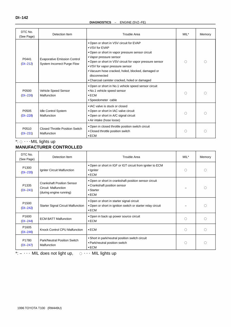
DI−142−DIAGNOSTICS ENGINE (5VZ−FE)
1996 TOYOTA T100 (RM449U)
DTC No.
(See Page)Detection Item Trouble Area MIL* Memory
P0441
(DI−212)
Evaporative Emission Control
System Incorrect Purge Flow
�Open or short in VSV circuit for EVAP
�VSV for EVAP
�Open or short in vapor pressure sensor circuit
�Vapor pressure sensor
�Open or short in VSV circuit for vapor pressure sensor
�VSV for vapor pressure sensor
�Vacuum hose cracked, holed, blocked, damaged or
disconnected
�Charcoal canister cracked, holed or damaged
� �
P0500
(DI−226)
Vehicle Speed Sensor
Malfunction
�Open or short in No.1 vehicle speed sensor circuit
�No.1 vehicle speed sensor
�ECM
�Speedometer cable
� �
P0505
(DI−228)
Idle Control System
Malfunction
� IAC valve is stuck or closed
�Open or short in IAC valve circuit
�Open or short in A/C signal circuit
�Air intake (hose loose)
� �
P0510
(DI−231)
Closed Throttle Position Switch
Malfunction
�Open in closed throttle position switch circuit
�Closed throttle position switch
�ECM
� �
*: � ���MIL lights upMANUFACTURER CONTROLLED
DTC No.
(See Page)Detection Item Trouble Area MIL* Memory
P1300
(DI−235)Igniter Circuit Malfunction
�Open or short in IGF or IGT circuit from igniter to ECM
� Igniter
�ECM
� �
P1335
(DI−241)
Crankshaft Position Sensor
Circuit Malfunction
(during engine running)
�Open or short in crankshaft position sensor circuit
�Crankshaft position sensor
�Starter
�ECM
− �
P1500
(DI−242)Starter Signal Circuit Malfunction
�Open or short in starter signal circuit
�Open or short in ignition switch or starter relay circuit
�ECM
− �
P1600
(DI−244)ECM BATT Malfunction
�Open in back up power source circuit
�ECM� �
P1605
(DI−246)Knock Control CPU Malfunction �ECM � �
P1780
(DI−247)
Park/Neutral Position Switch
Malfunction
�Short in park/neutral position switch circuit
�Park/neutral position switch
�ECM
� �
*: − ��� MIL does not light up, � ��� MIL lights up
https://www.truck-manuals.net/

DI0UD−01
A00783
DLC3
EGR Gas Temp. Sensor*
A/C Amplifier
Circuit Opening Replay
ECM
Throttle Position Sensor
IAC Valve
Igniter
Mass AirFlow Meter
Heated Oxygen Sensor (Bank 1 Sensor 1)
Combination Meter
Heated OxygenSensor (Bank 1Sensor 2)
Park/NeutralPosition Switch
Fuel Pump
Ignition Switch
VSV for EGR*
Stop Light Switch
VSV for Vapor Pressure Sensor
VSV for EVAP
EFI Main Relay(Marking : EFI)
DLC1Knock Sensor 2
Knock Sensor 1
Injector
Ignition Coil
Injector
CamshaftPosition Sensor
Engine CoolantTemp. Sensor
Crankshaft PositionSensor
*: Only for 2WD models with a load capacity of 0.5 ton and regular cab.
−DIAGNOSTICS ENGINE (5VZ−FE)DI−143
1996 TOYOTA T100 (RM449U)
PARTS LOCATION
https://www.truck-manuals.net/

DI0UE−02
FI6526
12345678910111213
14151617181920212223242526
12345678
910111213141516
123456
7891011121234567891011
141516171819202122 1213
E5E6E7
ECM Terminals
E4
DI−144−DIAGNOSTICS ENGINE (5VZ−FE)
1996 TOYOTA T100 (RM449U)
TERMINALS OF ECMFor M/T
Symbols (Terminals No.) Wiring Color Condition STD Voltage (V)
BATT (E4−2) − E1 (E7−24) B−G ↔ BR Always 9 − 14
+B (E4−12) − E1 (E7−24) W−R ↔ BR IG switch ON 9 − 14
VCC (E6−1) − E2 (E6−9) G−B ↔ BR−B IG switch ON 4.5 − 5.5
VG (E6−2) − E3 (E6−8) GR−R ↔ BR−W Idling, N position, A/C switch OFF 1.1 − 1.5
THA (E6−12) − E2 (E6−9) Y−G ↔ BR−B Idling, Intake air temp. 20°C (68°F) 0.5 − 3.4
THW (E6−4) − E2 (E6−9) G−Y ↔ BR−B Idling, Engine coolant temp. 80°C (176°F) 0.2 − 1.0
IDL (E6−11) − E2 (E6−9) Y−L ↔ BR−B
IG switch ON and apply vacuum to the throttle opener/Throttle
valve fully closed0 − 3
IG switch ON
Throttle valve fully open9 − 14
VTA (E6−10) − E2 (E6−9) Y−B ↔ BR−B
IG switch ON
Throttle valve fully closed0.3 − 0.8
IG switch ON
Throttle valve fully open3.2 − 4.9
STA (E4−11) − E1 (E7−24) B−W ↔ BR Cranking 6.0 or more
#10 (E7−12) − E01 (E7−13) W−R ↔ BR
IG switch ON 9 − 14
IdlingPulse generation
(See page DI−183)
#20 (E7−11) − E01 (E7−13) W ↔ BR
IG switch ON 9 − 14
IdlingPulse generation
(See page DI−183)
#30 (E7−25) − E01 (E7−13) W−G ↔ BR
IG switch ON 9 − 14
IdlingPulse generation
(See page DI−183)
#40 (E7−10) − E01 (E7−13) Y−K ↔ BR
IG switch ON 9 − 14
IdlingPulse generation
(See page DI−183)
#50 (E7−9) − E01 (E7−13) W−L ↔ BR
IG switch ON 9 − 14
IdlingPulse generation
(See page DI−183)
#60 (E7−8) − E01 (E7−13) Y−B ↔ BR
IG switch ON 9 − 14
IdlingPulse generation
(See page DI−183)
IGT1 (E7−23) − E1 (E7−24) B−L ↔ BR IdlingPulse generation
(See page DI−235)
https://www.truck-manuals.net/

−DIAGNOSTICS ENGINE (5VZ−FE)DI−145
1996 TOYOTA T100 (RM449U)
Symbols (Terminals No.) Wiring Color Condition STD Voltage (V)
IGT2 (E7− 22) − E1 (E7−24) BR−B ↔ BR IdlingPulse generation
(See page DI−235)
IGT3 (E7−31) − E1 (E7−24) B−W ↔ BR IdlingPulse generation
(See page DI−235)
IGF (E7−17) − E1 (E7−24) B−Y ↔ BR
IG switch ON, Disconnect igniter connector 4.5 − 5.5
IdlingPulse generation
(See page DI−235)
G (E5−11) − G− (E5−5) B ↔ W IdlingPulse generation
(See page DI−191)
NE (E5−12) − NE− (E5−6) G ↔ L IdlingPulse generation
(See page DI−191)
FPU (E7−19) − E1 (E7−24) R−B ↔ BRIG switch ON 9 − 14
Idling 0 − 3.0
EGR* (E7−18) − E1 (E7−24) R−W ↔ BR IG switch ON 9 − 14
THG* (E6−14) −E2( E6−9) P ↔ BR−B IG switch ON 4.5 − 5.5
EVP1 (E7−5) − E1 (E7−24) W−G ↔ BR IG switch ON 9 − 14
RSC (E7−6) − E1 (E7−24) B−R ↔ BR IG switch ON, Disconnect E7 of ECM connector 9 − 14
RSO (E7−7) − E1 (E7−24) BR−R ↔ BR IG switch ON, Disconnect E7 of ECM connector 9 − 14
ACV (E7−2) − E1 (7−24) B−R ↔ BRIdling, A/C switch ON 0 − 3
Idling, A/C switch OFF 9 − 14
FC (E7−14) − E1 (E7−24) G−Y ↔ BRIG switch ON 9 − 14
Idling 0 − 3
OX1 (E6−5) − E1 (E7−24) W ↔ BRMaintain engine speed at 2,500 rpm for 2 min. after
warming up
Pulse generation
(See page DI−172)
OX2 (E6−13) − E1 (E7−24) R ↔ BRMaintain engine speed at 2,500 rpm for 2 min. after
warming up
Pulse generation
(See page DI−172)
HT1 (E5−3) − E03 (E5−7) P−G ↔ BRIdling Below 3.0
IG switch ON 9 − 14
HT2 (E5−9) − E03 (E5−7) R−G ↔ BRIdling Below 3.0
IG switch ON 9 − 14
KNK1 (E6−6) − E1 (E7−24) B ↔ BR IdlingPulse generation
(See page DI−188)
KNK2 (E6−3) − E1 (E7−24) GR ↔ BR IdlingPulse generation
(See page DI−188)
SP1 (E4−8) − E1 (E7−24) G ↔ BRIG switch ON
Rotate driving wheel slowly
Pulse generation
(See page DI−226)
TE1 (E6−7) − E1 (E7−24) V−W ↔ BR IG switch ON 9 − 14
W (E4−4) − E1 (E7−24) V ↔ BRIdling 9 − 14
IG switch ON Below 3.0
ACT (E4−6) − E1 (E7−24) L−B ↔ BRA/C switch OFF at Idling Below 2.0
A/C switch ON at idling 5 or more
AC1 (E4−7) − E1 (E7−24) B−R ↔ BRA/C switch ON at idling Below 2.0
A/C switch OFF at Idling 9 − 14
SDL (E4−19) − E1 (E7−24) W ↔ BR During transmission Pulse generation
*: Only for 2WD models with a load capacity of 0.5 ton and regular cab.
https://www.truck-manuals.net/

FI6810
E7 E6 E5 E4
3433 3231 30 2928 27
17181920212223242526
111213141516
12345678910 12345678
910111213
1415161718192021
22232425262728
1234
567
891011
1213141516
123456
7891011
121314151617
1819202122
ECM Terminals
DI−146−DIAGNOSTICS ENGINE (5VZ−FE)
1996 TOYOTA T100 (RM449U)
For A/T
Symbols (Terminals No.) Wiring Color Condition STD Voltage (V)
BATT (E4−14) − E1 (E5−16) B−G ↔ BR Always 9 − 14
+B (E4−22) − E1 (E5−16) W−R ↔ BR IG switch ON 9 − 14
VCC (E6−1) − E2 (E6−22) G−B ↔ BR−B IG switch ON 4.5 − 5.5
VG (E6−8) − E3 (E6−18) GR−R ↔ BR−W Idling, P or N position, A/C switch OFF 1.1 − 1.5
THA (E6−14) − E2 (E6−22) Y−G ↔ BR−B Idling, Intake air temp. 20°C (68°F) 0.5 − 3.4
THW (E6−20) − E2 (E6−22) G−Y ↔ BR−B Idling, Engine coolant temp. 80°C (176°F) 0.2 − 1.0
STA (E7−13) − E1 (E5−16) B−W ↔ BR Cranking 6.0 or more
#10 (E7−10) − E01 (E7−34) W−R ↔ BR
IG switch ON 9 − 14
IdlingPulse generation
(See page DI−183)
#20 (E7−9) − E01 (E7−34) W ↔ BR
IG switch ON 9 − 14
IdlingPulse generation
(See page DI−183)
#30 (E7−8) − E01 (E7−34) W−G ↔ BR
IG switch ON 9 − 14
IdlingPulse generation
(See page DI−183)
#40 (E7−7) − E01 (E7−34) Y−R ↔ BR
IG switch ON 9 − 14
IdlingPulse generation
(See page DI−183)
#50 (E7−6) − E01 (E7−34) W−L ↔ BR
IG switch ON 9 − 14
IdlingPulse generation
(See page DI−183)
#60 (E7−5) − E01 (E7−34) Y−B ↔ BR
IG switch ON 9 − 14
IdlingPulse generation
(See page DI−183)
IGT1 (E7−24) − E1 (E5−16) B−L ↔ BR IdlingPulse generation
(See page DI−235)
IGT2 (E7−25) − E1 (E5−16) BR−B ↔ BR IdlingPulse generation
(See page DI−235)
IGT3 (E7−26) − E1 (E5−16) B−W ↔ BR IdlingPulse generation
(See page DI−235)
IGF (E7−12) − E1 (E5−16) B−Y ↔ BR
IG switch ON, Disconnect igniter connector 4.5 − 5.5
IdlingPulse generation
(See page DI−235)
IDL (E7−32) − E2 (E6−22) Y−L ↔ BR−B
IG switch ON and apply vacuum to the throttle opener/THrottle
valve fully closed0 − 3
IG switch ON
Throttle valve fully open9 − 14
https://www.truck-manuals.net/

−DIAGNOSTICS ENGINE (5VZ−FE)DI−147
1996 TOYOTA T100 (RM449U)
Symbols (Terminals No.) Wiring Color Condition STD Voltage (V)
VTA (E6−7) − E2 (E6−22) Y−B ↔ BR−B
IG switch ON
Throttle valve fully closed0.3 − 0.8
IG switch ON
Throttle valve fully open3.2 − 4.9
G (E6−10) − G− (E6−11) B ↔ W IdlingPulse generation
(See page DI−191)
NE (E6−5) − NE− (E6−6) G ↔ L IdlingPulse generation
(See page DI−191)
FPU (E5−9) − E1 (E5−16) R−B ↔ BRIG switch ON 9 − 14
Idling 0 − 3.0
EGR* (E5−8) − E1 (E5−16) R−W ↔ BR IG switch ON 9 − 14
EVP1 (E5−15) − E1 (E5−16) W−G ↔ BR IG switch ON 9 − 14
THG* (E6−21) − E2 (E6−22) P ↔ BR−B IG switch ON 4.5 − 5.5
RSC (E7−22) − E1 (E5−16) B−R ↔ BR IG switch ON, Disconnect E7 of ECM connector 9 − 14
RSO (E7−23) − E1 (E5−16) BR−R ↔ BR IG switch ON, Disconnect E7 of ECM connector 9 − 14
OX1 (E6−13) − E1 (E5−16) W ↔ BRMaintain engine speed at 2,500 rpm for 2 min. after
warming up
Pulse generation
(See page DI−172)
OX2 (E6−19) − E1 (E5−16) R ↔ BRMaintain engine speed at 2,500 rpm for 2 min. after
warming up
Pulse generation
(See page DI−172)
HT1 (E7−15) − E03 (E7−1) P−G ↔ W−BIdling Below 3.0
IG switch ON 9 − 14
HT2 (E7−16) − E03 (E7−1) R−G ↔ W−BIdling Below 3.0
IG switch ON 9 − 14
KNK1 (E6−17) − E1 (E5−16) B ↔ BR IdlingPulse generation
(See page DI−188)
KNK2 (E6−16) − E1 (E5−16) GR ↔ BR IdlingPulse generation
(See page DI−188)
NSW (E7−14) − E1 (E5−16) B−O ↔ BRIG switch ON, Other shift position in ”P”, ”N” position 9 − 14
IG switch ON, Shift position in ”P”, ”N” position 0 − 3.0
SP1 (E4−12) − E1 (E5−16) G ↔ BRIG switch ON
Rotate driving wheel slowly
Pulse generation
(See page DI−226)
TE1 (E5−5) − E1 (E5−16) V−W ↔ BR IG switch ON 9 − 14
W (E5−3) − E1 (E5−16) V ↔ BRIdling 9 − 14
IG switch ON Below 3.0
ACV (E5−10) − E1 (E5−16) B−R ↔ BRIdling, A/C switch ON 0 − 3
Idling, A/C switch OFF 9 − 14
ACT (E4−5) − E1 (E5−16) L−B ↔ BRA/C switch OFF at idling Below 2.0
A/C switch ON at idling 5 or more
AC1 (E4−20) − E1 (E5−16) B−R ↔ BRA/C switch ON at idling Below 2.0
A/C switch OFF at idling 9 − 14
SDL (E4−18) − E1 (E5−16) W ↔ BR During transmission Pulse generation
OD1 (E4−7) − E1 (E5−16) Y−R ↔ BR IG switch ON 9 − 14
THG* (E6−12) − E2 (E6−22) P ↔ BR−B IG switch ON 3.9 − 5.0
FC (E5−4) − E1 (E5−16) G−Y ↔ BRIG switch ON 9 − 14
Idling 0 − 3.0
*: Only for 2WD models with a load capacity of 0.5 ton and regular cab.
https://www.truck-manuals.net/

DI0UF−01
DI−148−DIAGNOSTICS ENGINE (5VZ−FE)
1996 TOYOTA T100 (RM449U)
PROBLEM SYMPTOMS TABLESymptom Suspect Area See page
Engine does not crank (Does not start) 1. Starter and starter relayST−6
ST−14
No initial combustion (Does not start)
1. ECM power source circuit
2. Fuel pump control circuit
3. Engine control module (ECM)
DI−251
DI−255
IN−26
No complete combustion (Does not start) 1. Fuel pump control circuit DI−255
Engine cranks normally (Difficult to start)
1. Starter signal circuit
2. Fuel pump control circuit
3. Compression
DI−248
DI−255
EM−2
Cold engine (Difficult to start)1. Starter signal circuit
2. Fuel pump control circuit
DI−248
DI−255
Hot engine (Difficult to start)1. Starter signal circuit
2. Fuel pump control circuit
DI−248
DI−255
High engine idle speed (Poor idling)1. A/C signal circuit (Compressor circuit)
2. ECM power source circuit
AC−79
DI−251
Low engine idle speed (Poor idling)1. A/C signal circuit (Compressor circuit)
2. Fuel pump control circuit
AC−79
DI−255
Rough idling (Poor idling)1. Compression
2. Fuel pump control circuit
EM−2
DI−255
Hunting (Poor idling)1. ECM power source circuit
2. Fuel pump control circuit
DI−251
DI−255
Hesitation/Poor acceleration (Poor driveability)1. Fuel pump control circuit
2. A/T faulty
DI−255
DI−282
Surging (Poor driveability) 1. Fuel pump control circuit DI−255
Soon after starting (Engine stall) 1. Fuel pump control circuit DI−255
During A/C operation (Engine stall)1. A/C signal circuit (Compressor circuit)
2. Engine control module (ECM)
AC−79
IN−26
https://www.truck-manuals.net/

DI0UG−01
FI6929
FI6972 A00098
Power Transistor
Platinum Hot Wire
OutputVoltage
Thermistor
A B
Platinum Hot WireThermistor
B+
−DIAGNOSTICS ENGINE (5VZ−FE)DI−149
1996 TOYOTA T100 (RM449U)
CIRCUIT INSPECTION
DTC P0100 Mass Air Flow Circuit Malfunction
CIRCUIT DESCRIPTIONThe mass air flow meter uses a platinum hot wire. the hot wire air flow meter consists of a platinum hot wire,thermistor and a control circuit installed in a plastic housing. the hot wire air flow meter works on the principlethat the hot wire and thermistor located in the intake air bypass of the housing detect any changes in theintake air temp.The hot wire is maintained at the set temp. by controlling the current flow through the hot wire. This currentflow is ten measured as the output voltage of the air flow meter.The circuit is constructed so that the platinum hot wire and thermistor provide a bridge circuit, with the powertransistor controlled so that the potential of A and B remains equal to maintain the set temp.
DTC No. Detection ItemDTC Trouble Area
P0100Open or short in mass air flow meter circuit with engine
speed 4,000 rpm or less �Open or short in mass air flow meter circuit
�Mass air flow meter
�ECMP0100
Open or short in mass air flow meter circuit with engine
speed 4,000 rpm or more
(2 trip detection logic)
If the ECM detects DTC ”P0100” it operates the fail sefe function, keeping the ignition timing and injectionvolume constant and making it possible to drive the vehicle.HINT:After confirming DTC P0100 use the OBD II scan tool or TOYOTA hand−held tester to confirm the mass airflow ratio from ”CURRENT DATA”.
Mass Air Flow Value (gm/sec.) Malfunction
Approx. 0�Mass air flow meter power source circuit open
�VG circuit open or short
11.0 − 25.1 (idling after warming up) �E3 circuit open
https://www.truck-manuals.net/

P19917
FromIG Switch Mass Air Flow Meter
Bat
tery
R/B No.2
J/B No.1
B−W
W−R
B−YEFI
IGN
EFI Relay
W−R
B−
Y
W−
B
EA1
EA1
IE1
W−
RW−
R
1A
1C
EA
12
2
2 22
1
2
22
32
4
17
3
1
2
5
2E6 E6
E6 E6
8
8 18
GR−R
BR−W
(M/T)(A/T)
VG
E3
E1
W
9
9
ECM
DI−150−DIAGNOSTICS ENGINE (5VZ−FE)
1996 TOYOTA T100 (RM449U)
WIRING DIAGRAM
INSPECTION PROCEDURE
1 Connect OBD II scan tool or TOYOTA hand−held tester and read value of massair flow rate.
PREPARATION:(a) Connect the OBD II scan tool or TOYOTA hand−held tester to the DLC3.(b) Turn the ignition switch ON and push the OBD II scan tool or TOYOTA hand−held tester main switch
ON.(c) Start the engine.CHECK:Read mass air flow rate on the OBD II scan tool or TOYOTA hand−held tester.RESULT:
Type I Type II
Mass air flow rata (gm/sec.) Approx. 0 11.0 − 25.1 (idling after warming up)
Type I Go to step 2.
Type II Go to step 5.
https://www.truck-manuals.net/

BE6653
P24310
A00099
ON
1 (+)
P23805P24311 A00100
For M/T
For A/T
VG (+)
VG (+)
−DIAGNOSTICS ENGINE (5VZ−FE)DI−151
1996 TOYOTA T100 (RM449U)
2 Check voltage of mass air flow meter power source.
PREPARATION:(a) Disconnect the mass air flow meter connector.(b) Turn the ignition switch ON.CHECK:Measure voltage between terminal 1 of mass air flow meter con-nector and body ground.OK:
Voltage: 9 − 14 V
NG Check for open in harness and connectorbetween EFI main relay and mass air flow meter(See page IN−26).
OK
3 Check voltage between terminals VG of ECM connector and body ground.
PREPARATION:(a) Remove the right cowl side trim (See page SF−61).(b) Start the engine.CHECK:Measure voltage between terminal VG of ECM connector andbody ground while engine is idling.OK:
Voltage: 1.1 − 1.5 V (P or N position and A/C switch OFF)
OK Check and replace ECM (See page IN−26).
NG
https://www.truck-manuals.net/
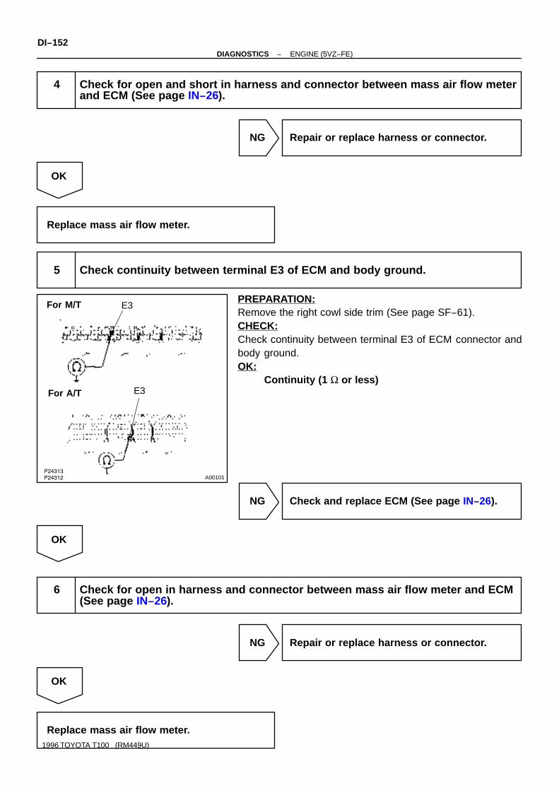
P24313
P24312 A00101
For M/T
For A/T
E3
E3
DI−152−DIAGNOSTICS ENGINE (5VZ−FE)
1996 TOYOTA T100 (RM449U)
4 Check for open and short in harness and connector between mass air flow meterand ECM (See page IN−26).
NG Repair or replace harness or connector.
OK
Replace mass air flow meter.
5 Check continuity between terminal E3 of ECM and body ground.
PREPARATION:Remove the right cowl side trim (See page SF−61).CHECK:Check continuity between terminal E3 of ECM connector andbody ground.OK:
Continuity (1 Ω or less)
NG Check and replace ECM (See page IN−26).
OK
6 Check for open in harness and connector between mass air flow meter and ECM(See page IN−26).
NG Repair or replace harness or connector.
OK
Replace mass air flow meter.
https://www.truck-manuals.net/

−DIAGNOSTICS ENGINE (5VZ−FE)DI−153
1996 TOYOTA T100 (RM449U)
DTC P0101 Mass Air Flow Circuit Range/PerformanceProblem
CIRCUIT DESCRIPTIONRefer to DTC P0100 on page DI−149.
DTC No. DTC Detecting Condition Trouble Area
P0101
After engine is warmed up, conditions (a) and (b) continue
with engine speed 900 rpm or less:
(2 trip detection logic)
(a) Throttle valve fully closed
(b) Mass air flow meter output � 2.2 V�Mass air flow meter
Conditions (a) and (b) continue with engine speed 1,500 rpm or
more:
(2 trip detection logic)
(a) VTA � 0.63 V
(b) Mass air flow meter output � 1.06 V
INSPECTION PROCEDURE
1 Are there any other codes (besides DTC P0101) being output?
NO Replace mass air flow meter.
YES
Go to relevant DTC chart.
DI0UH−01
https://www.truck-manuals.net/
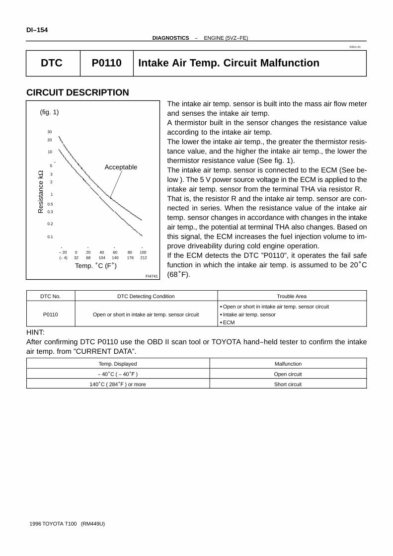
FI4741
(fig. 1)
Acceptable
Res
ista
nce
kΩ
− 20 0 20 40 60 80 100(− 4) 32 68 104 140 176 212
30
20
10
5
3
2
1
0.5
0.3
0.2
0.1
Temp. °C (F°)
DI−154−DIAGNOSTICS ENGINE (5VZ−FE)
1996 TOYOTA T100 (RM449U)
DTC P0110 Intake Air Temp. Circuit Malfunction
CIRCUIT DESCRIPTIONThe intake air temp. sensor is built into the mass air flow meterand senses the intake air temp.A thermistor built in the sensor changes the resistance valueaccording to the intake air temp.The lower the intake air temp., the greater the thermistor resis-tance value, and the higher the intake air temp., the lower thethermistor resistance value (See fig. 1).The intake air temp. sensor is connected to the ECM (See be-low ). The 5 V power source voltage in the ECM is applied to theintake air temp. sensor from the terminal THA via resistor R.That is, the resistor R and the intake air temp. sensor are con-nected in series. When the resistance value of the intake airtemp. sensor changes in accordance with changes in the intakeair temp., the potential at terminal THA also changes. Based onthis signal, the ECM increases the fuel injection volume to im-prove driveability during cold engine operation.If the ECM detects the DTC ”P0110”, it operates the fail safefunction in which the intake air temp. is assumed to be 20°C(68°F).
DTC No. DTC Detecting Condition Trouble Area
P0110 Open or short in intake air temp. sensor circuit
�Open or short in intake air temp. sensor circuit
� Intake air temp. sensor
�ECM
HINT:After confirming DTC P0110 use the OBD II scan tool or TOYOTA hand−held tester to confirm the intakeair temp. from ”CURRENT DATA”.
Temp. Displayed Malfunction
− 40°C ( − 40°F ) Open circuit
140°C ( 284°F ) or more Short circuit
DI0UI−01
https://www.truck-manuals.net/
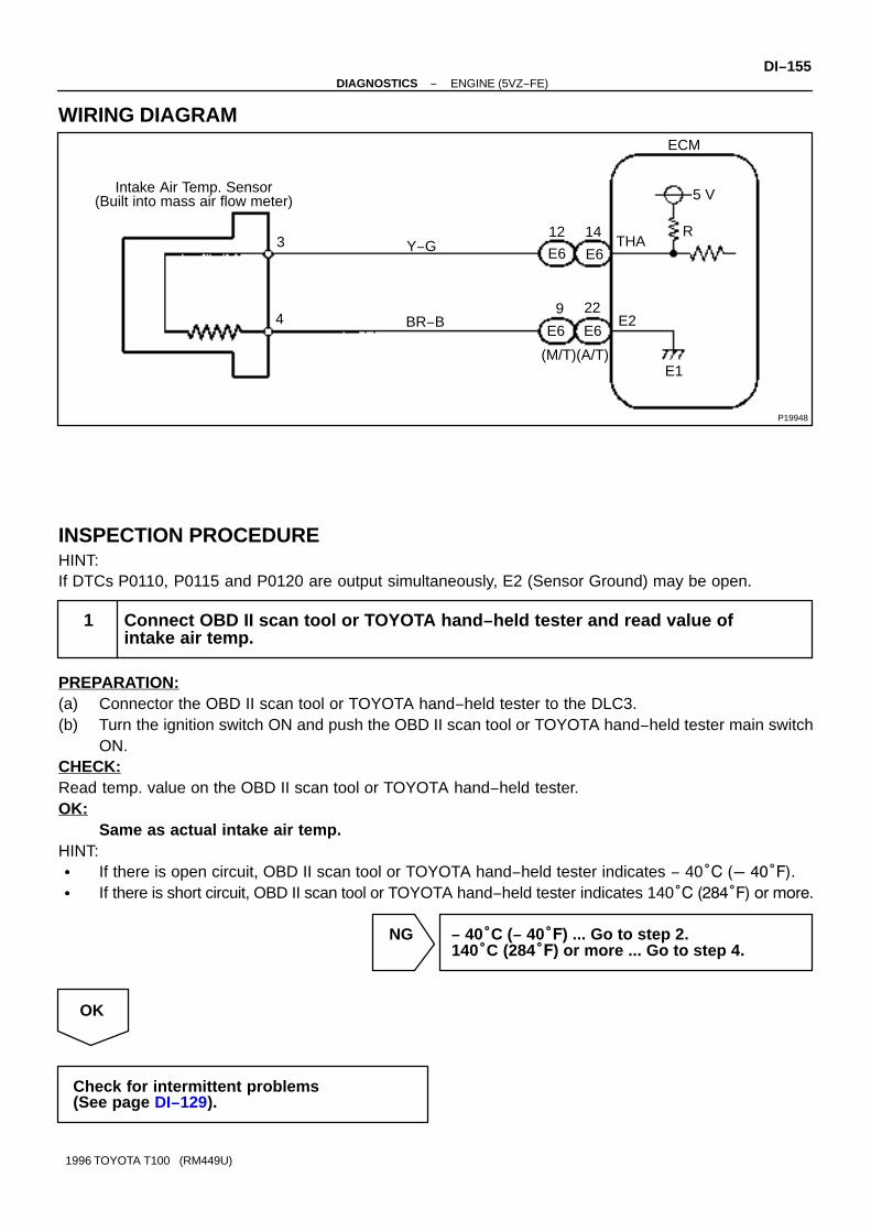
P19948
ECM
Intake Air Temp. Sensor(Built into mass air flow meter)
3
4
Y−G
BR−B
E6
E6 E6
E6
5 V
THA
E2
12 14
9 22
(M/T)(A/T)
R
E1
−DIAGNOSTICS ENGINE (5VZ−FE)DI−155
1996 TOYOTA T100 (RM449U)
WIRING DIAGRAM
INSPECTION PROCEDUREHINT:If DTCs P0110, P0115 and P0120 are output simultaneously, E2 (Sensor Ground) may be open.
1 Connect OBD II scan tool or TOYOTA hand−held tester and read value of intake air temp.
PREPARATION:(a) Connector the OBD II scan tool or TOYOTA hand−held tester to the DLC3.(b) Turn the ignition switch ON and push the OBD II scan tool or TOYOTA hand−held tester main switch
ON.CHECK:Read temp. value on the OBD II scan tool or TOYOTA hand−held tester.OK:
Same as actual intake air temp.HINT:� If there is open circuit, OBD II scan tool or TOYOTA hand−held tester indicates − 40°C (− 40°F).
� If there is short circuit, OBD II scan tool or TOYOTA hand−held tester indicates 140°C (284°F) or more.
NG − 40°C (− 40°F) ... Go to step 2. 140°C (284°F) or more ... Go to step 4.
OK
Check for intermittent problems(See page DI−129).
https://www.truck-manuals.net/

BE6653P19555 A00046
ON
ECMIntake AirTemp. Sensor
E2
E1
5 V
12 14
9 22
THA3
4E6
E6E6
E6(A/T)(M/T)
BE6653P19553P20223P20199 A00102
For M/T
For A/T
ON
Intake AirTemp. Sensor
ECM
3
4
12 14
9 22E2
E1
5 V
THAE6 E6
E6 E6
THA E2
THAE2
(M/T)(A/T)
DI−156−DIAGNOSTICS ENGINE (5VZ−FE)
1996 TOYOTA T100 (RM449U)
2 Check for open in harness or ECM.
PREPARATION:(a) Disconnect the mass air flow meter connector.(b) Connect the sensor wire harness terminals together.(c) Turn the ignition switch ON.CHECK:Read temp. value on the OBD II scan tool or TOYOTAhand−held tester.OK:
Temp. value: 140°C (284°F) or more
OK Confirm good connection at sensor. If OK, replace mass air flow meter.
NG
3 Check for open in harness or ECM.
PREPARATION:(a) Remove the right cowl side trim (See page SF−61).(b) Connect between terminals THA and E2 of the ECM
connector.HINT:The mass air flow meter connector is disconnected.Before checking, do a visual and contact pressure check for theECM connector (See page IN−26).(c) Turn the ignition switch ON.CHECK:Read temp. value on the OBD II scan tool or TOYOTAhand−held tester.OK:
Temp. value: 140°C (284°F) or more
OK Open in harness between terminals E2 or THA, repair or replace harness.
NG
Confirm good connection at ECM.If OK, check and replace ECM.
https://www.truck-manuals.net/

BE6653P19554 A00048
ON
Intake AirTemp. Sensor
ECM
3
4
5 V
E2
12 14
9 22
E1(A/T)(M/T)
THAE6
E6
E6
E6
BE6653FI7056P19798FI7034 A00103
ON
ECMIntake AirTemp. Sensor
E2
E1
THA
5 V
E6 Connector
E6 Connector
For M/T
For A/T
−DIAGNOSTICS ENGINE (5VZ−FE)DI−157
1996 TOYOTA T100 (RM449U)
4 Check for short in harness and ECM.
PREPARATION:(a) Disconnect the mass air flow meter connector.(b) Turn the ignition switch ON.CHECK:Read temp. value on the OBD II scan tool or TOYOTAhand−held tester.OK:
Temp. value: − 40°C (− 40°F)
OK Replace mass air flow meter.
NG
5 Check for short in harness or ECM.
PREPARATION:(a) Remove the right cowl side trim (See page SF−61).(b) Disconnect the E6 connector of the ECM.HINT:The mass air flow meter connector is disconnected.(c) Turn the ignition switch ON.CHECK:Read temp. value on the OBD II scan tool or TOYOTAhand−held tester.OK:
Temp. value: − 40°C (− 40°F)
OK Repair or replace harness or connector.
NG
Check and replace ECM (See page IN−26).
https://www.truck-manuals.net/

P19947
ECM
5 V
THW
E2
Engine Coolant Temp. Sensor
2
1
2
1
G−Y G−Y
BR−B BR−B
4 20
9 22
E1(M/T)(A/T)
E6 E6
EC2 E6 E6
EC2
DI−158−DIAGNOSTICS ENGINE (5VZ−FE)
1996 TOYOTA T100 (RM449U)
DTC P0115 Engine Coolant Temp. Circuit Malfunction
CIRCUIT DESCRIPTIONA thermistor built into the engine coolant temp. sensor changes the resistance value according to the enginecoolant temp.The structure of the sensor and connection to the ECM is the same as in the intake air temp. circuit malfunc-tion shown on page DI−154.If the ECM detects the DTC P0115, it operates the fail safe function in which the engine coolant temp. isassumed to be 80°C (176°F).
DTC No. Detection Item Trouble Area
P0115 Open or short in engine coolant temp. sensor circuit
�Open or short in engine coolant temp. sensor circuit
�Engine coolant temp. sensor
�ECM
HINT:After confirming DTC P0115 use the OBD II scan tool or TOYOTA hand−held tester to confirm the enginecoolant temp. from ”CURRENT DATA”.
Temp. Displayed Malfunction
− 40°C (− 40°F) Open circuit
140°C (284°F) or more Short circuit
WIRING DIAGRAM
DI0UJ−01
https://www.truck-manuals.net/

BE6653P19555 A00046
ON
Engine CoolantTemp. Sensor
ECM
2
1
4 20
9 22 E2
E1
THW
5 V
(A/T)(M/T)
E6
E6E6
E6
−DIAGNOSTICS ENGINE (5VZ−FE)DI−159
1996 TOYOTA T100 (RM449U)
INSPECTION PROCEDUREHINT:If DTCs P0110, P0115 and P0120 are output simultaneously, E2 (sensor ground) may be open.
1 Connect OBD II scan tool or TOYOTA hand−held tester and read value of engine coolant temp.
PREPARATION:(a) Connect the OBD II scan tool or TOYOTA hand−held tester to the DLC3.(b) Turn the ignition switch ON and push the OBD II scan tool or TOYOTA hand−held tester main switch
ON.CHECK:Read temp. value on the OBD II scan tool or TOYOTA hand−held tester.OK:
Same as actual engine coolant temp.HINT:� If there is open circuit, OBD II scan tool or TOYOTA hand−held tester indicates − 40°C (− 40°F).
� If there is open circuit, OBD II scan tool or TOYOTA hand−held tester indicates 140°C (284°F) or more.
NG − 40°C (− 40°F) ... Go to step 2.140°C (284°F) or more ... Go to step 4.
OK
Check for intermittent problems(See page DI−129).
2 Check for open in harness or ECM.
PREPARATION:(a) Disconnect the engine coolant temp. sensor connector.(b) Connect the sensor wire harness terminals together.(c) Turn the ignition switch ON.CHECK:Read temp. value on the OBD II scan tool or TOYOTAhand−held tester.OK:
Temp. value: 140°C (284°F) or more
OK Confirm good connection at sensor.If OK, replace engine coolant temp. sensor.
NG
https://www.truck-manuals.net/

BE6653P19553P20224P20200 A00104
ON
Engine CoolantTemp. Sensor
2
1
ECM
THW E2
THWE2
5 V
E2
E1
4 20
9 22
THWE6 E6
E6 E6(A/T)(M/T)
For M/T
For A/T
BE6653P19554 A00048
ON
Engine CoolantTemp. Sensor
2
1
4 20
9 22
5 V
E2
E1
THW
ECM
(A/T)(M/T)
E6 E6
E6 E6
DI−160−DIAGNOSTICS ENGINE (5VZ−FE)
1996 TOYOTA T100 (RM449U)
3 Check for open in harness or ECM.
PREPARATION:(a) Remove the right cowl side trim (See page SF−61).(b) Connect between terminals THW and E2 of the ECM con-
nector.HINT:The engine coolant temp. sensor connector is disconnected.Before checking, do a visual and contact pressure check for theECM connector (See page IN−26).(c) Turn the ignition switch ON.CHECK:Read temp. value on the OBD II scan tool or TOYOTAhand−held tester.OK:
Temp. value: 140°C (284°F) or more
OK Open in harness between terminals E2 or THW,repair or replace harness.
NG
Confirm good connection at ECM. If OK, check and replace ECM.
4 Check for short in harness and ECM.
PREPARATION:(a) Disconnect the engine coolant temp. sensor connector.(b) Turn the ignition switch ON.CHECK:Read temp. value on the OBD II scan tool or TOYOTAhand−held tester.OK:
Temp. value: − 40°C (− 40°F)
OK Replace engine coolant temp. sensor.
NG
https://www.truck-manuals.net/

BE6653FI7056P19798FI7034 A00103
ON
ECMEngine CoolantTemp. Sensor
E2
E1
THW
E6 Connector
E6 Connector
For M/T
For A/T
5 V
−DIAGNOSTICS ENGINE (5VZ−FE)DI−161
1996 TOYOTA T100 (RM449U)
5 Check for short in harness or ECM.
PREPARATION:(a) Remove the right cowl side trim (See page SF−61 ).(b) Disconnect the E6 connector of the ECM.HINT:The engine coolant temp. sensor connector is disconnected.(c) Turn the ignition switch ON.CHECK:Read temp. value on the OBD II scan tool or TOYOTAhand−held tester.OK:
Temp. value: − 40°C (− 40°F)
OK Repair or replace harness or connector.
NG
Check and replace ECM (See page IN−26).
https://www.truck-manuals.net/

DI−162−DIAGNOSTICS ENGINE (5VZ−FE)
1996 TOYOTA T100 (RM449U)
DTC P0116 Engine Coolant Temp. Circuit Range/Performance problem
CIRCUIT DESCRIPTIONRefer to DTC P0115 on page DI−158.
DTC No. DTC Detecting Condition Trouble Area
P0116
If THW − 7°C (19.4°F) at engine start, 20 min. or more
after starting engine, engine coolant temp. sensor value is
35°C (95°F) or less
(2 trip detection logic) �Engine coolant temp. sensor
�Cooling systemIf THW − 7°C (19.4°F) at engine start, 5 min. or more
after starting engine, engine coolant temp. sensor value is
35°C (95°F) or less
(2 trip detection logic)
INSPECTION PROCEDUREHINT:If DTCs P0115 and P0116 are output simultaneously, engine coolant temp. sensor circuit may be open.Per-form troubleshooting of DTC P0115 first.
1 Are there any other codes (besides DTC P0116) being output?
YES Go to relevant DTC chart.
NO
2 Check thermostat (See page CO−9).
NG Replace thermostat.
OK
Replace engine coolant temp. sensor.
DI0UK−01
https://www.truck-manuals.net/

P24296
ECMThrottle PositionSensor
VCC
VTA
E2
−DIAGNOSTICS ENGINE (5VZ−FE)DI−163
1996 TOYOTA T100 (RM449U)
DTC P0120 Throttle/Pedal position Sensor/Switch ”A”Circuit Malfunction
CIRCUIT DESCRIPTIONThe throttle position sensor is mounted in the throttle body anddetects the throttle valve opening angle. When the throttle valveis fully closed, a voltage of approximately 0.7 V is applied to ter-minal VTA of the ECM. The voltage applied to the terminals VTAof the ECM increases in proportion to the opening angle of thethrottle valve and becomes approximately 2.7 ∼ 5.2 V when thethrottle valve is fully opened. The ECM judges the vehicle driv-ing conditions from these signals input from terminals VTA anduses them as one of the conditions for deciding the air−fuel ratiocorrection, power increase correction and fuel−cut control etc.
DTC No. DTC Detecting Condition Trouble Area
P0120
Condition (a) or (b) continues:
(a) VTA 0.1 V
(b) VTA 4.9 V
�Open or short in throttle position sensor circuit
�Throttle position sensor
�ECM
HINT:After confirming DTC P0120 use the OBD II scan tool or TOYOTA hand−held tester to confirm the throttlevalve opening percentage and closed throttle position switch condition.
Throttle valve opening position
expressed as percentageTrouble Area
Throttle valve fully closed Throttle valve fully open Trouble Area
0 % 0 %VCC line open
VTA line open or short
Approx. 99 % Approx. 100 % E2 line open
DI0UL−01
https://www.truck-manuals.net/

A00004
ECM
5 V
VCC
VTA
E2
2
3
1
Throttle Position Sensor
E6
E6
E6
E6
E6
E6
1
10
9
1
7
22
G−B
Y−B
BR−B
(M/T) (A/T)
DI−164−DIAGNOSTICS ENGINE (5VZ−FE)
1996 TOYOTA T100 (RM449U)
WIRING DIAGRAM
https://www.truck-manuals.net/

FI7052
BE6653
A00014A00106
2 (+)ON
−DIAGNOSTICS ENGINE (5VZ−FE)DI−165
1996 TOYOTA T100 (RM449U)
INSPECTION PROCEDUREHINT:If DTCs P0110, P0115 and P0120 are output simultaneously, E2 (sensor ground) may be open. If DTCsP0110, P0115 and P0120 are output simultaneously, E2 (sensor ground) may be open.
1 Connect OBD II scan tool or TOYOTA hand−held tester and read the throttlevalve opening percentage.
PREPARATION:(a) Connect the OBD II scan tool or TOYOTA hand−held tester to DLC3.(b) Turn the ignition switch ON and push the OBD II scan tool or TOYOTA hand−held tester main switch
ON.CHECK:Read the throttle valve opening percentage.
OK:
Throttle valveThrottle valve opening position
expressed as percentage
Fully open Approx. 75 %
Fully closed Approx. 10 %
OK Check for intermittent problems(See page DI−129).
NG
2 Check voltage between terminal 2 of wire harness side connector and bodyground.
PREPARATION:(a) Disconnect the throttle position sensor connector.(b) Turn the ignition switch ON.CHECK:Measure voltage between terminals 2 of wire harness side con-nector and body ground.OK:
Voltage: 4.5 − 5.5 V
NG Go to step 5.
OK
https://www.truck-manuals.net/

A00015
Throttle PositionSensor
1
2
3
BE6653P23811P24315 A00107
ON
VTA (+) E2 (−)
VTA (+)E2 (−)
For M/T
For A/T
DI−166−DIAGNOSTICS ENGINE (5VZ−FE)
1996 TOYOTA T100 (RM449U)
3 Check throttle position sensor.
PREPARATION:Disconnect the throttle position sensor connector.CHECK:Measure voltage between terminals 1, 2 and 3 of throttle posi-tion sensor.OK:
Terminals Throttle valve Resistance
1 − 2 ⎯ 2.5 − 5.9 kΩ
1 − 3Fully closed 0.2 − 5.7 kΩ
Fully open 2.0 − 10.2 kΩ
NG Replace throttle position sensor.
OK
4 Check voltage between terminals VTA and E2 of ECM.
PREPARATION:(a) Remove the right cowl side trim (See page SF−61).(b) Turn the ignition switch ON.CHECK:Measure voltage between terminals VTA and E2 of ECM con-nector.OK:
Throttle valve Voltage
Fully closed 1.0 V
Fully open 2.72 ∼ 5.2 V
NG Check for open and short in harness and connector between ECM and throttle positionsensor (VTA line) (See page IN−26).
OK
Check and replace ECM (See page IN−26).
https://www.truck-manuals.net/
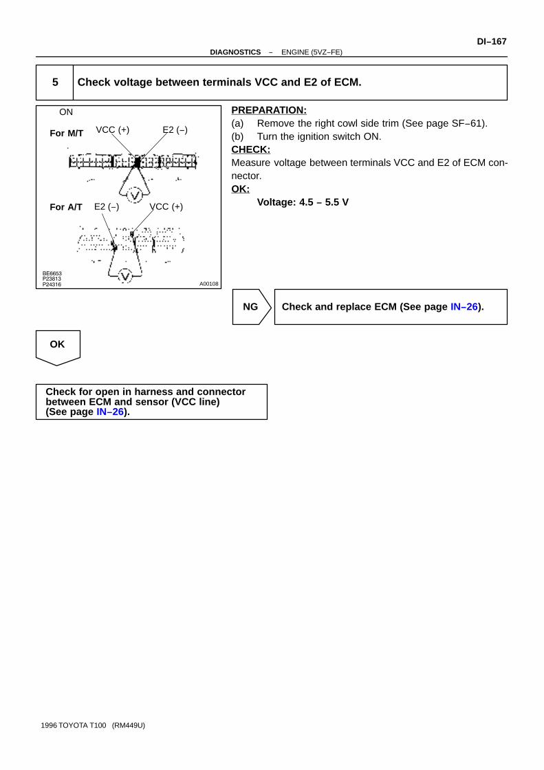
BE6653
P23813
P24316 A00108
ON
VCC (+) E2 (−)
VCC (+)E2 (−)
For M/T
For A/T
−DIAGNOSTICS ENGINE (5VZ−FE)DI−167
1996 TOYOTA T100 (RM449U)
5 Check voltage between terminals VCC and E2 of ECM.
PREPARATION:(a) Remove the right cowl side trim (See page SF−61).(b) Turn the ignition switch ON.CHECK:Measure voltage between terminals VCC and E2 of ECM con-nector.OK:
Voltage: 4.5 − 5.5 V
NG Check and replace ECM (See page IN−26).
OK
Check for open in harness and connector between ECM and sensor (VCC line)(See page IN−26).
https://www.truck-manuals.net/

DI−168−DIAGNOSTICS ENGINE (5VZ−FE)
1996 TOYOTA T100 (RM449U)
DTC P0121 Throttle/Pedal Position Sensor/Switch ”A”Circuit Range/Performance Problem
CIRCUIT DESCRIPTIONRefer to DTC P0120 on page DI−163.
DTC No. DTC Detecting Condition Trouble Area
P0121
After vehicle speed has been exceeded 30 km/h (19 mph)
even once, output value of throttle position sensor is out of
the applicable range while vehicle speed between 30 km/h
(19 mph) and 0 km/h (0 mph)
�Throttle position sensor
INSPECTION PROCEDURE
1 Are there any other codes (besides DTC P0121) being output?
YES Go to relevant DTC chart.
NO
Replace throttle position sensor.
DI0UM−01
https://www.truck-manuals.net/

P21242 FI7210 A00027
Atomosphere
Cover
Ideal Air−Fuel Mixture
Exhaust Gas
FlangePlatinum ElectrodeSolid Electrolyte(Zirconia Element)
Platinum Electrode
Heater
Coating(Ceramic)
Out
put
Vol
tage
Richer � Air−fuel Ratio � Leaner
−DIAGNOSTICS ENGINE (5VZ−FE)DI−169
1996 TOYOTA T100 (RM449U)
DTC P0125 Insufficient Coolant Temp. for Closed LoopFuel Control
CIRCUIT DESCRIPTIONTo obtain a high purification rate for the CO, HC and NOx components of the exhaust gas, a three−waycatalytic converter is used, but for the most efficient use of the three−way catalytic converter, the air−fuelratio must be precisely controlled so that it is always close to the stoichiometric air−fuel ratio.The oxygen sensor has the characteristic whereby its output voltage changes suddenly in the vicinity of thestoichiometric air−fuel ratio. This characteristic is used to detect the oxygen concentration in the exhaustgas and provide feedback to the computer for control of the air−fuel ratio.When the air−fuel ratio becomes LEAN, the oxygen concentration in the exhaust increases and the oxygensensor informs the ECM of the LEAN condition (small electromotive force: 0 V).When the air−fuel ratio is RICHER than the stoichiometric air−fuel ratio the oxygen concentration in the ex-haust gas is reduced and the oxygen sensor informs the ECM of the RICH condition (large electromotiveforce: 1 V). The ECM judges by the electromotive force from the oxygen sensor whether the air−fuel ratiois RICH or LEAN and controls the injection time accordingly. However, if malfunction of the oxygen sensorcauses output of abnormal electromotive force, the ECM is unable to perform accurate air−fuel ratio control.The heated oxygen sensors include a heater which heats the Zirconia element. The heater is controlled bythe ECM. When the intake air volume is low (the temp. of the exhaust gas is low) current flows to the heaterto heat the sensor for accurate oxygen concentration detection.
DTC No. DTC Detecting Condition Trouble Area
P0125
After engine is warmed up, heated oxygen sensor output
does not indicate RICH even once when conditions (a), (b),
(c) and (d) continue for at least 1.5 min.:
(a) Engine speed: 1,500 rpm or more
(b) Vehicle speed: 40 − 100 km/h (25 − 62 mph)
(c) Throttle valve does not fully closed
(d) 140 sec. or more after starting engine
�Open or short in heated oxygen sensor
(bank1 sensor 1) circuit
�Heated oxygen sensor (bank 1 sensor 1)
DI0UN−01
https://www.truck-manuals.net/

P19611
R/B No.2
B−
W
2 2
E6 E6
E6 E6
BR
E1
E1
EB
2
2
2 2
From Battery
To Body Ground
FromIG Switch
EF
I R
elay
W−
RE
FI 2
21
5
1 3
EA1 IE1W−R W−R W−R
9 9
W−
R
HeatedOxygenSensor(Bank 1Sensor 2)
2
1
3
4
2 3
1 4
HeatedOxygenSensor(Bank 1Sensor 1)
P−GE5 E7
E7 E5
E5 E7R−G
R
ECM
OX1
HT1
OX2
E1
HT2
E03
E03(M/T)(A/T)
5
3
13
24
9
13
16
19
16
15
W
BR
BR
BR
DI−170−DIAGNOSTICS ENGINE (5VZ−FE)
1996 TOYOTA T100 (RM449U)
HINT:After confirming DTC P0125 use the OBD II scan tool or TOYOTA hand−held tester to confirm voltage output
of heated oxygen sensor from "CURRENT DATA".
If voltage output of heated oxygen sensor is 0 V, heated oxygen sensor circuit may be open or short.
WIRING DIAGRAM
INSPECTION PROCEDURE
1 Connect OBD II scan tool or TOYOTA hand−held tester and read value for voltage output of heated oxygen sensor (bank 1 sensor 1).
PREPARATION:(a) Connect the OBD II scan tool or TOYOTA hand−held tester to the DLC3.(b) Warm up the engine to normal operating temp.CHECK:Read voltage output of heated oxygen sensor (bank 1 sensor 1) when engine is suddenly raced.HINT:Perform quick racing to 4,000 rpm 3 times using the accelerator pedal.OK:
Heated oxygen sensor (bank 1 sensor 1) output a RICH signal (0.45 V or more) at least once
OK Check and replace ECM (See page IN−26).
NG
https://www.truck-manuals.net/

−DIAGNOSTICS ENGINE (5VZ−FE)DI−171
1996 TOYOTA T100 (RM449U)
2 Check for open and short in harness and connector between ECM and heatedoxygen sensor (bank 1 sensor 1) (See page IN−26).
NG Repair or replace harness or connector.
OK
Replace heated oxygen sensor(bank 1 sensor 1).
https://www.truck-manuals.net/

FI7130
Vehicle speed
50 ∼ 65 km/h(31 ∼ 40 mph)
IdlingIG SW OFF
1 ∼ 3 min. 1 min. Time
(1)(2)
(3)
(4)
(5)
DI−172−DIAGNOSTICS ENGINE (5VZ−FE)
1996 TOYOTA T100 (RM449U)
DTC P0130 Heated Oxygen Sensor Circuit Malfunction(Bank 1 Sensor 1)
CIRCUIT DESCRIPTIONRefer to DTC P0125 on page DI−169.
DTC No. DTC Detecting Condition Trouble Area
P0130
Voltage output of heated oxygen sensor remains at 0.35 V or
more, or 0.55 V or less, during idling after engine is warmed up
(2 trip detection logic)
�Heated oxygen sensor
�Fuel trim malfunction
HINT:Sensor 1 refers to the sensor closer to the engine body.
The heated oxygen sensor’s output voltage and the short−term fuel trim value can be read using the
OBD II scan tool or TOYOTA hand−held tester.
WIRING DIAGRAMRefer to DTC P0125 on page DI−169.
CONFIRMATION DRIVING PATTERN
(1) Connect the TOYOTA hand−held tester to the DLC3.(2) Switch the TOYOTA hand−held tester from normal mode to check mode (See page DI−129).(3) Start the engine and warm it up with all the accessory switches OFF.(4) Drive the vehicle at 50 − 65 km/h (31 − 40 mph) for 1 − 3 min. to warm up the heated oxygen sensor.(5) Let the engine idle for 1 min.HINT:If a malfunction exists, the MIL will light up during step (5).NOTICE:If the conditions in this test are not strictly followed, detection of the malfunction will not be possible.If you do not have a TOYOTA hand−held tester, turn the ignition switch OFF after performing steps(3) to (5), then perform steps (3) to (5) again.
DI0UO−01
https://www.truck-manuals.net/

−DIAGNOSTICS ENGINE (5VZ−FE)DI−173
1996 TOYOTA T100 (RM449U)
INSPECTION PROCEDURE
1 Check for open and short in harness and connector between ECM and heatedoxygen sensor (See page IN−26).
NG Repair or replace harness or connector.
OK
2 Check for heated oxygen sensor data.
PREPARATION:(a) Connect the OBD II scan tool or TOYOTA hand−held tester to the DLC3.(b) Warm up the engine to normal operating temp.CHECK:Read heated oxygen sensor output voltage and short−term fuel trim.RESULT:
Pattern Heated oxygen sensor output voltage Short−term fuel trim
1 Lean condition (Changes at 0.55 V or less) Changes at about + 20 %
2 Rich condition (Changes at 0.35 V or more) Changes at about − 20 %
3 Except 1 and 2 Except 1 and 2
1, 2 Check fuel trim system (See page DI−183).
3
https://www.truck-manuals.net/

A00292
1 V
0.55 V
0.35 V
0 V
NG NG NGOK
DI−174−DIAGNOSTICS ENGINE (5VZ−FE)
1996 TOYOTA T100 (RM449U)
3 Check output voltage of heated oxygen sensor during idling.
PREPARATION:Warm up the heated oxygen sensor with the engine at 2,500 rpm for approx. 90 sec.CHECK:Use the OBD II scan tool or TOYOTA hand−held tester read the output voltage of the heated oxygen sensorduring idling.OK:
Heated oxygen sensor output voltage:Alternates repeatedly between less than 0.35 V and more than 0.55 V (See the following table)
OK Perform confirmation driving pattern.
NG
Replace heated oxygen sensor.
https://www.truck-manuals.net/

−DIAGNOSTICS ENGINE (5VZ−FE)DI−175
1996 TOYOTA T100 (RM449U)
DTC P0133 Heated Oxygen Sensor Circuit SlowResponse (Bank 1 Sensor 1)
CIRCUIT DESCRIPTIONRefer to DTC P0125 on page DI−169.
DTC No. DTC Detecting Condition Trouble Area
P0133
Response time for heated oxygen sensor’s voltage output to
change from rich to lean, or from lean to rich, is 1 sec. or
more during idling after engine is warmed up
(2 trip detection logic)
�Heated oxygen sensor
HINT:Sensor 1 refers to the sensor closer to the engine body.
INSPECTION PROCEDURE
1 Are there any other codes (besides DTC P0133) being output?
YES Go to relevant DTC chart.
NO
Replace heated oxygen sensor.
DI0UP−01
https://www.truck-manuals.net/

BE6653P24318P24317 A00109
ON
HT1 (+) HT2 (+)
HT1 (+) HT2 (+)
For M/T
For A/T
DI−176−DIAGNOSTICS ENGINE (5VZ−FE)
1996 TOYOTA T100 (RM449U)
DTC P0135 Heated Oxygen Sensor Heater Circuit Malfunction (Bank 1 Sensor 1)
DTC P0141 Heated Oxygen Sensor Heater Circuit Malfunction (Bank 1 Sensor 2)
CIRCUIT DESCRIPTIONRefer to DTC P0125 on page DI−169.
DTC No. DTC Detecting Condition Trouble Area
P0135
P0141
When heater operates, heater current exceeds 2.35 A
(2 trip detection logic) �Open or short in heater circuit of heated oxygen sensor
Heated oxygen sensor heater
ECMHeater current of 0.2 A or less when heater operates
(2 trip detection logic)
HINT:� Sensor 1 refers to the sensor closer to the engine body.
� Sensor 2 refers to the sensor farther away from the engine body.
WIRING DIAGRAMRefer to DTC P0125 on page DI−169.
INSPECTION PROCEDURE
1 Check voltage between terminals HT1, HT2 of ECM connector and body ground.
PREPARATION:(a) Remove the right cowl side trim (See page SF−61).(b) Turn the ignition switch ON.CHECK:Measure voltage between terminals HT1, HT2 of ECM connec-tor and body ground.HINT:� Connect terminal HT1 to bank 1 sensor 1.� Connect terminal HT2 to bank 1 sensor 2.
OK:Voltage: 9 − 14 V
OK Check and replace ECM (See page IN−26).
NG
DI0UQ−01
https://www.truck-manuals.net/

−DIAGNOSTICS ENGINE (5VZ−FE)DI−177
1996 TOYOTA T100 (RM449U)
2 Check resistance of heated oxygen sensor heater (See page SF−60).
NG Replace heated oxygen sensor.
OK
Check and repair harness or connectorbetween EFI main relay, heated oxygensensor and ECM (See page IN−26).
https://www.truck-manuals.net/

DI−178−DIAGNOSTICS ENGINE (5VZ−FE)
1996 TOYOTA T100 (RM449U)
DTC P0136 Heated Oxygen Sensor Circuit Malfunction(Bank 1 Sensor 2)
CIRCUIT DESCRIPTIONRefer to DTC P0125 on page DI−169.
DTC No. DTC Detecting Condition Trouble Area
P0136
Voltage output of heated oxygen sensor (bank 1 sensor 2)
remains at 0.4 V or more or 0.5 V or less when vehicle is
driven at 50 km/h (31 mph) or more after the engine is
warmed up.
(2 trip detection logic).
�Heated oxygen sensor
HINT:Sensor 2 refers to the sensor farther away from the engine body.
WIRING DIAGRAMRefer to DTC P0125 on page DI−169.
INSPECTION PROCEDURE
1 Are there any other codes (besides DTC P0136) being output?
YES Go to relevant DTC chart.
NO
2 Check for open and short in harness and connector between ECM and heatedoxygen sensor (See page IN−26).
NG Repair or replace harness or connector.
OK
DI0UR−01
https://www.truck-manuals.net/

−DIAGNOSTICS ENGINE (5VZ−FE)DI−179
1996 TOYOTA T100 (RM449U)
3 Check output voltage of heated oxygen sensor.
PREPARATION:(a) Connect the OBD II scan tool or TOYOTA hand−held tester to the DLC3.(b) Warm up the engine to normal operating temp.CHECK:Read voltage output of the heated oxygen sensor (bank 1 sensor 2) when the engine suddenly raced.HINT:Perform quick racing to 4,000 rpm 3 min. using the accelerator pedal.OK:
Heated oxygen sensor output voltage: Alternates from 0.4 V or less to 0.5 V or more
OK Check that each connector is properly connected.
NG
Replace heated oxygen sensor.
https://www.truck-manuals.net/

DI−180−DIAGNOSTICS ENGINE (5VZ−FE)
1996 TOYOTA T100 (RM449U)
DTC P0171 System too Lean (Fuel Trim)
DTC P0172 System too Rich (Fuel Trim)
CIRCUIT DESCRIPTIONFuel trim refers to the feedback compensation value compared against the basic injection time. Fuel trimincludes short−term fuel trim and long−term fuel trim.Short−term fuel trim is the short−term fuel compensation used to maintain the air−fuel ratio at its idealtheoretical value. The signal from the heated oxygen sensor indicates whether the air−fuel ratio is RICH orLEAN compared to the ideal theoretical value, triggering a reduction in fuel volume if the air−fuel ratio is rich,and an increase in fuel volume if it is lean.Long−term fuel trim is overall fuel compensation carried out long−term to compensate for continual deviationof the short−term fuel trim from the central value due to individual engine differences, wear over time andchanges in the usage environment.If both the short−term fuel trim and long−term fuel trim are LEAN or RICH beyond a certain value, it is detected as a malfunction and the MIL lights up.
DTC No. DTC Detecting Condition Trouble Area
P0171
When air fuel ratio feedback is stable after engine warming up,
fuel trim is considerably in error on RICH side
(2 trip detection logic)
�Air intake (hose loose)
�Fuel line pressure
� Injector blockage
�Heated oxygen sensor (bank 1 sensor 1) malfunction
�Mass air flow meter
�Engine coolant temp. sensor
P0172
When air fuel ratio feedback is stable after engine warming up,
fuel trim is considerably in error on LEAN side
(2 trip detection logic)
�Fuel line pressure
� Injector leak, blockage
�Heated oxygen sensor (bank 1 sensor 1) malfunction
�Mass air flow meter
�Engine coolant temp. sensor
HINT:� When DTC P0171 is recorded, the actual air−fuel ratio is on the LEAN side. When DTC P0172 is re-
corded, the actual air−fuel ratio is on the RICH side.� If the vehicle runs out of fuel, the air−fuel ratio is LEAN and DTC P0171 is recorded. The MIL then
comes on.� If the total of the short−term fuel trim value and long−term fuel trim value is within ± 25 %, the system
is functioning normally.
INSPECTION PROCEDURE
1 Check air induction system (See page SF−5).
NG Repair or replace.
OK
DI0US−01
https://www.truck-manuals.net/

−DIAGNOSTICS ENGINE (5VZ−FE)DI−181
1996 TOYOTA T100 (RM449U)
2 Check for heated oxygen sensor (bank 1 sensor 1) data.
PREPARATION:(a) Connect the OBD II scan tool or TOYOTA hand−held tester to the DLC3.(b) Warm up the engine to normal operating temp.CHECK:Read heated oxygen sensor (bank 1 sensor 1) output voltage and short−term fuel trim.RESULT:
Pattern Heated oxygen sensor output voltage Short−term fuel trim
1 Lean condition (Changes at 0.55 V or less) Changes at about + 20 %
2 Rich condition (Changes at 0.35 V or more) Changes at about − 20 %
3 Except 1 and 2 Except 1 and 2
3 Check for heated oxygen sensor(bank 1 sensor 1) (See page DI−172).
1, 2
3 Check fuel pressure (See page SF−5).
NG Check and repair fuel pump, pressureregulator, fuel pipe line and filter(See page SF−5).
OK
4 Check injector injection (See page SF−21).
NG Replace injector.
OK
https://www.truck-manuals.net/

DI−182−DIAGNOSTICS ENGINE (5VZ−FE)
1996 TOYOTA T100 (RM449U)
5 Check mass air flow meter and engine coolant temp. sensor (See page SF−29, SF−52).
NG Repair or replace.
OK
6 Check for spark and ignition (See page IG−1).
NG Repair or replace.
OK
Check and replace ECM (See page IN−26).
https://www.truck-manuals.net/
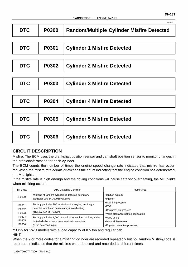
−DIAGNOSTICS ENGINE (5VZ−FE)DI−183
1996 TOYOTA T100 (RM449U)
DTC P0300 Random/Multiple Cylinder Misfire Detected
DTC P0301 Cylinder 1 Misfire Detected
DTC P0302 Cylinder 2 Misfire Detected
DTC P0303 Cylinder 3 Misfire Detected
DTC P0304 Cylinder 4 Misfire Detected
DTC P0305 Cylinder 5 Misfire Detected
DTC P0306 Cylinder 6 Misfire Detected
CIRCUIT DESCRIPTIONMisfire: The ECM uses the crankshaft position sensor and camshaft position sensor to monitor changes inthe crankshaft rotation for each cylinder.The ECM counts the number of times the engine speed change rate indicates that misfire has occur-red.When the misfire rate equals or exceeds the count indicating that the engine condition has deteriorated,the MIL lights up.If the misfire rate is high enough and the driving conditions will cause catalyst overheating, the MIL blinkswhen misfiring occurs.
DTC No. DTC Detecting Condition Trouble Area
P0300Misfiring of random cylinders is detected during any
particular 200 or 1,000 revolutions
� Ignition system
� Injector
�Fuel line pressure
�EGR*
�Compression pressure
�Valve clearance not to specification
�Valve timing
�Mass air flow meter
�Engine coolant temp. sensor
P0301
P0302
P0303
P0304
P0305
P0306
For any particular 200 revolutions for engine, misfiring is
detected which can cause catalyst overheating
(This causes MIL to blink)
For any particular 1,000 revolutions of engine, misfiring is de-
tected which causes a deterioration in emission
(2 trip detection logic)
*: Only for 2WD models with a load capacity of 0.5 ton and regular cab.HINT:When the 2 or more codes for a misfiring cylinder are recorded repeatedly but no Random Misfire code isrecorded, it indicates that the misfires were detected and recorded at different times.
DI0UT−01
https://www.truck-manuals.net/

S00901
Battery
W−R W−R
R−
LW
AM
2
2
2
4
3
R/B No.2
8IA3
8
7
SwitchIG
B−R IE114
B−R
B−
RB−
R
B−R 2
B−R 2
B−R 2
B−R 2
B−R 2
B−R 2
Injector
No.1
No.2
No.3
No.4
No.5
No.6
1
1
1
1
1
1
W−R
W
W−G
Y−R
W−L
Y−B
BR
BR
E7 E7
E7 E7
E7 E7
E7 E7
E7 E7
E7 E7
E7 E7
E7 E7(M/T)(A/T)
EB
12 10
11 9
25 8
10 7
9 6
8 5
13 34
26 33
#10
#20
#30
#40
#50
#60
E01
E02
ECM
FI6588 FI6538
A00064
10 V/Division
10 V/Division
GNDGND
100 msec./Division (Idling) 1 msec./Division (Idling)Injection duration
(Magnification)
DI−184−DIAGNOSTICS ENGINE (5VZ−FE)
1996 TOYOTA T100 (RM449U)
WIRING DIAGRAM
Reference INSPECTION USING OSCILLOSCOPEINJECTOR SIGNAL WAVEFORMWith the engine idling, measure between terminals #10 − #60 and E01 of ECM.HINT:The correct waveform is as shown.
https://www.truck-manuals.net/

P25779
P21163A00110
−DIAGNOSTICS ENGINE (5VZ−FE)DI−185
1996 TOYOTA T100 (RM449U)
INSPECTION PROCEDURE
1 Check spark plug and spark of misfiring cylinder.
PREPARATION:(a) Remove the ignition coil and high−tension cord.(b) Remove the spark plug.CHECK:(a) Check the spark plug type.(b) Check for carbon deposits on electrode.(c) Check the electrode gap.OK:
(1) Twin ground electrodes type.Recommended spark plug:ND K16TR11NGK BKR5EKB−11(2) No large carbon deposit present. Not wet with gosoline or oil.(3) Electrode gap: 1.0 − 1.1 mm (0.039 − 0.043 in.)
PREPARATION:(a) Install the spark plug to the ignition coil or high−tension
cord.(b) Disconnect the injector connector.(c) Ground the spark plug.CHECK:Check if the spark occurs while the engine is being cranked.NOTICE:To prevent excess fuel being injected from the injectorsduring this test, don’t crank the engine for more than 5 − 10sec. at a time.OK:
Spark jumps across electrode gap.
NG Replace or check ignition system (See page IG−1).
OK
https://www.truck-manuals.net/
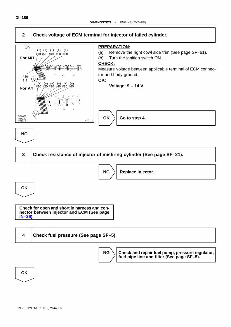
BE6653P24320P24319 A00111
ON
#10 #20
#30
#40 #50 #60(+) (+) (+) (+) (+)
(+)
#10 #20 #40 #50 #60#30(+) (+) (+) (+) (+) (+)
For M/T
For A/T
DI−186−DIAGNOSTICS ENGINE (5VZ−FE)
1996 TOYOTA T100 (RM449U)
2 Check voltage of ECM terminal for injector of failed cylinder.
PREPARATION:(a) Remove the right cowl side trim (See page SF−61).(b) Turn the ignition switch ON.CHECK:Measure voltage between applicable terminal of ECM connec-tor and body ground.OK:
Voltage: 9 − 14 V
OK Go to step 4.
NG
3 Check resistance of injector of misfiring cylinder (See page SF−21).
NG Replace injector.
OK
Check for open and short in harness and con-nector between injector and ECM (See pageIN−26).
4 Check fuel pressure (See page SF−5).
NG Check and repair fuel pump, pressure regulator,fuel pipe line and filter (See page SF−5).
OK
https://www.truck-manuals.net/

−DIAGNOSTICS ENGINE (5VZ−FE)DI−187
1996 TOYOTA T100 (RM449U)
5 Check injector injection (See page SF−21).
NG Replace injector.
OK
6 Check EGR system (See page EC−9).*
NG Repair EGR system.*
OK
*: Only for 2WD models with a load capacity of 0.5 ton and regular cab.
7 Check mass air flow meter and engine coolant temp. sensor (See page SF−29and SF−52).
NG Repair or replace.
OK
Check the compression pressure (See page EM−2), valve clearance (See page EM−4) and valvetiming (See page EM−17).
https://www.truck-manuals.net/

P19919
ECM
KNK1
KNK2
E1
E1
6 17
3 16
E6
E6
E6
E6(M/T)(A/T)
B B
GR GR
EC1
EC1
1
2
1
1
Knock Sensor 1(On right bank)
Knock Sensor 2(On left bank)
DI−188−DIAGNOSTICS ENGINE (5VZ−FE)
1996 TOYOTA T100 (RM449U)
DTC P0325 Knock Sensor 1 Circuit Malfunction
DTC P0330 Knock Sensor 2 Circuit Malfunction
CIRCUIT DESCRIPTIONKnock sensors are fitted one to the right bank and left bank of the cylinder block to detect engine knocking.This sensor contains a piezoelectric element which generates a voltage when it becomes deformed, whichoccurs when the cylinder block vibrates due to knocking. If engine knocking occurs, ignition timing is retardedto suppress it.
DTC No. DTC Detecting Condition Trouble Area
P0325No knock sensor 1 signal to ECM with engine speed between
1,760 rpm and 5,600 rpm
�Open or short in knock sensor 1 circuit
�Knock sensor 1 (looseness)
�ECM
P0330No knock sensor 2 signal to ECM with engine speed between
1,760 rpm and 5,600 rpm
�Open or short in knock sensor 2 circuit
�Knock sensor 2 (looseness)
�ECM
If the ECM detects the above diagnosis conditions, it operates the fail safe function in which the correctiveretard angle value is set to the maximum value.
WIRING DIAGRAM
DI0UU−01
https://www.truck-manuals.net/

A00053
A00054
P20457
A00112
ECMKnock Sensor
FemaleConnector
MaleConnector
1 1
2 2
E6 E6
E6 E6
KNK1
KNK2
176
3 16
1
1
(M/T)(A/T)
EC1
EC1
−DIAGNOSTICS ENGINE (5VZ−FE)DI−189
1996 TOYOTA T100 (RM449U)
INSPECTION PROCEDUREHINT:DTC P0325 is for the right bank knock sensor circuit. DTC P0330 is for the left bank knock sensor circuit.
1 Connect OBD II scan tool or TOYOTA hand−held tester and check knock sensorcircuit.
PREPARATION:(a) Connect the OBD II scan tool or TOYOTA hand−held tes-
ter to the DLC3.(b) Disconnect the wire to wire connector EC1.(c) Connect the terminals of the disconnected EC1 male con-
nector and EC1 female as follows.
Male connector ↔ Female connector
Terminal 1 ↔ Terminal 2
Terminal 2 ↔ Terminal 1
(d) Turn the ignition switch ON and push the OBDII scan toolor TOYOTA hand−held tester main switch ON.
(e) After the engine is warmed up, perform quick racing to4,000 rpm 3 times.
CHECK:Check the DTC.RESULT:
Type IDTC same as when vehicle brought in
P0325 → P0325 or P0330 → P0330
Type IIDTC different to when vehicle brought in
P0325 → P0330 or P0330 → P0325
Type II Go to step 3.
Type I
2 Check for open and short in harness and connector between EC1 connector andECM (See page IN−26).
NG Repair or replace harness or connector.
OK
Check and replace ECM (See page IN−26).
https://www.truck-manuals.net/

FI6510
FI6607
A00113
KNK signal waveform0.5 V/Division
5 msec./Division
100 μsec./Division
0V
200 mV/Division
0V
DI−190−DIAGNOSTICS ENGINE (5VZ−FE)
1996 TOYOTA T100 (RM449U)
3 Check for open and short in harness and connector between EC1 connector andknock sensor (See page IN−26).
HINT:� If DTC P0325 has changed to P0330, check the knock sensor circuit on the right bank side.� If DTC P0330 has changed to P0325, check the knock sensor circuit on the left bank side.
NG Repair or replace harness or connector.
OK
Replace knock sensor.
Reference INSPECTION USING OSCILLOSCOPE� With the engine racing (4,000 rpm), measure between
terminal KNK1, KNK2 of ECM and body ground.HINT:The correct waveform is as shown.
� Spread the time on the horizontal axis, and confirm thatperiod of the wave is 141 μsec (Normal mode vibrationfrequency of knock sensor: 7.1 kHz).
HINT:If normal mode vibration frequency is not 7.1 kHz, the sensoris malfunctioning.
https://www.truck-manuals.net/

P25501
ECM
G
G−
NE
NE−
B
W
G
L
1
2
1
2
Camshaft Position Sensor
Crankshaft Position Sensor
11 10
5 11
12 5
6 6
E5
E5
E5
E5
E6
E6
E6
E6E1
(M/T) (A/T)
−DIAGNOSTICS ENGINE (5VZ−FE)DI−191
1996 TOYOTA T100 (RM449U)
DTC P0335 Crankshaft Position Sensor ”A” Circuit Malfunction
CIRCUIT DESCRIPTIONThe crankshaft position sensor, which detects the engine speed and crankshaft angle signal (NE signal),has been installed on the oil pump body.The NE signal plate has 34 teeth. The NE signal sensor generates 34 signals of every engine revolution.The ECM detects the standard crankshaft angle based on the G signals, and the actual crankshaft angleand the engine speed by the NE signals.
DTC No. DTC Detecting Condition Trouble Area
P0335
No crankshaft position sensor signal to ECM during cranking
(2 trip detection logic)�Open or short in crankshaft position sensor circuit
�Crankshaft position sensor
�Starter
�ECMNo crankshaft position sensor signal to ECM with engine
speed 600 rpm or more (2 trip detection logic)
WIRING DIAGRAM
DI0UV−01
https://www.truck-manuals.net/

FI7059
FI7060 A00069
G, NE signal waveform
G
G
NE
NE
5 V/Division
5 V/Division
20 msec./Division (Idling)
10 msec./Division (Idling)
DI−192−DIAGNOSTICS ENGINE (5VZ−FE)
1996 TOYOTA T100 (RM449U)
INSPECTION PROCEDURE
1 Check resistance of crankshaft position sensor (See page IG−13).
Reference INSPECTION USING OSCILLOSCOPEDuring cranking or idling, check between terminals G and G−,NE and NE− of ECMHINT:The correct waveforms are as shown.
NG Replace crankshaft position sensor.
OK
2 Check for open and short in harness and connector between ECM and crank-shaft position sensor (See page IN−26).
NG Repair or replace harness or connector.
OK
https://www.truck-manuals.net/
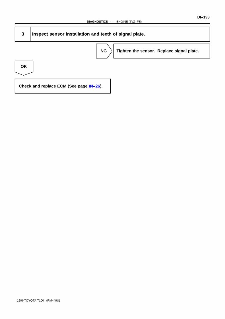
−DIAGNOSTICS ENGINE (5VZ−FE)DI−193
1996 TOYOTA T100 (RM449U)
3 Inspect sensor installation and teeth of signal plate.
NG Tighten the sensor. Replace signal plate.
OK
Check and replace ECM (See page IN−26).
https://www.truck-manuals.net/

DI−194−DIAGNOSTICS ENGINE (5VZ−FE)
1996 TOYOTA T100 (RM449U)
DTC P0340 Camshaft Position Sensor CircuitMalfunction
CIRCUIT DESCRIPTIONThe camshaft position sensor which detects the crankshaft angle signal (G signal), has been installed onthe front of right bank cylinder head. The timing rotor has been integrated with the right bank camshaft timingpulley. When the camshafts rotate, the protrusion on the timing rotor and the air gap on the pickup coilchange, causing fluctuations, in the magnetic field and generating an electromotive force in the pickup coil.The NE signal plate has 34 teeth and is mounted on the crankshaft. The NE signal sensor generates 34signals for every engine revolution. The ECM detects the standard crankshaft angle based on the G signalsand the actual crankshaft angle and the engine speed by the NE signals.
DTC No. DTC Detecting Condition Trouble Area
P0340
No camshaft position sensor signal to ECM during cranking
(2 trip detection logic)�Open or short in camshaft position sensor circuit
�Camshaft position sensor
�Starter
�ECMNo camshaft position sensor signal to ECM with engine
speed 600 rpm or more
WIRING DIAGRAMRefer to DTC P0335 on page DI−191.
INSPECTION PROCEDURE
1 Check resistance of camshaft position sensor (See page IG−1).
Reference INSPECTION USING OSCILLOSCOPERefer to DTC P0335 on page DI−191.
NG Replace camshaft position sensor.
OK
2 Check for open and short in harness and connector between ECM and camshaftposition sensor (See page IN−26).
NG Repair or replace harness or connector.
OK
DI0UW−02
https://www.truck-manuals.net/

−DIAGNOSTICS ENGINE (5VZ−FE)DI−195
1996 TOYOTA T100 (RM449U)
3 Inspect sensor installation.
NG Tighten the sensor.
OK
Check and replace ECM (See page IN−26).
https://www.truck-manuals.net/

FI4825
EGRVacuumModulator
ECM
VSV
EGR Valve
Throttle Body
ThrottleValve
Intake AirChamber
Exhaust Gas
P19921
R/B No.2
IG Switch
E4 E5
(M/T)(A/T)
E01
E1
ECM
E2
EGR
THGE6 E6
E6 E6
18 8
2114
9 22
1
BR−B
P
2
2
1
99
EA
W−RW−RIE1
W−REA1
W−
B
23
22
2 22
2
21
1 5
B−W
EFI
EFI Relay VSV for EGR
EGR GasTemp. Sensor
B−YEA14B
−Y
1C17
1A3
W−
R
IGNJ/B
No.1
FromFrom Battery
R−W
5 V
DI−196−DIAGNOSTICS ENGINE (5VZ−FE)
1996 TOYOTA T100 (RM449U)
DTC P0401 Exhaust Gas Recirculation Flow InsufficientDetected*
*: Only for 2WD models with a load capacity of 0.5 ton and regular cab.
CIRCUIT DESCRIPTIONThe EGR system recirculates exhaust gas which is controlled to the proper quantity to suit the driving condi-tions, into the intake air mixture to slow down combustion, reduce the combustion temp. and reduce NOxemissions. The amount of EGR is regulated by the EGR vacuum modulator according to the engine load.
If even one of the following conditions is fulfilled, the VSV isturned ON by a signal from the ECM.This results in atmospheric air acting on the EGR valve, closingthe EGR valve and shutting off the exhaust gas (EGR cut−off).Under the following conditions, EGR is cut to maintain driveability:
� Before the engine is warmed up� During deceleration (throttle valve closed)� Light engine load (amount of intake air very small)� Engine racing
DTC No. DTC Detecting Condition Trouble Area
P0401
After engine is warmed up and run at 80 km/h (50 mph)
for 3 to 5 min., EGR gas temp. sensor valve does not
exceed 60°C (140°F) above ambient air temp.
(2 trip detection logic)
�EGR valve stuck closed
�Short in VSV circuit for EGR
�Open in EGR gas temp. sensor circuit
�EGR hose disconnected
�ECM
WIRING DIAGRAM
DI0UX−01
https://www.truck-manuals.net/

S06906
Vehicle Speed
70 ∼ 90 km/h(43 ∼ 56 km/h)
IdlingIG SW OFF
(2)
(1)
(3)
(4)
(5)
(6)
Warm up 3 ∼ 5 min. 3 ∼ 5 min.2 min. 2 min. Time
−DIAGNOSTICS ENGINE (5VZ−FE)DI−197
1996 TOYOTA T100 (RM449U)
SYSTEM CHECK DRIVING PATTERN
(1) Connect the OBD II scan tool or TOYOTA hand−held tester to the DLC3.(2) Start and warm up the engine with all the accessories switched OFF.(3) Run the vehicle at 70 − 90 km/h (43 − 56 mph) for 3 min. or more.(4) Idle the engine for about 2 min.(5) Do steps (3) and (4) again.(6) Check the ”READINESS TESTS” mode on the OBD II scan tool or TOYOTA hand−held tester.If ”COMPL” is displayed and the MIL does not light up, the system is normal.If ”INCMPL” is displayed and the MIL does not light up, run the vehicle step (5) from some time and checkit.HINT:”INCMPL” is displayed when either condition (a) or (b) exists:(a) The system check is incomplete.(b) There is a malfunction in the system.If there is a malfunction in the system, the MIL will light up after steps (2) to (5) above are done.
https://www.truck-manuals.net/

BE6653
P19555 A00046
ECM
ON
2
1922
(M/T)(A/T)
THG
E2
5 V
E1
E6 E6
E6 E6
EGR Gas Temp.Sensor
1421
DI−198−DIAGNOSTICS ENGINE (5VZ−FE)
1996 TOYOTA T100 (RM449U)
INSPECTION PROCEDURETOYOTA hand−held tester:
1 Connect TOYOTA hand−held tester and read value of EGR gas temp. value.
PREPARATION:(a) Connect the TOYOTA hand−held tester to the DLC3.(b) Turn the ignition switch ON and push the TOYOTA hand−held tester main switch ON.CHECK:Read EGR gas temp. on the TOYOTA hand−held tester.OK:
EGR gas temp.: 10°C (50°F) or moreHINT:If there is an open circuit, the TOYOTA hand−held tester indicates 3.1°C (37.6°F).
OK Go to step 4.
NG
2 Check for open in harness or ECM.
PREPARATION:(a) Disconnect the EGR gas temp. sensor connector.(b) Connect the sensor wire harness terminals together.(c) Turn the ignition switch ON.CHECK:Read EGR gas temp. on the TOYOTA hand−held tester.OK:
EGR gas temp.: 159°C (318.2°F)
OK Confirm good connection at sensor.If OK, replace EGR gas temp. sensor.
NG
https://www.truck-manuals.net/

BE6653
P19553
P19681
P20205 A00780
EGR Gas Temp.Sensor
2
1
14 3
9 22E6 E6
E6 E6(M/T)(A/T)
THG
5 V
E2
E1
For M/T
For A/T
THG E2
E2 THG
ON
−DIAGNOSTICS ENGINE (5VZ−FE)DI−199
1996 TOYOTA T100 (RM449U)
3 Check for open in harness or ECM.
PREPARATION:(a) Remove the right cowl side trim (See page SF−61).(b) Connect between terminals THG and E2 of the ECM con-
nector.HINT:The EGR gas temp. sensor connector is disconnected.Before checking, do a visual check and contact pressure checkfor the ECM connector (See page IN−26).CHECK:Read EGR gas temp. on the TOYOTA hand−held tester.OK:
EGR gas temp.: 159°C (318.2°F)
OK Open in harness between terminals E2 or THG.Repair or replace harness.
NG
Confirm connection at ECM.If OK, replace ECM.
https://www.truck-manuals.net/

BE6653
A00774
A00775
A00781
ON
System is OFF System is ON
AirFilter Air
E
G
EAir
DI−200−DIAGNOSTICS ENGINE (5VZ−FE)
1996 TOYOTA T100 (RM449U)
4 Check connection of vacuum hose and EGR hose (See page EC−9).
NG Repair or replace.
OK
5 Check VSV for EGR.
PREPARATION:Select the ”ACTIVE TEST” mode on the TOYOTA hand−heldtester.CHECK:Check operation of VSV when it is operated by the TOYOTAhand−held tester.OK:
EGR system is OFF:Air flows from port E to the air filter.EGR system is ON:Air flows from port E to port G.
OK Go to step 7.
NG
6 Check operation of VSV for EGR (See page EC−9).
NG Replace VSV for EGR.
OK
Check for open in harness and connector be-tween VSV and ECM (See page IN−26).
https://www.truck-manuals.net/

−DIAGNOSTICS ENGINE (5VZ−FE)DI−201
1996 TOYOTA T100 (RM449U)
7 Check EGR vacuum modulator (See page EC−9).
NG Repair or replace.
OK
8 Check EGR valve (See page EC−9).
NG Repair or replace.
OK
9 Check value of EGR gas temp. sensor.
PREPARATION:(a) Connect the TOYOTA hand−held tester to the DLC3.(b) Turn the ignition switch ON and push the TOYOTA hand−held tester main switch ON.(c) Select the ”ACTIVE TEST” mode on the TOYOTA hand−held tester (EGR system ON).(d) Race the engine at 4,000 rpm for 3 min.CHECK:Measure EGR gas temp. while racing engine at 4,000 rpm.OK:
EGR gas temp. after 3 min.: 140°C (284°F) or more
NG Replace EGR gas temp. sensor.
OK
Check and replace ECM (See page IN−26 ).
https://www.truck-manuals.net/

P24322
EGR Gas Temp. SensorConnector
BE6653P24204 A00072
ON
Wire Harness Side
1 (−) 2 (+)
DI−202−DIAGNOSTICS ENGINE (5VZ−FE)
1996 TOYOTA T100 (RM449U)
OBD II scan tool (excluding TOYOTA hand−held tester):
1 Check resistance of EGR gas temp. sensor.
PREPARATION:Disconnect the EGR gas temp. sensor connector.CHECK:Measure resistance between terminals of EGR gas temp. sen-sor connector.OK:
Resistance: 600 kΩ or lessHINT:If there is open circuit, ohmmeter indicates 720 kΩ or more.
NG Check and replace EGR gas temp. sensor (Seepage SF−59).
OK
2 Check for open in harness or ECM.
PREPARATION:(a) Disconnect the EGR gas temp. sensor connector.(b) Turn the ignition switch ON.CHECK:Measure voltage between terminals of EGR gas temp. sensorwire harness side connector.OK:
4.5 − 5.5 V
OK Go to step 4.
NG
https://www.truck-manuals.net/

BE6653
P24203
P24323A00804
ON
For M/T
For A/T
THG (+)
THG (+)
E2 (−)
E2 (−)
−DIAGNOSTICS ENGINE (5VZ−FE)DI−203
1996 TOYOTA T100 (RM449U)
3 Check for open in harness or ECM.
PREPARATION:(a) Remove the right cowl side trim (See page SF−61).(b) Turn the ignition switch ON.CHECK:Measure voltage between terminals of THG and E2 of ECMconnector.HINT:The EGR gas temp. sensor connector is disconnected.OK:
4.5 − 5.5 V
OK Open in harness between terminals E2 or THG.Repair or replace harness.
NG
Confirm connection at ECM.If OK, replace ECM.
4 Check connection of vacuum hose and EGR hose (See page EC−2).
NG Repair or replace.
OK
https://www.truck-manuals.net/

P21116
BE6653
P21117
A00774
A00775
A00782
ON
For M/T
For A/T
OFFON
EGR
OFFON
EGR
E7 Connector
E5 Connector
VSV is ON VSV is OFF
AirFilter Air
E
G
EAir
DI−204−DIAGNOSTICS ENGINE (5VZ−FE)
1996 TOYOTA T100 (RM449U)
5 Check VSV for EGR.
PREPARATION:(a) Remove the right cowl side trim (See page SF−61).(b) Disconnect the E7 or E5 connector of the ECM.(c) Turn the ignition switch ON.CHECK:Check VSV function:
(1) Connect between terminal EGR of ECM connectorand body ground (ON).
(2) Disconnect between terminal EGR of ECM connec-tor and body ground (OFF).
OK:(1) VSV is ON:Air flows from port E to the air filter.(2) VSV is OFF:Air flows from port E to port G.
OK Go to step 7.
NG
6 Check operation for VSV for EGR (See page SF−49).
NG Replace VSV for EGR.
OK
Check for open in harness and connector be-tween R/B No.2 and ECM (See page EC−1).
https://www.truck-manuals.net/

P24227
EGR GasTemp.SensorConnector
−DIAGNOSTICS ENGINE (5VZ−FE)DI−205
1996 TOYOTA T100 (RM449U)
7 Check EGR vacuum modulator (See page EC−9).
NG Repair or replace.
OK
8 Check EGR valve (See page EC−9).
NG Repair or replace.
OK
9 Check resistance of EGR gas temp. sensor.
PREPARATION:(a) Disconnect the EGR gas temp. sensor connector.(b) Start the engine and warm it up.(c) Disconnect the VSV connector for EGR.(d) Race the engine at 4,000 rpm or 3 min.CHECK:Measure resistance of the EGR gas temp. sensor while racingthe engine at 4,000 rpm.OK:
Resistance of EGR gas temp. sensor after 3 min.:4.3 kΩ or less
HINT:Resistance: 188.6 ∼ 439.0 kΩ at 20°C (68°F)
NG Replace EGR gas temp. sensor.
OK
Check and replace ECM (See page IN−26).
https://www.truck-manuals.net/

DI−206−DIAGNOSTICS ENGINE (5VZ−FE)
1996 TOYOTA T100 (RM449U)
DTC P0402 Exhaust Gas Recirculation Flow ExcessiveDetected*
*: Only for 2WD models with a load capacity of 0.5 ton and regular cab.
CIRCUIT DESCRIPTIONRefer to DTC P0401 on page DI−196.
DTC No. Detection ItemDTC Detecting Condition Trouble AreaTrouble Area
P0402
EGR gas temp. sensor value is high during EGR cut−off
when engine is cold (Race engine at about 4,000 rpm
without load so that vacuum is applied to port E)
(2 trip detection logic)
�EGR valve stuck open
�VSV for EGR open malfunction
�Open in VSV circuit for EGR
�Short in EGR gas temp. sensor circuit
�ECMP0402 EGR valve is always open (2 trip detection logic)
WIRING DIAGRAMRefer to DTC P0401 on page DI−196.
SYSTEM CHECK DRIVING PATTERNRefer to DTC P0401 on page DI−196.
INSPECTION PROCEDURETOYOTA hand−held tester:
1 Connect TOYOTA hand−held tester and read EGR gas temp. value.
PREPARATION:(a) Connect the TOYOTA hand−held tester to the DLC3.(b) Turn the ignition switch ON and push the TOYOTA hand−held tester main switch ON.CHECK:Read EGR gas temp. on the TOYOTA hand−held tester.OK:
EGR gas temp.: 159°C (318.2°F) or less (Not immediately after driving)HINT:If there is a short circuit, the TOYOTA hand−held tester indicates 159.3°C (318.7°F).
OK Go to step 4.
NG
DI0UY−01
https://www.truck-manuals.net/

BE6653
P19554 A00048
ON
EGR Gas Temp.Sensor
2
1
ECM
E6 E6
E6 E6(M/T)(A/T)
THG
E2
5 V
E1
14 21
9 22
BE6653FI7056P19798FI7034 A00103
EGR Gas Temp.Sensor
ECM
THG
E2
5 V
E1
ON
For M/T
For A/T E6 Connector
E6 Connector
−DIAGNOSTICS ENGINE (5VZ−FE)DI−207
1996 TOYOTA T100 (RM449U)
2 Check for short in harness and ECM.
PREPARATION:Disconnect the EGR gas temp. sensor connector.CHECK:Read EGR gas temp. on the TOYOTA hand−held tester.OK:
EGR gas temp.: 3.1°C (37.6°F)
OK Replace EGR gas temp. sensor.
NG
3 Check for short in harness or ECM.
PREPARATION:(a) Remove the right cowl side trim (See page SF−61).(b) Disconnect the E6 connector of ECM.HINT:The EGR gas temp. sensor is disconnected.CHECK:Read EGR gas temp. on the TOYOTA hand−held tester.OK:
EGR gas temp.: 3.1°C (37.6°F)
OK Repair or replace harness or connector.
NG
Check and replace ECM (See pageIN−26).
https://www.truck-manuals.net/

P24227
EGR GasTempSensorConnector
DI−208−DIAGNOSTICS ENGINE (5VZ−FE)
1996 TOYOTA T100 (RM449U)
4 Check VSV for EGR (See page DI−196, step 5).
OK Check EGR valve (See page EC−9).
NG
5 Check operation of VSV for EGR (See page SF−49).
NG Replace VSV for EGR.
OK
Check for short in harness and connector be-tween VSV and ECM (See page IN−26).
OBD II scan tool (excluding TOYOTA hand−held tester):
1 Check resistance of EGR gas temp. sensor.
PREPARATION:Disconnect the EGR gas temp. sensor connector.CHECK:Measure resistance between terminals of EGR gas temp. sen-sor connector.OK:
Resistance: 2.5 kΩ or more (Not immediately after driving)
HINT:If there is short circuit, ohmmeter indicates 200 Ω or less.
NG Replace EGR gas temp. sensor.
OK
https://www.truck-manuals.net/

−DIAGNOSTICS ENGINE (5VZ−FE)DI−209
1996 TOYOTA T100 (RM449U)
2 Check for short in harness and connector between EGR gas temp. sensor andECM (See page IN−26).
NG Repair or replace harness or connector.
OK
3 Check VSV for EGR (See page DI−196, step 5).
OK Check EGR valve (See page EC−9).
NG
4 Check operation of VSV for EGR (See page SF−49).
NG Replace VSV for EGR.
OK
5 Check for short in harness and connector between VSV and ECM(See page IN−26).
NG Repair or replace harness or connector.
OK
Check and replace ECM (See page IN−26).
https://www.truck-manuals.net/

FI7081
Waveform of Oxygen Sensorbefore Catalyst
Normal Catalyst Waveform of Oxygen Sensorafter Catalyst
P25762
Engine Speed
2500 − 3000 rpm
Idling
IG SW OFF
Warmed up 3 minutes Check
Time(1)
(3) (4)
(2)
DI−210−DIAGNOSTICS ENGINE (5VZ−FE)
1996 TOYOTA T100 (RM449U)
DTC P0420 Catalyst System Efficiency Below Threshold
CIRCUIT DESCRIPTIONThe ECM compares the waveform of the oxygen sensor located before the catalyst with the waveform ofthe oxygen sensor located after the catalyst to determine whether or not catalyst performance has deterio-rated.Air−fuel ratio feedback compensation keeps the waveform of the oxygen sensor before the catalyst repeat-edly changing back and forth from rich to lean.If the catalyst is functioning normally, the waveform of the oxygen sensor after the catalyst switches backand forth between rich and lean much more slowly than the waveform of the oxygen sensor before the cata-lyst.But when both waveforms change at a similar rate, it indicates that catalyst performance has deteriorated.
DTC No. DTC Detecting Condition Trouble Area
P0420
After engine and catalyst are warmed up, and while
vehicle is driven within set vehicle and engine speed range,
waveforms of heated oxygen sensors (bank 1 sensor 1, 2)
have same amplitude
(2 trip detection logic)
�Three−way catalytic converter
�Open or short in heated oxygen sensor (bank 1 sensor 1, 2)
circuit
�Heated oxygen sensor (bank 1 sensor 1, 2)
CONFIRMATION ENGINE RACING PATTERN
DI0UZ−01
https://www.truck-manuals.net/

FI6514
OX Signal Waveform (Oscilloscope)
1.0 V
0 V
200 msec./Division
−DIAGNOSTICS ENGINE (5VZ−FE)DI−211
1996 TOYOTA T100 (RM449U)
(1) Connect the TOYOTA hand−held tester to the DLC3, or connect the probe of the oscilloscope betweenterminals OX1, OX2 and E1 of ECM.(2) Start engine and warm it up with all accessories switched OFF until water temp. is stable.(3) Race the engine at 2500 − 3000 rpm for about 3 min.(4) After confirming that the waveform of the heated oxygen sensor, bank 1 sensor 1 (OX1), oscillate around0.5 V during feedback to the ECM, check the waveform of the heated oxygen sensor bank 1 sensor 2 (OX2).
HINT:If there is a malfunction in the system, the waveform of theheated oxygen sensor bank 1 sensor 2 (OX2) is almost thesame as that of the heated oxygen sensor bank 1 sensor 1(OX1) on the left.There are some cases where, even though a malfunctionexists, the MIL may either light up or not light up.
INSPECTION PROCEDURE
1 Are there any other codes (besides DTC P0420) being output?
YES Go to relevant DTC chart.
NO
2 Check heated oxygen sensor (bank 1 sensor 1) (See page DI−172).
NG Repair or replace.
OK
3 Check heated oxygen sensor (bank 1 sensor 2) (See page DI−178).
NG Repair or replace.
OK
Replace center exhaust pipe (TWC: catalyst)(See page EM−108).
https://www.truck-manuals.net/
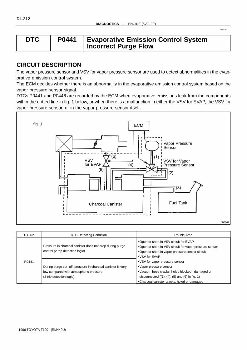
S00044
ECM
Vapor PressureSensor
VSV for VaporPressure Sensor
Fuel TankCharcoal Canister
VSVfor EVAP
(1)
(2)
(3)
(4)(5)
fig. 1
(6)
DI−212−DIAGNOSTICS ENGINE (5VZ−FE)
1996 TOYOTA T100 (RM449U)
DTC P0441 Evaporative Emission Control System Incorrect Purge Flow
CIRCUIT DESCRIPTIONThe vapor pressure sensor and VSV for vapor pressure sensor are used to detect abnormalities in the evap-orative emission control system.The ECM decides whether there is an abnormality in the evaporative emission control system based on thevapor pressure sensor signal.DTCs P0441 and P0446 are recorded by the ECM when evaporative emissions leak from the componentswithin the dotted line in fig. 1 below, or when there is a malfunction in either the VSV for EVAP, the VSV forvapor pressure sensor, or in the vapor pressure sensor itself.
DTC No. DTC Detecting Condition Trouble Area
P0441
Pressure in charcoal canister does not drop during purge
control (2 trip detection logic)
�Open or short in VSV circuit for EVAP
�Open or short in VSV circuit for vapor pressure sensor
�Open or short in vapor pressure sensor circuit
�VSV for EVAP
�VSV for vapor pressure sensor
�Vapor pressure sensor
�Vacuum hose cracks, holed blocked, damaged or
disconnected ((1), (4), (5) and (6) in fig. 1)
�Charcoal canister cracks, holed or damaged
During purge cut−off, pressure in charcoal canister is very
low compared with atmospheric pressure
(2 trip detection logic)
DI9AE−01
https://www.truck-manuals.net/

S00594
Vapor Pressure Sensor
ECM
FromBattery
FromIG Switch II ID IM1
2H
2D
2C
2B
E7
E6
E7
E6
E6
3 9
2
2
5
1 2
3
A A
2
1
8
21
VSV (for EVAP)
VSV(for VaporPressure Sensor)
LG
W−BB−O
B
P
L−R
BR
13
22
3
2
1
10
IGN
InstrumentPanel J/B
Driver Side J/B
EFI Relay
EB
J/BNo.3
VC
E2
E1
E01
E01
TPC
EVP 1
PTNK
BREFI
A
1 2LG W−L
3
B−O
5 V
−DIAGNOSTICS ENGINE (5VZ−FE)DI−213
1996 TOYOTA T100 (RM449U)
WIRING DIAGRAM
INSPECTION PROCEDURETOYOTA hand−held tester:
1 Check VSV connector for EVAP, VSV connector for vapor pressure sensor andvapor pressure sensor connector for looseness and disconnection.
NG Repair or connect VSV or sensor connector.
OK
https://www.truck-manuals.net/

BE6653
S00564
A06382
ON
E2(−) VC(+)
DI−214−DIAGNOSTICS ENGINE (5VZ−FE)
1996 TOYOTA T100 (RM449U)
2 Check vacuum hose between throttle body and VSV for EVAP, VSV for EVAP andcharcoal canister, charcoal canister and VSV for vapor pressure sensor, VSV forvapor pressure sensor and vapor pressure sensor.
CHECK:(a) Check that the vacuum hose is connected correctly.(b) Check the vacuum hose for looseness and disconnection.(c) Check the vacuum hose for cracks, hole, damage and blockage.
NG Repair or replace.
OK
3 Check voltage between terminals VCC and E2 of ECM connector.
PREPARATION:(a) Remove the glove compartment (See page SF−61).(b) Turn ignition switch ON.CHECK:Measure voltage between terminals VC and E2 of ECM con-nector.OK:
Voltage: 4.5 − 5.5 V
NG Check and replace ECM (See page IN−26).
OK
https://www.truck-manuals.net/

BE6653
S00568
P2 49 7
6S0 00 4
7
A06383
E2(−) PTNK(+)
ON
Vacuum
−DIAGNOSTICS ENGINE (5VZ−FE)DI−215
1996 TOYOTA T100 (RM449U)
4 Check voltage between terminals PTNK and E2 of ECM connector.
PREPARATION:(a) Remove the glove compartment (See page SF−61).(b) Turn ignition switch ON.CHECK:Measure voltage between terminals PTNK and E2 of ECM con-nector.
(1) Disconnect the vacuum hose from the vapor pres-sure sensor.
(2) Using the MITYVAC (Hand−Held Vacuum Pump),apply a vacuum to the vapor pressure sensor.
NOTICE:The vacuum applied to the vapor pressure sensor must beless than 66.7 kPa (500 mmHg, 19.7 in. Hg).OK:
(1) Voltage: 2.9 − 3.7 V(2) Voltage: 0.5 V or less
OK Go to step 6.
NG
5 Check for open and short in harness and connector between vapor pressuresensor and ECM (See page IN−26).
NG Repair or replace harness or connector.
OK
Replace vapor pressure sensor.
https://www.truck-manuals.net/

S05710
S05711
A00784
VSV is OFF
VSV is ON
DI−216−DIAGNOSTICS ENGINE (5VZ−FE)
1996 TOYOTA T100 (RM449U)
6 Check the purge flow.
PREPARATION:(a) Connect the TOYOTA hand−held tester to the DLC3.(b) Select the ”ACTIVE TEST” mode on the TOYOTA hand−
held tester.(c) Disconnect the VSV vacuum hose for EVAP from the
charcoal canister.(d) Start the engine.CHECK:When the VSV for the EVAP is operated by the TOYOTA hand−held tester, check whether the disconnected hose ap-plies suction to your finger.OK:
VSV is ON: Disconnected hose applies suction to your finger.VSV is OFF: Disconnected hose applies no suction to your finger.
OK Go to step 10.
NG
7 Check vacuum hose between throttle body and VSV for EVAP, VSV for EVAP andcharcoal canister.
CHECK:(a) Check that the vacuum hose is connected correctly.(b) Check the vacuum hose for looseness and disconnection.(c) Check the vacuum hose for cracks, hole, damage and blockage.
NG Repair or replace.
OK
https://www.truck-manuals.net/

−DIAGNOSTICS ENGINE (5VZ−FE)DI−217
1996 TOYOTA T100 (RM449U)
8 Check operation of VSV for EVAP (See page SF−50).
NG Replace VSV.
OK
9 Check for open and short in harness and connector between EFI main relay(Marking: EFI), VSV for EVAP and ECM (See page IN−26).
NG Repair or replace harness or connector.
OK
Check and replace ECM (See page IN−26).
https://www.truck-manuals.net/

S05709
BE6653
P24347
P24346 A00785
VSV ConnectorSTART
For M/T
For A/T
E2 (−) PTNK (+)
E2 (−) PTNK (+)
DI−218−DIAGNOSTICS ENGINE (5VZ−FE)
1996 TOYOTA T100 (RM449U)
10 Connect TOYOTA hand−held tester, when VSV connector for vapor pressure sen-sor is disconnected and VSV for EVAP is ON, measure voltage between terminalsPTNK and E2 of ECM connector.
PREPARATION:(a) Connect the TOYOTA hand−held tester to the DLC3.(b) Disconnect the VSV connector for the vapor pressure
sensor.(c) Select the ”ACTIVE TEST” mode on the TOYOTA hand−
held tester.(d) Start the engine.CHECK:Measure voltage between terminals PTNK and E2 of ECM con-nector, when VSV for EVAP is ON, using the TOYOTA hand−held tester.OK:
Voltage: 2.0 V or less
OK Go to step 13.
NG
11 Check vacuum hose between charcoal canister and VSV for vapor pressure sen-sor, vapor pressure sensor and VSV for vapor pressure sensor.
CHECK:(a) Check that the vacuum hose is connected correctly.(b) Check the vacuum hose for looseness and disconnection.(c) Check the vacuum hose for cracks, hole, damage and blockage.
NG Repair or replace.
OK
https://www.truck-manuals.net/

−DIAGNOSTICS ENGINE (5VZ−FE)DI−219
1996 TOYOTA T100 (RM449U)
12 Check operation of VSV for vapor pressure sensor (See page SF−50).
NG Replace VSV.
OK
13 Check for open and short in harness and connector between EFI main relay(Marking: EFI), VSV for vapor pressure sensor and ECM (See page IN−26).
NG Repair or replace harness or connector.
OK
https://www.truck-manuals.net/

S00049
P24346
P24347
A00117
Start
Stop
Engine
OFF
ON
OFF
ONVSV forVaporPressureSensor
VSV forEVAP
5 sec. 5 sec.
Measure Voltage
E2 (−) PTNK (+)
E2 (−) PTNK (+)
For M/T
For A/T
DI−220−DIAGNOSTICS ENGINE (5VZ−FE)
1996 TOYOTA T100 (RM449U)
14 Check charcoal canister.
PREPARATION:(a) Connect the TOYOTA hand−held tester to the DLC3.(b) Remove the fuel tank cap.(c) Disconnect the VSV connector for the vapor pressure
sensor.(d) Select the ”ACTIVE TEST” mode on the TOYOTA hand−
held tester.(e) Start the engine.(f) The VSV for the EVAP is ON by the TOYOTA hand−held
tester and remains on for 5 sec.CHECK:Measure voltage between terminals PTNK and E2 of ECM con-nector 5 sec. after switching VSV for EVAP from ON to OFF.OK:
Voltage: 2.5 V or less
NG Replace charcoal canister.
OK
Check and replace ECM (See page IN−26).
https://www.truck-manuals.net/

BE6653
S00564
A06382
ON
E2(−) VC(+)
−DIAGNOSTICS ENGINE (5VZ−FE)DI−221
1996 TOYOTA T100 (RM449U)
OBD II scan tool (excluding TOYOTA hand−held tester):
1 Check VSV connector for EVAP, VSV connector for vapor pressure sensor andvapor pressure sensor connector for looseness and disconnection.
NG Repair or connect VSV or sensor connectors.
OK
2 Check vacuum hoses between throttle body and VSV for EVAP, VSV for EVAPand charcoal canister, charcoal canister and VSV for vapor pressure sensor, VSVfor vapor pressure sensor and vapor pressure sensor.
CHECK:(a) Check that the vacuum hose is connected correctly.(b) Check the vacuum hose for looseness and disconnection.(c) Check the vacuum hose for cracks, hole, damage and blockage.
NG Repair or replace.
OK
3 Check voltage between terminals VCC and E2 of ECM connector.
PREPARATION:(a) Remove the glove compartment (See page SF−61).(b) Turn ignition switch ON.CHECK:Measure voltage between terminals VC and E2 of ECM con-nector.OK:
Voltage: 4.5 − 5.5 V
NG Check and replace ECM (See page IN−26).
OK
https://www.truck-manuals.net/

BE6653
S00568
P2 49 7
6S0 00 4
7
A06383
E2(−) PTNK(+)
ON
Vacuum
DI−222−DIAGNOSTICS ENGINE (5VZ−FE)
1996 TOYOTA T100 (RM449U)
4 Check voltage between terminals PTNK and E2 of ECM connector.
PREPARATION:(a) Remove the glove compartment (See page SF−61).(b) Turn ignition switch ON.CHECK:Measure voltage between terminals PTNK and E2 of ECM con-nector.
(1) Disconnect the vacuum hose from the vapor pres-sure sensor.
(2) Using the MITYVAC (Hand−Held Vacuum Pump),apply a vacuum to the vapor pressure sensor.
NOTICE:The vacuum applied to the vapor pressure sensor must beless than 66.7 kPa (500 mmHg, 19.7 in. Hg).OK:
(1) Voltage: 2.9 − 3.7 V(2) Voltage: 0.5 V or less
OK Go to step 6.
NG
5 Check for open and short in harness and connector between vapor pressuresensor and ECM (See page IN−26).
NG Repair or replace harness or connector.
OK
Replace vapor pressure sensor.
https://www.truck-manuals.net/

BE6653P24245P24350FI7205FI7206 A00118
ON
EVP
EVP
Air Air
VSV is ON VSV is OFF
ON
ONOFF
OFF
For M/T
For A/T
E F E F
−DIAGNOSTICS ENGINE (5VZ−FE)DI−223
1996 TOYOTA T100 (RM449U)
6 Check VSV for EVAP.
PREPARATION:(a) Remove the right cowl side trim (See page SF−61).(b) Turn the ignition switch ON.CHECK:Check VSV function.
(1) Connect between terminal EVP of ECM and bodyground.
(2) Disconnect between terminal EVP of ECM andbody ground.
OK:(1) VSV is ON: Air flows from port E to port F.(2) VSV is OFF: Air does not flow from port E to port F.
OK Go to step 9.
NG
7 Check operation of VSV for EVAP (See page SF−50).
NG Replace VSV.
OK
https://www.truck-manuals.net/

BE6653
P24353
P24352
S05700
S05703 A00786VSV is ON VSV is OFF
ON
For M/T
For A/T
TPC
OFF ON
OFF ON
TPC
DI−224−DIAGNOSTICS ENGINE (5VZ−FE)
1996 TOYOTA T100 (RM449U)
8 Check for open and short in harness and connector between EFI main relay(Marking: EFI), VSV for EVAP and ECM (See page IN−26).
NG Repair or replace harness or connector.
OK
Check and replace ECM (See page IN−26).
9 Check VSV for vapor pressure sensor.
PREPARATION:(a) Remove the right cowl side trim (See page SF−61).(b) Turn the ignition switch ON.CHECK:Check VSV function.
(1) Connect between terminal TPC of ECM and bodyground (ON).
(2) Disconnect between terminal TPC of ECM andbody ground (OFF).
OK:(1) VSV is ON:Air flows from port E to port F.(2) VSV is OFF:Air flows from port E to port G.
OK Check and replace charcoal canister (See pageEC−1).
NG
https://www.truck-manuals.net/

−DIAGNOSTICS ENGINE (5VZ−FE)DI−225
1996 TOYOTA T100 (RM449U)
10 Check operation of VSV for vapor pressure sensor.
NG Replace VSV.
OK
11 Check for open and short in harness and connector between EFI main relay(Marking: EFI), VSV for vapor pressure sensor and ECM (See page IN−26).
NG Repair or replace harness or connector.
OK
Check and replace ECM (See page IN−26).
https://www.truck-manuals.net/

FI7112 FI7166A00081
T/M
Cable CombinationMeter
ECM
4−pulse
To Speedometer Cable
No.1 Vehicle Speed Sensor
Magnet Reed Switch
S05704
Combination Meter
SpeedSensor
From CruiseControl ECU
ECM
E4 E4
(M/T)(A/T)
8 126
C11G G
G
5 V
SP1
E1
DI−226−DIAGNOSTICS ENGINE (5VZ−FE)
1996 TOYOTA T100 (RM449U)
DTC P0500 Vehicle Speed Sensor Malfunction
CIRCUIT DESCRIPTIONThis sensor is mounted in the combination meter. It contains a magnet which is rotated by the speed metercable.Turning the reed switch ON and OFF 4 times for every revolution of the speedmeter.It is then transmitted to the ECM. The ECM determines the vehicle speed based on the frequency of thesepulse signals.
DTC No. DTC Detecting Condition Trouble Area
P0500
No speed sensor signal to ECM under conditions (a)
(2 trip detection logic)
(a) Vehicle is being driven
�Open or short in No.1 vehicle speed sensor circuit
�No.1 vehicle speed sensor
�ECM
�Speedometer cable
WIRING DIAGRAM
DI0V3−01
https://www.truck-manuals.net/

BE6653
P24205
P24324A00120
ON
SP1 (+)
SP1 (+)
For M/T
For A/T
AT7809
4 ∼ 6 V
Turn Wheel
−DIAGNOSTICS ENGINE (5VZ−FE)DI−227
1996 TOYOTA T100 (RM449U)
INSPECTION PROCEDURE
1 Check operation of speedometer.
CHECK:Drive the vehicle and check if the operation of the speedometer in the combination meter is normal.HINT:The vehicle speed is operating normally if the speedometer display is normal.
NG Check speedometer and cable(See page BE−38).
OK
2 Check voltage between terminal SP1 of ECM connector and body ground.
PREPARATION:(a) Remove the right cowl side trim (See page SF−61).(b) Disconnect the cruise control ECU connector.(c) Shift the shift lever to neutral.(d) Jack up the rear wheel on one side.(e) Turn the ignition switch ON.CHECK:Measure voltage between terminal SP1 of ECM connector andbody ground when the wheel is turned slowly.OK:
Voltage is generated intermittently.
NG Check and repair harness and connectorbetween combination meter and ECM.
OK
Check and replace ECM (See page IN−26).
https://www.truck-manuals.net/

P01559
Throttle Valve
FromAirCleaner
SignalECM
ValveIAC Valve
To Cylinders
Intake Air Chamber
P19957
ECM
RSC
RSOE01
E01
B−R
BR−R
6
7
E7 E7
E7 E7(M/T)(A/T)
3
1
IACValve
W−R
IG SwitchFrom
From Battery
R/B No.2
EFI Relay
EFI
2IE1
EA1
W−
R
9
9
EA
W−R
W−B
2
22
3
B−W
2 2251
1
2
2B−Y
EA1
W−
R
B−
Y
4
IGNJ/B
No.1
1A
1C
3
17
22
23
DI−228−DIAGNOSTICS ENGINE (5VZ−FE)
1996 TOYOTA T100 (RM449U)
DTC P0505 Idle Control System Malfunction
CIRCUIT DESCRIPTIONThe rotary solenoid type IAC valve is located in front of the in-take air chamber and intake air bypassing the throttle valve isdirected to the IAC valve through a passage.In this way the intake air volume bypassing the throttle valve isregulated, controlling the engine speed.The ECM operates only the IAC valve to perform idle−up andprovide feedback for the target idling speed and a VSV for idle−up control is also added (for air conditioning).
DTC No. DTC Detecting Condition Trouble Area
P0505Idle speed continues to vary greatly from target speed
(2 trip detection logic)
� IAC valve is stuck or closed
�Open or short in IAC valve circuit
�Open or short in A/C signal circuit
�Air intake (hose loose)
WIRING DIAGRAM
DI0V4−01
https://www.truck-manuals.net/

BE6653
P24208
P24325A00121
ON
RSO (+) RSC (+)
RSO (+) RSC (+)
E7 Connector
E7 Connector
For M/T
For A/T
−DIAGNOSTICS ENGINE (5VZ−FE)DI−229
1996 TOYOTA T100 (RM449U)
INSPECTION PROCEDURE
1 Check air induction system (See page SF−1).
NG Repair or replace.
OK
2 Check A/C signal circuit (See page AC−79).
NG Repair or replace.
OK
3 Check voltage terminals RSO and RSC of ECM connector and body ground.
PREPARATION:(a) Remove the right cowl side trim (See page SF−61).(b) Disconnect the E7 connector of ECM.(c) Turn the ignition switch ON.CHECK:Measure voltage between terminals RSO and RSC of the ECMconnector and body ground.OK:
Voltage: 9 − 14 V
OK Go to step 5.
NG
https://www.truck-manuals.net/

DI−230−DIAGNOSTICS ENGINE (5VZ−FE)
1996 TOYOTA T100 (RM449U)
4 Check IAC valve (See page SF−39).
NG Replace IAC valve.
OK
Check for open and short in harness andconnector between R/B No.2 and IAC valve,IAC valve and ECM (See page IN−26).
5 Check operation of the IAC valve (See page SF−43).
NG Repair or replace IAC valve.
OK
Check and replace ECM (See page IN−26).
https://www.truck-manuals.net/

P19954
−DIAGNOSTICS ENGINE (5VZ−FE)DI−231
1996 TOYOTA T100 (RM449U)
DTC P0510 Closed Throttle Position Switch Malfunction
CIRCUIT DESCRIPTIONRefer to Throttle/ Pedal Position Sensor/ Switch ”A” Circuit Malfunction on page DI−163.
DTC No. DTC Detecting Condition Trouble Area
P0510The closed throttle position switch does not turn ON even once
when the vehicle is driven (2 trip detection logic)
�Open in closed throttle position switch circuit
�Closed throttle position switch
�ECM
HINT:After confirming DTC P0510 use the TOYOTA hand−held tester to confirm the closed throttle position switchsignal from ”CURRENT DATA”.
Throttle Valve Closed throttle position Switch Signal Malfunction
Fully Closed OFF Open Circuit
Fully Open ON Short Circuit
WIRING DIAGRAM
DI9AF−01
https://www.truck-manuals.net/

A16045
DI−232−DIAGNOSTICS ENGINE (5VZ−FE)
1996 TOYOTA T100 (RM449U)
INSPECTION PROCEDUREHINT:If DTC ”P0110” (intake air temp. circuit malfunction), ”P0115” (engine coolant temp. circuit malfunction) and”P0120” (throttle/pedal position sensor/ switch ”A” circuit malfunction) are output simultaneously, E2 (sensorground) may be open.
TOYOTA hand−held tester:
1 Check for open in harness or ECM.
PREPARATION:(a) Connect the TOYOTA hand−held tester to the DLC3.(b) Disconnect the throttle position sensor connector.(c) Connect sensor wire harness terminals between termi-
nals 3 and 4.(d) Turn ignition switch ON.CHECK:Read CTP switch signal on the TOYOTA hand−held tester.OK:
CTP switch signal: ON
OK Confirm good connection at sensor. If OK, re-place throttle position sensor.
NG
https://www.truck-manuals.net/

A16046
−DIAGNOSTICS ENGINE (5VZ−FE)DI−233
1996 TOYOTA T100 (RM449U)
2 Check for open in harness or ECM.
PREPARATION:(a) Remove right cowl side trim.(b) Connect between terminals IDL and E2 of ECM connec-
tors.HINT:Throttle position sensor connector is disconnected. Beforechecking, do a visual check and contact pressure check for theconnector.(c) Turn ignition switch ON.CHECK:Read CTP switch signal on the TOYOTA hand−held tester.OK:
CTP switch signal: ON
OK Open in harness between ECM and throttleposition sensor, repair or replace harness.
NG
Confirm connection at ECM. If OK, replaceECM.
https://www.truck-manuals.net/

A16047
DI−234−DIAGNOSTICS ENGINE (5VZ−FE)
1996 TOYOTA T100 (RM449U)
OBDII scan tool (excluding TOYOTA hand−held tester):
1 Check for open in harness or ECM
PREPARATION:(a) Disconnect the throttle position sensor connector.(b) Turn ignition switch ON.CHECK:Measure voltage between terminals 3 and 4 of throttle positionsensor connector.OK:
Voltage: 9 − 14 V
OK Confirm good connection at sensor. If OK, re-place throttle position sensor.
NG
2 Check for open in harness and connector between throttle position sensor andECM (See page IN−26).
NG Open in harness between ECM and throttleposition sensor.
OK
Confirm connection at ECM. If OK, replaceECM.
https://www.truck-manuals.net/

S00251
From Battery Ignition CoilSpark Plug
IGC1
IGC2
IGC3
GNDTAC
IGT1
IGT2
IGT3
IGF
To Tachometer
ECM
G
NE
CamshaftPositionSensor
Crankshaft
PositionSensor
Various
Sensor
No.1 Cylinder
No.4 Cylinder
No.5 Cylinder
No.2 Cylinder
No.3 Cylinder
No.6 Cylinder
−DIAGNOSTICS ENGINE (5VZ−FE)DI−235
1996 TOYOTA T100 (RM449U)
DTC P1300 Igniter Circuit Malfunction
CIRCUIT DESCRIPTIONA DIS (Direct Ignition System) has been adopted. The DIS improves the ignition timing accuracy, reduceshigh−voltage loss, and enhances the overall reliability of the ignition system by eliminating the distributor.The DIS is a 2−cylinder simultaneous ignition system which ignites 2 cylinders simultaneously with one igni-tion coil. In the 2−cylinder simultaneous ignition system, each of the 2 spark plugs is connected to the endof the secondary winding. High voltage generated in the secondary winding is applied directly to the sparkplugs. The sparks of the 2 spark plugs pass simultaneously from the center electrode to the ground elec-trode.The ECM determines ignition timing end outputs the ignition signals (IGT) for each cylinder. Based on IGTsignals, the igniter controls the primary ignition signals (IGC) for all ignition coils. At the same time, the igniteralso sends an ignition confirmation signal (IGF) as a fail−safe measure to the ECM.
DTC No. DTC Detecting Condition Trouble Area
P1300
No IGF signal to ECM for 6 consecutively IGT signals during
engine running
�Open or short in IGF or IGT circuit from igniter to ECM
� Igniter
�ECM
DI0V5−01
https://www.truck-manuals.net/

S00903
Battery
W−R
W−
RR−
LW
AM
2
2
2
4
3
R/B
8IA3
SwitchIG
B−R
IE1
B−L
BR−B
B−W
B−Y
BR
Injector
No.1
No.2
No.3
EB
8B−R7
14
No.2
SparkPlug
B−R B−RECM
IgnitionCoil
B−
RBR−Y
BR−W
B−R
B−R
B−W
2
1
2
1
2
1
10
2
1
3 8
4
5
6
7
9
ToTachometer
(M/T)(A/T)
E7 E7
E7 E7
E7 E7
E7 E7
IGT123 24
22 25
21 26
17 12
IGT2
IGT3
IGF
5 V
DI−236−DIAGNOSTICS ENGINE (5VZ−FE)
1996 TOYOTA T100 (RM449U)
WIRING DIAGRAM
INSPECTION PROCEDURE
1 Check spark plug (See page IG−1).
NG Go to step 4.
OK
https://www.truck-manuals.net/
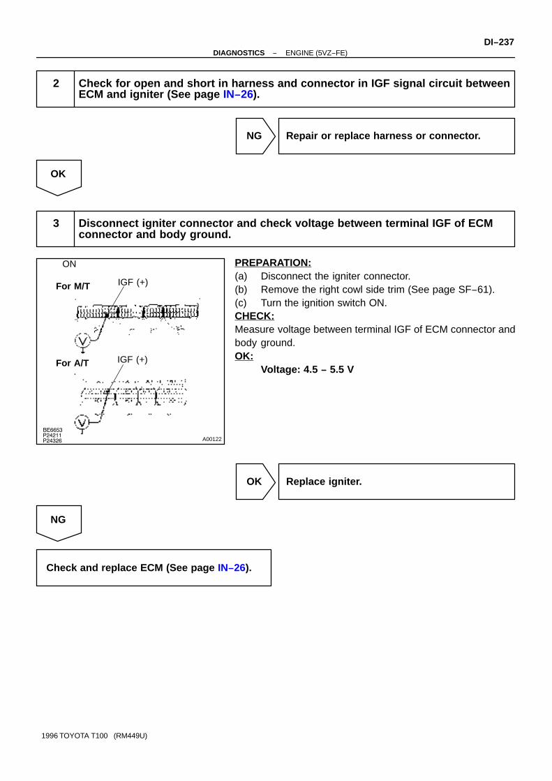
BE6653
P24211
P24326A00122
ON
IGF (+)
IGF (+)
For M/T
For A/T
−DIAGNOSTICS ENGINE (5VZ−FE)DI−237
1996 TOYOTA T100 (RM449U)
2 Check for open and short in harness and connector in IGF signal circuit betweenECM and igniter (See page IN−26).
NG Repair or replace harness or connector.
OK
3 Disconnect igniter connector and check voltage between terminal IGF of ECMconnector and body ground.
PREPARATION:(a) Disconnect the igniter connector.(b) Remove the right cowl side trim (See page SF−61).(c) Turn the ignition switch ON.CHECK:Measure voltage between terminal IGF of ECM connector andbody ground.OK:
Voltage: 4.5 − 5.5 V
OK Replace igniter.
NG
Check and replace ECM (See page IN−26).
https://www.truck-manuals.net/

BE6653
P24328
P24327A00123
For M/T
For A/T
IGT1 (+) IGT2 (+) IGT3 (+)
IGT1 (+)IGT2 (+)IGT3 (+)
START
P20870
IGT1 ∼ 3 and IGF Signal WaveformVOLT
5
0
5
0
50
5
0
IGT1
IGT2
IGT3
IGF
20 msec./Division (Idling)
DI−238−DIAGNOSTICS ENGINE (5VZ−FE)
1996 TOYOTA T100 (RM449U)
4 Check for open and short in harness and connector in IGT1 − 3 signal circuit be-tween ECM and igniter (See page IN−26).
NG Repair or replace harness or connector.
OK
5 Check voltage between terminals IGT1 − 3 of ECM connector and body ground.
PREPARATION:Remove the right cowl side trim (See page SF−61).CHECK:Measure voltage between terminal IGT1 − 3 of ECM connectorand body ground when engine is cranked.OK:
Voltage: More than 0.1 V and less than 4.5 V
Reference INSPECTION USING OSCILLOSCOPEDuring idling, check waveform between terminals IGT1 − 3, IGFand E1 of ECM.HINT:The correct waveforms are as shown.
NG Check and replace ECM (See page IN−26).
OK
https://www.truck-manuals.net/

BE6653
P24328
P24327A00123
For M/T
For A/T
IGT1 (+) IGT2 (+) IGT3 (+)
IGT1 (+)IGT2 (+)IGT3 (+)
START
BE6653
P24329A00124
ON START
9 (+)
−DIAGNOSTICS ENGINE (5VZ−FE)DI−239
1996 TOYOTA T100 (RM449U)
6 Disconnect igniter connector and check voltage between terminals IGT1 − 3 ofECM connector and body ground.
PREPARATION:(a) Disconnect the igniter connector.(b) Remove the right cowl side trim (See page SF−61).CHECK:Measure voltage between terminals IGT1 ∼ 3 of ECM connectorand body ground when engine is cranked.OK:
Voltage: More than 0.1 V and less than 5.0 V
NG Check and replace ECM (See page IN−26).
OK
7 Check voltage between terminal 9 of igniter connector and body ground.
PREPARATION:Disconnect the igniter connector.CHECK:Measure voltage between terminal 9 of igniter connector andbody ground, when ignition switch is turned to ”ON” and”START” position.OK:
Voltage: 9 − 14 V
NG Check and repair igniter power source circuit.
OK
https://www.truck-manuals.net/

DI−240−DIAGNOSTICS ENGINE (5VZ−FE)
1996 TOYOTA T100 (RM449U)
8 Check for open and short in harness and connector between ignition switch andignition coil, ignition coil and igniter (See page IN−26).
NG Repair or replace harness or connector.
OK
9 Check ignition coil (See page IG−1).
NG Replace ignition coil.
OK
Replace igniter.
https://www.truck-manuals.net/

−DIAGNOSTICS ENGINE (5VZ−FE)DI−241
1996 TOYOTA T100 (RM449U)
DTC P1335 Crankshaft Position Sensor Circuit Malfunction (during engine running)
CIRCUIT DESCRIPTIONRefer to DTC P0335 on page DI−191.
DTC No. DTC Detecting Condition Trouble Area
P1335No crankshaft position sensor signal to ECM with engine
speed 1,000 rpm or more
�Open or short in crankshaft position sensor circuit
�Crankshaft position sensor
�Starter
�ECM
WIRING DIAGRAMRefer to DTC P0335 on page DI−191.
INSPECTION PROCEDURERefer to DTC P0335 on page DI−191.
DI0V6−01
https://www.truck-manuals.net/

S00900
DI−242−DIAGNOSTICS ENGINE (5VZ−FE)
1996 TOYOTA T100 (RM449U)
DTC P1500 Starter Signal Circuit Malfunction
CIRCUIT DESCRIPTIONWhen the engine is cranked, the intake air flow is slow, so fuel vaporization is poor. A rich mixture is thereforenecessary in order to achieve good startability. While the engine is being cranked, the battery positive volt-age is applied to terminal STA of the ECM. The starter signal is mainly used to increase the fuel injectionvolume for the starting injection control and after−start injection control.
DTC No. DTC Detecting Condition Trouble Area
P1500 No starter signal to ECM
�Open or short in starter signal circuit
�Open or short in ignition switch or starter relay circuit
�ECM
HINT:In this circuit, diagnosis can only be made in the check mode.
WIRING DIAGRAM
DI9AG−01
https://www.truck-manuals.net/

−DIAGNOSTICS ENGINE (5VZ−FE)DI−243
1996 TOYOTA T100 (RM449U)
INSPECTION PROCEDUREHINT:This diagnostic chart is based on the premise that the engine is cranked normally. If the engine is notcranked, proceed to the matrix chart of problem symptoms on page DI−148.
1 Connect the TOYOTA hand−held tester and check STA signal.
PREPARATION:(a) Connect the TOYOTA hand−held tester to the DLC3.(b) Turn ignition switch ON and push TOYOTA hand−held tester main switch ON.CHECK:Read STA signal on the TOYOTA hand−held tester while starter operates.OK:
Ignition Switch Position ON START
STA Signal OFF ON
OK Proceed to next circuit inspection shown onmatrix chart (See page DI−148).
NG
2 Check for open in harness and connector between ECM and starter relay (Seepage IN−26).
NG Repair or replace harness or connector.
OK
Check and replace ECM (See page IN−26).
https://www.truck-manuals.net/

S00899
W−R
Battery
12 2
2
R/B No.2
W
EFI
B−G B−G8
EA12 14
(M/T)(A/T)E4 E4
ECM
BATT
DI−244−DIAGNOSTICS ENGINE (5VZ−FE)
1996 TOYOTA T100 (RM449U)
DTC P1600 ECM BATT Malfunction
CIRCUIT DESCRIPTIONBattery positive voltage is supplied to terminal BATT of the ECM even when the ignition switch is OFF foruse by the DTC memory and air−fuel ratio adaptive control value memory, etc.
DTC No. DTC Detecting Condition Trouble Area
P1600 Open in back up power source circuit�Open in back up power source circuit
�ECM
HINT:If DTC P1600 appear, the ECM does not store another DTC.
WIRING DIAGRAM
DI0V8−01
https://www.truck-manuals.net/
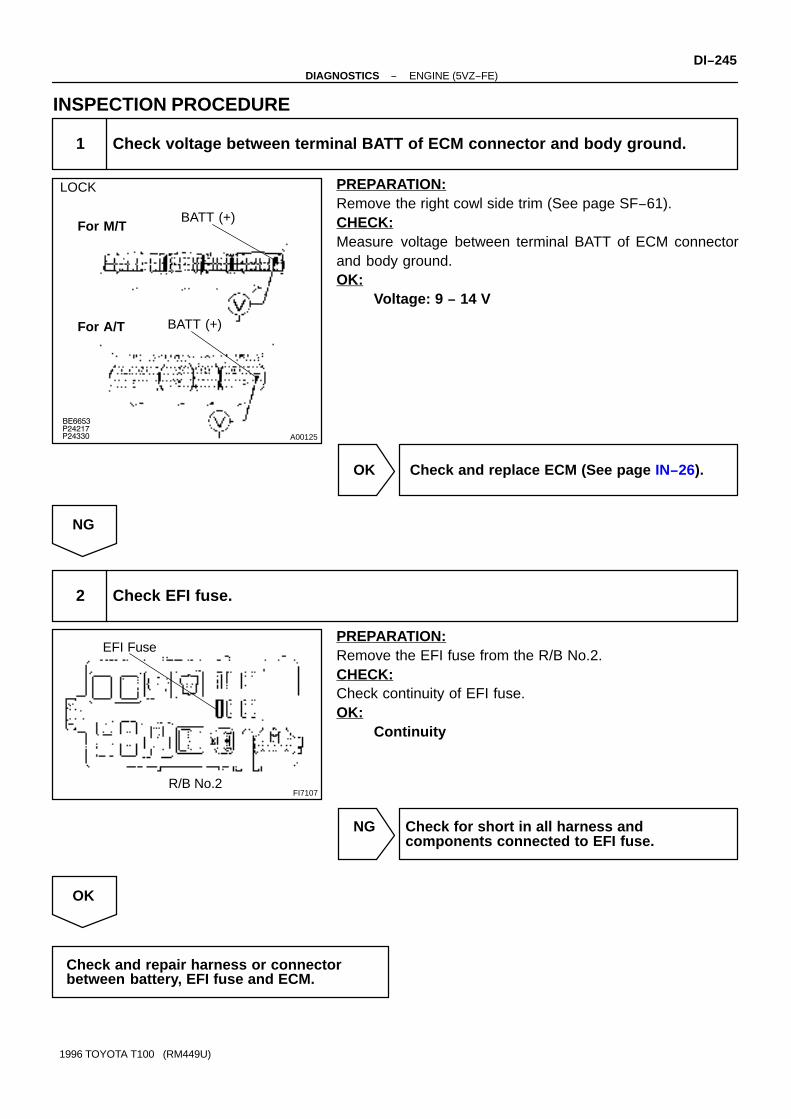
BE6653
P24217
P24330 A00125
LOCK
For M/T
For A/T
BATT (+)
BATT (+)
FI7107
EFI Fuse
R/B No.2
−DIAGNOSTICS ENGINE (5VZ−FE)DI−245
1996 TOYOTA T100 (RM449U)
INSPECTION PROCEDURE
1 Check voltage between terminal BATT of ECM connector and body ground.
PREPARATION:Remove the right cowl side trim (See page SF−61).CHECK:Measure voltage between terminal BATT of ECM connectorand body ground.OK:
Voltage: 9 − 14 V
OK Check and replace ECM (See page IN−26).
NG
2 Check EFI fuse.
PREPARATION:Remove the EFI fuse from the R/B No.2.CHECK:Check continuity of EFI fuse.OK:
Continuity
NG Check for short in all harness and components connected to EFI fuse.
OK
Check and repair harness or connectorbetween battery, EFI fuse and ECM.
https://www.truck-manuals.net/

DI−246−DIAGNOSTICS ENGINE (5VZ−FE)
1996 TOYOTA T100 (RM449U)
DTC P1605 Knock Control CPU Malfunction
CIRCUIT DESCRIPTIONRefer to Knock Sensor 1, 2 Circuit Malfunction on page DI−188.
DTC No. DTC Detecting Condition Trouble Area
P1605 Engine control computer malfunction (for knock control) �ECM
WIRING DIAGRAMRefer to page DI−188 for the WIRING DIAGRAM.
INSPECTION PROCEDURE
1 Are there any other codes (besides DTC P1605) being output?
YES Go to relevant DTC chart.
NO
Check and replace ECM (See page IN−26).
DI9AH−01
https://www.truck-manuals.net/

−DIAGNOSTICS ENGINE (5VZ−FE)DI−247
1996 TOYOTA T100 (RM449U)
DTC P1780 Park/Neutral Position Switch Malfunction
CIRCUIT DESCRIPTIONThe park/neutral position switch goes on when the shift lever is in the N or P shift position. When it goes onterminal NSW of the ECM is grounded to body ground via the starter relay, thus the terminal NSW voltagebecomes 0 V. When the shift lever is in the D, 2, L, or R position, the park/neutral position switch goes off,so the voltage of ECM. Terminal NSW becomes battery voltage, the voltage of the ECM internal powersource. If the shift lever is moved from the N position to the D position, this signal is used for air−fuel ratiocorrection and for idle speed control (estimated control), etc.
DTC No. DTC Detecting Condition Trouble Area
P1780
2 or more switches are ON simultaneously for ”R”, ”N”, ”2”
and ”L” and position
(2 trip detection logic)�Short in park/neutral position switch circuit
�Park/neutral position switch
�ECM
When driving under conditions (a) and (b) for 30 sec. or
more park/neutral position switch is ON (N position):
(2 trip detection logic)
(a) Vehicle speed: 70 km/h (44 mph) or more
(b) Engine speed: 1,500 ∼ 2,500 rpm
HINT:After confirming DTC P1780 use the TOYOTA hand−held tester to confirm the PNP switch signal from ”CUR-RENT DATA”.
WIRING DIAGRAMRefer to DTC P1780 on page DI−247.
INSPECTION PROCEDURERefer to DTC P1780 on page DI−247.
DI0V9−01
https://www.truck-manuals.net/

A00772
W
SwitchIG
W
WW
W
Park/NeutralPosition Switch
Clutch StartCancel Switch
ClutchStartSwitch
StarterRelay
Starter
ECM
STA
E1
11 13E4 E7
IE1(M/T)(A/T)
IE1IE1
IA3
IA3
EB1
B−W (M/T)
Battery
B−W
B−W B−W
B−W
B−
WB−
W
W−
B(A
/T)
W−
B(M
/T)
B−
R
B−R(M/T)
B−R(M/T)
(M/T
)
B−
R(M
/T)
W−
B(M
/T)
B−
YW
R/BNo.2
B (M/T)
BB (A/T)B−O
B−O(A/T)
ICIC
21
S111
13
3
1 5
2
1
2
1 2
3
1
5
2
6
2
2
ALT
AM
1
14
13
6 22
56
15
2
2
(M/T
)
(A/T) (A/T)
DI−248−DIAGNOSTICS ENGINE (5VZ−FE)
1996 TOYOTA T100 (RM449U)
Starter Signal Circuit
CIRCUIT DESCRIPTIONWhen the engine is cranked, the intake air flow is slow, so fuel vaporization is poor. A rich mixture is thereforenecessary in order to achieve good startability. While the engine is being cranked, the battery positive volt-age is applied to terminal STA of the ECM. The starter signal is mainly used to increase the fuel injectionvolume for the starting injection control and after−start injection control.
WIRING DIAGRAM
DI0VA−01
https://www.truck-manuals.net/

−DIAGNOSTICS ENGINE (5VZ−FE)DI−249
1996 TOYOTA T100 (RM449U)
INSPECTION PROCEDUREHINT:This diagnostic chart is based on the premise that the engine is cranked normally. If the engine is notcranked, proceed to the problem symptoms table on page DI−148.
TOYOTA hand−held tester:
1 Connect TOYOTA hand−held tester and check STA signal.
PREPARATION:(a) Connect the TOYOTA hand−held tester to the DLC3.(b) Turn the ignition switch ON and push the TOYOTA hand−held tester main switch ON.CHECK:Read STA signal on the TOYOTA hand−held tester while starter operates.OK:
Ignition Switch Position ON START
STA signal OFF ON
OK Proceed to next circuit inspection shown onproblem symptoms table (See page DI−148).
NG
2 Check for open in harness and connector between ECM and starter relay (Mark-ing: ST) (See page IN−26).
NG Repair or replace harness or connector.
OK
Check and replace ECM (See page IN−26).
https://www.truck-manuals.net/

BE6653
S04092
S05027 A00776
START
For M/T
For A/T
STA (+)
STA (+)
DI−250−DIAGNOSTICS ENGINE (5VZ−FE)
1996 TOYOTA T100 (RM449U)
OBD II scan tool (excluding TOYOTA hand−held tester):
1 Check voltage between terminal STA of ECM connector and body ground.
PREPARATION:Remove the right cowl side trim (See page SF−61).CHECK:Measure voltage between terminal STA of ECM connector andbody ground, during engine cranking.OK:
Voltage: 6 V or more
OK Proceed to next circuit inspection shown onproblem symptoms table (See page DI−148).
NG
2 Check for open in harness and connector between ECM and starter relay (Seepage IN−26).
NG Repair or replace harness or connector.
OK
Check and replace ECM (See page IN−26).
https://www.truck-manuals.net/

A00779
Battery
SwitchIG
W
2
2
2
W−R12 22E4 E4
(M/T)(A/T)
ECM
W−R
W−RR−L
B−W
B−R B−Y
W−R W−R
BR
W−
BB−
Y
IGN
J/B No.1
1A 1C3 17
8
8
7
IA3
EA1 4
9
4
3
1
2
R/B No.2
EFI
AM2
22 225
23 12
EFIRelay
E7 E524 16
E1
+B
EA EB
EA1
−DIAGNOSTICS ENGINE (5VZ−FE)DI−251
1996 TOYOTA T100 (RM449U)
ECM Power Source Circuit
CIRCUIT DESCRIPTIONWhen the ignition switch is turned ON, battery positive voltage is applied to the coil, closing the contacts ofthe EFI main relay (Marking: EFI) and supplying power to terminal +B of the ECM.
WIRING DIAGRAM
DI0VB−01
https://www.truck-manuals.net/

BE6653
P24221
P24332 A00126
ON
For M/T
For A/T
E1 (−) +B (+)
E1 (−) +B (+)
DI−252−DIAGNOSTICS ENGINE (5VZ−FE)
1996 TOYOTA T100 (RM449U)
INSPECTION PROCEDURE
1 Check voltage between terminals + B and E1 of ECM connector.
PREPARATION:(a) Remove the right cowl side trim (See page SF−61).(b) Turn the ignition switch ON.CHECK:Measure voltage between terminals + B and E1 of ECM con-nector.OK:
Voltage: 9 − 14 V
OK Proceed to next circuit inspection shown onproblem symptoms table (See page DI−148).
NG
2 Check for open in harness and connector between terminal E1 of ECM and bodyground (See page IN−26).
NG Repair or replace harness or connector.
OK
3 Check EFI main relay (Marking: EFI) (See page SF−45).
NG Replace EFI main relay.
OK
https://www.truck-manuals.net/

FI7106
IGN FuseJ/B No.1
−DIAGNOSTICS ENGINE (5VZ−FE)DI−253
1996 TOYOTA T100 (RM449U)
4 Check EFI fuse (See page DI−244, step 2).
NG Check for short in all harness andcomponents connected to EFI fuse.
OK
5 Check for open harness and connector between EFI main relay (Marking: EFI)and battery, EFI main relay (Marking: EFI) and ECM (See page IN−26).
NG Repair or replace harness or connector.
OK
6 Check IGN fuse.
PREPARATION:Remove the IGN fuse from the J/B No.1.CHECK:Check continuity of IGN fuse.OK:
Continuity
NG Check for short in all harness andcomponents connected to IGN fuse.
OK
https://www.truck-manuals.net/

DI−254−DIAGNOSTICS ENGINE (5VZ−FE)
1996 TOYOTA T100 (RM449U)
7 Check ignition switch (See page BE−12).
NG Replace ignition switch.
OK
Check for open in harness and connector be-tween IG switch and EFI main relay, EFI mainrelay and body ground (See page IN−26).
https://www.truck-manuals.net/

A01010
EFI
AM2
AM1
ALT
Battery
IG Switch
IG2
IG1
ST
IGN
EFI Relay
Circuit Opening Relay
Clutch StartCancel Switch(M/T)
L1
L2
ECM
Fuel Pump
FC Tr
STA
NE
Starter
Park/NeutralPosition Switch(A/T)
RelayStarter
StartClutch
Switch(M/T)
CrankshaftFrom
PositionSensor
(STA Signal)
(NE Signal)
−DIAGNOSTICS ENGINE (5VZ−FE)DI−255
1996 TOYOTA T100 (RM449U)
Fuel Pump Control Circuit
CIRCUIT DESCRIPTIONThe fuel pump is switched on (low voltage at terminal FC) when STA is on or while the NE signal is input tothe ECM.In the diagram below, when the engine is cranked, current flows from terminal ST of the ignition switch tothe starter relay coil, the starter relay switches on and current flows to coil L1 of the circuit opening relay.Thus the circuit opening relay switches on, power is supplied to the fuel pump and the fuel pump operates.When the STA signal and NE signal are input to the ECM, Tr is turned ON, current flows to coil L2 of the circuitopening relay, the relay switches on and the fuel pump operates.While the NE signal is generated (engine running), the ECM keeps Tr ON (circuit opening relay ON) and thefuel pump also keeps operating.
DI0VC−01
https://www.truck-manuals.net/

A00651
EC
M
EFI
AM2
ALT
Bat
tery
IG S
witc
h
Par
k/
Sw
itch
Sta
rter
Ope
ning
Rel
ay
Clu
tch
Sta
rtS
witc
h
E01
FC
414 E
7E
5(M
/T)(
A/T
)
G−
Y
13
IE1
G−
Y
L
1
4 6
Circ
uit
8
W−B
BJ1
W−B
ICIC
2
W−
RW−
RE
A1
9
EA
6
B−W
B−R
Rel
ay (M/T
)
3
B−O
W
B−
W
3
2
22
2
Rel
ayE
FI
2
2
2
5
1
22
2 2
2
2
5
R/B
1
22
2
3
1
W
W
B−
Y
IA3
IGN
B (
M/T
)
B
Neu
tral
Pos
ition
(A/T
)
Fue
lP
ump
W−B
BJ1
BJ2 BJ2 W−B
(w/ A
BS
)
(w/o
AB
S)
11(w
/ AB
S)
(w/o
AB
S)
10
16
Clu
tch
Sta
rt
Sw
itch
(M/T
)
Can
cel
No.
2
Sta
rter
J/B
No.
1
B−R
B−
WB−
WB−
WB−
W
B−
W
B−O
B
B−
RW−B
W−
R WB−
Y
W
2 2
W−
B
AM1
2
315
15
13
68
7317
11
13
IC
EB
1S
1
EA
1
IA3
IA3
1C1A
1
IE1
IE1
B−
Y
W−
RW−B
2
2564 11
3
A/T
DI−256−DIAGNOSTICS ENGINE (5VZ−FE)
1996 TOYOTA T100 (RM449U)
WIRING DIAGRAM
https://www.truck-manuals.net/

BE6653
A00773 A00788Fuel Inlet Hose
ON
−DIAGNOSTICS ENGINE (5VZ−FE)DI−257
1996 TOYOTA T100 (RM449U)
INSPECTION PROCEDURETOYOTA hand−held tester:
1 Connect TOYOTA hand−held tester and check operation of fuel pump.
PREPARATION:(a) Connect the TOYOTA hand−held tester to the DLC3.(b) Turn the ignition switch ON and push the TOYOTA hand−
held tester main switch ON.(c) Use ”ACTIVE TEST” mode to operate the fuel pump.CHECK:Check for fuel pressure in the fuel inlet hose when it is pinchedoff.OK:
There is pressure in the fuel inlet hose.HINT:At this time, you will hear a fuel flowing noise.
OK Go to step 7.
NG
2 Check for ECM power source circuit (See page DI−244).
NG Repair or replace.
OK
https://www.truck-manuals.net/

A00685
2 (+) 1 (+)
4 (−)
12
3
4
6
BE6653
P24225
P24335 A00128
ON
For M/T
For A/T
FC (+)
FC (+)
DI−258−DIAGNOSTICS ENGINE (5VZ−FE)
1996 TOYOTA T100 (RM449U)
3 Check circuit opening relay.
PREPARATION:Remove the circuit opening relay (See page SF−46).CHECK:(a) Apply battery voltage between terminals 2 and 4.(b) Measure voltage between terminals 1 and 4.OK:
Voltage: Same as battery
NG Replace circuit opening relay.
OK
4 Check voltage between terminal FC of ECM connector and body ground.
PREPARATION:(a) Remove the right cowl side trim (See page SF−61).(b) Turn the ignition switch ON.CHECK:Measure voltage between terminal FC of ECM connector andbody ground.OK:
Voltage: 9 − 14 V
NG Check for open in harness and connector be-tween EFI main relay and circuit opening relay,and ECM (See page IN−26).
OK
https://www.truck-manuals.net/

A00686
12
346
3 (+)
6 (−)
1
2
−DIAGNOSTICS ENGINE (5VZ−FE)DI−259
1996 TOYOTA T100 (RM449U)
5 Check fuel pump (See page SF−5).
NG Repair or replace fuel pump.
OK
6 Check for open in harness and connector between circuit opening relay and fuelpump, fuel pump and body ground (See page IN−26).
NG Repair or replace harness or connector.
OK
Check and replace ECM (See page IN−26).
7 Check circuit opening relay.
PREPARATION:Remove the circuit opening relay (See page SF−46).CHECK:(a) Apply battery voltage between terminals 3 and 6.(b) Check continuity between terminal 1 and 2.OK:
Continuity
NG Replace circuit opening relay.
OK
https://www.truck-manuals.net/

A00687
START 3
BE6653
P24337
P24336
A00773
A00789
ON
For M/T
For A/T
FC (+)
FC (+)
Fuel Inlet Hose
DI−260−DIAGNOSTICS ENGINE (5VZ−FE)
1996 TOYOTA T100 (RM449U)
8 Check voltage between terminal 3 of circuit opening relay connector and bodyground.
CHECK:Measure voltage between terminal 3 of circuit opening relayconnector and body ground when engine is cranked.OK:
Voltage: 9 − 14 V
NG Check for starter signal circuit (See page DI−248).
OK
Check for open in harness and connector be-tween terminal 6 of circuit opening relay con-nector and body ground (See page IN−26).
OBD II scan tool (excluding TOYOTA hand−held tester):
1 Check operation of fuel pump.
PREPARATION:(a) Remove the right cowl side trim (See page SF−61).(b) Turn the ignition switch ON.CHECK:(a) Connect between terminal FC of ECM connector and
body ground.(b) Check for fuel pressure in the inlet hose when it is pinched
off.OK:
There is pressure in the fuel inlet hose.HINT:At this time, you will hear a fuel flowing noise.
OK Go to step 7.
NG
https://www.truck-manuals.net/

−DIAGNOSTICS ENGINE (5VZ−FE)DI−261
1996 TOYOTA T100 (RM449U)
2 Check for ECM power source circuit (See page DI−251).
NG Repair or replace.
OK
3 Check circuit opening relay (See page DI−255, step 3).
NG Replace circuit opening relay.
OK
4 Check voltage between terminal FC of ECM connector and body ground (Seepage DI−255, step 4).
NG Check for open in harness and connector be-tween EFI main relay and circuit opening relayand ECM (See page IN−26).
OK
5 Check fuel pump (See page SF−5).
NG Repair or replace fuel pump.
OK
https://www.truck-manuals.net/

DI−262−DIAGNOSTICS ENGINE (5VZ−FE)
1996 TOYOTA T100 (RM449U)
6 Check for open in harness and connector between circuit opening relay and fuelpump, fuel pump and body ground (See page IN−26).
NG Repair or replace harness or connector.
OK
Check and replace ECM (See page IN−26).
7 Check circuit opening relay (See page DI−255, step 7).
NG Replace circuit opening relay.
OK
8 Check voltage between terminal 3 of circuit opening relay connector and bodyground (See page DI−255, step 8).
NG Check for starter signal circuit (See page DI−248).
OK
Check for open in harness and connector be-tween terminal 6 of circuit opening relay con-nector and body ground (See page IN−26).
https://www.truck-manuals.net/
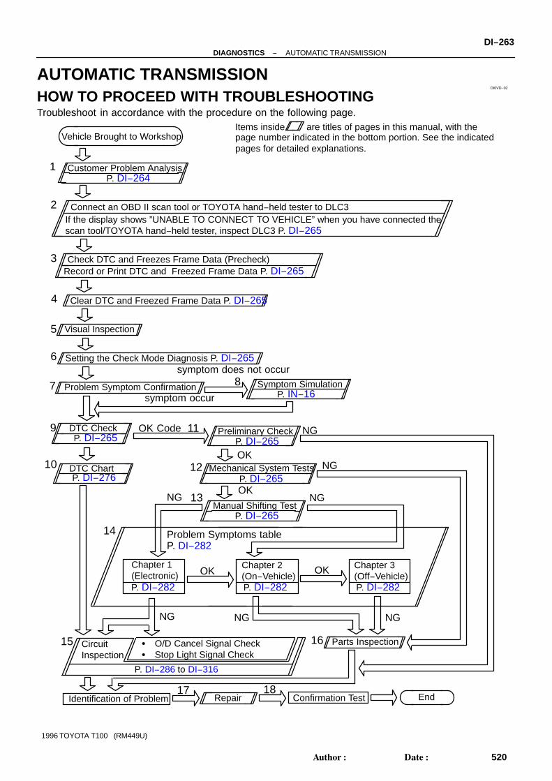
DI0VD−02
Vehicle Brought to Workshop
Customer Problem Analysis
Check DTC and Freezes Frame Data (Precheck)Record or Print DTC and Freezed Frame Data P. DI−265
Clear DTC and Freezed Frame Data P. DI−265
Visual Inspection
Setting the Check Mode Diagnosis P. DI−265
1
Items inside are titles of pages in this manual, with thepage number indicated in the bottom portion. See the indicatedpages for detailed explanations.
P. DI−264
Connect an OBD II scan tool or TOYOTA hand−held tester to DLC3If the display shows ”UNABLE TO CONNECT TO VEHICLE” when you have connected thescan tool/TOYOTA hand−held tester, inspect DLC3 P. DI−265
2
3
4
5
6symptom does not occur
Problem Symptom Confirmation 87 Symptom SimulationP. IN−16symptom occur
DTC CheckP. DI−265
OK Code 11 Preliminary CheckP. DI−265
DTC ChartP. DI−276
Mechanical System TestsP. DI−265
Manual Shifting TestP. DI−265
OK
OK
Chapter 1(Electronic)
Chapter 2(On−Vehicle)
OK Chapter 3(Off−Vehicle)OK
Problem Symptoms table P. DI−282
CircuitInspection
� O/D Cancel Signal Check� Stop Light Signal Check
NG
Parts Inspection
NG
NG
NG
Identification of Problem Repair Confirmation Test End
NG
NG
12
NG 13
14
15 16
17
9
10
P. DI−282
P. DI−286 to DI−316
18
P. DI−282 P. DI−282
−DIAGNOSTICS AUTOMATIC TRANSMISSIONDI−263
520Author�: Date�:
1996 TOYOTA T100 (RM449U)
AUTOMATIC TRANSMISSIONHOW TO PROCEED WITH TROUBLESHOOTINGTroubleshoot in accordance with the procedure on the following page.
https://www.truck-manuals.net/

DI0VE−01
Transmission ControlSystem Check Sheet
Inspector’sName :
Customer’s Name
Registration No.
Registration Year
Frame No.
Date VehicleBrought In Odometer Reading km
miles
/ /
/ /
Date ProblemOccurredHow Often DoesProblem Occur?
/ /
� Continuous � Intermittent ( times a day)
Symptoms
� Vehicle does not move ( � Any position � Particular position )
� No up−shift ( � 1st → 2nd � 2nd → 3rd � 3rd → O/D )
� No down−shift ( � O/D → 3rd � 3rd → 2nd � 2nd → 1st )
� Lock−up malfunction
� Shift point too high or too low
� Harsh engagement ( � N → D � Lock−up � Any drive position )
� Slip or shudder
� No kick−down
� Others
Check Item MalfunctionIndicator Lamp
DTC Check 1st Time
2nd Time
� Normal code � Malfunction code (Code )
� Normal � Remains ON
� Normal code � Malfunction code (Code )
DI−264−DIAGNOSTICS AUTOMATIC TRANSMISSION
1996 TOYOTA T100 (RM449U)
CUSTOMER PROBLEM ANALYSIS CHECK
https://www.truck-manuals.net/

A00653
w/o Tachometer
w/ Tachometer
DI0VF−02
Q08498
TOYOTA Hand−Held Tester
DLC3
−DIAGNOSTICS AUTOMATIC TRANSMISSIONDI−265
1996 TOYOTA T100 (RM449U)
PRE−CHECK1. DIAGNOSIS SYSTEM(a) Description
� When troubleshooting OBD II vehicles, the only dif-ference from the usual troubleshooting procedureis that you connect to the vehicle an OBD II scantool complying with SAE J1978 or TOYOTA hand−held tester, and read off various data output fromthe vehicle’s ECM.OBD II regulations require that the vehicle’s on−board computer lights up the Malfunction IndicatorLamp (MIL) on the instrument panel when the com-puter detects a malfunction in the computer itself orin drive system components which affect vehicleemissions. In addition to the MIL lighting up whena malfunction is detected, the applicable DTCs pre-scribed by SAE J2012 are recorded in the ECMmemory.(3RZ−FE: See page DI−13)(5VZ−FE: See page DI−140)
If the malfunction only occurs in 3 trips, the MIL goes off but theDTCs remain recorded in the ECM memory.
� To check the DTCs, connect an OBD II scan tool orTOYOTA hand−held tester to DLC3 on the vehicle.The OBD II scan tool or TOYOTA hand−held testeralso enables you to erase the DTCs and checkfreeze frame data and various forms of engine data(For instruction book).DTCs include SAE controlled codes and Manufac-turer controlled codes.SAE controlled codes must be set as prescribed bythe SAE, while Manufacturer controlled codes canbe set freely by the manufacturer within the pre-scribed limits (See DTC chart on page DI−276).
https://www.truck-manuals.net/
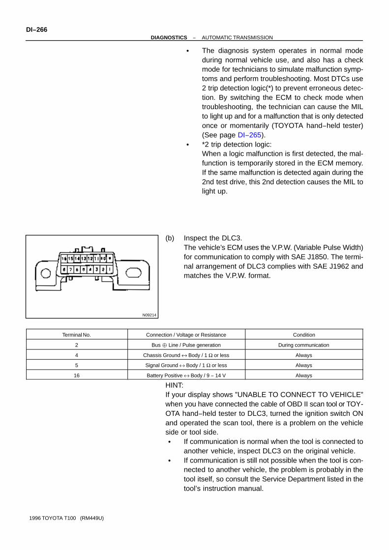
N09214
DI−266−DIAGNOSTICS AUTOMATIC TRANSMISSION
1996 TOYOTA T100 (RM449U)
� The diagnosis system operates in normal modeduring normal vehicle use, and also has a checkmode for technicians to simulate malfunction symp-toms and perform troubleshooting. Most DTCs use2 trip detection logic(*) to prevent erroneous detec-tion. By switching the ECM to check mode whentroubleshooting, the technician can cause the MILto light up and for a malfunction that is only detectedonce or momentarily (TOYOTA hand−held tester)(See page DI−265).
� *2 trip detection logic:When a logic malfunction is first detected, the mal-function is temporarily stored in the ECM memory.If the same malfunction is detected again during the2nd test drive, this 2nd detection causes the MIL tolight up.
(b) Inspect the DLC3.The vehicle’s ECM uses the V.P.W. (Variable Pulse Width)for communication to comply with SAE J1850. The termi-nal arrangement of DLC3 complies with SAE J1962 andmatches the V.P.W. format.
Terminal No. Connection / Voltage or Resistance Condition
2 Bus � Line / Pulse generation During communication
4 Chassis Ground ↔ Body / 1 Ω or less Always
5 Signal Ground ↔ Body / 1 Ω or less Always
16 Battery Positive ↔ Body / 9 − 14 V Always
HINT:If your display shows ”UNABLE TO CONNECT TO VEHICLE”when you have connected the cable of OBD II scan tool or TOY-OTA hand−held tester to DLC3, turned the ignition switch ONand operated the scan tool, there is a problem on the vehicleside or tool side.� If communication is normal when the tool is connected to
another vehicle, inspect DLC3 on the original vehicle.� If communication is still not possible when the tool is con-
nected to another vehicle, the problem is probably in thetool itself, so consult the Service Department listed in thetool’s instruction manual.
https://www.truck-manuals.net/
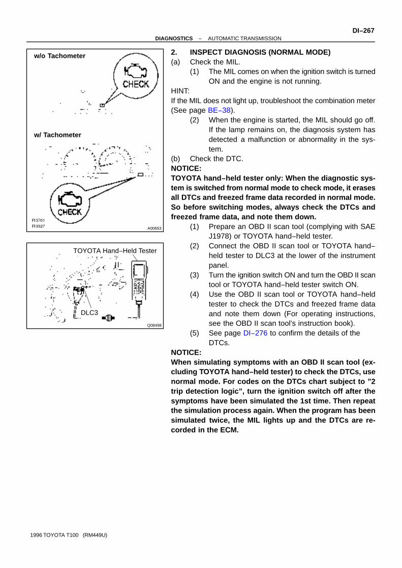
A00653
w/o Tachometer
w/ Tachometer
Q08498
TOYOTA Hand−Held Tester
DLC3
−DIAGNOSTICS AUTOMATIC TRANSMISSIONDI−267
1996 TOYOTA T100 (RM449U)
2. INSPECT DIAGNOSIS (NORMAL MODE)(a) Check the MIL.
(1) The MIL comes on when the ignition switch is turnedON and the engine is not running.
HINT:If the MIL does not light up, troubleshoot the combination meter(See page BE−38).
(2) When the engine is started, the MIL should go off.If the lamp remains on, the diagnosis system hasdetected a malfunction or abnormality in the sys-tem.
(b) Check the DTC.NOTICE:TOYOTA hand−held tester only: When the diagnostic sys-tem is switched from normal mode to check mode, it erasesall DTCs and freezed frame data recorded in normal mode.So before switching modes, always check the DTCs andfreezed frame data, and note them down.
(1) Prepare an OBD II scan tool (complying with SAEJ1978) or TOYOTA hand−held tester.
(2) Connect the OBD II scan tool or TOYOTA hand−held tester to DLC3 at the lower of the instrumentpanel.
(3) Turn the ignition switch ON and turn the OBD II scantool or TOYOTA hand−held tester switch ON.
(4) Use the OBD II scan tool or TOYOTA hand−heldtester to check the DTCs and freezed frame dataand note them down (For operating instructions,see the OBD II scan tool’s instruction book).
(5) See page DI−276 to confirm the details of the DTCs.
NOTICE:When simulating symptoms with an OBD II scan tool (ex-cluding TOYOTA hand−held tester) to check the DTCs, usenormal mode. For codes on the DTCs chart subject to ”2trip detection logic”, turn the ignition switch off after thesymptoms have been simulated the 1st time. Then repeatthe simulation process again. When the program has beensimulated twice, the MIL lights up and the DTCs are re-corded in the ECM.
https://www.truck-manuals.net/

FI3605
ON
OFF
Flashing
0.13 Second
DI−268−DIAGNOSTICS AUTOMATIC TRANSMISSION
1996 TOYOTA T100 (RM449U)
3. INSPECT DIAGNOSIS (CHECK MODE)HINT:TOYOTA hand−held tester only: Compared to the normalmode, the check mode has high sensing ability to detect mal-functions. Furthermore, the same diagnostic items which aredetected in Normal mode can also be detected in Check mode.(a) Check the DTC.
(1) Check the initial conditions.� Battery positive voltage 11 V or more� Throttle valve fully closed� Transmission in P position� Air conditioning switched off
(2) Turn the ignition switch OFF.(3) Prepare a TOYOTA hand−held tester.(4) Connect the TOYOTA hand−held tester to DLC3 at
the lower of the instrument panel.(5) Turn the ignition switch ON and switch the TOYOTA
hand−held tester ON.(6) Switch the TOYOTA hand−held tester from Normal
mode to Check mode (Check that the MIL flashes).(7) Start the engine (MIL goes out after the engine
starts).(8) Simulate the conditions of the malfunction de-
scribed by the customer.NOTICE:Leave the ignition switch ON until you have checked theDTCs, etc.
(9) After simulating the malfunction conditions, use theTOYOTA hand−held tester diagnosis selector tocheck the DTCs and freeze frame data, etc.
HINT:Take care not to turn the ignition switch OFF, as turning it offswitches the diagnosis system from Check mode to Normalmode, so all DTCs, etc. are erased.
(10) After checking the DTC, inspect the applicable cir-cuit.
(b) Clear the DTC.The following actions will erase the DTC and freezedframe data. Operating an OBD II scan tool (complyingwith SAE J1978) or TOYOTA hand−held tester to erasethe codes (See the OBD II scan tool’s instruction book foroperating instructions.).
NOTICE:If the TOYOTA hand−held tester switches the ECM fromnormal mode to check mode or vice−versa, or if the ignitionswitch is turned from ON to ACC or OFF during checkmode, the DTCs and freezed frame data will be erased.
https://www.truck-manuals.net/

−DIAGNOSTICS AUTOMATIC TRANSMISSIONDI−269
1996 TOYOTA T100 (RM449U)
4. ROAD TESTNOTICE:Perform the test at normal operating ATF temperature 50 − 80°C (122 − 176°F).(a) D position test
Shift into the D position and fully depress the accelerator pedal and and check the following points:(1) Check up−shift operation.
1 → 2, 2 → 3 and 3 → O/D up−shift takes place, at the shift point shown in the automatic shiftschedule (See page SS−49).
HINT:There is no O/D up−shift or lock−up when the coolant temperature is below 60°C (140°F).Evaluation:
Problem Possible cause
If there is no 1→ 2 up−shift�Shift solenoid valve No.2 is stuck
�1−2 shift valve is stuck
If there is no 2 → 3 up−shift�Shift solenoid valve No.1 is stuck
�2−3 shift valve is stuck
If there is no 3 → O/D up−shift �3−4 shift valve is stuck
If the shift point is defective �Throttle valve, 1−2 shift valve, 2−3 shift valve, etc. are defective
If the lock up is defective�Shift solenoid valve SL is stuck
�Lock−up relay valve is stuck
(2) Check for shift shock and slip.Check for shock and slip at the 1 → 2, 2 → 3 and 3 → O/D up−shifts.
Evaluation:
Problem Possible cause
If the shock is excessive
�Line pressure is too high
�Accumulator is defective
�Check ball is defective
(3) Check for abnormal noises and vibration.Run at the D position lock−up or O/D gear and check for abnormal noises and vibration.
HINT:The check for the cause of abnormal noises and vibration must be done very thoroughly as it could also bedue to loss of balance in the differential torque converter clutch, etc.
(4) Check kick−down operation.While running in the D position, 2nd, 3rd and O/D gears, check to see that the possible kick−downvehicle speed limits for 2 → 1, 3 → 2 and O/D → 3 kick−downs conform to those indicated onthe automatic shift schedule (See page SS−49).
(5) Check abnormal shock and slip at kick−down.(6) Check the lock−up mechanism.
� Drive in D position, O/D gear, at a steady speed (lock−up ON).� Lightly depress the accelerator pedal and check that there is lock−up.
If there is a big jump in engine speed, there is no lock−up.(b) 2 position test
Shift into the 2 position and fully depress the accelerator pedal and check the following points:(1) Check up−shift operation.
Check to see that the 1 → 2 up−shift takes place and that the shift point conforms to the automaticshift schedule (See page SS−49).
https://www.truck-manuals.net/

AT3417
OK if hot
Add if hot
DI−270−DIAGNOSTICS AUTOMATIC TRANSMISSION
1996 TOYOTA T100 (RM449U)
HINT:There is no O/D up−shift and lock−up in the 2 position.
(2) Check engine braking.While running in the 2 position and 2nd gear, release the accelerator pedal and check the enginebraking effect.
Evaluation:
Problem Possible cause
If there is no engine braking effect �2nd coast brake defective
(3) Check for abnormal noises during acceleration and deceleration, and for shock at up−shift anddown−shift.
(c) L position testShift into the 2 position and fully depress the accelerator pedal and check the following points:(1) Check no up−shift.
While running in the L position, check that there is no up−shift to 2nd gear.(2) Check engine braking.
While running in the L position, release the accelerator pedal and check the engine braking ef-fect.
Evaluation:
Problem Possible cause
If there is no engine braking effect �1st and reverse brake is defective
(3) Check for abnormal noises during acceleration and deceleration.(d) R position test
Shift into the R position and fully depress the accelerator pedal and check for slipping.CAUTION:Before conducting this test ensure that the test area is free from personnel and obstruction.(e) P position test
Stop the vehicle on a grade (more than 5°) and after shifting into the P position, release the parkingbrake. Then, check to see that the parking lock pawl holds the vehicle in place.
5. BASIC INSPECTION(a) Check the fluid level.HINT:� Drive the vehicle so that the engine and transmission are
at normal operating temperature.Fluid temp.: 70 − 80°C (158 − 176°F)
� Only use the COOL range on the dipstick as a rough refer-ence when the fluid is replaced or the engine does notrun.
(1) Park the vehicle on a level surface and set the park-ing brake.
(2) With the engine idling and the brake pedal de-pressed, shift the shift lever into all positions from Pto L position and return to P position.
(3) Pull out the dipstick and wipe it clean.(4) Push it back fully into the pipe.(5) Pull it out and check that the fluid level is in the HOT
range.
https://www.truck-manuals.net/

AT1347
AT6683
AT3417
OK if hot
Add if hot
AT4252
0 − 1 mm (0 − 0.04 in.)
Q03104No.1 Gear Shifting Rod
−DIAGNOSTICS AUTOMATIC TRANSMISSIONDI−271
1996 TOYOTA T100 (RM449U)
If the level is at the low side, add new fluid.Fluid type: ATF DEXRON®II
NOTICE:Do not overfill.(b) Check the fluid condition.
If the fluid smells burnt or is black, replace it.(c) Replace the ATF.
(1) Remove the drain plug and drain the fluid.(2) Reinstall the drain plug securely.
(3) With the engine OFF, add new fluid through the oilfiller pipe.
Fluid type: ATF DEXRON®IICapacity: A340E: 1.6 liters (1.7 US qts, 1.4 Imp. qts)A340F: 2.0 liters (2.1 US qts, 1.8 Imp. qts)(4) Start the engine and shift the shift lever into all posi-
tions from P to L position and then shift into P posi-tion.
(5) With the engine idling, check the fluid level. Addfluid up to the COOL level on the dipstick.
(6) Check the fluid level at the normal operating tem-perature, 70 − 80°C (158 − 176°F), and add as nec-essary.
NOTICE:Do not overfill.(d) Check the fluid leaks.
Check for leaks in the transmission.If there are leaks, it is necessary to repair or replace O−rings, FIPGs, oil seals, plugs or other parts.
(e) INSPECT AND ADJUST THROTTLE CABLE(1) Check that the accelerator pedal is fully released.(2) Check that the inner cable is not slack.(3) Measure the distance between the outer cable end
and stopper on the cable.Standard distance: 0 − 1 mm (0 − 0.04 in.)
If the distance is not standard, adjust the cable by the adjustingnuts.
(f) Inspect and adjust the shift lever position.When shifting the shift lever from the N position to otherpositions, check that the lever can be shifted smoothlyand accurately to each position and that the position indi-cator is not aligned with the correct position.
If the indicator is not aligned with the correct position, carry outthe following adjustment procedures.
(1) Remove the nut on the No.1 gear shifting rod.(2) Push the No.1 gear shifting rod fully downward.
https://www.truck-manuals.net/

Q06793
N RP
AT5115
Neutral Basic line
Bolt
Groove
DI−272−DIAGNOSTICS AUTOMATIC TRANSMISSION
1996 TOYOTA T100 (RM449U)
(3) Return the No.1 gear shifting rod 2 notches to Nposition.
(4) Set the shift lever to N position.(5) While holding the shift lever lightly toward the R
position side, adjust the No.1 gear shifting rod nut.(6) Tighten the No.1 gear shifting rod nut.Torque: 25 N·m (260 kgf·cm, 19 ft·lbf)(7) Start the engine and make sure that the vehicle
moves forward when shifting the lever from the N toD position and reverses when shifting it to the Rposition.
(g) Inspect and adjust the park/neutral position.Check that the engine can be started with the shift leveronly in the N or P position, but not in other positions.If itis not as stated above, carry out the following adjustmentprocedure.(1) Loosen the park/neutral position switch bolt and set
the shift lever to the N position.(2) Align the groove and neutral basic line.(3) Hold in position and tighten the bolt.Torque: 13 N·m (130 kgf·cm, 10 ft·lbf)
(h) Check the idle speed.Idle speed (In N position and air conditioner OFF): 3RZ−FE: 700 ± 50 rpm5VZ−FE: 700 ± 50 rpm
6. MECHANICAL SYSTEM TESTS(a) Measure the stall speed.
The object of this test is to check the overall performance of the transmission and engine by measuringthe stall speeds in the D and R positions.
NOTICE:� Do the that at normal operating fluid temperature 50 − 80°C (122 − 176°F)� Do not continuously run this test longer than 5 seconds.� To ensure safety, conduct this test in a wide, clear, level area which provides good traction.� The stall test should always be carried out in pairs. One technician should observe the condi-
tions of wheels or wheel stoppers outside the vehicle while the other is doing the test.(1) Chock the 4 wheels.(2) Connect an OBD II scan tool or TOYOTA hand−held tester to DLC3.(3) Fully apply the parking brake.(4) Keep your left foot pressed firmly on the brake pedal.(5) Start the engine.(6) Shift into the D position. Press all the way down on the accelerator pedal with your right foot.
Quickly read the stall speed at this time.Stall speed:3RZ−FE: 1,950 ± 150 rpm5VZ−FE: 2,150 ± 150 rpm(7) Do the same test in R position.Stall speed:3RZ−FE: 1,950 ± 150 rpm5VZ−FE: 2,150 ± 150 rpm
https://www.truck-manuals.net/
−DIAGNOSTICS AUTOMATIC TRANSMISSIONDI−273
1996 TOYOTA T100 (RM449U)
Evaluation:
Problem Possible cause
(a) Stall speed low in D and R positions
�Engine output may be insufficient
�Stator one−way clutch is operating properly
�HINT: If more than 600 rpm below the specified value, the torque
converter could be faulty.
(b) Stall speed high in D position
�Line pressure too low
� forward clutch slipping
�No.2 one−way clutch not operating properly
�O/D one−way clutch not operating properly
(c) Stall speed high in R position
�Line pressure too low
�Direct clutch slipping
�1st and reverse brake slipping
�O/D one−way clutch not operating properly
(d) Stall speed high in D and R positions
�Line pressure too low
� Improper fluid level
�O/D one−way clutch not operating properly
(b) Measure the time lag.When the shift lever is shifted while the engine is idling, there will be a certain time lapse or lag beforethe shock can be felt. This is used for checking the condition of the O/D direct clutch, forward clutch,direct clutch, and 1st and reverse brake.
NOTICE:� Do the test at normal operating fluid temperature 50 − 80°C (122 − 176°F)� Be sure to allow 1 minute interval between tests.� Take 3 measurements and take the average value.
(1) Fully apply the parking brake.(2) Start the engine and check idle speed.Idle speed (In N position and air conditioner OFF): 3RZ−FE: 700 ± 50 rpm5VZ−FE: 700 ± 50 rpm(3) Shift the shift lever from N to D position. Using a stop watch, measure the time from when the
lever is shifted until the shock is felt.In the same manner, measure the time lag for N → R.
Time lag:N → D Less than 1.2 secondsN → R Less than 1.5 seconds
Evaluation (If N → D time or N → R time lag is longer than specified):
Problem Possible cause
N → D time lag is longer
�Line pressure too low
�Forward clutch worn
�O/D one−way clutch not operating properly
N → R time lag is longer
�Line pressure too low
�Direct clutch worn
�1st and reverse brake worn
�O/D one−way clutch not operating properly
https://www.truck-manuals.net/

DI−274−DIAGNOSTICS AUTOMATIC TRANSMISSION
1996 TOYOTA T100 (RM449U)
7. HYDRAULIC TESTMeasure the line pressure.NOTICE:� Do the test at normal operation fluid temperature 50 − 80°C (122 − 176°F).� The line pressure test should always be carried out in pairs. One technician should observe
the conditions of wheels or wheel stoppers outside the vehicle while the other is doing the test.� Be careful to prevent SST’s hose from interfering with the exhaust pipe.
(1) Warm up the fluid.(2) Remove the test plug on the transmission case right side and connect SST.
(See page AT−26 and AT−33 for the location to connect SST)SST 09992−00094 (09992−00150, 09992−00270)(3) Fully apply the parking brake and chock the 4 wheels.(4) Start the engine and check idling speed.(5) Keep your left foot pressed firmly on the brake pedal and shift into D position.(6) Measure the line pressure when the engine is idling.(7) Depress the accelerator pedal all the way down. Quickly read the highest line pressure when
engine speed reaches stall speed.NOTICE:Release the accelerator pedal and stop test if the rear wheels begin to rotate before the engine speedreaches specified stall speed.
(8) In the same manner, do the test in R position.Specified line pressure:3RZ−FE
Condition D position kPa (kgf/cm2, psi) R position kPa (kgf/cm2, psi)
Idling 363 − 422 (3.7 − 4.3, 53 − 61) 490 − 588 (5.0 − 6.0, 71 − 85)
Stall 932 − 1,177 (9.5 − 12.0, 135 − 171) 1,294 − 1,638 (13.2 − 16.7, 188 − 238)
5VZ−FE
Condition D position kPa (kgf/cm2, psi) R position kPa (kgf/cm2, psi)
Idling 363 − 422 (3.7 − 4.3, 53 − 61) 608 − 696 (6.2 − 7.1, 88 − 101)
Stall 902 − 1,147 (9.2 − 11.7, 131 − 166) 1,432 − 1,942 (14.6 − 19.8, 208 − 282)
If the measured pressures are not up to specified values, recheck the throttle cable adjustment and retest.Evaluation
Problem Possible cause
If the measured value at all positions are higher
�Throttle cable out of adjustment
�Throttle valve defective
�Regulator valve defective
If the measured value at all positions are lower
�Throttle cable out of adjustment
�Throttle valve defective
�Regulator valve defective
�Oil pump defective
�O/D direct clutch defective
If pressure is low in the D position only�D position circuit fluid leakage
�Forward clutch defective
If pressure is low in the R position only
�R position circuit fluid leakage
�Direct clutch defective
�1st and reverse brake defective
https://www.truck-manuals.net/

Q05336
−DIAGNOSTICS AUTOMATIC TRANSMISSIONDI−275
1996 TOYOTA T100 (RM449U)
8. MANUAL SHIFTING TESTHINT:With this test, it can be determined whether the trouble is withinthe electrical circuit or is a mechanical problem in the transmis-sion.(a) Disconnect the solenoid wire.(b) Inspect the manual driving operation.
� Check that the shift and gear positions correspondwith the table below.
� While driving, shift through the L, 2 and D positions.Check that the gear change corresponds to the shiftposition.
Shift Position Gear Position
D O/D
2 3rd
L 1st
R Reverse
P Pawl Lock
HINT:If the L, 2 and D position gear positions are difficult to positionsare difficult to distinguish, do the following road test.If any abnormality is found in the above test, the problem is inthe transmission itself.(c) Connect the solenoid wire.(d) Cancel out DTC. (See page DI−265).
https://www.truck-manuals.net/

DI0VG−02
DI−276−DIAGNOSTICS AUTOMATIC TRANSMISSION
1996 TOYOTA T100 (RM449U)
DIAGNOSTIC TROUBLE CODE CHARTIf a DTC is displayed during the DTC check, check the circuit listed for that code in the table below and pro-ceed to the page given.*: � ... MIL lights up
DTC No.
(See Page)Detection Item Trouble Area MIL * Memory
P0500
3RZ−FE:
(DI−92)
5VZ−FE:
(DI−226)
Vehicle Speed Sensor
Malfunction
(No.1 Vehicle Speed Sensor)
�Open or short in No.1 vehicle speed sensor circuit
�No.1 vehicle speed sensor
�Combination meter
�ECM
� �
P0710
(DI−287)
Transmission Fluid Temperature
Sensor Malfunction
(ATF Temperature Sensor)
�Open or short in ATF temperature sensor circuit
�ATF temperature sensor
�ECM
� �
P0750
(DI−289)
Shift Solenoid A Malfunction
(Shift Solenoid Valve No.1)
�Shift solenoid valve No.1 is stuck open or closed
�Valve body is blocked up or stuck� �
P0753
(DI−290)
Shift Solenoid A Electrical
Malfunction
(Shift Solenoid Valve No.1)
�Open or short in shift solenoid valve No.1 circuit
�Shift solenoid valve No.1
�ECM
� �
P0755
(DI−289)
Shift Solenoid B Malfunction
(Shift Solenoid Valve No.2)
�Shift solenoid valve No.2 is stuck open or closed
�Valve body is blocked up or stuck� �
P0758
(DI−290)
Shift Solenoid B Electrical
Malfunction
(Shift Solenoid Valve No.2)
�Open or short in shift solenoid valve No.2 circuit
�Shift solenoid valve No.2
�ECM
� �
P0770
(DI−294)
Shift Solenoid E Malfunction
(Shift Solenoid Valve SL)
�Shift solenoid valve SL is stuck open or closed
�Valve body is blocked up or stuck
�Lock−up clutch
� �
P0773
(DI−296)
Shift Solenoid E Electrical
Malfunction
(Shift Solenoid Valve SL)
�Open or short in shift solenoid valve SL circuit
�Shift solenoid valve SL
�ECM
� �
P1700
(DI−300)
Vehicle Speed Sensor No.2
Malfunction
(No.2 Vehicle Speed Sensor)
�Open or short in No.2 vehicle speed sensor circuit
�No.2 vehicle speed sensor
�ECM
� �
P1780
(DI−306)
Park/Neutral Position Switch
Malfunction
�Short in park/neutral position switch circuit
�Park/neutral position switch
�ECM
� �
https://www.truck-manuals.net/

DI98H−01
D10997
D10998
−DIAGNOSTICS AUTOMATIC TRANSMISSIONDI−277
1996 TOYOTA T100 (RM449U)
PARTS LOCATION
https://www.truck-manuals.net/

Q07506
No.1 Vehicle Speed Sensor(In Combination Meter) O/D Main Switch
Cruise Control ECU
DLC3Stop Light Switch
ECM
DI−278−DIAGNOSTICS AUTOMATIC TRANSMISSION
1996 TOYOTA T100 (RM449U)
https://www.truck-manuals.net/

DI0VI−02
FI6526
12345678910111213
14151617181920212223242526
12345678
910111213141516
123456
7891011121234567891011
141516171819202122 1213
EE6E
ECM Terminals
E
−DIAGNOSTICS AUTOMATIC TRANSMISSIONDI−279
1996 TOYOTA T100 (RM449U)
TERMINALS OF ECM3RZ−FE:
Symbols (Terminals No.) Wiring Color Condition STD Voltage (V)
SP1 − E1 (E4, 8 − E7, 24) G ↔ BR
IG switch ON (Disconnect cruise control connector) Below 1.5 or 4 − 6
Turn one rear wheel slowly (Disconnect cruise control connec-
tor)
Pulse signal is output
Below 1.5 ↔ 4 − 6
S1 − E1 (E7, 10 − E7, 24)
W ↔ BR
IG switch ON 9 − 14
1st or 2nd gear 9 − 14
3rd or O/D gear Below 1.5
S2 − E1 (E7, 9 − E7, 24) B−W ↔ BR
IG switch ON Below 1.5
2nd or 3rd gear 9 − 14
1st or O/D gear Below 1.5
SL − E1 (E7, 8 − E7, 24) Y−B ↔ BRIG switch ON Below 1.5
Vehicle driving under lock−up position 9 − 14
SP2+ − SP2− (E5, 10 − E5, 4) BR−R ↔ B−R Vehicle is runningPulse signal is output
Below 1.5 ↔ 4 − 10
OD2 − E1 (E4, 5 − E7, 24) Y−G ↔ BRO/D main switch ON (Pushed in) 9 − 14
O/D main switch OFF (Pushed once again) Below 3
OIL − E2 (E7, 21 − E6, 9) G−B ↔ BR−B ATF temperature: 110°C (230°F) or more Below 1.5
L − E1 (E4, 15 − E7, 24) V−W ↔ BRIG switch ON, Shift lever L position 7.5 − 14
IG switch ON, Shift lever other than L position Below 1.5
2 − E1 (E4, 16 − E7, 24) P−G ↔ BRIG switch ON, Shift lever 2 position 7.5 − 14
IG switch ON, Shift lever other than 2 position Below 1.5
R − E1 (E4, 17 − E7, 24) R−B ↔ BRIG switch ON, Shift lever R position 7.5 − 14
IG switch ON, Shift lever other than R position Below 1.5
NSW − E1 (E4, 22 − E7, 24) B−Y ↔ BRIG switch ON, Shift lever P or N position Below 3
IG switch ON, Shift lever other than P or N position 9 − 14
B/K − E1 (E4, 21 − E7, 24) G−W ↔ BRIG switch ON, Brake pedal is depressed 7.5 − 14
IG switch ON, Brake pedal is released Below 1.5
THW − E2 (E6, 4 − E6, 9) G−Y ↔ BR−B Engine coolant temperature: 80°C (176°F) Below 1.5
IDL − E2 (E6, 11 − E6, 9) Y−L ↔ BR−BIG switch ON, Accel. pedal is released Below 1.5
IG switch ON, Accel. pedal is depressed 9 − 14
VTA − E2 (E6, 10 − E6, 9) Y−B ↔ BR−BIG switch ON, Accel. pedal is released Below 0.3 − 0.8
IG switch ON, Accel. pedal is depressed 3.2 − 4.9
https://www.truck-manuals.net/

FI6810
E7 E6 E5 E4
3433 3231 30 2928 27
17181920212223242526
111213141516
12345678910 12345678
910111213
1415161718192021
22232425262728
1234
567
891011
1213141516
123456
7891011
121314151617
1819202122
ECM Terminals
DI−280−DIAGNOSTICS AUTOMATIC TRANSMISSION
1996 TOYOTA T100 (RM449U)
5VZ−FE:
Symbols (Terminals No.) Wiring Color Condition STD Voltage (V)
SPD − E1 (E4, 12− E5, 16) G ↔ BR
IG switch ON (Disconnect cruise control connector) Below 1.5 or 4 − 6
Turn one rear wheel slowly (Disconnect cruise control connec-
tor)
Pulse signal is output
Below 1.5 ↔ 4 − 6
S1 − E1 (E7, 11 − E5, 16)
W ↔ BR
IG switch ON 9 − 14
1st or 2nd gear 9 − 14
3rd or O/D gear Below 1.5
S2 − E1 (E7, 17 − E5, 16) B−W ↔ BR
IG switch ON Below 1.5
2nd or 3rd gear 9 − 14
1st or O/D gear Below 1.5
SL − E1 (E7, 27 − E5, 16) Y−B ↔ BRIG switch ON Below 1.5
Vehicle driving under lock−up position 9 − 14
SP2 − E1 (E6, 9 − E5, 16) BR−R ↔ BR Turn one rear wheel slowlyPulse signal is output
Below 1.5 ↔ 4 ∼ 6
OD1 − E1 (E4, 7 − E5, 16) Y−R ↔ BR IG switch ON 9 − 14
OD2 − E1 (E4, 6 − E5, 16) Y−G ↔ BRO/D main switch ON (Pushed in) 9 − 14
O/D main switch OFF (Pushed once again) Below 3
OIL − E2 (E6, 12 − E6, 22) G−B ↔ BR−B ATF temperature: 110°C (230°F) or more Below 1.5
L − E1 (E4, 3 − E5, 16) V−W ↔ BRIG switch ON, Shift lever L position 7.5 − 14
IG switch ON, Shift lever other than L position Below 1.5
2 − E1 (E4, 2 − E5, 16) P−G ↔ BRIG switch ON, Shift lever 2 position 7.5 − 14
IG switch ON, Shift lever other than 2 position Below 1.5
R − E1 (E4, 1 − E5, 16) R−B ↔ BRIG switch ON, Shift lever R position 7.5 − 14
IG switch ON, Shift lever other than R position Below 1.5
NSW − E1 (E7, 14 − E6, 22) B−O ↔ BRIG switch ON, Shift lever P or N position Below 3
IG switch ON, Shift lever other than P or N position 9 − 14
B/K − E1 (E4, 25 − E5, 16) G−W ↔ BRIG switch ON, Brake pedal is depressed 7.5 − 14
IG switch ON, Brake pedal is released Below 1.5
THW − E2 (E6, 20 − E6, 22) G−Y ↔ BR−B Engine coolant temperature: 80°C (176°F) Below 1.5
IDL − E2 (E7, 32 − E6, 22) Y−L ↔ BR−BIG switch ON, Accel. pedal is released Below 1.5
IG switch ON, Accel. pedal is depressed 9 − 14
VTA − E2 (E6, 7 − E6, 22) Y−B ↔ BR−BIG switch ON, Accel. pedal is released Below 0.3 − 0.8
IG switch ON, Accel. pedal is depressed 3.2 − 4.9
TFN − E1 (E4, 17 − E5, 16) Y ↔ BRIG switch ON, Transfer N position Below 3
IG switch ON, Transfer other than N position 9 − 14
https://www.truck-manuals.net/

−DIAGNOSTICS AUTOMATIC TRANSMISSIONDI−281
1996 TOYOTA T100 (RM449U)
L4 − E1 (E7, 29 − E5, 16) R ↔ BRIG switch ON, Transfer L4 position 7.5 − 14
IG switch ON, Transfer other than L4 position Below 1.5
4WD − E1 (E4, 26 − E5, 16) R−G ↔ BRIG switch ON, Transfer H2 position 9 − 14
IG switch ON, Transfer other than H2 position Below 3
https://www.truck-manuals.net/

DI0VJ−02
DI−282−DIAGNOSTICS AUTOMATIC TRANSMISSION
1996 TOYOTA T100 (RM449U)
PROBLEM SYMPTOMS TABLEIf a normal code is displayed during the diagnostic trouble code check but the trouble still occurs, check thecircuits for each symptom in the order given in the charts on the following pages and proceed to the pagegiven for troubleshooting.The Matrix Chart is divided into 3 chapters.Chapter 1: Electronic Circuit Matrix ChartChapter 2: On−vehicle Repair Matrix ChartChapter 3: Off−vehicle Repair Matrix Chart
� If the instruction ”Proceed to next circuit inspection shown on matrix chart” is given in the flowchart for each circuit, proceed to the circuit with the next highest number in the table to continuethe check.
� If the trouble still occurs even though there are no abnormalities in any of the other circuits, thencheck and replace the ECM.
Chapter 1: Electronic Circuit Matrix Chart
Symptom Suspect Area See page
No up−shift
(A particular gear, from 1st to 3rd gear, is not up−shifted)1. ECM DI−279
No up−shift (3rd → O/D)
1. O/D main switch & O/D OFF indicator light circuit
2. O/D cancel signal circuit
3. ECM
DI−311
DI−309
DI−279
No down−shift (O/D → 3rd) 1. ECM DI−279
No down−shift
(A particular gear, from 1st to 3rd gear, is not up−shifted)1. ECM DI−279
No lock−up1. Stop light swich circuit
2. ECM
DI−316
DI−279
No lock−up off1. Stop light swich circuit
2. ECM
DI−316
DI−279
Shift point too high or too low 1. ECM DI−279
Up−shift to O/D from 3rd while O/D main switch is OFF1. O/D main switch & O/D OFF indicator light circuit
2. ECM
DI−311
DI−279
Up−shift to O/D from 3rd while engine is cold 1. ECM DI−279
No kick−down 1. ECM DI−279
Engine stalls when starting off or stopping1. Stop light swich circuit
2. ECM
DI−316
DI−279
https://www.truck-manuals.net/

−DIAGNOSTICS AUTOMATIC TRANSMISSIONDI−283
1996 TOYOTA T100 (RM449U)
Chapter 2: On−Vehicle Repair Matrix Chart(�: A340E, A340F, A340H AUTOMATIC TRANSMISSION Repair Manual Pub. No. RM391U)(�: A340F, A343F AUTOMATIC TRANSMISSION Repair Manual Pub. No. RM479U)
Symptom Suspect Area See page
Vehicle does not move in any forward position and reverse
position
1. Throttle cable
2. No.1 gear shifting rod
3. Manual valve
4. Parking lock pawl
5. Off−vehicle repair matrix chart
DI−265
DI−265
�
AT−17
DI−282
Vehicle does not move in R position 1. Off−vehicle repair matrix chart DI−282
Vehicle does not move in particular position or positions
(except R position)1. Off−vehicle repair matrix chart DI−282
No up−shift (1st → 2nd)1. 1−2 shift valve
2. Off−vehicle repair matrix chart
�
DI−282
No up−shift (2nd → 3rd)1. 2−3 shift valve
2. Off−vehicle repair matrix chart
�
DI−282
No up−shift (3rd → O/D)1. 3−4 shift valve
2. Off−vehicle repair matrix chart
�
DI−282
No down−shift (O/D → 3rd)1. 3−4 shift valve
2. Off−vehicle repair matrix chart
�
DI−282
No down−shift (3rd → 2nd)1. 2−3 shift valve
2. Off−vehicle repair matrix chart
�
DI−282
No down−shift (2nd → 1st)1. 1−2 shift valve
2. Off−vehicle repair matrix chart
�
DI−282
No lock−up or No lock−up off1. Lock−up relay valve
2. Off−vehicle repair matrix chart
�
DI−282
Harsh engagement (N → D)1. Accumulator control valve
2. Off−vehicle repair matrix chart
�
DI−282
Harsh engagement (Lock−up)1. Lock−up relay valve
2. Off−vehicle repair matrix chart
�
DI−282
Harsh engagement (N → R)
1. Accumulator control valve
2. C2 accumulator
3. Off−vehicle repair matrix chart
�
�
DI−282
Harsh engagement (N → L) 1. Low coast modulator valve �
Harsh engagement (2nd → 3rd → O/D) 1. Cut−back valve �
Harsh engagement (1st → 2nd → 3rd → O/D)1. Throttle valve
2. Actuator control valve
�
�
Harsh engagement (2nd → 3rd)
1. Accumulator control valve
2. C2 accumulator
3. Off−vehicle repair matrix chart
�
�
DI−282
Harsh engagement (3rd → O/D)
1. Accumulator control valve
2. B0 accumulator
3. Off−vehicle repair matrix chart
�
�
DI−282
Harsh engagement (O/D → 3rd)
1. Accumulator control valve
2. C0 accumulator
3. Off−vehicle repair matrix chart
�
�
DI−282
Slip or shudder (Forward and reverse)
1. Throttle cable
2. No.1 gear shifitng rod
3. Oil strainer
4. Pressure relief valve
5. Off−vehicle repair matrix chart
DI−265
DI−265
AT−12
�
DI−282
https://www.truck-manuals.net/

DI−284−DIAGNOSTICS AUTOMATIC TRANSMISSION
1996 TOYOTA T100 (RM449U)
Slip or shudder (Particular position)
1. Throttle cable
2. No.1 gear shifting rod
3. Off−vehicle repair matrix chart
DI−265
DI−265
DI−282
No engine braking (1st: L position)1. Low coast modulator valve
2. Off−vehicle repair matrix chart
�
DI−282
No engine braking (2nd: 2 position)1. 2nd coast modulator valve
2. Off−vehicle repair matrix chart
�
DI−282
No kick−down1. 1−2 shift valve
2. 2−3 shift valve
�
�
https://www.truck-manuals.net/

−DIAGNOSTICS AUTOMATIC TRANSMISSIONDI−285
1996 TOYOTA T100 (RM449U)
Chapter 3: Off−Vehicle Repair Matrix Chart(�: A340E, A340F, A340H AUTOMATIC TRANSMISSION Repair Manual Pub. No. RM391U)(�: A340F, A343F AUTOMATIC TRANSMISSION Repair Manual Pub. No. RM479U)
Symptom Suspect Area See page
Vehicle does not move in any forward position and reverse posi-
tion
1. O/D one−way clutch (F0)
2. O/D direct clutch (C0)
3. O/D planetary gear unit
4. Torque converter clutch
�
�
�
AT−38
Vehicle does not move in R position
1. Front and rear planetary gear unit
2. Direct clutch (C2)
3. 1st and reverse brake (B3)
4. O/D direct clutch (C0)
�
�
�
�
No up−shift (1st → 2nd)1. 2nd brake (B2)
2. No. 1 one−way clutch (F1)
�
�
No up−shift (2nd → 3rd) 1. Direct clutch (C2) �
No up−shift (3rd → O/D) 1. O/D brake (B0) �
No lock−up or No lock−up off 1. Torque converter clutch AT−38
Harsh engagement (N → D)
1. Forward clutch (C1)
2. O/D one−way clutch (F0)
3. No. 2 one−way clutch (F2)
�
�
�
Harsh engagement (N → R)
1. Direct clutch (C2)
2. 1st and reverse brake (B3)
3. O/D one−way clutch (F0)
�
�
�
Harsh engagement (N → 2)
1. Forward clutch (C1)
2. O/D one−way clutch (F0)
3. No. 2 one−way clutch (F2)
�
�
�
Harsh engagement (N → L)
1. Forward clutch (C1)
2. 1st and reverse brake (B3)
3. O/D one−way clutch (F0)
4. No. 2 one−way clutch (F2)
�
�
�
�
Harsh engagement (Lock−up) 1. Torque converter clutch AT−38
Slip or shudder (Forward and reverse: After warm−up)
1. Torque converter clutch
2. O/D one−way clutch (F0)
3. O/D direct clutch (C0)
AT−38
�
�
Slip or shudder (Particular position: Just after engine starts) 1. Torque converter clutch AT−38
Slip or shudder (R position)1. Direct clutch (C2)
2. 1st and reverse brake (B3)
�
�
Slip or shudder (1st)1. Forward clutch (C1)
2. No. 2 one−way clutch (F2)
�
�
Slip or shudder (2nd)
1. 2nd brake (B2)
2. 2nd coast brake (B1)
3. No. 1 one−way clutch (F1)
�
�
�
Slip or shudder (3rd) 1. Direct clutch (C2) �
Slip or shudder (O/D) 1. O/D brake (B0) �
No engine braking (1st ∼ 3rd: D position) 1. 2nd brake (B2) �
No engine braking (1st: L position) 1. 1st and reverse brake (B3) �
No engine braking (2nd: 2 position) 1. 2nd coast brake (B1) �
Poor acceleration (All position) 1. Torque converter clutch AT−38
Poor acceleration (O/D)1. O/D direct clutch (C0)
2. O/D planetary gear unit
�
�
Engine stalls when starting off or stopping 1. Torque converter clutch AT−38
https://www.truck-manuals.net/

DI0VK−01
DI−286−DIAGNOSTICS AUTOMATIC TRANSMISSION
1996 TOYOTA T100 (RM449U)
CIRCUIT INSPECTION
DTC P0500 Vehicle Speed Sensor Malfunction(No.1 Vehicle Speed Sensor)
See page 3RZ−FE DI−92, 5VZ−FE DI−226.
https://www.truck-manuals.net/

Q07378
O22
1
E6E7
E6
1221
22
*1 *2
*1: 3RZ−FE*2: 5VZ−FE
E2
OIL
4 − 6 V
G−B
BR−B
ECM
ATF Temp. Sensor
O2
E6
9
*1 *2
−DIAGNOSTICS AUTOMATIC TRANSMISSIONDI−287
1996 TOYOTA T100 (RM449U)
DTC P0710 Transmission Fluid Temperature SensorMalfunction (ATF Temperature Sensor)
CIRCUIT DESCRIPTIONThe ATF temperature sensor converts fluid temperature into a resistance value which is input into the ECM.
DTC No DTC Detecting Condition Trouble Area
P0710
Either (a) or (b) is detected for 0.5 sec. or more:
(2 trip detection logic)
(a) Temp. sensor resistance is less than 79 Ω(b) After engine has been operating for 15 minutes or
more, resistance at temp. sensor is more than 156 kΩ
�Open or short in ATF temp. sensor circuit
�ATF temp. sensor
�ECM
WIRING DIAGRAM
DI0VL−02
https://www.truck-manuals.net/

Q07637
DI−288−DIAGNOSTICS AUTOMATIC TRANSMISSION
1996 TOYOTA T100 (RM449U)
INSPECTION PROCEDURE
1 Check ATF Temperature Sensor.
PREPARATION:Remove the ATF temperature sensor.CHECK:Measure resistance between terminals of ATF temperaturesensor at 20°C (68°F) and 110°C (230°F).OK:
Resistance:20°C (68°F): Approx. 13.0 kΩ110°C (230°F): Approx. 800 Ω
NG Replace ATF temperature sensor.
OK
2 Check harness and connector between ATF temperature sensor and ECM(See page IN−26).
NG Repair or replace harness or connector.
OK
Check and replace ECM.
https://www.truck-manuals.net/

Q07640
−DIAGNOSTICS AUTOMATIC TRANSMISSIONDI−289
1996 TOYOTA T100 (RM449U)
DTC P0750, P0755 Shift Solenoid A/B Malfunction (ShiftSolenoid Valve No.1/No.2)
SYSTEM DESCRIPTIONThe ECM uses signals from the vehicle speed sensor to detect the actual gear position (1st, 2nd, 3rd or O/Dgear).Then the ECM compares the actual gear with the shift schedule in the ECM memory to detect mechanicaltrouble of the shift solenoid valves and valve body.
DTC No. DTC Detecting Condition Trouble Area
P0750
P0755
During normal driving, gear required by ECM does not match
actual gear
(2 trip detection logic)
�Shift solenoid valve No.1/No.2 is stuck open or closed
�Valve body is blocked up or stuck
HINT:Check the shift solenoid valve No.1 when DTC P0750 is output and check shift solenoid valve No.2 whenDTC P0755 is output.
INSPECTION PROCEDURE
1 Check shift solenoid valve No.1 or No.2 operation.
PREPARATION:(a) Remove the oil pan.(b) Remove the shift solenoid valve No.1 or No.2.CHECK:(a) Applying 490 kPa (5 kgf/cm2, 71 psi) of compressed air,
check that the solenoid valve does not leak air.(b) When battery positive voltage is supplied to the shift sole-
noid valve, check that the solenoid valve opens.
NG Replace shift solenoid valve No.1 or No.2.
OK
2 Check valve body (See page DI−282).
NG Repair or replace valve body.
OK
Repair or replace transmission (See pageAT−26, AT−33).
DI0VM−01
https://www.truck-manuals.net/

PositionNORMAL
SHIFT SOLENOID NO.1MALFUNCTIONING
Solenoid valveNo.1 No.2
Gear
SHIFT SOLENOID NO.2MALFUNCTIONING
BOTH SOLENOIDSMALFUNCTIONING
Solenoid valveNo.1 No.2
Gear Solenoid valveNo.1 No.2
GearGear when shift selector is manually operated
D
2
L
ON
ON
OFF
ON
ONOFF
OFF OFF
ON
ON
OFF
ON
ONOFF
ON
ON ON
OFF
1st
2nd
3rd
O/D
1st
2nd
3rd
1st
2nd
X
X
X
X
X
X
X
X
X
ON
ON
OFF
OFF
ON
ON
ON
3rd
3rd
O/D
3rd
3rd
1st
2nd
X
X
X
X
X
X
X
X
X
OFF
OFF
ON
ON
OFF
OFF
OFF
ON
ON
1st
O/D
3rd
1st
O/D
O/D
3rd
1st
1st
O/D
O/D
O/D
O/D
3rd
3rd
3rd
1st
1st
X: Malfunctions
ON
ON
3rd
3rd
DI−290−DIAGNOSTICS AUTOMATIC TRANSMISSION
1996 TOYOTA T100 (RM449U)
DTC P0753, P0758 Shift Solenoid A/B Electrical Malfunc-tion (Shift Solenoid Valve No.1/No.2)
CIRCUIT DESCRIPTIONShifting from 1st to O/D is performed in combination with ON and OFF of the shift solenoid valves No.1 andNo.2 controlled by ECM. If an open or short circuit occurs in either of the shift solenoid valves, the ECM con-trols the remaining normal shift solenoid valve to allow the vehicle to be operated smoothly (Fail safe func-tion).Fail safe function:If either of the shift solenoid valve circuits develops an open or short, the ECM turns the other shift solenoidON and OFF to shift to the gear positions shown in the table below. The ECM also turns the shift solenoidvalve SL OFF at the same time. If both solenoids are malfunction, hydraulic control cannot be performedelectronically and must be done manually.Manual shifting as shown in the following table must be done (In the case of a short circuit, the ECM stopssending current to the short circuited solenoid).
HINT:Check the shift solenoid valve No.1 when DTC P0753 is output and check the shift solenoid valve No.2 whenDTC P0758 is output.
DTC No. DTC Detecting Condition Trouble Area
P0753
P0758
ECM checks for open or short circuit in shift solenoid valves
No.1 and No.2 circuit when it changes
ECM records DTC P0753 or P0758 if condition (a) or (b) is
detected once, but it does not light up MIL
After ECM detects condition (a) or (b) continuously 2 times or
more in one−trip, it causes MIL light up until condition (a) or (b)
disappears
After that, if ECM detects condition (a) or (b) once, it starts
lighting up MIL again:
(a) Solenoid resistance is 8 Ω or less (short circuit) when sole-
noid is energized
(b) Solenoid resistance is 100 kΩ or more (open circuit) when
solenoid is not energized
�Open or short in shift solenoid valve No.1/No.2 circuit
�Shift solenoid valve No.1/No.2
�ECM
DI0VP−02
https://www.truck-manuals.net/

Q06970
ECM
B+
B+
S1
S2
E2
E2
Transmission
Shift SolenoidValve No.1
Shift SolenoidValve No.2
1
2
11
17*1
*2
*1: 3RZ−FE*2: 5VZ−FE
W
B−W
W
B
E7
E7
10
9
*2*1
B−W
B−W
To Cruise Control ECU
Q07641
Q07642
D00006
3RZ−FE
5VZ−FE
S2S1
S2
S1
−DIAGNOSTICS AUTOMATIC TRANSMISSIONDI−291
1996 TOYOTA T100 (RM449U)
WIRING DIAGRAM
INSPECTION PROCEDURE
1 Measure resistance between terminal S1 or S2 of ECM connector and bodyground.
PREPARATION:Disconnect the connector from the ECM.CHECK:Measure resistance between terminal S1 or S2 of ECM connec-tor and body ground.OK:
Resistance: 11 − 15 Ω
OK Check and replace ECM.
NG
https://www.truck-manuals.net/

Q07643
Q07644
Q05336D00007
3RZ−FE
5VZ−FE
S2
S1
S2
S1
S1
S2
S2
S1
S1
DI−292−DIAGNOSTICS AUTOMATIC TRANSMISSION
1996 TOYOTA T100 (RM449U)
2 Check harness and connector between ECM connector and automatic transmis-sion solenoid connector.
PREPARATION:Disconnect the solenoid connector from the automatic trans-mission.CHECK:Check the harness and connector between terminal S1 or S2of ECM connector and terminal S1 or S2 of solenoid connector.OK:
There is no open and no short circuit.
NG Repair or replace harness or connector.
OK
https://www.truck-manuals.net/

Q07645
Q07646
D00005
−DIAGNOSTICS AUTOMATIC TRANSMISSIONDI−293
1996 TOYOTA T100 (RM449U)
3 Check shift solenoid valve No.1 or No.2.
PREPARATION:(a) Remove the oil pan.(b) Remove the shift solenoid valve No.1 or No.2.CHECK:(a) Measure resistance between solenoid connector and so-
lenoid body.(b) Connect positive lead to terminal of solenoid connector,
negative lead to solenoid body.OK:
(a) Resistance: 11 − 15 Ω(b) The solenoid makes an operating noise.
NG Replace solenoid valve.
OK
Repair or replace solenoid wire.
https://www.truck-manuals.net/

Q06995
Drain
LinePressure
Q07640
DI−294−DIAGNOSTICS AUTOMATIC TRANSMISSION
1996 TOYOTA T100 (RM449U)
DTC P0770 Shift Solenoid E Malfunction(Shift Solenoid Valve SL)
SYSTEM DESCRIPTIONThe ECM uses the signals from the Throttle position sensor,mass air flow meter and crankshaft position sensor to monitorthe engagement condition of the lock−up clutch.Then the ECM compares the engagement condition of thelock−up clutch with the lock−up schedule in the ECM memoryto detect mechanical trouble of the shift solenoid valve SL,valve body and torque converter clutch.
DTC No. DTC Detecting Condition Trouble Area
P0770
Lock−up does not occur when driving in the lock−up range
(normal driving at 80 km/h [50 mph]), or lock−up remains ON
in the lock−up OFF range
(2 trip detection logic)
�Shift solenoid valve SL is stuck open or closed
�Valve body blocked up or stuck
�Lock−up clutch
INSPECTION PROCEDURE
1 Check solenoid valve SL operation.
PREPARATION:(a) Remove the oil pan.(b) Remove the shift solenoid valve SL.CHECK:(a) Applying 490 kPa (5 kgf/cm2, 71 psi) of compressed air,
check that the solenoid valve does not leak air.(b) When battery voltage is supplied to the shift solenoid
valve, check that the solenoid valve opens.
NG Replace solenoid valve SL.
OK
DI0VR−01
https://www.truck-manuals.net/

−DIAGNOSTICS AUTOMATIC TRANSMISSIONDI−295
1996 TOYOTA T100 (RM449U)
2 Check valve body (See page DI−282).
NG Repair or replace valve body.
OK
Replace torque converter clutch (See page AT−26, AT−33).
https://www.truck-manuals.net/

Q07379
Transmission
Shift SolenoidValve SL
Y E23
Y−B
B+
SL278E7E7
*1 *2
*1: 3RZ−FE*2: 5VZ−FE
ECM
DI−296−DIAGNOSTICS AUTOMATIC TRANSMISSION
1996 TOYOTA T100 (RM449U)
DTC P0773 Shift Solenoid E Electrical Malfunction(Shift Solenoid Valve SL)
CIRCUIT DESCRIPTIONThe shift solenoid valve SL is turned ON and OFF by signals from the ECM to control the hydraulic pressureacting on the lock−up relay valve, which then controls operation of the lock−up clutch.Fail safe function: If the ECM detects a malfunction, it turns the shift solenoid valve SL OFF.
DTC No. Detection ItemDTC Detecting Condition Trouble Area
P0773
Either (a) or (b) are detected for 1 time:
(2 trip detection logic)
(a) Solenoid resistance is 8 Ω or less (short circuit) when sole-
noid is energized
(b) Solenoid resistance is 100 kΩ or more (open circuit) when
solenoid is not energized
�Open or short in shift solenoid valve SL circuit
�Shift solenoid valve SL
�ECM
WIRING DIAGRAM
DI0VU−01
https://www.truck-manuals.net/

Q07647
Q07648 D00008
3RZ−FE
SL
SL
5VZ−FE
−DIAGNOSTICS AUTOMATIC TRANSMISSIONDI−297
1996 TOYOTA T100 (RM449U)
INSPECTION PROCEDURE
1 Measure resistance between terminal SL of ECM connector and body ground.
PREPARATION:Disconnect the connector from the ECM.CHECK:Measure resistance between terminal SL of ECM connectorand body ground.OK:
Resistance: 11 − 15 Ω
OK Check and replace ECM.
NG
https://www.truck-manuals.net/

Q07649
Q07650
Q05336 D00009
3RZ−FE
SL
5VZ−FE
SL
SL
SL
DI−298−DIAGNOSTICS AUTOMATIC TRANSMISSION
1996 TOYOTA T100 (RM449U)
2 Check harness and connector between ECM connector and automatictransmission solenoid connector.
PREPARATION:Disconnect the solenoid connector from the transmission.CHECK:Check the harness between terminal SL of ECM connector andterminal SL of transmission solenoid connector.OK:
There is no open or short circuit.
NG Repair or replace tharness or connector.
OK
https://www.truck-manuals.net/

Q07645
Q07646
D00005
−DIAGNOSTICS AUTOMATIC TRANSMISSIONDI−299
1996 TOYOTA T100 (RM449U)
3 Check shift solenoid valve SL.
PREPARATION:(a) Remove the oil pan.(b) Remove the shift solenoid valve SL.CHECK:(a) Measure resistance between terminal SL of shift solenoid
valve and solenoid body.(b) Connect positive lead to terminal of solenoid connector,
negative lead to solenoid body.OK:
(a) Resistance: 11 − 15 Ω(b) The shift solenoid valve SL makes operationnoise.
NG Replace shift solenoid valve SL.
OK
Repair or replace solenoid wire.
https://www.truck-manuals.net/

D00010
Rotor
No.2 Vehicle Speed Sensor
Rotor
No.2 Vehicle Speed Sensor
ECM
AT8761
0 V
2 msec./div.
5 V/div.
DI−300−DIAGNOSTICS AUTOMATIC TRANSMISSION
1996 TOYOTA T100 (RM449U)
DTC P1700 Speed Sensor No.2 Circuit Malfunction(No.2 Vehicle Speed Sensor) (3RZ−FE)
CIRCUIT DESCRIPTIONThe No.2 vehicle speed sensor detects the rotation speed of the transmission output shaft and sends signalsto the ECM. The ECM determines the vehicle speed based on these signals.An AC voltage is generated in the No.2 vehicle speed sensor coil as the rotor mounted on the output shaftrotates, and this voltage is sent to the ECM.The gear shift point and lock−up timing are controlled by the ECM based on the signals from this vehiclespeed sensor and the throttle position sensor signal.If the No.2 vehicle speed sensor malfunctions, the ECM uses input signals from the No.1 vehicle speed sen-sor as a back−up signal.
DTC No. DTC Detecting Condition Trouble Area
P1700
All conditions below are detected 500 times or more
continuously:
(2 trip detection logic)
(a) No signal from No.2 vehicle speed sensor is input to ECM
while 4 pulses of No.1 vehicle speed sensor signal is sent
(b) Vehicle speed: 9 km/h (5.6 mph) or more for as least 4
seconds
(c) Park/neutral position switch: OFF (Other than P or N)
�Open or short in No.2 vehicle speed sensor circuit
�No.2 vehicle speed sensor
�ECM
ReferenceWavefrom between terminals SP2+ and SP2− when vehiclespeed is approx. 60 km/h (37 mph).
DI0VZ−01
https://www.truck-manuals.net/

Q06835
ECM
SP2+
SP2−
E5
E5
10
4
BR−R
B−R
No.2 Vehicle Speed Sensor
V1
V1
1
2
Q08458
SP2−
SP2+
−DIAGNOSTICS AUTOMATIC TRANSMISSIONDI−301
1996 TOYOTA T100 (RM449U)
WIRING DIAGRAM
INSPECTION PROCEDURE
1 Check vehicle speed value or resistance between terminals SP2+ and SP2− ofECM.
When using OBD II scan tool or TOYOTA hand−held tester:PREPARATION:(a) Connect an OBD II scan tool or TOYOTA hand−held tes-
ter to the DLC3.(b) Start the engine and OBD II scan tool or TOYOTA hand−
held tester main switch ON.CHECK:Drive the vehicle and read vehicle speed value.OK:
Vehicle speed matches tester speed value.When not using OBD II scan tool or TOYOTA hand−held tes-ter:PREPARATION:Disconnect the connector from the ECM.CHECK:Check resistance between terminals SP2+ and SP2− of ECM.OK:
Resistance: 560 − 680 Ω
OK Check and replace ECM.
NG
https://www.truck-manuals.net/

Q08218
Magnet
DI−302−DIAGNOSTICS AUTOMATIC TRANSMISSION
1996 TOYOTA T100 (RM449U)
2 Check No.2 vehicle speed sensor.
PREPARATION:Remove the No.2 vehicle speed sensor from the transmission.CHECK:(a) Measure resistance between terminals 1 and 2 of vehicle
speed sensor.(b) Check voltage between terminals 1 and 2 of vehicle
speed sensor when a magnet is put close to the front endof the vehicle speed sensor then taken away quickly.
OK:(a) Resistance: 560 − 680 Ω(b) Voltage is generated intermittently.
HINT:The voltage generated is extremely low.
NG Replace No.2 vehicle speed sensor.
OK
Check and repair the harness and connectorbetween ECM and No.2 vehicle speedsensor (See page IN−26).
https://www.truck-manuals.net/
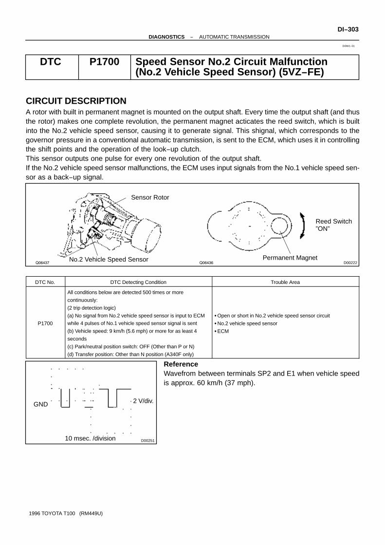
Q06437 Q06436 D00222No.2 Vehicle Speed Sensor
Sensor Rotor
Reed Switch”ON”
Permanent Magnet
D00251
GND 2 V/div.
10 msec. /division
−DIAGNOSTICS AUTOMATIC TRANSMISSIONDI−303
1996 TOYOTA T100 (RM449U)
DTC P1700 Speed Sensor No.2 Circuit Malfunction(No.2 Vehicle Speed Sensor) (5VZ−FE)
CIRCUIT DESCRIPTIONA rotor with built in permanent magnet is mounted on the output shaft. Every time the output shaft (and thusthe rotor) makes one complete revolution, the permanent magnet acticates the reed switch, which is builtinto the No.2 vehicle speed sensor, causing it to generate signal. This shignal, which corresponds to thegovernor pressure in a conventional automatic transmission, is sent to the ECM, which uses it in controllingthe shift points and the operation of the look−up clutch.This sensor outputs one pulse for every one revolution of the output shaft.If the No.2 vehicle speed sensor malfunctions, the ECM uses input signals from the No.1 vehicle speed sen-sor as a back−up signal.
DTC No. DTC Detecting Condition Trouble Area
P1700
All conditions below are detected 500 times or more
continuously:
(2 trip detection logic)
(a) No signal from No.2 vehicle speed sensor is input to ECM
while 4 pulses of No.1 vehicle speed sensor signal is sent
(b) Vehicle speed: 9 km/h (5.6 mph) or more for as least 4
seconds
(c) Park/neutral position switch: OFF (Other than P or N)
(d) Transfer position: Other than N position (A340F only)
�Open or short in No.2 vehicle speed sensor circuit
�No.2 vehicle speed sensor
�ECM
ReferenceWavefrom between terminals SP2 and E1 when vehicle speedis approx. 60 km/h (37 mph).
DI0W1−01
https://www.truck-manuals.net/

Q06836
No.2 VehicleSpeed Sensor
BR−R
BR
BR
SP2
E1
ECM
E5
E6V1
V1
4 − 6 V
EB
2
1
9
16BR
Q07653
E1
SP2
DI−304−DIAGNOSTICS AUTOMATIC TRANSMISSION
1996 TOYOTA T100 (RM449U)
WIRING DIAGRAM
INSPECTION PROCEDURE
1 Check vehicle speed value or resistance between terminals SP2 and E1 of ECM.
When using OBD II scan tool or TOYOTA hand−held tester:PREPARATION:(a) Connect an OBD II scan tool or TOYOTA hand−held tes-
ter to the DLC3.(b) Start the engine and OBD II scan tool or TOYOTA hand−
held tester main switch ON.CHECK:Drive the vehicle and read vehicle speed value.OK:
Vehicle speed matches tester speed value.When not using OBD II scan tool or TOYOTA hand−held tes-ter:PREPARATION:(a) Disconnect the connector from the ECM.(b) Shift the shift lever to N position.(c) Jack up the rear wheels on one side.CHECK:Check that there is continuity between terminals SP2 and E1of ECM while slowly turning the jacked−up wheel by hand.OK:
Resistance: Changes between 0 Ω and ∞ Ω
OK Check and replace ECM.
NG
https://www.truck-manuals.net/

Q07654
Magnet
−DIAGNOSTICS AUTOMATIC TRANSMISSIONDI−305
1996 TOYOTA T100 (RM449U)
2 Check No.2 vehicle speed sensor.
PREPARATION:Remove the No.2 vehicle speed sensor from the transmission.CHECK:Check that there is continuity between terminals of No.2 vehiclespeed sensor connector when a magnet is put close to it asshown.OK:
Resistance: Changes between 0 Ω and ∞ Ω
NG Replace No.2 vehicle speed sensor.
OK
Check and repair harness and connector between ECM and No.2 vehicle speed sensor(See page IN−26). Check and repair sensor rotor.
https://www.truck-manuals.net/
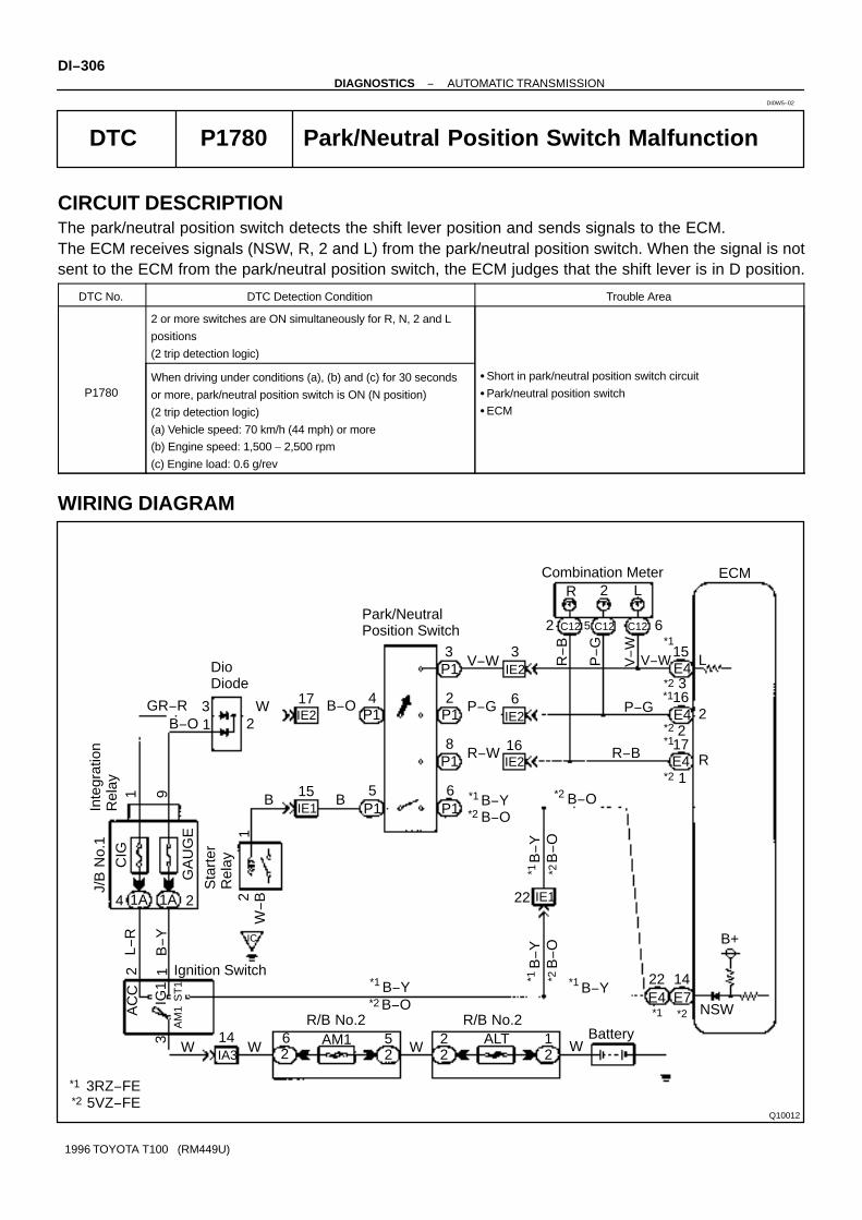
Q10012
ECMCombination Meter
Park/NeutralPosition Switch
DioDiode
Ignition Switch
Inte
grat
ion
Rel
ayJ/
B N
o.1
Sta
rter
Rel
ay
R/B No.2 R/B No.2Battery
GA
UG
E
CIG
AC
C
IG1
NSW
AM1 ALT
B+
E4
E4
E4
L
2
R
R 2 L
15
16
17
E4 E7
2 65C12 C12 C12
P1
P1
P1
P1
P1
P1
IE2
IE2
IE2
IE2
IE1
IA3
1A 1A IE1
R−B
P−G
V−W
R−W
P−G
V−W R−
B
P−
G
V−
W
B−OB−YB−O
B−YB−YB−O
B−OGR−RB−O
W W W W
W
B B
W−
B
L−R
B−
Y
B−
OB−
YB−
OB−
Y
3 3
2 6
8
6
16
17
15
4
5
31 2
2 26 5
2 22 13
24
2 1
1 9
12
14
AM
1S
T1
*1
3
2
1
*1
*1
*2
*2
*2
*1
*1*1
*2
*2
*2
*1 *2
*1 *2
IC
*1 *2
22
3RZ−FE5VZ−FE
*1
*2
1422
DI−306−DIAGNOSTICS AUTOMATIC TRANSMISSION
1996 TOYOTA T100 (RM449U)
DTC P1780 Park/Neutral Position Switch Malfunction
CIRCUIT DESCRIPTIONThe park/neutral position switch detects the shift lever position and sends signals to the ECM.The ECM receives signals (NSW, R, 2 and L) from the park/neutral position switch. When the signal is notsent to the ECM from the park/neutral position switch, the ECM judges that the shift lever is in D position.
DTC No. DTC Detection Condition Trouble Area
P1780
2 or more switches are ON simultaneously for R, N, 2 and L
positions
(2 trip detection logic)
�Short in park/neutral position switch circuit
�Park/neutral position switch
�ECM
When driving under conditions (a), (b) and (c) for 30 seconds
or more, park/neutral position switch is ON (N position)
(2 trip detection logic)
(a) Vehicle speed: 70 km/h (44 mph) or more
(b) Engine speed: 1,500 ∼ 2,500 rpm
(c) Engine load: 0.6 g/rev
WIRING DIAGRAM
DI0W5−02
https://www.truck-manuals.net/
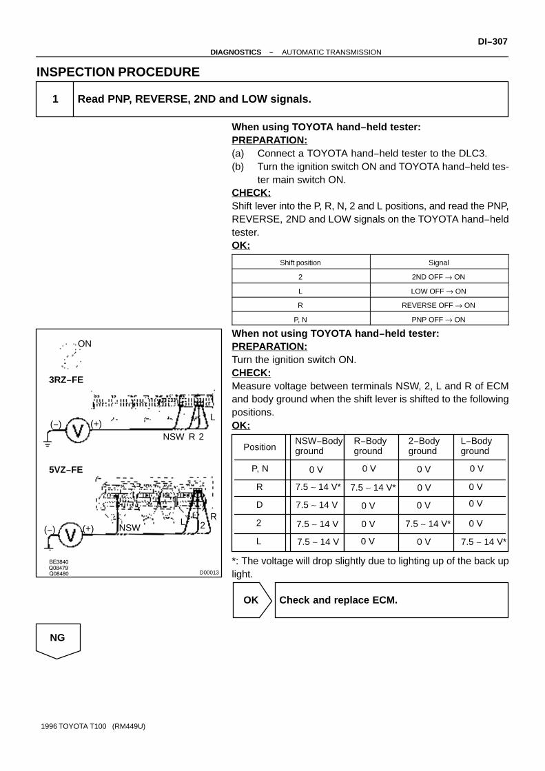
BE3840
Q08479
Q08480D00013
ON
L
2RNSW(+)(−)
(+)(−) NSWR
2L
3RZ−FE
5VZ−FE
Position
P, N
R
D
2
L
NSW−Bodyground
R−Bodyground
2−Bodyground
L−Bodyground
0 V0 V 0 V 0 V
0 V
0 V
0 V
0 V
0 V
0 V
0 V
0 V
0 V
7.5 ∼ 14 V*
7.5 ∼ 14 V
7.5 ∼ 14 V*
7.5 ∼ 14 V*
7.5 ∼ 14 V*
7.5 ∼ 14 V
7.5 ∼ 14 V
−DIAGNOSTICS AUTOMATIC TRANSMISSIONDI−307
1996 TOYOTA T100 (RM449U)
INSPECTION PROCEDURE
1 Read PNP, REVERSE, 2ND and LOW signals.
When using TOYOTA hand−held tester:PREPARATION:(a) Connect a TOYOTA hand−held tester to the DLC3.(b) Turn the ignition switch ON and TOYOTA hand−held tes-
ter main switch ON.CHECK:Shift lever into the P, R, N, 2 and L positions, and read the PNP,REVERSE, 2ND and LOW signals on the TOYOTA hand−heldtester.OK:
Shift position Signal
2 2ND OFF → ON
L LOW OFF → ON
R REVERSE OFF → ON
P, N PNP OFF → ON
When not using TOYOTA hand−held tester:PREPARATION:Turn the ignition switch ON.CHECK:Measure voltage between terminals NSW, 2, L and R of ECMand body ground when the shift lever is shifted to the followingpositions.OK:
*: The voltage will drop slightly due to lighting up of the back uplight.
OK Check and replace ECM.
NG
https://www.truck-manuals.net/

Q07657
DI−308−DIAGNOSTICS AUTOMATIC TRANSMISSION
1996 TOYOTA T100 (RM449U)
2 Check park/neutral position switch.
PREPARATION:(a) Jack up the vehicle.(b) Disconnect the park/neutral position switch connector.CHECK:Check continuity between each terminal shown below when theshift lever is moved to each position.OK:
Shift Position Terminal No. to continuity Terminal No. to continuity
P 4 − 7 5 − 6
R 4 − 8 −
N 4 − 10 5 − 6
D 4 − 9 −
2 2 − 4 −
L 3 − 4 −
NG Replace park/neutral position switch.
OK
Repair or replace harness and connector between battery and park/neutral position switch,park/neutral position switch and ECM (See page IN−26).
https://www.truck-manuals.net/

Q00758
Cruise Control Actuator with ECU ECM
B+
OD1E47Y−R
C17
9OD
D00053
ON
OD1(−) (+)
−DIAGNOSTICS AUTOMATIC TRANSMISSIONDI−309
1996 TOYOTA T100 (RM449U)
O/D Cancel Signal Circuit (5VZ−FE only)
CIRCUIT DESCRIPTIONWhile driving uphill with cruise control activated, in order to minimize gear shifting and provide smooth cruis-ing overdrive may be prohibited temporarily under some condition.The cruise control ECU sends O/D cut signals to the ECM as necessary and the ECM cancels O/D shiftinguntil these signals are discontinued.
WIRING DIAGRAM
INSPECTION PROCEDURE
1 Check voltage between terminal OD1 of ECM and body ground.
PREPARATION:Turn the ignition switch ON.CHECK:Measure voltage between terminal OD1 of ECM and bodyground.OK:
Voltage: 4 − 6 V
OK Proceed to next circuit inspection shown onproblem symptoms table (See page DI−282).
NG
DI0W9−02
https://www.truck-manuals.net/

D10999
DI−310−DIAGNOSTICS AUTOMATIC TRANSMISSION
1996 TOYOTA T100 (RM449U)
2 Check voltage between terminal OD of cruise control ECU harness sideconnector and body ground.
PREPARATION:(a) Disconnect the cruise control ECU connector.(b) Turn the ignition switch ON.CHECK:Measure voltage between terminal OD of cruise control ECUharness side connector and body ground.OK:
Voltage: 4 − 6 V
OK Check and replace cruise control ECU.
NG
3 Check harness and connector between cruise control ECU and ECM(See page IN−26).
NG Repair or replace harness or connector.
OK
Check and replace ECM.
https://www.truck-manuals.net/

Q10013
*O/D Main SwitchContacts go open with switch pushed in.Contacts go closed with switch pushed once again.
*1: 3RZ−FE*2: 5VZ−FE
O/D OFF Indicator Light(Combination Meter)
IntegrationRelay
Ignition Switch
R/B No.2 R/B No.2
J/B No.1
ECM
GAUGE
Battery
AM1 IG1
ALTAM1
B+
OD2B−Y B−O Y−G
W
W
WW6 5
2 2 22
21
1 99
23 1A
14 1
2
O3
O3
E4C13 C12
IA3
8 7 5
6
Y−
GW−
BIC
*1
*2
*O/DMainSwitch
−DIAGNOSTICS AUTOMATIC TRANSMISSIONDI−311
1996 TOYOTA T100 (RM449U)
O/D Main Switch & O/D OFF Indicator Light Circuit
CIRCUIT DESCRIPTIONThe O/D main switch contacts go open when the switch is pushed in and go closed when it is pushed out.In O/D main switch at OFF position, the O/D OFF indicator light lights up, and the ECM prohibits shifting O/D.
WIRING DIAGRAM
DI0WD−02
https://www.truck-manuals.net/

BE3840
Q06780
AT5623 D00221
ON
O/D Main Switch
ON
OFF
OFF
ON
DI−312−DIAGNOSTICS AUTOMATIC TRANSMISSION
1996 TOYOTA T100 (RM449U)
INSPECTION PROCEDUREO/D OFF indicator light does not light up:
1 Check operation of O/D main switch.
PREPARATION:Turn the ignition switch ON.CHECK:(a) Check the O/D OFF indicator light when O/D main switch
is pushed in to ON.(b) Check the O/D OFF indicator light when O/D main switch
is pushed again to OFF.OK:
(a) O/D OFF indicator light goes off(b) O/D OFF indicator light lights up
NG Go to step 4.
OK
https://www.truck-manuals.net/

BE3840
Q07661
Q07662
D00016
3RZ−FE
5VZ−FE
OD2(+)(−)
ON
OD2(+)(−)
−DIAGNOSTICS AUTOMATIC TRANSMISSIONDI−313
1996 TOYOTA T100 (RM449U)
2 Check OVRDRIVE CUT SW2 signal.
When using TOYOTA hand−held tester:PREPARATION:(a) Connect a TOYOTA hand−held tester to the DLC3.(b) Turn the ignition switch ON and TOYOTA hand−held tes-
ter main switch ON.CHECK:Read the ”OVRDRIVE CUT SW2” signal on the TOYOTAhand−held tester.OK:
O/D main switch condition OVRDRIVE CUT SW2 signal
ON (Pushed in) ON
OFF (Pushed once again) OFF
When not using TOYOTA hand−held tester:PREPARATION:Turn the ignition switch ON.CHECK:Check voltage between terminal OD2 of ECM and body ground.OK:
O/D main switch condition Voltage
ON (Pushed in) 9 − 14 V
OFF (Pushed once again) Below 3 V
OK Proceed to next circuit inspection shown onproblem symptoms table (See page DI−282).
NG
https://www.truck-manuals.net/

Q07663
1
2
DI−314−DIAGNOSTICS AUTOMATIC TRANSMISSION
1996 TOYOTA T100 (RM449U)
3 Check harness and connector between O/D OFF indicator light and ECM (Seepage IN−26).
NG Repair or replace harness or connector.
OK
Check O/D main switch.
4 Check O/D main switch.
PREPARATION:Disconnect the O/D main switch connector.CHECK:Check continuity resistance between terminal 1 and 2 of O/Dmain switch connector.OK:
O/D main switch condition Specified condition
ON (Pushed in) No continuity
OFF (Pushed once agin) Continuity
NG Replace O/D main switch.
OK
Check and replace the combination meter(See page BE−38).
https://www.truck-manuals.net/

Q07663
1
2
−DIAGNOSTICS AUTOMATIC TRANSMISSIONDI−315
1996 TOYOTA T100 (RM449U)
O/D OFF indicator light remains ON:
1 Check O/D main switch.
PREPARATION:Disconnect the O/D main switch connector.CHECK:Check continuity between terminals 1 and 2 of O/D main switchconnector.OK:
O/D main switch Specified condition
ON No continuity
OFF Continuity
NG Replace O/D main switch.
OK
2 Check harness and connector between O/D OFF indicator light and O/D mainswitch, O/D OFF indicator light and ECM (See page IN−26).
NG Repair or replace harness or connector.
OK
Check and replace ECM.
https://www.truck-manuals.net/

D09979
DI−316−DIAGNOSTICS AUTOMATIC TRANSMISSION
1996 TOYOTA T100 (RM449U)
Stop Light Switch Circuit
CIRCUIT DESCRIPTIONThe purpose of this circuit is to prevent the engine from stalling, while driving in lock−up condition, whenbrakes are suddenly applied.When the brake pedal is operated, this switch sends a signals to the ECM. Then the ECM cancels operationof the lock−up clutch while braking is in progress.
WIRING DIAGRAM
DI98I−01
https://www.truck-manuals.net/

D11000
−DIAGNOSTICS AUTOMATIC TRANSMISSIONDI−317
1996 TOYOTA T100 (RM449U)
INSPECTION PROCEDURE
1 Check operation of stop light.
CHECK:Check if the stop lights go on and off normally when the brake pedal is operated and released.
NG Check and repair stop light circuit.
OK
2 Check STP signal.
When using OBD II scan tool or TOYOTA hand−held tester:PREPARATION:(a) Connect an OBD II scan tool or TOYOTA hand−held tes-
ter to the DLC3.(b) Turn the ignition switch ON and OBD II scan tool or TOY-
OTA hand−held tester main switch ON.CHECK:Read the STP signal on the TOYOTA hand−held tester.OK:
Brake Pedal STP Signal
Depressed ON
Release OFF
When not using OBD II scan tool or TOYOTA hand−held tes-ter:PREPARATION:Turn the ignition switch ON.CHECK:Check the voltage between terminal B/K of the ECM connectorand body ground.OK:
Brake Pedal Voltage
Depressed 7.5 − 14 V
Release Below 1.5 V
https://www.truck-manuals.net/

DI−318−DIAGNOSTICS AUTOMATIC TRANSMISSION
1996 TOYOTA T100 (RM449U)
OK Proceed to next circuit inspection shown onproblem symptoms table (See page DI−282).
NG
3 Check harness and connector between stop light switch and ECM (See page IN−26).
NG Repair or replace harness or connector.
OK
Check and replace ECM.
https://www.truck-manuals.net/

DI0ZF−01
Vehicle Brought to Workshop
Customer Problem AnalysisP. DI−320
Check and Clear DTC (Precheck)P. DI−321
Items inside are titles of pages in this manual,with the page number in the bottom portion. Seethe pages for detailed explanations.
Problem Symptom Confirmation Symptom SimulationP. IN−16
Symptomdoes not occur
Symptomoccurs
DTC CheckP. DI−321
Sensor CheckCircuit Inspection
P. DI−332 ∼ DI−360
DTC ChartP. DI−326
Malfunction code
Problem Symptoms TableP. DI−331
Check for Fluid LeakageP. DI−362
Identification of Problem
Normal code
Repair
Confirmation Test
End
1
2
3 4
5
6 7
89
10
11
Step 8 : Diagnostic steps permitting the use of theTOYOTA hand−held tester or TOYOTAbreak−out−box.
−DIAGNOSTICS ANTI−LOCK BRAKE SYSTEMDI−319
576Author�: Date�:
1996 TOYOTA T100 (RM449U)
ANTI−LOCK BRAKE SYSTEMHOW TO PROCEED WITH TROUBLESHOOTINGTroubleshoooting in accordance with the procedure on the following pages.
https://www.truck-manuals.net/

DI0ZI−01
ABS Check SheetInspector’sName :
Customer’s Name
Date VehicleBrought In
Registration Year
Registration No.
Frame No.
Odometer Reading
/ /
/ /
Date Problem First Occurred
Frequency Problem Occurs
/ /
Continuous Intermittent ( times a day)
ABS does not operate.
ABS does not operate efficiently.
ABS Warning LightAbnormal
Remains ON Does not Light Up
DTC Check1st Time
2nd Time
Normal Code Malfunction Code (Code )
Normal Code Malfunction Code (Code )
Symptoms
kmmiles
DI−320−DIAGNOSTICS ANTI−LOCK BRAKE SYSTEM
1996 TOYOTA T100 (RM449U)
CUSTOMER PROBLEM ANALYSIS CHECK
https://www.truck-manuals.net/

R12019
DI0ZM−03
A00778DLC1
E1 Tc
F00006
DLC1
Short Pin
R01346
Normal Code
0.25 sec.
0.25 sec.
2 sec.
ON
OFF
ON
OFF
0.5 sec. 0.5 sec.
Code 11 and 21
4 sec.
1.5 sec.
2.5 sec.
Code 11 Code 21
−DIAGNOSTICS ANTI−LOCK BRAKE SYSTEMDI−321
1996 TOYOTA T100 (RM449U)
PRE−CHECK1. DIAGNOSIS SYSTEM(a) Check the indicator light.
When the ignition switch is turned ON, check that the ABSwarning light goes on for 3 seconds.
HINT:If the indicator check result is not normal, proceed to trouble-shooting for the ABS warning light circuit (See page DI−354).
(b) Check the DTC.(1) Using SST, connect terminals Tc and E1 of the
DLC1.SST 09843−18020
(2) Disconnect the short pin from the DLC1.(3) Turn the ignition switch ON.(4) Read the DTC from the ABS warning light on the
combination meter.HINT:� If no code appears, inspect the diagnostic circuit or ABS
warning light circuit (See page DI−354 or DI−358).
� As an example, the blinking patterns for normal code andcodes 11 and 21 are shown on the left.(5) Code are explained in the code table on page
DI−326.(6) After completing the check, disconnect terminals Tc
and E1, and turn off the display.If 2 or more malfunctions are indicated at the same time the low-est numbered DTC will be displayed 1st.
https://www.truck-manuals.net/

BR3890
F00006DLC1
Short Pin
N09348
TOYOTAhand−held tester
TOYOTAbrake−out−box
ECU
A00778DLC1
E1Tc
Ts
DI−322−DIAGNOSTICS ANTI−LOCK BRAKE SYSTEM
1996 TOYOTA T100 (RM449U)
(c) Clear the DTC.(1) Using SST, connect terminals Tc and E1 of the
DLC1 and remove the short pin from the DLC1.SST 09843−18020(2) Turn the ignition switch ON.(3) Clear the DTC stored in ECU by depressing the
brake pedal 8 or more times within 3 seconds.(4) Check that the warning light shows the normal
code.
(5) Remove the SST from the terminals of the DLC1.SST 09843−18020(6) Connect the short pin to the DLC1.
HINT:Cancellation can also be done by removing the ECU−B fuse,but in this case, other memory systems will also be cancelledout.
(d) Using TOYOTA brake−out−box and TOYOTA hand−heldtester, measure the ECU terminal value.(1) Hook up the TOYOTA hand−held tester and
TOYOTA break−out−box to the vehicle.(2) Read the ECU input/output values by following the
prompts on the tester screen.HINT:TOYOTA hand−held tester has a ”Snapshot” function. This re-cords the measured values and is effective in the diagnosis ofintermittent problems.Please refer to the TOYOTA hand−held tester/TOYOTA break−out−box operator’s manual for further details.
2. SPEED SENSOR SIGNAL AND DECELERATION SEN-SOR CHECK
(a) Check the speed sensor signal.(1) Turn the ignition switch OFF.(2) Using SST, connect terminals Ts and E1 of the
DLC1.SST 09843−18020(3) Start the engine.
https://www.truck-manuals.net/

BR3904
0.13 sec. 0.13 sec.
ON
OFF
BR3893
Malfunction Code (Example Code 72, 76)7 2 67
ON
OFF
0.5 sec.0.5 sec.0.5 sec.0.5 sec.
1.5 sec. 2.5 sec. 4 sec.
Repeat
A00778DLC1
E1
Ts
−DIAGNOSTICS ANTI−LOCK BRAKE SYSTEMDI−323
1996 TOYOTA T100 (RM449U)
(4) Check that the ABS warning light blinks.HINT:If the ABS warning light does not blink, inspect the ABS warninglight circuit (See page DI−354).
(5) Drive vehicle straight forward.HINT:Drive vehicle faster than 45 km/h (28 mph) for several seconds.
(6) Stop the vehicle.(7) Using SST, connect terminals Tc and E1 of the
DLC1.SST 09843−18020(8) Read the number of blinks of the ABS warning light.
HINT:� See the list of DTC on page DI−326.� If every sensor is normal, a normal code is output (A cycle
of 0.25 sec. ON and 0.25 sec. OFF is repeated).� If 2 or more malfunction are indicated at the same time,
the lowest numbered code will be displayed 1st.
(9) After doing the check, disconnect terminals Ts andE1, Tc and E1 of the DLC1, and ignition switchturned OFF.
(b) Check the deceleration sensor detection point.(1) Turn the ignition switch OFF.(2) Using SST, connect terminals Ts and E1 of the
DLC1.SST 09843−18020(3) Start the engine.
https://www.truck-manuals.net/

R05599
0.13 sec.
0.13 sec.3 sec.
ON
OFF
R12881
1,100 ± 30 mm(43.31 ± 1.18 in.)
R12882
830 ± 30 mm(32.68 ± 1.18 in.)
BR1865
0.13 sec.
0.13 sec.
ON
OFF
R05596
0.13 sec.
Braking 0.13 sec.
DI−324−DIAGNOSTICS ANTI−LOCK BRAKE SYSTEM
1996 TOYOTA T100 (RM449U)
(4) Check that the ABS warning light blinks.HINT:If the ABS warning light does not blink, inspect the ABS warninglight circuit (See page DI−354).
(5) Jack up the rear side of the vehicle slowly.HINT:When measuring the height, measure at the center of the lowerbody of the vehicle.
(6) Check that the warning light blinks.If the warning light turns on, inspect the deceleration sensorinstallation. If the sensor installation is OK, replace the decel-eration sensor.
(7) Jack down the vehicle slowly.
(8) Jack up the front side of the vehicle slowly, asshown.
HINT:When measuring the height, measure at the center of the lowerbody of the vehicle.
(9) Check that the warning light blinks.If the warning light turns on, inspect the deceleration sensorinstallation. If the sensor installation is OK, replace the decel-eration sensor.
(10) Jack down the vehicle slowly.(c) Check the deceleration sensor operation.
(1) Drive the vehicle straight ahead at about 20 km/h(12.4 mph) or more, lightly depress the brake pedal.
(2) Check that there is no change in the warning lightpattern.
(3) Drive the vehicle straight ahead at about 20 km/h(12.4 mph) or more, and depress the brake pedalmoderately.
(4) Check that the warning light turns on while braking.
https://www.truck-manuals.net/

R05597
0.13 sec. 0.13 sec.
Braking
−DIAGNOSTICS ANTI−LOCK BRAKE SYSTEMDI−325
1996 TOYOTA T100 (RM449U)
(5) Drive the vehicle straight ahead at about 20 km/h(12.4 mph) or more, and depress the brake pedalstrongly.
(6) Check that the warning light pattern changes whilebraking, as shown.
If the operation is not as specified, inspect the deceleration sen-sor installation. If the sensor installation is OK, replace the de-celeration sensor.
(7) Stop the vehicle and turn the ignition switch OFF.(8) Remove the SST from the terminals of the DLC1.SST 09843−18020
(d) Check the DTC of the speed sensor function.
Code No. Diagnosis Trouble Area
71 Low output voltage of right front speed sensor�Right front speed sensor
�Sensor installation
72 Low output voltage of left front speed sensor�Left front speed sensor
�Sensor installation
73 Low output voltage of right rear speed sensor�Right rear speed sensor
�Sensor installation
74 Low output voltage of left rear speed sensor�Left rear speed sensor
�Sensor installation
75Abnormal change in output voltage of right front speed
sensor�Right front speed sensor rotor
76Abnormal change in output voltage of left front speed
sensor�Left front speed sensor rotor
77Abnormal change in output voltage of right rear speed
sensor�Right rear speed sensor rotor
78Abnormal change in output voltage of left rear speed
sensor�Left rear speed sensor rotor
79* Deceleration sensor is faulty�Deceleration sensor
�Sensor installation
*: 4WD models
https://www.truck-manuals.net/

DI0ZQ−03
DI−326−DIAGNOSTICS ANTI−LOCK BRAKE SYSTEM
1996 TOYOTA T100 (RM449U)
DIAGNOSTIC TROUBLE CODE CHARTHINT:Using SST 09843−18020, connect terminals Tc and E1, and remove the short pin.If a malfunction code is displayed during the DTC check, check the circuit listed that the code. For detailsof each code, turn to the page referred to under the ”See Page” for respective ”DTC No.” in the DTC chart.
DTC No.
(See Page)Detection Item Trouble Area
11
(DI−332)Open circuit in ABS control (solenoid) relay circuit
�ABS control (solenoid) relay
�Open or short in ABS control (solenoid) relay circuit
�ECU
12
(DI−332)Short circuit in ABS control (solenoid) relay circuit
�ABS control (solenoid) relay
�B+ short in ABS control (solenoid) relay circuit
�ECU
13
(DI−335)Open circuit in ABS control (motor) relay circuit
�ABS control (motor) relay
�Open or short in ABS control (motor) relay circuit
�ECU
14
(DI−335)Short circuit in ABS control (motor) relay circuit
�ABS control (motor) relay
�B+ short in ABS control (motor) relay circuit
�ECU
21
(DI−338)
Open or short circuit in 2−position solenoid circuit for right front
wheel
�ABS actuator
�Open or short in SFRR or SFRH circuit
�ECU
22
(DI−338)
Open or short circuit in 2−position solenoid circuit for left front
wheel
�ABS actuator
�Open or short in SFLR or SFLH circuit
�ECU
23
(DI−338)
Open or short circuit in 2−position solenoid circuit for rear
wheel
�ABS actuator
�Open or short in SRR or SRH circuit
�ECU
31
(DI−341)Right front wheel speed sensor signal malfunction
�Right front, left front, right rear and left rear speed sensor
�Open or short in each speed sensor circuit
�ECU
32
(DI−341)Left front wheel speed sensor signal malfunction
33
(DI−341)Right rear wheel speed sensor signal malfunction
34
(DI−341)Left rear wheel speed sensor signal malfunction
35
(DI−341)Open circuit in left front or right rear wheel speed sensor.
36
(DI−341)Open circuit in right front or left rear wheel speed sensor.
37
(DI−345)Neither front speed sensor rotor missing
�Front axle hub
�Right front, left front speed sensor
�Wire harness for sensor system
�ECU
37
(DI−346)Some tire is different size from the other tires
�Tire size
�ECU
41
(DI−347)
Low battery positive voltage or abnormally high battery
positive voltage
�Battery
� IC regulator
�Open or short in power source circuit
�ECU
https://www.truck-manuals.net/

−DIAGNOSTICS ANTI−LOCK BRAKE SYSTEMDI−327
1996 TOYOTA T100 (RM449U)
43*
(DI−350)Malfunction in deceleration sensor
�Deceleration sensor
�Wire harness for deceleration sensor system
�ECU
44*
(DI−351)Open or short in deceleration sensor circuit
�Deceleration sensor
�Open or short in deceleration sensor circuit
�ECU
51
(DI−353)
Pump motor is locked
Open in pump motor ground�ABS pump motor
Always
ONMalfunction in ECU �ECU
*: 4WD models
https://www.truck-manuals.net/

DI0ZT−03
F14854
DI−328−DIAGNOSTICS ANTI−LOCK BRAKE SYSTEM
1996 TOYOTA T100 (RM449U)
PARTS LOCATION
https://www.truck-manuals.net/

DI7HH−02
R00463
A15 A16
12345678
910111213
12345678
141516
910111213
14151617181920212223242526
−DIAGNOSTICS ANTI−LOCK BRAKE SYSTEMDI−329
1996 TOYOTA T100 (RM449U)
TERMINALS OF ECU
Symbols (Terminals No.) STD Voltage (V) Condition
BAT (A15 − 22) − GND (A15 − 11, 24) 10 − 14 Always
IG1 (A15 − 10) − GND (A15 − 11, 24) 10 − 14 IG switch ON
SR (A16 − 5) − R− (A16 − 15) 9 − 14 IG switch ON, ABS warning light OFF
MR (A16 − 4) − R− (A16 − 15) Below 1.0 IG switch ON
SFRH (A16 − 1) − GND (A15 − 11, 24) 10 − 14 IG switch ON, ABS warning light OFF
SFRR (A16 − 2) − GND (A15 −11, 24) 10 − 14 IG switch ON, ABS warning light OFF
SFLH (A15 − 13) − GND (A15 − 11, 24) 10 − 14 IG switch ON, ABS warning light OFF
SFLR (A15 − 12) − GND (A15 − 11, 24) 10 − 14 IG switch ON, ABS warning light OFF
SRR (A15 − 25) − GND (A15 − 11, 24) 10 − 14 IG switch ON, ABS warning light OFF
SRH (A15 − 26) − GND (A15 − 11, 24) 10 − 14 IG switch ON, ABS warning light OFF
AST (A16 − 11) − GND (A15 − 11, 24) 10 − 14 IG switch ON, ABS warning light OFF
WA (A16 − 12) − GND (A15 − 11, 24)Below 2.0 IG switch ON, ABS warning light ON
10 − 14 IG switch ON, ABS warning light OFF
STP (A15 − 21) − GND (A15 − 11, 24)Below 1.5 Stop light switch OFF
8 − 14 Stop light switch ON
Tc (A15 − 20) − GND (A15 − 11, 24) 10 − 14 IG switch ON
Ts (A15 − 6) − GND (A15 − 11, 24) 10 − 14 IG switch ON
FR+ (A16 − 7) − FR− (A16 − 5) AC generationIG switch ON
Slowly turn right front wheel
FL+ (A16 − 14) − FL− (A16 − 13) AC generationIG switch ON
Slowly turn left front wheel
RR+ (A15 − 15) − RR− (A15 − 16) AC generationIG switch ON
Slowly turn right rear wheel
RL+ (A15 − 1) − RL− (A15 − 2) AC generationIG switch ON
Slowly turn left rear wheel
GS1* (A15 − 19) − GND (A15 − 11, 24) about 2 or 4 IG switch ON
GS2* (A15 − 7) − GND (A15 − 11, 24) about 2 IG switch ON
EXI* (A15 − 8) − GND (A15 − 11, 24)Below 2.0 IG switch ON, transfer is in L4 or H4 position
10 − 14 IG switch ON, transfer is in H4 position
EXI3 (A15 − 9) − GND (A15 − 11, 24)Below 2.0 IG switch ON, transfer is in L4 position
10 − 14 IG switch ON, transfer is in a position other than L4
MT (A16 − 8) − GND (A15 − 11, 24) Below 1.5 IG switch ON
FSS (A16 − 16) − GND (A15 − 11, 24) Continuity IG switch OFF
RSS (A15 − 23) − GND (A15 − 11, 24) Continuity IG switch OFF
PKB (A15 − 9) − GND (A15 − 11, 24)Below 1.5 IG switch ON, PKB lever pulled
10 − 14 IG switch ON, PKB lever released
https://www.truck-manuals.net/

DI−330−DIAGNOSTICS ANTI−LOCK BRAKE SYSTEM
1996 TOYOTA T100 (RM449U)
*: 4WD Vehicle
https://www.truck-manuals.net/

DI0ZZ−03
−DIAGNOSTICS ANTI−LOCK BRAKE SYSTEMDI−331
1996 TOYOTA T100 (RM449U)
PROBLEM SYMPTOMS TABLEIf a normal code is displayed during the DTC check but the problem still occurs, check the circuits for eachproblem symptom in the order given in the table below and proceed to the relevant troubleshooting page.
Symptoms Inspection Circuit See page
ABS does not operate.
Only when 1. − 4. are all normal and the problem is still occurring, replace the
ABS ECU.
1. Check the DTC reconfirming that the normal code is output.
2. IG power source circuit.
3. Speed sensor circuit.
4. Check the ABS actuator with a checker.
If abnormal, check the hydraulic circuit for leakage (See page DI−xx).
DI−321
DI−347
DI−341
BR−58
ABS does not operate
efficiently.
Only when 1. − 4. are all normal and the problem is still occurring, replace the
ABS ECU.
1. Check the DTC reconfirming that the normal code is output.
2. Speed sensor circuit.
3. Stop light switch circuit.
4. Check the ABS actuator with a checker.
If abnormal, check the hydraulic circuit for leakage (See page DI−362).
DI−321
DI−341
BR−58
ABS warning light
abnormal.
1. ABS warning light circuit.
2. ABS ECU.
DI−354
DTC check cannot be done.
Only when 1. and 2. are all normal and the problem is still occurring, replace the
ABS ECU.
1. ABS warning light circuit.
2. Tc terminal circuit.
DI−354
DI−358
Speed sensor signal check
cannot be done.
1. Ts terminal circuit.
2. ABS ECU.
DI−360
https://www.truck-manuals.net/

DI103−03
F14589
ABS Contorl Relay
ABS Actuator
ABS ECU
R/BNo.2
MotorRelay
SolenoidRelay
ABS ECU
DLC1
AB
S
Battery
A16
A16
A16
A16
A16
A6
A6
A5
A4
A4
A4 A4
A5A6
A6
A5
A5
A4
EA1
EA1
ID
MR
R−
SR
AST
MT
R−B
G−B
R−W
R−Y
R−L
W−B
W−B
W
W
W
W
W
R−L
W−R LG
4
15
5
4
3
1
3
5
1
2
6
1
5
10
10 2
29
2
2
5
4
11
8
DI−332−DIAGNOSTICS ANTI−LOCK BRAKE SYSTEM
1996 TOYOTA T100 (RM449U)
CIRCUIT INSPECTION
DTC 11, 12 ABS Control (Solenoid) Relay Circuit
CIRCUIT DESCRIPTIONThis relay supplies power to each ABS solenoid. After the ignition switch is turned ON, if the initial check isOK, the relay goes on.
DTC No. DTC Detecting Condition Trouble Area
11
Conditions 1 and 2 continue for 0.2 sec. or more:
1. ABS control (solenoid) relay terminal (SR) voltage:
Battery positive voltage
2. ABS control (solenoid) relay monitor terminal (AST)
voltage: 0V
�ABS control (solenoid) relay
�Open or short in ABS control (solenoid) relay circuit
�ECU
12
Conditions 1 and 2 continue for 0.2 sec. or more:
1. ABS control (solenoid) relay terminal (SR) voltage: 0 V
2. ABS control (solenoid) relay monitor terminal (AST)
voltage: Battery positive voltage
�ABS control (solenoid) relay
�B+ short in ABS control (solenoid) relay circuit
�ECU
Fail safe function: If trouble in the ABS control (solenoid) relay circuit, the ECU cuts off current to the ABS control (solenoid)relay and prohibits ABS control.
WIRING DIAGRAM
https://www.truck-manuals.net/

BE6653R14203 F00001
LOCK
2
6
A5
R13727
5
4
3
11
ABS ControlRelay
ABSActuator
ABS ECU
A4
A4 A4
A4
A16
A5
−DIAGNOSTICS ANTI−LOCK BRAKE SYSTEMDI−333
1996 TOYOTA T100 (RM449U)
INSPECTION PROCEDURE
1 Check voltage between terminals A5 − 2 and A5 − 6 of ABS control relayconnector.
PREPARATION:Disconnect the ABS control relay connector.CHECK:Measure the voltage between terminals A5 − 2 and A5 − 6 ofABS control relay harness side connector.OK:
Voltage: 10 − 14 V
NG Check and repair harness or connector.
OK
2 Check continuity between terminals A5 − 5 and A4 − 4, A4 − 4 and A4 − 3, A4 − 3and A16 − 11.
PREPARATION:Disconnect the 2 connectors from the ABS actuator.CHECK:Check continuity between terminals A5 − 5 and A4 − 4, A4 − 4and A4 − 3, A4 − 3 and A16 − 11.OK:
ContinuityHINT:There is a resistance of 26 ∼ 40 Ω between terminals A4 − 4 andA4 − 3.
NG Repair or replace harness or ABS actuator.
OK
https://www.truck-manuals.net/

R14139
ContinuityOpen
Continuity
1
2
63
A6A5
5
R14140
(−)
(+)
Continuity
Open3 6 5
1
2A6A5
DI−334−DIAGNOSTICS ANTI−LOCK BRAKE SYSTEM
1996 TOYOTA T100 (RM449U)
3 Check ABS control (solenoid) relay.
CHECK:Check continuity between each terminal of ABS control (sole-noid) relay.OK:
Terminals A5 − 1 and A6 − 3 Continuity (Reference value 80 Ω)
Terminals A5 − 5 and A5 − 6 Continuity
Terminals A5 − 2 and A5 − 5 Open
CHECK:(a) Apply battery positive voltage between terminals A5 − 1
and A6 − 3.(b) Check continuity between each terminal of ABS control
(solenoid) relay.OK:
Terminals A5 − 5 and A5 − 6 Open
Terminals A5 − 2 and A5 − 5 Continuity
NG Replace ABS control relay.
OK
4 Check for open and short in harness and connector between ABS control relayand ABS ECU (See page IN−26).
NG Repair or replace harness or connector.
OK
If same code is still output after DTC is deleted, check contact condition of each connection.If connections are normal, ECU may be defective.
https://www.truck-manuals.net/

F14589
ABS Contorl Relay
ABS Actuator
ABS ECU
R/BNo.2
MotorRelay
SolenoidRelay
ABS ECU
DLC1
AB
S
Battery
A16
A16
A16
A16
A16
A6
A6
A5
A4
A4
A4 A4
A5A6
A6
A5
A5
A4
EA1
EA1
ID
MR
R−
SR
AST
MT
R−B
G−B
R−W
R−Y
R−L
W−B
W−B
W
W
W
W
W
R−L
W−R LG
4
15
5
4
3
1
3
5
1
2
6
1
5
10
10 2
29
2
2
5
4
11
8
−DIAGNOSTICS ANTI−LOCK BRAKE SYSTEMDI−335
1996 TOYOTA T100 (RM449U)
DTC 13, 14 ABS Control (Motor) Relay Circuit
CIRCUIT DESCRIPTIONThe ABS control (motor) relay supplies power to the ABS pump motor. While the ABS is activated, the ECUswitches the ABS control (motor) relay ON and operates the ABS pump motor.
DTC No. DTC Detecting Condition Trouble Area
13
Conditions 1 and 2 continued for 0.2 sec. or more:
1. ABS control (motor) relay terminal (MR) voltage: Battery
positive voltage
2. ABS control (motor) relay monitor terminal (MT) voltage:
0 V
�ABS control (motor) relay
�Open or short in ABS control (motor) relay circuit
�ECU
14
Conditions 1 and 2 continued for 2.5 sec. or more:
1. ABS control (motor) relay terminal (MR) voltage: 0 V
2. ABS control (motor) relay monitor terminal (MT) voltage:
Battery positive voltage
�ABS control (motor) relay
�B+ short in ABS control (motor) relay circuit
�ECU
Fail safe function: If trouble occurs in the ABS control (motor) relay circuit, the ECU cuts off current to the ABS control (solenoid)relay and prohibits ABS control.
WIRING DIAGRAM
DI106−03
https://www.truck-manuals.net/

BE6653R14667 F15004
A6
LOCK
(−) (+)
1
R13728
8
ABS ControlRelay
ABSActuator
ABS ECU
22
55
A6
A4
A16
A4
A4A4
2
DI−336−DIAGNOSTICS ANTI−LOCK BRAKE SYSTEM
1996 TOYOTA T100 (RM449U)
INSPECTION PROCEDURE
1 Check voltage between terminal A6 − 1 of ABS control relay and body ground.
PREPARATION:Disconnect the ABS control relay connector.CHECK:Measure voltage between terminal A6 − 1 of ABS control relayharness side connector and body ground.OK:
Voltage: 10 − 14 V
NG Check and repair harness or connector.
OK
2 Check continuity between terminals A6 − 2 and A4 − 2, A4 − 2 and A4 − 5, A4 − 5and A16 − 12.
PREPARATION:Disconnect the 2 connectors from the ABS actuator.CHECK:Check continuity between terminals A6 − 2 and A4 − 2, A4 − 2and A4 − 5, A4 − 5 and A16 − 8.OK:
ContinuityHINT:.There is a resistance of 26 ∼ 40 Ω between terminals A4 − 2 andA4 − 5
NG Repair or replace harness or ABS actuator.
OK
https://www.truck-manuals.net/

W00572
Open
Continuity1
2
34
A6 A5
W00573
(+) (−)
Continuity
12
34
A6 A5
−DIAGNOSTICS ANTI−LOCK BRAKE SYSTEMDI−337
1996 TOYOTA T100 (RM449U)
3 Check ABS control (motor) relay.
CHECK:Check continuity between each terminal of ABS control (motor)relay.OK:
Terminals A6 − 3 and A6 − 4 Continuity (Reference value 62 Ω)
Terminals A6 − 1 and A6 − 2 Open
CHECK:(a) Apply battery positive voltage between terminals A6 − 3
and A6 − 4.(b) Check continuity between terminals of ABS control relay.OK:
Terminals A6 − 1 and A6 − 2 Continuity
NG Replace ABS control relay.
OK
4 Check for open and short in harness and connector between ABS control relayand ABS ECU (See page IN−26).
NG Repair or replace harness or connector.
OK
If same code is still output after DTC is deleted, check contact condition of each connection.If connections are normal, ECU may be defective.
https://www.truck-manuals.net/

DI−338−DIAGNOSTICS ANTI−LOCK BRAKE SYSTEM
1996 TOYOTA T100 (RM449U)
DTC 21, 22, 23 ABS Actuator Solenoid Circuit
CIRCUIT DESCRIPTIONThis solenoid goes on when signals are received from the ECU and controls the pressure acting on the wheelcylinders thus controlling the braking force.
DTC No. DTC Detecting Condition Trouble Area
21
Conditions 1 through 3 continue for 0.02 sec. or more:
1. ABS control (solenoid) relay terminal (SR) voltage:
Battery positive voltage
2. Voltage of ABS ECU terminal AST: Battery positive
voltage
3. When power transistor of ECU is ON, voltage of terminal
SFRR or SFRH is 0 V or battery positive voltage.
�ABS actuator
�Open or short in SFRR or SFRH circuit
�ECU
22
Conditions 1 through 3 continue for 0.02 sec. or more:
1. ABS control (solenoid) relay terminal (SR) voltage:
Battery positive voltage
2. Voltage of ABS ECU terminal AST: Battery positive
voltage
3. When power transistor of ECU is ON, voltage of terminal
SFLR or SFLH is 0 V or battery positive voltage.
�ABS actuator
�Open or short in SFLR or SFLH circuit
�ECU
23
Conditions 1 through 3 continue for 0.02 sec. or more:
1. ABS control (solenoid) relay terminal (SR) voltage:
Battery positive voltage
2. Voltage of ABS ECU terminal AST: Battery positive
voltage
3. When power transistor of ECU is ON, voltage of terminal
SRR or SRH is 0 V or battery positive voltage.
�ABS actuator
�Open or short in SRR or SRH circuit
�ECU
Fail safe function: If trouble occurs in the actuator solenoid circuit, the ECU cuts off current to the ABS control (solenoid) relayand prohibits ABS control.
DI10A−03
https://www.truck-manuals.net/

F14590
ABS Contorl Relay
ABS ECU
MotorRelay
SolenoidRelay
A15
A15
A16
A16
A15
A6
A6
A5
A15
A3
A3
A3
A3
A3
A3
G−Y
G−R
G−W
G
L−Y
ABS ECU
4
3
1
A61
A52
A5
6
W
W
EA110
EA15
W
W
W−B
DLC1
ID
A41
W−B
ABS Actuator
A6 A5
A4 A4
W−R LG10 2
AB
S
9 2
R/BNo.2
W
R−L
Battery
2
2
5
4ABS ECU
L−R
SFLR
SFLH
SFRR
SFRH
SRR
SRH
6
3
4
5
1
12
13
2
1
25
26
2
F14588
1
2
45
3
4
A3A4
6
−DIAGNOSTICS ANTI−LOCK BRAKE SYSTEMDI−339
1996 TOYOTA T100 (RM449U)
WIRING DIAGRAM
INSPECTION PROCEDURE
1 Check ABS actuator solenoid.
PREPARATION:Disconnect the 2 connectors from the ABS actuator.CHECK:Check continuity between terminals A4 − 4 and A3 − 1, 2, 3, 4,5, 6 of ABS actuator connector.OK:
ContinuityHINT:Resistance of each solenoid coilSFRH, SFLH, SRH: 5.0 ΩSFRR, SFLR, SRR: 2.2 Ω
NG Replace ABS actuator.
OK
https://www.truck-manuals.net/

DI−340−DIAGNOSTICS ANTI−LOCK BRAKE SYSTEM
1996 TOYOTA T100 (RM449U)
2 Check for open and short in harness and connector between ABS ECU andactuator (See page IN−26).
NG Repair or replace harness or connector.
OK
If same code is still output after DTC is deleted, check contact condition of each connection.If connector are normal, ECU may be defective.
https://www.truck-manuals.net/

BR3583BR3582 F00010
RotorSpeed Sensor
Magnet
To ECU
+V
−V
High Speed
Low Speed
CoilN S
−DIAGNOSTICS ANTI−LOCK BRAKE SYSTEMDI−341
1996 TOYOTA T100 (RM449U)
DTC 31 − 36 Speed Sensor Circuit
CIRCUIT DESCRIPTIONThe speed sensor detects wheel speed and sends the ap-propriate signals to the ECU. These signals are used to controlthe ABS system. The front and rear rotors each have 48 serra-tions.When the rotors rotate, the magnetic field emitted by the perma-nent magnet in the speed sensor generates an AC voltage.Since the frequency of this AC voltage changes in direct propor-tion to the speed of the rotor, the frequency is used by the ECUto detect the speed of each wheel.
DTC No. DTC Detecting Condition Trouble Area
31, 32, 33, 34
Detection of any of conditions 1 through 3:
1. At vehicle speed of 10 km/h (6 mph) or more, pulses are
not input for 15 sec.
2. Momentary interruption of speed sensor signal occurs at
least 7 times in time between switching the ignition
switch ON and switching it OFF.
3. Abnormal fluctuation of speed sensor signals with ve-
hicle speed 20 km/h (12 mph) or more.
4. An open is detected in speed sensor circuit for 0.6 sec.
�Right front, left front, right rear, left rear speed sensor
�Open or short in each speed sensor circuit
�ECU
35
Speed sensor signal is not input for about 1 sec. while left
front and right rear speed sensor signals are being
checked with IG switch ON.
�Open in left front or right rear speed sensor circuit
�ECU
36
Speed sensor signal is not input for about 1 sec. while right
front and left rear speed sensor signals are being checked
with IG switch ON.
�Open in right front or left rear speed sensor circuit
�ECU
HINT:� DTC No. 31 is for the right front speed sensor.� DTC No. 32 is for the left front speed sensor.� DTC No. 33 is for the right rear speed sensor.� DTC No. 34 is for the left rear speed sensor.
Fail safe function: If trouble occurs in the speed sensor circuit, the ECU cuts off current to the ABS control (solenoid) relay andprohibits ABS control.
DI10D−02
https://www.truck-manuals.net/

F00358
RightFrontSpeedSensor
LeftFrontSpeedSensor
Read Speed Sensor
ABS ECU
Right
Left
A16
A16
A16
A16
A15
A15
A15
A15
A15
FR+
A16 FR−
FSS
FL+
FL−
RR+
RR−
RSS
RL+
RL−
IA3
IA3
IA3
BJ2
BJ2
BJ2
BJ2
BJ2
BJ2
A20
A20
A20
A20
A7
A7
Y−G
W
R
R
G
B
W
BR−B
P
L
6
2
1
2
1
4
3
G
R
B
W
P
11
12
16
14
15
6
7
9
5
A8
A8
2
1
7
16
13
14
15
16
23
1
2L
DI−342−DIAGNOSTICS ANTI−LOCK BRAKE SYSTEM
1996 TOYOTA T100 (RM449U)
WIRING DIAGRAM
https://www.truck-manuals.net/

R14205
Front1
2
R15781
Rear2 1
3 4
−DIAGNOSTICS ANTI−LOCK BRAKE SYSTEMDI−343
1996 TOYOTA T100 (RM449U)
INSPECTION PROCEDURE
1 Check speed sensor.
FrontPREPARATION:Disconnect the speed sensor connector.CHECK:Measure resistance between terminals 1 and 2 of speed sensorconnector.OK:
Resistance: 0.6 − 1.8 kΩCHECK:Measure resistance between terminals 1 and 2 of speed sensorconnector and body ground.OK:
Resistance: 1 MΩ or higherRearPREPARATION:Disconnect the speed sensor connector.CHECK:Measure resistance between terminals 1 and 2, 3 and 4 ofspeed sensor connector.OK:
Resistance: 0.6 − 2.05 kΩCHECK:Measure resistance between terminals 1 and 2, 3 and 4 ofspeed sensor connector and body ground.OK:
Resistance: 1 MΩ or higher
NG Replace speed sensor.
NOTICE:Check the speed sensor signal last (See page DI−321).
OK
2 Check for open and short in harness and connector between each speed sensorand ECU (See page IN−26).
NG Repair or replace harness or connector.
OK
https://www.truck-manuals.net/

R07880
R07772
BR3795
OK NG
DI−344−DIAGNOSTICS ANTI−LOCK BRAKE SYSTEM
1996 TOYOTA T100 (RM449U)
3 Check sensor rotor and sensor installation.
FrontPREPARATION:Remove the axle hub (See page SA−16 or SA−23).CHECK:Check the sensor rotor serrations.OK:
No scratches or missing teeth.CHECK:Check the sensor tip.OK:
No scratches or foreign objects on the sensor tip.RearPREPARATION:Remove the axle shaft (See page SA−131).CHECK:Check the sensor rotor serrations.OK:
No scratches or missing teeth.CHECK:Check the sensor tip.OK:
No scratches or foreign objects on the sensor tip.CHECK:Check the speed sensor installation.OK:
The installation bolt is tightened properly and there isno clearance between the sensor and steeringknuckle or rear axle carrier.
NG Replace speed sensor or rotor.
NOTICE:Check the speed sensor signal last (See page DI−321).
OK
Check and repalce ABS ECU.
https://www.truck-manuals.net/

−DIAGNOSTICS ANTI−LOCK BRAKE SYSTEMDI−345
1996 TOYOTA T100 (RM449U)
DTC 37 Neither Front Speed Sensor Rotor Missing
CIRCUIT DESCRIPTIONDTC No. DTC Detecting Condition Trouble Area
37
With front wheels stationary and rear wheels rotating at
20+ km/h (12+ mph) for 10+ secs, turn ignition switch ON
then OFF 8 times, in succession.
�Front axle hub
�Right front, left front speed sensor
�Wire harness for sensor system
�ECU
INSPECTION PROCEDURE
1 Check front axle hub (See page SA−15 or SA−22).
NG Replace front axle hub.
OK
2 Check front speed sensor (See page DI−341).
NG Replace front speed sensor.
OK
3 Check for open or short in harness and connector between speed sensor andECU (See page IN−26).
NG Repair or replace harness or connector.
OK
Check and replace ABS ECU.
DI10F−01
https://www.truck-manuals.net/

DI−346−DIAGNOSTICS ANTI−LOCK BRAKE SYSTEM
1996 TOYOTA T100 (RM449U)
DTC 37 Tires of Different Size
CIRCUIT DESCRIPTION
DTC No. DTC Detecting Condition Trouble Area
37Driving at more than 30 km/h (19 mph) for more than 60
seconds with 1 or 2 tires of different size.
�Tire size
�ECU
INSPECTION PROCEDURE
1 Check tire size.
NG Replace tires so that all 4 tires are of the samesize.
OK
Check and replace ABS ECU.
DI10H−01
https://www.truck-manuals.net/

F00359
Fuse Boxon J/B No.1
ECU−IG
4WD: Deceleration SensorR/BNo.2
IG Switch ABS ECU
Battery
W−B
B−Y
AM
1A
LT
IG1
GND
GNDW−B
W−
B
WF7
14 6
IC
A15
IA3W
W
B B
B
A15
A15
F75
3 1
10
11
24
6 2
52
2
2
21
W
−DIAGNOSTICS ANTI−LOCK BRAKE SYSTEMDI−347
1996 TOYOTA T100 (RM449U)
DTC 41 IG Power Source Circuit
CIRCUIT DESCRIPTIONThis is the power source for the ECU, hence the actuators.
DTC No. DTC Detecting Condition Trouble Area
41
Vehicle speed is 3 km/h (1.9 mph) or more and voltage of
ECU terminal IG1 remains at more than 17 V or below 9.5
V for more than 10 sec.
�Battery
� IC regulator
�Open or short in power source circuit
�ECU
Fail safe function: If trouble occurs in the power source circuit, the ECU cuts off current to the ABS control (solenoid) relay andprohibits ABS control.
WIRING DIAGRAM
DI10J−01
https://www.truck-manuals.net/

BE6653R15782 F00460
ON
GND IG1
(−)
GND
(+)
BE6653R15783 F00004
LOCK
GND
GND
(+) (−)
DI−348−DIAGNOSTICS ANTI−LOCK BRAKE SYSTEM
1996 TOYOTA T100 (RM449U)
INSPECTION PROCEDURE
1 Check battery positive voltage.
OK:Voltage: 10 − 14 V
NG Check and repair charging system.
OK
2 Check voltage between terminals IG1 and GND of ABS ECU connector.
PREPARATION:Remove the ABS ECU with the connectors still connected.CHECK:(a) Turn the ignition switch ON.(b) Measure voltage between terminals IG1 and GND of ABS
ECU connector.OK:
Voltage: 10 − 14 V
OK Check and replace ABS ECU.
NG
3 Check continuity between terminals GND of ABS ECU connector and bodyground.
CHECK:Measure resistance between terminals GND of ABS ECU con-nector and body ground.OK:
Resistance: 1 Ω or less
NG Repair or replace harness or connector.
OK
https://www.truck-manuals.net/

A00777
J/B No.1
Fuse Box
ECU−IG Fuse
−DIAGNOSTICS ANTI−LOCK BRAKE SYSTEMDI−349
1996 TOYOTA T100 (RM449U)
4 Check ECU−IG fuse.
PREPARATION:Remove the ECU−IG fuse from the J/B No.1.CHECK:Check continuity of ECU−IG fuse.OK:
Continuity
NG Check for short in all harness and componentsconnected to ECU−IG fuse (See attached wiringdiagram).
OK
Check for open in harness and connector between ABS ECU and battery (See page IN−26).
https://www.truck-manuals.net/
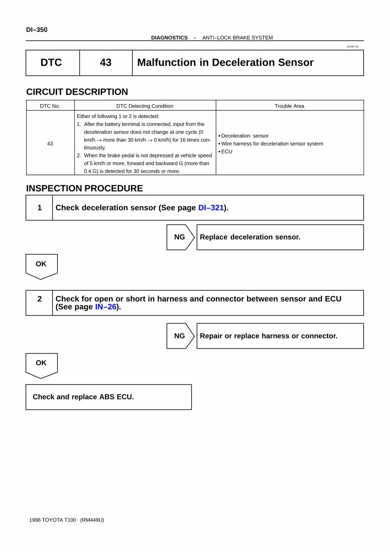
DI−350−DIAGNOSTICS ANTI−LOCK BRAKE SYSTEM
1996 TOYOTA T100 (RM449U)
DTC 43 Malfunction in Deceleration Sensor
CIRCUIT DESCRIPTIONDTC No. DTC Detecting Condition Trouble Area
43
Either of following 1 or 2 is detected:
1. After the battery terminal is connected, input from the
deceleration sensor does not change at one cycle (0
km/h → more than 30 km/h → 0 km/h) for 16 times con-
tinuously.
2. When the brake pedal is not depressed at vehicle speed
of 5 km/h or more, forward and backward G (more than
0.4 G) is detected for 30 seconds or more.
�Deceleration sensor
�Wire harness for deceleration sensor system
�ECU
INSPECTION PROCEDURE
1 Check deceleration sensor (See page DI−321).
NG Replace deceleration sensor.
OK
2 Check for open or short in harness and connector between sensor and ECU(See page IN−26).
NG Repair or replace harness or connector.
OK
Check and replace ABS ECU.
DI10K−01
https://www.truck-manuals.net/

F00360
6
ECU−IG
ABS ECU
L−W
LG
L
W−B
2
3
DecelerationSensor
A15
ABS ECU
GS1
GS2
GST
GGND
19
7
5
18
GS1
GS2
GST
IG1
A15
A15
A15
1
A14
A14
A14
A14 4
A14 6
5F7 F7
B
B
Fuse Boxon J/B No.1
IG Switch
GGND
−DIAGNOSTICS ANTI−LOCK BRAKE SYSTEMDI−351
1996 TOYOTA T100 (RM449U)
DTC 44 Deceleration Sensor Circuit
CIRCUIT DESCRIPTIONThis sensor detects deceleration on the vehicle. The sensor signal is used in ABS control. If the sensor func-tions abnormally, the ABS warning light comes on but the ABS still operates.
DTC No. DTC Detecting Condition Trouble Area
44
Either of following 1 or 2 is detected:
1. An open or short is detected in circuit GS1 or GS2 for
1sec.
2. After the ignition is turned ON, test signal is output by
GST. During this time, a trouble signal is detected for 0.5
sec.
�Deceleration sensor
�Open or short in deceleration sensor circuit
�ECU
WIRING DIAGRAM
DI10M−03
https://www.truck-manuals.net/

BE6653R15784 F00459
ON
GS2 GST
(−)
GS1
(+)
F00012
IG SW
GST
ON
OFF
12 V
0 V
1.5 sec. 0.5 sec.
DI−352−DIAGNOSTICS ANTI−LOCK BRAKE SYSTEM
1996 TOYOTA T100 (RM449U)
INSPECTION PROCEDURE
1 Check for open and short in harness and connector between Deceleration sen-sor and ECU (See page IN−26).
NG Repair or replace harness or connector.
OK
2 Check voltage between terminals GS1, GS2, GST of ABS ECU and body ground.
PREPARATION:(a) Remove the ABS ECU with the connectors still con-
nected.(b) Disconnect the deceleration sensor connector.(c) Turn the ignition switch ON.CHECK:Measure voltage between terminals GS1, GS2, GST of ECUand Body ground.OK:
Voltage: GS1, GS2: about 5 VGST: As shown below
NG Check and replace ABS ECU.
OK
Check and replace deceleration sensor.
https://www.truck-manuals.net/

F14589
ABS Contorl Relay
ABS Actuator
ABS ECU
R/BNo.2
MotorRelay
SolenoidRelay
ABS ECU
DLC1
AB
S
Battery
A16
A16
A16
A16
A16
A6
A6
A5
A4
A4
A4 A4
A5A6
A6
A5
A5
A4
EA1
EA1
ID
MR
R−
SR
AST
MT
R−B
G−B
R−W
R−Y
R−L
W−B
W−B
W
W
W
W
W
R−L
W−R LG
4
15
5
4
3
1
3
5
1
2
6
1
5
10
10 2
29
2
2
5
4
11
8
−DIAGNOSTICS ANTI−LOCK BRAKE SYSTEMDI−353
1996 TOYOTA T100 (RM449U)
DTC 51 ABS Pump Motor Lock
CIRCUIT DESCRIPTIONDTC No. DTC Detecting Condition Trouble Area
51 Pump motor is not operating normally during initial check. �ABS pump motor
Fail safe function: If trouble occurs in the ABS pump motor, the ECU cuts off current to the ABS control (solenoid) relay andprohibits ABS control.
WIRING DIAGRAM
DI10Q−03
https://www.truck-manuals.net/

F14591
ABS ContorlRelay
ABSActuator
ABS ECU
MotorRelay
SolenoidRelay
Battery
A5A5
EA1
ID
W−B
W
W
W
W
EA1
A5
A5A5
A6A6
A6
A4ABSActuator
ABS ECU
ABS ECU
IG Switch
IntegrationRelay
ABSWarningLight
I15
C10
C10
A16
1A
IE1
IE1
B−Y B−Y
LG
B−R B−R
B−
R
B−
R
B−
O23 22Short Pin
10
1
2
6
5
4
4
1
4
32
2
99
4
8
GA
UG
E
12WA
5
24
DI−354−DIAGNOSTICS ANTI−LOCK BRAKE SYSTEM
1996 TOYOTA T100 (RM449U)
ABS Warning Light Circuit
CIRCUIT DESCRIPTIONIf the ECU detects trouble, it lights the ABS warning light while at the same time prohibiting ABS control. Atthis time, the ECU records a DTC in memory.After removing the short pin of the DLC1, connect terminals Tc and E1 of the DLC1 to make the ABS warninglight blink and output the DTC.
WIRING DIAGRAM
DI10S−03
https://www.truck-manuals.net/

−DIAGNOSTICS ANTI−LOCK BRAKE SYSTEMDI−355
1996 TOYOTA T100 (RM449U)
INSPECTION PROCEDURETroubleshooting in accordance with the chart below for each trouble symptom.
ABS warning light does not light up Go to step 1
ABS warning light remains on Go to step 3
1 Check ABS warning light.
See Combination Meter Troubleshooting on page BE−2.
NG Repair bulb or combination meter assembly.
OK
https://www.truck-manuals.net/
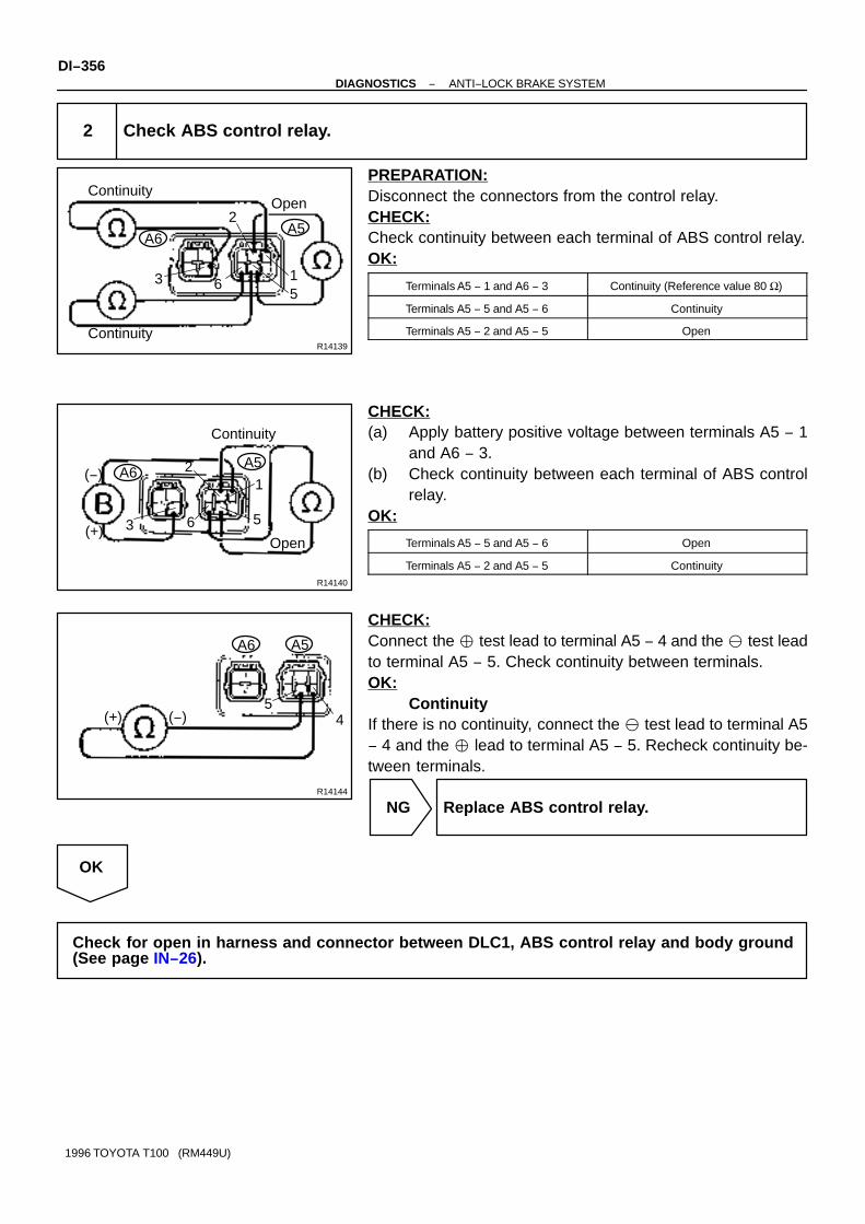
R14139
A6A5
Continuity
Continuity
Open
563 1
2
R14140
A5A6(−)
(+)
Continuity
Open
12
563
R14144
A5A6
(+) (−) 45
DI−356−DIAGNOSTICS ANTI−LOCK BRAKE SYSTEM
1996 TOYOTA T100 (RM449U)
2 Check ABS control relay.
PREPARATION:Disconnect the connectors from the control relay.CHECK:Check continuity between each terminal of ABS control relay.OK:
Terminals A5 − 1 and A6 − 3 Continuity (Reference value 80 Ω)
Terminals A5 − 5 and A5 − 6 Continuity
Terminals A5 − 2 and A5 − 5 Open
CHECK:(a) Apply battery positive voltage between terminals A5 − 1
and A6 − 3.(b) Check continuity between each terminal of ABS control
relay.OK:
Terminals A5 − 5 and A5 − 6 Open
Terminals A5 − 2 and A5 − 5 Continuity
CHECK:Connect the � test lead to terminal A5 − 4 and the � test leadto terminal A5 − 5. Check continuity between terminals.OK:
ContinuityIf there is no continuity, connect the � test lead to terminal A5− 4 and the � lead to terminal A5 − 5. Recheck continuity be-tween terminals.
NG Replace ABS control relay.
OK
Check for open in harness and connector between DLC1, ABS control relay and body ground(See page IN−26).
https://www.truck-manuals.net/

−DIAGNOSTICS ANTI−LOCK BRAKE SYSTEMDI−357
1996 TOYOTA T100 (RM449U)
3 Is DTC output?
Check DTC on page DI−321.
YES Repair circuit indicated by code output.
NO
4 Does ABS warning light go off if short pin is removed?
NO Check for short in harness and connector be-tween warning light, DLC1 and ECU (See pageIN−26).
YES
5 Check ABS control relay (See step 2).
NG Replace ABS control relay.
OK
Check for short in harness and connector between DLC1 and ABS control relay (See page IN−26).
https://www.truck-manuals.net/
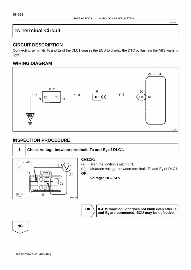
F00363
BR
ABS ECU
DLC1
Y−B Y−B
EB
IE1 A15E13 11
6 20
Tc Tc
AB0119
S08097 F00445
ON
E1
Tc
(−)
(+)
DI−358−DIAGNOSTICS ANTI−LOCK BRAKE SYSTEM
1996 TOYOTA T100 (RM449U)
Tc Terminal Circuit
CIRCUIT DESCRIPTIONConnecting terminals Tc and E1 of the DLC1 causes the ECU to display the DTC by flashing the ABS warninglight.
WIRING DIAGRAM
INSPECTION PROCEDURE
1 Check voltage between terminals Tc and E1 of DLC1.
CHECK:(a) Turn the ignition switch ON.(b) Measure voltage between terminals Tc and E1 of DLC1.OK:
Voltage: 10 − 14 V
OK If ABS warning light does not blink even after Tcand E1 are connected, ECU may be defective.
NG
DI10U−03
https://www.truck-manuals.net/

−DIAGNOSTICS ANTI−LOCK BRAKE SYSTEMDI−359
1996 TOYOTA T100 (RM449U)
2 Check for open and short in harness and connector between ABS ECU andDLC1, DLC1 and body ground (See page IN−26).
NG Repair or replace harness or connector.
OK
Check and replace ABS ECU.
https://www.truck-manuals.net/

F00363
BR
ABS ECU
DLC1
R−Y R−Y
EB
IE1 A15E13 16
1 6
Ts Ts
AB0119
S08096
F00446
ON
E1
Ts
(−)
(+)
DI−360−DIAGNOSTICS ANTI−LOCK BRAKE SYSTEM
1996 TOYOTA T100 (RM449U)
Ts Terminal Circuit
CIRCUIT DESCRIPTIONThe sensor check circuit detects abnormalities in the speed sensor signal which cannot be detected withthe DTC check.Connecting terminals Ts and E1 of the DLC1 in the engine compartment starts the check.
WIRING DIAGRAM
INSPECTION PROCEDURE
1 Check voltage between terminals Ts and E1 of DLC1.
CHECK:(a) Turn the ignition switch ON.(b) Measure voltage between terminals Ts and E1 of DLC1.OK:
Voltage: 10 − 14 V
OK If ABS warning light does not blink even after Tsand E1 are connected, ECU may be defective.
NG
DI10W−03
https://www.truck-manuals.net/

−DIAGNOSTICS ANTI−LOCK BRAKE SYSTEMDI−361
1996 TOYOTA T100 (RM449U)
2 Check for open and short in harness and connector between ABS ECU andDLC1, DLC1 and body ground (See page IN−26).
NG Repair or replace harness or connector.
OK
Check and replace ABS ECU.
https://www.truck-manuals.net/

F00447
DI−362−DIAGNOSTICS ANTI−LOCK BRAKE SYSTEM
1996 TOYOTA T100 (RM449U)
Check for fluid Leakage
Check for fluid leakage from actuator or hydraulic lines.
DI10Y−01
https://www.truck-manuals.net/

DI0XG−01
Vehicle Brought to Workshop
Identification of Problem
Confirmation Test
END
Repair
Customer Ploblem AnalysisDI−364
DI−365
DI−369
DI−373
Warning Light Check
DTC Check and Recording
Malfunction Code Clearance
DTC Check and Recording
DTC Chart
Circuit Inspection
Malfunction Code Clearance
DTC Check
Step , : Diagnostic steps permittingthe use of the TOYOTAhand−held tester.
3 4
1
2
3
4
5
7
8
9
10
11
12
5, 10 ,11 12, ,
Symptom Simulation
IN−16
Does Not Light Up
Normal Code
Normal CodeNormalCode
Malfunction Code
Malfunction Code
6
Normal Code
DI−365
DI−365
DI−365
DI−365
DI−365
−DIAGNOSTICS SUPPLEMENTAL RESTRAINT SYSTEMDI−363
620Author�: Date�:
1996 TOYOTA T100 (RM449U)
SUPPLEMENTAL RESTRAINT SYSTEMHOW TO PROCEED WITH TROUBLESHOOTINGTroubleshooting in accordance with the procedure on the following pages.
https://www.truck-manuals.net/

DI0XH−01
Supplemental Restraint System Check Sheet
Date Problem Dist Occurred
Customer’s Name
Registration No.
Registration Year
Frame No.
Odometer Reading
Weather
Temperature
Vehicle Operation
Road Conditions
Details of Problem
Vehicle Inspection, RepairHistory Prior to Occurrence ofMalfunction (IncludingSupplemental Restraint System)
Diagnosis System Inspection
SRS Warning Light Inspection
DTC Inspection
1st Time
2nd Time
1st Time
2nd Time
Inspector’s Name
Fine Cloudy Rainy Snowy Other
Approx.
Starting Idling
Driving [ Constant speed Acceleration DecelerationOther ]
Remains ON Sometimes Lights Up Does Not Light Up
Remains ON Sometimes Lights Up Does Not Light Up
Normal Code Malfunction Code
Normal Code Malfunction Code
[ Code. ]
[ Code. ]
kmMiles
/ /
/ /
/ /
Date Vehicle Brought In
DI−364−DIAGNOSTICS SUPPLEMENTAL RESTRAINT SYSTEM
1996 TOYOTA T100 (RM449U)
CUSTOMER PROBLEM ANALYSIS CHECK
https://www.truck-manuals.net/

R07710
R07711H00318
w/ Tachometer
w/o Tachometer
DI0XJ−02
S08098
E1 Tc
AT0716
Normal Code
ON
OFF
0.25
0.25
−DIAGNOSTICS SUPPLEMENTAL RESTRAINT SYSTEMDI−365
1996 TOYOTA T100 (RM449U)
PRE−CHECK1. SRS WARNING LIGHT CHECK(a) Turn the ignition switch to ACC or ON and check that the
SRS warning light lights up.(b) Check that the SRS warning light goes out after approx.
6 seconds.HINT:� When the ignition switch is at ACC or ON and the SRS
warning light remains on or flashes, the airbag sensor as-sembly has detected a malfunction code.
� If, after approx. 6 seconds have elapsed, the SRS warn-ing light sometimes lights up or the SRS warning lightlights up even when the ignition switch is OFF, a short inthe SRS warning light circuit can be considered likely.Proceed to ”SRS warning light system malfunction” onpage DI−398, DI−400.
2. DTC CHECK (Using diagnosis check wire)(a) Output the DTC.
(1) Turn the ignition switch to ACC or ON position andwait approx. 20 seconds.
(2) Using SST, connect terminals Tc and E1 of theDLC1.
SST SST 09843−18020NOTICE:Never make a mistake with the terminal connection posi-tion as this will cause a malfunction.(b) Read the DTC.
Read the 2−digit DTC as indicated by the number of timesthe SRS warning light blinks. As an example, the blinkingpatterns, normal, 11 and 31 are as shown on the illustra-tion.
� Normal code indication:The light will blink 2 times per second.
� Malfunction code indication:The first blinking output indicates the first digitof a 2−digit DTC. After a 1.5 second pause,the second blinking output will indicate thesecond digit.
https://www.truck-manuals.net/

AB0056
Code 11 and 31
ON
OFF
0.5 2.5 4.0
1.5 0.5
Code 11 Code 31
Repeat
S07739
DI−366−DIAGNOSTICS SUPPLEMENTAL RESTRAINT SYSTEM
1996 TOYOTA T100 (RM449U)
If there are 2 or more codes, there will be a 2.5 second pausebetween each codes. After al the codes have been output,there will be a 4.0 second pause and they will all be repeated.HINT:� In the event of a number of trouble codes, indication will
start from the smallest numbered code.� If it does not output a DTC or outputs a DTC without termi-
nal connection, proceed to the Tc terminal circuit inspec-tion on page DI−403.
3. DTC CHECK (Using TOYOTA hand−held tester)(a) Hook up the TOYOTA hand−held tester to the DLC1.(b) Read the DTCs by following the prompts on the tester
screen.HINT:Please refer to the TOYOTA hand−held tester operator’s manu-al, for further details.
4. DTC CLEARANCE (Using diagnosis check wire)(a) Conncect the 2 service wires to terminals Tc nad AB of
DLC1.(b) Turn the ignition switch to ACC or ON and wait approx.
6 seconds.(c) Starting with the Tc terminal, apply body ground alternate-
ly to terminal Tc and terminal AB twice each in cycles of1.0 seconds. Confirm that body ground is absolute.Finally, keep applying body ground to terminal Tc.
HINT:When alternately groundling terminals Tc and AB, releasegrounf from one terminal and immediately apply it to the otherterminal within an interval of 0.2 second. If DTCs do not clear,repeat the above procedure until the codes are cleared.
https://www.truck-manuals.net/

R07090
W05586 W05587
H00319
Terminal Time of Body ground
Tc
AB
OFF
BodyGround
OFF
BodyGround
Severalseconds
50 msec.
50 msec.
OFF
ON
1 second
(± 0.5 sec.)1 second
(± 0.5 sec.)
”1” ”3” ”5”
”2” ”4”
w/ Tachometer w/o Tachometer
ABTc
S07739
−DIAGNOSTICS SUPPLEMENTAL RESTRAINT SYSTEMDI−367
1996 TOYOTA T100 (RM449U)
(d) Several seconds after doing the clearing procedure, theSRS warning light will blink in a 50 msec. cycle to indicatethe codes have been cleared.
5. DTC CLEARANCE (Using TOYOTA hand−held tester)(a) Hook up the TOYOTA hand−held tester to the DLC1.(b) Clear the DTCs by following the prompts on the tester
screen.HINT:Please refer to the TOYOTA hand−held tester operator’s manu-al for further details.
6. RELEASE METHOD OF AIRBAG ACTIVATION PRE-VENTION MECHANISM
An airbag activation prevention mechanism is built into the con-nector for the squib circuit of the SRS.When release of the airbag activation prevention mechanism isdirected in the troubleshooting procedure, as shown in the il-lustration of the connectors ”1” and ”2” below, insert paperwhich is the same thickness as the male terminal, between theterminal and the short spring.
https://www.truck-manuals.net/

W03146 W03147
AB0130 AB0045 AB0046
AB0027
H00320
Airbag Sensor Assembly Connector (Connector ”1”)
Spiral Cable Connector (Connector ”2”)
Short Spring
Short Spring
Before Release After Release
After ReleaseBefore Release
Paper
Paper
CenterAirbagSensorAssembly
J/B No.1
Squib
RH and LH Front Airbag Sensors
Spiral Cable
Connector ”1” Connector ”2”
DI−368−DIAGNOSTICS SUPPLEMENTAL RESTRAINT SYSTEM
1996 TOYOTA T100 (RM449U)
CAUTION:Never release the airbag activation prevention mechanismon the steering wheel pad connector.NOTICE:� Do not release the airbag activation prevention mech-
anism unless specifically directed by the trouble-shooting procedure.
� If the paper inserted is too thick the terminal and shortspring may be damaged, so always use paper thesame thickness as the male terminal.
https://www.truck-manuals.net/

DI0XK−02
−DIAGNOSTICS SUPPLEMENTAL RESTRAINT SYSTEMDI−369
1996 TOYOTA T100 (RM449U)
DIAGNOSTIC TROUBLE CODE CHARTIf a malfunction code is displayed during the DTC check, check the circuit listed for that code in the tablebelow (Proceed to the page given for that circuit.).
DTC No.
(See Page)Detection Item Trouble Area
SRS
Warning Light
Normal
(DI−396)
�System normal − OFF
�Source voltage drop �Battery
�Center airbag sensor assemblyON
11
(DI−373)
�Short in squib circuit or front airbag
sensor circuit (to ground)
�Steering wheel pad (D squib)
�Front airbag sensor
�Spiral cable
�Center airbag sensor assembly
�Wire harness
ON
12
(DI−379)
�Short in squib circuit or front airbag
sensor circuit (to B+)
�Steering wheel pad (D squib)
�Front airbag sensor
�Spiral cable
�Center airbag sensor assembly
�Wire harness
ON
14
(DI−385)
�Open in D squib circuit �Steering wheel pad (D squib)
�Spiral cable
�Center airbag sensor assembly
�Wire harness
ON
15
(DI−390)
�Open in front airbag sensor circuit �Front airbag sensor
�Center airbag sensor assembly
�Wire harness
ON
31
(DI−394)
�Center airbag sensor assembly
malfunction
�Center airbag sensor assembly
ON
HINT:� When the SRS warning light remains lit up and the DTC is the normal code, this means a source voltage
drop. This malfunction is not stored in memory by the center airbag sensor assembly and if the powersource voltage returns to normal, approx. 10 seconds the SRS warning light will automatically go out.
� When 2 or more codes are indicated, the lowest numbered code will apper first.� If a code not listed on the chart is displayed, the center airbag sensor assembly is faulty.
https://www.truck-manuals.net/

DI0XL−02
R12499
Front Airbag Sensor RH
Front Airbag Sensor LH
Junction Block No.1
Center Airbag Sensor Assembly
Spiral Cable
SRS Warning Light
Steering Wheel Pad(with Airbag)
DI−370−DIAGNOSTICS SUPPLEMENTAL RESTRAINT SYSTEM
1996 TOYOTA T100 (RM449U)
PARTS LOCATION
https://www.truck-manuals.net/

DI7HL−02
W02759
4 3 2 1
10 9 8 7 56
BA
−DIAGNOSTICS SUPPLEMENTAL RESTRAINT SYSTEMDI−371
1996 TOYOTA T100 (RM449U)
TERMINALS OF ECU
No. Symbol Terminal Name
A − Electrical Connection Check Mechanism
B − Electrical Connection Check Mechanism
1 LA SRS Warning Light
2 D− Squib � (Driver)
3 D+ Squib � (Driver)
4 TC Diagnosis
5 E2 Ground
6 E1 Ground
7 +SR Front Airbag Sensor RH �
8 +SL Front Airbag Sensor LH �
9 IG2 Power Source (IGN Fuse)
10 ACC Power Source (CIG Fuse)
https://www.truck-manuals.net/

DI0XN−01
DI−372−DIAGNOSTICS SUPPLEMENTAL RESTRAINT SYSTEM
1996 TOYOTA T100 (RM449U)
PROBLEM SYMPTOMS TABLEProceed with troubleshooting of each circuit in the table below.
Symptom Suspect Area See page
�With the ignition switch at ACC or ON, the SRS warning light
sometimes lights up after approx. 6 seconds have elapsed.
�SRS warning light is always lit up even when ignition switch is in
the LOCK position.
�SRS warning light circuit
(Always lit up when ignition switch is in LOCK position.)DI−398
�With the ignition switch at ACC or ON, the SRS warning lights
does not light up.
�SRS warning light circuit
(Does not light up when ignition switch is turned to ACC
or ON.)
DI−400
�DTC not displayed.
�SRS warning light is always lit up a DTC check procedure.
�DTC displayed without Tc and E1 terminal connection.
�Tc terminal circuit DI−403
https://www.truck-manuals.net/

DI0XO−02
R15205
Center Airbag Sensor Assembly
Front Airbag Sensor RH
Front Airbag Sensor LH
D Squib
SpiralCable
W−B
W−B
+SR
+SL
B
LB−L
WD+
D−
1
2
1
2
13
14
1
2
7
6
−DIAGNOSTICS SUPPLEMENTAL RESTRAINT SYSTEMDI−373
1996 TOYOTA T100 (RM449U)
CIRCUIT INSPECTION
DTC 11 Short in Squib Circuit (to Ground)
CIRCUIT DESCRIPTIONThe squib circuit consists of the center airbag sensor assembly, spiral cable and steering wheel pad. Ifcauses the SRS to deploy when the SRS deployment conditions are satisfied.The front airbag sensor detects the deceleration force in a frontal collision and is located in the front fenderapron on the left and right sides.For details of the function of each component, see OPERATION on page RS−2.DTC 11 is recorded when ground short is detected in the squib circuit or front airbag sensor circuit.
DTC No. DTC Detecting Condition Trouble Area
11
�Short circuit in squib wire harness (to ground)
�Squib malfunction
�Short circuit in front airbag sensor +S wire harness
(to ground)
�Front airbag snesor malfunction
�Spiral cable malfunction
�Center airbag sensor assembly malfunction
�Steering wheel pad (D squib)
�Front airbag sensor
�Spiral cable
�Center airbag sensor assembly
�Wire harness
WIRING DIAGRAM
https://www.truck-manuals.net/

W05584
R14301 H00323
Center AirbagSensor Assembly
SpiralCable
D Squib
(−) (+)
D+
H18108
Center AirbagSensor Assembly
(−) (+)
+SL
+SR
DI−374−DIAGNOSTICS SUPPLEMENTAL RESTRAINT SYSTEM
1996 TOYOTA T100 (RM449U)
INSPECTION PROCEDURE
1 Preparation. (See step 1 on page DI−396)
2 Check D squib circuit.
CHECK:For connector on spiral cable side between spiral cable andsteering wheel pad, measure resistance between D+ and bodyground.OK:
Resistance: 1MΩ or higher
NG Go to step 6.
OK
3 Check front airbag sensor circuit. (Measure resistance between terminals +SR,+SL of center airbag sensor assembly connector.)
CHECK:Measure resistance between terminals +SR, +SL of harnessside connector of center airbag sensor assembly and bodyground.OK:
Resistance: 755 − 855 Ω
NG Go to step 7.
OK
https://www.truck-manuals.net/

W05582
AB0118 AB0119 AB0069
S08098 W02042 H00324
SpiralCable
ACC ON D− D+
or
DLC1
E1 Tc
Code 11
Center AirbagSensor Assembly
D Squib
−DIAGNOSTICS SUPPLEMENTAL RESTRAINT SYSTEMDI−375
1996 TOYOTA T100 (RM449U)
4 Check center airbag sensor assembly.
PREPARATION:(a) Connect connector to center airbag sensor assembly.(b) Using a service wire, connect D+ and D− on spiral cable
side of connector between spiral cable and steeringwheel pad.
(c) Connect negative (−) terminal cable to battery, and waitat least 2 seconds.
CHECK:(a) Turn ignition switch to ACC or ON, and wait at least 20 se-
conds.(b) Clear malfunction code stored in memory.
(See page DI−365)(c) Turn ignition switch to LOCK, and wait at least 20 se-
conds.(d) Turn ignition switch to ACC or ON, and wait at least 20 se-
conds.(e) Using SST, connect terminals Tc and E1 of DLC1.
SST 09843−18020(f) Check DTC.OK:
DTC 11 is not output.HINT:Codes other than code 11 may be output at this time, but theyare not relevant to this check.
NG Replace center airbag sensor assembly.
OK
https://www.truck-manuals.net/

AB0118 AB0119
S08098 W02042
H00352
H00325
Center AirbagSensor Assembly
SpiralCable
D Squib
ACC ON
or
DLC1
E1 Tc
Code 11
DI−376−DIAGNOSTICS SUPPLEMENTAL RESTRAINT SYSTEM
1996 TOYOTA T100 (RM449U)
5 Check D squib.
PREPARATION:(a) Turn ignition switch to LOCK.(b) Disconnect negative (−) terminal cable from the battery,
and wait at least 90 seconds.(c) Connect steering wheel pad connector.(d) Connect negative (−) terminal cable to battery, and wait
at least 2 seconds.CHECK:(a) Turn ignition switch to ACC or ON, and wait at least 20 se-
conds.(b) Clear malfunction code stored in memory.
(See page DI−365)(c) Turn ignition switch to LOCK, and wait at least 20 se-
conds.(d) Turn ignition switch to ACC or ON, and wait at least 20 se-
conds.(e) Using SST, connect terminals Tc and E1 of DLC1.
SST 09843−18020(f) Check DTC.OK:
DTC 11 is not output.HINT:Codes other than code 11 may be output at this time, but theyare not relevant to this check.
NG Replace steering wheel pad.
OK
From results of above inspection, malfunctioning part can now be considered normal.To make sure of this, use simulation method to check. If malfunctioning part can not be detectedby imulation method, replace all SRS components including wire harness.
https://www.truck-manuals.net/

W05583
R14301H00326
Center AirbagSensor Assembly
SpiralCable
D Squib
D+
(−) (+)
−DIAGNOSTICS SUPPLEMENTAL RESTRAINT SYSTEMDI−377
1996 TOYOTA T100 (RM449U)
6 Check spiral cable.
PREPARATION:Disconnect connector between center airbag sensor assemblyand spiral cable.CHECK:For connector on spiral cable side between spiral cable andsteering wheel pad, measure resistance between D+ and bodyground.OK:
Resistance: 1MΩ or higher
NG Repair or replace spiral cable.
OK
Repair or replace harness or connectorbetween center airbag sensor assembly andspiral cable.
https://www.truck-manuals.net/

AB0034
+A +S
−S −A
DI−378−DIAGNOSTICS SUPPLEMENTAL RESTRAINT SYSTEM
1996 TOYOTA T100 (RM449U)
7 Check front airbag sensor.
PREPARATION:Disconnect front airbag sensor connector.CHECK:Measure resistance between each terminal of front airbagsensor.OK:
Terminal Resistance
+S − +A Less than 1 Ω
+S − −S 1 MΩ or higher
−S − −A 755 − 855 Ω
NOTICE:� Do not press ohmmeter probes too strongly against
terminals of front airbag sensor.� Make sure front airbag sensor connector is properly
connected.
NG Replace front airbag sensor.
OK
Repair or replace harness or connectorbetween center airbag sensor assembly andfront airbag sensor.
https://www.truck-manuals.net/

−DIAGNOSTICS SUPPLEMENTAL RESTRAINT SYSTEMDI−379
1996 TOYOTA T100 (RM449U)
DTC 12 Short in Squib Circuit or Front Airbag Sensor Circuit (to B+)
CIRCUIT DESCRIPTIONThe squib circuit consists of the airbag sensor assembly, spiral cable, steering wheel pad and front passen-ger airbag assembly. It causes the SRS to deploy when the SRS deployment conditions are satisfied.The front airbag sensor detects the deceleration force in a frontal collision and is located in the front fenderon the left and right sides.For details of the function of each components, see page OPERATION on page RS−2.DTC 12 is recorded when a B+ short is detected in the squib circuit or front airbag sensor circuit.
DTC No. DTC Detecting Condition Trouble Area
12
�Short circuit in squib wire harness (to B+)
�Squib malfunction
�Short circuit in front airbag sensor +S wire harness (to B+)
�Open circuit in RH and LH front airbag sensor harness
�Spiral cable malfunction
�Center airbag sensor assembly malfunction
�Steering wheel pad (D squib)
�Front airbag sensor
�Spiral cable
�Center airbag sensor assembly
�Wire harness
WIRING DIAGRAMSee page DI−373.
DI986−01
https://www.truck-manuals.net/

H18109
Center AirbagSensor Assembly
(−) (+)
+SL
+SR
ON
DI−380−DIAGNOSTICS SUPPLEMENTAL RESTRAINT SYSTEM
1996 TOYOTA T100 (RM449U)
INSPECTION PROCEDURE
1 Preparation (See step 1 on page DI−396)
2 Check D squib circuit (Measure voltage between terminals D+ or D− of center air-bag sensor assembly connector and body ground.).
PREPARATION:(a) Connect negative (−) terminal cable to battery.(b) Turn ignition switch to ON.CHECK:Measure voltage between terminals D+ or D− of harness sideconnector of center airbag sensor assembly and body ground.OK:
Voltage: 0 V
NG Go to step 5.
OK
https://www.truck-manuals.net/

W05582
AB0118 AB0119 AB0069
S08098 W02043 H00329
Center AirbagSensor Assembly
SpiralCable
ACC ON D− D+
or
DLC1
E1
Code 12
Tc
D Squib
−DIAGNOSTICS SUPPLEMENTAL RESTRAINT SYSTEMDI−381
1996 TOYOTA T100 (RM449U)
3 Check center airbag sensor assembly.
PREPARATION:(a) Turn ignition switch LOCK.(b) Disconnect negative (−) terminal cable from battery.(c) Connect connector to center airbag sensor assembly.(d) Using a service wire, connect D+ and D− on spiral cable
side of connector between spiral cable and steeringwheel pad.
(e) Connect negative (−) terminal cable to battery, and waitat least 2 seconds.
CHECK:(a) Turn ignition switch to ACC or ON, and wait at least 20 se-
conds.(b) Clear malfunction code stored in memory (See page
DI−365).(c) Turn ignition switch to LOCK, and wait at least 20 se-
conds.(d) Turn ignition switch to ACC or ON, and wait at least 20 se-
conds.(e) Using SST, connect terminals Tc and E1 of DLC1.
SST 09843−18020(f) Check DTC.OK:
DTC 12 is not output.HINT:Codes other than code 12 may be output at this time, but theyare not relevant to this check.
NG Replace center airbag sensor assembly.
OK
https://www.truck-manuals.net/

AB0118 AB0119
S08098 W02043
H00352
H00330
Center AirbagSensor Assembly
SpiralCable
D Squib
ACC ON
or
DLC1
E1 Tc
Code 12
DI−382−DIAGNOSTICS SUPPLEMENTAL RESTRAINT SYSTEM
1996 TOYOTA T100 (RM449U)
4 Check D squib.
PREPARATION:(a) Turn ignition switch to LOCK.(b) Disconnect negative (−) terminal cable from the battery,
and wait at least 90 seconds.(c) Connect steering wheel pad connector.(d) Connect negative (−) terminal cable to battery, and wait
at least 2 seconds.CHECK:(a) Turn ignition switch to ACC or ON, and wait at least 20 se-
conds.(b) Clear malfunction code stored in memory (See page
DI−365).(c) Turn ignition switch to LOCK, and wait at least 20 se-
conds.(d) Turn ignition switch to ACC or ON, and wait at least 20 se-
conds.(e) Using SST, connect terminals Tc and E1 of DLC1.
SST 09843−18020(f) Check DTC.OK:
DTC 12 is not output.HINT:Codes other than code 12 may be output at this time. but theyare not relevant to this check.
NG Replace steering wheel pad.
OK
From results of above inspection, malfunctioning part can now be considered normal.To make sure of this, use simulation method to check.
https://www.truck-manuals.net/

W05583
AB0119 R14288 H00331
Center AirbagSensor Assembly
SpiralCable
D Squib
ON
D+
(−) (+)
−DIAGNOSTICS SUPPLEMENTAL RESTRAINT SYSTEMDI−383
1996 TOYOTA T100 (RM449U)
5 Check D squib circuit.
PREPARATION:(a) Turn ignition switch to LOCK.(b) Disconnect connector between center airbag sensor as-
sembly and spiral cable.(c) Turn ignition switch ON.CHECK:For connector on spiral cable side between spiral cable andsteering wheel pad, measure voltage between D+ and bodyground.OK:
Voltage: 0 V
NG Repair or replace spiral cable.
OK
Repair or replace harness or connector between center airbag sensor assembly and spiral cable.
https://www.truck-manuals.net/

AB0119
R14288
H01000
H01133
D SquibSpiralCable
AirbagSensorAssembly←
OND+
(+)(−)
→
DI−384−DIAGNOSTICS SUPPLEMENTAL RESTRAINT SYSTEM
1996 TOYOTA T100 (RM449U)
6 Check spiral cable.
PREPARATION:(a) Turn ignition switch to LOCK.(b) Disconnect connector between center airbag sensor as-
sembly and spiral cable.(c) Turn ignition switch ON.CHECK:Measure voltage at D+, D− on spiral cable side of connector be-tween spiral cable and steering wheel pad.OK:
Voltage: 0 V
NG Repair or replace spiral cable.
OK
From the results of the above inspection, the malfunctioning part can now be considered normal.To make sure of this, use the simulation method to check.
https://www.truck-manuals.net/

H01001H02142 H02196
D Squib
SpiralCable
(+)
D+D−
(−)
AirbagSensorAssembly
← →
−DIAGNOSTICS SUPPLEMENTAL RESTRAINT SYSTEMDI−385
1996 TOYOTA T100 (RM449U)
DTC 14 Open in D Squib Circuit
CIRCUIT DESCRIPTIONThe D squib circuit consists of the center airbag sensor assembly, spiral cable and steering wheel pad. Itcauses the airbag to deploy when the airbag deployment conditions are satisfied.For details of the function of each components, see OPERATION on page RS−2.DTC 14 is recorded when an open is detected in the D squib circuit.
DTC No. DTC Detecting Condition Trouble Area
14
�Open circuit in D+ wire harness or D− wire harness of
squib
�D squib malfunction
�Spiral cable malfunction
�Center airbag sensor assembly malfunction
�Steering wheel pad (D squib)
�Spiral cable
�Center airbag sensor assembly
�Wire harness
WIRING DIAGRAMSee page DI−373.
INSPECTION PROCEDURE
1 Preparation (See step 1 on page DI−396)
2 Check D squib circuit.
PREPARATION:(a) Disconnect center airbag sensor assembly connector.(b) Using a service wire, connect D+ and D− on center airbag
sensor assembly side connector.CHECK:For the connector (on the spiral cable side) between the spiralcable and steering wheel pad, measure the resistance betweenD+ and D−.OK:
Resistance: Below 1 Ω
NG Go to step 5.
OK
DI987−01
https://www.truck-manuals.net/

AB0118 AB0119 AB0069
S08098
W05582
W02044 H00338
SpiralCable
D Squib
ACC ON D− D+
or
DLC1
E1 Tc
Code 14
Center AirbagSensor Assembly
DI−386−DIAGNOSTICS SUPPLEMENTAL RESTRAINT SYSTEM
1996 TOYOTA T100 (RM449U)
3 Check center airbag sensor assembly.
PREPARATION:(a) Connect connector to center airbag sensor assembly.(b) Using a service wire, connect D+ and D− on spiral cable
side of connector between spiral cable and steeringwheel pad.
(c) Connect negative (−) terminal cable to battery, and waitat least 2 seconds.
CHECK:(a) Turn ignition switch to ACC or ON, and wait at least 20 se-
conds.(b) Clear malfunction code stored in memory (See page
DI−365).(c) Turn ignition switch to LOCK, and wait at least 20 se-
conds.(d) Turn ignition switch to ACC or ON, and wait at least 20 se-
conds.(e) Using SST, connect terminals Tc and E1 of DLC1.
SST 09843−18020(f) Check DTC.OK:
DTC 14 is not output.HINT:Codes other than code 14 may be output at this time, but theyare relevant to this check.
NG Go to step 7.
OK
https://www.truck-manuals.net/
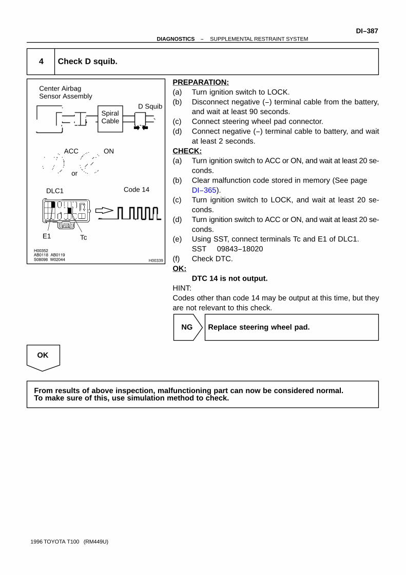
AB0118 AB0119
S08098 W02044
H00352
H00339
Center AirbagSensor Assembly
D SquibSpiralCable
ACC ON
or
DLC1
E1 Tc
Code 14
−DIAGNOSTICS SUPPLEMENTAL RESTRAINT SYSTEMDI−387
1996 TOYOTA T100 (RM449U)
4 Check D squib.
PREPARATION:(a) Turn ignition switch to LOCK.(b) Disconnect negative (−) terminal cable from the battery,
and wait at least 90 seconds.(c) Connect steering wheel pad connector.(d) Connect negative (−) terminal cable to battery, and wait
at least 2 seconds.CHECK:(a) Turn ignition switch to ACC or ON, and wait at least 20 se-
conds.(b) Clear malfunction code stored in memory (See page
DI−365).(c) Turn ignition switch to LOCK, and wait at least 20 se-
conds.(d) Turn ignition switch to ACC or ON, and wait at least 20 se-
conds.(e) Using SST, connect terminals Tc and E1 of DLC1.
SST 09843−18020(f) Check DTC.OK:
DTC 14 is not output.HINT:Codes other than code 14 may be output at this time, but theyare not relevant to this check.
NG Replace steering wheel pad.
OK
From results of above inspection, malfunctioning part can now be considered normal.To make sure of this, use simulation method to check.
https://www.truck-manuals.net/

H18112
Center AirbagSensor Assembly
SpiralCable
D Squib
D− D+
(−) (+)
DI−388−DIAGNOSTICS SUPPLEMENTAL RESTRAINT SYSTEM
1996 TOYOTA T100 (RM449U)
5 Check harness between center airbag sensor assembly and spiral cable.
PREPARATION:Using a service wire, connect D+ and D− on center airbag sen-sor assembly side connector.CHECK:For the connector (on the center airbag sensor assembly side)between the center airbag sensor assembly and spiral cable,measure the resistance between D+ and D−.OK:OK:
Resistance: Below 1 Ω
NG Repair or replace harness or connector be-tween center airbag sensor assembly and spiralcable.
OK
6 Check spiral cable.
NG Repair or replace spiral cable.
OK
From results of above inspection, malfunctioning part can now be considered normal. To makesure of this, use simulation method to check.
https://www.truck-manuals.net/

AB0118
R13006
AB0069
AB0119W02044
H01002
H01140
D SquibSpiralCable
AirbagSensorAssembly
OND+
DLC1 DTC 14
ACC
or
D−
TcE1
−DIAGNOSTICS SUPPLEMENTAL RESTRAINT SYSTEMDI−389
1996 TOYOTA T100 (RM449U)
7 Check center airbag sensor assembly.
CHECK:(a) Turn ignition switch to ACC or ON and wait at least 20 se-
conds.(b) Clear malfunction code stored in memory (See page
DI−365).(c) Turn ignition switch to LOCK, and wait at least 20 se-
conds.(d) Turn ignition switch to ACC or ON, and wait at least 20 se-
conds.(e) Using SST, connect terminals Tc and E1 of DLC1.
SST 09843−18020(f) Check DTC.OK:
DTC 14 is not output.HINT:Codes other than code 14 may be output at this time, but theyare not relevant to this check.
NG Replace center airbag sensor assembly.
OK
From the results of the above inspection, the malfunctioning part can now be considered normal.To make sure of this, use the simulation method to check.
https://www.truck-manuals.net/

DI−390−DIAGNOSTICS SUPPLEMENTAL RESTRAINT SYSTEM
1996 TOYOTA T100 (RM449U)
DTC 15 Open in Front Airbag Sensor Circuit
CIRCUIT DESCRIPTIONThe front airbag sensor detects the deceleration force in a frontal collision and is located in the front fenderon the left and right sides.For details of the function of each component, see OPERATION on page RS−2.DTC 15 is recorded when an open is detected in the front airbag sensor circuit.NOTICE:The front airbag sensor connector is equipped with an electrical connection check mechanism forthe purpose of detecting an open in the front airbag sensor (See page RS−2). This mechanism isconstructed so that when the terminals of the front airbag sensor have been connected (when theconnector housing lock is in the locked condition), the connection detection pin on the wire harnessside connects with the terminals for diagnosis use on the sensor side. If the connector is not properlyconnected, the diagnosis system may detect only a malfunction code, even through the SRS is func-tioning normally. When connecting the front airbag sensor connector, make sure it is connectedproperly. If DTC 15 is displayed after the front airbag sensor connector has been connected, checkagain that it is properly connected.
DTC No. DTC Detecting Condition Trouble Area
15
�Open cirxuit in +S wire harness or −S wire harness of front
airbag sensor.
�Front airbag sensor malfunction.
�Malfunction of electrical connection check mechanism of
front airbag sensor
�Center airbag sensor assembly malfunction.
�Front airbag sensor
�Center airbag sensor
�Wire harness
WIRING DIAGRAMSee page DI−373.
INSPECTION PROCEDURE
1 Preparaiton (See step 1 on page DI−396)
2 Check front airbag sensor circuit (Measure resistance between terminals +SRand +SL of center airbag sensor assembly connector and body ground.) (Seestep 2 on page DI−373).
NG Go to step 8.
OK
DI0XV−02
https://www.truck-manuals.net/

H18109
ON Airbag Sensor Assembly
+SR
(−)
−SR
(+)
−DIAGNOSTICS SUPPLEMENTAL RESTRAINT SYSTEMDI−391
1996 TOYOTA T100 (RM449U)
3 Check front airbag sensor circuit (Measure voltage between terminals +SR, +SLof center airbag sensor assembly connector and body ground.).
PREPARATION:(a) Connect negative (−) terminal cable to the battery, and
wait at least 2 seconds.(b) Turn ignition switch ON.CHECK:Measure voltage between terminals +SR and body ground,+SL and body ground of harness side connector of center air-bag sensor assembly.OK:
Voltage: 0 V
NG Repair or replace wire harness.
OK
https://www.truck-manuals.net/

AB0118 AB0119
S08098 H00316
H00350
H00340
Center AirbagSensor Assembly
D SquibSpiralCable
ACC ON
or
DLC1
E1 Tc
Code 15
DI−392−DIAGNOSTICS SUPPLEMENTAL RESTRAINT SYSTEM
1996 TOYOTA T100 (RM449U)
4 Check center airbag sensor assembly.
PREPARATION:(a) Connect center airbag assembly connector.(b) Connect negative (−) terminal cable to battery, and wait
at least 2 seconds.CHECK:(a) Turn ignition switch to ACC or ON, and wait at least 20 se-
conds.(b) Clear malfunction code stored in memory (See page
DI−365).(c) Turn ignition switch to LOCK, and wait at least 20 se-
conds.(d) Turn ignition switch to ACC or ON, and wait at least 20 se-
conds.(e) Using SST, connect terminals Tc and E1 of DLC1.
SST 09843−18020(f) Check DTC.OK:
DTC 15 is not output.HINT:Codes other than code 15 may be output at this time, but theyare not relevant to this check.
NG Replace center airbag sensor assembly.
OK
From results of above inspection, malfunction part can now be considered normal.To make sure of this, use simulation method to check.
5 Check connection of center airbag sensor assembly connector.
NG Repair.
OK
https://www.truck-manuals.net/

H18113
Center Airbag Sensor Assembly
(−) (+)
+SL +SR
1
Front Airbag Sensor+SR+SL
−DIAGNOSTICS SUPPLEMENTAL RESTRAINT SYSTEMDI−393
1996 TOYOTA T100 (RM449U)
6 Check front airbag sensor (See step 6 on page DI−373).
NG Replace front airbag sensor.
OK
7 Check harness between center airbag sensor assembly and front airbag sensor.
PREPARATION:(a) Disconnect center airbag sensor assembly connector.(b) Using service wires, connect +SR, +SL and body ground
on the wire harness side of the center airbag sensor as-sembly.
CHECK:Measure resistance between terminal +SR, +SL and bodyground of front airbag sensor connector.OK:
Resistance: Less than 1 ΩNOTICE:Lightly touch ohmmeter probes at position shown in il-lustration.
NG Repair or replace wire harness.
OK
8 Check front airbag sensor circuit (Measure voltage between terminals +SR, +SLof center airbag sensor assembly connector and body ground.) (See step 3).
NG Repair or replace wire harness.
OK
From results of above inspection, the malfunctioning part can now be considered normal. To make sure of this, use the simulation method to check.
https://www.truck-manuals.net/

H18114
Center AirbagSensor AssemblyON
ACC
IG2(−) (+)
DI−394−DIAGNOSTICS SUPPLEMENTAL RESTRAINT SYSTEM
1996 TOYOTA T100 (RM449U)
DTC 31 Center Airbag Sensor Assembly Malfunction
CIRCUIT DESCRIPTIONThe center airbag sensor assembly consists of a center airbag sensor, safing sensor, drive circuit, diagnosiscircuit and ignition control, etc.It receives signals from the airbag sensors, judges whether or not the SRS must be activated, and diagnosissystem malfunction.DTC 31 is recorded when occurrence of a malfunction in the center airbag sensor assembly is detected.
DTC No. DTC Detecting Condition Trouble Area
31 �Center airbag sensor assembly malfunction �Center airbag sensor assembly
INSPECTION PROCEDUREHINT:When a malfunction code other than code 31 is displayed at the same time, first repair the malfunction indi-cated by the malfunction code other than code 31.
1 Preparation (See step 1 on page DI−396)
2 Check voltage at IG2 and ACC of center airbag sensor assembly.
PREPARATION:(a) Disconnect center airbag sensor assembly connector.(b) Turn ignition switch ON.CHECK:Measure voltage between terminals IG2 and ACC of center air-bag sensor assembly and body ground.OK:
Voltage: Below 16 V
NG Check battery and charging system.(3RZ−FE: See page CH−2)(5VZ−FE: See page CH−1)
OK
DI0XW−02
https://www.truck-manuals.net/

AB0118 AB0119
S08098 FI1394 H00342
ACC ON
or
DLC1
E1 Tc
Code 31
−DIAGNOSTICS SUPPLEMENTAL RESTRAINT SYSTEMDI−395
1996 TOYOTA T100 (RM449U)
3 Is DTC 31 output again?
PREPARATION:Clear malfunction code.CHECK:(a) Turn ignition switch to LOCK, and wait at least 20 se-
conds.(b) Turn ignition switch to ACC or ON, and wait at least 20 se-
conds.(c) Repeat operation in steps (a) and (b) at least 5 times.(d) Using SST, connect terminals Tc and E1 of DLC1.
SST 09843−18020(e) Check the DTC.
NO Using simulation method, reproduce malfunc-tion symptoms (See page IN−16).
YES
Replace center airbag sensor assembly.
https://www.truck-manuals.net/

R15204
J/B No.1
Center AirbagSensor Assembly
IgnitionSwitch
ShortConnector
IntegrationRelay
R/B No.2
Battery
GR−R GR−R
B−Y B−Y
ACC
IG2
R−L
B−R
L−R
CIG
IGN
ALT
AM
1
AM
2
W W
W
W
W−R
1A
1A 1C
IA3
IA3W−R 3
4
3
416
15173
4
7
2
8
3
14
8
2
2
22
2
2
6
4
2
5
1 3
DI−396−DIAGNOSTICS SUPPLEMENTAL RESTRAINT SYSTEM
1996 TOYOTA T100 (RM449U)
DTC Normal Source Voltage Drop
CIRCUIT DESCRIPTIONThe SRS is equipped with a voltage−increase circuit (DC−DC converter) in the center airbag sensor assem-bly in case the source voltage drops.When the battery voltage drops, the voltage−increase circuit (DC−DC converter) functions to increase thevoltage of the SRS to normal voltage.The diagnosis system malfunction display for this circuit is different to other circuits−when the SRS warninglight remains lit up and the DTC is a normal code, source voltage drop is indicated.Malfunction in this circuit is not recorded in the center airbag sensor assembly, and the source voltage re-turns to normal, after approx. 10 seconds the SRS warning light automatically goes off.
DTC No. Diagnosis
(Normal) Source voltage drop
WIRING DIAGRAM
DI989−01
https://www.truck-manuals.net/

H18114
ON Airbag Sensor Assembly
IG2Acc
(+)(−)
AB0119
AB0234 H00351
ON
−DIAGNOSTICS SUPPLEMENTAL RESTRAINT SYSTEMDI−397
1996 TOYOTA T100 (RM449U)
INSPECTION PROCEDURE
1 Preparation.
PREPARATION:(a) Turn ignition switch to LOCK.(b) Disconnect center airbag sensor assembly connector.(c) Turn ignition switch ON. But do not start engine.(d) Measure voltage between terminal IG2 or ACC on con-
nector wire harness side of center airbag sensor assem-bly and body ground, and operate electric system (defog-ger, wiper, headlight, heater blower, etc.).Voltage: 6 V − 11.5 V at IG2 and ACC
(e) Turn electric system switch OFF.(f) Turn ignition switch to LOCK.(g) Remove voltmeter and connect center airbag sensor as-
sembly connector.
2 Does SRS warning light turn off?
PREPARATION:(a) Turn ignition switch to LOCK.(b) Connect steering wheel pad connector.(c) Connect center airbag sensor assembly connector.(d) Turn ignition switch ON.CHECK:Operate electric system (defogger, wiper, headlight, heaterblower, etc.), and check that SRS warning light goes off.
NO Check for DTCs. If a DTC is output, perform trou-bleshooting for DTC. If a normal code is output,replace center airbag sensor assembly.
YES
From results of above inspection, malfunctioning part can now be considered normal. To makesure of this, use simulation method to check.
https://www.truck-manuals.net/

R15207
Center AirbagSensor Assembly
Relay BlockNo.2
ECU−B SRS Warning Light
Bat
tery
ShortConnector
Y−BY−B
P−BP−B
P−B
P−B
Y−B
P−
B
DLC1
TC
LA
Tc
AB
IE1
IE2
IA3
W
W Y R
ALT
72 1 2 11
2
2
1
2 58
68
5
1 1
2 2
11
DI−398−DIAGNOSTICS SUPPLEMENTAL RESTRAINT SYSTEM
1996 TOYOTA T100 (RM449U)
SRS Warning Light Circuit Malfunction (Always lit up, when ignition switch is in LOCK position.)
CIRCUIT DESCRIPTIONThe SRS warning light is located on the combination meter.When the SRS is normal, the SRS warning light lights up for approx. 6 seconds after the ignition switch isturned from LOCK position to ACC or ON position, and then turns off automatically.If there is a malfunction in the SRS, the SRS warning light lights up to inform the driver of the abnormality.When terminals Tc and E1 of the DLC1 are connected, the DTC is displayed by the blinking of the SRS warn-ing light.
WIRING DIAGRAM
DI98A−01
https://www.truck-manuals.net/

H18115
LOCK Center AirbagSensor Assembly
−DIAGNOSTICS SUPPLEMENTAL RESTRAINT SYSTEMDI−399
1996 TOYOTA T100 (RM449U)
INSPECTION PROCEDURE
1 Does SRS warning light turn off?
PREPARATION:(a) Turn ignition switch to LOCK.(b) Disconnect negative (−) terminal cable from the battery,
and wait at least 90 seconds.(c) Disconnect center airbag sensor assembly connector.(d) Connect negative (−) terminal cable to battery.CHECK:Check operation of SRS warning light.
NO Check SRS warning light circuit or terminal ABcircuit of DLC1.
YES
Replace center airbag sensor assembly.
https://www.truck-manuals.net/

N14677
Fuse
DI−400−DIAGNOSTICS SUPPLEMENTAL RESTRAINT SYSTEM
1996 TOYOTA T100 (RM449U)
SRS Warning Light Circuit Malfunction (Does not light up, whenignition switch is turned to ACC or ON.)
CIRCUIT DESCRIPTIONThe SRS warning light is located on the combination meter.When the SRS is normal, the SRS warning light lights up for approx. 6 seconds after the ignition switch isturned from LOCK position to ACC or ON position, and then turns off automatically.If there is a malfunction in the SRS, the SRS warning light lights up to inform the driver of the abnormalityWhen terminal Tc and E1 of the DLC1 are connected, the DTC is displayed by the blinking of the SRS warn-ing light.
WIRING DIAGRAMSee page DI−398.
INSPECTION PROCEDURE
1 Check ECU−B Fuse.
PREPARATION:Remove ECU−B fuse.CHECK:Check continuity of ECU−B fuse.OK:
ContinuityHINT:� Fuse may be burnt out even if it appears to be OK during
visual inspection.� If fuse is OK, install it.
NG Go to step 6.
OK
2 Check connection of center airbag sensor assembly connector.
NG Repair.
OK
DI98B−01
https://www.truck-manuals.net/

H18116
Airbag Sensor Assembly
LA
(−) (+)
ON
−DIAGNOSTICS SUPPLEMENTAL RESTRAINT SYSTEMDI−401
1996 TOYOTA T100 (RM449U)
3 Preparation. (See step 1 on page DI−396)
4 Check SRS warning light circuit.
PREPARATION:(a) Connect negative (−) terminal cable to battery.(b) Turn ignition switch to ACC or ON.CHECK:Measure voltage LA terminal of harness side connector of cen-ter airbag sensor assembly and body ground.OK:
Voltage: 10 − 16 V
NG Check SRS warning light bulb/repair SRSwarning light circuit.
OK
https://www.truck-manuals.net/

AB0118 AB0119
W05587 W05586
H00350
H00346
Center AirbagSensor Assembly
SpiralCable
D Squib
ACC ON
w/o Tachometerw/ Tachometeror
DI−402−DIAGNOSTICS SUPPLEMENTAL RESTRAINT SYSTEM
1996 TOYOTA T100 (RM449U)
5 Does SRS warning light come on?
PREPARATION:(a) Disconnect negative (−) terminal cable from the battery.(b) Connect center airbag sensor assembly connector.(c) Connect negative (−) terminal cable to battery, and wait
at least 2 seconds.(d) Turn ignition switch to ACC or ON.CHECK:Check operation of SRS warning light.OK:
SRS warning light comes on.
NO Check terminal LA of center airbag sensorassembly. If normal, replace center airbagsensor assembly.
YES
From results of above inspection, malfunctioning part can now be considered normal. To makesure of this, use simulation method to check.
6 Is new ECU−B fuse burnt out again?
NO Using simulation method, reproducemalfunction symptoms. (See page IN−16)
YES
Check harness between ECU−B fuse andSRS warning light.
https://www.truck-manuals.net/
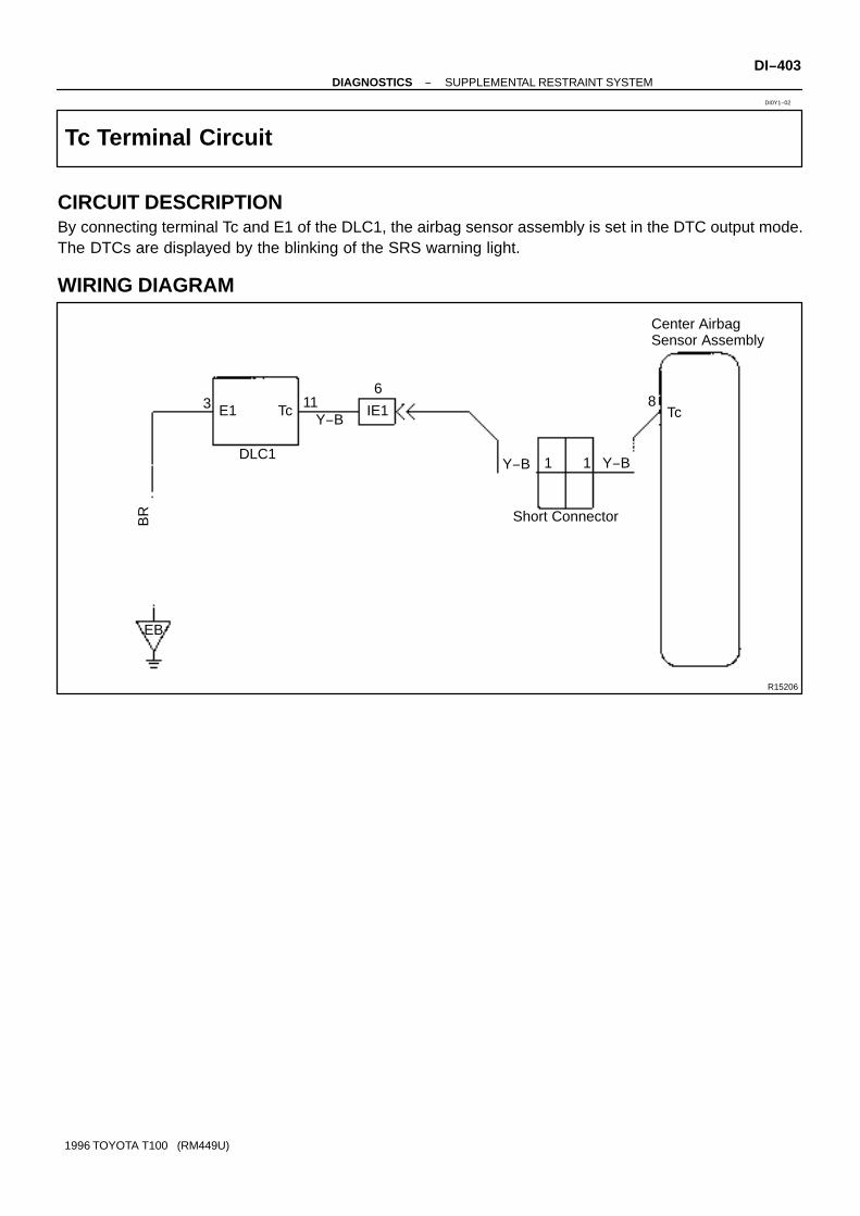
R15206
DLC1
Tc IE111Y−B
6
EB
BR
E1
Y−B Y−B1 1
Short Connector
8Tc
Center AirbagSensor Assembly
3
−DIAGNOSTICS SUPPLEMENTAL RESTRAINT SYSTEMDI−403
1996 TOYOTA T100 (RM449U)
Tc Terminal Circuit
CIRCUIT DESCRIPTIONBy connecting terminal Tc and E1 of the DLC1, the airbag sensor assembly is set in the DTC output mode.The DTCs are displayed by the blinking of the SRS warning light.
WIRING DIAGRAM
DI0Y1−02
https://www.truck-manuals.net/

AB0118 AB0119
W05587 W05586
AB0117
H00347
ACC ON
or
LOCK
w/o Tachometerw/ Tachometer
AB0118
R14305
AB0119H00030
ACC ON
or
E1Tc
(+)(−)
DI−404−DIAGNOSTICS SUPPLEMENTAL RESTRAINT SYSTEM
1996 TOYOTA T100 (RM449U)
INSPECTION PROCEDUREIf DTC is not displayed, do following troubleshooting:
1 Does SRS warning light up for approx. 6 seconds?
PREPARATION:Check operation of SRS warning light after ignition switch isturned from LOCK position to ACC or ON position.
NO Check SRS warning light system (See page DI−365).
YES
2 Check voltage between terminals Tc and E1 of DLC1.
PREPARATION:Turn ignition switch to ACC or ON.CHECK:Measure voltage between terminals Tc and E1 of DLC1.OK:
Voltage: 10 − 16 V
OK Go to step 4.
NG
https://www.truck-manuals.net/
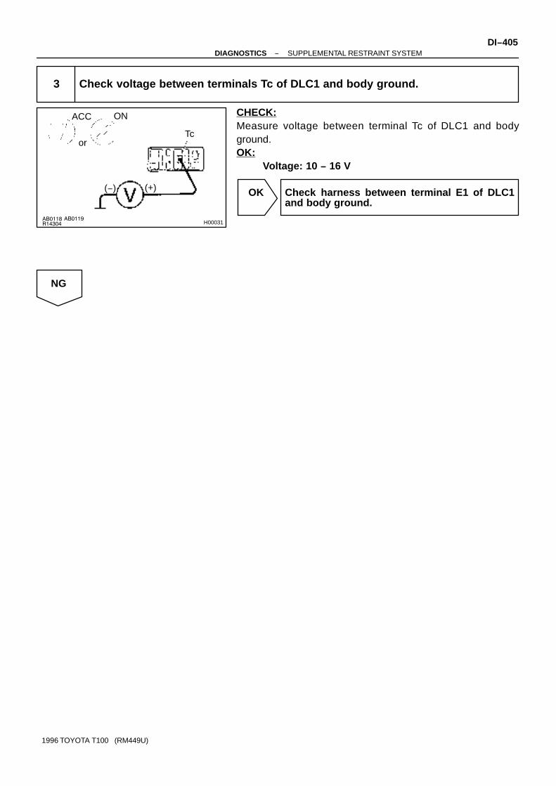
AB0118R14304
AB0119H00031
ACC ON
orTc
(+)(−)
−DIAGNOSTICS SUPPLEMENTAL RESTRAINT SYSTEMDI−405
1996 TOYOTA T100 (RM449U)
3 Check voltage between terminals Tc of DLC1 and body ground.
CHECK:Measure voltage between terminal Tc of DLC1 and bodyground.OK:
Voltage: 10 − 16 V
OK Check harness between terminal E1 of DLC1and body ground.
NG
https://www.truck-manuals.net/

H18117
LOCK Airbag Sensor Assembly
Tc
(+)(−)
DI−406−DIAGNOSTICS SUPPLEMENTAL RESTRAINT SYSTEM
1996 TOYOTA T100 (RM449U)
4 Check center airbag sensor assembly.
PREPARATION:
(a) Turn ignition switch to LOCK.(b) Disconnect negative (−) terminal cable from the battery,
and wait at least 90 seconds.(c) Remove steering wheel pad (See page SR−13 or
SR−26).(d) Disconnect center airbag sensor assembly connector.(e) Insert service wire into terminal Tc from back side as
shown.(f) Connect center airbag sensor assembly connector with
service wire.(g) Connect negative (−) terminal cable to battery.(h) Turn ignition switch to ACC or ON, and wait at least 20 se-
conds.(i) Connect service wire of terminal Tc to body ground.CHECK:Check operation of SRS warning light.OK:
SRS waning light comes on.NOTICE:Never make a mistake with the terminal connection posi-tion as this cause a malfunction.
OK Check harness between center airbag sensorassembly and DLC1.
NG
Replace center airbag sensor assembly.
https://www.truck-manuals.net/

R14303
Airbag Sensor Assembly
−DIAGNOSTICS SUPPLEMENTAL RESTRAINT SYSTEMDI−407
1996 TOYOTA T100 (RM449U)
If DTC is displayed without DTC check procedure, perform following trouble-shooting:
1 Check resistance between terminal Tc of center airbag sensor assembly andbody ground.
PREPARATION:(a) Turn ignition switch to LOCK.(b) Disconnect negative (−) terminal cable from the battery,
and wait at least 90 seconds.(c) Disconnect center airbag sensor assembly connector.CHECK:Check resistance between terminal Tc of center airbag sensorassembly connector and body ground.OK:
Resistance: 1MΩ or Higher
NG Repair or replace harness or connector.
OK
Replace center airbag sensor assembly.
https://www.truck-manuals.net/

DI34T−02
Customer Problem Analysis
Check and Clear DTC (Precheck)
Vehicle Brought to Workshop
Problem Symptom ConfirmationSymptom SimulationSymptom does not occur
DTC Check Normal code
DTC Chart Problem Symptom Table
Circuit Inspection Input Signal CheckParts Inspection
Identification of Problem
Repair
Confirmation Test
End
Items inside are titles of pages in thismanual with the page number indicated in thebottom portion. See the indicated pagesfor detailed explanations.
1
2
34
5
6 7
89
10
Step 2, 5, 8, 10: Diagnostic steps permitting the use of theTOYOTA hand−held tester or TOYOTAbreak−out−box.
P. DI−409
P. DI−410
P. DI−410
P. DI−415
P. IN−16
P. DI−419
P. DI−420 − DI−458
OK
NG
Symptom occurs
Malfunction code
DI−408−DIAGNOSTICS CRUISE CONTROL SYSTEM
665Author�: Date�:
1996 TOYOTA T100 (RM449U)
CRUISE CONTROL SYSTEM
HOW TO PROCEED WITH TROUBLESHOOTING
https://www.truck-manuals.net/
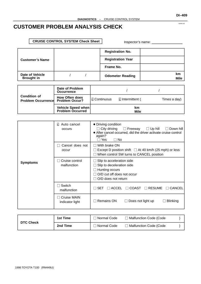
DI34U−02
CRUISE CONTROL SYSTEM Check Sheet Inspector’s name:
Customer’s Name
Date of Vehicle
Registration No.
Registration Year
Frame No.
Odometer Reading / / kmMile
Condition ofProblem Occurrence
Date of Problem
How Often does
Occurrence
Problem Occur?
Vehicle Speed whenProblem Occurred
/ /
Continuous Intermittent ( Times a day)
kmMile
Brought in
Auto cancel occurs
� Driving condition� City driving � Freeway � Up hill � Down hill
� After cancel occurred, did the driver activate cruise control again?� Yes � No
� Cancel does not occur
� With brake ON� Except D position shift � At 40 km/h (25 mph) or less� When control SW turns to CANCEL position
� Cruise control malfunction
� Slip to acceleration side� Slip to deceleration side� Hunting occurs� O/D cut off does not occur� O/D does not return
� Switch malfunction � SET � ACCEL � COAST � RESUME � CANCEL
� Remains ON � Does not light up � Blinking
Symptoms
DTC Check1st Time
2nd Time
� Normal Code � Malfunction Code (Code )
� Normal Code � Malfunction Code (Code )
� Cruise MAIN indicator light
−DIAGNOSTICS CRUISE CONTROL SYSTEMDI−409
1996 TOYOTA T100 (RM449U)
CUSTOMER PROBLEM ANALYSIS CHECK
https://www.truck-manuals.net/

N06022
DI34V−02
BE4034
Indicator Light
1.5 sec. 0.5 sec.
ON
OFF
I22833
DLC1
DI−410−DIAGNOSTICS CRUISE CONTROL SYSTEM
1996 TOYOTA T100 (RM449U)
PRE−CHECK1. DIAGNOSIS SYSTEM(a) Check the indicator.
(1) Turn the ignition switch to ON.(2) Check that the CRUISE MAIN indicator light comes
on when the cruise control main switch is turned on,and that the indicator light goes off when the mainswitch is turned OFF.
HINT:If the indicator check result is not normal, proceed to trouble-shooting (See page BE−36) for the combination meter section.
(b) Check the DTC.HINT:If a malfunction occurs in the No. 1 vehicle speed sensors or ac-tuator, etc. during cruise control driving, the ECU actuatesAUTO CANCEL of the cruise control and turns on and off theCRUISE MAIN indicator light to inform the driver of a malfunc-tion. At the same time, the malfunction is stopped in memory asa diagnostic trouble code.
(c) Using diagnosis check wire, check the output of DTC.(1) Turn the ignition switch ON.(2) Using SST, connect terminals Tc and E1 of DLC1.SST 09843−18020(3) Read the DTC on the CRUISE MAIN indicator light.
https://www.truck-manuals.net/

BE4032
BE4033 I00021
Normal Code
0.25 sec.0.25 sec.
ON
OFF
ON
OFF
4 sec. 1.5 sec.
0.5 sec.
2.5 sec.
0.5 sec.
1.5 sec.
Malfunction codes 11 and 21
Code 11 Code 21
N09348
TOYOTA hand−held tester
TOYOTA Break−out−box
N06038
ECU−B Fuse
−DIAGNOSTICS CRUISE CONTROL SYSTEMDI−411
1996 TOYOTA T100 (RM449U)
HINT:� If the DTC is not output, inspect the Tc circuit (See page
DI−456).� As an example, the blinking patterns for codes; normal,
11 and 21 are shown in the illustration.
2. ECU TERMINAL VALUES MEASUREMENT BY USINGTOYOTA BREAK−OUT−BOX AND TOYOTA HAND−HELD TESTER
(a) Hook up the TOYOTA break−out−box and TOYOTAhand−held tester to the vehicle.
(b) Read the ECU input/output values by following theprompts on the tester screen.
HINT:TOYOTA hand−held tester has a ”Snapshot” function. This re-cords the measured values and is effective in the diagnosis ofintermittent problems.Please refer to the TOYOTA hand−held tester /TOYOTAbreak−out−box operator’s manual for further details.
3. DTC CLEARANCE(a) After completing repairs, the diagnostic trouble code re-
tained in memory can be cleared by removing the ECU−Bfuse for 10 seconds or more, with the ignition switch OFF.
(b) Check that the normal code is displayed after connectingthe fuse.
https://www.truck-manuals.net/

N17520
N17520
N17520
DI−412−DIAGNOSTICS CRUISE CONTROL SYSTEM
1996 TOYOTA T100 (RM449U)
4. PROBLEM SYMPTOM CONFIRMATION (ROAD TEST)(a) Inspect the SET switch.
(1) Push the main switch ON.(2) Drive at a desired speed (40 km/h (25 mph) or high-
er).(3) Press the control switch to the SET/COAST.(4) After releasing the switch, check that the vehicle
cruises at the desired speed.
(b) Inspect the ACCEL switch.(1) Push the main switch ON.(2) Drive at a desired speed (40 km/h (25 mph) or high-
er).(3) Check that the vehicle speed is increased while the
control switch turned to RES/ACC, and that the ve-hicle cruises at the set speed when the switch is re-leased.
(4) Momentarily press the control switch upward in theRES/ACC and then immediately release it. Checkthat the vehicle speed increases by about 1.5 km/h(Tap−up function).
(c) Inspect the COAST.(1) Push the main switch ON.(2) Drive at a desired speed (40 km/h (25 mph) or high-
er).(3) Check that the vehicle speed is decreased while the
control switch is turned to SET/COAST, and the ve-hicle cruise at the set speed when the switch is re-leased.
(4) Momentarily press the control switch is turned toSET/COAST, and then immediately release it.Check that the vehicle speed decreases by about1.5 km/h (Tap−down function).
https://www.truck-manuals.net/

N17520
N17520
−DIAGNOSTICS CRUISE CONTROL SYSTEMDI−413
1996 TOYOTA T100 (RM449U)
(d) Insepct the CANCEL switch.(1) Push the main switch ON.(2) Drive at a desired speed (40 km/h (25 mph) or high-
er).(3) When operating one of the followings, check that
the cruise control system is cancelled and that thenormal driving mode is reset.� Depress the brake pedal� Shift to except D position� Push the main switch OFF� Pull the cruise control switch to CANCEL
(e) Inspect the RESUME switch.(1) Push the main switch ON.(2) Drive at a desired speed (40 km/h (25 mph) or high-
er).(3) When operating one of the followings, check that
the cruise control system is cancelled and that thenormal driving mode is reset.� Depress the brake pedal� Shift to except D position� Pull the cruise control switch to CANCEL
(4) After the control switch is turned to RES/ACC at thedriving speed of more than 40 km/h (25 mph), checkthat the vehicle restores the speed prior to the can-cellation.
https://www.truck-manuals.net/
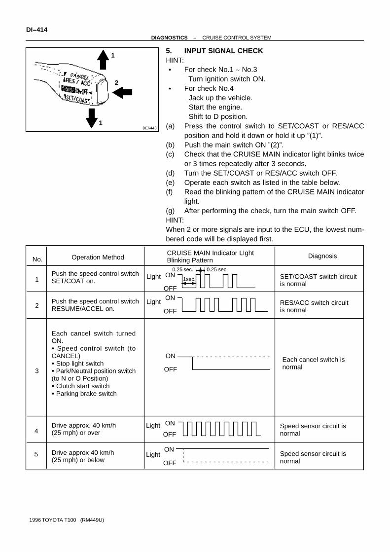
BE6443
1
1
2
No. Operation MethodCRUISE MAIN Indicator LIghtBlinking Pattern
Diagnosis
1
2
3
4Drive approx. 40 km/h (25 mph) or over
Drive approx 40 km/h(25 mph) or below
Light ON
OFF
LightON
OFF
ON
OFF
SET/COAST switch circuitis normal
RES/ACC switch circuitis normal
LightON
OFF
Light ON
OFF
1sec.
0.25 sec. 0.25 sec.Push the speed control switchSET/COAT on.
Push the speed control switchRESUME/ACCEL on.
Each cancel switch turnedON.� Speed control switch (toCANCEL)� Stop light switch� Park/Neutral position switch(to N or O Position)� Clutch start switch� Parking brake switch
Speed sensor circuit isnormal
Speed sensor circuit isnormal
Each cancel switch isnormal
5
DI−414−DIAGNOSTICS CRUISE CONTROL SYSTEM
1996 TOYOTA T100 (RM449U)
5. INPUT SIGNAL CHECKHINT:� For check No.1 ∼ No.3
Turn ignition switch ON.� For check No.4
Jack up the vehicle. Start the engine. Shift to D position.
(a) Press the control switch to SET/COAST or RES/ACCposition and hold it down or hold it up ”(1)”.
(b) Push the main switch ON ”(2)”.(c) Check that the CRUISE MAIN indicator light blinks twice
or 3 times repeatedly after 3 seconds.(d) Turn the SET/COAST or RES/ACC switch OFF.(e) Operate each switch as listed in the table below.(f) Read the blinking pattern of the CRUISE MAIN indicator
light.(g) After performing the check, turn the main switch OFF.HINT:When 2 or more signals are input to the ECU, the lowest num-bered code will be displayed first.
https://www.truck-manuals.net/

DI34W−02
−DIAGNOSTICS CRUISE CONTROL SYSTEMDI−415
1996 TOYOTA T100 (RM449U)
DIAGNOSTIC TROUBLE CODE CHARTIf a malfunction code is displayed during the DTC check, check the circuit listed for that code in the tablebelow and proceed to the appropriate page.
DTC No.
(See Page)Detection Item Trouble Area
11
(DI−420)�Actuator Motor Circuit
�Actuator
�Wire harness
�Cruise control ECU
12
(DI−422)�Actuator Magnetic Clutch Circuit
�Actuator
�Stop light switch
�Wire harness
�Cruise control ECU
13
(DI−425)�Actuator Position Sensor Circuit
�Actuator
�Wire harness
�Cruise control ECU
21
(DI−428)�Vehicle Speed Sensor Circuit
�Vehicle speed sensor
�Wire harness
�Cruise control ECU
*23
(DI−428)
�Actuator Control Cable
�Vehicle Speed Sensor circuit
�Vehicle speed sensor
�Speed control cable function
�Wire harness
�Cruise control ECU
32
(DI−431)�Control Switch Circuit
�Cruise control switch
�Wire harness
�Cruise control ECU
34
(DI−431)�Voltage abnormality in control switch circuit
�Control switch
�Wire harness
�Cruise control ECU
41 � Cruise Control ECU �Cruise control ECU
HINT:When 2 or more codes are indicated, the lowest numbered code will be displayed first.*When the vehicle speed decreases on uphill roads, the speed can be set again and drive can be continued(This is not a malfunction.).
https://www.truck-manuals.net/

DI0YO−05
I22834
DI−416−DIAGNOSTICS CRUISE CONTROL SYSTEM
1996 TOYOTA T100 (RM449U)
PARTS LOCATION
https://www.truck-manuals.net/

DI34Y−02
I00022
12345678910111213
20222425 18 16192123 1726 1415
C15
−DIAGNOSTICS CRUISE CONTROL SYSTEMDI−417
1996 TOYOTA T100 (RM449U)
TERMINALS OF ECU
Symbols (Terminals No.) Wiring Color Condition STD Voltage (V)
D ↔ GND (C15−2 ↔ C15−13) B−W ↔ B−O
Shift to except D position (A/T Vehicle)
Depress Clutch Pedal (M/T Vehicle)Below 1 V
Shift to D position (A/T Vehicle)
Depress Clutch Pedal (M/T Vehicle)10 − 16 V
PI ↔ GND (C15−5 ↔ C15−13) B−Y ↔ B−O
Ignition switch ON
Cruise control main switch ONBelow 1.2 V
Ignition switch ON
Cruise control main switch OFF10 − 16 V
TC ↔ GND
(C15−8 ↔ C15−13)Y−B ↔ B−O Ignition switch ON 10 − 16 V
OD ↔ GND
(C15−9 ↔ C15−13)Y−R ↔ B−O
During cruise control driving
OD switch ON.10 − 16 V
During cruise control driving
OD switch OFF (3rd driving)Below 1 V
L ↔ GND
(C15−10 ↔ C15−13)Y−R ↔ B−O
During cruise control driving 9 − 15 V
Except during cruise control driving Below 1 V
MC ↔ GND
(C15−11 ↔ C15−13)B−R ↔ B−O
During cruise control driving
COAST switch held ON9 − 16 V
During cruise control driving
ACC switch held ONBelow 1 V
MO ↔ GND
(C15−12 ↔ C15−13)LG ↔ B−O
During cruise control driving
ACC switch held ON9 − 15 V
During cruise control driving
COAST switch held ONBelow 1 V
GND ↔ Body Ground
(C15−13 ↔ Body Ground)
B−O ↔ Body
GroundConstant Below 1 V
B ↔ GND
(C15−14 ↔ C15−13)L−R ↔ B−O Ignition switch ON 10 − 16 V
BATT ↔ GND
(C15−15 ↔ C15−13)R ↔ B−O Constant 10 − 16 V
STP− ↔ GND
(C15−16 ↔ C15−13)G−W ↔ B−O
Depress brake pedal 10 − 16 V
Release brake pedal Below 1 V
https://www.truck-manuals.net/

DI−418−DIAGNOSTICS CRUISE CONTROL SYSTEM
1996 TOYOTA T100 (RM449U)
Symbols (Terminals No.) Wiring Color Condition STD Voltage (V)
CCS ↔ GND
(C15−18 ↔ C15−13)G−Y ↔ B−O
Ignition switch ON 10 − 16 V
Ignition switch ON
CANCEL switch held ON5.1 − 8.3 V
Ignition switch ON
SET/COAST switch held ON2.4 − 4.0 V
Ignition switch ON
RES/ACC switch held ON0.8 − 1.4 V
CMS ↔ GND
(C15−4 ↔ C15−13)G−B ↔ B−O
Ignition switch ON
Main switch ONBelow 1 V
Ignition switch ON
Main switch OFF10 − 16 V
SPD ↔ GND
(C15−20 ↔ C15−13)G ↔ B−O
Ignition switch ON 4.7 − 5.2 V
During driving 3 − 7 V
IDL ↔ GND
(C15−23 ↔ C15−13)Y−L ↔ B−O
Ignition switch ON
Throttle valve fully closedBelow 1 V
Ignition switch ON
Throttle valve fully opened10 − 16 V
ECT ↔ GND
(C15−22 ↔ C15−13)R−Y ↔ B−O
During cruise control driving
Gear position O/DBelow 1 V
During cruise control driving
Gear position 3rd10 − 16 V
VR1 ↔ GND
(C15−24 ↔ C15−13)R−W ↔ B−O Ignition switch ON 4.7 − 5.2 V
VR2 ↔ VR3
(C15−25 ↔ C15−26)R ↔ L
During cruise control driving 1.0 − 4.7 V
Ignition switch ON
Actuator control plate fully opened4.2 − 4.7 V
Ignition switch ON
Actuator control plate fully closed1.0 − 1.2 V
VR3 ↔ GND
(C15−26 ↔ C15−13)L ↔ B−O Constant Below 1 V
L− ↔ GND
(C15−10 ↔ C15−13)Y−R ↔ B−O Constant Below 1 V
https://www.truck-manuals.net/

DI34Z−02
−DIAGNOSTICS CRUISE CONTROL SYSTEMDI−419
1996 TOYOTA T100 (RM449U)
PROBLEM SYMPTOMS TABLESymptom Suspect Area See page
SET not occourring or CANCEL occurring.
(DTC is Normal)
1. Main Switch Circuit
(Cruise control switch)
2. Vehicle Speed Sensor
3. Control Switch Circuit
(Cruise control switch)
4. Stop Light Switch Circuit
5. Park/Neutral Position Switch Circuit
6. Actuator Motor Circuit
7. Cruise Control Cable
8. Cruise Control ECU
DI−454
DI−428
DI−431
DI−434
DI−443
DI−420
DI−458
IN−26
SET not occurring or CANCEL occurring.
(DTC is not output)
1. ECU Power Source Circuit
2. Cruise Control ECU
DI−449
IN−26
Actual vehicle speed deviates above or below the set speed.
1. Cruise Control Cable
2. Vehicle Speed Signal Abnormal
3. Electronically Controlled Transmission
Communication Circuit
4. Actuator Motor Circuit
5. Idle Signal Circuit
(Main throttle position sensor)
6. Cruise Control ECU
DI−458
DI−428
DI−440
DI−420
DI−437
IN−26
Gear shifting frequent between 3rd and O/D when driving on uphill
road. (Hurting)
1. Electronically Controlled Transmission
Communication Circuit
2. Cruise Control ECU
DI−440
IN−26
Cruise control not cancelled, even when brake pedal is de-
pressed.
1. Cruise Control Cable
2. Stop Light Switch Circuit
3. Actuator Motor Circuit
4. Cruise Control ECU
DI−458
DI−434
DI−420
IN−26
Cruise control not cancelled, even when transmission is shifted to
”N” postion.
1. Cruise Control Cable
2. Park/Neutral Position Switch Circuit
3. Actuator Motor Circuit
4. Cruise Control ECU
DI−458
DI−443
DI−420
IN−26
Control switch does not operate.
(SET/COAST, ACC/RES, CANCEL not possible)
1. Cruise Control Cable
2. Control Switch Circuit
3. Actuator Motor Circuit
4. Cruise Control ECU
DI−458
DI−431
DI−420
IN−26
SET possible at 40 km/h (25 mph) or less, or CANCEL does not
operate at 40 km/h (25 mph) or less.
1. Cruise Control Cable
2. Vehicle Speed Signal Abnormal
3. Actuator Motor Circuit
4. Cruise Control ECU
DI−458
DI−428
DI−420
IN−26
Poor response in ACCEL and RESUME modes.
1. Cruise Control Cable
2. Electronically Controlled Transmission
Communication Circuit
3. Actuator Motor Circuit
4. Cruise Control ECU
DI−458
DI−440
DI−420
IN−26
O/D does not resume, even though the road is not uphill.
1. Electronically Controlled Transmission
Communication Circuit
2. Cruise Control ECU
DI−440
IN−26
DTC memory is erased.1. Back−up Power Source Circuit
2. Cruise Control ECU
DI−452
IN−26
DTC is not output, or is output when it should not be.1. Tc Circuit
2. Cruise Control ECU
DI−456
IN−26
Cruise MAIN indicator light remains ON or fails to light up. 1. Cruise MAIN Indicator Light Switch Circuit −
https://www.truck-manuals.net/

DI350−02
Duty Ratio =A + B
A x 100 (%) ON
OFF
A
B1 cycle
I22682
DI−420−DIAGNOSTICS CRUISE CONTROL SYSTEM
1996 TOYOTA T100 (RM449U)
CIRCUIT INSPECTION
DTC 11 Actuator Motor Circuit
CIRCUIT DESCRIPTION
The actuator motor is operated by signals from the ECU. Acceleration and deceleration signals are trans-mitted by changes in the Duty Ratio (See note below).Duty Ratio:The duty ratio is the ratio of the period of continuity in one cycle. For example, if A is the period of continuityin one cycle, and B is the period of non−continuity, then.
DTC No. Detection Item Trouble Area
11 �Short in actuator motor circuit.
�Actuator motor
�Wire harness
�Cruise control ECU
WIRING DIAGRAM
https://www.truck-manuals.net/

I00248
7
6
−DIAGNOSTICS CRUISE CONTROL SYSTEMDI−421
1996 TOYOTA T100 (RM449U)
INSPECTION PROCEDURE
1 Check resistance between terminals MO and MC of actuator motor.
PREPARATION:(a) Turn ignition switch OFF.(b) Disconnect the actuator connector.CHECK:Measure resistance between terminals 6 and 7.HINT:If control plate position is fully opened or fully closed, resistancecan not be measured.OK:
Resistance: more than 4.2 Ω
NG Replace cruise control actuator.
OK
2 Check for open and short in harness and connectors between cruise controlECU and actuator motor (See page IN−16).
NG Repair or replace harness or connector.
OK
Check and replace cruise control ECU (Seepage IN−26).
https://www.truck-manuals.net/

I22681
DI−422−DIAGNOSTICS CRUISE CONTROL SYSTEM
1996 TOYOTA T100 (RM449U)
DTC 12 Actuator Magnetic Clutch Circuit
CIRCUIT DESCRIPTION
This circuit turns on the magnetic clutch inside the actuator during cruise control operation according to thesignal from the ECU. If a malfunction occurs in the actuator or speed sensor, etc. during cruise control opera-tion, the rotor shaft between the motor and control plate is released.When the brake pedal is depressed, the stop light switch turns ON, supplying electrical power to the stoplight. Power supply to the magnetic clutch is mechanically cut and the magnetic clutch is turned OFF.When driving downhill, if the vehicle speed exceeds the set speed by 15 km/h (9 mph), the ECU turns thesafety magnet clutch OFF. If the vehicle speed later drops to within 10 km/h (6 mph) above the set speed,then cruise control at the set speed is resumed.
DTC No. Detection Item Trouble Area
12�Short in actuator magnetic clutch circuit.
�Open (0.8 sec.) in actuator magnetic clutch circuit.
�Actuator
�Stop light switch
�Wire harness
�Cruise control ECU
WIRING DIAGRAM
DI351−02
https://www.truck-manuals.net/

N06038
STOP Fuse
I22835
−DIAGNOSTICS CRUISE CONTROL SYSTEMDI−423
1996 TOYOTA T100 (RM449U)
INSPECTION PROCEDURE
1 Check STOP fuse.
PREPARATION:(a) Turn ignition switch OFF.(b) Remove the STOP fuse from instrument panel junction
block.CHECK:Check fuse continuity.OK:
Continuity
NG Replace STOP fuse.
OK
2 Check stop light switch.
PREPARATION:Disconnect the stop light switch connector.CHECK:Check continuity between terminals.
Switch position Continuity
Switch pin free
(Brake pedal depressed)2 − 4
Switch pin pushed in
(Brake pedal released)1 − 3
NG Replace stop light switch.
OK
https://www.truck-manuals.net/

I00247
4
5
DI−424−DIAGNOSTICS CRUISE CONTROL SYSTEM
1996 TOYOTA T100 (RM449U)
3 Check resistance between terminal L and GND of actuator magnetic clutch.
PREPARATION:(a) Turn ignition switch OFF.(b) Disconnect the actuator connector.CHECK:Measure resistance between terminals 4 and 5.OK:
Resistance: 34.65 � 42.35 Ω
NG Replace cruise control actuator.
OK
4 Check for open and short in harness and connectors between cruise controlECU and actuator magnetic clutch, actuator magnetic clutch and body ground(See page IN−16).
NG Repair or replace harness or connector.
OK
Check and replace cruise control ECU (Seepage IN−26).
https://www.truck-manuals.net/

I22680
−DIAGNOSTICS CRUISE CONTROL SYSTEMDI−425
1996 TOYOTA T100 (RM449U)
DTC 13 Actuator Position Sensor Circuit
CIRCUIT DESCRIPTION
The circuit detects the rotation position of the actuator control plate and sends a signal to the ECU.
DTC No.. Detection Item Trouble Area
13 �Position sensor detects abnormal voltage.
�Actuator
�Wire harness
�Cruise control ECU
WIRING DIAGRAM
DI352−02
https://www.truck-manuals.net/

I22679
VR 3
VR 2
I00006
1
3
DI−426−DIAGNOSTICS CRUISE CONTROL SYSTEM
1996 TOYOTA T100 (RM449U)
INSPECTION PROCEDURE
1 Check resistance between terminals VR2 and VR3 of cruise control ECU connec-tor.
PREPARATION:(a) Remove the ECU with connectors still connected.(b) Turn ignition switch OFF.CHECK:Measure voltage between terminals VR2 and VR3 of ECU con-nector while turning control plate slowly by hand from the decel-eration side to the acceleration side.OK:
Voltage:Fully closed: Approx. 1.3 VFully opened: Approx. 4.0 VAs the control plate is turned, the voltage should in-crease gradually without interruption.
NG Proceed to next circuit inspection shown inproblem symptoms table (See page DI−419).
OK
2 Check resistance between terminals VR1 and VR3 of actuator position sensor.
PREPARATION:(a) Turn ignition switch OFF.(b) Disconnect the actuator connector.CHECK:Measure resistance between actuator terminals 1 and 3 of ac-tuator connector.OK:
Resistance: Approx. 2.2 kΩ (25 °C)
NG Replace cruise control actuator.
OK
https://www.truck-manuals.net/

I06382
23
−DIAGNOSTICS CRUISE CONTROL SYSTEMDI−427
1996 TOYOTA T100 (RM449U)
3 Check voltage between terminals VR2 and VR3 of actuator position sensor.
PREPARATION:(a) Turn ignition switch ON.(b) Connect the actuator connector.CHECK:Measure voltage between terminals 2 and 3 of actuator con-nector while turning control plate slowly by hand from the decel-eration side to the acceleration side.OK:
Voltage: 1.3 − 4.0 VHINT:As the control plate is turned, the voltage should increase grad-ually without interruption.
NG Replace cruise control actuator.
OK
4 Check for open and short in harness and connector between cruise control ECUand actuator position sensor (See page IN−16).
NG Repair or replace harness or connector.
OK
Check and replace cruise control ECU (Seepage IN−26).
https://www.truck-manuals.net/

I00414
Speed Sensor
ECT OD/TRIP METERCruise Control ECU
4 pulse/1 rotationof rotor shaft
4 pulse/1 rotationof rotor shaft
I22673
DI−428−DIAGNOSTICS CRUISE CONTROL SYSTEM
1996 TOYOTA T100 (RM449U)
DTC 21 Vehicle Speed Sensor Circuit
CIRCUIT DESCRIPTION
The vehicle speed siggnal is sent to cruise control ECU from the vehicle speed sensor.The rotor shaft is driven by the gear of the transmission.For each rotation of the shaft, the vehicle speed sensor sends a 4−pulse signal through the combinationmeter to the cruise control ECU (See the following).This signal is converted inside the combination meter and sent as a 4−pulse signal to the cruise control ECU.The ECU calculates the vehicle speed from this pulse frequency.
DTC No. Detection Item Trouble Area
21�Speed signal is not input to the cruise control ECU while
cruise control is set.
�Vehicle speed sensor
�Wire harness
�Cruise control ECU
WIRING DIAGRAM
DI353−02
https://www.truck-manuals.net/

Input Signal Indicator LightBlinking Pattern
Drive at about 40 km/h (25 mph)or below
Drive at about 40 km/h (25 mph)or higher
Light ON
OFF
LightON
OFF
−DIAGNOSTICS CRUISE CONTROL SYSTEMDI−429
1996 TOYOTA T100 (RM449U)
INSPECTION PROCEDURE
1 Input signal check.
CHECK:(a) See input signal check on page DI−410.(b) Check indicator light operation when driving at vehicle
speed above 40 km/h (25 mph), and at vehicle speed be-low 40 km/h (25 mph).
OK:Vehicle speed above 40 km/h (25 mph): Indicator light blinksVehicle speed below 40 km/h (25 mph): Indicator light stays on
OK Check and replace cruise control ECU (Seepage IN−26).
NG
2 Check speedometer circuit (See Combination meter troubleshooting on pageBE−36).
NG Repair or replace harness, connector or com-bination meter assembly.
OK
3 Check harness and connector between cruise control ECU and combination me-ter, combination meter and vehicle speed sensor (See page IN−16).
NG Repair or replace harness or connector.
OK
https://www.truck-manuals.net/

DI−430−DIAGNOSTICS CRUISE CONTROL SYSTEM
1996 TOYOTA T100 (RM449U)
4 Check vehicle speed sensor (See page BE−38).
NG Replace vehicle speed sensor.
OK
Check and replace cruise control ECU (Seepage IN−26).
https://www.truck-manuals.net/

I22674
−DIAGNOSTICS CRUISE CONTROL SYSTEMDI−431
1996 TOYOTA T100 (RM449U)
DTC 32, 34 Control Switch Circuit
CIRCUIT DESCRIPTION
This circuit sends the SET/COAST, RESUME/ACCEL and CANCEL signals (each voltage) to the ECU.
DTC No. Detection Item Trouble Area
32 �Short in control switch circuit. �Cruise control switch
�Wire harness
�Cruise control ECU34 �Voltage abnormality in control switch circuit
WIRING DIAGRAM
DI354−02
https://www.truck-manuals.net/

Input Signal Indicator Light Blinking Pattern
SET/COASTswitch
RESUME/ACCELswitch
CANCEL switch
2 PulsesON
OFF
ON
OFF
3 Pulses
ON
OFF
SW OFF
SW ON
AB0119
I00136
I00162
ON
CCS
(+)(−)
DI−432−DIAGNOSTICS CRUISE CONTROL SYSTEM
1996 TOYOTA T100 (RM449U)
INSPECTION PROCEDURE
1 Input signal check.
PREPARATION:See input signal check on page DI−410.CHECK:Check the indicator light operation when each of the SET/COAST, RESUME/ACCEL and CANCEL is turned ON.OK:
SET/COAST, RESUME/ACCEL switchThe signals shown in the table on the left should beoutput when each switch is ON. The signal shoulddisappear when the switch is turned OFF.CANCEL switchThe indicator light goes off when the cancel switch isturned ON.
OK Wait and see.
NG
2 Check voltage between terminal CCS of cruise control ECU connector and bodyground.
PREPARATION:(a) Remove the ECU with connector still connected.(b) Turn ignition switch ON.CHECK:Measure voltage between terminal CCS of ECU connector andbody ground, when each of the SET/COAST, RESUME/AC-CEL and CANCEL is turned ON.
Switch position Voltage (V)
Neutral 10 − 16
RES/ACC 0.8 − 14 V
SET/COAST 2.4 − 4.0 V
CANCEL 5.1 − 8.3 V
NG Proceed to next circuit inspection shown inproblem symptom table (See page DI−419).
OK
https://www.truck-manuals.net/

N16045
34
−DIAGNOSTICS CRUISE CONTROL SYSTEMDI−433
1996 TOYOTA T100 (RM449U)
3 Check control switch.
PREPARATION:(a) Remove steering wheel center pad.(b) Disconnect the control switch connector.CHECK:Measure resistance between terminals 3 and 4 of control switchconnector when control switch is operated.
Switch position Resistance (Ω)
Neutral ∞ (No continuity)
RES/ACC 50 − 80
SET/COAST 180 − 220
CANCEL 400 − 440
NG Replace control switch.
OK
4 Check harness and connector between cruise control ECU and cruise control switch,cruise control switch and body ground (See page IN−16).
NG Repair or replace harness or connector.
OK
5 Input signal check (See step 1).
OK Wait and see.
NG
Check and replace cruise control ECU (Seepage IN−26).
https://www.truck-manuals.net/

I22687
DI−434−DIAGNOSTICS CRUISE CONTROL SYSTEM
1996 TOYOTA T100 (RM449U)
Stop Light Switch Circuit
CIRCUIT DESCRIPTION
When the brake pedal is depressed, the stop light switch sends a signal to the ECU. When the ECU receivesthis signal, it cancels the cruise control.A fail−safe function is provided so that the cancel functions normally, even if there is a malfunction in the stoplight signal circuit.The cancel conditions are: Battery positive voltage at terminal STP−When the brake is ON, battery positive voltage is normally applied through the STOP fuse and stop lightswitch to terminal STP− of the ECU, and the ECU turns the cruise control OFF.If the harness connected to terminal STP− has an open circuit, terminal STP− will have battery positive volt-age and the cruise control will be turned OFF.Also, when the brake is ON, the magnetic clutch circuit is cut mechanically by the stop light switch, turningthe cruise control OFF (See page DI−422 for operation of the magnetic clutch).
WIRING DIAGRAM
DI355−02
https://www.truck-manuals.net/

Input SignalIndicator LightBlinking Pattern
Stop Light switch ON Light
ON
OFF
SW OFF
SW ON
−DIAGNOSTICS CRUISE CONTROL SYSTEMDI−435
1996 TOYOTA T100 (RM449U)
INSPECTION PROCEDURE
1 Check operation of stop light.
CHECK:Check that stop light comes on when brake pedal is depressed, and turns off when brake pedal is released.
NG Check stop light system (See page BE−30).
OK
2 Input signal check.
CHECK:(a) See input signal check on DI−410.(b) Check the indicator light when the brake pedal is de-
pressed.OK:
The indicator light goes off when the brake pedal isdepressed.
OK Proceed to next circuit inspection shown inproblem symptoms table (See page DI−419).
NG
https://www.truck-manuals.net/

AB0119
I00015 I00024
ON STP−
(−) (+)
DI−436−DIAGNOSTICS CRUISE CONTROL SYSTEM
1996 TOYOTA T100 (RM449U)
3 Check voltage between terminal STP− of cruise control ECU connector andbody ground.
PREPARATION:(a) Remove the ECU with connectors still connected.(b) Turn ignition switch ON.CHECK:Measure voltage between terminal STP− of cruise control ECUconnector and body ground, when the brake pedal is de-pressed and released.OK:
Depressed 10 − 16 V
Released Below 1 V
OK Proceed to next circuit inspection shown inproblem symptoms table (See page DI−419).
NG
4 Check for open in harness and connectors between terminal STP− of cruise con-trol ECU and stop light switch (See page IN−16).
NG Repair or replace harness or connector.
OK
Check and replace cruise control ECU (Seepage IN−26).
https://www.truck-manuals.net/

I22676
−DIAGNOSTICS CRUISE CONTROL SYSTEMDI−437
1996 TOYOTA T100 (RM449U)
Idle Switch Circuit
CIRCUIT DESCRIPTION
When the idle switch is turned ON, a signal is sent to the ECU. The ECU uses this signal to correct the dis-crepancy between the throttle valve position and the actuator position sensor value to enable accuratecruise control at the set speed. If the idle switch is malfunctioning, problem symptoms also occur in the en-gine, so also inspect the engine.
WIRING DIAGRAM
DI356−02
https://www.truck-manuals.net/

I22837
DI−438−DIAGNOSTICS CRUISE CONTROL SYSTEM
1996 TOYOTA T100 (RM449U)
INSPECTION PROCEDURE
1 Check voltage between terminal IDL of cruise control ECU connector and bodyground.
PREPARATION:(a) Remove the ECU with connector still connected.(b) Disconnect the ECM and ABS ECU connectors.(c) Turn ignition switch ON.CHECK:Measure voltage between terminal IDL of ECU connector andbody ground when the throttle valve is fully closed and fullyopened.OK:
Throttle valve position Voltage
Fully opened 10 − 16 V
Fully closed Below 1 V
OK Proceed to next circuit inspection shown inproblem symptoms table (See page DI−419).
NG
2 Check harness and connector between ECM and throttle position sensor (Seepage IN−16).
NG Repair or replace harness or connector.
OK
3 Check throttle position sensor circuit.(3RZ−FE: See page MF−25)(5VZ−FE: See page SF−31)
NG Replace throttle position sensor.
OK
https://www.truck-manuals.net/

I22686
Throttle Position Sensor
1
2
−DIAGNOSTICS CRUISE CONTROL SYSTEMDI−439
1996 TOYOTA T100 (RM449U)
4 Check throttle position sensor.
PREPARATION:Disconnect the throttle position sensor connector.CHECK:Measure resistance between terminals 1 and 2 of throttle posi-tion sensor connector when the throttle valve is fully closed andfully opened.OK:
Throttle valve position Resistance
Fully opened 1 MΩ or higher
Fully closed Below 500 Ω
NG Replace throttle position sensor.
OK
5 Check for open and short in harness and connector between cruise control ECUand throttle position sensor, throttle position sensor and body ground (See pageIN−16).
NG Repair or replace harness or connector.
OK
Check and replace cruise control ECU (Seepage IN−26).
https://www.truck-manuals.net/

I22685
DI−440−DIAGNOSTICS CRUISE CONTROL SYSTEM
1996 TOYOTA T100 (RM449U)
Electronically Controlled Transmission Communication Circuit
CIRCUIT DESCRIPTION
When driving uphill under cruise control, in order to reduce shifting due to ON−OFF overdrive operation andto provide smooth driving, when down shifting in the electronically controlled transmission occurs, a signalto prevent upshift until the end of the up hill slope is sent from the cruise control ECU to the electronicallycontrolled transmission.Terminal ECT of the cruise control ECU detects the shift change signal (output to electronically controlledtransmission No. 2 solenoid) from the ECM.If vehicle speed down, also when terminal ECT of the cruise control ECU receives down shifting signal, itsends a signal from terminal OD to ECM to cut overdrive until the end of the uphill slope, and the gear shiftsare reduced and gear shift points in the electronically controlled transmission are changed.
WIRING DIAGRAM
DI357−02
https://www.truck-manuals.net/

AB0119
I00012
I00025
ON
OD
(−) (+)
−DIAGNOSTICS CRUISE CONTROL SYSTEMDI−441
1996 TOYOTA T100 (RM449U)
INSPECTION PROCEDURE
1 Check operation of overdrive.
PREPARATION:Test drive after engine warms up.CHECK:Check that overdrive ON ↔ OFF occurs with operation of OD switch ON−OFF.
NG Check and repair electronically controlledtransmission (See page DI−311).
OK
2 Check voltage between terminal OD of harness side connector of cruise controlECU and body ground.
PREPARATION:(a) Remove the ECU with connector still connected.(b) Turn ignition switch ON.(c) Disconnect the ECU connector.CHECK:Measure voltage between terminal OD of ECU connector onthe harness side and body ground.OK:
Voltage: 10 − 16 V
NG Go to step 5.
OK
https://www.truck-manuals.net/

I00019
ECT
(−) (+)
DI−442−DIAGNOSTICS CRUISE CONTROL SYSTEM
1996 TOYOTA T100 (RM449U)
3 Check voltage between terminal ECT of cruise control ECU connector and bodyground (On test drive).
PREPARATION:(a) Connect the ECU connector.(b) Test drive after engine warms up.CHECK:Check voltage between terminal ECT of ECU connector andbody ground when OD switch is ON and OFF.OK:
OD switch position Voltage
ON Below 1 V
OFF 10 − 16 V
OK Proceed to next circuit inspection shown inproblem symptoms table (See page DI−419).
NG
4 Check harness and connector between terminal ECT of cruise control ECU andelectronically controlled transmission solenoid (See page IN−16).
NG Repair or replace harness or connector.
OK
Check and replace cruise control ECU.(Seepage IN−26)
5 Check harness and connector between terminal OD of cruise control ECU andterminal OD1 of ECM (See page IN−16).
NG Repair or replace harness or connector.
OK
Check and replace cruise control ECU (Seepage IN−26).
https://www.truck-manuals.net/

I22684
−DIAGNOSTICS CRUISE CONTROL SYSTEMDI−443
1996 TOYOTA T100 (RM449U)
Park/Neutral Position Switch Circuit
CIRCUIT DESCRIPTION
When the shift position is in except D position, a signal is sent from the park/neutral position switch to theECU. When this signal is input during cruise control driving, the ECU cancels the cruise control.
WIRING DIAGRAM
DI358−02
https://www.truck-manuals.net/

Input Signal Indicator Light Blinking Pattern
Turn PNP switchOFF (Shift to except D position)
LightON
OFF
SW ON
SW OFF
DI−444−DIAGNOSTICS CRUISE CONTROL SYSTEM
1996 TOYOTA T100 (RM449U)
INSPECTION PROCEDURE
1 Check starter operation.
CHECK:Check that the starter operates normally and that the engine starts.
NG Proceed to engine troubleshooting.(3RZ−FE: See page DI−1)(5VZ−FE: See page DI−127)
OK
2 Input signal check.
PREPARATION:See input signal check on page DI−410.CHECK:Check the indicator light when shifting into except D position.OK:
The indicator light goes off when shifting into exceptD position.
OK Proceed to next circuit inspection shown inproblem symptoms table (See page DI−419).
NG
https://www.truck-manuals.net/
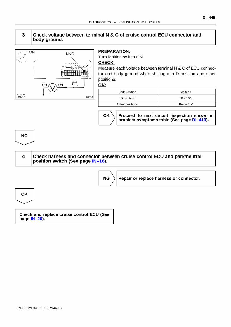
AB0119
I00017 I00026
ON N&C
(−) (+)
−DIAGNOSTICS CRUISE CONTROL SYSTEMDI−445
1996 TOYOTA T100 (RM449U)
3 Check voltage between terminal N & C of cruise control ECU connector andbody ground.
PREPARATION:Turn ignition switch ON.CHECK:Measure each voltage between terminal N & C of ECU connec-tor and body ground when shifting into D position and otherpositions.OK:
Shift Position Voltage
D position 10 − 16 V
Other positions Below 1 V
OK Proceed to next circuit inspection shown inproblem symptoms table (See page DI−419).
NG
4 Check harness and connector between cruise control ECU and park/neutralposition switch (See page IN−16).
NG Repair or replace harness or connector.
OK
Check and replace cruise control ECU (Seepage IN−26).
https://www.truck-manuals.net/

I22683
DI−446−DIAGNOSTICS CRUISE CONTROL SYSTEM
1996 TOYOTA T100 (RM449U)
Clutch Switch Circuit
CIRCUIT DESCRIPTION
When the clutch pedal is depressed, the clutch switch sends a signal to the cruise control ECU. When thesignal is input to the cruise control ECU during cruise control driving, the cruise control ECU cancels cruisecontrol.
WIRING DIAGRAM
DI359−02
https://www.truck-manuals.net/

Input Signal Indicator LightBlinking Pattern
Clutch switch OFF (Depressclutch pedal)
LightON
OFF
SW ON
SW OFF
−DIAGNOSTICS CRUISE CONTROL SYSTEMDI−447
1996 TOYOTA T100 (RM449U)
INSPECTION PROCEDURE
1 Check starter operation.
CHECK:Check that the starter operates normally and that the engine starts.
NG Proceed to engine troubleshooting.(3RZ−FE: See page DI−1)(5VZ−FE: See page DI−127)
OK
2 Input signal check.
PREPARATION:See input signal check on page DI−410.CHECK:Check the indicator light when clutch pedal is depressed.OK:
The indicator light goes off when depressing theclutch pedal .
OK Proceed to next circuit inspection shown inproblem symptoms table (See page DI−419).
NG
https://www.truck-manuals.net/

AB0119
I00017 I00026
ON N&C
(+)(−)
DI−448−DIAGNOSTICS CRUISE CONTROL SYSTEM
1996 TOYOTA T100 (RM449U)
3 Check voltage between terminal N & C of cruise control ECU and body ground.
PREPARATION:Turn ignition switch ON.CHECK:Measure voltage between terminal N & C of cruise control ECUconnector and body ground when clutch pedal is depressedand released.OK:
Shift Position Voltage
Clutch pedal released Below 1 V
Clutch pedal depressed 10 − 16 V
OK Proceed to next circuit inspection shown inproblem symptoms table (See page DI−419).
NG
4 Check for open in harness and connector between ECU and GAUGE fuse (Seepage IN−16).
NG Repair or replace harness or connector.
OK
Check and replace cruise control ECU (Seepage IN−26).
https://www.truck-manuals.net/

I22678
−DIAGNOSTICS CRUISE CONTROL SYSTEMDI−449
1996 TOYOTA T100 (RM449U)
ECU Power Source Circuit
CIRCUIT DESCRIPTION
The ECU power source supplies power to the actuator and sensors, etc. when terminal GND and the cruisecontrol ECU case are grounded.
WIRING DIAGRAM
DI35A−02
https://www.truck-manuals.net/

N06038
ECU−IG Fuse
AB0119
I00014 I00027
GND B
ON
(−) (+)
DI−450−DIAGNOSTICS CRUISE CONTROL SYSTEM
1996 TOYOTA T100 (RM449U)
INSPECTION PROCEDURE
1 Check ECU−IG fuse.
PREPARATION:Remove the ECU−IG fuse from instrument panel junction block.CHECK:Check continuity of ECU−IG fuse.OK:
Continuity
NG Check for short in all the harness and compo-nents connected to ECU−IG fuse.
OK
2 Check voltage between terminals B and GND of cruise control ECU connector.
PREPARATION:(a) Remove the ECU with connector still connected.(b) Turn ignition switch ON.CHECK:Measure voltage between terminals B and GND of ECU con-nector.OK:
Voltage: 10 − 16 V
OK Proceed to next circuit inspection shown inproblem symptoms table (See page DI−419).
NG
https://www.truck-manuals.net/

I00018
GND
−DIAGNOSTICS CRUISE CONTROL SYSTEMDI−451
1996 TOYOTA T100 (RM449U)
3 Check resistance between terminal GND of cruise control ECU connector andbody ground (See page IN−16).
CHECK:Measure resistance between terminal GND of ECU connectorand body ground.OK:
Resistance: Below 1 Ω
NG Repair or replace harness or connector.
OK
Check and repair harness and connector be-tween cruise control ECU and battery (Seepage IN−26).
https://www.truck-manuals.net/

I22675
DI−452−DIAGNOSTICS CRUISE CONTROL SYSTEM
1996 TOYOTA T100 (RM449U)
Back−up Power Source Circuit
CIRCUIT DESCRIPTION
The ECU back−up power source provides power even when the ignition is OFF, and it is used for DTCmemory, etc..
WIRING DIAGRAM
DI35B−02
https://www.truck-manuals.net/

N06038
ECU−B Fuse
I00016
BATT
(−) (+)
−DIAGNOSTICS CRUISE CONTROL SYSTEMDI−453
1996 TOYOTA T100 (RM449U)
INSPECTION PROCEDURE
1 Check ECU−B fuse.
PREPARATION:Remove the ECU−B fuse from relay block No.1.CHECK:Check continuity of ECU−B fuse.OK:
Continuity
NG Check for short in all the harness and compo-nents connected to the ECU−B fuse.
OK
2 Check voltage between terminal BATT of cruise control ECU connector and bodyground (See page IN−16).
PREPARATION:Remove the ECU with connector still connected.CHECK:Measure voltage between terminal BATT of ECU connectorand body ground.OK:
Voltage: 10 − 16 V
OK Proceed to next circuit inspection shown inproblem symptoms table (See page DI−419).
NG
Check and repair harness and connector be-tween battery and cruise control ECU (Seepage IN−16).
https://www.truck-manuals.net/

I22836
DI−454−DIAGNOSTICS CRUISE CONTROL SYSTEM
1996 TOYOTA T100 (RM449U)
Main Switch Circuit
CIRCUIT DESCRIPTION
When the cruise control main switch is turned OFF, the cruise control does not operate.
WIRING DIAGRAM
See page DI−431.
INSPECTION PROCEDURE
1 Check voltage between terminal CMS of cruise control ECU connector and bodyground.
PREPARATION:(a) Remove the ECU with connector still connected.(b) Turn ignition switch ON.CHECK:Measure voltage between terminal CMS of cruise control ECUconnector when main switch is held ON and OFF.OK:
Main switch Voltage
OFF 10 − 16 V
ON Below 1 V
OK Proceed to next circuit inspection shown inproblem symptoms table (See page DI−419).
NG
DI35C−02
https://www.truck-manuals.net/

N15969
4 2
−DIAGNOSTICS CRUISE CONTROL SYSTEMDI−455
1996 TOYOTA T100 (RM449U)
2 Check main switch continuity.
PREPARATION:(a) Remove steering wheel center pad. (See SR section)(b) Disconnect the control switch connector.CHECK:Check continuity between terminals 2 and 4 of control switchconnector when main switch is held ON and OFF.OK:
Switch position Tester connection Specified condition
OFF 2 − 4 No continuity
Hold ON 2 − 4 Continuity
NG Replace control switch.
OK
3 Check harness and connector between cruise control ECU and main switch (Seepage IN−16).
NG Repair or replace harness or connector.
OK
Check and replace cruise control ECU (Seepage IN−26).
https://www.truck-manuals.net/

I22677
DI−456−DIAGNOSTICS CRUISE CONTROL SYSTEM
1996 TOYOTA T100 (RM449U)
Tc Circuit
CIRCUIT DESCRIPTION
This circuit sends a signal to the ECU that DTC output is required.
WIRING DIAGRAM
DI35D−02
https://www.truck-manuals.net/

N06219
DLC1
E1
TC
−DIAGNOSTICS CRUISE CONTROL SYSTEMDI−457
1996 TOYOTA T100 (RM449U)
INSPECTION PROCEDURE
1 Check voltage between terminals Tc and E1 of DLC1.
PREPARATION:Turn ignition switch ON.CHECK:Measure voltage between terminals Tc and E1 of DLC1.OK:
Voltage: 10 − 16 V
OK Proceed to next circuit inspection shown inproblem symptoms table (See page DI−419).
NG
2 Check harness and connector between cruise control ECU and DLC1, DLC1 andbody ground (See page IN−16).
NG Repair or replace harness or connector.
OK
Check and replace cruise control ECU (Seepage IN−26).
https://www.truck-manuals.net/

DI−458−DIAGNOSTICS CRUISE CONTROL SYSTEM
1996 TOYOTA T100 (RM449U)
Actuator Control Cable Inspection
INSPECTION PROCEDURE
1 Actuator control cable inspection.
CHECK:(a) Check that the actuator and control cable throttle link are properly installed and that the cable and link
are connected correctly.(b) Check that the actuator and bell crank are operating smoothly.(c) Check that the cable is not loose or too tight.OK:
Freeplay: less than 10 mmHINT:� If the control cable is very loose, the vehicle’s loss of speed going uphill will be large.� If the control cable is too tight, the idle RPM will become high.
DI35E−01
https://www.truck-manuals.net/

EM – ENGINE MECHANICAL (3RZ-FE)
CO/HC EM-1 COMPRESSION EM-3 VALVE CLEARANCE EM-5 IGNITION TIMING EM-11 IDLE SPEED EM-12 TIMING CHAIN EM-13 CYLINDER HEAD EM-26 ENGINE UNIT EM-61 CYLINDER BLOCK EM-75 EXHAUST SYSTEM EM-104
https://www.truck-manuals.net/

P15056A03712
EM06Q−03
−ENGINE MECHANICAL (3RZ−FE) CO/HCEM−1
716Author�: Date�:
1996 TOYOTA T100 (RM449U)
CO/HCINSPECTIONHINT:This check is used only to determine whether or not the idle CO/HC complies with regulations.1. INITIAL CONDITIONS(a) Engine at normal operating temperature(b) Air cleaner installed(c) All pipes and hoses of air induction system connected(d) All accessories switched OFF(e) All vacuum lines properly connectedHINT:All vacuum hoses for EGR systems, etc. should be properlyconnected.(f) SFI system wiring connectors fully plugged(g) Ignition timing set correctly(h) Transmission in neutral position(i) Tachometer and CO/HC meter calibrated by hand2. START ENGINE3. RACE ENGINE AT 2,500 RPM FOR APPROX. 180
SECONDS4. INSERT CO/HC METER TESTING PROBE AT LEAST
40 cm (1.3 ft) INTO TAILPIPE DURING IDLING5. IMMEDIATELY CHECK CO/HC CONCENTRATION AT
IDLE AND/OR 2,500 RPMHINT:When doing the 2 mode (2,500 rpm and idle) test, follow themeasurement order prescribed by the applicable local regula-tions.
https://www.truck-manuals.net/

EM−2−ENGINE MECHANICAL (3RZ−FE) CO/HC
717Author�: Date�:
1996 TOYOTA T100 (RM449U)
6. TROUBLESHOOTINGIf the CO/HC concentration does not comply with regulations,troubleshoot according to the table below.(a) Check heated oxygen sensor operation.(b) Check and correct the cause if necessary.
CO HC Symptom Causes
Normal High Rough Idle
1. Faulty ignitions:
� Incorrect timing
� Fouled, shorted or improperly gapped plugs
� Open or crossed high−tension cords
� Cracked distributor cap
2. Incorrect valve clearance
3. Leaky EGR valves
4. Leaky exhaust valves
5. Leaky cylinder
Low HighRough Idle
(Fluctuating HC reading)
1. Vacuum leaks:
� Vacuum hose
� Intake manifold
� Intake chamber
� PCV line
� Throttle body
High HighRough Idle
(Black smoke from exhaust)
1. Clogged air filter
2. Plugged PCV valve
3. Faulty SFI systems:
� Faulty fuel pressure regulator
� Clogged fuel return line
� Faulty MAF meter
� Defective ECT sensor
� Defective IAT sensor
� Faulty engine control module (ECM)
� Faulty injector
https://www.truck-manuals.net/

EM06R−03
P15972
Compression Gauge
−ENGINE MECHANICAL (3RZ−FE) COMPRESSIONEM−3
718Author�: Date�:
1996 TOYOTA T100 (RM449U)
COMPRESSIONINSPECTIONHINT:If there is lack of power, excessive oil consumption or poor fueleconomy, measure the compression pressure.1. WARM UP AND STOP ENGINE2. REMOVE INTAKE AIR CONNECTOR
(See page EM−65)3. DISCONNECT HIGH−TENSION CORDS FROM
SPARK PLUGSNOTICE:Pulling on or bending the cords may damage the conductorinside.4. REMOVE SPARK PLUGS
5. CHECK CYLINDER COMPRESSION PRESSURE(a) Insert a compression gauge into the spark plug hole.(b) Fully open the throttle.(c) While cranking the engine, measure the compression
pressure.HINT:Always use a fully charged battery to obtain engine speed of250 rpm or more.(d) Repeat steps (a) through (c) for each cylinder.NOTICE:This measurement must be done in as short a time as pos-sible.
Compression pressure:1,230 kPa (12.5 kgf/cm2, 178 psi) or moreMinimum pressure:880 kPa (9.0 kgf/cm2, 127 psi)Difference between each cylinder:98 kPa (1.0 kgf/cm2, 14 psi) or less
(e) If the cylinder compression in one or more cylinders is low,pour a small amount of engine oil into the cylinder throughthe spark plug hole and repeat steps (a) through (c) forcylinders with low compression.� If adding oil helps the compression, chances are
that the piston rings and/or cylinder bore are wornor damage.
� If pressure stays low, a valve may be sticking orseating is improper, or there may be leakage pastthe gasket.
https://www.truck-manuals.net/

EM−4−ENGINE MECHANICAL (3RZ−FE) COMPRESSION
719Author�: Date�:
1996 TOYOTA T100 (RM449U)
6. REINSTALL SPARK PLUGSTorque:19 N·m (200 kgf·cm, 14 ft·lbf)
7. REINSTALL HIGH−TENSION CORDS TO SPARKPLUGS
8. REINSTALL AIR INTAKE CONNECTOR(See page EM−70)
https://www.truck-manuals.net/

EM06S−03
P24401
A03713
P14695
−ENGINE MECHANICAL (3RZ−FE) VALVE CLEARANCEEM−5
720Author�: Date�:
1996 TOYOTA T100 (RM449U)
VALVE CLEARANCEINSPECTIONHINT:Inspect and adjust the valve clearance when the engine is cold.1. DRAIN ENGINE COOLANT2. REMOVE AIR CLEANER CAP, MAF METER AND RES-
ONATOR (See page EM−65)3. REMOVE NO.1 AND NO.2 PCV HOSES4. DISCONNECT HIGH−TENSION CORDS FROM SPARK
PLUGSNOTICE:Pulling on or bending the cords may damage the conductorinside.5. REMOVE THROTTLE BODY (See page MF−28)6. DISCONNECT ENGINE WIRE(a) Disconnect these connectors:
� w/ A/C:A/C compressor connector
� Oil pressure sensor connector� ECT sensor connector
(b) Disconnect the 5 engine wire clamps and engine wire.
7. REMOVE CYLINDER HEAD COVERRemove the 10 bolts, cylinder head cover and gasket.
8. SET NO.1 CYLINDER TO TDC/COMPRESSION(a) Turn the crankshaft pulley clockwise and align its groove
with the ”0” mark on the timing chain cover.
https://www.truck-manuals.net/
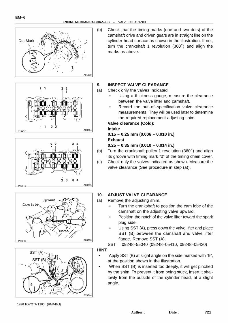
A01399
Dot Mark
P15017
A03714
P15018
A03715
P15045
A03716
P15044
SST (A)
SST (B)
EM−6−ENGINE MECHANICAL (3RZ−FE) VALVE CLEARANCE
721Author�: Date�:
1996 TOYOTA T100 (RM449U)
(b) Check that the timing marks (one and two dots) of thecamshaft drive and driven gears are in straight line on thecylinder head surface as shown in the illustration. If not,turn the crankshaft 1 revolution (360°) and align themarks as above.
9. INSPECT VALVE CLEARANCE(a) Check only the valves indicated.
� Using a thickness gauge, measure the clearancebetween the valve lifter and camshaft.
� Record the out−of−specification valve clearancemeasurements. They will be used later to determinethe required replacement adjusting shim.
Valve clearance (Cold):Intake0.15 − 0.25 mm (0.006 − 0.010 in.)Exhaust0.25 − 0.35 mm (0.010 − 0.014 in.)
(b) Turn the crankshaft pulley 1 revolution (360°) and alignits groove with timing mark ”0” of the timing chain cover.
(c) Check only the valves indicated as shown. Measure thevalve clearance (See procedure in step (a)).
10. ADJUST VALVE CLEARANCE(a) Remove the adjusting shim.
� Turn the crankshaft to position the cam lobe of thecamshaft on the adjusting valve upward.
� Position the notch of the valve lifter toward the sparkplug side.
� Using SST (A), press down the valve lifter and placeSST (B) between the camshaft and valve lifterflange. Remove SST (A).
SST 09248−55040 (09248−05410, 09248−05420)HINT:� Apply SST (B) at slight angle on the side marked with ”9”,
at the position shown in the illustration.� When SST (B) is inserted too deeply, it will get pinched
by the shim. To prevent it from being stuck, insert it shal-lowly from the outside of the cylinder head, at a slightangle.
https://www.truck-manuals.net/

P15046A03717
EM0494
P15043
SST (A)
SST (B)
−ENGINE MECHANICAL (3RZ−FE) VALVE CLEARANCEEM−7
722Author�: Date�:
1996 TOYOTA T100 (RM449U)
� Remove the adjusting shim with a small screwdriver andmagnetic finger.
(b) Determine the replacement adjusting shim size by follow-ing the Formula or Charts:� Using a micrometer, measure the thickness of the
removed shim.� Calculate the thickness of a new shim so that the
valve clearance comes within the specified value.T ....... Thickness of removed shimA ....... Measured valve clearanceN ....... Thickness of new shimIntake:N=T + (A − 0.20 mm (0.008 in.))Exhaust:N=T + (A − 0.30 mm (0.012 in.))� Select a new shim with a thickness as close as pos-
sible to the calculated value.HINT:Shims are available in 17 sized in increments of 0.05 mm(0.0020 in.), from 2.50 mm (0.0984 in.) to 3.30 mm (0.1299 in.).
(c) Install a new adjusting shim.� Place a new adjusting shim on the valve lifter.� Using SST (A), press down the valve lifter and re-
move SST (B).SST 09248−55040 (09248−05410, 09248−05420)
(d) Recheck the valve clearance.
https://www.truck-manuals.net/
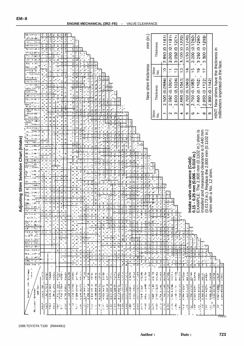
V00831
Ad
just
ing
Sh
im S
elec
tion
Ch
art (
Inta
ke)
New
shi
m th
ickn
ess
mm
(in
.)
HIN
T: N
ew s
him
s ha
ve th
e th
ickn
ess
inm
illim
eter
s im
prin
ted
on th
e fa
ce.
Inta
ke v
alve
cle
aran
ce (C
old
):0.
15 −
0.2
5 m
m (0
.006
− 0
.010
in.)
EX
AM
PLE
: T
he 2
.800
mm
(0.
1102
in.)
shi
m is
inst
alle
d an
d m
easu
red
clea
ranc
e is
0.4
40 m
m(0
.017
3 in
.). R
epla
ce th
e 2.
800
mm
(0.1
102
in.)
shim
with
a N
o. 1
2 sh
im.
Shi
mN
o.S
him
No.
Thi
ckne
ssT
hick
ness
EM−8−ENGINE MECHANICAL (3RZ−FE) VALVE CLEARANCE
723Author�: Date�:
1996 TOYOTA T100 (RM449U)
https://www.truck-manuals.net/

V00832
Shi
mN
o.S
him
No.
Thi
ckne
ssT
hick
ness
Ad
just
ing
Sh
im S
elec
tion
Ch
art (
Exh
aust
)
New
shi
m th
ickn
ess
mm
(in
.)
HIN
T: N
ew s
him
s ha
ve th
e th
ickn
ess
inm
illim
eter
s im
prin
ted
on th
e fa
ce.
Exh
aust
val
ve c
lear
ance
(Co
ld):
0.25
− 0
.35
mm
(0.0
10 −
0.0
14 in
.)E
XA
MP
LE:
The
2.8
00 m
m (
0.11
02 in
.) s
him
isin
stal
led
and
mea
sure
d cl
eara
nce
is 0
.440
mm
(0.0
173
in.).
Rep
lace
the
2.80
0 m
m (0
.110
2 in
.)sh
im w
ith a
No.
10
shim
.
Inst
alle
d s
him
thi
ckne
ss
Mea
sure
d cl
eara
nce
mm
(in
.)
mm
(in
.)
−ENGINE MECHANICAL (3RZ−FE) VALVE CLEARANCEEM−9
724Author�: Date�:
1996 TOYOTA T100 (RM449U)
https://www.truck-manuals.net/

P24401
A03718
EM−10−ENGINE MECHANICAL (3RZ−FE) VALVE CLEARANCE
725Author�: Date�:
1996 TOYOTA T100 (RM449U)
11. REINSTALL CYLINDER HEAD COVER(a) Install the gasket to the cylinder head cover.(b) Install the cylinder head cover with the 10 bolts.12. RECONNECT ENGINE WIRE(a) Connect the 5 engine wire clamps.(b) Connect these connectors:
� ECT sensor connector� Oil pressure sensor connector� w/ A/C:
A/C compressor connector13. REINSTALL THROTTLE BODY (See page MF−30)14. REINSTALL HIGH−TENSION CORDS TO SPARK
PLUGS15. REINSTALL NO.1 AND NO.2 PCV HOSES16. REINSTALL AIR INTAKE CONNECTOR (See page
EM−70)17. REFILL WITH ENGINE COOLANT18. CHECK IGNITION TIMING
https://www.truck-manuals.net/

EM06T−02
FI7231
TOYOTA Hand−Held Tester
DLC3
P16016
A03719
P15946
−ENGINE MECHANICAL (3RZ−FE) IGNITION TIMINGEM−11
726Author�: Date�:
1996 TOYOTA T100 (RM449U)
IGNITION TIMINGINSPECTION1. WARM UP ENGINEAllow the engine to warm up to normal operating temperature.
2. CONNECT TOYOTA HAND−HELD TESTER OR OBDIISCAN TOOL
(a) Connect the TOYOTA hand−held tester or OBDII scantool to the DLC3.
(b) Please refer to the TOYOTA hand−held tester or OBDIIscan tool operators manual for further details.
3. CHECK IGNITION TIMING(a) Using SST, connect terminals TE1 and E1 of the DLC1.
SST 09843−18020
(b) Using a timing light, connect the tester to No.1 high−tension cord.
(c) Check ignition timing.Ignition timing:3 − 7° BTDC @ idle(Air Conditioner OFF)
If the ignition timing is not as specified, check that followingconditions are normal:
� Throttle valve fully closed� Continuity between terminals IDL and E2 of the
throttle position sensor� Valve timing
(d) Remove the SST from the DLC1.SST 09843−18020
4. DISCONNECT TOYOTA HAND−HELD TESTER OROBDII SCAN TOOL, AND TIMING LIGHT
https://www.truck-manuals.net/

EM1OJ−01
EM−12−ENGINE MECHANICAL (3RZ−FE) IDLE SPEED
727Author�: Date�:
1996 TOYOTA T100 (RM449U)
IDLE SPEEDINSPECTION1. INITIAL CONDITIONS(a) Engine at normal operating temperature(b) Air cleaner installed(c) All pipes and hoses of air induction system connected(d) All accessories switched OFF(e) All vacuum lines properly connectedHINT:All vacuum hoses for EGR system, etc. should be properly connected.(f) MFI system wiring connectors fully plugged(g) Ignition timing set correctly(h) Transmission in neutral position2. CONNECT TOYOTA HAND−HELD TESTER OR OBD II SCAN TOOL (See page EM−11)3. INSPECT IDLE SPEED(a) Race the engine speed at 2,500 rpm for approx. 90 seconds.(b) Check the idle speed.
Idle speed: 650 − 750 rpmIf the idle speed is not as specified, check the IAC valve.4. DISCONNECT TOYOTA HAND−HELD TESTER OR OBD II SCAN TOOL
https://www.truck-manuals.net/

EM06X−02
P21630
A03720
25 (250, 20)
29 (300, 22)
27 (270, 20)
200 (2,650, 191)
18 (185, 13)
27 (270, 20)
N·m (kgf·cm, ft·lbf) : Specified torque
−ENGINE MECHANICAL (3RZ−FE) TIMING CHAINEM−13
728Author�: Date�:
1996 TOYOTA T100 (RM449U)
TIMING CHAINCOMPONENTS
https://www.truck-manuals.net/

EM06Z−03
P14842
Adjusting Bolt
Lock Bolt
Pivot Bolt
P14935
P14907 A03721
P14953
EM−14−ENGINE MECHANICAL (3RZ−FE) TIMING CHAIN
1996 TOYOTA T100 (RM449U)
REMOVAL1. DRAIN ENGINE OIL2. DRAIN ENGINE COOLANT3. REMOVE CYLINDER HEAD
(See page EM−28)4. REMOVE ENGINE UNDER COVERRemove the 4 bolts and engine under cover.5. w/ A/C:
REMOVE A/C COMPRESSOR DRIVE BELTLoosen the idler pulley nut and adjusting bolt, and remove thedrive belt.6. REMOVE DRIVE BELT, FAN WITH FLUID
COUPLING, WATER PUMP PULLEY AND FANSHROUD
(a) Stretch the belt and loosen the water pump pulley mount-ing nuts.
(b) Loosen the lock, pivot and adjusting bolts of the genera-tor, and remove the drive belts.
(c) Remove the 4 water pump pulley mounting nuts.(d) Pull out the fan with fluid coupling and water pump pulley.(e) Remove the No.2 fan shroud.(f) Remove the 4 bolts and No.1 fan shroud.7. w/ A/C:
DISCONNECT A/C COMPRESSOR AND BRACKET(a) Remove the 4 mounting bolts, and disconnect the com-
pressor from the bracket.HINT:Put a side the compressor, and suspend it.(b) Remove the 4 bolts and A/C compressor bracket.
8. REMOVE GENERATOR, ADJUSTING BAR ANDBRACKET
(a) Remove the lock, pivot bolts and the generator.(b) Remove the bolt and adjusting bar.(c) Remove the 3 bolts and bracket.
9. REMOVE CRANKSHAFT POSITION SENSOR(a) Remove the 2 bolts and crankshaft position sensor.(b) Remove the O−ring from the crankshaft position sensor.
https://www.truck-manuals.net/

P15008A03722
SST
P14954
A03723
P15097
A03724
P18141
Crankshaft Puller Bolt
SST
P14986A03725
−ENGINE MECHANICAL (3RZ−FE) TIMING CHAINEM−15
1996 TOYOTA T100 (RM449U)
10. REMOVE OIL PAN(a) Remove the 16 mounting bolts and 2 nuts.(b) Insert the blade of SST between the cylinder block and oil
pan, cut off applied sealer and remove the oil pan.SST 09032−00100
NOTICE:Be careful not to damage the oil pan flanges of the oil panand cylinder block.
11. REMOVE OIL STRAINERRemove the 2 bolts, 2 nuts, oil strainer and gasket.
12. REMOVE CRANKSHAFT PULLEY(a) w/ A/C:
Remove the 4 bolts, No.2 and No.3 crankshaft pulleies.(b) Using SST, remove the pulley bolt.
SST 09213−54015, 09330−00021(c) Remove the crankshaft pulley.
HINT:If necessary, remove the pulley with SST and crankshaft pulleybolt.
SST 09950−50010 (09951−05010, 09952−05010,09953−05010, 09954−05020)
13. REMOVE TIMING CHAIN COVER(a) Remove the 2 water by pass pipe mounting nuts.(b) Remove the 2 timing chain cover mounting bolts.
https://www.truck-manuals.net/

P14973A03726
P18142
SST
Crankshaft Pulley Bolt
P14923
P15081
Pin
P14932A03727
EM−16−ENGINE MECHANICAL (3RZ−FE) TIMING CHAIN
1996 TOYOTA T100 (RM449U)
(c) Remove the 9 mounting bolts and 2 mounting nuts.(d) Using a plastic−faced hammer, loosen the chain cover
and remove the timing chain cover and 3 gaskets.14. REMOVE NO.1 TIMING CHAIN AND CAMSHAFT
TIMING GEAR
15. REMOVE CRANKSHAFT TIMING GEARHINT:If necessary, remove the gear with SST and crankshaft pulleybolt.
SST 09950−40010 (09951−04010, 09952−04010,09953−04010, 09954−04010, 09955−04060)
16. REMOVE NO.1 TIMING CHAIN TENSIONERSLIPPER AND NO.1 VIBRATION DAMPER
(a) Remove the bolt and slipper.(b) Remove the bolt, nut and No.1 damper.
17. REMOVE NO.2, NO.3 VIBRATION DAMPERS ANDNO.2 CHAIN TENSIONER
(a) Install a pin to the No.2 chain tensioner and lock theplunger.
(b) Remove the bolt and No.2 damper.
https://www.truck-manuals.net/

P14974A03728
P15080
A03729
P14920A03730
P14962
−ENGINE MECHANICAL (3RZ−FE) TIMING CHAINEM−17
1996 TOYOTA T100 (RM449U)
(c) Remove the 2 bolts and No.3 damper.
(d) Remove the nut and No.2 chain tensioner.
18. REMOVE NO.2 TIMING CHAIN(a) Remove the bolt from the balance shaft drive gear.(b) Remove the balance shaft drive gear with shaft.(c) Remove the No.2 timing chain with the No.2 crankshaft
timing sprocket.
19. REMOVE NO.4 VIBRATION DAMPERRemove the 2 bolts and No.4 damper.
https://www.truck-manuals.net/

Z14864
16 Links
Z11085 A03751
Z11088 A03752
EM070−02
EM−18−ENGINE MECHANICAL (3RZ−FE) TIMING CHAIN
1996 TOYOTA T100 (RM449U)
INSPECTION1. INSPECT TIMING CHAINS, TIMING GEARS AND TIM-
ING SPROCKETS(a) Measure the length of 16 links with the chain fully
stretched.Maximum chain elongation:No.1 Timing chain147.5 mm (5.807 in.)No.2 Timing chain123.6 mm (4.866 in.)
If the elongation is greater than maximum, replace the chain.HINT:Make the same measurements pulling at 3 or more places se-lected at random.(b) Wrap the chain around the timing gear and timing sprock-
et.(c) Using vernier calipers, measure the timing gear and tim-
ing sprocket diameter with the chain.NOTICE:Vernier calipers must contact the chain rollers for measur-ing.
Minimum gear diameter:Camshaft113.8 mm (4.480 in.)Crankshaft59.4 mm (2.339 in.)Balance shaft75.9 mm (2.988 in.)Minimum sprocket diameter:No.2 crankshaft96.7 mm (3.807 in.)
If the diameter is less than minimum, replace the chain, gearsand sprocket.
https://www.truck-manuals.net/

P14927A03753
P14933A03754
P14928
Free
P14929
Lock
P14934
Air
−ENGINE MECHANICAL (3RZ−FE) TIMING CHAINEM−19
1996 TOYOTA T100 (RM449U)
2. INSPECT CHAIN TENSIONER SLIPPER AND VIBRA-TION DAMPERS
Measure the chain tensioner slipper and vibration damperwears.
Maximum wear: 1.0 mm (0.039 in.)If the wear is greater than maximum, replace the slipper and/ordampers.
3. INSPECT NO.2 CHAIN TENSIONER(a) Inspect the chain tensioner
� Check that the plunger moves smoothly when theratchet pawl is raised with your finger.
� Release the ratchet pawl and check that the plung-er is locked in place by the ratchet pawl and doesnot move when pushed with your finger.
(b) Inspect the oil jet (No.2 chain tensioner).Check the oil jet for damage or clogging.
If necessary, replace the oil jet (No.2 chain tensioner).
https://www.truck-manuals.net/

P14962
EM073−03
P15101
Aligin
Aligin
Aligin
P15100
P15080
A03755
EM−20−ENGINE MECHANICAL (3RZ−FE) TIMING CHAIN
1996 TOYOTA T100 (RM449U)
INSTALLATIONNOTICE:Check that No.1 cylinder is at TDC and that the weights ofthe No.1 and No.2 balance shafts are at the bottom side.1. INSTALL NO.4 VIBRATION DAMPERInstall the No.4 damper with the 2 bolts.
2. INSTALL NO.2 TIMING CHAIN(a) Install the No.2 timing chain by matching its mark links
with the timing marks on the No.2 crankshaft timingsprocket and balance shaft timing sprocket.
(b) Fit the other mark link of No.2 timing chain onto thesprocket behind the large timing mark of the balance shaftdrive gear.
(c) Insert the balance shaft drive gear shaft through the bal-ance shaft drive gear so that it fits into the thrust platehole.Then align the small timing mark of the balance shaft drivegear with the timing mark of the balance shaft timing gear.
(d) Install the bolt to the balance shaft drive gear and tightenit.Torque: 25 N·m (250 kgf·cm, 18 ft·lbf)
(e) Check that each timing mark is matched with the corre-sponding mark link.
3. INSTALL NO.2, NO.3 VIBRATION DAMPERS ANDNO.2 CHAIN TENSIONER
NOTICE:Assemble the chain tensioner with the pin installed, thenremove the pin after assembly.When doing this, avoid pushing the No.2 vibration damperagainst the chain.(a) Install the No.2 chain tensioner with the nut.
Torque: 18 N·m (185 kgf·cm, 13 ft·lbf)
https://www.truck-manuals.net/

P14974
A03756
P14932
A03757
P15081Pin
P14923
P14919
−ENGINE MECHANICAL (3RZ−FE) TIMING CHAINEM−21
1996 TOYOTA T100 (RM449U)
(b) Install No.3 damper with the 2 bolts.Torque: 18 N·m (185 kgf·cm, 13 ft·lbf)
(c) Install No.2 damper with the bolt.Torque: 27 N·m (270 kgf·cm, 20 ft·lbf)
(d) Remove a pin from the No.2 chain tensioner and free theplunger.
4. INSTALL NO.1 TIMING CHAIN TENSIONERSLIPPER AND NO.1 VIBRATION DAMPER
(a) Install the No.1 damper with the bolt and nut.Torque: 18 N·m (185 kgf·cm, 13 ft·lbf)
(b) Install the slipper with the bolt.Torque: 27 N·m (270 kgf·cm, 20 ft·lbf)
(c) Check that the slipper moves smoothly.
5. INSTALL CRANKSHAFT TIMING GEAR
https://www.truck-manuals.net/

P14930
SST
P14975
A03758
P14977
A03759
P14917A03760
A03761
EM−22−ENGINE MECHANICAL (3RZ−FE) TIMING CHAIN
1996 TOYOTA T100 (RM449U)
HINT:If necessary, install the gear with SST.
SST 09636−20010
6. INSTALL NO.1 TIMING CHAIN AND CAMSHAFT TIM-ING GEAR
(a) Align the timing mark between the mark link of the No.1timing chain, and install the No.1 timing chain to the timinggear.
(b) Align the timing mark of the crankshaft timing gear withthe mark link of the No.1 timing chain and install the No.1timing chain.
(c) Tie the No.1 timing chain with a cord as shown in the il-lustration and make sure it doesn’t come loose.
7. INSTALL TIMING CHAIN COVER(a) Install 3 new gaskets to the cylinder block and No.1 water
bypass pipe.
(b) Install the timing chain cover with the 9 bolts and 2 nuts.Torque:Bolt A: 20 N·m (200 kgf·cm, 14 ft·lbf)Bolt B: 24.5 N·m (250 kgf·cm, 18 ft·lbf)Bolt C: 44 N·m (440 kgf·cm, 32 ft·lbf)Nut D: 20 N·m (200 kgf·cm, 14 ft·lbf)
(c) Remove the cord from the chain.
https://www.truck-manuals.net/

P14986A03762
P15097A03763
P14954A03764
−ENGINE MECHANICAL (3RZ−FE) TIMING CHAINEM−23
1996 TOYOTA T100 (RM449U)
(d) Install the 2 timing chain cover mounting bolts.Torque: 18 N·m (185 kgf·cm, 13 ft·lbf)
(e) Install the 2 No.1 water bypass pipe mounting nuts.Torque: 20 N·m (200 kgf·cm, 14 ft·lbf)
8. INSTALL CRANKSHAFT PULLEY(a) Align the pulley set key with the key groove of the pulley,
and slide on the pulley.(b) Using SST, install and torque the pulley bolt.
SST 09213−54015, 09330−00021Torque: 260 N·m (2,650 kgf·cm, 193 ft·lbf)
(c) w/ A/C:Install the No.3 and No.2 crankshaft pulleies with the 4bolts.Torque: 25 N·m (250 kgf·cm, 18 ft·lbf)
9. INSTALL OIL STRAINERInstall a new gasket and oil strainer with the 2 bolts and 2 nuts.
Torque: 18 N·m (185 kgf·cm, 13 ft·lbf)
https://www.truck-manuals.net/

P14989
A03765
P14953
Z11309B
A
A
EM−24−ENGINE MECHANICAL (3RZ−FE) TIMING CHAIN
1996 TOYOTA T100 (RM449U)
10. INSTALL OIL PAN(a) Remove any old packing (FIPG) material and be careful
not to drop any oil on the contact surface of the oil pan.� Using a razor blade and gasket scraper, remove all
the old packing (FIPG) material from the gasket sur-faces and sealing grooves.
� Thoroughly clean all components to remove all theloose material.
� Using a non−residue solvent, clean both sealingsurfaces.
NOTICE:Do not use a solvent which will affect the painted surfaces.(b) Apply seal packing to the oil pan as shown in the illustra-
tion.Seal packing:Part No. 08826−00080 or equivalent� Install a nozzle that has been cut to a 2 − 3 mm (0.08
− 0.12 in.)opening or 3 − 4 mm (0.012 − 0.016 in.)opening.
HINT:Avoid applying an excessive amount to the surface.
� Parts must be assembled within 5 minutes of ap-plication. Otherwise the material must be removedand reapplied.
� Immediately remove nozzle from the tube and rein-stall cap.
(c) Install the oil pan with the 16 bolts and 2 nuts.Torque: 12.5 N·m (130 kgf·cm, 9 ft·lbf)
11. INSTALL CRANKSHAFT POSITION SENSOR(a) Install a new O−ring.(b) Install the crankshaft position sensor with the 2 bolts.
Torque: 8.5 N·m (85 kgf·cm, 74 in.·lbf)
12. INSTALL GENERATOR, ADJUSTING BAR ANDBRACKET
(a) Install the bracket with the 3 bolts.Torque:Bolt A: 74.5 N·m (760 kgf·cm, 55 ft·lbf)Bolt B: 18 N·m (185 kgf·cm, 13 ft·lbf)
(b) Install the adjusting bar with the bolt.Torque: 63.5 N·m (650 kgf·cm, 47 ft·lbf)
https://www.truck-manuals.net/

P14907A03766
P14935
P14842
Adjusting Bolt
Lock Bolt
Pivot Bolt
−ENGINE MECHANICAL (3RZ−FE) TIMING CHAINEM−25
1996 TOYOTA T100 (RM449U)
(c) Install the generator with the pivot bolt and lock bolt.
13. w/ A/C:INSTALL A/C COMPRESSOR AND BRACKET
(a) Install the A/C compressor bracket with the 4 bolts.Torque: 44 N·m (440 kgf·cm, 32 ft·lbf)
(b) Install the A/C compressor with the 4 bolts.Torque: 25 N·m (250 kgf·cm, 18 ft·lbf)
14. INSTALL WATER PUMP PULLEY, FAN SHROUD, FANWITH FLUID COUPLING AND DRIVE BELT
(a) Place the fan with fluid coupling, water pump pulley andfan shroud in position.
(b) Temporarily install the water pump pulley mounting nuts.(c) Install the No.1 fan shroud with the 4 bolts.(d) Install the No.2 fan shroud with the 2 clips.
(e) Install the drive belts with the adjusting bolt and pivot bolt.(f) Stretch the belt tight and tighten the 4 water pump pulley
mounting nuts.Torque: 21 N·m (210 kgf·cm, 16 ft·lbf)
(g) Adjust the drive belts.15. w/ A/C:
INSTALL A/C COMPRESSOR DRIVE BELTInstall and adjust the drive belt (See page CH−2).16. INSTALL ENGINE UNDER COVERInstall the engine under cover with the bolts.17. INSTALL CYLINDER HEAD (See page EM−50)18. START ENGINE AND CHECK FOR LEAKS
https://www.truck-manuals.net/

EM075−02
21 (210, 15)
29 (300, 22)
29 (300, 22)
29 (300, 22)
49 (500, 36)
: Specified torqueN·m (kgf·cm, ft·lbf)
29 (300, 22)
EM−26−ENGINE MECHANICAL (3RZ−FE) CYLINDER HEAD
741Author�: Date�:
1996 TOYOTA T100 (RM449U)
CYLINDER HEADCOMPONENTS
https://www.truck-manuals.net/

x 10
See page EM−50
46 (465, 34)
21 (210,15)
1st 39 (400, 29)2nd Turn 90°3rd Turn 90°
N·m (kgf·cm, ft·lbf) :Specified torque
−ENGINE MECHANICAL (3RZ−FE) CYLINDER HEADEM−27
742Author�: Date�:
1996 TOYOTA T100 (RM449U)
https://www.truck-manuals.net/

EM1OK−01
P14841
Adjust Bolt
Lock Bolt
P15755SST
EM−28−ENGINE MECHANICAL (3RZ−FE) CYLINDER HEAD
1996 TOYOTA T100 (RM449U)
REMOVAL1. DRAIN ENGINE COOLANT
2. REMOVE AIR CLEANER CAP, MAF METER AND RES-ONATOR
(a) Disconnect the MAF meter connector, IAT sensor con-nector and wire clamp.
(b) Loosen the air cleaner hose clamp.(c) Loosen the 4 clips, and remove the air cleaner cap, MAF
meter and resonator.3. M/T:
DISCONNECT ACCELERATOR CABLE FROMTHROTTLE BODY
4. REMOVE INTAKE AIR CONNECTOR(a) Disconnect the 2 air hoses and VS hose.(b) Remove the 2 bolts, hose clamp and intake air connector.
5. REMOVE PS PUMP DRIVE BELT AND IDLER PULLEY(a) Loosen the lock bolt and adjusting bolt and remove the
drive belt.(b) Remove the 3 bolts and idler pulley.
6. REMOVE PS PUMP AND BRACKET(a) Using SST, remove the nut and PS pump pulley.
SST 09960−10010 (09962−01000, 09963−01000)(b) Disconnect the 2 air hoses from air intake chamber.(c) Remove the 2 bolts, and disconnect the PS pump.(d) Remove the 4 bolts and PS pump bracket.7. REMOVE NO.1 AND NO.2 PCV HOSES
https://www.truck-manuals.net/

P15813 A03782
P14635A03783
−ENGINE MECHANICAL (3RZ−FE) CYLINDER HEADEM−29
1996 TOYOTA T100 (RM449U)
8. REMOVE DISTRIBUTORNOTICE:Pulling on or bending the cords may damage the conductorinside.(a) Disconnect the distributor connector.(b) Remove the hold−down bolts and distributor.(c) Remove the O−ring.
9. REMOVE WATER OUTLET(a) Disconnect the radiator inlet hose.(b) Disconnect the ECT sender gauge connector.(c) Remove the 2 bolts, water outlet and gasket.10. REMOVE THROTTLE BODY (See page MF−28)11. DISCONNECT ENGINE WIRE(a) Disconnect these connectors:
� w/ A/C:A/C compressor connector
� Oil pressure sensor connector� ECT sensor connector� EGR gas temperature sensor connector� EGR VSV connector
(b) Remove the 2 bolts and disconnect engine wire from theintake chamber.
(c) Disconnect the 5 engine wire clamps and engine wire.(d) Disconnect these connectors:
� Knock sensor connector� Crankshaft position sensor connector� Fuel pressure control VSV connector
(e) Disconnect the DLC1 from the bracket.(f) Disconnect the 2 engine wire clamps.(g) Remove the bolt and disconnect the engine wire.12. DISCONNECT INJECTOR CONNECTORS
13. REMOVE CYLINDER HEAD REAR COVER(a) Disconnect the heater water bypass hose.(b) Remove the 3 bolts and the rear cover and gasket.
https://www.truck-manuals.net/

P14653 A03784
P14628 A03785
P24689 A03786
A02538
P24691 A03787
EM−30−ENGINE MECHANICAL (3RZ−FE) CYLINDER HEAD
1996 TOYOTA T100 (RM449U)
14. REMOVE EGR VALVE AND VACUUM MODULATOR(a) Remove the bolt, 4 nuts, EGR pipe and 2 gaskets.(b) Disconnect these hoses:
� 2 vacuum hoses from EGR VSV (with clamp)� Water bypass hose from water bypass pipe
(c) Remove the bolt, 2 nuts, EGR valve, vacuum modulatorand gasket.
15. REMOVE INTAKE CHAMBER STAYRemove the 2 bolts and intake chamber stay.
16. REMOVE FUEL RETURN PIPE(a) Disconnect these hoses:
� Fuel return hose from fuel pressure regulator� Fuel return hose from fuel return pipe
(b) Remove the 2 bolts and fuel return pipe.
17. REMOVE AIR INTAKE CHAMBER(a) Disconnect the vacuum hose from the gas filter.(b) Disconnect the brake booster vacuum hose from intake
chamber.(c) Remove the 3 bolts, 2 nuts, air intake chamber and gas-
ket.
18. REMOVE FUEL INLET TUBERemove the 2 union bolts, 4 gaskets and fuel inlet tube.
https://www.truck-manuals.net/

P24692 A03788
P22272
P15073 A03789
P14686
−ENGINE MECHANICAL (3RZ−FE) CYLINDER HEADEM−31
1996 TOYOTA T100 (RM449U)
19. REMOVE DELIVERY PIPE AND INJECTORS(a) Disconnect the vacuum hose from the fuel pressure regu-
lator.(b) Remove the 2 bolts and delivery pipe together with the 4
injectors.NOTICE:Be careful not to drop the injectors when removing the de-livery pipe.(c) Remove the 4 insulators from the 4 spacers.(d) Pull out the 4 injectors from the delivery pipe.(e) Remove the O−ring and grommet from each injector.
20. REMOVE INTAKE MANIFOLDRemove the 3 bolts, 2 nuts, intake manifold and gasket.
21. REMOVE FRONT EXHAUST PIPE(a) Remove the 2 bolts, and retainer holding the front ex-
haust pipe from the TWC.(b) Loosen the clamp bolt and disconnect the clamp from the
support bracket.(c) Remove the 2 bolts and support bracket.(d) Remove the 3 nuts, front exhaust pipe and 3 gaskets.
22. REMOVE EXHAUST MANIFOLD(a) Remove the 2 bolts, 2 nuts and heat insulator.(b) Remove the 6 nuts, exhaust manifold and gasket.23. REMOVE NO.1 ENGINE HANGER(a) Remove the bolt and No.1 engine hanger.(b) Remove the bolt and ground strap.
https://www.truck-manuals.net/

P14687
P14695
A01399
Dot Mark
P14636
P15751 A03790
EM−32−ENGINE MECHANICAL (3RZ−FE) CYLINDER HEAD
1996 TOYOTA T100 (RM449U)
24. REMOVE CYLINDER HEAD COVERRemove the 10 bolts, cylinder head cover and gasket.25. REMOVE SPARK PLUGS
26. SET NO.1 CYLINDER TO TDC/COMPRESSION(a) Turn the crankshaft pulley clockwise and align its groove
with the ”0” mark on the timing chain cover.
(b) Check that the timing marks (1 and 2 dots) of the camshaftdrive and driven gears are in straight line on the cylinderhead surface as shown in the illustration. If not, turn thecrankshaft 1 revolution (360°) and align the marks asabove.
27. REMOVE CHAIN TENSIONERRemove the 2 nuts, chain tensioner and gasket.
28. REMOVE CAMSHAFT TIMING GEAR(a) Remove the 2 semi−circular plugs.(b) Place the matchmarks on the camshaft timing gear and
No.1 timing chain.
https://www.truck-manuals.net/
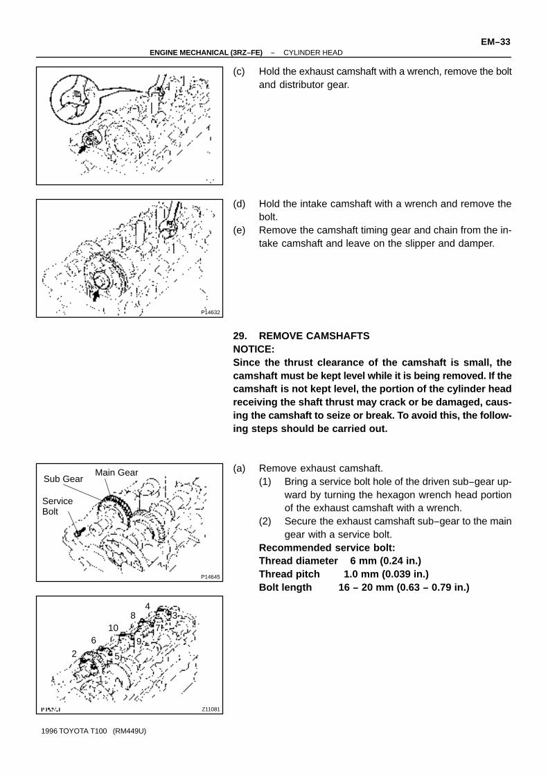
P14632
P14645
Main GearSub Gear
ServiceBolt
Z11081
48
106
2
1
5
9
73
−ENGINE MECHANICAL (3RZ−FE) CYLINDER HEADEM−33
1996 TOYOTA T100 (RM449U)
(c) Hold the exhaust camshaft with a wrench, remove the boltand distributor gear.
(d) Hold the intake camshaft with a wrench and remove thebolt.
(e) Remove the camshaft timing gear and chain from the in-take camshaft and leave on the slipper and damper.
29. REMOVE CAMSHAFTSNOTICE:Since the thrust clearance of the camshaft is small, thecamshaft must be kept level while it is being removed. If thecamshaft is not kept level, the portion of the cylinder headreceiving the shaft thrust may crack or be damaged, caus-ing the camshaft to seize or break. To avoid this, the follow-ing steps should be carried out.
(a) Remove exhaust camshaft.(1) Bring a service bolt hole of the driven sub−gear up-
ward by turning the hexagon wrench head portionof the exhaust camshaft with a wrench.
(2) Secure the exhaust camshaft sub−gear to the maingear with a service bolt.
Recommended service bolt:Thread diameter 6 mm (0.24 in.)Thread pitch 1.0 mm (0.039 in.)Bolt length 16 − 20 mm (0.63 − 0.79 in.)
https://www.truck-manuals.net/

P14676
Z11082
1
2 5
6 9
10 7
8 3
4
P14675
P14911
EM−34−ENGINE MECHANICAL (3RZ−FE) CYLINDER HEAD
1996 TOYOTA T100 (RM449U)
HINT:When removing the camshaft, make sure that the torsionalspring force of the sub−gear has been eliminated by the aboveoperation.(b) Uniformly loosen and remove the 10 bearing cap bolts in
several passes, in the sequence shown.(c) Remove the 5 bearing caps and camshaft.HINT:If the camshaft is not being lifted out straight and level, reinstallthe No.3 bearing cap with the 2 bolts. Then alternately loosenand remove the bearing cap bolts with the camshaft gear pulledup.NOTICE:Do not pry on or attempt to force the camshaft with a toolor other object.
(d) Remove intake camshaft.(1) Uniformly loosen and remove 10 bearing cap bolts
in several passes, in the sequence shown.(2) Remove the 5 bearing caps and camshaft.
HINT:If the camshaft is not being lifted out straight and level, reinstallthe No.3 bearing cap with the 2 bolts. Then alternately loosenand remove the 2 bearing cap bolts with the camshaft gearpulled up.NOTICE:Do not pry on or attempt to force the camshaft with a toolor other object.
30. DISASSEMBLE EXHAUST CAMSHAFT(a) Mount the hexagon wrench head portion of the camshaft
in a vise.NOTICE:Be careful not to damage the camshaft.
https://www.truck-manuals.net/

P14910
Service Bolt
SSTTurn
P14906
Z11080 A03791
P14709
−ENGINE MECHANICAL (3RZ−FE) CYLINDER HEADEM−35
1996 TOYOTA T100 (RM449U)
(b) Using SST, turn the sub−gear clockwise, and remove aservice bolt.SST 09960−10010 (09962−01000, 09963−00500)
(c) Using snap ring pliers, remove the snap ring.
(d) Remove these parts:(1) Wave washer(2) Camshaft sub−gear(3) Camshaft gear spring
31. REMOVE CYLINDER HEAD(a) Remove the 2 bolts in front of the head before the other
head bolts are removed.
https://www.truck-manuals.net/

Z10935
P14721
EM−36−ENGINE MECHANICAL (3RZ−FE) CYLINDER HEAD
1996 TOYOTA T100 (RM449U)
(b) Uniformly loosen and remove the 10 cylinder head bolts,in several passes, in the sequence shown.
NOTICE:Cylinder head warpage or cracking could result from re-moving bolts in incorrect order.(c) Lift the cylinder head from the dowels on the cylinder
block, and place the cylinder head on wooden blocks ona bench.
HINT:If the cylinder head is difficult to lift off, pry between the cylinderhead and cylinder block with a screwdriver.NOTICE:Be careful not to damage the contact surfaces of the cylin-der head and cylinder block.
https://www.truck-manuals.net/

EM079−02
P14702
SST
P14713
P14712
−ENGINE MECHANICAL (3RZ−FE) CYLINDER HEADEM−37
1996 TOYOTA T100 (RM449U)
DISASSEMBLY1. REMOVE VALVE LIFTERS AND SHIMSHINT:Arrange the valve lifters and shims in correct order.2. REMOVE VALVES(a) Using SST, compress the valve spring and remove the 2
keepers.SST 09202−70020
(b) Remove the spring retainer, valve spring and valve.
(c) Using needle−nose pliers, remove the oil seal.
(d) Using compressed air and a magnetic finger, remove thespring seat by blowing air.
HINT:Arrange the valves, valve springs, spring seats and spring re-tainers in correct order.
https://www.truck-manuals.net/

P14674
EM07C−03
P14673
P14693
P14692
P14660
EM−38−ENGINE MECHANICAL (3RZ−FE) CYLINDER HEAD
1996 TOYOTA T100 (RM449U)
INSPECTION1. CLEAN TOP SURFACES OF PISTONS ANDCYLINDER
BLOCK(a) Turn the crankshaft, and bring each piston to top dead
center (TDC). Using a gasket scraper, remove all the car-bon from the piston top surface.
(b) Using a gasket scraper, remove all the gasket materialfrom the cylinder block surface.
(c) Using compressed air, blow carbon and oil from the boltholes.
CAUTION:Protect your eyes when using high−compressed air.
2. REMOVE GASKET MATERIALUsing a gasket scraper, remove all the gasket material from thecylinder block contact surface.NOTICE:Be careful not to scratch the cylinder block contact sur-face.
3. CLEAN COMBUSTION CHAMBERSUsing a wire brush, remove all the carbon from the combustionchambers.NOTICE:Be careful not to scratch the cylinder block contact sur-face.
4. CLEAN VALVE GUIDE BUSHINGSUsing a valve guide bushing brush and solvent, clean all theguide bushings.
https://www.truck-manuals.net/

P14663
Z10933
P14696
EM0580
−ENGINE MECHANICAL (3RZ−FE) CYLINDER HEADEM−39
1996 TOYOTA T100 (RM449U)
5. CLEAN CYLINDER HEADUsing a soft brush and solvent, thoroughly clean the cylinderhead.
6. INSPECT FOR FLATNESSUsing a precision straight edge and thickness gauge, measurethe surfaces contacting the cylinder block and the manifolds forwarpage.
Maximum warpage:Cylinder block side0.05 mm (0.0020 in.)Manifold side0.10 mm (0.0039 in.)
If warpage is greater than maximum, replace the cylinder head.
7. INSPECT FOR CRACKSUsing a dye penetrant, check the combustion chambers, intakeports, exhaust ports and cylinder block surface for cracks.If cracked, replace the cylinder head.
8. CLEAN VALVES(a) Using a gasket scraper, chip off any carbon from the valve
head.(b) Using a wire brush, thoroughly clean the valve.
https://www.truck-manuals.net/

P14659
P03864
A03793
P14670
SST
P14667
EM−40−ENGINE MECHANICAL (3RZ−FE) CYLINDER HEAD
1996 TOYOTA T100 (RM449U)
9. INSPECT VALVE STEMS AND GUIDE BUSHINGS(a) Using a caliper gauge, measure the inside diameter of the
guide bushing.Bushing inside diameter:6.010 − 6.030 mm (0.2366 − 0.2374 in.)
(b) Using a micrometer, measure the diameter of the valvestem.Valve stem diameter:Intake5.970 − 5.985 mm (0.2350 − 0.2356 in.)Exhaust5.965 − 5.980 mm (0.2348 − 0.2354 in.)
(c) Subtract the valve stem diameter measurement from theguide bushing inside diameter measurement.Standard oil clearance:Intake0.025 − 0.060 mm (0.0010 − 0.0024 in.)Exhaust0.030 − 0.065 mm (0.0012 − 0.0026 in.)Maximum oil clearance:Intake0.08 mm (0.0031 in.)Exhaust0.10 mm (0.0039 in.)
If the clearance is greater than maximum, replace the valve andguide bushing.10. IF NECESSARY, REPLACE VALVE GUIDE BUSHINGS(a) Gradually heat the cylinder head to 80 − 100°C (176 −
212°F).(b) Using SST and a hammer, tap out the guide bushing.
SST 09201−10000 (09201−01060),09550−10012 (09252−10010)
(c) Using a caliper gauge, measure the bushing bore diame-ter of the cylinder head.
https://www.truck-manuals.net/

Both intake and exhaust
11.050 − 11.077(0.4350 − 0.4361)
(0.4331 − 0.4341)11.000 − 11.027
mm (in.)Bushing bore diameter Bushing size
Use STD
Use O/S 0.05
Z11079 A03794
Z10934 A03795
Z00054
44.5°
EM0181
Margin Thickness
−ENGINE MECHANICAL (3RZ−FE) CYLINDER HEADEM−41
1996 TOYOTA T100 (RM449U)
(d) Select a new guide bushing (STD size or O/S 0.05).If the bushing bore diameter of the cylinder head is greater than11.027 mm (0.4341 in.), machine the bushing bore to these di-mension:
11.050 − 11.077 mm (0.4350 − 0.4361 in.)If the bushing bore diameter of the cylinder head is greater than11.077 mm (0.4361 in.), replace the cylinder head.
(e) Gradually heat the cylinder head to 80 − 100°C (176 −212°F).
(f) Using SST and a hammer, tap in a new guide bushing towhere there 8.2 − 8.6 mm (0.323 − 0.339 in.) protrudingfrom the cylinder head.SST 09201−10000 (09201−01060),
09550−10012 (09252−10010)
(g) Using a sharp 6 mm reamer, ream the guide bushing toobtain the standard specified clearance (See step 9above) between the guide bushing and valve stem.
11. INSPECT AND GRIND VALVES(a) Grind the valve enough to remove pits and carbon.(b) Check that the valve is ground to the correct valve face
angle.Valve face angle:44.5°
(c) Check the valve head margin thickness.Standard margin thickness:1.0 mm (0.039 in.)Minimum margin thickness:0.5 mm (0.020 in.)
If the margin thickness is less than minimum, replace the valve.
https://www.truck-manuals.net/

P03849
Overall Length
EM0255
A03806
P04415
Width
Z11441
45°30°
1.0 − 1.4 mm
EM−42−ENGINE MECHANICAL (3RZ−FE) CYLINDER HEAD
1996 TOYOTA T100 (RM449U)
(d) Check the valve overall length.Standard overall length:Intake103.45 mm (4.0728 in.)Exhaust103.60 mm (4.0787 in.)Minimum overall length:Intake102.95 mm (4.0531 in.)Exhaust103.10 mm (4.0590 in.)
If the overall length is less than minimum, replace the valve.(e) Check the surface of the valve stem tip for wear.If the valve stem tip is worn, resurface the tip with a grinder orreplace the valve.NOTICE:Do not grind off more than minimum.
12. INSPECT AND CLEAN VALVE SEATS(a) Using a 45° carbide cutter, resurface the valve seats.
Remove only enough metal to clean the seats.(b) Check the valve seating position.
Apply a light coat of prussian blue (or white lead) to thevalve face. Lightly press the valve against the seat. Do notrotate valve.
(c) Check the valve face and seat for these:� If blue appears 360° around the face, the valve is
concentric. If not, replace the valve.� If blue appears 360° around the valve seat, the
guide and face are concentric. If not, resurface theseat.
� Check that the seat contact is in the middle of thevalve face with these width:
1.0 − 1.4 mm (0.039 − 0.055 in.)If not, correct the valve seats as follows:
� Intake:If the seating is too high on the valve face, use 30°and 45° cutters to correct the seat.
https://www.truck-manuals.net/
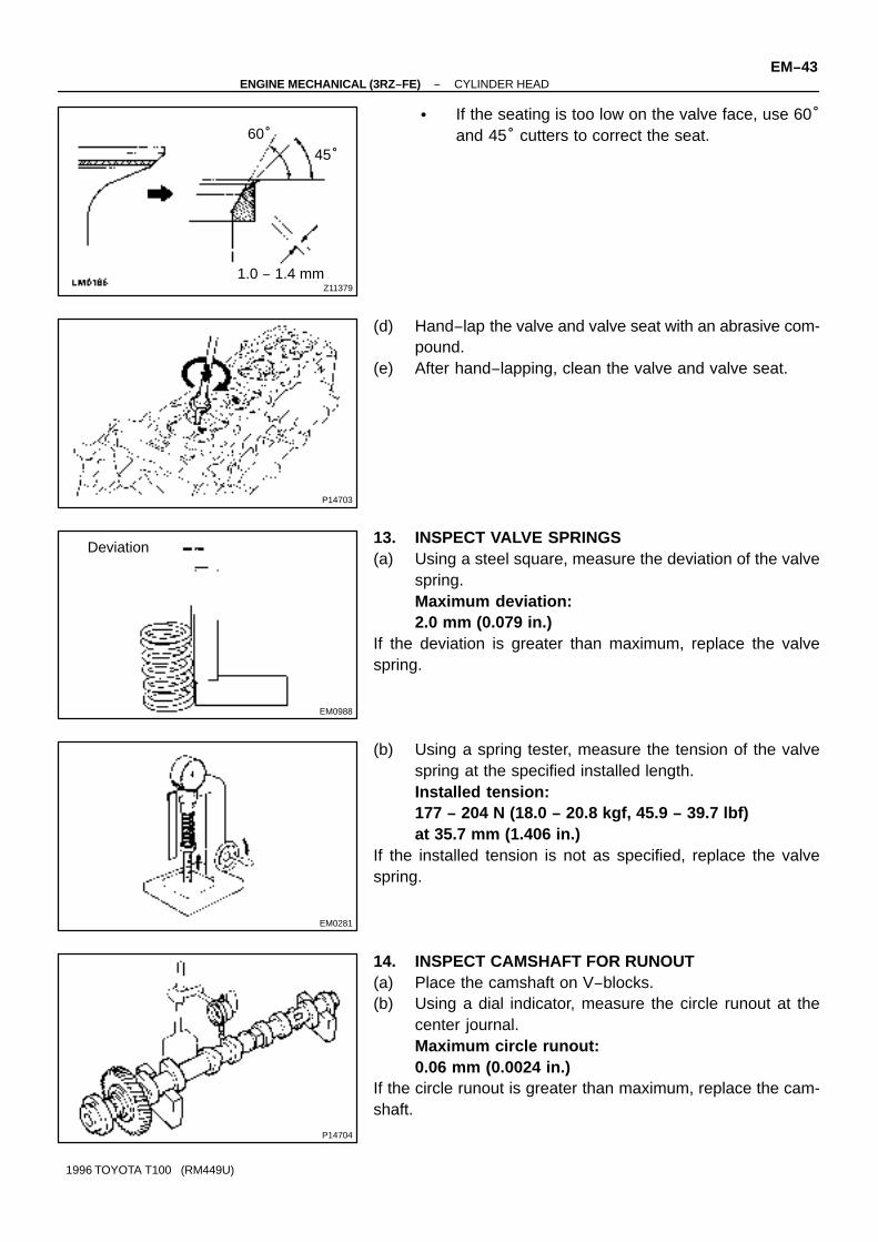
Z11379
45°60°
1.0 − 1.4 mm
P14703
EM0988
Deviation
EM0281
P14704
−ENGINE MECHANICAL (3RZ−FE) CYLINDER HEADEM−43
1996 TOYOTA T100 (RM449U)
� If the seating is too low on the valve face, use 60°and 45° cutters to correct the seat.
(d) Hand−lap the valve and valve seat with an abrasive com-pound.
(e) After hand−lapping, clean the valve and valve seat.
13. INSPECT VALVE SPRINGS(a) Using a steel square, measure the deviation of the valve
spring.Maximum deviation:2.0 mm (0.079 in.)
If the deviation is greater than maximum, replace the valvespring.
(b) Using a spring tester, measure the tension of the valvespring at the specified installed length.Installed tension:177 − 204 N (18.0 − 20.8 kgf, 45.9 − 39.7 lbf)at 35.7 mm (1.406 in.)
If the installed tension is not as specified, replace the valvespring.
14. INSPECT CAMSHAFT FOR RUNOUT(a) Place the camshaft on V−blocks.(b) Using a dial indicator, measure the circle runout at the
center journal.Maximum circle runout:0.06 mm (0.0024 in.)
If the circle runout is greater than maximum, replace the cam-shaft.
https://www.truck-manuals.net/

P03976
P03977
EM3322
Free Distance
P14668
Plastigage
P14665
EM−44−ENGINE MECHANICAL (3RZ−FE) CYLINDER HEAD
1996 TOYOTA T100 (RM449U)
15. INSPECT CAM LOBESUsing a micrometer, measure the cam lobe height.
Standard cam lobe height:Intake45.31 − 45.41 mm (1.7839 − 1.7878 in.)Exhaust45.06 − 45.16 mm (1.7740 − 1.7779 in.)
If the cam lobe height is less than standard allowable, replacethe camshaft.
16. INSPECT CAMSHAFT JOURNALSUsing a micrometer, measure the journal diameter.
Journal diameter:26.959 − 26.975 mm (1.0614 − 1.0620 in.)
If the journal diameter is not as specified, check the oil clear-ance.17. INSPECT CAMSHAFT BEARINGCheck the bearings for flaking and scoring.If the bearings are damaged, replace the bearing caps and cyl-inder head as a set.18. INSPECT CAMSHAFT GEAR SPRINGUsing a vernier caliper, measure the free distance between thespring ends.
Free distance:22.5 − 22.9 mm (0.886 − 0.902 in.)
If the free distance is not as specified, replace the gear spring.
19. INSPECT CAMSHAFT JOURNAL OIL CLEARANCE(a) Clean the bearing caps and camshaft journals.(b) Place the camshafts on the cylinder head.(c) Lay a strip of Plastigage across each of the camshaft jour-
nals.(d) Install the bearing caps (See page EM−50).
Torque: 15.5 N·m (160 kgf·cm, 12 ft·lbf)NOTICE:Do not turn the camshaft.
(e) Remove the bearing caps.(f) Measure the Plastigage at its widest point.
Standard oil clearance:0.025 − 0.062 mm (0.0010 − 0.0024 in.)Maximum oil clearance:0.08 mm (0.0031 in.)
If the oil clearance is greater than maximum, replace the cam-shaft. If necessary, replace the bearing caps and cylinder headas a set.(g) Completely remove the Plastigage.
https://www.truck-manuals.net/

P14708
P14706
P14650
EM2196
P14624
−ENGINE MECHANICAL (3RZ−FE) CYLINDER HEADEM−45
1996 TOYOTA T100 (RM449U)
20. INSPECT CAMSHAFT THRUST CLEARANCE(a) Install the camshaft (See page EM−50).(b) Using a dial indicator, measure the thrust clearance while
moving the camshaft back and forth.Standard thrust clearance:0.040 − 0.095 mm (0.0016 − 0.0037 in.)Maximum thrust clearance:0.12 mm (0.0047 in.)
If the thrust clearance is greater than maximum, replace thecamshaft. If necessary, replace the bearing caps and cylinderhead as a set.21. INSPECT CAMSHAFT GEAR BACKLASH(a) Install the camshafts without installing the exhaust cam
sub−gear (See page EM−50).(b) Using a dial indicator, measure the backlash.
Standard backlash:0.020 − 0.200 mm (0.0008 − 0.0079 in.)Maximum backlash:0.30 mm (0.0188 in.)
If the backlash is greater than maximum, replace the cam-shafts.22. INSPECT VALVE LIFTERS AND LIFTER BORES(a) Using a caliper gauge, measure the lifter bore diameter
of the cylinder head.Lifter bore diameter:31.000 − 31.016 mm (1.2205 − 1.2211 in.)
(b) Using a micrometer, measure the lifter diameter.Lifter diameter:30.966 − 30.976 mm (1.1578 − 1.2195 in.)
(c) Subtract the lifter diameter measurement from the lifterbore diameter measurement.Standard oil clearance:0.024 − 0.055 mm (0.0009 − 0.0022 in.)Maximum oil clearance:0.07 mm (0.0028 in.)
If the oil clearance is greater than maximum, replace the lifter.If necessary, replace the cylinder head.
23. INSPECT AIR INTAKE CHAMBERUsing a precision straight edge and thickness gauge, measurethe surface contacting the intake manifold for warpage.
Maximum warpage: 0.20 mm (0.0078 in.)If warpage is greater than maximum, replace the air intakechamber.
https://www.truck-manuals.net/

Z10936
Cylinder Head Side
Air Intake Chamber Side
P14622
P04666
Free
P04667
Lock
EM−46−ENGINE MECHANICAL (3RZ−FE) CYLINDER HEAD
1996 TOYOTA T100 (RM449U)
24. INSPECT INTAKE MANIFOLDUsing a precision straight edge and thickness gauge, measurethe surface contacting the cylinder head and air intake chamberfor warpage.
Maximum warpage: 0.20 mm (0.0078 in.)If warpage is greater than maximum, replace the manifold.
25. INSPECT EXHAUST MANIFOLDUsing a precision straight edge and thickness gauge, measurethe surface contacting the cylinder head for warpage.
Maximum warpage: 0.50 mm (0.0197 in.)If warpage is greater than maximum, replace the manifold.
26. INSPECT CHAIN TENSIONER(a) Check that the plunger moves smoothly when the ratchet
pawl is raised with your finger.
(b) Released the ratchet pawl and check that the plunger islocked in place by the ratchet pawl and does not movewhen pushed with your finger.
https://www.truck-manuals.net/
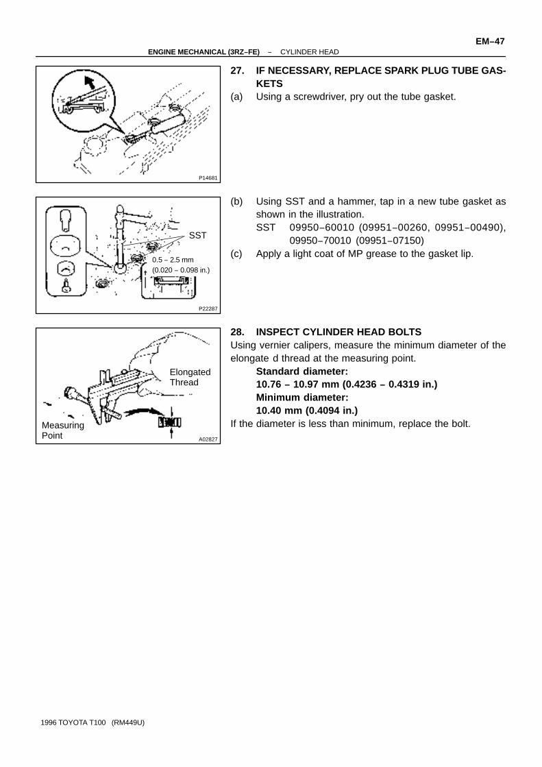
P14681
P22287
SST
0.5 − 2.5 mm(0.020 − 0.098 in.)
A02827
ElongatedThread
MeasuringPoint
−ENGINE MECHANICAL (3RZ−FE) CYLINDER HEADEM−47
1996 TOYOTA T100 (RM449U)
27. IF NECESSARY, REPLACE SPARK PLUG TUBE GAS-KETS
(a) Using a screwdriver, pry out the tube gasket.
(b) Using SST and a hammer, tap in a new tube gasket asshown in the illustration.SST 09950−60010 (09951−00260, 09951−00490),
09950−70010 (09951−07150)(c) Apply a light coat of MP grease to the gasket lip.
28. INSPECT CYLINDER HEAD BOLTSUsing vernier calipers, measure the minimum diameter of theelongate d thread at the measuring point.
Standard diameter:10.76 − 10.97 mm (0.4236 − 0.4319 in.)Minimum diameter:10.40 mm (0.4094 in.)
If the diameter is less than minimum, replace the bolt.
https://www.truck-manuals.net/

EM07D−02
Z11449
Protrusion47.0 mm
Mark
P14649
Sealant
P14662
Protrusion
P14651
SST
EM−48−ENGINE MECHANICAL (3RZ−FE) CYLINDER HEAD
1996 TOYOTA T100 (RM449U)
REASSEMBLYHINT:� Thoroughly clean all parts to be assembled.� Before installing the parts, apply new engine oil to all slid-
ing and rotating surfaces.� Replace all gaskets and oil seals with new ones.
1. INSTALL SPARK PLUG TUBESHINT:When using a new cylinder head, spark plug tubes must beinstalled.(a) Mark the standard position away from the edge, onto the
spark plug tube.Standard protrusion: 47.0 mm (1.850 in.)
(b) Apply adhesive to the spark plug tube hole of the cylinderhead.Sealant:Part No.08833−00070, Adhesive 1324, THREE BOND1324 or equivalent
(c) Using a press, press in a new spark plug tube until thereis 47.0 mm (1.850 in.) protruding from the camshaft bear-ing cap installation surface of the cylinder head.
NOTICE:Avoid pressing a new spark plug tube in too far by measur-ing the amount of protrusion while pressing.
2. INSTALL VALVES(a) Using SST, push in a new oil seal.
SST 09236−00101 (09236−15010)HINT:Different oil seals are used for the intake and exhaust.
Code mark (Intake side only): ”H”
https://www.truck-manuals.net/

P14652
(4)
(3)
(2)
(1)
P14702
SST
−ENGINE MECHANICAL (3RZ−FE) CYLINDER HEADEM−49
1996 TOYOTA T100 (RM449U)
(b) Install these parts:(1) Valve(2) Spring seat(3) Valve spring(4) Spring retainer
(c) Using SST, compress the valve spring and place the 2keepers around the valve stem.SST 09202−70020
(d) Using a plastic−faced hammer, lightly tap the valve stemtip to ensure a proper fit.
3. INSTALL VALVE LIFTERS AND SHIMS(a) Install the valve lifter and shim.(b) Check that the valve lifter rotates smoothly by hand.
https://www.truck-manuals.net/

P14680
Z10935
EM1OL−01
Z15489
90°
90°
Front
Painted Mark
P14709
EM−50−ENGINE MECHANICAL (3RZ−FE) CYLINDER HEAD
1996 TOYOTA T100 (RM449U)
INSTALLATION1. PLACE CYLINDER HEAD ON CYLINDER BLOCK(a) Apply seal packing to the 2 locations as shown.
Seal packing:Part No. 08826−00080 or equivalent
NOTICE:Do not apply too much seal packing.(b) Place a new cylinder head gasket in position on the cylin-
der block.NOTICE:Be careful of the installation direction.(c) Place the cylinder head in position on the cylinder head
gasket.2. INSTALL CYLINDER HEAD BOLTSHINT:� The cylinder head bolts are tightened in 3 progressive
steps (steps (b) and (d)).� If any cylinder head bolt is broken or deformed, replace
it.(a) Apply a light coat of engine oil on the threads and under
the heads of the cylinder head bolts.(b) Install and uniformly tighten the 10 cylinder head bolts
and plate washers in several passes, in the sequenceshown.Torque: 39 N·m (400 kgf·cm, 29 ft·lbf)
If any of the cylinder head bolts does not meet the torque speci-fication, replace the cylinder head bolt.
(c) Mark the front of the cylinder head bolt head with paint.(d) Retighten the cylinder head bolts by 90° in the numerical
order shown.(e) Retighten the cylinder head bolts by an additional 90°.(f) Check that the painted mark is now facing rearward.
(g) Install and torque the 2 mounting bolts.Torque: 21 N·m (210 kgf·cm, 15 ft·lbf)
https://www.truck-manuals.net/

P14911
Z11078
(1) (2) (3)
P14906
P14910
Service Bolt
SSTTurn
−ENGINE MECHANICAL (3RZ−FE) CYLINDER HEADEM−51
1996 TOYOTA T100 (RM449U)
3. ASSEMBLE EXHAUST CAMSHAFT(a) Mount the hexagon wrench head portion of the camshaft
in a vise.NOTICE:Be careful not to damage the camshaft.
(b) Install these parts:(1) Camshaft gear spring(2) Camshaft sub−gear(3) Wave washer
HINT:Align the pins on the gears with the spring ends.
(c) Using snap ring pliers, install the snap ring.
(d) Using SST, align the holes of the camshaft main gear andsub−gear by turning sub−gear clockwise, and install aservice bolt.SST 09960−10010 (09962−01000, 09963−00500)
4. INSTALL CAMSHAFTSNOTICE:Since the thrust clearance of the camshaft is small, thecamshaft must be kept level while it is being installed. If thecamshaft is not kept level, the portion of the cylinder headreceiving the shaft thrust may crack or be damaged, caus-ing the camshaft to seize or break. To avoid this, thesesteps should be carried out.
https://www.truck-manuals.net/

P14672
Straight Pin
P14711
P15749
73
1
5
9
8
4
2
6
10
P14699
Straight Pin
Aligh (Dot Mark)
P14701
EM−52−ENGINE MECHANICAL (3RZ−FE) CYLINDER HEAD
1996 TOYOTA T100 (RM449U)
(a) Install intake camshaft.(1) Apply MP grease to the thrust portion of the intake
camshaft.(2) Place the intake camshaft with knock pin facing up-
ward of camshaft angle on the cylinder head.
(3) Install the bearing caps in their proper locations.
(4) Apply a light coat of engine oil on the threads andunder the heads of the bearing cap bolts.
(5) Install and uniformly tighten the 10 bearing capbolts in the sequence shown.
Torque: 15.5 N·m (160 kgf·cm, 12 ft·lbf)
(b) Install exhaust camshaft.(1) Apply MP grease to the thrust portion of the exhaust
camshaft.(2) Engage the exhaust camshaft gear to the intake
camshaft gear by matching the timing marks (1 and2 dots) on each gear.
NOTICE:There are also timing marks (for TDC) on each gear asshown in the illustration. Do not use these marks.
(3) Roll down the exhaust camshaft onto the bearingjournals while engaging gears with each other.
(4) Install the bearing caps in their proper locations.
https://www.truck-manuals.net/

P15748
73
15
9
8
42
6
10
Z11084
P14695
A01399
Dot Mark
P14698
−ENGINE MECHANICAL (3RZ−FE) CYLINDER HEADEM−53
1996 TOYOTA T100 (RM449U)
(5) Apply light coat of engine oil on the threads and un-der the heads of the bearing cap bolts.
(6) Install and uniformly tighten the 10 bearing capbolts in several passes in the sequence shown.
(7) Remove a service bolt.(8) Check that the intake and exhaust camshafts turn
smoothly.
5. SET NO.1 CYLINDER TO TDC/COMPRESSION(a) Turn the crankshaft pulley clockwise, and align its groove
with the timing mark ”0” of the timing chain cover.
(b) Turn the camshafts so that the timing marks with one and2 dots will be in straight line on the cylinder head surfaceas shown in the illustration.
6. INSTALL CAMSHAFT TIMING GEARHINT:Check that the matchmarks on the camshaft timing gear andtiming chain are aligned.(a) Place the gear over the straight pin of the intake cam-
shaft.
https://www.truck-manuals.net/

P14632
P14685
Front Mark
P04668
HookPin
P14683
Push
EM−54−ENGINE MECHANICAL (3RZ−FE) CYLINDER HEAD
1996 TOYOTA T100 (RM449U)
(b) Hold the intake camshaft with a wrench, install and torquethe bolt.Torque: 73.5 N·m (750 kgf·cm, 54 ft·lbf)
(c) Hold the exhaust camshaft with a wrench, install the boltand distributor gear.Torque: 46 N·m (465 kgf·cm, 34 ft·lbf)
7. INSTALL CHAIN TENSIONER(a) Place a new gasket so that the front mark is toward the
front side.
(b) Release the ratchet pawl, fully push in the plunger and ap-ply the hook to the pin so that the plunger cannot springout.
(c) Turn the crankshaft pulley clockwise to provide someslack for the chain on the tensioner side.
NOTICE:Do not turn the pulley counterclockwise.
(d) Push the tensioner by hand until it touches the headinstallation surface, then install the 2 nuts.
(e) Tighten the 2 nuts.Torque: 21 N·m (210 kgf·cm, 15 ft·lbf)
(f) Check that the hook of the tensioner is not released.NOTICE:If the plunger springs out during installation of the chaintensioner, repeat the operation in step (b) before installingthe tensioner.
https://www.truck-manuals.net/

A01402
A01597
P14695
A01399
Dot Mark
−ENGINE MECHANICAL (3RZ−FE) CYLINDER HEADEM−55
1996 TOYOTA T100 (RM449U)
8. SET CHAIN TENSIONERTurn the crankshaft to the left so that the hook of the chain ten-sioner is released from the pin of the plunger, causing the plung-er to spring out and the slipper to be pushed into the chain.
HINT:If the plunger does not spring out, press the slipper into thechain tensioner with a screwdriver or your finger so that thehook is released and the plunger springs out.
9. CHECK VALVE TIMING(a) Turn the crankshaft pulley, and align its groove with the
timing mark ”0” of the timing chain cover.NOTICE:Always turn the crankshaft clockwise.
(b) Check that the timing marks (1 and 2 dots) of the camshaftdrive and driven gears are in straight line on the cylinderhead surface as shown in the illustration.
If not, turn the crankshaft 1 revolution (360°) and align themarks as above.10. CHECK AND ADJUST VALVE CLEARANCE (See page
EM−5)Turn the camshaft and position the cam lobe upward and checkand adjust the valve clearance.
Valve clearance (Cold):Intake0.15 − 0.25 mm (0.006 − 0.010 in.)Exhaust0.25 − 0.35 mm (0.010 − 0.014 in.)
11. INSTALL SPARK PLUGSUsing a 16 mm plug wrench, install the spark plug.
Torque: 20 N·m (200 kgf·cm, 14 ft·lbf)
https://www.truck-manuals.net/

P03789
P14695
P14687
P14686
EM−56−ENGINE MECHANICAL (3RZ−FE) CYLINDER HEAD
1996 TOYOTA T100 (RM449U)
12. INSTALL SEMI−CIRCULAR PLUGS(a) Remove any old packing (FIPG) material.(b) Apply seal packing to the cylinder head installation sur-
face of the semi−circular plugs.Seal packing:Part No. 08826−00080 or equivalent
(c) Install the semi−circular plug to the cylinder head.
13. SET NO. 1 CYLINDER TO TDC/COMPRESSION(a) Turn the crankshaft pulley clockwise, and align its groove
with the timing mark ”0” of the timing chain cover.
(b) Check that the timing marks with 1 and 2 dots are instraight line on the cylinder head surface as shown in theillustration.If not, turn the crankshaft 1 revolution (360°) and align themark as above.
14. INSTALL CYLINDER HEAD COVER(a) Install the gasket to the cylinder head cover.(b) Install the cylinder head cover with the 10 bolts.
Install the No.2 engine hanger and ground strap with thebolt.Torque: 42 N·m (420 kgf·cm, 30 ft·lbf)
15. INSTALL NO.1 ENGINE HANGERInstall the No.1 engine hanger with the bolt.
Torque: 42 N·m (420 kgf·cm, 30 ft·lbf)
16. INSTALL EXHAUST MANIFOLD(a) Install a new gasket and exhaust manifold with the 6 nuts.
Torque: 49 N·m (500 kgf·cm, 36 ft·lbf)(b) Install the heat insulator with the 2 bolts and 2 nuts.
Torque: 5.5 N·m (55 kgf·cm, 48 in.·lbf)
https://www.truck-manuals.net/

P15073
P22272
P24691
A02538
−ENGINE MECHANICAL (3RZ−FE) CYLINDER HEADEM−57
1996 TOYOTA T100 (RM449U)
17. INSTALL FRONT EXHAUST PIPE(a) Install 2 new gaskets and the front exhaust pipe assembly
with the 3 nuts.Torque: 62 N·m (630 kgf·cm, 46 ft·lbf)
(b) Install the support bracket with the 2 bolts.Torque: 39 N·m (400 kgf·cm, 29 ft·lbf)
(c) Connect the clamp and tighten the clamp bolt.Torque: 19 N·m (195 kgf·cm, 14 ft·lbf)
(d) Connect a new gasket and the front exhaust pipe assem-bly to the TWC with the 2 bolts and retainer.Torque: 39 N·m (400 kgf·cm, 29 ft·lbf)
(e) Install camshaft position sensor.18. INSTALL INTAKE MANIFOLDInstall a new gasket and intake manifold with the 3 bolts and 2nuts.
Torque: 29 N·m (300 kgf·cm, 22 ft·lbf)
19. INSTALL INJECTORS AND DELIVERY PIPE (See pageMF−21)
HINT:When using a new cylinder head, spacers must be installed.Apply a light coat of gasoline to a new O−ring a nd install it toa new spacer.
20. INSTALL FUEL TUBEInstall the fuel inlet tube and 4 new gaskets with 2 union bolts.
Torque: 29 N·m (300 kgf·cm, 22 ft·lbf)
21. INSTALL AIR INTAKE CHAMBER(a) Install a new gasket and the air intake chamber with the
3 bolts and 2 nuts.Torque: 21 N·m (210 kgf·cm, 15 ft·lbf)
(b) Connect the vacuum hose to the gas filter.(c) Connect the brake booster vacuum hose to the intake
camber.
https://www.truck-manuals.net/

P24689
P14628
Z15935
P14635
EM−58−ENGINE MECHANICAL (3RZ−FE) CYLINDER HEAD
1996 TOYOTA T100 (RM449U)
22. INSTALL FUEL RETURN PIPE(a) Install the fuel return pipe with the 2 bolts.(b) Connect these hoses:
� Fuel return hose to fuel pressure regulator� Fuel return hose to fuel return pipe
23. INSTALL INTAKE CHAMBER STAYInstall the intake chamber stay with the 2 bolts.
Torque: 20 N·m (200 kgf·cm, 14 ft·lbf)
24. INSTALL EGR VALVE AND VACUUM MODULATOR(a) Install a new gasket, EGR valve and vacuum modulator
with the bolt and 2 nuts.Torque:Bolt: 8.5 N·m (85 kgf·cm, 74 in.·lbf)Nut: 19 N·m (195 kgf·cm, 14 ft·lbf)
(b) Connect these hoses:� 2 vacuum hoses to EGR VSV (with clamp)� Water bypass hose to water bypass pipe
(c) Install 2 new gaskets and EGR pipe with the bolt and 4nuts.Torque:Bolt: 18 N·m (185 kgf·cm, 14 ft·lbf)Nut A: 19 N·m (195 kgf·cm, 14 ft·lbf)Nut B: 20 N·m (200 kgf·cm, 15 ft·lbf)
25. INSTALL CYLINDER HEAD REAR COVER(a) Install a new gasket and rear cover with the 3 bolts.
Torque: 13.5 N·m (135 kgf·cm, 10 ft·lbf)(b) Connect the heater water bypass pipe.26. CONNECT INJECTOR CONNECTORS27. CONNECT ENGINE WIRE(a) Connect the engine wire to the intake manifold with the
bolt.(b) Connect the 2 engine wire clamps.(c) Connect the DLC1 to the bracket.(d) Connect these connectors:
� Fuel pressure control VSV connector� Knock sensor connector� Crankshaft position sensor connector
(e) Connect the 5 engine wire clamps.(f) Connect the engine wire to the intake chamber with the
2 bolts.(g) Connect these connectors:
� EGR VSV connector� EGR gas temperature sensor connector
https://www.truck-manuals.net/

P15813
P15755SST
P14841
Adjusting Bolt
Look Bolt
P24651
−ENGINE MECHANICAL (3RZ−FE) CYLINDER HEADEM−59
1996 TOYOTA T100 (RM449U)
� ECT sensor connector� Oil pressure sensor connector� w/ A/C:
A/C compressor connector28. INSTALL THROTTLE BODY (See page MF−30)
29. INSTALL WATER OUTLET(a) Install a new gasket and water outlet with the 2 bolts.
Torque: 20 N·m (200 kgf·cm, 14 ft·lbf)(b) Connect the ECT sender gauge connector.(c) Connect the radiator inlet hose.30. INSTALL IGNITION COIL.31. INSTALL NO.1 AND NO.2 PCV HOSES
32. INSTALL PS PUMP AND BRACKET(a) Install the PS pump bracket with the 4 bolts.
Torque: 20 N·m (200 kgf·cm, 14 ft·lbf)(b) Connect the PS pump to the bracket with the 2 bolts.
Torque: 58 N·m (590 kgf·cm, 43 ft·lbf)(c) Connect the 2 air hoses to the intake chamber.(d) Using SST, install the PS pump pulley with the nut.
SST 09960−10010 (09962−01000, 09963−01000)Torque: 43 N·m (440 kgf·cm, 32 ft·lbf)
33. INSTALL PS PUMP DRIVE BELT AND IDLERPULLEY
(a) Install the idler pulley with the 3 bolts.Torque: 20 N·m (200 kgf·cm, 14 ft·lbf)
(b) Install and adjust drive belt (See page CH−2).
34. INSTALL AIR INTAKE CONNECTOR(a) Install the air intake connector with the 2 bolts and hose
clamp.(b) Connect the 2 air hoses.35. M/T:
CONNECT ACCELERATOR CABLE TO THROTTLEBODY
36. A/T:CONNECT THROTTLE AND ACCELERATOR CABLESTO THROTTLE BODY
https://www.truck-manuals.net/

P15087
EM−60−ENGINE MECHANICAL (3RZ−FE) CYLINDER HEAD
1996 TOYOTA T100 (RM449U)
37. INSTALL MAF METER, RESONATOR AND AIRCLEANER CAP
(a) Connect the air cleaner hose clamp.(b) Install the air cleaner cap, MAF meter and resonator with
the 4 clips.(c) Connect the MAF meter connector, IAT sensor connector
and wire clamp.38. FILL WITH ENGINE COOLANT39. START ENGINE AND CHECK FOR LEAKS40. CHECK IGNITION TIMING (See page EM−11)41. VEHICLE ROAD TESTCheck for abnormal noise, shock, slippage, correct shift pointsand smooth operation.42. RECHECK ENGINE COOLANT LEVEL
https://www.truck-manuals.net/

EM07H−03
−ENGINE MECHANICAL (3RZ−FE) ENGINE UNITEM−61
776Author�: Date�:
1996 TOYOTA T100 (RM449U)
ENGINE UNITCOMPONENTS
https://www.truck-manuals.net/

A02533
(w/AC)A/C Compressor
Front Exhaust PipeRetainer
� Gasket
Rear MountingBracket
(M/T)Clutch Release Cylinder
PS Pump
Stabilizer Bar
(w/AC)A/C Compressor Bracket
Drive Belt
Bracket
Cushion
Rropeller Shaft
� Gasket
Drive Belt
Drive Belt
PS Pump Pulley
Bracket
Cushion
� 62 (630, 46)
39 (400, 29)
N·m (kgf·cm, ft·lbf) : Specified torque
� Non − reusable part
EM−62−ENGINE MECHANICAL (3RZ−FE) ENGINE UNIT
777Author�: Date�:
1996 TOYOTA T100 (RM449U)
https://www.truck-manuals.net/

P21702
P21922
−ENGINE MECHANICAL (3RZ−FE) ENGINE UNITEM−63
778Author�: Date�:
1996 TOYOTA T100 (RM449U)
https://www.truck-manuals.net/

Z14987
EM−64−ENGINE MECHANICAL (3RZ−FE) ENGINE UNIT
779Author�: Date�:
1996 TOYOTA T100 (RM449U)
https://www.truck-manuals.net/

EM07I−03
−ENGINE MECHANICAL (3RZ−FE) ENGINE UNITEM−65
1996 TOYOTA T100 (RM449U)
REMOVAL1. REMOVE BATTERY2. REMOVE ENGINE UNDER COVERRemove the 4 bolts and engine under cover.3. DRAIN ENGINE COOLANT4. DRAIN ENGINE OIL5. DRAIN TRANSMISSION OIL6. REMOVE HOOD7. REMOVE RADIATOR RESERVOIR TANK8. REMOVE RADIATOR (See page CO−15)
9. REMOVE AIR CLEANER CAP, MAF METER AND RES-ONATOR
(a) Disconnect the MAF meter connector, IAT sensor con-nector and wire clamp.
(b) Loosen the air cleaner hose clamp.(c) Loosen the 4 clips, and remove the air cleaner cap, MAF
meter and resonator.10. REMOVE AIR CLEANER CASE(a) Remove the air cleaner element.(b) Remove the 3 bolts and air cleaner case.11. M/T:
DISCONNECT ACCELERATOR CABLE FROMTHROTTLE BODY
12. A/T:DISCONNECT ACCELERATOR AND THROTTLECABLES FROM THROTTLE BODY
13. REMOVE INTAKE AIR CONNECTOR(a) Disconnect the 2 air hoses and vs hose.(b) Remove the 2 bolts, hose clamp and intake air connector.
https://www.truck-manuals.net/

P14925
P15085
P15086
P15094
EM−66−ENGINE MECHANICAL (3RZ−FE) ENGINE UNIT
1996 TOYOTA T100 (RM449U)
14. w/ A/C:DISCONNECT A/C COMPRESSOR AND BRACKET
(a) Disconnect the A/C compressor connector.(b) Remove the 4 mounting bolts, and disconnect the com-
pressor from the bracket.HINT:Put a side the compressor, and suspend it.(c) Remove the 4 bolts and A/C compressor bracket.
15. DISCONNECT HEATER HOSES
16. DISCONNECT HOSESDisconnect these hoses:
� Brake booster vacuum hose� EVAP hose� 2 PS air hoses
� Fuel return hose� Fuel inlet hose
17. DISCONNECT PS PUMP(a) Using SST, remove the nut and PS pump pulley.
SST 09960−10010 (09962−01000, 09963−01000)(b) Remove the 2 bolts, and disconnect the PS pump.HINT:Put aside the pump, and suspend it.18. DISCONNECT GENERATOR WIRE(a) Disconnect the generator connector.(b) Remove the nut, and disconnect the generator wire and
wire clip.
https://www.truck-manuals.net/

P15739
P15078
P15089
P15072
−ENGINE MECHANICAL (3RZ−FE) ENGINE UNITEM−67
1996 TOYOTA T100 (RM449U)
19. REMOVE FRONT DOOR SCUFF PLATE AND COWLSIDE TRIM
(a) Remove the 4 screws and front door scuff plate.(b) Remove the clip and cowl side trim.20. DISCONNECT ENGINE WIRE AND CONNECTORS(a) Remove the 3 bolts and ECM.(b) Disconnect the 4 ECM connectors.(c) Disconnect the 2 connectors from the cowl wire.
(d) Disconnect these wires and connectors:� Igniter connector� Ground strap from cowl top panel
(e) Disconnect the 4 engine wire clamps.(f) Pull out the engine wire from the cabin.
21. M/T:REMOVE SHIFT LEVER ASSEMBLY
(a) Remove the shift lever knob.(b) Remove the 4 screws and shift lever boot.(c) Remove the 6 bolts, shift lever assembly and baffle.NOTICE:Do not lose the washers.
22. REMOVE STABILIZER BAR(a) Remove the nuts and cushions holding both sides of the
stabilizer bar to the lower arms, and disconnect the stabi-lizer bar.
(b) Remove both stabilizer bar bushings and brackets, andremove the stabilizer bar.
23. REMOVE PROPELLER SHAFT (See page PR−3)24. DISCONNECT SPEED METER CABLENOTICE:Do not lose the felt protector and washers.
https://www.truck-manuals.net/

P15073
P15137
P15099
P23949
EM−68−ENGINE MECHANICAL (3RZ−FE) ENGINE UNIT
1996 TOYOTA T100 (RM449U)
25. REMOVE FRONT EXHAUST PIPE(a) Disconnect the 2 heated oxygen sensor connectors.(b) Remove the 2 bolts, and retainer holding the front ex-
haust pipe to the TWC.(c) Loosen the clamp bolt and disconnect the clamp from the
support bracket.(d) Remove the 2 bolts and support bracket.(e) Remove the 3 nuts, front exhaust pipe and 3 gaskets.
26. M/T:REMOVE CLUTCH RELEASE CYLINDER
(a) Remove the 2 bolts, and disconnect clutch release cylin-der.
(b) Remove the bolt and disconnect the clutch line.27. A/T:
REMOVE CROSS SHAFT28. DISCONNECT STARTER WIRE(a) Remove the nut and disconnect the starter wire.(b) Disconnect the starter connector.(c) Remove the bolt and disconnect ground strap.29. PLACE JACK UNDER TRANSMISSION
30. REMOVE ENGINE REAR MOUNTING BRACKET� M/T:
Remove the 8 bolts holding the mounting bracket to themounting insulator and cross member.
� A/T:Remove the 7 bolts holding the mounting bracket to themounting insulator and cross member.
31. REMOVE ENGINE WITH TRANSMISSION(a) Install a rear engine hanger in the correct direction.
Part No:HANGER, ENGINE, NO.2 12282−75020BOLT 91512−61020Torque: 42 N·m (420 kgf·cm,30 ft·lbf)
https://www.truck-manuals.net/

P15084
P15092
−ENGINE MECHANICAL (3RZ−FE) ENGINE UNITEM−69
1996 TOYOTA T100 (RM449U)
(b) Attach the engine hoist chain to the 2 engine hangers.
(c) Remove the 4 bolts and nuts holding the engine frontmounting insulators to the frame.
(d) Lift the engine with transmission out of the vehicle slowlyand carefully.
NOTICE:Make sure the engine is clear of all wiring and hoses.(e) Place the engine and transmission assembly onto the
stand.32. SEPARATE ENGINE AND TRANSMISSION
https://www.truck-manuals.net/

P15082
EM1OM−01
P15092
P15099
P15092
P15137
EM−70−ENGINE MECHANICAL (3RZ−FE) ENGINE UNIT
1996 TOYOTA T100 (RM449U)
INSTALLATION1. INSTALL TRANSMISSION TO ENGINE2. INSTALL ENGINE AND TRANSMISSION ASSEMBLY
IN VEHICLE(a) Attach the engine hoist chain to the engine hangers.(b) Lower the engine and transmission assembly into the en-
gine compartment.
(c) Keep the engine level, and align the RH and LH mount-ings and body mountings.
(d) Attach the RH and LH mounting insulators to the bodymountings, and temporarily install the 4 bolts and nuts.
(e) Jack up and put the transmission onto the frame.(f) Remove the hoist chain.(g) Remove the bolt and rear engine hanger.
3. INSTALL ENGINE REAR MOUNTING BRACKET(a) Raise the transmission slightly by raising the engine with
a jack and a wooden block under the transmission.(b) Install the engine rear mounting bracket to the frame.
Torque: 25 N·m (260 kgf·cm, 19 ft·lbf)(c) Lower the transmission and rest it on the extension hous-
ing.(d) Install the mounting bracket to the mounting insulator.
Torque: 18 N·m (180 kgf·cm, 13 ft·lbf)
4. TIGHTEN RH AND LH ENGINE MOUNTINGINSULATOR BOLTS AND NUTS
Tighten the 4 bolts and nuts holding the mounting insulators tothe body mountings.
Torque: 38 N·m (380 kgf·cm, 28 ft·lbf)5. CONNECT STARTER WIRE(a) Connect the ground strap with the bolt.(b) Connect the starter connector.(c) Connect the starter wire with the nut.
6. M/T:INSTALL CLUTCH RELEASE CYLINDER
(a) Connect the clutch line with the bolt.Torque: 39 N·m (400 kgf·cm, 29 ft·lbf)
(b) Install the clutch release cylinder with the 2 bolts.Torque: 13 N·m (130 kgf·cm, 9 ft·lbf)
7. A/T:INSTALL CROSS SHAFT
https://www.truck-manuals.net/

P15073
P15072
R05270
P15078
−ENGINE MECHANICAL (3RZ−FE) ENGINE UNITEM−71
1996 TOYOTA T100 (RM449U)
8. INSTALL FRONT EXHAUST PIPE(a) Install 2 new gaskets and the front exhaust pipe assembly
with new 3 nuts.Torque: 62 N·m (630 kgf·cm, 46 ft·lbf)
(b) Install the support bracket with the 2 bolts.Torque: 39 N·m (400 kgf·cm, 29 ft·lbf)
(c) Connect the clamp and tighten the clamp bolt.Torque: 19 N·m (195 kgf·cm, 14 ft·lbf)
(d) Connect a new gasket and the front exhaust pipe assem-bly to the TWC with the 2 bolts and retainer.Torque: 39 N·m (400 kgf·cm, 29 ft·lbf)
(e) Connect the 2 heated oxygen sensor connectors.9. CONNECT SPEEDOMETER CABLE10. INSTALL PROPELLER SHAFT (See page PR−9)
11. INSTALL STABILIZER BAR(a) Place the stabilizer bar in position and install both stabiliz-
er bar bushings and brackets to the frame.(b) Torque the stabilizer bar mounting bolts.
Torque: 30 N·m (306 kgf·cm, 22 ft·lbf)
(c) Connect the stabilizer bar on both sides to the lower armswith brackets, cushions and new nuts as shown.
(d) Torque the nuts.Torque: 13 N·m (130 kgf·cm, 9 ft·lbf)
12. M/T:INSTALL SHIFT LEVER ASSEMBLY
(a) Install baffle and shift lever assembly with the 6 bolts.(b) Install the shift lever boot with the 4 screws.(c) Install the shift lever knob.
https://www.truck-manuals.net/

P15739
P15094
P15086
EM−72−ENGINE MECHANICAL (3RZ−FE) ENGINE UNIT
1996 TOYOTA T100 (RM449U)
13. CONNECT WIRES AND CONNECTORS(a) Push in the engine wire through the cowl panel.(b) Connect the 4 engine wire clamps(c) Connect these wires and connectors:
� Ground strap to cowl top panel� Igniter connector
(d) Connect 2 connectors to cowl wire.(e) Connect 4 connectors to the ECM.(f) Install the ECM with the 3 bolts.
14. INSTALL FRONT DOOR SCUFF PLATE AND COWLSIDE TRIM
(a) Install the cowl side trim with the clip.(b) Install the front door scuff plate with the 4 screws.15. CONNECT GENERATOR WIRE(a) Connect the generator connector.(b) Connect the generator wire with the nut.(c) Connect the wire harness clip to the generator.
16. CONNECT PS PUMP(a) Connect the PS pump to the bracket with the 2 bolts.
Torque: 58 N·m (590 kgf·cm, 43 ft·lbf)(b) Using SST, install the PS pump pulley with the nut.
SST 09960−10010 (09962−01000, 09963−01000)Torque: 43 N·m (440 kgf·cm, 32 ft·lbf)
17. CONNECT HOSESConnect these hoses:
� Fuel return hose� Fuel inlet hose
https://www.truck-manuals.net/

P15085
P14935
P24651
−ENGINE MECHANICAL (3RZ−FE) ENGINE UNITEM−73
1996 TOYOTA T100 (RM449U)
� Brake booster vacuum hose� EVAP hose� 2 PS hoses
18. CONNECT HEATER HOSES
19. w/ A/C:INSTALL A/C COMPRESSOR AND BRACKET
(a) Install the A/C compressor bracket with the 4 bolts.Torque: 44 N·m (440 kgf·cm, 32 ft·lbf)
(b) Install the A/C compressor with the 4 bolts.Torque: 25 N·m (250 kgf·cm, 18 ft·lbf)
(c) Connect the A/C compressor connector.
20. INSTALL INTAKE AIR CONNECTOR(a) Install the intake air connector with the 2 bolts and hose
clamp.Torque: 18 N·m (185 kgf·cm, 13 ft·lbf)
(b) Connect the 2 air hoses.21. M/T:
CONNECT ACCELERATOR CABLE TO THROTTLEBODY
22. A/T:CONNECT ACCELERATOR AND THROTTLE CABLESTO THROTTLE BODY
https://www.truck-manuals.net/

EM−74−ENGINE MECHANICAL (3RZ−FE) ENGINE UNIT
1996 TOYOTA T100 (RM449U)
23. INSTALL AIR CLEANER CASE(a) Install the air cleaner case with 3 bolts.(b) Install the air cleaner element.24. INSTALL MAF METER, RESONATOR AND AIR
CLEANER CAP(a) Connect the air cleaner hose clamp.(b) Install the air cleaner cap, MAF meter and resonator with
the 4 clips.(c) Connect the MAF meter connector, IAT sensor connector
and wire clamp.25. INSTALL RADIATOR (See page CO−20)26. INSTALL RADIATOR RESERVOIR TANK27. FILL WITH ENGINE OIL28. FILL WITH ENGINE COOLANT29. FILL TRANSMISSION OIL30. INSTALL BATTERY31. START ENGINE AND CHECK FOR LEAKS32. CHECK IGNITION TIMING (See page EM−11)33. INSTALL ENGINE UNDER COVERInstall the engine under cover with the 4 bolts.34. INSTALL HOOD35. VEHICLE ROAD TESTCheck for abnormal noise, shock, slippage, and smooth opera-tion.36. RECHECK ENGINE COOLANT AND ENGINE OIL LEV-
ELS
https://www.truck-manuals.net/

EM07K−03
P21632
−ENGINE MECHANICAL (3RZ−FE) CYLINDER BLOCKEM−75
790Author�: Date�:
1996 TOYOTA T100 (RM449U)
CYLINDER BLOCKCOMPONENTS
https://www.truck-manuals.net/

EM07L−02
P14816
KnockSensor
SST
P15971
SST
Oil Pressure Switch
P14771
EM−76−ENGINE MECHANICAL (3RZ−FE) CYLINDER BLOCK
1996 TOYOTA T100 (RM449U)
DISASSEMBLY1. M/T:
REMOVE FLYWHEELRemove the 10 bolts and flywheel.2. A/T:
REMOVE DRIVE PLATERemove the 10 bolts, front spacer, drive plate and rear spacer.3. REMOVE REAR END PLATERemove the 3 bolts and rear end plate.4. INSTALL ENGINE TO ENGINE STAND FOR DIS-
ASSEMBLY5. REMOVE CYLINDER HEAD (See page EM−28)6. REMOVE TIMING CHAINS, GEARS AND SPROCKET
(See page EM−14)7. REMOVE FUEL FILTERRemove the 2 bolts and fuel filter.
8. REMOVE KNOCK SENSORUsing SST, remove the knock sensor.
SST 09816−300109. REMOVE WATER BYPASS PIPERemove the bolt and water bypass pipe.10. REMOVE OIL FILTER AND BRACKET(a) Remove the oil filter (See page LU−3).(b) Remove the 2 bolts, nut, oil filter bracket and O−ring.11. REMOVE OIL FILTER BRACKET UNIONUsing 14 mm hexagon wrench, remove the union and O−ring.12. REMOVE ENGINE COOLANT DRAIN PLUG13. REMOVE OIL PRESSURE SWITCHUsing SST, remove the oil pressure switch.
SST 09816−3001014. REMOVE RH ENGINE MOUNTING BRACKETRemove the 4 bolts and bracket.15. REMOVE LH ENGINE MOUNTING BRACKETRemove the 5 bolts and bracket.
16. REMOVE REAR OIL SEAL RETAINERRemove the 6 bolts and retainer.
https://www.truck-manuals.net/

P14772
P14773
P14776
P14777
Plastigage
P14781
−ENGINE MECHANICAL (3RZ−FE) CYLINDER BLOCKEM−77
1996 TOYOTA T100 (RM449U)
17. CHECK CONNECTING ROD THRUST CLEARANCEUsing a dial indicator, measure the thrust clearance while mov-ing the connecting rod back and forth.
Standard thrust clearance:0.160 − 0.312 mm (0.0063 − 0.0123 in.)Maximum thrust clearance:0.35 mm (0.0138 in.)
If the thrust clearance is greater than maximum, replace theconnecting rod assembly. If necessary, replace the crankshaft.
18. REMOVE CONNECTING ROD CAPS AND CHECK OILCLEARANCE
(a) Using a punch or numbering stamp, place the matchmarkon the connecting rod cap to ensure correct reassembly.
(b) Remove the connecting rod cap nuts.(c) Using a plastic−faced hammer, lightly tap the connecting
rod bolts and lift off the connecting rod cap.HINT:Keep the lower bearing inserted with the connecting rod cap.
(d) Cover the connecting rod bolts with a short piece of hoseto protect the crankshaft from damage.
(e) Clean the crank pin and bearing.(f) Check the crank pin and bearing for pitting and scratches.If the crank pin or bearing is damaged, replace the bearings. Ifnecessary, grind or replace the crankshaft.
(g) Lay a strip of Plastigage across the crank pin.(h) Install the connecting rod cap with the 2 nuts (See page
EM−95).Torque:1st 45 N·m (460 kgf·cm, 33 ft·lbf)2nd Turn 90°
NOTICE:Do not turn the crankshaft.(i) Remove the 2 nuts and connecting rod cap (See proce-
dure (b) and (c) above).(j) Measure the Plastigage at its widest point.
Standard oil clearance:STD0.030 − 0.055 mm (0.0012 − 0.0022 in.)U/S 0.250.031 − 0.071 mm (0.0012 − 0.0026 in.)Maximum oil clearance:0.10 mm (0.0039 in.)
https://www.truck-manuals.net/

Z10578
4, 5 or 6
P14783
EM−78−ENGINE MECHANICAL (3RZ−FE) CYLINDER BLOCK
1996 TOYOTA T100 (RM449U)
If the oil clearance is greater than maximum, replace the bear-ings. If necessary, grind or replace the crankshaft.HINT:If using a standard bearing, replace with 1 having the samenumber as marked on the bearing cap. There are 3 sizes ofstandard bearings, marked ”4”, ”5”, ”6” accordingly.
Reference:Connecting rod big end inside diameter:
STD Mark ”4” 56.000 − 56.006 mm (2.2047 − 2.2050 in.)
STD Mark ”5” 56.006 − 56.012 mm (2.2050 − 2.2052 in.)
STD Mark ”6” 56.012 − 56.018 mm (2.2052 − 2.2054 in.)
U/S 0.25 56.000 − 56.018 mm (2.2047 − 2.2054 in.)
Crankshaft crank pin diameter:
STD 52.987 − 53.000 mm (2.0861 − 2.0866 in.)
U/S 0.25 52.745 − 52.755 mm (2.0766 − 2.0770 in.)
Standard sized bearing center wall thickness:
STD Mark ”4” 1.482 − 1.485 mm (0.0583 − 0.0585 in.)
STD Mark ”5” 1.485 − 1.488 mm (0.0585 − 0.0586 in.)
STD Mark ”6” 1.488 − 1.491 mm (0.0586 − 0.0587 in.)
U/S 0.25 1.601 − 1.607 mm (0.0630 − 0.0633 in.)
(k) Completely remove the Plastigage.19. REMOVE PISTON AND CONNECTING ROD AS-
SEMBLIES(a) Using a ridge reamer, remove the all carbon from the top
of the cylinder.
(b) Push the piston, connecting rod assembly and upperbearing through the top of the cylinder block.
HINT:� Keep the bearings, connecting rod and cap together.� Arrange the piston and connecting rod assemblies in cor-
rect order.
https://www.truck-manuals.net/

P14785
Z11077
610
8
2
1
5
9
7
3
4
P14787
−ENGINE MECHANICAL (3RZ−FE) CYLINDER BLOCKEM−79
1996 TOYOTA T100 (RM449U)
20. CHECK CRANKSHAFT THRUST CLEARANCEUsing a dial indicator, measure the thrust clearance while pryingthe crankshaft back and forth with a screwdriver.
Standard thrust clearance:0.020 − 0.220 mm (0.0008 − 0.0087 in.)Maximum thrust clearance:0.30 mm (0.0118 in.)
If the thrust clearance is greater than maximum, replace thethrust washers as a set.
Thrust washer thickness:2.440 − 2.490 mm (0.0961 − 0.0980 in.)
21. REMOVE MAIN BEARING CAPS AND CHECK OILCLEARANCE
(a) Uniformly loosen and remove the main bearing cap boltsin several passes, in the sequence shown.
(b) Using the removed main bearing cap bolts, pry the mainbearing cap back and forth, and remove the main bearingcaps, lower bearings and (No.3 main bearing cap only)lower thrust washers.
HINT:� Keep the lower bearing and main bearing cap together.� Arrange the main bearing caps and lower thrust washers
in correct order.(c) Lift out the crankshaft.HINT:Keep the upper bearings and upper thrust washers togetherwith the cylinder block.(d) Clean each main journal and bearing.(e) Check each main journal and bearing for pitting and
scratches.If the journal or bearing is damaged, replace the bearings. Ifnecessary, grind or replace the crankshaft.(f) Place the crankshaft on the cylinder block.
https://www.truck-manuals.net/

P14790
Plastigage
P14793
P14794
No.5
No.4
No.3
No.2
No.1 Mark 1, 2 or 3
EM−80−ENGINE MECHANICAL (3RZ−FE) CYLINDER BLOCK
1996 TOYOTA T100 (RM449U)
(g) Lay a strip of Plastigage across each journal.(h) Install the main bearing caps (See page EM−95).
Torque:1st 39 N·m (400 kgf·cm, 29 ft·lbf)2nd Turn 90°
NOTICE:Do not turn the crankshaft.(i) Remove the main bearing caps (See procedure (a) and
(b) above).
(j) Measure the Plastigage at its widest point.Standard clearance:STDNo.30.030 − 0.055 mm (0.0012 − 0.0022 in.)Others0.024 − 0.049 mm (0.0009 − 0.0019 in.)U/S 0.25No.30.030 − 0.070 mm (0.0012 − 0.0028 in.)Others0.025 − 0.065 mm (0.0010 − 0.0026 in.)Maximum clearance:0.10 mm (0.0039 in.)
HINT:� If the oil clearance is greater than maximum, replace the
bearings. If necessary, grind or replace the crankshaft.� If using a standard bearing, replace with 1 having the
same number as marked on the block. There are 3 sizesof standard bearings, marked ”1”, ”2” and ”3” accordingly.Reference:Cylinder block main journal bore diameter:
STD Mark ”1” 64.004 − 64.010 mm (2.5198 − 2.5201 in.)
STD Mark ”2” 64.011 − 64.016 mm (2.5201 − 2.5203 in.)
STD Mark ”3” 64.017 − 64.022 mm (2.5203 − 2.5205 in.)
U/S 0.25 64.000 − 64.024 mm (2.5197 − 2.5206 in.)
https://www.truck-manuals.net/

P14796
P14745
−ENGINE MECHANICAL (3RZ−FE) CYLINDER BLOCKEM−81
1996 TOYOTA T100 (RM449U)
Crankshaft Journal diameter:
STD NO.3 59.981 − 59.994 mm (2.2615 − 2.3620 in.)
STD Others 59.987 − 60.000 mm (2.3617 − 2.3622 in.)
U/S 0.25 No.3 59.740 − 59.750 mm (2.3520 − 2.3524 in.)
U/S 0.25 Others 59.745 − 59.755 mm (2.3522 − 2.3526 in.)
Bearing center wall thickness:
STD Mark ”1” 1.987 − 1.990 mm (0.0782 − 0.0783 in.)
STD Mark ”2” 1.991 − 1.993 mm (0.0784 − 0.0785 in.)
STD Mark ”3” 1.994 − 1.996 mm (0.0785 − 0.0786 in.)
U/S 0.25 2.106 − 2.112 mm (0.0829 − 0.0831 in.)
(k) Completely remove the Plastigage.22. REMOVE CRANKSHAFT(a) Lift out the crankshaft.(b) Remove the upper main bearings and upper thrust wash-
ers from the cylinder block.HINT:Arrange the main bearings and thrust washers in correct order.
23. REMOVE CYLINDER BLOCK ORIFICE
24. CHECK THRUST CLEARANCES OF NO.1 AND NO.2BALANCE SHAFTS OF ENGINE BALANCER
Using a dial indicator, measure the thrust clearance while mov-ing the balance shaft back and forth.
Standard thrust clearance:0.07 − 0.13 mm (0.0027 − 0.0051 in.)Maximum thrust clearance:0.2 mm (0.0079 in.)
If the thrust clearance is greater than maximum, replace the bal-ance shaft thrust washer.If necessary, replace the balance shaft.
https://www.truck-manuals.net/

P14744
P14748
No.1 Balance Shaft
No.2Balance Shaft
P14753
Z11075
P14818
EM−82−ENGINE MECHANICAL (3RZ−FE) CYLINDER BLOCK
1996 TOYOTA T100 (RM449U)
25. REMOVE NO.1 AND NO.2 BALANCE SHAFTS(a) Remove the 1 bolt from the No.1 balance shaft.(b) Remove the 2 bolts from the No.2 balance shaft.(c) Remove the balance shafts.NOTICE:When removing the balance shaft make sure you supportthe balance shaft with both hands and avoid scratching thebalance shaft bearing on the cylinder block side.
HINT:� No.1 balance shaft (RH):
Has indentations.� No.2 balance shaft (LH):
Has no indentations.
26. DISASSEMBLE NO.1 BALANCE SHAFT(a) Mount the hexagon wrench head portion of the balance
shaft in a vise.NOTICE:Be careful not to damage the balance shaft.
(b) Remove these parts from balance shaft assembly:(1) No.1 balance shaft(2) No.1 balance shaft thrust plate(3) Balance shaft thrust spacer.(4) Balance shaft timing gear.(5) Key
27. DISASSEMBLE NO.2 BALANCE SHAFT(a) Mount the hexagon wrench head portion of the balance
shaft in a vise.NOTICE:Be careful not to damage the balance shaft.
https://www.truck-manuals.net/

Z11076
P14762
P14760
P14764
P03870
−ENGINE MECHANICAL (3RZ−FE) CYLINDER BLOCKEM−83
1996 TOYOTA T100 (RM449U)
(b) Remove these parts from balance shaft assembly:(1) No.2 balance shaft(2) No.2 balance shaft thrust prate(3) Balance shaft timing sprocket
28. CHECK FIT BETWEEN PISTON AND PISTON PINTry to move the piston back and forth on the piston pin.If any movement is felt, replace the piston and pin as a set.
29. REMOVE PISTON RINGS(a) Using a piston ring expander, remove the 2 compression
rings.(b) Remove the 2 side rails and oil ring by hand.HINT:Arrange the rings in correct order only.
30. DISCONNECT CONNECTING ROD FROM PISTON(a) Using a small screwdriver, pry out the 2 snap rings.(b) Gradually heat the piston to 80 − 90°C ( 176 − 194
°F).
(c) Using plastic−faced hammer and brass bar, lightly tap outthe piston pin and remove the connecting rod.
HINT:� The piston and pin are a matched set.� Arrange the pistons, pins, rings, connecting rods and
bearings in correct order.
https://www.truck-manuals.net/

P14798
EM07M−03
Z10814
Z10815
EM−84−ENGINE MECHANICAL (3RZ−FE) CYLINDER BLOCK
1996 TOYOTA T100 (RM449U)
INSPECTION1. CLEAN CYLINDER BLOCK(a) Remove gasket material.
Using a gasket scraper, remove all the gasket materialfrom the top surface of the cylinder block.
(b) Clean cylinder block.Using a soft brush and solvent, thoroughly clean the cylin-der block.
2. INSPECT TOP SURFACE OF CYLINDER BLOCK FORFLATNESS
Using a precision straight edge and thickness gauge, measurethe surfaces contacting the cylinder head gasket for warpage.
Maximum warpage:0.05 mm (0.0020 in.)
If warpage is greater than maximum, replace the cylinder block.3. INSPECT CYLINDER FOR VERTICAL SCRATCHESVisually check the cylinder for vertical scratches.If deep scratches are present, rebore all the 4 cylinders. If nec-essary, replace the cylinder block.
4. INSPECT CYLINDER BORE DIAMETERUsing a cylinder gauge, measure the cylinder bore diameter atpositions A, B and C in the thrust and axial directions.
Standard diameter:STD94.990 − 95.003 mm (3.7398 − 3.7403 in.)Maximum diameter:STD95.06 mm (3.7425 in.)
If the diameter is greater than maximum, rebore all the 4 cylin-ders. If necessary, replace the cylinder block.
https://www.truck-manuals.net/

P14783
P14802
ElongatedThread
MeasuringPoint
P14767
P14822
−ENGINE MECHANICAL (3RZ−FE) CYLINDER BLOCKEM−85
1996 TOYOTA T100 (RM449U)
5. REMOVE CYLINDER RIDGEIf the wear is less than 0.2 mm (0.008 in.), using a ridge reamer,grind the top of the cylinder.
6. INSPECT MAIN BEARING CAP BOLTSUsing vernier calipers, measure the thread outside diameter ofthe bolt.
Standard outside diameter:10.76 − 10.97 mm (0.4236 − 0.4319 in.)Minimum outside diameter:10.40 mm (0.4094 in.)
If the diameter is less than minimum, replace the bolt.7. INSPECT CYLINDER BLOCK ORIFICECheck the orifice for clogging.If necessary, replace the orifice.
8. CLEAN PISTON(a) Using a gasket scraper, remove the carbon from the pis-
ton top.
(b) Using a groove cleaning tool or broken ring, clean the pis-ton ring grooves.
https://www.truck-manuals.net/

A03810
P14765
P14821
EM−86−ENGINE MECHANICAL (3RZ−FE) CYLINDER BLOCK
1996 TOYOTA T100 (RM449U)
(c) Using solvent and a brush, thoroughly clean the piston.NOTICE:Do not use a wire brush.
9. INSPECT PISTON OIL CLEARANCE(a) Using a micrometer, measure the piston diameter at right
angles to the piston pin center line, 37.5 mm (1.47 in.)from the piston head.Piston diameter:STD94.933 − 94.943 mm (3.7375 − 3.7379 in.)O/S 0.5095.433 − 95.443 mm (3.7572 − 3.7576 in.)
(b) Measure the cylinder bore diameter in the thrust direc-tions (See step 4.).
(c) Subtract the piston diameter measurement from the cylin-der bore diameter measurement.Standard oil clearance:0.047 − 0.070 mm (0.0019 − 0.0028 in.)
If the oil clearance is greater than maximum, replace all the 4pistons and rebore all the 4 cylinders. If necessary, replace thecylinder block.HINT:Use new cylinder block: Use a piston with the same numbermark as the cylinder bore diameter marked on the cylinderblock.
10. INSPECT PISTON RING GROOVE CLEARANCEUsing a thickness gauge, measure the clearance between newpiston ring and the wall of the piston ring groove.
Ring groove clearance:No.10.020 − 0.070 mm (0.0008 − 0.0028 in.)No.20.030 − 0.070 mm (0.0012 − 0.0028 in.)
If the clearance is not as specified, replace the piston.
https://www.truck-manuals.net/

P04002
125 mm
EM7639
P15014
P03829
−ENGINE MECHANICAL (3RZ−FE) CYLINDER BLOCKEM−87
1996 TOYOTA T100 (RM449U)
11. INSPECT PISTON RING END GAP(a) Insert the piston ring into the cylinder bore.(b) Using a piston, push the piston ring a little beyond the bot-
tom of the ring travel, 125 mm (4.92 in.) from the top of thecylinder block.
(c) Using a thickness gauge, measure the end gap.Standard end gap:No.10.300 − 0.400 mm (0.0118 − 0.0157 in.)No.2Code mark ”T”0.400 − 0.500 mm (0.0157 − 0.0196 in.)Code mark ”N”0.400 − 0.500 mm (0.0157 − 0.0196 in.)
If the end gap is not as specified, replace the piston ring. If theend gap is not as specified, even with a new piston ring, reboreall the 4 cylinders or replace the cylinder block.
12. INSPECT PISTON PIN FITAt 80 − 90°C (176 − 194°F), you should be able to push the pis-ton pin into the piston pin hole with your thumb.
13. INSPECT CONNECTING ROD ALIGNMENTUsing a connecting rod aligner and thickness gauge, check theconnecting rod alignment.
� Check for out−of−alignment.Maximum out−of−alignment:0.05 mm (0.0020 in.) per 100 mm (3.94 in.)
If out−of−alignment is greater than maximum, replace the con-necting rod assembly.
https://www.truck-manuals.net/

P03828
P03868
EM0227
EM7426
SST
EM−88−ENGINE MECHANICAL (3RZ−FE) CYLINDER BLOCK
1996 TOYOTA T100 (RM449U)
� Check for twistMaximum twist:0.15 mm (0.0059 in. ) per 100 mm (3.94 in.)
If twist is greater than maximum, replace the connecting rod as-sembly.
14. INSPECT PISTON PIN OIL CLEARANCE(a) Using a caliper gauge, measure the inside diameter of the
connecting rod bushing.Bushing inside diameter:24.008 − 24.017 mm (0.9452 − 0.9455 in.)
(b) Using a micrometer, measure the piston pin diameter.Piston pin diameter:24.000 − 24.009 mm (0.9449 − 0.9452 in.)
(c) Subtract the piston pin diameter measurement from thebushing inside diameter measurement.Standard oil clearance:0.005 − 0.011 mm (0.0002 − 0.0004 in.)Maximum oil clearance:0.015 mm (0.0006 in.)
If the oil clearance is greater than maximum, replace the bush-ing. If necessary, replace the piston and piston pin as a set.
15. IF NECESSARY, REPLACE CONNECTING RODBUSHING
(a) Using SST and a press, press out the bushing.SST 09207−76010
https://www.truck-manuals.net/

Z15492
SST
OilHole
P03827
P03867
P15015
EM8714
23 mm(0.91 in.)
−ENGINE MECHANICAL (3RZ−FE) CYLINDER BLOCKEM−89
1996 TOYOTA T100 (RM449U)
(b) Align the oil holes of a new bushing and the connectingrod.
(c) Using SST and a press, press in the bushing.SST 09207−76010
(d) Using a pin hole grinder, hone the bushing to obtain thestandard specified clearance (see step 14 above) be-tween the bushing and piston pin.
(e) Check the piston pin fit at normal room temperature. Coatthe piston pin with engine oil, and push it into the connect-ing rod with your thumb.
16. INSPECT CONNECTING ROD BOLTS(a) Install the cap nut to the connecting rod bolt. Check that
the cap nut can be turned easily by hand to the end of thethread.
(b) If the cap nut cannot be turned easily, measure the mini-mum outside diameter of the connecting rod bolt with ver-nier calipers.Standard outside diameter:7.80 − 7.90 mm (0.3071 − 0.3110 in.)Minimum outside diameter:7.60 mm (0.2992 in.)
HINT:� If the location of minimum diameter cannot be judged by
visual inspect ion, measure the outer diameter at the loca-tion shown in the illustration.
� If the outside diameter is less than limit, replace the con-necting rod bolt and nut as a set.
https://www.truck-manuals.net/

P14747
P14749
P14765
EM−90−ENGINE MECHANICAL (3RZ−FE) CYLINDER BLOCK
1996 TOYOTA T100 (RM449U)
17. INSPECT RH AND LH BALANCE SHAFTS(a) Using a cylinder gauge, measure the inside diameter of
the balance shaft bearing.Bearing inside diameter (from front side):No.1 38.025 − 38.045 mm (1.4970 − 1.4978 in.)No.2 37.525 − 37.545 mm (1.4774 − 1.4781 in.)
(b) Using a micrometer, measure the diameter of the balanceshaft main journals.Main journal diameter (from front side):No.1 37.969 − 37.985 mm (1.4948 − 1.4955 in.)No.2 37.449 − 37.465 mm (1.4744 − 1.4750 in.)
(c) Subtract the balance shaft main journal diameter mea-surement from the balance shaft bearing inside diametermeasurement.Standard oil clearance:No.1 0.040 − 0.076 mm (0.0016 − 0.0031 in.)No.2 0.060 − 0.096 mm (0.0024 − 0.0038 in.)Maximum oil clearance:No.1 0.15 mm (0.0059 in.)No.2 0.15 mm (0.0059 in.)
If the clearance is greater than maximum, replace the cylinderblock and balance shaft.
18. CYLINDER BORINGHINT:� Bore all the 4 cylinders for the oversized piston outside di-
ameter.� Replace all the piston rings with ones to match the over-
sized pistons.(a) Select oversized pistons
Oversized piston diameter:O/S 0.5095.433 − 95.443 mm (3.7572 − 3.7576 in.)
(b) Calculate amount to bore cylinders(1) Using a micrometer, measure the piston diameter at
right angles to the piston pin center line, 37.5 mm(1.47 in.) from the piston head.
https://www.truck-manuals.net/

P14803
P14813
−ENGINE MECHANICAL (3RZ−FE) CYLINDER BLOCKEM−91
1996 TOYOTA T100 (RM449U)
(2) Calculate the amount of each cylinder is to be re-bored as follows:
Size to be rebored = P + C − HP = Piston diameterC = Piston clearance0.047 − 0.070 mm (0.0019 − 0.0028 in.)H = Allowance for honing0.020 mm (0.0008 in.) or less
(c) Bore and hone cylinder to calculated dimensionsMaximum honing:0.02 mm (0.0008 in.)
NOTICE:Excess honing will destroy the finished roundness.
19. INSPECT CRANKSHAFT FOR RUNOUT(a) Place the crankshaft on V−blocks.(b) Using a dial indicator, measure the circle runout at the
center journal.Maximum circle runout:0.03 mm (0.0012 in.)
If the circle runout is greater than maximum, replace the crank-shaft.
20. INSPECT MAIN JOURNALS AND CRANK PINS(a) Using a micrometer, measure the diameter of each main
journal and crank pin.Main journal diameter:STD sizeNo.359.981 − 59.994 mm (2.2615 − 2.3620 in.)Others59.987 − 60.000 mm (2.3617 − 2.3622 in.)U/S 0.25No.359.740 − 59.750 mm (2.3520 − 2.3524 in.)Others59.745 − 59.755 mm (2.3522 − 2.3526 in.)Crank pin diameter:STD52.987 − 53.000 mm (2.0861 − 2.0866 in.)U/S 0.2552.745 − 52.755 mm (2.0766 − 2.0770 in.)
https://www.truck-manuals.net/

EM−92−ENGINE MECHANICAL (3RZ−FE) CYLINDER BLOCK
1996 TOYOTA T100 (RM449U)
If the diameter is not as specified, check the oil clearance (Seedisassembly in cylinder block) If necessary, grind or replace thecrankshaft.(b) Check each main journal and crank pin for taper and out−
of−round as shown.Maximum taper and out−of−round:0.005 mm (0.0002 in.)
If the taper and out−of−round is greater than maximum, replacethe crankshaft.21. IF NECESSARY, GRIND AND HONE MAIN JOURNALS
AND/OR CRANK PINS� Grind and hone the main journals and/or crank pins to the
finished undersized diameter (See procedure in step 20).� Install new main journal and/or crankshaft pin undersized
bearings.
https://www.truck-manuals.net/

EM07N−02
P14862
P14864
SST
P14861
P14863
SST
P14984
−ENGINE MECHANICAL (3RZ−FE) CYLINDER BLOCKEM−93
1996 TOYOTA T100 (RM449U)
REPLACEMENT1. REPLACE CRANKSHAFT FRONT OIL SEALHINT:There are 2 methods (A and B) to replace the oil seal which areas follows:(a) If oil pump is removed from cylinder block.
(1) Using a screwdriver and a hammer, tap out the oilseal.
(2) Using SST and a hammer, tap in a new oil seal untilits surface is flush with the oil pump case edge.
SST 09223 − 50010(3) Apply MP grease to the oil seal lip.
(b) If oil pump is installed to the cylinder block.(1) Using a screwdriver, pry out the oil seal.
NOTICE:Be careful not to damage the crankshaft.Tape the screwdriver tip.
(2) Apply MP grease to a new oil seal lip.(3) Using SST and a hammer, tap, in the oil seal until
its surface is flush with the oil pump case edge.SST 09223 − 50010
2. REPLACE CRANKSHAFT REAR OIL SEL(a) If rear oil seal retainer is removed from cylinder block.
(1) Using a screwdriver and a hammer, tap out the oilseal.
https://www.truck-manuals.net/

P14980
SST
P14983Cut Position
P14966
SST
EM−94−ENGINE MECHANICAL (3RZ−FE) CYLINDER BLOCK
1996 TOYOTA T100 (RM449U)
(2) Using SST and a hammer, tap in a new oil seal untilits surface is flush with the oil seal retainer edge.
SST 09223 − 15030, 09608 − 30012 (09608 − 04020)(3) Apply MP grease to the seal lip.
(b) If rear oil seal retainer is installed to cylinder block.(1) Using knife, cut off the oil seal lip.(2) Using a screwdriver pry out the oil seal.
NOTICE:Be careful not to damage the crankshaft.Tape the screwdriver tip.
(3) Apply MP grease to a new oil seal lip.(4) Using SST and a hammer, tap in the oil seal until its
surface is flush with the rear oil seal retainer edge.SST 09223 − 15030, 09608 − 30012 (09608 − 04020)
https://www.truck-manuals.net/

EM1ON−01
P04409
P15721
Front Mark
Front Mark
P14764
Z10816
−ENGINE MECHANICAL (3RZ−FE) CYLINDER BLOCKEM−95
1996 TOYOTA T100 (RM449U)
REASSEMBLYHINT:� Thoroughly clean all parts to be assembled.� Before installing the parts, apply new engine oil to all slid-
ing and rotating surfaces.� Replace all gaskets, O−rings and oil seals with new parts.
1. ASSEMBLE PISTON AND CONNECTING ROD(a) Install a new snap ring on one side of the piston pin hole.(b) Gradually heat the piston to at 80 − 90°C (176 − 194°F).
(c) Coat the piston pin with engine oil.(d) Align the front marks of the piston and connecting rod,
and push in the piston pin with your thumb.
(e) Install a new snap ring on the other side of the piston pinhole.
2. INSTALL PISTON RINGS(a) Install the oil ring expander and 2 side rails by hand.
(b) Using a piston ring expander, install the 2 compressionrings with the code mark facing upward.Code mark:”1T” or ”1N” for No.1”2T” or ”2N” for No.2
https://www.truck-manuals.net/

P15016
No.1 CompressionRing
Upper SideRail
Front Mark(Carirty)
No.2 Compression Ring
Expander Lower SideRail
P14796
P14748
No.1Balanceshaft
No.2Balanceshaft
Z11075
Z11076
EM−96−ENGINE MECHANICAL (3RZ−FE) CYLINDER BLOCK
1996 TOYOTA T100 (RM449U)
(c) Position the piston rings so that the ring ends are asshown.
NOTICE:Do not align the ring ends.3. INSTALL BEARINGS(a) Align the bearing claw with the groove of the connecting
rod or connecting rod cap.(b) Install the bearings in the connecting rod and connecting
rod cap.
4. INSTALL CYLINDER BLOCK ORIFICE
5. INSTALL NO.1 AND NO.2 BALANCE SHAFTS(a) No.1 balance shaft (RH):
Has indentations.(b) No.2 balance shaft (LH):
Has no indentations.6. ASSEMBLY NO.1 BALANCE SHAFT(a) Mount the hexagon wrench head portion of the balance
shaft in a vise.NOTICE:Be careful not to damage the balance shaft.(b) Install these parts to the balance shaft:
(1) No.1 balance shaft(2) No.1 balance shaft thrust plate(3) Balance shaft thrust spacer(4) Balance shaft timing gear(5) Key
(c) Install and torque the bolt.Torque: 36 N·m (365 kgf·cm, 26 ft·lbf)
7. ASSEMBLY NO.2 BALANCE SHAFT(a) Mount the hexagon wrench head portion of the balance
shaft in a vise.NOTICE:Be careful not to damage the balance shaft.(b) Install these parts to the balance shaft:
(1) No.2 balance shaft(2) No.2 balance shaft thrust plate(3) Balance shaft timing sprocket
(c) Install and torque the bolt.Torque: 36 N·m (365 kgf·cm, 26 ft·lbf)
https://www.truck-manuals.net/

P14746
P14744
P14804
P14808
No.2, 4 Bearing Cap
2 or 4
P14809
No.1, 5 Bearing Cap
1 or 5
−ENGINE MECHANICAL (3RZ−FE) CYLINDER BLOCKEM−97
1996 TOYOTA T100 (RM449U)
8. INSTALL BALANCE SHAFTS(a) Install balance shafts.NOTICE:When installing the balance shaft make sure you supportthe balance shaft with both hands and avoid scratching thebalance shaft bearing on the cylinder block side.
(b) Install the No.1 balance shaft with the bolt.(c) Install the No.2 balance shaft with the 2 bolts.
Torque: 18 N·m (185 kgf·cm, 13.4 ft·lbf)
9. INSTALL MAIN BEARINGS(a) Align the bearing claw with the claw groove of the cylinder
block, and push in the 5 upper bearings.
(b) Align the bearing claw with the claw groove of the mainbearing cap, and push in the 5 lower bearings.
HINT:A number is marked on each main bearing cap to indicate theinstallation position.
https://www.truck-manuals.net/

P15725
P14806
No.3 Bearing Cap
P14805
P14786
31
5
9
7
8
4
2
6
10
EM−98−ENGINE MECHANICAL (3RZ−FE) CYLINDER BLOCK
1996 TOYOTA T100 (RM449U)
10. INSTALL UPPER THRUST WASHERSInstall the 2 thrust washers under the No.3 journal position ofthe cylinder block with the oil grooves facing outward.11. PLACE CRANKSHAFT ON CYLINDER BLOCK
12. PLACE MAIN BEARING CAPS AND LOWER THRUSTWASHERS ON CYLINDER BLOCK
(a) Install the 2 thrust washers on the No.3 bearing cap withthe grooves facing outward.
(b) Install the 5 main bearing caps in their proper locations.HINT:Each bearing cap has a number and front mark.
13. INSTALL MAIN BEARING CAP BOLTSHINT:� The main bearing cap bolts are tightened in 2 progressive
steps (steps (b) and (d)).� If any of the main bearing cap bolts is broken or deformed,
replace it.
(a) Apply a light coat of engine oil on the threads and underthe heads of the main bearing cap bolts.
(b) Install and uniformly tighten the 10 bolts of the main bear-ing caps, in several passes, in the sequence shown.Torque: 39 N·m (400 kgf·cm, 29 ft·lbf)
If any one of the main bearing cap bolts does not meet thetorque specification, replace the main bearing cap bolt.
https://www.truck-manuals.net/

Z15490
Front
Painted Mark
90°
P14776
Z14823
FrontMark(Carity)
Front
P14778
FrontMark
−ENGINE MECHANICAL (3RZ−FE) CYLINDER BLOCKEM−99
1996 TOYOTA T100 (RM449U)
(c) Mark the front of the main bearing cap bolt with paint.(d) Retighten the main bearing cap bolts by 90° in the numer-
ical order shown above.(e) Check that the painted mark is now at a 90° angle to the
front.(f) Check that the crankshaft turns smoothly.(g) Check the crankshaft thrust clearance (See page
EM−84).
14. INSTALL PISTON AND CONNECTING ROD AS-SEMBLIES
(a) Cover the connecting rod bolts with a short piece of hoseto protect the crankshaft from damage.
(b) Using a piston ring compressor, push the correctly num-bered piston and connecting rod assemblies into eachcylinder with the front mark of the piston facing forward.
15. PLACE CONNECTING ROD CAP ON CONNECTINGROD
(a) Match the numbered connecting rod cap with the con-necting rod.
(b) Install the connecting rod cap with the front mark facingforward.
16. INSTALL CONNECTING ROD CAP NUTSHINT:� The connecting rod cap nuts are tightened in 2 progres-
sive steps (steps (b) and (d)).� If any connecting rod bolt is broken or deformed, replace
it.(a) Apply a light coat of engine oil on the threads and under
the nuts of the connecting rod cap.
https://www.truck-manuals.net/

P04615
Nut90°
Painted Mark
EM−100−ENGINE MECHANICAL (3RZ−FE) CYLINDER BLOCK
1996 TOYOTA T100 (RM449U)
(b) Install and alternately tighten the nuts of the connectingrod cap in several passes.Torque:45 N·m (460 kgf·cm, 33 ft·lbf)
If any one of the connecting rod cap nuts does not meet thetorque specification, replace the connecting rod bolt and capnut as a set.
(c) Mark the front of the connecting rod cap nut and bolt withpaint.
(d) Retighten the connecting rod cap nuts 90° as shown.
(e) Check that the painted mark on the nut is at a 90° anglein relation to the mark on the bolt.
(f) Check that the crankshaft turns smoothly.(g) Check the connecting rod thrust clearance (See page
EM−84).
https://www.truck-manuals.net/

P14810
Seal Packing
Z11442
P12478
Adhesive
−ENGINE MECHANICAL (3RZ−FE) CYLINDER BLOCKEM−101
1996 TOYOTA T100 (RM449U)
17. INSTALL REAR OIL SEAL RETAINER(a) Remove any old packing (FIPG) material and be careful
not to drop any oil on the contact surfaces of the retainerand cylinder block.� Using a razor blade and gasket scraper, remove all
the old packing (FIPG) material from the gasket sur-faces and sealing groove.
� Thoroughly clean all components to remove all theloose material.
� Using a non−residue solvent, clean both sealingsurfaces.
(b) Apply seal packing to the retainer as shown in the illustra-tion.Seal packing:Part No. 08826−00080 or equivalent� Install a nozzle that has been cut to a 2 − 3 mm (0.08
− 0.12 in.) opening.HINT:Avoid applying an excessive amount to the surface.
� Parts must be assembled within 5 minutes of ap-plication. Otherwise the material must be removedand reapplied.
� Immediately remove nozzle from the tube and rein-stall cap.
(c) Install the retainer with the 6 bolts.Torque: 13.5 N·m (135 kgf·cm, 9.7 ft·lbf)
18. INSTALL LH ENGINE MOUNTING BRACKETInstall the bracket with the 5 bolts.
Torque:Bolt A: 51 N·m (520 kgf·cm, 34 ft·lbf)Bolt B: 20 N·m (200 kgf·cm, 14 ft·lbf)
19. INSTALL RH ENGINE MOUNTING BRACKETInstall the bracket with the 4 bolts.
Torque: 51 N·m (520 kgf·cm, 34 ft·lbf)
20. INSTALL OIL PRESSURE SWITCH(a) Apply adhesive to 2 or 3 threads of the oil pressure switch.
Adhesive:Part No. 08833−00080, THREE BOND 1344, LOCTITE 242 or equivalent
https://www.truck-manuals.net/

P15971
Oil Pressure Switch
SST
P14816
KnockSensor
SST
EM−102−ENGINE MECHANICAL (3RZ−FE) CYLINDER BLOCK
1996 TOYOTA T100 (RM449U)
(b) Using SST, install the oil pressure switch.SST 09816−30010
21. INSTALL ENGINE COOLANT DRAIN PLUG(a) Apply adhesive to 2 or 3 threads of the engine coolant
drain plug.Adhesive:Part No. 08833−00080, THREE BOND 1344, LOCTITE 242 or equivalent
(b) Install the engine coolant drain plug.Torque: 25 N·m (250 kgf·cm, 18 ft·lbf)
22. INSTALL OIL FILTER BRACKET UNION(a) Install a new O−ring.(b) Using 14 mm hexagon wrench, install the oil filter bracket
union.Torque: 25 N·m (250 kgf·cm, 18 ft·lbf)
23. INSTALL OIL FILTER AND BRACKET(a) Install a new O−ring and oil filter bracket with the 2 bolts
and nut.Torque: 28 N·m (290 kgf·cm, 21 ft·lbf)
(b) Install the oil filter (See page LU−3).24. INSTALL WATER BYPASS PIPEInstall the bolt and water bypass pipe.
Torque: 20 N·m (200 kgf·cm, 14 ft·lbf)
25. INSTALL KNOCK SENSORUsing SST, install the knock sensor.
SST 09816−30010Torque: 37 N·m (380 kgf·cm, 27 ft·lbf)
26. INSTALL FUEL FILTERInstall the 2 bolts and fuel filter.
Torque: 20 N·m (200 kgf·cm, 14 ft·lbf)27. INSTALL TIMING CHAINS, GEARS AND SPROCKETS
(See page EM−20)28. INSTALL CYLINDER HEAD (See page EM−50)29. REMOVE ENGINE STAND
https://www.truck-manuals.net/

Z11443
A
AB
Z11127
(6)
(7)
(8)
(9)
(10)
(1)
(2)
(3)
(4)(5)
Z15493
Up ward 90°
Painted Mark
−ENGINE MECHANICAL (3RZ−FE) CYLINDER BLOCKEM−103
1996 TOYOTA T100 (RM449U)
30. INSTALL REAR END PLATEInstall the rear end plate with the 3 bolts.
Torque:Bolt A: 18 N·m (185 kgf·cm, 13 ft·lbf)Bolt B: 20 N·m (200 kgf·cm, 14 ft·lbf)
31. M/T:INSTALL FLYWHEEL
(a) Install and uniformly tighten 10 new bolts to the flywheel,in several passes, in the sequence shown.Torque: 26.5 N·m (270 kgf·cm, 19 ft·lbf)
(b) Mark the top of the flywheel bolt with paint.(c) Retighten the flywheel bolts by 90° in the numerical order
shown above.(d) Check that the painted mark is now at a 90° angle to the
top.32. A/T:
INSTALL DRIVE PLATEInstall the front spacer, drive plate and rear spacer with the 10bolts.
Torque: 74 N·m (750 kgf·cm, 56 ft·lbf)
https://www.truck-manuals.net/

EM07P−02
Z14985
: Specified torque
�
�
39 (400, 29)
� 62 (630, 46) 19 (195, 14)
N·m (kgf·cm, ft·lbf)
�
EM−104−ENGINE MECHANICAL (3RZ−FE) EXHAUST SYSTEM
819Author�: Date�:
1996 TOYOTA T100 (RM449U)
EXHAUST SYSTEMCOMPONENTS
https://www.truck-manuals.net/

EM – ENGINE MECHANICAL (5VZ-FE)
CO/HC EM-1 COMPRESSION EM-2 VALVE CLEARANCE EM-4 IGNITION TIMING EM-9 IDLE SPEED EM-10 TIMING BELT EM-11 CYLINDER HEAD EM-25 ENGINE UNIT (2WD) EM-62 ENGINE UNIT (4WD) EM-73 CYLINDER BLOCK EM-82 EXHAUST SYSTEM EM-108
https://www.truck-manuals.net/

EM06B−03
P15056
−ENGINE MECHANICAL (5VZ−FE) CO/HCEM−1
820Author�: Date�:
1996 TOYOTA T100 (RM449U)
CO/HCINSPECTION1. INITIAL CONDITIONS(a) Engine at normal operating temperature(b) Air cleaner installed(c) All pipes and hoses of air induction system connected(d) All accessories switched OFF(e) All vacuum lines properly connectedHINT:All vacuum hoses for EGR systems, etc. should be properlyconnected.(f) SFI system wiring connectors fully plugged(g) Ignition timing checked correctly(h) Transmission in neutral position(i) Tachometer and CO/HC meter calibrated by hand2. START ENGINE3. RACE ENGINE AT 2,500 RPM FOR APPROX. 180
SECONDS4. INSERT CO/HC METER TESTING PROBE AT LEAST
40 cm (1.3 ft) INTO TAILPIPE DURING IDLING5. IMMEDIATELY CHECK CO/HC CONCENTRATION AT
IDLE AND/OR 2,500 RPMHINT:When doing the 2 mode (2,500 rpm and idle) test, follow themeasurement order prescribed by the applicable local regula-tions
https://www.truck-manuals.net/

EM06C−05
P21054
EM−2−ENGINE MECHANICAL (5VZ−FE) COMPRESSION
821Author�: Date�:
1996 TOYOTA T100 (RM449U)
COMPRESSIONINSPECTIONHINT:If there is lack of power, excessive oil consumption or poor fueleconomy, measure the compression pressure.1. WARM UP AND STOP ENGINEAllow the engine to warm up to normal operating temperature.2. REMOVE HIGH−TENSION CORDS WITH IGNITION
COILS (See page IG−1)3. REMOVE SPARK PLUGS
4. CHECK CYLINDER COMPRESSION PRESSURE(a) Insert a compression gauge into the spark plug hole.(b) Fully open the throttle.(c) While cranking the engine, measure the compression
pressure.HINT:Always use a fully charged battery to obtain engine speed of250 rpm or more.(d) Repeat steps (a) through (c) for each cylinder.NOTICE:This measurement must be done in as short a time as pos-sible.
Compression pressure:1,200 kPa (12.2 kgf/cm2, 174 psi) or moreMinimum pressure:1,000 kPa (10.2 kgf/cm2, 145 psi)Difference between each cylinder:100 kPa (1.0 kgf/cm2, 15 psi) or less
(e) If the cylinder compression in 1 or more cylinders is low,pour a small amount of engine oil into the cylinder throughthe spark plug hole and repeat steps (a) through (c) forcylinders with low compression.� If adding oil helps the compression, it is likely that
the piston rings and/or cylinder bore are worn ordamaged.
� If pressure stays low, a valve may be sticking orseating is improper, or there may be leakage pastthe gasket.
5. REINSTALL SPARK PLUGS
https://www.truck-manuals.net/

−ENGINE MECHANICAL (5VZ−FE) COMPRESSIONEM−3
822Author�: Date�:
1996 TOYOTA T100 (RM449U)
6. REINSTALL HIGH−TENSION CORDS WITH IGNITIONCOILS (See page IG−1)
https://www.truck-manuals.net/

EM06D−03
P21120
P21152
Dot Mark
P01269
RH EX
1 2 3 6
LH EX
LH IN
RH IN
P01270
RH EX
3 4 5
LH EX
LH IN
RH IN
2
EM−4−ENGINE MECHANICAL (5VZ−FE) VALVE CLEARANCE
823Author�: Date�:
1996 TOYOTA T100 (RM449U)
VALVE CLEARANCEINSPECTIONHINT:Inspect and adjust the valve clearance when the engine is cold.1. DRAIN ENGINE COOLANT2. REMOVE INTAKE AIR CONNECTOR
(See page EM−65)3. REMOVE CYLINDER HEAD COVERS
(See page EM−30)
4. SET NO.1 CYLINDER TO TDC/COMPRESSION(a) Turn the crankshaft pulley, and align its groove with the
timing mark ”0” of the No.1 timing belt cover.
(b) Check that the timing marks (1 dot) of the camshaft driveand driven gears are in straight line on the cylinder headssurface as shown in the illustration.
If not, turn the crankshaft 1 revolution (360°) and align themarks.
5. INSPECT VALVE CLEARANCE(a) Check only the valves indicated in the illustration.
� Using a thickness gauge, measure the clearancebetween the valve lifter and camshaft.
� Record out of specification valve clearance mea-surements. They will be used later to determine therequired replacement adjusting shim.
Valve clearance (Cold):Intake 0.13 − 0.23 mm (0.006 − 0.009 in.)Exhaust 0.27 − 0.37 mm (0.011 − 0.014 in.)
(b) Turn the crankshaft 2/3 of a revolution (240°), and checkonly the valves indicated in the illustration. Measure thevalve clearance. (See procedure step (a))
https://www.truck-manuals.net/

P01268
RH EX
64 5
LH EX
LH IN
RH IN
1
P21221
Upward
Cam Lobe
Notch
P21225
Front of No.1 and Rear of No.6 Cylinders
Others
SST (A)SST (B)
SST (B) SST (A)
P21222
SST (B)
Magnetic Finger
−ENGINE MECHANICAL (5VZ−FE) VALVE CLEARANCEEM−5
824Author�: Date�:
1996 TOYOTA T100 (RM449U)
(c) Turn the crankshaft a further 2/3 of a revolution (240°),and check only the valves indicated in the illustration.Measure the valve clearance (See procedure step (a)).
6. ADJUST VALVE CLEARANCE(a) Remove the adjusting shim.
� Turn the camshaft so that the cam lobe for the valveto be adjusted faces up.
� Turn the valve lifter with a screwdriver so that thenotches are perpendicular to the camshaft.
� Using SST (A), press down the valve lifter and placeSST (B) between the camshaft and valve lifter. Re-move SST (A).
SST 09248−55040 (09248−05410, 09248−05420)HINT:� Apply SST (B) at a slight angle on the side marked with
”9” or ”7”, at the position shown in the illustration.� When SST (B) is inserted too deeply, it will get pinched by
the shim. To prevent it from being stuck, insert it gentlyfrom the intake side, at a slight angle.
� Using a small screwdriver and magnetic finger, re-move the adjusting shim.
https://www.truck-manuals.net/

EM0494
P21223
SST (B) SST (A)
EM−6−ENGINE MECHANICAL (5VZ−FE) VALVE CLEARANCE
825Author�: Date�:
1996 TOYOTA T100 (RM449U)
(b) Determine the replacement adjusting shim size accordingto these Formula or Charts:� Using a micrometer, measure the thickness of the
removed shim.� Calculate the thickness of a new shim so the valve
clearance comes within the specified value.T .......... Thickness of used shimA .......... Measured valve clearanceN .......... Thickness of new shimIntakeN = T + (A − 0.18 mm (0.007 in.))ExhaustN = T + (A − 0.32 mm (0.013 in.))� Select a new shim with a thickness as close as pos-
sible to the calculated values.HINT:Shims are available in 17 sizes in increments of 0.050 mm(0.0020 in.), from 2.500 mm (0.0984 in.) to 3.300 mm (0.1299in.).
(c) Install a new adjusting shim.� Place a new adjusting shim on the valve lifter, with
imprinted numbers facing down.� Press down the valve lifter with SST (A), and re-
move SST (B).SST 09248−55040 (09248−05410, 09248−05420)
(d) Recheck the valve clearance.
7. REINSTALL CYLINDER HEAD COVERS (See pageEM−51)
8. REINSTALL INTAKE AIR CONNECTOR (See page EM−69)
9. REFILL WITH ENGINE COOLANT10. START ENGINE AND CHECK FOR LEAKS
https://www.truck-manuals.net/

V06208
Ad
just
ing
Sh
im S
elec
tion
Ch
art (
Inta
ke)
mm
(in.
)In
stal
led
shim
thic
knes
s
mm
(in.
)M
easu
red
clea
ranc
e
Inta
ke v
alve
cle
aran
ce (C
old
):0.
13 −
0.2
3 m
m (0
.006
− 0
.009
in.)
EX
AM
PLE
: T
he 2
.800
mm
(0.
1102
in.)
shi
m is
inst
alle
d an
d m
easu
red
clea
ranc
e is
0.4
50 m
m(0
.017
7 in
.). R
epla
ce th
e 2.
800
mm
(0.1
102
in.)
shim
with
a N
o. 1
2 sh
im.
New
shi
m th
ickn
ess
mm
(in
.)
HIN
T: N
ew s
him
s ha
ve th
e th
ickn
ess
inm
illim
eter
s im
prin
ted
on th
e fa
ce.
Shi
mN
o.S
him
No.
Thi
ckne
ssT
hick
ness
−ENGINE MECHANICAL (5VZ−FE) VALVE CLEARANCEEM−7
826Author�: Date�:
1996 TOYOTA T100 (RM449U)
https://www.truck-manuals.net/

V06209
Ad
just
ing
Sh
im S
elec
tion
Ch
art (
Exh
aust
)
mm
(in.
)In
stal
led
shim
thic
knes
s
mm
(in.
)M
easu
red
clea
ranc
e
Exh
aust
val
ve c
lear
ance
(Co
ld):
0.27
− 0
.37
mm
(0.0
11 −
0.0
14 in
.)E
XA
MP
LE:
The
2.8
00 m
m (
0.11
02 in
.) s
him
isin
stal
led
and
mea
sure
d cl
eara
nce
is 0
.450
mm
(0.0
177
in.).
Rep
lace
the
2.80
0 m
m (0
.110
2 in
.)sh
im w
ith a
No.
12
shim
.
New
shi
m th
ickn
ess
mm
(in
.)S
him
No.
Thi
ckne
ssT
hick
ness
Shi
mN
o.
HIN
T: N
ew s
him
s ha
ve th
e th
ickn
ess
inm
illim
eter
s im
prin
ted
on th
e fa
ce.
EM−8−ENGINE MECHANICAL (5VZ−FE) VALVE CLEARANCE
827Author�: Date�:
1996 TOYOTA T100 (RM449U)
https://www.truck-manuals.net/
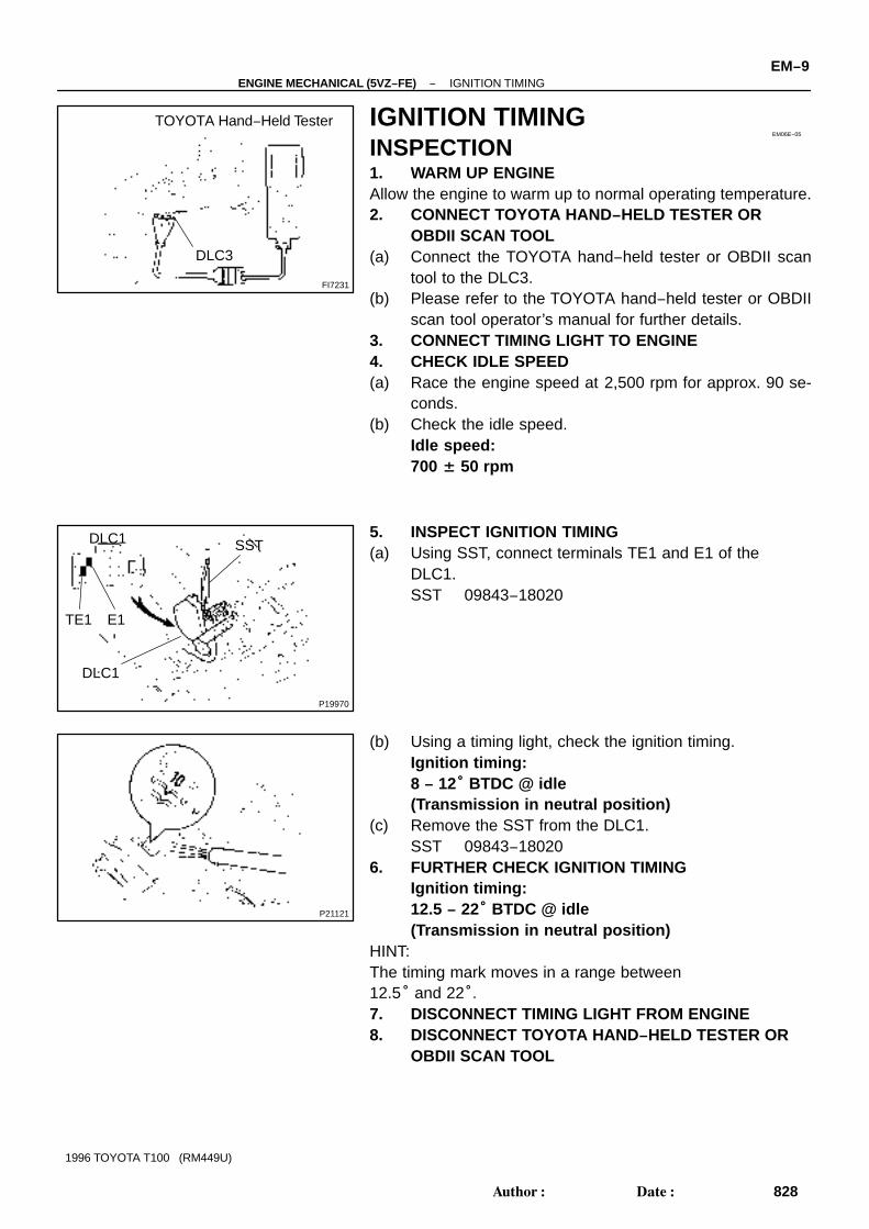
FI7231
TOYOTA Hand−Held Tester
DLC3
EM06E−05
P19970
SSTDLC1
TE1 E1
DLC1
P21121
−ENGINE MECHANICAL (5VZ−FE) IGNITION TIMINGEM−9
828Author�: Date�:
1996 TOYOTA T100 (RM449U)
IGNITION TIMINGINSPECTION1. WARM UP ENGINEAllow the engine to warm up to normal operating temperature.2. CONNECT TOYOTA HAND−HELD TESTER OR
OBDII SCAN TOOL(a) Connect the TOYOTA hand−held tester or OBDII scan
tool to the DLC3.(b) Please refer to the TOYOTA hand−held tester or OBDII
scan tool operator’s manual for further details.3. CONNECT TIMING LIGHT TO ENGINE4. CHECK IDLE SPEED(a) Race the engine speed at 2,500 rpm for approx. 90 se-
conds.(b) Check the idle speed.
Idle speed:700 ± 50 rpm
5. INSPECT IGNITION TIMING(a) Using SST, connect terminals TE1 and E1 of the
DLC1.SST 09843−18020
(b) Using a timing light, check the ignition timing.Ignition timing:8 − 12° BTDC @ idle(Transmission in neutral position)
(c) Remove the SST from the DLC1.SST 09843−18020
6. FURTHER CHECK IGNITION TIMINGIgnition timing:12.5 − 22° BTDC @ idle(Transmission in neutral position)
HINT:The timing mark moves in a range between12.5° and 22°.7. DISCONNECT TIMING LIGHT FROM ENGINE8. DISCONNECT TOYOTA HAND−HELD TESTER OR
OBDII SCAN TOOL
https://www.truck-manuals.net/

EM06F−01
EM−10−ENGINE MECHANICAL (5VZ−FE) IDLE SPEED
829Author�: Date�:
1996 TOYOTA T100 (RM449U)
IDLE SPEEDINSPECTION1. INITIAL CONDITIONS(a) Engine at normal operating temperature(b) Air cleaner installed(c) All pipes and hoses of air induction system connected(d) All accessories switched OFF(e) All vacuum lines properly connectedHINT:w/ EGR: All vacuum hoses for EGR system, etc. should beproperly connected.(f) SFI system wiring connectors fully plugged(g) Ignition timing check correctly(h) Transmission in neutral position2. CONNECT TOYOTA HAND−HELD TESTER OR OBD II
SCAN TOOL (See page EM−9)3. INSPECT IDLE SPEED(a) Race the engine speed at 2,500 rpm for approx. 90 se-
conds.(b) Check the idle speed.
Idle speed:700 ± 50 rpm
If the idle speed is not as specified, check the IAC valve and airintake system.4. DISCONNECT TOYOTA HAND−HELD TESTER OR
OBD II SCAN TOOL
https://www.truck-manuals.net/

EM06G−03
P20840
−ENGINE MECHANICAL (5VZ−FE) TIMING BELTEM−11
830Author�: Date�:
1996 TOYOTA T100 (RM449U)
TIMING BELTCOMPONENTS
https://www.truck-manuals.net/

EM−12−ENGINE MECHANICAL (5VZ−FE) TIMING BELT
831Author�: Date�:
1996 TOYOTA T100 (RM449U)
https://www.truck-manuals.net/

EM1OO−01
P20830
−ENGINE MECHANICAL (5VZ−FE) TIMING BELTEM−13
1996 TOYOTA T100 (RM449U)
REMOVAL1. 4WD:
REMOVE ENGINE UNDER COVER2. DRAIN ENGINE COOLANT3. DISCONNECT UPPER RADIATOR HOSE4. REMOVE DRIVE BELT FOR PS PUMP5. w/ A/C:
REMOVE DRIVE BELT FOR A/C COMPRESSOR6. REMOVE DRIVE BELT FOR GENERATOR7. REMOVE NO. 2 FAN SHROUD8. REMOVE FAN WITH FLUID COUPLING AND FAN PUL-
LEYS9. DISCONNECT PS PUMP FROM ENGINEHINT:Put aside the pump, and suspend it.10. w/ A/C:
DISCONNECT A/C COMPRESSOR FROM ENGINEHINT:Put aside the compressor, and suspend it.11. w/ A/C:
REMOVE A/C COMPRESSOR BRACKET
12. REMOVE NO.2 TIMING BELT COVER(a) Disconnect the camshaft position sensor connector from
the No.2 timing belt cover.(b) Disconnect the 3 high−tension cord clamps from the No.2
timing belt cover.(c) Remove the 6 bolts, and timing belt cover.
13. REMOVE FAN BRACKET(a) Remove the nut and PS pump adjusting strut.(b) Remove the bolt, nut, and fan bracket.
https://www.truck-manuals.net/

P20829
P20826
P20818
P20831
P20833
EM−14−ENGINE MECHANICAL (5VZ−FE) TIMING BELT
1996 TOYOTA T100 (RM449U)
14. SET NO.1 CYLINDER AT TDC/COMPRESSION(a) Turn the crankshaft pulley and align its groove with timing
mark ”0” of the No.1 timing belt cover.(b) Check that the timing marks of the camshaft timing pul-
leys and No.3 timing belt cover are aligned.If not, turn the crankshaft pulley 1 revolution (360°).
HINT:When re−using timing belt: Place the matchmarks on the timingbelt and camshaft timing pulleys, and place matchmark on tim-ing belt to match the end of the No.1 timing belt cover.
15. REMOVE TIMING BELT TENSIONERAlternately loosen the 2 bolts, and remove them, the belt ten-sioner and dust boot.
16. REMOVE RH CAMSHAFT TIMING PULLEY WITH TIM-ING BELT
(a) Using SST, loosen the pulley bolt.SST 09960−10010 (09962−01000, 09963−01000)
(b) Remove the bolt, knock pin and camshaft timing pulleywith timing belt.
https://www.truck-manuals.net/

P20825
P20516
SST
SST
P20515
SST
P20500
P20499
−ENGINE MECHANICAL (5VZ−FE) TIMING BELTEM−15
1996 TOYOTA T100 (RM449U)
17. REMOVE LH CAMSHAFT TIMING PULLEY(a) Using SST, loosen the pulley bolt.
SST 09960−10010 (09962−01000, 09963−01000)(b) Remove the bolt, knock pin and camshaft timing pulley.
18. REMOVE CRANKSHAFT PULLEY(a) Using SST, loosen the pulley bolt.
SST 09213−54015 (90119−08216), 09330−00021
(b) Remove the SST, pulley bolt and pulley.
HINT:If necessary, remove the pulley with SST and service bolt.
SST 09950−50010 (09551−05010, 09552−05010,09553−05020, 09554−05030)
19. REMOVE STARTER WIRE BRACKET AND NO.1 TIM-ING BELT COVER
(a) Remove the 2 bolts, starter wire bracket.(b) Remove the 4 bolts, timing belt cover.20. REMOVE TIMING BELT GUIDE
21. REMOVE TIMING BELTHINT:When re−using timing belt: If the installation marks have disap-peared, place a new installation mark on the timing belt tomatch the drilled mark of the crankshaft timing pulley.22. REMOVE NO.2 IDLER PULLEY AND NO.1 IDLER
PULLEY(a) Remove the bolt and No.2 idler pulley.(b) Using a 10 mm hexagon wrench, remove the pivot bolt,
No.1 idler pulley and plate washer.
https://www.truck-manuals.net/

P20816
SST
EM−16−ENGINE MECHANICAL (5VZ−FE) TIMING BELT
1996 TOYOTA T100 (RM449U)
23. REMOVE CRANKSHAFT TIMING PULLEYRemove crankshaft timing pulley.HINT:If the pulley cannot be removed by hand, use SST and servicebolt to remove the crankshaft timing pulley.
SST 09950−50010 (09951−05010, 09952−05010,09953−05020, 09954−05010)
https://www.truck-manuals.net/

EM06I−06
A01568
No!
OIL
P20043
P12604
−ENGINE MECHANICAL (5VZ−FE) TIMING BELTEM−17
1996 TOYOTA T100 (RM449U)
INSPECTION1. INSPECT TIMING BELTNOTICE:Do not bend, twist or turn the timing belt inside out.Do notallow the timing belt to come into contact with oil, water orsteam. Do not utilize timing belt tension when installing orremoving the mount bolt of the camshaft timing pulley.If there are any defects, as shown in the illustrations, checkthese points:(a) Premature parting
� Check for proper installation.� Check the timing cover gasket for damage and
proper installation.(b) If the belt teeth are cracked or damaged, check to see if
either camshaft is locked.(c) If there is noticeable wear or cracks on the belt face,
check to see if there are nicks on the side of the idlerpulley lock and water pump.
(d) If there is wear or damage on only one side of the belt,check the belt guide and the alignment of each pulley.
(e) If there is noticeable wear on the belt teeth, check timingcover for damage and check gasket has been installedcorrectly and for foreign material on the pulley teeth.
If necessary, replace the timing belt.
2. INSPECT IDLER PULLEYS(a) Visually check the seal portion of the idler pulley for oil
leakage.If leakage is found, replace the idler pulley.
(b) Check that the idler pulley turns smoothly.If necessary, replace the idler pulley.
https://www.truck-manuals.net/

P18782
P18764
P18770
Protrusion
EM−18−ENGINE MECHANICAL (5VZ−FE) TIMING BELT
1996 TOYOTA T100 (RM449U)
3. INSPECT TIMING BELT TENSIONER(a) Visually check the seal portion of the tensioner for oil leak-
age.HINT:If there is only the faintest trace of oil on the seal on the pushrod side, the tensioner is all right.If leakage is found, replace the tensioner.
(b) Hold the tensioner with both hands and push the push rodstrongly as shown to check that it doesn’t move.
If the push rod moves, replace the tensioner.NOTICE:Never hold the tensioner push rod facing downward.
(c) Measure the protrusion of the push rod from the housingend.Protrusion:10.0 − 10.8 mm (0.394 − 0.425 in.)
If the protrusion is not as specified, replace the tensioner.
https://www.truck-manuals.net/

P20822
Inward
Sensor
EM06J−03
P20821
P20499
P20823
Front
−ENGINE MECHANICAL (5VZ−FE) TIMING BELTEM−19
1996 TOYOTA T100 (RM449U)
INSTALLATION1. INSTALL CRANKSHAFT TIMING PULLEY(a) Align the pulley set key with the key groove of the timing
pulley and slide on the timing pulley.(b) Slide on the timing pulley, facing the flange side inward.
2. INSTALL NO. 1 IDLER PULLEY AND NO.2 IDLERPULLEY
(a) Using a 10 mm hexagon wrench, install the No.1 idlerpulley with the plate washer and bolt.Torque: 35 N·m (350 kgf·cm, 26 ft·lbf)
(b) Check that the pulley bracket moves smoothly.(c) Install the No.2 idler pulley with the bolt.
Torque: 40 N·m (400 kgf·cm, 30 ft·lbf)(d) Check that the pulley moves smoothly.
3. TEMPORARILY INSTALL TIMING BELTNOTICE:The engine should be cold.(a) Use the crankshaft pulley bolt to turn the crankshaft and
align the timing marks on the crankshaft timing pulley andon the oil pump body.
(b) Remove any oil or water on the crankshaft timing pulley,idler pulley and water pump pulley, and keep them clean.
NOTICE:Only wipe the pulleys; do not use any cleansing agent.(c) Align the installation mark on the timing belt with the
drilled mark of the crankshaft timing pulley.(d) Install the timing belt on the crankshaft timing pulley, No.1
idler and water pump pulleys.
4. INSTALL TIMING BELT GUIDEInstall the guide, facing the cup side outward.
https://www.truck-manuals.net/
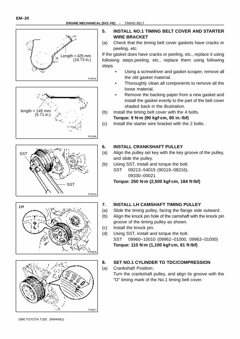
P20918
Length = 425 mm(16.73 in.)
P21686
length = 145 mm(5.71 in.)
P20516
SST
SST
P20828
P20827
EM−20−ENGINE MECHANICAL (5VZ−FE) TIMING BELT
1996 TOYOTA T100 (RM449U)
5. INSTALL NO.1 TIMING BELT COVER AND STARTERWIRE BRACKET
(a) Check that the timing belt cover gaskets have cracks orpeeling, etc.
If the gasket does have cracks or peeling, etc., replace it usingfollowing steps.peeling, etc., replace them using followingsteps.
� Using a screwdriver and gasket scraper, remove allthe old gasket material.
� Thoroughly clean all components to remove all theloose material.
� Remove the backing paper from a new gasket andinstall the gasket evenly to the part of the belt covershaded back in the illustration.
(b) Install the timing belt cover with the 4 bolts.Torque: 9 N·m (90 kgf·cm, 80 in.·lbf)
(c) Install the starter wire bracket with the 2 bolts.
6. INSTALL CRANKSHAFT PULLEY(a) Align the pulley set key with the key groove of the pulley,
and slide the pulley.(b) Using SST, install and torque the bolt.
SST 09213−54015 (90119−08216),09330−00021
Torque: 250 N·m (2,500 kgf·cm, 184 ft·lbf)
7. INSTALL LH CAMSHAFT TIMING PULLEY(a) Slide the timing pulley, facing the flange side outward.(b) Align the knock pin hole of the camshaft with the knock pin
groove of the timing pulley as shown.(c) Install the knock pin.(d) Using SST, install and torque the bolt.
SST 09960−10010 (09962−01000, 09963−01000)Torque: 110 N·m (1,100 kgf·cm, 81 ft·lbf)
8. SET NO.1 CYLINDER TO TDC/COMPRESSION(a) Crankshaft Position:
Turn the crankshaft pulley, and align its groove with the”O” timing mark of the No.1 timing belt cover.
https://www.truck-manuals.net/

P20820
P20826
P20834
P20836
−ENGINE MECHANICAL (5VZ−FE) TIMING BELTEM−21
1996 TOYOTA T100 (RM449U)
(b) RH Camshaft Position:Turn the camshaft, align the knock pin hole of the cam-shaft with the timing mark of the No.3 timing belt cover.
(c) LH Camshaft Pulley Position: Turn the camshaft timing pulley, align the timing marks ofthe camshaft timing pulley and No.3 timing belt cover.
9. INSTALL TIMING BELT TO LH CAMSHAFT TIMINGPULLEY
(a) HINT (When re−using timing belt):Check that the installation mark on the timing beltmatches the end of the No.1 timing belt cover.
If the installation mark do not align, shift the meshing of the tim-ing belt and crankshaft timing pulley until they align.
(b) Remove any oil or water on the LH camshaft timing pulley,and keep it clean.
(c) Using SST, slightly turn the LH camshaft timing pulleyclockwise. Align the installation mark on the timing beltwith the timing mark of the camshaft timing pulley, andhang the timing belt on the LH camshaft timing pulley.SST 09960−10010 (09962−01000, 09963−01000)
(d) Using SST, align the timing marks of the LH camshaftpulley and No.3 timing belt cover.SST 09960−10010 (09962−01000, 09963−01000)
(e) Check that the timing belt has tension between the crank-shaft timing and LH camshaft timing pulleys.
https://www.truck-manuals.net/

P20839
P20832
P08325
P10221
EM−22−ENGINE MECHANICAL (5VZ−FE) TIMING BELT
1996 TOYOTA T100 (RM449U)
10. INSTALL RH CAMSHAFT TIMING PULLEY AND TIM-ING BELT
(a) Remove any oil or water on the RH camshaft timing andNo.2 idler pulleys, and keep them clean.
(b) Align the installation mark on the timing belt with the tim-ing mark of the RH camshaft timing pulley as shown.
(c) Hang the timing belt on the RH camshaft timing pulley.(d) Align the timing marks of the RH camshaft timing pulley
and No.3 timing belt cover.(e) Slide the RH camshaft timing pulley on the camshaft.
(f) Using SST, align the knock pin hole of the camshaft withthe knock pin groove marked R of the pulley and install theknock pin.SST 09960−10010 (09962−01000, 09963−01000)
(g) Using SST, install and torque the bolt.SST 09960−10010 (09962−01000, 09963−01000)Torque: 110 N·m (1,100 kgf·cm, 81 ft·lbf)
11. SET TIMING BELT TENSIONER(a) Using a press, slowly press in the push rod using 100 −
1,000 kg (220 − 2,205 lb, 981 − 9,807 N) of pressure.(b) Align the holes of the push rod and housing, pass a 1.5
mm hexagon wrench through the holes to keep the set-ting position of the push rod.
(c) Release the press.
(d) Install the dust boot to the tensioner.
https://www.truck-manuals.net/

P20817
P20819
P20830
P20837
Length = 955 mm (37.60 in.)
Length = 270 mm (10.63 in.)
−ENGINE MECHANICAL (5VZ−FE) TIMING BELTEM−23
1996 TOYOTA T100 (RM449U)
12. INSTALL TIMING BELT TENSIONER(a) Install the tensioner with the 2 bolts.
Torque: 27 N·m (270 kgf·cm, 20 ft·lbf)(b) Remove the 1.5 mm hexagon wrench from the tensioner.
13. CHECK VALVE TIMING(a) Turn the crankshaft pulley 2 revolutions from TDC to TDC.HINT:Always turn the crankshaft clockwise.(b) Check that each pulley aligns with the timing marks as
shown in the illustration.If the marks do not align, remove the timing belt and reinstall it.
14. INSTALL FAN BRACKET(a) Install the fan bracket with the bolt and nut.(b) Install the PS pump adjusting strut with the nut.
15. INSTALL NO.2 TIMING BELT COVER(a) Check that the timing belt cover gasket has no cracks or
peeling, etc.If the gasket does have cracks or peeling, etc., replace it usingfollowing steps.
� Using a screwdriver and gasket scraper, remove allthe old gasket material.
� Thoroughly clean all components to remove all theloose material.
� Remove the backing paper from a new gasket andinstall the gasket evenly to the part of the belt covershaded black in the illustration.
(b) Install the belt cover with the 6 bolts.Torque: 9 N·m (90 kgf·cm, 80 in.·lbf)
(c) Connect the 3 high−tension cord clamps to the No.2 tim-ing belt cover.
(d) Connect the camshaft position sensor connector to theNo.2 timing belt cover.
https://www.truck-manuals.net/
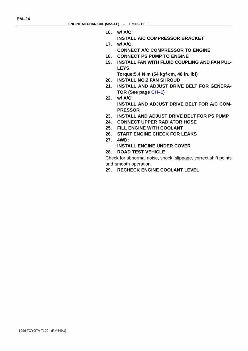
EM−24−ENGINE MECHANICAL (5VZ−FE) TIMING BELT
1996 TOYOTA T100 (RM449U)
16. w/ A/C:INSTALL A/C COMPRESSOR BRACKET
17. w/ A/C:CONNECT A/C COMPRESSOR TO ENGINE
18. CONNECT PS PUMP TO ENGINE19. INSTALL FAN WITH FLUID COUPLING AND FAN PUL-
LEYSTorque:5.4 N·m (54 kgf·cm, 48 in.·lbf)
20. INSTALL NO.2 FAN SHROUD21. INSTALL AND ADJUST DRIVE BELT FOR GENERA-
TOR (See page CH−1)22. w/ A/C:
INSTALL AND ADJUST DRIVE BELT FOR A/C COM-PRESSOR
23. INSTALL AND ADJUST DRIVE BELT FOR PS PUMP24. CONNECT UPPER RADIATOR HOSE25. FILL ENGINE WITH COOLANT26. START ENGINE CHECK FOR LEAKS27. 4WD:
INSTALL ENGINE UNDER COVER28. ROAD TEST VEHICLECheck for abnormal noise, shock, slippage, correct shift pointsand smooth operation.29. RECHECK ENGINE COOLANT LEVEL
https://www.truck-manuals.net/
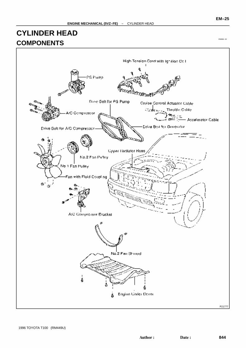
EM06K−02
P21777
−ENGINE MECHANICAL (5VZ−FE) CYLINDER HEADEM−25
844Author�: Date�:
1996 TOYOTA T100 (RM449U)
CYLINDER HEADCOMPONENTS
https://www.truck-manuals.net/

Z18898
EM−26−ENGINE MECHANICAL (5VZ−FE) CYLINDER HEAD
845Author�: Date�:
1996 TOYOTA T100 (RM449U)
https://www.truck-manuals.net/

−ENGINE MECHANICAL (5VZ−FE) CYLINDER HEADEM−27
846Author�: Date�:
1996 TOYOTA T100 (RM449U)
https://www.truck-manuals.net/

S05153
EM−28−ENGINE MECHANICAL (5VZ−FE) CYLINDER HEAD
847Author�: Date�:
1996 TOYOTA T100 (RM449U)
https://www.truck-manuals.net/

Z18899
−ENGINE MECHANICAL (5VZ−FE) CYLINDER HEADEM−29
848Author�: Date�:
1996 TOYOTA T100 (RM449U)
https://www.truck-manuals.net/

EM1OP−01
EM−30−ENGINE MECHANICAL (5VZ−FE) CYLINDER HEAD
1996 TOYOTA T100 (RM449U)
REMOVAL1. 4WD:
REMOVE ENGINE UNDER COVER2. DRAIN ENGINE COOLANT3. REMOVE FRONT EXHAUST PIPE (See page EM−108)4. REMOVE AIR CLEANER CAP, MAF METER AND RES-
ONATOR5. DISCONNECT THESE CABLES:(a) w/ Cruise control:
Cruise control actuator cable(b) Accelerator cable(c) A/T:
Throttle cable6. DISCONNECT HEATER HOSE7. DISCONNECT UPPER RADIATOR HOSE8. REMOVE DRIVE BELT FOR PS PUMP(a) Stretch the belt and loosen the fan pulley mounting nuts.9. w/ A/C:
REMOVE DRIVE BELT FOR A/C COMPRESSOR10. REMOVE DRIVE BELT FOR GENERATOR11. REMOVE NO. 2 FAN SHROUD12. REMOVE FAN WITH FLUID COUPLING AND FAN PUL-
LEYS13. DISCONNECT PS PUMP FROM ENGINEHINT:Put aside the pump, and suspend it.14. w/ A/C:
DISCONNECT A/C COMPRESSOR FROM ENGINEHINT:Put aside the compressor, and suspend it.15. w/ A/C:
REMOVE A/C COMPRESSOR BRACKET16. REMOVE HIGH−TENSION CORDS WITH IGNITION
COILS17. REMOVE SPARK PLUGS18. REMOVE TIMING BELT AND CAMSHAFT TIMING
PULLEYS (See page EM−13)19. REMOVE TIMING BELT IDLER NO. 2 (See page
EM−13)20. REMOVE GENERATOR
https://www.truck-manuals.net/

S05155
−ENGINE MECHANICAL (5VZ−FE) CYLINDER HEADEM−31
1996 TOYOTA T100 (RM449U)
21. w/ EGR:REMOVE EGR PIPE
Remove the 6 nuts, EGR pipe and 2 gaskets.22. REMOVE INTAKE CHAMBER STAY(a) A/T:
Remove the bolt, 2 nuts, oil filler tube and No.1 throttlecable clamp.
(b) Remove the 2 bolts and intake chamber stay.
23. REMOVE AIR INTAKE CHAMBER ASSEMBLY(a) Disconnect these connectors:
� VSV connector for fuel pressure control� Throttle position sensor connector� IAC valve connector� w/ EGR:
EGR gas temperature sensor connector� VSV connector for EGR
(b) Disconnect these hoses:(1) 2 PCV hoses(2) 2 water bypass hoses(3) Air assist hose from throttle body(4) 2 Vacuum sensing hoses from VSV� w/ A/C
Air hose from A/C idle−up valve(5) EVAP hose(6) Air hose from PS pump
(c) Remove the 4 bolts, 2 nuts, the air intake chamber as-sembly and gasket.
24. REMOVE INTAKE AIR CONNECTOR(a) Remove the bolt, and disconnect the engine wire.(b) Disconnect the 2 fuel return hoses.(c) Disconnect the brake booster vacuum hose from the in-
take air connector.(d) Remove the bolt, and disconnect the ground strap from
the intake air connector.(e) Disconnect the DLC1 from the bracket.(f) w/ A/C
Disconnect the A/C idle−up valve connector.(g) Remove the 3 bolts, 2 nuts, intake air connector and gas-
ket.
https://www.truck-manuals.net/

P21245
P21193
P21192
P21195
EM−32−ENGINE MECHANICAL (5VZ−FE) CYLINDER HEAD
1996 TOYOTA T100 (RM449U)
25. DISCONNECT ENGINE WIRE(a) Disconnect these connectors:
� Oil pressure sensor connector� Crankshaft position sensor connector� 6 Injector connectors� ECT sender gauge connector� ECT sensor connector� Knock sensor connector� Camshaft position sensor connector
(b) Disconnect the 3 engine wire clamps.(c) Remove the 3 bolts, and disconnect the engine wire from
the cylinder head.
26. REMOVE CAMSHAFT POSITION SENSOR27. REMOVE NO.3 TIMING BELT COVERRemove the 6 bolts and timing belt cover.28. REMOVE FUEL PRESSURE REGULATOR
29. REMOVE INTAKE MANIFOLD ASSEMBLY(a) Disconnect the fuel inlet hose.(b) Remove the 2 bolts and the intake manifold stay.(c) Remove the 8 bolts, 4 nuts, 4 plate washers, intake man-
ifold, delivery pipes and injectors assembly and 2 gas-kets.
30. REMOVE PS PUMP BRACKET31. REMOVE OIL DIPSTICK AND GUIDE(a) Remove the 2 bolts holding the dipstick guide to the gen-
erator bracket.(b) Pull out the dipstick guide together with the dipstick from
the oil pan.(c) Remove the O−ring from the dipstick guide.32. REMOVE GENERATOR BRACKET33. REMOVE EXHAUST CROSSOVER PIPERemove the 6 nuts, crossover pipe and 2 gaskets.34. REMOVE LH AND RH EXHAUST MANIFOLDS(a) Remove the 6 nuts and exhaust manifold heat insulators.(b) Remove the 12 nuts, LH, RH exhaust manifolds and gas-
ket.
https://www.truck-manuals.net/

P21141
P00867
P21146
P21145
−ENGINE MECHANICAL (5VZ−FE) CYLINDER HEADEM−33
1996 TOYOTA T100 (RM449U)
35. REMOVE CYLINDER HEAD COVERSRemove the 8 bolts, seal washers, cylinder head cover andgasket. Remove the 2 cylinder head covers.36. REMOVE SEMI−CIRCULAR PLUGS37. Exhaust:
REMOVE CAMSHAFTS OF RH CYLINDER HEADNOTICE:Since the thrust clearance of the camshaft is small, thecamshaft must be held level while it is being removed. If thecamshaft is not kept level, the portion of the cylinder headreceiving the shaft thrust may crack or be damaged, caus-ing the camshaft to seize or break. To avoid this, thesesteps should be carried out.(a) Align the timing marks (2 dot marks) of the camshaft drive
and driven gears by turning the camshaft with a wrench.(b) Secure the exhaust camshaft sub−gear to the main gear
with a service bolt.Recommended service bolt:Thread diameter 6 mmThread pitch 1.0 mmBolt length 16 − 20 mm
HINT:When removing the camshaft, mark certain that the torsionalspring force of the sub−gear has been eliminated by the aboveoperation.
(c) Uniformly loosen and remove the 8 bearing cap bolts, inseveral passes, in the sequence shown.
(d) Remove the 4 bearing caps and exhaust camshaft.
38. Intake:REMOVE CAMSHAFTS OF RH CYLINDER HEAD
(a) Uniformly loosen and remove the 10 bearing cap bolts, inseveral passes, in the sequence shown.
(b) Remove the 5 bearing caps, oil seal and intake camshaft.
https://www.truck-manuals.net/

P21160
P00897
P21144
P21143
EM−34−ENGINE MECHANICAL (5VZ−FE) CYLINDER HEAD
1996 TOYOTA T100 (RM449U)
39. Exhaust:REMOVE CAMSHAFTS OF LH CYLINDER HEAD
NOTICE:Since the thrust clearance of the camshaft is small, thecamshaft must be held level while it is being removed. If thecamshaft is not kept level, the portion of the cylinder headreceiving the shaft thrust may crack or be damaged, caus-ing the camshaft to seize or break. To avoid this, thesesteps should be carried out.
(a) Align the timing marks (1 dot mark) of the camshaft driveand driven gears by turning the camshaft with a wrench.
(b) Secure the exhaust camshaft sub−gear to the main gearwith a service bolt.Recommended service bolt:Thread diameter 6 mmThread pitch 1.0 mmBolt length 16 − 20 mm
HINT:When removing the camshaft, make sure that the torsionalspring force of the sub−gear has been eliminated by the aboveoperation.
(c) Uniformly loosen and remove the 8 bearing cap bolts, inseveral passes, in the sequence shown.
(d) Remove the 4 bearing caps and exhaust camshaft.
40. Intake:REMOVE CAMSHAFTS OF LH CYLINDER HEAD
(a) Uniformly loosen and remove the 10 bearing cap bolts, inseveral passes, in the sequence shown.
(b) Remove the 5 bearing caps, oil seal and intake camshaft.HINT:� Arrange the camshafts in the correct order.� Arrange the bearing caps in the correct order.
https://www.truck-manuals.net/

P24268
P21037
Z13745
8 mm Hexagon
Front
Recessed Head Bolt
Wrench
−ENGINE MECHANICAL (5VZ−FE) CYLINDER HEADEM−35
1996 TOYOTA T100 (RM449U)
41. DISASSEMBLE EXHAUST CAMSHAFTS(a) Mount the hexagonal wrench head portion of the cam-
shaft in a vise.NOTICE:Be careful not to damage the camshaft.(b) Using SST, turn the sub−gear clockwise, and remove the
service bolt.SST 09960−10010 (09962−01000, 09963−00600)
(c) Using snap ring pliers, remove the snap ring.(d) Remove these parts:
� Wave washer� Camshaft sub−gear� Camshaft gear spring
HINT:Arrange the camshaft sub−gears and gear springs (RH and LHside).
42. REMOVE CYLINDER HEADS(a) Remove the bolt, and disconnect the ground strap.(b) Using an 8 mm hexagon wrench, remove the cylinder
head (recessed head) bolt on each cylinder head, then re-peat for the other side, as shown.
https://www.truck-manuals.net/

Z14651
12 Pointed Head Bolt
Front
P00828
EM−36−ENGINE MECHANICAL (5VZ−FE) CYLINDER HEAD
1996 TOYOTA T100 (RM449U)
(c) Uniformly loosen and remove the 8 cylinder head (12pointed head) bolts on each cylinder head, in severalpasses, in the sequence shown, then repeat for the otherside, as shown. Remove the 16 cylinder head bolts andplate washers.
NOTICE:Head warpage or cracking could result from removingbolts in an incorrect order.
(d) Lift the cylinder head from the dowels on the cylinderblock and place the 2 cylinder heads on wooden blockson a bench.
HINT:� If the cylinder head is difficult to lift off, pry between the cyl-
inder head and cylinder block with a screwdriver.� Arrange the cylinder heads in the correct order.
NOTICE:Be careful not to damage the contact surfaces of the cylin-der head and cylinder block.
https://www.truck-manuals.net/

P20845
EM06M−03
P20847
SST
P20988
P20841
Magnetic Finger
−ENGINE MECHANICAL (5VZ−FE) CYLINDER HEADEM−37
1996 TOYOTA T100 (RM449U)
DISASSEMBLY1. REMOVE CAMSHAFT HOUSING PLUGS(a) Remove the bolt, nut, cylinder head rear plate and ground
strap.(b) Remove the 2 bolts and camshaft bearing cap.(c) Remove the housing plug.2. REMOVE VALVE LIFTERS AND SHIMSPull out the valve lifter and shim by hand.HINT:Arrange the valve lifters and shims in correct order.
3. REMOVE VALVES(a) Using SST, compress the valve spring and remove the 2
keepers.SST 09202−70020 (09202−00010)
(b) Remove these parts:� Spring retainer� Valve spring� Valve
(c) Using needle−nose pliers, remove the oil seal.
(d) Using compressed air and a magnetic finger, remove thespring seat by blowing air.
HINT:Arrange the valves, valve springs, spring seats and spring re-tainers in the correct order.
https://www.truck-manuals.net/

P20505
EM1OQ−01
P20504
P20503
P20512
P20986
EM−38−ENGINE MECHANICAL (5VZ−FE) CYLINDER HEAD
1996 TOYOTA T100 (RM449U)
INSPECTION1. CLEAN TOP SURFACES OF PISTONS AND
CYLINDER BLOCK(a) Turn the crankshaft and bring each piston to top dead
center (TDC). Using a gasket scraper, remove all the car-bon from the piston top surfaces.
(b) Using a gasket scraper, remove all the gasket materialfrom the cylinder block surfaces.
(c) Using compressed air, blow carbon and oil from the boltholes.
CAUTION:Protect your eyes when using high−compressed air.
2. REMOVE GASKET MATERIALUsing a gasket scraper, remove all the gasket material from thecylinder block contact surface.NOTICE:Be careful not to scratch the cylinder block contact sur-faces.
3. CLEAN COMBUSTION CHAMBERSUsing a wire brush, remove all the carbon from the combustionchambers.NOTICE:Be careful not to scratch the cylinder block contact sur-faces.
4. CLEAN VALVE GUIDE BUSHINGSUsing a valve guide bushing brush and solvent, clean all theguide bushings.
https://www.truck-manuals.net/

P20506
Z14652
P20514
EM0580
−ENGINE MECHANICAL (5VZ−FE) CYLINDER HEADEM−39
1996 TOYOTA T100 (RM449U)
5. CLEAN CYLINDER HEADSUsing a soft brush and solvent, thoroughly clean the cylinderheads.
6. INSPECT FOR FLATNESSUsing precision straight edge and feeler gauge, measure thesurfaces contacting the cylinder block and manifolds for war-page.
Maximum warpage:0.10 mm (0.0039 in.)
If warpage is greater than maximum, replace the cylinder head.
7. INSPECT FOR CRACKSUsing a dye penetrant, check the combustion chamber, intakeports, exhaust ports and cylinder block surface for cracks.If cracked, replace the cylinder head.
8. CLEAN VALVES(a) Using a gasket scraper, chip off any carbon from the valve
head.(b) Using a wire brush, thoroughly clean the valve.
https://www.truck-manuals.net/
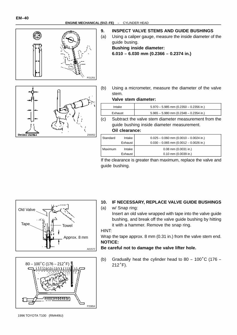
P21251
Z00052
A01572
Old Valve
Approx. 8 mm
TowelTape
P20854
80 − 100°C (176 − 212°F)
EM−40−ENGINE MECHANICAL (5VZ−FE) CYLINDER HEAD
1996 TOYOTA T100 (RM449U)
9. INSPECT VALVE STEMS AND GUIDE BUSHINGS(a) Using a caliper gauge, measure the inside diameter of the
guide busing.Bushing inside diameter:6.010 − 6.030 mm (0.2366 − 0.2374 in.)
(b) Using a micrometer, measure the diameter of the valvestem.Valve stem diameter:
Intake 5.970 − 5.985 mm (0.2350 − 0.2356 in.)
Exhaust 5.965 − 5.980 mm (0.2348 − 0.2354 in.)
(c) Subtract the valve stem diameter measurement from theguide bushing inside diameter measurement.Oil clearance:
Standard Intake
Exhaust
0.025 − 0.060 mm (0.0010 − 0.0024 in.)
0.030 − 0.065 mm (0.0012 − 0.0026 in.)
Maximum Intake
Exhaust
0.08 mm (0.0031 in.)
0.10 mm (0.0039 in.)
If the clearance is greater than maximum, replace the valve andguide bushing.
10. IF NECESSARY, REPLACE VALVE GUIDE BUSHINGS(a) w/ Snap ring:
Insert an old valve wrapped with tape into the valve guidebushing, and break off the valve guide bushing by hittingit with a hammer. Remove the snap ring.
HINT:Wrap the tape approx. 8 mm (0.31 in.) from the valve stem end.NOTICE:Be careful not to damage the valve lifter hole.
(b) Gradually heat the cylinder head to 80 − 100°C (176 −212°F).
https://www.truck-manuals.net/

P20853
SST
P20510
P20984
Snap Ring
SST
−ENGINE MECHANICAL (5VZ−FE) CYLINDER HEADEM−41
1996 TOYOTA T100 (RM449U)
(c) Using SST and a hammer, tap out the guide bushing.SST 09201−10000 (09201−01060),
09950−70010 (09951−07150)
(d) Using a caliper gauge, measure the bushing bore diame-ter of the cylinder head.
(e) Select a new guide bushing (STD size or O/S 0.05).Both intake and exhaust
Bushing bore diameter mm (in.) Bushing size
10.985 − 11.027 (0.4325 − 0.4341) Use STD
11.050 − 11.077 (0.4350 − 0.4361) Use O/S 0.05
If the bushing bore diameter of the cylinder head is greater than11.027 mm (0.4341 in.), machine the bushing bore to these di-mension:
11.050 − 11.077 mm (0.4350 − 0.4361 in.)If the bushing bore diameter of the cylinder head is greater than11.077 mm (0.4361 in.), replace the cylinder head.
(f) Gradually heat the cylinder head to 80 − 100°C (176 −212°F).
(g) Using SST and a hammer, tap in a new guide bushing un-til the snap ring makes contact with the cylinder head.SST 09201−10000 (09201−01060),
09950−70010 (09951−07150)
https://www.truck-manuals.net/

P20985
Sharp 6 mm Reamer
Z00054
44.5°
EM0181
Margin Thickness
EM2534
Overall Length
EM0255
EM−42−ENGINE MECHANICAL (5VZ−FE) CYLINDER HEAD
1996 TOYOTA T100 (RM449U)
(h) Using a sharp 6 mm reamer, ream the guide bushing toobtain the standard specified clearance (See step 9) be-tween the guide bushing and valve stem.
11. INSPECT AND GRIND VALVES(a) Grind the valve enough to remove pits and carbon.(b) Check that the valve is ground to the correct valve face
angle.Valve face angle: 44.5°
(c) Check the valve head margin thickness.Standard margin thickness:1.0 mm (0.039 in.)Minimum margin thickness:0.5 mm (0.020 in.)
If the margin thickness is less than minimum, replace the valve.
(d) Check the valve overall length.Overall length:
Standard Intake
Exhaust
95.15 mm (3.7461 in.)
94.90 mm (3.7362 in.)
Minimum Intake
Exhaust
94.60 mm (3.7244 in.)
94.40 mm (3.7165 in.)
If the overall length is less than minimum, replace the valve.
(e) Check the surface of the valve stem tip for wear.If the valve stem tip is worn, resurface the tip with a grinder orreplace the valve.NOTICE:Do not grind off more than the minimum.
https://www.truck-manuals.net/

P20511
45° Carvide Cutter
P12729
Width
Z11441
30°45°
1.0 − 1.4 mm
Z00139
60° 45°
1.0 − 1.4 mm
P20513
−ENGINE MECHANICAL (5VZ−FE) CYLINDER HEADEM−43
1996 TOYOTA T100 (RM449U)
12. INSPECT AND CLEAN VALVE SEATS(a) Using a 45° carbide cutter, resurface the valve seats. Re-
move only enough metal to clean the seats.
(b) Check the valve seating position.Apply a thin coat of prussian blue (or white lead) to thevalve face. Lightly press the valve against the seat. Do notrotate the valve.
(c) Check the valve face and seat for these:� If blue appears 360° around the face, the valve is
concentric. If not, replace the valve.� If blue appears 360° around the valve seat, the
guide and face are concentric. If not, resurface theseat.
� Check that the seat contact is in the middle of thevalve face with these width.
1.0 − 1.4 mm (0.039 − 0.055 in.)If not, correct the valve seats as follows:
(1) If the seating is too high on the valve face, use 30°and 45° cutters to correct the seat.
(2) If the seating is too low on the valve face, use 60°and 45° cutters to correct the seat.
(d) Hand−lap the valve and valve seat with an abrasive com-pound.
(e) After hand−lapping, clean the valve and valve seat.
https://www.truck-manuals.net/

EM0988
Deviation
EM0801
EM0281
EM1628
EM2011
EM−44−ENGINE MECHANICAL (5VZ−FE) CYLINDER HEAD
1996 TOYOTA T100 (RM449U)
13. INSPECT VALVE SPRINGS(a) Using a steel square, measure the squareness of the
valve spring.Maximum deviation:2.0 mm (0.079 in.)
If deviation is greater than maximum, replace the valve spring.
(b) Using vernier calipers, measure the free length of thevalve spring.Free length:44.78 mm (1.7630 in.)
If the free length is not as specified, replace the valve spring.
(c) Using a spring tester, measure the tension of the valvespring at the specified installed length.Installed tension:186 − 206 N (19.0 − 21.0 kgf, 41.9 − 46.3 lbf)at 33.3 mm (1.311 in.)
If the installed tension is not as specified, replace the valvespring.
14. INSPECT CAMSHAFT FOR RUNOUT(a) Place the camshaft on V−blocks.(b) Using a dial indicator, measure the circle runout at the
center journal.Maximum circle runout:0.06 mm (0.0024 in.)
If the circle runout is greater than maximum, replace the cam-shaft.
15. INSPECT CAM LOBESUsing a micrometer, measure the cam lobe height.
Cam lobe height:
Standard Intake
Exhaust
42.31 − 42.41 mm (1.6657 − 1.6697 in.)
41.96 − 42.06 mm (1.6520 − 1.6559 in.)
Minimum Intake
Exhaust
42.16 mm (1.6598 in.)
41.81 mm (1.6461 in.)
If the cam lobe height is greater than maximum, replace thecamshaft.
https://www.truck-manuals.net/

EM2538
EM3322
Free Distance
P20858Plastigage
P20852
P20855
−ENGINE MECHANICAL (5VZ−FE) CYLINDER HEADEM−45
1996 TOYOTA T100 (RM449U)
16. INSPECT CAMSHAFT JOURNALSUsing a micrometer, measure the journal diameter.
Journal diameter:26.949 − 26.965 mm (1.0610 − 1.0616 in.)
If the journal diameter is not as specified, check the oil clear-ance.17. INSPECT CAMSHAFT BEARINGSCheck the bearings for flaking and scoring.If the bearings are damaged, replace the bearing caps and cyl-inder head as a set.18. INSPECT CAMSHAFT GEAR SPRINGUsing vernier calipers, measure the free distance between thespring ends.
Free distance:18.2 − 18.8 mm (0.712 − 0.740 in.)
If the free distance is not as specified, replace the gear spring.
19. INSPECT CAMSHAFT JOURNAL OIL CLEARANCE(a) Clean the bearing caps and camshaft journals.(b) Place the camshafts on the cylinder head.(c) Lay a strip of Plastigage across each of the camshaft jour-
nals.(d) Install the bearing caps (See page EM−51).
Torque: 16 N·m (160 kgf·cm, 12 ft·lbf)NOTICE:Do not turn the camshaft.
(e) Remove the bearing caps.(f) Measure the Plastigage at its widest point.
Standard oil clearance: 0.035 − 0.072 mm (0.0014 − 0.0028 in.)Maximum oil clearance:0.10 mm (0.0039 in.)
If the oil clearance is greater than maximum, replace the cam-shaft. If necessary, replace the bearing caps and cylinder headas a set.
(g) Completely remove the plastigage.20. INSPECT CAMSHAFT THRUST CLEARANCE(a) Install the camshafts (See page EM−51).(b) Using a dial indicator, measure the thrust clearance while
moving the camshaft back and forth.Standard thrust clearance:0.033 − 0.080 mm (0.0013 − 0.0031 in.)Maximum thrust clearance:0.12 mm (0.0047 in.)
https://www.truck-manuals.net/
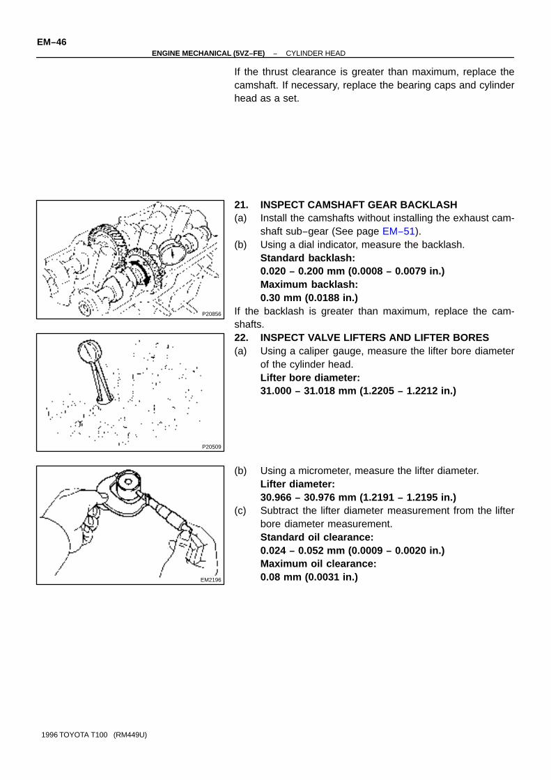
P20856
P20509
EM2196
EM−46−ENGINE MECHANICAL (5VZ−FE) CYLINDER HEAD
1996 TOYOTA T100 (RM449U)
If the thrust clearance is greater than maximum, replace thecamshaft. If necessary, replace the bearing caps and cylinderhead as a set.
21. INSPECT CAMSHAFT GEAR BACKLASH(a) Install the camshafts without installing the exhaust cam-
shaft sub−gear (See page EM−51).(b) Using a dial indicator, measure the backlash.
Standard backlash:0.020 − 0.200 mm (0.0008 − 0.0079 in.)Maximum backlash:0.30 mm (0.0188 in.)
If the backlash is greater than maximum, replace the cam-shafts.22. INSPECT VALVE LIFTERS AND LIFTER BORES(a) Using a caliper gauge, measure the lifter bore diameter
of the cylinder head.Lifter bore diameter:31.000 − 31.018 mm (1.2205 − 1.2212 in.)
(b) Using a micrometer, measure the lifter diameter.Lifter diameter:30.966 − 30.976 mm (1.2191 − 1.2195 in.)
(c) Subtract the lifter diameter measurement from the lifterbore diameter measurement.Standard oil clearance:0.024 − 0.052 mm (0.0009 − 0.0020 in.)Maximum oil clearance:0.08 mm (0.0031 in.)
https://www.truck-manuals.net/

Z14655
Cylinder Head Side
Intake Air Connector Side
Z14656
LH Side
RH Side
P21621
−ENGINE MECHANICAL (5VZ−FE) CYLINDER HEADEM−47
1996 TOYOTA T100 (RM449U)
If the oil clearance is greater than maximum, replace the lifter.If necessary, replace the cylinder head.23. INSPECT INTAKE MANIFOLD, EXHAUST MAN-
IFOLDS, AIR INTAKE CHAMBER AND INTAKE AIRCONNECTOR
(a) Intake Manifold:Using precision straight edge and thickness gauge, mea-sure the surfaces contacting the cylinder head and intakeair connector for warpage.Maximum warpage:0.10 mm (0.0039 in.)
If warpage is greater than maximum, replace the intake man-ifold.
(b) Exhaust Manifolds:Measure the surfaces contacting the cylinder head forwarpage.Maximum warpage:1.00 mm (0.0394 in.)
If warpage is greater than maximum, replace the exhaust man-ifold.
(c) Air Intake Chamber and intake air connector:Measure the surfaces contacting the intake manifold andintake air connector for warpage.Maximum warpage:0.10 mm (0.0039 in.)
If warpage is greater than maximum, replace the air intakechamber or intake air connector.
https://www.truck-manuals.net/

P20843
P20987
P24420
EM−48−ENGINE MECHANICAL (5VZ−FE) CYLINDER HEAD
1996 TOYOTA T100 (RM449U)
24. IF NECESSARY, REPLACE SPARK PLUG TUBE GAS-KETS
(a) Bend up the tab on the ventilation baffle plate which pre-vents the gasket from the slipping out.
(b) Using a screwdriver and hammer, tap out the gasket.NOTICE:Do not scratch or damage the joint of the cylinder head cov-er.
(c) Using needle−nose pliers, pry out the gasket.
(d) Using a 32 mm socket wrench and hammer, tap in a newgasket until its surface is flush with the upper edge of thecylinder head cover.
(e) Apply a light coat of MP grease to the gasket lip.(f) Return the ventilation plate tab to its original position.
https://www.truck-manuals.net/

EM06O−03
P11511
Adhesive
10 − 15 mm (0.39 − 0.59 in.)
P20850
Protrusion
P20842SST
Z09175
Silver Rubber Black Rubber
Plain SurfaceCoated Surface
Intake Exhaust
−ENGINE MECHANICAL (5VZ−FE) CYLINDER HEADEM−49
1996 TOYOTA T100 (RM449U)
REASSEMBLYHINT:� Thoroughly clean all parts to be assembled.� Before installing the parts, apply new engine oil to all slid-
ing and rotating surfaces.� Replace all gaskets and oil seals with new ones.
1. INSTALL SPARK PLUG TUBESHINT:When using a new cylinder head, spark plug tubes must beinstalled.(a) Apply adhesive to the end of the spark plug tube.
Adhesive:Part No. 08833−00070, THREE BOND 1324 or equiva-lent
(b) Using a press, press in a new spark plug tube until thereis 49.0 − 49.4 mm (1.929 − 1.945 in.) protruding from thecamshaft bearing cap installation surface of the cylinderhead.
NOTICE:Avoid pressing a new spark plug tube in too far by measur-ing the amount of the protrusion while pressing.
2. INSTALL VALVES(a) Using SST, push in a new oil seal.
SST 09201−41020
HINT:The intake valve oil seal is silver and the exhaust valve oil sealis black.
https://www.truck-manuals.net/

P20989
P20847
SST
P20848
P12390
Seal Packing
P20844
EM−50−ENGINE MECHANICAL (5VZ−FE) CYLINDER HEAD
1996 TOYOTA T100 (RM449U)
(b) Install these parts:(1) Valve(2) Spring seat(3) Valve spring(4) Spring retainer
(c) Using SST, compress the valve spring and place the 2keepers around the valve stem.SST 09202−70020 (09202−00010)
(d) Using a plastic−faced hammer, lightly tap the valve stemtip to ensure a proper fit.
3. INSTALL VALVE LIFTERS AND SHIMS(a) Install the valve lifter and shim.(b) Check that the valve lifter rotates smoothly by hand.
4. INSTALL CAMSHAFT HOUSING PLUGS(a) Remove any old packing (FIPG) material.(b) Apply seal packing to the bearing cap as shown.
Seal packing:Part No. 08826−00080 or equivalent
(c) Place a new housing plug in position on the cylinder head,facing the cap side inward.
(d) Install the camshaft bearing cap with the 2 bolts.Torque: 16 N·m (160 kgf·cm, 12 ft·lbf)
(e) Install the cylinder head rear plate, ground strap with thebolt and nut.Torque: 8 N·m (80 kgf·cm, 71 in.·lbf)
https://www.truck-manuals.net/

P21247
Front
RH
LH
EM1OR−01
Z14657
12 Pointed Head Bolt
Front
P21151
Painted Mark
Front
P00868
90°90°
90°
90°
Painted Mark
−ENGINE MECHANICAL (5VZ−FE) CYLINDER HEADEM−51
1996 TOYOTA T100 (RM449U)
INSTALLATION1. PLACE CYLINDER HEAD ON CYLINDER BLOCK(a) Place 2 new cylinder head gaskets in position on the cylin-
der block.NOTICE:Be careful of the installation direction.(b) Place the 2 cylinder heads in position on the cylinder head
gaskets.
2. INSTALL 12 POINTED HEAD CYLINDER HEAD BOLTSHINT:� The cylinder head bolts are tightened in 3 progressive
steps (steps (b), (d) and (e)).� If any bolt is broken or deformed, replace it.
(a) Apply a light coat of engine oil on the threads and underthe heads of the cylinder head bolts.
(b) Install and uniformly tighten the cylinder head bolts oneach cylinder head, in several passes, in the sequenceshown, then repeat for the other side, as shown.Torque: 34 N·m (350 kgf·cm, 25 ft·lbf)
If any of the cylinder head bolts does not meet the torque speci-fication, replace the cylinder head bolt.
(c) Mark the front of the cylinder head bolt head with paint.
(d) Retighten the cylinder head bolts by 90° in the numericalorder shown.
(e) Retighten the cylinder head bolts by an additional 90°.(f) Check that the painted mark is now facing rearward.
https://www.truck-manuals.net/

Z14658
Recessed Head Bolt
8 mm Hexagon Wrench
Front
P21041
P21037
EM−52−ENGINE MECHANICAL (5VZ−FE) CYLINDER HEAD
1996 TOYOTA T100 (RM449U)
3. INSTALL RECESSED HEAD CYLINDER HEAD BOLTS(a) Apply a light coat of engine oil on the threads and under
the heads of the cylinder head bolts.(b) Using an 8 mm hexagon wrench, install the cylinder head
bolt on each cylinder head, then repeat for the other side,as shown.Torque: 18 N·m (185 kgf·cm, 13 ft·lbf)
4. CONNECT GROUND STRAPInstall the bolt, and connect the ground strap.
5. ASSEMBLE EXHAUST CAMSHAFTS(a) Mount the hexagonal wrench head portion of the cam-
shaft in a vise.NOTICE:Be careful not to damage the camshaft.(b) Install these parts:
(1) Camshaft gear spring(2) Camshaft sub−gear
HINT:Attach the pins on the gears to the gear spring ends.
(3) Wave washer
(c) Using snap ring pliers, install the snap ring.
https://www.truck-manuals.net/

P21040
SST
Turn
Z17650
RH
90°
P21199
P12390Seal Packing
−ENGINE MECHANICAL (5VZ−FE) CYLINDER HEADEM−53
1996 TOYOTA T100 (RM449U)
(d) Using SST, align the holes of the camshaft main gear andsub−gear by turning camshaft sub−gear clockwise, andtemporarily install a service bolt.SST 09960−10010 (09962−01000, 09963−00600)
(e) Align the gear teeth of the main gear and sub−gear, andtighten the service bolt.
6. INSTALL CAMSHAFTS OF RH CYLINDER HEADNOTICE:Since the thrust clearance of the camshaft is small, thecamshaft must be held level while it is being installed. If thecamshaft is not level, the portion of the cylinder head re-ceiving the shaft thrust may crack or be damaged, causingthe camshaft to seize or break. To avoid this, these stepsshould be carried out.
(a) Install the intake camshaft.(1) Apply new engine oil to the thrust portion and jour-
nal of the camshaft.(2) Place the intake camshaft at 90° angle of timing
mark (2 dot marks) on the cylinder head.
(b) Apply MP grease to a new oil seal lip.(c) Install the oil seal to the camshaft.
(d) Remove any old packing (FIPG) material.(e) Apply seal packing to the No.1 bearing cap as shown.
Seal packing:Part No. 08826−00080 or equivalent
https://www.truck-manuals.net/

P21203
P21197
P21142
P21204
P21205
EM−54−ENGINE MECHANICAL (5VZ−FE) CYLINDER HEAD
1996 TOYOTA T100 (RM449U)
(f) Install the 5 bearing caps in their proper locations.
(g) Apply a light coat of engine oil on the threads and underthe heads of the bearing cap bolts.
(h) Install and uniformly tighten the 10 bearing cap bolts, inseveral passes, in the sequence shown.Torque: 16 N·m (160 kgf·cm, 12 ft·lbf)
(i) Install the exhaust camshaft.(j) Apply new engine oil to the thrust portion and journal of
the camshaft.(k) Align the timing marks (2 dot marks) of the camshaft drive
and driven gears.(l) Place the exhaust camshaft on the cylinder head.
(m) Install the 4 bearing caps in their proper locations.
(n) Apply a light coat of engine oil on the threads and underthe heads of the bearing cap bolts.
(o) Install and uniformly tighten the 8 bearing cap bolts, inseveral passes, in the sequence shown.Torque: 16 N·m (160 kgf·cm, 12 ft·lbf)
(p) Remove the service bolt.
https://www.truck-manuals.net/

P21249
P21200
P21202
P21201
−ENGINE MECHANICAL (5VZ−FE) CYLINDER HEADEM−55
1996 TOYOTA T100 (RM449U)
7. Intake:INSTALL CAMSHAFTS OF LH CYLINDER HEAD
NOTICE:Since the thrust clearance of the camshaft is small, thecamshaft must be held level while it is being installed. If thecamshaft is not level, the portion of the cylinder head re-ceiving the shaft thrust may crack or be damaged, causingthe camshaft to seize or break. To avoid this, these stepsshould be carried out.
(a) Apply new engine oil to the thrust portion and journal ofthe camshaft.
(b) Place the intake camshaft at 90° angle of timing mark (1dot mark) on the cylinder head.
(c) Apply MP grease to a new oil seal lip.(d) Install the oil seal to the camshaft.(e) Remove any old packing (FIPG) material.(f) Apply seal packing to the No.1 bearing cap.
Seal packing:Part No. 08826−00080 or equivalent
(g) Install the 5 bearing caps in their proper locations.
(h) Apply a light coat of engine oil on the threads and underthe heads of the bearing cap bolts.
(i) Install and uniformly tighten the 10 bearing cap bolts, inseveral passes, in the sequence shown.Torque: 16 N·m (160 kgf·cm, 12 ft·lbf)
https://www.truck-manuals.net/

P21158
P21162
P21159
P13274Seal Packing
EM−56−ENGINE MECHANICAL (5VZ−FE) CYLINDER HEAD
1996 TOYOTA T100 (RM449U)
8. Exhaust:INSTALL CAMSHAFTS OF LH CYLINDER HEAD
(a) Apply new engine oil to the thrust portion and journal ofthe camshaft.
(b) Align the timing marks (1 dot mark) of the camshaft driveand driven gears.
(c) Place the exhaust camshaft on the cylinder head.
(d) Install the 4 bearing caps in their proper locations.
(e) Apply a light coat of engine oil on the threads and underthe heads of bearing cap bolts.
(f) Install and uniformly tighten the 8 bearing cap bolts, inseveral passes, in the sequence shown.Torque: 16 N·m (160 kgf·cm, 12 ft·lbf)
(g) Remove the service bolt.9. CHECK AND ADJUST VALVE CLEARANCE
10. INSTALL SEMI−CIRCULAR PLUGS(a) Remove any old packing (FIPG) material.(b) Apply seal packing to the semi−circular plug grooves.
Seal packing:Part No. 08826−00080 or equivalent
https://www.truck-manuals.net/

P21206
: Semi−Circular Plug
Front
P00827
Front
: Seal Packing
P21195
−ENGINE MECHANICAL (5VZ−FE) CYLINDER HEADEM−57
1996 TOYOTA T100 (RM449U)
(c) Install the 4 semi−circular plugs to the cylinder heads.
11. INSTALL CYLINDER HEAD COVERS(a) Apply seal packing to the cylinder heads as shown in the
illustration.Seal packing:Part No. 08826−00080 or equivalent
(b) Install the gasket to the cylinder head cover.(c) Install the cylinder head cover with the 8 bolts. Uniformly
tighten the bolts in several passes. Install the 2 cylinderhead covers.Torque: 6 N·m (60 kgf·cm, 53 in.·lbf)
12. INSTALL RH AND LH EXHAUST MANIFOLDS(a) Install 2 new gaskets, the RH and LH exhaust manifolds
with the 12 nuts.Torque: 40 N·m (400 kgf·cm, 30 ft·lbf)
(b) Install the exhaust manifold heat insulators with the 6nuts.Torque: 8 N·m (80 kgf·cm, 71 in.·lbf)
13. INSTALL EXHAUST CROSSOVER PIPEInstall 2 new gaskets and the crossover pipe with the 6 nuts.
Torque: 45 N·m (450 kgf·cm, 33 ft·lbf)14. INSTALL GENERATOR BRACKET
Torque: 18.5 N·m (185 kgf·cm, 13 ft·lbf)15. INSTALL OIL DIPSTICK AND GUIDE(a) Install a new O−ring to the dipstick guide.(b) Apply soapy water to the O−ring.(c) Push in the dipstick guide end into the guide hole of the
oil pan.
https://www.truck-manuals.net/
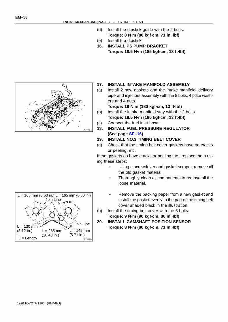
P21192
P21198
L = 165 mm (6.50 in.) L = 165 mm (6.50 in.)Join Line
L = 130 mm(5.12 in.) L = 265 mm
(10.43 in.)L = 145 mm(5.71 in.)
L = Length
Join Line
EM−58−ENGINE MECHANICAL (5VZ−FE) CYLINDER HEAD
1996 TOYOTA T100 (RM449U)
(d) Install the dipstick guide with the 2 bolts.Torque: 8 N·m (80 kgf·cm, 71 in.·lbf)
(e) Install the dipstick.16. INSTALL PS PUMP BRACKET
Torque: 18.5 N·m (185 kgf·cm, 13 ft·lbf)
17. INSTALL INTAKE MANIFOLD ASSEMBLY(a) Install 2 new gaskets and the intake manifold, delivery
pipe and injectors assembly with the 8 bolts, 4 plate wash-ers and 4 nuts.Torque: 18 N·m (180 kgf·cm, 13 ft·lbf)
(b) Install the intake manifold stay with the 2 bolts.Torque: 18.5 N·m (185 kgf·cm, 13 ft·lbf)
(c) Connect the fuel inlet hose.18. INSTALL FUEL PRESSURE REGULATOR
(See page SF−16)19. INSTALL NO.3 TIMING BELT COVER(a) Check that the timing belt cover gaskets have no cracks
or peeling, etc.If the gaskets do have cracks or peeling etc., replace them us-ing these steps:
� Using a screwdriver and gasket scraper, remove allthe old gasket material.
� Thoroughly clean all components to remove all theloose material.
� Remove the backing paper from a new gasket andinstall the gasket evenly to the part of the timing beltcover shaded black in the illustration.
(b) Install the timing belt cover with the 6 bolts.Torque: 9 N·m (90 kgf·cm, 80 in.·lbf)
20. INSTALL CAMSHAFT POSITION SENSORTorque: 8 N·m (80 kgf·cm, 71 in.·lbf)
https://www.truck-manuals.net/

P21245
S02073
−ENGINE MECHANICAL (5VZ−FE) CYLINDER HEADEM−59
1996 TOYOTA T100 (RM449U)
21. CONNECT ENGINE WIRE(a) Install the engine wire with the 3 bolts.(b) Connect the 3 engine wire clamps.(c) Connect these connectors:
� Oil pressure sensor connector� Crankshaft position sensor connector� 6 Injector connectors� ECT sender gauge connector� ECT sensor connector� Knock sensor connector� Camshaft position sensor connector
22. INSTALL INTAKE AIR CONNECTOR(a) Install a new gasket and the intake air connector with the
3 bolts and 2 nuts.Torque: 18.5 N·m (185 kgf·cm, 13 ft·lbf)
(b) Connect the DLC1 to the bracket.(c) Install the bolt, and connect the ground strap to the intake
air connector.(d) Connect the brake booster vacuum hose to the intake air
connector.(e) Connect the 2 fuel return hoses.(f) Install the engine wire with the bolt.(g) w/ A/C
Connect the A/C idle−up valve connector.
https://www.truck-manuals.net/
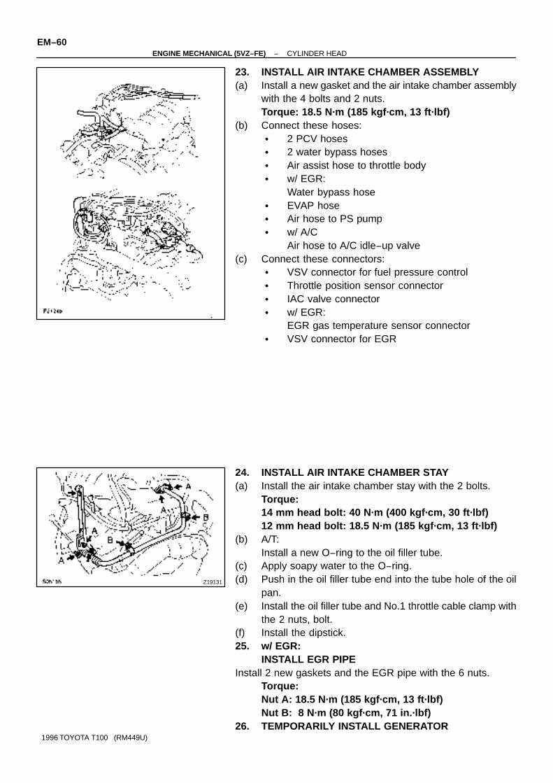
Z19131
EM−60−ENGINE MECHANICAL (5VZ−FE) CYLINDER HEAD
1996 TOYOTA T100 (RM449U)
23. INSTALL AIR INTAKE CHAMBER ASSEMBLY(a) Install a new gasket and the air intake chamber assembly
with the 4 bolts and 2 nuts.Torque: 18.5 N·m (185 kgf·cm, 13 ft·lbf)
(b) Connect these hoses:� 2 PCV hoses� 2 water bypass hoses� Air assist hose to throttle body� w/ EGR:
Water bypass hose� EVAP hose� Air hose to PS pump� w/ A/C
Air hose to A/C idle−up valve(c) Connect these connectors:
� VSV connector for fuel pressure control� Throttle position sensor connector� IAC valve connector� w/ EGR:
EGR gas temperature sensor connector� VSV connector for EGR
24. INSTALL AIR INTAKE CHAMBER STAY(a) Install the air intake chamber stay with the 2 bolts.
Torque:14 mm head bolt: 40 N·m (400 kgf·cm, 30 ft·lbf)12 mm head bolt: 18.5 N·m (185 kgf·cm, 13 ft·lbf)
(b) A/T:Install a new O−ring to the oil filler tube.
(c) Apply soapy water to the O−ring.(d) Push in the oil filler tube end into the tube hole of the oil
pan.(e) Install the oil filler tube and No.1 throttle cable clamp with
the 2 nuts, bolt.(f) Install the dipstick.25. w/ EGR:
INSTALL EGR PIPEInstall 2 new gaskets and the EGR pipe with the 6 nuts.
Torque:Nut A: 18.5 N·m (185 kgf·cm, 13 ft·lbf)Nut B: 8 N·m (80 kgf·cm, 71 in.·lbf)
26. TEMPORARILY INSTALL GENERATOR
https://www.truck-manuals.net/

−ENGINE MECHANICAL (5VZ−FE) CYLINDER HEADEM−61
1996 TOYOTA T100 (RM449U)
27. INSTALL TIMING BELT IDLER NO. 2 (See page EM−19)
28. INSTALL CAMSHAFT TIMING PULLEYS AND TIMINGBELT (See page EM−19)
29. INSTALL SPARK PLUGS30. INSTALL HIGH−TENSION CORDS WITH IGNITION
COILS (See page IG−1)31. w/ A/C:
INSTALL A/C COMPRESSOR BRACKET32. w/ A/C:
CONNECT A/C COMPRESSOR33. CONNECT PS PUMP34. INSTALL FAN WITH FLUID COUPLING AND FAN PUL-
LEYSTorque: 5.4 N·m (54 kgf·cm, 48 in.·lbf)
35. INSTALL NO. 2 FAN SHROUD36. INSTALL AND ADJUST DRIVE BELT FOR GENERA-
TOR (See page CH−1)37. w/ A/C:
INSTALL AND ADJUST DRIVE BELT FOR A/C COM-PRESSOR
38. INSTALL AND ADJUST DRIVE BELT FOR PS PUMP39. CONNECT HEATER HOSE AND UPPER RADIATOR
HOSE40. CONNECT THESE CABLES:(a) A/T:
Throttle cable(b) Accelerator cable(c) w/ Cruise control:
Cruise control actuator cable41. INSTALL MAF METER, RESONATOR AND AIR
CLEANER CAP ASSEMBLY42. INSTALL FRONT EXHAUST PIPE (See page EM−108)43. FILL WITH ENGINE COOLANT44. START ENGINE AND CHECK FOR LEAKS45. CHECK IGNITION TIMING (See page EM−9)46. 4WD:
INSTALL ENGINE UNDER COVER47. ROAD TEST VEHICLECheck for abnormal noise, shock, slippage, correct shift pointsand smooth operation.48. RECHECK ENGINE COOLANT LEVEL
https://www.truck-manuals.net/

EM07R−04
EM−62−ENGINE MECHANICAL (5VZ−FE) ENGINE UNIT (2WD)
881Author�: Date�:
1996 TOYOTA T100 (RM449U)
ENGINE UNIT (2WD)COMPONENTS
https://www.truck-manuals.net/

−ENGINE MECHANICAL (5VZ−FE) ENGINE UNIT (2WD)EM−63
882Author�: Date�:
1996 TOYOTA T100 (RM449U)
https://www.truck-manuals.net/

Z18855
EM−64−ENGINE MECHANICAL (5VZ−FE) ENGINE UNIT (2WD)
883Author�: Date�:
1996 TOYOTA T100 (RM449U)
https://www.truck-manuals.net/

EM06W−02
−ENGINE MECHANICAL (5VZ−FE) ENGINE UNIT (2WD)EM−65
1996 TOYOTA T100 (RM449U)
REMOVAL1. DRAIN ENGINE COOLANT2. DRAIN ENGINE OIL3. DRAIN TRANSMISSION OIL4. REMOVE HOOD5. REMOVE RADIATOR ASSEMBLY
(See page CO−16)6. REMOVE DRIVE BELT FOR PS PUMP7. w/ A/C:
REMOVE DRIVE BELT FOR A/C COMPRESSOR8. REMOVE DRIVE BELT FOR GENERATOR9. REMOVE FAN WITH FLUID COUPLING AND FAN PUL-
LEYS(See page CO−5)
10. DISCONNECT PS PUMP FROM ENGINEHINT:Put aside the pump, and suspend it.11. w/ A/C:
REMOVE A/C COMPRESSOR FROM ENGINEHINT:Put aside the compressor, and suspend it.12. REMOVE AIR CLEANER CAP, MAF METER AND RES-
ONATOR13. REMOVE AIR CLEANER CASE AND FILTER14. DISCONNECT THESE CABLES:(a) w/ Cruise control:
Cruise control actuator cable(b) Accelerator cable(c) A/T:
Throttle cable15. DISCONNECT HEATER HOSES
16. DISCONNECT HOSESDisconnect these hoses:
(1) Brake booster vacuum hose(2) EVAP hose
https://www.truck-manuals.net/

Z14701
P20501
P21435
P21441
P21437
EM−66−ENGINE MECHANICAL (5VZ−FE) ENGINE UNIT (2WD)
1996 TOYOTA T100 (RM449U)
(3) Fuel return hose(4) Fuel inlet hose
17. DISCONNECT STARTER WIRE AND CONNECTOR(a) Remove the bolt, and disconnect the ground strap.(b) Remove the 2 nuts, disconnect the positive (+) terminal
cable from battery.(c) Disconnect the 2 starter wire clamps and connector.18. DISCONNECT GENERATOR WIRE(a) Disconnect the generator connector.(b) Remove the nut, and disconnect the generator wire and
wire clip.19. REMOVE FRONT DOOR SCUFF PLATE AND COWL
SIDE TRIM20. DISCONNECT ENGINE WIRE AND CONNECTORS(a) Remove the 3 bolts and ECM.(b) M/T:
Disconnect the 3 ECM connectors.(c) A/T:
Disconnect the 4 ECM connectors.(d) Disconnect the 2 connectors from the cowl wire.(e) Disconnect these wires and connectors:
� Igniter connector� Ground strap
(f) Disconnect the 6 engine wire clamps.(g) Pull out the engine wire from the cabin.21. M/T:
REMOVE SHIFT LEVER(a) Remove the shift lever knob.(b) Remove the 4 screws and shift lever boot.(c) Remove the shift lever.22. REMOVE STABILIZER BAR
(See page SA−16)23. REMOVE PROPELLER SHAFT
(See page PR−3)24. DISCONNECT SPEEDOMETER CABLENOTICE: Do not lose the felt protector and washers.25. REMOVE FRONT EXHAUST PIPE(a) Disconnect the 2 heated oxygen sensor connectors.(b) Remove the 2 bolts, and retainer holding the front ex-
haust pipe to the center exhaust pipe.
https://www.truck-manuals.net/

P21436
P15099
P21444
Engine Hanger No. 2
P21459
−ENGINE MECHANICAL (5VZ−FE) ENGINE UNIT (2WD)EM−67
1996 TOYOTA T100 (RM449U)
(c) Remove the 3 bolts and support bracket.(d) Remove the 3 nuts, front exhaust pipe and 3 gaskets.
26. M/T:REMOVE CLUTCH RELEASE CYLINDER
(a) Remove the 3 bolts and disconnect the clutch line.(b) Remove the 2 bolts and disconnect the clutch release cyl-
inder.27. A/T:
REMOVE CROSS SHAFT(a) Remove the clip and disconnect the shifting rod.(b) Remove the nut, 4 bolts and the cross shaft.28. PLACE JACK UNDER TRANSMISSION29. REMOVE ENGINE REAR MOUNTING BRACKETRemove the 8 bolts holding the mounting bracket to the mount-ing insulator and cross member.
30. REMOVE ENGINE WITH TRANSMISSION(a) w/ A/C:
Remove the bolt and disconnect the A/C compressor wireclamp.
(b) Install a engine hanger No.2 in the correct direction.Part No.:Engine hanger No.2 12282−62030Bolt 91512−61020Torque:40 N·m (400 kgf·cm, 30 ft·lbf)
(c) Attach the engine hoist chain to the 2 engine hangers.
https://www.truck-manuals.net/

P23911
P21458
EM−68−ENGINE MECHANICAL (5VZ−FE) ENGINE UNIT (2WD)
1996 TOYOTA T100 (RM449U)
(d) Remove the 4 bolts and nuts holding the engine frontmounting insulators to the frame.
(e) Lift the engine with transmission out of the vehicle slowlyand carefully.
NOTICE: Make sure the engine is clear of all wiring and hoses.(f) Place the engine and transmission assembly onto the
stand.31. SEPARATE ENGINE AND TRANSMISSION
https://www.truck-manuals.net/

EM1OS−01
P21457
P21459
P21444
Engine Hanger No.2
P15099
P23911
−ENGINE MECHANICAL (5VZ−FE) ENGINE UNIT (2WD)EM−69
1996 TOYOTA T100 (RM449U)
INSTALLATION1. INSTALL TRANSMISSION TO ENGINE
(See page AT−26)2. INSTALL ENGINE AND TRANSMISSION ASSEMBLY
IN VEHICLE(a) Attach the engine hoist chain to the engine hangers.(b) Lower the engine and transmission assembly into the en-
gine compartment.
(c) Keep the engine level, and align the RH and LH mount-ings and body mountings.
(d) Attach the RH and LH mounting insulators to the bodymountings, and temporarily install the 4 bolts and nuts.
(e) Jack up and put the transmission onto the frame.
(f) Remove the engine chain hoist from the engine.(g) Remove the 2 bolts and engine hanger No.2.(h) w/ A/C:
Install the bolt, and connect the A/C compressor wire.
3. INSTALL ENGINE REAR MOUNTING BRACKET(a) Raise the transmission slightly by raising the engine with
a jack and a wooden block under the transmission.(b) Install the engine rear mounting bracket to the frame.
Torque: 58 N·m (590 kgf·cm, 43 ft·lbf)(c) Lower the transmission and rest it on the extension hous-
ing.(d) Install the mounting bracket to the mounting insulator.
Torque: 18 N·m (185 kgf·cm, 13 ft·lbf)
4. TIGHTEN RH AND LH ENGINE MOUNTINGINSULATOR BOLTS AND NUTS
Tighten the 4 bolts and nuts holding the mounting insulators tothe body mountings.
Torque: 38 N·m (387 kgf·cm, 28 ft·lbf)
https://www.truck-manuals.net/
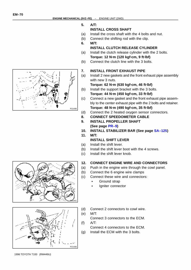
P21436
P21441
P21435
EM−70−ENGINE MECHANICAL (5VZ−FE) ENGINE UNIT (2WD)
1996 TOYOTA T100 (RM449U)
5. A/T:INSTALL CROSS SHAFT
(a) Install the cross shaft with the 4 bolts and nut.(b) Connect the shifting rod with the clip.6. M/T:
INSTALL CLUTCH RELEASE CYLINDER(a) Install the clutch release cylinder with the 2 bolts.
Torque: 12 N·m (120 kgf·cm, 9 ft·lbf)(b) Connect the clutch line with the 3 bolts.
7. INSTALL FRONT EXHAUST PIPE(a) Install 2 new gaskets and the front exhaust pipe assembly
with new 3 nuts.Torque: 62 N·m (630 kgf·cm, 46 ft·lbf)
(b) Install the support bracket with the 3 bolts.Torque: 44 N·m (450 kgf·cm, 33 ft·lbf)
(c) Connect a new gasket and the front exhaust pipe assem-bly to the center exhaust pipe with the 2 bolts and retainer.Torque: 48 N·m (490 kgf·cm, 35 ft·lbf)
(d) Connect the 2 heated oxygen sensor connectors.8. CONNECT SPEEDOMETER CABLE9. INSTALL PROPELLER SHAFT
(See page PR−9)10. INSTALL STABILIZER BAR (See page SA−125)11. M/T:
INSTALL SHIFT LEVER(a) Install the shift lever.(b) Install the shift lever boot with the 4 screws.(c) Install the shift lever knob.
12. CONNECT ENGINE WIRE AND CONNECTORS(a) Push in the engine wire through the cowl panel.(b) Connect the 6 engine wire clamps(c) Connect these wire and connectors:
� Ground strap� Igniter connector
(d) Connect 2 connectors to cowl wire.(e) M/T:
Connect 3 connectors to the ECM.(f) A/T:
Connect 4 connectors to the ECM.(g) Install the ECM with the 3 bolts.
https://www.truck-manuals.net/

P20501
−ENGINE MECHANICAL (5VZ−FE) ENGINE UNIT (2WD)EM−71
1996 TOYOTA T100 (RM449U)
13. INSTALL FRONT DOOR SCUFF PLATE AND COWLSIDE TRIM
14. CONNECT GENERATOR WIRE(a) Connect the generator connector.(b) Connect the generator wire with the nut.(c) Connect the wire harness clip to the generator.
15. CONNECT STARTER WIRE AND CONNECTOR(a) Connect the 2 starter wire clamps and connector.(b) Install the 2 nuts, and connect the positive (+) terminal
cable to battery.(c) Install the bolt, and connect the ground strap.
16. CONNECT HOSESConnect these hoses:
� Fuel return hose� Fuel inlet hose
� Brake booster vacuum hose� EVAP hose� A.D.D. Vacuum hose
17. CONNECT HEATER HOSES18. CONNECT THESE CABLES:(a) A/T:
Throttle cable(b) Accelerator cable(c) w/ Cruise control:
Cruise control actuator cable19. INSTALL AIR CLEANER CASE AND AIR FILTER20. INSTALL MAF METER, RESONATOR AND AIR
CLEANER CAP21. w/ A/C:
CONNECT A/C COMPRESSOR22. CONNECT PS PUMP23. INSTALL FAN WITH FLUID COUPLING AND FAN
PULLEYS(See page EM−19)24. INSTALL DRIVE BELT FOR GENERATOR (See page
CH−1)
https://www.truck-manuals.net/

EM−72−ENGINE MECHANICAL (5VZ−FE) ENGINE UNIT (2WD)
1996 TOYOTA T100 (RM449U)
25. w/ A/C:INSTALL DRIVE BELT FOR A/C COMPRESSOR
26. INSTALL DRIVE BELT FOR PS PUMP27. INSTALL RADIATOR ASSEMBLY
(See page CO−19)28. FILL WITH ENGINE OIL29. FILL WITH ENGINE COOLANT30. FILL TRANSMISSION OIL31. START ENGINE AND CHECK FOR LEAKS32. CHECK IGNITION TIMING
(See page EM−9)33. INSTALL HOOD34. ROAD TEST VEHICLECheck for abnormal noise, shock, slippage, correct shift pointsand smooth operation.35. RECHECK ENGINE COOLANT AND OIL LEVELS
https://www.truck-manuals.net/

EM1OT−01
−ENGINE MECHANICAL (5VZ−FE) ENGINE UNIT (4WD)EM−73
892Author�: Date�:
1996 TOYOTA T100 (RM449U)
ENGINE UNIT (4WD)COMPONENTS
https://www.truck-manuals.net/

EM−74−ENGINE MECHANICAL (5VZ−FE) ENGINE UNIT (4WD)
893Author�: Date�:
1996 TOYOTA T100 (RM449U)
https://www.truck-manuals.net/

−ENGINE MECHANICAL (5VZ−FE) ENGINE UNIT (4WD)EM−75
894Author�: Date�:
1996 TOYOTA T100 (RM449U)
https://www.truck-manuals.net/

EM1OU−01
EM−76−ENGINE MECHANICAL (5VZ−FE) ENGINE UNIT (4WD)
1996 TOYOTA T100 (RM449U)
REMOVAL1. REMOVE ENGINE UNDER COVER2. DRAIN ENGINE COOLANT3. DRAIN ENGINE OIL4. REMOVE HOOD5. REMOVE RADIATOR ASSEMBLY
(See page CO−16)6. REMOVE DRIVE BELT FOR PS PUMP7. w/ A/C:
REMOVE DRIVE FOR A/C COMPRESSOR8. REMOVE DRIVE BELT FOR GENERATOR9. REMOVE FAN WITH FLUID COUPLING AND FAN PUL-
LEYS (See page EM−13)10. DISCONNECT PS PUMP FROM ENGINEHINT:Put aside the pump, and suspend it.11. w/ A/C:
DISCONNECT A/C COMPRESSORHINT:Put aside the compressor, and suspend it.12. REMOVE AIR CLEANER CAP, MAF METER AND RES-
ONATOR13. REMOVE AIR CLEANER CASE AND FILTER14. DISCONNECT THESE CABLES:(a) w/ Cruise control:
Cruise control actuator cable(b) Accelerator cable(c) A/T:
Throttle cable15. DISCONNECT HEATER HOSES
16. DISCONNECT HOSESDisconnect these hoses:
(1) Brake booster vacuum hose(2) EVAP hose(3) A.D.D. vacuum hose
https://www.truck-manuals.net/

Z14703
P21443
P21435
P21441
−ENGINE MECHANICAL (5VZ−FE) ENGINE UNIT (4WD)EM−77
1996 TOYOTA T100 (RM449U)
(4) Fuel return hose(5) Fuel inlet hose
17. DISCONNECT STARTER WIRE AND CONNECTORS(a) Remove the bolt, and disconnect the ground strap.(b) Remove the 2 nut, and disconnect the positive (+) termi-
nal cable from battery.(c) Disconnect the 3 starter wire clamps and connector.(d) Disconnect the A.D.D. indicator switch connector.18. DISCONNECT GENERATOR WIRE(a) Disconnect the generator connector.(b) Remove the nut, and disconnect the generator wire and
wire clip.19. REMOVE FRONT DOOR SCUFF PLATE AND COWL
SIDE TRIM
20. DISCONNECT ENGINE WIRE AND CONNECTORS(a) Remove the 3 bolts and ECM.(b) M/T:
Disconnect the 3 ECM connectors.(c) A/T:
Disconnect the 4 ECM connectors.(d) Disconnect the 2 connectors from the cowl wire.
(e) Disconnect these wires and connectors:� Igniter connector� Ground strap
(f) Disconnect the 6 engine wire clamps.(g) Pull out the engine wire from the cabin.
https://www.truck-manuals.net/

P21444
Engine Hanger No. 2
P21617
P21776
P21615
EM−78−ENGINE MECHANICAL (5VZ−FE) ENGINE UNIT (4WD)
1996 TOYOTA T100 (RM449U)
21. REMOVE ENGINE(a) w/ A/C:
Remove the bolt and disconnect the A/C compressor wireclamp.
(b) Install a engine hanger No.2 in the correct direction.Part No.:Engine hanger No.2 12282−62030Bolt 91512−61020Torque: 40 N·m (400 kgf·cm, 30 ft·lbf)
(c) Attach the engine hoist chain to the 2 engine hangers.
(d) Remove the 4 bolts and nuts holding the engine frontmounting insulators to the frame.
(e) Lift the engine out of the vehicle slowly and carefully.NOTICE: Make sure the engine is clear of all wiring and hoses.(f) Place the engine assembly onto the stand.
https://www.truck-manuals.net/

EM1OV−01
P21617
P21444
Engine Hanger No. 2
P21776
P21441
P21435
−ENGINE MECHANICAL (5VZ−FE) ENGINE UNIT (4WD)EM−79
1996 TOYOTA T100 (RM449U)
INSTALLATION1. INSTALL ENGINE ASSEMBLY IN VEHICLE(a) Attach the engine hoist chain to the engine hangers.(b) Lower the engine assembly into the engine compartment.(c) Keep the engine level, and align the RH and LH mount-
ings and body mountings.(d) Attach the RH and LH mounting insulators to the body
mountings, and temporarily install the 4 bolts and nuts.(e) Remove the engine chain hoist from the engine.
(f) Remove the 2 bolts and engine hanger No.2.(g) w/ A/C:
Install the bolt, and connect the A/C compressor wire.
2. TIGHTEN RH AND LH ENGINE MOUNTINGINSULATOR BOLTS AND NUTS
Tighten the 4 bolts and nuts holding the mounting insulators tothe body mountings.
Torque: 38 N·m (385 kgf·cm, 28 ft·lbf)
3. CONNECT ENGINE WIRE AND CONNECTORS(a) Push in the engine wire through the cowl panel.(b) Connect the 6 engine wire clamps.(c) Connect these wire and connectors:
� Ground strap� Igniter connector
(d) Connect 2 connectors to cowl wire.(e) M/T:
Connect 3 connectors to the ECM.(f) A/T:
Connect 4 connectors to the ECM.(g) Install the ECM with the 3 bolts.4. INSTALL FRONT DOOR SCUFF PLATE AND COWL
SIDE TRIM5. CONNECT GENERATOR WIRE(a) Connect the generator connector.
https://www.truck-manuals.net/

P21443
EM−80−ENGINE MECHANICAL (5VZ−FE) ENGINE UNIT (4WD)
1996 TOYOTA T100 (RM449U)
(b) Connect the generator wire with the nut.(c) Connect the wire harness clip to the generator.
6. CONNECT STARTER WIRE AND CONNECTORS(a) Connect the 3 starter wire clamps and connector.(b) Install the 2 nuts, and connect the positive (+) terminal
cable to battery.(c) Connect the A.D.D. indicator switch connector.(d) Install the bolt, and connect the ground strap.
7. CONNECT HOSESConnect these hoses:
� Fuel return hose� Fuel inlet hose
� Brake booster vacuum hose� EVAP hose� A.D.D. vacuum hose
8. CONNECT HEATER HOSES9. CONNECT THESE CABLES:(a) A/T:
Throttle cable(b) Accelerator cable(c) w/ Cruise control:
Cruise control actuator cable10. INSTALL AIR CLEANER CASE AND AIR FILTER11. INSTALL MAF METER, RESONATOR AND AIR
CLEANER CAP12. w/ A/C:
CONNECT A/C COMPRESSOR13. CONNECT PS PUMP14. INSTALL FAN WITH FLUID COUPLING AND FAN PUL-
LEYS (See page EM−19)15. INSTALL DRIVE BELT FOR GENERATOR (See page
CH−1)
https://www.truck-manuals.net/

−ENGINE MECHANICAL (5VZ−FE) ENGINE UNIT (4WD)EM−81
1996 TOYOTA T100 (RM449U)
16. w/ A/C:INSTALL DRIVE BELT FOR A/C COMPRESSOR
17. INSTALL DRIVE BELT FOR PS PUMP18. INSTALL RADIATOR ASSEMBLY
(See page CO−19)19. FILL WITH ENGINE OIL20. FILL WITH ENGINE COOLANT21. INSTALL ENGINE UNDER COVER22. INSTALL TRANSMISSION
(See page MT−4)23. INSTALL HOOD24. PERFORM ROAD TESTCheck for abnormal noise, shock, slippage, correct shift pointsand smooth operation.25. RECHECK ENGINE COOLANT AND ENGINE OIL
LEVELS
https://www.truck-manuals.net/

EM07T−02
EM−82−ENGINE MECHANICAL (5VZ−FE) CYLINDER BLOCK
901Author�: Date�:
1996 TOYOTA T100 (RM449U)
CYLINDER BLOCKCOMPONENTS
https://www.truck-manuals.net/

P21786
−ENGINE MECHANICAL (5VZ−FE) CYLINDER BLOCKEM−83
902Author�: Date�:
1996 TOYOTA T100 (RM449U)
https://www.truck-manuals.net/

P21463
EM1OW−01
P21465
P21464
P21466
EM−84−ENGINE MECHANICAL (5VZ−FE) CYLINDER BLOCK
1996 TOYOTA T100 (RM449U)
DISASSEMBLY1. M/T:
REMOVE FLYWHEEL2. A/T:
REMOVE DRIVE PLATE3. REMOVE REAR END PLATERemove the bolt and end plate.4. INSTALL ENGINE TO ENGINE STAND FOR DIS-
ASSEMBLY5. REMOVE TIMING BELT AND PULLEYS (See page
EM−13)6. REMOVE CYLINDER HEADS (See page EM−30)7. REMOVE WATER BYPASS PIPE WITH KNOCK SEN-
SOR WIRE(a) Disconnect the 2 knock sensor connectors.(b) Remove the 2 bolts, nut and water bypass pipe.
8. REMOVE NO.2 IDLER PULLEY BRACKETRemove the 3 bolts and idler pulley bracket.
9. REMOVE KNOCK SENSORSUsing SST, remove the 2 knock sensors.
SST 09816−3001010. REMOVE WATER PUMP (See page CO−5)11. REMOVE GENERATOR ADJUSTING BAR12. REMOVE OIL PRESSURE SWITCHUsing SST, remove the oil pressure switch.
SST 09816−30010
13. REMOVE OIL FILTER AND OIL FILTER UNION(a) Using SST, remove the oil filter.
SST 09228−07501(b) Using 12 mm hexagon wrench, remove the union.14. REMOVE RH AND LH ENGINE MOUNTING BRACKET15. REMOVE COOLANT DRAIN COCK16. w/o OIL COOLER:
REMOVE OIL HOLE COVER PLATE
https://www.truck-manuals.net/

EM5228
P20859
P20862
−ENGINE MECHANICAL (5VZ−FE) CYLINDER BLOCKEM−85
1996 TOYOTA T100 (RM449U)
17. w/ OIL COOLER:REMOVE OIL COOLER WITH WATER BYPASS HOSEAND OIL COOLER UNION (See page LU−18)
18. REMOVE OIL PAN (See page LU−9)19. REMOVE OIL STRAINER (See page LU−9)20. REMOVE OIL PAN BAFFLE PLATE (See page
LU−9)21. REMOVE OIL PUMP (See page LU−9)
22. REMOVE REAR OIL SEAL RETAINER(a) Remove the 6 bolts.(b) Using a screwdriver, remove the oil seal retainer by prying
the portions between the oil seal retainer and main bear-ing cap.
23. CHECK CONNECTING ROD THRUST CLEARANCEUsing a dial indicator, measure the thrust clearance while mov-ing the connecting rod back and forth.
Standard thrust clearance:0.150 − 0.330 mm (0.0059 − 0.0130 in.)Maximum thrust clearance:0.38 mm (0.0150 in.)
If the thrust clearance is greater than maximum, replace theconnecting rod assembly. If necessary, replace the crankshaft.
24. REMOVE CONNECTING ROD CAPS AND CHECK OILCLEARANCE
(a) Using a punch or numbering stamp, mark the connectingrod and cap to ensure correct reassembly.
(b) Remove the connecting rod cap nuts.
https://www.truck-manuals.net/

P20865
P20864
EM5345
EM−86−ENGINE MECHANICAL (5VZ−FE) CYLINDER BLOCK
1996 TOYOTA T100 (RM449U)
(c) Using a plastic−faced hammer, lightly tap the connectingrod bolts and lift off the connecting rod cap.
HINT:Keep the lower bearing inserted with the connecting rod cap.(d) Cover the connecting rod bolts with a short piece of hose
to protect the crankshaft from damage.(e) Clean the crank pin and bearing.(f) Check the crank pin and bearing for pitting and scratches.If the crank pin or bearing is damaged, replace the bearings. Ifnecessary, grind or replace the crankshaft.(g) Lay a strip of Plastigage across the crank pin.
(h) Install the connecting rod cap with the 2 nuts (See pageEM−101).Torque:1st 25 N·m (250 kgf·cm, 18 ft·lbf)2nd Turn extra 90°
NOTICE:Do not turn the crankshaft.(i) Remove the 2 nuts and connecting rod cap (See proce-
dure (b) and (c) above).
https://www.truck-manuals.net/

P20863
P01284
Mark1, 2 or 3
Mark1, 2 or 3
P00884
−ENGINE MECHANICAL (5VZ−FE) CYLINDER BLOCKEM−87
1996 TOYOTA T100 (RM449U)
(j) Measure the Plastigage at its widest point.Standard oil clearance:STD 0.024 − 0.053 mm (0.0009 − 0.0021 in.)U/S 0.25 0.023 − 0.069 mm (0.0009 − 0.0027 in.)Maximum oil clearance:0.08 mm (0.0031 in.)
If the oil clearance is greater than maximum, replace the bear-ings. If necessary, grind or replace the crankshaft.HINT:If using a standard bearing, replace with one having the samenumber marked on the connecting rod cap. There are 3 sizesof standard bearings, marked ”1”, ”2” and ”3” accordingly.
Reference:Standard bearing center wall thickness
Mark ”1” 1.484 − 1.488 mm (0.0584 − 0.0586 in.)
Mark ”2” 1.488 − 1.492 mm (0.0586 − 0.0587 in.)
Mark ”3” 1.492 − 1.496 mm (0.0587 − 0.0589 in.)
(k) Completely remove the Plastigage.25. REMOVE PISTON AND CONNECTING ROD AS-
SEMBLIES(a) Using a ridge reamer, remove the all carbon from the top
of the cylinder.(b) Cover the connecting rod bolts with a short piece of hose
to protect the crankshaft from damage.(c) Push the piston, connecting rod assembly and upper
bearing through the top of the cylinder block.HINT:� Keep the bearings, connecting rod and cap together.� Arrange the piston and connecting rod assemblies in cor-
rect order.
https://www.truck-manuals.net/

P20860
EM5365
P21453
EM4968
Plastigauge
EM4969
EM−88−ENGINE MECHANICAL (5VZ−FE) CYLINDER BLOCK
1996 TOYOTA T100 (RM449U)
26. CHECK CRANKSHAFT THRUST CLEARANCEUsing a dial indicator, measure the thrust clearance while pryingthe crankshaft back and forth with a screwdriver.
Standard thrust clearance:0.020 − 0.220 mm (0.0008 − 0.0087 in.)Maximum thrust clearance:0.30 mm (0.0118 in.)
If the thrust clearance is greater than maximum, replace thethrust washers as a set.
Thrust washer thickness:2.440 − 2.490 mm (0.0961 − 0.0980 in.)
27. REMOVE MAIN BEARING CAP AND CHECK OILCLEARANCE
(a) Uniformly loosen and remove the main bearing cap bolts,in several passes, in the sequence shown.
(b) Using a screwdriver, pry up the main bearing cap, and re-move the main bearing cap, lower main bearings and low-er thrust washers (No.2 journal position of main bearingcap only).
HINT:Keep the lower main bearings and lower thrust washers togeth-er with the main bearing cap.(c) Lift out the crankshaft.HINT:Keep the upper main bearings and upper thrust washers to-gether with the cylinder block.(d) Clean each main journal and bearing.(e) Check each main journal and bearing for pitting and
scratches.If the journal or bearing is damaged, replace the bearings. Ifnecessary, grind or replace the crankshaft.(f) Place the crankshaft on the cylinder block.(g) Lay a strip of Plastigage across each journal.(h) Install the main bearing cap with the 8 bolts (See page
EM−101).Torque:1st 61 N·m (625 kgf·cm, 45 ft·lbf)2nd Turn extra 90°
NOTICE:Do not turn the crankshaft.(i) Remove the 8 bolts and main bearing cap (See procedure
(a) and (b) above).(j) Measure the Plastigage at its widest point.
https://www.truck-manuals.net/

Z04969
Mark1, 2 or 3
Mark1, 2, 3, 4 or 5
No. 1No. 2
No. 3 No. 4Mark 0, 1 or 2
Mark F
No. 1No. 2No. 3No. 4
No. 4 Crank Pin
No. 3 Crank Pin 5
Cylinder block
Crankshaft
Use bearing
Number marked
1
1
1
1 10 0 0
2
2
2 2
2 2
3
3 3 34 4
EXAMPLE: Cylinder block ”2” + Crankshaft ”1”= Total number 3 (Use bearing ”3”)
−ENGINE MECHANICAL (5VZ−FE) CYLINDER BLOCKEM−89
1996 TOYOTA T100 (RM449U)
Standard clearance:No.1
STD 0.020 − 0.038 mm (0.0008 − 0.0015 in.)
U/S 0.25 0.019 − 0.059 mm (0.0007 − 0.0023 in.)
Others
STD 0.024 − 0.042 mm (0.0009 − 0.0017 in.)
U/S 0.25 0.023 − 0.063 mm (0.0009 − 0.0025 in.)
Maximum clearance:0.08 mm (0.0031 in.)
HINT:If replacing the cylinder block subassembly, the bearing stan-dard clearance will be:
No.10.010 − 0.049 mm (0.0004 − 0.0020 in.)Others0.014 − 0.053 mm (0.0006 − 0.0021 in.)
If the oil clearance is greater than maximum, replace the bear-ings. If necessary, grind or replace the crankshaft.HINT:If using a standard bearing, replace with one having the samenumber. If the number of the bearing cannot be determined, se-lect the correct bearing by adding together the numbers im-printed on the cylinder block and crankshaft, then selecting thebearing with the same number as the total. There are 5 sizesof standard bearings, marked ”1”, ”2”, ”3”, ”4” and ”5” according-ly.
Reference:Standard sized bearing center wall thickness:No.1
Mark ”1” 1.991 − 1.994 mm (0.0784 − 0.0785 in.)
Mark ”2” 1.994 − 1.997 mm (0.0785 − 0.0786 in.)
Mark ”3” 1.997 − 2.000 mm (0.0786 − 0.0787 in.)
Mark ”4” 2.000 − 2.003 mm (0.0787 − 0.0789 in.)
Mark ”5” 2.003 − 2.006 mm (0.0789 − 0.0790 in.)
https://www.truck-manuals.net/

P21454
P21446
EM−90−ENGINE MECHANICAL (5VZ−FE) CYLINDER BLOCK
1996 TOYOTA T100 (RM449U)
Others
Mark ”1” 1.989 − 1.992 mm (0.0783 − 0.0784 in.)
Mark ”2” 1.992 − 1.995 mm (0.0784 − 0.0785 in.)
Mark ”3” 1.995 − 1.998 mm (0.0785 − 0.0787 in.)
Mark ”4” 1.998 − 2.001 mm (0.0787 − 0.0788 in.)
Mark ”5” 2.001 − 2.004 mm (0.0788 − 0.0789 in.)
Cylinder block main journal bore diameter:
Mark ”1” 68.010 − 68.016 mm (2.6776 − 2.6778 in.)
Mark ”2” 68.016 − 68.022 mm (2.6778 − 2.6780 in.)
Mark ”3” 68.022 − 68.028 mm (2.6780 − 2.6783 in.)
Crankshaft main journal diameter:
Mark ”0” 63.996 − 64.000 mm (2.5195 − 2.5197 in.)
Mark ”1” 63.990 − 63.996 mm (2.5193 − 2.5195 in.)
Mark ”2” 63.985 − 63.990 mm (2.5191 − 2.5193 in.)
(k) Completely remove the Plastigage.28. REMOVE CRANKSHAFT(a) Lift out the crankshaft.(b) Remove the upper main bearings and upper thrust wash-
ers from the cylinder block.HINT:Arrange the main bearings and thrust washers in correct order.
29. CHECK FIT BETWEEN PISTON AND PISTON PINTry to move the piston back and forth on the piston pin.If any movement is felt, replace the piston and pin as a set.
30. REMOVE PISTON RINGS(a) Using a piston ring expander, remove the 2 compression
rings.(b) Remove the 2 side rails and oil ring by hand.HINT:Arrange the piston rings in the correct order only.
https://www.truck-manuals.net/

P21451
P01030
−ENGINE MECHANICAL (5VZ−FE) CYLINDER BLOCKEM−91
1996 TOYOTA T100 (RM449U)
31. DISCONNECT CONNECTING ROD FROM PISTON(a) Using a small screwdriver, pry out the 2 snap rings.(b) Gradually heat the piston to about 60°C (140°F).
(c) Using a plastic−faced hammer and brass bar, lightly tapout the piston pin and remove the connecting rod.
HINT:� The piston and pin are a matched set.� Arrange the pistons, pins, rings, connecting rods and
bearings in the correct order.
https://www.truck-manuals.net/

P21512
EM07A−03
Z14704
P21514
EM6290
Mark 1, 2 or 3
No.6
Front
No.1 No.3 No.5
No.2 No.4
EM−92−ENGINE MECHANICAL (5VZ−FE) CYLINDER BLOCK
1996 TOYOTA T100 (RM449U)
INSPECTION1. REMOVE GASKET MATERIALUsing a gasket scraper, remove all the gasket material from thetop surface of the cylinder block.2. CLEAN CYLINDER BLOCKUsing a soft brush and solvent, thoroughly clean the cylinderblock.
3. INSPECT TOP SURFACE OF CYLINDER BLOCK FORFLATNESS
Using a precision straight edge and feeler gauge, measure thesurfaces contacting the cylinder head gasket for warpage.
Maximum warpage:0.05 mm (0.0020 in.)
If warpage is greater than maximum, replace the cylinder block.
4. INSPECT CYLINDER FOR VERTICAL SCRATCHESVisually check the cylinder for vertical scratches.If deep scratches are present, rebore all the 6 cylinders. If nec-essary, replace the cylinder block.
5. INSPECT CYLINDER BORE DIAMETERHINT:There are 3 sizes of the standard cylinder bore diameter,marked ”1”, ”2” and ”3” accordingly. The mark is stamped on thetop of the cylinder block.
https://www.truck-manuals.net/

Z00145
(1)Front (2)
ThrustDirection(1)
AxialDirection
(2)
10 mm(0.39 in.)
Middle
10 mm(0.39 in.)
P00884
P21450
P21455
−ENGINE MECHANICAL (5VZ−FE) CYLINDER BLOCKEM−93
1996 TOYOTA T100 (RM449U)
Using a cylinder gauge, measure the cylinder bore diameter atpositions A, B and C in the thrust and axial directions.
Standard diameter:
STD Mark ”1” 93.500 − 93.510 mm (3.6811 − 3.6815 in.)
STD Mark ”2” 93.510 − 93.520 mm (3.6815 − 3.6819 in.)
STD Mark ”3” 93.520 − 93.530 mm (3.6819 − 3.6823 in.)
Maximum diameter:
STD 93.730 mm (3.6902 in.)
O/S 0.50 94.230 mm (3.7098 in.)
If the diameter is greater than maximum, rebore all the 6 cylin-ders, If necessary, replace the cylinder block.
6. REMOVE CYLINDER RIDGEIf the wear is less than 0.2 mm (0.008 in.), using a ridge reamer,grind the top of the cylinder.
7. CLEAN PISTON(a) Using a gasket scraper, remove the carbon from the pis-
ton top.
(b) Using a groove cleaning tool or broken ring, clean the pis-ton ring grooves.
https://www.truck-manuals.net/

P21448
Z14705
Mark
26 mm
1, 2 or 3 FrontMark(Cavity)
P21456
EM−94−ENGINE MECHANICAL (5VZ−FE) CYLINDER BLOCK
1996 TOYOTA T100 (RM449U)
(c) Using solvent and a brush, thoroughly clean the piston.NOTICE:Do not use a wire brush.
8. INSPECT PISTON OIL CLEARANCEHINT:There are 3 sizes of the standard piston diameter, marked ”1”,”2” and ”3” accordingly. The mark is stamped on the piston top.(a) Using a micrometer, measure the piston diameter at right
angles to the piston pin center line, 26 mm (1.02 in.) fromthe piston head.Piston diameter:
STD Mark ”1” 93.356 − 93.366 mm (3.6754 − 3.6758 in.)
STD Mark ”2” 93.367 − 93.376 mm (3.6759 − 3.6762 in.)
STD Mark ”3” 93.377 − 93.386 mm (3.6763 − 3.6766 in.)
O/S 0.50 93.856 − 93.886 mm (3.6951 − 3.6963 in.)
(b) Measure the cylinder bore diameter in the thrust direc-tions (See step 5.).
(c) Subtract the piston diameter measurement from the cylin-der bore diameter measurement.Standard oil clearance:0.134 − 0.154 mm (0.0053 − 0.0060 in.)Maximum oil clearance:0.174 mm (0.0069 in.)
If the oil clearance is greater than maximum, replace all the 6pistons. If necessary, rebore all the 6 cylinders or replace thecylinder block.HINT:Use new cylinder block: Use a piston with the same numbermark as the standard bore diameter marked on the cylinderblock.
9. INSPECT PISTON RING GROOVE CLEARANCEUsing a feeler gauge, measure the clearance between new pis-ton ring and the wall of the piston ring groove.
Standard ring groove clearance:
No.1 0.040 − 0.080 mm (0.0016 − 0.0031 in.)
No.2 0.030 − 0.070 mm (0.0012 − 0.0028 in.)
If the clearance not as specified, replace the piston.
https://www.truck-manuals.net/

Z14733
115 mm
EM7639
P21449
Z00064
Z00065
−ENGINE MECHANICAL (5VZ−FE) CYLINDER BLOCKEM−95
1996 TOYOTA T100 (RM449U)
10. INSPECT PISTON RING END GAP(a) Insert the piston ring into the cylinder bore.(b) Using a piston, push the piston ring a little beyond the bot-
tom of the ring travel, 115 mm (4.53 in.) from the top of thecylinder block.
(c) Using a feeler gauge, measure the ring end gap.Standard ring end gap:
No.1 0.300 − 0.500 mm (0.0118 − 0.0197 in.)
No.2 0.400 − 0.600 mm (0.0157 − 0.0236 in.)
Oil (Side rail) 0.150 − 0.550 mm (0.0059 − 0.0217 in.)
Maximum ring end gap:
No.1 1.100 mm (0.0433 in.)
No.2 1.200 mm (0.0472 in.)
Oil (Side rail) 1.150 mm (0.0453 in.)
If the end gap is greater than maximum, replace the piston ring.If the end gap is greater than maximum, even with a new pistonring, rebore all the 6 cylinders or replace the cylinder block.11. INSPECT PISTON PIN FITAt 60°C (140°F), you should be able to push the piston pin intothe piston pin hole with your thumb.
12. INSPECT CONNECTING ROD ALIGNMENTUsing a rod aligner and feeler gauge, check the connecting rodalignment.
� Check for bend.Maximum bend:0.05 mm (0.0020 in.) per 100 mm (3.94 in.)
If bend is greater than maximum, replace the connecting rod as-sembly.
� Check for twist.Maximum twist:0.15 mm (0.0059 in.) per 100 mm (3.94 in.)
If twist is greater than maximum, replace the connecting rod as-sembly.
https://www.truck-manuals.net/

P00325
EM0227
P00331
SST
P00330
Oil Hole
P01038
EM−96−ENGINE MECHANICAL (5VZ−FE) CYLINDER BLOCK
1996 TOYOTA T100 (RM449U)
13. INSPECT PISTON PIN OIL CLEARANCE(a) Using a caliper gauge, measure the inside diameter of the
connecting rod bushing.Bushing inside diameter:22.005 − 22.017 mm (0.8663 − 0.8668 in.)
(b) Using a micrometer, measure the piston pin diameter.Piston pin diameter:21.997 − 22.009 mm (0.8660 − 0.8665 in.)
(c) Subtract the piston pin diameter measurement from thebushing inside diameter measurement.Standard oil clearance:0.005 − 0.011 mm (0.0002 − 0.0004 in.)Maximum oil clearance:0.05 mm (0.0020 in.)
If the oil clearance is greater than maximum, replace the bush-ing. If necessary, replace the piston and piston pin as a set.14. IF NECESSARY, REPLACE CONNECTING ROD
BUSHING(a) Using SST and a press, press out the bushing.
SST 09222−30010
(b) Align the oil holes of a new bushing and the connectingrod.
(c) Using SST and a press, press in the bushing.SST 09222−30010
(d) Using a pin hole grinder, hone the bushing to obtain thestandard specified clearance (see step 13 above) be-tween the bushing and piston pin.
https://www.truck-manuals.net/

P00326
P00593
P00603
15 mm (0.59 in.)Compressed Thread
P21447
26 mm
−ENGINE MECHANICAL (5VZ−FE) CYLINDER BLOCKEM−97
1996 TOYOTA T100 (RM449U)
(e) Check the piston pin fit at normal room temperature. Coatthe piston pin with engine oil, and push it into the connect-ing rod with your thumb.
15. INSPECT CONNECTING ROD BOLTS(a) Install the cap nut to the connecting rod bolt. Check that
the rod cap nut can be turned easily by hand to the endof the thread.
(b) If the cap nut cannot be turned easily, measure the outerdiameter of the compressed thread with vernier calipers.Standard outer diameter:7.860 − 8.000 mm (0.3094 − 0.3150 in.)Minimum outer diameter: 7.600 mm (0.2992 in.)
HINT:If the location of this area cannot be judged by visual inspection,measure the outer diameter at the location shown in the illustra-tion.If the outer diameter is less than minimum, replace the connect-ing rod and rod cap nut as a set.16. CYLINDER BORINGHINT:� Bore all the 6 cylinders for the oversized piston outside di-
ameter.� Replace all the piston rings with ones to match the over-
sized pistons.(a) Keep the oversized pistons.
Oversized piston diameter:O/S 0.50: 93.856 − 93.886 mm (3.6951 − 3.6963 in.)
(b) Calculate amount to the bore cylinders.(1) Using a micrometer, measure the piston diameter at
right angles to the piston pin center line, 26 mm(1.02 in.) from the piston head.
https://www.truck-manuals.net/

EM5349
Z00149
EM−98−ENGINE MECHANICAL (5VZ−FE) CYLINDER BLOCK
1996 TOYOTA T100 (RM449U)
(2) Calculate the amount of each cylinder is to be re-bored as follows:
Size to be rebored = P + C − HP = Piston diameterC = Piston oil clearance0.134 − 0.154 mm (0.0053 − 0.0060 in.)H = Allowance for honing0.02 mm (0.0008 in.) or less(3) C.Bore and hone cylinder to calculated dimensionsMaximum honing:0.02 mm (0.0008 in.)
NOTICE:Excess honing will destroy the finished roundness.
17. INSPECT CRANKSHAFT FOR RUNOUT(a) Place the crankshaft on V−blocks.(b) Using a dial indicator, measure the circle runout at the
No.2 and No.3 journals.Maximum circle runout:0.06 mm (0.0024 in.)
If the circle runout is greater than maximum, replace the crank-shaft.
18. INSPECT MAIN JOURNALS AND CRANK PINS(a) Using a micrometer, measure the diameter of each main
journal and crank pin.Main journal diameter:
STD 63.985 − 64.000 mm (2.5191 − 2.5197 in.)
U/S 0.25 63.745 − 63.755 mm (2.5096 − 2.5100 in.)
Crank pin diameter:
STD 54.987 − 55.000 mm (2.1648 − 2.1654 in.)
U/S 0.25 54.745 − 54.755 mm (2.1553 − 2.1557 in.)
If the diameter is not as specified, check the oil clearance (Seepage EM−84).(b) Check each main journal and crank pin for taper and out−
of−round as shown.Maximum taper and out−of−round:0.02 mm (0.0008 in.)
If the taper or out−of−round is greater than maximum, grind orreplace the crankshaft.
https://www.truck-manuals.net/

−ENGINE MECHANICAL (5VZ−FE) CYLINDER BLOCKEM−99
1996 TOYOTA T100 (RM449U)
19. IF NECESSARY, GRIND AND HONE MAIN JOURNALSAND/OR CRANK PINS
(a) Grind and hone the main journals and/or crank pins to thefinished undersized diameter (See procedure step 18).
(b) Install new main journal and/or crank pin undersizedbearings.
https://www.truck-manuals.net/

EM07B−04
EM5252
EM5251
SST
Z04104
Cut Position
EM7574
SST
EM−100−ENGINE MECHANICAL (5VZ−FE) CYLINDER BLOCK
1996 TOYOTA T100 (RM449U)
REPLACEMENT1. REPLACE CRANKSHAFT FRONT OIL SEAL
(See page EM−100)
2. REPLACE CRANKSHAFT REAR OIL SEALHINT:There are 2 methods (A and B) to replace the oil seal which areas follows:(a) If rear oil seal retainer is removed from cylinder block.
(1) Using a screwdriver and hammer, tap out the oilseal.
(2) Using SST and a hammer, tap in a new oil seal untilits surface is flush with the rear oil seal retaineredge.
SST 09223−15030, 09950−70010 (09951−07150)(3) Apply MP grease to the oil seal lip.
(b) If rear oil seal retainer is installed to cylinder block.(1) Using a knife, cut off the oil seal lip.(2) Using a screwdriver, pry out the oil seal.
NOTICE:Be careful not to damage the crankshaft. Tape the screw-driver tip.
(3) Apply MP grease to a new oil seal lip.(4) Using SST and a hammer, tap in the oil seal until its
surface is flush with the rear oil seal retainer edge.SST 09223−15030, 09950−70010 (09951−07150)
https://www.truck-manuals.net/

EM1EK−02
P21452
P21462
Front Mark
(Cavity)Front Mark
(Mold)
Z14706
No.1 Code Mark
No.2 Code Mark
P21438
Expander Front Mark(Cavity)
Upper SideRail
CompressionRing No.1
CompressionRing No.2
Lower SideRail
−ENGINE MECHANICAL (5VZ−FE) CYLINDER BLOCKEM−101
1996 TOYOTA T100 (RM449U)
INSTALLATIONHINT:� Thoroughly clean all parts to be assembled.� Before installing the parts, apply new engine oil to all slid-
ing and rotating surfaces.� Replace all gaskets, O−rings and oil seals with new parts.
1. ASSEMBLE PISTON AND CONNECTING ROD(a) Using a small screwdriver, install a new snap ring at one
end of the piston pin hole.HINT:Be sure that end gap of the snap ring is not aligned with the pinhole cutout portion of the piston.(b) Gradually heat the piston to about 60°C (140°F).(c) Coat the piston pin with engine oil.
(d) Align the front marks of the piston and connecting rod,and push in the piston pin with your thumb.
(e) Using a small screwdriver, install a new snap ring on theother end of the piston pin hole.
HINT:Be sure that end gap of the snap ring is not aligned with the pinhole cutout portion of the piston.
2. INSTALL PISTON RINGS(a) Install the oil ring expander and 2 side rails by hand.(b) Using a piston ring expander, install the 2 compression
rings with the code mark facing upward.Code mark:No.1: 1R or TNo.2: 2R or T
(c) Position the piston rings so that the ring ends are asshown.
NOTICE:Do not align the ring ends.
https://www.truck-manuals.net/

P00592
P10205
No. 1 Others
22 mm 20 mm
P10214
P10215
EM5354
EM−102−ENGINE MECHANICAL (5VZ−FE) CYLINDER BLOCK
1996 TOYOTA T100 (RM449U)
3. INSTALL BEARINGS(a) Align the bearing claw with the groove of the connecting
rod or connecting cap.(b) Install the bearings in the connecting rod and connecting
rod cap.
4. INSTALL MAIN BEARINGSHINT:� Main bearings come in widths of 20 mm (0.79 in.) and 22
mm (0.87 in.). Install the 22 mm (0.87 in.) bearings in theNo.1 cylinder block journal position with the main bearingcaps. Install the 20 mm (0.79 in.) bearings in the otherpositions.
� Upper bearings have an oil holes lower bearings do not.
(a) Align the bearing claw with the claw groove of the mainbearing cap or cylinder block.
(b) Install the bearings in the cylinder block and main bearingcap.
5. INSTALL UPPER THRUST WASHERSInstall the thrust washers under the No.2 journal position of thecylinder block with the oil grooves facing outward.6. PLACE CRANKSHAFT ON CYLINDER BLOCK
7. PLACE MAIN BEARING CAP AND LOWER THRUSTWASHERS ON CYLINDER BLOCK
(a) Install the thrust washers on the No.2 journal position ofthe bearing cap with the grooves facing outward.
https://www.truck-manuals.net/

P20861
Front Mark(Arrow)
Z14732
EM5369
FrontPaintedMark
EM5370
Painted Mark
90°
90°
P00591
−ENGINE MECHANICAL (5VZ−FE) CYLINDER BLOCKEM−103
1996 TOYOTA T100 (RM449U)
(b) Install the main bearing cap with the front mark facing for-ward.
8. INSTALL MAIN BEARING CAP BOLTSHINT:� The main bearing cap bolts are tightened in 2 progressive
steps (steps (b) and (d)).� If any main bearing cap bolt is broken or deformed, re-
place it.
(a) Apply a light coat of engine oil on the threads and underthe heads of the main bearing cap bolts.
(b) Install and uniformly tighten the 8 main bearing cap bolts,in several passes, in the sequence shown.Torque: 61 N·m (625 kgf·cm, 45 ft·lbf)
If any one of the main bearing cap bolts does not meet thetorque specification, replace the cap bolt.
(c) Mark the front of the main bearing cap bolt with paint.
(d) Retighten the main bearing cap bolts by 90° in the numer-ical order shown.
(e) Check that the painted mark is now at a 90° angle to thefront.
(f) Check that the crankshaft turns smoothly.(g) Check the crankshaft thrust clearance (See page
EM−92).
9. INSTALL PISTON AND CONNECTING ROD AS-SEMBLIES
(a) Cover the connecting rod bolts with a short piece of hoseto protect the crankshaft from damage.
https://www.truck-manuals.net/

Z14819
Front
FrontMark(Cavity)
P00655
Front Mark(Protrusion)
EM5345
P02237
PaintedMark
Front
EM−104−ENGINE MECHANICAL (5VZ−FE) CYLINDER BLOCK
1996 TOYOTA T100 (RM449U)
(b) Using a piston ring compressor, push the correctly num-bered piston and connecting rod assemblies into eachcylinder with the front mark of the piston facing forward.
10. PLACE CONNECTING ROD CAP ON CONNECTINGROD
(a) Match the numbered connecting rod cap with the con-necting rod.
(b) Install the connecting rod cap with the front mark facingforward.
11. INSTALL CONNECTING ROD CAP NUTS
HINT:� The connecting rod cap nuts are tightened in 2 progres-
sive steps (steps (b) and (d)).� If any connecting rod bolt is broken or deformed, replace
it.(a) Apply a light of engine oil on the threads and under the
nuts of the connecting rod cap.(b) Install and alternately tighten the nuts of the connecting
rod cap in several passes.Torque: 25 N·m (250 kgf·cm, 18 ft·lbf)
If any one of the connecting rod cap nuts does not meet thetorque specification, replace the cap nut.
(c) Mark the front of the connecting rod cap nut and bolt withpaint.
https://www.truck-manuals.net/

P02238
Painted Mark
90°90°
EM5292
A AB
B
Seal Width2 − 3 mm
−ENGINE MECHANICAL (5VZ−FE) CYLINDER BLOCKEM−105
1996 TOYOTA T100 (RM449U)
(d) Retighten the connecting rod cap nuts 90° as shown.(e) Check that the painted mark is now at a 90° angle to the
front.(f) Check that the crankshaft turns smoothly.(g) Check the connecting rod thrust clearance (See page
EM−92).
12. INSTALL REAR OIL SEAL RETAINER(a) Remove any old packing (FIPG) material and be careful
not to drop any oil on the contact surfaces of the retainerand cylinder block.� Using a razor blade and gasket scraper, remove all
the old packing (FIPG) material from the gasket sur-faces and sealing groove.
� Thoroughly clean all components to remove all theloose material.
� Using a non−residue solvent, clean both sealingsurfaces.
(b) Apply seal packing to the oil seal retainer as shown in theillustration.Seal packing:Part No.08826−00080 or equivalent� Install a nozzle that has been cut to a 2 − 3 mm (0.08
− 0.12 in.) opening.� Parts must be assembled within 5 minutes of ap-
plication. Otherwise the material must be removedand reapplied.
� Immediately remove nozzle from the tube and rein-stall cap.
(c) Install the oil seal retainer with the 6 bolts.Torque: 8 N·m (80 kgf·cm, 71 in.·lbf)
13. INSTALL OIL PUMP (See page LU−14)14. INSTALL OIL PAN BAFFLE PLATE15. INSTALL OIL STRAINER (See page LU−14)16. INSTALL OIL PAN (See page LU−14)17. w/ OIL COOLER:
INSTALL OIL COOLER WITH WATER BYPASS HOSEAND OIL COOLER UNION (See page LU−20)
18. w/o OIL COOLER:INSTALL OIL HOLE COVER PLATETorque: 60 N·m (600 kgf·cm, 44 ft·lbf)
19. INSTALL COOLANT DRAIN COCKTorque: 39 N·m (400 kgf·cm, 29 ft·lbf)
20. INSTALL RH AND LH ENGINE MOUNTING BRACKETSTorque: 44 N·m (440 kgf·cm, 32 ft·lbf)
21. INSTALL OIL FILTER UNIONTorque: 25 N·m (250 kgf·cm, 18 ft·lbf)
https://www.truck-manuals.net/

P00496
Adhesive
P10226
Seal Width2 − 3 mm
EM−106−ENGINE MECHANICAL (5VZ−FE) CYLINDER BLOCK
1996 TOYOTA T100 (RM449U)
22. INSTALL OIL FILTER (See page LU−3 )
23. INSTALL OIL PRESSURE SWITCH(a) Apply adhesive to 2 or 3 threads of the oil pressure switch.
Adhesive:Part No. 08833 − 00080, THREE BOND 1344,LOCTITE 242 or equivalent
(b) Using SST, install the oil pressure switch.SST 09816−30010Torque: 15 N·m (150 kgf·cm, 11 ft·lbf)
24. INSTALL GENERATOR ADJUSTING BARTorque: 42 N·m (420 kgf·cm, 31 ft·lbf)
25. INSTALL WATER PUMP (See page CO−7)26. INSTALL KNOCK SENSORSUsing SST, install the 2 knock sensors.
SST 09816−30010Torque: 39 N·m (400 kgf·cm, 29 ft·lbf)
27. INSTALL NO.2 IDLER PULLEY BRACKETTorque: 38 N·m (380 kgf·cm, 28 ft·lbf)
28. INSTALL WATER BYPASS PIPE WITH KNOCK SEN-SOR WIRE
(a) Remove any old packing (FIPG) material and be carefulnot to drop any oil on the contact surfaces of the bypassand cylinder block.� Using a razor blade and gasket scraper, remove all
the old packing (FIPG) material from the gasket sur-faces and sealing groove.
� Thoroughly clean all components to remove all theloose material.
� Using a non−residue solvent, clean both sealingsurfaces.
(b) Apply seal packing to the groove of the bypass pipe.Seal packing:Part No. 08826 − 00100 or equivalent� Install a nozzle that has been cut to a 2 − 3 mm (0.08
− 0.12 in.) opening.HINT:Avoid applying an excessive amount to the surface.
https://www.truck-manuals.net/
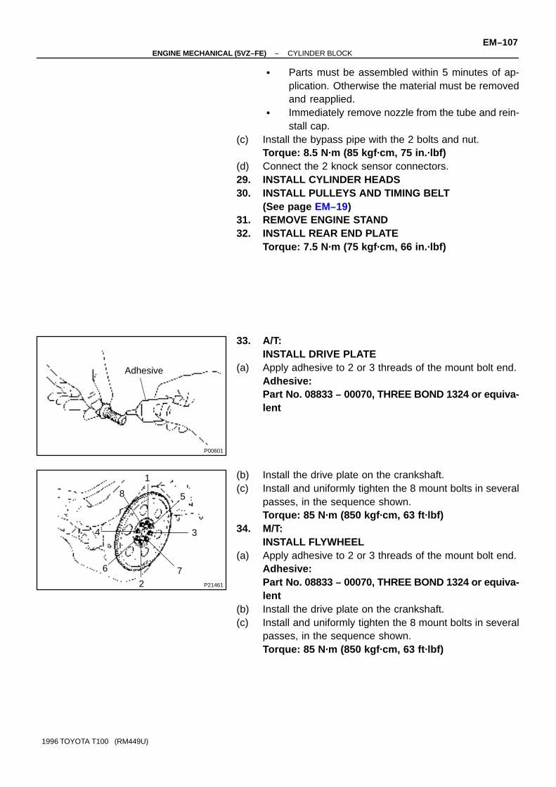
P00601
Adhesive
P21461
1
5
3
72
6
8
4
−ENGINE MECHANICAL (5VZ−FE) CYLINDER BLOCKEM−107
1996 TOYOTA T100 (RM449U)
� Parts must be assembled within 5 minutes of ap-plication. Otherwise the material must be removedand reapplied.
� Immediately remove nozzle from the tube and rein-stall cap.
(c) Install the bypass pipe with the 2 bolts and nut.Torque: 8.5 N·m (85 kgf·cm, 75 in.·lbf)
(d) Connect the 2 knock sensor connectors.29. INSTALL CYLINDER HEADS30. INSTALL PULLEYS AND TIMING BELT
(See page EM−19)31. REMOVE ENGINE STAND32. INSTALL REAR END PLATE
Torque: 7.5 N·m (75 kgf·cm, 66 in.·lbf)
33. A/T:INSTALL DRIVE PLATE
(a) Apply adhesive to 2 or 3 threads of the mount bolt end.Adhesive:Part No. 08833 − 00070, THREE BOND 1324 or equiva-lent
(b) Install the drive plate on the crankshaft.(c) Install and uniformly tighten the 8 mount bolts in several
passes, in the sequence shown.Torque: 85 N·m (850 kgf·cm, 63 ft·lbf)
34. M/T:INSTALL FLYWHEEL
(a) Apply adhesive to 2 or 3 threads of the mount bolt end.Adhesive:Part No. 08833 − 00070, THREE BOND 1324 or equiva-lent
(b) Install the drive plate on the crankshaft.(c) Install and uniformly tighten the 8 mount bolts in several
passes, in the sequence shown.Torque: 85 N·m (850 kgf·cm, 63 ft·lbf)
https://www.truck-manuals.net/

EM07F−01
P24419
EM−108−ENGINE MECHANICAL (5VZ−FE) EXHAUST SYSTEM
927Author�: Date�:
1996 TOYOTA T100 (RM449U)
EXHAUST SYSTEMCOMPONENTS
https://www.truck-manuals.net/

P24450
−ENGINE MECHANICAL (5VZ−FE) EXHAUST SYSTEMEM−109
928Author�: Date�:
1996 TOYOTA T100 (RM449U)
https://www.truck-manuals.net/

EC – EMISSIONS CONTROL (3RZ-FE)
EMISSION CONTROL SYSTEM EC-1 PARTS LAYOUT AND SCHEMATIC DRAWING
EC-2
POSITIVE CRANKCASE VENTILATION (PCV) SYSTEM
EC-4
EVAPORATIVE EMISSION (EVAP) CONTROL SYSTEM
EC-5
EXHAUST GAS RECIRCULATION (EGR) SYSTEM
EC-7
THREE-WAY CATALYTIC CONVERTER (TWC) SYSTEM
EC-10
https://www.truck-manuals.net/

EC02N−02
−EMISSION CONTROL (3RZ−FE) EMISSION CONTROL SYSTEMEC−1
929Author�: Date�:
1996 TOYOTA T100 (RM449U)
EMISSION CONTROL SYSTEMPURPOSEThe emission control systems are installed to reduce the amount of CO, HC and NOx exhausted from theengine ((3), (4) and (5)), to prevent the atmospheric release of blow−by gas−containing HC (1) and evapo-rated fuel containing HC being released from the fuel tank (2).The function of each system is shown in these table.
System Abbreviation Function
(1) Positive Crankcase Ventilation
(2) Evaporative Emission Control
(3) Exhaust Gas Recirculation
(4) Three−Way Catalytic Converter
(5) Multiport Fuel Injection *
PCV
EVAP
EGR
TWC
MFI
Reduces HC
Reduces evaporated HC
Reduces NOx
Reduces CO, HC and NOx
Injects a precisely timed, optimum amount of fuel for reduced exhaust
emissions
Remark: * For inspection and repair of the MFI system, refer to the MF section this manual.
https://www.truck-manuals.net/

EC02O−02
EC−2−EMISSION CONTROL (3RZ−FE) PARTS LAYOUT AND SCHEMATIC DRAWING
930Author�: Date�:
1996 TOYOTA T100 (RM449U)
PARTS LAYOUT AND SCHEMATIC DRAWINGLOCATION
https://www.truck-manuals.net/

EC02P−02
−EMISSION CONTROL (3RZ−FE) PARTS LAYOUT AND SCHEMATIC DRAWINGEC−3
1996 TOYOTA T100 (RM449U)
DRAWING
https://www.truck-manuals.net/

P05445
Cylinder Head Cover Side
Clean Hose
P05444
Air Intake Chamber Side
EC02Q−01
P15871
EC−4 −EMISSION CONTROL (3RZ−FE) POSITIVE CRANKCASE VENTILATION (PCV) SYSTEM
932Author�: Date�:
1996 TOYOTA T100 (RM449U)
POSITIVE CRANKCASEVENTILATION (PCV) SYSTEMINSPECTION1. REMOVE PCV VALVE2. INSTALL CLEAN HOSE TO PCV VALVE3. INSPECT PCV VALVE OPERATION(a) Blow into the cylinder head cover side, and check that air
passes through easily.CAUTION:Do not suck air through the valve. Petroleum substancesinside the valve are harmful.(b) Blow air into the air intake chamber side, and check that
air passes through with difficulty.If operation is not as specified, replace the PCV valve.4. REMOVE CLEAN HOSE FROM PCV VALVE5. REINSTALL PCV VALVE
6. VISUALLY INSPECT HOSES AND CONNECTIONSCheck for cracks, leaks or damage.
https://www.truck-manuals.net/

EC0GF−01
EC3069Check Valve (Vacuum Valve)
Gasket
−EMISSION CONTROL (3RZ−FE) EVAPORATIVE EMISSION (EVAP) CONTROL SYSTEMEC−5
933Author�: Date�:
1996 TOYOTA T100 (RM449U)
EVAPORATIVE EMISSION (EVAP)CONTROL SYSTEMINSPECTION1. VISUALLY INSPECT LINES AND CONNECTIONSLook for loosen connections, sharp bends or damage.2. VISUALLY INSPECT FUEL TANKLook for deformation, cracks or fuel leakage.
3. VISUALLY INSPECT FUEL TANK CAPCheck if the cap and/or gasket are deformed or damaged.If necessary, repair or replace the cap.4. REMOVE VSVRemove the screw from the charcoal canister.5. REMOVE CHARCOAL CANISTER6. REMOVE CAP FROM CHARCOAL CANISTER
7. VISUALLY INSPECT CHARCOAL CANISTERLook for cracks or damage.
8. INSPECT FOR CLOGGED FILTER AND STUCKCHECK VALVE
(a) Using low pressure compressed air (4.71 kPa, 48 gf/cm2,0.68 psi), blow into tank pipe and check that air flows with-out resistance from the other pipes.
(b) Blow air (4.71 kPa, 48 gf/cm2, 0.68 psi) into purge pipeand check that air does not flow from the tank pipe and airflows without resistance from the other pipe.
If a problem is found, replace the charcoal canister.
https://www.truck-manuals.net/

EC−6−EMISSION CONTROL (3RZ−FE) EVAPORATIVE EMISSION (EVAP) CONTROL SYSTEM
934Author�: Date�:
1996 TOYOTA T100 (RM449U)
9. CLEAN FILTER IN CANISTERClean the filter by blowing 294 kPa (3 kgf·cm2, 43 psi) of com-pressed air into tank pipe while holding purge pipe closedNOTICE:� Do not attempt to wash the canister.� No activated carbon should come out.
10. REINSTALL CAP TO CHARCOAL CANISTER11. RECONNECT CHARCOAL CANISTER
Torque: 31 N·m (310 kgf·cm, 23 ft·lbf)12. REINSTALL VSV
https://www.truck-manuals.net/

P23029
Cap
Filter EC0JU−01
P15107
P22300
TOYOTA Hand−Held Tester
DLC3
−EMISSION CONTROL (3RZ−FE) EXHAUST GAS RECIRCULATION (EGR) SYSTEMEC−7
935Author�: Date�:
1996 TOYOTA T100 (RM449U)
EXHAUST GAS RECIRCULATION(EGR) SYSTEMINSPECTION1. INSPECT AND CLEAN FILTER IN EGR VACUUM MOD-
ULATOR(a) Remove the cap and filter.(b) Check the filter for contamination or damage.(c) Using compressed air, clean the filter.(d) Install the filter and cap.HINT:Install the filter with the coarser surface facing the atmosphericside (outward).
2. INSTALL VACUUM GAUGEUsing a 3−way connector, connect a vacuum gauge to the hosebetween the EGR valve and EGR vacuum modulator.3. INSPECT SEATING OF EGR VALVEStart the engine and check that the engine starts and runs atidle.
4. CONNECT TOYOTA HAND−HELD TESTER OR OBDIISCAN TOOL
(a) Connect the TOYOTA hand−held tester or OBDII scantool to the DLC3.
(b) Please refer to the TOYOTA hand−held tester or OBDIIscan tool operators manual for further details.
5. INSPECT VSV OPERATION WITH COLD ENGINE(a) The engine coolant temperature should be below 50°C
(122°F).(b) Check that the vacuum gauge indicates zero at 3,500
rpm.(c) Check that the EGR pipe is not hot.6. INSPECT OPERATION OF VSV AND EGR VACUUM
MODULATOR(a) Select the active test mode on the TOYOTA hand−held
tester (VSV is closed.).
https://www.truck-manuals.net/

P23481
3−Way
Plug
Port Q
Low Vacuum
Z15471
B
A
A
B
EC−8−EMISSION CONTROL (3RZ−FE) EXHAUST GAS RECIRCULATION (EGR) SYSTEM
936Author�: Date�:
1996 TOYOTA T100 (RM449U)
(b) If you have no TOYOTA hand−held tester, check theseprocedures:(1) Remove the 3−way connector with the vacuum
hose.(2) Connect the vacuum hose (from port Q of EGR vac-
uum modulator) to the EGR valve.(3) Plug the vacuum hose (from VSV for EGR).
(c) Check that the vacuum gauge indicates low vacuum at3,500 rpm.
7. DISCONNECT TOYOTA HAND−HELD TESTER OROBDII SCAN TOOL
8. REMOVE VACUUM GAUGERemove the vacuum gauge, and reconnect the vacuum hosesto the proper locations.
9. INSPECT EGR VALVE(a) Apply vacuum directly to the EGR valve with the engine
idling.(b) Check that the engine runs rough or dies.(c) Reconnect the vacuum hoses to the proper locations.If no problem is found with this inspection, system is normal;otherwise inspect each part.
10. REMOVE EGR PIPERemove the bolt, 4 nuts, EGR pipe and 2 gaskets.HINT:Install 2 new gaskets.
Torque:Bolt: 18 N·m (185 kgf·cm, 13 ft·lbf)Nut A: 19 N·m (195 kgf·cm, 14 ft·lbf)Nut B: 20 N·m (200 kgf·cm, 15 ft·lbf)
11. REMOVE EGR VALVE(a) Disconnect these hoses:
� 2 Vacuum hoses� 2 Water bypass hoses
(b) Remove the 2 nuts, EGR valve and gasket.Torque: 19 N·m (195 kgf·cm, 14 ft·lbf)
https://www.truck-manuals.net/

EC0107
Orange Pipe
Black Pipe
−EMISSION CONTROL (3RZ−FE) EXHAUST GAS RECIRCULATION (EGR) SYSTEMEC−9
937Author�: Date�:
1996 TOYOTA T100 (RM449U)
12. DISCONNECT VACUUM HOSES FROM EGR VACUUMMODULATOR
13. INSPECT EGR VACUUM MODULATOR OPERATION(a) Block ports P and R with your finger.(b) Blow air into port Q, and check that the air passes through
to the air filter side freely.
(c) Start the engine, and maintain speed at 3,500 rpm.(d) Repeat the above test. Check that there is a strong resis-
tance to air flow.If operation is not as specified, replace the EGR vacuum modu-lator.14. RECONNECT VACUUM HOSES TO EGR VACUUM
MODULATOR
15. REMOVE CHECK VALVE16. INSPECT CHECK VALVE(a) Check that air flows from the orange pipe to the black
pipe.(b) Check that air does not flow from the black pipe to the
orange pipe.If operation is not as specified, replace the check valve.17. INSTALL CHECK VALVEHINT:Install the check valve with the orange pipe facing the EGR vac-uum modulator side.18. INSPECT VSV FOR EGR (See page MF−44)
https://www.truck-manuals.net/
EC02T−01
EC−10 −EMISSION CONTROL (3RZ−FE) THREE−WAY CATALYTIC CONVERTER (TWC) SYSTEM
938Author�: Date�:
1996 TOYOTA T100 (RM449U)
THREE−WAY CATALYTIC CONVERTER (TWC) SYSTEMINSPECTION1. CHECK TWC FOR DENTS OR DAMAGEIf any part of the protector is damaged or dented to the extent that it touches the three−way catalytic convert-er, repair or replace it.2. CHECK EXHAUST PIPE CONNECTIONS FOR
LOOSENESS OR DAMAGE3. CHECK EXHAUST PIPE CLUMPS FOR WEAKNESS,CRACKS OR DAMAGE4. CHECK HEAT INSULATOR FOR DAMAGE5. CHECK FOR ADEQUATE CLEARANCE BETWEEN CATALYTIC CONVERTER AND HEAT INSU-
LATOR
https://www.truck-manuals.net/

EC02U−03
P21187
P21181
−EMISSION CONTROL (3RZ−FE) THREE−WAY CATALYTIC CONVERTER (TWC) SYSTEM
EC−11
1996 TOYOTA T100 (RM449U)
REPLACEMENT1. REMOVE CENTER EXHAUST PIPE(a) Disconnect the 2 rings from the support bracket.(b) Remove the 2 nuts and gasket, and disconnect the
heated oxygen sensor (bank 1 sensor 2).Torque: 20 N·m (200 kgf·cm, 14 ft·lbf)
HINT:At the time of assembly please refer to the following item.Install the heated oxygen sensor with a new gasket.
(c) Remove the 4 bolts, TWC joint retainer, center exhaustpipe and 2 gasket.Torque: 48 N·m (490 kgf·cm, 35 ft·lbf)
HINT:At the time of assembly please refer to the following item.Place 2 new gaskets on the front exhaust and tail pipes, andtemporarily install the center exhaust pipe.2. REINSTALL CENTER EXHAUST PIPE
https://www.truck-manuals.net/

EC – EMISSIONS CONTROL (5VZ-FE)
EMISSION CONTROL SYSTEM EC-1 PARTS LAYOUT AND SCHEMATIC DRAWING
EC-2
POSITIVE CRANKCASE VENTILATION (PCV) SYSTEM
EC-4
EVAPORATIVE EMISSION (EVAP) CONTROL SYSTEM
EC-5
EXHAUST GAS RECIRCULATION (EGR) SYSTEM
EC-7
THREE-WAY CATALYTIC CONVERTER (TWC) SYSTEM
EC-12
https://www.truck-manuals.net/

EC032−03
−EMISSION CONTROL (5VZ−FE) EMISSION CONTROL SYSTEMEC−1
940Author�: Date�:
1996 TOYOTA T100 (RM449U)
EMISSION CONTROL SYSTEMPURPOSEThe emission control systems are installed to reduce the amount of CO, HC and NOx exhausted from theengine ((3) and (4)), to prevent the atmospheric release of blow−by gas−containing HC (1) and evaporatedfuel containing HC being released from the fuel tank (2).The function of each system is shown in these table.
System Abbreviation Function
(1) Positive Crankcase Ventilation
(2) Evaporative Emission Control
(3) Exhaust Gas Recirculation
(4) Three−Way Catalytic Converter
(5) Sequential Multiport Fuel Injection *
PCV
EVAP
EGR
TWC
SFI
Reduces crankcase blow−by gas (HC)
Reduces evaporated HC
Reduces NOx
Reduces CO, HC and NOx
Injects a precisely timed, optimum amount of fuel for reduced
exhaust emissions
Remark: * For inspection and repair of the SFI system, refer to the SF section of this manual.
https://www.truck-manuals.net/

EC033−03
B13074
EC−2−EMISSION CONTROL (5VZ−FE) PARTS LAYOUT AND SCHEMATIC DRAWING
941Author�: Date�:
1996 TOYOTA T100 (RM449U)
PARTS LAYOUT AND SCHEMATIC DRAWINGLOCATION
https://www.truck-manuals.net/

EC034−03
B13075
−EMISSION CONTROL (5VZ−FE) PARTS LAYOUT AND SCHEMATIC DRAWINGEC−3
1996 TOYOTA T100 (RM449U)
DRAWING
https://www.truck-manuals.net/

P20280
PCV Valve
EC035−04
P21212
Cylinder Head Cover Side
Clean Hose
P21213
Air Intake Chamber Side
P21214
Air Intake Chamber Side
P21676
EC−4 −EMISSION CONTROL (5VZ−FE) POSITIVE CRANKCASE VENTILATION (PCV) SYSTEM
943Author�: Date�:
1996 TOYOTA T100 (RM449U)
POSITIVE CRANKCASEVENTILATION (PCV) SYSTEMINSPECTION1. REMOVE PCV VALVE(a) Disconnect the PCV hose from the PCV valve.(b) Remove the PCV valve.
2. INSTALL CLEAN HOSE TO PCV VALVE3. INSPECT PCV VALVE OPERATION(a) Blow air into the cylinder head cover side, and check that
air passes through easily.CAUTION:Do not suck air through the valve.Petroleum substances inside the valve are harmful.
(b) Blow air into the air intake chamber side, and check thatair passes through with difficulty.
(c) Blow air into the air intake chamber side when lift up theinside valve, and check that there is a strong resistanceto air flow.
If operation is not as specified, replace the PCV valve.4. REMOVE CLEAN HOSE FROM PCV VALVE5. REINSTALL PCV VALVE
6. VISUALLY INSPECT HOSES, CONNECTIONS ANDGASKETS
Check for cracks, leaks or damage.
https://www.truck-manuals.net/

EC0JV−01
EC3069
Gasket
Check Valve (Vacuum Valve)
−EMISSION CONTROL (5VZ−FE) EVAPORATIVE EMISSION (EVAP) CONTROL SYSTEMEC−5
944Author�: Date�:
1996 TOYOTA T100 (RM449U)
EVAPORATIVE EMISSION (EVAP)CONTROL SYSTEMINSPECTION1. VISUALLY INSPECT LINES AND CONNECTIONSLook for loose connections, sharp bends or damage.2. VISUALLY INSPECT FUEL TANKLook for deformation, cracks or fuel leakage.
3. VISUALLY INSPECT FUEL TANK CAPCheck if the cap and/or gasket are deformed or damaged.If necessary, repair or replace the cap.4. REMOVE VSV5. REMOVE CHARCOAL CANISTER
6. VISUALLY INSPECT CHARCOAL CANISTERLook for cracks or damage.
7. CHECK FOR CLOGGED FILTER, AND STUCKCHECK VALVE
(a) Using low pressure compressed air (4.71 kPa, 48 gf/cm2,0.68 psi), blow into tank pipe and check that air flows with-out resistance from the other pipes.
(b) Blow low pressure compressed air (4.71 kPa, 48 gf/cm2,0.68 psi) into purge pipe and check that air does not flowfrom the tank pipe.But the air flows without resistance from the other pipe.If a problem is found, replace the charcoal canister.
https://www.truck-manuals.net/

EC−6−EMISSION CONTROL (5VZ−FE) EVAPORATIVE EMISSION (EVAP) CONTROL SYSTEM
945Author�: Date�:
1996 TOYOTA T100 (RM449U)
8. CLEAN FILTER IN CANISTERClean the filter by blowing 294 kPa (3 gf/cm2, 43 psi) of com-pressed air into tank pipe while holding purge pipe closed.NOTICE:� Do not attempt to wash the canister.� No activated carbon should come out.
9. INSPECT VSV FOR EVAP(See page SF−50)
10. REINSTALL VSV11. REINSTALL CHARCOAL CANISTER
https://www.truck-manuals.net/

EC02V−02
P21189
−EMISSION CONTROL (5VZ−FE) EXHAUST GAS RECIRCULATION (EGR) SYSTEMEC−7
946Author�: Date�:
1996 TOYOTA T100 (RM449U)
EXHAUST GAS RECIRCULATION (EGR) SYSTEMCOMPONENTS
https://www.truck-manuals.net/

EC02Z−03
S05202
EC−8−EMISSION CONTROL (5VZ−FE) EXHAUST GAS RECIRCULATION (EGR) SYSTEM
1996 TOYOTA T100 (RM449U)
REMOVAL1. DRAIN ENGINE COOLANT2. REMOVE EGR PIPERemove the 6 nuts, EGR pipe and 2 gaskets.HINT:At the time of installation, please refer to the following item.Ins-tall 2 new gaskets.
Torque:Nut A: 18.5 N·m (185 kgf·cm, 14 ft·lbf)Nut B: 8.0 N·m (80 kgf·cm, 71 in.·lbf)
3. REMOVE EGR GAS TEMPERATURE SENSOR4. REMOVE EGR VALVE(a) Disconnect these hoses from the EGR valve:
� Vacuum hose (from VSV for EGR)� EGR hose (from EGR vacuum modulator)� Water hose (from water bypass pipe)� Water bypass hose (from IAC valve)
(b) Remove the 2 nuts, EGR valve and gasket.Torque: 18.5 N·m (185 kgf·cm, 14 ft·lbf)
HINT:Use a new gasket.At the time of installation, please refer to the following item.(c) Check for sticking and heavy carbon deposits. If problem
is found, replace the EGR valve.
https://www.truck-manuals.net/

P23552
P23553
EC02W−02
P19970
DLC1
DLC1
TE1 E1
SST
P19945
P23554
−EMISSION CONTROL (5VZ−FE) EXHAUST GAS RECIRCULATION (EGR) SYSTEMEC−9
1996 TOYOTA T100 (RM449U)
INSPECTION1. CHECK AND CLEAN FILTER IN EGR VACUUM MOD-
ULATOR(a) Remove the cap and filter.(b) Check the filter for contamination or damage.(c) Using compressed air, clean the filter.(d) Reinstall the filter and cap.HINT:Install the filter with the coarser surface facing out to the atmo-spheric side.
2. INSTALL VACUUM GAUGEUsing a 3−way connector, connect a vacuum gauge to the hosebetween the EGR valve and VSV.3. INSPECT SEATING OF EGR VALVECheck that the engine starts and runs at idle.
4. CONNECT TERMINALS TE1 AND E1Using SST, connect terminals TE1 and E1 of the DLC1.
SST 09843−18020
5. INSPECT VSV OPERATION WITH COLD ENGINE(a) The engine coolant temperature should be below 45°C
(113°F).(b) Check that the vacuum gauge indicates zero at 2,800
rpm.(c) Check that the EGR pipe is not hot.
6. INSPECT OPERATION OF VSV AND EGR VACUUMMODULATOR WITH HOT ENGINE
(a) Warm up the engine to above 80°C (176°F).(b) Check that the vacuum gauge indicates low vacuum at
2,800 rpm.(c) Disconnect the vacuum hose from port R of the EGR vac-
uum modulator and connect port R directly to the intakemanifold with another hose.
https://www.truck-manuals.net/

P23555
P23551
P23556
P23557
EC−10−EMISSION CONTROL (5VZ−FE) EXHAUST GAS RECIRCULATION (EGR) SYSTEM
1996 TOYOTA T100 (RM449U)
(d) Check that the vacuum gauge indicates high vacuum at3,500 rpm.
HINT:As exhaust gas is increasingly recirculated, the engine will startto misfire.7. DISCONNECT TERMINALS TE1 AND E1Remove the SST from the DLC1.
SST 09843−180208. REMOVE VACUUM GAUGERemove the vacuum gauge, and reconnect the vacuum hosesto their proper locations.9. INSPECT EGR VALVE(a) Apply vacuum directly to the EGR valve with the engine
idle.(b) Check that the engine runs rough or dies.(c) Reconnect the vacuum hoses to their proper locations.If no problem is found during this inspection, system is normal;otherwise inspect each part.
10. DISCONNECT VACUUM HOSES FROM EGR VACUUMMODULATOR
Disconnect these vacuum hoses:(1) Vacuum hose from R port(2) Vacuum hose from Q port(3) Vacuum hose from P port
11. INSPECT EGR VACUUM MODULATOR OPERATION(a) Block ports P and R with your finger.(b) Blow air into port Q, and check that the air passes through
to the air filter side freely.
(c) Start the engine, and maintain speed at 3,500 rpm.(d) Repeat the above test. Check that there is a strong resis-
tance to air flow.12. RECONNECT VACUUM HOSES TO EGR VACUUM
MODULATORConnect these vacuum hoses:
(1) Vacuum hose to R port(2) Vacuum hose to Q port(3) Vacuum hose to P port
https://www.truck-manuals.net/

EC02X−02
−EMISSION CONTROL (5VZ−FE) EXHAUST GAS RECIRCULATION (EGR) SYSTEMEC−11
1996 TOYOTA T100 (RM449U)
INSTALLATIONInstallation is in the reverse order of removal (See page EC−8).
https://www.truck-manuals.net/

EC030−01
EC−12 −EMISSION CONTROL (5VZ−FE) THREE−WAY CATALYTIC CONVERTER (TWC) SYSTEM
951Author�: Date�:
1996 TOYOTA T100 (RM449U)
THREE−WAY CATALYTICCONVERTER (TWC) SYSTEMINSPECTION1. CHECK TWC FOR DENTS OR DAMAGEIf any part of the protector is damaged or dented to the extentthat it contacts the three−way catalytic converter, repair or re-place it.2. CHECK CONNECTIONS EXHAUST PIPE FOR
LOOSENESS OR DAMAGE3. CHECK EXHAUST PIPE CLAMPS FOR WEAKNESS,
CRACKS OR DAMAGE4. CHECK HEAT INSULATOR FOR DAMAGE5. CHECK FOR ADEQUATE CLEARANCE BETWEEN
CATALYTIC CONVERTER AND HEAT INSULATOR
https://www.truck-manuals.net/

EC031−04
P21187
P21181
−EMISSION CONTROL (5VZ−FE) THREE−WAY CATALYTIC CONVERTER (TWC) SYSTEM
EC−13
1996 TOYOTA T100 (RM449U)
REPLACEMENT1. REMOVE CENTER EXHAUST PIPE(a) 2WD:
Disconnect the 2 rings from the support bracket.(b) Remove the 2 nuts and gasket, and disconnect the
heated oxygen sensor (bank 1 sensor 2).Torque: 20 N·m (200 kgf·cm, 14 ft·lbf)
HINT:Use a new gasket.
(c) Remove the 4 bolts, TWC joint retainer, center exhaustpipe and 2 gasket.Torque: 48 N·m (490 kgf·cm, 35 ft·lbf)
2. REINSTALL CENTER EXHAUST PIPEHINT:Place 2 new gaskets on the front exhaust and tail pipes, andtemporarily install the center exhaust pipe.
https://www.truck-manuals.net/

MF – MFI SYSTEM (3RZ-FE)
MFI SYSTEM MF-1 FUEL PUMP MF-5 FUEL PRESSURE REGULATOR MF-13 INJECTOR MF-16 FUEL TANK AND LINE MF-23 THROTTLE BODY MF-25 IDLE AIR CONTROL (IAC) VALVE MF-31 MASS AIR FLOW (MAF) METER MF-36 EFI MAIN RELAY MF-40 CIRCUIT OPENING RELAY MF-41 VSV FOR EVAPORATIVE EMISSION (EVAP)
MF-43
VSV FOR EXHAUST GAS RECIRCULATION (EGR)
MF-44
ENGINE COOLANT TEMPERATURE (ECT) SENSOR
MF-45
INTAKE AIR TEMPERATURE (IAT) SENSOR
MF-46
KNOCK SENSOR MF-47 EXHAUST GAS RECIRCULATION (EGR) GAS TEMPERATURE SENSOR
MF-48
HEATED OXYGEN SENSOR MF-49 ENGINE CONTROL MODULE (ECM) MF-50 FUEL CUT RPM MF-54
https://www.truck-manuals.net/

SF0AF−04
−MFI (3RZ−FE) MFI SYSTEMMF−1
953Author�: Date�:
1996 TOYOTA T100 (RM449U)
MFI SYSTEMPRECAUTION1. BEFORE WORKING ON FUEL SYSTEM, DISCON-
NECT NEGATIVE (−) TERMINAL CABLE FROM BAT-TERY
HINT:Any diagnostic trouble code retained by the ECM will be erasedwhen the battery negative (−) terminal cable is removed fromthe battery.Therefore, if necessary, read the diagnostic trouble code(s) be-fore removing the negative (−) terminal cable from the battery.2. DO NOT SMOKE OR WORK NEAR AN OPEN FLAME
WHEN WORKING ON FUEL SYSTEM3. KEEP GASOLINE AWAY FROM RUBBER OR LEATH-
ER PARTS4. MAINTENANCE PRECAUTIONS(a) Precaution when the connecting gauge.
Use battery as the power source for the timing light, etc.(b) In the event of engine misfire, these precautions should
be taken.(1) Check proper connection of battery terminals, etc.(2) Handle high−tension cords carefully.(3) After repair work, check that the ignition coil termi-
nals and all other ignition system lines are recon-nected securely.
(4) When cleaning the engine compartment, be espe-cially careful to protect the electrical system fromwater.
(c) Precautions when the handling heated oxygen sensors.(1) Do not allow oxygen sensor to drop or hit against an
object.(2) Do not allow the sensor to come into contact with
water.If Vehicle is Equipped with Mobile Radio System (ham, cb, etc.)If the vehicle is equipped with a mobile communication system,refer to the precaution in the IN section.5. AIR INDUCTION SYSTEM(a) Separation of the engine oil dipstick, oil filler cap, PCV
hose, etc. may cause the engine to run out of tune.(b) Disconnection, looseness or cracks in the parts of the air
induction system between the throttle body and cylinderhead will cause air suction and cause the engine to runout of tune.
https://www.truck-manuals.net/

FI2553
SST
MF−2−MFI (3RZ−FE) MFI SYSTEM
954Author�: Date�:
1996 TOYOTA T100 (RM449U)
6. ELECTRONIC CONTROL SYSTEM(a) Before removing SFI wiring connectors, terminals, etc.,
first disconnect the power by either turning the ignitionswitch to LOCK or disconnecting the negative (−) terminalcable from the battery.
HINT:Always check the diagnostic trouble code before disconnectingthe battery terminal cable.(b) When installing the battery, be especially careful not to in-
correctly connect the positive (+) and negative (−) cableterminals.
(c) Do not permit parts to receive a severe impact during re-moval or installation. Handle all SFI parts carefully, espe-cially the ECM.
(d) Do not be careless during troubleshooting as there arenumerous transistor circuits and even slight terminal con-tact can further troubles.
(e) Do not open the ECM cover.(f) When inspecting during rainy weather, take care to pre-
vent entry of water. Also, when washing the enginecompartment, prevent water from getting on the SFI partsand wiring connectors.
(g) Parts should be replaced as an assembly.(h) Care is required when pulling out and inserting wiring con-
nectors.(1) Release the lock and pull out the connector, pulling
on the connectors.(2) Fully insert the connector and check that it is locked.
(i) When inspecting a connector with a volt/ohmmeter.(1) Carefully take out the water−proofing rubber if it is
a water−proof type connector.(2) Insert the test probe into the connector from wiring
side when checking the continuity, amperage orvoltage.
(3) Do not apply unnecessary force to the terminal.(4) After checking, install the water−proofing rubber on
the connector securely.
(5) Use SST for inspection or test of the injector or itswiring connector.
SST 09842−30070
https://www.truck-manuals.net/

P15006
Plug
P15007
New Gasket
NewGasket
FI1654
SST
Fulcrum Length
30 cm
P15750
Grommet
New O−Ring
Delivery Pipe
CORRECT
WRONG
P15128
Delivery Pipe
Injector
Insulator
O−RingGrommet
−MFI (3RZ−FE) MFI SYSTEMMF−3
955Author�: Date�:
1996 TOYOTA T100 (RM449U)
7. FUEL SYSTEM(a) When disconnecting the high pressure fuel line, a large
amount of gasoline will spill out, so observe these proce-dures:(1) Put a container under the connection.(2) Slowly loosen the connection.(3) Disconnect the connection.(4) Plug the connection with a rubber plug.
(b) When connecting the flare nut or union bolt on the highpressure pipe union, observe these procedures:(1) (Union Bolt Type)
Always use a new gasket.(2) (Union Bolt Type)
Tighten the union bolt by hand.(3) (Union Bolt Type)
Tighten the union bolt to the specified torque.Torque: 29 N·m (300 kgf·cm, 22 ft·lbf)
(4) (Flare Nut Type)Apply a light coat of engine oil to the flare and tight-en the flare nut by hand.
(5) (Flare Nut Type)Using SST, tighten the flare nut to the specifiedtorque.
SST 09631−22020Torque: 30 N·m (310 kgf·cm, 22 ft·lbf)
HINT:Use a torque wrench with a fulcrum length of 30 cm (11.81 in.).(c) Observe these precautions when removing and installing
the injectors.(1) Never reuse the O−ring.(2) When placing a new O−ring on the injector, take
care not to damage it in any way.(3) Coat a new O−ring with spindle oil or gasoline be-
fore installing−never use engine, gear or brake oil.
(d) Install the injector to the delivery pipe and cylinder headas shown in the illustration.
https://www.truck-manuals.net/
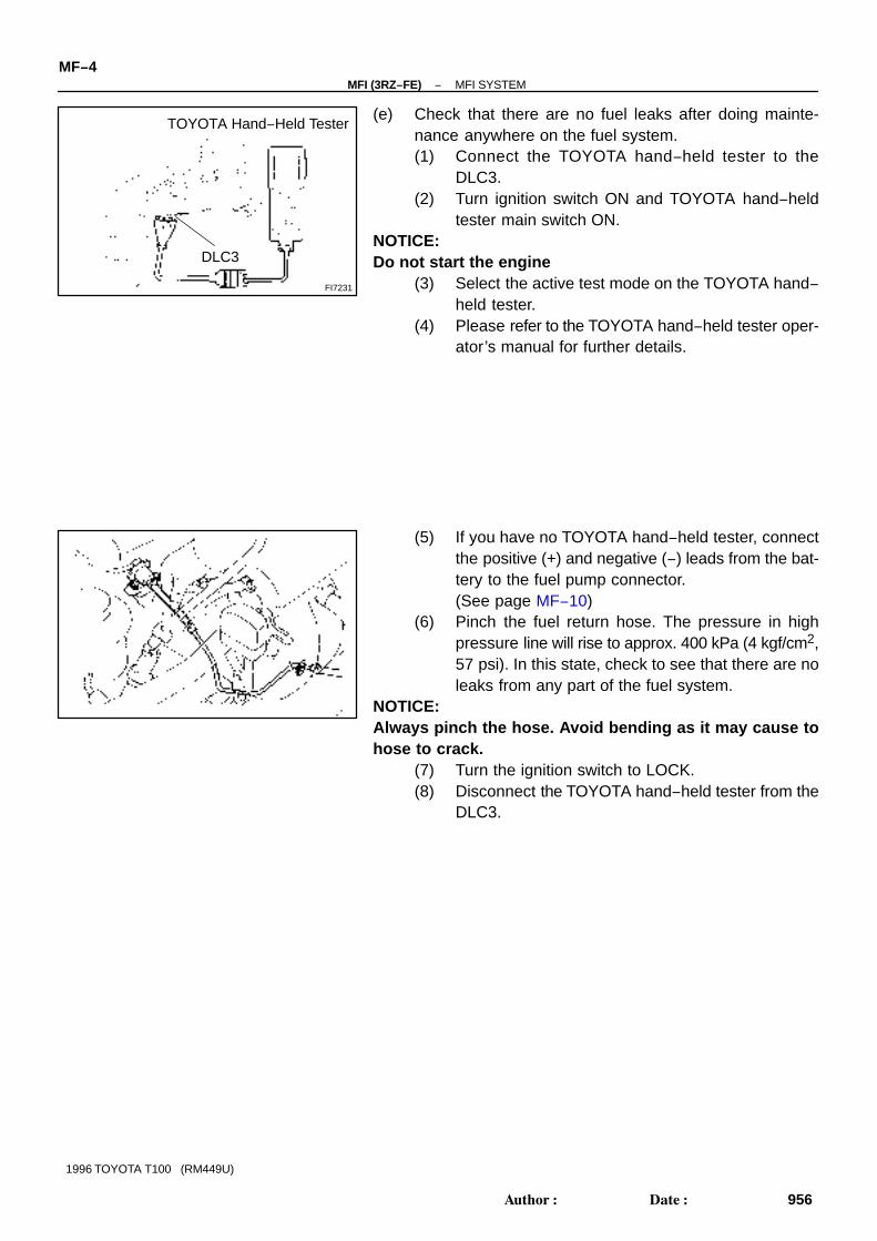
FI7231
TOYOTA Hand−Held Tester
DLC3
MF−4−MFI (3RZ−FE) MFI SYSTEM
956Author�: Date�:
1996 TOYOTA T100 (RM449U)
(e) Check that there are no fuel leaks after doing mainte-nance anywhere on the fuel system.(1) Connect the TOYOTA hand−held tester to the
DLC3.(2) Turn ignition switch ON and TOYOTA hand−held
tester main switch ON.NOTICE:Do not start the engine
(3) Select the active test mode on the TOYOTA hand−held tester.
(4) Please refer to the TOYOTA hand−held tester oper-ator’s manual for further details.
(5) If you have no TOYOTA hand−held tester, connectthe positive (+) and negative (−) leads from the bat-tery to the fuel pump connector.(See page MF−10)
(6) Pinch the fuel return hose. The pressure in highpressure line will rise to approx. 400 kPa (4 kgf/cm2,57 psi). In this state, check to see that there are noleaks from any part of the fuel system.
NOTICE:Always pinch the hose. Avoid bending as it may cause tohose to crack.
(7) Turn the ignition switch to LOCK.(8) Disconnect the TOYOTA hand−held tester from the
DLC3.
https://www.truck-manuals.net/

FI7231
TOYOTA Hand−Held Tester
DLC3
SF0AG−03
P24761
−MFI (3RZ−FE) FUEL PUMPMF−5
957Author�: Date�:
1996 TOYOTA T100 (RM449U)
FUEL PUMPON−VEHICLE INSPECTION1. CHECK FUEL PUMP OPERATION(a) Connect the TOYOTA hand−held tester to the DLC3.(b) Turn the ignition switch ON and TOYOTA hand−held tes-
ter main switch ON.NOTICE:Do not start the engine.(c) Select the active test mode on the TOYOTA hand−held
tester.(d) Please refer to the TOYOTA hand−held tester
operator’s manual for further details.(e) If you have no TOYOTA hand−held tester, connect the
positive (+) and negative (−) leads from the battery to thefuel pump connector.(See page MF−10)
(f) Check that there is pressure in the hose from the fuel filter.HINT:At this time, you will hear fuel return noise.If there is no pressure, check these parts:� Fusible links (AM1 40A, AM2 30A, ALT 80A)� Fuses (EFI 15A, IGN 7.5A)� EFI main relay� Fuel pump� ECM� Wiring connections
(g) Turn the ignition switch to LOCK.(h) Remove the TOYOTA hand−held tester.2. CHECK FUEL PRESSURE(a) Check that the battery voltage is above 12 volts.(b) Disconnect the negative (−) terminal cable from the bat-
tery.(c) Remove the union bolt and 2 gaskets, and disconnect the
fuel inlet pipe from the delivery pipe.HINT:� Put a suitable container or shop rag under the delivery
pipe.� Slowly loosen the union bolt.
https://www.truck-manuals.net/

P24762
FI7231
TOYOTA Hand−Held Tester
DLC3
MF−6−MFI (3RZ−FE) FUEL PUMP
958Author�: Date�:
1996 TOYOTA T100 (RM449U)
(d) Install the fuel inlet pipe and SST (pressure gauge) to thedelivery pipe with 3 gaskets and SST (union bolt).SST 09268−45012Torque: 29 N·m (300 kgf·cm, 22 ft·lbf)
(e) Wipe off any splattered gasoline.
(f) Connect the TOYOTA hand−held tester to the DLC3.(g) Turn the ignition switch ON and TOYOTA hand−held tes-
ter main switch ON.NOTICE:Do not start the engine.(h) Select the active test mode on the TOYOTA hand−held
tester.(i) Please refer to the TOYOTA hand−held tester operator’s
manual for further details.(j) If you have no TOYOTA hand−held tester, connect the
positive (+) and negative (−) leads from the battery to thefuel pump connector.(See page MF−10)
(k) Reconnect the negative (−) terminal cable to the battery.(l) Turn the ignition switch ON.(m) Measure the fuel pressure.
Fuel pressure:265 − 304 kPa (2.7 − 3.1 kgf/cm2, 38 − 44 psi)
If pressure is high, replace the fuel pressure regulator.If pressure is low, check these parts:
� Fuel hoses and connections� Fuel pump� Fuel filter� Fuel pressure regulator� Injectors
(n) Remove the TOYOTA hand−held tester.(o) Start the engine.(p) Disconnect the vacuum sensing hose from the fuel pres-
sure regulator, and plug the hose end.(q) Measure the fuel pressure at idle.
Fuel pressure:265 − 304 kPa (2.7 − 3.1 kgf/cm2, 38 − 44 psi)
(r) Reconnect the vacuum sensing hose to the fuel pressureregulator.
(s) Measure the fuel pressure at idle.Fuel pressure:206 − 255 kPa (2.1 − 2.6 kgf/cm2, 31 − 37 psi)
If pressure is not as specified, check the vacuum sensing hoseand fuel pressure regulator.(t) Stop the engine.
https://www.truck-manuals.net/

P24763
−MFI (3RZ−FE) FUEL PUMPMF−7
959Author�: Date�:
1996 TOYOTA T100 (RM449U)
(u) Check that the fuel pressure remains as specified for 5minutes after the engine has stopped.Fuel pressure:147 kPa (1.5 kgf/cm2, 21 psi) or more
If pressure is not as specified, check the fuel pump, pressureregulator and/or injector.
(v) After checking fuel pressure, disconnect the negative (−)terminal cable from the battery and carefully remove SSTto prevent gasoline from splashing.SST 09268−45012
(w) Reconnect the fuel inlet pipe to the delivery pipe with 2new gaskets and the union bolt.Torque: 29 N·m (300 kgf·cm, 22 ft·lbf)
(x) Reconnect the negative (−) terminal cable to the battery.(y) Check for fuel leakage.
https://www.truck-manuals.net/

SF0AH−03
MF−8−MFI (3RZ−FE) FUEL PUMP
1996 TOYOTA T100 (RM449U)
COMPONENTS
https://www.truck-manuals.net/

SF0AI−02
B02579
−MFI (3RZ−FE) FUEL PUMPMF−9
1996 TOYOTA T100 (RM449U)
REMOVALCAUTION:Do not smoke or work near an open flame when working onthe fuel pump.1. REMOVE FUEL TANK
(See page MF−23)
2. REMOVE FUEL PUMP BRACKET ASSEMBLY FROMFUEL TANK
(a) Disconnect the fuel pump connector from the clamp.(b) Remove the 7 bolts.
Torque: 3.9 N·m ( 40 kgf·cm, 35 in.·lbf)(c) Pull out the pump bracket assembly.(d) Remove the gasket from the pump bracket.HINT:At the time assembly please refer to the following items.Install the fuel pump bracket with a new gasket.
https://www.truck-manuals.net/

SF0AJ−03
P15055
P15059
MF−10−MFI (3RZ−FE) FUEL PUMP
1996 TOYOTA T100 (RM449U)
DISASSEMBLY1. INSPECT FUEL PUMP RESISTANCEUsing an ohmmeter, measure the resistance between the ter-minals.
Resistance: 0.2 − 3.0 Ω at 20°C (68°F)If the resistance is not as specified, replace the fuel pump and/or set plate.
2. INSPECT FUEL PUMP OPERATIONConnect the positive (+) lead from the battery to terminal 1 ofthe connector, and the negative (−) lead to terminal 2. Checkthat the fuel pump operates.NOTICE:These tests must be done quickly (within 10 seconds) toprevent the coil from burning out. Keep the fuel pump as faraway from the battery as possible. Always do the switchingat the battery side.If operation is not as specified, replace the fuel pump and/orplate.
3. REMOVE FUEL PUMP FROM FUEL PUMP BRACKET(a) Disconnect the fuel pump connector.(b) Pull off the lower side of the fuel pump from the pump
bracket.(c) Disconnect the fuel hose from the fuel pump, and remove
the fuel pump.(d) Remove the rubber cushion from the fuel pump.
4. REMOVE FUEL PUMP FILTER FROM FUEL PUMP(a) Using a small screwdriver, remove the clip.(b) Pull out the pump filter.
https://www.truck-manuals.net/

SF0AK−02
−MFI (3RZ−FE) FUEL PUMPMF−11
1996 TOYOTA T100 (RM449U)
REASSEMBLYReassembly is in the reverse order of disassembly (See page MF−10).
https://www.truck-manuals.net/

SF0AL−03
MF−12−MFI (3RZ−FE) FUEL PUMP
1996 TOYOTA T100 (RM449U)
INSTALLATIONInstallation is in the reverse order of removal (See page MF−9).
https://www.truck-manuals.net/

SF0AM−02
P25123� Non−reusable part
Vacuum SensingHose
� O−Ring
Fuel PressureRegulator
Fuel ReturnHose
−MFI (3RZ−FE) FUEL PRESSURE REGULATORMF−13
965Author�: Date�:
1996 TOYOTA T100 (RM449U)
FUEL PRESSURE REGULATORCOMPONENTS
https://www.truck-manuals.net/

SF0AN−03
P14968
MF−14−MFI (3RZ−FE) FUEL PRESSURE REGULATOR
1996 TOYOTA T100 (RM449U)
REMOVAL1. DISCONNECT VACUUM SENSING HOSE FROM FUEL
PRESSURE REGULATOR2. DISCONNECT FUEL RETURN HOSE FROM FUEL
PRESSURE REGULATORHINT:Put a suitable container or shop towel under the pressure regu-lator.
3. REMOVE FUEL PRESSURE REGULATOR(a) Remove the 2 bolts and the fuel pressure regulator.
Torque: 8.8 N·m (90 kgf·cm, 78 in.·lbf)(b) Remove the O−ring.HINT:At the time of installation please refer to the following items.Install the pressure regulator with a new O−ring.
https://www.truck-manuals.net/

SF0AO−03
−MFI (3RZ−FE) FUEL PRESSURE REGULATORMF−15
1996 TOYOTA T100 (RM449U)
INSTALLATIONInstallation is in the reverse order of removal (See page MF−14).
https://www.truck-manuals.net/

P25104Sound Scope
SF0AP−03
P24765
P25103
Ohmmeter
MF−16−MFI (3RZ−FE) INJECTOR
968Author�: Date�:
1996 TOYOTA T100 (RM449U)
INJECTORON−VEHICLE INSPECTION1. INSPECT INJECTOR OPERATIONCheck operation sound from each injector.
(1) With the engine running or cranking, use a soundscope to check that there is normal operating noisein proportion to engine speed.
(2) If you have no sound scope, you can check the in-jector transmission operation with your finger.
If no sound or unusual sound is heard, check the wiring connec-tor, injector or injection signal from the ECM.
2. INSPECT INJECTOR RESISTANCE(a) Remove the throttle body.
(See page MF−28)(b) Disconnect the injector connectors.(c) Using an ohmmeter, measure the resistance between the
terminals.Resistance:12 − 16 Ω at 20°C (68°F)
If the resistance is not as specified, replace the injector.(d) Reconnect the injector connectors.(e) Reinstall the throttle body.
(See page MF−30)
https://www.truck-manuals.net/

SF0AQ−02
−MFI (3RZ−FE) INJECTORMF−17
1996 TOYOTA T100 (RM449U)
COMPONENTS
https://www.truck-manuals.net/

SF1QI−01
MF−18−MFI (3RZ−FE) INJECTOR
1996 TOYOTA T100 (RM449U)
REMOVAL1. DRAIN ENGINE COOLANT
2. REMOVE AIR CLEANER CAP, MAF METER AND RES-ONATOR
(a) Disconnect the MAF meter connector, IAT sensor con-nector and wire clamp.
(b) Loosen the air cleaner hose clamp.(c) Loosen the 4 clips, and remove the air cleaner cap, MAF
meter and resonator.3. M/T:
DISCONNECT ACCELERATOR CABLE FROMTHROTTLE BODY
4. A/T:DISCONNECT THROTTLE AND ACCELERATORCABLES FROM THROTTLE BODY
5. REMOVE INTAKE AIR CONNECTOR(a) Disconnect the 2 air hoses.(b) Remove the 2 bolts, hose clamp and intake air connector.6. REMOVE NO. 1 AND NO. 2 PCV HOSES7. DISCONNECT HIGH−TENSION CORDS FROM SPARK
PLUGSNOTICE:Pulling on or bending the cords may damage the conductorinside.Disconnect the distributor connector.8. REMOVE THROTTLE BODY (See page MF−28)9. REMOVE DELIVERY PIPE AND INJECTORS
https://www.truck-manuals.net/

SF0AS−03
P21648
Z14631
SST(Hose)SST
(Union) UnionBolt
Gasket
P15780
SST(Union)
Fuel Return Hose
Fuel PressureRegulator
SST (Hose)
B02507
−MFI (3RZ−FE) INJECTORMF−19
1996 TOYOTA T100 (RM449U)
INSPECTION1. INSPECT INJECTOR INJECTIONCAUTION:Keep injector clean of sparks during the test.
(a) Connect SST (union and hose) to the fuel filter outlet with2 gaskets and the union bolt.SST 09268−41046 (90405−09015)Torque: 29 N·m (300 kgf·cm, 22 ft·lbf)
(b) Remove the fuel pressure regulator.(c) Install the O−ring to the fuel inlet of pressure regulator.(d) Connect SST (hose) to the fuel inlet of the pressure regu-
lator with SST (union) and the 2 bolts.SST 09268−41046 (09268−41091)
(e) Connect the fuel return hose to the fuel outlet of the pres-sure regulator.
(f) Install the grommet and O−ring to the injector.(g) Connect SST (union and hose) to the injector, and hold
the injector and union with SST (clamp).SST 09268−41046
(h) Put the injector into a graduated cylinder.HINT:Install a suitable vinyl hose onto the injector to prevent gasolinefrom splashing out.(i) Connect the TOYOTA hand−held tester to the DLC3.
(See page MF−5)
https://www.truck-manuals.net/

B02508
B02509
MF−20−MFI (3RZ−FE) INJECTOR
1996 TOYOTA T100 (RM449U)
(j) Connect SST (wire) to the injector and battery for 15 se-conds, and measure the injection volume with a gra-duated cylinder. Test each injector 2 or 3 times.SST 09842−30070Volume:69 − 88 cm3 (4.2 − 5.3 cu in.) per 15 secondsDifference between each injector:5 cm3 (0.3 cu in.) or less
If the injection volume is not as specified, replace the injector.2. INSPECT LEAKAGE(a) In the condition above, disconnect the test probes of SST
(wire) from the battery and check the fuel leakage fromthe injector.SST 09842−30070Fuel drop:1 drop or less per 3 minutes
(b) Turn the ignition switch to LOCK.(c) Disconnect the negative (−) terminal cable from battery.(d) Remove SST and TOYOTA hand−held tester.
SST 09268−41046(e) Reinstall the fuel pressure regulator to the delivery pipe.
https://www.truck-manuals.net/

P14758
New Grommet
NewO−Ring
SF0AT−03
P14756
Upward
Turn
Push
P14757
P24768
−MFI (3RZ−FE) INJECTORMF−21
1996 TOYOTA T100 (RM449U)
INSTALLATION1. INSTALL INJECTORS TO DELIVERY PIPE(a) Install a new grommet to the injector.(b) Apply a light coat of gasoline to a new O−ring and install
it to the injector.
(c) While turning the injector left and right, install it to the de-livery pipe. Install the 4 injectors.
(d) Position the injector connector upward.
2. INSTALL INJECTORS AND DELIVERY PIPE(a) Place the 4 new insulators and in position on the spacers.(b) Place the 4 injectors together with the delivery pipe in
position on the cylinder head.(c) Temporarily install the 2 bolts holding the delivery pipe to
the cylinder head.
(d) Check that the injectors rotate smoothly.HINT:If injectors do not rotate smoothly, the probable cause is incor-rect installation of O−rings. Replace the O−rings.(e) Position the injector connector upward.(f) Tighten the 2 bolts holding the delivery pipe to the cylinder
head.Torque: 21 N·m (210 kgf·cm, 15 ft·lbf)
3. INSTALL THROTTLE BODY (See page MF−30)4. REINSTALL HIGH−TENSION CORDS TO SPARK
PLUGS5. INSTALL NO.1 AND NO.2 PCV HOSES6. INSTALL AIR INTAKE CONNECTOR7. M/T:
CONNECT ACCELERATOR CABLE TO THROTTLEBODY
8. A/T:CONNECT THROTTLE AND ACCELERATOR CABLESTO THROTTLE BODY
https://www.truck-manuals.net/

MF−22−MFI (3RZ−FE) INJECTOR
1996 TOYOTA T100 (RM449U)
9. INSTALL MAF METER, RESONATOR AND AIRCLEANER CAP
10. FILL WITH ENGINE COOLANT11. RECHECK ENGINE COOLANT LEVEL
https://www.truck-manuals.net/

SF0AU−02
P21793�Non−reusable part
39 (400, 29)
1.5 (15, 13 in.·lbf)3.9 (40, 35 in.·lbf)
N·m (kgf·cm, ft·lbf)
3.5 (35, 31 in.·lbf)
: Specified torque No.1 Fuel Tank Band
−MFI (3RZ−FE) FUEL TANK AND LINEMF−23
975Author�: Date�:
1996 TOYOTA T100 (RM449U)
FUEL TANK AND LINECOMPONENTSCAUTION:� Always use new gaskets when replacing the fuel tank or component parts.� Apply the proper torque to all parts tightened.
https://www.truck-manuals.net/

BO0919
Crack Leakage
Deformation
Z10162
SST
SST: 09631−22020
Use SST30 N·m(310 kgf·cm, 22 ft·lbf)
FulcrumLength30 cm(11.81 in.)
FU0041
Pipe
0 − 3 mm (0 − 0.12 in.)
2 − 5 mm (0.08 − 0.20 in.)Hose
Clip
SF0AV−02
MF−24−MFI (3RZ−FE) FUEL TANK AND LINE
1996 TOYOTA T100 (RM449U)
INSPECTIONINSPECT FUEL TANK AND LINE(a) Check the fuel lines for cracks or leakage, and all connec-
tions for deformation.(b) Check the fuel tank vapor vent system hoses and connec-
tions for looseness, sharp bends or damage.(c) Check the fuel tank for deformation, cracks, fuel leakage
or tank band looseness.(d) Check the filler neck for damage or fuel leakage.(e) Hose and tube connections are as shown in the illustra-
tion.If a problem is found, repair or replace the part as necessary.
https://www.truck-manuals.net/

B02580
SF1QK−01
−MFI (3RZ−FE) THROTTLE BODYMF−25
977Author�: Date�:
1996 TOYOTA T100 (RM449U)
THROTTLE BODYON−VEHICLE INSPECTION1. INSPECT THROTTLE BODY(a) Check that the throttle linkage moves smoothly.
(b) Check the vacuum at each port.(1) Start the engine.(2) Check the vacuum with your finger.
Port name At idle At 3,500 rpm
P No vacuum Vacuum
E No vacuum Vacuum
R No vacuum Vacuum
2. INSPECT THROTTLE POSITION SENSOR(a) Disconnect the sensor connector.(b) Apply vacuum to the throttle opener.(c) Using an ohmmeter, measure the resistance between
each terminal.
Throttle valve
condition
Between
terminalsResistance
Fully closed VTA − E2 0.2 − 5.7 kΩ
Fully closed IDL − E2 2.3 kΩ or less
Open IDL − E2 Infinity
Fully open VTA − E2 2.0 − 10.2 kΩ
− VC − E2 2.5 − 5.9 kΩ
(d) Connect the sensor connector.3. INSPECT THROTTLE OPENER(a) Warm up engine
Allow the engine to warm up to normal operating tempera-ture.
(b) Connect TOYOTA hand−held tester or OBD II scan tool.(c) Check idle speed
Idle speed: 700 rpm(d) Disconnect the vacuum hose from the throttle opener,
and plug the hose end.
https://www.truck-manuals.net/

MF−26−MFI (3RZ−FE) THROTTLE BODY
978Author�: Date�:
1996 TOYOTA T100 (RM449U)
(e) Check the throttle opener setting speed.Throttle opener setting speed: 1,200 − 1,400 rpm
If the throttle opener setting is not as specified, replace thethrottle body.(f) Stop the engine.(g) Connect the vacuum hose to the throttle opener.(h) Start the engine, and check that the idle speed returns to
the correct speed.(i) Disconnect TOYOTA hand−held tester or OBDII scan
tool.
https://www.truck-manuals.net/

SF0B1−02
P21635
−MFI (3RZ−FE) THROTTLE BODYMF−27
1996 TOYOTA T100 (RM449U)
COMPONENTS
https://www.truck-manuals.net/

SF0B2−02
P24769
P21655
P21654
MF−28−MFI (3RZ−FE) THROTTLE BODY
1996 TOYOTA T100 (RM449U)
REMOVAL1. DRAIN ENGINE COOLANT2. REMOVE AIR CLEANER CAP, MAF METER AND
RESONATOR(a) Disconnect the MAF meter connector, IAT sensor con-
nector and wire clamp.(b) Loosen the air cleaner hose clamp.(c) Loosen the 4 clips, and remove the air cleaner cap, MAF
meter and resonator.
3. M/T:DISCONNECT ACCELERATOR CABLE FROMTHROTTLE BODY
4. A/T:DISCONNECT ACCELERATOR AND THROTTLECABLES FROM THROTTLE BODY
5. REMOVE INTAKE AIR CONNECTOR(a) Disconnect the 2 air hoses.(b) Remove the 2 bolts, hose clamp and intake air connector.6. REMOVE NO.1 AND NO.2 PCV HOSES
7. REMOVE THROTTLE BODY(a) Disconnect the throttle position sensor connector.(b) Disconnect the IAC valve connector.(c) Disconnect the EVAP hose.(d) Disconnect the 3 vacuum hoses.(e) Remove the 2 bolts, 2 nuts and disconnect the throttle
body from the air intake chamber.Torque: 20 N·m (200 kgf·cm, 14 ft·lbf)
(f) Remove the throttle body gasket.HINT:At the time assembly please refer to the following items.Install the throttle body with a new gasket.(g) Disconnect the No.1 and No.2 water bypass hoses from
the throttle body, and remove the throttle body.
https://www.truck-manuals.net/

SF0B3−03
P21653
−MFI (3RZ−FE) THROTTLE BODYMF−29
1996 TOYOTA T100 (RM449U)
INSPECTION1. CLEAN THROTTLE BODY(a) Using a soft brush and carburetor cleaner, clean the cast
parts.(b) Using compressed air, clean all the passages and aper-
tures.NOTICE:To prevent deterioration, do not clean the throttle positionsensor and IAC valve.
2. INSPECT THROTTLE VALVE(a) Apply vacuum to the throttle opener.(b) Check that there is no clearance between the throttle stop
screw and throttle lever when the closed throttle position.
3. INSPECT THROTTLE POSITION SENSOR(a) Apply vacuum to the throttle opener.(b) Insert a thickness gauge between the throttle stop screw
and stop lever.(c) Using an ohmmeter, measure the resistance between
each terminal.
Clearance between lever
and stop screwBetween terminals Resistance
0 mm (0 in.) VTA − E2 0.2 − 5.7 kΩ
0.50 mm (0.020 in.) IDL − E2 2.3 kΩ or less
0.75 mm (0.030 in.) IDL − E2 Infinity
Throttle valve fully open VTA − E2 2.0 − 10.2 kΩ
− VC − E2 2.5 − 5.9 kΩ
https://www.truck-manuals.net/

SF0B4−03
MF−30−MFI (3RZ−FE) THROTTLE BODY
1996 TOYOTA T100 (RM449U)
INSTALLATIONInstallation is in the reverse order of removal (See page MF−28).
https://www.truck-manuals.net/

SF0B5−02
P16016
P15974
−MFI (3RZ−FE) IDLE AIR CONTROL (IAC) VALVEMF−31
983Author�: Date�:
1996 TOYOTA T100 (RM449U)
IDLE AIR CONTROL (IAC) VALVEON−VEHICLE INSPECTION1. INSPECT IAC VALVE OPERATION(a) Initial conditions:
� Engine at normal operating temperature� Idle speed set correctly� Transmission in neutral range
(b) Using SST, connect terminals TE1 and E1 of theDLC1.SST 09843−18020
(c) After engine rpm are kept at 1,000 − 1,500 rpm for 5 se-conds, check that they return to idle speed.
If the rpm operation is not as specified, check the IAC valve, wir-ing and ECU.(d) Remove SST.
SST 09843−18020
2. INSPECT IAC VALVE RESISTANCENOTICE:”Cold” and ”Hot” in the following sentences express thetemperature of the coils themselves. ”Cold” is from −10°C(14°F) to 50°C (122°F) and ”Hot” is from 50°C (122°F) to100°C (212°F).(a) Disconnect the IAC valve connector.(b) Using an ohmmeter, measure the resistance between ter-
minal +B and other terminals (RSC, RSO).Resistance:Cold: 21.5 − 28.5ΩHot: 17.0 − 24.5Ω
If resistance is not as specified, replace the IAC valve.(c) Reconnect the IAC valve connector.
https://www.truck-manuals.net/
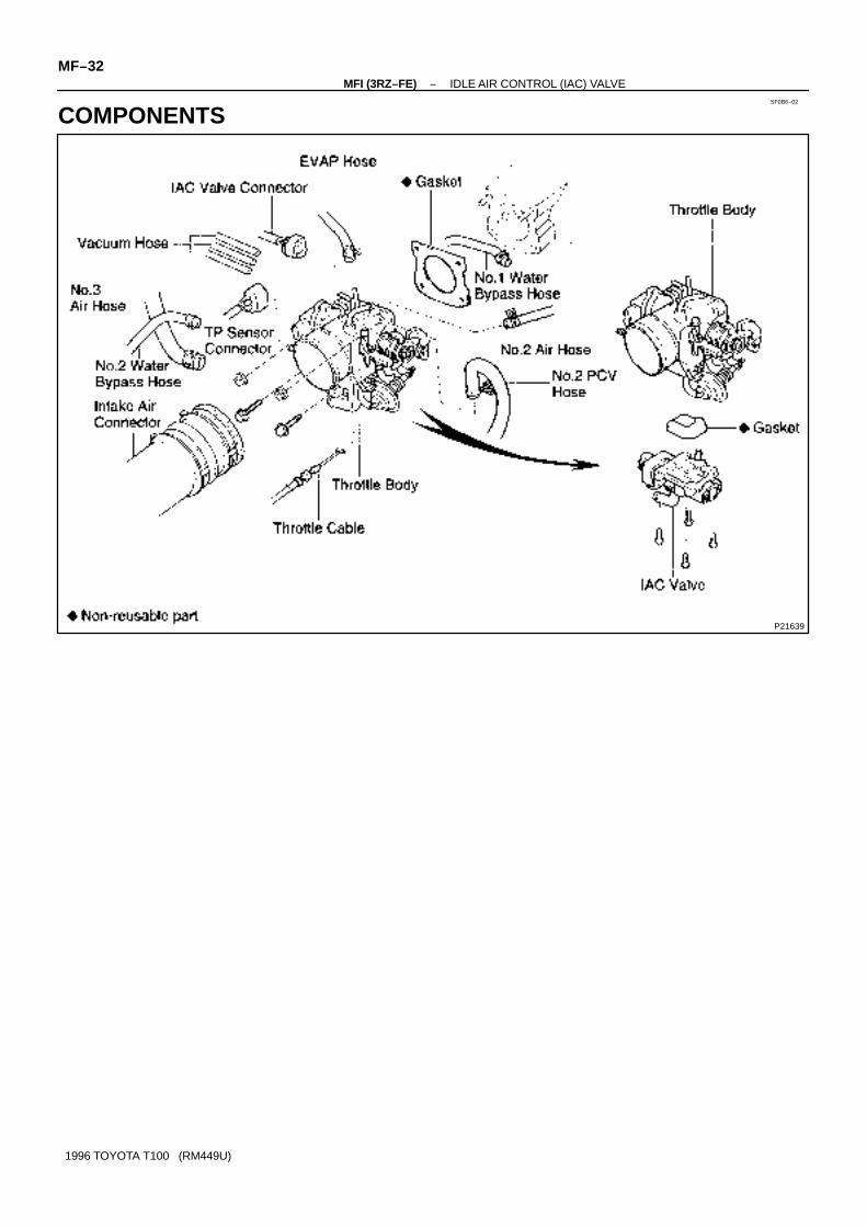
SF0B6−02
P21639
MF−32−MFI (3RZ−FE) IDLE AIR CONTROL (IAC) VALVE
1996 TOYOTA T100 (RM449U)
COMPONENTS
https://www.truck-manuals.net/

SF0B7−02
P15135
−MFI (3RZ−FE) IDLE AIR CONTROL (IAC) VALVEMF−33
1996 TOYOTA T100 (RM449U)
REMOVAL1. REMOVE THROTTLE BODY
(See page MF−28)2. REMOVE IAC VALVERemove the 4 screws, IAC valve and gasket.
https://www.truck-manuals.net/

SF0B8−01
P15730
Closed
RSC +B
Battery
P15729+B
Open
RSO
Battery
MF−34−MFI (3RZ−FE) IDLE AIR CONTROL (IAC) VALVE
1996 TOYOTA T100 (RM449U)
INSPECTIONINSPECT IAC VALVE OPERATION(a) Connect the positive (+) lead from the battery to terminal
+B and negative (−) lead to terminal RSC, and check thatthe valve is closed.
(b) Connect the positive (+) lead from the battery to terminal+B and negative (−) lead to terminal RSO, and check thatthe valve is open.
https://www.truck-manuals.net/

SF0B9−02
P15136
New Gasket
−MFI (3RZ−FE) IDLE AIR CONTROL (IAC) VALVEMF−35
1996 TOYOTA T100 (RM449U)
INSTALLATION1. INSTALL IAC VALVE(a) Place a new gasket on the throttle body.(b) Install the IAC valve with the 4 screws.2. INSTALL THROTTLE BODY
(See page MF−30)
https://www.truck-manuals.net/

SF0AW−03
MF−36−MFI (3RZ−FE) MASS AIR FLOW (MAF) METER
988Author�: Date�:
1996 TOYOTA T100 (RM449U)
MASS AIR FLOW (MAF) METERCOMPONENTS
https://www.truck-manuals.net/

SF1QJ−01
−MFI (3RZ−FE) MASS AIR FLOW (MAF) METERMF−37
1996 TOYOTA T100 (RM449U)
REMOVAL1. REMOVE AIR CLEANER CAP AND MAF METER(a) Disconnect the MAF meter connector, IAT sensor con-
nector and wire clamp.(b) Loosen the air cleaner hose clamp.(c) Loosen the 4 clips, and remove the air cleaner cap and
MAF meter.
2. REMOVE MAF METER FROM AIR CLEANER CAP(a) Remove the 4 nuts, MAF meter and gasket.(b) Remove the IAT sensor from air cleaner cap.
https://www.truck-manuals.net/

SF1GL−01
P15781
MF−38−MFI (3RZ−FE) MASS AIR FLOW (MAF) METER
1996 TOYOTA T100 (RM449U)
INSPECTIONINSPECT MAF METER OPERATION(a) Connect negative (−) terminal cable to battery.(b) Turn the ignition switch ON.(c) Connect the MAF meter connector.(d) Using a voltmeter, connect the positive (+) tester probe to
terminal VG, and negative (−) tester probe to terminal E3.(e) Blow air into the MAF meter, and check that the voltage
fluctuates.If operation is not as specified, replace the MAF meter.
(f) Turn the ignition switch OFF.(g) Disconnect negative (−) terminal cable from battery.(h) Disconnect the MAF meter connector.
https://www.truck-manuals.net/

SF0AZ−02
−MFI (3RZ−FE) MASS AIR FLOW (MAF) METERMF−39
1996 TOYOTA T100 (RM449U)
INSTALLATION1. INSTALL MAF METER TO AIR CLEANER CAP(a) Install the IAT sensor to the air cleaner cap.(b) Place a new gasket on the air cleaner cap.(c) Install the MAF meter with the 4 nuts.
Torque: 8.5 N·m (87 kgf·cm, 75 in.·lbf)2. INSTALL MAF METER AND AIR CLEANER CAP
https://www.truck-manuals.net/

B02510
SF0BA−03
P07170
OhmmeterNoContinuity
Continuity
3
Ohmmeter
2
1
5
P07171
Ohmmeter
3
2
1
5
Battery
MF−40−MFI (3RZ−FE) EFI MAIN RELAY
992Author�: Date�:
1996 TOYOTA T100 (RM449U)
EFI MAIN RELAYINSPECTION1. REMOVE EFI MAIN RELAY (Marking: EFI)
2. INSPECT EFI MAIN RELAY CONTINUITY(a) Using an ohmmeter, check that there is continuity be-
tween terminals 1 and 2.If there is no continuity, replace the relay.(b) Check that there is no continuity between terminals 3 and
5.If there is continuity, replace the relay.
3. INSPECT EFI MAIN RELAY OPERATION(a) Apply battery voltage across terminals 1 and 2.(b) Using an ohmmeter, check that there is continuity be-
tween terminals 3 and 5.If there is no continuity, replace the relay.4. REINSTALL EFI MAIN RELAY
https://www.truck-manuals.net/

SF0BB−02
Z14696
−MFI (3RZ−FE) CIRCUIT OPENING RELAYMF−41
993Author�: Date�:
1996 TOYOTA T100 (RM449U)
CIRCUIT OPENING RELAYCOMPONENTS
https://www.truck-manuals.net/

SF0BC−02
FI1908
FI1909
MF−42−MFI (3RZ−FE) CIRCUIT OPENING RELAY
1996 TOYOTA T100 (RM449U)
INSPECTION1. REMOVE GLOVE COMPARTMENT DOOR2. REMOVE CIRCUIT OPENING RELAY
3. INSPECT CIRCUIT OPENING RELAY CONTINUITY(a) Using an ohmmeter, check that there is continuity be-
tween terminals STA and E1.If there is no continuity, replace the relay.(b) Check that there is continuity between terminals +B and
FC.If there is no continuity, replace the relay.(c) Check that there is no continuity between terminals +B
and FP.If there is continuity, replace the relay.
4. INSPECT CIRCUIT OPENING RELAY OPERATION(a) Apply battery voltage across terminals STA and E1.(b) Using an ohmmeter, check that there is continuity be-
tween terminals +B and FP.If there is no continuity, replace the relay.5. REINSTALL CIRCUIT OPENING RELAY6. REINSTALL GLOVE COMPARTMENT DOOR
https://www.truck-manuals.net/

P15774
P15773
SF0BE−01
P15772
P15771
−MFI (3RZ−FE) VSV FOR EVAPORATIVE EMISSION (EVAP)MF−43
995Author�: Date�:
1996 TOYOTA T100 (RM449U)
VSV FOR EVAPORATIVEEMISSION (EVAP)INSPECTION1. INSPECT VSV FOR OPEN CIRCUITUsing an ohmmeter, check that there is continuity between theterminals.
Resistance: 30 − 34 Ω at 20°C (68°F)If there is no continuity, replace the VSV.
2. INSPECT VSV FOR GROUNDUsing an ohmmeter, check that there is no continuity betweeneach terminal and the body.If there is continuity, replace the VSV.
3. INSPECT VSV OPERATION(a) Check that air does not flow from pipe E to pipe F.
(b) Apply battery voltage across the terminals.(c) Check that air flows from pipe E to pipe F.If operation is not as specified, replace the VSV.
https://www.truck-manuals.net/
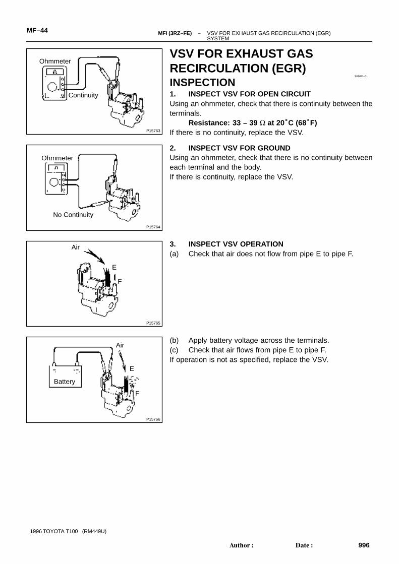
P15763
Ohmmeter
Continuity
SF0BD−01
P15764
Ohmmeter
No Continuity
P15765
Air
E
F
P15766
Air
E
F
Battery
MF−44 −MFI (3RZ−FE) VSV FOR EXHAUST GAS RECIRCULATION (EGR) SYSTEM
996Author�: Date�:
1996 TOYOTA T100 (RM449U)
VSV FOR EXHAUST GASRECIRCULATION (EGR)INSPECTION1. INSPECT VSV FOR OPEN CIRCUITUsing an ohmmeter, check that there is continuity between theterminals.
Resistance: 33 − 39 Ω at 20°C (68°F)If there is no continuity, replace the VSV.
2. INSPECT VSV FOR GROUNDUsing an ohmmeter, check that there is no continuity betweeneach terminal and the body.If there is continuity, replace the VSV.
3. INSPECT VSV OPERATION(a) Check that air does not flow from pipe E to pipe F.
(b) Apply battery voltage across the terminals.(c) Check that air flows from pipe E to pipe F.If operation is not as specified, replace the VSV.
https://www.truck-manuals.net/
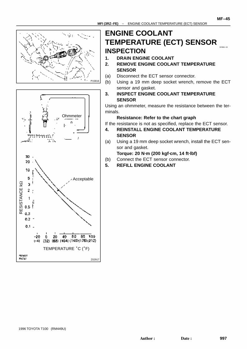
P15816
Z02917
Ohmmeter
Acceptable
TEMPERATURE °C (°F)
RE
SIS
TAN
CE
kΩ
SF0BG−02
−MFI (3RZ−FE) ENGINE COOLANT TEMPERATURE (ECT) SENSORMF−45
997Author�: Date�:
1996 TOYOTA T100 (RM449U)
ENGINE COOLANTTEMPERATURE (ECT) SENSORINSPECTION1. DRAIN ENGINE COOLANT2. REMOVE ENGINE COOLANT TEMPERATURE
SENSOR(a) Disconnect the ECT sensor connector.(b) Using a 19 mm deep socket wrench, remove the ECT
sensor and gasket.3. INSPECT ENGINE COOLANT TEMPERATURE
SENSORUsing an ohmmeter, measure the resistance between the ter-minals.
Resistance: Refer to the chart graphIf the resistance is not as specified, replace the ECT sensor.4. REINSTALL ENGINE COOLANT TEMPERATURE
SENSOR(a) Using a 19 mm deep socket wrench, install the ECT sen-
sor and gasket.Torque: 20 N·m (200 kgf·cm, 14 ft·lbf)
(b) Connect the ECT sensor connector.5. REFILL ENGINE COOLANT
https://www.truck-manuals.net/

SF1QL−01
Z02772
Ohmmeter
Acceptable
TEMPERATURE °C (°F)
RE
SIS
TAN
CE
kΩ
3020
10
532
1
0.50.30.2
0.1
−20 0 20 40 60 80 100(−4) (32) (68)(104)(140)(176)(212)
MF−46−MFI (3RZ−FE) INTAKE AIR TEMPERATURE (IAT) SENSOR
998Author�: Date�:
1996 TOYOTA T100 (RM449U)
INTAKE AIR TEMPERATURE (IAT)SENSORINSPECTION1. REMOVE IAT SENSOR
2. INSPECT IAT SENSORUsing an ohmmeter, measure the resistance between the ter-minals.
Resistance: Refer to the chart graphIf the resistance is not as specified, replace the IAT sensor.3. REINSTALL IAT SENSOR
https://www.truck-manuals.net/

P24770
SF0BI−03
P01630
−MFI (3RZ−FE) KNOCK SENSORMF−47
999Author�: Date�:
1996 TOYOTA T100 (RM449U)
KNOCK SENSORINSPECTION1. REMOVE KNOCK SENSOR(a) Disconnect the knock sensor connector.(b) Using SST, remove the knock sensor.
SST 09816−30010
2. INSPECT KNOCK SENSORUsing an ohmmeter, check that there is no continuity betweenthe terminal and body.If there is continuity, replace the sensor.3. REINSTALL KNOCK SENSOR(a) Using SST, install the knock sensor.
SST 09816−30010Torque: 44 N·m (450 kgf·cm, 33 ft·lbf)
(b) Connect the knock sensor connector.
https://www.truck-manuals.net/

P21698
SF0BK−02
FI6320
Ohmmeter
MF−48 −MFI (3RZ−FE) EXHAUST GAS RECIRCULATION (EGR) GAS TEMPERATURE SENSOR
1000Author�: Date�:
1996 TOYOTA T100 (RM449U)
EXHAUST GAS RECIRCULATION(EGR) GAS TEMPERATURESENSORINSPECTION1. REMOVE EGR GAS TEMPERATURE SENSOR
2. INSPECT EGR GAS TEMPERATURE SENSORUsing an ohmmeter, measure the resistance between the ter-minals.
Resistance:64 − 97 kΩ at 50°C (122°F)11 − 16 kΩ at 100°C (212°F)2 − 4 kΩ at 150°C (302°F)
If the resistance is not as specified, replace the sensor.3. REINSTALL EGR GAS TEMPERATURE SENSOR
https://www.truck-manuals.net/

P15820
SF0BL−02
−MFI (3RZ−FE) HEATED OXYGEN SENSORMF−49
1001Author�: Date�:
1996 TOYOTA T100 (RM449U)
HEATED OXYGEN SENSORINSPECTIONINSPECT HEATER RESISTANCE OF HEATEDOXYGEN SENSORS(a) Disconnect the heated oxygen sensor connectors.(b) Using an ohmmeter, measure the resistance between ter-
minals +B and HT.Resistance:Bank 1 Sensor 1: 5 − 7 Ω at 20°C (68°F)Bank 1 Sensor 2: 11 − 16 Ω at 20°C (68°F)
If resistance is not as specified, replace the heated oxygensensors.(c) Reconnect the heated oxygen sensor connectors.
https://www.truck-manuals.net/

SF0BM−02
P21637
MF−50−MFI (3RZ−FE) ENGINE CONTROL MODULE (ECM)
1002Author�: Date�:
1996 TOYOTA T100 (RM449U)
ENGINE CONTROL MODULE (ECM)COMPONENTS
https://www.truck-manuals.net/

SF0BN−01
P15739
−MFI (3RZ−FE) ENGINE CONTROL MODULE (ECM)MF−51
1996 TOYOTA T100 (RM449U)
REMOVAL1. REMOVE FRONT DOOR SCUFF PLATERemove the 4 screws and front scuff plate.2. REMOVE COWL SIDE TRIMRemove the clip and cowl side trim.3. REMOVE ECM(a) Disconnect the 4 ECM connectors.(b) Remove the 3 bolts and ECM.
https://www.truck-manuals.net/

SF0BO−01
MF−52−MFI (3RZ−FE) ENGINE CONTROL MODULE (ECM)
1996 TOYOTA T100 (RM449U)
INSPECTION(See page DI−17)
https://www.truck-manuals.net/

SF0BP−02
−MFI (3RZ−FE) ENGINE CONTROL MODULE (ECM)MF−53
1996 TOYOTA T100 (RM449U)
INSTALLATIONInstallation is in the reverse order of removal (See page MF−51).
https://www.truck-manuals.net/

SF0BQ−03
P24764
MF−54−MFI (3RZ−FE) FUEL CUT RPM
1006Author�: Date�:
1996 TOYOTA T100 (RM449U)
FUEL CUT RPMINSPECTION1. WARM UP ENGINEAllow the engine to warm up to normal operating temperature.2. CONNECT TOYOTA HAND−HELD TESTER
OR OBDII SCAN TOOL(See page MF−5)
3. INSPECT FUEL CUT OFF RPM(a) Increase the engine speed to at least 3,000 rpm.(b) Using a sound scope, check for injector operating noise.(c) Check that when the throttle lever is released, injector op-
eration noise stops momentarily and then resumes.HINT:Measure with the A/C OFF.
Fuel return rpm:M/T: 1,400 rpmA/T: 1,500 rpm
4. DISCONNECT TOYOTA HAND−HELD TESTEROR OBDII SCAN TOOL
https://www.truck-manuals.net/

SF – SFI SYSTEM (5VZ-FE)
SFI SYSTEM SF-1 FUEL PUMP SF-5 FUEL PRESSURE REGULATOR SF-14 INJECTOR SF-18 FUEL TANK AND LINE SF-25 MASS AIR FLOW (MAF) METER SF-28 THROTTLE BODY SF-31 IDLE AIR CONTROL (IAC) VALVE SF-39 EFI MAIN RELAY SF-45 CIRCUIT OPENING RELAY SF-46 VSV FOR FUEL PRESSURE CONTROL SF-47 VSV FOR EXHAUST GAS CONTROL VALVE
SF-49
VSV FOR EVAPORATIVE EMISSION (EVAP)
SF-50
ENGINE COOLANT TEMPERATURE (ECT) SENSOR
SF-51
KNOCK SENSOR SF-54 EXHAUST GAS RECIRCULATION (EGR) GAS TEMPERATURE SENSOR
SF-59
HEATED OXYGEN SENSOR SF-60 ENGINE CONTROL MODULE (ECM) SF-61 FUEL CUT RPM SF-63
https://www.truck-manuals.net/

SF1QM−01
−SFI (5VZ−FE) SFI SYSTEMSF−1
1007Author�: Date�:
1996 TOYOTA T100 (RM449U)
SFI SYSTEMPRECAUTION1. BEFORE WORKING ON FUEL SYSTEM, DISCON-
NECT NEGATIVE (−) TERMINAL CABLE FROM BAT-TERY
HINT:Any diagnostic trouble code retained by the computer will beerased when the negative (−) terminal cable is removed fromthe battery.Therefore, if necessary, read the diagnosis before removing thenegative (−) terminal cable from the battery.2. DO NOT SMOKE OR WORK NEAR AN OPEN FLAME
WHEN WORKING ON FUEL SYSTEM3. KEEP GASOLINE AWAY FROM RUBBER OR LEATH-
ER PARTS4. MAINTENANCE PRECAUTIONS(a) In the event of engine misfire, these precautions should
be taken.(1) Check proper connection to battery terminals, etc.(2) After repair work, check that the ignition coil termi-
nals and all other ignition system lines are recon-nected securely.
(3) When cleaning the engine compartment, be espe-cially careful to protect the electrical system fromwater.
(b) Precautions when the handling heated oxygen sensors.(1) Do not allow the oxygen sensor to drop or hit
against an object.(2) Do not allow the sensor to come into contact with
water.If Vehicle is Equipped with Mobile Radio System (ham, cb, etc.)If the vehicle is equipped with a mobile communication system,refer to the precaution in the IN section.5. AIR INDUCTION SYSTEM(a) Separation of the engine oil dipstick, oil filler cap, PCV
hose, etc. may cause the engine to run out of tune.(b) Disconnection, looseness or cracks in the parts of the air
induction system between the throttle body and cylinderhead will allow air suction and cause the engine to run outof tune.
https://www.truck-manuals.net/

P03244Press Down
Lock
P03245Lock
Insert
FI2553
SF−2−SFI (5VZ−FE) SFI SYSTEM
1008Author�: Date�:
1996 TOYOTA T100 (RM449U)
6. ELECTRONIC CONTROL SYSTEM(a) Before removing SFI wiring connectors, terminals, etc.,
first disconnect the power by either turning the ignitionswitch OFF or disconnecting the negative (−) terminalcable from the battery.
HINT:Always check the diagnostic trouble code before disconnectingthe negative (−) terminal cable from the battery.(b) When installing the battery, be especially careful not to in-
correctly connect the positive (+) and negative (−) cables.(c) Do not permit parts to receive a severe impact during re-
moval or installation. Handle all SFI parts carefully, espe-cially the ECM.
(d) Do not be careless during troubleshooting as there arenumerous transistor circuits and even slight terminal con-tact can further troubles.
(e) Do not open the ECM cover.
(f) When inspecting during rainy weather, take care to pre-vent entry of water. Also, when washing the enginecompartment, prevent water from getting on the SFI partsand wiring connectors.
(g) Parts should be replaced as an assembly.(h) Care is required when pulling out and inserting wiring con-
nectors.(1) Release the lock and pull out the connector, pulling
on the connectors.(2) Fully insert the connector and check that it is locked.
(i) When inspecting a connector with a volt/ohmmeter(1) Carefully take out the water−proofing rubber if it is
a water−proof type connector.(2) Insert the test probe into the connector from the wir-
ing side when checking the continuity, amperage orvoltage.
(3) Do not apply unnecessary force to the terminal.(4) After checking, install the water−proofing rubber on
the connector securely.
(5) Use SST for inspection or test of the injector or itswiring connector.
SST 09842−30070
https://www.truck-manuals.net/

P21154
P19985
FI1654
30 cm
SST
Fulcrum Length
−SFI (5VZ−FE) SFI SYSTEMSF−3
1009Author�: Date�:
1996 TOYOTA T100 (RM449U)
7. FUEL SYSTEM(a) When disconnecting the high fuel pressure line, a large
amount of gasoline will spill out, so observe these proce-dures:(1) Disconnect the fuel pump connector.(2) Start the engine. After the engine has stopped on
its own, turn the ignition switch to LOCK.
(3) Put a container under the connection.(4) Slowly loosen the connection.(5) Disconnect the connection.(6) Plug the connection with a rubber plug.
(b) When connecting the flare nut or union bolt on the highpressure pipe union, observe these procedures:(1) Union Bolt Type:
Always use 2 new gaskets.(2) Union Bolt Type:
Tighten the union bolt by hand.(3) Union Bolt Type:
Tighten the union bolt to the specified torque.Torque: 34.3 N·m (350 kgf·cm, 25 ft·lbf)
(4) Flare Nut Type:Apply a light coat of engine oil to the flare nut, andtighten the flare nut by hand.
(5) Flare Nut Type:Using SST, tighten the flare nut to specified torque.
SST 09631−22020NOTICE:Do not rotate the fuel pipe, when tightening the flare nut.
Torque:34.3 N·m (350 kgf·cm, 25 ft·lbf)28 N·m (285 kgf·cm, 21 ft·lbf) for using SST
HINT:Use a torque wrench with a fulcrum length of 30 cm (11.81 in.).
https://www.truck-manuals.net/

B00566
Grommet Delivery Pipe
CORRECT
WRONG
New O−Ring
Injector
B00567
Delivery Pipe
O−Ring
Grommet
O−Ring
Grommet
Spacer
FI7231
TOYOTA Hand−Held Tester
DLC3
P21058
SF−4−SFI (5VZ−FE) SFI SYSTEM
1010Author�: Date�:
1996 TOYOTA T100 (RM449U)
(c) Observe these precautions when removing and installingthe injectors.(1) Never reuse the O−ring.(2) When placing a new O−ring on the injector, take
care not to damage it in any way.(3) Coat a new O−ring with spindle oil or gasoline be-
fore installing−never use engine, gear or brake oil.
(d) Install the injector to the delivery pipe and intake manifoldas shown in the illustration.
(e) Check that there are no fuel leaks after doing mainte-nance anywhere on the fuel system.(1) Connect the TOYOTA hand−held tester to the
DLC3.(2) Turn the ignition switch ON and push the TOYOTA
hand−held tester main switch ON.NOTICE: Do not start the engine.
(3) Select the active test mode on the TOYOTA hand−held tester.
(4) Please refer to the TOYOTA hand−held tester oper-ator’s manual for further details.
(5) If you have no TOYOTA hand−held tester, connectthe positive (+) and negative (−) leads from the bat-tery to the fuel pump connector.(See page SF−10)
(6) Pinch the fuel return hose.The pressure in the high pressure line will rise toapprox. 400 kPa (4 kgf/cm2, 57 psi). In this state,check to see that there are no leaks from any partof the fuel system.
NOTICE:Always pinch the hose. Avoid bending as it may cause thehose to crack.
(7) Turn the ignition switch to LOCK.(8) Disconnect the TOYOTA hand−held tester from the
DLC3.
https://www.truck-manuals.net/

FI7231
TOYOTA Hand−Held Tester
DLC3
P21057
SF0BT−02
P21210
−SFI (5VZ−FE) FUEL PUMPSF−5
1011Author�: Date�:
1996 TOYOTA T100 (RM449U)
FUEL PUMPON−VEHICLE INSPECTION1. CHECK FUEL PUMP OPERATION(a) Connect the TOYOTA hand−held tester to the DLC3.(b) Turn the ignition switch ON and push the TOYOTA hand−
held tester main switch ON.NOTICE: Do not start the engine.(c) Select the active test mode on the TOYOTA hand−held
tester.(d) Please refer to the TOYOTA hand−held tester operator’s
manual for further details.(e) If you have no TOYOTA hand−held tester, connect the
positive (+) and negative (−) leads from the battery to thefuel pump connector.
(f) Check that there is pressure in the fuel inlet hose from thefuel filter.
HINT:If there is fuel pressure, you will hear the sound of fuel flowing.If there is no pressure, check these parts:
� H−fuse (ALT 80A)� M−fuses (AM1 40A, AM2 30A)� Fuses (EFI 15A, IGN 7.5A)� EFI main relay� Circuit opening relay� Fuel pump� ECM� Wiring connections
(g) Turn the ignition switch to LOCK.(h) Disconnect the TOYOTA hand−held tester from the
DLC3.2. CHECK FUEL PRESSURE(a) Check the battery positive voltage is above 12 V.(b) Disconnect the negative (−) terminal cable from the bat-
tery.(c) Remove the 6 bolts, and disconnect the No.2 timing belt
cover.
(d) Remove the union bolt holding the fuel pipe to the deliverypipe and gasket.
CAUTION:Put a shop towel under the delivery pipe. Slowly loosen theunion bolt.
https://www.truck-manuals.net/

P21220
SST (Union)
SST (Union Bolt)
Gasket
P21224
SF−6−SFI (5VZ−FE) FUEL PUMP
1012Author�: Date�:
1996 TOYOTA T100 (RM449U)
(e) Install SST (pressure gauge) to the delivery pipe with the2 gaskets and SST (union and union bolt).SST 09268−45012Torque:34.3 N·m (350 kgf·cm, 25 ft·lbf)
(f) Wipe off any splattered gasoline.(g) Connect the TOYOTA hand−held tester to the DLC3.
(See on−vehicle inspection in fuel pump)(h) Reconnect the negative (−) terminal cable to the battery.(i) Turn the ignition switch ON.(j) Measure the fuel pressure.
Fuel pressure:265 − 304 kPa (2.7 − 3.1 kgf/cm2, 38 − 44 psi)
If pressure is high, replace the fuel pressure regulator.If pressure is low, check these parts:
� Fuel hoses and connections� Fuel pump� Fuel filter� Fuel pressure regulator� VSV for fuel pressure control
(k) Disconnect the TOYOTA hand−held tester from theDLC3.
(l) Reinstall the No.2 timing belt cover with the 6 bolts.(m) Start the engine.(n) Disconnect the vacuum sensing hose from the fuel pres-
sure regulator, and plug the hose end.(o) Measure the fuel pressure at idle.
Fuel pressure:265 − 304 kPa (2.7 − 3.1 kgf/cm2, 38 − 44 psi)
(p) Reconnect the vacuum sensing hose to the fuelpressure regulator.
(q) Measure the fuel pressure at idle.Fuel pressure:226 − 265 kPa (2.3 − 2.7 kgf/cm2, 33 − 38 psi)
If pressure is not as specified, check the vacuum sensing hoseand fuel pressure regulator.(r) Stop the engine.(s) Check that the fuel pressure remains as specified for 5
minutes after the engine has stopped.Fuel pressure:147 kPa (1.5 kgf/cm2, 21 psi) or more
If pressure is not as specified, check the fuel pump, pressureregulator and/or injectors.(t) After checking fuel pressure, disconnect the negative (−)
terminal cable from the battery and carefully remove theSST to prevent gasoline from splashing.SST 09268−45012
(u) Remove the other union bolt, 3 gaskets and fuel pipefrom the delivery pipes.
https://www.truck-manuals.net/

−SFI (5VZ−FE) FUEL PUMPSF−7
1013Author�: Date�:
1996 TOYOTA T100 (RM449U)
(v) Reinstall the fuel pipe with 4 new gaskets and the 2 unionbolts.Torque:34.3 N·m (350 kgf·cm, 25 ft·lbf)
(w) Reconnect the negative (−) terminal cable to the battery.(x) Check for fuel leakage.
https://www.truck-manuals.net/

SF0BU−02
SF−8−SFI (5VZ−FE) FUEL PUMP
1996 TOYOTA T100 (RM449U)
FUEL PUMPCOMPONENTS
https://www.truck-manuals.net/

SF0BV−02
P22396
−SFI (5VZ−FE) FUEL PUMPSF−9
1996 TOYOTA T100 (RM449U)
REMOVALCAUTION:Do not smoke or work near an open flame when working onthe fuel pump.1. REMOVE FUEL TANKHINT:Check for fuel leakage.
2. REMOVE FUEL PUMP BRACKET ASSEMBLY FROMFUEL TANK
(a) Disconnect the fuel pump connector from the clamp.(b) Remove the 7 bolts.
Torque: 3.9 N·m (40 kgf·cm, 35 in.·lbf)(c) Pull out the pump bracket assembly.(d) Remove the gasket from the pump bracket.HINT:Install a new gasket to the pump bracket.
https://www.truck-manuals.net/

P15055
SF0BW−01
P15059
SF−10−SFI (5VZ−FE) FUEL PUMP
1996 TOYOTA T100 (RM449U)
DISASSEMBLY1. REMOVE FUEL PUMP FROM FUEL PUMP BRACKET(a) Disconnect the fuel pump connector.(b) Pull off the lower side of the fuel pump from the pump
bracket.(c) Disconnect the fuel hose from the fuel pump, and remove
the fuel pump.(d) Remove the rubber cushion from the fuel pump.
2. REMOVE FUEL PUMP FILTER FROM FUEL PUMP(a) Using a small screwdriver, remove the clip.HINT:Install the pump filter with a new clip.(b) Pull out the pump filter.
https://www.truck-manuals.net/

SF0BX−03
−SFI (5VZ−FE) FUEL PUMPSF−11
1996 TOYOTA T100 (RM449U)
INSPECTION1. INSPECT FUEL PUMP RESISTANCEUsing an ohmmeter, measure the resistance between the ter-minals.
Resistance: 0.2 − 3.0 Ω at 20°C (68°F)If the resistance is not as specified, replace the fuel pump and/or set plate.2. INSPECT FUEL PUMP OPERATIONConnect the positive (+) lead from the battery to terminal 1 ofthe connector, and the negative (−) lead to terminal 2. Checkthat the fuel pump operates.NOTICE:These tests must be done quickly (within 10 seconds) toprevent the coil from burning out.Keep the fuel pump as faraway from the battery as possible.Always do switching atthe battery side.If operation is not as specified, replace the fuel pump and/orplate.
https://www.truck-manuals.net/

SF0BY−01
SF−12−SFI (5VZ−FE) FUEL PUMP
1996 TOYOTA T100 (RM449U)
REASSEMBLYReassembly is in the reverse order of disassembly (Seepage SF−10).
https://www.truck-manuals.net/

SF0BZ−01
−SFI (5VZ−FE) FUEL PUMPSF−13
1996 TOYOTA T100 (RM449U)
INSTALLATIONInstallation is in the reverse order of removal (See pageSF−9).
https://www.truck-manuals.net/

SF0C0−04
SF−14−SFI (5VZ−FE) FUEL PRESSURE REGULATOR
1020Author�: Date�:
1996 TOYOTA T100 (RM449U)
FUEL PRESSURE REGULATORCOMPONENTS
https://www.truck-manuals.net/

P21128
Engine Wire
Fuel Pressure Regulator
Fuel Returen Hose
� O−Ring
� Non−reusable part
−SFI (5VZ−FE) FUEL PRESSURE REGULATORSF−15
1021Author�: Date�:
1996 TOYOTA T100 (RM449U)
https://www.truck-manuals.net/

SF0C1−03
P21127
Lift Up Bracket
P21123
SF−16−SFI (5VZ−FE) FUEL PRESSURE REGULATOR
1996 TOYOTA T100 (RM449U)
REMOVAL1. REMOVE AIR CLEANER HOSE2. REMOVE INTAKE AIR CONNECTOR
(See page EM−30)3. DISCONNECT FUEL RETURN HOSE FROM FUEL
PRESSURE REGULATORCAUTION:Put a shop rag under the pressure regulator.
4. REMOVE FUEL PRESSURE REGULATOR(a) Remove the bolt holding the engine wire to the LH cylin-
der head cover.(b) Disconnect the protector from the bracket on the RH cylin-
der head cover, and lift up the engine wire.
(c) Remove the 2 bolts, and pull out the pressureregulator.
(d) Remove the O−ring from the pressure regulator.
https://www.truck-manuals.net/

SF0C2−03
P21125
New O−Ring
P21218
Delivery Pipe
CORRECT New O−Ring
RegulatorWRONG
−SFI (5VZ−FE) FUEL PRESSURE REGULATORSF−17
1996 TOYOTA T100 (RM449U)
INSTALLATION1. INSTALL FUEL PRESSURE REGULATOR(a) Apply a light coat of gasoline to a new O−ring, and install
it to the pressure regulator.(b) Attach the pressure regulator to the LH delivery pipe.
(c) Check that the pressure regulator rotates smoothly.NOTICE:If it does not rotate smoothly, the O−ring may be pinched,so remove the pressure regulator and repeat steps (a) to (c)above.(d) Install the pressure regulator with the 2 bolts.
Torque: 8 N·m (80 kgf·cm, 71 in.·lbf)(e) Install the engine wire with the bolt.2. CONNECT FUEL RETURN HOSE TO FUEL
PRESSURE REGULATORNOTICE: Be sure to insert the hose up to the stopper and clip it.3. INSTALL INTAKE AIR CONNECTOR
(See page EM−69)4. INSTALL AIR CLEANER HOSE5. CHECK FOR FUEL LEAKS
https://www.truck-manuals.net/

SF0C3−04
SF−18−SFI (5VZ−FE) INJECTOR
1024Author�: Date�:
1996 TOYOTA T100 (RM449U)
INJECTORCOMPONENTS
https://www.truck-manuals.net/

Z15607
−SFI (5VZ−FE) INJECTORSF−19
1025Author�: Date�:
1996 TOYOTA T100 (RM449U)
https://www.truck-manuals.net/

SF0C4−01
P21209
P21207
SF−20−SFI (5VZ−FE) INJECTOR
1996 TOYOTA T100 (RM449U)
REMOVAL1. REMOVE AIR CLEANER HOSE2. REMOVE INTAKE AIR CONNECTOR
(See page EM−65)3. REMOVE FUEL PRESSURE REGULATOR
(See page SF−16)4. DISCONNECT FUEL INLET PIPECAUTION:Catch leaking fuel in a container.5. REMOVE FUEL PIPE6. DISCONNECT INJECTOR CONNECTORS7. REMOVE DELIVERY PIPES AND INJECTORSNOTICE:Be careful not to drop the injectors whenremoving the delivery pipes.(a) Remove the 4 bolts and delivery pipes together with the
6 injectors(b) Remove the 4 spacers from the intake manifold.(c) Pull out the 6 injectors from the delivery pipes.(d) Remove the 2 O−rings and 2 grommets from each injec-
tor.
https://www.truck-manuals.net/

SF0C5−03
P21184
Ohmmeter
P19986
SSTSST (Union)
Pressure Regulator(from Vehicle) SST (Hose)
Injector
SST
SST (Attachment)
B00568
SST (Union)
SST (Hose)
Vinyl Tube
SST
O−Ring
(Clamp)
P01077
SST(Wire)
P01010
−SFI (5VZ−FE) INJECTORSF−21
1996 TOYOTA T100 (RM449U)
INSPECTION1. INSPECT INJECTOR RESISTANCEUsing an ohmmeter, measure the resistance between the ter-minals.
Resistance:Approx. 13.8 Ω at 20°C (68°F)
If the resistance is not as specified, replace theinjector.
2. INSPECT INJECTOR INJECTIONCAUTION:Keep injector clear of sparks during the test.(a) Disconnect the fuel inlet pipe from the fuel tube.(b) Connect SST (attachment and hose) to the fuel tube.
SST 09268−41046 (09268−52011)(c) Connect the fuel return hose, SST (union) and SST
(hose) to the fuel pressure regulator.SST 09268−41046 (09268−41091)
(d) Install the O−ring to the injector.(e) Connect SST (union and hose) to the injector, and hold
the injector and union with SST (clamp).SST 09268−41046
(f) Put the injector into the graduated cylinder.HINT:Install a suitable vinyl tube onto the injector to prevent gasolinefrom splashing out.(g) Connect the TOYOTA hand−held tester to the DLC3.
(See on−vehicle inspection in fuel pump)(h) Connect SST (wire) to the injector and battery for 15 se-
conds, and measure the injection volume with a gra-duated cylinder. Test each injector 2 or 3 times.SST 09842−30070Volume:56 − 69 cm3 (3.4 − 4.2 cu in.) per 15 sec.Difference between each injector:6 cm3 (0.4 cu in.) or less
If the injection volume is not as specified, replace the injector.
3. INSPECT LEAKAGE(a) In the condition above, disconnect the test probes of SST
(wire) from the battery and check the fuel leakage fromthe injector.SST 09842−30070Fuel drop:1 drop or less per minute
(b) Turn the ignition switch to LOCK.(c) Disconnect the negative (−) terminal cable from the bat-
tery.
https://www.truck-manuals.net/

SF−22−SFI (5VZ−FE) INJECTOR
1996 TOYOTA T100 (RM449U)
(d) Remove SST.SST 09268−41046
(e) Disconnect the TOYOTA hand−held tester from theDLC3.
https://www.truck-manuals.net/

SF0C6−03
P10889
New Grommet
New O−Ring
New Grommet
New O−Ring
P21185
Push
Turn
Connector
P21208
P21216
Rotate
Outward
P21207
−SFI (5VZ−FE) INJECTORSF−23
1996 TOYOTA T100 (RM449U)
INSTALLATION1. TEMPORARILY INSTALL INJECTORS AND
DELIVERY PIPES(a) Install 2 new grommets to each injector.(b) Apply a light coat of spindle oil or gasoline to 2 new O−
rings and install them to each injector.
(c) While turning the injector clockwise and counterclock-wise, push it to the delivery pipes. Install the 6 injectors.
(d) Position the injector connector outward.
(e) Place the 4 spacers in position on the intake manifold.(f) Place the delivery pipes with the 6 injectors in position on
the intake manifold.(g) Temporarily install the 4 bolts holding the delivery pipes
to the intake manifold.
(h) Check that the injectors rotate smoothly.HINT:If injectors do not rotate smoothly, the probable cause is incor-rect installation of O−rings. Replace the O−rings.(i) Position the injector connector outward.
2. CONNECT INJECTOR CONNECTORS3. INSTALL FUEL PIPE AND TIGHTENING
DELIVERY PIPE HOLDING BOLTS(a) Install the fuel pipe with 4 new gaskets and the 2 union
bolts.Torque: 34.3 N·m (350 kgf·cm, 25 ft·lbf)
(b) Tighten the 4 bolts holding the delivery pipes to the intakemanifold.Torque: 13 N·m (130 kgf·cm, 10 ft·lbf)
https://www.truck-manuals.net/

P21209
P21217
SF−24−SFI (5VZ−FE) INJECTOR
1996 TOYOTA T100 (RM449U)
4. CONNECT FUEL INLET PIPE(a) Temporarily install the union and 2 new gaskets, and con-
nect the fuel pipe.(b) Install the clamp bolt.
Torque: 8 N·m (80 kgf·cm, 71 in.·lbf)(c) Tighten the union bolt.
Torque: 34.3 N·m (350 kgf·cm, 25 ft·lbf)5. INSTALL FUEL PRESSURE REGULATOR
(See page SF−17)
6. VISUALLY INSPECT AIR ASSIST LINES ANDCONNECTIONS
Look for loose connections, sharp bends or damage.7. INSTALL INTAKE AIR CONNECTOR
(See page EM−69)8. INSTALL AIR CLEANER HOSE9. CHECK FOR FUEL LEAKS
https://www.truck-manuals.net/

SF0CA−01
−SFI (5VZ−FE) FUEL TANK AND LINESF−25
1031Author�: Date�:
1996 TOYOTA T100 (RM449U)
FUEL TANK AND LINEPRECAUTION� Always use new gaskets when replacing the fuel tank
or component parts.� Apply the proper torque to all parts tightened.
https://www.truck-manuals.net/

SF0CB−01
P20166
SF−26−SFI (5VZ−FE) FUEL TANK AND LINE
1996 TOYOTA T100 (RM449U)
COMPONENTS
https://www.truck-manuals.net/

SF0D2−01
BO0919
Crack Leakage
Deformation
Z10162
SST
SST: 09631−22020
Use SST28 N·m(285 kgf·cm, 21 ft·lbf)
FulcrumLength30 cm(11.81 in.)
FU0041
Pipe
0 − 3 mm (0 − 0.12 in.)
2 − 7 mm (0.08 − 0.28 in.)Hose
Clip
−SFI (5VZ−FE) FUEL TANK AND LINESF−27
1996 TOYOTA T100 (RM449U)
INSPECTIONINSPECT FUEL TANK AND LINE(a) Check the fuel lines for cracks or leakage, and all connec-
tions for deformation.(b) Check the fuel tank vapor vent system hoses and connec-
tions for looseness, sharp bends or damage.(c) Check the fuel tank for deformation, cracks, fuel leakage
or tank band looseness.(d) Check the filler neck for damage or fuel leakage.(e) Hose and pipe connections are as shown in the illustra-
tion.If a problem is found, repair or replace the parts as necessary.
https://www.truck-manuals.net/
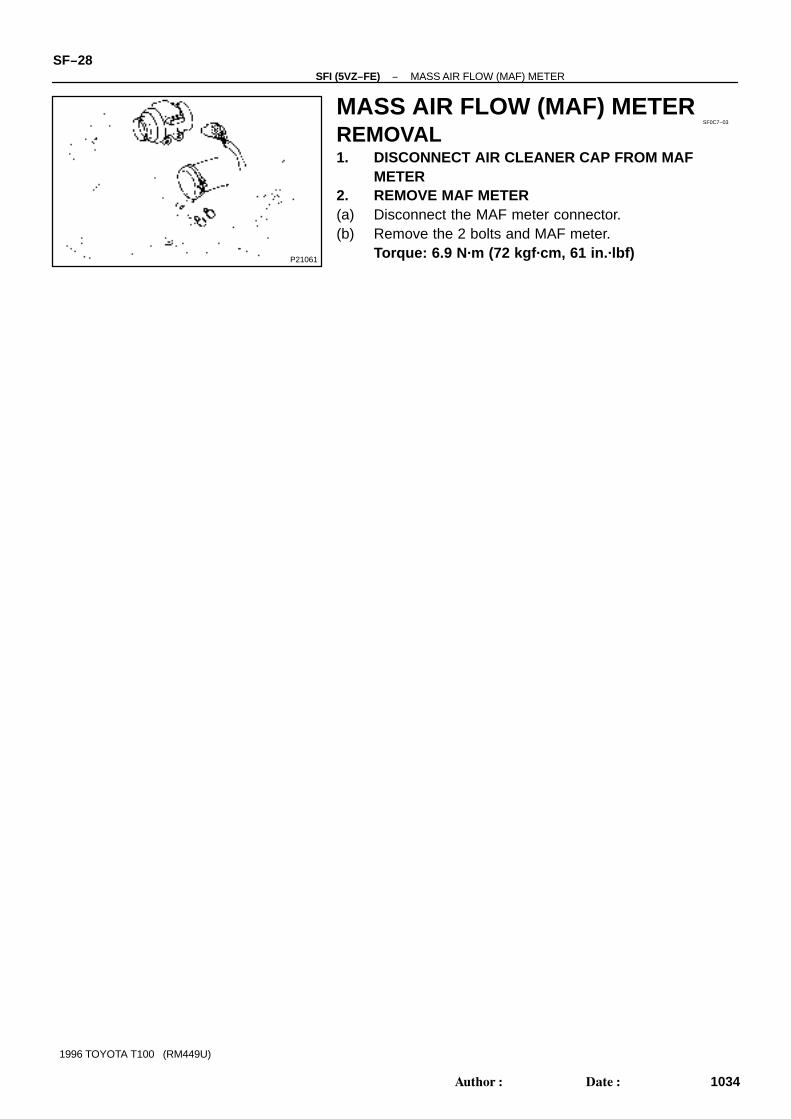
P21061
SF0C7−03
SF−28−SFI (5VZ−FE) MASS AIR FLOW (MAF) METER
1034Author�: Date�:
1996 TOYOTA T100 (RM449U)
MASS AIR FLOW (MAF) METERREMOVAL1. DISCONNECT AIR CLEANER CAP FROM MAF
METER2. REMOVE MAF METER(a) Disconnect the MAF meter connector.(b) Remove the 2 bolts and MAF meter.
Torque: 6.9 N·m (72 kgf·cm, 61 in.·lbf)
https://www.truck-manuals.net/

SF0C8−04
FI6961
OhmmeterE2 THA
Z11824
Voltmeter
VG
E3
Air
−SFI (5VZ−FE) MASS AIR FLOW (MAF) METERSF−29
1996 TOYOTA T100 (RM449U)
INSPECTION1. INSPECT MAF METER RESISTANCEUsing an ohmmeter, measure the resistance between terminalsTHA and E2.
Between
terminalsResistance Temperature
THA − E2 10 − 20 kΩ −20°C (−4°F)
THA − E2 4 − 7 kΩ 0°C (32°F)
THA − E2 2 − 3 kΩ 20°C (68°F)
THA − E2 0.9 − 1.3 kΩ 40°C (104°F)
THA − E2 0.4 − 0.7 kΩ 60°C (140°F)
THA − E2 0.2 − 0.4 kΩ 80°C (176°F)
If the resistance is not as specified, replace the MAF meter.
2. INSPECT MAF METER OPERATION(a) Connect the MAF meter connector.(b) Using a voltmeter, connect the positive (+) tester probe to
terminal VG, and negative (−) tester probe to terminal E3.(c) Blow air into the MAF meter, and check that the voltage
fluctuates.If operation is not as specified, replace the MAF meter.(d) Disconnect the MAF meter connector.
https://www.truck-manuals.net/

SF0C9−02
SF−30−SFI (5VZ−FE) MASS AIR FLOW (MAF) METER
1996 TOYOTA T100 (RM449U)
INSTALLATIONInstallation is in the reverse order of removal (See page SF−28).
https://www.truck-manuals.net/

SF1QN−01
P19944
P20279
−SFI (5VZ−FE) THROTTLE BODYSF−31
1037Author�: Date�:
1996 TOYOTA T100 (RM449U)
THROTTLE BODYON−VEHICLE INSPECTION1. INSPECT THROTTLE BODY(a) Check that the throttle linkage moves smoothly.
(b) w/ EGR:Check the vacuum at each port.� Start the engine.� Check the vacuum with your finger.
Port name At idle 3,500 rpm or more
E No vacuum Vacuum
R No vacuum Vacuum
2. INSPECT THROTTLE POSITION SENSOR(a) Apply vacuum to the throttle opener.(b) Disconnect the sensor connector.
(c) Using an ohmmeter, measure the resistance betweeneach terminal.
Throttle valve
condition
Between
terminalsResistance
Fully closed VTA − E2 0.28 − 6.4 kΩ
Fully closed IDL − E2 0.5 kΩ or less
Open IDL − E2 Infinity
Fully open VTA − E2 2.0 − 11.6 kΩ
− VC − E2 2.7 − 7.7 kΩ
(d) Reconnect the sensor connector.
https://www.truck-manuals.net/

P21056
Separator
Filter
Cap
S02081
S02082
P19943
SF−32−SFI (5VZ−FE) THROTTLE BODY
1038Author�: Date�:
1996 TOYOTA T100 (RM449U)
3. M/T:INSPECT DASHPOT (DP)
(a) Allow the engine to warm up to normal operating tempera-ture.
(b) Check the idle speed.Idle speed:700 ± 50 rpm
(c) Remove the cap, filter and separator from the DP.
(d) Maintain engine speed at 2,500 rpm or more.(e) Plug the VTV hole with your finger.(f) Release the throttle valve.(g) Check the DP is set.
DP setting speed:1,800 − 2,200 rpm
(h) If not as specified, adjust with the DP adjusting screw.(i) Remove your finger from the hole and check that the en-
gine returns to idle speed in approx. 1 second.(j) Reinstall the DP separator, filter and cap.HINT:Install the filter with the coarser surface facing the atmosphericside (outward).4. INSPECT THROTTLE OPENER(a) Allow the engine to warm up to normal operating tempera-
ture.(b) Check the idle speed.
Idle speed:700 ± 50 rpm
(c) Disconnect the vacuum hose from the throttle opener,and plug the hose end.
(d) Check the throttle opener setting speed.Throttle opener setting speed:900 − 1,950 rpm
If the throttle opener setting is not as specified, replace thethrottle body.(e) Stop the engine.(f) Reconnect the vacuum hose to the throttle opener.
https://www.truck-manuals.net/

−SFI (5VZ−FE) THROTTLE BODYSF−33
1039Author�: Date�:
1996 TOYOTA T100 (RM449U)
(g) Start the engine and check that the idle speed returns tothe correct speed.
https://www.truck-manuals.net/

SF0CE−03
S05190
SF−34−SFI (5VZ−FE) THROTTLE BODY
1996 TOYOTA T100 (RM449U)
COMPONENTS
https://www.truck-manuals.net/

SF1QO−01
P21153
−SFI (5VZ−FE) THROTTLE BODYSF−35
1996 TOYOTA T100 (RM449U)
REMOVAL1. DRAIN ENGINE COOLANT2. DISCONNECT THESE CABLES:(a) w/ Cruise control:
Cruise control actuator cable(b) Accelerator cable(c) A/T:
Throttle cable3. REMOVE AIR CLEANER HOSE
4. DISCONNECT THROTTLE POSITION SENSOR CON-NECTOR
5. DISCONNECT IAC VALVE CONNECTOR6. REMOVE THROTTLE BODY(a) Disconnect these vacuum hoses from the throttle body:
(1) Vacuum hose of throttle opener(2) w/ EGR:
Vacuum hose (from port R of EGR vacuum modula-tor)
(3) w/ EGR:Vacuum hose (from port E of EGR vacuum modula-tor)
(b) Disconnect these hoses from the IAC valve:(1) Water bypass hose
(w/ EGR: from EGR valve)(w/o EGR: from water bypass pipe)
(2) Water hose (from intake manifold)(3) Air assist hose
(c) Disconnect the ignition coil connector.(d) Remove the 2 bolts, 2 nuts, throttle body and gasket.
HINT:Place a new gasket on the air intake chamber, the facing theprotrusion upward.
Torque: 18 N·m (180 kgf·cm, 13 ft·lbf)
https://www.truck-manuals.net/

SF1QP−01
P19935
P20011
Throttle Lever
No Clearance
Throttle Stop Screw
Vacuum
SF−36−SFI (5VZ−FE) THROTTLE BODY
1996 TOYOTA T100 (RM449U)
INSPECTION1. CLEAN THROTTLE BODY(a) Using a soft brush and carburetor cleaner, clean the cast
parts.(b) Using compressed air, clean all the passages and aper-
tures.NOTICE:To prevent deterioration, do not clean the throttle positionsensor and IAC valve.
2. INSPECT THROTTLE VALVE(a) Apply vacuum to the throttle opener.(b) Check that there is no clearance between the throttle stop
screw and throttle lever when the throttle valve is fullyclosed.Throttle valve fully closed angle: 10°
3. INSPECT THROTTLE POSITION SENSOR(a) Apply vacuum to the throttle opener.(b) Insert a thickness gauge between the throttle stop screw
and stop lever.(c) Using an ohmmeter, measure the resistance between
each terminal.
Clearance between
lever and stop screw
Between
terminalsResistance
0 mm (0 in.) VTA − E2 0.28 − 6.4 kΩ
0.32 mm (0.013 in.) IDL − E2 0.5 kΩ or less
0.54 mm (0.021 in.) IDL − E2 Infinity
Throttle valve fully
openVTA − E2 2.0 − 11.6 kΩ
− VC − E2 2.7 − 7.7 kΩ
4. IF NECESSARY, ADJUST THROTTLE POSITION SEN-SOR
(a) Loosen the 2 set screws of the sensor.
(b) Apply vacuum to the throttle opener.(c) Insert a 0.43 mm (0.017 in.) thickness gauge, between
the throttle stop screw and stop lever.(d) Connect the test probe of an ohmmeter to the terminals
IDL and E2 of the sensor.(e) Gradually turn the sensor clockwise until the ohmmeter
deflects, and secure it with the 2 set screws.
https://www.truck-manuals.net/

−SFI (5VZ−FE) THROTTLE BODYSF−37
1996 TOYOTA T100 (RM449U)
(f) Recheck the continuity between terminals IDL and E2.
Clearance between
lever and stop screwContinuity (IDL − E2)
0.32 mm (0.013 in.) Continuity
0.54 mm (0.021 in.) No continuity
https://www.truck-manuals.net/

SF0CH−02
SF−38−SFI (5VZ−FE) THROTTLE BODY
1996 TOYOTA T100 (RM449U)
INSTALLATIONInstallation is in the reverse order of removal (See page SF−35).
https://www.truck-manuals.net/

SF0CI−03
P19970
SST
TE1 E1
DLC1
DLC1
P21126
Ohmmeter
RSC+B
RSO
IAC Valve
−SFI (5VZ−FE) IDLE AIR CONTROL (IAC) VALVESF−39
1045Author�: Date�:
1996 TOYOTA T100 (RM449U)
IDLE AIR CONTROL (IAC) VALVEON−VEHICLE INSPECTION1. INSPECT IAC VALVE OPERATION(a) Initial conditions:
� Engine at normal operating temperature� Idle speed check correctly� Transmission in neutral position� A/C switch OFF
(b) Using SST, connect terminals TE1 and E1 of theDLC1.SST 09843−18020
(c) After engine speed is kept at approx. 1,000 rpm for 5 se-conds, check that it returns to idle speed.
If the engine speed operation is not as specified, check the IACvalve, wiring and ECM.(d) Remove the SST from the DLC1.
SST 09843−18020
2. INSPECT IAC VALVE RESISTANCENOTICE:”Cold” and ”Hot” in the following sentences express thetemperature of the coils themselves. ”Cold” is from −10°C(14°F) to 50°C (122°F) and ”Hot” is from 50°C (122°F) to100°C (212°F).(a) Disconnect the IAC valve connector.(b) Using an ohmmeter, measure the resistance between ter-
minal +B and other terminals (RSC, RSO).Resistance:Cold: 17.0 − 24.5 ΩHot: 21.5 − 28.5 Ω
If resistance is not as specified, replace the IAC valve.(c) Reconnect the IAC valve connector.3. INSPECT AIR ASSIST SYSTEM(a) Initial conditions:
� Engine at normal operating temperature� Idle speed check correctly� Transmission in neutral position� A/C switch OFF
https://www.truck-manuals.net/

P19970
SST
TE1 E1
DLC1
P21055
Plug
Air Assist Hose
Disconnect
SF−40−SFI (5VZ−FE) IDLE AIR CONTROL (IAC) VALVE
1046Author�: Date�:
1996 TOYOTA T100 (RM449U)
(b) Using SST, connect terminals TE1 and E1 of theDLC1.SST 09843−18020
(c) After engine speed is kept at 900 − 1,300 rpm for 10 se-conds, check that it returns to idle speed.
(d) Stop the engine.
(e) Disconnect the air assist hose from the IAC valve, andplug it.
(f) Start the engine and check that the idle speed reaches500 rpm or below (the engine may stall).If the idle does not reach 500 rpm or below, check for aleak between the air assist hoses, pipe and injectors.
(g) Remove the SST from the DLC1.SST 09843−18020
(h) Reconnect the air assist hose to the IAC valve.
https://www.truck-manuals.net/

SF0CJ−01
S05191
−SFI (5VZ−FE) IDLE AIR CONTROL (IAC) VALVESF−41
1996 TOYOTA T100 (RM449U)
COMPONENTS
https://www.truck-manuals.net/

SF0CK−01
P19936
SF−42−SFI (5VZ−FE) IDLE AIR CONTROL (IAC) VALVE
1996 TOYOTA T100 (RM449U)
REMOVAL1. REMOVE THROTTLE BODY
(See page SF−35)2. REMOVE IAC VALVERemove the 4 screws, IAC valve and gasket.HINT:Place a new gasket on the throttle body.
https://www.truck-manuals.net/

SF0CL−01
P20109Battery Closed
+BRSC
P20108
RSO
Battery Open
+B
−SFI (5VZ−FE) IDLE AIR CONTROL (IAC) VALVESF−43
1996 TOYOTA T100 (RM449U)
INSPECTIONINSPECT IAC VALVE OPERATION(a) Connect the positive (+) lead from the battery to terminal
+B and negative (−) lead to terminal RSC, and check thatthe valve is closed.
(b) Connect the positive (+) lead from the battery to terminal+B and negative (−) lead to terminal RSO, and check thatthe valve is open.
If operation is not as specified, replace the IAC valve.
https://www.truck-manuals.net/

SF0CM−01
SF−44−SFI (5VZ−FE) IDLE AIR CONTROL (IAC) VALVE
1996 TOYOTA T100 (RM449U)
INSTALLATIONInstallation is in the reverse order of removal (See pageSF−42).
https://www.truck-manuals.net/

P15819
SF0CN−04
P07170No Continuity
2
3
4 Ohmmeter
Ohmmeter1
P07171
1
2
3
4
Continuity
Ohmmeter
Battery
−SFI (5VZ−FE) EFI MAIN RELAYSF−45
1051Author�: Date�:
1996 TOYOTA T100 (RM449U)
EFI MAIN RELAYINSPECTION1. REMOVE EFI MAIN RELAY (Marking: EFI)
2. INSPECT EFI MAIN RELAY CONTINUITY(a) Using an ohmmeter, check that there is continuity be-
tween terminals 1 and 2.If there is no continuity, replace the relay.(b) Check that there is no continuity between terminals 3 and
5.If there is continuity, replace the relay.
3. INSPECT EFI MAIN RELAY OPERATION(a) Apply battery positive voltage across terminals 1 and 2.(b) Using an ohmmeter, check that there is continuity be-
tween terminals 3 and 5.If there is no continuity, replace the relay.4. REINSTALL EFI MAIN RELAY
https://www.truck-manuals.net/

S05193
SF0D3−01
P14361
P14362
SF−46−SFI (5VZ−FE) CIRCUIT OPENING RELAY
1052Author�: Date�:
1996 TOYOTA T100 (RM449U)
CIRCUIT OPENING RELAYINSPECTION1. REMOVE CIRCUIT OPENING RELAY
2. INSPECT CIRCUIT OPENING RELAY CONTINUITY(a) Using an ohmmeter, check that there is continuity be-
tween terminals ST and E1.If there is no continuity, replace the relay.(b) Check that there is continuity between terminals +B and
FC.If there is no continuity, replace the relay.(c) Check that there is no continuity between terminals
+B and FP.If there is continuity, replace the relay.3. INSPECT CIRCUIT OPENING RELAY OPERATION(a) Apply battery positive voltage across terminals ST and
E1.(b) Using an ohmmeter, check that there is continuity be-
tween terminals +B and FP.If there is no continuity, replace the relay.4. REINSTALL CIRCUIT OPENING RELAY
https://www.truck-manuals.net/

SF1QQ−01
−SFI (5VZ−FE) VSV FOR FUEL PRESSURE CONTROLSF−47
1053Author�: Date�:
1996 TOYOTA T100 (RM449U)
VSV FOR FUEL PRESSURECONTROLINSPECTION1. REMOVE VSV(a) w/ EGR:
Disconnect the 2 connectors and 4 vacuum hoses, andremove the 2 bolts and VSV.
(b) w/o EGR:Disconnect the connector and 2 vacuum hoses, and re-move the 2 bolts and VSV.
2. INSPECT VSV FOR OPEN CIRCUITUsing an ohmmeter, check that there is continuity between theterminals.
Resistance: 33 − 39 Ω at 20 °C(69 °F)If there is no continuity, replace the VSV.
3. INSPECT VSV FOR GROUNDUsing an ohmmeter, check that there is no continuity betweeneach terminal and the body.If there is continuity, replace the VSV.
4. INSPECT VSV FOR OPERATION(a) Check that air flows from port E to port G.
https://www.truck-manuals.net/

SF−48−SFI (5VZ−FE) VSV FOR FUEL PRESSURE CONTROL
1054Author�: Date�:
1996 TOYOTA T100 (RM449U)
(b) Apply battery positive voltage across the terminals.(c) Check that air flows from port E to the filter.
If operation is not as specified, replace the VSV.5. REINSTALL VSV(a) Install the VSV with the 2 bolts.
Torque: 8 N·m (80 kgf·cm, 71 in.·lbf)(b) w/ EGR:
Connect the 2 connectors and 4 vacuum hoses to the 2VSV.
(c) w/o EGR:Connect the connector and 2 vacuum hoses to the VSV.
https://www.truck-manuals.net/

SF0D0−02
−SFI (5VZ−FE) VSV FOR EXHAUST GAS CONTROL VALVESF−49
1055Author�: Date�:
1996 TOYOTA T100 (RM449U)
VSV FOR EXHAUST GASCONTROL VALVEINSPECTION1. REMOVE VSVDisconnect the 2 connectors and 4 vacuum hoses, and removethe 2 bolts and VSV.
2. INSPECT VSV FOR OPEN CIRCUITUsing an ohmmeter, check that there is continuity between theterminals.
Resistance: 33 − 39 Ω at 20 °C (68 °F)If there is no continuity, replace the VSV.
3. INSPECT VSV FOR GROUNDUsing an ohmmeter, check that there is no continuity betweeneach terminal and the body.If there is continuity, replace the VSV.
4. INSPECT VSV OPERATION(a) Check that air flows from port E to port G.
(b) Apply battery positive voltage across the terminals.(c) Check that air flows from port E to the filter.
If operation is not as specified, replace the VSV.5. REINSTALL VSV(a) Install the VSV with the 2 bolts.
Torque: 8 N·m (80 kgf·cm, 71 in.·lbf)(b) Connect the 2 connectors and 4 vacuum hoses to the 2
VSV.
https://www.truck-manuals.net/
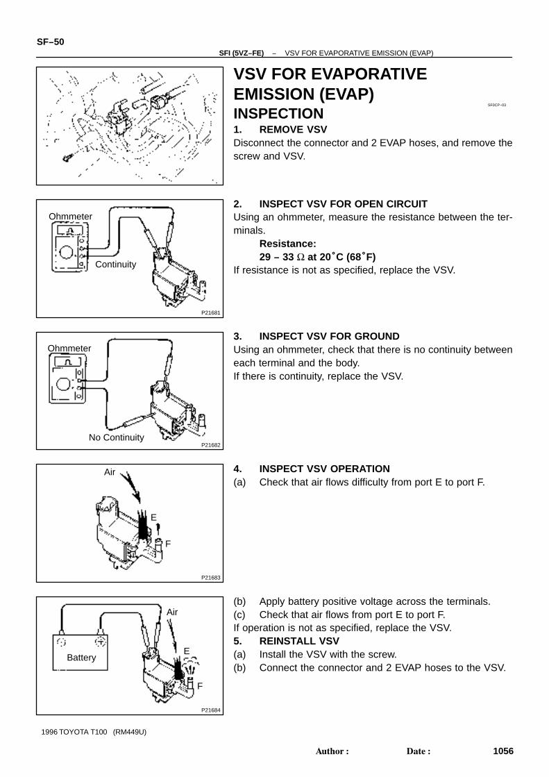
SF0CP−03
P21681
Continuity
Ohmmeter
P21682No Continuity
Ohmmeter
P21683
Air
E
F
P21684
Air
E
F
Battery
SF−50−SFI (5VZ−FE) VSV FOR EVAPORATIVE EMISSION (EVAP)
1056Author�: Date�:
1996 TOYOTA T100 (RM449U)
VSV FOR EVAPORATIVEEMISSION (EVAP)INSPECTION1. REMOVE VSVDisconnect the connector and 2 EVAP hoses, and remove thescrew and VSV.
2. INSPECT VSV FOR OPEN CIRCUITUsing an ohmmeter, measure the resistance between the ter-minals.
Resistance:29 − 33 Ω at 20°C (68°F)
If resistance is not as specified, replace the VSV.
3. INSPECT VSV FOR GROUNDUsing an ohmmeter, check that there is no continuity betweeneach terminal and the body.If there is continuity, replace the VSV.
4. INSPECT VSV OPERATION(a) Check that air flows difficulty from port E to port F.
(b) Apply battery positive voltage across the terminals.(c) Check that air flows from port E to port F.If operation is not as specified, replace the VSV.5. REINSTALL VSV(a) Install the VSV with the screw.(b) Connect the connector and 2 EVAP hoses to the VSV.
https://www.truck-manuals.net/
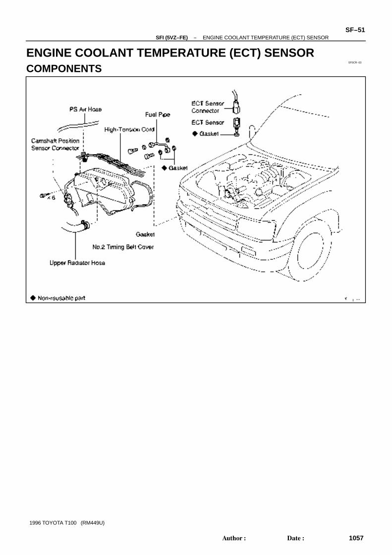
SF0CR−03
−SFI (5VZ−FE) ENGINE COOLANT TEMPERATURE (ECT) SENSORSF−51
1057Author�: Date�:
1996 TOYOTA T100 (RM449U)
ENGINE COOLANT TEMPERATURE (ECT) SENSORCOMPONENTS
https://www.truck-manuals.net/

SF0CS−03
P21183
SF−52−SFI (5VZ−FE) ENGINE COOLANT TEMPERATURE (ECT) SENSOR
1996 TOYOTA T100 (RM449U)
INSPECTION1. DRAIN ENGINE COOLANT2. DISCONNECT UPPER RADIATOR HOSE FROM WA-
TER OUTLET3. REMOVE NO. 2 TIMING BELT COVER(a) Disconnect the PS air hose from the clamp.(b) Disconnect the 3 cord clamps of the high−tension cords
from the belt cover.(c) Remove the 6 bolts, timing belt cover and gasket.(d) Disconnect the camshaft position sensor connector.4. REMOVE FUEL PIPE
5. REMOVE ECT SENSOR(a) Disconnect the ECT sensor connector.(b) Using a 19 mm deep socket wrench, remove the ECT
sensor and gasket.
https://www.truck-manuals.net/

Z02917
Ohmmeter
Acceptable
TEMPERATURE °C (°F)
RE
SIS
TAN
CE
kΩ
−SFI (5VZ−FE) ENGINE COOLANT TEMPERATURE (ECT) SENSORSF−53
1996 TOYOTA T100 (RM449U)
6. INSPECT ECT SENSORUsing an ohmmeter, measure the resistance between the ter-minals.
Resistance:Refer to the graph
If the resistance is not as specified, replace the ECT sensor.7. REINSTALL ECT SENSOR(a) Install a new gasket to the ECT sensor.(b) Using a 19 mm deep socket, install the ECT sensor.
Torque: 20 N·m (200 kgf·cm, 14 ft·lbf)(c) Connect the ECT sensor connector.8. REINSTALL FUEL PIPEInstall the fuel pipe with 4 new gaskets and the 2 union bolts.
Torque: 34.3 N·m (350 kgf·cm, 25 ft·lbf)9. REINSTALL NO.2 TIMING BELT COVER
Torque: 9 N·m (90 kgf·cm, 80 in.·lbf)10. RECONNECT UPPER RADIATOR HOSE TO WATER
OUTLET11. REFILL WITH ENGINE COOLANT
https://www.truck-manuals.net/

SF0CU−02
SF−54−SFI (5VZ−FE) KNOCK SENSOR
1060Author�: Date�:
1996 TOYOTA T100 (RM449U)
KNOCK SENSORCOMPONENTS
https://www.truck-manuals.net/

S05210
−SFI (5VZ−FE) KNOCK SENSORSF−55
1061Author�: Date�:
1996 TOYOTA T100 (RM449U)
https://www.truck-manuals.net/

Z15606
SF−56−SFI (5VZ−FE) KNOCK SENSOR
1062Author�: Date�:
1996 TOYOTA T100 (RM449U)
https://www.truck-manuals.net/

SF0CV−04
P21182
SST
Knock Sensor 1
Knock Sensor 2
P01630
Ohmmeter
−SFI (5VZ−FE) KNOCK SENSORSF−57
1996 TOYOTA T100 (RM449U)
INSPECTION1. DRAIN ENGINE COOLANT2. REMOVE AIR CLEANER HOSE3. REMOVE INTAKE AIR CONNECTOR (See page
EM−30)4. REMOVE HIGH−TENSION CORDS WITH IGNITION
COILS (See page IG−7)5. REMOVE TIMING BELT AND CAMSHAFT TIMING
PULLEYS (See page EM−13)6. REMOVE TIMING BELT IDLER NO. 27. REMOVE FUEL PRESSURE REGULATOR (See page
SF−16)8. REMOVE INTAKE MANIFOLD ASSEMBLY (See page
EM−30)9. REMOVE WATER BYPASS PIPE AND KNOCK SEN-
SOR WIRE (See page EM−84)
10. REMOVE KNOCK SENSORSUsing SST, remove the knock sensor.
SST 09816−30010
11. INSPECT KNOCK SENSORSUsing an ohmmeter, check that there is no continuity betweenthe terminal and body.If there is continuity, replace the sensor.12. INSTALL KNOCK SENSORSUsing SST, install the knock sensor.
SST 09816−30010Torque: 39 N·m (400 kgf·cm, 29 ft·lbf)
13. INSTALL WATER BYPASS PIPE AND KNOCK SEN-SOR WIRE (See page CO−5)
14. INSTALL INTAKE MANIFOLD ASSEMBLY (See pageEM−51)
15. INSTALL FUEL PRESSURE REGULATOR (See pageSF−17)
16. INSTALL TIMING BELT IDLER NO. 2 (See page EM−19)
17. INSTALL CAMSHAFT TIMING PULLEYS AND TIMINGBELT (See page EM−19)
18. INSTALL HIGH−TENSION CORDS WITH IGNITIONCOILS (See page IG−8)
https://www.truck-manuals.net/

SF−58−SFI (5VZ−FE) KNOCK SENSOR
1996 TOYOTA T100 (RM449U)
19. INSTALL INTAKE AIR CONNECTOR (See page EM−51)
20. INSTALL AIR CLEANER HOSE21. FILL WITH ENGINE COOLANT22. CHECK ENGINE COOLANT LEVEL
https://www.truck-manuals.net/

P21670
SF0D1−02
P21685
−SFI (5VZ−FE) EXHAUST GAS RECIRCULATION (EGR) GAS TEMPERATURE SENSOR
SF−59
1065Author�: Date�:
1996 TOYOTA T100 (RM449U)
EXHAUST GAS RECIRCULATION(EGR) GAS TEMPERATURESENSORINSPECTION1. REMOVE EGR GAS TEMPERATURE SENSOR
2. INSPECT EGR GAS TEMPERATURE SENSORUsing an ohmmeter, measure the resistance between the ter-minals.
Resistance:64 − 97 kΩ at 50°C (122°F)11 − 16 kΩ at 100°C (212°F)2 − 4 kΩ at 150°C (302°F)
If the resistance is not as specified, replace the sensor.3. REINSTALL EGR GAS TEMPERATURE SENSOR
Torque: 20 N·m (200 kgf·cm, 14 ft·lbf)
https://www.truck-manuals.net/

P21188
SF0CW−04
SF−60−SFI (5VZ−FE) HEATED OXYGEN SENSOR
1066Author�: Date�:
1996 TOYOTA T100 (RM449U)
HEATED OXYGEN SENSORINSPECTIONINSPECT HEATER RESISTANCE OF HEATEDOXYGEN SENSORS(a) Disconnect the oxygen sensor connector.(b) Using an ohmmeter, measure the resistance between the
terminals +B and HT.Resistance:M/T Bank 1 Sensor 1: 5 − 7 Ω at 20°C (68°F)Others: 11 − 16 Ω at 20°C (68°F)
If the resistance is not as specified, replace the sensor.Torque: 20 N·m (200 kgf·cm, 14 ft·lbf)
(c) Reconnect the oxygen sensor connector.
https://www.truck-manuals.net/

SF0CX−01
P20917
−SFI (5VZ−FE) ENGINE CONTROL MODULE (ECM)SF−61
1067Author�: Date�:
1996 TOYOTA T100 (RM449U)
ENGINE CONTROL MODULE (ECM)COMPONENTS
https://www.truck-manuals.net/
SF0CY−02
SF−62−SFI (5VZ−FE) ENGINE CONTROL MODULE (ECM)
1996 TOYOTA T100 (RM449U)
INSPECTION1. REMOVE ECM2. INSPECT ECM
(See page DI−144)3. REINSTALL ECM
https://www.truck-manuals.net/

FI7231
TOYOTA Hand−Held Tester
DLC3
SF0CZ−03
P21215
Sound Scope
−SFI (5VZ−FE) FUEL CUT RPMSF−63
1069Author�: Date�:
1996 TOYOTA T100 (RM449U)
FUEL CUT RPMINSPECTION1. WARM UP ENGINEAllow the engine to warm up to normal operating temperature.2. CONNECT TOYOTA HAND−HELD TESTER OR
OBDII SCAN TOOL(a) Connect the TOYOTA hand−held tester or OBDII scan
tool to the DLC3.(b) Please refer to the TOYOTA hand−held tester or OBDII
scan tool operator’s manual for further details.
3. INSPECT FUEL CUT OFF PRM(a) Increase the engine speed to at least 3,500 rpm.
(b) Use a sound scope to check for injector operating noise.(c) Check that when the throttle lever is released, injector op-
eration noise stops momentarily and then resumes.HINT:Measure with the A/C OFF.
Fuel return rpm:M/T: 1,000 rpmA/T: 1,200 rpm
4. DISCONNECT TOYOTA HAND−HELD TESTER OROBDII SCAN TOOL
https://www.truck-manuals.net/

CO – COOLING (3RZ-FE)
COOLANT CO-1 WATER PUMP CO-3 THERMOSTAT CO-7 RADIATOR CO-11
https://www.truck-manuals.net/

CO056−02
−COOLING (3RZ−FE) COOLANTCO−1
1070Author�: Date�:
1996 TOYOTA T100 (RM449U)
COOLANTINSPECTION1. CHECK ENGINE COOLANT LEVEL AT RESERVOIR TANKThe coolant level should be between the ”LOW” and ”FULL” lines.If low, check for leaks and add coolant up to the ”FULL” line.2. CHECK ENGINE COOLANT QUALITY(a) Remove the radiator cap.CAUTION:To avoid the danger of being burned, do not remove the radiator cap while the engine and radiatorare still hot, as fluid and steam can be blown out under pressure.(b) There should not be any excessive deposits of rust or scale around the radiator cap or radiator filler
hole, and the coolant should be free from oil.If excessively dirty, replace the coolant.(c) Reinstall the radiator cap.
https://www.truck-manuals.net/

CO057−03
P14901Drain Plug
Drain Plug
CO−2−COOLING (3RZ−FE) COOLANT
1996 TOYOTA T100 (RM449U)
REPLACEMENT1. REPLACE ENGINE COOLANT(a) Remove the radiator cap.CAUTION:To avoid the danger of being burned, do not remove it whilethe engine and radiator are still hot, as fluid and steam canbe blown out under pressure.(b) Drain the coolant from the radiator drain plug and engine
drain plug. (Engine drain plug at the right of engine block.)(c) Close the drain cock plug.
Torque:Torque (Engine drain plug):24 N·m (250 kgf·cm, 18 ft·lbf)
2. FILL ENGINE COOLANT(a) Slowly fill the system with coolant.
� Use a good brand of ethylene−glycol base coolantand mix it according to the manufacturer’s direc-tions.
� Using coolant which includes more than 50 % ethyl-ene−glycol (but not more than 70 %) is recom-mended.
NOTICE:Do not use an alcohol type coolant. The coolant should bemixed with demineralized water or distilled water.
Capacity (w/ Heater):8.7 liters (9.2 US qts, 7.7 lmp. qts)
(b) Reinstall the radiator cap.(c) Warm up the engine and check for leaks.(d) Recheck the coolant level and refill as necessary.
https://www.truck-manuals.net/
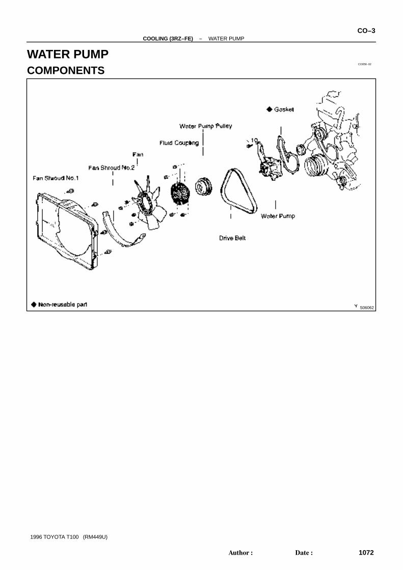
CO058−02
S06062
−COOLING (3RZ−FE) WATER PUMPCO−3
1072Author�: Date�:
1996 TOYOTA T100 (RM449U)
WATER PUMPCOMPONENTS
https://www.truck-manuals.net/

CO059−03
P14842
Adjusting Bolt
Lock Bolt
Pivot Bolt
P14838
A
CO−4−COOLING (3RZ−FE) WATER PUMP
1996 TOYOTA T100 (RM449U)
REMOVAL1. DRAIN ENGINE COOLANT2. DISCONNECT RADIATOR INLET HOSE3. REMOVE PS DRIVE BELTLoosen the lock bolt and adjusting bolt, and remove the drivebelt.4. w/ A/C:
REMOVE A/C DRIVE BELTLoosen the idler pulley nut and adjusting bolt, and remove thedrive belt.5. REMOVE DRIVE BELT, FAN WITH FLUID
COUPLING, WATER PUMP PULLEY AND FANSHROUD
(a) Stretch the belt and loosen the water pump pulley nuts.(b) Loosen the lock, pivot and adjusting bolts of the genera-
tor, and remove the drive belt.(c) Remove the 4 water pump pulley nuts.
Torque: 21 N·m (210 kgf·cm, 16 ft·lbf)(d) Pull out the fan with fluid coupling and water pump pulley.(e) Remove the No.2 fan shroud.(f) Remove the 4 bolts and No.1 fan shroud.
6. REMOVE WATER PUMPRemove the 10 bolts, water pump and gasket.
Torque:8.9 N·m (90 kgf·cm, 78 in.·lbf) except bolt A24.5 N·m (250 kgf·cm, 18 ft·lbf) for bolt A
HINT:Use a new gasket.
https://www.truck-manuals.net/

CO05A−03
P14847
−COOLING (3RZ−FE) WATER PUMPCO−5
1996 TOYOTA T100 (RM449U)
INSPECTION1. INSPECT WATER PUMP(a) Visually check the water hole for coolant leakage.If leakage is found, replace the water pump.(b) Turn the pulley, and check that the water pump bearing
moves smoothly and quietly.If necessary, replace the water pump.
2. INSPECT FLUID COUPLINGCheck the fluid coupling for damage and silicon oil leakage.If necessary, replace the fluid coupling.
https://www.truck-manuals.net/

CO05B−02
CO−6−COOLING (3RZ−FE) WATER PUMP
1996 TOYOTA T100 (RM449U)
INSTALLATIONInstallation is in the reverse order of removal (See page CO−4).
https://www.truck-manuals.net/

CO05C−02
P21642
−COOLING (3RZ−FE) THERMOSTATCO−7
1076Author�: Date�:
1996 TOYOTA T100 (RM449U)
THERMOSTATCOMPONENTS
https://www.truck-manuals.net/

CO05D−01
P14832
CO−8−COOLING (3RZ−FE) THERMOSTAT
1996 TOYOTA T100 (RM449U)
REMOVALHINT:Removal of the thermostat would have an adverse effect, caus-ing a lowering of cooling efficiency. Do not remove the thermo-stat, even if the engine tends to overheat.1. DRAIN ENGINE COOLANT2. DISCONNECT RADIATOR OUTLET HOSE
3. REMOVE WATER INLET AND THERMOSTAT(a) Remove the 2 nuts holding the water inlet to the inlet
housing, and disconnect the water inlet from the inlethousing.
(b) Remove the thermostat.(c) Remove the gasket from the thermostat.
https://www.truck-manuals.net/

P14835
CO05E−02
P11706
P14836
8 mm
−COOLING (3RZ−FE) THERMOSTATCO−9
1996 TOYOTA T100 (RM449U)
INSPECTIONINSPECT THERMOSTATHINT:The thermostat is numbered with the valve opening tempera-ture.
(a) Immerse the thermostat in water and gradually heat thewater.
(b) Check the valve opening temperature.Valve opening temperature:80 − 84°C (176 − 183°F)
If the valve opening temperature is not as specified, replace thethermostat.
(c) Check the valve lift.Valve lift:8 mm (0.31 in.) or more at 95°C (203°C)
If the valve lift is not as specified, replace the thermostat.(d) Check that the valve spring is tight when the thermostat
is at low temperatures (below 40°C (104°F)).If not closed, replace the thermostat.
https://www.truck-manuals.net/
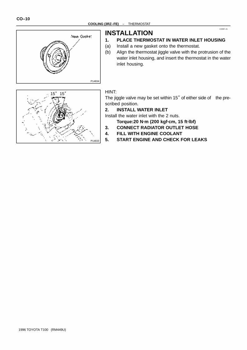
CO05F−01
P14834
P14833
15° 15°
CO−10−COOLING (3RZ−FE) THERMOSTAT
1996 TOYOTA T100 (RM449U)
INSTALLATION1. PLACE THERMOSTAT IN WATER INLET HOUSING(a) Install a new gasket onto the thermostat.(b) Align the thermostat jiggle valve with the protrusion of the
water inlet housing, and insert the thermostat in the waterinlet housing.
HINT:The jiggle valve may be set within 15° of either side of the pre-scribed position.2. INSTALL WATER INLETInstall the water inlet with the 2 nuts.
Torque:20 N·m (200 kgf·cm, 15 ft·lbf)3. CONNECT RADIATOR OUTLET HOSE4. FILL WITH ENGINE COOLANT5. START ENGINE AND CHECK FOR LEAKS
https://www.truck-manuals.net/
CO05G−02
−COOLING (3RZ−FE) RADIATORCO−11
1080Author�: Date�:
1996 TOYOTA T100 (RM449U)
RADIATORON−VEHICLE CLEANINGUsing water or a steam cleaner, remove any mud or dirt from the radiator core.NOTICE:If using a high pressure type cleaner, be careful not to deform the fins of the radiator core (i.e. Main-tain a distance between the cleaner nozzle and radiator core).
https://www.truck-manuals.net/

CO05H−02
Z02362
Radiator Cap Tester
Radiator Cap
P14849Radiator Cap Tester
CO−12−COOLING (3RZ−FE) RADIATOR
1996 TOYOTA T100 (RM449U)
ON−VEHICLE INSPECTION1. REMOVE RADIATOR CAPCAUTION:To avoid the danger of being burned, do not remove the ra-diator cap while the engine and radiator are still hot, as fluidand steam can be blown out under pressure.
2. INSPECT RADIATOR CAPNOTICE:If the radiator cap has contaminations,always rinse it withwater.Using a radiator cap tester, pump the tester and measure therelief valve opening pressure.
Standard opening pressure:74 − 103 kPa (0.75 − 1.05 kgf/cm2, 10.7 − 14.9 psi)
HINT:Use the tester’s maximum reading as the opening pressure.If the opening pressure is less than standard, replace the radia-tor cap.
3. INSPECT COOLING SYSTEM FOR LEAKS(a) Fill the radiator with coolant and attach a radiator cap tes-
ter.(b) Warm up the engine.(c) Pump it to 118 kPa (1.2 kgf/cm2, 17.1 psi), and check that
the pressure does not drop.If the pressure drops, check the hoses, radiator or water pumpfor leaks. If no external leaks are found, check the heater core,cylinder block and head.4. REINSTALL RADIATOR CAP
https://www.truck-manuals.net/

CO05I−01
S06060
−COOLING (3RZ−FE) RADIATORCO−13
1996 TOYOTA T100 (RM449U)
COMPONENTS
https://www.truck-manuals.net/

P21703
Radiator Cap
Upper Tank
� Tank Plate
� O−Ring
� O−Ring
Core
� Tank Plate
Lower Tank
� O−Ring Drain Cock
� Non−reusable part
CO−14−COOLING (3RZ−FE) RADIATOR
1996 TOYOTA T100 (RM449U)
https://www.truck-manuals.net/

CO18O−01
P14852
P14853
P20975
−COOLING (3RZ−FE) RADIATORCO−15
1996 TOYOTA T100 (RM449U)
REMOVAL1. DRAIN ENGINE COOLANT2. REMOVE BATTERY3. REMOVE RADIATOR GRILLE(a) Remove the 4 screws, and clearance lights.(b) Remove the 4 screws, 11 clips and radiator grille.
4. DISCONNECT RADIATOR INLET HOSE5. DISCONNECT RADIATOR RESERVOIR HOSE6. REMOVE PS DRIVE BELTLoosen the lock bolt and adjusting bolt, and remove the drivebelt.7. w/ A/C:
REMOVE A/C DRIVE BELTLoosen the idler pulley nut and adjusting bolt, and remove thedrive belt.
8. REMOVE DRIVE BELT, FAN WITH FLUID COUPLING,WATER PUMP PULLEY AND FAN SHROUD (See pageCO−4)
9. A/T:DISCONNECT OIL COOLER HOSES
10. DISCONNECT RADIATOR OUTLET HOSE11. REMOVE RADIATORRemove the 4 bolts and radiator.
12. REMOVE RADIATOR SUPPORTS� M/T:
Remove the 4 bolts and 2 radiator supports.
� A/T:Remove the 8 bolts and 2 radiator supports.
https://www.truck-manuals.net/

CO05K−02
P08306
P08307 CO0041 B02539
8 7
5 1 6
3 2 4
SST
Tank
Tank Plate
P14857
P14855
CO−16−COOLING (3RZ−FE) RADIATOR
1996 TOYOTA T100 (RM449U)
DISASSEMBLY1. M/T:
REMOVE TANK PLATE(a) Raise the claws of the tank plates with SST in the numeri-
cal order shown in the illustration.SST 09230 − 00010 (09231 − 00010, 09231 − 00020,
09231 − 00030 09231 − 00040, 09231 − 00050)NOTICE:Be careful not to damage the core plate.
(b) Pull the tank plates outward.
2. M/T:REMOVE TANK
(a) Pull the tank upward.(b) Remove the O−ring.
https://www.truck-manuals.net/

CO05L−02
CO0989
Core Plate
Core
Core Plate
P14856
CO0317O−Ring
� Normal X Twisted
X Twisted
P14854
−COOLING (3RZ−FE) RADIATORCO−17
1996 TOYOTA T100 (RM449U)
REASSEMBLY1. M/T:
INSTALL OIL COOLER TO LOWER TANKClean the O−ring contact surface of the lower tank.
2. M/T:CHECK CORE PLATE FOR DAMAGE
HINT:� If the sides of the core plate groove are deformed, reas-
sembly of the tank will be impossible. Therefore, first cor-rect any deformation with pliers.
� Water leakage will result if the bottom of the core plategroove is damaged or dented. Therefore, repair or re-place if necessary.
3. M/T:INSTALL TANK
Install a new O−ring and the tank.HINT:� Clean the tank and core plate.
� Take out any twists.
4. M/T:INSTALL TANK PLATE
Insert new tank plates from both ends in the direction of thearrows. Firmly set the tank plates in the core plate.
https://www.truck-manuals.net/

CO0373
SST
Punch
ShaftGuide Block
P14898
8
5
3 2 4
1 6
7
Z04269
Punch
Tank Plate
Tank
SST
StopperGuide Book
SST
P14858
P14859
CO−18−COOLING (3RZ−FE) RADIATOR
1996 TOYOTA T100 (RM449U)
5. M/T:STAKE CLAWS OF TANK PLATES
(a) Set the punch of SST to ”LOW”.SST 09230 − 00010 (09231 − 00010, 09231 − 00020,
09231 − 00030, 09231 − 00040, 09231 − 00050)
(b) Stake the claws of the tank plates with SST in the numeri-cal order shown in the illustration.
NOTICE:If the bottom of the core plate is staked with the SST on theguide block stopper, it may result in water leakage.
HINT:� Stake with just enough pressure to leave a mark on the
claw. The staked plate height (H) should be as follows.Plate height (H):9.2 − 9.6 mm (0.362 − 0.378 in.)
� Do not stake the are as protruding around the pipes.
https://www.truck-manuals.net/

P14899
P14860
CO0035
ClearanceTank
Core Plate
Tank Plate
O−Ring
−COOLING (3RZ−FE) RADIATORCO−19
1996 TOYOTA T100 (RM449U)
� The points shown in the illustration cannot be staked withthe SST. Use pliers and be careful not to damage the coreplates.
6. M/T:CHECK FOR WATER LEAKS
(a) Tighten the drain plug.(b) Plug the inlet and outlet pipes of the radiator with SST
SST 09230 − 01010 (09231 − 00060, 09231 − 01010,09231 − 01020, 09231 − 01030)
(c) Using a radiator cap tester, apply pressure to the radiator.Test pressure:147 kPa (1.5 kgf/cm2, 21 psi)
(d) Check for water leaks.HINT:On radiators with resin tanks, these is a clearance between thecore plate and tank plate where a minute amount of air will re-main, giving the appearance of an air leak when the radiator issubmerged in water. Therefore, before performing the waterleak test, first swirl the water around in the radiator until all airbubbles disappear.7. M/T:
PAINT TANK PLATEHINT:If the water leak test checks out okay, allow the radiator to drycompletely and then paint the tank plate.
https://www.truck-manuals.net/

P14853
CO18P−01
P20975
P14852
CO−20−COOLING (3RZ−FE) RADIATOR
1996 TOYOTA T100 (RM449U)
INSTALLATION1. INSTALL SUPPORTS� M/T:
Install the supports with the 4 bolts.Torque:13 N·m (130 kgf·cm,9 ft·lbf)
� A/T:Install the supports with the 8 bolts.
2. INSTALL RADIATOR(a) Insert the tabs of the radiator support through the radiator
service holes.(b) Install the radiator with the 4 bolts.
Torque:31 N·m (310 kgf·cm, 23 ft·lbf)3. CONNECT RADIATOR OUTLET HOSE4. INSTALL WATER PUMP PULLEY, FAN SHROUD, FAN
WITH FLUID COUPLING AND DRIVE BELT (See pageCO−6)
5. w/ A/C:INSTALL A/C COMPRESSOR DRIVE BELT
Install and adjust the A/C compressor drive belt (See page AC−16).6. INSTALL PS PUMP DRIVE BELTInstall and adjust the PS pump drive belt (See page SR−3).
7. CONNECT RADIATOR RESERVOIR HOSE8. CONNECT RADIATOR INLET HOSE9. INSTALL RADIATOR GRILLE(a) Install the 4 screws, 11 clips and radiator grille.(b) Install the 4 screws and clearance lights.10. FILL WITH ENGINE COOLANT11. START ENGINE AND CHECK FOR LEAKS
https://www.truck-manuals.net/

CO – COOLING (5VZ-FE)
COOLANT CO-1 WATER PUMP CO-3 THERMOSTAT CO-8 RADIATOR CO-12
https://www.truck-manuals.net/

CO05O−01
−COOLING (5VZ−FE) COOLANTCO−1
1090Author�: Date�:
1996 TOYOTA T100 (RM449U)
COOLANTINSPECTION1. CHECK ENGINE COOLANT LEVEL AT RESERVOIR
TANKThe engine coolant level should be between the”LOW” and ”FULL” lines, when the engine is cold.If low, check for leaks and add engine coolant up to the ”FULL”line.2. CHECK ENGINE COOLANT QUALITY(a) Remove the radiator cap from the water outlet.CAUTION:To avoid the danger of being burned, do not remove the ra-diator cap while the engine and radiator are still hot, as fluidand steam can be blown out under pressure.(b) There should not be any excessive deposits of rust or
scale around the radiator cap or radiator filler hole, andthe coolant should be free from oil.
If excessively dirty, clean the coolant passages and replace thecoolant.(c) Reinstall the radiator cap.
https://www.truck-manuals.net/

CO05P−04
P20925
Drain Plug
CO−2−COOLING (5VZ−FE) COOLANT
1996 TOYOTA T100 (RM449U)
REPLACEMENT1. DRAIN ENGINE COOLANT(a) Remove the radiator cap.CAUTION:To avoid the danger of being burned, do not remove the ra-diator cap while the engine and radiator are still hot, as fluidand steam can be blown out under pressure.(b) Loosen the drain plugs, and drain the engine coolant.(c) Close the drain plugs.2. FILL ENGINE COOLANT(a) Slowly fill the system with engine coolant.
� Use a good brand of ethylene−glycol base enginecoolant and mix it according to the manufacturer’sdirections.
� Using engine coolant which includes more than 50% ethylene−glycol (but not more than 70 %) is rec-ommended.
NOTICE:Do not use an alcohol type engine coolant.The engine cool-ant should be mixed with demineralized water or distilledwater.
Capacity:2WDM/T 10.0 liters (10.6 US qts, 8.8 lmp. qts)A/T 9.9 liters (10.5 US qts, 8.7 lmp. qts)4WDM/T 10.0 liters (10.6 US qts, 8.8 lmp. qts)A/T 10.2 liters (10.8 US qts, 9.0 lmp. qts)
(b) Install the radiator cap.(c) Start the engine, and bleed the cooling system.(d) If necessary, refill engine coolant into the reservoir tank
until it is ”FULL” line.3. CHECK ENGINE COOLANT FOR LEAKS
https://www.truck-manuals.net/

CO05Q−02
P20840
−COOLING (5VZ−FE) WATER PUMPCO−3
1092Author�: Date�:
1996 TOYOTA T100 (RM449U)
WATER PUMPCOMPONENTS
https://www.truck-manuals.net/

Z15614
CO−4−COOLING (5VZ−FE) WATER PUMP
1093Author�: Date�:
1996 TOYOTA T100 (RM449U)
https://www.truck-manuals.net/

CO05R−03
−COOLING (5VZ−FE) WATER PUMPCO−5
1996 TOYOTA T100 (RM449U)
REMOVAL1. REMOVE TIMING BELT
(See page EM−13)2. REMOVE WATER INLET AND THERMOSTAT3. w/ Oil Cooler:
DISCONNECT NO.2 OIL COOLER HOSE FROM WA-TER PUMP
4. REMOVE WATER PUMPRemove the 7 bolts and water pump.
https://www.truck-manuals.net/

CO05S−01
P20920
P21660
P21515
CO−6−COOLING (5VZ−FE) WATER PUMP
1996 TOYOTA T100 (RM449U)
INSPECTION1. INSPECT WATER PUMP(a) Visually check the air hole and water hole for coolant leak-
age.If leakage is found, replace the water pump.If engine coolant has leaked onto the timing belt, replace thetiming belt.(b) Turn the pulley, and check that the water pump bearing
moves smoothly and quietly.If necessary, replace the water pump.2. INSPECT FLUID COUPLING(a) Remove the 4 nuts and fan from the fluid coupling.(b) Check that the fluid coupling is not damaged and that no
silicon oil leaks.If necessary, replace the fluid coupling.
3. INSPECT FAN PULLEY BRACKET(a) Check the turning smoothness of the fan pulley.
If necessary, replace the pulley bracket.(b) Reinstall the fan to the fluid coupling with the 4 nuts.
Torque:5.4 N·m (75 kgf·cm, 48 in.·lbf)4. INSPECT TIMING BELT
(See page EM−17)
https://www.truck-manuals.net/

CO05T−02
P20922
Seal Packing
−COOLING (5VZ−FE) WATER PUMPCO−7
1996 TOYOTA T100 (RM449U)
INSTALLATION1. INSTALL WATER PUMP(a) Remove any old packing (FIPG) material and be careful
not to drop any oil on the contact surfaces of the waterpump and cylinder block.� Using a razor blade and gasket scraper, remove all
the old packing (FIPG) material from the gasket sur-faces and sealing groove.
� Thoroughly clean all components to remove all theloose material.
� Using a non−residue solvent, clean both sealingsurfaces.
(b) Apply seal packing to the water pump groove.Seal packing:Part No. 08826−00100 or equivalent� Install a nozzle that has been cut to a 2 − 3 mm (0.08
− 0.12 in.) opening.HINT:Avoid applying an excessive amount to the surface.
� Parts must be assembled within 5 minutes of ap-plication. Otherwise the material must be removedand reapplied.
� Immediately remove nozzle from the tube and rein-stall cap.
(c) Install the water pump with the 7 bolts.Torque:20 N·m (200 kgf·cm, 14 ft·lbf)
2. w/ OIL COOLER:CONNECT NO.2 OIL COOLER HOSE
3. INSTALL THERMOSTAT(See page CO−11)
4. INSTALL TIMING BELT(See page EM−19)
https://www.truck-manuals.net/

CO05U−01
S02352� Non−Reusable part
: Specified torqueN·m(kgf·cm, ft·lbf)
20 (200, 14)
Water Inlet
Thermostat
� Gasket
Wire Clamp
Lower Radiator Hose
CO−8−COOLING (5VZ−FE) THERMOSTAT
1097Author�: Date�:
1996 TOYOTA T100 (RM449U)
THERMOSTATCOMPONENTS
https://www.truck-manuals.net/

CO05V−03
P20967Jiggle Valve
−COOLING (5VZ−FE) THERMOSTATCO−9
1996 TOYOTA T100 (RM449U)
REMOVAL1. DRAIN ENGINE COOLANT2. DISCONNECT LOWER RADIATOR HOSE3. REMOVE THERMOSTAT(a) Remove the 3 nuts, water inlet and thermostat with gas-
ket from the water pump.Torque: 20 N·m (200 kgf·cm, 14 ft·lbf)
(b) Remove the gasket from the thermostat.HINT:Use a new gasket.
https://www.truck-manuals.net/

CO05W−03
CO0600
8.5 mm
CO−10−COOLING (5VZ−FE) THERMOSTAT
1996 TOYOTA T100 (RM449U)
INSPECTIONINSPECT THERMOSTATHINT:Thermostat is numbered according to the valve opening tem-perature.(a) Immerse the thermostat in water and heat the water grad-
ually.(b) Check the valve opening temperature and valve lift.
Valve opening temperature:80 − 84°C (176 − 183°F)Valve lift: At 95°C (203°F): 8.5 mm (0.335 in.) or more
If the valve opening temperature and valve lift are not withinspecifications, replace the thermostat.
(c) Check that the valve is fully closed when the thermostatis at low temperatures (below 40°C (104°F)).
If not closed, replace the thermostat.
https://www.truck-manuals.net/

CO05X−01
P20967Jiggle Valve
−COOLING (5VZ−FE) THERMOSTATCO−11
1996 TOYOTA T100 (RM449U)
INSTALLATION1. INSTALL THERMOSTAT(a) Place a new gasket to the thermostat.(b) Install the thermostat with the jiggle valve downward.(c) Install the water inlet with the 3 bolts.
Torque: 20 N·m (200 kgf·cm, 14 ft·lbf)2. CONNECT LOWER RADIATOR HOSE3. FILL WITH ENGINE COOLANT4. START ENGINE AND CHECK FOR LEAKS
https://www.truck-manuals.net/

CO05Y−01
CO−12−COOLING (5VZ−FE) RADIATOR
1101Author�: Date�:
1996 TOYOTA T100 (RM449U)
RADIATORON−VEHICLE CLEANINGUsing water or a steam cleaner, remove any mud or dirt from theradiator core.NOTICE:If using a high pressure type cleaner, be careful not to de-form the fins of the radiator core. (i.e. Maintain a distancebetween the cleaner nozzle and radiator core.)
https://www.truck-manuals.net/

CO05Z−03
Z02362
Radiator Cap Tester
Radiator Cap
P14264
−COOLING (5VZ−FE) RADIATORCO−13
1996 TOYOTA T100 (RM449U)
ON−VEHICLE INSPECTION1. REMOVE RADIATOR CAPCAUTION:To avoid the danger of being burned, do not remove the ra-diator cap while the engine and radiator are still hot, as fluidand steam can be blown out under pressure.2. INSPECT RADIATOR CAPNOTICE:If the radiator cap has contaminations, always rinse it withwater.Using a radiator cap tester, pump the tester and measure therelief valve opening pressure.
Standard opening pressure:74 − 103 kPa(0.75 − 1.05 kgf/cm2, 10.7 − 14.9 psi)Minimum opening pressure:59 kPa (0.6 kgf/cm2, 8.5 psi)
HINT:Use the tester’s maximum reading as the opening pressure.If the opening pressure is less than minimum, replace the radia-tor cap.3. INSPECT COOLING SYSTEM FOR LEAKS(a) Fill the radiator with coolant and attach a radiator cap tes-
ter.(b) Warm up the engine.(c) Pump it to 118 kPa (1.2 kgf/cm2, 17.1 psi), and check that
the pressure does not drop.If the pressure drops, check the hoses, radiator or water pumpfor leaks. If no external leaks are found, check the heater core,cylinder block and head.4. REINSTALL RADIATOR CAP
https://www.truck-manuals.net/

CO060−01
Z15608
CO−14−COOLING (5VZ−FE) RADIATOR
1996 TOYOTA T100 (RM449U)
COMPONENTS
https://www.truck-manuals.net/

P20979
−COOLING (5VZ−FE) RADIATORCO−15
1996 TOYOTA T100 (RM449U)
https://www.truck-manuals.net/
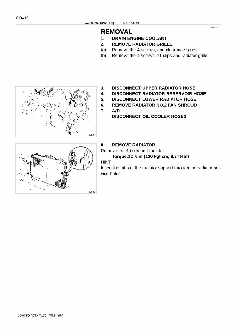
CO061−01
P20524
P20523
CO−16−COOLING (5VZ−FE) RADIATOR
1996 TOYOTA T100 (RM449U)
REMOVAL1. DRAIN ENGINE COOLANT2. REMOVE RADIATOR GRILLE(a) Remove the 4 screws, and clearance lights.(b) Remove the 4 screws, 11 clips and radiator grille.
3. DISCONNECT UPPER RADIATOR HOSE4. DISCONNECT RADIATOR RESERVOIR HOSE5. DISCONNECT LOWER RADIATOR HOSE6. REMOVE RADIATOR NO.2 FAN SHROUD7. A/T:
DISCONNECT OIL COOLER HOSES
8. REMOVE RADIATORRemove the 4 bolts and radiator.
Torque:12 N·m (120 kgf·cm, 8.7 ft·lbf)HINT:Insert the tabs of the radiator support through the radiator ser-vice holes.
https://www.truck-manuals.net/

P20975
CO062−01
−COOLING (5VZ−FE) RADIATORCO−17
1996 TOYOTA T100 (RM449U)
DISASSEMBLY1. REMOVE NO.1 FAN SHROUD.Remove the 4 bolts and No.1 fan shroud.2. REMOVE RADIATOR SUPPORTSUsing a torx wrench, remove the 8 torx screws and the 2 radia-tor supports.Torx wrench: T30 (Part No. 09042−00010 or locally manufac-tured tool)HINT:Insert the tabs the radiator upper tank through the radiator sup-port holes.
https://www.truck-manuals.net/

CO063−01
CO−18−COOLING (5VZ−FE) RADIATOR
1996 TOYOTA T100 (RM449U)
REASSEMBLYReassembly is in the reverse order of disassembly (Seepage CO−17).
https://www.truck-manuals.net/

CO064−01
−COOLING (5VZ−FE) RADIATORCO−19
1996 TOYOTA T100 (RM449U)
INSTALLATIONInstallation is in the reverse order of removal (See pageCO−16).
https://www.truck-manuals.net/

LU – LUBRICATION (3RZ-FE)
OIL AND FILTER LU-1 OIL PUMP LU-5
https://www.truck-manuals.net/

B00319
Recommended Viscosity (SAE):
10W−30
5W−30 PREFERRED
TEMPERATURE RANGE ANTICIPATED BEFORE NEXT OIL CHANGE
°F −20 0 20 40 60 80 100°C −29 −18 −7 4 16 27 38
LU0O7−01
−LUBRICATION (3RZ−FE) OIL AND FILTERLU−1
1109Author�: Date�:
1996 TOYOTA T100 (RM449U)
OIL AND FILTERINSPECTION1. CHECK ENGINE OIL QUALITYCheck the oil for deterioration, entry of water, discoloring or thin-ning.If the quality is visibly poor, replace the oil.
Oil grade:API grade SH Energy−Conserving II or SJ,Energy−Conserving or ILSAC multigrade engine oil.SAE 5W−30 is the bset choise for your vehicle, forgood fuel economy, and good starting in coldweather.
2. CHECK ENGINE OIL LEVELThe oil level should be between the ”L” and ”F” marks on the dip-stick.If low, check for leakage and add oil up to ”F” mark.NOTICE:� Do not fill with engine oil above the ”F” mark.� When inserting the dipstick, insert the curved tip of
the dipstick facing the same direction as the curve ofthe guide.
� If the dipstick gets caught while inserting it, do notforce it in. Reconfirm the direction of the dipstick.
3. REMOVE ENGINE UNDER COVER
https://www.truck-manuals.net/

P14870
P12478
Adhesive
LU−2−LUBRICATION (3RZ−FE) OIL AND FILTER
1110Author�: Date�:
1996 TOYOTA T100 (RM449U)
4. REMOVE OIL PRESSURE SWITCH, AND INSTALL OILPRESSURE GAUGE
5. WARM UP ENGINEAllow the engine to warm up to normal operating temperature.6. CHECK OIL PRESSURE
Oil pressure:At idle29 kPa (0.3 kgf/cm2, 4.3 psi) or moreAt 3,000 rpm245 − 490 kPa (2.5 − 5.0 kgf/cm2, 36 − 71 psi)
7. REMOVE OIL PRESSURE GAUGE AND REINSTALLOIL PRESSURE SWITCH
(a) Remove the oil pressure gauge.(b) Apply adhesive to 2 or 3 threads of the oil pressure switch.
Adhesive:Part No. 08833−00080, THREE BOND 1344, LOCTITE 242 or equivalent
(c) Reinstall the oil pressure switch.8. START ENGINE AND CHECK FOR LEAKS
https://www.truck-manuals.net/

LU0O8−01
P15000
SST
−LUBRICATION (3RZ−FE) OIL AND FILTERLU−3
1996 TOYOTA T100 (RM449U)
REPLACEMENTCAUTION:Prolonged and repeated contact with mineral oil will resultin the removal of natural fats from the skin, leading to dry-ness, irritation and dermatitis. In addition, used engine oilcontains potentially harmful contaminants which maycause skin cancer. Care should be taken, therefore, whenchanging engine, oil to minimize the frequency and lengthof time your skin is exposed to used engine oil. Protectiveclothing and gloves that cannot be penetrated by oil shouldbe worn. The skin should be thoroughly washed with soapand water, or use water−less hand cleaner, to remove anyused engine oil. Do not use gasoline, thinners, or solvents.In order to preserve the environment, used oil and used oilfilters must be disposed of only at designated disposalsites.
1. DRAIN ENGINE OIL(a) Remove the oil filler cap.(b) Remove the oil drain plug, and drain the oil into a contain-
er.
2. REPLACE OIL FILTER(a) Using SST, remove the oil filter.
SST 09228−07501(b) Check and clean the oil filter installation surface.
(c) Apply clean engine oil to the gasket of a new oil filter.(d) Lightly screw the oil filter into place, and tighten it until the
gasket contacts the seat.(e) Using SST, tighten it an additional 3/4 turn.
SST 09228−07501
https://www.truck-manuals.net/

LU−4−LUBRICATION (3RZ−FE) OIL AND FILTER
1996 TOYOTA T100 (RM449U)
3. REFILL WITH ENGINE OIL(a) Clean and install the oil drain plug with a new gasket.
Torque:25 N·m (250 kgf·cm, 18 ft·lbf)(b) Fill with fresh engine oil.
Oil capacityDrain and refillw/ Oil filter change5.3 liters (5.6 US qts, 4.7 lmp. qts)w/o Oil filter change5.0 liters (5.3 US qts, 4.4 lmp. qts)Dry fill6.0 liters (6.3 US qts, 5.3 lmp. qts)
(c) Reinstall the oil filler cap.4. START ENGINE AND CHECK FOR LEAKS5. RECHECK ENGINE OIL LEVEL
https://www.truck-manuals.net/

LU02V−02
P21633
: Specified torque
200 (2,650, 191)
N·m (kgf·cm, ft·lbf)
−LUBRICATION (3RZ−FE) OIL PUMPLU−5
1113Author�: Date�:
1996 TOYOTA T100 (RM449U)
OIL PUMPCOMPONENTS
https://www.truck-manuals.net/

P21644
LU−6−LUBRICATION (3RZ−FE) OIL PUMP
1114Author�: Date�:
1996 TOYOTA T100 (RM449U)
https://www.truck-manuals.net/

LU02W−01
−LUBRICATION (3RZ−FE) OIL PUMPLU−7
1996 TOYOTA T100 (RM449U)
REMOVAL1. REMOVE TIMING CHAIN COVER
(See page EM−14)2. REMOVE NO.1 TIMING CHAIN AND CAMSHAFT TIMING GEAR
(See page EM−14)
https://www.truck-manuals.net/

LU02X−02
P14865
Z11073
LU−8−LUBRICATION (3RZ−FE) OIL PUMP
1996 TOYOTA T100 (RM449U)
DISASSEMBLY1. REMOVE DRIVE AND DRIVEN ROTORSRemove the 9 screws, pump cover, drive rotor, driven rotor andO−ring.
2. REMOVE RELIEF VALVE(a) Using snap ring pliers, remove the snap ring.(b) Remove the these parts:
(1) Retainer(2) Spring(3) Relief valve
https://www.truck-manuals.net/

LU02Y−02
P14867
P14873
P14872
P14874
−LUBRICATION (3RZ−FE) OIL PUMPLU−9
1996 TOYOTA T100 (RM449U)
INSPECTION1. INSPECT RELIEF VALVECoat the valve with engine oil and check that it falls smoothlyinto the valve hole by its own weight.If it does not, replace the relief valve. If necessary, replace theoil pump assembly.
2. INSPECT ROTOR BODY CLEARANCEUsing a thickness gauge, measure the clearance between thedriven rotor and body.
Standard body clearance:0.100 − 0.175 mm (0.0039 − 0.0069 in.)Maximum body clearance:0.30 mm (0.0118 in.)
If the body clearance is greater than maximum, replace the ro-tors as a set. If necessary, replace the oil pump assembly.
3. INSPECT ROTOR SIDE CLEARANCEUsing a thickness gauge and precision straight edge, measurethe clearance between the rotors and precision straight edge.
Standard side clearance:0.030 − 0.090 mm (0.0012 − 0.0035 in.)Maximum side clearance:0.15 mm (0.0059 in.)
If the side clearance is greater than maximum, replace the ro-tors as a set. If necessary, replace the oil pump assembly.
4. INSPECT ROTOR TIP CLEARANCEUsing a thickness gauge, measure the clearance between thedrive and driven rotor tips.
Standard tip clearance:0.110 − 0.240 mm (0.0043 − 0.0094 in.)Maximum tip clearance:0.25 mm (0.0098 in.)
If the tip clearance is greater than maximum, replace the rotorsas a set.
https://www.truck-manuals.net/

LU02Z−02
P14862
P14864
SST
P14861
P14863
SST
LU−10−LUBRICATION (3RZ−FE) OIL PUMP
1996 TOYOTA T100 (RM449U)
REPLACEMENTREPLACE CRANKSHAFT FRONT OIL SEALHINT:There are 2 methods (A and B) to replace the oil seal which areas follows:(a) If oil pump is removed from cylinder block.
(1) Using a screwdriver and a hammer, tap out the oilseal.
(2) Using SST and a hammer, tap in a new oil seal untilits surface is flush with the oil pump case edge.
SST 09223−50010(3) Apply MP grease to the oil seal lip.
(b) If oil pump is installed to cylinder block.(1) Using a screwdriver, pry out the oil seal.
NOTICE:Be careful not to damage the crankshaft. Tape the screw-driver tip.
(2) Apply MP grease to a new oil seal lip.(3) Using SST and a hammer, tap in the oil seal until its
surface is flush with the oil pump case edge.SST 09223−50010
https://www.truck-manuals.net/

LU030−02
Z11072
P14912
P14866
New O−Ring
−LUBRICATION (3RZ−FE) OIL PUMPLU−11
1996 TOYOTA T100 (RM449U)
REASSEMBLY1. INSTALL RELIEF VALVE(a) Install these parts:
(1) Relief valve(2) Spring(s)(3) Retainer
(b) Using snap ring pliers, install the snap ring.
2. INSTALL DRIVE AND DRIVEN ROTORS(a) Place the drive and driven rotors into the pump body.
(b) Place a new O−ring to the pump body.(c) Install the pump cover with the 9 screws.
https://www.truck-manuals.net/

LU031−01
LU−12−LUBRICATION (3RZ−FE) OIL PUMP
1996 TOYOTA T100 (RM449U)
INSTALLATION1. INSTALL NO.1 TIMING CHAIN AND CAMSHAFT TIMING GEAR
(See page EM−20)2. INSTALL TIMING CHAIN COVER
(See page EM−20)
https://www.truck-manuals.net/

LU – LUBRICATION (5VZ-FE)
OIL AND FILTER LU-1 OIL PUMP LU-5 OIL COOLER LU-17
https://www.truck-manuals.net/

LU0817
Recommended Viscosity (SAE):
10W−30
5W−30 PREFERRED
TEMPERATURE RANGE ANTICIPATED BEFORE NEXT OIL CHANGE
LU033−04
P20966SST
P20969
Oil Pressure Gauge
−LUBRICATION (5VZ−FE) OIL AND FILTERLU−1
1121Author�: Date�:
1996 TOYOTA T100 (RM449U)
OIL AND FILTERINSPECTION1. CHECK ENGINE OIL QUALITYCheck the oil for deterioration, entry of water, discoloring or thin-ning.If oil quality is visibly poor, replace it.
Oil grade:API grade SH Energy−Conserving II or ILSAC multi-grade engine oil.SAE 5W−30 is the bset choise for your vehicle, forgood fuel economy, and good starting in coldweather.
2. CHECK ENGINE OIL LEVELThe oil level should be between the ”L” and ”F” marks on the dip-stick.3. CHECK OIL LEVELThe oil level should be between the ”L” and ”F” marks on the lev-el gauge. If low, check for leakage and add oil up to the ”F” mark.If low, check for leakage and add oil up to the ”F” mark.When inserting the oil dipstick, insert the curved tip of thedipstick facing the same direction as the curve of theguide.If the dipstick gets caught while inserting it, do notforce it in. Reconfirm the direction of the dipstick.
4. REMOVE OIL PRESSURE SWITCHUsing SST, remove the oil pressure switch.
SST 09816−300105. INSTALL OIL PRESSURE GAUGE6. START ENGINEStart the engine and warm it up to normal operating tempera-ture.
7. CHECK OIL PRESSUREOil pressure: At idle speed 29 kPa (0.3 kgf/cm2, 4.3 psi) or more At 3,000 rpm 245 − 520 kPa (2.5 − 5.3 kgf/cm2, 36 − 75 psi)
8. REMOVE OIL PRESSURE GAUGE
https://www.truck-manuals.net/

P00496
Adhesive
LU−2−LUBRICATION (5VZ−FE) OIL AND FILTER
1122Author�: Date�:
1996 TOYOTA T100 (RM449U)
9. INSTALL OIL PRESSURE SWITCH(a) Apply adhesive to 2 or 3 threads.
Adhesive:Part No. 08833−00080, THREE BOND 1344,LOCTITE 242 or equivalent
(b) Using SST, install the oil pressure switch.SST 09816−30010Torque:15 N·m (150 kgf·cm, 11 ft·lbf)
10. START ENGINE AND CHECK FOR LEAKS
https://www.truck-manuals.net/

LU034−03
P20927
Z04118
LU0490
SST
−LUBRICATION (5VZ−FE) OIL AND FILTERLU−3
1996 TOYOTA T100 (RM449U)
REPLACEMENTCAUTION:Prolonged and repeated contact with mineral oil will resultin the removal of natural fats from the skin, leading to dry-ness, irritation and dermatitis.In addition, used engine oilcontains potentially harmful contaminants which maycause skin cancer.Adequate means of skin protection and washing facilitiesshould be provided.Care should be taken, therefore, whenchanging engine oil, to minimize the frequency and lengthof time your skin is exposed to used engine oil.Protective clothing and gloves, that cannot be penetratedby oil, should be worn. The skin should be thoroughlywashed with soap and water, or use water−less hand clean-er, to remove any used engine oil. Do not use gasoline, thin-ners, or solvents.In order to preserve the environment,used oil and used oil filters must be disposed of only atdesignated disposal sites.1. DRAIN ENGINE OIL
(a) Remove the oil filler cap.(b) Remove the oil dipstick.(c) Remove the oil drain plug and gasket, and drain the oil
into a container.
2. REPLACE OIL FILTER(a) Using SST, remove the oil filter (located on left side of the
cylinder block).SST 09228−07501
(b) Clean the filter contact surface on the filter mounting.(c) Apply clean engine oil to the gasket of a new oil filter.
(d) Lightly screw the oil filter into place, and tighten it until thegasket contacts the seat.
(e) Using SST, tighten it an additional 3/4 turn.SST 09228−07501
https://www.truck-manuals.net/

LU−4−LUBRICATION (5VZ−FE) OIL AND FILTER
1996 TOYOTA T100 (RM449U)
3. FILL WITH ENGINE OIL(a) Clean and install the oil drain plug with a new gasket.(b) Fill the engine with new oil.
Oil capacity
ItemCapacity
liters (US qts, lmp. qts)
Drain and refill
w/ Oil filter change 2WD
4WD
w/o Oil filter change 2WD
4WD
Dry fill 2WD
4WD
5.2 (5.5, 4.6)
4.7 (5.0, 4.1)
4.9 (5.2, 4.3)
4.4 (4.7, 3.9)
5.9 (6.2, 5.2)
5.5 (5.8, 4.8)
(c) Reinstall the oil filler cap.4. START ENGINE AND CHECK FOR LEAKS5. RECHECK ENGINE LEVEL
https://www.truck-manuals.net/

LU035−03
P20840
−LUBRICATION (5VZ−FE) OIL PUMPLU−5
1125Author�: Date�:
1996 TOYOTA T100 (RM449U)
OIL PUMPCOMPONENTS
https://www.truck-manuals.net/
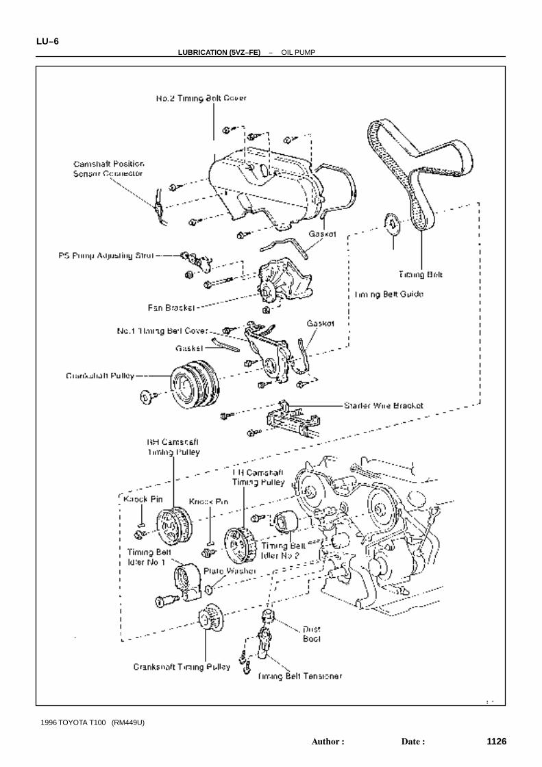
LU−6−LUBRICATION (5VZ−FE) OIL PUMP
1126Author�: Date�:
1996 TOYOTA T100 (RM449U)
https://www.truck-manuals.net/

−LUBRICATION (5VZ−FE) OIL PUMPLU−7
1127Author�: Date�:
1996 TOYOTA T100 (RM449U)
https://www.truck-manuals.net/

P20978
LU−8−LUBRICATION (5VZ−FE) OIL PUMP
1128Author�: Date�:
1996 TOYOTA T100 (RM449U)
https://www.truck-manuals.net/

LU036−03
Z04119
SST
SST
P20974
P20973
−LUBRICATION (5VZ−FE) OIL PUMPLU−9
1996 TOYOTA T100 (RM449U)
REMOVALHINT:When repairing the oil pump, the oil pan and strainer should beremoved and cleaned.1. REMOVE CRANKSHAFT TIMING PULLEY
(See page EM−13)2. 4WD:
REMOVE FRONT DIFFERENTIAL3. DRAIN ENGINE OIL4. A/T:
REMOVE OIL COOLER TUBE AND CLAMP(See page AT−28)
5. REMOVE STIFFENER PLATE6. REMOVE FLYWHEEL HOUSING UNDER AND COVER
DUST7. DISCONNECT STARTER WIRE CLAMP8. REMOVE CRANKSHAFT POSITION SENSOR
9. REMOVE OIL PAN(a) Remove the 15 bolts and 4 nuts.(b) Using SST and a brass bar, separate the oil pan from the
cylinder block.SST 09032−00100
HINT:When removing the oil pan, be careful not to damage the oil panflange.
10. REMOVE OIL STRAINERRemove the 2 bolts, 2 nuts and oil strainer and gasket.11. REMOVE OIL PAN BAFFLE PLATERemove the 2 bolt, nut and oil pan baffle plate.
12. REMOVE OIL PUMP(a) Remove the 8 bolts, ground strap and oil pump.(b) Using a plastic−faced hammer, carefully tap the oil pump
body.(c) Remove the O−ring from the cylinder block.
https://www.truck-manuals.net/

LU037−03
P20933
Mark
P20970
LU−10−LUBRICATION (5VZ−FE) OIL PUMP
1996 TOYOTA T100 (RM449U)
DISASSEMBLY1. REMOVE DRIVEN AND DRIVE ROTORS(a) Remove the 8 screws and pump body cover.
Torque:10 N·m (105 kgf·cm, 8 ft·lbf)(b) Remove the drive and driven rotors.HINT: Place the drive and driven rotor into pump body with the marksfacing the pump body cover side.
2. REMOVE RELIEF VALVE(a) Unscrew the relief valve plug and gasket.(b) Remove the spring and relief valve.
https://www.truck-manuals.net/

LU038−01
P20968
Relief Valve
P20934
P20935
P20936
−LUBRICATION (5VZ−FE) OIL PUMPLU−11
1996 TOYOTA T100 (RM449U)
INSPECTION1. INSPECT RELIEF VALVECoat the valve with engine oil and check that it falls smoothlyinto the valve hole by its own weight.If the valve does not fall smoothly, replace the valve. If neces-sary, replace the oil pump assembly.
2. INSPECT ROTOR BODY CIEARANCEUsing a thickness gauge, measure the clearance between thedriven rotor and pump body.
Standard body clearance:0.10 − 0.18 mm (0.0039 − 0.0069 in.)Maximum body clearance:0.30 mm (0.0118 in.)
If the body clearance is greater than maximum, replace the ro-tors as a set. If necessary, replace the oil pump assembly.3. INSPECT ROTOR TIP CLEARANCEUsing a thickness gauge, measure the clearance between thedrive and driven rotor tips.
Standard tip clearance:0.11 − 0.24 mm (0.0043 − 0.0094 in.)Maximum tip clearance:0.35 mm (0.0138 in.)
If the tip clearance is greater than maximum, replace the rotorsas a set.4. INSPECT ROTOR SIDE CLEARANCEUsing a thickness gauge and precision straight edge, measurethe clearance between the rotors and precision straight edge.
Standard side clearance:0.03 − 0.09 mm (0.0012 − 0.0035 in.)Maximum side clearance:0.15 mm (0.0059 in.)
If the side clearance is greater than maximum, replace the ro-tors as a set. If necessary, replace the oil pump assembly.
https://www.truck-manuals.net/

LU039−03
P20964
P20929
SST
P20977
Cut Position
P20965SST
LU−12−LUBRICATION (5VZ−FE) OIL PUMP
1996 TOYOTA T100 (RM449U)
REPLACEMENTREPLACE CRANKSHAFT FRONT OIL SEALHINT:There are 2 methods (A and B) to replace the oil seal, which areas follows:(a) If oil pump is removed from cylinder block.
(1) Using a screwdriver, pry out the oil seal.
(2) Using SST and a hammer, tap in a new oil seal untilits surface is flush with the oil pump body edge.
SST 09309−37010(3) Apply MP grease to the oil seal lip.
(b) If oil pump is installed to the cylinder block.(1) Using a knife, cut off the oil seal lip.(2) Using a screwdriver, pry out the oil seal.
NOTICE:Be careful not to damage the crankshaft. Tape the screw-driver tip.
(3) Apply MP grease to a new oil seal lip.(4) Using SST and a hammer, tap in the oil seal until its
surface is flush with the oil pump body edge.SST 09306−37010
https://www.truck-manuals.net/

LU03A−01
−LUBRICATION (5VZ−FE) OIL PUMPLU−13
1996 TOYOTA T100 (RM449U)
REASSEMBLYReassembly is in the reverse order of disassembly (Seepage LU−10).
https://www.truck-manuals.net/

LU03B−04
P20937
Seal WidthA
B
2 − 3 mm
A
B
P20930
New O−Ring
P20971
Mark
Key
LU−14−LUBRICATION (5VZ−FE) OIL PUMP
1996 TOYOTA T100 (RM449U)
INSTALLATION1. INSTALL OIL PUMP(a) Remove any old packing (FIPG) material and be careful
not to drop any oil on the contact surfaces of the oil pumpand cylinder block.� Using a razor blade and gasket scraper, remove all
the old packing (FIPG) material from the gasket sur-faces and sealing grooves.
� Thoroughly clean all components to remove all theloose material.
� Using a non−residue solvent, clean both sealingsurfaces.
(b) Apply seal packing to the oil pump, as shown in the il-lustration.Seal packing:Part No. 08826−00080 or equivalent� Install nozzle that has been cut out to a 2 − 3 mm
(0.08 − 0.12 in.) opening.HINT:Avoid applying an excessive amount to the surface.
� Parts must be assembled within 5 minutes of ap-plication. Otherwise the material must be removedand reapplied.
� Immediately remove nozzle from the tube and rein-stall cap.
(c) Place a new O−ring into the groove of the cylinder block.
(d) Install the oil pump to the crankshaft with the spline teethof the drive rotor engaged with the large teeth of thecrankshaft.
https://www.truck-manuals.net/

Z14383B
A
BB
BB
B
LU0609
Seal Packing
−LUBRICATION (5VZ−FE) OIL PUMPLU−15
1996 TOYOTA T100 (RM449U)
(e) Install the oil pump with the 8 bolts, and ground strap.Torque:Bolt A: 20 N·m (200 kgf·cm, 15 ft·lbf)Bolt B: 42 N·m (420 kgf·cm, 31 ft·lbf)
2. INSTALL CRANK SHAFT POSITION SENSOR3. INSTALL OIL PAN BAFFLE PLATE4. INSTALL OIL STRAINERPlace a new gasket and install the oil strainer.
Torque:7.5 N·m (76 kgf·cm, 66 in.·lbf)5. CLEAN OIL PANRemove any old packing (FIPG) material and be careful not todrop any oil on the contacting surfaces of the, oil pan, cylinderblock and sealing grooves.
� Using a razor blade and gasket scraper, remove allthe remaining seal packing (FIPG) material from thegasket surfaces.
� Thoroughly clean all components to remove all theloose material.
� Clean both sealing surfaces with a non−residue sol-vent.
NOTICE:Do not use a solvent which will affect the painted surfaces.6. INSTALL OIL PAN(a) Apply seal packing to the oil pan, as shown in the illustra-
tion.Seal packing:Part No. 08826−00080 or equivalent� Install a nozzle that has been cut to a 3 − 4 mm (0.12
− 0.16 in.) opening.HINT:Avoid applying an excess amount to the surface.
� If parts are not assembled within 5 minutes of apply-ing the seal packing, the effectiveness of the sealpacking is lost and the seal packing must be re-moved and reapplied.
� Immediately remove the nozzle from the tube andreinstall the cap after using the seal packing.
(b) Install the oil pan with the 4 nuts and 15 bolts.Torque:7.6 N·m (78 kgf·cm, 67 in.·lbf)
7. INSTALL FLYWHEEL HOUSING UNDER AND COVERDUST
8. INSTALL STIFFENER PLATE9. CONNECT STARTER WIRE CLAMP10. A/T:
INSTALL OIL COOLER TUBE AND CLAMP11. INSTALL CRANKSHAFT TIMING PULLEY
(See page EM−19)
https://www.truck-manuals.net/

LU−16−LUBRICATION (5VZ−FE) OIL PUMP
1996 TOYOTA T100 (RM449U)
12. 4WD:INSTALL FRONT DIFFERENTIAL(See page SA−68)
13. FILL WITH ENGINE OIL14. START ENGINE AND CHECK FOR LEAKS15. INSTALL ENGINE UNDER COVER16. RECHECK ENGINE OIL LEVEL
https://www.truck-manuals.net/

LU03C−03
−LUBRICATION (5VZ−FE) OIL COOLERLU−17
1137Author�: Date�:
1996 TOYOTA T100 (RM449U)
OIL COOLERCOMPONENTS
https://www.truck-manuals.net/

P20928
LU03D−03
LU−18−LUBRICATION (5VZ−FE) OIL COOLER
1996 TOYOTA T100 (RM449U)
REMOVAL1. DRAIN ENGINE COOLANT2. DISCONNECT OIL COOLER HOSESDisconnect the No.1 and No.2 oil cooler hoses.
3. REMOVE OIL COOLERRemove the bolt, relief valve, gaskets and oil cooler.
Torque:59 N·m (600 kgf·cm, 43 ft·lbf)HINT:� Replace the O−ring with a new part.� Use a new gasket to the relief valve.
https://www.truck-manuals.net/

LU03E−03
−LUBRICATION (5VZ−FE) OIL COOLERLU−19
1996 TOYOTA T100 (RM449U)
INSPECTIONINSPECT OIL COOLERCheck the oil cooler for damage or clogging.If necessary, replace the oil cooler.
https://www.truck-manuals.net/

LU03F−02
LU−20−LUBRICATION (5VZ−FE) OIL COOLER
1996 TOYOTA T100 (RM449U)
INSTALLATIONInstallation is in the reverse order of removal (See page LU−18).
https://www.truck-manuals.net/

IG – IGNITION (3RZ-FE)
IGNITION SYSTEM IG-1 DISTRIBUTOR IG-6 CRANKSHAFT POSITION SENSOR IG-13
https://www.truck-manuals.net/

IG0L9−01
CHECK CONNECTION OF IGNITION COIL ANDIGNITER AND DISTRIBUTOR CONNECTOR
SPARK TEST
CHECK RESISTANCE OF HIGH−TENSION
TRY ANOTHER IGNITER
Maximum resistance; 25 kΩ per cordCORD (See step 2.)
CHECK POWER SUPPLY TO IGNITION COILAND IGNITER1. Turn ignition switch to ON.2. Check that there is battery voltage at
ignition coil positive (+) terminal.
Check wiring between ECM, distributor
CHECK RESISTANCE OF IGNITION COIL (See step 4)Resistance: Cold
Secondary
Hot
9.0 − 15.4 kΩ 11.4 − 18.1 kΩ
GENERATOR (PICKUP COIL)(See step 5)Resistance: Cold
G� and G�Hot
185 − 275 Ω 240 − 325 Ω
CHECK RESISTANCE OF SIGNAL
POSITION SENSOR(See page IG−14)Resistance: Cold
NE� and NE�Hot
1,630 − 2,740 Ω 2,065 − 3,225 Ω
CHECK RESISTANCE OF CRANKSHAFT
CHECK IGT SIGNAL FROM ECM(See page DI−103)
OK
NO
BAD
OK
OK
OK
OK
OK
Connect securely.
Replace the cord(s).
Check wiring between ignition switchto ignition coil and igniter.
Replace the ignition coil.
Replace the distributor housing as-sembly.
Replace the crankshaft position sensor.
and igniter, and then try another ECM.
BAD
BAD
BAD
BAD
BAD
BAD
Primary 0.36 − 0.55 Ω 0.45 − 0.65 Ω
Replace the distributor housing assembly.CHECK AIR GAP OF DISTRIBUTOR (See page DI−103)
BADAir gap: 0.2 − 0.4 mm (0.008 − 0.016 in.)OK
−IGNITION (3RZ−FE) IGNITION SYSTEMIG−1
1141Author�: Date�:
1996 TOYOTA T100 (RM449U)
IGNITION SYSTEMON−VEHICLE INSPECTIONNOTICE:”Cold” and ”Hot” in the following sentences express the temperature of the coils themselves. ”Cold” is from−10°C (14°F) to 50°C (122°F) and ”Hot” is from 50°C (122°F) to 100°C (212°F).1. INSPECT IGNITOR AND SPARK TESTCheck that the spark occurs.
(1) Disconnect the high−tension cords from the spark plugs.(2) Remove the spark plugs.(3) Install the spark plugs to each high−tension cord.(4) Ground the spark plug.(5) Check if spark occurs while engine is being cranked.
NOTICE:To prevent gasoline from being injected from injectors during this test, crank the engine for no more than 1− 2 seconds at a time.If the spark does not occur, perform the test as follows:
https://www.truck-manuals.net/

P23501
CORRECT
WRONG
IG−2−IGNITION (3RZ−FE) IGNITION SYSTEM
1142Author�: Date�:
1996 TOYOTA T100 (RM449U)
2. INSPECT HIGH−TENSION CORDS(a) Disconnect the MAF meter connector and IAT sensor
connector.(b) Loosen the hose clamp, disconnect the air cleaner hose
from the intake air connector.(c) Remove the air cleaner cap and MAF meter assembly.
(d) Disconnect the air hose (for IAC) from the air connector.(e) Remove the 2 bolts.(f) Loosen the hose clamp, disconnect the intake air connec-
tor from the throttle body.
(g) Disconnect the high−tension cords from the spark plugs.NOTICE:Pulling on or bending the cords may damage the conductor in-side.
(h) Disconnect the high−tension cords from the ignition coils.(1) Using a screwdriver, lift up the lock claw and discon-
nect the holder from the distributor cap.
(2) Disconnect the high−tension cord at the grommet.NOTICE:� Pulling on or bending the cords may damage the conduc-
tor inside.� Do not wipe any of the oil from the grommet after the high−
tension cord is disconnected.
https://www.truck-manuals.net/

P04690
A01709
A01710
16 mm Plug Wrench
−IGNITION (3RZ−FE) IGNITION SYSTEMIG−3
1143Author�: Date�:
1996 TOYOTA T100 (RM449U)
(i) Using an ohmmeter, measure the resistance.Maximum resistance: 25 kΩ per cord
If the resistance is greater than the maximum, check the termi-nals.If necessary, replace the high−tension cord.
(j) Connect the high−tension cords to the distributor cap. As-semble the holder and grommet.
HINT:Connect the high−tension cords to the distributor cap as shownin the illustration.
NOTICE:Check that the holder is correctly installed to the grommetand distributor cap as shown in the illustration.(k) Check that the lock claw of the holder is engaged by lightly
pulling the holder.
(l) Connect the high−tension cords to the spark plugs.Secure the high−tension cords with the clamps as shownin the illustration.
(m) Install the intake air connector.(n) Install the air cleaner cap and MAF meter assembly.
3. INSPECT SPARK PLUGS(a) Disconnect the high−tension cords from the spark plugs.(b) Using a 16 mm plug wrench, remove the spark plug.
Torque: 20 N·m (200 kgf·cm, 14 ft·lbf)
https://www.truck-manuals.net/

IG0152
P03783
P03792
P04690
CORRECT
WRONG
IG−4−IGNITION (3RZ−FE) IGNITION SYSTEM
1144Author�: Date�:
1996 TOYOTA T100 (RM449U)
(c) Using a spark plug cleaner or wire brush, clean the sparkplug.
(d) Check the spark plug for electrode wear, threads damageand insulator damage.
If abnormal, replace the plugs.Recommended spark plugs:ND: K16R−UNGK: BKR5EYA
(e) Carefully bend the outer electrode to obtain the correctelectrode gap.Correct electrode gap: 0.8 mm (0.031 in.)
(f) Using a 16 mm plug wrench, install the spark plug.Torque: 20 N·m (200 kgf·cm, 14 ft·lbf)
(g) Connect the high−tension cords to the spark plugs.
NOTICE:Check that the holder is correctly installed to the grommetand ignition coil as shown in the illustration.(h) Check that the lock claw of the holder is engaged by lightly
pulling the holder.4. INSPECT IGNITION COILNOTICE:”Cold” and ”Hot” in these sentences express the tempera-ture of the coils them selves.”Cold” is from − 10 °C (14 °F) to 50 °C (104 °F) and ”Hot”is from 50 °C (104 °F) to 100 °C (212 °F)(a) Disconnect the distributor connctor.(b) Remove the distributor cap.(c) Remove the rotor.(d) Remove the ignition coil dust cover.
https://www.truck-manuals.net/

−IGNITION (3RZ−FE) IGNITION SYSTEMIG−5
1145Author�: Date�:
1996 TOYOTA T100 (RM449U)
(e) Inspect primary coil resistace.Using an ohmmeter, measure resistance between thepositive (+) and negative (−)terminals.Primary coil resistance:Cold: 0.36 − 0.55 kΩHot: 0.45 − 0.65 kΩ
If the resistance is not as specified, replace the ignition coil.
(f) Inspect secondary coil resistance.Usibg anohmmeter, measure resistance between posi-tive (+) and high−tension terminals.Secondary coil resistance:Cold: 9.0 − 15.4 kΩHot: 11.4 − 18.1 kΩ
If the resistance is not as specified, replace the ignition coil.
5. INSPECT DISTRIBUTOR(a) Inspect the air gap.
Using a feeler gange, measure the air gap between thesignal rotor and pickup coil projection.Air gap: 0.2 − 0.4 mm (0.008 − 0.016 in.)
If the air gap is not as specified, replace the distributor housingassembly.
(b) Inspect signal generator (pickup coil) resistance. .Using an ohmmeter, measure resistance between termi-nalsPickup coil resistance:Cold: G (+) and G (−): 185 − 275 ΩHot: G (+) and G (−): 240 − 325 Ω
If the resistance is not as specified, replace the distributor hous-ing assembly.
https://www.truck-manuals.net/

IG0IW−02
P20586
P20938 B11227
IG−6−IGNITION (3RZ−FE) DISTRIBUTOR
1146Author�: Date�:
1996 TOYOTA T100 (RM449U)
DISTRIBUTORCOMPONENTS
https://www.truck-manuals.net/
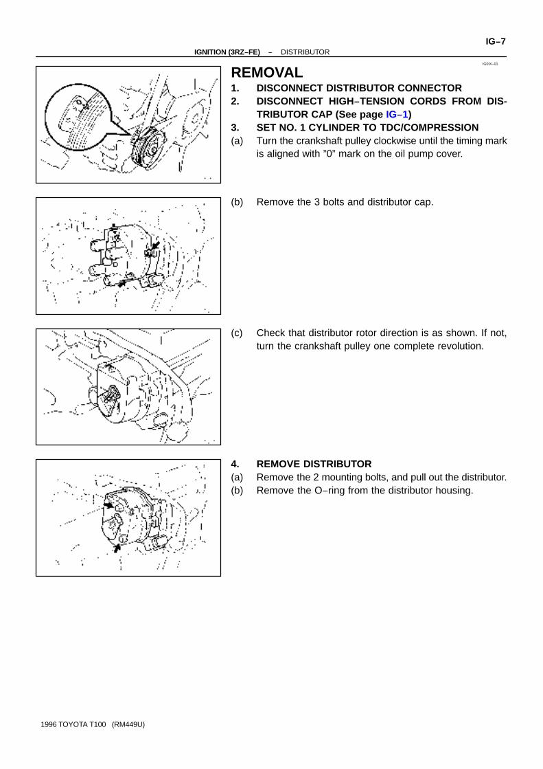
IG0IX−01
−IGNITION (3RZ−FE) DISTRIBUTORIG−7
1996 TOYOTA T100 (RM449U)
REMOVAL1. DISCONNECT DISTRIBUTOR CONNECTOR2. DISCONNECT HIGH−TENSION CORDS FROM DIS-
TRIBUTOR CAP (See page IG−1)3. SET NO. 1 CYLINDER TO TDC/COMPRESSION(a) Turn the crankshaft pulley clockwise until the timing mark
is aligned with ”0” mark on the oil pump cover.
(b) Remove the 3 bolts and distributor cap.
(c) Check that distributor rotor direction is as shown. If not,turn the crankshaft pulley one complete revolution.
4. REMOVE DISTRIBUTOR(a) Remove the 2 mounting bolts, and pull out the distributor.(b) Remove the O−ring from the distributor housing.
https://www.truck-manuals.net/

IG0LA−01
IG−8−IGNITION (3RZ−FE) DISTRIBUTOR
1996 TOYOTA T100 (RM449U)
DISASSEMBLY1. REMOVE ROTOR2. REMOVE IGNITION COIL DUST COVER(a) Remove the dust cover.(b) Remove the dust proof packing.HINT:At the time of reassembly, please refer to the following item. Usenew dust proof packing.
3. REMOVE IGNITION COIL(a) Remove the 2 nuts, and disconnect the 3 wires from the
ignition coil terminals.
NOTICE:At the time of reassembly, please refer to the followingitems.� When connecting the wires to the ignition coil, insert
the properly into the groove found on the side of theignition coil.
� Be sure the wire do not contact with signal rotor ordistributor housing.
(b) Remove the 4 screws and ignition coil.
NOTICE:At the time of reassembly, please refer to the followingitems.Apply seal packing to the ignition coil installing serface ofthe housing, as shown in the illustration.
Seal packing: Part No. 08826 − 00080 or equivalent
https://www.truck-manuals.net/

−IGNITION (3RZ−FE) DISTRIBUTORIG−9
1996 TOYOTA T100 (RM449U)
4. REMOVE SIGNAL GENERATOR (PICKUP COIL)(a) Remove the 2 screws.NOTICE:At the time of reassembly, please refer to the followingitems.� Be sure that the wires do not contact with the signal
rotor.
� Align the rotor tooth with the pickup coil.� Using a thickness gauge, set the air gap and tighten
the 2 screws.Air gap: 0.2 − 0.4 mm (0.008 − 0.016 in.)
(b) Remove the signal generator (pickup coil) from the distrib-utor housing.
5. REMOVE CONDENSERRemove the screw and condenser.
https://www.truck-manuals.net/

IG0IZ−01
IG−10−IGNITION (3RZ−FE) DISTRIBUTOR
1996 TOYOTA T100 (RM449U)
INSPECTIONINSPECT SHAFTTurn the shaft and check that it is not rough or worn.If it feels rough or worn, replace the distributor housing assem-bly.
https://www.truck-manuals.net/

IG0J0−01
−IGNITION (3RZ−FE) DISTRIBUTORIG−11
1996 TOYOTA T100 (RM449U)
REASSEMBLYReassembly is in the reverse order of disassembly (See page IG−8)
https://www.truck-manuals.net/

IG0LB−01
IG−12−IGNITION (3RZ−FE) DISTRIBUTOR
1996 TOYOTA T100 (RM449U)
INSTALLATION1. CHECK NO. 1 CYLINDER TO TDC/COMPORESSIONIf necessary, remove the cylinder head cover, and check theseconditions:
� Turn the crankshaft pulley clockwise and align itsgroove with the timing mark ”0” of the oil pump cov-er.
� Verify that the timing marks with 1 and 2 dots are instraight line on the cylinder head surface as shownin the illustration.
If not, turn the crankshaft 1 revolition (360 °) and align the markas above.
2. INSTALL DISTRIBUTOR(a) Install a new O−ring to the distributor.HINT:Always use a new O−ring when installing the distributor.
(b) Align the protrusion of the distributor housing with thegroove on the driven gear.
(c) Apply a light coat of engine oil on the O−ring.(d) Install the distributor with the 2 bolts.
Torque: 19 N·m (195 kgf·cm, 14 ft·lbf)3. INSTALL DISTRIBUTOR CAP4. RECONECT HIGH−TENSION CORDS TO DISTRIBU-
TOR CAP5. CONNECT DISTRIBUTOR CONNECTOR6. CHECK IGNITION TIMING (See page EM−11)
https://www.truck-manuals.net/

Z11309
B A
A
IG03K−03
P14953
−IGNITION (3RZ−FE) CRANKSHAFT POSITION SENSORIG−13
1153Author�: Date�:
1996 TOYOTA T100 (RM449U)
CRANKSHAFT POSITION SENSORREMOVAL1. REMOVE ENGINE UNDER COVER2. REMOVE GENERATOR
(See page CH−7)3. REMOVE GENERATOR BRACKETRemove the 3 bolts and bracket.
Torque:Bolt A: 74.5 N·m (760 kgf·cm, 55 ft·lbf)Bolt B: 18 N·m (180 kgf·cm, 13 ft·lbf)
4. DISCONNECT CRANKSHAFT POSITION SENSORCONNECTOR
5. REMOVE CRANKSHAFT POSITION SENSOR(a) Remove the 2 bolts and crankshaft position sensor.
Torque: 8.5 N·m (85 kgf·cm, 74 in.·lbf)(b) Remove the O−ring.HINT:� At the time assembly, please refer to the following items.� Install the crankshaft position sensor with a new gasket.� Always use a new O−ring when installing the crankshaft
position sensor.� Apply a light coat of engine oil the O−ring.
https://www.truck-manuals.net/

P16211
Ohmmeter
NE� NE�
IG03L−02
IG−14−IGNITION (3RZ−FE) CRANKSHAFT POSITION SENSOR
1996 TOYOTA T100 (RM449U)
INSPECTIONNOTICE:”Cold” and ”Hot” in these sentences express the tempera-ture of the sensors themselves. ”Cold” is from −10°C(14°F) to 50°C (122°F) and ”Hot is from 50°C (122°F) to100°C (212°F).INSPECT CRANKSHAFT POSITION SENSORRESISTANCEUsing an ohmmeter, measure the resistance between termi-nals.
Resistance (NE� and NE�):Cold: 1,630 − 2,740 ΩHot: 2,065 − 3,225 Ω
If the resistance is not as specified, replace the crankshaft posi-tion sensor.
https://www.truck-manuals.net/

IG03M−01
−IGNITION (3RZ−FE) CRANKSHAFT POSITION SENSORIG−15
1996 TOYOTA T100 (RM449U)
INSTALLATIONInstallation is in the reverse order of removal (See page IG−13).
https://www.truck-manuals.net/

IG – IGNITION (5VZ-FE)
IGNITION SYSTEM IG-1 IGNITION COIL IG-6 CAMSHAFT POSITION SENSOR IG-9 CRANKSHAFT POSITION SENSOR IG-12
https://www.truck-manuals.net/

IG03Z−04
SPARK TEST
CHECK CONNECTION OF IGNITION COIL AND
CHECK RESISTANCE OF HIGH−TENSION
TRY ANOTHER IGNITER
Maximum resistance; 25 kΩ per cordCORD (See step 2.)
CHECK POWER SUPPLY TO IGNITION COILAND IGNITER1. Turn ignition switch to ON.2. Check that there is battery voltage at
ignition coil positive (+) terminal.
Check wiring between ECM, distributor
CHECK RESISTANSE OF IGNITION COIL(See step 4.)Resistance: Cold
PrimaryHot
0.67 − 1.05 Ω 0.85 − 1.23 Ω
POSITION SENSOR(See step 5)Resistance: Cold
G� and G�Hot
835 − 1,400 Ω 1,060 − 1,645 Ω
CHECK RESISTANSE OF CAMSHAFT
POSITION SENSOR(See page IG−13)Resistance: Cold
NE� and NE�Hot
1,630 − 2,740 Ω 2,065 − 3,225 Ω
CHECK RESISTANSE OF CRANKSHAFT
CHECK IGT SIGNAL FROM ECM(See page DI−144)
OK
NO
BAD
OK
OK
OK
OK
OK
Connect securely.
Replace the cord(s).
Check wiring between ignition switchto ignition coil and igniter.
Replace the ignition coil.
Replace the camshaft position sensor.
Replace the crankshaft position sensor.
and igniter, and then try another ECM.
BAD
BAD
BAD
BAD
BAD
BAD
IGNITER
Secondary 9.3 − 16.0 kΩ 11.7 − 18.8 kΩ
−IGNITION (5VZ−FE) IGNITION SYSTEMIG−1
1156Author�: Date�:
1996 TOYOTA T100 (RM449U)
IGNITION SYSTEMON−VEHICLE INSPECTIONNOTICE:”Cold” and ”Hot” in the following sentences express thetemperature of the coils themselves. ”Cold” is from −10°C(14°F) to 50°C (122°F) and ”Hot” is from 50°C (122°F)to 100°C (212°F).1. INSPECT SPARK TESTCheck that the spark occurs.
(1) Disconnect the high−tension cords from the sparkplug.
(2) Remove the spark plug.(3) Install the spark plug to each high−tension cord.(4) Ground the spark plug.(5) Check if spark occurs while engine is being
cranked.NOTICE:To prevent excess fuel being injected from the injectorsduring this test, do not crank the engine for more 1 − 2 se-conds at a time.If the spark does not occur, perform the test as follows:
https://www.truck-manuals.net/

P23940
P20581
P20439
Ohmmeter
IG−2−IGNITION (5VZ−FE) IGNITION SYSTEM
1157Author�: Date�:
1996 TOYOTA T100 (RM449U)
2. INSPECT HIGH−TENSION CORDS(a) Remove the air cleaner cap and MAF meter assembly.(b) Disconnect the high−tension cords from the spark plugs.
Disconnect the high−tension cords at the rubber boot.DO NOT pull on the cords.
NOTICE: Pulling on or bending the cords may damage the conduc-tor inside.
(c) Disconnect the high−tension cords from the ignition coils.(1) Using a screwdriver, lift up the lock claw and discon-
nect the holder from the ignition coils.(2) Disconnect the high−tension cord at the grommet.
DO NOT pull on the cord.NOTICE:Pulling on or bending the cords may damage the conductorinside.Do not wipe any of the oil from the grommet after thehigh−tension cord is disconnected.
(d) Inspect the high−tension cord resistance.Using an ohmmeter, measure the resistance.Maximum resistance:25 kΩ per cord
If the resistance is greater than maximum, check the terminals.If necessary, replace the high−tension cord.
https://www.truck-manuals.net/

P20580
Push
P04690
CORRECT
WRONG
−IGNITION (5VZ−FE) IGNITION SYSTEMIG−3
1158Author�: Date�:
1996 TOYOTA T100 (RM449U)
(e) Reconnect the high−tension cords to ignition coils.
(1) Assemble the holder and grommet.(2) Align the spline of the ignition coil with the spline of
the holder, and push in the cord.
NOTICE:Check that the holder is correctly installed to the grommetand distributor cap as shown in the illustration.
(3) Check that the lock claw of the holder is engaged bylightly pulling the holder.
(f) Reconnect the high−tension cords to spark plugs.(g) Reinstall the air cleaner cap and MAF meter assembly.
https://www.truck-manuals.net/

P20430
16 mm Plug Wrench
IG0152
P20433
P20584
IG−4−IGNITION (5VZ−FE) IGNITION SYSTEM
1159Author�: Date�:
1996 TOYOTA T100 (RM449U)
3. INSPECT SPARK PLUGS(a) Remove the high−tension cords and ignition coils.(b) Remove the spark plugs.
Using a 16 mm plug wrench, remove the 6 spark plugsfrom the RH and LH cylinder heads.
(c) Clean the spark plugs.If the electrode has traces of wet carbon, allow it to dryand then clean with a spark plug cleaner.Air pressure:Below 588 kPa (6 kgf/cm2, 85 psi)Duration:20 seconds or less
HINT:If there are traces of oil, remove it with gasoline before using thespark plug cleaner.(d) Visually inspect the spark plugs.
Check the spark plug for thread damage and insulatordamage.
If abnormal, replace the spark plug.Recommended spark plug:ND: K16TR11NGK: BKR5EKB−11
(e) Adjust the electrode gap.Carefully bend the outer electrode to obtain the correctelectrode gap.Correct electrode gap:1.1 mm (0.043 in.)
(f) Reinstall the spark plugs.Torque:18 N·m (180 kgf·cm, 13 ft·lbf)
(g) Reinstall the ignition coils. (See page IG−8)(h) Reconnect the high−tension cords.4. INSPECT IGNITION COIL(a) Remove the air cleaner cap and MAF meter assembly.(b) Disconnect the high−tension cords from the ignition coils.(c) Disconnect the ignition coil connectors.
https://www.truck-manuals.net/

P20579
Ohmmeter
P21135
Ohmmeter
P20436
Ohmmeter
−IGNITION (5VZ−FE) IGNITION SYSTEMIG−5
1160Author�: Date�:
1996 TOYOTA T100 (RM449U)
(d) Inspect the primary coil resistance.Using an ohmmeter, measure the resistance between thepositive (+) and negative (−) terminals.Primary coil resistance :Cold: 0.67 − 1.05 ΩHot: 0.85 − 1.23 Ω
If the resistance is not as specified, replace the ignition coil.
(e) Remove the ignition coils.(f) Inspect the secondary coil resistance.
Using an ohmmeter, measure the resistance between thepositive (+) and high−tension terminals.Secondary coil resistance:Cold: 9.3 − 16.0 kΩHot: 11.7−18.8 kΩ
If the resistance is not as specified, replace the ignition coil.(g) Reinstall the ignition coils.(h) Reconnect the ignition coil connectors and high−tension
cors.(i) Reinstall the air cleaner cap and MAF meter assembly.
5. INSPECTION CAMSHAFT POSITION SENSOR(a) Disconnect the camshaft position sensor connectors.(b) Inspect the camshaft position sensor resistance.
Using an ohmmeter, measure the resistance between ter-minals.Resistance:Cold: 835 − 1,400ΩHot: 1,060 − 1,645 Ω
If the resistance is not as specified, replace the camshaft posi-tion sensor.(c) Reconnect the camshaft position sensor connector.6. INSPECT IGNITER (See page IG−1)
https://www.truck-manuals.net/

IG03P−03
IG−6−IGNITION (5VZ−FE) IGNITION COIL
1161Author�: Date�:
1996 TOYOTA T100 (RM449U)
IGNITION COILCOMPONENTS
https://www.truck-manuals.net/

IG03Q−03
−IGNITION (5VZ−FE) IGNITION COILIG−7
1996 TOYOTA T100 (RM449U)
REMOVAL1. REMOVE AIR CLEANER CAP AND MAF METER AS-
SEMBLY2. DISCONNECT HIGH−TENSION CORDS FROM
IGNITION COILS(See page IG−1)
3. REMOVE IGNITION COILS(a) Disconnect the 3 connectors from the ignition coils.(b) Remove the 3 bolts and 3 ignition coils from the LH cylin-
der head.Torque: 7.8 N·m (80 kgf·cm, 69 in.·lbf)
HINT:Arrange the ignition coils in correct order.
https://www.truck-manuals.net/

IG03R−01
IG−8−IGNITION (5VZ−FE) IGNITION COIL
1996 TOYOTA T100 (RM449U)
INSTALLATIONInstallation is in the reverse order of removal (See page IG−7).
https://www.truck-manuals.net/

IG03S−03
−IGNITION (5VZ−FE) CAMSHAFT POSITION SENSORIG−9
1164Author�: Date�:
1996 TOYOTA T100 (RM449U)
CAMSHAFT POSITION SENSORCOMPONENTS
https://www.truck-manuals.net/

IG03T−03
P20432
IG−10−IGNITION (5VZ−FE) CAMSHAFT POSITION SENSOR
1996 TOYOTA T100 (RM449U)
REMOVAL1. REMOVE UPPER RADIATOR HOSE2. REMOVE NO. 2 TIMING BELT COVER(a) Remove the high−tension cord clamps from the No. 2 tim-
ing belt cover.(b) Remove the PS pump hose from the No. 2 timing belt cov-
er clamp.(c) Remove the 6 bolts and No. 2 timing belt cover.3. REMOVE CAMSHAFT POSITION SENSOR(a) Disconnect the camshaft position sensor connector.(b) Remove the bolts and camshaft position sensor.
Torque:7.8 N·m (80 kgf·cm, 69 in.·lbf)
https://www.truck-manuals.net/
IG03U−02
−IGNITION (5VZ−FE) CAMSHAFT POSITION SENSORIG−11
1996 TOYOTA T100 (RM449U)
INSTALLATIONInstallation is in the reverse order of removal (See page IG−10).
https://www.truck-manuals.net/

P20434
IG03V−03
IG−12−IGNITION (5VZ−FE) CRANKSHAFT POSITION SENSOR
1167Author�: Date�:
1996 TOYOTA T100 (RM449U)
CRANKSHAFT POSITION SENSORREMOVAL1. REMOVE ENGINE UNDER COVER2. REMOVE CRANKSHAFT POSITION SENSOR(a) Disconnect the crankshaft position sensor connector.(b) Remove the bolt crankshaft position sensor.
Torque: 7.8 N·m (80 kgf·cm, 69 in.·lbf)
https://www.truck-manuals.net/

IG03W−01
P20431
Ohmmeter
−IGNITION (5VZ−FE) CRANKSHAFT POSITION SENSORIG−13
1996 TOYOTA T100 (RM449U)
INSPECTIONNOTICE:”Cold” and ”Hot” in the following sentences express thetemperature of the sensor itself. ”Cold” is from −10°C(14°F) to 50°C (122°F) and ”Hot” is from 50°C (122°F) to100°C (212°F).INSPECT CRANKSHAFT POSITION SENSORRESISTANCEUsing an ohmmeter, measure the resistance between termi-nals.
Resistance:Cold: 1,630 − 2,740 ΩHot: 2,065 − 3,225 Ω
If the resistance is not as specified, replace the crankshaft posi-tion sensor.
https://www.truck-manuals.net/

IG03X−02
IG−14−IGNITION (5VZ−FE) CRANKSHAFT POSITION SENSOR
1996 TOYOTA T100 (RM449U)
INSTALLATIONInstallation is in the reverse order of removal (See page IG−12).
https://www.truck-manuals.net/

ST – STARTING (3RZ-FE)
STARTER ST-1 STARTER RELAY ST-17
https://www.truck-manuals.net/

ST02W−03
B01307
Starter Wire
Starter Connector
Starter
−STARTING (3RZ−FE) STARTERST−1
1170Author�: Date�:
1996 TOYOTA T100 (RM449U)
STARTERCOMPONENTS
https://www.truck-manuals.net/
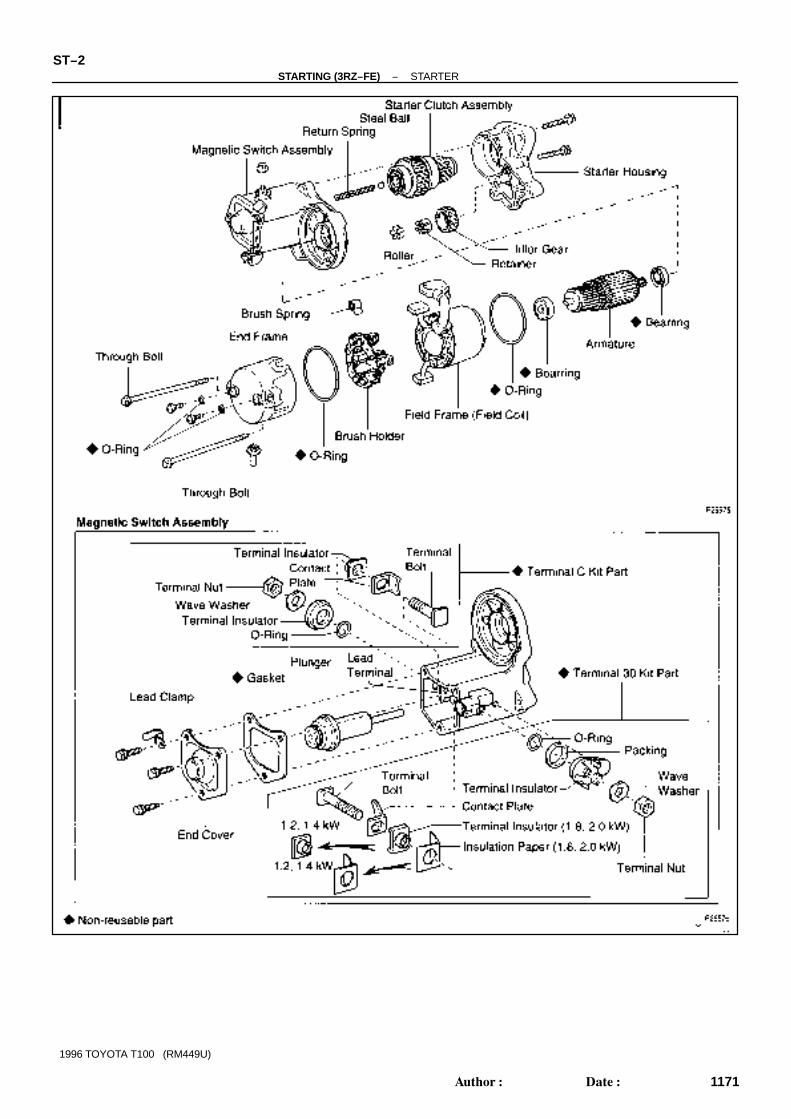
ST−2−STARTING (3RZ−FE) STARTER
1171Author�: Date�:
1996 TOYOTA T100 (RM449U)
https://www.truck-manuals.net/

ST02X−02
P14944
−STARTING (3RZ−FE) STARTERST−3
1996 TOYOTA T100 (RM449U)
REMOVAL1. DISCONNECT STARTER CONNECTOR2. REMOVE NUT, AND DISCONNECT STARTER WIRE
Torque: 8.8 N·m (90 kgf·cm, 70 in.·lbf)3. REMOVE 2 BOLTS AND STARTER
Torque: 39 N·m (400 kgf·cm, 29 ft·lbf)
https://www.truck-manuals.net/

ST02Y−03
P14884
P14885
P14893
P14886
P14887
(1)
(2)
(3)
(4)
(5)
ST−4−STARTING (3RZ−FE) STARTER
1996 TOYOTA T100 (RM449U)
DISASSEMBLY1. REMOVE FIELD FRAME AND ARMATURE(a) Remove the nut, and disconnect the lead wire from the
magnetic switch terminal.Torque: 5.9 N·m (60 kgf·cm, 52 in.·lbf)
(b) Remove the 2 through bolts.Torque:1.2 kW, 1.4 kW type: 5.9 N·m (60 kgf·cm, 52 in.·lbf)1.8 kW, 2.0 kW type: 9.3 N·m (95 kgf·cm, 82 in.·lbf)
(c) Pull out the field frame with the armature from the magnet-ic switch assembly.
NOTICE:At the time of notice, please refer to the following items.Align the protrusion of the field frame with cutout of themagnetic switch.(d) Remove the O−ring.HINT:At the time of assembly, please refer to the following items.Use a new O−ring.2. REMOVE STARTER HOUSING, CLUTCH
ASSEMBLY AND GEAR(a) Remove the 2 screws.
Torque:1.2 kW, 1.4 kW type: 5.9 N·m (60 kgf·cm, 52 in.·lbf)1.8 kW, 2.0 kW type: 9.3 N·m (95 kgf·cm, 82 in.·lbf)
(b) Remove these parts from the magnetic switch assembly:(1) Starter housing(2) Return spring(3) Bearing(4) Idler Gear(5) Clutch assembly
https://www.truck-manuals.net/

P04515
Magnetic Finger
P14945
P04525
−STARTING (3RZ−FE) STARTERST−5
1996 TOYOTA T100 (RM449U)
3. REMOVE STEEL BALLUsing a magnetic finger, remove the steel ball from the clutchshaft hole.
4. REMOVE BRUSH HOLDER(a) Remove the 2 screws, 2 O−rings and end cover from the
field frame.Torque:1.2 kW, 1.4 kW type: 1.5 N·m (15 kgf·cm, 13 in.·lbf)1.8 kW, 2.0 kW type: 3.8 N·m (39 kgf·cm, 34 in.·lbf)
(b) Remove the O−ring from the field frame.HINT:At the time of assembly, please refer to the following items.Use a new O−ring.(c) Using a screwdriver hold the spring back and disconnect
the brush from the brush holder.Disconnect the 4 brushes, and remove the brush holder.
5. REMOVE ARMATURE FROM FIELD FRAME
https://www.truck-manuals.net/

P10584
Ohmmeter
Continuity
ST0NJ−01
P10585
Ohmmeter
No Continuity
P10586
P10587
ST0040
ST−6−STARTING (3RZ−FE) STARTER
1996 TOYOTA T100 (RM449U)
INSPECTION1. INSPECT COMMUTATOR FOR OPEN CIRCUITUsing an ohmmeter, check that there is continuity between thesegments of the commutator.If there is no continuity between any segment, replace the ar-mature.
2. INSPECT COMMUTATOR FOR GROUNDEDUsing an ohmmeter, check that there is no continuity betweenthe commutator and armature coil core.If there is continuity, replace the armature.3. INSPECT COMMUTATOR FOR DIRTY AND BURNT
SURFACESIf the surface is dirty or burnt, clean it with sandpaper (No.400)or on a lathe.
4. INSPECT COMMUTATOR CIRCLE RUNOUT(a) Place the commutator on V−blocks.(b) Using a dial indicator, measure the circle runout.
Maximum circle runout:0.05 mm (0.0020 in.)
If the circle runout is greater than maximum, correct it on a lathe.
5. INSPECT COMMUTATOR DIAMETERUsing vernier calipers, measure the commutator diameter.
Standard diameter:1.2 kW, 1.4 kW type: 30 mm (1.18 in.)1.8 kW, 2.0 kW type: 35 mm (1.38 in.)Minimum diameter:1.2 kW, 1.4 kW type: 29 mm (1.14 in.)1.8 kW, 2.0 kW type: 34 mm (1.34 in.)
If the diameter is less than minimum, replace the armature.
6. INSPECT UNDERCUT DEPTH OF SEGMENTCheck that the undercut depth is clean and free of foreign mate-rial. Smooth out the edge.
Standard undercut depth:1.2 kW, 1.4 kW type: 0.6 mm (0.024 in.)1.8 kW, 2.0 kW type: 0.7 mm (0.028 in.)Minimum undercut depth: 0.2 mm (0.008 in.)
If the undercut depth is less than minimum, correct it with ahacksaw blade.
https://www.truck-manuals.net/

P00300
Ohmmeter
Continuity
P00299
Ohmmeter
No Continuity
Z10079
Brush Holder Side
Field Frame Side
Length
Length
ST0019
−STARTING (3RZ−FE) STARTERST−7
1996 TOYOTA T100 (RM449U)
7. INSPECT FIELD COIL FOR OPEN CIRCUITUsing an ohmmeter, check that there is continuity between thelead wire and field coil brush lead.If there is no continuity, replace the field frame.
8. INSPECT THAT FIELD COIL IS NOT GROUNDEDUsing an ohmmeter, check that there is no continuity betweenthe field coil end and field frame.If there is continuity, repair or replace the field frame.
9. INSPECT BRUSH LENGTHUsing vernier calipers, measure the brush length.
Standard length:1.2 kW, 1.4 kW type: 15.5 mm (0.610 in.)1.8 kW, 2.0 kW type: 15.0 mm (0.591 in.)Minimum length:1.2 kW, 1.4 kW type: 10.0 mm (0.394 in.)1.8 kW, 2.0 kW type: 9.0 mm (0.354 in.)
If the length is less than minimum, replace the brush holder andfield frame.
10. INSPECT BRUSH SPRING LOADTake the pull scale reading the instant the brush spring sepa-rates from the brush.
Standard installed load:1.2 kW type 13.7 − 19.6 N (1.40 − 2.00 kgf, 3.1 − 4.4 lbf)1.4 kW type 17.6 − 23.5 N (1.80 − 2.40 kgf, 4.0 − 5.3 lbf)1.8 kW, 2.0 kW type 21.5 − 27.5 N (2.20 − 2.80 kgf, 4.9 − 6.2 lbf)
https://www.truck-manuals.net/

P00303
Ohmmeter
No Continuity
P04514
Lock
Free
B01309
ST−8−STARTING (3RZ−FE) STARTER
1996 TOYOTA T100 (RM449U)
Minimum installed load:1.2 kW type: 9.8 N (1.00 kgf, 2.2 lbf)1.4 kW type: 11.8 N (1.20 kgf, 2.6 lbf)1.8 kW, 2.0 kW type: 12.7 N (1.30 kgf, 2.7 lbf)
If the installed load is less than minimum, replace the brushsprings.HINT:Take the pull scale reading the instant the brush spring sepa-rates from the brush.
11. INSPECT INSULATION OF BRUSH HOLDERUsing an ohmmeter, check that there is no continuity betweenthe positive (+) and negative (−) brush holders.If there is continuity, repair or replace the brush holder.
12. INSPECT GEAR TEETHCheck the gear teeth on the pinion gear, idler gear and clutchassembly for wear or damage.If damaged, replace the gear or clutch assembly.If damaged, also check the flywheel or drive plate ring gear forwear or damage.
13. INSPECT CLUTCHHold the starter clutch and rotate the clutch pinion gear clock-wise and check that it turns freely. Try to rotate the clutch pinioncounterclockwise and check that it locks. If necessary, replacethe clutch assembly.
14. INSPECT REAR BEARINGTurn the bearing by hand while applying inward force.If the resistance is felt or if the bearing sticks, replace the bear-ing.
https://www.truck-manuals.net/

P10593
SST
P10594
B01310
P10595
SST
P10596
SST
Upward
Downward
−STARTING (3RZ−FE) STARTERST−9
1996 TOYOTA T100 (RM449U)
15. IF NECESSARY, REPLACE REAR BEARING(a) Using SST, remove the bearing.
SST 09286−46011
(b) Press in a new bearing.
16. INSPECT FRONT BEARINGTurn the bearing by hand while applying inward force.If the resistance is felt or if the bearing sticks, replace the bear-ing.
17. IF NECESSARY, REPLACE FRONT BEARING(a) Using SST, remove the bearing.
SST 09286−46011
(b) Using SST and a press, press in a new bearing.SST 09820−00030
NOTICE:Be careful of the bearing installation direction.
https://www.truck-manuals.net/

P14888
Ohmmeter
Terminal C
Terminal 50
Continuity
P14889
Ohmmeter
Terminal 50
ContinuitySwitchBody
ST−10−STARTING (3RZ−FE) STARTER
1996 TOYOTA T100 (RM449U)
18. DO PULL−IN COIL OPEN CIRCUIT TESTUsing an ohmmeter, check that there is continuity between ter-minals 50 and C.If there is no continuity, check and replace the magnetic switch.
19. DO HOLD−IN COIL CIRCUIT TESTUsing an ohmmeter, check that there is continuity between ter-minal 50 and the switch body.If there is no continuity, replace the magnetic switch assembly.
https://www.truck-manuals.net/

P25590
ST0KU−02
P25594
Wear
P25595
SST
P25640
(1)(2)
(3) (8)(4)
(5)(6)
(7)
Long
Short
IndentationProtrusion
(1.2 kW,1.4 kW)
−STARTING (3RZ−FE) STARTERST−11
1996 TOYOTA T100 (RM449U)
REPLACEMENT1. REMOVE MAGNETIC SWITCH END COVERRemove the 3 bolts, lead clamp, end cover, gasket and plunger.
2. INSPECT CONTACT PLATE FOR WEARUsing vernier calipers, measure the contact plate for depth ofwear.
Maximum wear:0.9 mm (0.035 in.)
If the depth of wear is greater than the maximum, replace thecontact plate.
3. REMOVE TERMINAL KIT PARTS(a) Using SST, loosen the terminal nuts.
SST 09810−38140(b) Terminal C:
Remove the terminal nut, wave washer, terminal insulator(outside), O−ring, terminal bolt, contact plate and terminalinsulator (inside).
(c) Terminal 30:Remove the terminal nut, wave washer, terminal insulator(outside), packing, O−ring, terminal bolt, contact plate,terminal insulator (inside) and insulation paper.
4. REINSTALL TERMINAL KIT PARTS(a) Terminal 30:
Install these new parts:(1) Insulation paper(2) Terminal insulator (inside)
NOTICE:Be careful to install the terminal insulator in the correctdirection.
(3) Contact plate(4) Terminal bolt(5) O−ring(6) Packing and terminal insulator (outside):
Install the packing to the terminal insulator, andinstall them.
HINT:Match the protrusion of the insulator with the indentation of thehousing.
(7) Wave washer(8) Terminal nut
https://www.truck-manuals.net/

P25593
(1)(2)
(3)(4)(5)
(6)(7)
LongShort
Lead Terminal
P25597
40 mm
37 mm20 mm
Wooden Block
ContactPlate
(kgf/cm2) =
100 kgf
Ram diameter (cm) 2
2
2Ram diameter (in.)(psi) = x 3.14 (π)
x 3.14 (π)
2
(kPa) = (kgf/cm2) x 98.1
(kPa) = (psi) x 6.9
221 lbf
P25596
SST
ST−12−STARTING (3RZ−FE) STARTER
1996 TOYOTA T100 (RM449U)
(b) Terminal C:Install these new parts:(1) Terminal insulator (inside)(2) Contact plate(3) Terminal bolt(4) O−ring(5) Terminal insulator (outside)(6) Wave washer(7) Terminal nut
NOTICE:Be careful to install the terminal insulator (inside) in thecorrect direction.(c) Temporarily tighten the terminal nuts.5. TIGHTEN TERMINAL NUT(a) Put a wooden block on the contact plate and press it down
with a hand press.Dimensions of wooden block:20 x 37 x 40 mm (0.79 x 1.46 x 1.57 in.)Press force:981 N (100 kgf, 221 lbf)
NOTICE:� Check the diameter of the hand press ram. Then cal-
culate the gauge pressure of the press when 981 N (100 kgf, 221 lbf) of force is applied.Gauge pressure:
� If the contact plate is not pressed down with the spe-cified pressure, the contact plate may tilt due to coildeformation or the tightening of the nut.
(b) Using SST, tighten the nuts to the specified torque.SST 09810−38140Torque: 17 N·m (173 kgf·cm, 12 ft·lbf)
NOTICE:If the nut is over tightened, it may cause cracks on the in-side of the insulator.
https://www.truck-manuals.net/

P25589
−STARTING (3RZ−FE) STARTERST−13
1996 TOYOTA T100 (RM449U)
6. CLEAN CONTACT SURFACES OF CONTACT PLATEAND PLUNGER
Clean the contact surfaces of the remaining contact plate andplunger with a dry shop rag.7. REINSTALL MAGNETIC SWITCH END COVERInstall the plunger, new gasket, end cover and lead clamp withthe 3 bolts.
Torque:1.2 kW, 1.4 kW type: 2.5 N·m (25 kgf·cm, 22 in.·lbf)1.8 kW, 2.0 kW type: 3.6 N·m (35 kgf·cm, 30 in.·lbf)
https://www.truck-manuals.net/

ST031−02
ST−14−STARTING (3RZ−FE) STARTER
1996 TOYOTA T100 (RM449U)
REASSEMBLYReassembly is in the reverse order of disassembly (See page ST−4).
https://www.truck-manuals.net/

ST032−02
P14894
Terminal 50
Terminal CBattery
P14895
P14896
P14897
Terminal 30
Ammeter
Battery
−STARTING (3RZ−FE) STARTERST−15
1996 TOYOTA T100 (RM449U)
TESTNOTICE:These tests must be done within 3 to 5 seconds to avoidburning out the coil.1. DO PULL−IN TEST(a) Disconnect the field coil lead wire from terminal C.(b) Connect the battery to the magnetic switch as shown.
Check that the clutch pinion gear moves outward.
2. DO HOLD−IN TESTWith battery connected as above with the clutch pinion gearout, disconnect the negative (−) lead from terminal C. Checkthat the pinion gear remains out.
3. INSPECT CLUTCH PINION GEAR RETURNDisconnect the negative (−) lead from the switch body.Check that the clutch pinion gear returns inward.
4. DO NO−LOAD PERFORMANCE TEST(a) Connect the battery and ammeter to the starter as shown.(b) Check that the starter rotates smoothly and steadily with
the pinion gear moving out. Check that the ammeterreads the specified current.Specified current:1.2 kW, 1.4 kW type 90 A or less at 11.5 V1.8 kW, 2.0 kW type 100 A or less at 11.5 V
https://www.truck-manuals.net/

ST033−02
ST−16−STARTING (3RZ−FE) STARTER
1996 TOYOTA T100 (RM449U)
INSTALLATIONInstallation is in the reverse order of removal (See page ST−3).
https://www.truck-manuals.net/

P07170
OhmmeterNoContinuity
Continuity
Ohmmeter
1
3
2
5
ST034−02
P07171
Ohmmeter
Continuity
Battery
1
2
35
−STARTING (3RZ−FE) STARTER RELAYST−17
1186Author�: Date�:
1996 TOYOTA T100 (RM449U)
STARTER RELAYINSPECTION1. REMOVE STARTER RELAY (Marking: ST)HINT:The relay is located in the No. 1 junction block on the driver’sside.2. INSPECT STARTER RELAY CONTINUITY(a) Using an ohmmeter, check that there is continuity be-
tween terminals 1 and 2.If there is no continuity, replace the relay.(b) Check that there is no continuity between terminals 3 and
5.If there is continuity, replace the relay.
3. INSPECT STARTER RELAY OPERATION(a) Apply battery voltage across terminals 1 and 2.(b) Using an ohmmeter, check that there is continuity be-
tween terminals 3 and 5.If there is no continuity, replace the relay.4. REINSTALL STARTER RELAY
https://www.truck-manuals.net/

ST – STARTING (5VZ-FE)
STARTER ST-1 STARTER RELAY ST-16
https://www.truck-manuals.net/

ST036−04
P20589
Starter ConnectorStarter Wire
Starter
−STARTING (5VZ−FE) STARTERST−1
1187Author�: Date�:
1996 TOYOTA T100 (RM449U)
STARTERCOMPONENTS
https://www.truck-manuals.net/

ST−2−STARTING (5VZ−FE) STARTER
1188Author�: Date�:
1996 TOYOTA T100 (RM449U)
https://www.truck-manuals.net/

ST037−04
P20440
−STARTING (5VZ−FE) STARTERST−3
1996 TOYOTA T100 (RM449U)
REMOVALREMOVE STARTER(a) Disconnect the starter connector.(b) Remove the nut, and disconnect the starter wire.
Torque: 8.8 N·m (90 kgf·cm, 78 in.·lbf)(c) Remove the 2 bolts and starter.
Torque: 39 N·m (400 kgf·cm, 29 ft·lbf)
https://www.truck-manuals.net/

P20446
ST038−04
P20444
P20443
P20441
ST−4−STARTING (5VZ−FE) STARTER
1996 TOYOTA T100 (RM449U)
DISASSEMBLY1. REMOVE FIELD FRAME AND ARMATURE(a) Remove the nut, and disconnect the lead wire from the
magnetic switch terminal.Torque: 5.9 N·m (60 kgf·cm, 52 in.·lbf)
(b) Remove the 2 through bolts.Torque:1.2 kW, 1.4 kW type: 5.9 N·m (60 kgf·cm, 52 in.·lbf)1.8 kW type: 9.3 N·m (95 kgf·cm, 82 in.·lbf)
(c) Pull out the field frame with the armature from the magnet-ic switch assembly.
NOTICE:At the time of reassembly, please refer to the followingitem.Align the protrusion of the field frame with cutout of themagnetic switch.(d) Remove the O−ring.HINT:At the ime of reassembly, please refer to the following item.Use a new O−ring.
2. REMOVE STARTER HOUSING, CLUTCH ASSEMBLYAND GEAR
(a) Remove the 2 screws.Torque:1.2 kW, 1.4 kW type: 5.9 N·m (60 kgf·cm, 52 in.·lbf)1.8 kW type: 9.3 N·m (95 kgf·cm, 82 in.·lbf)
https://www.truck-manuals.net/

P25577
P04515
Magnetic Finger
P20445
P04525
−STARTING (5VZ−FE) STARTERST−5
1996 TOYOTA T100 (RM449U)
(b) Remove these parts from the magnetic switch assembly:(1) Starter housing(2) Return spring(3) Bearing(4) Idler Gear(5) Clutch assembly
3. REMOVE STEEL BALLUsing a magnetic finger, remove the steel ball from the clutchshaft hole.
4. REMOVE BRUSH HOLDER(a) Remove the 2 screws, 2 O−rings and end cover from the
field frame.Torque:1.2 kW, 1.4 kW type: 1.5 N·m (15 kgf·cm, 13 in.·lbf)1.8 kW type: 3.8 N·m (38 kgf·cm, 34 in.·lbf)
(b) Remove the O−ring from the field frame.HINT:Use a new O−ring.
(c) Using a screwdriver hold the spring back and disconnectthe brush from the brush holder.Disconnect the 4 brushes, and remove the brush holder.
5. REMOVE ARMATURE FROM FIELD FRAME
https://www.truck-manuals.net/

P10584
Ohmmeter
Continuity
ST0NK−01
P10585
Ohmmeter
No Continuity
P10586
P10587
ST0040
ST−6−STARTING (5VZ−FE) STARTER
1996 TOYOTA T100 (RM449U)
INSPECTION1. INSPECT COMMUTATOR FOR OPEN CIRCUITUsing an ohmmeter, check that there is continuity between thesegments of the commutator.If there is no continuity between any segment, replace the ar-mature.
2. INSPECT COMMUTATOR FOR GROUNDEDUsing an ohmmeter, check that there is no continuity betweenthe commutator and armature coil core.If there is continuity, replace the armature.3. INSPECT COMMUTATOR FOR DIRTY AND BURNT
SURFACESIf the surface is dirty or burnt, clean it with sandpaper (No.400)or on a lathe.
4. INSPECT COMMUTATOR CIRCLE RUNOUT(a) Place the commutator on V−blocks.(b) Using a dial indicator, measure the circle runout.
Maximum circle runout:0.05 mm (0.0020 in.)
If the circle runout is greater than maximum, correct it on a lathe.
5. INSPECT COMMUTATOR DIAMETERUsing vernier calipers, measure the commutator diameter.
Standard diameter: 1.2 kW, 1.4 kW type: 30 mm (1.18 in.) 1.8 kW type: 35 mm (1.38 in.)Minimum diameter: 1.2 kW, 1.4 kW type: 29 mm (1.14 in.) 1.8 kW type: 34 mm (1.34 in.)
If the diameter is less than minimum, replace the armature.
6. INSPECT UNDERCUT DEPTH OF SEGMENTCheck that the undercut depth is clean and free of foreign mate-rial. Smooth out the edge.
Standard undercut depth: 1.2 kW, 1.4 kW type: 0.6 mm (0.024 in.) 1.8 kW type: 0.7 mm (0.028 in.)Minimum undercut depth: 0.2 mm (0.008 in.)
If the undercut depth is less than minimum, correct it with ahacksaw blade.
https://www.truck-manuals.net/

P00300
Ohmmeter
Continuity
P00299
No continuity
Ohmmeter
Z10079
Length
Brush Holder Side
Field Frame Side
Length
ST0019
−STARTING (5VZ−FE) STARTERST−7
1996 TOYOTA T100 (RM449U)
7. INSPECT FIELD COIL FOR OPEN CIRCUITUsing an ohmmeter, check that there is continuity between thelead wire and field coil brush lead.If there is no continuity, replace the field frame.
8. INSPECT THAT FIELD COIL IS NOT GROUNDEDUsing an ohmmeter, check that there is no continuity betweenthe field coil end and field frame.If there is continuity, repair or replace the field frame.
9. INSPECT BRUSH LENGTHUsing vernier calipers, measure the brush length.
Standard length:1.2 kW, 1.4 kW type: 15.5 mm (0.610 in.)1.8 kW type: 15.0 mm (0.591 in.)Minimum length:1.2 kW, 1.4 kW type: 10.0 mm (0.394 in.)1.8 kW type: 9.0 mm (0.354 in.)
If the length is less than minimum, replace the brush holder andfield frame.
10. INSPECT BRUSH SPRING LOADTake the pull scale reading the instant the brush spring sepa-rates from the brush.
Standard installed load:1.2 kW type 13.7 − 19.6 N (1.40 − 2.00 kgf, 3.1 − 4.4 lbf)1.4 kW type 17.6 − 23.5 N (1.80 − 2.40 kgf, 4.0 − 5.3 lbf)1.8 kW type 21.5 − 27.5 N (2.20 − 2.80 kgf, 4.9 − 6.2 lbf)
https://www.truck-manuals.net/

P00303
No continuity
Ohmmeter
P04514
Free
Lock
P10593
SST
ST−8−STARTING (5VZ−FE) STARTER
1996 TOYOTA T100 (RM449U)
Minimum installed load:1.2 kw type: 9.8 N (1.00 kgf, 2.2 lbf)1.4 kw type: 11.8 N (1.20 kgf, 2.6 lbf)1.8 kw type: 12.7 N (1.30 kgf, 2.7 lbf)
If the installed load is less than minimum, replace the brushsprings.HINT:Take the pull scale reading the instant the brush spring sepa-rates from the brush.
11. INSPECT INSULATION OF BRUSH HOLDERUsing an ohmmeter, check that there is no continuity betweenthe positive (+) and negative (−) brush holders.If there is continuity, repair or replace the brush holder.
12. INSPECT GEAR TEETHCheck the gear teeth on the pinion gear, idler gear and clutchassembly for wear or damage.If damaged, replace the gear or clutch assembly.If damaged, also check the flywheel or drive plate ring gear forwear or damage.
13. INSPECT CLUTCHHold the starter clutch and rotate the clutch pinion gear clock-wise and check that it turns freely. Try to rotate the clutch pinioncounterclockwise and check that it locks. If necessary, replacethe clutch assembly.
14. INSPECT REAR BEARINGTurn the bearing by hand while applying inward force.If the resistance is felt or if the bearing sticks, replace the bear-ing.15. IF NECESSARY, REPLACE REAR BEARING(a) Using SST, remove the bearing.
SST 09286−46011
https://www.truck-manuals.net/

P10594
P10595
SST
P10596
Upward
Downward
SST
P25578
Terminal C
Terminal 50 Continuity
Ohmmeter
P25578
Terminal C
Terminal 50 Continuity
Ohmmeter
−STARTING (5VZ−FE) STARTERST−9
1996 TOYOTA T100 (RM449U)
(b) Press in a new bearing.
16. INSPECT FRONT BEARINGTurn the bearing by hand while applying inward force.If the resistance is felt or if the bearing sticks, replace the bear-ing.17. IF NECESSARY, REPLACE FRONT BEARING(a) Using SST, remove the bearing.
SST 09286−46011
(b) Using SST and a press, press in a new bearing.SST 09820−00030
NOTICE:Be careful of the bearing installation direction.
18. DO PULL−IN COIL OPEN CIRCUIT TESTUsing an ohmmeter, check that there is continuity between ter-minals 50 and C.If there is no continuity, check and replace the magnetic switch.
19. DO HOLD−IN COIL CIRCUIT TESTUsing an ohmmeter, check that there is continuity between ter-minal 50 and the switch body.If there is no continuity, replace the magnetic switch assembly.
https://www.truck-manuals.net/
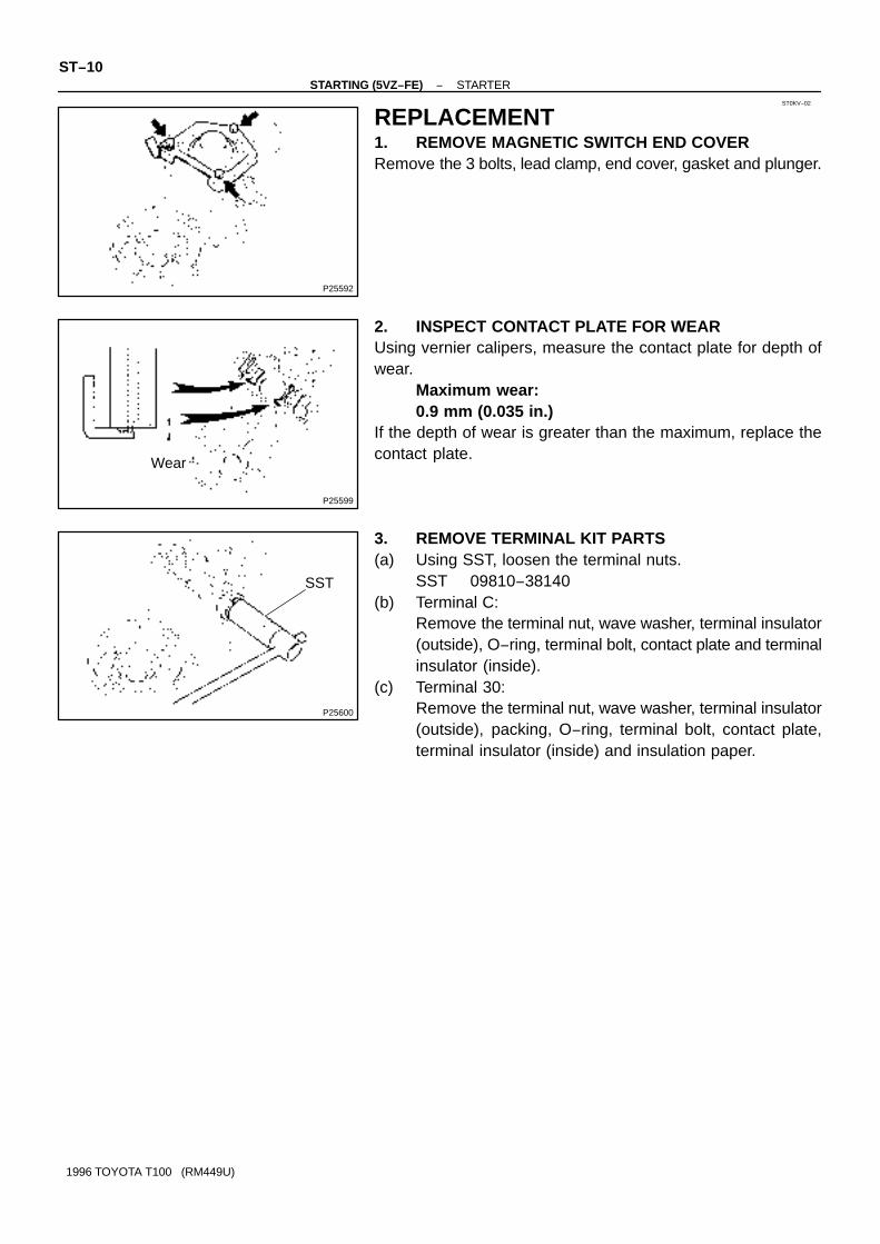
P25592
ST0KV−02
P25599
Wear
P25600
SST
ST−10−STARTING (5VZ−FE) STARTER
1996 TOYOTA T100 (RM449U)
REPLACEMENT1. REMOVE MAGNETIC SWITCH END COVERRemove the 3 bolts, lead clamp, end cover, gasket and plunger.
2. INSPECT CONTACT PLATE FOR WEARUsing vernier calipers, measure the contact plate for depth ofwear.
Maximum wear:0.9 mm (0.035 in.)
If the depth of wear is greater than the maximum, replace thecontact plate.
3. REMOVE TERMINAL KIT PARTS(a) Using SST, loosen the terminal nuts.
SST 09810−38140(b) Terminal C:
Remove the terminal nut, wave washer, terminal insulator(outside), O−ring, terminal bolt, contact plate and terminalinsulator (inside).
(c) Terminal 30:Remove the terminal nut, wave washer, terminal insulator(outside), packing, O−ring, terminal bolt, contact plate,terminal insulator (inside) and insulation paper.
https://www.truck-manuals.net/

P25641
LongShort
IndentationProtrusion
P25598
Long
Short
Lead Terminal
P25602
40 mm
37 mm 20 mm
Wooden Block
ContactPlate
−STARTING (5VZ−FE) STARTERST−11
1996 TOYOTA T100 (RM449U)
4. REINSTALL TERMINAL KIT PARTS(a) Terminal 30:
Install these new parts:(1) Insulation paper(2) Terminal insulator (inside)
NOTICE:Be careful to install the terminal insulator in the correctdirection.
(3) Contact plate(4) Terminal bolt(5) O−ring(6) Packing and terminal insulator (outside)
Install the packing to the terminal insulator, andinstall them.
HINT:Match the protrusion of the insulator with the indentation of thehousing.
(7) Wave washer(8) Terminal nut
(b) Terminal C:Install these new parts:(1) Terminal insulator (inside)(2) Contact plate(3) Terminal bolt(4) O−ring(5) Terminal insulator (outside)(6) Wave washer(7) Terminal nut
NOTICE:Be careful to install the terminal insulator (inside) in thecorrect direction.(c) Temporarily tighten the terminal nuts.
5. TIGHTEN TERMINAL NUT(a) Put a wooden block on the contact plate and press it down
with a hand press.Dimensions of wooden block:20 x 37 x 40 mm (0.79 x 1.46 x 1.57 in.)Press force:981 N (100 kgf, 221 lbf)
https://www.truck-manuals.net/

(kgf/cm2) =
100 kgf
Ram diameter (cm) 2
2
2Ram diameter (in.)(psi) = x 3.14 (π)
x 3.14 (π)
2
(kPa) = (kgf/cm2) x 98.1
(kPa) = (psi) x 6.9
221 lbf
P25601
SST
P25591
ST−12−STARTING (5VZ−FE) STARTER
1996 TOYOTA T100 (RM449U)
NOTICE:Check the diameter of the hand press ram. Then calculatethe gauge pressure of the press when 981 N (100 kgf, 221 lbf) of force is applied.
Gauge pressure:
If the contact plate is not pressed down with the specified pres-sure, the contact plate may tilt due to coil deformation or thetightening of the nut.
(b) Using SST, tighten the nuts to the specified torque.SST 09810−38140Torque: 17 N·m (173 kgf·cm, 12 ft·lbf)
NOTICE:If the nut is over tightened, it may cause cracks on the in-side of the insulator.
6. CLEAN CONTACT SURFACES OF CONTACT PLATEAND PLUNGER
Clean the contact surfaces of the remaining contact plate andplunger with a dry shop rag.7. REINSTALL MAGNETIC SWITCH END COVERInstall the plunger, new gasket, end cover and lead clamp (1.8kW type) with the 3 bolts.
Torque:1.2 kW, 1.4 kW type: 2.5 N·m (25 kgf·cm, 22 in.·lbf)1.8 kW type: 3.6 N·m (35 kgf·cm, 30 in.·lbf)
https://www.truck-manuals.net/

ST03B−03
−STARTING (5VZ−FE) STARTERST−13
1996 TOYOTA T100 (RM449U)
REASSEMBLYReassembly is in the reverse order of disassembly (See page ST−4).HINT:Use high−temperature grease to lubricate the bearings, gears, return spring and steel ball when assemblingthe starter.
https://www.truck-manuals.net/
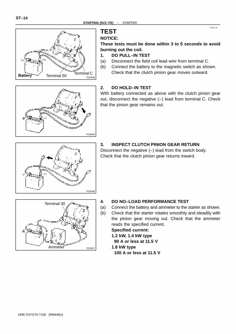
ST03C−03
P20438Battery Terminal 50
Terminal C
P20449
P20448
P20447
Terminal 30
Ammeter
ST−14−STARTING (5VZ−FE) STARTER
1996 TOYOTA T100 (RM449U)
TESTNOTICE:These tests must be done within 3 to 5 seconds to avoidburning out the coil.1. DO PULL−IN TEST(a) Disconnect the field coil lead wire from terminal C.(b) Connect the battery to the magnetic switch as shown.
Check that the clutch pinion gear moves outward.
2. DO HOLD−IN TESTWith battery connected as above with the clutch pinion gearout, disconnect the negative (−) lead from terminal C. Checkthat the pinion gear remains out.
3. INSPECT CLUTCH PINION GEAR RETURNDisconnect the negative (−) lead from the switch body.Check that the clutch pinion gear returns inward.
4. DO NO−LOAD PERFORMANCE TEST(a) Connect the battery and ammeter to the starter as shown.(b) Check that the starter rotates smoothly and steadily with
the pinion gear moving out. Check that the ammeterreads the specified current.Specified current:1.2 kW, 1.4 kW type 90 A or less at 11.5 V1.8 kW type 100 A or less at 11.5 V
https://www.truck-manuals.net/

ST03D−02
−STARTING (5VZ−FE) STARTERST−15
1996 TOYOTA T100 (RM449U)
INSTALLATIONInstallation is in the reverse order of removal (See page ST−3).
https://www.truck-manuals.net/

ST03E−03
P02536
Continuity No continuity
P02537
Ohmmeter
Battery
Continuity
ST−16−STARTING (5VZ−FE) STARTER RELAY
1202Author�: Date�:
1996 TOYOTA T100 (RM449U)
STARTER RELAYINSPECTION1. REMOVE STARTER RELAY (Marking: ”ST”)LOCATION: The relay is located in the No.1 junction block onthe driver’s side.
2. INSPECT STARTER RELAY CONTINUITY(a) Using an ohmmeter, check that there is continuity be-
tween terminals 1 and 2.If there is no continuity, replace the relay.(b) Check that there is no continuity between terminals 3 and
5.If there is continuity, replace the relay.
3. INSPECT STARTER RELAY OPERATION(a) Apply battery voltage across terminals 1 and 2.(b) Using an ohmmeter, check that there is continuity be-
tween terminals 3 and 5.If there is no continuity, replace the relay.4. REINSTALL STARTER RELAY
https://www.truck-manuals.net/

CH – CHARGING (3RZ-FE)
CHARGING SYSTEM CH-1 GENERATOR CH-6
https://www.truck-manuals.net/

CH02A−01
−CHARGING (3RZ−FE) CHARGING SYSTEMCH−1
1203Author�: Date�:
1996 TOYOTA T100 (RM449U)
CHARGING SYSTEMPRECAUTION� Check that the battery cables are connected to the correct terminals.� Disconnect the battery cables when the battery is given a quick charge.� Do not perform tests with a high voltage insulation resistance tester.� Never disconnect the battery while the engine is running.
https://www.truck-manuals.net/

S05619
Upper Level
Lower Level
Except Delco BatteryCH02B−03
B01312
B02086
and Delco Battery
CH−2−CHARGING (3RZ−FE) CHARGING SYSTEM
1996 TOYOTA T100 (RM449U)
ON−VEHICLE INSPECTION1. CHECK BATTERY ELECTROLYTE LEVELCheck the electrolyte quantity of each cell.Maintenance−Free Battery:If under the lower level, replace the battery (or add distilled wa-ter if possible). Check the charging system.Except Maintenance−Free Battery:If under the lower level, add distilled water.
2. Except Maintenance−Free Battery:CHECK BATTERY SPECIFIC GRAVITY
Check the specific gravity of each cell.Standard specific gravity:1.25 − 1.29 at 20°C (68°F)
If the specific gravity is less than specification, charge the bat-tery.3. Maintenance−Free Battery:
CHECK BATTERY VOLTAGE(a) After having driven the vehicle and in the case that 20
minutes have not passed after having stopped the en-gine, turn the ignition switch ON and turn on the electricalsystem (headlight, blower motor, rear defogger etc.) for60 seconds to remove the surface charge.
(b) Turn the ignition switch OFF and turn off the electrical sys-tems.
(c) Measure the battery voltage between the negative (−)and positive (+) terminals of the battery.Standard voltage:12.7 − 12.9 V at 20°C (68°F)
HINT:� Before measuring the voltage, turn the ignition switch
OFF and turn off the electrical systems (headlight, blowermotor, rear defogger etc.) for 60 seconds to remove thesurface charge.
� If the vehicle has been running, wait 20 minutes or moreafter the vehicle stops before measuring the battery volt-age.
If the voltage is less than specification, charge the battery.HINT:Check the indicator as shown in illustration.
https://www.truck-manuals.net/

P15119
CH0743
Delco Battery
Green Dot Dark Clear
P06717
−CHARGING (3RZ−FE) CHARGING SYSTEMCH−3
1996 TOYOTA T100 (RM449U)
4. CHECK BATTERY TERMINALS, FUSIBLE LINK ANDFUSES
(a) Check that the battery terminals are not loose or cor-roded.
(b) Check the fusible link and fuses for continuity.
5. Delco Battery:CHECK HYDROMETERGreen Dot visible: Battery is adequately charged.Dark (Green Dot not visible): Battery must be charged.Clear or Light Yellow: Replace battery.
HINT:There is no need to add water during the entire service life ofthe battery.
6. INSPECT DRIVE BELT(a) Visually check the belt for excessive wear, frayed cords
etc.HINT:Cracks on the ribbed side of the belt are considered acceptable.If the belt has chunks missing from the ribs, it should be re-placed.
https://www.truck-manuals.net/

Z00038
Nippondenso Borroughs
P06723
CORRECT WRONG
B02087
CH−4−CHARGING (3RZ−FE) CHARGING SYSTEM
1996 TOYOTA T100 (RM449U)
(b) Using a belt tension gauge, check the drive belt tension.Belt tension gauge:Nippondenso BTG 20 (95506−00020) orBorroughs No. BT−33−73FDrive belt tension:New belt 175 ± 5 lbfUsed belt 115 ± 20 lbf
If necessary, adjust the drive belt tension.HINT:� ”New belt” refers to a belt which has been used less than
5 minutes on a running engine.� ”Used belt” refers to a belt which has been used on a run-
ning engine for 5 minutes or more.� After installing the drive belt, check that it fits properly in
the ribbed grooves. Check with your hand to confirm thatthe belt has not slipped out of the groove on the bottomof the crank pulley.
� After installing a new belt, run the engine for approx. 5minutes and then recheck the tension.
7. VISUALLY CHECK GENERATOR WIRING AND LIS-TEN FOR ABNORMAL NOISES
(a) Check that the wiring is in good condition.(b) Check that there is no abnormal noise from the generator
while the engine is running.8. INSPECT DISCHARGE WARNING LIGHT CIRCUIT(a) Turn the ignition switch ON. Check that the discharge
warning light comes on.(b) Start the engine. Check that the light goes off.If the light does not operate as specified, troubleshoot the dis-charge warning light circuit.
9. CHECK CHARGING CIRCUIT WITHOUT LOADHINT:If a battery/generator tester is available, connect the tester tothe charging circuit according to the manufacturers instruc-tions.(a) If a tester is not available, connect a voltmeter and amme-
ter to the charging circuit as follows:� Disconnect the wire from terminal B of the generator
and connect the wire to the negative (−) terminal ofthe ammeter.
https://www.truck-manuals.net/

P20582
Terminal F
−CHARGING (3RZ−FE) CHARGING SYSTEMCH−5
1996 TOYOTA T100 (RM449U)
� Connect the test lead from the positive (+) terminalof the ammeter to terminal B of the generator.
� Connect the positive (+) lead of the voltmeter to ter-minal B of the generator.
� Ground the negative (−) lead of the voltmeter.(b) Check the charging circuit as follows:
With the engine running from idling to 2,000 rpm, checkthe reading on the ammeter and voltmeter.Standard amperage:10 A or lessStandard voltage:At 25 °C (77°F): 14.0 − 15.0 VAt 115 °C(239 °F): 13.5 − 14.3 V
If the voltage reading is greater than standard voltage, replacethe voltage regulator.If the voltage reading is less than standard voltage, check thevoltage regulator and generator as follows:
� With terminal F grounded, start the engine andcheck the voltage reading of terminal B.
� If the voltage reading is higher than standard volt-age, replace the voltage regulator.
� If the voltage reading is less than standard voltage,repair the generator.
10. INSPECT CHARGING CIRCUIT WITH LOAD(a) With the engine running at 2,000 rpm, turn on the high
beam headlights and place the heater fan control switchto HI.
(b) Check the reading on the ammeter.Standard amperage:30 A or more
If the ammeter reading is less than standard amperage, repairthe generator.HINT:If the battery is fully charged, the indication will sometimes beless than standard amperage.
https://www.truck-manuals.net/
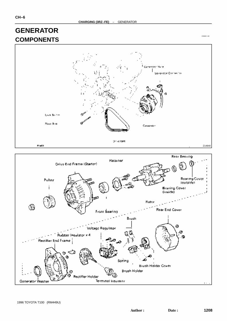
CH02C−03
Z14840
CH−6−CHARGING (3RZ−FE) GENERATOR
1208Author�: Date�:
1996 TOYOTA T100 (RM449U)
GENERATORCOMPONENTS
https://www.truck-manuals.net/

CH02D−03
P14842Pivot Bolt Lock Bolt
Adjust Bolt
P14830
−CHARGING (3RZ−FE) GENERATORCH−7
1996 TOYOTA T100 (RM449U)
REMOVAL1. REMOVE DRIVE BELT(a) Loosen the lock bolt, pivot bolt, nut and adjusting bolt.(b) Remove the drive belt.2. REMOVE GENERATOR(a) Disconnect the generator connector.(b) Remove the nut, and disconnect the generator wire.(c) Disconnect the wire harness with the clip.
(d) Remove the lock bolt, pivot bolt, nut and generator.Torque:Pivot bolt: 59 N·m (600 kgf·cm, 43 ft·lbf)Lock bolt: 29 N·m (300 kgf·cm, 21 ft·lbf)
https://www.truck-manuals.net/

CH0ES−02
P13397
P13398
P13396
P20344
CH0213
SST (B)SST (A)
CH−8−CHARGING (3RZ−FE) GENERATOR
1996 TOYOTA T100 (RM449U)
DISASSEMBLY1. REMOVE REAR END COVER(a) Remove the nut and terminal insulator.(b) Remove the 3 nuts and end cover.
2. REMOVE BRUSH HOLDER(a) Remove the 2 screws, brush holder and cover.(b) Remove the brush holder cover from the brush holder.
3. REMOVE VOLTAGE REGULATORRemove the 3 screws and voltage regulator.
4. REMOVE RECTIFIER HOLDER(a) Remove the 4 screws and rectifier holder.(b) Remove the 4 rubber insulators.
5. REMOVE PULLEY(a) Hold SST (A) with a torque wrench, and tighten SST (B)
clockwise to the specified torque.SST 09820−63010Torque: 39 N·m (400 kgf·cm, 29 ft·lbf)
(b) Check that SST (A) is secured to the rotor shaft.
https://www.truck-manuals.net/
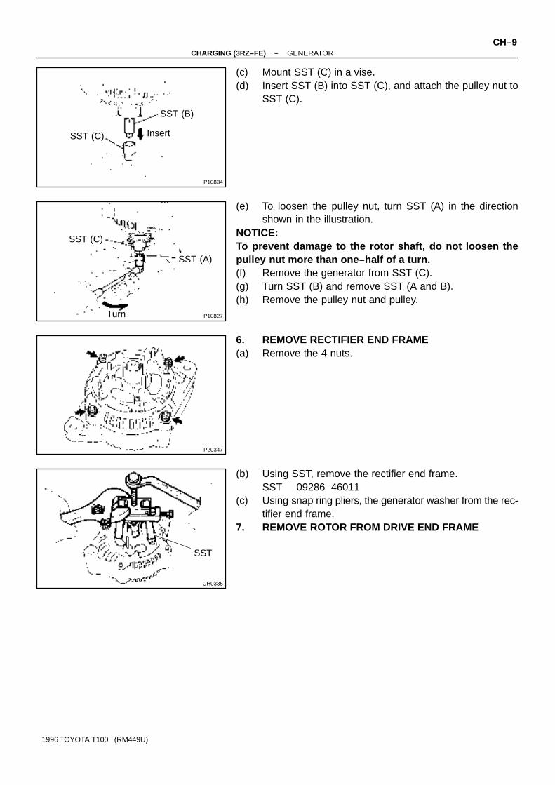
P10834
SST (C)
SST (B)
Insert
P10827
SST (C)
SST (A)
Turn
P20347
CH0335
SST
−CHARGING (3RZ−FE) GENERATORCH−9
1996 TOYOTA T100 (RM449U)
(c) Mount SST (C) in a vise.(d) Insert SST (B) into SST (C), and attach the pulley nut to
SST (C).
(e) To loosen the pulley nut, turn SST (A) in the directionshown in the illustration.
NOTICE:To prevent damage to the rotor shaft, do not loosen thepulley nut more than one−half of a turn.(f) Remove the generator from SST (C).(g) Turn SST (B) and remove SST (A and B).(h) Remove the pulley nut and pulley.
6. REMOVE RECTIFIER END FRAME(a) Remove the 4 nuts.
(b) Using SST, remove the rectifier end frame.SST 09286−46011
(c) Using snap ring pliers, the generator washer from the rec-tifier end frame.
7. REMOVE ROTOR FROM DRIVE END FRAME
https://www.truck-manuals.net/

CH0HW−01
CH0784
Continuity
Ohmmeter
B02105
No Continuity
Ohmmeter
CH0192
P13482
Continuity
Ohmmeter
P13565
No Continuity
Ohmmeter
CH−10−CHARGING (3RZ−FE) GENERATOR
1996 TOYOTA T100 (RM449U)
INSPECTION1. INSPECT ROTOR FOR OPEN CIRCUITUsing an ohmmeter, check that there is continuity between theslip rings.
Standard resistance:2.8 − 3.0 Ω at 20 °C (68 °F)
If there is no continuity, replace the rotor.
2. INSPECT ROTOR FOR GROUNDUsing an ohmmeter, check that there is no continuity betweenthe slip ring and rotor.If there is continuity, replace the rotor.
3. INSPECT SLIP RINGS(a) Check that the slip rings are not rough or scored.If rough or scored, replace the rotor.(b) Using a vernier caliper, measure the slip ring diameter.
Standard diameter: 14.2 − 14.4 mm (0.559 − 0.567 in.)Minimum diameter: 12.8 mm (0.504 in.)
If the diameter is less than minimum, replace the rotor.
4. INSPECT STATOR FOR OPEN CIRCUITUsing an ohmmeter, check that there is continuity between thecoil leads.If there is no continuity, replace the drive end frame assembly.
5. INSPECT STATOR FOR GROUNDUsing an ohmmeter, check that there is no continuity betweenthe coil lead and drive end frame.If there is continuity, replace the drive end frame assembly.
https://www.truck-manuals.net/

P13534
Length
CH0248
CH0414
10.5 mm
Positive (+)Terminal
P13568
RectifierTerminal
Ohmmeter
P13566
Ohmmeter Negative (−)Terminal
−CHARGING (3RZ−FE) GENERATORCH−11
1996 TOYOTA T100 (RM449U)
6. INSPECT EXPOSED BRUSH LENGTHUsing vernier calipers, measure the exposed brush length.
Standard exposed length:10.5 mm (0.413 in.)Minimum exposed length:1.5 mm (0.059 in.)
If the exposed length is less than minimum, replace thebrushes.
7. IF NECESSARY, REPLACE BRUSHES(a) Unsolder and remove the brush and spring.(b) Run the wire of the brush through the hole in the brush
holder, and insert the spring and brush into the brushholder.
(c) Solder the brush wire to the brush holder at exposedlength.Exposed length:10.5 mm (0.413 in.)
(d) Check that the brush moves smoothly in the brush holder.(e) Cut off the excess wire.(f) Apply insulation paint to the soldered point.
8. INSPECT POSITIVE RECTIFIER(a) Using an ohmmeter, connect one tester probe to the posi-
tive (+) terminal and the other to each rectifier terminal.(b) Reverse the polarity of the tester probes and repeat step
(a).(c) Check that one shows continuity and the other shows no
continuity.If continuity is not as specified, replace the rectifier holder.
9. INSPECT NEGATIVE RECTIFIER(a) Using an ohmmeter, connect one tester probe to each
negative (−) terminal and the other to each rectifier termi-nal.
(b) Reverse the polarity of the tester probes and repeat step(a).
(c) Check that one shows continuity and the other shows nocontinuity.
If continuity is not as specified, replace the rectifier holder.
https://www.truck-manuals.net/

CH0827
P22368
SST
P22369
SST
N00581
SST
CH−12−CHARGING (3RZ−FE) GENERATOR
1996 TOYOTA T100 (RM449U)
10. INSPECT FRONT BEARINGCheck that the bearing is not rough or worn.
11. IF NECESSARY, REPLACE FRONT BEARING(a) Remove the 4 screws and bearing retainer.
(b) Using SST and a press, press out the bearing.SST 09950−60010 (09951−00260, 09952−06010)
(c) Using SST and a press, press in a new bearing.SST 09950−60010 (09951−00500)
(d) Install the bearing retainer with the 4 screws.Torque: 2.6 N·m (27 kgf·cm, 23 in.·lbf)
12. INSPECT REAR BEARINGCheck that the bearing is not rough or worn.13. IF NECESSARY, REPLACE REAR BEARING(a) Using SST, remove the bearing cover and bearing.
SST 09820−00021(b) Remove the bearing cover (inside).
https://www.truck-manuals.net/
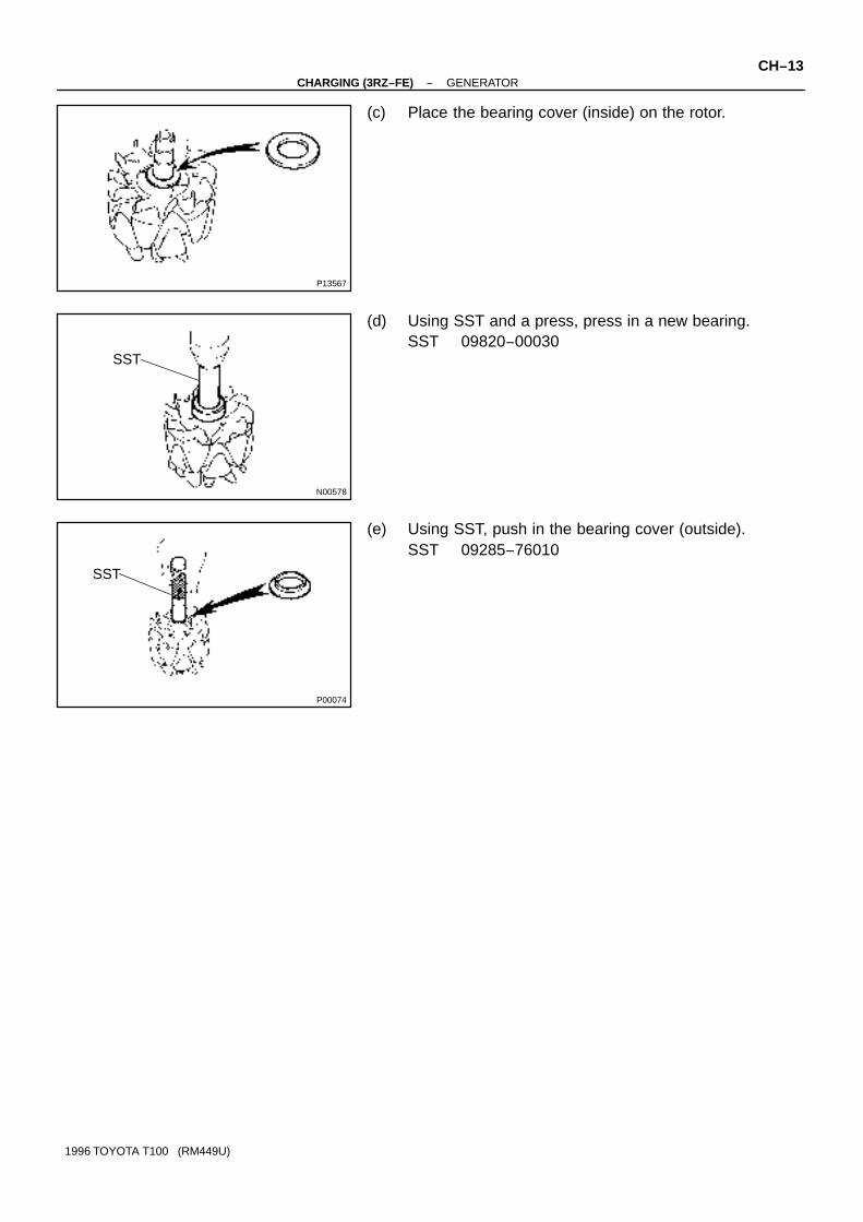
P13567
N00578
SST
P00074
SST
−CHARGING (3RZ−FE) GENERATORCH−13
1996 TOYOTA T100 (RM449U)
(c) Place the bearing cover (inside) on the rotor.
(d) Using SST and a press, press in a new bearing.SST 09820−00030
(e) Using SST, push in the bearing cover (outside).SST 09285−76010
https://www.truck-manuals.net/

P13486
CH0HX−01
P13762
Upward
P13487
29 mmSocketWrench
P13597
SST (A)
SST (B)
Turn
Turn
P10834
SST (C)
SST (B)
Insert
CH−14−CHARGING (3RZ−FE) GENERATOR
1996 TOYOTA T100 (RM449U)
REASSEMBLY1. PLACE RECTIFIER END FRAME ON PULLEY2. INSTALL ROTOR TO DRIVE END FRAME
3. INSTALL RECTIFIER END FRAMEInstall the generator washer to the rectifier end frame.NOTICE:Be careful of the generator washer installation directon.
4. INSTALL RECTIFIER END FRAME(a) Using a 29 mm socket wrench and press, slowly press in
the rectifier end frame.(b) Install the 4 nuts.
Torque: 4.5 N·m (46 kgf·cm, 39 in.·lbf)
5. INSTALL PULLEY(a) Install the pulley to the rotor shaft by tightening the pulley
nut by hand.(b) Hold SST (A) with a torque wrench, and tighten SST (B)
clockwise to the specified torque.SST 09820−63010Torque: 39 N·m (400 kgf·cm, 29 ft·lbf)
(c) Check that SST (A) is secured to the pulley shaft.
(d) Mount SST (C) in a vise.(e) Insert SST (B) into SST (C), and attach the pulley nut to
SST (C).
https://www.truck-manuals.net/

P04395
SST (C)
SST (A)Turn
P13569
P13541
P13624
P13543
−CHARGING (3RZ−FE) GENERATORCH−15
1996 TOYOTA T100 (RM449U)
(f) To torque the pulley nut, turn SST (A) in the directionshown in the illustration.Torque: 110 N·m (1,125 kgf·cm, 81 ft·lbf)
(g) Remove the generator from SST (C).(h) Turn SST (B), and remove SST (A and B).
6. INSTALL RECTIFIER HOLDER(a) Install the 4 rubber insulators on the lead wires.NOTICE:Be careful of the rubber insulators installation direction.
(b) Install the rectifier with the 4 screws.Torque: 2.0 N·m (20 kgf·cm, 18 in.·lbf)
7. INSTALL VOLTAGE REGULATOR AND BRUSH HOLD-ER
(a) Install the brush holder cover to the brush holder.NOTICE:Be careful of the holder installation direction.(b) Place the voltage regulator together with the brush holder
horizontally on the rectifier end frame.
(c) Install the 5 screws until there is a clearance of approx. 1mm (0.04 in.) between the brush holder and voltage regu-lator.Torque: 2.0 N·m (20 kgf·cm, 17 in.·lbf)
(d) Fit the brush holder cover.8. INSTALL REAR END COVER(a) Install the end cover with the 3 nuts.
Torque: 4.5 N·m (46 kgf·cm, 40 in.·lbf)(b) Install the terminal insulator with the nut.
Torque: 4.1 N·m (42 kgf·cm, 36 in.·lbf)
https://www.truck-manuals.net/

CH−16−CHARGING (3RZ−FE) GENERATOR
1996 TOYOTA T100 (RM449U)
9. CHECK THAT ROTOR ROTATES SMOOTHLY
https://www.truck-manuals.net/

CH02H−02
−CHARGING (3RZ−FE) GENERATORCH−17
1996 TOYOTA T100 (RM449U)
INSTALLATIONInstallation is in the reverse order of removal (See page CH−7).
https://www.truck-manuals.net/

CH – CHARGING (5VZ-FE)
CHARGING SYSTEM CH-1 GENERATOR CH-5
https://www.truck-manuals.net/

CH02P−03
S05376
Except Maintenance−Free Battery
Z18827
VoltmeterMaintenance−Free Battery
−CHARGING (5VZ−FE) CHARGING SYSTEMCH−1
1220Author�: Date�:
1996 TOYOTA T100 (RM449U)
CHARGING SYSTEMON−VEHICLE INSPECTIONCAUTION:� Check that the battery cables are connected to the
correct terminals.� Disconnect the battery cables when the battery is giv-
en a quick charge.� Do not perform tests with a high voltage insulation re-
sistance tester.� Never disconnect the battery while the engine is run-
ning.
1. CHECK BATTERY ELECTROLYTE LEVELCheck the electrolyte quantity of each cell.Maintenance−Free Battery:If under the lower level, replace the battery (or add distilled wa-ter if possible) and check the charging system.Except Maintenance−Free Battery:If under the lower level, add distilled water.
2. Except Maintenance−Battery:CHECK BATTERY SPECIFIC GRAVITY
Check the specific gravity of each cell.Standard specific gravity: At 20°C (68°F): 1.25 − 1.29
If the specific gravity is less than specification, charge the bat-tery.
3. Maintenance−Free Battery:CHECK BATTERY VOLTAGE
Measure the battery voltage between the negative (−) and posi-tive (+) terminals of the battery.
Standard voltage: At 20°C (68°F): 12.7 − 12.9 VHINT:� Before measuring the voltage, turn the ignition switch
OFF and turn off the electrical systems (headlight, blowermotor, rear defogger etc.) for 60 seconds to remove thesurface charge.
https://www.truck-manuals.net/

P15119
P06717
Z00038
Nippondenso Borroughs
CH−2−CHARGING (5VZ−FE) CHARGING SYSTEM
1221Author�: Date�:
1996 TOYOTA T100 (RM449U)
� When measuring the voltage, however, turn the ignitionswitch OFF and turn off the electrical systems.
If the voltage is less than the specification, charge the battery.
HINT:Check the indicator as shown in the illustration.
4. CHECK BATTERY TERMINALS, FUSIBLE LINK ANDFUSES
(a) Check that the battery terminals are not loose or cor-roded.
(b) Check the fusible link and fuses for continuity.
5. INSPECT DRIVE BELT(a) Visually check the belt for excessive wear, frayed cords
etc.HINT:Cracks on the ribbed side of the belt are considered acceptable.If the belt has chunks missing from the ribs, it should be re-placed.
(b) Using a belt tension gauge, check the drive belt tension.Belt tension gauge:Nippondenso BTG 20 (95506−00020) orBorroughs No. BT−33−73FDrive belt tension:New belt: 160 ± 20 lbfUsed belt: 100 ± 20 lbf
If necessary, adjust the drive belt tension.
https://www.truck-manuals.net/

P06723
CORRECT WRONG WRONG
−CHARGING (5VZ−FE) CHARGING SYSTEMCH−3
1222Author�: Date�:
1996 TOYOTA T100 (RM449U)
HINT:� ”New belt” refers to a belt which has been used less than
5 minutes on a running engine.� ”Used belt” refers to a belt which has been used on a run-
ning engine for 5 minutes or more.� After installing the drive belt, check that it fits properly in
the ribbed grooves. Check with your hand to confirm thatthe belt has not slipped out of the groove on the bottomof the crank pulley.
� After installing a new belt, run the engine for approx. 5minutes and then recheck the tension.
6. INSPECT FUSES FOR CONTINUITY� ENGINE 10A� CHARGE 7.5A� IGN 7.5A
7. VISUALLY CHECK GENERATOR WIRING AND LIS-TEN FOR ABNORMAL NOISES
(a) Check that the wiring is in good condition.(b) Check that there is no abnormal noise from the generator
while the engine is running.
8. CHECK CHARGING CIRCUIT WITHOUT LOADHINT:If a battery/generator tester is available, connect the tester tothe charging circuit according to the manufactuer’s instructions.(a) If a tester is not available, connect a voltmeter and amme-
ter to the charging circuit as follows:� Disconnect the wire from terminal B of the generator
and connect the wire to the negative (−) terminal ofthe ammeter.
� Connect the test lead from the positive (+) terminalof the ammeter to terminal B of the generator.
� Connect the positive (+) lead of the voltmeter to ter-minal B of the generator.
� Ground the negative (−) lead of the voltmeter.(b) Check the charging circuit as follows:
With the engine running from idling to 2,000 rpm, checkthe reading on the ammeter and voltmeter.Standard amperage: 10 A or lessStandard voltage:At 25 °C (77 °F): 14.0 − 15.0 VAt 115 °C (239 °F): 13.5 − 14.3 V
If the voltage reading is greater than the standard voltage, re-place the voltage regulator.
https://www.truck-manuals.net/

P20582
Terminal F
CH−4−CHARGING (5VZ−FE) CHARGING SYSTEM
1223Author�: Date�:
1996 TOYOTA T100 (RM449U)
If the voltage reading is less than the standard voltage, checkthe voltage regulator and generator as follows:
� With terminal F grounded, start the engine andcheck the voltage reading of terminal B.
� If the voltage reading is higher than the standardvoltage, replace the voltage regulator.
� If the voltage reading is less than the standard volt-age, repair the generator.
9. INSPECT CHARGING CIRCUIT WITH LOAD(a) With the engine running at 2,000 rpm, turn on the high
beam headlights and place the heater fan control switchto HI.
(b) Check the reading on the ammeter.Standard amperage: 30 A or more
If the ammeter reading is less than standard amperage, repairthe generator.HINT:If the battery is fully charged, the indication will sometimes beless than standard amperage.
https://www.truck-manuals.net/

CH02J−05
P20588
S05685
Generator Washer
Pulley
Drive End Frame (Starter)Retainer
Front Bearing
Rotor
Rear Bearing
BearingCover(inside)
BearingCover(outside)
Rear End Cover
Brush Holder Cover
Brush
Brush Holder
Spring
Voltage Regulator
Terminal Insulator
Rectifier Holder
Rubber Insulator x4
Rectifier End Frame
−CHARGING (5VZ−FE) GENERATORCH−5
1224Author�: Date�:
1996 TOYOTA T100 (RM449U)
GENERATORCOMPONENTS
https://www.truck-manuals.net/

CH0HY−01
P20342
Pivot Bolt
Adjusting BoltLock Nut
P20342
Pivot Bolt
Lock Nut
CH−6−CHARGING (5VZ−FE) GENERATOR
1996 TOYOTA T100 (RM449U)
REMOVAL1. DISCONNECT WIRING FROM GENERATOR(a) Disconnect the connector from the generator.(b) Remove the nut and disconnect the wire from the genera-
tor.
2. REMOVE GENERATOR DRIVE BELT(a) Loosen the adjust lock nut, adjusting bolt and pivot bolt.(b) Remove the drive belt.3. REMOVE GENERATOR(a) Remove the pivot bolt and adjusting lock nut.(b) Remove the generator.
Torque:Pivot bolt: 51.0 N·m (520kgf·cm, 38 ft·lbf)Lock Nut: 18.5 N·m (185kgf·cm, 14 ft·lbf)
https://www.truck-manuals.net/
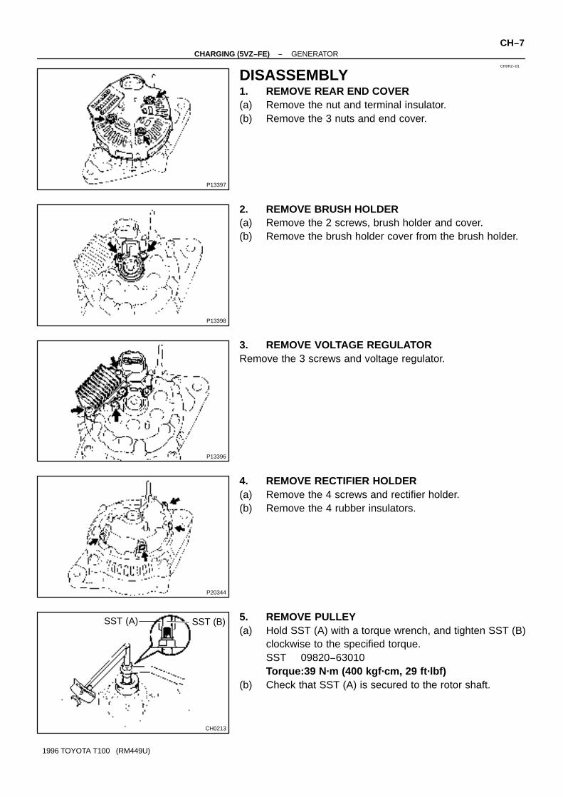
CH0HZ−01
P13397
P13398
P13396
P20344
CH0213
SST (A) SST (B)
−CHARGING (5VZ−FE) GENERATORCH−7
1996 TOYOTA T100 (RM449U)
DISASSEMBLY1. REMOVE REAR END COVER(a) Remove the nut and terminal insulator.(b) Remove the 3 nuts and end cover.
2. REMOVE BRUSH HOLDER(a) Remove the 2 screws, brush holder and cover.(b) Remove the brush holder cover from the brush holder.
3. REMOVE VOLTAGE REGULATORRemove the 3 screws and voltage regulator.
4. REMOVE RECTIFIER HOLDER(a) Remove the 4 screws and rectifier holder.(b) Remove the 4 rubber insulators.
5. REMOVE PULLEY(a) Hold SST (A) with a torque wrench, and tighten SST (B)
clockwise to the specified torque.SST 09820−63010Torque:39 N·m (400 kgf·cm, 29 ft·lbf)
(b) Check that SST (A) is secured to the rotor shaft.
https://www.truck-manuals.net/

P10834
SST (C)
SST (B)
Insert
P10827
SST (A)
SST (C)
Turn
P20347
CH0335
SST
CH−8−CHARGING (5VZ−FE) GENERATOR
1996 TOYOTA T100 (RM449U)
(c) Mount SST (C) in a vise.(d) Insert SST (B) into SST (C), and attach the pulley nut to
SST (C).
(e) To loosen the pulley nut, turn SST (A) in the directionshown in the illustration.
NOTICE:To prevent damage to the rotor shaft, do not loosen thepulley nut more than one−half of a turn.(f) Remove the generator from SST (C).(g) Turn SST (B), and remove SST (A and B).(h) Remove the pulley nut and pulley.
6. REMOVE RECTIFIER END FRAME(a) Remove the 4 nuts.
(b) Using SST, remove the rectifier end frame.SST 09286−46011
(c) Using snap ring pliers, the generator washer from the rec-tifier end continuity.
7. REMOVE ROTOR FROM DRIVE END FRAME
https://www.truck-manuals.net/

CH0I0−01
CH0784
Ohmmeter
Continuity
CH0783
Ohmmeter
No Continuity
CH0192
P13482
Ohmmeter
Continuity
P13565
Ohmmeter
No Continuity
−CHARGING (5VZ−FE) GENERATORCH−9
1996 TOYOTA T100 (RM449U)
INSPECTION1. INSPECT ROTOR FOR OPEN CIRCUITUsing an ohmmeter, check that there is continuity between theslip rings.
Standard resistance:2.8 − 3.0 Ω at 20°C (68°F)
If there is no continuity, replace the rotor.
2. INSPECT ROTOR FOR GROUNDUsing an ohmmeter, check that there is no continuity betweenthe slip ring and rotor.If there is continuity, replace the rotor.
3. INSPECT SLIP RINGS(a) Check that the slip rings are not rough or scored.If rough or scored, replace the rotor.(b) Using vernier calipers, measure the slip ring diameters.
Standard diameter:14.2 − 14.4 mm (0.559 − 0.567 in.)Minimum diameter:12.8 mm (0.504 in.)
4. INSPECT STATOR FOR OPEN CIRCUITUsing an ohmmeter, check that there is continuity between thecoil leads.If there is no continuity, replace the drive end frame assembly.
5. INSPECT STATOR FOR GROUNDUsing an ohmmeter, check that there is no continuity betweenthe coil leads and drive end frame.If there is continuity, replace the drive end frame assembly.
https://www.truck-manuals.net/

P13534
Length
P13729
CH0414
10.5 mm
P13568
TerminalPositive (+)
Ohmmeter
TerminalRectifer
P13566
Ohmmeter
TerminalNegative (−)
CH−10−CHARGING (5VZ−FE) GENERATOR
1996 TOYOTA T100 (RM449U)
6. INSPECT EXPOSED BRUSH LENGTHUsing vernier calipers, measure the exposed brush length.
Standard exposed length:10.5 mm (0.413 in.)Minimum exposed length:1.5 mm (0.059 in.)
If the exposed length is less than minimum, replace thebrushes.
7. IF NECESSARY, REPLACE BRUSHES(a) Unsolder and remove the brush and spring.(b) Run the wire of the brush through the hole in the brush
holder, and insert the spring and brush into the brushholder.
(c) Solder the brush wire to the brush holder at the exposedlength.Exposed length:10.5 mm (0.413 in.)
(d) Check that the brush moves smoothly in the brush holder.(e) Cut off the excess wire.(f) Apply insulation paint to the soldered point.
8. INSPECT POSITIVE RECTIFIER(a) Using an ohmmeter, connect one tester probe to the posi-
tive (+) terminal and the other to each rectifier terminal.(b) Reverse the polarity of the tester probes and repeat step
(a).(c) Check that one shows continuity and the other shows no
continuity.If continuity is not as specified, replace the rectifier holder.
9. INSPECT NEGATIVE RECTIFIER(a) Using an ohmmeter, connect one tester probe to each
negative (−) terminal and the other to each rectifier termi-nal.
(b) Reverse the polarity of the tester probes and repeat step(a).
(c) Check that one shows continuity and the other shows nocontinuity.
If continuity is not as specified, replace the rectifier holder.
https://www.truck-manuals.net/
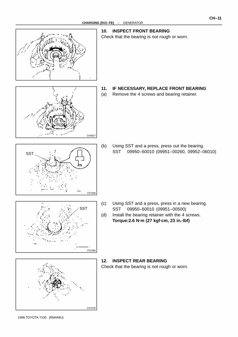
CH0827
P22368
SST
P22369
SST
CH1026
−CHARGING (5VZ−FE) GENERATORCH−11
1996 TOYOTA T100 (RM449U)
10. INSPECT FRONT BEARINGCheck that the bearing is not rough or worn.
11. IF NECESSARY, REPLACE FRONT BEARING(a) Remove the 4 screws and bearing retainer.
(b) Using SST and a press, press out the bearing.SST 09950−60010 (09951−00260, 09952−06010)
(c) Using SST and a press, press in a new bearing.SST 09950−60010 (09951−00500)
(d) Install the bearing retainer with the 4 screws.Torque:2.6 N·m (27 kgf·cm, 23 in.·lbf)
12. INSPECT REAR BEARINGCheck that the bearing is not rough or worn.
https://www.truck-manuals.net/

N00581
SST
P13567
N00578
SST
P00074
SST
CH−12−CHARGING (5VZ−FE) GENERATOR
1996 TOYOTA T100 (RM449U)
13. IF NECESSARY, REPLACE REAR BEARING(a) Using SST, remove the bearing cover and bearing.
SST 09820−00021(b) Remove the bearing cover (inside).
(c) Place the bearing cover (inside) on the rotor.
(d) Using SST and a press, press in a new bearing.SST 09820−00030
(e) Using SST, push in the bearing cover (outside).SST 09285−76010
https://www.truck-manuals.net/

CH02N−03
P13486
P13762
Upward
P13487
WrenchSocket29 mm
P13597
SST (B)
SST (A)
P10834
SST (B)
SST (C) Insert
−CHARGING (5VZ−FE) GENERATORCH−13
1996 TOYOTA T100 (RM449U)
REASSEMBLY1. PLACE RECTIFIER END FRAME ON PULLEY2. INSTALL ROTOR TO DRIVE END FRAME
3. INSTALL RECTIFIER END FRAME(a) Install the generator washer to the rectifier end frame.NOTICE:Be careful of the generator washer installation direction.
(b) Using a 29 mm socket wrench and press, slowly press inthe rectifier end frame.
(c) Install the 4 nuts.Torque:4.5 N·m (46 kgf·cm, 39 in.·lbf)
4. INSTALL PULLEY(a) Install the pulley to the rotor shaft by tightening the pulley
nut by hand.(b) Hold SST (A) with a torque wrench, and tighten SST (B)
clockwise to the specified torque.SST 09820−63010Torque:39 N·m (400 kgf·cm, 29 ft·lbf)
(c) Check that SST (A) is secured to the pulley shaft.
(d) Mount SST (C) in a vise.(e) Insert SST (B) into SST (C), and attach the pulley nut to
SST (C).
https://www.truck-manuals.net/

P04395
SST (A)
SST (C)
Turn
P13569
P13541
B07119
Upward
Protrusion
P13542
CH−14−CHARGING (5VZ−FE) GENERATOR
1996 TOYOTA T100 (RM449U)
(f) To torque the pulley nut, turn SST (A) in the directionshown in the illustration.Torque:110 N·m (1,125 kgf·cm, 81 ft·lbf)
(g) Remove the generator from SST (C).(h) Turn SST (B), and remove SST (A and B).
5. INSTALL RECTIFIER HOLDER(a) Install the 4 rubber insulators on the lead wires.NOTICE:Be careful of the rubber insulators installation direction.
(b) Install the rectifier with the 4 screws.Torque: 2.0 N·m (20 kgf·cm, 18 in.·lbf)
6. INSTALL BRUSH HOLDER AND VOLTAGEREGULATOR
(a) Install the brush holder cover to the brush holder.NOTICE:Be careful of the holder installation direction.
(b) Place the voltage regulator together with the brush holderhorizontally on the rectifier end frame.
https://www.truck-manuals.net/

P13543
B05826
Push
P13397
P13571
−CHARGING (5VZ−FE) GENERATORCH−15
1996 TOYOTA T100 (RM449U)
(c) Install the 5 screws until there is a clearance of approx. 1mm (0.04 in.) between the brush holder and voltage regu-lator.Torque: 2.0 N·m (20 kgf·cm, 17 in.·lbf)
(d) Fit the brush holder cover.
7. INSTALL REAR END COVER(a) Install the end cover with the 3 nuts.
Torque: 4.5 N·m (46 kgf·cm, 40 in.·lbf)
(b) Install the terminal insulator with the nut.Torque:4.1 N·m (42 kgf·cm, 36 in.·lbf)
8. CHECK THAT ROTOR ROTATES SMOOTHLY
https://www.truck-manuals.net/

CH02O−02
CH−16−CHARGING (5VZ−FE) GENERATOR
1996 TOYOTA T100 (RM449U)
INSTALLATIONInstallation is in the reverse order of removal (See page CH−6).
https://www.truck-manuals.net/
CL – CLUTCH
TROUBLESHOOTING CL-1 CLUTCH PEDAL CL-2 CLUTCH MASTER CYLINDER CL-5 CLUTCH RELEASE CYLINDER CL-10 CLUTCH UNIT CL-15
https://www.truck-manuals.net/

CL026−01
−CLUTCH TROUBLESHOOTINGCL−1
1236Author�: Date�:
1996 TOYOTA T100 (RM449U)
TROUBLESHOOTINGPROBLEM SYMPTOMS TABLEUse the table below to help you find the cause of the problem. The numbers indicate the priority of the likelycause of the problem. Check each part in order. If necessary, replace these parts.
Symptom Suspect Area See page
Clutch grabs/chatters
1. Engine mounting (Loosen)
2. Clutch disc (Runout is excessive)
3. Clutch disc (Oily)
4. Clutch disc (Worn out)
5. Clutch disc (Damaged torsion rubber)
6. Clutch disc (Glazed)
7. Diaphragm spring (Out of tip alignment)
−
CL−15
CL−15
CL−15
CL−15
CL−15
CL−19
Clutch pedal spongy
1. Clutch line (Air in line)
2. Master cylinder cup (Damaged)
3. Release cylinder cup (Damaged)
−
CL−5
CL−10
Clutch noisy
1. Release bearing (Worn, dirty or damaged)
2. Input shaft bearing (Worn, dirty or damaged)
3. Clutch disc torsion rubber (Damaged)
CL−15
−
CL−15
Clutch slips
1. Clutch pedal (Freeplay out of adjustment)
2. Clutch disc (Oily)
3. Clutch disc (Worn out)
4. Diaphragm spring (Damaged)
5. Pressure plate (Distortion)
6. Flywheel (Distortion)
CL−2
CL−15
CL−15
CL−15
CL−15
−
Clutch does not disengage
1. Clutch pedal (Freeplay out of adjustment)
2. Clutch line (Air in line)
3. Master cylinder cup (Damaged)
4. Release cylinder cup (Damaged)
5. Input shaft bearing (Worn, dirty or damaged)
6. Clutch disc (Out of true)
7. Clutch disc (Runout is excessive)
8. Clutch disc (Lining broken)
9. Clutch disc (Dirty or burred)
10. Clutch disc (Oily)
11. Clutch disc (Lack of spline grease)
12. Diaphragm spring (Damaged)
13. Diaphragm spring (Out of tip alignment)
14. Pressure plate (Distortion)
CL−2
−
CL−5
CL−10
−
CL−15
CL−15
CL−15
CL−15
CL−15
CL−19
CL−15
CL−19
CL−15
https://www.truck-manuals.net/

Q02464
Push Rod Play Adjust Point
Pedal HeightAdjust Point
Pedal Height
Push RodPlay
CL027−01
CL0102
Pedal Freeplay
CL−2−CLUTCH CLUTCH PEDAL
1237Author�: Date�:
1996 TOYOTA T100 (RM449U)
CLUTCH PEDALINSPECTION1. CHECK THAT PEDAL HEIGHT IS CORRECT
Pedal height from floor panel:154.6 − 164.6 mm (6.087 − 6.480 in.)Pedal height from asphalt sheet:Extra Cab (4WD): 150.1 − 160.1 mm (5.909 − 6.303 in.)Others: 153.1 − 163.1 mm (6.027 − 6.421 in.)
2. IF NECESSARY, ADJUST PEDAL HEIGHTLoosen the lock nut and turn the stopper bolt until the height iscorrect. Tighten the lock nut.
3. CHECK THAT PEDAL FREEPLAY AND PUSH RODPLAY ARE CORRECT
� Push in on the pedal until the beginning of clutch resis-tance is felt.Pedal freeplay: 5.0 − 15.0 mm (0.197 − 0.591 in.)
� Gently push on the pedal until the resistance begins to in-crease a little.Push rod play at pedal top:1.0 − 5.0 mm (0.039 − 0.197 in.)
4. IF NECESSARY, ADJUST PEDAL FREEPLAY ANDPUSH ROD PLAY
(a) Loosen the lock nut and turn the push rod until the free-play and push rod play are correct.
(b) Tighten the lock nut.(c) After adjusting the pedal freeplay, check the pedal height.(d) Connect the air duct and install the lower finish panel.5. CHECK CLUTCH RELEASE POINT(a) Pull the parking brake lever and install wheel stopper.(b) Start the engine and idle the engine.(c) Without depressing the clutch pedal, slowly shift the shift
lever into reverse position until the gears contact.
https://www.truck-manuals.net/

CL0512
25 mm (0.98 in.) or moreReleasePoint
Full StrokeEnd Position
Q02465
ClutchStart Switch
Q00617
8 ± 0.5 mm(0.31 ± 0.020 in.)
−CLUTCH CLUTCH PEDALCL−3
1238Author�: Date�:
1996 TOYOTA T100 (RM449U)
(d) Gradually depress the clutch pedal and measure thestroke distance from the point the gear noise stops (re-lease point) up to the full stroke end position.Standard distance:25 mm (0.98 in.) or more(From pedal stroke end position to release point)
If the distance not as specified, perform the following operation.� Check pedal height.� Check push rod play and pedal freeplay.� Bleed the clutch line.� Check the clutch cover and disc.
6. CHECK CLUTCH START SYSTEM(a) Check that the engine does not start when the clutch ped-
al is released.(b) Check that the engine starts when the clutch pedal is fully
depressed.If necessary, replace the clutch start switch.
7. CHECK CONTINUITY OF CLUTCH START SWITCHCheck the continuity between terminals when the switch is ONand OFF.
Switch position Condition
ON (pushed) Continuity
OFF (free) No Continuity
If continuity is not as specified, replace the switch.
https://www.truck-manuals.net/

Z17110
No continuity
Z17111
No continuity
Z17112No continuity
CL0363
Continuity
CL0364
No continuity
CL−4−CLUTCH CLUTCH PEDAL
1239Author�: Date�:
1996 TOYOTA T100 (RM449U)
8. CHECK CONTINUITY OF CLUTCH START CANCELSWITCH
(a) Check that there is no continuity when connecting thepositive (+) lead from the ohmmeter to terminal 2 and thenegative (−) lead to terminal 1.
(b) Check that there is no continuity when connecting thepositive (+) lead from the ohmmeter to terminal 3 and thenegative (−) lead to terminal 1.
(c) Check the there is no continuity between terminals 2 and3.
If continuity is not as specified, replace the clutch start cancelswitch.
9. CHECK OPERATION OF CLUTCH START CANCELSWITCH
(a) Connect positive (+) lead from the battery to terminal 3and connect negative (−) lead to terminal 1.
(b) Check that there is no continuity when connecting thepositive (+) lead from the ohmmeter to terminal 2 and thenegative (−) lead to terminal 1.
(c) When pushing the switch, check that the indicator lightconnect on and there is continuity between terminal 1 and2.
(d) Check that there is no continuity between terminals 1 and2 when disconnect the battery lead.
If continuity is not as specified, replace the clutch start cancelswitch.
https://www.truck-manuals.net/

CL028−03
Q07730
Filler Cap
Float
Clevis
Clip
Snap Ring
Push Rod
Pin
Lock Nut
BootWasher
Piston
Spring
� Non−reusable part
Clutch Line
Master Cylinder
Slotted Spring Pin
Reservoir Tank
� Grommet
Body
−CLUTCH CLUTCH MASTER CYLINDERCL−5
1240Author�: Date�:
1996 TOYOTA T100 (RM449U)
CLUTCH MASTER CYLINDERCOMPONENTS
https://www.truck-manuals.net/
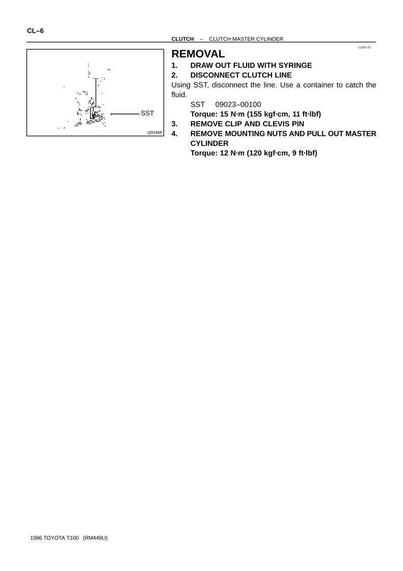
CL029−01
Q02468
SST
CL−6−CLUTCH CLUTCH MASTER CYLINDER
1996 TOYOTA T100 (RM449U)
REMOVAL1. DRAW OUT FLUID WITH SYRINGE2. DISCONNECT CLUTCH LINEUsing SST, disconnect the line. Use a container to catch thefluid.
SST 09023−00100Torque: 15 N·m (155 kgf·cm, 11 ft·lbf)
3. REMOVE CLIP AND CLEVIS PIN4. REMOVE MOUNTING NUTS AND PULL OUT MASTER
CYLINDERTorque: 12 N·m (120 kgf·cm, 9 ft·lbf)
https://www.truck-manuals.net/

CL02A−01
Q02469
Q02470
−CLUTCH CLUTCH MASTER CYLINDERCL−7
1996 TOYOTA T100 (RM449U)
DISASSEMBLY1. REMOVE RESERVOIR TANK(a) Using a pin punch and hammer, drive out the slotted
spring pin.(b) Remove the reservoir tank and grommet.
2. REMOVE PUSH RODPull back the boot, and using snap ring pliers, remove the snapring.
3. REMOVE PISTON
https://www.truck-manuals.net/

CL02B−01
Z08053
Q02471
Protrusion1.5 − 3.5 mm(0.059 − 0.138 in.)
CL−8−CLUTCH CLUTCH MASTER CYLINDER
1996 TOYOTA T100 (RM449U)
REASSEMBLY1. COAT PARTS WITH LITHIUM SOAP BASE GLYCOL
GREASE, AS SHOWN2. INSERT PISTON INTO CYLINDER3. INSTALL PUSH ROD ASSEMBLY WITH SNAP RING
4. INSTALL RESERVOIR TANK(a) Install the reservoir tank and a new grommet.(b) Using a pin punch and hammer, drive in the slotted spring
pin.
https://www.truck-manuals.net/
CL02C−02
−CLUTCH CLUTCH MASTER CYLINDERCL−9
1996 TOYOTA T100 (RM449U)
INSTALLATIONInstallation is in the reverse order of removal (See page CL−6).HINT:After installation, bleed system and adjust clutch pedal.
https://www.truck-manuals.net/

CL02D−03
Q07554
3RZ−FE: 5VZ−FE:Clutch Line
Bleeder Plug
ReleaseCylinder Body
Clutch LineBleeder Plug
Push Rod
Release Cylinder Body
Boot
PistonSpring
N·m (kgf·cm, ft·lbf) : Specified torque
CL−10−CLUTCH CLUTCH RELEASE CYLINDER
1245Author�: Date�:
1996 TOYOTA T100 (RM449U)
CLUTCH RELEASE CYLINDERCOMPONENTS
https://www.truck-manuals.net/

CL02E−03
Z17113
SST
Q06733
−CLUTCH CLUTCH RELEASE CYLINDERCL−11
1996 TOYOTA T100 (RM449U)
REMOVAL1. DISCONNECT CLUTCH LINEUsing SST, disconnect the line. Use a container to catch thefluid.
SST 09023−00100Torque: 15 N·m (155 kgf·cm, 11 ft·lbf)
2. REMOVE 2 BOLTS AND PULL OUT RELEASE CYL-INDERTorque: 13 N·m (130 kgf·cm, 9 ft·lbf)
https://www.truck-manuals.net/

CL02F−01
Q02475
CL−12−CLUTCH CLUTCH RELEASE CYLINDER
1996 TOYOTA T100 (RM449U)
DISASSEMBLY1. PULL OUT BOOT WITH PUSH ROD2. REMOVE PISTONUsing compressed air, remove the piston with the spring fromthe cylinder.
https://www.truck-manuals.net/

CL02G−01
Z07291
−CLUTCH CLUTCH RELEASE CYLINDERCL−13
1996 TOYOTA T100 (RM449U)
REASSEMBLY1. COAT PISTON WITH LITHIUM SOAP BASE GLYCOL
GREASE, AS SHOWN2. INSTALL PISTON WITH SPRING INTO CYLINDER3. INSTALL BOOT WITH PUSH ROD TO CYLINDER
https://www.truck-manuals.net/

CL02H−02
CL−14−CLUTCH CLUTCH RELEASE CYLINDER
1996 TOYOTA T100 (RM449U)
INSTALLATIONInstallation is in the reverse order of removal (See page CL−11).HINT:After installation, bleed clutch system.
https://www.truck-manuals.net/

CL02I−03
Q08025
Flywheel
� Pilot Bearing
Clutch Disc
Clutch Release Bearing
Clutch Release Fork
Clutch Cover
� Non−reusable part
Clutch ReleaseFork Support
Boot
3RZ−FE:
Clip
Clutch Disc
−CLUTCH CLUTCH UNITCL−15
1250Author�: Date�:
1996 TOYOTA T100 (RM449U)
CLUTCH UNITCOMPONENTS
https://www.truck-manuals.net/

CL02J−01
Q06639
Matchmarks
Q06637
CL−16−CLUTCH CLUTCH UNIT
1996 TOYOTA T100 (RM449U)
REMOVAL1. REMOVE TRANSMISSION FROM ENGINE
W59: See page MT−3R150 (2WD): MT−3R150F (4WD): MT−6
2. REMOVE CLUTCH COVER AND DISC(a) Place matchmarks on the flywheel and clutch cover.(b) Loosen each set bolt one turn at a time until spring tension
is released.(c) Remove the set bolts, and pull off the clutch cover with the
clutch disc.NOTICE:Do not drop the clutch disc.
3. REMOVE BOOT, RELEASE BEARING AND FORKFROM TRANSMISSION
Remove the boot and release bearing together with the fork andthen separate them.
https://www.truck-manuals.net/

CL02K−04
CL0239
CL0373
Q07250
Q02481
Q02482
SST
−CLUTCH CLUTCH UNITCL−17
1996 TOYOTA T100 (RM449U)
INSPECTION1. INSPECT CLUTCH DISC FOR WEAR OR DAMAGEUsing calipers, measure the rivet head depth.
Minimum rivet depth: 0.3 mm (0.012 in.)If necessary, replace the clutch disc.
2. INSPECT CLUTCH DISC RUNOUTUsing a dial indicator, check the disc runout.
Maximum runout: 0.8 mm (0.031 in.)If necessary, replace the clutch disc.
3. INSPECT FLYWHEEL RUNOUTUsing a dial indicator, check the flywheel runout.
Maximum runout: 0.1 mm (0.004 in.)If necessary, replace the flywheel.
4. INSPECT PILOT BEARINGTurn the bearing by hand while applying force in the rotationdirection.If the bearing sticks or has much resistance, replace the pilotbearing.HINT:The bearing is permanently lubricated and requires no clearingor lubrication.
5. IF NECESSARY, REPLACE PILOT BEARING(a) Using SST, remove the pilot bearing.
SST 09303−35011
https://www.truck-manuals.net/

Q02483
SST
Z10062
B
A
N00414
CL−18−CLUTCH CLUTCH UNIT
1996 TOYOTA T100 (RM449U)
(b) Using SST, install a new pilot bearing.SST 09304−30012
HINT:After assembling the pilot bearing to the hub, install sure thatit rotates smoothly.
6. INSPECT DIAPHRAGM SPRING FOR WEARUsing calipers, measure the diaphragm spring for depth andwidth of wear.
MaximumDepth A: 0.6 mm (0.024 in.)Width B: 5.0 mm (0.197 in.)
If necessary, replace the clutch cover.
7. INSPECT RELEASE BEARINGTurn the bearing by hand while applying force in the axial direc-tion.HINT:The bearing is permanently lubricated and requires no cleaningor lubrication.If necessary, replace the release bearing.
https://www.truck-manuals.net/

CL02L−01
Q06647
5VZ−FE 3RZ−FE
SSTFlywheelSide
Q06958
1,47
3
6 2,5
8
Matchmarks
Q06641
SST
Z00762
Q06642
−CLUTCH CLUTCH UNITCL−19
1996 TOYOTA T100 (RM449U)
INSTALLATION1. INSTALL CLUTCH DISC AND CLUTCH COVER ON
FLYWHEEL(a) Insert SST in the clutch disc, and then set them and the
clutch cover in position.SST 09301−00110
(b) Align the matchmarks on the clutch cover and flywheel.(c) Torque the 6 bolts on the clutch cover in the order shown.
Torque: 19 N·m (195 kgf·cm, 14 ft·lbf)HINT:Temporarily tighten the No.1 and No.2 bolts.
2. CHECK DIAPHRAGM SPRING TIP ALIGNMENTUsing a dial indicator with roller instrument, check the dia-phragm spring tip alignment.
Maximum non−alignment: 0.5 mm (0.020 in.)If alignment is not as specified, using SST, adjust the dia-phragm spring tip alignment.
SST 09333−00013
3. APPLY MOLYBDENUM DISULPHIDE LITHIUM BASEGREASE (NLGI NO.2)
(a) Apply release hub grease to the these parts.� Release fork and hub contact point� Release fork and push rod contact point� Release fork pivot point
(b) Apply clutch spline grease.� Clutch disc spline
HINT:Recommended grease part number 08887−01706 (100g).4. INSTALL BOOT, RELEASE BEARING AND FORK TO
TRANSMISSIONInstall the boot and bearing to the release fork, and then installthem to the transmission.
https://www.truck-manuals.net/

CL−20−CLUTCH CLUTCH UNIT
1996 TOYOTA T100 (RM449U)
5. INSTALL TRANSMISSION TO ENGINEW59: See page MT−3R150 (2WD): See page MT−3R150F (4WD):See page MT−6
https://www.truck-manuals.net/

MT – MANUAL TRANSMISSION (R150, R150F)
MANUAL TRANSMISSION SYSTEM MT-1 TROUBLESHOOTING MT-2 MANUAL TRANSMISSION UNIT (2WD) MT-3 MANUAL TRANSMISSION UNIT (4WD) MT-6 MANUAL TRANSMISSION ASSEMBLY MT-11 INPUT SHAFT MT-22 OUTPUT SHAFT MT-25 COUNTER GEAR AND REVERSE IDLER GEAR
MT-34
FRONT BEARING RETAINER OIL SEAL MT-40 EXTENSION HOUSING AND TRANSFER ADAPTOR
MT-42
https://www.truck-manuals.net/

MT04I−02
−MANUAL TRANSMISSION (R150, R150F) MANUAL TRANSMISSION SYSTEMMT−1
1256Author�: Date�:
1996 TOYOTA T100 (RM449U)
MANUAL TRANSMISSION SYSTEMPRECAUTIONWhen working with FIPG material, you must observe the following items.� Using a razor blade and gasket scraper, remove all the old FIPG material from the gasket sur-
faces.� Thoroughly clean all components to remove all the loose material.� Clean both sealing surfaces with a non−residue solvent.� Apply FIPG in an approx. 1 mm (0.04 in.) wide bead along the sealing surface.� Parts must be assembled within 10 minutes of application. Otherwise, the FIPG material must
be removed and reapplied.
https://www.truck-manuals.net/

MT04J−01
MT−2−MANUAL TRANSMISSION (R150, R150F) TROUBLESHOOTING
1257Author�: Date�:
1996 TOYOTA T100 (RM449U)
TROUBLESHOOTINGPROBLEM SYMPTOMS TABLEUse the table below to help you find the cause of the problem. The numbers indicate the priority of the likelycause of the problem. Check each part in order. If necessary, replace these parts.
Symptom Suspect Area See page
Noise
1. Oil (Level low) 2WD
4WD
2. Oil (Wrong) 2WD
4WD
3. Gear (Worn or damaged)
4. Bearing (Worn or damaged)
MT−4
MT−7
MT−4
MT−7
MT−11
MT−11
Oil leakage
1. Oil (Level too high) 2WD
4WD
2. Gasket (Damaged)
3. Oil seal (Worn or damaged)
4. O−Ring (Worn or damaged)
MT−4
MT−7
MT−11
MT−11
MT−11
Hard to shift or will not shift
1. Synchronizer ring (Worn or damaged)
2. Shift key spring (Damaged)
MT−22
MT−25
MT−34
MT−25
MT−34
Jumps out of gear
1. Locking ball spring (Damaged)
2. Shift fork (Worn)
3. Gear (Worn or damaged)
4. Bearing (Worn or damaged)
MT−11
MT−11
MT−11
MT−11
https://www.truck-manuals.net/

MT04K−04
D10947
−MANUAL TRANSMISSION (R150, R150F) MANUAL TRANSMISSION UNIT (2WD)MT−3
1258Author�: Date�:
1996 TOYOTA T100 (RM449U)
MANUAL TRANSMISSION UNIT (2WD)COMPONENTS
https://www.truck-manuals.net/

MT0501
Down
Cloth Counterclockwise
MT0ER−01
D10948
MT−4−MANUAL TRANSMISSION (R150, R150F) MANUAL TRANSMISSION UNIT (2WD)
1996 TOYOTA T100 (RM449U)
REMOVAL1. REMOVE TRANSMISSION WITH ENGINE (See page
EM−65)2. REMOVE REAR END PLATERemove the 4 bolts, nuts and rear end plate.
Torque:37 N·m (380 kgf·cm, 27 ft·lbf)3. REMOVE STARTERRemove the 2 bolts and starter.
Torque:39 N·m (400 kgf·cm, 29 ft·lbf)
4. REMOVE TRANSMISSION FROM ENGINE(a) Remove the 6 transmission mounting bolts from the en-
gine.Torque:72 N·m (730 kgf·cm, 53 ft·lbf)
(b) Pull out the transmission toward the rear.5. REMOVE ENGINE REAR MOUNTING(a) Remove the 4 bolts and engine rear mounting.
Torque:25 N·m (250 kgf·cm, 18 ft·lbf)(b) Lower the front side of the transmission and remove it
from the front side of the vehicle.
https://www.truck-manuals.net/

MT04M−03
−MANUAL TRANSMISSION (R150, R150F) MANUAL TRANSMISSION UNIT (2WD)MT−5
1996 TOYOTA T100 (RM449U)
INSTALLATIONInstallation is in the reverse order of removal (See page MT−4).HINT:After installation, do the road test.
https://www.truck-manuals.net/

MT04N−04
D10949
MT−6−MANUAL TRANSMISSION (R150, R150F) MANUAL TRANSMISSION UNIT (4WD)
1261Author�: Date�:
1996 TOYOTA T100 (RM449U)
MANUAL TRANSMISSION UNIT (4WD)COMPONENTS
https://www.truck-manuals.net/

MT0501
Down
Cloth Counterclockwise
MT04O−02
Q06817
Installation
Front
Select Return Spring
Tip of Shift Lever
−MANUAL TRANSMISSION (R150, R150F) MANUAL TRANSMISSION UNIT (4WD)MT−7
1996 TOYOTA T100 (RM449U)
REMOVAL1. REMOVE TRANSMISSION SHIFT LEVER(a) Remove the 4 screws and front console box.(b) Remove the 4 screws and shift lever boot retainer.(c) Cover the shift lever cap with a cloth.(d) Then, pressing down on the shift lever cap, rotate it coun-
terclockwise to remove.(e) Pull out the shift lever.HINT:At the time of installation, please refer to the following item.Apply MP grease to the tip of the shift lever.
2. REMOVE TRANSFER SHIFT LEVERUsing snap ring pliers, remove the snap ring and pull out theshift lever.HINT:At the time of installation, please refer to the following item.Apply MP grease to the tip of shift lever.3. RAISE VEHICLE AND DRAIN TRANSMISSION OIL
Oil grade: API GL−4 or GL−5Viscosity: SAE 75W−90Capacity: 2.2 liters (2.3 US qts, 1.9 Imp. qts)Torque: 37 N·m (380 kgf·cm, 27 ft·lbf)
4. REMOVE FRONT AND REAR PROPELLER SHAFTS(See page PR−10)
5. DISCONNECT SPEEDOMETER CABLE6. DISCONNECT BACK−UP LIGHT SWITCH AND 4WD
INDICATOR SWITCH CONNECTORS7. DISCONNECT CLUTCH RELEASE CYLINDER AND
LINERemove the 4 bolts, release cylinder and line.
Torque: 12 N·m (120 kgf·cm, 9 ft·lbf)
https://www.truck-manuals.net/

Q06824
Q06823
Q06822
Q10111
MT−8−MANUAL TRANSMISSION (R150, R150F) MANUAL TRANSMISSION UNIT (4WD)
1996 TOYOTA T100 (RM449U)
8. REMOVE FRONT EXHAUST PIPE(a) Remove the 2 nuts, gasket and oxygen sensor.(b) Remove the 2 bolts, retainer and gasket.
Torque: 48 N·m (490 kgf·cm, 35 ft·lbf)
(c) Remove the 3 bolts and bracket.Torque: 44 N·m (450 kgf·cm, 33 ft·lbf)
(d) Remove the 3 nuts, front exhaust pipe and 2 gaskets.Torque: 62 N·m (630 kgf·cm, 46 ft·lbf)
9. REMOVE STARTER(a) Disconnect the connector and wire from the starter.(b) Remove the 2 bolts and starter.
Torque: 39 N·m (400 kgf·cm, 29 ft·lbf)
10. REMOVE STIFFENER PLATE (RH AND LH) ANDREAR END PLATE
Remove the 8 bolts, stiffener plate (RH and LH) and rear endplate.
Torque: 37 N·m (380 kgf·cm, 27 ft·lbf)11. REMOVE STABILIZER BAR (See page SA−126)12. JACK UP TRANSMISSION SLIGHTLYUsing a transmission jack, support the transmission.13. REMOVE CROSSMEMBER(a) Remove the 4 set bolts of the engine rear mounting.
Torque: 13 N·m (130 kgf·cm, 9 ft·lbf)(b) Remove the 8 bolts and crossmember.
Torque: 95 N·m (970 kgf·cm, 70 ft·lbf)
14. REMOVE TRANSMISSION WITH TRANSFER(a) Remove the 6 transmission mounting bolts from the en-
gine.Torque: 72 N·m (730 kgf·cm, 53 ft·lbf)
(b) Disconnect the 3 wire clamps from the transmission.(c) Pull out the transmission with the transfer down and to-
ward the rear.15. REMOVE ENGINE REAR MOUNTINGRemove the 4 bolts and engine rear mounting.
Torque: 25 N·m (250 kgf·cm, 18 ft·lbf)
https://www.truck-manuals.net/

Q06907
−MANUAL TRANSMISSION (R150, R150F) MANUAL TRANSMISSION UNIT (4WD)MT−9
1996 TOYOTA T100 (RM449U)
16. REMOVE TRANSFER FROM TRANSMISSION(a) Remove the transfer adaptor rear mounting bolts.
Torque: 37 N·m (380 kgf·cm, 27 ft·lbf)(b) Pull the transfer straight up and remove it from the trans-
mission.HINT:Take care not to damage the adaptor rear oil seal with the trans-fer input gear spline.HINT:At the time of installation, please refer to the following item.Apply MP grease to the adaptor oil seal and shift the 2 shift forkshafts to the high − 4 position.
https://www.truck-manuals.net/

MT04P−04
MT−10−MANUAL TRANSMISSION (R150, R150F) MANUAL TRANSMISSION UNIT (4WD)
1996 TOYOTA T100 (RM449U)
INSTALLATIONInstallation is in the reverse order of removal (See page MT−7).HINT:After installation, do the road test.
https://www.truck-manuals.net/

MT04Q−04
D10950
−MANUAL TRANSMISSION (R150, R150F) MANUAL TRANSMISSION ASSEMBLYMT−11
1266Author�: Date�:
1996 TOYOTA T100 (RM449U)
MANUAL TRANSMISSION ASSEMBLYCOMPONENTS
https://www.truck-manuals.net/

Z15461
Output Shaft AssemblySpeedometer Drive Gear
Snap Ring
Ball
Bearing
Spacer
� Bearing
Input Shaft
Synchronizer Ring
Rear Bearing Retainer
Gear Spline Piece No.5
Synchronizer Cone Ring
Hub Sleeve No.3
Reverse Idler Gear
Shifting Key SpringShaft
Ball
Shifting Key
Counter 5th Gear
Reverse SynchronizerPull Ring
5th Synchronizer Ring
Reverse Synchronizer RingThrust Washer
Counter Gear Rear Bearing
Shift Fork Shaft No.2
Needle Roller Bearing
Straight Pin
Intermediate Plate
Counter Gear
� Front Bearing
Interlock Pin
Straight Pin
Shift Fork Shaft No.1
Slotted Spring Pin
Shift Fork No.32WD:
2WD:
Shift Fork No.1
Reverse Idler GearMagnet
Shift Fork Shaft No.3
Shift Lever HousingShift and Select Lever
Shift Lever HousingShift and Select Lever
4WD:
�
Reverse Shift Arm Bracket
Reverse Shift ArmE−Ring
Reverse Shift Fork
Shift Fork ShaftNo.4
� Non−reusable part� Precoated part
� Bearing
Snap Ring
Snap Ring
Snap Ring
Snap Ring
Snap Ring
Snap Ring
Snap Ring
�
�
Spring
Shift Fork No.2�
�
Interlock Pin
Snap Ring
Interlock Pin
Snap Ring
Snap Ring
MT−12−MANUAL TRANSMISSION (R150, R150F) MANUAL TRANSMISSION ASSEMBLY
1267Author�: Date�:
1996 TOYOTA T100 (RM449U)
https://www.truck-manuals.net/

MT04R−01
Q06902
FIPG
−MANUAL TRANSMISSION (R150, R150F) MANUAL TRANSMISSION ASSEMBLYMT−13
1996 TOYOTA T100 (RM449U)
DISASSEMBLY1. REMOVE BACK−UP LIGHT SWITCH
Torque: 44 N·m (450 kgf·cm, 32 ft·lbf)2. 2WD:
REMOVE SPEEDOMETER DRIVEN GEARRemove the driven gear lock plate set bolt and driven gear.
Torque: 11 N·m (115 kgf·cm, 8 ft·lbf)3. REMOVE CLUTCH HOUSING FROM TRANSMISSION
CASERemove the 9 bolts and clutch housing from the transmissioncase.
Torque: 36 N·m (370 kgf·cm, 27 ft·lbf)4. REMOVE CONTROL SHIFT LEVER RETAINER(a) Remove the 6 (2WD) or 4 (4WD) bolts.
Torque: 18 N·m (185 kgf·cm, 13 ft·lbf)(b) Remove the retainer and gasket (2WD) or oil deflector
(4WD).5. REMOVE 2 RESTRICT PINS
Torque: 37 N·m (380 kgf·cm, 27 ft·lbf)
6. 2WD:REMOVE EXTENSION HOUSING
(a) Remove the shift lever housing set bolt.Torque: 38 N·m (390 kgf·cm, 28 ft·lbf)
(b) Remove the 10 bolts.Torque: 37 N·m (380 kgf·cm, 27 ft·lbf)
(c) Using a plastic hammer, tap the extension housing, re-move the shift lever housing and shift and select lever.FIPG:Part No. 08826 − 00090, THREE BOND 1281 orequivalent
https://www.truck-manuals.net/

Q06901
FIPG
Q06900
FIPG
x8
Q06903
FIPG
MT−14−MANUAL TRANSMISSION (R150, R150F) MANUAL TRANSMISSION ASSEMBLY
1996 TOYOTA T100 (RM449U)
7. 4WD:REMOVE TRANSFER ADAPTOR
(a) Remove the shift lever housing set bolt.Torque: 38 N·m (390 kgf·cm, 28 ft·lbf)
(b) Remove the 10 bolts.Torque: 37 N·m (380 kgf·cm, 27 ft·lbf)
(c) Using a plastic hammer, tap the transfer adaptor, removethe shift lever housing and the shift and select lever.FIPG:Part No. 08826 − 00090, THREE BOND 1281 orequivalent
8. REMOVE FRONT BEARING RETAINER(a) Remove the 8 bolts.
Sealant:Part No. 08833 − 00080, THREE BOND 1344, LOCTITE242 or equivalentTorque: 17 N·m (170 kgf·cm, 12 ft·lbf)
(b) Using a plastic hammer, tap the front bearing retainer.FIPG:Part No. 08826 − 00090, THREE BOND 1281 orequivalent
9. REMOVE BEARING SNAP RINGUsing a snap ring expander, remove the 2 snap rings.
10. SEPARATE INTERMEDIATE PLATE FROM TRANS-MISSION CASE
(a) Using a brass bar and hammer, carefully tap the transmis-sion case.
(b) Remove the transmission case from the intermediateplate.
HINT:At the time of reassembly, please refer to the following item.Align the each bearing outer race, each fork shaft end and re-verse idler gear shaft end with the case installation holes.
https://www.truck-manuals.net/

Q06785
Q06905
Q06764
−MANUAL TRANSMISSION (R150, R150F) MANUAL TRANSMISSION ASSEMBLYMT−15
1996 TOYOTA T100 (RM449U)
FIPG:Part No. 08826 − 00090, THREE BOND 1281 orequivalent
11. REMOVE MAGNET FROM INTERMEDIATE PLATE
12. MOUNT INTERMEDIATE PLATE IN VISE(a) Use the 2 clutch housing bolts, plate washers and suit-
able nuts, as shown.HINT:Increase or decrease plate washers so that the bolt tip does notprotrude from the nut.(b) Mount the intermediate plate in a vise.
13. REMOVE STRAIGHT SCREW PLUG, LOCKING BALLAND SPRING
(a) Using a hexagon wrench, remove the 4 plugs.Sealant:Part No. 08833 − 00080, THREE BOND 1344, LOCTITE242 or equivalentTorque: 19 N·m (190 kgf·cm, 14 ft·lbf)
(b) Using a magnetic finger, remove the 3 springs and balls.14. REMOVE SHIFT FORK SET BOLTRemove the 2 bolts from the shift forks No.1 and No.2.
Torque: 20 N·m (200 kgf·cm, 14 ft·lbf)15. REMOVE SLOTTED SPRING PINUsing a pin punch and hammer, drive out the pin from the shiftfork No.3.
16. REMOVE SNAP RINGUsing 2 screwdrivers and a hammer, tap out the 4 snap ringsfrom each shift fork shaft.
https://www.truck-manuals.net/

Q06766
Q06763
Q06768
Q06904
Q06771
MT−16−MANUAL TRANSMISSION (R150, R150F) MANUAL TRANSMISSION ASSEMBLY
1996 TOYOTA T100 (RM449U)
17. REMOVE SHIFT FORK SHAFT NO.2 AND SHIFT FORKNO.2
(a) Pull out the shift fork shaft No.2 from the shift forks No.1,No.2 and intermediate plate.
(b) Remove the shift fork No.2 from the groove of hub sleeveNo.2.
(c) Using a magnetic finger, remove the interlock pin from theintermediate plate.
18. REMOVE SHIFT FORK SHAFT NO.1 AND SHIFT FORKNO.1
(a) Pull out the shift fork shaft No.1 with the straight pin fromthe shift fork No.1 and intermediate plate.
(b) Remove the shift fork No.1 from the groove of reversegear.
(c) Using a magnetic finger, remove the interlock pin from theintermediate plate.
19. REMOVE SHIFT FORK SHAFT NO.3 AND SHIFT FORKNO.3
(a) Pull out the shift fork shaft No.3 from the shift fork No.3,reverse shift fork and intermediate plate.
(b) Remove the shift fork No.3 from the groove of hub sleeveNo.3.
(c) Using a magnetic finger, remove the interlock pin from theintermediate plate.
20. REMOVE SHIFT FORK SHAFT NO.4(a) Using a magnetic finger, remove the ball.(b) Pull out the shift fork shaft No.4 from the reverse shift fork
and intermediate plate.NOTICE:Take care of the ball in the reverse shift fork. It will springout when you pull out the shift fork shaft No.4.(c) Using a magnetic finger, remove the spring from the re-
verse shift fork.
21. REMOVE REVERSE SHIFT FORK AND ARM(a) Remove the reverse shift fork and arm.HINT:At the time of reassembly, please refer to the following item.Align the reverse shift arm to the pivot of the reverse shift armbracket.(b) Using a screwdriver, remove the E−ring.(c) Separate the reverse shift fork and arm.
https://www.truck-manuals.net/

RM0063
RM0072
−MANUAL TRANSMISSION (R150, R150F) MANUAL TRANSMISSION ASSEMBLYMT−17
1996 TOYOTA T100 (RM449U)
22. REMOVE REVERSE SHIFT ARM BRACKETRemove the 2 bolts and reverse shift arm bracket.
Torque: 18 N·m (185 kgf·cm, 13 ft·lbf)
23. 2WD:REMOVE SPEEDOMETER DRIVE GEAR
(a) Using 2 screwdrivers and a hammer, tap out the rear snapring, and remove the drive gear and ball.
(b) Using 2 screwdrivers and a hammer, tap out the frontsnap ring, and remove the drive gear.
24. REMOVE OUTPUT SHAFT REAR BEARING(a) Using 2 screwdrivers and a hammer, tap out the snap
ring.HINT:At the time of reassembly, please refer to the following item.Select a snap ring that allows the minimum axial play.
Mark Thickness mm (in.)
A 2.65 − 2.70 (0.1043 − 0.1063)
B 2.70 − 2.75 (0.1063 − 0.1083)
C 2.75 − 2.80 (0.1083 − 0.1102)
D 2.80 − 2.85 (0.1102 − 0.1122)
E 2.85 − 2.90 (0.1122 − 0.1142)
F 2.90 − 2.95 (0.1142 − 0.1161)
G 2.95 − 3.00 (0.1161 − 0.1181)
H 3.00 − 3.05 (0.1181 − 0.1201)
J 3.05 − 3.10 (0.1201 − 0.1220)
K 3.10 − 3.15 (0.1220 − 0.1240)
L 3.15 − 3.20 (0.1240 − 0.1260)
M 3.20 − 3.25 (0.1260 − 0.1280)
N 3.25 − 3.30 (0.1280 − 0.1299)
P 3.30 − 3.35 (0.1299 − 0.1319)
Q 3.35 − 3.40 (0.1319 − 0.1339)
R 3.40 − 3.45 (0.1339 − 0.1358)
S 3.45 − 3.50 (0.1358 − 0.1378)
https://www.truck-manuals.net/

Z14821
SST4WD:
Z14820
SST2WD:
RM0070
SST2WD:
RM0071
SST
4WD:
Q06786
MT−18−MANUAL TRANSMISSION (R150, R150F) MANUAL TRANSMISSION ASSEMBLY
1996 TOYOTA T100 (RM449U)
(b) Using SST, remove the rear bearing.SST 09950−40010
HINT:At the time of reassembly, please refer to the following items.� 2WD:
Using SST and a hammer, drive in a new bearing.SST 09309−35010
� 4WD:Using SST and a hammer, drive in a new bearing.SST 09316−60011 (09316−00011, 09316−00071)
25. REMOVE SPACER
26. INSPECT COUNTER 5TH GEAR THRUST CLEAR-ANCE
Using a feeler gauge, measure the counter 5th gear thrustclearance.
Standard clearance:0.10 − 0.35 mm (0.0039 − 0.0138 in.)Maximum clearance:0.40 mm (0.0157 in.)
https://www.truck-manuals.net/

Q06688
Q06605
SST
RM0024
SST
−MANUAL TRANSMISSION (R150, R150F) MANUAL TRANSMISSION ASSEMBLYMT−19
1996 TOYOTA T100 (RM449U)
27. REMOVE GEAR SPLINE PIECE NO.5, SYNCHRONIZ-ER RING, NEEDLE ROLLER BEARING AND COUNT-ER 5TH GEAR WITH HUB SLEEVE NO.3
(a) Using 2 screwdrivers and a hammer, tap out the snapring.
HINT:At the time of reassembly, please refer to the following item.Select a snap ring that allows the minimum axial play.
Mark Thickness mm (in.)
A 2.80 − 2.85 (0.1102 − 0.1122)
B 2.85 − 2.90 (0.1122 − 0.1142)
C 2.90 − 2.95 (0.1142 − 0.1161)
D 2.95 − 3.00 (0.1161 − 0.1181)
E 3.00 − 3.05 (0.1181 − 0.1201)
F 3.05 − 3.10 (0.1201 − 0.1220)
G 3.10 − 3.15 (0.1220 − 0.1240)
(b) Using SST, remove the gear spline piece No.5.SST 09950−50010
(c) Remove the counter 5th gear with the hub sleeve No.3.
HINT:At the time of reassembly, please refer to the following items.� Using SST and a hammer, drive in the gear spline piece
No.5 with the synchronizer ring slots aligned with the shift-ing keys.SST 09316−60011 (09316−00011)
� When installing the gear spline piece No.5, support thecounter gear in front with a 1.4 − 2.3 kg (3 − 5 lb) hammeror equivalent.
28. REMOVE THRUST WASHER AND BALL FROMCOUNTER GEAR
29. REMOVE REAR BEARING RETAINERRemove the 4 bolts and rear bearing retainer.HINT:At the time of reassembly, please refer to the following item.Align the rear bearing retainer to the reverse idler gear shaftgroove.
Torque: 18 N·m (185 kgf·cm, 13 ft·lbf)
https://www.truck-manuals.net/

Z03540
RM0010
Q07393
SST
Q07552
SST SST
25 mm
MT−20−MANUAL TRANSMISSION (R150, R150F) MANUAL TRANSMISSION ASSEMBLY
1996 TOYOTA T100 (RM449U)
30. REMOVE REVERSE IDLER GEAR AND SHAFTPull out the shaft toward the rear.HINT:At the time of the reassembly, please refer to the following item.Align the reverse shift arm to the reverse idler gear shaft.31. REMOVE OUTPUT SHAFT CENTER BEARING SNAP
RINGUsing a snap ring expander, remove the snap ring.
32. REMOVE OUTPUT SHAFT AND COUNTER GEARFROM INTERMEDIATE PLATE
(a) Remove the output shaft, counter gear and input shaft asa unit from the intermediate plate by pulling on the countergear and tapping on the intermediate plate with a plastichammer.
(b) Remove the input shaft with the needle roller bearing fromthe output shaft.
33. REMOVE COUNTER REAR BEARING FROM INTER-MEDIATE PLATE
Using SST and a hammer, remove the counter rear bearing.SST 09950−60010 (09951−00620), 09950−70010
(09951−07150)
34. 2WD:IF NECESSARY, REPLACE SPEEDOMETER DRIVENGEAR OIL SEAL
(a) Using SST, remove the oil seal.SST 09921−00010
(b) Coat the lip of oil seal with MP grease.(c) Using SST, drive in a new oil seal.
SST 09201−10000 (09201−01080), 09950−70010(09951−07150)
Drive in depth: 25 mm (0.98 in.)
https://www.truck-manuals.net/

MT04S−05
−MANUAL TRANSMISSION (R150, R150F) MANUAL TRANSMISSION ASSEMBLYMT−21
1996 TOYOTA T100 (RM449U)
REASSEMBLYReassembly is in the reverse order of disassembly (See page MT−13).HINT:Coat all of the sliding and rotating surfaces with gear oil before reassembly.
https://www.truck-manuals.net/

MT04T−01
WM0301
Snap Ring
� Bearing
Input Shaft
Bearing
Synchronizer Ring
� Non−reusable part
MT−22−MANUAL TRANSMISSION (R150, R150F) INPUT SHAFT
1277Author�: Date�:
1996 TOYOTA T100 (RM449U)
INPUT SHAFTCOMPONENTS
https://www.truck-manuals.net/

Q00550
MT04U−01
Z03541
−MANUAL TRANSMISSION (R150, R150F) INPUT SHAFTMT−23
1996 TOYOTA T100 (RM449U)
INSPECTIONINSPECT SYNCHRONIZER RING(a) Check for wear or damage.(b) Check the braking effect of the synchronizer ring.
Turn the synchronizer ring in one direction while pushingit to the gear cone. Check that the ring locks.
If the braking effect is insufficient, apply a small amount of thefine lapping compound between the synchronizer ring and gearcone. Lightly rub the synchronizer ring and gear cone together.NOTICE:Ensure the fine lapping compound is completely washedoff after rubbing.(c) Check again the braking effect of the synchronizer ring.
(d) Using a feeler gauge, measure the clearance betweenthe synchronizer ring back and gear spline end.Minimum clearance: 0.8 mm (0.031 in.)
If the clearance is less than the minimum, replace the synchro-nizer ring, and apply a small amount of the fine lapping com-pound on gear cone.NOTICE:Ensure the fine lapping compound is completely washedoff after rubbing.
https://www.truck-manuals.net/

MT04V−01
Z03543
Z03544
SST
Z03545
MT−24−MANUAL TRANSMISSION (R150, R150F) INPUT SHAFT
1996 TOYOTA T100 (RM449U)
REPLACEMENTIF NECESSARY, REPLACE INPUT SHAFT BEARING(a) Using a snap ring expander, remove the snap ring.(b) Using a press, remove the bearing.
(c) Using SST and a press, install a new bearing.SST 09506−35010
(d) Select a snap ring that allows minimum axial play.
Mark Thickness mm (in.)
A 2.10 − 2.15 (0.0827 − 0.0846)
B 2.15 − 2.20 (0.0846 − 0.0866)
C 2.20 − 2.25 (0.0866 − 0.0886)
D 2.25 − 2.30 (0.0886 − 0.0906)
E 2.30 − 2.35 (0.0906 − 0.0925)
F 2.35 − 2.40 (0.0925 − 0.0945)
G 2.40 − 2.45 (0.0945 − 0.0965)
(e) Using a snap ring expander, install the snap ring.
https://www.truck-manuals.net/

MT04W−05
D10951
−MANUAL TRANSMISSION (R150, R150F) OUTPUT SHAFTMT−25
1280Author�: Date�:
1996 TOYOTA T100 (RM449U)
OUTPUT SHAFTCOMPONENTS
https://www.truck-manuals.net/
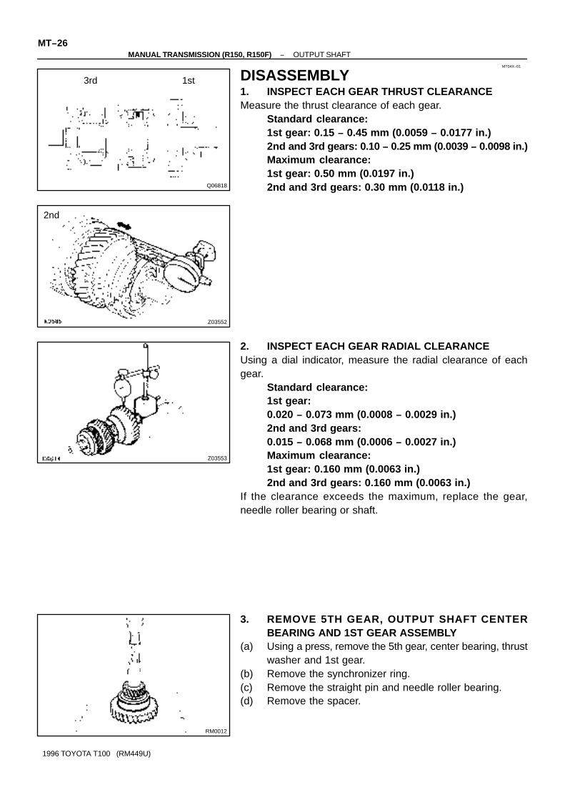
MT04X−01
Q06818
3rd 1st
Z03552
2nd
Z03553
RM0012
MT−26−MANUAL TRANSMISSION (R150, R150F) OUTPUT SHAFT
1996 TOYOTA T100 (RM449U)
DISASSEMBLY1. INSPECT EACH GEAR THRUST CLEARANCEMeasure the thrust clearance of each gear.
Standard clearance:1st gear: 0.15 − 0.45 mm (0.0059 − 0.0177 in.)2nd and 3rd gears: 0.10 − 0.25 mm (0.0039 − 0.0098 in.)Maximum clearance:1st gear: 0.50 mm (0.0197 in.)2nd and 3rd gears: 0.30 mm (0.0118 in.)
2. INSPECT EACH GEAR RADIAL CLEARANCEUsing a dial indicator, measure the radial clearance of eachgear.
Standard clearance:1st gear:0.020 − 0.073 mm (0.0008 − 0.0029 in.)2nd and 3rd gears:0.015 − 0.068 mm (0.0006 − 0.0027 in.)Maximum clearance:1st gear: 0.160 mm (0.0063 in.)2nd and 3rd gears: 0.160 mm (0.0063 in.)
If the clearance exceeds the maximum, replace the gear,needle roller bearing or shaft.
3. REMOVE 5TH GEAR, OUTPUT SHAFT CENTERBEARING AND 1ST GEAR ASSEMBLY
(a) Using a press, remove the 5th gear, center bearing, thrustwasher and 1st gear.
(b) Remove the synchronizer ring.(c) Remove the straight pin and needle roller bearing.(d) Remove the spacer.
https://www.truck-manuals.net/

Z03548
Q00888
Z03550
−MANUAL TRANSMISSION (R150, R150F) OUTPUT SHAFTMT−27
1996 TOYOTA T100 (RM449U)
4. REMOVE REVERSE GEAR ASSEMBLY AND 2NDGEAR ASSEMBLY
(a) Using 2 screwdrivers and a hammer, tap out the snapring.
(b) Using a press, remove the reverse gear assembly and2nd gear assembly.
(c) Remove the needle roller bearing.
5. REMOVE REVERSE GEAR, SHIFTING KEY ANDSPRING FROM CLUTCH HUB NO.1
(a) Remove the reverse gear from the clutch hub No.1.(b) Push the shifting key spring with a screwdriver, remove
the 3 shifting keys and key springs.
6. REMOVE HUB SLEEVE NO.2 ASSEMBLY AND 3RDGEAR ASSEMBLY
(a) Using a snap ring expander, remove the snap ring.(b) Using a press, remove the hub sleeve No.2 assembly and
3rd gear assembly.(c) Remove the needle roller bearing.7. REMOVE SHIFTING KEY AND SPRING FROM HUB
SLEEVE NO.2 ASSEMBLYUsing a screwdriver, remove the 3 shifting keys and 2 springs.
https://www.truck-manuals.net/

Z03554
MT04Y−05
Z03555
A B C
Z03556
WM0064
MT−28−MANUAL TRANSMISSION (R150, R150F) OUTPUT SHAFT
1996 TOYOTA T100 (RM449U)
INSPECTION1. INSPECT OUTPUT SHAFT(a) Using a micrometer, measure the output shaft flange
thickness.Minimum thickness: 4.70 mm (0.1850 in.)
If the thickness is less than the minimum, replace the outputshaft.
(b) Using a micrometer, measure the outer diameter of theoutput shaft journal.Minimum diameter:A 1st gear: 38.860 mm (1.5299 in.)B 2nd gear: 46.860 mm (1.8449 in.)C 3rd gear: 37.860 mm (1.4905 in.)
If the outer diameter is less than the minimum, replace the out-put shaft.
(c) Using a dial indicator, check the shaft runout.Maximum runout: 0.06 mm (0.0024 in.)
If the runout exceeds the maximum, replace the output shaft.
2. INSPECT 1ST AND 3RD GEARS SYNCHRONIZERRING
(a) Check for wear or damage.(b) Check the braking effect of the synchronizer ring.
Turn the synchronizer ring in one direction while pushingit to the gear cone. Check that the ring locks.
If the braking effect is insufficient, apply a small amount of thefine lapping compound between the synchronizer ring and gearcone. Lightly rub the synchronizer ring and gear cone together.NOTICE:Ensure the fine lapping compound is completely washedoff after rubbing.(c) Check again the braking effect of the synchronizer ring.
https://www.truck-manuals.net/

WM0065
Q00930
MT0780
D10952
WM0066
−MANUAL TRANSMISSION (R150, R150F) OUTPUT SHAFTMT−29
1996 TOYOTA T100 (RM449U)
(d) Using a feeler gauge, measure the clearance betweenthe synchronizer ring back and gear spline end.Minimum clearance: 0.8 mm (0.031 in.)
If the clearance is less than the minimum, replace the synchro-nizer ring, and apply a small amount of the fine lapping com-pound on gear cone.NOTICE:Ensure the fine lapping compound is completely washedoff after rubbing.
3. INSPECT 2ND GEAR SYNCHRONIZER RING(a) Check for wear or damage.(b) Install the synchronizer inner ring, middle ring and outer
ring to each gear.
(c) Check the braking effect of the synchronizer ring. Turn thesynchronizer ring in one direction while pushing it to thegear cone. Check that the ring locks.
If it does not lock, replace the synchronizer ring.
(d) Using a feeler gauge, measure the clearance betweenthe synchronizer ring back and gear spline end.Minimum clearance: 0.8 mm (0.031 in.)
If the clearance is less than the minimum, replace the synchro-nizer ring.
4. INSPECT SHIFT FORK AND HUB SLEEVE CLEAR-ANCE
Using a feeler gauge, measure the clearance between the hubsleeve and shift fork.
Maximum clearance: 1.0 mm (0.039 in.)If the clearance exceeds the maximum, replace the shift fork orhub sleeve.
https://www.truck-manuals.net/

MT04Z−01
Q06699
Front
Q00888
Q06700
Front
Z03558
MT−30−MANUAL TRANSMISSION (R150, R150F) OUTPUT SHAFT
1996 TOYOTA T100 (RM449U)
REASSEMBLYHINT:Coat all of the sliding and rotating surfaces with gear oil beforereassembly.1. INSTALL CLUTCH HUB NO.2 INTO HUB SLEEVE NO.2(a) Install the clutch hub No.2 and shifting keys to the hub
sleeve No.2.(b) Install the shifting key springs under the shifting keys.NOTICE:Position the key springs so that their end gaps are notaligned.
2. INSTALL CLUTCH HUB NO.1 INTO REVERSE GEAR(a) Install the 3 shifting key springs to the clutch hub No.1.(b) While pushing the shifting key spring with a screwdriver,
install the 3 shifting keys.
(c) While pushing the 3 shifting keys, install the clutch hubNo.1 to the reverse gear, as shown.
3. INSTALL 3RD GEAR AND HUB SLEEVE NO.2 ONOUTPUT SHAFT
(a) Apply gear oil to the shaft and needle roller bearing.(b) Place the synchronizer ring on the gear and align the ring
slots with the shifting keys.(c) Install the needle roller bearing in the 3rd gear.
https://www.truck-manuals.net/

GM0060
WM0116
RM0023
−MANUAL TRANSMISSION (R150, R150F) OUTPUT SHAFTMT−31
1996 TOYOTA T100 (RM449U)
(d) Using a press, install the 3rd gear and hub sleeve No.2.
4. INSTALL SNAP RING(a) Select a snap ring that allows the minimum axial play.
Mark Thickness mm (in.)
A 1.80 − 1.85 (0.0709 − 0.0728)
B 1.85 − 1.90 (0.0728 − 0.0748)
C 1.90 − 1.95 (0.0748 − 0.0768)
D 1.95 − 2.00 (0.0768 − 0.0787)
E 2.00 − 2.05 (0.0787 − 0.0807)
F 2.05 − 2.10 (0.0807 − 0.0827)
G 2.10 − 2.15 (0.0827 − 0.0846)
(b) Using a snap ring expander, install the snap ring.5. INSPECT 3RD GEAR THRUST CLEARANCE
(See page MT−26)6. INSTALL 2ND GEAR AND REVERSE GEAR(a) Apply gear oil to the shaft and needle roller bearing.(b) Place the synchronizer ring on the gear and align the ring
slots with the shifting keys.(c) Align the projection of the synchronizer inner ring with the
slots of the clutch hub No.1.(d) Install the needle roller bearing in the 2nd gear.
(e) Using a press, install the 2nd gear assembly and reversegear assembly.
https://www.truck-manuals.net/

Z03560
Z03563
Z03564
Z03565
2WD: 4WD:
SST SST
MT−32−MANUAL TRANSMISSION (R150, R150F) OUTPUT SHAFT
1996 TOYOTA T100 (RM449U)
7. INSTALL SNAP RING(a) Select a snap ring that allows the minimum axial play.
Mark Thickness mm (in.)
A 2.30 − 2.35 (0.0906 − 0.0925)
B 2.35 − 2.40 (0.0925 − 0.0945)
C 2.40 − 2.45 (0.0945 − 0.0965)
D 2.45 − 2.50 (0.0965 − 0.0984)
E 2.50 − 2.55 (0.0984 − 0.1004)
F 2.55 − 2.60 (0.1004 − 0.1024)
G 2.60 − 2.65 (0.1024 − 0.1043)
(b) Using a screwdriver and hammer, install the snap ring.
8. INSTALL SPACER AND 1ST GEAR ASSEMBLY(a) Install the spacer on the output shaft.(b) Apply gear oil to the needle roller bearing.(c) Assemble the 1st gear, synchronizer ring and needle roll-
er bearing.(d) Install the assembly on the output shaft with the synchro-
nizer ring slots aligned with the shifting keys.
9. INSTALL STRAIGHT PIN AND 1ST GEAR THRUSTWASHER
Install the 1st gear thrust washer onto the output shaft with thestraight pin aligned with the 1st gear thrust washer.
10. INSTALL OUTPUT SHAFT CENTER BEARING(a) 2WD:
Using SST and a hammer, drive in the bearing with theouter race snap ring groove toward the rear.SST 09309−35010
(b) 4WD:Using SST and a hammer, drive in the bearing with theouter race snap ring groove toward the rear.SST 09316−60011 (09316−00011, 09316−00071)
https://www.truck-manuals.net/

Z03568
SST
−MANUAL TRANSMISSION (R150, R150F) OUTPUT SHAFTMT−33
1996 TOYOTA T100 (RM449U)
11. INSPECT 1ST GEAR THRUST CLEARANCE(See page MT−26)
12. INSPECT 2ND GEAR THRUST CLEARANCE(See page MT−26)
13. INSTALL 5TH GEARUsing SST and a press, install the 5th gear.
SST 09316−60011 (09316−00031)
https://www.truck-manuals.net/

MT050−01
Z15462
Snap Ring
Counter Gear
Reverse Idler Gear Shaft
� Counter Gear Front Bearing
Reverse Idler Gear
Gear Spline Piece No.5
Synchronizer Cone Ring
Hub Sleeve No.3
Counter 5th Gear
Needle Roller Bearing
Straight Pin
Thrust Washer
Counter Gear Rear Bearing
� Non−reusable part
Reverse Synchronizer Ring
Shifting KeyShifting Key Spring
5th Synchronizer Ring
Reverse Synchronizer Pull Ring
Snap Ring
MT−34−MANUAL TRANSMISSION (R150, R150F) COUNTER GEAR AND REVERSE IDLER GEAR
1289Author�: Date�:
1996 TOYOTA T100 (RM449U)
COUNTER GEAR AND REVERSE IDLER GEARCOMPONENTS
https://www.truck-manuals.net/

MT051−01
Q07459
Q06828
Q06829
−MANUAL TRANSMISSION (R150, R150F) COUNTER GEAR AND REVERSE IDLER GEARMT−35
1996 TOYOTA T100 (RM449U)
DISASSEMBLYREMOVE HUB SLEEVE NO.3, SHIFTING KEY AND SPRINGFROM SYNCHRONIZER RING(a) Remove the synchronizer ring assembly from the hub
sleeve No.3.(b) Turn the reverse synchronizer pull ring.
(c) Remove the reverse synchronizer ring and 5th synchro-nizer ring from the synchronizer pull ring and cone ring.
(d) Turn the reverse synchronizer pull ring, separate the pullring and cone ring.
(e) Push the shifting key and spring, and remove the 3 shift-ing keys and springs to the reverse synchronizer ring.
https://www.truck-manuals.net/

MT052−01
Z03569
Q06689
Q06831
Q06832
MT−36−MANUAL TRANSMISSION (R150, R150F) COUNTER GEAR AND REVERSE IDLER GEAR
1996 TOYOTA T100 (RM449U)
INSPECTION1. INSPECT 5TH GEAR RADIAL CLEARANCE(a) Install the spacer, counter 5th gear and needle roller bear-
ings.(b) Using a dial indicator, measure the counter 5th gear radial
clearance.Standard clearance:0.015 − 0.068 mm (0.0006 − 0.0027 in.)Maximum clearance:0.160 mm (0.0063 in.)
If the clearance exceeds the maximum, replace the gear bear-ing or shaft.
2. INSPECT COUNTER GEARUsing a micrometer, measure the outer diameter of the countergear journal.
Minimum diameter: 27.860 mm (1.0968 in.)If the outer diameter is less than the minimum, replace thecounter gear.
3. INSPECT 5TH SYNCHRONIZER RING(a) Check for wear or damage.(b) Install the synchronizer pull ring, cone ring and outer ring
to the gear spline piece No.5.
(c) Check the braking effect of the synchronizer ring. Turn thesynchronizer ring in one direction while pushing it to thegear cone. Check that the ring locks.
If it does not lock, replace the synchronizer ring.
https://www.truck-manuals.net/

WM0066
Q01803
Q06775
−MANUAL TRANSMISSION (R150, R150F) COUNTER GEAR AND REVERSE IDLER GEARMT−37
1996 TOYOTA T100 (RM449U)
4. INSPECT SHIFT FORK AND HUB SLEEVE CLEAR-ANCE
Using a feeler gauge, measure the clearance between the hubsleeve and shift fork.
Maximum clearance: 1.0 mm (0.039 in.)If the clearance exceeds the maximum, replace the shift fork orhub sleeve.
5. INSPECT REVERSE IDLER GEAR RADIAL CLEAR-ANCE
Using a dial indicator, measure the reverse idler gear radialclearance.
Standard clearance:0.040 − 0.082 mm (0.0016 − 0.0032 in.)Maximum clearance:0.130 mm (0.0051 in.)
If the clearance exceeds the maximum, replace the reverseidler gear or reverse idler gear shaft.6. INSPECT REVERSE IDLER GEAR AND SHIFT ARM
CLEARANCEUsing a feeler gauge, measure the clearance between the re-verse idler gear and shift arm.
Standard clearance:0.05 − 0.35 mm (0.0020 − 0.0138 in.)Maximum clearance:0.50 mm (0.0197 in.)
If the clearance exceeds the maximum, replace the shift arm orreverse idler gear.
https://www.truck-manuals.net/
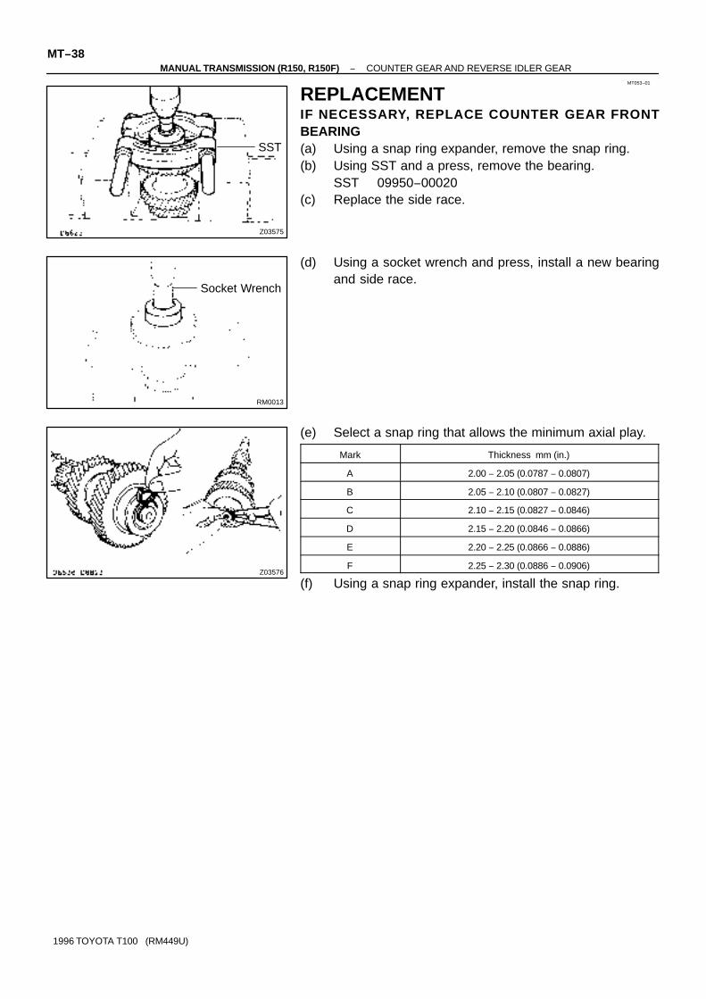
MT053−01
Z03575
SST
RM0013
Socket Wrench
Z03576
MT−38−MANUAL TRANSMISSION (R150, R150F) COUNTER GEAR AND REVERSE IDLER GEAR
1996 TOYOTA T100 (RM449U)
REPLACEMENTIF NECESSARY, REPLACE COUNTER GEAR FRONTBEARING(a) Using a snap ring expander, remove the snap ring.(b) Using SST and a press, remove the bearing.
SST 09950−00020(c) Replace the side race.
(d) Using a socket wrench and press, install a new bearingand side race.
(e) Select a snap ring that allows the minimum axial play.
Mark Thickness mm (in.)
A 2.00 − 2.05 (0.0787 − 0.0807)
B 2.05 − 2.10 (0.0807 − 0.0827)
C 2.10 − 2.15 (0.0827 − 0.0846)
D 2.15 − 2.20 (0.0846 − 0.0866)
E 2.20 − 2.25 (0.0866 − 0.0886)
F 2.25 − 2.30 (0.0886 − 0.0906)
(f) Using a snap ring expander, install the snap ring.
https://www.truck-manuals.net/

MT054−01
Q06830
Q06828
Q07460
Q06819
Front
−MANUAL TRANSMISSION (R150, R150F) COUNTER GEAR AND REVERSE IDLER GEARMT−39
1996 TOYOTA T100 (RM449U)
REASSEMBLYINSTALL SYNCHRONIZER RING ASSEMBLY TO HUBSLEEVE NO.3(a) Put the key spring to the hole of the shifting key.(b) Push the 3 shifting keys with the 3 key springs to the re-
verse synchronizer ring.(c) Install the synchronizer cone ring to the reverse synchro-
nizer pull ring and turn the pull ring.
(d) Install the 5th synchronizer ring.(e) Install the reverse synchronizer ring.
(f) Turn the reverse synchronizer pull ring.
(g) While pushing the 3 shifting keys, install the synchronizerring assembly to the hub sleeve No.3.
https://www.truck-manuals.net/

MT055−01
RM0322� Non−reusable part
Front Bearing Retainer
� Oil Seal
MT−40−MANUAL TRANSMISSION (R150, R150F) FRONT BEARING RETAINER OIL SEAL
1295Author�: Date�:
1996 TOYOTA T100 (RM449U)
FRONT BEARING RETAINER OIL SEALCOMPONENTS
https://www.truck-manuals.net/

MT056−01
Z03583
Q07394
SST
−MANUAL TRANSMISSION (R150, R150F) FRONT BEARING RETAINER OIL SEALMT−41
1996 TOYOTA T100 (RM449U)
REPLACEMENTIF NECESSARY, REPLACE FRONT BEARING RETAINEROIL SEAL(a) Using a screwdriver, pry out the oil seal.
(b) Using SST and a hammer, drive in a new oil seal.SST 09950−60010 (09951−00510), 09950−70010
(09951−07150)Drive in depth:11.7 ± 0.5 mm (0.461 ± 0.020 in.) from retainer end
https://www.truck-manuals.net/
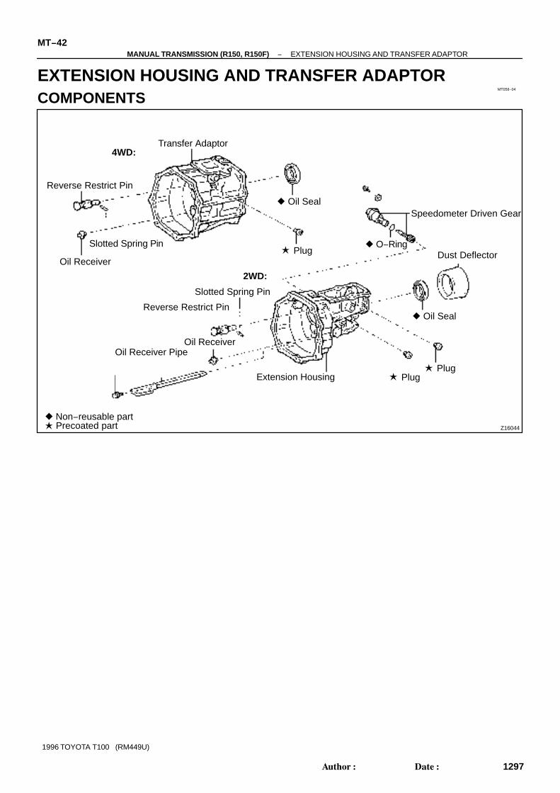
MT058−04
Z16044
4WD:
Slotted Spring Pin
Transfer Adaptor
� Oil Seal
� O−RingDust Deflector
� Oil Seal
2WD:
Oil Receiver
Reverse Restrict Pin
Oil Receiver PipeOil Receiver
Reverse Restrict Pin
Extension Housing
� Non−reusable part� Precoated part
Slotted Spring Pin
�
Speedometer Driven Gear
Plug
� Plug� Plug
MT−42−MANUAL TRANSMISSION (R150, R150F) EXTENSION HOUSING AND TRANSFER ADAPTOR
1297Author�: Date�:
1996 TOYOTA T100 (RM449U)
EXTENSION HOUSING AND TRANSFER ADAPTORCOMPONENTS
https://www.truck-manuals.net/

MT057−01
Q04410
Z03582
Q07365
SST
−MANUAL TRANSMISSION (R150, R150F) EXTENSION HOUSING AND TRANSFER ADAPTORMT−43
1996 TOYOTA T100 (RM449U)
REPLACEMENT1. IF NECESSARY, REPLACE REVERSE RESTRICT PIN(a) Remove the reverse restrict pin.
(1) Using a torx socket wrench (T40), remove the screwplug.
(2) Using a pin punch and hammer, drive out the slottedspring pin.
(3) Remove the reverse restrict pin.(b) Inspect the reverse restrict pin.
Turn and push the reverse restrict pin by hand.Check for smooth operation.
(c) Install the reverse restrict pin.(1) Install the reverse restrict pin to the extension hous-
ing or transfer adaptor.(2) Using a pin punch and hammer, drive in the slotted
spring pin, as shown.(3) Apply sealant to the plug threads.Sealant:Part No. 08833 − 00080, THREE BOND 1344, LOCTITE242 or equivalent(4) Using a torx socket wrench (T40), install and torque
the screw plug.Torque: 19 N·m (190 kgf·cm, 14 ft·lbf)
2. 2WD:IF NECESSARY, REPLACE EXTENSION HOUSINGOIL SEAL
(a) Remove the dust deflector.(b) Using a screwdriver, pry out the oil seal.(c) Using SST and a hammer, drive in a new oil seal.
SST 09950−60010 (09951−00570), 09950−70010(09951−07150)
Drive in depth: 0 ± 0.5 mm (0 ± 0.020 in.)(d) Install the deflector.
https://www.truck-manuals.net/

Q07366
SST
MT−44−MANUAL TRANSMISSION (R150, R150F) EXTENSION HOUSING AND TRANSFER ADAPTOR
1996 TOYOTA T100 (RM449U)
3. 4WD:IF NECESSARY, REPLACE TRANSFER ADAPTOR OILSEAL
(a) Using a screwdriver, pry out the oil seal.(b) Using SST and a hammer, drive in a new oil seal.
SST 09950−60010 (09951−00570), 09950−70010(09951−07150)
Drive in depth: 45.6 ± 0.5 mm (1.795 ± 0.020 in.)
https://www.truck-manuals.net/

MT – MANUAL TRANSMISSION (W59)
MANUAL TRANSMISSION SYSTEM MT-1 TROUBLESHOOTING MT-2 MANUAL TRANSMISSION UNIT MT-3 MANUAL TRANSMISSION ASSEMBLY MT-6 INPUT SHAFT MT-18 OUTPUT SHAFT MT-21 COUNTER GEAR AND REVERSE IDLER GEAR
MT-30
FRONT BEARING RETAINER OIL SEAL MT-38 EXTENSION HOUSING MT-40
https://www.truck-manuals.net/
MT03H−01
−MANUAL TRANSMISSION (W59) MANUAL TRANSMISSION SYSTEMMT−1
1300Author�: Date�:
1996 TOYOTA T100 (RM449U)
MANUAL TRANSMISSION SYSTEMPRECAUTIONWhen working with FIPG material, you must observe the following items.� Using a razor blade and gasket scraper, remove all the old FIPG material from the gasket sur-
faces.� Thoroughly clean all components to remove all the loose material.� Clean both sealing surfaces with a non−residue solvent.� Apply FIPG in an approx. 1 mm (0.04 in.) wide bead along the sealing surface.� Parts must be assembled within 10 minutes of application. Otherwise, the FIPG material must
be removed and reapplied.
https://www.truck-manuals.net/

MT03I−01
MT−2−MANUAL TRANSMISSION (W59) TROUBLESHOOTING
1301Author�: Date�:
1996 TOYOTA T100 (RM449U)
TROUBLESHOOTINGPROBLEM SYMPTOMS TABLEUse the table below to help you find the cause of the problem. The numbers indicate the priority of the likelycause of the problem. Check each part in order. If necessary, replace these parts.
Symptom Suspect Area See page
Noise
1. Oil (Level low)
2. Oil (Wrong)
3. Gear (Worn or damaged)
4. Bearing (Worn or damaged)
MT−4
MT−4
MT−6
MT−6
Oil leakage
1. Oil (Level too high)
2. Gasket (Damaged)
3. Oil seal (Worn or damaged)
4. O−Ring (Worn or damaged)
MT−4
MT−6
MT−6
MT−6
Hard to shift or will not shift
1. Synchronizer ring (Worn or damaged)
2. Shift key spring (Damaged)
MT−18
MT−21
MT−30
MT−18
MT−21
MT−30
Jumps out of gear
1. Locking ball spring (Damaged)
2. Shift fork (Worn)
3. Gear (Worn or damaged)
4. Bearing (Worn or damaged)
MT−6
MT−6
MT−6
MT−6
https://www.truck-manuals.net/
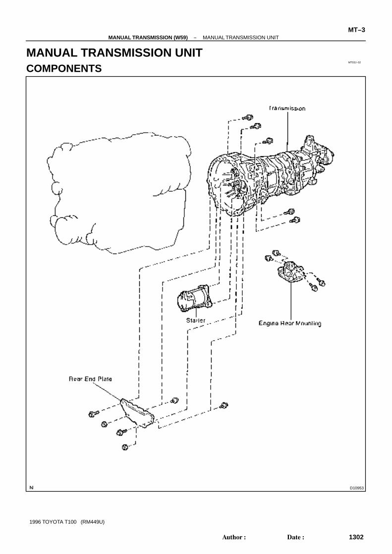
MT03J−02
D10953
−MANUAL TRANSMISSION (W59) MANUAL TRANSMISSION UNITMT−3
1302Author�: Date�:
1996 TOYOTA T100 (RM449U)
MANUAL TRANSMISSION UNITCOMPONENTS
https://www.truck-manuals.net/

MT0ES−01
D10954
D10955
MT−4−MANUAL TRANSMISSION (W59) MANUAL TRANSMISSION UNIT
1996 TOYOTA T100 (RM449U)
REMOVAL1. REMOVE TRANSMISSION WITH ENGINE (See page
EM−65)2. REMOVE REAR END PLATERemove the 4 bolts, 2 nuts and rear end plate.
Torque: 37 N·m (380 kgf·cm, 27 ft·lbf)3. REMOVE STARTERRemove the 2 bolts and starter.
Torque: 39 N·m (400 kgf·cm, 29 ft·lbf)
4. REMOVE TRANSMISSION FROM ENGINE(a) Remove the 3 transmission mounting bolts from the en-
gine.Torque: 72 N·m (730 kgf·cm, 53 ft·lbf)
(b) Pull out the transmission toward the rear.HINT:At the time of installation, please refer to the following item.Align the input shaft spline with the clutch disc and install thetransmission to the engine.5. REMOVE ENGINE REAR MOUNTINGRemove the 4 bolts and engine rear mounting.
Torque: 25 N·m (250 kgf·cm, 18 ft·lbf)
https://www.truck-manuals.net/

MT03L−02
−MANUAL TRANSMISSION (W59) MANUAL TRANSMISSION UNITMT−5
1996 TOYOTA T100 (RM449U)
INSTALLATIONInstallation is in the reverse order of removal (See page MT−4).HINT:After installation, do the road test.
https://www.truck-manuals.net/

MT03M−03
Z15702
Clutch Housing CoverSnap Ring
Transmission Case
Front Bearing
Clutch HousingFiller Plug
Drain Plug
Retainer
Release Fork Support
Straight Screw Plug
Intermediate Plate
Output Shaft
Locking Ball
�
�
x 7x 9
Boot
Back−Up Light Switch
Restrict PinControl Shift LeverRetainer
Oil Baffle Plate
Restrict Pin
Extension Housing
Speedometer Driven Gear
Non−reusable partPrecoated part
Input Shaft
x 6
x 9
Straight Screw Plug
Spring
�
�
�
�
�Gasket
�Gasket
�Gasket
�Gasket
�Gasket
�
39 (400, 29)
MT−6−MANUAL TRANSMISSION (W59) MANUAL TRANSMISSION ASSEMBLY
1305Author�: Date�:
1996 TOYOTA T100 (RM449U)
MANUAL TRANSMISSION ASSEMBLYCOMPONENTS
https://www.truck-manuals.net/

D10956
−MANUAL TRANSMISSION (W59) MANUAL TRANSMISSION ASSEMBLYMT−7
1306Author�: Date�:
1996 TOYOTA T100 (RM449U)
https://www.truck-manuals.net/

MT03N−04
Q06713
Q06714
FIPG
Q06715
FIPG
x 7
MT−8−MANUAL TRANSMISSION (W59) MANUAL TRANSMISSION ASSEMBLY
1996 TOYOTA T100 (RM449U)
DISASSEMBLY1. REMOVE BACK−UP LIGHT SWITCH
Torque: 40 N·m (410 kgf·cm, 30 ft·lbf)2. REMOVE SPEEDOMETER DRIVEN GEARRemove the lock plate set bolt and driven gear.
Torque: 13 N·m (130 kgf·cm, 9 ft·lbf)3. REMOVE CLUTCH HOUSING FROM TRANSMISSION
CASERemove the 9 bolts and clutch housing.
Torque: 37 N·m (380 kgf·cm, 27 ft·lbf)4. REMOVE CONTROL SHIFT LEVER RETAINER(a) Remove the 6 bolts.
Sealant: Part No.08833 − 00080, THREE BOND 1344, LOCTITE242 or equivalentTorque: 18 N·m (185 kgf·cm, 13 ft·lbf)
(b) Remove the control shift lever retainer and oil baffle plate.
5. REMOVE 2 RESTRICT PINS AND GASKETSHINT:At the time of reassembly, please refer to the following item.Install the black pin on the reverse gear/5th gear side.
Torque: 40 N·m (410 kgf·cm, 30 ft·lbf)6. REMOVE EXTENSION HOUSING(a) Remove the shift lever housing set bolt.
Torque: 39 N·m (400 kgf·cm, 29 ft·lbf)
(b) Remove the 9 bolts from the extension housing.Torque: 37 N·m (380 kgf·cm, 27 ft·lbf)
(c) Using a plastic hammer, carefully tap the extension hous-ing.
(d) Disengage the shift and select lever from the shift head.(e) Pull out the extension housing.
FIPG: Part No. 08826 − 00090, THREE BOND 1281 or equiva-lent
7. REMOVE FRONT BEARING RETAINER AND BEAR-ING SNAP RING
(a) Remove the 7 bolts.Sealant: Part No.08833 − 00080, THREE BOND 1344, LOCTITE242 or equivalentTorque: 25 N·m (250 kgf·cm, 18 ft·lbf)
(b) Remove the front bearing retainer.
https://www.truck-manuals.net/

Q06716FIPG
Q03881
−MANUAL TRANSMISSION (W59) MANUAL TRANSMISSION ASSEMBLYMT−9
1996 TOYOTA T100 (RM449U)
FIPG: Part No. 08826 − 00090, THREE BOND 1281 or equiva-lent
(c) Using a snap ring expander, remove the 2 bearing snaprings.
8. SEPARATE INTERMEDIATE PLATE FROM TRANS-MISSION CASE
(a) Using a plastic hammer, carefully tap the transmissioncase.
(b) Pull the transmission case from the intermediate plate.NOTICE:At the time of reassembly, please refer to the followingitem.Align each bearing outer race and each shift fork shaft endwith the case holes.
FIPG: Part No. 08826 − 00090, THREE BOND 1281 or equiva-lent
9. MOUNT INTERMEDIATE PLATE IN VISE(a) Use the 2 long clutch housing bolts, plate washers and
suitable nuts, as shown.HINT:Increase or decrease plate washers so that the bolt tip does notprotrude from the nut.(b) Mount the intermediate plate in a vise.10. REMOVE OIL SEPARATORRemove the 2 bolts and oil separator.
Torque: 18 N·m (185 kgf·cm, 13 ft·lbf)11. REMOVE FRONT MAGNET
https://www.truck-manuals.net/

Q06267
Short
Middle
Long
Q06717
D00861
D00862
D10957
MT−10−MANUAL TRANSMISSION (W59) MANUAL TRANSMISSION ASSEMBLY
1996 TOYOTA T100 (RM449U)
12. REMOVE LOCKING BALL AND SPRING(a) Using a hexagon wrench, remove the 4 straight screw
plugs.Sealant: Part No.08833 − 00080, THREE BOND 1344, LOCTITE242 or equivalentTorque: 25 N·m (250 kgf·cm, 18 ft·lbf)
(b) Using a magnetic finger, remove the 3 springs and balls.
13. REMOVE SHIFT FORK, SHIFT FORK SHAFT AND RE-VERSE IDLER GEAR
(a) Remove the No.1 and No.2 shift fork set bolts.Torque: 20 N·m (200 kgf·cm, 14 ft·lbf)
(b) Remove the bolt and reverse idler gear shaft stopper.Torque: 25 N·m (250 kgf·cm, 18 ft·lbf)
(c) Remove the reverse idler gear and shaft with the snapring.
(d) Remove the No.1 shift fork and shaft.
(e) Using a magnetic finger, remove the No.1 and No.2 inter-lock pins.
HINT:At the time of reassembly, please refer to the following item.Apply MP grease to the No.1 and No.2 interlock pins.(f) Using 2 screwdrivers and a hammer, tap out the No. 2 shift
fork shaft snap ring.(g) Remove the No. 2 shift fork and shaft.
(h) Using a magnetic finger, remove the No. 3 interlock pin.HINT:At the time of reassembly, please refer to the following item.Apply MP grease to the No.3 interlock pin.
(i) Using a pin punch and hammer, drive out the No. 3 shiftfork pin.
(j) Using a hexagon wrench, remove the plug.Torque: 25 N·m (250 kgf·cm, 18 ft·lbf)
(k) Using a magnetic finger, remove the spring and ball.
https://www.truck-manuals.net/

D10958
Q06720
Removal Installation
WM0041
−MANUAL TRANSMISSION (W59) MANUAL TRANSMISSION ASSEMBLYMT−11
1996 TOYOTA T100 (RM449U)
(l) Pull out the No.4 shift fork shaft.(m) Remove the pin from the reverse shift head.HINT:At the time of reassembly, please refer to the following item.Apply MP grease to the pin.(n) Remove the No.3 shift fork, fork shaft and reverse shift
arm with the snap ring.HINT:At the time of reassembly, please refer to the following item.Align the No.3 shift fork with the No.3 hub sleeve groove, putthe reverse shift arm into the pivot of bearing retainer and alignthe reverse shift arm shoe with the reverse idler gear groove.
14. REMOVE SPEEDOMETER DRIVE GEARPry out both ends of the clip and remove the drive gear.
15. INSPECT COUNTER 5TH GEAR THRUST CLEAR-ANCE
Using a feeler gauge, measure the counter 5th gear thrustclearance.
Standard clearance:0.10 − 0.41 mm (0.0039 − 0.0161 in.)Maximum clearance: 0.46 mm (0.0181 in.)
https://www.truck-manuals.net/

D00863
Q06283
SST
D00864
Socket Wrench
Q00987
MT−12−MANUAL TRANSMISSION (W59) MANUAL TRANSMISSION ASSEMBLY
1996 TOYOTA T100 (RM449U)
16. REMOVE COUNTER REAR BEARING, SPACER,COUNTER 5TH GEAR AND NEEDLE ROLLER BEAR-ING
(a) Using a snap ring expander, remove the snap ring.HINT:At the time of reassembly, please refer to the following item.Select a snap ring that allows the minimum axial play.
Mark Thickness mm (in.)
1 1.90 − 1.95 (0.0748 − 0.0768)
2 1.96 − 2.01 (0.0772 − 0.0791)
3 2.02 − 2.07 (0.0795 − 0.0815)
4 2.08 − 2.13 (0.0819 − 0.0839)
5 2.14 − 2.19 (0.0843 − 0.0862)
6 2.20 − 2.25 (0.0866 − 0.0886)
7 2.26 − 2.31 (0.0890 − 0.0909)
(b) Using SST, remove the rear bearing, spacer, counter 5thgear and bearing.SST 09950−40010
NOTICE:Be careful not to catch the output shaft rear bearing rolleron the counter 5th gear.(c) Remove the spacer.
HINT:At the time of reassembly, please refer to the following items.� Install the counter 5th gear with the 5th gear gaps aligned
with the synchronizer cone ring pin.� Using a socket wrench and hammer, drive in the bearing.� When driving in the bearing, support the counter shaft in
front with a 1.4 − 2.3 kg (3 − 5 lb) hammer or equivalent.
17. REMOVE SYNCHRONIZER RING ASSEMBLY WITHNO.3 HUB SLEEVE AND NO.3 CLUTCH HUB
(a) Remove the synchronizer ring assembly with the No.3hub sleeve from the No.3 clutch hub.
https://www.truck-manuals.net/

Q04007
Q06285
SST
D00865
SST
Front
−MANUAL TRANSMISSION (W59) MANUAL TRANSMISSION ASSEMBLYMT−13
1996 TOYOTA T100 (RM449U)
(b) Remove the spacer.(c) Using 2 screwdrivers and a hammer, tap out the snap
ring.HINT:At the time of reassembly, please refer to the following item.Select a snap ring that allows the minimum axial play.
Mark Thickness mm (in.)
2 2.06 − 2.11 (0.0811 − 0.0831)
3 2.12 − 2.17 (0.0835 − 0.0854)
4 2.18 − 2.23 (0.0858 − 0.0878)
5 2.24 − 2.29 (0.0882 − 0.0902)
(d) Using SST, remove the No.3 clutch hub.SST 09950−40010
HINT:At the time of reassembly, please refer to the following items.� Using SST and a hammer, drive in the No.3 clutch hub.
SST 09316−60011 (09316−00011, 09316−00071)� When installing the No.3 clutch hub, support the counter
shaft in front with a 1.4 − 2.3 kg (3 − 5 lb) hammer or equiv-alent.
18. REMOVE REAR MAGNET
https://www.truck-manuals.net/

D00866
WM0046
SST
D00867
SSTSST
MT−14−MANUAL TRANSMISSION (W59) MANUAL TRANSMISSION ASSEMBLY
1996 TOYOTA T100 (RM449U)
19. REMOVE OUTPUT SHAFT REAR BEARING AND 5THGEAR
(a) Using 2 screwdrivers and a hammer, tap out the snapring.
HINT:At the time of reassembly, please refer to the following item.Select a snap ring that allows the minimum axial play.
Mark Thickness mm (in.)
8 2.31 − 2.36 (0.0909 − 0.0929)
9 2.37 − 2.42 (0.0933 − 0.0953)
10 2.43 − 2.48 (0.0957 − 0.0976)
11 2.49 − 2.54 (0.0980 − 0.1000)
12 2.55 − 2.60 (0.1004 − 0.1024)
13 2.61 − 2.66 (0.1028 − 0.1047)
14 2.68 − 2.73 (0.1055 − 0.1075)
15 2.74 − 2.79 (0.1079 − 0.1098)
(b) Using SST, remove the rear bearing and 5th gear.SST 09312−20011 (09313−00030, 09313−00040,
09313−00050)
HINT:At the time of reassembly. please refer to the following item.Using SST, install the 5th gear and rear bearing.
SST 09312−20011 (09313−00010, 09313−00030,09313−00040, 09313−00050)
https://www.truck-manuals.net/

D00868
Q05168
SST
D00870
SST
−MANUAL TRANSMISSION (W59) MANUAL TRANSMISSION ASSEMBLYMT−15
1996 TOYOTA T100 (RM449U)
20. REMOVE REVERSE GEAR(a) Using a snap ring expander, remove the snap ring.HINT:At the time of reassembly, please refer to the following item.Select a snap ring that allows the minimum axial play.
Mark Thickness mm (in.)
5 2.25 − 2.30 (0.0886 − 0.0906)
11 2.30 − 2.35 (0.0906 − 0.0925)
12 2.35 − 2.40 (0.0925 − 0.0945)
13 2.40 − 2.45 (0.0945 − 0.0965)
14 2.45 − 2.50 (0.0965 − 0.0984)
15 2.50 − 2.55 (0.0984 − 0.1004)
16 2.55 − 2.60 (0.1004 − 0.1024)
17 2.61 − 2.66 (0.1028 − 0.1047)
18 2.67 − 2.72 (0.1051 − 0.1071)
19 2.73 − 2.78 (0.1075 − 0.1094)
20 2.79 − 2.84 (0.1098 − 0.1118)
21 2.85 − 2.90 (0.1122 − 0.1142)
22 2.91 − 2.96 (0.1146 − 0.1165)
23 2.97 − 3.02 (0.1169 − 0.1189)
(b) Using SST, remove the reverse gear.SST 09950−40010
HINT:At the time of reassembly, please refer to the following item.Using SST, install the reverse gear.
SST 09312−20011 (09313−00030, 09313−00040,09313−00050)
21. REMOVE REAR BEARING RETAINER(a) Using a torx socket wrench (T40), unscrew the 4 torx
screws and remove the rear bearing retainer.Torque: 18 N·m (185 kgf·cm, 13 ft·lbf)
https://www.truck-manuals.net/

Q00855
Q07367
SST
WM0125
SST
Q07552
SST SST
25mm
MT−16−MANUAL TRANSMISSION (W59) MANUAL TRANSMISSION ASSEMBLY
1996 TOYOTA T100 (RM449U)
(b) Using a snap ring expander, remove the 2 snap rings.HINT:At the time of reassembly, please refer to the following item.Make sure the snap ring is flush with the intermediate plate sur-face.
22. REMOVE OUTPUT SHAFT AND COUNTER GEARFROM INTERMEDIATE PLATE
(a) Remove the output shaft, input shaft and counter gear asa unit from the intermediate plate by pulling on the countergear and tapping on the intermediate plate with a plastichammer.
(b) Remove the input shaft from the output shaft.
HINT:At the time of reassembly, please refer to the following items.� Before installing the output shaft, use SST to remove the
counter gear center bearing outer race.SST 09950−60010 (09951−00510), 09950−70010
(09951−07150)� Install the outer race after installing the counter gear.� Install the output shaft into the intermediate plate by pull-
ing on the output shaft and tapping on the intermediateplate.
HINT:At the time of reassembly, please refer to the following items.� Apply gear oil to the needle roller bearing.� Install the needle roller bearing to the input shaft.� Install the input shaft and counter gear together.� Using SST and a hammer, install a new counter gear cen-
ter bearing outer race.SST 09316−60011 (09316−00011)
� Be careful not to damage the bearing rollers.
23. IF NECESSARY REPLACE SPEEDOMETER DRIVENGEAR OIL SEAL
(a) Using SST, remove the oil seal.SST 09921−00010
(b) Coat the lip of oil seal with MP grease.(c) Using SST, drive in a new oil seal.
SST 09201−10000 (09201−01080), 09950−70010(09951−07150)
Drive in depth: 25 mm (0.98 in.)
https://www.truck-manuals.net/

MT03O−02
−MANUAL TRANSMISSION (W59) MANUAL TRANSMISSION ASSEMBLYMT−17
1996 TOYOTA T100 (RM449U)
REASSEMBLYReassembly is in the reverse order of disassembly (See page MT−8).HINT:Coat all of the sliding and rotating surfaces with gear oil before reassembly.
https://www.truck-manuals.net/

MT03P−01
Q00884
Snap Ring
Snap RingBearing
Input Shaft
Synchronizer Ring
Roller Bearing
Non−reusable part�
�
MT−18−MANUAL TRANSMISSION (W59) INPUT SHAFT
1317Author�: Date�:
1996 TOYOTA T100 (RM449U)
INPUT SHAFTCOMPONENTS
https://www.truck-manuals.net/
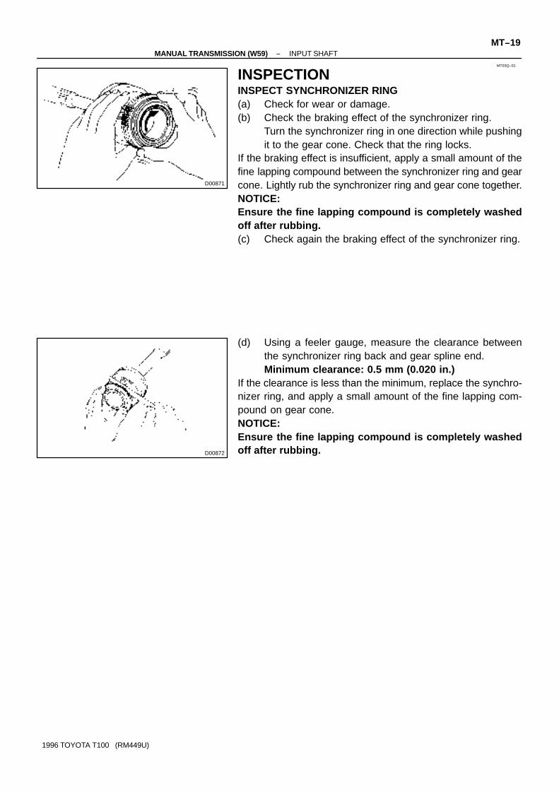
D00871
MT03Q−01
D00872
−MANUAL TRANSMISSION (W59) INPUT SHAFTMT−19
1996 TOYOTA T100 (RM449U)
INSPECTIONINSPECT SYNCHRONIZER RING(a) Check for wear or damage.(b) Check the braking effect of the synchronizer ring.
Turn the synchronizer ring in one direction while pushingit to the gear cone. Check that the ring locks.
If the braking effect is insufficient, apply a small amount of thefine lapping compound between the synchronizer ring and gearcone. Lightly rub the synchronizer ring and gear cone together.NOTICE:Ensure the fine lapping compound is completely washedoff after rubbing.(c) Check again the braking effect of the synchronizer ring.
(d) Using a feeler gauge, measure the clearance betweenthe synchronizer ring back and gear spline end.Minimum clearance: 0.5 mm (0.020 in.)
If the clearance is less than the minimum, replace the synchro-nizer ring, and apply a small amount of the fine lapping com-pound on gear cone.NOTICE:Ensure the fine lapping compound is completely washedoff after rubbing.
https://www.truck-manuals.net/

MT03R−01
Q00857
Q00878
SST
Q00858
MT−20−MANUAL TRANSMISSION (W59) INPUT SHAFT
1996 TOYOTA T100 (RM449U)
REPLACEMENTIF NECESSARY, REPLACE INPUT SHAFT BEARING(a) Using a snap ring expander, remove the snap ring.(b) Using a press, remove the bearing.
(c) Using SST and a press, install a new bearing.SST 09506−35010
(d) Select a snap ring that allows the minimum axial play.
Mark Thickness mm (in.)
1 2.05 − 2.10 (0.0807 − 0.0827)
2 2.10 − 2.15 (0.0827 − 0.0846)
3 2.15 − 2.20 (0.0846 − 0.0866)
4 2.20 − 2.25 (0.0866 − 0.0886)
5 2.25 − 2.30 (0.0886 − 0.0906)
11 2.30 − 2.35 (0.0906 − 0.0925)
12 2.35 − 2.40 (0.0925 − 0.0945)
(e) Using a snap ring expander, install the snap ring.
https://www.truck-manuals.net/

MT03S−01
Z07227
Shifting Key Spring
Synchronizer Outer RingSynchronizer Inner RingNo.2 Clutch Hub
Lock Ball
No.2 Hub SleeveSnap Ring
Needle Roller Bearing
2nd Gear
Synchronizer Middle Ring No.1 Clutch HUb
Needle Roller Bearing
Output Shaft
Shifting KeyShifting Key SpringNo.1 Hub Sleeve
Synchronizer Ring
Non−reusable part�
3rd Gear
BearingInner Race
1st Gear
Shifting Key
Synchronizer Middle Ring
Synchronizer Outer RingSynchronizer Inner Ring
Needle Roller Bearing �
−MANUAL TRANSMISSION (W59) OUTPUT SHAFTMT−21
1320Author�: Date�:
1996 TOYOTA T100 (RM449U)
OUTPUT SHAFTCOMPONENTS
https://www.truck-manuals.net/

MT03T−01
Q00880
3rd 2nd 1st
D00873
3rd2nd
1st
Q00859
WM0053
MT−22−MANUAL TRANSMISSION (W59) OUTPUT SHAFT
1996 TOYOTA T100 (RM449U)
DISASSEMBLY1. INSPECT EACH GEAR THRUST CLEARANCEUsing a feeler gauge, measure the thrust clearance of eachgear.
Standard clearance:0.10 − 0.25 mm (0.0039 − 0.0098 in.)Maximum clearance: 0.30 mm (0.0118 in.)
2. INSPECT EACH GEAR RADIAL CLEARANCEUsing a dial indicator, measure the radial clearance of eachgear.
Standard clearance:1st and 2nd gears:0.009 − 0.060 mm (0.0004 − 0.0024 in.)3rd gear: 0.015 − 0.066 mm (0.0006 − 0.0026 in.)Maximum clearance:1st and 2nd gears: 0.150 mm (0.0059 in.)3rd gear: 0.200 mm (0.0079 in.)
If the clearance exceeds the maximum, replace the gear, shaftor needle roller bearing.
3. REMOVE OUTPUT SHAFT CENTER BEARING AND1ST GEAR ASSEMBLY
(a) Shift the No.1 hub sleeve onto the 2nd gear.(b) Using a press, remove the center bearing, 1st gear,
needle roller bearing, inner race and synchronizer ring.4. REMOVE LOCKING BALL ON OUTPUT SHAFTUsing a magnetic finger, remove the locking ball.
5. REMOVE NO.1 HUB SLEEVE ASSEMBLY, 2ND GEARAND NEEDLE ROLLER BEARING
Using a press, remove the parts from the shaft as an assembly.
https://www.truck-manuals.net/
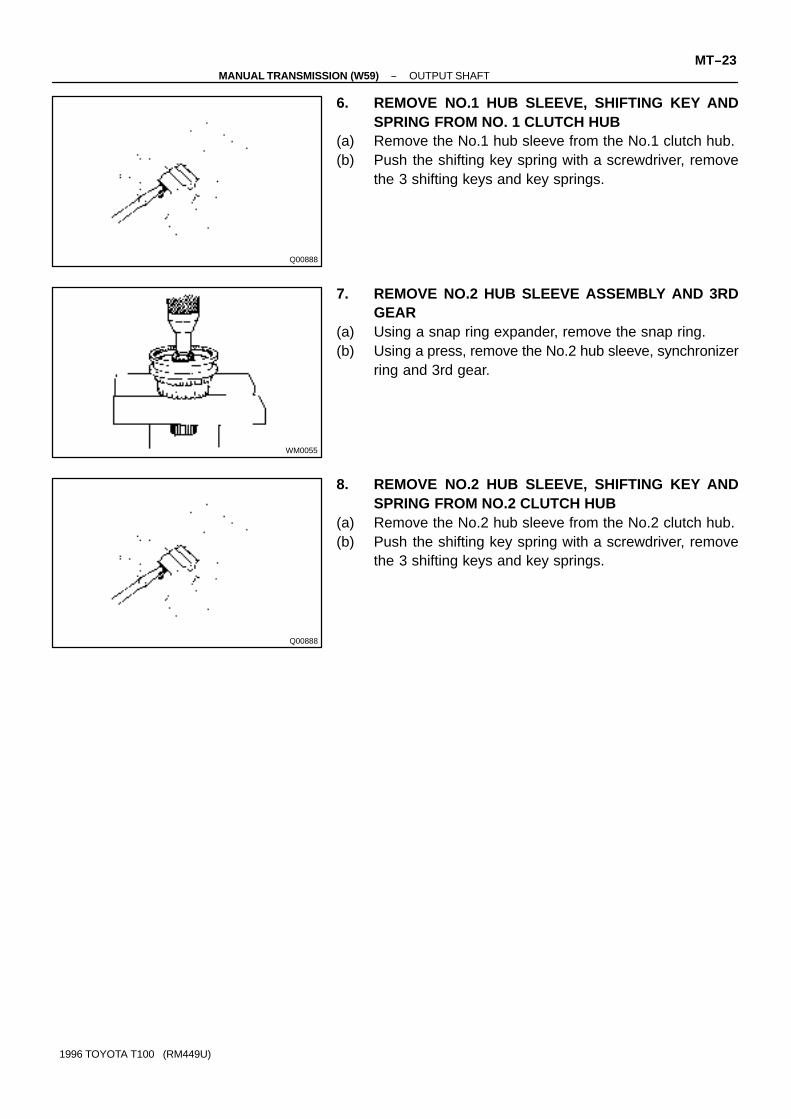
Q00888
WM0055
Q00888
−MANUAL TRANSMISSION (W59) OUTPUT SHAFTMT−23
1996 TOYOTA T100 (RM449U)
6. REMOVE NO.1 HUB SLEEVE, SHIFTING KEY ANDSPRING FROM NO. 1 CLUTCH HUB
(a) Remove the No.1 hub sleeve from the No.1 clutch hub.(b) Push the shifting key spring with a screwdriver, remove
the 3 shifting keys and key springs.
7. REMOVE NO.2 HUB SLEEVE ASSEMBLY AND 3RDGEAR
(a) Using a snap ring expander, remove the snap ring.(b) Using a press, remove the No.2 hub sleeve, synchronizer
ring and 3rd gear.
8. REMOVE NO.2 HUB SLEEVE, SHIFTING KEY ANDSPRING FROM NO.2 CLUTCH HUB
(a) Remove the No.2 hub sleeve from the No.2 clutch hub.(b) Push the shifting key spring with a screwdriver, remove
the 3 shifting keys and key springs.
https://www.truck-manuals.net/

WM0064
MT03U−01
WM0065
Q00930
MT0780
MT−24−MANUAL TRANSMISSION (W59) OUTPUT SHAFT
1996 TOYOTA T100 (RM449U)
INSPECTION1. INSPECT 1ST GEAR SYNCHRONIZER RING(a) Check for wear or damage.(b) Check the braking effect of the synchronizer ring.
Turn the synchronizer ring in one direction while pushingit to the gear cone. Check that the ring locks.
If the braking effect is insufficient, apply a small amount of thefine lapping compound between the synchronizer ring and gearcone. Lightly rub the synchronizer ring and gear cone together.NOTICE:Ensure the fine lapping compound is completely washedoff after rubbing.(c) Check again the braking effect of the synchronizer ring.
(d) Using a feeler gauge, measure the clearance betweenthe synchronizer ring back and gear spline end.Minimum clearance: 0.5 mm (0.020 in.)
If the clearance is less than the minimum, replace the synchro-nizer ring, and apply a small amount of the fine lapping com-pound on gear cone.NOTICE:Ensure the fine lapping compound is completely washedoff after rubbing.
2. INSPECT 2ND AND 3RD GEAR SYNCHRONIZERRINGS
(a) Check for wear or damage.(b) Install the synchronizer inner ring, middle ring and outer
ring to each gear.
(c) Check the braking effect of the synchronizer ring. Turn thesynchronizer ring in one direction while pushing it to thegear cone. Check that the ring locks.
If it does not lock, replace the synchronizer ring.
https://www.truck-manuals.net/

MT0786
WM0066
Q00860
Q00861
Q00862
−MANUAL TRANSMISSION (W59) OUTPUT SHAFTMT−25
1996 TOYOTA T100 (RM449U)
(d) Using a feeler gauge, measure the clearance betweenthe synchronizer ring back and the gear spline end.Minimum clearance: 0.7 mm (0.028 in.)
If the clearance is less than the minimum, replace the synchro-nizer ring.
3. INSPECT SHIFT FORK AND HUB SLEEVE CLEAR-ANCE
Using a feeler gauge, measure the clearance between the hubsleeves and shift forks.
Maximum clearance: 1.0 mm (0.039 in.)If the clearance exceeds the maximum, replace the shift fork orhub sleeve.
4. INSPECT OUTPUT SHAFT AND INNER RACE(a) Using vernier calipers, measure the output shaft flange
thickness.Minimum thickness: 5.60 mm (0.2205 in.)
If the thickness is less than the minimum, replace the outputshaft.
(b) Using vernier calipers, measure the inner race flangethickness.Minimum thickness: 4.78 mm (0.1881 in.)
If the thickness is less than the minimum, replace the inner race.
(c) Using a micrometer, measure the outer diameter of theoutput shaft journal.Minimum diameter:2nd gear: 42.975 mm (1.6919 in.)3rd gear: 31.969 mm (1.2586 in.)
If the outer diameter is less than the minimum, replace the out-put shaft.
https://www.truck-manuals.net/

Q00863
Q00864
MT−26−MANUAL TRANSMISSION (W59) OUTPUT SHAFT
1996 TOYOTA T100 (RM449U)
(d) Using a micrometer, measure the outer diameter of the in-ner race.Minimum diameter: 42.975 mm (1.6919 in.)
If the outer diameter is less than the minimum, replace the innerrace.
(e) Using a dial indicator, check the shaft runout.Maximum runout: 0.06 mm (0.0024 in.)
If the runout exceeds the maximum, replace the output shaft.
https://www.truck-manuals.net/

MT03V−01
Q00888
Z02648
No.2No.1
FrontFront
Q00865
−MANUAL TRANSMISSION (W59) OUTPUT SHAFTMT−27
1996 TOYOTA T100 (RM449U)
REASSEMBLYHINT:Coat all of the sliding and rotating surfaces with gear oil beforereassembly.1. INSTALL NO.1 AND NO.2 CLUTCH HUBS INTO HUB
SLEEVE(a) Install the 3 shifting key springs to the clutch hub.(b) While pushing the shifting key spring with a screwdriver,
install the 3 shifting keys.
(c) While pushing the 3 shifting keys, install the clutch hub tothe hub sleeve, as shown.
2. INSTALL 3RD GEAR AND NO.2 CLUTCH HUB ONOUTPUT SHAFT
(a) Apply gear oil to the shaft.(b) Place the synchronizer ring on the gear and align the ring
slots with the shifting keys.
https://www.truck-manuals.net/

WM0115
Q00887
Q00866
WM0119
MT−28−MANUAL TRANSMISSION (W59) OUTPUT SHAFT
1996 TOYOTA T100 (RM449U)
(c) Using a press, install the 3rd gear and No.2 clutch hub.
3. INSTALL SNAP RING(a) Select a snap ring that allows the minimum axial play.
Mark Thickness mm (in.)
C−1 1.75 − 1.80 (0.0689 − 0.0709)
D 1.80 − 1.85 (0.0709 − 0.0728)
11 1.86 − 1.91 (0.0732 − 0.0752)
12 1.92 − 1.97 (0.0756 − 0.0776)
13 1.98 − 2.03 (0.0780 − 0.0799)
14 2.04 − 2.09 (0.0803 − 0.0823)
15 2.10 − 2.15 (0.0827 − 0.0846)
(b) Using a snap ring expander, install the snap ring.4. INSPECT 3RD GEAR THRUST CLEARANCE
(See page MT−21)
5. INSTALL 2ND GEAR AND NO.1 CLUTCH HUB(a) Apply gear oil to the shaft and needle roller bearing.(b) Place the synchronizer ring on the gear and align the ring
slots with the shifting keys.(c) Install the needle roller bearing in the 2nd gear.
(d) Using a press, install the 2nd gear and No.1 clutch hub.6. INSPECT 2ND GEAR THRUST CLEARANCE
(See page MT−21)
https://www.truck-manuals.net/

Q00868
WM0122
SST
−MANUAL TRANSMISSION (W59) OUTPUT SHAFTMT−29
1996 TOYOTA T100 (RM449U)
7. INSTALL LOCKING BALL AND 1ST GEAR ASSEMBLY(a) Install the locking ball in the shaft.(b) Apply gear oil to the bearing.(c) Assemble the 1st gear, synchronizer ring, needle roller
bearing and bearing inner race.(d) Install the assembly on the output shaft with the synchro-
nizer ring slots aligned with the shifting keys and turn theinner race to align it with the locking ball.
8. INSTALL OUTPUT SHAFT CENTER BEARINGUsing SST and a press, install the bearing on the output shaftwith the outer race snap ring groove toward the rear.
SST 09506−35010HINT:Hold the 1st gear inner race to prevent it from falling.9. INSPECT 1ST GEAR THRUST CLEARANCE
(See page MT−21)
https://www.truck-manuals.net/

MT03W−03
Z15652
Shaft Stopper
Reverse Idler Gear Shaft
Reverse Idler Shaft
Snap Ring
Race
Counter GearCounter 5th Gear
Reverse Synchronizer Pull Ring
Shifting Key SpringNo.3 Clutch Hub
Reverse Synchronizer Ring
No.3 Hub Sleeve5th Synchronizer Ring
Synchronizer Cone BearingNeedle Roller Bearing
Shifting Key
Spacer
Non−reusable part�
Snap Ring
Snap Ring
Snap Ring
Bearing�
Bearing�
Spacer
Snap Ring
Race �
Bearing�
MT−30−MANUAL TRANSMISSION (W59) COUNTER GEAR AND REVERSE IDLER GEAR
1329Author�: Date�:
1996 TOYOTA T100 (RM449U)
COUNTER GEAR AND REVERSE IDLER GEARCOMPONENTS
https://www.truck-manuals.net/

MT03X−01
Q03887
Q04037
Q00873
Q04010
−MANUAL TRANSMISSION (W59) COUNTER GEAR AND REVERSE IDLER GEARMT−31
1996 TOYOTA T100 (RM449U)
DISASSEMBLYREMOVE NO.3 HUB SLEEVE, SHIFTING KEY AND SPRINGFROM SYNCHRONIZER RING(a) Remove the synchronizer ring assembly from the No.3
hub sleeve.(b) Turn the reverse synchronizer pull ring.
(c) Remove the reverse synchronizer ring and 5th synchro-nizer ring from the synchronizer pull ring and cone ring.
(d) Turn the reverse synchronizer pull ring and separate thepull ring and cone ring.
(e) Remove the 3 shifting keys and key springs by carefullylevering up the shifting key spring with one screwdriverand levering the shifting key away from the reverse syn-chronizer ring with another screwdriver.
https://www.truck-manuals.net/

MT03Y−01
D00875
D00878
B
A
D00879
Q00914
MT−32−MANUAL TRANSMISSION (W59) COUNTER GEAR AND REVERSE IDLER GEAR
1996 TOYOTA T100 (RM449U)
INSPECTION1. INSPECT COUNTER 5TH GEAR RADIAL CLEAR-
ANCE(a) Install the spacer, counter 5th gear and needle roller bear-
ing to the counter gear.(b) Using a dial indicator, measure the counter 5th gear radial
clearance.Standard clearance:0.009 − 0.060 mm (0.0004 − 0.0024 in.)Maximum clearance: 0.150 mm (0.0059 in.)
If the clearance exceeds the maximum, replace the countergear, needle roller bearing or counter 5th gear.
2. INSPECT COUNTER GEARUsing a micrometer, measure the outer diameter of the countershaft journal.
Minimum diameter:Part A: 26.975 mm (1.0620 in.)Part B: 29.950 mm (1.1791 in.)
If the outer race is less than the minimum, replace the countergear.
3. INSPECT REVERSE IDLER GEAR RADIAL CLEAR-ANCE
Using a dial indicator, measure the reverse idler gear radialclearance.
Standard clearance:0.041 − 0.074 mm (0.0016 − 0.0029 in.)Maximum clearance: 0.194 mm (0.0076 in.)
If the clearance exceeds the maximum, replace the gear orshaft.4. INSPECT REVERSE IDLER GEAR AND SHIFT ARM
SHOE CLEARANCEUsing a feeler gauge, measure the clearance between the re-verse idler gear and shift arm shoe.
Standard clearance:0.20 − 0.41 mm (0.0079 − 0.0161 in.)Maximum clearance: 0.90 mm (0.0354 in.)
If the clearance exceeds the maximum, replace the shift armshoe or reverse idler gear.
https://www.truck-manuals.net/

Q04038
Q04011
WM0066
−MANUAL TRANSMISSION (W59) COUNTER GEAR AND REVERSE IDLER GEARMT−33
1996 TOYOTA T100 (RM449U)
5. INSPECT 5TH GEAR SYNCHRONIZER RING(a) Check for wear or damage.(b) Install the synchronizer pull ring, cone ring and outer ring
to the 5th gear.
(c) Check the braking effect of the synchronizer ring. Turn thesynchronizer ring in one direction while pushing it to thegear cone. Check that the ring locks.
If it does not lock, replace the synchronizer ring.
6. INSPECT SHIFT FORK AND HUB SLEEVE CLEAR-ANCE
Using a feeler gauge, measure the clearance between the hubsleeves and shift forks.
Maximum clearance: 1.0 mm (0.039 in.)If the clearance exceeds the maximum, replace the shift fork orhub sleeve.
https://www.truck-manuals.net/

MT03Z−01
WM0073
SST
Q06319
SST
Socket Wrench
RM0013
Socket Wrench
D00876
WM0079
MT−34−MANUAL TRANSMISSION (W59) COUNTER GEAR AND REVERSE IDLER GEAR
1996 TOYOTA T100 (RM449U)
REPLACEMENT1. IF NECESSARY, REPLACE COUNTER GEAR FRONT
BEARING AND SIDE RACE(a) Using a snap ring expander, remove the snap ring.(b) Using SST and a press, press out the bearing.
SST 09950−00020(c) Check the side race for wear or damage.
(d) If necessary, remove the side race.Using SST and a socket wrench, remove the side race.SST 09950−40010
(e) Using a socket wrench and press, install a new bearing,side race and inner race.
(f) Select a snap ring that allows the minimum axial play.
Mark Thickness mm (in.)
A 2.05 − 2.10 (0.0807 − 0.0827)
B 2.10 − 2.15 (0.0827 − 0.0846)
C 2.15 − 2.20 (0.0846 − 0.0866)
D 2.20 − 2.25 (0.0866 − 0.0886)
E 2.25 − 2.30 (0.0886 − 0.0906)
F 2.30 − 2.35 (0.0906 − 0.0925)
(g) Using a snap ring expander, install the snap ring.
2. IF NECESSARY, REPLACE COUNTER GEAR CENTERBEARING
(a) Remove the bearing from the counter gear.(b) Install a new bearing on the counter gear.HINT:Engage the roller cages.
https://www.truck-manuals.net/

Q07367
SST
−MANUAL TRANSMISSION (W59) COUNTER GEAR AND REVERSE IDLER GEARMT−35
1996 TOYOTA T100 (RM449U)
(c) Using SST, tap out the bearing outer race.SST 09950−60010 (09951−00510), 09950−70010
(09951−07150)HINT:After the outer race has been installed, the transmission is reas-sembled.
https://www.truck-manuals.net/
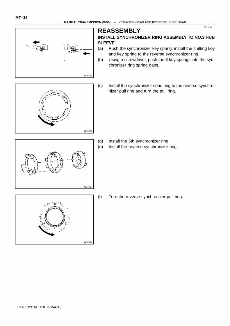
MT040−01
Q06721
Q00873
Q04037
Q00874
MT−36−MANUAL TRANSMISSION (W59) COUNTER GEAR AND REVERSE IDLER GEAR
1996 TOYOTA T100 (RM449U)
REASSEMBLYINSTALL SYNCHRONIZER RING ASSEMBLY TO NO.3 HUBSLEEVE(a) Push the synchronizer key spring, install the shifting key
and key spring to the reverse synchronizer ring.(b) Using a screwdriver, push the 3 key springs into the syn-
chronizer ring spring gaps.
(c) Install the synchronizer cone ring to the reverse synchro-nizer pull ring and turn the pull ring.
(d) Install the 5th synchronizer ring.(e) Install the reverse synchronizer ring.
(f) Turn the reverse synchronizer pull ring.
https://www.truck-manuals.net/

D00880
Front
−MANUAL TRANSMISSION (W59) COUNTER GEAR AND REVERSE IDLER GEARMT−37
1996 TOYOTA T100 (RM449U)
(g) While pushing 3 shifting keys, install the synchronizer ringassembly to the No.3 hub sleeve.
https://www.truck-manuals.net/

MT041−01
WM0295
Front Bearing Retainer
Non −reusable part
�Oil Seal
�
MT−38−MANUAL TRANSMISSION (W59) FRONT BEARING RETAINER OIL SEAL
1337Author�: Date�:
1996 TOYOTA T100 (RM449U)
FRONT BEARING RETAINER OIL SEALCOMPONENTS
https://www.truck-manuals.net/

MT042−01
Q07368
SST
−MANUAL TRANSMISSION (W59) FRONT BEARING RETAINER OIL SEALMT−39
1996 TOYOTA T100 (RM449U)
REPLACEMENTIF NECESSARY, REPLACE FRONT BEARING RETAINEROIL SEAL(a) Using a screwdriver, pry out the oil seal.(b) Using SST and a press, install a new oil seal.
SST 09950−60010 (09951−00440), 09950−70010(09951−07150)
Drive in depth: 12.2 ± 0.5 mm (0.480 ± 0.020 in.)
https://www.truck-manuals.net/

MT043−03
Z19272
Reverse Restrict Pin
Slotted Spring Pin
Straight Screw Plug
Shift Lever Housing
Dust Deflector
Oil Seal
Extension Housing
Snap Ring
Outer Race
Shift and Select Lever
Oil Receiver Pipe
Non−reusable PartPrecoated Part
�
�
�
�
�
�
MT−40−MANUAL TRANSMISSION (W59) EXTENSION HOUSING
1339Author�: Date�:
1996 TOYOTA T100 (RM449U)
EXTENSION HOUSINGCOMPONENTS
https://www.truck-manuals.net/

MT044−01
Q04410
D00877
Reverse Restrict Pin
SlottedSpring Pin
WM0085
Q07553
SST
−MANUAL TRANSMISSION (W59) EXTENSION HOUSINGMT−41
1996 TOYOTA T100 (RM449U)
REPLACEMENT1. IF NECESSARY, REPLACE REVERSE RESTRICT PIN(a) Remove the reverse restrict pin.
(1) Using a hexagon wrench, remove the screw plug.(2) Using a pin punch and hammer, drive out the slotted
spring pin.(3) Pull off the lever housing and slide out the shaft.
(b) Inspect the reverse restrict pin.Turn and push the reverse restrict pin by hand.Check for smooth operation.
(c) Install the reverse restrict pin.(1) Install the lever housing.(2) Using a pin punch and hammer, drive in the slotted
spring pin, as shown.(3) Apply sealant to the plug threads.Sealant: Part No. 08833 − 00080, THREE BOND 1344, LOCTITE242 or equivalent(4) Install and torque the screw plug.Torque: 25 N·m (250 kgf·cm, 18 ft·lbf)
2. IF NECESSARY, REPLACE REAR BEARING OUTERRACE
(a) Using 2 screwdrivers, remove the snap ring.
(b) Using SST, remove the outer race.SST 09308−00010
https://www.truck-manuals.net/

Q07370
SST
WM0110
SST
Q07371
SST
MT−42−MANUAL TRANSMISSION (W59) EXTENSION HOUSING
1996 TOYOTA T100 (RM449U)
(c) Using SST, install a new outer race.SST 09950−60010 (09951−00560), 09950−70010
(09951−07150)(d) Using a screwdriver, install the snap ring.
3. IF NECESSARY, REPLACE EXTENSION HOUSINGOIL SEAL
(a) Using SST, remove the oil seal.SST 09308−00010 or 09308−10010 w/ output shaft
installed
(b) Using SST and a hammer, drive in a new oil seal.SST 09950−60010 (09951−00560), 09950−70010
(09951−07150)Drive in depth: 0 ± 0.5 mm (0 ± 0.020 in.)
https://www.truck-manuals.net/

AT – AUTOMATIC TRANSMISSION
AUTOMATIC TRANSMISSION SYSTEM AT-1 EXTENSION HOUSING OIL SEAL (A340E)
AT-3
SENSOR ROTOR (A340E) AT-4 SPEEDOMETER DRIVEN GEAR AT-8 VEHICLE SPEED SENSOR AT-10 PARK/NEUTRAL POSITION (PNP) SWITCH
AT-11
VALVE BODY ASSEMBLY AT-12 PARKING LOCK PAWL AT-17 THROTTLE CABLE AT-18 SHIFT LOCK SYSTEM AT-19 AUTOMATIC TRANSMISSION UNIT (A340E)
AT-26
AUTOMATIC TRANSMISSION UNIT (A340F)
AT-33
TORQUE CONVERTER CLUTCH AND DRIVE PLATE
AT-38
https://www.truck-manuals.net/

AT01U−01
−AUTOMATIC TRANSMISSION AUTOMATIC TRANSMISSION SYSTEMAT−1
1342Author�: Date�:
1996 TOYOTA T100 (RM449U)
AUTOMATIC TRANSMISSION SYSTEMPRECAUTIONIf the vehicle is equipped with a mobile communication system, refer to the precautions in the IN section.
https://www.truck-manuals.net/

AT007−04
V07130
Shift lever position
P
N
R
D
L
2
C0Gear position C1 C2 B0 F0 F1 F2B1 B2 B3
Reverse
Parking
Neutral
1st
2nd
3rd
O/D
1st
2nd
�
1st
*2 2nd
*1 3rd
�
�
�
�
�
�
�
�
�
�
�
�
�
�
�
�
�
�
�
�
�
�
�
�
�
�
� �
�
�
�
�
�
�
� �
�
�
�
�
�
�
�
�
�
�
�
�
�
*1: Down−shift only in the 2 position and 3rd gear � no up−shift.*2: Down−shift only in the L position and 2nd gear � no up−shift.
� ... Operating
O/D Direct Clutch (C0)
O/D Input Shaft
O/D Brake (B0)
2nd Coast Brake (B1)
DirectClutch (C2)
Forward Clutch (C1)
2nd Brake (B2)
1st & ReverseBrake (B3)
Rear Planetary carrier
Rear Planetary Ring Gear
Input Shaft
Output Shaft
Front & Rear Planetary Sun Gear
No.2 One−Way Clutch (F2)
No.1 One−WayClutch (F1)
Front PlanetaryRing Gear
Front PlanetaryCarrier
O/D PlanetaryRing Gear
O/D PlanetaryCarrier
O/D PlanetarySun Gear
O/D One−WayClutch (F0)
AT−2−AUTOMATIC TRANSMISSION AUTOMATIC TRANSMISSION SYSTEM
1996 TOYOTA T100 (RM449U)
OPERATION
https://www.truck-manuals.net/

AT022−06
OR0004
SST
OR0005
SST
−AUTOMATIC TRANSMISSION EXTENSION HOUSING OIL SEAL (A340E)AT−3
1344Author�: Date�:
1996 TOYOTA T100 (RM449U)
EXTENSION HOUSING OIL SEAL(A340E)ON−VEHICLE REPAIR1. REMOVE PROPELLER SHAFT (See page PR−3)
2. REMOVE REAR OIL SEALNOTICE:Clean the extension housing before removing the oil seal.Using SST, remove the oil seal.
SST 09308−10010
3. INSTALL NEW OIL SEAL(a) Using SST and a hammer, carefully drive the oil seal in as
far as it will go.SST 09325−40010
(b) Coat the lip of a new oil seal with MP grease.4. INSTALL PROPELLER SHAFT (See page PR−9)5. CHECK FLUID LEVEL (See page DI−265)
https://www.truck-manuals.net/

AT023−02
Q06961
3RZ−FE
Z14780
5VZ−FE
Q06981
AT−4−AUTOMATIC TRANSMISSION SENSOR ROTOR (A340E)
1345Author�: Date�:
1996 TOYOTA T100 (RM449U)
SENSOR ROTOR (A340E)ON−VEHICLE REPAIR1. REMOVE PROPELLER SHAFT (See page PR−3)2. DISCONNECT SPEEDOMETER CABLE AND RE-
MOVE SPEEDOMETER DRIVEN GEAR (See page AT−8)
3. REMOVE NO.2 VEHICLE SPEED SENSOR(See page AT−10)
4. JACK UP TRANSMISSION SLIGHTLYSecurely support the transmission on a transmission jack. Liftthe transmission slightly from the crossmember.
5. 3RZ−FE:REMOVE REAR MOUNTING BRACKET FROM REARSUPPORT MEMBER
Remove the 7 bolts from the rear mounting bracket.
6. 5VZ−FE:REMOVE REAR MOUNTING BRACKET FROM REARSUPPORT MEMBER
Remove the 8 bolts from the rear mounting bracket.
7. REMOVE REAR MOUNTING INSULATOR FROMEXTENSION HOUSING
Remove the 4 bolts and the engine rear mounting insulator fromthe extension housing.
https://www.truck-manuals.net/

AT4357
Q00627
Q00626
3RZ−FE
Q07626
5VZ−FE
Q00626
3RZ−FE
−AUTOMATIC TRANSMISSION SENSOR ROTOR (A340E)AT−5
1346Author�: Date�:
1996 TOYOTA T100 (RM449U)
8. REMOVE EXTENSION HOUSING AND GASKETRemove the 6 bolts. If necessary, tap the extension housingwith a plastic hammer or a block of wood to loosen it.
9. REMOVE SPEEDOMETER DRIVE GEAR AND BALL(a) Using a snap ring expander, remove the snap ring.(b) Remove the speedometer drive gear and ball.
10. 3RZ−FE:REMOVE SENSOR ROTOR
(a) Remove the sensor rotor and key.(b) Using snap ring pliers, remove the snap ring.
11. 5VZ−VE:REMOVE SENSOR ROTOR
(a) Using a hammer handle, remove the sensor rotor from theoutput shaft.
(b) Remove the lock ball.
12. 3RZ−FE:INSTALL SENSOR ROTOR
(a) using snap ring pliers, install the snap ring.(b) Install the key and sensor rotor.
https://www.truck-manuals.net/

D00779
5VZ−FE
D00780
AT4357
Q06981
AT−6−AUTOMATIC TRANSMISSION SENSOR ROTOR (A340E)
1347Author�: Date�:
1996 TOYOTA T100 (RM449U)
13. 5VZ−FE:INSTALL SENSOR ROTOR
Install the lock ball and sensor rotor.
14. INSTALL SPEEDOMETER DRIVE GEAR AND BALL(a) Install the speedometer drive gear and ball.(b) Using a snap ring expander, install the snap ring.
15. INSTALL EXTENSION HOUSING AND GASKET(a) Apply sealant or equivalent to the 6 bolts.
Sealant:Part No. 08833 − 00080, THREE BOND 1344, LOCTITE242 or equivalent
(b) Install the extension housing with a new gasket to thecase.
(c) Install the 6 bolts.Torque: 36 N·m (370 kgf·cm, 27 ft·lbf)
16. INSTALL REAR MOUNTING INSULATOR TO EXTEN-SION HOUSING
Install the engine rear mounting insulator with the 4 bolts.Torque: 25 N·m (260 kgf·cm, 19 ft·lbf)
https://www.truck-manuals.net/

Q06961
3RZ−FE
Z14780
5VZ−FE
−AUTOMATIC TRANSMISSION SENSOR ROTOR (A340E)AT−7
1348Author�: Date�:
1996 TOYOTA T100 (RM449U)
17. 3RZ−FE:INSTALL REAR MOUNTING BRACKET TO REAR SUP-PORT MEMBER
Install the 7 bolts to the rear mounting bracket.Torque:Rear mounting side: 18 N·m (185 kgf·cm, 13 ft·lbf)Frame side: 58 N·m (590 kgf·cm, 42 ft·lbf)
18. 5VZ−FE:INSTALL REAR MOUNTING BRACKET TO REAR SUP-PORT MEMBER
Install the 8 bolts from the rear mounting bracket.Torque:Rear mounting side: 18 N·m (185 kgf·cm, 13 ft·lbf)Frame side: 58 N·m (590 kgf·cm, 42 ft·lbf)
19. INSTALL NO.2 VEHICLE SPEED SENSOR(See page AT−10)
20. INSTALL SPEEDOMETER DRIVEN GEAR AND CON-NECT SPEEDOMETER CABLE (See page AT−8)
21. INSTALL PROPELLER SHAFT (See page PR−9)
https://www.truck-manuals.net/

Q04730
AT01W−02
Q06873
Z15613
A340E SST
SSTA340F
Q07623
A340E SST
SSTA340F
AT−8−AUTOMATIC TRANSMISSION SPEEDOMETER DRIVEN GEAR
1349Author�: Date�:
1996 TOYOTA T100 (RM449U)
SPEEDOMETER DRIVEN GEARON−VEHICLE REPAIR1. DISCONNECT SPEEDOMETER CABLE AND RE-
MOVE SPEEDOMETER DRIVEN GEAR(a) Loosen the serrated collar with pliers. Do not lose the felt
dust protector and washer.(b) Disconnect the speedometer cable.
(c) Remove the bolt and locking plate. Pry out the speedom-eter driven gear assembly.
(d) Remove the O−ring from the speedometer drive gear as-sembly.
(e) Remove the clip and speedometer driven gear from thespeedometer driven gear sleeve.
2. REMOVE SPEEDOMETER DRIVEN GEAR OIL SEALUsing SST, remove the oil seal.
SST 09921−00010
3. INSTALL SPEEDOMETER DRIVEN GEAR OIL SEALUsing SST, install a new oil seal.
SST 09201−10000 (09201−01080)Drive in depth: 20 mm (0.79 in.)
4. INSTALL SPEEDOMETER DRIVEN GEAR AND CON-NECT SPEEDOMETER CABLE
(a) Install the clip and speedometer driven gear to thespeedometer driven gear sleeve.
(b) Install a new O−ring to the speedometer driven gear as-sembly.
(c) Install the speedometer driven gear.(d) Install the locking plate with the bolt.
Torque: 16 N·m (160 kgf·cm, 12 ft·lbf)(e) Connect the speedometer cable.
https://www.truck-manuals.net/

Q04730
−AUTOMATIC TRANSMISSION SPEEDOMETER DRIVEN GEARAT−9
1350Author�: Date�:
1996 TOYOTA T100 (RM449U)
(f) Tighten the serrated collar with pliers.
https://www.truck-manuals.net/

AT01X−01
Z14781
A340E
Z14782
A340F
AT−10−AUTOMATIC TRANSMISSION VEHICLE SPEED SENSOR
1351Author�: Date�:
1996 TOYOTA T100 (RM449U)
VEHICLE SPEED SENSORON−VEHICLE REPAIR1. DISCONNECT NO.2 VEHICLE SPEED SENSOR CON-
NECTOR
2. REMOVE NO.2 VEHICLE SPEED SENSOR(a) A340E:
Remove the bolt and No.2 vehicle speed sensor.
(b) A340F:Remove the bolt and No.2 vehicle speed sensor.
(c) Remove the O−ring from it.3. INSTALL NO.2 VEHICLE SPEED SENSOR(a) Cost a new O−ring with ATF and install it to the vehicle
speed sensor.(b) Install the speed sensor and torque the bolt.
Torque: 5.4 N·m (55 kgf·cm, 48 in.·lbf)4. CONNECT NO.2 VEHICLE SPEED SENSOR CONNEC-
TOR
https://www.truck-manuals.net/

Q07624
AT01Y−01
−AUTOMATIC TRANSMISSION PARK/NEUTRAL POSITION (PNP) SWITCHAT−11
1352Author�: Date�:
1996 TOYOTA T100 (RM449U)
PARK/NEUTRAL POSITION (PNP)SWITCHON−VEHICLE REPAIR1. DISCONNECT OIL COOLER PIPES
(See page A340E AT−28, A340F AT−34)2. REMOVE PARK/NEUTRAL POSITION SWITCH(a) Disconnect the connector.(b) Pry off the lock washer and remove the nut.(c) Remove the bolt and park/neutral position switch.3. INSTALL PARK/NEUTRAL POSITION SWITCH(a) Install the park/neutral position switch and bolt.
Torque: 13 N·m (130 kgf·cm, 9 ft·lbf)(b) Install a new lock plate and the nut.
Torque: 3.9 N·m (40 kgf·cm, 35 in.·lbf)(c) Bend claws on the lock plate to fix the nut.(d) Connect the connector.(e) Check that the engine can be started with the shift lever
only in the N or P position, but not in other positions.If not as stated above, carry out the adjustment procedure.(See page DI−265)4. CONNECT OIL COOLER PIPES
(See page A340E AT−28, A340F AT−34)5. TEST DRIVE VEHICLE
https://www.truck-manuals.net/

AT0ZJ−01
Q07625
AT3168
SST
AT0103
AT−12−AUTOMATIC TRANSMISSION VALVE BODY ASSEMBLY
1353Author�: Date�:
1996 TOYOTA T100 (RM449U)
VALVE BODY ASSEMBLYON−VEHICLE REPAIRCAUTION:When working with FIPG material, you must observe thefollowings.� Using a razor blade and a gasket scraper, remove all
oil FIPG material from the gasket surfaces.� Remove all loose material to thoroughly clean all
components.� Clean both sealing surfaces with a non−residue sol-
vent.� Apply FIPG in an approx. 1 mm (0.04 in.) wide bead
along the sealing surface.� Parts must be assembled within 10 minutes of ap-
plication. Otherwise, the FIPG material must be re-moved and reapplied.
1. REMOVE DRAIN PLUG AND DRAIN ATFTorque: 20 N·m (205 kgf·cm, 15 ft·lbf)
2. REMOVE OIL PANNOTICE:Some fluid will remain in the oil pan.(a) Remove the 19 bolts.
Torque: 7.4 N·m (75 kgf·cm, 65 in.·lbf)
(b) Install the blade of SST between the transmission caseand oil pan, cut off applied sealer, and remove the oil pan.SST 09032−00100
NOTICE:When removing the oil pan, be careful not to damage the oilpan flange.
3. EXAMINE PARTICLES IN PANRemove the magnets and use them to collect steel particles.Carefully look at the foreign matter and particles in the pan andon the magnets to anticipate the type of wear you will find in thetransmission.Steel (magnetic)......bearing, gear and clutch plate wearBrass (non−magnetic) ...... bushing wear
https://www.truck-manuals.net/

AT1993
Z14775
A340E
Z14776
A340F
Z14777
A340F
Z14778
A340E
AB
BA
A
A
B
B
−AUTOMATIC TRANSMISSION VALVE BODY ASSEMBLYAT−13
1354Author�: Date�:
1996 TOYOTA T100 (RM449U)
4. REMOVE SHIFT SOLENOID VALVE(a) Disconnect the connectors from the solenoid valves.(b) Remove the 3 solenoid valve mounting bolts.(c) Remove the 3 solenoid valves.(d) Remove the 3 O−rings from the solenoid valves.
5. A340E:REMOVE OIL STRAINER
NOTICE:Be careful as some fluid will come out with the oil strainer.(a) Separate the solenoid wire from the oil strainer.(b) Remove the 3 bolts, oil strainer and 2 gaskets.
6. A340F:REMOVE OIL STRAINER
NOTICE:Be careful as some fluid will come out with the oil strainer.(a) Remove the 11 bolts and oil strainer from the oil strainer
case.(b) Remove the 2 gaskets from the oil strainer.
(c) Remove the 5 bolts and oil strainer case.Torque: 10 N·m (100 kgf·cm, 7 ft·lbf)
7. A340E:REMOVE OIL PIPE
Pry up both pipe ends with a large screwdriver and remove the2 pipes.
https://www.truck-manuals.net/

Z14779
Z18882
A
B
B
B A
(A340E Only)
AT1369
Z18882
A B
B A
(A340E Only)B
Z14778
AB
A B
B
B
A
A
AT−14−AUTOMATIC TRANSMISSION VALVE BODY ASSEMBLY
1355Author�: Date�:
1996 TOYOTA T100 (RM449U)
8. A340F:REMOVE OIL PIPE
Pry up both pipe ends with a large screwdriver and remove thepipe.
9. REMOVE VALVE BODY(a) Remove the 17 (or 16) bolts.
Bolt length:Bolt A: 23 mm (0.91 in.)Bolt B: 32 mm (1.26 in.)
(b) Disconnect the throttle cable from the cam.(c) Remove the valve body.NOTICE:Be careful not to drop the check ball body and spring.10. INSTALL VALVE BODY(a) Align the groove of the manual valve with the pin of the
lever.(b) Connect the throttle cable cam.(c) Check the springs into the accumulator pistons are
installed correctly.(d) Install the 17 (or 16) bolts.
Torque: 10 N·m (100 kgf·cm, 7 ft·lbf)Bolt length:Bolt A: 23 mm (0.91 in.)Bolt B: 32 mm (1.26 in.)
11. A340E:INSTALL OIL PIPE
Using a plastic hammer, install the 2 pipes into the position, asshown in the illustration.NOTICE:Be careful not to bend or damage the pipes.
https://www.truck-manuals.net/

Z14779
A340F
Z14775
A340E
Z14777
A340F
Z14776
A340F
AT1993
A340E
−AUTOMATIC TRANSMISSION VALVE BODY ASSEMBLYAT−15
1356Author�: Date�:
1996 TOYOTA T100 (RM449U)
12. A340F:INSTALL OIL PIPE
Using a plastic hammer, install the pipe into the position, asshown in the illustration.NOTICE:Be careful not to bend or damage the pipes.
13. A340E:INSTALL OIL STRAINER
(a) Install 2 new gaskets to the oil strainer.(b) Install the 3 bolts.
Torque: 10 N·m (100 kgf·cm, 7 ft·lbf)(c) Clamp the solenoid wire.
14. A340F:INSTALL OIL STRAINER
(a) Install 2 new gaskets to the oil strainer case.(b) Install the oil strainer case with the 5 bolts.
Torque: 10 N·m (100 kgf·cm, 7 ft·lbf)
(c) Install the oil strainer with the 11 bolts.Torque: 6.9 N·m (70 kgf·cm, 61 in.·lbf)
15. INSTALL SHIFT SOLENOID VALVE(a) Install the 3 new O−rings to the solenoid valves.(b) Install the 3 solenoid valves.(c) Install the 3 solenoid valve mounting bolts.(d) Connect the connectors to the solenoid valves.
https://www.truck-manuals.net/

AT1362
Seal Breadth2 − 3 mm (0.08 − 0.12 in.)
Q07625
AT−16−AUTOMATIC TRANSMISSION VALVE BODY ASSEMBLY
1357Author�: Date�:
1996 TOYOTA T100 (RM449U)
16. INSTALL OIL PAN(a) A340E:
Install the 4 magnets.(b) A340F:
Install the 6 magnets.
(c) Remove any packing material and be careful not to dropoil on the contacting surfaces of the transmission caseand oil pan.
(d) Apply FIPG to the oil pan, as shown in the illustraiton.FIPG: Part No. 08826−00090, THREE BOND 1281 orequivalent
(e) Install the oil pan with the 19 bolts.Torque: 7.4 N·m (75 kgf·cm, 65 in.·lbf)
17. INSTALL DRAIN PLUGTorque: 20 N·m (205 kgf·cm, 15 ft·lbf)
18. FILL FLUID AND CHECK FLUID
https://www.truck-manuals.net/

AT1366
AT020−01
AT2000
AT2001
AT2000
AT1366
−AUTOMATIC TRANSMISSION PARKING LOCK PAWLAT−17
1358Author�: Date�:
1996 TOYOTA T100 (RM449U)
PARKING LOCK PAWLON−VEHICLE REPAIR1. REMOVE VALVE BODY (See page AT−12)2. REMOVE PARKING LOCK PAWL BRACKET
3. REMOVE SPRING FROM PARKING LOCK PAWLSHAFT
4. REMOVE PARKING LOCK PAWL AND SHAFT5. INSTALL PARKING LOCK PAWL AND SHAFT
6. INSTALL SPRING TO PARKING LOCK PAWL SHAFT
7. INSTALL PARKING LOCK PAWL BRACKETTorque: 7.4 N·m (75 kgf·cm, 65 in.·lbf)
HINT:� Push the lock rod fully forward.� Check that the parking lock pawl operates smoothly.
8. INSTALL VALVE BODY (See page AT−12)
https://www.truck-manuals.net/

AT0ZK−01
AT6684
Q05731
200 mm(7.87 in.)
0.8 − 1.5 mm (0.031 − 0.59 in)
AT−18−AUTOMATIC TRANSMISSION THROTTLE CABLE
1359Author�: Date�:
1996 TOYOTA T100 (RM449U)
THROTTLE CABLEON−VEHICLE REPAIR1. DISCONNECT THROTTLE CABLE(a) Disconnect the cable from the throttle linkage.(b) Disconnect the cable from the cable clamps in the engine
compartment.(c) Remove the bolt and disconnect the cable clamp from the
torque converter clutch housing.2. REMOVE VALVE BODY (See page AT−12)3. REMOVE THROTTLE CABLERemove the retaining bolt and pull out the throttle cable.4. INSTALL THROTTLE CABLE(a) Make sure to push it in all the way.(b) Install the bolt.5. INSTALL VALVE BODY (See page AT−12)
6. IF THROTTLE CABLE IS NEW, STAKE STOPPER ONINNER CABLE
HINT:New cable does not have a staked cable stopper.
(a) Bend the cable so there is a radius of about 200 mm (7.87in.).
(b) Pull the inner cable lightly until slight resistance is felt, andhold it there.
(c) Stake the stopper, 0.8 − 1.5 mm (0.031 − 0.059 in.) fromthe end of outer cable.
7. CONNECT THROTTLE CABLE(a) Install the bolt and connect the cable clamp to the torque
converter clutch housing.(b) Connect the cable to the cable clamps in the engine
compartment.(c) Connect the cable to the throttle linkage.8. ADJUST THROTTLE CABLE (See page DI−265)
https://www.truck-manuals.net/

AT024−01
−AUTOMATIC TRANSMISSION SHIFT LOCK SYSTEMAT−19
1360Author�: Date�:
1996 TOYOTA T100 (RM449U)
SHIFT LOCK SYSTEMON−VEHICLE INSPECTIONCHECK SHIFT LOCK SYSTEM(a) With depressing the brake pedal, check that the tip of the parking lock cable protrudes from the pedal
bracket.(b) Set the shift position to the P position. With the brake pedal depressed, check the select lock cancel.(c) Check that the lock pin has no unusual operation sound.(d) Remove the center cluster finish lower panel. (See page BO−36)
(1) Check that the sliding rod is protruded when the ignition key plate is turned from LOCK positionto ACC position.
(2) Check that the sliding rod is released when the ignition key plate is turned to LOCK position.If the key interlock solenoid operation is defective, replace the key cylinder.
https://www.truck-manuals.net/

AT025−01
Q06987
Shift Lever Sub−Assembly
Control Select Shaft
Control Shaft Assembly
Shift Lock Plate Stopper
Control Shaft Support Sub−Assembly
Parking Lock Cable Assembly
Plate Washer
Snap Ring
Shift Lever Plate Sub−Assembly
Slotted Spring Pin
Bushing
Clamp
Clamp
Boot
Spring
N·m (kgf·cm, ft·lbf) : Specified torque
19 (195, 14)
50 (510,37)Bushing
Spring
AT−20−AUTOMATIC TRANSMISSION SHIFT LOCK SYSTEM
1996 TOYOTA T100 (RM449U)
COMPONENTS
https://www.truck-manuals.net/

AT026−01
−AUTOMATIC TRANSMISSION SHIFT LOCK SYSTEMAT−21
1996 TOYOTA T100 (RM449U)
REMOVAL(See page SR−13)
https://www.truck-manuals.net/

AT027−02
Q06988
Q02712
Casing Cap
Q02711
D10995
AT−22−AUTOMATIC TRANSMISSION SHIFT LOCK SYSTEM
1996 TOYOTA T100 (RM449U)
DISASSEMBLY1. REMOVE 3 CLAMPS2. REMOVE SHIFT LEVER SUB−ASSEMBLYRemove the nut, bolt and shift lever sub−assembly.
3. REMOVE PARKING LOCK CABLE ASSEMBLYLoosen the casing cap and remove the parking lock cable as-sembly and spring.
4. REMOVE SHIFT LEVER PLATE SUB−ASSEMBLY,CONTROL SELECT SHAFT AND SPRING
(a) Using a pin punch and hammer, tap out the slotted springpin and control select shaft.
CAUTION:Be careful when tapping out the slotted spring pin so thatthe spring and control select shaft do not fly out.(b) Remove the shift lever plate sub−assembly.
5. REMOVE CONTROL SHAFT SUPPORT SUB−ASSEMBLY
(a) Using a snap ring expander, remove the snap ring.(b) Remove the plate washer, bushings and control shaft
support sub−assembly.(c) Remove the shift lock plate stopper.
https://www.truck-manuals.net/

AT028−02
D10995
Q06989
Q02711
Q02708
SpringCasingCap
Control SelectShaft
Control Shaft Support Sub−Assembly
Q02712
Casing Cap
−AUTOMATIC TRANSMISSION SHIFT LOCK SYSTEMAT−23
1996 TOYOTA T100 (RM449U)
REASSEMBLY1. INSTALL CONTROL SHAFT SUPPORT(a) Install the bushings, control shaft support sub−assembly
and plate washer.(b) Using a snap ring expander, install the snap ring.
2. INSTALL SHIFT LEVER SUB−ASSEMBLY, CONTROLSELECT SHAFT AND SPRING
(a) Insert the spring and control select shaft.(b) Install the shift lever sub−assembly with the bolt and nut.
Torque: 19 N·m (195 kgf·cm, 14 ft·lbf)
3. INSTALL SHIFT LEVER PLATE SUB−ASSEMBLY(a) Install the shift lever plate sub−assembly.(b) Align the hole of the shift lever plate assembly and hole
of the control select shaft.(c) Using a pin punch, tap in the slotted spring pin.
4. INSTALL PARKING LOCK CABLE ASSEMBLY(a) Apply MP grease to the inside sliding surface of the con-
trol shaft support sub−assembly.(b) Install the parking lock cable assembly to the control shaft
support sub−assembly, as shown.
(c) Tighten the casing cap.Torque: 50 N·m (510 kgf·cm, 37 ft·lbf)
https://www.truck-manuals.net/

Q02705
”R” direction
P position
L position
Q06988
AT−24−AUTOMATIC TRANSMISSION SHIFT LOCK SYSTEM
1996 TOYOTA T100 (RM449U)
5. CHECK PARKING LOCK CABLE OPERATION(a) Push the parking lock cable to check that there is no
scraping noise and stopper knocking due to lack ofgrease.
(b) Shift the shift lever in P position and check that the leveris locked when you push the parking lock cable 7 mm(0.28 in.).
(c) Check that the select lever is released when the parkinglock cable is free.
(d) Measure the freeplay of the tip of the control lever whenthe control shaft is in play.Freeplay: 6 mm (0.24 in.)
(e) Release the select lock and measure the freeplay of thetip of the control lever when the shift lock plate and stop-per lock in the shift direction.Freeplay: 10 mm (0.39 in.)
(f) Shift the shift in P position and check that the shift lockplate does not contact with the stopper when the controlshaft is rotated towards R position.
(g) With the stopper in operation, release shift lock and checkthat shifting from P to R position is prevented when select-ing a position.
(h) For each shift position from R to L position, check that theignition key plate turning from ACC position to LOCK posi-tion is prevented.
6. INSTALL 3 CLAMPS7. CHECK SHIFT LOCK SYSTEM
https://www.truck-manuals.net/

AT029−01
Q02581
Q02704
Shift LockRelease Link
Sliding Rod
Shift LockPlate Stopper
Q02703
Shift Lock PlateStopper
Q02581
−AUTOMATIC TRANSMISSION SHIFT LOCK SYSTEMAT−25
1996 TOYOTA T100 (RM449U)
INSTALLATION1. TEMPORARILY INSTALL SHIFT LEVER ASSEMBLY
TO STEERING COLUMN ASSEMBLYInstall the shift lever assembly to the steering column assemblywith the 2 bolts.
2. CONNECT AND ADJUST INTER LOCK(a) Put the control shaft in the P position.(b) Turn the ignition key plate to the LOCK position.(c) Slide the shift lock plate of the control shaft until it touch
the surface of the holder.(d) Slide the sliding rod, then align the center of the shift lock
pate stopper’s hole and shift lock release link’s hole.(e) Install the shift lock release link.
Torque: 4.9 N·m (50 kgf·cm, 43 in.·lbf)
(f) Tighten the screw.Torque: 1.4 N·m (14 kgf·cm, 12 in.·lbf)
(g) Turn the ignition switch key plate in the ACC position.(h) Set the control shaft in the D position.(i) Measure the clearance of the stopper and shift lock plate.
Clearance: 1.0 ± 0.8 mm (0.039 ± 0.031 in.)(j) When the control shaft is set in D position, check that the
ignition key plate does not turn to LOCK position.(k) When the control lever is changed from the R position to
L position, check that the shift lock plate does not interferewith stopper.
(l) Set the control shaft in the P position.When the ignition key plate is turned from the LOCK posi-tion to the ACC position, check that the stopper is un-locked from the lock condition.
3. TORQUE SHIFT LEVER ASSEMBLY MOUNTINGBOLTSTorque: 29 N·m (300 kgf·cm, 22 ft·lbf)
4. INSTALL SHIFT LEVER ASSEMBLY WITH STEERINGCOLUMN ASSEMBLY (See page SR−20)
5. CHECK AND ADJUST SHIFT LEVER POSITION(See page DI−265)
https://www.truck-manuals.net/

Q07584
3RZ−FE (A340E)
Front Exhaust Pipe
Starter
Oil Cooler Pipe
Plug for Hydraulic Test
Speedometer Cable
Bush
Cross ShaftRear MountingInsulator
Rear End Plate
� O−Ring
Oil Filler Pipe
No.2 Gear Shifting Rod
� Non−reusable part
Propeller Shaft
x6
Rear Mounting Bracket
AT02A−02
AT−26−AUTOMATIC TRANSMISSION AUTOMATIC TRANSMISSION UNIT (A340E)
1367Author�: Date�:
1996 TOYOTA T100 (RM449U)
AUTOMATIC TRANSMISSION UNIT (A340E)COMPONENTS
https://www.truck-manuals.net/
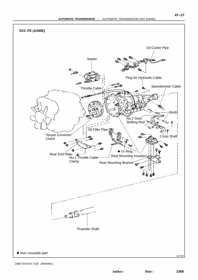
Q07585
5VZ−FE (A340E)
Starter
Oil Cooler Pipe
Plug for Hydraulic Cable
Speedometer Cable
Bush
No.2 Gear Shifting Rod
No.1 Throttle CableClamp
Torque ConverterClutch
Rear End Plate
Propeller Shaft
� Non−reusable part
Oil Filler Pipe
� O−Ring
Rear Mounting Bracket
Cross Shaft
x6
Throttle Cable
Rear Mounting Insulator
−AUTOMATIC TRANSMISSION AUTOMATIC TRANSMISSION UNIT (A340E)AT−27
1368Author�: Date�:
1996 TOYOTA T100 (RM449U)
https://www.truck-manuals.net/

AT02B−02
Q06797
Q06962
3RZ−FE
AT−28−AUTOMATIC TRANSMISSION AUTOMATIC TRANSMISSION UNIT (A340E)
1996 TOYOTA T100 (RM449U)
REMOVAL1. REMOVE ATF LEVEL GAUGE2. REMOVE ENGINE UNDER COVER3. DISCONNECT THROTTLE CABLE(a) Loosen the nut and disconnect the cable.(b) Remove the throttle cable from the clamps.4. 5VZ−FE:
REMOVE NO.1 THROTTLE CABLE CLAMPRemove the 2 nuts and No.1 throttle cable clamp.5. JACK UP VEHICLE
6. REMOVE OIL FILLER PIPERemove the bolt and oil filler pipe with the O−ring.HINT:At the time of reassembly, please refer to the following item.Replace used O−ring with a new one.7. REMOVE PROPELLER SHAFT (See page PR−3)
8. 3RZ−FE:REMOVE FRONT EXHAUST PIPE
(a) Disconnect the oxygen sensor connector.(b) Remove the 2 bolts and retainer.
Torque: 48 N·m (490 kgf·cm, 35 ft·lbf)(c) Loosen the clamp bolt and disconnect the clamp from the
support bracket.Torque: 19 N·m (195 kgf·cm, 14 ft·lbf)
(d) Remove the 2 bolts and support bracket.Torque: 71 N·m (730 kgf·cm, 53 ft·lbf)
(e) Remove the 3 nuts, front exhaust pipe and 3 gaskets.Torque: 62 N·m (630 kgf·cm, 40 ft·lbf)
HINT:At the time of reassembly, please refer to the following item.Replace the used 3 gaskets with new ones.
https://www.truck-manuals.net/

Q06796
5VZ−FE
Q06806
Z18883
AB
C
Q06986
−AUTOMATIC TRANSMISSION AUTOMATIC TRANSMISSION UNIT (A340E)AT−29
1996 TOYOTA T100 (RM449U)
9. 5VZ−FE:REMOVE FRONT EXHAUST PIPE
(a) Disconnect the oxygen sensor connector.(b) Remove the 2 bolts and retainer.
Torque: 48 N·m (490 kgf·cm, 35 ft·lbf)(c) Remove the 3 bolts and support bracket.
Torque: 44 N·m (450 kgf·cm, 33 ft·lbf)(d) Remove the 3 nuts, front exhaust pipe and 3 gaskets.
Torque: 62 N·m (630 kgf·cm, 40 ft·lbf)HINT:At the time of reassembly, please refer to the following item.Replace the used 3 gaskets with new ones.
10. DISCONNECT SPEEDOMETER CABLE(a) Loosen the serrated collar with pliers. Do not lose the felt
dust protector and washer.(b) Disconnect the cable.11. DISCONNECT NO.2 VEHICLE SPEED SENSOR CON-
NECTOR AND SOLENOID CONNECTOR
12. REMOVE CROSS SHAFT(a) Remove the clip and disconnect the No.2 gear shifting
rod.(b) Remove the nut, washer, 4 bolts and the cross shaft.
Torque:A (Transmission side): 13 N·m (130 kgf·cm, 9 ft·lbf)B (Frame side): 28 N·m (290 kgf·cm, 21 ft·lbf)C (Nut): 13 N·m (130 kgf·cm, 9 ft·lbf)
13. REMOVE OIL COOLER PIPE(a) Remove the bolts and 3 clamps.(b) Disconnect the 2 oil cooler pipes.
Torque: 34 N·m (350 kgf·cm, 25 ft·lbf)
https://www.truck-manuals.net/

Z15673
3RZ−FE
5VZ−FE
Q06810
3RZ−FE
Z14791
5VZ−FE
Q02647
AT−30−AUTOMATIC TRANSMISSION AUTOMATIC TRANSMISSION UNIT (A340E)
1996 TOYOTA T100 (RM449U)
14. DISCONNECT ATF TEMPERATURE SENSOR15. DISCONNECT PARK/NEUTRAL POSITION SWITCH
CONNECTOR16. DISCONNECT STARTER WIRE(a) Remove the nut and disconnect the starter wire.(b) Disconnect the starter connector.17. REMOVE FRONT STABILIZER BAR
(See page SA−124)
18. 3RZ−FE:REMOVE REAR END PLATE
Remove the 4 bolts, 2 nuts and rear end plate.Torque: 37 N·m (380 kgf·cm, 27 ft·lbf)
19. 5VZ−FE:REMOVE REAR END PLATE
Remove the 4 nuts, bolts and rear end plate.Torque: 37 N·m (380 kgf·cm, 27 ft·lbf)
20. 3RZ−FE:DISCONNECT REAR MOUNTING INSULATOR
Remove the 3 bolts and disconnect the rear mounting insulator.Torque: 18 N·m (180 kgf·cm, 13 ft·lbf)
21. 5VZ−FE:DISCONNECT REAR MOUNTING INSULATOR
Remove the 4 bolts and disconnect the rear mounting insulator.Torque: 18 N·m (180 kgf·cm, 13 ft·lbf)
22. JACK UP TRANSMISSION23. REMOVE TRANSMISSION WITH ENGINE(a) Turn the crankshaft to gain access to each bolt, remove
the 6 bolts with holding the crankshaft pully bolt with awrench.Torque: 41 N·m (420 kgf·cm, 30 ft·lbf)
(b) Disconnect the wire harness and connectors from thetransmission.
(c) Remove the transmission with the engine from the ve-hicle. (See page 3RZ−FE EM−65, 5VZ−FE EM−65)
https://www.truck-manuals.net/

Q06878
3RZ−FE
Q06879
5VZ−FE
−AUTOMATIC TRANSMISSION AUTOMATIC TRANSMISSION UNIT (A340E)AT−31
1996 TOYOTA T100 (RM449U)
24. 3RZ−FE:REMOVE TRANSMISSION FROM ENGINE
(a) Remove the 2 starter bolts and starter.Torque: 39 N·m (400 kgf·cm, 29 ft·lbf)
(b) Remove the 3 transmission mounting bolts from the en-gine.Torque: 71 N·m (730 kgf·cm, 53 ft·lbf)
(c) Pull out the transmission toward the rear.
25. 5VZ−FE:REMOVE TRANSMISSION FROM ENGINE
(a) Remove the 2 starter bolts and starter.Torque: 39 N·m (400 kgf·cm, 29 ft·lbf)
(b) Remove the 6 transmission mounting bolts from the en-gine.Torque: 71 N·m (730 kgf·cm, 53 ft·lbf)
(c) Pull out the transmission toward the rear.
https://www.truck-manuals.net/

D00842
AT02C−01
AT−32−AUTOMATIC TRANSMISSION AUTOMATIC TRANSMISSION UNIT (A340E)
1996 TOYOTA T100 (RM449U)
INSTALLATION1. CHECK TORQUE CONVERTER CLUTCH INSTALLA-
TIONUsing calipers and a straight edge, measure the distance fromthe installed surface of the transmission housing to the installedsurface of the torque converter clutch.
Correct distance:More than 31.75 mm (1.2500 in.) for 3RZ−FEMore than 17.95 mm (0.7067 in.) for 5VZ−FE
2. INSTALL TRANSMISSIONInstallation is in the reverse order of removal (See pageAT−28).HINT:� After installation, adjust the shift lever position (See page
DI−265).� Fill ATF and check the fluid level (See page DI−265).
https://www.truck-manuals.net/

AT02D−02
Q07586
x6
5VZ−FE (A340F)
Oil Cooler Pipe Shift Lever KnobTransfer Shift Lever
Staeter Plug for Hydraulic TestSpeedmeter Cable
Boot
Snap Ring
Oil Filler Pipe
No. 1 Throttle CableClampThrottle Cable
TorqueConverterClutch
Stiffener Plate
� O−Ring
Bush
No. 2 GearShifting Rod
Rear End Plate
x6
Cross ShaftRear Mounting Isulator
Rear Support Member
Dynamic DamperTransfer Under Cover
Retainer
TWC� GasketFront Exhaust Pipe
� Gasket
Bracket
Stabilizer Bar
Engine Under Cover Protector
Rear Propeller Shaft
Front Propeller Shaft
� Non−reusable part
−AUTOMATIC TRANSMISSION AUTOMATIC TRANSMISSION UNIT (A340F)AT−33
1374Author�: Date�:
1996 TOYOTA T100 (RM449U)
AUTOMATIC TRANSMISSION UNIT (A340F)COMPONENTS
https://www.truck-manuals.net/

AT02E−02
Q02639
Q02640
D10996
AT−34−AUTOMATIC TRANSMISSION AUTOMATIC TRANSMISSION UNIT (A340F)
1996 TOYOTA T100 (RM449U)
REMOVAL1. REMOVE ENGINE UNDER COVER2. DISCONNECT THROTTLE CABLE(a) Loosen the nut and disconnect the cable.(b) Remove the throttle cable from the clamp.
3. REMOVE TRANSFER SHIFT LEVER FROM INSIDE OFVEHICLE
(a) Remove the shift lever knob.(b) Remove the 4 screws and the boot.
(c) Using pliers, remove the snap ring and pull out the shiftlever from the transfer.
HINT:At the time of reassembly, please refer to the following item.Apply MP grease to the transfer shift lever.
4. REMOVE NO.1 THROTTLE CABLE CLAMPRemove the 2 nuts and No.1 throttle cable clamp.5. JACK UP VEHICLE6. REMOVE OIL FILLER PIPERemove the bolt and oil filler pipe with the O−ring.HINT:At the time of reassembly, please refer to the following item.Re-place the used O−ring with a new one.7. REMOVE FRONT AND REAR PROPELLER SHAFT
(See page PR−11)8. REMOVE FRONT EXHAUST PIPE (See page EM−108)
https://www.truck-manuals.net/

Q04688
Z18883
B A
C
Q06800
−AUTOMATIC TRANSMISSION AUTOMATIC TRANSMISSION UNIT (A340F)AT−35
1996 TOYOTA T100 (RM449U)
9. DISCONNECT SPEEDOMETER CABLE(a) Loosen the serrated collar with pliers. Do not lose the felt
dust protector and washer.(b) Disconnect the cable.10. DISCONNECT NO.2 VEHICLE SPEED SENSOR CON-
NECTOR11. DISCONNECT SOLENOID CONNECTOR12. DISCONNECT TRANSFER NEUTRAL POSITION
SWITCH13. DISCONNECT TRANSFER L4 POSITION SWITCH14. DISCONNECT TRANSFER INDICATOR SWITCH15. SEPARATE WIRE HARNESS FROM TRANSMISSION
AND TRANSFER
16. REMOVE CROSS SHAFT(a) Remove the clip and disconnect the No.2 gear shifting
rod.(b) Remove the nut, washer, 4 bolts and the cross shaft.
Torque:A (Transmission side): 13 N·m (130 kgf·cm, 9 ft·lbf)B (Frame side): 28 N·m (290 kgf·cm, 21 ft·lbf)C (Nut): 13 N·m (130 kgf·cm, 9 ft·lbf)
17. DISCONNECT STARTER WIRE(a) Remove the nut and disconnect the starter wire.(b) Disconnect the starter connector.
18. REMOVE OIL COOLER PIPE(a) Remove the bolt and front side oil cooler pipe clamp.(b) Remove the bolt and rear side oil cooler pipe clamp.(c) Disconnect the 2 oil cooler pipes.
Torque: 34 N·m (350 kgf·cm, 25 ft·lbf)19. DISCONNECT ATF TEMPERATURE SENSOR CON-
NECTOR20. DISCONNECT PARK/NEUTRAL POSITION SWITCH
CONNECTOR
https://www.truck-manuals.net/

Q06801
Q06802
Q06881
Q02647
Q06804
AT−36−AUTOMATIC TRANSMISSION AUTOMATIC TRANSMISSION UNIT (A340F)
1996 TOYOTA T100 (RM449U)
21. REMOVE STARTERRemove the 2 bolts and starter.
Torque: 39 N·m (400 kgf·cm, 29 ft·lbf)
22. REMOVE STIFFENER PLATE AND REAR END PLATERemove the 8 bolts, LH, RH stiffener plates and rear end plate.
Torque: 37 N·m (380 kgf·cm, 27 ft·lbf)23. REMOVE FRONT STABILIZER BAR (See page
SA−127)24. JACK UP TRANSMISSION
25. DISCONNECT REAR MOUNTING INSULATOR(a) Remove the 2 bolts and dynamic damper.
Torque: 61 N·m (620 kgf·cm, 44 ft·lbf)(b) Remove the 4 bolts and rear mounting bracket.
Torque: 18 N·m (180 kgf·cm, 13 ft·lbf)26. REMOVE REAR SUPPORT MEMBERRemove the 8 bolts and support member.
Torque: 95 N·m (970 kgf·cm, 70 ft·lbf)
27. REMOVE TRANSMISSION(a) Turn the crankshaft to gain access to each bolt, remove
the 6 bolts with holding the crankshaft pully bolt with awrench.Torque: 41 N·m (420 kgf·cm, 30 ft·lbf)
(b) Disconnect the wire harness and connectors from thetransmission.
(c) Remove the 6 bolts and transmission.Torque: 71 N·m (730 kgf·cm, 53 ft·lbf)
https://www.truck-manuals.net/

D00842
AT02F−01
−AUTOMATIC TRANSMISSION AUTOMATIC TRANSMISSION UNIT (A340F)AT−37
1996 TOYOTA T100 (RM449U)
INSTALLATION1. CHECK TORQUE CONVERTER CLUTCH INSTALLA-
TIONUsing calipers and a straight edge, measure from the installedsurface of the transmission housing.
Correct distance: More than 17.95 mm (0.7067 in.)2. INSTALL TRANSMISSIONInstallation is in the reverse order of removal (See pageAT−34).HINT:� After installation, adjust the shift lever position (See page
DI−265).� Fill ATF and check fluid level (See page DI−265).
https://www.truck-manuals.net/

AT0953
SST
AT02G−06
AT3306
Free
Lock
Hold
Turn
D00843
AT−38−AUTOMATIC TRANSMISSION TORQUE CONVERTER CLUTCH AND DRIVE PLATE
1379Author�: Date�:
1996 TOYOTA T100 (RM449U)
TORQUE CONVERTER CLUTCHAND DRIVE PLATEINSPECTION1. INSPECT ONE−WAY CLUTCH(a) Install SST in the inner race of one−way clutch.
SST 09350−30020 (09351−32010)(b) Install SST so that it fits in the notch of the converter hub
and outer race of the one−way clutch.SST 09350−30020 (09351−32020)
(c) With the torque converter clutch standing on its side,check that the clutch locks when turned counterclock-wise, and rotates freely and smoothly clockwise.
If necessary, clean the converter and retest the clutch.(d) Replace the converter if the clutch still fails the test.
2. MEASURE DRIVE PLATE RUNOUT AND INSPECTRING GEAR
Set up a dial indicator, measure the drive plate runout.Maximum runout: 0.20 mm (0.0079 in.)
If runout is not within the specification or if the ring gear is dam-aged, replace the drive plate.
Torque: 83 N·m (850 kgf·cm, 61 ft·lbf)
https://www.truck-manuals.net/

AT4184
−AUTOMATIC TRANSMISSION TORQUE CONVERTER CLUTCH AND DRIVE PLATEAT−39
1380Author�: Date�:
1996 TOYOTA T100 (RM449U)
3. MEASURE TORQUE CONVERTER CLUTCH SLEEVERUNOUT
Temporarily mount the torque converter clutch to the driveplate.Set up a dial indicator, measure the torque corverter clutchsleeve runout.
Maximum runout: 0.30 mm (0.0118 in.)If runout is not within the specification, try to correct by reorient-ing the installation of the converter clutch.HINT:Mark the position of the converter clutch to ensure the correctinstallation.
https://www.truck-manuals.net/

TR – TRANSFER
TRANSFER SYSTEM TR-1 TROUBLESHOOTING TR-2
TRANSFER UNIT TR-3 TRANSFER ASSEMBLY TR-5 OIL PUMP BODY TR-17 DRIVEN SPROCKET TR-21 REAR OUTPUT SHAFT TR-23 INPUT SHAFT TR-30 PLANETARY GEAR TR-33 OIL SEAL TR-36
https://www.truck-manuals.net/
TR01P−01
−TRANSFER TRANSFER SYSTEMTR−1
1381Author�: Date�:
1996 TOYOTA T100 (RM449U)
TRANSFER SYSTEMPRECAUTIONWhen working with FIPG material, you must be observe the following.� Using a razor blade and gasket scraper, remove all the old FIPG material from the gasket sur-
faces.� Thoroughly clean all components to remove all the loose material.� Clean both sealing surfaces with a non−residue solvent.� Apply the FIPG in approx. a 1 mm (0.04 in.) wide bead along the sealing surface.� Parts must be assembled within 10 minutes of application. Otherwise, the FIPG material must
be removed and reapplied.
https://www.truck-manuals.net/

TR01Q−01
TR−2−TRANSFER TROUBLESHOOTING
1382Author�: Date�:
1996 TOYOTA T100 (RM449U)
TROUBLESHOOTINGPROBLEM SYMPTOMS TABLEUse the table below to help you find the cause of the problem. The numbers indicate the priority of the likelycause of the problem. Check each part in order. If necessary, replace these parts.
Symptom Suspect Area See page
Noise
1. Oil (Level low)
2. Oil (Wrong)
3. Transfer faulty
−
−
TR−5
Oil leakage
1. Oil (Level too high)
2. Gasket (Damaged)
3. Oil seal (Worn or damaged)
4. O−ring (Worn or damaged)
−
−
TR−36
TR−36
Tight corner braking Center differential or transfer faulty TR−5
https://www.truck-manuals.net/

TR0CY−02
TF0626
Breather Hose
Transmission Side Transfer Side
TF0633
TF0655
TF0654
−TRANSFER TRANSFER UNITTR−3
1383Author�: Date�:
1996 TOYOTA T100 (RM449U)
TRANSFER UNITREMOVAL1. REMOVE TRANSFER WITH TRANSMISSION
M/T (See page MT−7)A/T (See page AT−34)
HINT:At the time of installation, shift the 2 shift fork shafts to the H4position.
2. A/T:REMOVE BREATHER HOSE
Disconnect the breather hose from transfer upper cover andtransmission control retainer.
Hose depth: 13 mm (0.51 in.) or more
3. REMOVE DYNAMIC DAMPERRemove the 2 bolts and dynamic damper.
Torque: 37 N·m (380 kgf·cm, 27 ft·lbf)
4. REMOVE ENGINE REAR MOUNTINGRemove the 4 bolts and engine rear mounting from the trans-mission.
Torque: 25 N·m (250 kgf·cm, 18 ft·lbf)
5. REMOVE PROPELLER SHAFT UPPER DUST COVERAND TRANSFER FROM TRANSMISSION
(a) Remove the dust cover bolt from the bracket.Torque: 23 N·m (230 kgf·cm, 17 ft·lbf)
(b) Remove the transfer adapter rear mounting bolts.(c) Pull the transfer straight up and remove it from the trans-
mission.HINT:Take care not to damage the adaptor rear oil seal with the trans-fer input gear spline.
https://www.truck-manuals.net/

TR01T−01
TR−4−TRANSFER TRANSFER UNIT
1996 TOYOTA T100 (RM449U)
INSTALLATIONInstallation is in the reverse order of removal (See page TR−3).1. APPLY MP GREASE TO TRANSFER ADAPTOR OIL SEAL2. AFTER INSTALLATION, DO ROAD TEST
https://www.truck-manuals.net/

TR01U−02
�
−TRANSFER TRANSFER ASSEMBLYTR−5
1385Author�: Date�:
1996 TOYOTA T100 (RM449U)
TRANSFER ASSEMBLYCOMPONENTS
https://www.truck-manuals.net/

TR−6−TRANSFER TRANSFER ASSEMBLY
1386Author�: Date�:
1996 TOYOTA T100 (RM449U)
https://www.truck-manuals.net/

TR0CZ−01
TF0629
TF0447
Q09400
FIPG
−TRANSFER TRANSFER ASSEMBLYTR−7
1996 TOYOTA T100 (RM449U)
DISASSEMBLY1. REMOVE SPEEDOMETER DRIVEN GEAR
Torque: 11 N·m (115 kgf·cm, 8 ft·lbf)2. REMOVE TRANSFER INDICATOR SWITCH
Torque: 37 N·m (380 kgf·cm, 27 ft·lbf)3. A/T:
REMOVE TRANSFER L4 AND NEUTRAL POSITIONSWITCHTorque: 37 N·m (380 kgf·cm, 27 ft·lbf)
HINT:At the time of installation, check the following items.� Check to see that the input shaft and output shafts rotate
smoothly.� Check to see that shifting can be made smoothly to all
position.
4. A/T:REMOVE SHIFT GEAR HEAD NO.1 AND NO.2
(a) Using a pin punch and hammer, drive out the 2 slottedspring pins.
(b) Remove the 2 shift gear heads.
5. REMOVE FRONT RETAINER(a) Remove the 7 bolts.
Torque: 12 N·m (120 kgf·cm, 9 ft·lbf)HINT:At the time of installation, apply liquid sealer to the bolts.
Sealant:Part No.08833−00080, THREE BOND 1344,LOCTITE 242 or equivalent
(b) Using a plastic hammer, tap the front retainer and removeit.
HINT:At the time of installation, please refer to the following items.� Remove any FIPG material and be careful not to drop oil
on the contacting surfaces of the front retainer.� Apply FIPG to the front retainer, as shown.
FIPG:Part No.08826−00090, THREE BOND 1281,LOCTITE 242 or equivalent
https://www.truck-manuals.net/

TF0448
TF0614
TF0451
SST
Q06503
SST
TR−8−TRANSFER TRANSFER ASSEMBLY
1996 TOYOTA T100 (RM449U)
6. M/T:REMOVE CONTROL RETAINER
(a) Remove the 4 bolts, control retainer and gasket.Torque: 18 N·m (185 kgf·cm, 13 ft·lbf)
HINT:At the time of installation, install a new gasket.(b) Remove the select return spring from the retainer.
7. A/T:REMOVE UPPER COVER AND OIL DEFLECTOR
Remove the 4 bolts, upper cover, 2 gaskets and oil deflector.Torque: 18 N·m (185 kgf·cm, 13 ft·lbf)
HINT:At the time of installation, install a new gasket.8. REMOVE FRONT COMPANION FLANGE(a) Using a chisel and hammer, loosen the staked part of the
nut.HINT:At the time of installation, stake a new lock nut.
(b) Using SST to hold the flange, remove the companionflange lock nut.SST 09330−00021Torque: 118 N·m (1,200 kgf·cm, 87 ft·lbf)
(c) Using SST, remove the companion flange.SST 09950−40010
9. REMOVE REAR COMPANION FLANGERemove the rear companion flange in the same way as the frontcompanion flange.HINT:At the time of installation, please refer to the following items.� Front companion flange bolts are silver.� Rear companion flange bolts are black.
https://www.truck-manuals.net/

TF0453
F02979
FIPG
TF0454
TF0455
Z14087
FIPG
−TRANSFER TRANSFER ASSEMBLYTR−9
1996 TOYOTA T100 (RM449U)
10. REMOVE EXTENSION HOUSING(a) Remove the 5 bolts.
Torque: 12 N·m (120 kgf·cm, 9 ft·lbf)HINT:At the time of installation, apply liquid sealer to the bolts.
Sealant:Part No.08833−00080, THREE BOND 1344,LOCTITE 242 or equivalent
(b) Using a plastic hammer, tap the extension housing andremove it.
HINT:At the time of installation, please refer to the following items.� Remove any FIPG material and be careful not to drop oil
on the contacting surfaces of the extension housing.� Apply FIPG to the extension housing, as shown.
FIPG:Part No.08826−00090,THREE BOND 1281 or equivalent
11. REMOVE SPEEDOMETER DRIVE GEAR(a) Remove the speedometer drive gear.HINT:At the time of installation, please refer to the following item.Make sure to install the speedometer drive gear in the correctdirection.(b) Using a magnetic finger, remove the ball from the rear out-
put shaft.
12. SEPARATE FRONT CASE AND REAR CASE(a) Remove the 12 bolts.
Torque: 28 N·m (285 kgf·cm, 20 ft·lbf)(b) Using a plastic hammer, tap the rear case and separate
the front case and rear case.
HINT:At the time of installation, please refer to the following items.� Shift the high and low clutch sleeve to low side (rear side)
and assemble the front case and rear case.� Remove any FIPG material and be careful not to drop oil
on the contacting surfaces of the rear case.� Apply FIPG to the rear case, as shown.
FIPG:Part No.08826−00090,THREE BOND 1281 or equivalent
https://www.truck-manuals.net/

TF0457
TF0458
TF0459
TF0619 F03415
M/T:
A/T:
TR−10−TRANSFER TRANSFER ASSEMBLY
1996 TOYOTA T100 (RM449U)
13. REMOVE STRAIGHT SCREW PLUGS, SPRINGS ANDLOCKING BALLS
(a) Using a hexagon wrench, remove the 2 straight screwplugs.Torque: 19 N·m (190 kgf·cm, 14 ft·lbf)
HINT:At the time of installation, apply liquid sealer to the plugs.
Sealant:Part No.08833−00080, THREE BOND 1344,LOCTITE 242 or equivalent
(b) Using a magnetic finger, remove the spring and ball fromthe both holes.
14. REMOVE FRONT DRIVE FORK SHAFT, FORK,SPRING AND STOPPER
(a) Using a pin punch and hammer, drive out the 2 slottedspring pins.
HINT:When the pin is removed from the front drive fork shaft, the shaftwill spring loose if the pin punch is removed, so keep the pinpunch inserted in the shaft hole.
https://www.truck-manuals.net/

TF0558
TF0622F03416
M/T:
A/T:
TF0460
−TRANSFER TRANSFER ASSEMBLYTR−11
1996 TOYOTA T100 (RM449U)
HINT:At the time of installation, please refer to the following item.When installing the pin in the front drive fork shaft, push theshaft towards the rear case and install the pin while the springis compressed.
(b) Hold the front drive fork shaft in place by hand, when re-moving the pin punch.
(c) Remove the front drive fork shaft, spring and fork.HINT:At the time of installation, please refer to the following items.� Place the front drive shift fork into the groove of the clutch
sleeve.� Make sure to install the shift fork and stopper in the correct
direction.
https://www.truck-manuals.net/

TF0462
TF0464
TF0465
TR−12−TRANSFER TRANSFER ASSEMBLY
1996 TOYOTA T100 (RM449U)
(d) Using a magnetic finger, remove the straight pin.HINT:At the time of installation, please refer to the following item.Apply gear oil to the straight pin and insert it into the case hole.
15. REMOVE HIGH AND LOW FORK SHAFT, SHIFT FORKAND STOPPER
HINT:At the time of installation, please refer to the following items.� Place the high and low shift fork into the groove of the
clutch sleeve.� Make sure to install the shift fork in the correct direction.
16. REMOVE REAR OUTPUT SHAFT, DRIVENSPROCKET AND CHAIN
(a) Using a snap ring expander, remove the snap ring.
(b) Mount the rear case in the vise.NOTICE:Be careful not to damage the sealing surface.(c) Using a plastic hammer, tap the rear case with pulling the
rear output shaft and driven sprocket.HINT:At the time of installation, please refer to the following item.If necessary, heat the rear case to about 70°C (158°F).(d) Remove the chain.
https://www.truck-manuals.net/

Q10176
TF0467
TF0468
TF0470
TF0471
−TRANSFER TRANSFER ASSEMBLYTR−13
1996 TOYOTA T100 (RM449U)
17. M/T:REMOVE SYNCHRONIZER RING FROM INPUTSHAFT
HINT:At the time of installation, please refer to the following items.� Apply gear oil to the synchronizer ring.� Align the synchronizer ring slots with the shifting keys,
and install it on the high and low clutch hub.
18. REMOVE SEPARATOR WITH OIL STRAINER(a) Remove the 3 bolts and the separator with the oil strainer.
Torque: 18 N·m (185 kgf·cm, 13 ft·lbf)(b) Remove the O−ring from the oil strainer pipe.HINT:At the time of installation, please refer to the following item.Coat a new O−ring with gear oil and install it to the oil strainerpipe.
19. REMOVE OIL PUMP BODY ASSEMBLYRemove the 3 bolts and the oil pump body assembly.
Torque: 11 N·m (115 kgf·cm, 8 ft·lbf)20. REMOVE OIL PUMP DRIVE GEAR
21. REMOVE PLANETARY GEAR ASSEMBLY WITHINPUT SHAFT
(a) Using a snap ring expander, remove the snap ring.
(b) Pull out the planetary gear assembly with the input shaft.HINT:At the time of installation, please refer to the following item.If necessary, heat the front case to about 70°C (158°F).
https://www.truck-manuals.net/

TF0473
TF0474
TR−14−TRANSFER TRANSFER ASSEMBLY
1996 TOYOTA T100 (RM449U)
22. REMOVE LOW GEAR SPLINE PIECE(a) Using a screwdriver, remove the snap ring.HINT:At the time of installation, please refer to the following item.Be sure the end gap of the snap ring is not aligned with cutoutportion of the planetary carrier.(b) Remove the low gear spline piece.
23. REMOVE NEEDLE ROLLER BEARING FROM INPUTSHAFT
HINT:At the time of installation, apply gear oil to the needle roller bear-ing.24. REMOVE INPUT SHAFT STOPPER AND THRUST
BEARING(a) Using a snap ring expander, remove the snap ring.HINT:At the time of installation, please refer to the following item.Select a snap ring that will allow 0.05 − 0.15 mm (0.0020 −0.0059 in.) axial play.
Mark Thickness mm (in.)
A 2.10 − 2.15 (0.0827 − 0.0846)
B 2.15 − 2.20 (0.0846 − 0.0866)
C 2.20 − 2.25 (0.0866 − 0.0886)
D 2.25 − 2.30 (0.0886 − 0.0906)
E 2.30 − 2.35 (0.0906 − 0.0925)
F 2.35 − 2.40 (0.0925 − 0.0945)
G 2.40 − 2.45 (0.0945 − 0.0965)
H 2.45 − 2.50 (0.0965 − 0.0984)
J 2.50 − 2.55 (0.0984 − 0.1004)
K 2.55 − 2.60 (0.1004 − 0.1024)
L 2.60 − 2.65 (0.1024 − 0.1043)
M 2.65 − 2.70 (0.1043 − 0.1063)
N 2.70 − 2.75 (0.1063 − 0.1083)
P 2.75 − 2.80 (0.1083 − 0.1102)
Q 2.80 − 2.85 (0.1102 − 0.1122)
R 2.85 − 2.90 (0.1122 − 0.1142)
S 2.90 − 2.95 (0.1142 − 0.1161)
T 2.95 − 3.00 (0.1161 − 0.1181)
U 3.00 − 3.05 (0.1181 − 0.1201)
https://www.truck-manuals.net/

TF0477
TF0478
TF0479
TF0507
−TRANSFER TRANSFER ASSEMBLYTR−15
1996 TOYOTA T100 (RM449U)
(b) Remove the input gear stopper, thrust bearing, race andthe 2 pins.
HINT:At the time of installation, apply gear oil to the thrust bearing andrace.
25. REMOVE INPUT SHAFT, THRUST BEARING ANDRACE
26. REMOVE PLANETARY RING GEAR(a) Using a screwdriver, remove the snap ring.HINT:At the time of installation, please refer to the following item.Be sure the end gap of the snap ring is not aligned with the up-per side of the case.
(b) Remove the plug, spring and pin.Torque: 19 N·m (190 kgf·cm, 14 ft·lbf)
HINT:At the time of installation, apply liquid sealer to the plug.
Sealant:Part No.08833−00080, THREE BOND 1344,LOCTITE 242 or equivalent
(c) Remove the planetary ring gear.HINT:At the time of installation, make sure to install the ring gear inthe correct direction.
https://www.truck-manuals.net/

TR01W−01
TR−16−TRANSFER TRANSFER ASSEMBLY
1996 TOYOTA T100 (RM449U)
REASSEMBLYReassembly is in the reverse order of disassembly (See page TR−7).HINT:Coat all of the sliding and rotating surfaces with gear oil before assembly.
https://www.truck-manuals.net/

TR01X−02
−TRANSFER OIL PUMP BODYTR−17
1397Author�: Date�:
1996 TOYOTA T100 (RM449U)
OIL PUMP BODYCOMPONENTS
https://www.truck-manuals.net/

TR0D0−01
TF0547
TF0485
TR−18−TRANSFER OIL PUMP BODY
1996 TOYOTA T100 (RM449U)
DISASSEMBLY1. CHECK OIL PUMP OPERATIONInstall the oil pump drive gear to the drive rotor and check thatthe drive rotor turns smoothly.
2. REMOVE STRAIGHT SCREW PLUG, SPRING, BALLAND SEAT
(a) Using a hexagon wrench, remove the straight screw plug.Torque: 29 N·m (300 kgf·cm, 22 ft·lbf)
HINT:At the time of installation, apply liquid sealer to the plug.
Sealant:Part No. 08833−00080, THREE BOND 1344, LOCTITE242 or equivalent
(b) Using a magnetic finger remove the spring and ball.(c) Using SST, pull out the seat.
SST 09921−00010(d) Remove the O−ring from the seat.HINT:At the time of reassembly, please refer to the following items.� Install a new O−ing to the seat.� When installing the seat, push the seat until it touches the
bottom of the hole in the body.
3. REMOVE OIL PUMP PLATE(a) Using a torx socket wrench (T30), unscrew the 3 torx
screws.Torque: 7.4 N·m (75 kgf·cm, 65 in.·lbf)
(b) Remove the oil pump plate.4. REMOVE DRIVE ROTOR AND DRIVEN ROTORHINT:At the time of reassembly, apply gear oil to the both rotors.
https://www.truck-manuals.net/

TR0D1−01
TF0486
TF0487
TF0488
−TRANSFER OIL PUMP BODYTR−19
1996 TOYOTA T100 (RM449U)
INSPECTION1. INSPECT DRIVEN ROTOR BODY CLEARANCE(a) Push the driven rotor to one side of the body.(b) Using a feeler gauge, measure the clearance.
Standard clearance:0.10 − 0.16 mm (0.0039 − 0.0063 in.)Maximum clearance: 0.16 mm (0.0063 in.)
If the clearance exceeds the maximum, replace the drive rotor,driven rotor or pump body.
2. INSPECT BOTH ROTORS TIP CLEARANCEUsing a feeler gauge, measure the clearance between both ro-tor tips.
Standard clearance:0.08 − 0.16 mm (0.0031 − 0.0063 in.)Maximum clearance: 0.16 mm (0.0063 in.)
If the clearance exceeds the maximum, replace the drive rotor,driven rotor or pump body.
3. INSPECT BOTH ROTORS SIDE CLEARANCEUsing a steel straight edge and feeler gauge, measure theclearance between the rotors and straight edge.
Standard clearance:0.03 − 0.08 mm (0.0012 − 0.0031 in.)Maximum clearance: 0.08 mm (0.0031 in.)
If the clearance exceeds the maximum, replace the drive rotor,driven rotor or pump body.
https://www.truck-manuals.net/

TR0D2−01
TR−20−TRANSFER OIL PUMP BODY
1996 TOYOTA T100 (RM449U)
REASSEMBLYReassembly is in the reverse order of disassembly (See page TR−18).
https://www.truck-manuals.net/

TR01Z−02
−TRANSFER DRIVEN SPROCKETTR−21
1401Author�: Date�:
1996 TOYOTA T100 (RM449U)
DRIVEN SPROCKETCOMPONENTS
https://www.truck-manuals.net/

TR020−02
TF0512
TF0513
Steel Bar
SST
TF0514
TF0515
TR−22−TRANSFER DRIVEN SPROCKET
1996 TOYOTA T100 (RM449U)
REPLACEMENT1. REMOVE FRONT BEARINGUsing a press, remove the front bearing.
2. REMOVE REAR BEARINGUsing SST, steel bar and a press, remove the rear bearing.
SST 09950−00020
3. INSTALL REAR BEARINGUsing a press, install the rear bearing.
4. INSTALL FRONT BEARINGUsing a press, install the front bearing.HINT:Make sure to install the bearing in the correct direction.
https://www.truck-manuals.net/

TR021−02
Z19022
A/T:
M/T:
High and Low Clutch Sleeve
High and Low Clutch Hub
� Key Retainer
High and Low Clutch Hub
High and Low Hub Sleeve
Snap Ring
Shifting Key Spring
Snap Ring
Ball
Bearing
SpacerRear Output Shaft
Shifting Key Spring
Front Drive Clutch Sleeve
Drive Sprocket
Needle Roller Bearing
Shifting Key
Synchronizer Ring� Non−reusable part
Shifting Key
−TRANSFER REAR OUTPUT SHAFTTR−23
1403Author�: Date�:
1996 TOYOTA T100 (RM449U)
REAR OUTPUT SHAFTCOMPONENTS
https://www.truck-manuals.net/

TR0D3−01
TF0516
TF0517
TF0549
TF0518
SST
TF0620
TR−24−TRANSFER REAR OUTPUT SHAFT
1996 TOYOTA T100 (RM449U)
DISASSEMBLY1. INSPECT DRIVE SPROCKET THRUST CLEARANCEUsing a feeler gauge, measure the drive sprocket thrust clear-ance.
Standard clearance:0.10 − 0.25 mm (0.0039 − 0.0098 in.)Maximum clearance: 0.25 mm (0.0098 in.)
If the clearance exceeds the maximum, replace the drivesprocket.
2. M/T:REMOVE HIGH AND LOW HUB SLEEVEASSEMBLY
(a) Using a snap ring expander, remove the snap ring.(b) Remove the hub sleeve and 3 shifting keys.(c) Using a press, remove the clutch hub, 2 key springs and
key retainer.
3. A/T:REMOVE HIGH AND LOW HUB SLEEVEASSEMBLY
(a) Using a snap ring expander, remove the snap ring.(b) Remove the hub sleeve.(c) Using a press, remove the clutch hub.
4. REMOVE REAR BEARING, SPACER AND DRIVESPROCKET WITH FRONT DRIVE CLUTCH SLEEVEASSEMBLY
(a) Using SST and a press, remove the bearing.SST 09950−00020
(b) Remove these parts:� Spacer and ball� Drive sprocket with front drive hub and hub sleeve� Needle roller bearing� Synchronizer ring
https://www.truck-manuals.net/

TF0531
−TRANSFER REAR OUTPUT SHAFTTR−25
1996 TOYOTA T100 (RM449U)
5. REMOVE 3 SHIFTING KEYS AND 2 KEY SPRINGSFROM FRONT DRIVE HUB ASSEMBLY
Using a screwdriver, remove the 2 shifting key springs and 3shifting keys.
https://www.truck-manuals.net/

TR023−02
Q09962
A B
TF0522
TF0523
TF0524
TR−26−TRANSFER REAR OUTPUT SHAFT
1996 TOYOTA T100 (RM449U)
INSPECTION1. INSPECT REAR OUTPUT SHAFTUsing a micrometer, measure the outer diameter of the rear out-put shaft journal surface.
Minimum diameter:Part A: 27.98 mm (1.1016 in.)Part B: 36.99 mm (1.4563 in.)
2. INSPECT DRIVE SPROCKET RADIAL CLEARANCEUsing a dial indicator, measure the radial clearance betweenthe sprocket and shaft with the needle roller bearing installed.
Standard clearance:0.010 − 0.055 mm (0.0004 − 0.0022 in.)Maximum clearance: 0.055 mm (0.0022 in.)
If the clearance exceeds the maximum, replace the drivesprocket, rear output shaft or needle roller bearing.
3. INSPECT FRONT DRIVE SHIFT FORK AND HUBSLEEVE CLEARANCE
Using a feeler gauge, measure the clearance between the frontdrive shift fork and hub sleeve.
Maximum clearance: 1.0 mm (0.039 in.)If the clearance exceeds the maximum, replace the shift fork orhub sleeve.
4. INSPECT HIGH AND LOW SHIFT FORK AND HUBSLEEVE CLEARANCE
Using a feeler gauge, measure the clearance between the highand low shift fork and hub sleeve.
Maximum clearance: 1.0 mm (0.039 in.)If the clearance exceeds the maximum, replace the shift fork orhub sleeve.
https://www.truck-manuals.net/

TR024−02
TF0621
TF0624
ShiftingKey
Q02329
Slots
TF0532
SST
TF0516
−TRANSFER REAR OUTPUT SHAFTTR−27
1996 TOYOTA T100 (RM449U)
REASSEMBLY1. INSTALL FRONT DRIVE CLUTCH HUB AND HUB
SLEEVE(a) Install the front drive hub sleeve onto the clutch hub.HINT:Make sure to install the hub sleeve in the correct direction.
(b) Install the 3 shifting keys and 2 springs.NOTICE:Install the key springs positioned so that their end gaps arenot in line.
2. INSTALL DRIVE SPROCKET WITH FRONT DRIVEHUB SLEEVE ASSEMBLY, SPACER AND REARBEARING
(a) Apply gear oil to the shaft and needle roller bearing.(b) Install the synchronizer ring.(c) Install the needle roller bearing in the drive sprocket.(d) Install the drive sprocket with the front drive hub sleeve.
(e) Place the synchronizer ring on the gear and align the ringslots with the shifting keys.
(f) Install the spacer to align it with the ball.(g) Using SST and a press, install the rear bearing with the
outer race snap ring groove toward the rear.SST 09316−60011 (09316−00011, 09316−00071)
3. INSPECT DRIVE SPROCKET THRUST CLEARANCEUsing a feeler gauge, measure the drive sprocket thrust clear-ance.
Standard clearance:0.10 − 0.25 mm (0.0039 − 0.0098 in.)
https://www.truck-manuals.net/

TF0528
ShiftingKey
ShiftingKey Spring
Front
M/T:
TF0690
Front
A/T:
TF0553
SST
TF0550
TF0550
TR−28−TRANSFER REAR OUTPUT SHAFT
1996 TOYOTA T100 (RM449U)
4. M/T:INSERT HIGH AND LOW CLUTCH HUB INTO HUBSLEEVE
(a) Install the clutch hub and 3 shifting keys to the hub sleeve.(b) Install the 2 shifting key springs under the 3 shifting keys.NOTICE:Install the key springs positioned so that their end gaps arenot in line.
5. A/T:INSERT HIGH AND LOW CLUTCH HUB INTO HUBSLEEVE
Install the clutch hub to the hub sleeve.
6. M/T:INSTALL HIGH AND LOW HUB SLEEVE ASSEMBLY
(a) Using SST and a hammer, drive in a new key retainer.SST 09316−60011 (09316−00011)
NOTICE:Be careful not to deform or damage the key retainer.
(b) Using a press, install the high and low hub sleeve assem-bly.
7. A/T:INSTALL HIGH AND LOW HUB SLEEVE ASSEMBLY
Using a press, install the high and low hub sleeve assembly.
https://www.truck-manuals.net/

TF0529
−TRANSFER REAR OUTPUT SHAFTTR−29
1996 TOYOTA T100 (RM449U)
8. INSTALL SNAP RINGSelect a snap ring that will allow minimum axial play and installit to the shaft.
Mark Thickness mm (in.)
A 2.10 − 2.15 (0.0827 − 0.0846)
B 2.15 − 2.20 (0.0846 − 0.0866)
C 2.20 − 2.25 (0.0866 − 0.0886)
D 2.25 − 2.30 (0.0886 − 0.0906)
E 2.30 − 2.35 (0.0906 − 0.0925)
F 2.35 − 2.40 (0.0925 − 0.0945)
G 2.40 − 2.45 (0.0945 − 0.0965)
H 2.45 − 2.50 (0.0965 − 0.0984)
J 2.50 − 2.55 (0.0984 − 0.1004)
K 2.00 − 2.05 (0.0787 − 0.0807)
L 2.05 − 2.10 (0.0807 − 0.0827)
https://www.truck-manuals.net/

TR025−02
TR−30−TRANSFER INPUT SHAFT
1410Author�: Date�:
1996 TOYOTA T100 (RM449U)
INPUT SHAFTCOMPONENTS
https://www.truck-manuals.net/

TR026−02
TF0535
TF0552
TF0536
−TRANSFER INPUT SHAFTTR−31
1996 TOYOTA T100 (RM449U)
INSPECTION1. REMOVE SUN GEAR(a) Using snap ring pliers, remove the snap ring.(b) Remove the sun gear from the input shaft.
2. INSPECT INPUT SHAFT(a) Using a micrometer, measure the outer diameter of the in-
put shaft journal surface.Minimum diameter: 47.59 mm (1.8736 in.)
(b) Using a dial indicator, measure the inside diameter of theinput shaft bushing.Maximum inside diameter: 39.14 mm (1.5409 in.)
If the inside diameter exceeds the maximum, replace the inputshaft.
3. M/T:INSPECT SYNCHRONIZER RING
(a) Turn the ring and push it in to check the braking action.
(b) Measure the clearance between the synchronizer ringback and the input shaft spline end.Standard clearance:1.15 − 1.85 mm (0.0453 − 0.0728 in.)Minimum clearance: 0.80 mm (0.0315 in.)
If the clearance is less than the minimum, replace the synchro-nizer ring.
https://www.truck-manuals.net/

TF0537
TR−32−TRANSFER INPUT SHAFT
1996 TOYOTA T100 (RM449U)
4. INSTALL SUN GEAR(a) Install the sun gear to the input shaft.HINT:Make sure to install the sun gear in the correct direction.(b) Using snap ring pliers, install the snap ring.
https://www.truck-manuals.net/
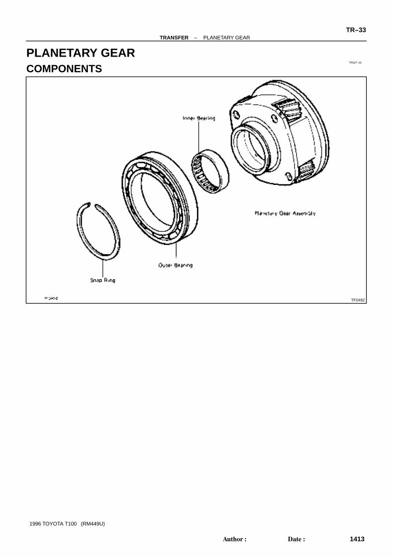
TR027−02
TF0492
−TRANSFER PLANETARY GEARTR−33
1413Author�: Date�:
1996 TOYOTA T100 (RM449U)
PLANETARY GEARCOMPONENTS
https://www.truck-manuals.net/

TR028−02
TF0493
TF0494
TF0496
SST
Q06505
SST
SST
TF0498
TR−34−TRANSFER PLANETARY GEAR
1996 TOYOTA T100 (RM449U)
INSPECTION1. INSPECT PINION GEAR THRUST CLEARANCEUsing a feeler gauge, measure the planetary pinion gear thrustclearance.
Standard clearance:0.11 − 0.86 mm (0.0043 − 0.0339 in.)Maximum clearance: 0.86 mm (0.0339 in.)
If the clearance exceeds the maximum, replace the planetarygear assembly
2. INSPECT PLANETARY PINION GEAR RADIALCLEARANCE
Using a dial indicator, measure the radial clearance of the plan-etary pinion gear.
Standard clearance:0.009 − 0.038 mm (0.0004 − 0.0015 in.)Maximum clearance: 0.038 mm (0.0015 in.)
If the clearance exceeds the maximum, replace the planetarygear assembly.
3. IF NECESSARY, REPLACE PLANETARY GEAR OUT-ER BEARING
(a) Using a snap ring expander, remove the snap ring.(b) Using SST and a press, remove the outer bearing.
SST 09554−30011, 09555−55010
(c) Using SST and a press, install a new bearing with the out-er race snap ring groove the front.SST 09223−15020, 09515−30010, 09550−22011
(09550−00020)
(d) Select a snap ring that will allow minimum axial play.
Mark Thickness mm (in.)
1 1.45 − 1.50 (0.0571 − 0.0591)
2 1.50 − 1.55 (0.0591 − 0.0610)
3 1.55 − 1.60 (0.0610 − 0.0630)
4 1.60 − 1.65 (0.0630 − 0.0650)
5 1.65 − 1.70 (0.0650 − 0.0669)
(e) Using a snap ring expander, install the snap ring.
https://www.truck-manuals.net/

TF0499
TF0538
−TRANSFER PLANETARY GEARTR−35
1996 TOYOTA T100 (RM449U)
4. IF NECESSARY, REPLACE PLANETARY GEAR INNERBEARING
(a) Using SST and a press, remove the bearing.SST 09550−10012 (09252−10010, 09557−10010)
(b) Using SST and a press, install a new bearing.SST 09550−10012 (09252−10010, 09557−10010),
09515−30010Bearing depth: 5.0 − 5.6 mm (0.197 − 0.220 in.)
https://www.truck-manuals.net/

TR029−02
Q06959
� Oil Seal (for A/T) Front Case
Rear Case
Rear Companion Flange
� Oil Seal
Extension Housing
Front Companion Flange
� Non−reusable part
Front Retainer
x5
x7
� Oil Seal
� Oil Seal
� Oil Seal
� Oil Seal
� O−ring
TR−36−TRANSFER OIL SEAL
1416Author�: Date�:
1996 TOYOTA T100 (RM449U)
OIL SEALCOMPONENTS
https://www.truck-manuals.net/

TR0D4−01
TF0500
TF0501
SST
TF0502
TF0503
SST
TF0504
−TRANSFER OIL SEALTR−37
1996 TOYOTA T100 (RM449U)
REPLACEMENT1. REPLACE FRONT RETAINER OIL SEAL(a) Using a screwdriver and hammer, drive out the oil seal.
(b) Using SST and a hammer, drive in a new oil seal until itssurface is flush with the retainer upper surface.SST 09223−22010
(c) Coat the lip of the oil seal with MP grease.
2. REPLACE FRONT CASE OIL SEAL(a) Using a screwdriver and hammer, drive out the oil seal.
(b) Using SST and a hammer, drive in a new oil seal until itssurface is flush with the case upper surface.SST 09316−60011 (09316−00011)
(c) Coat the lip of the oil seal with MP grease.
3. REPLACE EXTENSION HOUSING OIL SEAL(a) Using a screwdriver and hammer, drive out the oil seal.
https://www.truck-manuals.net/

TF0505
TF0506
TF0530
TF0631
TF0630
TR−38−TRANSFER OIL SEAL
1996 TOYOTA T100 (RM449U)
(b) Using SST and a hammer, drive in a new oil seal until itssurface is flush with the housing upper surface.SST 09550−00032, 09550−10012 (09252−10010)
(c) Coat the lip of the oil seal with MP grease.
4. REPLACE FRONT AND REAR COMPANION FLANGEOIL SEALS
(a) Using a screwdriver and hammer, drive out the oil sealsfrom the 2 flanges.
(b) Using a socket wrench and hammer, drive in a new oilseal.
(c) Coat the lip of the oil seal with MP grease.
5. A/T:REPLACE SHIFT FORK SHAFT OIL SEALS
(a) Using a screwdriver, pry out the oil seal.
(b) Using SST and a hammer, drive in a new oil seal.SST 09304−12012Oil seal depth: −0.5 − 0.5 mm (−0.020 − 0.020 in.)
https://www.truck-manuals.net/

PR – PROPELLER SHAFT
TROUBLESHOOTING PR-1
PROPELLER SHAFT ASSEMBLY (2WD) PR-2 PROPELLER SHAFT ASSEMBLY (4WD) PR-10 SPIDER BEARING PR-18
https://www.truck-manuals.net/

PR01F−01
−PROPELLER SHAFT TROUBLESHOOTINGPR−1
1419Author�: Date�:
1996 TOYOTA T100 (RM449U)
TROUBLESHOOTINGPROBLEM SYMPTOMS TABLEUse the table below to help you find the cause of the problem. The numbers indicate the priority of the likelycause of the problem. Check each part in order. If necessary, replace these parts.
Symptom Suspect Area See page
Noise
1. Center support bearing (Worn) 2WD
4WD
2. Sleeve yoke spline (Worn) 2WD
4WD
3. Spider bearing (Worn or stuck) 2WD
4WD
PR−5
PR−13
PR−5
PR−13
PR−5
PR−13
Vibration
1. Transmission extension housing rear bushing (Runout)
2. Sleeve yoke spline (Stuck) 2WD
4WD
3. Propeller shaft (Runout) 2WD
4WD
4. Propeller shaft (Imbalance) 2WD
4WD
−
PR−5
PR−13
PR−5
PR−13
PR−5
PR−13
https://www.truck-manuals.net/

Q06677
� TMC
Spider BearingSnap Ring
Intermediate ShaftSpacer
Center SupportBearingSleeve Yoke
Dust Cover
Flange Yoke
� DANA
�
�
� Non−reusable part
�
�
�
�
�
Flange Yoke
�
�
Spider BearingSnap Ring�
�
Intermediate Shaft
Center Support Bearing
Spacer
Spacer
Center Yoke
Spider�
Sleeve Yoke
Dust Cover
�
�
�
Propeller Shaft
�
�
Flange Yoke
�
Propeller Shaft
Spacer
PR01G−05
PR−2−PROPELLER SHAFT PROPELLER SHAFT ASSEMBLY (2WD)
1420Author�: Date�:
1996 TOYOTA T100 (RM449U)
PROPELLER SHAFT ASSEMBLY (2WD)COMPONENTS
https://www.truck-manuals.net/

PR01H−01
R15507Matchmarks
R04164
SST
−PROPELLER SHAFT PROPELLER SHAFT ASSEMBLY (2WD)PR−3
1996 TOYOTA T100 (RM449U)
REMOVALREMOVE PROPELLER SHAFT(a) Place matchmarks on the differential and propeller shaft
flanges.(b) Remove the 4 bolts, washers and nuts.(c) Remove the 2 mounting bolts and center support bearing
from the frame crossmember.
(d) Pull out the propeller shaft yoke from the transmission.(e) Insert SST in the transmission to prevent oil leakage.
SST 09325−40010
https://www.truck-manuals.net/

PR01I−02
R04398
Matchmarks
F14974
Z04243
Matchmarks
SST
S
Q06614
SST
F14975
PR−4−PROPELLER SHAFT PROPELLER SHAFT ASSEMBLY (2WD)
1996 TOYOTA T100 (RM449U)
DISASSEMBLYNOTICE:Be careful not to grip the propeller shaft tube too tightly ina vise as this will cause deformation.1. TMC−made:
SEPARATE PROPELLER SHAFT AND INTERMEDI-ATE SHAFT
(a) Place matchmarks on the flanges.(b) Remove the 4 bolts, washers and nuts.
2. DANA−made:SEPARATE PROPELLER SHAFT AND INTERMEDI-ATE SHAFT
(a) Place matchmarks on the yoke and propeller shaft.(b) Disassemble center yoke.
(See SPIDER BEARING REPLACEMENT on pagePR−18)
3. TMC−made:REMOVE CENTER SUPPORT BEARING FROM IN-TERMEDIATE SHAFT
(a) Using a hammer and chisel, loosen the staked part of thenut.
(b) Using SST to hold the flange, remove the nut.SST 09330−00021
(c) Place matchmarks on the flange and shaft.
(d) Using SST, remove the flange from the intermediateshaft.SST 09950−30010
(e) Remove the center support bearing from the intermediateshaft.
4. DANA−made:REMOVE CENTER SUPPORT BEARING FROM IN-TERMEDIATE SHAFT
(a) Using a hammer and chisel, loosen the staked part of thenut.
(b) Clamp the yoke in a vise and remove the nut.(c) Place matchmarks on the yoke and shaft.(d) Clamp the yoke in a vise and top off the shaft.(e) Using a brass bar and hammer, remove the center sup-
port bearing from the intermediate shaft.
https://www.truck-manuals.net/

PR01J−01
R04446
R04447
R04478
−PROPELLER SHAFT PROPELLER SHAFT ASSEMBLY (2WD)PR−5
1996 TOYOTA T100 (RM449U)
INSPECTIONNOTICE:Be careful not to grip the propeller shaft tube too tightly ina vise as this will cause deformation.1. INSPECT PROPELLER SHAFT AND INTERMEDIATE
SHAFT FOR DAMAGE OR RUNOUTUsing a dial indicator, check each runout of shaft.
Maximum runout: 0.8 mm (0.031 in.)If shaft runout is greater than the maximum, replace the shaft.
2. INSPECT SPIDER BEARING(a) Inspect the spider bearing for wear or damage.(b) Using a dial indicator, check the spider bearing axial play
by turning the yoke of flange while holding the shaft tight-ly.Bearing axial play: 0.05 mm (0.0020 in.)
3. INSPECT CENTER SUPPORT BEARING FOR WEAROR DAMAGE
Check that the bearing turns freely.If the bearing is damaged, worn, or does not turn freely, replaceit.
https://www.truck-manuals.net/

Z03923
TMC
DANA
PR01K−02
R04431
Front
F14976
PR−6−PROPELLER SHAFT PROPELLER SHAFT ASSEMBLY (2WD)
1996 TOYOTA T100 (RM449U)
REASSEMBLYHINT:When removing or installing any part, make sure that each jointis facing the correct direction, as shown in the illustration below.
1. TMC−made:INSTALL CENTER SUPPORT BEARING ON INTER-MEDIATE SHAFT
HINT:Install the center support bearing in the direction, as shown.
2. INSTALL FLANGE ON INTERMEDIATE SHAFT(a) Coat the splines of the intermediate shaft with MP grease.(b) Place the flange on the shaft and align the marks.HINT:If replacing either the center flange or intermediate shaft, reas-semble them so that the front yoke of the intermediate shaft andthe rear yoke of the propeller shaft are facing in the same direc-tion.
https://www.truck-manuals.net/

Z04251
SST
R04398
Matchmarks
R04431
Front
F
F14975
−PROPELLER SHAFT PROPELLER SHAFT ASSEMBLY (2WD)PR−7
1996 TOYOTA T100 (RM449U)
(c) Using SST to hold the flange, press the bearing into posi-tion by tightening down a new nut.SST 09330−00021Torque: 181 N·m (1,850 kgf·cm, 134 ft·lbf)
(d) Loosen the nut.(e) Torque the nut again.
Torque: 69 N·m (700 kgf·cm, 51 ft·lbf)(f) Using a hammer and chisel, stake the nut.
3. INSTALL PROPELLER SHAFT(a) Align the matchmarks on the flange and connect the
flanges with 4 bolts, washers and nuts.HINT:If replacing either the center flange or intermediate shaft, reas-semble them so that the front yoke of the intermediate shaft andthe rear yoke of the propeller shaft are facing in the same direc-tion.(b) Torque the bolts.
Torque: 74 N·m (750 kgf·cm, 54 ft·lbf)4. DANA−made:
INSTALL CENTER SUPPORT BEARING INTERMEDI-ATE SHAFT
HINT:Install the center support bearing in the direction, as shown.5. INSTALL YOKE ON INTERMEDIATE SHAFT(a) Coat the splines of the intermediate shaft with MP grease.
(b) Place the center yoke on the shaft and align the match-marks.
HINT:If replacing either the center yoke or intermediate shaft.(c) Clamp the yoke in a vise, press the bearing into position
by tightening down a new nut.Torque: 181 N·m (1,850 kgf·cm, 134 ft·lbf)
(d) Loosen the nut.(e) Torque the nut again.
Torque: 81 N·m (830 kgf·cm, 60 ft·lbf)(f) Using a hammer and punch, stake the nut.
https://www.truck-manuals.net/

F14974
PR−8−PROPELLER SHAFT PROPELLER SHAFT ASSEMBLY (2WD)
1996 TOYOTA T100 (RM449U)
6. CONNECT PROPELLER SHAFT AND INTERMEDIATESHAFT
Assemble the center yoke (See SPIDER BEARING REPLACE-MENT on page PR−18).
https://www.truck-manuals.net/

PR07Z−01
R15507Matchmarks
R04434
TMC
90
Bracket CenterLine
Shaft AxialDirection
R04435
DANA
90
Bracket CenterLine
Shaft AxialDirection
−PROPELLER SHAFT PROPELLER SHAFT ASSEMBLY (2WD)PR−9
1996 TOYOTA T100 (RM449U)
INSTALLATION1. INSTALL PROPELLER SHAFT(a) Remove SST from the transmission.
SST 09325−40010(b) Insert the yoke into the transmission.
(c) Temporarily install the center support bearing with 2mounting bolts.
HINT:Make sure the bearing is installed with facing the drain holedownwards.(d) Align the matchmarks on the flanges and connect the
flanges with the 4 bolts, washers and nuts.(e) Torque the 4 bolts.
Torque: 74 N·m (750 kgf·cm, 54 ft·lbf)
2. ADJUST CENTER SUPPORT BEARINGHINT:� With the vehicle unladen, adjust the center support bear-
ing to keep the intervals, as shown.� At the same condition, check the center line in the axial
direction. Adjust the bearing if necessary.� Check that the center line of the center bearing is set to
the center line of the bracket when the vehicle is unladen.Adjust the bracket if necessary.
Torque the 2 bolts.Torque: 36 N·m (370 kgf·cm, 27 ft·lbf)
https://www.truck-manuals.net/

PR01M−04
F14977
PR−10−PROPELLER SHAFT PROPELLER SHAFT ASSEMBLY (4WD)
1428Author�: Date�:
1996 TOYOTA T100 (RM449U)
PROPELLER SHAFT ASSEMBLY (4WD)COMPONENTS
https://www.truck-manuals.net/

PR01N−01
R04437
Matchmarks
R04440
Matchmarks
R04441
Matchmarks
R15508Matchmarks
−PROPELLER SHAFT PROPELLER SHAFT ASSEMBLY (4WD)PR−11
1996 TOYOTA T100 (RM449U)
REMOVAL1. REMOVE FRONT PROPELLER SHAFT(a) Place matchmarks on the differential and propeller shaft
flange.(b) Remove the 4 bolts, washers and nuts, disconnect the
propeller shaft from the differential.(c) M/T:
Remove the 2 bolts, nuts and propeller shaft No.2 dustcover.
(d) Remove the 3 bolts and propeller shaft dust cover.(e) Suspend the front side of the propeller shaft.
(f) Place matchmarks on the transfer and propeller shaftflanges.
(g) Remove the 4 nuts and washers.(h) Remove the propeller shaft from the transfer.
2. REMOVE REAR PROPELLER SHAFT(a) Place matchmarks on the differential and propeller shaft
flanges.(b) Remove the 4 bolts, washers and nuts, disconnect the
propeller shaft from the differential.(c) Remove the 4 bolts and protector.
(d) Remove the 2 mounting bolts and center support bearing.(e) Place matchmarks on the transfer and propeller shaft
flanges.(f) Remove the 4 nuts and washers, and the propeller shaft.
https://www.truck-manuals.net/

PR01O−02
R04444
Matchmarks
R04445
Matchmarks
Z04243
Matchmarks
SST
Q06613
SST
PR−12−PROPELLER SHAFT PROPELLER SHAFT ASSEMBLY (4WD)
1996 TOYOTA T100 (RM449U)
DISASSEMBLY1. Front:
REMOVE SLEEVE YOKE FROM FRONT PROPELLERSHAFT
(a) Place matchmarks on the sleeve yoke and propellershaft.
(b) Pull out the sleeve yoke from the propeller shaft.
2. Rear:SEPARATE PROPELLER SHAFT AND INTERMEDI-ATE SHAFT
(a) Place the matchmarks on the flanges.(b) Remove the 4 nuts, bolts and washers.
3. REMOVE CENTER SUPPORT BEARING FROM IN-TERMEDIATE SHAFT
(a) Using a hammer and chisel, loosen the staked part of thenut.
(b) Using SST to hold the flange, remove the nut.SST 09330−00021
(c) Place matchmarks on the flange and shaft.
(d) Using SST, remove the flange from the intermediateshaft.SST 09950−30010
(e) Remove the center support bearing from the intermediateshaft.
https://www.truck-manuals.net/

PR01P−01
R04446
R04447
R04478
R04479
Double CardanJoint
−PROPELLER SHAFT PROPELLER SHAFT ASSEMBLY (4WD)PR−13
1996 TOYOTA T100 (RM449U)
INSPECTIONNOTICE:Be careful not to grip the propeller shaft tube too tightly ina vise as this will cause deformation.1. INSPECT PROPELLER SHAFT AND INTERMEDIATE
SHAFT FOR DAMAGE OR RUNOUTUsing a dial indicator, check the runout of shafts.
Maximum runout: 0.8 mm (0.031 in.)If shaft runout is greater than the maximum, replace the shaft.
2. INSPECT SPIDER BEARING(a) Inspect the spider bearing for wear or damage.(b) Using a dial indicator, check the spider bearing axial play
by turning the yoke of flange while holding the shaft tight-ly.Bearing axial play: 0.05 mm (0.0020 in.)
3. INSPECT CENTER SUPPORT BEARING FOR WEAROR DAMAGE
Check that the bearing turns freely.If the bearing is damaged, worn, or does not turn freely, replaceit.HINT:When replacing the rear propeller shaft spider, be sure that thegrease fitting assembly hole is facing in the direction shown inthe illustration.
4. INSPECT WITH DOUBLE CARDAN JOINT PROPEL-LER SHAFT
(a) Inspect the shaft for wear or damage.(b) Inspect the double cardan joint for wear damage.If any problem is found, replace the propeller shaft assembly.HINT:Double cardan joint is used on front and rear propeller shafts.
https://www.truck-manuals.net/

Z03924
Front Propeller Shaft
Rear Propeller Shaft
PR01Q−01
PR0036
Front
PR−14−PROPELLER SHAFT PROPELLER SHAFT ASSEMBLY (4WD)
1996 TOYOTA T100 (RM449U)
REASSEMBLYHINT:When removing or installing any part, make sure that each jointis facing to the correct direction, as shown in the illustration be-low.
1. Frsont:INSERT SLEEVE YOKE INTO FRONT PROPELLERSHAFT
(a) Apply MP grease to the propeller shaft spline and sleeveyoke sliding surface.
(b) Align the matchmarks on the sleeve yoke and propellershaft.
(c) Insert the sleeve yoke into the propeller shaft.
2. Rear:INSTALL CENTER SUPPORT BEARING ON INTER-MEDIATE SHAFT
HINT:Install the center support bearing in the direction, as shown.
https://www.truck-manuals.net/

PR0011
Matchmarks
PR0034
SST
−PROPELLER SHAFT PROPELLER SHAFT ASSEMBLY (4WD)PR−15
1996 TOYOTA T100 (RM449U)
3. Rear:INSTALL FLANGE ON INTERMEDIATE SHAFT
(a) Coat the splines of the intermediate shaft with MP grease.(b) Place the flange on the shaft and align the matchmarks.HINT:If replacing either the center flange or intermediate shaft, reas-semble it so that the front side flange yoke of the intermediateshaft and the rear side flange yoke of the propeller shaft facingin the same direction.
(c) Using SST to hold the flange, press the bearing into posi-tion by tightening down a new nut.SST 09330−00021Torque: 181 N·m (1,850 kgf·cm, 134 ft·lbf)
(d) Loosen the nut.(e) Torque the nut again.
Torque: 69 N·m (700 kgf·cm, 51 ft·lbf)(f) Using a hammer and punch, stake the nut.4. Rear:
INSTALL PROPELLER SHAFT(a) Align the matchmarks on the flanges and connect the
flanges with 4 bolts, washers and nuts.HINT:If replacing either the center flange or intermediate shaft, reas-sembly it so that the front side flange yoke of the intermediateshaft and the rear side flange yoke of the propeller shaft are fac-ing in the same direction.(b) Torque the bolts.
Torque: 76 N·m (780 kgf·cm, 56 ft·lbf)
https://www.truck-manuals.net/

PR080−01
R04437
Matchmarks
R04440
Matchmarks
Z04758
A
A
B
R15508Matchmarks
PR−16−PROPELLER SHAFT PROPELLER SHAFT ASSEMBLY (4WD)
1996 TOYOTA T100 (RM449U)
INSTALLATION1. INSTALL FRONT PROPELLER SHAFT:(a) Align the matchmarks on the propeller shaft and differen-
tial flanges, and connect the flanges with the 4 nuts andwashers.
(b) Torque the 4 nuts.Torque: 74 N·m (750 kgf·cm,54 ft·lbf)
(c) Align the matchmarks on the propeller shaft and transferflanges, and connect the flanges with the 4 bolts, washersand nuts.
(d) Torque the 4 bolts.Torque: 74 N·m (750 kgf·cm, 54 ft·lbf)
(e) Install the propeller shaft dust cover with the 3 bolts.Torque:A bolt: 36 N·m (370 kgf·cm, 27 ft·lbf)B bolt: 23 N·m (230 kgf·cm, 17 ft·lbf)
(f) M/T:Install the propeller shaft No.2 dust cover with the 2 boltsand nuts.Torque:Bolt: 17 N·m (175 kgf·cm, 13 ft·lbf)Nut: 13 N·m (135 kgf·cm, 10 ft·lbf)
2. INSTALL REAR PROPELLER SHAFT(a) Align the matchmarks on the propeller shaft and transfer
flanges, and connect the flanges with 4 nuts and wash-ers.
(b) Torque the 4 nuts.Torque: 76 N·m (780 kgf·cm, 56 ft·lbf)
(c) Temporarily install the center support bearing with 2mount bolts finger tight.
HINT:Make sure the bearing is installed with facing the drain holedownwards.(d) Align the matchmarks on the flanges, and connect the
flanges with the 4 bolts, washers and nut.(e) Torque the 4 bolts.
Torque: 76 N·m (780 kgf·cm, 56 ft·lbf)
https://www.truck-manuals.net/

R04482
Bracket CenterLine
9 0
Shaft AxialDirection
−PROPELLER SHAFT PROPELLER SHAFT ASSEMBLY (4WD)PR−17
1996 TOYOTA T100 (RM449U)
3. ADJUST CENTER SUPPORT BEARINGHINT:� With the vehicle unladen, adjust the center support bear-
ing to keep the intervals, as shown.� At the same condition, check the center line in the axial
direction. Adjust the bearing if necessary.� Check that the center line of the center bearing is set to
the center line of the bracket when the vehicle is unladen.Adjust the bracket if necessary.
(a) Torque the 2 bolts.Torque: 36 N·m (370 kgf·cm, 27 ft·lbf)
(b) Install propeller shaft protector with 4 bolts.Torque: 29 N·m (300 kgf·cm, 22 ft·lbf)
https://www.truck-manuals.net/

Z03925
Matchmarks
Matchmarks
PR01S−01
Z16099
PR0019
SST
A
R04419
SST
PR−18−PROPELLER SHAFT SPIDER BEARING
1436Author�: Date�:
1996 TOYOTA T100 (RM449U)
SPIDER BEARINGREPLACEMENT1. PLACE MATCHMARKS ON SHAFT AND YOKE
2. REMOVE SNAP RING(a) Using a brass bar and hammer, slightly tap in the bearing
outer race.(b) 2WD (TMC−made) and 4WD:
Using 2 screwdrivers, remove the 4 snap rings from thegrooves.
(c) 2WD (DANA−made):Using a long nosed plier, remove the 4 snap rings from thegrooves.
3. REMOVE SPIDER BEARING(a) Using SST, push out the bearing from the flange.
SST 09332−25010HINT:Sufficiently raise the part indicated by ”A” so that it does notcome into contact with the bearing.(b) Clamp the bearing outer race in a vise and tap off the
flange with a hammer.HINT:Remove the bearing on the opposite side in the same proce-dure.
(c) Install the 2 removed bearing outer races to the spider.(d) Using SST, push out the bearing from the yoke.
SST 09332−25010(e) Clamp the outer bearing race in a vise and tap off the yoke
with a hammer.HINT:Remove the bearing on the opposite side in the same proce-dure.
https://www.truck-manuals.net/

R04421
Color
BearingCap
Drill Mark
Drill Mark
Yoke
Z00735
PR0027
SST
PR0028
R16052
−PROPELLER SHAFT SPIDER BEARINGPR−19
1437Author�: Date�:
1996 TOYOTA T100 (RM449U)
4. SELECT SPIDER BEARINGSelect the appropriate bearing according to the existence ofdrill mark on the yoke.
Yoke Bearing
With drill mark With color mark (Red)
No drill mark No color mark
5. INSTALL SPIDER BEARING(a) Apply MP grease to the spider and bearings.HINT:Be careful not to apply too much grease.(b) Align the matchmarks on the yoke and shaft.
(c) Fit a new spider into the yoke.(d) Using SST, install a new bearing on the spider.
SST 09332−25010
(e) Using SST, adjust both bearings so that the snap ringgrooves are at maximum and equal in width.
6. INSTALL SNAP RINGS(a) Install 2 new snap rings of equal thickness which will allow
0 − 0.05 mm (0 − 0.0020 in.) axial play.HINT:Do not reuse the snap rings.
https://www.truck-manuals.net/

R16053
R04428
PR−20−PROPELLER SHAFT SPIDER BEARING
1438Author�: Date�:
1996 TOYOTA T100 (RM449U)
2WD (TMC−made) and 4WD:
Color Mark Thickness mm (in.)
− 12.100 − 2.150
(0.0827 − 0.0846)
− 22.150 − 2.200
(0.0846 − 0.0866)
− 32.200 − 2.250
(0.0866 − 0.0886)
Brown −2.250 − 2.230
(0.0886 − 0.0906)
Blue −2.300 − 2.350
(0.0906 − 0.0925)
− 62.350 − 2.400
(0.0925 − 0.0945)
− 72.400 − 2.450
(0.0945 − 0.0965)
− 82.450 − 2.500
(0.0965 − 0.0984)
2WD (DANA−made):
Color Thickness mm (in.)
Green 1.384 (0.0545)
Red 1.435 (0.0565)
Black 1.486 (0.0585)
Copper 1.511 (0.0595)
Silver 1.537 (0.0605)
Yellow 1.588 (0.0625)
Blue 1.638 (0.0645)
(b) Using a hammer, tap the yoke until there is no clearancebetween the bearing outer race and snap ring.
7. CHECK SPIDER BEARING(a) Check that the spider bearing moves smoothly.(b) Check the spider bearing axial play.
Bearing axial play: Less than 0.05 mm (0.0020 in.)HINT:Install new spider bearings on the flange side in the proceduredescribed above.
https://www.truck-manuals.net/
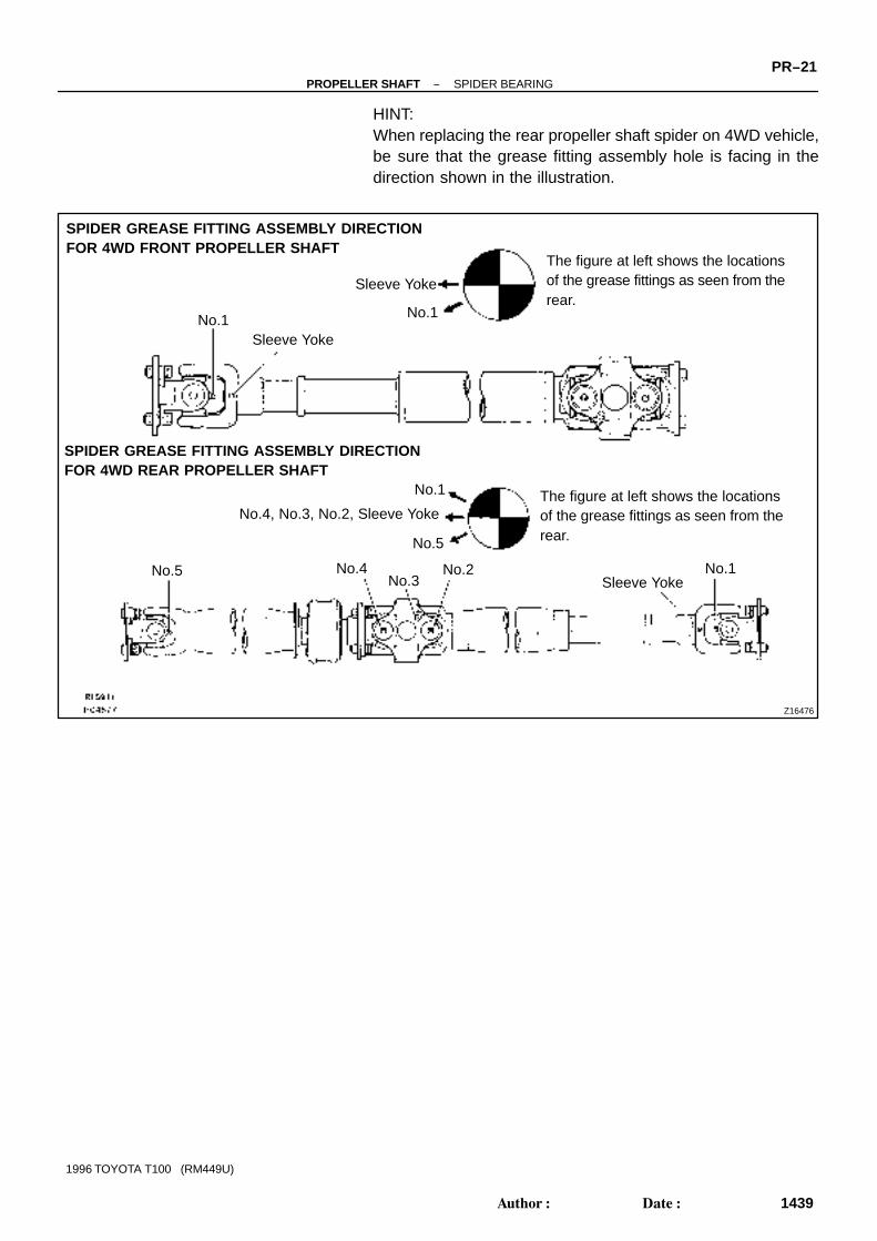
Z16476
SPIDER GREASE FITTING ASSEMBLY DIRECTIONFOR 4WD FRONT PROPELLER SHAFT
SPIDER GREASE FITTING ASSEMBLY DIRECTIONFOR 4WD REAR PROPELLER SHAFT
No.1Sleeve Yoke
Sleeve Yoke
No.1
No.1
No.4, No.3, No.2, Sleeve Yoke
No.5
No.2No.3
No.4No.5Sleeve Yoke
No.1
The figure at left shows the locationsof the grease fittings as seen from therear.
The figure at left shows the locationsof the grease fittings as seen from therear.
−PROPELLER SHAFT SPIDER BEARINGPR−21
1439Author�: Date�:
1996 TOYOTA T100 (RM449U)
HINT:When replacing the rear propeller shaft spider on 4WD vehicle,be sure that the grease fitting assembly hole is facing in thedirection shown in the illustration.
https://www.truck-manuals.net/

SA – SUSPENSION AND AXLE
TROUBLESHOOTING SA-1
TIRE AND WHEEL (2WD) SA-3 TIRE AND WHEEL (4WD) SA-5 FRONT WHEEL ALIGNMENT (2WD) SA-7 FRONT WHEEL ALIGNMENT (4WD) SA-10 FRONT AXLE HUB (2WD) SA-15 FRONT AXLE HUB (4WD) SA-22 FRONT WHEEL HUB BOLT (2WD) SA-27 STEERING KNUCKLE (4WD) SA-28 FRONT DRIVE SHAFT (4WD) SA-36 FRONT DIFFERENTIAL REAR OIL SEAL (4WD)
SA-42
FRONT DIFFERENTIAL CARRIER (4WD)
SA-45
A.D.D. CONTROL SYSTEM SA-69 FRONT SHOCK ABSORBER (2WD) SA-72 FRONT SHOCK ABSORBER (4WD) SA-77 FRONT TORSION BAR SPRING (2WD) SA-82 FRONT TORSION BAR SPRING (2WD) SA-85 FRONT STRUT BAR (2WD) SA-88 FRONT UPPER SUSPENSION ARM (2WD)
SA-91
FRONT UPPER SUSPENSION ARM (4WD)
SA-95
FRONT LOWER SUSPENSION ARM (2WD)
SA-99
FRONT LOWER SUSPENSION ARM (4WD)
SA-103
https://www.truck-manuals.net/
SA – SUSPENSION AND AXLE
FRONT UPPER BALL JOINT (2WD) SA-107 FRONT UPPER BALL JOINT (4WD) SA-111 FRONT LOWER BALL JOINT (2WD) SA-115 FRONT LOWER BALL JOINT (4WD) SA-119 FRONT STABILIZER BAR (2WD) SA-123 FRONT STABILIZER BAR (4WD) SA-126 REAR AXLE SHAFT SA-129 REAR WHEEL HUB BOLT SA-136 REAR DIFFERENTIAL CARRIER SA-137 REAR SHOCK ABSORBER SA-155 REAR LEAF SPRING SA-160
https://www.truck-manuals.net/

SA0FC−01
−SUSPENSION AND AXLE TROUBLESHOOTINGSA−1
1440Author�: Date�:
1996 TOYOTA T100 (RM449U)
TROUBLESHOOTINGPROBLEM SYMPTOMS TABLEUse the table below to help you find the cause of the problem. The numbers indicate the priority of the likelycause of the problem. Check each part in order. If necessary, replace these parts.
Symptom Suspect Area See page
Wander/pulls
1. Tires (Worn or improperly inflated)
2. Wheel alignment (Incorrect)
3. Steering linkage (Loosen or worn)
4. Hub bearings (Loosen or worn)
5. Suspension parts (Worn out)
6. Steering gear (Out of adjustment or broken)
SA−3
SA−5
SA−7
SA−10
−
SA−15
SA−22
SA−129
−
−
Bottoming
1. Vehicle (Overloaded)
2. Spring (Weak)
3. Shock absorber (Worn out)
−
SA−82
SA−85
SA−160
SA−72
SA−77
SA−155
Sways/pitches
1. Tires (Worn or improperly inflated)
2. Stabilizer bar (Bent or broken)
3. Shock absorber (Worn out)
SA−3
SA−5
SA−123
SA−126
SA−72
SA−77
SA−155
Front wheel shimmy
1. Tires (Worn or improperly inflated)
2. Wheels (Out of balance)
3. Shock absorber (Worn out)
4. Wheel alignment (Incorrect)
5. Ball joints (Worn)
6. Hub bearings (Loosen or worn)
7. Steering linkage (Loosen or worn)
8. Steering gear (Out of adjustment or broken)
SA−3
SA−5
SA−3
SA−5
SA−72
SA−77
SA−155
SA−7
SA−10
SA−107
SA−111
SA−115
SA−119
SA−15
SA−22
SA−129
−
−
Abnormal tire wear
1. Tires (Improperly inflated)
2. Wheel alignment (Incorrect)
3. Suspension parts (Worn out)
4. Shock absorber (Worn out)
SA−3
SA−5
SA−3
SA−5
−
SA−72
SA−77
SA−155
https://www.truck-manuals.net/

SA−2−SUSPENSION AND AXLE TROUBLESHOOTING
1441Author�: Date�:
1996 TOYOTA T100 (RM449U)
Noise in front differential
1. Oil level (Low or wrong grade)
2. Excessive backlash between pinion and ring gear
3. Ring, pinion or side gears (Worn or chipped)
4. Pinion shaft bearing (Worn)
5. Side bearing (Worn)
6. Differential bearing (Loosen or worn)
SA−42
SA−45
SA−45
SA−45
SA−45
SA−45
Oil leak from front differential
1. Oil level (Too high or wrong grade)
2. Front differential rear oil seal (Worn or damaged)
3. Side gear oil seal (Worn or damaged)
4. Companion flange (Loose or damaged)
5. Side gear shaft (Damaged)
SA−42
SA−42
SA−45
SA−42
SA−45
Noise in rear axle
1. Oil level (Low or wrong grade)
2. Excessive backlash between pinion and ring gear
3. Ring, pinion or side gears (Worn or chipped)
4. Pinion shaft bearing (Worn)
5. Axle shaft bearing (Worn)
6. Differential bearing (Loosen or worn)
SA−137
SA−137
SA−137
SA−137
SA−129
SA−137
Oil leak from rear axle1. Oil seal (Worn or damaged)
2. Rear axle housing (Cracked)
SA−129
SA−129
Oil leak from rear differential
1. Oil level (Too high or wrong grade)
2. Oil seal (Worn or damaged)
3. Companion flange (Loose or damaged)
SA−137
SA−137
SA−137
https://www.truck-manuals.net/

SA0FD−01
R03031
R12682
R07928
−SUSPENSION AND AXLE TIRE AND WHEEL (2WD)SA−3
1442Author�: Date�:
1996 TOYOTA T100 (RM449U)
TIRE AND WHEEL (2WD)INSPECTION1. INSPECT TIRE(a) Check the tires for wear and proper inflation pressure.
Cold tire inflation pressureFor driving under 120 km/h (75 mph).
Tire sizeFront
kPa (kg/cm2, psi)
Rear
kPa (kg/cm2, psi)
P215/75R15 230 (2.3, 33) 240 (2.4, 35)
P235/75R15
(0.5 ton)180 (1.8, 26) 200 (2.0, 29)
P235/75R15
(1.0 ton)180 (1.8, 26) 280 (2.8, 41)
(b) Check the tire runout.Tire runout: 3.0 mm (0.118 in.) or less
2. ROTATING TIRESHINT:See the illustration for where to rotate each tire.
3. INSPECT WHEEL BALANCE(a) Check and adjust the Off−the−car balance.(b) If necessary, check and adjust the On−the−car balance.
Unbalance after adjustment: 14.0 g (0.031 lb) or less
https://www.truck-manuals.net/

R04258
SA−4−SUSPENSION AND AXLE TIRE AND WHEEL (2WD)
1443Author�: Date�:
1996 TOYOTA T100 (RM449U)
4. CHECK WHEEL BEARING LOOSENESSCheck the backlash in the bearing shaft direction.
Maximum: 0.05 mm (0.0020 in.)5. CHECK FRONT SUSPENSION FOR LOOSENESS6. CHECK STEERING LINKAGE FOR LOOSENESS7. CHECK BALL JOINT FOR LOOSENESS8. CHECK SHOCK ABSORBER WORKS PROPERLY� Check for oil leaks.� Check mounting bushings for wear.� Check front and rear of the vehicle for bounce.
https://www.truck-manuals.net/

SA0FE−02
R03031
R12682
R07928
−SUSPENSION AND AXLE TIRE AND WHEEL (4WD)SA−5
1444Author�: Date�:
1996 TOYOTA T100 (RM449U)
TIRE AND WHEEL (4WD)INSPECTION1. INSPECT TIRE(a) Check the tires for wear and for the proper inflation pres-
sure.Cold tire inflation pressureFor driving under 120 km/h (75 mph).
Tire sizeFront
kPa (kg/cm2, psi)
Rear
kPa (kg/cm2, psi)
P235/75R15 180 (1.8, 26) 200 (2.0, 29)
31 x 10.5 R15LT 180 (1.8, 26) 200 (2.0, 29)
31 x 10.5 R15LT
Extra cab200 (2.0, 29) 240 (2.4, 35)
(b) Check the tire runout.Tire runout: 3.0 mm (0.118 in.) or less
2. ROTATING TIRESHINT:See the illustration for where to rotate each tire.
3. INSPECT WHEEL BALANCE(a) Check and adjust the Off−the−car balance.(b) If necessary, check and adjust the On−the−car balance.
Unbalance after adjustment: 14.0 g (0.031 lb) or less
https://www.truck-manuals.net/

SA−6−SUSPENSION AND AXLE TIRE AND WHEEL (4WD)
1445Author�: Date�:
1996 TOYOTA T100 (RM449U)
4. CHECK FRONT SUSPENSION FOR LOOSENESS5. CHECK STEERING LINKAGE FOR LOOSENESS6. CHECK BALL JOINT FOR LOOSENESS7. CHECK SHOCK ABSORBER WORKS PROPERLY� Check for oil leaks.� Check mounting bushings for wear.� Check front and rear of the vehicle for bounce.
https://www.truck-manuals.net/

R12919R12268 F01731
AB
CD
Front
Rear
SA0FF−02
Z03382
−SUSPENSION AND AXLE FRONT WHEEL ALIGNMENT (2WD)SA−7
1446Author�: Date�:
1996 TOYOTA T100 (RM449U)
FRONT WHEEL ALIGNMENT (2WD)INSPECTIONHINT:For the vehicle height of non−loaded vehidles for each modeland alighment standed values, refer to page SA−119.1. MEASURE VEHICLE HEIGHT
Vehicle height: See page SS−58Front: A − B = 74.0 mm (2.913 in.)Rear: C − D = Standed cab0.5 ton: 122.0 mm (4.803 in.)1.0 ton: 107.0 mm (4.213 in.)Extre cab: 115.5 mm (4.547 in.)Measuring points:A: Steering knuckle height measured at its center onthe outer edge.B: Lower suspension arm front adjusting bolt heightmeasured at its center.C: Rear axle shaft height measured at its center.D: Rear leaf spring front bushing height measured atits center.
NOTICE:Before inspecting the wheel alignment, adjust the vehicleheight to specification.If the vehicle height is not standard, try to adjust it by pushingdown on or lifting the body.
2. INSTALL CAMBER−CASTER−KINGPIN GAUGE ORONTO WHEEL ALIGNMENT TESTER
Follow the specific instructions of the equipment manufacturer.3. INSPECT CAMBER, CASTER AND STEERING AXIS
INCLINATION
Camber
Left−right error
0°00’ ± 45’ (0° ± 0.75°)
45’ (0.75°) or less
Caster
Left−right error
4°00’ ± 45’ (4° ± 0.75°)
45’ (0.75°) or less
Steering axis inclination
Left−right error
12°30’ ± 45’ (12.5° ± 0.75°)
45’ (0.75°) or less
If the steering axis inclination is not as specified, after camberand caster have correctly adjusted, recheck the steeringknuckle front wheel for bearing or looseness.
https://www.truck-manuals.net/

SA3213
A
Front
B
C
D
FA0014
R05239 F01733
R04256
R04257
SA−8−SUSPENSION AND AXLE FRONT WHEEL ALIGNMENT (2WD)
1447Author�: Date�:
1996 TOYOTA T100 (RM449U)
4. INSPECT TOE−INToe−in (total)
STD cabA + B: 0° ± 12’ (0° ± 0.2°)
C − D: 0 ± 2 mm (0 ± 0.08 in.)
Extra cab
P215/75 R15
A + B: 0°22’ ± 12’ (−0.36° ± 0.2°)
C − D: −4.7 ± 2 mm (0.18 ± 0.08 in.)
Extra cab
P235/75 R15
A + B: 0°22’ ± 12’ (0.36° ± 0.2°)
C − D: −4.9 ± 2 mm (0.19 ± 0.08 in.)
If the toe−in is not within the specification, adjust the rack end.
5. ADJUST CAMBER AND CASTERHINT:Try to adjust the camber and caster to center value.If camber or caster is not within the specification, adjust by ad-ding or removing shims on the upper suspension arm.
Shim thickness
4.0 mm (0.157 in.) 1.6 mm (0.063 in.) 1.2 mm (0.047 in.)
HINT:If the steering axis inclination is not as specified after camberand caster have been correctly adjusted, recheck the steeringknuckle and front wheel for distortion or looseness.NOTICE:Adjust the shim thickness to 7 mm (+4, −3), and adjust thedifference between the front and rear of the upper suspen-sion arm shaft to within 4 mm.If this adjustment is not possible, adjust the strut bar bushset nut.
6. ADJUST TOE−IN(a) Remove the boot clamps.(b) Loosen the tie rod end lock nuts.(c) Turn the left and right rack ends an amount to adjust the
toe−in.HINT:� Try to adjust the toe−in to the center value.
� Make sure that the length of the left and right rack endsare the same.Rack end difference: 3.0 mm (0.118 in.) or less
(d) Tighten the tie rod end lock nut.Torque: 56 N·m (570 kgf·cm, 41 ft·lbf)
(e) Place the boot on the seat and install the clip.HINT:Make sure that the boots are not twisted.
https://www.truck-manuals.net/

FA0018
A
Front
B AB
A: InsideB: Outside
−SUSPENSION AND AXLE FRONT WHEEL ALIGNMENT (2WD)SA−9
1448Author�: Date�:
1996 TOYOTA T100 (RM449U)
7. INSPECT WHEEL ANGLETurn the steering wheel fully, and measure the turning angle.
Item Inside wheelOutside wheel
<Reference>
STD cab 0.5 ton
Left−right error
40°42’ ± 2°
(40.7° ± 2°)
30’(0.5°)
34°23’
(34.38°)
STD cab 1.0 ton
Left−right error
39°55’ ± 2°
(39.92° ± 2°)
30’(0.5°)
34°37’
(34.67°)
Extra cab
Left−right error
40°10’ ± 2°
(40.17’ ± 2°)
30’(0.5°)
34°25’
(34.47°)
If the wheel angle differ from the standard specifications, checkto see if the lengths of the left and right tie rods are the same.HINT:If the tie rods lengths are not equal, the wheel angle cannot beadjusted properly.Reinspect the toe−in after adjusting the tie rods lengths.
https://www.truck-manuals.net/

FA0442R12257 F01732
A
B
C D
Front
Rear
Z03382
SA0FG−02
SA−10−SUSPENSION AND AXLE FRONT WHEEL ALIGNMENT (4WD)
1449Author�: Date�:
1996 TOYOTA T100 (RM449U)
FRONT WHEEL ALIGNMENT (4WD)INSPECTIONHINT:For the vehicle height of non−loaded vehicles for each modeland alignment standed values, refer to page SA−121.1. MEASURE VEHICLE HEIGHT
Vehicle height:Front: A − B = 58.0 mm (2.283 in.)Rear: C − B = STD cab: 23.0 mm (0.906 in.) Extra cab: 28.0 mm (1.102 in.)Measuring points:A: Drive shaft height measured at its center on theouter edge.B: Lower suspension arm front adjusting bolt heightmeasured at its center.C: Rear leaf spring front bushing height measured atits center.D: Rear axle shaft height measured at its center.
NOTICE:Before inspecting the wheel alignment, adjust the vehicleheight to specification.If the vehicle height is not standard, try to adjust it by pushingdown on or lifting the body.
2. INSTALL CAMBER−CASTER−KINGPIN GAUGE ORONTO WHEEL ALIGNMENT TESTER
Follow the specific instructions of the equipment manufacturer.3. INSPECT CAMBER, CASTER AND STEERING AXIS
INCLINATIONSTD cab
Camber
Left−right error
0°45’ ± 45’ (0.75° ± 0.75°)
45’ (0.75°) or less
Caster
Left−right error
1°30’ ± 45’ (1.5° ± 0.75°)
45’ (0.75°) or less
Steering axis inclination
Left−right error
11°50’ ± 45’ (11.83° ± 0.75°)
45’ (0.75°) or less
Extra cab
Camber
Left−right error
0°45’ ± 45’ (0.75° ± 0.75°)
45’ (0.75°) or less
Caster
Left−right error
1°20’ ± 45’ (1.33° ± 0.75°)
45’ (0.75°) or less
Steering axis inclination
Left−right error
11°50’ ± 45’ (11.83° ± 0.75°)
45’ (0.75°) or less
If the steering axis inclination is not as specified, after camberand caster have correctly adjusted, recheck the steeringknuckle front wheel for bearing or looseness.
https://www.truck-manuals.net/

SA3213
Front
A BD
C
FA0829FA0828 F01734
Decrease Increase
DecreaseIncrease
Front Adjusting Cam
Rear Adjusting Cam
R08116
FA0017
Front
A = B
A B
−SUSPENSION AND AXLE FRONT WHEEL ALIGNMENT (4WD)SA−11
1450Author�: Date�:
1996 TOYOTA T100 (RM449U)
4. INSPECT TOE−INToe−in (total)
0.5 tonA + B: 0°05’ ± 12’ (0.08° ± 0.2°)
C − D: 1.0 ± 2 mm (0.04 ± 0.08 in.)
Extra cab
P235/75 R15
A + B: −0°08’ ± 12’ (−0.14° ± 0.2°)
C − D: −1.9 ± 2 mm (0.07 ± 0.08 in.)
Extra cab
31 x 10.5 R15
A + B: −0°08’ ± 12’ (−0.14° ± 0.2°)
C − D: −2.0 ± 2 mm (0.08 ± 0.08 in.)
If the toe−in is not within specification, adjust the tie rod end.
5. ADJUST CAMBER AND CASTER(a) Loosen the front and/or rear adjusting cam nuts.(b) Adjust the camber and caster by front and/or rear adjust-
ing cams (See adjustment chart).HINT:Try to adjust the camber and caster to the center value.(c) Torque the front and/or rear adjusting cam nuts.
Torque: 226 N·m (2,300 kgf·cm, 166 ft·lbf)
6. ADJUST TOE−IN(a) Loosen the clamp bolts and nuts.
(b) Adjust toe−in by turning the left and right tie rod tubes anequal amount.
HINT:� Try to adjust the toe−in to the center value.� Make sure that the length of the left and right tie rods end
is equal.
https://www.truck-manuals.net/

FA0927
Front
FA0018
Front
A: InsideB: Outside
A B B A
R08117
SA−12−SUSPENSION AND AXLE FRONT WHEEL ALIGNMENT (4WD)
1451Author�: Date�:
1996 TOYOTA T100 (RM449U)
(c) Torque the tie rod clamp bolt.Torque: 22 N·m (225 kgf·cm, 16 ft·lbf)
HINT:Face the clamp bolt toward the front of the vehicle.
7. INSPECT WHEEL ANGLETurn the steering wheel fully, and measure the turning angle.
Item Inside wheelOutside wheel
<Reference>
STD cab32°01’ ± 2°
(32.02° ± 2°)
30°30’
(30.5°)
Extra cab32°14’ ± 2°
(33.23° ± 2°)
30°30’
(30.5°)
If maximum steering angles differ from standard value, adjustthe wheel angle with the knuckle stopper bolts.
Torque: 47 N·m (480 kgf·cm, 35 ft·lbf)If the wheel angle still cannot be adjusted within limits, inspectand replace damaged or worn steering parts.
8. HOW TO READ ADJUSTMENT CHART(a) Mark on the graph the measurements taken from the ve-
hicle.Example: Camber 0°40’ (0.67°) Caster 0°35’ (0.58°)
(b) As shown in the chart, read from the graph the amountsby which the from and/or rear cams are to be adjusted.Amount to turn adjusting cam (by graduation): Front cam −(Shorter) 1.8 Rear cam +(Longer) 3.1
https://www.truck-manuals.net/
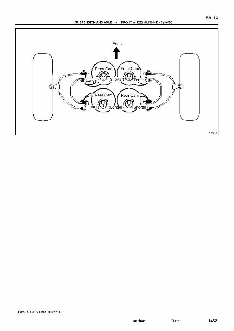
R08019
Front
Front Cam
(Longer)
Front Cam
(Shorter) (Longer)
(Longer)(Shorter) (Shorter)
Rear Cam Rear Cam
−SUSPENSION AND AXLE FRONT WHEEL ALIGNMENT (4WD)SA−13
1452Author�: Date�:
1996 TOYOTA T100 (RM449U)
https://www.truck-manuals.net/

SA−14−SUSPENSION AND AXLE FRONT WHEEL ALIGNMENT (4WD)
1453Author�: Date�:
1996 TOYOTA T100 (RM449U)
https://www.truck-manuals.net/

SA0FH−06
−SUSPENSION AND AXLE FRONT AXLE HUB (2WD)SA−15
1454Author�: Date�:
1996 TOYOTA T100 (RM449U)
FRONT AXLE HUB (2WD)COMPONENTS
https://www.truck-manuals.net/
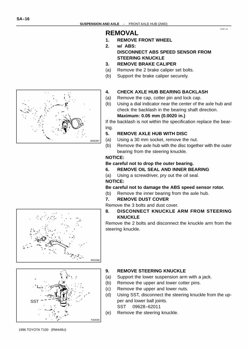
SA0FI−01
W00397
R04268
FA0026
SST
SA−16−SUSPENSION AND AXLE FRONT AXLE HUB (2WD)
1996 TOYOTA T100 (RM449U)
REMOVAL1. REMOVE FRONT WHEEL2. w/ ABS:
DISCONNECT ABS SPEED SENSOR FROMSTEERING KNUCKLE
3. REMOVE BRAKE CALIPER(a) Remove the 2 brake caliper set bolts.(b) Support the brake caliper securely.
4. CHECK AXLE HUB BEARING BACKLASH(a) Remove the cap, cotter pin and lock cap.(b) Using a dial indicator near the center of the axle hub and
check the backlash in the bearing shaft direction.Maximum: 0.05 mm (0.0020 in.)
If the backlash is not within the specification replace the bear-ing.5. REMOVE AXLE HUB WITH DISC(a) Using a 30 mm socket, remove the nut.(b) Remove the axle hub with the disc together with the outer
bearing from the steering knuckle.NOTICE:Be careful not to drop the outer bearing.6. REMOVE OIL SEAL AND INNER BEARING(a) Using a screwdriver, pry out the oil seal.NOTICE:Be careful not to damage the ABS speed sensor rotor.(b) Remove the inner bearing from the axle hub.7. REMOVE DUST COVERRemove the 3 bolts and dust cover.8. DISCONNECT KNUCKLE ARM FROM STEERING
KNUCKLERemove the 2 bolts and disconnect the knuckle arm from thesteering knuckle.
9. REMOVE STEERING KNUCKLE(a) Support the lower suspension arm with a jack.(b) Remove the upper and lower cotter pins.(c) Remove the upper and lower nuts.(d) Using SST, disconnect the steering knuckle from the up-
per and lower ball joints.SST 09628−62011
(e) Remove the steering knuckle.
https://www.truck-manuals.net/

SA0FJ−01
W00398
−SUSPENSION AND AXLE FRONT AXLE HUB (2WD)SA−17
1996 TOYOTA T100 (RM449U)
INSPECTIONINSPECT STEERING KNUCKLEUsing a dye penetrant, check the steering knuckle for cracks.
https://www.truck-manuals.net/

SA0FK−01
SA0171
R11699
SST
SA−18−SUSPENSION AND AXLE FRONT AXLE HUB (2WD)
1996 TOYOTA T100 (RM449U)
REPLACEMENT1. INSPECT BEARINGSClean the bearings and outer races and inspect them for wearor damage.2. REPLACE BEARING OUTER RACES(a) Using a brass bar and hammer, remove the inside and
outside bearing outer races.NOTICE:Be careful not to damage the ABS speed sensor rotor.
(b) Using SST and a press, install a new outside bearing out-er race.SST 09950−60010 (09951−00480),
09950−70010 (09951−07150)NOTICE:Be careful not to damage the ABS speed sensor rotor.(c) Using SST and a press, install a new inside bearing outer
race.SST 09950−60020 (09951−00710),
09950−70010 (09951−07150)
https://www.truck-manuals.net/

SA0FL−01
FA0028
R12261
Sealant
R04135
MP Grease
InnerBearing
OuterBearing
Cap
−SUSPENSION AND AXLE FRONT AXLE HUB (2WD)SA−19
1996 TOYOTA T100 (RM449U)
INSTALLATION1. INSTALL STEERING KNUCKLE(a) Support the lower suspension arm with a jack.(b) Install the steering knuckle to the upper ball joint and nut.(c) Push down the upper suspension arm and steering
knuckle and install the steering knuckle to the lower balljoint and nut.
(d) Torque the upper ball joint nut.Torque: 108 N·m (1,100 kgf·cm, 80 ft·lbf)
(e) Torque the lower ball joint nut.Torque: 142 N·m (1,450 kgf·cm, 105 ft·lbf)
(f) Install 2 new cotter pins.
2. CONNECT KNUCKLE ARM AND TO STEERINGKNUCKLE
(a) Clean the threads of the bolts and steering knuckle withtoluene or trichloroethylene.
(b) Apply sealant to the bolt threads.Sealant:Part No. 08833−00070, THREE BOND 1324 or equiva-lent.
(c) Tighten the 2 bolts.Torque: 183 N·m (1,870 kgf·cm, 135 ft·lbf)
3. INSTALL DUST COVERInstall the 3 bolts and tighten them.
Torque: 19 N·m (195 kgf·cm, 14 ft·lbf)
4. PACK BEARINGS WITH MP GREASE(a) Place MP grease in the palm of your hand.(b) Pack grease into the bearing, continuing until the grease
oozes out from the other side.(c) Employ the same manner around the bearing circumfer-
ence.5. COAT INSIDE OF HUB AND CAP WITH MP GREASE
https://www.truck-manuals.net/

R12255
SST
R04262
R11763
90°
R11764
90°
SA−20−SUSPENSION AND AXLE FRONT AXLE HUB (2WD)
1996 TOYOTA T100 (RM449U)
6. INSTALL INNER BEARING AND OIL SEAL(a) Place inner bearing into the axle hub.(b) Using SST and a hammer, install a new oil seal into the
hub.SST 09950−60020 (09951−00710),
09950−70010 (09951−00150)NOTICE:Be careful not to damage the ABS speed sensor rotor.(c) Coat the oil seal lip with MP grease.7. INSTALL AXLE HUB WITH DISC(a) Place the axle hub on the spindle.(b) Install the outer bearing and thrust washer.
8. ADJUST PRELOAD(a) Install and torque the nut.
Torque: 35 N·m (360 kgf·cm, 26 ft·lbf)(b) Turn the hub several times to make the bearing more
smoothly(c) Loosen the nut until it can be turned by hand.
(d) Using a spring tension gauge, measure and make a noteof the frictional force of the oil seal.Preload (at starting): 4.0 N (0.4 kgf, 0.9 lbf) or less
HINT:Make sure to check preload in the direction of rotation.
(e) Tighten the nut until the preload is within specification.Preload (at starting) :Frictional force plus5.0 − 14.0 N (0.5 − 1.4 kgf, 1.1 − 3.1 lbf)
HINT:Make sure to check preload in the direction of rotation.
https://www.truck-manuals.net/

R04258
−SUSPENSION AND AXLE FRONT AXLE HUB (2WD)SA−21
1996 TOYOTA T100 (RM449U)
(f) Using a dial indicator, measure the hub bearing backlash.Maximum: 0.05 mm (0.0020 in.)
9. INSTALL LOCK CAP, COTTER PIN AND GREASE CAP(a) Install the lock cap and a new cotter pin.(b) Install the grease cap.10. INSTALL BRAKE CALIPERInstall the 2 brake caliper set bolts.
Torque: 108 N·m (1,100 kgf·cm, 80 ft·lbf)11. w/ ABS:
CONNECT ABS SPEED SENSOR TO STEERINGKNUCKLETorque: 8.0 N·m (82 kgf·cm, 71 in.·lbf)
12. INSTALL FRONT WHEELTorque: 103 N·m (1,050 kgf·cm, 76 ft·lbf)
13. CHECK FRONT WHEEL ALIGNMENT(See page SA−7)
14. w/ ABS:CHECK ABS SPEED SENSOR SIGNAL(See page DI−321)
https://www.truck-manuals.net/

SA0FM−03
SA−22−SUSPENSION AND AXLE FRONT AXLE HUB (4WD)
1461Author�: Date�:
1996 TOYOTA T100 (RM449U)
FRONT AXLE HUB (4WD)COMPONENTS
https://www.truck-manuals.net/

SA0FN−01
W00399
SA0326
R04292
SST
−SUSPENSION AND AXLE FRONT AXLE HUB (4WD)SA−23
1996 TOYOTA T100 (RM449U)
REMOVAL1. REMOVE FRONT WHEEL2. w/ ABS:
DISCONNECT ABS SPEED SENSOR FROMSTEERING KNUCKLE
3. REMOVE BRAKE CALIPER(a) Remove the 2 bolts and disconnect the knuckle arm with
brake line bracket from the steering knuckle.(b) Remove the 2 brake caliper set bolts.(c) Support the brake caliper securely.
4. REMOVE FLANGE(a) Remove the grease cap from the flange.(b) Remove the bolt.(c) Remove the 6 mounting nuts and washers.(d) Using a brass bar and hammer, tap on the bolts head and
remove the 6 cone washers.(e) Install and tighten the 2 bolts and remove the flange.(f) Remove the gasket.
5. REMOVE AXLE HUB WITH DISC(a) Using a screwdriver, release the lock washer.(b) Using SST, remove the lock nut.
SST 09607−60020(c) Remove the lock washer and adjusting nut.(d) Remove the claw washer.(e) Remove the axle hub with the disc together with the outer
bearing.NOTICE:Be careful not to damage the ABS speed sensor rotor.6. REMOVE OIL SEAL AND INNER BEARING(a) Using a screwdriver, pry out the oil seal.(b) Remove the inner bearing from the hub.
https://www.truck-manuals.net/

SA0FO−01
FA0076
R12219
SST
SA−24−SUSPENSION AND AXLE FRONT AXLE HUB (4WD)
1996 TOYOTA T100 (RM449U)
REPLACEMENT1. INSPECT BEARINGSClean the bearings and outer races and inspect them for wearor damage.
2. REPLACE BEARING OUTER RACES(a) Using a brass bar and hammer, remove the inside and
outside outer bearing outer races.NOTICE:Be careful not to damage the ABS speed sensor rotor.(b) Using SST and a hammer, install a new outside bearing
outer race.SST 09950−60020 (09951−00720),
09950−70010 (09951−07100)(c) Using SST and a hammer, install a new inside bearing
outer race.SST 09950−60020 (09951−00810),
09950−70010 (09951−07150)NOTICE:Be careful not to damage the ABS speed sensor rotor.
https://www.truck-manuals.net/
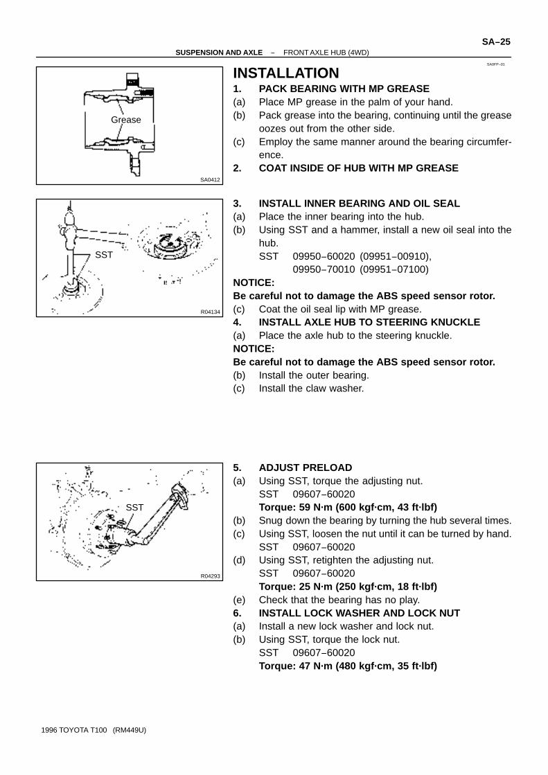
SA0FP−01
SA0412
Grease
R04134
SST
R04293
SST
−SUSPENSION AND AXLE FRONT AXLE HUB (4WD)SA−25
1996 TOYOTA T100 (RM449U)
INSTALLATION1. PACK BEARING WITH MP GREASE(a) Place MP grease in the palm of your hand.(b) Pack grease into the bearing, continuing until the grease
oozes out from the other side.(c) Employ the same manner around the bearing circumfer-
ence.2. COAT INSIDE OF HUB WITH MP GREASE
3. INSTALL INNER BEARING AND OIL SEAL(a) Place the inner bearing into the hub.(b) Using SST and a hammer, install a new oil seal into the
hub.SST 09950−60020 (09951−00910),
09950−70010 (09951−07100)NOTICE:Be careful not to damage the ABS speed sensor rotor.(c) Coat the oil seal lip with MP grease.4. INSTALL AXLE HUB TO STEERING KNUCKLE(a) Place the axle hub to the steering knuckle.NOTICE:Be careful not to damage the ABS speed sensor rotor.(b) Install the outer bearing.(c) Install the claw washer.
5. ADJUST PRELOAD(a) Using SST, torque the adjusting nut.
SST 09607−60020Torque: 59 N·m (600 kgf·cm, 43 ft·lbf)
(b) Snug down the bearing by turning the hub several times.(c) Using SST, loosen the nut until it can be turned by hand.
SST 09607−60020(d) Using SST, retighten the adjusting nut.
SST 09607−60020Torque: 25 N·m (250 kgf·cm, 18 ft·lbf)
(e) Check that the bearing has no play.6. INSTALL LOCK WASHER AND LOCK NUT(a) Install a new lock washer and lock nut.(b) Using SST, torque the lock nut.
SST 09607−60020Torque: 47 N·m (480 kgf·cm, 35 ft·lbf)
https://www.truck-manuals.net/

R12259
90°
R11765
Sealant
SA−26−SUSPENSION AND AXLE FRONT AXLE HUB (4WD)
1996 TOYOTA T100 (RM449U)
(c) Using a spring tension gauge, check the preload.Preload (starting) :25 − 53 N (2.6 − 5.4 kgf, 5.7 −11.9 lbf)
HINT:Make sure to check preload in the direction of rotation.If the preload is not within the specification, adjust it again withthe adjusting nut.(d) Secure the lock nut by bending one of the lock washer
teeth inward and the other lock washer teeth outward.7. INSTALL FLANGE(a) Place a new gasket in position on the axle hub.(b) Install the flange to the axle hub.(c) Install 6 cone washers, plate washers and nuts.(d) Torque the 6 nuts.
Torque: 31 N·m (315 kgf·cm, 23 ft·lbf)(e) Install the bolt and grease cap.
Torque: 18 N·m (185 kgf·cm, 13 ft·lbf)8. INSTALL BRAKE CALIPER(a) Install the brake caliper to the steering knuckle.(b) Torque the 2 bolts.
Torque: 123 N·m (1,250 kgf·cm, 90 ft·lbf)
9. CONNECT KNUCKLE ARM TO STEERING KNUCKLE(a) Clean the threads of the bolts and steering knuckle with
toluene or trichloroethylene.(b) Apply sealant to the bolt threads.
Sealant:Part No. 08833−00070, THREE BOND 1324 or equiva-lent.
(c) Connect the knuckle arm with brake line bracket to thesteering knuckle and torque the bolts.Torque: 183 N·m (1,870 kgf·cm, 135 ft·lbf)
10. w/ ABS:CONNECT ABS SPEED SENSOR TO STEERINGKNUCKLETorque: 8.0 N·m (82 kgf·cm, 71 in.·lbf)
11. INSTALL FRONT WHEELTorque: 103 N·m (1,050 kgf·cm, 76 ft·lbf)
12. w/ ABS:CHECK ABS SPEED SENSOR SIGNAL(See page DI−321)
https://www.truck-manuals.net/

SA0FQ−01
Z14480
Matchmarks
R03423
R03424
−SUSPENSION AND AXLE FRONT WHEEL HUB BOLT (2WD)SA−27
1466Author�: Date�:
1996 TOYOTA T100 (RM449U)
FRONT WHEEL HUB BOLT (2WD)REPLACEMENT1. REMOVE FRONT WHEEL2. REMOVE AXLE HUB WITH DISC (See page SA−16)
3. REMOVE HUB BOLT(a) Place matchmarks on the disc and axle hub.(b) Remove the 6 bolts, washers and separate the disc and
axle hub.
(c) Install the nut to the axle hub bolt.(d) Using an extension bar and press, remove the hub bolt.
4. INSTALL HUB BOLT(a) Using an extension bar and press, install the hub bolt.(b) Align the matchmarks and install the axle hub to the disc
with the 6 washers and bolts.Torque: 64 N·m (650 kgf·cm, 47 ft·lbf)
5. INSTALL AXLE HUB WITH DISC (See page SA−19)6. INSTALL FRONT WHEEL
Torque: 103 N·m (1,050 kgf·cm, 76 ft·lbf)
https://www.truck-manuals.net/
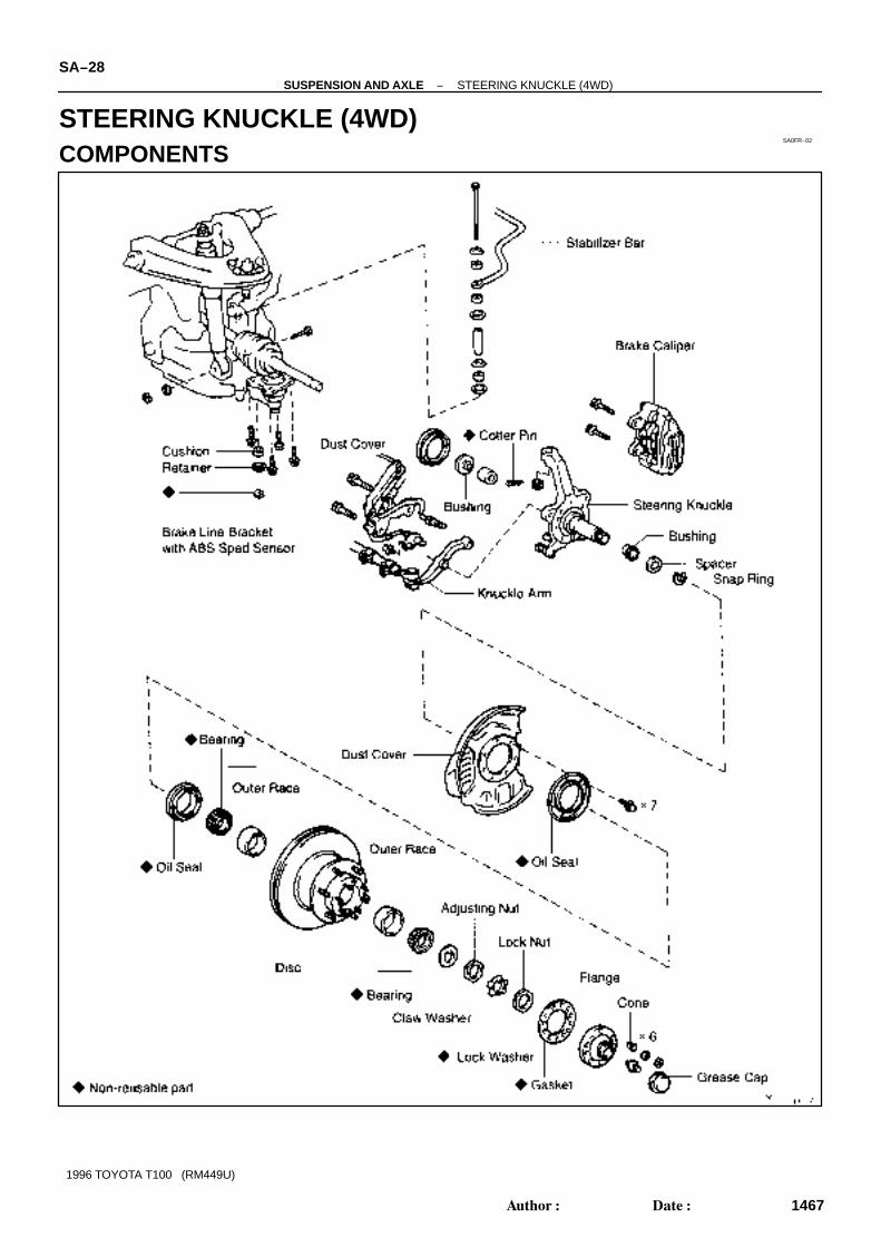
SA0FR−02
SA−28−SUSPENSION AND AXLE STEERING KNUCKLE (4WD)
1467Author�: Date�:
1996 TOYOTA T100 (RM449U)
STEERING KNUCKLE (4WD)COMPONENTS
https://www.truck-manuals.net/

SA0FS−01
R04382
FA0781
R04383
R04384
−SUSPENSION AND AXLE STEERING KNUCKLE (4WD)SA−29
1996 TOYOTA T100 (RM449U)
REMOVAL1. REMOVE BRAKE CALIPER AND FRONT AXLE HUB
(See page SA−23)2. REMOVE DUST COVER AND OIL SEAL
3. MEASURE STEERING KNUCKLE BUSHING THRUSTCLEARANCE
(a) Install a bolt in the drive shaft.(b) Using a feeler gauge, measure the drive shaft thrust
clearance between the steering knuckle outside bushingand spacer, by pulling the bolt and applying a load of 98N (10 kgf, 22.0 lbf).Front drive shaft thrust clearance:Standard: 0.10 − 0.50 mm (0.0039 − 0.0197 in.)Maximum: 1.0 mm (0.039 in.)
If the thrust clearance than the maximum, replace the steeringknuckle outside and inside bushings.
4. DISCONNECT FRONT SHOCK ABSORBER FROMLOWER SUSPENSION ARM
Remove the nut, washer, bolt and shock absorber from the low-er suspension arm.
5. DISCONNECT STABILIZER BAR FROM LOWERSUSPENSION ARM
(a) Remove the nut, bolt, 5 retainers, 4 cushions and collar.(b) Disconnect the stabilizer bar from the lower suspension
arm.
https://www.truck-manuals.net/

R12263
SST
FA0873
SA−30−SUSPENSION AND AXLE STEERING KNUCKLE (4WD)
1996 TOYOTA T100 (RM449U)
6. REMOVE STEERING KNUCKLE(a) Using snap ring pliers, remove the snap ring and spacer.(b) Support the lower suspension arm with a jack.(c) Remove the cotter pin and nut from the upper ball joint.(d) Using SST, disconnect the steering knuckle from the up-
per ball joint.SST 09628−62011
(e) Remove the 4 bolts from the lower ball joint and discon-nect the steering knuckle from the lower ball joint.
(f) Push down the lower suspension arm and remove thesteering knuckle.
NOTICE:Be careful not to damage the oil seal and boot.
https://www.truck-manuals.net/

SA0FT−01
FA0786
SST
−SUSPENSION AND AXLE STEERING KNUCKLE (4WD)SA−31
1996 TOYOTA T100 (RM449U)
DISASSEMBLY1. REMOVE DUST COVERUsing a screwdriver and hammer, remove the dust cover fromthe steering knuckle.2. REMOVE STEERING KNUCKLE BUSHING(a) Using SST, remove the steering knuckle outside bushing.
SST 09308−00010(b) Using a brass bar and hammer, remove the steering
knuckle needle roller bearing and inside bushing.
https://www.truck-manuals.net/

SA0FU−01
FA0735
SA−32−SUSPENSION AND AXLE STEERING KNUCKLE (4WD)
1996 TOYOTA T100 (RM449U)
INSPECTIONINSPECT STEERING KNUCKLEUsing a dye penetrant, check the steering knuckle for cracks.
https://www.truck-manuals.net/

SA0FV−02
W00456
SST
W00458
SST
KnuckleNeedleRoller Bearing
SSTThrustBushing
R04291
SST
−SUSPENSION AND AXLE STEERING KNUCKLE (4WD)SA−33
1996 TOYOTA T100 (RM449U)
REASSEMBLY1. INSTALL STEERING KNUCKLE BUSHING(a) Using SST and a press, install a new steering knuckle out-
side bushing.SST 09950−60010 (09951−00360),
09950−70010 (09951−07150)HINT:When installing the bushing to the spindle, make sure the flatportion of the bushing is aligned with the spindle groove, asshown in the illustration.
(b) Using SST and a press, install a new needle roller bear-ing, as shown in the illustration.SST 09950−60010 (09951−00360),
09950−70010 (09951−07150)HINT:� Bearing must be installed with flat side which has I.D. and
part number facing outward.� Press the bearing in until the top surface of the bearing is
in approx. 2 − 3 mm (0.08 − 0.12 in.) inside the knucklesurface.
(c) Using SST and a press, install a new thrust bushing.SST 09950−60010 (09951−00500),
09950−70010 (09951−07150)(d) Apply synthetic oil and lithium soap base chassis grease,
NLGI No.1 to the steering knuckle inner side of thrustbushing.
2. INSTALL DUST DEFLECTOR TO STEERINGKNUCKLE
Using SST and a hammer, install a new dust deflector.SST 09950−60020 (09951−00910),
09950−70010 (09951−07150)
https://www.truck-manuals.net/

SA0FW−02
R04389
FA0781
Z03703
SA−34−SUSPENSION AND AXLE STEERING KNUCKLE (4WD)
1996 TOYOTA T100 (RM449U)
INSTALLATION1. INSTALL STEERING KNUCKLE(a) Apply synthetic oil and lithium soap base chassis grease,
NLGI No.1 to the drive shaft.(b) Push down the lower suspension arm and install the
steering knuckle.NOTICE:Be careful not to damage the oil seal and boot.(c) Connect the lower ball joint to the steering knuckle, install
and torque the nut.Torque: 142 N·m (1,450 kgf·cm, 105 ft·lbf)
(d) Install a new cotter pin.(e) Connect the upper ball joint to the steering knuckle, install
and torque the 4 nuts.Torque: 142 N·m (1,450 kgf·cm, 105 ft·lbf)
(f) Install a new cotter pin.(g) Install the spacer to the drive shaft.(h) Using snap ring pliers, install the snap ring.NOTICE:If you replace the steering knuckle bushing, recheck thedrive shaft thrust clearance.(i) Install the bolt in the drive shaft.
(j) Using a feeler gauge, measure the drive shaft thrustclearance between the steering knuckle outside bushingand spacer, by pulling the bolt and applying a load of 98N (10 kgf, 22.0 lbf).Front drive shaft thrust clearance:Standard: 0.10 − 0.50 mm (0.0039 − 0.0197 in.)
If the clearance is not within specification, replace the spacer.Spacer thickness
1.80 mm (0.0709 in.) 2.25 mm (0.0886 in.)
2. CONNECT STABILIZER BAR TO LOWERSUSPENSION ARM
(a) Connect the stabilizer bar to the lower suspension armwith the bolt, 5 retainers, 4 cushions, collar and a new nut,as shown in the illustration.
(b) Torque the nut.Torque: 25 N·m (260 kgf·cm, 19 ft·lbf)
https://www.truck-manuals.net/

−SUSPENSION AND AXLE STEERING KNUCKLE (4WD)SA−35
1996 TOYOTA T100 (RM449U)
3. CONNECT FRONT SHOCK ABSORBER TO LOWERSUSPENSION ARM
Install the shock absorber, bolt, washer and nut to the lowersuspension arm.
Torque: 137 N·m (1,400 kgf·cm, 101 ft·lbf)4. INSTALL DUST COVER AND NEW OIL SEAL
Torque: 18 N·m (185 kgf·cm, 13 ft·lbf)5. INSTALL FRONT AXLE HUB AND BRAKE CALIPER
(See page SA−25)6. CHECK FRONT WHEEL ALIGNMENT
(See page SA−10)7. w/ ABS:
CHECK ABS SPEED SENSOR SIGNAL(See page DI−321)
https://www.truck-manuals.net/

SA0FX−02
SA−36−SUSPENSION AND AXLE FRONT DRIVE SHAFT (4WD)
1475Author�: Date�:
1996 TOYOTA T100 (RM449U)
FRONT DRIVE SHAFT (4WD)COMPONENTS
https://www.truck-manuals.net/

SA0FY−01
R04298
Matchmarks
−SUSPENSION AND AXLE FRONT DRIVE SHAFT (4WD)SA−37
1996 TOYOTA T100 (RM449U)
REMOVAL1. LOOSEN NUTS HOLDING FRONT DRIVE SHAFT(a) Place matchmarks on the inboard joint tulip and side gear
shaft.(b) Loosen the 6 nuts, with depressing the brake pedal.
Torque: 83 N·m (845 kgf·cm, 61 ft·lbf)2. REMOVE FLANGE (See page SA−23)3. REMOVE SNAP RING AND SPACERUsing a snap ring expander, remove the snap ring from thedrive shaft.4. REMOVE FRONT DRIVE SHAFTFirst pull the drive shaft inboard joint tulip from the side gearshaft and then pull it out from the steering knuckle.NOTICE:Be careful not to damage the oil seal and boot.
https://www.truck-manuals.net/

SA0FZ−02
FA0810
FA0838
Matchmarks
SA1443Matchmarks
FA0841
SA−38−SUSPENSION AND AXLE FRONT DRIVE SHAFT (4WD)
1996 TOYOTA T100 (RM449U)
DISASSEMBLY1. CHECK DRIVE SHAFT(a) Check to see there is no play in the inboard and outboard
joints.(b) Check to see that the inboard joint slides smoothly in the
thrust direction.(c) Check to see that there is no obvious play in the radial
direction of the universal joints.(d) Check the boot for damage.
2. REMOVE INBOARD AND OUTBOARD JOINT BOOTCLAMPS
(a) Using a screwdriver, remove the 4 boot clamps.(b) Slide the inboard joint boot toward the outboard joint.3. DISASSEMBLE INBOARD JOINT TULIP(a) Place matchmarks on the inboard joint tulip and drive
shaft.(b) Remove the inboard joint tulip from the drive shaft.
4. DISASSEMBLE TRIPOD(a) Using a snap ring expander, remove the snap ring.(b) Place matchmarks on the shaft and tripod.(c) Using a brass bar and hammer, remove the tripod from
the drive shaft.NOTICE:Do not tap the roller.5. REMOVE INBOARD AND OUTBOARD JOINT BOOT
CLAMPS AND BOOTSNOTICE:Do not disassemble the outboard joint.
6. REMOVE DUST DEFLECTORUsing a screwdriver and hammer, remove the dust deflector.
https://www.truck-manuals.net/

SA0G0−02
FA0843
FA1795
Vinyl Tape
−SUSPENSION AND AXLE FRONT DRIVE SHAFT (4WD)SA−39
1996 TOYOTA T100 (RM449U)
REASSEMBLY1. INSTALL DUST DEFLECTORUsing a screwdriver and hammer, install a new dust deflector.
2. TEMPORARILY INSTALL NEW INBOARD ANDOUTBOARD BOOTS AND NEW BOOT CLAMPS
HINT:Before installing the boots, wrap vinyl tape around the spline ofthe drive shaft to prevent the boots from being damaged.
3. INSTALL TRIPOD(a) Place the beveled side of the tripod axial spline toward the
outboard joint.(b) Align the matchmarks placed before disassembly.(c) Using a brass bar and hammer, tap the tripod onto the
drive shaft.NOTICE:Do not tap the roller(d) Using a snap ring expander, install a new snap ring.4. ASSEMBLE BOOT TO OUTBOARD JOINTBefore assembling the boot, coat the outboard joint and bootwith grease in the boot kit.
Grease capacity:176 − 186 g (6.21 − 6.56 oz.)
5. ASSEMBLE INBOARD JOINT TO INBOARD JOINTTULIP
(a) Coat the inboard joint tulip and boot with grease in theboot kit.Grease capacity:270 − 280 g (9.52 − 9.88 oz.)
(b) Align the matchmarks placed before disassembly.(c) Install the inboard tulip to the drive shaft.(d) Temporarily install the boot to the inboard tulip.
https://www.truck-manuals.net/

FA0811
SA−40−SUSPENSION AND AXLE FRONT DRIVE SHAFT (4WD)
1996 TOYOTA T100 (RM449U)
6. ASSEMBLE NEW BOOT CLAMPS TO BOTH BOOTS(a) Make sure the 2 boots are on the shaft groove.(b) Make sure that the 2 boots are not stretched or contracted
when the drive shaft is at standard length.Standard length:481.2 − 491.2 mm (18.945 − 19.339 in.)
(c) Using a screwdriver, bend the clamp and lock with ascrewdriver.
7. CHECK DRIVE SHAFT (See page SA−38)
https://www.truck-manuals.net/

SA0G1−01
−SUSPENSION AND AXLE FRONT DRIVE SHAFT (4WD)SA−41
1996 TOYOTA T100 (RM449U)
INSTALLATIONInstallation is in the reverse order of removal (See page SA−37).AFTER INSTALLATION, CHECK FRONT WHEEL ALIGNMENT (See page SA−10)
https://www.truck-manuals.net/

SA0G2−02
SA−42−SUSPENSION AND AXLE FRONT DIFFERENTIAL REAR OIL SEAL (4WD)
1481Author�: Date�:
1996 TOYOTA T100 (RM449U)
FRONT DIFFERENTIAL REAR OIL SEAL (4WD)COMPONENTS
https://www.truck-manuals.net/

SA0G3−02
Z00638
SST
B4056 B4057
R11389
SST
SA0505
SST
SA0507
SST
Z03906
SST
1.5 mm (0.059 in.)Drive in Depth
−SUSPENSION AND AXLE FRONT DIFFERENTIAL REAR OIL SEAL (4WD)SA−43
1996 TOYOTA T100 (RM449U)
REPLACEMENT1. REMOVE ENGINE UNDER COVER2. REMOVE FRONT PROPELLER SHAFT
(See page PR−11)3. REMOVE COMPANION FLANGE(a) Using a chisel and hammer, loosen the staked part of the
nut.(b) Using SST to hold the flange, remove the nut.
SST 09330−00021
(c) Using SST, remove the companion flange.SST 09950−30010
4. REMOVE OIL SEAL AND OIL SLINGER(a) Using SST, remove the oil seal.
SST 09308−10010(b) Remove the oil slinger.
5. REMOVE REAR BEARING AND BEARING SPACER(a) Using SST, remove the rear bearing from the drive pinion.
SST 09556−22010(b) Remove the bearing spacer.6. INSTALL BEARING SPACER, REAR BEARING AND
OIL SLINGER(a) Install a new bearing spacer.(b) Install the rear bearing.(c) Install the oil slinger.
7. INSTALL OIL SEAL(a) Using SST and a hammer, install a new oil seal.
SST 09554−30011Oil seal drive in depth: 1.5 mm (0.059 in.)
(b) Apply MP grease to the oil seal lip.
https://www.truck-manuals.net/
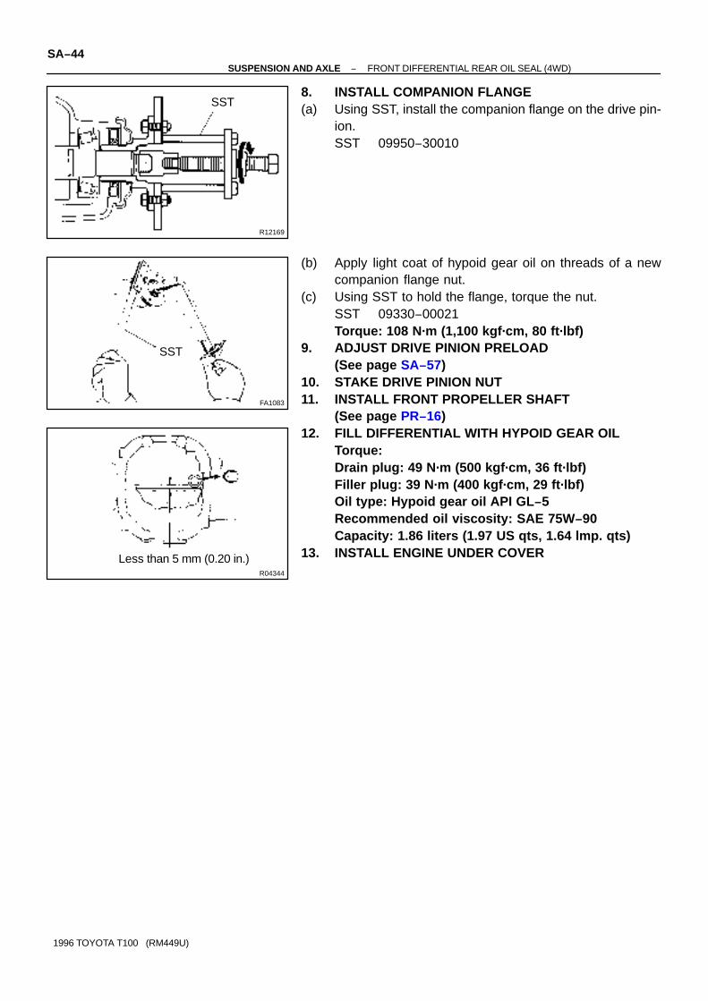
R12169
SST
FA1083
SST
R04344
Less than 5 mm (0.20 in.)
SA−44−SUSPENSION AND AXLE FRONT DIFFERENTIAL REAR OIL SEAL (4WD)
1996 TOYOTA T100 (RM449U)
8. INSTALL COMPANION FLANGE(a) Using SST, install the companion flange on the drive pin-
ion.SST 09950−30010
(b) Apply light coat of hypoid gear oil on threads of a newcompanion flange nut.
(c) Using SST to hold the flange, torque the nut.SST 09330−00021Torque: 108 N·m (1,100 kgf·cm, 80 ft·lbf)
9. ADJUST DRIVE PINION PRELOAD(See page SA−57)
10. STAKE DRIVE PINION NUT11. INSTALL FRONT PROPELLER SHAFT
(See page PR−16)12. FILL DIFFERENTIAL WITH HYPOID GEAR OIL
Torque:Drain plug: 49 N·m (500 kgf·cm, 36 ft·lbf)Filler plug: 39 N·m (400 kgf·cm, 29 ft·lbf)Oil type: Hypoid gear oil API GL−5Recommended oil viscosity: SAE 75W−90Capacity: 1.86 liters (1.97 US qts, 1.64 lmp. qts)
13. INSTALL ENGINE UNDER COVER
https://www.truck-manuals.net/

SA0G4−03
−SUSPENSION AND AXLE FRONT DIFFERENTIAL CARRIER (4WD)SA−45
1484Author�: Date�:
1996 TOYOTA T100 (RM449U)
FRONT DIFFERENTIAL CARRIER (4WD)COMPONENTS
https://www.truck-manuals.net/

SA−46−SUSPENSION AND AXLE FRONT DIFFERENTIAL CARRIER (4WD)
1485Author�: Date�:
1996 TOYOTA T100 (RM449U)
https://www.truck-manuals.net/

SA0G5−01
R04298
Matchmarks
R04533
FA0858
−SUSPENSION AND AXLE FRONT DIFFERENTIAL CARRIER (4WD)SA−47
1996 TOYOTA T100 (RM449U)
REMOVAL1. REMOVE ENGINE UNDER COVER AND DRAIN HYPO-
ID GEAR OIL2. REMOVE FRONT PROPELLER SHAFT
(See page PR−11)
3. REMOVE DRIVE SHAFT NUTS(a) Place matchmarks on the drive shaft and side gear shaft,
and remove the 6 nuts holding the drive shaft and sidegear shaft.Torque: 83 N·m (845 kgf·cm, 61 ft·lbf)
(b) Employ the same manner described above to the otherside.
4. DISCONNECT VACUUM HOSES AND 4WD INDICA-TOR SWITCH CONNECTOR
5. REMOVE CROSSMEMBERRemove the 4 nuts, washers, bolts and crossmember.
Torque: 126 N·m (1,280 kgf·cm, 93 ft·lbf)
6. REMOVE DIFFERENTIAL FRONT MOUNTING BOLTAND NUTTorque: 147 N·m (1,500 kgf·cm, 108 ft·lbf)
7. REMOVE FRONT DIFFERENTIAL ASSEMBLY(a) Support the front differential with a jack.(b) Remove the left and right rear mounting bolts.
Torque: 167 N·m (1,700 kgf·cm, 123 ft·lbf)(c) Lower the jack and remove the front differential assembly.
https://www.truck-manuals.net/

W00493
30 mm(1.18 in.)
SA258−01
SA2352
W00400
SA0344
SA−48−SUSPENSION AND AXLE FRONT DIFFERENTIAL CARRIER (4WD)
1996 TOYOTA T100 (RM449U)
DISASSEMBLY1. CHECK RUNOUT OF COMPANION FLANGEUsing a dial indicator, measure the runout of the companionflange vertical and lateral.
MaximumVertical runout: 0.10 mm (0.0039 in.)Lateral runout: 0.10 mm (0.0039 in.)
2. MEASURE DRIVE PINION PRELOADUsing a torque wrench, measure the drive pinion preload usingthe backlash of the drive pinion and ring gear.
Preload (at starting):0.6 − 1.0 N·m (6 − 10 kgf·cm, 5.2 − 8.7 in.·lbf)
If the runout is greater than the maximum, replace the compan-ion flange.3. CHECK TOTAL PRELOADUsing a torque wrench, measure the total preload.
Total preload (at starting):Drive pinion preload plus0.4 − 0.6 N·m (4 − 6 kgf·cm, 3.5 − 5.2 in.·lbf)
If necessary, disassemble and inspect the differential.
4. REMOVE A.D.D. ACTUATOR(a) Remove the 4 bolts.(b) Using a hammer handle, remove the actuator.5. REMOVE DIFFERENTIAL CARRIER COVERRemove the 8 bolts and tap out the cover with a plastic hammer.
6. CHECK SIDE GEAR BACKLASHUsing a dial indicator, measure the side gear backlash withholding one pinion gear toward the differential case.
Backlash: 0.05 − 0.20 mm (0.0020 − 0.0079 in.)If the backlash is out of specification, install the correct thrustwashers (See page SA−57).
https://www.truck-manuals.net/

SA0346
SA0349
SA0337
SST
SA0352
SST
R11390
SST
SST
−SUSPENSION AND AXLE FRONT DIFFERENTIAL CARRIER (4WD)SA−49
1996 TOYOTA T100 (RM449U)
7. REMOVE LH SIDE GEAR SHAFT WITH TUBE(a) Using a torx socket (E14), remove the 4 torx bolts.(b) Using a plastic hammer, tap on the tube to remove it.(c) Remove the sleeve.(d) Remove the O−ring from the tube.
8. REMOVE CLUTCH CASE(a) Using a torx socket (E14), remove the 2 torx bolts.(b) Using a plastic hammer, tap on the clutch case to remove
it.
9. REMOVE RH SIDE GEAR SHAFTUsing SST, remove the side gear shaft.
SST 09910−00015 (09911−00011, 09912−00010,09914−00011)
10. REMOVE RH SIDE GEAR SHAFT OIL SEALUsing SST, remove the right side gear shaft oil seal.
SST 09308−00010
11. REMOVE INTERMEDIATE SHAFTUsing SST, remove the intermediate shaft.
SST 09350−20015 (09369−20040), 09950−40010
https://www.truck-manuals.net/

Z03854
Z03853
Z03852
SA2349
SST
R11391
SST
SA−50−SUSPENSION AND AXLE FRONT DIFFERENTIAL CARRIER (4WD)
1996 TOYOTA T100 (RM449U)
12. CHECK RING GEAR RUNOUTUsing a dial indicator, measure the ring gear runout.
Maximum runout: 0.07 mm (0.0028 in.)If the runout is greater than the maximum, replace the ring gearand drive pinion as a set.
13. CHECK RING GEAR BACKLASH(a) Fix the dial indicator on the tooth surface at a 90° angle.(b) Using a dial indicator, with holding the drive pinion flange
and measure the ring gear backlash.Backlash: 0.13 − 0.18 mm (0.0051 − 0.0070 in.)
If the backlash is not within the specification, adjust the ringgear backlash.HINT:Measure from 3 or more places on the circumference of the ringgear.14. INSPECT TOOTH CONTACT BETWEEN RING GEAR
AND DRIVE PINION (See page SA−57)
15. REMOVE COMPANION FLANGE(a) Using a chisel and hammer, unstake the nut.(b) Using SST to hold the flange, remove the nut.
SST 09330−00021
(c) Using SST, remove the companion flange.SST 09950−30010
https://www.truck-manuals.net/

SA2348
SST
Z00641
SST
Z03859
Matchmarks
FA0751
SST
−SUSPENSION AND AXLE FRONT DIFFERENTIAL CARRIER (4WD)SA−51
1996 TOYOTA T100 (RM449U)
16. REMOVE OIL SEAL AND OIL SLINGER(a) Using SST, remove the oil seal from the differential carrier.
SST 09308−10010(b) Remove the oil slinger.
17. REMOVE REAR BEARING AND BEARING SPACER(a) Using SST, remove the rear bearing from the drive pinion.
SST 09556−30010(b) Remove the bearing spacer.
18. REMOVE DIFFERENTIAL CASE ASSEMBLY(a) Place matchmarks on the bearing cap and differential car-
rier.(b) Remove the 4 bolts and 2 bearing caps.
(c) Using SST and a hammer, remove the 2 side bearingplate washers.SST 09504−22011
HINT:Measure the plate washer and note down the thickness.(d) Remove the differential case with the bearing outer races
from the differential carrier.HINT:Tag the bearing outer races to show the location for reassem-bling.19. REMOVE DRIVE PINION FROM DIFFERENTIAL CAR-
RIER
https://www.truck-manuals.net/

R02482
SST
W00401
Front Rear
FA1998
Matchmarks
R11392
SST
SST
SA−52−SUSPENSION AND AXLE FRONT DIFFERENTIAL CARRIER (4WD)
1996 TOYOTA T100 (RM449U)
20. REMOVE DRIVE PINION FRONT BEARINGUsing SST and a press, remove the bearing from the drive pin-ion.
SST 09950−00020HINT:If the drive pinion or ring gear are damaged replace them as aset.
21. REMOVE DRIVE PINION BEARING OUTER RACESUsing a brass bar and hammer, remove the 2 outer races fromthe differential carrier.
22. REMOVE RING GEAR(a) Place matchmarks on the ring gear and differential case.(b) Using a screwdriver and hammer, unstake the lock plates.(c) Remove the 10 bolts and 5 lock plates.(d) Using a plastic hammer, tap on the ring gear to separate
it from the differential case.
23. REMOVE SIDE BEARINGSUsing SST, remove the 2 side bearings from the differentialcase.
SST 09950−40010, 09950−60010 (09951−00480)HINT:Fix the claws of SST to the notch in the differential case.24. DISASSEMBLE DIFFERENTIAL CASE ASSEMBLY(a) Using a pin punch and hammer, remove the straight pin.(b) Remove these parts from the differential case:
� Pinion shaft� 2 pinion gears� 2 pinion gear thrust washers� 2 side gears� 2 side gear thrust washers
https://www.truck-manuals.net/

SA0353
−SUSPENSION AND AXLE FRONT DIFFERENTIAL CARRIER (4WD)SA−53
1996 TOYOTA T100 (RM449U)
(c) Using a brass bar and hammer, remove the 2 bearings.
https://www.truck-manuals.net/

R04465
SST
SA0G7−02
R04348
SST
Z03857SA0331 SA0332
SA0358
SST
R04655
SST
SA−54−SUSPENSION AND AXLE FRONT DIFFERENTIAL CARRIER (4WD)
1996 TOYOTA T100 (RM449U)
REPLACEMENT1. REPLACE COMPANION FLANGE DUST DEFLECTOR,
IF NECESSARY(a) Using SST and a press, remove the dust deflector.
SST 09950−00020
(b) Using SST and a press, install a new dust deflector.SST 09636−20010
2. REPLACE SIDE GEAR SHAFT, IF NECESSARY(a) Remove the clutch hub.
(1) Using a snap ring expander, remove the snap ring.(2) Remove the clutch hub from the side gear shaft.
(b) Remove the LH side gear shaft from the tube.(1) Remove the 3 bearing retainer bolts.(2) Remove the side gear shaft from the tube.
(c) Replace the LH side gear shaft bearing and dust cover.(1) Using a snap ring expander, remove the snap ring.(2) Using SST and a press, remove the bearing.SST 09950−00020(3) Remove the bearing retainer.(4) Using a screwdriver and hammer, remove the dust
cover.
(5) Using SST and a press, install a new dust cover.SST 09316−20011(6) Install the bearing retainer.
https://www.truck-manuals.net/

SA0360
SST
SA0334SST
SA0398
SA0399
SST
SA0335
−SUSPENSION AND AXLE FRONT DIFFERENTIAL CARRIER (4WD)SA−55
1996 TOYOTA T100 (RM449U)
(7) Using SST and a press, install a new bearing.SST 09316−60011 (09316−00041)(8) Using a snap ring expander, install a new snap ring.
(d) Replace the LH side oil seal.(1) Using SST, remove the side oil seal.SST 09308−00010
(2) With the oil seal lip facing upward, use press andplate to press in a new oil seal until its end is flushwith the surface of the tube.
(3) Using SST and a press, install the oil seal.SST 09554−14010Oil seal drive in depth: 2.5 mm (0.098 in.)(4) Coat the lip of oil seal with MP grease.
(e) Install the LH side gear shaft to the tube.(1) Install the side gear shaft into the tube.(2) Torque the 3 bearing retainer bolts.Torque: 12 N·m (120 kgf·cm, 9 ft·lbf)
(f) Install the clutch hub.(1) Install the clutch hub to the shaft.(2) Using a snap ring expander, install a new snap ring.
https://www.truck-manuals.net/

R04467
SST
SA0366
SA−56−SUSPENSION AND AXLE FRONT DIFFERENTIAL CARRIER (4WD)
1996 TOYOTA T100 (RM449U)
(g) Repalce the RH side gear shaft dust cover.(1) Using a screwdriver and hammer, remove the dust
cover.(2) Using SST and a press, install a new dust cover.SST 09710−30055
3. REPLACE A.D.D. ACTUATOR, IF NECESSARY(a) Remove the A.D.D. indicator switch.(b) Remove the sleeve fork pin.
(1) Using a hexagon wrench, remove the screw plug.(2) Using a pin punch and hammer, remove the pin
through the hole of clutch case cover.(c) Seperate A.D.D. actuator from the clutch case cover and
remove the sleeve fork.(1) Using a hexagon wrench, remove the screw plug.(2) Remove the spring seat, spring and steel ball.(3) Remove the 2 bolts and actuator from the clutch
case cover.(4) Separate the actuator from the clutch case cover
and remove the sleeve fork.(5) Remove the O−ring from the actuator.
(d) Install the sleeve fork and A.D.D. actuator into the clutchcase cover.(1) Install the new O−ring to the actuator.(2) Coat the O−ring with MP grease.(3) Place the sleeve fork and install the actuator to the
clutch case cover.(4) Torque the 2 bolts.Torque: 21 N·m (210 kgf·cm, 15 ft·lbf)(5) Install the steel ball, spring and spring seat.(6) Coat the threads of screw plug with FIPG.FIPG:Part No.08826−00090, THREE BOND 1281 or equiva-lent(7) Using a hexagon wrench, install the screw plug.Torque: 20 N·m (200 kgf·cm, 14 ft·lbf)
(e) Install the sleeve fork pin.(1) Using a pin punch and hammer, install the pin
through the hole of clutch case cover.(2) Using a hexagon wrench, install the screw plug.Torque: 20 N·m (200 kgf·cm, 14 ft·lbf)
https://www.truck-manuals.net/

W00403
SA0G8−03
SA0355
SST
FA1121
FA1123
−SUSPENSION AND AXLE FRONT DIFFERENTIAL CARRIER (4WD)SA−57
1996 TOYOTA T100 (RM449U)
REASSEMBLY1. ASSEMBLE DIFFERENTIAL CASE(a) Using SST and a press, install 2 new needle bearings.
SST 09950−60010 (09951−00370),09950−70010 (09951−07150)
Bearing press in depth: 2.0 mm (0.079 in.)
(b) Install the 2 proper thrust washers on the side gears.HINT:Refer to the table below to select thrust washers which will en-sure that the backlash is within specifications.
Washer thickness
Thickness mm (in.) Thickness mm (in.)
0.96 − 1.04 (0.0378 − 0.0409) 1.16 − 1.24 (0.0457 − 0.0488)
1.06 − 1.14 (0.0417 − 0.0449) 1.26 − 1.34 (0.0496 − 0.0528)
(c) Install the 2 side gears, pinion gears, pinion gear thrustwashers and pinion shaft in the differential case.
HINT:Align the holes of the differential case and pinion shaft.
(d) Using a dial indicator measure the side gear backlashwith holding one pinion gear toward the differential case.Backlash: 0.05 − 0.20 mm (0.0020 − 0.0079 in.)
If the backlash is not within the specification, install side gearthrust washers with different thicknesses.
https://www.truck-manuals.net/
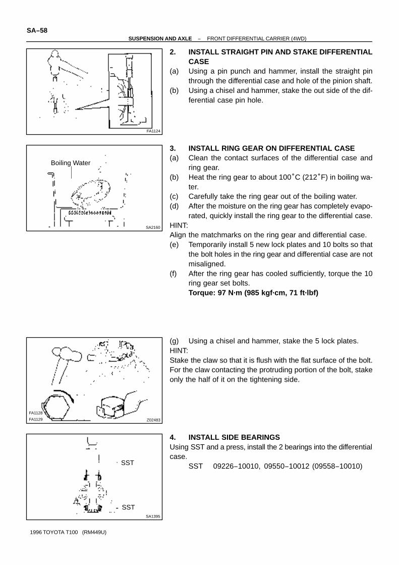
FA1124
SA2160
Boiling Water
Z02483
FA1128
FA1129
SA1395
SST
SST
SA−58−SUSPENSION AND AXLE FRONT DIFFERENTIAL CARRIER (4WD)
1996 TOYOTA T100 (RM449U)
2. INSTALL STRAIGHT PIN AND STAKE DIFFERENTIALCASE
(a) Using a pin punch and hammer, install the straight pinthrough the differential case and hole of the pinion shaft.
(b) Using a chisel and hammer, stake the out side of the dif-ferential case pin hole.
3. INSTALL RING GEAR ON DIFFERENTIAL CASE(a) Clean the contact surfaces of the differential case and
ring gear.(b) Heat the ring gear to about 100°C (212°F) in boiling wa-
ter.(c) Carefully take the ring gear out of the boiling water.(d) After the moisture on the ring gear has completely evapo-
rated, quickly install the ring gear to the differential case.HINT:Align the matchmarks on the ring gear and differential case.(e) Temporarily install 5 new lock plates and 10 bolts so that
the bolt holes in the ring gear and differential case are notmisaligned.
(f) After the ring gear has cooled sufficiently, torque the 10ring gear set bolts.Torque: 97 N·m (985 kgf·cm, 71 ft·lbf)
(g) Using a chisel and hammer, stake the 5 lock plates.HINT:Stake the claw so that it is flush with the flat surface of the bolt.For the claw contacting the protruding portion of the bolt, stakeonly the half of it on the tightening side.
4. INSTALL SIDE BEARINGSUsing SST and a press, install the 2 bearings into the differentialcase.
SST 09226−10010, 09550−10012 (09558−10010)
https://www.truck-manuals.net/

Z03851
W00404
SST
Front Rear
R01197
SST
R11163
SST
SA2347
SST
−SUSPENSION AND AXLE FRONT DIFFERENTIAL CARRIER (4WD)SA−59
1996 TOYOTA T100 (RM449U)
5. CHECK RING GEAR RUNOUT(a) Install the differential case onto the carrier and install the
2 plate washers to fill the play in the bearing (See pageSA−57).
(b) Install 2 bearing caps (See page SA−57).(c) Using a dial indicator, measure the runout of ring gear.
Maximum runout: 0.07 mm (0.0028 in.)
6. INSTALL DRIVE PINION FRONT AND REAR BEARINGOUTER RACES
(a) Using SST and a press, install the front side of the outerrace.SST 09950−60020 (09951−00710),
09950−70010 (09951−07150)(b) Using SST and a press, install the rear side of the outer
race.SST 09950−60020 (09951−00790),
09950−70010 (09951−07150)7. INSTALL DRIVE PINION FRONT BEARING(a) Install the washer on the drive pinion.HINT:First fit a washer with the same thickness as the washer whichwas removed, then after checking the tooth contact pattern, re-place the washer with one of a different thickness if necessary.(b) Using SST, install the front bearing onto the drive pinion.
SST 09506−30012
8. TEMPORARILY ADJUST DRIVE PINION PRELOAD(a) Install the drive pinion, rear bearing and oil slinger.HINT:Assemble the spacer and oil seal after adjusting the gear con-tact pattern.(b) Using SST, install the companion flange.
SST 09950−30010(c) Coat the threads of the nut with hypoid gear oil.
(d) Adjust the drive pinion preload by tightening the compan-ion flange nut.Using SST to hold the flange, tighten the nut.SST 09330−00021
NOTICE:As there is no spacer, tighten the nut a little at a time, beingcareful not to overtighten it.
https://www.truck-manuals.net/

SA2352
FA0743
FA0744
FA0746
FA0743
SA−60−SUSPENSION AND AXLE FRONT DIFFERENTIAL CARRIER (4WD)
1996 TOYOTA T100 (RM449U)
(e) Using a torque wrench, measure the preload.Preload (at starting):New bearing:1.2 − 1.9 N·m (12 − 19 kgf·cm, 10.4 − 16.5 in.·lbf)Reused bearing:0.6 − 1.0 N·m (6 − 10 kgf·cm, 5.2 − 8.7 in.·lbf)
9. INSTALL DIFFERENTIAL CASE IN DIFFERENTIALCARRIER
(a) Place the 2 bearing outer races on their respective bear-ings. Check that the left and right outer races are not inter-changed.
(b) Install the differential case in the differential carrier.10. ADJUST RING GEAR BACKLASH(a) Only install the plate washer on the ring gear back side.HINT:Make sure that the ring gear has backlash.(b) Tap on the ring gear with a plastic hammer so that the
washer fit to the bearing.
(c) Using a dial indicator, measure the side gear backlashwith holding one pinion gear toward the differential case.Backlash (reference): 0.13 mm (0.0051 in.)
(d) Select a plate washer for back side ring gear, using thebacklash as reference (See page SA−57).
https://www.truck-manuals.net/

FA0742
FA0752
Z03861
Plate Washer
Plate Washer
FA0754
Z03848
Plate Washer
Plate Washer
−SUSPENSION AND AXLE FRONT DIFFERENTIAL CARRIER (4WD)SA−61
1996 TOYOTA T100 (RM449U)
(e) Select a ring gear teeth side plate washer with a thicknesswhich eliminates any clearance between the outer raceand case.
(f) Remove the plate washes and differential case.(g) Install the plate washer into the ring gear back side of the
carrier.
(h) Place the other plate washer onto the differential case to-gether with the outer race, and install the differential casewith the outer race into the carrier.
(i) Tap on the ring gear with a plastic hammer so that thewasher fit to the bearing.
(j) Using a dial indicator, measure the ring gear backlash.Backlash: 0.13 − 0.18 mm (0.0051 − 0.0070 in.)
(k) If not within specification, adjust by either increasing ordecreasing the thickness of washers on both sides by anequal amount.
HINT:� There should be no clearance between the plate washer
and case.� Make sure that there is ring gear backlash.
https://www.truck-manuals.net/
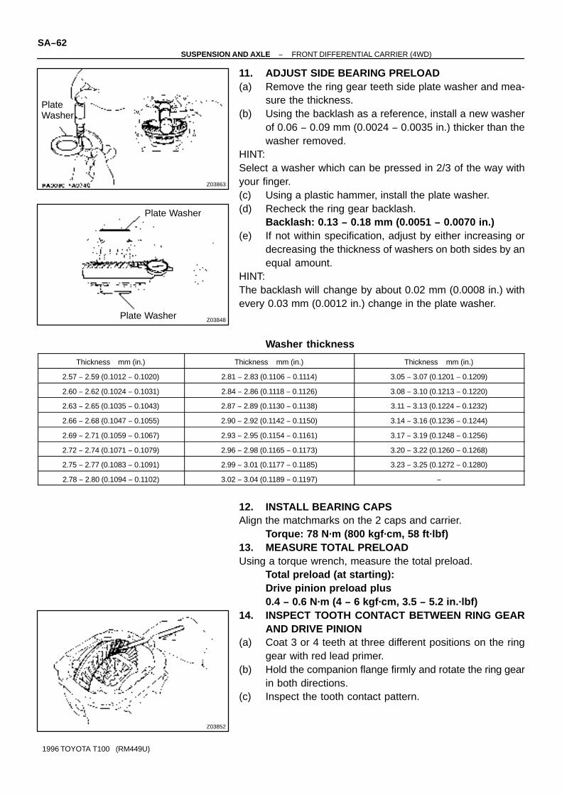
Z03863
Plate Washer
Z03848
Plate Washer
Plate Washer
Z03852
SA−62−SUSPENSION AND AXLE FRONT DIFFERENTIAL CARRIER (4WD)
1996 TOYOTA T100 (RM449U)
11. ADJUST SIDE BEARING PRELOAD(a) Remove the ring gear teeth side plate washer and mea-
sure the thickness.(b) Using the backlash as a reference, install a new washer
of 0.06 − 0.09 mm (0.0024 − 0.0035 in.) thicker than thewasher removed.
HINT:Select a washer which can be pressed in 2/3 of the way withyour finger.(c) Using a plastic hammer, install the plate washer.(d) Recheck the ring gear backlash.
Backlash: 0.13 − 0.18 mm (0.0051 − 0.0070 in.)(e) If not within specification, adjust by either increasing or
decreasing the thickness of washers on both sides by anequal amount.
HINT:The backlash will change by about 0.02 mm (0.0008 in.) withevery 0.03 mm (0.0012 in.) change in the plate washer.
Washer thickness
Thickness mm (in.) Thickness mm (in.) Thickness mm (in.)
2.57 − 2.59 (0.1012 − 0.1020) 2.81 − 2.83 (0.1106 − 0.1114) 3.05 − 3.07 (0.1201 − 0.1209)
2.60 − 2.62 (0.1024 − 0.1031) 2.84 − 2.86 (0.1118 − 0.1126) 3.08 − 3.10 (0.1213 − 0.1220)
2.63 − 2.65 (0.1035 − 0.1043) 2.87 − 2.89 (0.1130 − 0.1138) 3.11 − 3.13 (0.1224 − 0.1232)
2.66 − 2.68 (0.1047 − 0.1055) 2.90 − 2.92 (0.1142 − 0.1150) 3.14 − 3.16 (0.1236 − 0.1244)
2.69 − 2.71 (0.1059 − 0.1067) 2.93 − 2.95 (0.1154 − 0.1161) 3.17 − 3.19 (0.1248 − 0.1256)
2.72 − 2.74 (0.1071 − 0.1079) 2.96 − 2.98 (0.1165 − 0.1173) 3.20 − 3.22 (0.1260 − 0.1268)
2.75 − 2.77 (0.1083 − 0.1091) 2.99 − 3.01 (0.1177 − 0.1185) 3.23 − 3.25 (0.1272 − 0.1280)
2.78 − 2.80 (0.1094 − 0.1102) 3.02 − 3.04 (0.1189 − 0.1197) −
12. INSTALL BEARING CAPSAlign the matchmarks on the 2 caps and carrier.
Torque: 78 N·m (800 kgf·cm, 58 ft·lbf)13. MEASURE TOTAL PRELOADUsing a torque wrench, measure the total preload.
Total preload (at starting):Drive pinion preload plus0.4 − 0.6 N·m (4 − 6 kgf·cm, 3.5 − 5.2 in.·lbf)
14. INSPECT TOOTH CONTACT BETWEEN RING GEARAND DRIVE PINION
(a) Coat 3 or 4 teeth at three different positions on the ringgear with red lead primer.
(b) Hold the companion flange firmly and rotate the ring gearin both directions.
(c) Inspect the tooth contact pattern.
https://www.truck-manuals.net/
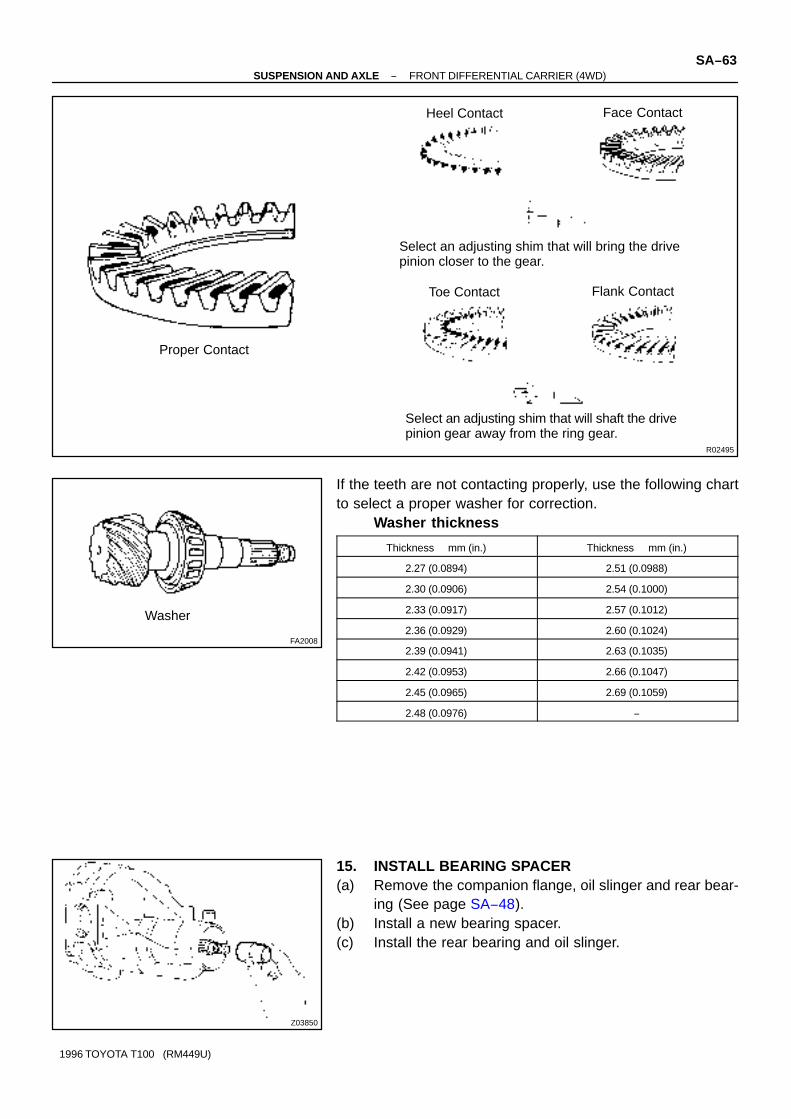
R02495
Proper Contact
Heel Contact Face Contact
Toe Contact Flank Contact
Select an adjusting shim that will bring the drivepinion closer to the gear.
Select an adjusting shim that will shaft the drivepinion gear away from the ring gear.
FA2008
Washer
Z03850
−SUSPENSION AND AXLE FRONT DIFFERENTIAL CARRIER (4WD)SA−63
1996 TOYOTA T100 (RM449U)
If the teeth are not contacting properly, use the following chartto select a proper washer for correction.
Washer thickness
Thickness mm (in.) Thickness mm (in.)
2.27 (0.0894) 2.51 (0.0988)
2.30 (0.0906) 2.54 (0.1000)
2.33 (0.0917) 2.57 (0.1012)
2.36 (0.0929) 2.60 (0.1024)
2.39 (0.0941) 2.63 (0.1035)
2.42 (0.0953) 2.66 (0.1047)
2.45 (0.0965) 2.69 (0.1059)
2.48 (0.0976) −
15. INSTALL BEARING SPACER(a) Remove the companion flange, oil slinger and rear bear-
ing (See page SA−48).(b) Install a new bearing spacer.(c) Install the rear bearing and oil slinger.
https://www.truck-manuals.net/

Z00698
SST
R11163SST
SA2351
SST
SA2352
SA−64−SUSPENSION AND AXLE FRONT DIFFERENTIAL CARRIER (4WD)
1996 TOYOTA T100 (RM449U)
16. INSTALL OIL SEAL(a) Using SST and a hammer, install a new oil seal.
SST 09554−30011Oil seal drive in depth: 1.5 mm (0.059 in.)
(b) Apply MP grease to the oil seal lip.
17. INSTALL COMPANION FLANGE(a) Using SST, install the companion flange.
SST 09950−30010
(b) Coat the threads of a new nut with hypoid gear oil installit.
(c) Using SST to hold the flange, tighten the nut.SST 09330−00021Torque: 108 N·m (1,100 kgf·cm, 80 ft·lbf)
18. ADJUST DRIVE PINION PRELOADUsing a torque wrench, measure the drive pinion preload usingthe backlash of the drive pinion and the ring gear.
Preload (at starting):New bearing:1.2 − 1.9 N·m (12 − 19 kgf·cm, 10.4 − 16.5 in.·lbf)Reused bearing:0.6 − 1.0 N·m (6 − 10 kgf·cm, 5.2 − 8.7 in.·lbf)
If the preload is greater than the specification, replace thespacer.If the preload is less than the specification, retighten the nut alittle at a time with a torque of 13 N·m (130 kgf·cm, 9 ft·lbf) untilthe specified preload is reached.
https://www.truck-manuals.net/

SA2351
SST
SA0339
SST
SA0340
SA0370
−SUSPENSION AND AXLE FRONT DIFFERENTIAL CARRIER (4WD)SA−65
1996 TOYOTA T100 (RM449U)
Maximum torque: 235 N·m (2,400 kgf·cm, 173 ft·lbf)If the maximum torque is exceeded while retightening the nut,replace the spacer and repeat the preload procedure. Do notloosen the nut to reduce the preload.19. RECHECK RING GEAR BACKLASH
(See page SA−57)20. RECHECK TOOTH CONTACT BETWEEN RING GEAR
AND DRIVE PINION (See page SA−57)21. CHECK RUNOUT OF COMPANION FLANGE (See
page SA−48)22. STAKE DRIVE PINION NUT
23. INSTALL RH SIDE GEAR SHAFT OIL SEAL(a) Using SST and a hammer, install a new oil seal until its
surface is flush with the differential carrier end.SST 09550−00032, 09950−70010 (09951−07150)
(b) Apply MP grease to the oil seal lip.
24. INSTALL RH SIDE GEAR SHAFT(a) Install a new snap ring to the side gear shaft.(b) Using a plastic hammer, install the side gear shaft to the
differential case.25. CHECK INSTALLATION OF SIDE GEAR SHAFT(a) Check that there is 2 − 3 mm (0.08 − 0.12 in.) of play in
axial direction.(b) Check that the side gear shaft will not come out by trying
to pull it completely out by hand.
26. INSTALL INTERMEDIATE SHAFT(a) Install a new snap ring to the shaft.(b) Using a plastic hammer, install the shaft to the differential
case.27. CHECK INSTALLATION OF INTERMEDIATE SHAFT(a) Check that there is 2 − 3 mm (0.08 − 0.12 in.) of play in
the axial direction.(b) Check that the intermediate shaft will not come out by try-
ing to pull it completely out by hand.
https://www.truck-manuals.net/

SA0371
SA0400
R11760
FIPG
SA0374
SA−66−SUSPENSION AND AXLE FRONT DIFFERENTIAL CARRIER (4WD)
1996 TOYOTA T100 (RM449U)
28. INSTALL CLUTCH CASE TO SIDE GEAR SHAFT TUBE(a) Install a new O−ring to the tube.(b) Coat the O−ring with MP grease.
(c) Install the clutch case to the tube.(d) Using a torx socket (E14), torque the 2 torx bolts.
Torque: 78 N·m (800 kgf·cm, 58 ft·lbf)29. INSTALL CLUTCH SLEEVE
30. INSTALL LH SIDE GEAR SHAFT TO DIFFERENTIALCARRIER
(a) Remove any old FIPG material and be careful not to dropoil on the contact surfaces of the differential carrier andclutch case.
(b) Clean surfaces with FIPG material attached to using gas-oline or alcohol.
(c) Apply FIPG to the carrier, as shown.FIPG:Part No. 08826−00090, THREE BOND 1281 or equiva-lent
HINT:Install the side gear shaft within 10 minutes after applying FIPG.(d) Install LH side gear shaft to the differential carrier.
(e) Using a torx socket (E14), torque the 4 torx bolts.Torque: 78 N·m (800 kgf·cm, 58 ft·lbf)
https://www.truck-manuals.net/

R11761
FIPG
Seal Width Approx.1 − 2 mm (0.04 − 0.08 in.)
R11762
FIPG
−SUSPENSION AND AXLE FRONT DIFFERENTIAL CARRIER (4WD)SA−67
1996 TOYOTA T100 (RM449U)
31. INSTALL DIFFERENTIAL CARRIER COVER(a) Remove any old FIPG material and be careful not to drop
oil on the contact surfaces of the differential carrier andcarrier cover.
(b) Clean surfaces with FIPG material attached to using gas-oline or alcohol.
(c) Apply FIPG to the carrier cover, as shown.FIPG:Part No. 08826−00090, THREE BOND 1281 or equiva-lent
HINT:Install the carrier cover within 10 minutes after applying FIPG.(d) Install the differential carrier cover with the 8 bolts.
Torque: 47 N·m (475 kgf·cm, 34 ft·lbf)
32. INSTALL A.D.D. ACTUATOR(a) Remove any old FIPG material and be careful not to drop
oil on the contact surfaces of the actuator and clutch case.(b) Clean surfaces with FIPG material attached to using gas-
oline or alcohol.(c) Apply FIPG to the clutch case, as shown.
FIPG:Part No. 08826−00090, THREE BOND 1281 or equiva-lent
HINT:Install the actuator within 10 minutes after applying FIPG.(d) Torque the 4 bolts.
Torque: 21 N·m (210 kgf·cm, 15 ft·lbf)
https://www.truck-manuals.net/

SA0G9−01
SA−68−SUSPENSION AND AXLE FRONT DIFFERENTIAL CARRIER (4WD)
1996 TOYOTA T100 (RM449U)
INSTALLATIONInstallation is in the reverse order of removal (See page SA−47).AFTER INSTALLATION, FILL DIFFERENTIAL WITH HYPOID GEAR OIL (See page SA−43)
https://www.truck-manuals.net/

SA0GA−01
F01743
Differential
A.D.D. Indicator Switch
ActuatorVacuum Tank
Transfer Indicator Switch
A.D.D. Relay
4WD Indicator
A.D.D. Solenoids(VSV2 and VSV4)
−SUSPENSION AND AXLE A.D.D. CONTROL SYSTEMSA−69
1508Author�: Date�:
1996 TOYOTA T100 (RM449U)
A.D.D. CONTROL SYSTEMLOCATION
https://www.truck-manuals.net/

SA0GB−01
SA0356
SA0361
SA0362
Port A
SA0363
Port B
SA0383
SA−70−SUSPENSION AND AXLE A.D.D. CONTROL SYSTEM
1996 TOYOTA T100 (RM449U)
INSPECTION1. INSPECT CLUTCH HUB AND CLUTCH SLEEVE(a) Check the clutch hub and clutch sleeve for wear and dam-
age.(b) Check that clutch sleeve sides smoothly on the clutch
hub.
2. MEASURE CLEARANCE OF SLEEVE FORK ANDCLUTCH SLEEVE
Using a feeler gauge, measure the clearance between thesleeve fork and the clutch sleeve.
Maximum clearance: 0.35 mm (0.0138 in.)
3. INSPECT A.D.D. ACTUATOR(a) Check that the sleeve fork moves to the actuator side
when a vacuum of 66.7 kPa (500 mmHg, 19.69 in.Hg) isapplied to the port A. Also check that the vacuum remainsconstant.
(b) Check that the sleeve fork moves away from the actuatorwhen a vacuum of 66.7 kPa (500 mmHg, 19.69 in.Hg) isapplied to port B. Also check that the vacuum remainsconstant.
4. INSPECT A.D.D. SOLENOIDS(a) Using an ohmmeter, measure the resistance of the sole-
noids.Resistance: 37 − 44 Ω
https://www.truck-manuals.net/

SA0384
Air Filter
E
F
SA0385
Air Filter
EF
SA0375
123
46
1
2
3
4
6
Z04174
Z04175
−SUSPENSION AND AXLE A.D.D. CONTROL SYSTEMSA−71
1996 TOYOTA T100 (RM449U)
(b) Connect the battery to the solenoid.Check that air flows from the port E to port F.Check that air does not flow from the port E to the air filter.
(c) Disconnect the battery positive voltage from the solenoid.Check that air flows from the port E to the air filter.Check that air does not flow from the port E to port F.
5. INSPECT A.D.D. RELAY(a) Using an ohmmeter, check that continuity exists between
terminals 1 and 3.(b) Using an ohmmeter, check that continuity exists between
terminals 2 and 6.(c) Connect the positive (+) lead from the battery to terminal
6 and the negative (−) lead to terminal 2.(d) Using an ohmmeter, check that continuity exists between
terminals 1 and 4.
6. INSPECT A.D.D. INDICATOR SWITCH(a) Using an ohmmeter, check that continuity exists between
terminals when the switch when the switch is pushed (dif-ferential connected position).
(b) Using an ohmmeter, check that continuity doesn’t existswhen the switch is free (differential disconnected posi-tion).
7. INSPECT TRANSFER INDICATOR SWITCH(a) Using an ohmmeter, check that there is continuity be-
tween terminals between terminals when the switch ispushed (transfer 4WD position).
(b) Using an ohmmeter, check that there is continuity be-tween terminals when switch is free (transfer H2 position).
https://www.truck-manuals.net/

SA0GC−07
SA−72−SUSPENSION AND AXLE FRONT SHOCK ABSORBER (2WD)
1511Author�: Date�:
1996 TOYOTA T100 (RM449U)
FRONT SHOCK ABSORBER (2WD)COMPONENTS
https://www.truck-manuals.net/

SA0GD−01
R03309
W00406
−SUSPENSION AND AXLE FRONT SHOCK ABSORBER (2WD)SA−73
1996 TOYOTA T100 (RM449U)
REMOVAL1. REMOVE FRONT WHEEL
Torque: 103 N·m (1,050 kgf·cm, 76 ft·lbf)2. REMOVE SHOCK ABSORBER(a) Remove the 2 bolts and disconnect the shock absorber
lower side from the lower suspension arm.Torque: 18 N·m (185 kgf·cm, 13 ft·lbf)
(b) Hold the shock absorber and remove the set nut, 2 retain-ers, cushion and shock absorber.Torque: 25 N·m (250 kgf·cm, 18 ft·lbf)
(c) Remove the 2 retainers and cushion from the shock ab-sorber.
https://www.truck-manuals.net/

SA0GE−01
SA0039
SA−74−SUSPENSION AND AXLE FRONT SHOCK ABSORBER (2WD)
1996 TOYOTA T100 (RM449U)
INSPECTIONINSPECT SHOCK ABSORBERCompress and extend the shock absorber piston rod and checkthat there is no abnormal resistance or unusual operationsound.If there is any abnormality, replace the shock absorber with anew one.NOTICE:When discarding the shock absorber, see DISPOSAL onpage SA−75.
https://www.truck-manuals.net/

SA0GF−01
SA0040
−SUSPENSION AND AXLE FRONT SHOCK ABSORBER (2WD)SA−75
1996 TOYOTA T100 (RM449U)
DISPOSAL1. FULLY EXTEND SHOCK ABSORBER ROD2. DRILL HOLE TO REMOVE GAS FROM CYLINDERUsing a drill, make a hole in the cylinder, as shown to removethe gas inside.CAUTION:The discharged gas is harmless, but be careful of chipswhich may fly up when drilling.
https://www.truck-manuals.net/

SA0GG−01
SA−76−SUSPENSION AND AXLE FRONT SHOCK ABSORBER (2WD)
1996 TOYOTA T100 (RM449U)
INSTALLATIONInstallation is in the reverse order of removal (See page SA−73).
https://www.truck-manuals.net/

SA0GH−02
−SUSPENSION AND AXLE FRONT SHOCK ABSORBER (4WD)SA−77
1516Author�: Date�:
1996 TOYOTA T100 (RM449U)
FRONT SHOCK ABSORBER (4WD)COMPONENTS
https://www.truck-manuals.net/
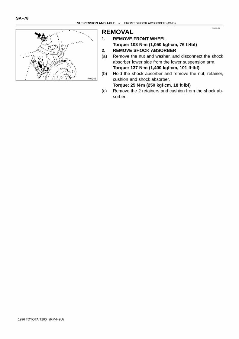
SA0GI−01
R04246
SA−78−SUSPENSION AND AXLE FRONT SHOCK ABSORBER (4WD)
1996 TOYOTA T100 (RM449U)
REMOVAL1. REMOVE FRONT WHEEL
Torque: 103 N·m (1,050 kgf·cm, 76 ft·lbf)2. REMOVE SHOCK ABSORBER(a) Remove the nut and washer, and disconnect the shock
absorber lower side from the lower suspension arm.Torque: 137 N·m (1,400 kgf·cm, 101 ft·lbf)
(b) Hold the shock absorber and remove the nut, retainer,cushion and shock absorber.Torque: 25 N·m (250 kgf·cm, 18 ft·lbf)
(c) Remove the 2 retainers and cushion from the shock ab-sorber.
https://www.truck-manuals.net/
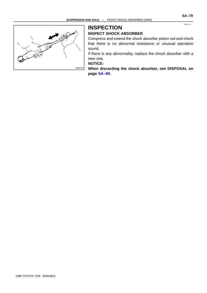
SA0GJ−01
R04270
−SUSPENSION AND AXLE FRONT SHOCK ABSORBER (4WD)SA−79
1996 TOYOTA T100 (RM449U)
INSPECTIONINSPECT SHOCK ABSORBERCompress and extend the shock absorber piston rod and checkthat there is no abnormal resistance or unusual operationsound.If there is any abnormality, replace the shock absorber with anew one.NOTICE:When discarding the shock absorber, see DISPOSAL onpage SA−80.
https://www.truck-manuals.net/

SA0GK−01
R04271
SA−80−SUSPENSION AND AXLE FRONT SHOCK ABSORBER (4WD)
1996 TOYOTA T100 (RM449U)
DISPOSAL1. FULLY EXTEND SHOCK ABSORBER ROD2. DRILL HOLE TO REMOVE GAS FROM CYLINDERUsing a drill, make a hole in the cylinder, as shown to removethe gas inside.CAUTION:The discharged gas is harmless, but be careful of chipswhich may fly up when drilling.
https://www.truck-manuals.net/
SA0GL−01
−SUSPENSION AND AXLE FRONT SHOCK ABSORBER (4WD)SA−81
1996 TOYOTA T100 (RM449U)
INSTALLATIONInstallation is in the reverse order of removal (See page SA−78).
https://www.truck-manuals.net/

SA0GM−07
SA−82−SUSPENSION AND AXLE FRONT TORSION BAR SPRING (2WD)
1521Author�: Date�:
1996 TOYOTA T100 (RM449U)
FRONT TORSION BAR SPRING (2WD)COMPONENTS
https://www.truck-manuals.net/

SA0GN−01
FA0037
A
R04273
R12264
Left Right
R04275
−SUSPENSION AND AXLE FRONT TORSION BAR SPRING (2WD)SA−83
1996 TOYOTA T100 (RM449U)
REMOVAL1. REMOVE FRONT WHEEL
Torque: 103 N·m (1,050 kgf·cm, 76 ft·lbf)2. MEASURE PROTRUDING BOLT END ”A” AS SHOWNHINT:� Use this measurement for reference when adjusting the
vehicle height.� After stabilizing the suspension, adjust the vehicle height
by turning the adjusting nut (See page SA−7).
3. LOOSEN ADJUSTING NUT AND REMOVE ANCHORARM
HINT:At the time of installation, tighten the adjusting nut to the boltprotrusion length is of before removal.
4. REMOVE TORSION BAR SPRINGHINT:At the time of installation, please refer to the following items.� There are left and right matchmarks on the rear end of the
torsion bar springs.Be careful not to interchange them.
� Apply a light coat of MP grease to the spline of the torsionbar spring.
5. REMOVE TORQUE ARMRemove the 2 torque arm mounting nuts.
Torque: 49 N·m (500 kgf·cm, 36 ft·lbf)
https://www.truck-manuals.net/

SA0GO−01
SA−84−SUSPENSION AND AXLE FRONT TORSION BAR SPRING (2WD)
1996 TOYOTA T100 (RM449U)
INSTALLATIONInstallation is in the reverse order of removal (See page SA−83).AFTER INSTALLATION CHECK FRONT WHEEL ALIGNMENT (See page SA−7)
https://www.truck-manuals.net/
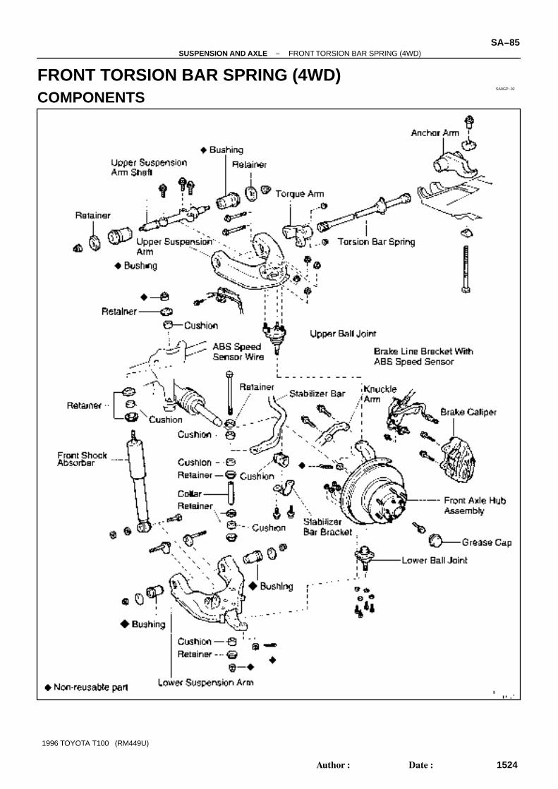
SA0GP−02
−SUSPENSION AND AXLE FRONT TORSION BAR SPRING (4WD)SA−85
1524Author�: Date�:
1996 TOYOTA T100 (RM449U)
FRONT TORSION BAR SPRING (4WD)COMPONENTS
https://www.truck-manuals.net/

SA0GQ−01
FA0037
A
R12267
Left Right
R04377
SA−86−SUSPENSION AND AXLE FRONT TORSION BAR SPRING (4WD)
1996 TOYOTA T100 (RM449U)
REMOVAL1. REMOVE FRONT WHEEL
Torque: 103 N·m (1,050 kgf·cm, 76 ft·lbf)2. MEASURE PROTRUDING BOLT END ”A” AS SHOWNHINT:� Use this measurement for reference when adjusting the
vehicle height.� After stabilizing the suspension, adjust the vehicle height
by turning the adjusting nut (See page SA−10).
3. LOOSEN ADJUSTING NUT, REMOVE ANCHOR ANDTORSION BAR SPRING
HINT:At the time of installation, please refer to the following items.� Tighten the adjusting nut to the bolt protrusion length is
of before removal.� There are left and right matchmarks on the rear end of the
torsion bar springs.Be careful not to interchange them.
� Apply a light coat of MP grease to the spline of the torsionbar spring.
4. REMOVE TORQUE ARMRemove the 2 torque arm mounting nuts.
Torque: 87 N·m (890 kgf·cm, 64 ft·lbf)
https://www.truck-manuals.net/

SA0GR−01
−SUSPENSION AND AXLE FRONT TORSION BAR SPRING (4WD)SA−87
1996 TOYOTA T100 (RM449U)
INSTALLATIONInstallation is in the reverse order of removal (See page SA−86).AFTER INSTALLATION, CHECK FRONT WHEEL ALIGNMENT (See page SA−10)
https://www.truck-manuals.net/

SA0GS−07
SA−88−SUSPENSION AND AXLE FRONT STRUT BAR (2WD)
1527Author�: Date�:
1996 TOYOTA T100 (RM449U)
FRONT STRUT BAR (2WD)COMPONENTS
https://www.truck-manuals.net/

SA0GT−01
FA0138
Matchmarks
R04244
R03328
R12936
−SUSPENSION AND AXLE FRONT STRUT BAR (2WD)SA−89
1996 TOYOTA T100 (RM449U)
REMOVAL1. REMOVE FRONT WHEEL
Torque: 103 N·m (1,050 kgf·cm, 76 ft·lbf)2. REMOVE ENGINE UNDER COVER3. PLACE MATCHMARKS ON STRUT BARPlace matchmarks on the strut bar and nut.
4. REMOVE STRUT BAR(a) Remove the nut, washer, retainer and cushion on the
front side of the strut bar.Torque: 123 N·m (1,250 kgf·cm, 90 ft·lbf)
HINT:At the time of installation, after stabilizing the suspension,torque the nut.
(b) Remove the 2 nuts and disconnect the strut bar from thelower suspension arm.Torque: 75 N·m (760 kgf·cm, 55 ft·lbf)
(c) Remove the collar, cushion, retainer and strut bar.(d) Remove the nut from the strut bar.
HINT:At the time of installation, if using a new strut bar, set the rearside nut to the standard distance.
Standard distance: 423 mm (16.65 in.)
https://www.truck-manuals.net/

SA0GU−01
SA−90−SUSPENSION AND AXLE FRONT STRUT BAR (2WD)
1996 TOYOTA T100 (RM449U)
INSTALLATIONInstallation is in the reverse order of removal (See page SA−89).AFTER INSTALLATION, CHECK FRONT WHEEL ALIGNMENT (See page SA−7)
https://www.truck-manuals.net/

SA0GV−07
−SUSPENSION AND AXLE FRONT UPPER SUSPENSION ARM (2WD)SA−91
1530Author�: Date�:
1996 TOYOTA T100 (RM449U)
FRONT UPPER SUSPENSION ARM (2WD)COMPONENTS
https://www.truck-manuals.net/

SA0GW−07
R04506
FA0126
SA−92−SUSPENSION AND AXLE FRONT UPPER SUSPENSION ARM (2WD)
1996 TOYOTA T100 (RM449U)
REMOVAL1. REMOVE FRONT WHEEL
Torque: 103 N·m (1,050 kgf·cm, 76 ft·lbf)2. REMOVE BRAKE CALIPER (See page BR−27)3. w/ ABS:
DISCONNECT ABS SPEED SENSOR WIRE FROM UP-PER SUSPENSION ARMTorque:8.0 N·m (82 kgf·cm, 71 in.·lbf)
4. REMOVE UPPER BALL JOINT FROM UPPER SUS-PENSION ARM
(a) Support the lower suspension arm with a jack.(b) Remove the 4 nuts and bolts, and disconnect the upper
suspension arm.Torque: 31 N·m (320 kgf·cm, 23 ft·lbf)
5. REMOVE UPPER SUSPENSION ARM(a) Remove the 2 bolts and camber adjusting shims.
Torque: 96 N·m (980 kgf·cm, 71 ft·lbf)(b) Remove the upper suspension arm.NOTICE:� Do not loose the camber adjusting shims. Record the
position and the thickness of camber adjusting shimsso that these can be reinstalled to their original loca-tion.
� At the times of installation, install an equal numberand thickness of shims in their original position.
https://www.truck-manuals.net/

SA0GX−01
Z03685
SST
Z03686
SST
−SUSPENSION AND AXLE FRONT UPPER SUSPENSION ARM (2WD)SA−93
1996 TOYOTA T100 (RM449U)
REPLACEMENT1. REMOVE BUSHING(a) Remove the 2 bolts and retainers.(b) Using SST, remove the 2 bushings.
SST 09710−30021 (09710−03031, 09710−03041)
2. INSTALL NEW BUSHING(a) Using SST, install 2 new bushings.
SST 09710−30021 (09710−03051, 09710−03061)(b) Install the washer and tighten the bolt by the hand.NOTICE:Do not torque the bolts.HINT:At the time of installation, after stabilizing the suspension,torque the bolts.
Torque: 126 N·m (1,280 kgf·cm, 93 ft·lbf)
https://www.truck-manuals.net/
SA0GY−01
SA−94−SUSPENSION AND AXLE FRONT UPPER SUSPENSION ARM (2WD)
1996 TOYOTA T100 (RM449U)
INSTALLATIONInstallation is in the reverse order of removal (See page SA−92).AFTER INSTALLATION, CHECK FRONT WHEEL ALIGNMENT (See page SA−7)
https://www.truck-manuals.net/

SA0GZ−02
−SUSPENSION AND AXLE FRONT UPPER SUSPENSION ARM (4WD)SA−95
1534Author�: Date�:
1996 TOYOTA T100 (RM449U)
FRONT UPPER SUSPENSION ARM (4WD)COMPONENTS
https://www.truck-manuals.net/
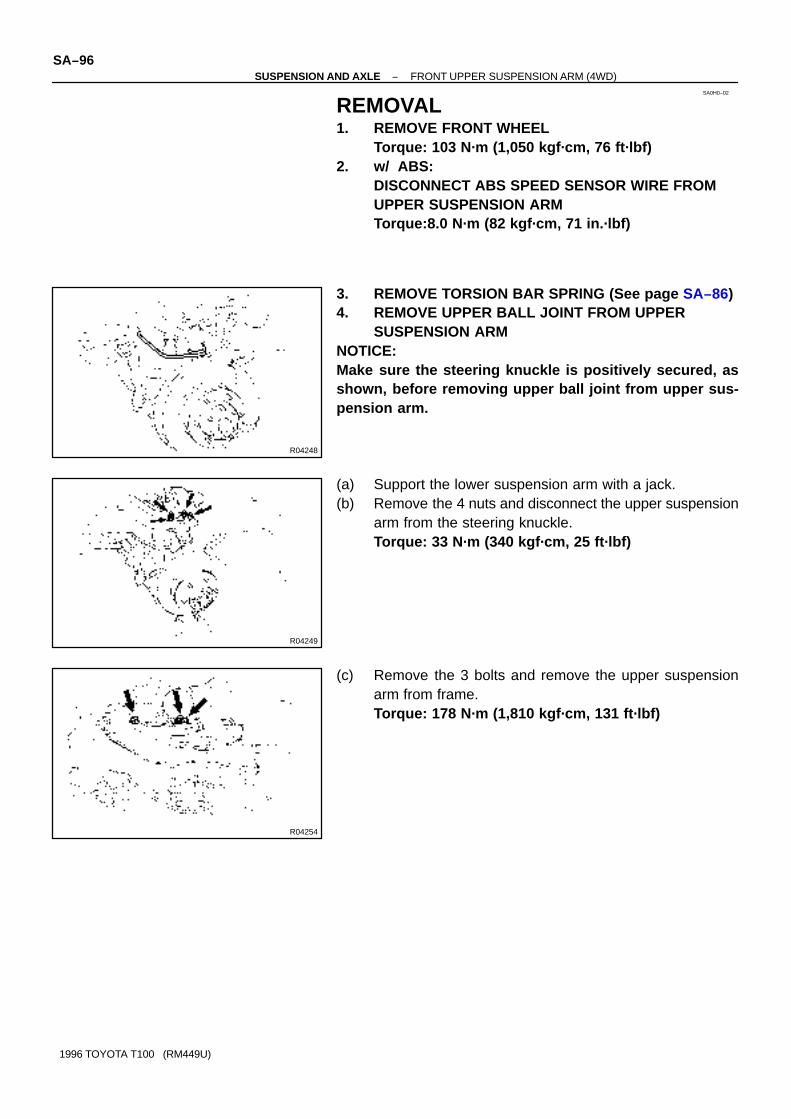
SA0H0−02
R04248
R04249
R04254
SA−96−SUSPENSION AND AXLE FRONT UPPER SUSPENSION ARM (4WD)
1996 TOYOTA T100 (RM449U)
REMOVAL1. REMOVE FRONT WHEEL
Torque: 103 N·m (1,050 kgf·cm, 76 ft·lbf)2. w/ ABS:
DISCONNECT ABS SPEED SENSOR WIRE FROMUPPER SUSPENSION ARMTorque:8.0 N·m (82 kgf·cm, 71 in.·lbf)
3. REMOVE TORSION BAR SPRING (See page SA−86)4. REMOVE UPPER BALL JOINT FROM UPPER
SUSPENSION ARMNOTICE:Make sure the steering knuckle is positively secured, asshown, before removing upper ball joint from upper sus-pension arm.
(a) Support the lower suspension arm with a jack.(b) Remove the 4 nuts and disconnect the upper suspension
arm from the steering knuckle.Torque: 33 N·m (340 kgf·cm, 25 ft·lbf)
(c) Remove the 3 bolts and remove the upper suspensionarm from frame.Torque: 178 N·m (1,810 kgf·cm, 131 ft·lbf)
https://www.truck-manuals.net/

SA0H1−01
FA0785
SST
FA0784
SST
FA0831
SST
FA0830
SST
FA0880
90°
−SUSPENSION AND AXLE FRONT UPPER SUSPENSION ARM (4WD)SA−97
1996 TOYOTA T100 (RM449U)
REPLACEMENT1. REMOVE TORQUE ARM2. REMOVE FRONT BUSHING(a) Using a chisel and hammer, loosen the staked part of the
nut and remove the nut.(b) Using SST and press, remove the front bushing.
SST 09710−26011 (09710−05041, 09710−05051)
3. REMOVE UPPER SUSPENSION ARM SHAFT4. REMOVE REAR BUSHINGUsing SST and press, remove the rear bushing
SST 09710−26011 (09710−05081),09950−60010 (09951−00530),09950−70010 (09951−07200)
5. INSTALL REAR BUSHING(a) Using SST and press, install a new rear bushing.
SST 09710−26011 (09710−05061, 09710−05081)HINT:Do not apply grease or oil to the bushing.(b) Install the upper suspension arm shaft.
6. INSTALL FRONT BUSHINGUsing SST and press, install a new front bushing
SST 09710−26011 (09710−05061, 09710−05081)7. TORQUE UPPER SUSPENSION ARM SHAFT(a) Install the 2 retainers and new nuts.
HINT:Position the upper suspension arm shaft so that the frameinstallation surface is level with the suspension shaft arm.(b) Torque the suspension arm shaft nuts.
Torque: 226 N·m (2,300 kgf·cm, 166 ft·lbf)(c) Stake the nuts with a chisel and hammer.8. INSTALL TORQUE ARM TO UPPER SUSPENSION
ARMTorque: 87 N·m (890 kgf·cm, 64 ft·lbf)
https://www.truck-manuals.net/

SA0H2−01
SA−98−SUSPENSION AND AXLE FRONT UPPER SUSPENSION ARM (4WD)
1996 TOYOTA T100 (RM449U)
INSTALLATIONInstallation is in the reverse order of removal (See page SA−96).AFTER INSTALLATION, CHECK FRONT WHEEL ALIGNMENT (See page SA−10)
https://www.truck-manuals.net/

SA0H3−07
−SUSPENSION AND AXLE FRONT LOWER SUSPENSION ARM (2WD)SA−99
1538Author�: Date�:
1996 TOYOTA T100 (RM449U)
FRONT LOWER SUSPENSION ARM (2WD)COMPONENTS
https://www.truck-manuals.net/

SA0H4−01
FA1600
SA−100−SUSPENSION AND AXLE FRONT LOWER SUSPENSION ARM (2WD)
1996 TOYOTA T100 (RM449U)
REMOVAL1. REMOVE FRONT WHEEL
Torque: 103 N·m (1,050 kgf·cm, 76 ft·lbf)2. REMOVE ENGINE UNDER COVER3. REMOVE TORSION BAR SPRING (See page SA−83)4. DISCONNECT SHOCK ABSORBER FROM LOWER
SUSPENSION ARM (See page SA−73)5. DISCONNECT STABILIZER BAR FROM LOWER
SUSPENSION ARM (See page SA−124)6. DISCONNECT STRUT BAR FROM LOWER
SUSPENSION ARM (See page SA−89)7. DISCONNECT LOWER BALL JOINT FROM LOWER
SUSPENSION ARM (See page SA−116)
8. REMOVE LOWER SUSPENSION ARMRemove the nut and lower suspension arm.
Torque: 206 N·m (2,100 kgf·cm, 152 ft·lbf)HINT:At the time of installation, after stabilizing the suspension,torque the nut.
https://www.truck-manuals.net/

SA0H5−01
FA0046
SST
Rubber iscut off.
Z03684
SST
Apply soapy water
−SUSPENSION AND AXLE FRONT LOWER SUSPENSION ARM (2WD)SA−101
1996 TOYOTA T100 (RM449U)
REPLACEMENT1. REMOVE BUSHING(a) Cut off the bushing rubber, as shown in the illustration.(b) Using SST, remove the bushing.
SST 09726−35011
2. INSTALL NEW BUSHING(a) Apply soapy water on the front rubber part of a new bush-
ing and fit SST on the bushing.SST 09726−35011
(b) Using SST, install the bushing.SST 09726−35011
https://www.truck-manuals.net/

SA0H6−01
SA−102−SUSPENSION AND AXLE FRONT LOWER SUSPENSION ARM (2WD)
1996 TOYOTA T100 (RM449U)
INSTALLATIONInstallation is in the reverse order of removal (See page SA−100).AFTER INSTALLATION, CHECK FRONT WHEEL ALIGNMENT (See page SA−7)
https://www.truck-manuals.net/
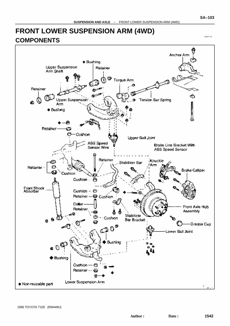
SA0H7−02
−SUSPENSION AND AXLE FRONT LOWER SUSPENSION ARM (4WD)SA−103
1542Author�: Date�:
1996 TOYOTA T100 (RM449U)
FRONT LOWER SUSPENSION ARM (4WD)COMPONENTS
https://www.truck-manuals.net/

SA0H8−01
R04509
FA1593
SST
Z14156Matchmarks
R04251
SA−104−SUSPENSION AND AXLE FRONT LOWER SUSPENSION ARM (4WD)
1996 TOYOTA T100 (RM449U)
REMOVAL1. REMOVE FRONT WHEEL
Torque: 103 N·m (1,050 kgf·cm, 76 ft·lbf)2. REMOVE FRONT SHOCK ABSORBER FROM LOWER
SUSPENSION ARMRemove the front shock absorber lower side set nut.
Torque: 137 N·m (1,400 kgf·cm, 101 ft·lbf)3. DISCONNECT STABILIZER BAR FROM LOWER
SUSPENSION ARM (See page SA−127)
4. DISCONNECT LOWER SUSPENSION ARM FROMLOWER BALL JOINT
(a) Remove the cotter pin and loosen the nut.Torque: 142 N·m (1,450 kgf·cm, 105 ft·lbf)
(b) Using SST, disconnect the lower suspension arm from thelower ball joint.SST 09628−62011
5. REMOVE LOWER SUSPENSION ARM(a) Place matchmarks on the front and rear adjusting cams.
(b) Remove the 2 nuts and adjusting cams and remove thelower suspension arm.Torque: 196 N·m (2,000 kgf·cm, 145 ft·lbf)
HINT:At the time of installation, after stabilizing the suspension,torque the nuts.
https://www.truck-manuals.net/

SA0H9−01
FA0823
SST
FA0824
SST
−SUSPENSION AND AXLE FRONT LOWER SUSPENSION ARM (4WD)SA−105
1996 TOYOTA T100 (RM449U)
REPLACEMENT1. REMOVE FRONT AND REAR BUSHINGSUsing SST, remove the 2 bushings from the lower suspensionarm.
SST 09726−27012 (09726−02051, 09726−02061)
2. INSTALL FRONT AND REAR BUSHINGSUsing SST, install 2 new bushings from the lower suspensionarm.
SST 09726−27012 (09726−02041, 09726−02061)HINT:Do not apply grease or oil to the bushing.
https://www.truck-manuals.net/

SA0HA−01
SA−106−SUSPENSION AND AXLE FRONT LOWER SUSPENSION ARM (4WD)
1996 TOYOTA T100 (RM449U)
INSTALLATIONInstallation is in the reverse order of removal (See page SA−104).AFTER INSTALLATION, CHECK FRONT WHEEL ALIGNMENT (See page SA−10)
https://www.truck-manuals.net/

SA0HB−08
−SUSPENSION AND AXLE FRONT UPPER BALL JOINT (2WD)SA−107
1546Author�: Date�:
1996 TOYOTA T100 (RM449U)
FRONT UPPER BALL JOINT (2WD)COMPONENTS
https://www.truck-manuals.net/

SA0HC−01
R04507
SA−108−SUSPENSION AND AXLE FRONT UPPER BALL JOINT (2WD)
1996 TOYOTA T100 (RM449U)
REMOVAL1. REMOVE FRONT WHEEL
Torque: 103 N·m (1,050 kgf·cm, 76 ft·lbf)2. REMOVE STEERING KNUCKLE (See page SA−16)
3. REMOVE UPPER BALL JOINT(a) Remove the 4 nuts and bolts.
Torque: 31 N·m (320 kgf·cm, 23 ft·lbf)(b) Remove the upper ball joint from the upper suspension
arm.
https://www.truck-manuals.net/

SA0HD−01
R04508
−SUSPENSION AND AXLE FRONT UPPER BALL JOINT (2WD)SA−109
1996 TOYOTA T100 (RM449U)
INSPECTIONINSPECT UPPER BALL JOINT FOR ROTATION CONDITION(a) As shown in the illustration, flip the ball joint stud back and
forth 5 times, before installing the nut.(b) Using a torque wrench, turn the nut continuously one turn
each 2 − 4 seconds and take the torque reading on the 5thturn.Turning torque:2.0 − 3.9 N·m (20 − 40 kgf·cm, 17 − 34 in.·lbf)
https://www.truck-manuals.net/
SA0HE−01
SA−110−SUSPENSION AND AXLE FRONT UPPER BALL JOINT (2WD)
1996 TOYOTA T100 (RM449U)
INSTALLATIONInstallation is in the reverse order of removal (See page SA−108).AFTER INSTALLATION, CHECK ABS SPEED SENSOR SIGNAL (See page DI−321) AND FRONTWHEEL ALIGNMENT (See page SA−7)
https://www.truck-manuals.net/

SA0HF−02
−SUSPENSION AND AXLE FRONT UPPER BALL JOINT (4WD)SA−111
1550Author�: Date�:
1996 TOYOTA T100 (RM449U)
FRONT UPPER BALL JOINT (4WD)COMPONENTS
https://www.truck-manuals.net/

SA0HG−01
SA−112−SUSPENSION AND AXLE FRONT UPPER BALL JOINT (4WD)
1996 TOYOTA T100 (RM449U)
REMOVAL1. REMOVE FRONT WHEEL
Torque: 103 N·m (1,050 kgf·cm, 76 ft·lbf)2. DISCONNECT UPPER AND LOWER BALL JOINT FROM STEERING KNUCKLE
(See page SA−23)3. REMOVE UPPER BALL JOINT(a) Remove the 4 nuts.
Torque: 33 N·m (340 kgf·cm, 25 ft·lbf)(b) Remove the upper ball joint from the upper suspension arm.
https://www.truck-manuals.net/

SA0HH−01
R04508
−SUSPENSION AND AXLE FRONT UPPER BALL JOINT (4WD)SA−113
1996 TOYOTA T100 (RM449U)
INSPECTIONINSPECT UPPER BALL JOINT FOR ROTATION CONDITION(a) As shown in the illustration, flip the ball joint stud back and
forth 5 times, before installing the nut.(b) Using a torque wrench, turn the nut continuously one turn
each 2 − 4 seconds and take the torque reading on the 5thturn.Turning torque:0.5 − 2.4 N·m (5 − 25 kgf·cm, 4 − 22 in.·lbf)
https://www.truck-manuals.net/

SA0HI−01
SA−114−SUSPENSION AND AXLE FRONT UPPER BALL JOINT (4WD)
1996 TOYOTA T100 (RM449U)
INSTALLATIONInstallation is in the reverse order of removal (See page SA−112).AFTER INSTALLATION, CHECK ABS SPEED SENSOR SIGNAL (See page DI−321) AND FRONTWHEEL ALIGNMENT (See page SA−10)
https://www.truck-manuals.net/

SA0HJ−08
−SUSPENSION AND AXLE FRONT LOWER BALL JOINT (2WD)SA−115
1554Author�: Date�:
1996 TOYOTA T100 (RM449U)
FRONT LOWER BALL JOINT (2WD)COMPONENTS
https://www.truck-manuals.net/

SA0HK−01
R03334
SA−116−SUSPENSION AND AXLE FRONT LOWER BALL JOINT (2WD)
1996 TOYOTA T100 (RM449U)
REMOVAL1. REMOVE FRONT WHEEL
Torque: 103 N·m (1,050 kgf·cm, 76 ft·lbf)2. REMOVE STEERING KNUCKLE (See page SA−16)
3. REMOVE LOWER BALL JOINT(a) Remove the 4 nuts.
Torque: 75 N·m (760 kgf·cm, 55 ft·lbf)(b) Remove the lower ball joint from the lower suspension
arm.
https://www.truck-manuals.net/

SA0HL−01
R04508
−SUSPENSION AND AXLE FRONT LOWER BALL JOINT (2WD)SA−117
1996 TOYOTA T100 (RM449U)
INSPECTIONINSPECT LOWER BALL JOINT FOR ROTATION CONDI-TION(a) As shown in the illustration, flip the ball joint stud back and
forth 5 times, before installing the nut.(b) Using a torque wrench, turn the nut continuously one turn
each 2 − 4 seconds and take the torque reading on the 5thturn.Turning torque :2.0 − 7.0 N·m (20 − 70 kgf·cm, 17 − 61 in.·lbf)
https://www.truck-manuals.net/

SA0HM−01
SA−118−SUSPENSION AND AXLE FRONT LOWER BALL JOINT (2WD)
1996 TOYOTA T100 (RM449U)
INSTALLATIONInstallation is in the reverse order of removal (See page SA−116).AFTER INSTALLATION, CHECK ABS SPEED SENSOR SIGNAL (See page DI−321) AND FRONTWHEEL ALIGNMENT (See page SA−7)
https://www.truck-manuals.net/

SA0HN−03
−SUSPENSION AND AXLE FRONT LOWER BALL JOINT (4WD)SA−119
1558Author�: Date�:
1996 TOYOTA T100 (RM449U)
FRONT LOWER BALL JOINT (4WD)COMPONENTS
https://www.truck-manuals.net/

SA0HO−01
FA0820
SST
SA−120−SUSPENSION AND AXLE FRONT LOWER BALL JOINT (4WD)
1996 TOYOTA T100 (RM449U)
REMOVAL1. REMOVE FRONT WHEEL
Torque: 103 N·m (1,050 kgf·cm, 76 ft·lbf)2. DISCONNECT UPPER AND LOWER BALL JOINT
FROM STEERING KNUCKLE (See page SA−23)
3. REMOVE LOWER BALL JOINT FROM STEERINGKNUCKLE
(a) Remove the cotter pin and nut from the lower ball joint.Torque: 58 N·m (590 kgf·cm, 43 ft·lbf)
(b) Using SST, disconnect the steering knuckle from the low-er ball joint.SST 09628−62011
https://www.truck-manuals.net/

SA0HP−01
R04508
−SUSPENSION AND AXLE FRONT LOWER BALL JOINT (4WD)SA−121
1996 TOYOTA T100 (RM449U)
INSPECTIONINSPECT LOWER BALL JOINT FOR ROTATION CONDI-TION(a) As shown in the illustration, flip the ball joint stud back and
forth 5 times, before installing the nut.(b) Using a torque wrench, turn the nut continuously one turn
each 2 − 4 seconds and take the torque reading on the 5thturn.Turning torque :2.0 − 3.9 N·m (20 − 40 kgf·cm, 17 − 34 in.·lbf)
https://www.truck-manuals.net/

SA0HQ−01
SA−122−SUSPENSION AND AXLE FRONT LOWER BALL JOINT (4WD)
1996 TOYOTA T100 (RM449U)
INSTALLATIONInstallation is in the reverse order of removal (See page SA−120).AFTER INSTALLATION, CHECK ABS SPEED SENSOR SIGNAL (See page DI−321) AND FRONTWHEEL ALIGNMENT (See page SA−10)
https://www.truck-manuals.net/

SA0HR−07
−SUSPENSION AND AXLE FRONT STABILIZER BAR (2WD)SA−123
1562Author�: Date�:
1996 TOYOTA T100 (RM449U)
FRONT STABILIZER BAR (2WD)COMPONENTS
https://www.truck-manuals.net/

SA0HS−01
R04505
R05271
SA−124−SUSPENSION AND AXLE FRONT STABILIZER BAR (2WD)
1996 TOYOTA T100 (RM449U)
REMOVAL1. REMOVE FRONT WHEEL
Torque: 103 N·m (1,050 kgf·cm, 76 ft·lbf)2. REMOVE STABILIZER BAR(a) Remove the nut, 3 retainers, 2 cushions and stabilizer bar
from the lower suspension arm.Torque: 13 N·m (130 kgf·cm, 9 ft·lbf)
(b) Remove the nut, 2 cushions, 2 retainers and disconnectthe stabilizer bar.Torque: 13 N·m (130 kgf·cm, 9 ft·lbf)
(c) Employ the same manner described above to the otherside.
(d) Remove the 4 bolts, stabilizer bar brackets, bushings andremove the stabilizer bar.Torque: 30 N·m (306 kgf·cm, 22 ft·lbf)
https://www.truck-manuals.net/

SA0HT−01
−SUSPENSION AND AXLE FRONT STABILIZER BAR (2WD)SA−125
1996 TOYOTA T100 (RM449U)
INSTALLATIONInstallation is in the reverse order of removal (See page SA−124).
https://www.truck-manuals.net/

SA0HU−02
SA−126−SUSPENSION AND AXLE FRONT STABILIZER BAR (4WD)
1565Author�: Date�:
1996 TOYOTA T100 (RM449U)
FRONT STABILIZER BAR (4WD)COMPONENTS
https://www.truck-manuals.net/

SA0HV−01
FA1722
R05271
−SUSPENSION AND AXLE FRONT STABILIZER BAR (4WD)SA−127
1996 TOYOTA T100 (RM449U)
REMOVALREMOVE STABILIZER BAR(a) Remove the nut, 4 cushions, 5 retainers, collar and stabi-
lizer bar from the lower suspension arms.Torque: 25 N·m (260 kgf·cm, 19 ft·lbf)
(b) Employ the same manner described above to the otherside.
(c) Remove the 4 bolts, 2 stabilizer bar brackets, 2 cushionsand remove the stabilizer bar.Torque: 29 N·m (300 kgf·cm, 22 ft·lbf)
https://www.truck-manuals.net/

SA0HW−01
SA−128−SUSPENSION AND AXLE FRONT STABILIZER BAR (4WD)
1996 TOYOTA T100 (RM449U)
INSTALLATIONInstallation is in the reverse order of removal (See page SA−127).
https://www.truck-manuals.net/

SA0HX−03
−SUSPENSION AND AXLE REAR AXLE SHAFTSA−129
1568Author�: Date�:
1996 TOYOTA T100 (RM449U)
REAR AXLE SHAFTCOMPONENTS
https://www.truck-manuals.net/

SA−130−SUSPENSION AND AXLE REAR AXLE SHAFT
1569Author�: Date�:
1996 TOYOTA T100 (RM449U)
https://www.truck-manuals.net/

SA0HY−07
R05272
R04282
SST
−SUSPENSION AND AXLE REAR AXLE SHAFTSA−131
1996 TOYOTA T100 (RM449U)
REMOVAL1. REMOVE REAR WHEEL
Torque: 103 N·m (1,050 kgf·cm, 76 ft·lbf)2. REMOVE BRAKE DRUM
3. CHECK BEARING BACKLASH AND AXLE SHAFTDEVIATION
(a) Using a dial indicator, check the backlash in the bearingshaft direction.Maximum: 0.7 mm (0.027 in.)
If the backlash exceeds the maximum, replace the bearing.(b) Using a dial indicator, check the deviation at the surface
of the axle shaft outside the hub bolt.Maximum: 0.1 mm (0.0039 in.)
If the deviation exceeds the maximum, replace the axle shaft.4. REMOVE REAR BRAKE ASSEMBLY
2WD: See page BR−404WD: See page BR−45
5. w/ ABS:REMOVE ABS SPEED SENSOR FROM REAR AXLEHOUSINGTorque: 8.0 N·m (82 kgf·cm, 71 in.·lbf)
6. DISCONNECT BRAKE LINEUsing SST, disconnect the brake line from the wheel cylinder.
SST 09751−36011Torque: 15 N·m (155 kgf·cm, 11 ft·lbf)
7. DISCONNECT PARKING BRAKE CABLE8. REMOVE REAR AXLE SHAFT ASSEMBLY(a) Remove the 4 backing plate mounting nuts.
Torque: 69 N·m (700 kgf·cm, 51 ft·lbf)(b) Pull out the rear axle shaft assembly from the rear axle
housing.NOTICE:Be careful not to damage the oil seal.9. REMOVE O−RING FROM REAR AXLE HOUSING
https://www.truck-manuals.net/

SA0HZ−01
R12297
R12298
SA0528
SST
RA0177
SST
R12254
SA−132−SUSPENSION AND AXLE REAR AXLE SHAFT
1996 TOYOTA T100 (RM449U)
INSPECTION1. w/ ABS:
REMOVE BEARING RETAINER (DIFFERENTIAL SIDE)AND ABS SPEED SENSOR ROTOR
(a) Attach 4 nuts to the serration bolts and remove the serra-tion bolts from the backing plate using a hammer.
NOTICE:Do not reuse the nuts previously removed from the vehicle.
(b) Grind the retainer and sensor rotor surfaces using a grind-er, then chisel them out with a chisel.
2. REMOVE SNAP RING FROM AXLE SHAFTUsing a snap ring expander, remove the snap ring.
3. REMOVE REAR AXLE SHAFT FROM BACKINGPLATE
(a) Attach 4 washers and nuts to the serration bolts, thentorque the nuts to install the serration bolts to the backingplate.
(b) Remove the 4 nuts from the serration bolts.(c) Position SST on the backing plate with 4 nuts.
SST 09521−25011
(d) Using a press, remove the rear axle shaft with bearing re-tainer from the backing plate.
(e) Remove the SST.
4. INSPECT AXLE SHAFT AND FLANGE FOR RUNOUTFOR WEAR, DAMAGE OR RUNOUTMaximum:Shaft runout: 2.0 mm (0.079 in.)Flange runout: 0.1 mm (0.004 in.)
If the rear axle shaft or flange are damaged or worn, or if runoutis greater than the maximum, replace the rear axle shaft.
https://www.truck-manuals.net/
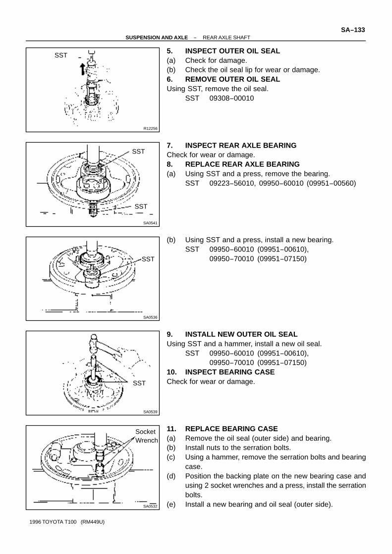
R12256
SST
SA0541
SST
SST
SA0536
SST
SA0539
SST
SA0532
SocketWrench
−SUSPENSION AND AXLE REAR AXLE SHAFTSA−133
1996 TOYOTA T100 (RM449U)
5. INSPECT OUTER OIL SEAL(a) Check for damage.(b) Check the oil seal lip for wear or damage.6. REMOVE OUTER OIL SEALUsing SST, remove the oil seal.
SST 09308−00010
7. INSPECT REAR AXLE BEARINGCheck for wear or damage.8. REPLACE REAR AXLE BEARING(a) Using SST and a press, remove the bearing.
SST 09223−56010, 09950−60010 (09951−00560)
(b) Using SST and a press, install a new bearing.SST 09950−60010 (09951−00610),
09950−70010 (09951−07150)
9. INSTALL NEW OUTER OIL SEALUsing SST and a hammer, install a new oil seal.
SST 09950−60010 (09951−00610),09950−70010 (09951−07150)
10. INSPECT BEARING CASECheck for wear or damage.
11. REPLACE BEARING CASE(a) Remove the oil seal (outer side) and bearing.(b) Install nuts to the serration bolts.(c) Using a hammer, remove the serration bolts and bearing
case.(d) Position the backing plate on the new bearing case and
using 2 socket wrenches and a press, install the serrationbolts.
(e) Install a new bearing and oil seal (outer side).
https://www.truck-manuals.net/

R04283
SST
R04284
SST
R12939
SST
Bearing Side
Z17542SST
122.2 ± 1mm(4.811 ± 0.039 in.)
SA−134−SUSPENSION AND AXLE REAR AXLE SHAFT
1996 TOYOTA T100 (RM449U)
12. INSPECT OIL SEAL (INNER SIDE)Check for wear or damage.13. REPLACE OIL SEAL (INNER SIDE)(a) Using SST, remove the oil seal.
SST 09308−00010
(b) Using SST and a hammer, install a new oil seal.SST 09950−60020 (09951−00890),
09950−70010 (09951−07150)(c) Apply MP grease to the oil seal lip.
14. INSTALL REAR AXLE SHAFT IN BACKING PLATE(a) Apply MP grease to the oil seal lip.(b) Install the backing plate and bearing retainer on the rear
axle shaft.(c) Using SST and a press, install the rear axle shaft into the
backing plate.SST 09316−60011 (09316−00051)
(d) Using snap ring pliers, install a new snap ring.
15. w/ ABS:INSTALL ABS SPEED SENSOR ROTOR ANDBEARING RETAINER (DIFFERENTIAL SIDE)
Using SST and a press, install a new sensor rotor and a newbearing retainer to the axle shaft.
SST 09316−60011 (09316−00051)Standard length: 122.2 ± 1 mm (4.811 ± 0.039 in.)
https://www.truck-manuals.net/

SA0I0−01
−SUSPENSION AND AXLE REAR AXLE SHAFTSA−135
1996 TOYOTA T100 (RM449U)
INSTALLATIONInstallation is in the reverse order of removal (See page SA−131).AFTER INSTALLATION, BLEED BRAKE SYSTEM (See page BR−4), CHECK FOR LEAKS AND ABSSPEED SENSOR SIGNAL (See page DI−321)
https://www.truck-manuals.net/

R04294
SST
SA0I1−01
R04295
SA−136−SUSPENSION AND AXLE REAR WHEEL HUB BOLT
1575Author�: Date�:
1996 TOYOTA T100 (RM449U)
REAR WHEEL HUB BOLTREPLACEMENT1. REMOVE REAR WHEEL AND BRAKE DRUM2. REMOVE HUB BOLTUsing SST, remove the hub bolt.
SST 09650−17011
3. INSTALL HUB BOLTHold the axle shaft, using plate washer and nut, install a newhub bolt.4. INSTALL REAR BRAKE DRUM AND WHEEL
Torque: 103 N·m (1,050 kgf·cm, 76 ft·lbf)
https://www.truck-manuals.net/

SA0I2−08
−SUSPENSION AND AXLE REAR DIFFERENTIAL CARRIERSA−137
1576Author�: Date�:
1996 TOYOTA T100 (RM449U)
REAR DIFFERENTIAL CARRIERCOMPONENTS
https://www.truck-manuals.net/
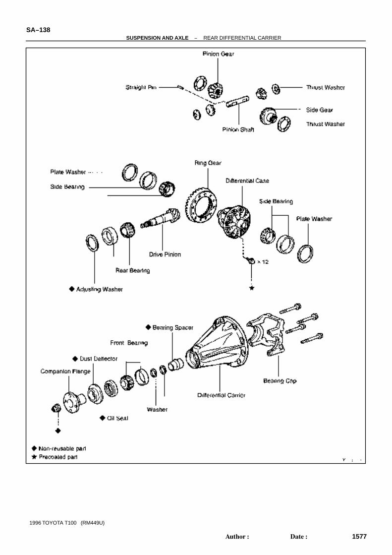
SA−138−SUSPENSION AND AXLE REAR DIFFERENTIAL CARRIER
1577Author�: Date�:
1996 TOYOTA T100 (RM449U)
https://www.truck-manuals.net/

R04163
Matchmarks
SA0I3−01
R08285
−SUSPENSION AND AXLE REAR DIFFERENTIAL CARRIERSA−139
1996 TOYOTA T100 (RM449U)
REMOVAL1. DRAIN HYPOID GEAR OIL2. REMOVE REAR AXLE SHAFTS (See page SA−131)3. REMOVE PROPELLER SHAFT
(2WD: See page PR−3)(4WD: See page PR−11)
4. REMOVE DIFFERENTIAL CARRIER ASSEMBLY(a) Remove the 10 nuts, washers and differential carrier as-
sembly.Torque: 73 N·m (740 kgf·cm, 54 ft·lbf)
NOTICE:Be careful not to damage the installation surface.(b) Remove the gasket.
https://www.truck-manuals.net/

SA259−01
W00493
30 mm(1.18 in.)
R04321
R04322
R04323
R04463
SA−140−SUSPENSION AND AXLE REAR DIFFERENTIAL CARRIER
1996 TOYOTA T100 (RM449U)
DISASSEMBLY1. CHECK RUNOUT OF COMPANION FLANGEUsing a dial indicator, measure the runout of the companionflange vertical and lateral.
MaximumVertical runout: 0.09 mm (0.0035 in.)Lateral runout: 0.09 mm (0.0035 in.)
If the runout is greater than the maximum, replace the compan-ion flange.
2. CHECK RING GEAR RUNOUTUsing a dial indicator, measure the ring gear runout.
Maximum runout: 0.05 mm (0.0020 in.)
3. CHECK RING GEAR BACKLASHUsing a dial indicator, measure the ring gear backlash.
Backlash:2WD: 0.08 − 0.13 mm (0.0031 − 0.0051 in.)4WD: 0.13 − 0.18 mm (0.0051 − 0.0071 in.)
If the backlash is not within specification, adjust the side bear-ing preload or repair if necessary.HINT:Measure from 3 or more places on the circumference of the ringgear.4. CHECK TOOTH CONTACT BETWEEN RING GEAR
AND DRIVE PINION (See page SA−145)
5. CHECK SIDE GEAR BACKLASHUsing a dial indicator, measure the side gear backlash withholding one pinion gear toward the case.
Backlash: 0.05 − 0.20 mm (0.0020 − 0.0079 in.)If the backlash is not within the specification, install the sidegear thrust washers of differential thickness.
https://www.truck-manuals.net/

SA2349
SST
R11391SST
SA2348
SST
Z00641
SST
R04324
Matchmarks
−SUSPENSION AND AXLE REAR DIFFERENTIAL CARRIERSA−141
1996 TOYOTA T100 (RM449U)
6. REMOVE COMPANION FLANGE(a) Using a chisel and hammer, unstake the staked part of the
nut.(b) Using SST to hold the flange, remove the nut.
SST 09330−00021
(c) Using SST, remove the companion flange.SST 09950−30010
7. REMOVE FRONT OIL SEALUsing SST, remove the oil seal from the differential carrier.
SST 09308−10010
8. REMOVE FRONT BEARING AND BEARING SPECER(a) Using SST, remove the bearing from the drive pinion.
SST 09556−22010(b) Remove the 2 washers and bearing spacer. If the front
bearing is damaged or worn, replace the bearing.
9. REMOVE DIFFERENTIAL CASE(a) Place matchmarks on the bearing cap and differential car-
rier.(b) Remove the 4 bolts and bearing cap.
https://www.truck-manuals.net/

R04325
SST
R02482
SST
R04326
R04327
Matchmarks
SA−142−SUSPENSION AND AXLE REAR DIFFERENTIAL CARRIER
1996 TOYOTA T100 (RM449U)
(c) Using SST and a hammer, remove the 2 side bearingplate washers.SST 09504−22011
HINT:Measure the plate washer and note down the thickness.(d) Remove the differential case and bearing outer race from
the carrier.HINT:Tag the bearing outer races to show the location for reassem-bling.10. REMOVE DRIVE PINION FROM DIFFERENTIAL
CARRIER
11. REMOVE DRIVE PINION REAR BEARINGUsing SST and a press, remove the bearing from the drive pin-ion.
SST 09950−00020HINT:If the drive pinion or ring gear are damaged replace them as aset.
12. REMOVE FRONT AND REAR BEARING OUTERRACES
NOTICE:Do not remove the outer races except when replacing thebearings.Using a brass bar and hammer, remove the 2 outer races andadjusting washer from the carrier.HINT:Measure the adjusting washer and note down the thickness.
13. REMOVE RING GEAR(a) Place matchmarks on the ring gear and differential case.(b) Remove the 12 ring gear set bolts.(c) Using a plastic hammer, tap on the ring gear to separate
it from the differential case.
https://www.truck-manuals.net/

R04328
R12920
SST
SST
RA0997
−SUSPENSION AND AXLE REAR DIFFERENTIAL CARRIERSA−143
1996 TOYOTA T100 (RM449U)
14. CHECK DIFFERENTIAL CASE RUNOUT(a) Install the differential case in the differential carrier (See
page SA−145).(b) Using a dial indicator, measure the differential case run-
out.Maximum case runout: 0.04 mm (0.0016 in.)
(c) Remove the differential case.
15. REMOVE SIDE BEARINGSUsing SST, remove the 2 side bearings from the differentialcase.
SST 09950−40010, 09950−60010 (09951−00450)HINT:Fix the claws of SST to the notch in the differential case.
16. DISASSEMBLE DIFFERENTIAL CASE ASSEMBLY(a) Using a pin punch and hammer, remove the straight pin.(b) Remove these parts from the differential case:
� Pinion shaft� 2 pinion gears� 2 pinion gear thrust washers� 2 side gears� 2 side gear thrust washers
https://www.truck-manuals.net/

R04330
SST
SA0I5−01
R04331
SST
SA−144−SUSPENSION AND AXLE REAR DIFFERENTIAL CARRIER
1996 TOYOTA T100 (RM449U)
REPLACEMENTREPLACE COMPANION FLANGE DUST DEFLECTOR(a) Using SST and a press, remove the dust deflector.
SST 09950−00020
(b) Using SST and a press, install a new dust deflector.SST 09523−36010
https://www.truck-manuals.net/

FA1121
SA0I6−02
FA1122
FA1123
FA1124
−SUSPENSION AND AXLE REAR DIFFERENTIAL CARRIERSA−145
1996 TOYOTA T100 (RM449U)
REASSEMBLY1. ASSEMBLE DIFFERENTIAL CASE(a) Install the 2 proper thrust washers to the side gears.HINT:Refer to the table below to select thrust washers which will en-sure that the backlash is within specifications.
Washer thickness
Thickness mm (in.) Thickness mm (in.)
1.50 (0.0590) 1.75 (0.0689)
1.55 (0.0610) 1.80 (0.0709)
1.60 (0.0630) 1.85 (0.0728)
1.65 (0.0650) 1.90 (0.0748)
1.70 (0.0669) −
(b) Install the 2 side gears with the thrust washers, piniongears, pinion gear thrust washers and pinion shaft.
HINT:Align the holes of the differential case and pinion shaft.
(c) Using a dial indicator, measure the side gear backlashwith holding one pinion gear toward the case.Backlash: 0.05 − 0.20 mm (0.0020 − 0.0079 in.)
If the backlash is not within specification, replace the thrustwashers.
(d) Using a pin punch and hammer, install the straight pinthrough the holes in the differential case and pinion shaft.
(e) Using a chisel and hammer, stake the out side of the dif-ferential case pin hole.
https://www.truck-manuals.net/

R04333
SST
SST
SA1143
Boiling Water
R04332
Matchmarks
R04334
R04335
SST
SA−146−SUSPENSION AND AXLE REAR DIFFERENTIAL CARRIER
1996 TOYOTA T100 (RM449U)
2. INSTALL SIDE BEARINGSUsing SST and a press, install the 2 side bearings into the differ-ential case.
SST 09506−35010, 09950−60010 (09951−00480),09950−70010 (09951−07150)
3. INSTALL RING GEAR ON DIFFERENTIAL CASE(a) Clean the contact surfaces of the differential case and
ring gear.(b) Heat the ring gear to about 100°C (212°F) in boiling wa-
ter.(c) Carefully take the ring gear out of the boiling water.(d) After the moisture on the ring gear has completely evapo-
rated, quickly install the ring gear to the differential case.
(e) Align the matchmarks on the ring gear and differentialcase.
(f) After the ring gear cools down enough, torque the setbolts to which thread lock has been applied.Thread lock:Part No. 08833−00100, THREE BOND 1360K or equiv-alent.Torque: 125 N·m (1,270 kgf·cm, 92 ft·lbf)
4. INSPECT RING GEAR RUNOUT(a) Install the differential case into the carrier and install the
plate washers to make sure the play in the bearing (Seepage SA−57).
(b) Install bearing cap (See page SA−57).(c) Using a dial indicator, measure the runout of ring gear.
Maximum runout: 0.05 mm (0.0020 in.)
5. INSTALL DRIVE PINION BEARING OUTER RACESAND ADJUSTING WASHER
(a) Using SST, install a new front bearing outer race to thecarrier.SST 09950−60020 (09951−00710),
09950−70010 (09951−07150)(b) Using SST, install a new adjusting washer and install a
new rear bearing outer race to the carrier.SST 09950−60020 (09951−00910),
09950−70010 (09951−07150)
https://www.truck-manuals.net/

R00055
SST
R11163SST
SA2351
SST
SA2446
−SUSPENSION AND AXLE REAR DIFFERENTIAL CARRIERSA−147
1996 TOYOTA T100 (RM449U)
HINT:First fit a washer with the same thickness as the washer whichwas removed, then after checking the tooth contact pattern, re-place the washer with one of a different thickness if necessary.
6. INSTALL DRIVE PINION REAR BEARINGUsing SST and a press, install the rear bearing onto the drivepinion.
SST 09506−35010
7. TEMPORARILY ADJUST DRIVE PINION PRELOAD(a) Install the drive pinion and front bearing.HINT:Assemble the spacer, washers and oil seal after adjusting thegear contact pattern.(b) Using SST, install the companion flange.
SST 09950−30010
(c) Coat the threads of the nut with hypoid gear oil.(d) Adjust the drive pinion preload by tightening the compan-
ion flange nut.Using SST to hold the flange, torque the nut.SST 09330−00021
NOTICE:As there is no spacer, tighten the nut a little at a time, beingcareful not to overtighten it.
(e) Using a torque wrench, measure the preload.Preload (at starting):New bearing:1.0 − 1.6 N·m (10 − 16 kgf·cm, 8.7 − 13.9 in.·lbf)Reused bearing:0.5 − 0.8 N·m (5 − 8 kgf·cm, 4.3 − 6.9 in.·lbf)
https://www.truck-manuals.net/

R04453
R04535
R04558
R04453
R04455
SA−148−SUSPENSION AND AXLE REAR DIFFERENTIAL CARRIER
1996 TOYOTA T100 (RM449U)
8. INSTALL DIFFERENTIAL CASE IN CARRIER(a) Place the bearing outer races on their respective bear-
ings. Make sure the left and right races are not inter-changed.
(b) Install the differential case in the carrier.9. ADJUST RING GEAR BACKLASH(a) Only install the plate washer on the ring gear back side.HINT:Makes that the ring gear has a backlash.
(b) Tap on the ring gear with a plastic hammer so that thewasher fit to the bearing.
(c) Using a dial indicator, measure the side gear backlashwith holding one pinion gear toward the differential case.Backlash (reference):2WD: 0.08 − 0.13 mm (0.0031 − 0.0051 in.)4WD: 0.13 − 0.18 mm (0.0051 − 0.0071 in.)
(d) Select a plate washer for back side ring gear, using thebacklash as reference (See page SA−145).
(e) Select a ring gear teeth side plate washer of a thicknesswhich eliminates any clearance between the outer raceand case.
https://www.truck-manuals.net/

R04338
R04456
RA0090
R04456
−SUSPENSION AND AXLE REAR DIFFERENTIAL CARRIERSA−149
1996 TOYOTA T100 (RM449U)
(f) Remove the plate washers and differential case.(g) Install the plate washer into the ring gear back side of the
carrier.(h) Place the other plate washer onto the differential case to-
gether with the outer race, and install the differential casewith the outer race into the carrier.
(i) Tap on the ring gear with a plastic hammer so that thewasher fit to the bearing.
(j) Using a dial indicator, measure the ring gear backlash.Backlash:2WD: 0.08 − 0.13 mm (0.0031 − 0.0051 in.)4WD: 0.13 − 0.18 mm (0.0051 − 0.0071 in.)
(k) If the backlash not within specification, adjust by either in-creasing or decreasing the thickness of washers on bothsides by an equal amount.
HINT:� There should be no clearance between the plate washer
and case.� Make sure that there is ring gear backlash.
10. ADJUST SIDE BEARING PRELOAD(a) After adjustment with the backlash as reference, remove
the ring gear teeth side plate washer and measure thethickness.
(b) Install a new washer of 0.06 − 0.09 mm (0.00024 − 0.0035in.) thicker than the washer removed.
HINT:Select a washer which can be pressed in 2/3 of the way by fin-ger.(c) Using a plastic hammer, tap in the plate washer.(d) Recheck the ring gear backlash.
Backlash:2WD: 0.08 − 0.13 mm (0.0031 − 0.0051 in.)4WD: 0.13 − 0.18 mm (0.0051 − 0.0071 in.)
(e) If the backlash is not within specification, adjust by eitherincreasing or decreasing the thickness washers on bothsides by equal amount.
HINT:The backlash will change by about 0.20 mm (0.0008 in.) withevery 0.03 mm (0.0012 in.) change in the side washer.
https://www.truck-manuals.net/

R04323
SA−150−SUSPENSION AND AXLE REAR DIFFERENTIAL CARRIER
1996 TOYOTA T100 (RM449U)
Washer thickness
Thickness
Mark mm (in.)
Thickness
Mark mm (in.)
Thickness
Mark mm (in.)
58 2.58 (0.1015) 90 2.90 (0.1142) 22 3.22 (0.1268)
60 2.60 (0.1024) 92 2.92 (0.1150) 24 3.24 (0.1276)
62 2.62 (0.1031) 94 2.94 (0.1157) 26 3.26 (0.1283)
64 2.64 (0.1039) 96 2.96 (0.1165) 28 3.28 (0.1291)
66 2.66 (0.1047) 98 2.98 (0.1173) 30 3.30 (0.1299)
68 2.68 (0.1055) 00 3.00 (0.1181) 32 3.32 (0.1307)
70 2.70 (0.1063) 02 3.02 (0.1189) 34 3.34 (0.1315)
72 2.72 (0.1071) 04 3.04 (0.1197) 36 3.36 (0.1323)
74 2.74 (0.1079) 06 3.06 (0.1205) 38 3.38 (0.1331)
76 2.76 (0.1087) 08 3.08 (0.1213) 40 3.40 (0.1339)
78 2.78 (0.1094) 10 3.10 (0.1220) 42 3.42 (0.1346)
80 2.80 (0.1102) 12 3.12 (0.1228) 44 3.44 (0.1354)
82 2.82 (0.1110) 14 3.14 (0.1236) 46 3.46 (0.1362)
84 2.84 (0.1118) 16 3.16 (0.1244) 48 3.48 (0.1370)
86 2.86 (0.1126) 18 3.18 (0.1252) −
88 2.88 (0.1134) 20 3.20 (0.1260) −
11. INSTALL BEARING CAPSAlign the matchmarks on the 2 caps and carrier and torque the4 bolts.
Torque: 113 N·m (1,150 kgf·cm, 83 ft·lbf)12. MEASURE TOTAL PRELOADUsing a torque wrench, measure the total preload.
Total preload (at starting):Drive pinion preload plus0.4 − 0.6 N·m (4 − 6 kgf·cm, 3.5 − 5.2 in.·lbf)
13. INSPECT TOOTH CONTACT BETWEEN RING GEARAND DRIVE PINION
(a) Coat 3 or 4 teeth at three different positions on the ringgear with red lead primer.
(b) Turn the companion flange in both directions to inspectthe ring gear for proper tooth contact.
https://www.truck-manuals.net/
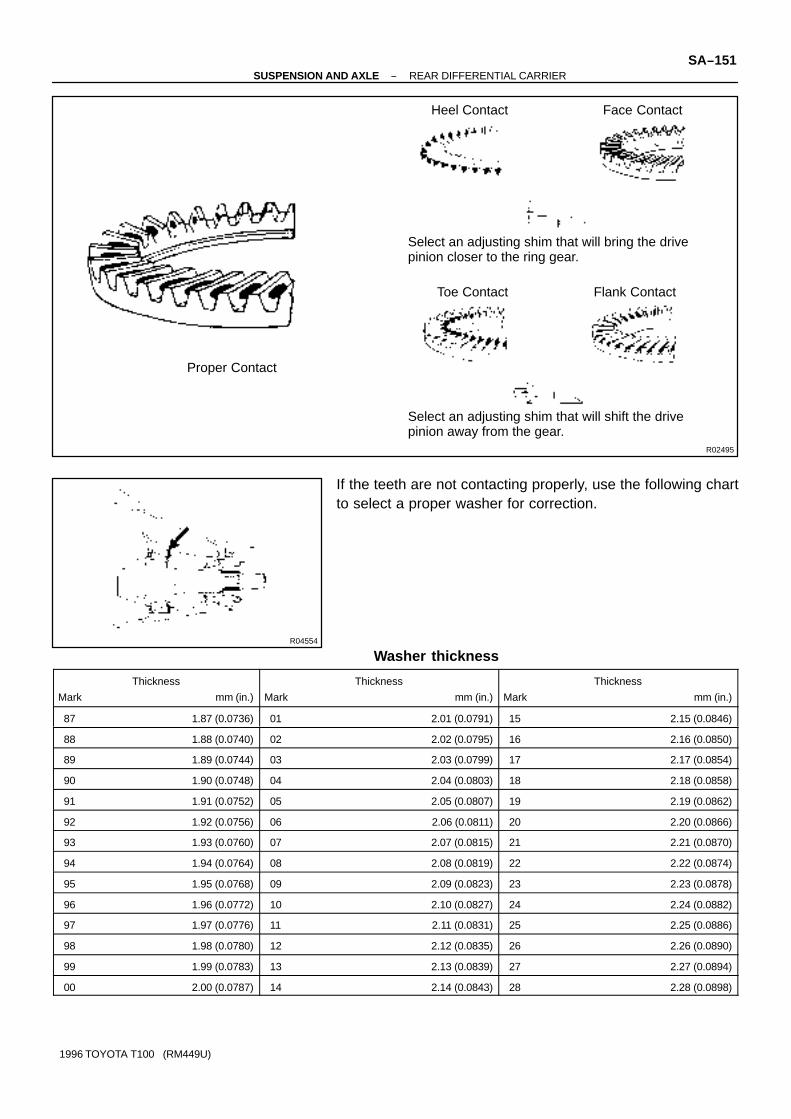
R02495
Proper Contact
Toe Contact Flank Contact
Heel Contact Face Contact
Select an adjusting shim that will bring the drivepinion closer to the ring gear.
Select an adjusting shim that will shift the drivepinion away from the gear.
R04554
−SUSPENSION AND AXLE REAR DIFFERENTIAL CARRIERSA−151
1996 TOYOTA T100 (RM449U)
If the teeth are not contacting properly, use the following chartto select a proper washer for correction.
Washer thickness
Thickness
Mark mm (in.)
Thickness
Mark mm (in.)
Thickness
Mark mm (in.)
87 1.87 (0.0736) 01 2.01 (0.0791) 15 2.15 (0.0846)
88 1.88 (0.0740) 02 2.02 (0.0795) 16 2.16 (0.0850)
89 1.89 (0.0744) 03 2.03 (0.0799) 17 2.17 (0.0854)
90 1.90 (0.0748) 04 2.04 (0.0803) 18 2.18 (0.0858)
91 1.91 (0.0752) 05 2.05 (0.0807) 19 2.19 (0.0862)
92 1.92 (0.0756) 06 2.06 (0.0811) 20 2.20 (0.0866)
93 1.93 (0.0760) 07 2.07 (0.0815) 21 2.21 (0.0870)
94 1.94 (0.0764) 08 2.08 (0.0819) 22 2.22 (0.0874)
95 1.95 (0.0768) 09 2.09 (0.0823) 23 2.23 (0.0878)
96 1.96 (0.0772) 10 2.10 (0.0827) 24 2.24 (0.0882)
97 1.97 (0.0776) 11 2.11 (0.0831) 25 2.25 (0.0886)
98 1.98 (0.0780) 12 2.12 (0.0835) 26 2.26 (0.0890)
99 1.99 (0.0783) 13 2.13 (0.0839) 27 2.27 (0.0894)
00 2.00 (0.0787) 14 2.14 (0.0843) 28 2.28 (0.0898)
https://www.truck-manuals.net/

R11163SST
R04341
SST
SA2351
SST
SA2352
SA−152−SUSPENSION AND AXLE REAR DIFFERENTIAL CARRIER
1996 TOYOTA T100 (RM449U)
14. REMOVE COMPANION FLANGE (See page SA−140)15. REMOVE FRONT BEARING (See page SA−140)16. INSTALL NEW BEARING SPACER, WASHERS AND
FRONT BEARING(a) Install a new bearing spacer and 2 washers, and place the
front bearing.(b) Using SST and the companion flange, install the front
bearing then remove the companion flange.SST 09950−30010
17. INSTALL NEW OIL SEAL(a) Coat a new oil seal lip with MP grease.(b) Using SST and a press, tap in the oil seal until its surface
with the differential carrier end.SST 09316−12010, 09649−17010,
HINT:Connect SST with vinyl tape.
18. INSTALL COMPANION FLANGE(a) Install the companion flange on the shaft.(b) Coat the threads of a new nut with hypoid gear oil.(c) Using SST to hold the flange, torque the nut.
SST 09330−00021Torque: 147 N·m (1,500 kgf·cm, 109 ft·lbf)
19. ADJUST DRIVE PINION PRELOADUsing a torque wrench, measure the preload of the backlashbetween the drive pinion and ring gear.
Preload (at starting):New bearing:1.0 − 1.6 N·m (10 − 16 kgf·cm, 8.7 − 13.9 in.·lbf)Reused bearing:0.5 − 0.8 N·m (5 − 8 kgf·cm, 4.3 − 6.9 in.·lbf)
If preload is greater than the specification, replace the bearingspacer.If preload is less than specification, retorque the nut a little ata time with a torque of 13 N·m (130 kgf·cm, 9 ft·lbf) until the spe-cified preload is reached.
https://www.truck-manuals.net/

SA2351
SST
−SUSPENSION AND AXLE REAR DIFFERENTIAL CARRIERSA−153
1996 TOYOTA T100 (RM449U)
Torque: 451 N·m (4,600 kgf·cm, 333 ft·lbf) or lessIf the maximum torque is exceeded with retightening the nut, re-place the bearing spacer and repeat the preload adjusting pro-cedure. Do not loosen the pinion nut to reduce the preload.20. INSTALL DIFFERENTIAL CASE IN CARRIER (See
page SA−145)21. RECHECK TOTAL PRELOAD (See page SA−145)22. RECHECK RING GEAR BACKLASH (See page
SA−145)23. RECHECK TOOTH CONTACT BETWEEN RING GEAR
AND DRIVE PINION (See page SA−145)24. CHECK RUNOUT OF COMPANION FLANGE (See
page SA−140)25. STAKE DRIVE PINION NUT
https://www.truck-manuals.net/

SA0I7−02
RA10720 − 5 mm (0 − 0.20 in.)Oil Filler Hole
SA−154−SUSPENSION AND AXLE REAR DIFFERENTIAL CARRIER
1996 TOYOTA T100 (RM449U)
INSTALLATION1. INSTALL NEW GASKET TO AXLE HOUSING2. INSTALL DIFFERENTIAL CARRIER ASSEMBLYInstall the differential carrier assembly in the axle housing.
Torque: 73 N·m (740 kgf·cm, 54 ft·lbf)3. INSTALL PROPELLER SHAFT
2WD: See page PR−94WD: See page PR−16
4. INSTALL REAR AXLE SHAFTS(See page SA−135)
5. FILL DIFFERENTIAL WITH DIFFERENTIAL OILTorque:Drain plug: 49 N·m (500 kgf·cm, 39 ft·lbf)Filler plug: 39 N·m (400 kgf·cm, 29 ft·lbf)Oil type: Hypoid gear oil API GL−5Recommended oil viscosity:Above −18°C (0°F) SAE 90Below −18°C (0°F) SAE 80W or 80W − 90Capacity: 2.35 liters (2.22 US qts, 2.67 lmp.qts)
https://www.truck-manuals.net/

SA0I8−07
W00408
Retainer Bushing
Retainer
Rear Shock Absorber
RetainerBushing
Retainer
−SUSPENSION AND AXLE REAR SHOCK ABSORBERSA−155
1594Author�: Date�:
1996 TOYOTA T100 (RM449U)
REAR SHOCK ABSORBERCOMPONENTS
https://www.truck-manuals.net/

SA0I9−01
SA−156−SUSPENSION AND AXLE REAR SHOCK ABSORBER
1996 TOYOTA T100 (RM449U)
REMOVAL1. SUPPORT BODY WITH STANDS(a) Jack up and support the body on stands.(b) Lower the axle housing until the leaf spring tension is free and keep it at this position.2. REMOVE REAR SHOCK ABSORBER(a) Remove the 2 rear shock absorber set bolts.
Torque: 26 N·m (260 kgf·cm, 19 ft·lbf)(b) Remove the rear shock absorber.
https://www.truck-manuals.net/

SA0IA−01
RA0851
−SUSPENSION AND AXLE REAR SHOCK ABSORBERSA−157
1996 TOYOTA T100 (RM449U)
INSPECTIONINSPECT SHOCK ABSORBERCompress and extend the shock absorber rod and check thatthere is no abnormal resistance or unusual operation sounds.If there is any abnormality, replace the shock absorber with anew one.NOTICE:When discarding the shock absorber, use the followingprocedure.
https://www.truck-manuals.net/

SA0IB−01
RA0807
10 − 20 mm (0.39 − 0.79 in.)
SA−158−SUSPENSION AND AXLE REAR SHOCK ABSORBER
1996 TOYOTA T100 (RM449U)
DISPOSAL1. FULLY EXTEND SHOCK ABSORBER ROD2. DRILL HOLE TO REMOVE GAS FROM CYLINDERUsing a drill, make a hole in the cylinder, as shown to removethe gas inside.
https://www.truck-manuals.net/

SA0IC−01
−SUSPENSION AND AXLE REAR SHOCK ABSORBERSA−159
1996 TOYOTA T100 (RM449U)
INSTALLATIONInstallation is in the reverse order of removal (See page SA−156).
https://www.truck-manuals.net/
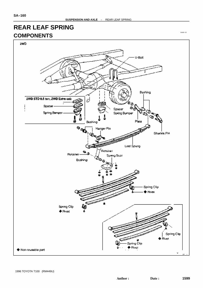
SA0ID−02
SA−160−SUSPENSION AND AXLE REAR LEAF SPRING
1599Author�: Date�:
1996 TOYOTA T100 (RM449U)
REAR LEAF SPRINGCOMPONENTS
https://www.truck-manuals.net/

−SUSPENSION AND AXLE REAR LEAF SPRINGSA−161
1600Author�: Date�:
1996 TOYOTA T100 (RM449U)
https://www.truck-manuals.net/

SA0IE−01
W00476
W00477
R04379
R04380
SA−162−SUSPENSION AND AXLE REAR LEAF SPRING
1996 TOYOTA T100 (RM449U)
REMOVAL1. SUPPORT BODY(a) Jack up and support the body on the stands.(b) Lower the axle housing until the leaf spring tension is free,
and keep it at this position.2. REMOVE REAR WHEEL
Torque: 103 N·m (1,050 kgf·cm, 76 ft·lbf)
3. 4WD:DISCONNECT PARKING BRAKE CABLE
4. DISCONNECT REAR SHOCK ABSORBERRemove the bolt and disconnect the rear shock absorber lowerside from the spring seat.
Torque: 26 N·m (260 kgf·cm, 19 ft·lbf)
5. REMOVE U−BOLTS(a) Remove the 4 U−bolt mounting nuts and washer.
Torque: 132 N·m (1,350 kgf·cm, 97 ft·lbf)(b) Remove the spring seat and 2 retainers.(c) Remove the U−bolts.HINT:At the time of installation, tighten the U−bolts so that the lengthof all the U−bolts under the spring seat is the same.(d) 4WD:
Remove the spring bumper.6. REMOVE REAR LEAF SPRING(a) Remove the hanger pin nut.
Torque: 91 N·m (930 kgf·cm, 67 ft·lbf)HINT:At the time of installation, after stabilizing the suspension,torque the bolt.
(b) Remove the 2 hanger pin lock bolts.Torque: 26 N·m (260 kgf·cm, 19 ft·lbf)
(c) Remove the nut, washer and 2 bushings.
https://www.truck-manuals.net/

W00478
−SUSPENSION AND AXLE REAR LEAF SPRINGSA−163
1996 TOYOTA T100 (RM449U)
(d) Remove the 2 shackle pin mounting nuts and washers.Torque: 91 N·m (930 kgf·cm, 67 ft·lbf)
HINT:At the time of installation, after stabilizing the suspension,torque the nut.(e) Remove the shackle pin, plate and bushings and rear leaf
spring.
https://www.truck-manuals.net/

R06802
SA0IF−01
SA0617
FA0157
Z03060
FA0160
SA−164−SUSPENSION AND AXLE REAR LEAF SPRING
1996 TOYOTA T100 (RM449U)
REPLACEMENT1. REPLACE BUSHINGUsing a socket wrench and press, replace the bushing.
2. REPLACE LEAF SPRING(a) Bend to open the spring clip.
Using a chisel and hammer, pry up the spring clip.
(b) Remove the center bolt.Hold the spring near the center bolt in a vise and removethe center bolt.
(c) Replace the spring clip.(1) Drill off the head of the rivet and drive it out.(2) Install a new rivet into the holes of the leaf spring
and clip. Then rivet with a press.
(d) Install the center bolt.(1) Align the leaf spring holes and secure the leaves
with a vise.(2) Install the spring center bolt.Torque: 44 N·m (450 kgf·cm, 33 ft·lbf)
https://www.truck-manuals.net/

R04069
W00479
W00480
−SUSPENSION AND AXLE REAR LEAF SPRINGSA−165
1996 TOYOTA T100 (RM449U)
(e) Bend the spring clip.Using a hammer, bend the spring clip into the position.
3. REPLACE SPRING BUMPER(a) Remove rear wheel.
Torque: 103 N·m (1,050 kgf·cm, 76 ft·lbf)(b) Remove spring bumper.
(1) STD 0.5 ton, Extra cab:Remove the 2 bolts, spring bumper and spacers.
Torque: 29 N·m (300 kgf·cm, 22 ft·lbf)HINT:At the time of installation, install the spacers, as shown in theillustration.
(2) STD 1.0 ton:Remove the 2 bolts, spring bumper and bumperblock spacers.
Torque: 29 N·m (300 kgf·cm, 22 ft·lbf)HINT:At the time of installation, install the spacers, as shown in theillustration.
https://www.truck-manuals.net/

SA0IG−01
SA−166−SUSPENSION AND AXLE REAR LEAF SPRING
1996 TOYOTA T100 (RM449U)
INSTALLATIONInstallation is in the reverse order of removal (See page SA−162).
https://www.truck-manuals.net/

BR – BRAKE
BRAKE SYSTEM BR-1 TROUBLESHOOTING BR-2 BRAKE FLUID BR-4 BRAKE PEDAL BR-6 PARKING BRAKE LEVER BR-8 BRAKE MASTER CYLINDER BR-9 BRAKE BOOSTER ASSEMBLY BR-17 FRONT BRAKE PAD (2WD) BR-21 FRONT BRAKE PAD (4WD) BR-24 FRONT BRAKE CALIPER (2WD) BR-26 FRONT BRAKE CALIPER (4WD) BR-33 REAR DRUM BRAKE (2WD) BR-39 REAR DRUM BRAKE (4WD) BR-44 LEAD SENSING PROPORTIONING AND BY-PASS VALVE (LSP & BV)
BR-50
ABS ACTUATOR BR-58 FRONT SPEED SENSOR BR-64 REAR SPEED SENSOR BR-67
https://www.truck-manuals.net/

BR08O−01
−BRAKE BRAKE SYSTEMBR−1
1606Author�: Date�:
1996 TOYOTA T100 (RM449U)
BRAKE SYSTEMGENERAL DESCRIPTION� Care must be taken to replace each part properly as it could affect the performance of the brake
system and result in a driving hazard. Replace the parts with parts having the same part numberor equivalent.
� It is very important to keep parts and the area clean when repairing the brake system.� If the vehicle is equipped with a mobile communication system, refer to the precaution in the
IN section.
https://www.truck-manuals.net/

BR08P−03
BR−2−BRAKE TROUBLESHOOTING
1607Author�: Date�:
1996 TOYOTA T100 (RM449U)
TROUBLESHOOTINGPROBLEM SYMPTOMS TABLEUse the table below to help you find the cause of the problem. The numbers indicate the priority of the likelycause of the problem. Check each part in order. If necessary, replace these parts.
Symptom Suspect Area See page
Low pedal or spongy pedal
1. Fluid leaks for brake system
2. Air in brake system
3. Piston seals (Worn or damaged)
4. Rear brake shoe clearance (Out of adjustment)
5. Master cylinder (Fauly)
6. Booster push rod (Out of adjustment)
DI−362
BR−4
BR−26
BR−33
BR−39
BR−44
BR−9
BR−20
Brake drag
1. Brake pedal freeplay (Minimum)
2. Parking brake lever travel (Out of adjustment)
3. Parking brake wire (Sticking)
4. Rear brake shoe clearance (Out of adjustment)
5. Pad or lining (Cracked or distorted)
6. Piston (Stuck)
7. Piston (Frozen)
8. Anchor or return spring (Faulty)
9. Booster push rod (Out adjustment)
10. Vacuum leaks for booster system
11. Master cylinder (Faulty)
BR−6
BR−8
−
BR−39
BR−44
BR−26
BR−33
BR−39
BR−44
BR−26
BR−33
BR−39
BR−44
BR−26
BR−33
BR−39
BR−44
BR−39
BR−44
BR−20
BR−17
BR−9
Brake pull
1. Piston (Stuck)
2. Pad or lining (Cracked or distorted)
3. Piston (Frozen)
4. Disk (Scored)
5. Pad or lining (Cracked or distorted)
BR−26
BR−33
BR−39
BR−44
BR−26
BR−33
BR−39
BR−44
BR−26
BR−33
BR−39
BR−44
BR−26
BR−33
BR−26
BR−33
BR−39
BR−44
https://www.truck-manuals.net/

−BRAKE TROUBLESHOOTINGBR−3
1608Author�: Date�:
1996 TOYOTA T100 (RM449U)
Hard pedal but brake inefficient
1. Fluid leaks for brake system
2. Air in brake system
3. Pad or lining (Worn)
4. Pad or lining (Cracked or distorted)
5. Rear brake shoe clearance (Out of adjustment)
6. Pad or lining (Oily)
7. Pad or lining (Glazed)
8. Disk (Scored)
9. Booster push rod (Out of adjustment)
10. Vacuum leaks for booster system
DI−362
BR−4
BR−26
BR−33
BR−39
BR−44
BR−26
BR−33
BR−39
BR−44
BR−39
BR−44
BR−26
BR−33
BR−39
BR−44
BR−26
BR−33
BR−39
BR−44
BR−26
BR−33
BR−20
BR−17
Noise from brakes
1. Pad or lining (Cracked or distorted)
2. Installation bolt (Loose)
3. Disk (Scored)
4. Pad support plate (Loose)
5. Sliding pin (Worn)
6. Pad or lining (Dirty)
7. Pad or lining (Glazed)
8. Anchor or return spring (Faulty)
9. Anti−squeal shim (Damaged)
10. Shoe hold−down spring (Damaged)
BR−26
BR−33
BR−39
BR−44
BR−26
BR−33
BR−26
BR−33
BR−26
BR−33
BR−39
BR−44
BR−26
BR−33
BR−39
BR−44
BR−39
BR−44
BR−26
BR−33
BR−39
BR−44
https://www.truck-manuals.net/

R12874
BR08Q−01
R12851
R12852
Z03605
BR−4−BRAKE BRAKE FLUID
1609Author�: Date�:
1996 TOYOTA T100 (RM449U)
BRAKE FLUIDBLEEDINGHINT:If any work is done on the brake system or if air is suspected inthe brake lines, bleed the system of air.NOTICE:Do not let brake fluid remain on a painted surface. Wash itoff immediately.1. FILL BRAKE RESERVOIR WITH BRAKE FLUIDCheck the fluid level in the reservoir after bleeding each wheel.Add fluid, if necessary.
2. BLEED MASTER CYLINDERHINT:If the master cylinder was disassembled or if the reservoir be-comes empty, bleed the air from the master cylinder.(a) Disconnect the brake lines from the master cylinder.(b) Slowly depress the brake pedal and hold it.
(c) Block off the outlet plug with your finger, and release thebrake pedal.
(d) Repeat (b) and (c) 3 or 4 times.
3. CONNECT VINYL TUBE TO WHEEL CYLINDERBLEEDER PLUG
Insert the other end of the tube in a half−full container of brakefluid.HINT:Begin air bleeding from the wheel cylinder with the longest hy-draulic line.4. BLEED BRAKE LINE(a) Slowly depress the brake pedal several times.
https://www.truck-manuals.net/

−BRAKE BRAKE FLUIDBR−5
1610Author�: Date�:
1996 TOYOTA T100 (RM449U)
(b) While an assistant depresses the pedal, loosen thebleeder plug until fluid starts to run out. Then close thebleeder plug.Torque: (bleeder plug) 11 N·m (110 kgf·cm, 8 ft·lbf)
(c) Repeat this procedure until there are no more air bubblesin the fluid.
5. REPEAT PROCEDURE FOR EACH WHEEL6. BLEED LSP & BV
https://www.truck-manuals.net/

BR3295
Stop Light Switch
Pedal Height
Push RodBR08R−01
BR4980
A
BR−6−BRAKE BRAKE PEDAL
1611Author�: Date�:
1996 TOYOTA T100 (RM449U)
BRAKE PEDALON−VEHICLE INSPECTION1. CHECK PEDAL HEIGHT
Pedal height from asphalt sheet:Extra cab 4WD:146.7 − 156.7 mm (5.776 − 6.169 in.)Except extra cab 4WD:149.7 − 159.7 mm (5.894 − 6.287 in.)
2. IF NECESSARY, ADJUST PEDAL HEIGHT(a) Disconnect the connector from the stop light switch.(b) Loosen the stop light switch lock nut and remove the stop
light switch.(c) Loosen the push rod lock nut.(d) Adjust the pedal height by turning the pedal push rod.(e) Tighten the push rod lock nut.
Torque: 25 N·m (260 kgf·cm, 19 ft·lbf)(f) Install the stop light switch and turn it until it lightly con-
tacts the pedal stopper.(g) Turn the stop light switch back one turn.(h) Check the clearance (A) between stop light switch and
pedal.Clearance: 0.5 − 2.4 mm (0.020 − 0.094 in.)
(i) Tighten the stop light switch lock nut.(j) Check the stop lights come on when the brake pedal is de-
pressed, and go off when the brake pedal is released.(k) After adjusting the pedal height, check the pedal freeplay.HINT:If clearance (A) between the stop light switch and the pedalstopper has been adjusted correctly, the pedal freeplay willmeet the specifications.
https://www.truck-manuals.net/

BR3296
Push Rod
Pedal Freeplay3 − 6 mm
BR3297
Pedal Reserve Distance
a
−BRAKE BRAKE PEDALBR−7
1612Author�: Date�:
1996 TOYOTA T100 (RM449U)
3. CHECK PEDAL FREEPLAY(a) Stop the engine and depress the brake pedal several
times until there is no more vacuum left in the booster.(b) Push in the pedal by hand until the second resistance be-
gins to be felt. Measure the distance as shown in the il-lustration.Pedal freeplay: 3 − 6 mm (0.12 − 0.24 in.)
HINT:The freeplay to the 1st resistance is due to the play between theclevis and pin. This is magnified up to 1 − 3 mm (0.04 − 0.12 in.)at the pedal.
4. CHECK PEDAL RESERVE DISTANCERelease the parking brake.With the engine running, depress the pedal and measure thepedal reserve distance, as shown.
Pedal reserve distance, ’a’, at 490 N (50 kgf, 110.2 lbf):2WD 1 ton (STD cab): More than 78 mm (3.07 in.)2WD 0.5 ton/4WD (STD cab): More than 73 mm (2.87 in.)4WD (Extra cab): More than 70 mm (2.76 in.)
If incorrect, troubleshoot the brake system.
https://www.truck-manuals.net/

BR0080
BR08S−02
BR0246
R12820
BR−8−BRAKE PARKING BRAKE LEVER
1613Author�: Date�:
1996 TOYOTA T100 (RM449U)
PARKING BRAKE LEVERON−VEHICLE INSPECTION1. CHECK PARKING BRAKE LEVER TRAVELPull the parking brake lever all the way up, and count the num-ber of clicks.
Parking brake lever travel at 196 N (20 kgf, 44.1 lbf):11 − 17 clicks
2. 2WD: IF NECESSARY, ADJUST PARKING BRAKE
HINT:Before adjusting the parking brake, make sure that the rearbrake shoe clearance has been adjusted.(a) Tighten the adjusting nut until the travel is correct.
Then tighten the lock nut.(b) After adjusting the parking brake, confirm that the rear
brakes are not dragging.
3. 4WD: IF NECESSARY, ADJUST PARKING BRAKE
HINT:Before adjusting the parking brake, make sure that the rearbrake shoe clearance has been adjusted.(a) Tighten 1 of the adjusting nuts of the intermediate lever
while loosening the other one until the travel is correct.Tighten the 2 adjusting nuts.
(b) After adjusting the parking brake, confirm that the bell-crank stopper screw comes into contact with the backingplate.
https://www.truck-manuals.net/

BR08T−02
F00667F00667
w/o ABS:
w/ ABS:
Master Cylinder
3−Way Union
Brake Booster
� Gasket
Clamp
� Non−reusable part
Check Valve Bracket
� Gasket
Brake Booster
Clamp3−Way Union
N·m (kgf·cm, ft·lbf) : Specified torque
15 (155, 11)
13 (130, 9)
13 (130, 9)
15 (155, 11)
Master Cylinder
−BRAKE BRAKE MASTER CYLINDERBR−9
1614Author�: Date�:
1996 TOYOTA T100 (RM449U)
BRAKE MASTER CYLINDERCOMPONENTS
https://www.truck-manuals.net/

R14642
Cap
Boot
Strainer
Reservoir
No.1 Piston and Spring
Reservoir Set Screw
Grommet
Snap Ring
Piston Stopper Bolt�Gasket
w/o ABS:
w/ ABS:
Cap
Strainer
Reservoir
Grommet
GrommetNo.1 Piston and Spring
Boot
Snap Ring
No.2 Piston and Spring
No.2 Piston and Spring
Piston Stopper Bolt�Gasket
Cylinder Body
Cylinder Body
Reservoir Set Screw
Grommet
Lithium soap base glycol greaseNon−reusable part�
N·m (kgf·cm, ft·lbf) : Specified torque
1.7 (17.5, 15.2 in.·lbf)
10 (100, 7)
1.7 (17.5, 15.2 in.·lbf)
10 (100, 7)
BR−10−BRAKE BRAKE MASTER CYLINDER
1615Author�: Date�:
1996 TOYOTA T100 (RM449U)
https://www.truck-manuals.net/

BR08U−01
R12875
SST
R12876
−BRAKE BRAKE MASTER CYLINDERBR−11
1996 TOYOTA T100 (RM449U)
REMOVAL1. DISCONNECT LEVEL WARNING SWITCH
CONNECTOR2. TAKE OUT FLUID WITH SYRINGENOTICE:Do not let brake fluid remain on a painted surface. Wash itoff immediately.3. DISCONNECT BRAKE LINESUsing SST, disconnect the brake lines from the master cylinderand 3−way union.
SST 09751−36011
4. REMOVE MASTER CYLINDER(a) Remove the 4 nuts and 3−way union.
Torque: 13 N·m (130 kgf·cm, 9 ft·lbf)(b) Remove the clamp.(c) w/ ABS:
Remove the check valve bracket.(d) Remove the master cylinder and gasket from the brake
booster.
https://www.truck-manuals.net/

BR08V−02
BR2248
R12218
Soft Jaws
R12217
Soft Jaws
BR−12−BRAKE BRAKE MASTER CYLINDER
1996 TOYOTA T100 (RM449U)
DISASSEMBLY1. REMOVE MASTER CYLINDER BOOTUsing a screwdriver, remove the master cylinder boot.NOTICE:At the time of reassembly, please refer to the followingitem. Facing the UP mark on the master cylinder boot upwards,install the cylinder boot to the master cylinder.2. REMOVE RESERVOIR(a) Remove the set screw and pull out the reservoir.
Torque: 1.7 N·m (17.5 kgf·cm, 15.2 in.·lbf)(b) Remove the cap and strainer from the reservoir.3. REMOVE 2 GROMMETS4. PLACE CYLINDER IN VISE
5. REMOVE PISTON STOPPER BOLTUsing a screwdriver, push the pistons in all the way and removethe piston stopper bolt and gasket.HINT:Tape the screwdriver tip before use.
Torque: 10 N·m (100 kgf·cm, 7 ft·lbf)
6. REMOVE 2 PISTONS AND SPRINGS(a) Push in the piston with a screwdriver and remove the
snap ring with snap ring pliers.HINT:Tape the screwdriver tip before use.(b) Remove the No.1 piston and spring by hand, pulling
straight out, not at an angle.NOTICE:If pulled out and installed at an angle, there is a possibilitythat the cylinder bore could be damaged.NOTICE:At the time of reassembly, please refer to the followingitem. Be careful not to damage the rubber lips on the pis-tons.
https://www.truck-manuals.net/

R12236
A
−BRAKE BRAKE MASTER CYLINDERBR−13
1996 TOYOTA T100 (RM449U)
(c) Place a rag and 2 wooden blocks on the work table, andlightly tap the cylinder flange against the block edges untilthe No.2 piston drops out of cylinder.
HINT:Make sure the distance (A) from the rag to the top of the blocksis at least 100 mm (3.94 in.).
https://www.truck-manuals.net/

BR08W−01
BR−14−BRAKE BRAKE MASTER CYLINDER
1996 TOYOTA T100 (RM449U)
INSPECTIONHINT:Clean the disassembled parts with compressed air.1. INSPECT CYLINDER BORE FOR RUST OR SCORING2. INSPECT CYLINDER FOR WEAR OR DAMAGEIf necessary, clean or replace the cylinder.
https://www.truck-manuals.net/

BR08X−01
−BRAKE BRAKE MASTER CYLINDERBR−15
1996 TOYOTA T100 (RM449U)
REASSEMBLYReassembly is in the reverse order of disassembly (See page BR−12).NOTICE:Apply lithium soap base glycol grease to the rubber parts indicated by the arrows (See page BR−9).
https://www.truck-manuals.net/
BR08Y−01
BR−16−BRAKE BRAKE MASTER CYLINDER
1996 TOYOTA T100 (RM449U)
INSTALLATIONInstallation is in the reverse order of removal (See page BR−11).1. BEFORE INSTALLATION, ADJUST LENGTH OF BRAKE BOOSTER PUSH ROD
(See page BR−20)2. AFTER INSTALLATION, FILL BRAKE RESERVOIR WITH BRAKE FLUID. AND BLEED BRAKE
SYSTEM (See page BR−4)3. CHECK FOR LEAKS, CHECK AND ADJUST BRAKE PEDAL (See page BR−6)
https://www.truck-manuals.net/

BR2237
BR08Z−01
BR2238
GOOD NO GOOD
1st 2nd3rd
−BRAKE BRAKE BOOSTER ASSEMBLYBR−17
1622Author�: Date�:
1996 TOYOTA T100 (RM449U)
BRAKE BOOSTER ASSEMBLYON−VEHICLE INSPECTION1. OPERATING CHECK(a) Depress the brake pedal several times with the engine off,
and check that there is no change in the pedal reservedistance.
(b) Depress the brake pedal and start engine. If the pedalgoes down slightly, operation is normal.
2. AIR TIGHTNESS CHECK(a) Start the engine and stop it after 1 or 2 minutes. Depress
the brake pedal several times slowly.If the pedal goes down furthest the 1st time, but gradually risesafter the 2nd or 3rd time, the booster is air tight.(b) Depress the brake pedal while the engine is running, and
stop it with the pedal depressed. If there is no change inpedal reserve travel after holding the pedal for 30 se-conds, the booster is air tight.
https://www.truck-manuals.net/

BR090−02
R14753R14753
Master Cylinder
�Non−reusable part
3−Way Union
Brake Booster
�Gasket
Clevis
Clip
Clevis Pin
Clamp
�Gasket
N·m (kgf·cm, ft·lbf) : Specified torque
15 (155, 11)
13 (130, 9)
25 (260, 19)13 (130, 9)
BR−18−BRAKE BRAKE BOOSTER ASSEMBLY
1996 TOYOTA T100 (RM449U)
COMPONENTS
https://www.truck-manuals.net/

BR091−01
BR3285
−BRAKE BRAKE BOOSTER ASSEMBLYBR−19
1996 TOYOTA T100 (RM449U)
REMOVAL1. REMOVE MASTER CYLINDER (See page BR−11)2. DISCONNECT VACUUM HOSE FROM BRAKE
BOOSTER3. REMOVE PEDAL RETURN SPRING4. REMOVE CLIP AND CLEVIS PIN
5. REMOVE BRAKE BOOSTER(a) Remove the 4 nuts and clevis.(b) Pull out the brake booster and gasket.
https://www.truck-manuals.net/

BR092−01
BR3286
F03521
SST
Gasket
Z03607
SST
BR−20−BRAKE BRAKE BOOSTER ASSEMBLY
1996 TOYOTA T100 (RM449U)
INSTALLATION1. INSTALL BRAKE BOOSTER(a) Install the booster and a new gasket.(b) Install the clevis to the operating rod.(c) Install and torque the booster installation nuts.
Torque: 13 N·m (130 kgf·cm, 9 ft·lbf)(d) Install the clevis pin into the clevis and brake pedal, and
install the clip to the clevis pin.(e) Install the pedal return spring.
2. ADJUST LENGTH OF BOOSTER PUSH ROD(a) Install a new gasket on the master cylinder.(b) Set the SST on the gasket, and lower the pin until its tip
slightly touches the piston.SST 09737−00010
(c) Turn the SST upside down, and set it on the booster.SST 09737−00010
(d) Measure the clearance between the booster push rodand pin head (SST).Clearance: 0 mm (0 in.)
(e) Adjust the booster push rod length until the push rod light-ly touches the pin head.
3. INSTALL MASTER CYLINDER (See page BR−16)4. CONNECT VACUUM HOSE TO BRAKE BOOSTER5. FILL BRAKE RESERVOIR WITH BRAKE FLUID AND
BLEED BRAKE SYSTEM (See page BR−4)6. CHECK FOR FLUID LEAKAGE7. CHECK AND ADJUST BRAKE PEDAL
(See page BR−6)Check and adjust the brake pedal, then tighten the clevis locknut.
Torque: 25 N·m (260 kgf·cm, 19 ft·lbf)8. DO OPERATIONAL CHECK (See page BR−17)
https://www.truck-manuals.net/

BR093−03
Z18924
Pad
Anti−Squeal Spring
Pad Wear Indicator Plate
1 ton :
Anti−Squeal Shim
Pad Support Plate
Inner Anti Squeal Shim
Disc brake grease
Pad
Pad Support Plate
Pad WearIndicator Plate
0.5 ton :
Bleeder Plug
Dust Boot
Sliding Bushing
Brake CaliperDust Boot
Set Ring
Torque Plate
Piston
Piston Seal
Boot
Gasket�
Anti−Squeal Shim
�
�
Gasket� Brake Caliper
Piston SealPiston
Boot
Dust Boot�
Bleeder Plug
Torque Plate
Sliding Pin
Lithium soap base glycol greaseNon−reusable part�
39 (400, 29)
36 (370, 27)
N·m (kgf·cm, ft·lbf) : Specified torque
−BRAKE FRONT BRAKE PAD (2WD)BR−21
1626Author�: Date�:
1996 TOYOTA T100 (RM449U)
FRONT BRAKE PAD (2WD)COMPONENTS
https://www.truck-manuals.net/

BR094−01
BR3082
R04837
BR3312
BR−22−BRAKE FRONT BRAKE PAD (2WD)
1996 TOYOTA T100 (RM449U)
REPLACEMENT1. REMOVE FRONT WHEELRemove the wheel and temporarily fasten the disc with hubnuts.2. INSPECT PAD LINING THICKNESSCheck the pad thickness through the caliper inspection holeand replace pads if not within specification.
Minimum thickness: 1.0 mm (0.039 in.)
3. LIFT UP CALIPER(a) Remove the installation bolt.(b) Lift up the caliper and suspend it securely.HINT:Do not disconnect the flexible hose from the caliper.4. REMOVE THESE PARTS:� 1 ton:
2 anti−squeal springs� 2 brake pads� 2 (1 ton) / 4 (0.5 ton) anti−squeal shims� 2 pad wear indicator plates� 4 pad support plates
NOTICE:The anti−squeal springs (1 ton) and support plates can beused again provided that they have sufficient rebound, nodeformation, cracks or wear, and have had all rust, dirt andforeign particles cleaned off.5. CHECK DISC THICKNESS AND RUNOUT
(See page BR−30)6. INSTALL 4 PAD SUPPORT PLATES7. INSTALL NEW PADSNOTICE:When replacing worn pads, the anti−squeal shims andwear indicator plates must be replaced together with thepads.
(a) Install a pad wear indicator plate to the pad.(b) 1 ton:
Install the anti−squeal shim to each pad.(c) 0.5 ton:
Install the 4 anti−squeal shims to each pad.HINT:Apply disc brake grease to both sides of inner anti−squealshims (See page BR−21).
https://www.truck-manuals.net/

R05057
R05256
−BRAKE FRONT BRAKE PAD (2WD)BR−23
1996 TOYOTA T100 (RM449U)
(d) Install the 2 pads so that the wear indicator plate is facingunderneath.
NOTICE:Do not allow oil or grease on the rubbing face.8. INSTALL CALIPER(a) Draw out a small amount of brake fluid from the reservoir.
(b) Press in piston with a hammer handle or equivalent.HINT:If the piston is difficult to push in, loosen the bleeder plug andpush in the piston while letting some brake fluid escape.(c) Insert the brake caliper carefully so the boot is not
wedged.(d) Install and torque the installation bolts.
Torque: 1 ton: 39 N·m (400 kgf·cm, 29 ft·lbf)Torque:0.5 ton: 36 N·m (370 kgf·cm, 27 ft·lbf)
9. INSTALL FRONT WHEEL10. CHECK THAT FLUID LEVEL IS AT MAX LINE
https://www.truck-manuals.net/

BR095−02
Z18922Disc brake grease
Inner Anti−Squeal Shim
Outer Pad
Anti−Squeal Shim
Inner Anti−Squeal Shim
Anti−Squeal Shim Inner Pad
Anti−Squeal Spring
Pin
Clip
Brake Caliper
Piston Seal
PistonBoot
Set Ring
Disc
Piston Seal
PistonBoot
Set Ring
Lithium soap base glycol grease
Pad WearIndicator Plate
BR−24−BRAKE FRONT BRAKE PAD (4WD)
1629Author�: Date�:
1996 TOYOTA T100 (RM449U)
FRONT BRAKE PAD (4WD)COMPONENTS
https://www.truck-manuals.net/
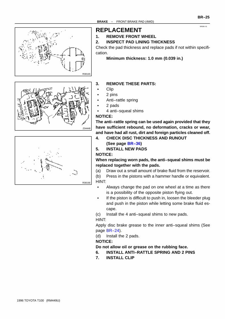
BR096−01
R08165
Z04448
R08166
−BRAKE FRONT BRAKE PAD (4WD)BR−25
1996 TOYOTA T100 (RM449U)
REPLACEMENT1. REMOVE FRONT WHEEL2. INSPECT PAD LINING THICKNESSCheck the pad thickness and replace pads if not within specifi-cation.
Minimum thickness: 1.0 mm (0.039 in.)
3. REMOVE THESE PARTS:� Clip� 2 pins� Anti−rattle spring� 2 pads� 4 anti−squeal shims
NOTICE:The anti−rattle spring can be used again provided that theyhave sufficient rebound, no deformation, cracks or wear,and have had all rust, dirt and foreign particles cleaned off.4. CHECK DISC THICKNESS AND RUNOUT
(See page BR−36)5. INSTALL NEW PADSNOTICE:When replacing worn pads, the anti−squeal shims must bereplaced together with the pads.(a) Draw out a small amount of brake fluid from the reservoir.(b) Press in the pistons with a hammer handle or equivalent.HINT:� Always change the pad on one wheel at a time as there
is a possibility of the opposite piston flying out.� If the piston is difficult to push in, loosen the bleeder plug
and push in the piston while letting some brake fluid es-cape.
(c) Install the 4 anti−squeal shims to new pads.HINT:Apply disc brake grease to the inner anti−squeal shims (Seepage BR−24).(d) Install the 2 pads.NOTICE:Do not allow oil or grease on the rubbing face.6. INSTALL ANTI−RATTLE SPRING AND 2 PINS7. INSTALL CLIP
https://www.truck-manuals.net/

BR097−03
Z18924Z18924
�Gasket
Piston
Pad
Piston SealTorque Plate
Bleeder Plug
�Dust Boot
Sliding Bushing
Brake Caliper
Anti−Squeal Spring
Pad Wear Indicator Plate
1 ton :
0.5 ton :
�Dust Boot
�Dust Boot
Anti−Squeal Shim
Bleeder Plug
Brake Caliper
Piston Seal
Piston
Torque Plate
Pad
Anti−Squeal Shim
Pad Support Plate
Boot
Set Ring
Boot
Pad Support Plate
�Gasket
Sliding Pin
Inner Anti Squeal Shim
Pad WearIndicator Plate
Non−reusable partLithium soap base glycol greaseDisc brake grease
�
N·m (kgf·cm, ft·lbf) : Specified torque
39 (400, 29)
36 (370, 27)
15 (155, 11)
15 (155, 11)
BR−26−BRAKE FRONT BRAKE CALIPER (2WD)
1631Author�: Date�:
1996 TOYOTA T100 (RM449U)
FRONT BRAKE CALIPER (2WD)COMPONENTS
https://www.truck-manuals.net/

BR098−03
R04699
−BRAKE FRONT BRAKE CALIPER (2WD)BR−27
1996 TOYOTA T100 (RM449U)
REMOVAL1. DISCONNECT FLEXIBLE HOSE(a) Remove the union bolt and disconnect the flexible hose.
Torque: 15 N·m (155 kgf·cm, 11 ft·lbf)NOTICE:At the time of installation, please refer to the following item.For correct brake hose routing, ensure that the hose hangsdown before installing hose to caliper.(b) Use a container to catch the brake fluid.2. REMOVE CALIPER FROM TORQUE PLATERemove the 2 installation bolts and caliper.
Torque:1 ton: 39 N·m (400 kgf·cm, 29 ft·lbf)Torque:0.5 ton: 36 N·m (370 kgf·cm, 27 ft·lbf)
3. REMOVE THESE PARTS:� 1 ton:
2 anti−squeal springs� 2 brake pads with anti−squeal shims� 4 pads support plates
https://www.truck-manuals.net/

BR099−02
BR3384
BR3079
BR0168
BR3080
BR−28−BRAKE FRONT BRAKE CALIPER (2WD)
1996 TOYOTA T100 (RM449U)
DISASSEMBLY1. 1 ton:
REMOVE CALIPER SLIDING BUSHINGS AND DUSTBOOTS
(a) Remove the sliding bushings.HINT:At the time of reassembly, please refer to the following item. Ensure that the boots are secured firmly to the caliper grooves.(b) Using a screwdriver and a hammer, remove the dust
boots.HINT:At the time of reassembly, please refer to the following item. Use 2 socket wrenches and a vise, press in new dust boots.
2. REMOVE CYLINDER BOOT SET RING (1 ton) ANDCYLINDER BOOT
Using a screwdriver, remove the cylinder boot set ring (1 ton)and cylinder boot.
3. REMOVE PISTON FROM CYLINDER(a) Put a piece of cloth or an equivalent between the piston
and caliper.(b) Use compressed air to remove the piston from the cylin-
der.CAUTION:Do not place your fingers in front of the piston when usingcompressed air.
4. REMOVE PISTON SEAL FROM BRAKE CYLINDERUsing a screwdriver, remove the piston seal.
https://www.truck-manuals.net/

−BRAKE FRONT BRAKE CALIPER (2WD)BR−29
1996 TOYOTA T100 (RM449U)
5. 0.5 ton:REMOVE SLIDING PINS AND DUST BOOTS
(a) Remove the 2 sliding pins from the torque plate.(b) Using a screwdriver and hammer, tap out the 2 dust
boots.HINT:At the time of reassembly, please refer to the following item. Using a 19 mm socket and hammer, tap in 2 new dust boots intothe torque plate.NOTICE:At the time of reassembly, please refer to the followingitem. Confirm that the metal plate portion of the dust boot fitssnugly in the torque plate.
https://www.truck-manuals.net/

BR09A−01
BR0251
R04701
R04702
BR0173
BR−30−BRAKE FRONT BRAKE CALIPER (2WD)
1996 TOYOTA T100 (RM449U)
INSPECTION1. MEASURE PAD LINING THICKNESSUsing a ruler, measure the pad lining thickness.
Standard thickness:1 ton: 9.5 mm (0.374 in.)Standard thickness:0.5 ton: 11.0 mm (0.433 in.)Minimum thickness:1.0 mm (0.039 in.)
Replace the pad if the thickness is less than the minimum (the1.0 mm slit is no longer visible), or if it shows signs of unevenwear.
2. MEASURE DISC THICKNESSUsing a micrometer, measure the disc thickness.
Standard thickness: 25.0 mm (0.984 in.)Minimum thickness: 23.0 mm (0.906 in.)
Replace the disc if the thickness of the disc is at the minimumthickness or less. Replace the disc or grind it on a lathe if it isscored or is worn unevenly.
3. MEASURE DISC RUNOUTUsing a dial indicator, measure the disc runout 10 mm (0.39 in.)from the outside edge of the disc.
Maximum disc runout: 0.07 mm (0.0028 in.)If the runout is greater than the maximum, replace the disc orgrind it on a ”On−Car” brake lathe.HINT:Before measuring the runout, check that the front hub bearingplay is within specification.
4. IF NECESSARY, REPLACE DISC(a) Remove the torque plate from the knuckle.(b) Remove the axle hub (See page SA−16).(c) Remove the disc from the axle hub.(d) Install a new disc. Torque the bolts.
Torque: 64 N·m (650 kgf·cm, 47 ft·lbf)(e) Install the axle hub and adjust the front bearing preload
(See page SA−19).(f) Install the torque plate onto the knuckle.
Torque: 108 N·m (1,100 kgf·cm, 80 ft·lbf)
https://www.truck-manuals.net/

BR09B−01
−BRAKE FRONT BRAKE CALIPER (2WD)BR−31
1996 TOYOTA T100 (RM449U)
REASSEMBLYReassembly is in the reverse order of disassembly (See page BR−28).NOTICE:Apply lithium soap base glycol grease to the parts indicated by the arrows (See page BR−26).
https://www.truck-manuals.net/

BR09C−01
BR−32−BRAKE FRONT BRAKE CALIPER (2WD)
1996 TOYOTA T100 (RM449U)
INSTALLATIONInstallation is in the reverse order of removal (See page BR−34).1. AFTER INSTALLATION, FILL BRAKE RESERVOIR BRAKE FLUID AND BLEED BRAKE SYSTEM
(See page BR−4)2. CHECK FOR LEAKS.
https://www.truck-manuals.net/

BR09D−02
Z18922Z18922
Inner
Boot
Disc
Piston
Set Ring
Pin
Piston Seal
Indicator Plate
Anti−Squeal Shim
Inner Anti−Squeal Shim
Anti−Rattle Spring
Anti−Squeal Shim
Clip
Set Ring
Boot
Piston
Piston Seal
Anti−SquealShim
Brake Caliper
Inner Pad
Outer Pad
Pad Wear
Lithium soap base glycol greaseDisc brake grease
N·m (kgf·cm, ft·lbf)
15 (155, 11)
123 (1,250, 90)
: Specified torque
−BRAKE FRONT BRAKE CALIPER (4WD)BR−33
1638Author�: Date�:
1996 TOYOTA T100 (RM449U)
FRONT BRAKE CALIPER (4WD)COMPONENTS
https://www.truck-manuals.net/

BR09E−01
R08172
SST
BR0961
BR−34−BRAKE FRONT BRAKE CALIPER (4WD)
1996 TOYOTA T100 (RM449U)
REMOVAL1. REMOVE FRONT WHEEL2. DISCONNECT BRAKE LINEUsing SST, disconnect the brake line.Use a container to catch the brake fluid.
SST 09751−36011Torque: 15 N·m (155 kgf·cm, 11 ft·lbf)
3. REMOVE CALIPERRemove the 2 mounting bolts and remove the caliper.
Torque: 123 N·m (1,250 kgf·cm, 90 ft·lbf)4. REMOVE THESE PARTS:� Clip� 2 pins� Anti−rattle spring� 2 pads� 4 anti−squeal shims
https://www.truck-manuals.net/

BR09F−01
BR2008
BR0212
170 mm(6.70 in.)
50 mm(1.97 in.)
16mm(0.63 in.)
BR0213
BR2009
−BRAKE FRONT BRAKE CALIPER (4WD)BR−35
1996 TOYOTA T100 (RM449U)
DISASSEMBLY1. REMOVE CYLINDER BOOT SET RINGS AND BOOTSUsing a screwdriver, remove the 4 cylinder boot set rings and4 boots.
2. REMOVE PISTONS FROM CYLINDER(a) Prepare the wooden plate to hold the pistons.
(b) Place the plate between the pistons and insert a pad atone side.
(c) Use compressed air to remove the pistons alternatelyfrom the cylinder.
CAUTION:Do not place your fingers in front of the pistons when usingcompressed air.
3. REMOVE PISTON SEALSUsing a screwdriver, remove the 4 seals from the cylinder.
https://www.truck-manuals.net/

BR09G−01
BR0251
BR3183
R08168
BR−36−BRAKE FRONT BRAKE CALIPER (4WD)
1996 TOYOTA T100 (RM449U)
INSPECTION1. MEASURE PAD LINING THICKNESSUsing a ruler, measure the pad lining thickness.
Standard thickness: 9.5 mm (0.374 in.)Minimum thickness: 1.0 mm (0.039 in.)
Replace the pad if the thickness is less than the minimum (the1.0 mm slit is no longer visible), or if it shows signs of unevenwear.
2. MEASURE DISC THICKNESSUsing a micrometer, measure the disc thickness.
Standard thickness: 25.0 mm (0.984 in.)Minimum thickness: 23.0 mm (0.906 in.)
Replace the disc if the thickness of the disc is at the minimumthickness or less. Replace the disc or grind it on a lathe if it isscored or is worn unevenly.
3. MEASURE DISC RUNOUTUsing a dial indicator, measure the disc runout 10 mm (0.39 in.)from the outside edge of the disc.
Maximum disc runout: 0.07 mm (0.0028 in.)If the runout is greater than the maximum, replace the disc orgrind it on a ”On−Car” brake lathe.HINT:Before measuring the runout, check that the front hub bearingplay is within specification.
4. IF NECESSARY, REPLACE DISC(a) Remove the front axle hub (See page SA−23).(b) Install the new axle hub with disc and adjust the front
bearing preload (See page SA−25).
https://www.truck-manuals.net/

BR09H−01
−BRAKE FRONT BRAKE CALIPER (4WD)BR−37
1996 TOYOTA T100 (RM449U)
REASSEMBLYReassembly is in the reverse order of disassembly (See page BR−35).NOTICE:Apply lithium soap base glycol grease to the parts indicated by the arrows (See page BR−33).
https://www.truck-manuals.net/

BR09I−01
BR−38−BRAKE FRONT BRAKE CALIPER (4WD)
1996 TOYOTA T100 (RM449U)
INSTALLATIONInstallation is in the reverse order of removal (See page BR−34).1. AFTER INSTALLATION, FILL BRAKE RESERVOIR BRAKE FLUID AND BLEED BRAKE SYSTEM
(See page BR−4)2. CHECK FOR LEAKS.
https://www.truck-manuals.net/

BR09J−02
F00995F00995
Adjuster
Wheel Cylinder
Parking Brake Lever
Shoe Hold−Down SpringAdjusting Lever
Front Shoe
Brake Drum
Boot
Piston
BootPiston
� C−WasherCup
� E−Ring
Cup
AdjustingLever Spring
Spring
�Gasket
Anchor Spring
Shoe Hold−Down Spring
Return Spring
Adjuster
Pin
�
Lithium soap base glycol greaseHigh temperature grease
Non−reusable partN·m (kgf·cm, ft·lbf)
Bleeder Plug
: Specified torque
15 (155, 11)
10 (100, 7)
11 (110, 8)
Cup
Cup
−BRAKE REAR DRUM BRAKE (2WD)BR−39
1644Author�: Date�:
1996 TOYOTA T100 (RM449U)
REAR DRUM BRAKE (2WD)COMPONENTS
https://www.truck-manuals.net/

BR09K−01
R08164
BR3096
R04711
SST
R04712
SST
R04713
SST
BR−40−BRAKE REAR DRUM BRAKE (2WD)
1996 TOYOTA T100 (RM449U)
REMOVAL1. INSPECT SHOE LINING THICKNESSRemove the inspection hole plug, and check the shoe liningthickness through the hole.If less than minimum, replace the shoes.
Minimum thickness: 1.0 mm (0.039 in.)2. REMOVE REAR WHEEL
3. REMOVE BRAKE DRUMHINT:If the brake drum cannot be removed easily, do the followingsteps.(a) Remove the adjusting hole plug in the backing plate.(b) Insert a screwdriver through the hole in the backing plate,
and hold the automatic adjusting lever away from the ad-justing bolt.
(c) Using another screwdriver, reduce the brake shoe adjust-ment by turning the adjusting bolt.
4. REMOVE FRONT SHOE(a) Using SST, disconnect the return spring.
SST 09703−30010
(b) Using SST, remove the shoe hold−down spring, cups andpin.SST 09718−00010
(c) Disconnect the anchor spring from the front shoe and re-move the front shoe.
(d) Remove the anchor spring from the rear shoe.
5. REMOVE ADJUSTER AND REAR SHOE(a) Using SST, remove the shoe hold−down spring, cups and
pin.SST 09718−00010
(b) Remove the adjusting lever spring.
https://www.truck-manuals.net/

R04715
Z03621
BR3027
SST
−BRAKE REAR DRUM BRAKE (2WD)BR−41
1996 TOYOTA T100 (RM449U)
(c) Remove the adjuster with the return spring together.(d) Using pliers, disconnect the parking brake cable from the
lever and remove the rear shoe.
6. REMOVE AUTOMATIC ADJUSTING LEVER ANDPARKING BRAKE LEVER
(a) Remove the E−ring.(b) Remove the automatic adjusting lever.(c) Remove the C−washer.(d) Remove the parking brake lever.
7. REMOVE WHEEL CYLINDER(a) Using SST, disconnect the brake line from the cylinder.
Use a container to catch the brake fluid.SST 09751−36011Torque: 15 N·m (155 kgf·cm, 11 ft·lbf)
(b) Remove the 2 bolts and wheel cylinder.Torque: 10 N·m (100 kgf·cm, 7 ft·lbf)
8. DISASSEMBLE WHEEL CYLINDERRemove these parts from the wheel cylinder.
� 2 boots� 2 pistons� 2 piston cups� Spring
https://www.truck-manuals.net/
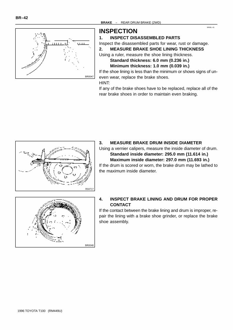
BR09L−01
BR0047
R04717
BR0048
BR−42−BRAKE REAR DRUM BRAKE (2WD)
1996 TOYOTA T100 (RM449U)
INSPECTION1. INSPECT DISASSEMBLED PARTSInspect the disassembled parts for wear, rust or damage.2. MEASURE BRAKE SHOE LINING THICKNESSUsing a ruler, measure the shoe lining thickness.
Standard thickness: 6.0 mm (0.236 in.)Minimum thickness: 1.0 mm (0.039 in.)
If the shoe lining is less than the minimum or shows signs of un-even wear, replace the brake shoes.HINT:If any of the brake shoes have to be replaced, replace all of therear brake shoes in order to maintain even braking.
3. MEASURE BRAKE DRUM INSIDE DIAMETERUsing a vernier calipers, measure the inside diameter of drum.
Standard inside diameter: 295.0 mm (11.614 in.)Maximum inside diameter: 297.0 mm (11.693 in.)
If the drum is scored or worn, the brake drum may be lathed tothe maximum inside diameter.
4. INSPECT BRAKE LINING AND DRUM FOR PROPERCONTACT
If the contact between the brake lining and drum is improper, re-pair the lining with a brake shoe grinder, or replace the brakeshoe assembly.
https://www.truck-manuals.net/

BR09M−01
R04724
BR0080
R04725
−BRAKE REAR DRUM BRAKE (2WD)BR−43
1996 TOYOTA T100 (RM449U)
INSTALLATIONInstallation is in the reverse order of removal (See pageBR−40).NOTICE:Apply lithium soap base glycol grease and high tempera-ture grease to the parts indicated by the arrows (See pageBR−39).
1. CHECK OPERATION OF AUTOMATIC ADJUSTERMECHANISM
(a) Move the parking brake lever of the rear shoe back andforth, as shown. Check that the adjusting bolt turns.
If the adjuster does not turn, check for incorrect installation ofthe rear brakes.
(b) Adjust the adjuster length to the shortest possibleamount.
(c) Install the drum.(d) Pull the parking brake lever all the way up until a clicking
sound can no longer be heard.
2. CHECK CLEARANCE BETWEEN BRAKE SHOES ANDDRUM
(a) Remove the drum.(b) Measure the brake drum inside diameter.(c) Measure the distance between brake shoes. Check that
the difference between the diameters is the correct shoeclearance.Shoe clearance: 0.6 mm (0.024 in.)
If incorrect, check the parking brake system.3. FILL BRAKE RESERVOIR WITH BRAKE FLUID AND
BLEED BRAKE SYSTEM (See Page BR−4)4. CHECK FOR LEAKS
https://www.truck-manuals.net/

BR09N−02
F01618F01618
Bellcrank Boot
AdjusterParking Brake Bellcrank No.1 or No.2
Bleeder Plug
Wheel Cylinder
Parking Brake Cable No.2
Rear Shoe
Pin
Spring
� C−Washer
Clip
Spring
Spring
� −Washer
� C−Washer
Piston
Boot
BellcrankBracket
Parking Brake Lever
Parking Brake Cable No.1
Dust Cover
Bellcrank No.3
Adjuster
ReturnSpring
Anchor Spring
Automatic Adjusting Lever
Cup
E−RingFront Shoe
�Gasket
Brake Drum
InspectionHole plug
Pin
High temperature grease
� Non−reusable partLithium soap base glycol grease
N·m (kgf·cm, ft·lbf)
Pin
: Specified torque
Plug 13 (130, 9)
Shoe Hold−Down Spring
Cup
11 (110, 8)
10 (100, 7)
15 (155, 11)
BR−44−BRAKE REAR DRUM BRAKE (4WD)
1649Author�: Date�:
1996 TOYOTA T100 (RM449U)
REAR DRUM BRAKE (4WD)COMPONENTS
https://www.truck-manuals.net/

BR09O−01
BR1134
BR3116
BR0966
SST
BR0967
SST
BR0968
SST
−BRAKE REAR DRUM BRAKE (4WD)BR−45
1996 TOYOTA T100 (RM449U)
REMOVAL1. INSPECT SHOE LINING THICKNESSRemove the inspection hole plug, and check the shoe liningthickness through the hole.If it is less than the minimum, replace the shoes.
Minimum thickness: 1.0 mm (0.03. in.)2. REMOVE REAR WHEEL
3. REMOVE BRAKE DRUMHINT:If the brake drum cannot be removed easily, do the followingsteps.(a) Remove the adjusting hole plug in the backing plate.(b) Insert a screwdriver through the hole in the backing plate,
and hold the automatic adjusting lever away from the ad-justing bolt.
(c) Using another screwdriver, reduce the brake shoe adjust-ment by turning the adjusting bolt.
4. REMOVE REAR SHOE(a) Using SST, disconnect the return spring.
SST 09703−30010
(b) Using SST, remove the shoe hold−down spring, cups andpin.SST 09718−00010
(c) Disconnect the anchor spring from the rear shoe and re-move the rear shoe.
(d) Remove the anchor spring from the front shoe.
5. REMOVE FRONT SHOE(a) Using SST, remove the shoe hold−down spring, cups and
pin.SST 09718−00010
(b) Remove the return spring from the front shoe.(c) Disconnect the parking brake cable No.1 from the parking
brake bellcrank No.3.(d) Remove the front shoe with adjuster.(e) Disconnect the parking brake cable from the front shoe.
https://www.truck-manuals.net/

Z03633
Z03634
Z03635
BR3119
BR−46−BRAKE REAR DRUM BRAKE (4WD)
1996 TOYOTA T100 (RM449U)
6. REMOVE ADJUSTER FROM FRONT SHOE(a) Remove the adjusting lever spring.(b) Remove the adjuster.
7. REMOVE AUTOMATIC ADJUSTING LEVER ANDPARKING BRAKE LEVER
(a) Remove the E−ring.(b) Remove the automatic adjusting lever.(c) Remove the C−washer.(d) Remove the parking brake lever.
8. REMOVE AND DISASSEMBLE PARKING BRAKEBELLCRANK
(a) Remove the clip and disconnect the parking brake cable.(b) Remove the tension spring.
(c) Using a screwdriver, remove the bellcrank No.3 from thebacking plate with the parking brake cable No.2.
(d) Remove the parking brake bellcrank No.1 or No.2 anddust cover with the 2 bolts.Torque: 13 N·m (130 kgf·cm, 9 ft·lbf)
(e) Remove the bellcrank boot from the bellcrank bracket.
(f) Remove the C−washer and pin.(g) Remove the parking brake bellcrank from the bellcrank
bracket.
https://www.truck-manuals.net/
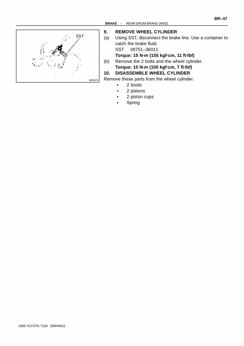
BR0970
SST
−BRAKE REAR DRUM BRAKE (4WD)BR−47
1996 TOYOTA T100 (RM449U)
9. REMOVE WHEEL CYLINDER(a) Using SST, disconnect the brake line. Use a container to
catch the brake fluid.SST 09751−36011Torque: 15 N·m (155 kgf·cm, 11 ft·lbf)
(b) Remove the 2 bolts and the wheel cylinder.Torque: 10 N·m (100 kgf·cm, 7 ft·lbf)
10. DISASSEMBLE WHEEL CYLINDERRemove these parts from the wheel cylinder.
� 2 boots� 2 pistons� 2 piston cups� Spring
https://www.truck-manuals.net/

BR09P−01
R04717
BR0048
BR−48−BRAKE REAR DRUM BRAKE (4WD)
1996 TOYOTA T100 (RM449U)
INSPECTION1. INSPECT DISASSEMBLED PARTSInspect the disassembled parts for wear, rust or damage.2. MEASURE BRAKE SHOE LINING THICKNESSUsing a ruler, measure the shoe lining thickness.
Standard thickness: 6.0 mm (0.236 in.)Minimum thickness: 1.0 mm (0.039 in.)
If the shoe lining is less than the minimum or shows signs of un-even wear, replace the brake shoes.HINT:If any of the brake shoes have to be replaced, replace all of therear brake shoes in order to maintain even braking.
3. MEASURE BRAKE DRUM INSIDE DIAMETERUsing vernier calipers, measure the inside diameter of drum.
Standard inside diameter: 295.0 mm (11.614 in.)Maximum inside diameter: 297.0 mm (11.693 in.)
If the drum is scored or worn, the brake drum may be lathed tothe maximum inside diameter.
4. INSPECT BRAKE LINING AND DRUM FOR PROPERCONTACT
If the contact between the brake lining and drum is improper, re-pair the lining with a brake shoe grinder, or replace the brakeshoe assembly.
https://www.truck-manuals.net/

BR09Q−01
BR0122
CA
B
Adjusting Bolt
BR0973
Z03640
Z03659
−BRAKE REAR DRUM BRAKE (4WD)BR−49
1996 TOYOTA T100 (RM449U)
INSTALLATIONInstallation is in the reverse order of removal (See pageBR−45).NOTICE:Apply lithium soap base glycol grease and high tempera-ture grease to the parts indicated by the arrows (See pageBR−44).
1. ADJUST BELLCRANK(a) Lightly pull the bellcrank in direction A until there is no
slack at part B.(b) In this condition, turn the adjusting bolt so that dimension
C will be 0.4 − 0.8 mm (0.016 − 0.031 in.).(c) Lock the adjusting bolt with the lock nut.
(d) Connect the parking brake cable to the parking brake bell-crank and install the clip.
(e) Install the tension spring.
2. CHECK OPERATION OF AUTOMATIC ADJUSTINGMECHANISM
(a) Move the parking brake lever of the front shoe back andforth. Check that the adjuster turns.
If the adjuster does not turn, check for incorrect installation ofthe rear brakes.(b) Adjust the adjuster length as short as possible.(c) Install the brake drum.
(d) Pull the parking brake lever all the way up until a clickingsound can no longer be heard.
3. CHECK CLEARANCE BETWEEN BRAKE SHOES ANDDRUM (See page BR−43)Shoe clearance: 0.6 mm (0.024 in.)
4. FILL BRAKE RESERVOIR WITH BRAKE FLUID ANDBLEED BRAKE SYSTEM (See Page BR−4)
5. CHECK FOR LEAKS
https://www.truck-manuals.net/

BR0060
BR09R−11
BR0061
SST
BR0062
80 kg/cm2
BR−50 −BRAKE LOAD SENSING PROPORTIONING AND BY−PASS VALVE (LSP & BV)
1655Author�: Date�:
1996 TOYOTA T100 (RM449U)
LOAD SENSING PROPORTIONINGAND BY−PASS VALVE (LSP & BV)ON−VEHICLE INSPECTION1. SET REAR AXLE LOAD
Rear axle load (includes vehicle weight):2WD: 1 ton: 850 kg (1,874 lb) 0.5 ton std: 800 kg (1,764 lb) 0.5 ton opt (soft ride): 850 kg (1,874 lb)4WD: 1,050 kg (2,315 lb)
2. INSTALL LSPV GAUGE (SST) AND BLEED AIRSST 09709−29017
3. RAISE FRONT BRAKE PRESSURE TO 7,845 kPa (80kgf/cm2, 1,138 psi) AND CHECK REAR BRAKE PRES-SURERear brake pressure:5,325 ± 490 kPa (54.3 ± 5 kgf/cm2, 772 ± 71 psi)
HINT:The brake pedal should not be depressed twice and/or returnedwhile setting to the specified pressure. Read the value of rearbrake pressure after holding the specified fluid pressure for 2seconds. If the brake pressure is incorrect, adjust the fluid pres-sure.
https://www.truck-manuals.net/
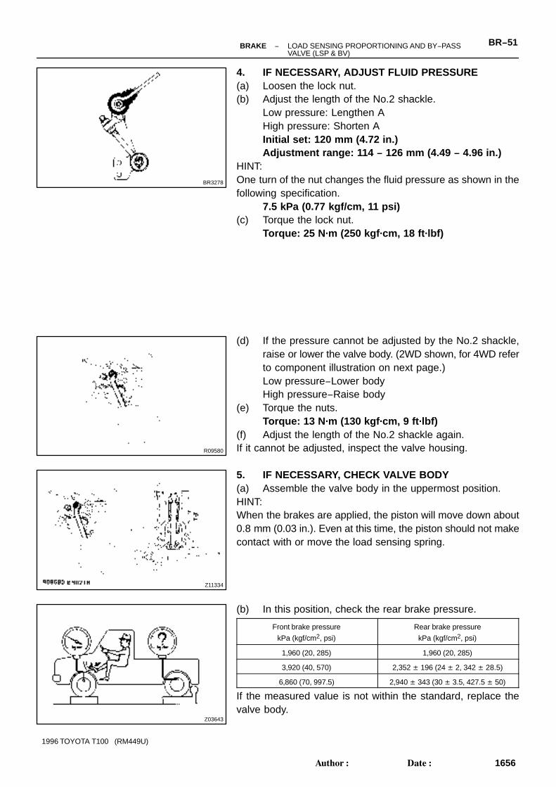
BR3278
R09580
Z11334
Z03643
−BRAKE LOAD SENSING PROPORTIONING AND BY−PASS VALVE (LSP & BV)
BR−51
1656Author�: Date�:
1996 TOYOTA T100 (RM449U)
4. IF NECESSARY, ADJUST FLUID PRESSURE(a) Loosen the lock nut.(b) Adjust the length of the No.2 shackle.
Low pressure: Lengthen AHigh pressure: Shorten AInitial set: 120 mm (4.72 in.)Adjustment range: 114 − 126 mm (4.49 − 4.96 in.)
HINT:One turn of the nut changes the fluid pressure as shown in thefollowing specification.
7.5 kPa (0.77 kgf/cm, 11 psi)(c) Torque the lock nut.
Torque: 25 N·m (250 kgf·cm, 18 ft·lbf)
(d) If the pressure cannot be adjusted by the No.2 shackle,raise or lower the valve body. (2WD shown, for 4WD referto component illustration on next page.)Low pressure−Lower bodyHigh pressure−Raise body
(e) Torque the nuts.Torque: 13 N·m (130 kgf·cm, 9 ft·lbf)
(f) Adjust the length of the No.2 shackle again.If it cannot be adjusted, inspect the valve housing.
5. IF NECESSARY, CHECK VALVE BODY(a) Assemble the valve body in the uppermost position.HINT:When the brakes are applied, the piston will move down about0.8 mm (0.03 in.). Even at this time, the piston should not makecontact with or move the load sensing spring.
(b) In this position, check the rear brake pressure.
Front brake pressure
kPa (kgf/cm2, psi)
Rear brake pressure
kPa (kgf/cm2, psi)
1,960 (20, 285) 1,960 (20, 285)
3,920 (40, 570) 2,352 ± 196 (24 ± 2, 342 ± 28.5)
6,860 (70, 997.5) 2,940 ± 343 (30 ± 3.5, 427.5 ± 50)
If the measured value is not within the standard, replace thevalve body.
https://www.truck-manuals.net/

BR09S−08
R12821R12821
Shackle Bracket
Shackle No.2
Load sensing Valve
4WD Only
�Cotter Pin
Load Sensing Spring Assembly
Valve Bracket
N·m (kgf·cm,ft·lbf)�
CollarBushing
Set Plate
2WD Only
Clip
Plate Washer
Shackle No.1Plate Washer
Non−reusable part
Load Sensing Valve BootRubber PlateCollar
Load Sensing Spring Boot
BushingBushing
Bushing
Load SensingSpring
15 (155, 11)
18 (185, 13)
13 (130, 9)
: Specified torque
18 (185, 13)
13 (130, 9)
Retainer
25 (250, 18)
BR−52 −BRAKE LOAD SENSING PROPORTIONING AND BY−PASS VALVE (LSP & BV)
1996 TOYOTA T100 (RM449U)
COMPONENTS
https://www.truck-manuals.net/

BR09T−01
R09582
Z11332
SST
−BRAKE LOAD SENSING PROPORTIONING AND BY−PASS VALVE (LSP & BV)
BR−53
1996 TOYOTA T100 (RM449U)
REMOVAL1. DISCONNECT SHACKLE NO.2 FROM BRACKET(a) Remove the cotter pin.(b) Remove the nut and cushion retainer, and disconnect the
shackle No.2.(c) Remove the 2 bushings and collar.
2. REMOVE LSP & BV ASSEMBLY(a) Using SST, disconnect the brake lines from the valve
body.SST 09751−36011
(b) Remove the valve bracket mounting bolts and the LSP &BV assembly.
https://www.truck-manuals.net/

R09581
BR09U−02
BR1638
BR3338
BR0589
BR0070
Valve Side Shackle Side
BR−54 −BRAKE LOAD SENSING PROPORTIONING AND BY−PASS VALVE (LSP & BV)
1996 TOYOTA T100 (RM449U)
DISASSEMBLY1. REMOVE VALVE BRACKET(a) Remove the nut and bolt.CAUTION:At the time of reassembly, please refer to the followingitem. When connecting the shackle to the load sensing witha bolt and nut, insert the bolt from the front side of vehicle.
Torque: 18 N·m (185 kgf·cm, 13 ft·lbf)
(b) Remove the 2 nuts, and remove the bracket and set platefrom the valve body.
HINT:At the time of reassembly, please refer to the following item.Finger tighten the valve body mounting nuts.2. DISCONNECT SPRING FROM VALVEUsing pliers, remove the clip and the spring from the valve.
3. REMOVE SHACKLES NO.1 AND NO.2(a) Remove the nuts and bolts, and then remove No.1 and
No.2 shackles and 2 plate washers from the load sensingspring assembly.Torque: 18 N·m (185 kgf·cm, 13 ft·lbf)
(b) Loosen the 2 nuts, remove the nut and shackle No.1 fromthe shackle No.2.
4. DISASSEMBLE LOAD SENSING SPRINGDisassemble these parts:
� 4 Bushings� 2 Collars� 2 Rubber plates� Load sensing valve boot� Load sensing spring boot
HINT:At the time of reassembly, please refer to the following items.� Apply lithium soap−base glycol grease to all rubbing
areas.� Do not mistake the valve side for the shackle side of the
load sensing spring.
https://www.truck-manuals.net/

BR09V−01
Z03645
Wear Limit 0.7 mm
−BRAKE LOAD SENSING PROPORTIONING AND BY−PASS VALVE (LSP & BV)
BR−55
1996 TOYOTA T100 (RM449U)
INSPECTIONINSPECT VALVE PISTON PIN AND LOAD SENSING CON-TACT SURFACE FOR WEAR
Wear limit: 0.7 mm (0.028 in.)
https://www.truck-manuals.net/

BR09W−01
BR−56 −BRAKE LOAD SENSING PROPORTIONING AND BY−PASS VALVE (LSP & BV)
1996 TOYOTA T100 (RM449U)
REASSEMBLYReassembly is in the reverse order of disassembly (See page BR−54).
https://www.truck-manuals.net/

BR09X−01
Z11332
SST
Z11333
A
BR0218
BR0061
SST
−BRAKE LOAD SENSING PROPORTIONING AND BY−PASS VALVE (LSP & BV)
BR−57
1996 TOYOTA T100 (RM449U)
INSTALLATION1. INSTALL LSP & BV ASSEMBLY TO FRAME
Torque: 29 N·m (300 kgf·cm, 22 ft·lbf)2. CONNECT BRAKE LINEUsing SST, connect the brake lines.
Torque: 15 N·m (155 kgf·cm, 11 ft·lbf)SST 09751−36011
3. CONNECT SHACKLE NO.2 BRACKET(a) Install the shackle No.2 to the load sensing spring.(b) Set dimension A and torque the lock nut.
Initial set: 120 mm (4.72 in.)Torque: 25 N·m (250 kgf·cm, 18 ft·lbf)
(c) Connect the shackle No.2 to the shackle bracket.Torque: 13 N·m (130 kgf·cm, 9 ft·lbf)
(d) Install a new cotter pin.
4. SET REAR AXLE LOAD (See page BR−50)
5. SET VALVE BODY(a) When pulling down the load sensing spring, check that
the valve piston moves down smoothly.(b) Position the valve body so that the valve piston lightly
contacts with the load sensing spring.(c) Tighten the valve body mounting nuts.
Torque: 13 N·m (130 kgf·cm, 9 ft·lbf)
6. BLEED BRAKE LINE (See page BR−4)7. CHECK AND ADJUST LSP & BV FLUID PRESSURE
(See page BR−50)8. APPLY SEALANT TO SHACKLE No.2Apply sealant to the top portion of the shackle No.2 bolt threadsnot to lose the upper lock nut.
Sealant:Part No. 08833−00070, THREE BOND 1324 or equiva-lent
https://www.truck-manuals.net/

F14857
BR1NW−01
R07778
BR−58−BRAKE ABS ACTUATOR
1663Author�: Date�:
1996 TOYOTA T100 (RM449U)
ABS ACTUATORON−VEHICLE INSPECTION1. INSPECT BATTERY POSITIVE VOLTAGE
Battery positive voltage: 10 − 14 V2. DISCONNECT CONNECTORS(a) Disconnect the 2 connectors from the control relay.(b) Disconnect the connector from the actuator.3. CONNECT ACTUATOR CHECKER (SST) TO ACTUA-
TOR(a) Connect the actuator checker (SST) to the actuator, con-
trol relay and body side wire harness through the sub−wire harness C and E (SST) as shown in the illustration.SST 09990−00150, 09990−00200, 09990−00210
(b) Connect the red cable of the checker to the battery posi-tive (+) terminal and black cable to the negative (−) termi-nal. Connect the black cable of the sub−wire harnessesto the battery negative (−) terminal or body ground.
(c) Place the ”SHEET L” (SST) on the actuator checker.SST 09990−00370
4. INSPECT BRAKE ACTUATOR OPERATION(a) Start the engine, and run it at idle.(b) Turn the selector switch of the actuator checker in
”FRONT” position.(c) Push and hold in the MOTOR switch for a few seconds.
Make sure that you can hear the motor running.
https://www.truck-manuals.net/

R07779
R07780
R07781
R07782
−BRAKE ABS ACTUATORBR−59
1664Author�: Date�:
1996 TOYOTA T100 (RM449U)
(d) Depress the brake pedal and hold it until the step (g) iscompleted.
(e) Push the POWER SWITCH, and check that the brakepedal does not go down.
NOTICE:Do not keep the POWER SWITCH pushed down for morethan 10 seconds.(f) Release the switch, and check that the pedal goes down.
(g) Push and hold in the MOTOR switch for a few seconds,and check that the pedal returns.
(h) Release the brake pedal.
(i) Push and hold in the MOTOR switch for a few seconds.(j) Depress the brake pedal and hold it for about 15 seconds.
As you hold the pedal down, push the MOTOR switch fora few seconds. Check that the brake pedal does not pul-sate.
(k) Release the brake pedal.5. INSPECT FOR OTHER WHEELS(a) Change the connection of the actuator checker (SST) to
the sub − wire harness E (SST) − from the sub − wire har-ness MAIN connector to the SUB connector, or vice ver-sa.
(b) Repeating (c) to (i) of the step 4, check the actuator opera-tion same way.
6. INSPECT FOR REAR WHEEL(a) Turn the selector switch to the ”REAR” position.(b) Push and hold in the MOTOR switch for a few seconds.(c) Depress the brake pedal and hold it until the step (g) is
completed.
https://www.truck-manuals.net/

R07783
R07784
R07785
R07782
BR−60−BRAKE ABS ACTUATOR
1665Author�: Date�:
1996 TOYOTA T100 (RM449U)
(d) Push the REAR switch while pressing the POWERSWITCH, and check that the brake pedal cannot be de-pressed.
NOTICE:Do not keep the POWER SWITCH pushed down for morethan 10 seconds.(e) Release the REAR switch then the POWER SWITCH,
and check that the brake pedal can be depressed.
(f) Push and hold in the MOTOR switch for a few seconds,and check that the pedal returns.
(g) Release the brake pedal.
(h) Push and hold in the MOTOR switch for a few seconds.(i) Depress the brake pedal and hold it for about 15 seconds.
As you hold the pedal down, push the MOTOR switch fora few seconds. Check that the brake pedal does not pul-sate.
(j) Release the brake pedal.
7. PUSH MOTOR SWITCH(a) Push and hold on the MOTOR switch for a few seconds.(b) Stop the engine.8. DISCONNECT ACTUATOR CHECKER (SST) FROM
ACTUATORRemove the ”SHEET L” (SST) and disconnect the actuatorchecker (SST) and sub−wire harness (SST) from the actuator,control relay and body side wire harness.
SST 09990−00150, 09990−00200, 09990−00210,09990−00370
9. CONNECT CONNECTOR TO ACTUATOR10. CLEAR DTC (See page DI−321)
https://www.truck-manuals.net/

BR09Z−02
F14858
−BRAKE ABS ACTUATORBR−61
1996 TOYOTA T100 (RM449U)
COMPONENTS
https://www.truck-manuals.net/

BR0A0−02
F14859
BR−62−BRAKE ABS ACTUATOR
1996 TOYOTA T100 (RM449U)
REMOVAL1. DISCONNECT BRAKE LINESUsing SST, disconnect the 5 brake lines from the ABS actuator.
SST 09023−00100Torque: 15 N·m (155 kgf·cm, 11 ft·lbf)
2. REMOVE ABS ACTUATOR ASSEMBLY(a) Disconnect the 2 connectors from the actuator.(b) Remove the 2 bolts, 2 nuts and ABS actuator assembly.
Torque: 19 N·m (195 kgf·cm, 14 ft·lbf)3. REMOVE ABS ACTUATOR(a) Remove the 3 nuts and ABS actuator from the actuator
bracket.Torque: 5.4 N·m (55 kgf·cm, 48 in.·lbf)
(b) Remove the 3 holders and cushions from the ABS actua-tor.
https://www.truck-manuals.net/

BR0A1−01
−BRAKE ABS ACTUATORBR−63
1996 TOYOTA T100 (RM449U)
INSTALLATIONInstallation is in the reverse order of removal (See page BR−62).1. AFTER INSTALLATION, FILL BRAKE RESERVOIR BRAKE FLUID AND BLEED BRAKE SYSTEM
(See page BR−4)2. CHECK FOR LEAKS.
https://www.truck-manuals.net/
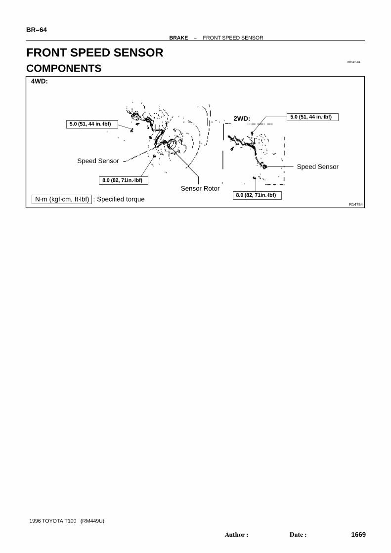
BR0A2−04
R14754
4WD:
2WD:
Speed Sensor
Sensor Rotor
N·m (kgf·cm, ft·lbf) : Specified torque
5.0 (51, 44 in.·lbf)
8.0 (82, 71in.·lbf)
Speed Sensor
8.0 (82, 71in.·lbf)
5.0 (51, 44 in.·lbf)
BR−64−BRAKE FRONT SPEED SENSOR
1669Author�: Date�:
1996 TOYOTA T100 (RM449U)
FRONT SPEED SENSORCOMPONENTS
https://www.truck-manuals.net/

BR0A3−01
R07884
−BRAKE FRONT SPEED SENSORBR−65
1996 TOYOTA T100 (RM449U)
REMOVAL1. DISCONNECT SPEED SENSOR CONNECTOR2. REMOVE SPEED SENSOR(a) 4WD:
Remove the 3 clamp bolts holding the sensor harnessfrom the frame, upper arm and steering knuckle.
(b) 2WD:Remove the 2 clamp bolts holding the sensor harnessfrom the frame and upper arm.Torque: 5.0 N·m (51 kgf·cm, 44 in.·lbf)
(c) Remove the speed sensor from the steering knuckle.Torque: 8.0 N·m (82 kgf·cm, 71 in.·lbf)
https://www.truck-manuals.net/

BR0A4−03
BR−66−BRAKE FRONT SPEED SENSOR
1996 TOYOTA T100 (RM449U)
INSTALLATIONInstallation is reverse in the order of removal (See page BR−65).AFTER INSTALLATION, CHECK SPEED SENSOR SIGNAL (See page DI−341)
https://www.truck-manuals.net/

BR0A5−04
R14755
Speed Sensor
Sensor Rotor
N·m (kgf·cm, ft·lbf) : Specified torque
13 (130, 9)
8.0 (82, 71 in.·lbf)
−BRAKE REAR SPEED SENSORBR−67
1672Author�: Date�:
1996 TOYOTA T100 (RM449U)
REAR SPEED SENSORCOMPONENTS
https://www.truck-manuals.net/

BR0A6−01
R12233
BR−68−BRAKE REAR SPEED SENSOR
1996 TOYOTA T100 (RM449U)
REMOVAL1. DISCONNECT SPEED SENSOR CONNECTOR2. REMOVE SPEED SENSOR(a) Remove the clamp bolt, the clamp nut and the 5 clips
holding the sensor wire harness from the axle and the fueltank.
HINT:� When installing the rear sensor wire harness, never use
the removed resin clips, which are service parts.� When replacing clips, set up new resin clips at the same
angle of the removed resin clips.� When removing a resin clip, take care so that the remov-
ing tool is not caught on the grommet or wire.Torque: 13 N·m (130 kgf·cm, 9 ft·lbf)
(b) Remove the speed sensor from the axle carrier.Torque: 8.0 N·m (82 kgf·cm, 71 in.·lbf)
https://www.truck-manuals.net/

BR0A7−03
−BRAKE REAR SPEED SENSORBR−69
1996 TOYOTA T100 (RM449U)
INSTALLATIONInstallation is in the reverse order of removal (See page BR−68).AFTER INSTALLATION, CHECK SPEED SENSOR SIGNAL (See page DI−341)
https://www.truck-manuals.net/

SR – STEERING
STEERING SYSTEM SR-1 TROUBLESHOOTING SR-2 DRIVE BELT SR-3 POWER STEERING FLUID SR-4 AIR CONTROL VALVE SR-8 STEERING WHEEL SR-9 NON-TILT STEERING COLUMN SR-10 TILT STEERING COLUMN SR-23 POWER STEERING VANE PUMP (3RZ-FE) SR-34 POWER STEERING VANE PUMP (5VZ-FE) SR-44 POWER STEERING GEAR (2WD) SR-54 POWER STEERING GEAR (2WD) SR-72 STEERING LINKAGE SR-84 IDLER ARM SR-89
https://www.truck-manuals.net/

SR06Z−01
−STEERING STEERING SYSTEMSR−1
1675Author�: Date�:
1996 TOYOTA T100 (RM449U)
STEERING SYSTEMPRECAUTION� Care must be taken to replace parts properly because they could affect the performance of the
steering system and result in a driving hazard.� The TOYOTA T100 is equipped with SRS (Supplemental Restraint System) such as the driver
airbag. Failure to carry out service operation in the correct sequence could cause the SRS tounexpectedly deploy during servicing, possibly leading to a serious accident. Before servicing(including removal or installation of parts, inspection or replacement), be sure to read the pre-cautionary notices in the RS section.
https://www.truck-manuals.net/

SR070−01
SR−2−STEERING TROUBLESHOOTING
1676Author�: Date�:
1996 TOYOTA T100 (RM449U)
TROUBLESHOOTINGPROBLEM SYMPTOMS TABLEUse the table below to help you find the cause of the problem. The numbers indicate the priority of the likelycause of the problem. Check each part in order. If necessary, repair or replace these parts.
Symptom Suspect Area See page
Hard steering
1. Tires (Improperly inflated)
2. Power steering fluid level (Low)
3. Drive belt (Loose)
4. Front wheel alignment (Incorrect)
5. Steering system joints (Worn)
6. Suspension arm ball joints
7. Steering column (Binding)
8.Power steering gear
SA−3
SA−5
SR−5
SR−3
SA−7
SA−10
−
SA−109
SA−113
SA−117
SA−121
−
SR−54
SR−72
Poor return
1. Tires (Improperly inflated)
2. Front wheel alignment (Incorrect)
3. Steering column (Binding)
4. Power steering gear
SA−3
SA−5
SA−7
SA−10
−
SR−54
SR−72
Excessive play
1. Steering system joints (Worn)
2. Suspension arm ball joints (Worn)
3. Universal joint, Intermediate shaft, Sliding yoke (Worn)
4. Front wheel bearing (Worn)
5. Power steering gear
−
SA−109
SA−113
SA−117
SA−121
−
SA−16
SR−54
SR−72
Abnormal noise
1. Power steering fluid level (Low)
2. Steering system joints (Worn)
3. Power steering gear
SR−5
−
SR−54
SR−72
https://www.truck-manuals.net/

P06717
SR071−02
Z00038
DENSO Borroughs
CH0087
CORRECT WRONG WRONG
−STEERING DRIVE BELTSR−3
1677Author�: Date�:
1996 TOYOTA T100 (RM449U)
DRIVE BELTINSPECTION1. INSPECT DRIVE BELT(a) Visually check the belt for excessive wear, frayed cords
etc.If any defect has been found, replace the drive belt.HINT:Cracks on the rib side of a belt are considered acceptable. If thebelt has chunks missing from the ribs, it should be replaced.
(b) Using a belt tension gauge, measure the belt tension.Belt tension gauge:DENSO BTG−20 (95506−00020)Borroughs No. BT−33−73F3RZ−FE Engine:Drive belt tension:New belt: 135 − 185 lbfUsed belt: 80 − 120 lbf5VZ−FE Engine:Drive belt tension:New belt: 135−180 lbfUsed belt: 85−120 lbf
If the best tension is not as specified, adjust it.
HINT:� ”New belt” refers to a belt which has been used less than
5 minutes on a running engine.� ”Used belt” refers to a belt which has been used on a run-
ning engine for 5 minutes or more.� After installing a belt, check that it fits properly in the
ribbed grooves.� Check with your hand to confirm that the belt has not
slipped out of the groove on the bottom of the pulley.� After installing a new belt, run the engine for about 5 min-
utes and recheck the belt tension.
https://www.truck-manuals.net/

SR072−01
R07281
Normal Abnormal
SR−4−STEERING POWER STEERING FLUID
1678Author�: Date�:
1996 TOYOTA T100 (RM449U)
POWER STEERING FLUIDBLEEDING1. CHECK FLUID LEVEL (See page SR−5)2. JACK UP FRONT OF VEHICLE AND SUPPORT IT
WITH STANDS3. TURN STEERING WHEELWith the engine stopped, turn the wheel slowly from lock to lockseveral times.4. LOWER VEHICLE5. START ENGINERun the engine at idle for a few minutes.6. TURN STEERING WHEEL(a) With the engine idling, turn the wheel to left or right full
lock and keep it there for 2 − 3 seconds, then turn thewheel to the opposite full lock and keep it there for 2 − 3seconds.
(b) Repeat (a) several times.7. STOP ENGINE
8. CHECK FOR FOAMING OR EMULSIFICATIONIf the system has to be bled twice specifically because of foam-ing or emulsification, check for fluid leaks in the system.9. CHECK FLUID LEVEL (See page SR−5)
https://www.truck-manuals.net/

SR2267
SR073−04
R07281
Normal Abnormal
R11361
5 mm (0.2 in.)or less
Engine Idling Engine Stopped
−STEERING POWER STEERING FLUIDSR−5
1996 TOYOTA T100 (RM449U)
INSPECTION1. CHECK FLUID LEVEL(a) Keep the vehicle level.(b) With the engine stopped, check the fluid level in the oil
reservoir.If necessary, add fluid.
Fluid: ATF DEXRON®II or IIIHINT:Check that the fluid level is within the HOT LEVEL range on thereservoir cap dipstick. If the fluid is cold, check that it is withinthe COLD LEVEL range.(c) Start the engine and run it at idle.(d) Turn the steering wheel from lock to lock several times to
boost fluid temperature.Fluid temperature: 80°C (176°F)
(e) Check for foaming or emulsification.If there is foaming or emulsification, bleed power steering sys-tem.
(f) With the engine idling, measure the fluid level in the oilreservoir.
(g) Stop the engine.(h) Wait a few minutes and remeasure the fluid level in the
reservoir.Maximum fluid level rise: 5 mm (0.20 in.)
If a problem is found, bleed power steering system.(i) Check the fluid level.
https://www.truck-manuals.net/

R14116
AttachmentPS Vane Pump
SST
Pressure Feed Tube
OUT
SST
3RZ−FE 5VZ−FE
IN
IN
OUT
Attachment
Attachment
Attachment
Pressure Feed TubePS Vane Pump
SR−6−STEERING POWER STEERING FLUID
1996 TOYOTA T100 (RM449U)
2. CHECK STEERING FLUID PRESSURE(a) 5VZ−FE Engine:
Remove the 5 bolts and air cleaner assembly.(b) Disconnect the pressure feed tube from the PS vane
pump.(3RZ−FE Engine: See page SR−36)(5VZ−FE Engine: See page SR−46)
(c) Connect SST, as shown bellow.SST 09640−10010 (09641−01010, 09641−01030,
09641−01060)NOTICE:Check that the valve of the SST is in the open position.
(d) Bleed the power steering system.(See page SR−4)
(e) Start the engine and run it at idle.(f) Turn the steering wheel from lock to lock several times to
boost fluid temperature.Fluid temperature: 80°C (176°F)
https://www.truck-manuals.net/

Z15498
OilReservoir
PS VanePump
Closed
SST
PS Gear
Z15499
PS Gear
OilReservoir
PS VanePump
Open
SST
Z15500
OilReservoir
PS VanePump
Lock Position
PS Gear Open
SST
−STEERING POWER STEERING FLUIDSR−7
1996 TOYOTA T100 (RM449U)
(g) With the engine idling, close the valve of the SST and ob-serve the reading on the SST.3RZ−FE and 5VZ−FE (2WD) Engines:Minimum fluid pressure:7,845 kPa (80 kgf/cm2, 1138 psi)5VZ−FE (4WD) Engine:Minimum fluid pressure:8,336 kPa (85 kgf/cm2, 1209 psi)
NOTICE:� Do not keep the valve closed for more than 10 se-
conds.� Do not let the fluid temperature become too high.
(h) With the engine idling, open the valve fully.(i) Measure the fluid pressure at engine speeds of 1,000 rpm
and 3,000 rpm.3RZ−FE and 5VZ−FE Engines:Difference fluid pressure:490 kPa (5 kgf/cm2, 71 psi) or less
NOTICE:Do not turn the steering wheel.
(j) With the engine idling and valve fully opened, turn thewheel to full lock.3RZ−FE and 5VZ−FE (2WD) Engines:Minimum fluid pressure:7,845 kPa (80 kgf/cm2, 1138 psi)5VZ−FE (4WD) Engine:Minimum fluid pressure:8,336 kPa (85 kgf/cm2, 1209 psi)
NOTICE:� Do not maintain lock position for more than 10 se-
conds.� Do not let the fluid temperature become too high.
(k) Disconnect the SST.(l) Connect the pressure feed tube.
(3RZ−FE Engine: SR−43)(5VZ−FE Engine: SR−53)
(m) 5VZ−FE Engine:Install the air cleaner and 3 bolts.
(n) Bleed the power steering system.(See page SR−4)
https://www.truck-manuals.net/

SR074−04
SR−8−STEERING AIR CONTROL VALVE
1682Author�: Date�:
1996 TOYOTA T100 (RM449U)
AIR CONTROL VALVEINSPECTION1. TURN AIR CONDITIONING SWITCH OFF2. CHECK IDLE−UP(a) Start the engine and run it at idle.(b) Fully turn the steering wheel.(c) Check that the engine rpm decreases when the vacuum
hose is pinched.(d) Check that the engine rpm increases when the hose is re-
leased.
https://www.truck-manuals.net/

R07653
SR0097
SR075−01
R09732
−STEERING STEERING WHEELSR−9
1683Author�: Date�:
1996 TOYOTA T100 (RM449U)
STEERING WHEELINSPECTION1. CHECK THAT STEERING WHEEL FREEPLAY IS COR-
RECTWith the vehicle stopped and tires pointed straight ahead, rockthe steering wheel gently back and forth with light finger pres-sure.Freeplay should not exceed the maximum.
Maimum freeplay: 30 mm (1.18 in.)4WD:If the freeplay exceeds the maximum, adjust it in the followingprocedure.2. 4WD:
ADJUST STEERING GEAR(a) Point the front wheels straight ahead.(b) Loosen the adjusting screw lock nut.(c) Turn the sector shaft adjusting screw clockwise to de-
crease steering wheel freeplay and counterclockwise toincrease it.
HINT:Turn the adjusting screw in small increments and check thefreeplay between each adjustment.(d) Turn the steering wheel half way around in both direc-
tions.Check the the freeplay is correct and steering is smoothand without rough spots.
(e) Torque the adjusting screw lock nut (See page SR−80).
3. CHECK STEERING EFFORT(a) Center the steering wheel.(b) Remove the steering wheel pad (See page SR−13).(c) Start the engine and run it at idle.(d) Measure the steering effort in both directions.
Reference: 8.3 N·m (85 kgf·cm, 73 in.·lbf)HINT:Be sure to consider the tire type, pressure and contact surfacebefore making your diagnosis.(e) Torque the steering wheel set nut.
Torque: 35 N·m (360 kgf·cm, 26 ft·lbf)(f) Install the steering wheel pad (See page SR−20).
https://www.truck-manuals.net/

W03127
AT:
For 2WD
Parking Lock Cable
Steering Wheel
Steering Wheel
Torx Screw
Steering Wheel LowerNo.2 Cover
PadControl Shaft
Column UpperCover
Lever
� LockingWire
Column HoleCover
Steering Column Assembly
Steering Wheel LowerNo.3 Cover
Torx Screw
Combination Switch(w/ Spiral Cable)
Column Lower Cover
Light Control Rheostat
Front Door ScuffPlate
Sliding w/ Shaft YorkSub−Assembly
Lower Finish Panel No.1IntermediateShaft Assembly
Engine Hood ReleaseLever
Duct Heater toRegister No.2
IntermediateShaft Assembly
Cowl Side Trim
� Non−reusable part
Control Shaft Assembly
x
35 (360, 26)
25 (260, 19)
35 (360, 26)
35 (360, 26)
35 (360, 26)
: Specified torqueN·m (kgf·cm, ft·lbf)
9.0 (90, 78 in.·lbf)
9.0 (90, 78 in.·lbf)
SR076−01
SR−10−STEERING NON−TILT STEERING COLUMN
1684Author�: Date�:
1996 TOYOTA T100 (RM449U)
NON−TILT STEERING COLUMNCOMPONENTS
https://www.truck-manuals.net/

W03128
MT:
Column UpperCover
Torx Screw Steering WheelPad
Steering Wheel
Steering Wheel LowerNo.3 Cover
Torx Screw
Combination Switch(w/ Spiral Cable)
Column Lower Cover
Light Control Rheostat
Front Door ScuffPlate
Steering Wheel LowerNo.2 Cover
Steering Column Assembly
Column Hole Cover
x7
Engine Hood ReleaseLever
Lower Finish Panel No.1
Sliding w/ Shaft YorkSub−Assembly
IntermediateShaft Assembly
Duct Heater toRegister No.2
Cowl Side Trim
IntermediateShaft Assembly
For 2WD
9.0 (90, 78 in.·lbf)
35 (360, 26)
: Specified torqueN·m (kgf·cm, ft·lbf)
9.0 (90, 78 in.·lbf)
25 (260, 19)
35 (360, 26)
35 (360, 26)
35 (360, 26)
−STEERING NON−TILT STEERING COLUMNSR−11
1685Author�: Date�:
1996 TOYOTA T100 (RM449U)
https://www.truck-manuals.net/

Z18646
A/T: Key Cylinder
Key UnlockWarning Switch
Ignition SwitchColumn UpperBracket
Key Cylinder
Column Upper Bracket
Column Tube
Key UnlockWarning Switch
Ignition Switch
� Bushing
Column Upper Clamp
� Tapered−Head Bolt
� Snap Ring
Main Shaft Assembly
Non−reusable partMolybdenum disulfide lithium base grease
�
35 (360, 26)
: Specified torqueN·m (kgf·cm, ft·lbf)
SR−12−STEERING NON−TILT STEERING COLUMN
1686Author�: Date�:
1996 TOYOTA T100 (RM449U)
https://www.truck-manuals.net/

SR077−01
R07659
Torx Screw Screw Case
Z14903
Airbag Connector
Correct Wrong
R00606R09597
R11211
Matchmarks SST
−STEERING NON−TILT STEERING COLUMNSR−13
1996 TOYOTA T100 (RM449U)
REMOVAL1. REMOVE STEERING WHEEL PADNOTICE:� If the airbag connector is disconnected with the igni-
tion switch at ON or ACC, DTCs will be recorded.� Never use airbag parts from another vehicle. When
replacing parts, replace with new parts.
(a) Place the front wheels facing straight ahead.(b) Remove the steering wheel lower No.2 and No.3 covers.(c) Using a torx socket wrench, loosen the 2 torx screws.HINT:Loosen the 2 screws until the groove along the screw circumfer-ence catches on the screw case.
(d) Pull the wheel pad out from the steering wheel and dis-connect the airbag connector.
CAUTION:� When storing the wheel pad, keep the upper surface
of the pad facing upward.� Never disassemble the wheel pad.
NOTICE:When removing the wheel pad, take care not to pull the air-bag wire harness.
2. REMOVE STEERING WHEEL(a) Disconnect the connector.(b) Remove the steering wheel set nut.(c) Place matchmarks on the steering wheel and main shaft.(d) Using SST, remove the wheel.
SST 09950−50010 (09951−05010, 09952−05010,09953−05020, 09954−05020)
https://www.truck-manuals.net/

Q02574
Matchmarks
Cap Nut
SR−14−STEERING NON−TILT STEERING COLUMN
1996 TOYOTA T100 (RM449U)
3. A/T:REMOVE UPPER AND LOWER COLUMN COVERS
Remove the 6 screws.4. M/T:
REMOVE UPPER AND LOWER COLUMN COVERSRemove the 7 screws.5. REMOVE LOWER FINISH PANEL NO.1(a) Remove the 2 screws and disconnect the engine hood re-
lease lever from the panel.(b) Remove the 4 screws and front door scuff plate.(c) Remove the clip and cowl side trim.(d) Remove the 4 panel set bolts.(e) Remove the light control rheostat and lock nut.6. REMOVE DUCT HEATER TO REGISTER NO.2Remove the screw.7. REMOVE COMBINATION SWITCH WITH SPIRAL
CABLE(a) Remove the 2 screws.(b) Disconnect the connectors.(c) Disconnect the airbag connector.(d) Remove the 4 screws.8. REMOVE SPIRAL CABLE
(See page BE−15)NOTICE:Do not disassemble the cable or apply oil to it.
9. A/T:DISCONNECT PARKING LOCK CABLE
(a) Place the matchmarks on the cap nut and parking lockcable.
(b) Loosen the cap nut.(c) Disconnect the parking lock cable.
https://www.truck-manuals.net/

Z16081
A
B
C
Intermediate Shaft AssemblyMatchmarks
Sliding w/ shaftYork Sub−Assembly
Intermediate Shaft Assembly
Sliding w/ shaft York Sub−Assembly
R12250R12251R12252
−STEERING NON−TILT STEERING COLUMNSR−15
1996 TOYOTA T100 (RM449U)
10. DISCONNECT INTERMEDIATE SHAFT ASSEMBLY(a) 2WD:
Place matchmarks on the intermediate shaft and controlvalve shaft.
(b) 4WD:Place matchmarks on the intermediate shaft and wormgear valve shaft.
(c) Remove the bolt A, B and C.11. REMOVE INTERMEDIATE SHAFT ASSEMBLY AND
SLIDING w/ SHAFT YORK SUB−ASSEMBLY12. A/T:
REMOVE STEERING COLUMN ASSEMBLY(a) Remove the locking wire.(b) Remove the bolt and control shaft lever.(c) Remove the 2 control shaft assembly mounting bolts from
the steering column assembly.(d) Remove the 2 column assembly set bolts and nuts.(e) Remove the steering column assembly with the control
shaft assembly.(f) Remove the control shaft assembly from the steering col-
umn assembly.13. M/T:
REMOVE STEERING COLUMN ASSEMBLYRemove the 2 steering column assembly set bolts and nuts.
https://www.truck-manuals.net/
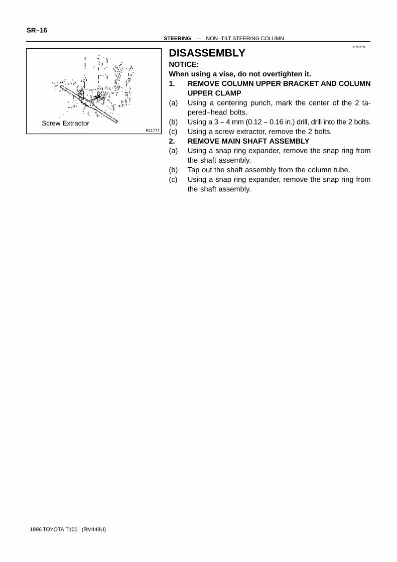
SR078−01
R11777
Screw Extractor
SR−16−STEERING NON−TILT STEERING COLUMN
1996 TOYOTA T100 (RM449U)
DISASSEMBLYNOTICE:When using a vise, do not overtighten it.1. REMOVE COLUMN UPPER BRACKET AND COLUMN
UPPER CLAMP(a) Using a centering punch, mark the center of the 2 ta-
pered−head bolts.(b) Using a 3 − 4 mm (0.12 − 0.16 in.) drill, drill into the 2 bolts.(c) Using a screw extractor, remove the 2 bolts.2. REMOVE MAIN SHAFT ASSEMBLY(a) Using a snap ring expander, remove the snap ring from
the shaft assembly.(b) Tap out the shaft assembly from the column tube.(c) Using a snap ring expander, remove the snap ring from
the shaft assembly.
https://www.truck-manuals.net/

R04668
SR079−01
R04670
R11778
R01835
−STEERING NON−TILT STEERING COLUMNSR−17
1996 TOYOTA T100 (RM449U)
INSPECTION1. INSPECT COLUMN UPPER BRACKETCheck that the steering lock mechanism operates properly.
2. IF NECESSARY, REPLACE KEY CYLINDER(a) Place the ignition key at the ACC position.(b) Push down the stop pin with a thin rod, and pull out the
key cylinder.(c) Install a new key cylinder.HINT:Make sure the ignition key is at the ACC position.3. INSPECT IGNITION SWITCH AND KEY UNLOCK
WARNING SWITCH (See page BE−12)4. IF NECESSARY, REPLACE IGNITION SWITCH AND
KEY UNLOCK WARNING SWITCH(a) Remove the 3 screws.(b) Install a new switches with the 3 screws.
5. INSPECT BEARINGCheck the bearing rotation condition and check for abnormalnoise.If the bearing is worn or damaged, replace the column tube/col-umn upper tube.
6. IF NECESSARY, REPLACE BUSHING(a) TILT STEERING COLUMN:
Remove the snap ring from the column lower tube.(b) Using a screwdriver, remove the bushing from the column
tube/column lower tube.NOTICE:Be careful not to damage the column tube.(c) Coat the inside of new bushing with molybdenum disul-
fide lithium base grease.
https://www.truck-manuals.net/

SR−18−STEERING NON−TILT STEERING COLUMN
1996 TOYOTA T100 (RM449U)
(d) Align the holes of the tube and the projections of the bush-ing, and install the bushing into the column tube/columnlower tube.
(e) TILT STEERING COLUMN:Install a new snap ring.
https://www.truck-manuals.net/

SR07A−01
R02893
−STEERING NON−TILT STEERING COLUMNSR−19
1996 TOYOTA T100 (RM449U)
REASSEMBLYNOTICE:When using a vise, do not overtighten it.1. INSTALL MAIN SHAFT ASSEMBLY(a) Using a snap ring expander, install a new snap ring to the
shaft assembly.(b) Install the shaft assembly into the column tube.(c) Using a snap ring expander, install a new snap ring to the
shaft assembly.2. INSTALL COLUMN UPPER BRACKET AND COLUMN
UPPER CLAMPTighten the 2 new tapered−head bolts until the bolt heads breakoff.
https://www.truck-manuals.net/

SR07B−01
Z16081
Intermediate Shaft AssemblyMatchmarks
Sliding w/ shaftYork Sub−Assembly
Intermediate Shaft Assembly
Sliding w/ shaft York Sub−Assembly
C
B
A
R12250R12251R12252
SR−20−STEERING NON−TILT STEERING COLUMN
1996 TOYOTA T100 (RM449U)
INSTALLATION1. A/T:
INSTALL STEERING COLUMN ASSEMBLY(a) Install the control shaft assembly to the steering column
assembly.(b) Torque the 2 steering column assembly set bolts and
nuts.Torque: 25 N·m (260 kgf·cm, 19 ft·lbf)
(c) Temporarily install the 2 control shaft assembly set bolts.(d) Install the control shaft lever with the bolt.
Torque: 35 N·m (360 kgf·cm, 26 ft·lbf)(e) Install a new locking wire.2. M/T:
INSTALL STEERING COLUMN ASSEMBLYTorque the 2 steering column assembly set bolts and nuts.
Torque: 25 N·m (260 kgf·cm, 19 ft·lbf)
3. INSTALL INTERMEDIATE SHAFT ASSEMBLY ANDSLIDING w/ SHAFT YORK SUB−ASSEMBLY
Temporarily install the bolt B and C.4. CONNECT INTERMEDIATE SHAFT ASSEMBLY(a) 2WD:
Align the matchmarks on the intermediate shaft and con-trol valve assembly.
(b) 4WD:Align the matchmarks on the intermediate shaft and wormgear valve body assembly.
(c) Torque the bolt C.Torque: 35 N·m (360 kgf·cm, 26 ft·lbf)
(d) Torque the bolt A.Torque: 35 N·m (360 kgf·cm, 26 ft·lbf)
(e) Torque the bolt B.Torque: 35 N·m (360 kgf·cm, 26 ft·lbf)
5. A/T:CONNECT AND ADJUST INTER LOCK (See page AT−25)
6. A/T:TORQUE 2 CONTROL SHAFT ASSEMBLY MOUNTINGBOLTSTorque: 29 N·m (300 kgf·cm, 22 ft·lbf)
7. A/T:CONNECT PARKING LOCK CABLE (See page AT−23)
8. INSTALL SPIRAL CABLE (See page BE−15)
https://www.truck-manuals.net/

R07644Red Mark
R07660
Torx Screw Screw Case
−STEERING NON−TILT STEERING COLUMNSR−21
1996 TOYOTA T100 (RM449U)
9. INSTALL COMBINATION SWITCH WITH SPIRALCABLE
(a) Install the 4 screws.(b) Connect the airbag connector.(c) Connect the connectors.(d) Install the 2 screws.10. INSTALL DUCT HEATER TO REGISTER NO.2Install the screw.11. INSTALL LOWER FINISH PANEL NO.1(a) Install the lock nuts and light control rheostat.(b) Tighten the 4 panel set bolts.(c) Install the cowl side trim and clip.(d) Install the front door scuff plate with the 4 screws.(e) Install the engine hood release lever with the 2 screws.12. A/T:
INSTALL UPPER AND LOWER COLUMN COVERSInstall the 6 screws.13. M/T:
INSTALL UPPER AND LOWER COLUMN COVERSInstall the 7 screws.14. CENTER SPIRAL CABLE(a) Check that the front wheels are facing straight ahead.(b) Turn the spiral counterclockwise by hand until it becomes
harder to turn the cable.(c) Then turn the spiral cable clockwise about 3 turns to align
the red mark.HINT:The spiral cable turns clockwise about 3 turns to either left orright of the center.15. INSTALL STEERING WHEEL(a) Align the matchmarks on the wheel and main shaft.(b) Torque the set nut.
Torque: 35 N·m (360 kgf·cm, 26 ft·lbf)(c) Connect the connector.
16. INSTALL STEERING WHEEL PADNOTICE:� Make sure the wheel pad is installed to the specified
torque.� If the wheel pad has been dropped, or there are
cracks, dents in the case or connector, replace thewheel pad with a new one.
� When installing the wheel pad, take care that the wir-ings do not interfere with other parts and are notpinched between other parts.
https://www.truck-manuals.net/

SR−22−STEERING NON−TILT STEERING COLUMN
1996 TOYOTA T100 (RM449U)
(a) Connect the airbag connector.(b) Install the wheel pad after confirming that the circumfer-
ence groove of the torx screws is caught on the screwcase.
(c) Using a torx wrench, torque the 2 screws.Torque: 9.0 N·m (90 kgf·cm, 78 in.·lbf)
17. CHECK STEERING WHEEL CENTER POINT
https://www.truck-manuals.net/

W03156
Column Upper
Parking Lock Cable
Torx Screw
Steering Wheel LowerNo.2 Cover
Control Shaft Assembly
Steering Wheel
Steering Wheel
Steering Wheel LowerNo.3 Cover
Torx Screw
Combination Switch(w/ Spiral Cable)
Column lower Cover
Light Control Rheostat
Front Door Scuff
Steering ColumnAssembly
Control Shaft
� Locking
Column Hole
Sliding w/ Shaft YorkSub−Assembly
Lower Finish Panel No.1
Engine Hood Release
IntermediateShaft Assembly
Register No.2Duct Heater to
Plate
PadLever
Cover
Wire
Cover
Lever
AT:
For 2WD
IntermediateShaft Assembly
Cowl Side Trim
x6
�Non−reusable part
35 (360, 26)
9.0 (90, 78 in.·lbf)
35 (360, 26)
35 (360, 26)
35 (360, 26)
35 (360, 26)
: Specified torqueN·m (kgf·cm, ft·lbf)
25 (260, 19)
25 (260, 19)
9.0 (90, 78 in.·lbf)
SR07C−01
−STEERING TILT STEERING COLUMNSR−23
1697Author�: Date�:
1996 TOYOTA T100 (RM449U)
TILT STEERING COLUMNCOMPONENTS
https://www.truck-manuals.net/

W03157
Cover
Pad
Plate
Lever
MT:
For 2WD
Steering Column Assembly
Steering Wheel
Steering Wheel
Steering Wheel LowerNo.3 Cover
Torx Screw
Combination Switch(w/ Spiral Cable)
Column Lower Cover
Light Control Rheostat
Front Door Scuff
x7
Sliding w/ Shaft YorkSub−Assembly
Lower Finish Panel No.1
Column Hole Cover
Column UpperTorx Screw
Steering Wheel LowerNo.2 Cover
IntermediateEngine Hood Release
Shaft Assembly
Duct Heater toRegister No.2
IntermediateShaft Assembly
Cowl Side Trim
9.0 (90, 78 in.·lbf)
35 (360, 26)
: Specified torqueN·m (kgf·cm, ft·lbf)
25 (260, 19)
9.0 (90, 78 in.·lbf)
35 (360, 26)
35 (360, 26)
35 (360, 26)
SR−24−STEERING TILT STEERING COLUMN
1698Author�: Date�:
1996 TOYOTA T100 (RM449U)
https://www.truck-manuals.net/

W03536
Tilt Pawl Stopper
Tilt Lever
Tilt Lever Lock Shaft
Tension Spring
Compression Spring
Bearing Thrust Collar
� Bearing
WasherTilt Pawl
Column Upper Tube� Snap Ring
Tum Signal Bracket
Tilt LeverAssembly
Tilt Sub Lever
Tilt Pawl Stopper
Main Shaft Assembly
Stopper
CollarA/T:
Key Cylinder
Key UnlockWarningSwitch
Tilt Lever Ratainer
Column UpperBracket
IgnitionSwitch
� E−ring
BoltTilt No.2
Bushing
Tension SpringKey Unlock Warning Switch
Ignition Switch
Column UpperBracket Column Lower
Tilt LeverRatainer
� E−ring
TensionSpeing
Tilt No.2 BoltTube
� BushingSliding York Sub−Assembly
Non−reusable partMolybdenum disulfide lithium base grease
� Snap Ring
� tapered−Head Bolt
�
Column Upper Clamp
Key Cylinder
Tilt Pawl
35 (360, 26)
: Specified torqueN·m (kgf·cm, ft·lbf)
7.8 (80, 69 in.·lbf)
5.9 (60, 52 in.·lbf)
7.8 (80, 69 in.·lbf)
15 (150, 11)
2.0 (20, 17 in.·lbf)
−STEERING TILT STEERING COLUMNSR−25
1699Author�: Date�:
1996 TOYOTA T100 (RM449U)
https://www.truck-manuals.net/
SR07D−01
SR−26−STEERING TILT STEERING COLUMN
1996 TOYOTA T100 (RM449U)
REMOVAL(See page SR−13)
https://www.truck-manuals.net/

SR07E−01
R15245
Matchmarks
R11947
Screw Extractor
R15212
SST
Bolt
SST
NutTilt No.2 Bolt
Plate Washer
−STEERING TILT STEERING COLUMNSR−27
1996 TOYOTA T100 (RM449U)
DISASSEMBLYNOTICE:When using a vise, do not overtighten it.1. REMOVE SLIDING YOKE SUB−ASSEMBLY(a) Remove the bolt.(b) Shift the yoke.(c) Place matchmarks on the sliding yoke and main shaft.
2. REMOVE COLUMN UPPER BRACKET AND COLUMNUPPER CLAMP
(a) Using a centering punch, mark the center of the 2 ta-pered−head bolts.
(b) Using a 3 − 4 mm (0.12 − 0.16 in.) drill, drill into the 2 bolts.(c) Using a screw extractor, remove the 2 bolts.3. REMOVE 3 TENSION SPRINGS4. REMOVE COMPRESSION SPRING(a) Remove the bolt with the spring.(b) Remove the 2 bushings from the spring.5. REMOVE 2 TILT LEVER RETAINERS(a) Remove the E−ring from the tilt lever lock shaft.(b) Remove the nut and retainer.6. REMOVE 2 TILT PAWL STOPPERS7. REMOVE 2 TILT PAWLS(a) Remove the tilt lever assembly set bolt.(b) Remove the nut and bolt.(c) Remove the washer.8. REMOVE TILT LEVER ASSEMBLY, TILT SUB LEVER,
TILT LEVER AND TILT LEVER LOCK SHAFT9. REMOVE COLUMN UPPER TUBE WITH MAIN SHAFT
ASSEMBLY(a) Set SST, the nut (10 mm nominal diameter, 1.25 mm
pitch), plate washer (36 mm outer diameter) and bolt (10mm nominal diameter, 1.25 mm pitch, 50 mm length), asshown in the illustration.SST 09910−00015 (09911−00011, 09912−00010)Reference Nut: 90170−10004 Plate washer: 90201−10201 Bolt: 91111−51050
(b) Remove the 2 tilt No.2 bolts by using the sliding hammeron SST.
(c) Remove the upper tube with the shaft assembly from thelower tube.
(d) Remove the collar and stopper from the shaft assembly.10. REMOVE TURN SIGNAL BRACKETRemove the 2 bolts.
https://www.truck-manuals.net/

R11780
SST
SST
SR−28−STEERING TILT STEERING COLUMN
1996 TOYOTA T100 (RM449U)
11. REMOVE MAIN SHAFT ASSEMBLY(a) Using SST, compress the compression spring.
SST 09950−40010 (09957−04010, 09958−04010)NOTICE:Do not bend the universal joint of the main shaft more than20°.(b) Using a snap ring expander, remove the snap ring from
the shaft assembly.(c) Remove the main shaft from the column upper tube.(d) Remove the compression spring, bearing thrust collar
and bearing from the shaft assembly.
https://www.truck-manuals.net/

SR07F−01
−STEERING TILT STEERING COLUMNSR−29
1996 TOYOTA T100 (RM449U)
INSPECTION(See page SR−17)
https://www.truck-manuals.net/

SR07G−01
R11780
SST
SST
R13024
1
2
Hollow Tipped
Mark Position
R04528
R04529
SR−30−STEERING TILT STEERING COLUMN
1996 TOYOTA T100 (RM449U)
REASSEMBLYNOTICE:When using a vise, do not overtighten it.1. COAT WITH MOLYBDENUM DISULFIDE LITHIUM
BASE GREASE(See pages SR−23)
2. INSTALL MAIN SHAFT ASSEMBLY(a) Install the bearing, bearing thrust collar and compression
spring to the main shaft.(b) Install the main shaft into the column upper tube.(c) Using SST, compress the compression spring.
SST 09950−40010 (09957−04010, 09958−04010)NOTICE:Do not bend the universal joint of the main shaft more than20°.(d) Using a snap ring expander, install a new snap ring.3. INSTALL TURN SIGNAL BRACKETTorque the 2 bolts.
Torque: 7.8 N·m (80 kgf·cm, 69 in.·lbf)
4. SELECT 2 TILT NO.2 BOLTSSelect the bolt with the hollow−tipped thread end when the col-umn upper tube mark is 1, and the bolt with the plain thread endwhen the mark is 2.NOTICE:Select the bolt type to match each number marked in thesquares on the upper tube.
5. INSTALL COLUMN UPPER TUBE WITH MAIN SHAFTASSEMBLY
(a) Install the stopper and collar to the shaft assembly.(b) Install the upper tube with the shaft assembly to the col-
umn lower tube.
(c) Using a plastic hammer, drive in the 2 tilt No.2 bolts.6. INSTALL TILT LEVER LOCK SHAFT, TILT LEVER
ASSEMBLY AND TILT SUB LEVER, TILT LEVERTorque the tilt lever assembly set bolt.
Torque: 2 N·m (20 kgf·cm, 17 in.·lbf)
https://www.truck-manuals.net/

W03535
R15213
Tilt Pawl
Alignment MarkTilt Pawl Stopper
SR3128
”A” ”A”
Mark
−STEERING TILT STEERING COLUMNSR−31
1996 TOYOTA T100 (RM449U)
7. INSTALL 2 TILT PAWLSInstall the pawl to the column upper tube and temporarily installthe washer with the bolt and nut.HINT:Install the pawl pin into the long hole of the tilt lever/tilt sub lever.8. ENGAGE AND ADJUST 2 TILT PAWLS(a) Engage the tilt sub lever side pawl to the center of the
ratchet.(b) While turning the tilt lever side collar, engage the tilt lever
side pawl to the ratchet completely.(c) Torque the nut.
Torque: 5.9 N·m (60 kgf·cm, 52 in.·lbf)(d) Check that the pawls rotate smoothly.9. SELECT 2 TILT PAWL STOPPERS(a) With the tilt pawl and ratchet engaged, install the 2 pawl
stoppers.(b) Check that the alignment marks on the stopper and pawl
align when the stopper is lightly rotated to the pawl side.(c) If the alignment marks are not align, select pawl stopper
according to the following table.
Right pawl stopper Left pawl stopperDimension ”A”
mm (in.)
1 A12.68 − 12.74
(0.4992 − 0.5016)
2 B12.61 − 12.67
(0.4965 − 0.4988)
3 C12.54 − 12.60
(0.4937 − 0.4961)
4 D12.47 − 12.53
(0.4909 − 0.4933)
5 E12.40 − 12.46
(0.4882 − 0.4906)
6 F12.33 − 12.39
(0.4854 − 0.4878)
7 G12.26 − 12.32
(0.4827 − 0.4850)
(d) After selecting the stoppers, check that the pawl andratchet are fully engaged.
10. INSTALL 2 TILT PAWL STOPPERS11. INSTALL 2 TILT LEVER RETAINERS(a) Install the tilt lever retainer and torque the nut.
Torque: 15 N·m (150 kgf·cm, 11 ft·lbf)(b) Install a new E−ring.12. INSTALL COMPRESSION SPRING(a) Install the 2 bushings to the compression spring.(b) Install the spring with the bolt.
Torque: 7.8 N·m (80 kgf·cm, 69 in.·lbf)
https://www.truck-manuals.net/

R04531
SR−32−STEERING TILT STEERING COLUMN
1996 TOYOTA T100 (RM449U)
13. INSTALL 3 TENSION SPRINGS14. INSTALL COLUMN UPPER BRACKET AND COLUMN
UPPER CLAMP(a) Install the bracket with 2 new tapered−head bolts.(b) Tighten the tapered−head bolts until the bolt heads break
off.15. INSTALL SLIDING YORK SUB−ASSEMBLY(a) Align the matchmarks on the sliding york and main shaft.(b) Torque the bolt.
Torque: 35 N·m (360 kgf·cm, 26 ft·lbf)16. CHECK TILT STEERING OPERATION(a) Check that there is no axial play at the end of the main
shaft.(b) With the main shaft in the neutral position, pull the tilt lever
and check that the main shaft rises to the uppermost posi-tion.
(c) Lower the main shaft, and check that it locks in the lower-most position.
https://www.truck-manuals.net/

SR07H−01
−STEERING TILT STEERING COLUMNSR−33
1996 TOYOTA T100 (RM449U)
INSTALLATION(See page SR−20)
https://www.truck-manuals.net/

R14723
PS Vane Pump Assembly
Vacuum Hose
Return Hose
Union Bolt
Pressure Feed Tube
� Gasket
Belt Adjusting Bolt
Drive Belt
Power SteeringIdle Pulley
�
� Non−reusable part
39 (400, 29)
: Specified torqueN·m (kgf·cm, ft·lbf)
47 (475, 34)
39 (400, 29)
SR07I−01
SR−34−STEERING POWER STEERING VANE PUMP (3RZ−FE)
1708Author�: Date�:
1996 TOYOTA T100 (RM449U)
POWER STEERING VANE PUMP (3RZ−FE)COMPONENTS
https://www.truck-manuals.net/

Z18935
Vane Pump Pulley
� Snap Ring
Oil Reservoir
SpringFront Housing
Flow Control Valve
Pressure PortUnion
Vane Pump Shaft
Wave Washer
Rear Housing
� Bearing
� Snap Ring
� Oil Seal
� O−Ring
� O−Ring
� Gasket
� Straight Pin
Side Plate
Cam Ring
Vane Plate
Non−reusable partPower Steering fluid
� O−Ring
�
�Vane Pump Rotor
43 (440, 32)
13 (130, 9)
24 (240, 17)
83 (850, 61)
24 (240, 17)
: Specified torqueN·m (kgf·cm, ft·lbf)
−STEERING POWER STEERING VANE PUMP (3RZ−FE)SR−35
1709Author�: Date�:
1996 TOYOTA T100 (RM449U)
https://www.truck-manuals.net/

SR07J−01
R09245
R13844
SR−36−STEERING POWER STEERING VANE PUMP (3RZ−FE)
1996 TOYOTA T100 (RM449U)
REMOVAL1. REMOVE DRIVE BELT(a) Loosen the power steering idle pulley set bolt.(b) Loosen the belt adjusting bolt.
2. DISCONNECT PRESSURE FEED TUBEUsing a spanner (24 mm) to hold the pressure port union, re-move the union bolt and the 2 gaskets.3. DISCONNECT RETURN HOSENOTICE:Take care not to spill fluid on the drive belt.4. REMOVE PS VANE PUMP ASSEMBLYRemove the 2 pump assembly set bolts.
https://www.truck-manuals.net/

SR07K−01
R12065
R09248
SST
Z14482
Vinyl Tape
Oil Seal
Bearing
−STEERING POWER STEERING VANE PUMP (3RZ−FE)SR−37
1996 TOYOTA T100 (RM449U)
DISASSEMBLYNOTICE:When using a vise, do not overtighten it.1. MEASURE PS VANE PUMP ROTATING TORQUE(a) Check that the pump rotates smoothly without abnormal
noise.(b) Using a torque wrench, check the pump rotating torque.
Rotating torque:0.25 N·m (2.5 kgf·cm, 2.2 in.·lbf) or less
2. REMOVE VANE PUMP PULLEYUsing SST to stop the pulley rotating, remove the pulley set nut.
SST 09960−10010 (09962−01000, 09963−01000)3. REMOVE OIL RESERVOIR(a) Remove the 3 bolts and oil reservoir.(b) Remove the O−ring from the oil reservoir.4. REMOVE PRESSURE PORT UNION, FLOW CONTROL
VALVE AND SPRINGRemove the O−ring from the union.5. REMOVE REAR HOUSING(a) Remove the 2 bolts and rear housing.(b) Remove the 2 O−rings from the housing.6. REMOVE WAVE WASHER7. REMOVE SIDE PLATE8. REMOVE CAM RING, VANE PLATES AND VANE
PUMP ROTOR(a) Remove the 10 plates.NOTICE:Take care not to drop the plate.(b) Using a screwdriver, remove the snap ring from the vane
pump shaft.9. REMOVE STRAIGHT PINSRemove the 2 pins from the front housing.10. REMOVE GASKET
11. REMOVE VANE PUMP SHAFT WITH BEARING(a) Using snap ring pliers, remove the snap ring from the front
housing.(b) Wind vinyl tape on the serrated part of the vane pump
shaft.(c) Using a press, press out the shaft with the bearing.NOTICE:Be careful not to damage the oil seal lip.
https://www.truck-manuals.net/

SR07L−02
R15214
Front Housing Vane PumpShaft
Bushing
Z06061
Thickness
Height
Length
R10282
R13897Inscribed Mark
SR−38−STEERING POWER STEERING VANE PUMP (3RZ−FE)
1996 TOYOTA T100 (RM449U)
INSPECTIONNOTICE:When using a vise, do not overtighten it.1. CHECK OIL CLEARANCE BETWEEN VANE PUMP
SHAFT AND BUSHINGUsing a micrometer and a caliper gauge, measure the oil clear-ance.
Standard Clearance:0.03 − 0.05 mm (0.0012 − 0.0020 in.)Maximum clearance: 0.007 mm (0.0028 in.)
If it is more than maximum, replace the front housing and vanepump shaft.2. INSPECT VANE PUMP ROTOR AND VANE PLATES(a) Using a micrometer, measure the height, thickness and
length of the 10 plates.Minimum height: 8.6 mm (0.339 in.)Minimum thickness: 1.397 mm (0.05500 in.)Minimum length: 14.991 mm (0.59020 in.)
(b) Using a feeler gauge, measure the clearance betweenthe rotor groove and plate.Maximum clearance: 0.035 mm (0.00138 in.)
If it is more than maximum, replace the plate and/or rotor withone having the same mark stamped on the cam ring.
Inscribed mark: 1, 2, 3, 4 or NoneHINT:There are 5 vane plate lengths with the following rotor and camring marks:
Rotor and
cam ring mark
Vane plate
part number
Vane plate length mm
(in.)
None 44345−2601014.999 − 15.001
(0.59051 − 0.59059)
1 44345−2602014.997 − 14.999
(0.59043 − 0.59051)
2 44345−2603014.995 − 14.997
(0.59035 − 0.59043)
3 44345−2604014.993 − 14.995
(0.59027 − 0.59035)
4 44345−2605014.991 − 14.993
(0.59020 − 0.59027)
https://www.truck-manuals.net/

Z14294
R09063
Compressed Air
R09064
InscribedMark
R08702
Calipers
Z14483
SST
Oil Seal
−STEERING POWER STEERING VANE PUMP (3RZ−FE)SR−39
1996 TOYOTA T100 (RM449U)
3. INSPECT FLOW CONTROL VALVE(a) Coat the valve with power steering fluid and check that it
falls smoothly into the valve hole by its own weight.
(b) Check the flow control valve for leakage.Close one of the holes and apply compressed air 392 −490 kPa (4 − 5 kgf/cm2, 57 − 71 psi) into the opposite side,and confirm that air does not come out from the end hole.
If necessary, replace the valve with one having the same letteron the front housing.
Inscribed mark: A, B, C, D, E or F
4. INSPECT SPRINGUsing calipers, measure the free length of the spring.
Minimum free length: 32.3 mm(1.272 in.)If it is not within the specification, replace the spring.
5. IF NECESSARY, REPLACE OIL SEAL(a) Using SST, tap out the oil seal from the front housing.
SST 09631−10030NOTICE:Be careful not to damage the bushing of the front housing.(b) Coat a new oil seal lip with power steering fluid.
https://www.truck-manuals.net/

F14896
R13869
Press
Bearing
REMOVE INSTALL
SR−40−STEERING POWER STEERING VANE PUMP (3RZ−FE)
1996 TOYOTA T100 (RM449U)
(c) Using a socket wrench (24 mm), press in the oil seal.NOTICE:Make sure to install the oil seal facing the correct direction.
6. IF NECESSARY, REPLACE BEARING(a) Press out the bearing from the vane pump shaft.(b) Using a snap ring expander, remove the snap ring from
the shaft.NOTICE:Be careful not to damage the shaft.(c) Using a snap ring expander, install a new snap ring to the
shaft.NOTICE:Be careful not to damage the shaft.(d) Coat a new bearing with power steering fluid.(e) Press in the bearing to the shaft.
https://www.truck-manuals.net/

SR07M−01
Z14487
SST
VinylTape
Bearing
Oil Seal
Z14920
Inscribed Mark
R09070
R09072
−STEERING POWER STEERING VANE PUMP (3RZ−FE)SR−41
1996 TOYOTA T100 (RM449U)
REASSEMBLYNOTICE:When using a vise, do not overtighten it.1. COAT WITH POWER STEERING FLUID
(See page SR−34)
2. INSTALL VANE PUMP SHAFT WITH BEARING(a) Wind vinyl tape on the serrated part of the vane pump
shaft.(b) Using SST, press in the shaft with the bearing.
SST 09608−04031NOTICE:Be careful not to damage the oil seal.(c) Using snap ring pliers, install a new snap ring to the front
housing.
3. INSTALL STRAIGHT PINSUsing a plastic hammer, tap in 2 new pins to the front housing.NOTICE:Be careful not to damage the pins.4. INSTALL CAM RINGInstall the ring with the inscribed mark facing outward.5. INSTALL VANE PUMP ROTOR(a) Install the rotor with the inscribed mark facing outward.(b) Install a new snap ring to the vane pump shaft.
6. INSTALL VANE PLATES AND GASKET(a) Install the 10 plates with the round end facing outward.(b) Install a new gasket on the front housing.NOTICE:Be careful the direction of the gasket.7. INSTALL SIDE PLATEAlign the holes of the side plate and straight pins, and install theplate.
8. INSTALL WAVE WASHERInstall the wave washer so that its protrusions fit into the slotsin the side plate.9. INSTALL REAR HOUSING(a) Coat 2 new O−rings with power steering fluid and install
them to the housing.(b) Torque the 2 bolts.
Torque: 24 N·m (240 kgf·cm, 17 ft·lbf)
https://www.truck-manuals.net/

R09251
SST
SR−42−STEERING POWER STEERING VANE PUMP (3RZ−FE)
1996 TOYOTA T100 (RM449U)
10. INSTALL SPRING, FLOW CONTROL VALVE ANDPRESSURE PORT UNION
(a) Install the valve facing the correct direction.(See page SR−34)
(b) Coat a new O−ring with power steering fluid and install itto the union.
(c) Torque the union.Torque: 83 N·m (850 kgf·cm, 61 ft·lbf)
11. INSTALL OIL RESERVOIR(a) Coat a new O−ring with power steering fluid and install it
to the oil reservoir.(b) Install the oil reservoir with the 3 bolts.
Torque:Front side bolt: 13 N·m (130 kgf·cm, 9 ft·lbf)Rear side bolts: 24 N·m (240 kgf·cm, 17 ft·lbf)
12. INSTALL VANE PUMP PULLEYUsing SST to stop the pulley rotating, torque the nut.
SST 09960−10010 (09962−01000, 09963−01000)Torque: 43 N·m (440 kgf·cm, 32 ft·lbf)
13. MEASURE PS VANE PUMP ROTATING TORQUE(See page SR−37)
https://www.truck-manuals.net/

SR07N−01
R12952
Stopper
R09245
−STEERING POWER STEERING VANE PUMP (3RZ−FE)SR−43
1996 TOYOTA T100 (RM449U)
INSTALLATION1. INSTALL PS VANE PUMP ASSEMBLYTorque the 2 pump assembly set bolts.
Torque: 39 N·m (400 kgf·cm, 29 ft·lbf)2. CONNECT RETURN HOSE3. CONNECT PRESSURE FEED TUBETorque the union bolt with a new gasket on each side of thetube.
Torque: 47 N·m (475 kgf·cm, 34 ft·lbf)
HINT:Make sure the stopper of the tube is touching the PS pump bodyas shown, then torque the union bolt.
4. INSTALL DRIVE BELT(a) Tighten the belt adjusting bolt, adjust drive belt tension.
(See page SR−3)(b) Torque the power steering idle pulley set nut.
Torque: 39 N·m (400 kgf·cm, 29 ft·lbf)5. BLEED POWER STEERING SYSTEM
(See page SR−4)
https://www.truck-manuals.net/

F14897
SR07O−02
SR−44−STEERING POWER STEERING VANE PUMP (5VZ−FE)
1718Author�: Date�:
1996 TOYOTA T100 (RM449U)
POWER STEERING VANE PUMP (5VZ−FE)COMPONENTS
https://www.truck-manuals.net/

Z18936
Pressure Port Union
Flow Control Valve
Oil Reservoir
Rear Housing
Front Housing
Bracket
Spring
� O−Ring
� Gasket
Vane PumpRotorVane Pump Shaft
Vane Pump PulleyWave Washer
Side Plate
Cam Ringx10
Vane Plate
Non−reusable part
�
� O−Ring
� O−Ring
�
Power steering fluid
� Straight Pin
� Oil Seal
� Snap Ring
43 (440, 32)
13 (130, 9)
24 (240, 17)
24 (240, 17)
83 (850, 62)
43 (440, 32)
: Specified torqueN·m (kgf·cm, ft·lbf)
−STEERING POWER STEERING VANE PUMP (5VZ−FE)SR−45
1719Author�: Date�:
1996 TOYOTA T100 (RM449U)
https://www.truck-manuals.net/

SR07P−01
R12179
ReturnHose
PressureFeed Tube
R12066
A
BC
SR−46−STEERING POWER STEERING VANE PUMP (5VZ−FE)
1996 TOYOTA T100 (RM449U)
REMOVAL1. REMOVE AIR CLEANER ASSEMBLYRemove the 5 bolts.2. DISCONNECT RETURN HOSENOTICE:Take care not to spill fluid on the drive belt.3. DISCONNECT PRESSURE FEED TUBE(a) Disconnect the connector from the oil pressure switch.(b) Remove the oil pressure switch from the pressure feed
tube.(c) Remove the union bolt and 2 gaskets, and disconnect the
tube from the PS vane pump assembly.
4. REMOVE DRIVE BELT(a) Loosen the bolt A and nut B.(b) Loosen the bolt C.5. REMOVE PS VANE PUMP ASSEMBLYRemove the bolt A and nut B.
https://www.truck-manuals.net/

SR07Q−01
R12180
R12181
SST
−STEERING POWER STEERING VANE PUMP (5VZ−FE)SR−47
1996 TOYOTA T100 (RM449U)
DISASSEMBLYNOTICE:When using a vise, do not overtighten it.1. MEASURE PS VANE PUMP ROTATING TORQUE(a) Check that the pump rotates smoothly without abnormal
noise.(b) Using a torque wrench, check the pump rotating torque.
Rotating torque:0.25 N·m (2.5 kgf·cm, 2.2 in.·lbf) or less
2. REMOVE VANE PUMP PULLEYUsing SST to stop the pulley rotating, remove the pulley set nut.
SST 09960−10010 (09962−01000, 09963−01000)3. REMOVE OIL RESERVOIR(a) Remove the 3 bolts and oil reservoir.(b) Remove the O−ring from the oil reservoir.4. REMOVE PRESSURE PORT UNION, FLOW CONTROL
VALVE AND SPRINGRemove the O−ring from the union.5. REMOVE BRACKETRemove the 2 bolts.6. REMOVE REAR HOUSING(a) Remove the 2 bolts.(b) Remove the 2 O−rings from the housing.7. REMOVE WAVE WASHER8. REMOVE SIDE PLATE9. REMOVE GASKET10. REMOVE CAM RING, VANE PLATES AND VANE
PUMP ROTOR(a) Remove the 10 plates.NOTICE:Take care not to drop the plate.(b) Using a screwdriver, remove the snap ring from the vane
pump shaft.11. REMOVE VANE PUMP SHAFT12. REMOVE STRAIGHT PINSRemove the 2 pins from the front housing.
https://www.truck-manuals.net/

SR07R−03
R15220
Vane Pump Front HousingShaft
Bushing
Z06061
Thickness
Length
Height
R10282
Feeler Gauge
SR−48−STEERING POWER STEERING VANE PUMP (5VZ−FE)
1996 TOYOTA T100 (RM449U)
INSPECTIONNOTICE:When using a vise, do not overtighten it.1. CHECK OIL CLEARANCE BETWEEN VANE PUMP
SHAFT AND BUSHINGUsing a micrometer and caliper gauge, measure the oil clear-ance.
Standard clearance: 0.003 − 0.005 mm (0.0012 − 0.0020 in.)Maximum clearance: 0.07 mm (0.0028 in.)
If it is more than maximum, replace the front housing and vanepump shaft.
2. INSPECT VANE PUMP ROTOR AND VANE PLATES(a) Using a micrometer, measure the height, thickness and
length of the 10 plates.Minimum height: 8.6 mm (0.339 in.)Minimum thickness: 1,397 mm (0.05500 in.)Minimum length: 14,991 mm (0.59020 in.)
(b) Using a feeler gauge, measure the clearance betweenthe rotor groove and plate.Maximum clearance: 0.035 mm (0.00138 in.)
https://www.truck-manuals.net/

R13897Inscribed Mark
R12184
R07591
Compressed Air
R12185Inscribed Mark
−STEERING POWER STEERING VANE PUMP (5VZ−FE)SR−49
1996 TOYOTA T100 (RM449U)
If it is more than maximum, replace the plate and/or rotor withone having the same mark stamped on the cam ring.
Inscribed mark: 1, 2, 3, 4 or NoneHINT:There are 5 vane plate lengths with the following rotor and camring marks:
Rotor and
cam ring mark
Vane plate
part number
Vane plate length mm
(in.)
None 44345−2601014.999 − 15.001
(0.59051 − 0.59059)
1 44345−2602014.997 − 14.999
(0.59043 − 0.59051)
2 44345−2603014.995 − 14.997
(0.59035 − 0.59043)
3 44345−2604014.993 − 14.995
(0.59027 − 0.59035)
4 44345−2605014.991 − 14.993
(0.59020 − 0.59027)
3. INSPECT FLOW CONTROL VALVE(a) Coat the valve with power steering fluid and check that it
falls smoothly into the valve hole by its own weight.
(b) Check the flow control valve for leakage.Close one of the holes and apply compressed air 392 −490 kPa (4 − 5 kgf/cm2, 57 − 71 psi) into the opposite side,and confirm that air does not come out from the end holes.
If necessary, replace the valve with one having the same letteras inscribed on the front housing.
Inscribed mark: A, B, C, D, E or F
https://www.truck-manuals.net/

R08702
Calipers
R12186
Vinyl Tape
R12187Oil Seal
Socket Wrench
SR−50−STEERING POWER STEERING VANE PUMP (5VZ−FE)
1996 TOYOTA T100 (RM449U)
4. INSPECT SPRINGUsing calipers, measure the free length of the spring.
Minimum free length: 32.3 mm (1.272 in.)If it is not within the specification, replace the spring.
5. IF NECESSARY, REPLACE OIL SEAL(a) Using a screwdriver with vinyl tape wound around its tip,
remove the oil seal.NOTICE:Be careful not to damage the bushing of the front housing.
(b) Coat a new oil seal lip with power steering fluid.(c) Using a socket wrench (24 mm) and a hammer, tap in the
oil seal.NOTICE:Make sure to install the oil seal facing the correct direction.
https://www.truck-manuals.net/

SR07S−01
R12188Inscribed Mark
R12189Inscribed Mark
R12190
Round End
−STEERING POWER STEERING VANE PUMP (5VZ−FE)SR−51
1996 TOYOTA T100 (RM449U)
REASSEMBLYNOTICE:When using a vise, do not overtighten it.1. COAT WITH POWER STEERING FLUID
(See page SR−44)2. INSTALL STRAIGHT PINSUsing a plastic hammer, tap in 2 new pins to the front housing.NOTICE:Be careful not to damage the pins.3. INSTALL VANE PUMP SHAFT
4. INSTALL CAM RINGInstall the ring with the inscribed mark facing outward.
5. INSTALL VANE PUMP ROTOR(a) Install the rotor with the inscribed mark facing outward.(b) Install a new snap ring to the vane pump shaft.
6. INSTALL VANE PLATESInstall the 10 plates with the round end facing outward.
https://www.truck-manuals.net/

R12191
R12193
R12181
SST
SR−52−STEERING POWER STEERING VANE PUMP (5VZ−FE)
1996 TOYOTA T100 (RM449U)
7. INSTALL GASKETInstall a new gasket on the front housing.NOTICE:Be careful the direction of the gasket.8. INSTALL SIDE PLATEAlign the 2 straight pins and holes of the plate.
9. INSTALL WAVE WASHERInstall the washer so that its protrusions fit into the slots in theside plate.10. INSTALL REAR HOUSING(a) Coat 2 new O−rings with power steering fluid and install
them to the housing.(b) Torque the 2 bolts.
Torque: 24 N·m (240 kgf·cm, 17 ft·lbf)11. INSTALL SPRING, FLOW CONTROL VALVE AND
PRESSURE PORT UNION(a) Install the valve facing the correct direction.
(See page SR−44)(b) Coat a new O−ring with power steering fluid and install it
to the union.(c) Torque the union.
Torque: 83 N·m (850 kgf·cm, 62 ft·lbf)12. INSTALL BRACKETTorque the 2 bolts.
Torque: 43 N·m (440 kgf·cm, 32 ft·lbf)13. INSTALL OIL RESERVOIR(a) Coat a new O−ring with power steering fluid and install it
to the oil reservoir.(b) Install the oil reservoir with the 3 bolts.
Torque:Front side bolt: 13 N·m (130 kgf·cm, 9 ft·lbf)Rear side bolts: 24 N·m (240 kgf·cm, 17 ft·lbf)
14. INSTALL VANE PUMP PULLEYUsing SST to stop the pulley rotating, torque the nut.
SST 09960−10010 (09962−01000, 09963−01000)Torque: 43 N·m (440 kgf·cm, 32 ft·lbf)
15. MEASURE PS VANE PUMP ROTATING TORQUE(See page SR−47)
https://www.truck-manuals.net/

SR07T−01
R12066
A
BC
R12951Stopper
−STEERING POWER STEERING VANE PUMP (5VZ−FE)SR−53
1996 TOYOTA T100 (RM449U)
INSTALLATION1. INSTALL PS VANE PUMP ASSEMBLYTemporarily tighten the bolt A and nut B.2. INSTALL DRIVE BELT(a) Tighten the bolt C, adjust drive belt tension.
(See page SR−3)(b) Torque the bolt A and nut B.
Torque: 39 N·m (400 kgf·cm, 29 ft·lbf)
3. CONNECT PRESSURE FEED TUBE(a) Torque the union bolt with a new gasket on each side of
the tube.Torque: 47 N·m (475 kgf·cm, 34 ft·lbf)
HINT:Make sure the stopper of the tube is touching the PS pump bodyas shown, then torque the union bolt.(b) Install the oil pressure switch.(c) Connect the connector.4. CONNECT RETURN HOSE5. INSTALL AIR CLEANER ASSEMBLYInstall the 5 bolts.6. BLEED POWER STEERING SYSTEM
(See page SR−4)
https://www.truck-manuals.net/
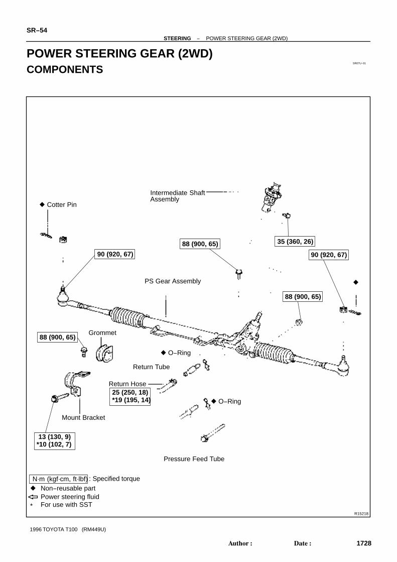
R15218
Intermediate ShaftAssembly
PS Gear Assembly
� O−Ring
Return Tube
Return Hose
Pressure Feed Tube
Mount Bracket
� Cotter Pin
Grommet
�
Non−reusable partPower steering fluid
�
� O−Ring
90 (920, 67)
88 (900, 65) 35 (360, 26)
88 (900, 65)
90 (920, 67)
88 (900, 65)
25 (250, 18)*19 (195, 14)
13 (130, 9)*10 (102, 7)
: Specified torqueN·m (kgf·cm, ft·lbf)
* For use with SST
SR07U−01
SR−54−STEERING POWER STEERING GEAR (2WD)
1728Author�: Date�:
1996 TOYOTA T100 (RM449U)
POWER STEERING GEAR (2WD)COMPONENTS
https://www.truck-manuals.net/

Z18926
Turn Pressure TubeDust Cover
Control Valve Housing
� Gasket
Control Valve Assembly
Steering Rack
Stopper
Rack End
Tie Rod End Cylinder End
� Rack Housing Cap
Rack Guide
Rack Housing
Rack GuideSpring
� Oil Seal
� Bearing
� Teflon Ring
� Bearing
� Oil Seal
� Oil Seal
� O−Ring
� O−Ring
� Rack Guide Spring
� Rack Guide
Cap Lock Nut
Spring Cap
� Bearing
� Self−Locking Nut
Rack Bushing
� O−Ring
� Oil Seal
� Wire
� Claw Wash
� O−Ring
Clip
� Teflon RingLock Nut
Rack Boot
Clamp
Non−reusable partPrecoated part
Molybdenum disulfide lithium base greasePower steering fluid
�
�
18 (185, 13)
13 (130, 9)*10 (102, 7)
13 (130, 9)*10 (102, 7)
: Specified torqueN·m (kgf·cm, ft·lbf)
* for use with SST
56 (570, 41)
60 (700, 51)*51 (521, 38)
25 (250, 18)
69 (700, 51)
83 (850, 62)*61 (618, 45)
−STEERING POWER STEERING GEAR (2WD)SR−55
1729Author�: Date�:
1996 TOYOTA T100 (RM449U)
https://www.truck-manuals.net/

SR07V−01
R04277
SST
R15246
SST
SR−56−STEERING POWER STEERING GEAR (2WD)
1996 TOYOTA T100 (RM449U)
REMOVAL1. PLACE FRONT WHEELS FACING STRAIGHT AHEAD2. REMOVE STEERING WHEEL PAD
(See page SR−13)3. REMOVE STEERING WHEEL
(See page SR−13)4. DISCONNECT RH AND LH TIE ROD ENDS(a) Remove the cotter pin and nut.(b) Using SST, disconnect the tie rod end from the knuckle
arm.SST 09610−20012
5. DISCONNECT INTERMEDIATE SHAFT ASSEMBLY(See page SR−13)
6. DISCONNECT RETURN HOSE7. DISCONNECT PRESSURE FEED TUBE AND REMOVE
RETURN TUBE(a) Using SST, disconnect the pressure feed tube and re-
move the return tube.SST 09631−22020
(b) Remove the O−ring from the tube.8. REMOVE MOUNT BRACKET AND GROMMET(a) Remove the 2 bolts.(b) Remove the mount bracket and grommet from the PS
gear assembly.9. REMOVE PS GEAR ASSEMBLYRemove the 2 gear assembly set bolts and nut.
https://www.truck-manuals.net/

SR07W−01
R15215
SST
R04580
SST
R00429
Matchmark
R12979
R04582
−STEERING POWER STEERING GEAR (2WD)SR−57
1996 TOYOTA T100 (RM449U)
DISASSEMBLYNOTICE:When using a vise, do not overtighten it.1. REMOVE 2 TURN PRESSURE TUBES(a) Remove the bolt and clamp plate.(b) Using SST, remove the tube.
SST 09633−00020(c) Remove the 2 O−rings from the tube.
2. SECURE PS GEAR ASSEMBLY IN VISEUsing SST, secure the gear assembly in a vise.
SST 09612−00012
3. REMOVE RH AND LH TIE ROD ENDS AND LOCKNUTS
Place matchmarks on the tie rod end and rack end.
4. REMOVE RH AND LH CLIPS, RACK BOOTS ANDCLAMPS
Using a screwdriver, loosen the clamp.NOTICE:� Be careful not to damage the boot.� Mark the RH and LH boots.
5. REMOVE RH AND LH RACK ENDS AND CLAWWASHERS
(a) Using a chisel and a hammer, unstake the washer.NOTICE:Avoid any impact to the steering rack.
https://www.truck-manuals.net/

Z14296
SST
R11782SST
R04590
SST
R04593
Matchmarks
SR−58−STEERING POWER STEERING GEAR (2WD)
1996 TOYOTA T100 (RM449U)
(b) Using a spanner to hold the steering rack steady, and us-ing SST, remove the rack end.SST 09922−10010
NOTICE:� Use SST 09922−10010 in the direction shown in the il-
lustration.� Mark the RH and LH rack ends.
6. REMOVE RACK GUIDE SPRING CAP LOCK NUTUsing SST, remove the nut.
SST 09922−10010NOTICE:Use SST 09922−10010 in the direction shown in the illustra-tion.7. REMOVE RACK GUIDE SPRING CAPUsing a hexagon wrench (21 mm), remove the cap.8. REMOVE RACK GUIDE SPRING AND RACK GUIDE9. REMOVE RACK HOUSING CAP
10. REMOVE SELF−LOCKING NUTUsing SST to stop the control valve assembly rotating, removethe nut.
SST 09616−00010
11. REMOVE DUST COVER12. REMOVE CONTROL VALVE HOUSING WITH
CONTROL VALVE ASSEMBLY(a) Place matchmarks on the valve housing and rack hous-
ing.(b) Remove the 2 bolts.(c) Pull out the control valve assembly with the valve hous-
ing.(d) Remove the gasket from the rack housing.
https://www.truck-manuals.net/

R13023
Vinyl Tape
R04594
SST
Wire
R15247
SST
−STEERING POWER STEERING GEAR (2WD)SR−59
1996 TOYOTA T100 (RM449U)
13. REMOVE CONTROL VALVE ASSEMBLY(a) To prevent oil seal lip damage, wind vinyl tape on the ser-
rated part of the valve shaft.(b) Using a plastic hammer, tap out the valve with the oil seal
from the control valve housing.NOTICE:Be careful not to damage the oil seal lip.(c) Remove the oil seal from the valve assembly.
14. REMOVE CYLINDER END STOPPER(a) Using SST, turn the stopper clockwise until the wire end
comes out.SST 09631−10021
(b) Using SST, turn the stopper counterclockwise, and re-move the wire.SST 09631−10021
15. REMOVE STEERING RACK AND RACK BUSHING(a) Using a brass bar and a hammer, tap out the rack with the
rack busing.(b) Remove the O−ring from the bushing.16. REMOVE OIL SEALUsing SST and a brass bar, drive out the oil seal from the rackhousing.
SST 09623−30011
https://www.truck-manuals.net/

SR1FE−01
R10072
Dial Indicator
R14216
SST
Oil Seal SST
Bearing
W03367
SST
SST
Oil Seal
SST
R14218
SST
SST
Bearing
Oil Seal
SST
Z14493Bearing
SR−60−STEERING POWER STEERING GEAR (2WD)
1996 TOYOTA T100 (RM449U)
INSPECTION1. INSPECT STEERING RACK(a) Using a dial indicator, check the rack for runout and for
teeth wear or damage.Maximum runout: 0.03 (0.0012 in.)
(b) Check the back surface for wear or damage.
2. IF NECESSARY, REPLACE OIL SEAL AND BEARING(a) Using SST, tap out the oil seal and bearing from the con-
trol valve housing.SST 09950−60010 (09951−00250),
09950−70010 (09951−07150)
(b) Coat a new oil seal lip with power steering fluid.(c) Using SST, press in the oil seal.
SST 09950−60010 (09951−00180, 09951−00320,09952−06010), 09950−70010 (09951−07200)
NOTICE:Make sure to install the oil seal facing the correct direction.
(d) Using SST, press in a new bearing.SST 09950−60010 (09951−00180, 09951−00340,
09952−06010), 09950−70010 (09951−07200)
3. IF NECESSARY, REPLACE 2 BEARINGS(a) Using a brass bar, drive out the bearing from the rack
housing.
https://www.truck-manuals.net/
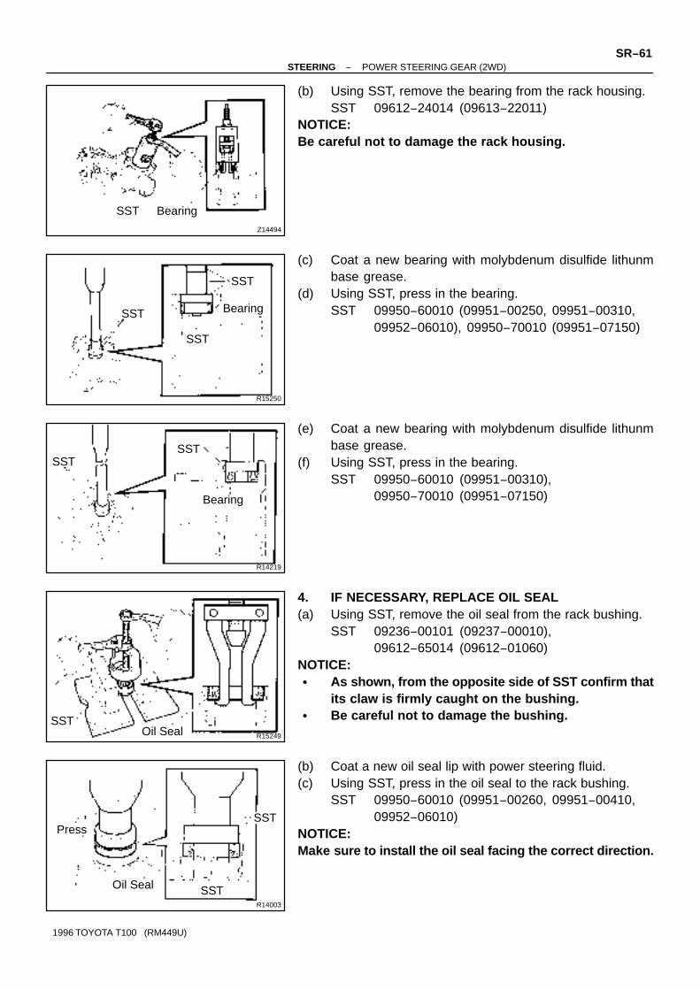
Z14494
SST Bearing
R15250
SST
SST
Bearing
SST
R14219
SSTSST
Bearing
R15249
SSTOil Seal
R14003
Press
Oil Seal SST
SST
−STEERING POWER STEERING GEAR (2WD)SR−61
1996 TOYOTA T100 (RM449U)
(b) Using SST, remove the bearing from the rack housing.SST 09612−24014 (09613−22011)
NOTICE:Be careful not to damage the rack housing.
(c) Coat a new bearing with molybdenum disulfide lithunmbase grease.
(d) Using SST, press in the bearing.SST 09950−60010 (09951−00250, 09951−00310,
09952−06010), 09950−70010 (09951−07150)
(e) Coat a new bearing with molybdenum disulfide lithunmbase grease.
(f) Using SST, press in the bearing.SST 09950−60010 (09951−00310),
09950−70010 (09951−07150)
4. IF NECESSARY, REPLACE OIL SEAL(a) Using SST, remove the oil seal from the rack bushing.
SST 09236−00101 (09237−00010),09612−65014 (09612−01060)
NOTICE:� As shown, from the opposite side of SST confirm that
its claw is firmly caught on the bushing.� Be careful not to damage the bushing.
(b) Coat a new oil seal lip with power steering fluid.(c) Using SST, press in the oil seal to the rack bushing.
SST 09950−60010 (09951−00260, 09951−00410,09952−06010)
NOTICE:Make sure to install the oil seal facing the correct direction.
https://www.truck-manuals.net/

N00399
R06172
N00401
R04603
F14898
SR−62−STEERING POWER STEERING GEAR (2WD)
1996 TOYOTA T100 (RM449U)
5. IF NECESSARY, REPLACE TEFLON RING ANDO−RING
(a) Using a screwdriver, remove the teflon ring and O−ringfrom the steering rack.
NOTICE:Be careful not to damage the groove of the ring.(b) Coat a new O−ring with power steering fluid and install it.
(c) Expand a new teflon ring with your fingers.NOTICE:Be careful not to overexpand the ring.
(d) Coat the ring with power steering fluid.(e) Install the ring to the rack, and snug it down with your fin-
gers.
6. IF NECESSARY, REPLACE TEFLON RINGS(a) Using a screwdriver, remove the 4 rings from the control
valve assembly.NOTICE:Be careful not to damage the grooves for the ring.
(b) Install 4 new teflon rings to SST, and expand them.SST 09631−20070
(c) Coat the rings with power steering fluid.
https://www.truck-manuals.net/

F14900
R04605
SST
−STEERING POWER STEERING GEAR (2WD)SR−63
1996 TOYOTA T100 (RM449U)
(d) Install the expanded teflon rings to the control valve andsnug them down with your fingers.
(e) Carefully slide the tapered end of SST over the rings toseat the rings.SST 09631−20081
NOTICE:Be careful not to damage the rings.
https://www.truck-manuals.net/

SR07Y−01
F00854
SSTSST
Oil Seal
SSTVinyl Tape
W03126
Rack Teeth End
SST
SR−64−STEERING POWER STEERING GEAR (2WD)
1996 TOYOTA T100 (RM449U)
REASSEMBLYNOTICE:When using a vise, do not overtighten it.1. COAT WITH POWER STEERING FLUID OR MOLYBDE-
NUM DISULFIDE LITHIUM BASE GREASE (See pageSR−54)
2. INSTALL OIL SEAL(a) Coat a new oil seal lip with power steering fluid.(b) Using SST, press in the oil seal.
SST 09950−60010 (09951−00240, 09951−00430,09952−06010), 09950−70010 (09951−07360)
NOTICE:� Make sure to install the oil seal facing the correct
direction.� Take care that the oil seal does not get reversed as
you install it.
3. INSTALL STEERING RACKHINT:If necessary, scrape the burrs off the rack teeth end then cleanand burnish before installation.(a) Make sure that the tube hole is not clogged with grease.HINT:If the tube hole is clogged, the pressure inside the boot willchange after it is assembled and the steering wheel turned.(b) Install SST to the rack.
SST 09631−33010(c) Coat SST with power steering fluid.(d) Insert the rack into the rack housing.NOTICE:Be careful not to damage the oil seal lip.(e) Remove the SST.
https://www.truck-manuals.net/

R13021
Vinyl Tape
R15248
Wire
SST
Cylinder EndStopper
R04609
SST
R13031
Vinyl Tape
W03369
SST
Oil Seal
−STEERING POWER STEERING GEAR (2WD)SR−65
1996 TOYOTA T100 (RM449U)
4. INSTALL RACK BUSHING AND CYLINDER ENDSTOPPER
(a) To prevent oil seal lip damage, wind vinyl tape on thesteering rack end, and apply power steering fluid.
(b) Coat a new O−ring with power steering fluid and install itto the bushing.
(c) Push in the bushing.NOTICE:Make sure to install the bushing facing the correct direc-tion.(d) Push in the cylinder end stopper until the wire installation
hole appears.5. INSTALL WIRE(a) Insert a new wire end into the hole of the rack housing.(b) Using SST, turn the cylinder end stopper clockwise until
the wire end disappears.SST 09631−10021
6. AIR TIGHTNESS TEST(a) Install SST to the rack housing.
SST 09631−12071(b) Apply 53.3 kPa (400 mmHg, 15.75 in.Hg) of vacuum for
about 30 seconds.(c) Check that there is no change in the vacuum.If there is change in the vacuum, check the installation of the oilseals.
7. INSTALL CONTROL VALVE ASSEMBLY(a) Coat the teflon rings with power steering fluid.(b) To prevent oil seal lip damage, wind vinyl tape on the ser-
rated part of the valve shaft.(c) Install the valve assembly into the control valve housing.NOTICE:Be careful not to damage the teflon rings and oil seal.
8. INSTALL OIL SEAL(a) Coat a new oil seal lip with power steering fluid.(b) Using SST, press in the oil seal.
SST 09612−22011NOTICE:Make sure to install the oil seal facing the correct direction.
https://www.truck-manuals.net/

R04613
SST
R05209
SR−66−STEERING POWER STEERING GEAR (2WD)
1996 TOYOTA T100 (RM449U)
9. INSTALL CONTROL VALVE HOUSING WITH CON-TROL VALVE ASSEMBLY
(a) Place a new gasket on the rack housing.(b) Torque the 2 bolts.
Torque: 18 N·m (185 kgf·cm, 13 ft·lbf)10. INSTALL DUST COVER
11. INSTALL SELF−LOCKING NUTUsing SST to stop the control valve assembly, install a new self−locking nut.
SST 09616−00010Torque: 25 N·m (250 kgf·cm, 18 ft·lbf)
12. INSTALL RACK HOUSING CAP(a) Apply sealant to 2 or 3 threads of the cap.
Sealant: Part No.08833−00080, THREE BOND 1344,LOCTITE 242 or equivalent
(b) Install the rack housing cap.Torque: 69 N·m (700 kgf·cm, 51 ft·lbf)
(c) Using a center punch, stake the cap at 2 places.13. INSTALL RACK GUIDE, RACK GUIDE SPRING AND
RACK GUIDE SPRING CAP(a) Apply sealant to 2 or 3 threads of the spring cap.
Sealant: Part No. 08833−00080, THREE BOND 1344,LOCTITE 242 or equivalent
(b) Temporarily install the spring cap.14. ADJUST TOTAL PRELOAD(a) To prevent the steering rack teeth from damaging the oil
seal lip, temporariry install the RH and LH rack ends.(b) Set the steering rack at the rack stroke center.(c) Fix the steering gear in a vise so that the rack guide spring
cap faces straight up.(d) Using a hexagon wrench (21 mm), torque the rack guide
spring cap.Torque: 10 N·m (100 kgf·cm, 7 ft·lbf)
https://www.truck-manuals.net/
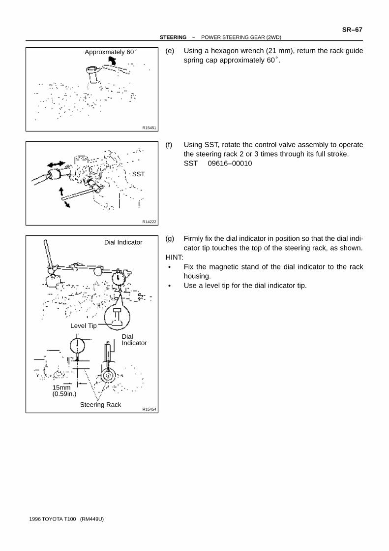
R15451
Approxmately 60°
R14222
SST
R15454
Dial Indicator
Level Tip
DialIndicator
15mm(0.59in.)
Steering Rack
−STEERING POWER STEERING GEAR (2WD)SR−67
1996 TOYOTA T100 (RM449U)
(e) Using a hexagon wrench (21 mm), return the rack guidespring cap approximately 60°.
(f) Using SST, rotate the control valve assembly to operatethe steering rack 2 or 3 times through its full stroke.SST 09616−00010
(g) Firmly fix the dial indicator in position so that the dial indi-cator tip touches the top of the steering rack, as shown.
HINT:� Fix the magnetic stand of the dial indicator to the rack
housing.� Use a level tip for the dial indicator tip.
https://www.truck-manuals.net/

R15452
SteeringTwist of Steering Rack
Steering Rack Center PositionDial Indicator
0.08mm(0.0032in.) or less
(55kgf·cm, 4.8in.·lbf)
SSTTorqueWrench
FulcrumLength SST
90°
180°
ValueControl
Rack
Dial Indicator
Shaft
SST
Clockwise Counterclckwise
90°
180°
5.4N·m
SR−68−STEERING POWER STEERING GEAR (2WD)
1996 TOYOTA T100 (RM449U)
(h) Using a hexagon wrench (21 mm), gradually tighten therack guide spring cap and adjust the twist of the steeringrack to 0.08 mm (0.0032 in.) or less when the rack istwisted clockwise and counterclockwise by SST andtorque wrench with 5.4 N·m (55 kgf·cm, 48 in.·lbf) oftorque applied.SST 09922−10010
NOTICE:Use SST 09922−10010 in the direction shown in the illustra-tionHINT:Use a torque wrench with a fulcrum length of 250 mm (9.84 in.).(i) Using SST to ratate the control valve shaft, adjust the
twist of the rack so that it is within the above specificationsat the following 5 points:SST 09616−00010(1) Steering rack at center position.(2) Steering pinion shaft rotated 90° clockwise from the
center position.(3) Steering pinion shaft rotated 90° counterclockwise
from the center position.(4) Steering pinion shaft rotated 180° clockwise from
the center position.(5) Steering pinion shaft rotated 180° counterclock-
wise from the center position.
https://www.truck-manuals.net/
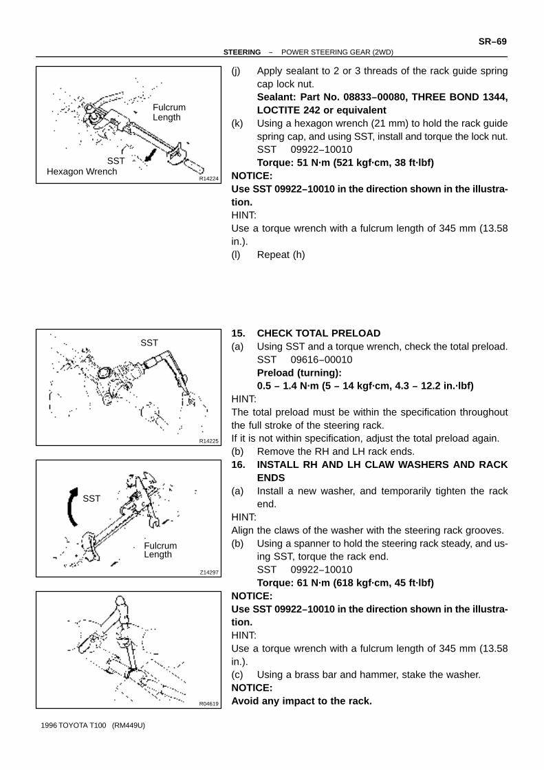
R14224
FulcrumLength
SSTHexagon Wrench
R14225
SST
Z14297
SST
LengthFulcrum
R04619
−STEERING POWER STEERING GEAR (2WD)SR−69
1996 TOYOTA T100 (RM449U)
(j) Apply sealant to 2 or 3 threads of the rack guide springcap lock nut.Sealant: Part No. 08833−00080, THREE BOND 1344,LOCTITE 242 or equivalent
(k) Using a hexagon wrench (21 mm) to hold the rack guidespring cap, and using SST, install and torque the lock nut.SST 09922−10010Torque: 51 N·m (521 kgf·cm, 38 ft·lbf)
NOTICE:Use SST 09922−10010 in the direction shown in the illustra-tion.HINT:Use a torque wrench with a fulcrum length of 345 mm (13.58in.).(l) Repeat (h)
15. CHECK TOTAL PRELOAD(a) Using SST and a torque wrench, check the total preload.
SST 09616−00010Preload (turning):0.5 − 1.4 N·m (5 − 14 kgf·cm, 4.3 − 12.2 in.·lbf)
HINT:The total preload must be within the specification throughoutthe full stroke of the steering rack.If it is not within specification, adjust the total preload again.(b) Remove the RH and LH rack ends.16. INSTALL RH AND LH CLAW WASHERS AND RACK
ENDS(a) Install a new washer, and temporarily tighten the rack
end.HINT:Align the claws of the washer with the steering rack grooves.(b) Using a spanner to hold the steering rack steady, and us-
ing SST, torque the rack end.SST 09922−10010Torque: 61 N·m (618 kgf·cm, 45 ft·lbf)
NOTICE:Use SST 09922−10010 in the direction shown in the illustra-tion.HINT:Use a torque wrench with a fulcrum length of 345 mm (13.58in.).(c) Using a brass bar and hammer, stake the washer.NOTICE:Avoid any impact to the rack.
https://www.truck-manuals.net/

R04620
R04621
28−8° 2−5 mm(0.08−0.20in.)
R15216
SST
FulcrumLength
SR−70−STEERING POWER STEERING GEAR (2WD)
1996 TOYOTA T100 (RM449U)
17. INSTALL RH AND LH RACK BOOTS, CLAMPS ANDCLIPS
(a) Make sure that the tube hole is not clogged with grease.HINT:If the tube hole is clogged, the pressure inside the boot willchange after it is assembled and the steering wheel turned.(b) Install the boot.NOTICE:Be careful not to damage or twist the boot.
(c) Tighten the clamp and clip, as shown in the illustration.18. INSTALL RH AND LH TIE ROD ENDS AND LOCK NUTS(a) Screw the lock nut and tie rod end onto the rack end until
the matchmarks are aligned.(b) After adjusting toe−in, torque the lock nut (See page
SA−7).Torque: 56 N·m (570 kgf·cm, 41 ft·lbf)
19. INSTALL 2 TURN PRESSURE TUBES(a) Coat 2 new O−rings with power steering fluid and install
them to the tube.(b) Using SST, install and torque the tube.
SST 09633−00020Torque: 10 N·m (102 kgf·cm, 7 ft·lbf)
HINT:� Use a torque wrench with a fulcrum length of 250 mm
(9.84 in.).� This torque value is effective in case that SST is parallel
to a torque wrench.(c) Install the clamp plate with the bolt.
https://www.truck-manuals.net/

SR07Z−01
R15251
SST
Fulcum Length
−STEERING POWER STEERING GEAR (2WD)SR−71
1996 TOYOTA T100 (RM449U)
INSTALLATION1. INSTALL PS GEAR ASSEMBLY
Torque: 88 N·m (900 kgf·cm, 65 ft·lbf)Torque the 2 gear assembly set bolts and nut.2. INSTALL MOUNT BRACKET AND GROMMET(a) Install the grommet and mount bracket to the PS gear as-
sembly.(b) Torque the 2 bolts.
Torque: 88 N·m (900 kgf·cm, 65 ft·lbf)3. CONNECT PRESSURE FEED TUBE AND INSTALL
RETRUN TUBE(a) Coat a new O−ring with power steering fluid and install it
to the tube.(b) Using SST, connect the pressure feed tube and install the
return tube.SST 09631−22020Torque: 19 N·m (195 kgf·cm, 14 ft·lbf)
HINT:� Use a torque wrench with a fulcrum length of 250 mm
(9.84 in.).� This torque value is effective in case that SST is parallel
to a torque wrench.4. CONNECT RETURN HOSE5. CONNECT INTERMEDIATE SHAFT ASSEMBLY
(See page SR−20)6. CONNECT RH AND LH TIE ROD ENDSInstall the nut and a new cotter pin.
Torque: 90 N·m (920 kgf·cm, 67 ft·lbf)7. POSITION FRONT WHEELS FACING STRAIGHT
AHEADHINT:Do it with the front of the vehicle jacked up.8. CENTER SPIRAL CABLE
(See page SR−20)9. INSTALL STEERING WHEEL(a) Align the matchmarks on the wheel and steering column
main shaft.(b) Temporarily tighten the wheel set nut.(c) Connect the connector.10. BLEED POWER STEERING SYSTEM
(See page SR−4)11. CHECK STEERING WHEEL CENTER POINT12. TORQUE STEERING WHEEL SET NUT
Torque: 35 N·m (360 kgf·cm, 26 ft·lbf)13. INSTALL STEERING WHEEL PAD
(See page SR−20)14. CHECK FRONT WHEEL ALIGNMENT
(See page SA−7)
https://www.truck-manuals.net/

R15457
Return Tube
Intermediate Shaft Assembly
Pressure Feed Tube
PS Gear Assembly
Pitman Arm Sub−AssemblyWith Relay Rod
Spring Washer
44 (450, 33)*36 (365, 26)
: Specified torqueN·m (kgf·cm, ft·lbf)
35 (360, 26)
44 (450, 33)*36 (365, 26)
142 (1450, 105)
177 (1800, 130)
SR080−01
SR−72−STEERING POWER STEERING GEAR (4WD)
1746Author�: Date�:
1996 TOYOTA T100 (RM449U)
POWER STEERING GEAR (4WD)COMPONENTS
https://www.truck-manuals.net/

Z18651
� Washer
� O−Ring
� No.1 Lock Nut
Side Cover
No.1 Hose Support Bracket
Adjusting Screw Lock Nut
Sector Shaft Adjusting Screw
Cross Shaft
Power PistonPlunger Guide Nut
Compression Spring
Power Piston Plunger
Power Piston Plunger Guide
Power Steering Gear Housing
Needle Roller Bearing
� Union Seat
� O−Ring
� Teflon Ring
Worm Gear ValveBody Assembly
Metal Spacer� Snap ring
Non−reusable partPower Steering fluidMolybdenum disulfide lithium base grease
�
� O−Ring
� O−Ring� Teflon Ring
� Oil Seal
61 (620, 45)
61 (620, 45)
: Specified torqueN·m (kgf·cm, ft·lbf)
46 (470, 34)
20 (205, 15)
−STEERING POWER STEERING GEAR (4WD)SR−73
1747Author�: Date�:
1996 TOYOTA T100 (RM449U)
https://www.truck-manuals.net/
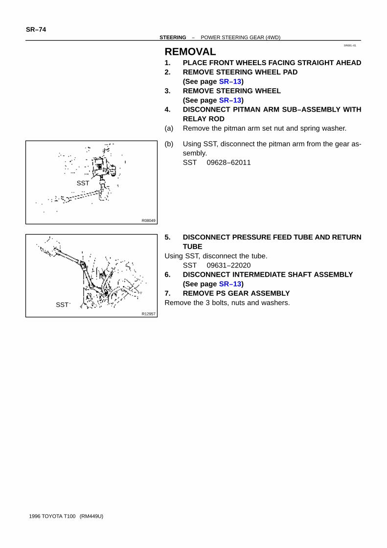
SR081−01
R08049
SST
R12957
SST
SR−74−STEERING POWER STEERING GEAR (4WD)
1996 TOYOTA T100 (RM449U)
REMOVAL1. PLACE FRONT WHEELS FACING STRAIGHT AHEAD2. REMOVE STEERING WHEEL PAD
(See page SR−13)3. REMOVE STEERING WHEEL
(See page SR−13)4. DISCONNECT PITMAN ARM SUB−ASSEMBLY WITH
RELAY ROD(a) Remove the pitman arm set nut and spring washer.
(b) Using SST, disconnect the pitman arm from the gear as-sembly.SST 09628−62011
5. DISCONNECT PRESSURE FEED TUBE AND RETURNTUBE
Using SST, disconnect the tube.SST 09631−22020
6. DISCONNECT INTERMEDIATE SHAFT ASSEMBLY(See page SR−13)
7. REMOVE PS GEAR ASSEMBLYRemove the 3 bolts, nuts and washers.
https://www.truck-manuals.net/

SR082−01
R01279
SST
R01292
R01293
Z14397
HexagonWrench
R15243
SST
−STEERING POWER STEERING GEAR (4WD)SR−75
1996 TOYOTA T100 (RM449U)
DISASSEMBLYNOTICE:When using a vise, do not overtightn it.1. SECURE PS GEAR ASSEMBLY IN VISEMount the gear assembly on SST and clamp SST in a vise.
SST 09630−00014 (09631−00142)
2. REMOVE ADJUSTING SCREW LOCK NUT AND SEALWASHER
3. REMOVE SIDE COVER(a) Remove the 4 bolts and No.1 hose support bracket.(b) Using a screwdriver, turn the sector shaft adjusting screw
clockwise until the cover comes off.(c) Remove the O−ring from the cover.
4. REMOVE SECTOR SHAFTUsing a plastic hammer, tap on the sector shaft end and pull outthe shaft.
5. REMOVE POWER PISTON PLUNGER GUIDE NUT,COMPRESSION SPRING, POWER PISTON PLUNGERAND POWER PISTON PLUNGER GUIDE
(a) Using a hexagon wrench (10 mm), remove the plungerguide nut.
(b) Remove the O−ring from the plunger guide nut.
6. REMOVE WORM GEAR VALVE BODY ASSEMBLY(a) Remove the 4 bolts.(b) Using SST, turn the valve body shaft clockwise with hold-
ing the power piston nut by your finger so it cannot move.SST 09616−00010
(c) Pull out the valve body assembly.NOTICE:Ensure that the power piston nut does not come off theworm shaft.(d) Remove the 2 O−rings from the gear housing.
https://www.truck-manuals.net/

SR083−01
Z14503
Dial Indicator
30 mm(1.18 in.)
Z14504
DialIndicator
R01297
R01283
SST
Z06211SR3019 SR3020
SR−76−STEERING POWER STEERING GEAR (4WD)
1996 TOYOTA T100 (RM449U)
INSPECTIONNOTICE:When using a vise, do not overtighten it.1. INSPECT BALL CLEARANCEUsing a dial indicator, check the ball clearance. Move the powerpiston nut up and down.
Maximum clearance: 0.15 mm (0.0059 in.)2. INSPECT SECTOR SHAFT ADJUSTING SCREW
THRUST CLEARANCEUsing a dial indicator, measure the thrust clearance.
Standard clearance: 0.03 − 0.05 mm (0.0012 − 0.0020 in.)Maximum clearance: 0.05 mm (0.0020 in.)
3. IF NECESSARY, ADJUST SECTOR SHAFTADJUSTING SCREW THRUST CLEARANCE
(a) Using a chisel and hammer, unstake the No.1 lock nut.
(b) Using SST, remove the No.1 lock nut.SST 09630−00014 (09631−00051)
(c) Using a screwdriver, adjust the adjusting screw for thecorrect thrust clearance.
(d) Tighten a new lock nut.(e) Stake the lock nut.
4. IF NECESSARY, REPLACE 2 NEEDLE ROLLERBEARINGS
(a) Using a screwdriver, pry out the oil seal from the gearhousing.
(b) Using snap ring pliers, remove the snap ring from the gearhousing.
(c) Remove the metal spacer, teflon ring and O−ring from thegear housing.
https://www.truck-manuals.net/

Z14505
SST
Bearing
R14227
SST
SST
Bearing
R14228
Bearing
SST23.1 mm(0.909 in.)
SST
SST
SST
R14324
SST
Bearing
89.0 mm(3,504 in.) SST
SSTSST
−STEERING POWER STEERING GEAR (4WD)SR−77
1996 TOYOTA T100 (RM449U)
(d) Using SST, remove the bearing from the gear housing.SST 09612−65014 (09612−01030)
(e) Using SST, press out the bearing from the gear housing.SST 09950−60010 (09951−00360, 09951−00420,
09952−06010), 09950−70010 (09951−07200)
(f) Coat a new bearing with molybdenum disulfide lithiumbase grease.
(g) Using SST, press in the bearing, as shown in the illustra-tion.SST 09950−60010 (09951−00360, 09951−00420,
09952−06010), 09950−70010 (09951−07200)
(h) Coat a new bearing with molybdenum disulfide lithiumbase grease.
(i) Using SST, press in the bearing, as shown in the illustra-tion.SST 09950−60010 (09951−00360, 09951−00420,
09952−06010), 09950−70010 (09951−07200)(j) Coat a new O−ring and metal spacer with power steering
fluid.(k) Install the O−ring and metal spacer.(l) Using snap ring pliers, install a new snap ring.(m) Coat a new teflon ring with power steering fluid.(n) Form the teflon ring into a heart shape and install it by
hand.
https://www.truck-manuals.net/

Z06212
SST
SR3026 SR3004
W03370
SST
Oil SealSST
R01298
SR2804
SR−78−STEERING POWER STEERING GEAR (4WD)
1996 TOYOTA T100 (RM449U)
(o) Using SST, form the teflon ring.SST 09630−00014 (09631−00121)
NOTICE:The teflon ring must be squeezed before inserting the sec-tor shaft or damage will result.
(p) Coat a new oil seal lip with power steering fluid.(q) Using SST, drive the oil seal into the gear housing.
SST 09950−60010 (09951−00340, 09951−00430,09952−06010), 09950−70010 (09951−07200)
NOTICE:Make sure to install the oil seal facing the correct direction.
5. IF NECESSARY, REPLACE TEFLON RING ANDO−RING
(a) Using a screwdriver, remove the teflon ring and O−ringfrom the worm gear valve body assembly.
NOTICE:Be careful not to damage the worm gear valve body assem-bly.(b) Coat a new O−ring with power steering fluid and install it.(c) Expand a new teflon ring with your fingers.NOTICE:Be careful not to overexpand the teflon ring.
(d) Install the teflon ring.(e) Coat the teflon ring with power steering fluid and snug it
down with a piston ring compressor for 5 − 7 minutes.
https://www.truck-manuals.net/

Z14510
Screw Extractor
SR2811
−STEERING POWER STEERING GEAR (4WD)SR−79
1996 TOYOTA T100 (RM449U)
6. IF NECESSARY, REPLACE UNION SEATS(a) Using a screw extractor, remove the 2 union seats from
the worm gear valve body assembly.
(b) Using a hammer and an extension bar, tap in 2 new unionseats.
NOTICE:Before installing the union seat, remove dust sticking tothe worm gear valve body assembly.
https://www.truck-manuals.net/

SR084−01
R15586
R15587
SST
R12202
HexagonWrench
SR−80−STEERING POWER STEERING GEAR (4WD)
1996 TOYOTA T100 (RM449U)
REASSEMBLYNOTICE:When using a vise, do not overtighten it.1. COAT WITH POWER STEERING FLUID OR MOLYBDE-
NUM DISULFIDE LITHIUM BASE GREASE (See pageSR−72)
2. INSTALL WORM GEAR VALVE BODY ASSEMBLY(a) Coat 2 new O−rings with power steering fluid and install
them to the gear housing.
(b) Install the valve body assembly into the gear housing.NOTICE:� Ensure that the power piston nut does not come off
the worm shaft.� Be careful not to damage the teflon ring.
(c) Torque the 4 bolts.Torque: 61 N·m (620 kgf·cm, 45 ft·lbf)
(d) Using SST and a torque wrench, check the valve body as-sembly rotating torque.SST 09616−00010Rotating torque:0.3 − 0.5 N·m (3 − 5.5 kgf·cm, 2.6 − 4.8 in.·lbf)
HINT:Hold the worm gear to prevent it from turning.If rotating torque is not correct, replace the worm gear valvebody assembly.
3. INSTALL POWER PISTON PLUNGER GUIDE, POWERPISTON PLUNGER, COMPRESSION SPRING ANDPOWER PISTON PLUNGER GUIDE NUT
(a) Coat a new O−ring with power steering fluid and install itto the plunger guide nut.
(b) Install the plunger guide nut with a hexagon wrench (10mm).Torque: 20 N·m (205 kgf·cm, 15 ft·lbf)
https://www.truck-manuals.net/

R01241
R01286
SST
Matchmarks
R01287
SST
R01290
−STEERING POWER STEERING GEAR (4WD)SR−81
1996 TOYOTA T100 (RM449U)
4. INSTALL SECTOR SHAFT AND SIDE COVER(a) Coat a new O−ring with power steering fluid and install it
the side cover.(b) Assemble the sector shaft to the side cover.HINT:Fully loosen the sector shaft adjusting screw.(c) Set the power piston nut at the center of the gear housing.(d) Install and push the sector shaft into the gear housing so
that the center teeth mesh together.(e) Torque the 4 bolts in a diagonal pattern.
Torque: 61 N·m (620 kgf·cm, 45 ft·lbf)
5. DETERMINE CENTER POSITION(a) Using SST, turn the worm gear valve body shaft so full
lock in both directions and determine the exact center.SST 09616−00010
(b) Place matchmarks on the worm gear valve body shaft andgear housing to show neutral position.
6. ADJUST SECTOR SHAFT ADJUSTING SCREW(a) Install SST with a torque wrench on the worm gear valve
body shaft.SST 09616−00010
(b) Turn the adjusting screw until the preload is within thespecification.Preload (Turning):0.2 − 0.4 N·m (2 − 4 kgf·cm, 1.7 − 3.5 in.·lbf)
7. INSTALL NEW SEAL WASHER
8. INSTALL ADJUSTING SCREW LOCK NUTTorque the lock nut while holding the sector shaft adjustingscrew.
Torque: 46 N·m (470 kgf·cm, 34 ft·lbf)
https://www.truck-manuals.net/

R01288
SST
SR−82−STEERING POWER STEERING GEAR (4WD)
1996 TOYOTA T100 (RM449U)
9. CHECK TOTAL PRELOADUsing SST and a torque wrench, check total preload.
SST 09616−00010Total preload (Turning):0.5 − 0.9 N·m (5 − 9.5 kgf·cm, 4.3 − 8.3 in.·lbf)
https://www.truck-manuals.net/

SR085−01
R15509
FulcrumLength
SST
SR2922
Alignment Marks
−STEERING POWER STEERING GEAR (4WD)SR−83
1996 TOYOTA T100 (RM449U)
INSTALLATION1. INSTALL PS GEAR ASSEMBLYInstall the 3 bolts, washers and nuts.
Torque: 142 N·m (1,450 kgf·cm, 105 ft·lbf)2. CONNECT INTERMEDIATE SHAFT ASSEMBLY
(See page SR−20)3. CONNECT PRESSURE FEED TUBE AND RETURN
TUBEUsing SST, connect the tube.
SST 09631−22020Torque: 36 N·m (365 kgf·cm, 26 ft·lbf)
HINT:� Use a torque wrench with a fulcrum length of 300 mm
(11.81 in.).� This torque value is effective in case that SST is parallel
to a torque wrench.4. CONNECT PITMAN ARM SUB−ASSEMBLY WITH
RELAY ROD(a) Align the alignment marks on the pitman arm and sector
shaft, and connect the pitman arm.(b) Install the spring washer and pitman arm set nut.
Torque: 177 N·m (1,800 kgf·cm, 130 ft·lbf)5. POSITION FRONT WHEELS FACING STRAIGHT
AHEADHINT:Do it with the front of the vehicle jacked up.6. CENTER SPIRAL CABLE
(See page SR−20)7. INSTALL STEERING WHEEL(a) Align the matchmarks on the wheel and steering column
main shaft.(b) Temporarily tighten the wheel set nut.(c) Connect the connector.8. BLEED POWER STEERING SYSTEM
(See page SR−4)9. CHECK STEERING WHEEL CENTER POINT10. TORQUE STEERING WHEEL SET NUT
Torque: 35 N·m (360 kgf·cm, 26 ft·lbf)11. INSTALL STEERING WHEEL PAD
(See page SR−20)12. CHECK FRONT WHEEL ALIGNMENT
(See page SA−10)
https://www.truck-manuals.net/

R15252
RH Tie Rod EndSub−Assembly
RH Knuckle Arm
Steering Damper
� Non−reusable part
Engine Under Cover
Spring Washer
Pitman Arm
LH Knuckle Arm
LH Tie RodSub−Assembly
LH Tie Rod End
AssemblyRH Tie Rod
Idler ArmAssembly
Relay Rod
� Cotter Pin
LH Tie RodAssembly
Clamp
Tie Rod Clamp
Clamp
Tie Rod Clamp
�
Sub−Assembly
Sub−Assembly
RH Tie Rod
�
�
�
�
�
22 (225, 16)22 (225, 16)
22 (225, 16)
22 (225, 16)
90 (920, 67)
177 (1800, 130)
90 (920, 67)
25 (260, 19)
59 (600, 43)
90 (920, 67)
90 (920, 67)
142 (1450, 105)
: Specified torqueN·m (kgf·cm, ft·lbf)
59 (600, 43)
SR086−01
SR−84−STEERING STEERING LINKAGE
1758Author�: Date�:
1996 TOYOTA T100 (RM449U)
STEERING LINKAGECOMPONENTS
https://www.truck-manuals.net/

SR087−01
R08049
SST
R15244
SST
R04470
SST
SR1254
SST
SR1260
SST
−STEERING STEERING LINKAGESR−85
1996 TOYOTA T100 (RM449U)
REMOVAL1. REMOVE ENGINE UNDER COVERRemove the 4 bolts.2. REMOVE PITMAN ARM(a) Remove the pitman arm set nut and spring washer.(b) Using SST, disconnect the pitman arm from the cross
shaft.SST 09628−62011
(c) Remove the cotter pin and nut.(d) Using SST, disconnect the pitman arm from the relay rod.
SST 09611−22012
3. REMOVE LH AND RH TIE ROD ASSEMBLIE(a) Remove the cotter pin and nut.(b) Using SST, disconnect the tie rod assembly from the relay
rod.SST 09628−62011
(c) Remove the cotter pin and nut.(d) Using SST, disconnect the tie rod assembly from the
knuckle arm.SST 09610−20012
4. REMOVE RH AND LH TIE ROD SUB−ASSEMBLIES,TIE ROD END SUB−ASSEMBLIES, TIE RODS AND 2CLAMPS
Remove the 2 bolts, washers and nuts.
5. REMOVE STEERING DAMPER(a) Remove the cotter pin and nut.(b) Using SST, disconnect the steering damper from the relay
rod.SST 09611−22012
(c) Remove the bolt and nut.
https://www.truck-manuals.net/

R08099
SST
SR−86−STEERING STEERING LINKAGE
1996 TOYOTA T100 (RM449U)
6. REMOVE IDLER ARM ASSEMBLY(a) Remove the cotter pin and nut.(b) Using SST, disconnect the idler arm from the relay rod.
SST 09610−20012(c) Remove the 3 bolts, washers and nuts.
https://www.truck-manuals.net/

SR088−02
R08100
A A = A’
B = B’
B B’
A’
Z03912
Front
FrontSR0262 SR1454
−STEERING STEERING LINKAGESR−87
1996 TOYOTA T100 (RM449U)
INSTALLATIONHINT:When connecting the ball stud to the arm or rod, remove thegrease on the joint surfaces.1. INSTALL IDLER ARM ASSEMBLY(a) Install the 3 bolts, washers and nuts.
Torque: 142 N·m (1,450 kgf·cm, 105 ft·lbf)(b) Connect the idler arm to the relay rod.(c) Install the nut and a new cotter pin.
Torque: 59 N·m (600 kgf·cm, 43 ft·lbf)2. INSTALL STEERING DAMPER(a) Torque the bolt and nut.
Torque: 25 N·m (260 kgf·cm, 19 ft·lbf)(b) Install the nut and a new cotter pin.
Torque: 59 N·m (600 kgf·cm, 43 ft·lbf)
3. INSTALL RH AND LH TIE ROD SUB−ASSEMBLIES,TIE ROD END SUB−ASSEMBLIES, TIE ROD AND 2CLAMPS
(a) Screw the tie rod end sub−assembly and tie rod sub−as-sembly into the tie rod.
HINT:The tie rod assembly length should be approximately 329.2 mm(12.961 in.), and the remaining length of threads on both RHand LH tie rod assemblies should be equal.
(b) Turn the tie rod end sub−assembly so that they cross atabout 90 degrees.
(c) After adjusting toe−in, torque the bolt.(See page SA−10)Torque: 22 N·m (225 kgf·cm, 16 ft·lbf)
4. INSTALL RH AND LH TIE ROD ASSEMBLIES(a) Connect the tie rod assembly to the knuckle arm.(b) Install the nut and a new cotter pin.
Torque: 90 N·m (920 kgf·cm, 67 ft·lbf)(c) Connect the tie rod assembly to the relay rod.(d) Install the nut and a new cotter pin.
Torque: 90 N·m (920 kgf·cm, 67 ft·lbf)
https://www.truck-manuals.net/

R04469
AlignmentMarks
SR−88−STEERING STEERING LINKAGE
1996 TOYOTA T100 (RM449U)
5. INSTALL PITMAN ARM(a) Align the alignment marks on the pitman arm and the
cross shaft.(b) Install the spring washer and pitman arm set nut.
Torque: 177 N·m (1,800 kgf·cm, 130 ft·lbf)(c) Connect the pitman arm to the relay rod.(d) Install the nut and a new cotter pin.
Torque: 90 N·m (920 kgf·cm, 67 ft·lbf)6. INSTALL ENGINE UNDER COVERTighten the 4 bolts.7. CHECK FRONT WHEEL ALIGNMENT
(See page SA−10)
https://www.truck-manuals.net/

Z18652
Idler Arm Bracket Cap
Plate Washer
Idler Arm Bracket
Non−reusable partMolybdenum disulfide lithium base grease
Idler Arm
� Bushing
� Oil Seal
�
�
78 (800, 58)
: Specified torqueN·m (kgf·cm, ft·lbf)
SR089−02
−STEERING IDLER ARMSR−89
1763Author�: Date�:
1996 TOYOTA T100 (RM449U)
IDLER ARMCOMPONENTS
https://www.truck-manuals.net/

SR08A−01
SR−90−STEERING IDLER ARM
1996 TOYOTA T100 (RM449U)
REMOVAL(See page SR−85)
https://www.truck-manuals.net/

SR08B−01
SR1279
SR1287
R04472
−STEERING IDLER ARMSR−91
1996 TOYOTA T100 (RM449U)
DISASSEMBLYNOTICE:When using a vise, do not overtighten it.1. REMOVE IDLER ARM BRACKET CAPUsing a screwdriver and a hammer, remove the idler arm brack-et cap.NOTICE:Be careful not to damage the idler arm bracket.
2. MEASURE IDLER ARM ROTATING TORQUE(a) Check that the arm rotates smoothly without abnormal
noise.(b) Using a torque wrench, check the arm rotating torque.
Rotating torque:0.5 − 2.9 N·m (5 − 30 kgf·cm, 5 − 26 in.·lbf)
3. REMOVE IDLER ARMRemove the nut and plate washer, and pull the idler arm off theidler arm bracket.4. REMOVE OIL SEAL
5. REMOVE 2 BUSHINGSUsing a screwdriver, remove the bushing.NOTICE:Be careful not to damage the idler arm bracket.
https://www.truck-manuals.net/

SR08C−01
R14326
SST
R04473
SR1285
SST
SR−92−STEERING IDLER ARM
1996 TOYOTA T100 (RM449U)
REASSEMBLYNOTICE:When using a vise, do not overtighten it.1. COAT WITH MOLYBDENUM DISULFIDE LITHIUM
BASE GREASE(See page SR−89)
2. INSTALL 2 BUSHINGSUsing SST and a hammer, tap in a new bushing to the idler armbraket.
SST 09950−60010 (09951−00300),09950−70010 (09951−07200)
3. INSTALL OIL SEAL(a) Coat a new oil seal lip with molybdenum disulfide lithium
base grease.(b) Install the oil seal.NOTICE:Make sure to install the oil seal facing the correct direction.4. INSTALL IDLER ARM(a) Install the idler arm to the bracket.(b) Install the plate washer and nut.
Torque: 78 N·m (800 kgf·cm, 58 ft·lbf)5. MEASURE IDLER ARM ROTATING TORQUE
(See page SR−91)6. INSTALL IDLER ARM BRACKET CAP(a) Apply sealant to a new cap end.
Sealant: Part No.08826−00090, THREE BOND 1281 orequivalent
(b) Using SST, tap in the idler arm bracket cap.SST 09223−46011
https://www.truck-manuals.net/

SR08D−01
−STEERING IDLER ARMSR−93
1996 TOYOTA T100 (RM449U)
INSTALLATION(See page SR−87)
https://www.truck-manuals.net/

RS – SUPPLEMENTAL RESTRAINT SYSTEM
SRS AIRBAG RS-1 STEERING WHEEL PAD AND SPIRAL CABLE
RS-7
AIRBAG SENSOR ASSEMBLY RS-21 FRONT AIRBAG SENSOR RS-26 WIRE HARNESS AND CONNECTOR RS-31
https://www.truck-manuals.net/

RS03H−01
−SUPPLEMENTAL RESTRAINT SYSTEM SRS AIRBAGRS−1
1768Author�: Date�:
1996 TOYOTA T100 (RM449U)
SRS AIRBAGPRECAUTIONNOTICE:� The TOYOTA T100 is equipped with SRS, which comprises a driver airbag. Failure to carry out
service operations in the correct sequence could cause the SRS to unexpectedly deploy duringservicing, possibly leading to a serious accident. Further, if a mistake is made in servicing theSRS, it is possible that the SRS may fail to operate when required. Before performing servicing(including removal or installation of parts, inspection or replacement), be sure to read the fol-lowing items carefully, then follow the correct procedures described in the repair manual.
� Malfunction symptoms of the SRS are difficult to confirm, so the DTCs become the most impor-tant source of information when troubleshooting. When troubleshooting the SRS, always in-spect the DTCs before disconnecting the battery.
� Even in cases of a minor collision where the SRS does not deploy, the steering wheel pad, air-bag sensor assembly and front airbag sensor should be inspected (See page RS−9, RS−23 andRS−28).
� Never use SRS parts from another vehicle. When replacing parts, replace them with new parts.� Never disassemble and repair the steering wheel pad, airbag sensor assembly or front airbag
sensor in order to reuse it.� If the steering wheel pad, airbag sensor assembly or front airbag sensor has been dropped, or
if there are cracks, dents or other defects in the case, bracket or connector, replace them withnew ones.
� Use a volt/ohmmeter with high impedance ( 10 kΩ/V minimum) for troubleshooting the system’selectrical circuits.
� Information labels are attached to the periphery of the SRS components. Follow the instruc-tions on the notices.
� After work on the SRS is completed, perform the SRS warning light check or SRS side airbagwarning light check (See page DI−365).
� If the vehicle is equipped with a mobile communication system, refer to the precaution in theIN section.
CAUTION:� Work must be started after 90 seconds from when the ignition switch is turned to the ”LOCK”
position and the negative (−) terminal cable is disconnected from the battery.(The SRS is equipped with a back−up power source so that if work is started within 90 secondsfrom disconnecting the negative (−) terminal cable of the battery, the SRS may be deployed.)
� When the negative (−) terminal cable is disconnected from the battery, the memory of the clockand audio system will be canceled. So before starting work, make a record of the contents mem-orized in the audio memory system. When work is finished, reset the audio systems as theywere before and adjust the clock. To avoid erasing the memory in each memory system, neveruse a back− up power supply from outside the vehicle.
� Before repairs, remove the airbag sensor if shocks are likely to be applied to the sensor duringrepairs.
� Do not expose the steering wheel pad, airbag sensor assembly or front airbag sensor directlyto hot air or flames.
https://www.truck-manuals.net/

RS03I−03
R07746
AB0250
Spiral Cable
Z09709
w/ Tachometer:
w/o Tachometer:
R12497
RS−2−SUPPLEMENTAL RESTRAINT SYSTEM SRS AIRBAG
1996 TOYOTA T100 (RM449U)
OPERATION1. STEERING WHEEL PAD (with AIRBAG)The inflater and bag of the SRS are stored in the steering wheelpad and cannot be disassembled. The inflater contains a squib,igniter charge, gas generant, etc., and inflates the bag wheninstructed by the airbag sensor assembly.
2. SPIRAL CABLE (in COMBINATION SWITCH)A spiral cable is used as an electrical joint from the vehicle bodyside to the steering wheel.
3. SRS WARNING LIGHTThe SRS warning light is located on the combination meter. Itgoes on to alert the driver of trouble in the system when a mal-function is detected in the airbag sensor assembly. In normaloperation conditions when the ignition switch is turned to theACC or ON position, the light goes on for about 6 seconds andthen goes off.
4. AIRBAG SENSOR ASSEMBLYThe airbag sensor assembly is mounted on the floor inside thelower center cover. The airbag sensor assembly consists of anairbag sensor, safing sensor, diagnosis circuit, ignition control,drive and circuit, etc.It receives signals from the airbag sensor and judges whetherthe SRS must be activated or not.
https://www.truck-manuals.net/

R08038
H03005
Connector 1
Connector 2
No.1 J/B
Connector 3
Spiral Cable
Connector 4
Squib
Rh and LH Front Airbag Sensor
Connector 5
Center AirbagSensor Assembly
Z05953
Spacer
Housing
Female Male
−SUPPLEMENTAL RESTRAINT SYSTEM SRS AIRBAGRS−3
1996 TOYOTA T100 (RM449U)
5. FRONT AIRBAG SENSORThe front airbag sensor is mounted inside each of the frontmembers. The sensor unit is a mechanical type. When the sen-sor detects deceleration force above a predetermined limit,contact is made in the sensor, sending a signal to the airbagsensor assembly. The sensor cannot be disassembled.
6. SRS CONNECTORS
No. Item Application
(1) Terminal Twin−Lock Mechanism Connectors 2, 3, 4
(2) Airbag Activation Prevention Mechanism Connectors 1, 3, 4
(3) Electrical Connection Check Mechanism Connectors 1, 5
(4) Connector Twin−Lock Mechanism Connectors 3, 4
(a) All connectors in the SRS are colored yellow to distin-guish them from other connectors. Connectors havingspecial functions and specifically designed for the SRSare used in the locations shown above to ensure high reli-ability. These connectors use durable gold−plated termi-nals.
(1) Terminal Twin−Lock MechanismEach connector has a two−piece component con-sisting of a housing and a spacer. This design se-cures the locking of the terminal by two locking de-vices (the retainer and the lance) to preventterminals from coming out.
https://www.truck-manuals.net/

R10587
When Connector is Connected When Connector is Disconnected
Short Spring PlateHousing
Housing
Terminal
Connectors Short Spring Plate
Squib
Closed Circuit
Squib
Short Spring Plate ON
Contacting Male Terminal
Short Spring Plate
RS−4−SUPPLEMENTAL RESTRAINT SYSTEM SRS AIRBAG
1996 TOYOTA T100 (RM449U)
(2) Airbag Activation Prevention MechanismEach connector contains a short spring plate. Whenthe connector is disconnected, the short springplate automatically connects the power source andgrounding terminals of the squib.
HINT:The illustration on the previous page shows connectors ”3” and”4”.
https://www.truck-manuals.net/

R07799
ConnectionDetectionPinResistor
Front Airbag Sensor
R10586
Connection Detection Pin
Terminal for Diagnosis
Slope
Connection DetectionPin Contacting Terminal
�Half Connection �Complete Connection
Z05490
Secondary Lock
Ribs
Primary LockLock
Lock
�Primary Lock Incomplete(Secondary Lock Prevented)
�Primary Lock Complete(Secondary Lock Permitted)
�Twin−Lock Completed
−SUPPLEMENTAL RESTRAINT SYSTEM SRS AIRBAGRS−5
1996 TOYOTA T100 (RM449U)
(3) Electrical Connection Check MechanismThis mechanism electrically checks if connectorsare connected correctly and completely. The electri-cal connection check mechanism is designed sothat the disconnection detection pin connects withthe diagnosis terminals when the connector hous-ing lock is locked.
(4) Connector Twin−Lock MechanismWith this mechanism connectors (male and femaleconnectors) are locked by 2 locking devices to in-crease the connection reliability. If the primary lockis incomplete, ribs interfere and prevent the sec-ondary lock.
https://www.truck-manuals.net/

Z14845
Safing Sensor
Fig.1
Power Source
Fig.2
Squib
FrontAirbagSensor
CenterAirbag Sensor
RS−6−SUPPLEMENTAL RESTRAINT SYSTEM SRS AIRBAG
1996 TOYOTA T100 (RM449U)
(b) When the vehicle is involved in a frontal collision in thehatched area (Fig. 1) and the shock is larger than the pre-determined level, the SRS is activated automatically. Asafing sensor is designed to go on at a smaller decelera-tion rate than the airbag sensor. As illustrated in Fig. 2,ignition is caused when current flows to the squib, whichhappens when a safing sensor and the airbag sensor goon simultaneously. When deceleration force acts on thesensors, squib in the driver airbag ignite and generategas. The gas discharging into the driver airbag rapidly in-creases the pressure inside the bags, breaking open thesteering wheel pad.Bag inflation then ends, and the bags deflate as the gasis discharged through discharge holes at the bag’s rear orside.
https://www.truck-manuals.net/

RS03J−01
Z14844
Under Column CoverSteering Wheel Pad
No.3 Cover
No.2 Cover
Torx Screw
Combination Switch
Lower Column Cover
Lower Finish Panel No.1
−SUPPLEMENTAL RESTRAINT SYSTEM STEERING WHEEL PAD AND SPIRAL CABLERS−7
1774Author�: Date�:
1996 TOYOTA T100 (RM449U)
STEERING WHEEL PAD AND SPIRAL CABLECOMPONENTS
https://www.truck-manuals.net/

RS03K−01
RS−8−SUPPLEMENTAL RESTRAINT SYSTEM STEERING WHEEL PAD AND SPIRAL CABLE
1996 TOYOTA T100 (RM449U)
REMOVAL(See page SR−13 or SR−33)
https://www.truck-manuals.net/

RS03L−02
R07746
R06972
R05736
Horn Button Contact Plate
−SUPPLEMENTAL RESTRAINT SYSTEM STEERING WHEEL PAD AND SPIRAL CABLERS−9
1996 TOYOTA T100 (RM449U)
INSPECTION1. VEHICLES NOT INVOLVED IN A COLLISION(a) Do a diagnostic system check.
(See page DI−365)(b) Do a visual check which includes the following items with
the steering wheel pad (with airbag) installed in the ve-hicle.Check for cuts, minute cracks or marked discoloration onthe steering wheel pad top surface and in the groovedportion.
2. VEHICLE INVOLVED IN A COLLISION AND AIRBAG ISNOT DEPLOYED
(a) Do a diagnostic system check.(See page DI−365)
(b) Do a visual check which includes the following items withthe steering wheel pad (with airbag) removed from the ve-hicle.� Check for cuts, minute cracks or marked discolor-
ation on the steering wheel pad top surface and inthe grooved portion.
� Check for cuts and cracks in wire harness, and chip-ping in connectors.
� Check for the deformation of the horn button con-tact plate of the steering wheel.
HINT:� If the horn button contact plate of the steering wheel is de-
formed, never repair it. Always replace the steering wheelassembly with a new one.
https://www.truck-manuals.net/
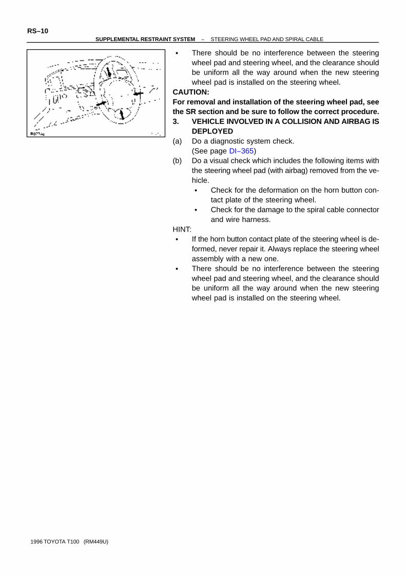
RS−10−SUPPLEMENTAL RESTRAINT SYSTEM STEERING WHEEL PAD AND SPIRAL CABLE
1996 TOYOTA T100 (RM449U)
� There should be no interference between the steeringwheel pad and steering wheel, and the clearance shouldbe uniform all the way around when the new steeringwheel pad is installed on the steering wheel.
CAUTION:For removal and installation of the steering wheel pad, seethe SR section and be sure to follow the correct procedure.3. VEHICLE INVOLVED IN A COLLISION AND AIRBAG IS
DEPLOYED(a) Do a diagnostic system check.
(See page DI−365)(b) Do a visual check which includes the following items with
the steering wheel pad (with airbag) removed from the ve-hicle.� Check for the deformation on the horn button con-
tact plate of the steering wheel.� Check for the damage to the spiral cable connector
and wire harness.HINT:� If the horn button contact plate of the steering wheel is de-
formed, never repair it. Always replace the steering wheelassembly with a new one.
� There should be no interference between the steeringwheel pad and steering wheel, and the clearance shouldbe uniform all the way around when the new steeringwheel pad is installed on the steering wheel.
https://www.truck-manuals.net/

RS03M−02
AB0152
SST
−SUPPLEMENTAL RESTRAINT SYSTEM STEERING WHEEL PAD AND SPIRAL CABLERS−11
1996 TOYOTA T100 (RM449U)
DISPOSALHINT:When scrapping vehicle equipped with an SRS or disposing ofa steering wheel pad (with airbag), always first deploy the air-bag in accordance with the procedure described below. If anyabnormality occurs with the airbag deployment, contact theSERVICE DEPT. of TOYOTA MOTOR SALES, U.S.A., INC..When disposing of a steering wheel pad with an airbagdeployed in a collision, follow the same procedure given in step1−(c) in ”DISPOSAL”.CAUTION:� Never dispose of a steering wheel pad which has an
undeployed airbag.� The airbag produces a sizeable exploding sound
when it deploys, so perform the operation out−of−doors and where it will not create a nuisance tonearby residents.
� When deploying the airbag, always use the specifiedSST (SRS Airbag Deployment Tool). Perform the op-eration in a place away from electrical noise.SST 09082−00700
� When deploying an airbag, perform the operation atleast 10 m (33 ft) away from the steering wheel pad.
� The steering wheel pad is very hot when the airbag isdeployed, so leave it alone for at least 30 minutes af-ter deployment.
� Use gloves and safety glasses when handling a steer-ing wheel pad with the deployed airbag.
� Always wash your hands with water after completingthe operation.
� Do not apply water, etc. to a steering wheel pad withthe deployed airbag.
https://www.truck-manuals.net/

AB0158
Battery
SST
AB0152
SST
AB0158
Battery
SST
H01580
SST
RS−12−SUPPLEMENTAL RESTRAINT SYSTEM STEERING WHEEL PAD AND SPIRAL CABLE
1996 TOYOTA T100 (RM449U)
1. AIRBAG DEPLOYMENT WHEN SCRAPPING VE-HICLE
HINT:Have a battery ready as the power source to deploy the airbag.
(a) Check functioning of SSTCAUTION:When deploying the airbag, always use the specified SST:SRS Airbag Deployment Tool.
SST 09082−00700
(1) Connect the SST battery.Connect the red clip of the SST to the battery posi-tive (+) terminal and the black clip to the battery neg-ative (−) terminal.
HINT:Do not connect the yellow connector which will be connectedwith the supplemental restraint system.
(2) Check functioning of SST.Press the SST activation switch, and check that theLED of the SST activation switch lights up.
CAUTION:If the LED lights up when the activation switch is not beingpressed, SST malfunction is probable, so definitely do notuse the SST.
(b) Install the SST.CAUTION:Check that there is no looseness in the steering wheel andsteering wheel pad.
(1) Disconnect the airbag connector of the spiral cable.
https://www.truck-manuals.net/

SST
R13455
SST
Battery
−SUPPLEMENTAL RESTRAINT SYSTEM STEERING WHEEL PAD AND SPIRAL CABLERS−13
1996 TOYOTA T100 (RM449U)
(2) Connect the SST connector to the airbag connectorof the spiral cable.
SST 09082−00700
(3) Move the SST at least 10 m (33 ft) away from thefront of the vehicle.
(4) Close all the doors and windows of the vehicle.NOTICE:Take care not to damage the SST wire harness.
(5) Connect the SST red clip to the battery positive (+)terminal and the black clip to the negative (−) termi-nal.
(c) Deploy the airbag.(1) Check that no one is inside the vehicle or within 10
m (33 ft) area around the vehicle.(2) Press the SST activation switch and deploy the air-
bag.HINT:The airbag deploys simultaneously as the LED of the SST ac-tivation switch lights up.(d) Dispose of steering wheel pad (with airbag).CAUTION:� The steering wheel pad is very hot when the airbag is
deployed, so leave it alone for at least 30 minutes af-ter deployment.
� Use gloves and safety glasses when handling a steer-ing wheel pad with deployed airbag.
� Always wash your hands with water after completingthe operation.
� Do not apply water, etc. to a steering wheel pad withdeployed airbag.(1) When scrapping a vehicle, deploy the airbag and
scrap the vehicle with the steering wheel pad stillinstalled.
(2) When moving a vehicle for scrapping which has asteering wheel pad with deployed airbag, usegloves and safety glasses.
https://www.truck-manuals.net/

R05747
InflaterCover
Connector
R05748
L
M
AB0163
Stripped Wire Harness Section
Wire Harness Diameter
RS−14−SUPPLEMENTAL RESTRAINT SYSTEM STEERING WHEEL PAD AND SPIRAL CABLE
1996 TOYOTA T100 (RM449U)
2. DEPLOYMENT WHEN DISPOSING OF STEERINGWHEEL PAD ONLY
NOTICE:� When disposing of the steering wheel pad (with air-
bag) only, never use the customers vehicle to deploythe airbag.
� Be sure to follow the procedure given below when de-ploying the airbag.
HINT:Have a battery ready as the power source to deploy the airbag.(a) Remove the steering wheel pad.
(See page SR−13 or SR−26)CAUTION:When storing the steering wheel pad, keep the upper sur-face of the pad facing upward.(b) Remove the steering wheel pad connector.
Remove the connector on the rear surface of the steeringwheel pad from the bracket.
(c) Fix steering wheel pad to disc wheel with tire.(1) Install the 2 bolt with washers in the 2 bolt holes in
the steering wheel pad.Bolt:L: 35. mm (1.387 in.)M: 6.0 mm (0.236 in.)Pitch: 1.0 mm (0.039 in.)
NOTICE:� Tighten the bolts by hand until the bolts become diffi-
cult to turn.� Do not tighten the bolts too much.
(2) Using a service−purpose wire harness tie down thesteering wheel pad to the disc wheel.
Wire harness: Stripped wire harness section1.25 mm2 or more (0.0019 in2. or more).
HINT:To calculate the square of the stripped wire harness section:Square = 3.14 x (Diameter)2 divided by 4
https://www.truck-manuals.net/

R05749
2 Times or more
R05751
−SUPPLEMENTAL RESTRAINT SYSTEM STEERING WHEEL PAD AND SPIRAL CABLERS−15
1996 TOYOTA T100 (RM449U)
CAUTION:If a wire harness which is too thin or some other thing isused to tie down the steering wheel pad, it may be snappedby the shock when the airbag is deployed. This is highlydangerous. Always use a wire harness for vehicle usewhich is at least 1.25 mm2 (0.0019 in2).
(3) Using 3 wire harness, wind the wire harness at least2 times each around the bolts installed on the leftand right sides of the steering wheel pad.
CAUTION:� Tightly wind the wire harness around the bolts so that
there is no slack.� If there is slackness in the wire harness, the steering
wheel pad may come loose due to the shock when theairbag is deployed. This is highly dangerous.
(4) Face the upper surface of the steering wheel padupward. Separately tie the left and right sides of thesteering wheel pad to the disc wheel through thehub nut holes. Position the steering wheel pad con-nector so that it hangs downward through a hubhole in the disc wheel.
CAUTION:� Make sure that the wire harness is tight. It is very dan-
gerous when looseness in the wire harness results inthe steering wheel pad coming free through the shockfrom the airbag deploying.
� Always tie down the steering wheel pad with the padside facing upward. It is very dangerous when thesteering wheel pad is tied down with the metal sur-face facing upward and the steering wheel pad will bethrown into the air.
NOTICE:The disc wheel will be marked by airbag deployment, souse the spare disc wheel.
https://www.truck-manuals.net/

AB0158
Battery
SST
R05752
SST
H00401Weight
y
yx
RS−16−SUPPLEMENTAL RESTRAINT SYSTEM STEERING WHEEL PAD AND SPIRAL CABLE
1996 TOYOTA T100 (RM449U)
(d) Check functioning of SST.SST 09082−00700
(e) Install the SSTCAUTION:Place the disc wheel on the level ground.
(1) Connect the SST connector to the steering wheelpad connector.
SST 09082−00700NOTICE:To avoid damaging the SST connector and wire harness,do not lock the secondary lock of the twin lock. Also, se-cure some slack for the SST wire harness inside the discwheel.
(2) Move the SST to at least 10 m (33 ft) away fromsteering wheel pad tied down on the disc wheel.
(f) Cover steering wheel pad with cardboard box or tires.� Covering method using cardboard box:
Cover the steering wheel pad with the cardboardbox and weight the cardboard box down in 4 placeswith at least 190 N (20 kg, 44 lb).
Size of cardboard box:Must exceed the following dimensions:x=460 mm (18.11 in.)When dimension of the cardboard box exceeds the di-ameter of the disc wheel with the tire which the steer-ing wheel pad is tied to−x=460 mm (18.11 in.) + width of tirey= 650 mm (25.59 in.)
NOTICE:If a cardboard box smaller than the specified size is used,the cardboard box will be broken by the shock from the air-bag deployment.
https://www.truck-manuals.net/

R04211
Inner Diam.
Tires(3 or More)
Width
H00400
10 m (33 ft) or more
AB0166
−SUPPLEMENTAL RESTRAINT SYSTEM STEERING WHEEL PAD AND SPIRAL CABLERS−17
1996 TOYOTA T100 (RM449U)
� Covering method using tires:Place at least 3 tires without disc wheel on top of thedisc wheel with the tire to which the steering wheelpad is tied.
Tire size: Must exceed the following dimensions−Width: 185 mm (7.87 in.)Inner diameter: 360 mm (14.17 in.)
CAUTION:Do not use tires with disc wheels.NOTICE:The tires may be marked by the airbag deployment, so usethe redundant tires.
(g) Deploy the airbag.(1) Connect the SST red clip to the battery positive (+)
terminal and the black clip to the battery negative(−) terminal.
(2) Check that no one is within 10 m (33 ft) area aroundthe disc wheel which the steering wheel pad is tiedto.
(3) Press the SST activation switch and deploy the air-bag.
HINT:The airbag deploys simultaneously as the LED of the SST ac-tivation switch lights up.
(h) Dispose of the steering wheel pad (with airbag)CAUTION:� The steering wheel pad is very hot when the airbag is
deployed, so leave it alone for at least 30 minutes af-ter deployment.
� Use gloves and safety glasses when handling a steer-ing wheel pad with deployed airbag.
� Always wash your hands with water after completingthe operation.
https://www.truck-manuals.net/

RS−18−SUPPLEMENTAL RESTRAINT SYSTEM STEERING WHEEL PAD AND SPIRAL CABLE
1996 TOYOTA T100 (RM449U)
� Do not apply water, etc. to a steering wheel pad withdeployed airbag.(1) Remove the steering wheel pad from the disc
wheel.(2) Place the steering wheel pad in a vinyl bag, tie the
end tightly and dispose of it in the same way as oth-er general parts disposal.
https://www.truck-manuals.net/

RS03N−01
−SUPPLEMENTAL RESTRAINT SYSTEM STEERING WHEEL PAD AND SPIRAL CABLERS−19
1996 TOYOTA T100 (RM449U)
REPLACEMENTREPLACEMENT REQUIREMENTSIn the following case, replace the steering wheel pad, steering wheel or spiral cable.
� If the airbag has been deployed.� If the steering wheel pad or spiral cable has been found to be faulty in troubleshooting.� If the steering wheel pad, steering or spiral cable has been found to be faulty during the check
in items (See page RS−9).� If the steering wheel pad has been dropped.
CAUTION:For removal and installation of the steering wheel pad, see SR section. Be sure to follow the correctprocedure.
https://www.truck-manuals.net/

RS03O−01
RS−20−SUPPLEMENTAL RESTRAINT SYSTEM STEERING WHEEL PAD AND SPIRAL CABLE
1996 TOYOTA T100 (RM449U)
INSTALLATION(See page SR−20 or SR−33)
https://www.truck-manuals.net/
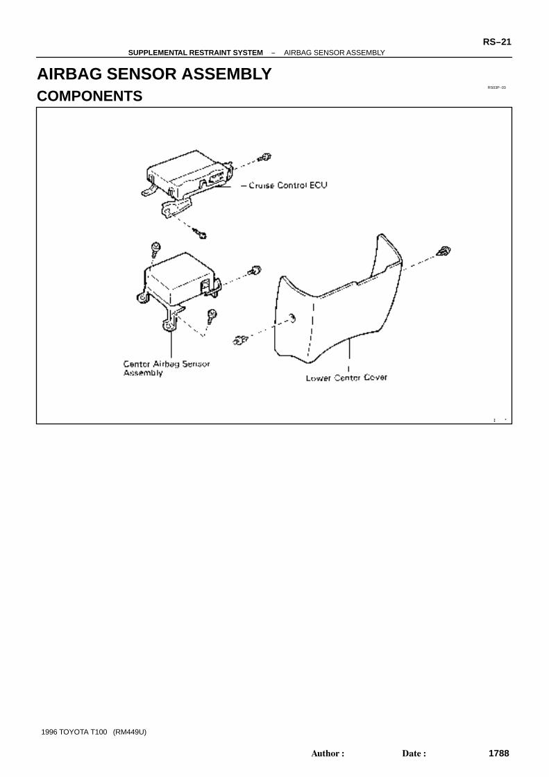
RS03P−03
−SUPPLEMENTAL RESTRAINT SYSTEM AIRBAG SENSOR ASSEMBLYRS−21
1788Author�: Date�:
1996 TOYOTA T100 (RM449U)
AIRBAG SENSOR ASSEMBLYCOMPONENTS
https://www.truck-manuals.net/

RS03Q−03
RS−22−SUPPLEMENTAL RESTRAINT SYSTEM AIRBAG SENSOR ASSEMBLY
1996 TOYOTA T100 (RM449U)
REMOVALNOTICE:Do not open the cover or the case of the ECU and variouscomputers unless absolutely necessary. (If the IC termi-nals are touched, the IC may be destroyed by static elec-tricity.)1. REMOVE THESE PARTS:(a) Lower center cover(b) Cruise control ECU
2. REMOVE AIRBAG SENSOR ASSEMBLY(a) Disconnect the connector.NOTICE:Removal of the connector is done with the sensor assem-bly installed.(b) Using a torx wrench, remove the 3 screws and the airbag
sensor assembly.Torx wrench: T40 (Part No. 09042−00020 or locallymanufactured tool)
https://www.truck-manuals.net/

RS03R−01
R12497
−SUPPLEMENTAL RESTRAINT SYSTEM AIRBAG SENSOR ASSEMBLYRS−23
1996 TOYOTA T100 (RM449U)
INSPECTION1. VEHICLE NOT INVOLVED IN COLLISIONDo a diagnostic system check.(See page DI−365)2. VEHICLE INVOLVED IN COLLISION AND AIRBAG IS
NOT DEPLOYEDDo a diagnostic system check.(See page DI−365)3. VEHICLE INVOLVED IN COLLISION AND AIRBAG IS
DEPLOYEDReplace the airbag sensor assembly.
https://www.truck-manuals.net/

RS03S−01
RS−24−SUPPLEMENTAL RESTRAINT SYSTEM AIRBAG SENSOR ASSEMBLY
1996 TOYOTA T100 (RM449U)
REPLACEMENTREPLACEMENT REQUIREMENTSIn the following cases, replace the airbag sensor assembly.
� If the SRS has been deployed in a collision.� If the airbag sensor assembly has been found to be faulty in troubleshooting.� If the airbag sensor assembly has been dropped.
CAUTION:For removal and installation of the airbag sensor assembly, see page RS−22 and RS−25. Be sure tofollow the correct procedure.
https://www.truck-manuals.net/

RS03T−03
−SUPPLEMENTAL RESTRAINT SYSTEM AIRBAG SENSOR ASSEMBLYRS−25
1996 TOYOTA T100 (RM449U)
INSTALLATIONNOTICE:� Never use SRS parts from another vehicle. When re-
placing parts, replace with new ones.� Never reuse the airbag sensor assembly involved in
a collision when the airbag has deployed.� Never repair a sensor in order to reuse it.
1. INSTALL AIRBAG SENSOR ASSEMBLY(a) Using a torx wrench, install the airbag sensor assembly
with 3 screws.Torx wrench: T40 (Part No. 09042−0020 or locallymanufactured tool)Torque: 21 N·m (210 kgf·cm, 15 ft·lbf)
(b) Connect the connector.NOTICE:� Installation of the connector is done with the sensor
assembly installed. Make sure the sensor assemblyis installed to the specified torque.
� If the sensor assembly has been dropped, or there arecracks, dents or other defects in the case, bracket orconnector, replace the sensor assembly with a newone.
� When installing the sensor assembly, take care thatthe SRS wiring does not interfere with other parts andis not pinched between other parts.
� After installing, shake the sensor assembly to checkthat there is no looseness.
2. INSTALL REMOVED PARTS
https://www.truck-manuals.net/

RS03U−03
Z14843
Front Airbag Sensor RH Front Airbag Sensor LH
Battery
Battery Carrier
Air CleanerAssembly
RS−26−SUPPLEMENTAL RESTRAINT SYSTEM FRONT AIRBAG SENSOR
1793Author�: Date�:
1996 TOYOTA T100 (RM449U)
FRONT AIRBAG SENSORCOMPONENTS
https://www.truck-manuals.net/

RS03V−01
−SUPPLEMENTAL RESTRAINT SYSTEM FRONT AIRBAG SENSORRS−27
1996 TOYOTA T100 (RM449U)
REMOVALNOTICE:� If the wiring connector of the SRS is disconnected with the ignition switch at ON or ACC posi-
tion, DTCs will be recorded.� Never use SRS parts from another vehicle. When replacing parts, replace them with new ones.� Never reuse the sensor involved in a collision when the SRS has been deployed.� Never repair a sensor in order to reuse it.
1. REMOVE THESE PARTS:(a) Battery(b) Air cleaner assembly2. REMOVE FRONT AIRBAG SENSOR(a) Disconnect the connector.(b) Using a torx wrench, loosen the 2 screws and the sensor.
Torx wrench: T40 (Part No. 09042−00020 or locally manufactured tool)
https://www.truck-manuals.net/

RS03W−02
R07748
R08038
RS−28−SUPPLEMENTAL RESTRAINT SYSTEM FRONT AIRBAG SENSOR
1996 TOYOTA T100 (RM449U)
INSPECTION1. VEHICLES NOT INVOLVED IN A COLLISIONDo a diagnostic system check. (See page DI−365)2. VEHICLES INVOLVED IN A COLLISION(a) Do a diagnostic system check. (See page DI−365)(b) If the front fender of the car or its periphery is damaged,
do a visually check for damage to the front airbag sensor,which includes the following items even if the airbag wasnot deployed:� Bracket deformation� Peeling of paint off the bracket� Cracks, dents or chips in the case� Cracks, dents, chipping and scratches the connec-
tor� Peeling of the label or damage to the series number
https://www.truck-manuals.net/

RS03X−01
−SUPPLEMENTAL RESTRAINT SYSTEM FRONT AIRBAG SENSORRS−29
1996 TOYOTA T100 (RM449U)
REPLACEMENTREPLACEMENT REQUIREMENTIn the following cases, replace the front airbag sensor.
� If the SRS has been deployed in a collision. (Replace both the left and right airbag sensors.)� If the front airbag sensor has been found to be faulty in troubleshooting.� If the front airbag sensor has been found to be faulty during the check in item
(See page RS−28).� If the front airbag sensor has been dropped.
CAUTION:For removal and installation of the front airbag sensor, see page RS−27 and RS−30.Be sure to follow the correct procedure.
https://www.truck-manuals.net/

RS03Y−02
Z09743
Front
RS−30−SUPPLEMENTAL RESTRAINT SYSTEM FRONT AIRBAG SENSOR
1996 TOYOTA T100 (RM449U)
INSTALLATION1. INSTALL FRONT AIRBAG SENSOR(a) Install the sensor so that the arrow on the sensor faces
toward the front of the vehicle.(b) Using a torx wrench, install the sensor with 2 screws.
Torx wrench: T40 (Part No. 09042−00020 or locallymanufactured tool)Torque: 29 N·m (300 kgf·cm, 22 ft·lbf)
(c) Connect the connector.NOTICE:� Make sure the sensor is installed to the specified
torque.� If the sensor has been dropped, or there are cracks,
dents or other defects in the case, brackets or con-nector, replace the removed sensor, always replacethe set bolts with new ones.
� The sensor set bolts which have been anti−rusttreated. When the sensor is removed, always replacethe set bolts with new ones.
� After installation, shake the sensor to check thatthere is no looseness.
� The front sensor is equipped with an electrical con-nection check mechanism. Be sure to lock this mech-anism securely when connecting the connector . Ifthe connector is not securely locked, a malfunctioncode will be detected by the diagnostic system.
2. INSTALL REMOVED PARTS
https://www.truck-manuals.net/

RS03Z−02
R12498
SRS Warning Light
Steering Wheel Pad(with Airbag)
Front Airbag Sensor RH
Front Airbag Sensor LH
Spiral Cable
Center Airbag Sensor Assembly
−SUPPLEMENTAL RESTRAINT SYSTEM WIRE HARNESS AND CONNECTORRS−31
1798Author�: Date�:
1996 TOYOTA T100 (RM449U)
WIRE HARNESS AND CONNECTORLOCATION
https://www.truck-manuals.net/

RS040−01
RS−32−SUPPLEMENTAL RESTRAINT SYSTEM WIRE HARNESS AND CONNECTOR
1996 TOYOTA T100 (RM449U)
INSPECTIONHINT:The SRS wire harness is integrated with the cowl wire harness assembly and floor wire harness assembly.The wires for the SRS wire harness are encased in a yellow corrugated tube and all the connectors in thesystem are a standard yellow color.1. VEHICLES NOT INVOLVED IN COLLISIONDo a diagnostic system check.(See page DI−365)2. VEHICLES INVOLVED IN COLLISION(a) Do a diagnostic system check.
(See page DI−365)(b) Check for breaks in all wires of the SRS wire harness, and for exposed conductors.(c) Check to see if the SRS wire harness connectors are cracked or chipped.
https://www.truck-manuals.net/

RS041−01
−SUPPLEMENTAL RESTRAINT SYSTEM WIRE HARNESS AND CONNECTORRS−33
1996 TOYOTA T100 (RM449U)
REPLACEMENTIn the following cases,replace the wire harness or connector.
� If any part of the SRS wire harness or any connector has been found to be faulty in troubleshoot-ing.
� If any part of the SRS wire harness or any connector has been found to be faulty during the checkin items (See page RS−32).
CAUTION:� If the wire harness used in the SRS is damaged, replace the whole wire harness assembly.� When the connector to the front airbag sensors can be repaired alone (when there is no damage
to the wire harness), use the repair wire specially designed for this purpose.
https://www.truck-manuals.net/

BE – BODY ELECTRICAL
BODY ELECTRICAL SYSTEM BE-1 POWER SOURCE BE-10 IGNITION SWITCH AND KEY UNLOCK WARNING SWITCH
BE-11
HEADLIGHT AND TAILLIGHT SYSTEM BE-14 TURN SIGNAL AND HAZARD WARNING SYSTEM
BE-22
INTERIOR LIGHT SYSTEM BE-24 BACK-UP LIGHT SYSTEM BE-26 STOP LIGHT SYSTEM BE-29 WIPER AND WASHER SYSTEM BE-31 COMBINATION METER BE-35 POWER WINDOW CONTROL SYSTEM BE-46 POWER DOOR LOCK CONTROL SYSTEM
BE-50
POWER MIRROR CONTROL SYSTEM BE-56 AUDIO SYSTEM BE-59 ANTENNA BE-81 CLOCK BE-83
https://www.truck-manuals.net/

BE01E−07
−BODY ELECTRICAL BODY ELECTRICAL SYSTEMBE−1
1801Author�: Date�:
1996 TOYOTA T100 (RM449U)
BODY ELECTRICAL SYSTEMPRECAUTIONTake care to observe the following precautions when performing inspections or removal and replacementof body electrical related parts.1. LIGHTING SYSTEMHalogen bulbs have pressurized gas inside and require special handling.They can burst or scatter if scratched or dropped. Hold a bulb only by its plastic or metal case.Don’t touch the glass part of a bulb with bare hands.2. SRS (SUPPLEMENTAL RESTRAINT SYSTEM)The TOYOTA T100 is equipped with an SRS (Supplemental Restraint System) such as the driver airbag.Failure to carry out service operations in the correct sequence could cause the SRS to unexpectedly deployduring servicing, possibly leading to a serious accident. Before servicing (including removal or installationof parts, inspection or replacement), be sure to read the precautionary notices in the RS section.3. AUDIO SYSTEM� If the battery negative (−) terminal is disconnected, the preset AM, FM 1 and FM 2 stations stored in
memory are erased, so be sure to note the stations and reset them after the battery terminal is recon-nected.
� If the battery negative (−) terminal is disconnected, the ”ANTI−THEFT SYSTEM” will operate when theterminal is reconnected, but the radio, tape player and CD player will not operate. Be sure to input thecorrect ID number so that the radio, tape player and CD player can be operated again.
4. MOBILE COMMUNICATION SYSTEMIf the vehicle is equipped with a mobile communication system, refer to precautions in the IN section.
https://www.truck-manuals.net/

BE01F−10
BE−2−BODY ELECTRICAL BODY ELECTRICAL SYSTEM
1996 TOYOTA T100 (RM449U)
PROBLEM SYMPTOMS TABLEThe table below will be useful for you in troubleshooting these electrical problems. The most likely causesof the malfunction are shown in the order of their probability. Inspect each part in the order shown, and re-place the part when it is found to be faulty.USA:HEADLIGHT AND TAILLIGHT SYSTEM
Symptom Suspect Area See page
Headlight does not light up
(Taillight is normal)
1. HEAD Fuse (Relay Block)
2. Light Control Switch
3. Headlight Dimmer Switch
4. Headlight Bulb
BE−14
BE−17
BE−17
BE−17
Headlight does not light up
(Taillight does not light up)
1. Light Control Switch
2. Headlight Dimmer Switch
3. Wire Harness
4. Headlight Bulb
BE−17
BE−17
−
−
Only one light comes on
1. HEAD Fuse (Relay Block)
2. Wire Harness
3. Headlight Bulb
BE−14
−
−
”Lo−Beam” does not light up
1. Headlight Control Relay
2. Headlight Dimmer Relay
3. Headlight Dimmer Switch
4. Wire Harness
5. Headlight Bulb
BE−17
BE−17
BE−17
−
−
”Hi−Beam” does not light up
1. Headlight Control Relay
2. Headlight Dimmer Relay
3. Headlight Dimmer Switch
4. Wire Harness
5. Headlight Bulb
BE−17
BE−17
BE−17
−
−
”Flash” does not light up
1. Headlight Control Relay
2. Headlight Dimmer Relay
3. Headlight Dimmer Switch
4. Wire Harness
5. Headlight Bulb
BE−17
BE−17
BE−17
−
−
Taillight does not light up
(Headlight does not light up)
1. TAIL Fuse (Junction Block No.1)
2. Light Control Switch
3. Wire Harness
4. Headlight Bulb
BE−17
BE−17
−
−
Taillight does not light up
(Headlight is normal)
1. TAIL Fuse (Junction Block No.1)
2. Light Control Switch
3. Taillight Control Relay
4. Wire Harness
5. Taillight Bulb
BE−14
BE−17
BE−17
−
−
Only one light goes out or does not light up1. Wire Harness
2. Taillight Bulb
−
−
Rear Combination light does not light up
1. TAIL Fuse (Junction Block No.1)
2. Wire Harness
3. Taillight Bulb
BE−14
−
−
”Light−on warning system” does not operate.
1. Integration Relay
2. DOME Fuse (Relay Block)
3. GAUGE Fuse (Junction Block No.1)
4. Door Courtesy Switch
5. Wire Harness
BE−17
BE−14
BE−14
BE−25
−
https://www.truck-manuals.net/

−BODY ELECTRICAL BODY ELECTRICAL SYSTEMBE−3
1996 TOYOTA T100 (RM449U)
CANADA:HEADLIGHT AND TAILLIGHT SYSTEM
Symptom Suspect Area See page
Only one side headlight does not light up.1. Headlight Bulb
2. Wire Harness
−
−
”Lo−Beam” does not light up. (ALL)
1. D.R.L. Relay
2. Headlight Dimmer Relay
3. Headlight Control Relay
4. Headlight Dimmer Switch
5. Wire Harness
BE−14
BE−17
BE−17
BE−17
−
”Lo−Beam” does not light up. (ONE SIDE)
1. HEAD LH−Lo Fuse (Relay Block)
2. HEAD RH−Lo Fuse (Relay Block)
3. Headlight Bulb
4. Wire Harness
BE−14
BE−14
−
−
”Hi−Beam” does not light up. (ALL)
1. DRL Fuse (Junction Block No.1)
2. Headlight Dimmer Relay
3. Headlight Control Relay
4. Headlight Dimmer Switch
5. Wire Harness
BE−14
BE−17
BE−17
BE−17
−
”Hi−Beam” does not light up. (ONE SIDE)
1. HEAD LH−Hi Fuse (Relay Block)
2. HEAD RH−Hi Fuse (Relay Block)
3. Headlight Bulb
4. Wire Harness
BE−14
BE−14
−
−
”Flash” does not light up.1. Headlight Dimmer Switch
2. Wire Harness
BE−17
−
Headlight does not light up.
(Taillight is normal)
1. Headlight Control Relay
2. D.R.L. Relay
3. D.R.L. No.4 Relay
4. D.R.L. Resistor
5. Headlight Dimmer Switch
6. Light Control Switch
7. Headlight Bulb
8. Wire Harness
BE−17
BE−17
BE−17
BE−17
BE−17
BE−17
−
−
Headlight does not light up.
(Taillight does not light up)
1. Headlight Control Relay
2. D.R.L. Relay
3. D.R.L. No.4 Relay
4. D.R.L. Resistor
5. Headlight Dimmer Switch
6. Light Control Switch
7. Headlight Bulb
8. Wire Harness
BE−17
BE−17
BE−17
BE−17
BE−17
BE−17
−
−
Only one side taillight does not light up.1. Taillight Bulb
2. Wire Harness
−
−
Taillight does not light up.
(Headlight is normal)
1. TAIL Fuse (Junction Block No.1)
2. Taillight Control Relay
3. Light Control Switch
4. Taillight Bulb
5. Wire Harness
BE−14
BE−17
BE−17
−
−
Taillight does not light up.
(Headlight does not light up)
1. Light Control Switch
2. Taillight Bulb
3. Wire Harness
BE−17
−
−
Headlight does not light up with light control SW in HEAD.
1. Light Control Switch
2. D.R.L. Relay
3. D.R.L. No.4 Relay
4. Wire Harness
BE−17
BE−17
BE−17
−
https://www.truck-manuals.net/

BE−4−BODY ELECTRICAL BODY ELECTRICAL SYSTEM
1996 TOYOTA T100 (RM449U)
Headlight does not go out with light control SW in OFF.
1. Headlight Control Relay
2. Light Control Switch
3. Wire Harness
BE−17
BE−17
−
Taillight does not light up with light control SW in TAIL.
1. Taillight Control Relay
2. Light Control Switch
3. Wire Harness
BE−17
BE−17
−
Taillight does not go out with light control SW in OFF.
1. Taillight Control Relay
2. Light Control Switch
3. Wire Harness
BE−17
BE−17
−
Headlight do not light up with engine running, parking brake SW
and light control SW in OFF.
1. ECU−B Fuse (Junction Block No.1)
2. GAUGE Fuse (Junction Block No.1)
3. DRL Fuse (Junction Block No.1)
4. D.R.L. Relay
5. D.R.L. No.4 Relay
6. D.R.L. Resistor
7. Wire Harness
8. Generator L Terminal
9. Parking Brake Switch
BE−14
BE−14
BE−14
BE−17
BE−17
BE−17
−
−
BE−38
”Light−on warning system” does not operate.
1. Integration Relay
2. DOME Fuse (Relay Block)
3. GAUGE Fuse (Junction Block No.1)
4. Door Courtesy Switch
5. Wire Harness
BE−17
BE−14
BE−14
BE−25
−
TURN SIGNAL AND HAZARD WARNING SYSTEM
Symptom Suspect Area See page
”Hazard” and ”Turn” do not light up
1. Hazard Warning Switch
2. Turn Signal Flasher
3. Wire Harness
BE−23
BE−23
−
The flashing frequency is abnormal
1. Bulb
2. Turn Signal Switch
3. Wire Harness
−
BE−23
−
Hazard warning light does not light up
(Turn signal is normal)
1. HAZ−HORN Fuse (Relay Block)
2. Wire Harness
BE−22
−
Hazard warning light does not light up in one direction1. Hazard Warning Switch
2. Wire Harness
BE−23
−
*1 Turn signal does not light up
1. Ignition Switch
2. TURN Fuse (Junction Block No.1)
3. Turn Signal Switch
4. Wire Harness
BE−12
BE−22
BE−23
−
*2 Turn signal does not light up
1. TURN Fuse (Junction Block No.1)
2. Turn Signal Switch
3. Wire Harness
BE−22
BE−23
−
Turn signal does not light up in one direction1. Turn Signal Switch
2. Wire Harness
BE−23
−
Only one bulb does not light up1. Bulb
2. Wire Harness
−
−
*1: Combination Meter, Wiper and Washer do not operate.*2: Combination Meter, Wiper and Washer are normal.
https://www.truck-manuals.net/
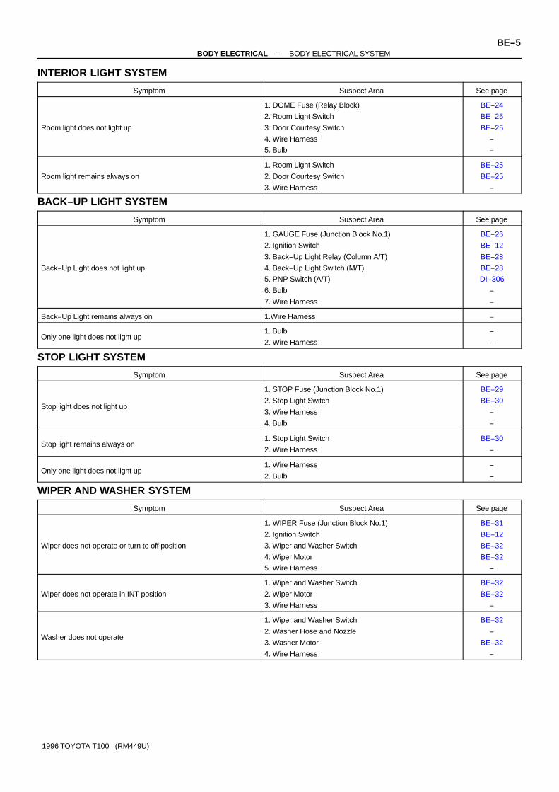
−BODY ELECTRICAL BODY ELECTRICAL SYSTEMBE−5
1996 TOYOTA T100 (RM449U)
INTERIOR LIGHT SYSTEM
Symptom Suspect Area See page
Room light does not light up
1. DOME Fuse (Relay Block)
2. Room Light Switch
3. Door Courtesy Switch
4. Wire Harness
5. Bulb
BE−24
BE−25
BE−25
−
−
Room light remains always on
1. Room Light Switch
2. Door Courtesy Switch
3. Wire Harness
BE−25
BE−25
−
BACK−UP LIGHT SYSTEM
Symptom Suspect Area See page
Back−Up Light does not light up
1. GAUGE Fuse (Junction Block No.1)
2. Ignition Switch
3. Back−Up Light Relay (Column A/T)
4. Back−Up Light Switch (M/T)
5. PNP Switch (A/T)
6. Bulb
7. Wire Harness
BE−26
BE−12
BE−28
BE−28
DI−306
−
−
Back−Up Light remains always on 1.Wire Harness −
Only one light does not light up1. Bulb
2. Wire Harness
−
−
STOP LIGHT SYSTEM
Symptom Suspect Area See page
Stop light does not light up
1. STOP Fuse (Junction Block No.1)
2. Stop Light Switch
3. Wire Harness
4. Bulb
BE−29
BE−30
−
−
Stop light remains always on1. Stop Light Switch
2. Wire Harness
BE−30
−
Only one light does not light up1. Wire Harness
2. Bulb
−
−
WIPER AND WASHER SYSTEM
Symptom Suspect Area See page
Wiper does not operate or turn to off position
1. WIPER Fuse (Junction Block No.1)
2. Ignition Switch
3. Wiper and Washer Switch
4. Wiper Motor
5. Wire Harness
BE−31
BE−12
BE−32
BE−32
−
Wiper does not operate in INT position
1. Wiper and Washer Switch
2. Wiper Motor
3. Wire Harness
BE−32
BE−32
−
Washer does not operate
1. Wiper and Washer Switch
2. Washer Hose and Nozzle
3. Washer Motor
4. Wire Harness
BE−32
−
BE−32
−
https://www.truck-manuals.net/

BE−6−BODY ELECTRICAL BODY ELECTRICAL SYSTEM
1996 TOYOTA T100 (RM449U)
COMBINATION METERMeter, Gauge and Illumination:
Symptom Suspect Area See page
Tachometer, fuel gauge oil Pressure and water temperature
gauge do not operate
1. GAUGE Fuse (Junction Block No.1)
2. Combination Meter Wiring Circuit
3. Wire Harness
4. Meter Circuit Plate
−
BE−36
−
BE−36
Speedometer does not operate1. Vehicle Speed Sensor
2. Speedometer Driven Gear and Drive Gear
BE−38
−
Tachometer does not operate
1. Combination Meter Wiring Circuit
2. Wire Harness
3. Igniter
4. Meter Circuit Plate
BE−36
−
−
−
BE−36
Fuel gauge does not operate or abnormal operation
1. Fuel Receiver Gauge
2. Fuel Sender Gauge
3. Combination Meter Wiring Circuit
4. Wire Harness
BE−38
BE−38
BE−36
−
Engine coolant temperature gauge does not operate
or abnormal operation
1. Engine Coolant Temperature Receiver Gauge
2. Engine Coolant Temperature Sender Gauge
3. Combination Meter Wiring Circuit
4. Wire Harness
BE−38
BE−38
BE−36
−
Oil pressure gauge does not operte or abnormal operation
1. Oil Pressure Receiver Gauge
2. Oil Pressure Sender Gauge
3. Combination Meter Wiring Circuit
4. Wire Harness
BE−38
BE−38
BE−36
−
All illumination lights do not light up
1. TAIL Fuse (Junction Block No.1)
2. Light Control Rheostat
3. Wire Harness
−
BE−38
−
Brightness does not change even when rheostat turned1. Bulb
2. Wire Harness
−
−
Only one illumination light does not light up1. Bulb
2. Wire Harness
−
−
COMBINATION METERWarning Lights:
Symptom Suspect Area See page
Warning light do not light up (Except Discharge)
1. GAUGE Fuse (Junction Block No.1)
2. Combination Meter Wiring Circuit
3. Wire Harness
−
BE−36
−
Oil pressure warning light does not light up
1. Bulb
2. Combination Meter Wiring Circuit
3. Oil Pressure Warning Switch
4. Wire Harness
−
BE−36
BE−38
−
Washer Fluid Level Warning light does not light up
1. Bulb
2. Combination Meter Wiring Circuit
3. Washer Fluid Level Warning Switch
4. Wire Harness
−
BE−36
BE−38
−
Fuel level warning light does not light up
1. Bulb
2. Combination Meter Wiring Circuit
3. Fuel Level Warning Switch
4. Wire Harness
−
BE−36
BE−38
−
https://www.truck-manuals.net/
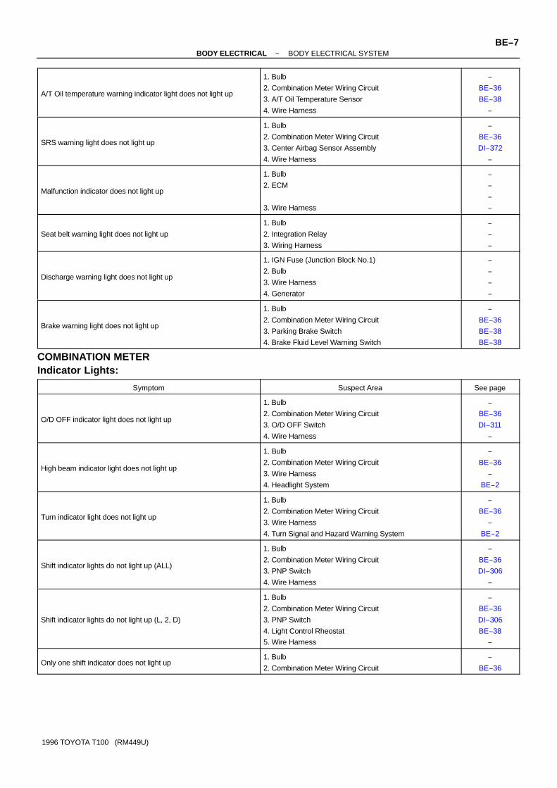
−BODY ELECTRICAL BODY ELECTRICAL SYSTEMBE−7
1996 TOYOTA T100 (RM449U)
A/T Oil temperature warning indicator light does not light up
1. Bulb
2. Combination Meter Wiring Circuit
3. A/T Oil Temperature Sensor
4. Wire Harness
−
BE−36
BE−38
−
SRS warning light does not light up
1. Bulb
2. Combination Meter Wiring Circuit
3. Center Airbag Sensor Assembly
4. Wire Harness
−
BE−36
DI−372
−
Malfunction indicator does not light up
1. Bulb
2. ECM
3. Wire Harness
−
−
−
−
Seat belt warning light does not light up
1. Bulb
2. Integration Relay
3. Wiring Harness
−
−
−
Discharge warning light does not light up
1. IGN Fuse (Junction Block No.1)
2. Bulb
3. Wire Harness
4. Generator
−
−
−
−
Brake warning light does not light up
1. Bulb
2. Combination Meter Wiring Circuit
3. Parking Brake Switch
4. Brake Fluid Level Warning Switch
−
BE−36
BE−38
BE−38
COMBINATION METERIndicator Lights:
Symptom Suspect Area See page
O/D OFF indicator light does not light up
1. Bulb
2. Combination Meter Wiring Circuit
3. O/D OFF Switch
4. Wire Harness
−
BE−36
DI−311
−
High beam indicator light does not light up
1. Bulb
2. Combination Meter Wiring Circuit
3. Wire Harness
4. Headlight System
−
BE−36
−
BE−2
Turn indicator light does not light up
1. Bulb
2. Combination Meter Wiring Circuit
3. Wire Harness
4. Turn Signal and Hazard Warning System
−
BE−36
−
BE−2
Shift indicator lights do not light up (ALL)
1. Bulb
2. Combination Meter Wiring Circuit
3. PNP Switch
4. Wire Harness
−
BE−36
DI−306
−
Shift indicator lights do not light up (L, 2, D)
1. Bulb
2. Combination Meter Wiring Circuit
3. PNP Switch
4. Light Control Rheostat
5. Wire Harness
−
BE−36
DI−306
BE−38
−
Only one shift indicator does not light up1. Bulb
2. Combination Meter Wiring Circuit
−
BE−36
https://www.truck-manuals.net/

BE−8−BODY ELECTRICAL BODY ELECTRICAL SYSTEM
1996 TOYOTA T100 (RM449U)
ndicator lights do not light up (Except. Turn, Hi−beam)1. GAUGE Fuse (Junction Block No1.)
2. Wire Harness
−
−
ABS indicator light does not light up
1. Bulb
2. Combination Meter Wiring Circuit
3. ABS ECU
4. Wire Harness
−
BE−36
DI−331
−
POWER WINDOW CONTROL SYSTEM
Symptom Suspect Area See page
*1Power window does not operate
1. POWER WINDOW Fuse (Junction Block No.1)
2. GAUGE Fuse (Junction Block No.1)
3. Door Lock Control Relay
4. Ignition Switch
5. Power Window Master Switch
6. Wire Harness
BE−46
BE−46
BE−47
BE−12
BE−47
−
*2Power window does not operate
1. POWER WINDOW Fuse (Junction Block No.1)
2. GAUGE Fuse (Junction Block No.1)
3. Ignition Switch
4. Door Lock Control Relay
5. Power Window Master Switch
6. Wire Harness
BE−46
BE−46
BE−12
BE−47
BE−47
−
”One Touch Power Window System” does not operate 1. Power Window Master Switch BE−47
Only one window glass does not move
1. Power Window Master Switch
2. Power Window Switch
3. Power Window Motor
4. Wire Harness
BE−47
BE−47
BE−47
−
”Window Lock System” does not operate 1. Power Window Master Switch BE−47
”Window Lock Illumination” does not operate 1. Power Window Master Switch BE−47
*1 Power door lock system does not operate*2 Power door lock system is normal
https://www.truck-manuals.net/

−BODY ELECTRICAL BODY ELECTRICAL SYSTEMBE−9
1996 TOYOTA T100 (RM449U)
POWER DOOR LOCK CONTROL SYSTEM
Symptom Suspect Area See page
”Door lock control system” does not operate (All)
1. GAUGE Fuse (Junction Block No.1)
2. POWER WINDOW Fuse (Junction Block No.1)
3. Door Lock Control Relay
4. Wire Harness
5. Other Parts
BE−50
BE−50
BE−51
−
−
Malfunction in Door Lock / Unlock
(Using door manual switch)
1. Door Lock Manual Switch
2. Wire Harness
3. Door Lock Control Relay
4. Other Parts
BE−51
−
BE−51
−
Mulfunction in Door Lock / Unlock
(Using door manual switch and key)
1. Wire Harness
2. Other Parts
−
−
Mulfunction in Door Lock / Unlock
(Using Key)
1. Door Key Lock and Unlock Switch
2. Wire Harness
3. Door Lock Control Relay
4. Other Parts
BE−51
−
BE−51
−
Fault in 2 − Operation unlock function of Driver’s side door key
Lock and Unlock switch
1. Door Key Lock and Unlock Switch
2. Wire Harness
3. Door Lock Control Relay
4. Other Parts
BE−51
−
BE−51
−
Fault in key confine prevention operation
1. Key Unlock Warning Switch
2. Door Courtesy Switch
3. Door Lock Switch
4. Wire Harness
5. Door Lock Control Relay
6. Other Parts
BE−12
BE−25
BE−51
−
BE−51
−
Only one door lock does not operate1. Door Lock Motor
2. Wire Harness
BE−51
−
POWER MIRROR CONTROL SYSTEM
Symptom Suspect Area See page
Power mirror on each side does not operate at all
1. RADIO Fuse (Junction Block No.1)
2. Mirror Switch
3. Mirror Motor (Up/Down or Left/Right Control)
4. Wire Harness
BE−56
BE−57
BE−57
−
Left or Right power mirror does not operate at all
1. Mirror Switch
2. Mirror Motor (Up/Down or Left/Right Control)
3. Wire Harness
BE−57
BE−57
−
Up/Down Control of left or right power mirror does not operate1. Mirror Motor (Up/Down Control)
2. Wire Harness
BE−57
−
Left/Right control of left or right power mirror does not operate1. Mirror Motor (Left/Right Control)
2. Wire Harness
BE−57
−
https://www.truck-manuals.net/

Z16012
Relay Block
Junction Block No.1
BE02V−02
BE−10−BODY ELECTRICAL POWER SOURCE
1810Author�: Date�:
1996 TOYOTA T100 (RM449U)
POWER SOURCELOCATION
https://www.truck-manuals.net/

N15094
Junction Block No.1� Integration Relay
Ignition Switch� Key Unlock Warning Switch
BE02W−03
−BODY ELECTRICAL IGNITION SWITCH AND KEY UNLOCK WARNING SWITCH
BE−11
1811Author�: Date�:
1996 TOYOTA T100 (RM449U)
IGNITION SWITCH AND KEY UNLOCK WARNING SWITCHLOCATION
https://www.truck-manuals.net/

Z08520
BE02X−03
Z14244
OFF
ON
N12605
N12606
BE−12 −BODY ELECTRICAL IGNITION SWITCH AND KEY UNLOCK WARNING SWITCH
1996 TOYOTA T100 (RM449U)
INSPECTION1. INSPECT IGNITION SWITCH CONTINUITY
Switch position Tester connection Specified condition
LOCK − No continuity
ACC 2 − 3 Continuity
ON1 − 2 − 3
7 − 8Continuity
START1 − 3 − 6
7 − 8Continuity
If continuity is not as specified, replace the switch.
2. INSPECT KEY UNLOCK WARNING SWITCH CONTI-NUITY
Switch position Tester connection Specified condition
OFF (Key removed) − No continuity
ON (Key set) 4 − 5 Continuity
If continuity is not as specified, replace the switch.
3. Key Unlock Warning System:INSPECT INTEGRATION RELAY OPERATION
(a) Connect the positive (+) lead from the battery to terminal2 and 3.
(b) Connect the negative (−) lead from the battery to terminal7 and 10.
(c) Check the buzzer sounds.
(d) Disconnect the positive (+) lead from the battery to termi-nal 3.
(e) Check that the buzzer stops sounding.
https://www.truck-manuals.net/
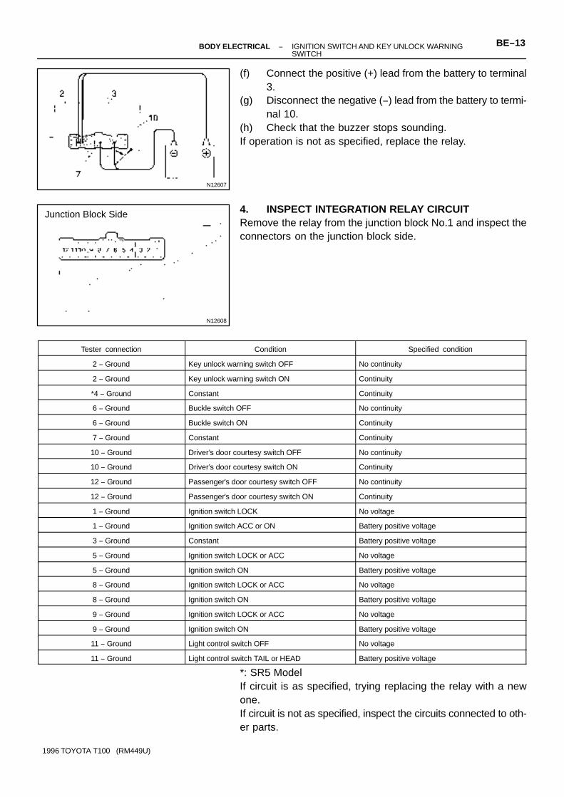
N12607
N12608
Junction Block Side
−BODY ELECTRICAL IGNITION SWITCH AND KEY UNLOCK WARNING SWITCH
BE−13
1996 TOYOTA T100 (RM449U)
(f) Connect the positive (+) lead from the battery to terminal3.
(g) Disconnect the negative (−) lead from the battery to termi-nal 10.
(h) Check that the buzzer stops sounding.If operation is not as specified, replace the relay.
4. INSPECT INTEGRATION RELAY CIRCUITRemove the relay from the junction block No.1 and inspect theconnectors on the junction block side.
Tester connection Condition Specified condition
2 − Ground Key unlock warning switch OFF No continuity
2 − Ground Key unlock warning switch ON Continuity
*4 − Ground Constant Continuity
6 − Ground Buckle switch OFF No continuity
6 − Ground Buckle switch ON Continuity
7 − Ground Constant Continuity
10 − Ground Driver’s door courtesy switch OFF No continuity
10 − Ground Driver’s door courtesy switch ON Continuity
12 − Ground Passenger’s door courtesy switch OFF No continuity
12 − Ground Passenger’s door courtesy switch ON Continuity
1 − Ground Ignition switch LOCK No voltage
1 − Ground Ignition switch ACC or ON Battery positive voltage
3 − Ground Constant Battery positive voltage
5 − Ground Ignition switch LOCK or ACC No voltage
5 − Ground Ignition switch ON Battery positive voltage
8 − Ground Ignition switch LOCK or ACC No voltage
8 − Ground Ignition switch ON Battery positive voltage
9 − Ground Ignition switch LOCK or ACC No voltage
9 − Ground Ignition switch ON Battery positive voltage
11 − Ground Light control switch OFF No voltage
11 − Ground Light control switch TAIL or HEAD Battery positive voltage
*: SR5 ModelIf circuit is as specified, trying replacing the relay with a newone.If circuit is not as specified, inspect the circuits connected to oth-er parts.
https://www.truck-manuals.net/

Z19311
Relay Block � Headlight Control Relay*2 � Headlight Dimmer Relay*1 � HEAD (RH) Fuse*2 � HEAD (RH−Hi) Fuse*2 � HEAD (RH−Lo) Fuse*1 � HEAD (LH) Fuse*2 � HEAD (LH−Hi) Fuse*2 � HEAD (LH−Lo) Fuse � DOME Fuse
*1 : USA Models Only*2 : CANADA Models OnlyD.R.L. Daytime Running Light
Headlight
*2 D.R.L. Resister
Combination Switch� Light Control Switch� Headlight Dimmer Switch
Ignition Switch
D.R.L. MainRelay
Door CourtesySwitch
Rear Combination Light
Junction Block No.1 � Taillight Control Relay*2 � D.R.L. No.4 Relay � Integration Relay*2 � D.R.L. No.4 Fuse � GAUGE Fuse � TAIL Fuse � ECU−B Fuse
BE02Z−03
BE−14−BODY ELECTRICAL HEADLIGHT AND TAILLIGHT SYSTEM
1814Author�: Date�:
1996 TOYOTA T100 (RM449U)
HEADLIGHT AND TAILLIGHT SYSTEMLOCATION
https://www.truck-manuals.net/

BE030−02
I01871
Light Control Switch
Spring
Connector
Wiper SwitchHorn Contact
Light Dimmer Turn Switch
Slip Ring(w/ Cruise Control System)
Switch Body
w/ Intermittent Wiper or Mist Wiper
Ball
−BODY ELECTRICAL HEADLIGHT AND TAILLIGHT SYSTEMBE−15
1996 TOYOTA T100 (RM449U)
COMPONENTS
https://www.truck-manuals.net/

I01872
Switch Body
Light Control Switch
Connector
Horn ContactWiper Switch
Spring
Ball
w/ Intermittent Wiper and Mist Wiper
Light Dimmer Turn Switch
Slip Ring(w/ Cruise Control System)
Z14541
Light Dimmer Turn Switch
Light Control Switch
Ball
Spiral Cable
Switch Body
Wiper Switch
Connector
BE−16−BODY ELECTRICAL HEADLIGHT AND TAILLIGHT SYSTEM
1996 TOYOTA T100 (RM449U)
https://www.truck-manuals.net/

Z09275
HEAD
TAIL
OFF
Flash
BE031−02
Z08521
12
34
12
34
Z08522
−BODY ELECTRICAL HEADLIGHT AND TAILLIGHT SYSTEMBE−17
1996 TOYOTA T100 (RM449U)
INSPECTION1. INSPECT LIGHT CONTROL SWITCH AND HEAD-
LIGHT DIMMER SWITCH CONTINUITY
Switch position Tester connection Specified condition
OFF
Low beam− No continuity
OFF
High beam− No continuity
OFF
Flash5 − 12 − 13 Continuity
TAIL
Low beam10 − 11 Continuity
TAIL
High beam10 − 11 Continuity
TAIL
Flash
10 − 11
5 − 12 − 13Continuity
HEAD
Low beam
4 − 10 − 11
6 − 13Continuity
HEAD
High beam
4 − 10 − 11
5 − 13Continuity
HEAD
Flash
4 − 10 − 11
5 − 12 − 13Continuity
If continuity is not as specified, replace the switch.
2. INSPECT HEADLIGHT CONTROL RELAY CONTINU-ITY
Condition Tester connection Specified condition
Constant 1 − 2 Continuity
Apply B+ between
terminals 1 and 2.3 − 4 Continuity
If continuity is not as specified, replace the relay.
3. INSPECT TAILLIGHT CONTROL RELAY CONTINUITY
Condition Tester connection Specified condition
Constant 1 − 2 Continuity
Apply B+ between
terminals 1 and 2.2 − 3 Continuity
If continuity is not as specified, replace the relay.
https://www.truck-manuals.net/

Z08523
12
34
12
34
N15399
N15400
N15773
N06230
Wire Harness Side
1 2 3 4 5 86 7119 10 1213 17161514 18
BE−18−BODY ELECTRICAL HEADLIGHT AND TAILLIGHT SYSTEM
1996 TOYOTA T100 (RM449U)
4. INSPECT HEADLIGHT DIMMER RELAY CONTINUITY
Condition Tester connection Specified condition
Constant1 − 4
2 − 4Continuity
Apply B+ between
terminals 2 and 4.3 − 4 Continuity
If continuity is not as specified, replace the relay.
5. INSPECT DOOR COURTESY SWITCH (See page BE−25)
6. Light−On Warning System:INSPECT INTEGRATION RELAY OPERATION
(a) Connect the positive (+) lead from the battery to terminal2 and 11.
(b) Connect the negative (−) lead from the battery to terminal7 and 10.
(c) Check the buzzer sounds.
(d) Disconnect the positive (+) lead from the battery to termi-nal 2.
(e) Check that the buzzer stops sounding.(f) Connect the positive (+) lead from the battery to terminal
2.
(g) Disconnect the negative (−) lead from the battery to termi-nal 10.
(h) Check that the buzzer stops sounding.If operation is not as specified, replace the relay.
7. Connector Disconnected:INSPECT DAYTIME RUNNING LIGHT RELAY CIRCUIT
Disconnect the connector from the relay and inspect the con-nector on the wire harness side.
https://www.truck-manuals.net/

Z10157
From Back Side
17
Z08559
12
3 4
12
3 4
−BODY ELECTRICAL HEADLIGHT AND TAILLIGHT SYSTEMBE−19
1996 TOYOTA T100 (RM449U)
Tester connection Condition Specified condition
5 − Ground Light control switch OFF or TAIL No continuity
5 − Ground Light control switch HEAD Continuity
7 − Ground
16 − Ground
Headlight dimmer switch
Low beamNo continuity
7 − Ground
16 − Ground
Headlight dimmer switch
High beam or FlashContinuity
8 − GroundParking brake switch OFF
(Parking brake lever released)No continuity
8 − GroundParing brake switch ON
(Parking brake lever pulled up)Continuity
12 − Ground Constant Continuity
13 − Ground Constant Continuity
2 − Ground Ignition switch LOCK or ACC No voltage
2 − Ground Ignition switch ON or START Battery positive voltage
6 − Ground Constant Battery positive voltage
11 − Ground Engine Stop No voltage
11 − Ground Engine Running Battery positive voltage
If circuit is as specified, perform inspections.8. Connector Connected:
INSPECT DAYTIME RUNNING LIGHT RELAY CIRCUITConnect the wire harness side connector to the relay and in-spect wire harness side connector from the back side, asshown.
Tester connection Condition Specified condition
17 − GroundHeadlight dimmer switch
Low beamNo voltage
17 − GroundHeadlight dimmer switch
High beam or FlashBattery positive voltage
If circuit is as specified, trying replacing the relay with a newone.
9. INSPECT DAYTIME RUNNING LIGHT RELAY NO.4CONTINUITY
Condition Tester connection Specified condition
Constant 3 − 4 Continuity
Apply B+ between
terminals 3 and 4.1 − 2 Continuity
If continuity is not as specified, replace the relay.
https://www.truck-manuals.net/

Z07683
BE−20−BODY ELECTRICAL HEADLIGHT AND TAILLIGHT SYSTEM
1996 TOYOTA T100 (RM449U)
10. INSPECT DAYTIME RESISTOR CONTINUITY
Condition Tester connection Specified condition
Constant 1 − 2 Approx. 337m Ω
If continuity is not as specified, replace the resistor.
https://www.truck-manuals.net/

BE032−02
Z15837
For Adjustment inVertical DirectionFor Adjustment in
Horizontal Direction
−BODY ELECTRICAL HEADLIGHT AND TAILLIGHT SYSTEMBE−21
1996 TOYOTA T100 (RM449U)
ADJUSTMENT1. ADJUST HEADLIGHT AIMING
2. ADJUST SPIRAL CABLE(See page SR−20)
https://www.truck-manuals.net/

Z16014
Relay Block� HAZ−HORN Fuse
Front Turn Signal Light Rear Combination Light
Hazard Warning Switch
Combination Switch� Turn Signal Switch
Ignition Switch
Turn Signal Flasher
Junction Block No.1� TURN Fuse
BE033−04
BE−22−BODY ELECTRICAL TURN SIGNAL AND HAZARD WARNING SYSTEM
1822Author�: Date�:
1996 TOYOTA T100 (RM449U)
TURN SIGNAL AND HAZARD WARNING SYSTEMLOCATION
https://www.truck-manuals.net/

BE034−10
Z09275
HEADTAIL
Flash
OFF
N06515
1
2 3
Turn Signal Light Bulbs (21 W)
Z09278
−BODY ELECTRICAL TURN SIGNAL AND HAZARD WARNING SYSTEMBE−23
1996 TOYOTA T100 (RM449U)
INSPECTION1. INSPECT TURN SIGNAL SWITCH CONTINUITY
Switch position Tester connection Specified condition
Left turn 3 − 9 Continuity
Neutral − No continuity
Right turn 3 − 8 Continuity
If continuity is not as specified, replace the switch.
2. INSPECT TURN SIGNAL FLASHER OPERATION(a) Connect the positive (+) lead from the battery to terminal
3 and the negative (−) lead to terminal 1.(b) Connect the 2 turn signal light bulbs in parallel to each
other to terminals 1 and 2, check that the bulbs flash.HINT:The turn signal lights should flash 60 to 120 times per minute.If one of the front or rear turn signal lights has an open circuit,the number of flashes will be more than 140 per minute.If operation is not as specified, replace the flasher.3. INSPECT HAZARD WARNING SWITCH CONTINUITY
Switch position Tester connection Specified condition
Switch OFF 7 − 10 Continuity
Switch ON4 − 5 − 6 − 9
7 − 8Continuity
Illumination circuit 2 − 3 Continuity
If continuity is not as specified, replace the switch.
https://www.truck-manuals.net/
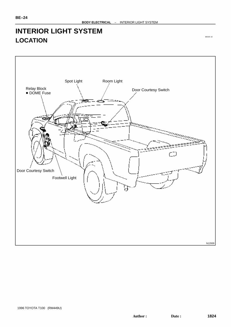
N12939
Relay Block� DOME Fuse
Spot Light Room Light
Door Courtesy Switch
Door Courtesy Switch
Footwell Light
BE035−02
BE−24−BODY ELECTRICAL INTERIOR LIGHT SYSTEM
1824Author�: Date�:
1996 TOYOTA T100 (RM449U)
INTERIOR LIGHT SYSTEMLOCATION
https://www.truck-manuals.net/

BE036−02
N05342
N05343
BE2875
ON
OFF
1
−BODY ELECTRICAL INTERIOR LIGHT SYSTEMBE−25
1996 TOYOTA T100 (RM449U)
INSPECTION1. INSPECT ROOM LIGHT ASSEMBLY CONTINUITY(a) Disconnect the connector from room light assembly.(b) Turn the room light switch ON, check that the there is con-
tinuity between terminal 2 and body ground.
(c) Turn the room light switch DOOR, check that there is con-tinuity between terminals 1 and 2.
If operation is not as specified, replace the switch.
2. INSPECT DOOR COURTESY SWITCH CONTINUITY(a) Check that there is no continuity between terminal and
the switch body in the ON position (switch pin released :opened door).
(b) Check that there is continuity between terminal and theswitch body in the OFF position (switch pin pushed in :closed door).
If operation is not as specified, replace the switch.
https://www.truck-manuals.net/

Z15840
Back−up Light Switch
Junction Block No.1� Back−up Light Relay (A/T)� GAUGE Fuse
Ignition Switch
Rear Combination Light
BE037−04
BE−26−BODY ELECTRICAL BACK−UP LIGHT SYSTEM
1826Author�: Date�:
1996 TOYOTA T100 (RM449U)
BACK−UP LIGHT SYSTEMLOCATION
https://www.truck-manuals.net/

Z15350
Back−up Light Switch (M/T Vehicle)
RZN Series
VZN Series
Back−up Light Switch (M/T Vehicle)
PNP Switch (A/T Vehicle)
−BODY ELECTRICAL BACK−UP LIGHT SYSTEMBE−27
1827Author�: Date�:
1996 TOYOTA T100 (RM449U)
https://www.truck-manuals.net/
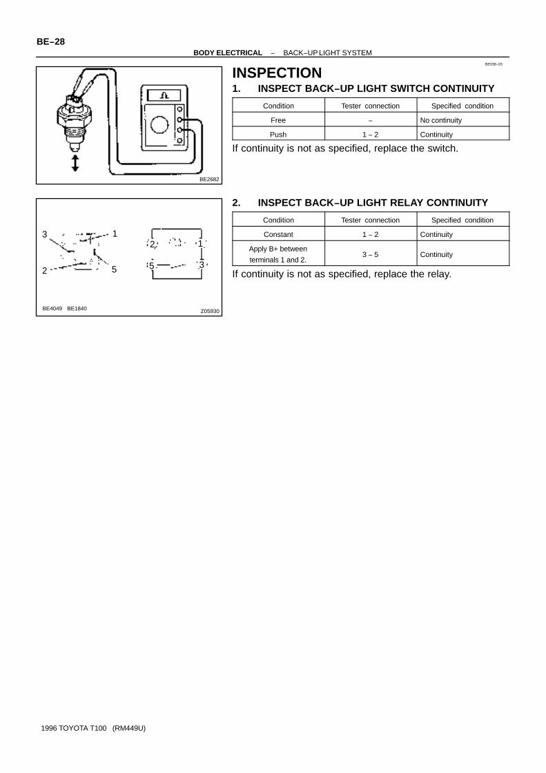
BE038−03
BE2682
Z05930
1
2
3
5
12
35
BE4049 BE1840
BE−28−BODY ELECTRICAL BACK−UP LIGHT SYSTEM
1996 TOYOTA T100 (RM449U)
INSPECTION1. INSPECT BACK−UP LIGHT SWITCH CONTINUITY
Condition Tester connection Specified condition
Free − No continuity
Push 1 − 2 Continuity
If continuity is not as specified, replace the switch.
2. INSPECT BACK−UP LIGHT RELAY CONTINUITY
Condition Tester connection Specified condition
Constant 1 − 2 Continuity
Apply B+ between
terminals 1 and 2.3 − 5 Continuity
If continuity is not as specified, replace the relay.
https://www.truck-manuals.net/

Z15844
Hi−Mount Stop Light
Rear Combination Light
Stop Light Switch
Junction Block No.1� STOP Fuse
BE039−04
−BODY ELECTRICAL STOP LIGHT SYSTEMBE−29
1829Author�: Date�:
1996 TOYOTA T100 (RM449U)
STOP LIGHT SYSTEMLOCATION
https://www.truck-manuals.net/

BE03A−03
Z09279
2 1
Z09280
BE−30−BODY ELECTRICAL STOP LIGHT SYSTEM
1996 TOYOTA T100 (RM449U)
INSPECTIONINSPECT STOP LIGHT SWITCH CONTINUITY
w/o Cruise Control:
Switch position Tester connection Specified condition
Switch pin free (Brake
pedal depressed)1 − 2 Continuity
Switch pin pushed in
(Brake pedal released)− No continuity
If continuity is not as specified, replace the switch.
w/ Cruise Control:
Switch position Tester connection Specified condition
Switch pin free (Brake
pedal depressed)2 − 4 Continuity
Switch pin pushed in
(Brake pedal released)1 − 3 Continuity
If continuity is not as specified, replace the switch.
https://www.truck-manuals.net/

BE03B−05
I22851
−BODY ELECTRICAL WIPER AND WASHER SYSTEMBE−31
1831Author�: Date�:
1996 TOYOTA T100 (RM449U)
WIPER AND WASHER SYSTEMLOCATION
https://www.truck-manuals.net/

Z15841
w/MIST WIPER
MIST
Washer
LO
HI
Washer
INT
LO
HI
BE03C−02
BE2769
BE2770
BE−32−BODY ELECTRICAL WIPER AND WASHER SYSTEM
1996 TOYOTA T100 (RM449U)
INSPECTION1. INSPECT WIPER SWITCH CONTINUITY
w/ Mist Wiper:
Switch position Tester connection Specified condition
MIST 4 − 8 Continuity
OFF 7 − 8 Continuity
LO 4 − 8 Continuity
HI 4 − 9 Continuity
w/ Intermittent Wiper:
Switch position Tester connection Specified condition
OFF 7 − 8 Continuity
INT 7 − 8 Continuity
LO 4 − 8 Continuity
HI 4 − 9 Continuity
2. INSPECT WASHER SWITCH CONTINUITYw/ Mist Wiper:
Switch position Tester connection Specified condition
OFF − No continuity
ON 1 − 2 Continuity
w/ Intermittent Wiper:
Switch position Tester connection Specified condition
OFF − No continuity
ON 1 − 2 Continuity
If continuity is not as specified, replace the switch.
3. INSPECT INTERMITTENT WIPER OPERATION(a) Turn the wiper switch to INT position.(b) Variable Type:
Turn the intermittent time control switch to FAST position.(c) Connect the positive (+) lead from the battery to terminal
4/9 and the negative (−) lead to terminal 1/9.(d) Connect the positive (+) lead from the voltmeter to termi-
nal 8/9 and the negative (−) lead to terminal 1/9, checkthat the meter needle indicates battery positive voltage.
(e) After connecting terminal 7/9 to terminal 4/9, connect toterminal 1/9.Then, check that the voltage rises from 0 volts to batterypositive voltage within the times, as shown in the table.
https://www.truck-manuals.net/

V06095
Non Variable Type
Variable Type
Specified value
3.3 ± 1 secs.
INT
FAST
LOW
Switch position
Switch position
INT
Specified value
1.6 ± 1 secs.
10.7 ± 5 secs.
Approx. 12 V
Approx. 12 V
Approx. 12 V
0 V
0 V
0 V
N05983
N05984
N05985
−BODY ELECTRICAL WIPER AND WASHER SYSTEMBE−33
1996 TOYOTA T100 (RM449U)
If operation is not as specified, replace the wiper and washerswitch.
4. Low Speed:INSPECT WIPER MOTOR OPERATION
Connect the positive (+) lead from the battery to terminal 3 andthe negative (−) lead from the battery to the motor body, checkthat the motor operates at low speed.If operation is not as specified, replace the motor.
5. High Speed:INSPECT WIPER MOTOR OPERATION
Connect the positive (+) lead from the battery to terminal 2 andthe negative (−) lead from the battery to the motor body, checkthat the motor operates at high speed.If operation is not as specified, replace the motor.
6. Stopping at Stop Position:INSPECT WIPER MOTOR OPERATION
(a) Operate the motor at low speed and stop the motor op-eration anywhere except at the stop position by discon-necting positive (+) lead from terminal 3.
https://www.truck-manuals.net/

N05986
BE4117
BE−34−BODY ELECTRICAL WIPER AND WASHER SYSTEM
1996 TOYOTA T100 (RM449U)
(b) Connect terminals 3 and 5.(c) Connect the positive (+) lead from the battery to terminal
6 and the negative (−) lead from the battery to the motorbody, check that the motor stops running at the stop posi-tion after the motor operates again.
If operation is not as specified, replace the motor.
7. INSPECT WASHER MOTOR OPERATIONConnect the positive (+) lead from the battery to terminal 2 andthe negative (−) lead to terminal 1, check that the motor oper-ates.NOTICE:These tests must be performed quickly (within 20 seconds)to prevent the coil from burning out.If operation is not as specified, replace the motor.
https://www.truck-manuals.net/

BE03D−02
I22848
−BODY ELECTRICAL COMBINATION METERBE−35
1835Author�: Date�:
1996 TOYOTA T100 (RM449U)
COMBINATION METERLOCATION
https://www.truck-manuals.net/

BE03E−02
I22850
BE−36−BODY ELECTRICAL COMBINATION METER
1996 TOYOTA T100 (RM449U)
CIRCUIT
https://www.truck-manuals.net/

I22849
−BODY ELECTRICAL COMBINATION METERBE−37
1996 TOYOTA T100 (RM449U)
https://www.truck-manuals.net/

BE03F−03
Z09689
Aw/ Tachometer
w/o TachometerA
B
B
BE−38−BODY ELECTRICAL COMBINATION METER
1996 TOYOTA T100 (RM449U)
INSPECTION1. INSPECT SPEEDOMETER ON−VEHICLE(a) Using a speedometer tester, inspect the speedometer for
allowable indication error and check the operation of theodometer.
HINT:Tire wear and tire over or under inflation will increase the indica-tion error.If error is excessive, replace the speedometer.(b) Check the speedometer for pointer vibration and abnor-
mal noise.
USA (mph) CANADA (km/h)
Standard indication Allowable range Standard indication Allowable range
20 18 − 24 20 17 − 24
40 38 − 44 40 38 − 46
60 58 − 66 60 57.5 − 67
80 78 − 88 80 77 − 88
100 98 − 110 100 96 − 109
120 118 − 132 120 115 − 130
140 134 − 151.5
160 153 − 173
2. INSPECT VEHICLE SPEED SENSOR OPERATIONCheck that there is continuity between terminals A and B fourtimes for every revolution of the speedometer shaft.If operation is not as specified, replace the speedometer.
https://www.truck-manuals.net/

Z09692
B Aw/ Tachometer
N06031
BE3235
IgnitionSwitch
Battery(Wire Harness Side)
(3.4W)
Fuel Gauge
−BODY ELECTRICAL COMBINATION METERBE−39
1996 TOYOTA T100 (RM449U)
3. INSPECT TACHOMETER ON−VEHICLE(a) Connect a tune−up test tachometer, and start the engine.NOTICE:Reversing the connection of the tachometer will damagethe transistors and diodes inside. When removing or instal-ling the tachometer, be careful not to drop or subject it toheavy shocks.(b) Compare the tester and tachometer indications.
DC 13.5 V 20°C at (68°F)
Standard indication (rpm) Allowable range (rpm)
700 610 − 750
3,000 2,850 − 3,150
5,000 4,850 − 5,150
7,000 6,790 − 7,210
If error is excessive, replace the tachometer.
4. INSPECT VOLT GAUGE SYSTEMMeasure the resistance between terminals A and B.
Resistance: Approx. 347 ΩIf resistance value is not as specified, replace the gauge.
5. INSPECT FUEL RECEIVER GAUGE OPERATION(a) Disconnect the connector from the sender gauge.(b) Turn the ignition switch ON, check that the receiver gauge
needle indicates EMPTY.
(c) Connect terminals 1 and 3 on the wire harness side con-nector through a 3.4 watts test bulb.
(d) Turn the ignition switch ON, check that the bulb lights upand the receiver gauge needle moves towards the fullside.
HINT:Because of the silicon oil in the gauge, it will take a short timefor needle to stabilize.If operation is not as specified, inspect the receiver gauge resis-tance.
https://www.truck-manuals.net/

Z09690
w/ Tachometer
w/o Tachometer
A
B
C
A
B C
N06021
N06027
F
1/2
E
BE3238
Warning Light
(Wire Harness Side)
IgnitionSwitch
Battery
BE−40−BODY ELECTRICAL COMBINATION METER
1996 TOYOTA T100 (RM449U)
6. INSPECT FUEL RECEIVER GAUGE RESISTANCEMeasure the resistance between terminals.
w/ Tachometer:
Between terminals Resistance (Ω)
A − B Approx. 137.0
A − C Approx. 123.0
B − C Approx. 260.0
w/o Tachometer:
Between terminals Resistance (Ω)
A − B Approx. 150.0
A − C Approx. 80.0
B − C Approx. 55.0
If resistance value is not as specified, replace the receivergauge.
7. INSPECT FUEL SENDER GAUGE OPERATION(a) Connect a series of three 1.5 V dry batteries.(b) Connect the positive (+) lead from the dry cell batteries to
terminal 2 through a 3.4 W test bulb and the negative (−)lead to terminal 1.
(c) Check the positive (+) lead from the voltmeter to terminal2 and the negative (−) lead to terminal 1.
(d) Check that the voltage rises as the float is moved from thetop to bottom position.
If operation is not as specified, replace the sender gauge.8. INSPECT FUEL SENDER GAUGE RESISTANCEMeasure the resistance between terminals 1 and 2.
Float position (mm) Resistance (Ω)
F : Approx. 95.0 F : Approx. 3.0
1 / 2 : Approx. 188.0 1 / 2 : Approx. 32.5
E : Approx. 283.0 E : Approx. 110.0
If resistance value is not as specified, replace the sendergauge.
9. INSPECT FUEL LEVEL WARNING LIGHT(a) Disconnect the connector from the sender gauge.(b) Connect terminals 1 and 4 on the wire harness side con-
nector.(c) Turn the ignition switch ON, check that the warning light
lights up.If the warning light does no light up, test the bulb.
https://www.truck-manuals.net/

N12609
N12610
N06616
Engine Coolant Temperature Gauge
IgnitionSwitch
BatterySenderGauge
N06617
Engine Coolant Temperature Gauge
Test Bulb (3.4 W)
−BODY ELECTRICAL COMBINATION METERBE−41
1996 TOYOTA T100 (RM449U)
10. INSPECT FUEL LEVEL WARNING SWITCH(a) Apply battery positive voltage between terminal 1 and 3,
and through a 3.4 W test bulb, check the bulb lights up.HINT:It will take a short time for bulb to light up.
(b) Submerge the switch in fuel, check that the bulb goes out.If operation is not as specified, replace the sender gauge.
11. INSPECT ENGINE COOLANT TEMPERATURE RE-CEIVER GAUGE OPERATION
(a) Disconnect the connector from the sender gauge.(b) Turn the ignition switch ON, check that the receiver gauge
needle indicates COOL.
(c) Ground terminal on the wire harness side connecterthrough a 3.4 W test bulb.
(d) Turn the ignition switch ON, check that the bulb lights upand the receiver gauge needle moves to the hot side.
If operation is as specified, replace the sender gauge. Then, re-check the system.If operation is not as specified, measure the receiver gauge re-sistance.
https://www.truck-manuals.net/

Z09691
w/ Tachometer
w/o Tachometer
B
A C
BA
N02651
Warning Light
IgnitionSwitch
Battery
BE0146
BE1222
Oil Pressure Gauge
IgnitionSwitch
BatterySenderGauge
BE−42−BODY ELECTRICAL COMBINATION METER
1996 TOYOTA T100 (RM449U)
12. INSPECT ENGINE COOLANT TEMPERATURE RE-CEIVER GAUGE RESISTANCE
Measure the resistance between terminals.w/ Tachometer:
Between terminals Resistance (Ω)
A − B Approx. 150.0
A − C Approx. 54.0
B − C Approx. 138.0
w/o Tachometer:
Between terminals Resistance (Ω)
A − B Approx. 25.0
HINT:Connect the test leads so that the current from the ohmmetercan flow according to the above order. This circuit includes thediode.If resistance value is not as specified, replace the receivergauge.
13. INSPECT OIL PRESSURE WARNING LIGHT(a) Disconnect the connector from the warning switch and
ground terminal on the wire harness side connector.(b) Turn the ignition switch ON, check that the warning light
lights up.If the warning light does not light up, test the bulb.
14. INSPECT OIL PRESSURE SENDER GAUGE(a) Disconnect the connector from the sender gauge.(b) Check that there is continuity between terminal and
ground with the engine stopped.(c) Check that there is no continuity between terminal and
ground with the engine running.HINT:Oil pressure should be over 49 kPa (0.5 kgf/cm2, 7.1 psi).If operation is not as specified, replace the sender gauge.
15. INSPECT RECEIVER OIL PRESSURE GAUGE OP-ERATION
(a) Disconnect the connector from the sender gauge.(b) Turn the ignition switch ON, check that the receiver gauge
needle indicates LOW.
https://www.truck-manuals.net/

N06234
Oil Pressure Gauge
IgnitionSwitch
Battery
Test Bulb(3.4W)
Z09833
w/ Tachometer A B
BE4917
Test LED
Battery
BE1217
IgnitionSwitch
Battery
Warning Light
BE2570
ON
OFF
−BODY ELECTRICAL COMBINATION METERBE−43
1996 TOYOTA T100 (RM449U)
(c) Ground terminal on the wire harness side connectorthrough a 3.4 W test bulb.
(d) Turn the ignition ON, check that the bulb lights up and thereceiver gauge needle moves to the high side.
If resistance value is not as specified, replace the receivergauge.
16. INSPECT OIL PRESSURE RECEIVER GAUGE RESIS-TANCE
Measure the resistance between terminals A and B.Resistance: Approx. 25.0 Ω
If resistance value is not as specified, replace the receivergauge.
17. INSPECT OIL PRESSURE SENDER GAUGE OPERA-TION
(a) Disconnect the connector from the sender gauge.(b) Apply battery positive voltage to the sender gauge termi-
nal through a test LED.(c) Check that the bulb does not light when the engine is
stopped.(d) Check that the LED flashes when the engine is running.
The number of flashes should vary with the engine speed.If operation is not as specified, replace the sender gauge.18. INSPECT BRAKE WARNING LIGHT(a) Disconnect the connectors from the level warning switch
and parking brake switch.(b) Connect terminals on the wire harness side connector of
the level warning switch connector.(c) Turn the ignition switch ON, check that the warning light
lights up.If the warning light does not light up, test the bulb.
19. INSPECT BRAKE FLUID LEVEL WARNING SWITCH(a) Check that there is no continuity between terminals with
the switch OFF (float up).(b) Check that there is continuity between terminals with the
switch ON (float down).If operation is not as specified, replace the switch.
https://www.truck-manuals.net/

N06136
ON
OFF
BE1217
Warning Light
IgnitionSwitch
Battery
N07797
ON
OFF
N13155
Warning Light
IgnitionSwitch
Battery
N06137
ON
OFF
BE−44−BODY ELECTRICAL COMBINATION METER
1996 TOYOTA T100 (RM449U)
20. INSPECT PARKING BRAKE SWITCH(a) Check that there is continuity between terminals with the
switch ON (switch pin released).(b) Check that there is no continuity between terminals with
the switch OFF (switch pin pushed in).If operation is not as specified, replace the switch.
21. INSPECT WASHER LEVEL WARNING LIGHT(a) Disconnect the connectors from the level warning switch
and parking brake switch.(b) Connect terminals on the wire harness side connector of
the level warning switch connector.(c) Remove the CHARGE fuse and turn the ignition switch
ON, check that the warning light come on.If the warning light does not light up, test the bulb.
22. INSPECT WASHER LEVEL SWITCH(a) Check that there is no continuity between terminals with
the switch OFF (float up).(b) Check that there is continuity between terminals with the
switch ON (float down).If operation is not as specified, replace the switch.
23. INSPECT SEAT BELT WARNING LIGHT(a) Remove the integration relay from the junction block
No.1.(b) Ground terminal 9 on the junction block side connector.(c) Turn the ignition switch ON, check that the warning light
lights up.If the warning light does not light up, inspect the bulb or wire har-ness.
24. INSPECT BUCKLE SWITCH CONTINUITY(a) Check that there is continuity between terminals on the
switch side connector with the switch ON (belt unfas-tened).
(b) Check that there is no continuity between terminals on theswitch side connector with the switch OFF (belt fastened).
If operation is not as specified, replace the seat belt inner.
https://www.truck-manuals.net/

N12611
N12612
Z04393
4WD Indicator Light
(Wire Harness Side)
IgnitionSwitch
Battery
BE3241
OFF
ON
Z04394
Test Bulb(3.4W)
Bright
Extinguished
Dark
−BODY ELECTRICAL COMBINATION METERBE−45
1996 TOYOTA T100 (RM449U)
25. INSPECT INTEGRATION RELAY SEAT BELT WARN-ING SYSTEM OPERATION
(a) Connect the positive (+) lead from the battery to terminals3 and 9.
(b) Connect the terminal 8 to terminal 9 through the 3.4 W testbulb.
(c) Connect the negative (−) lead from the battery to terminal7.
(d) Check that the bulb lights and the buzzer sounds.
(e) Return to step (a), and operate the buzzer again.(f) Connect the negative (−) lead from the battery to terminal
6.(g) Check that the buzzer stops sounding.HINT:Check the buzzer within a period of 4 to 8 seconds.If operation is not as specified, replace the relay.26. INSPECT INTEGRATION RELAY CIRCUIT (See page
BE−12)
27. INSPECT 4WD INDICATOR LIGHT(a) Disconnect the connector from the 4WD indicator switch.
Connect the switch terminal 2 and body ground.(b) Turn the ignition switch on. Check that the bulb lights up.If operation is not as specified, remove and test the bulb.
28. INSPECT 4WD INDICATOR SWITCH(a) Check that the there is continuity when the switch pin is
pushed.(b) Check that there is no continuity when the switch is free.If operation is not as specified, replace the switch.
29. INSPECT LIGHT CONTROL RHEOSTAT(a) Connect terminals 1 and 3 through a 3.4 W test bulb.(b) Connect the positive (+) lead from the battery to terminal
1 and the negative (−) lead to terminal 2.(c) Turn the rheostat knob fully counterclockwise, check that
the test bulb goes out.(d) Gradually turn the rheostat knob clockwise, check that
the test bulb brightness changes from dark to bright.If operation is not as specified, replace the rheostat.
https://www.truck-manuals.net/

BE03O−04
N13075
Power Window Master Switch
Ignition Switch
Power Window Switch
Power Window Motor
Door Lock Control Relay
Junction Block No.1� GAUGE Fuse� POWER WINDOW Fuse
BE−46−BODY ELECTRICAL POWER WINDOW CONTROL SYSTEM
1846Author�: Date�:
1996 TOYOTA T100 (RM449U)
POWER WINDOW CONTROL SYSTEMLOCATION
https://www.truck-manuals.net/

Z09295
N05998
e−10−2
BE03P−02
Z09296
N0599
e−5−2
−BODY ELECTRICAL POWER WINDOW CONTROL SYSTEMBE−47
1996 TOYOTA T100 (RM449U)
INSPECTION1. INSPECT POWER WINDOW MASTER SWITCH CON-
TINUITYDriver’s switch: Window unlock
Switch position Tester connection Specified condition
UP 4 − 6, 3 − 9 Continuity
OFF 3 − 4 − 6 Continuity
DOWN 3 − 6, 4 − 9 Continuity
Driver’s switch: Window lock
Switch position Tester connection Specified condition
UP 3 − 9, 4 − 6 Continuity
OFF 3 − 4 − 6 Continuity
DOWN 3 − 6, 4 − 9 Continuity
Passenger’s switch: Window unlock
Switch position Tester connection Specified condition
UP 6 − 7, 9 − 10 Continuity
OFF − No continuity
DOWN 7 − 9, 6 − 10 Continuity
Passenger’s switch: Window lock
Switch position Tester connection Specified condition
UP 9 − 10 Continuity
OFF 7 − 10 Continuity
DOWN 7 − 9 Continuity
If continuity is not as specified, replace the switch.
2. INSPECT POWER WINDOW SWITCH CONTINUITY
Switch position Tester connection Specified condition
UP 1 − 2, 3 − 4 Continuity
OFF 1 − 2, 3 − 5 Continuity
DOWN 3 − 5, 1 − 4 Continuity
If continuity is not as specified, replace the switch.
https://www.truck-manuals.net/

Z14792N06023 N13101
Z14793N06024 N13100
Z14794N06026 N13101
Z14795N06025 N13100
Z04612BE2654 BE2890
Wire Harness Side
BE−48−BODY ELECTRICAL POWER WINDOW CONTROL SYSTEM
1996 TOYOTA T100 (RM449U)
3. Driver’s Side:INSPECT POWER WINDOW MOTOR OPERATION
(a) Connect the positive (+) lead from the battery to terminal2 and negative (−) lead to terminal 1. Check that the motorturns (moves upward).
(b) Reverse the polarity, check that the motor turns the oppo-site way (moves downward).
If operation is not as specified, replace the motor.
4. Passenger’s Side:INSPECT POWER WINDOW MOTOR OPERATION
(a) Connect the positive (+) lead from the battery to terminal2 and negative (−) lead to terminal 1. Check that the motorturns (moves upward).
(b) Reverse the polarity, check that the motor turns the oppo-site way (moves downward).
If operation is not as specified, replace the motor.
5. Using an ammeter:INSPECT ONE TOUCH POWER WINDOW
(a) Disconnect the connector the master switch.(b) Connect the positive (+) lead from the ammeter to termi-
nal 3 on the wire harness side connector and the negative(−) lead to negative terminal of the battery.
(c) Connect the positive (+) lead from the battery to terminal4 on the wire harness side connector.
https://www.truck-manuals.net/

Z04613
Wire Harness Side
BE2656 BE2890
Z04614BE2654 BE2891
Z04615BE2656 BE2891
Z04397
Wire HarnessSide
BE2659
BE2615 BE2854
43
Z04398
Wire HarnessSide
43
BE2659
BE2617 BE2895
−BODY ELECTRICAL POWER WINDOW CONTROL SYSTEMBE−49
1996 TOYOTA T100 (RM449U)
(d) As the window goes down, check that the current in-creases to approximately 7.0 A.
(e) Check that the current increases to approximately 14.5 Aor more when the window stops going down.
HINT:The circuit breaker opens some 4 − 40 seconds after the win-dow stops going down, so that the check must be made beforethe circuit breaker operates.If the operation is as specified, replace the master switch.
6. Using an ammeter with a current−measuring probe:INSPECT ONE TOUCH POWER WINDOW
(a) Remove the master switch with connector connected.(b) Attach a current−measuring probe to terminal 3 of the
wire harness.(c) Turn the ignition switch ON and set the power window
switch in the down position.(d) As the window goes down, check that the current in-
creases to approximately 7.0 A.
(e) Check that the current increases to approximately 14.5 Aor more when the window stops going down.
HINT:The circuit breaker opens some 4 − 40 seconds after the win-dow stops going down, so that the check must be made beforethe circuit breaker operates.If operation is as specified, replace master switch.
7. INSPECT CIRCUIT BREAKER OPERATION(a) Disconnect the connector from the master switch.(b) Connect the positive (+) lead from the battery to terminal
3 and the negative (−) lead to terminal 4 on the wire har-ness side connector, and raise the window to full closedposition.
(c) Continue to apply voltage, check that there is a circuitbreaker operation noise within approximately 4 − 40 se-conds.
(d) Reverse the polarity, check that the window begins to de-scend within approximately 60 seconds.
If operation is not as specified, replace the motor.
https://www.truck-manuals.net/

Z16016
Door Lock Control Switch
Door Courtesy Switch
Junction Block No.1� GAUGE Fuse� POWER WINDOW Fuse
Door Lock ControlRelay
Door Lock Motor� Door Unlock Detection Switch
Ignition Switch� Key Unlock Warning Switch
Door Key Lock and Unlock Switch
BE03I−03
BE−50−BODY ELECTRICAL POWER DOOR LOCK CONTROL SYSTEM
1850Author�: Date�:
1996 TOYOTA T100 (RM449U)
POWER DOOR LOCK CONTROL SYSTEMLOCATION
https://www.truck-manuals.net/

Z09297
BE03J−02
Z09298
−BODY ELECTRICAL POWER DOOR LOCK CONTROL SYSTEMBE−51
1996 TOYOTA T100 (RM449U)
INSPECTION1. INSPECT DRIVER’S DOOR LOCK CONTROL SWITCH
CONTINUITY
Switch position Tester connection Specified condition
LOCK1 − 5
2 − 6Continuity
OFF − No continuity
UNLOCK2 − 5
1 − 6Continuity
If continuity is not as specified, replace the switch.
2. INSPECT PASSENGER’S DOOR LOCK CONTROLSWITCH CONTINUITY
Switch position Tester connection Specified condition
LOCK 3 − 4 Continuity
OFF − No continuity
UNLOCK 2 − 4 Continuity
If continuity is not as specified, replace the switch.
https://www.truck-manuals.net/

N15388
LH
Lock
Unlock
RH
Lock
Unlock
Z04374
Z04375
Z04376
BE−52−BODY ELECTRICAL POWER DOOR LOCK CONTROL SYSTEM
1996 TOYOTA T100 (RM449U)
3. INSPECT DOOR KEY LOCK AND UNLOCK SWITCHCONTINUITYLH:
Switch position Tester connection Specified condition
LOCK 5 − 6 Continuity
OFF − No continuity
UNLOCK 1 − 5 Continuity
If continuity is not as specified, replace the switch.RH:
Switch position Tester connection Specified condition
LOCK 8 − 7 Continuity
OFF − No continuity
UNLOCK 4 − 8 Continuity
If continuity is not as specified, replace the switch.
4. INSPECT DRIVER’S DOOR LOCK MOTOR OPERA-TION
(a) Connect the positive (+) lead from the battery to terminal3 and the negative (−) lead to terminal 7, check that thedoor lock link moves to UNLOCK position.
(b) Remove the polarity, check that the door lock link movesto LOCK position.
If operation is not as specified, replace the door lock assembly.
5. INSPECT PASSENGER’S DOOR LOCK MOTOR OP-ERATION
(a) Connect the positive (+) lead from the battery to terminal2 and the negative (−) lead to terminal 6, check that thedoor lock moves to UNLOCK position.
https://www.truck-manuals.net/

Z04377
Z09300
Z09301
Z13472
Wire Harness Side
−BODY ELECTRICAL POWER DOOR LOCK CONTROL SYSTEMBE−53
1996 TOYOTA T100 (RM449U)
(b) Remove the polarity, check that the door lock link movesto LOCK position.
If operation is not as specified, replace the door lock assembly.
6. INSPECT DRIVER’S DOOR UNLOCK DETECTIONSWITCH OPERATION
Switch position Tester connection Specified condition
OFF (Door Lock set to
UNLOCK)− No continuity
ON (Door Lock set to
UNLOCK)4 − 8 Continuity
If continuity is not as specified, replace the switch.
7. INSPECT PASSENGER’S DOOR UNLOCK DETEC-TION SWITCH CONTINUITY
Switch position Tester connection Specified condition
OFF (Door Lock set to
LOCK)− No continuity
ON (Door Lock set to
UNLOCK)1 − 5 Continuity
If continuity is not as specified, replace the switch.
8. INSPECT DOOR LOCK CONTROL RELAY CIRCUITDisconnect the connector from the relay and inspect the con-nector on the wire harness side, as shown in the chart.
Tester connection Condition Specified condition
3 − GroundDoor lock control switch or passenger’s door key
lock and unlock switch LOCK or OFFNo continuity
3 − GroundDoor lock control switch or passenger’s door key
lock and unlock switch UNLOCKContinuity
4 − GroundDoor lock control switch or door key lock and
unlock switch UNLOCK or OFFNo continuity
4 − GroundDoor lock control switch or door key lock and
unlock switch LOCKContinuity
https://www.truck-manuals.net/

Z14871
Unlock
1 6
BE2595 N02970
BE−54−BODY ELECTRICAL POWER DOOR LOCK CONTROL SYSTEM
1996 TOYOTA T100 (RM449U)
7 − GroundPassenger’s door courtesy switch OFF
(Door closed)No continuity
7 − GroundPassenger’s door courtesy switch ON
(Door opened)Continuity
9 − Ground Driver’s door lock switch UNLOCK Continuity
9 − Ground Driver’s door lock switch LOCK No continuity
10 − Ground Driver’s key lock and unlock switch Lock or OFF No countinuity
10 − Ground Driver’s key lock and unlock switch UNLOCK Countinuity
11 − Ground Constant Continuity
12 − Ground Passenger’s door lock switch UNLOCK Continuity
12 − Ground Passenger’s door lock switch LOCK No continuity
14 − Ground Driver’s door courtesy switch OFF (Door closed) No continuity
14 − Ground Driver’s door courtesy switch ON (Door opened) Continuity
2 − Ground Constant Battery positive voltage
8 − Ground Ignition switch LOCK or ACC No voltage
8 − Ground Ignition switch ON Battery positive voltage
13 − GroundKey unlock warning switch OFF
(Ignition key removed)No voltage
13 − Ground Key unlock warning switch ON (Ignition key set) Battery positive voltage
If circuit is as specified, inspect the door lock signal and key−offpower window signal.
9. Door Lock Signal:INSPECT DOOR LOCK CONTROL RELAY
HINT:When the relay circuit is as specified, inspect the door lock sig-nal.(a) Connect the connector to the relay.(b) Connect the positive (+) lead from the voltmeter to termi-
nal 1 and the negative (−) lead to terminal 6.(c) Set the door lock control switch to UNLOCK, check that
the voltage rises from 0 V to battery positive voltage forapproximately 0.2 seconds.
https://www.truck-manuals.net/
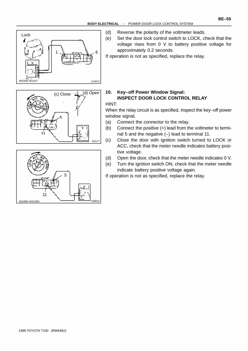
Z14872
Lock
1 6
BE2595 N02427
I02177
(c) Close (d) Open
Z08642
5
11
BE2886 N03190R
−BODY ELECTRICAL POWER DOOR LOCK CONTROL SYSTEMBE−55
1996 TOYOTA T100 (RM449U)
(d) Reverse the polarity of the voltmeter leads.(e) Set the door lock control switch to LOCK, check that the
voltage rises from 0 V to battery positive voltage forapproximately 0.2 seconds.
If operation is not as specified, replace the relay.
10. Key−off Power Window Signal:INSPECT DOOR LOCK CONTROL RELAY
HINT:When the relay circuit is as specified, inspect the key−off powerwindow signal.(a) Connect the connector to the relay.(b) Connect the positive (+) lead from the voltmeter to termi-
nal 5 and the negative (−) lead to terminal 11.(c) Close the door with ignition switch turned to LOCK or
ACC, check that the meter needle indicates battery posi-tive voltage.
(d) Open the door, check that the meter needle indicates 0 V.(e) Turn the ignition switch ON, check that the meter needle
indicate battery positive voltage again.If operation is not as specified, replace the relay.
https://www.truck-manuals.net/

Z15842
Outer Rear View Mirror� Mirror Motor
Junction Block No.1� RADIO Fuse
Mirror Switch
BE03G−04
BE−56−BODY ELECTRICAL POWER MIRROR CONTROL SYSTEM
1856Author�: Date�:
1996 TOYOTA T100 (RM449U)
POWER MIRROR CONTROL SYSTEMLOCATION
https://www.truck-manuals.net/

BE03H−03
Z09299
Left/LightAdjustmentSwitch
Control Switch
Z04379
Z04380
−BODY ELECTRICAL POWER MIRROR CONTROL SYSTEMBE−57
1996 TOYOTA T100 (RM449U)
INSPECTION1. INSPECT MIRROR SWITCH CONTINUITY
Left side:
Switch position Tester connection Specified condition
UP3 − 4
1 − 8Continuity
DOWN1 − 3
4 − 8Continuity
LEFT3 − 4
1 − 7Continuity
RIGHT1 − 3
4 − 7Continuity
Right side:
Switch position Tester connection Specified condition
UP3 − 4
1 − 5Continuity
DOWN1 − 3
4 − 5Continuity
LEFT3 − 4
1 − 6Continuity
RIGHT1 − 3
4 − 6Continuity
If continuity is not as specified, replace the switch.
2. INSPECT MIRROR MOTOR OPERATION(a) Connect the positive (+) lead from the battery to terminal
3 and negative (−) lead to terminal 1. Check that the mirrorturns to left side.
(b) Remove the polarity, check that the mirror turns to rightside.
https://www.truck-manuals.net/

Z04654
Z04382
BE−58−BODY ELECTRICAL POWER MIRROR CONTROL SYSTEM
1996 TOYOTA T100 (RM449U)
(c) Connect the positive (+) lead from the battery to terminal2 and the negative (−) lead to terminal 1. Check that themirror turns upward.
(d) Reverse the polarity, that the mirror turns downward.If operation is not as specified, replace the mirror assembly.
https://www.truck-manuals.net/

The radio wave bands used in radio broadcasting are as follows:
Frequency
Designation
Radio wave
Modulation method
LF: Low frequency MF: Medium Frequency HF: High Frequency VHF: Very High Frequency
Amplitude modulation Frequency modulation
30 kHz 300 kHz 3 MHz 30 MHz 300 MHz
LF MF HF VHF
AM FM
BE1PI−02
BE2818
FM (Stereo)
FM (Monaural)AM
−BODY ELECTRICAL AUDIO SYSTEMBE−59
1859Author�: Date�:
1996 TOYOTA T100 (RM449U)
AUDIO SYSTEMDESCRIPTION1. RADIO WAVE BAND
2. SERVICE AREAThere are great differences in the size of the service area for AMand FM monaural. Sometimes FM stereo broadcasts cannot bereceived even though AM comes in very clearly at the samelocation.Not only does FM stereo have the smallest service area, but italso picks up static and other types of interference (”noise”)easily if the vehicle is moving in a fringe area.3. RECEPTION PROBLEMSBesides the problem by static, there are also the problemscalled ”fading”, ”multipath” and ”fade out”. These problems arecaused not by electrical noise but by the nature of the radiowaves propagations.
https://www.truck-manuals.net/

BE2819
Fading Ionosphere
BE2820
Multipath
BE2821
Fade Out
I03092
Example :Pinch Roller
HeadCapstan
BE−60−BODY ELECTRICAL AUDIO SYSTEM
1860Author�: Date�:
1996 TOYOTA T100 (RM449U)
� FadingBesides electrical interference, AM broadcasts arealso susceptible to other types of interference, es-pecially at night. This is because AM radio wavesbounce off the ionosphere at night.These radio waves then interfere with the signalsfrom the same transmitter that reach the vehicle’santenna directly. This type of interference is called”fading”, because the reflected indirect signal(which is off−phase in relation to the direct wave)sporadically strengthen or weaken the resultant sig-nal at reception point.
� MultipathOne type of interference caused by bouncing of ra-dio waves off of obstructions is called ”multipath”.Multipath occurs when a signal from the broadcasttransmitter antenna bounces off buildings, moun-tains and interference with the signal that is re-ceived directly.
� Fade OutBecause FM radio waves are of higher frequenciesthan those of AM, they bounce off buildings, moun-tains, and other obstructions. For this reason, FMsignals often seem to gradually disappear or fadeaway as the vehicle goes behind a building or otherobstruction. This is called ”fade out”.
4. Tape player / Tape head cleaning:MAINTENANCE OF TAPE PLAYER
Using a moist−type cleaning tape, clean the head surface,pinch rollers and capstans (Never use ”abrasive” type cas-sette−shaped cleaner.).
https://www.truck-manuals.net/

BE2826
Cassette Tape Slot Cover
−BODY ELECTRICAL AUDIO SYSTEMBE−61
1861Author�: Date�:
1996 TOYOTA T100 (RM449U)
5. ANTI−THEFT SYSTEMHINT:The words ”ANTI−THEFT SYSTEM” are displayed on the cas-sette tape slot cover.For operation instructions for the anti−theft system, please con-sult the audio system section in the Owner’s Manual (hereaftercalled O/M).(a) Setting system
The system is in operation once the customer has pushedthe required buttons and entered the customer−selected3−digit ID number.(Refer to the O/M section, ”Setting the anti−theft system”)
HINT:� When the audio system is shipped the ID number has not
been input, so the anti−theft system is not in operation.� If the ID number has not been input, the audio system re-
mains the same as a normal audio system.(b) Anti−theft system operation
If the normal electrical power source (connector or batteryterminal) is cut off, the audio system becomes inoperable,even if the power supply resumes.
(c) Canceling systemThe ID number chosen by the customer is input to cancelthe anti−theft system.(Refer to the O/M section, ”If the system is activated”)HINT: To change or cancel the ID number, please refer tothe O/M section ”Canceling the system”.
https://www.truck-manuals.net/

BE27H−01
BE−62−BODY ELECTRICAL AUDIO SYSTEM
1996 TOYOTA T100 (RM449U)
TROUBLESHOOTINGNOTICE:When replacing the internal mechanism (computer part) of the audio system, be careful that no partof your body or clothing comes in contact with the terminals of the leads from the IC, etc. of the re-placement part (spare part).HINT:This inspection procedure is a simple troubleshooting which should be carried out on the vehicle during sys-tem operation and was prepared on the assumption of system component troubles (except for the wires andconnectors, etc.).Always inspect the trouble taking the following items into consideration.
� Open or short circuit of the wire harness� Connector or terminal connection fault� For audio systems with anti−theft system, troubleshooting items marked (*) indicate that ”Trou-
bleshooting for ANTI−THEFT SYSTEM” should be carried out first.
Problem No.
Radio No power coming in. *1
Power coming in, but radio not operating. *2
Noise present, but AM − FM not operating. 3
Either speaker does not work. 4
Either AM or FM does not work. 5
Reception poor (Volume faint). 5
Few preset tuning bands. 5
Sound quality poor. 6
Cannot set station select button. 6
Preset memory disappears. 7
Tape Player Cassette tape cannot be inserted. 8
Cassette tape inserts, but no power. *9
Power coming in, but tape player not operating. 10
Either speaker does not work. 11
Sound quality poor (Volume faint). 12
Tape jammed, malfunction with tape speed or auto−reverse. 13
APS, SKIP, RPT buttons not operating. 14
Cassette tape will not eject. *15
Antenna Antenna does not fully extened or fully retract. 16
Antenna − related. 17
Noise Noise produced by vibration or shock while driving. 18
Noise produced when engine starts. 19
https://www.truck-manuals.net/

−BODY ELECTRICAL AUDIO SYSTEMBE−63
1996 TOYOTA T100 (RM449U)
1. ANTI−THEFT SYSTEM
https://www.truck-manuals.net/

1 Radio NO POWER COMING IN
S U PYes
No
R
Yes
No
No
No
Yes
Yes
OK
NG
NG
OK
R S U
R S U P
P
R S U
P
SR
U
S
U P
Is tape player operating normally? Radio faulty.
Radio assembly faulty.
Check if RADIO fuse is OK. Replace fuse.
Is ACC applied to power amplifier?
Is ACC for the radio assembly beingoutput from the power amplifier?
ACC wire harness faulty.
Power amplifier faulty.
Check if GND (wire harness side) topower amplifier is OK.
Is ACC applied to radio assembly? ACC wire harness faulty.
Check if GND (wire harness side) to radio is OK.
GND faulty.
Power Amplifier faulty.
GND wire harness faulty.
Radio faulty.
Radio assembly faulty.
RP
S U: Radio : Radio + Tape Player : Radio − Tape Player (Built−in Power Amplifier): Radio − Tape Player (Separate Power Amplifier)
P
NG
OK
BE−64−BODY ELECTRICAL AUDIO SYSTEM
1996 TOYOTA T100 (RM449U)
2. AUDIO SYSTEM
https://www.truck-manuals.net/

2 Radio POWER COMING IN, BUT RADIO NOT OPERATING
R S
PU
R
U
R S
U
S
U P
: Radio: Radio − Tape Player (Separate Power Amplifier)
: Radio + Tape Player : Radio − Tape Player (Built−in Power Amplifier)
Yes
Yes
Yes
Yes
Yes
No
No
No
No
No
No
Is tape player operating normally?
Is there continuity in speaker wire harness?
Temporarily install another speaker, Functions OK?
Speaker wire harness faulty.
Radio assembly faulty.
If radio side faulty
Radio faulty.Go to No. 17.
Hissing sound from speaker?
Radio faulty.
Radio faulty.
Radio assembly faulty.
Radio assembly faulty.
Go to No. 17.Is tape player operating normally?
Speaker faulty.
Power amplifier faulty, Recheck system after repair.
Radio assembly faulty. Recheck system after repair.
3 Radio NOISE PRESENT, BUT AM−FM NOT OPERATING
: Radio : Radio + Tape Player: Radio − Tape Player (Separate Power Amplifier)
Hissing sound from speaker? Power amplifier faulty, Recheck system after repair.
Radio assembly faulty.
If radio side faulty
R S U
S U P
S U P
P
S U P
PR
S
S U
R
S U PR
R
S U P
Yes
: Radio − Tape Player (Built−in Power Amplifier)
−BODY ELECTRICAL AUDIO SYSTEMBE−65
1996 TOYOTA T100 (RM449U)
https://www.truck-manuals.net/

R : Radio S : Radio + Tape Player U : Radio − Tape Player (Built−in Power Amplifier)
Radio4 ANY SPEAKER DOES NOT WORK
P : Radio − Tape Player (Separate Power Amplifier)
S U P
R
R S U P
S
S
U
P
R
U P
Yes
No
Yes
Yes
Yes
No
No
No
Is tape player operating normally?
Is hiss produced by non−functioning speaker? Radio faulty.
Radio assembly faulty.
Is there continuity in speaker wire harness?
Temporarily install another speaker. Functions OK?
Speaker wire harness faulty.
Speaker faulty.
Radio faulty.
Radio assembly faulty.
Radio assembly faulty.Recheck system after repair.
S
U
P
R Radio faulty.
Radio assembly faulty.
Radio assembly faulty.Recheck system after repair.
BE−66−BODY ELECTRICAL AUDIO SYSTEM
1996 TOYOTA T100 (RM449U)
https://www.truck-manuals.net/

5 RadioEITHER AM OR FM DOES NOT WORK, RECEPTIONPOOR (VOLUME FAINT), FEW PRESET TUNING BANDS
R : Radio S : Radio + Tape Player U : Radio − Tape player (Built−in Power Amplifier)
Are both AM and FM defective?
P : Radio − Tape Player (Separate Power Amplifier)
No
Yes
No
No
No
No
No
Yes
Yes
Yes
Yes
Yes
Problem with radio wave signals or location?Poor signals, poor location.
Adjust antenna trimmer (See page BE−82).
Speaker faulty.
Electronic TuningRadio type?
Radio or radioassembly faulty.
Which band is poor?
If radio side faulty.
Is tape player operating normally?
Temporarily install another speaker. Functions OK?
Radio faulty.
Go to No.17
Radio assembly faulty.
Hissing sound from speaker?
Radio assembly faulty. Recheck system after repair.
Power amplifier faulty. Recheck system after repair.
P
FM
AM
Radio faulty.
Radio assembly faulty.
R S U
R S
U
−BODY ELECTRICAL AUDIO SYSTEMBE−67
1996 TOYOTA T100 (RM449U)
https://www.truck-manuals.net/

6 Radio SOUND QUALITY POOR
P : Radio − Tape Player (Separate Power Amplifier)
Is sound quality always bad? Is sound quality badin certain areas only?
Radio faulty.
Yes
No
P
No
No
No
Yes
Yes
Yes
NG
R S
U
R S U
R S U
PS U
Radio assembly faulty.
Is tape player operatingnormally?
Go to No. 17.
Install properly.
Speaker faulty.
Is speaker properly installed?
Temporarily install another speaker. Function OK?
Radio assembly faulty.
P
R : Radio S : Radio + Tape Player U : Radio − Tape Player (Built−in Power Amplifier)
Poor signals, poor location.
Radio assembly faulty.
If radio side faulty.
OK
BE−68−BODY ELECTRICAL AUDIO SYSTEM
1996 TOYOTA T100 (RM449U)
https://www.truck-manuals.net/

CANNOT SET STATION SELECT BUTTON, PRESETMEMORY DISAPPEARS7 Radio
Can cassette tape be inserted in tape player?
Check if DOME fuse is OK?
Radio assembly faulty.
R : Radio S : Radio + Tape Player U : Radio − Tape Player (Built−in Power Amplifier)
Replace fuse.
Is B + applied to power amplifier? B + Wire harness faulty.
GND faulty.Check if GND (wire harness side) topower amplifier?
Check if GND (wire harness side) to radio orradio assembly?
Yes
No
NG
OK
P : Radio − Tape Player (Separate Power Amplifier)
P
S
P
R U
S U P
S U PR
R S U
R
Yes
Yes
No
NG
NG
OK
OK
GND faulty.
Is B + applied to radio or radio assembly?
Power amplifier faulty.
Radio or radio assembly faulty.
Power amplifier faulty.
S
P
R UNo
B + Wire harness faulty.
−BODY ELECTRICAL AUDIO SYSTEMBE−69
1996 TOYOTA T100 (RM449U)
https://www.truck-manuals.net/

8 Tape Player CASSETTE TAPE CANNOT BE INSERTED
S : Radio + Tape Player U : Radio − Tape Player (Built−in Power Amplifier)
Is there a foreign object inside tape player? Remove foreign object.
Is radio operating normally? Tape Player faulty.
Radio assembly faulty.
Check if DOME fuse is OK? Replace fuse.
Is B + applied to tape player?
B + wire harness faulty.
B + wire harness faulty.
Check if GND (wire harness side) to tape player is OK? GND faulty.
Yes
No
NG
OK
S
S
S
U
U
U
P
P
P
P
P
S U P
S
U
P
S P
P : Radio − Tape Player (Separate Power Amplifier)
Yes
Yes
No
No
No
Yes
NG
NG
OK
OK
Tape Player faulty.
Radio assembly faulty.
Is B + applied to power amplified?
Check if GND (wire harness side) to power amplifier is OK?
GND faulty.
Is B + applied to radio assembly?
Check if GND (wire harness side) to radioassembly is OK?
Power amplifier faulty.
Power amplifier faulty.
BE−70−BODY ELECTRICAL AUDIO SYSTEM
1996 TOYOTA T100 (RM449U)
https://www.truck-manuals.net/

9 Tape Player CASSETTE TAPE INSERTS, BUT NO POWER
S : Radio + Tape player U : Radio − Tape Player (Built−in Power Amplifier)P : Radio − Tape Player (Separate Power Amplifier)
Is radio operating normally? S
U P
S P
P
S
U
U
P
Yes
NG
No
OK
Yes
No
No
Is there continuityin ACC speakerwire harness?
Check if CIG & RAD fuse is OK? Replace fuse.
Is ACC applied to power amplifier?
S
P
Is ACC applied to tape player? ACC wire harness faulty.
Is ACC applied to radio assembly?
Radio assembly faulty. ACC wire harness faulty.
Tape player faulty.
Radio assembly faulty.
Tape player faulty.
Yes Power amplifierfaulty.
No
Yes
No
−BODY ELECTRICAL AUDIO SYSTEMBE−71
1996 TOYOTA T100 (RM449U)
https://www.truck-manuals.net/

S
U P
S : Radio + Tape player U : Radio − Tape Player (Built−in Power Amplifier)P : Radio − Tape Player (Separate Power Amplifier)
Yes
Yes
Yes
No
No
No
Radio assembly faulty.
10 Tape Player POWER COMING IN, BUT TAPE PLAYER NOT OPERATION
Tape player faulty.Is radio operating normally?
Cassette tape faulty.Functions OK if different cassette tape inserted?
Is there, continuity in speaker wire harness? Speaker wire harness faulty.
Temporarily install another speaker. Functions OK? Speaker faulty.Yes
No
PS
Yes
NoP
U
Tape player faulty.
Radio assembly faulty.
Power amplifier faulty. Recheck system afterrepair.
Hissing sound from speaker?
Radio assembly faulty. Recheck system after repair.
S U
BE−72−BODY ELECTRICAL AUDIO SYSTEM
1996 TOYOTA T100 (RM449U)
https://www.truck-manuals.net/

Yes
Yes
No
No
No
Yes
OK
NG
S
S
U
U
P
P
Tape player faulty.
Radio assembly faulty.
Tape player faulty.
Radio assembly faulty.
Tape player11 ANY SPEAKER DOES NOT WORK
S : Radio + Tape Player U : Radio − Tape Player (Built−in Power Amplifier)
Is radio operating normally?
P : Radio − Tape Player (Separate Power Amplifier)
Is hiss produced by non−functioning speaker?
Is there continuity in speaker wire harness?
Temporarily install another speaker.Functions OK?
Speaker wire harness faulty.
Radio assembly faulty.Recheck system after repair.
Speaker faulty.
S
U
P
Tape player faulty.
Radio assembly faulty.
Radio assembly faulty.Recheck system after repair.
−BODY ELECTRICAL AUDIO SYSTEMBE−73
1996 TOYOTA T100 (RM449U)
https://www.truck-manuals.net/

12 Tape Player SOUND QUALITY POOR (VOLUME FAINT)
S : Radio + Tape Player U : Radio − Tape Player (Built−in Power Amplifier)P : Radio − Tape Player (Separate Power Amplifier)
Functions OK if different cassette tape inserted? Cassette tape faulty.
No
Yes
No
No
No
No
Yes
Yes
Yes
Yes
Operates normally after cleaning the heads? Head dirty.
Install properly.
Speaker faulty.
Is radio operating normally?
Is speaker properly installed?
Temporarily install another speaker.Functions OK?
Radio assembly faulty.
S
U
P
Tape player faulty.
Radio assembly faulty.
Radio assembly faulty.Recheck system after repair.
BE−74−BODY ELECTRICAL AUDIO SYSTEM
1996 TOYOTA T100 (RM449U)
https://www.truck-manuals.net/

S
U P
S : Radio + Tape Player U : Radio − Tape Player (Built−in Power Amplifier)P : Radio − Tape Player (Separate Power Amplifier)
Tape player faulty.
Radio assembly faulty.
13 Tape Player TAPE JAMMED, MALFUNCTION WITH TAPE SPEED OR AUTO−REVERSE
Functions OK if different tape (less than 120 mins.)is inserted?
Is there a foreign object inside tape player?
Operates normally after cleaning the heads?
Cassette tape faulty.
Remove foreign object.
Head dirty.
No
No
No
Yes
Yes
Yes
14 Tape Player APS, SKIP, RPT BUTTONS NOT OPERATING
S : Radio + Tape Player U : Radio − Tape Player (Built−in Power Amplifier)
P : Radio − Tape Player (Separate Power Amplifier)
Functions OK if different cassette tape inserted? Radio assembly faulty.
Yes
Cassette tape faulty.(Less than 3 secs. of silence between songs (APS, RPT). Less than 15 secs.of silence (SKIP).)
No
−BODY ELECTRICAL AUDIO SYSTEMBE−75
1996 TOYOTA T100 (RM449U)
https://www.truck-manuals.net/

S : Radio + Tape Player U : Radio − Tape Player (Built−in Power Amplifier)P : Radio − Tape − CD Player (Separate Power Amplifier)
15 Tape Player
No
Radio assembly faulty.
CASSETTE TAPE WILL NOT EJECT
Is tape player operating normally?
OK
Is radio operating normally?
NGCheck if DOME fuse is OK? Replace fuse.
Is B + applied to power amplifier?
Yes
Yes
Yes
Yes
Yes
No
No
No
Cassette tape jammed.
Tape player faulty.S
U P
S
U P
B + wire harness faulty.
Is B + applied to tape player?
Is B + applied to radio assembly?
Is there continuity inB+ wire harness betweenpower amplifier andradio assembly.
Power amplifierfaulty.
No
Radio assembly faulty.
Tape player faulty.S
U P
B + wire harness faulty.
P
S U
BE−76−BODY ELECTRICAL AUDIO SYSTEM
1996 TOYOTA T100 (RM449U)
https://www.truck-manuals.net/

−BODY ELECTRICAL AUDIO SYSTEMBE−77
1996 TOYOTA T100 (RM449U)
https://www.truck-manuals.net/

BE−78−BODY ELECTRICAL AUDIO SYSTEM
1996 TOYOTA T100 (RM449U)
https://www.truck-manuals.net/

−BODY ELECTRICAL AUDIO SYSTEMBE−79
1996 TOYOTA T100 (RM449U)
https://www.truck-manuals.net/

BE03K−02
IgnitionSwitch
Z19225
Radio Assembly
Door Speaker
Tweeter Speaker
IgnitionSwitch
Extra Cab
Radio Assembly
Door Speaker
Rear Speaker
BE−80−BODY ELECTRICAL AUDIO SYSTEM
1996 TOYOTA T100 (RM449U)
LOCATION
https://www.truck-manuals.net/

BE1PK−02
−BODY ELECTRICAL ANTENNABE−81
1881Author�: Date�:
1996 TOYOTA T100 (RM449U)
ANTENNAINSPECTION1. INSPECT ANTENNA MOTOR(a) Connect the positive (+) lead from the battery to terminal
1 and the negative (−) lead to terminal 2.(b) Check that the motor turns (moves upward).NOTICE:These tests must be done quickly (within 3 − 5 seconds) toprevent the coil from burning out.(c) Then, reverse the polarity, check that the motor turns the
opposite way (moves downward).NOTICE:These tests must be done quickly (within 3 − 5 seconds) toprevent the coil from burning out.
2. INSPECT ANTENNA MOTOR CONTROL RELAY CIR-CUIT
Disconnect the connector from the relay and inspect the con-nector on wire harness side, as shown in the chart below.
Tester connection Condition Specified condition
2 − 3 Constant Continuity
6 − Ground Constant Continuity
1 − Ground Constant Battery positive voltage
4 − Ground Ignition switch LOCK or ACC No voltage
4 − Ground Ignition switch ON Battery positive voltage
5 − Ground Ignition switch LOCK No voltage
5 − Ground Ignition switch ACC or ON Battery positive voltage
7 − Ground Ignition switch LOCK No voltage
7 − GroundIgnition switch ACC or ON
(Radio switch and cassette OFF)No voltage
7 − GroundIgnition switch ACC or ON
(Radio switch or cassette ON)Battery positive voltage
8 − Ground Ignition switch LOCK No voltage
If circuit is as specified, replace the relay.
https://www.truck-manuals.net/

BE1PL−02
BE4671
Antenna Nut
BE5781
BE5780
BE4674
Twist
BE−82−BODY ELECTRICAL ANTENNA
1996 TOYOTA T100 (RM449U)
REPLACEMENT1. REMOVE ANTENNA RODHINT:Perform this operation with negative (−) cable connected to thebattery terminal.(a) Turn the ignition switch to ”LOCK” position.(b) Remove the antenna nut.
(c) Press the ”AM” buttons on the radio receiver, and simulta-neously turn the ignition switch to ”ACC” position.
HINT:� The rod will extend fully and be released from the motor
antenna.� After removing the antenna rod, leave the ignition switch
as ”ACC”.NOTICE:To prevent body damage when the antenna rod is released,hold the rod while it comes out.2. INSTALL ANTENNA ROD(a) Insert the cable of the rod until it reaches the bottom.HINT:When inserting the cable, the teeth on the cable must face to-ward the front of the vehicle.
(b) Wind the cable to retract the rod by turning the ignitionswitch to ”LOCK” position.
HINT:� If the ignition switch is already in ”LOCK” position, perform
step 1 (c) first, then turn the ignition switch to ”ACC” posi-tion.
� In case the cable is not wound, twist it as shown in the il-lustration.
� Even if the rod has not retracted fully, install the antennanut and inspect the antenna rod operation. It will finally re-tract fully.
(c) Inspect the antenna rod operation by pushing the radiowave band select buttons.
https://www.truck-manuals.net/

BE03N−09
I01856
Ground
Power Source(Illumination)
(Clock Side) (Wire Harness Side)
E
ILL
B
ACC
Power Source(System Operation)
Power Source(Display Operation)
2
3
4
Connector
1 CLOCK WILL NOT OPERATE
I01857
(Clock Side) (Wire Harness Side)
B + GNDe−4−2−D e−4−1−D
Yes
Yes
No
No
Is there battery positive voltage between terminal +B and bodyground.
Is there battery positive voltage between terminal GND and bodyground.
Replace clock.
Open or short circuit in wire harness between terminal+B and DOME fuse.
Open circuit in wire harness between terminalGND and body ground.
−BODY ELECTRICAL CLOCKBE−83
1883Author�: Date�:
1996 TOYOTA T100 (RM449U)
CLOCKTROUBLESHOOTINGHINT:Troubleshoot the clock according to the table below.
Problem No.
Clock will not operate 1
Clock loses or gains time 2
± 1.5 seconds / day
1. PROBLEM NO.1
(a) Check that the battery positive voltage is 10 − 16 V.If voltage is not as specified, replace the battery.(b) Check that the DOME fuse is not blown.If the fuse is blown, replace the fuse and check for short.(c) Troubleshoot the clock as follows.HINT:Inspect the connector on the wire harness side.
https://www.truck-manuals.net/

2 CLOCK LOSES OR GAINS TIME
I01858
(Clock Side)
(Wire Harness Side)
B + GNDe−4−2−D
e−4−1−D
Yes
Is there battery positive voltage between terminal +B andbody ground.
Adjust or replace clock.
Bellow 10 V Locate cause and repair, or rechange battery.
BE−84−BODY ELECTRICAL CLOCK
1884Author�: Date�:
1996 TOYOTA T100 (RM449U)
2. PROBLEM NO.2
(a) Check that the battery positive voltage is 10 − 16 V.If voltage is not as specified, replace the battery.(b) Inspect the error of the clock.
Allowable error (per day): ± 1.5 secondsIf the error exceeds the allowable error, replace the clock.(c) Check that the clock adjusting button is sticking in posi-
tion and has failed to return.If the error exceeds the allowable error, replace the clock.(d) Troubleshoot the clock as follows.HINT:Inspect the connector on the wire harness side.
https://www.truck-manuals.net/

BO – BODY
CLIP BO-1 SRS AIRBAG BO-3 FRONT BUMPER BO-4 HOOD BO-5 FRONT DOOR BO-6 FRONT WIPER AND WASHER BO-11 WHEEL ARCH MOULDING BO-16 WINDSHIELD BO-19 QUARTER WINDOW GLASS BO-25 BACK WINDOW GLASS BO-29 INSTRUMENT PANEL BO-34 TAIL GATE BO-41 FRONT SEAT (BENCH TYPE) BO-44 FRONT SEAT (SPLIT BENCH TYPE) BO-45 REAR SEAT BO-46 SEAT BELT BO-47
https://www.truck-manuals.net/

V00005
Shape (Example) Removal/Installation
Clip Remover
Pliers
Screwdriver
Scraper
BO0DT−02
−BODY CLIPBO−1
1885Author�: Date�:
1996 TOYOTA T100 (RM449U)
CLIPREPLACEMENTThe removal and installation methods of typical clips used in body parts are shown in the table below.HINT:If the clip is damaged during the operation, always replace it with a new clip.
https://www.truck-manuals.net/

V00012
Removal Installation
Shape (Example) Removal/Installation
Removal Installation
BO−2−BODY CLIP
1886Author�: Date�:
1996 TOYOTA T100 (RM449U)
https://www.truck-manuals.net/

BO0DU−02
−BODY SRS AIRBAGBO−3
1887Author�: Date�:
1996 TOYOTA T100 (RM449U)
SRS AIRBAGPRECAUTIONThe TOYOTA T100 is equipped with an SRS (Supplemental Restraint System) such as the driver airbag.Failure to carry out service operation in the correct sequence could cause the SRS to unexpectedly deployduring servicing, possibly leading to a serious accident. Before servicing (including removal or installationof parts, inspection or replacement), be sure to read the precautionary notices in the RS section.
https://www.truck-manuals.net/

BO0DV−02
H16111
Side Mounting Bracket
Bumper Arm
Front Bumper
Front Balance Panel
Turn Signal Light
CushionSide Mounting Bracket
Bumper Arm
Cushion
Turn Signal Light
61 (620,45)
61 (620,45)
N·m (kgf·cm,ft·lbf) : Specigied torque
BO−4−BODY FRONT BUMPER
1888Author�: Date�:
1996 TOYOTA T100 (RM449U)
FRONT BUMPERCOMPONENTS
https://www.truck-manuals.net/

N03433
Centering Bolt Standard Bolt
BO0DW−02
N12588
BO3211
BO2553
−BODY HOODBO−5
1889Author�: Date�:
1996 TOYOTA T100 (RM449U)
HOODADJUSTMENTHINT:Since the centering bolt is used as the hood hinge and lock setbolt, the hood and lock cannot be adjusted with it on. Substitutethe standard bolt for the centering bolt.
1. ADJUST HOOD IN FORWARD/REARWARD ANDLEFT/RIGHT DIRECTIONS
Adjust the hood by loosening the hood side hinge bolts.Torque: 14 N·m (145 kgf·cm, 10 ft·lbf)
2. ADJUST FRONT EDGE OF HOOD IN VERTICALDIRECTIONS
Adjust the hood by turning the cushions.
3. ADJUST HOOD LOCKAdjust the lock by loosening bolts.
Torque: 19 N·m (195 kgf·cm, 14 ft·lbf)
https://www.truck-manuals.net/

BO0DX−02
N12592
w/ Power door lock:
w/ Remote control
w/ Tweeter
w/ Power window:
w/ Tweeter speaker:
Regulator Handle Inner Weatherstrip
Inside Handle Bezel
Pull Handles
Door Armrest Base
Door Lock Striker
Rear Lower Frame
Window Regulator
Door Hinge
Front Lower FrameRear View Mirror
Door Lock Remote Control
Door Lock
Snap Ring
(Driver’s)
Door Frame Moulding
Door Lock
Outside Handle
Door Glass
Door Glass Run
Door Belt Moulding
mirror:
speaker:
Cylinder
Link
Inside Handle
Armrest Panel(Passenger’s)
Door Trim
Speaker
w/ Power window:Precoated part�
�
N·m (kgf·cm, ft·lbf) : Specified torque
5.9 (60, 52 in.·lbf)
25 (260, 19)
5.4 (55, 48 in.·lbf)
5.9 (60, 52 in.·lbf)
�
25 (260, 19)
5.4 (55, 48 in.·lbf)
BO−6−BODY FRONT DOOR
1890Author�: Date�:
1996 TOYOTA T100 (RM449U)
FRONT DOORCOMPONENTS
https://www.truck-manuals.net/

BO0DY−02
BO0020
N0590513 Clips
BO2455
CottonTape
Panel
Cover
N09263
−BODY FRONT DOORBO−7
1996 TOYOTA T100 (RM449U)
DISASSEMBLY1. w/o Power window:
REMOVE REGULATOR HANDLEPull off the snap ring with a shop rag and remove the regulatorhandle and plate.2. REMOVE INSIDE HANDLE BEZELRemove the screw and pull the inside handle bezel.
3. REMOVE POWER WINDOW SWITCH4. REMOVE PULL HANDLE5. REMOVE DOOR TRIM6. REMOVE INSIDE HANDLE7. w/ Tweeter speaker:
REMOVE SPEAKER AND TWEETER SPEAKER8. REMOVE DOOR ARMREST BASE
9. REMOVE SERVICE HOLE COVERHINT:At the time of reassembly, please refer to the follwing item.Bring out the links through the service hole cover.10. REMOVE REAR VIEW MIRROR11. REMOVE DOOR BELT MOULDING12. REMOVE DOOR FRAME MOULDING13. REMOVE DOOR GLASS RUN14. REMOVE INNER WEATHERSTRIP15. REMOVE DOOR GLASS16. REMOVE WINDOW REGULATOR(a) Remove the 5 bolts and regulator.
Torque: 5.4 N·m (55 kgf·cm, 48 in.·lbf)(b) Disconnect the connector.HINT:At the time of reassembly, please refer to the follwing item.Apply MP grease to the window regulator rollers.
https://www.truck-manuals.net/

N05928
BO−8−BODY FRONT DOOR
1996 TOYOTA T100 (RM449U)
17. REMOVE DOOR LOCK(a) Disconnect the 2 links to the door lock.(b) Disconnect the 2 links to the outside handle and the door
lock cylinder.(c) w/ Power door lock:
Disconnect the connector.(d) Remove the 3 screws.
Torque: 5.9 N·m (60 kgf·cm, 52 in.·lbf)HINT:At the time of reassembly, please refer to the follwing items.� Apply adhesive to the 3 screws.
Part No. 08833−00070, THREE BOND 1324 or equiva-lent.
� Apply MP grease to the sliding and rotating parts of thedoor lock.
18. REMOVE FRONT LOWER FRAME19. REMOVE OUTSIDE HANDLE20. REMOVE REAR LOWER FRAME
https://www.truck-manuals.net/

BO0DZ−03
Z07820
SST
Z07821
BO2556
−BODY FRONT DOORBO−9
1996 TOYOTA T100 (RM449U)
ADJUSTMENT1. ADJUST DOOR IN FORWARD/REARWARD AND
VERTICAL DIRECTIONSUsing SST, adjust the door by loosening the body side hingebolts.
SST 09812−00010Torque: 25 N·m (260 kgf·cm, 19 ft·lbf)
2. ADJUST DOOR IN LEFT/RIGHT AND VERTICALDIRECTIONS
Loosen the door side hinge bolts to adjust.HINT:Substitute the standard bolt for the centering bolt.(See page BO−5)
Torque: 25 N·m (260 kgf·cm, 19 ft·lbf)
3. ADJUST DOOR LOCK STRIKER(a) Check that the door fit and door lock linkages are adjusted
correctly.(b) Loosen the striker mounting screws to adjust the striker.(c) Using a plastic hammer, tap the striker to adjust it.
https://www.truck-manuals.net/

BO0E0−01
BO−10−BODY FRONT DOOR
1996 TOYOTA T100 (RM449U)
REASSEMBLYReassembly is in the reverse order of disassembly (See page BO−7).
https://www.truck-manuals.net/

BO0E1−02
N15354
Wiper Arm
Cowl LouverWiper Link
Wiper Motor
N·m (kgf·cm, ft·lbf) : Specified torque
20 (204, 15)
20 (204, 15)
−BODY FRONT WIPER AND WASHERBO−11
1895Author�: Date�:
1996 TOYOTA T100 (RM449U)
FRONT WIPER AND WASHERCOMPONENTS
https://www.truck-manuals.net/

BO0E2−02
N12590
BO−12−BODY FRONT WIPER AND WASHER
1996 TOYOTA T100 (RM449U)
REMOVAL1. REMOVE WIPER ARMS
Torque: 20 N·m (204 kgf·cm, 15 ft·lbf)2. REMOVE COWL LOUVER
3. REMOVE WIPER MOTOR(a) Disconnect the connector, then unfasten 4 bolts.(b) Connect the claw of the wiper link to the panel.(c) Disconnect the motor from the wiper link and remove it.4. REMOVE WIPER LINK5. REMOVE WINDOW WASHER NOZZLE
https://www.truck-manuals.net/

BO0E3−02
N05675
B B
A
C
A
C
−BODY FRONT WIPER AND WASHERBO−13
1996 TOYOTA T100 (RM449U)
INSPECTIONINSPECT WASHER NOZZLE(a) While operating the washer, check whether the upper
point where the washer fluid hits the windshield and thesurge area are within the range indicated by the hatchedline.A: Approx. 150 mm (5.91 in.)B: Approx. 50 mm (1.97 in.)C: Approx. 0 − 50 mm (0 − 1.97 in.)
(b) Check if the lower point where the washer fluid hits thewindshield is within the range of the wiping pattern thearea of the glass which is wiped by the wiper blades.
https://www.truck-manuals.net/

BO0E4−02
BE3367
2 − 2.5 mm(0.079 −0.098 in.)
0.7 − 0.75 mm(0.028 −0.030 in.)
BO−14−BODY FRONT WIPER AND WASHER
1996 TOYOTA T100 (RM449U)
ADJUSTMENTADJUST WASHER NOZZLEUsing a tool like that shown in the figure, change the directionof the nozzle hole to adjust the point where washer fluid strikesthe windshield.
https://www.truck-manuals.net/

BO0E5−01
−BODY FRONT WIPER AND WASHERBO−15
1996 TOYOTA T100 (RM449U)
INSTALLATIONInstallation is in the reverse order of removal (See page BO−12).
https://www.truck-manuals.net/

BO0E6−02
N12569 H01707
Front Wheel Arch Moulding
Rear Wheel Arch Moulding
BO−16−BODY WHEEL ARCH MOULDING
1900Author�: Date�:
1996 TOYOTA T100 (RM449U)
WHEEL ARCH MOULDINGCOMPONENTS
https://www.truck-manuals.net/

BO0E7−01
−BODY WHEEL ARCH MOULDINGBO−17
1996 TOYOTA T100 (RM449U)
REMOVAL1. REMOVE FRONT WHEEL ARCH MOULDINGHINT:Tape a screwdriver tip before use.(a) Remove the 6 screws and a clip.(b) Using the screwdriver, pry up the wheel arch moulding, and remove it.2. REMOVE REAR WHEEL ARCH MOULDINGHINT:Tape a screwdriver tip before use.(a) Remove the screw and 5 clips.(b) Using the screwdriver, pry up the wheel arch moulding, and remove it.
https://www.truck-manuals.net/

BO0E8−01
BO−18−BODY WHEEL ARCH MOULDING
1996 TOYOTA T100 (RM449U)
INSTALLATIONInstallation is in the reverse order of removal (See page BO−17).
https://www.truck-manuals.net/

BO0E9−02
N05945
Windshield Upper Moulding
Inner Rear View Mirror
Windshield Outside Moulding Windshield Glass
Front Pillar Garnish
Cowl Louver
Assist Grip
Weatherstrip
Non−reusable part
Wiper Arm
Dam
Sun Visor
Holder
�
Holder
�
N·m (kgf·cm,ft·lbf) : Specigied torque
20 (204, 15)
−BODY WINDSHIELDBO−19
1903Author�: Date�:
1996 TOYOTA T100 (RM449U)
WINDSHIELDCOMPONENTS
https://www.truck-manuals.net/

BO0EA−02
N05942
N12567
BO5232
BO1689
BO−20−BODY WINDSHIELD
1996 TOYOTA T100 (RM449U)
REMOVAL1. REMOVE INNER REAR VIEW MIRROR2. REMOVE SUN VISORS AND HOLDERS3. REMOVE ASSIST GRIPS4. REMOVE FRONT PILLAR GARNISHES5. REMOVE WIPER ARMS6. REMOVE COWL LOUVER7. REMOVE WEATHERSTRIP
8. REMOVE WINDSHIELD OUTSIDE MOULDINGRemove the 4 screws and the moulding.
9. REMOVE WINDSHIELD OUTSIDE MOULDINGUsing a knife, cut off the moulding, as shown.NOTICE:Do not damage the body with the knife.
10. REMOVE WINDSHIELD GLASS(a) Push piano wire through between the body and glass
from the interior.(b) Tie both wire ends to a wooden block or similar object.HINT:Apply adhesive tape to the outer surface to keep the surfacefrom being scratched.NOTICE:When separating the glass, take care not to damage thepaint and interior and exterior ornaments. To preventscratching the safety pad when removing the windshield,place a plastic sheet between the piano wire and safetypad.(c) Cut the adhesive by pulling the piano wire around it.(d) Remove the glass.NOTICE:Leave as much of the adhesive on the body as possiblewhen cutting off the glass.
https://www.truck-manuals.net/

BO3E4−02
N21214
Adhesive
BO5231
N06557
Spacer
BO4421
N06558
7 mm (0.28 in.)
−BODY WINDSHIELDBO−21
1996 TOYOTA T100 (RM449U)
INSTALLATION1. CLEAN AND SHAPE CONTACT SURFACE OF BODY(a) Using a knife, cut away any rough areas on the body.HINT:Leave as much of the adhesive on the body as possible.(b) Clean the cutting surface of the adhesive with a piece of
shop rag saturated in cleaner.HINT:Even if all the adhesive has been removed, clean the body.
2. CLEAN REMOVED GLASS(a) Using a scraper, remove the adhesive sticking to the
glass.(b) Clean the glass with cleaner.NOTICE:Do not touch the glass after cleaning it.
3. POSITION GLASS(a) Place the glass in correct position.(b) Check that all contacting parts of the glass rim are perfect-
ly even and do not make contact with the spacers.(c) Place reference marks between the glass and body.(d) Remove the glass.
4. CLEAN CONTACT SURFACE OF GLASSUsing a cleaner, clean the contact surface black−colored areaaround the entire glass rim.NOTICE:Do not touch the glass face after cleaning it.
5. INSTALL DAMInstall the dam with double − stick tape as shown in the illustra-tion.NOTICE:Do not touch the glass face after cleaning it.
https://www.truck-manuals.net/

N00141
Primer M
AdhesivePrimer M
Primer M
N06556
Primer G
BO4422
N06484
15 mm(0.59 in.)
7 mm(0.28 in.)
BO−22−BODY WINDSHIELD
1996 TOYOTA T100 (RM449U)
6. COAT CONTACT SURFACE OF BODY WITH PRIMER”M”
Using a brush, coat the contact surface on the body with PrimerM.NOTICE:
� Let the primer coating dry for 3 minutes or more.� Do not coat Primer M to the adhesive.� Do not keep any of the opened Primer M for later use.
7. COAT CONTACT SURFACE OF GLASS WITH PRIMER”G”
(a) Using a brush or sponge, coat the edge of the glass andthe contact surface with Primer G.
(b) Before the primer dries, wipe it off with a clean shop rag.NOTICE:� Let the primer coating dry for 3 minutes or more.� Do not keep any of the opened Primer G for later use.
8. MIX ADHESIVE COATINGNOTICE:� Be sure that installation of the moulding is finished
within usable time.� The mixture should be made in 5 minutes or less.
(a) Throughly clean the glass plate and putty spatula with sol-vent.
(b) Thoroughly mix 500 g (17.64 oz.) of the main agent and75 g (2.65 oz.) of the hardening agent on a glass plate orlike object with a putty spatula.
9. APPLY ADHESIVE(a) Cut off the tip of the cartridge nozzle.
Part No. 08850−00801 or equivalentHINT:After cutting off the tip, use all adhesive within the time de-scribed in the chart below.
Temperature Tackfree time
35°C (95 °F) 15 minutes
20°C (68 °F) 100 minutes
5°C (41 °F) 8 hours
(b) Load the cartridge into the sealer gun.(c) Coat the glass with adhesive, as shown.
https://www.truck-manuals.net/

BO2821
BO3986
BO3671
Adhesive
Adhesive
N12568
−BODY WINDSHIELDBO−23
1996 TOYOTA T100 (RM449U)
10. INSTALL GLASS(a) Position the glass so that the reference marks are lined
up, and press in gently along the rim.(b) Using a spatula, apply adhesive on the glass rim.
(c) Use a scraper to remove any excess or protruding adhe-sive.
(d) Fasten glass securely until the adhesive sets.NOTICE:Take care not to drive the vehicle during the time describedin the chart below.
Temperature Minimum time prior to drive of the vehicle
35°C (95 °F) 1.5 hours
20°C (68 °F) 5 hours
5°C (41 °F) 24 hours
11. INSPECT FOR LEAKS AND REPAIR(a) Perform a leak test after the hardening time has elapsed.(b) Seal any leak with sealant.
Part No. 08833−00030 or equivalent
12. APPLY ADHESIVE AT MOULDING INSTALLATIONAREA
Coat the glass with adhesive at the mouldig installation area.Part No. 08833−00030 or equivalent
13. INSTALL WINDSHIELD UPPER MOULDINGPlace the moulding onto the body and tap it by hand.14. INSTALL WINDSHIELD OUTSIDE MOULDING15. INSTALL WEATHERSTRIP16. INSTALL COWL LOUVER17. INSTALL WIPER ARMS
Torque: 20 N·m (204 kgf·cm, 15 ft·lbf)18. INSTALL FRONT PILLAR GARNISHES19. INSTALL ASSIST GRIPS20. INSTALL SUN VISORS AND HOLDERS
https://www.truck-manuals.net/

BO−24−BODY WINDSHIELD
1996 TOYOTA T100 (RM449U)
21. INSTALL INNER REAR VIEW MIRROR
https://www.truck-manuals.net/

BO0EC−02
N15352
Back Panel Upper Garnish
Back Panel Lower Garnish
Rear Seat Cushion
Quarter Window Glass
Back Panel Trim
Rear SeatOuter Belt
Front Seat
Quarter Trim
Outer Belt
43 (440, 32)
9.8 (100, 7)
43 (440, 32)
43 (440, 32)
43 (440, 32)
N·m (kgf·cm, ft·lbf) : Specifeid torque
9.8 (100, 7)
−BODY QUARTER WINDOW GLASSBO−25
1909Author�: Date�:
1996 TOYOTA T100 (RM449U)
QUARTER WINDOW GLASSCOMPONENTS
https://www.truck-manuals.net/

BO0ED−03
N13374
10 clips
N13376
N1337711 clips6 clips
BO−26−BODY QUARTER WINDOW GLASS
1996 TOYOTA T100 (RM449U)
REMOVAL1. REMOVE FRONT PILLAR GARNISH2. REMOVE DOOR SCUFF PLATE3. REMOVE ASSIST GRIP
4. REMOVE BACK PANEL UPPER GARNISH AND BACKPANEL TRIM
(a) Insert a screwdriver between the back panel upper gar-nish and body to remove the back panel upper garnish.
HINT:Tape the screwdriver tip before use.(b) Remove the 3 bolts and back panel trim.
Torque: 9.8 N·m (100 kgf·cm, 7 in.·lbf)5. REMOVE REAR SEAT CUSHION(a) Remove the 3 clips and back panel lower garnishes.(b) Remove the 2 bolts and rear seat cushion.
Torque: 9.8 N·m (100 kgf·cm, 7 in.·lbf)6. REMOVE SEAT BELTRemove the 4 bolts, seat belt anchor and belt guide.
Torque: 43 N·m (440 kgf·cm, 32 ft·lbf)
7. REMOVE LOCK HANDLEHINT:Tape a screwdriver tip before use.(a) Using a screwdriver, remove the cover.(b) Remove the 2 screws.
8. REMOVE QUARTER TRIMRemove the 17 clips and quarter trim.
https://www.truck-manuals.net/

N13378
N13379
−BODY QUARTER WINDOW GLASSBO−27
1996 TOYOTA T100 (RM449U)
9. REMOVE QUARTER WINDOW GLASS(a) Remove the 4 nuts and quarter window glass.
(b) Remove the screw and lock handle from the quarter win-dow glass.
(c) Remove the 2 screws and hinges from the quarter win-dow glass.
https://www.truck-manuals.net/

BO0EE−01
BO−28−BODY QUARTER WINDOW GLASS
1996 TOYOTA T100 (RM449U)
INSTALLATIONInstallation is in the reverse order of removal (See page BO−26).
https://www.truck-manuals.net/
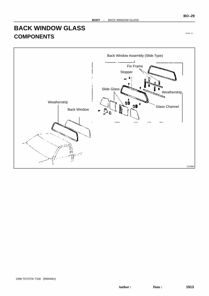
BO0EF−03
Z14390
Weatherstrip
Back Window
Back Window Assembly (Slide Type)
Glass Channel
Slide Glass
Stopper
Fix Frame
Weatherstrip
−BODY BACK WINDOW GLASSBO−29
1913Author�: Date�:
1996 TOYOTA T100 (RM449U)
BACK WINDOW GLASSCOMPONENTS
https://www.truck-manuals.net/

BO0EG−03
BO3301
Weatherstrip
Body
Z04539
Weatherstrip
BO−30−BODY BACK WINDOW GLASS
1996 TOYOTA T100 (RM449U)
REMOVALREMOVE BACK WINDOW GLASS WITH WINDOW FRAMEHINT:Tape a screwdriver tip before use.(a) Using a screwdriver, loosen the weatherstrip from the
body.NOTICE:Be careful not to damage the body paint.
(b) Pry the lip of the weatherstrip outward from the interiorpart of the body flange.
(c) Pull the glass outwards, and remove it with the weather-strip.
https://www.truck-manuals.net/

BO0EH−02
Z04533
BO0050
BO0051
BO0052
−BODY BACK WINDOW GLASSBO−31
1996 TOYOTA T100 (RM449U)
DISASSEMBLY1. REMOVE STOPPER2. REMOVE FIX FRAMES
3. REMOVE SLIDE GLASSPull apart the channels and remove the 2 slide glass panes atthe center area of the glass channel.
4. REMOVE NON−SLIDE GLASS(a) Pull apart the channels and remove the 2 fix frames, as
shown.
(b) Pull apart the channels and remove the 2 non−slide glasspanes, as shown.
HINT:At the time of reassembly, please refer to the following item.Apply soapy water to the contact surface of the weatherstripand glass channel flange.
https://www.truck-manuals.net/

BO0EI−01
BO−32−BODY BACK WINDOW GLASS
1996 TOYOTA T100 (RM449U)
REASSEMBLYReassembly is in the reverse order of disassembly (See page BO−31).
https://www.truck-manuals.net/

BO0EJ−02
N05950
N05949
(0.31 in)8 mm
(0.08 in)2 mm
N05951
N05952
−BODY BACK WINDOW GLASSBO−33
1996 TOYOTA T100 (RM449U)
INSTALLATION1. INSTALL BACK WINDOW GLASS WITH WINDOW
FRAME(a) Install the working cord to the frame, as shown.
(b) Apply soapy water to the contact surface of the body andthe weatherstrip lip.
(c) Hold the glass in position on the body.(d) Install the glass by pulling the cord from the room side,
while pushing on the outside of the weatherstrip with youropen hand.
(e) To snug the glass in place, tap from the outside with youropen hand.
2. INSPECT FOR LEAKS AND REPAIR(a) Perform a leak test after the hardening time has elapsed.(b) Seal any leak with sealant.
Part No. 08833−00030 or equivalent
https://www.truck-manuals.net/

BO0EK−02
N20330
Instrument Panel Reinforcement
Center Defroster NozzleFront Pillar Garnish
Brace No. 3
Cowl Side Trim
Front Door Scuff Plate
Duct Heater toRegister No. 4
Center Register
Duct Heater to Register No. 1
Instrument Panel
Combination Meter
Center Cluster Finish Panel
Steering Column
Cluster Finish Panel
Combination SwitchSteering Column Cover
Lower Center Cover Glove Compartment Door
Rear Console Box
Stereo Opening Cover
Steering Wheel Pad
Radio
Steering Wheel
B
Lower Finish Panel No. 2
Brace No. 1
Brace No. 2
Side Bracket RH
Ash Tray
Register No. 1
Center Cluster Finish Lower Panel
Duct Heater to Register No. 2
Glove CompartmentDoor Reinforcement
Lower Finish Panel No. 1
I
Side Bracket LHF
G
A
HD
H
A
D
A
A
A
AA
G
G
G
E
EE
E
E
FFFF
F
E E
F
B
B
B
B
E
E
II
I
BB B
BB
CA
C
A
Duct Heater to
E E
35 (360, 26)
N·m (kgf·cm, ft·lbf) : Specified torque
BO−34−BODY INSTRUMENT PANEL
1918Author�: Date�:
1996 TOYOTA T100 (RM449U)
INSTRUMENT PANELCOMPONENTS
https://www.truck-manuals.net/

N15353
F
Duct Heater to Register No. 3
Center Register
Mounting Bracket No. 1
Center Bracket
Stay No. 2
Register No. 2
Instrument Panel
Cup Holder
Duct Heater to Register No. 5
Mounting Bracket No. 2
F
F
F F
FFF
F
F F
F
F
F
FF
F
F
V06838
A
D
G
B
E
H
C
F
I
Code Shape Size
ø = 6 (0.24)L = 22 (0.87)
Code Shape Size Code Shape Size
ø = 5 (0.20)L = 14 (0.55)
ø = 5 (0.20)L = 18 (0.71)
ø = 8 (0.31)L = 20 (0.79)
ø = 5 (0.20)L = 16 (0.63)
ø = 5 (0.20)L = 14 (0.55)
ø = 6 (0.24)L = 18 (0.71)
−BODY INSTRUMENT PANELBO−35
1919Author�: Date�:
1996 TOYOTA T100 (RM449U)
HINT:Screw shapes and sizes are inndecated in the able below. The codes (A ∼ I) correspond to those indecated on the previous pages.
https://www.truck-manuals.net/

BO0EL−03
N05924
N06045
N05919
BO−36−BODY INSTRUMENT PANEL
1996 TOYOTA T100 (RM449U)
REMOVAL1. REMOVE FRONT PILLAR GARNISH2. REMOVE FRONT DOOR SCUFF PLATE3. REMOVE COWL SIDE TRIM4. REMOVE STEERING WHEEL
(See page SR−13)5. REMOVE STEERING COLUMN COVER6. REMOVE HOOD LOCK RELEASE LEVER7. REMOVE LOWER FINISH PANEL NO. 18. REMOVE COMBINATION SWITCH9. REMOVE GLOVE COMPARTMENT DOOR10. REMOVE LOWER FINISH PANEL NO. 211. REMOVE LOWER CENTER COVER12. w/ Sports seat:
REMOVE REAR CONSOLE BOX
13. REMOVE CENTER CLUSTER FINISH PANELHINT:Tape a screwdriver tip before use.(a) Remove the heater control knobs.(b) Using a screwdriver, remove the panel.(c) Remove the radio.(d) Remove the heater control.
14. REMOVE CENTER CLUSTER FINISH LOWER PANELHINT:Tape a screwdriver tip before use.(a) Remove the 2 screws.(b) Using a screwdriver, remove the panel, then disconnect
the connector.(c) Remove the stereo opening cover.
15. REMOVE CLUSTER FINISH PANEL(a) Remove the 5 screws.(b) Remove the combination meter.16. REMOVE REGISTER NO. 117. REMOVE DUCT HEATER TO REGISTER NO. 118. REMOVE DUCT HEATER TO REGISTER NO. 219. REMOVE GLOVE COMPARTMENT DOOR RE-
INFORCEMENT20. REMOVE BRACE NO. 1 AND NO. 2
https://www.truck-manuals.net/

N12565
−BODY INSTRUMENT PANELBO−37
1996 TOYOTA T100 (RM449U)
21. REMOVE INSTRUMENT PANEL(a) Disconnect the connectors.(b) Remove the 2 bolts from instrument panel.22. REMOVE INSTRUMENT PANEL REINFORCEMENT(a) Remove the brace No. 3.(b) Remove the 4 nuts, 2 bolts and the reinforcement.
https://www.truck-manuals.net/

BO0EM−02
BO−38−BODY INSTRUMENT PANEL
1996 TOYOTA T100 (RM449U)
DISASSEMBLY1. REMOVE DUCT HEATER TO REGISTER NO. 32. REMOVE DUCT HEATER TO REGISTER NO. 53. REMOVE REGISTER NO.24. REMOVE CENTER BRACKET5. REMOVE MOUNTING BRACKET NO. 1 AND NO. 26. REMOVE STAY NO. 27. REMOVE CENTER REGISTER8. REMOVE CUP HOLDER9. REMOVE DUCT HEATER TO CENTER REGISTER10. REMOVE DUCT HEATER TO REGISTER NO. 411. REMOVE CENTER DEFROSTER NOZZLE
https://www.truck-manuals.net/

BO0EN−01
−BODY INSTRUMENT PANELBO−39
1996 TOYOTA T100 (RM449U)
REASSEMBLYReassembly is in the reverse order of disassembly (See page BO−38).
https://www.truck-manuals.net/

BO0EO−01
BO−40−BODY INSTRUMENT PANEL
1996 TOYOTA T100 (RM449U)
INSTALLATIONInstallation is in the reverse order of removal (See page BO−36).
https://www.truck-manuals.net/

BO0EP−02
N12566
Tail Gate Lock Striker
Tail Gate Stay
Door Outside Handle
Tail Gate Lock Link
Tail Gate Lock
Tail Gate HingeTail GateService Hole Cover
Stay Stopper
N·m (kgf·cm, ft·lbf) : Specified torque
12 (120, 9)
18 (185, 13)
12 (120, 9)
12 (120, 9)
−BODY TAIL GATEBO−41
1925Author�: Date�:
1996 TOYOTA T100 (RM449U)
TAIL GATECOMPONENTS
https://www.truck-manuals.net/

BO0EQ−02
BO−42−BODY TAIL GATE
1996 TOYOTA T100 (RM449U)
REMOVAL1. REMOVE SERVICE HOLE COVER2. REMOVE TAIL GATE LOCK3. REMOVE TAIL GATE LOCK LINK
Torque: 12 N·m (120 kgf·cm, 9 ft·lbf)4. REMOVE DOOR OUTSIDE HANDLE5. REMOVE TAIL GATE STAY6. REMOVE TAIL GATE LOCK STRIKER
Torque: 12 N·m (120 kgf·cm, 9 ft·lbf)7. REMOVE TAIL GATE8. REMOVE TAIL GATE HINGE
Torque: 18 N·m (185 kgf·cm, 13 ft·lbf)
https://www.truck-manuals.net/

BO0ER−01
−BODY TAIL GATEBO−43
1996 TOYOTA T100 (RM449U)
INSTALLATIONInstallation is in the reverse order of removal (See page BO−42).
https://www.truck-manuals.net/

BO0FE−02
N21243
w/ Armrest:
Floor M/T only:
Center Armrest
Seatback Cover
Seatback Pad
Headrest Support
Seatback Frame
Hog Ring
Outer Track LH
Seat Cushion Cover
Seat Cushion Pad
Seat Cushion Frame
Outer Track RH
Non−reusable part�
Headrest
w/o Armrest:
�
Hog Ring�
Equalizing Wire
BO−44−BODY FRONT SEAT (Bench Type)
1928Author�: Date�:
1996 TOYOTA T100 (RM449U)
FRONT SEAT (Bench Type)COMPONENTS
https://www.truck-manuals.net/

BO0F1−03
H16112
Floor M/T only:Extra cab (DLX grade):
Center Armrest
Seat Cushion Cover
Seat Cushion Pad
Seat Cushion Frame
Seat Cushion Shield
Headrest Support
Seatback Frame
Seatback PadSeatback Cover
Inner Adjuster
Seat Adjuster
Inner Track
Inner ShieldSeat Adjuster
Outer Shield
Headrest
Outer Track
Center Armrest
Cable
Inner Track
Equalizing Wire
Hog Ring�
Hog Ring�
�Non−reusable part
−BODY FRONT SEAT (Split Bench Type)BO−45
1929Author�: Date�:
1996 TOYOTA T100 (RM449U)
FRONT SEAT (Split Bench Type)COMPONENTS
https://www.truck-manuals.net/

BO0F7−02
N13722
Back Panel Trim
Rear Seat Cushion Cover
Rear Seat CushionHinge Lower Cover
Hinge Cover
Hinge Upper CoverRear Seat Cushion Pad
Rear Seat Cushion
Rear Seat Cushion
BO−46−BODY REAR SEAT
1930Author�: Date�:
1996 TOYOTA T100 (RM449U)
REAR SEATCOMPONENTS
https://www.truck-manuals.net/

BO0FC−02
N21244
Adjustable anchor: Outer belt:
Inner belt split seat:Inner belt bench seat:
Front Seat Outer
Front Seat Inner
Seat BeltAnchor Cap
ShoulderBeltAnchorAdjuster
Belt RH
Belt LH
Belt
Front Seat Inner
Front Seat InnerBelt RH
Belt LHFront Seat Inner
43 (440, 32)
N·m (kgf·cm, ft·lbf) : Specified torque
43 (440, 32)
43 (440, 32)
43 (440, 32) 43 (440, 32)
Regular cab:
−BODY SEAT BELTBO−47
1931Author�: Date�:
1996 TOYOTA T100 (RM449U)
SEAT BELTCOMPONENTS
https://www.truck-manuals.net/

H16113
(Front seat belt)Extra cab
Adjustable Anchor
Slide GarnishQuarter Trim
Front Seat BeltShoulder Anchor
Anchor Cover
Front Seat Inner Belt
Front SeatOuter Belt
43 (440, 32) 43 (440, 32)
43 (440, 32)
43 (440, 32)
N·m (kgf·cm, ft·lbf) : Specified torque
BO−48−BODY SEAT BELT
1932Author�: Date�:
1996 TOYOTA T100 (RM449U)
https://www.truck-manuals.net/

N21245
(Rear seat belt)
Rear Seat BeltShoulder Anchor
Rear SeatOuter Belt
Inner BeltRear Seat
N·m (kgf·cm, ft·lbf) : Specified torque
43 (440, 32)
43 (440, 32)
43 (440, 32)43 (440, 32)
Extra cab
−BODY SEAT BELTBO−49
1933Author�: Date�:
1996 TOYOTA T100 (RM449U)
https://www.truck-manuals.net/

BO0FD−02
BO0632
BO0633
15°45°
N15359
BO−50−BODY SEAT BELT
1996 TOYOTA T100 (RM449U)
INSPECTIONCAUTION:Replace the seat belt assembly (outer belt, inner belt, boltsor nuts and sill−bar) if it has been used in a severe impact.The entire assembly should be replaced even if damage isnot obvious.1. All seat belts:
RUNNING TEST (IN SAFE AREA)(a) Fasten the seat belts.(b) Drive the car at 10 mph (16 km/h) and make a very hard
stop.(c) Check that the seat belt is locked and cannot be extended
at this time.HINT:Conduct this test in a safe area. If the belt does not lock, removethe belt mechanism assembly and conduct the following staticcheck. Also, whenever installing a new belt assembly, verify theproper operation before installation.2. All seat belts:
STATIC TEST(a) Make sure that the belt locks when pulled out quickly.(b) Remove the locking retractor assembly.(c) Tilt the retractor slowly.(d) Make sure that the belt can be pulled out at a tilt of 15 de-
grees or less, and cannot be pulled out at over 45 degreesof tilt.
If a problem is found, replace the assembly.3. Except driver’s seat belt:
STATIC TEST(a) Pull out the whole belt, release it slightly and then pull it
out again.(b) Make sure that the belt cannot be extended further.If a problem is found, replace the assembly.
4. Manual type seat belt:TEST
(a) Adjust the belt to the proper length.(b) Apply a firm load to the belt.(c) Make sure that the belt does not extend.
https://www.truck-manuals.net/

AC – AIR CONDITIONING
AIR CONDITIONING SYSTEM AC-1 DRIVE BELT AC-14 MANIFOLD GAUGE SET AC-17 REFRIGERANT LINE AC-19 COOLING UNIT AC-22 HEATER UNIT AC-27 BLOWER UNIT AC-33 COMPRESSOR AND MAGNETIC CLUTCH
AC-38
RECEIVER AC-46 CONDENSER AC-49 EVAPORATOR AC-53 HEATER RADIATOR AC-56 EXPANSION VALVE AC-59 WATER VALVE AC-62 BLOWER MOTOR AC-65 BLOWER RESISTOR AC-68 THERMISTOR AC-71 PRESSURE SWITCH AC-75 HEATER MAIN RELAY AC-78 AIR CONDITIONING AMPLIFIER AC-79 AIR CONDITIONING SWITCH AC-82 HEATER CONTROL ASSEMBLY AC-85
https://www.truck-manuals.net/
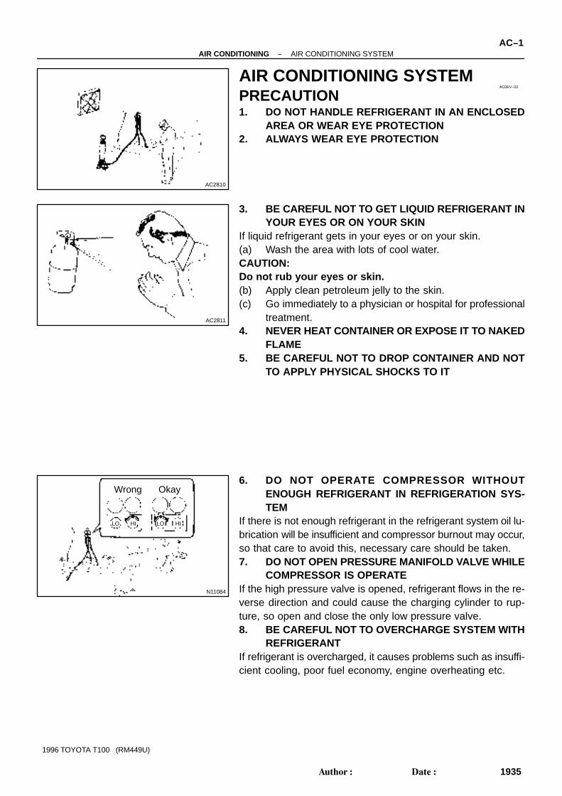
AC2810
AC0EV−02
AC2811
N11084
Wrong Okay
HILO HILO
−AIR CONDITIONING AIR CONDITIONING SYSTEMAC−1
1935Author�: Date�:
1996 TOYOTA T100 (RM449U)
AIR CONDITIONING SYSTEMPRECAUTION1. DO NOT HANDLE REFRIGERANT IN AN ENCLOSED
AREA OR WEAR EYE PROTECTION2. ALWAYS WEAR EYE PROTECTION
3. BE CAREFUL NOT TO GET LIQUID REFRIGERANT INYOUR EYES OR ON YOUR SKIN
If liquid refrigerant gets in your eyes or on your skin.(a) Wash the area with lots of cool water.CAUTION:Do not rub your eyes or skin.(b) Apply clean petroleum jelly to the skin.(c) Go immediately to a physician or hospital for professional
treatment.4. NEVER HEAT CONTAINER OR EXPOSE IT TO NAKED
FLAME5. BE CAREFUL NOT TO DROP CONTAINER AND NOT
TO APPLY PHYSICAL SHOCKS TO IT
6. DO NOT OPERATE COMPRESSOR WITHOUTENOUGH REFRIGERANT IN REFRIGERATION SYS-TEM
If there is not enough refrigerant in the refrigerant system oil lu-brication will be insufficient and compressor burnout may occur,so that care to avoid this, necessary care should be taken.7. DO NOT OPEN PRESSURE MANIFOLD VALVE WHILE
COMPRESSOR IS OPERATEIf the high pressure valve is opened, refrigerant flows in the re-verse direction and could cause the charging cylinder to rup-ture, so open and close the only low pressure valve.8. BE CAREFUL NOT TO OVERCHARGE SYSTEM WITH
REFRIGERANTIf refrigerant is overcharged, it causes problems such as insuffi-cient cooling, poor fuel economy, engine overheating etc.
https://www.truck-manuals.net/

AC−2−AIR CONDITIONING AIR CONDITIONING SYSTEM
1936Author�: Date�:
1996 TOYOTA T100 (RM449U)
9. SUPPLEMENTAL RESTRAINT SYSTEM (SRS)The TOYOTA T100 is equipped with an SRS (SupplementalRestraint System) such as the driver airbag and passenger air-bag. Failure to carry out service operations the correct se-quence could cause the SRS to unexpectedly deployed duringservicing, possible the SRS may fail to operate when required.Before servicing (including removal or installation of parts, in-spection or replacement), be sure to read the following itemcarefully, then follow the correct procedure described in the re-pair manual.
https://www.truck-manuals.net/

N06110
Sight Glass
AC0EX−02
−AIR CONDITIONING AIR CONDITIONING SYSTEMAC−3
1996 TOYOTA T100 (RM449U)
ON−VEHICLE INSPECTION1. INSPECT REFRIGERANT VOLUMEObserve the sight glass on the liquid tube.
Test conditions:� Running engine at 1,500 rpm� Blower speed control switch on ”HI” position� A/C switch ON� Temperature control dial on ”COOL” position� Fully open the doors
Item Symptom Amount of refrigerant Remedy
1 Bubbles present in sight glass Insufficient*
(1) Check for gas leakage with gas leak de-
tector and repair if necessary
(2) Add refrigerant until bubbles disappear
2 No bubbles present in sight glass None, sufficient or too much Refer item 3 and 4
3No temperature difference between com-
pressor inlet and outletEmpty or nearly empty
(1) Check for gas leakage with gas leak de-
tector and repair if necessary
(2) Add refrigerant until bubbles disappear
4Temperature between compressor inlet and
outlet is noticeably differentCorrect or too much Refer to items 5 and 6
5Immediately after air conditioning is turned
off, refrigerant in sight glass stays clearToo much
(1) Discharge refrigerant
(2) Evacuate air and charge proper amount
of purified refrigerant
6When air conditioning is turned off, refriger-
ant foams and then stays clearCorrect −
*: Bubbles in the sight glass with ambient temperatures higher than usual can be considered normal if coolingis sufficient.
https://www.truck-manuals.net/

I01386
I01387
Condition : Periodically cools and then fails to cool
AC−4−AIR CONDITIONING AIR CONDITIONING SYSTEM
1996 TOYOTA T100 (RM449U)
2. INSPECT REFRIGERANT PRESSURE WITH MAN-IFOLD GAUGE SET
This is a method in which the trouble is located by using a man-ifold gauge set. Read the manifold gauge pressure when theseconditions are established.
Test conditions:� Temperature at the air inlet with the switch set
at RECURC is 30 − 35 °C (86 − 95 °F)� Engine running at 1500 rpm� Blower speed control switch on ”HI” position� Temperature control dial on ”COOL” position
HINT:It should be noted that the gauge indications may vary slightlydue to ambient temperature conditions.
(1) Normally functioning refrigeration system.Gauge reading:Low pressure side:0.15 − 0.25 MPa (1.5 − 2.5 kgf/cm2)High pressure side:1.37 − 1.57 MPa (14 − 16 kgf/cm2)
(2) Moisture present in refrigeration system.
Symptom seen in
refrigeration systemProbable cause Diagnosis Remedy
During operation, pressure on low
pressure side sometimes become
a vacuum and sometime normal
Moisture entered in refrigeration
system freezes at expansion valve
orifice and temporarily stops cycle,
but normal state is restored after a
time when the ice melts
� Drier in oversaturated state
� Moisture in refrigeration system
freezes at expansion valve orifice
and blocks circulation of refriger-
ant
(1) Replace receiver
(2) Remove moisture in cycle
through repeatedly evacuating air
(3) Charge proper amount of new
refrigerant
https://www.truck-manuals.net/

I01388
Condition: Insufficient cooling
I01389
Condition: Insufficient cooling
−AIR CONDITIONING AIR CONDITIONING SYSTEMAC−5
1996 TOYOTA T100 (RM449U)
(3) Insufficient cooling
Symptom seen in
refrigeration systemProbable cause Diagnosis Remedy
� Pressure low on both low and
high pressure sides
� Bubbles seen in sight glass con-
tinuously
� Insufficient cooling performance
Gas leakage at some place in re-
frigeration system
� Insufficient refrigerant in system
� Refrigerant leaking
(1) Check for gas leakage with gas
leak detector and repair if neces-
sary
(2) Charge Proper amount of re-
frigerant
(3) If indicated pressure value is
near 0 when connected to gauge,
create the vacuum after inspecting
and repairing the location of the
leak
(4) Poor circulation of refrigerant
Symptom seen in
refrigeration systemProbable cause Diagnosis Remedy
� Pressure low in both low and
high pressure sides
� Frost on tube from receiver to
unit
Refrigerant flow obstructed by dirt
in receiverReceiver clogged Replace receiver
https://www.truck-manuals.net/

I01449
Condition: Does not cool (Cools from time to time in some cases)
I01390
Condition: Insufficient cooling
AC−6−AIR CONDITIONING AIR CONDITIONING SYSTEM
1996 TOYOTA T100 (RM449U)
(5) Refrigerant does not circulate
Symptom seen in
refrigeration systemProbable cause Diagnosis Remedy
� Vacuum indicated on low pres-
sure side, very low pressure indi-
cated on high pressure side
� Frost or dew seen on piping be-
fore and after receiver/ drier or ex-
pansion valve
� Refrigerant flow obstructed by
moisture or dirt in refrigeration sys-
tem
� Refrigerant flow obstructed by
gas leakage from expansion valve
Refrigerant does not circulate
(1) Check expansion valve
(2) Clean out dirt in expansion
valve by blowing with air
(3) Replace receiver
(4) Evacuate air and charge new
refrigerant to proper amount
(5) For gas leakage from expan-
sion valve, replace expansion
valve
(6) Refrigerant overcharged or insufficient cooling ofcondenser
Symptom seen in
refrigeration systemProbable cause Diagnosis Remedy
� Pressure too high on both low
and high pressure sides
� No air bubbles seen through the
sight glass even when the engine
rpm is lowered
� Unable to develop sufficient per-
formance due to excessive refrig-
erant in system
� Insufficient cooling of condenser
� Excessive refrigerant in
cycle → refrigerant overcharged
� Condenser cooling
insufficient → condenser fins
clogged of cooling fn faulty
(1) Clean condenser
(2) Check cooling fan with fluid
coupling operation
(3) If (1) and (2) are in normal
state, check amount of refrigerant
Charge proper amount of refriger-
ant
https://www.truck-manuals.net/

I01392
Condition: Insufficient cooling
NOTE : These gauge indica-tions are shown when therefrigeration system hasbeen opened and the refrig-erant charged without vacu-um purging.
I01450
Condition: Insufficient cooling
−AIR CONDITIONING AIR CONDITIONING SYSTEMAC−7
1996 TOYOTA T100 (RM449U)
(7) Air present in refrigeration system
Symptom seen in
refrigeration systemProbable cause Diagnosis Remedy
� Pressure too high on both low
and high pressure sides
� The low pressure piping hot to
the touch
� Bubbles seen in sight glass
Air entered in refrigeration system
� AIr present in refrigeration sys-
tem
� Insufficient vacuum purging
(1) Check compressor oil to see if
it is dirty or insufficient
(2) Evacuate air and charge new
refrigerant
(8) Expansion valve improperlyMounted/ Heat sensing tube defective(Open too wide)
Symptom seen in
refrigeration systemProbable cause Diagnosis Remedy
� Pressure too high on both low
and high pressure sides
� Frost or large amount of dew on
piping on low pressure side
Trouble in expansion valve or heat
sensing tube not installed correctly
� Excessive refrigerant in low
pressure piping
� Expansion valve opened too
wide
(1) Check heat sensing tube
installed condition
(2) Check expansion valve
Replace if defective
https://www.truck-manuals.net/

I01393
Condition : Does not cool
AC−8−AIR CONDITIONING AIR CONDITIONING SYSTEM
1996 TOYOTA T100 (RM449U)
(9) Defective compression compressor
Symptom seen in
refrigeration systemProbable cause Diagnosis Remedy
� Pressure too high on low and
high pressure sides
� Pressure too low on high pres-
sure side
Internal leak in compressor
� Compression defective
� Valve leaking or broken sliding
parts
Repair or replace compressor
3. INSPECT IDLE−UP SPEED(a) Warm up engine.(b) Inspect idle−up speed when the these conditions are es-
tablished.� Warm up engine� Blower speed control switch at ”HI” position� A/C switch ON� Temperature control dial at ”COOL” position
Magnetic clutch condition Idle−up speed
3RZ−FE Engine −
Magnetic clutch not engaged 700 ± 50 rpm
Magnetic clutch engaged 900 ± 50 rpm
5VZ−FE Engine −
Magnetic clutch not engaged 700 ± 50 rpm
Magnetic clutch engaged 850 ± 50 rpm
If idle speed is not as specified, check idle control system.4. INSPECT FOR LEAKAGE OF REFRIGERANT(a) Perform in these conditions:
� Stop engine.� Secure good ventilation (If the gas leak detector
may not react to volatile gases which are not refrig-erant, such as evaporated gasoline and exhaustgas.)
� Repeat the test 2 or 3 times.� Make sure that there is some refrigerant remaining
in the refrigeration system.When compressor is OFF: approx. 392 − 588 kPa(4 − 6 kgf/ cm2, 57 − 85 psi)
https://www.truck-manuals.net/

N14519
Drain Hose
N17949
−AIR CONDITIONING AIR CONDITIONING SYSTEMAC−9
1996 TOYOTA T100 (RM449U)
(b) Bring the gas leak detector close to the drain hose beforeperforming the test.
HINT:� After the blower motor has stopped, leave the cooling unit
for more than 15 minutes.� Expose the gas leak detector sensor under the drain
hose.� When bring the gas leak detector close to the drain hose,
make sure that the gas leak detector does not react to thevolatile gases.
If such reaction is unavoidable, the vehicle must be lifted up.
(c) If gas leak is not detected on the drain hose, remove theblower resistor from the cooling unit. Then insert the gasleak detector sensor into the unit and perform the test.
(d) Disconnect the connector and leave the pressure switchfor approx. 20 minutes. Then bring the gas leak detectorclose to the pressure switch and perform the test.
(e) Bring the gas leak detector close to the refrigerant linesand perform the test.
https://www.truck-manuals.net/

AC0EZ−01
N13793
Charging Cylinder
High PressureService Valve
Low PressureService Valve
PushAir
N13792
Gas LeakDetector
−AIR CONDITIONING AIR CONDITIONING SYSTEMAC−11
1996 TOYOTA T100 (RM449U)
CHARGING1. INSTALL CHARGING CYLINDERHINT:When handling the charging cylinder, always follow the direc-tions given in the instruction manual.(a) Charge the proper amount of refrigerant into the charging
cylinder.(b) Connect the center hose to the charging cylinder.CAUTION:Do not open both high and low hand valves of manifoldgauge set.(c) Open the valve of charging cylinder.(d) Press the valve core on the side of manifold gauge and
expel the air inside of the center hose.
2. INSPECT REFRIGERATION SYSTEM FOR LEAKS(a) Open the high pressure hand valve and charge refriger-
ant.(b) When the low pressure gauge indicates 98 kPa
(1 kgf/cm2, 14 psi) close the high pressure hand valve.(c) Using a gas leak detector, check the system for leakage.If leak is found, repair the faulty component or connection.CAUTION:Use the refrigerant recovery/ recycling machine to recoverthe refrigerant whenever replacing parts.
https://www.truck-manuals.net/

N13790
Low PressureService Valve
High PressureService Valve
AC−12−AIR CONDITIONING AIR CONDITIONING SYSTEM
1996 TOYOTA T100 (RM449U)
3. CHARGE REFRIGERANT INTO REFRIGERANT SYS-TEM
If there is no leak after refrigerant leak check, charge the properamount of refrigerant into refrigeration system.CAUTION:� Never run the engine when charging the system
through the high pressure side.� Do not open the low pressure hand valve when the
system is being charged with liquid refrigerant.(a) Open the high pressure hand valve fully.(b) Charge specified amount of refrigerant, then close the
high pressure hand valve.HINT:A fully charged system is indicated by the sight glass being freeof any bubbles.4. SET OFF MANIFOLD GAUGE SET(a) Close both hand valves of manifold gauge set.(b) Disconnect the quick disconnect adapters from the ser-
vice valves.5. INSTALL CAPS TO SERVICE VALVES ON REFRIGER-
ANT LINES
https://www.truck-manuals.net/
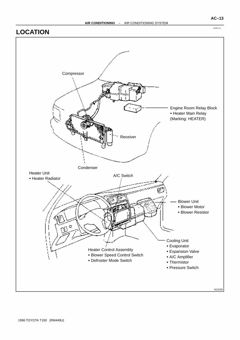
AC0F0−01
N13105
Compressor
Engine Room Relay Block� Heater Main Relay(Marking: HEATER)
Receiver
Condenser
Blower Unit� Blower Motor� Blower Resistor
Heater Control Assembly� Blower Speed Control Switch� Defroster Mode Switch
Heater Unit� Heater Radiator
A/C Switch
Cooling Unit� Evaporator� Expansion Valve� A/C Amplifier� Thermistor� Pressure Switch
−AIR CONDITIONING AIR CONDITIONING SYSTEMAC−13
1996 TOYOTA T100 (RM449U)
LOCATION
https://www.truck-manuals.net/

CH0086
Correct Wrong
AC0F1−01
Z17871
CompressorCrankshaft
PulleyCrankshaft
Compressor
Pulley
Idle pulley
Idle pulley
3RZ−FE 5VZ−FE
N01881
DENSO Borroughs
AC−14−AIR CONDITIONING DRIVE BELT
1948Author�: Date�:
1996 TOYOTA T100 (RM449U)
DRIVE BELTON−VEHICLE INSPECTION1. INSPECT DRIVE BELT’S INSTALLATION CONDITIONCheck that the drive belt fits properly in the ribbed grooves.
2. INSPECT DRIVE BELT TENSIONUsing a belt tension gauge, check the drive belt tension.
Drive belt tension:New belt 160 ± 25 lbfUsed belt 100 ± 20 lbf
HINT:� ”New belt” refers to a belt which has been used less than
5 minutes on a running engine.� ”Used belt” refers to a belt which has been used on a run-
ning engine for 5 minutes or more.� After installing the drive belt, check that it fits properly in
the ribbed grooves.
https://www.truck-manuals.net/

AC0F2−01
N06121Adjusting Bolt
Idle pulley lock nut
−AIR CONDITIONING DRIVE BELTAC−15
1996 TOYOTA T100 (RM449U)
REMOVAL1. REMOVE PS PUMP DRIVE BELT
3RZ−FE: (See page SR−36)5VZ−FE: (See page SR−46)
2. REMOVE ENGINE UNDER COVER
3. LOOSEN IDLE PULLEY LOCK NUT4. REMOVE COMPRESSOR DRIVE BELTLoosen drive belt tension by adjusting bolt and remove the drivebelt.
https://www.truck-manuals.net/

AC0F3−01
N06121
Idle Pulley Lock Nut
Adjusting Bolt
AC−16−AIR CONDITIONING DRIVE BELT
1996 TOYOTA T100 (RM449U)
INSTALLATION1. TIGHTEN IDLE PULLEY LOCK NUT TEMPORALLY
Torque: 2.5 N·m (25 kgf·cm, 22 in.·lbf)2. INSTALL DRIVE BELT3. USING ADJUSTING BOLT, ADJUST DRIVE BELT TEN-
SIONDrive belt tension:New belt: 160 ± 25 lbfUsed belt: 100 ± 25 lbf
4. TIGHTEN IDLE PULLEY LOCK NUTTorque: 39 N·m (400 kgf·cm, 29 ft·lbf)
5. INSTALL PS PUMP DRIVE BELT6. INSTALL ENGINE UNDER COVER
https://www.truck-manuals.net/

N09385
Low PressureCharging Hose
High PressureCharging Hose AC0F4−01
N04392
Sleeve
−AIR CONDITIONING MANIFOLD GAUGE SETAC−17
1951Author�: Date�:
1996 TOYOTA T100 (RM449U)
MANIFOLD GAUGE SETSET ON1. CONNECT CHARGE HOSE TO MANIFOLD GAUGE
SETTighten the nuts by hand.CAUTION:Do not connect the wrong hoses.2. CONNECT QUICK DISCONNECT ADAPTERS TO
CHARGING HOSESTighten the nuts by hand.3. CLOSE BOTH HAND VALVES OF MANIFOLD GAUGE
SET4. REMOVE CAPS FROM SERVICE VALVES ON RE-
FRIGERANT LINE
5. CONNECT QUICK DISCONNECT ADAPTERS TO SER-VICE VALVES
HINT:Push the quick disconnect adapter onto the service valve, thenslide, then slide the sleeve of the quick disconnect adapterdownward to lock it.
https://www.truck-manuals.net/

AC0F5−01
N06553
AC−18−AIR CONDITIONING MANIFOLD GAUGE SET
1996 TOYOTA T100 (RM449U)
SET OFF1. CLOSE BOTH HAND VALVE OF MANIFOLD GAUGE
SET2. DISCONNECT QUICK DISCONNECT ADAPTERS
FROM SERVICE VALVES ON REFRIGERANT LINEHINT:Slide the sleeve of the quick disconnect adapter upward to un-lock the adapter and remove it from the service valve.3. INSTALL CAPS TO SERVICE VALVES ON REFRIGER-
ANT LINE
https://www.truck-manuals.net/

AC0F6−01
−AIR CONDITIONING REFRIGERANT LINEAC−19
1953Author�: Date�:
1996 TOYOTA T100 (RM449U)
REFRIGERANT LINEON−VEHICLE INSPECTION1. INSPECTION HOSE AND TUBE CONNECTIONS FOR LOOSENESS2. INSPECT HOSES AND TUBES FOR LEAKAGEUsing a gas leak detector, check for leakage of refrigerant.
https://www.truck-manuals.net/
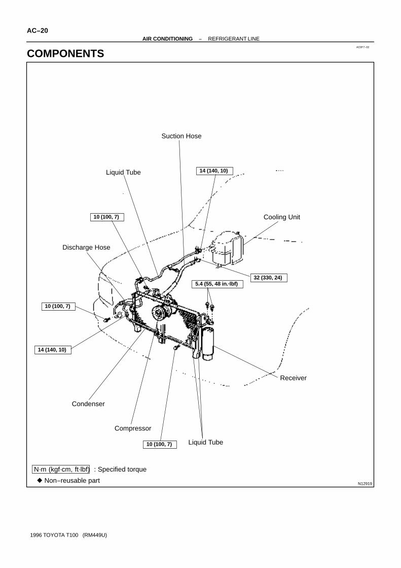
AC0F7−02
N12919
Condenser
Compressor
N·m (kgf·cm, ft·lbf)
Cooling Unit
Discharge Hose
Liquid Tube
Receiver
Liquid Tube
Suction Hose
: Specified torque
� Non−reusable part
10 (100, 7)
14 (140, 10)
5.4 (55, 48 in.·lbf)32 (330, 24)
10 (100, 7)
10 (100, 7)
14 (140, 10)
AC−20−AIR CONDITIONING REFRIGERANT LINE
1996 TOYOTA T100 (RM449U)
COMPONENTS
https://www.truck-manuals.net/

AC0F8−01
−AIR CONDITIONING REFRIGERANT LINEAC−21
1996 TOYOTA T100 (RM449U)
REPLACEMENT1. DISCHARGE REFRIGERANT FROM REFRIGERATION SYSTEM2. REPLACE FAULTY TUBE OR HOSENOTICE:Cap the open fittings immediately to keep moisture or dirt out of the system.3. TIGHTEN JOINT OF BOLT OR NUT TO SPECIFIED TOQUENOTICE:Connections should not be torqued tighter than the specified torque.
Part tightened N·m kgf·cm ft·lbf
Receiver x Liquid tube 6.0 60 52 in.·lbf
Condenser x Discharge hose 10 100 7
Condenser x Liquid tube 14 140 10
Compressor x Discharge hose 10 100 7
Compressor x Suction hose 10 100 7
Cooling unit x Liquid tube 14 140 10
Cooling unit x Suction tube 32 330 24
Expansion valve x Evaporator 22 225 16
Expansion valve x Liquid tube 14 140 10
Suction line (Piping joint) 32 330 24
Liquid line (Piping joint) 14 140 10
4. EVACUATE AIR IN REFRIGERATION SYSTEM AND CHARGE SYSTEM WITH REFRIGERANTSpecified amount: 650 ± 50g (22.92 ± 1.76 oz.)
5. INSPECT FOR LEAKAGE OF REFRIGERANTUsing a gas leak detector, check for leakage of refrigerant.6. INSPECT AIR CONDITIONING OPERATION
https://www.truck-manuals.net/

AC0F9−02
I04698
Glove CompartmentDoor Reinforcement
Lower Center Cover
Glove Compartment Door
Lower Finish Panel No. 2
Upper Unit Case� Packing
A/C Amplifier
� Packing
Lower Unit Case
Evaporator
Expansion Valve
Cooling Unit
N·m (kgf·cm, ft·lbf) : Specified torque
� Non−reusable part
� O−Ring
� O−Ring
Thermistor
Pressure Switch
Amplifier Cover
22 (225, 16)
14 (140, 10)
32 (330, 24)
14 (140, 10)
AC−22−AIR CONDITIONING COOLING UNIT
1956Author�: Date�:
1996 TOYOTA T100 (RM449U)
COOLING UNITCOMPONENTS
https://www.truck-manuals.net/

AC0FA−01
N06114
Z04401
−AIR CONDITIONING COOLING UNITAC−23
1996 TOYOTA T100 (RM449U)
REMOVAL1. DISCHARGE REFRIGERANT FROM REFRIGERATION
SYSTEMHINT:At the time of installation, please refer to the following item.Evacuate air from refrigeration system.Charge system with refrigerant and inspect for leakage of refrig-erant
Specified amount: 650 ± 50 g (22.92 ± 1.76 oz.)
2. DISCONNECT LIQUID TUBE AND SUCTION HOSELoosen the 2 nuts and disconnect the both tube and hose.
Torque:Liquid tube: 14 N·m (140 kgf·cm, 10 ft·lbf)Suction hose: 32 N·m (330 kgf·cm, 24 ft·lbf)
CAUTION:Cap the open fittings immediately to keep moisture or dirtout of the system.HINT:At the time of installation, please refer to the following item.Lubricate 2 new O−rings with compressor oil and install the tubeand hose.3. REMOVE 2 GROMMETS4. REMOVE DRAIN PIPE GROMMET5. REMOVE GLOVE COMPARTMENT PARTS
(See page BO−36)
6. REMOVE COOLING UNIT(a) Disconnect the connectors.(b) Remove the 5 screws, nut and cooling unit.
https://www.truck-manuals.net/

AC0FB−02
Z04403
Liquid TubeExpansion Valve
Z04402
AC−24−AIR CONDITIONING COOLING UNIT
1996 TOYOTA T100 (RM449U)
DISASSEMBLY1. REMOVE A/C AMPLIFIER2. SEPARATE COOLING UNIT CASES(a) Using a knife, cut off each packing.(b) Remove the 4 clip and 4 screws then separate the cooling
unit cases.3. REMOVE EVAPORATOR FROM COOLING UNIT CASEHINT:At the time of reassembly, please refer to the following item,.If evaporator is replaced, add compressor oil to evaporator.
Add 40 cc (1.4 fl.oz.)Compressor oil: ND−OIL 8 or equivalent
4. REMOVE THERMISTOR FROM EVAPORATOR(a) Disconnect the connector from pressure switch.(b) Pull out the thermistor from evaporator.
5. REMOVE EXPANSION VALVE(a) Pry out the packing.(b) Remove the clamp and disconnect heat sensing tube.(c) Loosen the 2 nuts and remove the expansion valve.
Torque:Expansion valve x Liquid tube:14 N·m (140 kgf·cm, 10 ft·lbf)Expansion valve x Evaporator:22 N·m (225 kgf·cm, 16 ft·lbf)
NOTICE:Cap the open fittings immediately to keep moisture or dirtout of the system.HINT:At the time of reassembly, please refer to the following item.Lubricate 2 new O−rings with compressor oil and install thevalve.6. REMOVE PRESSURE SWITCH(a) Disconnect the connector.(b) Remove the pressure switch from liquid tube.
Torque: 10 N·m (100 kgf·cm, 7 ft·lbf)HINT:� Lock the switch mounted on the tube with on open end
wrench, being careful not to deform the tube and removethe switch.
� At the time of installation, please refer to the followingitem.Lubricate a new O−ring with compressor oil and install thevalve.
https://www.truck-manuals.net/

AC0FC−01
−AIR CONDITIONING COOLING UNITAC−25
1996 TOYOTA T100 (RM449U)
REASSEMBLYReassembly is in the reverse order of disassembly (See page AC−24).
https://www.truck-manuals.net/

AC0FD−01
AC−26−AIR CONDITIONING COOLING UNIT
1996 TOYOTA T100 (RM449U)
INSTALLATIONInstallation is in the reverse order of removal (See page AC−23).
https://www.truck-manuals.net/

AC0FE−01
I04696
Instrument Panel
Reinforcement
Duct Heater toRegister No. 4
No. 2 Brace
No. 1 Brace
Center Defroster Nozzle
Heater Unit
Heater Air Duct
Cooling Unit
Heater Radiator pipe
Heater Radiator
Heater Unit Case
Air Vent Duct
� O−Ring
� Non−reusable part
−AIR CONDITIONING HEATER UNITAC−27
1961Author�: Date�:
1996 TOYOTA T100 (RM449U)
HEATER UNITCOMPONENTS
https://www.truck-manuals.net/

AC0FF−02
I01453
N06486
Hose Clip
Heater Radiator Pipe
Second ridgeWater Hose
45 °
Upper
Lower
LHRH
N05820
AC−28−AIR CONDITIONING HEATER UNIT
1996 TOYOTA T100 (RM449U)
REMOVAL1. REMOVE COOLING UNIT (See page AC−23)2. DRAIN ENGINE COOLANT FROM RADIATORHINT:It is not necessary to drain out all coolant.
3. DISCONNECT WATER HOSES FROM HEATER RA-DIATOR PIPES
(a) Grip the claws of hose clip and slide the hose clip alongthe hose.
(b) Disconnect the water hose.
HINT:At the time of installation, please refer to the following item.� Push the water hose onto the heater radiator pipe as far
as the second ridge on the pipe.� Install the hose clip in the position, as shown in the illustra-
tion.4. REMOVE INSTRUMENT PANEL AND REINFORCE-
MENT (See page BO−36)5. DISCONNECT HEATER CONTROL CABLES FROM
HEATER UNITHINT:At the time of installation, please refer to the following item.After connection, adjust the control cables.
6. REMOVE HEATER TO REGISTER No. 4 DUCTRemove the screw and the duct.7. REMOVE HEATER TO REGISTER CENTER DUCTRemove the screw and duct.
https://www.truck-manuals.net/

N06076
−AIR CONDITIONING HEATER UNITAC−29
1996 TOYOTA T100 (RM449U)
8. REMOVE HEATER AIR DUCTRemove the screw and duct.9. REMOVE HEATER UNITRemove the 2 bolts, nut and heater unit.
https://www.truck-manuals.net/

AC0FG−01
AC−30−AIR CONDITIONING HEATER UNIT
1996 TOYOTA T100 (RM449U)
DISASSEMBLY1. REMOVE HEATER RADIATOR(a) Remove the 3 screws and 3 plates.(b) Pull out the heater radiator.(c) Remove the 2 clips and heater radiator pipes.(d) Remove the 2 O−rings from heater radiator pipes.HINT:At the time of reassembly, please refer to the following item.Do not reuse the 2 O−rings.2. REMOVE AIR VENT DUCTRemove the 2 screws and duct.
https://www.truck-manuals.net/
AC0FH−01
−AIR CONDITIONING HEATER UNITAC−31
1996 TOYOTA T100 (RM449U)
REASSEMBLYReassembly is in the reverse order of disassembly (See page AC−30).
https://www.truck-manuals.net/

AC0FI−01
AC−32−AIR CONDITIONING HEATER UNIT
1996 TOYOTA T100 (RM449U)
INSTALLATIONInstallation is in the reverse order of removal (See page AC−28).
https://www.truck-manuals.net/

AC0FJ−01
I04697
Lower Finish Panel No. 2
Glove CompartmentDoor
Lower Center Cover
Cooling Unit
Blower Unit
Glove CompartmentDoor Reinforcement
Blower Unit Case
Blower Resistor
Blower Motor
−AIR CONDITIONING BLOWER UNITAC−33
1967Author�: Date�:
1996 TOYOTA T100 (RM449U)
BLOWER UNITCOMPONENTS
https://www.truck-manuals.net/

AC3IX−01
AC−34−AIR CONDITIONING BLOWER UNIT
1996 TOYOTA T100 (RM449U)
REMOVAL1. REMOVE GLOVE COMPARTMENT DOOR2. REMOVE GLOVE COMPARTMENT REINFORCE-
MENT3. REMOVE INSTRUMENT PANEL LOWER FINISH PAN-
EL4. REMOVE COOLING UNIT
5. REMOVE BLOWER UNIT(a) Disconnect the connectors.(b) Disconnect the air inlet control cable.HINT:At the time of installation, please refer to the following item.After connection, adjust the control cable.(c) Remove the nut, 2 bolts and blower unit.
https://www.truck-manuals.net/

AC0FL−01
−AIR CONDITIONING BLOWER UNITAC−35
1996 TOYOTA T100 (RM449U)
DISASSEMBLY1. REMOVE BLOWER MOTORRemove the 3 screws and blower motor.2. REMOVE BLOWER RESISTORRemove the 2 screws and blower resistor.
https://www.truck-manuals.net/

AC0FM−01
AC−36−AIR CONDITIONING BLOWER UNIT
1996 TOYOTA T100 (RM449U)
REASSEMBLYReassembly is in the reverse order of disassembly (See page AC−35).
https://www.truck-manuals.net/

AC0FN−01
−AIR CONDITIONING BLOWER UNITAC−37
1996 TOYOTA T100 (RM449U)
INSTALLATIONInstallation is in the reverse order of removal (See page AC−34).
https://www.truck-manuals.net/

AC07W−02
N13080
AC−38−AIR CONDITIONING COMPRESSOR AND MAGNETIC CLUTCH
1972Author�: Date�:
1996 TOYOTA T100 (RM449U)
COMPRESSOR AND MAGNETICCLUTCHON−VEHICLE INSPECTION1. SET ON MANIFOLD GAUGE SET
(See page AC−17)2. START ENGINE3. INSPECT COMPRESSOR FOR METALLIC SOUNDCheck if there is an abnormal metallic sound from the compres-sor when the A/C switch is on.If abnormal metallic sound is heard, replace the compressor as-sembly.4. INSPECT REFRIGERANT PRESSURESee ”ON−VEHICLE INSPECTION” of AIR CONDITIONINGSYSTEM on page AC−3.5. STOP ENGINE6. INSPECT VISUALLY FOR LEAKAGE OF REFRIGER-
ANT FROM SAFETY SEALUsing a gas leak detector, check for leakage of refrigerant.If there is any leakage, replace the compressor assembly.7. SET OFF MANIFOLD GAUGE SET
(See page AC−18)8. MAKE THESE VISUAL CHECK:(a) Leakage of grease from the clutch bearing.(b) Signs of oil on the pressure plateIf necessary, repair or replace.9. INSPECT MAGNETIC CLUTCH BEARING FOR NOISE(a) Start engine.(b) Check for abnormal noise from near the compressor
when the A/C switch is OFF.If abnormal noise is being emitted, replace the magnetic clutch.
10. INSPECT MAGNETIC CLUTCH OPERATION(a) Disconnect the connector.(b) Connect the positive (+) lead from the battery to terminal
on the magnetic clutch connector and the negative (−)lead to the body ground.
(c) Check that the magnetic clutch is energized.If operation is not as specified, replace the magnetic clutch.
https://www.truck-manuals.net/

AC07X−03
I01455
Discharge Hose
Compressor Bracket
Compressor
Stator
RotorPressure Plate
N·m (kgf·cm,ft·lbf)
Non−reusable part
: Specified torque
ShimSnap Ring
�
�
O−Ring�
O−Ring
Discharge Hose
3RZ−FE Engine Models:
5VZ−FE Engine Models:
Compressor
�
CompressorBracket
Suction Hose
Suction Hose
Compressor
10 (100, 7)
25 (250, 18)
39 (400, 29)
132 (135, 9)
10 (100, 7)
25 (250, 18)
39 (400, 29)
−AIR CONDITIONING COMPRESSOR AND MAGNETIC CLUTCHAC−39
1996 TOYOTA T100 (RM449U)
COMPONENTS
https://www.truck-manuals.net/

AC07Y−02
AC−40−AIR CONDITIONING COMPRESSOR AND MAGNETIC CLUTCH
1996 TOYOTA T100 (RM449U)
REMOVAL1. RUN ENGINE AT IDLE SPEED WITH A/C ON FOR APPROX. 10 MINUTES WITH A/C ON2. STOP ENGINE3. DISCONNECT NEGATIVE (−) TERMINAL CABLE FROM BATTERY4. DISCHARGE REFRIGERANT FROM REFRIGERATION SYSTEM5. REMOVE ENGINE UNDER COVER6. DISCONNECT DISCHARGE AND SUCTION HOSESRemove the 2 bolts and disconnect the both hoses.NOTICE:Cap the open fitting immediately to keep moisture or dirt out of the system.7. REMOVE DRIVE BELT (See page AC−15)8. 5VZ−FE Engine Models:
REMOVE PS PUMP SET BOLT AND NUT9. REMOVE COMPRESSOR(a) Disconnect the connector.(b) Remove the 4 bolts and compressor.
https://www.truck-manuals.net/

AC07Z−02
AC0943
SST
AC0944
SST
AC0945
SST
AC0946
Shim
PressurePlate
AC0947
SST
−AIR CONDITIONING COMPRESSOR AND MAGNETIC CLUTCHAC−41
1996 TOYOTA T100 (RM449U)
DISASSEMBLY1. REMOVE PRESSURE PLATE(a) Using SST and a socket wrench, remove the shaft bolt.
SST 07112−76060Torque: 13.2 N·m (135 kgf·cm, 9 ft·lbf)
(b) Install SST on the pressure plate.SST 07112−66040
(c) Using SST and socket wrench, remove the pressureplate.SST 07112−66040, 07112−76060
(d) Remove the shims from the pressure plate.
2. REMOVE ROTOR(a) Using SST, remove the snap ring.
SST 07114−84020
https://www.truck-manuals.net/

N20013
R−Shape Rotor
Snap Ring
Compressor
AC1743
AC1744
AC0950
SST
N20012
R−ShapeSnap Ring
Compressor
Stator
AC−42−AIR CONDITIONING COMPRESSOR AND MAGNETIC CLUTCH
1996 TOYOTA T100 (RM449U)
NOTICE:At the time of reassembly, please refer to the followingitem.The snap ring should be installed so that beveled sidefaces up.
(b) Using a plastic hammer, tap the rotor off the shaft.NOTICE:Be careful not to damage the pulley when tapping on the ro-tor.
3. REMOVE STATOR(a) Disconnect the stator lead wire from the compressor
housing.
(b) Using SST, remove the snap ring.SST 07114−84020
NOTICE:At the time of reassembly, please refer to the followingitem.The snap ring should be installed so that its beveled sidefaces up.
https://www.truck-manuals.net/

AC0951
Stator
−AIR CONDITIONING COMPRESSOR AND MAGNETIC CLUTCHAC−43
1996 TOYOTA T100 (RM449U)
(c) Remove the stator.
https://www.truck-manuals.net/

AC080−02
N04963
Dial Indicator
AC−44−AIR CONDITIONING COMPRESSOR AND MAGNETIC CLUTCH
1996 TOYOTA T100 (RM449U)
REASSEMBLYReassembly is in the reverse order of disassembly (See page AC−41).
AFTER REASSEMBLY, CHECK THE MAGNETIC CLUTCHCLEARANCE(a) Set the dial indicator to the pressure plate of the magnetic
clutch.(b) Connect the magnetic clutch lead wire to the positive (+)
terminal of the battery.(c) Check the clearance between the pressure plate and ro-
tor when connecting the negative (−) terminal to the bat-tery.Standard clearance:0.5 ± 0.15 mm (0.020 ± 0.0059 in.)
If the clearance is not within the standard clearance, adjust theclearance using shims to obtain the standard clearance.
Shim thickness:0.1 mm (0.004 in.)0.3 mm (0.012 in.)0.5 mm (0.020 in.)
https://www.truck-manuals.net/

AC081−02
−AIR CONDITIONING COMPRESSOR AND MAGNETIC CLUTCHAC−45
1996 TOYOTA T100 (RM449U)
INSTALLATION1. INSTALL COMPRESSOR(a) Install the compressor with 4 bolts.
Torque: 25 N·m (250 kgf·cm, 18 ft·lbf)(b) Connect the connector.2. CONNECT DISCHARGE AND SUCTION HOSESConnect the both hoses with the 2 bolts.
Torque: 10 N·m (100 kgf·cm, 7 ft·lbf)NOTICE:Hose should be connected immediately after the caps have been removed.HINT:Lubricate 2 new O−rings with compressor oil and install the hoses.3. INSTALL AND CHECK DRIVE BELT
(See page AC−16, AC−14)4. INSTALL ENGINE UNDER COVER5. 5VZ− FE Engine Models:
INSTALL PS PUMP SET BOLT AND NUTTorque: 43 N·m (440 kgf·cm, 32 ft·lbf)
6. CONNECT NEGATIVE (−) TERMINAL CABLE TO BATTERY7. EVACUATE AIR FROM REFRIGERATION SYSTEM8. CHARGE SYSTEM WITH REFRIGERANT
Specified amount: 650 ± 50 g (22.92 ± 1.76 oz.)
9. INSPECT FOR LEAKAGE OF REFRIGERANTUsing a gas leak detector, check for leakage of refrigerant.If there is leakage, check the tightening torque at the joints.10. INSPECT A/C OPERATION
https://www.truck-manuals.net/

AC0FO−01
AC−46−AIR CONDITIONING RECEIVER
1980Author�: Date�:
1996 TOYOTA T100 (RM449U)
RECEIVERON−VEHICLE INSPECTIONINSPECT FITTINGS FOR LEAKAGEUsing a gas leak detector, check for leakage.If there is leakage, check the tightening toque at the joints.
https://www.truck-manuals.net/

AC0FP−02
N13103
−AIR CONDITIONING RECEIVERAC−47
1996 TOYOTA T100 (RM449U)
REMOVAL1. DISCHARGE REFRIGERANT FROM REFRIGERATION
SYSTEMHINT:At the time of installation, please refer to the following item.Evacuate air from refrigeration system.Charge system with refrigerant and inspect for leakage of refrig-erant.
Specified amount: 650 ± 50 g (22.92 ± 1.76 oz.)2. REMOVE RADIATOR GRILLE
3. DISCONNECT LIQUID TUBE BETWEEN RECEIVERAND COOLING UNIT
Remove the bolt and disconnect the liquid tube.Torque: 5.4 N·m (55 kgf·cm, 48 in.·lbf)
NOTICE:Cap the open fittings immediately to keep moisture or dirtout of the system.HINT:At the time of installation, please refer to the following item.Lubricate 2 new O−rings with compressor oil and install thetube.4. REMOVE RECEIVER FROM RECEIVER HOLDERRemove the holder bolt and pull the receiver upward from theholderHINT:At the time of installation, please refer to the following item.If receiver is replaced, add compressor oil to receiver.
Add 20 cc (0.71 fl.oz.)Compressor oil: ND−OIL 8 or equivalent
https://www.truck-manuals.net/

AC0FQ−01
AC−48−AIR CONDITIONING RECEIVER
1996 TOYOTA T100 (RM449U)
INSTALLATIONInstallation is in the reverse order of removal (See page AC−47).
https://www.truck-manuals.net/

AC0FR−01
−AIR CONDITIONING CONDENSERAC−49
1983Author�: Date�:
1996 TOYOTA T100 (RM449U)
CONDENSERON−VEHICLE INSPECTION1. INSPECT CONDENSER FINS FOR BLOCKAGE OR DAMAGEIf the fins are clogged, wash them with water and dry with compressed air.NOTICE:Be careful not to damage the fins.If the fins are bent, straighten them with a screwdriver or pliers.2. INSPECT CONDENSER AND FITTINGS FOR LEAKAGEUsing a gas leak detector, check for leakage of refrigerant.If there is leakage, check the tightening torque at the joints.
https://www.truck-manuals.net/

AC0FS−02
N13104
AC−50−AIR CONDITIONING CONDENSER
1996 TOYOTA T100 (RM449U)
REMOVAL1. DISCHARGE REFRIGERANT FROM REFRIGERATION
SYSTEMHINT:At the time of installation, please refer to the following item.Evacuate air from refrigeration system.Charge system with refrigerant and inspect for leakage of refrig-erant.
Specified amount: 650 ± 50 g (22.92 ± 1.76 oz.)2. REMOVE RADIATOR GRILE3. REMOVE HORNS4. REMOVE HOOD LOCK SET BOLTS5. REMOVE CENTER BRACE
6. REMOVE 2 LIQUID TUBES(a) Remove the 2 bolt and disconnect the liquid tubes from
receiver.Torque: 5.4 N·m (55 kgf·cm, 48 in.·lbf)
NOTICE:Cap the open fittings immediately to keep moisture or dirtout of the system.HINT:At the time of installation, please refer to the following item.Lubricate 2 new O−rings with compressor oil and install thetubes.(b) Loosen the nut and disconnect the 2 clamps, then re-
move the liquid tube.Torque: 14 N·m (140 kgf·cm, 10 ft·lbf)
NOTICE:Cap the open fittings immediately to keep moisture or dirtout of the system.HINT:At the time of installation, please refer to the following item.Lubricate a new O−ring with compressor oil and install thetubes.
https://www.truck-manuals.net/

−AIR CONDITIONING CONDENSERAC−51
1996 TOYOTA T100 (RM449U)
7. DISCONNECT DISCHARGE HOSE FROM CONDENS-ER
Remove the bolt and disconnect the liquid tubes from receiver.Torque: 10 N·m (100 kgf·cm, 7 ft·lbf)
NOTICE:Cap the open fittings immediately to keep moisture or dirtout of the system.HINT:At the time of installation, please refer to the following item.Lubricate a new O−ring with compressor oil and install thetubes.8. REMOVE CONDENSERRemove the 2 set bolts and pull out the condenserHINT:At the time of installation, please refer to the following item.If condenser is replaced, add compressor oil to the condenser.
Add 40 cc (1.4 fl.oz.)Compressor oil: ND−OIL 8 or equivalent
https://www.truck-manuals.net/

AC0FT−01
AC−52−AIR CONDITIONING CONDENSER
1996 TOYOTA T100 (RM449U)
INSTALLATIONInstallation is in the reverse order of removal (See page AC−50).
https://www.truck-manuals.net/

AC0FU−01
I01456
−AIR CONDITIONING EVAPORATORAC−53
1987Author�: Date�:
1996 TOYOTA T100 (RM449U)
EVAPORATORREMOVAL1. REMOVE COOLING UNIT
(See page AC−23)
2. REMOVE EVAPORATOR(a) Using a knife, cut off each packing.(b) Remove the 4 screws and 4 clips, then separate the up-
per and lower case.(c) Remove the evaporator.HINT:At the time of installation, please refer to the following item.If evaporator is replaced, add compressor oil to evaporator.
Add 40 cc (1.4 fl.oz.)Compressor oil: ND−OIL 8 or equivalent
https://www.truck-manuals.net/

AC0FV−01
AC−54−AIR CONDITIONING EVAPORATOR
1996 TOYOTA T100 (RM449U)
INSPECTION1. CHECK EVAPORATOR FINS FOR BLOCKAGEIf the fins are clogged, clean them with compressed air.2. CHECK FITTING FOR CRACKS FOR SCRATCHESIf necessary, repair or replace.
https://www.truck-manuals.net/

AC0FW−01
−AIR CONDITIONING EVAPORATORAC−55
1996 TOYOTA T100 (RM449U)
INSTALLATIONInstallation is in the reverse order of removal (See page AC−53).
https://www.truck-manuals.net/

AC0FX−02
N05733
Heater Radiator
AC−56−AIR CONDITIONING HEATER RADIATOR
1990Author�: Date�:
1996 TOYOTA T100 (RM449U)
HEATER RADIATORREMOVAL1. REMOVE HEATER UNIT (See page AC−28)
2. REMOVE HEATER RADIATOR(a) Remove the 3 screws, 3 plates and clamp.(b) Pull out the heater radiator.
https://www.truck-manuals.net/

AC0FY−01
−AIR CONDITIONING HEATER RADIATORAC−57
1996 TOYOTA T100 (RM449U)
INSPECTIONINSPECT FINS FOR BLOCKAGEIf the fins are clogged, clean them with compressed air.
https://www.truck-manuals.net/

AC0FZ−01
AC−58−AIR CONDITIONING HEATER RADIATOR
1996 TOYOTA T100 (RM449U)
INSTALLATIONInstallation is in the reverse order of removal (See page AC−56).
https://www.truck-manuals.net/

AC0G0−02
−AIR CONDITIONING EXPANSION VALVEAC−59
1993Author�: Date�:
1996 TOYOTA T100 (RM449U)
EXPANSION VALVEON−VEHICLE INSPECTION1. CHECK QUANTITY OF GAS DURING REFRIGERATION CYCLE2. SET ON MANIFOLD GAUGE SET (See page AC−17)3. RUN ENGINE(a) Run the engine at 1,500 rpm for at least 5 minutes.(b) Then check that the high pressure reading is 1.37 − 1.57 MPa (14 − 16 kgf/cm2, 199 − 228 psi).4. CHECK EXPANSION VALVEIf the expansion valve is faulty, the low pressure reading will drop to 0 kPa (0 kgf/cm2, 0 psi).HINT:When the low pressure drops to 0 kPa (0 kgf/cm2, 0 psi), check the receiver’s IN and OUT sides for no tem-perature difference.
https://www.truck-manuals.net/

AC0G1−02
Z04403
Liquid TubeExpansion Valve
Z04402
AC−60−AIR CONDITIONING EXPANSION VALVE
1996 TOYOTA T100 (RM449U)
REMOVAL1. REMOVE EVAPORATOR (See page AC−53)
2. REMOVE EXPANSION VALVE(a) Remove the packing and clamp, then disconnect the heat
sensing tube from suction tube of evaporator.(b) Loosen the 2 nuts and remove the expansion valve from
evaporator and liquid tube.Torque:Expansion valve x Evaporator:22 N·m (225 kgf·cm, 16 ft·lbf)Expansion valve x Liquid tube13 N·m (135 kgf·cm, 9 ft·lbf)
NOTICE:Cap the open fittings immediately to keep moisture or dirtout of the system.HINT:At the time of installation, please refer to the following item.Lubricate 2 new O−rings with compressor oil and install thevalve.
https://www.truck-manuals.net/

AC0G2−01
−AIR CONDITIONING EXPANSION VALVEAC−61
1996 TOYOTA T100 (RM449U)
INSTALLATIONInstallation is in the reverse order of removal (See page AC−60).
https://www.truck-manuals.net/
AC08H−02
AC−62−AIR CONDITIONING WATER VALVE
1996Author�: Date�:
1996 TOYOTA T100 (RM449U)
WATER VALVEON−VEHICLE INSPECTION1. WARM UP ENGINE2. DISCONNECT WATER VALVE CONTROL CABLE3. INSPECT WATER VALVE OPERATION(a) Check that warm air blown out the vent when the water valve lever is moved to ”WARM” position.(b) Check that cool air blown out when the water valve is moved to the ”COOL” position.If operation is not as specified, replace the water valve.4. CONNECT WATER VALVE CONTROL CABLEAfter connection, adjust the control cable.
https://www.truck-manuals.net/

AC0G3−01
I04699
I04700
Heater Radiator PipeWater Hose
Hose ClipLower
Second Ridge
Upper
−AIR CONDITIONING WATER VALVEAC−63
1996 TOYOTA T100 (RM449U)
REMOVAL1. DRAIN ENGINE COOLANT FROM RADIATORHINT:It is not necessary to drain out all coolant.
2. DISCONNECT WATER VALVE CONTROL CABLEFROM WATER VALVE
HINT:At the time of installation, please refer to the following item.After installation, adjust the control cable (See page AC−91).3. DISCONNECT WATER HOSES(a) Using pliers grip the claws of hose clip and slide the clip
along the hose.(b) Disconnect the water hose.
HINT:At the time of installation, please refer to the following item.� Push the water hose onto the heater radiator pipe as far
as second ridge on the pipe.� Push the water hose onto the pipe of water valve pipe as
far as water valve.4. REMOVE WATER VALVERemove the bolt and water valve.
https://www.truck-manuals.net/

AC0G4−01
AC−64−AIR CONDITIONING WATER VALVE
1996 TOYOTA T100 (RM449U)
INSTALLATIONInstallation is in the reverse order of removal (See page AC−63).
https://www.truck-manuals.net/

N05818
AC0G5−01
−AIR CONDITIONING BLOWER MOTORAC−65
1999Author�: Date�:
1996 TOYOTA T100 (RM449U)
BLOWER MOTORREMOVALREMOVE BLOWER MOTOR(a) Disconnect the connector.(b) Remove the 3 screws and blower motor.
https://www.truck-manuals.net/

AC0G6−01
I02318
1
2
AC−66−AIR CONDITIONING BLOWER MOTOR
1996 TOYOTA T100 (RM449U)
INSPECTIONINSPECT BLOWER MOTOR OPERATIONConnect the positive (+) lead from the battery to terminal 1 andthe negative (−) lead to terminal 2, then check that the motor op-erations smoothly.If operation is not as specified, replace the blower motor.
https://www.truck-manuals.net/

AC0G7−01
−AIR CONDITIONING BLOWER MOTORAC−67
1996 TOYOTA T100 (RM449U)
INSTALLATIONInstallation is in the reverse order of removal (See page AC−65).
https://www.truck-manuals.net/

N05817
AC0G8−01
AC−68−AIR CONDITIONING BLOWER RESISTOR
2002Author�: Date�:
1996 TOYOTA T100 (RM449U)
BLOWER RESISTORREMOVALREMOVE BLOWER RESISTOR(a) Disconnect the connector.(b) Remove the 2 screws and blower resistor.
https://www.truck-manuals.net/

AC0G9−01
N09039
12
34
−AIR CONDITIONING BLOWER RESISTORAC−69
1996 TOYOTA T100 (RM449U)
INSPECTIONINSPECT BLOWER RESISTOR RESISTANCE
Tester connection Condition Specified condition
1 − 2 − 3 − 4 Constant Continuity
If continuity is not as specified, replace the blower resistor.
https://www.truck-manuals.net/

AC0GA−01
AC−70−AIR CONDITIONING BLOWER RESISTOR
1996 TOYOTA T100 (RM449U)
INSTALLATIONInstallation is in the reverse order of removal (See page AC−68).
https://www.truck-manuals.net/

AC0GB−01
Z04351
Connector
3
2 1
4
−AIR CONDITIONING THERMISTORAC−71
2005Author�: Date�:
1996 TOYOTA T100 (RM449U)
THERMISTORON−VEHICLE INSPECTION1. REMOVE GLOVE COMPARTMENT DOOR
(See page BO−36)
2. INSPECT THERMISTOR RESISTANCE(a) Disconnect the connector(b) Measure resistance between terminals 2 and 4.
Standard resistance: 1,500 Ω at 25 °C (77°F)If resistance is not as specified, proceed next inspection.
https://www.truck-manuals.net/
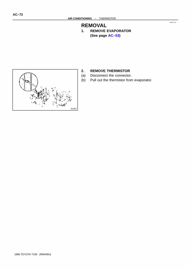
AC0GC−01
I01457
AC−72−AIR CONDITIONING THERMISTOR
1996 TOYOTA T100 (RM449U)
REMOVAL1. REMOVE EVAPORATOR
(See page AC−53)
2. REMOVE THERMISTOR(a) Disconnect the connector.(b) Pull out the thermistor from evaporator.
https://www.truck-manuals.net/

AC0GD−01
I03338
Thermometer
Ice
Thermistor Ohmmeter
10 cm (0.39 in.)
Z04352
5,000
5000
0
4,5004,0003,5003,0002,5002,0001,5001,000
5 10 15 20 25
32 41 50 59 68 77
(Ω)
(°C)
(°F)
−AIR CONDITIONING THERMISTORAC−73
1996 TOYOTA T100 (RM449U)
INSPECTIONINSPECT THERMISTOR RESISTANCE(a) Place the thermistor in cold water, and while changing the
temperature of the water, measure resistance at the con-nector and at the same time, measure temperature of thewater with a thermometer.
(b) Compare the 2 readings on the chart.If resistance value is not as specified, replace the thermistor.
https://www.truck-manuals.net/

AC0GE−01
AC−74−AIR CONDITIONING THERMISTOR
1996 TOYOTA T100 (RM449U)
INSTALLATIONInstallation is in the reverse order of removal (See page AC−72).
https://www.truck-manuals.net/

AC0GF−01
Z04350
Connector
3
2 1
4
Z13470
Low Pressure High PressureSideSide
ON (Continuity)
3,140 kpa196 kpa(2.0 kgf/cm2,28psi)OFF (No Continuity)
(32.0 kgf/cm2,455psi)OFF (No Continuity)
−AIR CONDITIONING PRESSURE SWITCHAC−75
2009Author�: Date�:
1996 TOYOTA T100 (RM449U)
PRESSURE SWITCHON−VEHICLE INSPECTION1. SET ON MANIFOLD GAUGE SET
(See page AC−17)2. REMOVE GLOVE COMPARTMENT DOOR
(See page BO−36)3. DISCONNECT CONNECTOR FROM COOLING UNIT4. SET VEHICLE IN THESE CONDITIONS:(a) Running engine at 2,000 rpm(b) Blower speed control switch at HI(c) Temperature control lever MAX. COOL(d) A/C switch ON
5. INSPECT PRESSURE SWITCH OPERATION(a) Connect the positive (+) lead from the ohmmeter to termi-
nal 1 and negative (−) lead to terminal 3.
(b) Check continuity between terminals when refrigerantpressure is changed, as shown in the illustration.
If operation is not as specified, replace the pressure switch.
https://www.truck-manuals.net/

AC0GG−02
I01456
AC−76−AIR CONDITIONING PRESSURE SWITCH
1996 TOYOTA T100 (RM449U)
REMOVAL1. REMOVE EVAPORATOR (See page AC−53)
2. REMOVE PRESSURE SWITCH FROM LIQUID TUBEDisconnect the connector and remove the pressure switch.
Torque: 10 N·m (100 kgf·cm, 7 ft·lbf)HINT:� Lock the switch mounted on the tube with an open end
wrench, being careful not to deform the tube and removethe switch.
� At the time of installation, please refer to the followingitem.Lubricate a new O−ring with the compressor oil and installthe switch.
https://www.truck-manuals.net/

AC0GH−01
−AIR CONDITIONING PRESSURE SWITCHAC−77
1996 TOYOTA T100 (RM449U)
INSTALLATIONInstallation is in the reverse order of removal (See page AC−76).
https://www.truck-manuals.net/

Z19533
3 4 5
21
3 4 5
1 2
AC0GI−01
AC−78−AIR CONDITIONING HEATER MAIN RELAY
2012Author�: Date�:
1996 TOYOTA T100 (RM449U)
HEATER MAIN RELAYINSPECTIONINSPECT HEATER MAIN RELAY (Making: HTR) CONTINU-ITY
Condition Tester connection Specified condition
Constant2 − 4
3 − 5Continuity
Apply B+ between
terminals 3 and 51 − 2 Continuity
If continuity is not as specified, replace the relay.
https://www.truck-manuals.net/

Z14605
Wire Harness SideAC0GJ−02
Z14604
From Back Side
−AIR CONDITIONING AIR CONDITIONING AMPLIFIERAC−79
2013Author�: Date�:
1996 TOYOTA T100 (RM449U)
AIR CONDITIONING AMPLIFIERON−VEHICLE INSPECTIONINSPECT AMPLIFIER CIRCUIT(a) Remove the glove compartment door
(See page BO−36).(b) Disconnect the amplifier connector and inspect the con-
nector on wire harness side, as shown in the chart below.Test conditions:� Temperature control lever MAX. COOL� A/C switch ON� Turn ignition switch to ON� Blower speed switch at HI
Tester connection Condition Specified condition
8 − Ground Constant Continuity
2 − 6 Constant Continuity
2 − 10 Evaporator temperature at 25 °C (77 °F) Approx. 1.5 kΩ at 25 °C (77 °F)
4 − Ground A/C switch ON Battery positive voltage
4 − Ground A/C switch OFF No voltage
1 − ECM terminal ACT Constant Continuity
9 − ECM terminal AC1 Constant Continuity
7 − Ground A/C switch ON Continuity
7 − Ground A/C switch OFF No continuity
If the circuit is not as specified, inspect the circuits connectedto other parts.
(c) Connect the connector to amplifier and inspect wire har-ness side connector from the back side, as shown in thechart below.Test conditions� Running engine at idle speed� Blower speed switch at ”HI” position� A/C switch ON� Temperature control lever at ”COOL” position� Set on manifold gauge set
Tester connection Condition Specified condition
3 − Ground Refrigerant pressure 196 − 1,340 kPa Battery positive voltage
3 − GroundRefrigerant pressure
less than 196 or more than 3,140 kPaNo voltage
If circuit is as specified, try replacing the amplifier with a newone. If the circuit is not as specified, inspect the circuits con-nected to other parts.
https://www.truck-manuals.net/

AC0GK−01
N09337
AC−80−AIR CONDITIONING AIR CONDITIONING AMPLIFIER
1996 TOYOTA T100 (RM449U)
REMOVAL1. REMOVE GLOVE COMPARTMENT DOOR
(See page BO−36)
2. REMOVE A/C AMPLIFIER(a) Disconnect the connector.(b) Remove the amplifier from the cooling unit.
https://www.truck-manuals.net/

AC0GL−01
−AIR CONDITIONING AIR CONDITIONING AMPLIFIERAC−81
1996 TOYOTA T100 (RM449U)
INSTALLATIONInstallation is in the reverse order of removal (See page AC−80).
https://www.truck-manuals.net/

N05730
AC0GM−02
AC−82−AIR CONDITIONING AIR CONDITIONING SWITCH
2016Author�: Date�:
1996 TOYOTA T100 (RM449U)
AIR CONDITIONING SWITCHREMOVALREMOVE A/C SWITCHUsing a screwdriver, pry loose the clips and remove the A/Cswitch.HINT:Tape the screwdriver tip before use.
https://www.truck-manuals.net/

AC0GN−02
I02282
OFF ON
64
I02283
OFF ON
6
4
3
Z07777
1
346 5
−AIR CONDITIONING AIR CONDITIONING SWITCHAC−83
1996 TOYOTA T100 (RM449U)
INSPECTION1. INSPECT A/C INDICATOR OPERATION(a) Connect the positive (+) lead from the battery to terminal
6 and negative (−) lead to terminal 4 and check that theindicator lights up, when A/C switch ON.
(b) Connect the positive (+) lead from the battery to terminal3 and check that the indicator dims
If operations are not as specified, replace the A/C switch.
2. INSPECT A/C SWITCH CONTINUITY
Condition/ Circuit Tester connection Specified condition
OFF − No continuity
ON4 − 5
4 − 6Continuity
Illumination circuit 3 − 1 Continuity
If continuity is not as specified, replace the A/C switch
https://www.truck-manuals.net/

AC0GO−01
AC−84−AIR CONDITIONING AIR CONDITIONING SWITCH
1996 TOYOTA T100 (RM449U)
INSTALLATIONInstallation is in the reverse order of removal (See page AC−82).
https://www.truck-manuals.net/

N05725
AC0GP−01
−AIR CONDITIONING HEATER CONTROL ASSEMBLYAC−85
2019Author�: Date�:
1996 TOYOTA T100 (RM449U)
HEATER CONTROL ASSEMBLYON−VEHICLE INSPECTIONINSPECT HEATER CONTROL LEVER OPERATIONMove the control lever and dials left and right check for stiffnessand binding the full range of the lever and dials.If there is stiffness and binding, adjust the heater control cable.
https://www.truck-manuals.net/

AC0GQ−01
I01458
Instrument Panel
Heater Control Assembly
Heater Control Knob
Heater Control Panel
A/C Switch
Air Inlet Control Cable
Air Mix Control Cable
Water Valve Control Cable
Mode Control Cable
Heater Control Base
Blower Speed Control Switch
Defroster Mode SwitchBulb
AC−86−AIR CONDITIONING HEATER CONTROL ASSEMBLY
1996 TOYOTA T100 (RM449U)
COMPONENTS
https://www.truck-manuals.net/

AC0GR−02
I04701
Water Valve Control CableAir Inlet Control Cable
Air Mix Control Cable
Mode Control Cable
−AIR CONDITIONING HEATER CONTROL ASSEMBLYAC−87
1996 TOYOTA T100 (RM449U)
REMOVAL1. REMOVE INSTRUMENT PANEL
(See page BO−36)2. DISCONNECT HEATER CONTROL CABLES
3. REMOVE HEATER CONTROL ASSEMBLYRemove the 2 screws and pull out the heater control assembly,then disconnect the connector.
https://www.truck-manuals.net/

AC0GS−01
N05794
N17972
AC−88−AIR CONDITIONING HEATER CONTROL ASSEMBLY
1996 TOYOTA T100 (RM449U)
DISASSEMBLY1. REMOVE BLOWER SPEED CONTROL SWITCH(a) Pull out the bulb.(b) Disconnect the bulb holder.(c) Using a screwdriver, pry loose the clip and push out the
blower speed control switch to rear of the heater controlassembly.
2. REMOVE DEFROSTER MODE SWITCH(a) Disconnect the connector clamp.(b) Remove the screw and switch.
https://www.truck-manuals.net/

Z16144
M1 M2
AC3IY−01
−AIR CONDITIONING HEATER CONTROL ASSEMBLYAC−89
1996 TOYOTA T100 (RM449U)
INSPECTIONINSPECT BLOWER SPEED CONTROL SWITCH CONTINU-ITY
Position/ Circuit Tester connection Specified condition
OFF − No continuity
LO 5 − 6 Continuity
M1 1 − 5 − 6 Continuity
M2 2 − 5 − 6 Continuity
HI 5 − 6 − 8 Continuity
Illumination circuit 3 − 4 Continuity
Switch continuity:If continuity is not as specified, replace the switch.Illumination circuit:If continuity is not as specified, test the bulb.
https://www.truck-manuals.net/

AC0GU−01
AC−90−AIR CONDITIONING HEATER CONTROL ASSEMBLY
1996 TOYOTA T100 (RM449U)
REASSEMBLYReassembly is in the reverse order of disassmebly (See page AC−88)
https://www.truck-manuals.net/

AC0GV−02
N05735
FRESH Clamp
RECIRC
N05736
Clamp
DEF
FACE
N05734
ClampCOOL
WARM
−AIR CONDITIONING HEATER CONTROL ASSEMBLYAC−91
1996 TOYOTA T100 (RM449U)
INSTALLATIONInstallation is in the reverse order of removal (See pageAC−87).1. AFTER INSTALLATION, INSPECT HEATER CONTROL
LEVER OPERATIONMove the control lever and dials left and right check for stiffnessand binding the full range of the lever.If there is stiffness and binding, proceed next step.2. ADJUST HEATER CONTROL CABLES(a) Set heater control assembly in these conditions:
(1) Air inlet control lever in ”FRESH” position(2) Mode control lever in ”FACE” position(3) Temperature control lever in ”Max. WARM” position
(b) Adjust the air inlet control cable.Set the air inlet damper control damper on ”FRESH” posi-tion, install the control cable and lock the clamp.
HINT:Lock the clamp during lightly pushing the outer cable in thedirection shown by arrow.
(c) Adjust mode control cable.Set the air inlet damper control damper on ”FACE” posi-tion, install the control cable and lock the clamp.
HINT:Lock the clamp during lightly pulling the outer cable in the direc-tion shown by arrow.
(d) Adjust air mix control cable.Set the air inlet damper control damper on ”WARM” posi-tion, install the control cable and lock the clamp.
HINT:Lock the clamp during lightly pulling the outer cable in the direc-tion shown by arrow.
https://www.truck-manuals.net/

N05737Clamp
COOLWARM
AC−92−AIR CONDITIONING HEATER CONTROL ASSEMBLY
1996 TOYOTA T100 (RM449U)
(e) Adjust water valve control cable.Set the air inlet damper control damper on ”WARM” posi-tion, install the control cable and lock the clamp.
HINT:Lock the clamp during lightly pulling the outer cable in the direc-tion shown by arrow.
https://www.truck-manuals.net/