15 Medical Physics - Hodder Education
67
1 15 Medical Physics PRIOR KNOWLEDGE Before you start, make sure that you are confident in your knowledge and understanding of the following points: l Light is a wave which shows wave properties including reflection and refraction. l When light crosses from air into glass, the light slows down and is refracted towards the normal. It refracts away from the normal when it travels from glass into air. l Sound is a wave which can be transmitted through media. The speed of sound depends on the medium. l Sound is reflected off denser media. This is called an echo. l Ultrasound is a high frequency sound wave above the frequency range of human hearing. l X-rays are used in medicine as a diagnostic tool. l Radioactive materials emitting beta and gamma rays are used in radiotherapy. TEST YOURSELF ON PRIOR KNOWLEDGE 1 A ray of light is incident on one face of a parallel-sided block of glass, at an angle of 30 ° to the normal. Draw a sketch to show the path of the ray as it passes through the block. 2 An ultrasonic wave travelling in water at a speed of 1500 m s -1 has a frequency of 100 kHz. Calculate the wavelength of the ultrasound. 3 A boy shouts in a mountainous area and hears an echo reflected back to him off a cliff after a time of 2.2 s. Calculate the distance of the cliff away from the boy. Sound travels at 330 m s –1 in air. 4 Technetium-99 is a gamma-emitting radioisotope with a half-life of 6 hours. Explain why technetium-99 is used as a tracer in medical diagnosis. 5 Iridium-192 ( Ir 77 192 ) decays by β − emission to platinum (Pt). a) Write a balanced nuclear equation to describe the decay. b) Explain why iridium-192 can be used effectively as an implant to treat a small cancer in the body. ● l Lenses Refraction in lenses Many optical instruments use glass lenses to form an image. A lens forms an image by refracting light. There are two types of lens: l convex (or converging) l concave (or diverging).
-
Upload
khangminh22 -
Category
Documents
-
view
2 -
download
0
Transcript of 15 Medical Physics - Hodder Education

1
15 Medical Physics
PRiORKNOWledGeBefore you start, make sure that you are confident in your knowledge and understanding of the following points:
l Light is a wave which shows wave properties including reflection and refraction.
l When light crosses from air into glass, the light slows down and is refracted towards the normal. It refracts away from the normal when it travels from glass into air.
l Sound is a wave which can be transmitted through media. The speed of sound depends on the medium.
l Sound is reflected off denser media. This is called an echo.l Ultrasound is a high frequency sound wave above the frequency range
of human hearing.l X-rays are used in medicine as a diagnostic tool.l Radioactive materials emitting beta and gamma rays are used in
radiotherapy.
TesTyOURselFONPRiORKNOWledGe
1 A ray of light is incident on one face of a parallel-sided block of glass, at an angle of 30° to the normal. Draw a sketch to show the path of the ray as it passes through the block.
2 An ultrasonic wave travelling in water at a speed of 1500 m s-1 has a frequency of 100 kHz. Calculate the wavelength of the ultrasound.
3 A boy shouts in a mountainous area and hears an echo reflected back to him off a cliff after a time of 2.2 s. Calculate the distance of the cliff away from the boy. Sound travels at 330 m s–1 in air.
4 Technetium-99 is a gamma-emitting radioisotope with a half-life of 6 hours. Explain why technetium-99 is used as a tracer in medical diagnosis.
5 Iridium-192 ( Ir77192 ) decays by β − emission to platinum (Pt).
a) Write a balanced nuclear equation to describe the decay.b) Explain why iridium-192 can be used effectively as an implant to
treat a small cancer in the body.
●l LensesRefraction in lensesMany optical instruments use glass lenses to form an image. A lens forms an image by refracting light.
There are two types of lens:
l convex (or converging)l concave (or diverging).

15
Me
dic
al
Ph
ysic
s
2
Figure 15.1 shows how each type of lens refracts light. The rules of refraction apply to both types of lens. When light enters the lens it bends towards the normal. When light leaves the lens it bends away from the normal.
Convex lensesAs a result of refractions, parallel rays of light entering a convex lens converge and meet at a point. This point is the principal focus of the lens (Figure 15.2).
focus
Figure15.2
Light can pass through the lens in either direction. So parallel rays coming from the right of the lens converge at a focus that is an equal distance on the left.
A converging lens can form an image of a distant object onto a screen or a piece of paper. The image is sharpest when the piece of paper or screen is at the principal focus of the lens. The distance between the principal focus and the lens is called the focal length of the lens.
When a lens forms an image that we can see on a screen, it is a real image.
Figure15.3
The principal focus of a lens is the point at which rays parallel to the principal axis of the lens are brought to a focus.
The focal length of a lens is the distance between the centre of the lens and the principal focus (or focal point).
A real image is formed when light rays converge to a point.
light refracts towardsthe normal
light refracts awayfrom the normal
concave lens
convex lens
light refractstowards the normal
light refracts awayfrom the normal
(a)
(b)
Figure15.1

Lenses
3
Ray diagramsWhen an object is placed beyond the focal length, as shown in Figure 15.4, the lens forms a real image of the object.
principalaxis
object
image (real,diminished,
inverted)
F F
convex lens
1
23
Figure15.4
Rays come at all angles into the lens, but there are three rays which we can use to locate the image. These rays are chosen because we can predict their path through the lens.
Ray 1 A ray parallel to the principal axis (on the left) passes through the focal point on the right.
Ray 2 A ray which passes through the centre of the lens does not change direction.
Ray 3 A ray which passes through the focal point of the lens on the left-hand side emerges from the lens parallel to the principal axis on the right-hand side.
The place where these three rays meet on the right-hand side of the lens, locates the top of the image. The bottom of the image lies on the principal axis.
In this example, where the object is a long way from the lens, the image is:
l reall invertedl diminished in size.
A real image is formed when rays meet at a point, and the image can be seen by many people on a screen.
Focal length and lens shapeThe focal length of a lens depends on the curvature of the lens surface. The lens in Figure 15.5 has a short focal length because its surfaces have large radii of curvature, and the light is refracted through relatively large angles. The lens in Figure 15.6 is a thinner lens, with less curved surfaces. Its focal length is longer than the lens in Figure 15.5.
A lens with a short focal length is said to be more powerful than a lens with a longer focal length. The power of the lens is defined as the reciprocal of its focal length measured in metres. The power is measured in dioptres, D.
TiPYou should know the rules of refraction and be able to predict which way a light ray bends when it crosses a curved surface.Although you need to understand that light is refracted at both surfaces of a lens, we use a helpful approximation. We make it easier to draw ray diagrams by showing refraction to occur in one place. The refraction in Figure 15.2 is shown to occur at the centre of the lens. We use the symbol to represent a concave lens, and the symbol ↕ to represent a convex lens.
The principal axis of a lens is an imaginary line that passes through the centre of the lens and through the centres of curvature of the faces of the lens.
principalaxis
FF
Figure15.5
principalaxis
F
Figure15.6

15
Me
dic
al
Ph
ysic
s
4
For example, the power of a converging lens of focal length 40 cm is calculated as follows.
Power (P) = 1
0.4m
= + 2.5 dioptres or + 2.5 D
Diverging lenses have a negative power, as they diverge light rather than converge it.
When two thin lenses are placed in contact with each other, the powers of the lenses add up to produce a combined power of the lenses.
P = P1 + P2
Locating an image by drawing or calculationTo find the position of an image you only need to draw two of the rays, not all three. So, from now on, we will just use rays 1 and 2.
Figure 15.7 shows the size and position of the image when the object is just outside the focal length of the lens. In this diagram, the following distances and heights are given these letters:
l the focal length of the lens, fl the distance from the centre of the lens to the object, ul the distance from the centre of the lens to the image, vl the height of the object, hl the height of the image, H
FF
u v
H
h
f
v – f1
2
Figure15.7
The magnification produced by a lens is given by the equation:
=magnification image height
object height
Magnification is a ratio of two heights and so has no units.
Using similar triangles we can see from Figure 15.7 that:
H
h =
v
u
or the magnification,
M = vu
EXAMPLEIn Figure 15.7 the height of the object is 14 mm and the height of the image is 28 mm.
magnification=image heightobject height
=2814
= 2

Lenses
5
The position of the image, the position of the object and the focal length are linked by the following formula:
u
1 +
v
1 =
f
1
In this book, we use the real-is-positive convention.
l All distances are measured from the centre of the lens. l Distances of real objects and real images are positive. l Distances of virtual images (and virtual objects) are negative. l The focal length of a converging lens is positive.l The focal length of a diverging lens is negative.
EXAMPLECalculate the position of the image, when an object is placed 9 cm away from a lens of focal length 6 cm.
answer
u1
+ v1
= f1
so 1v
= f1 – 1u
and
1
v = 1
6 – 19
therefore 1v
= 118
and v = 18 cm
and because v is positive, the image is real.
MaThsBOXHere we derive the formula given above. You are not expected to be able to do this, but the derivation is provided for the interested mathematician.
From Figure 15.7, and using similar triangles, we can write the following equation:
H
v f – =
h
fsoH
h =
v f
f
–
=
v
f –1
However, we know that:H
h =
v
u
Therefore:v
u =
v
f – 1
u
1 =
f
1 – v
1
And finally
u
1 +
v
1 =
f
1

15
Me
dic
al
Ph
ysic
s
6
Concave lensesAs a result of refraction, parallel rays of light entering a concave (or diverging) lens spread out as they pass through the lens (Figure 15.8). The rays look as though they spread out or diverge from a single point. This point is the principal focus of the lens – but because the light only seems to diverge from this point, it is a virtual focus.
The power of a diverging lens is negative. For example, a diverging lens of focal length 67 cm is calculated as follows.
Power = – 1
0.67 m = – 1.5 D
Images and ray diagramsRay diagrams can be drawn for diverging lenses in the same was as for converging lenses. A ray of light incident on the centre of the lens does not change direction. A ray of light that is parallel to the principal axis is refracted so that it seems to have come from a virtual focus.
A virtual image is formed where the two rays seems to cross. It does not matter where the object is, inside or outside the focal length of the lens, the nature of the image is always the same:
l virtuall uprightl diminished.
object
imageF F
Figure15.9
We can also calculate the position of a virtual image using the same formula as we did for the concave lens.
focus
Figure15.8
EXAMPLECalculate the position of the virtual image seen when an object is place 9 cm away from a diverging lens of focal length 6 cm.
Because the focal length is virtual, it is negative.
answer
1u
+ 1v
= f1
19
+ 1v
= 16
−
1v
= – 16
– 19
1v
= – 518
And v = – 3.6 cm
The minus sign tells us that the image is virtual and therefore on the same side of the lens as the object, as shown in Figure 15.9.

The eye
7
TesTyOURselF
1 A diverging lens has a ‘virtual’ principal focus. What does this mean?2 a) What is meant by (i) a real image (ii) a virtual image?
b) Which type of lens always produces a virtual image?3 a) Copy and complete the diagram in Figure 15.10 to show how the
lens forms an image.
F F
Figure15.10
b) State whether the image isi) real or virtualii) magnified or diminishediii) upright or inverted.
4 A converging lens produces a magnification of × 1.5 when a real image is formed at a distance of 15 cm from the lens.a) Draw a scale diagram to show the formation of the image.b) Use your diagram to calculate the focal length of the lens.c) Check your answer to part (b) by doing a calculation.
5 a) A converging lens has a focal length of 20 cm. An object with a height of 2 cm is placed 25 cm from the lens. Calculate the position and height of the image. Is this a real or virtual image? Which way up is the image?
b) A diverging lens has a focal length of 10 cm. An object is placed 30 cm from the lens. Calculate the position and apparent height of the image seen by an observer. Is this a real or a virtual image? Which way up is the image?
6 a) i) Calculate the power of a converging lens with a focal length of 250 cm.
ii) Calculate the power of a diverging lens with a focal length of 50 cm.
b) The two lenses are placed close together. What is the combined power of the lenses now?
●l The eyeThe structure of a human eye is shown in Figure 15.11. The eye is filled with fluid to maintain its even spherical shape. There are two chambers of fluid on either side of the lens, the aqueous humour and vitreous humour. The iris controls the amount of light entering the pupil: in bright light the pupil is small and it is large in low light intensities. The lens and the cornea focus the light in exactly the same way as any other convex lens. A real, inverted, diminished image of an object is formed onto the retina. The retina is the light sensitive part of the eye. The light-sensitive receptors in the eye are known as rods (slender rod-like elements) and cones (narrow conical elements). These receptors have diameters of a few microns.

15
Me
dic
al
Ph
ysic
s
8
lens
iris
cornea
retinavitreous humour
fovea
aqueous humour
optic nerve
suspensory ligaments
Figure5.11
Although the image on the retina is upside down, our brains interpret this image so that we see things the right way up.
The eye as a photodetectorWhen the retina is illuminated with visible light it produces electrical signals, which enable the brain to visualise the image. The retina contains two types of light sensitive cell – rods and cones, as shown in Figure 15.12. There are about twenty times more rods than cones. Rods are used in low-intensity light detection. They produce a simple perception of light; there is little detail and rods do not differentiate between colours – we see shades of grey. Cones are sensitive to different wavelengths (and hence colours of light – see Figure 15.13). Each cone is connected by one nerve fibre to the brain, so we see greater detail with cones and detailed colour. Cones are sensitive to high intensity light, but do not function well in low intensity light, where rods are more effective.
light
section
eye
nerve fibres
synapses
receptors
rod
pigmentedcells
cone
bipolar cells
ganglion cells
Figure15.12There are three different types of cone which respond primarily to blue, green and red light.
TiP1 micron = 1 μm = 10–6 m

The eye
9
0
380nm 450nm 500nm 550nm
wavelength of light (nm)
600nm 650nm 700nm 750nm
25
50
75
100
greenconesrods
redcones
bluecones
retin
al re
spon
se (p
erce
nt m
axim
um)
Figure15.13The rods respond to all wavelengths of light but do not allow us to distinguish colours.
Each rod and cone behaves like a small photoelectric cell, because the light incident on the cell generates an electrical signal, which passes to the brain.
The ratio of rods to cones is not the same in all parts of the retina. The fovea, the region of the retina in line with the pupil, consists entirely of thin closely packed cones. This means that the spatial resolution is high.
Further away from the fovea there are many fewer cones and many more rods. When the eye looks directly at an object, the image is formed in the fovea. Due to the high resolution of the closely packed cones, we can see in great detail. However, the rods also form a very important part of our vision. Rods enable us to detect movement in our peripheral vision. As rods are sensitive to low levels of light, they are responsible for our night vision.
TesTyOURselF
7 a) Explain the differences between the two types of light-detecting cells in the retina.
b) Why do we see in greater details when we look straight at an object?
c) Why do we see less detail in our peripheral vision?d) Explain why rods are used in night vision, rather than cones.
8 a) Use Figure 15.13 to state the range of wavelengths that the eye can detect.
b) Explain which two types of cones are used to detect yellow light. Why is the eye particularly sensitive to yellow light?
AccommodationYou learnt earlier that the position of an image formed by a converging lens depends on the position of the object. The eye is of a fixed length (about 2.5 cm from the cornea to the retina) so the image position is fixed. When an object is in a different position, the eye lens changes shape so

15
Me
dic
al
Ph
ysic
s
10
that we always get a sharp image on our retina. This automatic mechanism is known as accommodation. The shape of the eye lens is controlled by the ciliary muscles. Figure 15.14(a) shows how the eye acts as a refracting system when it is looking at a distant object and Figure 15.14(b) shows it when looking at a nearby object. Most of the refraction occurs at the air/cornea boundary, due to the large change in refractive index across this interface. The cornea acts as a lens with a power of about 41 D.
When the eye lens looks at a distant object, it has a relatively flat shape, providing an additional power of 18 D. So the eye has a total power of about 59 D.
When a young human eye looks at a nearby object, the eye lens can accommodate and provide about an extra 11 D. This provides a refracting system with a total power of about 70 D. The eye in Figure 15.14(b) provides a more powerful refracting system than the lens in Figure 15.14(a).
In a young healthy eye, the accommodation of the eye allows a person to see clearly between a near point of about 25 cm to objects in the far distance. As people get older, the eye lens becomes less flexible and its range of accommodation reduces. So it is common for people who are about 40 years old to have clear vision for distant objects but to focus less well on nearby objects.
●l Defects in visionShort sight (myopia)
When an eye is short sighted, near objects can be seen clearly, as shown in Figure 15.15(a). But the eye lens is too powerful for the length of the eye and distant objects are focused in front of the retina, as shown in Figure 15.15(b). The far point of the eye is the furthest distance that the eye can focus on clearly.
Figure 15.15(c) shows how a diverging lens can be used to correct the eye. For example, if the far point of the eye is 2 m away, a diverging lens with this focal length must be put in front of the eye. Then parallel rays coming from a distant object appear to diverge from the far point of the eye.
So a diverging lens allows a short-sighted person to view distant objects. If the person then wishes to read, he or she simply removes the glasses, because it is easy to focus on objects close to the eye.
(a)
(b)
Figure15.14
Accommodation is the name given to the automatic mechanism whereby the eye lens changes shape to focus on objects at different distances from the eye.
far point
eye’s farpoint and
focal lengthof lens
(a)Ashort-sighted eye sees clearly close to it.
far point
eye’s farpoint and
focal lengthof lens
(b)Ashort-sighted eye is too powerful to focus on distant objects.
far point
eye’s farpoint and
focal lengthof lens
(c)A short-sighted eye is corrected with a diverging lens.Figure15.15For simplicity, the refraction in the eye is shown to take place in the eye lens.

Defects in vision
11
Long sight (hypermetropia)When people suffer from long sight, they can see things clearly at long distances, but their eyes cannot focus clearly on nearby objects. When this condition exists, people are likely to need reading glasses.
Figure 15.16(a) shows a long-sighted eye. The normal near point for a healthy eye is about 25 cm away from the eye. This eye is not powerful enough to focus an image on the retina and the image would come to a focus behind the retina. In this example, the eye’s near point is 75 cm away from the eye, as shown in Figure 15.16(b). This is too far away for the person to read comfortably, so reading glasses are needed. Figure 15.16(c) shows how a converging lens helps the eye to focus an image on the retina when it looks at an object at the normal near point of vision, 25 cm away.
EXAMPLEHow do we calculate the power of the lens needed in Figure 15.16 (c)?
answerWe assume that the lens is close to the eye so that the point A is 25 cm from the lens. [Note that Figure 15.16 (c) is not drawn to scale].
The image seen through the converging lens is at B, but this is a virtual image as the rays appear to come from B, rather than converging at B.
The focal length of the reading lens can be calculated from the formula:
u1
+ v1
= f1
where u = 0.25 m and v = -0.75 m. Using the convention real-is-positive, v is a negative quantity as the image is virtual.
So
1
0.25 – 1
0.75 = f
1
f
1 = 4.0 – 1.33
= 2.67
So power = f
1 = 2.67 D
Note that if you work in metres f
1 gives the power in dioptres.
Some people have difficulty focusing both on distant objects and nearby objects. Then their eyesight can be corrected by using varifocal lenses. These glasses have weaker lenses at the top for distant vision and stronger lenses at the bottom for closer vision.
eye’s ownnear point
virtualimage of A
readinglens
normalnear point
A
B
B A
25cm
75cm
image
(a) A long-sighted eye is too weak to focus on near objects.
eye’s ownnear point
virtualimage of A
readinglens
normalnear point
A
B
B A
25cm
75cm
image
(b) A long-sighted eye sees clearly far away.
eye’s ownnear point
virtualimage of A
readinglens
normalnear point
A
B
B A
25cm
75cm
image
Figure15.16
(c)A long-sighted eye is corrected with a converging lens.

15
Me
dic
al
Ph
ysic
s
12
AstigmatismSo far, we have assumed that the surface of the cornea is a perfect sphere, like an orange or a football. However, it is very common for people to have eyes that have surfaces that are not spherical. So the curvature of the eye surface is more like that of an egg or a rugby ball, as shown in Figure 15.17.
astigmatic
non-astigmatic
Figure15.17In astigmatism, the front surface of the eye has an irregular shape like an egg. Whereas the non-astigmatic eye is shaped like an orange.
In Figure 15.17, the egg shaped ‘eyeball’ has a greater curvature in the vertical plane than the horizontal plane. This means that light is focused more strongly by the eye in the vertical plane than in the horizontal plane. So when opticians design our glasses, they take account of astigmatism by making the lenses cylindrical in shape to correct for astigmatism. Opticians define the direction of astigmatism relative to the eye using an angle, as shown in Figure 15.18.
90100 80 7060
50
4030
2010
0
110120
130
140
150
160
170
180
Figure15.18

Defects in vision
13
EXAMPLE1 A patient has the following prescription. What does it mean?
Near sphere cylinder axisRight +2.00 –0.50 10°
left +2.25 –1.25 170°
answer First, the patient is long sighted as the correcting lenses for both eyes
are converging with powers of 2.00 D and 2.25 D. The heading ‘near’ tells us that this prescription corrects for vision near to the eye.
The right eye lens has a power of 2.00 D along the 10° axis, and a power of 1.50 D at right angles to this along the 100° axis. The left eye lens has a power of 2.25 D along the 170° axis and 1.00 D at right angles to this along the 80° axis.
2 A patient has the following prescription. What does it mean?
Far sphere cylinder axisRight –1.25 0
left –0.75 –0.25 40°
answer Here we can see that this prescription corrects for vision far from the eye.
The negative powers of the lens show that the patient is short sighted. The right eye has no astigmatism, as the cylindrical measurement is
zero. The left eye has a power of −0.75 D along the 40° axis and a power of −1.00 D along the 130° axis.
TesTyOURselF
9 a) Make a sketch of a human eye and label the iris, pupil, cornea, lens, suspensory ligaments, retina and optic nerve.
b) Which two parts of the eye are responsible for refracting light and forming an image?
10 a) Explain what is meant by the term accommodation.
b) Draw diagrams to explain how an eye accommodates to focus oni) an object far awayii) an object close by.
11 An eye is short sighted. The far point of vision for the eye is 1.8 m.a) Sketch a diagram to show how a lens can be
used to enable the eye to focus on far away objects.
b) Calculate the power of the lens required for the eye to focus on far away objects.
12 An eye is long sighted and has a near point of vision of 30 cm.
a) Sketch a diagram to show how a lens can be used to help the eye to focus on a book 25 cm in front of it.
b) Calculate the power of the lens you have chosen. It is rare for reading glasses to be stronger than +4.0 D. Explain why.
13 a) Explain what is meant by the term astigmatism.b) Two patients, X and Y, have the following
prescriptions for their eyes. In each case, describe what is wrong with their eyes.
X Near sphere cylinder axis
Right +0.5 0
Left +0.75 0
y Near sphere cylinder axis
Right −2.25 −1.0 80
Left −1.75 −0.5 100
c) What shape of lens is used to correct astigmatism?
TiPFor an astigmatic eye:l the power of the lens along the
axis = sphere powerl the power of the lens
perpendicular to the axis = sphere power + cylinder power

15
Me
dic
al
Ph
ysic
s
14
●l Physics of the earThe ear as a detection systemThe eye consists of three regions, the outer ear, the middle ear and the inner ear.
external auditory passage
tympanicmembrane
malleus (hammer)
incus (anvil)semicircular canals
auditory nerve
cochlea
Eustachian tube(leading to the mouth)
round window
oval window
pinna
stapes (stirrup)
EXTERNAL OROUTER EAR
MIDDLEEAR
INNEREAR
Figure15.19
The outer ear begins with the ear flap (pinna) which is connected by the ear canal (external auditory passage) to the ear drum (the tympanic membrane).
The middle ear comprises a cavity which is connected by the Eustachian tube to the mouth. This allows the pressure in the ear to be adjusted – you can do this by swallowing; you will find you need to adjust your ear pressure when you go uphill in a car, for example.
The middle ear also has three small bone levers (ossicles) which connect the outer ear to the inner ear, where nerves can detect sound.
The inner ear has three semicircular canals, which help us with balance and detect changes in velocity. The inner ear also contains the cochlea, which is the organ responsible for transmitting the sensation of sound to our brains.
The cochlea is a helical, spiral shaped cavity, but its function can be best understood by reference to Figure 15.20, which is an ‘uncoiled’ representation of the cochlea. One end of the cochlea is connected to the oval window and the lower end of the cochlea is terminated by the round window. Sound waves are transmitted along the cochlea, where movement in the membrane causes small hairs in the cochlea to bend backwards and forwards. The distortion of the hair cells then initiates neural impulses which travel along the auditory nerve to the brain.

Frequency range of sound
15
basilarmembrane
BONE
BONEoval window
stapes
tympanic cavity
round window
tectorial membrane
tectorialmembrane
basilar membrane
endolymph
detailed inset
organ of Corti
organ ofCorti
‘structural’ cellshair cells
nerve fibresto brain
hairs
Figure15.20
The mechanism of sound transmissionEach of the three parts of the ear plays a part in allowing us to hear.
The earflap is designed to collect sound and channel it down the ear canal. It also helps us to detect the direction of sounds. The eardrum then vibrates as a result of the changes in pressure caused by the expansions and rarefactions in the sound waves. The eardrum is connected to the three ossicles which rock like levers to transfer energy to the oval window. Then, finally, the energy stimulates movement in the hair cells in the cochlea, to transmit a signal along the auditory nerve, which our brain recognises as sound.
●l Frequency range of soundThe range of audible frequency varies from person to person, but the average range is about 20 Hz to 20 000 Hz. However, as we get older we are less able to hear the higher frequencies and, for people past middle age, the upper limit of hearing is likely to be about 12 000 Hz.
The sensitivity of our ears depends on the frequency of the sound. Figure 15.21 shows that the ear is most sensitive to sounds of frequency about 3000 Hz. For us to hear lower or higher frequencies, the intensity of sound must be several orders of magnitude higher. For example, Figure 15.21 shows us that for us to hear sounds of frequency 100 Hz or 10 000 Hz, the lowest intensity of sound must be about 10–8 W m–2.
10–12
10–10
10–8
10–6
10–4
102
1
10–2
0
20
40
60
80
140
120
100
frequency (Hz)101 100 1000 10000
soun
d in
tens
ity (W
m–2
)
inte
nsity
leve
l (dB
)
frequency range atgiven intensity level
not detected detected
threshold of hearing
Figure15.21

15
Me
dic
al
Ph
ysic
s
16
The ear’s logarithmic responseThe ear can detect a great range of intensities of sound. At the lower limit, the ear can detect intensities as low as 10–12 W m–2 at a frequency of 1 kHz, which is known as the threshold of hearing. At the upper limit, the ear can hear sounds as loud as 100 W m–2, above which point we would be likely to suffer pain, and if we are exposed to such intensities for long periods, the ear is likely to be damaged and our hearing adversely affected.
However, our detection and discernment of changes in intensity are not linear. We can more easily discern changes in intensity at low intensities of sound than at high intensities. For example, if the intensity of sound is increased from 1 × 10⁻⁶ W m–2 to 2 × 10⁻⁶ W m–2, and then again from 2 × 10⁻⁶ W m–2 to 4 × 10⁻⁶ W m–2, the loudness of the sound appears to change in equal steps. This is a logarithmic response to sound intensity, and it therefore makes sense for us to describe sound intensity using a logarithmic scale.
The definition of intensity and the decibel scaleThe intensity level of sound is defined by this equation:
intensity level = I
Ilog B10
0
where Io is the generally accepted threshold of hearing of 10–12 W m–2.
In this scale the intensity is measured in bels (B).
However, since the bel is a large unit, representing intensity differences in the ratio 10 :1, we use the decibel (dB) to describe sound intensities.
1 B = 10 dB
and intensity level = 10 I
Ilog dB10
0
For example, a sound of intensity 10–11 W m–2 has an intensity level of:
intensity level = 10 log10
1010
11
12
−
−
= 10 dB (or 1B)
Note that we define intensity levels of sound relative to the thresholds of hearing of 10–12 W m–2 at 1 kHz.
Sound intensity is a direct measure of the power reaching an eardrum measured in W/m2.
The intensity level of sound is a measure relative to the threshold of hearing, defined as 0 dB. Intensity levels are measured in dB.

Frequency range of sound
17
The difference in intensity level between two sounds is given by:
−
I
I
I
I10 log log dB10
2
010
1
0
= 10 I
Ilog dB10
2
1
For example, the difference in intensity levels between a person shouting with sound intensity 8 × 10⁻⁵ W m–2 and someone speaking with sound intensity 2 × 10⁻⁶ W m–2 is:
10 log8 10
2 1010
5
6
××
−
−
= 10 log10 40
= 16 dB
EXAMPLE
1 The sound intensity near to a road in a town centre is 3 × 10⁻⁵ W m–2. Calculate the intensity level in dB.
answer
Intensity level = 10 ×
−
−log3 1010
10
5
12
= 75 dB
2 Background noise from a loudspeaker produces an intensity level of 46 dB. Calculate the sound intensity of the music.
answer
46 = 10
−log
1010 12I
4.6 = −log
1010 12I
104.6 = −10 12I
So
I = 10–12 × 104.6
= 10–12 × 4 × 104
= 4 × 10⁻⁸ W m–2

15
Me
dic
al
Ph
ysic
s
18
Equal loudness curves and the dBA scaleYou read earlier that the ear is most sensitive to sounds in the region close to 3 kHz. The ear is less sensitive at frequencies above and below 3 kHz.
The decibel scale relates to the intensity of a sound calculated in W m–2. However, what matters to us is not so much the sound intensity measured in W m–2, but the loudness that we actually perceive. We can tolerate a low frequency noise of 100 Hz much more comfortably than the same sound intensity at 3 kHz.
The sensitivity of the ear varies from person to person. An equal loudness curve can be produced for a person by getting him/her to say what sounds appear to be of the same loudness. Figure 15.22 shows two typical responses for people of different ages, and also a response for someone with impaired hearing.
frequency (Hz)
100
100
A Threshold of hearing for a 20 year oldB Threshold of hearing for a 55 year oldC Threshold of hearing for an ear damaged by excessive noise
300 103 1043 ×103
80
60
40
20
inte
nsity
leve
l (dB
)
A
B
C
Figure15.22
Curve A shows the typical response for a young person with good hearing. Their threshold of hearing is at approximately the accepted value, 10–12 W m–2 at 1 kHz. You can see that for them just to hear a sound of frequency 100 Hz the intensity of the sound needs to be about 30 dB above the level to hear the same sound intensity at 3 kHz.
Curve B shows an equal loudness curve for someone in middle age. They have suffered from a hearing loss of about 10 dB at lower frequencies, but the loss is more severe at high frequencies. So sounds need to be 10 dB to 20 dB louder for the middle-aged person to have the same loudness as have for the young person.
Curve C shows an equal loudness curve for someone whose hearing has been damaged by industrial noise. The ear is most sensitive to frequencies of about 3 KHz, so the loss can be greatest at this frequency.
Loudness is a subjective quantity which depends on the sensitivity of an individual’s ears.

Frequency range of sound
19
The dBA scaleIt is usual to quote the intensity of sounds on the dBA scale which takes account of the sensitivity of the human ear. These are called A-weighted sound levels. The dBA scale links the sound intensity at different frequencies to the relative loudness perceived by the human ear.
Figure 15.23 shows the A-weighted sound levels adjusted to dBA for the three different people highlighted in Figure 15.21.
These curves are the inverse shape of the equal loudness curves shown in Figure 15.22.
A-w
eigh
ted
soun
d le
vels
(dB
A)
60 A
B
C40
20
0
100 1000 3000300 10000
frequency (Hz)
Figure15.23Three people A, B, C, are exposed to sounds of intensity level 60 dB across the audible range of frequencies. Due to the sensitivity of the ear, the perception of loudness changes with frequency. B and C have different corrected curves, because their hearing is not as good as A’s.
l At 3000 Hz, A is exposed to an intensity level of 60 dB. When he is exposed to the same level at a frequency of 300 Hz, it sounds quieter to him. At 300, Hz A’ s weighted sound level is 40 dBA, even though a microphone might record the intensity level of 60 dB. It is the subjective impact of the sound on the ear that gives rise to the loudness heard by each person.
l B suffers from some age-related hearing loss. In comparison with A, B has lost about 10 dB of hearing in the range close to 3000 Hz.
l C’ s hearing is worse that both A’ s and B’ s. C hears a narrower range of frequencies than the others. C’ s loss of hearing (at around 3 kHz) might have been caused by being exposed to excessive noises which have damaged the cochlea, or it might be as a result of an illness.
Table 15.1 shows some approximate intensity levels for various common sources of sound.
Table15.1
sourceofsound intensitylevel(dBa) soundintensity(Wm–2)
Silence(threshold of hearing)
0 10–12
Whispering 20 10–10
Normal speech 60 10–6
A jet plane 1000 m overhead 100 10–2
Thunder overhead 110 10–1

15
Me
dic
al
Ph
ysic
s
20
TesTyOURselF
14 Each of the following is part of the ear. Explain the function of each part.i) malleusii) tympanic membraneiii) oval windowiv) cochleav) pinna
15 Give an account of how sound is transmitted from the outer ear to the inner ear.
16 a) Explain what is meant by the threshold of hearing. b) How is the threshold of hearing defined?
17 a) A person speaks with an intensity of 7 × 10⁻⁶ W m–2. Calculate the sound’s intensity level in dB.
b) A car makes a sound with an intensity level of 65 dB. Calculate the intensity of the sound in W m–2.
c) A musician plays two notes on a violin. A person hears two different sound intensities for the notes: 5 × 10⁻⁶ W m–2 and 8 × 10⁻⁷ W m–2. Calculate the differences between the two intensity levels in decibels.
18 The three curves in Figure 15.23 show the A-weighted sound levels for three people.a) i) Explain what is meant by an A-weighted sound level. ii) Explain what is meant by the word loudness. iii) Two people listen to a sound, but do not agree on how loud it is.
What do you know about loudness that would explain this?b) Compare the difference in the sensitivity of A’s ear at frequencies
of 100 Hz and 3000 Hz.c) i) Use the graph to state the range of frequencies which C was
able to hear in this test. ii) State the hearing loss of C in dB, in comparison to A, at a
frequency of 3 kHz. How many times more sensitive are A’s ears than C’s ears at this frequency?
19 a) Distinguish between the intensity, intensity level and loudness of a sound, and give the units to measure each quantity.
b) Express the following in decibels: i) The increase in intensity level due to the power from a
loudspeaker changing from 3 W to 12 W. ii) The decrease in intensity level due to moving from 10 m
to 20 m away from a source which is emitting sound in all directions.
[Hint: you need to assume that sound intensities obey an inverse square law I α 1
r2 ].
iii) The difference in intensity level between the noise from an express train of 4 × 10⁻³ W m–2 10 m away and someone shouting 5 m with a noise of 6 × 10⁻⁶ W m–2.

Biological m
easurement
21
●l Biological measurementSimple ECG machines and the normal ECG waveformThe brain controls the action of muscles by sending a signal along nerves. For example, if we decide to pick something up, our brain sends a signal to our fingers. The muscle which is an exception to this rule is our heart, where the electrical stimulus for movement originates in the heart itself.
The heart muscle contains millions of cells which are more negatively charged on the inside and less positively charged on the outside. There is a potential difference of about 80 mV across the cell membranes; this is known as the resting membrane potential. Figure 15.24 shows how the potential varies with time across the cell membranes.
0.2
leakage
+40
–80 repolarisation
threshold
time (s)
mem
bran
e po
tent
ial (
mV)
contraction
0.4 0.6 0.8
A
B
C D
E
Figure15.24
Over the period AB, charges migrate across the membrane, until the time B is reached (the threshold). At this point, charge migration becomes very rapid. Consequently, the cells redistribute the charges, so that the inside of the cells become more positively charged. This process is known as depolarisation. After the cells in each zone have depolarised, the charges rapidly move back to their original positions and the cell membrane is repolarised, as shown by part DE of the graph. This process repeats itself every second or so, and this is one beat of the heart.
Electrocardiography (ECG) measurementsDuring one heartbeat, different parts of the heart are stimulated at different times. For example, the atria are stimulated slightly before the ventricles. So cells in different places depolarised at different times. Therefore there is a potential difference between cells which have depolarised and those which are about to depolarise. The body conducts electricity sufficiently well for this potential difference to be detected across different parts of the body.
The study of the waveform from the heart is known as electrocardiography. The machine that examines the waveform produces electrocardiograms which can be examined by cardiologists. Electrodes are connected to the body at various places. Good electrical contact is ensured by connecting the electrodes to the body using a conducting gel. Figure 15.25 shows a typical ECG which is produced when electrodes are placed in the right arm and in the left arm.
l The P-wave occurs during depolarisation of the atria which causes the contraction of the atria.
l The QRS pulse corresponds to the depolarisation and then the contraction of the ventricles.
l The T-wave occurs during the repolarisation of the ventricles which corresponds to the relaxation of the ventricles.
p.d.
at s
urfa
ce e
lect
rode
s (m
V)
time (s)0.2
P
Q
R
S
T
0
1
0.4 0.6 0.8 1.0
Figure15.25

15
Me
dic
al
Ph
ysic
s
22
ECG electrode sitesThe ECG electrodes may be placed over the heart, on the torso or on the limbs at points where the major arteries run close to the surface.
There are standard electrode sites, which allow electrocardiographers to observe the heart’s electrical activity; these are listed in the table. The standard sites are connected in pairs to the two terminals of an ECG amplifier to give 12 possible connection systems (known as ‘leads’).
right arm and left arm lead 1
right arm and left leg lead 2
left arm and left leg lead 3
right arm and left arm and leg aVR
left arm and left leg and right arm aVL
left leg and right and left arm aVF
one of six chest sites both arms and left leg V1, V2, V3, V4, V5, V6
l aVR stands for augmented vector rightl aVL stands for augmented vector leftl aVF stands for augmented vector foot
Examination of electrocardiograms allows specialists to note various heart complaints, such as irregularity in rhythm or parts of the body where blood flow is restricted.
TesTyOURselF20 a) What is meant by the term ECG?
b) Explain how an ECG can allow cardiologists to investigate whether a patient’s heart is healthy.
21 a) State how good electrical contact is made between the electrodes of an ECG and the body.
b) Name four parts of the body where electrodes are placed for an ECG.22 Sketch a graph of potential difference, obtained at the electrodes,
against time for the waveform obtained from a single beat of the heart in a healthy person. Give approximate scales on the axes and label your diagram with the chief features of interest in cardiology.
●l Non-ionising imagingUltrasound imaging
Piezoelectric devicesUltrasound is a sound wave above the upper end of the human hearing range of 20 kHz. Ultrasound is produced using piezoelectric crystals such as quartz or the synthetic ceramic, lead zirconate titanate. When a potential difference is applied across a piezoelectric crystal it compresses or extends along the direction of the p.d. Therefore, if a high frequency p.d. is applied across the crystal, it vibrates backwards and forwards at that frequency, so that ultrasonic waves are produced. See Figure 15.26.
+ + + +
– – – – + + + +
– – – –
Figure15.26A p.d. applied across a piezoelectric crystal causes it to change shape.

Non-ionising im
aging
23
An ultrasonic transducer is a device which converts the electrostatic energy supplied to a crystal into the energy transferred by the ultrasonic waves. The same transducer can be used as a receiver to detect ultrasound when the ultrasound impacts on to the piezoelectric crystal, causing it to distort. The oscillating crystal now produces an a.c. signal which can be detected and amplified.
casing acousticabsorber
plastic membrane
ultrasoundbeam
quartz piezoelectriccrystal
backing material
coaxial cable
Figure15.27
Ultrasound as a diagnostic toolTypical ultrasonic frequencies range between 1 MHz and 18 MHz. The choice of frequency is a balance between the spatial resolution of the image and the imaging depth. Higher frequency (small wavelength) sounds produce a narrow beam because they diffract less than lower frequency (long wavelength) sounds. The smaller wavelength sounds are also capable of reflecting or scattering off smaller structures. Higher frequency sounds are absorbed more readily by tissues. Therefore, the lower frequency sounds can penetrate more deeply into body tissues. When energy is absorbed, the intensity of the transmitted sound decreases; this is called attenuation. Ultrasound can be used to build up images of the inside of our bodies because ultrasound waves reflect differently off the various organs or bones inside the body.
Reflection of ultrasoundThe reflection of ultrasound (or sound) between the interface of two mediums depends significantly on the acoustic impedances of the two materials.
The acoustic impedance of a material is defined by the following equations.
Acoustic impedance = density × speed of sound
Z = c ρ ×
Where Z is the acoustic impedance in kg m–2 s–1
ρ is the density in kg m–3
c is the speed of sound in m s–1
Figure 15.28 shows a beam of ultrasound incident on the boundary between two media: 1 and 2. The acoustic impedance of medium 1 is Z1, and the acoustic impedance of medium 2 is Z2.
refracted or transmittedsound beam
reflectedsound beamnormal
Z1
Z2
incidentsoundbeam
Figure15.28
Attenuation is the gradual loss in intensity as sound (or any other wave) passes through a medium.

15
Me
dic
al
Ph
ysic
s
24
It can be shown that the ratio of the reflected intensity Ir, to the incident energy Ii is given by:
I
I
Z Z
Z Z
r
i
2 12
2 12=
( )( )
−+
This equation assumes that the energy is incident along the normal (at right angles) to the surface.
The ratio I
Ir
i
is called the intensity reflection coefficient.
Table 15.2 below shows the velocity of sound in various body tissues and air, together with the associated densities and acoustic impedances.
Table15.2
MaterialVelocityofsound/ms–1 density/kgm–3
acousticimpedance/kgm–2 s–1×10⁶
Air 330 1.3 4.30 × 10⁻⁴
Oil 1500 950 1.43
Water 1500 1000 1.50
Bone 4100 1900 7.79
Brain 1540 1030 1.59
Muscle 1580 1080 1.71
Liver 1590 1040 1.65
Fat 1450 950 1.38
Blood 1570 1060 1.66
EXAMPLE1 A beam of ultrasound passes through the muscle tissue in a patient’s
stomach and is incident on the bladder full of water. Calculate the fraction of the ultrasound reflected off the water in the bladder.
answer
Z2 (water) = 1.50 × 10⁶ kg m–2 s–1
Z1 (muscle) = 1.71 × 10⁶ kg m–2 s–1
=II
Z Z
Z Zr
i
2 12
2 12
( )( )
−
+
= 1.50 1.71
1.71 1.50
2
2
( )( )
−
+
= 0.012
Note that since all impedances are multiplied by 106, this factor can be cancelled out before doing the calculation.
So only a small amount of energy is reflected. However, this is sufficient for a small echo to be produced, and for the echo or reflection to be noticeable. In this example, the tissues are acoustically well matched, and the reflection is small. When Z1 » Z2 or Z2 » Z1 the materials are poorly matched acoustically and there is a large reflection.

Non-ionising im
aging
25
2 Ultrasound travels from air into muscle tissue. What fraction of the energy is reflected now?
answer
Z2 (muscle) = 1.71 × 10⁶ kg m–2 s–1
Z1 (air) = 4.3 × 10-4 × 106 kg m–2 s–1
= 4.3 ¥ 102 kg m–2 s–1
II
1.71 10 4.3 10
1.71 10 4.3 10
r
i
6 2 2
6 2 2
( )( )
=× − ×
× + ×
= 1.0
In this case nearly all the energy is reflected.
This second example explains why, when an ultrasonic transducer is placed on the body, it must have a layer of gel between it and the body. The gel ensures a good acoustic match; if any air gets between the transducer and the body, a lot of energy is reflected.
TesTyOURselF23 An ultrasonic scanner uses a frequency of 10 MHz.
a) State the advantages of using a higher frequency of ultrasound.b) State the disadvantages of using a higher frequency ultrasound.
24 a) What is meant by a piezoelectric crystal?b) Explain how a piezoelectric crystal can be used to generate high
frequency ultrasound.25 Oil has a density of 950 kg m-3 and sound travels through it at a
speed of 1500 m s–1.a) Calculate the acoustic impedance of oil.b) A beam of ultrasound in oil is incident on an oil/water boundary.
Water has an acoustic impedance of 1.50 × 10⁶ kg m-2 s-1. Calculate the fraction of energy
i) reflected at the surfaceii) transmitted into the surface.
26 a) Rock and air are acoustically poorly matched. Explain what this means.
b) Use the data in Table 15.2 and the data below to show why sound is reflected very efficiently off a cliff. Speed of sound in granite is 6000 m s–1; density of granite is 2700 kg m–3.
15
Me
dic
al
Ph
ysic
s
26
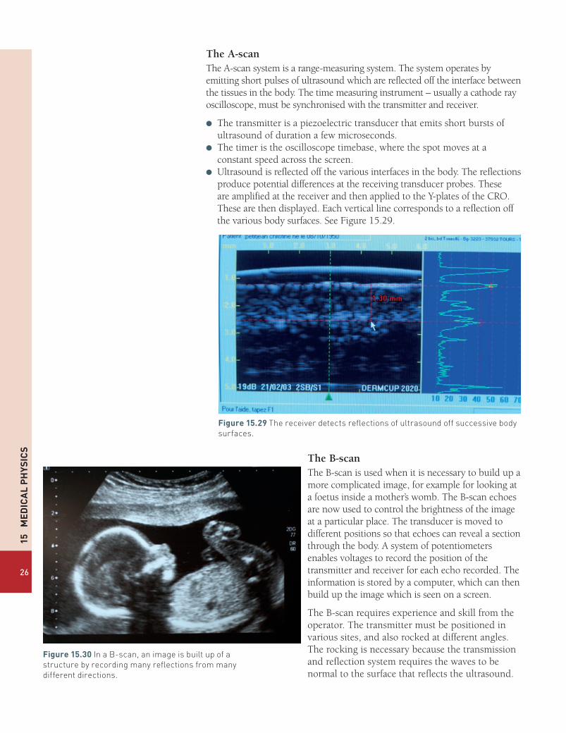
The A-scanThe A-scan system is a range-measuring system. The system operates by emitting short pulses of ultrasound which are reflected off the interface between the tissues in the body. The time measuring instrument – usually a cathode ray oscilloscope, must be synchronised with the transmitter and receiver.
● The transmitter is a piezoelectric transducer that emits short bursts of ultrasound of duration a few microseconds.
● The timer is the oscilloscope timebase, where the spot moves at a constant speed across the screen.
● Ultrasound is reflected off the various interfaces in the body. The reflections produce potential differences at the receiving transducer probes. These are amplified at the receiver and then applied to the Y-plates of the CRO. These are then displayed. Each vertical line corresponds to a reflection off the various body surfaces. See Figure 15.29.
Figure15.29The receiver detects reflections of ultrasound off successive body surfaces.
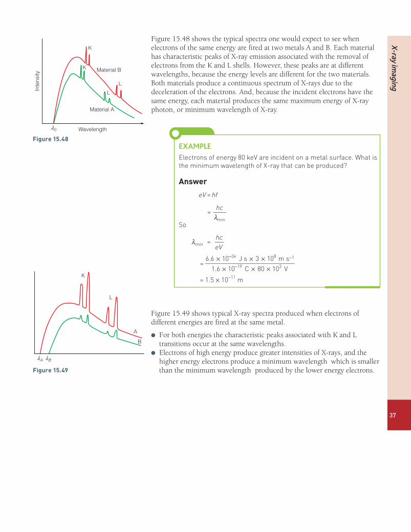
The B-scanThe B-scan is used when it is necessary to build up a more complicated image, for example for looking at a foetus inside a mother’s womb. The B-scan echoes are now used to control the brightness of the image at a particular place. The transducer is moved to different positions so that echoes can reveal a section through the body. A system of potentiometers enables voltages to record the position of the transmitter and receiver for each echo recorded. The information is stored by a computer, which can then build up the image which is seen on a screen.
The B-scan requires experience and skill from the operator. The transmitter must be positioned in various sites, and also rocked at different angles. The rocking is necessary because the transmission and reflection system requires the waves to be normal to the surface that reflects the ultrasound.
Figure15.30In a B-scan, an image is built up of a structure by recording many reflections from many different directions.

Non-ionising im
aging
27
Use of ultrasound scanningUltrasound scanning is widely used in medicine. A few uses are listed below.
● Echocardiography is an essential tool in cardiology to diagnose the dilation of parts of the heart and function of heart ventricles and valves.
● In emergency medicine, ultrasound can be used to locate the position of a trauma inside the body.
● Organs such as the pancreas, liver, gall bladder and kidneys may be examined.
● In the neck, the thyroid, lymph nodes and saliva glands may be examined.
● In the field of obstetrics, ultrasound is widely used during pregnancy. Scans can determine: the date of the pregnancy; the viability of the foetus; check on the location of the foetus thus ensuring safety during birth; check for physical abnormalities; check on movement and heartbeat; and determine the sex of the baby.
● Ultrasound can also be used to examine tendons, muscles, nerves and ligaments. Sometimes ultrasound is used as an alternative to X-rays for patients up to the age of 12.
Advantages and disadvantages of ultrasound● It is non-ionising, has no known side effects and, for nearly all patients,
produces no discomfort. This makes ultrasound particularly useful for examining unborn babies and infants, for whom ionizing radiation is particularly dangerous.
● It shows the structures of organs.● It images muscle, soft tissue and bone surfaces very well. It shows up
clearly the boundary between solid and fluid filled spaces.● The resolution of ultrasound is high – but not as clear as X-rays or MR
scanners.
Some of the disadvantages of ultrasound are listed below.
● Ultrasound does not penetrate bone.● Ultrasound performs poorly when there is gas between the transmitter
and organ to be examined due to the extreme differences in acoustic impedances. For example, lung imaging is not possible.
● The depth of ultrasound penetration can be limited. This can be a particular problem in obese patients. Greater penetration can be o btained by using lower frequency ultrasound, but then the resolution is poorer.
● The method depends on the operator. A high level of skill and experience is required to produce good quality images.

15
Me
dic
al
Ph
ysic
s
28
TesTyOURselF27 a) Why is ultrasound used in medicine as a
diagnostic tool? State two advantages of using ultrasound, and two disadvantages.
b) Give three examples of how ultrasound is used as a diagnostic tool.
28 Explain the difference between the uses of A and B-scans in ultrasonic diagnosis.
29 When structures near the surface of the body are examined – for example muscles and tendons – ultrasound of frequency 7–18 MHz is used. Deeper structures such as the liver and kidney are imaged at lower frequency 1–6 MHz. Explain why different frequencies are used for these investigations.
30 Figure 15.31 shows the intensity of reflections when ultrasound is reflected off different layers of the bodies.
Discuss qualitatively why the intensity of the reflections is different at each surface.
31 a) Why is a coupling medium necessary between a source of ultrasound and a body during ultrasonic investigation of the body?
b) The velocities of sound in air, oil and in body tissue (on average) are 0.33 km s–1, 1.50 km s–1 and 1.53 km s–1. The densities of the three media are respectively: 1.3 kg m–3, 950 kg m–3, 1065 kg m-3. Estimate the fraction of the sound intensity reflected at each of the following interfaces.i) an air-tissue interfaceii) an oil-tissue interfaceiii) an air-oil interfaceComment on your results.
32 When ultrasound passes through the body, some energy is absorbed. This is called attenuation. The graph in Figure 15.32 shows the attenuation of the intensity of ultrasound 2 MHz with depth. In this investigation a child’s kidney is to be examined.
The acoustic impedance of the kidney is 1.65 × 10⁶ kg m–2 s–1 and that of the surrounding body tissue is 1.40 × 10⁶ kg m–2 s–1. Use this information and the information in the graph to calculate the ratio of the intensity of the reflections from A and B, by the time the pulses come back to the receiver. (Remember that attenuation happens in both directions and assume that attenuation occurs at the same rate in the kidney and the body tissue.)
Figure15.31
fat muscle bone
probe
piezoelectrictransmitter/
receiver
0 1 2 3 4 5 6 7Dep m/cm
A B
body tissue
Kidney
Figure15.32(a)
Figure15.32(b)
1
1 2
inte
nsity
depth (cm)
2
3
4
5
6
7
8
3 4 5 6 7 8

Non-ionising im
aging
29
Fibre optics and endoscopyFigure 15.33 shows a surgeon using an endoscope as he operates on a patient, and Figure 15.34 shows what he sees through the endoscope.
An endoscope is a fibre optic device which depends on light being transmitted, without loss, along an optical fibre. When light strikes the inside of the optical fibre at a shallow angle the light undergoes total internal reflection. (See page 86 of AQA A level Physics Book 1.)
The fibre (or the core) which transmits the light is surrounded by a cladding which has a slightly lower refractive index. The cladding serves two purposes.
● Firstly, the cladding protects the inner fibre.● Secondly, by having a refractive index just smaller than the inner fibre,
the critical angle reaches a large value. This reduces the number of reflections along a length of fibre.
Figure15.35(a)and(b)A ray is reflected at the critical angle inside a fibre.
transmitted ray
reflected ray
nc
nfn0
i rq
nc
nfn0
i rqcqc
Typical values for the refractive indices are:
● refractive index of inner fibre 1.52 nf
● refractive index of cladding 1.48 nc
● refractive index of air 1.00 n0
Figure15.33
Figure15.34
EXAMPLE1 Calculate the critical angle inside the fibre in
Figure 15.35.answerThe critical angle is given by the formula (page 86 Book 1):
θ nn
sin =cc
f
= 1.481.52
= 0.974
θ −= sin 0.974c1
= 77° (2 sig fig)
Figure 15.35 shows what happens if a light ray enters the fibre at a larger angle of incidence. The angle of refraction r becomes larger and therefore the angle of incidence on the fibre,θ , becomes smaller, and below the critical angle. [The angle θ is equal to (90° – r).]
2 Calculate the greatest angle of incidence, imax, which ensures that the light undergoes total internal reflection inside the fibre.
answerIn Figure 15.35(a)
θ = 77co
Therefore r = 90° – 77°
= 13°
=ir
nn
sinsin
max
max
f
0
So
sin imax = ×1.521.00
sin13°
= 0.34
i = sin-1 0.34
= 20°

15
Me
dic
al
Ph
ysic
s
30
Coherent and incoherent bundlesA coherent bundle of fibres is the name given to fibres that are placed together in an orderly fashion. In this bundle, a fibre remains in the same position relative to its neighbouring fibres. Each fibre transmits a small portion of an image, so that a coherent bundle allows the eye to see a clear image at the other end of the endoscope. (See Figure 15.36.) The image can be viewed using an eyepiece at the end of the endoscope.
Typically, fibres of diameter 10 μm are used in coherent bundles. The small diameter allows greater resolution of the image, as each fibre images a small part of the object under examination. If fibres of diameter smaller than about 5 μm are used, diffraction starts to be significant, so there is a loss of clarity in the image.
Incoherent bundles of fibres are also used in endoscopes. Here the fibres are arranged at random. Incoherent bundles are not used for image formation, but only to transmit light. The fibres in an incoherent bundle are relatively large compared with the fibres in a coherent bundle, having diameters of 50 μm–100 μm.
Fibre-optic endoscopeFigure 15.37 shows the basic principles behind an endoscope used for investigation or operations inside a patient’s body.
The long flexible shaft of the endoscope is usually made of steel, which is sheathed in a protective PVC coating.
Within the shaft lie at least these channels.
● An aperture to pass and control instruments.● A channel for air or water.● A bundle of incoherent optical fibres to transmit light.● A bundle of coherent optical fibres, with a lens, to enable the surgeon to
see an image, at the far end of the endoscope, through the eyepiece.
Figure15.36A bundle of fibres is placed in order. The ends of the fibres are cut flat and polished. The image falls on a number of fibres and is transmitted to the other end where it can be viewed.
Thus from the above example, we can see that if such a fibre is used in an endoscope, the instrument has a field of view of 20o, on either side of the normal. This is adequate for most investigative or surgical procedures.
This analysis assumes that the fibre is straight. An endoscope is flexible, to allow passage down
a patient’s throat (for example), so the fibres can become curved. When a fibre is curved, the angles of incidence vary, and losses can occur if the angle falls below the critical angle. In practice, a radius of curvature as small as about 20 times the fibre diameter can be tolerated without significant losses of the light intensity.

Magnetic resonance (M
R) and scanner
31
eyepiece
flexible tube
objective lens(and coherent bundle)
light transmission (incoherent bundle)
air or water apertureinstrument
aperture
Figure15.37An endoscope used for surgery or investigation.
●l Magnetic resonance (MR) and scannerThe magnetic resonance scanner is a very high-resolution diagnostic device that provides detailed information about any part of a patient’s body. Magnetic resonance imaging provides more detailed information than X-rays or ultrasound, and has the advantage (over X-rays) that it is non-ionising and therefore safe to use. However, magnetic resonance imaging is used sparingly as it is expensive.
TesTyOURselF
33 a) Explain what is meant by the term total internal reflection.b) How is internal reflection put to use in an endoscope?
34 a) Explain the difference between a coherent and an incoherent bundle of optical fibres.
b) A coherent bundle of fibres has fibres with a diameter of 5 mm.i) What is the advantage of having fibres with a small diameter?ii) What is the disadvantage of having fibres with a diameter
smaller than 5 mm?35 a) A fibre has a refractive index of 1.50. It is surrounded with a
cladding of refractive index 1.45. Calculate the critical angle for the fibre.
b) Use your answer for part (a) to show that the greatest angle of incidence, imax, for a ray incident at the end of the fibre is 23o. Assume the light enters the end of the fibre from air.
c) Explain how an endoscope could be constructed with a wider field of view.

15
Me
dic
al
Ph
ysic
s
32
Nuclear magnetic resonanceNuclear spinProtons and neutrons have a quantum mechanical property called spin, which provides each particle with a magnetic field like a miniature bar magnet. This is referred to as a magnetic dipole moment, or just magnetic moment. Each particle has two possible magnetic states, which are sometimes referred to ‘spin up’ and ‘spin down’ states. In many nuclei where there are even numbers of protons and neutrons (for example
16O 8 with 8 protons and 8 neutrons) the protons and the neutrons pair off in pairs of protons and pairs of neutrons, so that the magnetic fields of the spin up and spin down protons and the spin up and spin down neutrons cancel out. However, nuclei with odd numbers of protons and neutrons can have a magnetic field associated with them.
Magnetic resonance imaging depends on examining protons (hydrogen nuclei) which have these two possible spin or magnetic field states.
In the absence of a magnetic field the two spin states of a proton have the same energy and equal numbers of protons occupy the two possible states. However, when a magnetic field is applied, there is a difference in energy between the two spin or magnetic states. The spinning protons precess about the direction of the applied field, in the same way that a spinning top precesses under the influence of gravity.
Spin is the name given to the quantum mechanical state of a proton or neutron associated with the nuclear magnetic field.
Magnetic field refers to the B-field which is also known as the magnetic flux density. The unit is the tesla, T. (See p.132 of AQA A Level Physics Book 2.)
protonspin up
protonspin down
Figure15.38Protons have two possible spin states.
Figure 15.40 shows how the magnetic moments of two protons precess around the direction of the magnetic field. The spin up proton has its magnetic moment in the same direction as the external field, and this now lies in a lower energy level than the spin down proton. So when a magnetic field is applied, there is a difference between the two spin states and most nuclei therefore lie in the lower energy state.
Figure15.40The spinning protons precess around the direction of the magnetic field.
spin uplow energy state
spin downhigh energy state
N
N
S
S
B – field
Figure15.39A spinning top precesses around the direction of the gravitational field.

Magnetic resonance (M
R) and scanner
33
Magnetic resonanceFigure 15.41 shows how the energy difference between the two magnetic states depends on the magnetic field that is applied to the protons. The diagram shows an energy difference E1 when the applied magnetic field is B1, or E2 when the field is B2.
ener
gy
magnetic field
spin up
E1 E2
spin down
B1 B2
Figure15.41
When the field is B1, if a proton is irradiated with a photon of energy exactly E1, the proton’s spin can be flipped from the spin up to the spin down state. So the proton’s spin moves to the higher energy level. This is called nuclear magnetic resonance.
However, the nuclei do not stay in their excited state for long, and they soon return to their lower every state – by emitting a photon of exactly the same energy E1. In a magnetic field of about 10 T, the photon has a frequency of about 420 MHz, which is in the radiofrequency range. This is a very low energy photon, which does not cause any damage to body tissues.
Magnetic resonance scanningFigure 15.42 shows a simplified version of a magnetic resonance scanner that could be used in a laboratory.
Nuclear magnetic resonance occurs when a nucleus absorbs a photon of exactly the energy required to flip its spin from a lower energy state to a higher energy stage.
Figure15.42A magnetic resonance scanner.
transmitter
receiver
sample anddetector coil
radiofrequency coilmagnet
magnet powersupply
magnet fieldsweep
computer

15
Me
dic
al
Ph
ysic
s
34
● The magnetic field causes the energy levels of the proton’s two magnetic spin states to separate – Figure 15.41. Magnetic fields are now usually generated by superconducting magnets which can produce flux densities as high as 20 T.
● The radiofrequency coil emits a range of frequencies which, if absorbed by a proton, can flip it into a higher energy state.
● When the proton returns to its lower energy level (this is known as spin relaxation), a radiofrequency photon is emitted, which is detected by the detector coil.
● The magnetic field sweep varies the strength of the magnetic field over the sample to be examined.
Since the frequency of the detected signal is proportional to the applied magnetic field, changing the strength of the field produces a different detected frequency. By placing a magnetic field gradient across a sample, we can locate the position of the proton which is emitting the radio frequency signal.
Magnetic shieldingAs well as detecting the position of a proton, magnetic resonance can also detect what type of chemical compound the proton is attached to. The electrons in a compound shield the nucleus (the proton) from the external magnetic field to an extent that depends on the electron configuration. Thus the frequency emitted by a relaxing proton depends not only on the strength of the external field, but on what the chemical the proton is attached to.
Magnetic resonance can probe deep into our bodies to locate protons and the chemical they are attached to. Thus computers can build up a visual picture of the body, picking out variations of tissue types.
Hospital MR scanners
B-field
E2E1
x2
position, x
samplex1
B1
B2
Figure15.43The two protons in positions x1 and x2 are located by a computer analysing the emissions. The computer knows the magnetic field at B1 and B2, and by detecting the energies E1 and E2, it can match the protons to those two positions, x1 and x2.
Figure15.44This magnetic resonance scan shows a composite image, with a normal coronal (frontal) cross-sectional MRI image of the brain (in brown), and then a superimposed coronal MRI image of a brain with advanced Alzheimer’s disease (in green).

X-ray im
aging
35
In hospitals, MR scanners can be used to build up detailed images of a patient’s body. The procedure can take up to an hour as the magnetic fields are used to scan small parts of the body in turn.
●l X-ray imagingThe physics of diagnostic X-raysX-rays are widely used in hospitals for diagnosing injuries or illness. Different wavelengths of X-rays are used for different purposes: for example the image of the broken bone shown in Figure 15.46 was taken using X-rays of wavelength about 4 × 10–11 m.
Production of X-raysAn X-ray is produced when a highly energetic electron transfers some (or all) of its kinetic energy to a photon. You have met this idea before in Chapter 3 of Book 1: we explained how electrons in a light bulb transfer energy to photons to produce a continuous spectrum.
To produce X-rays, electrons with an energy of 20 kV to 150 kV are fired at a metal target, such as tungsten. Much of each electron’s kinetic energy is transferred in many low energy collisions and only succeeds in heating up
Figure15.45The photograph shows a patient who is having a whole body scan.
TesTyOURselF
36 How many spin states does a proton have?37 a) Explain what is meant by the word ‘precession’.
b) Draw a diagram to describe the behaviour of a proton in a magnetic field. Explain why the proton’s magnetic moment has two possible energy levels in a magnetic field.
c) What is meant by the term ‘spin flip’?38 a) Explain what is meant by the term ‘magnetic resonance’.
b) In a magnetic resonance experiment, a proton absorbs and then re-emits a photon of frequency 630 MHz.
Calculate the energy of the photon in (i) J (ii) eV.c) A molecule usually requires an energy of about 1 eV or more to
ionise it. Explain why the photon described in part (b) is of no danger to humans.
39 The energy gap between the spin up and spin down levels in Figure 15.41 can be calculated using the formula:
=π
EehB4 mp
where B is the magnetic flux density, e the electronic charge, h is the Planck constant and mp the mass of the proton (look up these quantities).a) Calculate the frequency emitting in magnetic resonance when B is 10 T.b) State the frequency when B = 20 T.
40 Explain why magnetic resonance scanners vary the strength of the magnetic field.
41 Why does the frequency of radiation absorbed by a proton in a magnetic field depend on which compound the proton is attached to?
Figure15.46X-ray images can easily diagnose a broken bone.

15
Me
dic
al
Ph
ysic
s
36
the metal target. However, if an electron passes close to a nucleus, or hits a nucleus, it can lose a large amount of kinetic energy by emitting an X-ray photon.
higherenergyphoton
13
2
2
1
characteristicenergy photon
lower energyphoton
K
L
M
N
Figure15.47
In Figure 15.47:
● electron 1 is deflected and slowed by the nucleus and emits an X-ray photon.
● electron 2 also emits an X-ray photon but with greater energy – and therefore smaller wavelength.
Electrons can transfer any amount of energy by the process described above. So if, for example, a beam of electrons has an energy of 100 keV, photons of any energy up to 100 keV may be emitted.
So there is a continuous spectrum of X-rays produced. This is sometimes called bremsstrahlung, which in German means braking radiation.
However, each metal target also produces its own characteristic radiation, which is unique to each element.
In Figure 15.47, electron 3 strikes and ejects an electron in the atom’s lowest energy level (known as the K level). With a vacancy in the atom’s lowest energy level, another electron can fall from a higher level, L, M, N, etc. to fill that vacancy. When an electron transfers to the lowest level in an atom, an X-ray is emitted. However, this X-ray is always of the same wavelength, as the energy levels in atoms are fixed. If an electron is removed from the next level (L), X-rays are also emitted in some heavier atoms.
Braking radiation is the name given to X-rays produced when an electron slows down. This radiation can have any energy up to the maximum kinetic energy of the electron.
X-ray im
aging
37
Figure 15.48 shows the typical spectra one would expect to see when electrons of the same energy are fired at two metals A and B. Each material has characteristic peaks of X-ray emission associated with the removal of electrons from the K and L shells. However, these peaks are at different wavelengths, because the energy levels are different for the two materials. Both materials produce a continuous spectrum of X-rays due to the deceleration of the electrons. And, because the incident electrons have the same energy, each material produces the same maximum energy of X-ray photon, or minimum wavelength of X-ray.
EXAMPLEElectrons of energy 80 keV are incident on a metal surface. What is the minimum wavelength of X-ray that can be produced?
answer
eV hf=
λhc
=min
So
λ hceV
=min
= × × ×
× × ×
− −
−6.6 10 J s 3 10 m s1.6 10 C 80 10 V
34 8 1
19 3
= 1.5 × 10⁻¹¹ m
Figure 15.49 shows typical X-ray spectra produced when electrons of different energies are fired at the same metal.
l For both energies the characteristic peaks associated with K and L transitions occur at the same wavelengths.
l Electrons of high energy produce greater intensities of X-rays, and the higher energy electrons produce a minimum wavelength which is smaller than the minimum wavelength produced by the lower energy electrons.
K
L
A
B
lBlA
Figure15.49
Figure15.48
Wavelength
Material A
Material B
K
K
L
L
Inte
nsity
l0

15
Me
dic
al
Ph
ysic
s
38
Rotating-anode X-ray tubeFigure 15.50 shows the principle behind a rotating anode X-ray tube.
0 +80 kV
tungsten target
rotatinganode
electrons
X-rays
6 V
vacuum cathode
Figure15.50
A heated cathode produces electrons by thermionic emission. A large potential difference accelerates these electrons so that they strike the bevelled edge of the anode. As a result of the electron collisions with the tungsten target in the anode, X-rays are emitted. However, most of the kinetic energy carried by the electrons is dissipated due to low energy collisions in the target which transfer thermal energy to the target. By having a rotating anode, the thermal energy produced by the electron collisions is spread more evenly. Thus the target heats up less and does not melt.
The intensity of the X-rays produced by the tube can be controlled by adjusting the accelerating potential difference, or by adjusting the temperature of the cathode. A hotter cathode produces more electrons per second, so the current carried by the electrons may be increased. A larger accelerating potential difference between anode and cathode increases the kinetic energy of the electrons and therefore the intensity of the X-rays.
TesTyOURselF
42 What is meant by these two terms:i) a continuous X-ray spectrum;ii) a characteristic X-ray spectrum?
43 a) Explain why electrons striking a metal target produce a continuous spectrum of X-rays.
b) What determines the shortest wavelength of X-rays produced by an electron beam?
c) Explain why the ‘characteristic spectrum’ of a source of X-rays, depends on the metal target.
44 Describe and explain the operation of a rotating-anode X-ray tube.

X-ray im
aging
39
Radiographic image sharpness and contrastOne common use of X-rays is to investigate whether a bone has been broken. The principle behind this is quite straightforward. The intensity of X-rays reduces (or attenuates) as it passes through a material. However, the degree of attenuation is much greater when X-rays enter bone, whereas the attenuation is much less when X-rays pass through flesh. Therefore, when an ‘X-ray’ is taken of an arm, the bones cast a deeper shadow than the flesh. In this way we can ‘look’ inside the arm and inspect the bone.
It is very difficult to focus X-rays, so an image is taken by directing X-rays at the patient and placing a flat detector (or film) behind. It is important to get as sharp an image as possible so that the bone can be seen clearly. Producing a sharp X-ray image is similar to using a light source to produce a sharp shadow. In Figure 15.52 you can see that a point source of light produces a sharp shadow, whereas an extended source produces a fuzzy shadow. The dark area in the centre is called the umbra – the region where no light reaches from the source. Round the edge of the shadow is the penumbra where light reaches from part of the source.
45 In an X-ray tube electrons are accelerated through a p.d. of 40 kV.a) Calculate the shortest wavelength of X-rays which the tube
produces.b) State the shortest wavelength of X-rays which are produced by
the tube when the electrons are accelerated through a p.d. of 120 kV.
46 Figure 15.51 shows three electron energy levels in a metal. Calculate the wavelengths of three characteristic X-rays produced by this element.
0
–10
–20
–30
–40
–50
–60
–70
Elec
tron
bind
ing
ener
gy (k
eV)
–80
–90
Figure15.51

15
Me
dic
al
Ph
ysic
s
40
pointsource
sharpshadow
extendedsource object
shadow
penumbra
fuzzyshadow
umbra
Figure15.52
When an X-ray image is taken of a bone, it is important that the penumbra is small, so that the greatest possible clarity is achieved. However, in taking X-ray images, there is always a compromise between image brightness and image clarity.
focusanode
x-rays
electrons
object
detectord
f
umbra
q
penumbra
(a) (b)
focusing cup
≈17°
filament
X-rays
electrons
tungsten target
target focalspot
anode
projected focalspot
Figure15.53Electrons are incident on the focal spot in the tungsten target. By inclining the target at a sharp angle (usually 17o) the X-rays appear to come from a smaller focal spot, or apparent focus.
Figure 15.53(a) illustrates how the penumbra of the X-ray image can be reduced by choosing a favourable geometrical arrangement. A sharp beam of X-rays is produced when the anode is shaped so that the angle q is about 17o. Then, for taking an X-ray of a limb, the distance between the anode and screen, f, is about 1 m, and the distance between the patient and detector is a few cm. In practice, the focus has a diameter of a few mm, so there is always some blurring of the image. This is called geometric unsharpness.

X-ray im
aging
41
Length of exposure and clarityIn order for a clear image to be produced, the X-ray detector (or film) must receive sufficient exposure for a clear contrast to be seen between different parts of the body.
● It is relatively easy to produce clear X-rays of bones or teeth, because the optical density of bones and teeth is high. This means that these materials absorb or attenuate the X-ray beam much more effectively than the surrounding body tissue. Also, a foot, for example, can be immobilised: the patient can sit still for a few seconds. The advantage of using a longer exposure is that the intensity of the X-rays and the electron beam, which is incident on the anode, can be reduced. Then a smaller focus on the anode can be used, because the heating of the anode due to the electron beam is less. The advantage of the smaller focus is that the X-rays emerge from a smaller source, and the sharpness of the image is increased.
● Taking an X-ray image of the stomach is more difficult. The contrast between the optical density of the body tissues is lower, and the stomach has involuntary movements. Such movement produces further blurring of the image which is known as movement unsharpness. It is not possible to sharpen the image by using an intensive beam of X-rays on a small focus, as the anode would melt.
Contrast enhancementOne way for an X-ray image to be sharpened is to use a contrasting medium. A barium meal is a diagnostic test used to detect abnormalities of the oesophagus, stomach, intestine and bowel. A patient swallows the contrasting medium, barium sulfate, which is opaque to X-rays. The barium sulfate coats the lining of the digestive tract, allowing accurate X-ray imaging. The images of the abdomen may be viewed in real time, as the barium meal passes through the digestive system.
TesTyOURselF
47 In the context of X-ray imaging, explain the terms geometric and movement unsharpness.
48 a) What is meant by the focus of the anode in an X-ray tube?b) Explain why a small focus produces a sharper X-ray image.
Illustrate your answer with a diagram.c) Discuss the factors that determine the size of the focus.
49 a) Write a paragraph to explain what adjustments a radiographer would make to the size of the focus in an X-ray tube, and the time of exposure, to take an image of:i) a bone in a handii) the stomach.
b) What is meant by the contrast of an X-ray image? How can the contrast between body tissues be improved?
An object which is opaque to X-rays does not allow X-rays to pass through it.
Figure15.54Barium sulfate is opaque to X-rays. Thus the barium meal allows a good contrast to be seen between the inside of the stomach and the surrounding body tissues.

15
Me
dic
al
Ph
ysic
s
42
Image detectionFigure 15.55 shows the simple geometry of taking an X-ray image of a patient: an X-ray tube is placed about 1 m away from a patient, and X-rays form an image on a flat detector, which is placed a few centimetres behind the object. Until about 2005, the detector used in hospitals or by dentists was a photographic film. Such a film produced very good images of the body, but the main disadvantage of a film was the time spent on developing it. A patient would have to wait for up to an hour in an accident and emergency department while the film was developed. And if a dentist took an X-ray of a tooth, the patient might have made a second appointment to return at a later date. Now, with the help of new technology, X-ray images are stored electronically within seconds.
Now X-ray flat panel (FTP) detectors include an X-ray scintillator, photodiode pixels and an electronic scanner which allows the image to be displayed in real time on a screen, or to be stored on a disc or in the computer memory. Figure 15.56 shows the principle.
X-ray photons
X-ray tube
target
scintillation layer
photo diodes
amorphous silicon electronicimage data
electrons
visible lightphotons
X-ray photo
ay tube
target
scintillation layer
Figure15.55This diagram shows the main steps in producing an electronic image using x-rays. The photodiodes produce electrical signals in wires which are then processed to form an image.
digital x-rayimage detector
peripheral electronics and A/D converter
x-raysource
x-rays
object
metal cap
scintillator
photodetector
Figure15.56

X-ray im
aging
43
● An X-ray tube directs X-rays towards an object (the hand in Figure 15.56). An image of the bones and flesh in the hand is formed on the scintillation layer behind.
● The high-energy X-ray photons are absorbed by the scintillation layer behind the hand. As a result of the absorption of energy, electrons in the scintillator are excited into higher energy levels. These electrons then fall back into lower levels emitting visible photons of light. So when the X-ray photon is absorbed, the material produces a flash of light: this is called scintillation.
● Visible photons which are emitted by the scintillation layer are then absorbed by photodiodes. The photodiodes generate a p.d., which is processed and transmitted to an image panel or stored on a computer.
Figure15.57X-ray detectors can be made very small. Here a small detector is placed inside a patient’s mouth and irradiated by X-rays from outside. Within seconds the patient and the dentist can view the image on a screen and discuss what to do next.
Photographic detectionWhen a patient is exposed to X-rays, it is important to reduce the time of exposure in order to minimise the risk of damage being done by ionising radiation, and also to reduce the time a patient must remain still.
When a photographic film is used to form an X-ray image, intensifying screens are used to shorten the exposure time. In the simple intensifying cassette shown in Figure 15.58, two fluorescent screens are placed in close contact with two faces of a double-sided light-sensitive X-ray film. X-rays penetrate the film and the two fluorescent screens. The X-rays produce an image on the film directly, but 95% of the activation of the film derives from the light emitted on either side by the fluorescent screens. Thus the exposure time can be reduced by a factor of about 20.
The image intensifierThe image intensifier described below was first used in hospitals in 1948. It is still in use in some parts of the world, but it has now been replaced by flat panel detectors in UK hospitals.
Scintillation is a flash of visible light produced in a transparent material by the passage of a particle (an electron, alpha particle, ion or high-energy photon).
x-rays
12mm
cassette front (plastic)
front intensifying screen
double-sided film
rear intensifying screen
felt padding
cassette back (metal)
Figure15.58
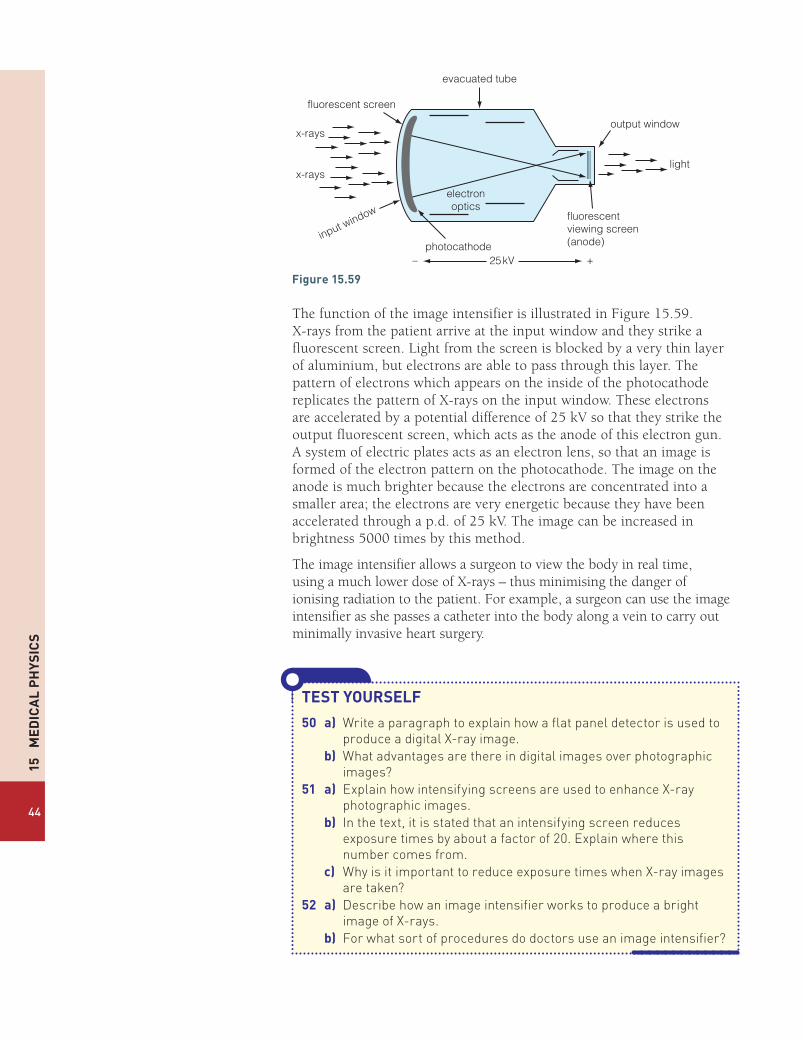
15
Me
dic
al
Ph
ysic
s
44
fluorescent screen
evacuated tube
output window
light
photocathode
electronoptics
input window fluorescentviewing screen(anode)
25kV
x-rays
x-rays
+–
Figure15.59
The function of the image intensifier is illustrated in Figure 15.59. X-rays from the patient arrive at the input window and they strike a fluorescent screen. Light from the screen is blocked by a very thin layer of aluminium, but electrons are able to pass through this layer. The pattern of electrons which appears on the inside of the photocathode replicates the pattern of X-rays on the input window. These electrons are accelerated by a potential difference of 25 kV so that they strike the output fluorescent screen, which acts as the anode of this electron gun. A system of electric plates acts as an electron lens, so that an image is formed of the electron pattern on the photocathode. The image on the anode is much brighter because the electrons are concentrated into a smaller area; the electrons are very energetic because they have been accelerated through a p.d. of 25 kV. The image can be increased in brightness 5000 times by this method.
The image intensifier allows a surgeon to view the body in real time, using a much lower dose of X-rays – thus minimising the danger of ionising radiation to the patient. For example, a surgeon can use the image intensifier as she passes a catheter into the body along a vein to carry out minimally invasive heart surgery.
TesTyOURselF
50 a) Write a paragraph to explain how a flat panel detector is used to produce a digital X-ray image.
b) What advantages are there in digital images over photographic images?
51 a) Explain how intensifying screens are used to enhance X-ray photographic images.
b) In the text, it is stated that an intensifying screen reduces exposure times by about a factor of 20. Explain where this number comes from.
c) Why is it important to reduce exposure times when X-ray images are taken?
52 a) Describe how an image intensifier works to produce a bright image of X-rays.
b) For what sort of procedures do doctors use an image intensifier?

X-ray im
aging
45
Absorption of X-raysIn common with all types of electromagnetic waves, X-rays are able to travel an infinite distance in space. However, the intensity of a beam of X-rays is attenuated as it passes through matter. As X-rays pass through a medium, they interact with electrons or the nucleus of an atom. When a photon interacts with matter, it can lose energy by exciting electrons or the nucleus. An X-ray photon is more likely to interact with matter the further it travels through a particular material.
The intensity of a beam of X-rays decreases exponentially with the distance it travels through a material. The intensity of a beam of radiation can be calculated using the equation:
I = Ioe–μx
where I is the transmitted intensity after passing through a length x of material.
Io is the incident intensity
μ is the linear attenuation coefficient in m−1.
The intensity of a beam of radiation can be measured in W m-2. However, for most purposes it is sufficient to compare the relative intensities using the ratio I/Io.
The value of μ depends on the energy of the incident photons; μ also depends on the density of the material.
A denser material either has atoms with more massive nuclei, or more nuclei per unit volume. An X-ray photon is more likely to interact with a nucleus if there are more of them along its path.
The attenuation of X-rays is also described using the mass attenuation coefficient.
μm = μρwhere μm is the mass attenuation coefficient m2 kg−1
μ is the linear attenuation coefficient in m−1
ρ is the density of the material in kg m−3
The difference in density between body tissues is important, as it allows X-rays to distinguish between fat and a kidney, for example. A kidney has a higher density than fat, so X-rays are attenuated more as they pass through the kidney than they are as they pass through fat.
The exponential decay of the intensity of X-rays as they pass through a material means that it is impossible to reduce the intensity of X-rays to zero, no matter how thick the material is. However, we can describe the effectiveness of the absorption of X-rays using the half-value thickness x1
2,
which is the thickness of a material that reduces the intensity of an X-ray beam to half its initial value.

15
Me
dic
al
Ph
ysic
s
46
Half-value thickness and linear attenuation coefficientThe half-value thickness, x1
2, and linear attenuation coefficient μ, may be
linked as follows.
I = Ioe–μx
Since I
I =2o when x = x1
2
we get:
II e
2
xo
o
–
=µ
1
2
e1
2
x–
=µ
1
2
and
ln x1
2= –µ
1
2
or
ln x2 = µ1
2
Therefore
x =ln2
µ1
2
Calculations using attenuation coefficientsTable 15.3 shows linear attenuation coefficients for various body tissues for three different X-ray photon energies.
Table15.3
Photonenergy/keV Boneµ / m–1 Muscleµ / m–1 Fatµ / m–1 Waterµ / m–1
50 74.2 24.0 20.5 22.780 39.0 19.3 16.7 18.7100 32.6 17.9 15.5 17.1
The densities of these materials are shown below.
Bone 1750 kg m-3
Muscle 1060 kg m-3
Fat 960 kg m-3
Water 1000 kg m-3
Note that the lower the photon energy the higher the linear attenuation coefficient; a lower energy photon is more easily stopped than a higher energy photon.

X-ray im
aging
47
EXAMPLE1 Calculate the mass attenuation coefficient for 80 keV X-rays in bone.
answermµ µ
ρ=
= 39.0 m1750 kg m
1
3
−
= 0.0223 m2 kg–1
2 Calculate the half-value thickness of water for 100 keV X-rays.
answer
µ=xIn 2
12
= 0.69317.1
= 0.041 m or 4.1 cm
3 Calculate the intensity reduction when a beam of 100 keV X-rays passes through 6 cm of muscle.
answer
= −µI I e xo
= −µII
eo
x
= e 17.9 0.06− ×
= −e 1.074
= 0.34
So the intensity of X-rays is reduced to about a third of the initial value.
TesTyOURselF
53 a) Explain the term linear attenuation coefficient, μ.b) Does μ increase or decrease as the energy of X-rays increases
for a particular material?54 a) Calculate the mass attenuation coefficient of muscle for 80 keV
X-rays.b) Calculate the half-value thickness of bone for 100 keV X-rays.c) Calculate the reduction in intensity of a beam of 50 keV X-rays
passing through 5 cm of muscle.d) Calculate the reduction in intensity of 50 keV X-rays passing
through 5 cm of fat. Explain why it is possible for a radiographer to distinguish between fat and muscle.
e) Calculate the reduction in intensity of 50 keV X-rays passing through 5 cm of bone. Explain why bones are shown clearly in X-ray images.

15
Me
dic
al
Ph
ysic
s
48
Optional experimentFigure 15.60 shows an experimental arrangement that you can use to test whether the intensity of gamma radiation decreases exponentially as the thickness of lead absorbers increased.
You can do this for yourself in the laboratory or use the data provided.
The Geiger Müller tube is used to record the activity of a Cobalt-60 source, which emits gamma rays and beta particles. The activity is recorded over a 10 second period for different thicknesses of lead absorber.
The following results were recorded.
Table15.4
Thicknessofleadabsorber/mm 2 3 5 8 10 15 20Recordedactivityovera10secondperiod
2260 2130 1880 1560 1380 1010 740
Experimental note: now caesium-137 sources are also available. which emit just gamma rays.
If the intensity of the gamma rays reduces exponentially with thickness the following relationship holds:
= −µI I e xo
or= −µI
I e x
o
Therefore ln xo
= − µI
I
and In I – ln Io = – xµ
or In I = ln Io – xµ
So if we plot a graph of: ln (count) against the thickness (in m) the gradient of the graph is – μ.
radioactivesource absorber
GM tube
to counter
2 cm
Figure15.60
acTiViTy1 Plot a suitable graph to determine μ.2 Calculate μm for lead. The density of lead is 11 300 kg m-3.3 Calculate the half-value thickness of lead for cobalt-60 gamma rays.4 Explain why the experimenter did not record a value for the count
with no absorber present. [Hint: what other radiation is emitted by cobalt-60?]

X-ray im
aging
49
CT ScannerA CT scan is the shorthand name we give to X-ray computerised tomography (X-ray CT) or computerized axial tomography (CAT scan). The word tomography refers to imaging by sections using any type of penetrating wave.
In a CT, scan radiographers make a sectional image through the body by moving an X-ray tube and detectors in opposite directions during the exposure. This method of investigation allows a thin slice of the body to be brought into sharp focus with other planes appearing blurred. Throughout a CT scan, a narrow beam of monochromatic X-rays is directed at different planes of the body, and an array of detectors surrounding the patient builds up images of sections of the organ under investigation. The information from the detectors goes to a computer which turns electrical signals into the detailed image we see. Figure 15.61 shows the principle of a CT scan.
With the usual X-ray technique an image similar to Figure 15.46 is produced: a two-dimensional image of a three-dimensional object. A CT scan allows slices (S1 and S2) to be produced, so that a clear focus is seen for each section of the body.
Figure 15.62 shows a CT scan through a patient’s head. Many slices of the head are seen allowing doctors to make a detailed diagnosis of any illness.
S1 S2
P
Figure15.61The computer builds up many images at different depths.
Monochromatic means of one colour, but in the context of X-rays it means of one wavelength.
Figure15.62Computerised tomography of the human brain, from the base of the skull to the top.

15
Me
dic
al
Ph
ysic
s
50
Advantages of CT scansThere are three advantages that CT has over conventional two-dimensional radiography.
l CT completely eliminates superimposition of images of structures outside the area of interest.
l CT scans produce high resolution and high contrast images, so that differences between tissues that differ in density by 1% can be detected. This is very important for the diagnosis of cancer.
l A CT scan allows images to be formed from any of the three planes of the body – see Figure 15.63.
Disadvantages of CT scansThere are two main disadvantages: cost and safety.
l CT scanners are costly to build and take between 15 to 60 minutes for a scan to be completed – so they are costly on manpower too.
l A CT scan exposes a patient to a relatively high radiation dose which can damage body cells (see below). Such cell damage can lead to cancer. The radiation dose received from a CT scan can be equivalent to 100 to 1000 times the dose for a conventional chest X-ray. Although the dose from a CT scan is small, it does carry a risk of inducing a cancer, so it must only be used sparingly. Doctors must weigh up carefully the potential benefit to a patient against the risk. For example, a doctor would only decide to expose a 1-year-old child to a CT scan if a serious life-shortening illness is under investigation. Exposure to radiation might cause illness many years later. By contrast, the risk posed by a CT scan to a patient aged 65 or over is relatively small. If a patient of that age is suffering from cancer already, a CT scan can provide important information about how to treat it.
Radiation damageYou do not need to know any detail about radiation doses, but this brief section is included to provide some additional background information. Radiation can be ionising or non-ionising. Ionising radiation can cause damage to our bodies. Common types of ionising radiation include alpha and beta particles, other heavy ions, neutrons, gamma rays and X-rays. Damage can be caused in two ways.
l Direct damage is caused by a particle colliding directly with a cell in the body. An alpha particle, for example, behaves like a miniature bullet and destroys body tissue.
l Indirect damage is caused by ionisation. Radiation produces ions by removing electrons from atoms and molecules. Such ions can produce strong acids in our bodies such as H3O
+. These acids can destroy cells in our bodies or cause mutations to our genes.
Both types of damage can lead to cancer.
Measuring the doseThe heavier type of radiation, such as alpha particles, cause the greatest damage. The alpha particle typically has a lot of energy and because it
sagittalplane
coronalplane
transverseplane
Figure15.63

Radionuclide imaging and therapy
51
travels relatively slowly, it transfers its energy over a short distance. Thus it causes intense localised damage. X-rays and gamma rays penetrate further into flesh, and spread their energy over a greater distance.
When we assess the dangers of radiation, we take into account now much we have been exposed to. We measure radiation dose in sieverts, Sv. Doses are often quoted in thousandths of sieverts – millisieverts, mSv.
The dose takes into account the quality of the radiation. For example, an alpha particle delivers 20 times the dose of a gamma ray with the same energy. Table 15.5 provides some examples of radiation doses which are used in medicine, including a comparison with the annual background dose we are exposed to in the UK.
Table15.5
dose/msv sourceofdose
equivalencewithUKbackgroundradiation effectofdose
0.0005 dental X-ray 18 hours low risk 0.02 chest X-ray 3 days low risk 2.0 head CT 300 days low risk 2.4 yearly background
radiation1 year low risk
10.0 chest, abdomen and pelvis CT
4.2 years low risk
1000 highly targeted dose of radiotherapy
420 years high risk, but balanced by a short-term cure of cancer.
TesTyOURselF
55(G) a) State what is meant by the phrase CT scan. b) Give a brief outline of how a CT scan is done. c) i) What are the advantages of a CT scan
over a conventional X-ray? ii) What are the disadvantages of a CT
scan over a conventional X-ray?
56(G) a) What is meant by the term radiation dose? b) With reference to Table 15.5, compare the
risks posed by: a dental X-ray; a CT scan; targeted radiation therapy.
gamma rays
gammacamera
Figure15.64
A radioisotope is an isotope that is radioactive.
A tracer is a radioisotope that is absorbed by the body and therefore allows its radioactive emissions to help form an image of an organ.
●l Radionuclide imaging and therapyImaging techniquesRadionuclines are commonly used in medicine as a diagnostic tool. The principle of radionuclide imaging is shown in Figure 15.64.
A radionuclide is absorbed by a particular organ that is to be investigated. Then gamma rays which are emitted by the radionuclide allow medical physicists to form an image of the organ using a gamma camera (see Figure 15.71 and page 57). A range of gamma-emitting radioisotopes is used, depending on the investigation which is to be undertaken. However, the following broad principles apply to tracers.
l The isotope used must have a chemical affinity for the organ or cells to be investigated. Unless the isotope is naturally absorbed in the right part of the body, no investigation can take place.
l The isotope should emit low energy gamma rays. This radiation can pass through the body and be detected outside by the gamma camera,

15
Me
dic
al
Ph
ysic
s
52
whereas beta or alpha radiation would not escape from the body. Gamma radiation is ionising and so can cause damage to our body; by using low energy gamma rays, such radiation damage is kept to a minimum.
l The isotope should have a short half-life, of a few hours or a few days. The advantage of the short half-life is that the total radiation dose absorbed by the patient is kept to a minimum. An isotope with a short half-life produces a high activity for a short time. The high activity allows the radiation to be detected and thus form an image of an organ under investigation, but the isotope soon decays once the investigation has been completed.
Technetium–99mTechnetium-99m, 99m
43Tc, is a metastable state of technetium-99. A metastable state is an excited state of a nucleus. The nucleus decays to its ground state by emitting a gamma ray; this is a similar process to an excited electron returning to its ground state by emitting a photon of visible or ultraviolet light.
Technetium-99m is used, world-wide, in tens of millions of diagnostic procedures annually, making it the most commonly used medical radioisotope. Technetium-99m is well suited to this role as it emits low energy gamma rays (140 keV), which are of similar wavelength and energy to X-rays used by conventional diagnostic equipment. The isotope has a half-life of 6.0 h, which means that the patient is exposed to a low radiation dose. The typical dose received by a patient undergoing an investigative procedure with technetium-99m is about 10 mSv, which is about 5 times the annual dose due to background radiation in the UK.
There are about 30 radiopharmaceuticals based on 99m43Tc. Uses of these
compounds includes investigation of the brain, thyroid, lungs, liver, gall bladder, kidneys, skeleton, blood and tumours. For example, one radiopharmaceutical allows blood flow round the brain to be investigated and another labels white blood cells, so that the site of an infection can be determined.
Iodine-131 Iodine-131 (131
53I ) decays with a half-life of 8.0 days with both beta-minus and gamma ray emissions. The decay takes place in two steps: first to metastable xenon-131, then to stable xenon-131 by the emission of a gamma ray.
I Xe e 53131
54131m
10
eυ→ + +−
Xe Xe 54131m
54131 γ→ +
The maximum energy of the electrons emitted in the beta decay process is about 600 keV, and the gamma ray emitted has an energy of 360 keV.
Due to the emission of the high energy beta particle, iodine-131 is not a suitable isotope to be used first for diagnostic purposes. The beta particles have a tissue penetration of between 0.6 mm and 2.0 mm, and therefore cause significant damage to any tissue that they strike. If an isotope of iodine
Figure15.65The decay of 99m43Tc
99m43Tc
99m43Tc
g140 keV
b�2 × 10⁵ years
6 hours
A radiopharmaceutical is a drug used to diagnose a disease that relies on the radioactive emissions of the drug for the purposes of image formation.

Radionuclide imaging and therapy
53
is needed for diagnostic purposes only, a more suitable isotope is iodine-123, which emits gamma rays of energy 160 keV with a half-life of 13.0 hours.
Iodine is readily absorbed by the thyroid gland. Thus iodine-131 has two main uses.
l In the case of an overactive thyroid gland (hyperthyroidism) a dose of radioactive iodine destroys part of the thyroid gland, so that the thyroid gland then functions at a normal level.
l In the case of thyroid cancer, it is usual for the thyroid gland to be removed. Then a large dose of iodine-131 is used to destroy any remaining thyroid tissue in the area. The radioactive iodine also circulates throughout the body and can be picked up by any thyroid cells which have moved round the body.
Although iodine-131 is primarily used to treat conditions, the fact that the isotope emits gamma rays allows it also to act as a tracer. By viewing the emitted gamma rays, it is possible to monitor how effective the treatment has been.
Indium-111Indium-111 is a radioisotope which decays to the stable nucleus cadmium-111 by electron capture (see Book 2, page 205) with a half-life of 68 hours.
11149In + 0–1e Æ 111
48Cd + n + g
In the process of decay, the nucleus emits gamma rays of energy 170 keV and 250 keV.
Indium-111 is a very expensive radioisotope, which is used to label antibodies, polypeptides and white blood cells. This allows the diagnosis of blood disorders and rare cancers. The short half-life of 67 hours and the emission of only gamma rays makes indium-111 an ideal choice for a tracer.
The molybdenum-technetium generatorOne of the problems with using radioisotopes with short half-lives is that the material cannot readily be stored or transported. The most commonly used tracer, technetium-99m, has a half-life of only 6 hours. Thus if you stored a sample in a hospital ready for use the next day, about 94% of it would have decayed. The solution is to use a generator from which the isotope can be extracted.
Molybdenum-99 (9942Mo) is the parent nucleus of technetium-99. The
isotope 9942Mo is produced in nuclear reactors and it has a half–life of 66.0
hours, which makes it far more convenient to transport to hospitals.
A hospital is supplied with a molybdenum–technetium generator. The isotope 99
42Mo then decays to 99m42Tc. The two elements are separated by a
chemical process, which allows a supply of technetium-99m to be produced. Since molybdenum-99 has a half-life of 66 h, it means that a weekly supply of the radioisotope allows the hospital to produce technetium-99m on a daily basis ready for use.
Positron emission tomography (PET)Positron emission tomography (PET) is an expensive, but high resolution, imaging process which allows highly detailed images of the body to be produced. PET is used for monitoring the treatment of cancers such as lymphoma and lung cancer. PET scans are also most effective at monitoring brain activity and blood flow to the brain.
Figure15.66This scan of the thyroid taken with a gamma camera reveals an abnormality in the gland.

15
Me
dic
al
Ph
ysic
s
54
PET requires a radioisotope which decays by positron emission to be absorbed by the body. The most commonly used tracer is fluorodeoxyglucose, which contains the isotope fluorine-18. 18
9F decays by positron decay with a half-life of 110 minutes.
F O e 918
818
10 υ→ + +
As soon as a positron has slowed down, it encounters an electron, when the electron–positron pair annihilate to produce a pair of γ -rays with energy 512 keV each. Due to the conservation of momentum, these two γ -rays move off in opposite directions. [Figure 15.67]
The production of pairs of gamma photons allows an image of the body to be constructed using computers. Figure 15.68 shows the operation of a PET scanner. Here the patient’s brain is being examined. The head is surrounded by a three-dimensional array of detectors, which detect pairs of gamma rays. The computer and detectors use the information recorded to determine the origin of a pair of gamma rays.
image reconstruction
coincidenceprocessing unit
Figure15.68The annihilation of a position–electron pair produces a pair of γ-rays (shown in red).
Figure15.69In this PET scan of a human brain the red colour indicates areas of higher brain activity.
g -ray
g -ray
electron–positron pair+ −
Figure15.67
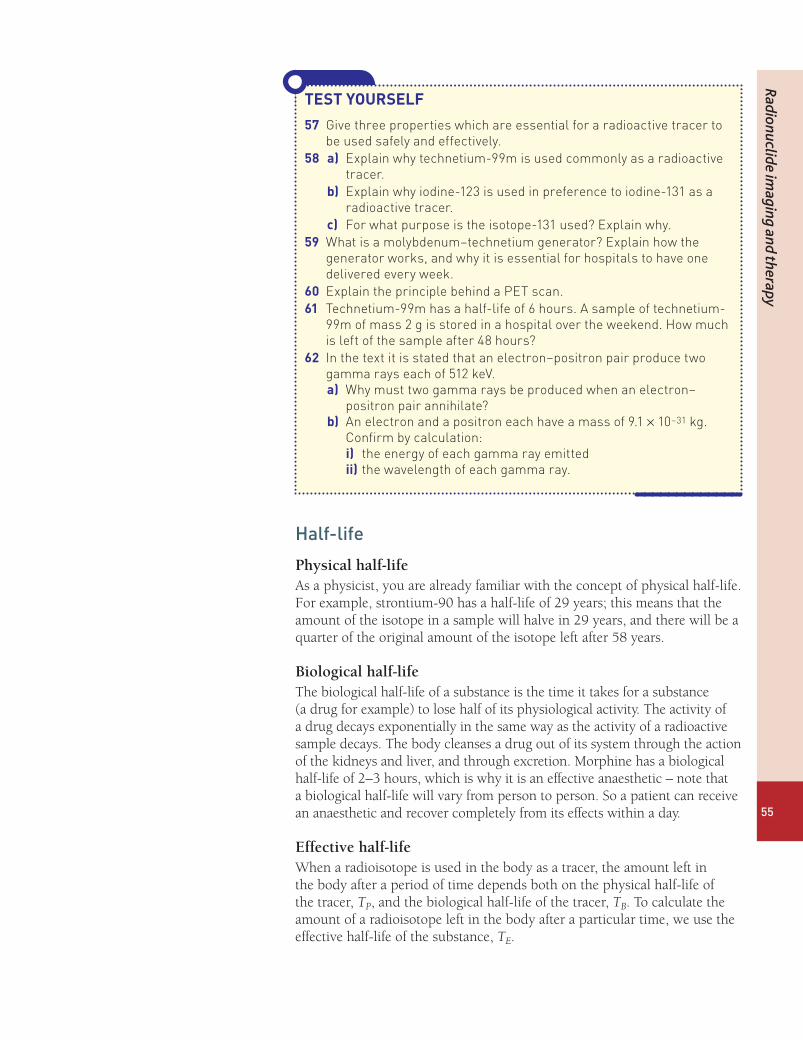
Radionuclide imaging and therapy
55
Half-life
Physical half-lifeAs a physicist, you are already familiar with the concept of physical half-life. For example, strontium-90 has a half-life of 29 years; this means that the amount of the isotope in a sample will halve in 29 years, and there will be a quarter of the original amount of the isotope left after 58 years.
Biological half-lifeThe biological half-life of a substance is the time it takes for a substance (a drug for example) to lose half of its physiological activity. The activity of a drug decays exponentially in the same way as the activity of a radioactive sample decays. The body cleanses a drug out of its system through the action of the kidneys and liver, and through excretion. Morphine has a biological half-life of 2–3 hours, which is why it is an effective anaesthetic – note that a biological half-life will vary from person to person. So a patient can receive an anaesthetic and recover completely from its effects within a day.
Effective half-lifeWhen a radioisotope is used in the body as a tracer, the amount left in the body after a period of time depends both on the physical half-life of the tracer, TP, and the biological half-life of the tracer, TB. To calculate the amount of a radioisotope left in the body after a particular time, we use the effective half-life of the substance, TE.
TesTyOURselF
57 Give three properties which are essential for a radioactive tracer to be used safely and effectively.
58 a) Explain why technetium-99m is used commonly as a radioactive tracer.
b) Explain why iodine-123 is used in preference to iodine-131 as a radioactive tracer.
c) For what purpose is the isotope-131 used? Explain why.59 What is a molybdenum–technetium generator? Explain how the
generator works, and why it is essential for hospitals to have one delivered every week.
60 Explain the principle behind a PET scan.61 Technetium-99m has a half-life of 6 hours. A sample of technetium-
99m of mass 2 g is stored in a hospital over the weekend. How much is left of the sample after 48 hours?
62 In the text it is stated that an electron–positron pair produce two gamma rays each of 512 keV.a) Why must two gamma rays be produced when an electron–
positron pair annihilate?b) An electron and a positron each have a mass of 9.1 × 10⁻³¹ kg.
Confirm by calculation: i) the energy of each gamma ray emittedii) the wavelength of each gamma ray.

15
Me
dic
al
Ph
ysic
s
56
The three half-lives are connected by the equation:
T T T
1
1
1
E P B
= +
MaThsBOXWhen a radioisotope is in the body, there is a biological activity and a physical activity. So the total activity is:
AE = AP + AB
orl l l= +N N N E P B
but
l =T
0.693
So
N
T
N
T
N
T
0.693
0.693
0.693
E P B
= +
and
T T T
1
1
1
E P B
= +
EXAMPLEThe biological half-life of technetium-99m is 1 day, and the physical half-life of technetium-99m is 6 hours.
Calculate the effective half-life of the isotope.
answer
= +T T T1 1 1
E P B
16
124
= +
424
124
= +
524
=
=T245E
= 4.8 hours
So the activity of a sample of Tc4399m halves every 4.8 hours.

Radionuclide imaging and therapy
57
TesTyOURselF
63 Define each of the terms:i) Physical half-lifeii) Biological half-lifeiii) Effective half-life.
64 Explain why a patient, who has been treated with a radioactive tracer, is kept in isolation for a period of time. What factors determine the length of the isolation?
65 Cobalt-60 has a physical half-life of 5.3 years and a biological half-life of 10 days. Explain why a patient who has consumed some cobalt-60 will show a low activity after a few weeks.
66 Strontium-90 has a biological half-life of 50 years and a physical half-life of 29 years. Calculate its effective half-life.
67 a) Zinc-65 has a biological half-life of 933 days and a physical half-life of 244 days. Calculate the effective half-life of this isotope.
b) A person consumes a dose of zinc-65, which produces an activity, A, in his body. Calculate the activity in the body, in terms of A, after 1 year.
The gamma cameraThe principle of a gamma camera is illustrated in Figure 15.70.
computer
lead shielding
image
photomultiplier tubes
image crystal
collimator
gamma emittergamma camera
Figure15.70
Once a patient has consumed a radiopharmaceutical, they are positioned so that the organ to be investigated is under the gamma camera. In Figure 15.70, the gamma camera is taking an image of the patient’s kidneys. The gamma rays are emitted in all directions from the patient’s body, but the camera only allows gamma rays to enter it from one direction. At the front

15
Me
dic
al
Ph
ysic
s
58
A collimator is a device which ensures that a beam of particles travels in a narrow beam in one direction.
of the camera is a collimator; this is a thick plate of lead riddled with a large number of very thin parallel channels. The gamma rays which pass through the collimator are those whose direction is perpendicular to the surface of the lead plate and the scintillating crystal. The lead collimator reduces gamma rays travelling at an oblique angle to an insignificant level.
When the gamma photons strike the scintillating crystal, photons of visible light are emitted on the upper side of it. Above the crystal, an array of small photomultipliers (or photodiodes) converts photons of light into electrical signals. From these signals, the computer can determine the energy of the incoming gamma photons and the position of the impacts on the crystal. Now the computer can build up an image of the gamma ray emissions from the patient’s kidneys, which provides useful diagnostic information.
Due to the difficulties of focusing gamma rays, the gamma camera has relatively poor resolution – it is able to resolve areas about 6 mm apart in an organ. But the advantage of gamma ray diagnosis is that we can gather information about the function of the inside of an organ.
RadiotherapyWhen a patient is diagnosed with cancer, the oncologist (a doctor who treats cancer) will decide on a course of treatment. Sometimes a cancer can be cured by surgery or by chemotherapy (treatment using anti-cancer drugs), and cancers may also be treated using radiotherapy, in addition to the two other treatments.
Use of high energy X-raysOne type of radiotherapy is an external treatment using high energy X-rays. In this treatment, X-rays are directed towards the tumour from outside the body. Figure 15.71 illustrates how X-rays are directed from different directions towards a deep tumour. Since X-rays can damage healthy cells as well as cancerous cells, it is important to direct the X-ray beam from different directions in order to reduce the damage to the surrounding healthy tissue.
X-ray energiesThe type of X-rays used to treat cancer depends on the nature and position of the tumour. [Refer to pages 35–37 for information about X-ray production and energies.]
l Superficial X-rays 50 keV to 200 keV These X-rays do not penetrate very far before they are absorbed, reaching
a depth of about 2 mm. These X-rays are used to treat diseases of the skin. This type of treatment is the least likely to cause side effects, as the X-rays can be focused on a small area of tissue.
l Orthovoltage X-rays 200 keV to 500 keV These X-rays can penetrate to a depth of 4–6 cm. So they can be used to
treat problems close to the skin.l Megavoltage X-rays 1 MeV to 25 MeV Megavoltage X-rays penetrate deep into the body and are used to treat
cancers in the bladder, bowel, prostate, lung or brain. This treatment brings a risk to healthy tissue, but this risk has to be weighed against the
TesTyOURselF68 a) Explain the function of the
collimator in a gamma camera.
b) Why must the collimator be made out of a heavy metal?
69 Draw a diagram to explain how a gamma camera works. Explain the function of each part of the camera.
tumour
Figure15.71

Radionuclide imaging and therapy
59
likely benefit of slowing or stopping entirely the growth of the tumour. The risk can also be reduced by directing the beam from different directions, as shown in Figure 15.71. The risk to the body is also reduced by using X-ray filters. When X-rays are produced they come with a wide range of energies and wavelengths (Figure 15.48). So when megavoltage X-rays are used, the less energetic X-rays are removed from the beam by placing a sheet of aluminium or lead in front of the beam. The filtering allows only high energy X-rays to reach the patient, which then penetrate to the tumour. Lower energy X-rays, which would be absorbed by the skin and shallow body tissues, are prevented from reaching the patient by filtering.
Use of radioactive implantsSome cancers are best treated with a radioactive implant, which is placed inside the body next to the cancerous tumour. This type of treatment is also called brachytherapy, from the Greek word brachys, meaning ‘short-distance’.
This type of treatment has considerable advantages over external therapy. A radioactive source can be placed in a small wire implant, which is inserted inside the body next to the cancer. Then the radiation dose is applied only to the tissue next to the implant, thus reducing the risk of radiation damage to healthy body tissue.
The radioisotopes used for short-range internal therapy are placed in very small seeds, which are then implanted in the body tissue. Some seeds are placed in the body temporarily, so that a large dose is administered over a short period of time. On the other hand, some cancers – prostate cancer for example – are treated with small seeds which are left permanently in the body; the radioisotope used has a short half-life so that the dose is administered over a short period of time.
The radiation emitted in internal therapy must be short range, and must be able to pass through the metal casing of the seed.
l Alpha radiation is unsuitable for two reasons: first it will not pass through the metal case; secondly, even if the alpha particles could get through the seed casing they would lose their energy in a very small distance, causing intense localised damage.
l Beta radiation is commonly used. Iridium-92 is a β– emitter with a half-life of 72 days, and ruthenium-106 is a β– emitter with a half-life of 367 days. A beta emitter produces electrons with a range of energies, which allows body tissues to be irradiated at a distance of a few millimetres away from the source.
l Gamma radiation is also used, but the gamma rays emitted must be of low energy, so that they do not penetrate far from the source. A suitable gamma emitter is iodine-125, which has a half-life of 59 days and emits gamma rays with an energy of 29 keV.
Figure15.72Seeds like these are placed near to the cancerous tumour.
gland
radioisotopeseeds
cancer

15
Me
dic
al
Ph
ysic
s
60
TesTyOURselF
70 a) Discuss the advantages and disadvantages of internal and external radiotherapy.
b) What precautions are taken to reduce the risk posed by i) external radiotherapy ii) internal radiotherapy?
71 What factors determine the choice of X-ray energy for the treatment of tumours by external radiotherapy?
72 Explain what is meant by an X-ray filter. Why does an X-ray filter help to make radiotherapy safer for patients?
73 a) Iridium-72 is a beta-emitter with a half-life of 72 days. The maximum energy carried by a beta particle emitted by an iridium source is 0.67 MeV. Explain why iridium is a suitable isotope for internal radiotherapy.
b) Calculate the period of time over which an iridium implant delivers 90% of its radiation dose.
A comparison of imaging techniquesThroughout this option of medical physics you have studied various imaging techniques. In the text, comments have been made about the advantages and disadvantages of each technique. Table 15.6 includes a summary. Questions in the A-level exam will be limited to consideration of imaging resolution, convenience and safety issues.
Table15.6
Method Resolution advantages disadvantagesGamma rays from an ingested source
6 mm Shows images of the inside of organs and their function.
Relatively easy to administer
Low resolution.
Presents some radiation danger.
X-rays from outside the body
0.5 mm Cheap and easy to use. Limited contrast between some types of tissues.
Some organs cannot be seen.
Some radiation danger.CT scan 0.5 mm High resolution.
Can distinguish clearly between types of tissue.
Expensive.
Relatively high radiation dose equivalent to a few years’ background radiation dose.
MRI 1 mm No radiation danger.
Images are of high quality.
Can distinguish between types of tissue.
Expensive.
Some patients find it claustrophobic.
Ultrasound 2 mm No radiation dangers Some organs cannot be reached by ultrasound.
Low resolution, and less clear images.PET scans 1 mm Allows a study of the function of organs.
Excellent images of the brain.Some organs cannot be imaged.
Expensive.

61
Exam practice questions
exampracticequestions 1 a) A person with a defective eye wears spectacles to look at an object
25 cm away from his eye. The power of the correcting lens in the spectacles is +2.50 D.
i) Calculate the distance of the image seen by the eye through the correcting lens. (3)
ii) State the defect of vision that is being corrected. (1)
b) Draw a labelled diagram to show how the lens in part (a) forms an image of the object 25 cm away. Mark the image and principal foci of the lens. Your image does not have to be to scale. (3)
lens
object
F F
Figure15.73
2 a) Copy and complete the ray diagram in Figure 15.73 ato show the formation of the image of a real object by a diverging lens. (3)
b) A lens of focal length –0.45 m is used to correct a defect of vision in an eye.
i) Name this defect of vision. (1)
ii) Calculate the power of the correcting lens. (1)
c) The defective eye has an unaided near point at 0.18 m from the eye.
Calculate the aided near point with the correcting lens, expressing your answer to an appropriate number of significant figures. (3)
3 A patient’s prescription for her eyes is shown in the table below. Explain what the patient’s eye defects are. (4)
sphere cylinder axisRight +1.75 0Left +1.50 -0.25 50o
4 a) Describe how the vibrations of a sound wave are received by the outer ear and transmitted to the inner ear. (3)
b) An intensity meter, set to the dB scale, measures the intensity level of a sound as 57 dB. Calculate the intensity of sound at the meter, giving the appropriate unit. (3)
c) The scale on the intensity meter is now set to the dBA scale. The new reading is found to be 52 dBA. Explain this change. (2)
5 a) Define the threshold of hearing I0. (2)
b) A person speaks with an intensity of 8 x 10⁻⁵ W m–2. Calculate the intensity level of the sound in dB.

15
Me
dic
al
Ph
ysic
s
62
c) Give two reasons why we use a logarithmic scale to define the intensity level of a sound. (2)
d) A hearing test was used to obtain threshold hearing audiograms for several people. The audiogram in Figure 15.74 was obtained for a person with normal hearing.
00
Inte
nsity
leve
l (dB
)
frequency (Hz)
20
40
60
80
100
30 100 300 1000 3000 10000
Figure15.74
Copy the graph and on the same axes sketch curves to show:
i) a curve labelled X to show a person suffering from hearing loss due to excessive noise (2)
ii) a curve labelled Y to show a person suffering from hearing loss due to old age. (2)
6 a) Figure 15.75 shows an ultrasound transducer used in an A-scan.
metal outercasing backing block
electrodes applyan alternatingpotential difference
piezoelectriccrystal
plastic‘nose’
acousticinsulator
power cable
Figure15.75

63
Exam practice questions
Explain, with reference to Figure 15.75, the process by which the transducer produces a pulse of ultrasound. (4)
b) Table 15.7 shows the acoustic impedances of some media.
Table15.7
Medium acousticimpedance/kgm–2 s–1×10⁶
Air 4.3 × 10⁻⁴
Muscle 1.7Liver 1.6
i) Calculate the percentage of an incident beam of ultrasound which would be transmitted from muscle into the liver. (2)
ii) When obtaining the ultrasound image of an unborn foetus, a coupling gel is used. Explain why a coupling gel is needed and state the desirable properties of such a gel. (2)
iii) State and explain one advantage and one disadvantage of ultrasound imaging. (2)
7 Oil is used as a coupling gel between an ultrasonic transducer and body tissue. Use the information in Table 15.8 to calculate the percentage of energy from the ultrasonic transducer that is transmitted into the body. (6)
Table15.8
Material density/kgm–3 Ultrasoundvelocity/ms–1
Oil 950 1500Body tissue 1065 1530
8 Figure 15.76 shows the cross-section through an optical fibre. The refractive index of the core is 1.52.
Air A
B
D
CCladding
Core
Cladding
Air
Figure15.76
a) Sketch a graph to show how the refractive index of the fibre changes along the line ABCD. (3)
b) In an endoscope, there are two types of optical fibre: coherent and non-coherent. Explain the purpose of each type of optical fibre. (2)

15
Me
dic
al
Ph
ysic
s
64
9 a) State the changes to a normal eye when the eye changes from focusing on a distant object to focusing on a near object, both being viewed in bright light. (2)
b) State two differences between the image seen by an eye when it looks at a coloured object in bright white light and the image seen of the same object in very dim light. (2)
10 When protons are placed in a strong magnetic field, there is an energy difference between the two possible spin states for the protons, as shown in Figure 15.77. A proton in the higher energy state can move to the lower state by emitting a radiofrequency photon. Information from radiofrequency photons is used to build up an image in an MRI scan.
a) What does the term MRI stand for? (1)
b) Why is there an energy difference between the two spin states of a proton in a magnetic field? (1)
c) A photon of frequency 750 MHz is emitted when a proton ‘relaxes’ from the higher state to the lower state.
Calculate the energy of this photon. (2)
d) Explain why a magnetic field gradient is applied to a patient during an MRI scan. (2)
e) Explain the advantages and disadvantages of an MRI scan as a diagnostic tool. (2)
11 Figure 15.78 shows the X-ray spectrum produced by a beam of electrons which strike a tungsten target.
intens
ity
wavelength
Figure15.78
a) i) Explain why the spectrum has some sharp peaks in intensity. (2)
ii) Explain why there is also a continuous spectrum with a well-defined minimum wavelength. (2)
b) Copy the graph and sketch a second graph of a spectrum which is produced by an electron beam in which the electrons have slightly less energy than in part (a). (3)
Figure15.77
state 1
state 2
magnetic field strength (T)
E
ener
gy
B

65
Exam practice questions
c) An electron is accelerated through a p.d. of 80 kV.
i) Calculate the kinetic energy of the electron, expressing your answer in joules. (2)
ii) Assuming all of this kinetic energy is transferred into the energy of an X-ray photon, calculate the wavelength of the photon. (2)
12 A diagnostic X-ray tube produces a beam of X-rays. The beam passes through an aperture, the size of which is controlled by two pairs of lead sheets that move at right angles to each other. The beam then passes through an aluminium filter.
a) i) Explain the purpose of the lead sheets. (1)
ii) Explain the purpose of the aluminium filter. (2)
b) A monochromatic beam of X-rays passes through an aluminium sheet of thickness 5.0 mm. The intensity of the beam is reduced by 20%.
i) Calculate the mass attenuation coefficient for these X-rays. State an appropriate unit for your answer. The density of aluminium is 2700 kg m-3. (5)
ii) Calculate the intensity reduction of the beam when it passes through an aluminium sheet of thickness 10 mm. (2)
13 a) A CT scan is carried out using X-rays. Give an account of how a CT scan is carried out. (3)
b) Explain the main advantages and disadvantages of a CT scan in comparison with a conventional X-ray imaging process. (2)
14 a) Describe the operation of a gamma camera. (3)
b) Explain what is meant by the term radiopharmaceutical. (1)
c) A doctor is considering a choice of two isotopes for use as a tracer to examine the thyroid of a patient. Explain which isotope would be better, using the data in Table 15.9. (4)
Table15.9
Isotope Half-life Radiation emitted Energy of radiation
II53123 13 hours γ 160 keV
II53131 8 days γ
β300 keV up to 600 keV
15 Technetium-99 is a tracer widely used in diagnostic medicine. This isotope has a physical half-life of 6 h and a biological half-life of 24 h.
a) Explain the terms biological and physical half-life. (2)
b) A patient consumes a dose of technetium-99. The doctor decides to keep the patient in isolation until 90% of the technetium has been removed from the body. How long will the patient spend in isolation? (5)

15
Me
dic
al
Ph
ysic
s
66
16 A cancerous tumour can be treated by using radiotherapy. Sometimes treatment can be applied externally and sometimes treatment is carried out using a radioactive implant.
a) Explain how X-rays are used to treat
i) a tumour near the skin
ii) a tumour deep inside the body. (6)
Include in your explanation a discussion about the energy of the X-rays used and how radiation damage is minimised.
b) Explain how internal radiotherapy is carried out. Include in your explanation a discussion of the choice of radioisotope for this purpose. (6)
17 a) State the differences between the two types of light detecting cells in the retina. (2)
b) Explain why we see objects with the sharpest clarity when we look straight ahead. (2)
c) Explain why we are more likely to see something at night time using our peripheral vision, rather than looking straight ahead. (2)

67
Photo credits
●l Photo creditsp.1 © BSIP/UIG Via Getty Images; p.26 top © Hubert Fanthomme/Paris Match via Getty
Images; p.26 bottom © Isabelle Limbach/iStockphoto/Thinkstock; p.29 top © vario
images GmbH & Co.KG / Alamy; p.29 bottom © GASTROLAB/SCIENCE PHOTO
LIBRARY; p.34 © MEDICAL BODY SCANS/JESSICA WILSON/SCIENCE PHOTO
LIBRARY; p.35 top © GUSTOIMAGES/SCIENCE PHOTO LIBRARY p.35 bottom © zhu
difeng - Fotolia; p.41 © CAVALLINI JAMES/BSIP/SCIENCE PHOTO LIBRARY; p.43 ©
bertys30 - Fotolia; p.49 © gloszilla - Fotolia; p.53 © CHRIS PRIEST/SCIENCE PHOTO
LIBRARY; p.54 © DR ROBERT FRIEDLAND/SCIENCE PHOTO LIBRARY