
(12) United States Patent (10) Patent No.: US 6,665,373 B1
15
USOO6665373B1 (12) United States Patent (10) Patent No.: US 6,665,373 B1 Kotowski et al. (45) Date of Patent: Dec. 16, 2003 (54) X-RAY IMAGING SYSTEM WITH ACTIVE 4,366,382. A 12/1982 Kotowski .................... 378/57 DETECTOR 4,366,576 A 12/1982 Annis ......................... 378/146 4,389,729 A 6/1983 Stein ........................... 378/99 (75) Inventors: Andreas F. Kotowski, Rancho Palos :: A 3. SE et i et al... 3.g 2 : 142 aSOa C a c A S. Steven W. Smith, 4,426,721. A 1/1984 Wang .......................... 378/99 s 4,454,605 A 6/1984 DeLucia ...................... 378/57 4,472,822 A 9/1984 Swift .......................... 378/10 (73) Assignee: Rapiscan Security Products (USA), f W f Inc., Hawthorne, CA (US) (List continued on next page.) (*) Notice: Subject to any disclaimer, the term of this OTHER PUBLICATIONS patent is extended or adjusted under 35 Nicholas Tsoulfanidis. Measurement and Detection of U.S.C. 154(b) by 0 days. Radiation, second edition (Washington, D. C.: Taylor & Francis, 1995).* (21) Appl. No.: 10/097,700 “Passenger Screening Technologies,” Airline Passenger 1-1. Security Screening, pp. 13–21. (22) Filed: Mar 12, 2002 Bossi, et al., “BackScatter X-Ray Imaging, Materials (51) Int. Cl." ................................................ G01N 23/04 Evaluation/46/Oct. 1988. (52) U.S. Cl. ................. ... 378/90; 378/57 (List continued on next page.) (58) Field of Search ... 378/57, 86, 87, 378/88, 89,90 Primary |ality J. Glick ASSistant Examiner Allen C. Ho (56) References Cited (74) Attorney, Agent, or Firm- Thelen Reid & Priest LLP, Steven J. Robbins U.S. PATENT DOCUMENTS (57) ABSTRACT 3,678,278 A 7/1972 Peil ............................ 250/108 3,780.291. A 12/1973 Stein et al. ... 250/363 The present invention provides for an apparatus and method 3,790,799 A 2/1974 Stein et al. ....... ... 250/363 for use in a System with an X-ray Source to produce a pencil 3.843,881. A 10/1974 Barton, Jr. et al. 250269 beam of X-rays to scan an object and a first detector 3.884.816. A 5/ E. Takahashi .. ... 250/359 providing a value representative of the intensity of the X-rayS SEA E. E. et al. - - - - 25. Scattered from the object to produce a Scattered image 4020.346 A 4f1977 Dennis ... 250 35s having a Second detector disposed opposite the first detector 4.031545 A 6/1977 Stein et al... ... 358/10s to provide a value representative of the intensity of the 4.047,035 A 9/1977 Dennhoven et al. ........ 250/355 X-rays passing directly from the X-ray Source to the Second 4,070,576 A 1/1978 Cobb ............... ... 250/303 detector; a processor coupled to the System to receive 4,112,301 A 9/1978 Annis et al. ...... ... 250/364 information Specifying a position of the pencil beam of 4,139,771 A 2/1979 Dennhoven et al. ........ 250/408 X-rays, the processor also coupled to Second detector to 4,160,165 A 7/1979 McCombs et al........... 250/354 produce a shadow image formed of pixels indicating the 4,179,100 A 12/1979 Sashin et al. ............... 250/416 intensity value measured by the Second detector for a 4,196,352 A 4/1980 Berninger et al. ... 250/445 4200,800 A 4/1980 Swift 250/445 plurality of positions of the pencil beam of X-rays, and 4.228.357 A 10/1980 Annis. - - - - 250/445 combining the Scattered and Shadow image to produce a 4.298,800 A 1/1981 Goldman. 250/445 composite image. 4,303,830 A 12/1981 Heinzelmann et al. ...... 250/445 4,349,739 A 9/1982 Annis .......................... 378/99 48 Claims, 6 Drawing Sheets 10 & X-Ray Detector
-
Upload
khangminh22 -
Category
Documents
-
view
5 -
download
0
Transcript of (12) United States Patent (10) Patent No.: US 6,665,373 B1
USOO6665373B1
(12) United States Patent (10) Patent No.: US 6,665,373 B1 Kotowski et al. (45) Date of Patent: Dec. 16, 2003
(54) X-RAY IMAGING SYSTEM WITH ACTIVE 4,366,382. A 12/1982 Kotowski .................... 378/57 DETECTOR 4,366,576 A 12/1982 Annis ......................... 378/146
4,389,729 A 6/1983 Stein ........................... 378/99
(75) Inventors: Andreas F. Kotowski, Rancho Palos :: A 3. SE et i et al... 3.g 2 : 142 aSOa C a
c A S. Steven W. Smith, 4,426,721. A 1/1984 Wang .......................... 378/99 s 4,454,605 A 6/1984 DeLucia ...................... 378/57
4,472,822 A 9/1984 Swift .......................... 378/10 (73) Assignee: Rapiscan Security Products (USA), f W f
Inc., Hawthorne, CA (US) (List continued on next page.) (*) Notice: Subject to any disclaimer, the term of this OTHER PUBLICATIONS
patent is extended or adjusted under 35 Nicholas Tsoulfanidis. Measurement and Detection of U.S.C. 154(b) by 0 days. Radiation, second edition (Washington, D. C.: Taylor &
Francis, 1995).* (21) Appl. No.: 10/097,700 “Passenger Screening Technologies,” Airline Passenger
1-1. Security Screening, pp. 13–21. (22) Filed: Mar 12, 2002 Bossi, et al., “BackScatter X-Ray Imaging, Materials (51) Int. Cl." ................................................ G01N 23/04 Evaluation/46/Oct. 1988. (52) U.S. Cl. ................. ... 378/90; 378/57 (List continued on next page.) (58) Field of Search ... 378/57, 86, 87,
378/88, 89,90 Primary |ality J. Glick ASSistant Examiner Allen C. Ho
(56) References Cited (74) Attorney, Agent, or Firm- Thelen Reid & Priest LLP, Steven J. Robbins
U.S. PATENT DOCUMENTS (57) ABSTRACT
3,678,278 A 7/1972 Peil ............................ 250/108 3,780.291. A 12/1973 Stein et al. ... 250/363 The present invention provides for an apparatus and method 3,790,799 A 2/1974 Stein et al. ....... ... 250/363 for use in a System with an X-ray Source to produce a pencil 3.843,881. A 10/1974 Barton, Jr. et al. 250269 beam of X-rays to scan an object and a first detector 3.884.816. A 5/ E. Takahashi .. ... 250/359 providing a value representative of the intensity of the X-rayS SEA E. E. et al. - - - - 25. Scattered from the object to produce a Scattered image 4020.346 A 4f1977 Dennis ... 250 35s having a Second detector disposed opposite the first detector 4.031545 A 6/1977 Stein et al... ... 358/10s to provide a value representative of the intensity of the 4.047,035 A 9/1977 Dennhoven et al. ........ 250/355 X-rays passing directly from the X-ray Source to the Second 4,070,576 A 1/1978 Cobb ............... ... 250/303 detector; a processor coupled to the System to receive 4,112,301 A 9/1978 Annis et al. ...... ... 250/364 information Specifying a position of the pencil beam of 4,139,771 A 2/1979 Dennhoven et al. ........ 250/408 X-rays, the processor also coupled to Second detector to 4,160,165 A 7/1979 McCombs et al........... 250/354 produce a shadow image formed of pixels indicating the 4,179,100 A 12/1979 Sashin et al. ............... 250/416 intensity value measured by the Second detector for a 4,196,352 A 4/1980 Berninger et al. ... 250/445 4200,800 A 4/1980 Swift 250/445 plurality of positions of the pencil beam of X-rays, and 4.228.357 A 10/1980 Annis. - - - - 250/445 combining the Scattered and Shadow image to produce a 4.298,800 A 1/1981 Goldman. 250/445 composite image. 4,303,830 A 12/1981 Heinzelmann et al. ...... 250/445 4,349,739 A 9/1982 Annis .......................... 378/99 48 Claims, 6 Drawing Sheets
10 & X-Ray Detector
US 6,665,373 B1 Page 2
U.S. PATENT DOCUMENTS 5,764,683 A 6/1998 Swift et al. ................... 378/57 5,796,110 A * 8/1998 An et al. ........ ... 250/385.1
4,503,332 A 3/1985 Annis ......................... 250/368 5,966,422 A 10/1999 Dafni et al. ................... 378/9 4,514,691 A 4f1985 De Los Santos et al. ... 324/301 5,974,111 A 10/1999 Kruget al. .. ... 378/57 4,535.245 A 8/1985 Zonneveld et al. ......... 250/385 6,018,562 A 1/2000 Willson ......................... 378/9 4,736,401 A 4/1988 Donges et al. .............. 378/146 6,094,472 A 7/2000 Smith .......................... 378/86 4,756,015 A 7/1988 Doenges et al. .............. 378/57 6,278,115 B1 8/2001 Annis et al. ........... 250/363.01 4,759,047 A 7/1988 Donges et al. .... ... 378/57 6,546,072 B1 4/2003 Chalmers ..................... 378/57 4,768,214 A 8/1988 Bjorkholm . ... 378/87 4,783,794. A 11/1988 Dietrich ..... ... 378/57 OTHER PUBLICATIONS 4,799.247 A 1/1989 Annis et al. .................. 378/87 4,809,312 A 2/1989 Annis ......................... 378/146 Gregory, William, “Medical X-Ray Measuring Device 4,817,121 A 3/1989 Shimizu et al. ... 378/57 Finds Use in Explosive Detection”, Aviation Week & Space 4,819,256 A 4/1989 Annis et al. ... ... 378/87 Technology, vol. 124, No. 17, Apr. 28, 1986. 4,825.454 A 4/1989 Annis et al. ... ... 378/87 Gustafsson, et al., "X-Ray Spectrophotometry for 4,839,913 A 6/1989 Annis et al. ... ... 378/44 Bone-Mineral Determinations”.Medical and Biological 4,845,769 A 7/1989 Burstein et al. ... 378/58 Engi - - - 113-118. J 1974 ngineering, pp. , Jan. 4,870,670 A 9/1989 Geus ........................... 378/87 4,884,289 A 11/1989 Glockmann et al. .......... 378/57 Norland Corp., The Norland Dichromatic Bone Densitom 4,893,015 A 1/1990 Kubierschky et al. ...... 250/360 eter, Advanced Technology for Axial Bone Analysis. 4,974,247 A 11/1990 Friddell ....................... 378/90 Osteometer Presents: DTX-100 Single Energy X-Ray Bone 5,022,062 A 6/1991 Annis ..... ... 378/86 Densitometer.
SE A s 1: Edel 3.t PerkinElmer Instruments, “Z-Scan7”, printed from http:// 2Y- - -2 CII . . . . . . . . . . . . . . . . . . . . . . . . . . .
5,084619 A 1/1992 Pfeiler et al. ............ 250/327.2 its pointmereomproducts/catalog/prodcuts/ 5,127,030 A 6/1992 Annis et al. ................ 378/150 P .asp 5,132,995. A 7/1992 Stein ........................... 378/S6 “New X-Ray System Exposes Unseen Threats", Security 5,156.270 A 10/1992 Kachel et al. . 206/451 World, May 1986. 5,179.581 A 1/1993 Annis ... ... 378/57 Stein, et al., “Flying Spot X-ray Imaging Systems, Ameri 5,181,234 A 1/1993 Smith. ... 378/87 can Science & Engineering, Inc., pp. 137-142, 1972. 5,224,144 A 6/1993 Annis ... . 378/146 Towe, et al., "X-Ray Compton Scatter Imaging Using a 5,247,561 A 9/1993 Kotowski et al. ............. 378/87 igh S d Flving Spot X-Rav Tube’” IEEET ti 5,253,283 A 10/1993 Annis et al. ................ High Speed Flying Spo ay lube SCOSO 5,313,511 A 5/1994 Annis et al. .................. 378/87 Biomedical Engineering, vol. BME-28, No. 10 Oct. 1981. 5,579,360 A * 11/1996 Abdel-Mottaleb ........... 378/37 Bjorkholm, Paul J., “An X-Ray Inspection System For 5,600,700 A 2/1997 Krug et al. ................... 378/57 Detection of Explosives on Personnel', ASE-5249-I vol. I 5,642,394 A 6/1997 Rothschild. ... 378/57 of II (58 pages). 5,666,393 A * 9/1997 Annis ........ ... 378/57 5,699.400 A 12/1997 Lee et al. ... 378/57 * cited by examiner
U.S. Patent Dec. 16, 2003 Sheet 1 of 6
104 WXXXXXXXXX W WYYYW WQW XXXXXXXXXXXXX00 XXXXXXXXXXXXXXX XXXXXXXXXXXXXXX XXXXXXXXXXX0000 We (XXXXXXXXXXXXXX XXXXXXXXXXXXX) XXXXXXXXXXXXXXX XXXXXX0000XXXXX (XXXXXXXXXXXXXX XXXXXXXXXXXXXXX XXXXXXXXXXXXXXX XXXXXXXXXXXXXXXA XXXXXXXXXXXXXXX XXX0000XXXXXXXXXX XXXXXXXXXXX0000 WXXXXXXXXXXXX XXXXXXXXXXX XXXXXXXXXXXXXX) XXXXXXXX XXXXXX000 XXXXXXXXXX XXXX0000) RXXXXXXX 0000000 XXXXX0 XXX000 XOXXX XXXXX) XXXXX0 XXXXXX XXXXX 00000 XXXX) XXXX00 (XXXXX XXXXX XXXX0 XXXXX 0000 W W 0000 XXXX
ONYXX WY 102 W XXXXXXXXXX XXXX0000XX XXXXXXXXXX) XXXXXXXXXX XXXXXXXXXX XXXXXXXXXX XXXXXXXXXXX XXXXXXXX XXXXXXXXXXX 00XXXXXXXXX XXXXXXXXXXXX XXXXXXXXXXX XXX00000000 XXXXXXXXXXX XXXXXXXXXXXX XXXXXXXXXXX XXXXXXXXXXXX XXX000000000 XXXXXXXXXXXX) XXXXXXXX0000 XXXXXXXXXXXX (XXXXXXXXXX XXXXXXXXXXXX XXXXXXXXXXXX XX0000000000 XXXXXXXXXXX XXXXX0000XXX XXXXXXXXXXXX XXXXXXXXXXX). XXXX00000000 XXXXXXXX00000 XXXXXXXXXX XXXXXXXXXXXX (XXXX00000000 XXXXXXXXXXXX XXXXXXXX0000 XXXXXXXXXXX XXXXXXXXX) XXXXXXXXXXXXX XXXXXXXXXXXX XXXXXXXXXXXXX 0000000000000 W. XXXXXX0000000 W. XXXXXXXXXXX W XXXXX0000000 0000XXX0000 X0000000000 00000000000 XXX000 XXXXXX00000 XXXXXXXXXXX XXX0000 XXX00000000 WWOW XXXXXXXXXXXXXXXXXXXXXXXXXXXXX00000000000 W.
FIG. (Prior Art)
US 6,665,373 B1
U.S. Patent Dec. 16, 2003 Sheet 2 of 6 US 6,665,373 B1
104 W W (XXXXXX000000000000000000000XXXXX0000) XXXXXXXXXXXXXXXXYYYXXXXXXXXX00000XX. XXXXXXXXXXXXXXX00pSOOOOOOOOOOOOOOOO XXXXXXXXXXXXXXX XXXXXXXXXXXXXXX XXXXXXXXXXXXXX) XXXXXXXXXXXXXXX 00000000000000 (XXXX000000000XX. XXXXXXXXXX00000 XXXXXXXXXXXXXXX XXXX0000000000 (XXXXXXXXXXXXXX XXX000000000000 000000000000000 XXXXXX00000000 XXXXX00000000000 XXXXXXXXXXXXXXXX XXXXX00000000000 W. W. WXXXE) (KW XXXXXXXXX XXXXXXXXX XXXX00009 RXXXXXX W W 00000X) W XXX000 O W W 106
AREX Fasa
XON (XN 40X W W X00000000 (OXXXXXXX XXXXXX0000 XXX000000 XXX00000000 XXXXXXXXXX XXXXXXXXXXX XXXXX0000X XXXXXXXXXXX 00000XXXX000 XXXXXXX00000 XXXX0000000 XX0000000000 XXXXXXXX0000 XXXXXXXXX000 XXXXXXXXXXXX XXX000000000 XXXXXXXXXXX XXX0000000000 XXXXXXXXXXXX 000000000000 XXXXXXXXXX) XXXXXXXXXXXX XXXXXXXXXXXX 0000000000XXX XXXXXXXX0000 XXXX0000XXXX XXXXXXXXXXX XXXXXXXXXXX) XXXXXXXXXXX 000000000000 XXXXXXXXXXXX 000000000000 XXXXXXX00000 XXXX0000000 XXXXXXXXXXX) 0000000000000 000000000000 XXX000000000 XXXXX0000000 XXXXXXXXXXXXX XXXXXXXXXX000 W XXXXXXXXXXXX W. XXXXXXXXXXXX XOXOXXXXXXX XXXXX WXXXXXXXXXXX) XX000000000W XXXX00 WXX0000000000 XXXXXXXXXXX XXXXXXX YXXXXXXX0000 XXXXXXXXXXX XXXXXXX XXXXXXXXX000 WWW XXXXXXXXXXXXXXXXXXXX00000000000XX000000 8
F.G. 2 (Prior Art)
U.S. Patent Dec. 16, 2003 Sheet 3 of 6 US 6,665,373 B1
10-N 17 X-Ray Detector N Image Display
Monitor
Digital Computer
FIG. 3 (Prior Art)
, ()
US 6,665,373 B1 Sheet 4 of 6
s
Dec. 16, 2003 U.S. Patent
U.S. Patent Dec. 16, 2003 Sheet 5 of 6 US 6,665,373 B1
104-8 502 W. W. XXXXXXXX XXXXXXXX
W XXXXXXXXXXXXX) WWW XXXXXXXXXXXXXXXX XXXXXXXX0000 WX) OXXXXXXXXXX XX XXX0000000 WX XXXXXXXXX XXX Y XXXXXXXXX WX XXXXXXXXXA WX 0000000000 W XXXXXXXXXXX A XX00000000 0 XWA) S$2. WXXXXX
XXXXXXYY XXX XXX WWY W W
W. XXXXXXX W W XXXXXX) W XXXXX XXXXXX) XXXXXX XXXXXX XXXXXXX XXXXXX) XXXXXXX (XXXXXX XXXXXX) XXX0000 00000XX. XXXXXXX WWW XXXXX000000XXX) W
508
Composite Image F.G. 5
U.S. Patent Dec. 16, 2003 Sheet 6 of 6 US 6,665,373 B1
700
Position Person or Object in X-Ray Scanning Area
702
Scan X-Rays. Over Person Or Object
Detect X-Rays Scattered from Detect X-Rays not Scattered from Person or Object Person or Object
708
input Signals into a Digital Computer
712 710
Generate a Scatter Image Generate a Shadow image
Combine Images to Form a Composite image
F.G. 6
US 6,665,373 B1 1
X-RAY MAGING SYSTEM WITH ACTIVE DETECTOR
FIELD OF THE INVENTION
The present invention relates to the general field of radiant energy imaging Systems, and Specifically to Systems and techniques for detecting concealed items on or in objects.
BACKGROUND OF THE INVENTION
Security systems are limited in their ability to detect contraband, weapons, explosives, and other dangerous objects concealed under a person's clothing or in an object, Such as a box or bag. Metal detectors and chemical Sniffers are commonly used for the detection of large metal objects and Some kinds of explosives, however, a wide range of dangerous objects exist that cannot be detected with these devices. Plastic and ceramic weapons developed by modem technology increase the types of non-metallic objects that Security perSonnel are required to detect. The alternative of manual Searching of Subjects is slow, inconvenient, and would not be well tolerated by the general public, especially as a Standard procedure in, for example, airports.
Radiation exposure is an important consideration in X-ray concealed object detection systems. The United States National Council on Radiation Protection (NCRP), in NCRP Report No. 91, “Recommendations on Limits for Exposure to Ionizing Radiation”, 1987, addresses this issue. In this report, the NCRP states that a radiation exposure of less than 1000 microRem per year in excess of environmental levels is negligible, and efforts are not warranted at reducing the level further. Persons employed in high Security or Secured facilities, or those who frequently travel by airlines, may be Subjected to many hundred Security examinations per year. A yearly radiation exposure limit of 1000 microRem safely permits a Single Scan exposure within the range of 1 to 10 microRem for the general public. In accordance with the NCRP recommendations, radiation levels significantly higher than this may present Some health risk. Known prior art X-ray Systems have limitations in their
design and method which prohibit them from achieving the low dose and high image quality that are prerequisites to commercial acceptance. For example, radiant energy imag ing Systems that detect concealed objects carried on or in an object often Scan pencil beam of X-rays through the object where the beam is transmitted or absorbed depending upon the concealed object, if any. A detector may be Scanned vertically behind the object in step with the pencil beam to collect the transmitted X-rayS.
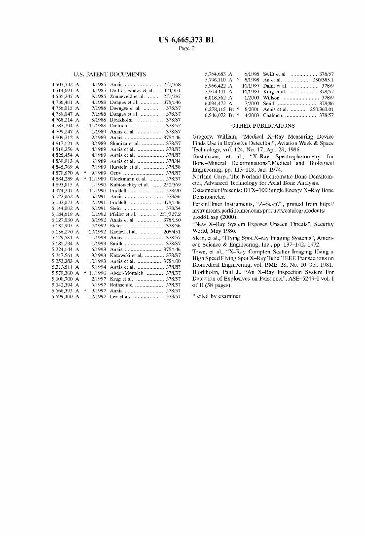
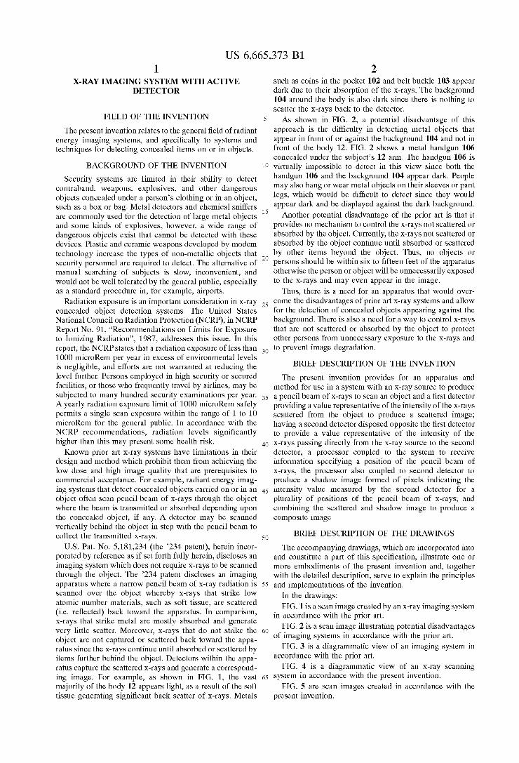
U.S. Pat. No. 5,181,234 (the 234 patent), herein incor porated by reference as if Set forth fully herein, discloses an imaging System which does not require X-rays to be Scanned through the object. The 234 patent discloses an imaging apparatus where a narrow pencil beam of X-ray radiation is Scanned over the object whereby X-rays that Strike low atomic number materials, Such as Soft tissue, are Scattered (i.e. reflected) back toward the apparatus. In comparison, X-rays that Strike metal are mostly absorbed and generate very little scatter. Moreover, X-rays that do not strike the object are not captured or Scattered back toward the appa ratus Since the X-rays continue until absorbed or Scattered by items further behind the object. Detectors within the appa ratus capture the Scattered X-rays and generate a correspond ing image. For example, as shown in FIG. 1, the vast majority of the body 12 appears light, as a result of the Soft tissue generating significant back Scatter of X-rayS. Metals
15
25
35
40
45
50
55
60
65
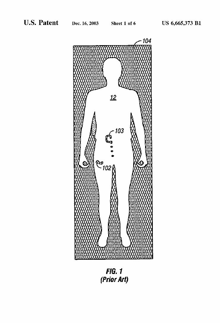
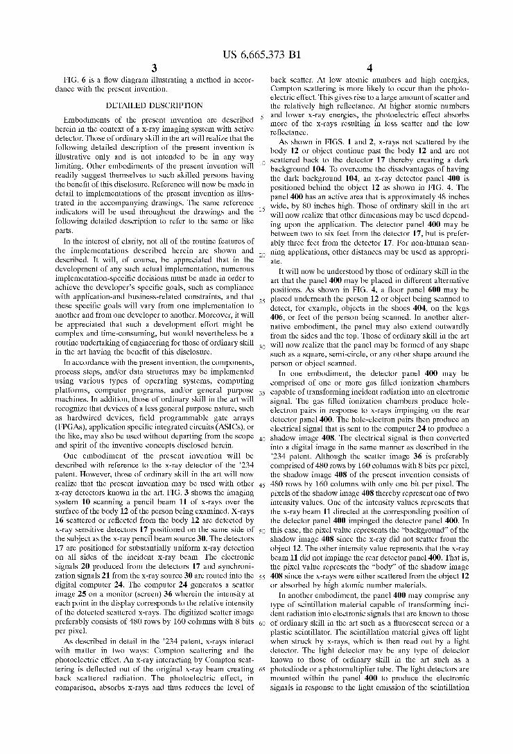
2 such as coins in the pocket 102 and belt buckle 103 appear dark due to their absorption of the X-rays. The background 104 around the body is also dark since there is nothing to Scatter the X-rays back to the detector. AS Shown in FIG. 2, a potential disadvantage of this
approach is the difficulty in detecting metal objects that appear in front of or against the background 104 and not in front of the body 12. FIG. 2 shows a metal handgun 106 concealed under the subject's 12 arm. The handgun 106 is virtually impossible to detect in this view since both the handgun 106 and the background 104 appear dark. People may also hang or wear metal objects on their sleeves or pant legs, which would be difficult to detect since they would appear dark and be displayed against the dark background. Another potential disadvantage of the prior art is that it
provides no mechanism to control the X-rays not Scattered or absorbed by the object. Currently, the X-rays not scattered or absorbed by the object continue until absorbed or scattered by other items beyond the object. Thus, no objects or perSons should be within six to fifteen feet of the apparatus otherwise the perSon or object will be unnecessarily exposed to the X-rays and may even appear in the image.
Thus, there is a need for an apparatus that would over come the disadvantages of prior art X-ray Systems and allow for the detection of concealed objects appearing against the background. There is also a need for a way to control X-rayS that are not scattered or absorbed by the object to protect other perSons from unnecessary exposure to the X-rays and to prevent image degradation.
BRIEF DESCRIPTION OF THE INVENTION
The present invention provides for an apparatus and method for use in a System with an X-ray Source to produce a pencil beam of X-rays to Scan an object and a first detector providing a value representative of the intensity of the X-rayS Scattered from the object to produce a Scattered image; having a Second detector disposed opposite the first detector to provide a value representative of the intensity of the X-rays passing directly from the X-ray Source to the Second detector; a processor coupled to the System to receive information Specifying a position of the pencil beam of X-rays, the processor also coupled to Second detector to produce a shadow image formed of pixels indicating the intensity value measured by the Second detector for a plurality of positions of the pencil beam of X-rays, and combining the Scattered and Shadow image to produce a composite image.
BRIEF DESCRIPTION OF THE DRAWINGS
The accompanying drawings, which are incorporated into and constitute a part of this Specification, illustrate one or more embodiments of the present invention and, together with the detailed description, Serve to explain the principles and implementations of the invention.
In the drawings: FIG. 1 is a Scan image created by an X-ray imaging System
in accordance with the prior art. FIG. 2 is a Scan image illustrating potential disadvantages
of imaging Systems in accordance with the prior art. FIG. 3 is a diagrammatic view of an imaging System in
accordance with the prior art. FIG. 4 is a diagrammatic view of an X-ray Scanning
System in accordance with the present invention. FIG. 5 are Scan images created in accordance with the
present invention.
US 6,665,373 B1 3
FIG. 6 is a flow diagram illustrating a method in accor dance with the present invention.
DETAILED DESCRIPTION
Embodiments of the present invention are described herein in the context of a X-ray imaging System with active detector. Those of ordinary skill in the art will realize that the following detailed description of the present invention is illustrative only and is not intended to be in any way limiting. Other embodiments of the present invention will readily Suggest themselves to Such skilled perSons having the benefit of this disclosure. Reference will now be made in detail to implementations of the present invention as illus trated in the accompanying drawings. The same reference indicators will be used throughout the drawings and the following detailed description to refer to the same or like parts.
In the interest of clarity, not all of the routine features of the implementations described herein are shown and described. It will, of course, be appreciated that in the development of any Such actual implementation, numerous implementation-specific decisions must be made in order to achieve the developer's Specific goals, Such as compliance with application-and busineSS-related constraints, and that these Specific goals will vary from one implementation to another and from one developer to another. Moreover, it will be appreciated that Such a development effort might be complex and time-consuming, but would nevertheless be a routine undertaking of engineering for those of ordinary skill in the art having the benefit of this disclosure.
In accordance with the present invention, the components, proceSS Steps, and/or data Structures may be implemented using various types of operating Systems, computing platforms, computer programs, and/or general purpose machines. In addition, those of ordinary skill in the art will recognize that devices of a less general purpose nature, Such as hardwired devices, field programmable gate arrays (FPGAS), application specific integrated circuits (ASICs), or the like, may also be used without departing from the Scope and Spirit of the inventive concepts disclosed herein. One embodiment of the present invention will be
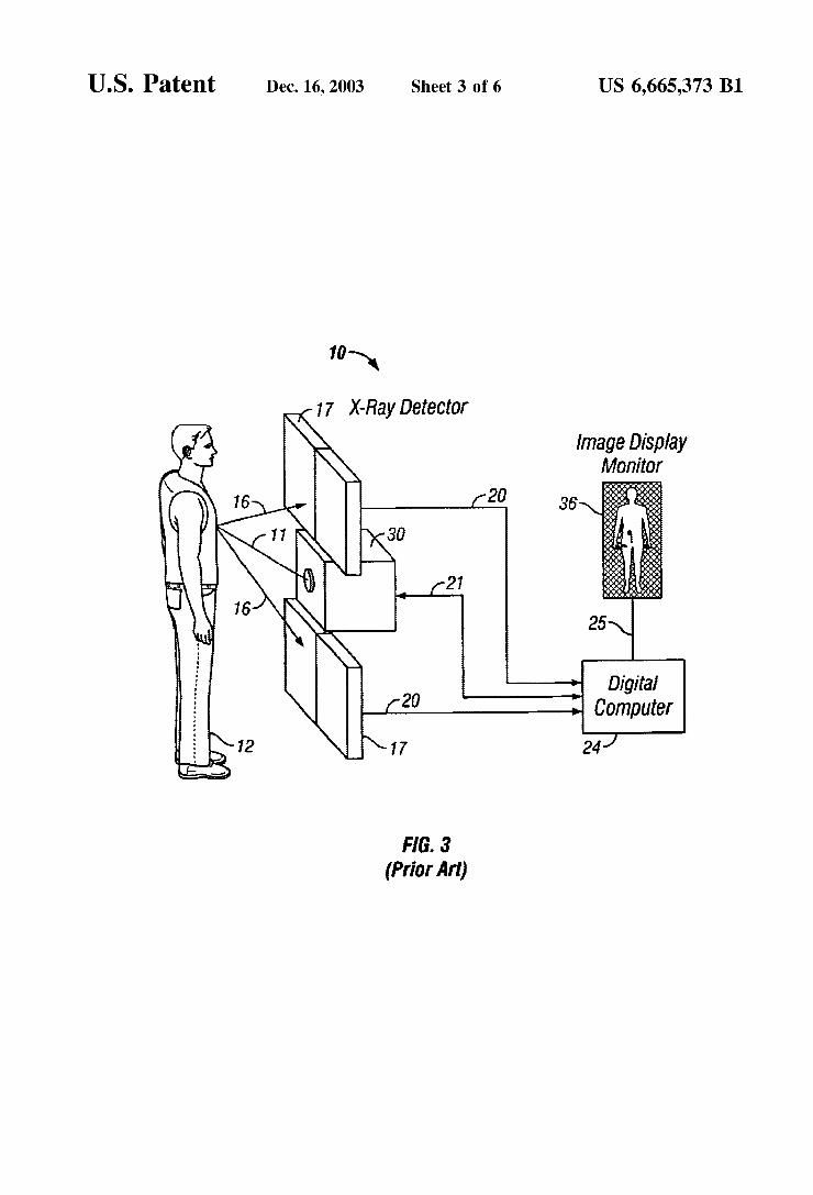
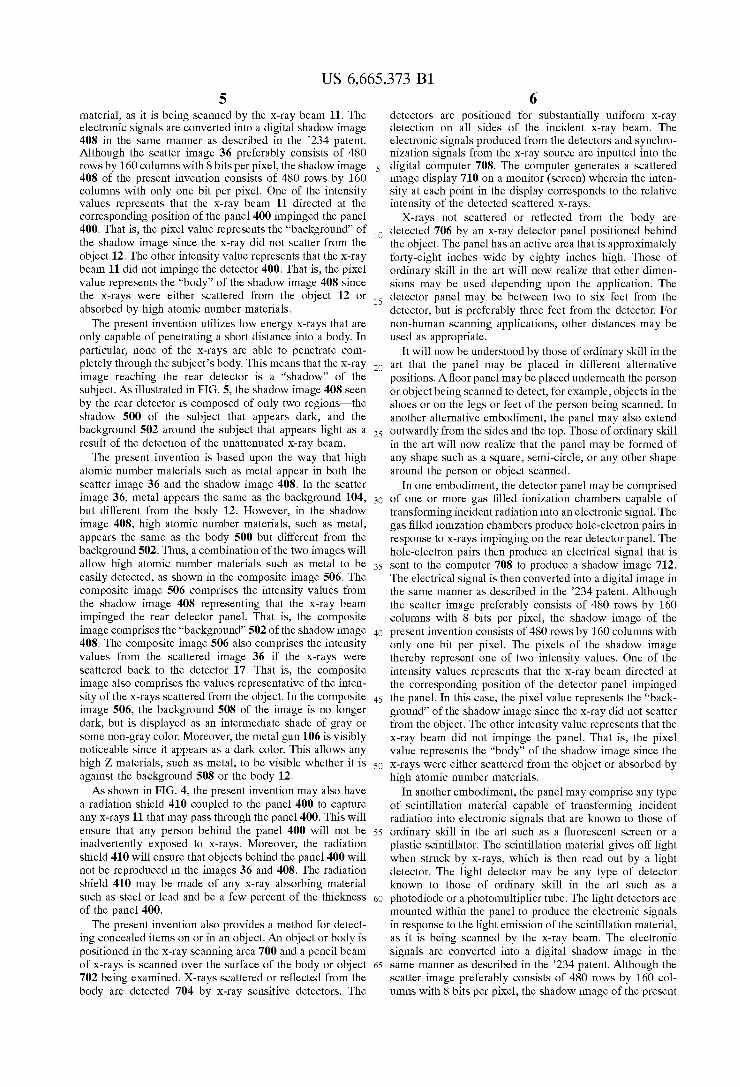
described with reference to the X-ray detector of the 234 patent. However, those of ordinary skill in the art will now realize that the present invention may be used with other X-ray detectors known in the art. FIG. 3 shows the imaging System 10 Scanning a pencil beam 11 of X-rays over the Surface of the body 12 of the perSon being examined. X-rays 16 scattered or reflected from the body 12 are detected by X-ray Sensitive detectorS 17 positioned on the same Side of the subject as the X-ray pencil beam source 30. The detectors 17 are positioned for substantially uniform X-ray detection on all Sides of the incident X-ray beam. The electronic signals 20 produced from the detectors 17 and synchroni zation signals 21 from the X-ray source 30 are routed into the digital computer 24. The computer 24 generates a Scatter image 25 on a monitor (Screen) 36 wherein the intensity at each point in the display corresponds to the relative intensity of the detected Scattered X-rayS. The digitized Scatter image preferably consists of 480 rows by 160 columns with 8 bits per pixel. AS described in detail in the 234 patent, X-rays interact
with matter in two ways: Compton Scattering and the photoelectric effect. An X-ray interacting by Compton Scat tering is deflected out of the original X-ray beam creating back Scattered radiation. The photoelectric effect, in comparison, absorbs X-rays and thus reduces the level of
15
25
35
40
45
50
55
60
65
4 back Scatter. At low atomic numbers and high energies, Compton Scattering is more likely to occur than the photo electric effect. This gives rise to a large amount of Scatter and the relatively high reflectance. At higher atomic numbers and lower X-ray energies, the photoelectric effect absorbs more of the X-rays resulting in less Scatter and the low reflectance. As shown in FIGS. 1 and 2, X-rays not scattered by the
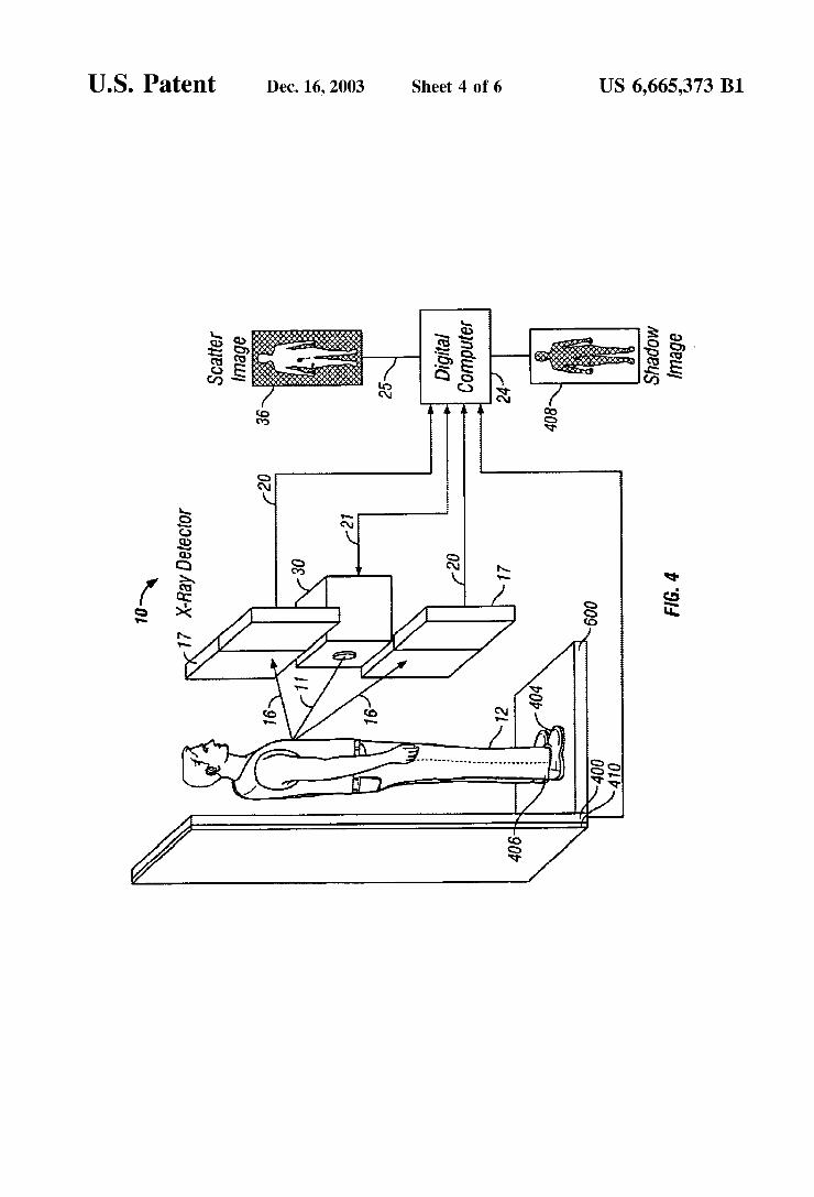
body 12 or object continue past the body 12 and are not scattered back to the detector 17 thereby creating a dark background 104. To overcome the disadvantages of having the dark background 104, an X-ray detector panel 400 is positioned behind the object 12 as shown in FIG. 4. The panel 400 has an active area that is approximately 48 inches wide, by 80 inches high. Those of ordinary skill in the art will now realize that other dimensions may be used depend ing upon the application. The detector panel 400 may be between two to six feet from the detector 17, but is prefer ably three feet from the detector 17. For non-human scan ning applications, other distances may be used as appropri ate.
It will now be understood by those of ordinary skill in the art that the panel 400 may be placed in different alternative positions. As shown in FIG. 4, a floor panel 600 may be placed underneath the perSon 12 or object being Scanned to detect, for example, objects in the ShoeS 404, on the legs 406, or feet of the person being scanned. In another alter native embodiment, the panel may also extend outwardly from the sides and the top. Those of ordinary skill in the art will now realize that the panel may be formed of any shape Such as a Square, Semi-circle, or any other shape around the perSon or object Scanned.
In one embodiment, the detector panel 400 may be comprised of one or more gas filled ionization chambers capable of transforming incident radiation into an electronic Signal. The gas filled ionization chambers produce hole electron pairs in response to X-rays impinging on the rear detector panel 400. The hole-electron pairs then produce an electrical Signal that is sent to the computer 24 to produce a shadow image 408. The electrical signal is then converted into a digital image in the same manner as described in the 234 patent. Although the scatter image 36 is preferably comprised of 480 rows by 160 columns with 8 bits per pixel, the shadow image 408 of the present invention consists of 480 rows by 160 columns with only one bit per pixel. The pixels of the shadow image 408 thereby represent one of two intensity values. One of the intensity values represents that the X-ray beam 11 directed at the corresponding position of the detector panel 400 impinged the detector panel 400. In this case, the pixel value represents the “background” of the shadow image 408 since the X-ray did not scatter from the object 12. The other intensity value represents that the X-ray beam 11 did not impinge the rear detector panel 400. That is, the pixel value represents the “body” of the shadow image 408 since the X-rays were either scattered from the object 12 or absorbed by high atomic number materials.
In another embodiment, the panel 400 may comprise any type of Scintillation material capable of transforming inci dent radiation into electronic Signals that are known to those of ordinary skill in the art Such as a fluorescent Screen or a plastic Scintillator. The Scintillation material gives off light when Struck by X-rays, which is then read out by a light detector. The light detector may be any type of detector known to those of ordinary skill in the art Such as a photodiode or a photomultiplier tube. The light detectors are mounted within the panel 400 to produce the electronic Signals in response to the light emission of the Scintillation
US 6,665,373 B1 S
material, as it is being Scanned by the X-ray beam 11. The electronic Signals are converted into a digital Shadow image 408 in the same manner as described in the 234 patent. Although the scatter image 36 preferably consists of 480 rows by 160 columns with 8 bits per pixel, the shadow image 408 of the present invention consists of 480 rows by 160 columns with only one bit per pixel. One of the intensity values represents that the X-ray beam 11 directed at the corresponding position of the panel 400 impinged the panel 400. That is, the pixel value represents the “background” of the Shadow image Since the X-ray did not Scatter from the object 12. The other intensity value represents that the X-ray beam 11 did not impinge the detector 400. That is, the pixel value represents the “body” of the shadow image 408 since the X-rays were either scattered from the object 12 or absorbed by high atomic number materials. The present invention utilizes low energy X-rays that are
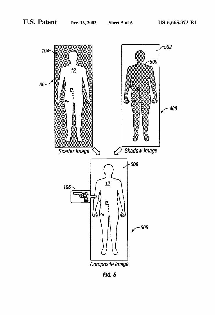
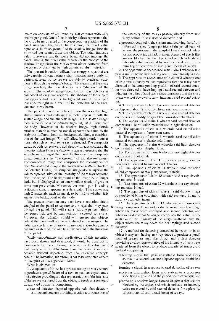
only capable of penetrating a short distance into a body. In particular, none of the X-rays are able to penetrate com pletely through the Subject’s body. This means that the X-ray image reaching the rear detector is a “shadow” of the subject. As illustrated in FIG. 5, the shadow image 408 seen by the rear detector is composed of only two regions-the shadow 500 of the subject that appears dark, and the background 502 around the Subject that appears light as a result of the detection of the unattenuated X-ray beam.
The present invention is based upon the way that high atomic number materials. Such as metal appear in both the scatter image 36 and the shadow image 408. In the scatter image 36, metal appears the same as the background 104, but different from the body 12. However, in the shadow image 408, high atomic number materials, Such as metal, appears the same as the body 500 but different from the background 502. Thus, a combination of the two images will allow high atomic number materials. Such as metal to be easily detected, as shown in the composite image 506. The composite image 506 comprises the intensity values from the shadow image 408 representing that the X-ray beam impinged the rear detector panel. That is, the composite image comprises the “background' 502 of the shadow image 408. The composite image 506 also comprises the intensity values from the Scattered image 36 if the X-rays were scattered back to the detector 17. That is, the composite image also comprises the values representative of the inten sity of the X-rayS Scattered from the object. In the composite image 506, the background 508 of the image is no longer dark, but is displayed as an intermediate Shade of gray or Some non-gray color. Moreover, the metal gun 106 is visibly noticeable Since it appears as a dark color. This allows any high Z materials, Such as metal, to be visible whether it is against the background 508 or the body 12. As shown in FIG. 4, the present invention may also have
a radiation shield 410 coupled to the panel 400 to capture any X-rays 11 that may pass through the panel 400. This will ensure that any person behind the panel 400 will not be inadvertently exposed to X-rayS. Moreover, the radiation shield 410 will ensure that objects behind the panel 400 will not be reproduced in the images 36 and 408. The radiation shield 410 may be made of any X-ray absorbing material Such as Steel or lead and be a few percent of the thickneSS of the panel 400.
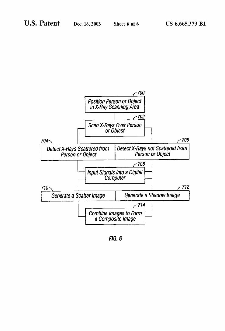
The present invention also provides a method for detect ing concealed items on or in an object. An object or body is positioned in the X-ray Scanning area 700 and a pencil beam of X-rays is Scanned over the Surface of the body or object 702 being examined. X-rays scattered or reflected from the body are detected 704 by X-ray sensitive detectors. The
15
25
35
40
45
50
55
60
65
6 detectors are positioned for Substantially uniform X-ray detection on all sides of the incident X-ray beam. The electronic Signals produced from the detectors and Synchro nization signals from the X-ray Source are inputted into the digital computer 708. The computer generates a Scattered image display 710 on a monitor (Screen) wherein the inten sity at each point in the display corresponds to the relative intensity of the detected Scattered X-rayS.
X-rays not scattered or reflected from the body are detected 706 by an X-ray detector panel positioned behind the object. The panel has an active area that is approximately forty-eight inches wide by eighty inches high. Those of ordinary skill in the art will now realize that other dimen Sions may be used depending upon the application. The detector panel may be between two to six feet from the detector, but is preferably three feet from the detector. For non-human Scanning applications, other distances may be used as appropriate.
It will now be understood by those of ordinary skill in the art that the panel may be placed in different alternative positions. A floor panel may be placed underneath the perSon or object being Scanned to detect, for example, objects in the shoes or on the legs or feet of the perSon being Scanned. In another alternative embodiment, the panel may also extend outwardly from the sides and the top. Those of ordinary skill in the art will now realize that the panel may be formed of any shape Such as a Square, Semi-circle, or any other shape around the perSon or object Scanned.
In one embodiment, the detector panel may be comprised of one or more gas filled ionization chambers capable of transforming incident radiation into an electronic Signal. The gas filled ionization chambers produce hole-electron pairs in response to X-rays impinging on the rear detector panel. The hole-electron pairs then produce an electrical Signal that is sent to the computer 708 to produce a shadow image 712. The electrical Signal is then converted into a digital image in the same manner as described in the 234 patent. Although the scatter image preferably consists of 480 rows by 160 columns with 8 bits per pixel, the Shadow image of the present invention consists of 480 rows by 160 columns with only one bit per pixel. The pixels of the shadow image thereby represent one of two intensity values. One of the intensity values represents that the X-ray beam directed at the corresponding position of the detector panel impinged the panel. In this case, the pixel value represents the “back ground” of the shadow image Since the X-ray did not Scatter from the object. The other intensity value represents that the X-ray beam did not impinge the panel. That is, the pixel value represents the “body” of the shadow image since the X-rays were either scattered from the object or absorbed by high atomic number materials.
In another embodiment, the panel may comprise any type of Scintillation material capable of transforming incident radiation into electronic signals that are known to those of ordinary skill in the art Such as a fluorescent Screen or a plastic Scintillator. The Scintillation material gives off light when Struck by X-rays, which is then read out by a light detector. The light detector may be any type of detector known to those of ordinary skill in the art Such as a photodiode or a photomultiplier tube. The light detectors are mounted within the panel to produce the electronic signals in response to the light emission of the Scintillation material, as it is being Scanned by the X-ray beam. The electronic Signals are converted into a digital shadow image in the Same manner as described in the 234 patent. Although the scatter image preferably consists of 480 rows by 160 col umns with 8 bits per pixel, the Shadow image of the present
US 6,665,373 B1 7
invention consists of 480 rows by 160 columns with only one bit per pixel. One of the intensity values represents that the X-ray beam directed at the corresponding position of the panel impinged the panel. In this case, the pixel value represents the “background” of the shadow image Since the X-ray did not scatter from the object. The other intensity value represents that the X-ray beam did not impinge the panel. That is, the pixel value represents the “body' of the Shadow image Since the X-rays were either Scattered from the object or absorbed by high atomic number materials.
The present invention utilizes low energy X-rays that are only capable of penetrating a short distance into a body. In particular, none of the X-rays are able to penetrate com pletely through the Subject’s body. This means that the X-ray image reaching the rear detector is a “shadow” of the Subject. The Shadow image Seen by the rear detector is composed of only two regions-the Shadow of the Subject that appears dark, and the background around the Subject that appears light as a result of the detection of the unat tenuated X-ray beam.
The present invention is based upon the way that high atomic number materials. Such as metal appear in both the Scatter image and the shadow image. In the Scatter image, metal appears the same as the background, but different from the body. However, in the Shadow image, high atomic number materials, Such as metal, appears the same as the body but different from the background. Thus, a combina tion of the two images 714 will allow high atomic number materials. Such as metal to be easily detected. The composite image of both the Scattered and Shadow images comprise the intensity values from the Shadow image representing that the X-ray beam impinged the panel. In this case, the composite image comprises the “background” of the Shadow image. The composite image also comprises the intensity values from the Scattered image if the X-rays were Scattered back to the detector. That is, the composite image also comprises the values representative of the intensity of the X-rayS Scattered from the object. The background of the image is no longer dark, but is displayed as an intermediate Shade of gray or Some non-gray color. Moreover, the metal gun is visibly noticeable Since it appears as a dark color. This allows any high Z materials, Such as metal, to be visible whether it is against the background or the body. The present invention may also have a radiation shield
coupled to the panel to capture any X-rays that may pass through the panel. This will ensure that any perSon behind the panel will not be inadvertently exposed to X-rayS. Moreover, the radiation shield will ensure that objects behind the panel will not be reproduced in the images. The radiation Shield may be made of any X-ray absorbing mate rial Such as Steel or lead and be a few percent of the thickneSS of the panel.
While embodiments and applications of this invention have been shown and described, it would be apparent to those skilled in the art having the benefit of this disclosure that many more modifications than mentioned above are possible without departing from the inventive concepts herein. The invention, therefore, is not to be restricted except in the Spirit of the appended claims. What is claimed is: 1. An apparatus for use in a System having an X-ray Source
to produce a pencil beam of X-rays to Scan an object and a first detector providing a value representative of the intensity of the X-rays Scattered from the object to produce a Scattered image, Said apparatus comprising:
a Second detector disposed opposite Said first detector, Said Second detector providing a value representative of
15
25
35
40
45
50
55
60
65
8 the intensity of the X-rays passing directly from Said X-ray Source to Said Second detector; and
a processor coupled to the System and receiving therefrom information Specifying a position of the pencil beam of X-rays, the processor also coupled to Said Second detec tor and producing a shadow image formed of pixels that are not blocked by the object and which indicate an intensity value measured by Said Second detector for a plurality of positions of Said pencil beam of X-rayS.
2. The apparatus in accordance with claim 1 wherein Said pixels are limited to representing one of two intensity values.
3. The apparatus in accordance with claim 2 wherein one of Said two intensity values represents that the X-ray beam directed at the corresponding position of Said Second detec tor was detected to have impinged said Second detector and wherein the other of Said two values represents that the X-ray beam was not detected to have impinged Said Second detec tor.
4. The apparatus of claim 1 wherein Said Second detector is disposed about 2 to 6 feet from Said X-ray Source.
5. The apparatus of claim 1 wherein Said Second detector comprises a plurality of gas filled ionization chambers.
6. The apparatus of claim 1 wheren Said Second detector comprises a Scintillation material and a light detector.
7. The apparatus of claim 6 wherein said scintillation material comprises a fluorescent Screen.
8. The apparatus of claim 6 wherein said scintillation material comprises a plastic Scintillator.
9. The apparatus of claim 6 wherein said light detector comprises a photomultiplier tube.
10. The apparatus of claim 6 wherein said light detector comprises a photodiode.
11. The apparatus of claim 1 further comprising a radia tion shield coupled to Said Second detector.
12. The apparatus of claim 11 wherein Said radiation Shield comprises an X-ray absorbing material.
13. The apparatus of claim 12 wheren said X-ray absorb ing material is Steel.
14. The apparatus of claim 12 wherein said X-ray absorb ing material is lead.
15. The apparatus of claim 1 wherein Said Shadow image is capable of being combined with Said Scattered image to form a composite image.
16. The apparatus of claim 15 wherein said composite image comprises the intensity value from Said Shadow image where the X-ray beam impinged Said Second detector, and wherein Said composite image comprises the value repre Sentative of the intensity of the X-rays Scattered from the object where the X-ray beam did not impinge Said Second detector.
17. A method for detecting concealed items on or in an object in a System having an X-ray Source to produce a pencil bean of X-rays to Scan the object and a first detector providing a value representative of the intensity of the X-rayS Scattered from the object to produce a Scattered image, Said method comprising:
detecting X-rays that pass unscattered from Said X-ray Source to a Second detector disposed opposite Said first detector;
forming a signal in response to Said detection of X-rays, receiving information from Said System to a processor
Specifying a position of the pencil beam of X-rays, and producing a shadow image formed of pixels that are not
blocked by the object and which indicate an intensity value measured by Said Second detector for a plurality of positions of Said pencil beam of X-rayS.
US 6,665,373 B1
18. The method in accordance with claim 17 wherein said pixels are limited to representing one of two intensity values.
19. The method in accordance with claim 18 wherein one of Said two intensity values represents that the X-ray beam directed at the corresponding position of Said Second detec tor was detected to have impinged said Second detector and wherein the other of Said two values represents that the X-ray beam was not detected to have impinged Said Second detec tor.
20. The method of claim 17 further comprising disposing Said Second detector about 2 to 6 feet from Said X-ray Source.
21. The method of claim 17 wherein said second detector comprises a plurality of gas filled ionization chambers.
22. The method of claim 17 wherein said second detector comprises a Scintillation material and a light detector.
23. The method of claim 22 wherein said Scintillation material comprises a fluorescent Screen.
24. The method of claim 22 wherein said Scintillation material comprises a plastic Scintillator.
25. The method of claim 22 wherein said light detector comprises a photomultiplier tube.
26. The method of claim 22 wherein said light detector comprises a photodiode.
27. The method of claim 17 further comprising coupling a radiation shield to Said Second detector.
28. The method of claim 27 wherein said radiation shield comprises an X-ray absorbing material.
29. The method of claim 28 wherein said X-ray absorbing material is Steel.
30. The method of claim 28 wherein said X-ray absorbing material is lead.
31. The method of claim 17 further comprising combining Said shadow image with Said Scattered image to form a composite image.
32. The method of claim 31 wherein said composite image comprises the intensity value from Said Shadow image where the X-ray beam impinged Said Second detector, and wherein Said composite image comprises the value repre Sentative of the intensity of the X-rays Scattered from the object where the X-ray beam did not impinge Said Second detector.
33. A program Storage device readable by a machine, tangibly embodying a program of instructions executable by the machine to perform a method for detecting concealed items on or in an object in a System having an X-ray Source to produce a pencil beam of X-rays to Scan the object and a first detector providing a value representative of the intensity of the X-rays Scattered from the object to produce a Scattered image, Said method comprising:
detecting X-rays that pass unscattered from Said X-ray Source to a Second detector disposed opposite Said first detector;
forming a signal in response to Said detection of X-rays, receiving information from Said System to a processor
Specifying a position of the pencil beam of X-rays, and producing a shadow image formed of pixels that are not
blocked by the object and which indicate an intensity value measured by Said Second detector for a plurality of positions of Said pencil beam of X-rayS.
34. A System for Scanning an object, comprising: an X-ray Source to produce a pencil beam of X-rays to Scan
the object; a first detector to provide a value representative of the
intensity of X-rays Scattered from the object; an image former responsive to Said first detector to form
a Scattered image;
1O
15
25
35
40
45
50
55
60
65
10 a Second detector disposed opposite Said first detector,
Said Second detector providing a value representative of an intensity of X-rays passing directly from Said X-ray Source to Said Second detector; and
a processor coupled to receive information Specifying a position of the pencil beam of X-rays, the processor also coupled to Said Second detector and producing a Shadow image formed of pixels that are not blocked by the object and which indicate an intensity value mea Sured by Said Second detector for a plurality of posi tions of Said pencil beam of X-rayS.
35. The system in accordance with claim 34 wherein said pixels are limited to representing one of two intensity values.
36. The system in accordance with claim 35 wherein one of Said two intensity values represents that the X-ray beam directed at the corresponding position of Said Second detec tor was detected to have impinged said Second detector and wherein the other of Said two values represents that the X-ray beam was not detected to have impinged Said Second detec tor.
37. The system of claim 34 wherein said shadow image is adapted to be combined with Said Scattered image to form a composite image.
38. The system of claim 37 wherein said composite image comprises the intensity value from Said shadow image where the X-ray beam impinged said Second detector, and wherein Said composite image comprises the value representative of the intensity of the X-rays scattered from the object where the X-ray beam did not impinge Said Second detector.
39. A System for Scanning an object, comprising: X-ray Scanning means for producing a pencil beam of
X-rays to Scan the object; Scattered X-ray detection means for detecting an intensity
of X-rays Scattered from the object; image forming means responsive to Said Scattered X-ray
detection means for forming a Scattered image; direct X-ray detection means disposed opposite Said Scat
tered X-ray detection means, Said direct X-ray detection means responsive to an intensity of X-rays passing directly from Said X-ray Source to Said direct X-ray detection means, and
processor means coupled to receive information specify ing a position of the pencil beam of X-rays, Said processor means also responsive to Said direct X-ray detection means for forming a shadow image formed of pixels that are not blocked by the object and which indicate intensity values measured by Said direct X-ray detection means at a plurality of positions of Said pencil beam of X-rayS.
40. The system in accordance with claim 39 wherein said pixels are limited to representing one of two intensity values.
41. The system in accordance with claim 40 wherein one of Said two intensity values represents that the beam of X-rays directed at a corresponding position of Said direct X-ray detection means was detected to have impinged Said direct X-ray detection means and wherein the other of Said two values represents that the beam of X-rays was not detected to have impinged Said direct X-ray detection means.
42. The system of claim 39 wherein the shadow image is adapted to be combined with Said Scatted image to form a composite image.
43. The System of claim 42 wherein Said composite image comprises the intensity value from Said shadow image where the X-ray beam impinged said direct X-ray detection means, and wherein Said composite image comprises the value representative of the intensity of the X-rays Scattered from

US 6,665,373 B1 11
the object where the X-ray beam did not impinge Said direct X-ray detection means.
44. A method for Scanning an object, comprising: forming a pencil beam of X-rays with an X-ray Source; Scanning the object with the pencil beam of X-rays, detecting an intensity of X-rays Scattered from the object; forming a Scattered image in response to Said detecting; measuring an intensity of X-rays passing directly from
Said X-ray Source to a direct X-ray detector, and forming a Shadow image of pixels that are not blocked at
the object and which indicate intensity values measured by the direct X-ray detector at a plurality of positions of the pencil beam of X-rayS.
45. The method in accordance with claim 44 wherein the pixels are limited to representing one of two intensity values.
46. The method in accordance with claim 45 wherein one of the two intensity values represents that the beam of X-rays
15
12 directed at a corresponding position of the direct X-ray detection means was detected to have impinged Said direct X-ray detection means and wherein the other of the two values represents that the beam of X-rays was not detected to have impinged the direct X-ray detector.
47. The method of claim 44, further comprising: combining the Shadow image with the Scattered image to
form a composite image. 48. The method of claim 47 wherein the composite image
comprises the intensity value from the Shadow image where the beam of X-rays impinged the direct X-ray detector, and wherein the composite image comprises the value represen tative of the intensity of the X-rays scattered from the object where the X-ray beam did not impinge the direct X-ray detector.

UNITED STATES PATENT AND TRADEMARK OFFICE
CERTIFICATE OF CORRECTION
PATENT NO. : 6,665,373 B1 Page 1 of 1 DATED : December 16, 2003 INVENTOR(S) : Andreas F. Kotowski and Steven W. Smith
It is certified that error appears in the above-identified patent and that said Letters Patent is hereby corrected as shown below:
Column 8 Lines 23 and 37, replace “wheren” with -- wherein --. Line 53, replace “bean” with -- beam --.
Signed and Sealed this
Fifteenth Day of June, 2004
WDJ JON W. DUDAS
Acting Director of the United States Patent and Trademark Office