(12) Patent Application Publication (10) Pub. No.: US 2016 ...
Upload
khangminh22Category
view
0download
0
(19) United States (12) Patent Application Publication (10) Pub. No.: US 2006/0252421 A1
Lee
US 20060252421A1
(43) Pub. Date: Nov. 9, 2006
(54) METHOD AND APPARATUS FOR BASE STATION CONTROLLER RELOCATION IN WIRELESS COMMUNICATION SYSTEM
(75) Inventor: Sang Chul Lee, Seoul (KR)
Correspondence Address: FLESHNER & KIM, LLP P.O. BOX 2212OO CHANTILLY, VA 20153 (US)
(73) Assignee: LG Electronics Inc.
(21) Appl. No.: 11/429,220
(22) Filed: May 8, 2006
(30) Foreign Application Priority Data
May 9, 2005 (KR)............................ 10-2005-003827O
Publication Classification
(51) Int. Cl. H04O 7/20 (2006.01)
(52) U.S. Cl. ............................................ 455/428; 455/560
(57) ABSTRACT
A method and apparatus for base station controller reloca tion in a wireless communication system are disclosed. The apparatus for relocating a serving base station controller according to the present invention comprises a Switching function part and a signaling function part. The signaling function part executes a change through a connection pro cedure in response to a base station controller relocation request from a source base station controller. The Switching function part creates a termination 3 (T3) for the target base station controller and performs simplex Switching to the terminations to connect the termination 3 (T3) to a termi nation 2(T2) initially maintaining connection with the Source base station controller, thereby relocating the target base station controller as a serving base station controller.
MSCS
RN C
MSC S r
MSCS
FINAL STATE
- - - - - - - - - - CALL CONTROL SIGNALING
BEARER CONTROL SIGNALING AND THE BEARER

Patent Application Publication Nov. 9, 2006 Sheet 1 of 5 US 2006/0252421 A1
FIG. 1
MSC S
RNC S -- - it is as a NTAL STATE
INTERMEDIATE STATE
MSCS
kg a FINAL STATE
C
CALL CONTROL SIGNALNG - - - - - BEARER CONTROL SIGNALING AND THE BEARER
Patent Application Publication Nov. 9, 2006 Sheet 2 of 5 US 2006/0252421 A1
FG. 2
RNCT
S2: u Relocation Reauiret : S, oneway). Topo T.S., isolate}}, ADOS))
: R(C1, AODT3}) Prepare Bearer + Change Flow Direction 5:lu-Relocation-Recuest
SS
S8: il-Relocation-Commah
T(C, (Topo (T2, T3, bdthway, Topo (2.T1, oneway}}. MOOT3}) } S10 R)C1. MOD(T3)) Change Flow Direction + change Flow Direction
S11: u-Relocation-Complete S12:lu-Release-Commant
s13 ( - A - C
T(C1. SU8T1 }) RC1. SU3)

Patent Application Publication Nov. 9, 2006 Sheet 3 of 5 US 2006/0252421 A1
FIG. 3
UIA B' B" B"
lu"A" C
UIA B'
B"
U"A" B"

Patent Application Publication Nov. 9, 2006 Sheet 4 of 5 US 2006/0252421 A1
FIG. 4
MSCS
is is - - - C
NTERMEDIATE STATE
MSC S
- a a FINAL STATE
C
CALL CONTROL SIGNALNG a w w X w. BEARER CONTROL SIGNALING AND THE BEARER

Patent Application Publication Nov. 9, 2006 Sheet 5 of 5 US 2006/0252421 A1
FIG. 5
RNCS MSVS RNCT
S101: C1 (T1 (u). T2(a)) S102: tu Relocation- Require
AOD. red (C1. S (inactive)) ADD. repC1, T3) Prepare Bearer S104 lu-Relocatibn-Request
S105
S107: il-Relocation-Commah
tive) Change Through Connection dRecv}) Change Through Connection
S110 u-Relocatibn-Complete S111:lu-Release-Commanb
s112 (C-E-> 519 releasel, SUB. rea(C1, T 1)
- S114 { SUB. rec(C1, T1) Release Terminiation N H
S115: C1 (T2(w), 3(u))

US 2006/0252421 A1
METHOD AND APPARATUS FOR BASE STATION CONTROLLER RELOCATION IN WIRELESS
COMMUNICATION SYSTEM
CROSS REFERENCE TO RELATED APPLICATIONS
0001. The present application claims priority to Korean Patent Application No. 10-2005-0038270 entitled “SRNS Relocation/Handover Method in the WCDMA System” and filed on May 09, 2005, the contents of which are incorpo rated herein by reference.
BACKGROUND OF THE INVENTION
0002) 0003. The present invention generally relates to wireless communication systems, and more particularly to a reloca tion/handover of a base station controller in a WCDMA (wideband code division multiple access) system. 0004 2. Description of the Related Art 0005 The WCDMA radio communication system is one of the 3rd generation wireless communication system devel oped for multimedia transmission. Such system has several advantages over the conventional systems such as high quality motion picture service and fast data transmission rate. The WCDMA radio communication system comprises a plurality of mobile stations (MSs), a universal terrestrial radio access network (UTRAN) consisting of a plurality of radio network systems (RNSs) and a core network (CN). Among the above features, the RNS comprises a plurality of Node Bs, which handles two-way data communication with the mobile stations located inside the assigned cell region and a radio network controller (RNC), which controls the Node Bs within the same RNS to thereby dynamically allocate the radio resource. When the MS exits the serving cell region to enter into another cell region, a mobile services switching center (MSC), which is an switching center for the core network (CN), performs the handover or relocation of the serving RNC (SRNC) in order to maintain the call. The SRNC provides mobile service to the MS by rerouting the channel assigned to the MS from the exiting cell to the entering cell. The MSC in the WCMA network is categorized into 3G MSC A and 3G MSC B, according to its role in the network during the relocation or handover operation.
0006. In the WCDMA system, all the calls are made through channels formed by connecting Iu(Iu', Iu") (an interface between the RNS and CN) or A(A', A") (an interface between the BSC and CN) to B(B', B", B") (an relay interface). To describe the connecting operation for each interface in the SRNS relocation or handover, the existing call is presumed to be in a state where Iu'/A" and B' are connected. When there is an intra 3G MSC relocation/ handover (Rel/HO), which only performs Iu relocation/ handover between the RNS and the MSC, a new connection between Iu"/A" and B' must be established. On the other hand, when there is an inter 3G MSC relocation/handover (Rel/HO), which includes the relocation of the connection between the MSCs, a new connection between B" and B' must be established. Also, when a subsequent inter 3G MSC relocation/handover occurs while B" and B' are in connec tion, a new connection between B" and B' must be estab
1. Field of the Invention
Nov. 9, 2006
lished. These procedures and steps are disclosed in 3GPP TS 23.009, as summarized in Table 1 provided below.
TABLE 1.
Initial Intermediate Final State
Type State State Success Fail
Intra 3G B'tou B'to Iul' and Iu" B'to Ill' B'to Il RelBIO
B'tou B'to Iul' and A" B'to A' B'to Il B'to A B'to A" and Iu" B'to Ill' B'to A
Inter 3G B'to Il B'to Iul' and B" BtoB' B'to Il RelBIO Subsequent B' to B' B' to B'and B" B" to B' Bto B' Inter 3G RelBIO
0007. In the intra 3G MSC relocation/handover, 3G MSC A uses a RANAP (Radio Access Network Appli cation Part) or BSSMAP (Base Station System Mobile Application Parts) interface to handle resource management, mobility management and call control during the SRNS relocation/handover. On the contrary, in the inter 3G MSC relocation/handover, 3G MSC A and 3G MSC B are con nected through MAP (Mobile Application Part) and ISUP (ISDN User Part)/BICC (Bearer Independent Call Control) interface. Further, mobility management and call control are handled by 3G MSC A, whereas resource management is handled by both 3G MSC)A and 3G MSC B. Also, in the subsequent SRNS relocation/handover, 3G MSC A addi tionally performs the role as an anchor MSC.
0008. A conventional MSC employs a 3-way bridging function or a complex Switch structure with an extended Switching function to Support and realize the aforementioned functions. It further Supports an intermediate state to reduce the time gap during the relocation/handover. The aforemen tioned role of 3G MSC A for the SRNS relocation/han dover in the WCDMA R4 system is distributed into a MSC Server (MSV) and a Media Gateway (MGW). The switching function is performed by the MGW node having the com plex Switching function that uses context parameters created by a change flow direction procedure. The MSC controls this through H.248/MEGACO. H.248/MEGACO, which is one of the protocols for VoIP provides a logical connection in the MGW. Such connection is described as an entity or a context, thereby classifying the MGW into terminations and COInteXtS.
0009. The context is a logical connection element of the termination in MGW, thus defining the relationship between the terminations, such as topology or media mixing between terminations, Switching parameter, etc., in the context. The context, which is used for connections between a plurality of terminals, contains more than two terminations. Further, a null context used for event detection and connected network Support contains one termination. Executing an add instruc tion (ADD) pointing to a certain context ID to connect the termination to the context connects the termination to the assigned context. Otherwise, the MGW creates a new con text and connects it to the termination. On the contrary, a subtract instruction (SUB) is used to remove the termination or terminate the connection and a move instruction (MOVE) is used to move the termination to a different context. The termination is a logical entity that creates and transmits

US 2006/0252421 A1
media streams and control streams in the MGW. The termi nation's characteristic is defined by a descriptor contained in an instruction. The termination has a termination ID assigned by the MGW at its creation. The type of termina tion can be broadly classified into a permanent termination, which semi-permanently exists in the MWG, and an ephem eral termination that temporarily exists.
0010 Since the aforementioned inter 3G MSC SRNS relocation/handover procedure using H.248/MEGACO is different from the intra 3G MSC RNS relocation/handover procedure in terms of signaling aspect but similar in Switch ing control aspect, only the intra 3G MSC relocation/han dover procedure will be described below. 0011 FIG. 1 is a schematic diagram illustrating the operation of a complex switch in the MGW of intra 3G MSC Adisclosed in 3GPP TS 23.305. FIG. 2 is a schematic diagram showing the overall process of the intra 3G MSC A relocation/handover procedures. First of all, S in RNC S. MSV S and MGW S denotes the source that currently provides the service, while T in RNC T denotes the target for the relocation/handover. Referring to FIG. 1, as for an established call subjected to the intra MSC SRNS relocation handover procedure in the conventional WCDMA R4 sys tem, termination 1 (T1), which provides access to a RNC S (RNC source) through Iu in the MGW and termination 2 (T2, which provides access to the other party in the MGW. provide a connection between the RNS (connected to the MS) and CN. The connection is provided through a topology descriptor set by a context 1 (C1), which has context related parameters (bothway, oneway, isolate) (S1).
0012. At this time, when the SRNS relocation/handover becomes necessary, such as a change in the location of the MS, the RNC S providing service to MS sends a relocation request (Relocation Required) to the MSV S (S2). The MSV S, upon receiving the relocation request from RNC S by step S2, acquires a binding reference and a bearer address from the MGW by a prepare bearer procedure to prepare the radio resource. It then creates a termination 3 (T3) for RNC T in the MGW. Thereafter, the MGW creates the topology descriptor that initializes the MGW through a change flow direction procedure to set T1 and T2 bothway, as well as T2 and T3 oneway to T3 (S3). 0013. After step S3, the MGW performs switching to set T1 and T2 bothway, T2 and T3 oneway to T3 (shown in FIG. 2) by using the topology descriptor (S4). Upon creat ing T3 through the aforementioned steps, the MSV S sends a relocation request signal (Relocation Request) to a target RNC T by using the information of the established call (S5). Then, the MGW and the target RNC T sets the radio resource (bearer) for an Iu relocation/handover of SRNS for the MS by using ALCAP (AAL Type2 signaling Protocol Capability set1) and UP (User Plane) protocol (S6). When the preparation of radio resource for the SRNS relocation/ handover in step S6 is complete, the RNC T sends a relocation request acknowledgement (Relocation Request Ack) to the MSV S to notify that the radio resource prepa ration has been successfully completed (S7). Along with step S7, the MSV S sends a relocation instruction (Reloca tion Command) to the RNC S to proceed with the SRNS relocation/handover (Rel/HO) procedure (S8). Next, when the relocation procedure proceeds at RNC T by step S7, the MSV S receives a relocation detect message (Relocation
Nov. 9, 2006
Detect) from RNC T (S9). Then, when the relocation com mand is sent to the RNC S in step S8 or selectively, if the relocation detect message is received from the RNC T in step S9, the MSV S creates a topology descriptor that defines the topology relationship, wherein T1 of the MGW is set to an isolated State, T2 is set to a oneway state to T1, and T2 and T3 are set to a bothway state, thereby connecting the terminations in the MGW similar to the intermediate state b shown in FIG. 2.
0014) Next, upon completing the relocation by the RNC T, the RNT T sends a relocation complete message (Relocation Complete) to MSC S (S11). Upon receiving the relocation complete message from the RNC T in step S11, the MSV S sends a radio resource release command for releasing the bearer assigned to the RNC S so as to release the resource for the RNC S (S12). After receiving the radio resource release command (Release Command) from the MSV S, the RNC S releases the bearer by using ALCAP (S13). The RNC S completes the release of the bearer for interface Iu through step S12 and then notifies the comple tion of the bearer release to the MSV S through a bearer release complete message (Release Complete) (S14). The MSV S releases the resources of the MGW assigned to the RNC S by releasing the oneway connection from T2 to T1 and removing T1 through release termination procedures, thereby connecting the terminations as the final State shown in FIG. 2. Through step S15, T2 and T3 in the MGW are connected, thereby completing the SRNS relocation/han dover (Rel/HO) (S16). 0.015 The aforementioned conventional SRNS reloca tion/handover method in the WCDMA R4 system only describes the relocation/handover procedures by using the 3-way bridging function or the special Switching function implemented by the MGWs having a handover device with the complex Switching structure. It does not provide the SRNS relocation/handover procedure using a MGW having a handover device with a simplex Switching structure. Therefore, the prior art does not provide a SRNS relocation/ handover function using the MGW having the simplex Switch structure, which does not have an intermediate state, or, optionally, that does not Support the topology descriptor of H.248/MEGACO. Also, not only does the prior art require the MGW with high complexity to realize the topology, but it also requires intricate control of MGW and MSV when the context has more than three terminations, such as the SRNS relocation/handover for the system with value added service.
SUMMARY OF THE INVENTION
0016. Therefore, it is the object of the present invention to provide a method for SRNS relocation/handover (Rel/ HO) in a WCDMA system through a MGW having a handover device with a simplex switch structure, thereby resolving the aforementioned problems in the conventional SRNS relocation or handover method in the WCDMA R4 system.
0017. The present invention provides a method for relo cating a serving base station controller by Switching termi nations each associated with a plurality of base station controllers. The method comprises receiving a relocation request from a source base station controller, creating a termination 3 (T3) for a target base station controller in response to the relocation request and performing simplex
US 2006/0252421 A1
Switching to the terminations according to the change through connection procedure, thereby connecting the ter mination 3 (T3) with a termination 2 (T2). This initially maintains the connection with the source base station con troller. The target base controller is relocated as a serving base station controller by the above connection. 0018. The step of connecting the second termination comprises initializing the terminations, requesting a base station relocation to the target base station controller, setting the terminations to an intermediate state connected by a stream mode, receiving a relocation complete message from the target base station controller, and removing a termination 1 (T1) for the source base station controller. 0019. The step of requesting the relocation comprises initializing the terminations after receiving the relocation detect message from the target base station controller. 0020. The step of removing the termination 1 (T1) removes the termination 1 (T1) after receiving the relocation complete message from the target base station controller. 0021. The step of requesting the base station controller relocation initializes the terminations to set the termination 3 (T3) to the inactive mode as well as the termination 1 and 2 (T1, T2) to the send and receive mode. 0022. The intermediate state is a state connected by a stream mode where the termination 2 and 3 (T2, T3) are set to the send and receive mode, and where the termination 1 (T1) is set to the inactive mode. 0023 The present invention also provides an apparatus for relocating a serving base station controller by Switching terminations each associated with a plurality of base station controllers. The apparatus comprises: a signaling function part for executing a change through connection procedure in response to a base station controller relocation request from a source base station controller; and a Switching function part for creating a termination 3 (T3) for the target base station controller. This is to perform simplex Switching to the terminations to connect the termination 3 (T3) to the termination 2 (T2), which initially maintains the connection with the Source base station controller. A serving base station controller is relocated to the target base station controller by the connection.
0024. The switching function part initializes the termi nations and then requests a base station controller relocation request to the target base station controller. It then sets the terminations to an intermediate mode connected by a stream mode. Upon receiving a relocation complete message from the target base station controller, it removes a termination 1 (T1) for the source base station controller. 0.025 The switching function part initializes the termi nations to a state connected by a stream mode, where the termination 3 (T3) is set to the inactive mode, and where the terminations 1 and 2 (T1, T2) are set to the send and receive mode.
0026. The intermediate state is a state connected by the stream mode, where the termination 2 and 3 (T2, T3) are set to the send and receive mode, and where the termination 3 (T1) is set to the inactive mode.
BRIEF DESCRIPTION OF THE DRAWINGS
0027. The above and other object and features in accor dance with the present invention will become apparent from
Nov. 9, 2006
the following descriptions of preferred embodiments given in conjunction with the accompanying drawings, in which:
0028 FIG. 1 is a schematic diagram showing a switching operation of a complex Switch using a topology descriptor in a conventional intra MSC SRNS relocation procedure dis closed in 3GPP TS 23.205.
0029 FIG. 2 is a flow chart showing a conventional intra MSC RNS relocation procedure.
0030 FIG. 3 is a block diagram of a switching center (MSC) for a SRNS relocation/handover in a WCDMA system in accordance with a preferred embodiment of the present invention.
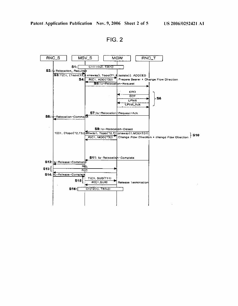
0031 FIG. 4 is a diagram showing a switching process of a simplex Switch using stream mode method in accordance with a preferred embodiment of the present invention.
0032 FIG. 5 is a flow chart showing a WCDMA SRNS relocation/handover process in accordance with a preferred embodiment of the present invention.
DETAILED DESCRIPTION OF THE PRESENT INVENTION
0033 Hereinafter, the preferred embodiments of the present invention will be described in detail with reference to the accompanying drawings.
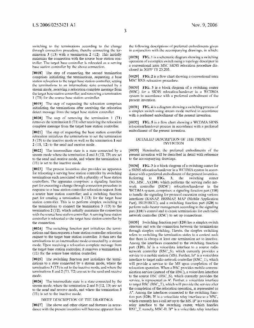
0034 FIG. 3 is a block diagram of a switching center for a SRNS relocation/handover in a WCDMA system in accor dance with a preferred embodiment of the present invention. Referring to FIG. 3, the switching center (3G MSC A)(100), which performs the serving radio net work controller (SRNC) relocation/handover in the WCDMA system, comprises: a signaling function part (110) to handle the signaling for protocol execution using various interfaces (RANAP, BSSMAP, MAP (Mobile Application Part), ISUP/BICC); and a switching function part (120) to perform radio bearer management according to the signaling part (110)'s control and to create terminations for each radio network controller (RNC) to set up connections.
0035) Switching function part (120) has a simplex switch structure and sets the connection between the terminations through simplex Switching. Herein, the simplex Switching refers to Switching the termination states in a context Such that there is always at least one termination set to inactive. Among the interfaces connected to the Switching function part (120), Iu' is a voice/data interface to a source radio network controller (RNC S), which currently provides a service to a mobile station (MS). Further, Iu" is a voice/data interface to target radio network controller (RNC. T), which will provide a service to the MS upon completion of the relocation operation. When a BSC provides mobile commu nication service (instead of the RNC), a voice/data interface to the source BSC (BSC S), which currently provides the service, is represented as A. Further, a voice/data interface to target BSC (BSC T), which will provide the service after the completion of the relocation operation, is represented as A". Among the interfaces connected to the Switching func tion part (120), B' is a voice/data relay interface to a MSC, which currently has a call set up to the MS. B" is a voice/data relay interface to the switching center, which handles RNC. T. namely, MSC-B. B." is a voice/data relay interface
US 2006/0252421 A1
to the switching center, which handles the target RNC in subsequent relocation/handover, namely, MSC-B". 0.036 By setting the connection between the terminations through simplex Switching, the Switching function part (120), media gateway (MGW) for example, which does not Support a topology descriptor (an optional parameter of H.248/MEGACO) or a complex switch structure can be used to provide the SRNS relocation/handover. Also, the complexity of the switching function part (120) is not increased to implement the topology. Further, the complex ity of the control of switching function part (120) for relocation/handover does not increase even when more than three terminations are in a context. When the relocation/ handover is required for reasons such as location displace ment of the MS, a termination 3 for the target RNC (RNC T) is created in the switching function part (120) according to the relocation/handover request from the Source RNC (RNC S), which provides a service to the MS. 0037 Signaling function part (110) initializes the switch ing function part (120) by using a change through connec tion procedure. It then requests the relocation/handover to the RNC. T. Advantageously, through the initialization, the switching function part (120) comes into a state where the terminations are connected in a stream mode, in which the termination for RNC S (T1) is in the send and receive mode (SendRcv), the termination for the other party initially maintaining connection with the RNC S (T2) is in the send and receive mode (SendRcv) and the termination for RNC T is in the inactive mode (Inactive). Said change in the stream mode is performed by a change through connection procedure, which changes the characteristics of the termi nation.
0038. The stream mode is a parameter that defines the characteristic of each termination (T1, T2, T3) in the change through connection procedure. The stream mode, which defines the characteristic of the terminations, has a send and receive mode, send only mode, receive only mode and inactive mode, by which the terminations form the stream connection. Since Switching is performed by using the stream mode, only the stream mode of each termination needs to be considered, thereby relatively easing the man agement of the SRNS relocation/handover. 0.039 The signaling function part (110), after sending the relocation command to the RNC S or receiving the reloca tion detect message from the RNC T upon completing the radio resource allocation between the Switching function part (120) and the RNC. T. sets each termination of switch ing function part (120) to an intermediate state connected by stream mode by using the change through connection pro cedure. Advantageously, the intermediate State means the state connected by the stream mode where the termination for the RNC S is in the inactive mode, the termination for the other party initially maintaining connection with the RNC S is in the send and receive mode, and the termination for the RNC T is in the send and receive mode. Signaling function part (110) receives a relocation complete message, releases the Iu for the RNC S and controls the switching function part (120) to remove the termination for the RNC S in the Switching function part (120). By doing so, the serving RNC, which provides the service to the MS, becomes relocated from the RNC S to the RNC. T. 0040. Among the interfaces connected to the signaling function part(110), Iu' is a signaling interface to Source
Nov. 9, 2006
RNC(RNC S) that currently provides service to MS. Fur ther, Iu" is a signaling interface to the target RNC(RNC. T) that will provide service to MS upon completing the relo cation operation. When a BSC provides service to the MS (instead of the RNC), the signaling interface to the source BSC, which currently provides a service to MS, is denoted as A. Further, the signaling interface to the target BSC (BSC T ), which will provide a service to the MS upon completing the relocation operation, is denoted as A". Among the interfaces connected to the signaling function part (110), B' is a signaling relay interface to MSC that currently has a call set up to the MS. B" is a signaling relay interface to a switching center that handles the RNC. T. namely, MSC B. B" is a signaling relay interface to the switching center that handles the target RNC in subsequent relocation/handover, namely, MSC-B'. C is an interface that connects to the MSC-B and MAP message is exchanged through this interface.
0041 Under the 3GPP separated type R4 standard, the role of switching center (100) or 3G MSC A for the SRNS relocation/handover in the WCDMA R4 system is divided into a MSC server(MSV) (corresponds to signaling function part (110)) and a media gateway(MGW) (corresponds to switching function part (120)). The MSV controls the MGW using H.248/MEGACO.
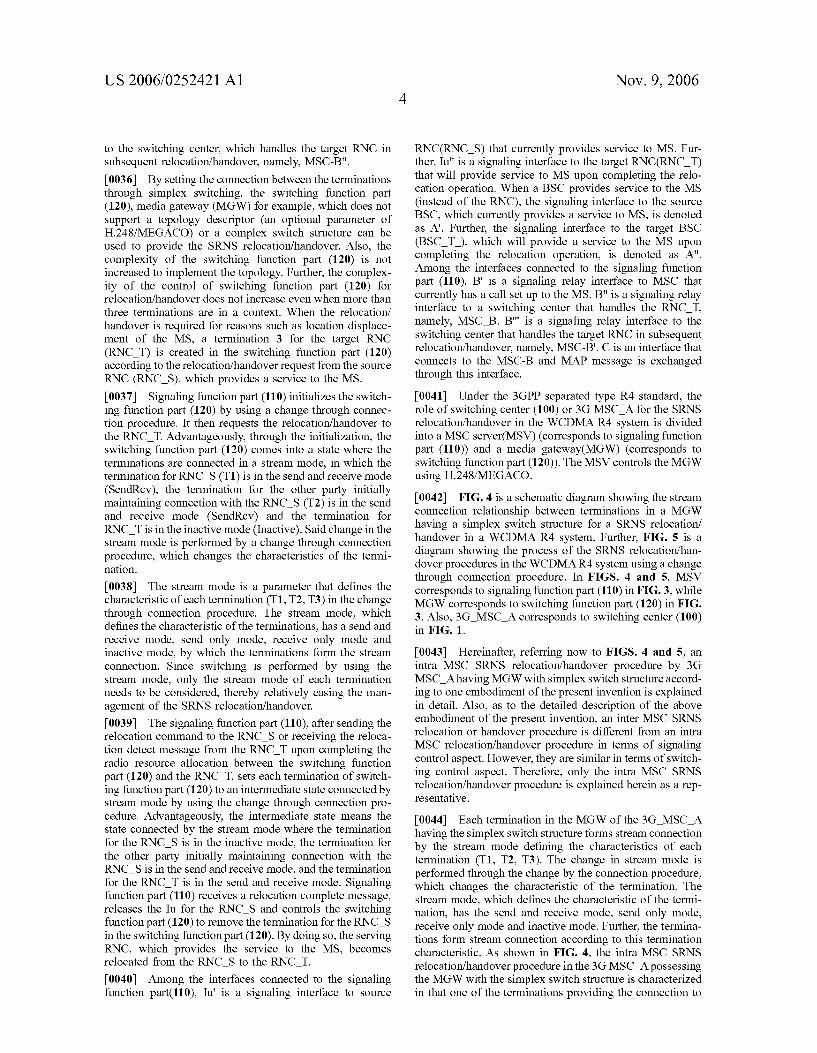
0042 FIG. 4 is a schematic diagram showing the stream connection relationship between terminations in a MGW having a simplex switch structure for a SRNS relocation/ handover in a WCDMA R4 system. Further, FIG. 5 is a diagram showing the process of the SRNS relocation/han dover procedures in the WCDMA R4 system using a change through connection procedure. In FIGS. 4 and 5, MSV corresponds to signaling function part (110) in FIG. 3, while MGW corresponds to switching function part (120) in FIG. 3. Also, 3G MSC A corresponds to switching center (100) in FIG. 1.
0043. Hereinafter, referring now to FIGS. 4 and 5, an intra MSC SRNS relocation/handover procedure by 3G MSC Ahaving MGW with simplex switch structure accord ing to one embodiment of the present invention is explained in detail. Also, as to the detailed description of the above embodiment of the present invention, an inter MSC SRNS relocation or handover procedure is different from an intra MSC relocation/handover procedure in terms of signaling control aspect. However, they are similar in terms of switch ing control aspect. Therefore, only the intra MSC SRNS relocation/handover procedure is explained herein as a rep resentative.
0044) Each termination in the MGW of the 3G MSC A having the simplex Switch structure forms stream connection by the stream mode defining the characteristics of each termination (T1, T2, T3). The change in stream mode is performed through the change by the connection procedure, which changes the characteristic of the termination. The stream mode, which defines the characteristic of the termi nation, has the send and receive mode, send only mode, receive only mode and inactive mode. Further, the termina tions form stream connection according to this termination characteristic. As shown in FIG. 4, the intra MSC SRNS relocation/handover procedure in the 3G MSC A possessing the MGW with the simplex switch structure is characterized in that one of the terminations providing the connection to

US 2006/0252421 A1
the RNC S and the RNC T is always in the inactive mode. That is, as shown in FIG. 4, the present invention is characterized in that, instead of setting the connection between the terminals of the RNC and the MGW by creating the topology descriptor with context related parameters in the MGW having a complex switch structure, the termina tions are connected by the stream mode defining the termi nation characteristic through the simplex Switch structure. 0045. In the intra MSC SRNS relocation/handover pro cedure, the existing call, which is Subject to the relocation/ handover, provides the connection between the RNS con nected with the MS and CN through context 1 (C1). Context 1 forms the stream connection where the termination 1 (T1) (provides connection to the RNC S in the MGW) and the termination 2 (T2) (provides connection to the other party in the MGW) are both set to the send and receive mode. At this time, when the relocation/handover is required due to certain events (e.g., location movement of the MS), a relocation request signal (Relocation Required) is sent to the RNC S. which provides a service to the MS (S102). MSV S, upon receiving the relocation request signal from the RNC S by step S102, acquires a binding reference and a bearer address from the MGW using a prepare bearer procedure to prepare the radio resource, thereby creating a new termination 3 (T3) in the MGW. Next, the MSV Sperforms the initialization of the MGW to set the stream mode for T3 to inactive and maintains the existing stream connection between T1 and T2 by using the change through connection procedure, as shown in the intermediate state c (S103). 0046) After acquiring new T3 in step S103, the MSV S sends a relocation request message (Relocation Request) to a target radio network controller (RNC. T), the subject of the relocation/handover, using the connected call information (S104). After step S104, the RNC T and the MGW sets the radio resource (bearer) by interchanging ERQ (Establish Request), ECF (Establish Confirm), UPinit and UPinit Ack by using ALCAP (AALType2 signaling Protocol-Capability set1) and UP (User Plane) protocol (S105). When the radio resource (bearer) is set, the RNC T sends a relocation request acknowledge message (Relocation Request Ack) to the MSV S so as to notify that the radio resource (bearer) has been successfully set (S106). The MSV S, upon receiv ing the relocation request acknowledge message in step S106, sends a relocation command (Relocation Command) to proceed with the relocation/handover procedure (S107). After step S107, the MSV S receives a relocation detect signal (Relocation Detect) notifying the reception of the relocation command from the target RNC (RNC. T) (S108). At this time, by using the change through connection pro cedure, the MSV S sends MOD.req (C1, T1 inactive}) to inactivate T1, where the MGW notifies inactivation of T1 to the MSV S by sending MOD.rep (C1, T1), where the MSV S sends MOD.req(C1, T3{SendRecv}) to the MGW to set T3 to the send and receive mode, and where the MGW sends MOD.rep(C1, T3) to the MSV S to notify that T3 has been set to the send and receive mode. This sets the stream connection between T1, T2 and T3, as shown in the inter mediate stated of FIG. 4. At this time, it is characterized in that, of the three terminations in the C1 at the intermediate state, initially T3 is in the inactive state and T1 later becomes inactive. Thus, only two of the three terminations maintain the connection at any given state (S109). After step S109, the MSV S receives a relocation complete message (Relocation Complete) from the RNC T (S110). The MSV S, upon
Nov. 9, 2006
receiving the relocation complete message from the RNC. T. sends an Iu release command (Iu Release Command) to the RNC S to release Iu resource for RNC S (S111). The RNC S, upon receiving the Iu release command in step S111, releases the radio resource (bearer) for MSV S by using the radio bearer release procedure using ALCAP (S112). Upon completing the radio resource (bearer) release for Iu between the RNC S and the MSV S, the RNC S notifies the MSV S of Iu release completion by sending a radio resource release complete message (Release Com plete) (S113). Upon receiving the radio resource (bearer) release complete message from the RNC S, the MSV S releases the resource in the MGW for T1 set for the connection to RNC S by using release termination proce dure. The above-mentioned release termination procedure is a procedure where the MSV S sends SUB.req (C1, T1) to the MGW to request the release of resource for T1, where the MGW releases the resource for T1 upon receiving SUB.req (C1, T1) and then sends SUB.rep (C1, T1) to MSV S to notify that the resource for T1 has been released (S114). By the MGW of the simplex switch structure fol lowing the aforementioned step S101 to S114, T2 and T3 become connected. The intra MSC SRNS relocation/han dover procedure is completed (S115). 0047 While the present invention has been shown and described with respect to a preferred embodiments, those skilled in the art will recognize that various changes and modifications may be made without departing from the spirit and scope of the invention as defined in the appended claims.
What is claimed is: 1. A method of relocating a serving base station controller
by Switching terminations each associated with a plurality of base station controllers, the method comprising the steps of
receiving a relocation request from a source base station controller;
creating a termination 3 (T3) for a target base station controller in response to the relocation request; and
performing simplex Switching to the terminations accord ing to a change through a connection procedure, such that connecting the termination 3 (T3) is connected with a termination 2 (T2) initially maintaining a con nection with the source base station controller;
wherein the target base controller is relocated as a serving base station controller by the above connection.
2. The method of claim 1, wherein the step of connecting the second termination comprises:
initializing the terminations;
requesting a base station relocation to the target base station controller,
setting the terminations to an intermediate state connected by a stream mode;
receiving a relocation complete message from the target base station controller, and
removing a termination 1 (T1) for the source base station controller.

US 2006/0252421 A1
3. The method of claim 2, wherein the step of requesting a base station relocation includes initializing the termina tions after receiving a relocation detect message from the target base station controller.
4. The method of claim 2, wherein the step of removing a termination 1 (T1) includes removing the termination 1 (T1) after receiving a relocation complete message from the target base station controller.
5. The method of claim 2, wherein the step of requesting a base station controller relocation includes initializing the terminations to set the termination 3 (T3) to an inactive mode, and the terminations 1 and 2 (T1, T2) to a send and receive mode.
6. The method of claim 2, wherein the intermediate state is a state connected by a stream mode wherein the termi nations 2 and 3 (T2, T3) are set to a send and receive mode, and wherein the termination 1 (T1) is set to an inactive mode.
7. An apparatus for relocating a serving base station controller by Switching terminations each associated with a plurality of base station controllers, the apparatus compris 1ng:
a signaling function part for executing a change through a connection procedure in response to a base station controller relocation request from a source base station controller, and
a Switching function part for creating a termination 3 (T3) for the target base station controller, performing sim plex Switching to the terminations to connect the ter
Nov. 9, 2006
mination 3 (T3) to the termination 2 (T2) initially maintaining a connection with the source base station controller;
wherein a serving base station controller is relocated to the target base station controller by the connection.
8. The apparatus of claim 7, wherein the switching function part:
initializes the terminations;
requests a base station controller relocation request to the target base station controller,
sets the terminations to an intermediate mode connected by a stream mode; and
removes a termination 1 (T1) for the source base station controller upon receiving a relocation complete mes Sage from the target base station controller.
9. The apparatus of claim 8, wherein the switching function part initializes the terminations to a state connected by a stream mode, wherein the termination 3 (T3) is set to an inactive mode, and the terminations 1 and 2 (T1, T2) are set to a send and receive mode.
10. The apparatus of claim 8, wherein the intermediate state is a state connected by the stream mode wherein the terminations 2 and 3 (T2, T3) are set to a send and receive mode, and wherein the termination 3 (T1) is set to an inactive mode.
Copyright © 2022 FDOKUMEN