High-Resolution Indirect Feet-Ground Interaction Measurement for Hydraulic-Legged Robots
Upload
khangminh22Category
view
0download
0
- 1 -
Sandy Feet
Final Report
Prepared by:
Jerin Brust - [email protected]
Jacqueline Chuang - [email protected]
Parker Duncan - [email protected]
Garrett Herbst - [email protected]
QL+ Representative:
Vanessa Salas - [email protected]
Team Advisor:
Karla Carichner - [email protected]

- 2 -
DISCLAIMER STATEMENT
The university makes it clear that the information forwarded herewith is a project
resulting from a class assignment and has been graded and accepted as a fulfillment of a course
requirement. Acceptance by the university does not imply technical accuracy or reliability. Any
use of the information in this report is made by the user(s) at his/her own risk, which may
include catastrophic failure of the device or infringement of patent or copyright laws.
Therefore, the recipient and/or user of the information contained within this report
agrees to indemnify, defend, and save harmless the State, its officers, agents, and employees
from any and all claims and losses accruing or resulting to any person, firm, or cooperation who
may be injured or damaged as a result of the use of this report.

- 3 -
TABLE OF CONTENTS Disclaimer Statement ...................................................................................................................... 2
1. List Of Nomenclature ................................................................................................................. 8
2. Executive Summary .................................................................................................................... 9
3. Introduction .............................................................................................................................. 10
4. Background ............................................................................................................................... 10
4.1 Challenger Information .................................................................................................. 10
4.2 Physical Characteristics of Walking ............................................................................... 11
4.3 Existing Product Research .............................................................................................. 12
5. Design Development ................................................................................................................ 15
5.1 Objectives....................................................................................................................... 15
5.1.1 Customer Requirements ............................................................................... 15
5.1.2 Technical Specifications ................................................................................ 15
5.2 Conceptual Designs ........................................................................................................ 17
5.2.1 Design Mass Ideation .................................................................................... 17
5.2.2 Potential Designs ........................................................................................... 18
5.3 Concept Selection .......................................................................................................... 19
5.3.1 Conceptual Foot Design ................................................................................ 20
5.3.2 Conceptual Ankle Design .............................................................................. 21
5.4 Changes to Conceptual Design ...................................................................................... 22
6. Final Design .............................................................................................................................. 23
6.1 Design Overview ............................................................................................................ 23
6.1.1 Foot and Ankle Geometry ............................................................................. 23
6.1.2 Design of Attachment to Residual Limb ........................................................ 24
6.2 Maintenance Considerations ......................................................................................... 25
6.3 Design Safety .................................................................................................................. 26
6.4 Cost Analysis .................................................................................................................. 26
6.4.1 Pylon Design Components ............................................................................ 26
6.4.2 Foot Design Components .............................................................................. 27
7. Product Realization .................................................................................................................. 27
7.1 Manufactured Product................................................................................................... 27

- 4 -
7.2 CAD Modeling ................................................................................................................ 32
7.3 Manufacturing Process and Steps ................................................................................. 32
7.3.1 Differentiation from Design .......................................................................... 34
7.4 Future Manufacturing .................................................................................................... 35
8. Design Verification ................................................................................................................... 36
8.1 Satisfaction of Customer Requirements ........................................................................ 36
8.2 Foot and Ankle Verification ........................................................................................... 38
8.2.1 Material Selection ......................................................................................... 38
8.2.2 Corrosion Testing .......................................................................................... 39
8.2.3 Finite Element Analysis ................................................................................. 40
8.3 Pylon Verification ........................................................................................................... 41
8.3.1 Pylon Corrosion Resistance ........................................................................... 41
8.3.2 Pylon Dimensions Verification ...................................................................... 41
8.3.3 Water/Sand Proof Verification ...................................................................... 42
9. Conclusion and Recommendations .......................................................................................... 42
10. Acknowledgements ................................................................................................................. 42
11. References .............................................................................................................................. 44
12. Appendices .............................................................................................................................. 45
12.1 User Product Guide ........................................................................................................ 45
12.1.1 Securing the Prothesis to the Pyramid........................................................ 45
12.1.2 Adjusting the Prothesis Pylon Length ......................................................... 46
12.1.3 Adjusting the Prothesis Foot Size or Flexibility ........................................... 47
12.1.4 Securing the Pylon ....................................................................................... 49
12.1.5 Exposure to Saltwater and Preventing Corrosion ....................................... 51
12.2 Quality Function Deployment ........................................................................................ 52
12.3 Final Design Drawings Foot and Pylon .......................................................................... 53
12.4 Mold Drawings for FDM Instruction and Assembly ....................................................... 58
12.5 Pylon Prototype and Programming ............................................................................... 65
12.6 Tensile Testing Data ....................................................................................................... 66
12.7 DVP&R ............................................................................................................................ 67
12.8 Finite Element Analysis Figures ..................................................................................... 68

- 5 -
12.9 Bill of Materials and Cost ............................................................................................... 73
12.10 Technical Data Sheets and Safety Data Sheet Links ...................................................... 74
12.11 Gantt Chart..................................................................................................................... 75
12.12 Safety Check List ............................................................................................................ 77
12.13 Generative Design .......................................................................................................... 78
12.14 Team Contract................................................................................................................ 80

- 6 -
LIST OF FIGURES Figure 1: Human Gait Cycle [2] ..................................................................................................... 11
Figure 2: Ankle Range of Motion [8] ............................................................................................. 12
Figure 3: Energy Storage of Ankle [2] ........................................................................................... 12
Figure 4: Rush Rogue Foot Prosthesis [4] ..................................................................................... 13
Figure 5: Common Design for Leg Prosthesis Using Carbon Fiber [3] .......................................... 14
Figure 6: TruLife Kinetic Lower Limb System. Sgt. Brady’s Current Sand Prothesis. .................... 14
Figure 7: 2018-2019 QL+ Sand Foot Project Final Product [5] ..................................................... 14
Figure 8: Mass Ideation Foot Concepts ........................................................................................ 17
Figure 9: Foam Foot (Left), Snowshoe (Right) .............................................................................. 18
Figure 10: “C” Shape (Left), "C" with Spring (Right) ..................................................................... 19
Figure 11: Telescoping Rod with Spring (Left), Ball and Socket with Spring (Right) ..................... 19
Figure 12: Foot Concept ................................................................................................................ 20
Figure 13: Ankle Concept .............................................................................................................. 22
Figure 14: Chosen Design CAD Model .......................................................................................... 23
Figure 15: Bottom of Foot Cleat Feature ...................................................................................... 24
Figure 16: TruLife Adjustable Clamp Adapter (AAA100) .............................................................. 25
Figure 17: Pylon Attachment with Flange..................................................................................... 25
Figure 18: Final Sand Foot V2. View: Inside. ................................................................................. 28
Figure 19: Final Sand Foot V2. View: Front. .................................................................................. 29
Figure 20: Final Sand Foot V2. View: Outside. .............................................................................. 30
Figure 21: Final Sand Foot V2. View: Bottom. .............................................................................. 31
Figure 22: 60% Scale Prototype .................................................................................................... 33
Figure 23: TruLife Aluminum Pylon with Bonded Adapter ........................................................... 34
Figure 24. Foot Depth Analysis. .................................................................................................... 37
Figure 25: Physical Gait Cycle Testing. .......................................................................................... 37
Figure 26: Foot Surface Area Reference. ...................................................................................... 38
Figure 27: Final Design FEA. Stress Analysis Forward Step. .......................................................... 40
Figure 28: Final Design FEA. Displacement Analysis. .................................................................... 41
Figure 29: Example Male Pyramid. TruLife Rotatable Male Pyramid Insert (AAA216-01) [13]. .. 46
Figure 30. Provided Thread Locker. .............................................................................................. 47
Figure 31. TruLife Adjustable Clamp Adapter (AAA100). ............................................................. 47
Figure 32: Example Foot Cutting Line ........................................................................................... 48
Figure 33: Side Profile Example Cutting Line ................................................................................ 49
Figure 34. Provided Bolts. ............................................................................................................. 50
Figure 35. Potential Bolt Location. View: Inside. .......................................................................... 50
Figure 36. Provided Drill Bit. ......................................................................................................... 50
Figure 37. Prototype with Bolted Pylon.. ...................................................................................... 51
- 7 -
LIST OF TABLES
Table 1: Formal Engineering Requirements ................................................................................. 16
Table 2: Foot Pugh Matrix ............................................................................................................. 20
Table 3: Ankle Pugh Matrix ........................................................................................................... 21
Table 4: Experimental Material Properties ................................................................................... 39

- 8 -
1. LIST OF NOMENCLATURE
Below is a list of common nomenclature and the associated meaning as utilized within
the following document.
• QL+: Quality of Life Plus, a multi-campus organization whose mission statement is to “foster
and generate innovations that aid and improve the quality of life for those who have served
our country”
• Sandy Feet: the interdisciplinary senior project working on Sand Foot V2 comprised of Brust,
Chuang, Duncan, and Herbst
• FOS: “Factor of Safety”, the ratio of the yield strength and either the static or fatigue
loading of a material
• FDM: Fused Deposition Modeling, a type of 3-D printing
• PLA: Polylactic acid, a common material used for 3-D printing
• Socket: The sleeve that covers an amputee’s residual biological limb
• Pylon: The vertical tube or rod that makes up the “ankle” of a transtibial prosthetic
• Pyramid Receiver: (also referred to as adapter, adapter clamp) the uppermost portion of
the prosthetic that connects the bottom of the socket to the top of the pylon.
• PMC: Polymer Matrix Composite, referred to specifically for our purposes as PMC-780 and
PMC-790; the rubber materials used to manufacture our prototype and final product from
Smooth-On, Inc.

- 9 -
2. EXECUTIVE SUMMARY
The goal of this project was to provide Sgt. Craig Brady with a transtibial prosthetic that
functions at the beach. Currently, there are few prosthetic devices and that are designed for
the aggressive marine environment. Of the devices that he uses, the one recommended by his
prosthetist is far from satisfactory for a myriad of reasons. A previous attempt at making such a
device was largely unsuccessful. Sgt. Brady specified several issues with this device that were
addressed in this design.
The chosen design specifications were derived from analysis of the gait cycle, the needs
of Sgt. Brady, and the primary environment in which the prosthesis would be used. These
included the following: weight less than 4 lbs., ankle rigidity of approximately that of the
residual foot, sufficient foot strength to prevent breaking, water/dust proofing, material
durability to increase longevity, ability to stand and walk with device, easy interface with
current socket, sufficient contact area to prevent sinking, and limited sand collection while
stationary or moving.
From there, many different iterations were developed. Based on the design
specifications and their relative importance, a final design was chosen. The design uses the
following components: a TruLife Adjustable Clamp Adapter to allow height adjustability (Figure
16), a TruLife Aluminum pylon (has a bonded female adapter to be used to keep the pylon in
the foot/ankle, Figure 23), and a PMC-790 foot/ankle geometry (Figure 14). The geometry was
highly iterated to meet the design specifications.
Manufacturing was done via polyurethane molding in a 6-peiece PLA FDM mold. The
pylon was imbedded into the mold and then cut so that the total height of the device (from
bottom of the foot to the top of the adapter) was 8.75 inches, per Sgt. Brady’s request.
Testing and verification were preformed using physical tests and computer simulations.
Physical testing included testing the deflection, sand collection, surface area, and depth of
sinking of the final device at the beach with a team member. Additionally, corrosion testing on
a scale model was performed. Computer simulations were used to predict the approximate
deflection and stresses. All of these tests indicate that the device will perform as designed.
The device was sent to Sgt. Brady for use. In addition to the device, the user manual and
TruLife manufactures instructions were sent. Within the user manual are directions to adjust
the prothesis to fit Sgt. Brady’s height, desired flexibility, and desired foot surface area.
Future recommendations include utilizing a vacuum chamber to increase the quality of
the molding process and manufacturing a custom pylon to decrease the weight and price.
These were not achievable given the facility closures due to the COVID-19 pandemic.

- 10 -
3. INTRODUCTION
This Final Design Report outlines the chosen design for Sand Foot V2, a project
sponsored by Quality of Life Plus. Sand Foot V2 is a prosthetic foot and ankle combination to be
used on sand by Sgt. Craig Brady.
Sgt. Brady is a former armed forces member with a transtibial amputation. He is the
Recreation Director for Ossipee, NH and is often required to walk on sand. He is also a father
who frequently takes his children to the beach. He needs a prosthesis that will allow him to
walk on sand for long periods of time without issue.
In 2018, Sgt. Brady was given a device from another senior project team but was
unsatisfied. The mission of our team, “Sandy Feet,” has been to design and manufacture a new
lower-leg prosthetic foot that Sgt. Brady will use for walking on sand effectively. Fall 2019 was
spent performing background research, formulating design ideas, and narrowing down designs.
Winter 2020 was spent manufacturing prototypes and iterations. Spring 2020 was completely
virtually conducted, so it was focused on further iterations, manufacturing planning, and
manufacturing. The prosthesis meets the requirements given by Sgt. Brady, our primary
stakeholder, outlined in §5.1.1.
The primary motivation is to improve Sgt. Brady’s quality of life. Upon receiving the
product, Sgt. Brady will be relived of back pain when walking on sand. This burden on his work
life and leisure will no longer be impacted by the loss of his limb.
As a secondary stakeholder, QL+ has played a role in both engineering and financial
aspects of our project throughout the year in order to conform to standards provided by our
sponsor.
Our team is also a secondary stakeholder since the product’s functionality directly
influences our graduation requirement completion, but we will not be the end users.
4. BACKGROUND
4.1 CHALLENGER INFORMATION Much of the information given by Sgt. Brady outlines qualities the prosthesis he
currently uses for sand lacks. It is not flexible enough to walk on soft sand comfortably for
longer periods. He frequently finds himself needing to walk on both soft/dry and compact/wet
sand. Hard-packed sand is less of an issue, as it behaves similar to other nonyielding surfaces.
He reported experiencing days of severe back pain after walking on soft sand for just a few
hours.
A team of students from Cal Poly made a product for Sgt. Brady last year. With this
team's final report, initial information was gathered that aided in the design process. The

- 11 -
positives and negatives of the previous design were a launching point for many of the iterated
designs.
Information from Sgt. Brady acquired through last year’s project largely contributed to
the engineering specifications and customer requirements. He provided additional insights in
light of the flaws of the previous model. The product weight of the previous design was a
concern, as the finished product was roughly 4.5 lbs. Sgt. Brady requests that the product be
lighter than before; he is accustomed to his everyday foot’s weight of roughly 2 lbs. The foot
portion of last year’s design was shaped like a scoop and was highly susceptible to taking on
and holding large amounts of sand. This issue will be avoided in the new design. He also
requests that there be no sharp or pointed edges on the prosthesis. Sgt. Brady did like the large
contact area that last year’s design had with the ground.
4.2 PHYSICAL CHARACTERISTICS OF WALKING The process of locomotion can be subdivided into the gait cycle, as outlined in Figure 1
[1]. The final product functions as the residual limb, whose function is well-defined in this cycle.
Normal ranges of motion during the gait cycle can also be found in Figure 1. The movement of
the product is within these ranges under the loading of the bodyweight of Sgt. Brady. Normal
maximum ranges can be found in Figure 2. These should be the approximate maximum ranges
of motion of the prosthesis to prevent instability.
Figure 1: Human Gait Cycle [2]

- 12 -
Figure 2: Ankle Range of Motion [8]
Although research on the mechanics and energetics of transtibial amputees walking on
various terrains such as asphalt, mowed lawn and high grass have been performed and
assessed, little research has been done on trans-tibial amputees walking on soft surfaces such
as sand or mud [3]. Energy storage and release throughout the gait cycle can be found in Figure
3. It is important to note that, one publication found there was a decrease in efficiency,
resulting in an increase in energy expenditure required for natural limbs to walk on sand
compared to walking on hard surfaces [1].
Figure 3: Energy Storage of Ankle [2]
4.3 EXISTING PRODUCT RESEARCH There are typically three major components of a transtibial prothesis: the socket, pylon,
and foot. The socket is usually a polymer or carbon composite with a comfortable lining. The
socket fits via compression of suction to the residual limb. The pylon then attaches the socket
to the ankle. The pylon attaches with pyramid and pyramid receivers. Not all protheses have
pylons. The pyramids are typically metal equilateral pyramids with a point welded to a plate
- 13 -
with screw holes to attach to the socket or foot. See Figure 4 for an example of a pyramid. The
pyramid receivers are metal reviewers with four set screws that tighten to the sides of the
pyramid to hold it. See Figure 6 for an example of a pyramid receiver at the end of the pylon.
There are pyramid and pyramid receiver attachments on both sides of the pylon. The final
component is the foot. Here, much of the variation based on the desired physical activity, the
surface being walked on, and challenger preference occurs. See Figure 4, Figure 5, and Figure 6
for a representative sample of different prosthetic feet.
The major issue with most currently available prostheses is that they are not intended
for use on surfaces like soft sand. Some are marketed as “all-terrain” prosthetics, capable of
handling higher loads, flexing to more drastic angles, and comprised of more durable materials.
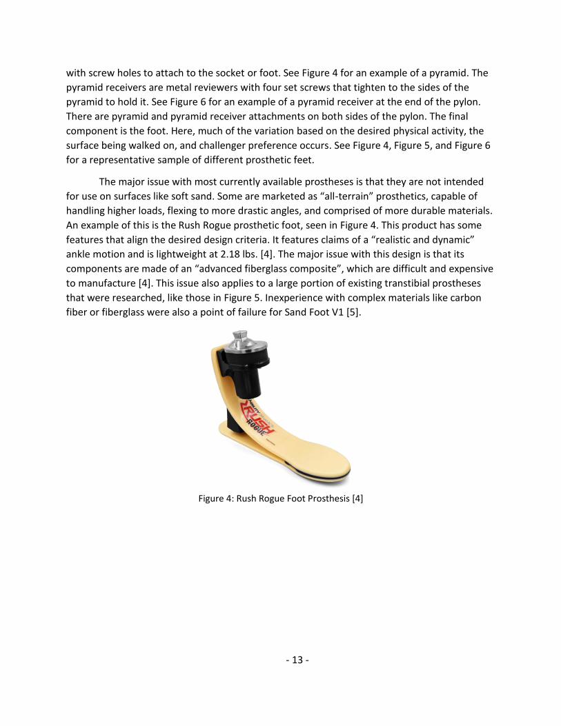
An example of this is the Rush Rogue prosthetic foot, seen in Figure 4. This product has some
features that align the desired design criteria. It features claims of a “realistic and dynamic”
ankle motion and is lightweight at 2.18 lbs. [4]. The major issue with this design is that its
components are made of an “advanced fiberglass composite”, which are difficult and expensive
to manufacture [4]. This issue also applies to a large portion of existing transtibial prostheses
that were researched, like those in Figure 5. Inexperience with complex materials like carbon
fiber or fiberglass were also a point of failure for Sand Foot V1 [5].
Figure 4: Rush Rogue Foot Prosthesis [4]

- 14 -
Figure 5: Common Design for Leg Prosthesis Using Carbon Fiber [3]
Figure 6: TruLife Kinetic Lower Limb System. Sgt. Brady’s Current Sand Prothesis.
Figure 7: 2018-2019 QL+ Sand Foot Project Final Product [5]

- 15 -
5. DESIGN DEVELOPMENT
5.1 OBJECTIVES Prior to ideation or prototyping, the objects and scope of the project were clearly
defined. They are outlined in this section.
5.1.1 Customer Requirements
Our overall goal for the Sand Foot V2 project has been to design and manufacture a
prosthetic foot that Sgt. Brady will be able to use for walking on sand successfully. Our decisions
during the design development phase were centered around the customer requirements
desired by Sgt. Brady, which are as follows:
• Low weight: Sgt. Brady does not expect the prosthesis to be as light as his daily use one
(about 2 lbs.), but he prefers it to be light enough to avoid causing discomfort.
• User-friendly: Sgt. Brady specified a simpler design, one that did not include sharp
edges, and that interfaces with his current prosthesis.
• Low maintenance: The prosthesis should not require frequent cleaning, tightening,
adjustment, or replacement.
• Durable: The product should withstand reasonable the force from walking, pivoting, etc.
It should be designed with cyclical loading and corrosion effects considered.
• Comfortable for long periods: Sgt. Brady desires a product that will help reduce the pain
he experiences during and after use of his current device on sand.
• Able to walk on sand: The prosthesis should not fill with sand while standing or moving.
• More flexible than current product: Sgt. Brady specified that his daily-use prosthesis is
slightly too rigid for use on sand.
5.1.2 Technical Specifications
The specifications given by the primary stakeholder were then made into explicit and
numeric requirements by Sandy Feet. They can be found below in Table 1.

- 16 -
Table 1: Formal Engineering Requirements
Spec. Parameter Requirement Tolerance Risk Compliance
1 Weight Assembly is less than approximately 4 lbs. 4lb Max. M T
2 Ankle Rigidity 25° flexion, 45° extension, 30° pronation, and
60° supination under 240 lbs. (x1 BW) Max. M T
3 Foot strength Supports standing, walking, running, jumping Min. M T
4 Water/Dust Proof IP57 (Protection from dust and fluid immersion
up to 1m) Min. M S
5 Material Durability Corrosion rate of < 0.004 in/year [6] Min. L T
6 Able to stand with
device Does not yield under 240 lbs. (1x BW). FOS = 2 H T
7 Able to walk on
device Repeated loading of 360 lbs. (1.5x BW) for 20
million cycles Min. H A
8 Interfaces with current device
Uses standard prosthesis attachment - H S
9 Contact area Prevents foot sinking into sand Min. L T
10 Stationary sand
collection 1 oz. of sand Max. M T
11 Moving sand
collection 3 oz. of sand Max. M T
Risk: H = High, M = Medium, L = Low. Compliance: A = Analysis, T = Testing, S = Similar to other designs. I =
Inspection. See §12.1 for QFD.
Each technical specification must be met within the specified tolerance and be
measured by its associated compliance. “Analysis” involves computer simulation that was
completed to evaluate the specification. “Testing” refers to physically testing the product or
prototypes and recording values or pass-fail data based on the specification. “Similar to other
designs” involves a qualitative comparison of the chosen design to other products to ensure the
specification is met. “Inspection” involves a quantitative measurement of the product to
determine conformity to the specification. Each specification also has an associated risk factor.
Higher risk factors are specifications that are more crucial to the product’s function, while lower
risk factors are less crucial to the function of the design. Further description of the technical
specifications can be found below.
1. The total weight of the prosthesis needs to be less than the approximate limit of 4 lbs.,
which is lighter than Sand Foot V1, but heavier than his daily use prosthesis. It has a
medium risk and is determined by weighing the prototype.
2. The ankle rigidity needs to be rigid enough to allow force to be applied to yielding surfaces
but flexible enough provide adequate locomotion on non-yielding surfaces. This is a
medium risk verified using FEA.
3. The foot strength specification requires that the product can withstand the expected
loading and impact from regular use and function without fracturing, buckling, or
permanently deforming. This is a medium risk factor evaluated using FEA.

- 17 -
4. The device needs to be water and dust proof. It was determined to need to meet IP57
specifications, meaning the device operation is not interfered with after exposure to dust
(particles less than 1 mm) for 2 to 8 hours and immersion in 1 m of water for 30 minutes.
This is a medium risk and is verified via physical testing.
5. Material durability specifies that the product is made of material that will withstand
chemical corrosion in a marine environment without premature device failure. The value
chosen was less than 0.1 mm/year, the corrosion rate of 6061-T6 aluminum [6]. This
specification is low risk and is evaluated through physical testing.
6. Being able to stand with the device requires that Sgt. Brady be able to use the product while
stationary. This is a high-risk factor assessed through FEA.
7. Being able to walk with the device is defined not failing after 1.5 times his body weight (360
lbs.). This is a high risk verified using finite element analysis.
8. Interfacing with current device requires that the product be compatible with Sgt. Brady’s
current residual limb attachment. This is a high-risk factor verified by comparing to the
prosthesis to the products Sgt. Brady currently uses.
9. The contact area needs to be sufficient to prevent Sgt. Brady from sinking in soft, fine sand
while stationary. This is low risk and verified by testing (loading the device on sand).
10. Stationary sand collection is defined by how much sand (by weight) the product collects
while Sgt. Brady is standing in the sand. This is a medium risk factor measured by testing.
11. Moving sand collection is defined by how much sand in weight the product collects when
Sgt. Brady is walking through the sand. This is a medium risk factor measured by testing.
5.2 CONCEPTUAL DESIGNS
5.2.1 Design Mass Ideation
Through a thorough process of brainstorming and prototyping, over 30 concepts were
generated for Sand Foot V2. These concepts were made into small scale, foam-core prototypes,
shown in Figure 8 below.
Figure 8: Mass Ideation Foot Concepts

- 18 -
These preliminary designs consisted mostly of feet, with some being combinations of
foot and ankle. Initially, it was decided that feet and ankles would be considered as separate
entities, and the best combination would be chosen. Later on, this idea was replaced by a more
wholistic approach to the design. In general, brainstorming for feet was focused on large
surface area, flexibility, and sand proofing. Ankle design brainstorming was focused on energy
return and mimicking the displacement of a biological ankle.
These concepts were narrowed down based on feasibility, manufacturability, and safety.
There were about 8 designs for feet and 5 for ankles. The remaining designs were shared and
discussed with Sgt. Brady, as well as with prosthetist Tim Bump. Sgt. Brady gave us feedback,
and his suggestions allowed us to adjust some existing designs as well as generate several new
ones. Bump provided feedback on the designs and further background on information on the
design of prosthetic feet and ankles. This feedback revealed which of the designs were the most
realistic and had the most potential for successfully walking on sand. Two feet and four ankle
designs were chosen to be further analyzed. They can be found in §5.2.2.1 and §5.2.2.2,
respectively. These designs were not manufactured.
5.2.2 Potential Designs
Initially, designs were separated into foot and ankle elements. Preliminary designs for
the foot and ankle portions can be found in §5.3.1 and §5.3.2. The design of the foot and ankle
were combined. Justification for this action can be found in §5.4 The final result of this merge
can be seen in §6. The joined design is designated “Rubber Foot + Ankle” in Table 2 and Table 3.
5.2.2.1 Foot Designs
The snowshoe foot idea on the right in Figure 9 is similar to Sand Foot V1 design with
the increased surface area from the wide profile and curved foot. The large surface area would
evenly distribute weight and keep from sinking into the sand.
The foam curved foot idea on the left in Figure 9 is the most lightweight of the foot
designs because of its material. With the curved base, the foot would easily be able to roll from
the heel strike to the push off of the toes without problems.
Figure 9: Foam Foot (Left), Snowshoe (Right)

- 19 -
5.2.2.2 Ankle Designs
The telescoping rod with spring design on the left in Figure 11 is the ankle design that
focused on the axial ankle flexion component the most. Both the telescoping rod and spring
would be able to control how much the ankle moved axially and the combination of the two
would keep the degree of axial flexion in a predetermined range.
The ball and socket with spring design on the right in Figure 11 is the ankle design that
focused on the rotational ankle flexion component the most. The combination of the ball and
socket and the spring is to keep the ankle rotational flexion range in check; the ball and socket
component would mimic mobility of the ankle and the spring would be used for axial
displacement.
Figure 10: “C” Shape (Left), "C" with Spring (Right)
Figure 11: Telescoping Rod with Spring (Left), Ball and Socket with Spring (Right)
5.3 CONCEPT SELECTION Pugh matrices for the ankle and foot designs were created with the technical
specifications and potential designs (see
Table 3). This design “Rubber Foot + Ankle” was not created at the initial time of
conceptual design but was generated later and retroactively added the matrices. Before this,

- 20 -
the chosen foot and ankle designs were a rubber flipper and spring ankle, highlighted below in
Figure 12 and Figure 13.
5.3.1 Conceptual Foot Design
A Pugh matrix was created for the foot designs. The technical requirements are on the
right with the associated criteria on the left.
Table 2: Foot Pugh Matrix
Criteria Weight Current
Prosthesis Snowshoe Foam Flipper
Rubber Foot + Ankle
Technical Requirements
Low Weight 4
DATUM
+ + s - < 4 lbs.
User Friendly 3 + + + + Interfaces with Current Prosthesis
Easily Maintained 1 s + + + IP57, Non-corrosive
Durable 2 + + + s IP57, Repeated loading of 360 lbs. (1.5x BW)
for 200 million cycles
Comfortable for Long Periods
3 s s + + Can stand with less pain, Sand contact area
prevents sinking into sand
Walks on Sand Well 5 + - + + Can hold 360 lbs. (1.5x BW) for 200mil
cycles
Sandproof 5 + + + + IP57, Does not take on sand while
moving/stationary
Flexible (Ankle Rotation Flex)
5 - + + + 25° flexion, 45° extension, 30° pronation,
and 60° supination
Σ+ 5 6 7 6
Σ- 1 1 0 1
Σs 2 1 1 1
The rubber flipper is a composite of rubber, for movements and durability, and metal,
for increased rigidity, as seen in Figure 12. The foot outline is similar to that of a flipper,
providing a large surface area. The profile of the foot is downward sloping in order to prevent
sand buildup. These design elements were transferred to the final design seen in §6.
Figure 12: Foot Concept

- 21 -
5.3.2 Conceptual Ankle Design
A separate Pugh matrix for the ankle was developed with the same criteria as the foot.
Table 3: Ankle Pugh Matrix
Criteria Weight Current Solution
Curve Curve + Spring
Telescoping Rod + Spring
Ball & Socket + Spring
Spring
Rubber Foot + Ankle
Technical Requirements
Low Weight 4
DATUM
s - - - s - < 4 lbs.
User Friendly 3 s s s s s + Interfaces with Current
Prosthesis
Easily Maintained
1 s - - - - + IP57, Non-corrosive
Durable 2 - - - - - s IP57, Repeated loading of 360 lbs. (1.5x BW) for 200 million
cycles
Comfortable for Long Periods
3 + + + + + + Can stand with less pain, Sand contact area prevents sinking
into sand
Walks on Sand Well
5 + + + + + + Can hold 360 lbs.(1.5x BW) for
200mil cycles
Sandproof 5 + s - - + + IP57, Does not take on sand
while moving/stationary
Flexible (Ankle Rotation Flex)
5 s s - + + + 25° flexion, 45° extension, 30° pronation, and 60° supination
Σ+ 3 3 3 4 4 6
Σ- 1 3 4 4 2 1
Σs 4 2 1 0 2 1
From this matrix, the winner was, excluding the final design, was the spring. This is
highlighted in Figure 13. The plate at the bottom of the figure would be inserted into the rubber
molded foot seen in Figure 12.
- 22 -
Figure 13: Ankle Concept
5.4 CHANGES TO CONCEPTUAL DESIGN Manufacturing this conceptual design was a large concern. There were three primary
areas of difficulty: the connection between the pylon and the spring, the connection between
the spring and foot, and the foot itself. The connection between the pylon and the spring
proved a difficult challenge to overcome because welding spring steel causes it to become very
brittle. A hardware connection would dramatically increase the device’s price, increase weight,
decrease durability, decrease the ability to sand-proof, increase the difficulty of manufacturing,
and increase the possible modes of failure. The connection between the spring and foot proved
difficult for the same reasons. The foot itself was a challenge since attaching the spring to the
foot would require connections to either be external and thus susceptible to damage from
water and sand, or in the foot, and decrease manufacturability.
Another issue arose in the utilization of wave springs. Initially, there were issues in
procuring springs to the desired specifications, especially without a large lead time. In order to
save on weight and decrease the height of the device, wave springs were chosen over the
typical coil springs. However, upon procurement, wave springs did not meet the desired tensile
loading. They provided a large compression stiffness, but little to no tensile and shear stiffness.
This is a less-than-ideal situation for locomotion, which requires significant stability in the
ankles. To rectify these issues, further hardware would need to be added, resulting in the same
issues seen in adding hardware for attaching the spring to the pylon and foot.
Finally, there was a design challenge in sand and waterproofing the design. The sand
would interfere with the waves springs functions since the wave spring requires self-
interference to provide a constant loading. To prevent this, further material would need to be
added, resulting in the same issues as listed above.
To remedy these issues, the spring was replaced with a hollow cylindrical geometry of
rubber of the same material as the foot. This design went through several slight adjustments in
geometry as FEA iterations were performed. Material was added in areas of excessive
deflection and removed in those of insufficient deflection. Material was also removed in several
places for weight reduction purposes. The bottom face of the rubber foot was altered to have a
pattern of small cutouts for Sgt. Brady to have better traction and eliminate suction to wet sand
while using the device.
Additionally, due to the COVID-19 pandemic, the pylon selected from our original design
development went through several changes. Initially it appeared that outsourcing the pylon
would be necessary, until a premade pylon from TruLife was procured. The attachment clamp
on this pylon turned out to be the ideal shape to be used as a flange.

- 23 -
6. FINAL DESIGN
6.1 DESIGN OVERVIEW
6.1.1 Foot and Ankle Geometry
Figure 14: Chosen Design CAD Model
The chosen design for Sand Foot V2 is shown in Figure 14 above. Movement in the ankle
is attained through flex in the rubber, which is direction-specific due to the ankle’s geometry.
The wider sections on the side prevent supination and pronation while the thinner sections
allow more flexion and extension. This is meant to mimic the flex of a biological ankle. The ribs
at the top of the foot add structural stability to prevent the foot from plastically deforming
when loaded at the toe for a regular step. The foot geometry, obtained through both
generative design and CAD modeling, boasts an impressively large 52.3 square inch surface area
on the bottom to prevent sinking into the sand. The bottom of the foot also contains oval
shaped cut-outs to act like a cleat in the sand allowing more traction, shown in Figure 15. The
foot is angled downward in all places to ensure sand does not become trapped in or on the

- 24 -
foot. Thinner material around the toes and heel of the foot also allow for greater flexibility in
areas involved in the heel strike and toe-off phases of the gait cycle.
Figure 15: Bottom of Foot Cleat Feature
A ratio of 3A:1B by volume of PMC-790 was chosen for the material.
6.1.2 Design of Attachment to Residual Limb
The rubber portion of the prosthesis is connected to Sgt. Brady’s residual limb through a
pylon, adapter clamp, and socket. See §4.3 for further general information. Sgt. Brady already
owns the desired socket, leaving the pylon and associated attachments within the scope of this
project.
The pyramid receiver chosen for the final design is made by TruLife™, the same
prosthetic manufacturer as Sgt. Brady’s current prosthesis. It has a one-inch operation range.

- 25 -
This will allow Sgt. Brady to set the prosthesis to the desired height without having to visit his
prosthetist. This can be seen in Figure 16.
Figure 16: TruLife Adjustable Clamp Adapter (AAA100)
The pylon is manufactured from a 6061-T6 aluminum tube that is powder coated and
will contain a flange at the distal end to prevent movement with respect to the ankle. A model
can be seen in Figure 17 below and a detailed drawing in §12.3. It was to be molded into the
rubber for permanent attachment.
Figure 17: Pylon Attachment with Flange
6.2 MAINTENANCE CONSIDERATIONS The final product requires the user to perform maintenance to ensure the continued
quality, function, and longevity of the product. Due to the minimalist number of parts in the
design, maintenance is simple. Prior to the first use of the product, the user must read the
User Product Guide in §12.1 to ensure proper setup for safe use of the product.
The most common maintenance required of the user is exterior cleaning after use. It is
recommended the user clean with fresh water or alcohol any portions of the product that
- 26 -
contacted salt water. The user may wish to rinse the product of any sand collection after use as
well. It is also recommended the user visually inspect the product for any signs of cracking or
deformation prior to use to ensure safe use of the product. If any damage occurs to the device,
it is recommended the user end use of the product immediately.
Another maintenance required is that user check the height of the adjustable pylon
prior to use and adjust the height to that specified by a professional prosthetist.
6.3 DESIGN SAFETY A safe design is extremely important due to the direct human interaction there will be
with the project. The product is intended to serve as a prosthetic lower limb that will connect
directly to Sgt. Brady. The product must have no risk of harming Sgt. Brady’s physical health and
any other humans who may interact with Sgt. Brady while using the product or assist Sgt. Brady
with using the product.
Sgt. Brady will use the product to support his body weight for walking and standing. The
intent is to design the product with a safety factor of two times that of the loading Sgt. Brady
could exert by running with the device. Based on preliminary FEA, the design will be able to
withstand any loading put on it during use by Sgt. Brady. Based on the final design, the team
can ensure that the product will not fracture or plastically deform and cause Sgt. Brady to fall.
Additionally, the strength of the chosen materials exceeds that of his residual limb.
The prosthesis is designed to have no sharp corners or edges because Sgt. Brady will be
handling the product often and it may contact the rest of his body or other people during use.
The prosthesis is designed such that all points of potential pinching are eliminated to ensure
user safety and the safety of anyone that may contact the product during use. Sgt. Brady does
not have any allergies to the materials that are included in the Sand Foot V2’s design. For a
detailed list of the safety concerns addressed by Sand Foot V2, see §12.12.
6.4 COST ANALYSIS The total cost must be within the $4,000 maximum project budget and preferably below
the $1,000 project budget goal set by QL+. The cost of any manufacturing processes or labor
will not be included in this analysis since Sandy Feet is performing all manufacturing processes
with Cal Poly tools. Previously purchased and unused materials were also excluded from this
analysis. The cost analysis of the final product is broken down by component below. There
overall cost estimate of the final product is approximately $176. Previously and planned
purchased products can be found below.
6.4.1 Pylon Design Components
The support of the ankle is likely going to be manufactured with material removal
processes from aluminum stock. The grade and type of stock (billet, forged, etc.) are yet to be

- 27 -
determined. A corrosion resistant grade aluminum would cost from $20 to $50 [7]. To purchase
a premade one, the cost would be approximately $50 [8].
The pyramid receiver attachment for the device would cost approximately $75 [8]. It is
height adjustable and compatible with Sgt. Brady’s current pyramid.
6.4.2 Foot Design Components
The foot is planned to be made of polyurethane rubber, specifically Smooth-On™ PMC-
790. The cost for the volume required would be about $34.08. Additional materials for molding
will be $16.52. The mold will be created of FDM parts. These are provided by QL+ without cost.
7. PRODUCT REALIZATION
7.1 MANUFACTURED PRODUCT Images of the final version of the manufactured product can be found below in Figure
18, Figure 19, Figure 20, and Figure 21. Note that the pylon has yet to be cut to length and the
clamp adapter added. These are final steps that require close communication with Sgt. Brady
and thus have yet to be completed but will be prior to delivery of the device.

- 28 -
Figure 18: Final Sand Foot V2. View: Inside.

- 29 -
Figure 19: Final Sand Foot V2. View: Front.

- 30 -
Figure 20: Final Sand Foot V2. View: Outside.

- 31 -
Figure 21: Final Sand Foot V2. View: Bottom.

- 32 -
7.2 CAD MODELING To achieve a CAD model and geometries to meet the engineering requirements of the
design, Fusion 360™ (Autodesk, Inc.) Generative Design and conventional solid modeling with
SOLIDWORKS (Dassault Systèmes SE) were used. For analyzing and guiding the geometries of
the design with computer simulation of the predicted mechanical loading during use with Sgt.
Brady, SOLIDWORKS FEA software was used.
Generative Design software requires geometric, loading, material, and manufacturing
inputs to begin iterating a design through a cloud-based artificial intelligence. The details of this
geometry were chosen to meet the requirement of a large surface area contact on the bottom
of the foot and a location to interface with a pylon from Sgt. Brady’s residual limb. The software
required geometries to indicate where to and where not to generate material. The “keep”
(green) and “keep out” (red) geometries used are shown in §12.13. The loading inputs used
were a 250 lbs. normal to the bottom of the “keep” geometry with a factor of safety of 2 and a
design goal of “minimize mass” specified. For the material choice input, the values from the
manufacturers of the polyurethane rubber (Smooth-On™ PMC-790) were used. Note that the
values were later verified through tensile testing and the exact values were used to edit
geometry to meet our design and customer specifications. See §8.2.1 For the manufacturing
operation specification, the input used was “5-axis milling” with a “smallest tool diameter” of
0.125. Although 5-axis milling is not the planned manufacturing process it yielded the best
design based on the engineering requirements. The generated model shown in §12.13 was then
modified using conventional CAD modeling to reach the final geometry as previously seen in
Figure 14. Detailed drawings with the dimensions of the “keep” geometries and conventionally
modeled portions are shown in §12.3. The ankle portion was modeled using the SOLIDWORKS
feature “Loft” sweep between two ellipses for the profile curves (drawing notes 2 and 3) and
using two B-splines (drawing note 4) as guide curves. The ellipse used for the lower portion of
the loft identified by drawing note 3 is a projected curve to the geometry obtained from the
generative design. The bump on the heel and the arches on the foot are modeled with simple
features and is outlined in §12.3.
7.3 MANUFACTURING PROCESS AND STEPS To manufacture Sand Foot V2, the components to be manufactured by the team are the
polyurethane foot and the flanged pylon. The component being purchasing is the residual leg
connection adapter. The three components will then be assembled and adjusted to the exact
overall height (bottom of foot to residual limb connection) recommended by Sgt. Brady’s
prosthetist.
To manufacture the polyurethane component, a polymer casting method with an FDM
manufactured PLA mold cavity and cores was used. The polyurethane compound was
purchased and mixed according to manufactures specifications, but with variations in ratios.

- 33 -
In order to imbed the pylon to the polyurethane foot, the pylon was inserted into the
mold when the polyurethane poured so that the flange will be embedded in the solid
polyurethane foot as seen in Figure 17. To fix the pylon at the correct height, a clamping system
was designed that attaches to the top of the mold using fasteners. These are items 5 and 6 as
shown in the mold assembly in §12.4. The rest of the mold is a four-piece assembly creating the
necessary cavity geometry and are assembled with standard fasteners. A detailed drawing of
mold components with necessary information for FDM manufacturing is seen in §12.4.
To manufacture the mold, mold tools on SOLIDWORKS were used to establish a parting
line, ensure proper draft angles, and obtain a geometric mold split of the CAD model. Then the
mold was split into 4 pieces to ensure the part will release from the mold and each piece of the
mold can fit the allowable envelope of the FDM machine. The mold was designed to clamp the
4 pieces together using off-the-shelf fasteners. Then the mold cores were manufactured
through an FDM process. To test this molding process, a scale prototype was molded by
printing a 60% scale of the mold design, shown in Figure 22.
Figure 22: 60% Scale Prototype
To manufacture the pylon to be attached to the foot, an aluminum tube stock would
have been machined to the necessary final geometry as specified in §12.3. The aluminum is
selected based on the engineering requirements, focused on supporting the necessary loading
and withstanding corrosive specifications. The tube or billet bar stock would have been be
turned down to the outer diameter that fits into the pyramid receiver (30 mm) using a lathe. If
starting with billet bar stock, a manual or CNC drilling operation series would be added to
create the internal hole feature. The flange component would have been created in the same
turning operation leaving a larger outer diameter at the bottom end of the tube. A milling
operation would then add notches to the flange to prevent the pylon from rotating in the
polyurethane foot component. The milling operation would have utilized 4th axis milling to

- 34 -
complete the flange cut-outs in one operation, with the long end of the pylon held by a 3-jaw
chuck. A scaled prototype was manufactured using a manual lathe and the HAAS Tool Room 4th
axis Mill (shown in §12.5) to prove out the machining operations necessary. However, changes
to this design were made in response to a limitation of resources. See §7.3.1.
7.3.1 Differentiation from Design
Due to the effect of COVID-19 on access to on-campus tools and manufacturing
equipment, the design and timeline of the project were changed. The design of the pylon and
associated geometries required change since they required access to high precision mills and
lathes that became no longer available. Initially, outsourcing this manufacturing was
investigated, but quotes exceeded $400 and had a lead time exceeding 4 weeks. Due to the
necessity of iteration, the price and lead time were too great. Ultimately, it decided to use an
off the shelf pylon from TruLife (Figure 23), the same manufacturer as makes the pyramid
receiver shown in Figure 16 for approximately $175. The pylon comes with a bonded adapter
which substituted for the flange. The bonded adapter also has four internal protruding set
screws that prevent torsional rotation in place of the notches in the final design.
Figure 23: TruLife Aluminum Pylon with Bonded Adapter
Molding of the foot was also affected by the limited resources. Without access to a
vacuum chamber, the rubber had bubbles at the bottom of the foot, as seen in Figure 21. This
increased the stress concentration factors and potential for failure. This concern was
considered negligible since there were already stress concentrations accounted for due to the
pattern added to the bottom to add additional grip to the foot as seen in Figure 15 and that
there was typically low stresses in this portion of the foot as seen in §12.8.
Additionally, without access to Cal Poly’s 3D printing resources, FDM printing was
outsources. QL+ referred the team to Mark Oppenheimer, a Cal Poly graduate who was willing
to do all 3D printing for all QL+ projects at no charge. The mold was manufactured with his 3D

- 35 -
printer, with a lead time of roughly ten days. The team acquired the TruLife pylon and clamp
adapter from Vanessa Salas through a local San Luis Obispo prosthetics doctor, the Hanger
Clinic. The amount of PMC-790 needed for final molding was purchased toward the beginning
of the quarter. The ability to order quickly and easily some unexpectedly required parts online
through McMaster-Carr and other sources allowed manufacturing to run smoothly in an at-
home setting.
Despite these unexpected changes, the Sand Foot V2 was manufactured successfully
and still exceeded all engineering specifications. The finished product was packaged in a box
along with tooling for possible future modifications (material cutting, addition of a bolt),
instructions for safe use, and a handwritten note for Sgt. Brady from the team.
7.4 FUTURE MANUFACTURING The design of this product is not intended for high volume manufacturing. This design is
custom tailored to a single user. Future production of this product would need to take these
characteristics of the design into consideration.
The pylon manufacturing process could be improved by utilizing a lathe with live tooling
capabilities. This would eliminate the need for multiple machining operations which cause
inherent errors due to re-fixturing the part. This would also improve efficiency if more than a
low volume (1-3 pieces) was desired to be manufactured. The only critical feature of the pylon
is the outer diameter that mates with the TruLife adapter to Sgt. Brady’s residual limb. Other
features have loose, easily achievable dimensions and features. Altering the manufacturing
process would not necessarily improve the achievable accuracy of this dimension. Therefore,
unless higher production volume is desired, the current process is capable.
The manufacturing process of the polyurethane foot portion would remain a rubber
casting method. It would be recommended to utilize a machined mold cavity that would be
capable of providing a more accurate cavity to reduce variance of the final product from the
complex surfaces of the model. A machined mold cavity would also reduce misalignment issues
that created larger parting lines. The molding process could be further improved by moving
from a hand mixing and pouring process to an automated version. This would reduce the
amount of overflow of the mold and ensure a homogenous blend of polyurethane. Lastly, the
molding process should be done in a vacuum chamber to eliminate any air bubbles that cause
defects in the final design.
These additions would make the process higher quality, however, more expensive. To
justify the higher cost of quality, a larger profit margin would be necessary. This product was
not designed to be a production item and create revenue. However, if desired to move in that
direction, it is recommended to create a process that would allow for small changes to the
general design to accommodate users of different body sizes. A process like this could be
achieved by setting up a quality molding system as described, with the ability to rapid

- 36 -
prototype new molds custom tailored to each new customer or create a set of usable molds for
users of different body-sizes in standard ranges.
Overall, the product’s design intentions were meant to be custom to Sgt. Brady and a
one-of-a-kind product. If more resources could be allotted to the manufacturing process, the
changes described above should be implemented to improve quality, durability, and function of
the product.
8. DESIGN VERIFICATION
To verify that the design meets all of the customer requirements, computer simulation
analysis testing and physical simulation testing were performed. Appendix 4 shows the
complete DVP&R for the project which highlights the customer requirements, specifications,
and testing procedures.
8.1 SATISFACTION OF CUSTOMER REQUIREMENTS The chosen prosthetic configuration is designed to satisfy all customer requirements by
meeting the technical engineering specifications. These criteria are met as described below.
1. Low Weight: The total weight of the Sand Foot V2 is 2.89 lbs., significantly less than the
intended goal of 4 lbs.
2. Ankle Rigidity: The material and geometry allow the Sand Foot V2 ankle to bend at angles
similar to those of a natural ankle per our physical testing with the scaled prototype and
FEA. See more in §8.2.3.
3. Foot Strength: The maximum stress in the foot is less than that the maximum yielding stress
of the rubber material. See more in §12.8.
4. Water/Dust Proof: No water or dust entered the prototype. See §8.3.3 for further
information.
5. Durability: The rubber selected for Sand Foot V2 is specified by its manufacturer as suitable
for outdoor use. The upper portion consists of aluminum and titanium, materials that are
known to resist corrosion. Additionally, the rubber passed the corrosion specifications.
6. Able to stand with device: The foot provided sufficient stability in all directions to be able to
stand. It also does not sink into the sand a significant difference than the residual foot. See
Figure 24 below. The reference foot US shoe size is 12 at approximately 200 lbs.; Sgt.
Brady’s shoe size is 10.5 and weights approximately 240 lbs. Consequently, the depth of Sgt.
Brady’s foot is predicted to be slightly more.
7. Fatigue analysis for cyclical loading was not able to be performed because of lack of
necessary material data from the manufacturer and access to testing equipment.

- 37 -
Figure 24. Foot Depth Analysis.
8. Able to walk with device: The chosen design very closely mimics normal locomotion with
adjustments in the ankle to compensate yielding surfaces. Through surface area and
flexibility, the prosthesis is able to be used for walking on sand effectively. See Figure 25
below.
Figure 25: Physical Gait Cycle Testing.
9. Interfaces with Current Prosthesis: The upper end of the adjustable clamp fits with Sgt.
Brady’s residual limb attachment without need for intervention by his prosthetist.
10. Contact Area: The contact area of the foot was approximately that of Sgt. Brady’s foot. This
can be seen in Figure 26. The reference foot US shoe size is 12; Sgt. Brady’s is 10.5.

- 38 -
Figure 26: Foot Surface Area Reference.
11. Stationary and moving sand collection: The curved top of the polymer foot allows sand to
spill off the prosthesis and not add weight by catching on the top of the foot during the toe
lift portion of the gait cycle. With slots inserted into the foot portion, sand will be able to
exit through these as well. All internal hollow areas are completely closed off to avoid
collecting sand. See the last image in Figure 25 for the moving sad collection. This was
approximately 1.335 oz of sand; less sand collection is predicted since the prothesis used in
that figure was too long for the tester.
8.2 FOOT AND ANKLE VERIFICATION Some verification of the foot and ankle components had to be performed virtually due
to limited access to challengers due to the COVID-19 pandemic. Additional testing with a
pseudo transtibial amputation testing device was done to ensure loading capability and
stability.
8.2.1 Material Selection
Experimental data was used to determine a suitable material. Based on preliminary
research, polyurethane rubber was selected. Two polyurethane rubbers from Smooth-On, Inc.

- 39 -
(PMC-780 and PMC-790) were selected for testing. These were molded into dog-bone shapes
for tensile testing. Some materials of interest were baked at 150 degrees Fahrenheit for 6 hours
per the manufacture’s recommendation. It was found that post-cure treatment did not
positively influence the material properties with regard to the engineering specifications.
Results are shown in Table 4. Stress-Strain curves provided in §12.6.
Table 4: Experimental Material Properties
Material (A:B) Ultimate Strength (MPa) Modulus of Elasticity (MPa)
PMC-780 (1:1)* 0.77 9.13
PMC-780 (1.5:1) 2.32 ± 0.12 4.3 ± 0.53
PMC-780 (2:1, Baked) 3.18 ± 0.17 6.32 ± 0.93
PMC-780 (2:1) 3.7 ± 0.32 7.71 ± 1.68
PMC-780 (3:1) 3.63 ± 0.25 6.91 ± 0.54
PMC-780 (4:1) 2.69 ± 0.04 6.23 ± 0.63
PMC-790 (1:1)* 0.77 8.87
PMC-790 (1.5:1) 3.91 ± 0.04 34.19 ± 0.59
PMC-790 (2:1, Baked) 3.05 ± 0.23 26.77 ± 1.06
PMC-790 (2:1) 3.45 ± 0.55 31.21 ± 3.31
PMC-790 (3:1) 8.23 ± 4.15 41.15 ± 0.8
PMC-790 (4:1) 4.22 ± 0.41 24.33 ± 4.05
*One sample used; A is a TDI prepolymer. B is a polyurethane elastomer.
Since the specific gravities of the materials were the same (1.04 g/cm3), the strongest
and stiffest material was selected. This was a ratio of 3A:1B by volume of PMC-790. The
properties shown were inputted to the model to predict the deformation under the design
loading conditions. Outputs from the on the elastic deformation analysis can be found in §12.8.
8.2.2 Corrosion Testing
In addition to FEA testing, physical prototypes will also undergo immersion testing to
ensure minimal corrosion and waterproof and dustproof abilities. The 60%-scale prototype was
immersed in water salted to approximately 30 parts per thousand for 70.8 hours, then
calculated to be 0.001 in/year using the equation below (converting mm/year to in/year). The
rate of corrosion is less than 0.004 in/year (the approximate rate of corrosion for 316 stainless
steel). This is acceptable since the design should be as non-corrosive as other protheses, which
are made of stainless steel [6].
𝑐𝑜𝑟𝑟𝑜𝑠𝑖𝑜𝑛 𝑟𝑎𝑡𝑒 (𝑖𝑛 𝑚𝑚
𝑦𝑒𝑎𝑟) = 87.6 ∗ (
𝑊
𝐷 ∗ 𝐴 ∗ 𝑇)
In this equation, W = weight loss in mg (270567 mg to 270860 mg), D = material density
in g/cm3 (1.04 g/cm3) A = surface area of the sample in cm3 (11935 mm3), and T = time of
exposure in hours (70.8 hours) [9].

- 40 -
8.2.3 Finite Element Analysis
Finite element analysis was used to verify engineering specifications for safety and
desired displacements. It is important to note that FEA results are only estimates and vary
based on the loading case and fixturing. The team exercised numerous simulations using a wide
variety of loading conditions to simulate the different possibilities of how the foot would be
loaded during Sgt. Brady’s use. Due to the variation in loading conditions, only estimated ranges
can be provided for the displacement seen at the toe, heel, and side of the foot.
Figure 27 below is an example stress analysis on the foot model with loading simulated
for a forward step, the most important loading condition. Figures showing other loading
analysis can be found in §12.8. The loading is simulated by adding “fixtures” to a cut-out on the
foot where the pylon would be. Then a load equivalent to Sgt. Brady’s body weight is placed on
the bottom of the foot surface in the toe region to simulate the maximum loading of a step.
This is placed on the outside portion of the foot for side loading, and the heel region for the
heel strike. The loading is predicted to be less than this because of the lesser normal force that
dry sand will have compared to a rigid surface. The stress map shows that the model will not
plastically deform, and that stress lies where desired—at the top of the arches where a
biological ankle would bend. The maximum estimated stresses on the foot for loading are for a
front step about 4.1 MPa, for side loading about 2.5 MPa, and for heel strike loading about 3.5
MPa. These provide a safety factor of at least 1.
Figure 27: Final Design FEA. Stress Analysis Forward Step.

- 41 -
The displacement of each loading case ranges from 1.6 inches to 2.15 inches for a front
step, about 1.1 inches for side loading, and 0.6 inches to 1 inch for heel strike loading. These
deflection values are slightly smaller than the target angles of deflection specified in §5.1.2;
however, they were needed to prevent yielding. An example of a displacement plot for toe
loading is shown on a true scale in Figure 28.
Figure 28: Final Design FEA. Displacement Analysis.
8.3 PYLON VERIFICATION
8.3.1 Pylon Corrosion Resistance
Since the TruLife pylon was used, the corrosion resistance for this component was not
achieved. The components must be cleaned after exposure to corrosive materials, per the
manufacturer’s instructions.
8.3.2 Pylon Dimensions Verification
The flange dimensions were chosen to exceed the ultimate strength of the human
femur, since it is generally the largest and strongest bone in the human body. The change in
cross-sectional area will prevent axial loading from displacing the rod, avoiding the use of any
mechanical fasteners or clamps. The approximate average ultimate compressive and tensile
strengths are 205 MPa and 135 MPa, respectively [10]. These are below the 310 MPa ultimate
strength of 6061-T6 aluminum, meaning the femur will fail before the tube. Additionally,
empirically, the rubber is much stronger in compression than in tension, implying that the
material will withstand the axial loading. FEA was conducted to verify this. See §12.8. Notches
along that flange will prevent torsional motion. To prevent cutting or digging into the rubber,

- 42 -
the pylon has generous fillets. The approximate average of femur torsional ultimate strength is
154.7 Nm [11]. From §12.3, the area of one of the notches equals 0.0001205 m2, the mean
radius equals 0.0334899 m, and there are 6 notches. Given the maximum possible torsion of
the femur exerted at mean radius over the total notch surface area, maximum expected stress
would be 925.7 kPa, well below the 8.23 ± 4.15 MPa ultimate strength of the selected rubber
and aluminum.
8.3.3 Water/Sand Proof Verification
Sand and water immersion tests were conducted together for dustproof and waterproof
testing; the prototype was tested on the beach for functionality using the test fixture on
Parker’s leg. The prototype maintained full functionality after submersion, with no water or
sand entering the foot (there are no open entries to the inside of the foot). Passing the tests
showed compliance with the IP57 standard, which protects the object from limited dust ingress
and immersion in water up to one meter in depth [12].
9. CONCLUSION AND RECOMMENDATIONS
We as a team are very pleased with the results of our three quarters of work on this
project. The design process through this past year has been long, but every step was necessary
for arriving at our final solution. In conclusion, Sand Foot V2 was completed successfully and
met all of the customer requirements and engineering specifications based on physical and
virtual testing. The product addresses all issues with Sgt. Brady’s previous prosthetics that have
either broken or caused severe inconvenience and pain. We expect that Sgt. Brady, upon
receiving the prosthesis, will walk with it on sand without issue.
While our design was successful, there are some steps we recommend for any future
person or team who decides to manufacture the Sand Foot V2 or some version of it. Most of
these include the use of tools and machinery that we did not have access to due to the COVID-
19 pandemic. First, machinery for a vacuum molding process would be ideal. The use of this
machine during the molding process would prevent the presence of permanent air bubbles in
the prosthesis, which add a greater risk for tearing due to stress concentrations. The use of a
custom pylon would also be desirable because the flange could be more precisely engineered
to match the loading and flexibility of the rubber foot. This could be acquired through the use
of Cal Poly’s shops and labs.
10. ACKNOWLEDGEMENTS
Sandy Feet would like to acknowledge the individual contributions of the following
people for their contributions to the success of Sand Foot V2.
• Sgt. Craig Brady, for the opportunity to exercise our creativity and technical skills
to build this unique prosthesis

- 43 -
• Jon Monett, Vanessa Salas, and the QL+ Foundation for their guidance, support,
and funding to complete this project
• Karla Carichner, for being an honest and supportive senior project advisor
• Alexis (of The Hanger Clinic of San Luis Obispo), for her assistance in procuring
prosthetic parts
• Mark Oppenheimer, for his expertise and assistance in 3D printing during the
manufacturing stage of this project
• Tim Bump, for his suggestions and advice when brainstorming designs for the
prosthesis

- 44 -
11. REFERENCES
[1] T. Lejeune, "“Mechanics and Energetics of Human Locomotion on Sand," The Journal of
Experimental Biology, vol. 201, pp. 2071-2080, 1998.
[2] M. Karadsheh, "Gait Cycle," [Online]. Available: https://www.orthobullets.com/foot-and-
ankle/7001/gait-cycle. [Accessed 2019].
[3] Ottoblock. [Online]. Available: https://www.ottobockus.com/prosthetics/lower-limb-
prosthetics/solution-.
[4] "Prosthetist RUSH Rogue," [Online]. Available: https://rushfoot.com/prosthetist-
solutions/prosthetist-rush-rogue/..
[5] S. A. Galicinao, "Sand Foot: A Prosthesis for Walking on Sand.," DigitalCommons@CalPoly,
[Online]. Available: https://digitalcommons.calpoly.edu/bmedsp/108/..
[6] R. D. Monteiro, J. V. D. Wetering, B. Krawczyk and D. L. Engelberg, "Corrosion Behaviour of
Type 316L Stainless Steel in Hot Caustic Aqueous Environments," Metals and
Materials International, 2019.
[7] "Speedy Metals," [Online]. Available: http://www.speedymetals.com/pc-2470-8368-3-rd-
6061-t6511-aluminum-extruded.aspx. [Accessed 2019].
[8] SPS Co., [Online]. Available: https://www.spsco.com/. [Accessed 2020].
[9] T. Bell, "How to Calculate the Rate of Metal Corrosion," The Balance, 8 December 2019.
[Online]. Available: https://www.thebalance.com/corrosion-rate-calculator-
2339697. [Accessed 2020].
[10] B. P. Joon and D. B. Joseph, Biomaterials: Principles and Applications, CRC Press, 2002.
[11] S. B. Roberts and S. A. Pathak, "Torsional Behavior of the Human Femur," pp. 379-386,
1977.
[12] "IP Rating Chart," DSM&T Co. Inc. , [Online]. Available:
http://www.dsmt.com/resources/ip-rating-chart/. [Accessed 2020].
[13] TruLife, "Rotatable Male Pyramid Insert," TruLife, [Online]. Available:
https://trulife.com/product/rotatable-male-pyramid-insert/. [Accessed May 2020].
- 45 -
[14] J. e. a. Paysant, "Influence of Terrain on Metabolic and Temporal Gait Characteristics of
Unilateral Transtibial Amputees," Journal of Rehabilitation Research &
Development, vol. 43, pp. 153-160, 2006.
[15] "Prosthetic Feet and L-codes," [Online]. Available:
https://drive.google.comfile/d/1OTglH1EjOZ32C0rfP-QMzg_DleXkswQx/view.
[Accessed 2019].
12. APPENDICES
12.1 USER PRODUCT GUIDE Prior to use of the prothesis, there are a few stems to the clamp adapter that must be
securely attached to the pylon and to the pyramid on the distal end of the socket.
There are several steps required to maintain the integrity and usefulness of this
prothesis, as there are with other protheses. The given instructions for all prothesis
components are provided for the user’s references. It is highly recommended that these be
reviewed before use.
There are also options to customize the prothesis to the desired height, size, and
flexibly. Instructions for doing so are provided below.
12.1.1 Securing the Prothesis to the Pyramid
Directions from the manufacture are provided on the device packaging. Please follow
those steps, but key points are outlined below.
At the distal end of the user’s socket, there should be a metal pyramid, like the one
shown below in Figure 29. If there is not, the user should contact their prosthetist to obtain
one. They should be readily available.

- 46 -
Figure 29: Example Male Pyramid. TruLife Rotatable Male Pyramid Insert (AAA216-01) [13].
This is inserted to the TruLife Adjustable Clamp Adapter, shown in Figure 31. There are
four set screws, labeled with green arrows in the figure. Tighten these to between 15 and 18
Nm (132 in-lbs. and 156 in-lbs.) using either a 4 mm Metric Hexagon Key or 5/32” Inch Series
Hexagon Keys. To achieve this, put between approximately 51 lbs. and 64 lbs. on the end of a
short 2.5-inch hex key (or between 31 lbs. and 39 lbs. on the end of a long 4-inch hex key). Do
not use the provided Loctite Blue 242 Thread Locker on these fasteners.
12.1.2 Adjusting the Prothesis Pylon Length
The pylon was cut to a length such that the end of TruLife Adjustable Clamp Adapter is
approximately 8.75 inches from the bottom of the foot. However, Sgt. Brady may prefer to have
a slightly taller or shorter prothesis. Directions re provided. Please follow the procedure on
those. Below are some key points especially relevant with this design.
A slightly taller prothesis can be achieved by adjusting the clamped attachment upward.
To do so, it is imperative that the attachment have a minimum of 1 1/2 inches of pylon within
it, or at least up to the shown as grey arrow (labeled with a blue arrow in Figure 31).
A slightly shorter prothesis can be achieved by adjusting the TruLife Adjustable Clamp
Adapter in a similar way as described above. If further shortening is to be achieved, the pylon
can be cut to length using a household saw. This may be a relatively tedious process. Final
sanding using midrange grit sandpaper is also recommended to prevent the pylon from cutting
into the clamp adapter.
Upon reaching the desired length, tighten the fasteners labeled in red in Figure 31.
Apply one drip of the provided Loctite Blue 242 Thread Locker shown in Figure 30 on the
threads of each fastener. Tighten the fasteners to between 7 and 10 Nm (60 and 84 in-lbf) using
either a 4 mm Metric Hexagon Key or 5/32” Inch Series Hexagon Keys. To achieve this, put
between approximately 23 lbs. and 35 lbs. on the end of a short 2.5-inch hex key (or between
14 lbs. and 21 lbs. on the end of a long 4-inch hex key).
Walk with the prothesis for a few steps, and then retighten the fasteners. Let the Loctite
cure and dry for approximately 10 minutes. After this time, the prothesis will be ready for use.
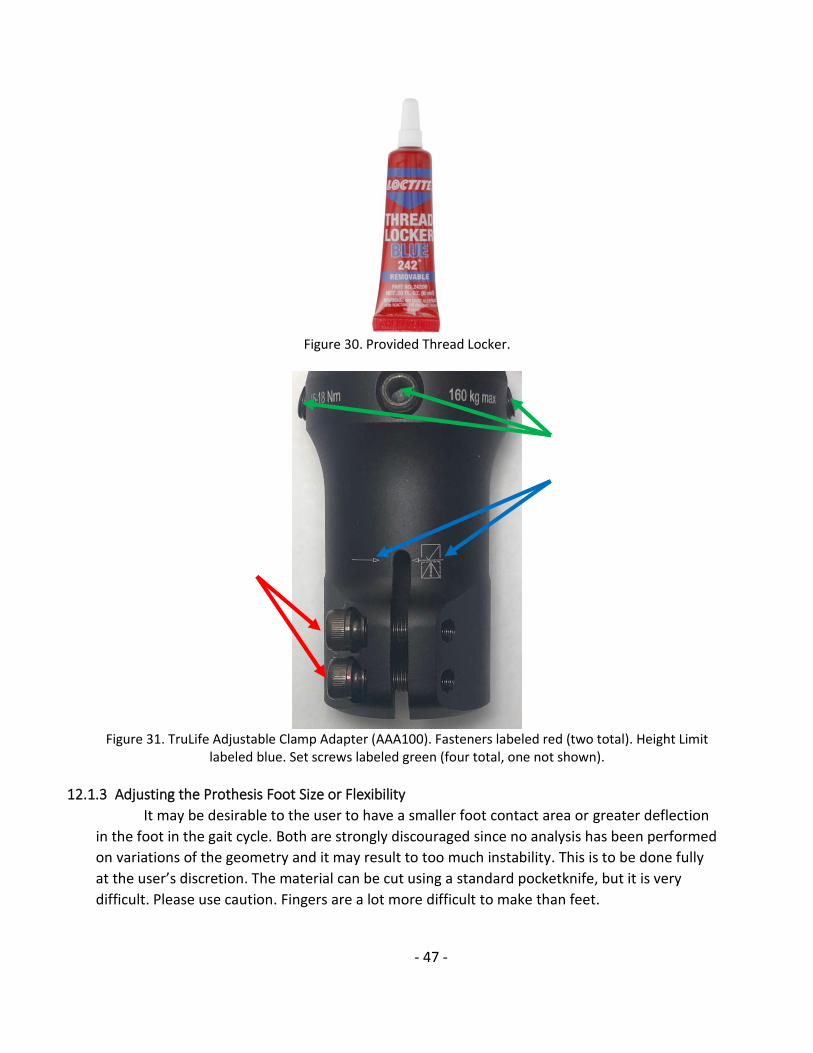
- 47 -
Figure 30. Provided Thread Locker.
Figure 31. TruLife Adjustable Clamp Adapter (AAA100). Fasteners labeled red (two total). Height Limit
labeled blue. Set screws labeled green (four total, one not shown).
12.1.3 Adjusting the Prothesis Foot Size or Flexibility
It may be desirable to the user to have a smaller foot contact area or greater deflection
in the foot in the gait cycle. Both are strongly discouraged since no analysis has been performed
on variations of the geometry and it may result to too much instability. This is to be done fully
at the user’s discretion. The material can be cut using a standard pocketknife, but it is very
difficult. Please use caution. Fingers are a lot more difficult to make than feet.

- 48 -
To adjust the toe deflection, cut parallel to the current outer edge of the foot to
decrease the contact area. Note that this will also decrease the amount of flex the toe has as
the user takes a step. See Figure 32 for an example of a cutting line.
To adjust the amount of ankle deflection, similar cutting can be performed. An example
can be found in Figure 33.
Figure 32: Example Foot Cutting Line

- 49 -
Figure 33: Side Profile Example Cutting Line
12.1.4 Securing the Pylon
In the scenario where, upon use, the pylon begins to separate from the foot/ankle,
suspend use immediately if possible. Separation may take the form of movement independent
of the foot, rotation within the foot, or movement up or down within the foot. This may
introduce unanalyzed stresses and prevent effective support.
To remedy this, the user can apply one bolt shown in Figure 34 to prothesis at
approximately the location provided shown in Figure 35. This is located right above the ridge
between the imbedded flange and the pylon. It is recommended to use the shorter bolt, as its
length is sided for this application. An additional bolt is provided if the first bolt begins to be
corroded, as it is the most likely component to corrode if used.
To achieve this, begin drilling with a standard drill and drill bit parallel to the bottom
plane of the foot and perpendicular to the drilling surface. It is recommended to use drill bits of
a small nominal diameter (around approximately ⅛-inch) and proceeded to gradually larger
diameters (up to ¼-in), before using the provided drill bit shown in Figure 36. Then, using an
appropriately sized hex key and wrench, tighten the bolt securely. This should prevent further
movement.
Physical testing was performed with a bolt in place in a prototype foot, which is shown
in Figure 37. There were no visual signs of increased likelihood of failure; however, introducing
a hole and fastener will introduce unanalyzed stresses, so it is to be done at the user’s
discretion.

- 50 -
Figure 34. Provided Bolts.
Figure 35. Potential Bolt Location. View: Inside. Bolt location shown at red dot.
Figure 36. Provided Drill Bit.

- 51 -
Figure 37. Prototype with Bolted Pylon. Please Ignore the Duct Tape.
12.1.5 Exposure to Saltwater and Preventing Corrosion
The rubber portion of the Sand Foot has been tested for corrosion and is highly
corrosion resistant. However, the pylon and clamp adapter are made of powder-coated
aluminum and are only slightly resistant to the effects of saltwater. It is highly recommended
that the foot and pylon be rinsed with fresh water and wiped dry after every use. The pylon is
sealed with a cork and plumbers’ putty to prevent it from filling with water, but it is crucial that
the inside of the pylon not be wet for extended periods of time.

- 52 -
12.2 QUALITY FUNCTION DEPLOYMENT

- 53 -
12.3 FINAL DESIGN DRAWINGS FOOT AND PYLON
Note: Ellipse identified by note 3 is projected downward to next surface
1

- 54 -
3

- 55 -

- 56 -

- 57 -

- 58 -
12.4 MOLD DRAWINGS FOR FDM INSTRUCTION AND ASSEMBLY

- 59 -

- 60 -

- 61 -

- 62 -
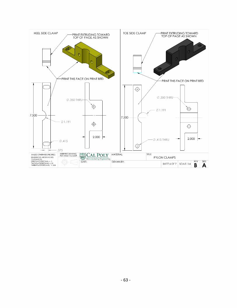
- 63 -

- 64 -

- 65 -
12.5 PYLON PROTOTYPE AND PROGRAMMING
Scaled Pylon Prototype
4th Axis Tool Paths Programmed with MasterCam

- 66 -
12.6 TENSILE TESTING DATA Stress-Strain curves from trial one and trial two for the chosen materials are provided
below. Intron tensile tester used. All data in light grey. Linear region in dark grey. Linear fit in
black.
y = 40.588xR² = 0.8373
0
1
2
3
4
5
6
7
0 0.5 1 1.5 2 2.5
Stre
ss (
MP
a)
Strain (mm/mm)
y = 41.719xR² = 0.7682
0
2
4
6
8
10
12
0 0.5 1 1.5 2 2.5 3 3.5 4
Stre
ss (
MP
a)
Strain (mm/mm)

- 67 -
12.7 DVP&R
Specification Test Description Acceptance
Criteria Test
Responsibility Test
Stage
Sample Tested
TIMING
Quantity Type Start Finish
1 Weight Assembly total
weight. < 4 lbs. Jackie PV 1 F 5/20 6/20
2 Ankle Rigidity
Ankle deflections within ranges of biological ankle under 240 lbs.
25° flexion, 45° extension, 30° pronation, and 60°supination
Parker DV 1 FP 4/20 5/20
3 Foot strength Support standing,
walking.
Stress < 2 * Material Yield
Strength Parker CV 1 CD 2/20 3/20
4 Water/Dust
Proof
Protection from dust and fluid
immersion up to 1m.
IP57 Jerin DV 1 FP 4/20 5/20
5 Material
Durability
Device can withstand
environmental factors.
Corrosion rate < 0.004 in/year [9]
Jackie PV 1 SP 2/20 3/20
6 Able to stand with device
Device does not cause pain to user.
6 hours without pain
Garrett PV 1 F 5/20 6/20
7 Able to walk
on device
Device can withstand repeated
stationary loads.
Repeated loading of 360 lbs. (1.5x
BW) for 20 million cycles
Parker CV 1 CD 2/20 3/20
8 Interfaces
with current device
Use standard prosthesis
attachment.
Attaches to current residual limb attachment
Jerin CV 1 CD 2/20 3/20
9 Contact area Prevents foot
sinking in sand. Does not sink in
sand Garrett PV 1 FP 4/20 5/20
10 Stationary
sand collection
Sand accumulation cannot affect
device operation. 1 oz. of sand Garrett PV 1 FP 4/20 5/20
11 Moving sand
collection
Sand accumulation cannot affect
device operation. 3 oz. of sand Garrett PV 1 FP 4/20 5/20
Test Stage (CV= Concept verification, DV= Design verification, PV= Product and Process validation). Sample Tested Type (CD = Conceptual Design, FP = Full- Size Prototype, SP = Scaled-Prototype,
F = Final Product).

- 68 -
12.8 FINITE ELEMENT ANALYSIS FIGURES
Fixed Geometry for FEA studies
Loading Conditions for each FEA

- 69 -
Stress Analysis of Front Step Loading
Displacement Analysis of Front Step Loading

- 70 -
Stress Analysis of Side Loading
Displacement Analysis of Side Loading

- 71 -
Stress Analysis of Heel Strike

- 72 -
Displacement Analysis of Heel Strike

- 73 -
12.9 BILL OF MATERIALS AND COST
Part Description Product No. Vendor Qty Price/Each
($) Total
($)
Black-Oxide Alloy Steel Socket Head Screw (3/8"-16 Thread Size, 8-1/2" Long)
#91251A341 McMaster-
Carr 4 5.78 23.12
Medium-Strength Steel Hex Nut (Grade 5, 3/8”-16 Thread Size)
#95505A603 McMaster-
Carr 1 6.54 6.54
Black-Oxide Alloy Steel Socket Head Screw (3/8"-16 Thread Size, 2-3/4" Long,
Partially Threaded) #91251A635
McMaster-Carr
1 7.65 7.65
Uncoated High-Speed Steel Drill Bit (25/64” Size, 5-1/8” Overall Length)
#8870A37 McMaster-
Carr 1 6.29 6.29
Standard-Wall Steel Pipe Nipple, Unthreaded, 3/4 Pipe Size, 1 Foot Long
#7750K112 McMaster-
Carr 1 7.37 7.37
Corks (Trade Size 11, for 7/8” to 1” ID) #9566K61 McMaster-
Carr 1 9.58 9.58
Loctite Thread Locker Blue 242 - Home Depot
1 6.47 6.47
PMC®-790 Trial Size - Smooth-On 4 34.08 136.32
PMC®-780 Wet Trial Size - Smooth-On 2 34.08 68.16
SuperSeal & Ease Release 205 Combo Pack
- Smooth-On 2 8.26 16.52
Adjustable Height Clamp Adapter #AAA100 TruLife 1 175.00 175.00
Bonded Pylon #AAA201 TruLife 1 75.00 75.00

- 74 -
12.10 TECHNICAL DATA SHEETS AND SAFETY DATA SHEET LINKS Part Technical Data Sheet Safety Data Sheet
PMC-780 WET
https://www.smooth-on.com/tb/files/PMC-780_Dry-Wet.pdf
https://www.smooth-on.com/msds/files/PMC-780.pdf
PMC-790 https://www.smooth-on.com/tb/files/PMC-
790_Shore_90A.pdf https://www.smooth-
on.com/msds/files/PMC-790.pdf
SuperSeal https://www.smooth-
on.com/tb/files/SuperSeal.pdf https://www.smooth-
on.com/msds/files/SuperSeal.pdf
Ease-Release 205
https://www.smooth-on.com/tb/files/ER205.pdf
https://www.smooth-on.com/msds/files/ER205.pdf
Loctite Thread
Locker Blue 242
https://dm.henkel-dam.com/is/content/henkel/TDS-209728-US-Loctite-Threadlocker-Blue-242-Carded-Tube-
0.20-fl-oz-2018-04-09pdf
http://www.techni-tool.com/site/MSDS/512AD038.pdf

- 75 -
12.11 GANTT CHART
Design Phase

- 76 -
Build Phase
Test and Deliver Phases
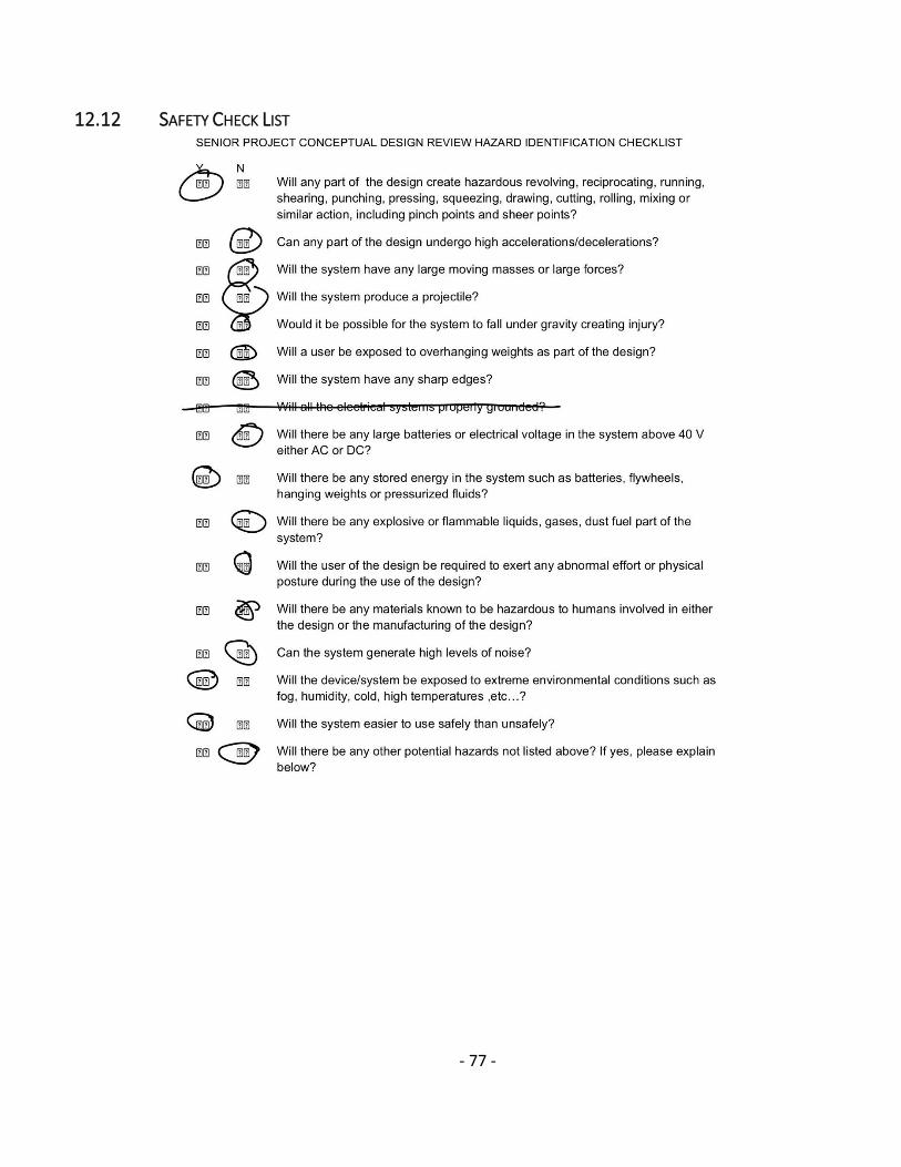
- 77 -
12.12 SAFETY CHECK LIST
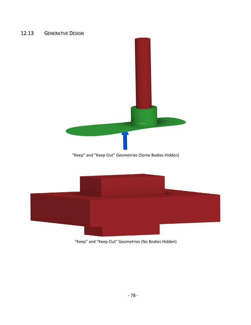
- 78 -
12.13 GENERATIVE DESIGN
“Keep” and “Keep Out” Geometries (Some Bodies Hidden)
“Keep” and “Keep Out” Geometries (No Bodies Hidden)

- 79 -
CAD model Obtained from Generative Design

- 80 -
12.14 TEAM CONTRACT

- 81 -
Copyright © 2022 FDOKUMEN