
+ The 5532 OpAmplifier - part2
88
w --rrt November zoro AU5$r3.9o - NZ$r6.9o - SAR99.95 Lq.6S + The 5532 OpAmplifier - part2 + Wireless lnstrumentation Network llill[iliilllllllllllllill ililtil
-
Upload
khangminh22 -
Category
Documents
-
view
2 -
download
0
Transcript of + The 5532 OpAmplifier - part2

w --rrt
November zoro AU5$r3.9o - NZ$r6.9o - SAR99.95 Lq.6S
+ The 5532 OpAmplifier - part2
+ Wireless lnstrumentation Network
llill[iliilllllllllllllill ililtil

:l't
Hry ;\mLLo -r \
ffin#ff*€gry€ng
**a#i€r:* fo'3--F*br::+rv 25 :
Register f or the challenge at
www. ci rc u itce Ia r. co m/nxp m be d d esign c h a [ [e n g e
NXP mbed Design Chatlenge empowered by:
$.kror 8[ttHF+#.: g,i
^f A.i. 3t\.., -_c&.
ffi&## w#yRedefine the way peopte buitd
prototypes! NXP and ARM/mbedare chaltenging you to use thembed NXP LPC 17 68 prototypingboard and m bed on tine "Ctoud"
compiter to develop aninnovative hardware- or
software- based application.Succeed, and you coutd walk
away with part of a prize poolworth S10.000!
mbed

SAUTY||UR PllWERWIIH,'sl,sr' .Fs,wr a
'.6: 'r',,
."y fI
4A)
.;{:
1']:1il:ilrlr
IFzuUoCL
=UF
FzU=Ao)Uuoro&.
uro
ffiffi@g
Easv24-33 u6
r3li'#lllTffiH'-Ttfl It'J8i @ G @ffiTHE EASIESTWAYTO CREATEYOUR OWN LOW POWER DEVICES
The Easy24-33 v6 development system supports 14-,18-,20- and 28-pin PlC24 and dsPlC33 devices fromMicrochip. lt comes with a PIC24F16KA102 (P,C2416-bit Microcontroller featuring nanoWatt XLP" foreXtreme Low Power consumption) designed for power constrained and battery powered applications.
The system features a USB 2.0 programmer with mikrolCD and many peripheral modules, such asTouch
Sense, Serial RAM, EEPROM, etc, suitable for developing low power, sensor and wireless devices.
mili$r,Rtt#f tl#,p.T,iltflGET IT NOW
. . . ^oL,*q ll sl^gl-
'ii ' ffio
www.mikroe.com

Privileged
When it comes to (high end) audio, Elel<-
tor has standards and a reputation to
maintain. Many of our amplifier designs
have reached 'legendary' status and
apparently are still built. ln recent years,
audio as a subject has suffered under the
weight of microcontroller projects, and
we promise to mal<e amends.
Unusually, our current audio amplifierproject (of which the first instalmentappeared last month), is not a Purein-house design but originally develo-
ped by Douglas Self, a widely respected
author of articles and bool<s on the
design of audio amplifiers. However in
good Elel<tor fashion the 5532 OpAmpli-
fier design was tweaked and optimized.
Ton Giesberts here at Elel<tor Labs was
asked to supervise the post engineering
phase of the project. And what do you
thinl< happens if let two ambitious audio
designers worl< together on a project?
They will not tal<e each other's word for
any decibel when approaching the noise
floor of the AP analyser! Questions, com-
ments, criticisms and amendments got
sent back and forth over the past few
months. Eventually this led to a design
that's improved and polished in some
areas; 'the best of two minds', so to
speak, right up to the board design and
the publication ProPer.The resulting project is a rather unu-
sual power amplifier with an outPut
stage that consists of cheap, paral-
leled opamps- lots of them! lf you are
interested, do not hesitate to build your
own OpAmplifier. ln terms of parts cost,
it won't breal< the banl<, apart from the
power supply of course which is traditio-nally the biggest cost factor. Let us l<now
what you thinl< of it! My colleague Harry
Baggen was the first to be able to listen
to the OpAmplifier within the peace of
his own home and he was pleasantly sur-
prised by the performance of all those
little opamps. lt sure is a privilege to be
an Elel<tor editor - with the soldering
irons still smol<ing you can listen to the
latest audio creations straight away.
Jan Buiting, Editor
4
&o\oa)*Q
IJ;[r A
o
€f@
;: ilffr6
20
24
32
36
4'l
43
44
gektorColophonWho's who at Elel<tor magazine.
News & New ProductsA monthly roundup of all the latest in
electronics land.
14 lntroducing mbed
What's That in the Air?Here we tackle the theory and methods
of real-time oxygen and hydrocarbon
compound measurements.
MicroFuelCellMeasu res Oxygen ConcentrationA must read and must have not just for
divers and cave explorers.
The 5532 OpAmplifier (z)
Besides construction and test results, the
closing instalment also covers bridged
operation and modification for 4 ohms.
SensorlessMotor Speed MeasurementA technology is described that enables
the speed of an electric motor to be
measured by means of an ammeter
circu it.
Wireless I nstrumentation Networl<Add Maxstream and Xbee modules,
stir in some Arduino and You have a
measurement networl< with no wires.
Fortable EnergyAlternative energy sources for your cell
phone, iPod and other gizmos normally
operating from rechargeable batteries.
JTAC Live Buzz (E-Labs lnside)
JTAC is increasingly used for boundary
scan methods, calling for new lC
a rchitectu res.
USB port from a g-pin sub-D con-nector (E-Labs lnside)FTDI have again come up with the goods!
Rapid Prototyping (E-Labs lnside)The AutoFab product from Muvium
fiu t r- i. Tr i 99Erv1.2JP6
* Bg/A?/frLB
46
1o-2o.ro elel<tor

i::j:-!.:...1,!l
CONTENTS
20 MicroFuel CellMeasu res Oxygen Concentration 48
We have previously described carbon dioxide sensors based on chemical and
optical principles in Elel<tor, and an oxygen sensor complements these designs
nicely. The meter described here is based around an Elektor MinimodrS micro- 54
controller board featuring an ATmega3zS microcontroller and a two-line bacl<-
lit LCD panel.
Volume 36November 2o1ono.4o7
presents a new approach to circuitprototyping.
lmage Processing Made EasyBluff your way into motion detection witha webcam.
Designing and Mal<ingBasic AntennasIt's surprisingly easy to make monopoles,dipoles and directional antennas for thez.4CHz lSM band.
Tall< Show (ATMr8 series)VRBot, SpeakJet and ATMr8 are the main
ingredients of an experimental voice
synthesizer with a giant r-pixel indicatorthrown in for fun.
Unilab DuoHere we show how the Unilab bench
PSU gets converted into a twin supplytogether with the September zoro V/lreadout.
Design TipsLED remote control for RC modelsSimple lR remote control tester
Camera lntervalTimerA fully programmable timer & multishotcontroller for photo cameras like theCanon EOS.
Light TrackerVery lil<ely one of the simplest roboticscircuits around that succeeds in findinglight sources.
HexadokuOur monthly puzzle
with an electronics touch.
Retronics: Chauvin-Arnoux MF7Precision Astatic WattmeterRegular feature on electronics 'odd &ancient'. Series Editor: Jan Buiting
Coming AttractionsNext month in Elektor magazine.
F*
Erilf;
ft
6o
24 The 5532 OpAmplifier (z)This month we get real by building the 5532 OpAmplifier project and putting itthrough its paces. The test results are pleasing if not impressive and definitelyput the design in the high-end audio class. Bridging and 4 ohm conversion are
also described.
36 WirelessI nstru mentation Networl(
ln this project, the node consists of an Arduino nodule with an XBee shield
module. The gateway also consists of these two modules, plus an EtherShield
module for communication with the lnternet. The resulting measurement data
can be retrieved from the Pachube website.
70 Camera lnterval TimerThe camera shutter operating system described here enables you to tal<e pho-
tos at a predefined interval, or to trigger two cameras together for stereoscopic
shots. This way you can take a series of photos every 30 minutes of a flower as
it opens, a baby bird hatching, etc. so as to include them in a video. The system
was originally designed for a Canon EOS camera, but it can readily be adapted
for other cameras that are able to be remote controlled.
66
69
7o
74
75
76
elektor ro-zoro
84

elektorl international media bv
Elektor lnternational Media provides a multimedia and interactive platform for evervone interestedin electronics. From professionals passionate about their worl< to enthusiasts r.,,ith professional
ambitions. From beginner to diehard, from student to lecturer. lnformation, education, inspirationand entertainment. Analogue and digital; practical and theoretical; soft',n,are ard hardware.
'&.q6 ig
{itngili#i,t3
ffi..'#$t
* ANALOGUE . DICITALMICROCONTROLLERS & EMBEDDE
AUDIO . TEST & MEASUREMENT
'ffitk' *
W
ektor+ E0 Gndles forthe Pentode
20 ACIIK clamp meters-:,,b. on thetbst bench
Volume36, Number4oT, November:oro ISSN U57-o87S
Eleldor aims at inspiring people to master electronics at any
personal level by presenting construction projects and spotting
developments in electronics dnd information technology.
l'::r i, ElektorlnternationalMedia,RegusBrentford,looo 6reatWest Road, Brentford TW8 9HH, England.
Tel. (+44) 208 261 45og,Iax: (+44)zo9z61 4447tm-elektor.com
The magazine is available from newsagents, bookshops and
electronics retail outlets, or on subscription.
- . !!k"l ts p!dl'1"9 'Il'"'-l f"i,*llh,:,9:6!"1:*J"!'!._1 ly!l:'
6
Elektor is also published in French. Spanish, AmericanEnglish, Cerman and Dutch. Together with franchiseded tions the magazine is on circulation in more thar 5oco u ntries.
r ,,:r i, tii:Wisse Hettinga (w.hettinga@elektonnl)
Jan Buitinq ([email protected])
Eduardo Corral, Ernst Krempelsauer,Jens Nickel, Clemens Valens.
Christian Vossen (Head),
Ton Ciesberts, Luc Lemmens,.lan Vi5ser.
Hedwig Hennekens (secretariaateelektor.nl)
' : Ciel Dols, N4art SchroUen
,:- Paulsnakkers
' j:i .r Carlo van Njstelrooy
: .: . - : Elektor lnternational Media,Regus Brentford, rooo Creat West Road, Brentford TW8
9HH, England.Tel. (+44) zo8 z61 45 og,fax: (+44). zo8 z6t 4447lnternet: www.elektor.com/subs
'r1-2o1o elektor

Elektor ersona2o-11
o
anrzerContents refill available separately
The Elektor Personal Organizer zorr makes planning
your appointments a real pleasure, and you always
have ready access to have handy information thateveryone who works with electronics needs to know.
-e'$
The Organizer20l 1 ata glance:
. zorr calendar(two pages perweek)
. Appointments calendar (with cornerperforations) in six languages
. 6o pages of technical information on
electronics. Seven sections,separated bytab sheets. Alphabetic address and telephone book. Handymonthlyplanner. Lined pagesforyournotes. Five credit-card pockets and a pocket
for business cards. Push-buttonclosure. Six-ring bindermechanism. Luxurious grey imitationJeather binding. Free pen and SMDTool (with complete
package only)
Contents refill 201 1
lfyou purchased the ElektorOrganizer last
year, the content refill for zon can be ordered
separately for fi+.8o (US $z3.go).
ISBN 978-9o-5381-259-4 . fz4.9o . US 54o.u o
Contains 60 Pages
of technical inf ormation
on Electronics!
VTVAVTVAVTVI:J I: cli il, tlTI:Il(r !II!EEmail: [email protected] and terms are given on the Subscription Order Form.
tlerd Olllcer Elektor lnternational lvledia b.v.P.o. Box11 NL-6114-ZG susteren The NetherlandsTelephone: (+3r) 46 4389444, Fax: (+31) 46 4370161
Di\tribuliiln:Seymour,2 East Poultry Street, London ECIA, EnglandTelephone:+44 zo7 429 4o73
Ul( Adve' ti5inqiHuson lnternational Media, Cambridge House,Gogmore Lane, Chertsey, Surrey KTr6 9AB England.Telephone: +441932 564999, Farc +44r932 564998
Email: [email protected] ww.husonmedia,comAdvertising rates and terms available on request.
Copyright NoticeThe circuits described in this magazine are for domestic use
only. All drawings, photographs, printed circuit board layouts,programmed integrated circuits, disks, CD-ROl\4s, softwarecarriers and article texts published in our books and magazines(other than third-party advertisements) are copyright Elektorlnternational l\4edia b.v. and may not be reproduced ortransmit-ted in any form or by any means, including photocopying, scan-
ning an recording, in whole or in part without prior written Per-mission from the Publisher. Suchwritten permission mustalso be
obtained before any part ofthis publication is stored in a retrieval
system of any nature. Patent protection may exist in respect ofcircuits, devices, components etc. described in this magazine.
The Publisherdoes not accept responsibilityforfailing to identify
such patent(s) or other protection. The submission of designs or
articles implies permission to the Publisher to alter the text and
design, and to use the cont€nts in other Elektor lnternational
l\.4edia publications and activities. The Publisher cannot guaran-
tee to return any material submitted to them.
Dirclaimer
Prices and descriptions of publication-related items subject tochange. Errors and omissions excluded.
@ Elekorlnternational Media b.v.2oro Printed inthe Netherlands
elektor rr-zoro

NEWS & NEW PRODUCTS
World's fi rst ultra-thinwaterproof piezoelectricspeakerFeaturing a thicl<ness of only 0.9 mm,Murata has launched the world's firstultra-thin waterproof piezoelectricspeaker. Based on Murata's proprietarypiezoelectric technology, the speakeris waterproof to lPX5/lPX7. The speal<er
measures 19.5 by 14.1 by 0.9 mm; its rec-
tangular shape reduces dead-space fromdesigns while its ultra-thin dimensionscontribute to greater freedom in equip-ment design.
Of the 50 new Japanese mobile phonemodels announced for 2010, almostone in four will be waterproof mobilephones, one of numerous indicators of agrowing trend towards the waterproof-
Mainstream universalcontroller platformfor RF and lR
The M-Remote from Audivo is the firstmainstream universal RF remote controlplatform to complement RF with tradi-tional lR capabilities, and offer a color (LCD
or OLED) display. By using Nordic Semi-conductor's nRF24LE'l 2.4 CHz SoCs andCazell RF software protocol, the M-Remotecan seamlessly control the latest video andaudio wireless streaming devices via bi-directional RF. The device also controls tra-ditional lR-only equipped appliances suchas TVs, set-top boxes (STBs), and A/V amps.Universal controllers have the ability to oper-ate consumer electronics (CE) appliances
8
ing of mobile equipment. Civen thereare so many different areas that requirewaterproofing, there were many tech-nical challenges and cost issues to over-come when developing the waterproofspeaker. Conventional methods of water-proofing dynamic speakers used water-proof sheets which covered the outputsound holes, reducing sound quality.Murata's approach incorporates a rub-ber film into the speal<er itself, leavingthe output sound holes open. The widthof the metal frame housing the speakerhas been increased to improve the seal
between the metal frame and the chas-sis, preventing waterpenetration.
The new waterproofspeaker has been des-ignated part numbervsLBCl 91 4E1 400-T0. lts average soundpressure level (SPL) is
92.013.0 dB (1500 Hz
12000H212500 Hzl3000 Hz average) with a
resonant frequency of1400 Hzt2j'A. Sinceno magnets are used,there is no possibil-ity of malfunctions
from different manufacturers eliminating theneed for multiple dedicated remote controls.Until now, however, mass-marl<et universalcontrollers have typically only employed tra-ditional lR (infrared) technology.The M-Remote OEM platform offers bothRF and lR and targets consumer electronics(CE) manufacturers of the latest networl<edA/V devices such as streaming music servers,lnternet radios and wireless multimedia cent-ers. These appliances demand more advanced
user interfaces than traditional push-button,one-way lR technology can support. RF offersthe high-bandwidth, bi-directional wire-less connectivity required to support moreadvanced user interface mechanisms such as
scroll wheels, touch-screens, and track-balls.These are all designed to make it easier andmore intuitive for end users to access andenjoy their digital content and services. Thisincludes the ability to browse large librariesof stored music or long lists of lnternet radiostations, or have continuous ('live') playingstatus info (including that usually shownon a front panel but often too small or faraway for users to be able to see) and graph-ics (e.9. album artwork) displayed directlyon a remote's display, ln addition, RF elimi-nates the need for lR's line-of-sight access,
allorving devices to be controlled throughobjects and even interior walls (usually upto a range of about I 5m and assuming wallbuilding materials do not excessively atten-uate RF signals).ln operation, a Nordic nRF24LE1 locatedin the universal lv'l-Remote communicateswith a second nRF24LE1-based moduleembedded into the A/V networked stream-ing device using the Nordic Gazell softwareprotocol. The Nordic nRF24LE1 utilizes a
proven Nordic nRF24L01 + transceiver coreand features an up to 2 Mbps on-air datarate combined r'vith ultra low power (ULP)
operation and advanced power manage-ment. The Cazell RF protocol provides fea-tures for advanced navigation, backgrounddata transfers (e.9. of larger files such as
album artwork), and advanced pairingschemes, while being able to handle up tofive remote devices at the same time. lnaddition, Cazell is a frequency agile protocolthat is highly immune to interference fromother 2.4 CHz radio sources such as Blue-tooth wireless technology and Wi-Fi.To conserve power, the M-Remote willtypically enter an ultra-low power (22 pA)
standby sleep mode when not in use (after30 s in default mode, or between ten and90 s if set by the user). This, however, is allhidden from the end user by the use of an
,$ry'ItIl',f,) - ------., .-----I --.--'.:ir'
. -,/,frI
caused by iron sand, or electromagneticeffects on magnetic sensors.
www.murata.eu (roo639-lX)
r'r-2o1o elektor

inbuilt motion sensor that means if theremote is picked up it activates a rapid powerup (including the display) in 200 ms readyto respond immediately to any user inputrequest. The M-Remote is able to offer overa week ofoperation before battery recharge.
The fully customizable M-Remote is a com-plete solution including the remote con-trol handset with integrated rechargeablelithium-ion (Li-ion) battery, charging cra-dle, host A/V device RF module, lR trans-mitter for standard devices (optional), API
source codes (making it very easy to inte-grate the M-Remote platform into anymodern A/V device), product design sup-port, development kit, automatic pairing,and an optional touch (scroll) wheel. A fulltouchscreen could also be integrated ifrequired, and multi-room (zone) control is
also supported.www.nordicsemi.com
(roo639-Vll)
Online IGBT selection toollnternational Rectifier has introduced a
new online lnsulated Cate Bipolar Transis-
tor (ICBT) selection tool that enables designoptimization in a wide range of applicationsincluding motor drives, uninterruptablepower supplies (UPS), solar inverters, andwelding.
lR's new ICBT Selection Tool evaluates appli-cation conditions including bus voltage,switching frequency, and short circuit pro-tection requirements. Located at mypower.irf.com/lGBT, the online tool provides an
estimate of losses and suggests parts thatcan function within the given constraints.The tool also provides pricing for each partto enable designers to consider the effectsof device choice on system cost.lR offers a broad array of ICBT products ena-
elektor rr-zoro
bling optimized inverter designs for differ-ent applications. The new online selectiontool enables engineers to quickly and easilycompare choices to select the optimal ICBT
for their design.ICBT selection requires evaluation of manyparameters that cannot be simplified intoa single metric. As switching losses canbe traded for conduction losses, for exam-ple, calculating operating losses requiresboth operating frequency and bus voltageparameters, in addition to operating cur-rent. Also, the requirement of some motordrive inverters for minimum short circuitwithstand time comes at the expense ofhigher losses.
lR offers a wide selection of IGBTs offeringvarious tradeoffs in switching speed as wellas devices designed for applications thatdo not have minimum short circuit require-ments. The new selection tool helps design-ers make use of lR's broad ICBT portfolioand weigh the performance tradeoffs.
www.irf.com
(roo639-X)
SGHz RMS powerdetector with digitaloutputLinear Technology introduces the 1TC5587,
an industry first 40 dB dynamic range 6 CHzRMS detector integrated with a high sam-pling rate 12-bit serial A/D converter. The
digital output RMS RF detector provides+1 dB measurement accuracy of high crest-factor signals, independent of the modula-tion used. The detector is capable of oper-ating over a wide frequency range from10 MHz to 6 GHz. The integrated 12-bitADC captures and digitizes the detectormeasurement at a rate of up to 500 ksam-ples/second and delivers the data via a bit
J[.r1n-rRtlE ololbl 0llorl
,rrm
lllli Cfi&fatiorSltntlt
/\/-
.c7tfiKN
Chip
USB MADE EASYwww.ftdichip.com
FTDI

NEWS & NEW PRODUCTS
stream over a serial SPI port. The RF detec-tor operates with single-ended input andrequires no external balun transformer. ltssmall 3mm x 3mm DFN package provides a
highly compact solution.The LTC5587's il dB accuracy over a 40 dB
dynamic range and over the full tempera-ture range from -40'C to 85'C offers best-in-class performance. Combined with a
12-bit A/D converter, the device provides0.014 dB per bit measurement resolution.Its low power consumption is ideal forapplications in cellular basestations, pico-cells, and femtocells supporting all stand-ards including LTE, W-CDMA, TD-SCDMA,CDMA/2k, CSM/EDCE and WiMAX. Otherapplications include MIMO radios, repeat-ers, point-to-point microwave links, militaryradios with complex modulation, remotepower measurements, and portable testand measurement instruments. The detec-tor is particularly useful in FPGA-based sys-
tems where no A/D converters are available.The LTC5587 is powered from a single 3.3 Vsupply. During sampling mode, its totaloperating current is 3 mA, consuming only10 mW of power. lts consumption is fur-ther reduced by one-half when the ADC is
idled, making the LTC5587 suitable for bat-tery powered or portable remote RF meas-urement systems. The device also has shut-down capability, drawing less than
.l 0 pA
supply current when disabled. The LTC5587
is offered in a small 3mm x 3mm 12-pin DFN
package, providing a compact solution foot-print. The LTC5587 is available from stocl<.
http://www. linear.com/5587
Copy protection andlicense-ma nagementsecurity over a single-contact interfaceMaxim lntegrated Products introducesthe D528E1 0, a challenge-and-responsesecure authentication lC that includes user-programmable nonvolatile (NV) memory.Authentication is implemented with theindustry-proven FIPS 180-3 secure hashalgorithm (SHA-1) combined with com-mands that operate on a programmableprivate secret and random challenge froma host controller. The device provides flexi-bility to implement private secret sizes from64 bits to 288 bits; the host challenge size
is 96 bits. These large secret and challenge
Farnell first to stock
boardFarnell is the first European dis-tributor to stock the new Micro-stick for dsPlC33F and P|C24Hdevelopment board, which pro-vides a complete, low-cost solu-tion for designing with Microchip's16-bit PlC24H microcontrollers and dsPlC33F Digital Signal Controllers (DSCs), in acompact 20x76 mm footprint. The low-cost Microstick offers an integrated USB pro-grammer/debugger, which shortens learning curves. For maximum flexibility, theMicrostick can be used stand-alone or plugged into a prototyping board.Manyengineers, educators, students and hobbyists need a low-cost solution forwork-ing with and debugqing code on 16-bit microcontrollers and DSCs. ln addition to itsother benefits, the Microstick is populated with a socketed microcontrollerthat can be
easily swapped out. The Microstick works with the P|C24H)64CP502, which is the high-est performance 16-bit MCU in the industry, and the dsPlC33FJ64l\1C802 DSC, whichseamlessly blends DSP and MCU resources into a single architecture. Software sup-port includes the same free MPLAB@ lntegrated Development Environment (lDE) andsoftware libraries that work with all of Microchip's 8/1 6/32-bit PICO m icrocontrollersand DSCs. Additionally, the dsPlC33F DSCs are supported by the free demo version ofMicrochip's Device Blocksets forthe MATLAB@ language and 5imulink@ environment,which work seamlessly within the MPLAB lDE.
This combination of low-cost tools and free software provides an industry-leadingplatform for experimentation and development of smart-sensor and a host of otherembedded-control applications.Through its industry-leading websites featuring tools such as Live Chat, and easilyaccessible data sheets, Farnell is able to support its electronics design engineeringcustomers with information and ideas to help them select the most appropriate com-ponents and devices for their new designs. The elementl4 online engineering commu-nity provides a unique additional resource. Further information about the Microstickfor dsPlC33F and PIC24H development board can be found at http://www.element-14.com/com m u n ity/d ocs/ DOC23484.
wwwmicrochip.com/get/E0KR wrnr,.farnell.co.uk (roo639-Xl)
new Microchip development
sizes make algorithmic brute-force attacksto discover the private secret mathemati-cally impractical. Because die-level probemethods are the more likely method ofsecurity attack, the DS28E10 implementsproprietary circuits and methods to protectsensitive data from being captured. Thisauthentication solution is well suited fora broad range of cost-sensitive consumer,medical, and industrial products.
The D528E1 0 provides 28 bytes of user-pro-grammable OTP-EPROM portioned with pro-grammable protection modes. This memorycan be used to store end-product informa-tion such as calibration constants, manufac-turing data, and feature settings. Additionally,a unique, unalterable, factory-programmed,64-bitserial number(ROM lD)is included andcan be used as an input parameterforauthen-
tication security functions and/or as a uniqueidentifi er for the end product.Communication with the DS28E1 0 is imple-mented using Maxim's l-Wire interface.The single-contact l/O interface enablesthe part to be easily added to a design froma spare microcontroller or FPCA port pin.
11-2o1o elektor

The D528E10 operates from 2.8 V to 3.6 Vand is fully specified over the -40 degreesCelsius to +85 degrees Celsius extendedtemperature range. lt is available in small,3-pin SOT23 and 6-pin TSOC packages. An
evaluation kit (DS28E10EVK|T+) is also avail-
able to assist with end application develop-m e nt a n d t" o'"nffi
*"."-ii.',T."#iJIl r r,,(too639-Xlll)
Tinytagcurrentlvoltage loggersThe new battery-powered 1-channel dataloggers with 16-bit resolution have a rug-ged housing with LCD display of the currentreadings. There is the model TV-4704 avail-
able with an inputvoltage range of 0-25 VDC
and a resolution of 1 mV aswell asthe modelTV-4804 with the input current range of0-25 mA DC and a resolution of 1 pA.
With the above mentioned current and volt-age ranges a variety of industry standardsensors and transducers can be connected,which enables the recording of a wide range
of process and environmental parameters.The devices have a memory capacity of30,000 readings and the housing protec-
tion is rated at 1P67. They are supplied withan input connection cable.
The optional data logger software enables
the scaling of the readings, that means,during the evaluation of the signals the real
values ofthe connected sensors as well as
the suitable physical units can be displayed.
There are user-programmable samplingintervals between 1 s and 10 days and twoprogrammable alarms available, and thereis also an option for delayed start up to 45days, direct start via reed switch and threestop functions (when memory is full; after n
readings or overwrite oldest data).After the run is finished, the stored data can
be transferred to a computer via an inter-face cable, and they can be displayed a s a
curve or spreadsheet, printed or processed
inotherapplications' www.priggen.com
(roo-Xll)
IPS for servo motorcontrollerslmages Scientific lnstruments lnc. new IPS
(lntegrated Power Supply) is setting thenew standard of excellence in servomotorcontrollers. Our line of servo motor control-lers allows you to use a variety of inexpen-
sive power supplies to run both your con-troller board and servomotors. Use availablepower supplies; transformers, batteries,wall transformers, etc. anything from 6Vto 30V either AC or DC. The IPS system willregulate the power to run your servomo-tors efficiently. Power is supplied through2.5 mm power socket on board. A discrete2.5 mm power jack is provided with ourcontrollers for connecting your own power
supply.The picture shows the newest products inthe Servobotics line of servo motor control-lers; starting at the upper right and movingclockwise; the PS2-5MC-06, USB-SMC-05,
USB-SMC-4 and USB-SMG08.http://www.imagesco.com
(roozo8-l)
LeCroy: fastestoscilloscope in the worldLeCroy Corporation's new line of WaveMas-
ter 8Zi-A digital oscilloscopes - the 8 Zi-ASeries - now provides up to 45 CHz of band-width and 120 CS/s of sample rate - theworld's highest bandwidth and fastest sam-
ple rate real-time oscilloscope - combinedwith 768 Megapoints of analysis memory.
rwelcome worldwlde Pcrtner)
ffiMade in Taiwan/ Desagner & Manufacturer & Expoder

NEWS & NEW PRODUCTS
i tttew boards galore easily connected to a PC. Now you can explore thenewAtmel@ XMECAn' A1 family at a low price.The EasyPULL board contains 8 pull-up resistors(10 kOor 1 kQoption). ltcan be usedtofixan inputpin to a known state if no input is present. On-boardjumpers set pull-up/pull-down resistors for each pin
connected to your prototype device.Also new is the EasyWiFi Board - a
full-featured add-on tool for deve-lopment of devices that use2.4 CHz wireless communication.It features the ZeroC ZC2100Mmodule that provides fast datatransmission and a wide datarange. The board can be con-nected to your system or micro-controller via lDC10 connectors.Besides this, the tool featuresvoltage translators which allowstool to work on both 3.3 V and5 V voltage systems.
Finally there's the EasyLED Board. This tool featureseight LEDs that can be used for visual indication of
from mikroelektronikaMikroelektronika have released a number of newboards to the microcontroller/embedded markets.The SmartTMl Board allows usersto use Teltonika TM1 module in theirGSM/CPRS application design. Thetool supports Teltonika TM1 CSMiGPRS module and has on-board vol-tage regulation, so there is no needfor additional power supply circuit.All you need to do is to connectpower supply to the board, attacha CSM antenna and you are readyforyour device designing. Each fea-ture of the board is supported by examplewritten in mikroC, mil<roPascaland mikro-Basic PRO compilers.The new XMEGA-Ready is a full-featuredprototype board that contains ATxme-ga.l 2841 device (it is connected to 8Mhzoscillator). lt also features a USB support via FT232R. This tool output signals. Also, it can be connected to external electronicis ideal for exploring and desiging devices using new Atmel@ circuits via lDCl0 connector and extension pins. The board is idealXMECATM 41 family. for embedded projects that need some kind of visual indication,The developmenttool called mikroXMEGA is a small-package pro- which can be used for signal monitoring purposes.totype board with ATxmega'l 2841 device (running at 8 MHz). This www.mikroe.comtool contains the FT232R (USB to serial UART interface) that can be (roo7o8-l)
Additionally, the introduction ofa model with 20 CHz of band-width on four channels providesthe highest performance and sig-nalfidelity available on four mea-surement channels. On all models,acquisition capability can be dou-bled with the use of the Z|-SCH-SYNCH Oscil loscope Synchroniza-tion Kit, with all acquired channelsdisplayed on a single display grid.The standard sample rate is 120GS/s for 45 CHz bandwidth, 80GSis for 25 to 30 CHz bandwidths,and 40 CS/s on all4 channels at 20GHz bandwidth. For 4 to 20 CHzbandwidths, the standard samplerate is 40 CS/s on all four channelswith an option to increase thesampling rate to 80 CS/s on two channels.All memory is available at full record lengthsfor analysis processing, 20 Mpts/ch is provi-ded standard, with memory options up to256 Mpts/ch available. ln 120 and 80 CS/s
mode, memory can be interleaved to 768and 512 Mpts/ch.
The WaveMaster 8Zi-A models utilize sec-
ond generation silicon germanium (SiCe)components to ensure high performance.SiGe is the most widely adopted anddeployed semiconductor fabrication pro-cess with many years of commercial deploy-ment. Additionally, it has none of the ther-
mal conductivity, reliability, yield,cost and other concerns that cap-tive in-house processes must con-tend with. LeCroy's 30 to 45 CHzSZ|-A models make use of sixthgeneration Digital Bandwidthlnterleave (DBl) to effectively andreliably extend bandwidth withoutthe deleterious effects of band-width "boosting".LeCroy has designed the 8 Zi-ASeries as a single hardware plat-form, supporting all nine mod-els spanning from 4 to 45 CHz ofbandwidth. This means engineerscan leverage their investment andstay current with emerging high-speed technologies and serial datastandards by purchasing only the
bandwidth needed for current designs, andupgrading to additional bandwidth as needschange. Customers who had previously pur-chased an 8 Zi model can upgrade to 8 Zi-Aperformance and bandwidth.
www,lecroy.com(rooto8-lll)
1l-2oio elektor

Low-Power Microcontrollers for Battery-Friendly Design
Microchip Offers Lowest Currents for Active and Sleep Modes
Extend the battery life in your application using PIC' microcontrollers with nanoWatt
XIP lechnology and get the industry's lowest currents for Active and Sleep modes.
Microchip's new peripheral-rich PlC12F182X, PlC16F1B2X and PlC16F19XX families offer active
currents of less than 50 pA and sleep currents down to 20 nA. These products enable you t0 create
battery-friendly designs that also incorporate capacitive touch sensing, LCD, communications and
other functions which help differentiate your products in the marketplace.
Microchip's Enhanced Mid-range B-bit architecture provides up to 5070 increased performance
and 14 new instructions that result in up to 40% better code execution over previous-generation
B-bit PlC16 MCUs.
GET STARTED IN 3 EASY STEPS
1. View the Low Power Comparison
videos
2. Download the Low Power
Tips'n Tricks
3. 0rder samples and development
tools
www.microchip.com/XLP
Pl(12F182X and PlC16F182X families
include:. Packages ranging from 8 to 64 pins
. mTouch'" capacitive touch-sensing
. Multiple communications peripherals
. Dual |2(YSPI interfaces
. PWM outputs with independent time bases
. Data signal modulator
Pl(l6Fl9XX family includes:. mTouch capacitive touch-sensing
' LCD drive
. Multiple communications peripherals
' More PWM channels, with independent
timers
. Up to 28 KB of Flash program memory
. Enhanced data EEPRoM
. 32-level bandgap reference
. Three rail-to-rail input comparators
lntelligent Electronics start with Microchip
rnicnochiptr3iFlEGTwww. m ic roch ipdlract.com SMrcnocHrP
Pl(16F193X'F1' Evaluation Platform - DM164130i

By Simon Ford (Ul()
When Circuit Cellar and Elel<tor approached me about running a
"design challenge" around mbed, I saw an opportunity to do some-thing special. Bringing together the mbed platform we've beendeveloping and a gaggle of innovative engineers should be a recipefor some great results! We're setting out to help mal<e the micro-controller world a better place by laying down a very specific, yetwide-ranging, challenge: What technology can you help unlocl< foryour fellow innovators?I grew up on magazines lil<e Circuit Cellar and Elel<tor, and many ofmy early experiments were inspired by the projects people had sentin. A few years on, I wrote a couple of articles about projects I haddesigned, and got them published too.My hope was that the articles would serveto inspire my comrades in the same way.I was still at school at the time, so gettingpaid to do my hobby was a huge novelty.lnterestingly, it is a novelty I have man-aged to l<eep going at ARM, and one that I
plan to continue! The point: progress is all
about standing on the shoulders ofgiants,but sometimes I wonder if the embeddedworld missed that memo.I started mbed as a sl<unl< worl<s projectwith Chris, a friend from worl<. We were both volunteering, tryingto help people with microcontroller projects, and it was really pain-ful. You can only mal<e so many excuses for the tools, processes,
and general fiddliness until you have to step bacl< and asl<, "Whydoes it have to be so hard?" That led to many evenings of researchand experiments to understand how we could help people get stuffdone. Fast forward a few years and it has become an official ARM
project and we've grown an excellent team that is mal<ing the idea
a reality. But what mal<es me really proud is the great communityspringing up around it; everyone has been incredibly supportive ofeach other, and it is a nice reminder that engineers are fundamen-tally enthusiastic, inventive, selfless, and helpful.lf you haven't already seen what we are up to, tal<e a lool< at http://mbed.org. The mbed Microcontroller is the hardware component,
tal<ing a top-end ARNl microcontroller and pacl<aging it in a 0.1"pitch form factor rvith built-in USB programmer. The mbed Compileraims to simplify tools too, mal<ing them accessible online just lil<e
webmail, so it "just worl<s." And the developer website we're build-ing is helping to provide the support, the resources, and the toolsto allow you to share your developments, programs, libraries, andwrite-ups to help others get the next job done faster. This is wherethe challenge really kicl<s in.
We're lool<ing for you to collectively enable as much technologyas possible: get components tall<ing, create a killer library, buildan innovative reference design, or invent some form of interest-ing product prototype. This basicalll, means anything that can be
sha red o n http: / i m b e d or: j il r,'il : :i:[;',,:;'J,'J;:: l: ]i:: i;reality, this is less of a competition againstother developers (although that is verymuch encouraged!) than it is a challengeagainst the stranglehold of complexityand obscurity that hangs around micro-control ler technology.I'll be at Elel<tor Live! in Eindhoven, TheNetherlands, on November 20,2010. So, ifyou are around, please tracl< me down andsay hello. lt would be great to hear yourplans, problems, and progress first hand.
The most successful projects are ones where you scratch your ownitch. Our itch was a full-on allergic reaction to all the barriers to pro-totyping with microcontrollers. We've tried to get things moving,and I hope you'll tal<e up the challenge to join us. So, get yourselfan mbed, get involved in the design challenge, and get buildingthe foundations for enabling the products of the future. Help us setembedded technology free!
(roo6r;)
r-2oio elektor

+r c:,_
QUASARelecironics
l q4"jt's way $ltxstl,FE*:(and old) en<jifiring mindit rr
30 in ONE - €19.95Order Code EPL030KT
130 in ONE - €49.95Order Code EPL130KT
: ----"F. \w"",'J#)
-c.+,Sit/
Trainmech-€13.95Order Code C21-606KT
:a .., -*\_.
Tyrannomech - E12.95Order Code C21-601KT
Flashing LED Christ-mas Tree - €7.95Order Code MK100KT
Robot Sensor - €21.95Order Code EPLR2OKT
Digital RecordingLaboratory - €34.95Order Code EPLDRKT
AM / FM Radio Kit - tl 1.95
Order Code ERKAFKT
Short Wave Kit - t1 1.95Order Code ERKSWKT
Crystal Radio Kit - f8.95Order Code ERKCKT
Electronic Bell - €8.95Order Code EAKEBKT
sc.
Electronic Motor - €8.95Order Code EAKEMKT
T-@
Generator - €8.95Order Code EAKEGKT
Hand Held MetalDetector - €9.95Order Code ELMDXT
Metal Detector - €9.95Order Code ELMDKT
Line Tracker - e49.95Order Code 4O21KT
\ - wt:'te TjFt* *:
Air Shooter - f39.95Order Code 4025KT$:ft {
300 in ONE - t89.95Order Code EPL300KT
500 in ONE - €199.95Order Code EPL500KT
Running Microbug - f 12,95
Order Code MK127Kf
4f :{N\r[r {tn
f
Hyper Peppy - €23.95Order Code MR969E
Room Alarm - f4.95Order Code EAKRAKT
,HTiIMusical LED JingleBells - €17.95Order Code 1176KT
\F0htmns

CAS DETECTION
All real-time gas analysers measure partial pressure. The reading youtake from a barometer is actually nothing more than the weight ofthe molecules in the air around us. Dry air consists of 78.02% nitro-gen (N2), 2034% oxygen (O2),0.04'A carbon-dioxide (CO2) and a
small amount of noble gasses and water vapour. All together, thesegasses at sea level add up to a pressure of 760 mm Hg = 101.3 kPa= 1.01 bar. At higher altitudes the density of the air is less and thepressure reduces. When the weather is nice the total pressureincreases - that's the high-pressure region that the weathermanalways talks about. Unless there is a severe frost, the air is usuallynot dry, but has a certain humidity, which is usually expressed as a
Relative Humidity (RH) in percent.
Principles of gas measurementsBefore the gas can be measured, steps have to be taken to preventwater vapour from being included. ln addition, you don't want thegas in the analyser to be stationary: you are usually interested inchanges ofthe gas concentrations. That is why gas analysers nearlyalways take samples using a sample-pump, which draws the gasthrough the analyser. Furthermore, an analyser needs to be cali-brated and you are usually also interested in the flow rate throughthe analyser, so that you can calculate the concentrotion of the meas-ured gas. Figure 1 shows the diagram of a typical gas analyser. Atthe far right is the sample-pump, which draws the gas through theanalyser. A pressure sensor is connected with a T-coupling in frontof the analyser. This measures the barometric pressure when thesample-pump is off. You need to now this so that you can calculatethe partial pressure. When the sample-pump is on, the sensor givesan indication ofthe flow rate through the analyser(s).
Moisture problem?Before the gas enters the analyser, it passes though a sample tube.These things come in different variations. Sometimes it is a columnof anhydrous (containing no water) calcium sulphate, which absorbs
r6
What'sThatin the Air?
By Rolf Blijleven (The Netherlands)
Detection and analysis of gasses is a
requirement for numerous branches ofindustry and science, from petrochemical
to medical instrumentation. ln this article
we discuss the theory and methods
of real-time gas measurements of twoimportant groups: oxygen and hydrocarbon
compounds.
all water vapour. ln other cases it is a cooling chamber, whichensures that the water vapour condenses and which can then bedrained as liquid water. A third, very common method uses Nafion,a derivative of Teflon, which has a very high permeability to water.Make this into a tube and the tube will then ensure that the con-centrations of water molecules on the inside and outside are nearlyidentical.An analyser is usually calibrated in two places: zero and range, thatis, at the zero point and at the upper limit of the measuring range.This requires two bottles of calibration gas, the gas concentrationsof which are accurately known. First one and then the other calibra-tion gas is sent through the analyser. The gas that comes from thebottle has an RH = 0%. At the end of the sample tube this dry gasis humidified to the RH in the room: ambient, in jargon. After thecalibration, the sampling is switched to the measuring input. Whenyou measure air from the room, the RH does not change, ambientremains ambient. When you measure gas with a higher RH, such asexhaled gas, then at the end ofthe sample tube that gas has driedout and again has the same RH as the ambient. The analyserthere-fore always'sees'a gas with the same humidity, so this uncertaintyis now eliminated from the measurement!ln some cases it is sufficient to have only one calibration gas. Whencalibrating oxygen, we can assume that the ambient air contains20.94%C2. This number is virtually constant across the entire world,thanks to the production of oxygen by tropical forests and oceans.However, this is certainly not true for CO2. After a day in a meet-ing room with all the windows closed the amount of CO2 can easilyincrease to one percent.
Sufficiently fast and sensitive?Gas analysers are usually not fast, a speed of response measured inminutes is not at all unusual. For some applications - such as thethree-gas measurement for the annual car certification - this is nota problem. ln other cases, a response time shorter than 'l 50 millisec-
11-2o1o elektor

onds is a necessity, monitoring anaesthetics is an example. Whileit is possible to design analysers with improved response time thisis sometimes still not sufficient. The solution is software, the oper-ating principle is outlined in Figure 2. With a step-change of inputsignal, the response time is generally accepted as being the time(t1 ) required for the output to reach 90% of the full swing. But youcan also just sample the beginning of the output signal as soon asit starts to increase and based on the rate of change in that regionestimate what the finalvalue will be. Response times in the order of90 ms are possible. Pure guessworl<? lt is not that bad: the result ofthis'guess'can be verified during the calibration. The disadvantageof this method is that the equipment usually has to be calibratedbefore each measurement.As most readers will know already, the sensitivity of gas analysers is
usually expressed as parts per million, ppm. One litre of water (.1 kg)polluted with i milligram of lead has a lead concentration of 1 ppm.
With this basic l<nowledge let's take a look at a few types of practi-cal gas analysers.
OxygenElectrochemical gas sensors have been around since the j950s.The operating principle is illustrated in Figure 3. The gas is pumpedthrough the top of the cell past a membrane and diffuses through itinto an electrolyte. The membrane is hydrophobic, literally .scared
of water', and ensures that the electrolyte does not leal< out. At thebottom of the electrolyte is an anode made from lead (pb) or cad-mium (Cd) which oxidises. This releases electrons, which travel tothe cathode via an external circuit, where they are consumed bythe oxygen molecules. The chemical reactions are as follows. Withan acidic electrolyte:
anode: 2Pb+2H2O ) 2PbO +4H-+4e+cathode: Oz+ 4H* + 4e- ) 2HzO
and with an all<aline electrolyte:
anode: 2Pb+4OH- ) 2PbO +2HzO+4e-cathode Oz+ 2HzO + 4e- ) 4OH-
The total reaction in both cases is: 2pb + Oz ) 2pbo2. The oxidis-ing reaction consumes the anode material, so this type of cell willnot last forever. lf the sensor is continually exposed to high oxygenconcentrations then its life expectancy will be shortened.There is a lot of choice in oxygen cells. The life expectancy of mostcells is around one and a half totwo years, but, forexample, theK5-50 from the Japanese JS Yuasa ttl has an extremely long lifeexpectancy of 'l 0 years at21% 02 and 20q C. The response time isquite slow at 60 s, response times of 6 to 10 s are more usual tzl.Teledyne calls its A-1, for industrial applications, with less than 4 s,ultra fast I:1, but for medical application Teledyne can also supplythe UFO-I30-2 (Figure 4), which at 130 ms is another 30 (!) timesfaster. A measuring range of 0 to 100% 02 is typical, but a smallerrange, from 0 to 30% is also common.
elektor rr-zoro
cal gas '1
cal gas 2
osas I
sampre
Figure 1 . Functional diagram of gas detection.
Figure 2. By measuring the shape of the slope at the start of therise time the response time can be improved.
electrolyte
CAS DETECTION
o o o o"o o o o
ooooooo
= electrons
Figure 3. Functional schematic of an electrochemical oxygen cell.

CAS DETECTION
Figure 4. The UFO-1 30-2 oxygen sensor from Teledyne has a veryshort response time of I30 ms (photo: Teledyne).
Hydrocarbons and family: non-dispersed infraredCas molecules consist of atoms. Figure 5 shows a carbon-dioxideatom (CO2), but such a picture also applies to carbon-monoxide(CO), nitrogen-dioxide (N02), nitrogen-monoxide (NO), ozone(O3), methane (CHa), sulphur-dioxide (5O2), etc. The bond betweenatoms has one or more resonant frequencies which are a character-istic of a particular molecule and so for the gas of interest.lnfrared (lR) is a generic term for radiation with a wavelength of0.75 prm near the visible red light up to about 1000 pm for far infra-red (FlR). Heat radiation or thermal lR has a wavelength of about 3tot 15 pm.When a gas is radiated with infra red energy in that spectrum, thengas molecules will absorb energy at their characteristic resonantfrequencies. At the other end of the gas we detect the remaininglR-energy. From the frequencies that are no longer present, followswhich gas has been detected.The generation of radiation with a frequency range of 3 tot 1 5 pm is
possible using bundled infrared light which passes through a prism,so thatthe radiation is dispersed into a range of wavelengths. This is
called dispersed infrared, but is not very common in practice. Non-dispersed infrared (NDIR) is by far the most common method of lR-
detection, the principle of which is illustrated in Figure 6.At the far left is the lR-source. This can be a simple lR-LED, an incan-descent lamp that gives off a little heat, or a special lR-source lal.This light passes though the gas in the sample cell, at the other endof which is the detector. Filter B, usually made from coloured glass,forms a band-pass filter, the centre frequency if which is equal tothat ofthe gas to be detected. This filter can also be placed in frontof the lR-source, inthe position of filterA.The gas sample normally also contains other gasses which alsoabsorb a small amount of lR, but we do not want to detect those.The absorption spectra of CO and CO2 are right next to each other(Figure 7). Say we want to measure CO, but the gas sample alsocontains CO2 and the combination of detector and band-pass filteris not selective enough. A solution is to place a block of 100% CO2after the lR-source, in the position of filter A. This acts as a steepband-stop filter: all lR-energy that the CO2 ca n absorb is completelyabsorbed before the radiation enters the sample cell; how muchCO2 that contains is now no longer relevant. ln this way the detec-tor contains a signal related only to CO.
All gas analysers have unavoidable problems with fluctuation of thezero point (zero drift). ln addition, the signal from the gas is burieddeep in noise - not unexpected if you want to measure 0.3% gas. Themost popular solution for this is shown in Figure 8. The chopper is a
rotating disl< with a hole in it. An lR-beam passes through this holeonto the concave mirror on the left, and in turn through the sample-cell followed by the reference cell. By subtracting one signal from theother it is possible to automatically compensate for zero drift andeliminate the noise. Furthermore, the lR radiation takes a longer path,which results in greater absorption and improves the signal.
Because of all the mechanical parts such an analyser is quite size-able, count on a box of about 20x'l 0x1 0 cm. Thanks to mathemati-
tr
fres
0 .o1 00535 - 14
Figure 5. A CO2 molecule.
gas sample
+ +
lres
r8
Figure 6. The principle of infrared gas detection (see text).
11-2o1o elel<tor

Figure 7. The absorption spectra of CO and CO2 are right next toeach other.
cal noise reduction and fast Fourier analysis (FFT, Fast FourierTrans-form) the chopper and reference cell can be omitted. Miniature ver-sions of the design of Figure 5 are now possible, such as the ZC-01andZC02 lR modules from ZyAura tzl (Figure 9), which we usedin our CO2 monitor in the May 2010 edition of Elel<tor. The lapa-nese Shinyei uses the principle of lR detection in integrated detec-tors for dust particles and pollen tsl, fully integrated with sample-pump and measuring cell on a board measuring about 6 by 5 cm(see Figure 10).And those are not the only ones. lCx Technologies came in 2006with the SensorChip-CO2 (Figure 11), an integrated MEMS chip(Micro Electro-Mechanical System). This sensor measures 0.45 cmsquare, has a response time of less than one second, uses only70 mW and detects CO2 from 0 to 100% with a resolution of betterthan +50 ppm 161.
Detection of gasses is a subject on its own with many specialisa-tions. ln this article we showed a few of the common techniques.As a matter of course this also involves a lot of pneumatics andmechanics. We hope you have enjoyed this overview crossing theborders off the purely electronics domain.
(1 00s3s-t)
Sources and lnternet linl<s
1. www.gs-yLrasa.com/gyid/Lrs/prodLrcts/l<e_series/index.htrrl
2. www.a ii I . co m/Rep_O2_sen sors. htnr
3. www.teledyne-ai.corn/industrialsensors.as;r
4. http://photonics.icxt.corr/inclex.php?page=pulsir
5. www. sh inyei. co. jp/STC/o ptica l/clLrst_c. htm I
6. http://photonics. cxt.con'r/Lrplo.rcls/tiles/D.:tasheets/
SensorCh ipCO2-cls.pdf
7 . \ry\,v\ /.zvcrr.r r cr.com/ prod Lrcts/ZCi20rrod uIt.asp
3. wr,vr'v.rntlsensor.com/pdf/inflared.pclf
9. hltp:/lint sensor.ccinr/pclf/electrochtnric.rl.pclf
elel<tor rr-zoro
CAS DETECTION
Flgure 8. lnfrared analyser with chopper motor, reference cell andconcave mirrors (source: [8])
Figure 9. fheZC-021R-module from ZyAura (photo: ZyAura)
Figure 10. This detector from Shinyei uses lR light for the detectionof dust particles and pollen.
Figure 'l 1. The SensorChip-CO2 is a MEMS chip for measuring CO2(photo: ICX Technologies).
MotorChopper
19
Filter/Detector
SL
U

TEST & MEASUREMENT
Micro Fuel Cell MeasuresOxygen Concentration
By Helge Weber (Germany)
6
Oxygen mal<es up about 21 %
of the air in the atmosphere.
Normaliy we tal<e this for
granted but for some, oxygen
concentration can be a matter
purposes must behave according to thespecifications in this standard and be testedagainst it. Hazards when caving includedangerously high levels of gases such as CO,
CO2, CH4 and H2S as well as reduced levelsof oxygen. The oxygen meter can thus bea useful addition to gas detectortubes andother monitoring devices.
Principle of operationOxygen can be detected relatively straight-forwardly using an electrochemical sensorIsl16l), also l<nown as a micro fuel cell. Themethod was first used (and patented) in1964 for medical applications by the Amer-ican company Teledyne Analytical lnstru-ments as a sensor in artificial respirationsystems.The internals ofthe sensor (Figure 1) arebased around a Teflon membrane with a
gold cathode and a lead anode. Oxygen gas
molecules diffuse through the Teflon mem-brane and are electrochemically reduced
r* bLb ,:::::::i,::::Jiliff::B
We have previously described carbon diox-ide sensors based on chemical ttl and opti-cal tz1 principles in E/ektor, and an oxygensensor complements these designs nicely.The meter described here is based arounda Minimodl8 microcontroller board [l] fea-turing an ATmega328 microcontroller anda two-line backlit LCD panel.
Bacl<groundHypoxia (inadequate oxygen supply to thebody) can lead to life-threatening situa-tions, in particular for divers and cavers.Symptoms range from a general reductionof awareness through uncontrolled move-ments to complete loss of consciousness. lnsuch cases medical treatment involves pro-viding emergency respiration, ideally with1 00 % oxygen.
Oxygen concentration meters are useful inrecreational diving. On many dives thesedays a breathing gas is used with a higher
Reoders Circuits contoin contributions from Elektor reoders for experimentol purposes ond further development by others.The circuit(s) presented on these poges hove not been tested for reproducibility or octuol use in the Elektor Lobs.
20
Ardrm REs (S concentration in the breathing
gas in his cylinder, and a cave
explorer needs to l<now the oxygen
Ievel in the ambient air he is breathing. This article
describes an oxygen concentration sensor and hon,to Drocess its output.
cKAL
concentration of oxygen than that found inatmospheric air. These'nitrox' [q] mixturesusually have an oxygen level of between22 % and 40 %. A further application is inso-called 'rebreathers' used by divers.It is vital for divers to know the concen-tration of oxygen in the gas they are tobreathe. lf the concentration is more than1 % away from the correct value the gasshould not be used: the discrepancy mustbe checked and the dive planned afresh.The oxygen meter described here will givea sufficiently accurate indication of theoxygen concentration of the gas in scubabreathing equipment.
A second use for the oxygen concentrationmeter is in caving, for example to moni-tor the oxygen concentration in the air ina cave. European standard EN50104 for'Electrical apparatus for the detection andmeasurement of oxygen' applies in thiscase. Oxygen meters used for professional
'r1-2o1o elektor

TEST & MEASURFMENT
at the gold cathode. The electrons for thisreduction are provided by oxidation of thelead cathode, resulting in a flow of anionsand cations between the electrodes. Thision flow corresponds to a current whichwill increase in magnitude as more oxy-gen molecules diffuse. The current flow isturned into a voltage using a resistor, andthe output ofthe sensor is in the region ofa few millivolts. The transfer characteristicsof the sensor change with age (Figure 2).
ln normal atmospheric air the outputvoltage of the sensor in lies somewherebetween 7 mV and
.l 3 mV, rising linearly with
increased oxygen concentration. The lifetimeof a micro fuel cell sensor of this type variesfrom manufacturer to manufacturer anddepending on the environment in which itis used, and is typically two or three years.
The meter circuitThe first task is to convert the output of thesensor into a level suitable for input to theA/D converter in the microcontroller. Alter-natively, if the sensor is to be used withoutthe microcontroller circuit, the output ofthe front-end can be connected directly toa millivoltmeter capable of displaying volt-ages from 0 mV to 199.9 mV. The conver-sion is done using an operational amplifier
connected in a non-invertingconfiguration. Figure 3shows the complete cir-cuit of the front-endstage built around anOP90 t7l, with the out-put taken to the A/D con-verter input of the micro-controller or to the millivoltmeteras appropriate.The gain A of the amplifier is set by feedbacl<
resistors R1 and R2 and is given by the for-ru;.4=1+(R2/R1). The values given in thecircuit diagram result in a gain of 16.Offset compensation of the opamp in Fig-ure 3 is done by R3 and R4. lf the outputof the opamp is being used to drive a mil-livoltmeter for display purposes it is worthconnecting a trimmer to pins 1 and 5 andadjusting it to cancel the offset voltage ofthe opamp. Furthermore, a second trimmerpotentiometer can be added in series withresistor R2, to allow the output voltage tobe set to exactly 20.9 mV in atmosphericair so that the concentration can be readdirectly from the meter's display.
ConstructionThe Minimod'l 8 is at the heart of the meterunit. The module includes everythingneeded for rapid and trouble-free system
Bild 1 . Sensor with adapter forconnecting to a diver's breathing kit.
construction and integration. The oxygensensor itself is built into the enclosure (seeFigure 5).The front-end circuit of Figure 4 can beassembled on a piece of prototyping board.All the required connections are to K1 onthe Minimodl8 board:
reference voltage.oin 1 ARIF' (rJnrlt'CtiUtl
pin 2 +5 V por,ver sLippl'",
pin 3 ADC6 sensor sign;l
pirr 9 CND pon,er supply
70,0
60.0
E sooc;P 40.0
=oI :oo
O ZU.\J
oE 1U.0
at,
0.0
o\ ,S! "ro! .oS o$ 6s! oo$ ro$ oos *oS no$Oxygen voltage [%l 100476_ 11
Figure 2. Typical characteristic curve of an oxygen sensor.
elektor rr-zoro
Figure 3. Front-end amplifier circuit to interface the oxygensensor to an A/D converter.
Oxygen sensor response

TEST & MEASUREMENT
Figure 4. lf a millivoltmeter is to be usedas a display readout, two calibration
potentiometers should be added to theamplifier circuit.
aE
-
A suitable voltage reference is the 1M336-2.5V from National Semiconductor Isl. Theamplified sensor signal must of course becalibrated against the reference voltage.The other pins can be used for furtherexpansion. For example, pin 4 (ADC7)could be used to connect another sensor;other inputs could be used to add buttonsand so on.
SoftwareSoftware for the Minimodl8 can easily bewritten using, for example, BASCOM AVRor CodeVisionAVR. ln this case, the authordeveloped software for the prototype
using BASCOM. Figure 5 gives an overviewof the program as a flowchart; source andhex files for the project are available fordownload from the Elektor web pages forthis article Isl. Two versions of the code areavailable: the first is intended for use as a
breathing gas (nitrox) analysdr; the secondis designed for monitoring ambient oxygenlevels in air.
The unit can be calibrated using either a
one-point method or a two-point method.ln the one-point method we assume thatthe sensor plus front-end circuit have a lin-ear characteristic that passes through the
100476 - 14
Figure 6. The flowchart illustrates thesimple structure of the program.
.L
measure and reportoxygen vol. %
Figure 5. View ofthe prototype.
11-2o1o elektor

origin, and so we only need to calibrate themeter to one other point, for example the20.9 % concentration of oxygen in ordinaryatmospheric air.
However, the circuit might exhibit an over-all offset, with the straight-line transferfunction not passing exactly through theorigin. ln such cases a two-point calibra-tion gives better accuracy. A reference gas
sample, ideally pure oxygen, is needed.The first calibration point is the reading inatmospheric air (concentration 20.9 %, as
stated above), and the second point is thereading in the reference gas, with knownoxygen concentration. lt should be notedthat even this process is not perfectly accu-rate, as the oxygen concentration in atmos-pheric air is not exactly 20.9% since thepartial pressure of oxygen varies with bar-ometric pressure, humidity and tempera-ture. lnaccuracy due to these effects canhowever be neglected in the two applica-tions we are considering here.
The unit in practiceA suitable gas sampling device is needed touse the unit to measure the oxygen contentof breathing gases. One option is the 'Quick
Ox'[tol.
When using the unit to monitor ambient airit is a good idea to add warning indicatorsusing LEDs and a buzzer. The authorfittedthree LEDs to his prototype. A green LED
lights when the ambient oxygen concentra-
TEST & MEASURIMENT
About the author
Helge Weber is a power electronics engineer and worl<s as a site managbr specialising in
metallurgy. ln his free time he is a rescue diver and diving teacher with the German Life
Saving Association.
tion is close to the normal level of 20.9 %. seen, the hardware required to make anlf the concentration falls below 19 % a red oxygen meter is minimal: just the sensor,LED lights, and if the concentration further an opamp and either a millivoltmeter, or forfalls to beiow 17 %thebuzzer also sounds. more sophisticated applications, the Mini-A blue LED lights to indicate a concentration mod18 and a voltage reference.of above 22%,which is useful when check- (100476)ing for leaks when refilling or mixing withoxygen.
The source code can be freely modified toimplement further functions. As we have
References and links
[1 ] ElektorJanuary 2008: http://www.elektor.com/070802
[2] Elektor May 201 0: http:l/www.elektor.com/1 00020
[3] Elektor JanLra ry 20 1 0: http://www.elektor.coml090773
[4] http://en.wil<ipedia.org/wil<ilNitrox
[5] www.teledyne-ai.comfoern/divirrg.asp (Teledyne oxygen sensors)
[6] www.aiil.comlRep_O2_sensors.htm (Analytic lndustries oxygen sensors)
[7] www.analog.com/staticiirnported-files/data_sheets/OP90.pdf(opampdatasheet)
[8] www.national.corr/dsi LM/LM 1 36-2. 5. pdf (voltage reference datasheet)
[9] www.elektor.comil 00476 (pages for this article, including downloads)
[ 1 0] www.vandag ra ph.co. u k/?page=catagory&cat=294&subcat=296
(Quick Ox gas sampling adaptor)
elektor rr-zoro 23

By Douglas Self (UK) and Ton Giesberts (Elektor Labs)
lf you thought that paralleling a few dozenNE5532 opamps is a curious way of design-ing a high-end audio amplifier and typicalof Elektor's off-the-beaten track approachto electronics you are probably right. Lastmonth's design considerations did not failto trigger responses from you, our reader-ship, in particular from all and sundry aspir-ing or even claiming to be a high-end audiodesigner. This month we get real by buildingthe 5532 OpAmplifier project and putting itthrough its paces.
The amplifier proper is built on a double-sided through plated circuit board of whichthe component overlay is shown in Fig-ure 1. Two of these boards are required for a
stereo amplifier. Boards supplied by Elektorcome with through plating, a solder maskand holes predrilled. As such they are thebest guarantee for success in replicating theproject. While on the subject of quality, youare lool<ing at an expensive, high-end ampli-fier. lf you use mishmash components andditto assembly methods and tools, you'llget mishmash results. More on selectingthe best NE5532 brand to use in the inset.
Construction on the 205 x 84 mm boardshould not present problems as only stand-ard through-hole parts are used. A properlyfunctioning amp can be expected if youwork with care and precision, like Ton Gies-berts of Elel<tor Audio Labs who designed,built and tested all the boards pictured.Some notes and coyeots deserve mention-ing, however.
24
Most resistors are mounted vertically. Usea uniform method of bending the long ter-minaltwice to obtain right angles. Semicir-cles indicate where the resistors sit on theboard. Where rectangles are printed, theresistor ls mounted flat on the board.Although it's possible to solder all opampsdirectly on the board, you do so at a risk(see part 'l
), hence the prototype was builtusing turned-pin 8-way DIL socl<ets for allopamps. lt is essentialto use premium qual-ity sockets here - don't be tempted to usecheap ones with dodgy spring contacts; it is
false economy.
The tallest components on the board arecapacitors C2, coil L1 , relay RE1 and thescrew terminal blocl<s for the loudspeal<erand supply connections. The coil consistsof 10 turns of 1 mm diameter (AWC1S)enamelled copper wire (ECW) with an inter-nal diameter of 20 mm. The coil windingsshould be spread evenly to obtain an over-all length to suit the footprint on the board.Fit the coil first, then R.106 at a height of5-1 0 mm above the board surface and nottouching L1 anywhere.
Although printed on the silk screen pCB
overlay, capacitors C24, C25, C26 and C27are not fitted. lnstead, a single 1,000 pF,
63 V electrolytic capacitor is used, its ter-minals being inserted directly into terminalblocks l(16/K17 (observe the polarity andprovide the leads with sleeving for insula-tion). This should be a high quality electro-lytic capacitor with low ESR. The modifica-tion proved necessary to get rid of unex-
pected distortion levels occurring at about20 kHz in the initial design and was foundto totally cure the problem. The amplifierspecifications printed last month apply tothe capacitor-modified version only.The four corners of the amplifier board haveholes for PCB standoffs - we used 'l 0 mmtall ones.
The finished amplifier board should be givena thorough visual inspection before takinginto use. Did you get all the polarised com-ponents' orientations right? Are all solderjoints beyond reproach? lt often helps tohave a friend look at the board. Figure 1
once again shor.,'s the amp board for yourreference. 5ee hou' close you can get to thislevel of sophistication in building high-endaudio circuitrl,.
This is also a classic board with nothing butstandard components, hence should beeasy to assemble and get worl<ing. lt's justthe heatsinking of the voltage regulatorsthat requires some mechanical work.The two bridge rectifiers B'l and 82 shouldbe fitted with 2 mm thick 70 x 35 mm alu-minium plates bolted directly to the flatsides. The two voltage regulators lC1 andlC2 are secured to a single black, finned,extruded aluminium heatsink of which themounting outline is shown on the compo-nent overlay. The heatsink is secured to theboard with three M4 screws or bolts, forwhich holes need to be drilled and tappedin the underside. Venting holes are pro-vided in the PCB area under the heatsinl<
11-201o elektor

))i a!;
GTits'{.l
g€ 6 i ,r!.'
.8fi*'t#- 'rd R/t:=t ha6 J\i*'#
ffit*-tn9
flr. EB
*ffi}\
1L:' F;:.4,:
Figure 1. Perfect sound from perfect construction. Can you match it? Please note that capacitor positions C24-C27 must remain empty.
Figure 2. The power supply board is conventional as far as construction and assembly is concerned, but do malce sure you get the
mounting of the heatsinl< and the voltage regulators right.An AB5 suitcase as shown here is not recommended as a permanent housing for the amplifier.
l .l
bHriiiM:iil15',
elel<tor rr-zoro
++
raato=
!osb
, pnm. I
TFF
=N
))b:. o
90P>?
*
Eq.l
os+?,
@
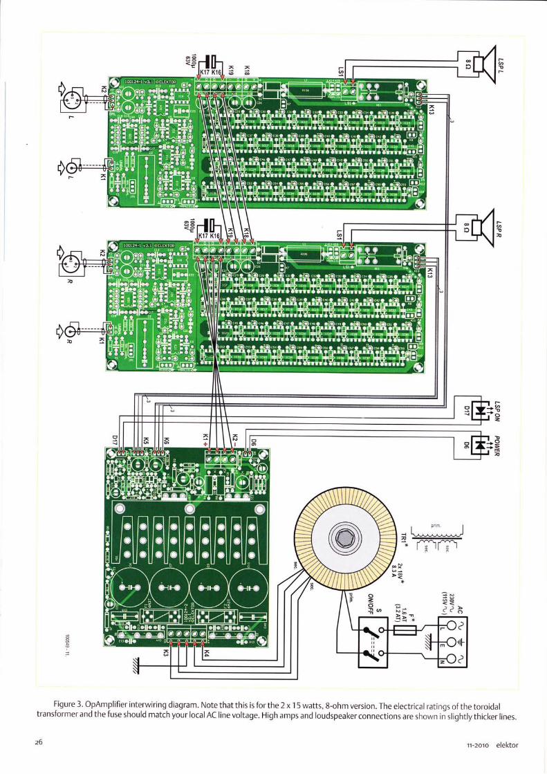
Figure 3. OpAmplifier interwiring diagram. Note that this is for the 2 x 15 watts, 8-ohm version. The electrical ratings of the toroidaltransformer and the fuse should match your local AC line voltage. High amps and loudspeaker connections are shown in"slightly thicker lines.
11-2oio elektor

It is an inherent property of the 5532 power amplifier that its output
current is limited by the internal overload protection of the opamps
used. This means that if more current is needed in the load, you
need to put more opamps in parallel. The basic design is intended to
drive 8 Ohm loudspeal<ers with a reasonable safety margin, but as it
stands it is definitely not recommended for 4 ohm operation.
To extend the 5532 amplifier for 4 ohm operation, it is necessary
to double the number of 5532 sections driving the output. This is
easier than it might sound because facilities are provided for adding
one or more power amplifier PCBs in parallel. The connector l(4 (see
circuit schematic published last month) is used as an output from
the main power amplifier PCB; it comes from the'zero-impedance'
stage lC3A, so the output is at a very low impedance (l measured
0.24 ohms at .1
kHz) but is immune to HF instability caused by cable
capacitance. Any desired length of cable can be used. The output
from l(4 drives an identical power amplifier PCB that has the all the
output opamps in place, but the redundant input amplifier circuitry
omitted. The equivalent connectoT l(4 on this PCB is used as an in-
put, and drives the output opamPs in exactly the same way as on the
main power amplifier PCB.
The connectors K1 4, K1 5 are used to connect toqether the outPuts
of the two amplifier PCBs. Note that this connection is made up-
stream ofthe output muting relay RE1, to preserve full protection
for the loudspeaker in case of a DC fault.
While this conversion for 4 ohm operation is relatively straightfor-
ward, it is essential to remember that the power supply require-
ments are doubled along with the current output. You will need to
consider a larger power transformer, more capable rectifiers, larger
reservoir capacitors, and increased supply regulator capacity. ln view
of these various requirements, this 4 ohm version is mentioned here
more as an option for the experimenter rather than a fully cut-and-
dried design.
case will depend on the number of ampli-fier boards used, as well as the associatedpower supply, see the insets on bridgedoperation and 4-ohm conversion. Allow forquite some heat developing in the amplifiercase, from the heatsinl< as well as from theNE5532s. Allthose milliwatts add up!
Everything ahead of the bridge rectifierAC terminals should be built, secured and
wired with the high currents and voltagesalways in mind. lf possible, do not extendthe transformer wires. The amplifier inter-wiring diagram for the 8 ohm 2 x 15 watts
Figure 4. The OpAmplifier was duly 'grilled' on our AP System 2 analyser'
Craph (a): THD & noise vs. output power. Craph (b): distortion vs. output power (1 kHz, BW :22KHz).
Craph (c): FFT graph for 1 kHz, 1 watt, 8 ohms.
to assist cooling. The LTl 083CP devices are
secured to the heatsinl< with a heat con-ducting washer inserted. Two holes have
to be drilled for the M3 bolts and nuts thathold the regulators firmly on the heatsink.First, determine the location of the holes forthe regulators; then secure the heatsink tothe board. The regulator terminals shouldbe 'kinked outward' slightly for thermalrelief. The two LT1 083 regulators should be
mounted, secured and soldered last.
Figure 2 shows the PSU board in a "travel &
demo" version of the amplifier. PCB stand-
elektor rr-zoro
offs are used as with the amplifier board.The PSU can be tested (carefully) by tem-porarily connecting the secondaries of thetoroidal transformer to the AC input termi-nals and checking for the correct outputvoltage of 18.0 VDC 10.7 V on each rail.
The OpAmplifier should be built into in a
metal case observing all relevant precau-
tions in respect of electrical safety, spe-cifically with respect to earthing and theuse of wiring carrying the AC grid voltage(230 V or 1 1 5 V). The size and shape ofthe

Two power amplifiers are bridged when they are driven with anti-phase signals and the load connected between their outputs; theload is not connected to ground in anyway. This method of workingdoubles the signalvoltage across the load, which in theory at least
quadruples the output power. lt is a convenient and inexpensive way
to turn a stereo amplifier into a more powerful mono amplifier. Mostconventional power amplifiers do not give anything close to powerquadrupling- in reality the increase in available power will be consid-erably less, due to the power supply sagging and extra voltage losses
in the two output stages, which are effectively in series. ln mostcases you will get something lil<e three times the power rather thanfour times, and it may be less. I have come across many power am-plifiers where the bridged mode only gave twice the output power,
and it has to be said that in many cases the bridged mode lool<s lil<e
something of an afterthought.
The 5532 power amplifier will give better results than that for tworeasons - firstly the power supply rails are regulated, and will notdroop significantly under heavy loading. Secondly, the parallel struc-
ture minimises voltage losses; for example, allthe 1 ohm outputcombining resistors are in parallel and their effective resistance is
therefore very small.
Bridged mode is so called because if you draw the four output tran-sistors of a conventional amplifier with the load connected betweenthenr, as in Figure A, it looks something like the four arms of a
Wheatstone bridge.
ln the drawinq, the B ohm load has been divided into two 4 ohmhalves, to emphasise that the voltage at their centre is zero, and so
as far as current output is concerned, both amplifiers are effectivelydriving 4 Ohms loads to ground. The current capability required is
therefore doubled, with all that that implies for increased losses in
the output stages. A unity-gain inverting stage is shown generat-ing the anti-phase signal; there are other ways to do it but this is themost straightforward and it simply adds one more 5532 section to a
design that already contains quite a few of them. The simple shunt-feedbacl< unity-gain stage shown does the job very nicely, and the5532 power amplifier incorporates a version of this circuit. The resis-
tors in the inverting stage need to be l<ept as low in value as possible
to reduce theirJohnson noise contribution, but not of course made
so low that the opamp distortion is increased by driving them. The
capacitor C1 across the feedbacl< resistor R2 assures HF stability -with the circuitvalues shown it qives a roll-off that is -3 dB at 5 MHz,
so it does not in any way imbalance the audio frequency response ofthe two amplifiers.
You sometimes see the glib statement that bridging always reduces
the distortion seen across the load because the push-pull actioncauses cancellation ofthe distortion products. lt is not true. Push-
pull systems can cancel even-order distortion products; odd-orderharmonics will not be cancelled.
The 5532 power amplifier has facilities for bridging built in. The last
stage in the input amplifier is the inverting stage around lC3A, whichis needed to get the phase between amplifier input and output cor-
rect. lf we take the signal off from before this stage, then it is invert-ed with respect to the amplifier output and can so be used to driveanother power amplifier board in anti-plrase; ihis PCB can be builtwith the input amplifier circuitrv omitted, as for the 4 ohm conver-
sion described above. This inverted signal is available at connectorl(3. The loudspeaker is connected betr.,,een the two output terminalson the amplifier PCBs and the output ground ierminals are not used.
As explained above, driving an 8 ohm load v,,ith trvo bridqed power
amplifiers means that each amplifier is effectivelV driving a 4 ohmload to ground, so to take full advantage of the bridging capabilityrequires the output stages to be doubled up. so that there are twopower amplifier PCBs in parallel driving in-phase, and two power am-plifier PCBs in parallel driving in anti-phase. This is of course quite a
serious undertaking, as the number of output opamps has been dou-bled for bridging, and then doubled again to give adequate outputcurrent capability. The power supply capabilitv rvill also need to be
suitably increased.
stereo version of the amplifier is shown inFigure 3. The rating of the AC power fuseshould match the line voltage in your area(1 15 V/60 Hz or 230 V/50 Hz). Whichever,an approved IEC style appliance socketwithintegral fuseholder and double-pole rockerswitch must be used.We should emphasise that the 8.3-amptoroidal transformer indicated in the
z8
drawing is advised for the 2 x 1 5 watt,8-ohm version of the OpAmplifier. Amuch beefier transformer is required ifyou decide to build a 4-ohm or bridgedversion of the amplifier. As with nearlyall audio power amplifiers, it's essentialto have a good deal of spare capacity inthe 'amps department' so do not skimpon the transformer.
The basic concept behind the 5532 poweramplifier is to create an amplifier which has
the very low distortion of the 5532 opamp.Preserving this performance when largecurrents are flowing to and fro on a cir-cuit board is something of a challenge andrequires very careful attention to ground-ing topology, supply-rail routing, and
11-201o elel<tor

Amplifier board (one channel)
Resistors
5%,0.25W, Farnell/Multicomp MCF series, un-less otherwise indicated.
R1,R14,R17=47f)R2 = 220koR3 = 47kOR4,R6 = 910f-1% 0.25W, Multicomp type
MF25 910RR5,R7,Rl0,Rl I,R.l 5,R16 = 2.2kOR8,R9,R32,R33 = 1 0c)R12=1kORl3 = 2.00kf) 1%0.25w, Multicomp type
MF25 2KRt8,R21 = 150kOR]9,R22=100clR20,R23 = 68koR24-R31 = 8200R34,R35 = 1oMOR36 = 1 00kOR37,R38,R71,R72 =22kO
decoupling arrangements. For this reason
it is strongly recommended that you use
the Elektor PCB design - better still, ready-made boards supplied by Elektor.
The completed prototype was measuredusing Elektor Labs'Audio Precision Sys-
tem Two Cascade Plus2722 Dual Domaintest-set, and Figures 4a,4b and 4c show
elektor n-zoro
R39-R70,R73-R104= 10R105 = 1OkO
R]06 = 10O 5% 3W, Tyco Electronics typeROX3SJl 0R
CapacitorsC1,C12,C14,C16-C19 = 100pn 2.5%, 160V,
polystyrene, axial (LCR Components)C2=2.21tF 5% 250V, polypropylene, Evox Rifa
type PHE426HF7220JR06L2C3,C4,C6,C8,C9 = 33pF t1 pF 160V, axial, poly-
styrene (LCR Components)C5,C7,C1 0,C1 5,C20,C23,C28-C59 = 1 00nF
10% 100V, lead pitch 7.5mm, Epcostype832s60J1 1 04K
C1 1,C13 = 471tF 20%35V non polarised, Mul-ticomp type NP35V476M8X1 1.5 (Farnell#1236671)
C21 =22nF'10%,400v,lead pitch 7.5mm, Ep-
cos type 832560J6223K (Farnell # 9752366)C22 = 11.tF,1 0%, 1 0V, lead pitch 7.5mm, Epcos
type 832560J1 i 05K (Farnell # 97523821C24-C27 = not fitted, see text
lnductorsLi = 1 .7prH; 10 turns 1 mm (1 8AWG) ECW,
the pleasing and impressive results. Fig-ure 4a shows the harmonic distortion and
noise as a function of signal frequency.Measurements carried out at 1 watt (red)
and 8 watts (blue) of output power within80 kHz bandwidth. The graph in Figure 4bshows distortion as a function of outputpower at 1 kHz and a bandwidth of 22kHz.From about 3 watts the amplifier actu-
diameter 20mm, effective length 20mm
SemiconductorsD1,D2 = I N5402D3 = 1 N4148lcl-lC5,lC7-1C38 = NE5532 (see text for notes
on device selection)lC6 = OP177 (Analog Devices)
MiscellaneousKl ,l(5-K1 2,Kl4,Ki 5 = 2-pin 5lL pinheader,
lead pitch 0.1 inchK2,K3,K4,Ki 3 = 3-pin SIL pinheader, lead pitch
0..1 inchKl6-K19,1S1 = 2-way PCB terminal block, lead
pitch 5mm
JP1 = 3-pin SIL pinheader and jumper, leadpitch 0.1 inch
REl = PCB mountrelay, PCB, DPCO,
24VDC| 1 1 00o/5A, Omron type G2R-2 24DC
Phono socket, chassis mount, black, Neutriktype NY5367-0
XLR socket, chassis mount, 3-way, Pro Signal
type PSG01 588PCB # 1 001 24-1, Elektor Shop, see www.
elektor.com/1 00549
ally gets close to the lower measurementthreshold and noise floor of our analyser!At 15 watts (roughly) the amplifier veers
off into clipping. The curve in Figure 4c,
finally, is an FFT plot for 1 kHz, 1 watt into8 ohms. The fundamental frequency is
suppressed. The second harmonic is waydown at -121 dB and the third harmonicslightly higher at -1 15 dB. At a bandwidth

Power supply board
Resistors5'/", 0.25W, Farnell/ M ulticom p MCF series, un-
less otherwise indicated.
Rl,R5 = 100fiR2,R6 = 1.3OkO 1% 0.25W, Multicomp MF25
1t(3R3,R7 = 39OR4,R8 = 1.5kO 5% 1W Multicomp MCF 1W
1K5R9,R1 1 ,R1 6,R20-R22 = 2.2koRl 0,Rl 2-R1 5,R19 = 47kAR17=150kOR1 8 = 470k0
CapacitorsC1 ,C3,C24= 47ytF 20%25Y,lead pitch 2.5mm,
Ru byco n type 257LC47 M6.3X7C2,C4 = 100p,F 20% 25V, lead pitch 2.5mm,
1.43A AC, Nichicon type UPM1E101MEDC5,C8 = 100nF 10% 100V, lead pitch 7.5mm,
Epcos type 832560J1 1 04KC6,C7,C9,C10 = 4700ptF 20%35V, lead pitch
10mm, snap in, Panasonictype ECOSlVP-4728A (25mm max. diameter)
Cl 1-Cl8 = 47nF 10% 50V ceramic, lead pitch5mm
Cl 9,C20 = 47nF 20%,630VDC X2, leadpitch 15mm, Vishay BCcomponents8FC233620473
C21 = 4.71tF 20% 63V, lead pitch 2.5mmC22,C23 = 22'pF 20%35V, non polar-
ised, lead pitch 2.5mm, MulticompNP35V226tvt6.3X1 1
SemiconductorsDl-D4,D7 = 1N4002D5,D8-D16 = 1N4.148D6,D17 = LED, green, 3mm
of 22 kHz, the total level of noise and har-monics is about 0.0005%. lf the distortion is
measured for the two strongest harmonicsonly, it is at a level of 0.0002%.
To the non-initiated, the OpAmplifier withits case closed may be just another high-endaudio amplifier albeit with quite impressivespecs relative to the investment. To the dis-cerning electronic engineer, it's a delight-ful and off-the beaten path approach to get-ting high-quality audio watts from a deadcommon component like the NE5532 you
3o
T1,T3,T4,T6 = BC33712,r5,T7 =8C327lCl ,lC2 = LT1 083 (Linear Technology)B1,82 = CSIBl 520 (1 5A/200V bridge rectifier)
(Vishay Ceneral Semiconductor)
MiscellaneousK1,K2,K4 = 2-way PCB terminal block, lead
pitch 5mml(3 = 3-way PCB terminal block, lead pitch
5mmD6,D17,S1 = 2-pin SIL pinheader, lead pitch
0.1 inchK5,K6 = 3-pin 5lL pinheader, lead pitch 0.1 inch
normally associate with nano-amperes andmicrovolts electronics-wise, and pennies inthe fi nancial department!
The proof of the pudding is in the eating.That's why a demo version of the OpAmpli-fier was cased up in a rugged suitcase foreasy transporting, pacl<aging and demoing.At the time of writing, it's about to leaveElektor House on a journey along severalaudiophiles and audio communities aroundthe world for listening tests. Theirfeedbackis awaited eagerly.
(tooSag)
F1,F2 = fuse, 6.3A antisurge (time lag), with20x5mm PCB mount fuseholder and cover
Heatsink, Fischer Elektronik type SK92i 75SA1.6 K'lV, size: 1O0x40mm, Farnell#4621518. Reichelt = V733 1 C
Miscellaneous, mechanicalM3 screu,s, nuts and washers for mountinq
lC1 and lC2 to heatsink (see text)TO-3P thermal pad. (Bergquist type K6-1 04)M4x10 scrervs for mounting heatsink to PCB
PCB # I 001 24-2, Elektaor Shop, seewww.elektor.comi 100549
11-2o1o elektor

It is an unsettling fact that not all 5532 opamps are created equal.
The design is made by a number of manufacturers, and there are
definite performance differences. While the noise characteristics ap-
pear to show little variation in my experience, the distortion perfor-
mance does appear to vary significantly from one manufacturer to
another. Although, to the best of my knowledge, allversions of the
5532 have the same internal circuitry, they are not necessarily made
from the same masl<s, and even if they were, there would inevitably
be process variations between manufacturers
Since the distortion performance of the amplifier is unusually, and
possibly uniquely, dependent on only one type of semiconductor, it
mal<es sense to use the best parts you can get. ln the course ofthedevelopment ofthis project 5532s from several sources were tested.
I tool< as wide a range of samples as I could, ranging from brand-new
devices to parts over twenty years old, and it was reassuring to find
that without exception, every part tested gave the good linearity we
expect from a 5532. The information here will be of use not only in
the 5532 power amplifier project, but should prove very valuable foianyone using 5532s in high-quality applications.
The main sources at present are Texas lnstruments, Fairchild Semi-
conductor, ON Semicondr-rctor, (was Motorola) NJR, (NewJapan
Radio) and jRC (Japan Radio Company). Tl, ON Semi and Fairchild
samples were compared in the Elel<tor labs by Ton Ciesberts. The au-
thor for his part did THD tests on six samples from Fairchild, JRC, and
Texas, plus one old Signetics 5532 for historical interest. Tlre Elel<tor
lab tests were carried out on an actual and very crucial section ofthe
OpAmplifier design: the driver section! See Figure A for the circuit
and Figure B for the AP2 plots.
As it turned out, the Texas 5532s (green line) proved to be distinctly
inferior, both in the Elel<tor Labs and in the author's tests. We have
to admit this surprised us, as we have always thought that the Texas
part was one of the best available, but the measurements say other-
wise. Distortion at 20 kHz ranges from 0.001% to 0.002%, showing
more variation than Fairchild and ON Semi as well as being higher in
general level. The low-frequency sectiot.t of the plot, below 10 kHz, is
approaching the measurement floor, as for all the other devices, and
distortion is only just visible in the noise.
Compared with other malcer's parts, the THD above 20 l<Hz is much
higher- and at least 3 times greater at 30 kHz. Fortunately this
should have no effect unless you have very high levels of ultrason-
ic signals that could cause intermodulation. lf you have, then you
have bigger problems on your hands than picking the best opamp
ma n ufactu rer...
The graphs show undisputedly that the Fairchild 5532s (blue line)
are top of the bill and true ar-rdio purists should select these devices
even if they come at a slightly higher price as well as being awkward
in terms of type code print on the device. Checl< with your supplier, it
should be worth your while. There is effectively no distortion visible
above the noise floor up to about 12k1z, and distortion at 20 kHz is
less than 0.00057;.
A
201
0,002
0,001
0.0008
0,0006
0,0005
0.000{
0.0003
31elektor 11-2o1o

SPEED MEASUREMENT
Sensorless Motor SpeedMeasurement
By Ernesto VSzquez Sdnchez and Jaime G6mez Cil (Spain)
A characteristic property of DC motors is that they can also act as generators, due to the complementarynature of Faraday's and Lenz's laws of magnetic induction. Thanks to this relationship, it is possible todevise a technique that measures the speed of a DC motor by monitoring the current drawn by the motor.ln this article we describe a method of this sort, which can be used in a wide variety of applications.
Figure 1 . Supply current waveform of a DC motor. Figure 2. Wiring diagram of the various components.
Technological progress and the automation of all sorts of tasl<s ln many applications of DC motors, the motor speed (rpm) must bethat were formerly performed manually has led to a dramatic controlled by a closed-loop system, which means that it is necessaryincrease in the use of motors in various applications. For exam- to measure how fast the motor is turning. Transducers and sensorsple, the simple task of manuallyopening or closing a car win-dow, formerly performed man-ually with a crank mechanism,is now performed by pressing a
button, which causes a motorto raise or lower the window.DC motors of this sort (andtheir relatives, such as step-per motors, servo motors andbrushless DC motors) are pri-marily used in situations werepositioning speed and posi-
such as tachometers, encodersand Hall-effect devices are com-monly used for this purpose.They are fitted on or near themotor shaft, preferably closeto the load. These componentsincrease the risk of malfunc-tions, as well as the overall costof the system.
As an alternative to sensors andtransducers ofthis sort, here wedescribe a method for measur-
tioning accuracy are the main considerations, rather than effi- ing the motor speed that operates solely on the basis of the currentciency or power consumption. Their popularity is partly due to drawn by the DC motor. This method is based on the electromo-fact that it is easy to drive a DC motor. tive force (EMF) generated in the motor windings. As you know,
Resistance (R")
Back EMF constant (c) 0.0178 V/rpn
32 11-201o elektor

the EMF induced in a coil rotating in the magnetic field of a motorhas a sinusoidal waveform. This signal is rectified by the commuta-tor on the rotor. After it is rectified, a small ripple voltage remains'
The amplitude of this ripple voltage is proportional to the number
of windings in the motor. This ripple voltage is an AC voltage whose
frequency is directly proportional to the speed of the DC motor as
indicated by equation (1), where f is the frequency of the AC volt-age (this is called the ripple frequency), p is the number of pole pairs
in the DC motor, k4 is the number of commutator segments on therotor, n is the speed of the motor in rpm, and 11 is the greatest com-
mon denominator of 2p and k.
f= 2pkan
60rl
Figure 1 shows an example of the current measured at the terminals
of a DC motor. Here you can see that the current consists of a DC
component with a value of approximately 0.3 A and an AC compo-nent with a peak-to-peak amplitude of 0.1 A.
SPEED MEASUREMENT
Figure 3.The system hardware.
System hardwareFigure 2 shows the schematic diagram of our system hardware. ltincludes a DC motor, in this case a type EMC30, whose specifica-tions are listed in Table 1. The current is sensed by a 20 mC) sense
resistor. The voltage across this resistor is measured by an inexpen-sive data acquisition card (Nl USB-6008), which has a maximumsampling rate of 10 kHz. This card has four differential analogueinputs, which can be configured to have a measuring range fromt1 V to t20 V. One of these inputs is used here to sample the motorcurrent by means of the sense resistor.
The data acquisition card is connected to a PC, which processes thesampled signal and determines the speed of the DC motor. The PC is
a laptop modelwith an lntelT8300 CPU,3 CB of RAM and a 320-CB
hard disk. The operating system is Windows Vista, and the develop-
ment environment is LabVlEW 8.5. Figure 3 shows a photo of thehardware used in the system.
Measurement algorithmNow let's look at the algorithm we used to determine the motorspeed. Figure 4 depicts the method in block diagram form' lt con-
sists of three blocks: a ripple detector, a frequency meter, and a con-
tll
detected?
Imaximum I lr"t
..Nvy
change
rising edgedetector
+ lavg
mtntmumlmin
2090198 - 13
elektor rr-zoto
Figure 4. Block diagram of the motor speed detection method.
JJ

SPEED MEASUREMENT
Figure 5. Block diagram of the ripple detector.
verter. The ripple detector ensures that all variations in the motorcurrent waveform are detected. The frequency meter calculatesthe period of each waveform cycle, thereby determining the fre-quency of the AC component. Finally, the converter translates thisfrequency into the speed ofthe motor.
Ripple detectorThis function of this block is to detect the starting point of everywaveform cycle of the AC component of the motor current. Figure 5shows the block diagram of the ripple detector. The signal from thesense resistor is fed to a maximum peak detector and a minimumpeal< detector, which determine the minimum and maximum sig-nal levels. The threshold level ofthe peak detectors is successivelyreduced at regular intervals. As a result, the detector circuit can
adapt quickly and dynamically to the actual minimum and maxi-mum signallevels.After detection, the average value of the minimum and maximumvalues (luun) is calculated. This value is then compared to the totalcurrent by a comparatol which operates with hysteresis to suppressthe effects of small noise signals. The square-wave gutput signalfrom the comparator is fed to an edge detector. The logical outputof the edge detector is 'True' if the sampled signal is high and thepreviously sampled signal was low.Here we should also mention that the system processes each sam-ple in turn and the processing takes place in real time. This meansthat when the output of the edge detector is 'True', the crossoverpoint of the signal has already occurred at the time when the signalwas sampled.
Frequency meterThis block calculates the motor speed based on the signal crossovertimes. The flow chart is shown in Figure 6. First it checks whethera level change has occurred. lf nothing has changed, no action istaken. Otherwise, when a level change has occurred, the time whenthe change occurred is added to the list of crossover points 1L*7,
where k is the number of detected crossover times.After this, the ripple frequency is calculated using an approximationformula (2), where N is the number of crossover points for whichthe average value must be calculated as indicated in equation (3),
fL is the ripple frequency determined for the most recently detectedcrossover, fr*r is the ripple frequency currently being calculated, andIo is the length of time over which the average value is calculated.The operation [.] determines the integer value. This method yieldsa noise-free motor speed measurement, and it tracks changes in themotor speed well if the value of Io is chosen properly. Finally, thenumber of detected crossover points k is incremented by 1 .
t.l k+l = N-l
Lro*r-, -Tr,-il=0
ConverterThis block is responsible for deriving the DC motor speed in rpmfrom the ripple frequency determined by the previous block. Equa-
tion (1 ) is used for this purpose.
Testing and resultsTo see whether the described method for the determining themotor speed works properly, we performed a variety of tests. Firstwe determined the mean error and the deviation of the error withthe motor running at a constant speed. Next we measured theerror and the lag with the motor speed changing linearly (constantacceleration). Finally, we made step changes in the motor speed
N
N =lro fol
l2l
t3l
34
Figure 6. Flow chart of the frequency meter.
11-2o1o elektor

SPEED MEASUREMENT
0.8 1 1.2 1.4 1.6 1.8 2
t (s) oeores.l1
Figure 8. Step change in motor speed with an EMC30 motor.
to measure the speeds of several motors, which is not possible withconventional methods.
(oso1e8-r)
2800
eg 2600
0.40.2
Figure 7. Linear speed change with an EMC30 motor.
and measured how long it took for the new speed to be indicated.The results at various speeds are summarised in Table 2. Figure 7
shows the performance with linearly changing motor speed. The
mean error in tracking the motor speed was 17.39 rpm in this situ-ation, with a deviation of 8.90 rpm. The time lag for tracking themotor speed was 0.2 s, which is negligible for many applications.The error that occurred with a step change in the motor speed can
be seen in Figure 8. The time required for the indicated speed toreach the actual speed was 0.4 s.
Conclusionsln this article, we have described a method for determining the speed(rpm) of DC motors by observing only the motor current. Although themethod described here is based on a system incorporating a computer,
this does not mean that it cannot be implemented in otherways. The
ripple detectorcould also be constructed using opamps, and the othertwo blocks could be implemented with an inexpensive microcontroller,
orwith the microcontroller used to control the motor.Various tests were performed after the system was put together.The measured performance of the system is good enough for use in
a large number of applications. This method has several advantages:
it is not necessary to fit any objects on the motor shaft, the risk ofmalfunctions is lower, and the cost of the total system is lower.We can therefore conclude that this method fornis a good alterna-tive for measuring the speed of a DC motor under normal condi-tions. Multiplexing techniques could also be used with this method
l
Actual speed(rpm)
Mean errortrpm)
Deviation(rpm)
500 676.1 B 157.82
tll 1 17.60 73.47
1 023 1.86 7.91
1242 0.74 3.74
1 516 0.23 s.08
201 5 0.1 I 4.86
2514 0.30 5.7 5
3021 r.28 5.97
3502 1.96 t lc
4037 0.06 4.36
4492 0.50 L) I
5000 0.51 q.6q
55i I 1.21 i 1.94
Jaime G6mez-Gil was born in 1 971 in Aguilar de Bureba, Spain. He studied at the University of Valladolid, where he received a degree in
telecommunication engineering in 2000 and was subsequently awarded a PhD degree in 2005. He has been employed there since 2001 as a
lecturer in signal and communication theory and telecommunication engineering. His research areas are communication, CP5 applications
for agricultural use, sensorless technology for motors, artificialvision and augmented reality.
Ernesto V6zquez-Siinchez was born in 1 985 in Plasencia, Spain. He studied at the University of Valladolid, where he received a degree in
telecommunication engineering in 2008 and a degree in electrical engineering in 2010. He is currently working on his doctoral thesis. He
has been employed in the Department of Signal and Communication Theory of the University of Valladolid since 2009, with a stlrdy con-
tract as a recently qraduated staff researcher. His interests and research encompass communication and sensorless technology for motors
elektor rr-zoro

READER'S CIRCUITS
Wireless I nstrumentation Network
By Johan van den Brande (Belgium) ([email protected])'ru***
ln this article we describe how to put
together a wireless instrumentation
networl< with the Arduino platform and
MaxStream XBee modules. The networl<
uses an EtherShield module to automatically
mal<e measurement data accessible via the
I nternet.
It's not difficult to construct a wireless instrumentation networkwith the Arduino platform. Here we use two stations to form thenetwork (see Figure 1). The first station is the node, which takesreadings from the sensors and sends the results to the second sta-tion, which is the gateway. The node consists of an Arduino nodulewith an XBee shield module. The gateway also consists of these twomodules, plus an EtherShield module for communication with thelnternet. The resulting measurement data can be retrieved fromthe Pachube website [t].
ArduinoArduino is an open-source microcontroller platform with a user-friendly development environment, based on an 8-bit Atmel AVR
microcontroller. lt is used primarily by hobbyists and artists tocreate interactive projects. The Arduino platform has a low entrythreshold. You don't need to know how to program in assembly lan-guage or write your own boot loader. The programming languageyou use is a lot lil<e C, but all of the difficult tasks such as initialisingthe microcontroller and communication with a PC are already takencare of. The Arduino development environment is based on a pro-gram called Processing, which is used by graphic artists to createvisual masterpieces. lt includes a handy library with lots of routinesto help you achieve useful results quickly.The Arduino module has several digital ports and analogue inputs.The analogue inputs utilise the A/D converter of the AVR microcon-troller. Some of the outputs can be driven in pulse width modulation(PWM) mode. lf you add a small RC filter, the result is a nice ana-logue signal. The basic functionality can be extended with modulescalled shields, which can be plugged onto headers on the Arduinomodule. Shields are available for all sorts of applications, such as
video and audio, joysticks, MP3 and so on.A program forthe Arduino module is called a sketch, and it includesa setup routine and a loop routine. ln the setup routine, the portsare defined as inputs or outputs and the serial port is initialised.
Reoders Circuits contoin contributions from Elektor reoders for experimentol purposes ond further development by others.The circuit(s) presented on these plges hove not been tested for reproducibility or octuol use in the Elektor Lob.
36
Serial commu-nication is animportantpart of Arduinosketches. Mostperipheral devices usethis to communicate withthe PC. The loop routine containsthe actual program, which controls read-ing data or a signal from individual inputs,responding to the input signals, and driving the outputs.
XBeeXBee modules are a convenient way to add wireless communicationto a design. The modules from MaxStream are an implementation ofthe ZigBee technology developed by the ZigBee Alliance, a nonprofitconsortium of chip makers, technology providers, OEMs and endusers. ZigBee technology is intended to facilitate the creation of inex-pensive, low-powerwireless sensor networks. The modules transmitdata at rates up to 250 kbps over a range of 30 to 1 00 m, dependingon the version (1 mW or 10 mW) and the ambient conditions.The modules can be used to replace a serial communication cable,but they can also be controlled through the Application Program-ming lnterface (APl) mode to form a more complex wireless net-worl<. The modules are configured using AT commands. For serialline emulation, it is important that both modules are configured withthe same networl< lD and the same channel (CH). By default, the MYparameter (the 16-bit module address), the DL parameter and theDH parameter are set to '0'. This means that both modules can iden-tify each other. The DL and DH parameters specify the destinationaddress (DL = lower 16 bits, DH = upper 1 6 bits). They determine thereception options. These parameters may be configured in variousways. lf DH is '0' and DL is less than 'OxFFFF', every module whoseMY parameter matches the value of DL receives data from the trans-
11-2o1o elektor

mitting module. lf DH is '0' and DL is 'OxFFFF', every module receivesthe data transmitted by this module. lf DH is not'0' and DL is greaterthan '0xFFFF', data is received only by modules whose serial numbermatches the destination address of the transmitting module (SH ofthe receiving module = DH of the transmitting module and SL of thereceiving module = DL of the transmitting module).
Extension shieldsln this project we use a ready-made shield called EtherShield, whichprovides lnternet access capability for the Arduino module. lt has anRJ45 connectorand can be linked to a router ora switch by a UTp cable.A separate software library is available forthe EtherShield module.It's usually possible to stack several Arduino shields on top of eachother, as long as there aren't any conflicts between the inputs andoutputs that are used. Although a standard XBee shield is availablefor the Arduino module, it poses a problem here because it can-not be stacked with the EtherShield module. For this reason, wedeveloped a shield that can accept an XBee module and can also beplugged on top of the Ether5hield module.The design of our shield module is reasonably straightforward (seeFigure 2). We included the voltage regulator because the pro ver-sion of the XBee module can draw up to 100 mA, which is too muchfor the integrated regulator of the Arduino module. The XBee mod-ule also requires a 3.3-V supply voltage.The XBee module communicates with the Arduino module viapins 1 (RX) and 2 (TX). The Arduino module also uses these pins forserial communication with the PC. As we want to be able to pro-gram the Arduino module with the XBee shield fitted, we inserteda pair of switches in the communication path. The Arduino modulenormally communicates with TTl-level signals on pins I and 2, so a
voltage divider reduces the level of the input signal on the XBee RXpin to 3 V. Level adjustment is not necessary in the other direction,since the Arduino sees 3.3 V as a high level.The PCB layout has been kept simple, and all of the components(except the pushbutton) are leaded types. The Eagle and pDF filesof the PCB layout are included in the download file for this article [zl.
Sensor optionsWe use the analogue inputs of the Arduino module in this project,which means we can use simple sensors, such as an LDR to measurelight intensity. Another interesting application is measuring rela-tive humidity. You can mal<e a simple sensor for this by embeddingtwo nails about half a centimetre apart in plaster of Paris inside a
length of plastic pipe. Connect one ofthe nails to +5 V and the otherto an analogue input pin and to ground via a
.l 0-ke resistor (see
Figure 3).A lot of other quantities can be measured using the digital inputs.The number of ports can be expanded with an lzC bus device, suchas the Texas lnstruments PCA9535.
Alltogether nowAs already mentioned, our system consists of two stations: thenode formed by the Arduino and XBee shield modules (Fig-ure 4) and the gateway formed by the Arduino, XBee shield and
elektor rr-zoro
READER'S CIRCUITS
Figure 1 . The instrumentation networl< consists of a node, agateway and a data platform at www.pachube.com.
Arduinoshield
RXOitG02003Gilq05qSG07G
me@qD10q011 G012 G013q
BfuSA
oo
our'A ...-u"o,I l<o*, IL-]<." :
Io"*l
i o".re I
1u r{ iEsfi;lal ii, nesa I i
Figure 2. The schematic diagram of our Arduino shield is
reasona bly stra ig htforwa rd.
Vcc
--:*jo*oroo,,il
Figure 3. A simple humidity sensor can be made by embeddingtwo nails in plaster of Paris inside a length of plastic pipe.
XBee
Arduino
GNO \N()
Sensor
)1

READER'S CIRCUITS
ln the last while there's been a lot of activity related to the 'lnternet
ofThings', which means connecting everyday objects to the lnternet.
Sensor data platforms such as the Pachube website are a good exam-ple of this. On this site you can store and retrieve sensor data for pur-
poses such as displaying a chart or maintaining a log. Another poten-
tial application is monitoring sensor values and performing a suitable
action if they exceed a deflned level, such as sending an e-mail or textmessage. Pachube is a publicly accessible site with a simple protocol
for sending data to the site. You can assign geographic coordinates toyour sensors, which are then shown on a map of the world. The data
can be viewed in the form ofcharts, and you can also grant other peo-
ple access to your data. lnstead of sending data directly to other par-
ties, you can publish it once on the Pachube site, where other parties
can subscribe to receive your data stream.
After registering on the Pachube site, you have to create a feed. You
should click'Manual update'when you configure your feed, since this
allows the microcontroller to determine when to publish new data.
With the other option, 'Automatic', the Pachube site actively sends
Web request commands to fetch the data. To mal<e this possible, you
would have to embed a web server in the microcontroller and config-
ure your networl< to allow access to the microcontroller from the Inter-
net. After you create your feed, you are assigned an API key.
The microcontroller uses the HTTP protocol for manual updating. This
is a very simple text-based protocol that supports the usual tasl< ofretrieving data (CET command), as well as sending data (PUT com-
mand), modifying data (POST command), and deleting data (DELETE
command).
An HTTP request consists ofa header and a body, separated by a blank
line. The first header line contains the protocol version, the command
type (CET, POST, PUT or DELETE) and the resource, which is wherethe command is supposed to do its worl<. lt may be followed by otherheader lines that supply various parameters to the web server, such as
the type of content your client is able to process. A header line consists
of a name and value. For the application described in this article, theAPI key belonging to the feed is placed in a header line.
The header is followed by the data. The following is an example of a
PUT request to the Pachube website:
PUT /v2lfeeds/ENTER_FEED_l D_H ERE.csv HTTP/ 1 . 1
Host: api.pachube.com
X-Pachu beApiKey: ENTER_YOUR_PACHUBE_APl_l(EY_H ERE
Content-Length: 1 0
Connection: close
0,1 00
1,244
The HTTP protocol is easy to implement in a sketch (an HTTP-based
protocol of this sort is called a REST API). lt is even possible to test theadaptation of the feed from the console, for example with the curl
command:
curl --request PUT --heoder "X-PochubeApiKey: YOIJR ,API_KEY" -doto" 0, 1 00 " " http: I I www. po ch u be. com I o pi I f ee d s I YOU R _F EED _l D. csv"
The cur/ function is available in the standard OS X installation and can
easily be installed under Linux. Windows users can download it fromhttp://cu rl.haxx.se/download. htm l.
EtherShield modules (Figure 5). Plug the EtherShield module ontothe Arduino gateway module first, and then plug the XBee shieldmodule on top so its pins and switches are readily accessible. Setboth switches in the USB position when you want to program theArduino module, and set them to the XBee position when youwant to transmit or receive data with the XBee module. lf you onlywant to receive data from the XBee module, set the RX switchto the XBee position and the TX switch to the USB position. Thisallows you to display IDE debug information on the serial port con-sole of the Arduino module. lt may be convenient to fit the boardwith headers with jumpers instead of switches so you can open theTX signal path between the Arduino and XBee modules, which is
handy for debugging.XBee modules must be properly configured in order to communi-cate with each other. They are supplied with a factory default con-figuration for operation in serial line emulation mode. You can con-figure them by using the terminal emulator utility in a Windows,Minicom or Linux environment to send them Hayes AT commands,or by using the X-CTU software supplied by MaxStream t:l. This doesnot require any special hardware. Set both switches to the USB posi-tion and unplug the AVR microcontrollerfrom the Arduino module.Now you can use the USB link to communicate with the XBee mod-ule via the PC.
:8
FirmwareThis brings us to the firmware, or as it is called, the sl<etches. Thesketch that runs in the node (see the program code in the downloadpacl<age [2]) is the simplest. Briefly, it waits for a certain time, tal<es
a snapshot of the analogue inputs, and sends it via a serial link to theXBee module. The following description is based on the programlisting with line numbers provided in a separate document.
The time interval for reading and forwarding the measurement datais specified in line 10. Here it is set to 5 seconds, which is the short-est allowable interval for sending data to Pachube with a non-pro-fessional account. Line 1 1 assigns a unique name to the node. Thisname is not used at present, but you could use it in the gateway todistinguish between different nodes. ln the setup routine, the trans-mission rate is set to 9600 baud in line 42 (the standard value for theXBee modules). Furthermore, serial communication is configured to8 bits, no parity and 1 stop bit without any additional parameters.The /oop routine is fairly simple. lt calls the intervalPossed routine,which determines whether the configured interval (5 seconds) has
expired. lf it has, the meosure routine is called. First we send thename of the node to the XBee module (lines 29 and 30), followedby a colon (:). The for loop in lines 32-35 polls all of the analogueports and sends their values to the XBee module (line 32). Line 34
11-2o1o elel<tor

inserts a comma after each analogue value (except the last one)to separate the values. Line 37 finishes off with a new line.The ske-tch for the gateway is more complex because it alsolooks after the lnternet linl< to the pachube website (see inset'The lnternet of Things,). The gateway waits until a full line hasbeen received from the serial link ,nd th"n sends the nameof the measurement method and the sensor values to thePachube site.
Before using this sketch, you must edit it to have the rightparameter values for your pachube account and networl<. lnline 1 3, enterthe lD ofthe feed you have created, and in line
.l4,enter your API key (from My profile > Settings at [1 ]).connect the gateway to a router or switch so it ian access the
Figure 4. The node for reading the sensors consists of anArduino module and an XBee shield.
lnternet directly. Configure the network parameters in lines l6to 1 8 by putting the MAC of the Ethershield module in line
.16
and its lP address in line I7. A MAC address identifies a specificdevice in an Ethernet network. you can use nearly any value youwant for the MAC as long as it does not cause a conflict withother devices connected to the router or switch. Choose anunused lP address in the address space of your local area net_work and enter it in line 'l 7. Here yo, ,rrt replace the dotsin the lP address with commas, since the code in lines 16_1gd5fi5s g set of arrays. The lp address of the pachube site is spec_ified in line 18. ln more elaborate software you could use theDomain Name Service (DNS), which translates domain namesinto lP addresses, but the approach used here is adequate forour purposes.
Line 20 allows you to set a debug flag that activates the _[06macro in line 23. This macro first reserves 256 bytes on the stack
elektor rr-zoro
glt CO-=z/
!. r. t-" !";,--; r*, &.illt:,t,: toa\:r:
BANDWIDTHir r ',,. ', t i I -, r";.r i ., i..t I i.t.
SAMPLING RATES
MEMORY'.' ; ,
RESOLUTION
Latest Software Updates: l2C & CAN bus decoding,mask limit testing, advanced triggers,
digital low pass filtering, rapid triggering
lq
39

READER'S CIRCUITS
Figure 5. The gateway, with an adapter board that allows the XBeeshield to be used together with an EtherShield module.
as a C string in the m variable. This is followed by a formatted printcommand (snprinf) for this string. Like the pnnrf (and snprinff) func-tion, this macro can receive a variable number of parameters. Thisis indicated to the compiler by the ellipsis (...) in the macro defini-tion. The construction ##_VA_ARCS_ expands this variable num-ber of parameters in code that calls snpnntf. lf you disable the debugfunction by commenting out line 20, the _lOG macro is expandedto nothing (line 25).Lines 27 and 28 link in the Ethernet library. This library is necessaryfor using the EtherShield module. The string library (line 29) is nec-essa ry for snp ri ntf and strncot, a mo n g other thi n gs.Line 30 specifies that six sensors will be read, and lines 31 -34 definethe sensor structure. The data received from the remote sensor is
transformed to this structure. Line 35 creates an EtherShield clientobject: the TCP client, which establishes a connection to seryer onport 80 at the Pachube lP address.
The core of the sketch is the /oop function in lines 103-1 12, whichruns reiteratively. Lines
.l 05 and 'l 06 define a character buffer (buf)
for the data read from the remote node. The data is read in by call-ing the function reodRemoteSensors (line 109). After a full line hasbeen received, it is analysed in line 110. The porse function con-verts the data to the sensor structure.The pochbubePostfunction inline 1
.1 1 sends the converted data to the Pachube site.
The reodRemote5ensorfunction defined in lines 85-97 reads datafrom the serial port and places it in the buffer (bufl until the 'newline' character \n is received or the buffer is full (while loop atline 90). Line 91 checks for new data on the serial input. lf new datais present, it is read in line 92 and placed in the buffer, and the bufferpointer i is shifted one position to the right. When all the data forthe buffer has been read, the routine sets the current buffer loca-tion to '0'and exits.The porse function in lines 67-84 uses the strtok function to analysethe data in the buf variable. lt split the string each time it encountersany of the characters defined in the sep (separator) variable, whichin this case are the colon (:) and comma (,) characters. The strtok
4o
function returns the next token or character each time it is called.As a result, when the for loop in lines 78-82 has completed execu-tion, the full line has been analysed and the corresponding sensorvalues are located in the sensor structure. The otoi function convertsan ASC|l number to an integer value.
The connection to the Pachube site is established by the poch ubepostfunction (line 36). lt receives the sensor structure as an input parame-ter. The name is not used, but you could use it to select a different feed.Lines 42-46 convert the sensor values into comma-separated values.The format consists of the sequential number of the sensor and thevalue, separated by a comma. Each sensor is on a separate line.Lines 49-61 handle the actual data transfer between the gate-way and the Pachube site. Line 49 establishes a connection to thePachube site at the TCP level. Once this connection is available,the print and prinfln functions can send data to the pachube site.Line 52 outputs a PUT command to Pachube, along with the feedname (FEED_ID). The data is sent as a CSV file, which is why the keyhas the.csyextension. The HTTP 1.1 protocol is used forthis. Sev-eral header lines are sent as well. Line 53 sends the hosf header line,which indicates that the data is intended for the pachube.com host.This construction allows more than one domain to be hosted froma single lP address. Line 54 sends the API key. pachube uses thisunique key instead of a user name and password. Line 59 terminatesthe header with a blank line, after which the sensor data is sent byline 60. The data length must be the same as the value stated inthe Content-lengfh header. After this operation, the feed has beensupplied with new data and the current values and history can beretrieved from the Pachube website.
Finalremarl<sIt's easy to put together a wireless instrumentation network withMaxStream XBee modules linked to Arduino modules. Serial lineemulation allows data to be sent and received relatively easily.An EtherShield module handles the connection to the lnternet.Although it is possible to use more then one sensor node, you haveto watch out for interference when two nodes send data at the sametime. lt's therefore better to switch to API operation and configurea mesh network or star network. This requires considerably morecomplex software, although the hardware remains the same.
(o9ro9z-l)
lnternet linl<s
[1] www.pachube.com
[2] www.elektor.com/091092
[3] www.digi.com/support/l<base/kbaseresultdetl.jsp?kb: 1 25
[4] www.arduino.cc/en/Main/ArduinoXbeeShield
[5] www.ladyada.net/make/xbee/arduino.html
[6] www.faIudi.com/projects/comrnon-xbee-mistal<es
[7] www.adafruit.com/index.
ph p?mai n_page=prod uct_info&cPath :29&prod ucts_id =.l 26
r.r-201o elektor
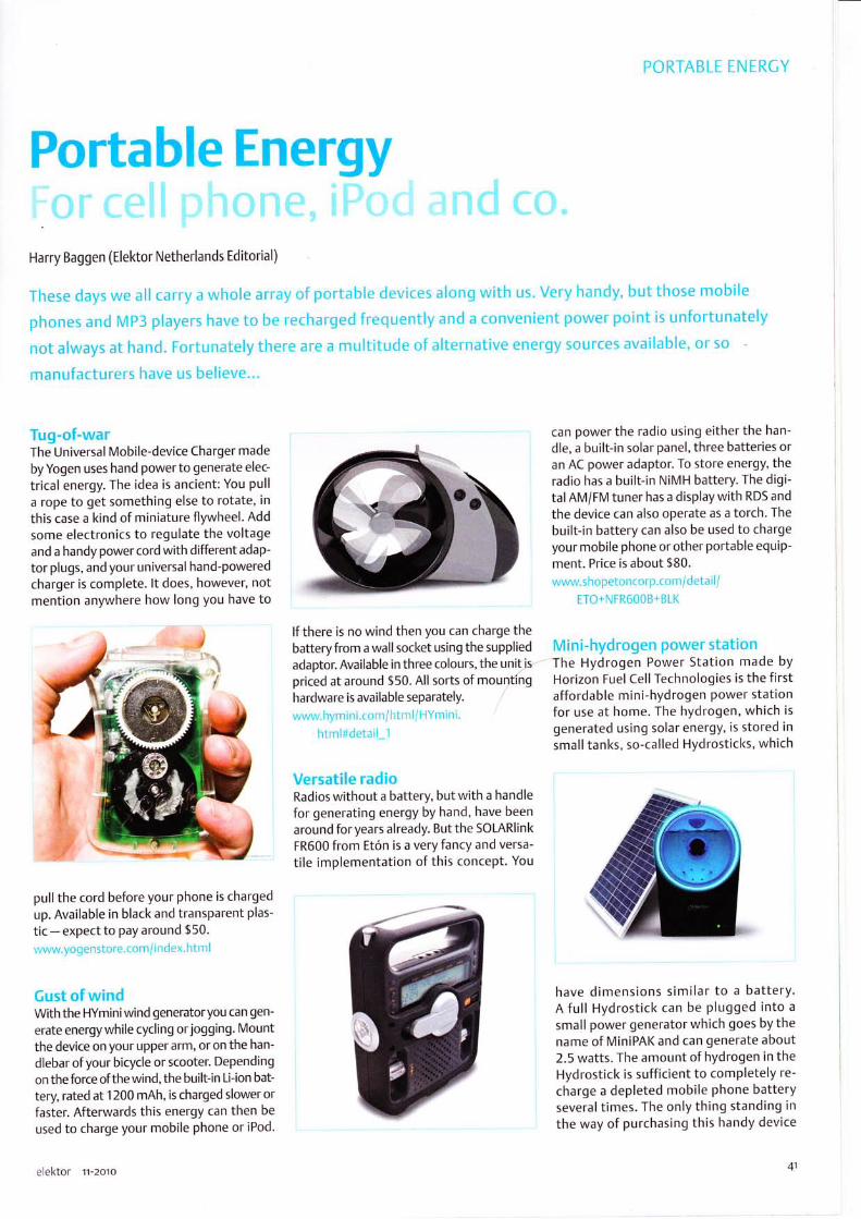
PORTABLE ENERCY
Portable Energy
Harry Baggen (Elektor Netherlands Editorial)
These days we all carry a whole array of portable devices along with us. Very handy, but those mobile
phones and Mp3 players have to be recharged frequently and a convenient power point is unfortunately
not always at hand. Fortunately there are a multitude of alternative energy sources available, or so
manufacturers have us believe...
Tug-of-warThe Universal Mobile-device Charger made
by Yogen uses hand power to generate elec-
trical energy. The idea is ancient: You pull
a rope to get something else to rotate, in
this case a kind of miniature flywheel. Add
some electronics to regulate the voltageand a handy power cord with different adap-
tor plugs, and your universal hand-poweredcharger is complete. lt does, however, notmention anywhere how long you have to
,'')!/
pull the cord before your phone is charged
up. Available in black and transparent plas-
tic - expect to pay around $50.
www.yogenstore.com/ i ndex. htrn I
Gust of windWith the HYminiwind generatoryou can gen-
erate energywhile cycling or jogging. Mount
the device on your upper arm, or on the han-
dlebar ofyour bicycle or scooter. Depending
on the force of the wind, the built-in Li-ion bat-
tery, rated at 1200 mAh, is charged slower or
faster. Afterwards this energy can then be
used to charge your mobile phone or iPod'
elektor tr-zoto
lf there is no wind then you can charge thebattery from a wall socket using the supplied
adaptor. Available in three colours, the unit'spriced at around $50. All sorts of mountinghardware is available separately.
www.hymini.com/html/HYmini.
html#detail_1
Versatile radioRadios without a battery, but with a handle
for generating energy by hand, have been
around for years already. But the SOLAR|ink
FR600 from Et6n is a very fancy and versa-
tile implementation of this concept. You
can power the radio using either the han-
dle, a built-in solar panel, three batteries oran AC power adaptor. To store energy, theradio has a built-in NiMH battery. The digi-tal AM/FM tuner has a display with RDS and
the device can also operate as a torch. The
built-in battery can also be used to chargeyour mobile phone or other portable equip-
ment. Price is about $80.
www.shopetoncorp.com/detail/
ETO+N FR600B+ BLI(
Mini-hydrogen power stationThe Hydrogen Power Station made bY
Horizon Fuel Cell Technologies is the firstaffordable mini-hydrogen power stationfor use at home. The hydrogen, which isgenerated using solar energy, is stored insmall tanks, so-called Hydrosticl<s, which
have dimensions similar to a battery.A full Hydrostick can be plugged into a
small power generator which goes by thename of MiniPAK and can generate about2.5 watts. The amount of hydrogen in theHydrostick is sufficient to completely re-
charge a depleted mobile phone batteryseveral times. The only thing standing in
the way of purchasing this handy device

ffi
IH
It
PORTABLE EN ERCY
is probably the price, which is around the$750 mark.www. horizonf Lrelcell.co rr/electron ics. htnr
Sturdy dyno-torchWho does not remember them from thepast? This type of torch, which requiredrepeated squeezing to get some light, isavailable these days in modern, high-effi-ciency versions. The Sharl< Diving Torch is
a waterproof torch fitted with a generatorwhich produces energy when cranking thehandle. This energy is stored in the built-inbattery and can be used to powerthe built-in LEDs or charge your mobile phone. The
torch is fitted with several standard LEDs
plus a powerful .l -watt LED, so that a con-siderable amount of light is available. Themanufacturer claims that after one minuteof cranking the handle, the battery will have
sufficient energy to power the 1-watt LED
for 20 minutes, a respectable time! Priceabout €35 (t30, $50).http:/ / shop. ecogadgets.conr/ i ndex.
p h p?cat=Eco_Tor clres_La ntern s&Acti
n icSlD:clf7 23 2c6 b.r b7 b449 5 2 aef49d
ca635420
Wall<ing is healthy!Using the nPower PEC you can charge prac-
tically any mobile phone, MP3 player orany other hand-held device while you walk.The device is in the shape of a pipe with a
bulge in the middle. Put it in your backpackor attach it to your belt. As a result of therepetitive motion of your body the nPowerPEG produces sufficient electricity to quicklycharge your mobile phone - says the manu-facturer Tremont Electric. A normal phonebattery can supposedly be charged to 80%
of its nominal capacity in only one hour. Thedevice is able to deliver no less than 4 watts.
You can register your interest at the man-ufacturer's website, but the exact date itbecomes available is not l<nown. The priceis around the $150 marl<.
www.g reennPoweT.com
Pumping for a full batteryThe companies Cotwind and Orange pre-sent an alternative method to charge thebattery of your mobile phone or iPod, thePower Pump. This is a smallwind generatorwhere you generate the wind yourself usinga foot pump. Handy while going camping,and thanl<s to its small dimensions it is
unlikely not to fit in your bacl<pack some-where! Orange presented this device last
year at the Glastonbury Festival, where vis-itors could try it for themselves. As far as wel<now the device is not yet available for sale.
www. g otw i n d. o rg / o ra n g e_powe r_p u rn p. h tn'r
Batteries on waterFor a number ofyears already theJapanesemanufacturer APS (Aqua Power System) has
been offering AA and AAA batteries whichworl< using water, juice, coffee or other liq-uids. When you want to use a battery youfill it with a few drops of liquid and it is
immediately ready for use. You can re-fillthe battery about 10 times, according tothe manufacturer. The second generationof the so-called NoPoPo-batteries is now inproduction and D-size cells will be availablesoon as well. Not really energy saving, butnevertheless very alternative. Perhaps theywill also be available in US and Europeanshops in the near future.wr'vw. a ps-j.jp i enq lis h/inclex. htnr I
11-201o elektor


I i"F,'r"!lq .:,-l

.i.{rj
:':i.ii+!
.:-:lq"{
l{ektor
!r:itq:imin.lbllillli ilfltr
" qtii#"rii ll-
"m'\b5I
iJt
a subscription!
Advantages to subscribers
o
o
o
o
o
www.elekt0t.com/subs . Tel . +44 (0) 20 8261 4509
or
##@F:;*""..'i.1"";,'"';'i6*n
'""Ji*HII,*
Or use the subscription order form near the end of the magazine. ffi.ktor

ByJens Nickel (Elektor Germany Editorial)
As already clearly demonstrated by thearticle 'Vision System for Small Micro-controllers' ItJ, you don't need expensivehardware to implement a simple presencedetection system or similar application. Ourobjective here is to show that the softwarealso does not need to be overly complex. Asmall experimental program demonstratesa basic approach to implementing a sim-ple motion detection system. All it tal<es toshow that everything works is a PC, a web-cam and a free software development envi-ronment, such as Visual Studio Express.
It all started on a Friday afternoon when theauthorwas reading through a book on com-puter vision in search of inspiration for thistopic. ln addition to the theory, this bookdiscusses the practical aspects of imageprocessing in detail, including motiondetection and object recognition. Suitablealgorithms are presented in pseudocode,which makes it easy to implement them inthe programming language of your choice.The authorthought itwould be a good ideato try this in Visual Basic, which is especiallyfamiliar to many readers. While reading thefirst practicalexample for motion detection(for purposes such as detecting an unau-thorised visitor), the author - an enthusi-astic programmer - could hardly wait toget his hands on a keyboard. He already hadthe Basic-language version of Visual StudioExpress (available free of charge) installedon the computer, so it took only two orthree hours to program the necessary algo-rithms for motion detection and a simpleuser interface. To quickly check everythingout, he used the editorial department's digi-
48
Figure 1. Two original images to be compared
Figure 2. Creyscale versions of the original images.
tal camera to snap a couple of pictures, witha chair shifted by a small distance in the sec-
ond photo. And lo and behold, it worked:the approximate size and location of themoved object could be detected by imagecomparison.
Here's how it worl<s. First the program hasto get its hands on the colour data of the
individual pixels. ln modern versions of Vis-ual Basic (2008 and 201 0) supported bythe.NET framework, this is fairly easy. After animage file (in .bmp or.1pg format) has beenloaded as a bitmap image with the namepic, the colour data of an individual pixel canbe accessed with the following commands:
intR = pic.GetPixel (intx, intY) .R
1ttL6 = pic.cetPixel(intX, intY).G
'r'r-2o1o elektor

Figure 3. The difference image produced bypixelwise greyscale value subtraction and
discarding negative values.
ingg = pic.GetPixel(intx, intY).B
Here intX and intY are the pixel coordi-nates, and the variables intR, intG and intB
are assigned the values of the colour bytesfor red, green and blue (value range 0-255).For motion detection we can restrict our-selves to the greyscale value of each pixel,which can be obtained in a straightforwardmanner from the colour data:
intcrey = (lntR + intG + intB) / 3
Pixel by pixel comparison of the greyscalevalues suffices for a simple image compari-son. This is done by synchronously interat-ing over all pixels. To avoid potential prob-lems, both images should have the samesize (intX range: 0 to intXmox - 1, infY range:
0 to intYmox - 1).
The pixels can be compared by a simplesubtraction operation. The results for all ofthe pixel coordinates can then be displayedagain as an image, as long as we take care
to avoid including any results with negativevalues. ln our example, we simply sweepthese values under the carpet (more abouthis later on):
intDiff = intcreyl - inEcrey2if intDiff < 0 then intDiff = 0
Figure 3 shows the result of applying thisprocessing to the pair of images shown in
Figure 1 and the greyscale representationsshown in Figure 2.
Due to ever-present image noise, smallchanges in overall image brightness andthe like, it is unfortunately not possible todistinguish moving objects especially wellwith this representation, since even thesmallest change in the pixel greyscale val-ues is displayed.
elektor rr-zoro
Figure 4. The result ofthe next step: thepixels in this image are white where the
greyscale difference is greater than a
defined threshold.
We can obtain better results by discardingsmall changes in greyscale values beforegenerating the output image. For this pur-pose, we define a threshold intlimit (witha reasonable range of 1 to 'l 00). lf thedifference intDiff is larger than inflimit,the change in intensity (greyscale level)should be regarded as valid and displayedas a white pixel in the output image. lf thechange is less than the threshold level orthere is no change at all, the pixel remainsblack.
A new bitmap image can be constructedfrom the resulting pixels fairly easily inVB.NET by setting the red, green and bluevalues to 255 where a white pixel shouldappear in the image:
pic . SetPixel ( intx, intY, _Color. FromArgb (incResult, _intResult, intResult) )
for all intX = O..intXmox-l and intY = 0..intY-mox- 1, with intResu/f being either 255 or 0.
The result of this is shown in Figure 4,where the part of the image that has movedcan be clearly recognised. However, it maybe difficult to associate the result with anobject in the original image (not all objectsare as easy to identify from their outlines as
the author's colleague ;-)). For this reason,we need to combine the data from the origi-nal image with the detected pixels to forma new image. The following commandsare executed for each pixel. lf the pixel is a
detected pixel, we set the pixel to mediumgreen, but if no motion has been detectedfor the pixel, it retains the colour it had inthe original image:
If intResult = 255 Then
Figure 5. Here the detected pixels have
been melded with the original image. Thered spot marks the centre of mass of the
detected motion.
p1c . SetPixel ( intX, intY, _Color.FrornArqb(0, 150, 0) )
E1 se
pic . SetPixel ( intx, intY, _Col"or.FrornArgb (intR, intG, intB) )
End If
The result is shown in Figure 5. This sort ofimage could be fed to a head-up display orsomething similar to create a form of aug-mented reality (a live video image enhancedwith supplementary data).
The results so far are very nice to look at,but we still need to extract machine-read-able values if we want to use them to senda signal to an alarm system orthe like. For
example, we need to have an indication ofwhether the detected motion is actually'critical'. lt would also be useful to detectthe centre of the moving object. Amongother things, this would allow us to aima second camera at the object in order torecord a detailed image.Both of these tasks are relatively easy toimplement. A simple estimate of the rel-evance of the motion can be obtained byjust counting the pixels for which intResult is
255. lf we also sum the intX and intYcoordi-nates ofthe detected pixels and then dividethe sums by the number of detected pixels,
we obtain the centre of mass of the objectrepresented by these coordinates, as shownin Figure 4.ln the example program available for down-load from the Elektorwebsite tzl, a separateprocedure has been implemented for each
of the algorithms mentioned above. Thismakes the program a good basis for devel-oping your own applications or just playingwith the code (source code file: PicProce'
dures.vb).
49

lf you do not already have tlre Visual Studio Express 2010 developrrent environment (for
Visual Basic 2010) installed on your computer, yoLt first need to download it [31.
Click the download file to
start the installation pro-
gram, which dowrrloads
additional files (lnternet
conrrection required).
After cornpletion of the
installation process, you
shou ld fi nd Microsoft Vis-
ual Studio 201 0 fxpress i n
the All Programs list, withthe Basic-language ver-
sion of the development
environment under the
main entry.
As usual, the example
software for this article
can be downlo.rded free of charge frorr the Elektor website [3]. You
should copy the contents of the Zip file to the folder provided by
VS 2010 for project files, which is usually C:\... \User_nome\My Docu-
menfs \ Visuol Studio 20 1 0 \Projects.
After launching the development environment, click Prolect in the
File menr-r and then select the Pics project. All files belonging to theproject are shown in the So/utlon Explorer window at the top riqht(projects are called 'solutions' in Visr-ral Str-rdio jargon).
Double-click Form.vb to open the main form of the example software
in the design view (see Figure 7). Here you can edit the corrtrols,
such as buttons and text boxes. lfyou wish to add rrew controls, se-
lect View >> Other Windows >> Ioolbox to open the toolbox.
Right-click Form.vb in the So/ution Explorerwindow to display the correspondirrg code,
which defines how the form responds to events such as button clicks. The actual image pro-
cessing procedures are contained in a separate code module named PicProcedures.vb.
Unfortunately, there is not enough room here to describe how to perform tasl<s such as
placing new buttorrs on the form and linking them to corresponding code, but a free online
tutorial on Visual Studio and Visual Basic .NET is available from Microsoft. lf you want towork more extensively with this very powerful and entirely free PC developrrent environ-
merrt, it would certainly be worthwhile to buy a book on Visual Basic 2010. Several books
are available at prices ranging frorn 30 to 50 pounds/euros. Before purchasing one ofthesebooks, you should check whether the learning curve demanded by the book matches your
existing knowledge; the levels of the various books differ considerably.
Beforeyoutryoutthesoftwarebyclickingthegreen affow(Debugging),youshouldalsoensure tlrat WlAAut.dllis installed correctly. After opening the Pics project in the So/ution
Fxplorerwindow, you will see a References folder. Click the '+' sign next to the folder icon tosee a list of tl.re software libraries used bythe program. You should seeWlA in this list. lf the
WlAicon is marked with an X, Visual Str:dio cannot access the WlAAut.dllfle.
,, rl tl
-@
All of this is somewhat pointless withouta source of live imagery. Fortunately, the.NET framework facilitates access to allsorts of hardware, including webcams. Forthis purpose the frameworl< comes with a
collection of classes that encapsulate hard-ware accesses via the corresponding Win-dows library (.d//) files. lf you want to usethe classes (i.e. the corresponding com-mands, status variables and so on) in yourown software, you only need to give VisualStudio a suitable reference. Unfortunately,many of these classes are not especially welldocumented. ln the course of a long Satur-day afternoon, the author finally discoveredwhich .d//file is the most suitable for this pur-pose (WIAAut.d//) and how to get a webcamto take snapshots under VB.NET so they can
be used in user-developed software. A majoradvantage ofthis approach is that it does notrequire any manufacturer-specific drivers.Once the webcam has been recognised as a
USB device, it's all systems go.
After a bit of fiddling around, the authorpersuaded his Logitech Quicl<Cam 55500to start producing a continuous stream ofsnapshots that could be used for live imageprocessing. However, we have to live with a
couple of limitations here. Everything is very(very!) slow, probably because the imagesare stored in webcam memory. Further-more, this memory eventually becomes full.To clear the memory, you have to clicl< thewebcam camera icon under'My Computer'(in Windows XP) and then click'Delete pic-
tures on camera' to clear the stored images(see Figure 5). After the memory wascleared, the author's webcam achieved a
dizzying speed of one frame per second,which would certainly leave something tobe desired for security-critical applications.However, all we were interested in at thispoint was trying a few things out.
lf we compare each webcam image withits previous image, it's possible to detectmotion 'continuously'. However, even withthe low resolution of the webcam snapshotsit would tal<e far too much time to first cal-culate the greyscale values of both imagesand then compare them pixel by pixel, ana-
- -rl.j pt'
+ til applcation,myapp
:l A$embrrtro.vb- -l ncorcs.resx
:l R.'os..'.b@r+ I seftino5.rettnot
l ststeo,Data,o.t.s.tErj Syrtcm,D.ploym.ntJ 5ytt.m.0rawr@j srrtem.win&wt.Fohs
j syttem xml,L.aJ@
.l Foml Detgner vb
5o 'r'r-2oro elel<tor

a;----;;;
Figure 6. The image memory of thewebcam should be cleared from time to
time.
lyse the differential image again, and so
on. A significant increase in speed can be
achieved by storing the greyscale represen-
tation of each image in a sort of buffer, so
that it is available for comparison with thenext image. As we do not display the actualgreyscale images, we can also omit the divi-
Figure 7. The development environmentfor Visual Basic 201 0 can be downloadedfree of charge. Even beginners can quicl<ly
achieve useful results.
sion by 3 and simply sum the red, green and
blue components.
The MotionPicture function in the examplesoftware contains all the code for motiondetection. lt outputs a bitmap image show-ing a combination of the original image and
Figure 8. The demo software forms a goodbasis for DIY projects.
the supplementary motion data meldedwith the image. This function expects thefollowing inputs: the original image picNew,
the parameter intLimit, and the Booleanvariable boolDrowDiffPoints, which speci-fies whether the detected pixels are tobe coloured green. The 'relevance' of the
51
LEDs 1d i i:'lr: ;r:^ f i.r,.,r irf Prt;ie,. t
DIY projects:. Ambilight with Bluetooth. Budget LED dimmer. Computerised LED Christmas light. Programmable LED lamp
And much more!
This special edition offers not only theoretical information but also shows
how and where LEDs are applied nowadays. Additionally, this edition
contains some tested electronic circuits for DlY.
Theory and applications:. Control electronics and heat management for LED lighting. LEDprojectortechnology. Voltage converter with constant-current output for Power LEDs
. LED power and control unit on a single chip
Qektor
Elektor
Regus Brentford
1000 GreatWest Road
Brentford TW8 9HH
United Kingdom
Tel.+44208261 4509
elel<tor rr-zoto

motion is returned to the calling routine inthe infMotion parameter. The value of thisparameter corresponds to the square rootof the number of detected pixels. Motion-Prcture also loads the image into a greyscale
buffer for the subsequent image compari-son. This buffer is empty when the functionis first called, so it must be initialised withthe data of the first image before the firstimage comparison (this is handled by thesubroutine lnitcreyBuffer).
The author has written a small sample pro-gram to demonstrate everything describedin this article. Although the user interfaceisn't likely to win any design prizes, it is fullyadequate for initial experiments.This software is solely intended to forma starting point for developing your ownapplications. Users can also change the val-ues of constants in the source code (see thecode for this). For this reason, the authorhas not generated an .exe file; the softwaremust always be run inside the developmentenvironment. The installation process forVisual Basic Studio 2010 is describe in an
inset, while linking in the webcam library is
described in another inset.After you open the example project in Vis-ual Studio (see Figure 7), click the green
52
arrow on the toolbar to run the program.The main form (Figure 8) appears afteryouselect the webcam. After you clicl< Sfort, thewebcam starts taking snapshots. The cur-rent and previous images are shown at thetop left, and the result of the motion detec-tion process is shown at the top right. Theleft slider adjusts the value of intlimit, whilethe right slider sets the value of intMotion,which is the threshold level for triggering an
alarm (see above). When this happens, thecorresponding image is shown below theslider and saved as a file. The 'X' buttonsare provided to delete the displayed 'falsealarm'images.
False alarms occur regularly when the auto-matic brightness control of the webcamcauses the entire image to become brighteror darker. To partially filter out this effect,the MotionPicture function includes an algo-rithm that detects global intensity changes.ln addition, you should always avoid allow-ing too much daylight to enter the roomunder observation, since outdoor lightingconditions are almost always constantlychanging.
lf you play with this program for a while,you will quicl<ly discover a significant short-coming of the motion detection scheme
WlAAut.dllis not included in all Windows installations. lf lheWlAAut.d//file is missing in
the C:\WIVDOWS\system32 folder, it must be downloaded from the Web lql. After extract-
ing the .d// file from the downloaded Zip ftle (WlAAut.sdk), drag it to tlre above-mentioned
folder (which also holds the other.d// files).
Next yor-r must register the new library with the operating system. To do this, open the
small Windows command line window by clicking Run... in the Stort menu (with Windows
XP). Enter the command regsvr3 2 wlaaut . dI I in the window and click Ol(.
After this you must re-configure
the corresponding reference in
Visual Studio. You can view all the
references in the So/ution Explorer
window after you open the Pics
project (see the'lnstalling Visual
5tudio'inset). lf WlAis marl<ed
with an X, you rnust first delete
the reference (by right-clicking
WA) and then create an new
reference. To do this, right-click
References and clicl< Add Refer-
ence in the pop-up menu. ln the
window that this opens up, select tlre COM tab and then select Mlcrosoft Windows lmoge
Acquisition Library v2.0 in the long list. A valid reference should then appear in the So/utlon
Explorer window.
described here: it only works with darkobjects moving in front of a light back-ground, and furthermore, in case of objectswith different colours the system primarydetects the motion of their dark-colouredportions (see Figure 3). This is a conse-quence ofthe fact that we discard negativechanges in the greyscale values, as previ-ously mentioned. lf you wish, you can tryusing the magnitude of the greyscale dif-ference instead of the signed value. Withthe latter approach, both bright and darl<
objects will be detected. However, if themoving object is already visible in the firstimage, it will appear twice in the outputimage: once in its original location, andagain in its new location. This is becausethe greyscale values ofthe pixels change atboth locations.
The described experimental scheme is
reasonably well suited to checl<ing for thepresence of an object, or for similar non-critical monitoring tasks. lf you wish to use
this motion detection scheme in a securitycontext, increasing the frame rate is essen-tial. lt should be at least 5 frames per sec-
ond (10 would be better) for use in practi-cal situations, so that fast motions can alsobe detected reliably. Unfortunately, due tolacl< of time the author was not able to tryout other image sources, such as a TV cardor the like. We would certainly appreciatereader feedbacl< in this regard.
(too539-l)
lnternet Linl<s
[1 ] vvlv,,v.elektor.corn/090334
l2l ivww.elektor.com/.1 00539
l3] wivw.rnicrosoft.comf express/
Dolvnloads/
[4] wwlv.microsoft.com/downloadsfdetails.
.rs px?f a m i lyid - a332a1 1 a -Q1 b8-4d e6-
9 1 c2-b7ea32537e29&displaylang=en
r-2oro elel<tor

E
sql9E>+lsOHE;EEO -o)-osCo-t+
lrJE
trL-Je
C5ooFF-
-ElrlLlJ
elektor r-zoro

RF & RADIO
Pesjglling and MakingBasic-Ant6nnas
ByJean Marie Floc'h (France)
The antennas presented in this article were designed for a frequency of z.45CHz. This frequency is within the 2.4 CHzISM band (lndustrial, Scientific, and Medical) that can be used without a licence in many countries in the world.
Some simple rules explained below sive) copper laminate to make them easier nas on double-sided pCB laminate, so theymake it easy to design antennas for other to adjust to the correct frequencies (using will stand up to the weather better. Unlessfrequencies' a craft knife). But we recommend you to otherwise stated all antennas have a footThe prototypes were made from (adhe- make the final versions of these inten- impedanceof 50ohms.
Simple dipole
' )"t2r--1
IA
The dipole is one of the simplest antenna you can mal<e.
i,l2-long metal conductor divided in two. lt is fed frornthe centre. The cr,rrrents in the two elements must be inopposite phase, so that the current is maximum at thecentre of the dipole. Feeding a dipole requires the use
of a balun (for balanced-unbalanced) device to producecurTents in antiphase and in order to present it with thecorrect impedance.
The impedance across the terminals has a value close to73 O, and it racliates ornnidirectionally, except in line with the elements, where the radiation is
zero. The theoretical gain of tlre dipole is 2.1 5 dBi. The term dBi denotes decibels with respect toan isotropic antenna radiating uniformly in all directions and which has absolute unity gain.
-
-- ll -T'091095 - 12
The simple dipole comes in the form of a
AB
Coaxialdipole
One trick for avoiding the balun and the impedance transformer is to feed the dipole directly via acoaxial feeder. ln practice, the plrysical length ofthe dipole is slightly shorter (a few percent) than theelectricallength.
One of the elements is soldered directlyto the centre core of the coax, the otherto the ground.The length here is set at 56 mm (two 27 mm elements with a 2 mm gap) so as to obtain a resonantfrequency close to 2.45 CHz. At this frequency, the half-wave length is 60 mm. lt's best to start withelements that are a little bit longer (makirrg sure that both elements stay the same length), so as
to be able to then adjust them to get the resonantfrequency required. Bandwidth is around 400 MHz,
i.e. 1 6% of the band's centre frequency. A maximumgain of the order of 2 dBi has been rneasured. The
red curve shows the radiation pattern in line with thedipole (referred to as the E plane, note the humps); theradiation in the plane at 90', referred to as the H plane,(green curve) is virtually orrnidirectional.
11-2oro elektor

RF & RADIO
Dualdipole with ground plane
You can try to reduce the backwards racliation f rorrr
the coaxial clipole by pl.rcing a nret.rl groLrncl plane
.rpproxinrately r/4 away. To be effcctivc, tlrc di.rnretcr
of this ground plane rrust be.rt least 0.75 i. To keep
the radiation patterr syrnrnc.trical, it's best to Lrse.-l
clisc. Watch oLrt, .r slight shift in lhe resonant freqr-rency
is often noticecl, so it's necess.rry to le-trinr the lenqths
of the clipoles. lf you w.r nt a cross- pola rizcd (H/V)
..rntenna, yoLl can Lrse two co.rxial clipoles together.
Banclwidth is.rror-rncl zl50 MHz (18"r.). The dtr.rl
Toson.lrce is clLrc. lo the ef{ect of nrLrtr-r.rl couplinq between the two dipciles. lt's best to termin.rte the urrr.lsecl feed r'vith a 50 !) resistor to
.rvoid spr-r rious effcc ts.
(.rror-rncl -15 clB). You can also see greater directivity in both planes, due to the presenre of the second dipole in the plane perpendicular to
the first one. This results in a significant gairr value of 6 dBi. The same results are note d forthe other feed point.
Monopole
lf you wanl to rccluce anlcn{rn sizc, r.inc sin'rplc way is tcr
rnal<e use of the electiic.il images gener.rted by a gror-rnd
plane. ln this way, you obtain a nronopole whose size is
7,/a, i.e. half the size. The gror,rnd plane also rcclr:ces tlre
bacl<w.rrds radiation.
The monopole shown here is ted via a micro stripline (1 .5 mmr
wide) prodr-rced on FR-4 PCB lanrirratt. The rnonopole's 30 nrnr
long element is soldered clirectly to tire line. This is a
very sir-nple technique for producirrg .rntennas directly
on PCBs. You qet a bandwidth of .rround 450 MHz
A hole is seen in the radiation on the axis of the monopole, and orlnidirectional r.rcliation in tlre
perpendicular plane. A sllqhl rc.cltrction in the re.rr racliation due to the presencc of the qror,rncl
plane can be seen. Tlre qain is of thr-- orderof 1 dBi.
Broadband monopole
lf yor.r want to achieve greater b.rnclwicJths, yor-r need to ad.rpt the shapc of the nronopole. Thus you
c.rn Lrse an ellipse (see photo).'1'he clirrensions of this ellipse - made fronr 0.3 nrnr thick copper
sheet arc 45 mm high by 30 nrrr wicle. The heiglrt of the ellipse corresponcls to the antenrt.r
resonance centre freclr-rencv (hcre, 1.86 CHz) and is arouncl r,/4.
The barrdwidtir is 550 MHz (30'',,), lwice thal of dipoles and sirrple monopolc's. The racliation p.rtterf
looks the sanre .rs th.-rt of the sinrple rronopole .rrrcl the g.rin tor-r h.rs a valr-rc of the s.tnre orcler.
:.l: *-t"I
elektor rr-zoro

Printed dipoleThe two elements of the dipole are now printed eachon one side of the substrate. They are fed via a 2-wirefeeder, to which an SMA connector is soldered (the
centre pin to one element and bull<head to ground).
The antenna proper was made from copper foil, so as
to mal<e it easier to adjust the dimensions. But onceyou've got the dimensions right, we recommend you
to mal<e the antennas on double-sided copper-clad
board, to improve performance (particularly gain)
and get an antenna that will last.
The length of the dipole elements and the distancebetweerr the elements and ground is )./4. The board
used is 0.8 mm thick and has low perrnittivity (2.2), resulting in slightly higher gain (of the order of2.4 dBi) and improved bandwidth (of the order of 410 MHz, i.e. 1 9%).
The disruption in the radiation pattern beneath the dipole is due to the measuring system and thepresence of the feeder and connector.
TLEE
Printed dipole with reflectorlf you want to radiate in a half-space and limit backwards
radiation, one widely-used technique is to place a reflectorsoldered to the qround side of the feeder line. The size willbe chosen to be slightly larger than the two elements ofthe dipole. For good matching, the dimensions change
slightly compared to the simple dipole. This antenna has
a bandwidth of 350 MHz (a%),i.e. narrowerthan thesimple printed dipole.
With this antenna, you can look forward to a reduction in
bacl<wards radiation of over 10 dB. The maximum gain is 5 dBi.
Also note the radiation 'hole' in line with the dipole elements.
lf you want to increase the antenna's gain, simply place a
director in front of the dipole elements, at a distance of d
lI Connecteur
around )./4. This director is markedly shorter than the Itwo dipole elements. ln this way, the gain increases by I
1.5 dBi. There is a reduction in rear radiation and an l--
-l"-;;'"'I
.. ! air@.!:
increaseindirectivity(narrowerforwardangleintheEand H planes). s, n't ffi.-*-.L. *:
Electromagnetically-coupled printed dipoleln this type of configuration, the dipole is positioned above a micro stripline bythe use of a substrate. ln thisway, you get a dual-layerstructure with a feed layer and a radiating layer with the dipole. The energy is cor-rpled to the dipole by proximity or by a capacitive effect. Twoconfigurations are possible:
O Longitudinalcoupling: the sr-rbstrate used is FR-4 PCB laminate, 0.8 mm thick for the feeder line and i.6 mm for the dipole. The dipolemeasures 9 x 30 mm (a half wavelenqth). The feeder line is 1 .5 rnm wide, in order to obtain a characteristic impedance of 50 A.
The position ofthe dipole is adjusted by hand to obtain good coupling and hence good matching ofthe antenna. To avoid air bubbles and
56 11-2oro elektor

for bettc.r reproducibility, it's advisable to pLrt some
V.rselinerlr between the two sr-rbstrates.
The bandwidth of 55 MHz (2r.;) is n.rttowet thatr for.r
simplc dipole. The measured q.ritr is aror,ttrd 1 dBi. This
low valr-re is explained by lhe irse of FR-4 larlinate, which
exhibits significant losses.
O Transverse coupling: this tinre, tlre dipoic is positioned laterally with respect to the
feecler lile. Tlrc dirrensiorrs of the dipole ancl tlrc char.rcteristics of the sr-tbsttalcs are identic.'r v'.'ilh tht' llrcviotrs
antenna. The clipole position is .rcljustecl in the s.rme way to obtain goocl coupling between tlre line and the dipole. The b.rndr.' idth is of the
orderof40MHz(1.5";),i.e.slightlynaTrowL.TthanthelongitLrdlnally-coupled.'mtenna.Thetneasrttecl gainisarouncl 1.5dBi.
Patch fed by a micro stripline
OFedbymicrostriplinetheprtchrs.rS0nrmx30rnmsquareonsi.rncl.rtcJ FR-4PCU(thicknessl.6mtr,pernrittivilyu, -{.1 ,1' 2.45CH2.
2ir. The rreasured g.tin is of tlre order of 0.5 dBi.
elektor rr-zoro 57

t*iHry__
O Coax fed: the dirrr.nsions ol the p.rtch .rre .:lso J0 x 30 mnr.Coax feccl is achievecl using an SMA connector soldered to thegror-rncl plane on the other sidc of the board, with the ce ntrccore to the patch. Feeding in this w.ry mal<es it possible tor ccluce the losses in thc substrate. Experience shows that thep.rtch should be fed at a l)oint centre(l 1/3 of the ur.ry in f ronr
the cdqe of tht p.rtch (10 nrnr in ciLrrcase). The nie.rsurcd q.rin
is of tlre orde'r of 4 dBi.
lf you lv.ltt circular polarization, you need to nral<e a notchof .rboLrt 1 0'r, (l'rerc' 3 rrnt) at 45' in the two ogtposite.
cor ners of the p.-iLch. Depending on the position
of thc :lots rvith rr.sltcct to the fr.:c.cl point, you
will qct e ithcr riqlht- or lcft lr.rnd (RH/LH)
pol.r is.tion.
i /i;Ki:;:,:;&1'ir*rN..\ Achieving matching using the Smith chart
{/,i,,,,4;t:;;!:rrri;j.r.a.rf;l;.:'.t-t.iti:: ..\'\ lnordertoachievematching,youfirstmeasuretheimpedanceofthepatchat
!.lrr'l-tt.;:.riir;i-..ffi*Sig{,.tUi rf,i:ir,l*\, j\ resonance using a network analyser (on the edge of the patch). The impedance for the
T:::r,i:;1ll'j.?.fl1!lr rear at the resonant frequencv' you then use a smith chart
-thepatch'simpedancenormalisedto50ois125/50=2'5,i.e.anormalisedf.H#,ffi.Lffit+;:t\iftH'iffiF,ry#/ admittance of y = 112.5 = 0.4. rhe constant-reflection coefficient circte (with the point
rlk?l.&T,ilW/;HlT}re)intersectsthecircler=1at.l+0.95jand1-0,95j.YouaccepttheItil, .,1$r$;;'ii i$#i,:::/':/ -when the antenna is matched, you are arthe centre orthe chart at point 1. Hence the
I 't|}^.xsi;*)"} ':r'$:J,]- / t flf:Y;:Wfiiit/ stub needs to contribute an imaginary component of 0.95j in order to compensate for the
c'':':ir:S+l{]].: t,-;;917 patch'sadmittance, i.e. (1 -0.95j) +0.95j= 1J
E '1'::,::i:i.:-.:':;.,:.a. ,...'1'':r2' - to get from y = 0.4 to 1 I 0.95j, you need to move 0.34 l, round the perimeter of the Smitha-I chart in the direction of the generator, which means that the stub will need to be positionedg 0.34 x 60 mm = 20.4 mm from the patch. ln the prototype, the stub was positioned at around 20 mm.I - Still on the perimeter of the Smith cha rt, going from y.o (open-circuit admittance) to a value of 0.95j, you find 0.I 2 ), as the stub
i length, i.e. 0.12 x 60 mm = 7.2 mm. ln order to be able to cut it down to adjust, you'll make it slightly longer. The stub on theE prototype was 9 mm long.
Near-fi eld measurement setup
Radiation diagrams illustrating the antennas covered in this article wereobtained using a Satimo Stargate 32 near-field measurement setup. This makesit possible to perform measurements between 400 MHz and 6 CHz. The systemconsists of an arch fitted with detectors that measure in real time a cross-section of the radiation pattern of the antenna under test. The antenna is thenrotated in orderto obtain a 3D diagram. The measurements made belowtheantenna need to be interpreted with care, as there are no detectors under theantenna and these values are extrapolated.
(o9ro95)
1r-2oro elektor58

www,elel(to t,
c0mp..aa-:*-e^nf{i4nt $ llntr | ,i,.ir. G.te TEIIIUE Rs-224-x Il q.*gl
":gS;;
lektor:'PCB Service
0rder custom-designed boards lrom the Elektor PCB Service
The advantages at a glance. Professional quality pCBs.. No film charges or start_up charges.
; fto yiljmum order quantiiy o, .nuig, for this service.. Available to private and commerciatiustomeis. - ''-
. Design.check applied to arr entriei. weLiiuivo, r,no*within 4 hoursl.
J.u19 PCBs supptied - three produced.
lf the third board is also okay, you ieceive it as well _free of charge!
elektor rr-zoro59

ATMt8
we're going to be using:
. VRbot: voice recognition module.
. Speal<jet: a board that can generate voice messages and com-
plex sounds.. BlinkM MaxM: module witlr three RCB high-brightness 10 mm
LEDs designed to be driven via an l2C bus.
The whole project is based on solid foundations: Elektor ATM18, the
2-wire LCD diiplay, and all the software developments that have
already appeared and can be downloaded for free (BASCOM-AVR
or nvR-cttl and which can be used as a starting-point to modify
or expand as necessarY.
What would you say to a third hand?What do you think of the ability to react to voice commands to
replace piessing a button while your two poor little hands are busy
holding test probes for precision measurements?
the VRbot voice recognition module can mal<e this dream come
true. The recognition is virtually Speaker Dependent (SD), i'e' the
timbre of the voice is taken into account in the voice recognition.
Say "Open Ssesame!" and VRbot will respond to you, and only you!
Bydefiult, VRbot also offers 25 pre-recorded words in a Speaker
lndependent (Sl) mode.
TalkShow
r'l
By Grdgory Ester (France)
Would you lil<e to equip your project with voice recognition, a voice synthesizer, or maybe a giant RGB
pixel? well, here we,re offering you some building-blocl(s you can put together to suit yourself
Since April 2008, to the delight of many of our readers, the pages
of this magazine have been liberally sprinkled with a multitude of
applicatiois based on use of the ATM18 AVR board' On the Elek-
toiforrt, under the topic heading "Elektor ATM18 i/ overview of
instalments published [1 ] you'll find convenient links to all instal-
ments in the Elektor / CC2 ATM18 series.
ln this article, it's not our aim to enter into the details of a complex
implementation of the now world famous ATM18' No! Quite the
reverse. For once, let's leave aside the structural and mathemati-
cal aspects, and spend a little time looking at how to use'prefabri-
cated'modules.These days, the manufacturers' constant efforts to offer us ready-to-
use modules mean we can forget the hardware in order to concen-
trate a bit more on putting these building-blocks together and pro-
gramming them' lt's now easy to create, put together' take apart'
ind combine functions to produce your latest'toy"
Of course, we shouldn't ever lose sight of the fact that electronics
leaves no room for chance, and our keyword must be rigorousness.
After all, there's no reason why you can't have fun and learn at the
same time, is there?For this particular construction game, I wanted to use voice rec-
ognition as well as the reproduction of sound effects and words'
d make it a bit more fun, I've added a driver for an RCB module.''
so "Look, no hands!" Here are the building-blocks (easy to find [3])
n"a. o..n, glue, Mood lightjeasons, Thunderstorm, s.o.s., Black, Hue cycle, Virtualcandle, white
flash
Left, Right, Up, Down, Forward, Back
Action, Move, Turn, Run, Look, Attack, Stop, Hello
Elektor, VRbot, CC2, Adelek
Left, Right, Up, Down, Forward, Backward
Zero, One, Two, Three, Four, Five, Six, Seven, Eight, Nine' Ten
Action, Move, Turn, Run, Look, Attack, Stop, Hello
6o11-201o elektor

- ,:.....:;,,.,,. 1X*-.r5:J:- r -
..;r:k6&6i*,
The user stores a collection of words in groups. At start-up, press-ing button 51 on the ATM18 board (connected to PBO) allows youto navigate through a menu to choose one of seven groups: SD1to 5D4 (SPEAI(J ET_VRBOT_TEST_5D. bas) a nd 5t 1 to St3 (SPEAKJ ET_VRBOT_TEST_SI.bas). The program loops through the selected testto let you test all the words in the group and, where applicable, seethe action produced.
You have a few seconds in which to speal<. lf VRbot understandswhat you say, it displays the word spol<en on the 2-wire LCD dis-play. lf it hears noise or if the word is poorly-pronounced or isn't inthe memory, it will display "What ?l?" lf you tal<e too long speal<ingwhen you are supposed to, it will display "Too late".VRbot originally does not speak French, so the author decided toteach it a few words of his native language (SD2 and 5D3 in Table i ,
English equivalents are shown). ln group SD4, it's also taught fournew words: Elel<tor, VRbot, CC2, Adelek. The first group (SD1) con-tains the names of the mood lights you need to say to drive theRCB module.
Let's tal<e a moment to see how to teach VRbot one of the words ingroup SD1. To do this, we're going to use the famous U5B/5 V TTLserial umbilical cord Ia] that will allow us to connect the mod-ule to the PC on which you will already have installed VRbot CUI(Vl.1.5) [5]. Connect the module to the USB/TTL cable, followingthe colours as shown in Figure 1 , to end up with a cross-wired seriallink. Plug the other end into a vacant USB port on your PC.
Start the VRbot CUI software and select the language you want touse to speal< the words in the 5l group. Select the appropriate COMport and establish the link ('connect'); the software automaticallyirnports words already recorded. A progress bar indicates how theimport process is progressing. lt's worth noting here that by default,VRbot is configured to operate at 9600 baud.
Now clicl< on the group you want to add words to. Select'addcommand' and give it a name, like WHITE_FLASH (for example)for index 10 in group 1 (5D1). Figure 2 shows that the commandhas been created, but not yet recorded ('Trained: 0'). This is notthe moment to be strucl< dumb with excitement, you're going to
elektor rr-zoro
ATMr8
have to speal<: soprano or tenor, it doesn't matter! You just needto repeat the same word twice with the same intonation at about40 cm from the mic so that the command can then be recognized
Figure 1. VRbot and the USB link.Don't forget to connect up a microphone.
Gq I Cqilnud Ljd
d.
tt:
il Too&
I'isorGryGrowGroup
GropGroup
Goup
GnW
Grilp
FED
GFEEN
SLUE
MOOD-LIGHT
sms0NsTHUNOERSTORM
s0sBhCKHUE frCLE
0
11
6
I
Tr.M Cofd20K20K20K20K20K20K20K20K20K20K
,,,, "0 0K ]
9 VIFTUAL-MNDLEI --'iit-wiliii-iilsilt0
11
Figure 2. Eleven mood lights. The last one has not been taught('Trained = 0').

ATMr8
ov5V
PD{PDO
Figure 3. Howto connectVRbotto the ATMl 8 board. ConnecttheATM18 board's S1 push-button to PB0.
ov5VP82PBO
Figure 4. Connecting up the 2-wire LCD display, as described in [2].
Figure 5. Speakjet and the U5B link. This is a one-way connection:this talkative module is too snobby to talk to the computer!
by the system ('train command'). Once the groups have been cre-ated, you can have fun testing them ('tool', then 'test group'); if theword is recognized, it is highlighted in flashing green.
At this stage, the VRbot module is ready to be built in to the system.Figure 3 shows the pin-out to follow for connecting to the ATM'l 8board, Figure 4 shows the same thing for the 2-wire LCD display.
Speakjet......uses a 'phoneme'-based voice synthesis technique, just as humansdo. Phorremes are the bLrilding-blocks that allow us to constructwords. An allophone is a possible sound variant of a phoneme. Com-bined end-to-errd, the phonemes form words or phrases. There are72 sound components available, and using them we're gcling to be
able to form the word 'Elel<tor'. lt's also possible to adjust a multi-tude of parameters to add tone of voice, a slangy pronunciation,or a question at the end of a sentence, for exarnple. So you need tothink of it in terms of the sounds that come out of our mouths, whilealso allowing for the fact that sounds will be pronounced differentlyaccording to their position in the word and the influence of the sur-rounding vowels. For example, the B in bool< will not be pronouncedthe same way as the B irr baby.
There are numerous nuances, but the device's technical documen-tation is very comprehensive and you'll find it essential reading.You'll be able to learn all about the use of diphthongs, silences,stressed and unstressed intonations, and so on.
A bit more fun is the possibility of producing 43 sound effects(alarm, biological noises, etc.) and I2 DTIVIF frequencies.
So we're going to implement the board based around the Speal<jet
lC. The Phrase-A-Lator [6] software lets yoir communicate directlywith the rnodule so you can test the words in the built-in dictionaryor ones you've made up yourself, along with tlre sounds. lt's alsopossible to control events according to the state of certain inputs,and to store words in EEPROM memory so that you can then veryeasily call them up r-rsing just a few lines of code" A small area withsolder pads will let you very quickly solder arr adjacent row of sixmale pins, which will let you program the board directly, once againusing the USBI5 V TTL serial cable. To do this, you need to solderthree wires as shown in Figure 5:TxD of the USB/TTL serial cable (pin4, orange) to the 'pin 2' on the Speakjet board that's next to the 'TX'
Present \PO \FAST \RR \EY \SE \EH \NE \TT
Speakjet
\sLOW \AY \SLOW \NE
\Eyry \ry \ru \ry \rY \EH \EH \MM \NrF#2 \EY|Y \P4 \rr \rY \NE
\sE \PE \slow \rY \EK UH \EH \rrVRbot *L\:ro.ylw \slow \ry \p6 \p6 \AWRRJIq \p6 \Bo \oH \rI
11-2o1o elektor

TCfz \IH \LE \EH \KE \NTF$z \TU \AXFF S y lt I View Eodes ISay Seleclion I View Codes I
Clear Say Data I for Selection I
Dietionary
l-bLtr- Load 0verwrite I Load lnsert I Load & Say Next Word I jsel tn*ro I o*" I
ATMr8
Figure 6. Make it say what you want it to.
pin; the +5 V rail (pin 3, red) and ground (pin 1, black) for porn,erirrg
the board will be derivecl from the USB port via the same connector.After installirrg tlie Phrase-A-Lator software, connect the wholcthing to;l \i.rcant USB port on your PC. You should then hear a
robotic voice say "ready", telling you that everything is in order.Rr-rn the software, select the COM port and clicl<'Test serial con-nection';you should hear arrother "ready" to indicate the link is
worl<ing. Now clicl< on Phrase-A-Lator.rnd compose the word 'Ele-
l<tor', with the help of FigLrre 6. Clicl< on tlre 'say it?' button, and heypresto! it's said it.
Table 2 shows lrow to construct the other words of tlre welcomernessage "Elektor and ATM18 present Speakjet and VRbot" whichwill be heard when tlre Talk Show is powered up.You'll r.reed to save the words into EEPROM memory so you'll be ableto callthem later on using .r few lines written in BASCOM-AVR. Theprocedure is simple. Run the Plrrase-A-Lator software, therr select'tEPROM editor'. When editing the last word (in this case, 'Elektor'),refer to FigLrre 7 for the four steps to follow for savir.rg all the wordsto the EIPROM. You'll need to tal<e care to store all tlre terms in thecorrect places ir"r the TEPROM memory.Clicking on 'view codes'will let you generate part of the code
nee .Jed to complete the progranr in BASCOM-AVR (Figr"rre 8). Clickthe 'save' button to save yclur composition into the dictionary.Lastly, Figure 9 shows hovr' lo connect tlre Speal<jet nrodule to theATM 1 8 board. Mal<e sure you use tlre riglrt 'pin 2' - it's the one nextto the'TX' pin.
Mega r-pixel displayThe last building-blocl< we're going to be r-rsing (Fiqurt 10) includesthree 10 nrnr high-brightness RCB LEDs. Figure 11 shows how toconnect this "mega" pixel to the ATM 1 8 board.The whole thing is clesigned to be driven via an l2C bus. Additivesynthesis is used, ancl 3 x 8 bits allow the colour mix to be con-trolled very precisely. And that's not all-there are lots of optiorrsfor configuring this giant pixel, lil<e the generation of various displaysequences in stand-alone mode, the choice of transition speed, ran-donr illurnirration, etc.At start-up, by way of a test, the colour displayed will be Elel<torred (217 / 0 / 0 in decimal). Our'smart pixel'will follow pre-definedscripts. Sayoneof the eleven mood lights in group 5Dl in ordertosee it .rppear on the RCB LEDs: 'storrn'. 'virtr-ral candle', 'seasons',etc. - whatever you feel like.
At start-up, you'll hear'ready', so Speakjet is ready to speak. The lzC
address of the RCB module is detected automatically. The welcome
screen comes up and Speakjet speaks the text at the same time.Next it displays the number of words in VRbot's first four SD groups
(Table 1).
Pressing 51, accompanied by a pretty tinkling sound, will let you
browse a menu where you can select the group to be tested. By de-fault, group SD1 or Sl1 is active (depending on the program loaded).
Speak when you are prompted to. lf you take too long, you'll get thereply "Too late"; if you pronounce the word badly or there is back-
ground noise, the reply is "What ?!?" lf the word spoken is recogni-zed ("Fine!!!"), it is displayed and, where applicable, the event is trig-gered. As it stands, the mood lights (5D1) are activated and emittedby BlinkM MaxM or the word "Elektor" is spoken (5D4).
Pressing 51 will take you back to the main menu, otherwise the testwill loop indefinitely through the selected group.
Note that if a problem arises while the VRbot module is being detected, a superb alarm generated by Speakjet is set off and the message"YOU MUST RESET!!1" is displayed. ln this event, press button 54 (RST) on your ATM 18 board (pC reset) or wait ten seconds for the program tore-boot of its own accord.
elektor rr-zoro 6:

ATMIB
t- F-1q
s*uo I o*
Figure 7. End with "Elektor" so you can then finally save the wordsin the EEPROM memory (step 4). And have you tried number seven
(fxrobotbede)? Does it remind you of anything?J
qnqaLlqt nndqe €
2rJ. 38. 21. I 1,1. :i. EB. f3. 5. 22. 65. 1 25. 1,15. 1 11. 1 34. 22. 87. 1 52. 1 5l
Copy to Clipboard Done
Figure 8. The code generated for the word "Elel<tor". The valuesmean that the volume (20) is set to 96, speed (21 ) to 1 14, pitch(22) to 88, bend (23) to 5, then 22 and65 (sets the frequencyto
c#2),12e (\lH), 14s (\LE), 1 31 (\EH), 1 e4 (\l(E), 22 and 87 (sets thefrequency to F#2),192 (\TU), and to end 1 51 (\AXRR).
P.5. The author used the ATM18-DlP version (090896) as publishedin the 2010 double issue instead of the ATM18 controller board(071035-e1)
(roo:6o)
ov5V
PD3
Figure 9. Connecting up the Speal<jet. Note that the pin referred toas '2' is the one next to the 'TX' pin.
64
ilFigure 10. The mega-pixel BlinkM MaxM display is amazinqly
powerful, it generates a light source I000 times brighter than a
standard high-brightness LED! So it's vital never to lool< directly atthe lig ht sou rce, at risl< of serious eye da mage.
lnternet linl<s
|1 I rvr'r'vrr.clcklor.ronri forunr/t. t ktor.forunrs/
rc.cnl nrnin-projects-and-.rriic esiclektor.atrn 1 E.1 149E68.1ynkx
l2i r'vww.clektor.corni0Tl 035
f 3l \4od Lrlt's: r,vwr'r,. lertron ic.f r
[.1] U5B / TTL scria cablc: rvr',,',.r'.r.lel<tor.corr/Lrsb'ltl
li I VRbot: w\,v\,v.liq. .corrll 770
| 6 I S pe.a k.1 et : h tt p: i /www. nr a g n ev.r t i o r r. co n-r
(Download p.rge)
|7 ] BIi nkM Max[V . wr'r,lri.sparkfun.corr/conr rrer ce/
pr oclLrc t_in fo.;r h p? p r oclLrcts_icl=9001)
1,3 | Pro jcct sof Lrn,arc: wrnrw.clcktor.corl/1 00360
Figure 1 1 . Connecting up the giant pixel.
r
I
PfiE"E
li-201o elel<tor

Select your personalsubscription atwww.Gc-accgss.com',lbs
12 editions per year for iust$os$sa$e0Print + Digital:

POWER SUPPLIES
Unilab Duo
The UniLab bench supply we published in the April 2010
issue of Elektor has proved very popular. Here we show how
to extend the project into a twin-output supply tal<ing full
advantage of the dual voltage/current display published in
the September 2010 issue, including wiring plan and front
panel design.
Unilab is a bench power supply based on a
switching regulator. Technical details and a
circuit description can be found on the E/e-
ktorwebsite ttl; and you can purchase theprinted circuit board (order code 090786-1) from the Elektor Shop, as well as a l<it
of parts (090786-71) which includes theprinted circuit board along with allcompo-nents apart from the mains transformer. For
the twin-output version of the supply weneed two populated boards plus the dualvoltage/current display circuit. The four-l ine
by twenty-character display shows the two
output voltages and output currents as wellas the temperature inside the unit's enclo-sure. Again, the display circuit is available as
a complete kit of parts from the E/e/ctor shop(order code i 00166-71), including printedcircuit board.
Optionally you can add the soft-start cir-cuit from our 1997 Summer Circuits issue('Mains on delay circuit'), included in thewiring plan in Figure 1, which limits theinput current on the mains side to avoidthose embarrassing moments when you
switch the power supply on and trip the cir-cuit breaker in your consumer unit, plung-ing the house into darkness. The printed cir-cuit board can be obtained via the projectweb page t:1.
Transformer and enclosureFor the prototype shown here we used a
toroidal transformer with two 25 V second-aries rated at 3.2 A. The two 8 V windingsfor powering the voltage/current displaywere manually added to the transformer, as
described in the original article in Septem-
$ektor
-66 1r-201o elektor

ber 2010. lt is of course also possible to usea separate 3.3 VA transformer with two g Vwindings to power the display, assuming itwillfit in the enclosure.
The two-part metal enclosure we used isthe Telet 1C]050, which has been used inElektor projects in the past. Sadly Telet hassince disappeared from the marl<et. Thecase measures22 cm wide by 25 cm deepby 1 2 cm high (S.7 x 10 x 4.7 inch). A frontpanel was designed for use with the enclo-sure (Figure 2), and the layout is availableas a freely downloadable PDF file on the pro-ject web page I4l. Various methods for mal<-ing the front panel overlay were describedin an E/ektor article in November 'l 997 (arti-cle available, see Isl).
It is of course possible to use a differentmodel of enclosure as long as it is largeenough to hold all the boards and trans-former (or transformers). The dimensionsof the front panel will need to be adjustedaccordingly.
ConstructionThe first step is to equip the enclosure withan extra baseplate made from 2 mm (0.0gin.) aluminium sheet, designed to fit theenclosure's side mounting rails. This ,mez-
zanine floor' simplifies mounting the vari-ous parts and avoids modifying the enclo-sure's bottom panel. Everything apartfrom the voltage/current display, the cur-rent-limit LEDs, the output socl<ets and themains inlet is fixed to this plate.
elel<tor rr-zoro
Figure 1 . Overall wiring diagram for the twin-output bench supply.
To economise on space the two Uni-Lab boards are mounted vertically. Therequired mounting brackets can be madefrom 1.5 mm (0.06 in.) sheet aluminium:marl< the fold line and bend the sheet in a
vice with the help of a short wooden batten.The dimensions of the brackets are available
POWER SUPPLIES
as a downloadable PDF along with the frontpanel drawings [+1.
The mounting positions of the two UniLabboards are determined by the position ofthe holes for the potentiometer spindles inthe front panel. ln our prototype the poten-tiometers were bolted to the mounting
67
]F
'100166.1 - o +

POWER SUPPLIES
Figure 2. The front panel design can be downloaded free from the E/ektorwebsite and printed out onto a suitable film.
brackets behind the front panel rather thanto the panel itself, but at the same heightas the holes in the panel. The bracl<et andthe Unilab boards were then fixed to thebaseplate using M3 screws. Take care toensure that there is enough space for thedisplay board and the three output socketsbetween the two UniLab boards. lf neces-sary, fit pieces of insulating material to pre-vent short circuits.
The toroidal transformer is mounted on thebaseplate behind the UniLab boards usingthe M6 screw and nut supplied with it. Onthe right next to the transformer thereis enough space on the rear panel of theenclosure to fit a mains inlet module, incor-porating a mains switch and fuseholder.The optional soft-start circuit board can bemounted to the left of the transformer.The display requires a rectangular cut-outin the aluminium front panel measuring76 mm by 25 mm (3 x 2 in.). This can bemade using a fine-toothed fretsaw, neaten-ing up the results with a warding file.To mount the voltage/current display wefixed M3 bolts to the inside of the front
68
panel using a two-component adhesive. lt isimportant to key and degrease the relevantareas ofthe panel before applying the glue.
WiringThe complete wiring plan is shown in Fig-ure
.l . lt is important to observe the gauges
of the various wires involved: the con-nections to the output socl<ets should bemade using 2.5 mmz (approx. 13 AWC)wire, while ordinary 0.75 mmz (approx.18 AWC) insulated stranded hook-up wirecan be used for all the other connections.
lnternet Linl<s
Exposed metal on all wires carrying mainsvoltages should be carefully insulated atthe AC power inlet module using heatshrinl<tubing, and of course you must ensure thatthe chassis is securely connected to AC pow-erline Earth.
The voltage/current display is simplyconnected using six-way flat cables andheaders.
( 1 00s29)
tl l
t2l
t3l
www.elel<tor.com/090786 (UniLab bench supply)
www.elel<tor.com/ 1 001 66 (dual voltage/current display)
'Mains On Delay Circuit', Elektor Electronics July & August .l
997 (article on Elel<tor
1 990-1 999 DVD)
[4] www.elektor.com/100529 (frontpanel artwork)
[5] 'Make your own Front Panels', Elektor Electronics November 1997
(article on Elektor 'l 990-1999 DVD)
ov
oI
Qektor
oV
oI
U NILAB
oso-0+
oCURRENT
LIMIT
oCURREA'I
LIMIT
11-2cr1o elel<tor

DESICN TIPS
LED remote control for RC modelsBy Al Baur (lsrael)
When flying a remote controlled (RC) airplane in the dark, it helps tohave different colored lights on the wings. The use of high-intensityred and blue LEDs on the wings allows a visualtakeoff/landing indi-cation to be added to the plane and seen from a distance. Whenused on helicopters the different color LEDs are sure to stir up UFOstories in the local newspaper within a few days.Most RC transmitters have a spare channel for a simple oni offfunction('SWITCH)'transmitting fixed 1 ms or 2 ms pulse lengths; if not, a nor-mal 'stick channel' is also suitable for use with this circuit shown here.The circuit consists of three lCs in essence. Two halves of a CD4538operate as fixed-length pulse generators triggered by the receiver'soutput pulses, lC1.A supplying 1.25 ms pulses and lcl.B, 1.75 mspulses. Two flip-flops in a 4013 package, lC2.A and lC2.B, comparethe reference pulses with those obtained from the receivel which areeither 1 ms or 2 ms for an 'on/off' type of channel, or vary in lengthbetween 1 ms and 2 ms for a stick channel. Each flipflop toggles its eand Q outputs depending on the outcome of the length comparison.Using gate lC3.A the circuit decides it's a 1 .5 ms pulse if neither 1 msor 2 ms is detected, thus adding the third digital output.Unless you are using very low current LEDs (not recommended), thered and blue wing LEDs should be connected through transistor drivers.
(o8tt45)
button. lf the remote control is working then the voltage shown onthe display will quickly rise. When you release the button the volt-age will drop again.However, don't expect a very high voltage from the lR diode! The
voltage generated by the diode willonly be about 300 mV, but this is suf-ficient to show wlrether the remotecontrol is working or not.There are quite a few other objectsthat emit lR radiation. 5o first notethe voltage indicated by the voltme-ter before pushing any ofthe buttonson the remote control and use this as
a reference value. Also, don't do thistest in a well lit room or a room withthe sun shining in, because there is thechance that there is too much lR radia-tion present.To quickly reduce the diode voltage tozero before doing the next measure-ment you can short-circuit the pins ofthe diode briefly. This will not damagethe diode.
(ogo+8o)
Simple lR remote control testerBy Tom van Steenkiste (The Netherlands)
On the lnternet you can find them in all shapes and sizes: circuits totest remote controls. Here we describe a simple and cheap methodwhich is not that well-known.This method is based on the principlethat an LED does not only generate lightwhen you apply a voltage to it, but alsoworks in the opposite direction to gener-ate a voltage when light falls on it. Withinconstraints it can therefore be used as analternative for a proper photo transistoror photo diode. The major advantage isthat you will usually have an LED aroundsomewhere, which may not be true for a
photo diode.This is also true for lR (infra-red) diodes andthis makes them eminently suitable fortesting a remote control. You only need toconnect a voltmeterto the lR diode and theremote controltester is finished.Set the multimeter so it measures DCvoltage and turn it on. Hold the remotecontrol close to the lR diode and push any
elektor rr-zoro 69

I'lr-rIt iTr*igger'ul ' fJFI:
' # 1313"'ffF"''3fl 1H
. [r;l9
i,.h?'".11:i::,;
lf fi, lli.J tr:
.; iiiil ti
ii"$il: Bl
;,:i' ili:'.ij
By lean-Pierre Gauthier (France)
Tech n ica I cha racteristics. PlCr6F886 microcontroller. Compatible with Sony SIRC remote controls
. Number of photos programmable between t and too
. lnterval programmable between r and 3,599 s
. Automatic standbY
. optimised for canon Eos camera, but can be used for any other PUrpose
lo
The camera shutter operating systemdescribed here mal<es it possible to tal<e
photos at a predefined interval, or to trig-ger two cameras together for stereoscopic
shots. This device mal<es it possible, forexample, to tal<e a series of photos every
30 minutes of a flower as it opens, a baby
bird hatching, etc. so as to include them in
a video. The system was originally designed
11-201o elel<tor

for a Canon EOS camera, but it can readilybe adapted for other cameras that are ableto be remote controlled.The timer is capable of taking from 1 to 100photos at intervals from 1 second to 59 min-utes, 59 seconds, with or without pre-focus-
ing. The parameters are stored in EEPROM.
An alphanumeric LCD uses four lines of 20characters to show the number of shotstaken and display menus to help you con-figure the device. The backlight is controlledby the microcontroller.
lf necessary, you can adjust the focus andshot at any time between shots by using a
remote control compatible with Sony's 5lRCprotocol [3]. Once all the photos have beentaken, the timer goes into stand-by modeto save power.
Thanks to the use of a microcontroller, thecircuit itself (Figure 1 ) has been kept simple:four push-buttons, a liquid crystal display,and a few additional components are all it
Figure 2. Here's how to wire upthe control plug
for the Canon camera.
POWER INPUT
II'GND
4x20
BE.-tz ----$H>>>8E400000000JJ
o
-ttCmrupp RC()
RAO RCI
RA1 RC2
RAz RC3
RA3 RC4
RA4 RCs
RAs tuz Rc6
Ptc16F8S6 Rc7
RB4 RB()
RBs R81
RB6iICSPCLK RB2
RB7/ICSPDAT RB3
oo*oo+
J1elektor tr-zoro
Figure .l
. The timer is a basic microcontroller project.

Trigger' ?136H+
Figure 3. Setting key 1 of the remote.
Fnc.us ?1?BH+
Figure 4. Setting key 2 of the remote.
I'lr c,f photssBETH+L
Figure 5. Setting the number of photos tobe tal<en.
5elec.t. . .
FFTF${r
Figure 6. The first menu in 'Normal' mode.
Tinren BE: 95
R+5
Figure 7. Setting the interval between twoshots.
Tir,reHtI
BBr Bg
R
takes to control the camera. The shutterand focus commands are produced usingtwo relays RE1 and RE2, driven by transis-tors T2 and T3. The two relays connect thecontacts of the jack socl<et l(6 to ground viathe switches in 55. Figure 2 shows how towire the jack so as to be compatible with a
Canon camera.Provision has been made fortwo additionalterminal blocks (l(4 and K5) in case the pro-ject is going to be used to drive somethingother than a Canon camera. ln this case, thepositions of the 55 switches depend on theapplication.Each output has an LED to let you see at a
distance if one of the relays is on or not. Thebuzzer BZ1 offers the possibility of produc-ing an audible signal, for those instanceswhere you might not be able to see theLEDs.
The remote control signal is picked up by lR
detector lC3.
Transistor T1 is used to enable the backlightonly when it is needed - a handy functionthat all too often still gets overlool<ed.Thanl<s to regulator lC1, the circuit can bepowered from any voltage between 8 and1 2 Vdc.
As for every microcontroller circuit, thesoftware is what mal<es all the functionspossible. Here, the software (available freefrom It l) has been written in C and compiledusing the free'lite'version of the Hi-Tech Cfor PlC.l 0/.1 2/1 6 compiler (version 9.70) t2l.
lnteraction with the software is achieved viaa series of menus, around which we navi-gate with the help of the four push-buttonsS1 -S4. Their function depends on the menuselected and is displayed on the LCD usinglittle'icons'.lf 51 is pressed while power is applied tothe circuit, the software goes first intoconfiguration mode before going into nor-mal mode. A series of menus appear thatlet you configure the remote-control keys(Figures 3 and 4) that will be recognizedby the timer (see Table 1, don't use thesame code twice!) and the number of pho-tos to be tal<en (Figure 5). ln these menus,pressing 52 decreases the value displayed,while pressing 53 increases it. S'l lets youstore the value in the EEPROM and go on to
the next menu. 54 is only used in the thirdmenu, where it offers the possibility of ena-bling the bacl<light.ln normal mode, a menu is displayed (Fig-ure 5) that shows the status of the buzzer(53) and pre-focus (52). Pressing 54 bringsup a new menu where 52 and 53 are usedto set the time delay between shots from0 to 3,599 seconds (i.e. t hour less
.l sec-
ond, Figure 7). For user convenience, ifyoul<eep one of these two switches pressed, thevalue increases or decreases automatically.This function worl<s in the other menus too.
Table r:The codes for some of the keys on an S|RC
remote control, as seen by the timer. ltonly accepts codes between 1 28 and 1 37,
i.e. the'0'to'9' keys.
0x80 1 28 1
0x81 129 2
0x8Z 1 30 3
0x8l 131 4
0xB4 132 5
0x85 1 33 6
0x86
0x87
0x88
0x89
0x8C
0x8D
0x90
0x9 1
0x92
0x93
0x94
0x95
0x96
0xA5
0xB4
0xB5
0xB6
0xBA
0xBC
134 7
135 8
136 9
137 0
140 1-
141
144
145
146
141
148
149
150
165
180
181
182
186
188
2-
Program+
Prograrn-
Volume+
Volume-
Mute
Standby
Normal
TV/Video
+
Sleep
Display
Select
11-2o.ro elel<tor
Figure 8. The screen during shooting.

- ' jr:'j,
Resistors(5%,0.25 W unless otherwise indicated)Ri =4.7koR2=100f2R3 = 10f2, 0.5 wR4 = 2.7 kOR5,R6 = 68kc)R7,R8 = 1 koR9,R10=100koPl = 1OkO trimpot, horizontal
CapacitorsC1 =470pF25VradialC2,C3,C5,C6 = 100nF ceramicC4 = 47ytF 16V radialC7,C8 = 22pF ceramic NP0C9 = 4.71tF 16V radial
SemiconductorsDl,D2 = 1N4004D3,D4 = LED, red, low current, 3mmlcl = 7805, TO-220 caserc2 = Ptc16F886-u5P, SPDtP2SlC3 = TSOP1 138, 38 kHz lR receiver (e.9. Far-
nell # 491 3036)
program currently running. lt also lets you'wake up'the circuit, in association with 54.This is possible through the use of an exter-nal interrupt, provided by lC3.Table 1 shows the correspondence betweenthe remote control key number (as seen bythe timer) and its function as envisaged bySony.
(o8rr84)
*i i]'' lf. ,t''.,t .:?:t-,, 't
Tt = 8C337r2,r3 = 8C547
Miscellaneous871 = piezo buzzer, lead pitch 7.62mm (e.g.
Farnell # 1502726)RE1,RE2 = relay, miniature SPST-NO, 5 VDC
(e.9. Farnell # 9561757)Kl ,K4,K5 = PCB terminal block, lead pitch
5mmK2 = 8-pin pinheader, lead pitch 0.1 inchK3 = 5-pin pinheader, lead pitch 0..1 inchK6 = 2.5mm 3-way jack socket (e.9. Farnell #
1 308867)LCDl = LCD, 4x20 (e.9. Elektor # 0501 76-73)S1 -54 = SPNO pushbutton (e.9. Farnell #
1 55s982)55 = 2-element DIP switchX1 = 4MHz quartz crystalSPDlP28 socket for lC2PCB, Elektor#081 184-1 [1]
ll,":
lf your version of the timer works first time,it's thanks to Daniel in the Elektor lab.
lf it doesn't work, then it's entirelyyour own fault.
Pressing 54 starts shooting. The Focus out-put is active for 400 ms ten seconds beforeeach shot is taken (if pre-focusing has beenenabled, of course). Depending on howthe buzzer is configured, this event maybe accompanied by an audible signal. Fir-ing the Trigger output, also for 400 ms,also activates the buzzer (if enabled). Theelapsed time is displayed briefly, and press-ing 53 lets you mute the buzzer.The number of photos taken is updatedthen displayed on the LCD after each shot(Figure 8). Pressing 54 for at least 2 s allowsyou to stop the count at any time and goback to the start menu.lf the timer finishes its program withoutbeing interrupted, it plays a little tune andthen goes into stand-by. You then have toreboot it, or'wake it up' using the remotecontrol, followed by a long (at least 2 s)press on 54 to start a new series of photos.
As indicated above, the timer can be con-trolled by a Sony remote control or anyother remote capable of 'speaking' SlRCtsl - for example, a 'universal' remote.The remote lets you activate the Triggeror Focus outputs manually at any moment(except in stand-by) without affecting the
elektor rr-zoro
t1l
I2l
t3l
www.elektor.com/081 1 84
wvwv. htsoft.com/down loads/
picp rojects.org. u l</ projects/si rc/
73

ROBOTICS
LightTracker
Simple means sometimes provide amaz-
ingly good results. For instance, the pre-
sent circuit is able to tracl< a source oflight, such as the sun or a powerful torch,provided, of course, that its output is con-nected to a small motor. lt may be used,
for instance, to ensure that solar cells are
always directed towards the sun, or tomal<e a robot cart follow a tracl<, or what-ever the reader may decide. The circuitis intended to be linked to a small motorwith some hysteresis that allows the circuitto rotate 360 degrees. The motor movesclocl<wise or anti-clockwise until the bright-est light is detected.The circuii is virtually self-explanatory. The
lC, Type 74HC240, contains eight logicgates (inverting amplifiers) of which twoare connected in parallel three times toensure sufficient current for the motor. Each
motor driver is controlled by one amplifierto which a photodiode is connected. The
two diodes are connected in anti-parallel.When light falls on to one diode, this deliv-ers a current the level of which depends on
the luminous flux. lf the light incidence onthe two diodes is the same, the resultingdiode currents cancel one another. ln case
of unequal fluxes, the resultant current is
that from the diode with the greatest fluxonto it. This current causes an increasing
d-'-"F
charge on either Cl or C2 and a diminish-ing one on the other capacitor. This results
in a changing voltage across the capacitorsand at a certain instant this change will be
enough to cause the relevant logic gateto switch its output level. The motor thenchanges direction. This results after a shortwhile in a change in the luminous flux on thediodes and a little later the motor changes
direction again. This process repeats itselfendlessly.Provided the values of Cl and C2 havebeen chosen correctly, the motor assumes
a stable position and should not wob-ble around the direction of the strongestlight. lf it does, reduce the value of the twoca pacitors.The lC operates from supply voltages of2-6 V, which means that the motor mustbe capable of working with the same volt-age. The lC is intentionally a buffer typebecause this provides a higher current atits outputs. Nevertheless, the total current
from the three parallel-connected outputsshould not exceed 1 00 mA to prevent thelC from over-heating.The photodiodes may be of a variety oftypes. However, they differ in light sensi-
tivity and two aspects should therefore be
borne in mind. A less sensitive diode willfunction only with sufficiently strong light,so it should be used only in the outdoors,not in enclosed spaces. Also, such a diodeprovides a smaller current and this willincrease the likelihood of motor wobble.This may, of course, as mentioned before,be countered by reducing the values of C1
and C2.
The photograph of the prototype showsthat even standard, low-cost LEDs may be
used as sensors. Their sensitivity is, how-ever, small and they therefore providea current of only a few milliampdres. ln
other words, they are usable only in brightsunlight.
(o64oo9-t)
oI-ltQ9 1".t+ncz+o j
@ lroonlll-JI
D1, D2 = 8P104, BPW34
11-201o elel<tor

INFOTAINMENT
HexadokuPuzzle wilh an e ectronics touchIt's gratifying to see the monthly response to Hexadoku measured in terms of correct solutions receivedfrom readers all over the globe. Thanl< you all for making this a success and do you recl<on you can solvethe one below? Enter the right numbers in the puzzle, send the ones in the grey boxes to us and youautomatically enter the prize draw for four Elel<tor Shop vouchers. Have fun!
The instructions for this puzzle are straightforward. Fully geared to in each column and in each of the 4x4 boxes (marked by the thickerelectronics fans and programmers, the Hexadoku puzzle employs black lines). A number of clues are given in the puzzle and thesethe hexadecimal range 0 through F. ln the diagram composed of determine the start situation. Correct entries received enter a draw16 x 16 boxes, enter numbers such that all hexadecimal numbers for a main prize and three lesser prizes. All you need to do is send us0 through F (that's 0-9 and A-F) occur once only in each row once the numbers in the grey boxes.
Correct solutions received from the entire Elektor readership automati-cally enter a prize draw for one Elektor Shop voucher worth t 80.00and three Elektor Shop Vouchers worth f 40.00 each, which shouldencourage all Elektor readers to participate.
Before December 1, 2010, send your solution (the numbers in the greyboxes) by email, fax or post to
Elektor Hexadoku - 1000, Creat West Road - Brentford TWg gHH
United Kingdom.
Fax(+4412082614447 Email:[email protected]
Prize winnersThe solution of the September 2010 Hexadoku is:3AE5g.
The t80.00 voucher has been awarded to: Udo Altmann (Cermany).The f40.00 vouchers have been awarded to: Stefanie Kalkbrenner (Germany),
Suzanne Pecado (France) and W.J. Vis (the Netherlands).Congratulations everyone!
F 1 2 D A 0 c6 9 7 5 1 3 A F 2 ED A 2 E 0 8 9 B 5 b
4 A 6 C D 3B E 3 0 c D 6 5
0 D 1 4 E 2 8 A 92 5 I 3 7 F B 0 E 4
I 3 8 C 6 A B 5 7
5 D F 8 2
1 F 6 0 4C 7 8 4 6 3 A D
F 6 A 1 3 7 4 2 B
c 5 2
B 8 D c 0 5
5 F 2 6 A 1 cA 7 4 F I 3 8 B
(a) PzL.6n
F B 3 4 C 2 B 7 1 0 D 5 6 I E AA 0 5 6 D 4 F 9 c E 7 3 B 8 2 IE D C 1 8 0 5 A 2 6 B 9 F 7 3 42 I B 7 E 6 1 3 F 4 A 8 c D 0 5
D 3 A E 5 I 6 0 B 7 4 F I 1 c 29 1 0 C 4 F 7 B E D 6 2 3 5 A 85 7 6 8 1 9 2 D 0 C 3 A E 4 F B4 B 2 F 3 A E C 5 8 9 1 7 0 6 D
1 6 4 D 9 B 8 E 3 2 5 0 A F 7 C3 E 8 B A c 4 2 D 1 F 7 5 6 I 00 C 9 5 F 7 3 1 6 A B B D 2 4 E
7 A F 2 0 5 D 6 4 I c E I B 1 3
6 4 7 9 2 D A 5 8 3 1 C 0 E B F
B F 1 A 6 E C 4 9 5 0 D 2 3 8 78 2 D 0 7 3 I F A B E 4 1 C 5 6C 5 E 3 B 1 0 8 7 F 2 6 4 A D I
elektor rr-zoro
The competition is not open to employees of Elektor lnternational Nledia, its business partners and/or associated publishinq houses.

RETRONICS
By Jean-Marc Dubrunfaut (France)
Since the famous compass that Ampdre christened a
'galvanometer', two successive types of voltmeter have held sway.The first of these combined the idea of having the conductor wiremake several turns around the needle with Ampdre's astatic system(the idea of using two mechanically-coupled magnetic needleswith opposing poles, with only one of the needles subject to theinfluence ofthe electrical current, in orderto get round the problemof the Earth's magnetic field). The second was the moving-coilvoltmeter, where it is no longer a magnet that moves within a coil,but a coilthat moves within a magnet.
lf we combine these two principles by placing one moving coilwithin another coil, the deviation obtained depends on the product
Chauvin-Arnoux MD7of the two currents: we have created an
analogue multiplier. The stationary coilconsists of a small number of turns oflarge-diameter wire and is connected inseries with the device under test (DUT).
The moving coil has a large number ofturns of fine wire and is connected, via aseries resistor, in parallel rryith the DUT.
The first is called a 'current winding',the second a 'voltage winding'. Thisvery special voltmeter is the heart ofthe commonest analogue wattmeters:electrodynamic wattmeters.
Unlike the ferroma gnetic voltmeter,the magneto-electric voltmeter ca n
only operate on direct current, sincethe sense of the deviation depends
on the direction ofthe current. But in the case
of a wattmeter, the fact that the polarities to both stationary andmoving windings are inverted together means that it works justas well on AC as DC, and without the user even needing to changeranges! Better still, the value obtained in AC is inherently the activepower. The deviation is linked to the product of the instantaneousvalues of voltage and current. This product is smoothed by theinertia of the moving element and by the air damper, hence weobtain the mean value of the instantaneous power, which is whatis measured by the supply authority's meter, i.e. U x I x cos(Q) in thecase ofa pure sinewave.
And we don't need to do anything further to obtain a value thatintegrates both AC and DC components, as this is what happensby default. However, one real limitation compared to digitalwattmeters is that the frequency of the current to be measuredmust remain within narrow limits. lf it's too low, the mechanicalsmoothing would be insufficient; if it's too high, the measurementwill be distorted by the self-inductance of the coils. The usableoperating frequency range of this type of device never exceedsa few hundred hertz (the dialof the MD7 indicates 50 Hz, butour experiments show that it manages ten times that). So thisbandwidth excludes high-frequency signals if they are toodistorted, because of their harmonics. But at low frequencies, andin particular at 50 Hz, the measurement is accurate for signals of anyshape (including squarewaves and clipped sinewaves).
The separate I and U circuits (they are even electrically isolated)offer several advantages. Firstly, they allow a choice betweenupstream and downstream measurement, which is useful, given theZ,nof 5 kQ. Then, when making measurements on a transformer,there's nothing to stop you measuring the current in the primaryand the voltage on the secondary, or vice-versa (not forgetting totake the transformer ratio into account), with the object of makingthe best use ofthe input ranges ofthe device depending on thevalues to be measured. Lastly, the four terminals makes it possible
to significantly extend the range of measurements possible. ln thisway, it can be adapted to very high currents by using a measuring
t6
The switch wiring.
11-201o elektor

RETRONICS
Precision Astatic Wattmetertransformer (the principle of the current clamp), measure just thereactive power, etc.Astatism requires the moving element to be doubled up: twomoving coils fitted head-to-tail react in an opposing fashion whenthey are subjected to the same magnetic field. So that they movewhen under the influence of the current to be measured, each isplaced within a dedicated stationary coil, both of which are alsowired head-to-tail. So for the system to be astatic, i.e. very littleinfluenced by the Earth's magnetic field or polluters like motors,dynamos, or high-current conductors, we need four coils. So whythis costly astatism when just some good magnetic shielding wouldhave sufficed? Probably because the manufacturer knows, becauseof their long experience, that such an instrument can lose a greatdeal of its accuracy because of Foucault currents. In the presenceof a massive metallic element, and even more so if it is enclosed in a
metal case, a device generating a variable magnetic field will induceFoucault currents into the conductive mass, which will create amagnetic field in opposition to the field that induced them, whencea measurement that is disrupted in a not very predictable manner."All wood and Bakelite" is not only an aesthetic choice: minimizingthe amount of metal as much as possible is also the best technicaloption, even though that may not be intuitively obvious.
What's more, the designers have taken advantage of thisdoubling-up of the windings and offered the possibility of wiringthe stationary windings in parallel or series, in order to have twocurrent ranges available: 5 A and 10 A. But the selector switchoffers a mysterious third position 'CC' to that is not described inthe instructions and with no maximum current value.
ln fact, in the 'CC' position the current measurement inputs aresimply bypassed. So'CC'doesn't stand for'DC' (French CC: courantcontinu), but rather, 'short circuit'!The astatic operation means thatthe MD7 works as a real synchronous demodulator, i.e. even whenplaced in a noisy electromagnetic environment, it only extracts thatwhich is at the exact frequency of the current passing through theDUT. lt does not react to either static fields or those at differentfrequencies. But if the DUT itself radiates, the MD7 will include thisunwanted field into its measurement. ln this event, the'CC'positionmakes it possible to measure the spurious field alone. A simplesubtraction and the measured value becomes accurate again!But there's a price to be paid for the accuracy of this fine device. ltwould be out of the question to subject such a delicate mechanismto any kind of shock. Or to use it without first using a spirit-levelto check it is level. What's more, it's obvious that compensatingfor spurious fields using the famous 'CC' position is only validif one is careful not to move the instrument at all between thetwo measurements, nor to change its orientation. And the mostimportant thing of all: be wary of invisible' range overloads. Youcan merrily burn out your collector's piece while the needle isinnocently showing very modest values. Not only can the currentexceed the set range ifthe voltage is very low (and vice-versa), but,since what we see is the product of three value (the third being
The stationary windings are offset to reduce mutual coupling.
the phase angle cos(Q)), we can unwittingly burn out both U andI circuits at the same time when the phase angle gets close to 90..And with a 'single-/3-phase' selector switch connected directlyto the voltages being measured, we're a long way from lECl010measuring instruments!
(roo38r)
The range resistors are wound flat so as to have negligible self-inductance and hence an extended frequency response, and are
trimmed to the nearest ohm. There are .14
of them (for six ranges),which mal<es it possible to reduce the power dissipated in each of
them (never more than 1 .5 watts) and hence the thermal drift - allthe more so, since they are particularly well ventilated: accuracy,
accuracy, accuracy!
Retronics is o monthlyrequests ore welcomed;
elektor rr-zoro
column covering vintoge electronics including legendory Elektor designs. Contributions, suggestions ondpleose send on emoil to [email protected]

S H OWGAS E
ASTROBE U3.Owww.astrobe.com
Windows Development System for LPC2000
microcontrollers.. Develop high-and low-level software without
C or assembler. Generate fast 32-bit native ARM code. No special programming hardware required. Personal, Standard and Professional Editions
BvVlcwww.byvac.com. PlC32 With BASIC. ARM With Forth. USB to l2Co Serial Devices. Wl00 LCD Displays
EMBEDDED ADVEiITURESwww.em beddedadventures.com
From news and tutorials to modules, components
and kits, we have everything for your next
microcontroller based project.
Your embedded adventure starts here.
dd$Bh"ttfrEd$CEDAwww.ceda.in
. PCB Layout @ $5 Hourly
. Learn PCB Designing with Multimedia DVD in
OTCAD, PADS &ALLEGRO. Self or e-learning with support by email, phone
& web-meeting
ATOMIC PROGRAIJIMII{G tTDwww.atomicprogramming.com. AP-l 14 ISP/JTAG Programming Systemo JTAG Programming and Testing. Boundary Scan Testingr Universal ln-System Programmingr EEPROM and SPI Flash 0ut-of-Circuit
Programming. Generic GDB Proxy
Server. Jennic JN51 48
ZigBee Development
Applications. Training Platform available
FTRST TECHiTOLOGY mnsrm ttO.http://www.ftt.co.ukr Training and consulting A t rrl
iTih'#3l$:iTo {lt'#i:i:in. Assembler, C, C++ (all levels). 8, 16 and 32 bit microcontrollerso Microchip, ARM, Renesas, Tl, Freescale
. CMX, uC0Sll, FreeRTOS, Linux operating
systems. Ethernet, CAN, USB,TCP/B Zigbee, Bluetooth
programming
lhiT'.lill:hH'
ffiTEAclippers - the smallestPIC programmers in the worlc
from t20 each:.per-copyfirmwaresates I i i l io Firmware programming & archivin$ " ' .'. ln-the{ield firmware updateso Protection from design theft by subcontractors
DESIGI{ER SYSTEMShttp://www.desi g nersystems.c0. uk
Professional product development services.. Marine (Security, Tracking, Monitoring & control). Automotive (AV Tracking,
Gadget, Monitoring & control). lndustrial (Safety systems,
Monitoring over Ethernet). Telecoms (PSTN handsets, GSM/GPRS). AudioVisual (HD)DVD accessories & controllers)
Tel: +44 (0) 845 51 92306
AUIT RESEARCHwww.avitresearch. co. uk
USB has never been so simple...
with our USB to Microcontroller lnterface cable.
Appears just like a serial port to both PC and
Microcontroller, for really easy USB connection to
your projects, or replacement of existing RS232
interfaces.
See our webpage for more
details. From tl0.00.FUTURE TECHiIOTOGY DEUICEShttp://www.ft d ichi p.com
FIDI designs and sells
USB-UART and USB-FIFO
interface i.c.'s.
Complete with PC drivers,
these devices simplify the task of designing or
upgrading peripherals to USB
BETA TAYOUTwww.pcb-pool.com
Beta layout Ltd Award-
winning site in both
English and German
offers prototype
PCBs at a fraction of the cost of the usual
manufacturefs prices.
EASYSYI{Chttp://www.easysync.co. uk
EasySync Ltd sells a wide
range of single and multi-port USB to RS232/RS422
and RS485 converters at competitive prices.
EtitEcwww.elnec.comEurope's leading device programmers ^manufacturer: -r 9-=-
.[ti*i*l-r*,*:!2
. free SW updates
. SW release: lew times a weeko excellent technical support:
Algorithms 0n Request, 0n Demand SW. all products at stock / fast delivery
BTACK ROBOTICSwww. blackrobotics. com
Robot platforms and brains for
research, hobby and education.
. Make your robot talk!o TalkBotBrain is open-source. Free robot speech software. Robot humanisation technology. Mandibot Gripper Robot
t8 11-2o'ro elektor

products and seruices directoryHEXI/I'AX LTDniww.hexwax.com
World leaders in Driver-Free USB lCs:
. USB-UART/SPl/l2C bridges
. TEA|eaf-USB authentication dongles
. expandl0-USB l/0 USB expanderr USB-F|leSys flash drive with SPI intedace. USB-DAQ data logging flash drive
WWW,elektor.
c0m
STEORI{ SKDB LITEJoin the SKDB Lite, the place
to understand, discuss and
experiment with magnetics.
. Learn more about magnetics and
electromagnetics. Participate in developer forums and discussion
surrounding magnetics and related topics.
For FREE access to SKDB Lite:
https://kdb,steorn.com/ref 25
ROBOT EIECTROI{ICShttp://www. robot-electronics.co. uk
Advanced Sensors and Electronics for Robotics
r Ultrasonic Range Finders
. Compass modules
. lnfra-Red Thermal sensors
. Motor Controllers
o Vision Systems
r Wireless Telemetry Links
r Embedded Controllers
-=-_ : = = =
; 160pagesoftechaudioartides
Li near Aud io Selt, linkwitz, (ordell, Pass a.o.
i.",,*i""at,"*,i" www.linearaudio,neth* "[(*IrHr?) .,;.
USB I]{STRUMEI{TShttp://www. usb-instruments.com
USB lnstruments specialises
in PC based instrumentationproducts and software such
as 0scilloscopes, Data
Loggers, Logic Analaysers
which intedace to your PC via USB
Iffffiifi-,T,J},,,. High, Full or Low speed captures. Graphical analysis and filtering. Automatic speed detection. Bus powered from high speed PC
. Capture buttons and feature connector
. 0ptional analysis classes
ROBOTIOhttp://www.robotiq.co. uk
Build your own Robot!
Fun for the whole family!
Now, available in time for X-mas
. Arduino Starter Kits .NEWI!.
. Lego NXT Mindstorms
. Affordable Embedded Linux Boards
. Vex Robotics (kits and components)
. POB Robots (kits and components)
email: [email protected] Tel: 020 8669 0769
'' +i-4{' -
n*-ff'il' ,qr
lflRTtr{s TEGHilorocYwww,vidins.com
PC and Pocket PC based
virtual instrument such
as sound card real time
oscilloscope, spectrum
analyzer, signal generator,
multimeter, sound meter,
distortion analyzer, LCR meter.
Free to download and try.
.\\{
Elektor Electronics has a feature to helpcustomers promote their business,Showcase - a permanent feature of themagazine where you will be able to showcaseyour products and services.
For just f242 + YNI (f22 per issue foreleven issues) Elektor will publish yourcompany name, website address and a
30-word descriptionFor f363 + VAT for the year (f,33 perissue for eleven issues) we will publishthe above plus run a 3cm deep full colour
image - e.g. a product shot, a screen shotfrom your site, a company logo - yourchoice
Places are limited and spaces will go ona strictly first come, first served basis.So-please fax back your order today !
II I wish to promote my company, please book my space:. Text inserlion only for f242 +YAT . Text and photo for f363 + VAI
TEL:
PLEASE COMPLETE COUPON BELOW AND FAX BACK TO 00-44-(0)t932 564998
elektor rr-zoro 79

SHOP BooKS, CD-RoMs, DVDs, Krrs & MoDULES
.; ilt.ir!,1:,-
It;li ;i
", ri
!
i
I1
1II1
€
1ii
1
1
lil
10Pfacing
THIg BOOK I5
@lektor
Going Strong'i'
'il..',, l"'r' lr I il
* ,,1
l ll.
sNrosram*#
visual studio
C# 2010 Programming and PC interfacingThis book is aimed at anyone who wants to learn about C# programming and interfacing to a PC.
It covers programming concepts from the basics to object oriented programming, displaying
graphs, threading and databases. The book is complete with many full program examples, self
assessment exercises and links to supporting videos. All code examples used are available -freeof charge- from the www.elektor.com support website; you can easily create your own results
to demonstrate the concepts explained and reinforce your learning in the process. Professional
quality software tools are downloadable -also free of charge- from Microsoft. The Microsoft
Visual Studio 201 0 environment is extensively covered with user controls and their properties,
methods and events. Detailed guidance is provided forthose wishing to control hardware from a
PC with PC interfacing chapters which explain the legacy serial and parallel ports, analogue inter-
facing using the sound card and use of Microsoft DirectX drivers. lnterfacing to the ubiquitous
USB port is explained in-depth with a detailed hardware and software design for a USB connected
PIC-based hardware target included.
306 pages . |SBN 978-0-905705-95-8 . f29.50 . US S47.60
f,4 DISCOUNT
Prices and item descriptions subject to change, E. & O.E r'r-2o1o elektor
Use only free or open source software!
ARM Microcontrol!erlnterfacingLearn to interface and program hardware
devices in a wide range of useful applica-
tions, using ARMT microcontrollers and
the C programming language. Examples
covered in fulldetail include a simple LED
to a multi-megabyte SD card running theFAT file system. lnterface to LEDs, transis-
tors, optocouplers, relays, solenoids,
switches, keypads, LCD displays, seven
segment displays, DC motors, stepper mo-
tors, external analogue signals using the
ADC, RS-232, R5-485, TWl, USB, SPI and
SD memorycards.
?5C pages . lSBN 978-0-905705-91 -0
[29.t0 . us s47.50
Get started quickly and proceed rapidly
Python Programmingand GUlsThis book is aimed at people who want
to interface PCs with hardware projects
using graphic user interfaces. The pro-
gramming language used is Python,
an object-oriented scripting language.
The book guides you through starting
with Linux byway of a free downloadable,
live bootable distribution that can be
ported around different computers with-
out requiring hard drive installation.
224 pages . |SBN 978-0-905705-87-3
f29.50 . US 547.60

Experiments withDigitol lledronic
@lertoJ
50 practical circuits
Experiments withNew models and applications
High-End Valve
Amplifiers 2Nobody has any doubt that valve ampli-
fiers produce a remarkably beautiful
sound. They have a lively, deep, clear, and
expressive sound, and dynamically they
do not appear to have any limitations.
Menno van derVeen investigates, in a sys-
tematic theoretical approach, the reasons
for these beautiful properties. He devel-
ops new models for power valves and
transformers, thus enabling the designer
to determine the properties of the ampli-
fier during the design process. You will no-
tice in this book that the author not only
writes about amplifi ertechnique, buttells
about the way the development of valve
amplifiers can have an influence on your
daily life; even the usefulness ofpatents is
discussed. Summarizing: new theories
and solutions for perfect audio with valve
amplifiers. Not only the professional and
the DIY-er but everyone who wants to un-
derstand valve amplifiers will read this
book with much pleasure.
420 pages . ISBN 978-0-905705-90-3
t37.00 . us s59.70
Digital ElectronicsThe field ofdigital electronics is central to
modern technology. This book presents
fundamental circuits using gates, flip-flops
and counters from the CMOS 4000 Series.
Each ofthe 50 experiments hasa circuitdia-
gram aswellas a detailed illustration of the
circuit's construction on solderless bread-
board. Building these digital circuits will
improve your knowledge and will be fun
to boot. Many of the circuits presented
here have practical real-life applications.
A kit of parts for this book is available via
www.elektor.com/d ig ita lexperi ments.
1 76 pages . lSBN 978-0-905705-97-2
f26.50. US542.80
Principles, Application and Design
Power Electronicsin Motor DrivesThis book is aimed at people who want tounderstand how AC inverter drives work
and how they are used in industry. The
book is much more about the practical
design and application ofdrivesthan about
the mathematical principles behind them.
The detailed electronics of DCand ACdrive
are explained, together with the theore-
tical background and the practical design
issues such as cooling and protection.
240 paqes . ISBN 978-0-905705-89-7
t29.50 . Us 547.60
elektor rr-zoro
$"ktor
A must-have for audiophiles
DVD Masterclass High-End Valve Amplifiersln this Masterclass Mennovan derVeenwill
examine the predictability and perceptibil-
ity of the specifications of valve amplifiers.
The DVD represents 3.5 hours of video ma-
terial. Bonus elements on the DVD include
the complete PowerPoint presentation (74
slides), scanned overhead sheets (22 pcs),
AES Publications mentioned during theMasterclass. Not forgetting the bombshell:
25 Elektor publications aboutvalves.
tsBN 978-0-905705-86-5
E24.90 . US 540.20
75 Audio designs for home construction
DVDTheAudio
Collection 3A unique DVD for the true audio lover,
containing more than 75 different audio
circuits from the volumes 2002-2008
of Elektor. The articles on the DVD-ROM
cover Amplifiers, Digital Audio, Loud-
speakers, PC Audio, Test & Measurement
and Valves. Highlights include the ClariTy
2x300 W Class-T amplifier, High-End
PowerAmp, DigitalVU Meter, Valve Sound
Converter, paX Power Amplifier, Active
Loudspeaker System, MP3 preamp and
much more. Using the included Adobe
Readeryou are able to browse the articles
on your computer, as well as print texts,
circuit diagrams and PCB layouts.
tsBN 978-90-5381 -263-1
El7.90. U5528.90

SHOP Boor(s, cD-RoMs, DVDs, Krrs & MoDULEs
0uly/August 201 0)
Many radio amateurs in practice use two
receivers, one portable and the other a
fixed receiver with a PC control facility.
The Elektor DSP radio can operate in ei-
ther capacity, with a USB interface giving
the option of PC control. An additional
feature ofthe USB interface is that it can
be used as the source of power for the re-
ceiver, the audio output being connected
to the PC's powered speakers. To allowportable 6 V battery operation the circuit
also provides for an audio amplifier with
one or two loudspeakers.
PCB, ossembled ond tested
(une 201 0)
ln our March issue, we introduced Sceptre,
a fast prototyping system fitted with a 32-
bit microcontroller. Even on its own, this
board will let you produce some great re-
sults, but ifwe add an extension board to
make it easier to access all its peripherals,
the Sceptre platform becomes downrightpowerful. What's more, if you fit this
extension board into a suitable case, you'll
be able right from the start to develop a
prototype that you can use 'properly' in a
installation, with no trailing wires or bits of
sticky tape holding everything together.
Now that's what you call fast, convenient
prototypingl
Kit of ports, contoins PCB and
components
(May 201 0)
This control board has been designed for
incorporation into typical industrial elec-
tronics applications like controlling mo-
tors or adjustment of static up- ordown-converters.The objectives were to
obtain a board with a large number of pul-
sewidth modulation (PWM) generators,
which enables us to control several mo-
tors and static converters at the same
time. The cost ofthe control board nee-
ded to be as low as possible too. ln addi-
tion, it must be possible to construct the
board using a soldering iron, without re-
quiring use ofa reflow oven.
PCB, populoted ond tested
(March 2010)
This open-source & open-hardware pro-
ject aimsto be more than justa little board
with a big microcontroller and a few use-
ful peripherals - it seeks to be a fast pro-
totyping system. To justify this title, in
addition to a very useful little board, we
also need user-friendly developmenttools
and libraries that allow fast implementa-
tion of the board's peripherals. Ambitio-
us? Maybe, but nothing should deteryou
from becoming Masterof Embedded Sys-
tems Universe with the help of the Elektor
Sceptre.
PCB, populoted ond tested, test soflwore
looded (excluding Bluetooth module)
l l 0 issues, more than 2,1 00 articles
DVD EICKtOT
1 990 through 1 999This DVD-ROM contains the full range of
1990-1999 volumes (all 1 10 issues) of
Elektor Electronics magazine (PDF). The
more than 2,100 separate articles have
been classified chronologically by theirdates of publication (month/year), but are
also listed alphabetically by topic.A comprehensive index enables you tosearch the entire DVD.
rsBN 978-0-905705-76-7
t69.00 . u5 s100.00
See the light on Solid state Lighting
DVD LED ToolboxThis DVD-ROM contains carefully-sorted
comprehensive technical documentation
aboutand around LEDs. Forstandard mod-
els, and fora selection of LED modules, this
Toolbox gathers toqether data sheets from
all the manufacturers, application notes,
design guides, white papersand soon. ltof-
fers several hundred drivers for powering
and controlling LEDs in differentconfigura-
tions, along with ready-to-use modules
(power supply units, DMX controllers, dim-
mers). ln addition to optical systems, light
detectors, hardware, etc., this DVD alsoad-
dresses the main shortcoming of power
LEDs: heating. This DVD contains morethan
1 00 articles on the subjectofLEDs.
tSBN 978-90-5381-245-7
f28.50 . U5 s46.00
Prices and item descriptions subject to change. E. & O.E il-201o elel<tor

November20l0(No.407) E
+ + + p1e!u6t Shortlist November : See www.elektor.com
uss
October 201 0 (No.406)
CL-3 Digital RotaryCombination lock
1 00026-41 .... Atmel ATT|NY231 3-20PU, pr09rammed..................... 8.00.......1 2.90
WheelieGT
100479-71 .... Kit of parts upgrade kit controller board +
2x Hall sensor board 1 05.00.....1 69.40
September 201 0 (No.405)
Elektor Project Case
1 00500-71 .... Predrilled Lexan sheets with standoffs
Digital Multi-Effects Unit
090835-31....EEPROM24LC32 ...........................4.00.........6.50
090835-41 .... ATmega8-1 6PU. ........................... 8.30.......1 3.40
090835-42 .... ATtiny231 3-20PU........., ............... 8.30.......1 3.40
090835-71 .... Kitof parts including PCBs, programmed controllers
and EEPROM ......... 1 65.00.....266.20
Dual Voltagef Current Display
1 001 66-71 .... Kit of parts incl. PCB, item -41 , LCD ........................... 62.00.....1 00.00
Vision System forSmall Microcontrollers
090334-1 ......PCB 19.90 32.10
090334-41 .... PlCl 6F690-l/B pro9rammed...................................... 8.00.......1 2.90
JulyfAugust 201 0 (No.403f40a)
The Elektor DSP radio
100126-41 ....ATmegal68PU. 12.50.......20.20
100126-91....PCB,assembledandtested............... 149.00.....240.40
Daggerboard Position Detector
080307-41 .... PlCl 6F628A-DlL-1 8, programmed ............................. 8.00.......1 2.90
PIC RJ-45 CableTester
090643-41 .... PlCl 6F72, proqrammed ............................................ 8.00 ......1 2.90
3D LED Pyramid
090940-41 ....ATtiny2313-205U, programmed .. 8.00.......12.90
Digital Thumbwheel Switch
090538-41 .... ATtiny231 3 dip20, programmed ................................ 8.00 ......1 2.90
Whistler: Electronic Trainerf Coach
1 00203-41 .... PlCl 6F88 DlPi 8, programmed.,...........,..................... 8.00.......1 2.90
Solar Cell Battery Chargerf Monitor
090544-41....P|C16F877A,programmed...,.......... 16.50.......26.70
Universal Timer with Zero Standby Current
090534-41 .... ATTiny231 3, programmed ......................................... 8.00.......1 2.90
TinyTimer
091044-41 .... ATtiny23l 3, programmed ........... 8.00.......1 2.90
UniversalPWM Driver
090856-41....P|Cl6F628-1/P,programmed........... 8.00.......12.90
BinaryClock
0901 87-41 .... PlCl 65F877-20/P DlP40, programmed .................... 1 8.50.......29.90
USBTiltSensor
07082941 .... ATmegaS-16AU (TQFP), pr09rammed........................ 8.00.......12.90
090645-9i .... MMA7620 breakout board ......................................... 8.50.......1 3.80
Bench PSUfoTPC
090863-41 ....P|Cl6F6161/Bprogrammed .......8.00.......12.90
Sailor's Battery Meter
0901 17-41 .... PlC16F690 DIB programmed .
TinyPulser
090444-41 .... ATTINY13-20P4, programmed ....... 8.00.......12.90
MicroMinimal Thermometer
090634-41 .... ATTINYl 3(A)dip8. programmed................................. 8.00.......1 2.90
Waterproof Bathroom Switch
090537-4 1 .... ATtinyl 3A, programmed .......................................... 8.00.......1 2.90
lights Control for Model Cars
09083441 .... Programmed controllerATtiny45 DIP-8 ...................... 8.00.......1 2.90
Modeller'sClock
090023-41 .... PlCl 8LFl 320 l/P DlLl 8, programmed......................... 8.00.......1 2.90
Q"ktor lffifr::,"*". K nsd.m
Fax +44208261 4447Email: [email protected]
83
1
2
3
4
5
1
2
3
4
5
ARM Microcontroller lnterfacingtsBN 978-0-905705-91 -0.... f29.50.....US $47.60
High-End Valve Amplifiers 2tsBN 978-0-905705-90-3.... €37.00.....US S59.70
Power Electronics in Motor DrivestsBN 978-0-9057 05-89-7 .... f 29.50 .....US S47.60
Elektor Personal 0rganizer 2011rsBN 978-90-5381 -259-4.... f24.90.....USi40.20
50 PIC Microcontroller projectstsBN 978-0-905705-88-0.... E36.00.....US S58.1 0
ovo The Audio Collection 3tSBN 978-90-5381 -263-1 .... €1 7.90 .....U5 S28.90
Masterclass
ovo High-End Valve AmplifierslsBN 978-0-905705-86-6.... E24.90.... US S40.20
ovo Elektor 1 990 through 1 999tsBN 978-0-9057 05-7 6-7 .... 869.00 ...US S 1 00.00
DVD LED ToolboxrsBN 978-90-5381 -245-7 .... €28.50 .....U5 S46.00
ovo Elektor 2009rsBN 978-90-5381 -251 -8.... f1 7.s0 .....US S28.30
Art. # I 001 26-91 .............. f 149.00 US 5240.40
Art. # 090559-91 ................ 989.00...US S143.60
Art.#080804-71................ 884.00 US5135.50
Art.# 100174-71 .............. El 16.00 ...US S187.10
Art. # 100479-71 .............. €105.00 US S
elel<tor rr-zoro

COMINC ATTRACTIONS /VEXI MONTH IN ELEKTOR
Stroboscopic PC Fan
Many PC users constantly attempt to adorn their computers with visual gadgets whosemain purpose is to draw attention. PC cases with a transparent side panel in particularoffer super opportunities for special effects. Our circuit based on an ATtinyz5 micro con-trols an LED in such a way as to mal<e the PC ventilator fan blades appear to stand still, turnslowly in either direction, or turn at intervals. A fascinating effectl
Ethernet ModuleAdding an Ethernet connection to your circuit allows you to easily capture data from sen-sors, actuators and other devices, through the lnternet. Unfortunately, many electronicsenthusiasts find it hard to master or at least get to grips with the relevant hardware andsoftware. Now, a handy solution is found in a small module comprising a PIC micro withan on-chip Ethernet transceiver, an isolating transformer and a networl< connector. Theproject is completed with a free software library and lots of examples to get you going.
Elel<tor Embedded Special
ln the December 2o1o edition you can lool< forward to finding a special insert totally dedi-cated to embedded projects. Space allowing we'll be covering: an infra-red thermometer,a U5B-to-RS485 converter with galvanic isolation, an intelligent modular LED display, abreadboard interface for an XPort module, a carrier board forthe Arduino Nano, severalprojects for our own MiniModr8 and lots morel
Article titles ond magozine contents sLtbject to chonge: pleose check the Mogazine tob on ww.elektor.con
ElektotUK/Europeonedition:onsoleNovenembertS.2olo. ElektotUSAedition:publishedNovemhern,zoto.
'w. *: i g Ect* €". i-i-r :'tl
All magazine articles bacl< to volume 2ooo are available online in pdf format. The article summary and parts list (if applicable) can be
instantly viewed to help you positively identify an article. Article related items are also shown, including software downloads, circuit
boards, programmed lCs and corrections and updates if applicable. Complete magazine issues may also be downloaded.
ln the Elektor Shop you'llfind all other products sold by the
publishers, like CD-ROMs, DVDs, kits, modules, equipment,
tools and books. A powerful search function allows you to
search for items and references across the entire website.
Also on the Elektor website:r Electronics news and Elel<tor announcements
o Readers Forum
o PCB, software and e-magazine downloads
o Time limited offers
o FAQ, Author Guidelines and Contact
8q
Eil ''t
trEIEil
Eil
Eil
ru
i$rr$ilF:rffiI
4.0 / 370 / c50 ors<ouNr
tsPrqBmming EmbeddedPIC Miff*ontrclleE
l(it ot part!Elektorwhefie

Description
-,,r i',.i,,.,,.r, rl,t*i,','.;i.NE.*
ARM Microcontroller lnterfac
Power Electronics in Motor Drives
DVD The Audio Collection 3
Price each Qty. Total Order Code
f29.50
f29.50
sub-totol
P&P
Totol poid
METHOD OF PAYMENT
(see reverse before ticking as apPropriate)
I eant transfer
! ch"que(UK-resident customers ONLY)
zffi nffi
Expiry date:
Address + Post code
Verification code:
Please send this order form to -
(see reverse for conditions)
ElektorRegus Brentford
1OO0 Creat West Road
Brentford TW8 9HH
United l(ingdom
Tel.: +44 20 8261 4509Fax: +44 20 8261 4447www. elel<tor.comsa I es(de lel<to r. co m
USA and canad.r residents should use 5 prices
and send tlre order form to:Elektor U5PO Box 1 80Vcrnon fT 06066USAPhone:860'875-2'199Fax; 860 87 1 -041 1
E mail: salesi!i'elektor.com
Signoture
Yes, I am taking out an annual subscription
to Elektor and receive the E-book
Microcontroller Basics totally free!.(Please fill in your emailaddress below)
lwould like:
nn
Standard Subscription (1 1 issues)
METHOD OF PAYMENT
(see reverse before ticking as aPpropriate)
I eank transfer
! ch"qu"(UK-resident customers ONLY)
Subscription-Plus(1 1 issues plus the Elektor Volume 2010 DVD-ROM @+ exclusive access to www.elektor-plus.com)
Offer ovoiloble to Subscribers who hove not held o subscription
to Elektor durinq the lost 1 2 months. Offer subiect to ovoilobility.
See reverse for rotes ond conditions.
zw nffi
Expiry date:
Verification code:
Please send this order form to
ElektorRegus Brentford
1000 Creat West Road
Brentford TW8 9HH
United l(ingdom
Tel.: +44 20 8261 4509Fax: +44 20 8261 4441www.elektor.comsu bscri ptio ns@ele kto r. co m
Address + Post code
Signoture

ORDERING INSTRUCTIONS, P&P CHARGES
All orders, except for subscriptions (for which see below), must be sent BY POST or FAX to our Brentford address using the Order Formoverleaf. Online ordering: www.elel<tor.com/shopReaders in the USA and Canada should send orders, except for subscriptions (for which see below), to the USA address given on theorder form. Please apply to Elektor U5 for applicable P&P charges. Please allow 4-6 weeks for delivery.Orders placed on our Brentford office must include P&P charges (Priority or Standard) as follows: Europe: E6.00 (Standard)or [7.00(Priority) Outside Europe: f9.00 (Standard) or f1 1.00 (Priority)
HOW TO PAY
All orders must be accompanied by the full payment, including postage and packing charges as stated above or advised by CustomerServices staff.
. Bank transfer into account no.4027021 t held by Elel<tor lnternational Media BV with The Royal Bank of Scotland, London.IBAN: CB96 ABNA 4050 3040 2702 1 1 . BIC: ABNAC82L. Currency: sterling (UKP).
Please ensure your full name and address gets communicated to us.
Cheque sent by post, made payable to Elel<tor Electronics. We can only accept sterling cheques and bank drafts from UK-residentcustomers or subscribers. We regret that no cheques can be accepted from customers or subscribers in any other country.GCredit card V|SA and MasterCard can be processed by mail, email, web, fax and telephone. Online ordering through our website is
SSL-protected for your security.
ryComponents for projects appearing in Elel<tor are usually available from certain advertisers in this magazine. lf difficulties in the supplyof components are envisaged, a source will normally be advised in the article. Note, however, that the source(s) given is (are) notexclusive.
TERMS OF BUSINESS
Delivery Although every effort will be made to dispatch your order within 2-3 weel<s from receipt of your instructions, we can not guaran-tee this time scale for all orders. Returns Faulty goods or goods sent in error may be returned for replacement or refund, but not beforeobtaining our consent. All goods returned should be packed securely in a padded bag or box, enclosing a covering letter stating thedispatch note number. lf the goods are returned because of a mistal<e on our part, we will refund the return postage. Damaged goodsClaims for damaged goods must be received at our Brentford office within '10-days (Ul(); l4-days (Europe) or 21-days (all other countries).Cancelled orders All cancelled orders will be subject to a 10% handling charge with a minimum charge of t5.00. Patents Patent protectionmay exist in respect ofcircuits, devices, components, and so on, described in our books and magazines. Elel<tor does not accept responsi-bility or liability for failing to identify such patent or other protection. Copyright All drawings, photographs, articles, printed circuit boards,programmed integrated circuits, disl<ettes and software carriers published in our bool<s and magazines (other than in third-party adver-tisements) are copyright and may not be reproduced or transmitted in any form or by any means, including photocopying and recording,in whole or in part, without the prior permission of Elel<tor in writing. Such written permission must also be obtained before any part ofthese publications is stored in a retrieval system ofany nature. Notwithstanding the above, printed-circuit boards may be produced forprivate and personal use without prior permission. Limitation of liability Elektor shall not be liable in contract, tort, or otherwise, for any loss
or damage suffered by the purchaser whatsoever or howsoever arising out of, or in connexion with, the supply of goods or services by Elektor
other than to supply goods as described or, at the option of Elektor, to refund the purchaser any money paid in respect of the goods. Law Anyquestion relating to the supply ofgoods and services by Elektor shall be determined in all respects by the laws of England.
January 20.10
SUBSCRIPTION RATES FOR
SUBSCRIPTION
-
United Kingdom & lreland
Surface MailRest of the World f63.00 t75.50
AirmailRest of the World f79.00 f91.50
USA
Cr*ai
HOW TO PAY
Bank transfer into account no.4027021 t held by Elektorlnternational Media BV with The Royal Bank of Scotland, London.IBAN: 6896 ABNA 4050 3040 2102 11. BIC: ABNAC82L.Currency: sterling (Ul(P). Please ensure your full name and addressgets communicated to us.
Cheque sent by post, made payable to Elel<tor Electronics. We canonly accept sterling cheques and bank drafts from Ul(-resident cus-
tomers or subscribers. We regret that no cheques can be acceptedfrom customers or subscribers in any other country.Credit card V|SA and MasterCard can be processed by mail, email,web, fax and telephone. Online ordering through our website is
551-protected for your security.
SUBSCRIPTION CONDITIONS
The standard subscription order period is twelve months.lf a permanent change of address during the subscriptionperiod means that copies have to be despatched by a moreexpensive service, no extra charge will be made. Conversely,no refund will be made, nor expiry date extended, if a changeof address allows the use of a cheaper service.
Student applications, which qualify for a 20% (twenty percent) reduction in current rates, must be supported byevidence of studentship signed by the head of the college,school or university faculty.A standard Student 5ubscription costs f39.20, a StudentSubscription-Plus costs [51.70 (UK only).
Please note that new subscriptions tal<e about four weel<s
from receipt of order to become effective.Cancelled subscriptions will be subject to a charge of 25%(twenty-five per cent) of the full subscription price or f7.50,whichever is the higher, plus the cost of any issues alreadydispatched. Subsciptions cannot be cancelled after they haverun for six months or more.
ANNUAT
Standard
f49.00Plus
f61.50
lanuary 201 0

($ sl$s*rgnis?,ae:R
Astrobe, Showcase
Atomic Programming Ltd, Showcase . .
Avil Research, Showcase.
Beiling Draco Electronics Ltd . . .
Beta Layout, Showcase
Black Robotics, Showcase. . . . .
Byvac.Showcase.....
CEDA, Showcase.... .. .. .
Designer Systems, Showcase .
Easysync. Showcase.
Elnec, Showcase
Embedded Adventures, Showcase . .
EmbeddedLive.....
Eurocircuits
First Technology Transfer Ltd, Showcase
FlexiPanel Ltd, Showcase.
Future Technology Devices, Showcase. .
Hameg. Showcase.
Hexwax Ltd, Showcase
Labcenter.
elektor rr-zoro
v,/vr'w.astrcbe.com
illv.atamicprogramming.com . .
rMr.avitresearch.co.uk . . . . . . . .
*v r.ezpcb.com
r/v/w.pcb-pool.com
,',1'/',,/.blackrobatics.com. . . . . . . .
,'nvv.byvac.com .
rmw.ceda.in
vww.designersystems.co.uk . . . .
wvw.easysync.co.uk
vltvv/.elnec.com
w,,vt /. em be d d ed adventures. co m
www.enbedded-live.com. . .. . . .
wvlw.eurocircuits.com . . . . . . . . .
www.ftt.co.uk.
www.flexipanel.com
www.ftdichip.com
www.hameg.com.
www.hexwax.com
www.labcentercom
......78
......78
......57
...59,78
......78
......78
......78
.....78
......53
......23
......78
......78
....9,78
......79
.....88
Come see us at
Munich, og-12 November
Visit elektronica 2010, the world's leading trade fair
for components, systems and applications.
Meet the makers of Elektor:
Hall A5 / Booth #531New li,lun ch Trade Fa r Centre
Opening hours:
Tuesday-Thursday 09-11 November 9 a.m. - 6 p.m.
Friday 'l 2November 9a.m.-5p.m.
h,rpsx or Aovsnttsnns
LinearAudio, Showcase........
lvlicrochip
lMikroEleKronika.
lVlOP Electronics, Showcase. . . . .
Nurve Networks.
NXP Contest.
Pico.....
0uasar Electronics .
Robot Electronics, Showcase. . . .
Robotiq, Showcase
Showcase
Steorn SKDB Lite, Showcase . . . .
Temwell Corporation
USB Instruments, Showcase ....
Virtins Technology, Showcase . . .
Adveltising space lor the issue 23 December 2010 may be reserved
not laler than 23 November 2010
with Huson lnternational Nledia - Cambridge House - Gogmore Lane -
Chertsey, Surrey KT16 9AP - England - Telephone 01932 564 999 -
Fax 01932 564 998 - e-mail: [email protected] to whom all
correspondence, copy instructions and artwork should be addressed.
,
www.linearaudio.net........ .............79
wwwmicrochip.comlxtp . . . . . . . . . . . . . . . . . 13
www.mikroe.com. ..............3
www.mqp.com. ......79
www.xgamestation.com..................59
wwv.circuitcellarcomlnxpmbeddesignchallenge . . 2
www.picotech.comlscope2123............ 39
www.quasarelectronics.com ............ . 15
www.robot-electronics.co.uk. ............79
wwwrobotiq.co.uk. ............79
......78,79
www.kdb.steorn.comlref25 ...............79
www.temwe11.c0m.tw....................11
www.usb-instruments.com. . . . . . . . . . . . . . . .79
www.virtins.com ..............79
Eingong WestEnlrance West
6y "!:.ilo,li:a"10:9
87

{!
iilf::.i
,: a.i, .i'!,fi#i-;itli:,i{rl
,. ..