& TemBreak - Terasaki UK
435
MCCBs from 12A to 3200A • MCCBs for 1000V AC MCCBs for 1000V DC • MCCBs with Integral RCD Switch Disconnectors • Measurement and Data Communication & TemBreak
-
Upload
khangminh22 -
Category
Documents
-
view
4 -
download
0
Transcript of & TemBreak - Terasaki UK

MCCBs from 12A to 3200A • MCCBs for 1000V AC MCCBs for 1000V DC • MCCBs with Integral RCD Switch Disconnectors • Measurement and Data Communication
& TemBreak


Quality is Guaranteed
Quality is Accredited
Technical Support is Free
Ordering is Easy
Sales Order Line
All products supplied from this catalogue carrya guarantee against defects in materials andworkmanship for a period of 12 months from date of purchase as standard.
Terasaki has ISO 9001 accreditation for themanufacture, sale and distribution of allproducts featured in this catalogue.
We offer free technical support and applicationsoftware to all customers. This could range fromselecting a product for an unusual applicationthrough to carrying out a protection study.
We have made ordering easy for you by colourcoding the sections of this catalogue and includingorder codes
+44 (0) 141 941 [email protected]
OUR CUSTOMER CARECOMMITMENTS

Terasaki supply circuit breakers whichprotect people and equipment fromelectrical faults. Safety and protection are the prime purposes of our products.
Our products are designed and tested atour headquarters in Osaka, Japan.
Our test laboratory meets the requirements of DEKRA (formerly KEMA)and is used to test and certify our products to international standards.
We supply our products to switchboardbuilders, shipbuilders and equipmentmanufacturers. We are global marketleaders for switchgear in the marinemarket. Terasaki have worldwide exportexperience and language skills to support your business.Please read further to discover the benefits of TemBreak 2.

PRODUCTS
page 3 The Ultimate Safety Breaker
Founded in Japan tomake switches for ships
Developed the first currentlimiting breakers
Terasaki develop circuit breakers
Patented a double-break ACB
1923 1945 1965 2002
AUTOMOTIVE:Toyota Manufacturing Plant, Argentina
Miniature Circuit BreakersMoulded Case Circuit BreakersAir Circuit Breakers
PROJECTS
TIMELINE
DATA CENTRE:TelehouseLondon, UK
POWER PLANT:West County Energy Centre, Florida, USA
SOLARPOWER:South Italy
DESALINATIONPLANT:Spain
NUCLEARPOWER:Ringhals, Sweden

MINING:BHP Billiton,Australia
The Ultimate Safety Breaker page 4
Development of circuit breaker with integral residual current protection (CBR)
Terasaki and itsmajor facilitieshave attained ISO 9000 seriescertification theinternationalstandard for quality assurance.
Certified ISO 9001 Certified ISO 14001 Certified OHSAS 18001
Terasaki hasattained ISOS 14001certification theinternationalstandard forenvironmentalmanagementsystems.
Terasaki hasattained OHSAS 18001certification thestandard foroccupational healthand safetymanagementsystems.
TRANSPORT:Mass Rapid TransitSystem, Singapore
ALUMINIUMSMELTER:ALBA, Bahrain
2008
BANK:Central Bank ofKenya,Nairobi, Kenya
OILPRODUCTION:Sakhalin Island, Russia
Contactors Distribution Boards Retrofits
TERASAKI DESIGN CENTRE
ANDHEADQUARTERSARE IN JAPAN
MARINE:Oil Tanker“Belokamenka”,Russia
page 5 The Ultimate Safety Breaker
10 REASONS TO USE TEMBREAK 2
• Most accessories can be fitted by the switchboard builder or added by the end-user.
• All accessories are endurance tested to the same level as the host MCCB.
1. FIELD-INSTALLABLE ACCESSORIES
The mechanical interlock is installed on the front of the MCCB, and fits underneath motor operatorsand external operating handles. An automaticchangeover system can be assembled in a fewminutes by a switchboard builder on end-user.Compact interlocks are available on MCCBs up to 800A.
5. COMPACT INTERLOCKS
The plug-in MCCB is locked to the base when the toggle is ON.It cannot be removed unless the toggle is OFF or TRIPPED. The safety lock prevents a trip occurring while the MCCB isbeing removed from the base. Safety lock is availableon plug-in MCCBs up to 800A.
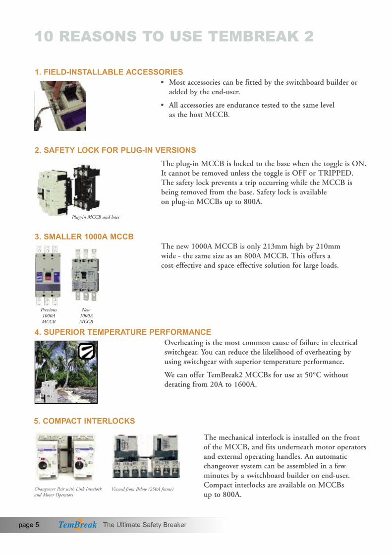
The new 1000A MCCB is only 213mm high by 210mm wide - the same size as an 800A MCCB. This offers a cost-effective and space-effective solution for large loads.
2. SAFETY LOCK FOR PLUG-IN VERSIONS
3. SMALLER 1000A MCCB
Overheating is the most common cause of failure in electricalswitchgear. You can reduce the likelihood of overheating byusing switchgear with superior temperature performance.
We can offer TemBreak2 MCCBs for use at 50°C withoutderating from 20A to 1600A.
4. SUPERIOR TEMPERATURE PERFORMANCE
Plug-in MCCB and base
Previous 1000A MCCB
New 1000A MCCB
Changeover Pair with Link Interlockand Motor Operators
Viewed from Below (250A frame)

The Ultimate Safety Breaker page 6
Under the heading “Measures to minimise the risk in the event offailure”. IEC 60204-1 Safety of Machinery-Electrical Equipmentof Machinery includes the following recommendation:
“-the use of switching devices having positive (or direct) opening operation”.
7. DIRECT OPENING ACTION
TemBreak2 offers:
• Electronic protection up to 3200A
• Measurement and data communication
• Thermal-magnetic protection (fixed and adjustable) up to 800A
Save space and save money with our Lite 160A frame breaker.
8. UNSURPASSED FLEXIBILITY
9. NEW 75MM WIDE MCCB UP TO 160A, 40KA
10. VISUAL SAFETY
10 REASONS TO USE TEMBREAK 2
Terasaki CBRs deliver integrated protection from earth leakagefaults, overloads and short-circuits in one device. Ideal for themining industry, temporary site supplies, heavy industry andcommercial building use.
6. CIRCUIT BREAKER WITH INTEGRAL RESIDUAL CURRENT PROTECTION (CBRs)
Coloured indicators display theON or OFF status. The indicators are fully coveredif the breaker trips, and black isthe only visible colour.
ON (I) OFF (O) TRIPPED

WELCOME TO TEMBREAK 2
Terasaki have an innovative approach to product design. Our goal is to develop products which not only meet, but exceed recognised standards.
We use our knowledge of related applications to improvecircuit breaker designs. For instance, when developing the Direct Opening Action, we applied ideas from a machinery safety standard to the design of theTemBreak 2 switching mechanism.
This pro-active development policy confirms our reputation as Innovators in Protection Technology.
Machine Safety
TemBreak 2 MCCBs are marked with IEC symbol indicatingDirect Opening Action.
The robust mechanism ensures that the force you apply to the toggle is transmitted directly to the contacts.
Under the heading “Measures to minimise risk in the event offailure”, IEC 60204-1 Safety of Machinery - ElectricalEquipment of Machines includes the followingrecommendation:
TemBreak 2 MCCBs help you to comply with the world’s moststringent safety standards. It is one of the safest switchingdevices for machinery.
“ - the use of switching devices having positive (or direct) opening operation.”
Opening force istransmitteddirectly fromthe toggle switch
Contacts separated Maintenance canbe performed onthe load side
page 7 The Ultimate Safety Breaker

WELCOME TO TEMBREAK 2
You can easily see if a breaker is open, closed or tripped. SAFETY+ colouredindicators boldly display the ON or OFF status. The indicators are fully covered ifa breaker trips, and black is the only visible colour.
This is a unique safety feature. You can identify faulty circuits at a glance.
The toggle position always matches the position of the main contacts.
ON (I) OFF (O) TRIPPED
The risk of touching live parts has been minimised by design. These features reduce the risk of touching live parts:
• There are no exposed metal screws on the front face
• IP20 protection at the terminals
• IP30 protection at the toggle
• If the toggle is broken by accident or misuse, no live part is exposed
• No live parts are exposed when fitting accessories
• Double Insulation
Touch Safety
Visual Safety
The Ultimate Safety Breaker page 8

page 9 The Ultimate Safety Breaker
WELCOME TO TEMBREAK 2
Safety Plus
TemBreak 2 MCCBs exceed the requirements of recognised standards.
International Compliance
• The TemBreak 2 MCCB complies with the internationalstandard IEC 60947-2
• TemBreak 2 Switch Disconnectors comply with IEC 60947-3
• Accessories comply with IEC 60947-5-1
• The entire range conforms to the IEC general rules for switchgear, IEC 60947-1
• TemBreak 2 MCCBs comply with JIS C 8201-2-1 Ann.1
• The TemBreak 2 range complies with the EC Low Voltage Directive and all models are CE marked
• TemBreak 2 MCCBs carry the IEC symbol indicating Direct Opening Action as defined by IEC 60947-5-1. IEC 60204-1, Safety of Machinery - Electrical Equipment of Machines recommends that switches used for machinery have Direct Opening Action to minimise risk in the event of failure
• TemBreak 2 MCCBs have breaking capacity ratings accordingto the NEMA AB1 Standard
Independent TestsTemBreak 2 circuit breakers have been tested at independent laboratories as well as in Terasaki's own laboratory in Osaka, Japan. Copies of independent test reports are availableon request.
Marine ApprovalsTemBreak 2 MCCBs are approved by the leading marine approval organisations.
JAPANESE DESIGN: EXCEEDING STANDARDS

WELCOME TO TEMBREAK 2JAPANESE DESIGN: REDUCING ENVIRONMENTAL IMPACT
Longer Life Cycle It makes good environmental sense to install a product with a long life expectancy. If you install a TemBreak 2MCCB, you can expect it to stay in service for at least 30,000 mechanical operations (250A Frame). This is 22,000 more operations than recommended by IEC 60947-2, the international standard for circuit breakers.
If a system must be upgraded in future, we have made the following provisions for recycling:
The modular design of TemBreak 2 allows component parts and accessories to be easily disassembled and separately disposed of. Moulded parts do not contain any embedded metal parts.
Materials are clearly marked to allow future identification for easy recycling.
Uses Eco-friendly MaterialsThe following materials are used in most TemBreak 2 circuitbreakers:
• Thermoplastic resin not containing PBBs or PBDEs
• Lead-free solder
• Cadmium-free contacts
Lighter and SmallerComponents with low weight and volume make life easy for users, but high performance from smaller products alsomeans less material used and less waste produced.
1
2
ISO 14001 Terasaki operate an Environmental Management System accredited to ISO 14001:2004. This requires us to monitor and measure the environmental performance of our activities, products and services in order to continually improve such performance.
1
2
The Ultimate Safety Breaker page 10

page 11 The Ultimate Safety Breaker

The Ultimate Safety Breaker page 12
TEMBREAK 2 & TEMBREAK MCCBS FROM 12A TO 3200A • MCCBS FOR 1000V AC MCCBS FOR 1000V DC • MCCBS WITH INTEgRAL RCD SWITCH DISCONNECTORS • MEASUREMENT AND DATA COMMUNICATION
RATINGS AND SPECIFICATIONS
PROTECTION CHARACTERISTICS
APPLICATION DATA
ACCESSORIES
INSTALLATION
DIMENSIONS
ORDER CODES
SECTION 1
SECTION 2
SECTION 3
SECTION 4
SECTION 5
SECTION 6
SECTION 7
CONTENTS

TEMBREAK 2MOULDED CASECIRCUITBREAKERS
S400-NNS250-NNS125-NNS250-SNS160-SN
Frame Reference
VS125-NJ VS250-NJ
page 13 The Ultimate Safety Breaker
RATINGS AND SPECIFICATIONSTB2 Lite 160
160 250 125 250 250 400 630Max. In (A) of Frame
TB2 Lite 250 TB2 S125 TB2 S250 TB2 S/H/L 250 TB2 H/L 400 TB2 E/S 630
S125-NJS125-gJ
S160-NJS160-gJS250-NJS250-gJ
H125-NJL125-NJH160-NJL160-NJH250-NJL250-NJ
S250-NE
S250-gES250-PEH250-NE
L125-PJ L400-PE
XV400NE
E400-NJS400-CJS400-NJS400-gJS400-PJS400-NE
S400-gE
S400-PES630-CEE630-NES630-gE
H400-NE
L400-NE
TEMBREAK 2CIRCUITBREAKERS WITHIcu = 70KA AT 690V Ac
TEMBREAK 2CIRCUITBREAKERS FOR 1000V Ac
TEMBREAK 2 LITESPACE SAVINg,MONEY SAVINgMOULDED CASE CIRCUITBREAKERS
E160-SFS160-SCFS160-SFE160-SJ
S160-SCJS160-SJ
E250-SCFE250-SFS250-SF
E250-SCJE250-SJS250-SJ
TEMBREAK 2CIRCUITBREAKERS WITHINTEgRALRESIDUALCURRENTPROTECTION(CBR)
ZE125-NJZS125-NJZS125-gJ
ZE250-NJZS250-NJZS250-gJ
TEMBREAK 2CIRCUITBREAKERS ANDSWITCH-DISCONNECTORSFOR USE ABOVE250V DC
S250-SD S250-gD
S250-SDN
S160-SD S160-gD
S160-SDN
PVS160-SDLPVS160-SDHPVS160-SNLPVS160-SNHPVS250-SDLPVS250-SDHPVS250-SNLPVS250-SNH
PVS400-NDLPVS400-NDHPVS400-NNLPVS400-NNH
S400-ND
TEMBREAK 2SWITCHDISCONNECTORS

PVS800-NDLPVS800-NDHPVS800-NNLPVS800-NNH
S800-NDS1000-ND
XS1250ND XS1600ND XS2000ND
XS2500ND
XS32000ND
The Ultimate Safety Breaker page 14
800 1000 1250 1600 3200
TB2 H/L 800 TB2 1000 TB2 1250 TB2 1600 TB 3200
XV630PE
XV800PE
XV1250NE
L800-PE
H800-NE
L800-NE
S800-CJS800-NJS800-RJS800-NES800-RES1000-SES1000-NE
S1250-SES1250-NES1250-gE
S1600-SES1600-NE
XS2000-NEXS2500-NEXS3200-NE
TEMBREAK 2MOULDED CASECIRCUIT BREAKERS
Pages 15 - 22
TEMBREAK 2CIRCUIT BREAKERSWITH ICU = 70KA AT 690V AC
Page 23
TEMBREAK 2CIRCUIT BREAKERS FOR 1000V AC
Page 24
TEMBREAK 2 LITESPACE SAVING,MONEY SAVINGMOULDED CASE CIRCUITBREAKERS
Pages 25 - 28
TEMBREAK 2CIRCUIT BREAKERSWITH INTEGRALRESIDUAL CURRENTPROTECTION (CBR)
Pages 29 - 30
CIRCUIT BREAKERS ANDSWITCH-DISCONNECTORSFOR USE ABOVE250V DC
Pages 31 - 34
SWITCHDISCONNECTORS
Pages 35 - 38
S800-NN S1250-NN S1600-NN XS2000-NN
XS2500-NN
CONTENTS SECTION 1
Tembreak 1. Frame sizes vary from TemBreak 2. Contact Terasaki for ratings and specifications.

TEMBREAK 2 MOULDED CASE CIRCUIT BREAKERSMCCB Electrical Characteristics to IEC 60947-2, EN 60947-2, JIS C 8201-2-1 ANN.1, AS/NZS 3947-2, NEMA AB-1
page 15 The Ultimate Safety Breaker Standard • Optional - Not Available
30,00030,000
RATINGS AND SPECIFICATIONS
TB2 S125
125
Frame Reference Quantity Unit Condition
Max In (A) of Frame
Model S125 S125Number of Poles 3, 4 3,4 Type NJ gJ
Nominal current ratings
In (A) 50°C 20,32,50, 20,32,50,63,100,125 63,100,125
Electrical characteristics
Rated operational voltage Ue (V) AC 50/60 Hz 690 690DC 250 250
Rated insulation voltage Ui (V) 800 800Rated impulse withstand voltage Uimp (kV) 8 8 8 8 8 8 8 8 8 8 8 8
Ultimate breaking capacity Icu (kA) 690V AC 6 6 7 (IEC, JIS, AS/NZS) 525V AC 22 25
440V AC 25 50 400/415V AC 36 65 220/240V AC 50 85 250V DC 25 40
Service breaking capacity Ics (kA) 690V AC 6 6 7 (IEC, JIS, AS/NZS) 525V AC 22 22
440V AC 25 25 400/415V AC 36/30 36/33 220/240V AC 50 85 250V DC 19 40
Rated breaking capacity (NEMA) (kA) 480V AC 22 25 240VAC 50 85
Protection
Adjustable thermal, adjustable magneticFixed thermal, fixed magneticMicroprocessorUtilisation category A A A A A A A A A A A A
Installation
Front connection (FC)Extension bar (FB) • • • • • • • • • • • •Cable clamp (FW) • • • • • • • • • • • •Rear connection (RC) • • • • • • • • • • • •Plug-in (PM) • • • • • • • • • • •*DIN rail mounting (DA) • • -Dimensions height (mm) 155 155
width (mm) 3 pole, (1 pole) 90 904 pole 120 120
depth (mm) 68 68Weight weight (kg) 3 pole, (1 pole) 1.1 1.1
4 pole 1.4 1.4
Operation
Direct Opening ActionToggle operation Door mounted (HS) / Breaker mounted handle (HB) • • • • • • • • • • • •Motor operation (MC) • • • • • • • • • • • •
Endurance Electrical cycles 415V ACMechanical cycles

TB2 S/H/L 250TB2 S250TB2 S250 SECTION 1
The Ultimate Safety Breaker page 16*Applies only to 20A and 32A models **Max. rating 200A for Plug-in
10,00030,000
30,00030,000
20,00030,000
20,00030,000
160 250 125
RATINGS AND SPECIFICATIONS
160 250
10,00030,000
S160 S160 S250 S250 H125 L125 H160 L160 S250 S250 3, 4 3, 4 3, 4 3, 4 3, 4 3, 4 3, 4 3, 4 3, 4 3, 4
NJ gJ NJ gJ NJ NJ NJ NJ NE gE
20,32,50, 50,63,100, 160 160 20,32, 20,32, 160 160 40 4063,100, 125,160 200 200 50,63, 50,63, 125 125125,160 250 250 100, 100, 160 160
125 125 250 250
690 690 690 690 690 690 690 690 690 690250 250 250 250 250 250 250 250 - -
R 800 800 800 800 800 800 800 800 800 800 8 8 8 8 8 8 8 8 8 8
U 7.5 (5*) 7.5 7.5 7.5 20 25 20 25 7.5 7.5 25 (18*) 25 25 25 45 65 45 65 25 25
25 (18*) 50 25 50 120 180 120 180 25 50 36 (30*) 65 36 65 125 200 125 200 36 65 65 (42*) 85 65 85 150 200 150 200 65 85
40 (30*) 40 40 40 40 40 40 40 - -
S 7.5 (5*) 7.5 7.5 7.5 15 20 15 20 7.5 7.5 25 (18*) 25 25 25 45 65 45 65 25 25
25 (18*) 25 25 25 80 135 80 135 25 25 36 (25*) 36 36 36 85 150 85 150 36 36 65 (35*) 85 65 85 150 150 150 150 65 85
40 (25*) 40 40 40 40 40 40 40 - -
R 22 (18*) 25 22 25 45 65 45 65 25 2565 (42*) 85 65 85 150 200 150 200 65 85
A A A A A A A A A A
I
• • • • • • • • • •
C • • • • • • • • • •R • • • • • • • • • •P • • • • • • • • •** •**
- - - - - - - - - -D 165 165 165 165 165 165 165 165 165 165
105 105 105 105 105 105 105 105 105 105 140 140 140 140 140 140 140 140 140 140
68 68 68 68 103 103 103 103 103 103 1.5 1.5 1.5 1.5 2.4 2.4 2.5 2.5 2.3 2.3 1.9 1.9 1.9 1.9 3.2 3.2 3.3 3.3 3.1 3.1
• • • • • • • • • •M • • • • • • • • • •
E

page 17 The Ultimate Safety Breaker Standard • Optional - Not Available
10,00030,000
RATINGS AND SPECIFICATIONS
TB2 S/H/L 250
250
TEMBREAK 2 MOULDED CASE CIRCUIT BREAKERSMCCB Electrical Characteristics to IEC 60947-2, EN 60947-2, JIS C 8201-2-1 ANN.1, AS/NZS 3947-2, NEMA AB-1
Frame Reference Quantity Unit Condition
Max In (A) of Frame
Model S250 H250 H250 L250Number of Poles 3, 4 3, 4 3, 4 3, 4 Type PE NJ NE NJ
Nominal current ratings
In (A) 50°C 40, 160, 40, 160125 250 125 250160 160250 250
Electrical characteristics
Rated operational voltage Ue (V) AC 50/60 Hz 690 690 690 690DC - 250 - 250
Rated insulation voltage Ui (V) 800 800 800 800 Rated impulse withstand voltage Uimp (kV) 8 8 8 8 8 8 8 8 8 8 8 8 8 8 8 8 8
Ultimate breaking capacity Icu (kA) 690V AC 20 20 20 25(IEC, JIS, AS/NZS) 525V AC 35 45 45 65
440V AC 50 120 120 180400/415V AC 70 125 125 200220/240V AC 125 150 150 200250V DC - 40 - 40
Service breaking capacity Ics (kA) 690V AC 15 15 15 20(IEC, JIS, AS/NZS) 525V AC 35 45 45 65
440V AC 50 80 80 135400/415V AC 70 85 85 150220/240V AC 125 150 150 150250V DC - 40 - 40
Rated breaking capacity (NEMA) (kA) 480V AC 35 45 45 65240V AC 125 150 150 200
Rated short-time withstand current Icw (kA) 0.3 Seconds - - - - 5 5 - - - 5 - 5 - 5 - -
Protection
Adjustable thermal, adjustable magneticFixed thermal, fixed magneticMicroprocessorUtilisation category A A A A B B
Installation
Front connection (FC)Extension bar (FB) • • • •Cable clamp (FW) • • • •Rear connection (RC) • • • •Plug-in (PM) - • - •DIN rail mounting (DA) - - - - - - - - - - - - - - - - -Dimensions height (mm) 165 165 165 165
width (mm) 3 pole 105 105 105 105 (mm) 4 pole 140 140 140 140
depth (mm) 103 103 103 103Weight weight (kg) 3 pole 2.5 2.4 2.5 2.4
4 pole 3.3 3.2 3.3 3.2
Operation
Direct Opening ActionToggle operationDoor mounted (HS) / Breaker mounted handle (HB) • • • • • • • • • • • • • • • • •Motor operation (MC) • • • • • • • • • • • • • • • • •Endurance Electrical cycles 415V AC
Mechanical cycles

TB2 E/S 630TB2 H/L 400 SECTION 1
The Ultimate Safety Breaker page 18 MCCB cannot be used in IT systems at this voltage. Not fully rated at 50°C refer to Temperature Ratings
Pages 168 169
4,50015,000
630
RATINGS AND SPECIFICATIONS
400
H400 L400 E400 S400 S400 S400 S400 S400 S400 S400 E630 S630 S630 3, 4 3, 4 3, 4 3, 4 3, 4 3, 4 3, 4 3,4 3, 4 3, 4 3, 4 3, 4 3, 4
NE NE NJ CJ NJ NE gJ gE PJ PE NE CE gE
250 250 250 250 250 250 250 250 250 250, 630 630 630400 400 400 400 400 400 400 400 400 400
690 690 525 690 690 690 690 690 690 690 690 690 690- - 250 250 250 - 250 - 250 - - - -
800 800 800 800 800 800 800 800 800 800 800 800 800 8 8 8 8 8 8 8 8 8 8 8 8 8
U 35 50 - 15 20 20 20 20 20 20 10 20 20 45 65 15 22 30 30 30 30 30 30 15 30 30
120 180 22 30 45 45 65 65 80 80 25 45 65 125 200 25 36 50 50 70 70 85 85 36 50 70 150 200 35 50 85 85 100 100 100 100 50 85 100
- - 25 40 40 - 40 - 40 - - - -
S 35 50 - 15 15 15 15 15 15 15 10 15 15 45 65 15 22 30 30 30 30 30 30 15 30 30
80 135 22 30 45 45 50 50 80 80 25 45 50 85 150 25 36 50 50 50 50 85 85 36 50 50 150 150 35 50 85 85 85 85 85 85 50 85 85
- - 19 40 40 - 40 - 40 - - - -
R 45 65 15 22 25 25 30 30 30 30 15 25 30 150 200 35 50 85 85 100 100 100 100 50 85 100
5 5 - - - 5 - 5 - 5 - -
P
B B A A A B A B A B A A A
I
• • • • • • • • • • • • •
C • • • • • • • • • • - - -R • • • • • • • • • • • • •P • • • • • • • • • • D - - - - - - - - - - - - -D 260 260 260 260 260 260 260 260 260 260 260 260 260
140 140 140 140 140 140 140 140 140 140 140 140 140 185 185 185 185 185 185 185 185 185 185 185 185 185
140 140 103 103 103 103 103 103 103 103 103 103 103 7.1 7.1 4.2 4.3 4.2 4.3 4.2 4.3 4.2 4.3 5.0 5.0 5.0 9.4 9.4 5.6 5.6 5.6 5.7 5.6 5.7 5.6 5.7 6.5 6.5 6.5
• • • • • • • • • • • • •M • • • • • • • • • • • • •E

Frame reference
page 19 The Ultimate Safety Breaker Standard • Optional - Not Available
RATINGS AND SPECIFICATIONS
H8003, 4NE
630800
690-
8008
2540
125125150
-20349494
150-
4015010
B
-
-••-
273210280140
••
L8003, 4NE
630800
690-
8008
2545
180200200
-2034
135150150
-45
20010
B
-
-••-
273210280140
••
In
Ue
UiUimp
Icu
Ics
Icw
heightwidth
depthweight
ElectricalMechanical
(A)
(V)
(V)(kV)(kA)
(kA)
(kA)
(kA)
(mm)(mm)
(mm)(kg)
cyclescycles
4,00010,000
TEMBREAK 2 MOULDED CASE CIRCUIT BREAKERSMCCB Electrical Characteristics to IEC 60947-2, EN 60947-2, JIS C 8201-2-1 ANN.1, AS/NZS 3947-2, NEMA AB-1
Quantity Unit Condition TB2 H/L 800
800
50°C
AC 50/60 HzDC
690V AC525V AC440V AC
400/415V AC220/240V AC
250V DC690V AC525V AC440V AC
400/415V AC220/240V AC
250V DC480V AC240V AC
0.3 Seconds
3 pole4 pole
3 pole4 pole
690V AC
Max In (A) of Frame
ModelNumber of PolesType
Nominal current ratings
Electrical characteristics
Rated operational voltage
Rated insulation voltageRated impulse withstand voltageUltimate breaking capacity(IEC, JIS, AS/NZS)
Service breaking capacity(IEC, JIS, AS/NZS)
Rated breaking capacity (NEMA)
Rated short-time withstand current
Protection
Adjustable thermal, adjustable magneticFixed thermal, fixed magnetic Microprocessor Utilisation category
Installation
Front connection (FC)Extension bar (FB)Cable clamp (FWRear connection (RC)Plug-in (PM)DIN rail mounting (DA)Dimensions
Weight
Operation
Direct Opening ActionToggle operationDoor mounted (HS) / Breaker mounted handle (HB)Motor operation (MC)
Endurance

SECTION 1
The Ultimate Safety Breaker page 20
TB2 1000
S16003, 4NE
1600
690-
8008
456585
100/85125
-345065
75/6594-
6512520
B
-•-
--
37021028014027.035.0
••
S12503, 4NE
1250
690-
8008
25456570
100-
2034505075-
4510015
B
-
-••-
37021028012019.825.0
••
S10003, 4NE
1000
690-
8008
25456570
100-
2034505075-
45100
-
A
-
-•--
27321028010311.014.8
••
S8003, 4NJ
630800
690250800
82030505085502030505085503085-
A
••••-
2732102801038.511.5
••
S8003, 4CJ
630800
690250800
81015303650501015303650501550-
A
••••-
2732102801038.511.5
••
RATINGS AND SPECIFICATIONS
S8003, 4RE
630800
690-
8008
25356570
100-
2030505075-
3510010
B
••••-
273210280103
••
S8003, 4NE
630800
690-
8008
2030505085-
2030505085-
308510
B
••••-
273210280103
••
S8003, 4RJ
630800
690250800
825456570
1005020345050755045
100-
A
••••-
2732102801038.511.5
••
S10003, 4SE
1000
690-
8008
2030455085-
1523343865-
3085-
A
-
-•--
27321028010311.014.8
••
S12503, 4SE
1250
690-
8008
2030455085-
1523343865-
308515
B
-
-••-
37021028012019.825.0
••
S12503, 4gE
1250
690-
8008
456585
100/85125
-345065
75/6594-
6512515
B
-
-••-
37021028012019.825.0
••
S16003, 4SE
1600
690-
8008
2030455085-
1523343865-
308520
B
-•-
--
37021028014027.035.0
••
4,00010,000
2,0005,000
4,0005,000
TB2 1250 TB2 1600
1000 1250 1600
16.8kg 630A, 18.8kg 800A MCCB cannot be used in
IT systems at this voltage Not fully rated at 50ºC,
refer to temperature ratings pages 168 -169
100KA at 400V 75KA at 400V 630A only 8.7kg 630A, 9.1kg 800A 11.9kg 630A, 12.3kg 800A 13.3kg 630A, 14.8kg 800A
Max In (A) of Frame
ModelNumber of PolesType
Nominal current ratings
Electrical characteristics
Rated operational voltage
Rated insulation voltageRated impulse withstand voltageUltimate breaking capacity(IEC, JIS, AS/NZS)
Service breaking capacity(IEC, JIS, AS/NZS)
Rated breaking capacity (NEMA)
Rated short-time withstand current
Protection
Adjustable thermal, adjustable magneticFixed thermal, fixed magnetic Microprocessor Utilisation category
Installation
Front connection (FC)Extension bar (FB)Cable clamp (FWRear connection (RC)Plug-in (PM)DIN rail mounting (DA)Dimensions
Weight
Operation
Direct Opening ActionToggle operationDoor mounted (HS) / Breaker mounted handle (HB)Motor operation (MC)
Endurance

Max In (A) of Frame
ModelNumber of PolesType
Nominal current ratings
Electrical characteristics
Rated operational voltage
Rated insulation voltageRated impulse withstand voltageUltimate breaking capacity(IEC, JIS, AS/NZS)
Service breaking capacity(IEC, JIS, AS/NZS)
Rated short-time withstand current
Protection
Adjustable thermal, adjustable magneticFixed thermal, fixed magnetic Microprocessor Utilisation category
Installation
Front connection (FC)Extension bar (FB)Cable clamp (FWRear connection (RC)Plug-in (PM)DIN rail mounting (DA)Dimensions
Weight
Operation
Direct Opening ActionToggle operationDoor mounted (HS) / Breaker mounted handle (HB)Motor operation (MC)
Endurance
XS20003, 4NE
2000
690690
8
456585
100/85125
-424964
75/6494-
42
B
-•-
--
4503204291855467
-
OHE TYPE•
5002500
XS25003, 4NE
2500
690690
8
456585
100/85125
-424964
75/6494-
42
B
---
--
4503204291856378
-
OHE TYPE•
5002500
page 21 The Ultimate Safety Breaker Standard • Optional - Not Available
RATINGS AND SPECIFICATIONS
In
UeUi
Uimp
Icu
Ics
Icw
heightwidth
depthweight
ElectricalMechanical
(A)
(V)(V)(kV)
(kA)
(kA)
(kA)
(mm)(mm)
(mm)(kg)
cyclescycles
TEMBREAK MOULDED CASE CIRCUIT BREAKERSMCCB Electrical Characteristics to IEC 60947-2, EN 60947-2, JIS C 8201-2-1 ANN.1, AS/NZS 3947-2, NEMA AB-1
Frame reference Quantity Unit Condition TB 3200
3200
50°C
AC 50/60 Hz
690V AC525V AC440V AC
400/415V AC220/240V AC
250V DC690V AC525V AC440V AC
400/415V AC220/240V AC
250V DC
0.3 Seconds
3 pole4 pole
3 pole4 pole
690V AC

Max In (A) of Frame
ModelNumber of PolesType
Nominal current ratings
Electrical characteristics
Rated operational voltage
Rated insulation voltageRated impulse withstand voltageUltimate breaking capacity(IEC, JIS, AS/NZS)
Service breaking capacity(IEC, JIS, AS/NZS)
Rated short-time withstand current
Protection
Adjustable thermal, adjustable magneticFixed thermal, fixed magnetic Microprocessor Utilisation category
Installation
Front connection (FC)Extension bar (FB)Cable clamp (FWRear connection (RC)Plug-in (PM)DIN rail mounting (DA)Dimensions
Weight
Operation
Direct Opening ActionToggle operationDoor mounted (HS) / Breaker mounted handle (HB)Motor operation (MC)
Endurance
XS32003
NE
3200
690690
8
456585
100/65125
-425065
75/6594-
38 (0.5s)
B
---
--
450320
-18565-
-
OHE TYPE•
5002500
3200
SECTION 1
The Ultimate Safety Breaker page 22
RATINGS AND SPECIFICATIONS
TB 3200
MCCB cannot be used in IT systems at this voltage

TB2 H/L 800TB2 H/L 400TB2 H/L 250
630,800
690800
8
70
50
10
B
---
•-
273210140
••
5002,500
13.3kg/630A, 14.8kg/800 A Refer temperature rating table pages 168 - 169
In
UeUi
Uimp
Icu
Ics
Icw
heightwidthdepth
weight
ElectricalMechanical
(A)
(V)(V)(kV)
(kA)
(kA)
(kA)
(mm)(mm)(mm)
(kg)
cyclescycles
50°C
AC 50/60 Hz
690V AC
690V AC
0.3 Seconds
3 pole
3 pole
690V AC
page 23 The Ultimate Safety Breaker
25,32,50,60, 100,125
690800
8
70
33
-
A
•-••-
165105103
2.4
••
1,0007,000
250,400
690800
8
70
50
5
B
---
•-
260140140
7.1
••
1,0004,000
Quantity Unit Condition
RATINGS AND SPECIFICATIONSTEMBREAK 2 CIRCUIT BREAKERS WITH ICU = 70KA @ 690V ACMCCB Electrical Characteristics to IEC 60947-2, EN60947-2, JIS C 8201-2-1 ANN.1, AS/NZS 3947-2
Standard • Optional - Not Available
250 400 800
L1253
PJ3
PE3
PE
L400 L800
Frame Reference
Maximum In (A) of Frame
ModelNumber of PolesType
Nominal current Ratings
Electrical characteristics
Rated operational voltageRated insulation voltageRated impulse voltage
Ultimate breaking capacity(IEC, JIS,AS/NZS)
Service breaking capacity(IEC, JIS,AS/NZS)
Rated short-time withstand
Protection
Adjustable thermal, adjustable magneticMicroprocessorUtilisation Category
Installation
Front Connection (FC)Extension Bar (FB)Cable Clamp (FW)Rear Connection (RC)Plug-in (PM)Din Rail Mounting (DA)Dimensions:
Weight
Operation
Direct Opening ActionToggle operationDoor mounted (HS)/ Breaker mounted handle (HB)Motor operation
Endurance

In
UeUi
Uimp
Icu
Ics
heightwidthdepth
weight
ElectricalMechanical
TB2 S250TB2 S 125
The Ultimate Safety Breaker page 24
TEMBREAK 2 CIRCUIT BREAKERS WITH ICU = 70KA @ 690V ACMCCB Electrical Characteristics to IEC 60947-2, EN60947-2, JIS C 8201-2-1 ANN.1, AS/NZS 3947-2
(A)
(V)(V)(kV)
(kA)
(kA)
(mm)(mm)(mm)
(kg)
cyclescycles
50°C
AC 50/60 Hz
1100V AC
1100V AC
3 pole
3 pole
1100V AC
Quantity Unit Condition
RATINGS AND SPECIFICATIONSTEMBREAK 2 CIRCUIT BREAKERS FOR 1000V ACMCCB Electrical Characteristics to IEC 60947-2, EN60947-2, JIS C 8201-2-1 ANN.1
125 250
VS1253
NJ3
NJ
VS250
160,250
11001100
8
6
4
A
••••-
16510568
1.5
••
1,0007,000
20,32
11001100
8
4
4
A
••••-
1559068
1.1
••
1,0007,000
50,63,100125
11001100
8
6
4
A
••••-
1559068
1.1
••
1,0007,000
SECTION 1
CIR
CU
IT BR
EA
KE
RS
FOR
1000V A
C A
RE
AVAILA
BLE
UP TO
1250A. A
SK
FOR
DE
TAILS
.
Frame Reference
Maximum In (A)
ModelNumber of PolesType
Nominal current ratings
Electrical characteristics:
Rated operational voltageRated insulation voltageRated impulse voltage
Ultimate breaking capacity(IEC, JIS,AS/NZS)
Service breaking capacity(IEC, JIS,AS/NZS)
Protection
Adjustable thermal, adjustable magneticUtilisation Category
Installation
Front Connection (FC)Extension Bar (FB)Cable Clamp (FW)Rear Connection (RC)Plug-in (PM)Din Rail Mounting (DA)Dimensions:
Weight
Operation:
Direct Opening ActionToggle operationDoor mounted (HS)/ Breaker mounted handle (HB)Motor operation
Endurance

page 25 The Ultimate Safety Breaker Standard • Optional - Not Available
RATINGS AND SPECIFICATIONSTEMBREAK 2 LITE MOULDED CASE CIRCUIT BREAKERSMCCB Electrical Characteristics to IEC 60947-2, EN60947-2, JIS C 8201-2-1 ANN.1, NEMA AB-1
160 160TB2 Lite 160Frame Reference Quantity Unit Condition
Max in ( A) of Frame
Model E160 E160 E160 S160 S160 S160 S160Number of Poles 1 3,4 3, 4 3, 4 3, 4 3, 4 3, 4Type SF SF SJ SCF SCJ SF SJ
Nominal current ratings
In (A) 50°C 16,20,25,32, 16,20,25, 25,40,63,80 16,20,25,32 25,40,63,80, 16,20,25,32 25,40,63,8040,50,63,80, 32,40,50, 100,125,160 40,50,63,80, 100,125,160 40,50,63,80, 100,125,160100,125 63,80,100, 100,125,160 100,125,160
125,160Electrical characteristics
Rated operational voltage Ue (V) AC 50/60 Hz 240 525 525 525 525 690 690DC - 250 250 250 250 250 250
Rated insulation voltage Ui (V) 690 690 690 690 690 690 690Rated impulse withstand voltage Uimp (kV) 8 8 8 8 8 8 8
Ultimate breaking capacity Icu (kA) 690V AC - - - - - 6 6(IEC, JIS, AS/NZS) 525V AC - 6 6 7.5 7.5 10 10
440V AC - 10 10 15 15 25 25400/415V AC - 16 16 25 25 40 40220/240V AC 25 25 25 35 35 50 50250V DC - 13 13 20 20 25 25
Service breaking capacity Ics (kA) 690V AC - - - - - 3 3(IEC, JIS, AS/NZS) 525V AC - 3 3 4 4 7.5 7.5
440V AC - 5 5 7.5 7.5 13 13400/415V AC - 8 8 13 13 20 20220/240V AC 13 13 13 18 18 25 25250V DC - 7 7 10 10 13 13
Rated breaking capacity (NEMA) (kA) 480V AC - 6 6 7.5 7.5 10 10240VAC 25 25 25 35 35 50 50
Protection
Fixed thermal, fixed magnetic - - -
Adjustable thermal, fixed magnetic - - - -Utilisation category A A A A A A A
Installation
Front connection (FC)Extension bar (FB) • • • • • • •Cable clamp (FW) - - - Rear connection (RC) - • • • • • •Plug-in (PM) - - - - - - -DIN rail mounting (DA) - • • • • • •Dimensions height (mm) 130 130 130 130 130 130 130
width (mm) 3 pole, (1 pole) (25) 75 75 75 75 75 754 pole - 100 100 100 100 100 100
depth (mm) 68 68 68 68 68 68 68Weight weight (kg) 3 pole, (1 pole) (0.3) 0.8 0.8 0.8 0.8 0.8 0.8
4 pole - 1.0 1.0 1.0 1.0 1.0 1.0
Operation
Direct Opening ActionToggle operation Door mounted (HS) / Breaker mounted handle (HB) - • • • • • •Motor operation - - - - - - -
Endurance Electrical cycles 415V AC 10,000 10,000 10,000 10,000 10,000 10,000 10,000Mechanical cycles 20,000 20,000 20,000 20,000 20,000 20,000 20,000

The Ultimate Safety Breaker page 26 Factory-fit at time of order 14,000 ≤125A
TB2 Lite 160
RATINGS AND SPECIFICATIONS
160
SECTION 1
Frame Reference Quantity Unit Condition
Max in ( A) of Frame
Model E160 E160 E160 S160 S160 S160 S160Number of Poles 1 3,4 3, 4 3, 4 3, 4 3, 4 3, 4Type SF SF SJ SCF SCJ SF SJ
Nominal current ratings
In (A) 50°C 16,20,25,32, 16,20,25, 25,40,63,80 16,20,25,32 25,40,63,80, 16,20,25,32 25,40,63,8040,50,63,80, 32,40,50, 100,125,160 40,50,63,80, 100,125,160 40,50,63,80, 100,125,160100,125 63,80,100, 100,125,160 100,125,160
125,160Electrical characteristics
Rated operational voltage Ue (V) AC 50/60 Hz 240 525 525 525 525 690 690DC - 250 250 250 250 250 250
Rated insulation voltage Ui (V) 690 690 690 690 690 690 690Rated impulse withstand voltage Uimp (kV) 8 8 8 8 8 8 8
Ultimate breaking capacity Icu (kA) 690V AC - - - - - 6 6(IEC, JIS, AS/NZS) 525V AC - 6 6 7.5 7.5 10 10
440V AC - 10 10 15 15 25 25400/415V AC - 16 16 25 25 40 40220/240V AC 25 25 25 35 35 50 50250V DC - 13 13 20 20 25 25
Service breaking capacity Ics (kA) 690V AC - - - - - 3 3(IEC, JIS, AS/NZS) 525V AC - 3 3 4 4 7.5 7.5
440V AC - 5 5 7.5 7.5 13 13400/415V AC - 8 8 13 13 20 20220/240V AC 13 13 13 18 18 25 25250V DC - 7 7 10 10 13 13
Rated breaking capacity (NEMA) (kA) 480V AC - 6 6 7.5 7.5 10 10240VAC 25 25 25 35 35 50 50
Protection
Fixed thermal, fixed magnetic - - -
Adjustable thermal, fixed magnetic - - - -Utilisation category A A A A A A A
Installation
Front connection (FC)Extension bar (FB) • • • • • • •Cable clamp (FW) - - - Rear connection (RC) - • • • • • •Plug-in (PM) - - - - - - -DIN rail mounting (DA) - • • • • • •Dimensions height (mm) 130 130 130 130 130 130 130
width (mm) 3 pole, (1 pole) (25) 75 75 75 75 75 754 pole - 100 100 100 100 100 100
depth (mm) 68 68 68 68 68 68 68Weight weight (kg) 3 pole, (1 pole) (0.3) 0.8 0.8 0.8 0.8 0.8 0.8
4 pole - 1.0 1.0 1.0 1.0 1.0 1.0
Operation
Direct Opening ActionToggle operation Door mounted (HS) / Breaker mounted handle (HB) - • • • • • •Motor operation - - - - - - -
Endurance Electrical cycles 415V AC 10,000 10,000 10,000 10,000 10,000 10,000 10,000Mechanical cycles 20,000 20,000 20,000 20,000 20,000 20,000 20,000

page 27 The Ultimate Safety Breaker Standard • Optional - Not Available
RATINGS AND SPECIFICATIONS
250TB2 Lite 250
TEMBREAK 2 LITE MOULDED CASE CIRCUIT BREAKERSMCCB Electrical Characteristics to IEC 60947-2, EN60947-2, JIS C 8201-2-1 ANN.1, NEMA AB-1
Frame Reference Quantity Unit Condition
Max In (A) of Frame
Model E250 E250 E250 E250 S250 S250Number of Poles 3, 4 3, 4 3, 4 3, 4 3, 4 3, 4Type SCF SCJ SF SJ SF SJ
Nominal current ratings
In (A) 50°C 125,150,175 100,125, 125,150,175 100,125,160 125,150,175 160,200200,225, 160,200 200,225, 200,250 200,225, 250250 250 250 250
Electrical characteristics
Rated operational voltage Ue (V) AC 50/60 Hz 525 525 525 525 690 690DC 250 250 250 250 250 250
Rated insulation voltage Ui (V) 690 800 690 800 690 800Rated impulse voltage Uimp (kV) 8 8 8 8 8 8
Ultimate breaking capacity Icu (kA) 690V AC - - - - 4 4(IEC, JIS, AS/NZS) 525V AC 6 6 7.5 7.5 10 10
440V AC 10 10 15 15 30 30400/415V AC 16 16 25 25 40 40220/240V AC 25 25 35 35 85 85250V DC 13 13 15 15 25 25
Service breaking capacity Ics (kA) 690V AC - - - - 4 4(IEC, JIS, AS/NZS) 525V AC 3 3 6 6 7.5 7.5
440V AC 5 5 12 12 15 15400/415V AC 8 8 19 19 20 20220/240V AC 13 13 27 27 43 43250V DC 7 7 12 12 13 13
Rated breaking capacity (NEMA) (kA) 480V AC 6 6 10 10 25 25240VAC 25 25 35 35 85 85
Protection
Fixed thermal, fixed magnetic - - -
Adjustable thermal, adjustable magnetic - - -Utilisation category A A A A A A
Installation
Front connection (FC)Extension bar (FB) • • • • • •Cable clamp (FW) • • • • • •Rear connection (RC) • • • • • •Plug-in (PM) - - - - - -DIN rail mounting (DA) - - - - - -Dimensions height (mm) 165 165 165 165 165 165
width (mm) 3 pole 105 105 105 105 105 1054 pole 140 140 140 140 140 140
depth (mm) 68 68 68 68 68 68Weight weight (kg) 3 pole 1.5 1.5 1.5 1.5 1.5 1.5
4 pole 1.9 1.9 1.9 1.9 1.9 1.9
Operation
Direct Opening ActionToggle operation Door mounted (HS) / Breaker mounted handle (HB) • • • • • •Motor operation • • • • • •
Endurance Electrical cycles 415V AC 6,000 6,000 6,000 6,000 6,000 6,000Mechanical cycles 18,000 18,000 18,000 18,000 18,000 18,000

The Ultimate Safety Breaker page 28
RATINGS AND SPECIFICATIONS
TB2 Lite 250
250
SECTION 1
Frame Reference Quantity Unit Condition
Max In (A) of Frame
Model E250 E250 E250 E250 S250 S250Number of Poles 3, 4 3, 4 3, 4 3, 4 3, 4 3, 4Type SCF SCJ SF SJ SF SJ
Nominal current ratings
In (A) 50°C 125,150,175 100,125, 125,150,175 100,125,160 125,150,175 160,200200,225, 160,200 200,225, 200,250 200,225, 250250 250 250 250
Electrical characteristics
Rated operational voltage Ue (V) AC 50/60 Hz 525 525 525 525 690 690DC 250 250 250 250 250 250
Rated insulation voltage Ui (V) 690 800 690 800 690 800Rated impulse voltage Uimp (kV) 8 8 8 8 8 8
Ultimate breaking capacity Icu (kA) 690V AC - - - - 4 4(IEC, JIS, AS/NZS) 525V AC 6 6 7.5 7.5 10 10
440V AC 10 10 15 15 30 30400/415V AC 16 16 25 25 40 40220/240V AC 25 25 35 35 85 85250V DC 13 13 15 15 25 25
Service breaking capacity Ics (kA) 690V AC - - - - 4 4(IEC, JIS, AS/NZS) 525V AC 3 3 6 6 7.5 7.5
440V AC 5 5 12 12 15 15400/415V AC 8 8 19 19 20 20220/240V AC 13 13 27 27 43 43250V DC 7 7 12 12 13 13
Rated breaking capacity (NEMA) (kA) 480V AC 6 6 10 10 25 25240VAC 25 25 35 35 85 85
Protection
Fixed thermal, fixed magnetic - - -
Adjustable thermal, adjustable magnetic - - -Utilisation category A A A A A A
Installation
Front connection (FC)Extension bar (FB) • • • • • •Cable clamp (FW) • • • • • •Rear connection (RC) • • • • • •Plug-in (PM) - - - - - -DIN rail mounting (DA) - - - - - -Dimensions height (mm) 165 165 165 165 165 165
width (mm) 3 pole 105 105 105 105 105 1054 pole 140 140 140 140 140 140
depth (mm) 68 68 68 68 68 68Weight weight (kg) 3 pole 1.5 1.5 1.5 1.5 1.5 1.5
4 pole 1.9 1.9 1.9 1.9 1.9 1.9
Operation
Direct Opening ActionToggle operation Door mounted (HS) / Breaker mounted handle (HB) • • • • • •Motor operation • • • • • •
Endurance Electrical cycles 415V AC 6,000 6,000 6,000 6,000 6,000 6,000Mechanical cycles 18,000 18,000 18,000 18,000 18,000 18,000

In
Ue
UiUimp
Icu
Icu
heightwidth
depthweight
ElectricalMechanical
(A)
(V)(V)(kV)
(kA)
(kA)
(mm)(mm)
(mm)(kg)
cyclescycles
50°C
AC 50/60 Hz
525V AC440V AC
400/415V AC220/240V AC
525V AC440V AC
400/415V AC220/240V AC
3 pole4 pole
3 pole4 pole
415V AC
RATINGS AND SPECIFICATIONS
page 29 The Ultimate Safety Breaker Standard • Optional - Not Available
TEMBREAK 2 CIRCUIT BREAKERS WITH INTEGRAL RESIDUAL CURRENTPROTECTION (CBR) MCCB Electrical Characteristics to IEC 60947-1, IEC 60947-2, IEC 60947-2 ANNEX B, IEC 60755
Frame reference Quantity Unit Condition
Maximum In (A) of Frame
ModelNumber of PolesType
Nominal current ratings
Electrical characteristics
Rated operational voltageRated insulation voltageRated impulse voltage
Ultimate breaking capacity(IEC, JIS,AS/NZS)
Service breaking capacity(IEC, JIS,AS/NZS)
Protection
Adjustable thermal, fixed magneticResidual current protection, Type AUtilisation Category
Installation
Front Connection (FC)Extension Bar (FB)Cable Clamp (FW)Rear Connection (RC)Plug-in (PM)Din Rail Mounting (DA)Dimensions:
Weight
Operation
Direct Opening ActionToggle operationDoor mounted (HS)/ Breaker mounted handle (HB)Motor operationResidual Current Monitor and Remote Trip Module
Endurance

NJ
20,3250,63
100,125
525525
8
8152535
6121927
A
•••-•
15590
120681.11.4
•••
30,00030,000
10,00010,000
gJ
160,250
525525
8
25506585
25253685
A
•••-•
165105140681.51.9
•••
NJ
20,3250,63
100,125
525525
8
22253650
2225
36/3050
A
•••-•
15590
120681.11.4
•••
gJ
20,3250,63
100,125
525525
8
25506585
2225
36/3385
A
•••-•
15590
120681.11.4
•••
NJ
160,250
525525
8
10152535
7.5121927
A
•••-•
165105140681.51.9
•••
NJ
160,250
525525
8
25253665
25253665
A
•••-•
165105140681.51.9
•••
SECTION 1
The Ultimate Safety Breaker page 30
RATINGS AND SPECIFICATIONSTEMBREAK 2 CIRCUIT BREAKERS WITH INTEGRAL RESIDUAL CURRENTPROTECTION (CBR) MCCB Electrical Characteristics to IEC 60947-1, IEC 60947-2, IEC 60947-2 ANNEX B, IEC 60755
125ZE125
3,4 3,4 3,4 3,4 3,4 3,4
250
TB2 S125
ZS125 ZS125 ZE250 ZS250 ZS250
TB2 S250

In
UiUimp
Icu
Ics
heightwidth
depthweight
Electrical
Mechanical
3 SD
25,32,40,63,80,100,125,160
6908
--5
7.510
--5
7.510
••--
130+5075-
680.8-
••-
-
1,0007,000
TB2 Lite 160
50°C
AC 50/60 Hz
1000V DC750V DC600V DC500V DC350V DC
1000V DC750V DC600V DC500V DC350V DC
3 pole4 pole
3 pole4 pole
1000V DC750V DC
350 - 600V DC-
RATINGS AND SPECIFICATIONS
3 gD
25,32,40,63,80,100,125,160
6908
--
1015-
--5
7.5-
••--
130+5075-
680.8-
••-
-
1,0007,000
page 31 The Ultimate Safety Breaker Standard • Optional - Not Available
(A)
(V)(kV)
(kA)
(kA)
(mm)(mm)
(mm)(kg)
cycles
cycles
MOULDED CASE CIRCUIT BREAKERS FOR USE ABOVE 250V DCMCCB Electrical Characteristics to IEC 60947-2, EN60947-2, JIS C 8201-2-1 ANN.1
Frame reference Quantity Unit Condition
S160160
S160Max In (A) of Frame
ModelNumber of PolesType
Nominal current ratings
Electrical characteristics
Rated insulation voltageRated impulse voltage
Ultimate breaking capacity(IEC, JIS)
Service breaking capacity(IEC, JIS)
Protection
Adjustable thermal, fixed magneticMagnetic trip only (adjustable)
Installation
Front connection (FC)Extension bar (FB)Rear connection (RC)Plug-in (PM)DIN rail mounting (DA)Dimensions
Weight
Operation
Direct Opening ActionToggle operationBreaker mounted (HB)Door mounted (HS)Motor operation
Endurance

4 SDH
100125160200250
10008
5-
5----
••--
165+55 x 2-
14068-
1.9
•••
1,000--
7,000
TB2 S250
3 SD
100,125160,200,
250
8008
--5
7.510
--5
7.510
••--
165+55105
-681.5-
•••
--
1,0007,000
TB2 Lite 250
3 gD
100,125160,200,
250
8008
--
1015-
--5
7.5-
••--
165+55105
-681.5-
•••
--
1,0007,000
3(4) SDL
5063
100125160
8008
-5(10)
-5(5)
---
••--
165+55 x 2105140681.51.9
•••
-1,000
-7,000
4 SDH
5063
100125160
10008
5-
5----
••--
165+55 x 2-
14068-
1.9
•••
1,000--
7,000
3(4) SDL
100125160200250
8008
-5(10)
-5(5)
---
••--
165+55 x 2105140681.51.9
•••
-1,000
-7,000
SECTION 1
The Ultimate Safety Breaker page 32
RATINGS AND SPECIFICATIONS
250 250S250 PVS160 PVS160 PVS250 PVS250S250
Connect all poles in series when over DC250V The time constant (L/R) of the circuit should be less than 2.0ms nearby
rated current less than 5ms for short circuit < 10kA less than 10ms for short circuit < 20kA less than 15ms for short circuit > 20kA
Includes the dimensions of the terminal cover (Mandatory)

Max In (A) of Frame
ModelNumber of PolesType
Nominal current ratings
Electrical characteristics
Rated insulation voltageRated impulse voltage
Ultimate breaking capacity(IEC, JIS)
Service breaking capacity(IEC, JIS)
Protection
Fixed thermal, fixed magneticAdjustable thermal, fixed magneticMagnetic trip only (adjustable)
Installation
Front connection (FC)Extension bar (FB)Rear connection (RC)Plug-in (PM)DIN rail mounting (DA)Dimensions
Weight
Operation
Direct Opening ActionToggle operationBreaker mounted (HB)Door mounted (HS)Motor operation
Endurance
3ND
250,400
8008
- -
151520
--
151520
••--
260140
-1034.2-
•••
--
1,0004,000
TB2 H/L 400
3 (4)NDL
250,400
800 (1150)8
- 10---
-5 (10)
---
••--
2601401851034.25.6
•••
-1,000
-4,000
In
UiUimp
Icu
Ics
heightwidth
depthweight
Electrical
Mechanical
50°C
AC 50/60 Hz
1000V DC750V DC600V DC500V DC350V DC
1000V DC750V DC600V DC500V DC350V DC
3 pole4 pole
3 pole4 pole
1000V DC750V DC
350 - 600V DC-
RATINGS AND SPECIFICATIONS
(A)
(V)(kV)
(kA)
(kA)
(mm)(mm)
(mm)(kg)
cycles
cycles
MOULDED CASE CIRCUIT BREAKERS FOR USE ABOVE 250V DCMCCB Electrical Characteristics to IEC 60947-2, EN60947-2, JIS C 8201-2-1 ANN.1
Frame reference Quantity Unit Condition TB2 E/S 400
400 400S400 PVS400
page 33 The Ultimate Safety Breaker

3ND
3200
6908
-
205050
--
152525
--
--
450320
-18562.5
-
-
-••
--
5002,500
XS32003
ND
2500
6908
-
205050
--
152525
--
--
450320
-18562.5
-
-
-••
--
5002,500
4NDH
250,400
11508
5 ----
5----
••--
260-
185103
-5.6
•••
-1,000
-4,000
TB2 H/L 400
3 (4)NDL
630,800
800 (1150)8
-10---
-10---
-
•--
2732102801038.511.5
•••
-500
- 2,500
RATINGS AND SPECIFICATIONS
TB2 H/L 800 TB2 1000 TB 1250 TB 1600 TB 3200
XS2000 XS25003
ND
1250
6908
-
205050
--
152525
-
•--
370210
-14026.0
-
•••
--
5002,500
3ND
1600
6908
-
205050
--
152525
-•
--
370210
-14027.0
-
•••
--
5002,500
3ND
2000
6908
-
205050
--
152525
-•
--
450320
-18554.0
-
-
-••
--
5002,500
4NDH
630,800
11508
5----
5----
-
•--
273-
280103
-11.5
•••
500--
2,500
3ND
630,800
8008
--
202030
--
101015
-
•--
273210
-1038.5-
•••
--
5002,500
3ND
1,000
8008
--
202030
--
101015
-
•--
273210
-10310.8
-
•••
--
5002,500
800 800 1000 1250 1600 3200400PVS400 PVS800PVS800 S800 S1000 XS1250 XS1600
SECTION 1
The Ultimate Safety Breaker page 34
Connect all poles in series when over DC250V The time constant (L/R) of the circuit should be less than 2.0ms nearby
rated current less than 5ms for short circuit < 10kA less than 10ms for short circuit < 20kA less than 15ms for short circuit > 20kA
Fixed Depth (not adjustable)

TB2 Lite 160 TB2 Lite 250
(A)
(V)(V)(kV)
(kA peak)(kA rms)
(mm)(mm)
(mm)
(kg)
cycles
cycles
DCAC 50/60 Hz
0.3 secondsDC
3 pole4 pole
3 pole4 pole
1000V DC800V DC600V DC
SDN
160
600690
8
22
DC-22A
••-•
13075-
68
0.8-
••-
--
1,0007,000
SDN
250
600800
8
33
DC-22A
••--
165105
-
68
1.5-
•••
--
1,0007,000
In
UeUi
Uimp
IcmIcw
heightwidth
depth
weight
Electrical
Mechanical
RATINGS AND SPECIFICATIONS
page 35 The Ultimate Safety Breaker Standard • Optional - Not Available
SWITCH-DISCONNECTORS FOR USE ABOVE 250V DCMCCB Electrical Characteristics to IEC 60947-3, EN60947-3, JIS C 8201-3
Frame reference Quantity Unit Condition
160 250S160 S250
3 3
Max In (A) of Frame
ModelNumber of PolesType
Nominal current ratings
Electrical characteristics
Rated operational voltage Rated insulation voltageRated impulse voltage
Rated short circuit making capacityRated short-time withstand currentUtilisation category to IEC 60947-3
Installation
Front connection (FC)Extension bar (FB)Rear connection (RC)Plug-in (PM)DIN rail mounting (DA)Dimensions
Weight
Operation
Direct Opening ActionToggle operationBreaker mounted handle (HB)Door mounted (HS)Motor operation
Endurance

400PVS400
NNL
400
8001150
8
95
DC-22A
••--
260-
185
103
-5.6
•••
-1,000
-4,000
NNH
400
10001150
8
95
DC-22A
••--
260-
185
103
-5.6
•••
1,000--
4,000
NNL
630800
8001150
8
1710
DC-22A
-
•--
273-
280
103
-11.5
•••
-500
-2,500
NNH
630800
10001150
8
1710
DC-22A
-
•--
273-
280
103
-11.5
•••
500--
2,500
SNL
250
800800
8
33
DC-22A
••--
165+55 x 2-
140
68
-1.9
•••
-1,000
-7,000
SNH
250
10001000
8
33
DC-22A
••--
165+55 x 2-
140
68
-1.9
•••
1,000--
7,000
TB2 S250
SNL
160
800800
8
33
DC-22A
••--
165+55 x 2-
140
68
-1.9
•••
-1,000
-7,000
SNH
160
10001000
8
33
DC-22A
••--
165 + 55 x 2-
140
68
-1.9
•••
1,000--
7,000
TB2 H/L 400 TB2 H/L 800
4 4 4 4 4
SECTION 1
The Ultimate Safety Breaker page 36
RATINGS AND SPECIFICATIONS
250PVS160 PVS160 PVS250 PVS250
44 4
800
PVS400 PVS800 PVS800
Connect all poles in series. The time constant (L/R) of the circuit should be less than 2.0ms nearby
rated current less than 5ms for short circuit < 10kA less than 10ms for short circuit < 20kA less than 15ms for short circuit > 20kA
Includes the dimensions of the terminal cover (mandatory).

Max In (A) of Frame
ModelNumber of PolesType
Nominal current ratings
Electrical characteristics
Rated operational voltage
Rated insulation voltageRated impulse withstand voltageRated short-circuit making capacityRated short-time withstand currentUtilisation category to IEC 60947-3
Installation
Front connection (FC)Extension bar (FB)Cable clamp (FW)Rear connection (RC)Plug-in (PM)Draw-out (DR)DIN rail mounting (DA)Dimensions
Weight
Operation
Direct Opening ActionToggle operationDoor mounted (HS) / Breaker mounted handle (HB)Motor operation (MC)
Endurance
TB2 Lite 250TB2 Lite 160
page 37 The Ultimate Safety Breaker Standard • Optional - Not Available
RATINGS AND SPECIFICATIONS
Frame reference
250
S2503, 4SN
250
690250800
863
AC-23ADC-22A
•••---
165105140681.51.9
••
600018000
(A)
(V)
(V)(kV)
(kA peak)(kA rms)
(mm)(mm)
(mm)(kg)
cyclescycles
Ie
Ue
UiUimp
IcmIcw
heightwidth
depthweight
ElectricalMechanical
160
S1603, 4SN
160
690250690
82.82
AC-23ADC-22A
•••--•
13075
100680.70.9
••
10,00020,000
AC 50/60 HzDC
0.3 SecondsACDC
3 pole4 pole
3 pole4 pole
415V AC
SWITCH-DISCONNECTORSMCCB Electrical Characteristics to IEC 60947-3, EN 60947-3, AS/NZS 60947-3
Quantity Unit Condition

1600
S16003, 4NN
1600
690250800
84520
AC-23ADC-22A
-
•-
-•-
37021028014024.932.9
••
2,0005,000
800
S8003, 4NN
630800
690250800
81710
AC-23ADC-22A
•-•••-
273210280103
••
630
S6303, 4NN
630
690250800
89
5
AC-23ADC-22A
•••--
2601401851034.45.8
••
4,50015,000
TB2 1600TB2 1000 TB21250TB2 S250TBS S125 TB2 E/S 630
8.0kg/630A, 8.5kg/800A 11.0kg/630A, 11.5kg/800A 7.6kA/0.1sec. Contact Terasaki for details.
SECTION 1
The Ultimate Safety Breaker page 38
1000
S10003, 4NN
1000
690250800
81710
AC-23ADC-22A
-
-•---
27321028010310.414.0
••
250
S2503, 4NN
250
690250800
863
AC-23ADC-22A
••••--
165105140681.51.9
••
10,00030,000
400
S4003, 4NN
400
690250800
895
AC-23ADC-22A
••••--
2601401851034.25.6
••
4,50015,000
1250
S12503, 4NN
1250
690250800
83215
AC-23ADC-22A
-
-•••-
37021028012018.223.4
••
4,0005,000
160
S1603, 4NN
160
690250800
863
AC-23ADC-22A
••••--
165105140681.51.9
••
10,00030,000
125
S1253, 4NN
125
690250800
83.62
AC-23ADC-22A
••••-•
15590
120681.11.4
••
30,00030,000
RATINGS AND SPECIFICATIONS
4,00010,000
SW
ITCH
DIS
CO
NN
EC
TOR
S A
RE
AVAILA
BLE
UP TO
2500A. A
SK
US
FOR
DE
TAILS
.

page 39 The Ultimate Safety Breaker

TEMBREAK 2 & TEMBREAK MCCBS FROM 12A TO 3200A • MCCBS FOR 1000V AC MCCBS FOR 1000V DC • MCCBS WITH INTEgRAL RCD SWITCH DISCONNECTORS • MEASUREMENT AND DATA COMMUNICATION
RATINgS AND SPECIFICATIONS
PROTECTION CHARACTERISTICS
APPLICATION DATA
ACCESSORIES
INSTALLATION
DIMENSIONS
ORDER CODES
SECTION 1
SECTION 2
SECTION 3
SECTION 4
SECTION 5
SECTION 6
SECTION 7
CONTENTS
The Ultimate Safety Breaker page 40

TEMBREAK 2MOULDED CASECIRCUITBREAKERS
CIRCUITBREAKERS ANDSWITCH-DISCONNECTORSFOR USE ABOVE250V DC
S125-NJS125-gJ
S160-NJS160-gJS250-NJS250-gJ
L400-PEL125-PJ
VS125-NJ
E400-NJS400-CJS400-NJS400-gJS400-PJS400-NE
S400-gE
S400-PES630-CEE630-NES630-NES630-gE
H400-NE
L400-NE
160 250 125 250 250 400 630Frame Reference
Max. In (A) of Frame
E160-SFS160-SCFS160-SF
E160-SJS160-SCJS160-SJ
E250-SCFE250-SFS250-SF
E250-SCJE250-SJS250-SJ
page 41 The Ultimate Safety Breaker Standard • Optional - Not Available
VS250-NJ
PROTECTION CHARACTERISTICSTB2 Lite 160 TB2 Lite 250 TBS 125 TB2 S250 TB2 S/H/L 250 TB2 H/L 400 TB2 E/S 630
H125-NJL125-NJH160-NJL160-NJH250-NJL250-NJ
S250-NE
S250-gES250-PEH250-NE
TEMBREAK 2CIRCUITBREAKERS WITHIcu = 70KA AT 690V Ac
TEMBREAK 2CIRCUITBREAKERS FOR 1000V Ac
TEMBREAK 2 LITESPACE SAVINg,MONEY SAVINgMOULDED CASE CIRCUITBREAKERS
ZE125-NJZS125-NJZS125-gJ
ZE250-NJZS250-NJZS250-gJ
TEMBREAK 2CIRCUITBREAKERS WITHINTEgRALRESIDUALCURRENTPROTECTION(CBR)
S160-SD S160-gD
S160-SDN
S250-SD S250-gD
S250-SDN
PVS160-SDLPVS160-SDHPVS250-SDLPVS250-SDH
S400-ND 350V DC
S400-ND 600V DC
PVS400-NDL PVS400-NDH
●
●
●●
XV400NE

L800-PE
ELECTRONIC PROTECTION Pages 60 - 70
XS2000NEXS2500NEXS3200NE
12501000800
ELECTRONIC PROTECTION WITH MEASUREMENTAND DATACOMMUNICATION
Pages 71 - 77
ELECTRONIC PROTECTION LET-THROUGHCHARACTERISTICS
Pages 78 - 87
TEMBREAK 2ADJUSTABLETHERMAL ANDADJUSTABLEMAGNETICPROTECTION Pages 43 - 59
TEMBREAK 2 LITE FIXEDPROTECTION
Pages 88 - 94
TEMBREAK 2 LITE ADJUSTABLEPROTECTION
Pages 95 - 101
RESIDUAL (EARTH LEAKAGE)CURRENTPROTECTION
Pages 102 - 104
DC PROTECTION
Pages 105 - 109
The Ultimate Safety Breaker page 42
Except L400-PE, L800-PE, S1250 and S1600 TemBreak 1. Frame sizes vary from Tembreak 2. Contact Terasaki for protection characteristics.
PVS800-NDLPVS800-NDH
S800-NDS1000-ND
XS1250ND XS1600ND XS2000NDXS2500ND
XS3200ND
1600 3200
TB2 H/L 800 TB2 1000 TB2 1250 TB2 1600 TB 3200
S800-CJS800-NJS800-RJS800-NES800-NES800-RES1000-SE
S1000-NE
S1250-SES1250-NES1250-gE
S1600-NES1600-SE
H800-NE
L800-NE
●
● ●
● ●
XV630PEXV800PE
XV1250NE
●●
●
CONTENTS SECTION 2

page 43 The Ultimate Safety Breaker
TEMBREAK 2 ADJUSTABLE THERMAL AND ADJUSTABLEMAGNETIC PROTECTION
3 Pole MCCB with Adjustable Thermal and Adjustable Magnetic Characteristics
All standard 3 pole and 4 pole TemBreak 2 thermal magnetic models have adjustable thermal andadjustable magnetic characteristics.
Traditionally, thermal magnetic MCCBs have had adjustable thermal with fixed magnetic characteristics. The fixed magnetic element can limit the application of the MCCB.
An adjustable magnetic characteristic allows short-circuit protection to be matched to the load and supply characteristics, for example motor inrush currents or generator short-circuit currents.Lowering the short-circuit tripping threshold can allow a higher earth-loop impedance in an installation and provide end-of-cable protection with the correct disconnection times.
Thermal Magnetic trip units are especially suited to the following applications:
• Installations where harmonic distortion of current waveforms is likely. They operate inherently on the root mean square (rms) heating effect of current.
• DC circuits. Refer to section 3“MCCBs in DC SYSTEMS” for more information.
PROTECTION CHARACTERISTICS

Model Type Rated current In (A) Magnetic trip current Ii (A)
S125 -NJ 20, 32, 50, 63, 100 6 – 12 xIn125 6 – 10 xIn
S125 -gJ 20, 32, 50, 63, 100 6 – 12 xIn125 6 – 10 xIn
H125 -NJ 20, 32, 50, 63, 100, 125 6 - 12 xInL125 -NJ 20, 32, 50, 63, 100, 125 6 – 12 xInVS125 -NJ 20, 32, 50, 63, 100 6 – 12 xIn
125 6 – 10 xInL125 -PJ 20, 32, 50, 63, 100, 125 6 – 12 xInS160 -NJ 20, 32, 50, 63, 100, 125 6 – 12 xIn
160 6 – 13 xInS160 -gJ 50, 63, 100, 125 6 – 12 xIn
160 6 – 13 xInH160 -NJ 160 6 – 13 xInL160 -NJ 160 6 – 13 xInS250 -NJ 160, 200 6 – 13 xIn
250 6 – 10 xInS250 -gJ 160, 200 6 – 13 xIn
250 (225A for Plug-In) 6 – 10 xInH250 -NJ 160 6 – 13 xIn
250 (225A for Plug-in) 6 – 10 xInL250 -NJ 160 6 – 13 xIn
250 (225A for Plug-in) 6 – 10 xInVS250 -NJ 160 6 – 13 xIn
250 6 – 10 xInE400 -NJ 250, 400 6 – 12 xInS400 -CJ 250, 400 6 – 12 xInS400 -NJ 250, 400 6 – 12 xInS400 -gJ 250, 400 6 – 12 xInS400 -PJ 250, 400 6 – 12 xInS800 -CJ 630, 800 5 – 10 xInS800 -NJ 630, 800 5 – 10 xInS800 -RJ 630, 800 5 – 10 xIn
SECTION 2
The Ultimate Safety Breaker page 44
TEMBREAK 2 ADJUSTABLE THERMAL AND ADJUSTABLEMAGNETIC PROTECTION
Adjustable Dials
1. IR is the thermal element adjustment dial and is used to set the rated current tomatch the conductor rating.
IR can be set between 0.63 and 1.0 times In.
2. Ii is the magnetic element adjustment dial and is used to set the short circuittripping threshold to suit the application.
Ii Can be set to the values shown in the table below:
Models, Types, Rated Currents and Magnetic trip current
PROTECTION CHARACTERISTICS

Neutral Pole ProtectionNeutral pole protection is available as an optional extra on four pole thermal magnetic MCCBs.The thermal and magnetic elements in the neutral pole are related to those in the phase poles as follows:
Motor ProtectionMCCBs feeding motors are often only required to provide protection from short-circuits. Overloadprotection is provided by a dedicated thermal or electronic overload relay. Tembreak 2 MCCBs withoutthermal protection elements are available for this application. Four pole MCCBs with magnetic trip only have protection on the neutral pole as standard.
generator ProtectionGenerators may need specially modified protection characteristics, based on their short-circuit capability.
If a generator is capable of delivering short-circuit current greater than six times its full load current, a standard TemBreak 2 thermal magnetic MCCB may be used, with I i set at less than the available short-circuit current. (Note that MCCBs, with fixed magnetic characteristics may not be suitable for this application.)
A thermal magnetic MCCB with low instantaneous protection may be used where the generator short-circuit current is less than six times its full load current. These are modified versions of thestandard MCCB.
Four pole MCCBs with low instantaneous protection have protection on the neutral pole as standard.The magnetic characteristic of MCCBs with low instantaneous protection is fixed at the following values:
PROTECTION CHARACTERISTICS
Model Magnetic Trip Current
S125 3xIn
S160 3xIn
S250 3xIn
E400 3.5xIn
S400 3.5xIn
Phase Trip Threshold Neutral Trip Threshold
Thermal Ir (adjustable) IN (adjustable)= In
Magnetic Ii (adjustable) Ii (adjustable)
TEMBREAK 2 ADJUSTABLE THERMAL AND ADJUSTABLEMAGNETIC PROTECTION
page 45 The Ultimate Safety Breaker

Time/Current Characteristic Curves
S125-NJ, S125-GJ, VS125-NJ (20A to 100A)
50-100A(max)
20-32A(max)
50-100A(min)
20-32A(min)
Adjustable setting rangeof magnetic tripLO HI
20325063
100
240±48384±77
600±120756±151
1200±240
Time/Current Characteristic Curves
S125-NJ, S125-GJ, VS125-NJ (125A)
125A(max)
125A(min)
Adjustable setting rangeof magnetic tripLO HI
125 1250±250
PROTECTION CHARACTERISTICS TEMBREAK 2 ADJUSTABLE THERMAL AND ADJUSTABLEMAGNETIC PROTECTION
The Ultimate Safety Breaker page 46
SECTION 2

Time/Current Characteristic Curves
H125-NJ, L125-NJ, L125-PJ
PROTECTION CHARACTERISTICS TEMBREAK 2 ADJUSTABLE THERMAL AND ADJUSTABLEMAGNETIC PROTECTION
page 47 The Ultimate Safety Breaker

Time/Current Characteristic Curves
S160-NJ, S160-GJ, S250-NJ, S250-GJ, VS250-NJ(20A to 200A)
20-200A(max)
20-200A(min)
Time/Current Characteristic Curves
S250-NJ, S250-GJ, VS250-NJ (250A)
250A(max)
250A(min)
250 2500±500
PROTECTION CHARACTERISTICS TEMBREAK 2 ADJUSTABLE THERMAL AND ADJUSTABLEMAGNETIC PROTECTION
The Ultimate Safety Breaker page 48
SECTION 2

� For Plug-in 225A 2925±585A
Time/Current Characteristic Curves
H160-NJ, H250-NJ, L160-NJ,L250-NJ
PROTECTION CHARACTERISTICS TEMBREAK 2 ADJUSTABLE THERMAL AND ADJUSTABLEMAGNETIC PROTECTION
page 49 The Ultimate Safety Breaker

PROTECTION CHARACTERISTICS TEMBREAK 2 ADJUSTABLE THERMAL AND ADJUSTABLEMAGNETIC PROTECTION
Time/Current Characteristic Curves
E400-NJ, S400-CJ, S400-NJ, S400-GJ, S400-PJ
The Ultimate Safety Breaker page 50
SECTION 2

Time/Current Characteristic Curves
S800-CJ, S800-NJ, S800-RJ (630A)
Percent Rated Current
Tripp
ing T
ime
minu
tese
cond
hour
10080 90 125
150
250
200
300
400
500
600
700
800
900
1000
1500
2000
2500
3000
4000
5000
6000
7000
8000
0.005
0.010.0080.006
0.020.030.040.050.060.08
0.1
0.20.3
0.60.8
0.40.5
1
23
5468
10
20304050
1
2
46
10
203040
1
234
3
5
8
50
Magnetic trip currentIn(A)630
Ii(A)
6300±1260
630A(max.)
630A(min.)
Adjustable setting rangeof magnectic trip
LO HI
Time/Current Characteristic Curves
S800-CJ, S800-NJ, S800-RJ (800A)
Percent Rated Current
Tripp
ing T
ime
minu
tese
cond
hour
10080 90 125
150
250
200
300
400
500
600
700
800
900
1000
1500
2000
2500
3000
4000
5000
6000
7000
8000
0.005
0.010.0080.006
0.020.030.040.050.060.08
0.1
0.20.3
0.60.8
0.40.5
1
23
5468
10
20304050
1
2
46
10
203040
1
234
3
5
8
50
Magnetic trip current
800 8000±1600
800A(max.)
LO HI
800A(min.)
Adjustable setting rangeof magnectic trip
In(A)
Ii(A)
PROTECTION CHARACTERISTICS TEMBREAK 2 ADJUSTABLE THERMAL AND ADJUSTABLEMAGNETIC PROTECTION
page 51 The Ultimate Safety Breaker

PROTECTION CHARACTERISTICS
SECTION 2
TEMBREAK 2 ADJUSTABLE THERMAL AND ADJUSTABLE MAGNETIC PROTECTION
The Ultimate Safety Breaker page 52
Let-Through Peak Current Characteristics
S125-NJ, S125-GJ. 380/415/440V AC.
Let-Through Peak Current Characteristics
S125-NJ, S125-GJ. 690V AC.

PROTECTION CHARACTERISTICS TEMBREAK 2 ADJUSTABLE THERMAL AND ADJUSTABLEMAGNETIC PROTECTION
Let-Through Peak Current Characteristics
H125-NJ, L125-NJ. 380/415/440V AC.
Let-Through Peak Current Characteristics
H125-NJ, L125-NJ. 690V AC.
Let-Through Peak Current Characteristics
S160-NJ, S160-GJ, S250-NJ, S250-GJ. 380/415/440V AC.
Let-Through Peak Current Characteristics
S160-NJ, S160-GJ, S250-NJ, S250-GJ. 690V AC.
page 53 The Ultimate Safety Breaker

PROTECTION CHARACTERISTICS TEMBREAK 2 ADJUSTABLE THERMAL AND ADJUSTABLE MAGNETIC PROTECTION
Let-Through Peak Current Characteristics
H160-NJ, L160-NJ, H250-NJ. 380/415/440V AC.
c
E400-NJ up to 25kAS400-CJ up to 36kAS400-NJ up to 50kAS400-GJ up to 70kAS400-PJ up to 85kAS400-PJ up to 85kAS400-PJ up to 85kAS400-PJ up to 85kAS400-PJ up to 85kAS400-PJ up to 85kAS400-GJ up to 70kAS400-GJ up to 70kAS400-GJ up to 70kAS400-GJ up to 70kAS400-NJ up to 50kAS400-NJ up to 50kAS400-NJ up to 50kAS400-NJ up to 50kAS400-CJ up to 36kAS400-CJ up to 36kAS400-CJ up to 36kAS400-CJ up to 36kAE400-NJ up to 25kAE400-NJ up to 25kAE400-NJ up to 25kAE400-NJ up to 25kA
Let-Through Peak Current Characteristics
H160-NJ, L160-NJ, H250-NJ, L250-NJ. 690V AC.
Let-Through Peak Current Characteristics
E400-NJ, S400-CJ, S400-NJ, S400-GJ, S400-PJ. 415V AC.
Let-Through Peak Current Characteristics
S400-CJ, S400-NJ, S400-GJ, S400-PJ. 690V AC.
The Ultimate Safety Breaker page 54
SECTION 2

PROTECTION CHARACTERISTICS TEMBREAK 2 ADJUSTABLE THERMAL AND ADJUSTABLEMAGNETIC PROTECTION
Let-Through Peak Current Characteristics
S800-CJ, S800-NJ, S800-RJ. 415V AC.
300
200
100
5
3
2
1
0.5
Max
. Let
-thro
ugh
peak
cur
rent
(kA)
0.3
0.2
2 3 5 10 20 30 50 100 200 300
50
30
20
10
Prospective short circuit current in RMS sym. (kA)
Range:Voltage:Curve Type:Drawing N0:
Tembreak 23ø415VACMax.Let-through peak currentM5261
S800-CJ ... up to 36kA
S800-NJ ... up to 50kA
S800-RJ ... up to 70kA
S800-CJ, S800-NJ, S800-RJ. 415V AC.
Let-Through Peak Current Characteristics
S800-NJ, S800-RJ. 690V AC.
page 55 The Ultimate Safety Breaker
Let-Through Energy Characteristics
S125-NJ, S125-GJ. 440V AC. 380/415/440V AC.
Let-Through Energy Characteristics
S125-NJ, S125-GJ. 690V AC.
300
200
100
5
3
2
1
0.5
Max
. Let
-thro
ugh
peak
cur
rent
(kA)
0.3
0.2
2 3 5 10 20 30 50 100 200 300
50
30
20
10
Prospective short circuit current in RMS sym. (kA)
Range:Voltage:Curve Type:Drawing N0:
Tembreak 23ø690VACMax.Let-through peak currentM5262
S800-NE ... up to 20kA
S800-RE ... up to 25kA
300
200
100
5
3
2
1
0.5
Max
. Let
-thro
ugh
peak
cur
rent
(kA)
0.3
0.2
2 3 5 10 20 30 50 100 200 300
50
30
20
10
Prospective short circuit current in RMS sym. (kA)
Range:Voltage:Curve Type:Drawing N0:
Tembreak 23ø415VACMax.Let-through peak currentM5253
H800-NE ... up to 125kA
L800-NE ... up to 200kA
.CA V514 .EN-008L ,EN-008H.CA V096 .ER-008S ,EN-008S

PROTECTION CHARACTERISTICS TEMBREAK 2 ADJUSTABLE THERMAL AND ADJUSTABLE MAGNETIC PROTECTION
The Ultimate Safety Breaker page 56
SECTION 2
Let-Through Energy Characteristics
H125-NJ, L125-NJ. 380/415/440V AC.
Let-Through Energy Characteristics
H125-NJ, L125-NJ. 690V AC.
Let-Through Energy Characteristics
S160-NJ, S160-GJ, S250-NJ, S250-GJ. 380/415/440V AC.
Let-Through Energy Characteristics
S160-NJ, S160-GJ, S250-NJ, S250-GJ. 690V AC.

PROTECTION CHARACTERISTICS TEMBREAK 2 ADJUSTABLE THERMAL AND ADJUSTABLEMAGNETIC PROTECTION
page 57 The Ultimate Safety Breaker
Let-Through Energy Characteristics
HI60-NJ, L160-NJ, H250-NJ, L250-NJ. 380/415/440V AC.
Let-Through Energy Characteristics
HI60-NJ, L160-NJ, H250-NJ, L250-NJ. 690V AC.

PROTECTION CHARACTERISTICS TEMBREAK 2 ADJUSTABLE THERMAL AND ADJUSTABLE MAGNETIC PROTECTION
The Ultimate Safety Breaker page 58
E400-NJ... up to 25kAS400-CJ... up to 36kAS400-NJ... up to 50kAS400-GJ... up to 70kAS400-PJ... up to 85kA
S400-CJ... up to 15kAS400-NJ, S400-GJ, S400-PJ...up to 20kA
Let-Through Energy Characteristics
E400-NJ, S400-CJ, S400-NJ, S400-GJ, S400-PJ. 380/415/440V AC.
Let-Through Energy Characteristics
S400-CJ, S400-NJ, S400-GJ, S400-PJ. 690V AC.
SECTION 2

PROTECTION CHARACTERISTICS TEMBREAK 2 ADJUSTABLE THERMAL AND ADJUSTABLEMAGNETIC PROTECTION
Let-Through Energy Characteristics
S800-CJ, S800-NJ, S800-RJ. 415V AC.
30
20
10
0.5
0.3
0.2
0.1
0.05
Max
. Let
-thro
ugh
Ener
gy (I
2 t) (
106 A
2 sec
)
0.03
0.02
2 3 5 10 20 30 50 100 200 300
5
3
2
1
Prospective short circuit current in RMS sym. (kA)
Range:Voltage:Curve Type:Drawing N0:
Tembreak 23ø415VACMax.Let-through energy (I2t)M5263
S800-CJ ... up to 36kA
S800-NJ ... up to 50kA
S800-RJ ... up to 70kA
S800-CJ, S800-NJ, S800-RJ. 415V AC.
Let-Through Energy Characteristics
S800-NJ, S800-RJ. 690V AC.
SE
CT
ION
3
30
20
10
0.5
0.3
0.2
0.1
0.05
Max
. Let
-thro
ugh
Ener
gy (I
2 t) (
106 A
2 sec
)
0.03
0.02
2 3 5 10 20 30 50 100 200 300
5
3
2
1
Prospective short circuit current in RMS sym. (kA)
Range:Voltage:Curve Type:Drawing N0:
Tembreak 23ø690VACMax.Let-through energy (I2t)M5264
S800-NJ ... up to 20kA
S800-RJ ... up to 25kA
S800-NJ, S800-RJ. 690V AC.
page 59 The Ultimate Safety Breaker

The Ultimate Safety Breaker page 60
PROTECTION CHARACTERISTICS
TemBreak 2 MCCBs from 250A frame to 1600A frame are available withelectronic protection units. Current ratings, In, of 40A, 125A, 160A, 250A, 400A,630A, 800A, 1000A, 1250A and 1600A are available. These offer great flexibilityas their characteristics can be set to suit a wide range of application conditions.Overload protection can be set between 0.4 and 1.0 times In.
Terasaki offer one of the most adaptable protection units on the market:
If you require a characteristic which is not available as a preset on our standardelectronic protection unit, send us the details and we will program a customisedcharacteristic to your specification.*
ELECTRONIC PROTECTION
Every TemBreak 2 electronic protection unit includes overload protection (L),delayed short-circuit protection (S) and instantaneous protection (I) as standard.
*Characteristic is programmable within certain limits.Contact us for details.
Selecting a Preset Characteristic for a 400A TemBreak 2 MCCB with Electronic Protection
Electronic Protection Characteristic
SECTION 2

ELECTRONIC PROTECTIONOptional Functions
Three optional functions are available:
Ground Fault Trip (G)
This function trips the MCCB after time delay, tg, if the ground fault current exceeds the presetthreshold, Ig. Ground fault protection can be enabled and disabled by operating a DIP switch onthe electronic protection unit. An external current transformer is available if the ground fault tripfunction is required on a 3 pole MCCB, in a 3 phase, 4 wire system. The ground fault trip function is available from 400A to 1600A.
Neutral Protection (N)
Neutral protection trips the MCCB after time delay, tN, if current in the neutral conductor exceedsthe rated current, In, of the MCCB. The time delay characteristic is identical to that of the overload characteristic (L).
Preferential Trip Alarm (P)
An LED and volt-free output contact are activated after a time delay, tp, if the load current exceedsthe preset threshold, Ip.
An OCR power supply is required for operation of the preferential trip alarm. This is mounted asshown below, either on the side of the breaker (250A to 1600A – standard), or remotely (400 to1600A only – on request). Ratings, specifications and wiring arrangements are shown below.Dimensions of the OCR power supply for preferential trip alarm can be found in Section 7. Notethat the breaker mounted terminal block is not compatible with the OCR power supply for Front-
Connected and Rear-Connected MCCBs describedin Section 5, if the OCR power supply is mountedon the right side of the breaker.
page 61 The Ultimate Safety Breaker
Rated Current of Output Contact
resistive load inductive load
250V AC 2A 2A
220V DC 2A 2A
OCR Power Supply Specifications
Voltage 200-240V AC
Rated Power 2VA
PROTECTION CHARACTERISTICS
Neutralprotection (N)is present if thisbox is filled
Ground faulttrip (G) is
present if thisbox is filled
Preferential trip(P) alarm ispresent if thisbox is filled
DIP switch toenable/ground
fault trip

SECTION 2
The Ultimate Safety Breaker page 62Available - Not Available
Optional Function
Poles
3
4
3
4
Code
APAPAN
APNAPAG
APGAPAN
APNAGN
APGN
Ground Fault (G)
-
-
-
-
-
-
-
-
Neutral Protection (N)
-
-
-
-
-
-
Preferential Trip Alarm (P)
-
-
-
-
How to Specify Optional Functions
Optional functions must be specified at the time of order. Descriptions for electronic MCCBsinclude a 1-4 digit alphabetic code after the type designation which details the combination ofoptional functions. For example:
S400-GE APG 3P 400A FC - includes preferential trip and ground fault trip.
The table below lists codes for all the optional functions currently available:
In250
400
630
800
1000
1250
1600
MCCB ProtectionRelay
OCR powersupply forpreferentialTrip Alarm
ControlPowerSupply
Terminals
OutputContactCables,
Pre-Wired
Connectionsfrom OCR
power supply toProtection Relay,
Pre-Wired
A
B
A. Connection Arrangement for Preferential Trip Alarm withBreaker Mounted OCR power supply (Standard).
B. Connection Arrangement for Preferential Trip Alarm withRemotely Mounted OCR power supply (On Request).
PROTECTION CHARACTERISTICS ELECTRONIC PROTECTION

Characteristics Tolerance
Long Time DelayIR Tripping when (IR�1.05) < load current < (IR�1.25)
tR ± 20%
Short Time DelayIsd ± 15%
tsd Total clearing time +50ms, resettable time –20ms
Instantaneous Ii ± 20%
Preferential Trip AlarmIp ± 10%
tp ± 10%
ground Fault TripIg ± 15%
tg Total clearing time +50ms, resettable time –20ms
Neutral Protection IN Tripping when (IN�1.05) < load current < (IN�1.3)
page 63 The Ultimate Safety Breaker
Tolerances of Characteristics
The left adjustment dial sets the rated current to match the conductor rating. The right adjustmentdial selects one of seven preset characteristics on 400A, 800A, 1250A and 1600A models, and one ofsix preset characteristics on 630A and 1000A models, and one of 5 preset characteristics on 250Amodel. The effects of the left adjustment dial (labelled IR(A)), and the right adjustment dial (labelledCharacteristics) are detailed in the tables shown underneath each time / current graph.
PROTECTION CHARACTERISTICS ELECTRONIC PROTECTION Adjustment Dials
‗
‗

SECTION 2
The Ultimate Safety Breaker page 64
Trip
ping
Tim
e
Percent Rated Current IR
In = 250A; 160A; 125A; 40A Note(1)
LT
ST
PTA
NPOption
Standard
IR (A)LTD Pick-up current IR xIn 0.4 0.5 0.63 0.8 0.9 0.95 1.0
1Characteristics
Note(1) For Plug-in (PM), max. setting for IR should be less than 225A. When In=250A, IR should be In�0.9 or less.(2) Ii max. = 13 x In. (3) Characteristic of neutral protection (tN vs. IN) is identical to characteristic of phase protection (tR vs. IR).
No. 2 4 511
2.5 5 100.20.1
14(Max: 13 x In) Note (2)0.840
1.0 Note (3)tN = tRtN
IN
tpIp
Ii
tsd
Isd xIR
xIRxIR
xIR
(s)
(s)
(s)
tR (s)at 200% x IR at 600% x IR
21 21 5 7.5
INST
3
PROTECTION CHARACTERISTICS
Time/Current Characteristic Curves
S250-NE, S250-GE, S250-PE, H250-NE
ELECTRONIC PROTECTION

page 65 The Ultimate Safety Breaker
Percent Rated Current IRPercent Rated Current In
LT
ST
PTA
NP
Option
Standard
IR (A)LTD Pick-up current IR xIn 0.4 0.5 0.63 0.8 0.9 0.95 1.0
1Characteristics
Note(1) gF is not available when In is 250A. (2) Ii max. = 13 x In. (3) 1.0 x IR or 0.5 x IR can be selected. Characteristic of neutral protection (tN vs. IN) isidentical to characteristic of phase protection (tR vs. IR). (4) When you specify gF on MCCBs with 3 poles the terminal block is automatically fitted toconnect with the external neutral CT for 3 phases 4 wires system. See terminal blocks in section 4.
No. 2 3 4 5 6 711
2.5 5 100.20.1
14(Max: 13 x In) Note (2)0.840
1.0/0.5 Note (3)
tN=tRtN
IN
tpIpIi
tsd
Isd xIR
xIRxIR
xIR
(s)
(s)
gFNote(4)
0.20.2tg
Ig xIn(s)
(s)
tR (s)at 200% x IR at 600% x IR
21 21 5 10 19 29
INST
In = 400A; 250A Note (1)
PROTECTION CHARACTERISTICS
Time/Current Characteristic Curves
S400-NE, S400-GE, S400-PE, H400-NE, L400-NE, L400-PE
ELECTRONIC PROTECTION

SECTION 2
The Ultimate Safety Breaker page 66
Thermal Magnetic Characteristics and AdjustmentsTime, Current & Temperature Curves
Time/current characteristic curvesE630-CE, S630-CE, S630-GE
E630-NE, S630-CE, S630-GE
0.005
0.01
0.02
0.04
0.06
0.1
0.2
0.4
0.6
1
2
4
6
10
20
3040
1
2
4
6
10
20
3040
1
2
3
Tripp
ing T
ime
seco
ndm
inute
hour
100
125
200
300
400
500
600
1000
1500
2000
3000
4000
5000
8000805040302010
Ii
IRIp
Ig Isdtsd
tp
tg
tR
I
T
Percent Rated Current IRPercent Rated Current In
In = 630A
LT
ST
PTA
NP
Option
Standard
IR (A)LTD Pick-up current IR xIn 0.4 0.5 0.63 0.8 0.85 0.95 1.0
1Characteristics
Note(1) Ii max. = 10 x In. (2) 1.0 x IR or 0.5 x IR can be selected. Characteristic of neutral protection (tN vs. IN) is identical to characteristic ofphase protection (tR vs. IR). (3) When you specify gF on MCCBs with 3 poles the terminal block is automatically fitted to connect withthe external neutral CT for 3 phases 4 wires system. See terminal blocks in section 4.
No. 2 3 4 5 611
2.5 5 80.20.1
14(Max: 10 x In) Note (1)0.840
1.0/0.5 Note(2)
tN=tRtN
IN
tpIpIi
tsd
Isd xIR
xIRxIR
xIR
(s)
(s)
gFNote(3)
0.20.2tg
Ig xIn(s)
(s)
tR (s)at 200% x IR at 600% x IR
21 21 5 10
0.9
16
INST
PROTECTION CHARACTERISTICS
Time/Current Characteristic Curves
E630-NE, S630-CE, S630-GE
ELECTRONIC PROTECTION

Note(1) Ii max. = 12 x In. (2) 1.0 x IR or 0.5 x IR can be selected. Characteristic of neutral protection (tN vs. IN) is identical to characteristic of phaseprotection (tR vs. IR). (3) When you specify gF on MCCBs with 3 poles the terminal block is automatically fitted to connect with the external neutralCT for 3 phases 4 wires system. See terminal blocks in section 4.
page 67 The Ultimate Safety Breaker
Percent Rated Current IRPercent Rated Current In
LT
ST
PTA
NP
Option
Standard
IR (A)LTD Pick-up current IR xIn 0.4 0.5 0.63 0.8 0.9 0.95 1.0
1Characteristics No. 2 3 4 5 6 711
2.5 5 100.20.1
14(Max: 12 x In) Note (1)0.840
1.0/0.5 Note(2)
tN=tRtN
IN
tpIpIi
tsd
Isd xIR
xIRxIR
xIR
(s)
(s)
gFNote(3)
0.20.2tg
Ig xIn(s)
(s)
tR (s)at 200% x IR at 600% x IR
21 21 5 10 19 29
INST
In = 800A; 630A
PROTECTION CHARACTERISTICS
Time/Current Characteristic Curves
S800-NE, S800-RE, H800-NE, L800-NE, L800-PE
ELECTRONIC PROTECTION

Note(1) Ii max. = 10 x In. (2) 1.0 x IR or 0.5 x IR can be selected. Characteristic of neutral protection (tN vs. IN) is identical to characteristic ofphase protection (tR vs. IR). (3) When you specify gF on MCCBs with 3 poles the terminal block is automatically fitted to connect withthe external neutral CT for 3 phases 4 wires system. See terminal blocks in section 4.
SECTION 2
The Ultimate Safety Breaker page 68
Thermal Magnetic Characteristics and AdjustmentsTime, Current & Temperature Curves
Time/current characteristic curvesE630-CE, S630-CE, S630-GE
E630-NE, S630-CE, S630-GE
0.005
0.01
0.02
0.04
0.06
0.1
0.2
0.4
0.6
1
2
4
6
10
20
3040
1
2
4
6
10
20
3040
1
2
3
Tripp
ing T
ime
seco
ndm
inute
hour
100
125
200
300
400
500
600
1000
1500
2000
3000
4000
5000
8000805040302010
Ii
IRIp
Ig Isdtsd
tp
tg
tR
I
T
Percent Rated Current IRPercent Rated Current In
In = 1000A
LT
ST
PTA
NP
Option
Standard
IR (A)LTD Pick-up current IR xIn 0.4 0.5 0.63 0.8 0.95 1.0
1Characteristics No. 2 3 4 5 611
2.5 5 80.20.1
14(Max: 10 x In) Note (1)0.840
1.0/0.5 Note(2)
tN=tRtN
IN
tpIpIi
tsd
Isd xIR
xIRxIR
xIR
(s)
(s)
gFNote(3)
0.20.2tg
Ig xIn(s)
(s)
tR (s)at 200% x IR at 600% x IR
21 21 5 10
0.9
16
INST
PROTECTION CHARACTERISTICS
Time/Current Characteristic Curves
S1000-SE, S1000-NE
ELECTRONIC PROTECTION

Note(1) Ii max. = 12 x In. (2) 1.0 x IR or 0.5 x IR can be selected. Characteristic of neutral protection (tN vs. IN) is identical to characteristic of phaseprotection (tR vs. IR). (3) When you specify gF on MCCBs with 3 poles the terminal block is automatically fitted to connect with the external neutralCT for 3 phases 4 wires system. See terminal blocks in section 4.
page 69 The Ultimate Safety Breaker
Percent Rated Current IRPercent Rated Current In
LT
ST
PTA
NP
Option
Standard
IR (A)LTD Pick-up current IR xIn
1Characteristics No. 2 3 4 5 6 711
2.5 5 100.20.1
14(Max: 12 x In) Note (1)0.840
1.0/0.5 Note(2)
tN=tRtN
IN
tpIpIi
tsd
Isd xIR
xIRxIR
xIR
(s)
(s)
gFNote(3)
0.20.2tg
Ig xIn(s)
(s)
tR (s)at 200% x IR at 600% x IR
21 21 5 10 19 29
INST
In = 1250A
0.4 0.5 0.63 0.8 0.9 0.95 1.0
PROTECTION CHARACTERISTICS
Time/Current Characteristic Curves
S1250-SE, S1250-NE, S1250-GE
ELECTRONIC PROTECTION

Note(1) Ii max. = 12 x In. (2) 1.0 x IR or 0.5 x IR can be selected. Characteristic of neutral protection (tN vs. IN) is identical to characteristic of phaseprotection (tR vs. IR). (3) When you specify gF on MCCBs with 3 poles the terminal block is automatically fitted to connect with the external neutralCT for 3 phases 4 wires system. See terminal blocks in section 4.
SECTION 2
The Ultimate Safety Breaker page 70
Percent Rated Current IRPercent Rated Current In
In = 1600A
LT
ST
PTA
NP
Option
Standard
IR (A)LTD Pick-up current IR xIn
1Characteristics No. 2 3 4 5 6 711
2.5 5 100.20.1
14(Max: 12 x In) Note (1)0.840
1.0/0.5 Note(2)
tN=tRtN
IN
tpIpIi
tsd
Isd xIR
xIRxIR
xIR
(s)
(s)
gFNote(3)
0.20.2tg
Ig xIn(s)
(s)
tR (s)at 200% x IR at 600% x IR
21 21 5 10 19 29
INST
0.4 0.5 0.63 0.8 0.9 0.95 1.0
PROTECTION CHARACTERISTICS
Time/Current Characteristic Curves
S1600-SE, S1600-NE
ELECTRONIC PROTECTION

Panel cutout
Handle frame
LCD window
ELECTRONIC PROTECTION WITH MEASUREMENT ANDDATA COMMUNICATION
page 71 The Ultimate Safety Breaker
The TemBreak 2 enhanced electronic breakerwith integrated VT and CT monitors the current,voltage, instantaneous electrical power, integratedelectrical energy and power factor of a circuit.This breaker using the Modbus protocol allowsdata such as measured values and event/fault logsto be transmitted to an external device.
250A frame models have measurements and data communication options but no LCD window.
Models of 400A frame and above have an LCD window. The LCD window provides the phase currents, line voltages (and their maximum values), power factor, electrical power and electrical energy. It can also provide the 1st to 19th harmonic currents for each phase.
When a fault occurs, the cause of the fault and the fault current are indicated on the LCD. Data in memory is stored even if the power is lost. You can view event or fault logs after the power is restored.
Appearance
The LCD window isequal to the handleframe in width; thepanel cutout can bemade easily.
PROTECTION CHARACTERISTICS
•
•
•

The XOW OCR, protection relays, requires control power.The OCR power supply is installed on the right side of the breaker as standard. This can also be installed separately to the breaker. Please specify when ordering.
• Specifications of OCR power supply (XOW -1)
Note q : The permissible range of the control voltage is 85 to 110% of the rated voltage.Please specify the rated voltage when ordering.
Note w: When the OCR power supply is installed on the right side of the breaker, the breaker cannot be equipped with a terminal block for connection to the shunt trip device and under voltage trip device.
Note e: XOW-2 requires a 24V DC (2W) supply.
Dimensions of the OCR power supply can be found in Section 6.
ELECTRONIC PROTECTION WITH MEASUREMENT ANDDATA COMMUNICATION
SECTION 2
The Ultimate Safety Breaker page 72
• Models of 400A frame and above are available in three LCD orientations corresponding to the installation orientations of the breaker.
Vertical (move the handle up to ON)(Standard orientation) Horizontal (move the handle right to ON) Horizontal (move the handle left to ON)
If the breaker is installed in a horizontal orientation, please specify "Horizontal (move the handle right to ON)"or "Horizontal (move the handle left to ON)" when ordering. Otherwise the standard orientation "Vertical (movethe handle up to ON)" will apply.
OCR Power Supply for Electronic Protection with Measurement and Data Communication
PROTECTION CHARACTERISTICS
Control voltage Note q 100 – 120 VAC or 200 – 240 VAC(Rated voltage)Current consumption 2VA

Electronic ProtectionCode
ACN
AC
ACP
ACZ
ACNP
ACNZ
ACPZ
ACNPZ
A
AGN
AP
APGNS
APCWH
APGNSCWH
�
�
A GF NP NS
�
�
�
�
�
�
�
�
�
�
�
�
—
—
—
—
—
—
—
—
—�
—�
—�
�
—
—
—�
�
—�
—�
—�
—�
—
—
—
—
—
—
—
—
—
—
—�
—�
PTA
LCD windowPre-trip alarmPhase rotationprotectionN-phase protectionGround fault trip
Long time-delay trip Short time-delay tripInstantaneous trip
—
—
�
—�
—
�
�
—
—�
�
�
�
—
—
—
—
—
—
—
—�
�
�
�
�
�
LCD backlight
—
—
—
—
—
—
—
—�
�
�
�
�
�
PROTECTION CHARACTERISTICS
Measurement/event (accuracy)
Load current (±1%)
Modbus communication function� : Yes —: Non Note
Line voltage (±0.5%)
Electrical power (±2%)
Demand Electric Power(±2%)
Electrical energy (±2%)
Power Factor (±0.02%)Frequency (±0.1Hz)
Trip event log
Alarm event log
Present value for each phasePresent max value
�
�
Among L1, L2, L3 phases, the phase having thehighest current is subject to measurement.
Applies to 4-pole breakers only
Present value of each line voltagePresent max valuePresent phase voltage value for each phase
�
�
�
Present value of active powerPresent value of reactive powerPresent value of apparent power
�
�
�
Demand value of active powerDemand value of reactive powerDemand value of apparent powerMax demand value of active power
��
�
�
Active electrical energyReactive electrical energyApparent electrical energy
�
�
�
Present value �
Present value �
Fault currentIndication of cause
�
�
Cause of alarm, indication of operated value �
Measurement Indication Function Specification XOW - 2 without Display (250AF)
Note: Electrical energy is stored every 2 hours and the fault current and cause of fault are stored every time a fault occurs in a flash memory.
page 73 The Ultimate Safety Breaker
Available types
ELECTRONIC PROTECTION WITH MEASUREMENT AND DATA COMMUNICATION
Protective function Alarm function Display
� : Standard equipment � : Optional — : Not applicableNote - A volt-free output contact is not available. The OCR can send the data via communication.
The fault sensed data is output only. The OCR can send the fault sensed data to it’s upstream TemPower2 OCR. 24V DC only (2W)
Network interface I/O specificationsItem Modbus lineCommunication protocol RS-485Communication mode 2-wire, half-duplexTopology Multi-drop busTransmission rate 19.2 kbps maxTransmission distance 1.2 km max (at 19.2 kbps)Data format Modbus-RTUMax number of nodes 1–31
Measurement/event indication
FOR
400A
TO
1000
AFO
R 25
0 AF

Measurement/event (accuracy) Modbus communication function� : Yes —: Non Note
Load current(±1.5%)
Present value for each phase �Ground fault current and negative-phase current can bedisplayed depending on the specifications.
Present max value �Among L1, L2, L3 phases, the phase having the highestcurrent is subject to measurement and the value of thecurrent is displayed.
Line voltage(±1.0%)
Present value of each line voltage �
Present max value �
Present phase voltage value for each phase � Applies to 4-pole breakers only.Harmoniccurrent (±2.5%)
Present value of 3rd, 5th, 7th, ...19thharmonic current for each phase —
Electrical power(±2.5%)
Present value �
Demand value �
Max demand value �
Electrical energy(±2.5%) Electrical energy �
Power factor(±5%) Present value �
Trip event log Fault current (±1.5%) �
Indication of cause �
Alarm event log Cause of alarm, Indication of operated value �
Item Modbus lineCommunication protocol RS-485Communication mode 2-wire, half-duplexTopology Multi-drop busTransmission rate 19.2 kbps maxTransmission distance 1.2 km max (at 19.2 kbps)Data format Modbus-RTUMax number of nodes 1–31
ELECTRONIC PROTECTION WITH MEASUREMENT ANDDATA COMMUNICATION
Required
Required
Required
Required
Required
Required
Required
Required
Required
Required
Required
Required
Required
Required
Z
Zone Interlock
—
—
—�
—�
�
�
—
—
—
—
—
—
Load current, Line voltage Electrical
power, Electricalenergy, Power factor,
Demand electricalpower
�
�
�
�
�
�
�
�
�
�
�
�
�
�
W
Electrical energy pulse
—
—
—
—
—
—
—
—
—
—
—
—�
�
H C
Harmonic current
—
—
—
—
—
—
—
—
—
—
—
—�
�
Tripevent log
�
�
�
�
�
�
�
�
�
�
�
�
�
�
Alarmevent log
�
�
�
�
�
�
�
�
�
�
�
�
�
�
Communicationfunction
�
�
�
�
�
�
�
�
—
—
—
—�
�
I
Externaldisplay
�
�
�
�
�
�
�
�
—
—
—
—�
�
Testfunction
—
—
—
—
—
—
—
—�
�
�
�
�
�
Y
Indication via output
contact
—
—
—
—
—
—
—
—
—
—�
�
�
�
Control power supply
SECTION 2
The Ultimate Safety Breaker page 74
PROTECTION CHARACTERISTICS
Measurement Indication Function Specification XOW - 1S with LCD (400AF - 1000AF)
Note: Electrical energy is stored every hour and the fault current and cause of fault are stored every time a fault occurs in a flash memory.
SelectivityFunction Measurement/event indication
Network interface I/O specifications

ELECTRONIC PROTECTION WITH MEASUREMENT ANDDATA COMMUNICATION
PROTECTION CHARACTERISTICS Tr
ippi
ng T
ime
Percent Rated Current IR
Time/Current Characteristic Curves
S250-NE, S250-GE, S250-PE, H250-NE
page 75 The Ultimate Safety Breaker
In = 250A; 160A; 125A; 40A Note(1)
LT
ST
PTA
NPOption
Standard
LTD Pick-up current IR xIn 0.4 0.5 0.63 0.8 0.9 0.95 1.0
1Characteristics
Note(1) For Plug-in (PM), max. setting for IR should be less than 225A. When In=250A, IR should be In�0.9 or less.(2) Ii max. = 13 x In. (3) Characteristic of neutral protection (tN vs. IN) is identical to characteristic of phase protection (tR vs. IR).
No. 2 4 511
2.5 5 100.20.1
14(Max: 13 x In) Note (2)0.840
1.0 Note (3)tN = tRtN
IN
tpIp
Ii
tsd
Isd xIR
xIRxIR
xIR
(s)
(s)
(s)
tR (s)at 200% x IR at 600% x IR
21 21 5 7.5
INST
3

400A and Above
Applicable MCCB type CT rated primary current ICTS400-NE, S400-GE, S400-PE,H400-NE, L400-NE
250A400A
E630-NE, S630-CE, S630-GE 630AS800-NE, S800-RE, H800NE, L800-NE
630A800A
S1000-SE, S1000-NE 1000A
Note q: For E630, S630, S1000, (0.5-1.25-2.5-5-10-15-16)sec.w: For E630, S630, S1000, [In] x (1-1.5-2-2.5-3-4-6-8-NON).e: For E630, S630, S1000, 800% or more [In].r: The max. pick-up current is set to 1300% x [ICT] for S400, H400 and L400, 1000% x [ICT] for E630, S630 and S1000,
1200% x [ICT] for S800, H800 and L800.t: When the short time delay trip function has been set to NON, the instantaneous trip function cannot be set to NON. When the instantaneous trip
function has been set to NON, the short time delay trip function cannot be set to NON. y: Selecting "OFF" disables protective functions.
Unless otherwise specified when ordering, the settings will default to those underlined in the table above.
Protective function Symbol Setting rangeRated current (A) In [ICT] x (0.5-0.63-0.8-1.0)
Long time-delay tripLT
Pick-up current (A) IR [In] x (0.8-0.85-0.9-0.95-1.0)• Non tripping at not more than [IR] x 1.05• Tripping at more than [IR] x 1.05 and not more than [IR] x 1.2
Time-delay (s) tR (0.5-1.25-2.5-5-10-15-20-25-30) (sec) at 600% of [IR] qTime-delay setting tolerance: ±20%, +0.13s –0s
COLD/HOT — COLD/HOTShort time-delay trip
STPick-up current (A) Isd [In] x (1-1.5-2-2.5-3-4-6-8-10-NON) w
Current setting tolerance: ±15%Time-delay (s) tsd I2t OFF: 0.05-0.1-0.2-0.3s (Definite time characteristic)
I2t ON: 0.05-0.1-0.2-0.3s (Ramp characteristic at less than 1000% of [In],Definite time characteristic at 1000% or more of [In]) e
I2t ramp characteristic — OFF/ON
Instantaneous tripINST
Pick-up current (A) Ii [In] x (2-3-4-6-8-10-12-13-14-NON) rt
Current setting tolerance: ±20%Ground fault trip
GFPick-up current (A) Ig [ICT] x (0.2-0.3-0.4-NON)
Current setting tolerance: ±20%Time-delay (s) tg I2t OFF: 0.1-0.2-0.3-0.4-0.8s (Definite time characteristic)
Time-delay setting tolerance: +50ms –20msI2t ON: 0.1-0.2-0.3-0.4-0.8s (Ramp characteristic at less than 40% of [ICT], Definite time characteristic at 40% or more of [ICT])Time-delay setting tolerance: ±15%, +50ms –20ms
I2t ramp characteristic — OFF/ONMode — TRIP/OFF y
N-phase protectionNP
Pick-up current (A) IN [ICT] x (0.4-0.5-0.63-0.8-1.0-NON)• Non tripping at not more than [IN] x 1.05• Tripping at more than [IN] x 1.05 and not more than [IN] x 1.2
Time-delay (s) tN Tripping at 600% of [IN] with LT time-delay [tR].COLD/HOT — COLD/HOT
Phase rotation protectionNS
Pick-up current (A) INS [In] x (0.2-0.3-0.4-0.5-0.6-0.7-0.8-0.9-1.0)Current setting tolerance: ±10%
Time-delay (s) tNS (0.4-0.8-1.2-1.6-2.0-2.4-2.8-3.2-3.6-4.0) (sec) at 150% of [INS]Time-delay setting tolerance: ±20%, +0.13s –0s
Mode — TRIP/OFF y
Pre-trip alarmPTA
Pick-up current (A) IP [In] x (0.7-0.8-0.9-1.0)Current setting tolerance: ±10%
Time-delay (s) tP 5-10-15-20-40-60-80-120-160-200s more than [IP]Time-delay setting tolerance: ±10%, +0.1s –0s
Mode — AL/OFF y
PROTECTION CHARACTERISTICS ELECTRONIC PROTECTION WITH MEASUREMENT ANDDATA COMMUNICATION
The Ultimate Safety Breaker page 76
SECTION 2

Long time-delay and instantaneous trip32
10
1
0.1
0.01
100
150
3020
10
5
32
1
600
1000
1000
0
Tripp
ing tim
eho
urm
inute
seco
nd
% of rated current [In]
125
COLD start curve
75% HOT start curve
Short time-delay trip
min
ute
% of rated current [In]
seco
ndho
ur
5
10
2030
501
23
Trip
ping
tim
e
1
23
1
10
Trip
ping
tim
e
t OFF2I
t ON2I
0.01
0.1
10 100
1000
N-phase protection and ground fault trip
hour
seco
nd
% of CT rated primary current [ICT]
min
ute
23
5
10
2030
501
23
hour
min
ute
COLD start curve
start curve75% HOT
1
10
Trip
ping
tim
e
1
2
seco
nd
t OFF2I
0.01
0.1
10
I
100
100012
5
t ON2
Phase rotation protection and pre-trip alarm32
150
3020
10
5
32
1
10
1
0.1
0.01
100010
010
Tripp
ing tim
eho
urm
inute
seco
nd
% of rated current [In]
PROTECTION CHARACTERISTICS ELECTRONIC PROTECTION WITH MEASUREMENT ANDDATA COMMUNICATION
page 77 The Ultimate Safety Breaker

The Ultimate Safety Breaker page 78
SECTION 2
ELECTRONIC PROTECTION: LET-THROUGH CHARACTERISTICS
PROTECTION CHARACTERISTICS
Let-Through Peak Current Characteristics
S250-NE, S250-GE, S250-PE, H250-NE. 380/415/440V AC.
c
S250-NE, S250-GE(250A)S250-PE, H250-NE(250A)
H250-NE...up to 125kA/380-415V. 120kA/440VS250-PE...up to 70kA/380-415V. 50kA/440VS250-NE...up to 36kA/380-415V. 25ka/440V S250-GE...up to 65kA/380-415V. 50kA/440V
S400-NE up to 50kAS400-GE up to 70kAS400-PE up to 85kAS400-PE up to 85kAS400-PE up to 85kAS400-PE up to 85kAS400-PE up to 85kAS400-GE up to 70kAS400-GE up to 70kAS400-GE up to 70kAS400-GE up to 70kAS400-NE up to 50kAS400-NE up to 50kAS400-NE up to 50kAS400-NE up to 50kA
S400-NE, S400-GE, S400-PE... up to 20kA
Let-Through Peak Current Characteristics
S250-NE, S250-GE, S250-PE, H250-NE. 690V AC.
S250-NE, S250-GE(250A)S250-PE, H250-NE(250A)
S250-PE, H250-NE...up to 20kAS250-NE, S250-GE...up to 7.5kA
Let-Through Peak Current Characteristics S400-NE, S400-GE, S400-PE. 415V AC.
Let-Through Peak Current Characteristics
S400-NE, S400-GE, S400-PE. 690V AC.

PROTECTION CHARACTERISTICS ELECTRONIC PROTECTION:LET-THROUGH CHARACTERISTICS
Let-Through Peak Current Characteristics
H400-NE, L400-NE. 415V AC.
H400-NE...up to 125kAL400-NE...up yo 200kA
H400,L400
Let-Through Peak Current Characteristics
E630-NE, S630-CE, S630-GE. 415V AC.
300
200
100
5
3
2
1
0.5
Max
. Let
-thr
ough
pea
k cu
rren
t(kA)
0.3
0.2
50
30
20
10
300
200
100
5
3
2
1
0.5
Max
. Let
-thr
ough
pea
k cu
rren
t(kA)
0.3
0.2
50
30
20
10
Let-Through Peak Current Characteristics
E630-NE, S630-CE, S630-GE. 690V AC.
page 79 The Ultimate Safety Breaker

The Ultimate Safety Breaker page 80
SECTION 2
ELECTRONIC PROTECTION: LET-THROUGH CHARACTERISTICS
PROTECTION CHARACTERISTICS
Let-Through Peak Current Characteristics
S800-NE, S800-RE. 415V AC.
300
200
100
5
3
2
1
0.5
Max
. Let
-thro
ugh
peak
cur
rent
(kA)
0.3
0.2
2 3 5 10 20 30 50 100 200 300
50
30
20
10
Prospective short circuit current in RMS sym. (kA)
Range:Voltage:Curve Type:Drawing N0:
Tembreak 23ø415VACMax.Let-through peak currentM5261
S800-NE ... up to 50kA
S800-RE ... up to 70kA
300
200
100
5
3
2
1
0.5
Max
.Let
-thro
ugh
peak
curre
nt(k
A)
0.3
0.2
2 3 5 10 20 30 50 100 200 300
50
30
20
10
Prospective short circuit current in RMS sym. (kA)
Range:Voltage:Curve Type:Drawing N0:
Tembreak 23ø690VACMax.Let-through peak currentM5262
S800-NE ... up to 20kA
S800-RE ... up to 25kA
300
200
100
5
3
2
1
0.5
Max
. Let
-thro
ugh
peak
cur
rent
(kA)
0.3
0.2
2 3 5 10 20 30 50 100 200 300
50
30
20
10
Prospective short circuit current in RMS sym. (kA)
Range:Voltage:Curve Type:Drawing N0:
Tembreak 23ø415VACMax.Let-through peak currentM5253
H800-NE ... up to 125kA
L800-NE ... up to 200kA
.CAV514.EN-008L,EN-008H.CAV096.ER-008S,EN-008S
Let-Through Peak Current Characteristics
S800-NE, S800-RE. 690V AC.
300
200
100
5
3
2
1
0.5
Max
. Let
-thro
ugh
peak
cur
rent
(kA)
0.3
0.2
2 3 5 10 20 30 50 100 200 300
50
30
20
10
Prospective short circuit current in RMS sym. (kA)
Range:Voltage:Curve Type:Drawing N0:
Tembreak 23ø690VACMax.Let-through peak currentM5262
S800-NE ... up to 20kA
S800-RE ... up to 25kA
300
200
100
5
3
2
1
0.5
Max
.Let
-thro
ugh
peak
curre
nt(k
A)
0.3
0.2
2 3 5 10 20 30 50 100 200 300
50
30
20
10
Prospective short circuit current in RMS sym. (kA)
Range:Voltage:Curve Type:Drawing N0:
Tembreak 23ø415VACMax.Let-through peak currentM5253
H800-NE ... up to 125kA
L800-NE ... up to 200kA
.CAV514.EN-008L,EN-008H.CAV096.ER-008S,EN-008S
Let-Through Peak Current Characteristics
H800-NE, L800-NE. 415V AC.
SE
CT
ION
3
300
200
100
5
3
2
1
0.5
Max
. Let
-thro
ugh
peak
cur
rent
(kA)
0.3
0.2
2 3 5 10 20 30 50 100 200 300
50
30
20
10
Prospective short circuit current in RMS sym. (kA)
Range:Voltage:Curve Type:Drawing N0:
Tembreak 23ø690VACMax.Let-through peak currentM5254
H800-NE, L800-NE ... up to 25kA
H800-NE, L800-NE. 690V AC.Let-Through Peak Current Characteristics
H800-NE, L800-NE. 690V AC.

PROTECTION CHARACTERISTICS ELECTRONIC PROTECTION: LET-THROUGH CHARACTERISTICS
Let-Through Peak Current Characteristics
S1000-SE S1000-NE. 415V AC.
300
200
100
5
3
2
1
0.5
Max
. Let
-thro
ugh
peak
cur
rent
(kA)
0.3
0.2
2 3 5 10 20 30 50 100 200 300
50
30
20
10
Prospective short circuit current in RMS sym. (kA)
Range:Voltage:Curve Type:Drawing N0:
Tembreak 23ø415VACMax.Let-through peak currentM5261
S1000-SE ... up to 50kA
S1000-NE ... up to 70kA
S1000-SE, S1000-NE. 415V AC.
Let-Through Peak Current Characteristics
S1000-SE, S1000-NE. 690V AC.
300
200
100
5
3
2
1
0.5
Max
. Let
-thro
ugh
peak
cur
rent
(kA)
0.3
0.2
2 3 5 10 20 30 50 100 200 300
50
30
20
10
Prospective short circuit current in RMS sym. (kA)
Range:Voltage:Curve Type:Drawing N0:
Tembreak 23ø690VACMax.Let-through peak currentM5262
S1000-SE ... up to 20kA
S1000-NE ... up to 25kA
.CAV096.EN-0001S,ES-0001S
page 81 The Ultimate Safety Breaker

The Ultimate Safety Breaker page 82
SECTION 2
ELECTRONIC PROTECTION: LET-THROUGH CHARACTERISTICS
PROTECTION CHARACTERISTICS
Let-Through Peak Current Characteristics
S1250-SE, S1250-NE, S1250-GE. 415V AC.
300
200
100
5
3
2
1
0.5
Max
. Let
-thro
ugh
peak
cur
rent
(kA)
0.3
0.2
2 3 5 10 20 30 50 100 200 300
50
30
20
10
Prospective short circuit current in RMS sym. (kA)
Range:Voltage:Curve Type:Drawing N0:
Tembreak 23ø415VACMax.Let-through peak currentM5251
S1250-SE ... up to 50kA
S1250-NE ... up to 70kA
S1250-GE ... up to 85kA
.CAV514.EG-0521S,EN-0521S,ES-0521SLet-Through Peak Current Characteristics
S1250-SE, S1250-NE, S1250-GE. 690V AC.S1250-SE, S1250-NE, S1250-GE. 690V AC.
300
200
100
5
3
2
1
0.5
Max
. Let
-thro
ugh
peak
cur
rent
(kA)
0.3
0.2
2 3 5 10 20 30 50 100 200 300
50
30
20
10
Prospective short circuit current in RMS sym. (kA)
Range:Voltage:Curve Type:Drawing N0:
Tembreak 23ø690VACMax.Let-through peak currentM5252
S1250-SE ... up to 20kA
S1250-NE ... up to 25kA
S1250-GE ... up to 45kA
Let-Through Peak Current Characteristics
S1600-SE, S1600-NE. 415V AS1600-SE, S1600-NE. 415V AC.
300
200
100
5
3
2
1
0.5
Max
. Let
-thro
ugh
peak
cur
rent
(kA)
0.3
0.2
2 3 5 10 20 30 50 100 200 300
50
30
20
10
Prospective short circuit current in RMS sym. (kA)
Range:Voltage:Curve Type:Drawing N0:
Tembreak 23ø415VACMax.Let-through peak currentM5251
S1600-SE ... up to 50kA
S1600-NE ... up to 85kA
Let-Through Peak Current Characteristics
S1600-SE, S1600-NE. 690V AC.S1600-SE, S1600-NE. 690V AC.
300
200
100
5
3
2
1
0.5
Max
. Let
-thro
ugh
peak
cur
rent
(kA)
0.3
0.2
2 3 5 10 20 30 50 100 200 300
50
30
20
10
Prospective short circuit current in RMS sym. (kA)
Range:Voltage:Curve Type:Drawing N0:
Tembreak 23ø690VACMax.Let-through peak currentM5252
S1600-SE ... up to 20kA
S1600-NE ... up to 45kA

page 83 The Ultimate Safety Breaker
PROTECTION CHARACTERISTICS ELECTRONIC PROTECTION: LET-THROUGH CHARACTERISTICS
S250-PE...up to 70kA/380-415V, 50kA/440VH250-NE...up to 125KA/380-415, 120A/440V
S250-NE…up to 36kA/380-415V, 25kA/440VS250-GE…up to 65kA/380-415V, 50kA/440V
S250-NE, S250-GE(250A)S250-PE, H250-NE(250A)
S250-NE, S250-GE…up to 7.5kAS250-PE, H250-NE…up to 20kA
S250-NE, S250-GE(250A)S250-PE, H250-NE(250A)
S400-GE ...up to 70kA S400-PE ...up to 85kA
S400-NE ...up to 50kA
S250-NE, S250-GE, S250-PE,H250-NE. 690V AC.S250-NE, S250-GE, S250-PE, H250-NE. 440V AC.
S400-NJ, S400-NE, S400-GE, S400-PE. 415V AC.
S400-NE, S400-GE, S400-PE...up to 20kA
S400-NE, S400-GJ, S400-GE, S400-PE, 690V AC
Let-Through Energy Characteristics
S250-NE, S250-GE, S250-PE H250-NE. 380/415/440V AC.
Let-Through Energy Characteristics
S250-NE, S250-GE, S250-PE H250-NE. 690V AC.
S250-PE...up to 70kA/380-415V, 50kA/440VH250-NE...up to 125KA/380-415, 120A/440V
S250-NE…up to 36kA/380-415V, 25kA/440VS250-GE…up to 65kA/380-415V, 50kA/440V
S250-NE, S250-GE(250A)S250-PE, H250-NE(250A)
S250-NE, S250-GE…up to 7.5kAS250-PE, H250-NE…up to 20kA
S250-NE, S250-GE(250A)S250-PE, H250-NE(250A)
S400-GE ...up to 70kA S400-PE ...up to 85kA
S400-NE ...up to 50kA
S250-NE, S250-GE, S250-PE,H250-NE. 690V AC.S250-NE, S250-GE, S250-PE, H250-NE. 440V AC.
S400-NJ, S400-NE, S400-GE, S400-PE. 415V AC.
S400-NE, S400-GE, S400-PE...up to 20kA
S400-NE, S400-GJ, S400-GE, S400-PE, 690V AC
Let-Through Energy Characteristics
S400-NE, S400-GE, S400-PE. 415V AC.
Let-Through Energy Characteristics
S400-NE, S400-GE, S400-PE. 690V AC.

The Ultimate Safety Breaker page 84
SECTION 2
PROTECTION CHARACTERISTICS ELECTRONIC PROTECTION: LET-THROUGH CHARACTERISTICSPROTECTION CHARACTERISTICS
LET-THROUGH ENERGY CHARACTERISTICS
E630-NE, S630-CE, S630-GE. 415V AC.H400-NE, L400-NE. 415V AC.
E630-NE, S630-CE, S630-GE. 690V AC.
30
20
10
0.5
0.3
0.2
0.1
0.05
Max
.Let
-thr
ough
Ener
gy(I2 t)
(10
6 A2 s
ec)
0.03
0.02
2 3 5 10 20 30 50 100 200 300
5
3
2
1
Prospective short circuit current in RMS sym. (kA)
Range:Voltage:Curve Type:Drawing N0:
Tembreak 23ø415VACMax.Let-through energy (I2t)M5263
S800-CJ ... up to 36kA
S800-NJ ... up to 50kA
S800-RJ ... up to 70kA
S800-CJ, S800-NJ, S800-RJ. 415V AC.
PROTECTION CHARACTERISTICS
LET-THROUGH ENERGY CHARACTERISTICS
E630-NE, S630-CE, S630-GE. 415V AC.H400-NE, L400-NE. 415V AC.
E630-NE, S630-CE, S630-GE. 690V AC. S800-CJ, S800-NJ, S800-RJ. 415V AC.
Let-Through Energy Characteristics
H400-NE, L400-NE. 415V AC.
Let-Through Energy Characteristics
E630-NE, S630-CE, S630-GE. 415V AC.
Let-Through Energy Characteristics
E630-NE. S630-CE, S630-GE. 690V AC.

page 85 The Ultimate Safety Breaker
PROTECTION CHARACTERISTICS ELECTRONIC PROTECTION: LET-THROUGH CHARACTERISTICS
LET-THROUGH ENERGY CHARACTERISTICS
PROTECTION CHARACTERISTICS
30
20
10
0.5
0.3
0.2
0.1
0.05
Max
.Let
-thr
ough
Ener
gy(I2 t)
(10
6 A2 s
ec)
0.03
0.02
2 3 5 10 20 30 50 100 200 300
5
3
2
1
Prospective short circuit current in RMS sym. (kA)
Range:Voltage:Curve Type:Drawing N0:
Tembreak 23ø690VACMax.Let-through energy (I2t)M5264
S800-NE ... up to 20kA
S800-RE ... up to 25kA
30
20
10
0.5
0.3
0.2
0.1
0.05
Max
.Let
-thr
ough
Ener
gy(I2 t)
(10
6 A2 s
ec)
0.03
0.02
2 3 5 10 20 30 50 100 200 300
5
3
2
1
Prospective short circuit current in RMS sym. (kA)
Range:Voltage:Curve Type:Drawing N0:
Tembreak 23ø415VACMax.Let-through energy (I2t)M5255
H800-NE ... up to 125kA
L800-NE ... up to 200kA
30
20
10
0.5
0.3
0.2
0.1
0.05
Max
.Let
-thr
ough
Ener
gy(I2 t)
(10
6 A2 s
ec)
0.03
0.02
2 3 5 10 20 30 50 100 200 300
5
3
2
1
Prospective short circuit current in RMS sym. (kA)
Range:Voltage:Curve Type:Drawing N0:
Tembreak 23ø690VACMax.Let-through energy (I2t)M5264
S800-NJ ... up to 20kA
S800-RJ ... up to 25kA
30
20
10
0.5
0.3
0.2
0.1
0.05
Max
. Let
-thr
ough
Ene
rgy
(I2 t) (
106 A
2 sec
)
0.03
0.02
2 3 5 10 20 30 50 100 200 300
5
3
2
1
Prospective short circuit current in RMS sym. (kA)
Range:Voltage:Curve Type:Drawing N0:
Tembreak 23ø415VACMax.Let-through energy (I2t)M5263
S800-NE ... up to 50kA
S800-RE ... up to 70kA
S800-NE, S800-RE. 415V AC.
.CAV514.EN-008L,EN-008H.CAV096.ER-008S,EN-008S
S800-NJ, S800-RJ. 690V AC.Let-Through Energy Characteristics
S800-NE, S800-RE. 415V AC.
LET-THROUGH ENERGY CHARACTERISTICS
PROTECTION CHARACTERISTICS
30
20
10
0.5
0.3
0.2
0.1
0.05
Max
. Let
-thr
ough
Ene
rgy
(I2 t) (
106 A
2 sec
)
0.03
0.02
2 3 5 10 20 30 50 100 200 300
5
3
2
1
Prospective short circuit current in RMS sym. (kA)
Range:Voltage:Curve Type:Drawing N0:
Tembreak 23ø690VACMax.Let-through energy (I2t)M5264
S800-NE ... up to 20kA
S800-RE ... up to 25kA
30
20
10
0.5
0.3
0.2
0.1
0.05
Max
.Let
-thr
ough
Ener
gy(I2 t)
(10
6 A2 s
ec)
0.03
0.02
2 3 5 10 20 30 50 100 200 300
5
3
2
1
Prospective short circuit current in RMS sym. (kA)
Range:Voltage:Curve Type:Drawing N0:
Tembreak 23ø415VACMax.Let-through energy (I2t)M5255
H800-NE ... up to 125kA
L800-NE ... up to 200kA
30
20
10
0.5
0.3
0.2
0.1
0.05
Max
.Let
-thr
ough
Ener
gy(I2 t)
(10
6 A2 s
ec)
0.03
0.02
2 3 5 10 20 30 50 100 200 300
5
3
2
1
Prospective short circuit current in RMS sym. (kA)
Range:Voltage:Curve Type:Drawing N0:
Tembreak 23ø690VACMax.Let-through energy (I2t)M5264
S800-NJ ... up to 20kA
S800-RJ ... up to 25kA
30
20
10
0.5
0.3
0.2
0.1
0.05
Max
.Let
-thr
ough
Ener
gy(I2 t)
(10
6 A2 s
ec)
0.03
0.02
2 3 5 10 20 30 50 100 200 300
5
3
2
1
Prospective short circuit current in RMS sym. (kA)
Range:Voltage:Curve Type:Drawing N0:
Tembreak 23ø415VACMax.Let-through energy (I2t)M5263
S800-NE ... up to 50kA
S800-RE ... up to 70kA
S800-NE, S800-RE. 415V AC.
.CAV514.EN-008L,EN-008H.CAV096.ER-008S,EN-008S
S800-NJ, S800-RJ. 690V AC.
LET-THROUGH ENERGY CHARACTERISTICS
PROTECTION CHARACTERISTICS
30
20
10
0.5
0.3
0.2
0.1
0.05
Max
.Let
-thr
ough
Ener
gy(I2 t)
(10
6 A2 s
ec)
0.03
0.02
2 3 5 10 20 30 50 100 200 300
5
3
2
1
Prospective short circuit current in RMS sym. (kA)
Range:Voltage:Curve Type:Drawing N0:
Tembreak 23ø690VACMax.Let-through energy (I2t)M5264
S800-NE ... up to 20kA
S800-RE ... up to 25kA
30
20
10
0.5
0.3
0.2
0.1
0.05
Max
. Let
-thr
ough
Ene
rgy
(I2 t) (
106 A
2 sec
)
0.03
0.02
2 3 5 10 20 30 50 100 200 300
5
3
2
1
Prospective short circuit current in RMS sym. (kA)
Range:Voltage:Curve Type:Drawing N0:
Tembreak 23ø415VACMax.Let-through energy (I2t)M5255
H800-NE ... up to 125kA
L800-NE ... up to 200kA
30
20
10
0.5
0.3
0.2
0.1
0.05
Max
.Let
-thr
ough
Ener
gy(I2 t)
(10
6 A2 s
ec)
0.03
0.02
2 3 5 10 20 30 50 100 200 300
5
3
2
1
Prospective short circuit current in RMS sym. (kA)
Range:Voltage:Curve Type:Drawing N0:
Tembreak 23ø690VACMax.Let-through energy (I2t)M5264
S800-NJ ... up to 20kA
S800-RJ ... up to 25kA
30
20
10
0.5
0.3
0.2
0.1
0.05
Max
.Let
-thr
ough
Ener
gy(I2 t)
(10
6 A2 s
ec)
0.03
0.02
2 3 5 10 20 30 50 100 200 300
5
3
2
1
Prospective short circuit current in RMS sym. (kA)
Range:Voltage:Curve Type:Drawing N0:
Tembreak 23ø415VACMax.Let-through energy (I2t)M5263
S800-NE ... up to 50kA
S800-RE ... up to 70kA
S800-NE, S800-RE. 415V AC.
.CAV514.EN-008L,EN-008H.CAV096.ER-008S,EN-008S
S800-NJ, S800-RJ. 690V AC.
Let-Through Energy Characteristics
S800-NE, S800-RE. 690V AC.
Let-Through Energy Characteristics
H800-NE, L800-NE. 415V AC.

The Ultimate Safety Breaker page 86
PROTECTION CHARACTERISTICS ELECTRONIC PROTECTION: LET-THROUGH CHARACTERISTICS
LET-THROUGH ENERGY CHARACTERISTICS
S1000-SE, S1000-NE. 415V AC.
S1000-SE, S1000-NE. 690V AC. S1250-SE, S1250-NE, S1250-GE. 415V AC.
PROTECTION CHARACTERISTICS
H800-NE, L800-NE. 690V AC.
30
20
10
0.5
0.3
0.2
0.1
0.05
Max
. Let
-thr
ough
Ene
rgy
(I2 t) (
106 A
2 sec
)
0.03
0.02
2 3 5 10 20 30 50 100 200 300
5
3
2
1
Prospective short circuit current in RMS sym. (kA)
Range:Voltage:Curve Type:Drawing N0:
Tembreak 23ø690VACMax.Let-through energy (I2t)M5256
H800-NE, L800-NE ... up to 25kA
30
20
10
0.5
0.3
0.2
0.1
0.05
Max
.Let
-thr
ough
Ener
gy(I2 t)
(10
6 A2 s
ec)
0.03
0.02
2 3 5 10 20 30 50 100 200 300
5
3
2
1
Prospective short circuit current in RMS sym. (kA)
Range:Voltage:Curve Type:Drawing N0:
Tembreak 23ø415VACMax.Let-through energy (I2t)M5263
S1000-SE ... up to 50kA
S1000-NE ... up to 70kA
30
20
10
0.5
0.3
0.2
0.1
0.05
Max
.Let
-thr
ough
Ener
gy(I2 t)
(10
6 A2 s
ec)
0.03
0.02
2 3 5 10 20 30 50 100 200 300
5
3
2
1
Prospective short circuit current in RMS sym. (kA)
Range:Voltage:Curve Type:Drawing N0:
Tembreak 23ø690VACMax.Let-through energy (I2t)M5264
S1000-SE ... up to 20kA
S1000-NE ... up to 25kA
Max
.Let
-thr
ough
Ener
gy(I2 t)
(10
6 A2 s
ec)
2 3 5 10 20 30 50 100 200 300
Prospective short circuit current in RMS sym. (kA)
300
200
100
5
3
2
1
0.5
0.3
0.2
50
30
20
10
Range:Voltage:Curve Type:Drawing N0:
Tembreak 23ø415VACMax.Let-through energy (I2t)M5249
S1250-SE ... up to 50kA
S1250-NE ... up to 70kA
S1250-GE ... up to 85kA
LET-THROUGH ENERGY CHARACTERISTICS
S1000-SE, S1000-NE. 415V AC.
S1000-SE, S1000-NE. 690V AC. S1250-SE, S1250-NE, S1250-GE. 415V AC.
PROTECTION CHARACTERISTICS
H800-NE, L800-NE. 690V AC.
30
20
10
0.5
0.3
0.2
0.1
0.05
Max
.Let
-thr
ough
Ener
gy(I2 t)
(10
6 A2 s
ec)
0.03
0.02
2 3 5 10 20 30 50 100 200 300
5
3
2
1
Prospective short circuit current in RMS sym. (kA)
Range:Voltage:Curve Type:Drawing N0:
Tembreak 23ø690VACMax.Let-through energy (I2t)M5256
H800-NE, L800-NE ... up to 25kA
30
20
10
0.5
0.3
0.2
0.1
0.05
Max
.Let
-thr
ough
Ener
gy(I2 t)
(10
6 A2 s
ec)
0.03
0.02
2 3 5 10 20 30 50 100 200 300
5
3
2
1
Prospective short circuit current in RMS sym. (kA)
Range:Voltage:Curve Type:Drawing N0:
Tembreak 23ø415VACMax.Let-through energy (I2t)M5263
S1000-SE ... up to 50kA
S1000-NE ... up to 70kA
30
20
10
0.5
0.3
0.2
0.1
0.05
Max
. Let
-thr
ough
Ene
rgy
(I2 t) (
106 A
2 sec
)
0.03
0.02
2 3 5 10 20 30 50 100 200 300
5
3
2
1
Prospective short circuit current in RMS sym. (kA)
Range:Voltage:Curve Type:Drawing N0:
Tembreak 23ø690VACMax.Let-through energy (I2t)M5264
S1000-SE ... up to 20kA
S1000-NE ... up to 25kA
Max
.Let
-thr
ough
Ener
gy(I2 t)
(10
6 A2 s
ec)
2 3 5 10 20 30 50 100 200 300
Prospective short circuit current in RMS sym. (kA)
300
200
100
5
3
2
1
0.5
0.3
0.2
50
30
20
10
Range:Voltage:Curve Type:Drawing N0:
Tembreak 23ø415VACMax.Let-through energy (I2t)M5249
S1250-SE ... up to 50kA
S1250-NE ... up to 70kA
S1250-GE ... up to 85kA
LET-THROUGH ENERGY CHARACTERISTICS
S1000-SE, S1000-NE. 415V AC.
S1000-SE, S1000-NE. 690V AC. S1250-SE, S1250-NE, S1250-GE. 415V AC.
PROTECTION CHARACTERISTICS
H800-NE, L800-NE. 690V AC.
30
20
10
0.5
0.3
0.2
0.1
0.05
Max
.Let
-thr
ough
Ener
gy(I2 t)
(10
6 A2 s
ec)
0.03
0.02
2 3 5 10 20 30 50 100 200 300
5
3
2
1
Prospective short circuit current in RMS sym. (kA)
Range:Voltage:Curve Type:Drawing N0:
Tembreak 23ø690VACMax.Let-through energy (I2t)M5256
H800-NE, L800-NE ... up to 25kA
30
20
10
0.5
0.3
0.2
0.1
0.05
Max
. Let
-thr
ough
Ene
rgy
(I2 t) (
106 A
2 sec
)
0.03
0.02
2 3 5 10 20 30 50 100 200 300
5
3
2
1
Prospective short circuit current in RMS sym. (kA)
Range:Voltage:Curve Type:Drawing N0:
Tembreak 23ø415VACMax.Let-through energy (I2t)M5263
S1000-SE ... up to 50kA
S1000-NE ... up to 70kA
30
20
10
0.5
0.3
0.2
0.1
0.05
Max
.Let
-thr
ough
Ener
gy(I2 t)
(10
6 A2 s
ec)
0.03
0.02
2 3 5 10 20 30 50 100 200 300
5
3
2
1
Prospective short circuit current in RMS sym. (kA)
Range:Voltage:Curve Type:Drawing N0:
Tembreak 23ø690VACMax.Let-through energy (I2t)M5264
S1000-SE ... up to 20kA
S1000-NE ... up to 25kA
Max
.Let
-thr
ough
Ener
gy(I2 t)
(10
6 A2 s
ec)
2 3 5 10 20 30 50 100 200 300
Prospective short circuit current in RMS sym. (kA)
300
200
100
5
3
2
1
0.5
0.3
0.2
50
30
20
10
Range:Voltage:Curve Type:Drawing N0:
Tembreak 23ø415VACMax.Let-through energy (I2t)M5249
S1250-SE ... up to 50kA
S1250-NE ... up to 70kA
S1250-GE ... up to 85kA
LET-THROUGH ENERGY CHARACTERISTICS
S1000-SE, S1000-NE. 415V AC.
S1000-SE, S1000-NE. 690V AC. S1250-SE, S1250-NE, S1250-GE. 415V AC.
PROTECTION CHARACTERISTICS
H800-NE, L800-NE. 690V AC.
30
20
10
0.5
0.3
0.2
0.1
0.05
Max
.Let
-thr
ough
Ener
gy(I2 t)
(10
6 A2 s
ec)
0.03
0.02
2 3 5 10 20 30 50 100 200 300
5
3
2
1
Prospective short circuit current in RMS sym. (kA)
Range:Voltage:Curve Type:Drawing N0:
Tembreak 23ø690VACMax.Let-through energy (I2t)M5256
H800-NE, L800-NE ... up to 25kA
30
20
10
0.5
0.3
0.2
0.1
0.05
Max
.Let
-thr
ough
Ener
gy(I2 t)
(10
6 A2 s
ec)
0.03
0.02
2 3 5 10 20 30 50 100 200 300
5
3
2
1
Prospective short circuit current in RMS sym. (kA)
Range:Voltage:Curve Type:Drawing N0:
Tembreak 23ø415VACMax.Let-through energy (I2t)M5263
S1000-SE ... up to 50kA
S1000-NE ... up to 70kA
30
20
10
0.5
0.3
0.2
0.1
0.05
Max
.Let
-thr
ough
Ener
gy(I2 t)
(10
6 A2 s
ec)
0.03
0.02
2 3 5 10 20 30 50 100 200 300
5
3
2
1
Prospective short circuit current in RMS sym. (kA)
Range:Voltage:Curve Type:Drawing N0:
Tembreak 23ø690VACMax.Let-through energy (I2t)M5264
S1000-SE ... up to 20kA
S1000-NE ... up to 25kA
Max
. Let
-thr
ough
Ene
rgy
(I2 t) (
106 A
2 sec
)
2 3 5 10 20 30 50 100 200 300
Prospective short circuit current in RMS sym. (kA)
300
200
100
5
3
2
1
0.5
0.3
0.2
50
30
20
10
Range:Voltage:Curve Type:Drawing N0:
Tembreak 23ø415VACMax.Let-through energy (I2t)M5249
S1250-SE ... up to 50kA
S1250-NE ... up to 70kA
S1250-GE ... up to 85kA
Let-Through Energy Characteristics
H800-NE, L800-NE. 690V AC.
Let-Through Energy Characteristics
S1000-SE, S1000-NE. 415V AC.
Let-Through Energy Characteristics
S1000-SE, S1000-NE. 690V AC.
Let-Through Energy Characteristics
S1250-SE, S1250-NE, S1250-GE. 415V AC.
SECTION 2

page 87 The Ultimate Safety Breaker
PROTECTION CHARACTERISTICS ELECTRONIC PROTECTION: LET-THROUGH CHARACTERISTICS
S1600-SE, S1600-NE. 690V AC.
PROTECTION CHARACTERISTICS
LET-THROUGH ENERGY CHARACTERISTICS
S1600-SE, S1600-NE. 415V AC.S1250-SE, S1250-NE, S1250-GE. 690V AC.
Max
. Let
-thr
ough
Ene
rgy
(I2 t) (
106 A
2 sec
)
2 3 5 10 20 30 50 100 200 300
Prospective short circuit current in RMS sym. (kA)
300
200
100
5
3
2
1
0.5
0.3
0.2
50
30
20
10
Range:Voltage:Curve Type:Drawing N0:
Tembreak 23ø690VACMax.Let-through energy (I2t)M5250
S1250-SE ... up to 20kA
S1250-NE ... up to 25kA
S1250-GE ... up to 45kA
Max
.Let
-thr
ough
Ener
gy(I2 t)
(10
6 A2 s
ec)
2 3 5 10 20 30 50 100 200 300
Prospective short circuit current in RMS sym. (kA)
300
200
100
5
3
2
1
0.5
0.3
0.2
50
30
20
10
Range:Voltage:Curve Type:Drawing N0:
Tembreak 23ø415VACMax.Let-through energy (I2t)M5249
S1600-SE ... up to 50kA
S1600-NE ... up to 85kA
Max
.Let
-thr
ough
Ener
gy(I2 t)
(10
6 A2 s
ec)
2 3 5 10 20 30 50 100 200 300
Prospective short circuit current in RMS sym. (kA)
300
200
100
5
3
2
1
0.5
0.3
0.2
50
30
20
10
Range:Voltage:Curve Type:Drawing N0:
Tembreak 23ø690VACMax.Let-through energy (I2t)M5250
S1600-SE ... up to 20kA
S1600-NE ... up to 45kA
S1600-SE, S1600-NE. 690V AC.
PROTECTION CHARACTERISTICS
LET-THROUGH ENERGY CHARACTERISTICS
S1600-SE, S1600-NE. 415V AC.S1250-SE, S1250-NE, S1250-GE. 690V AC.
Max
.Let
-thr
ough
Ener
gy(I2 t)
(10
6 A2 s
ec)
2 3 5 10 20 30 50 100 200 300
Prospective short circuit current in RMS sym. (kA)
300
200
100
5
3
2
1
0.5
0.3
0.2
50
30
20
10
Range:Voltage:Curve Type:Drawing N0:
Tembreak 23ø690VACMax.Let-through energy (I2t)M5250
S1250-SE ... up to 20kA
S1250-NE ... up to 25kA
S1250-GE ... up to 45kA
Max
. Let
-thr
ough
Ene
rgy
(I2 t) (
106 A
2 sec
)
2 3 5 10 20 30 50 100 200 300
Prospective short circuit current in RMS sym. (kA)
300
200
100
5
3
2
1
0.5
0.3
0.2
50
30
20
10
Range:Voltage:Curve Type:Drawing N0:
Tembreak 23ø415VACMax.Let-through energy (I2t)M5249
S1600-SE ... up to 50kA
S1600-NE ... up to 85kA
Max
.Let
-thr
ough
Ener
gy(I2 t)
(10
6 A2 s
ec)
2 3 5 10 20 30 50 100 200 300
Prospective short circuit current in RMS sym. (kA)
300
200
100
5
3
2
1
0.5
0.3
0.2
50
30
20
10
Range:Voltage:Curve Type:Drawing N0:
Tembreak 23ø690VACMax.Let-through energy (I2t)M5250
S1600-SE ... up to 20kA
S1600-NE ... up to 45kA
Let-Through Energy Characteristics
S1250-SE, S1250-NE, S1250-GE. 690V AC.
Let-Through Energy Characteristics
S1600-SE, S1600-NE. 415V AC.
S1600-SE, S1600-NE. 690V AC.
PROTECTION CHARACTERISTICS
LET-THROUGH ENERGY CHARACTERISTICS
S1600-SE, S1600-NE. 415V AC.S1250-SE, S1250-NE, S1250-GE. 690V AC.
Max
.Let
-thr
ough
Ener
gy(I2 t)
(10
6 A2 s
ec)
2 3 5 10 20 30 50 100 200 300
Prospective short circuit current in RMS sym. (kA)
300
200
100
5
3
2
1
0.5
0.3
0.2
50
30
20
10
Range:Voltage:Curve Type:Drawing N0:
Tembreak 23ø690VACMax.Let-through energy (I2t)M5250
S1250-SE ... up to 20kA
S1250-NE ... up to 25kA
S1250-GE ... up to 45kA
Max
.Let
-thr
ough
Ener
gy(I2 t)
(10
6 A2 s
ec)
2 3 5 10 20 30 50 100 200 300
Prospective short circuit current in RMS sym. (kA)
300
200
100
5
3
2
1
0.5
0.3
0.2
50
30
20
10
Range:Voltage:Curve Type:Drawing N0:
Tembreak 23ø415VACMax.Let-through energy (I2t)M5249
S1600-SE ... up to 50kA
S1600-NE ... up to 85kA
Max
. Let
-thr
ough
Ene
rgy
(I2 t) (
106 A
2 sec
)
2 3 5 10 20 30 50 100 200 300
Prospective short circuit current in RMS sym. (kA)
300
200
100
5
3
2
1
0.5
0.3
0.2
50
30
20
10
Range:Voltage:Curve Type:Drawing N0:
Tembreak 23ø690VACMax.Let-through energy (I2t)M5250
S1600-SE ... up to 20kA
S1600-NE ... up to 45kA
Let-Through Energy Characteristics
S1600-SE, S1600-NE. 690V AC.

SECTION 2
The Ultimate Safety Breaker page 88
PROTECTION CHARACTERISTICS TEMBREAK 2 LITE FIXED PROTECTION
TemBreak 2 Lite MCCBs are available in 160A and 250A frame sizes. Interrupting capacities of 16kA,25kA and 40kA are offered in 3 and 4 poles versions. MCCBs with fixed thermal and fixed magneticprotection characteristics offer economic solutions for electrical power distribution networks.
160A TemBreak 2 Lite MCCBs are extremely compact in size (W75 H130 D68) and offer space savingsolutions for electrical power distribution where size is critical.
3 Pole MCCB with Fixed Characteristics 1 Pole MCCB with Fixed Characteristics

Model Type Rated current In(A) Magnetic trip current Ii (A)E160 (1P) -SF 16, 20, 25, 32, 40, 50, 600
63, 80, 1000100, 125 1500
E160 -SF 16, 20, 25, 32, 40, 50, 60063, 80, 1000100, 125 1500160 1600
S160 -SCF 16, 20, 25, 32, 40, 50, 60063, 80, 1000100, 125 1500160 1600
S160 -SF 16, 20, 25, 32, 40, 50, 60063, 80, 1000100, 125 1500160 1600
E250 -SCF 125, 150 13 x In175, 200, 225 13 x In250 11 x In
E250 -SF 125, 150 13 x In175, 200, 225 13 x In250 11 x In
S250 -SF 125, 150 13 x In175, 200, 225 13 x In250 11 x In
PROTECTION CHARACTERISTICS TEMBREAK 2 LITE FIXED PROTECTION
1. IR is the thermal protection element. It is fixed at In, the nominal current rating ofthe circuit breaker, In should be selected to match the conductor rating.
2. Ii is the tripping threshold of the magnetic short circuit protection element.
Fixed Characteristic MCCB
Models, Ratings and Settings
Magnetic trip tolerance +/- 20%
page 89 The Ultimate Safety Breaker

16A 50A,125A
PROTECTION CHARACTERISTICS TEMBREAK 2 LITE FIXED PROTECTION
Time/Current Characteristic CurvesE160-SF (Single Pole)
Time/Current Characteristic CurvesE160-SF, S160-SCF, S160-SF
100
125
200
300
400
500
700
1000
1500
2000
3000
4000
5000
80000.005
0.010.020.040.06
0.10.20.40.6
1246
10203040
1246
10203040
123
16A160A
Percent Rated Current
Min.
Max.
Trip
ping
Tim
eho
urmi
nute
seco
nd
16
3240506380100125160
600±120±20 600 20%
25 600±120600±120600±120600±120
1000±2001000±2001500±3001500±3001600±300
Rated Current (A)
Magnetic trip current AC (A)
100
125
200
300
400
500
700
1000
1500
2000
3000
4000
5000
80000.005
0.010.020.040.060.10.20.40.6
1246
10203040
1246
10203040
123
Percent Rated Current
Trip
ping
Tim
e
Min.
Max.
hour
minu
tese
cond
125150175
225250
200
1625 3251950 3902275 4552600 5202925 5852750 550
Time/Current Characteristic CurvesE250-SCF, E250-SF, S250-SF
SECTION 2
The Ultimate Safety Breaker page 90

Let-Through Peak Current Characteristics
E160-SF, S160-SCF, S160-SF. 415V AC.
PROTECTION CHARACTERISTICS TEMBREAK 2 LITE FIXED PROTECTION
page 91 The Ultimate Safety Breaker
0.1 1 10 100
100
1
10
0.1
Let -
thro
ugh
peak
cur
rent
Ip (K
A)
Prospective current in Iccp (kA rms)
E160-SF up to 18kAS160-SCF up to 25kAS160-SF up to 40kA
160A125A100A 75A, 80A
60-63A50A40A
30-32A15-16-20-25A
0,3
0,5
0,7
0,8
0,9
0,25

The Ultimate Safety Breaker page 92
PROTECTION CHARACTERISTICS TEMBREAK 2 LITE FIXED PROTECTION
1 10 100 1000
Prospective short-circuit current in RMS sym. (kA)
1000
100
10
1
0.1
Max
. Let
-thro
ugh
peak
cur
rent
(kA)
E250-SCF - up to 16kA E250-SF - up to 25kA S250-SF - up to 40kA
Let-Through Peak Current Characteristics
E250-SCF, E250-SCJ, E250-SF, E250-SJ, S250-SF, S250-SJ. 415V AC.
Range:Voltage:Curve Type:Drawing N0:
Prospective short circuit current in RMS sym.(kA)
Max
. Let
-thro
ugh
peak
cur
rent
(kA)
300
200
100
50
30
20
10
5
3
2
1
0.5
0.3
0.2
2 3 5 10 20 30 50 100 200 300
3 440V ACMax.Let-through peak currentM5297
E250-SCF, E250-SCJ…up to 10kA
E250-SF, E250-SJ…up to 15kA
S250-SF, S250-SJ…up to 30kA
Let-Through Peak Current Characteristics
E250-SCF, E250-SCJ, E250-SF, E250-SJ, S250-SF, S250-SJ. 440V AC.
SECTION 2

The Ultimate Safety Breaker page 93
SECTION 2
Max. Let-Through Energy Characteristics
E160-SF, S160-SCF, S160-SF. 415V AC.
Max
. Let
-thro
ugh
ener
gy (1
0A
s)
10
1.0
0.1
0.01 E160-SF - up to 18kAS160-SCF - up to 25kAS160-SF - up to 40kA
0.1 0.2 0.3 0.4 0.5 1 2 3 4 5 10 20 30 40 50 100
Prospective short-circuit current in RMS sym. (kA)
160A125A
100A75-80A
60-63A50A
40A30-32A15-16-20-25A
PROTECTION CHARACTERISTICS TEMBREAK 2 LITE FIXED PROTECTION
Let-Through Energy Characteristics
E250-SCF, E250-SF, S250-SF. 440 AC.

page 94 The Ultimate Safety Breaker
PROTECTION CHARACTERISTICS TEMBREAK 2 LITE FIXED PROTECTION
Range:Voltage:Curve Type:Drawing N0:
3 380V AC,415V ACMax.Let-through energy (I2T)M5082
Prospective short circuit current in RMS sym.(kA)
Max
. Let
-thro
ugh
ener
gy (I
2 T) (
10
6 A2 sec)
E250-SCF, E250-SCJ…up to 16kA
E250-SF, E250-SJ…up to 25kA
S250-SF, S250-SJ…up to 40kA
30
20
10
5
3
2
1
0.5
0.3
0.2
0.1
0.05
0.03
0.02
2 3 5 10 20 30 50 100 200 300
Let-Through Energy Characteristics
E250-SCF, E250-SF, S250-SF. 415V AC.
Range:Voltage:Curve Type:Drawing N0:
3 440V ACMax.Let-through energy (I2T)M5298
Prospective short circuit current in RMS sym.(kA)
Max
. Let
-thro
ugh
ener
gy (I
2 T) (
10
6 A2 sec)
30
20
10
5
3
2
1
0.5
0.3
0.2
0.1
0.05
0.03
0.02
2 3 5 10 20 30 50 100 200 300
E250-SCF, E250-SCJ…up to 10kA
E250-SF, E250-SJ…up to 15kA
S250-SF, S250-SJ…up to 30kA
Let-Through Energy Characteristics
E250-SCF, E250-SF, S250-SF. 440 AC.

PROTECTION CHARACTERISTICS TEMBREAK 2 LITE ADJUSTABLE PROTECTION
160A MCCB Adjustment Dial
page 95 The Ultimate Safety Breaker
The TemBreak 2 Lite range is available in 2 frame sizes, 160A and 250A. Interrupting capacities of16kA, 25kA and 40kA are offered in 3 and 4 pole versions. MCCBs with adjustable thermal andmagnetic protection characteristics offer bespoke solutions allowing the breaker settings to match theload and supply characteristics.
160A TemBreak 2 Lite MCCBs are extremely compact in size (W75 H130 D68) and offer space savingsolutions for electrical power distribution where the installation size is critical. 160A TemBreak 2 Litemodels have adjustable thermal and fixed magnetic settings. 250A TemBreak 2 Lite MCCBs haveadjustable thermal and adjustable magnetic settings.
3 Pole 160A MCCB with Adjustable Characteristics

0.63
0.8
15
7
9
11
IR (xIn)(xIn)Ii
PROTECTION CHARACTERISTICS
E160 -SJ 25, 40 600 63, 80 1000100, 125 1500160 1600
S160 -SCJ 25, 40 60063, 80 1000100, 125 1500160 1600
S160 -SJ 25, 40 60063, 80 1000100, 125 1500160 1600
E250 -SCJ 100, 125, 160, 200 5 - 13 x In250 5 - 11 x In
E250 -SJ 100, 125, 160, 200 5 - 13 x In250 5 - 11 x In
S250 -SJ 160, 200 5 - 13 x In250 5 - 11 x In
TEMBREAK 2 LITE ADJUSTABLE PROTECTIONAdjustment Dials
1. IR is the thermal element adjustment dial and is used to set the rated current tomatch the conductor rating.
IR can be set between 0.63 and 1.0 times In.
2. Ii is the magnetic element adjustment dial and is used to set the short circuittripping threshold to suit the application. It is fixed on 160A frame.
250A MCCB Adjusting Dials
Model Type Rated current In (A) Magnetic trip current Ii (A)
Models, Ratings and Settings
Magnetic trip tolerance +/-20%
The Ultimate Safety Breaker page 96
SECTION 2

100 - 200A Max Magnetic trip settings1040% - 1560%
100 - 200A MinMagnetic tripsettings400% - 600%
PROTECTION CHARACTERISTICS TEMBREAK 2 LITE ADJUSTABLE PROTECTION
Time/Current Characteristic CurvesE160-SJ, S160-SCJ, S160-SJ
Time/Current Characteristic CurvesE250-SCJ, E250-SJ, S250-SJ (100 ~ 200A)
Time/Current Characteristic CurvesE250-SCJ, E250-SJ, S250-SJ (250A)
250A MinMagnetic tripsettings400% - 600%
250A MaxMagnetic tripsettings880% - 1320%
page 97 The Ultimate Safety Breaker

PROTECTION CHARACTERISTICS TEMBREAK 2 LITE ADJUSTABLE PROTECTION
The Ultimate Safety Breaker page 98
SECTION 2
Let-Through Peak Current Characteristics
E160-SJ, S160-SCJ, S160-SJ. 415V AC.E160-SF, S160-SCF, S160-SF. 415V AC
Let-t
hrou
gh p
eak
curre
nt Ip
(kA)
100
10
1
0.10.1 0.2 0.3 0.4 0.5 1 2 3 4 5 10 20 30 40 50 100
Prospective short-circuit current in RMS sym. (kA)
160A125A100A 75A 80A
60-63A50A40A
30-32A
100
. 415V AC
40A40A
60-63A
40A50A50A60-63A60-63A
75A 80A75A 80A100A100A125A125A160A160A
75A 80A
10
ent I
p (k
A)ou
gh p
eak
curr
30-32A30-32A
1
ough
pea
k cu
rrLe
t-thr
0.1 0.2 0.3 0.4 0.5 1 2 3 4 50.1
ospective short-cirPr
0.1 0.2 0.3 0.4 0.5 1 2 3 4 5
cuit currospective short-cir
0.1 0.2 0.3 0.4 0.5 1 2 3 4 5
ent in RMS sym. (kA)cuit curr
10 20 30 40 50 1000.1 0.2 0.3 0.4 0.5 1 2 3 4 5 10 20 30 40 50 100 10 20 30 40 50 100
E160-SJ - up to 18kA S160-SCJ - up to 25kA S160-SJ - up to 40kA

PROTECTION CHARACTERISTICS TEMBREAK 2 LITE ADJUSTABLE PROTECTION
page 99 The Ultimate Safety Breaker
Max. Let-Through Peak Current Characteristics
E250-SCJ, E250-SJ, S250-SJ. 415V AC.
Max
. Let
-thro
ugh
peak
cur
rent
(kA)
1000
100
10
1
0.1
E250-SJ - up to 4kA
1 10 100 1000
Prospective short-circuit current in RMS sym. (kA)
Max. Let-Through Peak Current Characteristics
S250-SJ. 440V AC.
Max
. Let
-thro
ugh
peak
cur
rent
(kA)
1000
100
10
1
0.1
E250-SCJ - up to 16kAE250-SJ - up to 25kAS250-SJ - up to 40kA
1 10 100 1000
Prospective short-circuit current in RMS sym. (kA)

PROTECTION CHARACTERISTICS TEMBREAK 2 LITE ADJUSTABLE PROTECTION
The Ultimate Safety Breaker page 100
Max
. Let
-thro
ugh
ener
gy (1
0A
s)
10
1.0
0.1
0.01 E160-SJ - up to 18kA S160-SCJ - up to 25kA S160-SJ - up to 40kA
0.1 0.2 0.3 0.4 0.5 1 2 3 4 5 10 20 30 40 50 100
Prospective short-circuit current in RMS sym. (kA)
160A125A
100A75-80A
60-63A50A
40A30-32A15-16-20-25A
Max Let-Through Energy Characteristics
E160-SJ, S160-SCJ, S160-SJ. 415V AC.
SECTION 2

PROTECTION CHARACTERISTICS TEMBREAK 2 LITE ADJUSTABLE PROTECTION
Max. Let-Through Energy Characteristics
E250-SCJ, E250-SJ, S250-SJ. 415V AC. E250-SCF, E250-SF, S250-SF. 415V AC
Max
. Let
-thro
ugh
ener
gy (I
t) (x
10A
sec)
100
10
1
0.1
0.011 10 100 1000
Prospective short-circuit current in RMS sym. (kA)
100E250-SCF
. 415V AC
10
1
sec)
At)
(x10
Iou
gh e
nerg
y (
0.1
ough
ene
rgy
(M
ax. L
et-th
r
E250-SCJ - up to 16kAE250-SJ - up to 25kAS250-SJ - up to 40kA
0.1
10.01
ospective short-cirPr
10
ent in RMS sym. (kA)cuit currospective short-cir
ent in RMS sym. (kA)
100 1000 100 1000
Range:Voltage:Curve Type:Drawing N0:
3 440V ACMax.Let-through energy (I2T)M5298
Prospective short circuit current in RMS sym.(kA)
Max
. Let
-thro
ugh
ener
gy (I
2 T) (
10
6 A2 sec)
30
20
10
5
3
2
1
0.5
0.3
0.2
0.1
0.05
0.03
0.02
2 3 5 10 20 30 50 100 200 300
Max. Let-Through Energy Characteristics
S250-SJ. 440V AC.
page 101 The Ultimate Safety Breaker
E250-SCJ - up to 10kAE250-SJ - up to 15kAS250-SJ - up to 30kA

The Ultimate Safety Breaker page 102
RESIDUAL (EARTH LEAKAGE) CURRENT PROTECTION
PROTECTION CHARACTERISTICS
Circuit Breakers with Integral Residual Current Protection (CBRs) are the ultimate safeguards against the hazards of earth leakage.
The TemBreak 2 CBR range is available in 2 frame sizes, 125A and 250A. Interruptingcapacities of 25kA, 36kA and 65kA are offered in 3 and 4 poles versions with adjustable thermal and fixed magnetic protection characteristics. CBR residual current protection settings are shown on the following page.
Residual Current Monitor and Pre Trip Module (Optional)
4 Pole CBR with Adjustable SettingsCBR Test Button, Trip Indicator, Power LED and Adjustment Dial
* Normally open alarm contact (2A, 250V AC) closes ondetection of residual current. Alarm threshold is adjustable
* Green LED indicates voltage is present
* Red LED provides visual indications of residual current
* Can be configured to provide trip + alarm or alarm only
* Remote trip terminals allow tripping by pushbutton
* Can be configured to provide voltage drop protection
SECTION 2

Model Type I∆n (A) ∆t (ms) Rated current In(A) Magnetic trip current (A)
ZE125 -NJ 0.03, 0.1, 0.3, 0.5, 1, 3 0 (40), 60 (195), 200 (365), 400 (620) 20, 32, 50, 63, 100 12 x in700 (950), NT∞ 125 10 x in
ZS125 -NJ 0.03, 0.1, 0.3, 0.5, 1, 3 0 (40), 60 (195), 200 (365), 400 (620) 20, 32, 50, 63, 100 12 x in700 (950), NT∞ 125 10 x in
ZS125 -GJ 0.03, 0.1, 0.3, 0.5, 1, 3 0 (40), 60 (195), 200 (365), 400 (620) 20, 32, 50, 63, 100 12 x in700 (950), NT∞ 125 10 x in
ZE250 -NJ 0.03, 0.1, 0.3, 0.5, 1, 3 0 (40), 60 (195), 200 (365), 400 (620) 160 13 x in700 (950), NT∞ 250 10 x in
ZS250 -NJ 0.03, 0.1, 0.3, 0.5, 1, 3 0 (40), 60 (195), 200 (365), 400 (620) 160 13 x in700 (950), NT∞ 250 10 x in
ZS250 -GJ 0.03, 0.1, 0.3, 0.5, 1, 3 0 (40), 60 (195), 200 (365), 400 (620) 160 13 x in700 (950), NT∞ 250 10 x in
RESIDUAL (EARTH LEAKAGE) CURRENT PROTECTIONAdjustment Dials
PROTECTION CHARACTERISTICS
I∆n (A) is the adjustabletripping threshold forresidual current (earthleakage) protection. It canbe set between 30mA and3A. Available settings areshown below:
∆t (ms) is a time delaywhich is introduced to theresidual current (earthleakage) protectioncharacteristic. Availablesettings are shown below.It can also be set to 0(max. actual tripping timeis 40ms) or NT (No Trip- tripping time = ∞). Themaximum breaking timeat each setting is shown inbrackets. Note that if /∆tis set at 30mA, ∆t defaultsto 0.
/R(A) is the adjustabletripping threshold foroverload protection. It canbe set between 0.63 and1.0 times /n. Available /nratings are shown below:
/i is the trippingthreshold for short-circuit protection. It is fixed at the valuesshown below:
page 103 The Ultimate Safety Breaker
Models, Ratings and Settings

Time/Current Characteristic CurvesZE125-NJ, ZS125-NJ, ZS125-GJ, ZE250-NJ, ZS250-NJ,ZS250-GJ
Time/Current Characteristic CurvesZE125-NJ, ZS125-NJ, ZS125-GJ
Time/Current Characteristic CurvesZE250-NJ , ZS250NJ, ZS 250-GJ, 160A
The Ultimate Safety Breaker page 104
SECTION 2
RESIDUAL (EARTH LEAKAGE) CURRENT PROTECTION
PROTECTION CHARACTERISTICS
Time/Current Characteristic CurvesZE250-NJ , ZS250NJ, ZS 250-GJ, 250A

DC PROTECTION
PROTECTION CHARACTERISTICS
4 Pole 800A MCCB for use up to 1000V DC
LOAD
OFF
ON
+I
OFF
ON
+I
OFF
ON
+I
OFF
LOAD
ON
+I
3P Poles Connected in Series 4P Poles Connected in Series
Full Range of DC Specific MCCBs for Renewable or Critical Power Supply Applications.
The TemBreak 2 range of DC MCCB’s offers a complete range of direct current protection and switchingsolutions. TemBreak 2 DC MCCB s can meet the demand for large photovoltaic (Solar Power) and UPS(Uninterruptable Power Supply) installations.
Tembreak 2 DC MCCBs can be used in switching applications of up to 1000V DC. Current ratingsbetween 20A through 2500A are available in 11 frame sizes.
Models up to 1000A have adjustable overload settings and fixed instantaneous protection. MCCBs rated between 1250A and 2500A have adjustable instantaneous protection only.
Connection of Conductors to DC Circuit Breakers
It is more difficult to interrupt DC current than AC current because DC current does not have a zeropoint. Therefore for high DC voltages, 3 pole and 4 pole breakers are connected in series to ensurebreaking performance, as illustrated below. It is important that insulation distances are maintainedbetween the breaker and earthed metal parts to prevent electrical arcing faults. Please refer to pages 184 - 190 for recommended distances.
Non grounded system
page 105 The Ultimate Safety Breaker

Model Type Rated current In(A) Thermal Protection 3P 4P Magnetic trip current (A)S160 -SD 25, 32, 40 adjustable thermal • - 750 (+/- 20%)
63, 80 adjustable thermal • - 1220 (+/- 20%)100, 125 adjustable thermal • - 1940 (+/- 20%)160 adjustable thermal • - 2070 (+/- 20%)
S160 -GD 25, 32, 40 adjustable thermal • - 750 (+/- 20%)63, 80 adjustable thermal • - 1220 (+/- 20%)100,125 adjustable thermal • - 1940 (+/- 20%)160 adjustable thermal • - 2070 (+/- 20%)
S250 -SD 100, 125, 160, 200 adjustable thermal • - 13 x In (+/- 20%)250 adjustable thermal • - 11 x In (+/- 20%)
S250 -GD 100, 125, 160, 200 adjustable thermal • - 13 x In (+/- 20%)250 adjustable thermal • - 11 x In (+/- 20%)
S400 -ND 250, 400 adjustable thermal • - 12 x In (+/- 20%)PVS400 -NDH 250, 400 adjustable thermal - • 8 x In (+/- 20%)PVS400 -NDL 250, 400 adjustable thermal • - 8 x In (+/- 20%)PVS400 -NDL 250, 400 adjustable thermal - • 12 x In (+/- 20%)S800 -ND 630, 800 adjustable thermal • - 10 x In (+/- 20%)PVS800 -NDL 630, 800 adjustable thermal - • 3500 (+/- 20%)PVS800 -NDH 630, 800 adjustable thermal - • 3500 (+/- 20%)S1000 -ND 1000 fixed thermal • - 8000 (+/- 20%)XS1250 ND 1250 instantaneous only • - 4000 - 8000 (+/- 25%)XS1600 ND 1600 instantaneous only • - 4000 - 8000 (+/- 25%)
XS2000 ND 2000 instantaneous only • - 4000 - 8000 (+/- 25%)XS2500 ND 2500 instantaneous only • - 4000 - 8000 (+/- 25%)
PROTECTION CHARACTERISTICS DC PROTECTIONAdjustment Dials
1. IR is the thermal element adjustment dial and is used to set the rated current to match the conductor rating.
IR can be set between 0.63 and 1.0 times In.2. Ii is the magnetic element adjustment dial and is used to set the short circuit tripping threshold to suit theapplication.
Ii can be set between 4000A and 8000A. Graduations are shown below.
MCCBs up to 800A MCCBs rated between 1250A and 2500A
Models, Ratings and Settings
0.630.8 5 7.1
6.3
841
IR
Ii (kA)
(xIn)
0.630.8 5 7.1
6.3
841
IR
Ii (kA)
(xIn)
Rated Current Magnetic trip current (A)
(A) Scale 8 7.1 6.3 5 4
(A) 8000 7100 6300 5000 4000
The Ultimate Safety Breaker page 106
AdjustableThermal
FixedMagnetic
AdjustableMagnetic
Only
SECTION 2
1. 2.

PROTECTION CHARACTERISTICS DC PROTECTION
Time/Current Characteristic CurvesS160-SD, S160-GD S250-SD, S250 GD (100-200A)
Time/Current Characteristic Curves
Time/Current Characteristic CurvesS250-SD, S250-GD, (250A)
100
125
200
300
400
500
700
1000
1500
2000
3000
4000
5000
80000.005
0.010.020.040.060.10.20.40.6
1246
10203040
1246
10203040
123
seco
ndm
inute
hour
Max.
25AMin.
160A
Trip
ping
Tim
e
Percent Rated Current
100
125
200
300
400
500
700
1000
1500
2000
3000
4000
5000
80000.005
0.010.020.040.06
0.10.20.40.6
1246
10203040
1246
10203040
123
hour
minu
tese
cond
Percent Rated Current
Trip
ping
Tim
e
250A(Max)
250A(Min)
100
125
200
300
400
500
700
1000
1500
2000
3000
4000
5000
80000.005
0.010.020.040.060.10.20.40.6
1246
10203040
1246
10203040
123
hour
minu
tese
cond
Percent Rated Current
Trip
ping
Tim
e
100-200A(Max)
100-200A(Min)
page 107 The Ultimate Safety Breaker

PROTECTION CHARACTERISTICS DC PROTECTION
Time/Current Characteristic CurvesS400-ND
Time/Current Characteristic CurvesPVS400-NDL 4P
100
125
200
300
400
500
700
1000
1500
2000
3000
4000
5000
80000.005
0.010.020.040.06
0.10.20.40.6
1246
10203040
1246
10203040
123
seco
ndm
inute
hour
Trip
ping
Tim
e
Percent Rated Current
100
125
200
300
400
500
700
1000
1500
2000
3000
4000
5000
80000.005
0.010.020.040.060.10.20.40.6
1246
10203040
1246
10203040
123
seco
ndm
inute
hour
Trip
ping
Tim
e
Percent Rated Current
100
125
200
300
400
500
700
1000
1500
2000
3000
4000
5000
80000.005
0.010.020.040.060.10.20.40.6
1246
10203040
1246
10203040
123
seco
ndm
inute
hour
Trip
ping
Tim
e
Percent Rated Current
100
125
200
300
400
500
700
1000
1500
2000
3000
4000
5000
80000.005
0.010.020.040.06
0.10.20.40.6
1246
10203040
1246
10203040
123
seco
ndm
inute
hour
Trip
ping
Tim
e
Percent Rated Current
Time/Current Characteristic CurvesPVS400-NDH PVS400-NDL 3P
Time/Current Characteristic CurvesS800-ND
SECTION 2
The Ultimate Safety Breaker page 108

3
PVS800-NDL 3P, 4PPVS800-NDH 4P
seco
ndm
inut
eho
urTr
ippi
ng T
ime
Percent Rated Current
PVS800-NDH 4PPVS800-NDL 3P, 4P
PVS800-NDH 4PPVS800-NDL 3P, 4P
PVS800-NDH 4P
PVS800-NDH 4P
321
4030201064
3
21
40302010642
emiT
gnippirT
0.2
10.60.4
0.10.060.040.02
800A
630A
0.010.005
1000700
500
400
300
200
125
100
8000
5000
4000
3000
2000
1500
1000
PROTECTION CHARACTERISTICS DC PROTECTION
Time/Current Characteristic CurvesPVS800-NDL, PVS800-NDH (630A, 800A)
100
125
200
300
400
500
700
1000
1500
2000
3000
4000
5000
8000
0.0050.010.020.040.060.10.20.40.6
1246
102030401246
10203040123
hour
minu
tese
cond
Trip
ping
Tim
e
Percent Rated Current
Max.
Min.
0.0060.01
0.02
0.040.060.1
0.2
0.40.6
1
2
46
10
20
401
2
46
10
20
401
23
1000
2000
1250
3000
5000
6000
8000
1000
0
2000
0
3000
0
XS-2000NDRated Current (A)
Trip
ping
Tim
e
Setting tolerance(Scale4)
Setting tolerance(Scale8)
Adjustable setting range of magnetic trip. Five stageswithin this range.
seco
ndm
inut
e ho
ur
Time/Current Characteristic CurvesS1000-ND
Time/Current Characteristic CurvesXS1250ND, XS1600ND, XS2000ND, XS2500ND
page 109 The Ultimate Safety Breaker

The Ultimate Safety Breaker page 110
TEMBREAK 2 & TEMBREAK MCCBS FROM 12A TO 3200A • MCCBS FOR 1000V AC MCCBS FOR 1000V DC • MCCBS WITH INTEgRAL RCD SWITCH DISCONNECTORS • MEASUREMENT AND DATA COMMUNICATION
RATINgS AND SPECIFICATIONS
PROTECTION CHARACTERISTICS
APPLICATION DATA
ACCESSORIES
INSTALLATION
DIMENSIONS
ORDER CODES
SECTION 1
SECTION 2
SECTION 3
SECTION 4
SECTION 5
SECTION 6
SECTION 7
CONTENTS
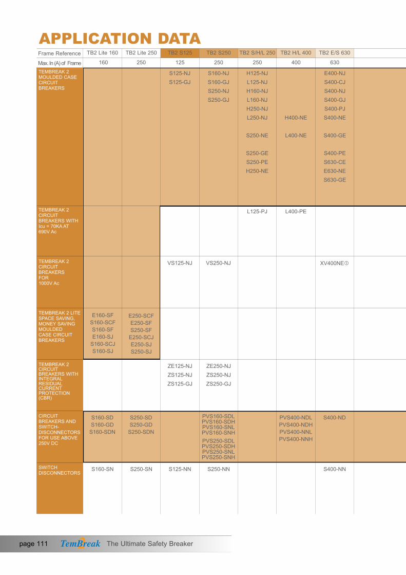
TEMBREAK 2MOULDED CASECIRCUITBREAKERS
E160-SFS160-SCFS160-SFE160-SJ
S160-SCJS160-SJ
E250-SCFE250-SFS250-SF
E250-SCJE250-SJS250-SJ
SWITCHDISCONNECTORS
CIRCUITBREAKERS ANDSWITCH-DISCONNECTORSFOR USE ABOVE250V DC
Frame Reference
VS125-NJ VS250-NJ XV400NE
page 111 The Ultimate Safety Breaker
APPLICATION DATATB2 Lite 160
160 250 125 250 250 400 630Max. In (A) of Frame
TB2 Lite 250 TB2 S125 TB2 S250 TB2 S/H/L 250 TB2 H/L 400 TB2 E/S 630
S125-NJS125-GJ
S160-NJS160-GJS250-NJS250-GJ
H125-NJL125-NJH160-NJL160-NJH250-NJL250-NJ
S250-NE
S250-GES250-PEH250-NE
L125-PJ L400-PE
E400-NJS400-CJS400-NJS400-GJS400-PJS400-NE
S400-GE
S400-PES630-CEE630-NES630-GE
H400-NE
L400-NE
TEMBREAK 2CIRCUITBREAKERS WITHIcu = 70KA AT 690V Ac
TEMBREAK 2CIRCUITBREAKERS FOR 1000V Ac
TEMBREAK 2 LITESPACE SAVING,MONEY SAVINGMOULDED CASE CIRCUITBREAKERS
TEMBREAK 2CIRCUITBREAKERS WITHINTEGRALRESIDUALCURRENTPROTECTION(CBR)
ZE125-NJZS125-NJZS125-GJ
ZE250-NJZS250-NJZS250-GJ
S250-SD S250-GD
S250-SDN
S160-SD S160-GD
S160-SDN
PVS160-SDLPVS160-SDHPVS160-SNLPVS160-SNHPVS250-SDLPVS250-SDHPVS250-SNLPVS250-SNH
PVS400-NDLPVS400-NDHPVS400-NNLPVS400-NNH
S400-ND
S160-SN S250-SN S125-NN S250-NN S400-NN

XS2000-NEXS2500-NEXS3200-NE
CO
NT
EN
TS
SE
CT
ION
3
PVS800-NDLPVS800-NDHPVS800-NNLPVS800-NNH
S800-NDS1000-ND
XS1250ND XS1600ND XS2000-NDXS2500-NDXS3200-ND
XV630PEXV800PE
XV1250NE
The Ultimate Safety Breaker page 112
800 1000 1250 1600 3200
TB2 H/L 800 TB2 1000 TB2 1250 TB2 1600 TB 3200
L800-PE
H800-NE
L800-NE
S800-CJS800-NJS800-RJS800-NES800-RES1000-SES1000-NE
S1250-SES1250-NES1250-GE
S1600-NES1600-SE
DISCRIMINATION
Pages 113 - 116
CASCADE
Pages 117 - 120
MCCBsIN DC SYSTEMS
Pages 121 - 122
S800-NN S1250-NN S1600-NN XS2000-NNXS2500-NN
Tembreak 1. Frame sizes vary from Tembreak2.
MCCB PERFORMANCEAT HIGH ALTITUDE
Pages 123- 124
MCCBs IN 400HzSYSTEMS
Pages 125- 127

Discrimination, also called selectivity, is the co-ordination of protective devices such that a fault is cleared by the protective device installed immediately upstream of the fault, and by that device alone.
Total discrimination
Discrimination is said to be total if the downstream circuit breaker opens and the upstream circuit breaker remains closed. This ensures maximumavailability of the system.
Partial discrimination
Discrimination is partial if the above condition is not fulfilled up to theprospective short-circuit current, but to a lesser value, termed the selectivity limit current (Is).
Above this value both circuit breakers could open, resulting in loss of selectivity.
How to read the discrimination tablesBoxes containing the letter “T” indicate total discrimination between therelevant upstream and downstream circuit-breakers. Total discrimination applies for all fault levels up to the breaking capacity of the upstream or the downstream circuit breaker, whichever is the lesser.
For the other boxes, discrimination is either partial or there is no discrimination.
If discrimination is partial then the value of the selectivity limit current, Is, is shown in the box.
upstreamcircuitbreaker
downstreamcircuitbreaker
faultcurrent
X
X
page 113 The Ultimate Safety Breaker
APPLICATION DATADISCRIMINATIONWhat is discrimination?

Notes: 1. All ACB’s have Ii set at NON, MCR ON.2. Assuming ACB time settings are greater than MCCB.
3. External relay can be used - Contact Terasaki for further details.4. T= total discrimination.
SE
CT
ION
3
APPLICATION DATA
Frame
Model
800A 1250A 1600A 2000A 2500A 3200A 4000A 5000A 6300AAR208S
AR212S
AR212H
AR216S
AR216H
AR316H
AR220S
AR220H
AR320H
AR325S
AR325H
AR332S
AR332H
AR440SB
AR650S
AR663S
AR663H
Upstream ACB
Downstream
MCCB
65kA 65kA 80kA 65kA 80kA 100kA 65kA 80kA 100A 85kA 100kA 85kA 100kA 100kA 120kA 120kA 135kABreakingCapacity
TB2 S125NJ 36kA T T T T T T T T T T T T T T T T TS125 S125GJ 65kA T T T T T T T T T T T T T T T T T
TB2 S160NJ 36kA T T T T T T T T T T T T T T T T TS250 S160GJ 65kA T T T T T T T T T T T T T T T T T
S250NJ 36kA T T T T T T T T T T T T T T T T TS250GJ 65kA T T T T T T T T T T T T T T T T T
TB2 H125NJ 125kA T T T T T T T T T T T T T T T T TS/H/L L125NJ 200kA T T T T T T T T T T T T T T T T T250 S250PE 70kA T T T T T T T T T T T T T T T T T
H250NJ 125kA T T T T T T T T T T T T T T T T TL250NJ 200KA T T T T T T T T T T T T T T T T T
TB2 E400NJ 25kA T T T T T T T T T T T T T T T T TE/S S400CJ 36kA T T T T T T T T T T T T T T T T T630 S400NJ 50kA T T T T T T T T T T T T T T T T T
S400NE 50kA T T T T T T T T T T T T T T T T TS400GJ 70kA T T T T T T T T T T T T T T T T TS400GE 70kA T T T T T T T T T T T T T T T T TS400PJ 85kA T T T T T T T T T T T T T T T T TS400PE 85kA T T T T T T T T T T T T T T T T TE630NE 36kA T T T T T T T T T T T T T T T T TS630CE 50kA T T T T T T T T T T T T T T T T TS630GE 70kA T T T T T T T T T T T T T T T T T
TB2 H400NE 125kA T T T T T T T T T T T T T T T T TH/L L400NE 200KA T T T T T T T T T T T T T T T T T400
TB2 S800-CJ 36kA T T T T T T T T T T T T T T T T T1000 S800-NJ 50kA T T T T T T T T T T T T T T T T T
S800-RJ 70kA T T T T T T T T T T T T T T T T TS800-NE 50kA T T T T T T T T T T T T T T T T TS800-RE 70kA T T T T T T T T T T T T T T T T TS1000-SE 50kA - T T T T T T T T T T T T T T T TS1000-NE 70kA - T T T T T T T T T T T T T T T T
TB2 H800-NE 125kA T T T T T T T T T T T T T T T T TH/L L800-NE 200kA T T T T T T T T T T T T T T T T T800
TB2 S1250-SE 50kA - T T T T T T T T T T T T T T T T1250 S1250-NE 70kA - T T T T T T T T T T T T T T T T
S1250-GE 100kA - T T T T T T T T T T T T T T T T
TB2 S1600-SE 50kA - - - T T T T T T T T T T T T T T1600 S1600-NE 100kA - - - T T T T T T T T T T T T T T
The Ultimate Safety Breaker page 114
DISCRIMINATIONTempower 2 ACB, Tembreak 2 MCCBDiscrimination Tables According To IEC 60947-2, Annex A, At 400V AC

36kA
65kA
70kA
125kA
50kA
70kA
85kA
125kA
200kA
36kA
50kA
70kA
50kA
70kA
125kA
200kA
50kA
70kA
50kA
70kA
100kA
50kA
100kA
DISCRIMINATIONTembreak 2 MCCB, (Electronic), Discrimination Tables According To IEC 60947-2, Annex A, At 400V AC
TB2S125
BreakingCapacity
ModelFrame 250A 400A 630A 800A 1000A 1250A 1600A
Upstream MCCB
S250-NE
S250-GE
S250-PE
H250-NE
S400-NE
S400-GE
S400-PE
H400-NE
L400-NE
E630-NE
S630-CE
S630-GE
S800-NE
S800-RE
H800-NE
L800-NE
S1000-SE
S1000-NE
S1250-SE
S1250-NE
S1250-GE
S1600-SE
S1600-NE
T T T T T T T T T T T T T T T T T T T T T T TS125-NJ 36kA
TB2S250
TB2S/H/L250
TB2E/S630
TB2H/L400TB21000
S125-GJ 65kAS160-NJ 36kAS160-GJ 65kAS250-NJ 36kAS250-GJ 65kA
S250-NE 36kA
T T T T T T T T T T T T T 50 T T T T T T T T T- - - - T T T T T T T T T T T T T T T T T T T- - - - T T T T T T T T 36 36 T T T 50 T T T T T- - - - T T T T T T T T T T T T T T T T T T T- - - - T T T T T T T T 36 36 T T T 50 T T T T T
H125-NJ 125kAH160-NJ 125kA
T T T T T T T T T T T T T 50 T T T T T T 70 T 85- - - - - - - T T T T T T 50 T T T T T T 70 T 85- - - - - - - T T T T T T T T T T T T T T T T
S250-GE 65kA - - - - - - - T T T T T 36 36 T T T 50 T T T T TH250-NJ 125kA - - - - - - - T T T T T T 50 T T T T T T 70 T 85S250-PE 70kA - - - - - - - T T T T T 36 36 T T T 50 T T 70 T TH250-NE 125kA - - - - - - - T T T T T 36 36 T T T 50 T T 70 T 85E400-NJ 25kA - - - - - - - - - 10 10 10 T T T T T T T T T T TS400-CJ 36kAS400-NJ 50kAS400-NE 50kAS400-GJ 70kAS400-GE 70kAS400-PJ 85kAS400-PE 85kA
- - - - - - - - - 10 10 10 25 25 25 25 30 30 T T T T T- - - - - - - - - 10 10 10 25 25 25 25 30 30 36 36 36 T T- - - - - - - - - 10 10 10 25 25 25 25 30 30 36 36 36 T T- - - - - - - - - 10 10 10 25 25 25 25 30 30 36 36 36 T 50- - - - - - - - - 10 10 10 25 25 25 25 30 30 36 36 36 T 50- - - - - - - - - 10 10 10 25 25 25 25 30 30 36 36 36 T 50- - - - - - - - - 10 10 10 25 25 25 25 30 30 36 36 36 T 50
E630-NE 36kA - - - - - - - - - - - - - - - - - - T T T T TS630-CE 50kAS630-GE 70kAH400-NE 125kA
- - - - - - - - - - - - - - - - - - 36 36 36 T T- - - - - - - - - - - - - - - - - - 36 36 36 T 50- - - - - - - - - 10 10 10 36 36 25 25 T 50 T T 70 T 50
S800-CJ 36kAS800-NJ 50kAS800-RJ 70kAS800-NE 50kAS800-RE 70kA
- - - - - - - - - - - - - - - - - - - - - 20 20- - - - - - - - - - - - - - - - - - - - - 20 20- - - - - - - - - - - - - - - - - - - - - 20 20- - - - - - - - - - - - - - - - - - - - - 20 20- - - - - - - - - - - - - - - - - - - - - 20 20
page 115 The Ultimate Safety Breaker
APPLICATION DATA
Notes: 1. All pick-up current and time delay settings are to be set at maximum for upstream MCCBs.2. Is expressed in kA.3. T= Total Selectivity
Downstream
MCCB

TD3 M06, TD3 M10
MCBs Type B, C & D
DISCRIMINATIONTembreak 2 MCCB, TD3 MCBDiscrimination Tables According To IEC 60947-2, Annex A, At 400V AC
SE
CT
ION
3
The Ultimate Safety Breaker page 116
APPLICATION DATA
Tembreak 2 Lite MCCB, TD3 MCBDiscrimination Tables According To IEC 60947-2, Annex A, At 400V AC
APPLICATION DATA
Upstream MCCB Type
in 20A 32A 50A 63A 100A 125A 20A 32A 50A 63A 100A 125A 160A 200A 250A 250A 400A6A 260 T T T T T 260 T T T T T T T T T T10A 260 420 T T T T 260 420 T T T T T T T T T16A 260 420 650 T T T 260 420 650 T T T T T T T T20A 260 420 650 T T T 260 420 650 1000 T T T T T T T25A 260 420 650 1000 T T 260 420 650 1000 T T T T T T T32A 260 420 650 1000 1500 T 260 420 650 1000 1500 T T T T T T40A 260 420 650 1000 1500 2000 260 420 650 1000 1500 2000 T T T T T50A 260 420 650 1000 1500 2000 260 420 650 1000 1500 2000 3000 T T T T63A 260 420 650 1000 1500 2000 260 420 650 1000 1500 2000 3000 2600 T T T
S400-PJ (85kA)S400-GJ (70kA)S400-NJ (50kA)S400-CJ (36kA)E400-NJ (25kA)
S160-GJ (65kA)S160-NJ (36kA)
S250-GJ (65kA)S250-NJ (36kA)
S125-GJ (65kA)S125-NJ (36kA)
Downstream
MCB Type
Notes: 1. This rating is not available for S160-GJ.2. Is is expressed in A.3. T = Total selectivity.
TD3 M06, TD3 M10
MCBs Type B, C & D
Upstream MCCB Type
in 25A 40A 63A 80A 100A 125A 160A 100A 125A 160A 200A 250A6A 1000 1000 3000 3000 5000 5000 6000 T T T T T10A 1000 1000 2000 2000 4000 4000 5000 T T T T T16A 600 600 2000 2000 3000 3000 4000 T T T T T20A 600 600 2000 2000 3000 3000 4000 T T T T T25A - 600 1500 1500 2500 2500 3000 T T T T T32A - 600 1500 1500 2500 2500 3000 9000 T T T T40A - - 1500 1500 2500 2500 3000 8000 9000 T T T50A - - 1500 1500 2500 2500 3000 7000 8000 9000 T T63A - - - 1500 2500 2500 3000 6000 7000 8000 9000 T
S160-SJ (40kA)S160-SCJ (25kA)E160-SJ (16kA)
S250-SJ (40kA)E250-SJ (25kA)
E250-SCJ (16kA)
Downstream
MCB Type
Notes: 1. Is is expressed in A.2. T = Total selectivity.

CASCADEWhat is Cascading
Cascading is a technique where the current limiting capability of upstream circuitbreakers is used to permit the installation of lower rated and therefore lower costcircuit breakers downstream.
The upstream TemBreak 2 circuit breaker acts as a resistance against short-circuitcurrents. With this assistance, downstream circuit breakers with breaking capacitieslower than the prospective short-circuit at their point of installation can interruptthe reduced short-circuit current.
Since the current is limited downstream of the limiting circuit breaker, cascadingapplies to all switchgear in the downstream circuit. It is not restricted to twoconsecutive devices.
Cascading is recognised by the following standards related to electrical installations:
IEC 60364
BS 7671
AS/NZS 3000
The Advantages
Installation of a single limiting circuit-breaker results in considerablesimplifications and savings for the entire downstream installation:
• Simplification of selection of devices using the cascading tables
• Savings on downstream devices. Cascading allows circuit-breakerswith lower ratings to be used.
In addition the application of cascading will reduce both electrodynamic and thermal stress within the installation.
How to Read the Cascade Tables
The value shown in the table is the increased breaking capacity, expressed in kA, that can be achieved if the downstream MCCB is backed up by the appropriate upstream MCCB.
page 117 The Ultimate Safety Breaker
APPLICATION DATA

SE
CT
ION
3
The Ultimate Safety Breaker page 118
APPLICATION DATA
Upstream MCCB
Model
Breaking Capacity 36kA 65kA 125kA 200kA 36kA 65kA 125kA 200kA 36kA 65kA 70kA 125kA 200kA
S125NJ
S125GJ
H125NJ
L125NJ
S160NJ
S160GJ
H160NJ
L160NJ
S250NJ
S250GJ
S250PE
H250NJ
H250NE
L250NJ
Downstream
MCCB
S125NJ 36kA - 50 65 65 85 125 - 50 65 - 50 50 - - - - - - - - -S125GJ 65kA - - 70 85 125 150 - - 70 - - 70 - - - - - - - - -H125NJ 125kA - - - - - 200 - - - - - - - - - - - - - - -
S160NJ 36kA - 50 65 65 85 125 - 50 65 - 50 70 50 50 50 70 - - - - -S160GJ 65kA - - 70 85 125 150 - - 70 - - 70 70 70 - 70 - - - - -H160NJ 125kA - - - - - 200 - - - - - - - - - - - - - - -S250NJ 36kA - 50 65 65 85 125 - 50 65 - 50 70 50 50 50 70 - - - - -S250GJ 65kA - - 70 85 125 150 - - 70 - - 70 70 70 - 70 - - - - -S250PE 70kA - - - - 125 150 - - - - - - 85 85 - - - - - - -H250NJ 125kA - - - - - 200 - - - - - - - 150 - - - - - - -
E400NJ 25kA 36 36 50 50 65 85 36 36 50 30 36 50 36 36 36 36 36 36 36 36 36S400CJ 36kA - 50 65 65 70 100 - 50 65 - 50 70 50 50 50 50 50 50 50 50 50S400NJ 50kA - - 70 70 85 125 - - 70 - - 70 70 70 - 70 - 70 70 - 70S400GJ 70kA - - - 85 125 150 - - - - - - 85 85 - - - - - - 85S400PJ 85kA - - - - 125 150 - - - - - - - - - - - - - - -
S400CJ
S400NJ
S400NE
S400GJ
S400GE
S400PJ
S400PE
H400NE
L400NE
E630NE
S630CE
S630GE
S800CJ
S800NJ
S800NE
S800RJ
S800RE
H800NE
L800NE
S1000SE
S1000NE
S1250SE
S1250NE
S1250GE
S1600SE
S1600NE
Upstream MCCB
Downstream
MCCB
Notes: 1. Cascade fault level limit is expressed in kA.
Notes: 1. Cascade fault level limit is expressed in kA.
Breaking Capacity 36kA 50kA 70kA 85kA 125kA 200kA 36kA 50kA 70kA 36kA 50kA 70kA 125kA 200kA 50kA 70kA 50kA 70kA 85kA 50kA 85kA
S125NJ 36kA - 65 85 125 - 65 85 125 - 65 65 85 125S125GJ 65kA - - 125 150 - - 125 150 - - 70 125 150H125NJ 125kA - - - 200 - - - 200 - - - - 200
S160NJ 36kA - - - - - 65 85 125 - 65 65 85 125S160GJ 65kA - - - - - - 125 150 - - 70 125 150H160NJ 125kA - - - - - - - 200 - - - - 200S250NJ 36kA - - - - - - - - - 65 65 85 125S250GJ 65kA - - - - - - - - - - 70 125 150S250PE 70kA - - - - - - - - - - - 125 150H250NJ 125kA - - - - - - - - - - - - 200
CASCADETembreak 2 MCCBCascade Tables According to IEC 60947-2. Annex A, At 400V AC

CASCADETembreak 2 MCCB, TD3 MCBCascade Tables According To IEC 60947-2, Annex A, At 400V AC
125A 125A 160A 160A 250A 250A
125A 125A 160A 160A 250A 250A
In
In
TD3M06(6kA)
TD3M10(10kA)
6A 14 14 12 12 12 1210A 14 14 12 12 12 1216A 14 14 12 12 12 1220A 14 14 12 12 12 1225A 14 14 12 12 12 1232A 14 14 12 12 12 1240A 12 12 10 10 10 1050A 12 12 10 10 10 1063A 12 12 10 10 10 10
6A 30 30 25 25 25 2510A 30 30 25 25 25 2516A 30 30 25 25 25 2520A 30 30 25 25 25 2525A 30 30 25 25 25 2532A 30 30 25 25 25 2540A 30 30 23 23 23 2350A 30 30 23 23 23 2363A 30 30 23 23 23 23
Model
Model
Notes: 1. Cascade fault level limit is expressed in kA.
Notes: 1. Cascade fault level limit is expressed in kA.
Upstream MCCB
Upstream MCCB
Downstream
MCB
Downstream
MCB
S125NJ (36kA)
S125NJ (36kA)
S125GJ (65kA)
S125GJ (65kA)
S160NJ (36kA)
S160NJ (36kA)
S160GJ (65kA)
S160GJ (65kA)
S250NJ (36kA)
S250NJ (36kA)
S250GJ (65kA)
S250GJ (65kA)
APPLICATION DATA
page 119 The Ultimate Safety Breaker

Downstream
MCB Type
CASCADETembreak 2 Lite MCCB, TD3 MCBCascade Tables According To IEC 60947-2, Annex A, At 400V AC
E250-SJ (25kA)
S160-SCJ (25kA)
SE
CT
ION
3
APPLICATION DATA
Upstream MCCB Type
Upstream MCCB Type
Downstream
MCB
Notes: 1. Cascade fault level limit is expressed in kA.
TD3 M10 MCBs (10kA)
Type B, C & D
TD3 M10 MCBs (10kA)
Type B, C & D
TD3 M06 MCBs (6kA)
Type B, C & D
TD3 M06 MCBs (6kA)
Type B, C & D
S160-SJ (40kA)
S250-SJ (40kA)
in6A10A16A20A25A32A40A50A63A6A10A16A20A25A32A40A50A63A
in6A10A16A20A25A32A40A50A63A6A10A16A20A25A32A40A50A63A
14 14 14 14 14 14 14 14 14 14 14 14 14 1414 14 14 14 14 14 14 14 14 14 14 14 14 1414 14 14 14 14 14 14 14 14 14 14 14 14 1414 14 14 14 14 14 14 14 14 14 14 14 14 14- 14 14 14 14 14 14 - 14 14 14 14 14 14- 14 14 14 14 14 14 - 14 14 14 14 14 14- - 14 14 14 14 14 - - 14 14 14 14 14- - 14 14 14 14 14 - - 14 14 14 14 14- - - 14 14 14 14 - - - 14 14 14 1425 25 25 25 20 20 20 40 40 40 40 30 30 2525 25 25 25 20 20 20 40 40 40 40 30 30 2525 25 25 25 20 20 20 40 40 40 40 30 30 2525 25 25 25 20 20 20 40 40 40 40 30 30 25- 25 25 25 20 20 20 - 40 40 40 30 30 25- 25 25 25 20 20 20 - 40 40 40 30 30 25- - 25 25 20 20 20 - - 40 40 30 30 25- - 25 25 20 20 20 - - 40 40 30 30 25- - - 25 20 20 20 - - - 40 30 30 25
10 10 10 10 10 12 12 12 12 1210 10 10 10 10 12 12 12 12 1210 10 10 10 10 12 12 12 12 1210 10 10 10 10 12 12 12 12 1210 10 10 10 10 12 12 12 12 1210 10 10 10 10 12 12 12 12 125 5 5 5 5 10 10 10 10 105 5 5 5 5 10 10 10 10 105 5 5 5 5 10 10 10 10 1020 20 20 20 20 25 25 25 25 2520 20 20 20 20 25 25 25 25 2520 20 20 20 20 25 25 25 25 2520 20 20 20 20 25 25 25 25 2520 20 20 20 20 25 25 25 25 2520 20 20 20 20 25 25 25 25 2520 20 20 20 20 25 25 25 25 2520 20 20 20 20 25 25 25 25 2520 20 20 20 20 25 25 25 25 25
25A 40A 63A 80A 100A 125A 160A 25A 40A 63A 80A 100A 125A 160A
100A 125A 160A 200A 250A 100A 125A 160A 200A 250A
The Ultimate Safety Breaker page 120
Notes: 1. Cascade fault level limit is expressed in kA.

MCCBs IN DC SYSTEMS
Terasaki’s MCCBs provide an excellent range of protection for DC installations. We offer MCCBs of up to 1000A with DC overload protection and up to 2500A with DC short-circuit protection.
Protection MethodCurrent transformers require alternating current to generate magnetic flux thereby inducing current toflow in the secondary winding. Any device which relies on current transformers for measurement ordetection of current is therefore unsuitable for protection of DC systems. Most electronic MCCBs fallinto this category.
The most common method of detecting DC overloads is by the use of a thermal element. Short-circuit protection in DC circuits is provided by electromagnetic tripping elements.
Tripping CharacteristicsThe time-current characteristics of a thermal element, such as those published in Section 3, areunaffected by the frequency of current applied. They hold good for both AC and DC currents.
A magnetic element operates on the instantaneous value of the current waveform. This means that inpractice in an AC circuit, it will operate at the peak value of the sinusoidal waveform. Trippingcharacteristics are published in AC root mean square (rms) Amperes (A). This means that the value ofAC instantaneous current, Ip, which will operate the element is equal to the rms current multiplied by√–2. Similarly, the value of DC instantaneous current which will operate the element is equal to the ACrms current multiplied by √
–2.
Time ConstantTime constants associated with DC circuits prevent the voltage of the circuit from reactingimmediately when a load current is suddenly interrupted.
The time constant, τ, of a circuit indicates how quickly voltage across capacitors and current throughinductors react to transient conditions.
DC operating current of magnetic element = √–2 � AC rms operating current of magnetic element.
The time constant of a capacitive circuit is the product of capacitance and resistance: τ = RC (s).The time constant of an inductive circuit is given by: τ = L/R (s).
APPLICATION DATA
page 121 The Ultimate Safety Breaker

SE
CT
ION
3
APPLICATION DATA
Time ConstantTransient voltages and currents, including those produced by switching, donot approximate their steady state values until 5 time constants have elapsed.
Fault currents occurring in circuits with high time constants are extremelydifficult to interrupt due to the lagging voltage. All DC breaking capacitiesin this section are shown with the assumption that the time constant of thecircuit is restricted to the values shown below.
Fault Level
Near the rated current, In, of the circuit breaker <2.0ms
<2.5 x In <2.5ms
<10kA <7ms
>10kA <15ms
τ
The Ultimate Safety Breaker page 122
MCCBs IN DC SYSTEMS

page 123 The Ultimate Safety Breaker
Degree of Vacuum (Torr)
HIGH ALTITUDE REGION
10 10 10 10 10 10 1 10 10 10-6 -5 -4 -3 -2 -1 2 3
REGION WHEREMCCBs CAN BEUSED AS VACUUMCIRCUT BREAKERs
DIEL
ECTR
IC S
TREN
GTH
MCCB PERFORMANCE AT HIGH ALTITUDE
APPLICATION DATA
General
IEC 60947-2, Low Voltage Switchgear and Controlgear states that a circuit breakers shall be capable ofoperating at altitudes up to 2000m. Above 2000m, it is necessary to take into account the reduction indielectric strength and cooling effect of the air.
Effect of Altitude
The relationship between the dielectric strength of air and degree of vacuum (atmospheric pressure) isshown below.
The degree of vacuum of air at the normal atmospheric pressure is 760 Torr. On the graph, the area tothe left of this value is the “high altitude region”. As can be seen, the dielectric strength of air decreasesas the atmosphere pressure decreases (with increasing altitude). At Torr values between 101, it increasessharply.
At altitudes above 2000m, the rating correction factors specified in ANSI C37.13-1981 should beapplied to maximum rated voltage and continuous rated current:

The Ultimate Safety Breaker page 124
MCCB PERFORMANCE AT HIGH ALTITUDE
APPLICATION DATA
Altitude(m)RatingCorrectionFactor
Current Voltage
2000 1.00 1.00
2600 0.99 0.95
4000 0.96 0.8
Intermediate values of the rating correction factors (for altitudes below 4000m) may be calculated bylinear extrapolation.
It should be noted that the short-time and short circuit ratings are not affected by altitude. The insulation voltage, Ui, will be reduced according to the above table and the voltage at short circuit ratings will be reduced.
For example:
Upto2000m At4000m
Voltage Ultimatebreakingcapacity,Icu(kA) Voltage Ultimatebreaking
capacity,Icu(kA)
S400-NJ 690V AC 20kA 550V AC 20kA
525V AC 30kA 420V AC 30kA
440V AC 45kA 350V AC 45kA
415V AC 50kA 330V AC 50kA
400V AC 50kA 320V AC 50kA
380V AC 50kA 300V AC 50kA
240V AC 85kA 190V AC 85kA
SE
CT
ION
3

APPLICATION DATAMCCB’S IN 400Hz SYSTEMS
GENERAL
It is possible to use TemBreak2 MCCBs in 400Hz circuits. This high frequency causes an increase ineddy currents (iron losses) which has a number of effects:
- increased temperature rise- reduction of thermal trip thresholds of thermal magnetic MCCBs- demagnetising effect on the instantaneous trip elements of thermal-magnetic MCCBs
THERMAL-MAGNETIC MCCBs
Thermal Element for Overload Protection
In the low overload region near the MCCB rated current, the required tripping current is reducedbecause of the heat generated by the increase in eddy currents. As a result the MCCB must be derated.However, in the high overload region (from a few hundred to several hundred percent of rated current)the time-current characteristics is approximately the same as that at 50/60Hz. This is due to the factthat the heat from the increased eddy currents forms a smaller percentage of the total heat generatedby the high overload current plus the eddy currents, and consequently has less effect on the tripping time.
Figure 1. Illustrates how the gradient of the time-current curve of the thermal element is less steep at400Hz than at 50/60Hz.
page 125 The Ultimate Safety Breaker

Table 1
APPLICATION DATAMCCB’s IN 400Hz SYSTEMSThermal-Magnetic MCCBsMagnetic Element for Instantaneous Short-Circuit Protection
The magnetic element uses the large electromagnetic force created around conductor or by a short-circuit current to operate the MCCB trip mechanism. The minimum value of current required to operate the magnetic element is the “instantaneous” trip setting. This setting is calibrated at 50 Hz. If the MCCB is used at 400Hz the required operating current will be larger due to the de-magnetising effect of the higher eddy currents.
At 400Hz, the instantaneous trip setting is estimated to be approximately twice the setting at 50Hz.(The exact value depends on the structure of the particular MCCB’s magnetic element).
Figure 1. Illustrates the higher instantaneous trip threshold at 400Hz
400Hz
50Hz
400Hz
Figure 1
t
i
Thermal-Magnetic-MCCBsConductor-SizeSpecified-in-
IEC947-1-(mm2)
MCCB-Rating-at400Hz
Type Rating at 50/60Hz (A)125-NJ125-GJ
20 2.5 18A32 6.0 30A50 10 45A63 16 58A100 35 89A125 50 110A
S160-SCJS160-SJ
25 4.0 24A40 10 39A63 16 61A80 25 78A100 35 97A125 50 121A160 70 154A
S160-SCFS160-SF
15 2.5 14A20 2.5 19A30 6.0 29A40 10 39A50 10 49A60 16 58A75 25 73A100 35 97A125 50 121A160 70 154A
The Ultimate Safety Breaker page 126
SE
CT
ION
3

Electronic MCCBs CONDUCTOR SIZE SPECIFIED INIEC947-1 (mm2)
MAXIMUM MCCB RATING AT 400Hz
MAXIMUM IR settingTYPE RATING AT (A)
S250-NES250-GES250-PE
160 70 144A (Inx0.9)
250 120 200A (Inx0.8)
S400-NES400-GES400-PE
250A 120 237.5A (Inx0.95)
400A 240 360A (Inx0.9)
E630-NES630-CES630-GE
630A 2x185 576A (Inx0.9)
S800-NES800-RE
630A 2x185 576A (Inx0.9)
800A 2x240 640A (Inx0.8)
S1000-SES1000-NE 1000A 2x(60x5t) 630A (Inx0.63)
S1250-SES1250-NES1250-GE
1250A 2x(80x5t) 787.5A (Inx0.63)
APPLICATION DATAMCCB’S IN 400Hz SYSTEMS
Terasaki recommend that electronic MCCBs are used for protection of 400Hz circuits where possible. Table 1 (previous page) shows de-rating and conductor sizes for thermal-magnetic MCCBs up to 250A. Table II shows de-rating and conductor sizes for electronic MCCBs up to 1250A.
Table II
Note: When used at 400Hz, the rated current setting of the OCR must not exceed the values in column 4 of table II.
page 127 The Ultimate Safety Breaker
ELECTRONIC MCCBs
The time- current characteristic of the TemBreak 2 electronic MCCBs at 400Hz follows thecharacteristic at 50Hz very closely, but the MCCBs must be derated when used at this frequency due to the increase in temperature caused by higher eddy currents. Table II lists the maximum ratingsof Tembreak 2 electronic MCCBs at 400Hz. The protection must not be set to values higher thanthose listed.

TEMBREAK 2 & TEMBREAK MCCBs FROM 12A TO 3200A • MCCBs FOR 1000V AC MCCBs FOR 1000V DC • MCCBs WITH INTEGRAL RCD SWITCH DISCONNECTORS • MEASUREMENT AND DATA COMMUNICATION
RATINGS AND SPECIFICATIONS
PROTECTION CHARACTERISTICS
APPLICATION DATA
ACCESSORIES
INSTALLATION
DIMENSIONS
ORDER CODES
SECTION 1
SECTION 2
SECTION 3
SECTION 4
SECTION 5
SECTION 6
SECTION 7
CONTENTS
The Ultimate Safety Breaker page 128

CIRCUITBREAKERS ANDSWITCH-DISCONNECTORSFOR USE ABOVE250V DC
TEMBREAK 2CIRCUITBREAKERS WITHIcu = 70KA AT 690V Ac
TEMBREAK 2CIRCUITBREAKERS FOR 1000V Ac
TEMBREAK 2 LITESPACE SAVING,MONEY SAVINGMOULDED CASE CIRCUITBREAKERS
TEMBREAK 2CIRCUITBREAKERS WITHINTEGRALRESIDUALCURRENTPROTECTION(CBR)
SWITCH-DISCONNECTORS
TEMBREAK 2MOULDED CASECIRCUITBREAKERS
S400-ND
S125-NJS125-GJ
S160-SN
S160-SD S160-GD
S160-SDN
S250-SD S250-GD
S250-SDN
E160-SFS160-SCFS160-SF
E160-SJS160-SCJS160-SJ
E250-SCFE250-SFS250-SF
E250-SCJE250-SJS250-SJ
S250-SN
ZE125-NJZS125-NJZS125-GJ
ZE250-NJZS250-NJZS250-GJ
VS125-NJ VS250-NJ
S160-NJS160-GJS250-NJS250-GJ
PVS160-SDLPVS160-SDHPVS160-SNLPVS160-SNHPVS260-SDLPVS260-SDHPVS260-SNLPVS260-SNH
S125-NN S250-NN S400-NN
XV400NE
PVS400-NDL PVS400-NDH
H400-NE
L400-NE
160 250 125 250 250 400 630Frame Reference
Max. In (A) of Frame
ACCESSORIESTB2 Lite 160 TB2 Lite 250 TB2 125 TB2 S250 TB2 S/H/L 250 TB2 H/L 400 TB2 E/S 630
H125-NJL125-NJH160-NJL160-NJH250-NJL250-NJ
S250-NE
S250-GES250-PEH250-NE
L125-PJ L400-PE
●
●
E400-NJS400-CJS400-NJS400-GJS400-PJS400-NE
S400-GE
S400-PES630-CEE630-NES630-NES630-GE
page 129 The Ultimate Safety Breaker

S1600NN XS2000NNXS2500NN
XS2000-NDXS2500-NDXS3200-ND
TEMBREAK 2 MCCBsAND SWITCHDISCONNECTORS• Electrical Control
(Internal Accessories)• Termination of
Control Wiring• Electrical Control
(Motorised Operation)• Operating Handles
& Locking Devices• Insulation Accessories• Dual Supply
Changeover Systems
Pages 131 - 157
XS2000NE
XS2500NE
XS3200NE
S800-NDS1000-ND
XS1250ND XS1600ND
TEMBREAK MCCBsAND SWITCHDISCONNECTORS • Electrical Control
(Internal Accessories• Termination
of Control Wiring• Electrical Control
(Motorised Operation)• Operating Handles
& Locking Devices
Pages 171 - 184
CO
NT
EN
TS
SE
CT
ION
4S1600-NES1600-SE
L800-PE
H800-NE
L800-NE
XV630PEXV800PE
XV1250NE
TEMBREAK 2 LITEMCCBS AND SWITCHDISCONNECTORS• Electrical Control
(Internal Accessories• Termination
of Control Wiring• Electrical Control
(Motorised Operation)• Operating Handles
& Locking Devices• Insulation Accessories
Pages 158 - 170
12501000800
PVS800-NDLPVS800-NDH
S800-NN S1250-NN
1600 2000
TB2 H/L 800 TB2 1000 TB2 1250 TB2 1600 TB 3200
S800-CJS800-NJS800-RJ
S800-NES800-RES1000-SE
S1000-NE
S1250-SES1250-NES1250-GE
●
●
●
●
The Ultimate Safety Breaker page 130Tembreak 1. Frame sizes vary from Tembreak 2.Contact Terasaki for details of accessories.

Electrical control accessories for TemBreak 2 aredesigned with the installer in mind. Status andalarm contacts, remote tripping coils andundervoltage protection coils are of modulardesign and convenient to use.
• All auxiliary, alarm switches and shunt tripsare common up to 1600A. Undervoltage tripsare split between two sizes: 125 to 630A and800 to 1600A.
• All accessories are endurance tested to the same level as MCCBs.
• TemBreak 2 internal accessories are easily field-installable.
• All accessories are individually packaged and are supplied with fitting instructions.
• Control wiring is terminated on the accessoryscrew terminal. Alternatively a terminal blockwhich clips to the side of the MCCB is available.
1) Heavy-duty auxiliary switch2) Heavy-duty alarm switch3) General-purpose auxiliary switch4) General-purpose alarm switch5) Shunt trip6) Undervoltage trip
(1) (2) (3) (4) (5) (6)
Installing Accessories in a 4 pole S400 model
1 2 3
5
7 8
6
The internal accessories can be easily installed in the field without special tools or product training.
4
Easy field-Installation of Accessories• Internal accessory can be simply
plugged into position.
• No tools are required for this,except a screwdriver to lift theMCCB front cover clips.
• Accessories fit with a firm clickwhen installed correctly.
• Colour coding of accessories helps identification and installation.
Click
page 131 The Ultimate Safety Breaker
TEMBREAK 2 MCCBs AND SWITCH DISCONNECTORSElectrical Control Using Internally Mounted Accessories
ACCESSORIES

S125H125L125
VS125ZE125 **ZS125 **
S160H160L160
PVS160S250H250L250
VS250ZE250 **ZS250 **
S800H800L800
S1000PVS800
S1250S1600
E400E630S400S630H400L400
PVS400
TB2 S125TB2 S250
TB2 S/H/L 250
004L/H 2BTecnerefeR emarFTB2 E/S 630
TB2 H/L 800TB2 1000
TB2 1250TB2 1600
Shunt Trip
General Purpose Alarm Switch
General Purpose Auxiliary Switch
Undervoltage Trip
General Purpose Alarm Switch
General Purpose Auxiliary Switch
Shunt Trip
Heavy Duty Alarm Switch
Heavy Duty Auxiliary Switch
Undervoltage Trip
Heavy Duty Alarm Switch
Heavy Duty Auxiliary Switch
Auxiliary Switch
Alarm Switch
Shunt Trip
Undervoltage Trip
SE
CT
ION
4
• General purpose and heavy duty status indication switches cannot be mixed in the same MCCB.
• It is not possible to install a shunt trip and an undervoltage trip in an MCCB as they occupy the same location. Undervoltage trips can provide remote tripping if necessary by wiring a normally closed contact or pushbutton in series with the protected supply.
• Undervoltage trips with time delays require an external time delay controller which clips to the side of the MCCB.
** Shunt trip and undervoltage cannot be installed in this model.
The Ultimate Safety Breaker page 132
TEMBREAK 2 MCCBs AND SWITCH DISCONNECTORSElectrical Control Using Internally Mounted AccessoriesValid Maximum Accessory Combinations
ACCESSORIES

.4
OFF,Trip
.1
.2
Status Indication Switches
General Purpose Auxiliary Switch
Terminal Designations andFunction of General PurposeAuxiliary Switch
.4
.1
.2
General Purpose Alarm Switch
Terminal Designations andFunction of General PurposeAlarm Switch
General Purpose Auxiliary Switch (AX)An auxiliary switch electrically indicatesthe ON or OFF status of the MCCB. The general purpose type is a changeoverswitch with 3 terminals.
A microcurrent version is available forswitching currents as low as 1mA.
Auxiliary switches are colour coded grey.The cable capacity of the terminals is 0.5to 1.25mm2, bare cable.
The general purpose auxiliary switchmeets the requirements of IEC 61058-1.
General Purpose Alarm Switch (AL)An alarm switch electrically indicates theTRIP status of the MCCB. The generalpurpose type is a changeover switch with3 terminals.
A microcurrent version is available forswitching currents as low as 1mA.
Alarm switches are colour coded grey andblack. The cable capacity of the terminalsis 0.5 to 1.25mm2, bare cable
The general purpose alarm switch meetsthe requirements of IEC 61058-1.
General purpose auxiliaries and alarm switch ratings Microcurrent versions
ACVolts (V)
DC
ResistiveLoad
ResistiveLoad
InductiveLoad
InductiveLoad
Volts (V) Amperes (A)Amperes (A)DC
Minimum Load
Minimum Load
Volts Amperes (A)(V)
ResistiveLoad
1mA at 5V30 0.1 DC and 30V
DC.
440 - - 250 - - 100mA at240 3 2 125 0.4 0.05 15V DC.110 3 2 30 3 2
Trip
page 133 The Ultimate Safety Breaker
TEMBREAK 2 MCCBs AND SWITCH DISCONNECTORSElectrical Control Using Internally Mounted Accessories
ACCESSORIES

SE
CT
ION
4
.4
.3
Status Indication Switches
Heavy Duty Auxiliary Switch
Terminal Designationsand Function of Heavy DutyAuxiliary Switch, a contact
.2
.1 Terminal Designationsand Function of Heavy DutyAuxiliary Switch, b contact
.4
.3 Terminal Designationsand Function of Heavy DutyAlarm Switch, a contact
.2
.1 Terminal Designationsand Function of Heavy Duty Alarm Switch, b contact
Heavy Duty Alarm Switch
Heavy Duty Auxiliary Switch (AX)The heavy duty auxiliary switch has animpulse withstand voltage (Uimp) of 6kV and is suitable for isolating safetycircuits. The auxiliary switch electricallyindicates the ON or OFF status of theMCCB. The heavy duty type is a bridgeswitch with two terminals. It is availablein either normally open or normallyclosed configurations.
Heavy duty auxiliary switches are colourcoded grey. The cable capacity of the terminals is 1.25 to 2.5mm2. bare cable.
The heavy duty auxiliary switch meetsthe requirements of IEC 60947-5-1.
It has direct opening action,recommended by IEC 60204-1 Safety of Machinery - ElectricalEquipment for Machines.
Heavy Duty Alarm Switch (AL)The heavy duty alarm switch has animpulse withstand voltage (Uimp) of 6kV and is suitable for isolating controlcircuits. The alarm switch electricallyindicates the TRIP status of the MCCB.The heavy duty type is a bridge switchwith two terminals. It is available ineither normally open or normally closedconfigurations.
Heavy duty auxiliary switches are colourcoded grey and black. The cable capacity ofthe terminals is 1.25 to 2.5mm2, bare cable.
The heavy duty alarm switch meets therequirements of IEC 60947-5-1.
It has direct opening action,recommended by IEC 60204-1 Safety of Machinery - ElectricalEquipment for Machines.
Ratings of Heavy Duty Auxiliary and Alarm Switches
ACVolts (V)
DC
ResistiveLoad
13456
50044024011048
13456
-2501254824
0.5136
0.51
2.52.5
ResistiveLoad
InductiveLoad
InductiveLoad
Volts (V) Amperes (A)Amperes (A)
OFF,Trip
OFF,Trip
Trip
Trip
The Ultimate Safety Breaker page 134
TEMBREAK 2 MCCBs AND SWITCH DISCONNECTORSElectrical Control Using Internally Mounted Accessories
ACCESSORIES

Under Voltage Trip (UVT) An undervoltage trip will trip the breakerautomatically when the voltage applied to theterminals of the undervoltage coil drops to between 70% and 35% of its voltage rating. The undervoltage trip prevents the circuit breakerbeing closed unless a voltage corresponding to atleast 85% of its voltage rating is applied across the terminals of the undervoltage coil.
The MCCB contacts and toggle will move to thetripped position when the under-voltage tripoperates.
Undervoltage trips with AC operating voltages areavailable with 500ms time delays. Time-delay unitsare fitted to the outside of MCCBs.
The cable capacity of the terminals is 0.5 to1.25mm2, bare cable. Undervoltage trips are colourcoded grey and black. A UVT controller is requiredfor time delay UVT only.
Shunt Trip (SHT)A shunt trip allows an MCCB to be trippedremotely on the application of the rated coil voltageacross the shunt trip terminals. TemBreak 2 shunttrips have continuously rated coils and are suitablefor use in electrical interlocking applications.
The MCCB contacts and toggle will move to thetripped position when the shunt trip is operated.
The permissible voltage range is 85% to 110% forAC or 75% to 125% for DC.
The cable capacity of the terminals is 0.5 to1.25mm2, bare cable. Shunt trips are colour coded grey.
Ratings of Undervoltage TripsPower supply capacity (VA) Excitation current (mA)
MCCB Model RatedVoltage
Voltage AC Voltage DC100-120 200-240 380-450 24 100-120 200-240
S125, H125, L125, S160, H160,L160, PVS160, 250, H250, L250,E400, S400, H400, L400, E630,S630 VS125, VS250, PVS400
1.4 2.8 2.3 23 10 10
MCCB Model RatedVoltage
Voltage AC Voltage DC100-110 115-120 200-220 230-240 380-415 440-450 24 100-120 200-240
S800, H800, L800, S1000,S1250, S1600, PVS800 1.5 1.6 2.4 2.9 2.1 2.3 29 13 11
100-120 200-240 380-450 24 48 100-120 200-240
0.014 0.014 0.0065 0.03 0.03 0.011 0.011
Remote Tripping Devices
RatedVoltage
ExcitationCurrent(A)
Voltage DCVoltage AC
Terminal Designations of Shunt TripsShunt Trips
Undervoltage Trips Terminal Designations of Undervoltage Trips
Ratings of Shunt Trips
C1 C2
D1 D2
Controller
page 135 The Ultimate Safety Breaker
TEMBREAK 2 MCCBs AND SWITCH DISCONNECTORSElectrical Control Using Internally Mounted Accessories
ACCESSORIES

TEMBREAK 2 MCCBs AND SWITCH DISCONNECTORSTermination of Control Wiring
SE
CT
ION
4
Terminal Block for Front-Connected and Rear-Connected MCCBs (TF)A terminal block facilitates convenient and accessiblecontrol wiring to internally mounted accessoriesespecially the accessories with lead wire. It allows the use of control wiring cables with largercross-sectional area than permitted by the internalaccessories themselves.
This terminal block can be clipped to either side of theMCCB. If mounted on the left incoming wiring will be fed vertically up to the terminals. If mounted on theright, the incoming wiring will be fed vertically down to the terminals.
The maximum incoming cable size to the terminal blockis 2.0mm2. 11 terminals or 6 terminals can be specified.See pages 261-262.
Terminal blocks are for optional use with all types of internally mounted accessory.
Terminal Block for Front-Connected and Rear-Connected MCCBs
Terminal Block for Plug-in MCCBs
Terminal Block for Plug-in MCCBsThe terminal block for a plug-in MCCBconsists of:
• a male section pre-fitted with 3 cables with which clips easily to the back of the MCCB
• a female section with 3 user terminals which clips easily into the plug-in base.
Up to 4 terminal blocks can be installedon a 125A, 160A or 250A frame MCCB.Up to 5 terminal blocks can be installedon a 400A to 800A frame MCCB.
1250A MCCBs utilise different terminalblock arrangement from 800A model andbelow. Contact Terasaki for more details.
The Ultimate Safety Breaker page 136
ACCESSORIES

Motor operators provide the possibility ofopening and closing an MCCB onapplication of electrical control signals.TemBreak 2 motor operators areextremely reliable, having been designedto endure the same switching duty as thehost MCCB.
• Easy field-installation.
• Fast operation ( 100ms).
• Positive contact indication.
• Padlocking facility as standard(Maximum 3, hasp diameter 8mm).
• Versions available with automatic reset function.
• Voltage presence indication.
Motor operators for 125A and250A frame are mounted on thefront of the breaker. They can berapidly fitted by locating the roundpegs and square pegs on the motorinto corresponding round andsquare holes on the breaker. It takesless than 10 seconds to secure themotor to the MCCB. Two levers securely lock the motor intoposition. No tools are needed to fit the motor operator.
400A frame to 1600A frame motoroperators are held in place withmounting screws. They can beinstalled easily in the field.
Mountingscrews
Round Peg
Padlockingfacility
ON / OFFTRIPPED
IndicatorOperatingHandle
Voltage presence
ON / OFFpush buttons
ManualCharging Point
Spring statusManualcharginglever
Optionalkey lock
ON / OFF+TRIPPED indicator
Optionalkey lock
Select Lever
Motor Operator for 125A and 250A Frame MCCB’s
Motor Operator for 400A and 630A Frame MCCB’s
Motor Operator for 125A and 250A frame MCCB’s
Motor Operator for 400A and 630A frame MCCB’s
Square Peg
page 137 The Ultimate Safety Breaker
TEMBREAK 2 MCCBs AND SWITCH DISCONNECTORSElectrical Control Using Motorised Operation Up To 1000AOverview - Motor Operators (MC)
ACCESSORIES

TEMBREAK 2 MCCBs AND SWITCH DISCONNECTORSElectrical Control Using Motorised Operation Up To 1000AIndication of ON, OFF or TRIPPED Status
SE
CT
ION
4Ratings and Specifications
MCCB on MCCB off MCCB tripped
The handle of 125A and 250A frame motor operators has dual functions:
1. Indication of ON, OFF or TRIPPED status as shown in the photographs below;
2. Manual operation when handle is pulled out. The supply to electrical control circuits inside the motor operator is cut when the handle is pulled out.
Motor operators for400A to 1000A frameMCCBs incorporate amechanical flag whichindicates the ON, OFFand TRIPPED status of the MCCB. They can be manuallycharged using the lever provided.
� = AvailableNote: Operating times shown in the above table apply only when the rated operational voltage is supplied to the motor operator. The voltage supplied to the motor operator must be within the range of 85% and 110% of the rated operating voltage.
The Ultimate Safety Breaker page 138
ACCESSORIES
Type of Motor Operators T2MC12 T2MC25 T2MC40 T2MC80
Applicable MCCB S125 S160, S250 E400 S800, S1000, PVS800VS125 VS250, PVS160 S400, PVS400 H800
H125, H160, H250 E630 L800L125, L160, L250 S630
Rated operatingvoltage
100-110 V AC � � �
200-220 V AC � � �
230-240 V AC � � �
24 V DC � � �
48 V DC � � �
100-110 V DC � � �
200-220 V DC � NA NAOperating current/Starting currentPeak value (A)
100-110 V AC 4.5/8 ON ---/2.3 OFF, RESET 1.4/3.7 ON ---/2.2 OFF, RESET 1.7/3.5200-220 V AC 4/8 ON ---/2.3 OFF, RESET 1.1/3.5 ON ---/2.2 OFF, RESET 1.3/3.5230-240 V AC 3.5/7 ON ---/2.3 OFF, RESET 1.1/3.5 ON ---/2.2 OFF, RESET 1.3/3.524 V DC 18/26 ON ---/7.2 OFF, RESET 3.9/8.1 ON ---/12 OFF, RESET 6.0/11.548 V DC 12/18 ON ---/7.2 OFF/RESET 2.0/5.1 ON ---/7 OFF, RESET 3.2/6.5100-110 V DC 2.2/6 ON ---/2.4 OFF/RESET 1.2/3.8 ON ---/2.2 OFF, RESET 1.3/3.5200-220 V DC 2.2/5.5 — —
Operating method Direct drive Spring charging Spring chargingOperating time (s) ON 0.1 0.1 0.1
OFF 0.1 1.5 1.5RESET 0.1 1.5 1.5
Operating switch rating 100V, 0.1 A, Opening voltage44V, current 4mA 100V, 0.1 A, Opening voltage 48V, current 1mA
Power supply required 300 VA minimum 300VA minimum 300VA minimumDielectric properties (1 min) 1500 V AC (1000V AC for 24V DC and 48V DC motors)Weight 1.4 kg 3.5kg 3.5kg

OperationThe motor operator incorporates a self-holdcircuit for the closing and opening signals.Therefore a momentary (over 50msec.) open orclose signal will ensure a complete operation.
When the breaker trips, the breaker is reset by applying a signal to the OFF terminals of the motor.
When a UVT is used with a motor operator,design the control circuit so that the UVT isenergised before a reset or close signal is sent to the motor operator. A 40ms time delay in the reset and close signals is sufficient to allow the UVT to energise.
When a shunt trip is used with a motor operator,design the control circuit so that the shunt trip is de-energised before a reset or close signal is sent to the motor operator.
When a mechanical interlock is used with motoroperators, design the control circuit to provideelectrical interlocking between the motoroperators. The electrical interlocking shouldprevent a close signal being sent to a motoroperator unless the other motor operator andcircuit breaker are in the OFF position.
Auto- reset
Two types of motor operator are available: motor operators without auto-reset and motoroperators with auto-reset. The correct type of motor operator should be selected for theapplication. MCCB auxiliary and alarm switchesdo not have to be used in the control circuits for motor operators whether they have auto-reset or not, saving cost and space.
MCCB and Motor Operator Showing Control Wiring Socket
The Control circuits for MotorOperators are connected using a simple plug and socket system.
Control circuit for Motor Operators
Control Wiring Plug
page 139 The Ultimate Safety Breaker
TEMBREAK 2 MCCBs AND SWITCH DISCONNECTORSElectrical Control Using Motorised Operation Up To 1000AMotor Operator Control Circuits
ACCESSORIES

SE
CT
ION
4
� = Available� Trip button on breaker to be used (accessible with motor fitted)
NOTE Maximum values at AC115V, 50Hz Maximum values at AC230V, 50Hz Maximum values at DC110V Maximum values at the rated operating voltages
The breaker can be padlocked in the “OFF” position by pulling out the lock plate, and locking it with a padlock. When the breaker is “ON”, the lock plate cannot be pulled out.Up to three lock can be used.Padlock not supplied.
Ratings and SpecificationsType of Motor Operators T2MCX6
Applicable MCCB S1250
S1600
Rated OperatingVoltage (V)
AC 100-115V 50/60Hz �
200-230V 50/60Hz �
DC 100-110V �
24V �
Lock in “OFF” position (standard) �
Manual Trip Button �
Steady-state r.m.s.Amp/inrush Amp (A)
AC100-115V ON –/3.1
OFF, RESET 1.8/6.0
AC200-230V ON –/1.2
OFF, RESET 1.0/3.2
DC100-110V ON –/0.8
OFF, RESET 1.1/4.2
DC24V ON –/4.5
OFF, RESET 4.0/12.0
Type of operation Spring Charged
Operating Time(s) ON (Maximum values) 0.06
OFF, RESET 3
Control Switch Ratings 250V, 5A
Power Source Capacity (VA) 300VA
Dielectric withstand voltage The value in brackets for 24V DC
AC1500V(AC500V)
Weight (kg) 6.4
Positive Contact Indication• Colour coding indicates the true position of the contacts clearly: ON (red), OFF (green), TRIP (white).
Easy Maintenance• Breaker mounting, removal, and even settingchanges can be done without removing themotor operator.
Manual ON/OFF Operation with One Stroke
Fast Closing Operation• Closing in 60ms or less. The closing timeremains constant over repeated operations.
Manual Operating Handle
Indicator
Lock Plate
Trip Button
The Ultimate Safety Breaker page 140
TEMBREAK 2 MCCBs AND SWITCH DISCONNECTORSElectrical Control Using Motorised Operation 1250A and 1600A
ACCESSORIES
Type 1250, 1600A, S1250 IS1600

Motorised OperationON CONTROLWhen the ON switch is closed,the latch release coil (LRC) isexcited and the closing spring isreleased. The breaker quicklycloses and goes into ON status.When the closing spring isreleased, the limit switch (LS) is opened and the LRC is de-excited.
OFF CONTROLWhen the off switch is closed,self-hold control relay (Y) isactivated and motor (M)operates to charge the closingspring. The breaker changes to OFF status.
RESET CONTROLWhen the breaker is in TRIPstatus, closing the OFF switchactivates self-hold control relay(Y) and starts motor (M). Motor(M) charges the closing springand resets the breaker.
Manual OperationON, OFF (RESET)The breaker can be opened (OFF or RESET) and closed(ON) alternately by pulling theoperating lever down in one fullstroke. ON/OFF operation ofthe breaker is possible withoutcharging or releasing the closing spring.
EMERGENCY TRIPOpening the breaker (OFF)using the motor operator takesup to 3 seconds. If a remoteemergency OFF function isnecessary, incorporate the shunttrip device (SHT) or theundervoltage trip device (UVT)into the breaker.
PRECAUTIONS REGARDING USAGE• If using the UVT option, be sure to reset the UVT before closing the breaker.
• The motor operator must be supplied with voltage within the following range:
DC: 75-110% of rated voltageAC: 85-100% of rated voltageOperation at low voltage may burn out the motor.
Anti-pumping FunctionWhen the breaker is turned ON and the closing spring isreleased, self-hold control relayX is active. Xa-contact is heldclosed, and Xb-contact isopened. While the ON switch isclosed, latch release coil (LRC)will not be excited even if theOFF switch is closed or anautomatic reset circuit is beingused. Pumping is thusprevented.
Automatic Charge/discharge FunctionIf the breaker is closed manually(ON) while the power source ison, the handle switch (HS)induces automatic release of theclosing spring. Likewise, if thebreaker is opened manually(OFF), the springs areautomatically charged. If thebreaker is opened or closedwhile the power source is off,later when the power source isturned on, the closing springwill automatically be charged ordischarged to match theON/OFF status of the breaker.This automatic charge/dischargefunction is necessary to preparethe closing mechanism for thenext ON/OFF operation. The sound of the charging ordischarging of the spring should not be mistaken for amalfunction.
page 141 The Ultimate Safety Breaker
TEMBREAK 2 MCCBs AND SWITCH DISCONNECTORSElectrical Control Using Motorised Operation 1250A And 1600A
ACCESSORIES

Automatic ResetAn alarm switch (a-contact)fitted in the breaker, can be usedto induce recharging of theclosing spring and automaticallyreset the MCCB. Connect theautomatic reset circuit as shown below.
If the alarm switch is used, apulse signal will be produced inthe automatic reset circuit whenthe alarm is activated. Be sure touse a self-hold circuit to avoidpossible problems caused by this pulse signal.
It is recommended that a timedelay of approximately 3minutes is introduced to theautomatic reset circuit forthermal magnetic MCCB’s Inthe event of an overload trip thiswill prevent the motor operatorrepeatedly driving the MCCBbetween the tripped and resetpositions while the thermalelement is hot.
If an alarm signal is alsorequired for external control, usea 2 alarm switch combination.
SE
CT
ION
4
Connect Circuit AC and DC
Note: Customer wiring shown in orange
The Ultimate Safety Breaker page 142
TEMBREAK 2 MCCBs AND SWITCH DISCONNECTORSElectrical Control Using Motorised Operation 1250A and 1600A
ACCESSORIES

TemBreak 2 external operating handles are extremely reliable, having been designed to endure thesame switching duty as the host MCCB.
Safety Features• Door interlock mechanism with override facility included as standard
• IP55 as standard (HS), IP3X as standard (HB)
• IP65 optional (HS), IP5X optional (HB)
• Locks OFF with up to 3 padlocks (8mm hasps)
• Optional Key fitting facility is available for Castell FS1 (HS) Contact us for the details of mounting dimension.
• Optional keylock in OFF position (HB)
• Available Gre y handle with Black base or Red handle with Yellow base (HS)
• Available in black or red and yellow (HB)
• A trip test can be performed with the external operating handle fitted to the MCCB
OrientationTo switch the breaker from OFF to ON the externaloperating handle is rotated through 90 degrees in aclockwise direction.
The ON (I) and OFF (O) indication of the externaloperating handle can be re-oriented in steps of 90 degreeswith respect to the operating mechanism. This allows the indication position to remain the same whether thebreaker is mounted vertically (right side up or upside down) or horizontally (on its left side or on its right side). The hole cut-out dimensions for a panel or door will remain unchanged if the external operatinghandle is re-oriented. The external operating handle’s axis of rotation is on the intersection of thecentre lines of a 3P MCCB. This means that the positioning of the door cutouts is symmetrical forbreakers mounted horizontally on either side of a vertical busbar system.
MCCB ONMCCB ON
page 143 The Ultimate Safety Breaker
TEMBREAK 2 MCCBs AND SWITCH DISCONNECTORSOperating Handles & Locking Devices
ACCESSORIES

The door mounted handles allow breakers installed in control centers or switchboards to be manually operated from outside and complieswith IEC 60204-1. It consists of an operating mechanism that is mounted on the breaker,an operating handle that is mounted on the door, and a shaft thattransmits the turning force from the handle to the operating unit.The shaft can be cut to the required length.The shaft support makes easy to insert to the operating handle whenthe panel door is being closed.
The external operating handle keeps the paneldoor locked when in the ON position.
OFF open typeThe handle is turned to the OFF position toopen the panel door.
• Door interlock release buttonThe release button enables the panel door to beopened with the handle in theON position. To release: push the release button on the side of theoperating handle with a flat-bladed screwdriver.
Door Interlock Mechanism
• Padlock (Standard)This mechanism allows the breaker to bepadlocked in the OFF position.Padlocks are not supplied. Up to three padlocks can be installed.
Handle Lock Mechanism
Handle cover
Operating handle
Gasket for IP65(optional)
Shaft support
Square shaft
Operating unit
Pad locking leverPlastic lever or Metal leveravailable.
SE
CT
ION
4
The Ultimate Safety Breaker page 144
TEMBREAK 2 MCCBs AND SWITCH DISCONNECTORSOperating Handles & Locking DevicesDoor Mounted Handle (HS) Standard Type
ACCESSORIES

TEMBREAK 2 MCCBs AND SWITCH DISCONNECTORSOperating Handles & Locking DevicesBreaker Mounted Handle (HB)
Locking DevicesToggle locking devices allow MCCBs to be locked ON or OFF using up to three padlocks. Locking devices for 125A to 160A and 250A frame models accept padlocks with 5mm hasp diameter. Locking devices for 400A to 1600Aframe models accept padlock with 8mm hasp diameter.
TemBreak 2 Cam for HS Handle (Castell Interlocking)An operating cam can be used in conjunction with castell bolt locking system as a solution to provide personnel safety and ensure switchgear equipment is used in the correct mode. The cam utilises the shaft from the HS style handle as a means to interlocking the switchgear.
This external operating handle is used tooperate a circuit breaker mounted justbehind a compartment door with thedoor closed. The operating unit and thehandle itself are mounted directly ontothe circuit breaker. The handle protrudesthrough a cutout in the door. A mouldeddoor flange is supplied with the externaloperating handle which covers the cutoutfrom the front.
Padlocking and keylocking is possible in the OFF position.
S400 Locked OFF
Cutoutflange
OFFPadlockedlever
Door interlockingmechanism
Breaker Mounted Handle Padlocked in the OFF Position
S250 Locked OFF
page 145 The Ultimate Safety Breaker
ACCESSORIES

A disconnectable neutral conductor offers the facility of isolating the neutral connection byincorporating a sliding link disconnector. With safety in mind, insulating shrouds can be purchased separately for each neutral link rating.
Current ratings: 125A, 250A, 400A, 630A, 800A, 1000A
TemBreak 2 Door FlangeDoor Flanges are available for MCCBs up to 1000A. Door flanges are recommended to be used to cover the cut-out of a switchboard panel. Two types of door flanges are available, one for MCCB with motoroperator fitted, and one style without.
SE
CT
ION
4
The Ultimate Safety Breaker page 146
Neutral Link with Optional Shroud
TEMBREAK 2 MCCBs AND SWITCH DISCONNECTORSTembreak 2 Neutral Link
ACCESSORIES

Terminal covers are used to prevent directcontact with live MCCB terminations.They also provide additional insulationto reduce the possibility of a short circuit between phases or to earth whenlarge conductors are used.
General features• Terminal covers for 125A to 630A
frame models require no tools forinstallation.
• Terminal covers for 800A to 1250Aare fixed using self-tapping screws.
• Terminal covers for 125A to 1250Aframe models have an IP20 ingressprotection rating 1250A.
• Terminal covers are orderedindividually. Two terminal covers arerequired to cover both the line andload terminals of an MCCB. Eachcover can either be fitted to the top orbottom of the MCCB.
• Terminal covers for 125A to 1250Ahave a megger measurement hole of4mm diameter on each phase.
Options• A terminal cover for 125A to 630A
frame models include facility for ananti-tampering seal to be added.
Meggermeasurement
holes
Terminal Cover Lock with Lead Seal
page 147 The Ultimate Safety Breaker
TEMBREAK 2 MCCBs AND SWITCH DISCONNECTORSInsulation AccessoriesTerminal Covers for 1250A MCCB
ACCESSORIES

SE
CT
ION
4
Terminal covers for front connection are suitable for coveringthe exposed live parts of conductors terminated on the MCCB.
Flush Terminal Covers (CS)Flush terminal covers are available for 125A to 630A frame models and are useful for increasing theingress protection rating at the terminals without increasing the overall length. They can be used withbusbar and for direct entry of stranded cable (with cable clamp terminals (FW), refer to Section 5,Installation).Flush terminal covers are identical to rear terminal covers for 400A and 630A frame models. The user can remove a section of the rear terminal cover using a tool to allow entry of the conductor.
Terminal Covers for Front Connection Flush Terminal Covers
Terminal Covers for Rear Connection (CR)Terminal covers for rear connection are available for125A to 1000A frame models and may be used onMCCBs fitted with rear connections (RC) or plug-inconnections (PM). They prevent access to theterminals from the front and top.
Terminal Covers for Rear Connection
The Ultimate Safety Breaker page 148
TEMBREAK 2 MCCBs AND SWITCH DISCONNECTORSInsulation AccessoriesTerminal Covers for Front Connections (CF)
ACCESSORIES

MCCB Fitted with Interpole Barriers on Both Ends Interpole Barriers between Adjacent MCCBs
Interpole barriers provide maximum insulation between phases at the terminals of the MCCB. They cannot be fitted at the same time as any of the terminal covers. Interpole barriers for use on one end of the MCCB are supplied as standard. Additional interpole barriers can beordered individually. All interpole barriers can easily be fitted to either end of an MCCB.
MCCB moulds have been designed to accept an additionalinterpole barrier between two adjacent MCCBs.
page 149 The Ultimate Safety Breaker
TEMBREAK 2 MCCBs AND SWITCH DISCONNECTORSInsulation AccessoriesInterpole Barriers (BA)
ACCESSORIES

TEMBREAK 2 MCCBs AND SWITCH DISCONNECTORSDual Supply Changeover Systems
SE
CT
ION
4
Viewed from Below
Where more than one AC voltage source is available to a distribution system it is often necessary toprevent multiple sources supplying the system at one time. Interlocking accessories are used togetherwith two MCCBs to prevent both being in the ON state simultaneously. This provides a securemechanical means of preventing the connection of two supply sources.
An automatic changeover controller can monitor the status of two supplies and control the switchingof two MCCBs according to pre-programmed parameters. When an automatic changeover controller isinterfaced to a pair of interlocked MCCBs fitted with remote control accessories, a secure, fullyautomatic changeover system is achieved.
Link Interlock (ML)Link interlocks are available for 125A to 1000Aframe models and consist of a mechanismmounted to each MCCB in an adjacently mounted pair. The link betweeneach mechanism inhibits the closure of oneMCCB unless the other is in the OFF position.
Link interlocks can be used on a mixture of 3 and 4 pole breakers of the same frame size.
The TemBreak 2 link interlock is an innovativedesign which will save space, time and money forswitchboard builders in that:
• Installation is extremely simple.Link interlocks are field-installable and only require a screwdriver to fit.
• Link interlocks replace the accessory cover onthe front of the breaker.
• Motor operators and operating handles are compatible with link interlocks.
• The interlock is installed on the front of theMCCB and does not therefore interfere withcopperwork or cables.
• No need to buy factory-built backplates with MCCBs and interlocks pre-fitted.
Link Interlock
Changeover Pair with Link Interlock and Motor Operators
The Ultimate Safety Breaker page 150
ACCESSORIES

STATUS OF STATUS OF VALIDITY OF MCCB 1 MCCB 2 COMBINATION
ON ON NOT ALLOWEDON TRIP NOT ALLOWEDTRIP ON NOT ALLOWEDTRIP TRIP NOT ALLOWEDOFF OFF ALLOWEDON OFF ALLOWEDOFF ON ALLOWEDTRIP OFF ALLOWEDOFF TRIP ALLOWED
An important safety feature is that the interlocks do not allow a control system to close a secondpower supply on to a fault. If a breaker has tripped its partner is mechanically prevented from closing.This differs from other interlocks you may be familiar with, which allow a breaker to be closed whileits partner is in the tripped position.
Front link-type and wire-type interlocks operate according to the following table:
The electrical control system of an automatic changeoverscheme which uses these interlocks should not attemptto switch the MCCBs to a combination indicated as“NOT ALLOWED” in the above table otherwisedamage to the motor operations will occur.
page 151 The Ultimate Safety Breaker
TEMBREAK 2 MCCBs AND SWITCH DISCONNECTORSDual Supply Changeover Systems
ACCESSORIES

The TemBreak 2 wire interlock is an innovative designwhich will save space, time and money for switchboardbuilders in that:
• Installation is extremely simple. Wire interlocks are field-installable up to 1000A models.
• Wire interlocks replace the accessory cover on the front ofthe breaker.
• Motor operators and operating handles are compatiblewith wire interlocks.
• Interlocking of MCCBs mounted in differentcompartments is possible.
• No need to buy factory-built backplates with MCCBs andinterlocks pre-fitted.
Wire interlocks are available also for 1250A and 1600Aframe models.
The mechanisms are mounted on the back of two MCCBs.MCCBs cannot be mounted directly to a flat plate, but areinstalled on a frame to ensure space for the interlockmechanism. (Factory Fit).
An important safety feature is that the interlocks do notallow a control system to close a second power supply on toa fault. If a breaker has tripped its partner is mechanicallyprevented from closing. This differs from other interlocksyou may be familiar with, which allow a breaker to be closedwhile its partner is in the tripped position.
Front link-type and wire-type interlocks operate according tothe following table: See Over
Wire interlocks for 125A to 1000A frame models consist of two mechanisms connected by a cable.The mechanisms are mounted on two MCCBs located at a distance from each other which is limitedby the length and bend radius of the cable. The mechanisms and cable inhibit the closure of oneMCCB unless the other is in the OFF position. Each mechanism is ordered separately. Cables of 1.0mor 1.5m length are also ordered as separate items.
Wire interlocks can be used on a mixture of 3 and 4 pole MCCBs of different frame sizes. This allows potential cost savings by using lower rated MCCBs for the alternative power supply. MCCBs can be mounted in different switchboard compartments or on different planes.
Changeover Pair with Wire Interlock and Motor Operators
View from above
SE
CT
ION
4
The Ultimate Safety Breaker page 152
TEMBREAK 2 MCCBs AND SWITCH DISCONNECTORSDual Supply Changeover SystemsWire Interlock (MW)
ACCESSORIES

STATUS OF STATUS OF VALIDITY OF MCCB 1 MCCB 2 COMBINATION
ON ON NOT ALLOWEDON TRIP NOT ALLOWEDTRIP ON NOT ALLOWEDTRIP TRIP NOT ALLOWEDOFF OFF ALLOWEDON OFF ALLOWEDOFF ON ALLOWEDTRIP OFF ALLOWEDOFF TRIP ALLOWED
The electrical control system of an automatic changeoverscheme which uses these interlocks should not attempt toswitch the MCCBs to a combination indicated as “NOTALLOWED” in the above table otherwise damage to themotor operations will occur.
Slide Interlock (MS)Slide interlocks are manually operated toggle locking devices which can be installed between twoadjacent MCCBs. Depending on the position of the slide, one or other of the MCCBs on either sideof a slide interlock is inhibited from being in the ON position. Slide interlocks can be used betweenMCCBs of the same number of poles and of the same frame size.Slide interlocks can be installed in the field and are padlockable in both positions.
Slide Interlock Installed Between two MCCBs
page 153 The Ultimate Safety Breaker
TEMBREAK 2 MCCBs AND SWITCH DISCONNECTORSDual Supply Changeover SystemsFront link-type and wire-type interlocks operate according to the following table:
ACCESSORIES

SE
CT
ION
4
TemTransfer 2 Automatic Changeover ControllerTemTransfer 2 is fully configurable Automatic Changeover Controller (ACC) for use in standby powerapplications. The module will monitor the voltage and frequency of the incoming AC mains (utility)supply and in the event of a failure will issue a start command to the generator control system.
The controller (ACC) is designed to monitor the incoming AC mains supply (1 or 3 phases) forunder/over voltage and under/over frequency. Should any of the parameters fall out of limit, themodule will issue a command to the generating set controller. Once the generator set is available andproducing an output within limits, TemTransfer 2 will control the transfer device and switch the loadfrom the mains (utility) to the generating set.
When the mains (utility) supply returns to within limits, the module will command a return to themains (utility) supply and shut down the generator after a suitable cooling run. Various timingsequences are available to prevent nuisance starting or unnecessary supply breaks.
TemTransfer 2 Product FeaturesTemTransfer 2’s back-lit LCD shows system status and indicates any system warnings via a 4 line textdisplay. Red and green LEDs indicate the operational status of the network. The module can be easilyconfigured by using TemTransfer 2 Configuration Suite PC Software, via an interface kit (optional).
• Back-lit LCD with 4 line text display • Real time clock• PC / Front panel configuration • Volt-free relays• Configurable timers
• 5 configurable outputs• 10 configurable inputs• Event log• Auto start inhibit• Load inhibit
Supporting many different topologies, configurable timers, volt-free digital inputs and outputs makethe TemTransfer 2 controller a fully flexible solution to suit a wide variety of applications.
The Ultimate Safety Breaker page 154
TEMBREAK 2 MCCBs AND SWITCH DISCONNECTORSDual Supply Changeover SystemsTemTransfer 2 Automatic Changeover Controller
ACCESSORIES

ON/OFFSTATUS
Schematic Diagram: Automatic ChangeoverSystem with TemTransfer 2 and TemBreak 2Interlocked MCCBs
STATUS
STATUSGenerator Mains
START
MAINS (UTILITY)VOLTAGE RANGE15V to 333V AC (L-N)
OUTPUTSOUTPUT A (MAINS/UTILITY)
Normally closed volt-freeoutput 8A AC at 250V AC
OUTPUT B (GENERATOR)Normally open volt-free output 8A AC at 250V AC
OUTPUT C(START AND RUN)Normally closed volt-freeoutput 8A DC at 35V DC (UL Rating 30V)
OUTPUT DChangeover volt-free output8A AC at 250V DC
CONTINUOUS VOLTAGE RATING8V to 35V Continuous
CRANKING DROPOUTS
Able to survive 0V for 50 mS,providing supply was at least10V before dropout and supply recovers to 5V.
This is achieved without theneed for internal batteries.LEDs and backlight will not be maintained during cranking.
MAXIMUM OPERATING CURRENT167 mA at 24V
MAXIMUM STANDBY CURRENT66 mA at 24V
GENERATOR VOLTAGE RANGE15V to 333V AC (L-N)
FREQUENCY RANGE3.5 Hz to 75 Hz
DIMENSIONS OVERALL
215mm x 158mm x 42mm8.5" x 6.2" x 1.6"
PANEL CUT-OUT182mm x 137mm7.2" x 5.4"
MAXIMUM PANEL THICKNESS
8mm0.3"
page 155 The Ultimate Safety Breaker
TEMBREAK 2 MCCBs AND SWITCH DISCONNECTORSDual Supply Changeover SystemsTemTransfer 2 Specifications
ACCESSORIES

AC SUPPLY VOLTAGERANGE90V to 305V (L-N)
BS EN 60950-1-2006DC OUTPUT OUTPUT1 A DC at 24V DC
CURRENT LIMIT1.5 A DCRISE TIME<20 ms
RIPPLE AND NOISE<1%
EFFICIENCY >80%
REGULATION LINE<0.1% Vo
LOAD <5% Vo
PROTECTIONSShort CircuitOver CircuitReverse Polarity
DIMENSIONS OVERALL136mm x 140mm x 63mm5.4" x 5.5" x 2.5"
WEIGHT0.5 kg
ENVIRONMENTAL TESTINGSTANDARDS
ELECTRO-MAGNETICCOMPATIBILITYBS EN 61000-6-2-2005BS EN 61000-6-4-2007
ELECTRICAL SAFETYBS EN 60950-1-2006
OPERATING TEMPERATURE
Supplied as a separate unit, the power supply module for the TemTransfer 2 Automatic ChangeoverController is self-seeking. The module will provide DC power output to the ACC whens mains poweris lost, this is achieved by automatically switching between either generator or battery supply. Housedwithin a strong plastic casing the module can be either DIN or chassis mounted and has 3 red LEDswhich provide system status.
With short circuit protection, the module offers many features and is available with 24V DC output.
SE
CT
ION
4
The Ultimate Safety Breaker page 156
TEMBREAK 2 MCCBs AND SWITCH DISCONNECTORSDual Supply Changeover SystemsTemTransfer 2 Power Supply Module
ACCESSORIES

The following schematic diagram illustrates an automatic changeover system employing the TemTransfer 2 Automatic Changeover Controller.
Mechanically and ElectricallyInterlocked MCCBs andAccessories
Up to 1000A accessories,including mechanical interlocks,can be fitted in the field.
The unique design of theinterlocks means that a specialmounting plate is not necessary.
Contact us for a list of theaccessories required.
Wiring Panel for TemTransfer 2(Optional)
This optional wiring panelcentralises wiring-connections,and simplifies wiring of aTemTransfer 2 automaticchangeover system.
It consists of a control elementand terminal block.
Contact us for the wiringdiagram.
TemTransfer 2 AutomaticChangeover Controller (refer to page 124 for details).
Terasaki can supply TemTransfer 2 pre-programmed to yourspecification (contact us fordetails), or with an optionalinterface for self-programming(refer to section 7 for ordercodes). Otherwise supplied withfactory default settings.
TemTransfer 2 controllerrequires 24V DC supply for its operation.
LOAD
WIRING PANEL
AUTO CHANGEOVERCONTROLLER
24VDC Tem Transfer 2 Power Supply Optional
MAIN SUPPLY
ALTERNATIVE SUPPLY
Two-way, two-position latching key switch (required)
Equipmentsuppliedbycustomer
page 157 The Ultimate Safety Breaker
TEMBREAK 2 MCCBs AND SWITCH DISCONNECTORSDual Supply Changeover Systems
ACCESSORIES
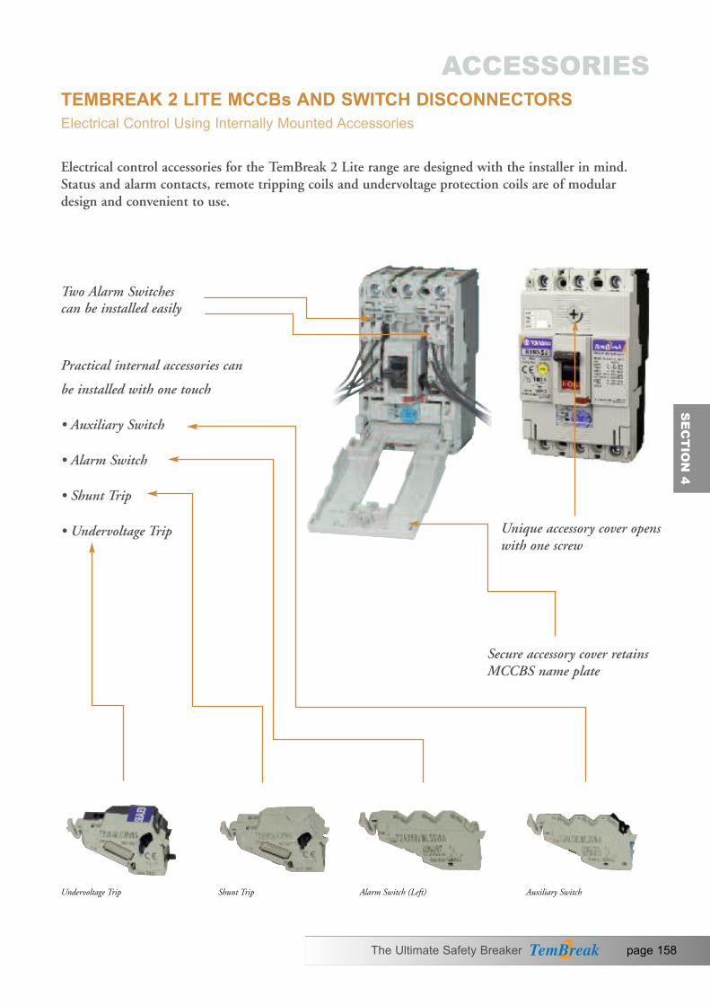
Electrical control accessories for the TemBreak 2 Lite range are designed with the installer in mind.Status and alarm contacts, remote tripping coils and undervoltage protection coils are of modulardesign and convenient to use.
Undervoltage Trip Shunt Trip Alarm Switch (Left) Auxiliary Switch
Two Alarm Switches can be installed easily
Practical internal accessories can
be installed with one touch
• Auxiliary Switch
• Alarm Switch
• Shunt Trip
• Undervoltage Trip Unique accessory cover openswith one screw
Secure accessory cover retainsMCCBS name plate
SE
CT
ION
4
The Ultimate Safety Breaker page 158
TEMBREAK 2 LITE MCCBs AND SWITCH DISCONNECTORSElectrical Control Using Internally Mounted Accessories
ACCESSORIES

SH UV AX AL AL
SH
AL
UV
AX
UV
AX
AL
AX
SH
AX
UV
AL
AX
SH
AL
3・4
3・4
2
Auxiliary switch Alarm switchUnder
voltage trip Shunt trip
Type Numberof
poles
S160-SCF
C1 C2 Shunt trips are continuous rating without anti-burn switches.
1pc Aux. SW installed.
2pcs Aux. SW installed.
4pcs Aux. SW installed.
1pc Alarm. SW installed.
2pcs Alarm. SW installed.
D1 D2
12/AXb1 14/AXa1
11/AXc1
12/AXb1 14/AXa1
11/AXc1
22/AXb2 24/AXa2
21/AXc2
12/AXb1 14/AXa1
11/AXc1
22/AXb2 24/AXa2
21/AXc2
32/AXb3 34/AXa3
31/AXc3
42/AXb4 44/AXa4
41/AXc4
92/ALb1 94/ALa1
TRIP
91/ALc1
92/ALb1 94/ALa1
TRIP
91/ALc1
02/ALb2 04/ALa2
TRIP
01/ALc2
Accessory .oN lanimret dna margaid noitcennoClobmys noitanibmoC Remarks
Shun
t trip
dev
ice
(SH)
Auxil
iary s
witch
(A
X)Al
arm
switc
h (A
L)Un
dervo
ltage t
rip de
vice
(UV)
• Without anti-burn switch
U1 U2
C/DCA roF
Valid/Maximum Accessory Combinations Moulded Case Circuit Breakers
Notes:: The two-pole type breaker obtained by modifying a three-pole breaker by removing the conductive part of its central pole is regarded as the same as the three-pole type. ①
j
E160-SF S160-SCF S160-SF E160-SJ S160-SCJ S160-SJ S160-SN
E250-SCFE250-SF S250-SF E250-SCJ S250-SJ E250-SJ S250- N
page 159 The Ultimate Safety Breaker
TEMBREAK 2 LITE MCCBs AND SWITCH DISCONNECTORSElectrical Control Using Internally Mounted AccessoriesConnection Diagrams and Terminal Numbers
ACCESSORIES

Standard For microload �AC (V) DC (V)
Minimumload
DC (V)Minimum
loadVoltage(V)
Current (A) Voltage(V)
Current (A) Voltage(V)
Current (A)Resistive
loadInductiveload �
Resistiveload
Inductiveload �
Resistiveload
480 - - 250 - -
DC15V100mA 30 0.1 DC5V
1mA250 3 2 125 0.4 0.05
125 3 2 30 3 2
Note: � This is a custom-made product. When ordering for this product, specify that it is intended for minute load use.Note: �
�
The inductive load means power factor of no smaller than 0.4 and time constant of no larger than 7 ms.
Type of breaker
The applicable load of the switch shall be no larger than the rating and no smaller than the minimum load.
Operation of AX and AL
Ratings of Auxilary and Alarm (AX/AL)
Switch Breaker status [OFF]
Auxiliaryswitch (AX)status
11/AXc-14/AXa “Closed”11/AXc-12/AXb “Open”
11/AXc-14/AXa “Open”11/AXc-12/AXb “Closed”
Alarm switch(AL) status
91/ALc-94/ALa “Open”91/ALc-92/ALb “Closed”
91/ALc-94/ALa “Open”91/ALc-92/ALb “Closed”
[TRIP]
11/AXc-14/AXa “Open”11/AXc-12/AXb “Closed”
91/ALc-94/ALa “Closed”91/ALc-92/ALb “Open”
[ON]
12/AXb 14/AXa
91/AXc
92/ALb 94/ALa
TRIP
91/ALc
E160-SF, S160-SCF, S160-SF, E160-SJ, S160-SCJ, S160-SJ, S160-SNE250-SCF, E250-SF, S250-SF, E250-SCJ E250-SJ, S250-SJ, S250-SN
Remote Tripping Devices
Ratings of Shunt Trip (SHT)
Breaker contacts usually start opening within
Peak exciting current, ARated
voltageAC (V) DC (V)
0.014 0.014 0.0065 0.03 0.03 0.011 0.011
200-240 380- 450 24 48 100 -120100 -120 200-240
Notes: The permissible voltage range is from 85% to 110% of the rated voltage for AC or 75 % to 125 % thereof for DC. Ensure that the voltage does not drop or exceed the permissible voltage range when SHT is actuated.
30 ms after the rated voltage is applied to the breaker.
Type of breaker
E160-SF, S160-SCF, S160-SF, E160-SJ, S160-SCJ, S160-SJ, S160-SNE250-SCF, E250-SF, S250-SF, E250-SCJ, E250-SJ, S250-SJ, S250-SN
�
SE
CT
ION
4
The Ultimate Safety Breaker page 160
TEMBREAK 2 LITE MCCBs AND SWITCH DISCONNECTORSElectrical Control Using Internally Mounted Accessories
Status Indication Switches
ACCESSORIES

Ratings of Undervoltage Trip (Instantaneous)
Ratedvoltage
AC (V)100 -120 200 -240 380 - 450 24 100 -120 200 -240
1.4 2.3 23 10 3.5
Power supply capacity, VA Type of breaker
Exciting current, mA DC (V)
Time delays: 500±300 msec.
Ratedvoltage
AC (V)100 -110 200 -220 380 -415 24 100 -110 115 -120
2.11. 11 .5 22 7.6 8.3
Power supply capacity, VADC (V)
115 -120 230 -240 440 -450 200 -220 230 -240
1.3 2.5 1. 87 .6 9.3
Exciting current, mA
E160-SF, S160-SCF, S160-SF, E160-SJ, S160-SCJ, S160-SJ, S160-SN
E160-SF, S160-SCF, S160-SF, E160-SJ, S160-SCJ, S160-SJ, S160-SN
E250-SF, E250-SCF, S250-SF, E250-SJ E250-SCJ, S250-SJ, S250-SN
E250-SF, E250-SCF, S250-SF, E250-SJ E250-SCJ, S250-SJ, S250-SN
1.5
Ratings of Undervoltage Trip with Time Delay
Applicable breakers
Undervoltage trips with AC operating voltage are available with time delay (500+/-300 mili seconds). UVT controllers are installed on the right hand side of the breaker. For this option refer to page 142 details.
page 161 The Ultimate Safety Breaker
TEMBREAK 2 LITE MCCBs AND SWITCH DISCONNECTORSElectrical Control Using Internally Mounted AccessoriesRemote Tripping Devices
ACCESSORIES

A terminal block facilitates convenient and accessible control wiring to internally mounted accessoriesby allowing the use of control wiring cables with larger cross-sectional area than permitted by theinternal accessories.
This terminal block can be clipped to either side of the MCCB. The customer should specify left orright hand side version depending on the internal accessory combination required.
Block fitted on 250A MCCB
SE
CT
ION
4
The Ultimate Safety Breaker page 162
TEMBREAK 2 LITE MCCBs AND SWITCH DISCONNECTORSTermination of Control WiringTerminal Blocks for Front Connected and Rear Connector MCCB’s (TF)
ACCESSORIES

Type of breaker
Notes:① : Permissible operating range is 85 to 110%. A power transformer is available as option for AC380V or AC400- 460V.② : The currents shown are the maximum values at the maximum rated operational voltage.③ : The operating time is the value when the rated operational voltage is supplied.
Allow a longer time for the motor operator to complete the operation.④ : The motor operator is of a short time duty. Do not subject it to more than 10 continuous ON-OFF operations. If this occurs, allow
the motor operator to cool for at least 15 minutes.⑤ : When the rated operational voltage is DC24V the open voltage will be DC22V.
T2MC25L
AC100-110VAC200-220VAC230-240VDC24VDC48VDC100-110VDC200-220V
Peak steady-state/starting current, A 2
8/5.4V011-001CAAC200-220VAC230-240VDC24VDC48VDC100-110VDC200-220V
Operation method Motor driven (direct drive system)Operating times at rated voltage
1.0NOOFF/RESET 0.1③④
Operating switch ratings100V 0.1A (Open voltage/current: 44 V/4 mA) ⑤
Power supply required 300VA or higherDielectric withstand voltage (for one minute) AC1500V (AC 1000 V for DC 24/48 V)Weight 1.4kg
Rated operational voltage 1
4/83.5/718/2612/182.2/6
2.2/5.5
Ratings and Specifications
E250-SF, E250-SCF, S250-SF, E250-SJ, E 250-SCJ, S250-SJ, S250-SN
Features
Installation and Removal Ease
Simply rotate two knobs allows the motor operator to be installed on or removed from the breaker.
HIgh-speed, Stable Actuation
The quick operating timemakes it possible to use the motor operators forsynchronized closing ofbreakers.
Silent Operation
T2MC25L use a direct drive system, providingoperational silence.
“Lock-in Off” Capability
This capability allows thebreaker to be padlocked in the OFF state. Up to threepadlocks with a 5 mm haspdiameter can be used. Padlocks are not supplied.
Lock plate
OperatingHandle
Voltage Presence LED indicationVoltage Presence LED indication
Key lock (optional)
page 163 The Ultimate Safety Breaker
TEMBREAK 2 LITE MCCBs AND SWITCH DISCONNECTORSElectrical Control Using Motorised OperationMotor Operators (MC)
ACCESSORIES

SE
CT
ION
4
Motorized OperationThe motor operator has an input-signal self-hold circuit: closing the ON or OFF switch (see circuitdiagrams shown below) momentarily allows activating the motor operator. To reset the tripped breaker to the OFF position, close the OFF (RESET) switch. The voltage presence LED indication is on when the power is supplied to the motor operator.
Auto Reset Feature (optional)The auto reset feature allows the breaker to be automatically reset approx 1.5 seconds after the breaker trips open. This option contains auto-reset switches and does not require to use auxiliary oralarm switches installed in the breaker.
Note: that after the thermal OCR trips a thermal-magnetic breaker, the breaker cannot be immediately closed though it can be auto-reset. Wait for a few minutes after the tripping and provide a close signal to the breaker.
This option resets the tripped breaker automatically, regardless of the cause of the tripping.
Manual OperationPull the operating handle out. Rotating the handle counter clockwise turns ON the breaker andclockwise turns OFF or resets the breaker.
Operation Precaution1. Ensure that the actual operation voltage ranges from 85% to 110% of the rated one.
2. Use operation switches whose ratings and power capacity is as specified in the “Ratings and Specifications” table on the previous page.
3. Use noise filters if the control power supply of the motor operator is shared by peripheral devices. Otherwise, power supply noise may cause malfunction of the peripheral devices.
Control Circuit Diagrams of Motor Operators
The Ultimate Safety Breaker page 164
TEMBREAK 2 LITE MCCBs AND SWITCH DISCONNECTORSElectrical Control Using Motorised Operation
ACCESSORIES
LEDOFF
DS
OFF(RESET)
+
–
M
P1(+)
ON
COM
P2(–)
E
ON
UcThe “+” and “–” symbols indicate the polarities of DC-rated motor operators.
Con
trol p
ower
circ
uit
ON
/OFF
con
trol c
ircui
t
Mot
or d
rive
circ
uit
T2MC25L

Breaker Mounted Handle (HB)This external operating handle is used to operate a circuit breaker mounted just behind a compartmentdoor with the door closed.
The operating mechanism and handle are mounted directly onto the circuit breaker. The handleprotrudes through a cut-out in the door. A mould flange is supplied with the handle, covering panel cut-out from the front.
Outer View
Mounting InstructionsMounting of external operating handle assembly
• Make sure that the breaker is in the OFF position.
• Put the external operating handle assembly onto the breaker in place so that the breaker handle is engaged with the handle catch of the assembly. Tighten the screw to secure the handle assembly.
Installation of handle escutcheon and latch plate• Drill holes in the panel according to the panel cutout dimensions. Sandwich the panel between the handle escutcheon and latch plate and temporarily tighten using the supplied screws.
• Close the panel.
• Make adjustment so that the gap between the handle assembly and handle escutcheon is even and the assembly is not inclined against the breaker.
Breaker Mounting DirectionThe ON and OFF positions of the handle and the positions of drilled holes in the panel do not need to be changed depending on the breaker mounting direction. The upper supply type is standard.
Dustproof packing (optional)
Breaker
Breaker
Handle frame
Handle escutcheon
Handle escutcheon
Gap
(Incorrect)
S
Screw
Screw
U: Upper power supply type (standard)
L: Left power supply type
R : Right power supply type
Power supply
Load
Pow
er s
uppl
y
Pow
er s
uppl
y
Load
Load
• For a change in mounting direction, see the Operating Instructions packaged with the product.
page 165 The Ultimate Safety Breaker
TEMBREAK 2 LITE MCCBs AND SWITCH DISCONNECTORSOperating Handles and Locking Devices
ACCESSORIES

Panel Lock MechanismThis external operating handle keeps the panel door locked when in the ‘ON’ position.
(1) Reset. OpenThe handle is turned to the ‘RESET/OPEN COVER’ position to open the panel door.
Panel lock release knobThe release knob enables the panel door to be openedwith the handle in the ‘ON’ position. To release: turn the release knob in the direction of anti-clockwise witha flat-bladed screwdriver.
Safety interlock (Standard)The safety interlock prevents the breaker from turningON as long as the panel is open. This interlock can be released using the hook lever.
Handle Lock MechanismPadlock (Standard)
This Mechanism allows the breaker to be padlock in the OFF position. Padlocks are not supplied.
Up to three padlocks can be installed.
SE
CT
ION
4
The Ultimate Safety Breaker page 166
TEMBREAK 2 LITE MCCBs AND SWITCH DISCONNECTORSOperating Handles and Locking Devices
ACCESSORIES
ADia.
Type of handle A Dia.
T2HB 13 min ø5.5-8
Padlock dimensions (mm)
IP30 standard specification
IP50 optional, with a dust proof packing

Handle cover
Operating handle
Gasket for IP 65
Shaft support
Square shaft
Operating unit
T
Door Mounted Handle The door mounted operating handle allows breakers installed in control centers or switchboards to bemanually operated from outside and complies with IEC 6020-1.It consists of an operating mechanism that is mounted on the breaker, a handle that is mounted on thedoor and a shaft that transmits the turning force from the handle to the operating unit. The shaft support acts as a guide when the panel door is being closed.
Outer View
Breaker Mounting DirectionThe ON and OFF positions of the handle and the positions of drilled holes in the panel do not need to be changed depending on the breaker mounting direction.
Operating Direction of HandlesRotate the operating handle clockwise to turn the breaker on.
Line (ON)
Line
(ON
)
Line
(ON
)
Horizontal mounting / ON to move the breaker handle right
Horizontal mounting / ON to move the breaker handle left
Vertical mounting / ON to move the breaker handle up
Type 160A Frame
ON
OFF
ON
OFF
Type 250A Frame
Rotate clockwise to turn the breaker ON
page 167 The Ultimate Safety Breaker
TEMBREAK 2 LITE MCCBs AND SWITCH DISCONNECTORSOperating Handles and Locking Devices
ACCESSORIES

ø5
Panel Lock Mechanism The external operating handle keeps the panel door locked when in the ‘ON’ position.
OFF open typeThe handle is turned to the OFF position toopen the panel door.
Panel lock release buttonThe release button enables the panel door to be opened with the handle in the “ON’position. To release: push the release button on the side of the operating handle with a flat-bladed screwdriver.
Locking Devices (Toggle Lock HL)Toggle locking devices allow MCCB’s to belocked ON or OFF using up to three padlocks. Locking devices for 160A and 250A frame models accept padlocks with a 5mm haspdiameter.
Toggle Lock MechanismPadlock (Standard)
This Mechanism allows the breaker to be padlock in the OFF position. Padlocks are not supplied.Up to three padlocks can be installed.
Key Fitting Facility (optional)Key fitting facility is available for Castell FS1.Contact us for the details of mountingdimensions.
Type 250A Frame
Pad locking lever
I
Type 160A Frame Type 250A Frame Type 160A Frame
Pad locking lever
SE
CT
ION
4
The Ultimate Safety Breaker page 168
TEMBREAK 2 LITE MCCBs AND SWITCH DISCONNECTORSOperating Handles and Locking Devices
ACCESSORIES

Flush Terminal Covers (CS)Flush terminal covers are available for 250A frame models with CS terminal covers front or cableclamp (FW) connection increase the ingress protection rating at the terminals without increasing the overall length. They can be used with busbar and for direct entry of stranded cable.
Terminal covers for Rear Connection (CR)
Terminal covers for rear connection areavailable for 160A to 250A frame modelsand may be used on MCCBs fitted withrear connections (RC). They preventaccess to the terminals from the frontand top.
Terminal Cover Lock Option is availableto lock and seal CF, CS and CR cover on to MCCB.
Terminal Covers for Front Connection (CF)Terminal covers for front connection are suitable for covering the exposed live parts of conductorsterminated on the MCCB.
Terminal Cover for Front Connection
Terminal Cover for Rear Connection
Flush Terminal Covers (CS)
page 169 The Ultimate Safety Breaker
TEMBREAK 2 LITE MCCBs AND SWITCH DISCONNECTORSInsulation Accessories
ACCESSORIES

Additional interpole barriers can be ordered individually. All interpole barriers can easily be fitted toeither end of an MCCB.
Interpole Barriers (BA)Interpole barriers provide maximum insulation between phases at the terminals of the MCCB. Theycannot be fitted at the same time as any of the terminal covers. Interpole barriers for use on one end of the MCCB are supplied as standard.
MCCB fitted with Interpole Barriers at both ends
SE
CT
ION
4
The Ultimate Safety Breaker page 170
TEMBREAK 2 LITE MCCBs AND SWITCH DISCONNECTORSInsulation Accessories
ACCESSORIES

12/AXb1 14/AXa1
11/AXc1
An auxiliary switch electrically indicates the ON or OFF status of the MCCB.
An alarm switch electrically indicates theTRIP status of the MCCB.
General Current For microload AC (V) DC (V)
Minimumload
DC (V)Minimum
loadVoltage(V)
Ampres (A) Voltage(V)
Ampres (A) (A) (V)Resistive
loadInductiveload
Resistiveload
Inductiveload
Resistiveload
Minimumload
30 0.1
MCCB Model
XS1250ND, XS1600ND
XS2000ND, XS2500ND
480 3 2 250 0.30.3
250
DC5V160mADC30V26.7mA
DC5V1mADC30V1mA
5 5 125 0.60.6
125 5 5 5 45
Switch Breaker status [OFF]
Auxiliaryswitch (AX)status
11/AXc-14/AXa “Closed”11/AXc-12/AXb “Open”
11/AXc-14/AXa “Open”11/AXc-12/AXb “Closed”
Alarm switch(AL) status
91/ALc-94/ALa “Open”91/ALc-92/ALb “Closed”
91/ALc-94/ALa “Open”91/ALc-92/ALb “Closed”
[TRIP]
11/AXc-14/AXa “Open”11/AXc-12/AXb “Closed”
91/ALc-94/ALa “Closed”91/ALc-92/ALb “Open”
[ON]
12/AXb 14/AXa
91/AXc
92/ALb 94/ALa
TRIP
91/ALc
12/AXb1 14/AXa1
11/AXc1AX Terminal Designations AL Terminal Designations
Operation of AX and AL
Ratings of Auxiliary and Alarm (AX/AL)Auxiliary and Alarm Switch Ratings
page 171 The Ultimate Safety Breaker
TEMBREAK MCCBs AND SWITCH DISCONNECTORSElectrical Control Using Internally Mounted AccessoriesOperation of AX and AL
ACCESSORIES

Ratings of Undervoltage Trips
A shunt trip allows an MCCB to be trippedremotely on the application of the rated coilvoltage across the shunt trip terminals. TheMCCB contacts and toggle will move to thetripped position when the shunt trip isoperated.
The permissible voltage range is 85% to110% for AC or 75% to 125% for DC.
Excitation Current (A)Voltage AC Voltage DC
100-115 200-480 24 48MCCB Model
XS2000ND, XS2500ND
1.1 0.93 2.52 1.55 0.350.67XS1250ND, XS 1600ND
100-115 200-230
P
Power Supply Capacity (VA) Excitation Current (mA)AC (V) DC (V)
100-120 200-240 380-450 24MCCB Model
XS2000-ND, XS2500ND
5 5 5 22.7 -6.0XS1250-ND, XS 1600ND
100-115 200-240
S2 S1~(-)
~(+)
UC1
UC2
P1
P2
controller
Note: Shunt trip is provided with anti-burn switch
Under Voltage Trip (UVT)An undervoltage trip will automatically tripthe circuit breaker when the voltage appliedto its coil falls below a pre-set value. Remotetripping of the breaker is also possible.
Tripping voltage is 35% 70% of the rated voltage.Resettable voltage is 85% or less, of therated voltage.
Note: The UVT controller is installed externally, when provided with AC UVT.
SE
CT
ION
4
Ratings of Shunt Trips
Shunt Trip (SHT)
The Ultimate Safety Breaker page 172
TEMBREAK MCCBs AND SWITCH DISCONNECTORSElectrical Control Using Internally Mounted AccessoriesRemote Tripping Devices
ACCESSORIES

1250 and 1600A 2000 and 2500A
)
A)( ezis emarF
SH
AL
AX
UV
AL
AX
Auxiliary Switch
Alarm Switch
Shunt Trip
Undervoltage Trip
XS1250NDXS1600ND
XS2000NDXS2500ND
page 173 The Ultimate Safety Breaker
TEMBREAK MCCBs AND SWITCH DISCONNECTORSElectrical Control Using Internally Mounted AccessoriesValid Maximum Accessory Combination
ACCESSORIES

The LTF terminal block facilitates convenient and accessible control wiring to internally mountedaccessories by allowing the use of control wiring cables with larger cross-sectional area than permittedby the internal accessories.
Mounting Position and Standard Terminal Arrangement for 1250 to 1600A MCCB (LTF)
SE
CT
ION
4
Mounting Position and Standard Terminal Arrangement for 2000 to 2500A MCCB (LTF)
The Ultimate Safety Breaker page 174
TEMBREAK MCCBs AND SWITCH DISCONNECTORSTermination of Control Wiring
ACCESSORIES

Type of Motor Operators XMD 9
Applicable MCCB XS1250 - ND
XS1600 - ND
Rated OperatingVoltage (V)
AC 100-115V 50/60Hz �
200-230V 50/60Hz �
DC 100-110V �
24V �
Lock in “OFF” position (standard) �
Manual Trip Button �
Steady-state r.m.s.Amp/inrush Amp (A)
AC100-115V ON –/3.1
OFF, RESET 1.8/6.0
AC200-230V ON –/1.2
OFF, RESET 1.0/3.2
DC100-110V ON –/0.8
OFF, RESET 1.1/4.2
DC24V ON –/4.5
OFF, RESET 4.0/12.0
Type of operation Spring Charged
Operating Time(s) ON (Maximum values) 0.06
OFF, RESET 3
Control Switch Ratings 250V, 5A
Power Source Capacity (VA) 300VA
Dielectric withstand voltage The value in brackets for 24V DC
AC1500V(AC500V)
Weight (kg) 6.4
NOTE Maximum values at AC115V, 50Hz Maximum values at AC230V, 50Hz Maximum values at DC110V Maximum values at the rated operating voltages
� = Available� Trip button on breaker to be used (accessible with motor fitted)
Ratings and Specifications
Type 1250, 1600A, Motor Operator
Positive Contact Indication• Colour coding indicates the true position of the contacts clearly: ON (red), OFF (green), TRIP (white).
Easy Maintenance• Breaker mounting, removal, and even settingchanges can be done without removing themotor operator.
Manual ON/OFF Operation with One Stroke
Fast Closing Operation• Closing in 60ms or less. The closing timeremains constant over repeated operations.
Manual Operating Handle
Indicator
Lock Plate
Trip Button
The breaker can be padlocked in the “OFF” position by pulling out the lock plate, and locking it with a padlock. When the breaker is “ON”, the lock plate cannot be pulled out.Up to three lock can be used.Padlock not supplied.
page 175 The Ultimate Safety Breaker
TEMBREAK MCCBs AND SWITCH DISCONNECTORSElectrical Control Using Motorised Operation 1250A and 1600A
ACCESSORIES

Motorised OperationON CONTROL
When the ON switch is closed,the latch release coil (LRC) isexcited and the closing spring isreleased. The breaker quicklycloses and goes into ON status.When the closing spring isreleased the limit switch (LS) is opened and the LRC is de-excited.
OFF CONTROL
When the off switch is closed,self-hold control relay (Y) isactivated and motor (M)operates to charge the closingspring. The breaker changes to OFF status.
RESET CONTROL
When the breaker is in TRIPstatus, closing the OFF switchactivates self-hold control relay(Y) and starts motor (M).Motor (M) charges the closingspring and resets the breaker.
Manual OperationON, OFF (RESET)
The breaker can be opened(OFF or RESET) and closed(ON) alternately by pulling theoperating lever down in onefull stroke. ON/OFF operationof the breaker is possiblewithout charging or releasingthe closing spring.
EMERGENCY TRIP
Opening the breaker (OFF)using the motor operator takesup to 3 seconds. If a remoteemergency OFF function isnecessary, incorporate the shunttrip device (SHT) or theundervoltage trip device (UVT) into the breaker.
PRECAUTIONS REGARDING USAGE
• If using the UVT option, be sure to reset the UVT before closing the breaker
• The motor operator must be supplied with voltage within the following range:
DC: 75-110% of rated voltageAC: 85-100% of rated voltageOperation at low voltage may burn out the motor.
Anti-pumping FunctionWhen the breaker is turnedON and the closing spring isreleased, self-hold control relayX is active. Xa-contact is heldclosed, and Xb-contact isopened. While the ON switchis closed, latch release coil(LRC) will not be excited evenif the OFF switch is closed oran automatic reset circuit isbeing used. Pumping is thus prevented.
Automatic Charge/discharge Function
If the breaker is closedmanually (ON) while thepower source is on, the handleswitch (HS) induces automaticrelease of the closing spring.Likewise, if the breaker isopened manually (OFF), thesprings are automaticallycharged. If the breaker isopened or closed while thepower source is off, later whenthe power source is turned on,the closing spring willautomatically be charged ordischarged to match theON/OFF status of the breaker.This automaticcharge/discharge function isnecessary to prepare the closingmechanism for the nextON/OFF operation. The sound of the charging ordischarging of the springshould not be mistaken for amalfunction.
SE
CT
ION
4
The Ultimate Safety Breaker page 176
TEMBREAK MCCBs AND SWITCH DISCONNECTORSElectrical Control Using Motorised Operation 1250A and 1600A
ACCESSORIES

An alarm switch (a-contact)fitted in the breaker, can be used to induce recharging of theclosing spring and automaticallyreset the MCCB. Connect theautomatic reset circuit as shown below.
If the alarm switch is used, apulse signal will be produced inthe automatic reset circuit whenthe alarm is activated. Be sure touse a self-hold circuit to avoidpossible problems caused by this pulse signal.
It is recommended that a time delay of approximately 3 minutes is introduced to theautomatic reset circuit forthermal magnetic MCCB’s Inthe event of an overload trip this will prevent the motor operatorsrepeatedly driving the MCCBbetween the tripped and resetpositions while the thermalelement is hot.
If an alarm signal is alsorequired for external control, usea 2 alarm switch combination.
Connected Circuit AC and DC
Note: Customer wiring shown in orange.
page 177 The Ultimate Safety Breaker
TEMBREAK MCCBs AND SWITCH DISCONNECTORSElectrical Control Using Motorised Operation 1250A and 1600AAutomatic Reset
ACCESSORIES

Applicable breakers XS2000-NDXS2000-ND
Operating Voltage (V) (1) AC 100-110V 50/60HzAC 200-230V 50/60HzDC 100-110V
Automatic Reset (2)Steady-state r.ms. (A) AC 100-110V 50/60Hz (5) 0.85/3.5Amp/inrush Amp (A) AC 200-230V 50/60Hz (6) 1.3/2.1
DC 100V (7) 1.1/2.5DC 110V (7) 1.2/3.0
Type Motor DrivenOperating Time(s) ON (Maximum values) 0.06 2.0(3) (4) OFF/RESET 1.6Control Switch Rating 250, 5APower Source Capacity (VA) 300Dielectric Withstand Voltage AC1000VWeight (kg) 16
Reference Notes
(1) Permissible operating voltage range as Follows:AC rated, 85% to 110% of the rated voltageDC rated, 85% to 110% of the rated voltageNote: AC rated operating voltage 380V or400-460V a power transformer is available (optional).
(2) Requires breaker’s auxiliary switch (1b contact). This will be wired at the factory (on request) when thebreaker/motor operator assemblies are ordered. However,when all the auxiliary switch contacts are specified forother purposes, an external auxiliary relay (not supplied)is required to be controlled by the auxiliary a-contact ofthe breaker and use the relay’s normally closed contact(b-contact) for automatic reset.
(3) Time values at the rated operating voltage. Allow a longer time for the motor operator to completethe operation, at lower operating voltage.
(4) The motor operator is of a short time duty. Do not subject it to more than 10 continuous ON-OFFoperations. If this occurs, allow the motor operator tocool for at least 15 minutes.
(5) Maximum values at 110V AC
(6) Maximum values at 220V AC
(7) Special specification, available on request
Type of Motor Operators XMB 10
Ratings and Specifications
SE
CT
ION
4
The Ultimate Safety Breaker page 178
TEMBREAK MCCBs AND SWITCH DISCONNECTORSElectrical Control Using Motorised Operation 2000A and 2500AMotor Driven Type
ACCESSORIES

Motor operation‘ON’ controlOperating the ON switchenergises the relay (X) via themotor switch 2-3 (closed). This in turn energises themotor, which turns the breakerON. When the breaker is ON,the motor switch is thrown tothe other side resulting in therelay (X) de-energising andstopping the motor.
‘OFF’ controlOperating the OFF/RESETSwitch energises the relay (Y) via the motor switch 1-2(closed). This in turn energisesthe motor which turns thebreaker OFF. When the breakeris OFF the motor switch isthrown to the other sideresulting in the relay (Y) de-energising and stopping the motor.
“RESET” controlOperate the OFF/RESETSwitch to reset the trippedbreaker. Circuit operation is the same for the OFF Control procedures.
Automatic reset (Optional)The automatic reset feature canbe incorporated by connectingthe breaker’s auxiliary switchcontact (b-contact) in parallelwith the OFF/RESET control switch.
Manual operationPosition the manual handle(supplied with motor operator)onto the motor operator shaft.Turn the handle anti-clockwiseto turn the breaker OFF orRESET. During manualoperation (by handle) the motoroperator shaft is disengagedfrom the mechanism. Removingthe handle automaticallyengages the shaft with themotor operator mechanism.
Handle switchWith the addition of a handleswitch, the motor operatormechanism can be automaticallybrought to the manuallyoperated position (ON or OFF) on removal of the handle,providing that the motoroperator is powered up.
CAUTIONARY NOTES1) When the breaker is ON andis then tripped, the ON/OFFindicator on the motor operatorwill indicate ON until thebreaker is reset.
Note: The breaker’s conditionmay differ.
2) If the motor operator isturned ON with the breakerOFF and the UVT de-energised,apply the power and completeone ON-OFF operation. (The breaker cannot be turnedON). Then complete one ONoperation again (The breakercan be turned ON)
3) Allow several minutes to coolwhen a thermal-magneticbreaker is tripped by a thermaloverload trip, then reset thebreaker.
SOURCE
OFF
RESET
AUTO RESETSW (OPTION)
HANDLESW
MOTORSW
Xa
Xa
Xb Yb
Xa
Ya
Ya
Ya
X
M
Y
ON
A
1 3
2
4 6
5
7 9
8
B C D E
SOURCE
OFF
RESET
AUTO RESETSW (OPTION)
HANDLESW
MOTORSW
Xa
Xa
Xb Yb
Xa
Ya
Ya
Ya
X
M
Y
ON
A
1 3
2
4 6
5
7 9
8
B C D E
DCAC
~ ~
Control Circuit for Motor Driven Type
page 179 The Ultimate Safety Breaker
TEMBREAK MCCBs AND SWITCH DISCONNECTORSElectrical Control Using Motorised Operation 2000A and 2500A
ACCESSORIES

The door mounted handle allows breakers installed in control centers or switchboards to be manually operated from outside and complieswith IEC 60204-1. HS style handles are available for 1250 and1600A models only. It consists of an operating mechanism that ismounted on the breaker, an operating handle that is mounted on thedoor, and a shaft that transmits the turning force from the handle tothe operating unit.The shaft can be cut to the required length.The shaft support makes easy to insert to the operating handle whenthe panel door is being closed.
The external operating handle keeps the paneldoor locked when in the �ON� position. There is OFF open type only.
OFF open typeThe handle is turned to the OFF position to open the panel door.
• Door interlock release buttonThe release button enables thepanel door to be opened with thehandle in the �ON� position. To release: push therelease button on theside of the operatinghandle with a flat-bladed screwdriver.
Door Interlock Mechanism
• Padlock (Standard)This mechanism allows the breaker to bepadlocked in the OFF position.Padlocks are not supplied. Up to three padlocks can be installed.
Toggle Lock Mechanism
Handle cover
Operating handle
Gasket for IP65(optional)
Shaft support
Square shaft
Operating unit
Pad locking leverPlastic lever or Metal leveravailable.
SE
CT
ION
4
The Ultimate Safety Breaker page 180
TEMBREAK MCCBs AND SWITCH DISCONNECTORSOperating Handles & Locking DevicesDoor Mounted Handle (HS) Standard Type for 1250A and 1600A MCCB
ACCESSORIESACCESSORIES

TEMBREAK MCCBs AND SWITCH DISCONNECTORSOperating Handles & Locking DevicesBreaker Mounted Handle for 1250A and 1600A MCCB (HB)
Fittings for Castell locks are available. They are suitable for use on door mounted handles (HS) for MCCBs.
Operating Handle for 2000A and 2500A MCCB, Panel Mounted Type XFE10ONTurn the handle clockwise to the ON position on the indication plate.OFF Turn the handle anti-clockwise to the OFF position on the indication plate.RESETWhen the breaker trips the handle indicates tripped Turn the handle anti-clockwise to the RESET position. This will reset the breaker
OPENING THE PANELTurn the handle anti-clockwise to OPEN DOOR. The lock is released and the panel door can be opened.
Locking DevicesToggle locking devices allow MCCBs to be locked ON or OFF using up to three padlocks. Locking devices for 1250A to 1600A frame models accept padlocks with 8mm hasp diameter.
Name Plate.
This external operating handle is used to operate acircuit breaker mounted just behind a compartmentdoor with the door closed. The operating unit andthe handle itself are mounted directly onto the circuit breaker. The handle protrudes through acutout in the door. A moulded door flange is supplied with the external operating handle whichcovers the cutout from the front.
Padlocking is possible in the OFF position.
Breaker Mounted Handle
Handle.
Panel lock release.
page 181 The Ultimate Safety Breaker
ACCESSORIES

XHA9B
MCCB
(1250A ~ 1600A) XHA10 (2000 ~ 2500A)
Handle extensions assist manual opening and closing operations for large frame MCCBs. Handle extensions are supplied as standard on DC breakers rated 1250A and above.
SE
CT
ION
4
The Ultimate Safety Breaker page 182
TEMBREAK MCCBs AND SWITCH DISCONNECTORSOperating Handles & Locking DevicesHandle Extension for 1250 - 2500 A MCCB’s (XHA)
ACCESSORIES

Terminal covers are used to prevent directcontact with live MCCB terminations. They also provide additional insulation toreduce the possibility of a short circuitbetween phases or to earth when largeconductors are used.
General features• Terminal covers for 1250A frame models
have an IP20 ingress protection rating
• Terminal covers are ordered individually.Two terminal covers are required to coverboth the line and load terminals of anMCCB. Each cover can either be fitted tothe top or bottom of the MCCB
• Terminal covers have a meggermeasurement hole of 4mm diameter on each phase.
Meggermeasurement
holes
1250AF Terminal Cover
page 183 The Ultimate Safety Breaker
TEMBREAK 2 MCCBs AND SWITCH DISCONNECTORSInsulation AccessorisesTerminal Covers for 1250A MCCB
ACCESSORIES

MCCB Fitted with Interpole Barriers on Both Ends
Interpole barriers provide maximum insulation between phases at the terminals of the MCCB. They cannot be fitted at the same time as any of the terminal covers. Interpole barriers for use on one end of the MCCB are supplied as standard. Additional interpole barriers can beordered individually. All interpole barriers can easily be fitted to either end of an MCCB.
MCCB moulds have been designed to accept an additionalinterpole barrier between two adjacent MCCBs.
SE
CT
ION
4
The Ultimate Safety Breaker page 184
TEMBREAK 2 MCCBs AND SWITCH DISCONNECTORSInsulation AccessoriesInterpole Barriers for 1250A and 1600A MCCB (BA)
ACCESSORIES

page 185 The Ultimate Safety Breaker

The Ultimate Safety Breaker page 186
TEMBREAK 2 & TEMBREAK MCCBs FROM 12A TO 3200A • MCCBs FOR 1000V AC MCCBs FOR 1000V DC • MCCBs WITH INTEGRAL RCD SWITCH DISCONNECTORS • MEASUREMENT AND DATA COMMUNICATION
RATINGS AND SPECIFICATIONS
PROTECTION CHARACTERISTICS
APPLICATION DATA
ACCESSORIES
INSTALLATION
DIMENSIONS
ORDER CODES
SECTION 1
SECTION 2
SECTION 3
SECTION 4
SECTION 5
SECTION 6
SECTION 7
CONTENTS

TEMBREAK 2MOULDED CASECIRCUITBREAKERS400 AC
SWITCHDISCONNECTORS
TEMBREAK 2CIRCUITBREAKERS WITHIcu = 70KA AT 690V Ac
TEMBREAK 2CIRCUITBREAKERS FOR 1000V Ac
TEMBREAK 2 LITESPACE SAVING,MONEY SAVINGMOULDED CASE CIRCUITBREAKERS
TEMBREAK 2CIRCUITBREAKERS WITHINTEGRALRESIDUALCURRENTPROTECTION(CBR)
CIRCUITBREAKERS ANDSWITCH-DISCONNECTORSFOR USE ABOVE250V DC
S160-SD S160-GD
S160-SDN
ZE125-NJZS125-NJZS125-GJ
ZE250-NJZS250-NJZS250-GJ
E160-SFS160-SCFS160-SF
E160-SJS160-SCJS160-SJ
E250-SCFE250-SF
S250-SFF
E250-SCJE250-SJS250-SJ
VS125-NJ VS250-NJ
S160-NJS160-GJS250-NJS250-GJ
S125-NJS125-GJ
S160-SN S250-SN S125-NN S250-NN S400-NN
XV400-NE
S250-SD S250-GD
S250-SDN
PVS160-SDLPVS160-SDHPVS160-SNLPVS160-SNHPVS250-SDLPVS250-SDHPVS250-SNLPVS250-SNH
S400-ND PVS400-NDL PVS400-NDH
H400-NE
L400-NE
160 250 125 250 250 400 630Frame Reference
Max. In (A) of Frame
INSTALLATIONTB2 Lite 160 TB2 Lite 250 TB2 125 TB2 S250 TB2 S/H/L 250 TB2 H/L 400 TB2 E/S 630
H125-NJL125-NJH160-NJL160-NJH250-NJL250-NJ
S250-NE
S250-GES250-PEH250-NE
L125-PJ L400-PE
●
●
E400-NJS400-CJS400-NJS400-GJS400-PJS400-NE
S400-GE
S400-PES630-CEE630-NES630-NES630-GE
page 187 The Ultimate Safety Breaker

S800-NDS1000-ND
XS2000-NNXS2500-NN
XS1600ND
XS2000-NEXS2600-NEXS3200-NE
XS2000-NDXS2500-NDXS3200-ND
TEMBREAK 2 MCCBSAND SWITCHDISCONNECTORS• Connection and
Mounting• Insulation Distances• Mounting Angle• Direction of Power
Supply• Standard Installation
Environment and Special Treatments
• Temperature Ratings
Pages 189 - 199
TEMBREAK 2 LITEMOULDED CASECIRCUIT BREAKERSAND SWITCHDISCONNECTORS• Connection and
Mounting• Insulation Distances• Mounting Angle• Direction of
Power Supply• Standard Installation
Environment and Special Treatments
• Temperature Ratings
Pages 200 - 205
MOULDED CASECIRCUIT BREAKERSAND SWITCHDISCONNECTORSFOR USE ABOVE 250V DC• Cable Connection
for DC Circuits• Insulation Distances• Standard Installation
Environment and Special Treatments
• Temperature Ratings
Pages 206 - 221
CO
NT
EN
TS
SE
CT
ION
5S1600-NES1600-SE
L800-PE
H800-NE
L800-NE
XV630PEXV800PE
XV1250NE
S800-NN S1250-NN S1600-NN
12501000800
PVS800-NDLPVS800-NDH
XS1250ND
1600 3200
TB2 H/L 800 TB2 1000 TB2 1250 TB2 1600 TB 3200
S800-CJS800-NJS800-RJ
S800-NES800-RES1000-SE
S1000-NE
S1250-SES1250-NES1250-GE
●
●
●
●
The Ultimate Safety Breaker page 188Tembreak 1. Frame sizes vary from Tembreak 2.Contact Terasaki for installation details.

TemBreak 2 MCCBs connection andmounting accessories facilitate easy installationin any arrangement. Breakers and accessoriesare easy to fit. They are designed to providesafe and secure termination and mountingpoints. 125A and 160A/250A frame modelshave a 45mm front cutout.
Overview of Connection and Mounting Accessories
Please refer to Section, 1 Ratings and Specifications, for details of the connection and mountingoptions which are available for each model.
Please refer to Section, 6 Dimensions, for detailed dimensions of connection and mounting optionsand accessories.
Note that one set of mounting screws is supplied as standard with every circuit breaker or switchdisconnector purchased.
Connection and mounting options overview diagram
45mm Cutout Patterns
45mm
page 189 The Ultimate Safety Breaker
TEMBREAK 2 MCCBs AND SWITCH DISCONNECTORSConnection and Mounting
INSTALLATION

SE
CT
ION
5
This connection method is standard for all front connected (FC) MCCB models. Solid conductors or cables terminated with crimp lug terminals can be used.
Serrated Terminal SurfaceEach terminal on 160A and 250A models has aserrated surface. This provides excellent grip forheavy cables terminated with crimp lug terminals,thereby preventing sideways rotation of the lug.
Connection of Large Conductors and Multiple ConductorsExtension bars (FB) are terminal extensions which can be fitted to lineor load side terminals and are used to connect large conductors andmultiple conductors. Available for field fitting in sets of 3 or 4 bars.
*H125 and L125 are 250A frame size
Maximum Dimensions of Compression Terminals
Frame Size (A) 125* 160 & 250 400 & 630
Width, W (mm) 17 25 25
Diameter, d (mm) 9 9 11
Maximum from centre to tip, dim e (mm) 8.5 10 12
The Ultimate Safety Breaker page 190
TEMBREAK 2 MCCBs AND SWITCH DISCONNECTORSConnection and MountingConnection of Busbars and Terminated Cables
INSTALLATION

page 191 The Ultimate Safety Breaker
Cable clamp terminals (FW) can be used to secure stranded cable directly to the MCCB. Available for field fitting in sets of 3 or 4.
Rear connections (RC) allow termination of conductors in a different switchboardcompartment to the MCCB body.
The stud can be rotated in steps of 45 degrees on a 125A to 630A frame MCCBs and 90 degrees on a 800A frame MCCBs in the field.
Termination in Separate Compartment
MCCB Model Cable Capacity (mm2)
TEMBREAK 2 MCCBs AND SWITCH DISCONNECTORSConnection and MountingDirect Entry of Stranded Cable
INSTALLATION
S125, VS125, ZE125, ZS125 1.5 to 50 (1 cable)
H125, L125 1.5 to 70 (1 cable)
S160, PVS160, S250, H250, L250, VS250, ZE250, ZS250 35 to 120 (1 cable)
E400, S400, H400, L400 80 to 240 (1 cable)
60 to 120 (2 cables)

SE
CT
ION
5
The Ultimate Safety Breaker page 192
The plug in mounting system allows fast replacement of the MCCB body without the need to disturbthe terminations. Solid conductors or cables terminated with compression terminals can be used.
Plug-In Safety Lock
The plug-in MCCB body is automatically locked to the base when the contacts are closed (toggle ON). It cannot be removed unless the contacts are in the isolated position (toggle OFF or TRIPPED). This system ensures safe removal of the MCCB from the base. Plug-in safety lock is available from125A to 800A frame models.
The connection bars for plug-in bases are optional and can be configured in the field either for frontor rear access. The illustrations below show possible mounting and connection options for plug inbases. These mounting and connection options are available from 125A to 800A frame models.
1. Mounted on base plate withconnection bars mounted forfront access.Insulation plates are suppliedas standard and must be fitted.
2. Terminations in separate compartment. Connection barsare mounted for top access at thetop and rear access at the bottom.
3. Mounted on angle bars.Connection bars aremounted for rear access.
Plug-in connections and safety lock are fittedto the back of the MCCB
Plug-in MCCB and base
Safety Lock
IP2X
InsulationPlates
Note: Plug-in mounting for 1250A frame model is available for only “Mounted on angle bars”, and safety trip can be specified as option.
TEMBREAK 2 MCCBs AND SWITCH DISCONNECTORSConnection and MountingPlug-in Mounting
INSTALLATION

page 193 The Ultimate Safety Breaker
The DIN rail adaptor is easily fitted to the rear of 3 pole S125 and S250 models to allow clip mountingof the MCCB to 35mm DIN rail.
The 45mm cutout of TemBreak 2 devices makes them suitable for mounting alongside modular devicesin distribution boards.
45mm
A range of flanges which improves the appearance of door cutouts is available. These aresuitable for toggle-operated and motor-operated MCCBs and switch-disconnectors.
Door Flanges
TEMBREAK 2 MCCBs AND SWITCH DISCONNECTORSConnection and MountingMounting on 25mm DIN Rail
INSTALLATION

SE
CT
ION
5
The Ultimate Safety Breaker page 194
The insulation distances between the MCCB and earthed metal parts and insulators shown in this section must be maintained to prevent arcing faults occurring due to conductive ionised gas. In cases where other specifications require different insulation distances to those shown here, the greater distance must be maintained. In cases where two different models are installed one above the other, the insulation distance between the two models should be as for the lower model.
1. Insulation plate
2. Top plate (earthed metal)
3. Interpole barrier
4. Front-connected type
5. Front-connected type with extension bar
6. Rear-connected type, plug-in type
7. Side panel
8. A. Distance from lower breaker to exposed live part of upper breaker terminal (front-connected type) or distance from lower breaker to end face of upper breaker (rear-connected type or plug-in type)
B1. Distance from end face of breaker to top plate
B2. Distance from end face of breaker to insulation plate
C. Gap between breakers
D. Distance from side of breaker to side panel (earthed metal)
E. Dimensions of insulation over exposed conductors
Exposed conductors must be insulated up to the breaker terminals. Interpole barriers or optional terminalcovers are recommended. If optional terminal covers are used, insulate the exposed conductor until it overlaps the terminal cover.
ATTENTION
TEMBREAK 2 MCCBs AND SWITCH DISCONNECTORSInsulation Distances
INSTALLATION

Model Type A B1 B2 C (4) D E
S125 NJ 50 40(2) 10 0 25 *(1)S125 GJ 75 45 25 0 25 *(1)H125 NJ 100 80 60 0 50 *(1)L125 NJ 100 80 60 0 50 *(1)L125 PJ 120 120 80 0 50 *(1)S160 NJ 50 40 30 0 25 *(1)S160 GJ 100 80 60 0 50 *(1)H160 NJ 100 80 60 0 50 *(1)L160 NJ 100 80 60 0 50 *(1)S250 NJ 50 40 30 0 25 *(1)S250 NE 50 40 30 0 25 *(1)S250 GJ 100 80 30 0 25 *(1)S250 GE 100 80 30 0 25 *(1)S250 PE 100 80 60 0 50 *(1)H250 NJ 100 80 60 0 50 *(1)H250 NE 100 80 60 0 50 *(1)L250 NJ 100 80 60 0 50 *(1)E400 NJ 100 80 40 0 30 *(1)S400 CJ 100 80 40 0 30 *(1)S400 NJ 100 80 40 0 30 *(1)S400 GJ 100 80 40 0 30 *(1)S400 GE 100 80 40 0 30 *(1)S400 PJ 100 80 40 0 30 *(1)S400 PE 100 80 40 0 30 *(1)H400 NE 120 120 80 0 80 *(1)L400 NE 120 120 80 0 80 *(1)L400 PE 120 120 80 0 80 *(1)E630 NE 120 100 80 0 80 *(1)S630 CE 120 100 80 0 80 *(1)S630 GE 120 100 80 0 80 *(1)S800 CJ 120 100 80 0 80 *(1)S800 NJ 120 100 80 0 80 *(1)S800 NE 120 100 80 0 80 *(1)S800 RJ 150 120 80 0 80 *(1)S800 RE 150 120 80 0 80 *(1)H800 NE 120(3) 120 80 0 80 *(1)L800 NE 120(3) 120 80 0 80 *(1)L800 PE 200(3) 200 160 0 100 *(1)S1000 SE 150 120 80 0 80 *(1)S1000 NE 150 120 80 0 80 *(1)S1250 SE 150 120 80 0 80 *(1)S1250 NE 150 120 80 0 80 *(1)S1250 GE 150 150 100 0 100 *(1)S1600 SE 150 150 100 0 100 *(1)S1600 NE 150 150 100 0 100 *(1)
page 195 The Ultimate Safety Breaker
*Note: (1) Insulate the exposed conductor until it overlaps the moulded case at the terminal, or the terminal cover.(2) 10mm at 440V AC Maximum.(3) Take care that arc gases are emitted to both line and load sides.(4) If using extension bars (optional), ensure the insulation distance for the application.(5) Contact Terasaki for model types VS125-NJ and VS250-NJ.
TEMBREAK 2 MCCBs AND SWITCH DISCONNECTORSInsulation Distance in mm (At 690V AC Maximum) Note (5)
INSTALLATION

SE
CT
ION
5
The Ultimate Safety Breaker page 196
TemBreak 2 MCCBs may be mounted at any angle without affecting performance.
Power can be supplied through TemBreak 2 MCCBs in either direction without loss of performance.
Direction of Power Supply
Mounting angle does not affect performance.
TEMBREAK 2 MCCBs AND SWITCH DISCONNECTORSMounting Angle
INSTALLATION

page 197 The Ultimate Safety Breaker
TemBreak 2 MCCBs are intended for installation in the following conditions as standard:
• Operating ambient temperature -10 degrees C to 50 degrees C. Refer to page 198, 199, 221 forthermal derating information above this temperature.
• Relative humidity of up to 85%.
• Altitude up to 2000m.
• Atmospheres free from dust, smoke, corrosive gases, inflammable gases, moisture and salt.
For installation in conditions more onerous than those described above, contact Terasaki for details.
The following special treatments have been developed for installation in specific environmental conditions:
• Low temperature treatment.For installation attemperatures down to -40degrees C for storage and -20 degrees C for operation. The environment must be free from rapid changes intemperature that result in theformation of condensation.
• Fungus-moisture proofing. Forinstallation at temperatures upto 65 degrees C and relative humidity of up to 95%. The environment must be freefrom rapid changes intemperature.
• Anti-corrosion treatment.MCCB is surface treated to increase resistance tocorrosion. If the MCCB is tobe installed in atmosphere thatcontains excessive volumes ofcorrosive gases or moisture, itshould be house in an airtightenclosure.
TEMBREAK 2 MCCBs AND SWITCH DISCONNECTORSStandard Installation Environment and Special Treatments
INSTALLATION

S125-NJ Front 20A 20 18.5 18 17.5S125-GJ Rear 32A 32 30.5 30 29
Plug-in 50A 50 45 43 4163A 63 57 55 52
100A 100 94 90 87125A 125 117 113 109
H125-NJ Front 20A 20 18.5 18 17.5L125-NJ Rear 32A 32 30 29 28L125-PJ Plug-in 50A 50 47 45 44
63A 63 59 57 55100A 100 95 92 89125A 125 118 114 111
S160-NJ Front 20A 20 18.5 18 17.5Rear, Plug-in 32A 32 30 29 28
S160-NJ Front 50A 50 46 44 42S160-GJ Rear 63A 63 59 57 55
Plug-in 100A 100 94 91 88125A 125 117 113 109160A 160 151 146 141
H160-NJ FrontL160-NJ Rear 160A 160 151 147 143
Plug-inS250-NJ Front 160A 160 151 146 141S250-GJ Rear 250A 250 235 227 219H250-NJ FrontL250-NJ Rear 160A 160 151 147 143
Plug-inFront 250A 250 237 230 223Rear
S400-CJ Front 250A 250 237 230 223S400-NJ Rear 400A 400 380 369 358S400-GJ Plug-inS400-PJS800-CJ Front 630A 630 600.1 584.7 569.4S800-NJ Rear 800A 800 758.9 737.9 716.9S800-RJ Plug-in
Models Calibrated at 30°C Rating at calibration temperature (30°C) 30°C 40°C 50°C 55°C 60°C 65°C
The Ultimate Safety Breaker page 198
SE
CT
ION
5
Rated Current (A)
Calibration Temperature: 50°C
Calibration Temperature: 30°C
MCCB Type Connection Rating at calibrationType temperature (50°C) 50°C 55°C 60°C 65°C
H250-NJ Plug-in 250A 250 236 219 209 200 190L250-NJ
TEMBREAK 2 MCCBs AND SWITCH DISCONNECTORSTemperature Ratings
INSTALLATION

page 199 The Ultimate Safety Breaker
TEMBREAK 2 MCCBs AND SWITCH DISCONNECTORSTemperature Ratings
INSTALLATION
S250-NE Front 250A 250 250 237.5 225 200 200S250-GE Rear
Plug-in 250A 250 225 200 200 157.5 157.5S250-PE Front 250A 250 250 237.5 225 200 200H250-NE RearS400-NE Front 250A 250 250 250 250 225 200S400-GE Rear 400A 400 400 400 380 360 320S400-PE Plug-inH400-NEL400-NEL400-PE Rear 250A 250 250 250 250 225 200
Plug-in 250A 250 250 250 250 225 200Rear 400A 400 400 400 380 360 320
Plug-in 400A 400 400 400 360 340 320E630-NE Front 630A 630 630 630 598.5 567 504S630-CE RearS630-GEE630-NES630-CE Plug-in 630A 535.5 535.5 504 396.9 396.9 396.9S630-GES800-NE Front 630A 630 630 630 598.5 567 504S800-RE Rear, Plug-in
Front 800A 800 800 800 720 640 504Rear, Plug-in 800A 800 800 760 720 640 504
H800-NE Front 630A 630 630 630 598.5 567 504L800-NE Rear 800A 800 800 720 640 504 504
Plug-inL800-PE Rear 630A 630 630 630 598.5 567 504
Plug-inRear 800A 800 800 720 640 504 504
Plug-inS1000-SE (1) Front 1000A 1000 1000 900 800 630 630S1000-SE (1) RearS1250-SE (1) Front 1250A 1250 1250 1250 1000 787 787S1250-NE (1) Rear 1250A 1250 1250 1125 1000 787 787 S1250-GE (1) Plug-inS1600-SE (1) Front 1600A 1600 1600 1600 1440 1280 1008S1600-NE (1) Rear 1600A 1600 1600 1520 1440 1280 1008
Rated Current (A)
30°C 40°C 50°C 55°C 60°C 65°C
Electronic ModelsRating
Note (1.) Supplied with terminal bars fitted as standard. Temperature ratings are not valid if the terminal bars are removed.

Front-connected (FC) Rear-connected (RC)
For compressionterminals / flat bars With extension bars With cable clamps
Flat bar studs
S160-SCFS160-SF
E250-SF
S250-SFE250-SJS250-SJS250-SN
Connect compressionterminals or flat bars directlyto breaker terminals.
Extension bars are attachedto breaker terminals. Connect compressionterminals or flat bars to theextension bars.
Cable clamps are attachedto breaker terminals.Connect wires directly tocable clamps.
Flat bar studs will be factoryinstalled in the horizontalposition unless otherwisespecified.
For E250, S250, the flat barstuds in the vertical positionare available on request.Please select a position codefrom those shown in the tablebelow:
For S160, the studs arehorizontal direction only.
S160-SCJS160-SJS160-SN
Connecting types(Abbreviation)
Outer view
Breaker
Stud can be turned 45° or 90°
See page 171 terminal screw size and tightening torques. Notes:
: Standard. This configuration used unless otherwise specified. : Optional standard. Specify when ordering. : “no” or “not available”.
Position
code
Position of flat bar studsLine side Load side
RC-A Vertical HorizontalRC-B Horizontal VerticalRC-C Vertical VerticalRC-D Horizontal Horizontal
Bolt studs
E160-SF
E160-SJ
E250-SCF
E250-SCJ
The Ultimate Safety Breaker page 200
SE
CT
ION
5
TEMBREAK 2 LITE MOULDED CASE CIRCUIT BREAKERS ANDSWITCH DISCONNECTORSConnections and Mountings
INSTALLATION

NOTE The studs can be rotated to four angular positions. 0 (horizontal), 45, 90 (vertical) and 135 degrees.
NOTE Two sets are required per breaker one for the line side and one for the load side.
Bars For Front ConnectionNumber
of poles Applicable breakers Minorder qty
Constituent partsRemarksExtension bar Screw B
E160-SF, S160-SCF, S160-SF, E160-SJ, S160-SCJ, S160-SJ, S160-SN
1/211/211/21
3 3 34 4 4
4
Screw C34
Straight extension bars
3 E250-SCF, E250-SF, S250-SF, E250-SCJ, E250-SJ, S250-SJ, S250-SN Spread extension bars 3 3 3
4 4 4 43 3 34 4 4
3 Spread extension bars
E250-SCF, E250-SF, S250-SF, E250-SCJ, E250-SJ, S250-SJ, S250-SN
Rear Connection
Terminal Screws Sizes and Standard Torques
4 4 4
4 4 4
3 3 3
3 3 3
Number of poles Applicable breakers RemarksStud bar Screw D Screw E
3434
Constituent parts
1/2
1/21
1
Minorder qty
E160-SF, S160-SCF, S160-SF, E160-SJ, S160-SCJ, S160-SJ, S160-SN
E250-SCF, E250-SF, S250-SF, E250-SCJ, E250-SJ, S250-SJ, S250-SN
Rear connection (RC) (Flat Bar stud)Connectingtypes
Type
Front connection (FC)
Frame size(A) Breaker
Compression terminal Extension barScrew size (A)Torque (N . m)
Screw size (B)Torque (N . m)
Screw size (C)Torque (N . m)
Screw size (D)Torque (N . m)
Screw size (E)Torque (N . m)
Screw D
Screw E
160
(16~50A)
Wire clamping M5x14 Wire clamping M5x14 Hex head M8x22 Pan head M5x14 Hex head M8x23
S160-SN Pan head M8x14 Pan head M8x14 Hex head M8x22 Hex socket head M6x18 Hex head M8x23
250 E250-SCFE250-SFS250-SF
E250-SJS250-SJS250-SN
Hex socket head M8x18 Hex socket head M8x18 Hex head M10x25 Hex socket head M6x18 Hex head M8x25
Pan head M8x14 Pan head M8x14 Hex head M8x22 Hex socket head M6x18 Hex head M8x23
2.3~3. 24 .3~3.4 11.8~18.6 2.3~2.8 2.7~4.5
4.9~6. 49 .9~6.9 11.8~18.6 7.8~11.8 11.8~18.6
4.9~6.9
7.8~12.7 7.8~12.7 22.5~37.2 7
.8~11.8 11.8~18.6
4.9~6.9 11.8~18.6 7.8~11.8 11.8~18.6
Screw A
Screw B Screw C
W
E160-SF S160-SCF S160-SF E160-SJ S160-SCJ S160-SJ
E250-SCJ
(63~160A)
E160-SF S160-SCF S160-SF E160-SJ S160-SCJ S160-SJ
Wire clamping screw Pan head screw Hex socket head bolt
page 201 The Ultimate Safety Breaker
TEMBREAK 2 LITE MOULDED CASE CIRCUIT BREAKERS ANDSWITCH DISCONNECTORSConnections and Mountings
INSTALLATION

Frame Size (A) 160 250
Width, W (mm) 17.2 25
Diameter, d (mm) 8.5 9
Maximum from centre to tip, e(mm) 9.5 11
Connection of Busbar and Terminated Cable
Multiple Conductors
If a shortage of insulating occurs between themounting plate and a terminal, use arecommended taping or insulator.
Connection (one electric cable)
If a shortage of insulatingoccurs, use recommendedtape or insulator.
Connection (two electric cables) Connection (two terminals)
If a shortage of insulatingoccurs, use recommendedtape or insulator.
Make connection sothat the screw headsface toward themounting surface.
Make connection sothat the screw headsface toward themounting surface.
When a single terminal is connected
Second terminal when two terminals are connected
Compression TerminalEach terminal on 250A models has aserrated surface. This provides excellent grip for heavy cables terminated with crimp lug terminals, thereby preventingsideways rotation of the lug.
SE
CT
ION
5
The Ultimate Safety Breaker page 202
TEMBREAK 2 LITE MOULDED CASE CIRCUIT BREAKERS ANDSWITCH DISCONNECTORSConnections and Mountings
INSTALLATION
Maximum Dimensions of Compression Terminals

page 203 The Ultimate Safety Breaker
Front connection, terminal screw
Front connection, extension bar
Rear connection, Plug-in
B1
A
B2
B1
A
B2
B1 E
D
C
A
B2
Insulation plate
Insulation tube or tape
Side plate
Top plate (earthed metal) Interpole barrier(Insulation tube or tape is also acceptable)
Insulating tube or tape
Interpole barrierExposedconductor
Sheathed wire
Compressionterminal
Interpole barrier
Line side
Load side
A Distance from lower breaker to exposed live part of upper breaker terminal (front connection) or distance fromlower breaker to end face of upper breaker (rear connection).
B1 Distance from end face of breaker to top plate.B2 Distance from end face of breaker to insulation plate.C Gap between breakers.D Distance from side of breaker to side plate (earthed metal).E Dimension of insulation over exposed conductors.
The insulation distance between the breaker and earthed metal parts and insulators shown in the tableon the next page must be maintained to prevent arcing faults occurring due to conductive ionised gas.In addition, completely cover exposed conductors, to their roots at the breaker or to below the heightprotected by interpole barriers, on the line side of the breaker using insulation tube or tape, in order to provide positive protection against short circuit or ground fault due to the metal chipping, surgevoltage, dust particles or salt. Be sure to install the interpole barriers supplied with the breaker.
TEMBREAK 2 LITE MOULDED CASE CIRCUIT BREAKERS ANDSWITCH DISCONNECTORSInsulation Distance from Line Side
INSTALLATION

( O
Breaker D
E160-SF, S160-SCF, E160-SJ, S160-SF, S160-SCJ, S160-SJ 25
E
Not less than the length of the bare live part Note 3E250-SCF, E250-SF, E250-SCJ, E250-SJ 50 Not less than the length of the bare live part Note 3
S250-SF, S250-SJ 50 Not less than the length of the bare live part Note 3
C
Possible to set closePossible to set closePossible to set close
ANote②
B 1 B 2
50 50 1050 40 40
50 50 40
E
l ( ON)
(OFF)
Line side
Normal connection
l ( ON)
(OFF)
Load side
Reverse connection
Load side Line side
Breaker AC240V AC415V AC450V
B
Note 3
E160-SF, S160-SCF, S160-SF,E160-SJ, S160-SCJ, S160-SJ, S160-SNE250-SCF, E250-SF, S250-SF, E250-SCJ, E250-SJ, S250-SJ, S250-SN
' ' '
The Ultimate Safety Breaker page 204
Notes: Required to allow free and uninterrupted flow of arc gases. Ensure additional clearance or insulation distance if required to perform wiring, barrier installation or electrical work or to meet the need for more insulation distance between bare live parts and grounded metal members in a switchboard or the like.
The figures are for lower breakers.
For front connection breakers, insulate all exposed conductors of the line side until the breaker end. If interpole barriers are packed, be sure to use the barriers; more over, insulate all exposed conductors by insulating tape or the like so that the tape overlaps with the barriers.
* If using extension bars (optional), ensure the insulation distance specified for the application.
The breakers are available for normal connection by default. Reverse connection is optional. See tables below.
Reverse Connection
SE
CT
ION
5
Moulded Case Circuit Breakers
TEMBREAK 2 LITE MOULDED CASE CIRCUIT BREAKERS ANDSWITCH DISCONNECTORSInsulation Distance from Line Side
INSTALLATION

E160-SF, S160-SCF Front 16A 15 14 13S160-SF Rear 20A 19 18 17
25A 24 24 2332A 30 28 2740A 39 37 3650A 48 47 4563A 61 59 5780A 76 73 70
100A 97 94 91125A 122 118 115160A 156 152 149
E160-SJ, S160-SCJ, Front 25A 24 24 23S160-SJ Rear 40A 39 37 36
63A 61 59 5780A 77 73 70
100A 97 94 91125A 122 118 115160A 156 152 149
E250-SCF, E250-SF Front 125A 120 116 111S250-SF Rear 150A 146 143 139
175A 168 164 159200A 194 189 184225A 216 211 204250A 243 236 229
E250-SCJ, E250-SJ Front 100A 98 96 94S250-SJ Rear 125A 122 119 115
160A 156 152 148200A 195 189 183250A 243 236 229
page 205 The Ultimate Safety Breaker
TEMBREAK 2 LITE MOULDED CASE CIRCUIT BREAKERS ANDSWITCH DISCONNECTORSTemperature Ratings
INSTALLATION
MCCB Type ConnectionType
Rating at Calibrationtemperature (50°C)
Rated current (A)
(55°C) (60°C) (65°C)

The Ultimate Safety Breaker page 206
Type of breakers No.s ofpoles
Applicablevoltage
(V)
Non-grounded system(Protection + Isolation function)
Applicablevoltage
(V)
Ordinallyconnection
Source
Load
Source
Load
Source
Load
Reverseconnection
Load
SourceSource
Load
Source
Load
Applicablevoltage
(V)
S1000-ND
2 poles breaker is a 3 pole breaker with the center pole omitted.
2P 250 250 150
Grounded system(Protection)
Grounded system(Protection + Isolation function)
Rated breakingcapacityIcu/Ics
Rated breakingcapacityIcu/Ics
Rated breakingcapacityIcu/Ics
Ak02/Ak05Ak02/Ak05Ak02/Ak05
Type of breakers No.s ofpoles
Applicablevoltage
(V)
Non-grounded system(Protection + Isolation function)
Applicablevoltage
(V)
Ordinallyconnection
Source
Load
Source
Load
Source
Load
Applicablevoltage
(V)
XS3200ND
2 poles breaker is a 3 pole breaker with the center pole omitted.
2P 250 250 150
Grounded system(Protection)
Grounded system(Protection + Isolation function)
Rated breakingcapacityIcu/Ics
Rated breakingcapacityIcu/Ics
Rated breakingcapacityIcu/Ics
Ak03/Ak05Ak03/Ak05Ak03/Ak05
XS1250ND 2P 250 50kA/30kA 250 50kA/30kA 150 50kA/30kA
XS1600ND 2P 250 50kA/30kA 250 50kA/30kA 150 50kA/30kA
XS2000ND 2P 250 50kA/30kA 250 50kA/30kA 150 50kA/30kA
XS2500ND 2P 250 50kA/30kA 250 50kA/30kA 150 50kA/30kA
SE
CT
ION
5
MOULDED CASE CIRCUIT BREAKERS AND SWITCHDISCONNECTORS FOR USE ABOVE 250V DCConnection of Conductors to DC Circuit Breakers
INSTALLATION

page 207 The Ultimate Safety Breaker
MOULDED CASE CIRCUIT BREAKERS AND SWITCHDISCONNECTORS FOR USE ABOVE 250V DCConnection of Conductors to DC Circuit Breakers
INSTALLATION
Type of breakers No.s ofpoles
Applicablevoltage
(V)
Non-grounded system(Protection + Isolation function)
Applicablevoltage
(V)
Ordinallyconnection
Source
Load
Source
Load
Source
Load
Reverseconnection
Source
Load
Source
Load
Source
Load
Applicablevoltage
(V)
S160-SD 3P 600 600 400S160-SD 3P 500 500 350S160-SD 3P 350 350 250S160-GD 3P 600 600 400S160-GD 3P 500 500 350S250-SD 3P 600 600 400S250-SD 3P 500 500 350S250-SD 3P 350 350 250S250-GD 3P 600 600 400S250-GD 3P 500 500 350S400-ND 3P 600 600 400S400-ND 3P 350 350 250S800-ND 3P 600 600 400S800-ND 3P 350 350 250S1000-ND 3P 600 600 400S1000-ND 3P 350 350 250
PVS160-SDL 3P 750 750 500
PVS250-SDL 3P 750 750 500PVS400-NDL 3P 750 750 500PVS800-NDL 3P 750 750 500S160-SDN 3P 600 600 400S250-SDN 3P 600 600 400
Grounded system(Protection)
Grounded system(Protection + Isolation function)
Rated breakingcapacityIcu/Ics
Rated breakingcapacityIcu/Ics
Rated breakingcapacityIcu/Ics
Ak5/Ak5Ak5/Ak5Ak5/Ak5
Ak5.7/Ak5.7Ak5.7/Ak5.7Ak5.7/Ak5.7
Ak01/Ak01Ak01/Ak01Ak01/Ak01
Ak5/Ak01Ak5/Ak01Ak5/Ak01
Ak5.7/Ak51Ak5.7/Ak51Ak5.7/Ak51
Ak5/Ak5Ak5/Ak5Ak5/Ak5
Ak5.7/Ak5.7Ak5.7/Ak5.7Ak5.7/Ak5.7
Ak01/Ak01Ak01/Ak01Ak01/Ak01
Ak5/Ak01Ak5/Ak01Ak5/Ak01
Ak5.7/Ak51Ak5.7/Ak51Ak5.7/Ak51
Ak51/Ak51Ak51/Ak51Ak51/Ak51
Ak02/Ak02Ak02/Ak02Ak02/Ak02
Ak01/Ak02Ak01/Ak02Ak01/Ak02
Ak51/Ak03Ak51/Ak03Ak51/Ak03
Ak01/Ak02Ak01/Ak02Ak01/Ak02
Ak51/Ak03Ak51/Ak03Ak51/Ak03
Ak5/Ak5Ak5/Ak5Ak5/Ak5
Ak5/Ak5Ak5/Ak5Ak5/Ak5
Ak5/Ak01Ak5/Ak01Ak5/Ak01
Ak01/Ak01Ak01/Ak01Ak01/Ak01
Note Two breakers are available for ordlnary connection and for reverse connection. Use the ordinally connected breakers for ordinal connection and the reverse connectedbreakers for reverse connection. Do not use contrary.

The Ultimate Safety Breaker page 208
MOULDED CASE CIRCUIT BREAKERS AND SWITCHDISCONNECTORS FOR USE ABOVE 250V DCConnection of Conductors to DC Circuit Breakers
INSTALLATION
Type of breakers No.s ofpoles
Applicablevoltage
(V)
Non-grounded system(Protection + Isolation function)
Applicablevoltage
(V)
Ordinallyconnection
Source
Load
Source
Load
Source
Load
Applicablevoltage
(V)
XS3200ND 3P 500 500 350
Grounded system(Protection)
Grounded system(Protection + Isolation function)
Rated breakingcapacityIcu/Ics
Rated breakingcapacityIcu/Ics
Rated breakingcapacityIcu/Ics
Ak52/Ak05Ak52/Ak05Ak52/Ak05
XS2000ND 3P 500 50kA/25kA 500 50kA/25kA 350 50kA/25kA
XS2500ND 3P 600 20kA/15kA 600 20kA/15kA 400 20kA/15kA
XS2500ND 3P 500 50kA/25kA 500 50kA/25kA 350 50kA/25kA
XS3200ND 3P 600 20kA/15kA 600 20kA/15kA 400 20kA/15kA
XS1250ND 3P 600 20kA/15kA 600 20kA/15kA 400 20kA/15kA
XS1250ND 3P 500 50kA/25kA 500 50kA/25kA 350 50kA/25kA
XS1600ND 3P 600 20kA/15kA 600 20kA/15kA 400 20kA/15kA
XS1600ND 3P 500 50kA/25kA 500 50kA/25kA 350 50kA/25kA
XS2000ND 3P 600 20kA/15kA 600 20kA/15kA 400 20kA/15kA
SE
CT
ION
5

page 209 The Ultimate Safety Breaker
MOULDED CASE CIRCUIT BREAKERS AND SWITCHDISCONNECTORS FOR USE ABOVE 250V DCConnection of Conductors to DC Circuit Breakers
INSTALLATION
Type of breakers No.s ofpoles
Applicablevoltage
(V)
Non-grounded system(Protection + Isolation function)
Applicablevoltage
(V)
Ordinallyconnection
Source
Load
Source
Load
Source
Load
Applicablevoltage
(V)
PVS800-NNH 4P 1000 1000
Grounded system(Protection)
Grounded system(Protection + Isolation function)
Rated breakingcapacityIcu/Ics
Rated breakingcapacityIcu/Ics
Rated breakingcapacityIcu/Ics
PVS250-SNL 4P 800 800 600
PVS400-NNL 4P 800 800 750PVS400-NNH 4P 1000 1000PVS800-NNL 4P 800 800 750
PVS160-SDL 4P 750 10kA/5kA 750 10kA/5kA 550 10kA/5kA
PVS400-NDL 4P 750 10kA/10kA 750 10kA/10kA 750 10kA/10kA PVS400-NDH 4P 1000 5kA/5kA 1000 5kA/5kA
PVS800-NDL 4P 750 10kA/10kA 750 10kA/10kA 750 10kA/10kA
PVS800-NDH 4P 1000 5kA/5kA 1000 5kA/5kA 750 5kA/5kA
Reverseconnection
Source
Load
Source
Load
Source
Load
PVS250-SDL 4P 750 10kA/5kA 750 10kA/5kA 550 10kA/5kA
PVS160-SDH 4P 1000 5kA/5kA 1000 5kA/5kA 750 5kA/5kA
PVS250-SDH 4P 1000 5kA/5kA 1000 5kA/5kA 750 5kA/5kA
PVS160-SNL 4P 800 800 600
PVS160-SNH 4P 1000 1000 750PVS250-SNH 4P 1000 1000 750
Note The breaking capacity goes down to Icu10kA / Ics5kA for ground fault protection.

The Ultimate Safety Breaker page 210
SE
CT
ION
5
INSTALLATIONMOULDED CASE CIRCUIT BREAKERS AND SWITCHDISCONNECTORS FOR USE ABOVE 250V DCInsulation Distance DC600V or Less
INSTALLATION
The insulation distances between the breaker and earthed metal parts and insulators shown in thetable below must be maintained to prevent arcing faults occurring due to conductive ionised gas. In addition, any exposed line-side conductors must be completely covered, right up the breaker casingor to below the height protected by any interpole barriers. This can done by using an insulation tubeor tape, in order to provide positive protection against short circuit or ground fault due to metalchipping, surge voltage, dust particles or salt. If terminal covers are not being used, the interpolebarriers supplied with the breaker as standard must be used.
Front connection, terminal screw
Front connection, extension bar
Rear connection, Plug-in
B1
A
B2
B1
A
B2
B1 E
D
C
A
B2
Insulation plate
Insulation tube or tape
Top plate (earthed metal)
Side plate
Interpole barrier(Insulation tube or tape is also acceptable)
Insulating tube or tape
Interpole barrier
Sheathed wire
Interpole barrier
Line side
Load side
Exposedconductor
Compressionterminal
A Distance from lower breaker to exposed live part of upper breaker terminal (front connection) or distance fromlower breaker to end face of upper breaker (rear connection).
B1 Distance from end face of breaker to top plate.B2 Distance from end face of breaker to insulation plate.C Gap between breakers.D Distance from side of breaker to side plate (earthed metal).E Dimension of insulation over exposed conductors.

page 211 The Ultimate Safety Breaker
Moulded Case Circuit Breakers B1 B2 D E
S400-ND 120 80 〃 80 〃DN0052SXDN0521SX 150 100 〃 100 〃
A Note ②
S800-ND S1000-ND 150XS1600ND XS2000ND 150
S160-SD S160-GD S160-SDN ⑤ 50 50 50Possible to set close
Note ③ 25Not less than the length ofthe bare live part Note④
S250-SD S250-GD S250-SDN ⑤ 65 65 65 〃 50 〃
C
XS3200ND
Notes: Required to allow free and uninterrupted flow of arc gases. Ensure additional clearance or insulation distance if required to perform wiring, barrier installation or electrical
work or to meet the need for more insulation distance between bare live parts and grounded metal members in a switchboard or the like.
The figures are for lower breakers.
When the accessories are fitted it is not possible to set close.
For front connected breakers, insulate all exposed conductors of the line side until the breaker end. If interpole barriers are packed, be sure to use the barriers; more over, insulate all exposed conductors by insulating tape or the like so that the tape overlaps with the barriers.
Be sure to install the terminal covers (supplied as standard) on the line side of the breakers.
If using extension bars (optional), ensure the insulation distance specified for the application.
MOULDED CASE CIRCUIT BREAKERS AND SWITCHDISCONNECTORS FOR USE ABOVE 250V DCInsulation Distance, mm (DC 600 V or less) Note
INSTALLATION

The Ultimate Safety Breaker page 212
SE
CT
ION
5
MOULDED CASE CIRCUIT BREAKERS AND SWITCHDISCONNECTORS FOR USE ABOVE 250V DCInsulation Distances
INSTALLATION
PVS160-SDL 3P, PVS250-SDL 3P
5 5
B16
5B
A 105 70
70
A
5 5
B16
5B
A 105 A
Terminal cover
Terminal cover
Insulating plate(supplied as standard)
Mounting plate
Insulating plate(supplied as standard)
Mounting plate
Insulating plate(supplied as standard)
Mounting plate
Terminal cover
Terminal cover
Insulating plate(supplied as standard)
Mounting plate
Type Connection
PVS160-SDL 3PPVS250-SDL 3P
Front-connectedRear-connected 50
Minimum insulation distance (mm) Insulating plate
A B Terminal caver
65 2pcs are supplied for line and load side as standard.
Insulating plate
2pcs of 115mm 137.5mmare supplied as standard.

page 213 The Ultimate Safety Breaker
MOULDED CASE CIRCUIT BREAKERS AND SWITCHDISCONNECTORS FOR USE ABOVE 250V DCInsulation Distances
INSTALLATIONB
165
B
A 140 68
68
A
B16
5B
A 140 A
Terminal cover
Terminal cover
Mounting plate
Mounting plate
Terminal cover
Terminal cover
Mounting plate
Mounting plate
Type Connection
PVS160-SDL 4PPVS250-SDL 4PPVS160-SNL 4PPVS250-SNL 4P
Front-connectedRear-connected 50
Minimum insulation distance (mm)Terminal caver
A B
.dradnats sa edis daol dna enil rof deilppus era scp256
PVS160-SDL 4P, PVS250-SDL 4P, PVS160-SNL 4P, PVS 250-SNL 4P

The Ultimate Safety Breaker page 214
SE
CT
ION
5
MOULDED CASE CIRCUIT BREAKERS AND SWITCHDISCONNECTORS FOR USE ABOVE 250V DCInsulation Distances
INSTALLATION
20 20
B16
5B
A 140 70
70
A
20 20
B16
5B
A 140 A
Terminal cover
Terminal cover
Insulating plate(supplied as standard)
Mounting plate
Insulating plate(supplied as standard)
Mounting plate
Insulating plate(supplied as standard)
Mounting plate
Terminal cover
Terminal cover
Insulating plate(supplied as standard)
Mounting plate
Type Connection
PVS160-SDH 4PPVS250-SDH 4PPVS160-SNH 4PPVS250-SNH 4P
Front-connectedRear-connected 50
Minimum insulation distance (mm) Insulating plate
A B Terminal caver
65 2pcs are supplied for line and load side as standard.
Insulating plate
2pcs of 180mm 137.5mmare supplied as standard.
PVS160-SDH 4P, PVS250-SDH 4P, PVS160-SNH 4P, PVS250-SNH 4P

page 215 The Ultimate Safety Breaker
MOULDED CASE CIRCUIT BREAKERS AND SWITCHDISCONNECTORS FOR USE ABOVE 250V DCInsulation Distances
INSTALLATION
G G
B26
0
C 140 C105
F
ED
A
420
420
105
E
F
D
C 140 C
AB
260
GG
260
260
Insulating plate(supplied as standard)
Insulating plate(supplied as standard)
Mounting plate
Mounting plate
Ionised gas area
Ionised gas area
Interpole barrier
Insulating plate
Interpole barrier
Insulating plate
Type Connection
PVS400-NDL 3P Front-connectedRear-connected 160 Not supplied Supplied as standard
Minimum insulation distance (mm) Insulating plate
A B C D E F Front panel side Mounting plate side
80 80 30 140 160
G
60
PVS 400-NDL 3P

The Ultimate Safety Breaker page 216
SE
CT
ION
5
INSTALLATION
The insulation distances between the breaker and earthed metal parts and insulators shown in thetable below must be maintained to prevent arcing faults occurring due to conductive ionised gas. Inaddition, any exposed line-side conductors must be completely covered, right up the breaker casing orto below the height protected by any interpole barriers. This can done by using an insulation tube ortape, in order to provide positive protection against short circuit or ground fault due to metalchipping, surge voltage, dust particles or salt. If terminal covers are not being used, then the interpolebarriers supplied with the breaker as standard must be used. For DC750V-1000V breakers, the frontand the rear insulating plates must also be installed.
PVS400-NDL 4P, PVS400-NDH 4P
G G
B 26
0
C 185 C
105
F
E D
A
420
420
105
E
F
D
C 185 C
A B
260
G G
305
305
Ionised gas area
Ionised gas area
Interpole barrierFront panel
Front panel
Insulating plate(supplied as standard)
Insulating plate(supplied as standard)
Mounting plate
Mounting plate
Interpole barrier
Interpole barrier
Insulating plate
Insulating plate
T
Front-connected
Rear-connected
Type Connection
PVS400-NDL 4PPVS400-NDH 4P
Front-connectedRear-connected 160 Not supplied Supplied as standard
F
Minimum insulation distance (mm) Insulating plate
A B C D E F Front panel side Mounting plate side
80 80 30 140 160
G
60
MOULDED CASE CIRCUIT BREAKERS AND SWITCHDISCONNECTORS FOR USE ABOVE 250V DCInsulation Distance DC750V-1000V

page 217 The Ultimate Safety Breaker
PVS400-NNL 4P, PVS400-NNH 4P
G G
A B
260
C 185 C 103
F
E D
103
E
F
D
C 185 C
G G
A B
260
Interpole barrier
Interpole barrier
Interpole barrier
Insulating plate
Insulating plate
Insulating plate
Insulating plate
Front panel
Front panel
Ionised gas area
Ionised gas area
Mounting plate
Mounting plate
T
Rear-connected
Front-connected
Type Connection
PVS400-NNL 4PPVS400-NNH 4P
Front-connectedRear-connected 120 Not supplied Not supplied
Minimum insulation distance (mm) Insulating plate
A B C D E F Front panel side Mounting plate side
80 80 30 80 80
G
40
MOULDED CASE CIRCUIT BREAKERS AND SWITCHDISCONNECTORS FOR USE ABOVE 250V DCInsulation Distance DC750V-1000V
INSTALLATION

The Ultimate Safety Breaker page 218
SE
CT
ION
5
INSTALLATIONMOULDED CASE CIRCUIT BREAKERS AND SWITCHDISCONNECTORS FOR USE ABOVE 250V DCInsulation Distance DC750V-1000V
Front-connected
Rear-connected
513
105
E
F
D
C 280 C
A B
273
400
G G
B 27
3
C 280 C
105
F
E D
A
513
400
G G
Interpole barrier
Interpole barrier
Insulating plate
Insulating plate
Ionised gas areaFront panel
Front panel
Insulating plate(supplied as standard)
Mounting plate
Ionised gas area
Insulating plate(supplied as standard)
Mounting plate
Type Connection
PVS800-NDL 4PPVS800-NDH 4P
Front-connectedRear-connected 160 Not supplied Supplied as standard
Minimum insulation distance (mm) Insulating plate
A B C D E F Front panel side Mounting plate side
80 80 80 140 160
G
60
PVS800-NDL 4P, PVS800-NDH 4P

page 219 The Ultimate Safety Breaker
INSTALLATION
Type Connection
PVS800-NNL 4PPVS800-NNH 4P
Front-connectedRear-connected 120 Not supplied Not supplied
Minimum insulation distance (mm) Insulating plate
A B C D E F Front panel side Mounting plate side
80 80 80 80 80
G
60
103
E
F
D
C 280 C
A B
273
400
G G
B 27
3
C 280 C
103
F
E D
A
400
G G
Interpole barrier
Interpole barrier
Insulating plate
Insulating plate
Insulating plate
Ionised gas areaFront panel
Mounting plate
Ionised gas areaFront panel
Mounting plate
Insulating plate(supplied as standard)
T
Front-connected
Rear-connected
PVS800-NNL 4P, PVS800-NNH 4P
MOULDED CASE CIRCUIT BREAKERS AND SWITCHDISCONNECTORS FOR USE ABOVE 250V DCInsulation Distance DC750V-1000V

The Ultimate Safety Breaker page 220
SE
CT
ION
5
PVS800-NDL 3P
MOULDED CASE CIRCUIT BREAKERS AND SWITCHDISCONNECTORS FOR USE ABOVE 250V DCConnection of Conductors to DC Circuit Breakers
INSTALLATION
513
105
E
F
D
C 210 C
AB
273
330
G G
B27
3
C 210 C105
F
ED
A
513
330
G G
Insulating plate(supplied as standard)
Mounting plate
Ionised gas area
Insulating plate(supplied as standard)
Mounting plate
Ionised gas area
Interpole barrier
Insulating plate
Interpole barrier
Insulating plate
Type Connection
PVS800-NDL 3P Front-connectedRear-connected 160 Not supplied Supplied as standard
Minimum insulation distance (mm) Insulating plate
A B C D E F Front panel side Mounting plate side
80 80 80 140 160
G
60

MCCB Type
S160-SD Front 25A 25 24 24 23S160-GD Rear 32A 32 31 29 28PVE160-SDL 40A 40 39 37 36PVS160-SDL 63A 63 61 59 57PVS160-SDH 80A 80 77 73 70
100A 100 97 94 91125A 125 122 118 115160A 160 156 152 149
S250-SD Front 100A 100 98 96 94S250-GD Rear 125A 125 122 119 115PVS250-SDL 160A 160 156 152 148PVS250-SDH 200A 200 195 189 183
250A 250 243 236 229S400-ND Front 250A 250 237 230 223PVS400-NDL, PVS400-NDH Rear 400A 400 380 369 358S800-ND Front 630A 630 600 585 569PVS800-NDL, PVS800-NDH Rear 800A 800 759 738 717S1000-ND Front 1000A 1000 950 920 900
RearXS1250ND Front 1250A 1250 1175 1150 1100
RearXS1600ND Front 1600A 1600 1500 1470 1440
RearXS2000ND Rear 2000A 2000 2000 1840 1800
XS2500ND Rear 2500A 2500 2300 2250 2175
Calibration Temperature: 50°C
ConnectionType
Rating at Calibrationtemperature (50°C)
Rated current (A)
(50°C) (55°C) (60°C) (65°C)
page 221 The Ultimate Safety Breaker
MOULDED CASE CIRCUIT BREAKERS AND SWITCHDISCONNECTORS FOR USE ABOVE 250V DCTemperature Ratings
INSTALLATION

The Ultimate Safety Breaker page 222
TEMBREAK 2 & TEMBREAK MCCBs FROM 12A TO 3200A • MCCBs FOR 1000V AC MCCBs FOR 1000V DC • MCCBs WITH INTEGRAL RCD SWITCH DISCONNECTORS • MEASUREMENT AND DATA COMMUNICATION
RATINGS AND SPECIFICATIONS
PROTECTION CHARACTERISTICS
APPLICATION DATA
ACCESSORIES
INSTALLATION
DIMENSIONS
ORDER CODES
SECTION 1
SECTION 2
SECTION 3
SECTION 4
SECTION 5
SECTION 6
SECTION 7
CONTENTS

TEMBREAK 2CIRCUITBREAKERS WITHINTEGRALRESIDUALCURRENTPROTECTION(CBR)
CIRCUITBREAKERS ANDSWITCH-DISCONNECTORSFOR USE ABOVE250V DC
SWITCHDISCONNECTORS
TEMBREAK 2CIRCUITBREAKERS WITHIcu = 70KA AT 690V Ac
TEMBREAK 2CIRCUITBREAKERS FOR 1000V Ac
TEMBREAK 2 LITESPACE SAVING,MONEY SAVINGMOULDED CASE CIRCUITBREAKERS
TEMBREAK 2MOULDED CASECIRCUITBREAKERS
VS250-NJ
S250-SN
E160-SFS160-SCFS160-SFE160-SJ
S160-SCJS160-SJ
E250-SCFE250-SFS250-SF
E250-SCJE250-SJS250-SJ
S160-SN
S160-SD S160-GD
S160-SDN
ZE125-NJZS125-NJZS125-GJ
ZE250-NJZS250-NJZS250-GJ
VS125-NJ
page 223 The Ultimate Safety Breaker
Frame Reference
DIMENSIONSTB2 Lite 160
160 250 125 250 250 400 630Max. In (A) of Frame
TB2 Lite 250 TB2 S125 TB2 S250 TB2 S/H/L 250 TB2 H/L 400 TB2 E/S 630
S125-NJS125-GJ
S160-NJS160-GJS250-NJS250-GJ
H125-NJL125-NJH160-NJL160-NJH250-NJL250-NJ
S250-NE
S250-GES250-PEH250-NE
L125-PJ L400-PE
XV400NE
E400-NJS400-CJS400-NJS400-GJS400-PJS400-NE
S400-GE
S400-PES630-CEE630-NES630-GE
H400-NE
L400-NE
S250-SD S250-GD
S250-SDN
PVS160-SDLPVS160-SDHPVS160-SNLPVS160-SNHPVS250-SDLPVS250-SDHPVS250-SNLPVS250-SNH
PVS400-NDLPVS400-NDHPVS400-NNLPVS400-NNH
S400-ND
S125-NN S250-NN S400-NN

L800-PE
XS2000-NN
The Ultimate Safety Breaker page 224
PVS800-NDLPVS800-NDHPVS800-NNLPVS800-NNH
S800-NDS1000-ND
XS1250ND* XS1600ND* XS2000NDXS2500ND
XS3200ND
800 1000 1250 1600 3200
TB2 H/L 800 TB2 1000 TB2 1250 TB2 1600 TB 3200
XV630PE
XV800PE
XV1250NE
H800-NE
L800-NE
S800-CJS800-NJS800-RJS800-NES800-RES1000-SES1000-NE
S1250-SES1250-NES1250-GE
S1600-SES1600-NE
XS2000-NE
XS2500-NE
XS3200-NE
TEMBREAK 2MOULDED CASECIRCUIT BREAKERS& SWITCHDISCONNECTORS
Pages 225 - 245
TEMBREAK 2CIRCUIT BREAKERSWITHICU = 70KA AT 690V AC
Pages 246 - 251
TEMBREAK 2MOULDED CASECIRCUIT BREAKERS FOR 1000V AC
Pages 252 - 253
TEMBREAK 2 LITEMOULDED CASECIRCUIT BREAKERS& SWITCHDISCONNECTORS
Pages 254 - 258
TEMBREAK 2MOULDED CASECIRCUIT BREAKERSWITH INTEGRALRESIDUAL CURRENTPROTECTION (CBR)
Pages 259 - 260
MOULDED CASECIRCUIT BREAKERS& SWITCHDISCONNECTORSFOR USE ABOVE250V DC
Pages 261 - 269
ACCESSORIES
Pages 270 - 321
S800-NN S1250-NN S1600-NN
CO
NT
EN
TS
SE
CT
ION
6
Tembreak 1. Frame sizes vary from Tembreak 2.Contact Terasaki for dimensions.

page 225 The Ultimate Safety Breaker
With extension bars (optional)
Panel hinge position (hatching area)bottom view
HL
154±
1
8.5
100
17
200150
100200
150
Front connected
Rear connected
Front connected with Motor Operator
Rear connected with Motor Operator
15
M4x0.7Tapped hole30
132
ø9
8.5(
max
.)
30
17(max.)max.t5
3P
L
Drilling plan
4P
LH H
Preparation of conductor
30 303060 M4X0.7
Tapped hole
ø18ø8.5
16
132
15
5
3030
3030
8
M4X0.7Mountingscrew
134
134
52102
15 30
L L
H
H
L3P
H
Drilling plan
4P
Stud can be
Conductoroverlap max.
Mounting plate(max. t3.2)
Panel cutout(Front view)
Panel cutout dimensions showngive an allowance of 1.5mmaround the handle escutcheon.
HL
6110
3.5
4P3P
6090
4561
24
134
8
155
47
90 10645164.55.5
154
10
28(max.)
30 30 3045 75
Interpole barrier(removable) Mounting hole
Connector plug
Front panel t2M8 screw
M4x0.7Mounting screw
Operating knob
HLHL
CL
CLCL
6110645
164.55.5
154
28(max.)
Connector plug
Front panel t2Operating knob
CL
90
155
45
4P3P
R1
21.514.5
155
148
Pad lock
8690
Panel cutout dimensions shown give an allowance of 1.0mm or more around the handle escutcheon.
48
ASL: Arrangement Standard Line HL: Handle Frame Centre Line
TEMBREAK 2 MOULDED CASE CIRCUIT BREAKERS & SWITCH DISCONNECTORSS125-NJ, S125-GJ, S125-NN
DIMENSIONS

The Ultimate Safety Breaker page 226
SE
CT
ION
6
8.5
8.5
3.2t
3.2t
14.2 14.2
22.2 22.2
Detail of connecting partOriented for rear access
8.5
8.5
3.2t
3.2t
14.2 14.2
22.2 22.2
Detail of connecting partOriented for rear access
Detail of connecting part
8.5
3.2t
812
5
Oriented for front access
21.8
Note that the insulation plate (supplied as standard) must be fitted between the base and the backplate.
6.5
5 (max.)
10 (max.)
Preperation of conductor
15 (max.)
8.5
2- 6 4- 6
2- 6 4- 6
(rear view) Drilling plan(front view)
(rear view) Drilling plan(front view)
3P
Mounting Plate
Mounting Plate
4P
3P
1715 15
30 30 30 30 30
30 60
185
152
88
17
4P 3P 4P
3P 4P
30
17 17 1530 30 30 30 30
94 12460
180
102
113
155
3.2t
3.2t
12110197
60.268.2
Support or rail
Support or rail
Mounting screwM6x14 max.
Mounting on a support or rails (shown with optional connection bars oriented for rear access)
Outline Dimensions Termination of Busbar
Mounting through the backplate (shown with optional connection bars oriented for rear access)
Mounting on the backplate (optional connection bars must be oriented for front access)
Mounting Plate
Mounting Screw M5x20a
27 22.24
(61)
(61)
45
168
(rear view)
3P 4P
Drilling plan(front view)
4- 64- 6
3P
17.5 22.5
37.5 75
35 70
15 15
50
4P
max
105
45
4
102
155
155
3.2t
3.2t
21.8
168
148144
21.81
Insulating plate
Mounting plate
Insulating plateMounting screw M5 NUT
ASL: Arrangement Standard Line HL: Handle Frame Centre Line
TEMBREAK 2 MOULDED CASE CIRCUIT BREAKERS & SWITCH DISCONNECTORSS125-NJ, S125-GJ, S125-NN Plug in Version
DIMENSIONS

page 227 The Ultimate Safety Breaker
With extension bars (optional)
Panel cutout dimensions shown give an allowance of 1.0mm or more around the handle escutcheon.
48
Front connected
Rear connected
Front connected with Motor Operator
Rear connected with Motor Operator
TEMBREAK 2 MOULDED CASE CIRCUIT BREAKERS & SWITCH DISCONNECTORSS160-NJ, S160-GJ, S250-NJ, S250-GJ, S250-NN
DIMENSIONS
ASL: Arrangement Standard Line HL: Handle Frame Centre Line

The Ultimate Safety Breaker page 228
SE
CT
ION
6
9
6 (max.)
15.5 (max.)
Preperation of conductor
22 (max.)
Mounting on a support or rails (shown with optional connection bars oriented for rear access)
Mounting through the backplate (shown with optional connection bars oriented for rear access)
Mounting on the backplate (optional connection bars must be oriented for front access)
Mounting screwM8x18 max.
Support or rail
Support or rail
45
427
102
42
88
116
172
4t4t
165
97(61)
101121
76.5
M5x20Mounting screw
Mounting plate
45
(61)
102
22
160
4t
2020
165
144
1681484
122
Insulating plate
Mounting screw M5 NUT
Insulating plate
Mounting plate
Termination of Busbar
TEMBREAK 2 MOULDED CASE CIRCUIT BREAKERS & SWITCH DISCONNECTORSS160-NJ, S160-GJ, S250-NJ, S250-GJ, S250-NN Plug-in Versions
DIMENSIONS
ASL: Arrangement Standard Line HL: Handle Frame Centre Line

page 229 The Ultimate Safety Breaker
With extension bars (optional)
Front connected
Rear connected
Front connected with Motor Operator
Rear connected with Motor Operator
Panel cutout dimensions shown give an allowance of 1.0mm or more around the handle escutcheon.
48
TEMBREAK 2 MOULDED CASE CIRCUIT BREAKERS & SWITCH DISCONNECTORSH125-NJ, L125-NJ, H160-NJ, L160-NJ, S250-NE, S250-GE, S250-PE, H250-NJ, H250-NE, L250-NJ
DIMENSIONS
ASL: Arrangement Standard Line HL: Handle Frame Centre Line

The Ultimate Safety Breaker page 230
SE
CT
ION
6
9
6 (max.)
15.5 (max.)
Preperation of conductor
22 (max.)
Mounting on a support or rails (shown with optional connection bars oriented for rear access)
Mounting through the backplate (shown with optional connection bars oriented for rear access)
Mounting on the backplate (optional connection bars must be oriented for front access)
Mounting screwM8x18 max.
45
4
27
102
42
88
116
172
4t4t
165
132
96
136
156
76.5
M5x20Mounting screw
Mounting plate
45
96
102
22
160
4t
2020
165
179
203
1834
122
Insulating plate
Mounting screw M5 NUT
Insulating plate
Mounting plate
Support or rail
Support or rail
Termination of BusbarOutline Dimensions
TEMBREAK 2 MOULDED CASE CIRCUIT BREAKERS & SWITCH DISCONNECTORSH125-NJ, L125-NJ, H160-NJ, L160-NJ, S250-NE, S250-GE, H250-NJ, L250-NJ. Plug-in Versions
DIMENSIONS
ASL: Arrangement Standard Line HL: Handle Frame Centre Line

Front connected
Rear connected
Plug-in (except S250-PE & H250-NE)
Mounting on a support or rails (shown with optional connection bars oriented for rear access)
ø9
6 (max.)
15.5 (max.)
Preperation of conductor
22 (max.)
Mounting screwM8518 max.
Termination of Busbar
Detail of connecting partOriented for rear access
ø11
30.542
30.542
4t
4t
ø11
Terminal bars should be connected alternately on adjacent poles.
Drilling plan (front view)
Panel cutout(front view)
Preparation of conductor
3P 4P
52.5 52.5
53.5 53.5107 142
35 35
M8 screw
M450.7Mounting screw
RJ45 cables(for communication)
96
107
59
127
8
4
80
103
45102
Interpole barrier(removable)
Mounting hole
4P3P
22
70105
35105140 24
100
165
144
116
4812
6 CLCLCL
CLCLCL
CL CL
CL CL
HLHL HL HL
3P 4PHL HL
4PHL
3PHL
25(max.)max.t7
10 (m
ax.)
ø9
M450.7Tapped hole0.2-1.5mm2 wires
(for power supply)
(rear view) Drilling plan (front view)
Mounting hole
105 140 24
22
165
180
200
116
M550.8Mounting screw
Support or rail
0.2-1.5mm2 wires(for power supply)
RJ45 cables(for communication)
175
96 271518
102 108
180
45
Mounting plate1535
17.570
154510
75m
ax. 1
05
37.5
ø6
4P3P
35
105
52.5
35
17.5
105 140
70
144
75
M8
3P 4PHL
3PHLHLHL
4PHL
HL
50CL
M550.8Mounting screw
0.2-1.5mm2 wires(for power supply)
RJ45 cables(for communication)
175
96 271518
102 108
180
45
Communication unit
Communication unit
M450.7Tapped hole
M450.7Mounting screw
Panel cutout dimensions shown give an allowance of 1.0mm or more around the handle escutcheon.
126
20
144
14445102
6
822
35 35 35 35 3535 35 35
71106
15 1596
1031074
127
4P3P
3535
ø9
ø24
Conductor overlap max.
Drilling plan (front view)
Stud can beturned 45°90°
Mounting plate(max. t3.2)
0.2-1.5mm2 wires(for power supply)
RJ45 cables(for communication)
page 231 The Ultimate Safety Breaker
TEMBREAK 2 MOULDED CASE CIRCUIT BREAKERS & SWITCH DISCONNECTORSS250-NE, S250-GE, S250-PE, H250-NE with Communication Module
DIMENSIONS
ASL: Arrangement Standard Line HL: Handle Frame Centre Line

With extension bars (optional)
With extension bars (optional)
30
30
Front connected
Rear connected
Front connected with Motor Operator
Rear connected with Motor Operator
SE
CT
ION
6
The Ultimate Safety Breaker page 232
TEMBREAK 2 MOULDED CASE CIRCUIT BREAKERS & SWITCH DISCONNECTORSE400-NJ, S400-CJ, S400-NJ, S400-NE, S400-GJ, S400-GE, S400-PJ, S400-PE, S400-NN
DIMENSIONS
ASL: Arrangement Standard Line HL: Handle Frame Centre Line

page 233 The Ultimate Safety Breaker
11
8 (max.)
20 (max.)
Preperation of conductor
30 (max.)
Support or rail
Support or rail
Mounting screwM10x30 max.
Mounting screw M5 x 20
Mounting plate
90102
260
97
4
102113
48
138142
180
6t
6t19
825
8
65
276
90102
260
971
4
32
6t
32
204208
246
12
1
Insulating plate
Mounting plate
Mounting M6 NUT
Insulating plate
Mounting screw M6x70
Mounting on a support or rails (shown with optional connection bars oriented for rear access)
Mounting through the backplate (shown with optional connection bars oriented for rear access)
Mounting on the backplate (optional connection bars must be oriented for front access)
Outline Dimensions Termination of Busbar
TEMBREAK 2 MOULDED CASE CIRCUIT BREAKERS & SWITCH DISCONNECTORSE400-NJ, S400-CJ, S400-NJ, S400-NE, S400-GJ, S400-GE, S400-PJ, S400-PE Plug-in Version
DIMENSIONS
ASL: Arrangement Standard Line HL: Handle Frame Centre Line

The Ultimate Safety Breaker page 234
With extension bars (optional)
With extension bars (optional)
Front connected
Rear connected
Front connected with Motor Operator
Rear connected with Motor Operator
SE
CT
ION
6
TEMBREAK 2 MOULDED CASE CIRCUIT BREAKERS & SWITCH DISCONNECTORSH400-NE, L400-NE
DIMENSIONS
ASL: Arrangement Standard Line HL: Handle Frame Centre Line

page 235 The Ultimate Safety Breaker
11
8 (max.)
20 (max.)
Preperation of conductor
30 (max.)
Support or rail
Support or rail
188
188
Mounting screwM10x30 max.
Mounting on a support or rails (shown with optional connection bars oriented for rear access)
Mounting through the backplate (shown with optional connection bars oriented for rear access)
Mounting on the backplate (optional connection bars must be oriented for front access)
Mounting screw M5 x 20
Mounting plate
90102
260
134
4
102113
48
175179
217
6t
6t19
825
8
65
276
90102
260
1341
4
32
6t
32
241245
283
12
133
Insulating plate
Mounting plate
Insulating plate
Mounting screw M6x70
Outline Dimensions Termination of Busbar
TEMBREAK 2 MOULDED CASE CIRCUIT BREAKERS & SWITCH DISCONNECTORSH400-NE, L400-NE. Plug-in Versions
DIMENSIONS
ASL: Arrangement Standard Line HL: Handle Frame Centre Line

The Ultimate Safety Breaker page 236
SE
CT
ION
6
With extension bars (optional)
30
Front connected
Rear connected
TEMBREAK 2 MOULDED CASE CIRCUIT BREAKERS & SWITCH DISCONNECTORSE630-NE, S630-CE, S630-GE, S630-NN
DIMENSIONS
ASL: Arrangement Standard Line HL: Handle Frame Centre Line

page 237 The Ultimate Safety Breaker
With extension bars (optional)
30
Front connected
Rear connected with Motor Operator
TEMBREAK 2 MOULDED CASE CIRCUIT BREAKERS & SWITCH DISCONNECTORSE630-NE, S630-CE, S630-GE, S630-NN with Motor Operators
DIMENSIONS
ASL: Arrangement Standard Line HL: Handle Frame Centre Line

Breaker TypeS800-CJ, S800-NJS800-RJ, S800-NNS800-NE, S800-RE
3PHL
4PHL
HLHL
HL 3PHL
4PHL
ø48
ø15
8
(15.
5)
263
126
117
243
160 15
6101.
9
26
55
2532
20
103
122
4210
137.516
140
(19.8)
(18)
200.512.5
213
99.5 434343 0734 70707070
13
707070
1328
0707
(15.
5)
(19.8)
(18)
ø13
101.
9
101.
9
126
117
160
160 15
6
110
25832
15
8027
380 140
16 137.5
13
12.5 200.5
213
99.5
1328
70
W
L1t1
L2t2
280175105
707070
210140
136
LSALSALSALSA
ASL ASL ASL
ASL
HL
8 16
200.
5
100100
200200150150
ASLASL
4P3P
3P
ASL
HL
HL HLHL
HL
)weiv tnorf( tuotuc lenaP)weiv tnorf( nalp gnillirD
Conductor overlap, max
M8Tapped hole
Note: Studs are factory installed in horizontal direction both on the line and load sides.
M8Mounting screw
Panel cutout dimensions shown give an allowance of 1.0mm around the handle escutcheon.
Toggle extension(removable)
Stud can be turned 90° ø15 for accessory wiring
when necessary
Groove for dissipating heat generated by overcurrent
Drilling plan (front view)
Connector plug
Front Panel
Front Panel
Interpole barrier(removable)
M8Mounting screw
Panel cutout dimensions shown give an allowance of 1.5mm around motor operator.
M8Tapped hole
M8Tapped hole
Mounting hole
Drilling plan (front view)
Panel cutout (front view)
Cond
uctor
ov
erlap
, max
Con
duct
or
over
lap,
max
Stud can be turned 90°
Note: Studs are factory installed in horizontal direction both on the line and load sides.
Manual operating handle (removable)
Manual operating handle (removable)
M8 Mounting screw
Pad lock
Pad lock
Connector plug
ø15 for accessory wiring when necessary
Panel hinge position (hatching area)(bottom view)
3P4P
172
92
R6
70 70 70
13
70 70 70 70 70 43 43 43 43
117
1
26
122
1
03
20
32 2
5
136
5
1
27
5
30.
5 3P
4P
ø13
8
ø48
ø13
70 70 103
28 13
145
10
80.5
117
126
127.5
42
8
140 210
W
13
51
170
ASL
3P 4P
4P
LSALSALSA
HL
HL HL
Drilling plan (front view)
Conductor overlap, max
M8Tapped hole
Interpole barrier (removable) Mounting hole
M8Mounting screw
Trip button (red)
Toggle extension (removable)
70 70 70 105 175
280
70 70 80
273
8
0
15
32 8 25
55
.5 46
.5
110
117
1
26
141
1
32
170
51
90
103
145
28 13
127.5 80.5
t1 L1
t2 L28
Front connected with extension bars (optional)
Rear connected
Front connected with Motor Operator
Rear connected with Motor Operator
SE
CT
ION
6
The Ultimate Safety Breaker page 238
Rated Current630A800A630A800A
t1810810
t2810810
L132323232
L234353636
W40404040
TEMBREAK 2 MOULDED CASE CIRCUIT BREAKERS & SWITCH DISCONNECTORSS800-CJ, S800-NJ, S800-RJ, S800-NE, S800-RE, S800-NN
DIMENSIONS
ASL: Arrangement Standard Line HL: Handle Frame Centre Line

page 239 The Ultimate Safety Breaker
ø13
10 (max.)
25 (max.)
17
Preperation of conductor
40 (max.) Mounting screw M12525 max. Hex. sec. head bolt.
Mounting on a support or rails
Outline Dimensions
Mounting through the backplate (shown with optional connection bars oriented for rear access)
Mounting on the backplate (optional connection bars must be oriented for front access)
Termination of Busbar
HL HL
HL HL
HL HL
HL HL
HL HL
HL HL
ASL
3P 4P
ASL
ASL
ASL
ASL
3P 4P
ASL
3P 4P
ASL
3P 4P
3P 4P
ASL
3P 4P
ASL
3P 4P
ASL
HL HL
ASL
ASL
105 280
103
145 127.5 210 51.6
116 175
158
.5
46.5
126
3
08
350
117
80.5
103
145 127.5 51.6
116
126
3
08
350
117
80.5
55.5
132
141
149.
5
90
70 70 70 70 70
170
40.5
182
6
3 6
3 2
1 2
1 7
9.5
70.
5
70 70 70 70 70
70 70 70
40.5
65 81
193 293
308
273
102
90
18
112148163
10t
10t
6630
8144
ø13 R6.52140
10t
13
25
R6.5
21
40
13
1725
169.
516
0.5
330
160.
515
1.5
70 70 70 70 70 40
284177107
1053570
214
312
105140
ø1366
30
8144
5317
68
4-ø9
R6.52140
10t
1317
25
ø13
10t
ø13
280 210 105 175
100 170
50
79.
5 7
0.5
15
15
ø9
279
279
53
272
102
90
44
10t
10t
1
1715
44 1
137179
8
8 220262
ø13
25
6630
8144
ø13 R6.521
4010
t
13
25
1725
ø1366
30
8144
R6.521
4010
t
1317
25
ø13
ø13
25
144
135
8
8
ø13
Detail of connecting part Oriented for rear access
Detail of connecting part Oriented for front access
Terminal bars should be connected alternatelyon adjacent poles.
Detail of connecting part Oriented for rear access
Terminal bars should be connected alternatelyon adjacent poles.
Drilling plan (front view)(rear view)
Drilling plan (front view)(rear view)
Mounting hole
M8Mounting screw
Trip button (red)
Toggle extension (removable)
M8Mounting screw
Mounting plateMounting plate
Pan head screw M8516
Mounting plate
Toggle extension (removable)
Mounting base (rear view)
Toggle extension (removable)
Drilling plan (front view)
M8580
Insulating plate
Mounting plate
Insulating plate
Toggle extension (removable)
51
170
100
51
170
TEMBREAK 2 MOULDED CASE CIRCUIT BREAKERS & SWITCH DISCONNECTORSS800-CJ, S800-NJ, S800-RJ, S800-NE, S800-RE. Plug-in Versions
DIMENSIONS
ASL: Arrangement Standard Line HL: Handle Frame Centre Line

The Ultimate Safety Breaker page 240
HL
L2630ARated current
800A7374
L2630ARated current
800A7374
Panel cutout (front view)
Panel cutout dimensions shown give an allowance of 1.0mm around the handle escutcheon.
Panel cutout dimensions shown give an allowance of 1.5mm around motor operator.
Panel cutout (front view)
Drilling plan (front view)
Drilling plan (front view)
Conductor overlap, max
Conductor overlap, max
M8Tapped hole
M8Tapped hole
Note: Studs are factory installed in horizontal direction both on the line and load sides.
Interpole barrier (removable)
Mounting hole
M8Mounting screw
M8Mounting screw
Trip button (red)
Toggle extension (removable)
Toggle extension(removable)
Stud can be turned 90° ø15 for accessory wiring
when necessary
Groove for dissipating heat generated by overcurrent
Drilling plan (front view)
Front Panel
Interpole barrier(removable)
M8Mounting screw
M8Tapped hole
Mounting hole
Cond
ucto
r ov
erlap
, max
Manual operating handle (removable)
Pad lock
Connector plug
Connector plug
Front Panel
M8Tapped hole
Drilling plan (front view)
Cond
uctor
ov
erlap
, max
Stud can be turned 90°
Note: Studs are factory installed in horizontal direction both on the line and load sides.
Manual operating handle (removable)
M8 Mounting screw
Pad lock
ø15 for accessory wiring when necessary
Groove for dissipating heat generated by overcurrent
Panel hinge position (hatching area)(bottom view)
3P4P
172
92 R6
Front connected
Rear connected
Front connected with Motor Operator
Rear connected with Motor Operator
HL
101.
916
0
140
ASL
HL HL
HL HL
HLHL HL
ASL ASL ASL
4P
4P
ASL
3P
3P
4P
ASL ASL
3P
70140 105
70
7070
15
164.5175
13
140
182
10 L2
10 69
210 280
40 70
65 117
126
1546
.5
110
8055
.525 8
32
273
80
140
65 15
70 70 70
13
70 70 70 70 7043 43 43 43
117
126
10
42 2032
25
136
512
75
30.5
126
117
3P4P
ø13
ø13
ø48
8
8
8
122
164.518280.5
80.5
90
51
7070
51
170170
3PHL
4PHL
HL
(19.8)
(18)
ø13
101.
9
126
117
160 15
6
110
25 83215
8027
380
16 174.5
13
237.5
250
136.5
70
40
280175105
707070
210140
ASL ASL ASL ASL
15
10 L2
10 69
65
12.5
(15.
5)
HL
8(15.
5)
160 15
6101.
9
2532
20
140
122
174.516
140
(19.8)
(18)
237.512.5
250
136.5
13
707070
136
ASL
HL HL4P
ASL
3P
70 70 70 70 7043 43 43 43
117
126
136
512
75
30.5
ø48
7070
65 15
10
4212
611
7
HL
8 16
237.
5
100100
200200150150
ASL
SE
CT
ION
6
TEMBREAK 2 MOULDED CASE CIRCUIT BREAKERS & SWITCH DISCONNECTORSH800-NE, L800-NE
DIMENSIONS
ASL: Arrangement Standard Line HL: Handle Frame Centre Line

page 241 The Ultimate Safety Breaker
ø13
10 (max.)
25 (max.)
17
Preperation of conductor
40 (max.) Mounting screw M12525 max. Hex. sec. head bolt.
Mounting on a support or rails
Outline Dimensions
Mounting through the backplate (shown with optional connection bars oriented for rear access)
Mounting on the backplate (optional connection bars must be oriented for front access)
Termination of Busbar
HL HL
HL HL
HL HL
HL HL
HL HL
HL HL
ASL
3P 4P
ASL
ASL
3P 4P
ASL
3P 4P
ASL
3P 4P
3P 4P
ASL
3P 4P
3P 4P
ASL
HL HL
ASL
105 280
210
116
175
158
.5
46.5
126
3
08
350
117
126
3
08
350
117
55.5
132
141
149.
5
90
70 70 70 70 70
170
40.5
182
6
3 6
3 2
1 2
1 7
9.5
70.
5
70 70 70 70 70
70 70 70
40.5
65 81
193 293
308
273
102
90
112148163
10t
10t
6630
8144
ø13 R6.52140
10t
13
25
R6.5
21
40
13
1725
169.
516
0.5
330
70 70 70 70 70 40
284177107
1053570
214
312
105140
ø1366
30
8144
5317
68
4-ø9
R6.52140
10t
1317
25
ø13
10t
ø13
280 210 105 175
100 170
50
79.
5 7
0.5
15
15
ø9
279
279
53
272
102
90
44
10t
10t
1
1715
44 1
174216
8
8 257299
ø13
25
6630
8144
ø13 R6.521
4010
t
13
25
1725
ø1366
30
8144
R6.521
4010
t
1317
25
ø13
ø13
25
144
135
51.6
51.6 116
160.
515
1.5
ø13
18
Detail of connecting part Oriented for rear access
Detail of connecting part Oriented for front access
Terminal bars should be connected alternatelyon adjacent poles.
Detail of connecting part Oriented for rear access
Terminal bars should be connected alternatelyon adjacent poles.
Drilling plan (front view)(rear view)
Drilling plan (front view)(rear view)
Mounting hole
M8Mounting screw
Trip button (red)
Toggle extension (removable)
M8Mounting screw
Mounting plateMounting plate
Pan head screw M8516
Mounting plate
Toggle extension (removable)
Mounting base (rear view)
Toggle extension (removable)
Drilling plan (front view)
Insulating plate
Mounting plate
Insulating plate
Toggle extension (removable) M8580
51
170
100
51
170
ASL
182164.5
1408
80.5
ASL
182164.5
1408
80.5
ASL
ASL
TEMBREAK 2 MOULDED CASE CIRCUIT BREAKERS & SWITCH DISCONNECTORSH800-NE, L800-NE. Plug-in Versions
DIMENSIONS
ASL: Arrangement Standard Line HL: Handle Frame Centre Line

The Ultimate Safety Breaker page 242
HLHL HL
HL HL
HL HL
HL
8
ASL
117
127.5
ø13
45
103
28 13
145
25 8
32 20 126
13
80.5
ø13
45
25 8
32 20
13
117
3PHL
4PHL
HLHL
HL 3PHL
4PHL
ø48
ø15
(15.
5)
263
126
117
160 15
6101.
9
26
55
103
122
137.516
140
(19.8)
(18)
200.512.5
213
99.5 43434343 7070707070
1328
70 70
(15.
5)
(19.8)
(18)
ø13
101.
9
101.
9
126
117
160
160 15
6
110
25 83215
8027
380 140
16 137.5
13
12.5 200.5
213
99.5
1328
70
45
3214
3714
280175105
707070
210140
136
ASL ASL ASL ASL
ASL ASL ASL
ASL
HL
8 16
200.
5
100100
200200150150
ASLASL
4P3P
ASL
3P 4P
3P 4P
ASL ASL ASL
Drilling plan (front view) Panel cutout (front view)
Drilling plan (front view)
Conductor overlap, max
M8Tapped hole
M8Tapped hole
Interpole barrier (removable) Mounting hole
M8Mounting screw
M8Mounting screw
Panel cutout dimensions shown give an allowance of 1.0mm around the handle escutcheon.
Trip button (red)
Toggle extension (removable)
Toggle extension(removable)
Vertical direction only ø15 for accessory wiring
when necessary
Groove for dissipating heat generated by overcurrent
Drilling plan (front view)
Connector plug
Front Panel
Front Panel
Interpole barrier(removable)
M8Mounting screw
Panel cutout dimensions shown give an allowance of 1.5mm around motor operator.
M8Tapped hole
M8Tapped hole
Mounting hole
Drilling plan (front view)
Panel cutout (front view)
Cond
ucto
r ov
erlap
, max
Note: Studs are factory installed in horizontal direction both on the line and load sides.
Manual operating handle (removable)
Manual operating handle (removable)
M8 Mounting screw
Pad lock
Pad lock
Connector plug
ø15 for accessory wiring when necessary
Panel hinge position (hatching area)(bottom view)
Conductor overlap, max
Vertical direction only
Conductor overlap, max
3P4P
172
92 R6
70 70 70 70 70 43 43 43 43
117
126
1
36
5
127
5
30.
5
ø48
ø13
70 70
3P4P
140 210
70 70 70 105 175
280
70
45
13
70 80
273
8
0
15
32 8 25
55
.5 46
.5
110
117
126
141
1
32
170
51
90
103
145
28 13
127.5 80.5
51
170
14 32
14 37
Front connected
Rear connected
Front connected with Motor Operator
Rear connected with Motor Operator
8
103
1
22
1270 70 70
1270 70 70
SE
CT
ION
6
TEMBREAK 2 MOULDED CASE CIRCUIT BREAKERS & SWITCH DISCONNECTORSS1000-SE, S1000-NE, S1000-NN
DIMENSIONS
ASL: Arrangement Standard Line HL: Handle Frame Centre Line

page 243 The Ultimate Safety Breaker
Drilling plan (front view)
Drilling plan (front view)
Interpole barrier (removable)
Mounting hole
M8Mounting screw
M8Mounting screw
Panel cutout (front view)
Panel cutout dimensions shown give an allowance of 1.5mm around the handle escutcheon.
Soft plastic tubing ø50 to be provided on center pole and neutral pole of vertical terminal type for insulation.
Note: Studs are factory installed in horizontal direction both on the line and load sides.
Conductor overlap, max
Conductor overlap, max
Trip button (red)
Toggle extension (removable)
Toggle extension (removable)
ø15 for accessory wiring when necessary
Insulating plate
Mounting plate
Drilling plan (front view)
M8Mounting screw
Pad lock
Conductor overlap, max
Control circuit terminal
Soft plastic tubing ø50 to be provided on center pole and neutral pole of vertical terminal type for insulation.
Note: Studs are factory installed in horizontal direction both on the line and load sides.
Insulating plate
Drilling plan (front view) Panel cutout (front view)
ø15 for accessory wiring when necessaryConductor overlap, max
Mounting plateM8Mounting screw
Panel cutout dimensions shown give an allowance of 1.0mm around motor operator.
HLHLHL
HL
HL HL
ASLASL
4P3P
ASL
4P
ASLASL
3P
ø13
ø13
ø9
45
4P3P
ø9
20
19
7310
171
73
120
1118
3215
184
154
13
45
296113
226
300230
7070707070
4P3P
110
258
329547
.5
184
154
200
170
15
8037
080
78
13
70
190
78
190
105 175707070
140280210
ASL
170
140
14
80 171
1828
120112
3114
29
17
HL
ASL 98
193
4P3P
ASL
80 17117
144
114
258
12
21 140
1828120
ø9
ø13
140
184
154
79
40
173.
5
102
31.5
117.
5
8
80
200
370
170
25
80
1532
13
210
45
280175
70
338(max.)
4.5 2914
4P3P
18
242.570
3114
1057070
28
166
4P3P
ASLASL ASL ASL
11(max.)
R3
ø13
ø9
ASLASL
70 70
73
13
15
114
144
12
184
154
101
7173
19 90.5
13.5
32820
111
242.
5
168
140
70300230
3P
4P3P
242.5 45
4.570
296
4P
113226
70
3P 4P
ASL
18
11(max.)
HL HLHL
HL HL
HL
HL
Front connected
Rear connected
Front connected with Motor Operator
Rear connected with Motor Operator
TEMBREAK 2 MOULDED CASE CIRCUIT BREAKERS & SWITCH DISCONNECTORSS1250-SE, S1250-NE, S1250-GE, S1250-NN
DIMENSIONS
ASL: Arrangement Standard Line HL: Handle Frame Centre Line

The Ultimate Safety Breaker page 244
Plug-in with Motor Operator
Plug-in
HL HLHLHL
ASLASL
4P3P
ASL ASL
145
40
4P3P
ø13
40
4P3P
ø11
15
147
30 832
15
144
114
1515
199
169
2658
2194
6421
26
9464
18980
13
7021280
707045
856290
90 90
210140
105175707070
11(max.)ø11
70
144
9421
64Max.15
15114
26
30
40
1532 8 14
7 Max.15
199
64
169
5826
58
94
21
260.5
21
6245 280
90
210
4P3P
85
4P3P
9070140
40
4.5
70 70
13
18
90
7070105175
ø13
ASL
HL3P 4P
ASL ASLASL
R3
ASL 90.5
13.5
168
4P3P
HL
HL HL
HL
Drilling plan (front view)
M10 Mounting screw
Mounting base (rear view)
Conductor overlap, max
Toggle extension (removable)
Auxiliary circuit terminals
Mounting angle
Drilling plan (front view)Mounting base (rear view)
Conductor overlap, max
M10Mounting screw
Auxiliary circuit terminals
Mounting angle
Mounting angle
Panel cutout (front view)
Panel cutout dimensions shown give an allowance of 1.0mm around motor operator.
SE
CT
ION
6
TEMBREAK 2 MOULDED CASE CIRCUIT BREAKERS & SWITCH DISCONNECTORSS1250-SE, S1250-NE, S1250-GE, S1250-NN. Plug-in Versions
DIMENSIONS
ASL: Arrangement Standard Line HL: Handle Frame Centre Line

page 245 The Ultimate Safety Breaker
TEMBREAK 2 MOULDED CASE CIRCUIT BREAKERS & SWITCH DISCONNECTORSS1600-SE, S1600-NE, S1600-NN
DIMENSIONS
ASL: Arrangement Standard Line HL: Handle Frame Centre Line
Front connected
Rear connected
Front connected with Motor Operator
Rear connected with Motor Operator
Conductor overlap, max
Conductor overlap, max
Trip button (red)
Mounting angle
Mounting angle
( )ON side Center pole and Neutral poleOFF side All poles
Insulation tube
Panel cutout dimensions shown give an allowance of 1.5mm around the handle escutcheon.
Interpole barrier(removable)
Toggle extension(removable)
Toggle extension(removable)
Panel cutout (front view)
Drilling plan (front view)
Drilling plan (front view)
M8Mounting screw
M8Mounting screw
Mounting hole
Insulating plate
ø12
Mounting angleL4054055
Conductor overlap, max
Drilling plan (front view)
M8Mounting screw
Insulating plate
Control circuit terminal
Pad lock
Conductor overlap, max
Mounting angle
( )ON side Center pole and Neutral poleOFF side All poles
Insulation tube
Panel cutout (front view)Drilling plan (front view)
M8Mounting screw
Panel cutout dimensions shown give an allowance of 1.0mm around motor operator.
3P
ASL ASL
4PHL
HL
HL
HL
ASL
ASL
HL
4P3P
184
154
139(
min
)
70
4P3P
4P3P
85 3015 30
15
707070
ø9
ø13
139(
min
.)15
(max
)
184
154
110
9547
.5
200
170
15
100
370
100
140
70
78
190
78
190
105 17570707045
280210
ø9
3220
ASL
30
170
140
20
80 191
1828
140132
1120
46
17
LH
ASL
4P
R3
98
193
3P
ASL
6010
06530
13015115
851570
80 191
17 140
ø13
ø9
1525
154
184
30
4010
231
.5
117.
517
3.5
79
2032
15
100
100
370
170
200
28
70
4P
3P
11(max.) 4.5
262.5
18
358(max.)
20 46
1120
280
175105
707070
210
14045
166
4P3P
ASL ASL ASL ASL
R3
ø9
ø12
ASL
139(
min
.)15
184
154
153015
3085
130
262.
5
100
60
6530
13.5
90.5
11(max.) 4.5
262.5 70
4P
3P
70707015
4P
3P
168
4P
3P
HL
ASL
HL
HL
HL
HL HL

8
8
8
Front connected
Rear connected
Front connected with Motor Operator
Rear connected with Motor Operator
Panel cutout dimensions shown give an allowance of 1.0mm or more around the handle escutcheon.
48
� Be sure to install the insulation caps (supplied as standard).
M8 screw with insulation cap �
M8 screw with insulation cap �
Mounting hole
Mounting hole
Interpole barrier (removable)
M4�0.7Mounting screw
M4�0.7Mounting screw
M4�0.7Mounting screw
M4�0.7Mounting screw
M4�0.7Mounting screw M4�0.7
Tapped hole
M4�0.7Tapped hole
M4�0.7Tapped hole
M4�0.7Tapped hole
Mounting hole
With extension bars (optional)
Terminal cover
Terminal cover
Front panel t2
Mounting plate(max. t3.2)
Mounting plate(max. t3.2)
Stud can be turned 45 or 90
Stud can be turned 45 or 90
Interpole barrier (removable)
M8 screw with insulation cap �
59
ø11
6
6
TEMBREAK 2 CIRCUIT BREAKERS WITH ICU = 70KA AT 690V ACL125-PJ
DIMENSIONS
ASL: Arrangement Standard Line HL: Handle Frame Centre Line
The Ultimate Safety Breaker page 246
SE
CT
ION
6

Mounting screwM8�18 max.
45
427
102
42
88
116
172
4t4t
165
132
96
136156
76.5
45
96
102
22
160
4t
2020
165
179
203183
4
122
Insulating plate
Mounting sc rew M5 NUT
Insulating plate
Mounting plate
Support or rail
Support or rail
Termination of BusbarOutline Dimensions
ø9
6 (max.)
15.5 (max.)
15.5 (max.)
Preperation of conductor
22 (max.)
Mounting on a support or rails (shown with optional connection bars oriented for rear access)
Mounting th rough the backplate (shown with optional connection bars oriented for rear access)
Mounting on the backplate (optional connection bars must be oriented for front access)
6Terminal cover
6
Terminal cover
6
Terminal cover
6
Terminal cover
200
Mounting screwM5�0.8
Mounting hole
Mounting screw
Mounting screw M5�20
M5�0.8
Mounting Plate
Mounting Plate
Mounting plate
TEMBREAK 2 CIRCUIT BREAKERS WITH ICU = 70KA AT 690V ACL125-PJ. Plug in Versions
DIMENSIONS
ASL: Arrangement Standard Line HL: Handle Frame Centre Line
page 247 The Ultimate Safety Breaker

8135.6141.6
183.6
Rear connected
Rear connected with Motor Operator
5Terminal cover
5
Terminal cover
14060 60
260
51
116
260
83.5
83.5
78.5
78.5
270
427
3045 45
140
110
108.
41.
6
70 68.4
1539
ø13
HL
CL
HL
Insulation plate �
Stud can be turned 45 or 90
Stud can be turned 45 or 90
Manual operating handle(removable)
� Be sure to install the insulation plates (supplied as standard).Note: Studs are factory installed in horizontal direction both on the line and load sides.
� Be sure to install the insulation plates (supplied as standard).Note: Studs are factory installed in horizontal direction both on the line and load sides.
Groove for dissipating heat generated by overcurrent
Panel cutout dimensions shown give an allowance of 1.5mm around motor operator.
Panel cutout dimensions shown give an allowance of 1.0mm around the handle escutcheon.
Groove for dissipating heat generated by overcurrent
Conductoroverlap, max
Insulation plate �
Mounting plateM6Tapped hole
3045 45
140136
110
250
108.
41.
6
7015
175
68.4
1539
ø13
Conductoroverlap, max
Insulation plate �
Mounting plate
1.6Insulation plate �Mounting plate
1.6
Insulation plate �Mounting plate
176.116
TEMBREAK 2 CIRCUIT BREAKERS WITH ICU = 70KA AT 690V ACL400-PE
DIMENSIONS
ASL: Arrangement Standard Line HL: Handle Frame Centre Line
SE
CT
ION
6
The Ultimate Safety Breaker page 248

8 (max.)
20 (max.)
20 (max.)
Preperation of conductor
30 (max.)
1888
1888
Mounting on a support or rails
Outline Dimensions
(shown with optional connection bars oriented for rear access)
(shown with optional connection bars oriented for rear access)
Mounting on the backplate (optional connection bars must be oriented for front access)
Mounting plate
90102
260
1348
102113
48175
217
6t
6t19
825
8
65
276
230
90102
260
1341
832
6t32
241283
12
133
Mounting screw M6�70
Termination of Busbar
Mounting through the backplate
ø13
ø11Mounting screwM10�30 max.
230
Mounting screw M5�20
5
Terminal cover
5
Terminal cover
5
Terminal cover
5
Terminal cover
CL
Mounting Angle
Mounting Plate
Insulating plate �Mounting plate
Mounting plateInsulating plate
Insulating plate �� Be sure to install the insulation plates (supplied as standard).
TEMBREAK 2 CIRCUIT BREAKERS WITH ICU = 70KA AT 690V ACL400-PE. Plug in Versions
DIMENSIONS
ASL: Arrangement Standard Line HL: Handle Frame Centre Line
page 249 The Ultimate Safety Breaker

Rear connected
Rear connected with Motor Operator
HLHL
ASL ASL
3P
HL3P
R6
172
92
140
65 15
70 70
13
70 7043 43
117
126
10
42
2032
25
136
512
75
30.5
126
117
3P
90
ø13
ø48
8
8
122
140
164.518280.5
70
HL
ASL
3P
70 7043 43
117
126
136
512
75
30.5
ø48
70
HL
ASL
156
144
135
147
170
210
3P
51
HL
HL
HL
8(15.
5)
160 15
6101.
9
2532
20
140
122
174.516
140
(19.8)
(18)
237.512.5
250
136.5
13
7070
8 16
237.
5
101.
916
0
140
100100
200200150150
136
ASL ASL
65 15
10
4212
611
7
Drilling plan (front view)
Conductor overlap, max
M8Tapped hole
Note: Studs are factory installed in horizontal direction both on the line and load sides.
M8Mounting screw
Panel cutout (front view)
Trip button (red)
Toggle extension (removable)
Stud can be turned 90°Terminal cover
ø15 for accessory wiring when necessary
Groove for dissipatingheat generated by overcurrent
Drilling plan (front view)
M8Tapped hole
ø15 for accessory wiring when necessary
Groove for dissipatingheat generated by overcurrent
Panel cutout dimensions shown give an allowance of 1.0mm around the handle escutcheon.
Connector plug
Front Panel
Panel cutout dimensions shown give an allowance of 1.5mm around motor operator.
Panel hinge position (hatching area)(bottom view)
Panel cutout (front view)
Cond
uctor
ov
erlap
, max
Stud can be turned 90°
Note: Studs are factory installed in horizontal direction both on the line and load sides.
Manual operating handle (removable)
M8 Mounting screw
Pad lock
Terminal cover
TEMBREAK 2 CIRCUIT BREAKERS WITH ICU = 70KA AT 690V ACL800. PE
DIMENSIONS
ASL: Arrangement Standard Line HL: Handle Frame Centre Line
SE
CT
ION
6
The Ultimate Safety Breaker page 250

Outline Dimensions
ø13
10 (max.)
25 (max.)
17
40 (max.)
Preperation of conductor
Mounting on the angle support
Mounting through the backplate (shown with optional connection bars oriented for rear access)
Mounting on the backplate (optional connection bars must be oriented for front access)
Termination of Busbar
HL HL
3P3P
HL
3P
HL
3P
3P
HL
HL
3P
Mounting base (rear view)
(rear view)
Drilling plan (front view)
Drilling plan (front view)
Drilling plan (front view)(rear view)
70
144
135
279
4-ø9
126
117
21
4-ø9
40
40
1579
.570
.5
ASLASL
Mounting angle
126
117
21
ASL
4-ø970
214
ASL
330
169.
516
0.5
160.
531
215
1.5
158.
517
9.5
170.
514
9.5
21020
158.
517
9.5
170.
514
9.5
20
21070
ASL
40ø13
117
15
6814
9.5
158.
568
126
279
21 1121 11
100
65 81
HL
ASL ASL
182164.5210 51.6
116
126
117
144
135
149.
515
8.5
1408
80.5
ASL
182164.5 51.6
116
126
117
1408
80.5
ASL
216198.5
82
174 188
80.5
ASL ASL
182164.5 51.6
116
1408
80.5
51
170
210
243
6630
8144
ø13 R6.521
4010
t
13
25
1725
ø1366
30
8144
R6.521
4010
t
1317
25
ø13
ø13
25
6630
8144
ø13 R6.521
4010
t
13
25
1725
ø1366
30
8144
R6.521
4010
t
1317
25
ø13
ø13
25
ø13
R6.5
21
40
13
5317
68
10t
ø13
193 293
308
112148
163
10t
10t
Mounting holeM8Mounting screw
Trip button (red)
Terminal cover
M8Mounting screw
Mounting screw M8516
Terminal cover
Terminal cover
Mounting plate
Detail of connecting part Oriented for front access
Terminal cover
Mounting screw M12525 max. Hex. sec. head bolt.
Detail of connecting part Oriented for rear access
Terminal bars should be connected alternatelyon adjacent poles.
Detail of connecting part Oriented for rear access
Terminal bars should be connected alternatelyon adjacent poles.
Mounting plate
Mounting plate
Mounting plate
Insulating plate
1 1553
3410t
Mounting screw M8580
TEMBREAK 2 CIRCUIT BREAKERS WITH ICU = 70KA AT 690V ACL800-PE. Plug-in Versions
DIMENSIONS
ASL: Arrangement Standard Line HL: Handle Frame Centre Line
page 251 The Ultimate Safety Breaker

Mounting hole
M4×0.7Tappedhole
Insulation cap
Insulation plate
Interpole barrier(removable)
PROR-2114OUTLINE DIMENSIONS
2M0860_1AA1.PRT
Panel cutout
M4x0.7Mounting screw
8 6090
27.23.2
53 4692
45
68110
0.8
102
194
4715
547
134
4713
2
20.5
8
Panel cutout dimensionsshown give an allowance of 1.0mmaround the handle escutcheon LC
3P
Drilling planHL
HL
:Handle Frame Centre LineHL
3P
LCLC
LH
3P
LC
22
4561
724
30
92
45
[Cutout A]Panel cutout
C
Conductor overlap max.
H
Panel cutout dimensionsshown give anallowance of 1.0mmaround the handleescutcheon
H
L
[Cutout B]
L3P
Drilling plan
H
:Handle Frame Centre LineL
L
PROR-2114OUTLINE DIMENSIONS
2M0863_1AA1.PRT
3P
CL CL
3PLH
3PHL
CL
H3PL
LC
-------Panel cutout B-------Panel cutout A
Insulation plate Mounting plate(max.t3.2)
M4× 0.7Mounting screw
Mounting hole
M4×0.7Tapped hole
Terminal cover
68
61 52
155
619
4
45102
513
416
8.5
8
134
132 47
6
47
90110
22
924 72
11.513.5
3 13.53 13.5
10230 30
3060
45
9246 12
24
45
0.8
18Ø
[Cutout A]
Mounting block
:Handle Frame Centre LineH
C
Drilling plan
L
Panel cutout[Cutout B]
Details of connection
3P
15(max.)
L
-----------Panel cutout A
HL
-----------Panel cutout B
(NOTE) To ensure full contact of conductor with copper terminal, to prevent steel stud bolt becoming part of current path.
SR-2114/OUTLINE DIMENSIONS/2M0861_1AA1.PRT
Panel cutout dimesionsshown give an allowance of 1.0mm around the handle escutcheon
LC
3PHL
CL
Ø18
L
CL
H
3P
10(m
ax.)
Preparationof conductor
Mounting hole M5× 0.8Mounting screw
M6
Mounting plate
M6 nut
Terminal cover
1204
61( )116
140
2790
60
90
35
14 1435
45
4692
45
2412
24.25.2 20
22
47 47
615
56
190
180
170
45102
108
160
75 134
7537
.5
6Ø
for accessory wiring when necessary
6.5Ø
Front connected with terminal bars optional
Rear connected
Plug in (PMB)
TEMBREAK 2 MOULDED CASE CIRCUIT BREAKERS FOR 1000V ACVS125-NJ
DIMENSIONS
ASL: Arrangement Standard Line HL: Handle Frame Centre Line
SE
CT
ION
6
The Ultimate Safety Breaker page 252

-----------Panel cutout A
[Cutout A]
:Handle Frame Centre Line
3P
CL
SR-2114/OUTLINE DIMENSIONS/2M0658_1AA1.PRTHL
Details of connection
C
3P
L
HL
-----------Panel cutout B
NOTE) To ensure full contact of conductor with coper terminal, to prevent steel stud bolt becoming part of current path.
CL
HL 3PMounting blockHL
CL
Drilling plan
Panel cutout
[Cutout B]
CL
HL HL
CL
Panel cutout dimensions shown give an allowance of 1.0mm around the handle escutcheon.
15.5
(max
.)
3P 3P
22 max. conductor width
M8 nut
Mounting plate
Mounting hole
M5x0.8Mounting screw
Terminal cover
105
165
200
75180
45102
108
180
75 144
50 37.5
47 47
66
5
24 26.5
105
22
61( )1161204
140
27
35
70
1535
52.5
53.5107
52.5
2412
6Ø
8M
Drilling plan
H
SR-2114/OUTLINE DIMENSIONS/2M0601_1AA1.PRT
HL
Panel cutout 3P
L
Panel cutout dimensions shown give an allowance of 1.0mm around handle escutcheon
3P
H
L
L
:Handle Frame Centre Line
C
3P
CL CL
LH
CL
LH3P
Conductor overlap max.
Stud can beturned 45°,90°
Mounting plate(max.t2.4)
M4× 0.7Mounting screw
M4× 0.7Tapped hole
Insulation plate
Terminal cover
Mounting hole
15
22
105 61 7168 106
4 7292
22
15
0.8
35 35
3535 35
52.5
53.5107
124
165
220
45102
620
144
8
144
126
47
66
9Ø
24Ø
Panel cutout
LH
L
Drilling plan
:Handle Frame Centre Line
H
L
H
L
C
SR-2114/OUTLINE DIMENSIONS/2M0661_1AA1.PRT
C
3P
L
3P
L
3PH
CLCL
Interpole barrier
M4x0.7Mounting screw
M4× 0.7Tapped hole
Insulation plate
Mounting hole
Insulation cap
23
52.5
53.5107
22
124105
4
0.8
35
9723
284
45 8616872
92
165
100
100
45102
126
47
11.5
2330.5
220
11Ø
Panel cutout dimensionsshown give anallowance of 1.0mmaround the handleescutcheon
Front connected with terminal bars
Rear connected
Plug in (PMB)
TEMBREAK 2 MOULDED CASE CIRCUIT BREAKERS FOR 1000V ACVS250-NJ
DIMENSIONS
ASL: Arrangement Standard Line HL: Handle Frame Centre Line
page 253 The Ultimate Safety Breaker

Front connected
With extension bars(optional)
Drilling plan (front view)
130CL CL
25
288.5
CL
HL
17
284
102
45
5.568
95
1P
HL251P
111CL
25
CL
M5 0.8 screw (16-50A)M8 screw (63-125A)
24
10.5
M4 0.7Mounting screw
M4 0.7Tapped hole
TEMBREAK 2 LITE MOULDED CASE CIRCUIT BREAKERS & SWITCH DISCONNECTORSE160-SF (1P)
DIMENSIONS
ASL: Arrangement Standard Line HL: Handle Frame Centre Line CL: Handle Centre Line
SE
CT
ION
6
The Ultimate Safety Breaker page 254

Front connected
Rear connected
TEMBREAK 2 LITE MOULDED CASE CIRCUIT BREAKERS & SWITCH DISCONNECTORSE160-SF, S160-SCF, S160-SF
DIMENSIONS
ASL: Arrangement Standard Line HL: Handle Frame Centre Line CL: Handle Centre Line
page 255 The Ultimate Safety Breaker

CL CL CL
LH LHLHLH
Front connected
Rear connectedDrilling plan (front view)
M4 0.7Tapped hole
M4 0.7Mounting screw
Panel cutout (front view)
Detail of connecting part
Mounting plate(max. t3.2)
Stud can be turned 45° or 90°
Panel cutout dimensions shown give an allowance of 1.0mm around the handle escutcheon.
Conductor overlap, max
3P 4Pø24
35353513
9
7
102
144
144
206
126
ø9
6 3516
6860
10772 3535 5353 35
4P3P
35
25 22
R1
3P52.5
52
100
4P
50
M4 0.7Mounting screw
10.5
CL CL CLCL
LH LH
LH LH
LH LH23 23
Preparation of conductor
With extension bars (optional)
Drilling plan (front view)
M4 0.7Tapped hole
Interpole barrier (removable)
Interpole barrier (removable)
Mounting hole M8 screw
Conductoroverlap, max
Conductoroverlap, max
Mounting holeP4P3P4P3
3P 4P
25(max.)max.t7
ø11
30.5
11.5
23
30.5
11.5
19
30.5
11.5
23
48.548.5 48.523
1691209723
3535 35 3535
23
102
101
165
144
126
11(m
ax.)
9898
95
7 3535
24
686046
CL
14010535
22
10570
ø9
6.8ø11
30.5
11.5
19
Note: For the extension bars, Straight bars or Spread bars can be supplied.
50
284
50
50TEMBREAK 2 LITE MOULDED CASE CIRCUIT BREAKERS & SWITCH DISCONNECTORSE250-SCF, E250-SF, SF250-SF
DIMENSIONS
ASL: Arrangement Standard Line HL: Handle Frame Centre Line CL: Handle Centre Line
SE
CT
ION
6
The Ultimate Safety Breaker page 256

CL CL
LH LH LH LHLH
Front connected
Rear connectedDrilling plan (front view)
M4 0.7Tapped hole
M4 0.7Mounting screw
Panel cutout (front view)Detail of connecting part
Mounting plate(max. t3.2)
Panel cutout dimensions shown give an allowance of 1.0mm or more around the handle escutcheon.
Studs are horizontaldirection only
2550
C D
E
A
3P
25
111
114
4P
ø20
37.5
3P 4P
37.5
38.577 102
38.5
25 25 25
B
C D
A
B
10252
114
68
102
F
95
3P4P
7.7
25 25 25
102
52
45
CL CL CL CLCL
LH LHLH
LH LH
Preparation of conductor With extension bars
(optional)Drilling plan (front view)
M4 0.7Tapped hole
Interpole barrier (removable)
Mounting hole
M4 0.7Mounting screw
M5 0.8 screw (25-40A)M8 screw (63-160A)
1
257550
102
7.7
24
9568
52
3P22
10.5
3P
10075
5013
0
4P
25
111
4P
N
P4P3
8.5
5.63
173570
114
Note: For the extension bars: Straight bars or spread bars can be supplied depending oncurrent rating. Refer to order codes for details.
LH25 25 25 25 25
ø8.3
45 45
17
8.5
36.5
35
5
35 35ø8.3
284
48
Rated current (A) A B C D E16-50 10.5 6.5 4 13 1663-160 12.5 8.5 4 13 16
F45
6.5(m
ax.)
9(max
.)16.5(max.)max.t5
14(max.)max.t5
ø5.5(25-40A)ø9(63-160A)
ø5.5(25-40A)ø9(63-160A)
TEMBREAK 2 LITE MOULDED CASE CIRCUIT BREAKERS & SWITCH DISCONNECTORSE160-SJ, S160-SCJ, S160-SJ, S160-SN
DIMENSIONS
ASL: Arrangement Standard Line HL: Handle Frame Centre Line CL: Handle Centre Line
page 257 The Ultimate Safety Breaker

CL CL
LHLHLH
CL
LH LH
Front connected
Rear connectedDrilling plan (front view)
M4 0.7Tapped hole
M4 0.7Mounting screw
Panel cutout (front view)
Detail of connecting part
Mounting plate(max. t3.2)
Stud can be turned 45° or 90°
Panel cutout dimensions shown give an allowance of 1.0mm around the handle escutcheon.
Conductor overlap, max
3P 4Pø24
35353513
9
7
102
144
144
206
126
ø9
6 3516
6860
10772 3535 5353 35
4P3P
35
25 22
52.5
3P 4P
52.5
53.5107 142
53.5
45
CL CLCL
LH LH
LH LH23 23
Preparation of conductor
With extension bars (optional)
Drilling plan (front view)
M4 0.7Tapped hole
Interpole barrier (removable)
M8 screw
Conductoroverlap, max
Conductoroverlap, max
Mounting holeP4P3
3P 4P
25(max.)max.t7
ø11
30.5
11.5
23
30.5
11.5
19
30.5
11.5
23
48.548.5 48.523
1691209723
3535 35 3535
23
102
126
11(m
ax.)
95
7 3535
24
10.5686046
ø9
6.8ø11
30.5
11.5
19
Note: For the extension bars, Straight bars or Spread bars can be supplied.
CL
LH LH
Interpole barrier (removable)
Mounting hole
P4P3
101
165
144
14010535
22
10570
45 45
M4 0.7Mounting screw
CL
284
48
TEMBREAK 2 LITE MOULDED CASE CIRCUIT BREAKERS & SWITCH DISCONNECTORSE250-SCJ, E250-SJ, S250-SJ, S250-SN
DIMENSIONS
ASL: Arrangement Standard Line HL: Handle Frame Centre Line
SE
CT
ION
6
The Ultimate Safety Breaker page 258

With extension bars (optional)
Front connected
Rear connected
Panel cutout dimensions shown give an allowance of 1.0mm or more around the handle escutcheon.
47
TEMBREAK 2 MOULDED CASE CIRCUIT BREAKERS WITH INTEGRAL RESIDUAL CURRENT PROTECTION (CBR)ZE125-NJ, ZS125-NJ, ZS125-GJ
DIMENSIONS
ASL: Arrangement Standard Line HL: Handle Frame Centre Line
page 259 The Ultimate Safety Breaker

With extension bars (optional)
Panel cutout dimensions shown give an allowance of 1.0mm or more around the handle escutcheon.
48
Front connected
Rear connected
Front connected with Motor Operator
Rear connected with Motor Operator
TEMBREAK 2 MOULDED CASE CIRCUIT BREAKERS WITH INTEGRAL RESIDUAL CURRENT PROTECTION (CBR)ZE250-NJ, ZS250-NJ, ZS250-GJ
DIMENSIONS
ASL: Arrangement Standard Line HL: Handle Frame Centre Line
SE
CT
ION
6
The Ultimate Safety Breaker page 260

CL CL
LH LHLH
Front connected
Rear connected Drilling plan (front view)
M4 0.7Tapped hole
M4 0.7Mounting screw
Panel cutout (front view)Detail of connecting part
Mounting plate(max. t3.2)
Studs are horizontaldirection only
Panel cutout dimensions shown give an allowance of 1.0mm or more around the handle escutcheon.
Straight bars only. For line side, use with the terminal cover.
With extension bars (optional)
Drilling plan (front view)
Preparation of conductor
25
50
C D
E
A
3P
111
114
ø20
37.5
3P
38.577
B
C D
A
B
10252
114
68
102
F
95
3P
7.7
25 25
102
52
6.5(m
ax.)
9(max
.)16.5(max.)max.t5
14(max.)max.t5
ø5.5(25-40A)ø9(63-160A)
ø5.5(25-40A)ø9(63-160A)
45
CL CL CL CLCL
LH LH
LH
M4 0.7Tapped hole
Terminal cover
M4 0.7Mounting screw
M5 0.8 screw (25-40A)M8 screw (63-160A)
257550
102
7.7
24
6661
60.3
9568
52
3P
10.5
3P
5013
0
111
3P
8.5
5.63
17
114
25 25
ø8.3
45
284
CL
LH
75
3P
5.3
130
665756
22
22
Terminal coverTerminal cover
Mounting hole
Mounting hole
48
Rated current (A) A B C D E25- 40 10.5 6.5 4 13 1663-160 12.5 8.5 4 13 16
F45
CL CL CLCLCL
CL CL
LHLH
LH
CL
LH
LH
LH
LH
7
23
Preparation of conductor
With extension bars (optional)
Drilling plan (front view)
45
3P 3P
3P
3Pø24
3513
9
7
102
144
144
206
126
ø9
6 3516
6860
10772 35 5353
3P
65.5
65.5
30.5
11.5
19
165
3535
102
5516
514
4
45 126
7 35
24
4610570
25 22
ø1110.5 95
6860
284
22
3P
5.3
165
105
22
22
25(max.)max.t7
11(m
ax.)ø9
45
3P
Mounting hole
Terminal cover
Mounting holeTerminal cover
Terminal cover
Terminal cover
M8 screw
M4 0.7Mounting screw
M4 0.7Tapped hole
Conductoroverlap, max
Mounting hole
Straight bars only. For line side, use with the terminal cover.
Drilling plan (front view)
M4 0.7Tapped hole
M4 0.7Mounting screw
Panel cutout (front view)Detail of connecting part
Mounting plate(max. t3.2)
Stud can be turned 45° or 90°
Panel cutout dimensions shown give an allowance of 1.0mm around the handle escutcheon.
Conductor overlap, max
52.5
53.5107
48
Front connected
Rear connected
S250-SD, S250-GD, S250-SDN Outline Dimensions
DIMENSIONSMOULDED CASE CIRCUIT BREAKERS & SWITCH DISCONNECTORS FOR USE ABOVE 250V DCS160-SD, S160-GD, S160-SDN Outline Dimensions
page 261 The Ultimate Safety Breaker
ASL: Arrangement Standard Line HL: Handle Frame Centre Line

MOULDED CASE CIRCUIT BREAKER & SWITCH DISCONNECTORS FOR USE ABOVE 250V DCPVS400-NDL, PVS400-NDH, PVS400-NNL, PVS400-NNH Outline Dimensions
DIMENSIONS
CL CL
CL
CL CL CL
HL
L
HL
HL
HL
H
4P
4P
CL260
214
228
116
110
37.68
45
45 4570 115
51
45
18530
14.5
44.5
ø14
36.68
60 60 60126.581.5
14.5
30 44.5
349
260
118
92
R6
36.598.6
108.64
90102
104.6
228
260
830
ø13
129.1
30 45 45 45
103
11070
153915
39
214
45
228
45 45 45
88
ø36
ø13
52.5
1.6t
86.9
100
98.6
108.64104.6
90102
13.1
129.1146.6
25(max.)12
ø11
(max
.)
1.6t
146.6
)weiv tnorf( tuotuc lenaP)weiv tnorf( nalp gnillirD
Preparation of conductor With extension bars (optional) Drilling plan (front view)Front connected
Rear connected
Con
duct
or
over
lap,
max
Con
duct
or
over
lap,
max
Stud can be turned 45° or 90°
M6Tapped hole
M6Tapped hole
Mounting plateInsulation plate
Interpole barrier(removable)
Interpole barrier
Mounting hole
Insulation plate
Panel cutout dimensions shown give an allowance of 1.0mm around the handle escutcheon.Note: Studs are factory installed in horizontal direction both on the line and load sides.
ON side : 37.6OFF side : 36.6
Groove for dissipating heat generated by overcurrent
Trip button (red)
M10 screw
M6Mounting screw
SE
CT
ION
6
The Ultimate Safety Breaker page 262
ASL: Arrangement Standard Line HL: Handle Frame Centre Line

MOULDED CASE CIRCUIT BREAKER & SWITCH DISCONNECTORS FOR USE ABOVE 250V DCS400-ND Outline Dimensions
HLHL
HL
HL
HL
ASL ASL
3P
ASL
3P
3P
ASL
ASL
ASL
103 107
28 13
4
145
70 70
13
70 70 43 43
117
1
26
10
42
122
1
03
136
5
1
27
5
30.
5
80.5
117
126
3P
ø13
ø48
127.5
R6
ø13
70
140 210
3P
172
40
13
70 80
273
8
0
92
55.5
46.5
117
1
26
141
1
32
t2 L2
t1 L1
103 107
145
28 13
127.5 4
80.5
51
170
90
25
2532
20
158
8
32
L1 L2 t132 34 832 35 10
t2810
630800
Front connected
)weiv tnorf( tuotuc lenaP)weiv tnorf( nalp gnillirD
Drilling plan (front view)
Conductor overlap, max
Conductor overlap, max
Stud can be turned 90°
M8 Tapped hole
M8Mounting screw
Interpole barrier (removable)
Mounting hole
M8Mounting screw
Panel cutout dimensions shown give an allowance of 1.0mm around the handle escutcheon.Note: Studs are factory installed in horizontal direction both on the line and load sides.
Trip button (red)
ø15 for accessory wiring when necessary
Rated Current (A)
Toggle extension(removable)
Toggle extension(removable)
M8 Tapped hole
Groove for dissipating heat generated by overcurrent
Rear connected
)weiv tnorf( tuotuc lenaP)weiv tnorf( nalp gnillirD
Front connected
Rear connected
Panel cutout dimensions shown give an allowance of 1.0mm around the handle escutcheon.
Preparation of conductor
With extension bars (optional)
Drilling plan (front view)
M10 screw
M6Tapped hole
Interpole barrier (removable) Mounting hole
M6Mounting screw
(With handle cap)
On side 36Off side 35
Cond
ucto
r ov
erlap
max
.
Cond
ucto
r ov
erlap
max
.
M6Tapped hole
Mounting plateStud can be turned 45° or 90°
Trip button (red)
Note: Studs are factory installed in horizontal direction both on the line and load sides.
LH LH
LH
LH
90
116
51 51
116
45 45 45
85.3 14.7
148
8 36
8 35
45 45
28120
60 6052.5
6081.5 126.5
97103107
127.5145
9730 45 45 45
1031074
127.5145
4140 70 115185
260
102
90
102
90
30 3026
034
9
214
14.5
14.5
44.5
44.5
44.5
110
228
260
70 3915
1539
110
103
214
92228
88
228
830
CL
CL
CL CL CL12
(max
.)
ø11
ø14
ø13 ø36
R6
ø13
30(max.)
max. t10
H3PL L
4PH
45
90 45 45 45
36.5118
45
CL CL
CL
CLH
3PL L
4P4P
3PH
S800-ND Outline Dimensions
DIMENSIONS
page 263 The Ultimate Safety Breaker
ASL: Arrangement Standard Line HL: Handle Frame Centre Line

HLHL
HL
HL
HL
ASLASL ASL
ASLLSALSA
172
92
104.6 108.6
29.6 11.4
4
146.6
70 70 70
13
70 70 70 43
117
1
26
10
122
1
03
20
32 2
5
136
5
1
27
5
30.
5
80.5
117
126
R6
ø13
8
ø48
129.1
ø13
70
42
1.6t
1.6t
70 70 70 105 175
280
t2 L2
t1 L1
70
40
13
104.6 108.6
146.6
29.6 11.4
129.1 4
80
273
8
0
15
32 8 25
55
.5 46
.5
110
117
1
26
141
1
32
80.5
170
51
90
L1 L2 t133.6 35.6 833.6 36.6 10
t28
10630800
4P
4P
)weiv tnorf( tuotuc lenaP)weiv tnorf( nalp gnillirD
Drilling plan (front view)
Front connected
Rear connected
Con
duct
or
over
lap,
max
Con
duct
or
over
lap,
max
Stud can be turned 90°
M8Tapped hole
M8Tapped hole
Interpole barrier(removable)
Interpole barrier
Mounting hole
M8Mounting screw
M8Mounting screwMounting plate
Panel cutout dimensions shown give an allowance of 1.0mm around the handle escutcheon.Note: Studs are factory installed in horizontal direction both on the line and load sides.
Groove for dissipating heat generated by overcurrent
Trip button (red)
Toggle extension(removable)
Toggle extension(removable)
ø15 for accessory wiring when necessary
Rated Current (A)
Insulation plate
Mounting plate
Insulation plate
MOULDED CASE CIRCUIT BREAKERS & SWITCH DISCONNECTORS FOR USE ABOVE 250V DCPVS800-NDL, PVS800-NDH, PVS800-NNL, PVS800-NNH
DIMENSIONS
ASL: Arrangement Standard Line HL: Handle Frame Centre Line CL: Handle Centre Line
SE
CT
ION
6
The Ultimate Safety Breaker page 264

HL
HL
HL
HL
HL
3P
ASL
ASL
3P
ASL ASL
ASL
3P
ASLR6
ø13
117
127.5
ø133P
45
ø51 3P
172
70
92
117
1
26
140 210
14 35
14 32
45
13
103 107
145
28 13
127.5 4
80
273
80
15
32 8 25
55
.5 46
.5 90
141
1
32
80.5
110
103 107
28 13
4
145
70 70 43 43
25 8
32 20
103
117
1
26
136
5
1
27
5
30.
5
126
122
13
80.5
51
170
70 1270 70
Toggle extension(removable)
Toggle extension(removable)
Drilling plan (front view) Panel cutout (front view)
Preparation of conductor Drilling plan (front view)Front connected
Rear connected
Conductor overlap, max
Conductoroverlap, max
M8Tapped hole
M8Tapped hole
M8Tapped hole
Interpole barrier (removable) Mounting hole
M8Mounting screw
Panel cutout dimensions shown give an allowance of 1.0mm around the handle escutcheon.
Trip button (red)
ø15 for accessory wiring when necessary
Groove for dissipating heat generated by overcurrent
Secured in vertical position only
Note: 2 poles breaker is same outline dimensions as 3 poles breaker.
MOULDED CASE CIRCUIT BREAKERS & SWITCH DISCONNECTORS FOR USE ABOVE 250V DCS1000-ND
DIMENSIONS
ASL: Arrangement Standard Line HL: Handle Frame Centre Line CL: Handle Centre Line
page 265 The Ultimate Safety Breaker

Front connected
Rear connected
Note: 2 poles breaker is same outline dimensions as 3 poles breaker.
Drilling plan (front view)
Conductoroverlap, max
M8Mounting screw
Toggle extension(removable)
Mounting hole
Drilling plan (front view) Panel cutout (front view)
Conductoroverlap, max
Mounting plate
M8 Mounting screw
Insulating plate
Panel cutout dimensions shown give an allowance of 1.5mm around the handle escutcheon.
ø15 for accessory wiring when necessary
Soft plastic tubing ø50 to be provided on center pole and neutral pole of vertical terminal type for insulation.
Mounting plate
Note: Studs are factory installed in horizontal direction both on the line and load sides.Please specify when ordering if vertical direction is reqired.
Rear-connected
MOULDED CASE CIRCUIT BREAKERS & SWITCH DISCONNECTORS FOR USE ABOVE 250V DCXS1250ND
DIMENSIONS
ASL: Arrangement Standard Line HL: Handle Frame Centre Line CL: Handle Centre Line
SE
CT
ION
6
The Ultimate Safety Breaker page 266

Conductor overlap, max
Cond
ucto
r ov
erlap
, max
Mounting angle
( )ON side Center pole OFF side All poles
Insulation tube
Panel cutout dimensions shown give an allowance of 1.5mm around the handle escutcheon.
Panel cutout (front view)
Drilling plan (front view)
Drilling plan (front view)
M8Mounting screw
M8Mounting screw
Insulating plate
Mounting angle
Toggle extension(removable)
Front connected
Rear connected
MOULDED CASE CIRCUIT BREAKERS & SWITCH DISCONNECTORS FOR USE ABOVE 250V DCXS1600ND
DIMENSIONS
ASL: Arrangement Standard Line HL: Handle Frame Centre Line CL: Handle Centre Line
page 267 The Ultimate Safety Breaker

90
ø12
232
793030
105
302
3P
320320105 105
3065
38022560
20 1810
28.8130
34024518510
160
95
20105 105
3030
302 ø12
105
7923
2
119
144
466371308
13 25
160
9565
30
268
280
232
130
6530
3020
20
112
30
ø11
R10
ø11
15
314
105105
1520
2020
624
34334
310
405(max.)※
ASL
ASL
ASLASL
ASL
ASL
ASL
ASL
ø11
340(3P)
290(3P)
ø14
3P
LHLHLH
LH
LH LH
450
9090
193
257
30 2015
20
250
5898
.5
1
1
ASL
LH
Draw out
Front connected
Rear connected
Mounting angleMounting hole
M10Mounting screw
M10Mounting screw
Conductoroverlap, max
Conductor overlap, max
Drilling plan (front view)
Toggle extension(removable)
Toggle extension(removable) Mounting angle
Drilling plan (front view) Panel cutout (front view)
Panel cutout dimensions shown give an allowance of 2mm around the handle escutcheon.
Mounting hole ø14
Conductor overlap, max
561(draw-out)
Draw-out toggle (removable)
Manual operating toggle (removable)
371(disconnected)341(test)
311(connected)Mounting hole
Mounting angle
Drilling plan (front view)Auxiliary circuit terminals (Automatic connection)
Note: 2 poles breaker is same outline dimensions as 3 poles breaker.
MOULDED CASE CIRCUIT BREAKERS & SWITCH DISCONNECTORS FOR USE ABOVE 250V DCXS2000ND
DIMENSIONS
ASL: Arrangement Standard Line HL: Handle Frame Centre Line CL: Handle Centre Line
SE
CT
ION
6
The Ultimate Safety Breaker page 268

Front connected
ø14
ø12
450
30
257
19398
.558
232
793030
144
119
R10
105
302
113
178
9040
320250
340
1
LSALSA
ASL ASL
150245
105 10520
28.890
20 40 2018510
3P
�
�
LH
LHLH
Mounting angle
Mounting angle
Mounting hole
M10 Mounting screw
Conductor overlap, max
� Use non-magnetic angle (SUS 304 etc.)
� Use non-magnetic angle (SUS 304 etc.)
Toggle extension(removable)
Panel cutout dimensions shown give an allowance of 2mm around the handle escutcheon.
Note: 2 poles breaker is same outline dimensions as 3 poles breaker.
MOULDED CASE CIRCUIT BREAKER & SWITCH DISCONNECTORS FOR USE ABOVE 250V DCXS2500ND Outline Dimensions
DIMENSIONS
ASL: Arrangement Standard Line HL: Handle Frame Centre Line CL: Handle Centre Line
page 269 The Ultimate Safety Breaker

109±241.5
75
75
8522
22
200
65 87.5
200
6.5
2020
ON
CL CL
4-ø10
ø65
LH
60
60
CL
LH
1.2-3.2
• Positions of the hinge and handle as seen from the load side of the breaker.Ensure that the hinge is positioned in the area.
Handle escutcheon
Hook lever
Panel Plate thickness
Panel lock release
¡Panel cutout dimensions¡Outline dimensions
Applicablebreakertypes
E160-SF, S160-SCF, S160-SF E160-SJS160-SCJ, S160-SJ, S160-SN
BREAKER MOUNTED HANDLESTembreak 2 Lite MCCBs & Switch Disconnectors
DIMENSIONS
ASL: Arrangement Standard Line HL: Handle Frame Centre Line CL: Handle Centre Line
SE
CT
ION
6
The Ultimate Safety Breaker page 270

75
109±241.5
2222 8
5
200
65 87.5
200
6.5
2020
75LH
4-ø10
ø65
60
60
CL
LH
CL CL
ON
1.2-3.2
• Positions of the hinge and handle as seen from the load side of the breaker.Ensure that the hinge is positioned in the area.
Handle escutcheon
Hook lever
Panel Plate thickness
Panel lock release
¡Panel cutout dimensions¡Outline dimensions
Applicablebreakertypes
E250-SF, E250-SCF, S250-SF E250-SJE250-SCJ, S250-SJ, S250-SN
BREAKER MOUNTED HANDLESTembreak 2 Lite MCCBs & Switch Disconnectors
DIMENSIONS
ASL: Arrangement Standard Line HL: Handle Frame Centre Line CL: Handle Centre Line
page 271 The Ultimate Safety Breaker

Applicable MCCB A
S160-NJ, S250-NJ, S250-GJ, 106±2S250-NN, VS250, PVS 160
H125, L125, H160, L160,S250-NE, S250-GE, 141±2S250-PE, H250, L250
Applicable MCCBS125, VS125
106±2
BREAKER MOUNTED HANDLESTembreak 2 MCCBs & Switch Disconnectors
DIMENSIONS
ASL: Arrangement Standard Line HL: Handle Frame Centre Line CL: Handle Centre Line
The Ultimate Safety Breaker page 272
SE
CT
ION
6

1.2-3.2
B
Handleescutcheon
Hook lever(Defeatmechanism)
Door defeatrelease button
130
18 12922 5
5
130 10 24 50 A 105
105CL CL CL
HL
HL
HL 4-ø10
ø110
200 20014090
187±2 134
Applicable MCCB AS800, S1000, PVS800 150±2
H800, L800 187±2
Handle escutcheon
Panel cutout Indicator
Positions of the hinge and handle as seen from the load side of the breaker.
Door defeatrelease button
Hook lever(Defeatmechanism)
Applicable MCCB A BE400, S400, E630, S630, PVS400 150±2 97
H400, L400 187±2 134
A
BREAKER MOUNTED HANDLETembreak 2 Lite MCCBs & Switch Disconnectors
DIMENSIONS
ASL: Arrangement Standard Line HL: Handle Frame Centre Line CL: Handle Centre Line
page 273 The Ultimate Safety Breaker

in the area.
¡Outline dimensions
¡Panel cutout dimensions
• Positions of the hinge and handle as seen from the load side of the breaker.Ensure that the hinge is positioned
Applicable breaker types A±2 B±0.5175min. 80453max. 358
Note q :“Min (minimum)” means the minimum possible distance from the panel surface to the breaker mounting surface, which can be formed by cutting the square shaft. “Max (maximum)” means the maximum distance of the same section, which is formed with no cutting of the square shaft. A: Distance from the panel surface to the breaker mounting surfaceB: Length of the square shaft used
150
250200
9°
8 16
150
250200
9 °
816
CL
HL
A
B
19.5±2
144.5
44
Panel
M5 (Nominal size of Allen key applicable: 2.5)
28
40 CL
4-ø7
ø31-ø37
HL
1.2–3.2
E160-SF S160-SCF S160-SF E160-SJ, S160-SCJ S160-SJ S160-SN
E250-SF E250-SCF S250-SF E250-SJ E250-SCJ S250-SJ S250-SN
q
40
28
ø31
136.5
B
ø71
62.6
100150150
100
200 200
9˚9˚
35.7
A
4-ø7
14±1
Panel thickness1.2~3.2
HL
CL
816 8 16
¡Outline dimensions
¡Panel cutout dimensions
• Positions of the hinge and handle as seen from the load side of the breaker.Ensure that the hinge is positioned in the area.
M5 (Nominal size of Allen key applicable: 2.5)
HL
CL
DOOR MOUNTED HANDLETembreak 2 Lite MCCBs & Switch Disconnectors
DIMENSIONS
ASL: Arrangement Standard Line HL: Handle Frame Centre Line CL: Handle Centre Line
SE
CT
ION
6
The Ultimate Safety Breaker page 274

358453 max.S125, VS125 14480175 min 144
Padlock dimensions (mm)
Applicable MCCB AQQ1 B C
Min. means the minimum length for A. by cutting the shaft. ]1: Max. means the maximum length fot A without cutting the shaft.+ The shaft can be cut to the required length. A: Distance from the panel surface to the breaker mounting surfaceB: Length of the square shaft used
HL
LC
LC
ø78
70
LC
44
C
Panel thickness1.2–3.2
A19.5±2
B
Max. ø8Min.ø5 Min. 13
HL28
4-ø7
ø31-ø37
40
HL
250
150 150
200 200
250
7.9
15.8
7.9
15.8
9° 9°
Positional relationship between the hinge and handle as viewed from the load side of the breaker.The hinge must be inside the hatched area.
Panel cutout
DOOR MOUNTED HANDLETembreak 2 MCCBs & Switch Disconnectors
DIMENSIONS
ASL: Arrangement Standard Line HL: Handle Frame Centre Line CL: Handle Centre Line
page 275 The Ultimate Safety Breaker

Padlock dimensions (mm)
Applicable MCCB A]1 B CS160-NJ, 175 min 80 144 S250-NJ, S250-GJ 453 max. 358 144S250-NN, VS250, PVS160H125, L125, H160, L160, 210 min 80 144S250-NE, S250-GE, S250-PE, 488 max 358 179H250, L250
Min means the length for A. by cutting the shaft.]1: Max. means the maximum length fot A without cutting the shaft.+ The shaft can be cut to the required length.
A: Distance from the panel surface to the breaker mounting surfaceB: Length of the square shaft used
HL
LC
LC
ø78
70
LC
44
C
Panel thickness1.2–3.2
A19.5±2
B
Max. ø8Min.ø5 Min. 13
HL28
4-ø7
ø31-ø37
40
HL
250
150 150
200 200
250
7.9
15.8
7.9
15.8
9° 9°
Positional relationship between the hinge and handle as viewed from the load side of the breaker.The hinge must be inside the hatched area.
Panel cutout
DOOR MOUNTED HANDLETembreak 2 MCCBs & Switch Disconnectors
DIMENSIONS
ASL: Arrangement Standard Line HL: Handle Frame Centre Line CL: Handle Centre Line
SE
CT
ION
6
The Ultimate Safety Breaker page 276

220 min.456 max.257 min.493 max.
E400, E630,S400, S630, PVS400H400,L400
8632286
322
188.5188.5225.5225.5
Applicable MCCB A]1 B C
Panel cutout
Positional relationship between the hinge and handle as viewed from the load side of the breaker.The hinge must be inside the hatched area.
LC
LC
LC
HL
HL HL
125
19.5±2
150 150
200 200
250 250
28
B
45
A
C
Panel thickness1.2–3.2
Max. ø8Min. ø5 Min. 13
9° 9°
15.8
7.9
7.9
15.8
40
ø31-ø37
ø78
4-ø7
]1: Min. means the minimum length for A by cutting the shaft. Max. means the maximum length fot A without cutting the shaft.+ The shaft can be cut to the required length.
A: Distance from the panel surface to the breaker mounting surfaceB: Length of the square shaft used
Padlock dimensions (mm)
DOOR MOUNTED HANDLETembreak 2 MCCBs & Switch Disconnectors
DIMENSIONS
ASL: Arrangement Standard Line HL: Handle Frame Centre Line CL: Handle Centre Line
page 277 The Ultimate Safety Breaker

]1: Min. means the minimum length for A by cutting the shaft. Max. means the maximum length fot A without cutting the shaft.+ The shaft can be cut to the required length.
A: Distance from the panel surface to the breaker mounting surfaceB: Length of the square shaft used
Applicable MCCB AQQ1 B C
H800, L800 257 min. 86493 max. 322
S800, S1000, PVS800 220 min. 86456 max. 322
225.5225.5
188.5188.5
Panel cutout
Positional relationship between the hinge and handle as viewed from the load side of the breaker.The hinge must be inside the hatched area.
LCLC
LC
HL
HLHL
19.5±2
B
A
C
ø78
125
15.8
7.9
7.9
15.8
40
150
200
150
200
250 250
28
45
Panel thickness1.2–3.2
9° 9°
ø31-ø37
4-ø7
Max. ø8Min. ø5 Min. 13
Padlock dimensions (mm)
DOOR MOUNTED HANDLETembreak 2 MCCBs & Switch Disconnectors
DIMENSIONS
ASL: Arrangement Standard Line HL: Handle Frame Centre Line CL: Handle Centre Line
SE
CT
ION
6
The Ultimate Safety Breaker page 278

]1: Min. means the minimum length for A by cutting the shaft. Max. means the maximum length fot A without cutting the shaft.+ The shaft can be cut to the required length.
A: Distance from the panel surface to the breaker mounting surfaceB: Length of the square shaft used
Applicable MCCB AQQ1 B C
512.5max. 322 245276.5min. 86 245
296.5min. 86 265532.5max. 322 265
S1250
S1600
Positional relationship between the hinge and handle as viewed from the load side of the breaker.The hinge must be inside the hatched area.
Max. ø8Min. ø5 Min. 13
150 150
200 200
250 250
7.9
15.8
15.8
7.9
9° 9°
28
40
LH
LH
125
ø78
LCLC
LC
45
B
C
A
Panel thickness1.2–3.2
19.5±2
LH
ø31-ø37
4-ø7
Padlock dimensions (mm)
DOOR MOUNTED HANDLETembreak 2 MCCBs & Switch Disconnectors
DIMENSIONS
ASL: Arrangement Standard Line HL: Handle Frame Centre Line CL: Handle Centre Line
page 279 The Ultimate Safety Breaker

]1: Min. means the minimum length for A by cutting the shaft. Max. means the maximum length fot A without cutting the shaft.+ The shaft can be cut to the required length.
A: Distance from the panel surface to the breaker mounting surfaceB: Length of the square shaft used
Applicable MCCB AQQ1 B C
512.5max. 322 245276.5min.XS1250ND
XS1600ND
86 245
296.5min. 86 265532.5max. 322 265
Positional relationship between the hinge and handle as viewed from the load side of the breaker.The hinge must be inside the hatched area.
Max. ø8Min. ø5 Min. 13
150 150
200 200
250 250
7.9
15.8
15.8
7.9
9° 9°28
40
LH
LH
125
ø78
LCLC
LC
45
B
C
A
Panel thickness1.2–3.2
19.5±2
LH
ø31-ø37
4-ø7
Padlock dimensions (mm)
DOOR MOUNTED HANDLETembreak DC MCCB Above 1000A
DIMENSIONS
ASL: Arrangement Standard Line HL: Handle Frame Centre Line CL: Handle Centre Line
SE
CT
ION
6
The Ultimate Safety Breaker page 280

DOOR MOUNTED HANDLETembreak DC MCCB Above 2000A
ASL
78 80
195
55
150173.2
260
57.5 13
0
220
CL CL
CLCL
CL
13
140
28
11
42
130
Applicable MCCBXS2000NDXS2500ND
Panel Mounting plate
Mounting hole M3X0.5 tapped hole for indication plate
Hook holder(not supplied)
H
Hook
Release
18020
25
160
295
(XS2
500N
D)
335
(XS2
000N
D)
CL
HL
Hook holder(not supplied)
Panel door
DIMENSIONS
ASL: Arrangement Standard Line HL: Handle Frame Centre Line CL: Handle Centre Line
page 281 The Ultimate Safety Breaker

TERMINAL COVERS Tembreak 2 Lite MCCBs & Switch Disconnectors
DIMENSIONS
SE
CT
ION
6
The Ultimate Safety Breaker page 282

Types and dimensions of terminal covers, units in mmCR for rear-connected
Types of breakers3 poles 4 poles
CS for front-connected breakers with cable clampsA
Types of breakersA
G: Gray2poles 3 poles 4 poles
75 100 61
B
5.5 5
50 75 100 61
2/3 poles 4 poles
1
S160-SCF 1
2/3 poles 4 poles 2/3 poles 4 poles
(2) CR for rear-connected CS for front-connected breakers with cable clamps
C DColour of cover
B
B
B' Colour of coverG: GrayC FigureD
A
ø4Hole for Megger measurement (at each terminal)
C
DA
B
B’
To be stated when ordering• Please state “with CR” if ordering along with the breaker. • Covers should be ordered individually for Line and Load side.
Fig.1
Figure
E160-SF, S160-SCF, S160-SF, E160-SJ, S160-SCJ, S160-SJ, S160-SN
E250-SF, E250-SCF, S250-SF, E250-SJ, E250-SCJ, S250-SJ, S250-SN
E160-SF, S160-SCF, S160-SF, E160-SJ, S160-SCJ, S160-SJ, S160-SN
E250-SF, E250-SCF, S250-SF, E250-SJ, E250-SCJ, S250-SJ, S250-SN
B'
105
105 105 140 2.3 2.3
5.5 5
5.3 58.6 58.6 57.1 57.1 G
G
G
1
140 2.3 5.3 58.6 57.1 G 1
75 100 55 61 60.3
61 60.3 60.3
61 60.3 60.3
G 1
TERMINAL COVERS Tembreak 2 Lite MCCBs & Switch Disconnectors
DIMENSIONS
page 283 The Ultimate Safety Breaker

Plug-inmountedversionThis version can be mountedsimply by being plugged in the breaker body.
Screw-mountedversionThe terminal covers for 630 to1000AF are mounted to thebreakers using tapping screws.The terminal cover for 1250AFis mounted using insert nuts onthe breaker cover using screws.The insert nuts do not comestandard with the breaker. Please be sure to state “withterminal cover (CF)” whenordering the breaker.
Megger measurement hole ø4(Above each terminal)
A
B
C
D
A C
D
B
Megger measurement hole ø4(Above each terminal)
Mounting screw
TERMINAL COVERS Tembreak 2 MCCBs & Switch DisconnectorsTerminal Covers for Front Connected MCCBs (CF)
DIMENSIONS
SE
CT
ION
6
The Ultimate Safety Breaker page 284

Notes: (1) Not suitable when extension bars (FB) are fitted.(2) There will be an approx. 40 mm gap between the bottom of the terminal cover and the breaker mounting surface.(3) Values in brackets indicate the distance to the head of terminal cover mounting screws.
MCCBtype ConnectionA B B’ C D Mounting version
1P 3P 4P 1P 3P 4P 3P, 4P 1P 3P 4P 1P 3P 4P Plug-inmounted
Screw-mounted
S125, VS125 Front conn. 30 90 120 40 40 40 o 48 48 48 46 46 46 õ —Cable clamp 30 90 120 2.5 2.5 2.5 6 62.5 61 61 60 59.5 59.5 õ —
S160,-NJ, S160NNS250-NJ, S250-GJ, S250-NN, VS250, PVS160
Front conn. (1) 35 105 140 55 55 55 o 54 54 54 52 52 52 õ —Cable clamp 35 105 140 2.5 2.5 2.5 6 63 61 61 49.5 59.5 59.5 õ —
H125, L125, H160, L160,S250-NE, S250-GE, S250-PEH250, L250
Front conn. (1) o 105 140 o 55 55 o o 89 89 o 87 87 õ —Cable clamp o 105 140 o 2.5 2.5 4.5 o 96 96 o 59.5 59.5 õ —
E400, S400E630, S630PVS400
Front conn. Wide type o 180 240 o 110 114 o o 97 98 o 96 98 õ —Front conn. Straight type o 140 185 o 85 85 o o 97 97 o 94.5 94.5 õ —Cable clamp o 140 185 o 3 3 4.5 o 97 97 o 93 93 õ —
H400, L400 Front conn. Wide type o 180 240 o 110 114 o o 134 135 o 96 98 õ —Front conn. Straight type o 140 185 o 85 85 o o 134 134 o 94.5 94.5 õ —Cable clamp — 140 185 o 3 3 4.5 o 134 134 o 93 93 õ —
S800, S1000, PVS800 Front conn. (3) — 215 285 — 130 130 — — 99.5(102)
99.5(102)
— 99(101.5)
99(101.5)
— õ
H800, L800 Front conn. (2) (3) — 215 285 — 130 130 — — 99.5(139)
99.5(139)
— 99(101.5)
99(101.5)
— õ
S1250 Front conn. (3) — 215 285 — 130 130 — — 115 115 — 99(102.5)
99(102.5)
— õ
TERMINAL COVERS Tembreak 2 MCCBs & Switch DisconnectorsTerminal Covers for Cable Clamp Terminals Type MCCBs (CS)
DIMENSIONS
page 285 The Ultimate Safety Breaker

Megger measurement hole ø4 (Above each terminal)
Notes: (1): There will be an approx. 40 mm gap between the bottom of the terminal cover and the breaker mounting surface.(2): Values in brackets indicate the distance to the head of terminal cover mounting screws.
MCCB typeA B
B'C D Mounting version
3 poles 4 poles 3 poles 4 poles 3 poles 4 poles 3 poles 4 poles Plug-inmounted
Screw-mounted
S125, VS125 90 120 2 2 6 41.5 41.5 40.5 40.5 õ —
S160, S250-NJ, S250-GJ, S250-NN, VS250, PVS160 105 140 2 2 6 42.5 42.5 39.5 39.5 õ —
H125, L125, H160, L160, S250-NE,S250-GE, S250-PE, H250, L250 105 140 2 2 6 77.5 77.5 39.5 39.5 õ —
E400, S400, E630, S630, PVS400 140 185 3 3 5 97 97 93 93 õ —
H400, L400, (1) 140 185 3 3 5 134 134 93 93 õ —
S800, S1000 (2) PVS800 206 280 14 18 — 101(103.5)
99(101.5)
100.5(103)
98(100.5) — õ
H800, L800 (2) 206 280 14 18 — 138(140.5)
136(138.5)
137.5(140)
135(137.5) — õ
Plug-inmountedversionThis version can bemounted simply by being plugged in thebreaker body.
Screw-mountedversionThe terminal covers for 630to 1000AF are mounted tothe breakers using tapping screws.
A
B
C3.5
D
Megger measurement hole ø4 (Above each terminal)
Mounting screw
ø4 Hole for Megger measurement
TERMINAL COVERS Tembreak 2 MCCBs & Switch DisconnectorsTerminal Covers for Rear Connected and Plug-in MCCBs (CR)
DIMENSIONS
SE
CT
ION
6
The Ultimate Safety Breaker page 286

Black
2 PHL
3 PHL
4 P
N
HLA
B
B
A
• Slide interpole barriers into the grooveslocated on the breaker.
To be stated when orderingPlease state the type when ordering. One set contains two barriers. Caution: Be sure to use the interpole barriers supplied with the breaker in order to prevent accidents.
Note: Line side interpole barriers are supplied as standard for all front connected breakres.
Types of breakers
Types and dimensions of interpole barriers, units in mm
A B
50 55
101 53
E160-SF, S160-SCF, S160-SF, E160-SJ, S160-SCJ, S160-SJ, S160-SN
E250-SF, E250-SCF, S250-SF, E250-SJ E250-SCJ, S250-SJ, S250-SN
Interpole barriers serve to enhance electrical insulation between pole and prevent short-circuit due toelectrically conductive foreign matter. Combined use of interpole barriers and terminal covers(standard type) is not possible.
INTERPOLE BARRIERS Tembreak 2 Lite MCCBs & Switch Disconnectors
DIMENSIONS
page 287 The Ultimate Safety Breaker

MCCB type A B
S125, VS125 47 53S160, E250, S250-NJ, S250-GJ 100 53S250-NN, VS250, PVS160H125, L125, H160, L160, 100 88S250-NE, S250-GE, S250-PE,H250, L250E400, S400, E630, S630, PVS400 110 95H400, L400 110 95S800, H800, L800, 110 95S1000, PVS800
INTERPOLE BARRIERS Tembreak 2 MCCBs & Switch DisconnectorsTerminal Interpole Barriers (BA)
DIMENSIONS
SE
CT
ION
6
The Ultimate Safety Breaker page 288

Dimensions, mmTypes of breakers A
S160-SCF (2/3/4 poles) 9
Notes: 1) Tightening torque of M3.5 terminal screws: 0.9 – 1.2 N • m2) Applicable wire size: 2.0mm2 max
(3/4 poles)9
CL
18
18
55 6
67 86.5
4625 A
46
227 5.5
CL
CL
CL
7 5.5
34
55 6
86.5A674625
ON
OFF
ON
OFF
ALa2 ALb2 ALc2 AXc2 AXb2 AXa2
C2
C1
ALa1 ALb1 ALc1 AXc1 AXb1 AXa1
C2
C1
ALa1 ALb1 ALc1 AXc1 AXb1 AXa1
Ex. 1 Ex. 2
Ex. 1 Ex. 2
Ex. 1
Left terminalarrangement
Right terminalarrangement
Right terminalarrangement
3/4 poles
2 poles
Terminal cover (clear)
Terminal cover (clear)
Mounting position/typical terminal arrangement
6
E160-SF, S160-SCF, S160-SF, E160-SJ, S160-SCJ, S160-SJ,S160-SN
TERMINAL BLOCKS FOR FRONT-CONNECTED AND REAR-CONNECTED MCCBs TERMINAL BLOCKS (TF) Tembreak 2 Lite MCCBs & Switch Disconnectors6 Terminals Vertical Leading Type with 160A Frame
DIMENSIONS
page 289 The Ultimate Safety Breaker

ON
OFF
ALa2ALb2ALc2AXc3AXb3AXa3
C2
C1
ALa1ALb1ALc1AXc1AXb1AXa1
ALa1ALb1ALc1AXc1AXb1AXa1
AXc2AXb2AXa2
AXc4AXb4AXa4
ALa2ALb2ALc2AXc3AXb3AXa3
CL
18 55 6
67 86.5
4625 A
46
227 5.534
CL
2 pieces of terminal blocks can be fitted side by side.
Ex. 1 Ex. 2 Ex. 1 Ex. 2 Ex. 3
Left terminalarrangement
Right terminalarrangement
3/4 poles
Terminal cover (clear)
Dimensions, mmTypes of breakers A
7
Notes: 1) Tightening torque of M3.5 terminal screws: 0.9 – 1.2 N • m2) Applicable wire size: 2.0mm2 max
Mounting position/typical terminal arrangement
E250-SF, E250-SCF, S250-SF, E250-SJ E250-SCJ, S250-SJ, S250-SN
TERMINAL BLOCKS FOR FRONT-CONNECTED AND REAR-CONNECTED MCCBs TERMINAL BLOCKS (TF) Tembreak 2 Lite MCCBs & Switch Disconnectors6 Terminals Vertical Leading Type with 250A Frame
DIMENSIONS
SE
CT
ION
6
The Ultimate Safety Breaker page 290

kkll
8 8
MCCB type A B C
E400, S400, E630, S630, PVS400 39.5 30.5 70H400, L400 39.5 67.5 107S800, S1000, PVS800 31 30.5 70H800, L800 31 67.5 107
Comments:1. The tightening torque for the M3.5 terminal screws is 0.9 to 1.2 N.m.2. Connection wire size is 2.5mm2 (max).3. When you specify Ground Fault Trip on electronic MCCBs with
3 poles the terminal block is automatically fitted to connect with the external neutral CT for 3 phases 4 wires system.
8
8
MCCB type A A’ B C Fig
S125, VS125 — 3 0.5 40 2S160, E250, S250-NJ, PVS160S250-GJ, S250-NN, VS250 2 — 0.5 40 1H125, L125, H160, L160,S250-NE, S250-GE, S250-PE, 2 — 35.5 75 1H250, L250
Comments:1. The tightening torque for the M3.5 terminal screws is 0.9 to 1.2 N.m.2. Connection wire size is 2.5mm2 (max).
11 Terminals
TERMINAL BLOCKS FOR FRONT-CONNECTED AND REAR-CONNECTED MCCBs Tembreak 2 MCCBs & Switch Disconnectors11 Terminals
DIMENSIONS
page 291 The Ultimate Safety Breaker

Comments:1. The tightening torque for the M3.5 terminal screws is 0.9 to 1.2 N.m.2. Connection wire size is 1.25mm2 (max).
Comments:1. Values in parentheses applies to 4-pole breakers.2. Tightening torque of M3.5 terminal screws: 0.9 1.2 N.m. 3. Connection wire size: 2.0mm2 max x 2.
PALcPALa
kR
C1C2
PALcPALa
kR
D1D2
AXc1AXb1AXa1AXc2AXb2AXa2
AXc1AXb1AXa1ALc1ALb1ALa1
ON
OFF
L CL
14.5 C
2440
A
B
D
8
14.5
14.51
4.514.
5
11.5
Left terminal designationsExample
Right terminal designationsExample
M3.5 screw
With SHT
With UVT
Wire Lead Direction
Wire Lead Direction
Terminal cover (see through)
3/4 poles
MCCBType A B C DE125, S125, VS125 42.5 27 53 53S160, S250-NJ, S250-GJ, S250-NN, VS250, PVS160 42.5 27 53 53H125, L125, H160, L160,S250-NE, S250-GE, S250-PE,H250, L250
77.5 62 53 53
E400, S400, E630, S630, PVS400 72.5 57 43 63H400, L400 109.5 94 43 63S800, S1000, PVS800 72.5 57 23.5 82.5H800, L800 109.5 94 23.5 82.5
MCCBType A B C D
S1250 51 114(124) 57 72
S1600 51 114(124) 77 92
ON
OFF
AXc1
AXb1
AXa1
AXc2
AXb2
AXa2
AXc3
AXb3
AXc4
AXb4
D1
D2
AXc1
AXb1
AXa1
AXc2
AXb2
AXa2
AXc3
AXb3
AXc4
AXb4
C1
C2
ALc1
ALb1
ALa1
PALc
PALa
ALc1
ALb1
ALa1
ALc2
ALb2
ALa2
A
21
9.65
5
12
6262
1
B62
21
27.5C
12.5D
7.8
M3.550.7 screw
Left terminal designations Example
Right terminal designations Example
TERMINAL BLOCKS FOR FRONT-CONNECTED AND REAR-CONNECTED MCCBs Tembreak 2 MCCBs & Switch Disconnectors6 Terminals
DIMENSIONS
SE
CT
ION
6
The Ultimate Safety Breaker page 292

ON
OFF
U2
U1
S2
S1
1 2
PAL a
PAL c
AX b4
AX a4
AX c4
3 4 A
9.6×
5
62
21
12
Left terminal designation right terminal designation
1
62
1
62
B
PAL a
PAL c
AX b2
AX a2
AX c2
AX b3
AX a3
AX c3
AX b2
AX a2
AX c2
AX b1
AX a1
AX c1
AL b1
AL a1
AL c1
AX b1
AX a1
AX c1
AL b1
AL a1
AL c1
①
27.5 C
12.5
7.8
M3.5×0.7
D
type A B
C D
2000XS2000ND 54 208 100 115
2500XS2500ND 54 208 100 115
XS1250NDXS1600ND
51194(184)
77 9210001200
TERMINAL BLOCKS FOR FRONT-CONNECTED AND REAR-CONNECTED MCCBs Tembreak DC MCCB Above 1000A
DIMENSIONS
page 293 The Ultimate Safety Breaker

MCCBType
S250-NE, S250-GE,S250-PE, H250-NE
PTA output 1a
Control power
ONOP1OP2PALcPALa
OFF
Notes: Separate installation of the OCR power supply is not available.
Terminal screw M3.5
ON
PALc
16.2
3480
1616
1518
15
25.2 79
PALa
OP1OP2
OFF
Notes: 1. Tightening torque of terminal screws: 0.9 – 1.2 N.m 2. Applicable wire size: 2.0 mm2 max
Connectiondiagram Mountingdimensions
OCR POWER SUPPLY FOR ELECTRONIC PROTECTION (STANDARD TYPE) Tembreak 2 MCCBs & Switch Disconnectors
DIMENSIONS
SE
CT
ION
6
The Ultimate Safety Breaker page 294

Terminal screw M3.5
ON
OS1
D
A80
1616
1518
15
C B
OS2
OP1OP2
OFF
Notes: 1. Tightening torque of terminal screws: 0.9 – 1.2 N.m 2. Applicable lead wire size: 2.0 mm2 max
OCR power supply installed on the breaker OCR power supply installed separately to the breaker
ON
OS1
Factory wired
Lead wire (450 mm long) Lead wire (450 mm long)
OS2
OP1OP2
PALc PTA output 1a
PTA output 1aPALa
PALc
PALa
WhiteRed
Control power
Control power
OS1OS2
OP1OP2
White Red
OFF
ON
OFF
Lead wire (600 mm long)
16
16
108088
66
59
45 57.5
6 22
25
9
100
10
167.8
1515
18
Mounting hole ø4.5
Terminal screw M3.5
Support
Connectiondiagram
Mountingdimensions
OCR power supply installed on the breaker
OCR power supply installed separately to the breaker
MCCBType A B C DS400-NE, S400-GE, S400-PE,E630-NE, S630-CE, S630-GE 71 74 25.2 16.2H400-NE, L400-NE 71 111 25.2 16.2S800, S1000 62.5 74 25.2 16.2H800, L800 62.5 111 25.2 16.2
S1250 3P 33 72 21 124P 43 72 21 12
S1600 3P 33 92 21 124P 43 92 21 12
OCR POWER SUPPLY FOR ELECTRONIC PROTECTION (STANDARD TYPE) Tembreak 2 MCCBs & Switch Disconnectors
DIMENSIONS
page 295 The Ultimate Safety Breaker

Terminal screw M3.5
ON
OS1
D
A80
1616
1518
15
C B
OS2
OP1OP2
OFF
Notes: 1. Tightening torque of terminal screws: 0.9 – 1.2 N.m 2. Applicable lead wire size: 2.0 mm2 max
MCCBType A B C D
S400-NE, S400-GE, S400-PE,E630-NE, S630-CE, S630-GE 71 74 25.2 16.2
H400-NE, L400-NE 71 111 25.2 16.2S800, S1000 62.5 74 25.2 16.2H800, L800 62.5 111 25.2 16.2
OCR power supply installed on the breaker OCR power supply installed separately to the breaker
ON
OS1
Factory wired
OS2
OP1OP2
WhiteRed
Control power
Control power
OS1OS2
OP1OP2
White Red
OFF
ON
OFF
Lead wire (600 mm long)
16 Mounting hole ø4.5
16
108088
66
83
69
81.5
6 22
25
9
100
10
167.8
1515
18
Terminal screw�M3.5
Support
OP1
OP2
Control�power supply
OS1 (red)
OS2 (white)
Connect the red and white lead wires from the breaker to OS1 and OS2 respectively. (Max lead wire length : 600 mm)
Connectiondiagram
Mountingdimensions
OCR power supply installed on the breaker
OCR power supply installed separately to the breaker
OCR POWER SUPPLY FOR ELECTRONIC PROTECTION (WITH LCD) Tembreak 2 MCCBs & Switch Disconnectors
DIMENSIONS
SE
CT
ION
6
The Ultimate Safety Breaker page 296

[Cutout A] [Cutout B]
Panel cutout dimensionsshown give anallowance of 1.0mmaround the handleescutcheon
Panel cutout
CL
CL
CL
CL
CL
118
36.5
3P
4P
145.
5
46
53
4
3P
4P
2R
1R
Panel cutout dimensionsshown give anallowance of 1.0mmaround the handleescutcheon
Panel cutout B
ASL
LH HL
Panel cutout A
172
3P
4P
3P
4P
53
2R
149
46
HL: Handle Frame Centre Line
ASL: Standard Line Arrangement HL: Handle Frame Centre Line
Panel Cut-out for 800-1000AF MCCB with LCD Display
PANEL CUT-OUT FOR 400-630AF MCCB WITH LCD DISPLAY Tembreak 2 MCCBs & Switch Disconnectors
DIMENSIONS
page 297 The Ultimate Safety Breaker

3
R1 R1P4P3
111
111
111
25
169
1456085
1206060
111
2525
91.7
49
52
1214512
245145
6085
130
52
1214412012
195120
6060
25
HL HL HL
HL HL
HL HL
HLHL HL HL
HL
HL HL
HL HL
CL
CL
CL CL
CL
CL
M4 0.7Tapped hole
M4 0.7Tapped hole
Panel cutout (front view)
Drilling plan (front view)
The cutout dimensions allow for a side clearance of 1.0 mm from the bank of the breaker.
Dimensions mmTypes of breakers Number of
poles
3 FC,RC
4 FC,RC
Breaker connectionmethod
E160-SF, S160-SCF, S160-SF, E160-SJ, S160-SCJ, S160-SJ, S160-SN
ASL: Arrangement Standard Line HL: Handle Frame Centre Line CL: Handle Centre Line
SLIDE INTERLOCKS Tembreak 2 Lite MCCBs & Switch Disconnectors
DIMENSIONS
SE
CT
ION
6
The Ultimate Safety Breaker page 298

1556095
126
3535
1206060
126
3535
295155
6095
165
126
126
225120
606095
91.7
49
HL HL HLHL
HL HL
HL HL
HL HL
HL HL
HL HL HLHL
CL CL
CL
CL CL
CL CL
3P 4P
2121 155
179
2121120144
52 52
R1 R1The cutout dimensions allow for a side clearance of 1.0 mm from the bank of the breaker.
Panel cutout (front view)
Drilling plan (front view)
Tapped hole
Tapped holeM4 0.7
M4 0.7
ASL: Arrangement Standard Line HL: Handle Frame Centre Line CL: Handle Centre Line
SLIDE INTERLOCKS Tembreak 2 Lite MCCBs & Switch Disconnectors
DIMENSIONS
page 299 The Ultimate Safety Breaker
Dimensions mmTypes of breakers Number of
poles
3 FC,RC
4 FC,RC
Breaker connectionmethod
E250-SF, E250-SCF, S250-SF, E250-SJ E250-SCJ, S250-SJ, S250-SN

MCCBType Poles Conn. A
S125, VS1253 FC, RC 91.7
4 FC, RC 91.7
ASL: Arrangement Standard Line HL: Handle Frame Centre Line CL: Handle Centre Line
Mechanical Interlocks slide type (MS)For 125A frame size
SLIDE INTERLOCKS Tembreak 2 MCCBs & Switch Disconnectors
DIMENSIONS
SE
CT
ION
6
The Ultimate Safety Breaker page 300

MCCBType Poles Conn. A
S160, S250-NJ, S250-GJ, S250-NN
3 FC, RC4 FC, RC
H125, L125, H160, L160, S250-NE, S250-GE, S250-PE,H250, L250
3 FC, RC
4 FC, RC
ASL: Arrangement Standard Line HL: Handle Frame Centre Line CL: Handle Centre Line
Mechanical Interlocks slide type (MS)For 125A, 160A frame size
SLIDE INTERLOCKS Tembreak 2 MCCBs & Switch Disconnectors
DIMENSIONS
page 301 The Ultimate Safety Breaker
91.7
126.7

Panel Cutout
Drilling plan
Panel cutout dimensions shown give an allowance of 1.0 mm around the handle escutcheon.
Panel Cutout
MCCBType Poles Conn. A
E400, S400, E630, S6303 FC, RC4 FC, RC
H400, L4003 FC, RC4 FC, RC
ASL: Arrangement Standard Line HL: Handle Frame Centre Line CL: Handle Centre Line
Mechanical Interlock slide type (MS)For 400A, 630A frame size
SLIDE INTERLOCKS Tembreak 2 MCCBs & Switch Disconnectors
DIMENSIONS
SE
CT
ION
6
The Ultimate Safety Breaker page 302
135.5
172.5

Drilling plan
Panel cutout dimensions shown give an allowance of 1.0 mm around the handle escutcheon.
ASL
HL HL LH HL
LH LH LH LH
ASL ASL
ASL ASL
HL HL HL HL
ASL
LH LH LH LH
M8 Tapped hole
3P 4P
M6 Tapped hole M8 Tapped hole M6 Tapped hole
ASL
107
107
92
R6R6
273
223
6.5
105175
6.5
10520
105
8686 320422
8686
107
107
117
126
92
107
70
320195
70125
250
7070
250492
600
A
460
107
20 2020
Panel Cutout
MCCBType Poles Conn. A
S800, S10003 FC, RC4 FC, RC
H800, L8003 FC, RC4 FC, RC
Notes:(1) The interlock cannot be applied to breakers equipped with front extension bars
due to the shortage of the insulating distance.
ASL: Arrangement Standard Line HL: Handle Frame Centre Line CL: Handle Centre Line
Mechanical Interlocks slide type (MS)For 800A, 1000A frame size
SLIDE INTERLOCKS Tembreak 2 MCCBs & Switch Disconnectors
DIMENSIONS
page 303 The Ultimate Safety Breaker
135.5
172.5

Notes:1 : Please order interlock with breaker.(1) The interlock cannot be applied to breakers equipped with a terminal block, UVT controller or OCR controller. (2) See the outline dimensions of the breaker for the drilling plan.
MCCB Type Poles a b c d e f g h k m R R
S1250 3 220 340 135 61.5 343 64 74 138 430 160.5 30 8.5
4 290 410 135 61.5 413 64 74 138 570 160.5 30 8.5
TL-1250NE3 220 340 129 61.5 343 58 74 132 430 179.6 30 8.5
4 290 410 129 61.5 413 58 74 132 570 179.6 30 8.5
S16003 220 340 135 61.5 343 64 74 138 430 180.5 30 8.5
4 290 410 135 61.5 413 64 74 138 570 180.5 30 8.5
SLIDE INTERLOCKS Tembreak 2 MCCBs & Switch Disconnectors
DIMENSIONS
ASL: Arrangement Standard Line HL: Handle Frame Centre Line CL: Handle Centre Line
SE
CT
ION
6
The Ultimate Safety Breaker page 304

ASL: Arrangement Standard Line HL: Handle Frame Centre Line CL: Handle Centre Line
MCCBType Poles Position A
S125
3Right
43
Left4
Mechanical Interlocks link type (ML)For 125A frame size
LINK INTERLOCKS Tembreak 2 MCCBs & Switch Disconnectors
DIMENSIONS
page 305 The Ultimate Safety Breaker
81.7

MCCBType Poles Position A
S160, S250-NJ, S250-GJ, S250-NN
3Right
43
Left4
H125, L125, H160, L160,S250-NE, S250-GE, S250-PE,H250, L250
3Right
43
Left4
ASL: Arrangement Standard Line HL: Handle Frame Centre Line CL: Handle Centre Line
Mechanical Interlocks link type (ML)For 125A, 160A, 250A frame size
LINK INTERLOCKS Tembreak 2 MCCBs & Switch Disconnectors
DIMENSIONS
SE
CT
ION
6
The Ultimate Safety Breaker page 306
81.7
116.7

Mechanical Interlocks link type (ML)For 400A, 630A frame size
Mounting hole(For pan head screw M6)
Mounting hole(For pan head screw M6)
CL
CL CL
CL
HL HL HL HL
HL HL
HL
HL
HL
HL
HL HL
140 14040
214
45 45 45 45
4545 45 4518
160
5770 70
214
260
214
260
214
1857070
40140
185 40115 70
185
14070115
40185
140
156
136140
19.8 A
136
MCCBType Poles Position A
E400, S400E630, S630
3Right
21343
Left4
H400, L400
3Right
25043
Left4
For 400A and 630A frame, the link mechanical interlocks can not be used without motor operators. Please specify also the motor operatorswhen ordering. Furthermore, please request the additional labels for the breakers to TERASAKI and put the labels on the side of the breakers.
ASL: Arrangement Standard Line HL: Handle Frame Centre Line CL: Handle Centre Line
LINK INTERLOCKS WITH MOTOR OPERATORS Tembreak 2 MCCBs & Switch Disconnectors
DIMENSIONS
page 307 The Ultimate Safety Breaker

ASL: Arrangement Standard Line HL: Handle Frame Centre Line CL: Handle Centre Line
140 14040
214
45 45 45 45
4545 45 45
70 70
1857070
40140
185 40115 70
185
14070115
40185
260
260
214
260
260
24 50 BA
76
76
1.2~3.2
214
214
Mounting hole(For pan head screw M6)
Mounting hole
Key lock(option)
(For pan head screw M6)
CL
CL
CL
CL
HL HL HL HL
HL HL HL HL
HL HL HL HL
MCCBType Poles Position A B
E400, S400E630, S630
3Right
200 150±243
Left4
H400, L400
3Right
237 187±243
Left4
For 400A and 630A frame, the link mechanical interlocks can not be used without breaker mounted handles. Please specify also the breakermounted handles when ordering. Furthermore, please request the additional labels for the breakers to TERASAKI and put the labels on theside of the breakers.
Mechanical Interlocks link type (ML)For 400A, 630A frame size
LINK INTERLOCKS WITH BREAKER MOUNTED HANDLES Tembreak 2 MCCBs & Switch Disconnectors
DIMENSIONS
SE
CT
ION
6
The Ultimate Safety Breaker page 308

105
M8Mounting hole
M8Mounting hole
LC
136140
HL
18
210280105175105
280210
243
273
243
LC
105175280280
105105
70707070
70707070
243
273
243
LH
5815
6
19.8
136140
21040
40
160
A40
40210
LC
LC
LHLHLHLH
LHLHLHLH
LH
HL
LC
For 800A and 1000A frame, the link mechanical interlocks can not be used without motor operators. Please specify also the motor operatorswhen ordering. Furthermore, please request the additional labels for the breakers to TERASAKI and put the labels on the side of the breakers.
MCCBType Poles Position A
S800, S1000
3Right
21343
Left4
H800, L800
3Right
25043
Left4
Mechanical Interlocks link type (ML)For 800A, 1000A frame size
Notes:(1) The interlock cannot be applied to breakers equipped with terminal block.
ASL: Arrangement Standard Line HL: Handle Frame Centre Line CL: Handle Centre Line
LINK INTERLOCKS WITH MOTOR OPERATORS Tembreak 2 MCCBs & Switch Disconnectors
DIMENSIONS
page 309 The Ultimate Safety Breaker

ASL: Arrangement Standard Line HL: Handle Frame Centre Line CL: Handle Centre Line
Key lock(option)
M8 Mounting hole
M8 Mounting hole
273
243
273
243
LC
LC
210280105175
280210105105
40 40
LH
LC
LC
LHLHLHLH
LHLHLHLH
LHLHHL
273
243
273
243
280280175105175105105105
70707070
70707070
21040 40210
24 50 BA
1.2–3.2
MCCBType Poles Position A B
S800, S1000
3Right
200 15043
Left4
H800, L800
3Right
237 18743
Left4
For 800A and 1000A frame, the link mechanical interlocks can not be used without breaker mounted handles. Please specify also the breakermounted handles when ordering. Furthermore, please request the additional labels for the breakers to TERASAKI and put the labels on theside of the breakers.
Mechanical Interlocks link type (ML)For 800A, 1000A frame size
Notes:(1) The interlock cannot be applied to breakers equipped with terminal block.
LINK INTERLOCKS WITH BREAKER MOUNTED HANDLES Tembreak 2 MCCBs & Switch Disconnectors
DIMENSIONS
SE
CT
ION
6
The Ultimate Safety Breaker page 310

ASL: Arrangement Standard Line HL: Handle Frame Centre Line CL: Handle Centre Line
B C
MCCBType A
S125 81.7
Cablelength B C
1.0m 130min. – 480max. 160min. – 480max.
1.5m 130min. – 980max. 160min. – 980max.
Mechanical Interlocks wire type (MW)For 125A frame size
WIRE INTERLOCKS Tembreak 2 MCCBs & Switch Disconnectors
DIMENSIONS
page 311 The Ultimate Safety Breaker

C D
Cablelength C D
1.0m 155min. – 480max. 180min. – 480max.
1.5m 155min. – 980max. 180min. – 980max.
MCCBType A B
S160, S250-NJS250-GJ, S250-NN 81.7 64
H125, L125, H160,L160, S250-NE, S250-GE, S250-PE,H250, L250
116.7 99
ASL: Arrangement Standard Line HL: Handle Frame Centre Line CL: Handle Centre Line
Mechanical Interlocks wire type (MW)For 125A, 160A, 250A frame size
WIRE INTERLOCKS Tembreak 2 MCCBs & Switch Disconnectors
DIMENSIONS
SE
CT
ION
6
The Ultimate Safety Breaker page 312

CL CL
HL HL HL HL
CL CL
HL HL HL HL
HL
HL
HL
HL
45 45 45 45
45 45 45 45
70140
70140 185
70185
115
19.8 A
18
156
160
57
18570
14070
14070
185115
136
140
136
140
214
214
214
260
214
260
ø9
C D
19B B
19
Min.
R100
Min.
R100
Min.
R100
Min.
R100
27.5 27.5
27.5 27.5
Mounting hole(For pan head screw M6)
Mounting hole(For pan head screw M6)
MCCBType A B
E400, S400, E630, S630 213 105.4
H400, L400 250 142.4
Cablelength C D
1.0m 180min. – 480max. 225min. – 480max.
1.5m 180min. – 930max. 225min. – 930max.
For 400A and 630A frame, the wire mechanical interlocks can not be used without motor operators. Please specify also the motor operatorswhen ordering. Furthermore, please request the additional labels for the breakers to TERASAKI and put the labels on the side of the breakers.
ASL: Arrangement Standard Line HL: Handle Frame Centre Line CL: Handle Centre Line
Mechanical Interlocks wire type (MW) For 400A, 630A frame size
WIRE INTERLOCKS WITH MOTOR OPERATORS Tembreak 2 MCCBs & Switch Disconnectors
DIMENSIONS
page 313 The Ultimate Safety Breaker

140 140
214
214
214
214
45 45 45 45
4545 45 45
70 70
1857070
140
185115 70
185
14070.1115
185
260
260
260
260
24 50 BA
27.5 27.5
27.5 27.5
DC
76
27.576
C D
1.2~3.2
Key lock(option)
Mounting hole(For pan head screw M6)
Mounting hole(For pan head screw M6)
CL CL
HL HL HL HL
CL CL
HL HL HL HL
HL HL HL HL
MCCBType A B
E400, S400, E630, S630 200 150±2
H400, L400 237 187±2
Cablelength C D
1.0m 180min. – 430max. 225min. – 430max.
1.5m 180min. – 930max. 225min. – 930max.
For 400A and 630A frame, the wire mechanical interlocks can not be used without breaker mounted handles. Please specify also the breakermounted handles when ordering. Furthermore, please request the additional labels for the breakers to TERASAKI and put the labels on theside of the breakers.
ASL: Arrangement Standard Line HL: Handle Frame Centre Line CL: Handle Centre Line
Mechanical Interlocks wire type (MW)For 400A, 630A frame size
WIRE INTERLOCKS WITH BREAKER MOUNTED HANDLES Tembreak 2 MCCBs & Switch Disconnectors
DIMENSIONS
SE
CT
ION
6
The Ultimate Safety Breaker page 314

Mechanical Interlocks wire type (MW)For 800A, 100A frame size
CL CL
LH
HL
HL
HL HLHL
HL
HLHL
HLHL
CL
CL
HL
Mounting hole
Electrical Interlock cable ø5length 2m
Mechanical Interlock cable ø5length 1m or 1.5m
Min.R100
Min.R100 Min.R100
Min.R100
160
105
243
A
C
140
136
D
19.8
210 210
210175105
175280
58
428
MC
CB
O
N16
MC
CB
O
FF
8
Min
.200
1515
273
17.5
124.
5
70 70 70
70707070
70
210
105 105
105
18
140
136
17.5
124.
5
280
280 280105
ø9
ø9
156
MCCBType A
S800, S1000 213
H800, L800 250
Cablelength C D
1.0m 250min. – 430max. 320min. – 430max.
1.5m 250min. – 930max. 320min. – 930max.
For 800A and 1000A frame, the wire mechanical interlocks can not be used without motor operators. Please specify also the motor operatorswhen ordering. Furthermore, please request the additional labels for the breakers to TERASAKI and put the labels on the side of the breakers.
ASL: Arrangement Standard Line HL: Handle Frame Centre Line CL: Handle Centre Line
WIRE INTERLOCKS WITH MOTOR OPERATORS Tembreak 2 MCCBs & Switch Disconnectors
DIMENSIONS
page 315 The Ultimate Safety Breaker

For 800A and 1000A frame, the wire mechanical interlocks can not be used without breaker mounted handles. Please specify also the breakermounted handles when ordering. Furthermore, please request the additional labels for the breakers to TERASAKI and put the labels on theside of the breakers.
MCCBType A B
S800, S1000 200 150±2
H800, L800 237 187±2
Cablelength C D
1.0m 250min. – 430max. 320min. – 430max.
1.5m 250min. – 930max. 320min. – 930max.
CL
LH HL HL
HL HLHL HL
HLHL HL HL
CL CL
CL CL
HL
243
243
105 105
DC
210 210 175 175
210 175105 105 175 210
428
MC
CB
O
FF
8M
CC
B
ON
16M
in.2
00
130
124.
517
.5
1515
273
1515
273
70 70 70 70
70 70 70 70
DC
50
24 A
B
1.2-3.2
Min.100
ø9
Mounting hole
Mechanical Interlock cable ø5length 1m or 1.5m
Key lock(option)
ASL: Arrangement Standard Line HL: Handle Frame Centre Line CL: Handle Centre Line
Mechanical Interlocks wire type (MW)For 800A, 100A frame size
WIRE INTERLOCKS WITH BREAKER MOUNTED HANDLES Tembreak 2 MCCBs & Switch Disconnectors
DIMENSIONS
SE
CT
ION
6
The Ultimate Safety Breaker page 316

MCCBType A
S1250 120
S1600 140
Cablelength P L
1.0m 650–500–350 450–500–530 ±30
1.5m 1000–900–750 550–600–700 ±30
210
280A
70 70
17105 175
17180
5.5 90 40.5
25.5
60
25.5
60
P220220
6 6
370
154
184
A
6016.5
3568
4073
P
L
ø9
ASL
ASL
HL
ASL ASL ASL
ASL ASL
ø13
Min.R50
HL
HL HL
HL HL
3P 4P Mounting hole
Cable fitting screw
Partition
Toggle extension(removable)
Drilling plan (front view)
Vertical installation
Horizontal installation
ASL: Arrangement Standard Line HL: Handle Frame Centre Line CL: Handle Centre Line
WIRE INTERLOCKS REAR TYPE Tembreak 2 MCCBs & Switch Disconnectors
DIMENSIONS
page 317 The Ultimate Safety Breaker
Mechanical Interlocks wire type (MW)For 1250A, 1600A frame size

External Neutral CT
80
85
2-M4
35 145
85110
4-ø10
4-M6
k
50
l
k l
75
140
4-M6
75100
50105
4-ø8
2-M4 40
1102050
57
Type of CT Rated primary current (A) Rated secondary current (mA)T2GB40N04 400 100T2GB40N06 630 100T2GB40N08 800 100
Type of CT Rated primary current (A) Rated secondary current (mA)T2GBX6N10 1000 100T2GBX6N12 1250 100T2GBX6N16 1600 100
Positions of Trip Button B
D
C
A Trip button
HL
LC
MCCBType Poles A B C D
S125 3, 4 13.8 20.4 3.3 4.3
S160 S250-NJ, S250-GJ, S250-NN, 3, 4 17.2 20.4 3.3 4.3
H125, L125, H160, L160, S250-NE, S250-GE, S250-PE,H250, L250
3, 4 17.2 20.4 3.3 4.3
E400, S400H400, L400, E630, S630 3, 4 21.6 37.2 5.3 6.6
S800, S1000H800, L800 3, 4 21.6 33 5.3 6.6
MCCBType Poles A B A2 B2 C D E
S1250S1600 3, 4 30 37.5 31 70.5 6 6 8
HL
BE
D
B2
A2
A
Trip button
øC Trip button
ASL
ASL: Arrangement Standard Line HL: Handle Frame Centre Line CL: Handle Centre Line
ASL: Arrangement Standard Line HL: Handle Frame Centre Line CL: Handle Centre Line
POSITION OF TRIP BUTTON Tembreak 2 MCCBs & Switch Disconnectors
DIMENSIONS
SE
CT
ION
6
The Ultimate Safety Breaker page 318

Min Max Min Max Min MaxTypes of breakers
M3 × 0.5 2
A B C D E F G H d t
82.5 82.5 105 50 92 37 42 37 42 32 45 M3 × 0.5 2
HL
HL
D Ht
CA
FG
E
B
CL CL CL
M3 0.5Flat head screwBreaker outline Panel
d tapped hole
Panel drilling plan
E160-SF, S160-SCF, S160-SF, E160-SJ S160-SCJ, S160-SJ, S160-SN
E250-SF, E250-SCF, S250-SF, E250-SJ E250-SCJ, S250-SJ, S250-SN
65 65 105 50 92 37 42 37 42 32 45
Door flanges are recommended to be used to cover the cutout of a switchboard panel.
HL
HL
D
HL
HL
DK
H
FG
E
AB
C
Ht
t
CA
FG
E
B
CL CL CL
ASLCLASLASLASL
ASLCL
ASLCL
Fig. 1 Fig. 2
M3�0.5Flat head screw PanelBreaker Outline
d tapped hole
Panel drilling plan Breaker outlineM3�0.5 Flat head screwM4�0.7 Flat head screw Panel
d tapped hole
Panel drilling plan
Door Flange for Toggle-operated MCCBs (mm) Tembreak 2 MCCB
Notes:1 : CL Handle centre line is applied.2 : ASL Arrangement standard line is applied.
MCCBType Fig. A B C D E F G H K d tMin Max Min Max Min Max
S125 1 1 77.5 77.5 105 50 92 37 42 37 42 32 45 — M3�0.5 2
H125, L125, H160, L160, S250-NE, S250-GE, S250-PE, H250,L250
1 1 82.5 82.5 105 50 92 37 42 37 42 32 45 — M3�0.5 2
S160, S250-NJ, S250-GJ, S250-NN 1 1 82.5 82.5 105 50 92 37 42 37 42 32 45 — M3�0.5 2
E400, S400, E630, S630 2 1 130 130 135 95 120 48 56 48 56 57 90 80 M3�0.5 2
H400, L400 2 1 130 130 135 95 120 48 56 48 56 57 90 80 M3�0.5 2
S800, S1000 2 2 132 141 135 95 120 48 56 48 56 57 90 80 M3�0.5 2
H800, L800 2 2 132 141 135 95 120 48 56 48 56 57 90 80 M3�0.5 2
S1250 2 2 170 200 150 120 135 51 63.5 51 63.5 85 115 80 M3�0.5 2
S1600 2 2 170 200 150 120 135 51 63.5 51 63.5 85 115 80 M3�0.5 2
Door Flange for Toggle-operated MCCB Tembreak 2 Lite MCCB
Dimensions mm
DOOR FLANGES Tembreak 2 MCCBs & Switch Disconnectors
DIMENSIONS
page 319 The Ultimate Safety Breaker
ASL: Arrangement Standard Line HL: Handle Frame Centre Line CL: Handle Centre Line

SHROUDED NEUTRAL LINK Tembreak 2 MCCBs & Switch Disconnectors
DIMENSIONS
SE
CT
ION
6
The Ultimate Safety Breaker page 320

SHROUD ML N P
TNL125
TNL250
TNL400
TNL630
TNL800
TNL1000
4
4
6
8
12
12
A B C D E F G(G1) H J K
4
4
8
8
12
12
16
20
30
40
40
50
40
40
60
60
55
60
155
165
252
252
273
273
134
144
228
228
243
243
24
24
36(20)
36 (20)
32
32
M5
M5
M5
M5
M5
M5
M6
M6
M6
M6
M6
M6
M8x20
M8x20
M10x25
M10x25
M10x40
M10x40
SHROUDED NEUTRAL LINK Tembreak 2 MCCBs & Switch Disconnectors
DIMENSIONS
page 321 The Ultimate Safety Breaker
TNL250CV
TNL630CV
TNL1000CV
245
TBC
TBC
30 45 35

The Ultimate Safety Breaker page 322
TEMBREAK 2 & TEMBREAK MCCBs FROM 12A TO 3200A • MCCBs FOR 1000V AC MCCBs FOR 1000V DC • MCCBs WITH INTEGRAL RCD SWITCH DISCONNECTORS • MEASUREMENT AND DATA COMMUNICATION
RATINGS AND SPECIFICATIONS
PROTECTION CHARACTERISTICS
APPLICATION DATA
ACCESSORIES
INSTALLATION
DIMENSIONS
ORDER CODES
SECTION 1
SECTION 2
SECTION 3
SECTION 4
SECTION 5
SECTION 6
SECTION 7
CONTENTS

SWITCHDISCONNECTORS
CIRCUITBREAKERS ANDSWITCH-DISCONNECTORSFOR USE ABOVE250V DC
TEMBREAK 2CIRCUITBREAKERS WITHIcu = 70KA AT 690V Ac
TEMBREAK 2CIRCUITBREAKERS FOR 1000V Ac
TEMBREAK 2 LITESPACE SAVING,MONEY SAVINGMOULDED CASE CIRCUITBREAKERS
TEMBREAK 2CIRCUITBREAKERS WITHINTEGRALRESIDUALCURRENTPROTECTION(CBR)
TEMBREAK 2MOULDED CASECIRCUITBREAKERS
TemBreak2 Lite250A Frame
Pages 335 - 344
TemBreak2 E/S125A Frame
Pages 345 - 356
TemBreak2 Lite160A Frame
Pages 325 - 334
S160-SD S160-GD
S160-SDN
E160-SFS160-SCFS160-SFE160-SJ
S160-SCJS160-SJ
Frame Reference
VS125-NJ VS250-NJ XV400NE
ORDER CODESTB2 Lite 160
160 250 125 250 250 400 630Max. In (A) of Frame
TB2 Lite 250 TB2 S125 TB2 S250 TB2 S/H/L 250 TB2 H/L 400 TB2 E/S 630
S125-NJS125-GJ
S160-NJS160-GJS250-NJS250-GJ
H125-NJL125-NJH160-NJL160-NJH250-NJL250-NJ
S250-NE
S250-GES250-PEH250-NE
L125-PJ L400-PE
E400-NJS400-CJS400-NJS400-GJS400-PJS400-NE
S400-GE
S400-PES630-CEE630-NES630-GE
H400-NE
L400-NE
E250-SCFE250-SFS250-SF
E250-SCJE250-SJS250-SJ
ZE125-NJZS125-NJZS125-GJ
ZE250-NJZS250-NJZS250-GJ
S250-SD S250-GD
S250-SDN
PVS160-SDLPVS160-SDHPVS160-SNLPVS160-SNHPVS250-SDLPVS250-SDHPVS250-SNLPVS250-SNH
PVS400-NDLPVS400-NDHPVS400-NNLPVS400-NNH
S400-ND
S160-SN
TemBreak2 E/S 250A& H/L 250A FramePages 357 - 377
TemBreak2 H/L 400A& E/S 630A FramePages 378 - 399
S250-SN S125-NN S250-NN S400-NN
page 323 The Ultimate Safety Breaker

XS2000-NEXS2500-NE
XS32000-NE
CO
NT
EN
TS
SE
CT
ION
7
PVS800-NDLPVS800-NDHPVS800-NNLPVS800-NNH
S800-NDS1000-ND
XS1250ND XS1600ND XS2000-ND* XS2500-NDXS3200-ND
XV630PEXV800PE
XV1250NE
800 1000 1250 1600 32000
TB2 H/L 800 TB2 1000 TB2 1250 (*TB1 1250 TB2 1600 (*TB1 1600) TB 2000
L800-PE
H800-NE
L800-NE
S800-CJS800-NJS800-RJS800-NES800-RES1000-SES1000-NE
S1250-SES1250-NES1250-GE
S1600-NES1600-SE
TemBreak2 H/L 800A& 1000A FramePages 400 - 416
TemBreak2 1250A& 1600A FramePages 417 - 430
TemBreak2 2000A, 2500A &3200A Frame
Pages 431 - 432
S800-NN S1250-NN S1600-NN XS2000-NNXS2500-NN
The Ultimate Safety Breaker page 324

Terminal Cover
page 325 The Ultimate Safety Breaker
Model In (A) 1P
16 4547560 595004
20 4547560 595011
25 4547560 595028
32 4547560 595035
40 4547560 595042
50 4547560 595059
63 4547560 595066
80 4547560 595073
100 4547560 595080
125 4547560 595097
Model In (A) 1P16 4547560 591761
20 4547560 591778
25 4547560 591785
32 4547560 591792
40 4547560 591808
50 4547560 591815
63 4547560 591822
80 4547560 591839
100 4547560 591846
125 4547560 591853
FieldFitAccessory 1P1P, 1 cover long 4547560 065224
E160-SFIcu = 25 kA @ 400V ACFront Connection (FC)
E160-SFIcu = 25 kA @ 400V ACCable clamps (FW)
ORDER CODESTB2 LITE 160 FRAME1P Fixed thermal and fixed magnetic MCCBs and Accessories

The Ultimate Safety Breaker page 326
SE
CT
ION
7
Model IR (A) 3P 4P
16 - 25 4547560 596360 4547560 596438
25 - 40 4547560 596377 4547560 596445
40 - 63 4547560 596384 4547560 596452
50 - 80 4547560 596391 4547560 596469
63 - 100 4547560 596407 4547560 596476
80 - 125 4547560 596414 4547560 596483
100 - 160 4547560 596421 4547560 596490
Model IR (A) 3P 4P
16 - 25 4547560 596575 4547560 596711
25 - 40 4547560 596582 4547560 596728
40 - 63 4547560 596599 4547560 596735
50 - 80 4547560 596605 4547560 596742
63 - 100 4547560 596612 4547560 596759
80 - 125 4547560 596629 4547560 596766
100 - 160 4547560 596636 4547560 596773
Model IR (A) 3P 4P16 - 25 4547560 596858 4547560 596995
25 - 40 4547560 596865 4547560 597008
40 - 63 4547560 596872 4547560 597015
50 - 80 4547560 596889 4547560 597022
63 - 100 4547560 596896 4547560 597039
80 - 125 4547560 596902 4547560 597046
100 - 160 4547560 596919 4547560 597053
E160-SJIcu = 16kA @ 400V ACFront Connection (FC)
S160-SCJIcu = 25kA @ 400V ACFront Connection (FC)
S160-SJIcu = 40kA @ 400V ACFront Connection (FC)
ORDER CODESTB2 LITE 160 FRAMEAdjustable thermal and fixed magnetic MCCBs with Front Connections

Model In (A) 3P 4PS160-SFIcu = 40kA @ 400V ACFront Connection (FC)
16 4547560 596049 4547560 596155
20 4547560 596056 4547560 596162
25 4547560 596063 4547560 596179
32 4547560 596070 4547560 596186
40 4547560 596087 4547560 596193
50 4547560 596094 4547560 596209
63 4547560 596100 4547560 596216
80 4547560 596117 4547560 596223
100 4547560 596124 4547560 596230
125 4547560 596131 4547560 596247
160 4547560 596148 4547560 596254
ORDER CODES
page 327 The Ultimate Safety Breaker
TB2 LITE 160 FRAMEFixed thermal and fixed magnetic MCCB with Front Connections
Model In (A) 3P 4PE160-SFIcu = 16kA @ 400V ACFront Connection (FC)
16 4547560 595103 4547560 595219
20 4547560 595110 4547560 595226
25 4547560 595127 4547560 595233
32 4547560 595134 4547560 595240
40 4547560 595141 4547560 595257
50 4547560 595158 4547560 595264
63 4547560 595165 4547560 595271
80 4547560 595172 4547560 595288
100 4547560 595189 4547560 595295
125 4547560 595196 4547560 595301
160 4547560 595202 4547560 595318
Model In (A) 3P 4PS160-SCFIcu = 25kA @ 400V ACFront Connection (FC)
16 4547560 595325 4547560 595431
20 4547560 595332 4547560 595448
25 4547560 595349 4547560 595455
32 4547560 595356 4547560 595462
40 4547560 595363 4547560 595479
50 4547560 595370 4547560 595486
63 4547560 595387 4547560 595493
80 4547560 595394 4547560 595509
100 4547560 595400 4547560 595516
125 4547560 595417 4547560 595523
160 4547560 595424 4547560 595530

The Ultimate Safety Breaker page 328
TB2 LITE 160 FRAMEAdjustable thermal and fixed magnetic MCCBs with Cable Clamps
ORDER CODES
SE
CT
ION
7
Model IR (A) 3P 4PE160-SJIcu = 16kA @ 400V ACCable clamps (FW)
16 - 25 4547560 592263 4547560 592409
25 - 40 4547560 592270 4547560 592416
40 - 63 4547560 592287 4547560 592423
50 - 80 4547560 592294 4547560 592430
63 - 100 4547560 592300 4547560 592447
80 - 125 4547560 592317 4547560 592454
100 - 160 4547560 592324 4547560 592461
Model IR (A) 3P 4PS160-SCJIcu = 25kA @ 400V ACCable clamps (FW)
16 - 25 4547560 591983 4547560 592126
25 - 40 4547560 591990 4547560 592133
40 - 63 4547560 592003 4547560 592140
50 - 80 4547560 592010 4547560 592157
63 - 100 4547560 592027 4547560 592164
80 - 125 4547560 592034 4547560 592171
100 - 160 4547560 592041 4547560 592188
Model IR (A) 3P 4PS160-SJIcu = 40kA @ 400V ACCable clamps (FW)
16 - 25 4547560 592546 4547560 592683
25 - 40 4547560 592553 4547560 592690
40 - 63 4547560 592560 4547560 592706
50 - 80 4547560 592577 4547560 592713
63 - 100 4547560 592584 4547560 592720
80 - 125 4547560 592591 4547560 592737
100 - 160 4547560 592607 4547560 592744
Switch Disconnectors
Model IR (A)) 3P 4PS160-SNFront Connection (FC) 160 4547560 597107 4547560 597114

page 329 The Ultimate Safety Breaker
Model In (A) 3P25 4547560 936203
32 4547560 936210
40 4547560 936227
63 4547560 936234
80 4547560 936241
100 4547560 936258
125 4547560 936265
160 4547560 936272
Model In (A) 3P25 4547560 937064
32 4547560 937071
40 4547560 937088
63 4547560 937095
80 4547560 937101
100 4547560 937118
125 4547560 937125
160 4547560 937132
Model In (A) 3P160 4547560 936333
Switch Disconnectors for use above 250V
S160-SDIcu = 5kA @ 600V DCIcu = 10kA @ 350V DCFront Connection (FC)
S160-GDIcu = 10kA @ 600V DCIcu = 15kA @ 500V DCFront Connection (FC)
S160-SDNFront Connection (FC)600V DC
ORDER CODESTB2 LITE 160 FRAMEMCCBs for use Above 250V DC

The Ultimate Safety Breaker page 330
SE
CT
ION
7
Auxiliary Switches (AX)
FieldFitAccessory CodeChangeover (1AB) 4547560 002489
Changeover for low currents (1AB) (mA) 4547560 002892
Alarm Switches (AL)
Shunt Trips (SHT)
FieldFitAccessory CodeChangeover (left pole) 4547560 002557
Changeover (right pole) 4547560 002564
FieldFitAccessory CodeAC 100-120V 4547560 002649
AC 200-240V 4547560 002656
AC 380-450V 4547560 002663
DC 24V 4547560 002670
DC 48V 4547560 002687
DC 100-120V 4547560 002694
DC 200-240V 4547560 002700
ORDER CODESTB2 LITE 160 FRAMEAccessories

FieldFitAccessory CodeAC 100-120V 4547560 002779
AC 200-240V 4547560 002786
AC 380-450V 4547560 002793
DC 24V 4547560 002809
DC 100-120V 4547560 002816
DC 200-240V 4547560 002823
AC 100-110V Time Delay for 3P 4547560 002908
AC 200-220V Time Delay for 3P 4547560 002915
AC 380-415V Time Delay for 3P 4547560 002922
DC 24V Time Delay for 3P 4547560 002939
DC 100-110V Time Delay for 3P 4547560 002946
DC 200-220V Time Delay for 3P 4547560 002953
AC 115V to 120V Time Delay for 3P 4547560 002960
AC 230-240V Time Delay for 3P 4547560 002977
AC 440V-450V Time Delay for 3P 4547560 002984
DC 115V to 120V Time Delay for 3P 4547560 002981
DC 230-240V Time Delay for 3P 4547560 003004
AC 100-110V Time Delay for 4P 4547560 003011
AC 200-220V Time Delay for 4P 4547560 003028
AC 380-415V Time Delay for 4P 4547560 003035
DC 24V Time Delay for 4P 4547560 003042
DC 100-110V Time Delay for 4P 4547560 003059
DC 200-220V Time Delay for 4P 4547560 003066
AC 115V to 120V Time Delay for 4P 4547560 003073
AC 230-240V Time Delay for 4P 4547560 003080
AC 440V-450V Time Delay for 4P 4547560 003097
DC 115V to 120V Time Delay for 4P 4547560 003103
DC 230-240V Time Delay for 4P 4547560 003110
page 331 The Ultimate Safety Breaker
Undervoltage Trips (UVT)
ORDER CODESTB2 LITE 160 FRAMEAccessories

The Ultimate Safety Breaker page 332
SE
CT
ION
7
Extension Bars
Horizontal Rear Connections
External Operating Handles Breaker Mounted Type (HB)
External Operating Handles Panel Mounted Type
ORDER CODESTB2 LITE 160 FRAMEAccessories
FieldFitAccessory Code3 bars (straight) (60-160A) 4547560 061486
3 bars (spread) (60-160A) 4547560 066948
4 bars (straight) (60-160A) 4547560 061493
4 bars (spread) (60-160A) 4547560 066955
FieldFitAccessory Code3 studs (60 - 160A) 4547560 061783
4 studs (60 - 160A) 4547560 061790
3 studs (10 - 50A) 4547560 061738
4 studs (10 - 50A) 4547560 061745
FieldFitaccessory CodeBlack handle IP3X 4547560 906046
Red handle IP3X 4547560 906527
Black handle IP5X 4547560 906053
Red handle IP5X 4547560 906534
FieldFitAccessory Code
S Type Black handle IP55 4547560 067174
S Type Black handle IP65 4547560 067198

FieldFitAccessory Code3P, 1 cover long 4547560 065248
4P, 1 cover long 4547560 065255
3P, 1 cover wide (for spread extension bars) 4547560 065262
4P, 1 cover wide (for spread extension bars) 4547560 065279
Terminal cover lock 4547560 066917
Slide Type Mechanical Interlocks (MS)
Handle Locks (HL)
Terminal Covers for Front Connection (FC)
Terminal Covers for Rear Connection
Interpole Barriers (BA)
ORDER CODESTB2 LITE 160 FRAMEAccessories
FieldFitAccessory CodeFront / rear connection 160AF 3P 4547560 066962
Front / rear connection 160AF 4P 4547560 066979
Order one part between two MCCBs
FieldFitAccessory CodeFor 160 / 250AF 4547560 064906
FieldFitAccessory Code3P, 1 cover 4547560 065453
4P, 1 cover 4547560 065460
Terminal cover lock 4547560 066917
FieldFitAccessory CodeInterpole barriers are supplied as standard 2 pieces per 3P MCCB, 3pieces per 4P MCCB. For additional barriers please order individually. 1 Barrier
page 333 The Ultimate Safety Breaker
4547560 065682

Lead Terminal Block
ORDER CODESTB2 LITE 160 FRAMEAccessories
FieldFitAccessory CodeLeft side 4547560 065743
Right side 4547560 065736
Din Rail Adapter
FieldFitAccessory CodeDin Rail Adapter 4547560 066900
The Ultimate Safety Breaker page 334
SE
CT
ION
7

ORDER CODESTB2 LITE 250 FRAMEAdjustable Thermal and Adjustable Magnetic MCCBs
Model IR (A) 3P 4P32 - 50 4547560 933486 4547560 933509
40 - 63 4547560 933493 4547560 933516
63 - 100 4547560 929540 4547560 929595
80 - 125 4547560 929557 4547560 929601
100 - 160 4547560 929564 4547560 929618
125 - 200 4547560 929571 4547560 929625
160 - 250 4547560 929588 4547560 929632
Model IR (A) 3P 4P32 - 50 4547560 933523 4547560 933547
40 - 63 4547560 933530 4547560 933554
63 - 100 4547560 930485 4547560 930584
80 - 125 4547560 930492 4547560 930591
100 - 160 4547560 930508 4547560 930607
125 - 200 4547560 930515 4547560 930614
160 - 250 4547560 930522 4547560 930621
Model IR (A) 3P 4P32 - 50 4547560 933561 4547560 933608
40 - 63 4547560 933578 4547560 933615
100 - 160 4547560 930683 4547560 930744
125 - 200 4547560 930690 4547560 930751
160 - 250 4547560 930706 4547560 930768
page 335 The Ultimate Safety Breaker
E250-SCJIcu = 16kA @ 400V ACFront Connection (FC)
E250-SJIcu = 25kA @ 400V ACFront Connection (FC)
S250-SJIcu = 40 kA @ 400V DCFront Connection (FC)

ORDER CODESTB2 LITE 250 FRAMEFixed Thermal and Fixed Magnetic MCCBs with Front Connections
Model In (A) 3P 4PE250-SCFIcu = 16kA @ 400V ACFront Connection (FC)
50 4547560 933363 4547560 933387
63 4547560 933370 4547560 933394
100 4547560 936340 4547560 936357
125 4547560 936304 4547560 929366
150 4547560 929311 4547560 929373
175 4547560 929328 4547560 929380
200 4547560 929335 4547560 929397
225 4547560 929342 4547560 929403
250 4547560 929359 4547560 929410
Model In (A) 3P 4PE250-SFIcu = 25kA @ 400V ACFront Connection (FC)
50 4547560 933400 4547560 933424
63 4547560 933417 4547560 933431
100 4547560 936364 4547560 936371
125 4547560 930126 4547560 929489
150 4547560 930133 4547560 929496
175 4547560 930140 4547560 929502
200 4547560 930157 4547560 929519
225 4547560 930164 4547560 929526
250 4547560 930171 4547560 929533
Model In (A) 3P 4PS250-SFIcu = 40kA @ 400V ACFront Connection (FC)
50 4547560 933448 4547560 933462
63 4547560 933455 4547560 933479
100 4547560 936388 4547560 936395
125 4547560 930300 4547560 930423
150 4547560 930317 4547560 930430
175 4547560 930324 4547560 930447
200 4547560 930331 4547560 930454
225 4547560 930348 4547560 930461
250 4547560 930355 4547560 930478
Model In (A) 3P 4PS250-SNFront Connection (FC) 250 4547560 930342 4547560 930973
The Ultimate Safety Breaker page 336
SE
CT
ION
7
Switch Disconnectors

ORDER CODESTB2 LITE 250 FRAMEMCCBs for Use Above 250V DC
Model In (A) 3P100 4547560 941092
125 4547560 941108
160 4547560 941115
200 4547560 941122
250 4547560 941139
Model In (A) 3P100 4547560 941177
125 4547560 941184
160 4547560 941191
200 4547560 941207
250 4547560 941214
Switch Disconnectors for use above 250V DC
Model In (A) 3P250 4547560 941245
page 337 The Ultimate Safety Breaker
S250-SDIcu = 5kA @ 600V DCIcu = 10kA @ 350V DCFront Connection (FC)
S250-GDIcu = 10kA @ 600V DCIcu = 15kA @ 500V DCFront Connection (FC)
S250-SDNFront Connection (FC)600V DC

ORDER CODESTB2 LITE 250 FRAMEAccessories
Auxiliary Switches (AX)
Alarm Switches (AL)
Shunt Trips (SHT)
FieldFitAccessory CodeChangeover (1AB) 4547560 002489
Changeover for low currents (1AB) (mA) 4547560 002892
FieldFitAccessory CodeChangeover (left pole) 4547560 002557
Changeover (right pole) 4547560 002564
FieldFitAccessory CodeAC 100-120V 4547560 002649
AC 200-240V 4547560 002656
AC 380-450V 4547560 002663
DC 24V 4547560 002670
DC 48V 4547560 002687
DC 100-120V 4547560 002694
DC 200-240V 4547560 002700
The Ultimate Safety Breaker page 338
SE
CT
ION
7

ORDER CODESTB2 LITE 250 FRAMEAccessories
page 339 The Ultimate Safety Breaker
Undervoltage Trips (UVT)
FieldFitAccessory CodeAC 100-120V 4547560 002779
AC 200-240V 4547560 002786
AC 380-450V 4547560 002793
DC 24V 4547560 002809
DC 100-120V 4547560 002816
DC 200-240V 4547560 002823
DC 24V Time Delay for 3P 4547560 002939
DC 100-110V Time Delay for 3P 4547560 002946
DC 200-220V Time Delay for 3P 4547560 002953AC 100V To 110V Time Delay for 3P 4547560 002908
AC 115V to 120V Time Delay for 3P 4547560 002960AC 200V to 220V Time Delay for 3P 4547560 002915
AC 230-240V Time Delay for 3P 4547560 002977AC 380V to 415V Time Delay for 3P 4547560 002922
AC 440V-450V Time Delay for 3P 4547560 002984
DC 115V to 120V Time Delay for 3P 4547560 002960
DC 230-240V Time Delay for 3P 4547560 003004
AC 100-110V Time Delay for 4P 4547560 003011
AC 200-220V Time Delay for 4P 4547560 003028
AC 380-415V Time Delay for 4P 4547560 003035
DC 24V Time Delay for 4P 4547560 003042
DC 100-110V Time Delay for 4P 4547560 003059
DC 200-220V Time Delay for 4P 4547560 003066
AC 115V to 120V Time Delay for 4P 4547560 003073
AC 230-240V Time Delay for 4P 4547560 003080
AC 440V-450V Time Delay for 4P 4547560 003097
DC 115V to 120V Time Delay for 4P 4547560 003103
DC 230-240V Time Delay for 4P 4547560 003110

ORDER CODESTB2 LITE 250 FRAMEAccessories
The Ultimate Safety Breaker page 340
FieldFitAccessory Code3 clamps 4547560 062247
4 clamps 4547560 062254
Extension Bars
FieldFitAccessory Code3 Bars (Straight) 4547560 061608
3 Bars (Spread) 4547560 061622
4 Bars (Straight) 4547560 061615
4 Bars (Spread) 4547560 061639
Rear Connections
Cable Clamps
FieldFitAccessory Code3 Studs 4547560 061844
4 Studs 4547560 061851
SE
CT
ION
7
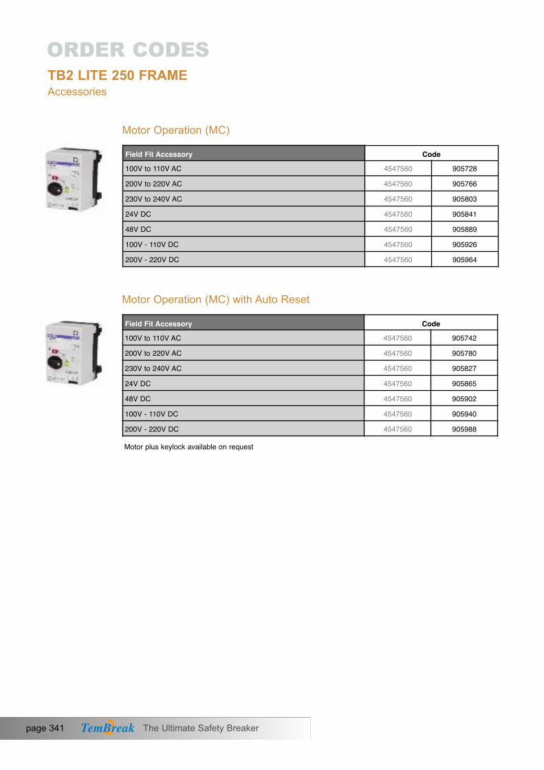
page 341 The Ultimate Safety Breaker
Motor Operation (MC)
FieldFitAccessory Code100V to 110V AC 4547560 905728
200V to 220V AC 4547560 905766
230V to 240V AC 4547560 905803
24V DC 4547560 905841
48V DC 4547560 905889
100V - 110V DC 4547560 905926
200V - 220V DC 4547560 905964
Motor Operation (MC) with Auto Reset
FieldFitAccessory Code100V to 110V AC 4547560 905742
200V to 220V AC 4547560 905780
230V to 240V AC 4547560 905827
24V DC 4547560 905865
48V DC 4547560 905902
100V - 110V DC 4547560 905940
200V - 220V DC 4547560 905988
Motor plus keylock available on request
ORDER CODESTB2 LITE 250 FRAMEAccessories

The Ultimate Safety Breaker page 342
SE
CT
ION
7
External Operating Handles Breaker Mounted Type (HB)
Order one part between two MCCBs
FieldFitAccessory CodeBlack handle IP3X 4547560 907005
Red handle IP3X 4547560 907487
Black handle IP5X 4547560 907012
Red handle IP5X 4547560 907494
External Operating Handles Panel Mounted Type (S Type)
Slide Type Mechanical Interlocks (MS)
Link Type Mechanical Interlocks (ML)
FieldFitAccessory CodeS Type black handle IP55 4547560 066344
S Type red handle IP55 4547560 066351
S Type black handle IP65 4547560 066382
S Type red handle IP65 4547560 066399
FieldFitAccessory CodeFront, rear connection 250AF 3P 4547560 066986
Front, rear connection type 250AF 4P 4547560 066993
FieldFitAccessory CodeInterlock Link RHS 4547560 064869
Interlock Link LHS 3P 4547560 064876
Interlock Link LHS 4P 4547560 064883
Order one interlock part for each MCCB
ORDER CODESTB2 LITE 250 FRAMEAccessories

ORDER CODESTB2 LITE 250 FRAMEAccessories
page 343 The Ultimate Safety Breaker
Wire Type Mechanical Interlock (MW)
FieldFitAccessory CodeInterlock Wire type mechanism 4547560 064890
1m length interlock cable 4547560 036064
1.5m length interlock cable 4547560 036057
Order one interlock part for each MCCB and one cable between each pair of MCCBs
Handle Locks (HL)
Terminal Covers for Front Connection (FC)
FieldFitAccessory Codefor 160 / 250AF 4547560 064906
FieldFitAccessory Code3P, 1 cover (Short) 4547560 065286
4P, 1 cover (Short) 4547560 065293
3P, 1 cover (Long) 4547560 065309
4P, 1 cover (Long) 4547560 065316
3P, 1 cover (Spread) 4547560 065323
4P, 1 cover (Spread) 4547560 065330
Terminal cover lock 4547560 065644
Terminal Covers for Rear Connection
FieldFitAccessory Code3P, 1 cover 4547560 067075
4P, 1 cover 4547560 067082
Terminal cover lock 4547560 065644

The Ultimate Safety Breaker page 344
SE
CT
ION
7
Terminal Covers for Cable Clamp Connection
FieldFitAccessory Code3P, 1 cover 4547560 065620
4P, 1 cover 4547560 065637
Terminal cover lock 4547560 065644
Interpole Barriers (BA)
Lead Terminal Block
FieldFitAccessory Code
4547560 065729
FieldFitAccessory CodeLeft Side 4547560 065743
Right Side 4547560 065736
ORDER CODESTB2 LITE 250 FRAMEAccessories
Interpole barriers are supplied as standard2 pieces per 3P MCCB, 3 pieces per 4P MCCB.for additional barriers please order individually.
1 Barrier

ORDER CODESTB2 S125 FRAME
page 345 The Ultimate Safety Breaker
Adjustable Thermal and Adjustable Magnetic MCCBs
Model IR (A) 3P 4P32 - 50 4547560 255021 4547560 255120
40 - 63 4547560 255038 4547560 255137
63 - 100 4547560 255045 4547560 255144
79 - 125 4547560 255052 4547560 255151
Model IR (A) 3P 4P13 - 20 4547560 255205 4547560 255304
20 - 32 4547560 255212 4547560 255311
32 - 50 4547560 255229 4547560 255328
40 - 63 4547560 255236 4547560 255335
63 - 100 4547560 255243 4547560 255342
79 - 125 4547560 255250 4547560 255359
MCCBs with Magnetic Trip Only
Model IR (A) 3P 4P12 - 20 4547560 257001 4547560 257100
20 - 32 4547560 257018 4547560 257117
32 - 50 4547560 257025 4547560 257124
40 - 63 4547560 257032 4547560 257131
63 - 100 4547560 257049 4547560 257148
80 - 125 4547560 257056 4547560 257155
Model IR (A) 3P 4P12 - 20 4547560 257506 4547560 257605
20 - 32 4547560 257513 4547560 257612
32 - 50 4547560 257520 4547560 257629
40 - 63 4547560 257537 4547560 257636
63 - 100 4547560 257544 4547560 257643
80 - 125 4547560 257551 4547560 257650
S125-NJIcu = 36kA @ 400V ACFront Connection (FC)
S125-GJIcu = 65kA @ 400V ACFront Connection (FC)
S125-NJIcu = 36kA @ 400V ACFront Connection (FC)
S125-GJIcu = 65kA @ 400V AC Front Connection (FC)

ORDER CODESTB2 S125 FRAME
The Ultimate Safety Breaker page 346
MCCBs with Adjustable Thermal and Fixed Low Instantaneous Trip: For Generator
SE
CT
ION
7
MCCBs for 1000V AC
Model IR (A) 3P 4P12 - 20 4547560 258244 4547560 258305
20 - 32 4547560 258251 4547560 258312
63 - 100 4547560 258268 4547560 258329
80 - 125 4547560 258275 4547560 258336
Model IR (A) 3P 4P12 - 20 4547560 258541 4547560 258602
20 - 32 4547560 258558 4547560 258619
63 - 100 4547560 258565 4547560 258626
80 - 125 4547560 258572 4547560 258633
Model In (A) 3P20 * 4547560 270932
32 * 4547560 270949
50 4547560 270956
63 4547560 270963
100 4547560 270970
125 4547560 270987
* Icu = 4kA
S125-NJIcu = 36kA @ 400V ACFront Connection (FC)
S125-GJIcu = 65kA @ 400V ACFront Connection (FC)
VS125-NJ1000V ACIcu = 6kAThermal Magnetic

page 347 The Ultimate Safety Breaker
Model IR (A) 3P 4P12 - 20 4547560 622106 4547560 622205
20 - 32 4547560 622113 4547560 622212
32 - 50 4547560 622120 4547560 622229
40 - 63 4547560 622137 4547560 622236
63 - 100 4547560 622144 4547560 622243
80 - 125 4547560 622151 4547560 622250
Model IR (A) 3P 4P12 - 20 4547560 622502 4547560 622601
20 - 32 4547560 622519 4547560 622618
32 - 50 4547560 622526 4547560 622625
40 - 63 4547560 622533 4547560 622632
63 - 100 4547560 622540 4547560 622649
80 - 125 4547560 622557 4547560 622656
Model IR (A) 3P 4P12 - 20 4547560 622304 4547560 622403
20 - 32 4547560 622311 4547560 622410
32 - 50 4547560 622328 4547560 622427
40 - 63 4547560 622335 4547560 622434
63 - 100 4547560 622342 4547560 622441
80 - 125 4547560 622359 4547560 622458
CBR with Residual Monitor and Remote Trip
Model IR (A) 3P 4P12 - 20 4547560 622700 4547560 622809
20 - 32 4547560 622717 4547560 622816
32 - 50 4547560 622724 4547560 622823
40 - 63 4547560 622731 4547560 622830
63 - 100 4547560 622748 4547560 622847
80 - 125 4547560 622755 4547560 622854
ORDER CODESTB2 S125 FRAMECircuit Breakers with Residual Current Protection (CBR)
ZE125-NJIcu = 25 kA @ 400V ACFront Connection (FC)
ZS125-NJIcu = 36kA @ 400V ACFront Connection (FC)
ZS125-GJIcu = 65kA @ 400V ACFront Connection (FC)
ZE125-NJZPIcu = 25kA @ 400V ACFront Connection (FC)

The Ultimate Safety Breaker page 348
SE
CT
ION
7
Switch Disconnectors
ORDER CODESTB2 S125 FRAMECBR with Residual Monitor and Remote Trip
Model IR (A) 3P 4P12 - 20 4547560 623103 4547560 623202
20 - 32 4547560 623110 4547560 623219
32 - 50 4547560 623127 4547560 623226
40 - 63 4547560 623134 4547560 623233
63 - 100 4547560 623141 4547560 623240
80 - 125 4547560 623158 4547560 623257
Model IR (A) 3P 4P12 - 20 4547560 622908 4547560 623004
20 - 32 4547560 622915 4547560 623011
32 - 50 4547560 622922 4547560 623028
40 - 63 4547560 622939 4547560 623035
63 - 100 4547560 622946 4547560 623042
80 - 125 4547560 622953 4547560 623059
Model In (A) 3P 4P125 4547560 244902 4547560 245008
ZS125-NJZPIcu = 36kA @ 400V ACFront Connection (FC)
ZS125-GJZPIcu = 65kA @ 400V ACFront Connection (FC)
S125-NNFront Connection (FC)

page 349 The Ultimate Safety Breaker
ORDER CODESTB2 S125 FRAMEAccessories
FieldFitAccessory CodeAC 100-120V 4547560 000904
AC 200-240V 4547560 000911
AC 380-450V 4547560 000928
DC 12V 4547560 000973
DC 24V 4547560 000935
DC 48V 4547560 000942
DC 100-120V 4547560 000959
DC 200-240V 4547560 000966
Auxiliary Switches (AX) General Purpose
FieldFitAccessory CodeNormally open 4547560 000300
Normally closed 4547560 000317
Auxiliary Switches (AX) Heavy Duty
FieldFitAccessory CodeChangeover 4547560 000744
Changeover for low currents (mA) 4547560 000720
Alarm Switches (AL) General Purpose
Alarm Switches (AL) Heavy Duty
Shunt Trips (SHT)
FieldFitAccessory CodeChangeover 4547560 000348
Changeover for low currents (mA) 4547560 000324
FieldFitAccessory CodeNormally open 4547560 000706
Normally closed 4547560 000713

The Ultimate Safety Breaker page 350
SE
CT
ION
7
ORDER CODESTB2 S125 FRAMEAccessories
Undervoltage Trips (UVT)
FieldFitAccessory-NotcompatiblewithCBR CodeAC 100-120V 4547560 001208
AC 200-240V 4547560 001215
AC 380-450V 4547560 001222
DC 24V 4547560 001239
DC 100-120V 4547560 001246
DC 200-240V 4547560 001253
AC 100-110V Time-delay 4547560 001307
AC 100-120V Time-delay 4547560 001369
AC 200-220V Time-delay 4547560 001314
AC 230-240V Time-delay 4547560 001376
AC 380-415V Time-delay 4547560 001321
AC 440-450V Time-delay 4547560 001383
DC 24V Time-delay Version 4547560 001338
DC 100-110V Time-delay 4547560 001345
DC 115-120V Time-delay 4547560 001390
DC 200-220V Time-delay 4547560 001352
DC 220-240V Time-delay 4547560 001406
FieldFitAccessory Code3 bars (Straight) 4547560 010026
4 bars (Straight) 4547560 010040
Extension Bars (FB)
*Not suitable for use with CBR

page 351 The Ultimate Safety Breaker
ORDER CODESTB2 S125 FRAMEAccessories
Terminal Covers for Extension Terminals for Fixed Part of Plug-in MCCB
FieldFitAccessory Code3P 125A Plug-in Base, 1 Terminal Cover 4547560 045707
4P 125A Plug-in Base, 1 Terminal Cover 4547560 045714
FieldFitAccessory-NotcompatibleforusewithCBR Code3 bars 4547560 045813
4 bars 4547560 045820
Rear Connections (RC)
FieldFitAccessory-NotcompatibleforusewithCBR Code3 studs 4547560 080883
4 studs 4547560 080890
FieldFitAccessory-NotcompatibleforusewithCBR Code3P 4547560 060267
4P 4547560 060359
Fixed Part of Plug-in MCCB (PM)
FieldFitAccessory-NotcompatibleforusewithCBRorMCCBsfor1000VAC Code
3P 4547560 800160
4P 4547560 800177
Plug-in Conversion for MCCB
Control Wiring Terminals for Plug-in MCCBs
Extension Terminal for Fixed Part of Plug-in MCCB (PF)
FieldFitAccessory-NotcompatibleforusewithCBR CodePlug for auxiliary switches and alarm switches 4547560 800108
Plug for shunt trips and undervoltage trips 4547560 800115
Order one plug for each electrical accessory.

FieldFitAccessory CodeAC 100-110V 4547560 755873
AC 200-220V 4547560 755880
AC 230-240V 4547560 755897
DC 24V 4547560 755675
DC 48V 4547560 755682
DC 100V 4547560 755699
DC 200-220V 4547560 755583
The Ultimate Safety Breaker page 352
SE
CT
ION
7
ORDER CODESTB2 S125 FRAMEAccessories
Control Wiring Terminals for Plug-in MCCBs
Cable Clamps (FW)
Order one socket for each electrical accessory.
Motor Operation (MC)
Motor Operation (MC) with Automatic Reset
FieldFitAccessory CodeAC 100-110V 4547560 755606
AC 200-220V 4547560 755613
AC 230-240V 4547560 755620
DC 24V 4547560 755637
DC 48V 4547560 755644
DC 100V 4547560 755651
DC 200-220V 4547560 755668
FieldFitAccessory-NotcompatibleforusewithCBR CodeSocket 4547560 045004
FieldFitAccessory-NotcompatiblewithCBR Code3 clamps 4547560 080715
4 clamps 4547560 080722

page 353 The Ultimate Safety Breaker
External Operating Handles (Breaker Mounted Type) (HB)
FieldFitAccessory CodeBlack handle IP3X 4547560 725623
Black handle IP3X with keylock 4547560 725609
Red handle IP3X 4547560 726101
Red handle IP3X with keylock 4547560 726088
Black handle IP5X 4547560 725630
Black handle IP5X with keylock 4547560 725616
Red handle IP5X 4547560 726118
Red handle IP5X with keylock 4547560 726095
External Operating Handles (Panel Mounted Type) (S Type)
Order one part between two MCCBs
Slide Type Mechanical Interlocks (MS)
FieldFitAccessory CodeFront / rear connection 125AF 3P 4547560 033513
Front / rear connection 125AF 4P 4547560 033520
Plug-in type 125AF 3P 4547560 033544
Plug-in type 125AF 4P 4547560 033551
Order one interlock part for each MCCB
Link Type Mechanical Interlocks (ML)
ORDER CODESTB2 S125 FRAMEAccessories
FieldFitAccessory Code‘S Type’ Black handle IP55 4547560 060601
‘S Type’ Red handle IP55 4547560 060618
‘S Type’ Black handle IP65 4547560 060649
‘S Type’ Red handle IP65 4547560 060656
Castell Cam for K Lock 4547560 800634
FieldFitAccessory-notcompatiblewithCBR CodeRight side 4547560 035005
Left side 3P 4547560 035012
Left side 4P 4547560 035029

The Ultimate Safety Breaker page 354
SE
CT
ION
7
ORDER CODESTB2 S125 FRAMEAccessories
FieldFitAccessory-notcompatiblewithCBR CodeInterlock Mechanism 4547560 036026
1m length interlock cable 4547560 036064
1.5m length interlock cable 4547560 036057
Order one interlock part for each MCCB and one cable between two MCCBs
Wire Type Mechanical Interlocks (MW)
Handle Locks (HL)
FieldFitAccessory CodeFor 125 / 250AF 4547560 037016
Terminal Covers for Front Connection (CF)
Terminal Covers for Rear Connection and Plug-In (CR)
FieldFitAccessory Code3P, 1 cover 4547560 080425
4P, 1 cover 4547560 080432
Terminal cover lock 4547560 038006
FieldFitAccessory Code3P, 1 cover 4547560 080487
4P, 1 cover 4547560 080494
Terminal cover lock 4547560 038006
Terminal Covers for Cable Clamps (CS)
FieldFitAccessory Code3P, 1 cover 4547560 080555
4P, 1 cover 4547560 080562
Terminal cover lock 4547560 038006

page 355 The Ultimate Safety Breaker
ORDER CODESTB2 S125 FRAMEAccessories
Lead Terminal Block
DIN Rail Adapter
Interpole Barriers (BA)
FieldFitAccessory Code1 barrier 4547560 043062
Interpole barriers are supplied as standard: 2 pieces per 3P MCCB, 3 pieces per 4P MCCB.For additional barriers please order individually.
FieldFitAccessoryLeft side 4547560 044526
Right side 4547560 044533
FieldFitAccessory CodeDIN rail adapter for 125AF & 250AF 4547560 045127
Neutral Link
Door Flange
FieldFitAccessory Code125A Neutral Link 4547560 800481
125/250A Neutral Link Shroud 4547560 800559
FieldFitAccessory CodeFor toggle operation 4547560 044908
For motorised operation 4547560 044915
Code

The Ultimate Safety Breaker page 356
SE
CT
ION
7
ORDER CODESTB2 S125 FRAMEAutomatic Changeover Pairs
We offer a range of accessories which allow our customers to produce automatic changeover systems using our circuit breakers.
Wiring between the components is the customers responsibility,but can be easily completed by following the Terasaki WiringDiagram, available on request.
Order codes for the necessary components are shown in thetable below:
125AFrame Code Function
a. Two TemBreak 2 MCCBs, 125A Frame Refer to MCCB order codes
d. Motor operator for mains MCCBRefer to “Motor Operator” Selectcode base on required voltage.
Motor operator for generator MCCBRefer to “Motor Operator” Selectcode base on required voltage.
e. TemTransfer 2 Wiring Panel 304001006
f. TemTransfer 2 Reset Key Switch 304001005 Resets and isolates the system for maintenance. Only suitable when using Terasaki Wiring Diagram.
304001001Monitors mains and generator voltages and controlstransfer of load. Pre-configured to operate with
Terasaki Wiring Diagram.
h. TemTransfer 2 Power Supply 24V DC 304001003 Power Supply for TemTransfer 2. Also available in 12V DC.
TemTransfer 2 Interface Kit (optional) 304001002 Optional: Allows re-configuration of TemTransfer 2,diagnostics and advanced parameter settings.
b. 2 x Auxillary switch for mains MCCB2 x Auxillary switch for generator MCCB
Alarm switch for main MCCBAlarm switch for generator MCCB
c Link type mechanical interlock (left)Link type mechanical interlock (right)
orLink type mechanical interlock (left, 4P)
2 x 0003482 x 000348
000744000744
Electrical interlocking and MCCB status.
Mechanical interlocking. Cable-type mechanical interlocking may
alternatively be used.
035005*
035029
035012*
Automatic operation of circuit breaker.
g. TemTransfer 2 Automatic Changeover Controller
Simplifies customer wiring. Terminal blocks and control relay are included. Only suitable when
using Terasaki Wiring Diagram.
*Not available for CBR’s
Switching and protection of the load.

page 357 The Ultimate Safety Breaker
ORDER CODESTB2 S250 FRAMEAdjustable Thermal and Adjustable Magnetic MCCBs
Model IR (A) 3P 4P12 - 20* 4547560 326837 4547560 326905
20 - 32* 4547560 326844 4547560 326912
32 - 50 4547560 326851 4547560 326929
40 - 63 4547560 326868 4547560 326936
63 - 100 4547560 326875 4547560 326943
80 - 125 4547560 326882 4547560 326950
100 - 160 4547560 326899 4547560 326967
Model IR (A) 3P 4P32 - 50 4547560 327025 4547560 327124
40 - 63 4547560 327032 4547560 327131
63 - 100 4547560 327049 4547560 327148
80 - 125 4547560 327056 4547560 327155
100 - 160 4547560 327063 4547560 327162
Model IR (A) 3P 4P100 - 160 4547560 312021 4547560 312120
125 - 200 4547560 312052 4547560 312151
160 - 250 4547560 312038 4547560 312137
Model IR (A) 3P 4P100 - 160 4547560 312229 4547560 312328
125 - 200 4547560 312250 4547560 312359
160 - 250 4547560 312236 4547560 312335
S160-NJIcu = 36 kA @ 400V AC*Icu = 30 kA @ 400V ACFront Connection (FC)
S160-GJIcu = 65 kA @ 400V ACFront Connection (FC)
S250-NJIcu = 36 kA @ 400V ACFront Connection (FC)
S250-GJIcu = 65 kA @ 400V ACFront Connection (FC)
*Applies only to 20A and 32A models.

The Ultimate Safety Breaker page 358
SE
CT
ION
7
ORDER CODESTB2 S250 FRAMEMCCBs with Magnetic Trip Only
Model In (A) 3P 4P20* 4547560 328305 4547560 328404
32* 4547560 328312 4547560 328411
50 4547560 328329 4547560 328428
63 4547560 328336 4547560 328435
100 4547560 328343 4547560 328442
125 4547560 328350 4547560 328459
160 4547560 328367 4547560 328466
Model In (A) 3P 4P50 4547560 328602 4547560 328701
63 4547560 328619 4547560 328718
100 4547560 328626 4547560 328725
80 - 125 4547560 328633 4547560 328732
100 - 160 4547560 328640 4547560 328749
Model In (A) 3P 4P160 4547560 329302 4547560 329333
200 4547560 329319 4547560 329340
250 4547560 329326 4547560 329357
Model In (A) 3P 4P160 4547560 329401 4547560 329432
200 4547560 329418 4547560 329449
250 4547560 329425 4547560 329456
S160-NJIcu = 36 kA @ 400V AC*Icu = 30 kA Magnetic Trip OnlyFront Connection (FC)
S160-GJIcu = 65 kA @ 400V ACFront Connection (FC)
S250-NJIcu = 36 kA @ 400V ACFront Connection (FC)
S250-GJIcu= 65 kA @ 400V ACFront Connection (FC)
*Applies only to 20A and 32A models.

page 359 The Ultimate Safety Breaker
ORDER CODESTB2 S250 FRAMEMCCBs with Adjustable ~Thermal and Fixed Low Instantaneous Trip: For Generator
Model IR (A) 3P 4P12 - 20 4547560 329517 4547560 329616
20 - 32 4547560 329524 4547560 329623
63 - 100 4547560 329531 4547560 329630
80 - 125 4547560 329548 4547560 329647
100 - 160 4547560 329500 4547560 329609
Model IR (A) 3P 4P63 - 100 4547560 331008 4547560 331039
80 - 125 4547560 331015 4547560 331046
100 - 160 4547560 331022 4547560 331053
Model In (A) 3P 4P100 - 160 4547560 330117 4547560 330216125 - 200 4547560 330124 4547560 330223160 - 250 4547560 330100 4547560 330209
Model In (A) 3P 4P100 - 160 4547560 330414 4547560 330438
125 - 200 4547560 330421 4547560 330445
160 - 250 4547560 330407 4547560 330452
MCCBs for 1000V AC
Model IR (A) 3P100 - 160 4547560 318504
160 - 250 4547560 318511
S160-NJIcu = 36 kA @ 400V AC*Icu = 30 kA @ 400V ACFront Connection (FC)
S160-GJIcu = 65 kA @ 400V ACFront Connection (FC)
S250-NJIcu = 36 kA @ 400V ACFront Connection (FC)
S250-GJIcu = 65 kA @ 400V ACFront Connection (FC)
VS250-NJ1000V ACIcu = 6kAThermal Magnetic
*Applies only to 20A and 32A models.

Model IR (A) 3P 4P100 - 160 4547560 642807 4547560 642906
160 - 250 4547560 642814 4547560 642913
The Ultimate Safety Breaker page 360
SE
CT
ION
7
ORDER CODESTB2 S250 FRAMECircuit Breakers with Residual Current Protection (CBR)
CBR with Residual Current Monitor and Remote Trip Module
Model IR (A) 3P 4P
100 - 160 4547560 643002 4547560 643101
160 - 250 4547560 643019 4547560 643118
Model IR (A) 3P 4P
100 - 160 4547560 643200 4547560 643309
160 - 250 4547560 643217 4547560 643316
Model IR (A) 3P 4P
100 - 160 4547560 644009 4547560 644108
160 - 250 4547560 644016 4547560 644115
Model IR (A) 3P 4P
100 - 160 4547560 644207 4547560 644306
160 - 250 4547560 644214 4547560 644313
Model IR (A)) 3P 4P
100 - 160 4547560 644405 4547560 644504
160 - 250 4547560 644412 4547560 644511
ZE250-NJIcu = 25 kA @ 400V ACFront Connection (FC)
ZS250-NJIcu = 36kA @ 400V ACFront Connection (FC)
ZS250-GJIcu = 65kA @ 400V ACFront Connection (FC)
ZE250-NJZPIcu = 25 kA @ 400V ACFront Connection (FC)
ZS250-NJZPIcu = 36kA @ 400V ACFront Connection (FC)
ZS250-GJZPIcu = 65kA @ 400V ACFront Connection (FC)

page 361 The Ultimate Safety Breaker
Poles wired in series. Reverse Connection version available on request.
Poles wired in series. Reverse Connection version available on request.
Poles wired in series. Reverse Connection version available on request.
Poles wired in series. Reverse Connection version available on request.
ORDER CODESTB2 S250 FRAMECircuit Breakers and Switch Disconnectors for use above 250V DC
Model IR (A) 3P 4P50 4547560 93888763 4547560 938894100 4547560 938900125 4547560 938917160 4547560 938924
Model IR (A) 3P 4P50 4547560 939297
63 4547560 939303
100 4547560 939310
125 4547560 939327
160 4547560 939334
Model IR (A) 3P 4P50 4547560 939884
63 4547560 939891
100 4547560 939907
125 4547560 939914
160 4547560 939921
Model IR (A) 3P 4P100 4547560 938931
125 4547560 938948
160 4547560 938955
200 4547560 938962
250 4547560 938979
PVS160-SDL750V DCIcu = 5kAThermal Magnetic
PVS160-SDL750V DCIcu = 10kAThermal Magnetic
PVS160-SDH1000V DCIcu = 5kAThermal Magnetic
PVS250-SDL750V DCIcu = 5kAThermal Magnetic

The Ultimate Safety Breaker page 362
Poles wired in series. Reverse Connection version available on request.
Poles wired in series. Reverse Connection version available on request.
Poles wired in series. Reverse Connection version available on request.
Poles wired in series. Reverse Connection version available on request.
Poles wired in series. Reverse Connection version available on request.
Poles wired in series. Reverse Connection version available on request.
SE
CT
ION
7
ORDER CODESTB2 S250 FRAMECircuit Breakers and Switch Disconnectors for use above 250V DC
Model IR (A) 3P 4P100 4547560 939341
125 4547560 939358
160 4547560 939365
200 4547560 939372
250 4547560 939389
Model IR (A) 3P 4P100 4547560 939938
125 4547560 939945
160 4547560 939952
200 4547560 939969
250 4547560 939976
Model In (A) 3P 4P160 4547560 939426
Model In (A) 3P 4P160 4547560 940118
Model In (A) 3P 4P250 4547560 939457
Model In (A) 3P 4P250 4547560 940149
PVS250-SDL750V DCIcu = 10kAThermal Magnetic
PVS250-SDH1000V DCIcu = 5kAThermal Magnetic
PVS160-SNL750V DC
PVS160-SNH1000V DC
PVS250-SNL750V DC
PVS250-SNH1000V DC

page 363 The Ultimate Safety Breaker
ORDER CODESTB2 S250 FRAMESwitch Disconnectors
Model In (A) 3P 4PS160-NNFront Connection (FC) 160 4547560 315800 4547560 315909
S250-NNFront Connection (FC) 250 4547560 316005 4547560 316104

The Ultimate Safety Breaker page 364
SE
CT
ION
7
ORDER CODESTB2 S/H/L 250 FRAMEAdjustable Thermal and Adjustable Magnetic MCCBs
Model IR (A) 3P 4P13 - 20 4547560 255403 4547560 255502
20 - 32 4547560 255410 4547560 255519
32 - 50 4547560 255427 4547560 255526
40 - 63 4547560 255434 4547560 255533
63 - 100 4547560 255441 4547560 255540
80 - 125 4547560 255458 4547560 255557
Model IR (A) 3P 4P13 - 20 4547560 255601 4547560 255700
20 - 32 4547560 255618 4547560 255717
32 - 50 4547560 255625 4547560 255724
40 - 63 4547560 255632 4547560 255731
63 - 100 4547560 255649 4547560 255748
80 - 125 4547560 255656 4547560 255755
Model IR (A) 3P 4P
100 - 160 4547560 318474 4547560 318573
Model IR (A) 3P 4P100 - 160 4547560 318672 4547560 318771
Model IR (A) 3P 4P100 - 160 4547560 312427 4547560 312526
160 - 250 4547560 312434 4547560 312533
Model IR (A) 3P 4P100 - 160 4547560 312625 4547560 312724
160 - 250 4547560 312632 4547560 312731
H125-NJIcu = 125kA @ 400V ACFront Connection (FC)
L125-NJIcu = 200kA @ 400V ACFront Connection (FC)
H160-NJIcu = 125 kA @ 400V ACFront Connection (FC)
L160-NJIcu = 200 kA @ 400V ACFront Connection (FC)
H250-NJIcu = 125 kA @ 400V ACFront Connection (FC)
L250-NJIcu = 200 kA @ 400V ACFront Connection (FC)

page 365 The Ultimate Safety Breaker
ORDER CODESTB2 S/H/L 250 FRAMEElectronic MCCBs
ModelProtectionCodes IR (A) 3P 4PA 40 16 - 40 4547560 331701 4547560 331725AN 40 16 - 40 4547560 331749AP 40 16 - 40 4547560 331718 4547560 331732APN 40 16 - 40 4547560 331756A 125 50 - 125 4547560 331800 4547560 331824AN 125 50 - 125 4547560 331848AP 125 50 - 125 4547560 331817 4547560 331831APN 125 50 - 125 4547560 331855A 160 63 - 160 4547560 337802 4547560 337826AN 160 63 - 160 4547560 337840AP 160 63 - 160 4547560 337819 4547560 337833APN 160 63 - 160 4547560 337857A 250 100 - 250 4547560 331909 4547560 331923AN 250 100 - 250 4547560 331947AP 250 100 - 250 4547560 331916 4547560 331930APN 250 100 - 250 4547560 331954
ModelProtectionCodes IR (A) 3P 4PA 40 16 - 40 4547560 332005 4547560 332029AN 40 16 - 40 4547560 332043AP 40 16 - 40 4547560 332012 4547560 332036APN 40 16 - 40 4547560 332050A 125 50 - 125 4547560 332104 4547560 332128AN 125 50 - 125 4547560 332142AP 125 50 - 125 4547560 332111 4547560 332135APN 125 50 - 125 4547560 332159A 160 63 - 160 4547560 337925 4547560 337949AN 160 63 - 160 4547560 337963AP 160 63 - 160 4547560 337932 4547560 337956APN 160 63 - 160 4547560 337970A 250 100 - 250 4547560 332203 4547560 332227AN 250 100 - 250 4547560 332241AP 250 100 - 250 4547560 332210 4547560 332234APN 250 100 - 250 4547560 332258
S250-NEIcu = 36 kA @ 400V ACFront Connection (FC)
Electronic Protection Codes: A - LSIP - Preferential Trip AlarmG - Ground FaultN - Neutral Protection
S250-GEIcu = 65kA @ 400V ACFront Connection (FC)
Electronic Protection Codes: A - LSIP - Preferential Trip AlarmG - Ground FaultN - Neutral Protection

The Ultimate Safety Breaker page 366
SE
CT
ION
7
ORDER CODESTB2 S/H/L 250 FRAMEElectronic MCCBs
ModelProtectionCodes IR (A) 3P 4PA 40 16 - 40 4547560 327704 4547560 327728 AN 40 16 - 40 4547560 327742 AP 40 16 - 40 4547560 327711 4547560 327735 APN 40 16 - 40 4547560 327759 A 125 50 - 125 4547560 327803 4547560 327827 AN 125 50 - 125 4547560 327841 AP 125 50 - 125 4547560 327810 4547560 327834 APN 125 50 - 125 4547560 327858 A 160 63 - 160 4547560 327902 4547560 327926 AN 160 63 - 160 4547560 327940 AP 160 63 - 160 4547560 327919 4547560 327933 APN 160 63 - 160 4547560 327957 A 250 100 - 250 4547560 319006 4547560 319013 AN 250 100 - 250 4547560 319044 AP 250 100 - 250 4547560 319020 4547560 319037 APN 250 100 - 250 4547560 319051
ModelProtectionCodes IR (A) 3P 4PA 40 16 - 40 4547560 328008 4547560 328022AN 40 16 - 40 4547560 328046AP 40 16 - 40 4547560 328015 4547560 328039APN 40 16 - 40 4547560 328053A 125 50 - 125 4547560 328107 4547560 328121AN 125 50 - 125 4547560 328145AP 125 50 - 125 4547560 328114 4547560 328138APN 125 50 - 125 4547560 328152A 160 63 - 160 4547560 328206 4547560 328220AN 160 63 - 160 4547560 328244AP 160 63 - 160 4547560 328213 4547560 328237APN 160 63 - 160 4547560 328251A 250 100 - 250 4547560 319105 4547560 319112AN 250 100 - 250 4547560 319143AP 250 100 - 250 4547560 319129 4547560 319136APN 250 100 - 250 4547560 319150
S250-PEIcu = 70kA @ 400V ACFront Connection (FC)
Electronic Protection Codes: A - LSIP - Preferential Trip AlarmG - Ground FaultN - Neutral Protection
H250-NEIcu = 125kA @ 400V ACFront Connection (FC)
Electronic Protection Codes: A - LSIP - Preferential Trip AlarmG - Ground FaultN - Neutral Protection

page 367 The Ultimate Safety Breaker
ORDER CODESTB2 S/H/L 250 FRAMEMCCBs with Measurement and Data Communication
ModelProtectionCodes IR (A) 3P 4PAC 40 16 - 40 Contact Terasaki Contact TerasakiACN 40 16 - 40 Contact TerasakiACPZ 40 16 - 40 Contact Terasaki Contact TerasakiACNPZ 40 16 - 40 Contact TerasakiAC 125 50 - 125 Contact Terasaki Contact TerasakiACN 125 50 - 125 Contact TerasakiACPZ 125 50 - 125 Contact Terasaki Contact TerasakiACNPZ 125 50 - 125 Contact TerasakiAC 160 63 - 160 Contact Terasaki Contact TerasakiACN 160 63 - 160 Contact TerasakiACPZ 160 63 - 160 Contact Terasaki Contact TerasakiACNPZ 160 63 - 160 Contact TerasakiAC 250 100 - 250 Contact Terasaki Contact TerasakiACN 250 100 - 250 Contact TerasakiACPZ 250 100 - 250 Contact Terasaki Contact TerasakiACNPZ 250 100 - 250 Contact Terasaki
ModelProtectionCodes IR (A) 3P 4PAC 40 16 - 40 Contact Terasaki Contact TerasakiACN 40 16 - 40 Contact TerasakiACPZ 40 16 - 40 Contact Terasaki Contact TerasakiACNPZ 40 16 - 40 Contact TerasakiAC 125 50 - 125 Contact Terasaki Contact TerasakiACN 125 50 - 125 Contact TerasakiACPZ 125 50 - 125 Contact Terasaki Contact TerasakiACNPZ 125 50 - 125 Contact TerasakiAC 160 63 - 160 Contact Terasaki Contact TerasakiACN 160 63 - 160 Contact TerasakiACPZ 160 63 - 160 Contact Terasaki Contact TerasakiACNPZ 160 63 - 160 Contact TerasakiAC 250 100 - 250 Contact Terasaki Contact TerasakiACN 250 100 - 250 Contact TerasakiACPZ 250 100 - 250 Contact Terasaki Contact TerasakiACNPZ 250 100 - 250 Contact Terasaki
S250-GEIcu = 65kA @ 400V ACFront Connection (FC)
Electronic Protection Codes: AC - LSI and Modbus CommunicationP - Preferential Trip AlarmZ - Zone InterlockN - Neutral Protection
H250-NEIcu = 125kA @ 400V ACFront Connection (FC)
Electronic Protection Codes: AC - LSI and Modbus CommunicationP - Preferential Trip AlarmZ - Zone InterlockN - Neutral Protection

The Ultimate Safety Breaker page 368
SE
CT
ION
7
ORDER CODESTB2 S/H/L 250 FRAMEMCCBs with Icu = 70kA at 690V AC
Model IR (A) 3P16 - 25 4547560 268090
25 - 40 4547560 268106
40 - 63 4547560 268113
50 - 80 4547560 268120
63 - 100 4547560 268137
80 - 125 4547560 268114
L125-PJ690V ACIcu = 70kAFront Connection (FC)

page 369 The Ultimate Safety Breaker
ORDER CODESTB2 S250 AND S/H/L 250 FRAMEAccessories
FieldFitAccessory-NotcompatiblewithCBR CodeAC 100-120V 4547560 000904
AC 200-240V 4547560 000911
AC 380-450V 4547560 000928
DC 12V 4547560 000973
DC 24V 4547560 000935
DC 48V 4547560 000942
DC 100-120V 4547560 000959
DC 200-240V 4547560 000966
Auxiliary Switches (AX) General Purpose
FieldFitAccessory CodeNormally open 4547560 000300
Normally closed 4547560 000317
Auxiliary Switches (AX) Heavy Duty
FieldFitAccessory CodeChangeover 4547560 000744
Changeover for low currents (mA) 4547560 000720
Alarm Switches (AL) General Purpose
Alarm Switches (AL) Heavy Duty
Shunt Trips (SHT)
FieldFitAccessory CodeNormally open 4547560 000706
Normally closed 4547560 000713
FieldFitAccessory CodeChangeover 4547560 000348
Changeover for low currents (mA) 4547560 000324
Early make switch 4547560 710513

FieldFitAccessory Code3 studs for thermal magnetic E and S types 4547560 081309
4 studs for thermal magnetic E and S types 4547560 081316
3 studs for H and L types and electronic S types 4547560 081323
4 studs for H and L types and electronic S types 4547560 081330
The Ultimate Safety Breaker page 370
SE
CT
ION
7
ORDER CODESTB2 S250 AND S/H/L 250 FRAMEAccessories
Undervoltage Trips (UVT)
Extension Bars (FB)
Rear Connections (RC)
FieldFitAccessory Code3 bars (offset) 4547560 010149
3 bars (straight) 4547560 010408
4 bars (straight) 4547560 010163
FieldFitAccessory-NotcompatiblewithCBR CodeAC 100-120V 4547560 001208
AC 200-240V 4547560 001215
AC 380-450V 4547560 001222
DC 24V 4547560 001239
DC 100-120V 4547560 001246
DC 200-240V 4547560 001253
AC 100-110V Time-delay 4547560 001307
AC 115-120V Time-delay 4547560 001307
AC 200-220V Time-delay 4547560 001314
AC 230-240V Time-delay 4547560 001376
AC 380-415V Time-delay 4547560 001321
AC 440-450V Time-delay 4547560 001383
DC 24V Time-delay Version 4547560 001338
DC 100-110V Time-delay 4547560 001345
DC 115-120V Time-delay 4547560 001390
DC 200-220V Time-delay 4547560 001352
DC 230-240V Time-delay 4547560 001406

*Bars suitable for plug-in base only
Order one plug for each internal accessory
Order one socket for each internal accessory
page 371 The Ultimate Safety Breaker
ORDER CODESTB2 S250 AND S/H/L 250 FRAMESAccessories
Fixed Part of Plug-in MCCB (PM)
Plug-in Conversion for MCCB
Extension Terminal for Fixed Part of Plug-in MCCB (PF)
FieldFitAccessory-notcompatiblewithCBR Code3P 4547560 012365
4P 4547560 012464
FieldFitAccessory-notcompatiblewithCBRorMCCBsfor1000VAC Code3P for thermal magnetic E and S types 4547560 800023
4P for thermal magnetic E and S types 4547560 800030
3P for H and L types (250A) and electronic S types 4547560 800184
4P for H and L types (250A) and electronic S types 4547560 800191
FieldFitAccessory Code3 Bars 4547560 045837
4 Bars 4547560 045844
Terminal Covers for Extension Terminals for Fixed Part of Plug-in MCCB
FieldFitAccessory Code3P 250A Plug-in Base, 1 Terminal Cover 4547560 045721
4P 250A Plug-in Base, 1 Terminal Cover 4547560 045738
Control Wiring Terminals for Plug-in MCCBs
Control Wiring Terminals for Plug-in MCCBs
FieldFitAccessory CodePlug for auxiliary switches and alarm switches 4547560 800108
Plug shunt trips and undervoltage trips 4547560 800115
FieldFitAccessory CodeSocket for Aux/Alarm/UVT/SHT 4547560 045004

The Ultimate Safety Breaker page 372
SE
CT
ION
7
ORDER CODESTB2 S250 AND S/H/L 250 FRAMESAccessories
Motor Operation (MC)
Motor Operation (MC) with Automatic Reset
Cable Clamps (FW)
FieldFitAccessory Code3 clamps for S160, H160, L160, S250, H250, L250 4547560 081354
4 clamps for S160, H160, L160, S250, H250, L250 4547560 081361
3 clamps for H125, L125 4547560 080746
4 clamps for H125, L125 4547560 080753
FieldFitAccessory Code100V to 110V AC 4547560 755705
200V to 220V AC 4547560 755712
230V to 240V AC 4547560 755729
24V DC 4547560 755736
48V DC 4547560 755743
100V DC 4547560 755750
220V to 220V DC 4547560 755767
FieldFitAccessory Code100V to 110V AC 4547560 755972
200V to 220V AC 4547560 755989
230V to 240V AC 4547560 755996
24V DC 4547560 755774
48V DC 4547560 755781
100V DC 4547560 755798
220V to 220V DC 4547560 755590

page 373 The Ultimate Safety Breaker
ORDER CODESTB2 S250 AND S/H/L 250 FRAMESAccessories
External Operating Handles (Breaker Mounted Type) (HB)
External Operating Handles (Breaker Mounted Type) (S Type)
FieldFitAccessory CodeBlack handle IP3X 4547560 726347
Black handle IP3X with keylock 4547560 726323
Red handle IP3X 4547560 726828
Red handle IP3X with keylock 4547560 726804
Black handle IP5X 4547560 726354
Black handle IP5X with keylock 4547560 726330
Red handle IP5X 4547560 726835
Red handle IP5X with keylock 4547560 726811
FieldFitAccessory Code‘S Type’ Black handle IP55 for 250AF 4547560 060687
‘S Type’ Red handle IP55 for 250AF 4547560 060694
‘S Type’ Black Handle IP65 4547560 060724
‘S Type’ Red Handle IP65 4547560 060731
Castell Cam for K Style Lock 4547560 800634
Slide Type Mechanical Interlocks (MS)
FieldFitAccessory-NotcompatiblewithCBR CodeE,S thermal magnetic types for front, rear connection 250AF 3P 4547560 033605
E,S thermal magnetic types for front, rear connection type 250AF 4P 4547560 033612
E,S type for thermal magnetic plug-in type 250AF 3P 4547560 033629
E,S type for plug-in type 250AF 4P 4547560 033636
H,L type for front, rear connection type 250AF 3P and electronic S types 4547560 033643
H,L type for front, rear connection type 250AF 4P and electronic S types 4547560 033650
H,L type for plug-in type 250AF 3P and electronic S types 4547560 033667
H,L type for plug-in type 250AF 4P and electronic S types 4547560 033674
Link Type Mechanical Interlocks (ML)
FieldFitAccessory-NotcompatiblewithCBR CodeRight side 4547560 035104
Left side 3P 4547560 035111
Left side 4P 4547560 035128
Order one part for each MCCB
Order one part between two MCCBs

The Ultimate Safety Breaker page 374
SE
CT
ION
7
ORDER CODESTB2 S250 AND S/H/L 250 FRAMESAccessories
Order one interlock part for each MCCB and one cable between two MCCBs
Wire Type Mechanical Interlocks (MW)
Terminal Covers for Cable Clamps (CS)
Handle Locks (HL)
FieldFitAccessory CodeFor 125 / 250AF 4547560 037016
Terminal Covers for Front Connection
Terminal Covers for Rear and Plug-in Connections
FieldFitAccessory Code3P, 1 cover 4547560 080586
4P, 1 cover 4547560 080593
Terminal cover lock 4547560 038006
FieldFitAccessory-NotcompatiblewithCBR CodeInterlock Mechanical 4547560 036125
1m length interlock cable 4547560 036064
1.5m length interlock cable 4547560 036057
FieldFitAccessory Code3P, 1 cover for thermal magnetic E and S types 4547560 080456
4P, 1 cover for thermal magnetic E and S types 4547560 080463
3P, 1 cover for H and L types and electronic S types 4547560 080654
4P, 1 cover for H and L types and electronic S types 4547560 080661
Terminal cover lock 4547560 038006
FieldFitAccessory Code3P, 1 cover 4547560 080517
4P, 1 cover 4547560 080524
Terminal cover lock 4547560 038006

page 375 The Ultimate Safety Breaker
ORDER CODESTB2 S250 AND S/H/L 250 FRAMESAccessories
Lead Terminal Block
DIN Rail Adapter
Interpole Barriers (BA)
FieldFitAccessory CodeLeft side 4547560 044526
Right side 4547560 044533
FieldFitAccessory CodeDIN rail adapter for 125A & 250A 4547560 045127
Neutral Link Shroud
Door Flange
FieldFitAccessory Code250A Neutral Link 4547560 800498
125/250A Neutral Link Shroud 4547560 800559
FieldFitAccessory CodeFor toggle operation 4547560 044908
For motorised operation 4547560 044915
FieldFitAccessory CodeFor thermal magnetic E and S types 4547560 043161
For H and L types and electronic S types 4547560 043260

The Ultimate Safety Breaker page 376
SE
CT
ION
7
ORDER CODESTB2 S250 AND S/H/L 250 FRAMESAccessories
OCR Sealing Facility
Terminal Temperature Monitor and Alarm
OCR Checker
Circuit Breaker Monitor
FieldFitAccessory CodeElectronic display for MCCBs with Measurementsand communication facility (24V DC) 4547560 731907
FieldFitAccessory CodeOCR Checker 100-120V AC 4547560 756306
OCR checker 200-240V AC 4547560 756313
FieldFitAccessory CodeOCR sealing cover (thermal/mag) 4547560 055522
OCR sealing cover (electronic) 4547560 055539
FieldFitAccessory CodeTemperature Monitor for 3P S250 and S/H/L 250 Frames 4547560 Contact Terasaki
Temperature Monitor for 4P S250 and S/H/L 250 Frames 4547560 Contact Terasaki

page 377 The Ultimate Safety Breaker
ORDER CODESTB2 S250 AND S/H/L 250 FRAMESAutomatic Changeover Pairs
250AFrame Code Function
a. Refer to MCCB order codes Switching and protection of the load.
d. Motor operator for mains MCCBRefer to “Motor Operator” Selectcode base on required voltage.
Motor operator for generator MCCBRefer to “Motor Operator” Selectcode base on required voltage.
e. TemTransfer 2 Wiring Panel 304001006
f. TemTransfer 2 Reset Key Switch 304001005 Resets and isolates the system for maintenance. Only suitable when using Terasaki Wiring Diagram.
304001001Monitors mains and generator voltages and controlstransfer of load. Pre-configured to operate with
Terasaki Wiring Diagram.
h. TemTransfer 2 Power Supply 24V DC 304001003 Power Supply for TemTransfer 2. Also available in 12V DC.
TemTransfer 2 Interface Kit (optional) 304001002 Optional: Allows re-configuration of TemTransfer 2,diagnostics and advanced parameter settings.
b. 2 x Auxillary switch for mains MCCB2 x Auxillary switch for generator MCCB
Alarm switch for main MCCBAlarm switch for generator MCCB
c Link type mechanical interlock (left)Link type mechanical interlock (right)
orLink type mechanical interlock (left, 4P)
g. TemTransfer 2 Automatic Changeover Controller
*Not available for CBR’s
We offer a range of accessories which allow our customers to produce automatic changeover systems using our circuit breakers.
Wiring between the components is the customers responsibility,but can be easily completed by following the Terasaki WiringDiagram, available on request.
Order codes for the necessary components are shown in thetable below:
Electrical interlocking and MCCB status.
Mechanical interlocking. Cable-type mechanical interlocking may
alternatively be used.
Automatic operation of circuit breaker.
Simplifies customer wiring. Terminal blocks and control relay are included. Only suitable when
using Terasaki Wiring Diagram.
2 x 0003482 x 000348
000744000744
035111*
0351289*
035014*
Two TemBreak 2 MCCbs, TB2 S250 orTB2 S/H/L

The Ultimate Safety Breaker page 378
SE
CT
ION
7
ORDER CODESTB2 H/L 400 FRAMEElectronic MCCBs
*An external neutral CT must be ordered. Refer to External Accessories.
ModelProtectionCodes IR (A) 3P 4P
A 100 - 250 4547560 364907 4547560 364921AN 100 - 250 4547560 372810AP 100 - 250 4547560 364945 4547560 372803APN 100 - 250 4547560 372827A 160 - 400 4547560 364914 4547560 364938AG 160 - 400 4547560 364983* 4547560AN 160 - 400 4547560 372865AP 160 - 400 4547560 364976 4547560 372858AGN 160 - 400 4547560 372889APG 160 - 400 4547560 364990*APN 160 - 400 4547560 372872APGN 160 - 400 4547560 372896
ModelProtectionCodes IR (A) 3P 4P
A 100 - 250 4547560 365003 4547560 365027AN 100 - 250 4547560 372919AP 100 - 250 4547560 365041 4547560 372902APN 100 - 250 4547560 372926A 160 - 400 4547560 365010 4547560 365034AG 160 - 400 4547560 365089*AN 160 - 400 4547560 372964AP 160 - 400 4547560 365072 4547560 372957AGN 160 - 400 4547560 372988APG 160 - 400 4547560 365096*APN 160 - 400 4547560 372971APGN 160 - 400 4547560 372995
H400-NEIcu = 125 kA @ 400V ACFront Connection (FC)
Electronic Protection Codes: A - LSIP - Pre-trip alarmG - Ground fault tripN - N-phase protectionS - Phase rotation protectionC - Communication functionW - Electrical energy pulseH - Harmonic current
L400-NEIcu = 200 kA @ 400V ACFront Connection (FC)
Electronic Protection Codes: A - LSIP - Pre-trip alarmG - Ground fault tripN - N-phase protectionS - Phase rotation protectionC - Communication functionW - Electrical energy pulseH - Harmonic current

page 379 The Ultimate Safety Breaker
ORDER CODESTB2 H/L 400 FRAMEMCCBs with Measurement and Data Communication
ModelProtectionCodes IR (A) 3P 4P
A 100 - 250 4547560 393549 4547560 393785AG 100 - 250 4547560 393556* AGN 100 - 250 4547560 393792APGS 100 - 250 4547560 393570* APGNS 100 - 250 4547560 393815
APGSCWH 100 - 250 4547560 393594* APGNSCWH 100 - 250 4547560 393839
A 160 - 400 4547560 393662 4547560 393907AG 160 - 400 4547560 393679* AGN 160 - 400 4547560 393914APGS 160 - 400 4547560 393693* APGNS 160 - 400 4547560 393938
APGSCWH 160 - 400 4547560 393716* APGNSCWH 160 - 400 4547560 393952
*An external neutral CT must be ordered for ground fault trip function.
*An external neutral CT must be ordered. Refer to External Accessories.
ModelProtectionCodes IR (A) 3P 4P
A 100 - 250 4547560 395468 4547560 395703AG 100 - 250 4547560 395475*AGN 100 - 250 4547560 395170APGS 100 - 250 4547560 395499*APGNS 100 - 250 4547560 395734
APGSCWH 100 - 250 4547560 395512*APGNSCWH 100 - 250 4547560 395758
A 160 - 400 4547560 395581 4547560 395826AG 160 - 400 4547560 395598*AGN 160 - 400 4547560 395833APGS 160 - 400 4547560 395611*APGNS 160 - 400 4547560 395857
APGSCWH 160 - 400 4547560 395635*APGNSCWH 160 - 400 4547560 395871
H400-NEIcu = 125 kA @ 400V ACFront Connection (FC)
Electronic Protection Codes: A - LSIP - Pre-trip alarmG - Ground fault tripN - N-phase protectionS - Phase rotation protectionC - Communication functionW - Electrical energy pulseH - Harmonic current
L400-NEIcu = 200 kA @ 400V ACFront Connection (FC)
Electronic Protection Codes: A - LSIP - Pre-trip alarmG - Ground fault tripN - N-phase protectionS - Phase rotation protectionC - Communication functionW - Electrical energy pulseH - Harmonic current

The Ultimate Safety Breaker page 380
SE
CT
ION
7
ORDER CODESTB2 H/L 400 FRAMEMCCBs with Icu = 70kA at 690V DC
ModelProtectionCodes IR (A) 3P
A 100 - 250 4547560 365003A 160 - 400 4547560 365010
Circuit Breakers and Switch Disconnectors for use Above 250V DC
Model IR (A) 4P250 4547560 400902
400 4547560 400919
Connect 4 poles in series.
Connect 4 poles in series.
Connect 4 poles in series.
Connect 4 poles in series.
Model IR (A) 4P250 4547560 400926
400 4547560 400933
Model In (A) 4P400 4547560 400940
Model In (A) 4P400 4547560 400957
L400-PE690V ACIcu = 70kAFront Connections
A - LSIP - Pre-trip alarmG - Ground fault tripAPG - Pre-Trip & Ground Fault
PVS400-NDL750V DCIcu = 10kAFront Connection (FC)
PVS400-NDH1000V DCIcu = 5kAFront Connection (FC)
PVS400-NNL800V DCFront Connection (FC)
PVS400-NNH800V DCFront Connection (FC)

page 381 The Ultimate Safety Breaker
ORDER CODESTB2 E/S 630 FRAMEAdjustable Thermal and Adjustable Magnetic MCCBs
Model IR (A) 3P 4P
158 - 250 4547560 378522 4547560 378560
252 - 400 4547560 378539 4547560 378577
Model IR (A) 3P 4P
158 - 250 4547560 381423 4547560 378645
252 - 400 4547560 381430 4547560 378652
Model IR (A) 3P 4P
158 - 250 4547560 378720 4547560 378843
252 - 400 4547560 378737 4547560 378850
Model IR (A) 3P 4P
158 - 250 4547560 378928 4547560 379048
252 - 400 4547560 378935 4547560 379055
Model IR (A) 3P 4P
158 - 250 4547560 378003 4547560 378065
252 - 400 4547560 378010 4547560 378072
E400-NJIcu = 25kA @ 400V ACFront Connection (FC)
S400-CJIcu = 36 kA @ 400V ACFront Connection (FC)
S400-NJIcu = 50 kA @ 400V ACFront Connection (FC)
S400-GJIcu = 70 kA @ 400V ACFront Connection (FC)
S400-PJIcu = 85 kA @ 400V ACFront Connection (FC)

The Ultimate Safety Breaker page 382
SE
CT
ION
7
ORDER CODESTB2 E/S 630 FRAMEMCCBs with Magnetic Trip Only
Model IR (A) 3P
158 - 250 4547560 380747
252 - 400 4547560 380754
Model IR (A) 3P 4P
158 - 250 4547560 380907 4547560 380921
252 - 400 4547560 380914 4547560 380938
Model IR (A) 3P 4P
158 - 250 4547560 381102 4547560 381126
252 - 400 4547560 381119 4547560 381133
Model IR (A) 3P 4P
158 - 250 4547560 381300 4547560 381324
252 - 400 4547560 381317 4547560 381331
E400-NJIcu = 25kA @ 400V ACFront Connection (FC)
S400-CJIcu = 36 kA @ 400V ACFront Connection (FC)
S400-NJIcu = 50 kA @ 400V ACFront Connection (FC)
S400-GJIcu = 70 kA @ 400V ACFront Connection (FC)

page 383 The Ultimate Safety Breaker
ORDER CODESTB2 E/S 630 FRAMEMCCBs with Adjustable Thermal and Fixed Low Instantaneous Trip: For generators
Model IR (A) 3P 4P
252 - 400 4547560 383120 4547560 383137
Model IR (A) 3P 4P
252 - 400 4547560 383175 4547560 383182
Model IR (A) 3P 4P
252 - 400 4547560 383236 4547560 383243
Model IR (A) 3P 4P
252 - 400 4547560 383335 4547560 383342
E400-NJIcu = 25kA @ 400V ACFront Connection (FC)
S400-CJIcu = 36 kA @ 400V ACFront Connection (FC)
S400-NJIcu = 50 kA @ 400V ACFront Connection (FC)
S400-GJIcu = 65 kA @ 400V ACFront Connection (FC)

The Ultimate Safety Breaker page 384
SE
CT
ION
7
ORDER CODESTB2 E/S 630 FRAMEElectronic MCCBs
ModelProtectionCodes IR (A)) 3P 4P
A 100 - 250 4547560 379604 4547560 379703AN 100 - 250 4547560 379727AP 100 - 250 4547560 379611 4547560 379710APN 100 - 250 4547560 379734A 160 - 400 4547560 379628 4547560 379741AG 160 - 400 4547560 379642*AN 160 - 400 4547560 379765AP 160 - 400 4547560 379635 4547560 379758AGN 160 - 400 4547560 379789APG 160 - 400 4547560 379659*APN 160 - 400 4547560 379772APGN 160 - 400 4547560 379796
*An external neutral CT must be ordered. Refer to External Accessories.
*An external neutral CT must be ordered. Refer to External Accessories.
ModelProtectionCodes IR (A) 3P 4P
A 100 - 250 4547560 379802 4547560 379901AN 100 - 250 4547560 379925AP 100 - 250 4547560 379819 4547560 379918APN 100 - 250 4547560 379932A 160 - 400 4547560 379826 4547560 379949AG 160 - 400 4547560 379840*AN 160 - 400 4547560 379963AP 160 - 400 4547560 379833 4547560 379956AGN 160 - 400 4547560 379987APG 160 - 400 4547560 379857*APN 160 - 400 4547560 379970APGN 160 - 400 4547560 379994
S400-NEIcu = 50kA @ 400V AC Front Connection (FC)
Electronic Protection Codes: A - Standard relay with LSIcharacteristicP - Preferential Trip AlarmG - Ground FaultN - Neutral Protection
S400-GEIcu = 70kA @ 400V ACFront Connection (FC)
Electronic Protection Codes: A - Standard relay with LSIcharacteristicP - Preferential Trip AlarmG - Ground FaultN - Neutral Protection

page 385 The Ultimate Safety Breaker
ORDER CODESTB2 E/S 630 FRAMEElectronic MCCBs
ModelProtectionCodes IR (A) 3P 4P
A 100 - 250 4547560 378300 4547560 378362
AN 100 - 250 4547560 378386
AP 100 - 250 4547560 378317 4547560 378379
APN 100 - 250 4547560 378393
A 160 - 400 4547560 378324 4547560 378409
AG 160 - 400 4547560 368348*
AN 160 - 400 4547560 378423AP 160 - 400 4547560 368331 4547560 378416AGN 160 - 400 4547560 378447APG 160 - 400 4547560 378355*APN 160 - 400 4547560 378430APGN 160 - 400 4547560 378454
*An external neutral CT must be ordered. Refer to External Accessories.
*An external neutral CT must be ordered. Refer to External Accessories.
*An external neutral CT must be ordered. Refer to External Accessories.
ModelProtectionCodes IR (A) 3P 4P
A 250 - 630 4547560 380204 4547560 380242AG 250 - 630 4547560 380228*AN 250 - 630 4547560 380266AP 250 - 630 4547560 380211 4547560 380259AGN 250 - 630 4547560 380280APG 250 - 630 4547560 380235*APN 250 - 630 4547560 380273APGN 250 - 630 4547560 380297
ModelProtectionCodes IR (A) 3P 4P
A 250 - 630 4547560 380303 4547560 380341AG 250 - 630 4547560 380327*AN 250 - 630 4547560 380365AP 250 - 630 4547560 380310 4547560 380358AGN 250 - 630 4547560 380389APG 250 - 630 4547560 380334*APN 250 - 630 4547560 380372APGN 250 - 630 4547560 380396
S400-PEIcu = 80kA @ 400V ACFront Connection (FC)
Electronic Protection Codes: A - Standard relay with LSI characteristicP - Preferential Trip AlarmG - Ground FaultN - Neutral Protection
E630-NEIcu = 36 kA @ 400V ACFront Connection (FC)
Electronic Protection Codes: A - Standard relay with LSI characteristicP - Preferential Trip AlarmG - Ground FaultN - Neutral Protection
S630-CEIcu = 50 kA @ 400V ACFront Connection (FC)
Electronic Protection Codes: A - Standard relay with LSI characteristicP - Preferential Trip AlarmG - Ground FaultN - Neutral Protection

The Ultimate Safety Breaker page 386
SE
CT
ION
7
ORDER CODESTB2 E/S 630 FRAMEElectronic MCCBs
*An external neutral CT must be ordered. Refer to External Accessories.
*An external neutral CT must be ordered. Refer to External Accessories.
ModelProtectionCodes IR (A) 3P 4P
A 250 - 630 4547560 380402 4547560 380440AG 250 - 630 4547560 380426*AN 250 - 630 4547560 380464AP 250 - 630 4547560 380419 4547560 380457AGN 250 - 630 4547560 380488APG 250 - 630 4547560 380433*APN 250 - 630 4547560 380471APGN 250 - 630 4547560 380495
MCCBs with Measurement and Data Communication
ModelProtectionCodes IR (A) 3P 4P
A 100 - 250 4547560 390661 4547560 390906AG 100 - 250 4547560 390678*AGN 100 - 250 4547560 390913APGS 100 - 250 4547560 390692*APGNS 100 - 250 4547560 390937
APGSCWH 100 - 250 4547560 390715*APGNSCWH 100 - 250 4547560 390951
A 160 - 400 4547560 390784 4547560 391026AG 160 - 400 4547560 390791*AGN 160 - 400 4547560 391033APGS 160 - 400 4547560 390814*APGNS 160 - 400 4547560 391057
APGSCWH 160 - 400 4547560 390838*APGNSCWH 160 - 400 4547560 391071
S630-GEIcu = 70 kA @ 400V ACFront Connection (FC)
Electronic Protection Codes: A - Standard relay with LSI characteristicP - Preferential Trip AlarmG - Ground FaultN - Neutral Protection
S400-NEIcu = 50 kA @ 400V ACFront Connection (FC)
Electronic Protection Codes: A - LSIP - Pre-trip alarmG - Ground fault tripN - N-phase protectionS - Phase rotation protectionC - Communication functionW - Electrical energy pulseH - Harmonic current

page 387 The Ultimate Safety Breaker
*An external neutral CT must be ordered. Refer to External Accessories.
*An external neutral CT must be ordered. Refer to External Accessories.
ORDER CODESTB2 E/S 630 FRAMEMCCBs with Measurement and Data Communication
ModelProtectionCodes IR (A) 3P 4P
A 100 - 250 4547560 391620 4547560 391866AG 100 - 250 4547560 391637* AGN 100 - 250 4547560 391873APGS 100 - 250 4547560 391651* APGNS 100 - 250 4547560 391897
APGSCWH 100 - 250 4547560 4547560APGNSCWH 100 - 250 4547560 391910
A 160 - 400 4547560 391743 4547560 391989AG 160 - 400 4547560 391750* AGN 160 - 400 4547560 391996APGS 160 - 400 4547560 391774* APGNS 160 - 400 4547560 392016
APGSCWH 160 - 400 4547560 391798* APGNSCWH 160 - 400 4547560 392030
S400-GEIcu = 70 kA @ 400V ACFront Connection (FC)
Electronic Protection Codes: A - LSIP - Pre-trip alarmG - Ground fault tripN - N-phase protectionS - Phase rotation protectionC - Communication functionW - Electrical energy pulseH - Harmonic current
*An external neutral CT must be ordered. Refer to External Accessories.
ModelProtectionCodes IR (A) 3P 4P
A 100 - 250 4547560 392580 4547560 392825
AG 100 - 250 4547560 392597*
AGN 100 - 250 4547560 392832
AP 100 - 250 4547560 392603 4547560 392849
APGS 100 - 250 4547560 392610*
APGNS 100 - 250 4547560 392856
APGSCWH 100 - 250 4547560 392634*
APGNSCWH 100 - 250 4547560 392870
A 160 - 400 4547560 392702 4547560 392948
AG 160 - 400 4547560 392719*
AGN 160 - 400 4547560 392955
AP 160 - 400 4547560 392726 4547560 392962
APGNS 160 - 400 4547560 392979
APGSCWH 160 - 400 4547560 392757
APGSCWH 160 - 400 4547560 392993
S400-PEIcu = 85 kA @ 400V ACFront Connection (FC)
Electronic Protection Codes: A - LSIP - Pre-trip alarmG - Ground fault tripN - N-phase protectionS - Phase rotation protectionC - Communication functionW - Electrical energy pulseH - Harmonic current

The Ultimate Safety Breaker page 388
*An external neutral CT must be ordered. Refer to External Accessories.
*An external neutral CT must be ordered. Refer to External Accessories.
SE
CT
ION
7
ORDER CODESTB2 E/S 630 FRAMEMCCBs with Measurement and Data Communication
ModelProtectionCodes IR (A) 3P 4P
A 250 - 630 4547560 397462 4547560 397585
AG 250 - 630 4547560 397479*
AGN 250 - 630 4547560 397592
APGS 250 - 630 4547560 397493*
APGNS 250 - 630 4547560 397615
APGSCWH 250 - 630 4547560 397516*
APGNSCWH 250 - 630 4547560 397639
ModelProtectionCodes IR (A) 3P 4P
A 250 - 630 4547560 397967 4547560 398087AG 250 - 630 4547560 397974*AGN 250 - 630 4547560 398094APGS 250 - 630 4547560 397998*APGNS 250 - 630 4547560 398117
APGSCWH 250 - 630 4547560 398018*APGNSCWH 250 - 630 4547560 398131
ModelProtectionCodes IR (A) 3P 4P
A 250 - 630 4547560 398469 4547560 398582AG 250 - 630 4547560 398476*AGN 250 - 630 4547560 398599APGS 250 - 630 4547560 398490*APGNS 250 - 630 4547560 398612
APGSCWH 250 - 630 4547560 398513*APGNSCWH 250 - 630 4547560 398636
E630-NEIcu = 36 kA @ 400V ACFront Connection (FC)Electronic Protection Codes: A - LSIP - Pre-trip alarmG - Ground fault tripN - N-phase protectionS - Phase rotation protectionC - Communication functionW - Electrical energy pulseH - Harmonic current
S630-CEIcu = 50 kA @ 400V ACFront Connection (FC)Electronic Protection Codes: A - LSIP - Pre-trip alarmG - Ground fault tripN - N-phase protectionS - Phase rotation protectionC - Communication functionW - Electrical energy pulseH - Harmonic current
S630-GEIcu = 70 kA @ 400V ACFront Connection (FC)Electronic Protection Codes: A - LSIP - Pre-trip alarmG - Ground fault tripN - N-phase protectionS - Phase rotation protectionC - Communication functionW - Electrical energy pulseH - Harmonic current

page 389 The Ultimate Safety Breaker
ORDER CODESTB2 E/S 630 FRAMECircuit Breakers and Switch Disconnectors for Use Above 250V DC
Model IR (A) 3P250 4547560 399008
400 4547560 399015
Poles wired in series.
Poles wired in series.
Model IR (A) 3P250 4547560 399046
400 4547560 399053
Switch Disconnectors
Model In (A) 3P 4P400 4547560 381553 4547560 381557
Model In (A) 3P 4P630 4547560 381607 4547560 381621
S400-ND350V DCIcu = 20kA Front Connection (FC)
S400-ND600V DCIcu = 15kAFront Connection (FC)
S400-NNFront Connection (FC)
S630-NNFront Connection (FC)

The Ultimate Safety Breaker page 390
SE
CT
ION
7
ORDER CODESTB2 2 H/L 400 AND E/S 630 FRAMESAccessories
FieldFitAccessory CodeAC 100-120V 4547560 000904
AC 200-240V 4547560 000911
AC 380-450V 4547560 000928
DC 12V 4547560 000973
DC 24V 4547560 000935
DC 48V 4547560 000942
DC 100-120V 4547560 000959
DC 200-240V 4547560 000966
Auxiliary Switches (AX) General Purpose
FieldFitAccessory CodeNormally open 4547560 000300
Normally closed 4547560 000317
Auxiliary Switches (AX) Heavy Duty
FieldFitAccessory CodeChangeover 4547560 000744
Changeover for low currents (mA) 4547560 000720
Alarm Switches (AL) General Purpose
Alarm Switches (AL) Heavy Duty
Shunt Trips (SHT)
FieldFitAccessory CodeNormally open 4547560 000706
Normally closed 4547560 000713
FieldFitAccessory CodeChangeover 4547560 000348
Changeover for low currents (mA) 4547560 000324

page 391 The Ultimate Safety Breaker
ORDER CODESTB2 2 H/L 400 AND E/S 630 FRAMESAccessories
FieldFitAccessory CodeAC 100-120V 4547560 001208
AC 200-240V 4547560 001215
AC 380-450V 4547560 001222
DC 24V 4547560 001239
DC 100-120V 4547560 001246
DC 200-240V 4547560 001253
AC 100-110V Time-delay (3P) 4547560 001307
AC 115-120V Time-delay (3P) 4547560 001369
AC 200-220V Time-delay (3P) 4547560 001314
AC 230-240V Time-delay (3P) 4547560 001376
AC 380-415V Time-delay (3P) 4547560 001321
AC 440-450V Time-delay (3P) 4547560 001383
DC 24V Time-delay Version (3P) 4547560 001338
DC 100-110V Time-delay (3P) 4547560 001345
DC 115-120V Time-delay (3P) 4547560 001390
DC 200-220V Time-delay (3P) 4547560 001352
DC 230-240V Time-delay (3P) 4547560 001406
AC 100-110V Time-delay for 4 Pole only 4547560 002014
AC 115-120V Time-delay for 4 Pole only 4547560 002076
AC 200-220V Time-delay for 4 Pole only 4547560 002021
AC 230-240V Time-delay for 4 Pole only 4547560 002083
AC 380-415V Time-delay for 4 Pole only 4547560 002038
AC 440-450V Time-delay for 4 Pole only 4547560 002090
DC 24V Time-delay for 4 Pole only 4547560 002045
DC 100-110V Time-delay for 4 Pole only 4547560 002052
DC 115-120V Time-delay for 4 Pole only 4547560 002106
DC 200-220V Time-delay for 4 Pole only 4547560 002069
DC 230-240V Time-delay for 4 Pole only 4547560 002113
Undervoltage Trips (UVT)

The Ultimate Safety Breaker page 392
A plug-in conversion is also required to complete the plug-in MCCB
SE
CT
ION
7
ORDER CODESTB2 2 H/L 400 AND E/S 630 FRAMESAccessories
Extension Bars (FB)
Rear Connections (RC) for E/S 630A Frame
Rear Connections (RC) for H/L 400A Frame
Fixed Part of Plug-in MCCB (PM)
FieldFitAccessory Code3 bars, 400A (Offset) 4547560 010323
3 bars, 400A (Straight) 4547560 010415
4 bars, 400A (Offset) 4547560 010330
4 bars, 400A (Straight) 4547560 010422
3 bars, 630A (Offset) 4547560 010347
3 bars, 630A (Straight) 4547560 010439
4 bars, 630A (Offset) 4547560 010354
4 bars, 630A (Straight) 4547560 010446
Straight Type
Offset Type
FieldFitAccessory Code3 studs, 400A 4547560 080210
4 studs, 400A 4547560 080227
3 studs, 630A 4547560 080265
4 studs, 630A 4547560 080272
FactoryFitAccessory Code3 studs, 400A 4547560 080241
3 studs, 400A 4547560 080258
FieldFitAccessory Code3P 4547560 0125634P 4547560 012662

FieldFitAccessory Code3P, 400A 4547560 800047
4P, 400A 4547560 800054
3P, 630A 4547560 800085
4P, 630A 4547560 800092
page 393 The Ultimate Safety Breaker
ORDER CODESTEMBREAK 2 H/L 400A AND E/S 630A FRAMEAccessories
Order one plug for each internal accessory.
Plug-in Conversion for E/S 630A Frame
Plug-in Conversion for H/L 400A Frame)
Extension Terminal for Fixed Part of Plug-in MCCB (PF)
FieldFitAccessory Code3 bars 4547560 045851
4 bars 4547560 045868
Terminal Covers for Extension Terminals for Fixed Parts of Plug-in MCCBs
Control Wiring Terminals for Plug-in MCCBs
FactoryFitAccessoryexceptforL400-PE CodeContact Terasaki Contact Terasaki
FieldFitAccessory Code3P 400A Plug-in Base, 1 Terminal Cover 4547560 0457454P 400A Plug-in Base, 1 Terminal Cover 4547560 045752
FieldFitAccessory CodePlug for auxiliary switches and alarm switches 4547560 800108Plug for shunt trips and undervoltage trips 4547560 800115

The Ultimate Safety Breaker page 394
SE
CT
ION
7
ORDER CODESTB2 2 H/L 400 AND E/S 630 FRAMESAccessories
Control Wiring Terminals for Plug-in MCCBs
Cable Clamps (FW) for E/S 630A Frame
Cable Clamps (FW) for H/L 400A Frame
Motor Operation (MC)
Motor Operation (MC) with Automatic Reset
FieldFitAccessory CodeSocket for aux/al/sht/uvt 4547560 045004
FieldFitAccessory Code3 clamps, 400A 4547560 014734
4 clamps, 400A 4547560 014741
FieldFitAccessory CodeContact Terasaki Contact Terasaki
Order one socket for each internal accessory.
FieldFitAccessory Code100V to 240V AC for 400-630AF 4547560 75600924V to 48V DC for 400-630AF 4547560 756016100V to 120V DC for 400-630AF 4547560 756023
FieldFitAccessory CodeAC 100V to 240V 4547560 756092DC 24V to 48V 4547560 756108DC 100V to 120V 4547560 756115

page 395 The Ultimate Safety Breaker
ORDER CODESTB2 2 H/L 400 AND E/S 630 FRAMESAccessories
External Operating Handles (Breaker Mounted Type) (HB)
External Operating Handles (Panel Mounted Type) (S Type)
Slide Type Mechanical Interlocks (MS)
Link Type Mechanical Interlocks (ML)
Order one part between two MCCBs
Order one interlock part for each MCCB
FieldFitAccessory CodeBlack handle IP3X 4547560 727061
Black handle IP3X with keylock 4547560 727047
Red handle IP3X 4547560 727542
Red handle IP3X with keylock 4547560 727528
Black handle IP5X 4547560 727078
Black handle IP5X with keylock 4547560 727054
Red handle IP5X 4547560 727559
Red handle IP5X with keylock 4547560 727535
FieldFitAccessory Code‘S Type’ Black handle IP55 4547560 060922
S Type’ Red handle IP55 4547560 060939
S Type’ Black Handle IP65 4547560 060960
Type’ Red Handle IP65 4547560 060977
Castell Cam for K Lock 4547560 800634
FieldFitAccessory CodeE,S type for front, rear connection type 400-630AF 3P 4547560 033704
E,S type for front, rear connection type 400-630AF 4P 4547560 033711
E,S type for plug-in type 400-630AF 3P 4547560 033728
E,S type for plug-in type 400-630AF 4P 4547560 033735
H,L type for front, rear connection type 400-630AF 3P 4547560 033742
H,L type for front, rear connection type 400-630AF 4P 4547560 033759
H,L type for plug-in type 400-630AF 3P 4547560 033766
H,L type for plug-in type 400-630AF 4P 4547560 033773
FieldFitAccessory CodeRight side 4547560 035265
Left side 3P 4547560 035272
Left side 4P 4547560 035289

The Ultimate Safety Breaker page 396
SE
CT
ION
7
ORDER CODESTB2 2 H/L 400 AND E/S 630 FRAMESAccessories
Order one interlock part for each MCCB and one cable between two MCCBs
Wire Type Mechanical Interlocks (MW)
Handle Locks (HL)
Terminal Covers for Front Connection (CF)
Terminal Covers for Rear Connection, Cable Clamps and Plug-In (CR)
Interpole Barriers (BA)
FieldFitAccessory CodeInterlock 4547560 036248
1m length interlock cable 4547560 036064
1.5m length interlock cable 4547560 036057
FieldFitAccessory CodeFor 400-1000AF 4547560 037306
FieldFitAccessory Code3P, 1 cover (narrow type) 4547560 081002
4P, 1 cover (narrow type) 4547560 081019
3P, 1 cover 4547560 081347
4P, 1 cover 4547560 080814
Terminal cover lock 4547560 038006
FieldFitAccessory Code3P, 1 cover 4547560 080982
4P, 1 cover 4547560 080999
Terminal cover lock 4547560 038006
FieldFitAccessory CodeFor E and S types 4547560 043338

page 397 The Ultimate Safety Breaker
ORDER CODESTB2 2 H/L 400 AND E/S 630 FRAMESAccessories
Lead Terminal Block
Neutral Link
FieldFitAccessory CodeLeft side 4547560 044540
Right side 4547560 044557
Door Flange
FieldFitAccessory Code400A Neutral Link 4547560 800504
630A Neutral Link 4547560 800511
400/630 Neutral Link Shroud 4547560 800566
FieldFitAccessory CodeFor toggle operation 4547560 45400
For motorised application 4547560 45417

The Ultimate Safety Breaker page 398
SE
CT
ION
7
ORDER CODESTB2 2 H/L 400 AND E/S 630 FRAMESAccessories
External Neutral CT
Terminal Temperature Monitor and Alarm
OCR Checker
FieldFitAccessory CodeOCR Checker 100-120V AC 4547560 756306
OCR checker 200-240V AC 4547560 756313
FieldFitAccessory Code400A 4547560 045912
630A 4547560 045929
FieldFitAccessory CodeTemperature Monitor for 3P H/L 400 and E/S 630 Frames
Temperature Monitor for 4P H/L 400 and E/S 630 Frames
Contact Terasaki
Contact Terasaki
Circuit Breaker Monitor
FieldFitAccessory CodeCircuit Breaker Monitor 24V DC 4547560 731907

page 399 The Ultimate Safety Breaker
ORDER CODESTB2 2 H/L 400 AND E/S 630 FRAMESAutomatic Changeover Pairs
We offer a range of accessories which allow our customers to produce automatic changeover systems using our circuit breakers.
Wiring between the components is the customers responsibility,but can be easily completed by following the Terasaki WiringDiagram, available on request.
Order codes for the necessary components are shown in thetable below:
400AFrame Code Function
a. Refer to MCCB order codes Switching and protection of the load.
d. Motor operator for mains MCCBRefer to “Motor Operator” Selectcode base on required voltage.
Motor operator for generator MCCBRefer to “Motor Operator” Selectcode base on required voltage.
e. TemTransfer 2 Wiring Panel 304001006
f. TemTransfer 2 Reset Key Switch 304001005 Resets and isolates the system for maintenance. Only suitable when using Terasaki Wiring Diagram.
304001001Monitors mains and generator voltages and controlstransfer of load. Pre-configured to operate with
Terasaki Wiring Diagram.
h. TemTransfer 2 Power Supply 24V DC 304001003 Power Supply for TemTransfer 2. Also available in 12V DC.
TemTransfer 2 Interface Kit (optional) 304001002 Optional: Allows re-configuration of TemTransfer 2,diagnostics and advanced parameter settings.
b. 2 x Auxillary switch for mains MCCB2 x Auxillary switch for generator MCCB
Alarm switch for main MCCBAlarm switch for generator MCCB
c Link type mechanical interlock (left)Link type mechanical interlock (right)
orLink type mechanical interlock (left, 4P)
2 x 0003482 x 000348
000744000744
Electrical interlocking and MCCB status.
Mechanical interlocking. Cable-type mechanical interlocking may
alternatively be used.
035272
035289
035265
Automatic operation of circuit breaker.
g. TemTransfer 2 Automatic Changeover Controller
Simplifies customer wiring. Terminal blocks and control relay are included. Only suitable when
using Terasaki Wiring Diagram.
Two TemBreak 2 MCCBs, H/L 400 or E/S 630 Frames

The Ultimate Safety Breaker page 400
SE
CT
ION
7
ORDER CODESTB2 H/L 800 FRAMEElectronic MCCBs
*An external neutral CT must be ordered. See External Accessories.
*An external neutral CT must be ordered. See External Accessories.
ModelProtectionCodes IR (A) 3P 4P
A 250 - 630 4547560 482809 4547560 482885AN 250 - 630 4547560 482908AP 250 - 630 4547560 482816 4547560 482892AG 250 - 630 482823*AGN 250 - 630 4547560 4547560 482922APG 250 - 630 4547560 482830*APN 250 - 630 4547560 482915APGN 250 - 630 4547560 482939A 320 - 800 4547560 481406 4547560 481482AN 320 - 800 4547560 481505AP 320 - 800 4547560 481413 4547560 481499AG 320 - 800 4547560 481420*AGN 320 - 800 4547560 481529APG 320 - 800 4547560 481437*APN 320 - 800 4547560 481512APGN 320 - 800 4547560 481536
ModelProtectionCodes IR (A) 3P 4P
A 250 - 630 4547560 483004 4547560 483080AN 250 - 630 4547560 483103AP 250 - 630 4547560 483011 4547560 483097AG 250 - 630 4547560 483028*AGN 250 - 630 4547560 483127APG 250 - 630 4547560 483035APN 250 - 630 4547560 483110APGN 250 - 630 4547560 483134A 320 - 800 4547560 481604 4547560 481680AN 320 - 800 4547560 481703AP 320 - 800 4547560 481611 4547560 481697AG 320 - 800 4547560 481628* 4547560AGN 320 - 800 4547560 481727APG 320 - 800 4547560 481635APN 320 - 800 4547560 481710APGN 320 - 800 4547560 481734
H800-NEIcu = 125kAwith extension bars (mandatory)
Electronic Protection Codes: A - Standard relay with LSI characteristicP - Pre-trip alarmG - Ground fault tripN - N-phase protection
L800-NEIcu = 200kAwith extension bars (mandatory)
Electronic Protection Codes: A - Standard relay with LSI characteristicP - Pre-trip alarmG - Ground fault tripN - N-phase protection

page 401 The Ultimate Safety Breaker
ORDER CODESTB2 H/L 800 FRAMEMCCBs with Measurement and Data Communication
ModelProtectionCodes IR (A) 3P 4P
A 250 - 630 4547560 489501 4547560 489624AG 250 - 630 4547560 489518*AGN 250 - 630 4547560 489631AP 250 - 630 4547560 489525 4547560 489648
APGS 250 - 630 4547560 489532*APGNS 250 - 630 4547560 489655APCWH 250 - 630 4547560 489549 4547560 489662
APGSCWH 250 - 630 4547560 489556*APGNSCWH 250 - 630 4547560 489679
A 320 - 800 4547560 490224 4547560 490347AG 320 - 800 4547560 490231*AGN 320 - 800 4547560 490354AP 320 - 800 4547560 490248 4547560 490361
APGS 320 - 800 4547560 490255*APGNS 320 - 800 4547560 490378APCWH 320 - 800 4547560 490262 4547560 490385
APGSCWH 320 - 800 4547560 490279*APGNSCWH 320 - 800 4547560 490392
*An external neutral CT must be ordered. See External Accessories.
*An external neutral CT must be ordered. See External Accessories. Extension bars are optional for S800 models.
ModelProtectionCodes IR (A) 3P 4P
A 250 - 630 4547560 490941 4547560 491061AG 250 - 630 4547560 490958*AGN 250 - 630 4547560 491078AP 250 - 630 4547560 490965 4547560 491085
APGS 250 - 630 4547560 490972*APGNS 250 - 630 4547560 491092APCWH 250 - 630 4547560 490989 4547560 491108
APGSCWH 250 - 630 4547560 490996APGNSCWH 250 - 630 4547560 491115
A 320 - 800 4547560 491665 4547560 491788AG 320 - 800 4547560 491672*AGN 320 - 800 4547560 491795AP 320 - 800 4547560 491689 4547560 491801
APGS 320 - 800 4547560 491696* 4547560APGNS 320 - 800 4547560 491818APCWH 320 - 800 4547560 491702 4547560 491825
APGSCWH 320 - 800 4547560 491719* 4547560APGNSCWH 320 - 800 4547560 491832
H800-NEIcu = 125kAFront Connection (FC)with extension bars (mandatory)
Electronic Protection Codes: A - LSIP - Pre-trip alarmG - Ground fault tripN - N-phase protectionS - Phase rotation protectionC - Communication functionW - Electrical energy pulseH - Harmonic current
L800-NEIcu = 200kAFront Connection (FC)
Front Connectionwith extension bars (mandatory)
Electronic Protection Codes: A - LSIP - Pre-trip alarmG - Ground fault tripN - N-phase protectionS - Phase rotation protectionC - Communication functionW - Electrical energy pulseH - Harmonic current

The Ultimate Safety Breaker page 402
SE
CT
ION
7
ORDER CODESTB2 H/L 800 FRAMEMCCBs with Icu = 70kA @ 690V AC
ModelProtectionCodes IR (A) 3P
A 250 - 630 4547560 485183AP 250 - 630 4547560 485190AG 250 - 630 4547560 485206APG 250 - 630 4547560 485213A 320 - 800 4547560 485268AP 320 - 800 4547560 485275AG 320 - 800 4547560 485282APG 320 - 800 4547560 485299
ModelProtectionCodes IR (A) 3P
A 250 - 630 4547560 485220AP 250 - 630 4547560 485237AG 250 - 630 4547560 485244*APG 250 - 630 4547560 485251*A 320 - 800 4547560 485305AP 320 - 800 4547560 485312AG 320 - 800 4547560 485329*APG 320 - 800 4547560 485336*
Circuit Breakers and Switch Disconnectors for use above 250V DC
Order Plug-in base and auxiliary connectors separately.*An external neutral CT must be ordered. See external accessories.
Connect 4 poles in series.
Connect 4 poles in series.
Model IR (A) 4P630 4547560 484148
800 4547560 484162
Model IR (A) 4P630 4547560 484193
800 4547560 484216
L800-PEIcu = 70kA @ 690V ACWith Rear Connections
L800-PEIcu = 70kA @ 690V ACwith Plug-in connections
PVS800-NDL750V DCIcu = 10kAwith extension bars (mandatory)
PVS800-NDH1000V DCIcu = 5kAwith extension bars (mandatory)

page 403 The Ultimate Safety Breaker
ORDER CODESTB2 H/L 800 FRAMECircuit Breakers and Switch Disconnectors for use above 250V DC
Model In (A) 4P
630 4547560 484124
800 4547560 484223
Connect 4 poles in series.
Connect 4 poles in series.
Model In (A) 4P
800 4547560 484131
800 4547560 484230
PVS800-NNL800V DCwith extension bars (mandatory)
PVS800-NNH1000V DCwith extension bars (mandatory)

The Ultimate Safety Breaker page 404
SE
CT
ION
7
ORDER CODESTB2 1000 FRAMEAdjustable Thermal and Adjustable Magnetic MCCBs
*An external neutral CT must be ordered. See External Accessories.
Model IR (A) 3P 4P
400 - 630 4547560 812088 4547560 812101
500 - 800 4547560 812095 4547560 812118
Model IR (A) 3P 4P
400 - 630 4547560 812149 4547560 812163
500 - 800 4547560 812156 4547560 812170
Model IR (A) 3P 4P
400 - 630 4547560 812200 4547560 812224
500 - 800 4547560 812217 4547560 812231
Electronic MCCBs
ModelProtectionCodes IR (A) 3P 4P
A 250 - 630 4547560 812262 4547560 812309AN 250 - 630 4547560 812323AP 250 - 630 4547560 812279 4547560 812316AG 250 - 630 4547560 812286*AGN 250 - 630 4547560 812347APG 250 - 630 4547560 812293*APN 250 - 630 4547560 812330APGN 250 - 630 4547560 812354A 320 - 800 4547560 812361 4547560 812408AN 320 - 800 4547560 812422AP 320 - 800 4547560 812378 4547560 812415AG 320 - 800 4547560 812385*AGN 320 - 800 4547560 812446APG 320 - 800 4547560 812392*APN 320 - 800 4547560 812439APGN 320 - 800 4547560 812453
S800-CJIcu = 36kA at 400V ACFront Connected (FC)
S800-NJIcu = 50kA at 400V ACFront Connected (FC)
S800-NEIcu = 50kA at 400V ACFront Connection (FC)
Electronic Protection Codes: A - Standard relay with LSI characteristicP - Pre-trip alarmG - Ground fault tripN - N-phase protection
S800-RJIcu = 70kA at 400V ACFront Connected (FC)

page 405 The Ultimate Safety Breaker
ORDER CODESTB2 1000 FRAMEElectronic MCCBs
ModelProtectionCodes IR (A) 3P 4P
A 250 - 630 4547560 812460 4547560 812507AN 250 - 630 4547560 812521AP 250 - 630 4547560 812477 4547560 812514AG 250 - 630 4547560 812484*AGN 250 - 630 4547560 812545APG 250 - 630 4547560 812491*APN 250 - 630 4547560 812538APGN 250 - 630 4547560 812552A 320 - 800 4547560 812569 4547560 812606AN 320 - 800 4547560 812620AP 320 - 800 4547560 812576 4547560 812613AG 320 - 800 4547560 812583*AGN 320 - 800 4547560 812644APG 320 - 800 4547560 812590* 4547560APN 320 - 800 4547560 812637APGN 320 - 800 4547560 812651
*An external neutral CT must be ordered. See External Accessories.
*An external neutral CT must be ordered. See External Accessories.
*An external neutral CT must be ordered. See External Accessories.
ModelProtectionCodes IR (A) 3P 4P
A 400 - 1000 4547560 530302 4547560 530340AN 400 - 1000 4547560 530364AP 400 - 1000 4547560 530319 4547560 530357AG 400 - 1000 4547560 530326*AGN 400 - 1000 4547560 530388APG 400 - 1000 4547560 530333*APN 400 - 1000 4547560 530371APGN 400 - 1000 4547560 530395
ModelProtectionCodes IR (A) 3P 4P
A 400 - 1000 4547560 530401 4547560 530449AN 400 - 1000 4547560 530463AP 400 - 1000 4547560 530418 4547560 530456AG 400 - 1000 4547560 530425*AGN 400 - 1000 4547560 530487APG 400 - 1000 4547560 530432*APN 400 - 1000 4547560 530470APGN 400 - 1000 4547560 530494
S800-REIcu = 70kA at 400V ACFront Connection (FC)
Electronic Protection Codes: A - Standard relay with LSI characteristicP - Pre-trip alarmG - Ground fault tripN - N-phase protection
S1000-SEIcu = 50kA at 400V ACwith extension bars (mandatory)
Electronic Protection Codes: A - Standard relay with LSI characteristicP - Pre-trip alarmG - Ground fault tripN - N-phase protection
S1000-NEat 400V ACIcu = 70kA at 400V AC
Electronic Protection Codes: A - Standard relay with LSI characteristicP - Pre-trip alarmG - Ground fault tripN - N-phase protection

The Ultimate Safety Breaker page 406
SE
CT
ION
7
ORDER CODESTB2 1000 FRAMEMCCBs with Measurement and Data Communication
ModelProtectionCodes IR (A) 3P 4P
A 250 - 630 4547560 829765 4547560 829888AG 250 - 630 4547560 829772*AGN 250 - 630 4547560 829895AP 250 - 630 4547560 829789 4547560 829901
APGS 250 - 630 4547560 829796*APGNS 250 - 630 4547560 829918APCWH 250 - 630 4547560 829802 4547560 829925
APGSCWH 250 - 630 4547560 829819*APGNSCWH 250 - 630 4547560 829932
A 320 - 800 4547560 830006 4547560 830129AG 320 - 800 4547560 830013*AGN 320 - 800 4547560 830136AP 320 - 800 4547560 830020 4547560 830143
APGS 320 - 800 4547560 830037*APGNS 320 - 800 4547560 830150APCWH 320 - 800 4547560 830044 4547560 830167
APGSCWH 320 - 800 4547560 830051*APGNSCWH 320 - 800 4547560 830174
*An external neutral CT must be ordered. See External Accessories.
*An external neutral CT must be ordered. See External Accessories.
ModelProtectionCodes IR (A) 3P 4P
A 250 - 630 4547560 830242 4547560 830365AG 250 - 630 4547560 830259*AGN 250 - 630 4547560 830372AP 250 - 630 4547560 830266 4547560 830389
APGS 250 - 630 4547560 830273*APGNS 250 - 630 4547560 830396APCWH 250 - 630 4547560 830280 4547560 830402
APGSCWH 250 - 630 4547560 830297*APGNSCWH 250 - 630 4547560 830419
A 320 - 800 4547560 830488 4547560 830600AG 320 - 800 4547560 830495*AGN 320 - 800 4547560 830617AP 320 - 800 4547560 830501 4547560 830624
APGS 320 - 800 4547560 830518* 4547560APGNS 320 - 800 4547560 830631APCWH 320 - 800 4547560 830525 4547560 830648
APGSCWH 320 - 800 4547560 830532*APGNSCWH 320 - 800 4547560 830655
S800-NEIcu = 50kA at 400V ACFront Connection (FC)
Electronic Protection Codes: A - LSIP - Pre-trip alarmG - Ground fault tripN - N-phase protectionS - Phase rotation protectionC - Communication functionW - Electrical energy pulseH - Harmonic current
S800-REIcu = 70kA at 400V ACFront Connection (FC)
Electronic Protection Codes: A - LSIP - Pre-trip alarmG - Ground fault tripN - N-phase protectionS - Phase rotation protectionC - Communication functionW - Electrical energy pulseH - Harmonic current

page 407 The Ultimate Safety Breaker
ORDER CODESTB2 1000 FRAMEMCCBs with Measurement and Data Communication
ModelProtectionCodes IR (A) 3P 4P
A 400 - 1000A 4547560 530821 4547560 530944AG 400 - 1000A 4547560 530838*AGN 400 - 1000A 4547560 530951AP 400 - 1000A 4547560 530845 4547560 530968
APGS 400 - 1000A 4547560 530852*APGNS 400 - 1000A 4547560 530975APCWH 400 - 1000A 4547560 530869 4547560 530982
APGSCWH 400 - 1000A 4547560 530876*APGNSCWH 400 - 1000A 4547560 530999
*An external neutral CT must be ordered. See External Accessories.
*An external neutral CT must be ordered. See External Accessories.
Poles wired in series.
Poles wired in series.
ModelProtectionCodes IR (A) 3P 4P
A 400 - 1000A 4547560 531307 4547560 531422AG 400 - 1000A 4547560 531316*AGN 400 - 1000A 4547560 531439AP 400 - 1000A 4547560 531323 4547560 531446
APGS 400 - 1000A 4547560 531330*APGNS 400 - 1000A 4547560 531453APCWH 400 - 1000A 4547560 531347 4547560 531460
APGSCWH 400 - 1000A 4547560 531354*APGNSCWH 400 - 1000A 4547560 531477
MCCBs for use above 250V DC
Model IR (A) 3P630 4547560 483967
800 4547560 483974
Model IR (A) 3P630 4547560 483981
800 4547560 483998
S1000-SEIcu = 50kA at 400V AC
with extension bars (mandatory)
S1000-NEIcu = 70kA at 400V AC
with extension bars (mandatory)
600V DCIcu = 20kAwith extension bars (mandatory)
350V DCIcu = 30kAwith extension bars (mandatory)
S800-ND
S800-ND

The Ultimate Safety Breaker page 408
SE
CT
ION
7
ORDER CODESTB2 1000 FRAMEMCCBs for use above 250V DC
Poles wired in series
Switch Disconnectors
Model IR (A) 3P1000 4547560 530531
Model In (A) 3P 4P800 4547560 812682 4547560 812699
S1000-ND600V DCIcu = 20kAwith extension bars (mandatory)
S800-NNFront Connection (FC)
Model In (A) 3P 4PS1000-NNFront Connection (FC) 1000 4547560 530227 4547560 530234

page 409 The Ultimate Safety Breaker
ORDER CODESTB2 H/L 800 AND 1000 FRAMESAccessories
FieldFitAccessory CodeAC 100-120V 4547560 000904
AC 200-240V 4547560 000911
AC 380-450V 4547560 000928
DC 12V 4547560 000973
DC 24V 4547560 000935
DC 48V 4547560 000942
DC 100-120V 4547560 000959
DC 200-240V 4547560 000966
Auxiliary Switches (AX) General Purpose
FieldFitAccessory CodeNormally open (Bridge, A) 4547560 000300
Normally closed (Bridge, B) 4547560 000317
Auxiliary Switches (AX) Heavy Duty
FieldFitAccessory CodeChangeover (1AB) 4547560 000744
Changeover for low currents (1AB) (mA) 4547560 000720
Alarm Switches (AL) General Purpose
Alarm Switches (AL) Heavy Duty
Shunt Trips (SHT)
FitAccessory CodeChangeover 4547560 000348
Changeover for low currents (mA) 4547560 000324
FieldFitAccessory CodeNormally open 4547560 000706
Normally closed 4547560 000713

The Ultimate Safety Breaker page 410
SE
CT
ION
7
ORDER CODESTB2 H/L 800 AND 1000 FRAMESAccessories
FieldFitAccessory CodeUVT AC100-110V 4547560 002304
UVT AC200-220V 4547560 002311
UVT AC380-415V 4547560 002328
UVT DC24V 4547560 002335
UVT DC100-120V 4547560 002342
UVT DC200-240V 4547560 002359
UVT AC115-120V 4547560 002366
UVT AC230-240V 4547560 002373
UVT AC440-450V 4547560 002380
UVT (Time-delay) AC100-110V 4547560 003127
UVT (Time-delay) AC200-220V 4547560 003134
UVT (Time-delay) AC380-415V 4547560 003141
UVT (Time-delay) DC24V 4547560 003158
UVT (Time-delay) DC100-110V 4547560 003165
UVT (Time-delay) DC200-220V 4547560 003172
UVT (Time-delay) AC115-120V 4547560 003189
UVT (Time-delay) AC230-240V 4547560 003196
UVT (Time-delay) AC440-450V 4547560 003202
UVT (Time-delay) DC115-120V 4547560 003219
UVT (Time-delay) DC230-240V 4547560 003226
Undervoltage Trips (UVT)
Extension Bars (FB)
FieldFitAccessory Code3 bars, 630A (S800 types only) 4547560 831874
4 bars, 630A (S800 types only) 4547560 831881
3 bars, 800A (S800 types only) 4547560 831898
4 bars, 800A (S800 types only) 4547560 831904

page 411 The Ultimate Safety Breaker
ORDER CODESTB2 H/L 800 AND 1000 FRAMESAccessories
Rear Connections
Fixed Part of Plug-in MCCB (PM) for S800A and H/L 800 Frame MCCBs
Plug-in conversion for S800A Frame MCCBs
Plug-in conversion for H/L 800A Frame MCCBs
FieldFitAccessory(Except*:FactoryFit) Code3 studs, 800A for E and S types 4547560 081101
4 studs, 800A for E and S types 4547560 081118
3 studs, 800A for H and L types (Line Side)* 4547560 081125
4 studs, 800A for H and L types (Line Side)* 4547560 081132
3 studs, 800A for H and L types (Load Side)* 4547560 081378
4 studs, 800A for H and L types (Load Side)* 4547560 081385
3 studs, 1000A (vertical installation only) 4547560 081149
4 studs, 1000A (vertical installation only) 4547560 081156
FieldFitAccessory Code3P Plug-in Block (suitable for attach bars) 4547560 012754
4P Plug-in Block (suitable for attach bars) 4547560 012952
FieldFitAccessory Code3P, 630A, 800A (S800 type only) 4547560 812705
4P, 800A (S800 types only) 4547560 812712
FactoryFitAccessory Code3P, 630A, 800A Factory Fit
4P, 800A Factory Fit

Cable Clamps (FW) for S800A
FieldFitaccessory* CodeAC 100V to 240V* 4547560 735400
DC 24V to 48V* 4547560 735417
DC 100V to 120V* 4547560 735424
The Ultimate Safety Breaker page 412
SE
CT
ION
7
ORDER CODESTB2 H/L 800 AND 1000 FRAMESAccessories
Extension terminal for fixed part of Plug-in MCCB for S800A and H/L 800A MCCBs
Terminal Covers for Extension Terminals for Fixed Part of Plug-in Base
FieldFitAccessory Code3 flat bars for plug-in mount blocks 4547560 045875
4 flat bars for plug-in mount blocks 4547560 045882
Contact Terasaki for H/L wiring connections. Order one plug for each accessory.
Order one socket for each accessory
*Motor must be factory fitted for H/L 800 frame MCCBs
*Motor must be factory fitted for H/L 800 frame MCCBs
Control Wiring Terminals for Plug-In MCCBS
Control Wiring Terminals for Plug-In MCCBS
Motor Operation (MC)
FieldFitaccessory* CodeAC 100V to 240V* 4547560 753947
DC 24V to 48V* 4547560 753954
DC 100V to 120V* 4547560 753961
Motor Operation (MC) with Automatic Reset
FieldFitAccessory Code3P 800A Plug-in Base, 1 Terminal Cover 4547560 045769
4P 800A Plug-in Base, 1 Terminal Cover 4547560 045776
FieldFitAccessory CodePlug for removable part of MCCB, 3 terminals 4547560 045004
Plug for Aux Switch and Alarm Switch 4547560 800610
Plug for SHT and UVT 4547560 800627
FieldFitAccessory CodeSocket for Fixed part of MCCB, 3 terminals 4547560 045004
FieldFitAccessory Code3 off 630A Clamps 4547560 831973
4 off 630A Clamps 4547560 831980

page 413 The Ultimate Safety Breaker
ORDER CODESTB2 H/L 800 AND 1000 FRAMESAccessories
External Operating Handles (Breaker Mounted Type) (HB)
External Operating Handles (Panel Mounted Type) (S Type)
Slide Type Mechanical Interlocks (MS)
Link Type Mechanical Interlocks (ML)
FieldFitaccessory CodeBlack handle IP3X 4547560 027062
Black handle IP3X with keylock 4547560 027048
Red handle IP3X 4547560 027307
Red handle IP3X with keylock 4547560 027284
Black Handle IP5X 4547560 027079
Black Handle IP5X with keylock 4547560 027055
Red Handle IP5X 4547560 027314
Red Handle IP5X with key lock 4547560 027291
FieldFitaccessory Code"S" Type Black handle IP55 4547560 061240
"S" Type Red handle IP55 4547560 061257
"S" Type Black handle IP65 4547560 061288
"S" Type Red handle IP65 4547560 061295
Castell Cam for K Lock 4547560 800634
FieldFitAccessory CodeS type for front, rear connection type 800AF 3P 4547560 033803
S type for front, rear connection type 800AF 4P 4547560 033810
H,L type for front, rear connection type 800AF 3P 4547560 033858
H,L type for front, rear connection type 800AF 4P 4547560 033865
Order one part between two MCCBs
Order one interlock part for each MCCB
FieldFitAccessory CodeRight side (common to 3P/4P) 4547560 036309
Left side, 3P 4547560 036316
Left side, 4P 4547560 036323

Handle Locks
FieldFitAccessory CodeS type 800AF 3P, 1 cover 4547560 081200
S type 800AF 4P, 1 cover 4547560 081217
H/L type 800AF 3P, 1 cover 4547560 081392
H/L type 800AF 4P, 1 cover 4547560 081408
The Ultimate Safety Breaker page 414
SE
CT
ION
7
ORDER CODESTB2 H/L 800 AND 1000 FRAMESAccessories
Wire Type Mechanical Interlocks (MW)
FieldFitAccessory CodeInterlock mechanism 4547560 036330
1m length interlock cable 4547560 036064
1.5m length interlock cable 4547560 036057
FieldFitAccessory CodeHandle Lock 400 - 1000AF 4547560 037306
Terminal Covers for Front Connection (CF)
Terminal Covers for Rear Connection and Plug-in Connection
Interpole Barriers (BA)
FieldFitaccessory CodeS type 800AF 3P, 1 cover 4547560 081040
S type 800AF 4P, 1 cover 4547560 081057
FieldFitaccessory CodeInterpole barriers 4547560 043338
Order one interlock part for each MCCB and one cable between two MCCBs
Interpole barriers are supplied as standard: 2 pieces per 3P MCCB, 3 pieces with a 4P MCCB. For additional barriers please order individually.

page 415 The Ultimate Safety Breaker
ORDER CODESTB2 H/L 800 AND 1000 FRAMESAccessories
Lead Terminal Block
Neutral Link
FieldFitAccessory CodeLeft Side 4547560 044540
Right Side 4547560 044557
NeutralLink Code800A Neutral Link 4547560 800528
800A Neutral Link Shroud 4547560 800580
1000A Neutral Link 4547560 800535
1000A Neutral Link Shroud 4547560 800580
Door Flanges
OCR Checker
External Neutral CT
Terminal Temperature Monitor and Alarm
Circuit Breaker Monitor
NeutralLink CodeFor toggle operation 4547560 045400
For motor operation 4547560 045417
FieldFitAccessory CodeOCR Checker 100-120V AC 4547560 756306
OCR checker 200-240V AC 4547560 756313
ExternalNeutralCT Code630A 4547560 045929
800A 4547560 046001
1000A 4547560 046018
FieldFitAccessory CodeTemperature Monitor for 3P H/L800 and S1000 Frames Contact TerasakiTemperature Monitor for 4P H/L800 and S1000 Frames Contact Terasaki
FieldFitAccessory CodeElectronic Display for MCCBs with measurement and communication facility (24V DC) 4547560 731907

The Ultimate Safety Breaker page 416
SE
CT
ION
7
ORDER CODESTB2 H/L 800 AND 1000 FRAMESAutomatic Changeover Pairs
We offer a range of accessories which allow our customers to produce automatic changeover systems using our circuit breakers.
Wiring between the components is the customers responsibility,but can be easily completed by following the Terasaki WiringDiagram, available on request.
Order codes for the necessary components are shown in thetable below:
800&1000Frames Code Function
a. Refer to MCCB order codes Switching and protection of the load.
d. Motor operator for mains MCCBRefer to “Motor Operator” Selectcode base on required voltage.
Refer to “Motor Operator” Selectcode base on required voltage.
e. TemTransfer 2 Wiring Panel 304001006
f. TemTransfer 2 Reset Key Switch 304001005 Resets and isolates the system for maintenance. Only suitable when using Terasaki Wiring Diagram.
304001001Monitors mains and generator voltages and controlstransfer of load. Pre-configured to operate with
Terasaki Wiring Diagram.
TemTransfer 2 Interface Kit (optional) 304001002 Optional: Allows re-configuration of TemTransfer 2,diagnostics and advanced parameter settings.
b. 2 x Auxillary switch for mains MCCB2 x Auxillary switch for generator MCCB
Alarm switch for main MCCBAlarm switch for generator MCCB
c Link type mechanical interlock (left)Link type mechanical interlock (right)
orLink type mechanical interlock (left, 4P)
2 x 0003482 x 000348
000744000744
Electrical interlocking and MCCB status.
Mechanical interlocking. Cable-type mechanical interlocking may
alternatively be used.
036316
036323
036309
Automatic operation of circuit breaker.
g. TemTransfer 2 Automatic Changeover Controller
Simplifies customer wiring. Terminal blocks and control relay are included. Only suitable when
using Terasaki Wiring Diagram.
Two TemBreak 2 MCCBs, H/L 800 orS1000 Frame
Motor operator for generator MCCB

page 417 The Ultimate Safety Breaker
ORDER CODESTB2 1250 FRAMEElectronic MCCBs
ModelProtectionCodes IR (A) 3P 4P
A 500 - 1250A 4547560 552809 4547560 552960AN 500 - 1250A 4547560 552984AP 500 - 1250A 4547560 552816 4547560 552977AG 500 - 1250A 4547560 552823*AGN 500 - 1250A 4547560 553004APG 500 - 1250A 4547560 552830*APN 500 - 1250A 4547560 552991APGN 500 - 1250A 4547560 553011
*An external neutral CT must be ordered. See External Accessories.
*An external neutral CT must be ordered. See External Accessories.
*An external neutral CT must be ordered. See External Accessories.
ModelProtectionCodes IR (A) 3P 4P
A 500 - 1250A 4547560 550607 4547560 550683AN 500 - 1250A 4547560 550706AP 500 - 1250A 4547560 550614 4547560 550690AG 500 - 1250A 4547560 550621*AGN 500 - 1250A 4547560 550720APG 500 - 1250A 4547560 550638*APN 500 - 1250A 4547560 550713APGN 500 - 1250A 4547560 550737
ModelProtectionCodes IR (A) 3P 4P
A 500 - 1250A 4547560 550805 4547560 550881AN 500 - 1250A 4547560 550904AP 500 - 1250A 4547560 550812 4547560 550898AG 500 - 1250A 4547560 550829*AGN 500 - 1250A 4547560 550928APG 500 - 1250A 4547560 550836* 4547560APN 500 - 1250A 4547560 4547560 550911APGN 500 - 1250A 4547560 550935
Switch Disconnectors
Model In (A) 3P 4P1250 4547560 551246 4547560 551260
S1250-SEIcu = 50kA at 400V ACwith extension bars (mandatory)Electronic Protection Codes:
A - Standard relay with LSI characteristicP - Pre-trip alarmG - Ground fault tripN - N-phase protection
S1250-NEIcu = 70kA at 400V ACwith extension bars (mandatory)
Electronic Protection Codes: A - Standard relay with LSI characteristicP - Pre-trip alarmG - Ground fault tripN - N-phase protection
S1250-GEIcu = 85kA at 400V ACwith extension bars (mandatory)
Electronic Protection Codes: A - Standard relay with LSI characteristicP - Pre-trip alarmG - Ground fault tripN - N-phase protection
S1250-NNwith extension bars (mandatory)

ModelProtectionCodes IR (A) 3P 4P
A 640 - 1600A 4547560 570803 4547560 570841AN 640 - 1600A 4547560 570865AP 640 - 1600A 4547560 570810 4547560 570858AG 640 - 1600A 4547560 570827* 4547560AGN 640 - 1600A 4547560 570889APG 640 - 1600A 4547560 570834* 4547560APN 640 - 1600A 4547560 570872APGN 640 - 1600A 4547560 570896
The Ultimate Safety Breaker page 418
SE
CT
ION
7
ORDER CODESTB2 1600 FRAMEElectronic MCCBs
*An external neutral CT must be ordered. See External Accessories.
*An external neutral CT must be ordered. See External Accessories.
*An external neutral CT must be ordered. See External Accessories.
*An external neutral CT must be ordered. See External Accessories.
ModelProtectionCodes IR (A) 3P 4P
A 640 - 1600A 4547560 570407 4547560 570483AN 640 - 1600A 4547560 570506AP 640 - 1600A 4547560 570414 4547560 570490AG 640 - 1600A 4547560 570421*AGN 640 - 1600A 4547560 570520APG 640 - 1600A 4547560 570438*APN 640 - 1600A 4547560 570513APGN 640 - 1600A 4547560 570537
ModelProtectionCodes IR (A) 3P 4P
A 640 - 1600A 4547560 570902 4547560 570940AN 640 - 1600A 4547560 570964AP 640 - 1600A 4547560 570919 4547560 570957AG 640 - 1600A 4547560 570926*AGN 640 - 1600A 4547560 570988APG 640 - 1600A 4547560 570933*APN 640 - 1600A 4547560 570971APGN 640 - 1600A 4547560 570995
ModelProtectionCodes IR (A) 3P 4P
A 640 - 1600A 4547560 570209 4547560 570285AN 640 - 1600A 4547560 570308AP 640 - 1600A 4547560 570216 4547560 570292AG 640 - 1600A 4547560 570223*AGN 640 - 1600A 4547560 570322APG 640 - 1600A 4547560 570230*APN 640 - 1600A 4547560 570315APGN 640 - 1600A 4547560 570339
S1600-SEIcu = 50kA at 400V ACwith extension bars (mandatory)
Electronic Protection Codes: A - Standard relay with LSI characteristicP - Pre-trip alarmG - Ground fault tripN - N-phase protection
S1600-SEVerticalRCIcu = 50kA at 400V ACRear Connection
Electronic Protection Codes: A - Standard relay with LSI characteristicP - Pre-trip alarmG - Ground fault trip
S1600-NEIcu = 85kA at 400V ACwith extension bars (mandatory)
Electronic Protection Codes: A - Standard relay with LSI characteristicP - Pre-trip alarmG - Ground fault tripN - N-phase protection
S1600-NEVerticalRCIcu = 85kA at 400V ACRear ConnectionElectronic Protection Codes:
A - Standard relay with LSI characteristicP - Pre-trip alarmG - Ground fault tripN - N-phase protection

page 419 The Ultimate Safety Breaker
ORDER CODESTB2 1600 FRAMESwitch Disconnectors
Model In (A) 3P 4P1600 4547560 570643 4547560 570667
Model In (A) 3P 4P1600 4547560 571022 4547560 571039
S1600-NNwith extension bars (mandatory)
S1600-NNRear Connection (RC)

The Ultimate Safety Breaker page 420
SE
CT
ION
7
Auxiliary Switches (AX) General Purpose
FieldFitAccessory CodeNormally open (Bridge, A) 4547560 000300
Normally closed (Bridge, B) 4547560 000317
Auxiliary Switches (AX) Heavy Duty
FieldFitAccessory CodeChangeover (1AB) 4547560 000744
Changeover for low currents (1AB) (mA) 4547560 000720
Alarm Switches (AL) General Purpose
Alarm Switches (AL) Heavy Duty
Shunt Trips (SHT)
FitAccessory CodeChangeover 4547560 000348
Changeover for low currents (mA) 4547560 000324
FieldFitAccessory CodeNormally open 4547560 000706
Normally closed 4547560 000713
ORDER CODESTB2 1250 AND TB2 1600 FRAMESAccessories
FieldFitAccessory CodeAC 100-120V 4547560 003905
AC 200-240V 4547560 003912
AC 380-450V 4547560 003929
DC 24V 4547560 003936
DC 48V 4547560 003943
DC 100-120V 4547560 003950
DC 200-240V 4547560 003967

page 421 The Ultimate Safety Breaker
ORDER CODESTB2 1250 AND TB2 1600 FRAMESAccessories
Undervoltage Trips (UVT)
Rear Connections for S1250 MCCBs
Fixed Part of Plug-in MCCB (PM)
FactoryFit(contactTerasaki) Code3P, 1250A 4547560 013003
4P, 1250A 4547560 013034
FieldFitAccessory CodeUVT AC100-110V 4547560 002304
UVT AC200-220V 4547560 002311
UVT AC380-415V 4547560 002328
UVT DC24V 4547560 002335
UVT DC100-120V 4547560 002342
UVT DC200-240V 4547560 002359
UVT AC115-120V 4547560 002366
UVT AC230-240V 4547560 002373
UVT AC440-450V 4547560 002380
UVT (Time-delay) AC100-110V 4547560 003233
UVT (Time-delay) AC200-220V 4547560 003240
UVT (Time-delay) AC380-415V 4547560 003257
UVT (Time-delay) DC24V 4547560 003264
UVT (Time-delay) DC100-110V 4547560 003271
UVT (Time-delay) DC200-220V 4547560 003288
UVT (Time-delay) AC115-120V 4547560 003295
UVT (Time-delay) AC230-240V 4547560 003301
UVT (Time-delay) AC440-450V 4547560 003318
UVT (Time-delay) DC115-120V 4547560 003325
UVT (Time-delay) DC230-240V 4547560 003332
FactoryFit(contactTerasaki) Code3 studs, 1250A (bottom) 4547560 831560
3 studs, 1250A (top) 4547560 831546
4 studs, 1250A (bottom) 4547560 831577
4 studs, 1250A (top) 4547560 831553

The Ultimate Safety Breaker page 422
SE
CT
ION
7
ORDER CODESTB2 1250 AND TB2 1600 FRAMESAccessories
Plug-in conversions for S1250 Frame MCCBs
Control Wiring Connectors for S1250 Plug-in MCCB
Motor Operation (MC)
FactoryFit(contactTerasaki) Code3P, 1250A 4547560 801969
4P, 1250A 4547560 801976
FactoryFit(contactTerasaki) CodeConnectors for MCCB side 4547560 831805
Each connector has 5 terminals. Work out how many connectors are required from the total number of terminals on all internal accessories.
FieldFitaccessory CodeAC 100V to 115V 4547560 735332
AC 200V to 230V 4547560 735349
AC 240V 4547560 735356
DC 24V 4547560 735363
DC 100V to 110V 4547560 735370
External Operating Handles (Breaker Mounted Type) (HB)
FieldFitaccessory CodeBlack handle IP3X 4547560 027543
Red handle IP3X 4547560 027789
Black Handle IP5X 4547560 027550
Red Handle IP5X 4547560 027796
External Operating Handles (Panel Mounted Type) (S Type)
FieldFitaccessory Code"S" Type Black handle IP55 4547560 061325
"S" Type Red handle IP55 4547560 061332
"S" Type Black handle IP65 4547560 061363
"S" Type Red handle IP65 4547560 061370
Castell Cam for K Lock 4547560 800634

page 423 The Ultimate Safety Breaker
ORDER CODESTB2 1250 AND TB2 1600 FRAMESAccessories
Slide Type Mechanical Interlocks (MS)
Rear "See-Saw" Type Mechanical Interlocks for MCCBs with Extension Bars
Rear Wire Type Mechanical Interlocks for MCCBs with Extension Bars
FieldFitAccessory CodeS type for front, rear connection type 1250AF 3P 4547560 035302
S type for front, rear connection type 1250AF 4P 4547560 035319
FactoryFit(contactTerasaki) CodeRear Mechanical Interlock 1250A 3P 4547560 801983
Rear Mechanical Interlock 1250A 4P 4547560 801990
Rear Mechanical Interlock 1600A 3P 4547560 802003
Rear Mechanical Interlock 1600A 4P 4547560 802010
Order one part between two MCCBs
Order one interlock between 2 MCCBs
Order one interlock mechanism for each MCCB and one cable between two MCCBs
FactoryFit(contactTerasaki) CodeWire Interlock Mechanism for 1250A Frame 4547560 830846
Wire Interlock Mechanism for 1600A Frame 4547560 830853
1m length interlock cable 4547560 831362
1.5m length interlock cable 4547560 831379
FieldFitAccessory CodeHandle Lock (HL) 1250AF 4547560 035326
Handle Extension (HA) 800AF ~ 1250AF 4547560 033001
Handle Locks (HL) and Extension (HA)
Terminal Covers for S1250 MCCBs with Extension Bars
FieldFitAccessory Code3P, 1 cover 1250AF 4547560 081088
4P, 1 cover 1250AF 4547560 081095

The Ultimate Safety Breaker page 424
SE
CT
ION
7
ORDER CODESTB2 1250 AND TB2 1600 FRAMESAccessories
Interpole Barriers (BA)
Lead Terminal Block
OCR Checker
External Neutral CTs for 3P MCCBs with Ground Fault Protection
FieldFitAccessory Code
S types 4547560 043338
Interpole barriers are supplied as standard: 2 pieces per 3P MCCB,3 pieces with a 4P MCCB. For additional barriers please order individually Field Fit accessory
FactoryFitAccessory CodeLeft Side 4547560 802027
Right Side 4547560 802027
FieldFitAccessory CodeOCR Checker 100-120V AC 4547560 756306OCR Checker 200-240V AC 4547560 756313
FieldFitAccessory Code1250A 4547560 046025
1600A 4547560 046032

page 425 The Ultimate Safety Breaker
ORDER CODESTB2 1250 AND TB2 1600 FRAMESAutomatic Changeover Pairs
We offer a range of accessories which allow our customers to produce automatic changeover systems using our circuit breakers.
The components below may be purchased individually withwiring and assembly to be completed by the customer.Alternatively the system can be purchased as a completelywired and assembled unit from Terasaki.
Order codes for the necessary components are shown in the table below:
Code Function
a. Refer to MCCB order codes Switching and protection of the load.
304001007
304001005
304001001
304001002
b. 2 x Auxillary switch for mains MCCB2 x Auxillary switch for generator MCCB
Alarm switch for main MCCBAlarm switch for generator MCCB
c. Rear mechanical interlock for 1250A 3P
e. TemTransfer 2 Wiring Panel for 1250A & 1600A
g. TemTransfer 2 Automatic Changeover Controller
2 x 0003482 x 000348
000744000744
Electrical interlocking and MCCB status.
Mechanical interlocking. Cable-type mechanical interlocking may
alternatively be used. Contact Terasaki for a price.801983
Automatic operation of circuit breaker.Refer to “Motor Operator” Select code based on required voltage.
Simplifies customer wiring. Terminal blocks and control relay are included. Only suitable when
using Terasaki Wiring Diagram.
Two TemBreak 2 MCCBs, 3P, 1250A Frame
Motor operator for mains MCCB
Motor operator for generator MCCB
1250AFrame3P
d.
Power Supply for TemTransfer 2. Also available in 12V DC.304001003
Resets and isolates the system for maintenance. Only suitable when using Terasaki Wiring Diagram.
h. TemTransfer 2 Power Supply 24V DC
TemTransfer 2 Reset Key Switchf.
i. TemTransfer 2 Interface Kit (optional)Optional: Allows re-configuration of
TemTransfer 2, diagnostics and advanced parameter settings.
Monitors mains and generator voltages and controls transfer of load. Pre-configured to operate
with Terasaki Wiring Diagram.

The Ultimate Safety Breaker page 426
SE
CT
ION
7
ORDER CODESTB2 1250 AND TB2 1600 FRAMESAutomatic Changeover Pairs
We offer a range of accessories which allow our customers to produce automatic changeover systems using our circuit breakers.
The components below may be purchased individually withwiring and assembly to be completed by the customer.Alternatively the system can be purchased as a completelywired and assembled unit from Terasaki.
Order codes for the necessary components are shown in the table below:
Code Function
a. Refer to MCCB order codes Switching and protection of the load.
304001007
304001005
304001001
304001002
b. 2 x Auxillary switch for mains MCCB2 x Auxillary switch for generator MCCB
Alarm switch for main MCCBAlarm switch for generator MCCB
c. Rear mechanical interlock for 1250A 4P
e. TemTransfer 2 Wiring Panel for 1250A & 1600A
g. TemTransfer 2 Automatic Changeover Controller
2 x 0003482 x 000348
000744000744
Electrical interlocking and MCCB status.
Mechanical interlocking. Cable-type mechanical interlocking may
alternatively be used. Contact Terasaki for a price.801990
Automatic operation of circuit breaker.Refer to “Motor Operator” Select code based on required voltage.
Simplifies customer wiring. Terminal blocks and control relay are included. Only suitable when
using Terasaki Wiring Diagram.
Two TemBreak 2 MCCBs, 4P, 1250A Frame
Motor operator for mains MCCB
Motor operator for generator MCCB
1250AFrame4P
d.
Power Supply for TemTransfer 2. Also available in 12V DC.304001003
Resets and isolates the system for maintenance. Only suitable when using Terasaki Wiring Diagram.
h. TemTransfer 2 Power Supply 24V DC
TemTransfer 2 Reset Key Switchf.
i. TemTransfer 2 Interface Kit (optional)Optional: Allows re-configuration of
TemTransfer 2, diagnostics and advanced parameter settings.
Monitors mains and generator voltages and controls transfer of load. Pre-configured to operate
with Terasaki Wiring Diagram.

page 427 The Ultimate Safety Breaker
ORDER CODESTB2 1250 AND TB2 1600 FRAMESAutomatic Changeover Pairs
We offer a range of accessories which allow our customers to produce automatic changeover systems using our circuit breakers.
The components below may be purchased individually withwiring and assembly to be completed by the customer.Alternatively the system can be purchased as a completelywired and assembled unit from Terasaki.
Order codes for the necessary components are shown in the table below:
Code Function
a. Refer to MCCB order codes Switching and protection of the load.
304001007
304001005
304001001
304001002
b. 2 x Auxillary switch for mains MCCB2 x Auxillary switch for generator MCCB
Alarm switch for main MCCBAlarm switch for generator MCCB
c. Rear mechanical interlock for 1600A 3P
e. TemTransfer 2 Wiring Panel for 1250A & 1600A
g. TemTransfer 2 Automatic Changeover Controller
2 x 0003482 x 000348
000744000744
Electrical interlocking and MCCB status.
Mechanical interlocking. Cable-type mechanical interlocking may
alternatively be used. Contact Terasaki for a price.802003
Automatic operation of circuit breaker.Refer to “Motor Operator” Select code based on required voltage.
Simplifies customer wiring. Terminal blocks and control relay are included. Only suitable when
using Terasaki Wiring Diagram.
Two TemBreak 2 MCCBs, 3P, 1600A Frame
Motor operator for mains MCCB
Motor operator for generator MCCB
1600AFrame3P
d.
Power Supply for TemTransfer 2. Also available in 12V DC.304001003
Resets and isolates the system for maintenance. Only suitable when using Terasaki Wiring Diagram.
h. TemTransfer 2 Power Supply 24V DC
TemTransfer 2 Reset Key Switchf.
i. TemTransfer 2 Interface Kit (optional)Optional: Allows re-configuration of
TemTransfer 2, diagnostics and advanced parameter settings.
Monitors mains and generator voltages and controls transfer of load. Pre-configured to operate
with Terasaki Wiring Diagram.

The Ultimate Safety Breaker page 428
SE
CT
ION
7
We offer a range of accessories which allow our customers to produce automatic changeover systems using our circuit breakers.
The components below may be purchased individually withwiring and assembly to be completed by the customer.Alternatively the system can be purchased as a completelywired and assembled unit from Terasaki.
Order codes for the necessary components are shown in the table below:
Code Function
a. Refer to MCCB order codes Switching and protection of the load.
304001007
304001005
304001001
304001002
b. 2 x Auxillary switch for mains MCCB2 x Auxillary switch for generator MCCB
Alarm switch for main MCCBAlarm switch for generator MCCB
c. Rear mechanical interlock for 1600A 4P
e. TemTransfer 2 Wiring Panel for 1250A & 1600A
g. TemTransfer 2 Automatic Changeover Controller
2 x 0003482 x 000348
000744000744
Electrical interlocking and MCCB status.
Mechanical interlocking. Cable-type mechanical interlocking may
alternatively be used. Contact Terasaki for a price.802010
Automatic operation of circuit breaker.Refer to “Motor Operator” Select code based on required voltage.
Simplifies customer wiring. Terminal blocks and control relay are included. Only suitable when
using Terasaki Wiring Diagram.
Two TemBreak 2 MCCBs, 4P, 1600A Frame
Motor operator for mains MCCB
Motor operator for generator MCCB
1600AFrame4P
d.
Power Supply for TemTransfer 2. Also available in 12V DC.304001003
Resets and isolates the system for maintenance. Only suitable when using Terasaki Wiring Diagram.
h. TemTransfer 2 Power Supply 24V DC
TemTransfer 2 Reset Key Switchf.
i. TemTransfer 2 Interface Kit (optional)Optional: Allows re-configuration of
TemTransfer 2, diagnostics and advanced parameter settings.
Monitors mains and generator voltages and controls transfer of load. Pre-configured to operate
with Terasaki Wiring Diagram.
ORDER CODESTB2 1250 AND TB2 1600 FRAMESAutomatic Changeover Pairs

page 429 The Ultimate Safety Breaker
ORDER CODESDC 1250A AND 1600A TEMBREAK MCCBSMCCBs for use above 250V DC
Model In (A) 3P
XS1600ND with extension bars (mandatory)Icu = 50kA @ 500V DCIcu = 20kA @ 600V DCDC Magnetic only
XS1250ND with extension bars (mandatory)Icu = 50kA @ 500V DCIcu = 20kA @ 600V DCDC Magnetic only 1250 206645512
1600 206740516
Auxiliary Switches
Alarm Switches
Combined Auxiliary/Alarm Switches
FactoryFitAccessory Code1 Auxiliary 212001006
2 Auxiliary 212001016
3 Auxiliary 212001026
FactoryFitAccessory Code1 Alarm 212001071
FactoryFitAccessory Code1 Auxiliary, 1 Alarm 212001043
2 Auxiliaries, 1 Alarm 212001053
3 Auxiliaries, 1 Alarm 212001101
2 Auxiliary, 2 Alarm 212001102

The Ultimate Safety Breaker page 430
SE
CT
ION
7
ORDER CODESDC 1250A AND 1600A TEMBREAK MCCBSAccessories
Rear Connections for 1250A TemBreak MCCBs
Rear Connections for 1600A TemBreak MCCBs
FactoryFitAccessory CodeStuds Contact Terasaki
FactoryFitAccessory CodeStuds Contact Terasaki
FieldFitAccessory CodeAC110-115V 211008074
AC200-230V 211008075
AC240V 212008044
DC100V 211008077
DC24V 211008076
Motor Operators
FieldFitAccessory Code"S" Type Black handle IP55 801204
"S" Type Red handle IP55 801211
"S" Type Black handle IP65 801242
"S" Type Red handle IP65 801259
External Operating Handels: Panel Mounted
Handle Lock and Handle Extension
FieldFitAccessory CodeHandle Lock 211011005
Handle Extension 215011007
FieldFitAccessory Code1 Barrier 215004042
Interpole Barriers

Model In (A) 3P
page 431 The Ultimate Safety Breaker
ORDER CODESDC 2000A, 2500A AND 3200A TEMBREAK MCCBS
Model In (A) 3PXS2000NDIcu = 50kA @ 500V DCIcu = 20kA @ 600V DCwith extension bars (mandatory)
XS2000NDIcu = 50kA @ 500V DCIcu = 20kA @ 600V DCRear Connected (RC)
2000 206840520
2000 206840620
Model In (A) 3P2500 206940625
Model In (A) 3P32500 206940632
XS2500NDIcu = 50kA @ 500V DCIcu = 20kA @ 600V DCRear Connected (RC)
XS3200NDIcu = 50kA @ 500V DCIcu = 20kA @ 600V DCRear Connected (RC)

The Ultimate Safety Breaker page 432
SE
CT
ION
7
ORDER CODESDC TEMBREAK 2 2000A AND 2500A FRAMEAccessories
Auxiliary Switches
Alarm Switches
Combined Auxiliary and Alarm Switches
FactoryFitAccessories Code1 Auxiliary 212001010
2 Auxiliaries 212001020
3 Auxiliaries 212001030
4 Auxiliaries 212001031
5 Auxiliaries 212001035
6 Auxiliaries 212001036
FactoryFitAccessories Code1 Alarm 212001075
FactoryFit Code1 Auxiliary, 1 Alarm 212001047
2 Auxiliaries, 1 Alarm 212001057
3 Auxiliaries, 1 Alarm 212001063
4 Auxiliaries, 1 Alarm 212001064
5 Auxiliaries, 1 Alarm 212001065
FieldFitAccessory CodeAC100-1105V 211008018
AC200-220V 211008026
DC 110V 211008059
AC 440V 211008088
Motor Operators
FieldFitAccessory CodeHandle Lock 211011006
Handle Locks

TERASAKI ELECTRIC CO., LTD.Head Office: 7-2-10 Hannancho, AbenokuOsaka, Japan
Circuit Breaker Division: 7-2-10 Kamihigashi, Hiranoku Osaka, Japan
Telephone: 81-6-6791-9323Fax: 81-6-6791-9274Email: [email protected]
http://www.terasaki.co.jp/
Ratings and specifications are subject to change without notice. CAT REF. 16-I61EU© Copyright Terasaki Electric (Europe) Ltd 2016
TERASAKI ELECTRIC (EUROPE) LTD. 80 Beardmore Way, Clydebank Industrial EstateClydebank, Glasgow, G81 4HT, Scotland (UK)
Telephone: 44-141-941-1940Fax: 44-141-952-9246Email: [email protected]
http://www.terasaki.com/
TERASAKI ELECTRIC (EUROPE) LTD.(FILIALE ITALIA) Via Ambrosoli, 4A-20090 Rodano, Milano, Italy
Telephone: 39-02-92278300Fax: 39-02-92278320Email: [email protected]
http://www.terasaki.it/
TERASAKI ELECTRIC (EUROPE) LTD.(SUCURSAL EN ESPA ÑA) C/Ros Dels Ocells 5-7, 08043 Granollers, (Barcelona) España
Telephone: 34-93-879-60-50Fax: 34-93-870-39-05Email: [email protected]
http://www.terasaki.es/
TERASAKI ELECTRIC (EUROPE) LTDBox 2082, Flygfältsgatan 12
SE-128 22 Skarpnäck
Telephone: +46-8-556-282-30Fax: +46-8-556-282-39Email: [email protected]
http://www.terasaki.se
TERASAKI CIRCUIT BREAKERS (S) PTD. LTD.17 Tuas Street, Singapore 638454
Telephone: 65-6744-9752Fax: 65-6748-7592Email: [email protected]
TERASAKI ELECTRIC (M) SDN, BHD.Lot 3, Jalan 16/13D, 40000 Shah Alam, Selangor DarulEhsan, Malaysia
Telephone: 60-3-5549-3820Fax: 60-3-5549-3960Email: [email protected]
TERASAKI DO BRASIL LTDA.Rua Cordovil, 259-Parada De Lucas, 21250-450Rio De Janeiro-R.J., Brazil
Telephone: 55-21-3301-9898Fax: 55-21-3301-9861Email: [email protected]
http://www.terasaki.com.br
TERASAKI ELECTRIC (CHINA) LTD.72 Pacific Industrial Park, Xin Tang Zengcheng,Guangzhou 511340, China
Telephone: 86-20-8270-8556Fax: 86-20-8270-8586Email: [email protected]
TERASAKI ELECTRIC GROUP SHANGHAI REPRESENTATIVE OFFICERoom No. 1405-6, Tomson Commercial Building710 Dong Fang Road, Pudong, Shanghai, 200122, China
Telephone: 86-21-58201611Fax: 86-21-58201621Email: [email protected]
TERASAKI MIDDLE EASTSaif Zone Q3-168, PO Box 120860Sharjah, UAE
Telephone: 971-56-676-4825Fax: 976-655-78141Email: [email protected]
http://www.terasaki.com