大立機器工業股份有限公司 - dah lih machinery industry co., ltd.
89
精湛的技術•傑出的產品 大立機器工業股份有限公司 DAH LIH MACHINERY INDUSTRY CO., LTD. 誠信踏實 永續經營 091-T2-99-011 VERSION:1.1 JAN/15/2013 MACRO EXECUTOR AUXILIARY FUNCTION FANUC FOR 10.4inch
-
Upload
khangminh22 -
Category
Documents
-
view
0 -
download
0
Transcript of 大立機器工業股份有限公司 - dah lih machinery industry co., ltd.
精湛的技術•傑出的產品
大立機器工業股份有限公司 DAH LIH MACHINERY INDUSTRY CO., LTD.
誠信踏實
永續經營 091-T2-99-011 VERSION:1.1
JAN/15/2013
MACRO EXECUTOR AUXILIARY FUNCTION
FANUC FOR 10.4inch
i
DAH LIH MACHINERY INDUSTRY CO., LTD. MACRO EXECUTOR (FOR 10.4 INCH)
MENU 1. DAHLIH Custom function guide ......................................................... 1 2. Specification for the key and screen displayed................................... 2
2.1. Soft key .................................................................................. 2 2.2. Cursor move keys .................................................................. 2 2.3. Page change key.................................................................... 3 2.4. Input key................................................................................. 3 2.5. CAN key ................................................................................. 3 2.6. Numeric key ........................................................................... 3 2.7. Custom key ............................................................................ 3
3. Measurement Function ....................................................................... 4 3.1. Workpiece coordinates and tool length setting....................... 4
3.1.1. How to enter the coordinates and tool length setting ....... 4 3.1.2. Center measure ............................................................... 5 3.1.3. Edge side measure .......................................................... 8 3.1.4. Arc center measure.........................................................11 3.1.5. Intersection measure...................................................... 13 3.1.6. Tool length setting .......................................................... 16 3.1.7. Probe radius and gauge height setting........................... 18
3.2. Five axes calibration............................................................. 19 3.2.1. Features ......................................................................... 19 3.2.2. Use................................................................................. 19
4. Cut Function ..................................................................................... 23 4.1. Spindle load monitor............................................................. 23
4.1.1. Features ......................................................................... 23 4.1.2. User................................................................................ 23 4.1.3. The load wave form of the main shaft shows ................. 24 4.1.4. Notes.............................................................................. 25
4.2. Adaptive feedrate control ..................................................... 26 4.2.1. Features ......................................................................... 26 4.2.2. Setting description.......................................................... 26 4.2.3. Cycle set ........................................................................ 27 4.2.4. Empty load set ............................................................... 28 4.2.5. Spindle load set.............................................................. 29 4.2.6. Use................................................................................. 29 4.2.7. Note................................................................................ 29
4.3. Auto learning cutting function ............................................... 30
ii
DAH LIH MACHINERY INDUSTRY CO., LTD. MACRO EXECUTOR (FOR 10.4 INCH)
4.3.1. Features ......................................................................... 30 4.3.2. Use................................................................................. 30 4.3.3. Note................................................................................ 30
4.4. Multi machining condition ..................................................... 31 4.4.1. Features ......................................................................... 31 4.4.2. Setting description.......................................................... 31 4.4.3. Use................................................................................. 34
5. Compensation Function.................................................................... 35 5.1. Spindle temperatures compensate....................................... 35
5.1.1. Features ......................................................................... 35 5.1.2. Use................................................................................. 35 5.1.3. TC INF............................................................................ 36 5.1.4. TC SET .......................................................................... 37 5.1.5. TC REC.......................................................................... 38
6. Tool Function .................................................................................... 39 6.1. Calculator ............................................................................. 39
6.1.1. Explanation of the key .................................................... 39
6.1.2. Example ........................................................................... 40
6.2. Big tool manager .................................................................. 43 6.2.1. Features ......................................................................... 43 6.2.2. Set description ............................................................... 43 6.2.3. Note................................................................................ 46
6.3. Machine process manage .................................................... 47 6.3.1. Features ......................................................................... 47 6.3.2. Use................................................................................. 47 6.3.3. Note................................................................................ 50
6.4. Thread maker ....................................................................... 51 6.4.1. Features ......................................................................... 51 6.4.2. Operation description ..................................................... 51 6.4.3. Use(Example for mill parallel internal right hand thread) 53
6.4.4. Use(Example for mill taper internal right hand thread)
60
6.4.5. Use(Example for mill taper external right hand thread)
iii
DAH LIH MACHINERY INDUSTRY CO., LTD. MACRO EXECUTOR (FOR 10.4 INCH)
66 6.4.6. Note................................................................................ 70
6.5. PEN...................................................................................... 72 6.5.1. Features ......................................................................... 72 6.5.2. Character format ............................................................ 72
6.5.3. Use(main program) ................................................... 73
6.5.4. Use(sub program) ..................................................... 74
6.6. Intelligent Multi-Axes Guide ........................................... 76
6.6.1. Features ......................................................................... 76 6.6.2. Kinetic error compensate setting(EX:ac axes mode) ..... 76 6.6.3. Rotary table center setting(EX:ac axes mode)............... 77 6.6.4. How to use IMG function(EX:ac axes mode) ................. 78
7. Adjustment Function ......................................................................... 82 7.1. KEEP RELAY ....................................................................... 82
7.1.1. Features ......................................................................... 82 7.1.2. Use................................................................................. 82
7.2. Rotary table quick start......................................................... 83 7.2.1. Use................................................................................. 83
Appendix................................................................................................ 85 A. Customers auxiliary M code ................................................. 85
1
DAH LIH MACHINERY INDUSTRY CO., LTD. MACRO EXECUTOR (FOR 10.4 INCH)
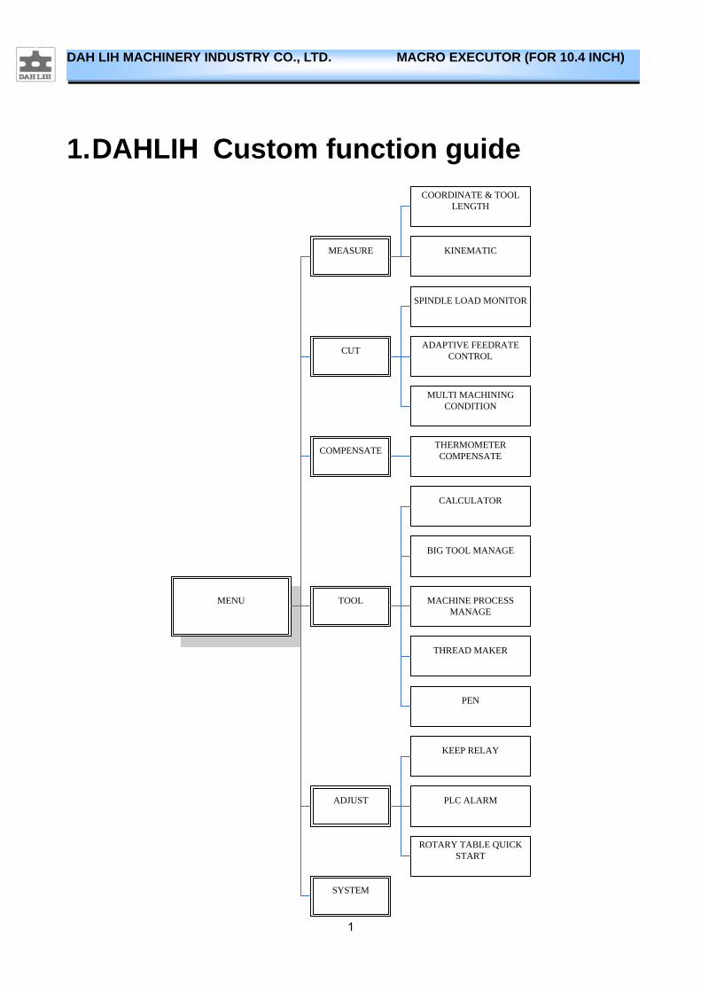
1. DAHLIH Custom function guide
MENU
COMPENSATE
TOOL
CUT
SYSTEM
MEASURE
COORDINATE & TOOL LENGTH
KINEMATIC
ADAPTIVE FEEDRATE CONTROL
MULTI MACHINING CONDITION
SPINDLE LOAD MONITOR
THERMOMETER COMPENSATE
MACHINE PROCESS MANAGE
THREAD MAKER
BIG TOOL MANAGE
PEN
CALCULATOR
ADJUST
PLC ALARM
ROTARY TABLE QUICK START
KEEP RELAY
2
DAH LIH MACHINERY INDUSTRY CO., LTD. MACRO EXECUTOR (FOR 10.4 INCH)
2. Specification for the key and screen
displayed
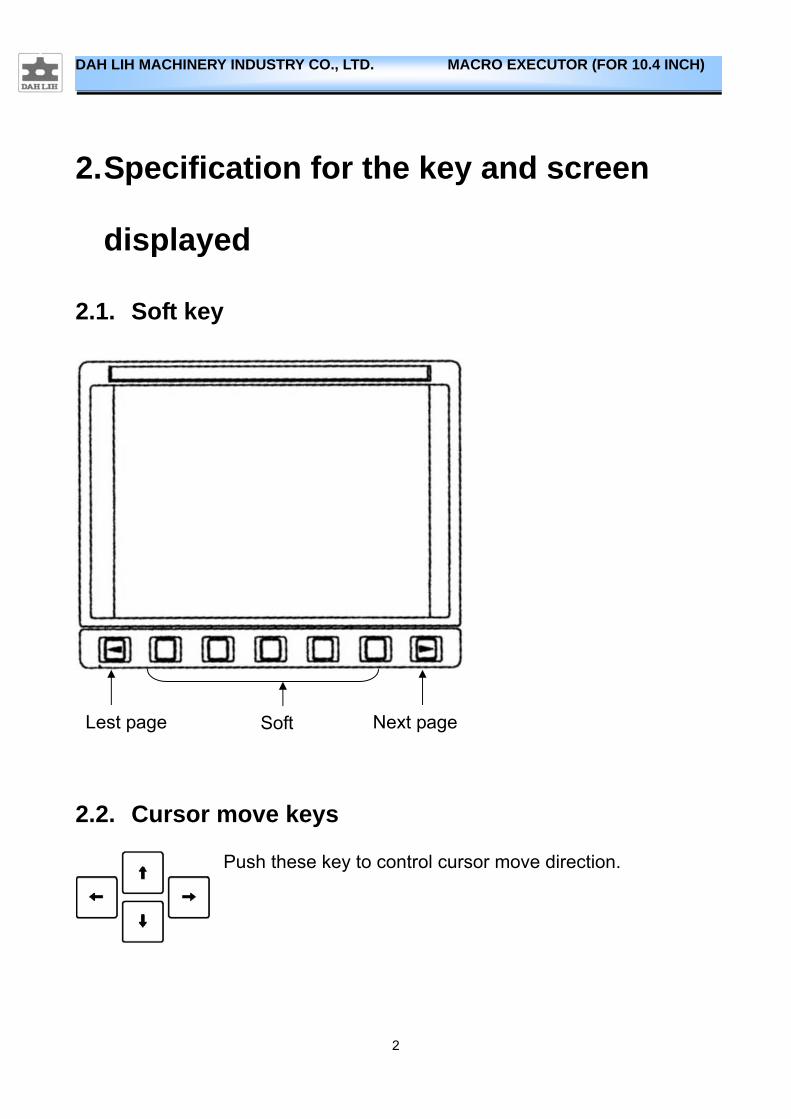
2.1. Soft key
2.2. Cursor move keys
Push these key to control cursor move direction.
Next page Soft Lest page
3
DAH LIH MACHINERY INDUSTRY CO., LTD. MACRO EXECUTOR (FOR 10.4 INCH)
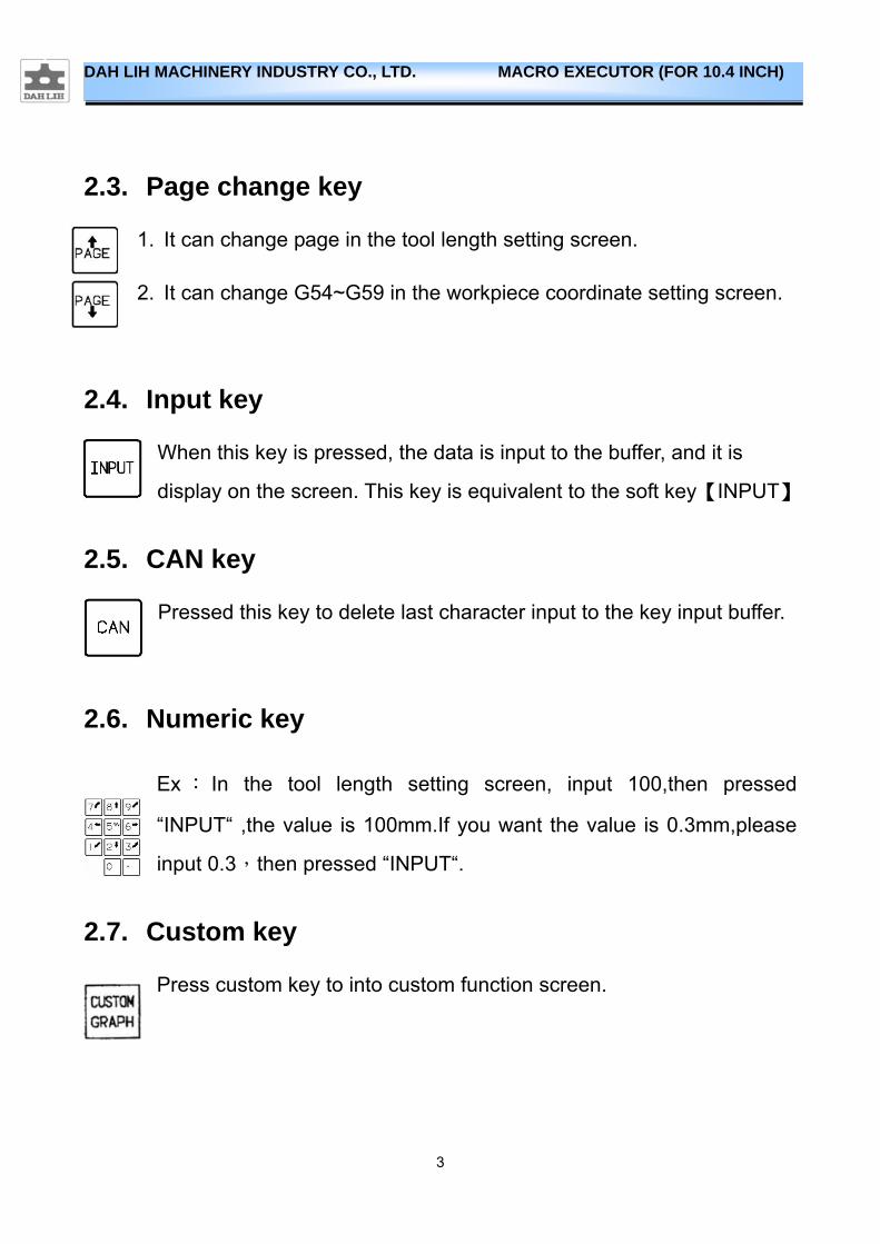
2.3. Page change key
1. It can change page in the tool length setting screen. 2. It can change G54~G59 in the workpiece coordinate setting screen.
2.4. Input key
When this key is pressed, the data is input to the buffer, and it is
display on the screen. This key is equivalent to the soft key【INPUT】
2.5. CAN key
Pressed this key to delete last character input to the key input buffer.
2.6. Numeric key
Ex : In the tool length setting screen, input 100,then pressed
“INPUT“ ,the value is 100mm.If you want the value is 0.3mm,please
input 0.3,then pressed “INPUT“.
2.7. Custom key
Press custom key to into custom function screen.
4
DAH LIH MACHINERY INDUSTRY CO., LTD. MACRO EXECUTOR (FOR 10.4 INCH)
3. Measurement Function
3.1. Workpiece coordinates and tool length setting
3.1.1. How to enter the coordinates and tool length setting
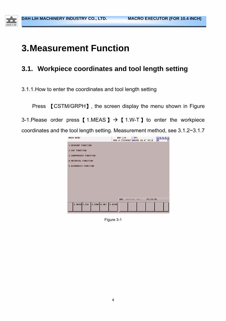
Press 【CSTM/GRPH】, the screen display the menu shown in Figure
3-1.Please order press【1.MEAS】【1.W-T】 to enter the workpiece
coordinates and the tool length setting. Measurement method, see 3.1.2~3.1.7
Figure 3-1
5
DAH LIH MACHINERY INDUSTRY CO., LTD. MACRO EXECUTOR (FOR 10.4 INCH)
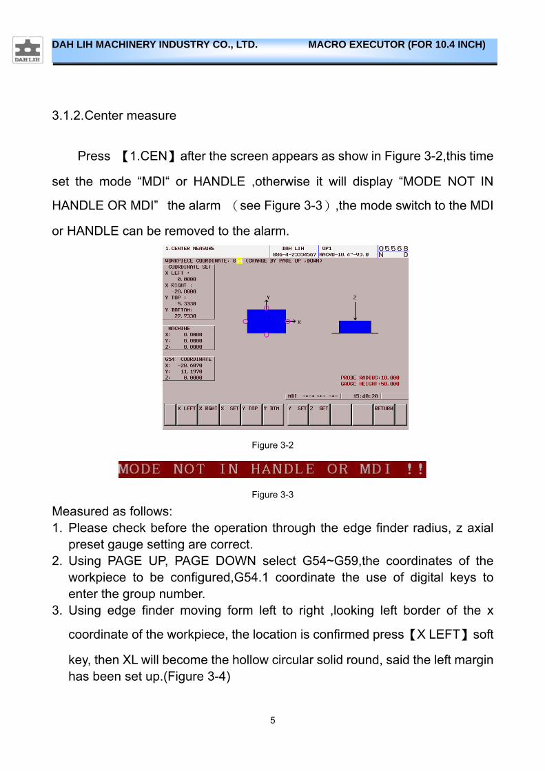
3.1.2. Center measure
Press 【1.CEN】after the screen appears as show in Figure 3-2,this time
set the mode “MDI“ or HANDLE ,otherwise it will display “MODE NOT IN
HANDLE OR MDI” the alarm (see Figure 3-3),the mode switch to the MDI
or HANDLE can be removed to the alarm.
Figure 3-2
Figure 3-3
Measured as follows: 1. Please check before the operation through the edge finder radius, z axial
preset gauge setting are correct. 2. Using PAGE UP, PAGE DOWN select G54~G59,the coordinates of the
workpiece to be configured,G54.1 coordinate the use of digital keys to enter the group number.
3. Using edge finder moving form left to right ,looking left border of the x
coordinate of the workpiece, the location is confirmed press【X LEFT】soft
key, then XL will become the hollow circular solid round, said the left margin has been set up.(Figure 3-4)
6
DAH LIH MACHINERY INDUSTRY CO., LTD. MACRO EXECUTOR (FOR 10.4 INCH)
Figure 3-4
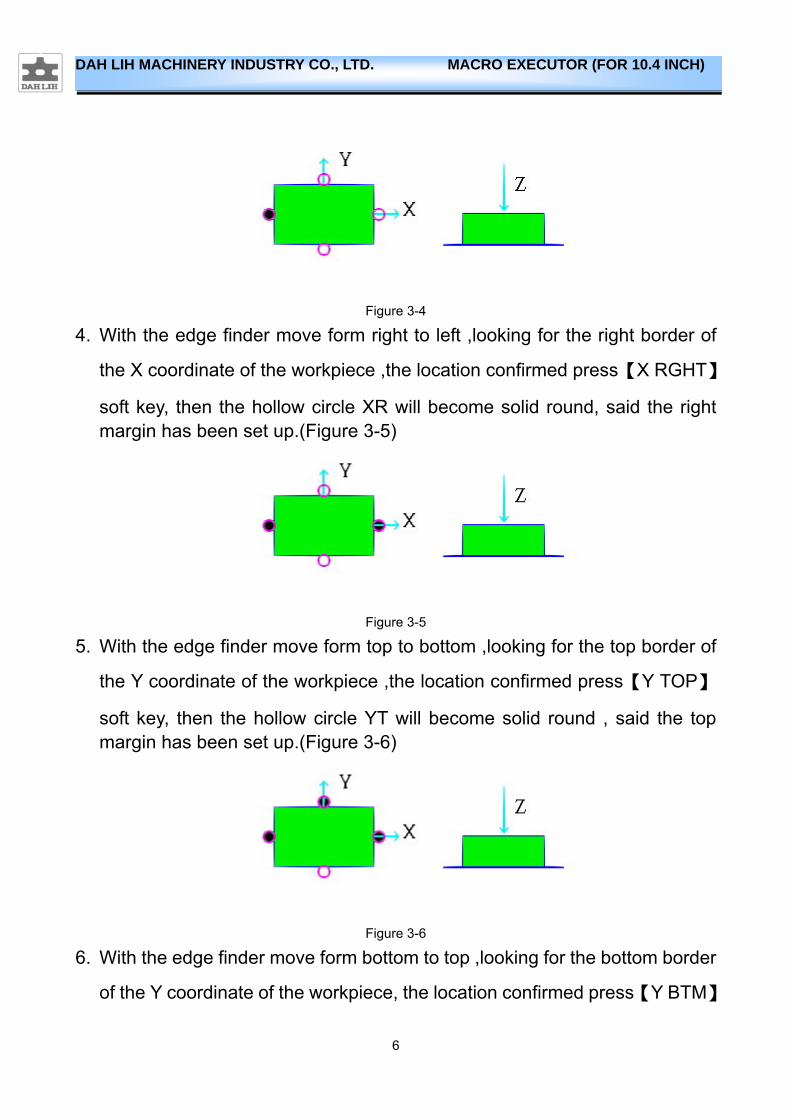
4. With the edge finder move form right to left ,looking for the right border of
the X coordinate of the workpiece ,the location confirmed press【X RGHT】
soft key, then the hollow circle XR will become solid round, said the right margin has been set up.(Figure 3-5)
Figure 3-5
5. With the edge finder move form top to bottom ,looking for the top border of
the Y coordinate of the workpiece ,the location confirmed press【Y TOP】
soft key, then the hollow circle YT will become solid round , said the top margin has been set up.(Figure 3-6)
Figure 3-6
6. With the edge finder move form bottom to top ,looking for the bottom border
of the Y coordinate of the workpiece, the location confirmed press【Y BTM】
7
DAH LIH MACHINERY INDUSTRY CO., LTD. MACRO EXECUTOR (FOR 10.4 INCH)
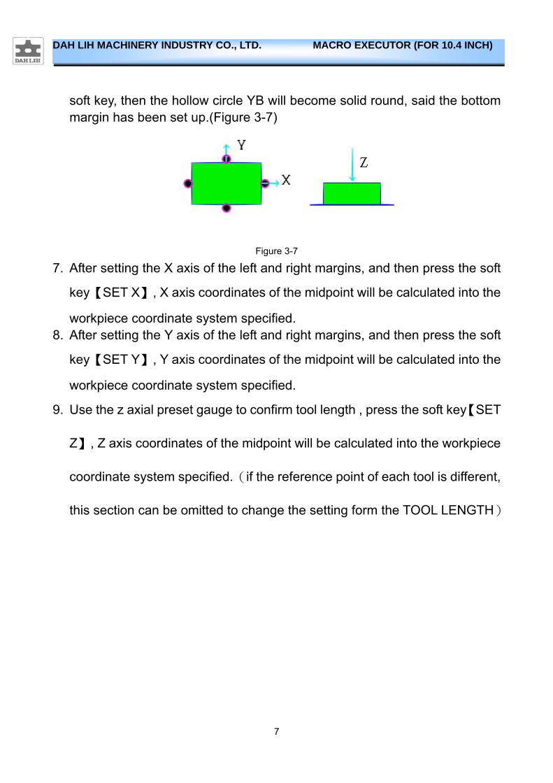
soft key, then the hollow circle YB will become solid round, said the bottom margin has been set up.(Figure 3-7)
Figure 3-7
7. After setting the X axis of the left and right margins, and then press the soft
key【SET X】, X axis coordinates of the midpoint will be calculated into the
workpiece coordinate system specified. 8. After setting the Y axis of the left and right margins, and then press the soft
key【SET Y】, Y axis coordinates of the midpoint will be calculated into the
workpiece coordinate system specified.
9. Use the z axial preset gauge to confirm tool length , press the soft key【SET
Z】, Z axis coordinates of the midpoint will be calculated into the workpiece
coordinate system specified.(if the reference point of each tool is different,
this section can be omitted to change the setting form the TOOL LENGTH)
8
DAH LIH MACHINERY INDUSTRY CO., LTD. MACRO EXECUTOR (FOR 10.4 INCH)
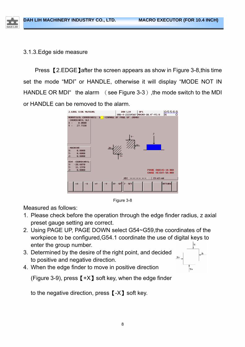
3.1.3. Edge side measure
Press 【2.EDGE】after the screen appears as show in Figure 3-8,this time
set the mode “MDI” or HANDLE, otherwise it will display “MODE NOT IN
HANDLE OR MDI“ the alarm (see Figure 3-3),the mode switch to the MDI
or HANDLE can be removed to the alarm.
Figure 3-8
Measured as follows: 1. Please check before the operation through the edge finder radius, z axial
preset gauge setting are correct. 2. Using PAGE UP, PAGE DOWN select G54~G59,the coordinates of the
workpiece to be configured,G54.1 coordinate the use of digital keys to enter the group number.
3. Determined by the desire of the right point, and decided to positive and negative direction.
4. When the edge finder to move in positive direction
(Figure 3-9), press【+X】soft key, when the edge finder
to the negative direction, press【-X】soft key.
9
DAH LIH MACHINERY INDUSTRY CO., LTD. MACRO EXECUTOR (FOR 10.4 INCH)
Figure 3-9
5. Positive and negative direction of the judge as shown:
Angle 1:+X、+Y
Angle 2:+X、-Y
Angle 3:-X、-Y
Angle 4:-X、+Y
:
Angle 1:-X、-Y
Angle 2:-X、+Y
Angle 3:+X、+Y
Angle 4:+X、-Y
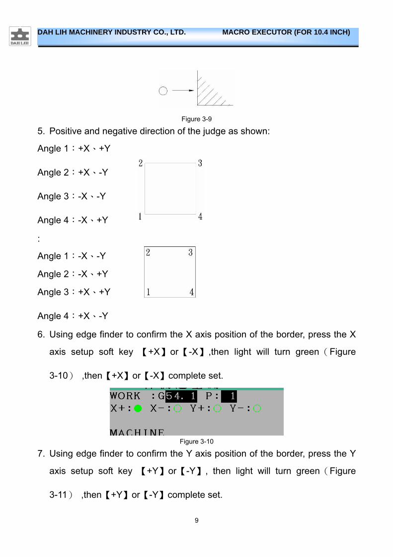
6. Using edge finder to confirm the X axis position of the border, press the X
axis setup soft key 【+X】or【-X】,then light will turn green(Figure
3-10) ,then【+X】or【-X】complete set.
Figure 3-10
7. Using edge finder to confirm the Y axis position of the border, press the Y
axis setup soft key 【+Y】or【-Y】, then light will turn green(Figure
3-11) ,then【+Y】or【-Y】complete set.
10
DAH LIH MACHINERY INDUSTRY CO., LTD. MACRO EXECUTOR (FOR 10.4 INCH)
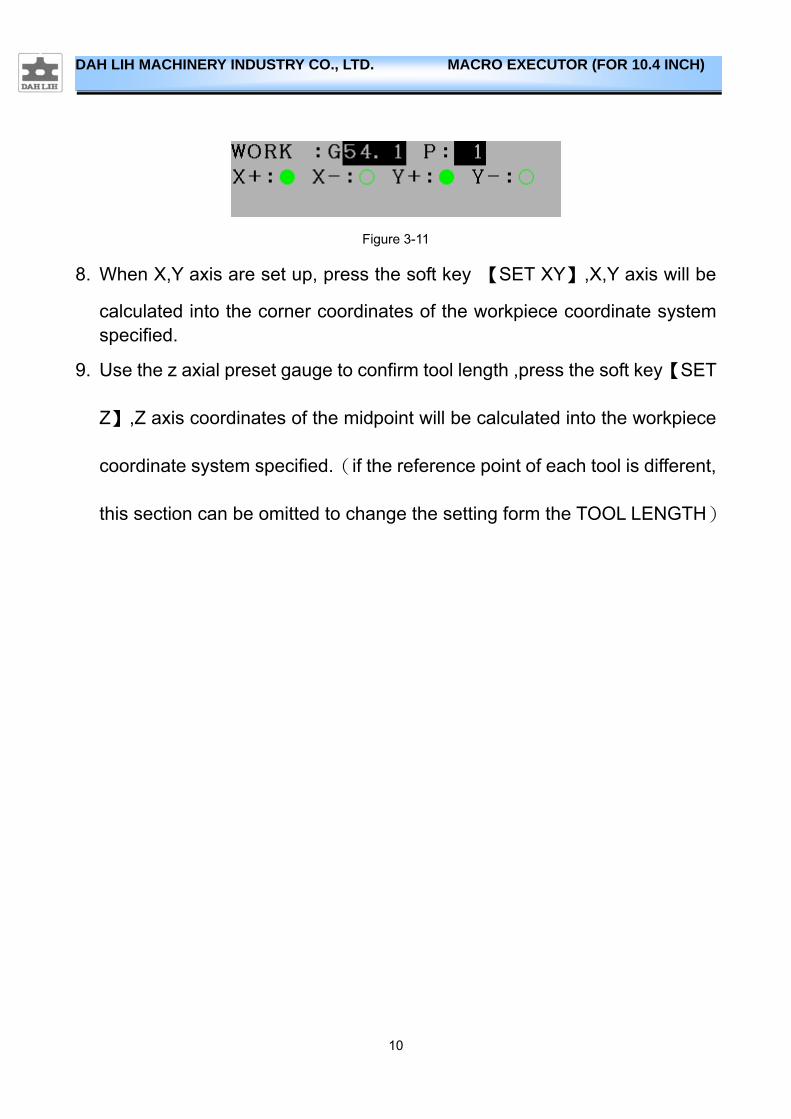
Figure 3-11
8. When X,Y axis are set up, press the soft key 【SET XY】,X,Y axis will be
calculated into the corner coordinates of the workpiece coordinate system specified.
9. Use the z axial preset gauge to confirm tool length ,press the soft key【SET
Z】,Z axis coordinates of the midpoint will be calculated into the workpiece
coordinate system specified.(if the reference point of each tool is different,
this section can be omitted to change the setting form the TOOL LENGTH)
11
DAH LIH MACHINERY INDUSTRY CO., LTD. MACRO EXECUTOR (FOR 10.4 INCH)
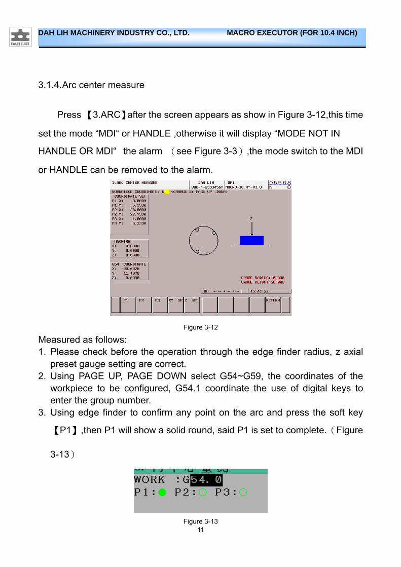
3.1.4. Arc center measure
Press 【3.ARC】after the screen appears as show in Figure 3-12,this time
set the mode “MDI“ or HANDLE ,otherwise it will display “MODE NOT IN
HANDLE OR MDI“ the alarm (see Figure 3-3),the mode switch to the MDI
or HANDLE can be removed to the alarm.
Figure 3-12
Measured as follows: 1. Please check before the operation through the edge finder radius, z axial
preset gauge setting are correct. 2. Using PAGE UP, PAGE DOWN select G54~G59, the coordinates of the
workpiece to be configured, G54.1 coordinate the use of digital keys to enter the group number.
3. Using edge finder to confirm any point on the arc and press the soft key
【P1】,then P1 will show a solid round, said P1 is set to complete.(Figure
3-13)
Figure 3-13
12
DAH LIH MACHINERY INDUSTRY CO., LTD. MACRO EXECUTOR (FOR 10.4 INCH)
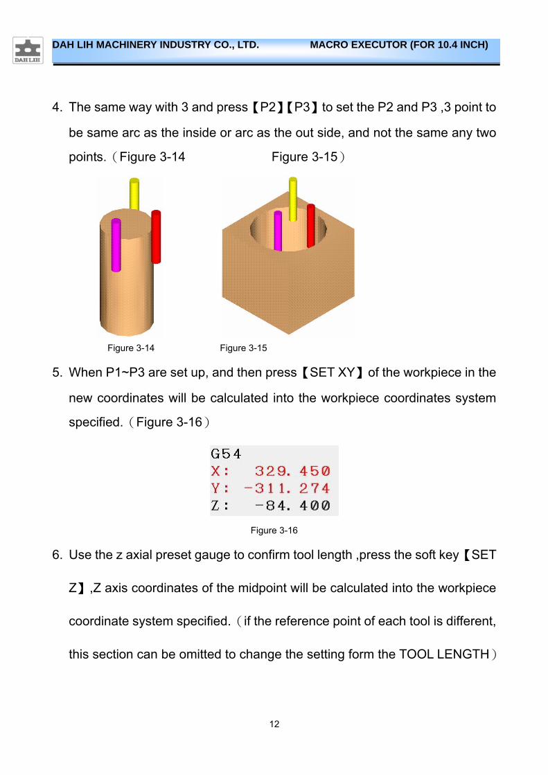
4. The same way with 3 and press【P2】【P3】to set the P2 and P3 ,3 point to
be same arc as the inside or arc as the out side, and not the same any two
points.(Figure 3-14 Figure 3-15)
Figure 3-14 Figure 3-15
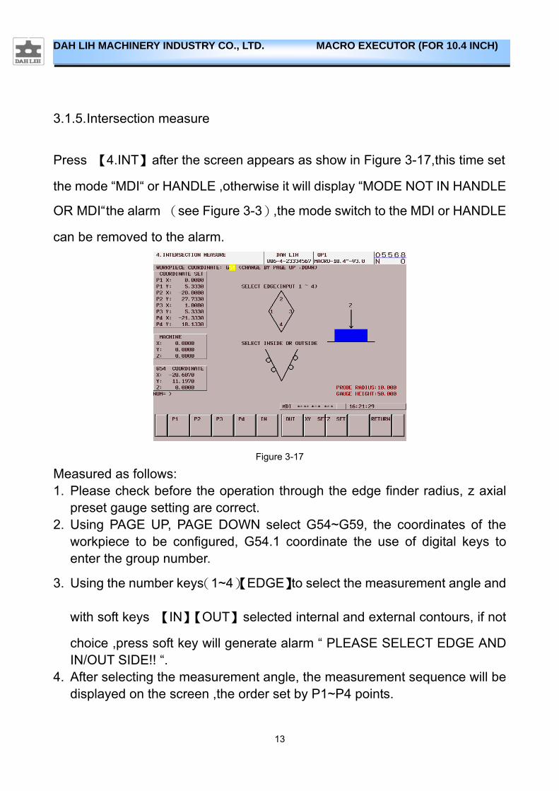
5. When P1~P3 are set up, and then press【SET XY】of the workpiece in the
new coordinates will be calculated into the workpiece coordinates system
specified.(Figure 3-16)
Figure 3-16
6. Use the z axial preset gauge to confirm tool length ,press the soft key【SET
Z】,Z axis coordinates of the midpoint will be calculated into the workpiece
coordinate system specified.(if the reference point of each tool is different,
this section can be omitted to change the setting form the TOOL LENGTH)
13
DAH LIH MACHINERY INDUSTRY CO., LTD. MACRO EXECUTOR (FOR 10.4 INCH)
3.1.5. Intersection measure
Press 【4.INT】after the screen appears as show in Figure 3-17,this time set
the mode “MDI“ or HANDLE ,otherwise it will display “MODE NOT IN HANDLE
OR MDI“ the alarm (see Figure 3-3),the mode switch to the MDI or HANDLE
can be removed to the alarm.
Figure 3-17
Measured as follows: 1. Please check before the operation through the edge finder radius, z axial
preset gauge setting are correct. 2. Using PAGE UP, PAGE DOWN select G54~G59, the coordinates of the
workpiece to be configured, G54.1 coordinate the use of digital keys to enter the group number.
3. Using the number keys(1~4)【EDGE】to select the measurement angle and
with soft keys 【IN】【OUT】selected internal and external contours, if not
choice ,press soft key will generate alarm “ PLEASE SELECT EDGE AND IN/OUT SIDE!! “.
4. After selecting the measurement angle, the measurement sequence will be displayed on the screen ,the order set by P1~P4 points.

14
DAH LIH MACHINERY INDUSTRY CO., LTD. MACRO EXECUTOR (FOR 10.4 INCH)
Figure 3-18 Figure 3-19 Figure 3-20 Figure 3-21
5. Selected the inside and outside the contours, the contours position the edge finder relative to the icon.
Figure 3-22 Figure 3-23
6. According to the order screen icon, use the edge finder to find the location
of P1,then press soft key【P1】,then P1 becomes solid the P1 set to
complete.
Figure 3-24
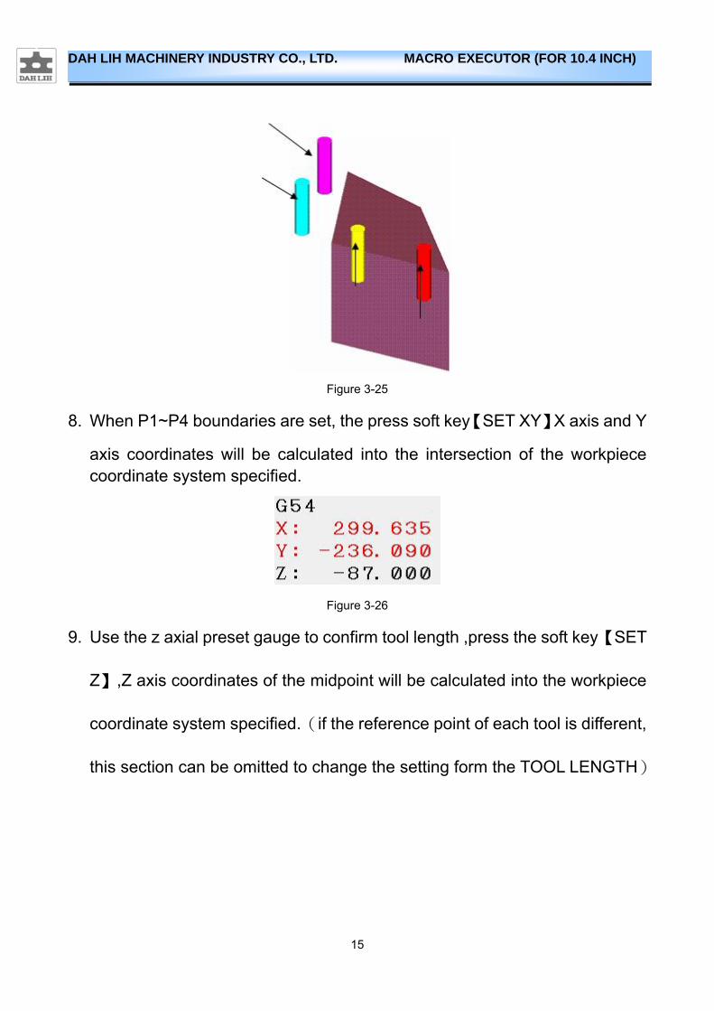
7. The same way with 3 and press【P2】【P3】【P4】to set the P2,P3 and P4.
(Figure 3-25)
15
DAH LIH MACHINERY INDUSTRY CO., LTD. MACRO EXECUTOR (FOR 10.4 INCH)
Figure 3-25
8. When P1~P4 boundaries are set, the press soft key【SET XY】X axis and Y
axis coordinates will be calculated into the intersection of the workpiece coordinate system specified.
Figure 3-26
9. Use the z axial preset gauge to confirm tool length ,press the soft key【SET
Z】,Z axis coordinates of the midpoint will be calculated into the workpiece
coordinate system specified.(if the reference point of each tool is different,
this section can be omitted to change the setting form the TOOL LENGTH)
16
DAH LIH MACHINERY INDUSTRY CO., LTD. MACRO EXECUTOR (FOR 10.4 INCH)
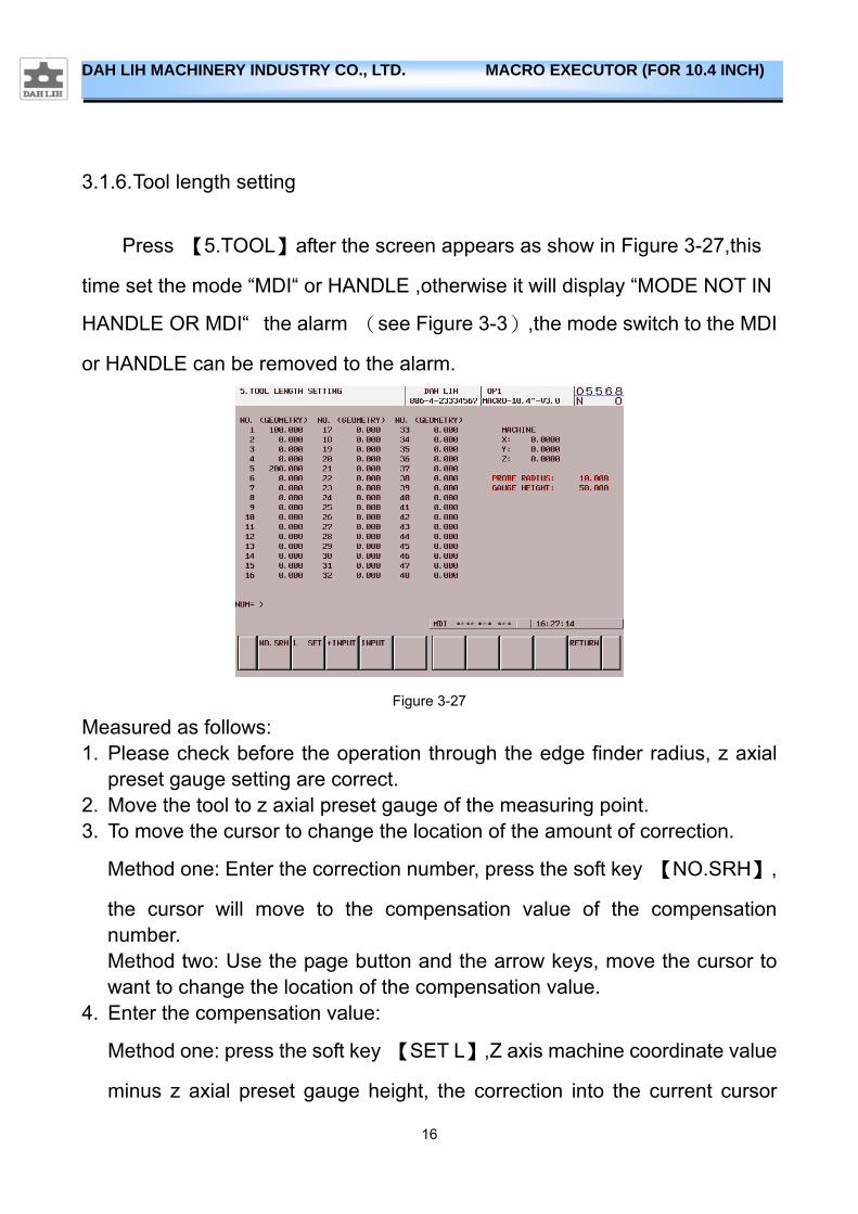
3.1.6. Tool length setting
Press 【5.TOOL】after the screen appears as show in Figure 3-27,this
time set the mode “MDI“ or HANDLE ,otherwise it will display “MODE NOT IN
HANDLE OR MDI“ the alarm (see Figure 3-3),the mode switch to the MDI
or HANDLE can be removed to the alarm.
Figure 3-27
Measured as follows: 1. Please check before the operation through the edge finder radius, z axial
preset gauge setting are correct. 2. Move the tool to z axial preset gauge of the measuring point. 3. To move the cursor to change the location of the amount of correction.
Method one: Enter the correction number, press the soft key 【NO.SRH】,
the cursor will move to the compensation value of the compensation number. Method two: Use the page button and the arrow keys, move the cursor to want to change the location of the compensation value.
4. Enter the compensation value:
Method one: press the soft key 【SET L】,Z axis machine coordinate value
minus z axial preset gauge height, the correction into the current cursor

17
DAH LIH MACHINERY INDUSTRY CO., LTD. MACRO EXECUTOR (FOR 10.4 INCH)
comes up in number. Method two: Enter the increase or decrease the number and then press the
soft key【+INPUT】,the current compensative value with the value added,
save the current cursor number of compensative value.
Method three: Enter the tool length, then press the soft key 【INPUT】, the
input value will be stored at the compensative number of the compensative value.
18
DAH LIH MACHINERY INDUSTRY CO., LTD. MACRO EXECUTOR (FOR 10.4 INCH)
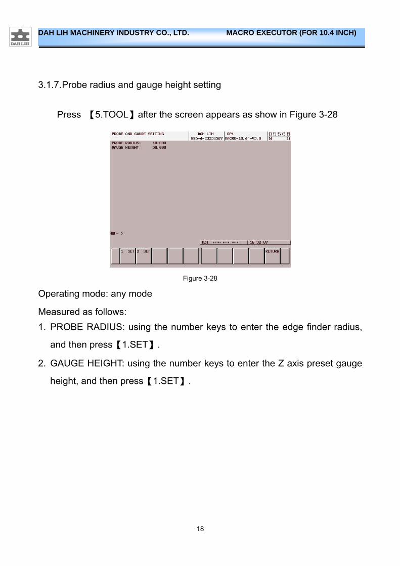
3.1.7. Probe radius and gauge height setting
Press 【5.TOOL】after the screen appears as show in Figure 3-28
Figure 3-28
Operating mode: any mode
Measured as follows:
1. PROBE RADIUS: using the number keys to enter the edge finder radius,
and then press【1.SET】.
2. GAUGE HEIGHT: using the number keys to enter the Z axis preset gauge
height, and then press【1.SET】.
19
DAH LIH MACHINERY INDUSTRY CO., LTD. MACRO EXECUTOR (FOR 10.4 INCH)
3.2. Five axes calibration
3.2.1. Features
Five axes calibration(FAC), provides easy set four or five axis indexing
accuracy check, the operator easily through icons to teach measurement and set four or five axis rotary machining parameters, without the need for complex mathematical operations through.
3.2.2. Use
1. Press 【CSTM/GRPH】 into the main screen.(Figure 3-1)
2. Press【1.MEAS】【3.FAC】for the five axes calibration.
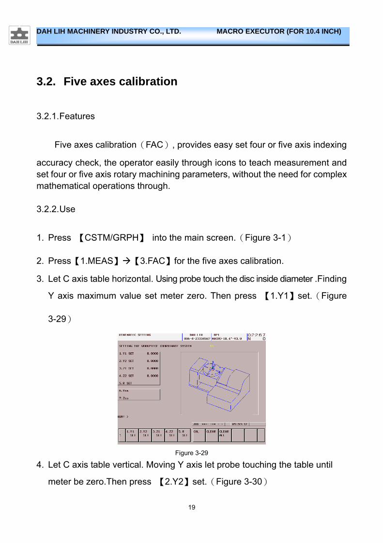
3. Let C axis table horizontal. Using probe touch the disc inside diameter .Finding
Y axis maximum value set meter zero. Then press 【1.Y1】set.(Figure
3-29)
Figure 3-29
4. Let C axis table vertical. Moving Y axis let probe touching the table until
meter be zero.Then press 【2.Y2】set.(Figure 3-30)
20
DAH LIH MACHINERY INDUSTRY CO., LTD. MACRO EXECUTOR (FOR 10.4 INCH)
Figure 3-30
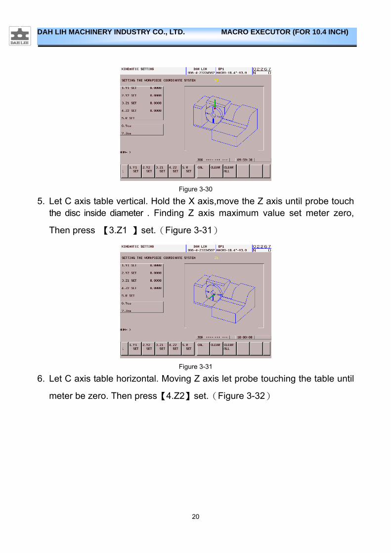
5. Let C axis table vertical. Hold the X axis,move the Z axis until probe touch the disc inside diameter . Finding Z axis maximum value set meter zero,
Then press 【3.Z1 】set.(Figure 3-31)
Figure 3-31
6. Let C axis table horizontal. Moving Z axis let probe touching the table until
meter be zero. Then press【4.Z2】set.(Figure 3-32)
21
DAH LIH MACHINERY INDUSTRY CO., LTD. MACRO EXECUTOR (FOR 10.4 INCH)
Figure 3-32
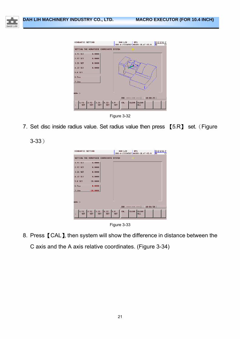
7. Set disc inside radius value. Set radius value then press 【5.R】 set.(Figure
3-33)
Figure 3-33
8. Press 【CAL】,then system will show the difference in distance between the
C axis and the A axis relative coordinates. (Figure 3-34)

22
DAH LIH MACHINERY INDUSTRY CO., LTD. MACRO EXECUTOR (FOR 10.4 INCH)
Figure 3-34
23
DAH LIH MACHINERY INDUSTRY CO., LTD. MACRO EXECUTOR (FOR 10.4 INCH)
4. Cut Function
4.1. Spindle load monitor
4.1.1. Features
The function detected load of spindle by CNC. When load of spindle exceeded value of setting, the machine has stopped working .And appears alarm“ 2021 SPINDLE CUTTING OVERLOAD “
4.1.2. User
1. Press 【CSTM/GRPH】 into the main screen.(Figure 3-1)
2. Press 【2.CUT】【1.SLM】【LSET】
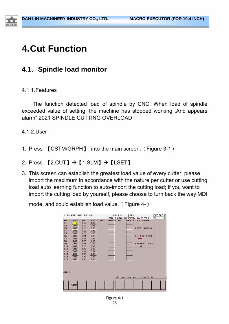
3. This screen can establish the greatest load value of every cutter; please import the maximum in accordance with the nature per cutter or use cutting load auto learning function to auto-import the cutting load; if you want to import the cutting load by yourself, please choose to turn back the way MDI
mode, and could establish load value.(Figure 4-)
Figure 4-1
24
DAH LIH MACHINERY INDUSTRY CO., LTD. MACRO EXECUTOR (FOR 10.4 INCH)
4. After setting the program in CNC tool change to be added after M302 Q1
Rxxx(R need to increase the decimal point)to start the spindle load
function, where R is the set value range is 1~200,the spindle load function
maximum load for the basic load * SLM factor(Rxxx).shown in Figure 4-1:
T.N.: spindle tool E.L.: not cutting empty load S.F.: SLM factor M.L.: maximum spindle load value
EX:
M6T10; M302 Q1 R100.; G5.1Q1; M3S1500; G90G01X-100.Y-100.Z-1.; 5. User must know that actual cutting was causing load, and it add 1%~5% for
spindle abnormality load. Big tools can tolerate large abnormality load(ex.
face mill).Small tools can tolerate abnormality load(ex. Small drill).The
precision of minimum detection is 1%.
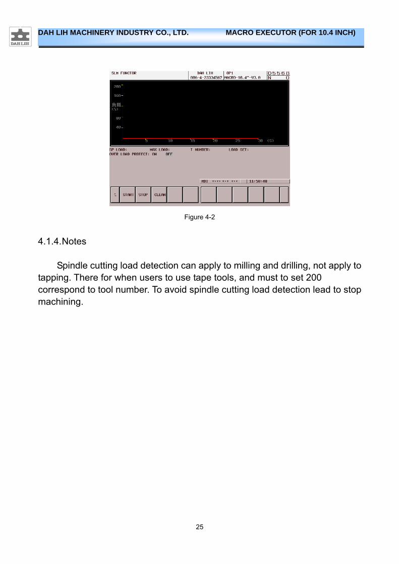
4.1.3. The load wave form of the main shaft shows
1. Press 【CSTM/GRPH】 into the main screen.(Figure 3-1)
2. Press【2.CUT】【1.SLM】【2.SLM】
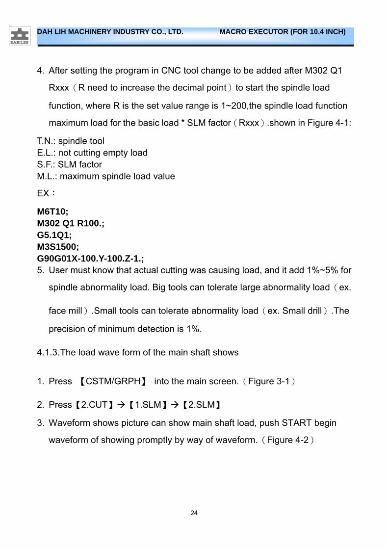
3. Waveform shows picture can show main shaft load, push START begin
waveform of showing promptly by way of waveform.(Figure 4-2)
25
DAH LIH MACHINERY INDUSTRY CO., LTD. MACRO EXECUTOR (FOR 10.4 INCH)
Figure 4-2
4.1.4. Notes
Spindle cutting load detection can apply to milling and drilling, not apply to tapping. There for when users to use tape tools, and must to set 200 correspond to tool number. To avoid spindle cutting load detection lead to stop machining.

26
DAH LIH MACHINERY INDUSTRY CO., LTD. MACRO EXECUTOR (FOR 10.4 INCH)
4.2. Adaptive feedrate control
4.2.1. Features
Adaptive Feedrate Control (AFC), it is not traditions fixed feedrate CNC will auto change feedrate by spindle load in order to reach efficiency optimization. Adjustment feedrate percentage datum is by cut program F code.
4.2.2. Setting description
1. Press 【CSTM/GRPH】 into the main screen.(Figure 3-1)
2. Press 【2.CUT】【2.AFC】【3.SET】can enter the settings page.(Figure
4-3)
(1) PERIOD OF F%+:This parameter is adjustment feedrate increase
percentage (1~100)
(2) PERIOD OF F%-:This parameter is adjustment feedrate reduce
percentage (1~100)
(3) MAX FEED:This parameter is adjustment maximum feedrate
percentage (100~200)
(4) MIN FEED:This parameter is adjustment minimum feedrate percentage
(1~100)
27
DAH LIH MACHINERY INDUSTRY CO., LTD. MACRO EXECUTOR (FOR 10.4 INCH)
Figure 4-3
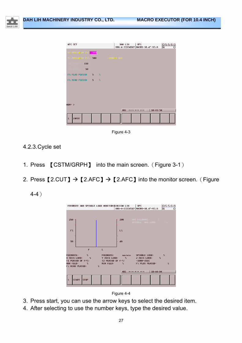
4.2.3. Cycle set
1. Press 【CSTM/GRPH】 into the main screen.(Figure 3-1)
2. Press【2.CUT】【2.AFC】【2.AFC】into the monitor screen.(Figure
4-4)
Figure 4-4
3. Press start, you can use the arrow keys to select the desired item. 4. After selecting to use the number keys, type the desired value.
28
DAH LIH MACHINERY INDUSTRY CO., LTD. MACRO EXECUTOR (FOR 10.4 INCH)
(1) T1 OF %+:Every interval T1 examines the spindle load, if spindle load
except for exceed set load, namely constant to accelerate.(Unit:ms)
(2) T2 OF %-:Every interval T2 examines the spindle load, if spindle load
exceed set load, namely constant to slow down. (Unit:ms)
5. AFC function when open, it can draw form this observation into the given page load change spindle.
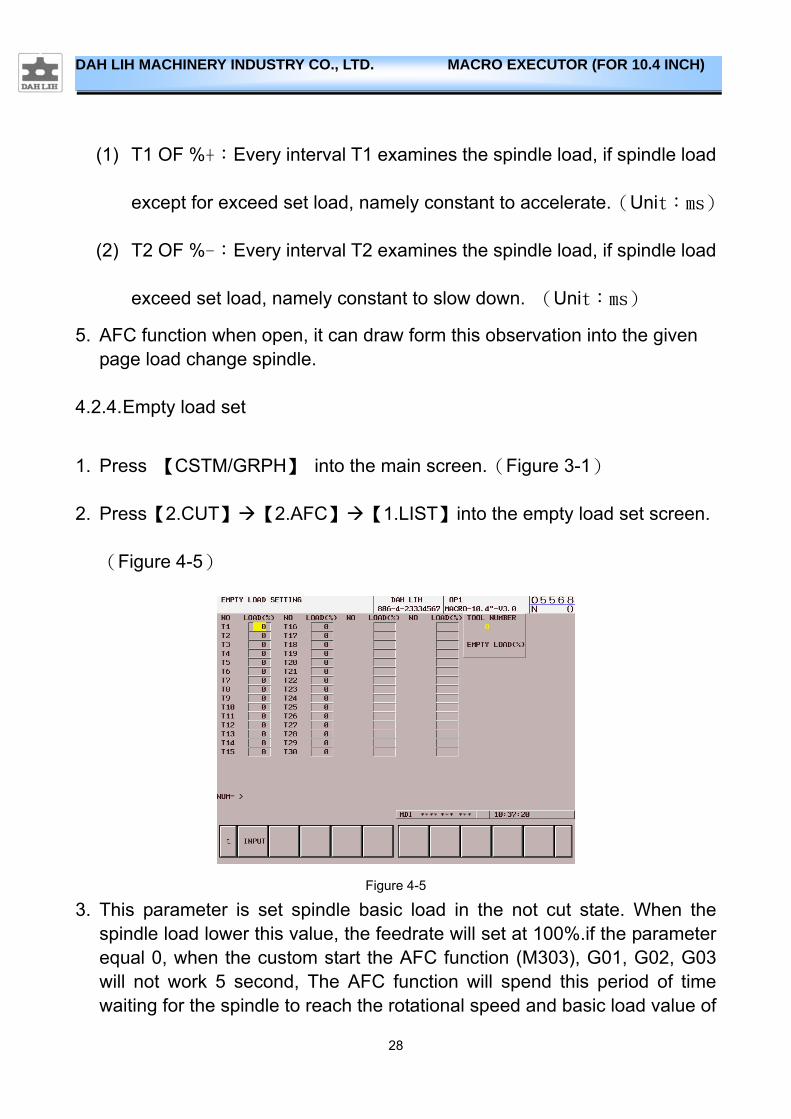
4.2.4. Empty load set
1. Press 【CSTM/GRPH】 into the main screen.(Figure 3-1)
2. Press【2.CUT】【2.AFC】【1.LIST】into the empty load set screen.
(Figure 4-5)
Figure 4-5
3. This parameter is set spindle basic load in the not cut state. When the spindle load lower this value, the feedrate will set at 100%.if the parameter equal 0, when the custom start the AFC function (M303), G01, G02, G03 will not work 5 second, The AFC function will spend this period of time waiting for the spindle to reach the rotational speed and basic load value of
29
DAH LIH MACHINERY INDUSTRY CO., LTD. MACRO EXECUTOR (FOR 10.4 INCH)
record (this value will not be written into the basic load form).
4.2.5. Spindle load set
See the 4.1.2
4.2.6. Use
Processing program in the tool change instruction command input AFC
function :M303 Q1 Rxxx
EX:
O1234; M6T1; M303 Q1 R120.; G5.1Q1; M3S1500;
G90G01X-100.Y-100.Z-1.;
4.2.7. Note
M302 and M303 and M304 can not be shared.
30
DAH LIH MACHINERY INDUSTRY CO., LTD. MACRO EXECUTOR (FOR 10.4 INCH)
4.3. Auto learning cutting function
4.3.1. Features
Auto Learning Cutting (ALC), It is a automatic learning function, CNC will
cutting workpiece and recording spindle load at the same time. Then it will
record cutting load into the load table.(Figure 4-)
4.3.2. Use
The cutting tool processing program instruction in the ALC function input command:M304 Q1.
EX:
O1234; M6T1; M304 Q1 ; G5.1Q1; M3S1500; G90G01X-100.Y-100.Z-1.;
4.3.3. Note
M302 and M303 and M304 can not be shared
31
DAH LIH MACHINERY INDUSTRY CO., LTD. MACRO EXECUTOR (FOR 10.4 INCH)
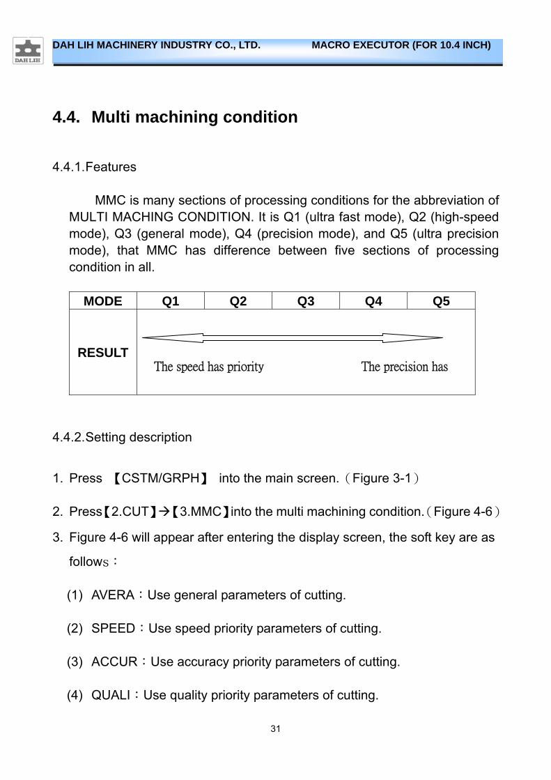
4.4. Multi machining condition
4.4.1. Features
MMC is many sections of processing conditions for the abbreviation of MULTI MACHING CONDITION. It is Q1 (ultra fast mode), Q2 (high-speed mode), Q3 (general mode), Q4 (precision mode), and Q5 (ultra precision mode), that MMC has difference between five sections of processing condition in all.
MODE Q1 Q2 Q3 Q4 Q5
RESULT
4.4.2. Setting description
1. Press 【CSTM/GRPH】 into the main screen.(Figure 3-1)
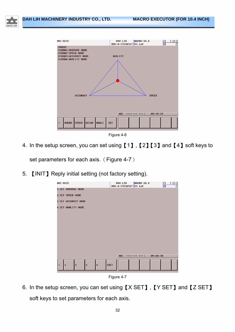
2. Press【2.CUT】【3.MMC】into the multi machining condition.(Figure 4-6)
3. Figure 4-6 will appear after entering the display screen, the soft key are as
follows:
(1) AVERA:Use general parameters of cutting.
(2) SPEED:Use speed priority parameters of cutting.
(3) ACCUR:Use accuracy priority parameters of cutting.
(4) QUALI:Use quality priority parameters of cutting.
The speed has priority The precision has
32
DAH LIH MACHINERY INDUSTRY CO., LTD. MACRO EXECUTOR (FOR 10.4 INCH)
Figure 4-6
4. In the setup screen, you can set using【1】,【2】【3】and【4】soft keys to
set parameters for each axis.(Figure 4-7)
5. 【INIT】Reply initial setting (not factory setting).
Figure 4-7
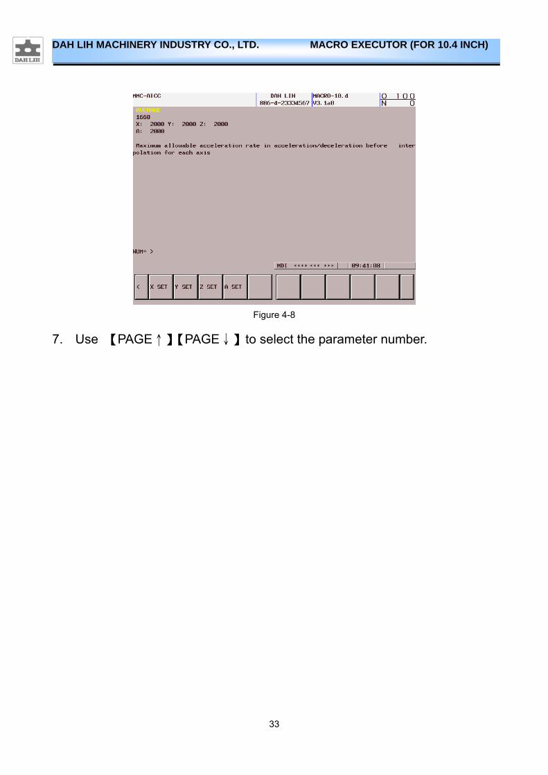
6. In the setup screen, you can set using【X SET】,【Y SET】and【Z SET】
soft keys to set parameters for each axis.
33
DAH LIH MACHINERY INDUSTRY CO., LTD. MACRO EXECUTOR (FOR 10.4 INCH)
Figure 4-8
7. Use 【PAGE↑】【PAGE↓】to select the parameter number.
34
DAH LIH MACHINERY INDUSTRY CO., LTD. MACRO EXECUTOR (FOR 10.4 INCH)
4.4.3. Use
Start the MMC function, just before the program’s G5.1Q1join M300Qx
(no decimal point), the program will automatically change to the desired
parameter settings.
EX:
O1234; M6T1; M300 Q1 ; G5.1Q1; M3S1500; G90G01X-100.Y-100.Z-1.;
35
DAH LIH MACHINERY INDUSTRY CO., LTD. MACRO EXECUTOR (FOR 10.4 INCH)
5. Compensation Function
5.1. Spindle temperatures compensate
5.1.1. Features
machine one's own geometric error and the structure heat produced variation while cutting is influence the main factor of its machining accuracy, so the temperatures compensate technology is paid attention to gradually in recent years. Show via the experimental result, temperatures compensate
function to be can reach compensate the result to±15μm.
The machine is in the course of cutting, side effects of different movements--- friction hot, power while cutting, unique major part turn into heat energy, and the function of the environment temperature, Part material of every part, structure, the position and size are of different size, the degree heated is different too, Make it whole in the table, workpiece, tool and fixture Produce the hot variation in various degree. Every part hot to destroy cutter relative workpiece sport relation to process surface that design originally while being out of shape(tool path), the result has produced the processing error which is cut the workpiece. While developing precision machinery, Development lowers the hot variation, have very important meanings in improving the machining accuracy.
5.1.2. Use
1. Before using the temperatures compensate function, Must install AD-590 temperature sensor first and Install its corresponding peripheral software and hardware device, such as temperature single converter and PLC.
2. Press 【CSTM/GRPH】 the frame shows the menu.(Figure 3-1)
3. Press 【3.COMP】【1.T.C.】(Figure 5-).
4. Respectively【TC INF】、【TC SET】、【TC REC】the three options, Please
36
DAH LIH MACHINERY INDUSTRY CO., LTD. MACRO EXECUTOR (FOR 10.4 INCH)
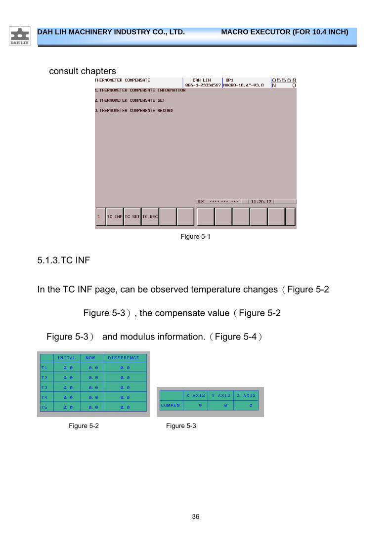
consult chapters
Figure 5-1
5.1.3. TC INF
In the TC INF page, can be observed temperature changes(Figure 5-2
Figure 5-3), the compensate value(Figure 5-2
Figure 5-3) and modulus information.(Figure 5-4)
Figure 5-2 Figure 5-3
37
DAH LIH MACHINERY INDUSTRY CO., LTD. MACRO EXECUTOR (FOR 10.4 INCH)
Figure 5-4
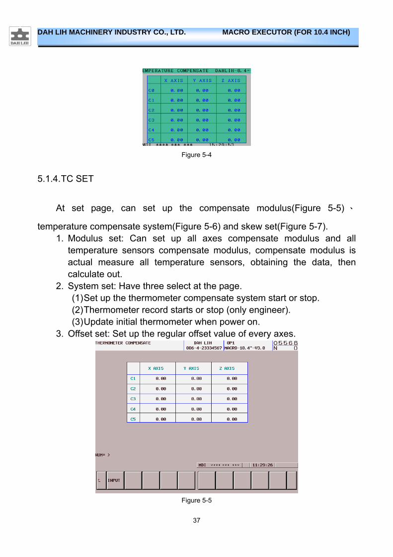
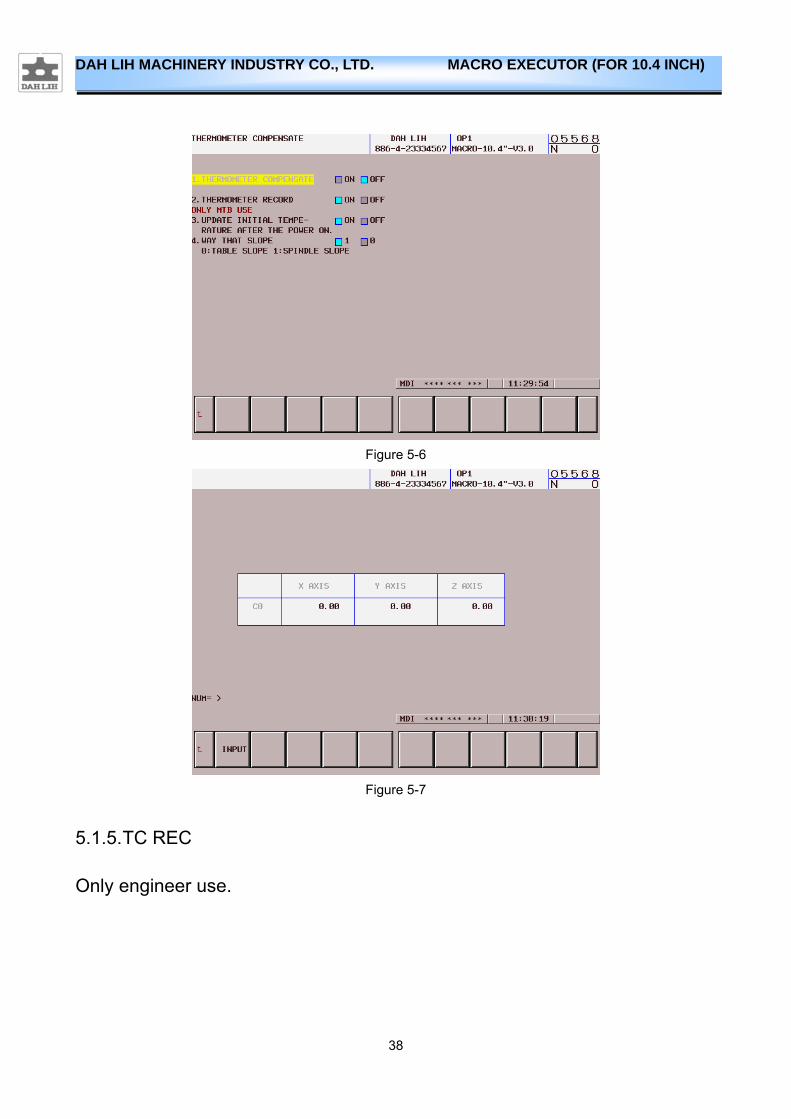
5.1.4. TC SET
At set page, can set up the compensate modulus(Figure 5-5) 、
temperature compensate system(Figure 5-6) and skew set(Figure 5-7). 1. Modulus set: Can set up all axes compensate modulus and all
temperature sensors compensate modulus, compensate modulus is actual measure all temperature sensors, obtaining the data, then calculate out.
2. System set: Have three select at the page. (1) Set up the thermometer compensate system start or stop. (2) Thermometer record starts or stop (only engineer). (3) Update initial thermometer when power on.
3. Offset set: Set up the regular offset value of every axes.
Figure 5-5
38
DAH LIH MACHINERY INDUSTRY CO., LTD. MACRO EXECUTOR (FOR 10.4 INCH)
Figure 5-6
Figure 5-7
5.1.5. TC REC
Only engineer use.
39
DAH LIH MACHINERY INDUSTRY CO., LTD. MACRO EXECUTOR (FOR 10.4 INCH)
6. Tool Function
6.1. Calculator
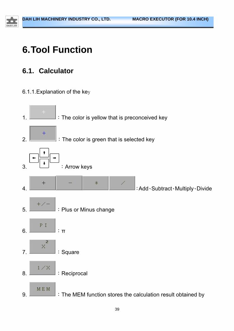
6.1.1. Explanation of the key
1. :The color is yellow that is preconceived key
2. :The color is green that is selected key
3. :Arrow keys
4. :Add、Subtract、Multiply、Divide
5. :Plus or Minus change
6. :π
7. :Square
8. :Reciprocal
9. :The MEM function stores the calculation result obtained by
40
DAH LIH MACHINERY INDUSTRY CO., LTD. MACRO EXECUTOR (FOR 10.4 INCH)
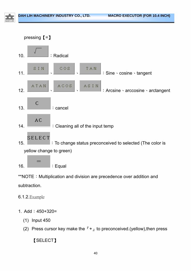
pressing【=】
10. :Radical
11. 、 、 :Sine、cosine、tangent
12. 、 、 :Arcsine、arccosine、arctangent
13. :cancel
14. :Cleaning all of the input temp
15. :To change status preconceived to selected (The color is
yellow change to green)
16. :Equal
**NOTE:Multiplication and division are precedence over addition and
subtraction.
6.1.2. Example
1. Add:450+320=
(1) Input 450
(2) Press cursor key make the『+』to preconceived.(yellow),then press
【SELECT】
41
DAH LIH MACHINERY INDUSTRY CO., LTD. MACRO EXECUTOR (FOR 10.4 INCH)
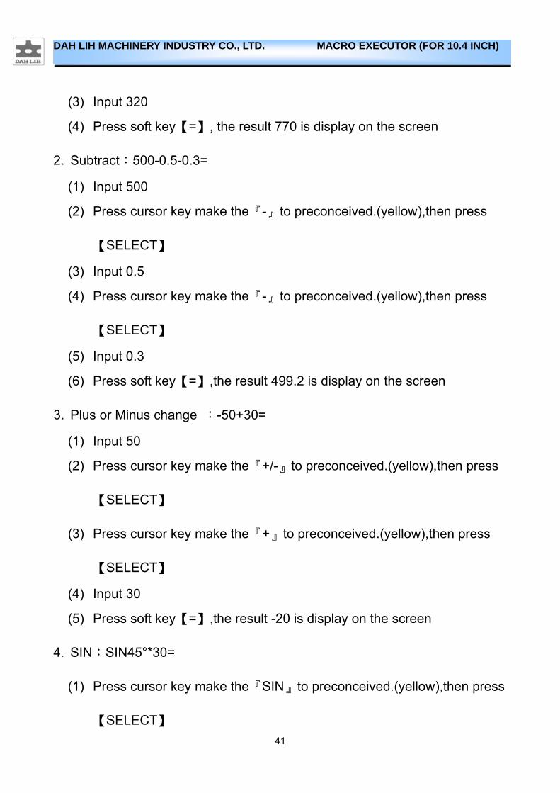
(3) Input 320
(4) Press soft key【=】, the result 770 is display on the screen
2. Subtract:500-0.5-0.3=
(1) Input 500
(2) Press cursor key make the『-』to preconceived.(yellow),then press
【SELECT】
(3) Input 0.5
(4) Press cursor key make the『-』to preconceived.(yellow),then press
【SELECT】
(5) Input 0.3
(6) Press soft key【=】,the result 499.2 is display on the screen
3. Plus or Minus change :-50+30=
(1) Input 50
(2) Press cursor key make the『+/-』to preconceived.(yellow),then press
【SELECT】
(3) Press cursor key make the『+』to preconceived.(yellow),then press
【SELECT】
(4) Input 30
(5) Press soft key【=】,the result -20 is display on the screen
4. SIN:SIN45°*30=
(1) Press cursor key make the『SIN』to preconceived.(yellow),then press
【SELECT】
42
DAH LIH MACHINERY INDUSTRY CO., LTD. MACRO EXECUTOR (FOR 10.4 INCH)
(2) Input 45
(3) Press cursor key make the『*』to preconceived.(yellow),then press
【SELECT】
(4) Input 30
(5) Press soft key【=】,the result 21.213203 is display on the screen
5. Square:532=
(1) Input 53
(2) Press cursor key make the『X2』to preconceived.(yellow),then press
【SELECT】
(3) Press soft key【=】,the result 2809 is display on the screen
6. Reciprocal:1/58
(1) Input 58
(2) Press cursor key make the『1/X』to preconceived.(yellow),then press
【SELECT】
(3) Press soft key【=】,the result 0.01724138 is display on the screen
43
DAH LIH MACHINERY INDUSTRY CO., LTD. MACRO EXECUTOR (FOR 10.4 INCH)
6.2. Big tool manager
6.2.1. Features
When spindle or tool depot have big tool, big tool needs put fixed pot, and adjoin pot can’t use. So as not to produce the phenomenon of interfering, this is the purpose of this system.
6.2.2. Set description
1. Press 【CSTM/GRPH】 the frame shows the menu.(Figure 3-1)
2. Press【4.MAT】【2.TOOL】into the big tool manager
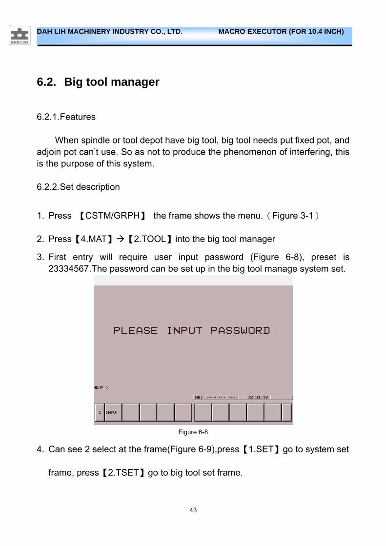
3. First entry will require user input password (Figure 6-8), preset is 23334567.The password can be set up in the big tool manage system set.
Figure 6-8
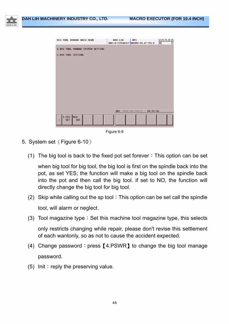
4. Can see 2 select at the frame(Figure 6-9),press【1.SET】go to system set
frame, press【2.TSET】go to big tool set frame.
44
DAH LIH MACHINERY INDUSTRY CO., LTD. MACRO EXECUTOR (FOR 10.4 INCH)
Figure 6-9
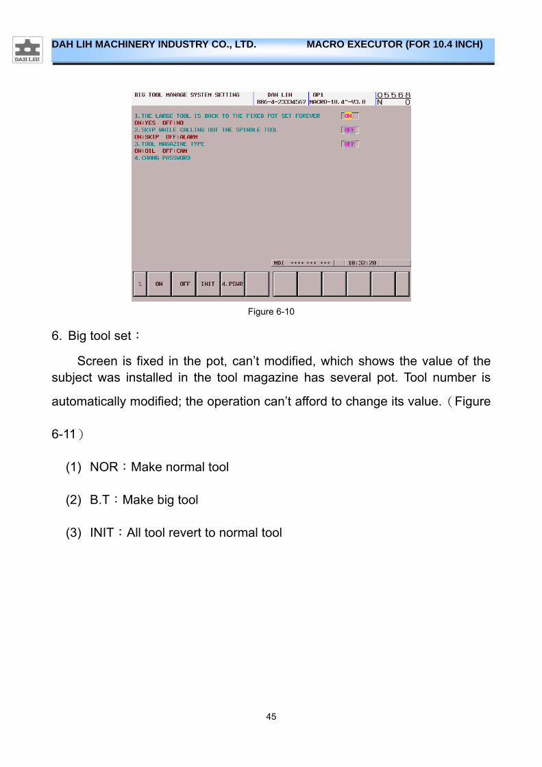
5. System set(Figure 6-10)
(1) The big tool is back to the fixed pot set forever:This option can be set
when big tool for big tool, the big tool is first on the spindle back into the pot, as set YES; the function will make a big tool on the spindle back into the pot and then call the big tool. if set to NO, the function will directly change the big tool for big tool.
(2) Skip while calling out the sp tool:This option can be set call the spindle
tool, will alarm or neglect.
(3) Tool magazine type:Set this machine tool magazine type, this selects
only restricts changing while repair, please don't revise this settlement of each wantonly, so as not to cause the accident expected.
(4) Change password:press【4.PSWR】to change the big tool manage
password.
(5) Init:reply the preserving value.
45
DAH LIH MACHINERY INDUSTRY CO., LTD. MACRO EXECUTOR (FOR 10.4 INCH)
Figure 6-10
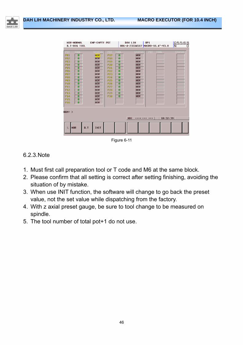
6. Big tool set:
Screen is fixed in the pot, can’t modified, which shows the value of the subject was installed in the tool magazine has several pot. Tool number is
automatically modified; the operation can’t afford to change its value.(Figure
6-11)
(1) NOR:Make normal tool
(2) B.T:Make big tool
(3) INIT:All tool revert to normal tool
46
DAH LIH MACHINERY INDUSTRY CO., LTD. MACRO EXECUTOR (FOR 10.4 INCH)
Figure 6-11
6.2.3. Note
1. Must first call preparation tool or T code and M6 at the same block. 2. Please confirm that all setting is correct after setting finishing, avoiding the
situation of by mistake. 3. When use INIT function, the software will change to go back the preset
value, not the set value while dispatching from the factory. 4. With z axial preset gauge, be sure to tool change to be measured on
spindle. 5. The tool number of total pot+1 do not use.
47
DAH LIH MACHINERY INDUSTRY CO., LTD. MACRO EXECUTOR (FOR 10.4 INCH)
6.3. Machine process manage
6.3.1. Features
Develop 6APC manage program finishing newly, the state of distinguishing each pallet that can be very clear, combine with humanized operation interface, can very convenient change each processing procedure of pallet, reduce and process wrong probability. And can insert the work piece to process at any time , reduce the waiting time that the interim work piece is processed,, reduce the time of shutting down.
6.3.2. Use
1. Press 【CSTM/GRPH】 the frame shows the menu.(Figure 3-1)
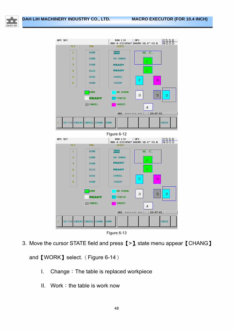
2. Press【4.MAT】【3.APC】into the machine process manage.(Figure 6-12)
(1) PLT:Pallet number
(2) PRG:Set up the program number that each pallet.(Figure 6-12)
(3) STATE:state of each pallet, when the cursor is moved to the state field,
the soft key will present state menu, can change the state of each pallet.
(Figure 6-13)
I. Ready :The pallet has already finished the workpiece to change,
while waiting to process.
II. Insert:After the workpiece processing is finished, have priority to
process the workpiece of this pallet.
III. Cancel:This pallet is not processed
48
DAH LIH MACHINERY INDUSTRY CO., LTD. MACRO EXECUTOR (FOR 10.4 INCH)
Figure 6-12
Figure 6-13
3. Move the cursor STATE field and press 【>】, state menu appear 【CHANG】
and【WORK】select.(Figure 6-14)
I. Change:The table is replaced workpiece
II. Work:the table is work now
READY
READY
READY
READY
READY
READY
49
DAH LIH MACHINERY INDUSTRY CO., LTD. MACRO EXECUTOR (FOR 10.4 INCH)
Figure 6-14
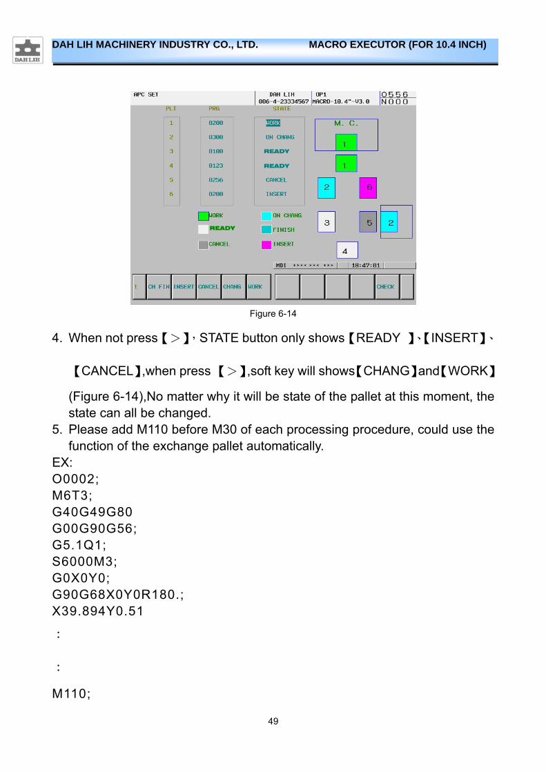
4. When not press【>】,STATE button only shows【READY 】、【INSERT】、
【CANCEL】,when press 【>】,soft key will shows【CHANG】and【WORK】
(Figure 6-14),No matter why it will be state of the pallet at this moment, the state can all be changed.
5. Please add M110 before M30 of each processing procedure, could use the function of the exchange pallet automatically.
EX: O0002; M6T3; G40G49G80 G00G90G56; G5.1Q1; S6000M3; G0X0Y0; G90G68X0Y0R180.; X39.894Y0.51
:
:
M110;
READY
READY
READY
50
DAH LIH MACHINERY INDUSTRY CO., LTD. MACRO EXECUTOR (FOR 10.4 INCH)
M30:
6.3.3. Note
1. The maintenance button only restricts maintenance use, please don't use at ordinary times.
2. If there are messy situations, after finishing getting rid of, please check every pallet state and utilize the maintenance button to establish every pallet of states again
3. he materials of the following DATA TABLE please don't change at will in order to note down and change a material
D20、D21、D22、D23、D30、D60
4. When the program number is 0, no matter why it will be the state can’t carry out.
51
DAH LIH MACHINERY INDUSTRY CO., LTD. MACRO EXECUTOR (FOR 10.4 INCH)
6.4. Thread maker
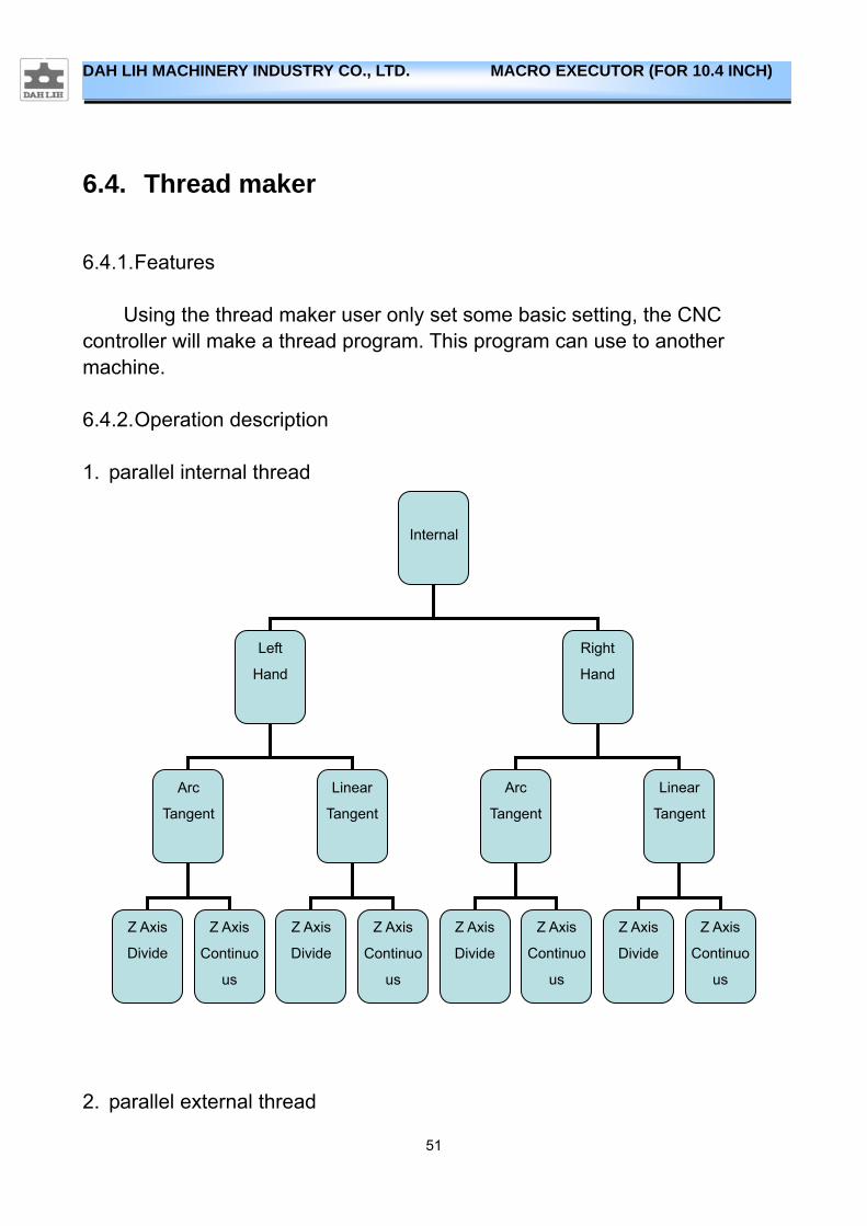
6.4.1. Features
Using the thread maker user only set some basic setting, the CNC controller will make a thread program. This program can use to another machine.
6.4.2. Operation description
1. parallel internal thread
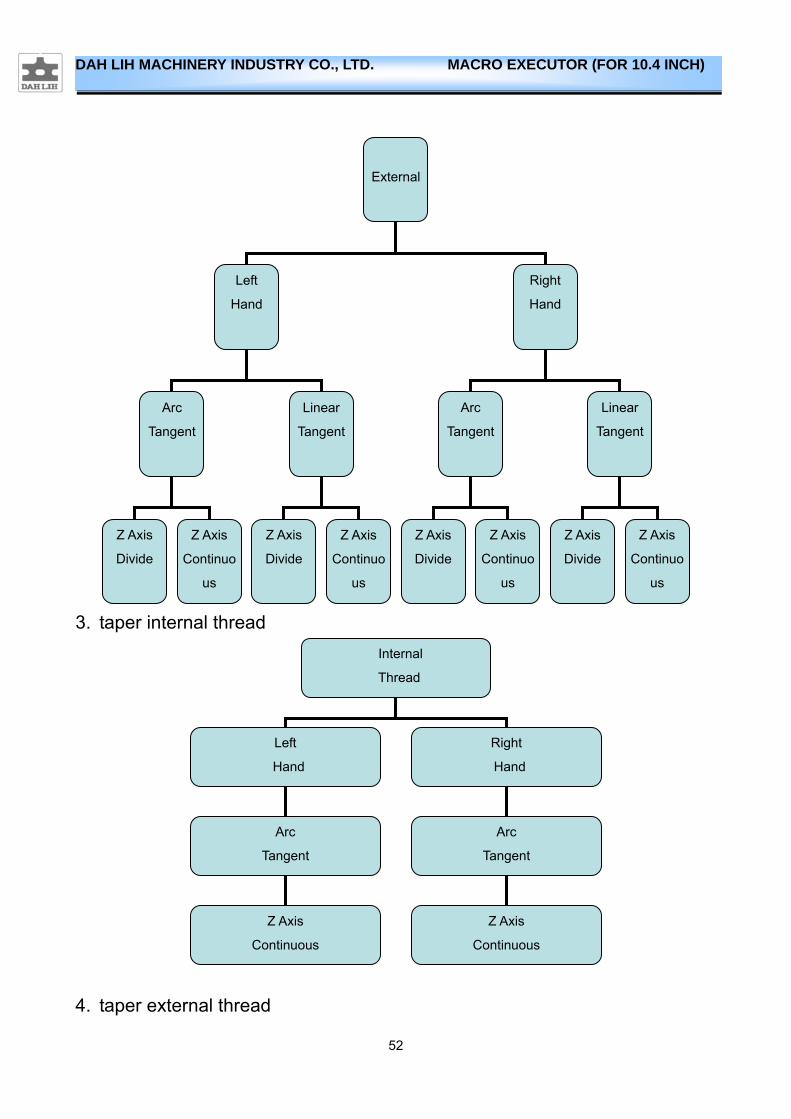
2. parallel external thread
Internal
Left
Hand
Right
Hand
Arc
Tangent
Arc
Tangent
Linear
Tangent
Linear
Tangent
Z Axis
Divide
Z Axis
Continuo
us
Z Axis
Divide
Z Axis
Continuo
us
Z Axis
Divide
Z Axis
Divide
Z Axis
Continuo
us
Z Axis
Continuo
us
52
DAH LIH MACHINERY INDUSTRY CO., LTD. MACRO EXECUTOR (FOR 10.4 INCH)
3. taper internal thread
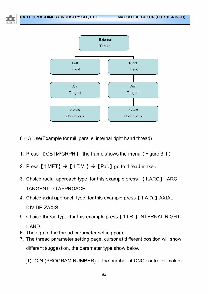
4. taper external thread
Internal
Thread
Left
Hand
Right
Hand
Arc
Tangent Arc
Tangent
Z Axis
Continuous
Z Axis
Continuous
External
Left
Hand
Right
Hand
Arc
Tangent
Arc
Tangent
Linear
Tangent
Linear
Tangent
Z Axis
Divide
Z Axis
Continuo
us
Z Axis
Divide
Z Axis
Continuo
us
Z Axis
Divide
Z Axis
Divide
Z Axis
Continuo
us
Z Axis
Continuo
us
53
DAH LIH MACHINERY INDUSTRY CO., LTD. MACRO EXECUTOR (FOR 10.4 INCH)
6.4.3. Use(Example for mill parallel internal right hand thread)
1. Press 【CSTM/GRPH】 the frame shows the menu(Figure 3-1)
2. Press【4.MET】【4.T.M.】【Par.】go to thread maker.
3. Choice radial approach type, for this example press 【1.ARC】 ARC
TANGENT TO APPROACH.
4. Choice axial approach type, for this example press【1.A.D.】AXIAL
DIVIDE-ZAXIS.
5. Choice thread type, for this example press【1.I.R.】INTERNAL RIGHT
HAND. 6. Then go to the thread parameter setting page. 7. The thread parameter setting page, cursor at different position will show
different suggestion, the parameter type show below:
(1) O.N.(PROGRAM NUMBER):The number of CNC controller makes
External
Thread
Left
Hand
Right
Hand
Arc
Tangent Arc
Tangent
Z Axis
Continuous
Z Axis
Continuous
54
DAH LIH MACHINERY INDUSTRY CO., LTD. MACRO EXECUTOR (FOR 10.4 INCH)
program.
(2) D.O.(THREAD MAJOR DIAMETER-mm):EX:M16x2,set 16
(3) T.D.(TOOL DIAMETER-mm):Thread tool diameter.
(4) T.L.(THREAD LENGTH-mm):The thread length.
(5) V.(CUTTING SPEED-m/min):Thread tool’s cutting speed.
(6) F.P.(FEED PER TOOTH-mm/Zahn):Thread tool’s feed per tooth.
(7) Zn.(NUMBER OF INSERTS):Number fo thread tool’s inserts.
(8) G.P.(WORK COORDINATES):Work coordinates for machining.
(9) Xco(X START POINT):X start point of hole center.
(10) Yco(Y START POINT):Y start point of hole center.
(11) T.N.(TOOL NUMBER):Thread tool number.
(12) T.Lo(TOOL LENTH OFFSET NUM.):Thread tool length offset number.
(13) T.Ro(TOOL RADIUS OFFSET NUM.):Thread tool radius offset number
(14) Pi.(PITCH):Thread pitch,EX:M16x2 set 2.
(15) H.D.(STARTING DIAMETER-mm):EX:M16x2 set 14.
(16) R.C.(ROUGH CUTTING VALUE-mm):Cutting value of rough cutting.
(17) F.C.(FINISH CUTTING VALUE-mm):Cutting value of finish cutting.
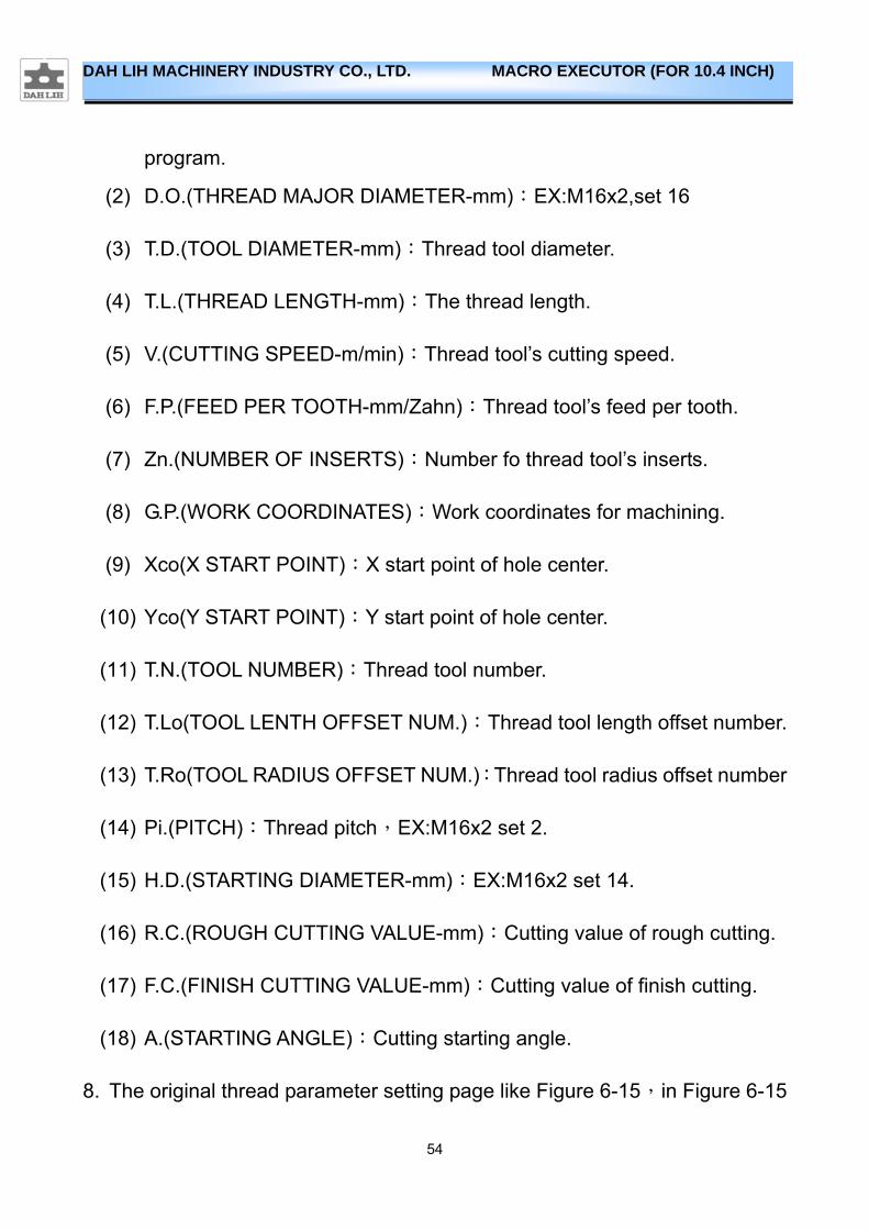
(18) A.(STARTING ANGLE):Cutting starting angle.
8. The original thread parameter setting page like Figure 6-15,in Figure 6-15

55
DAH LIH MACHINERY INDUSTRY CO., LTD. MACRO EXECUTOR (FOR 10.4 INCH)
show internal right hand .Before set thread parameter, user must clean all
parameter to keep mistake away. So press 【CLEAN】 key, then set thread
parameter.
Figure 6-15
9. If you want to mill M50x2 thread:
O.N.:1000、D.O.50、T.D.12、T.L.30、V.150、 F.P.:0.03、Zn.:4、G.P.:54、Xco:0、
Yco:0、T.N.1、T.Lo:1、T.Ro:1、Pi. 2、H.D.: 48、R.C.0.3、F.C.0.1、A.0;
Figure 6-16
56
DAH LIH MACHINERY INDUSTRY CO., LTD. MACRO EXECUTOR (FOR 10.4 INCH)
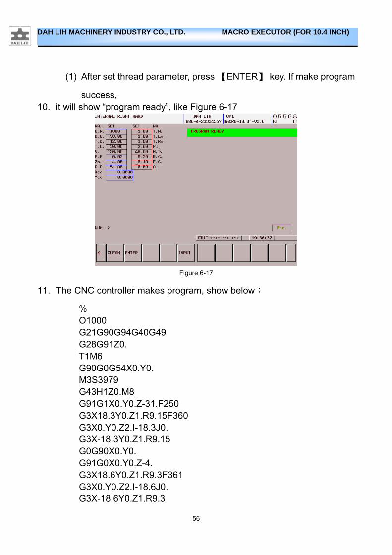
(1) After set thread parameter, press 【ENTER】 key. If make program
success, 10. it will show “program ready”, like Figure 6-17
Figure 6-17
11. The CNC controller makes program, show below:
% O1000 G21G90G94G40G49 G28G91Z0. T1M6 G90G0G54X0.Y0. M3S3979 G43H1Z0.M8 G91G1X0.Y0.Z-31.F250 G3X18.3Y0.Z1.R9.15F360 G3X0.Y0.Z2.I-18.3J0. G3X-18.3Y0.Z1.R9.15 G0G90X0.Y0.
G91G0X0.Y0.Z-4. G3X18.6Y0.Z1.R9.3F361 G3X0.Y0.Z2.I-18.6J0. G3X-18.6Y0.Z1.R9.3

57
DAH LIH MACHINERY INDUSTRY CO., LTD. MACRO EXECUTOR (FOR 10.4 INCH)
G0G90X0.Y0. G91G0X0.Y0.Z-4. G3X18.9Y0.Z1.R9.45F362 G3X0.Y0.Z2.I-18.9J0. G3X-18.9Y0.Z1.R9.45 G0G90X0.Y0. G91G0X0.Y0.Z-4. G3X19.Y0.Z1.R9.5F363 G3X0.Y0.Z2.I-19.J0. G3X-19.Y0.Z1.R9.5 G0G40G90G54X0.Y0. Z0. G49G91G28Z0. M30 % 12. Top view of thread path, like Figure 6-18
Figure 6-18
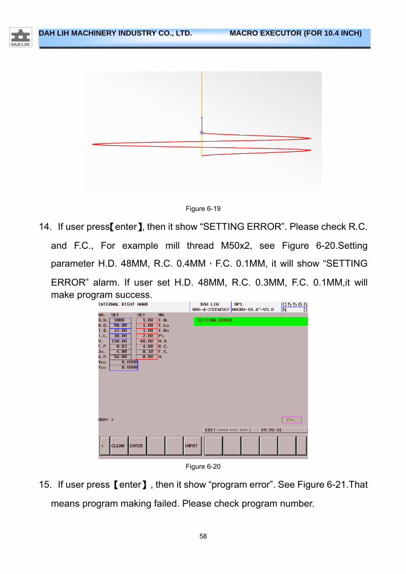
13. Front view of thread path, like Figure 6-19
58
DAH LIH MACHINERY INDUSTRY CO., LTD. MACRO EXECUTOR (FOR 10.4 INCH)
Figure 6-19
14. If user press【enter】, then it show “SETTING ERROR”. Please check R.C.
and F.C., For example mill thread M50x2, see Figure 6-20.Setting
parameter H.D. 48MM, R.C. 0.4MM,F.C. 0.1MM, it will show “SETTING
ERROR” alarm. If user set H.D. 48MM, R.C. 0.3MM, F.C. 0.1MM,it will make program success.
Figure 6-20
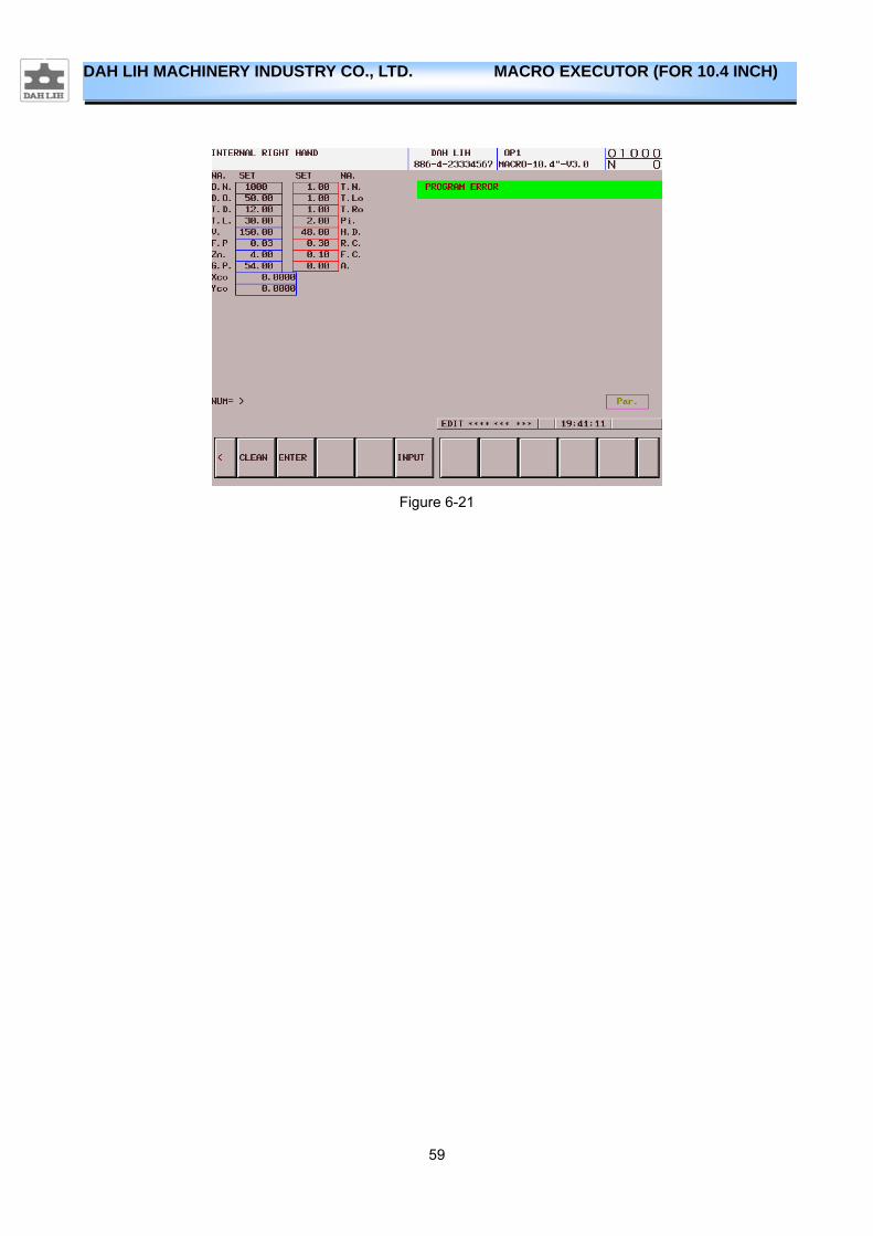
15. If user press【enter】, then it show “program error”. See Figure 6-21.That
means program making failed. Please check program number.
59
DAH LIH MACHINERY INDUSTRY CO., LTD. MACRO EXECUTOR (FOR 10.4 INCH)
Figure 6-21
60
DAH LIH MACHINERY INDUSTRY CO., LTD. MACRO EXECUTOR (FOR 10.4 INCH)
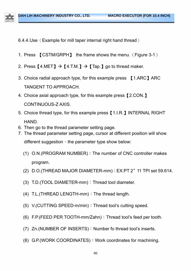
6.4.4. Use(Example for mill taper internal right hand thread)
1. Press 【CSTM/GRPH】 the frame shows the menu.(Figure 3-1)
2. Press【4.MET】【4.T.M.】【Tap.】go to thread maker.
3. Choice radial approach type, for this example press 【1.ARC】ARC
TANGENT TO APPROACH.
4. Choice axial approach type, for this example press【2.CON.】
CONTINUOUS-Z AXIS.
5. Choice thread type, for this example press【1.I.R.】INTERNAL RIGHT
HAND. 6. Then go to the thread parameter setting page. 7. The thread parameter setting page, cursor at different position will show
different suggestion,the parameter type show below:
(1) O.N.(PROGRAM NUMBER):The number of CNC controller makes
program.
(2) D.O.(THREAD MAJOR DIAMETER-mm):EX:PT 2〞11 TPI set 59.614.
(3) T.D.(TOOL DIAMETER-mm):Thread tool diameter.
(4) T.L.(THREAD LENGTH-mm):The thread length.
(5) V.(CUTTING SPEED-m/min):Thread tool’s cutting speed.
(6) F.P.(FEED PER TOOTH-mm/Zahn):Thread tool’s feed per tooth.
(7) Zn.(NUMBER OF INSERTS):Number fo thread tool’s inserts.
(8) G.P.(WORK COORDINATES):Work coordinates for machining.
61
DAH LIH MACHINERY INDUSTRY CO., LTD. MACRO EXECUTOR (FOR 10.4 INCH)
(9) Xco(X START POINT):X start point of hole center
(10) Yco(Y START POINT):Y start point of hole center.
(11) T.N.(TOOL NUMBER):Thread tool number
(12) T.Lo(TOOL LENTH OFFSET NUM.):Thread tool lenth offset number
(13) n.(TPI):Thread numbers per inch.
(14) Pi.(PITCH):Thread pitch.
(15) H.D.(STARTING DIAMETER-mm):EX:PT 2〞11 TPI set 56.656
(16) R.C.(ROUGH CUTTING VALUE-mm):Cutting value of rough cutting.
(17) F.C.(FINISH CUTTING VALUE-mm):Cutting value of finish cutting.
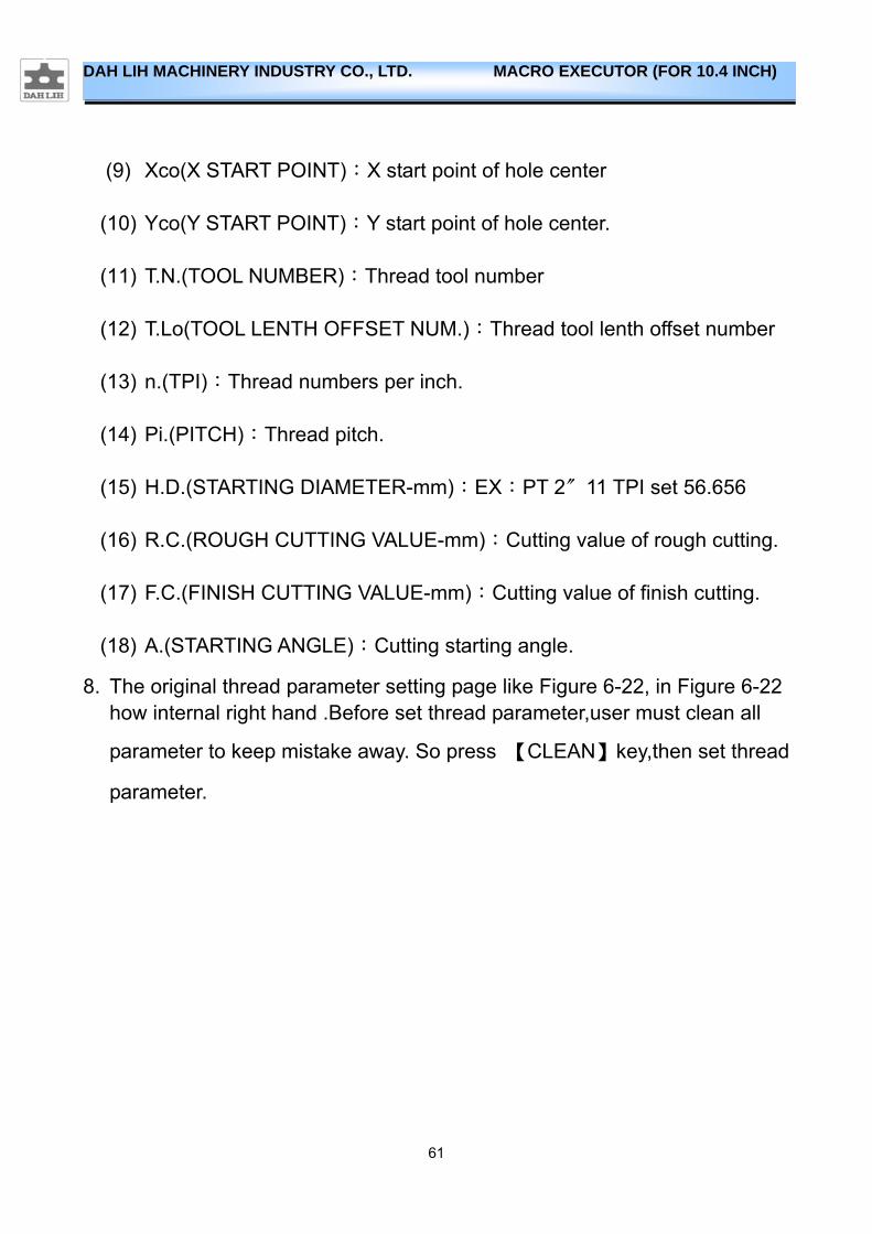
(18) A.(STARTING ANGLE):Cutting starting angle.
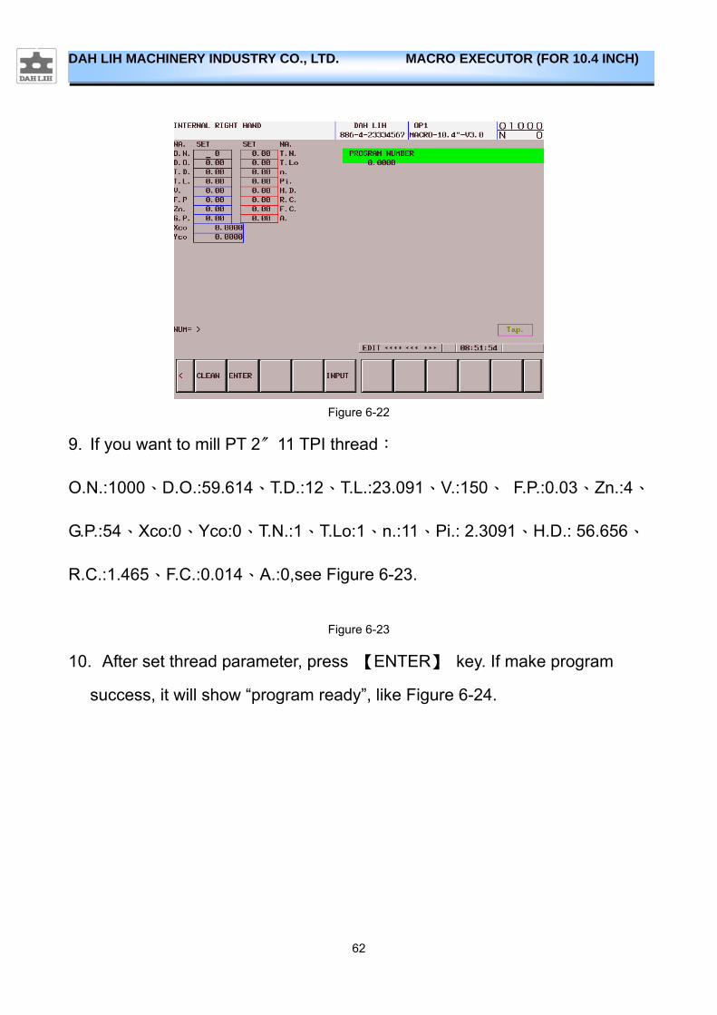
8. The original thread parameter setting page like Figure 6-22, in Figure 6-22 how internal right hand .Before set thread parameter,user must clean all
parameter to keep mistake away. So press 【CLEAN】key,then set thread
parameter.
62
DAH LIH MACHINERY INDUSTRY CO., LTD. MACRO EXECUTOR (FOR 10.4 INCH)
Figure 6-22
9. If you want to mill PT 2〞11 TPI thread:
O.N.:1000、D.O.:59.614、T.D.:12、T.L.:23.091、V.:150、 F.P.:0.03、Zn.:4、
G.P.:54、Xco:0、Yco:0、T.N.:1、T.Lo:1、n.:11、Pi.: 2.3091、H.D.: 56.656、
R.C.:1.465、F.C.:0.014、A.:0,see Figure 6-23.
Figure 6-23
10. After set thread parameter, press 【ENTER】 key. If make program
success, it will show “program ready”, like Figure 6-24.

63
DAH LIH MACHINERY INDUSTRY CO., LTD. MACRO EXECUTOR (FOR 10.4 INCH)
Figure 6-24
11. The CNC controller makes program, show below:
% O1000
G21G90G94G40G49 G28G91Z0.0000 T1M6 G90G0G54X0.0000Y0.0000 M3S3979 G43H1Z3.4635M8 G91G2X23.8652Y0.0000Z-1.1545R11.9326F381. G2X-0.8161Y-6.1760Z-0.0962I-23.8652J0.0000 G2X-2.3864Y-5.7536Z-0.0962I-23.0491J6.1760 G2X-3.7938Y-4.9393Z-0.0962I-20.6626J11.9296 G2X-4.9423Y-3.7886Z-0.0962I-16.8688J16.8688 . . M30
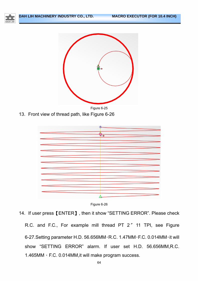
% 12. Top view of thread path, like Figure 6-25.
64
DAH LIH MACHINERY INDUSTRY CO., LTD. MACRO EXECUTOR (FOR 10.4 INCH)
Figure 6-25
13. Front view of thread path, like Figure 6-26
Figure 6-26
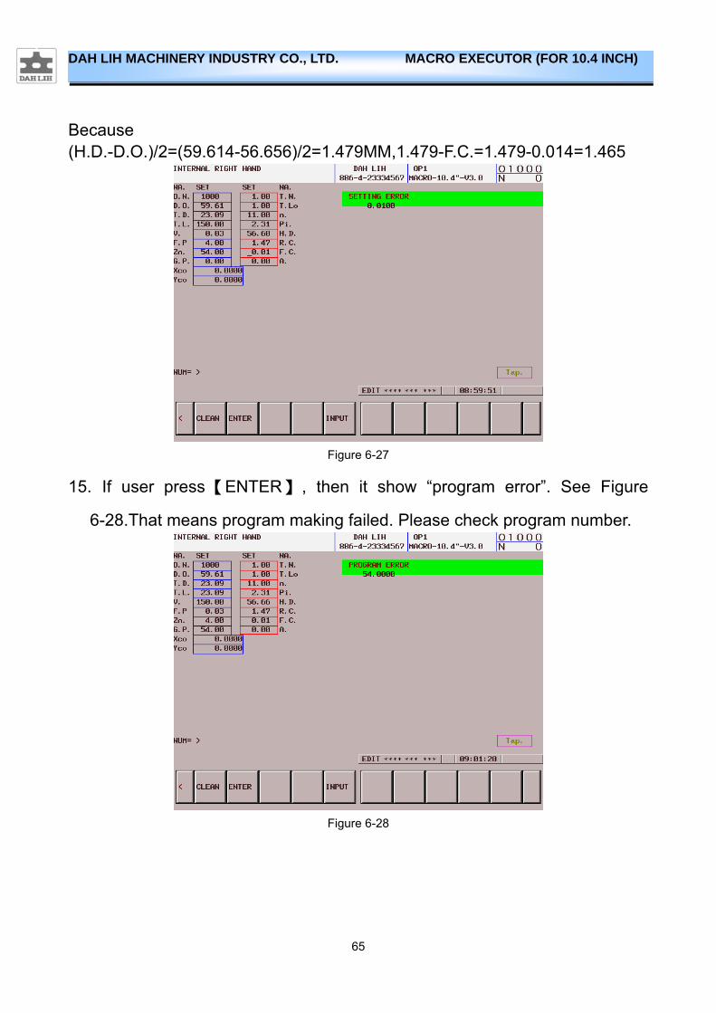
14. If user press【ENTER】, then it show “SETTING ERROR”. Please check
R.C. and F.C., For example mill thread PT 2〞 11 TPI, see Figure
6-27.Setting parameter H.D. 56.656MM,R.C. 1.47MM,F.C. 0.014MM,it will
show “SETTING ERROR” alarm. If user set H.D. 56.656MM,R.C.
1.465MM,F.C. 0.014MM,it will make program success.
65
DAH LIH MACHINERY INDUSTRY CO., LTD. MACRO EXECUTOR (FOR 10.4 INCH)
Because (H.D.-D.O.)/2=(59.614-56.656)/2=1.479MM,1.479-F.C.=1.479-0.014=1.465
Figure 6-27
15. If user press【ENTER】 , then it show “program error”. See Figure
6-28.That means program making failed. Please check program number.
Figure 6-28
66
DAH LIH MACHINERY INDUSTRY CO., LTD. MACRO EXECUTOR (FOR 10.4 INCH)
6.4.5. Use(Example for mill taper external right hand thread)
1. Press 【CSTM/GRPH】 the frame shows the menu.(Figure 3-1)
2. Press【4.MET】【4.T.M.】【Tap.】go to thread maker.
3. Choice radial approach type, for this example press 【1.ARC】 ARC
TANGENT TO APPROACH.
4. Choice axial approach type, for this example press 【 2.CON. 】
CONTINUOUS-Z AXIS.
5. Choice thread type, for this example press【3.E.R.】EXTERNAL RIGHT
HAND. 6. Then go to the thread parameter setting page. 7. The thread parameter setting page, cursor at different position will show
different suggestion, the parameter type show below:
(1) O.N.(PROGRAM NUMBER):The number of CNC controller makes
program.
(2) D.I.( THREAD DIA. OF VALLEY): THREAD DIA. OF VALLEY, EX:PT
2〞11 TPI set 56.656.
(3) T.D.(TOOL DIAMETER-mm):Thread tool diameter.
(4) T.L.(THREAD LENGTH-mm):The thread length.
(5) V.(CUTTING SPEED-m/min):Thread tool’s cutting speed.
(6) F.P.(FEED PER TOOTH-mm/Zahn):Thread tool’s feed per tooth.
(7) Zn.(NUMBER OF INSERTS):Number fo thread tool’s inserts.

67
DAH LIH MACHINERY INDUSTRY CO., LTD. MACRO EXECUTOR (FOR 10.4 INCH)
(8) G.P.(WORK COORDINATES):Work coordinates for machining.
(9) Xco(X START POINT):X start point of hole center.
(10) Yco(Y START POINT):Y start point of hole center.
(11) T.N.(TOOL NUMBER):Thread tool number.
(12) T.Lo(TOOL LENTH OFFSET NUM.):Thread tool length offset number.
(13) n.(TPI):Thread numbers per inch.
(14) Pi.(PITCH): Thread pitch.
(15) D.O.( THREAD MAJOR DIAMETER): EX:PT 2〞11 TPI set 59.614 .
(16) R.C.(ROUGH CUTTING VALUE-mm):Cutting value of rough cutting.
(17) F.C.(FINISH CUTTING VALUE-mm):Cutting value of finish cutting.
(18) A. (STARTING ANGLE):Cutting starting angle.
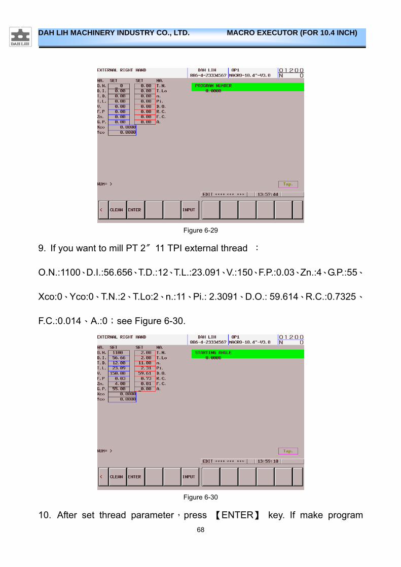
8. The original thread parameter setting page like Figure 6-29,in Figure 6-29 show internal right hand .Before set thread parameter, user must clean all
parameter to keep mistake away. So press 【CLEAN】 key,then set thread
parameter.
68
DAH LIH MACHINERY INDUSTRY CO., LTD. MACRO EXECUTOR (FOR 10.4 INCH)
Figure 6-29
9. If you want to mill PT 2〞11 TPI external thread :
O.N.:1100、D.I.:56.656、T.D.:12、T.L.:23.091、V.:150、F.P.:0.03、Zn.:4、G.P.:55、
Xco:0、Yco:0、T.N.:2、T.Lo:2、n.:11、Pi.: 2.3091、D.O.: 59.614、R.C.:0.7325、
F.C.:0.014、A.:0;see Figure 6-30.
Figure 6-30
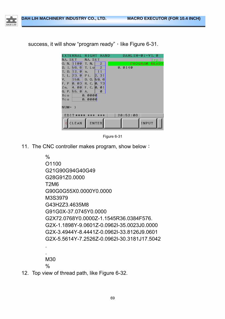
10. After set thread parameter,press 【ENTER】 key. If make program
69
DAH LIH MACHINERY INDUSTRY CO., LTD. MACRO EXECUTOR (FOR 10.4 INCH)
success, it will show “program ready”,like Figure 6-31.
Figure 6-31
11. The CNC controller makes program, show below:
% O1100 G21G90G94G40G49 G28G91Z0.0000 T2M6 G90G0G55X0.0000Y0.0000 M3S3979 G43H2Z3.4635M8 G91G0X-37.0745Y0.0000 G2X72.0768Y0.0000Z-1.1545R36.0384F576. G2X-1.1898Y-9.0601Z-0.0962I-35.0023J0.0000 G2X-3.4944Y-8.4441Z-0.0962I-33.8126J9.0601 G2X-5.5614Y-7.2526Z-0.0962I-30.3181J17.5042 . . M30 %
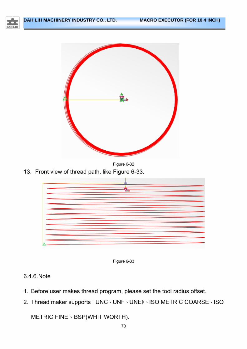
12. Top view of thread path, like Figure 6-32.
70
DAH LIH MACHINERY INDUSTRY CO., LTD. MACRO EXECUTOR (FOR 10.4 INCH)
Figure 6-32
13. Front view of thread path, like Figure 6-33.
Figure 6-33
6.4.6. Note
1. Before user makes thread program, please set the tool radius offset.
2. Thread maker supports:UNC、UNF、UNEF、ISO METRIC COARSE、ISO
METRIC FINE、BSP(WHIT WORTH).
71
DAH LIH MACHINERY INDUSTRY CO., LTD. MACRO EXECUTOR (FOR 10.4 INCH)
3. If you want using thread maker for BSPT、NPT、NPTF,you must make sure
CNC parameter #1013.1 setting 1.
4. If you use thread maker for BSPT、NPT、NPTF, T.L.(THREAD LENGTH)
must be a multiple of pitch, if CNC show T.L. SETTING ERROR, please check T.L. setting.
5. Thread maker non-supports wear offset.
72
DAH LIH MACHINERY INDUSTRY CO., LTD. MACRO EXECUTOR (FOR 10.4 INCH)
6.5. PEN
6.5.1. Features
PEN production function to quickly text processing program, will need to use CAM software to create original text processing program, built in the controller, and can also zoom in or out the actual needs of the size of characters, simplified the program's preparation time.
6.5.2. Character format
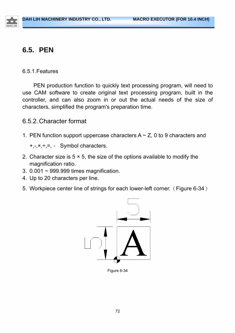
1. PEN function support uppercase characters A ~ Z, 0 to 9 characters and
+,-,×,÷,=,。 Symbol characters.
2. Character size is 5 × 5, the size of the options available to modify the magnification ratio.
3. 0.001 ~ 999.999 times magnification. 4. Up to 20 characters per line.
5. Workpiece center line of strings for each lower-left corner.(Figure 6-34)
Figure 6-34
73
DAH LIH MACHINERY INDUSTRY CO., LTD. MACRO EXECUTOR (FOR 10.4 INCH)
6.5.3. Use(main program)
1. Press 【CSTM/GRPH】 the frame shows the menu.(Figure 3-1)
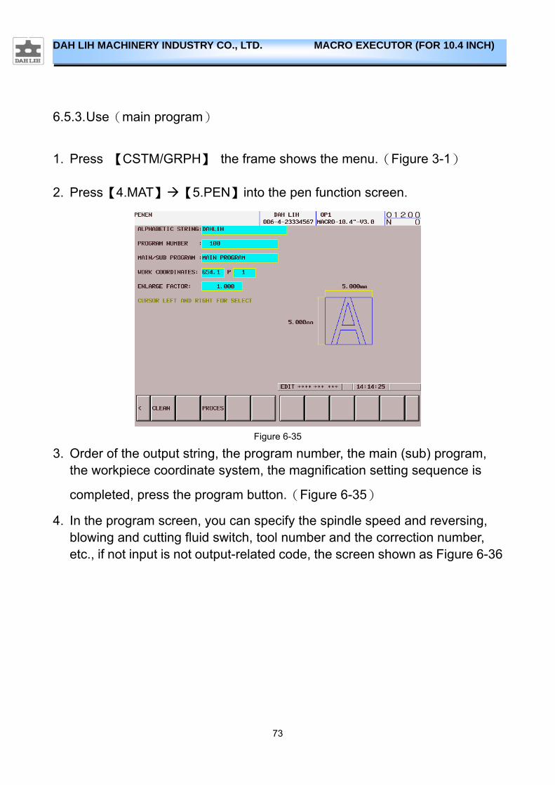
2. Press【4.MAT】【5.PEN】into the pen function screen.
Figure 6-35
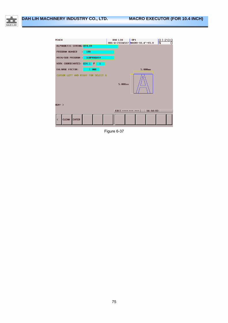
3. Order of the output string, the program number, the main (sub) program, the workpiece coordinate system, the magnification setting sequence is
completed, press the program button.(Figure 6-35)
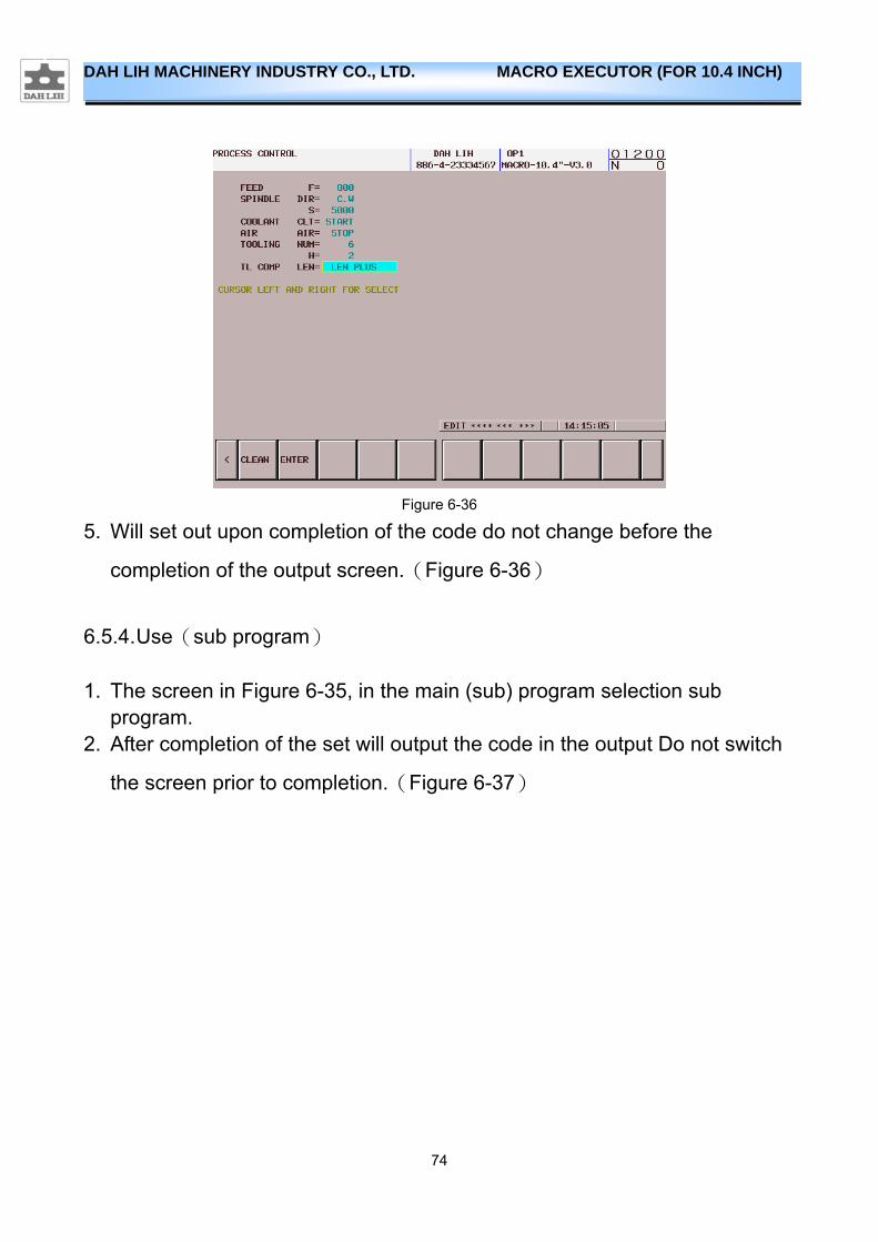
4. In the program screen, you can specify the spindle speed and reversing, blowing and cutting fluid switch, tool number and the correction number, etc., if not input is not output-related code, the screen shown as Figure 6-36
74
DAH LIH MACHINERY INDUSTRY CO., LTD. MACRO EXECUTOR (FOR 10.4 INCH)
Figure 6-36
5. Will set out upon completion of the code do not change before the
completion of the output screen.(Figure 6-36)
6.5.4. Use(sub program)
1. The screen in Figure 6-35, in the main (sub) program selection sub program.
2. After completion of the set will output the code in the output Do not switch
the screen prior to completion.(Figure 6-37)
75
DAH LIH MACHINERY INDUSTRY CO., LTD. MACRO EXECUTOR (FOR 10.4 INCH)
Figure 6-37
76
DAH LIH MACHINERY INDUSTRY CO., LTD. MACRO EXECUTOR (FOR 10.4 INCH)
6.6. Intelligent Multi-Axes Guide
6.6.1. Features
Formerly the x-y plane maching program only use in x-y plane,but now the x-y plane maching program can use to another plane.If you use intelligent multi-axes guide function,you can use x-y plane maching program to another plane simply.Intelligent multi-axes guide function is suitable for table-table type multi-axes machine,it supports a-c axes mode and b-c axes mode.
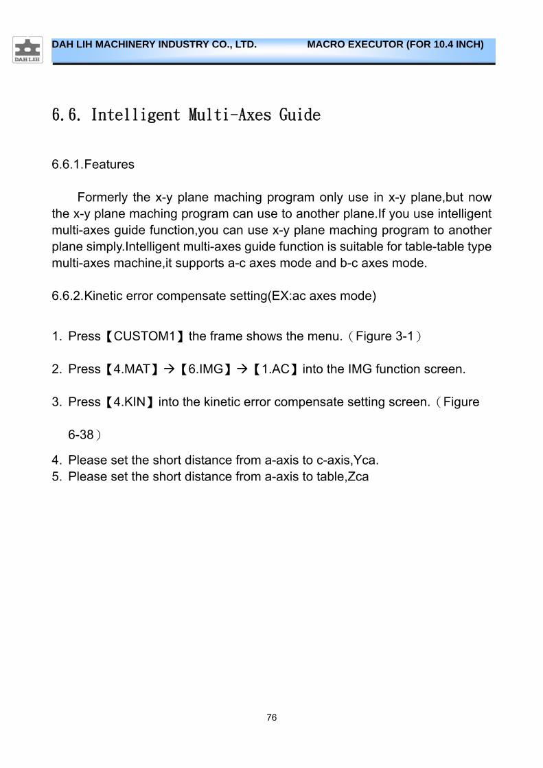
6.6.2. Kinetic error compensate setting(EX:ac axes mode)
1. Press【CUSTOM1】the frame shows the menu.(Figure 3-1)
2. Press【4.MAT】【6.IMG】【1.AC】into the IMG function screen.
3. Press【4.KIN】into the kinetic error compensate setting screen.(Figure
6-38)
4. Please set the short distance from a-axis to c-axis,Yca. 5. Please set the short distance from a-axis to table,Zca
77
DAH LIH MACHINERY INDUSTRY CO., LTD. MACRO EXECUTOR (FOR 10.4 INCH)
Figure 6-38
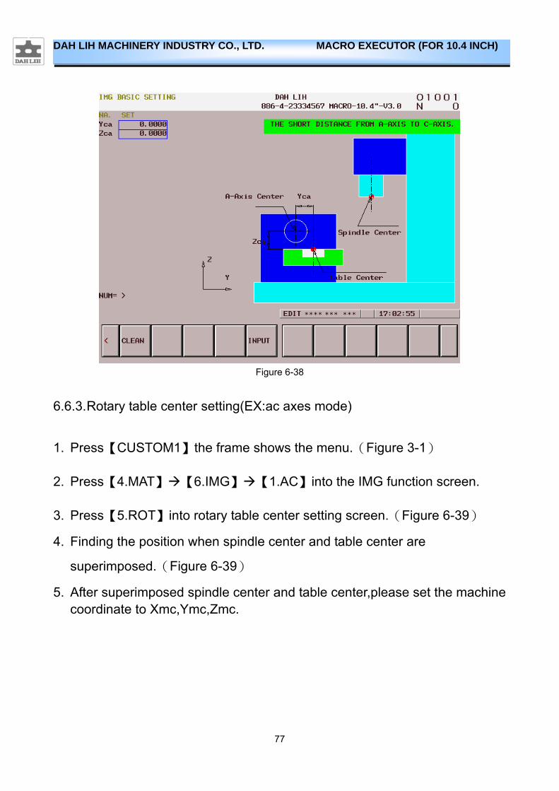
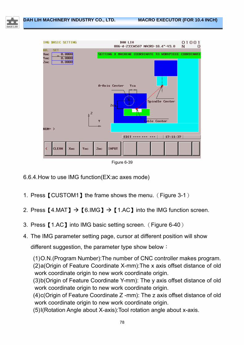
6.6.3. Rotary table center setting(EX:ac axes mode)
1. Press【CUSTOM1】the frame shows the menu.(Figure 3-1)
2. Press【4.MAT】【6.IMG】【1.AC】into the IMG function screen.
3. Press【5.ROT】into rotary table center setting screen.(Figure 6-39)
4. Finding the position when spindle center and table center are
superimposed.(Figure 6-39)
5. After superimposed spindle center and table center,please set the machine coordinate to Xmc,Ymc,Zmc.
78
DAH LIH MACHINERY INDUSTRY CO., LTD. MACRO EXECUTOR (FOR 10.4 INCH)
Figure 6-39
6.6.4. How to use IMG function(EX:ac axes mode)
1. Press【CUSTOM1】the frame shows the menu.(Figure 3-1)
2. Press【4.MAT】【6.IMG】【1.AC】into the IMG function screen.
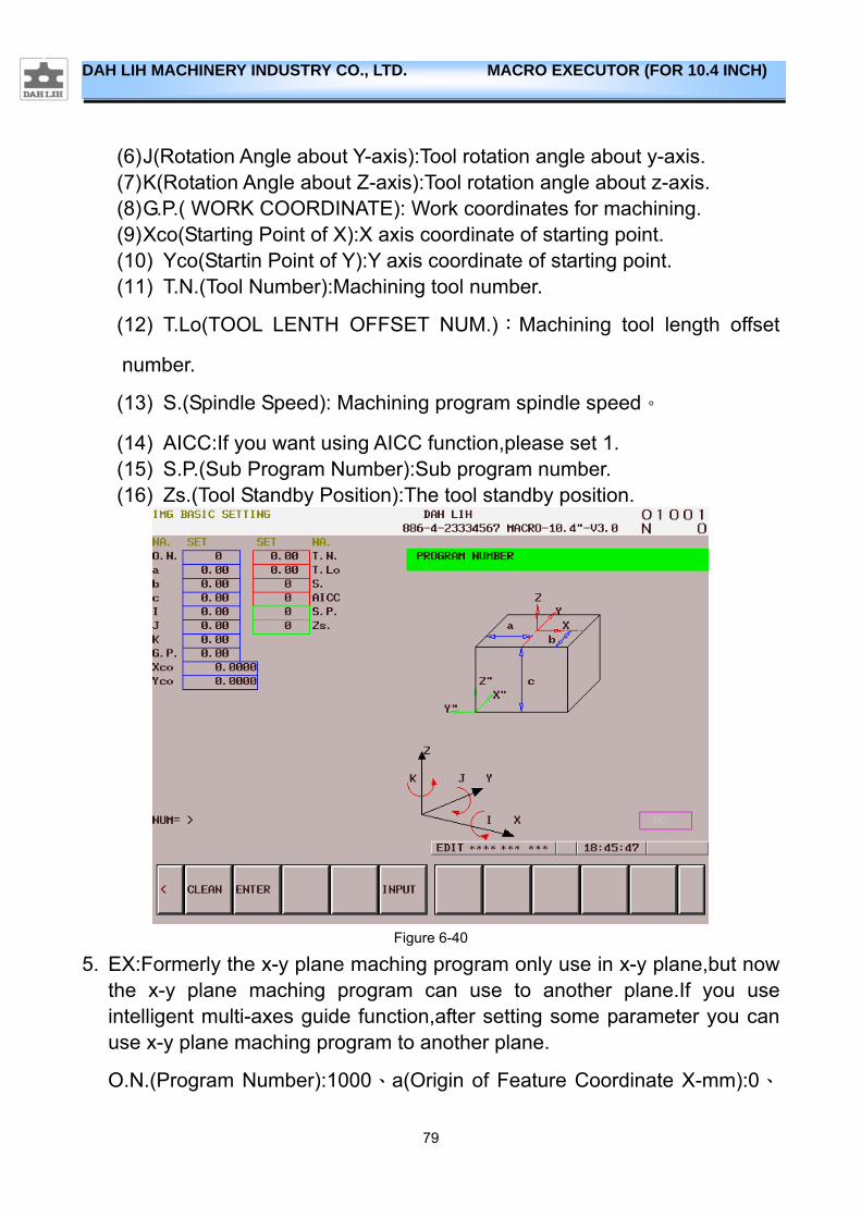
3. Press【1.AC】into IMG basic setting screen.(Figure 6-40)
4. The IMG parameter setting page, cursor at different position will show
different suggestion, the parameter type show below:
(1) O.N.(Program Number):The number of CNC controller makes program. (2) a(Origin of Feature Coordinate X-mm):The x axis offset distance of old work coordinate origin to new work coordinate origin. (3) b(Origin of Feature Coordinate Y-mm): The y axis offset distance of old work coordinate origin to new work coordinate origin. (4) c(Origin of Feature Coordinate Z -mm): The z axis offset distance of old work coordinate origin to new work coordinate origin. (5) I(Rotation Angle about X-axis):Tool rotation angle about x-axis.
79
DAH LIH MACHINERY INDUSTRY CO., LTD. MACRO EXECUTOR (FOR 10.4 INCH)
(6) J(Rotation Angle about Y-axis):Tool rotation angle about y-axis. (7) K(Rotation Angle about Z-axis):Tool rotation angle about z-axis. (8) G.P.( WORK COORDINATE): Work coordinates for machining. (9) Xco(Starting Point of X):X axis coordinate of starting point. (10) Yco(Startin Point of Y):Y axis coordinate of starting point. (11) T.N.(Tool Number):Machining tool number.
(12) T.Lo(TOOL LENTH OFFSET NUM.):Machining tool length offset
number.
(13) S.(Spindle Speed): Machining program spindle speed。
(14) AICC:If you want using AICC function,please set 1. (15) S.P.(Sub Program Number):Sub program number. (16) Zs.(Tool Standby Position):The tool standby position.
Figure 6-40
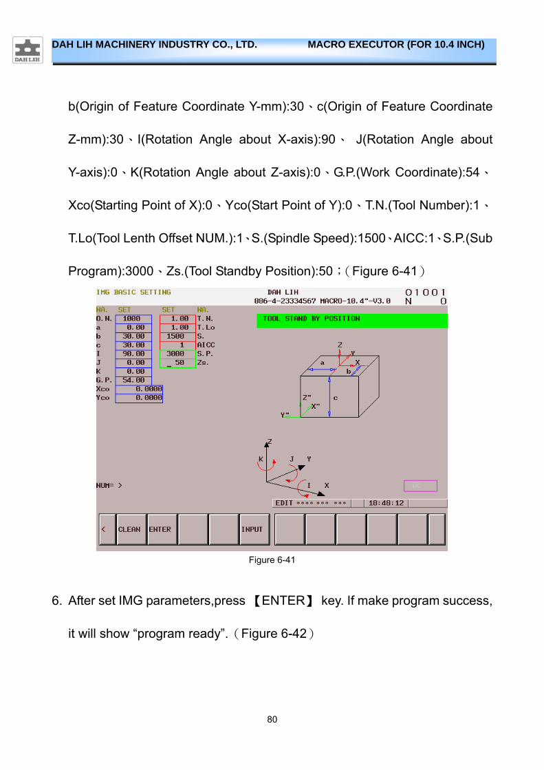
5. EX:Formerly the x-y plane maching program only use in x-y plane,but now the x-y plane maching program can use to another plane.If you use intelligent multi-axes guide function,after setting some parameter you can use x-y plane maching program to another plane.
O.N.(Program Number):1000、a(Origin of Feature Coordinate X-mm):0、
80
DAH LIH MACHINERY INDUSTRY CO., LTD. MACRO EXECUTOR (FOR 10.4 INCH)
b(Origin of Feature Coordinate Y-mm):30、c(Origin of Feature Coordinate
Z-mm):30、I(Rotation Angle about X-axis):90、 J(Rotation Angle about
Y-axis):0、K(Rotation Angle about Z-axis):0、G.P.(Work Coordinate):54、
Xco(Starting Point of X):0、Yco(Start Point of Y):0、T.N.(Tool Number):1、
T.Lo(Tool Lenth Offset NUM.):1、S.(Spindle Speed):1500、AICC:1、S.P.(Sub
Program):3000、Zs.(Tool Standby Position):50;(Figure 6-41)
Figure 6-41
6. After set IMG parameters,press 【ENTER】 key. If make program success,
it will show “program ready”.(Figure 6-42)

81
DAH LIH MACHINERY INDUSTRY CO., LTD. MACRO EXECUTOR (FOR 10.4 INCH)
Figure 6-42
7. The CNC controller makes program, show below:
% O1000 G91G28Z0. G40G49G80
M6T1 G90G0G54X0.Y0.A0.C0. M3S1500 G43H1Z50. G5.1Q1 M168X0Y30.Z30.I90.J0K0 M98P3000 G5.1Q0 M30 %
82
DAH LIH MACHINERY INDUSTRY CO., LTD. MACRO EXECUTOR (FOR 10.4 INCH)
7. Adjustment Function
7.1. KEEP RELAY
7.1.1. Features
In FANUC, you can use KEEP RELAY switch to control some of the components of the switch, but KEEP RELAY screen, there is no KEEP RELAY simple instructions. Operator often due to different models, different functions and made a mistake, or query operation manual must be caused by the waste of time.
7.1.2. Use
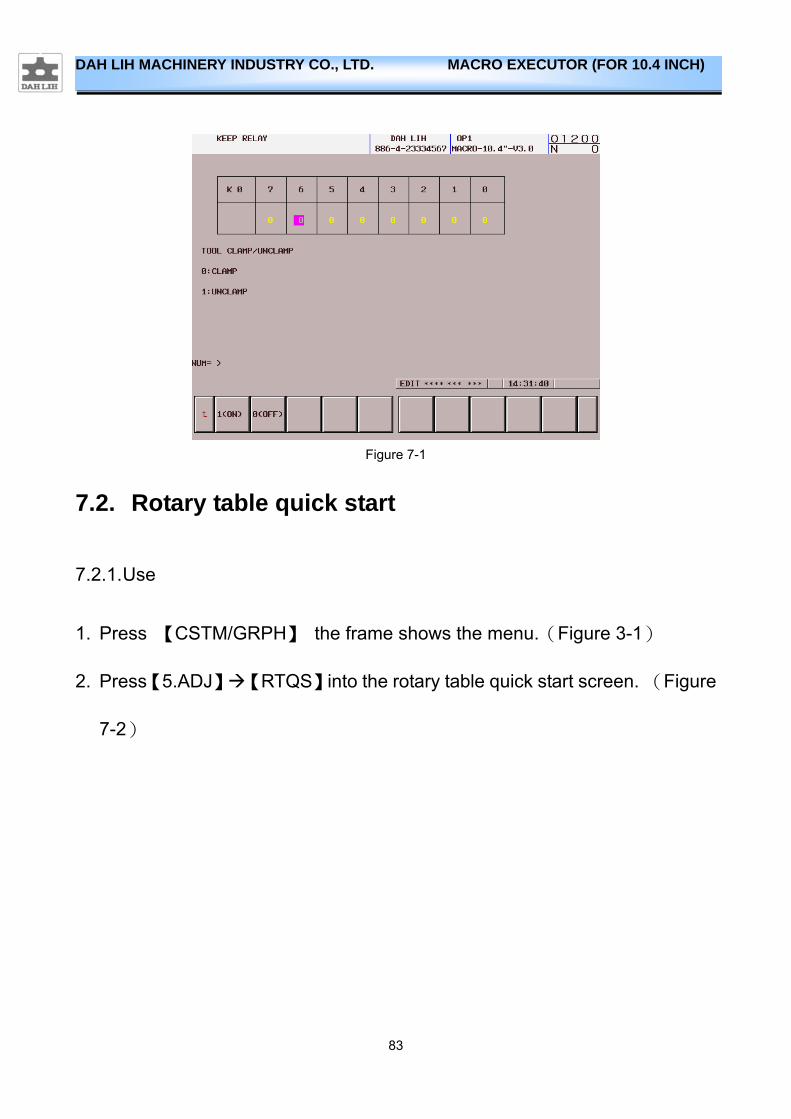
1. Press 【CSTM/GRPH】 the frame shows the menu.(Figure 3-1)
2. Press【5.ADJ】【KEEPRL】into the KEEP RELAY adjust.(Figure 7-1)
3. Use the number keys KEEP RELAY number. 4. Use the left and right arrow keys to select the value.
5. Use the soft key to select ON or OFF. (Figure 7-1)
83
DAH LIH MACHINERY INDUSTRY CO., LTD. MACRO EXECUTOR (FOR 10.4 INCH)
Figure 7-1
7.2. Rotary table quick start
7.2.1. Use
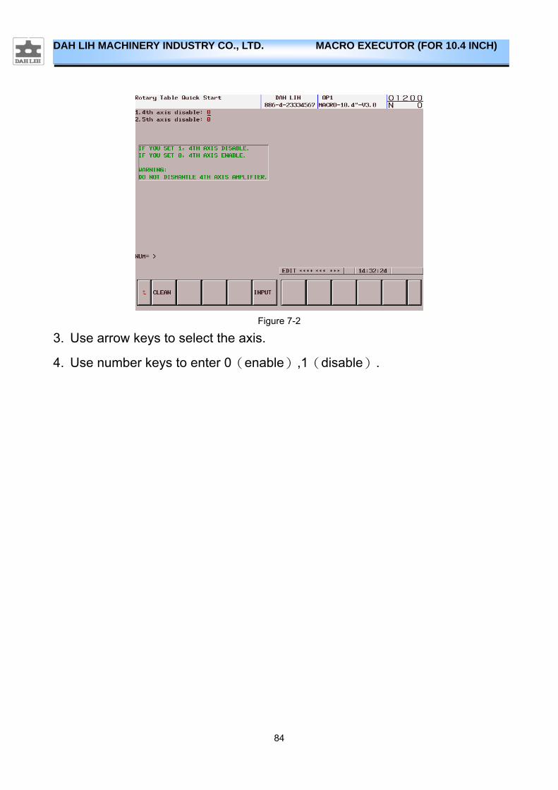
1. Press 【CSTM/GRPH】 the frame shows the menu.(Figure 3-1)
2. Press【5.ADJ】【RTQS】into the rotary table quick start screen. (Figure
7-2)
84
DAH LIH MACHINERY INDUSTRY CO., LTD. MACRO EXECUTOR (FOR 10.4 INCH)
Figure 7-2
3. Use arrow keys to select the axis.
4. Use number keys to enter 0(enable),1(disable).
85
DAH LIH MACHINERY INDUSTRY CO., LTD. MACRO EXECUTOR (FOR 10.4 INCH)
Appendix
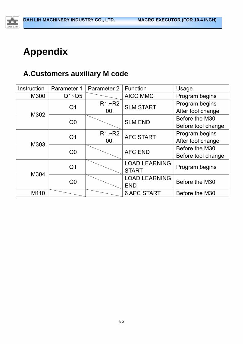
A.Customers auxiliary M code
Instruction Parameter 1 Parameter 2 Function Usage M300 Q1~Q5 AICC MMC Program begins
Q1 R1.~R2
00. SLM START
Program begins After tool change
M302 Q0 SLM END
Before the M30 Before tool change
Q1 R1.~R2
00. AFC START
Program begins After tool change
M303 Q0 AFC END
Before the M30 Before tool change
Q1 LOAD LEARNINGSTART
Program begins M304
Q0 LOAD LEARNINGEND
Before the M30
M110 6 APC START Before the M30