PERILAKU MEKANIK PADA KOMPOSIT - cahaya...
14
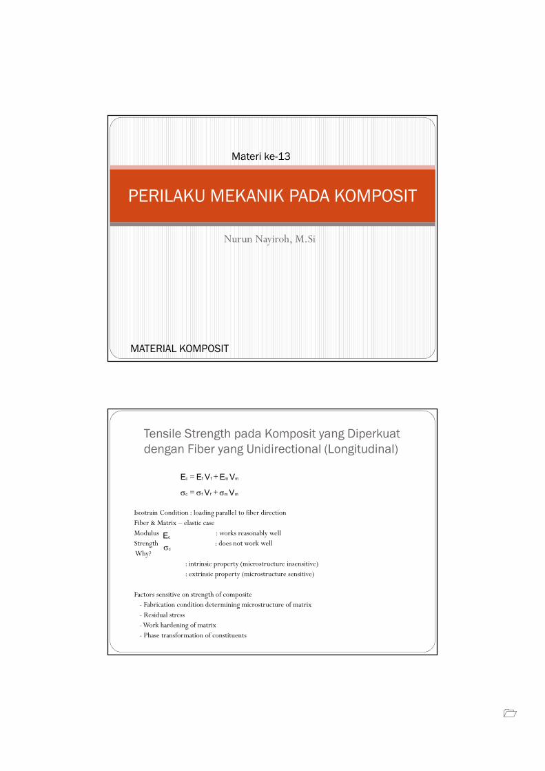
Nurun Nayiroh, M.Si PERILAKU MEKANIK PADA KOMPOSIT Materi ke-13 MATERIAL KOMPOSIT Isostrain Condition : loading parallel to fiber direction Fiber & Matrix – elastic case Modulus : works reasonably well Strength : does not work well Why? : intrinsic property (microstructure insensitive) : extrinsic property (microstructure sensitive) Factors sensitive on strength of composite - Fabrication condition determining microstructure of matrix - Residual stress -Work hardening of matrix - Phase transformation of constituents V E V E E m m f f c + = V V m m f f c σ + σ = σ Ec σc Tensile Strength pada Komposit yang Diperkuat dengan Fiber yang Unidirectional (Longitudinal)
Transcript of PERILAKU MEKANIK PADA KOMPOSIT - cahaya...
�
Nurun Nayiroh, M.Si
PERILAKU MEKANIK PADA KOMPOSIT
Materi ke-13
MATERIAL KOMPOSIT
Isostrain Condition : loading parallel to fiber directionFiber & Matrix – elastic caseModulus : works reasonably wellStrength : does not work wellWhy?
: intrinsic property (microstructure insensitive): extrinsic property (microstructure sensitive)
Factors sensitive on strength of composite- Fabrication condition determining microstructure of matrix- Residual stress-Work hardening of matrix- Phase transformation of constituents
VEVEE mmffc +=
VV mmffc σ+σ=σ
Ec
σc
Tensile Strength pada Komposit yang Diperkuat
dengan Fiber yang Unidirectional (Longitudinal)
�
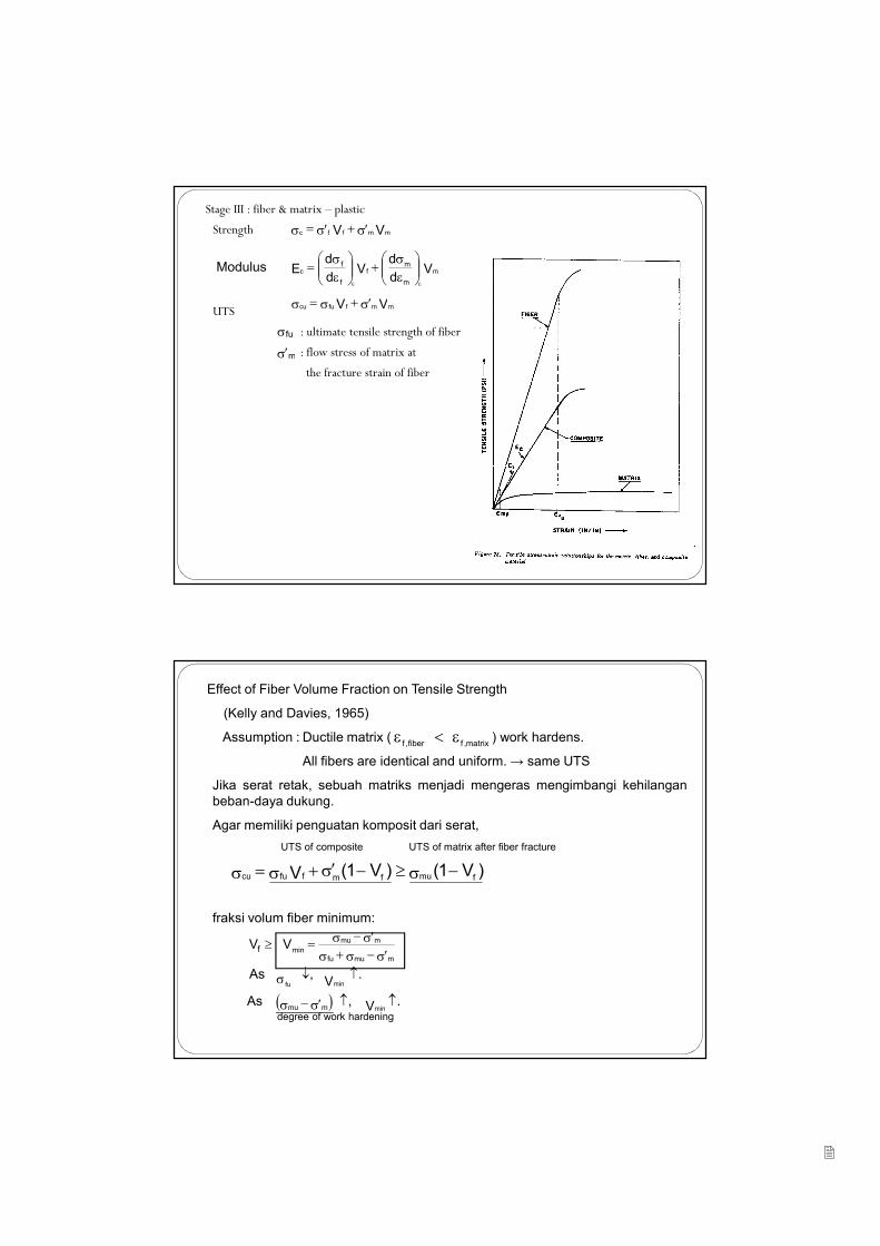
Stage III : fiber & matrix – plastic
Strength
UTS
: ultimate tensile strength of fiber
: flow stress of matrix at
the fracture strain of fiber
VV mmffc σ′+σ′=σ
Vd
dV
d
dE Modulus mfc
m
m
f
f
εσ
+
εσ
=εε
VV mmffucu σ′+σ=σ
σfu
σ′m
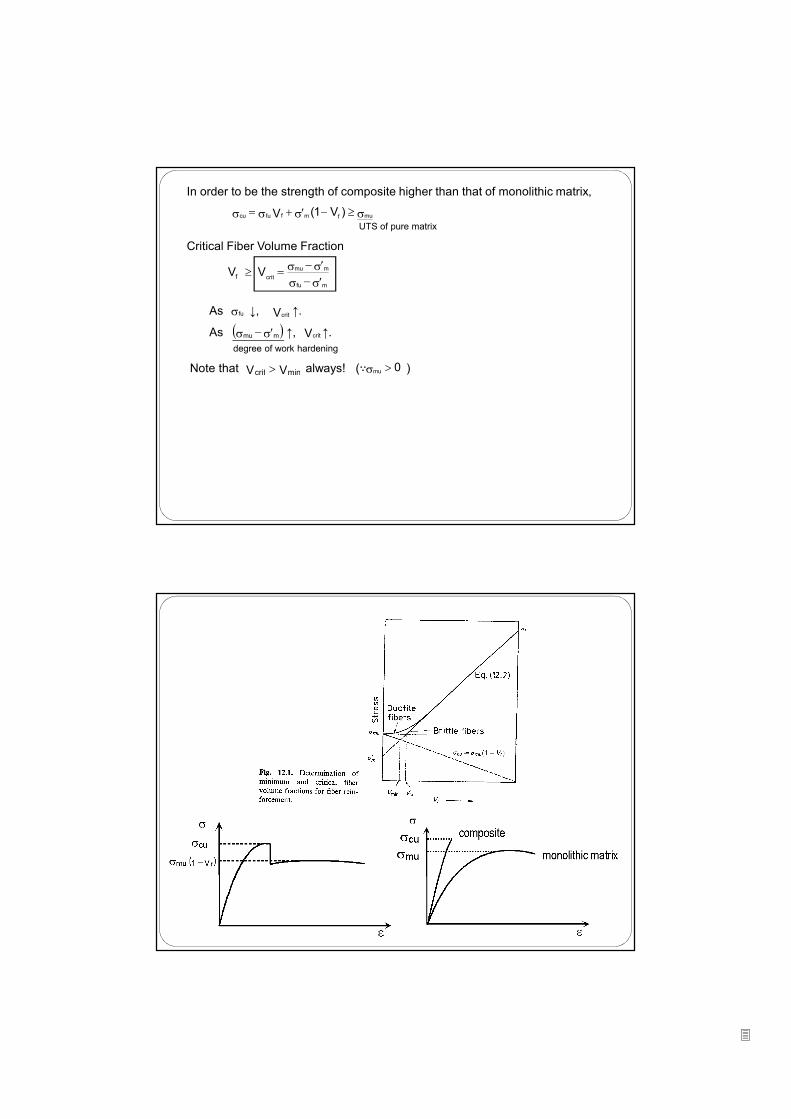
Effect of Fiber Volume Fraction on Tensile Strength
(Kelly and Davies, 1965)
Assumption : Ductile matrix ( ) work hardens.
All fibers are identical and uniform. → same UTS
Jika serat retak, sebuah matriks menjadi mengeras mengimbangi kehilangan
beban-daya dukung.
Agar memiliki penguatan komposit dari serat,
UTS of composite UTS of matrix after fiber fracture
fraksi volum fiber minimum:
As ↓, ↑.
As ↑, ↑.degree of work hardening
matrix,ffiber,f
ε<ε
σ′−σ+σσ′−σ=≥
mmufu
mmu
minV Vf
fuσ Vmin
( )σ′−σ mmu Vmin
)V1()V1(V fmufmffucu −σ≥−σ′+σ=σ
�
σ≥−σ′+σ=σ mufmffucu )V1(V
σfu Vcrit
In order to be the strength of composite higher than that of monolithic matrix,
UTS of pure matrix
Critical Fiber Volume Fraction
As ↓, ↑.
As ↑, ↑.
degree of work hardening
Note that always! (∵ )VV mincrit >
σ′−σσ′−σ=≥
mfu
mmu
crit V Vf
( )σ′−σ mmu
0mu >σ
Vcrit
�
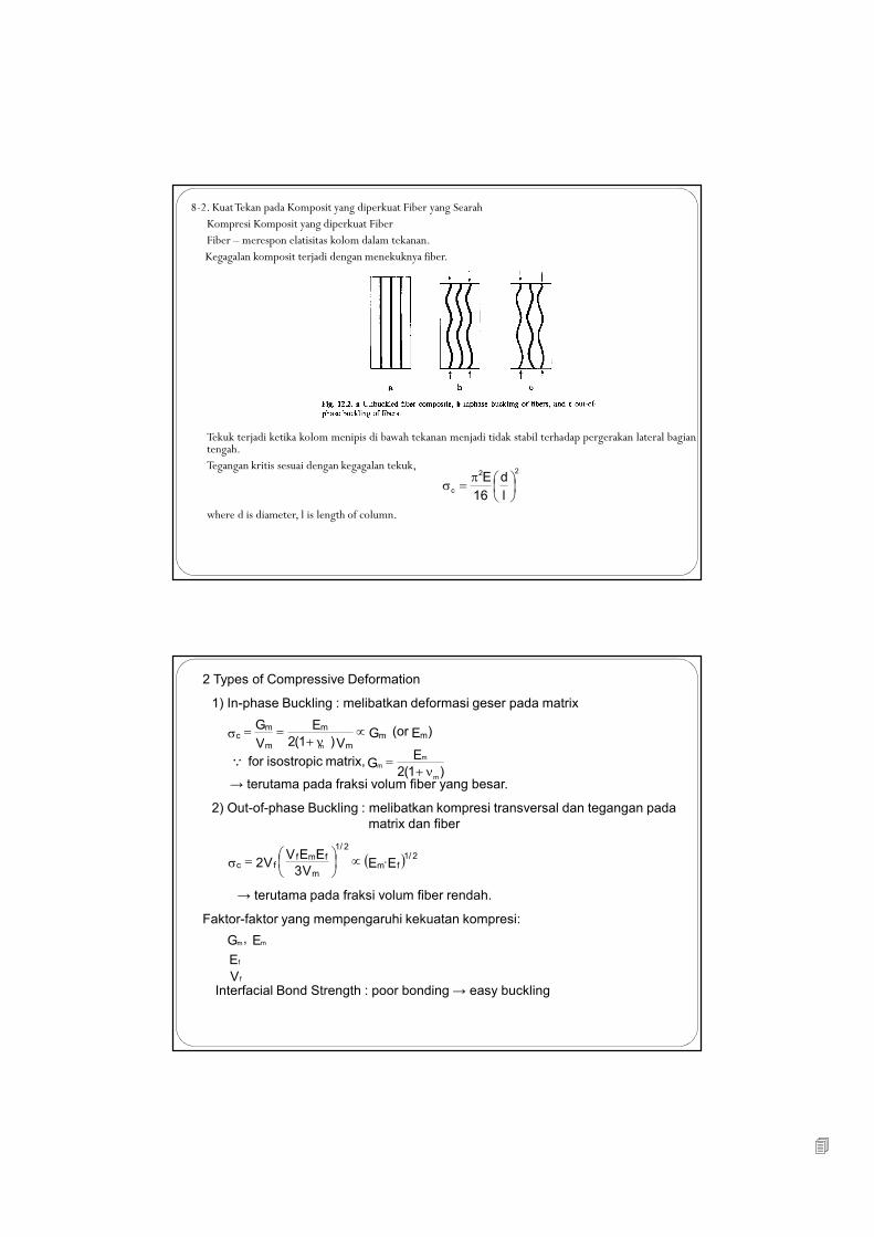
8-2. KuatTekan pada Komposit yang diperkuat Fiber yang SearahKompresi Komposit yang diperkuat FiberFiber – merespon elatisitas kolom dalam tekanan.Kegagalan komposit terjadi dengan menekuknya fiber.
Tekuk terjadi ketika kolom menipis di bawah tekanan menjadi tidak stabil terhadap pergerakan lateral bagiantengah.Tegangan kritis sesuai dengan kegagalan tekuk,
where d is diameter, l is length of column.
22
cl
d
16
E
π
=σ
2 Types of Compressive Deformation
1) In-phase Buckling : melibatkan deformasi geser pada matrix
→ terutama pada fraksi volum fiber yang besar.
2) Out-of-phase Buckling : melibatkan kompresi transversal dan tegangan pada
matrix dan fiber
→ terutama pada fraksi volum fiber rendah.
Faktor-faktor yang mempengaruhi kekuatan kompresi:
Interfacial Bond Strength : poor bonding → easy buckling
)E or( GV) 1(2
E
V
Gmm
m
m
m
mc ∝
ν+==σ
) 1(2
EG matrix, isostropic for m
m
ν+=Q
( )EEV3
EEVV2 fm
2/1
m
fmf2/1
fc ⋅∝
=σ
E ,G mm
Ef
V f
m
m
�
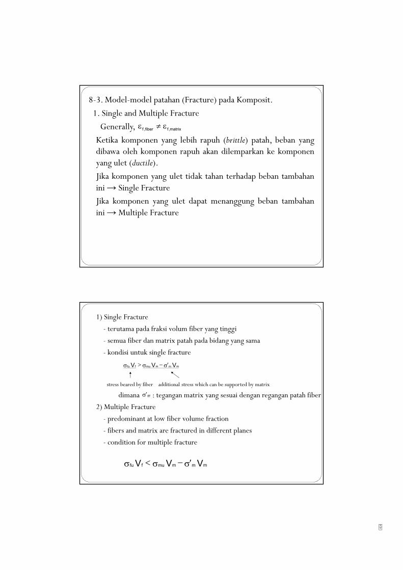
8-3.Model-model patahan (Fracture) pada Komposit.
1. Single and Multiple Fracture
Generally,
Ketika komponen yang lebih rapuh (brittle) patah, beban yangdibawa oleh komponen rapuh akan dilemparkan ke komponenyang ulet (ductile).
Jika komponen yang ulet tidak tahan terhadap beban tambahanini→ Single Fracture
Jika komponen yang ulet dapat menanggung beban tambahanini→Multiple Fracture
matrix,ffiber,fε≠ε
1) Single Fracture
- terutama pada fraksi volum fiber yang tinggi
- semua fiber dan matrix patah pada bidang yang sama
- kondisi untuk single fracture
stress beared by fiber additional stress which can be supported by matrix
dimana : tegangan matrix yang sesuai dengan regangan patah fiber
2) Multiple Fracture
- predominant at low fiber volume fraction
- fibers and matrix are fractured in different planes
- condition for multiple fracture
VVV mmmmuffu σ′−σ>σ
σ′m
VVV mmmmuffu σ′−σ<σ
�
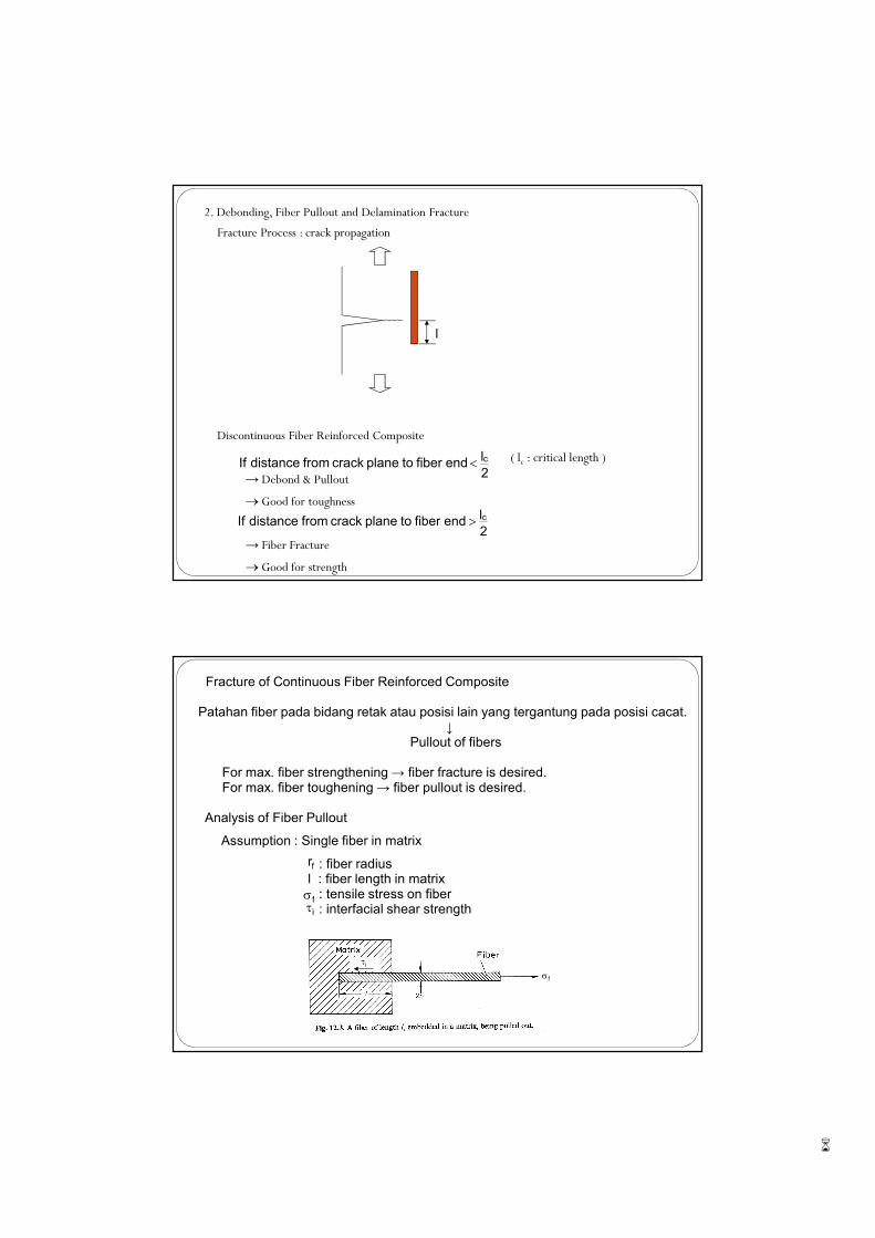
2. Debonding, Fiber Pullout and Delamination Fracture
Fracture Process : crack propagation
Discontinuous Fiber Reinforced Composite
( lc : critical length )
→ Debond & Pullout
→ Good for toughness
→ Fiber Fracture
→ Good for strength
2
l end fiber to plane crack from distance If c<
2
l end fiber to plane crack from distance If c>
l
Fracture of Continuous Fiber Reinforced Composite
Patahan fiber pada bidang retak atau posisi lain yang tergantung pada posisi cacat.↓
Pullout of fibers
For max. fiber strengthening → fiber fracture is desired.For max. fiber toughening → fiber pullout is desired.
Analysis of Fiber Pullout
Assumption : Single fiber in matrix
: fiber radiusl : fiber length in matrix
: tensile stress on fiber: interfacial shear strength
fr
fσiτ
fσiτ

�
Force Equilibrium
( lc : critical length of fiber )
1) Condition for fiber fracture,
2) Condition for fiber pullout,
lr2r iff
2
f τπ=σπ
ciffu
2
f lr2r τπ=σπ
d
l
r2
l
4
c
f
c
i
fu ==τσ
r
l
2 f
c
i
fu =τσ
lr2r iff
2
f τπ<σπ
=<
τσ
→>fi
fuc
r2
1
d
l
4 ll If
lr2r iff
2
f τπ>σπ
=≥
τσ
→<fi
fuc
r2
1
d
l
4 ll If
Fracture Process of Fiber Reinforced Composites
Real fibers - non-uniform properties
3 steps of fracture process
1) Fracture of fibers at weak points near fracture plane :
2) Debonding of fibers :
3) Pullout of fibers :
W d
Wp
WWW pdfracture +=
Wp
Load
Displacement
WP
Wd

�
Energy Required for Fracture & Debonding
elastic strain E. volume
Energy Required for Pullout
Let k : distance (lekat) of a broken fiber from crack plane
: pullout distance at a certain moment
: interfacial shear strength
Force to resist the pullout = fiber contact area
Total energy(work) to pullout a fiber for distance k
Average energy to pullout per fiber(considering all fibers with different k, )
<<
2
lk0 c
x
τi
)xk(di −πτ
dx)xk(ddx distanceapullouttoEnergy i −πτ=
2
dkdx)xk(d W
2i
ip
πτ=−πτ=
2
lk0 c<<
24
dldk
2
dk
2l
1W
2ci
2i
cave,p
πτ=
πτ=∴
∫k
0
∫2cl
0
length debond : x x24
dπ
E
σW
2
f
2fu
d ⋅
⋅
=
Fracture of Discontinuous Fiber Reinforced Composite
→ pullout
Average energy to pullout per fiber with length, l
probability for pullout energy required for pullout
Energy for Fiber Pullout vs Fiber Length(l)
plane, crack from ,2
l distance, a withinlocated is fiber a If c±
l
l l length, withfiber a of pullout fory Probabilit c≈
24
dl
l
lW
2cic
ave,p
πτ
=
l. length increasing withincreases distance pullout fiber , l l If c<( )2
pp lW l. length increasing withincreases, W ∝→
l. length increasing withincreasestendency fracture fiber , l l If c>
constant l l
1W l. length increasing withdecreases, W cpp =
∝→ Q
.ll whenmaximum, becomesW c p ≈
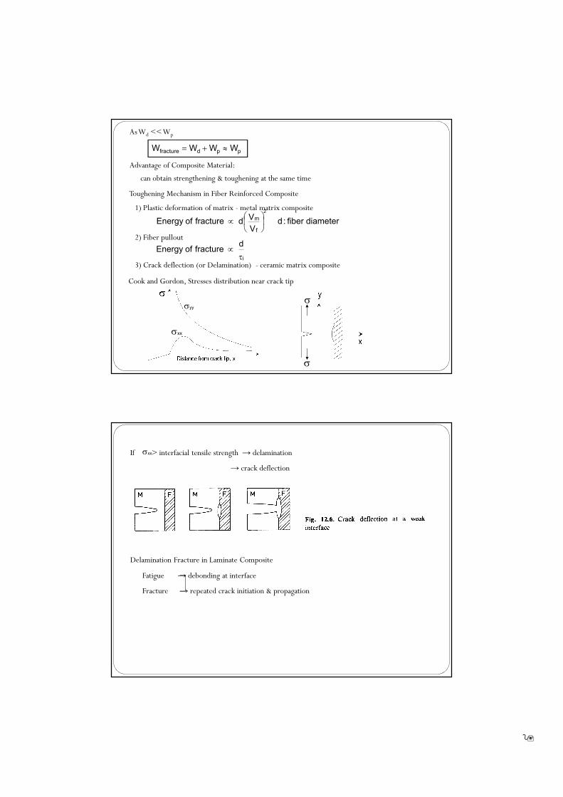
As Wd << Wp
Advantage of Composite Material:
can obtain strengthening & toughening at the same time
Toughening Mechanism in Fiber Reinforced Composite
1) Plastic deformation of matrix - metal matrix composite
2) Fiber pullout
3) Crack deflection (or Delamination) - ceramic matrix composite
Cook and Gordon, Stresses distribution near crack tip
diameter fiber :d V
Vd fracture ofEnergy
f
m
2
∝
τ∝
i
d fracture ofEnergy
ppdfracture WWWW ≈+=
σ
σ
σyy
σxx
If > interfacial tensile strength → delamination
→ crack deflection
Delamination Fracture in Laminate Composite
Fatigue → debonding at interface
Fracture → repeated crack initiation & propagation
σxx
�
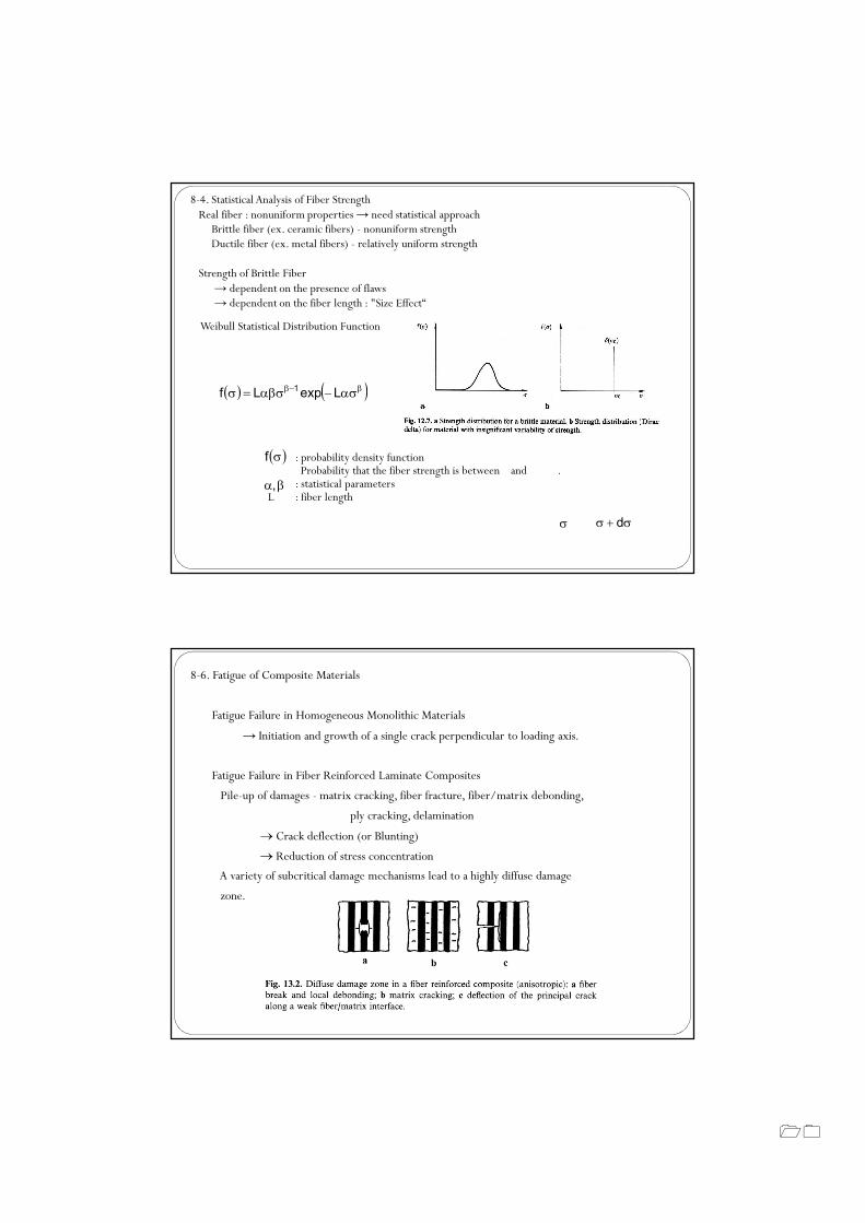
8-4. Statistical Analysis of Fiber StrengthReal fiber : nonuniform properties→ need statistical approachBrittle fiber (ex. ceramic fibers) - nonuniform strengthDuctile fiber (ex. metal fibers) - relatively uniform strength
Strength of Brittle Fiber→ dependent on the presence of flaws→ dependent on the fiber length : "Size Effect“
Weibull Statistical Distribution Function
: probability density functionProbability that the fiber strength is between and .: statistical parameters
L : fiber length
( ) ( )β−β ασ−αβσ=σ LexpLf 1
( )σf
βα ,
σ σ+σ d
8-6. Fatigue of Composite Materials
Fatigue Failure in Homogeneous Monolithic Materials
→ Initiation and growth of a single crack perpendicular to loading axis.
Fatigue Failure in Fiber Reinforced Laminate Composites
Pile-up of damages - matrix cracking, fiber fracture, fiber/matrix debonding,
ply cracking, delamination
→ Crack deflection (or Blunting)
→ Reduction of stress concentration
A variety of subcritical damage mechanisms lead to a highly diffuse damage
zone.
��
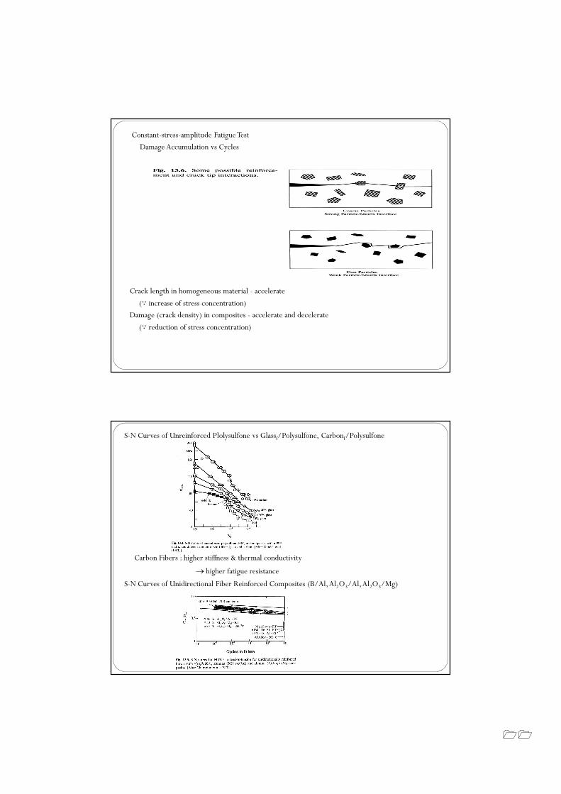
Constant-stress-amplitude Fatigue Test
Damage Accumulation vs Cycles
Crack length in homogeneous material - accelerate
(∵ increase of stress concentration)
Damage (crack density) in composites - accelerate and decelerate
(∵ reduction of stress concentration)
S-N Curves of Unreinforced Plolysulfone vs Glassf/Polysulfone, Carbonf/Polysulfone
Carbon Fibers : higher stiffness & thermal conductivity
→ higher fatigue resistance
S-N Curves of Unidirectional Fiber Reinforced Composites (B/Al, Al2O3/Al, Al2O3/Mg)
��
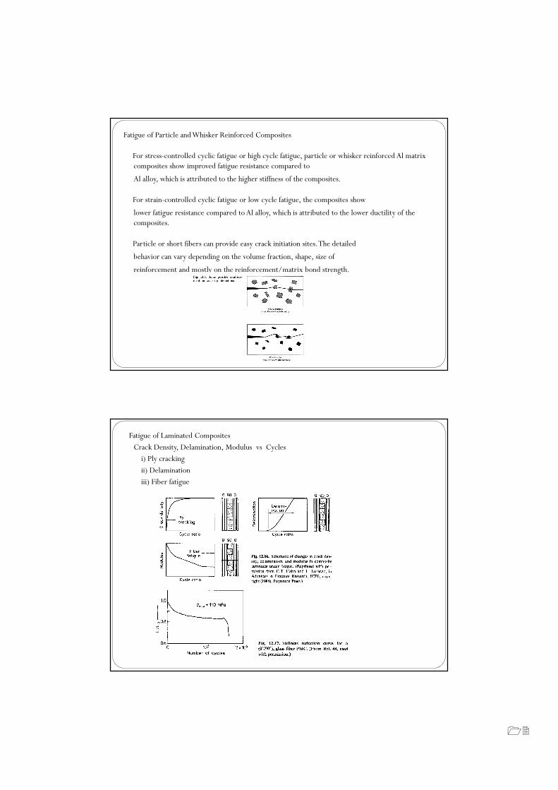
Fatigue of Particle and Whisker Reinforced Composites
For stress-controlled cyclic fatigue or high cycle fatigue, particle or whisker reinforced Al matrix composites show improved fatigue resistance compared to
Al alloy, which is attributed to the higher stiffness of the composites.
For strain-controlled cyclic fatigue or low cycle fatigue, the composites show
lower fatigue resistance compared to Al alloy, which is attributed to the lower ductility of the composites.
Particle or short fibers can provide easy crack initiation sites. The detailed
behavior can vary depending on the volume fraction, shape, size of
reinforcement and mostly on the reinforcement/matrix bond strength.
Fatigue of Laminated Composites
Crack Density, Delamination, Modulus vs Cycles
i) Ply cracking
ii) Delamination
iii) Fiber fatigue
��
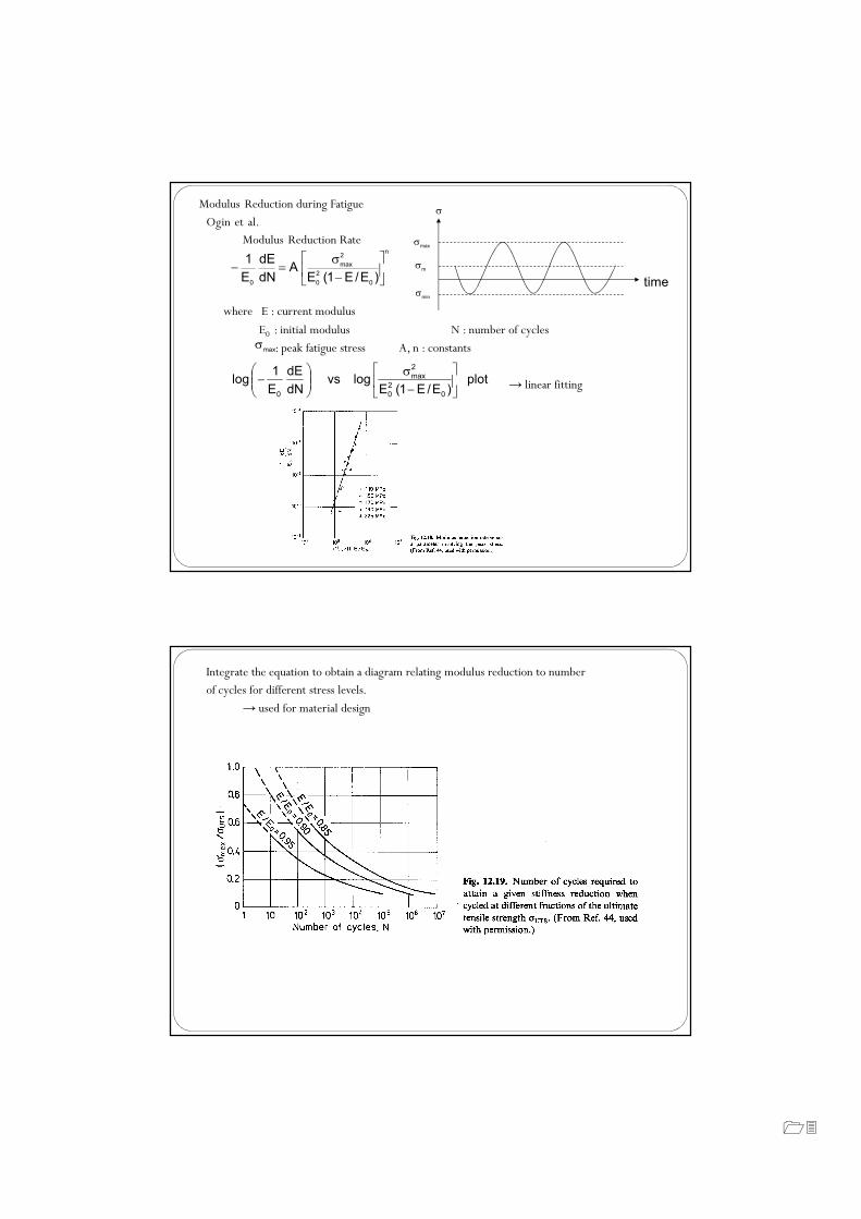
Modulus Reduction during Fatigue
Ogin et al.
Modulus Reduction Rate
where E : current modulus
E0 : initial modulus N : number of cycles
: peak fatigue stress A, n : constants
→ linear fitting
n
0
2
0
2
max
0)E/E 1( E
A dN
dE
E
1
−σ
=−
maxσ
time
maxσ
mσ
minσ
σ
plot )E/E 1( E
log vs dN
dE
E
1 log
0
2
0
2
max
0
−σ
−
Integrate the equation to obtain a diagram relating modulus reduction to number
of cycles for different stress levels.
→ used for material design
��
8-7. Thermal Fatigue of Composite Materials
Thermal Stress
Tegangan Thermal terjadi di dalam material komposit karena secara umum adanya perbedaan koefisien ekspansi termal (α) yang luas pada reinforcement dan matrix.
Perlu ditekankan bahwa tegangan termal dalam komposit akantimbul jika suhu berubah secra seragam di seluruh volume komposit.
T∆⋅α∆∝σ
Thermal Fatigue (Kelelahan Termal)
� Ketika suhu berulang kali berubah, tegangan termal akan menghasilkan kelelahan termal, karena tegangan yang berputar adalah asal dari adanya termal.
� Kelelahan termal dapat menyebabkan retak pada matriks yang brittle -rapuh atau deformasi plastik dari matriks yang ductile-ulet.
� Kavitasi dalam matriks dan fiber/matriks debonding adalah bentuk lain dari kerusakan yang teramati karena kelelahan termal komposit.
� Thermal fatigue dalam matriks dapat dikurangi dengan memilih matriks yang memiliki kuat tarik yang tinggi dan regangan gagal yang besar.
� Fiber/matriks debonding hanya dapat dihindari dengan memilih bahan dasar sehingga perbedaan koefisien ekspansi termal pada fiber dan matriks rendah.