para la naturaleza 100% papel reciclado - GarazPartspara la naturaleza 100% papel reciclado pour la...
18
740-741 & 740D 740-741 & 740D carta riciclata 100% per la natura for nature recycled paper 100% ist umweltfreundlich 100% Altpapier para la naturaleza 100% papel reciclado papier recyclé 100% pour la nature voor de natuur 100% kringlooppapier
Transcript of para la naturaleza 100% papel reciclado - GarazPartspara la naturaleza 100% papel reciclado pour la...
�������������
�������������
cart
a ric
icla
ta 1
00%
per
la n
atur
afo
r na
ture
recy
cled
pap
er 1
00%
ist
umw
eltfr
eund
lich
100%
Altp
apie
rpa
ra la
nat
ural
eza
100%
pap
el r
ecic
lado
papi
er r
ecyc
lé 1
00%
pour
la n
atur
evo
or d
e na
tuur
100%
krin
gloo
ppap
ier
15
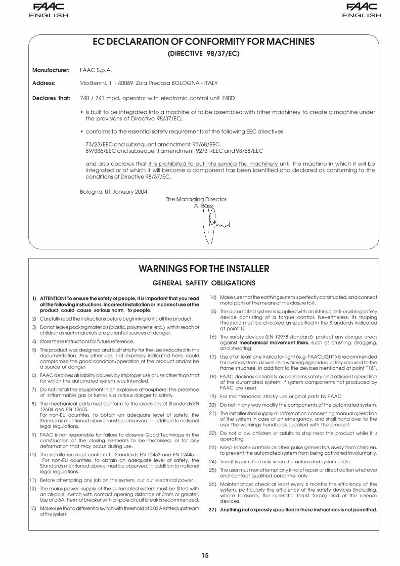
1) ATTENTION! To ensure the safety of people, it is important that you readall the following instructions. Incorrect installation or incorrect use of theproduct could cause serious harm to people.
2) Carefully read the instructions before beginning to install the product.
3) Do not leave packing materials (plastic, polystyrene, etc.) within reach ofchildren as such materials are potential sources of danger.
4) Store these instructions for future reference.
5) This product was designed and built strictly for the use indicated in thisdocumentation. Any other use, not expressly indicated here, couldcompromise the good condition/operation of the product and/or bea source of danger.
6) FAAC declines all liability caused by improper use or use other than thatfor which the automated system was intended.
7) Do not install the equipment in an explosive atmosphere: the presenceof inflammable gas or fumes is a serious danger to safety.
8) The mechanical parts must conform to the provisions of Standards EN12604 and EN 12605.For non-EU countries, to obtain an adequate level of safety, theStandards mentioned above must be observed, in addition to nationallegal regulations.
9) FAAC is not responsible for failure to observe Good Technique in theconstruction of the closing elements to be motorised, or for anydeformation that may occur during use.
10) The installation must conform to Standards EN 12453 and EN 12445. For non-EU countries, to obtain an adequate level of safety, theStandards mentioned above must be observed, in addition to nationallegal regulations.
11) Before attempting any job on the system, cut out electrical power .
12) The mains power supply of the automated system must be fitted withan all-pole switch with contact opening distance of 3mm or greater.Use of a 6A thermal breaker with all-pole circuit break is recommended.
13) Make sure that a differential switch with threshold of 0.03 A is fitted upstreamof the system.
14) Make sure that the earthing system is perfectly constructed, and connectmetal parts of the means of the closure to it.
15) The automated system is supplied with an intrinsic anti-crushing safetydevice consisting of a torque control. Nevertheless, its trippingthreshold must be checked as specified in the Standards indicatedat point 10.
16) The safety devices (EN 12978 standard) protect any danger areasagainst mechanical movement Risks, such as crushing, dragging,and shearing.
17) Use of at least one indicator-light (e.g. FAACLIGHT ) is recommendedfor every system, as well as a warning sign adequately secured to theframe structure, in addition to the devices mentioned at point “16”.
18) FAAC declines all liability as concerns safety and efficient operationof the automated system, if system components not produced byFAAC are used.
19) For maintenance, strictly use original parts by FAAC.
20) Do not in any way modify the components of the automated system.
21) The installer shall supply all information concerning manual operationof the system in case of an emergency, and shall hand over to theuser the warnings handbook supplied with the product.
22) Do not allow children or adults to stay near the product while it isoperating.
23) Keep remote controls or other pulse generators away from children,to prevent the automated system from being activated involuntarily.
24) Transit is permitted only when the automated system is idle.
25) The user must not attempt any kind of repair or direct action whateverand contact qualified personnel only.
26) Maintenance: check at least every 6 months the efficiency of thesystem, particularly the efficiency of the safety devices (including,where foreseen, the operator thrust force) and of the releasedevices.
27) Anything not expressly specified in these instructions is not permitted.
WARNINGS FOR THE INSTALLERGENERAL SAFETY OBLIGATIONS
EC DECLARATION OF CONFORMITY FOR MACHINES(DIRECTIVE 98/37/EC)
Manufacturer: FAAC S.p.A.
Address: Via Benini, 1 - 40069 Zola Predosa BOLOGNA - ITALY
Declares that: 740 / 741 mod. operator with electronic control unit 740D
• is built to be integrated into a machine or to be assembled with other machinery to create a machine underthe provisions of Directive 98/37/EC;
• conforms to the essential safety requirements of the following EEC directives:
73/23/EEC and subsequent amendment 93/68/EEC.89/336/EEC and subsequent amendment 92/31/EEC and 93/68/EEC
and also declares that it is prohibited to put into service the machinery until the machine in which it will beintegrated or of which it will become a component has been identified and declared as conforming to theconditions of Directive 98/37/EC.
Bologna, 01 January 2004The Managing Director
A. Bassi
16
Fig.01
Fig.02
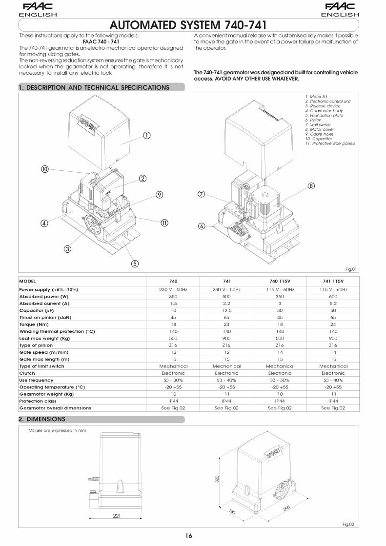
These instructions apply to the following models:FAAC 740 - 741
The 740-741 gearmotor is an electro-mechanical operator designedfor moving sliding gates.The non-reversing reduction system ensures the gate is mechanicallylocked when the gearmotor is not operating, therefore it is notnecessary to install any electric lock
AUTOMATED SYSTEM 740-741A convenient manual release with customised key makes it possibleto move the gate in the event of a power failure or malfunction ofthe operator.
The 740-741 gearmotor was designed and built for controlling vehicleaccess. AVOID ANY OTHER USE WHATEVER.
1. DESCRIPTION AND TECHNICAL SPECIFICATIONS
2. DIMENSIONS
����� ��� �� ���� ���
� �� �������������� ��������� ��������� ������ ������
���������������� ��� ��� ��� ��
��� !����"�������� �� ��� � ���
�#$��� %"&�&' � ��� �� ��
�(&��!�%!%�!� ���)* �� � �� �
�+(���,��* �� ��
�'-�!�% "� ����&+��) .!%�!%� �� �� �� ��
�./� ).%��0&+1&�� ��� ��� ��� ���
!�%!%�1����* � � � �
�!%+2+������� &3 � � � �
�+�) .!��0&+� &3 � � � �
)" %�� %+%�1����* ���������� ���������� ���������� ����������
)" ��' ���������� ���������� ���������� ����������
�"!��,��1��4 ������ ������ ������ ������
�'-���� &���+� .!% &���� ������ ������ ������ ������
�./� ).%���� �+�&�3 � �
��&�"!�% "� ��� �� ! �� ! �� ! �� !
�!�%�!�+%���&��5��� �+�&�3 ���"�#��� ���"�#��� ���"�#��� ���"�#���
1. Motor lid2. Electronic control unit3. Release device4. Gearmotor body5. Foundation plate6. Pinion7. Limit switch8. Motor cover9. Cable holes10. Capacitor11. Protective side panels
Values are expressed in mm
�
�
�
�
�
�
�
�
�
221
322
180 295
17
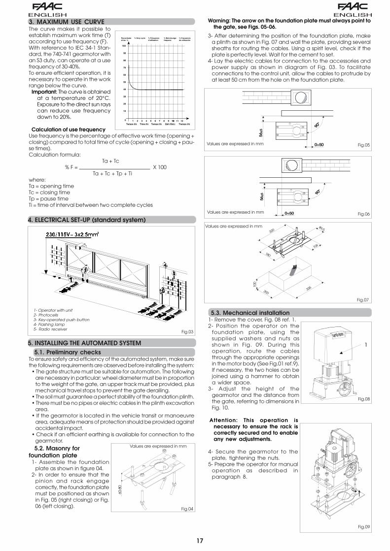
3. MAXIMUM USE CURVEThe curve makes it possible toestablish maximum work time (T)according to use frequency (F).With reference to IEC 34-1 Stan-dard, the 740-741 gearmotor withan S3 duty, can operate at a usefrequency of 30-40%.To ensure efficient operation, it isnecessary to operate in the workrange below the curve.Important: The curve is obtained
at a temperature of 20°C.Exposure to the direct sun rayscan reduce use frequencydown to 20%.
Calculation of use frequencyUse frequency is the percentage of effective work time (opening +closing) compared to total time of cycle (opening + closing + pau-se times).Calculation formula:
Ta + Tc% F = X 100
Ta + Tc + Tp + Tiwhere:Ta = opening timeTc = closing timeTp = pause timeTi = time of interval between two complete cycles
4. ELECTRICAL SET-UP (standard system)
5. INSTALLING THE AUTOMATED SYSTEM5.1. Preliminary checks
To ensure safety and efficiency of the automated system, make surethe following requirements are observed before installing the system:• The gate structure must be suitable for automation. The following
are necessary in particular: wheel diameter must be in proportionto the weight of the gate, an upper track must be provided, plusmechanical travel stops to prevent the gate derailing.
• The soil must guarantee a perfect stability of the foundation plinth.• There must be no pipes or electric cables in the plinth excavation
area.• If the gearmotor is located in the vehicle transit or manoeuvre
area, adequate means of protection should be provided againstaccidental impact.
• Check if an efficient earthing is available for connection to thegearmotor.
5.2. Masonry forfoundation plate1- Assemble the foundation
plate as shown in figure 04.2- In order to ensure that the
pinion and rack engagecorrectly, the foundation platemust be positioned as shownin Fig. 05 (right closing) or Fig.06 (left closing).
Warning: The arrow on the foundation plate must always point tothe gate, see Figs. 05-06.
3- After determining the position of the foundation plate, makea plinth as shown in Fig. 07 and wall the plate, providing severalsheaths for routing the cables. Using a spirit level, check if theplate is perfectly level. Wait for the cement to set.
4- Lay the electric cables for connection to the accessories andpower supply as shown in diagram of Fig. 03. To facilitateconnections to the control unit, allow the cables to protrude byat least 50 cm from the hole on the foundation plate.
5.3. Mechanical installation1- Remove the cover, Fig. 08 ref. 1.2- Position the operator on the
foundation plate, using thesupplied washers and nuts asshown in Fig. 09. During thisoperation, route the cablesthrough the appropriate openingsin the motor body (See Fig.01 ref.9).If necessary, the two holes can bejoined using a hammer to obtaina wider space.
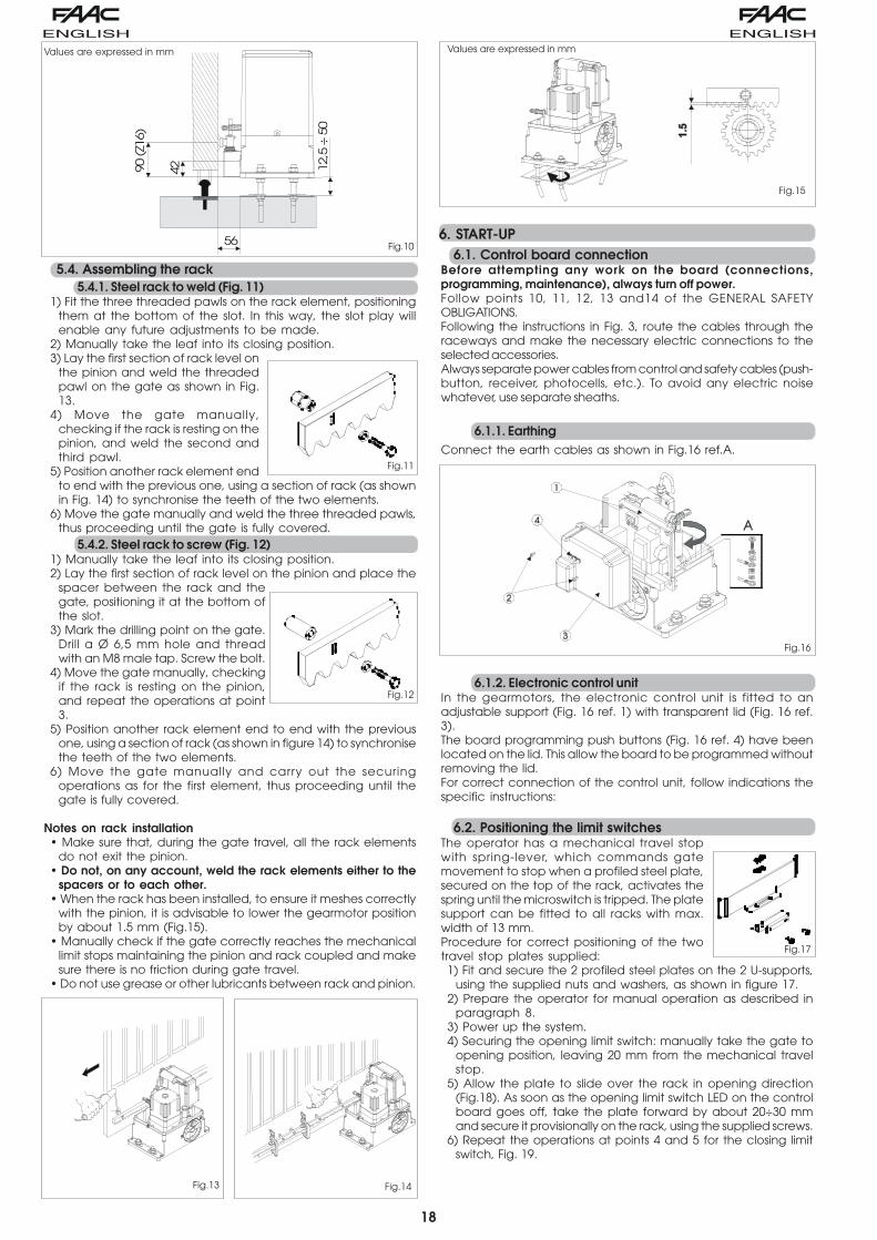
3- Adjust the height of thegearmotor and the distance fromthe gate, referring to dimensions inFig. 10.
Attention: This operation isnecessary to ensure the rack iscorrectly secured and to enableany new adjustments.
4- Secure the gearmotor to theplate, tightening the nuts.
5- Prepare the operator for manualoperation as described inparagraph 8.
10
20
30
40
50
60
70
80
90
100
0 1 2 3 4 5 6 7 8 9 10 10 11 12
Percentuale di lav. %
Tiempo (h)
% Duty cycle % Fréquenced'utilisation
% Benutzungs- frequenz
% Frecuencia de utilización
Zeit (Std.)Temps (h)Time (h)Tempo (h)
����������������
Fig.03
1- Operator with unit2- Photocells3- Key-operated push button4- Flashing lamp5- Radio receiver
Fig.04
Values are expressed in mm
60-8
0
90°
0÷50
56±5
Fig.05Values are expressed in mm
0÷50
90°
56±5
Fig.06Values are expressed in mm
Fig.07
Values are expressed in mm320
335
100
106
180
200
89,5
Fig.08
1
Fig.09
18
Fig.10
5.4. Assembling the rack5.4.1. Steel rack to weld (Fig. 11)
1) Fit the three threaded pawls on the rack element, positioningthem at the bottom of the slot. In this way, the slot play willenable any future adjustments to be made.
2) Manually take the leaf into its closing position.3) Lay the first section of rack level on
the pinion and weld the threadedpawl on the gate as shown in Fig.13.
4) Move the gate manually,checking if the rack is resting on thepinion, and weld the second andthird pawl.
5) Position another rack element endto end with the previous one, using a section of rack (as shownin Fig. 14) to synchronise the teeth of the two elements.
6) Move the gate manually and weld the three threaded pawls,thus proceeding until the gate is fully covered.
5.4.2. Steel rack to screw (Fig. 12)1) Manually take the leaf into its closing position.2) Lay the first section of rack level on the pinion and place the
spacer between the rack and thegate, positioning it at the bottom ofthe slot.
3) Mark the drilling point on the gate.Drill a Ø 6,5 mm hole and threadwith an M8 male tap. Screw the bolt.
4) Move the gate manually, checkingif the rack is resting on the pinion,and repeat the operations at point3.
5) Position another rack element end to end with the previousone, using a section of rack (as shown in figure 14) to synchronisethe teeth of the two elements.
6) Move the gate manually and carry out the securingoperations as for the first element, thus proceeding until thegate is fully covered.
Notes on rack installation• Make sure that, during the gate travel, all the rack elements
do not exit the pinion.• Do not, on any account, weld the rack elements either to the
spacers or to each other.• When the rack has been installed, to ensure it meshes correctly
with the pinion, it is advisable to lower the gearmotor positionby about 1.5 mm (Fig.15).
• Manually check if the gate correctly reaches the mechanicallimit stops maintaining the pinion and rack coupled and makesure there is no friction during gate travel.
• Do not use grease or other lubricants between rack and pinion.
6. START-UP6.1. Control board connection
Before attempting any work on the board (connections,programming, maintenance), always turn off power.Follow points 10, 11, 12, 13 and14 of the GENERAL SAFETYOBLIGATIONS.Following the instructions in Fig. 3, route the cables through theraceways and make the necessary electric connections to theselected accessories.Always separate power cables from control and safety cables (push-button, receiver, photocells, etc.). To avoid any electric noisewhatever, use separate sheaths.
6.1.1. EarthingConnect the earth cables as shown in Fig.16 ref.A.
6.1.2. Electronic control unitIn the gearmotors, the electronic control unit is fitted to anadjustable support (Fig. 16 ref. 1) with transparent lid (Fig. 16 ref.3).The board programming push buttons (Fig. 16 ref. 4) have beenlocated on the lid. This allow the board to be programmed withoutremoving the lid.For correct connection of the control unit, follow indications thespecific instructions:
6.2. Positioning the limit switchesThe operator has a mechanical travel stopwith spring-lever, which commands gatemovement to stop when a profiled steel plate,secured on the top of the rack, activates thespring until the microswitch is tripped. The platesupport can be fitted to all racks with max.width of 13 mm.Procedure for correct positioning of the twotravel stop plates supplied:1) Fit and secure the 2 profiled steel plates on the 2 U-supports,
using the supplied nuts and washers, as shown in figure 17.2) Prepare the operator for manual operation as described in
paragraph 8.3) Power up the system.4) Securing the opening limit switch: manually take the gate to
opening position, leaving 20 mm from the mechanical travelstop.
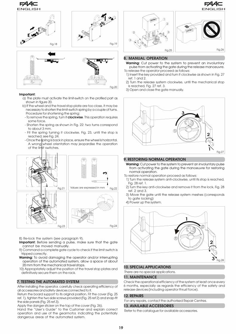
5) Allow the plate to slide over the rack in opening direction(Fig.18). As soon as the opening limit switch LED on the controlboard goes off, take the plate forward by about 20÷30 mmand secure it provisionally on the rack, using the supplied screws.
6) Repeat the operations at points 4 and 5 for the closing limitswitch, Fig. 19.
Values are expressed in mm
90 (Z1
6)
12,5
÷ 5
0
42
56
Fig.14Fig.13
Fig.11
Fig.12
Fig.15
Values are expressed in mm
Fig.16
Fig.17
19
Important:a) The plate must activate the limit-switch on the profiled part as
shown in figure 20.b) If the wheel and the travel stop plate are too close, it may be
necessary to shorten the limit-switch spring by a couple of turns.Procedure for shortening the spring:
- To remove the spring, turn it clockwise. This operation requiressome force.
- Shorten the spring as shown in Fig. 22: two turns correspondto about 3 mm.
- Fit the spring turning it clockwise, Fig. 23, until the stop isreached; see Fig. 24.
- Once the spring is back in place, ensure the wheel is horizontal.A wrong wheel orientation may jeopardise the operationof the limit switches.
8) Re-lock the system (see paragraph 9).Important: Before sending a pulse, make sure that the gate
cannot be moved manually.9) Command a complete gate cycle to check if the limit switch is
tripped correctly.Warning: To avoid damaging the operator and/or interrupting
operation of the automated system, allow a space of about20 mm from the mechanical travel stops.
10) Appropriately adjust the position of the travel stop plates anddefinitively secure them on the rack.
7. TESTING THE AUTOMATED SYSTEMAfter installing the operator, carefully check operating efficiency ofall accessories and safety devices connected to it.Return the board support to its original position. Fit the cover (Fig. 25ref. 1), tighten the two side screws provided (Fig. 25 ref 2) and snap-fitthe side panels (Fig. 25 ref.3).Apply the danger sticker on the top of the cover (Fig. 26).Hand the “User’s Guide” to the Customer and explain correctoperation and use of the gearmotor, indicating the potentiallydangerous areas of the automated system.
8. MANUAL OPERATIONWarning: Cut power to the system to prevent an involuntary
pulse from activating the gate during the release manoeuvre.To release the operator proceed as follows:1) Insert the key provided and turn it clockwise as shown in Fig. 27
ref. 1 and 2.2) Turn the release system clockwise, until the mechanical stop
is reached, Fig. 27 ref. 3.3) Open and close the gate manually.
9. RESTORING NORMAL OPERATIONWarning: Cut power to the system to prevent an involuntary pulse
from activating the gate during the manoeuvre for restoringnormal operation.
To restore normal operation proceed as follows:1) Turn the release system anti-clockwise, until its stop is reached,
Fig. 28 ref. 1.2) Turn the key anti-clockwise and remove it from the lock, Fig. 28
ref. 2 and 3.3) Move the gate until the release system meshes (corresponds
to gate locking)4) Power up the system.
10. SPECIAL APPLICATIONSThere are no special applications.
11. MAINTENANCECheck the operational efficiency of the system at least once every6 months, especially as regards the efficiency of the safety andrelease devices (including operator thrust force).
12. REPAIRSFor any repairs, contact the authorised Repair Centres.
13. AVAILABLE ACCESSORIESRefer to the catalogue for available accessories.
Fig.18 Fig.19
Fig.20
�
Fig.21 Fig.22
Fig.23 Fig.24
Values are expressed in mm
Fig.25 Fig.26
2
1
3
3
2
Fig.271
2
3
Fig.28
1
2
3
20
���
��
��
�������������������������������������������������������� �������������������� � ���������
����
���
��� �
�
��� ��������������� ���� ���
����
�
��
�����
���
���
����
�
� �
�
��
���
����
�
� �
��
���
����
��
����
� �
��
� �
�
���
����
�� �
���
��
�
�������
����
��
�
��
��
�� ����
��
F
F1
F2
J1
J2
J3J5
J6
DL
–+
Led
J7
24 Vdc3 W
C
M
���
�������������������������������������������������������� �������������������� � ���������
����
���
��� �
�
��� ��������������� ���� ���
����
�
��
���
����
��
����
� �
��
� �
�
���
����
�� �
���
��
�
��
��
�� ����
Fig. 29
Fig. 30
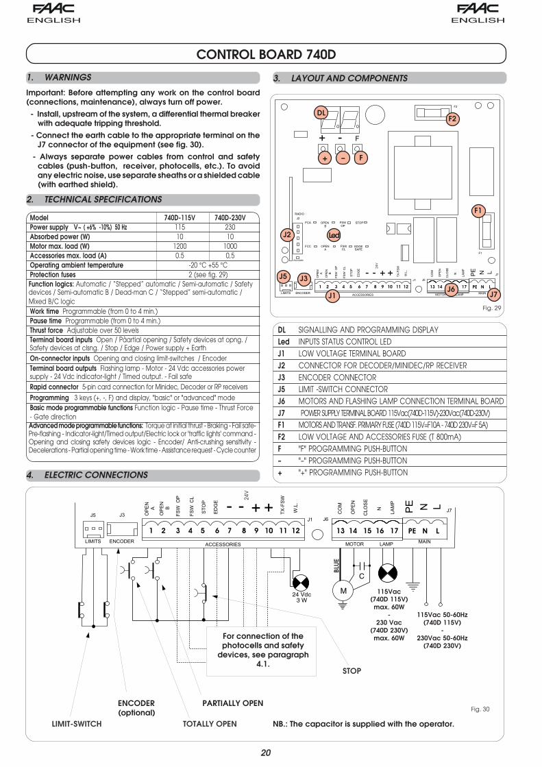
NB.: The capacitor is supplied with the operator.TOTALLY OPEN
PARTIALLY OPEN
STOP
CONTROL BOARD 740D
DL SIGNALLING AND PROGRAMMING DISPLAYLed INPUTS STATUS CONTROL LEDJ1 LOW VOLTAGE TERMINAL BOARDJ2 CONNECTOR FOR DECODER/MINIDEC/RP RECEIVERJ3 ENCODER CONNECTORJ5 LIMIT -SWITCH CONNECTORJ6 MOTORS AND FLASHING LAMP CONNECTION TERMINAL BOARDJ7 POWER SUPPLY TERMINAL BOARD 115Vac(740D-115V)-230Vac(740D-230V)F1 MOTORS AND TRANSF. PRIMARY FUSE (740D 115V=F10A - 740D 230V=F 5A)F2 LOW VOLTAGE AND ACCESSORIES FUSE (T 800mA)F "F" PROGRAMMING PUSH-BUTTON– "–" PROGRAMMING PUSH-BUTTON+ "+" PROGRAMMING PUSH-BUTTON
Model 740D-115V 740D-230VPower supply V~ ( +6% -10%) 50 Hz 115 230Absorbed power (W) 10 10Motor max. load (W) 1200 1000Accessories max. load (A) 0.5 0,5Operating ambient temperature -20 °C +55 °CProtection fuses 2 (see fig. 29)Function logics: Automatic / “Stepped” automatic / Semi-automatic / Safetydevices / Semi-automatic B / Dead-man C / “Stepped” semi-automatic /Mixed B/C logicWork time Programmable (from 0 to 4 min.)Pause time Programmable (from 0 to 4 min.)Thrust force Adjustable over 50 levelsTerminal board inputs Open / Pàartial opening / Safety devices at opng. /Safety devices at clsng. / Stop / Edge / Power supply + EarthOn-connector inputs Opening and closing limit-switches / EncoderTerminal board outputs Flashing lamp - Motor - 24 Vdc accessories powersupply - 24 Vdc indicator-light / Timed output. - Fail safeRapid connector 5-pin card connection for Minidec, Decoder or RP receivers
Programming 3 keys (+, -, F) and display, "basic" or "advanced" modeBasic mode programmable functions Function logic - Pause time - Thrust Force- Gate directionAdvanced mode programmable functions: Torque at initial thrust - Braking - Fail safe-Pre-flashing - Indicator-light/Timed output/Electric lock or 'traffic lights' command -Opening and closing safety devices logic - Encoder/ Anti-crushing sensitivity -Decelerations - Partial opening time - Work time - Assistance request - Cycle counter
For connection of thephotocells and safety
devices, see paragraph4.1.
BLU
E
LIMIT-SWITCH
ENCODER(optional)
1. WARNINGS
Important: Before attempting any work on the control board(connections, maintenance), always turn off power. - Install, upstream of the system, a differential thermal breaker
with adequate tripping threshold. - Connect the earth cable to the appropriate terminal on the
J7 connector of the equipment (see fig. 30). - Always separate power cables from control and safety
cables (push-button, receiver, photocells, etc.). To avoidany electric noise, use separate sheaths or a shielded cable(with earthed shield).
2. TECHNICAL SPECIFICATIONS
3. LAYOUT AND COMPONENTS
4. ELECTRIC CONNECTIONS
115Vac(740D 115V)
max. 60W-
230 Vac(740D 230V)
max. 60W
115Vac 50-60Hz(740D 115V)
-230Vac 50-60Hz
(740D 230V)
21
���
��������������������������������������������������������
����
���
��� �
� ��
���
����
��
����
� �
��
� �
�
���
��������������������������������������������������������
����
���
��� �
� ��
���
����
��
����
� �
��
� �
�
���
��������������������������������������������������������
����
���
��� �
� ��
���
����
��
����
� �
��
� �
�
1
2
5
4
3
1
2
RX TX
-
+
-
+
���
��������������������������������������������������������
����
���
��� �
� ��
���
����
��
����
� �
��
� �
�
1
2
5
4
3
1
2
RX TX
-
+
-
+
���
��������������������������������������������������������
����
���
��� �
� ��
���
����
��
����
� �
��
� �
�
1
2
5
4
3
1
2
����� �����
1
2
5
4
3
1
2
����������
-
-
-
-
+
+
+
+
���
��������������������������������������������������������
����
���
��� �
� ��
���
����
��
����
� �
��
� �
�
Fig. 31
Fig. 33
Fig. 32
Fig. 35
Fig. 36
Fig. 34Fig. 38
Fig. 37
Opening/closing safety devices
Closing safety device
Opening safetydevices
Connection of no safety device
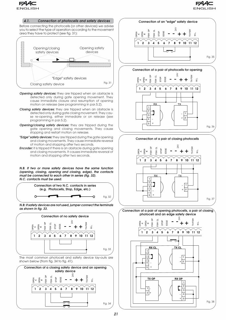
4.1. Connection of photocells and safety devicesBefore connecting the photocells (or other devices) we adviseyou to select the type of operation according to the movementarea they have to protect (see fig. 31):
"Edge" safety devices
Connection of two N.C. contacts in series(e.g. Photocells, Stop, Edge, etc.)
Connection of an "edge" safety device
Connection of a pair of photocells for opening
Connection of a pair of closing photocells
Connection of a closing safety device and an openingsafety device
Connection of a pair of opening photocells, a pair of closingphotocell and an edge safety device
Opening safety devices: they are tripped when an obstacle isdetected only during gate opening movement. Theycause immediate closure and resumption of openingmotion on release (see programming in par.5.2).
Closing safety devices: they are tripped when an obstacle isdetected only during gate closing movement. They cau-se re-opening, either immediate or on release (seeprogramming in par.5.2).
Opening/closing safety devices: they are tripped during thegate opening and closing movements. They causestopping and restart motion on release.
"Edge" safety devices: they are tripped during the gate openingand closing movements. They cause immediate reversalof motion and stopping after two seconds.
Encoder: it is tripped if there is an obstacle during gate openingand closing movements. It causes immediate reversal ofmotion and stopping after two seconds.
N.B. If two or more safety devices have the same function(opening, closing, opening and closing, edge), the contactsmust be connected to each other in series (fig. 32).N.C. contacts must be used.
N.B: If safety devices are not used, jumper connect the terminalsas shown in fig. 33.
The most common photocell and safety device lay-outs areshown below (from fig. 34 to fig. 41).
22
1
2
5
4
3
1
2
RX CL1 TX CL1
1
2
5
4
3
1
2
RX CL2TX CL2
-
+-
+
���
��������������������������������������������������������
����
���
��� �
� ��
�������
��
����
� �
��
� �
�
1
2
5
4
3
1
2
RX CL TX CL
1
2
5
4
3
1
2
RX OP/CLTX OP/CL
-
+-
+
1
2
5
4
3
1
2
RX OP TX OP
-
+-
+
���
��������������������������������������������������������
����
���
��� �
� ��
���
����
��
����
� �
��
� �
�
1
2
5
4
3
1
2
����� �����
1
2
5
4
3
1
2
��������������
-
+-
+
���
��������������������������������������������������������
����
���
��� �
� ��
���
����
��
����
� �
��
� �
�
Fig. 42
Fig. 39
Fig. 40
Fig. 41
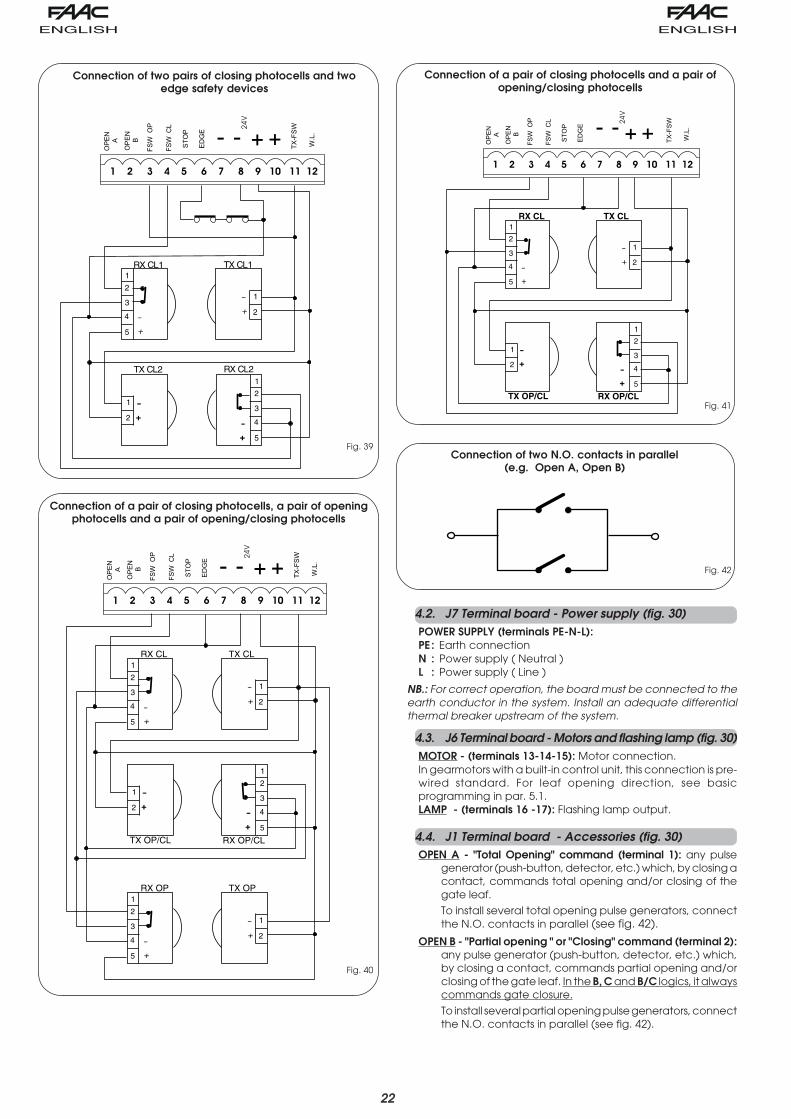
Connection of two N.O. contacts in parallel(e.g. Open A, Open B)
Connection of two pairs of closing photocells and twoedge safety devices
Connection of a pair of closing photocells and a pair ofopening/closing photocells
Connection of a pair of closing photocells, a pair of openingphotocells and a pair of opening/closing photocells
4.2. J7 Terminal board - Power supply (fig. 30)POWER SUPPLY (terminals PE-N-L):PE : Earth connectionN : Power supply ( Neutral )L : Power supply ( Line )
NB.: For correct operation, the board must be connected to theearth conductor in the system. Install an adequate differentialthermal breaker upstream of the system.
4.3. J6 Terminal board - Motors and flashing lamp (fig. 30)MOTOR - (terminals 13-14-15): Motor connection.In gearmotors with a built-in control unit, this connection is pre-wired standard. For leaf opening direction, see basicprogramming in par. 5.1.LAMP - (terminals 16 -17): Flashing lamp output.
4.4. J1 Terminal board - Accessories (fig. 30)OPEN A - "Total Opening" command (terminal 1): any pulse
generator (push-button, detector, etc.) which, by closing acontact, commands total opening and/or closing of thegate leaf.
To install several total opening pulse generators, connectthe N.O. contacts in parallel (see fig. 42).
OPEN B - "Partial opening " or "Closing" command (terminal 2):any pulse generator (push-button, detector, etc.) which,by closing a contact, commands partial opening and/orclosing of the gate leaf. In the B, C and B/C logics, it alwayscommands gate closure.
To install several partial opening pulse generators, connectthe N.O. contacts in parallel (see fig. 42).
23
MINIDEC
PLUS PLUS
DECODER
RP
740D 740D
740D
Fig. 44Fig. 43
Fig. 45
FSW OP - Opening safety devices contact (terminal 3): Thepurpose of the opening safety devices is to protect the leafmovement area during opening. During opening, in the A-AP-S-E-EP logics the safety devices reverse the movementof the gate leaves, or stop and restart the movement whenthey are released (see advanced programming in Par 5.2).During the opening cycle in logics B, C and B/C, theyinterrupt movement. They never operate during the closingcycle.If the Opening safety devices are engaged when the gateis closed, they prevent the leaf opening movement.To install several safety devices, connect the N.C. contactsin series (fig. 32).NB.: If no opening safety devices are connected, jumperconnect inputs OP and -TX FSW (fig. 33).
FSW CL - Closing safety devices contact (terminal 4): Thepurpose of the closing safety devices is to protect the leafmovement area during closing. During closing, in the A-AP-S-E-EP logics, the safety devices reverse the movementof the gate leaves, or stop and reverse the movementwhen they are released (see advanced programming inPar 5.2). During the closing cycle in logics B, C and B/C, theyinterrupt movement. They never operate during theopening cycle. If the Closing safety devices are engagedwhen the gate is open, they prevent the leaf closingmovement.To install several safety devices, connect the N.C. contactsin series (fig. 32).NB.: If no closing safety devices are connected, jumperconnect terminals CL and -TX FSW (fig. 33).
STOP - STOP contact (terminal 5): any device (e.g. a push-button) which, by opening a contact, is able to stop gatemovement.To install several STOP devices, connect the N.C. contactsin series.
NB.: If STOP devices are not connected, jumper connectthe STOP and - terminals.
EDGE - EDGE safety device contact (terminal 6): The purpose ofthe "edge" safety device is to protect the leaf movementarea during opening/closing against fixed obstacles (pillars,walls, etc.). In all logics, during opening and closing, thesafety devices reverse gate leaf movement for 2 seconds. Ifthe safety devices operate again during the 2-secondsreversing time, they STOP movement without any reversing.If the Edge safety devices are engaged while the gate isclosed or open, they prevent the leaves movement.To install several safety devices, connect the N.C. contactsin series (fig. 32).NB.: If edge safety devices are not connected, jumperconnect the EDGE and - inputs. (fig. 33).
– Negative for power supply to accessories (terminals 7 and8)
+ 24 Vdc - Positive for power supply to accessories (terminals9 and 10)Important: Accessories max. load is 500 mA. To calculateabsorption values, refer to the instructions for individualaccessories.
TX -FSW - Negative for power supply to photocell transmitters(terminal 11)If you use this terminal for connecting the negative forsupplying power to the photocell transmitters, you may, ifnecessary, also use the FAIL SAFE function (see advancedprogramming in par. 5.2).If this function is enabled, the equipment checks operationof the photocells before every opening or closing cycle.
W.L. - Power supply to indicator light / timed exit / electric lock/'traffic lights' (terminal 12)Connect any 24 Vdc - 3 W max indicator light, timed exit,command device for electric lock or 'traffic lights' betweenthis terminal and the +24V (see advanced programmingin par. 5.2). To avoid geopardising correct operation ofthe system, do not exceed the indicated power.
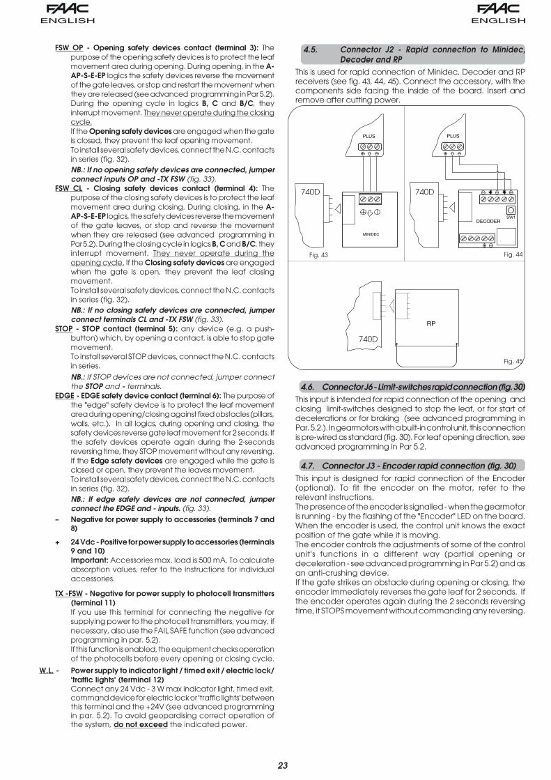
4.5. Connector J2 - Rapid connection to Minidec,Decoder and RP
This is used for rapid connection of Minidec, Decoder and RPreceivers (see fig. 43, 44, 45). Connect the accessory, with thecomponents side facing the inside of the board. Insert andremove after cutting power.
4.6. Connector J6 - Limit-switches rapid connection (fig. 30)This input is intended for rapid connection of the opening andclosing limit-switches designed to stop the leaf, or for start ofdecelerations or for braking (see advanced programming inPar. 5.2.). In gearmotors with a built-in control unit, this connectionis pre-wired as standard (fig. 30). For leaf opening direction, seeadvanced programming in Par 5.2.
4.7. Connector J3 - Encoder rapid connection (fig. 30)This input is designed for rapid connection of the Encoder(optional). To fit the encoder on the motor, refer to therelevant instructions.The presence of the encoder is signalled - when the gearmotoris running - by the flashing of the "Encoder" LED on the board.When the encoder is used, the control unit knows the exactposition of the gate while it is moving.The encoder controls the adjustments of some of the controlunit's functions in a different way (partial opening ordeceleration - see advanced programming in Par 5.2) and asan anti-crushing device.If the gate strikes an obstacle during opening or closing, theencoder immediately reverses the gate leaf for 2 seconds. Ifthe encoder operates again during the 2 seconds reversingtime, it STOPS movement without commanding any reversing.

24
F ++
F
FAIL SAFE:If this function is activated, it enables afunction test of the photocells before anygate movement. If the test fails (photocellsnot serviceable signalled by value onthe display), the gate does not start moving.
= Active = Disabled
PRE-FLASHING (5 s):Activates the flashing lamp for 5 secondsbefore start of movement.
= Disabled = Only before opening
= Only before closing = Before every movement
MAXIMUM TORQUE AT INITIAL THRUST:The motor operate at maximum torque(ignoring the torque setting) at start ofmovement. Useful for heavy leaves.
= Active = Disabled
FINAL BRAKING:When the gate engages the opening orclosing limit-switch, a braking stroke can beselected to ensure the leaf is stoppedimmediately. If decelerations are selected,braking starts when they finish.At value, braking is disabled.Time can be adjusted from to in0.01-second steps.
= Braking disabledfrom to = Timed braking
FORCE:Adjusts Motor thrust.
= minimum force = maximum force
STATUS OF AUTOMATED SYSTEM:Exit from programming, save data, andreturn to gate status viewing.
= Closed = Now opening = At "STOP" = Open = Pause = "FAIL SAFE" tripped = Now closing = Now reversing = Photocells tripped
FUNCTION LOGICS (see table of logics): = Automatic
= "Stepped" automatic = "Safety" Automatic = Semi-automatic
= "Stepped" Semi-automatic = Dead-man = "B" Semi-automatic
= Mixed Log. (B opening / C closing)
PAUSE TIME:This has effect only if the automatic logicwas selected. Adjustable from to sec. in one-second steps.Subsequently, display changes to minutesand tens of seconds (separated by apoint) and time is adjusted in 10-secondsteps, up to the maximum value of minutes.
E.g. if the display shows , pause timeis 2 min. and 50 sec.
BASIC PROGRAMMING
5. PROGRAMMINGTo program operation of the automated system, you have toaccess the "PROGRAMMING" mode.Programming is split into two parts: BASIC and ADVANCED.
5.1. BASIC PROGRAMMINGTo access BASIC PROGRAMMING, press key F:•if you press it (and hold it down), the display shows the name
of the first function.•if you release the key, the display shows the value of the
function that can be modified with keys + and -.•if you press F again (and hold it down), the display shows the
name of the next function, etc.•when you reach the last function, press F to exit the program,
and the display resumes showing the gate status.The following table shows the sequence of functions accessiblein BASIC PROGRAMMING:
Display Function Default
Display Function Default
ADVANCED PROGRAMMING
OPENING DIRECTION:Indicates the gate opening movement and makesit possible not to change the motor and limit-switches connections on the terminal board.
= Right-hand opening movement = Left-hand opening movement
5.2. ADVANCED PROGRAMMINGTo access ADVANCED PROGRAMMING, press key F and, as youhold it down, press key +:
•if you release key + , the display indicates the name of the firstfunction.
•if you release key F too, the display shows the value of thefunction that can be modified with keys + and -.
•if you press key F (and hold it down), the display shows thename of the next function, and if you release it, the value thatcan be modified with keys + and - is shown.
•when you reach the last function, press F to exit the program,and the display resumes showing the gate status.
The following table shows the sequence of functions accessiblein ADVANCED PROGRAMMING:
25
Display Function Default Display Function Default
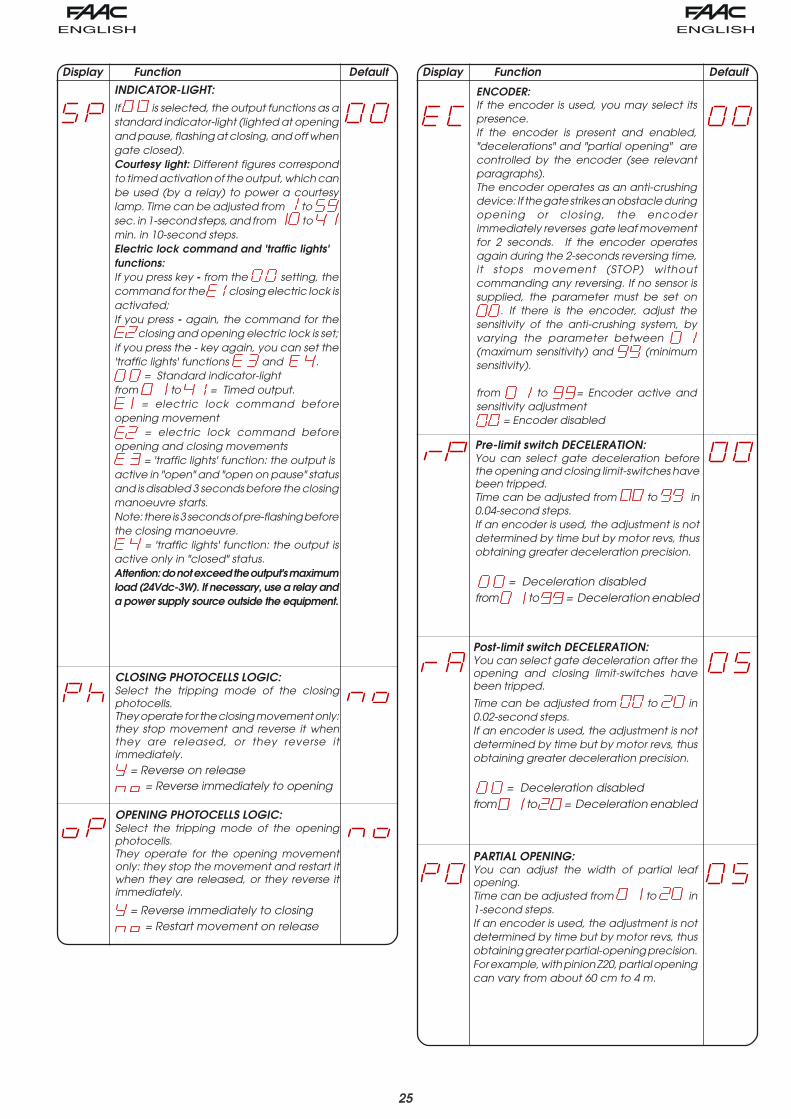
PARTIAL OPENING:You can adjust the width of partial leafopening.Time can be adjusted from to in1-second steps.If an encoder is used, the adjustment is notdetermined by time but by motor revs, thusobtaining greater partial-opening precision.For example, with pinion Z20, partial openingcan vary from about 60 cm to 4 m.
ENCODER:If the encoder is used, you may select itspresence.If the encoder is present and enabled,"decelerations" and "partial opening" arecontrolled by the encoder (see relevantparagraphs).The encoder operates as an anti-crushingdevice: If the gate strikes an obstacle duringopening or closing, the encoderimmediately reverses gate leaf movementfor 2 seconds. If the encoder operatesagain during the 2-seconds reversing time,it stops movement (STOP) withoutcommanding any reversing. If no sensor issupplied, the parameter must be set on
. If there is the encoder, adjust thesensitivity of the anti-crushing system, byvarying the parameter between (maximum sensitivity) and (minimumsensitivity).
from to = Encoder active andsensitivity adjustment
= Encoder disabled
Pre-limit switch DECELERATION:You can select gate deceleration beforethe opening and closing limit-switches havebeen tripped.Time can be adjusted from to in0.04-second steps.If an encoder is used, the adjustment is notdetermined by time but by motor revs, thusobtaining greater deceleration precision.
= Deceleration disabledfrom to = Deceleration enabled
Post-limit switch DECELERATION:You can select gate deceleration after theopening and closing limit-switches havebeen tripped.
Time can be adjusted from to in0.02-second steps.If an encoder is used, the adjustment is notdetermined by time but by motor revs, thusobtaining greater deceleration precision.
= Deceleration disabledfrom to = Deceleration enabled
OPENING PHOTOCELLS LOGIC:Select the tripping mode of the openingphotocells.They operate for the opening movementonly: they stop the movement and restart itwhen they are released, or they reverse itimmediately.
= Reverse immediately to closing = Restart movement on release
CLOSING PHOTOCELLS LOGIC:Select the tripping mode of the closingphotocells.They operate for the closing movement only:they stop movement and reverse it whenthey are released, or they reverse itimmediately.
= Reverse on release = Reverse immediately to opening
INDICATOR-LIGHT:If is selected, the output functions as astandard indicator-light (lighted at openingand pause, flashing at closing, and off whengate closed).Courtesy light: Different figures correspondto timed activation of the output, which canbe used (by a relay) to power a courtesylamp. Time can be adjusted from to sec. in 1-second steps, and from to min. in 10-second steps.Electric lock command and 'traffic lights'functions:If you press key - from the setting, thecommand for the closing electric lock isactivated;If you press - again, the command for the
closing and opening electric lock is set;if you press the - key again, you can set the'traffic lights' functions and .
= Standard indicator-lightfrom to = Timed output.
= electric lock command beforeopening movement
= electric lock command beforeopening and closing movements
= 'traffic lights' function: the output isactive in "open" and "open on pause" statusand is disabled 3 seconds before the closingmanoeuvre starts.Note: there is 3 seconds of pre-flashing beforethe closing manoeuvre.
= 'traffic lights' function: the output isactive only in "closed" status.Attention: do not exceed the output's maximumload (24Vdc-3W). If necessary, use a relay anda power supply source outside the equipment.
26
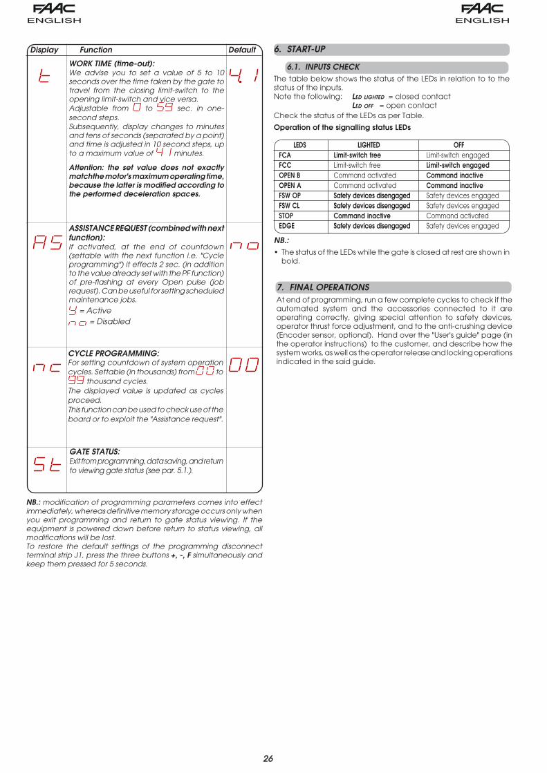
ASSISTANCE REQUEST (combined with nextfunction):If activated, at the end of countdown(settable with the next function i.e. "Cycleprogramming") it effects 2 sec. (in additionto the value already set with the PF function)of pre-flashing at every Open pulse (jobrequest). Can be useful for setting scheduledmaintenance jobs.
= Active = Disabled
WORK TIME (time-out):We advise you to set a value of 5 to 10seconds over the time taken by the gate totravel from the closing limit-switch to theopening limit-switch and vice versa.Adjustable from to sec. in one-second steps.Subsequently, display changes to minutesand tens of seconds (separated by a point)and time is adjusted in 10 second steps, upto a maximum value of minutes.
Attention: the set value does not exactlymatchthe motor's maximum operating time,because the latter is modified according tothe performed deceleration spaces.
CYCLE PROGRAMMING:For setting countdown of system operationcycles. Settable (in thousands) from to
thousand cycles.The displayed value is updated as cyclesproceed.This function can be used to check use of theboard or to exploit the "Assistance request".
GATE STATUS:Exit from programming, data saving, and returnto viewing gate status (see par. 5.1.).
Display Function Default
NB.: modification of programming parameters comes into effectimmediately, whereas definitive memory storage occurs only whenyou exit programming and return to gate status viewing. If theequipment is powered down before return to status viewing, allmodifications will be lost.To restore the default settings of the programming disconnectterminal strip J1, press the three buttons +, -, F simultaneously andkeep them pressed for 5 seconds.
NB.:• The status of the LEDs while the gate is closed at rest are shown in
bold.
7. FINAL OPERATIONSAt end of programming, run a few complete cycles to check if theautomated system and the accessories connected to it areoperating correctly, giving special attention to safety devices,operator thrust force adjustment, and to the anti-crushing device(Encoder sensor, optional). Hand over the "User's guide" page (inthe operator instructions) to the customer, and describe how thesystem works, as well as the operator release and locking operationsindicated in the said guide.
6. START-UP
6.1. INPUTS CHECKThe table below shows the status of the LEDs in relation to to thestatus of the inputs.Note the following: LED LIGHTED = closed contact
LED OFF = open contactCheck the status of the LEDs as per Table.
Operation of the signalling status LEDs
LEDS LIGHTED OFFFCA Limit-switch free Limit-switch engagedFCC Limit-switch free Limit-switch engagedOPEN B Command activated Command inactiveOPEN A Command activated Command inactiveFSW OP Safety devices disengaged Safety devices engagedFSW CL Safety devices disengaged Safety devices engagedSTOP Command inactive Command activatedEDGE Safety devices disengaged Safety devices engaged

27
Tab
. 3/a
Tab
. 3/b
Tab
. 3/c
Tab
. 3/d
"A"
cig
oLSESL
UP
SUT
ATSET
AG
A-NE
PO
B-NE
PO
POTS
SECI
VED
YTEFAS
GNI
NEP
OSE
CIVE
DYTEF
ASG
NISOL
CE
CIVE
DYTEF
ASL
C/P
OE
CIVE
DYTEF
ASE
GDE
DESOL
Cs
esol
cd
na
fa
ele
hts
ne
pO
)1(
emit
esu
ap
retf
ati
laitr
ap
eht
rof
fa
els
ne
pO
retf
as
esol
cd
na
emit
gni
ne
po
)1(
emit
esu
ap
tc
effe
oN
)d
elb
asid
NE
PO(
tc
effe
oN
tc
effe
oN
)d
elb
asid
NE
PO(
ESU
APn
oNE
PO
)3()
1(e
mites
ua
ps
da
ole
R
sp
otSn
oitar
ep
o
tc
effe
oN
)d
elb
asid
AN
EP
O.
gn
po.tr
ap
no
fi()
3()
1(e
mites
ua
ps
da
ole
R)
1(e
mites
ua
ps
da
ole
R)
del
basi
dN
EP
O()
1(e
mites
ua
ps
da
ole
R)
del
basi
dN
EP
O(
GNIS
OLC
)1(
ylet
aid
em
mif
ael
eht
sn
ep
o-e
Rt
ceff
eo
N)
NE
PO
se
vas(
.2.
5h
par
gar
ap
ees
ots
esre
ver
,es
ael
ern
o,
dn
as
kc
oLn
ep
o)
2("
2r
ofn
ep
oot
sesr
ev
eR
GNI
NEP
O)
3()
1(t
ceff
eo
N.
2.5
hp
arg
ara
pe
est
ceff
eo
Ns
eu
nitn
oc
,es
ael
ern
o,
dn
as
kc
oLg
nin
ep
o)
2("
2r
ofes
olc
ots
esre
ve
R
DEK
COL
)3(
fa
ele
hts
esol
Ct
ceff
eo
N)
del
basi
dN
EP
O(t
ceff
eo
Nt
ceff
eo
N)
del
basi
dN
EP
O(
"P
A"ci
goL
SESLU
P
SUT
ATSET
AG
A-NE
PO
B-NE
PO
POTS
SECI
VED
YTEFAS
GNI
NEP
OSE
CIVE
DYTEF
ASG
NISOL
CE
CIVE
DYTEF
ASL
C/P
OE
CIVE
DYTEF
ASE
GDE
DESOL
Cs
esol
cd
na
fa
ele
hts
ne
pO
emit
esu
ap
retf
ati
laitr
ap
eht
rof
fa
els
ne
pO
retf
as
esol
cd
na
emit
gni
ne
po
emit
esu
ap
tc
effe
oN
)d
elb
asid
NE
PO(
tc
effe
oN
tc
effe
oN
)d
elb
asid
NE
PO(
ESU
APn
oNE
PO
)3(
noit
are
po
sp
otS
sp
otSn
oitar
ep
o
tc
effe
oN
)d
elb
asid
AN
EP
O.
gn
po.tr
ap
no
fi()
3(e
mites
ua
ps
da
ole
R)
del
basi
dN
EP
O(e
mites
ua
ps
da
ole
R)
del
basi
dN
EP
O(e
mites
ua
ps
da
ole
R)
del
basi
dN
EP
O(
GNIS
OLC
ylet
aid
em
mif
ael
eht
sn
ep
o-e
Rt
ceff
eo
N)
NE
PO
se
vas(
.2.
5h
par
gar
ap
ees
ots
esre
ver
,es
ael
ern
o,
dn
as
kc
oLn
ep
o)
2("
2r
ofn
ep
oot
sesr
ev
eR
GNI
NEP
O)
3(n
oitar
ep
os
potS
.2.
5h
par
gar
ap
ees
tc
effe
oN
se
unit
no
c,
esa
eler
no
,d
na
sk
coL
gni
ne
po
)2(
"2
rof
esol
cot
sesr
ev
eR
DEK
COL
,d
eg
ag
ne
se
civ
ed
ytef
aSg
nisol
Chti
w(f
ael
eht
ses
olC
)3(
)esl
up
dn
2e
htt
as
ne
po
tc
effe
oN
)d
elb
asid
NE
PO(
tc
effe
oN
tc
effe
oN
)d
elb
asid
NE
PO(
"S"ci
goL
SESLU
P
SUT
ATSET
AG
A-NE
PO
B-NE
PO
POTS
SECI
VED
YTEFAS
GNI
NEP
OSE
CIVE
DYTEF
ASG
NISOL
CE
CIVE
DYTEF
ASL
C/P
OE
CIVE
DYTEF
ASE
GDE
DESOL
Cs
esol
cd
na
fa
ele
hts
ne
pO
emit
esu
ap
retf
ati
laitr
ap
eht
rof
fa
els
ne
pO
retf
as
esol
cd
na
emit
gni
ne
po
emit
esu
ap
tc
effe
oN
)d
elb
asid
NE
PO(
tc
effe
oN
tc
effe
oN
)d
elb
asid
NE
PO(
ESU
APn
oNE
PO
)3(
ylet
aid
em
mif
ael
eht
ses
olc-
eR
sp
otSn
oitar
ep
o
tc
effe
oN
)d
elb
asid
AN
EP
O.
gn
po.tr
ap
no
fi(N
EP
O("
5r
etfa
ses
olc
,es
ael
ern
O)
3()
del
basi
d"
5r
etfa
ses
olc
,es
ael
ern
O)
del
basi
dN
EP
O()
1(e
mites
ua
ps
da
ole
R)
del
basi
dN
EP
O(
GNIS
OLC
ylet
aid
em
mif
ael
eht
sn
ep
o-e
Rt
ceff
eo
N)
NE
PO
se
vas(
.2.
5h
par
gar
ap
ees
ots
esre
ver
,es
ael
ern
o,
dn
as
kc
oLn
ep
o)
2("
2r
ofn
ep
oot
sesr
ev
eR
GNI
NEP
O)
3(yl
etai
de
mmi
fa
ele
hts
esol
c-e
R.
2.5
hp
arg
ara
pe
est
ceff
eo
N)
NE
PO
se
vas(
se
unit
no
c,
esa
eler
no
,d
na
sk
coL
gni
ne
po
)2(
"2
rof
esol
cot
sesr
ev
eR
DEK
COL
)3(
fa
ele
hts
esol
Ct
ceff
eo
N)
del
basi
dN
EP
O(t
ceff
eo
Nt
ceff
eo
N)
del
basi
dN
EP
O
"E"ci
goL
SESLU
P
SUT
ATSET
AG
A-NE
PO
B-NE
PO
POTS
SECI
VED
YTEFAS
GNI
NEP
OSE
CIVE
DYTEF
ASG
NISOL
CE
CIVE
DYTEF
ASL
C/P
OE
CIVE
DYTEF
ASE
GDE
DESOL
Cf
ael
eht
sn
ep
Ol
aitra
pe
htr
off
ael
sn
ep
Oe
mitg
nin
ep
ot
ceff
eo
N)
del
basi
dN
EP
O(t
ceff
eo
Nt
ceff
eo
N)
del
basi
dN
EP
O(
NEP
O)
3(yl
etai
de
mmi
fa
ele
hts
esol
c-e
R
sp
otSn
oitar
ep
o
tc
effe
oN
)d
elb
asid
AN
EP
O.
gn
po.tr
ap
no
fi()
3(t
ceff
eo
N)
del
basi
dN
EP
O(t
ceff
eo
N)
del
basi
dN
EP
O(
GNIS
OLC
ylet
aid
em
mif
ael
eht
sn
ep
o-e
Rt
ceff
eo
N)
NE
PO
se
vas(
.2.
5h
par
gar
ap
ees
ots
esre
ver
,es
ael
ern
o,
dn
as
kc
oLn
ep
o)
2("
2r
ofn
ep
oot
sesr
ev
eR
GNI
NEP
O)
3(n
oitar
ep
os
potS
.2.
5h
par
gar
ap
ees
tc
effe
oN
se
unit
no
c,
esa
eler
no
,d
na
sk
coL
gni
ne
po
)2(
"2
rof
esol
cot
sesr
ev
eR
DEK
COL
,d
eg
ag
ne
se
civ
ed
ytef
aSg
nisol
Chti
w(f
ael
eht
ses
olC
)3(
)esl
up
dn
2e
htt
as
ne
po
tc
effe
oN
)d
elb
asid
NE
PO(
tc
effe
oN
tc
effe
oN
)d
elb
asid
NE
PO(

28
Tab
. 3/e
Tab
. 3/f
Tab
. 3/g
Tab
. 3/h
"PE"
cig
oLSESL
UP
SUT
ATSET
AG
A-NE
PO
B-NE
PO
POTS
SECI
VED
YTEFAS
GNI
NEP
OSE
CIVE
DYTEF
ASG
NISOL
CE
CIVE
DYTEF
ASL
C/P
OE
CIVE
DYTEF
ASE
GDE
DESOL
Cf
ael
eht
sn
ep
Ol
aitra
pe
htr
off
ael
sn
ep
Oe
mitg
nin
ep
ot
ceff
eo
N)
del
basi
dN
EP
O(t
ceff
eo
N)
del
basi
dN
EP
O(t
ceff
eo
N
NEP
O)
3(yl
etai
de
mmi
fa
ele
hts
esol
c-e
R
sp
otSn
oitar
ep
o
AN
EP
O.
gn
po.tr
ap
no
fi(t
ceff
eo
N)
del
basi
d)
3()
del
basi
dN
EP
O(t
ceff
eo
N)
del
basi
dN
EP
O(t
ceff
eo
N
GNIS
OLC
noit
are
po
sp
otS)
NE
PO
se
vas(
tc
effe
oN
.2.
5h
par
gar
ap
ees
ots
esre
ver
,es
ael
ern
o,
dn
as
kc
oLn
ep
o)
2("
2r
ofn
ep
oot
sesr
ev
eR
GNI
NEP
O)
3(n
oitar
ep
os
potS
.2.
5h
par
gar
ap
ees
tc
effe
oN
se
unit
no
c,
esa
eler
no
,d
na
sk
coL
gni
ne
po
)2(
"2
rof
esol
cot
sesr
ev
eR
DEK
COL
)3(
noit
ceri
desr
ev
erni
tn
em
ev
om
strats
eR
)p
otSa
retf
as
esol
cs
ya
wla(
tc
effe
oN
)d
elb
asid
NE
PO(
tc
effe
oN
)N
EP
Os
elb
asid
ti,
ne
po
tsu
mti
fi(t
ceff
eo
N)
NE
PO
sel
basi
dti
,es
olc
tsu
mti
fi()
del
basi
dN
EP
O(t
ceff
eo
N
"C"
cig
oLN
WO
DDLE
HS
YA
WLA
SLO
RTN
OC
SESLU
P
SUT
ATSET
AG
)g
nin
ep
o(A-
NEP
O)
gnis
olc(
B-NE
PO
POTS
SECI
VED
YTEFAS
GNI
NEP
OSE
CIVE
DYTEF
ASG
NISOL
CE
CIVE
DYTEF
ASL
C/P
OE
CIVE
DYTEF
ASE
GDE
DESOL
Cf
ael
eht
sn
ep
Ot
ceff
eo
N)
del
basi
dA-
NE
PO(
tc
effe
oN
)d
elb
asid
AN
EP
O(t
ceff
eo
Nt
ceff
eo
N)
del
basi
dA
NE
PO(
NEP
Ot
ceff
eo
N)
del
basi
dB-
NE
PO(
fa
ele
hts
esol
Ct
ceff
eo
N)
del
basi
dB/
A-NE
PO(
tc
effe
oN
)d
elb
asid
AN
EP
O(t
ceff
eo
N)
del
basi
dB
NE
PO(
tc
effe
oN
)d
elb
asid
BN
EP
O(t
ceff
eo
N)
del
basi
dB/
A-N
EP
O(
GNIS
OLC
noit
are
po
sp
otS/
noit
are
po
sp
otSt
ceff
eo
Nn
oitar
ep
os
potS
)d
elb
asid
B-N
EP
O(n
oitar
ep
os
potS
)d
elb
asid
B/A-
NE
PO(
)2(
"2
rof
ne
po
ots
esre
ve
R
GNI
NEP
O/
noit
are
po
sp
otSn
oitar
ep
os
potS
)d
elb
asid
A-N
EP
O(t
ceff
eo
N)
2("
2r
ofes
olc
ots
esre
ve
R
"B"
cig
oLSESL
UP
SUT
ATSET
AG
)g
nin
ep
o(A-
NEP
O)
gnis
olc(
B-NE
PO
POTS
SECI
VED
YTEFAS
GNI
NEP
OSE
CIVE
DYTEF
ASG
NISOL
CE
CIVE
DYTEF
ASL
C/P
OE
CIVE
DYTEF
ASE
GDE
DESOL
Cf
ael
eht
sn
ep
Ot
ceff
eo
Nt
ceff
eo
N)
del
basi
dA
NE
PO(
tc
effe
oN
tc
effe
oN
)d
elb
asid
AN
EP
O(
NEP
Ot
ceff
eo
Nf
ael
eht
ses
olC
NE
PO(
tc
effe
oN
)d
elb
asid
Bt
ceff
eo
Nt
ceff
eo
N)
del
basi
dB
NE
PO(
tc
effe
oN
)d
elb
asid
BN
EP
O(t
ceff
eo
N)
del
basi
dB/
A-N
EP
O(
GNIS
OLC
ne
po
ots
esre
ve
Rt
ceff
eo
Ns
potS
noit
are
po
tc
effe
oN
)A
NE
PO
se
vas(
noit
are
po
sp
otS)
del
basi
dB-
NE
PO(
noit
are
po
sp
otS)
del
basi
dB/
A-N
EP
O(
)2(
"2
rof
ne
po
ots
esre
ve
R
GNI
NEP
Ot
ceff
eo
Nt
ceff
eo
Nn
oitar
ep
os
potS
)d
elb
asid
A-N
EP
O(t
ceff
eo
N)
2("
2r
ofes
olc
ots
esre
ve
R
DEK
COL
fa
ele
hts
ne
pO
fa
ele
hts
esol
Ct
ceff
eo
N)
del
basi
dB/
ANE
PO(
tc
effe
oN
)d
elb
asid
A-N
EP
O(t
ceff
eo
N)
del
basi
dB
NE
PO(
tc
effe
oN
)d
elb
asid
B/A
NE
PO(
"C/
B"ci
goL
SLO
RTN
OC
NU
ROT
DLO
HG
NISOL
C/ESLU
PG
NINE
PO
SESLU
P
SUT
ATSET
AG
)g
nin
ep
o(A-
NEP
O)
gnis
olc(
B-NE
PO
POTS
SECI
VED
YTEFAS
GNI
NEP
OSE
CIVE
DYTEF
ASG
NISOL
CE
CIVE
DYTEF
ASL
C/P
OE
CIVE
DYTEF
ASE
GDE
DESOL
Cf
ael
eht
sn
ep
Ot
ceff
eo
Nt
ceff
eo
N)
del
basi
dA
NE
PO(
tc
effe
oN
tc
effe
oN
)d
elb
asid
AN
EP
O(
NEP
Ot
ceff
eo
Nf
ael
eht
ses
olC
tc
effe
oN
)d
elb
asid
BN
EP
O(t
ceff
eo
Nt
ceff
eo
N)
del
basi
dB
NE
PO(
tc
effe
oN
)d
elb
asid
BN
EP
O(t
ceff
eo
N)
del
basi
dB/
A-N
EP
O(
GNIS
OLC
ne
po
ots
esre
ve
Rt
ceff
eo
Ns
potS
noit
are
po
tc
effe
oN
)A
NE
PO
se
vas(
noit
are
po
sp
otS)
del
basi
dB-
NE
PO(
noit
are
po
sp
otS)
del
basi
dB/
A-N
EP
O(
)2(
"2
rof
ne
po
ots
esre
ve
R
GNI
NEP
Ot
ceff
eo
Nt
ceff
eo
Nn
oitar
ep
os
potS
)d
elb
asid
A-N
EP
O(t
ceff
eo
N)
2("
2r
ofes
olc
ots
esre
ve
R
DEK
COL
fa
ele
hts
ne
pO
fa
ele
hts
esol
CN
EP
O(t
ceff
eo
N)
del
basi
dB/
At
ceff
eo
N)
del
basi
dA-
NE
PO(
tc
effe
oN
)d
elb
asid
BN
EP
O(t
ceff
eo
N)
del
basi
dB/
AN
EP
O(
(1)I
f ma
inta
ine
d, i
t pro
long
s the
pa
use
unt
il disa
ble
d b
y th
e c
om
ma
nd (t
ime
r fun
ctio
n)(3
) Dur
ing
the
pa
rtia
l op
eni
ng c
ycle
, an
OPE
N A
pul
se c
aus
es t
ota
l op
eni
ng.
(2)I
f a n
ew
pul
se o
cc
urs w
ithin
2 se
co
nds a
fter r
eve
rsin
g, i
t im
me
dia
tely
sto
ps o
pe
ratio
n.N
B.: E
ffec
ts o
n o
the
r ac
tive
pul
se in
put
s in
bra
cke
ts.
���������������� ����Read the instructions carefully before using the product andkeep them for future consultation.
GENERAL SAFETY RULESIf installed and used correctly, the 740-741 automated system willensure a high degree of safety.Some simple rules regarding behaviour will avoid any accidentaltrouble:• Do not stand near the automated system and do not allow
children and other people or things to stand there, especiallywhile it is operating.
• Keep radiocontrols or any other pulse generator well away fromchildren to prevent the automated system from being activatedinvoluntarily.
• Do not allow children to play with the automated system.• Do not willingly obstruct gate movement.• Prevent any branches or shrubs from interfering with gate
movement.• Keep light signalling systems efficient and clearly visible.• Do not attempt to activate the gate by hand unless you have
released it.• In the event of malfunctions, release the gate to allow access
and wait for qualified technical personnel to do the necessarywork.
• After enabling manual operation, switch off the power supply tothe system before restoring normal operation.
• Do not make any alterations to the components of the automatedsystem.
• Do not attempt any kind of repair of direct action whatsoeverand contact qualified personnel only.
• Call in qualified personnel at least every 6 months to check theefficiency of the automated system, safety devices and earthconnection.DESCRIPTION
The 740-741 automated system is ideal for controlling vehicle accessareas of medium transit frequency.The 740-741 automated system for sliding gates is an electro-mechanical operator transmitting motion to the sliding gate via arack pinion or chain appropriately coupled to the gate.Operation of the sliding gate is controlled by an electronic controlunit housed inside the operator or in a hermetically sealed outdoorenclosure.When, with the gate closed, the unit receives an opening commandby radiocontrol or from another suitable device, it activates themotor until the opening position is reached.If automatic operation was set, the gate re-closes automaticallyafter the selected pause time has elapsed.If the semi-automatic operation was set, a second pulse must besent to close the gate again.An opening pulse during re-closing, always causes movement tobe reversed.A stop pulse (if provided) always stops movement.The light signalling indicates that the gate is currently moving.For details on sliding gate behaviour in different function logics,consult the installation technician.The automated systems include obstacle-detection and/or safetydevices (photocells, edges) that prevent the gate from closing when
1
2
31
2
3
Fig.01 Fig.02
������������
there is an obstacle in the area they protect.The system ensures mechanical locking when the motor is notoperating and, therefore, it is not necessary to install any lock.Manual opening is, therefore, only possible by using the release system.The gearmotor does not have a mechanical clutch and, therefore, itis coupled to a unit with an electronic clutch offering the necessaryanti-crushing safety if the system is completed with the necessary safetydevices.A convenient manual release with customised key makes it possibleto move the gate in the event of a power failure or malfunction.
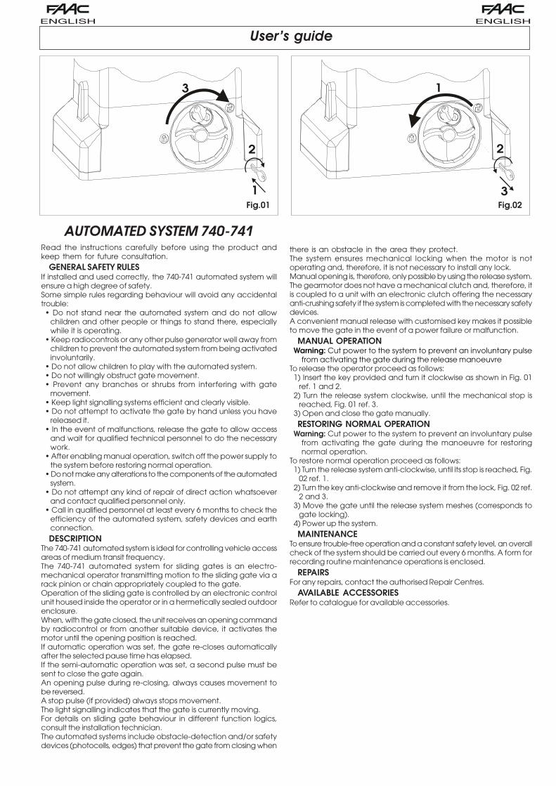
MANUAL OPERATIONWarning: Cut power to the system to prevent an involuntary pulse
from activating the gate during the release manoeuvreTo release the operator proceed as follows:1) Insert the key provided and turn it clockwise as shown in Fig. 01
ref. 1 and 2.2) Turn the release system clockwise, until the mechanical stop is
reached, Fig. 01 ref. 3.3) Open and close the gate manually.RESTORING NORMAL OPERATION
Warning: Cut power to the system to prevent an involuntary pulsefrom activating the gate during the manoeuvre for restoringnormal operation.
To restore normal operation proceed as follows:1) Turn the release system anti-clockwise, until its stop is reached, Fig.
02 ref. 1.2) Turn the key anti-clockwise and remove it from the lock, Fig. 02 ref.
2 and 3.3) Move the gate until the release system meshes (corresponds to
gate locking).4) Power up the system.MAINTENANCE
To ensure trouble-free operation and a constant safety level, an overallcheck of the system should be carried out every 6 months. A form forrecording routine maintenance operations is enclosed.
REPAIRSFor any repairs, contact the authorised Repair Centres.
AVAILABLE ACCESSORIESRefer to catalogue for available accessories.

Le descrizioni e le illustrazioni del presente manuale non sono impegnative. La FAAC si riserva il diritto, lasciandoinalterate le caratteristiche essenziali dell’apparecchiatura, di apportare in qualunque momento e senzaimpegnarsi ad aggiornare la presente pubblicazione, le modifiche che essa ritiene convenienti per miglioramentitecnici o per qualsiasi altra esigenza di carattere costruttivo o commerciale.
The descriptions and illustrations contained in the present manual are not binding. FAAC reserves the right, whilstleaving the main features of the equipments unaltered, to undertake any modifications it holds necessary for eithertechnical or commercial reasons, at any time and without revising the present publication.
Les descriptions et les illustrations du présent manuel sont fournies à titre indicatif. FAAC se réserve le droitd’apporter à tout moment les modifications qu’elle jugera utiles sur ce produit tout en conservant les caractéristiquesessentielles, sans devoir pour autant mettre à jour cette publication.
Die Beschreibungen und Abbildungen in vorliegendem Handbuch sind unverbindlich. FAAC behält sich das Rechtvor, ohne die wesentlichen Eigenschaften dieses Gerätes zu verändern und ohne Verbindlichkeiten in Bezug aufdie Neufassung der vorliegenden Anleitungen, technisch bzw. konstruktiv/kommerziell bedingte Verbesserungenvorzunehmen.
Las descripciones y las ilustraciones de este manual no comportan compromiso alguno. FAAC se reserva elderecho, dejando inmutadas las características esenciales de los aparatos, de aportar, en cualquier momentoy sin comprometerse a poner al día la presente publicación, todas las modificaciones que considere oportunaspara el perfeccionamiento técnico o para cualquier otro tipo de exigencia de carácter constructivo o comercial.
De beschrijvingen in deze handleiding zijn niet bindend. FAAC behoudt zich het recht voor op elk willekeurigmoment de veranderingen aan te brengen die het bedrijf nuttig acht met het oog op technische verbeteringenof alle mogelijke andere productie- of commerciële eisen, waarbij de fundamentele eigenschappen van deapparaat gehandhaafd blijven, zonder zich daardoor te verplichten deze publicatie bij te werken.
Timbro del Rivenditore:/Distributor’s Stamp:/Timbre de l’Agent:/ Fachhändlerstempel:/Sello del Revendedor:/Stempel van de dealer:
7324
84 -
Rev
. B -
FAAC S.p.A.Via Benini, 140069 Zola Predosa (BO) - ITALIATel.: 051/61724 - Fax: 051/758518www.faacgroup.com
FAAC per la natura• La presente istruzione è realizzata al 100% in carta riciclata.• Non disperdete nell'ambiente gli imballaggi dei componenti dell'automazione bensì selezionate
i vari materiali (es. cartone, polistirolo) secondo prescrizioni locali per lo smaltimento rifiuti e lenorme vigenti.
FAAC for the environment• The present manual is produced in 100% recycled paper• Respect the environment. Dispose of each type of product packaging material (card, polystyrene)
in accordance with the provisions for waste disposal as specified in the country of installation.
FAAC écologique• La présente notice a été réalisée 100% avec du papier recyclé.• Ne pas jeter dans la nature les emballages des composants de l’automatisme, mais sélectionner
les différents matériaux (ex.: carton, polystyrène) selon la législation locale pour l’élimination desdéchets et les normes en vigueur.
FAAC der Umwelt zuliebe• Vorliegende Anleitungen sind auf 100% Altpapier gedruckt.• Verpackungsstoffe der Antriebskomponenten (z.B. Pappe, Styropor) nach den einschlägigen
Normen der Abfallwirtschaft sortenrein sammeln.
FAAC por la naturaleza.• El presente manual de instrucciones se ha realizado, al 100%, en papel reciclado.• Los materiales utilizados para el embalaje de las distintas partes del sistema automático (cartón,
poliestireno) no deben tirarse al medio ambiente, sino seleccionarse conforme a las prescripcioneslocales y las normas vigentes para el desecho de residuos sólidos.
FAAC voor de natuur• Deze gebruiksaanwijzing is gedrukt op 100% kringlooppapier.• Laat de verpakkingen van de componenten van het automatische systeem niet in het milieu
achter, maar scheidt de verschillende materialen (b.v. karton, polystyreen) volgens de plaatselijkevoorschriften op de afvalverwerkingen en de geldende normen.
cart
a ric
icla
ta 1
00%
per
la n
atur
afo
r na
ture
recy
cled
pap
er 1
00%
ist
umw
eltfr
eund
lich
100%
Altp
apie
rpa
ra la
nat
ural
eza
100%
pap
el r
ecic
lado
papi
er r
ecyc
lé 1
00%
pour
la n
atur
evo
or d
e na
tuur
100%
krin
gloo
ppap
ier