3.1 Dasar Sistem Komunikasi Analog Rev 1
45
Dasar Sist. Telkom 1 Dasar Sistem Telekomunikasi Dasar Sistem Komunikasi Analog
-
Upload
aan-junior -
Category
Documents
-
view
269 -
download
3
description
ebook
Transcript of 3.1 Dasar Sistem Komunikasi Analog Rev 1
Dasar Sist. Telkom 1
Dasar Sistem Telekomunikasi
Dasar Sistem Komunikasi Analog
Obyektif Perkuliahan
Dapat memahami blok diagram sistem komunikasi analog
Dapat memahami beberapa jenis komunikasi analog
Dasar Sist. Telkom 2
Referensi :
MS Iqbal, 2001, Diktat dasar Telkom. Jurusan Teknik
Elektro FT, Unram,
Kennedy & Davis, 1993, Electronic Comm. System,
Fourth Ed, Mc Graw Hill.
Dennis Roddy & John Coolen, 1995, Electronic
Comm. System, Fourth Ed, Prentice Hall Inc. SM Sasongko, Buku Ajar Dasistel. Jurusan Teknik Elektro
FT, Unram.
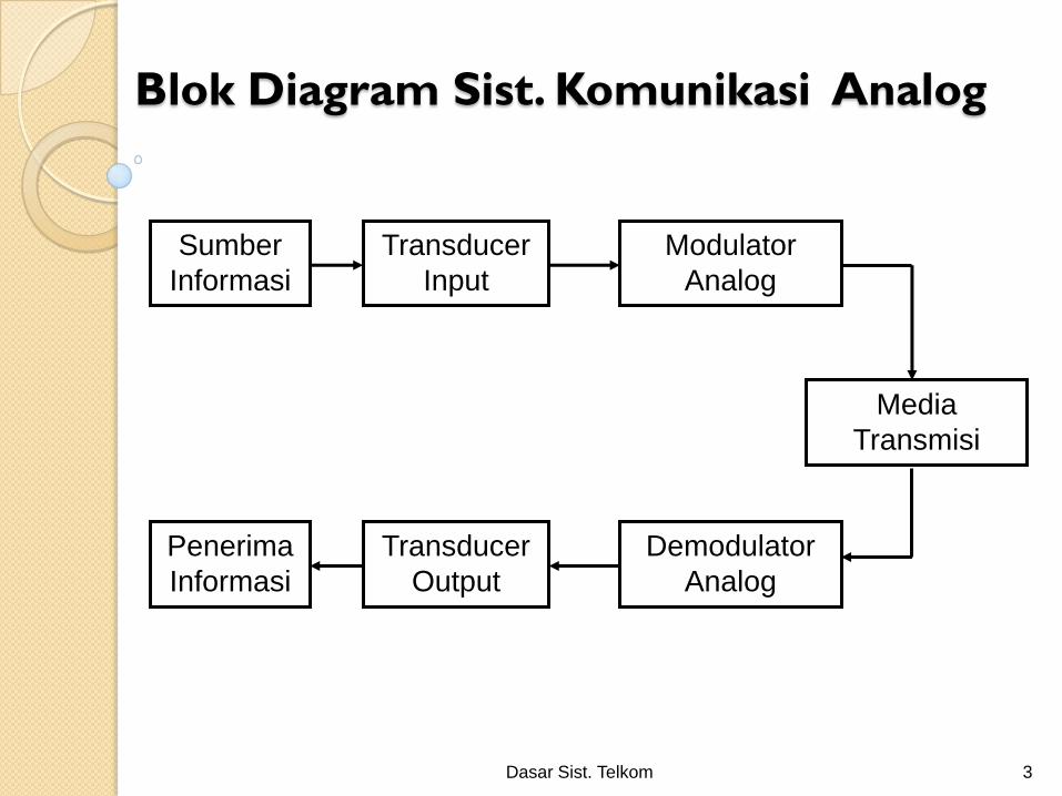
Blok Diagram Sist. Komunikasi Analog
Dasar Sist. Telkom 3
Sumber
Informasi
Transducer
Input
Modulator
Analog
Penerima
Informasi
Transducer
Output
Demodulator
Analog
Media
Transmisi
Dasar Sist. Telkom 4
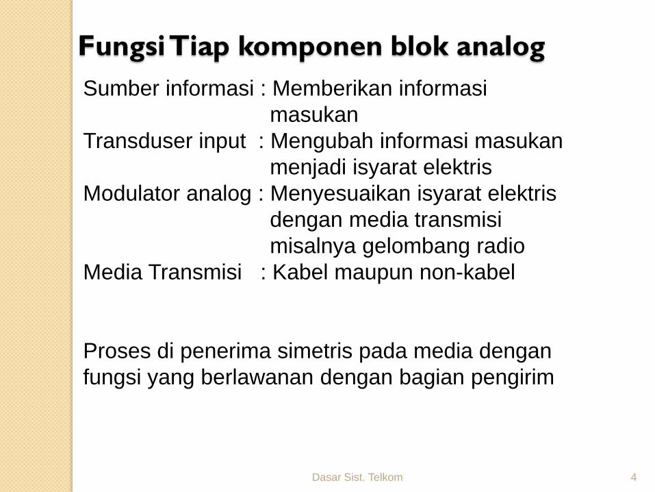
Sumber informasi : Memberikan informasi
masukan
Transduser input : Mengubah informasi masukan
menjadi isyarat elektris
Modulator analog : Menyesuaikan isyarat elektris
dengan media transmisi
misalnya gelombang radio
Media Transmisi : Kabel maupun non-kabel
Proses di penerima simetris pada media dengan
fungsi yang berlawanan dengan bagian pengirim
Fungsi Tiap komponen blok analog
5
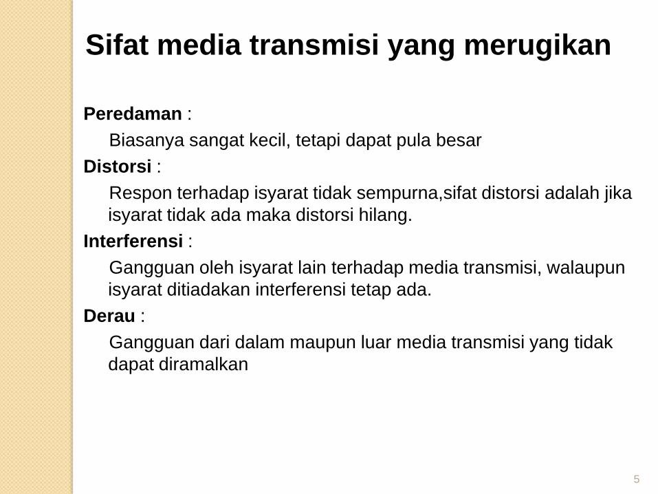
Sifat media transmisi yang merugikan
Peredaman :
Biasanya sangat kecil, tetapi dapat pula besar
Distorsi :
Respon terhadap isyarat tidak sempurna,sifat distorsi adalah jika
isyarat tidak ada maka distorsi hilang.
Interferensi :
Gangguan oleh isyarat lain terhadap media transmisi, walaupun
isyarat ditiadakan interferensi tetap ada.
Derau :
Gangguan dari dalam maupun luar media transmisi yang tidak
dapat diramalkan
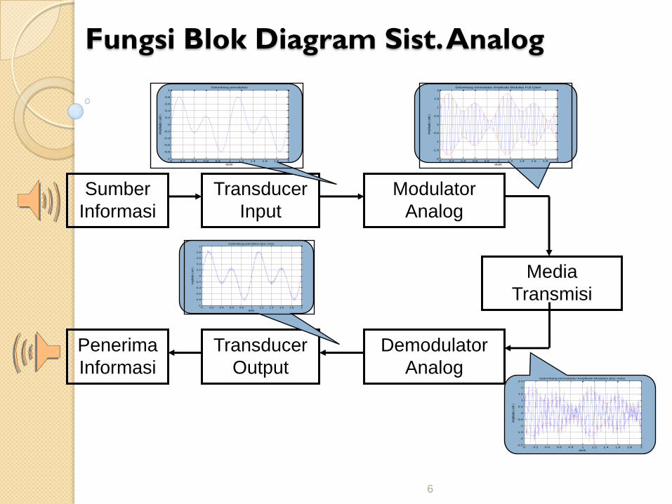
Fungsi Blok Diagram Sist. Analog
6
Sumber
Informasi
Transducer
Input
Modulator
Analog
Penerima
Informasi
Transducer
Output
Demodulator
Analog
Media
Transmisi
0 0.2 0.4 0.6 0.8 1 1.2 1.4 1.6 1.8 2-1
-0.8
-0.6
-0.4
-0.2
0
0.2
0.4
0.6
0.8
1
detik
Am
plitu
do (
volt
)
Gelombang pemodulasi
0 0.2 0.4 0.6 0.8 1 1.2 1.4 1.6 1.8 2-2
-1.5
-1
-0.5
0
0.5
1
1.5
2
detik
Am
plitu
do (
volt
)
Gelombang termodulasi Amplitudo Modulasi Full Carier
0 0.2 0.4 0.6 0.8 1 1.2 1.4 1.6 1.8 2-2.5
-2
-1.5
-1
-0.5
0
0.5
1
1.5
2
2.5
detik
Am
plitu
do (
volt
)
Gelombang termodulasi Amplitudo Modulasi plus noise
0 0.2 0.4 0.6 0.8 1 1.2 1.4 1.6 1.8 2-1
-0.8
-0.6
-0.4
-0.2
0
0.2
0.4
0.6
0.8
1
detik
Am
plitu
do (
volt
)
Gelombang pemodulasi plus noise
Dasar Sist. Telkom 7
MODULASI ANALOG
Double Side Band Full Carrier ( AM )
Double Side Band Supressed Carrier (DSB)
Dasar Sist. Telkom 8
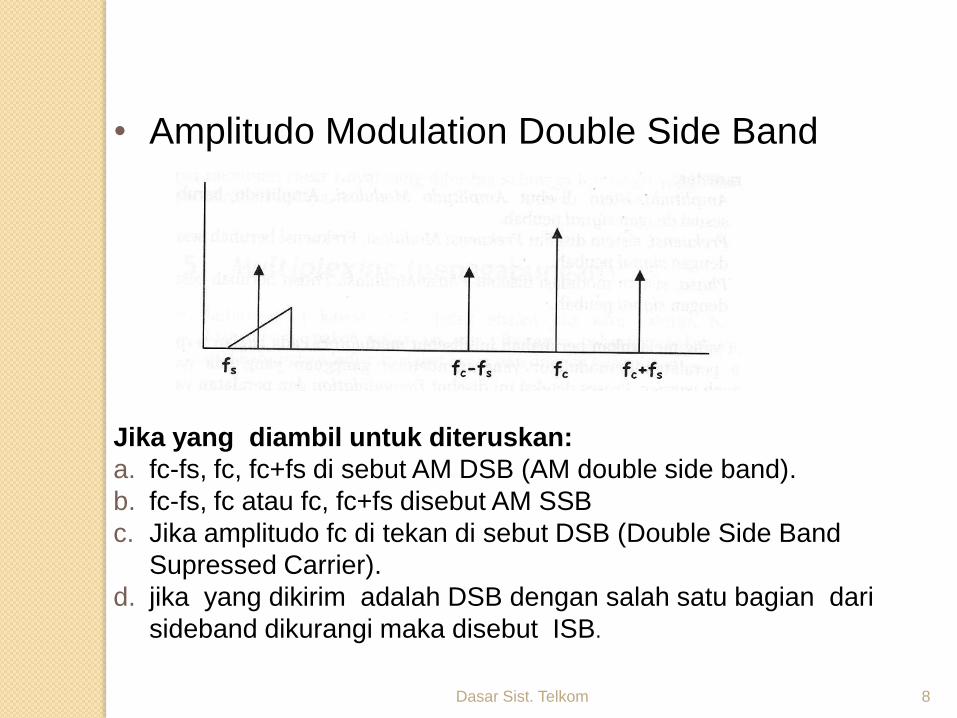
• Amplitudo Modulation Double Side Band
Jika yang diambil untuk diteruskan:
a. fc-fs, fc, fc+fs di sebut AM DSB (AM double side band).
b. fc-fs, fc atau fc, fc+fs disebut AM SSB
c. Jika amplitudo fc di tekan di sebut DSB (Double Side Band
Supressed Carrier).
d. jika yang dikirim adalah DSB dengan salah satu bagian dari
sideband dikurangi maka disebut ISB.
Dasar Sist. Telkom 9
Obyektif Perkuliahan
Dapat memahami teknik modulasi DSBFC ( AM )
Dapat memahami teknik modulasi DSBSC ( DSB )
Dapat memahami indeks modulasi dan efisiensi daya
Dapat memahami spektrum magnitudo dan bandwidth
Referensi :
MS Iqbal, 2001, Diktat dasar Telkom. Jurusan Teknik
Elektro FT, Unram,
Kennedy & Davis, 1993, Electronic Comm. System,
Fourth Ed, Mc Graw Hill.
Dennis Roddy & John Coolen, 1995, Electronic
Comm. System, Fourth Ed, Prentice Hall Inc.
Dasar Sist. Telkom 10
Proses Pengiriman Informasi
• Suatu sinyal carrier murni dibangkitkan pada sisi pengirim / pemancar
• Sinyal carrier dimodulasi / dimodifikasi oleh sinyal informasi agar dapat dipancarkan. Terjadi perubahan karakteristik sinyal carrier yang memuat informasi
• Pada bagian penerima sinyal informasi harus dapat dideteksi dan didemodulasi kembali.
Dasar Sist. Telkom 11
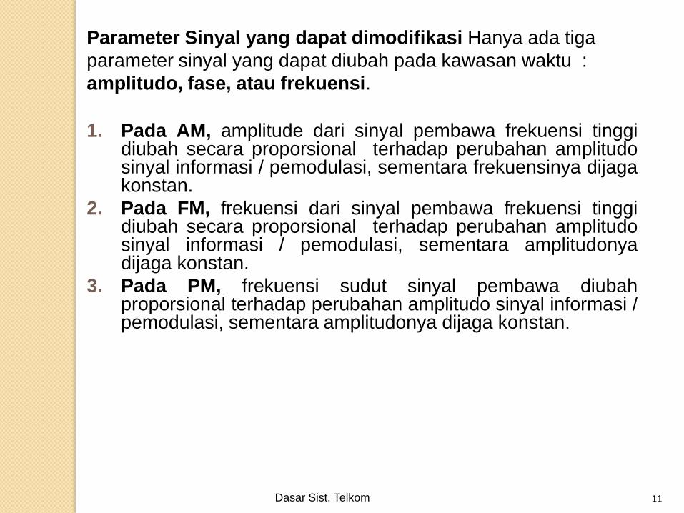
Parameter Sinyal yang dapat dimodifikasi Hanya ada tiga
parameter sinyal yang dapat diubah pada kawasan waktu :
amplitudo, fase, atau frekuensi.
1. Pada AM, amplitude dari sinyal pembawa frekuensi tinggidiubah secara proporsional terhadap perubahan amplitudosinyal informasi / pemodulasi, sementara frekuensinya dijagakonstan.
2. Pada FM, frekuensi dari sinyal pembawa frekuensi tinggidiubah secara proporsional terhadap perubahan amplitudosinyal informasi / pemodulasi, sementara amplitudonyadijaga konstan.
3. Pada PM, frekuensi sudut sinyal pembawa diubahproporsional terhadap perubahan amplitudo sinyal informasi /pemodulasi, sementara amplitudonya dijaga konstan.
Dasar Sist. Telkom 12
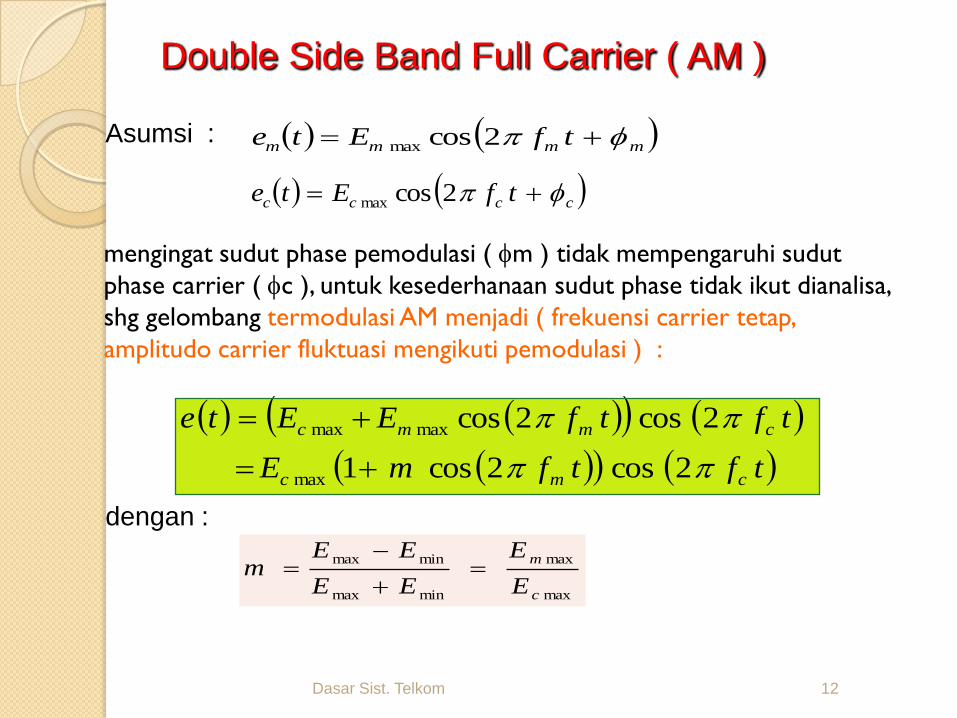
mengingat sudut phase pemodulasi ( m ) tidak mempengaruhi sudut
phase carrier ( c ), untuk kesederhanaan sudut phase tidak ikut dianalisa,
shg gelombang termodulasi AM menjadi ( frekuensi carrier tetap,
amplitudo carrier fluktuasi mengikuti pemodulasi ) :
mmmm tfEte 2cosmax
cccc tfEte 2cosmax
Double Side Band Full Carrier ( AM )
tftfmE
tftfEEte
cmc
cmmc
2cos2cos1
2cos2cos
max
maxmax
dengan :
max
max
minmax
minmax
c
m
E
E
EE
EEm
Asumsi :
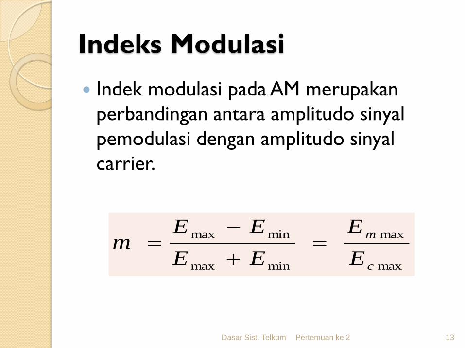
Indeks Modulasi
Indek modulasi pada AM merupakan
perbandingan antara amplitudo sinyal
pemodulasi dengan amplitudo sinyal
carrier.
Dasar Sist. Telkom Pertemuan ke 2 13
max
max
minmax
minmax
c
m
E
E
EE
EEm
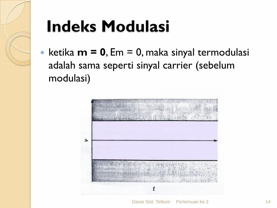
Indeks Modulasi
ketika m = 0, Em = 0, maka sinyal termodulasi
adalah sama seperti sinyal carrier (sebelum
modulasi)
Dasar Sist. Telkom Pertemuan ke 2 14
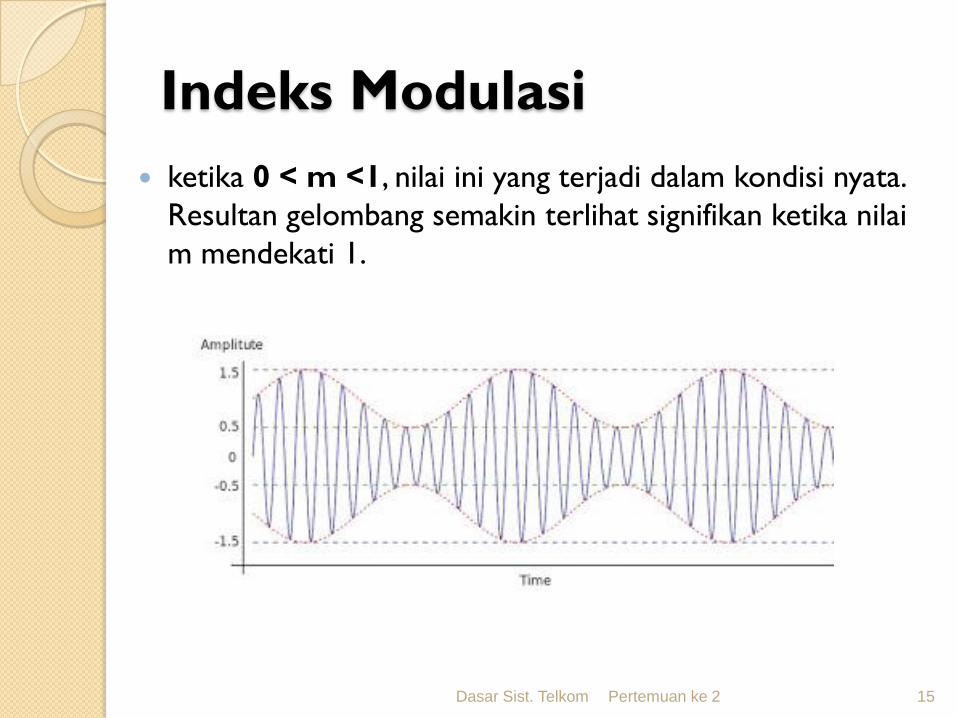
Indeks Modulasi
ketika 0 < m <1, nilai ini yang terjadi dalam kondisi nyata.
Resultan gelombang semakin terlihat signifikan ketika nilai
m mendekati 1.
Dasar Sist. Telkom Pertemuan ke 2 15
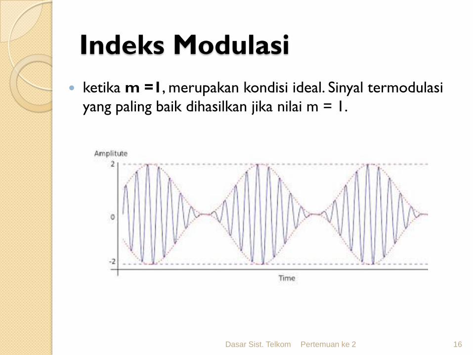
Indeks Modulasi
ketika m =1, merupakan kondisi ideal. Sinyal termodulasi
yang paling baik dihasilkan jika nilai m = 1.
Dasar Sist. Telkom Pertemuan ke 2 16
Indeks Modulasi
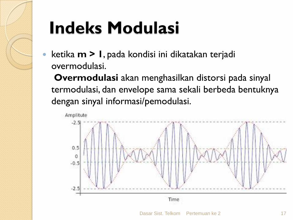
ketika m > 1, pada kondisi ini dikatakan terjadi
overmodulasi.
Overmodulasi akan menghasilkan distorsi pada sinyal
termodulasi, dan envelope sama sekali berbeda bentuknya
dengan sinyal informasi/pemodulasi.
Dasar Sist. Telkom Pertemuan ke 2 17
Dasar Sist. Telkom 18
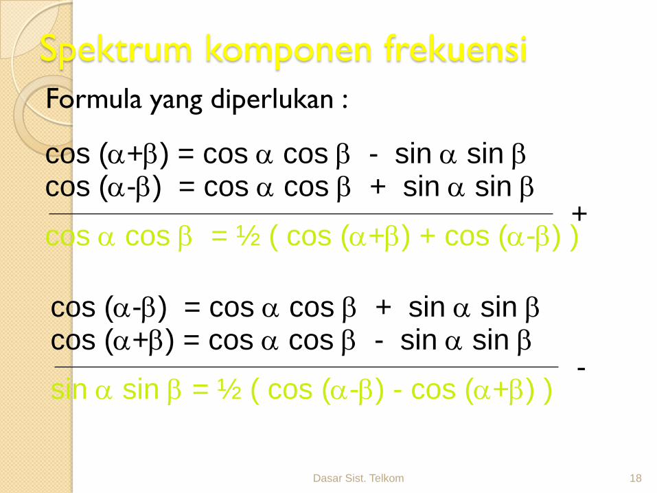
Spektrum komponen frekuensi
Formula yang diperlukan :
cos (+) = cos cos - sin sin cos (-) = cos cos + sin sin
+cos cos = ½ ( cos (+) + cos (-) )
cos (+) = cos cos - sin sin cos (-) = cos cos + sin sin
-sin sin = ½ ( cos (-) - cos (+) )
Dasar Sist. Telkom 19
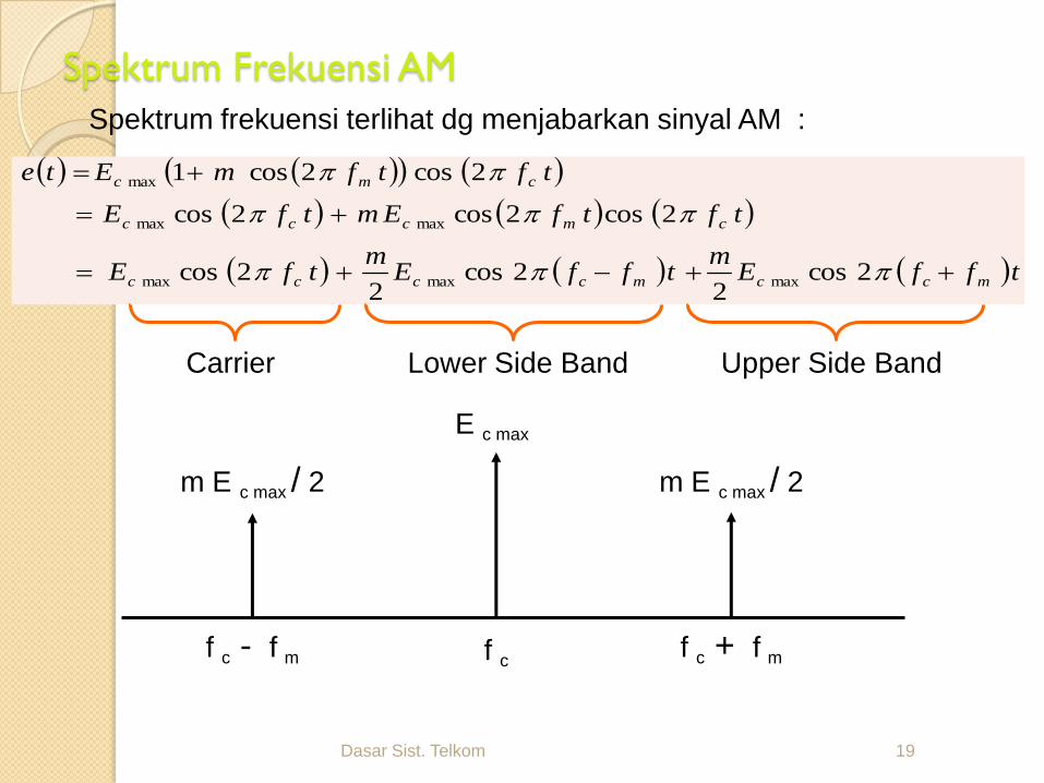
Spektrum Frekuensi AM
Spektrum frekuensi terlihat dg menjabarkan sinyal AM :
tffEm
tffEm
tfE
tftfEmtfE
tftfmEte
mccmcccc
cmccc
cmc
2cos2
2cos2
2cos
2cos2cos2cos
2cos2cos1
maxmaxmax
maxmax
max
Carrier Lower Side Band Upper Side Band
E c max
m E c max / 2 m E c max / 2
f c - f m f c + f mf c
Dasar Sist. Telkom 20
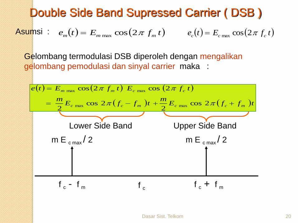
Gelombang termodulasi DSB diperoleh dengan mengalikan
gelombang pemodulasi dan sinyal carrier maka :
tfEte mmm 2cosmax tfEte ccc 2cosmax
Double Side Band Supressed Carrier ( DSB )
tffEm
tffEm
tfEtfEte
mccmcc
ccmm
2cos2
2cos2
2cos2cos
maxmax
maxmax
Asumsi :
Lower Side Band Upper Side Band
f c - f m f c + f mf c
m E c max / 2 m E c max / 2
Dasar Sist. Telkom 21
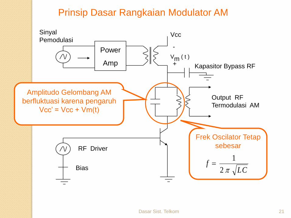
Prinsip Dasar Rangkaian Modulator AM
Power
Amp
Sinyal
Pemodulasi
Kapasitor Bypass RF
Output RF
Termodulasi AM
RF Driver
Bias
Vcc
Vm ( t )
-
+
Amplitudo Gelombang AM
berfluktuasi karena pengaruh
Vcc’ = Vcc + Vm(t)
Frek Oscilator Tetap
sebesar
CLf
2
1
Dasar Sist. Telkom 22
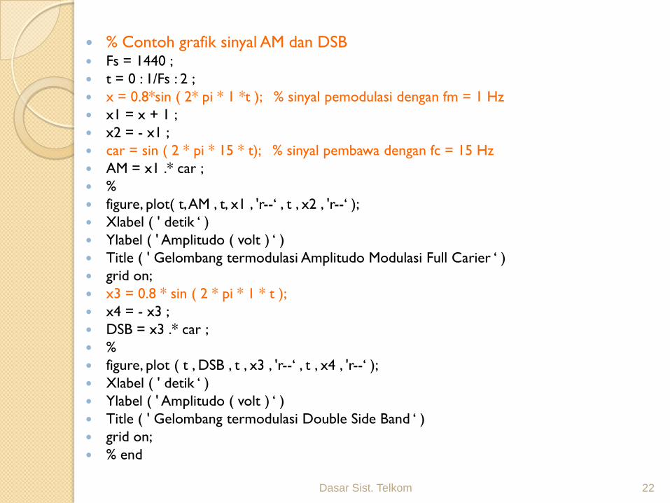
% Contoh grafik sinyal AM dan DSB Fs = 1440 ;
t = 0 : 1/Fs : 2 ;
x = 0.8*sin ( 2* pi * 1 *t ); % sinyal pemodulasi dengan fm = 1 Hz
x1 = x + 1 ;
x2 = - x1 ;
car = sin ( 2 * pi * 15 * t); % sinyal pembawa dengan fc = 15 Hz
AM = x1 .* car ;
%
figure, plot( t, AM , t, x1 , 'r--‘ , t , x2 , 'r--‘ );
Xlabel ( ' detik ‘ )
Ylabel ( ' Amplitudo ( volt ) ‘ )
Title ( ' Gelombang termodulasi Amplitudo Modulasi Full Carier ‘ )
grid on;
x3 = 0.8 * sin ( 2 * pi * 1 * t );
x4 = - x3 ;
DSB = x3 .* car ;
%
figure, plot ( t , DSB , t , x3 , 'r--‘ , t , x4 , 'r--‘ );
Xlabel ( ' detik ‘ )
Ylabel ( ' Amplitudo ( volt ) ‘ )
Title ( ' Gelombang termodulasi Double Side Band ‘ )
grid on;
% end
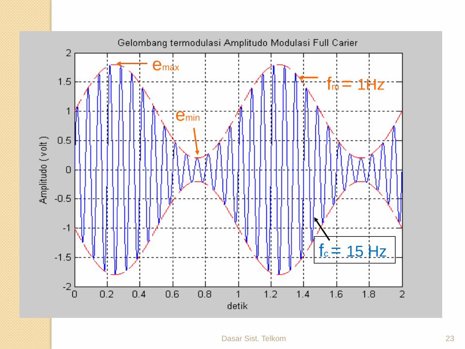
Dasar Sist. Telkom 23
emax
emin
fm = 1Hz
fc = 15 Hz
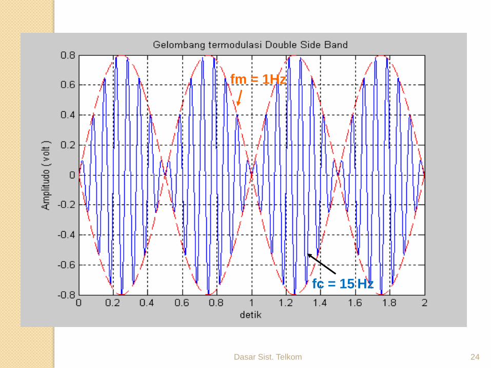
Dasar Sist. Telkom 24
fm = 1Hz
fc = 15 Hz
Dasar Sist. Telkom 25
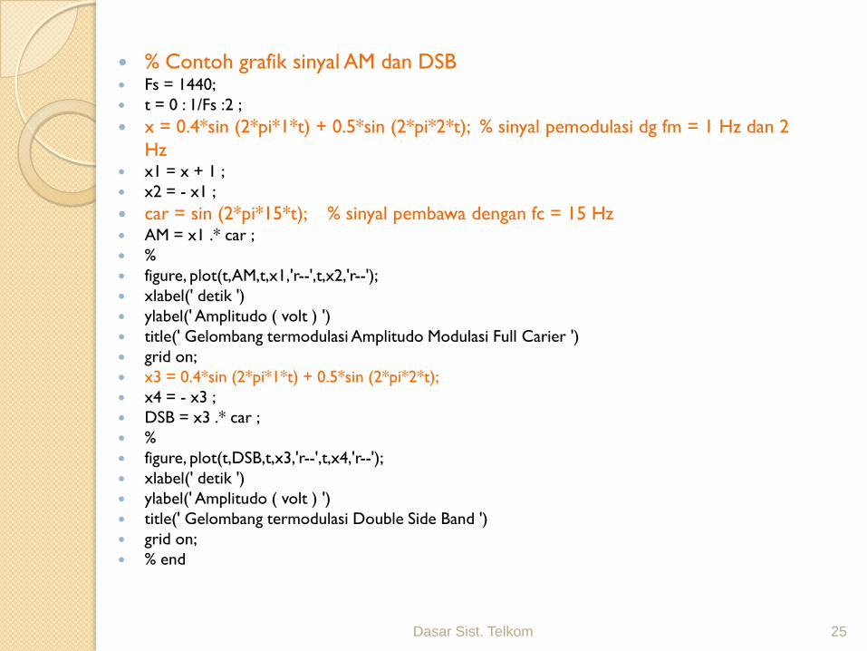
% Contoh grafik sinyal AM dan DSB Fs = 1440;
t = 0 : 1/Fs :2 ;
x = 0.4*sin (2*pi*1*t) + 0.5*sin (2*pi*2*t); % sinyal pemodulasi dg fm = 1 Hz dan 2
Hz x1 = x + 1 ;
x2 = - x1 ;
car = sin (2*pi*15*t); % sinyal pembawa dengan fc = 15 Hz AM = x1 .* car ;
%
figure, plot(t,AM,t,x1,'r--',t,x2,'r--');
xlabel(' detik ')
ylabel(' Amplitudo ( volt ) ')
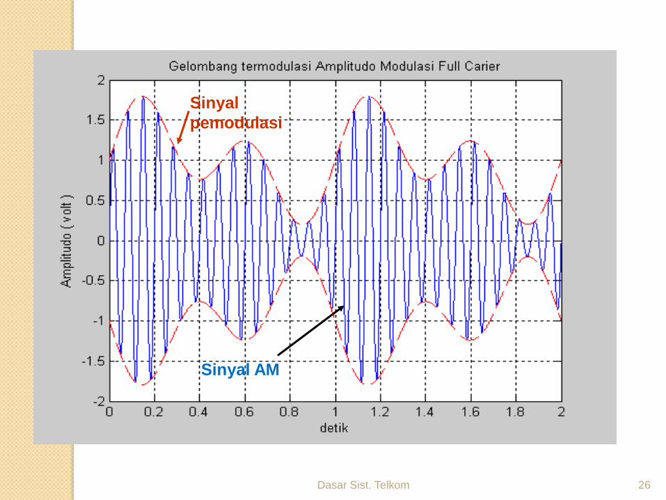
title(' Gelombang termodulasi Amplitudo Modulasi Full Carier ')
grid on;
x3 = 0.4*sin (2*pi*1*t) + 0.5*sin (2*pi*2*t);
x4 = - x3 ;
DSB = x3 .* car ;
%
figure, plot(t,DSB,t,x3,'r--',t,x4,'r--');
xlabel(' detik ')
ylabel(' Amplitudo ( volt ) ')
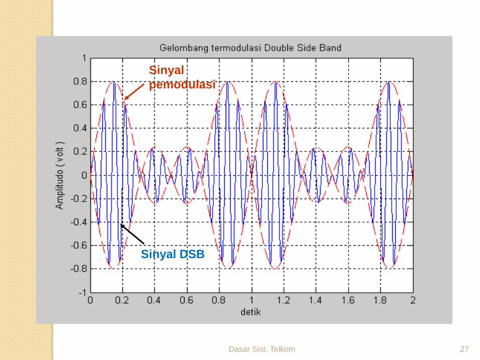
title(' Gelombang termodulasi Double Side Band ')
grid on;
% end
Dasar Sist. Telkom 26
Sinyal
pemodulasi
Sinyal AM
Dasar Sist. Telkom 27
Sinyal
pemodulasi
Sinyal DSB
Dasar Sist. Telkom 28
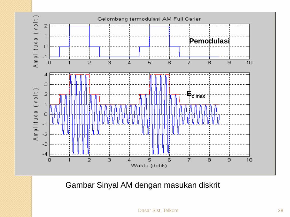
Pemodulasi
Ec max
Gambar Sinyal AM dengan masukan diskrit
Dasar Sist. Telkom 29
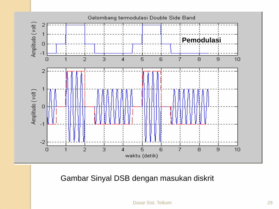
Pemodulasi
Gambar Sinyal DSB dengan masukan diskrit
Dasar Sist. Telkom 30
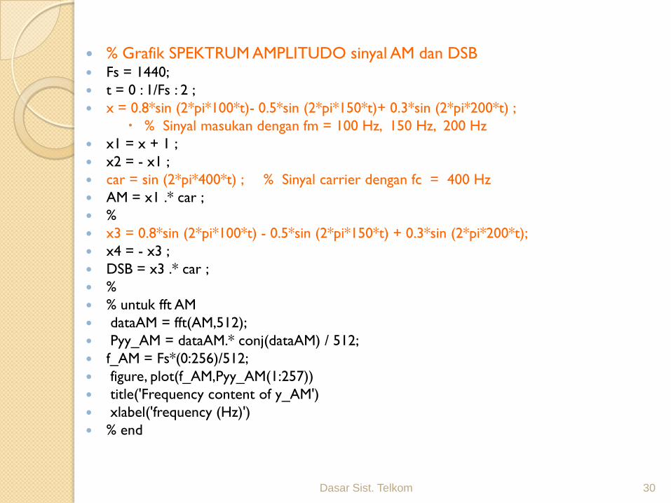
% Grafik SPEKTRUM AMPLITUDO sinyal AM dan DSB Fs = 1440;
t = 0 : 1/Fs : 2 ;
x = 0.8*sin (2*pi*100*t)- 0.5*sin (2*pi*150*t)+ 0.3*sin (2*pi*200*t) ;
% Sinyal masukan dengan fm = 100 Hz, 150 Hz, 200 Hz
x1 = x + 1 ;
x2 = - x1 ;
car = sin (2*pi*400*t) ; % Sinyal carrier dengan fc = 400 Hz
AM = x1 .* car ;
%
x3 = 0.8*sin (2*pi*100*t) - 0.5*sin (2*pi*150*t) + 0.3*sin (2*pi*200*t);
x4 = - x3 ;
DSB = x3 .* car ;
%
% untuk fft AM
dataAM = fft(AM,512);
Pyy_AM = dataAM.* conj(dataAM) / 512;
f_AM = Fs*(0:256)/512;
figure, plot(f_AM,Pyy_AM(1:257))
title('Frequency content of y_AM')
xlabel('frequency (Hz)')
% end
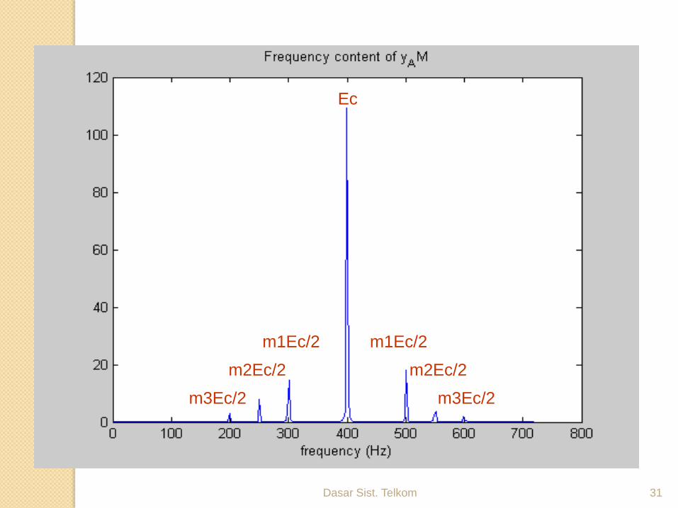
Dasar Sist. Telkom 31
Ec
m1Ec/2
m2Ec/2
m3Ec/2
m1Ec/2
m2Ec/2
m3Ec/2
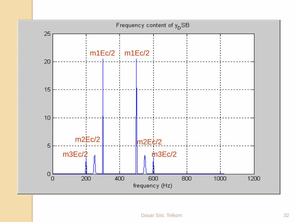
Dasar Sist. Telkom 32
m1Ec/2m1Ec/2
m2Ec/2
m3Ec/2
m2Ec/2
m3Ec/2
Dasar Sist. Telkom 33
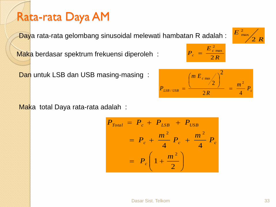
Rata-rata Daya AM
Daya rata-rata gelombang sinusoidal melewati hambatan R adalah :R
E
2
2
max
Maka berdasar spektrum frekuensi diperoleh :R
EP
c
c2
2
max
Dan untuk LSB dan USB masing-masing :
c
c
USBLSB Pm
R
Em
P42
2
2 2
max
/
Maka total Daya rata-rata adalah :
21
442
22
mP
Pm
Pm
P
PPPP
c
ccc
USBLSBcTotal
Dasar Sist. Telkom 34
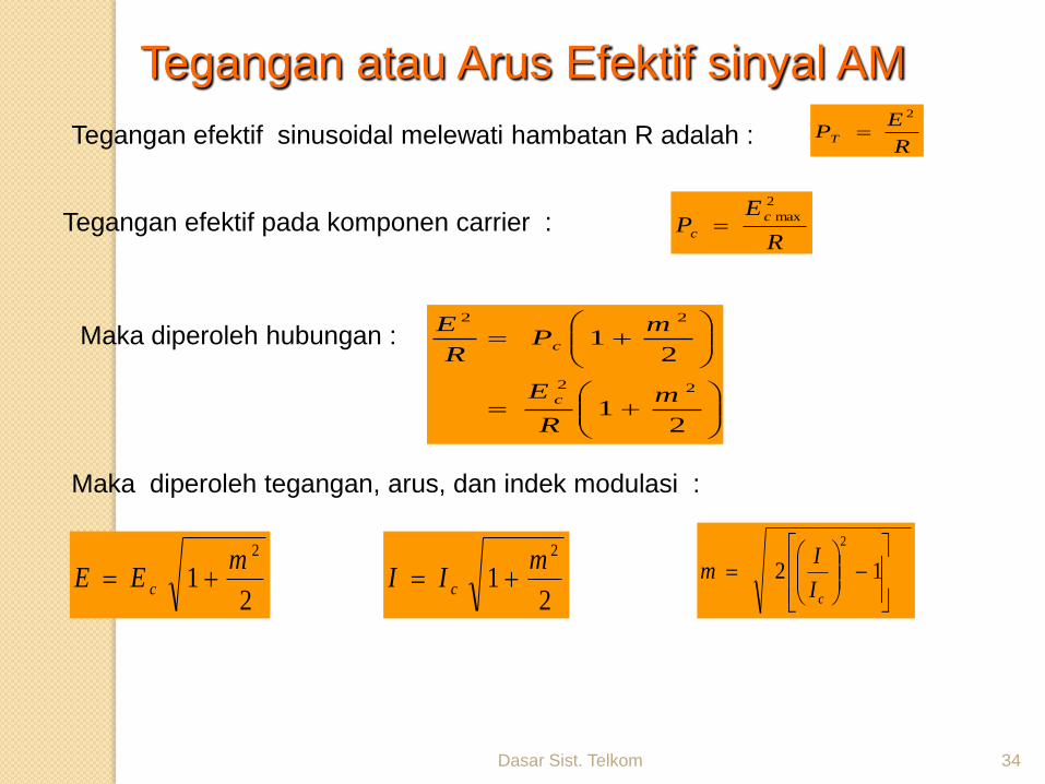
Tegangan atau Arus Efektif sinyal AM
Tegangan efektif sinusoidal melewati hambatan R adalah :
Tegangan efektif pada komponen carrier :R
EP
c
c
2
max
Maka diperoleh hubungan :
Maka diperoleh tegangan, arus, dan indek modulasi :
R
EPT
2
21
21
22
22
m
R
E
mP
R
E
c
c
21
2mEE c
21
2mII c
12
2
cI
Im
Dasar Sist. Telkom 35
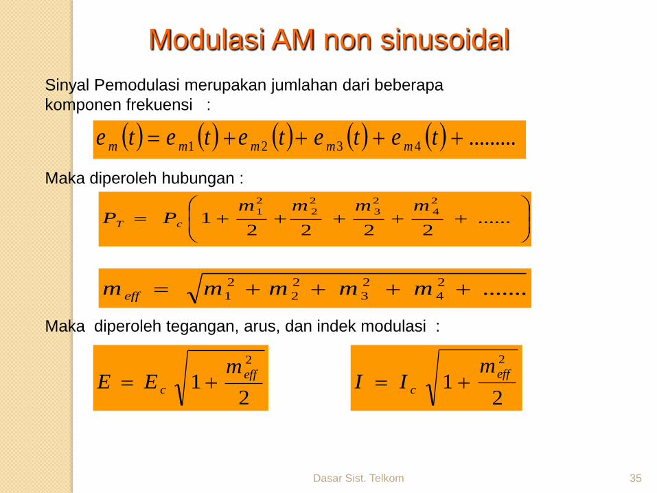
Modulasi AM non sinusoidal
Sinyal Pemodulasi merupakan jumlahan dari beberapa
komponen frekuensi :
Maka diperoleh hubungan :
Maka diperoleh tegangan, arus, dan indek modulasi :
.........4321 tetetetete mmmmm
......
22221
2
4
2
3
2
2
2
1 mmmmPP cT
.......2
4
2
3
2
2
2
1 mmmmm eff
21
2
eff
c
mEE
21
2
eff
c
mII
Dasar Sist. Telkom 36
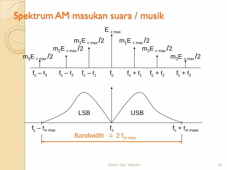
Spektrum AM masukan suara / musik
E c max
m1E c max /2m1E c max /2m2E c max /2 m2E c max /2
m3E c max /2 m3E c max /2
fc – f1 fc + f1 fc + f2fc – f2fc – f3 fc + f3fc
fcfc – fm max fc + fm maax
LSB USB
Bandwidth = 2 fm max
Dasar Sist. Telkom 37
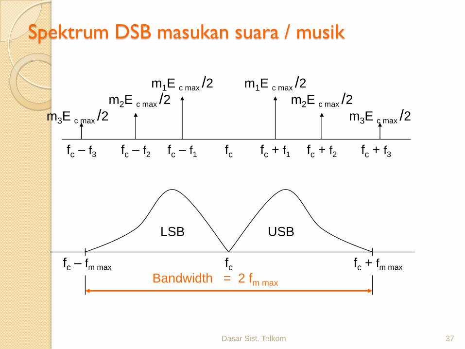
Spektrum DSB masukan suara / musik
m1E c max /2m1E c max /2m2E c max /2 m2E c max /2
m3E c max /2 m3E c max /2
fc – f1 fc + f1 fc + f2fc – f2fc – f3 fc + f3fc
fcfc – fm max fc + fm max
LSB USB
Bandwidth = 2 fm max
Dasar Sist. Telkom 38
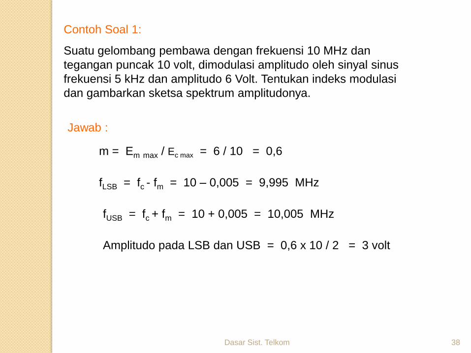
Contoh Soal 1:
Suatu gelombang pembawa dengan frekuensi 10 MHz dan
tegangan puncak 10 volt, dimodulasi amplitudo oleh sinyal sinus
frekuensi 5 kHz dan amplitudo 6 Volt. Tentukan indeks modulasi
dan gambarkan sketsa spektrum amplitudonya.
Jawab :
m = Em max / Ec max = 6 / 10 = 0,6
fLSB = fc - fm = 10 – 0,005 = 9,995 MHz
fUSB = fc + fm = 10 + 0,005 = 10,005 MHz
Amplitudo pada LSB dan USB = 0,6 x 10 / 2 = 3 volt
Dasar Sist. Telkom 39
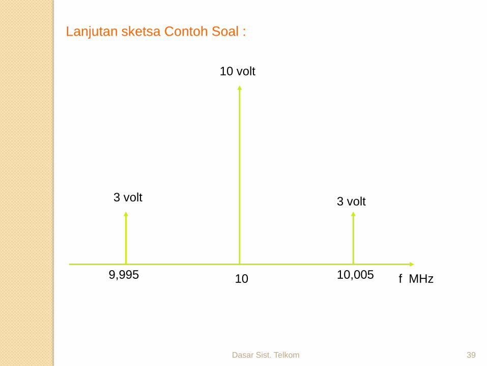
Lanjutan sketsa Contoh Soal :
10 volt
3 volt 3 volt
10 10,0059,995 f MHz
Dasar Sist. Telkom 40
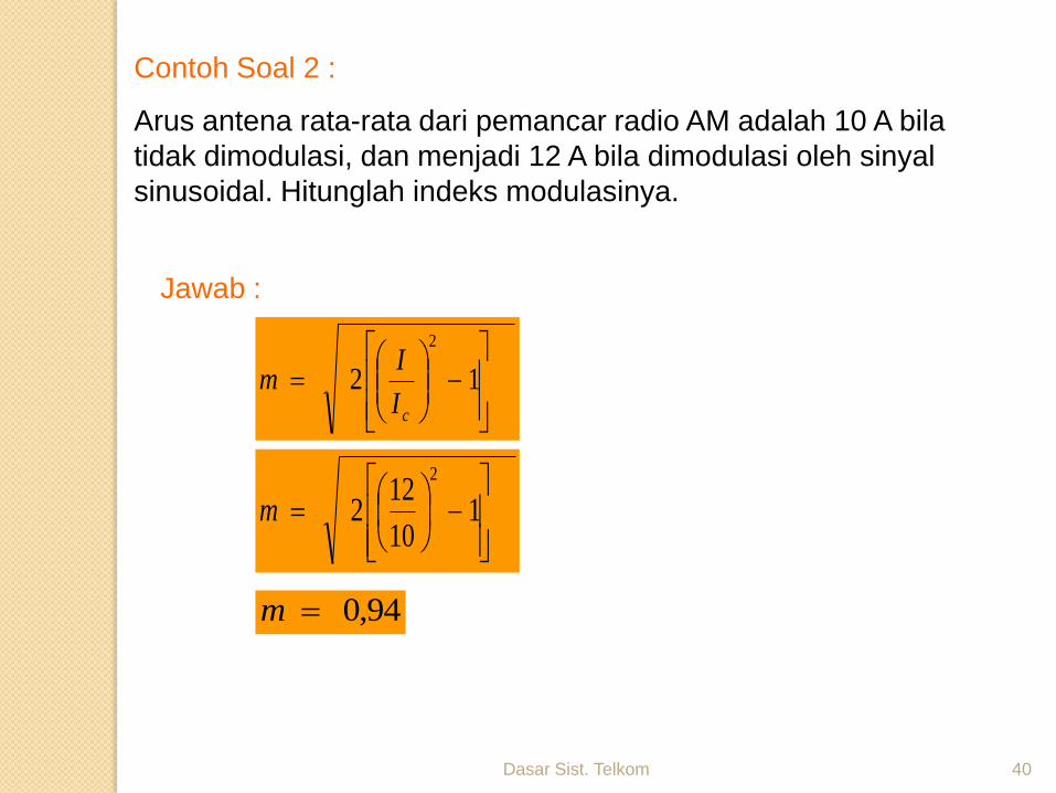
Contoh Soal 2 :
Arus antena rata-rata dari pemancar radio AM adalah 10 A bila
tidak dimodulasi, dan menjadi 12 A bila dimodulasi oleh sinyal
sinusoidal. Hitunglah indeks modulasinya.
Jawab :
12
2
cI
Im
1
10
122
2
m
94,0m
Dasar Sist. Telkom 41
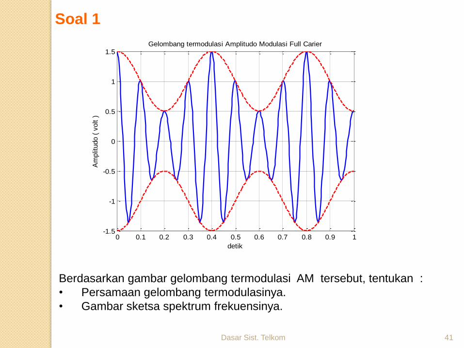
Berdasarkan gambar gelombang termodulasi AM tersebut, tentukan :
• Persamaan gelombang termodulasinya.
• Gambar sketsa spektrum frekuensinya.
Soal 1
0 0.1 0.2 0.3 0.4 0.5 0.6 0.7 0.8 0.9 1-1.5
-1
-0.5
0
0.5
1
1.5
detik
Am
plit
udo (
volt )
Gelombang termodulasi Amplitudo Modulasi Full Carier
Dasar Sist. Telkom 42
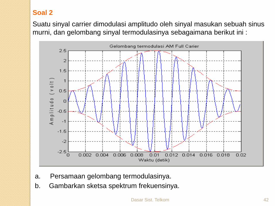
Suatu sinyal carrier dimodulasi amplitudo oleh sinyal masukan sebuah sinus
murni, dan gelombang sinyal termodulasinya sebagaimana berikut ini :
a. Persamaan gelombang termodulasinya.
b. Gambarkan sketsa spektrum frekuensinya.
Soal 2
Dasar Sist. Telkom 43
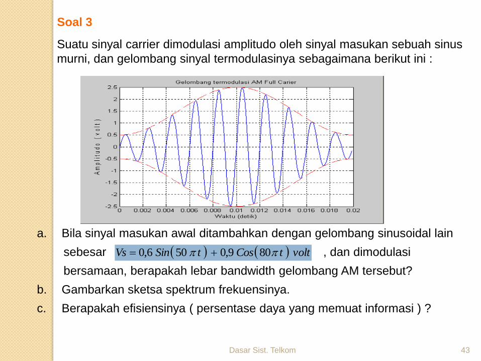
Suatu sinyal carrier dimodulasi amplitudo oleh sinyal masukan sebuah sinus
murni, dan gelombang sinyal termodulasinya sebagaimana berikut ini :
a. Bila sinyal masukan awal ditambahkan dengan gelombang sinusoidal lain
sebesar , dan dimodulasi
bersamaan, berapakah lebar bandwidth gelombang AM tersebut?
b. Gambarkan sketsa spektrum frekuensinya.
c. Berapakah efisiensinya ( persentase daya yang memuat informasi ) ?
volttCostSinVs 809,0506,0
Soal 3
Dasar Sist. Telkom Pertemuan ke-1 44

Dasar Sist. Telkom 45
THANK’S
NOW
REST TIME