


Bahasa
Halaman
Hukum

The University of Sheffield
Analysis of High-Speed Permanent
Magnet Machines
Yu Wang
A thesis submitted for the degree of Doctor of Philosophy Department of Electronic and Electrical Engineering
The University of Sheffield Mappin Street, Sheffield, S1 3JD, UK
23 October 2019
i
Abstract
High-speed permanent magnet machines (HSPMM) are a competent candidate for high-
speed applications due to its better efficiency, power factor, and utilization factor in comparison
to other types of high-speed electrical machines. In this thesis, both the electromagnetic and
mechanical issues of HSPMM including rotor split ratio optimization, rotor stress analysis, and
parasitic effects such as rotor eddy current loss and UMF are investigated elaborately by means
of analytical and finite element analyses, together with experimental validation.
Firstly, the optimal rotor split ratio of HSPMM is investigated analytically with
consideration of stator iron loss as well as rotor mechanical stress. The influence of design
parameters such as air gap length and rotor pole pairs on the optimal split ratio is investigated.
Both analytical and finite element analyses reveal that the optimal split ratio for HSPMM will
be significantly reduced when stator iron loss and mechanical constraints are taken into
consideration.
Secondly, the rotor eddy current loss of the four-pole HSPMM with alternate stator winding
configuration is investigated. The contribution of each harmonic in the production of magnet
loss, either from PM field or armature field, is determined by the proposed method with
consideration of stator slotting effect. In addition, the armature reaction induced magnet losses
with different stator winding configurations are compared as well. It is found that the value of
magnet loss is dependent on both the penetration depth and the amplitude of asynchronous
spatial harmonic, which are determined by the specific slot and pole number combination.
Following from this, the existence criterion of UMF in PM machines with odd number stator
slot is determined. In addition, the influence of slot and pole number combination on the rotor
UMF is investigated.
Finally, a novel HSPMM design methodology considering both electromagnetic and
mechanical issues is illustrated. The rotor stress is firstly analysed with consideration of PM
segmentation effect. The corresponding worst operating scenarios and influential factors are
then investigated. Based on the stress analysis of the HSPMM, the mechanical stress limitation
is incorporated as the geometric constraints in the electromagnetic design so that the mutual
influence of two different design aspects can be considered.
ii
Acknowledgements
I give my most sincere thanks to Prof. Z. Q. Zhu for his professional and inspiring
supervision during my PhD study. His encouragement helped me through the toughest time of
my PhD study. His excellence as a role model will be a treasure to me for the rest of my life.
I would also like to express my gratitude to the members of the Electrical Machines and
Drives Group at the University of Sheffield, particularly Dr. Liren Huang, Dr. Shaoshen Xue,
Dr. Peilin Xu, Dr. Wenqiang Chu, Dr. Yue Liu, Mr. Shun Cai, Mr. Rui Zhou and Mr. Kai
Zhang for their many constructive suggestions and selfless help. Further thanks to the technical
staff in the Department of Electraonic and Electrical Engineering for their help.
I also would like to acknowledge CRRC ZhuZhou Institute Co. Ltd for the PhD studentship
via Sheffield CRRC Electric Drives Technology Research Centre.
Finally, I would like to thank my parents for their wise counsel and sympathetic ear. You
are always my strongest backing.
iii
Contents Abstract ................................................................................................................. i Acknowledgements ..............................................................................................ii Nomenclature .....................................................................................................vii Chapter 1 General Introduction ........................................................................ 1
1.1 Introduction .................................................................................................................. 1
1.2 High-speed Machine Technologies .............................................................................. 2
1.2.1 Definition of High-speed ...................................................................................... 3
1.2.2 High-speed Machine Types for Alternate Applications and Specifications ......... 4
1.3 Electromagnetic Issues in High-speed PM Machines ................................................ 20
1.3.1 Machine Topologies ........................................................................................... 20
1.3.2 Stator AC Copper Loss ....................................................................................... 31
1.3.3 Iron Loss ............................................................................................................. 33
1.3.4 Rotor Eddy Current Loss .................................................................................... 34
1.3.5 Rotor Unbalanced Magnetic Force ..................................................................... 42
1.4 Mechanical and Aerodynamic Issues in High-speed PM Machines .......................... 43
1.4.1 Rotor Stress ......................................................................................................... 43
1.4.2 Rotor Dynamics .................................................................................................. 45
1.4.3 Aerodynamics Loss............................................................................................. 46
1.5 Research Scope and Major Contributions .................................................................. 47
1.5.1 Outline of Thesis ................................................................................................. 47
1.5.2 Major Contributions of the Thesis ...................................................................... 48
Chapter 2 Rotor Split Ratio Optimization for High Speed PM Machines with Consideration of Stator Iron Loss and Mechanical Stress Constraints ...... 50
2.1 Introduction ................................................................................................................ 50
2.2 Optimal Split Ratio Accounting for Copper Loss Only ............................................. 52
2.3 Optimal Split Ratio Accounting for Copper Loss and Stator Iron Loss .................... 58
2.3.1 Optimal Split Ratio Considering Stator Iron Loss .............................................. 58
iv
2.3.2 Influence of Design Parameters on Optimal Split Ratio .................................... 61
2.4 Optimal Split Ratio Accounting for Copper Loss and Mechanical Stress ................. 70
2.4.1 Split Ratio Optimization with Tangential Stress Limitation .............................. 70
2.4.2 Split Ratio Optimization with Contact Pressure Limitation ............................... 72
2.4.3 Influence of Design Parameters on Optimal Split Ratio .................................... 81
2.5 Optimal Split Ratio Accounting for Stator Loss and Mechanical Stress ................... 89
2.6 Summary .................................................................................................................... 91
Chapter 3 Analysis of Magnet Eddy Current Loss for Four-Pole High Speed PM Machines with Alternate Stator Winding Configuration ...................... 92
3.1 Introduction ................................................................................................................ 92
3.2 Rotor Magnet Loss Segregation of HSPMM ............................................................. 94
3.2.1 Causes of PM Eddy Current Loss ....................................................................... 94
3.2.2 Determination of Harmonic-Induced PM Eddy Current Loss Based on Frozen Permeability Method ........................................................................................................ 95
3.2.3 Segregation of PM Eddy Current Loss Due to Each Spatial Harmonic in Armature Reaction ......................................................................................................................... 101
3.3 Analysis of Slotting Opening Effect on the Rotor Magnet Loss ............................. 107
3.3.1 Slotting Effect on Magnet Loss Due to PM Harmonics ................................... 107
3.3.2 Slot Opening Effect on Armature Reaction Field Induced Magnet Loss ......... 109
3.4 Comparison of Armature Reaction Induced Magnet Loss with Different Slot and Pole Number Combinations ....................................................................................................... 116
3.5 Experimental Validation .......................................................................................... 126
3.6 Summary .................................................................................................................. 135
Chapter 4 Investigation of Unbalanced Magnetic Force in Fractional-Slot PM Machines with Odd Number of Stator Slot ........................................... 136
4.1 Introduction .............................................................................................................. 137
4.2 Analytical Analysis of Air Gap Field and Magnetic Forces .................................... 141
4.2.1 Open-Circuit Air Gap Flux Density.................................................................. 141
4.2.2 Armature Reaction Air Gap Flux Density ........................................................ 143

v
4.2.3 Radial Stress and Tangential Stress .................................................................. 144
4.2.4 Unbalanced Magnetic Force ............................................................................. 144
4.3 Existence of Criterion for Unbalanced Magnetic Force in PM Brushless Machines Having Odd Number of Stator Slots .................................................................................. 145
4.3.1 Determination for UMF Existence ................................................................... 146
4.3.2 FE Validation .................................................................................................... 148
4.4 Influence of Slot and Pole Number Combinations on Unbalanced Magnetic Force..151
4.5 Experimental Validation .......................................................................................... 161
4.6 Summary .................................................................................................................. 165
Chapter 5 Design and Analysis of High-Speed PM Machines Considering Electromagnetic and Mechanical Issues ....................................................... 167
5.1 Introduction .............................................................................................................. 167
5.2 Rotor Mechanical Stress Analysis of High-Speed PM Machines Considering PM Segmentation ...................................................................................................................... 172
5.2.1 Theoretical Analysis of Rotor Stress with Carbon-Fibre Sleeve ...................... 172
5.2.2 Determination of Worst Operating Scenarios Considering PM Segmentation..186
5.2.3 Influence of Mechanical Design Parameters on Rotor Stress........................... 193
5.2.4 Rotor Stress Concentration and Reduction ....................................................... 199
5.3 Design Methodology for High Speed PM Machines Considering both Electromagnetic and Mechanical Issue ......................................................................................................... 205
5.3.1 Constraints of Rotor Geometric Parameters Considering Mechanical Stress Limitation....................................................................................................................... 205
5.3.2 Multi-physics Design of HSPMM Considering Electromagnetic and Mechanical Constraints Simultaneously ........................................................................................... 209
5.4 Summary .................................................................................................................. 214
Chapter 6 General Conclusion and Future Work ....................................... 216
6.1 General Conclusion .................................................................................................. 216
6.2 Optimal Split Ratio .................................................................................................. 216
6.3 Rotor Eddy Current Loss ......................................................................................... 217
6.4 Rotor Mechanical Stress and Design Methodology ................................................. 217

vi
6.5 Unbalanced Magnetic Force .................................................................................... 217
6.6 Future work .............................................................................................................. 218
References ........................................................................................................ 219
Appendix A: AutoCAD drawings for all machines ...................................... 235
Appendix B: Publications ............................................................................... 240
vii
Nomenclature
α Steinmetz coefficient
0a Initial rotor position rad
na Numerical constant related with problem boundaries
αr, αθ Radial and tangential coefficients of thermal expansion /C°
AFe Slot iron area m2
As Slot area m2
Ai Amplitude of the ith harmonic A
B Iron flux density T
Bα Tangential flux density T
armB Flux density due to armature reaction T
BFe Flux density in iron T
Bg Air gap flux density T
Bm Maximum flux density in iron T
Br PM remanence T
Br Radial flux density T
fC Coefficient of rotor skin friction
Cs1, Cs2 Integration constants of sleeve
Cm1, Cm2 Integration constants of magnets
Do Stator outer diameter m
sD Stator bore diameter m
Dr Rotor outer diameter m
E Young’s modulus Pa
rE , Eθ Radial and tangential Young’s modulus Pa
mE Young’s modulus of magnets Pa
bE Young’s modulus of back-iron Pa
f Frequency Hz ( , )ABCF tα Three-phase MMF A
hF Amplitude of each MMF harmonic A
rF Radial force N
Fα Tangential force N
xF Unbalanced magnetic force in horizonal direction N
yF Unbalanced magnetic force in vertical direction N
viii
g Effective air gap length m
h Thermal heat transfer coefficient W/(m2‧K)
bh Thickness of sleeve m
hm PM thickness m
i Harmonic order (i=1,3,5…)
Ia RMS of phase current A
j Harmonic order (j=1,2,3…)
k Stress safety factor
ek Coefficient of eddy current loss
exk Coefficient of excess loss
hk Coefficient of hysteresis loss
ks Slot packing factor
kw Winding factor
al Axial core length m
l Axial rotor length m
mFe Mass of iron kg
Ns Slot number
Nw Serial turns of each phase
p Rotor pole pairs
pb, pm Pressures of magnets and sleeve due to centrifugal force Pa
pc, pFe Iron loss W
contact pressureP − Contact pressure Pa
limitP Heat limitation W
P0 DC component of air gap permanence H
( )P α Permanence function H
wp Windage loss per unit W
moR Rotor outer radius m
miR Rotor inner radius m
siR Sleeve outer radius m
boR Back-iron outer radius m
rb, rm Average radius of selected sleeve and magnets m
SCF Stress concentration factor
T Output torque Nm
t Machine periodicity
ix
u Radial displacement m
1µ Mass in per unit length Kg/m
0µ Permeability of free space H/m
mru Radial displacement of magnets m
bru Radial displacement of back-iron m
ν Harmonic order
cv Rotor peripheral speed m/s
mυ Maximum allowed temperature
νθr, νrθ Radial and tangential Poisson’s ratios
νm Poisson’s ratio of magnets
νb Poisson’s ratio of bandage
w Angular speed rad/s
nw Natural frequency Hz
rω Mechanical angular frequency Hz
sω Electrical angular frequency Hz
WFe Iron loss in watts per kilogram W/kg
δ Physical air gap length m
γ Flux density ratio
Ω Rotating speed rad/s
rθ Rotor position in rotor reference frame rad
sθ Rotor position in stator reference frame rad
λ Rotor split ratio
λp Optimal split ratio of HSPMM
rε , θε Radial strain and tangential strain of sleeve material
ρ Material mass density Kg/m3
bρ Mass density of sleeve Kg/m3
𝜌𝜌m Mass density of magnets Kg/m3
𝜌𝜌cu Resistivity of copper S/m
𝜌𝜌Fe Resistivity of iron S/m
tσ Total tangential stress Pa
,t prestressσ Pre- tangential stress Pa
,t wσ Tangential stress due to rotation Pa
limitσ Tangential stress limit Pa
srσ , sθσ Sleeve radial and tangential stresses Pa
x
mrσ , mθσ Magnet radial and tangential stresses Pa
brσ , bθσ Back-iron radial and tangential stresses Pa
D∆ Interference fit m
ΔT Temperature rise
1
Chapter 1 General Introduction
1.1 Introduction
High-speed electrical machines (HSEM) have been widely used in various applications such
as high-speed spindles [ZWY09], turbochargers for more electric engines [GER14], micro-gas
turbines [FER95], [GOL03], flywheel energy storage system [TSA03], and compressors and
air blowers [KOL11], [ZHA16], [HUA16]. They have been gaining increasing interest from
machine designers in the past twenty years. There are at least two benefits for increasing
operating speed of electrical machines. One of the commonly acknowledged advantages of
HESMs lies in the reduction of overall mass and volume for the same power requirement. This
is particularly desirable for applications which demand a high system power density. The
second advantage of adopting high-speed machines is the enhancement of system robustness
and lower maintenance due to elimination associated accessories such as gearboxes.
The high-speed permanent magnet (PM) machine (HSPMM) is a competent candidate for
high-speed applications due to its better efficiency and power factor, compared to other HSEMs
[BIA04]. However, there are still many challenges and obstacles in terms of both mechanical
and electromagnetic aspects for HSPMM which are summarized in the following paragraphs.
Under the high-speed rotating, all components in the rotor will suffer significant centrifugal
force and tangential stress, which can be further aggravated by the rotor temperature rise
[BIN06]. As the most vulnerable part, the rotor magnets are rather brittle with small tensile
strength [DU19], [ZHA16]. Sleeves are therefore adopted to retain the magnets in surface-
mounted PM (SPM) machines. Hence, rotor stress analysis is a key issue for the design of
HSPMMs in order to keep the maximum induced rotor stress within the material strength limits,
especially for PMs [BIN07].
On the other hand, for low to medium speed operating electrical machines, the rotor
dynamics are typically not a significant issue since the operating speed range is normally far
below the first critical speed. For HSPMM, the rotor dynamic issue becomes more crucial and
challenging in that resonant vibration could easily happen with an improper rotor design
[ZHU02].
Compared with high-speed induction machines, the HSPMMs are equipped with a more

2
compact size featuring high power density and loss density, thus imposing a great challenge on
the cooling system design. The stator core loss and AC copper loss should be accounted under
the high-speed operation. Meanwhile, a significant amount of rotor magnet loss and sleeve loss
if applicable will be induced. This would cause severe rotor temperature to rise which may
cause the PM irreversible demagnetization. On the other hand, the potential unbalanced
magnetic force (UMF) in HSPMM with an odd number of stator slots may deteriorate the high-
speed bearing wear which is vital for the rotor robustness. Hence, the electromagnetic issue in
the analysis of HSPMM consists at least two aspects: (a) Understanding the generation
mechanism of electromagnetic loss and UMF, as well as their precise prediction, especially at
the worst operating scenario; (b) reasonable selection of machine topologies and other
measures for the electromagnetic loss and UMF reduction.
It should be noted that the electromagnetic issues and the mechanical issues in HSPMM are
not independent. They are strongly coupled to one another due to the link of rotor geometry.
Both considerations from electromagnetic and mechanical aspects should be accounted for the
HSPMM rotor design. Furthermore, the influence of one aspect on the other becomes more
obvious in HSPMM, compared to low speed machines. The optimal design in one domain may
be altered when the other issue is considered, which will be addressed in Chapter 2 and Chapter
5.
In summary, the essence of HSPMM analysis is a multiple iteration process which
incorporates the electromagnetic, mechanical and other factors. Usually, design trade-offs must
be made between different aspects according to the specific case. The aim of this chapter is to
provide a systematic overview of the key design considerations and tradeoffs for HSPMM with
regard to the aforementioned aspects.
This chapter will firstly discuss the definition of high-speed and summarize the alternate
high-speed machine technologies. Advantages and disadvantages of each high-speed machine
type will be identified. Then, both the electromagnetic issues and mechanical issues in HSPMM
will be reviewed in detail. Finally, the main contribution and future work will be presented.
1.2 High-speed Machine Technologies
In this section, the definition of high-speed is firstly discussed. Then, the high-speed machine
technologies are classified into three typical groups: induction machines (IM), switched
3
reluctance machines (SRM), and permanent magnet (PM) machines. The operating power as
well as the speed of each type of machines are compared so that the suitable applications for
different high-speed machines can be determined.
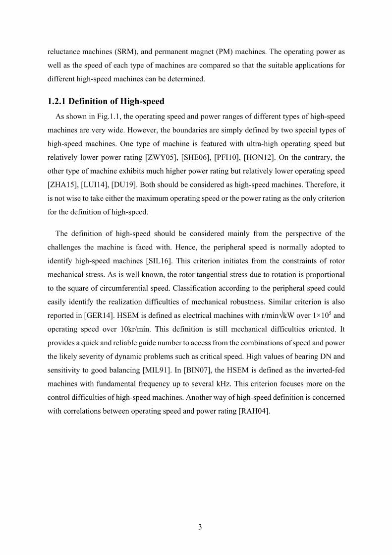
1.2.1 Definition of High-speed As shown in Fig.1.1, the operating speed and power ranges of different types of high-speed
machines are very wide. However, the boundaries are simply defined by two special types of
high-speed machines. One type of machine is featured with ultra-high operating speed but
relatively lower power rating [ZWY05], [SHE06], [PFI10], [HON12]. On the contrary, the
other type of machine exhibits much higher power rating but relatively lower operating speed
[ZHA15], [LUI14], [DU19]. Both should be considered as high-speed machines. Therefore, it
is not wise to take either the maximum operating speed or the power rating as the only criterion
for the definition of high-speed.
The definition of high-speed should be considered mainly from the perspective of the
challenges the machine is faced with. Hence, the peripheral speed is normally adopted to
identify high-speed machines [SIL16]. This criterion initiates from the constraints of rotor
mechanical stress. As is well known, the rotor tangential stress due to rotation is proportional
to the square of circumferential speed. Classification according to the peripheral speed could
easily identify the realization difficulties of mechanical robustness. Similar criterion is also
reported in [GER14]. HSEM is defined as electrical machines with r/min√kW over 1×10⁵ and
operating speed over 10kr/min. This definition is still mechanical difficulties oriented. It
provides a quick and reliable guide number to access from the combinations of speed and power
the likely severity of dynamic problems such as critical speed. High values of bearing DN and
sensitivity to good balancing [MIL91]. In [BIN07], the HSEM is defined as the inverted-fed
machines with fundamental frequency up to several kHz. This criterion focuses more on the
control difficulties of high-speed machines. Another way of high-speed definition is concerned
with correlations between operating speed and power rating [RAH04].
4
Fig.1.1. Operating power and speed of high-speed machines in literature [GER14].
1.2.2 High-speed Machine Types for Various Applications and Specifications Over the last two decades, numerous overviews on HSEM topologies have been published
[REI95], [RAM04], [BIN07], [MOG14], [GER14], [TEN14], [XIA15], [SIL16]. This section
will summarize and analyse high-speed machines found in literature. The targets mainly
focuses on high-speed induction machines (IMs), high-speed switched reluctance machines
(SRMs) and high-speed PM machines (HSPMMs). Emphases are put on the rotor structures
for each type of high-speed machines in terms of dealing with rotor stress and loss. In addition,
a schematic comparison between different topologies in terms of reachable power and
maximum operating speed will be made in order to identify the suitable cases for each topology.
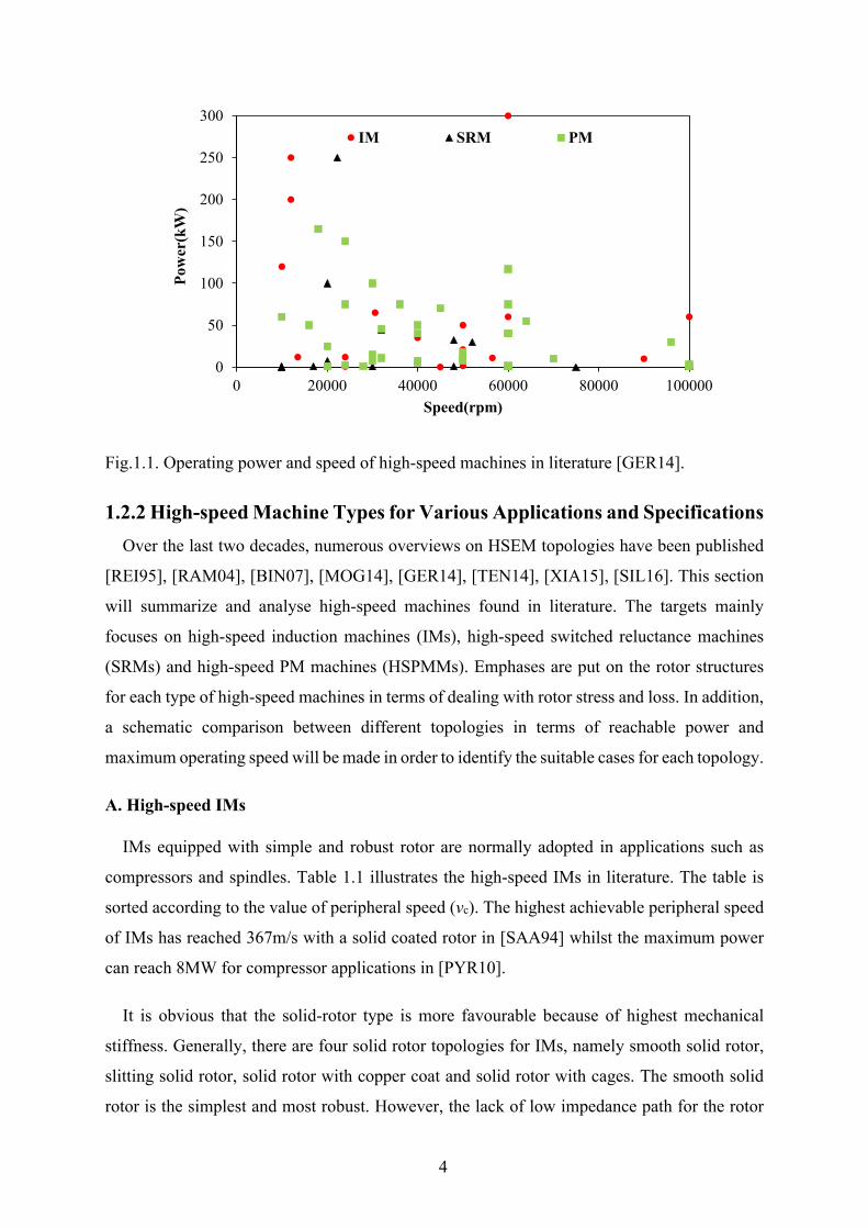
A. High-speed IMs
IMs equipped with simple and robust rotor are normally adopted in applications such as
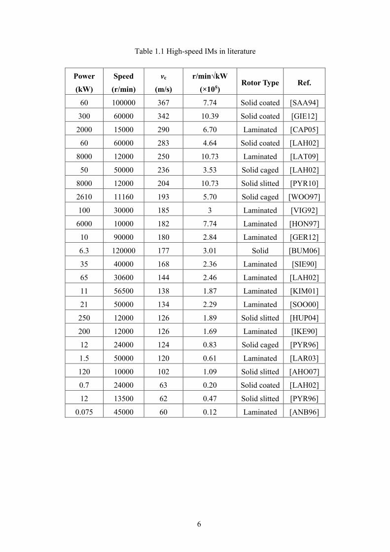
compressors and spindles. Table 1.1 illustrates the high-speed IMs in literature. The table is
sorted according to the value of peripheral speed (νc). The highest achievable peripheral speed
of IMs has reached 367m/s with a solid coated rotor in [SAA94] whilst the maximum power
can reach 8MW for compressor applications in [PYR10].
It is obvious that the solid-rotor type is more favourable because of highest mechanical
stiffness. Generally, there are four solid rotor topologies for IMs, namely smooth solid rotor,
slitting solid rotor, solid rotor with copper coat and solid rotor with cages. The smooth solid
rotor is the simplest and most robust. However, the lack of low impedance path for the rotor
0
50
100
150
200
250
300
0 20000 40000 60000 80000 100000
Pow
er(k
W)
Speed(rpm)
IM SRM PM
5
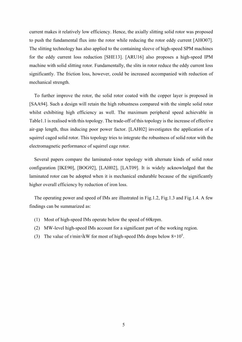
current makes it relatively low efficiency. Hence, the axially slitting solid rotor was proposed
to push the fundamental flux into the rotor while reducing the rotor eddy current [AHO07].
The slitting technology has also applied to the containing sleeve of high-speed SPM machines
for the eddy current loss reduction [SHE13]. [ARU16] also proposes a high-speed IPM
machine with solid slitting rotor. Fundamentally, the slits in rotor reduce the eddy current loss
significantly. The friction loss, however, could be increased accompanied with reduction of
mechanical strength.
To further improve the rotor, the solid rotor coated with the copper layer is proposed in
[SAA94]. Such a design will retain the high robustness compared with the simple solid rotor
whilst exhibiting high efficiency as well. The maximum peripheral speed achievable in
Table1.1 is realised with this topology. The trade-off of this topology is the increase of effective
air-gap length, thus inducing poor power factor. [LAH02] investigates the application of a
squirrel caged solid rotor. This topology tries to integrate the robustness of solid rotor with the
electromagnetic performance of squirrel cage rotor.
Several papers compare the laminated–rotor topology with alternate kinds of solid rotor
configuration [IKE90], [BOG92], [LAH02], [LAT09]. It is widely acknowledged that the
laminated rotor can be adopted when it is mechanical endurable because of the significantly
higher overall efficiency by reduction of iron loss.
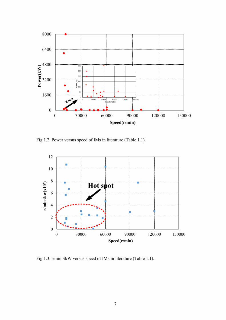
The operating power and speed of IMs are illustrated in Fig.1.2, Fig.1.3 and Fig.1.4. A few
findings can be summarized as:
(1) Most of high-speed IMs operate below the speed of 60krpm.
(2) MW-level high-speed IMs account for a significant part of the working region.
(3) The value of r/min√kW for most of high-speed IMs drops below 8×10⁵.
6
Table 1.1 High-speed IMs in literature
Power
(kW)
Speed
(r/min)
νc
(m/s)
r/min√kW
(×105) Rotor Type Ref.
60 100000 367 7.74 Solid coated [SAA94]
300 60000 342 10.39 Solid coated [GIE12]
2000 15000 290 6.70 Laminated [CAP05]
60 60000 283 4.64 Solid coated [LAH02]
8000 12000 250 10.73 Laminated [LAT09]
50 50000 236 3.53 Solid caged [LAH02]
8000 12000 204 10.73 Solid slitted [PYR10]
2610 11160 193 5.70 Solid caged [WOO97]
100 30000 185 3 Laminated [VIG92]
6000 10000 182 7.74 Laminated [HON97]
10 90000 180 2.84 Laminated [GER12]
6.3 120000 177 3.01 Solid [BUM06]
35 40000 168 2.36 Laminated [SIE90]
65 30600 144 2.46 Laminated [LAH02]
11 56500 138 1.87 Laminated [KIM01]
21 50000 134 2.29 Laminated [SOO00]
250 12000 126 1.89 Solid slitted [HUP04]
200 12000 126 1.69 Laminated [IKE90]
12 24000 124 0.83 Solid caged [PYR96]
1.5 50000 120 0.61 Laminated [LAR03]
120 10000 102 1.09 Solid slitted [AHO07]
0.7 24000 63 0.20 Solid coated [LAH02]
12 13500 62 0.47 Solid slitted [PYR96]
0.075 45000 60 0.12 Laminated [ANB96]
7
Fig.1.2. Power versus speed of IMs in literature (Table 1.1).
Fig.1.3. r/min √kW versus speed of IMs in literature (Table 1.1).
0
1600
3200
4800
6400
8000
0 30000 60000 90000 120000 150000
Pow
er(k
W)
Speed(r/min)
0
50
100
150
200
250
300
0 30000 60000 90000 120000 150000
Pow
er(k
W)
Speed(r/min)Zoom
0
2
4
6
8
10
12
0 30000 60000 90000 120000 150000
r/min√kw(x10
5 )
Speed(r/min)
Hot spot
8
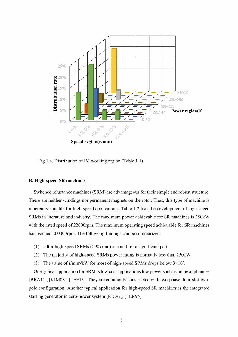
Fig.1.4. Distribution of IM working region (Table 1.1).
B. High-speed SR machines
Switched reluctance machines (SRM) are advantageous for their simple and robust structure.
There are neither windings nor permanent magnets on the rotor. Thus, this type of machine is
inherently suitable for high-speed applications. Table 1.2 lists the development of high-speed
SRMs in literature and industry. The maximum power achievable for SR machines is 250kW
with the rated speed of 22000rpm. The maximum operating speed achievable for SR machines
has reached 200000rpm. The following findings can be summarized:
(1) Ultra-high-speed SRMs (>90krpm) account for a significant part.
(2) The majority of high-speed SRMs power rating is normally less than 250kW.
(3) The value of r/min√kW for most of high-speed SRMs drops below 3×10⁵.
One typical application for SRM is low cost applications low power such as home appliances
[BRA11], [KIM08], [LEE13]. They are commonly constructed with two-phase, four-slot-two-
pole configuration. Another typical application for high-speed SR machines is the integrated
starting generator in aero-power system [RIC97], [FER95].
Power region(kWDis
trub
utio
n ra
te
Speed region(r/min)
9
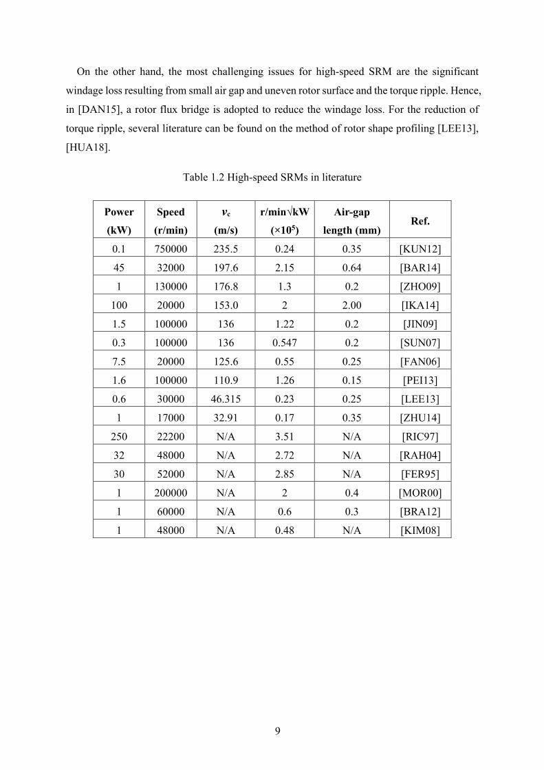
On the other hand, the most challenging issues for high-speed SRM are the significant
windage loss resulting from small air gap and uneven rotor surface and the torque ripple. Hence,
in [DAN15], a rotor flux bridge is adopted to reduce the windage loss. For the reduction of
torque ripple, several literature can be found on the method of rotor shape profiling [LEE13],
[HUA18].
Table 1.2 High-speed SRMs in literature
Power
(kW)
Speed
(r/min)
νc
(m/s)
r/min√kW
(×105)
Air-gap
length (mm) Ref.
0.1 750000 235.5 0.24 0.35 [KUN12]
45 32000 197.6 2.15 0.64 [BAR14]
1 130000 176.8 1.3 0.2 [ZHO09]
100 20000 153.0 2 2.00 [IKA14]
1.5 100000 136 1.22 0.2 [JIN09]
0.3 100000 136 0.547 0.2 [SUN07]
7.5 20000 125.6 0.55 0.25 [FAN06]
1.6 100000 110.9 1.26 0.15 [PEI13]
0.6 30000 46.315 0.23 0.25 [LEE13]
1 17000 32.91 0.17 0.35 [ZHU14]
250 22200 N/A 3.51 N/A [RIC97]
32 48000 N/A 2.72 N/A [RAH04]
30 52000 N/A 2.85 N/A [FER95]
1 200000 N/A 2 0.4 [MOR00]
1 60000 N/A 0.6 0.3 [BRA12]
1 48000 N/A 0.48 N/A [KIM08]
10
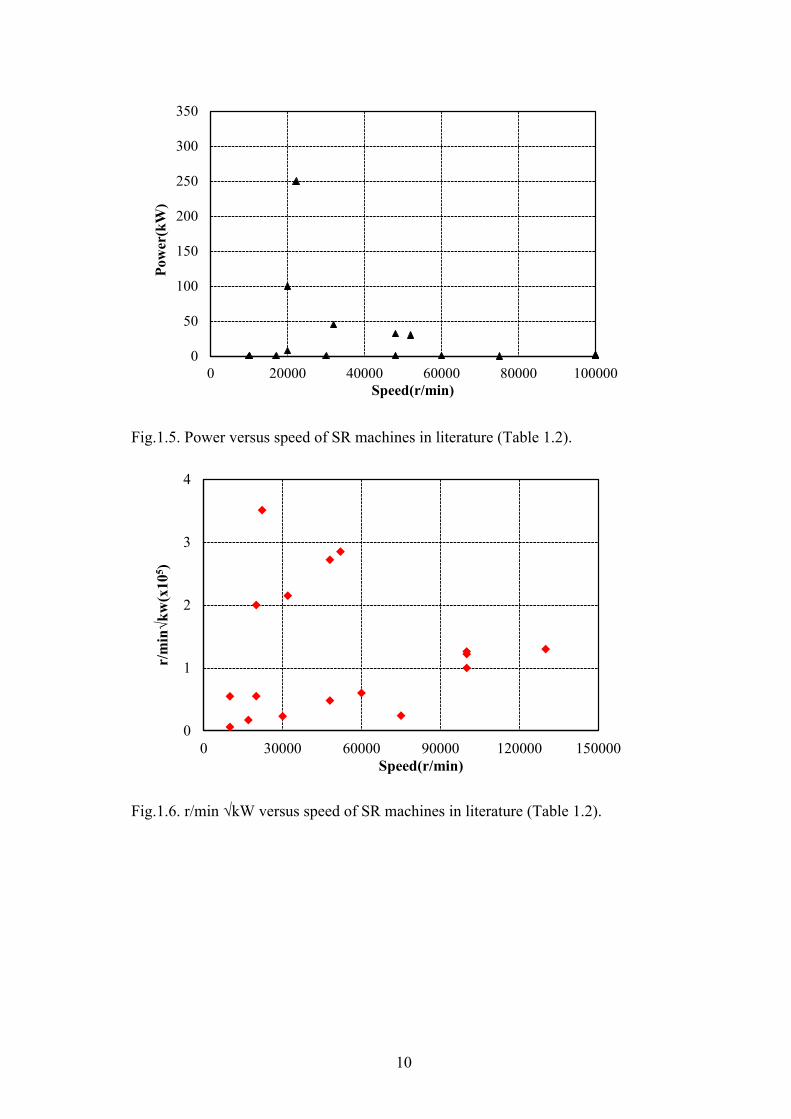
Fig.1.5. Power versus speed of SR machines in literature (Table 1.2).
Fig.1.6. r/min √kW versus speed of SR machines in literature (Table 1.2).
0
50
100
150
200
250
300
350
0 20000 40000 60000 80000 100000
Pow
er(k
W)
Speed(r/min)
0
1
2
3
4
0 30000 60000 90000 120000 150000
r/min√kw(x10
5 )
Speed(r/min)
11
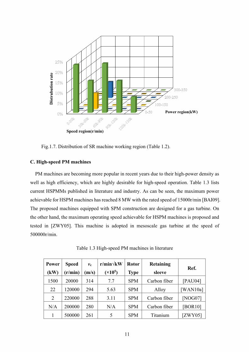
Fig.1.7. Distribution of SR machine working region (Table 1.2).
C. High-speed PM machines
PM machines are becoming more popular in recent years due to their high-power density as
well as high efficiency, which are highly desirable for high-speed operation. Table 1.3 lists
current HSPMMs published in literature and industry. As can be seen, the maximum power
achievable for HSPM machines has reached 8 MW with the rated speed of 15000r/min [BAI09].
The proposed machines equipped with SPM construction are designed for a gas turbine. On
the other hand, the maximum operating speed achievable for HSPM machines is proposed and
tested in [ZWY05]. This machine is adopted in mesoscale gas turbine at the speed of
500000r/min.
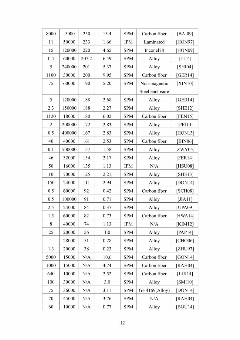
Table 1.3 High-speed PM machines in literature
Power
(kW)
Speed
(r/min)
νc
(m/s)
r/min√kW
(×105)
Rotor
Type
Retaining
sleeve Ref.
1500 20000 314 7.7 SPM Carbon fiber [PAU04]
22 120000 294 5.63 SPM Alloy [WAN10a]
2 220000 288 3.11 SPM Carbon fiber [NOG07]
N/A 200000 280 N/A SPM Carbon fiber [BOR10]
1 500000 261 5 SPM Titanium [ZWY05]
Power region(kW)
Dis
trub
utio
n ra
te
Speed region(r/min)
12
8000 5000 250 13.4 SPM Carbon fiber [BAI09]
11 50000 233 1.66 IPM Laminated [HON97]
15 120000 220 4.65 SPM Inconel78 [HON09]
117 60000 207.2 6.49 SPM Alloy [LI14]
5 240000 201 5.37 SPM Alloy [SHI04]
1100 30000 200 9.95 SPM Carbon fiber [GER14]
75 60000 190 5.20 SPM Non-magnetic
Steel enclosure
[XIN10]
5 120000 188 2.68 SPM Alloy [GER14]
2.3 150000 188 2.27 SPM Alloy [SHE12]
1120 18000 180 6.02 SPM Carbon fiber [FEN15]
2 200000 172 2.83 SPM Alloy [PFI10]
0.5 400000 167 2.83 SPM Alloy [HON13]
40 40000 161 2.53 SPM Carbon fiber [BIN06]
0.1 500000 157 1.58 SPM Alloy [ZWY05]
46 32000 154 2.17 SPM Alloy [FER14]
50 16000 135 1.13 IPM N/A [HSU08]
10 70000 125 2.21 SPM Alloy [SHE13]
150 24000 111 2.94 SPM Alloy [DON14]
0.5 60000 92 0.42 SPM Carbon fiber [SCH08]
0.5 100000 91 0.71 SPM Alloy [JIA11]
2.5 24000 84 0.37 SPM Alloy [UPA09]
1.5 60000 82 0.73 SPM Carbon fiber [HWA14]
8 40000 74 1.13 IPM N/A [KIM12]
25 20000 56 1.0 SPM Alloy [PAP14]
1 28000 51 0.28 SPM Alloy [CHO06]
1.3 20000 38 0.23 SPM Alloy [ZHU97]
5000 15000 N/A 10.6 SPM Carbon fiber [GON14]
1000 15000 N/A 4.74 SPM Carbon fiber [RAH04]
640 10000 N/A 2.52 SPM Carbon fiber [LUI14]
100 30000 N/A 3.0 SPM Alloy [SMI10]
75 36000 N/A 3.11 SPM GH4169(Alloy) [DON14]
70 45000 N/A 3.76 SPM N/A [RAH04]
60 10000 N/A 0.77 SPM Alloy [BOU14]
13
55 64000 N/A 4.74 SPM Alloy [JAN04]
50 40000 N/A 2.83 SPM N/A [YON12]
40 60000 N/A 3.79 SPM N/A [LON98]
30 96000 N/A 5.26 SPM Alloy [XIA15]
18 50000 N/A 2.12 SPM Alloy [HAS14]
11 32000 N/A 1.06 IPM Alloy [CHO06]
7.6 50000 N/A 1.38 SPM N/A [NAG05]
5 150000 N/A 3.35 SPM Carbon fiber [TAK94]
3 150000 N/A 2.59 SPM Alloy [HU14]
1.85 136000 N/A 1.85 SPM Alloy [LIN08]
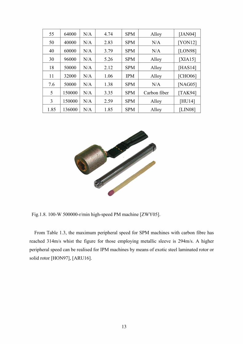
Fig.1.8. 100-W 500000-r/min high-speed PM machine [ZWY05].
From Table 1.3, the maximum peripheral speed for SPM machines with carbon fibre has
reached 314m/s whist the figure for those employing metallic sleeve is 294m/s. A higher
peripheral speed can be realised for IPM machines by means of exotic steel laminated rotor or
solid rotor [HON97], [ARU16].
14
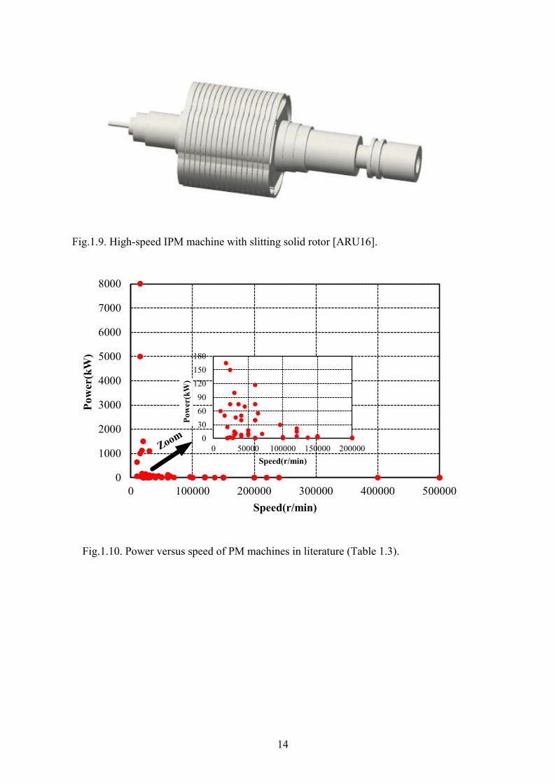
Fig.1.9. High-speed IPM machine with slitting solid rotor [ARU16].
Fig.1.10. Power versus speed of PM machines in literature (Table 1.3).
0
1000
2000
3000
4000
5000
6000
7000
8000
0 100000 200000 300000 400000 500000
Pow
er(k
W)
Speed(r/min)
0306090
120150180
0 50000 100000 150000 200000
Pow
er(k
W)
Speed(r/min)Zoom

15
Fig.1.11. r/min √kW versus speed of PM machines in literature (Table 1.3).
Fig.1.12. Distribution of high-speed PM machines working region (Table 1.3).
0
4
8
12
16
0 100000 200000 300000 400000 500000
r/min√kw
speed(r/min)
Hot spot
(x10
5 )
Power region(kW)
Dis
trub
utio
n ra
te
Speed region(r/min)
16
Table 1.4 summarizes key parameters of the feasible topologies of high-speed electrical
machines. A few observations can be concluded:
1) The maximum peripheral speed can be realized with solid-rotor IM topology, followed with
the SPM machine with carbon fibre sleeve. These two topologies are the most selected
solutions in the MW level high-speed applications.
2) The IM with strengthened laminated rotor shares equal value of r/min√kW with SPM
machine with a metallic sleeve. However, the maximum power achievable for SPM
machines is only 150kW which is far behind that of IMs. This can be attributed to the thermal
limits of the permanent magnet under the protection of thermal limits. The induced sleeve
loss imposes a great threat on the magnet, thus restricting the improvement of power level.
3) Switched reluctance machines are relatively advantageous in the tolerable operating speed
thanks to its unique rotor structure. However, the large iron loss and windage loss make them
not so competitive with SPM machines and IMs.

17
Table 1.4. Summary of key parameters for feasible topologies of HSEM
Machine Type Max. power (kW)
Max. speed
(r/min)
Max. r/min√k
W (×105)
Max. peripheral
speed (m/s)
Ref.
IMs
Solid-rotor IMs 60 10000 7.74 367 [SAA94]
IMs using high-strength sheet steels
for rotor
2000 15000 6.70 290 [CAP05]
IMs with conventional
laminated rotor
280 90000 3.0 185 [GER12]
SPM
SPM machines
with carbon fiber
8000 220000 13.4 314 [PAU04]
SPM machines
with metallic sleeve
22 120000 5.63 294 [WAN10a]
IPM
IPM machine with high strength
laminated rotor
11 50000 1.66 233 [HON97]
IPM machines
with normal laminated
rotor
50 40000 1.13 135 [HSU08]
SRM SRMs 250 220000 3.51 210 [RIC97]
18
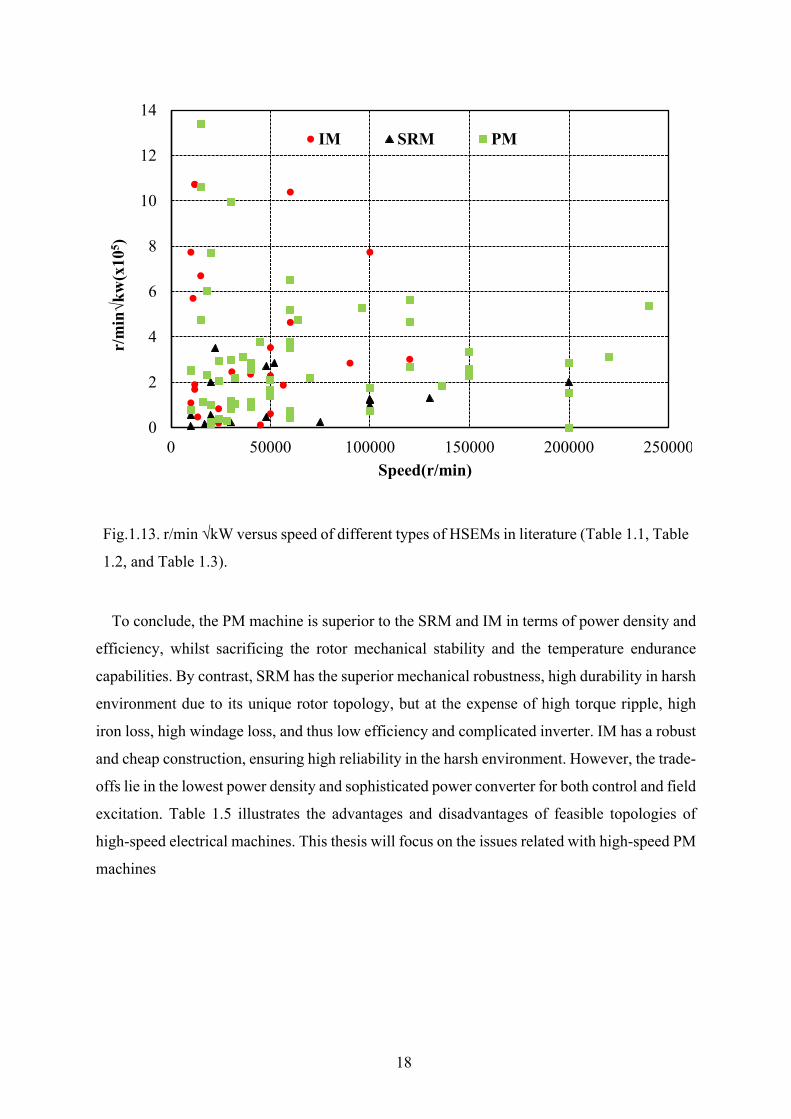
Fig.1.13. r/min √kW versus speed of different types of HSEMs in literature (Table 1.1, Table
1.2, and Table 1.3).
To conclude, the PM machine is superior to the SRM and IM in terms of power density and
efficiency, whilst sacrificing the rotor mechanical stability and the temperature endurance
capabilities. By contrast, SRM has the superior mechanical robustness, high durability in harsh
environment due to its unique rotor topology, but at the expense of high torque ripple, high
iron loss, high windage loss, and thus low efficiency and complicated inverter. IM has a robust
and cheap construction, ensuring high reliability in the harsh environment. However, the trade-
offs lie in the lowest power density and sophisticated power converter for both control and field
excitation. Table 1.5 illustrates the advantages and disadvantages of feasible topologies of
high-speed electrical machines. This thesis will focus on the issues related with high-speed PM
machines
0
2
4
6
8
10
12
14
0 50000 100000 150000 200000 250000
r/min√kw(x10
5 )
Speed(r/min)
IM SRM PM

19
Table 1.5 Advantages and disadvantages of feasible topologies of HSEMs
Machine Type Advantages Disadvantages
Induction machines
Robustness and low maintenance
High rotor loss thus low efficiency Low power factor
Radial PM machines
Large airgap length (SPM) High efficiency High power factor High power density thus compact size
Rotor robustness Rotor eddy current loss (SPM) PM temperature endurance (SPM)
Axial PM machine
High power factor and efficiency Low rotor loss Large airgap length
Increased cost Complicated structure
Homopolar machine
High power factor Easy field adjustment Simple rotor structure
Large windage loss Large iron loss
Claw-pole machine
High power factor Easy field adjustment
Complicated 3D rotor structure High rotor loss and leakage flux thus low efficiency
Switched reluctance machine
Fault tolerant due to lack of PMs Robust and simple rotor
Low torque density High torque ripple Small airgap required
Synchronous reluctance machine
Fault tolerant due to lack of PM Relatively robust rotor structure
Low power density Small airgap length needed
20
1.3 Electromagnetic Issues in High-speed PM Machines
The electromagnetic analysis of HSPMM has never only been about the improvement of
efficiency and power density. Instead, design guidelines in terms of topology such as slot and
pole number combination should be considered more from the loss and stress point of view.
This section will discuss various aspects of electromagnetic design considerations which is
quite interdependent on the rotor thermal stability and mechanical robustness, reflected by the
electromagnetic loss and unbalanced magnetic force.
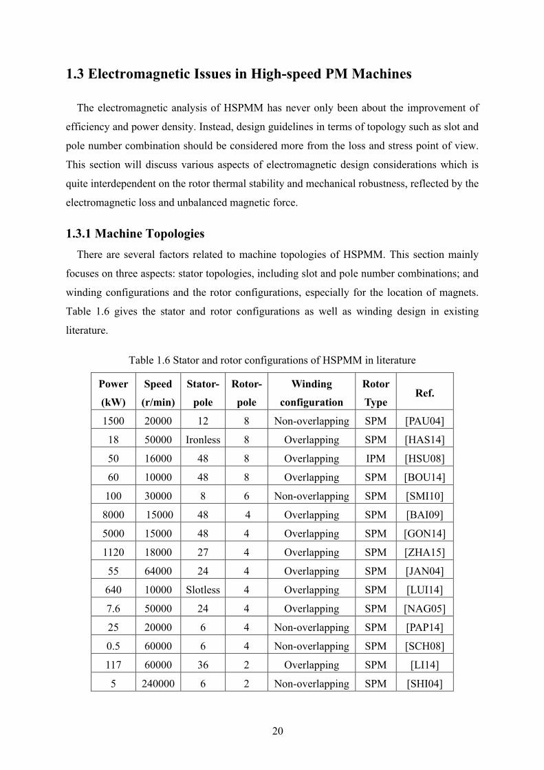
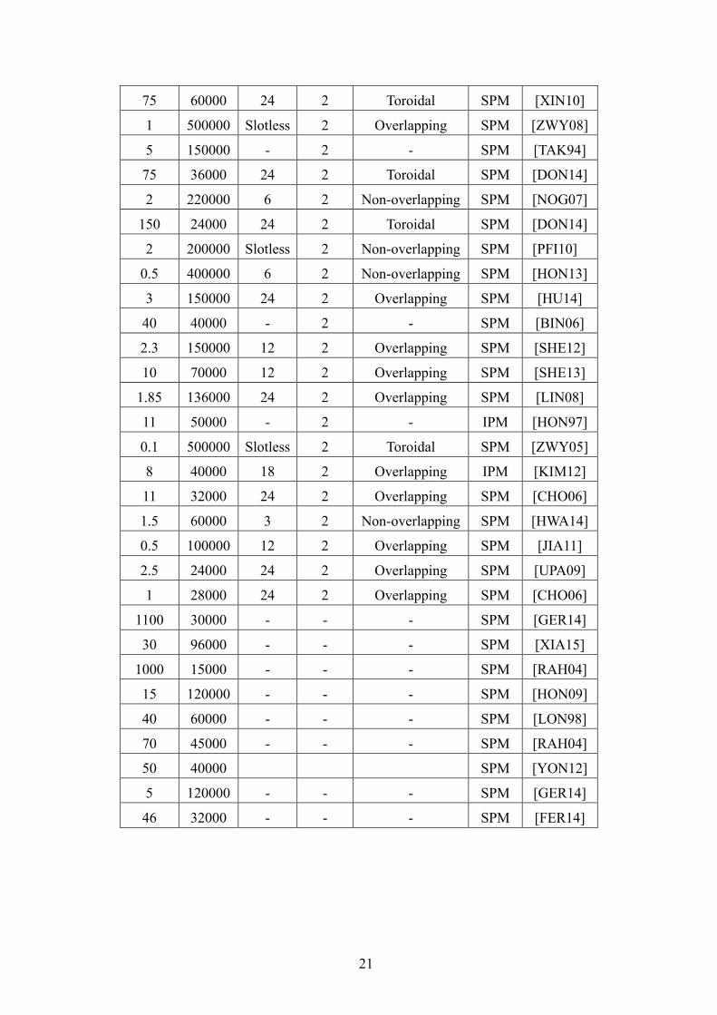
1.3.1 Machine Topologies There are several factors related to machine topologies of HSPMM. This section mainly
focuses on three aspects: stator topologies, including slot and pole number combinations; and
winding configurations and the rotor configurations, especially for the location of magnets.
Table 1.6 gives the stator and rotor configurations as well as winding design in existing
literature.
Table 1.6 Stator and rotor configurations of HSPMM in literature
Power
(kW)
Speed
(r/min)
Stator-
pole
Rotor-
pole
Winding
configuration
Rotor
Type Ref.
1500 20000 12 8 Non-overlapping SPM [PAU04]
18 50000 Ironless 8 Overlapping SPM [HAS14]
50 16000 48 8 Overlapping IPM [HSU08]
60 10000 48 8 Overlapping SPM [BOU14]
100 30000 8 6 Non-overlapping SPM [SMI10]
8000 15000 48 4 Overlapping SPM [BAI09]
5000 15000 48 4 Overlapping SPM [GON14]
1120 18000 27 4 Overlapping SPM [ZHA15]
55 64000 24 4 Overlapping SPM [JAN04]
640 10000 Slotless 4 Overlapping SPM [LUI14]
7.6 50000 24 4 Overlapping SPM [NAG05]
25 20000 6 4 Non-overlapping SPM [PAP14]
0.5 60000 6 4 Non-overlapping SPM [SCH08]
117 60000 36 2 Overlapping SPM [LI14]
5 240000 6 2 Non-overlapping SPM [SHI04]
21
75 60000 24 2 Toroidal SPM [XIN10]
1 500000 Slotless 2 Overlapping SPM [ZWY08]
5 150000 - 2 - SPM [TAK94]
75 36000 24 2 Toroidal SPM [DON14]
2 220000 6 2 Non-overlapping SPM [NOG07]
150 24000 24 2 Toroidal SPM [DON14]
2 200000 Slotless 2 Non-overlapping SPM [PFI10]
0.5 400000 6 2 Non-overlapping SPM [HON13]
3 150000 24 2 Overlapping SPM [HU14]
40 40000 - 2 - SPM [BIN06]
2.3 150000 12 2 Overlapping SPM [SHE12]
10 70000 12 2 Overlapping SPM [SHE13]
1.85 136000 24 2 Overlapping SPM [LIN08]
11 50000 - 2 - IPM [HON97]
0.1 500000 Slotless 2 Toroidal SPM [ZWY05]
8 40000 18 2 Overlapping IPM [KIM12]
11 32000 24 2 Overlapping SPM [CHO06]
1.5 60000 3 2 Non-overlapping SPM [HWA14]
0.5 100000 12 2 Overlapping SPM [JIA11]
2.5 24000 24 2 Overlapping SPM [UPA09]
1 28000 24 2 Overlapping SPM [CHO06]
1100 30000 - - - SPM [GER14]
30 96000 - - - SPM [XIA15]
1000 15000 - - - SPM [RAH04]
15 120000 - - - SPM [HON09]
40 60000 - - - SPM [LON98]
70 45000 - - - SPM [RAH04]
50 40000 SPM [YON12]
5 120000 - - - SPM [GER14]
46 32000 - - - SPM [FER14]
22
A. Stator configurations
Both the stator and the stator winding of HSPMMs are immersed in the high frequency
variable magnetic field. Hence, the design of stator parts should be considered more from the
perspective of loss reduction and heat dissipation.
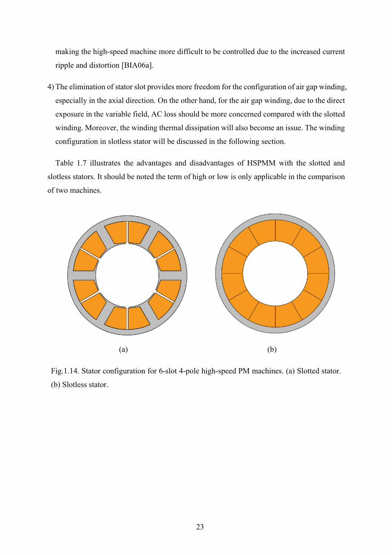
Generally, the stator configuration of HSPMM can be classified into two kinds: slotted stator
and slotless stator, as shown in Fig.1.14. For the HSPMM with slotted stator, the spatial
harmonics caused by stator slotting effect would induce a significant amount of eddy current
loss in the rotor of SPM machines which will be discussed in detail in Chapter 3. On the other
hand, the number of stator slot number also makes a difference to the slotting effect. In [XIN10],
it was pointed out that the rotor loss will be significantly reduced with the increasing slot
number due to weakened slotting effect.
In order to fully eliminate the influence of slotting effect, slotless stator structure can be
found in several papers [BIA04], [BIA05], [PER10], [LUI14], [CHE15]. A few features of this
type of stator can be summarized as:
1) The rotor loss due to the PM field pulsation is fully eliminated. This is quite desirable for
high speed machines with lower number of stator slots, where slot harmonics order is
relatively low thus penetrating into the rotor magnets easily. The cogging torque has been
mitigated as well. From Fig.1.15, for the machine with slotted stator, significant flux
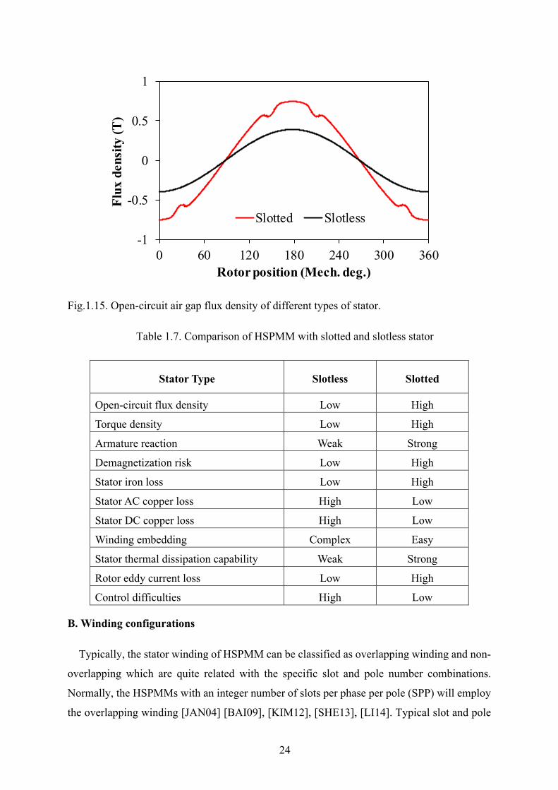
distortion appears in the air gap, which will yield parasitic effects such as rotor loss or UMF.
On the other hand, the open-circuit air gap flux density is quite sinusoidal for in HSPMM
with a slotless stator. However, this merit is at the expense of a lower torque density. A lower
amplitude of fundamental flux due to the increased reluctance will be observed in slotless
machines. Hence, normally, the Halbach magnetization will be adopted together with the
slotless structure to compensate for the reduced flux density [JAN01], [JAN03], [PRA12],
[LUI14].
2) The stator core loss will be significantly reduced due to decreased iron volume and stator
flux density.
3) The relatively large equivalent air gap also acts as a double-edged sword. On the one hand,
the armature reaction is negligible, thus having a lower demagnetization risk and lower rotor
eddy current loss. On the other hand, the phase inductance will be significantly reduced,
23
making the high-speed machine more difficult to be controlled due to the increased current
ripple and distortion [BIA06a].
4) The elimination of stator slot provides more freedom for the configuration of air gap winding,
especially in the axial direction. On the other hand, for the air gap winding, due to the direct
exposure in the variable field, AC loss should be more concerned compared with the slotted
winding. Moreover, the winding thermal dissipation will also become an issue. The winding
configuration in slotless stator will be discussed in the following section.
Table 1.7 illustrates the advantages and disadvantages of HSPMM with the slotted and
slotless stators. It should be noted the term of high or low is only applicable in the comparison
of two machines.
(a) (b)
Fig.1.14. Stator configuration for 6-slot 4-pole high-speed PM machines. (a) Slotted stator.
(b) Slotless stator.
24
Fig.1.15. Open-circuit air gap flux density of different types of stator.
Table 1.7. Comparison of HSPMM with slotted and slotless stator
Stator Type Slotless Slotted
Open-circuit flux density Low High
Torque density Low High
Armature reaction Weak Strong
Demagnetization risk Low High
Stator iron loss Low High
Stator AC copper loss High Low
Stator DC copper loss High Low
Winding embedding Complex Easy
Stator thermal dissipation capability Weak Strong
Rotor eddy current loss Low High
Control difficulties High Low
B. Winding configurations
Typically, the stator winding of HSPMM can be classified as overlapping winding and non-
overlapping which are quite related with the specific slot and pole number combinations.
Normally, the HSPMMs with an integer number of slots per phase per pole (SPP) will employ
the overlapping winding [JAN04] [BAI09], [KIM12], [SHE13], [LI14]. Typical slot and pole
-1
-0.5
0
0.5
1
0 60 120 180 240 300 360
Flux
den
sity
(T)
Rotor position (Mech. deg.)
Slotted Slotless
25
number combinations are 12-slot/2-pole, 18-slot/2-pole, 24-slot/2-pole, 12-slot/4-pole, 48-
slot/4-pole. On the other hand, the HSPMMs with a fractional number of SPP will normally
employ the non-overlapping winding also known as fractional-slot concentrated winding
(FSCW) [REF10]. Typical slot and pole number combinations are with the classical 3s/2p
series such as 3-slot/2-pole [ZHU97], [MA19], 6-slot/4-pole [SCH08], [PAP14], 12-slot/8-pole
[PAU04].
The advantages and disadvantages of overlapping and non-overlapping windings have been
heavily reported in literature [BIA06b], [BOG09], [REF10], [PFI10]. For HSPMM, the
concern is how these two winding configurations make a difference in terms of aforementioned
rotor loss and rotor mechanical robustness. To be more specific, attention should be paid on
the produced MMF harmonics as well as the end-winding length of these two types of windings.
The rotor loss is significantly dependent on the produced MMF. The rotor critical speed will
be significantly increased with the enlarged end-winding length. There is no doubt that the
overlapping winding is superior in terms of spatial harmonic contents and the non-overlapping
winding is more preferred due to shorted end-winding length. Hence, the selection of the
winding type should take the requirement of operating speed and power into consideration.
From Table 1.6, it is obvious to find that the overlapping winding is more preferred in the
HSPMM with high power rating [BAI09], [GON14], [LUI14], [ZHA15] in which the rotor loss
is quite an issue. By contrary, the non-overlapping is more inclined to be adopted in HSPMM
with ultra-high speed [SHI04], [NOG07], [PFI10]. This basic rule is also capable of explaining
the increasing popularity of 6-slot/2-pole HSPMM with non-overlapping winding in the recent
decades [UZH16], [WAN18], [MA18]. Although the winding factor of this configuration is
only half of that in non-overlapping configuration, the reduced end-winding length is more
advantageous for ultra-high-speed application.
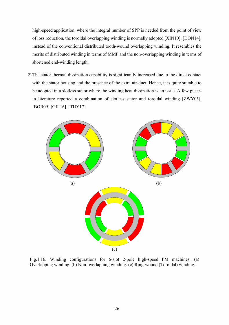
Another typical method to reduce the end-winding length is the adoption of toroidal winding
as shown in Fig.1.16. The overlapping winding or non-overlapping winding is wound in the
stator yoke instead of stator teeth. The advantages of this type of winding includes three aspects:
better thermal dissipation; increased machine integrity due to short end-winding length, and
easy manufacturing compared with the overlapping winding. Accordingly, there are also at
least two applications suitable for the adoption of the toroidal winding in HSPMM:
1) Compared with overlapping winding, the end-winding length is significantly reduced; and
the stator thermal dissipation capability is greatly strengthened. Hence, in the high-power
26
high-speed application, where the integral number of SPP is needed from the point of view
of loss reduction, the toroidal overlapping winding is normally adopted [XIN10], [DON14],
instead of the conventional distributed tooth-wound overlapping winding. It resembles the
merits of distributed winding in terms of MMF and the non-overlapping winding in terms of
shortened end-winding length.
2) The stator thermal dissipation capability is significantly increased due to the direct contact
with the stator housing and the presence of the extra air-duct. Hence, it is quite suitable to
be adopted in a slotless stator where the winding heat dissipation is an issue. A few pieces
in literature reported a combination of slotless stator and toroidal winding [ZWY05],
[BOR09] [GIL16], [TUY17].
(a) (b)
(c)
Fig.1.16. Winding configurations for 6-slot 2-pole high-speed PM machines. (a) Overlapping winding. (b) Non-overlapping winding. (c) Ring-wound (Toroidal) winding.
27
C. Rotor configurations
The selection of rotor topologies for HSPMM is a vital issue which is involved with both
electromagnetic and mechanical problems such as magnet utilization and protection. The
electromagnetic performance, such as power density and efficiency, and mechanical robustness
of HSPMM are quite dependent on the rotor design. Basically, the rotor design of HSPMM can
be regarded as the search for a reasonable combination of magnets, rotor iron and retaining
sleeve if applicable, by making trade-offs between the PM containment for mechanical
robustness and PM utilization for high efficiency.
This section will briefly summarize and give a schematic analysis of the rotor configurations
of HSPMM and try to discover the reasons behind it. From Table 1.6, it can be seen that the
SPM machines with the retaining sleeves are widely used for high speed applications. On the
other hand, the IPM machines with strengthened material together with the magnetic bridge
and shaping techniques are also gaining popularity in the last decade [KIM12], [JIA15],
[ARU16].
(a) High-speed SPM machines
As proven in the previous section, the SPM machines are more favored due to mechanical
robustness. Normally, the HSPMM rotor topologies can be grouped into two categories
according to the rotor pole number. The rotor pole number of HSPMM is usually selected to
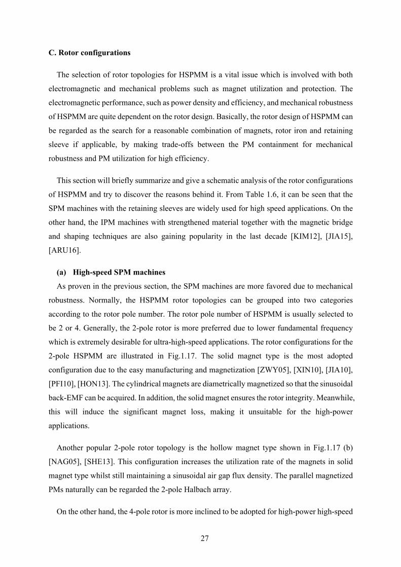
be 2 or 4. Generally, the 2-pole rotor is more preferred due to lower fundamental frequency
which is extremely desirable for ultra-high-speed applications. The rotor configurations for the
2-pole HSPMM are illustrated in Fig.1.17. The solid magnet type is the most adopted
configuration due to the easy manufacturing and magnetization [ZWY05], [XIN10], [JIA10],
[PFI10], [HON13]. The cylindrical magnets are diametrically magnetized so that the sinusoidal
back-EMF can be acquired. In addition, the solid magnet ensures the rotor integrity. Meanwhile,
this will induce the significant magnet loss, making it unsuitable for the high-power
applications.
Another popular 2-pole rotor topology is the hollow magnet type shown in Fig.1.17 (b)
[NAG05], [SHE13]. This configuration increases the utilization rate of the magnets in solid
magnet type whilst still maintaining a sinusoidal air gap flux density. The parallel magnetized
PMs naturally can be regarded the 2-pole Halbach array.
On the other hand, the 4-pole rotor is more inclined to be adopted for high-power high-speed
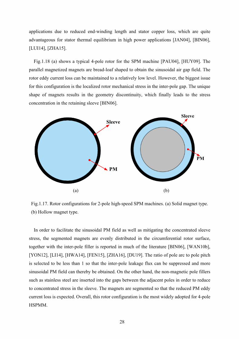
28
applications due to reduced end-winding length and stator copper loss, which are quite
advantageous for stator thermal equilibrium in high power applications [JAN04], [BIN06],
[LUI14], [ZHA15].
Fig.1.18 (a) shows a typical 4-pole rotor for the SPM machine [PAU04], [HUY09]. The
parallel magnetized magnets are bread-loaf shaped to obtain the sinusoidal air gap field. The
rotor eddy current loss can be maintained to a relatively low level. However, the biggest issue
for this configuration is the localized rotor mechanical stress in the inter-pole gap. The unique
shape of magnets results in the geometry discontinuity, which finally leads to the stress
concentration in the retaining sleeve [BIN06].
(a) (b)
Fig.1.17. Rotor configurations for 2-pole high-speed SPM machines. (a) Solid magnet type.
(b) Hollow magnet type.
In order to facilitate the sinusoidal PM field as well as mitigating the concentrated sleeve
stress, the segmented magnets are evenly distributed in the circumferential rotor surface,
together with the inter-pole filler is reported in much of the literature [BIN06], [WAN10b],
[YON12], [LI14], [HWA14], [FEN15], [ZHA16], [DU19]. The ratio of pole arc to pole pitch
is selected to be less than 1 so that the inter-pole leakage flux can be suppressed and more
sinusoidal PM field can thereby be obtained. On the other hand, the non-magnetic pole fillers
such as stainless steel are inserted into the gaps between the adjacent poles in order to reduce
to concentrated stress in the sleeve. The magnets are segmented so that the reduced PM eddy
current loss is expected. Overall, this rotor configuration is the most widely adopted for 4-pole
HSPMM.
Sleeve
PM
Sleeve
PM

29
As mentioned in the previous section, the Halbach array is normally adopted in the slotless
stator for production of stronger air gap field [HON97], [MYE03]. The inherent self-shielding
property and sinusoidal air gap field distribution is quite desirable for the rotor of 4-pole
HSPMM [JAN04], [LUI04]. The inter-pole gap can be eliminated while a much stronger and
sinusoidal air gap field can be obtained. The rotor magnet loss is also significantly lower
because of magnet segmentation and sinusoidal field. The main challenges for this type of
configuration are the massive consumption of magnets and high manufacturing cost.
(a) (b)
(c)
Fig.1.18. Rotor configurations for 4-pole high-speed SPM machines. (a) Broad-loaf magnets
type. (b) Segmented magnets with inter-pole filler. (c) Halbach magnetized magnets.
Sleeve
PM PM
Sleeve
Pole filler
PM
Sleeve
30
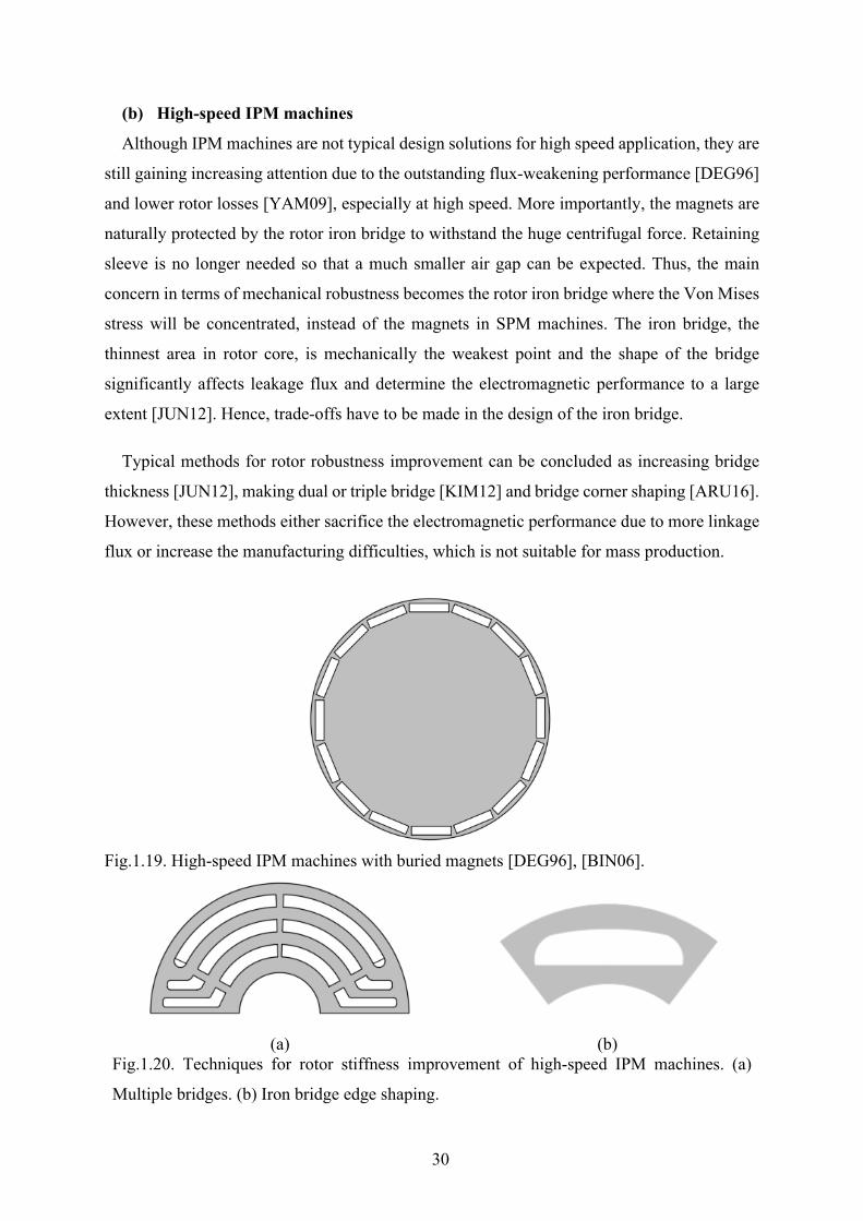
(b) High-speed IPM machines
Although IPM machines are not typical design solutions for high speed application, they are
still gaining increasing attention due to the outstanding flux-weakening performance [DEG96]
and lower rotor losses [YAM09], especially at high speed. More importantly, the magnets are
naturally protected by the rotor iron bridge to withstand the huge centrifugal force. Retaining
sleeve is no longer needed so that a much smaller air gap can be expected. Thus, the main
concern in terms of mechanical robustness becomes the rotor iron bridge where the Von Mises
stress will be concentrated, instead of the magnets in SPM machines. The iron bridge, the
thinnest area in rotor core, is mechanically the weakest point and the shape of the bridge
significantly affects leakage flux and determine the electromagnetic performance to a large
extent [JUN12]. Hence, trade-offs have to be made in the design of the iron bridge.
Typical methods for rotor robustness improvement can be concluded as increasing bridge
thickness [JUN12], making dual or triple bridge [KIM12] and bridge corner shaping [ARU16].
However, these methods either sacrifice the electromagnetic performance due to more linkage
flux or increase the manufacturing difficulties, which is not suitable for mass production.
Fig.1.19. High-speed IPM machines with buried magnets [DEG96], [BIN06].
(a) (b) Fig.1.20. Techniques for rotor stiffness improvement of high-speed IPM machines. (a)
Multiple bridges. (b) Iron bridge edge shaping.
31
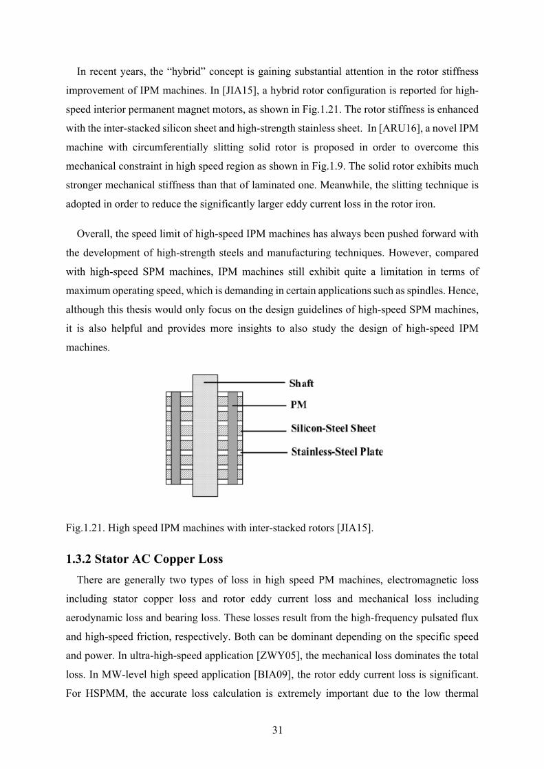
In recent years, the “hybrid” concept is gaining substantial attention in the rotor stiffness
improvement of IPM machines. In [JIA15], a hybrid rotor configuration is reported for high-
speed interior permanent magnet motors, as shown in Fig.1.21. The rotor stiffness is enhanced
with the inter-stacked silicon sheet and high-strength stainless sheet. In [ARU16], a novel IPM
machine with circumferentially slitting solid rotor is proposed in order to overcome this
mechanical constraint in high speed region as shown in Fig.1.9. The solid rotor exhibits much
stronger mechanical stiffness than that of laminated one. Meanwhile, the slitting technique is
adopted in order to reduce the significantly larger eddy current loss in the rotor iron.
Overall, the speed limit of high-speed IPM machines has always been pushed forward with
the development of high-strength steels and manufacturing techniques. However, compared
with high-speed SPM machines, IPM machines still exhibit quite a limitation in terms of
maximum operating speed, which is demanding in certain applications such as spindles. Hence,
although this thesis would only focus on the design guidelines of high-speed SPM machines,
it is also helpful and provides more insights to also study the design of high-speed IPM
machines.
Fig.1.21. High speed IPM machines with inter-stacked rotors [JIA15].
1.3.2 Stator AC Copper Loss There are generally two types of loss in high speed PM machines, electromagnetic loss
including stator copper loss and rotor eddy current loss and mechanical loss including
aerodynamic loss and bearing loss. These losses result from the high-frequency pulsated flux
and high-speed friction, respectively. Both can be dominant depending on the specific speed
and power. In ultra-high-speed application [ZWY05], the mechanical loss dominates the total
loss. In MW-level high speed application [BIA09], the rotor eddy current loss is significant.
For HSPMM, the accurate loss calculation is extremely important due to the low thermal
32
endurance of the rotor magnets. Meanwhile, the mechanical stress is also affected by the
thermal expansion [BIN06]. The understanding of loss production mechanism and precise
prediction will lay a solid foundation for the proposal of targeted loss mitigation strategy. This
section will try to give a brief analysis of the losses and summarize the alternate techniques for
reduction in the existing literature.
Under high-speed operation, the stator AC copper loss will rise rapidly as a result of the skin
effects and proximity effect [SUL99]. The skin effect refers to the trend for high-frequency
currents to travel on the conductor skin; whereas the proximity effect refers to the inclination
for current to flow in a non-uniform pattern on the cross-section of conductors. These
undesirable patterns tend to form the concentrated current loops because of the nearby magnetic
field.
There are several papers involved with the calculation of AC copper loss under high-speed
operation. In [LUO09], an analytical model is reported to predict the AC copper loss of a 100W,
50krpm slotless PM machine. In [THO09], a simple analytical model is established to estimate
the proximity loss in high-speed flux switching machines. Those analytical methods could give
a rough evaluation of stator losses. However, the accuracy is not satisfying due to the
negligence of the non-linear factor, slot opening flux leakage and other theoretical assumptions.
Hence, in [RED08], the 2-D analytical model is proposed for predicting strand-level proximity
losses with consideration of the slotting effect. In [RED10], the stand-level and bundle-level
proximity loss due to both armature reaction field and PM field can be predicted with an
integrated analysis tool.
In order to cope with the significant AC copper loss in HSPMM, [MEL06] points out that
the reasonable arrangement of conductors will significantly mitigate the proximity effect. The
stator winding should be placed in the rear parts of stator slot with the minimized radial height.
On the other hand, the skin effect can be suppressed with the adoption of smaller conductor
strands. Hence, Litz wire, consists of hundreds of smaller conductors, is typically one of the
most preferred techniques [SUL99]. However, this will also reduce the slot packing factor and
thermal dissipation capability. Meanwhile, the high cost of Litz wire is the main issue for its
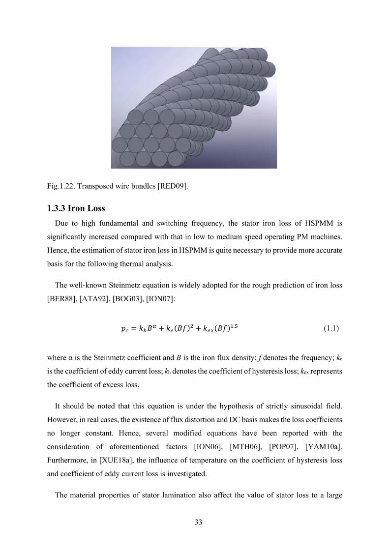
massive implementation. Hence, use of transposed wire bundles as an alternative method of
proximity loss reduction is investigated in [RED09] [RED11]. 3-D FE method is adopted for
the investigation of the influence of different strand number and transposed degrees.
33
Fig.1.22. Transposed wire bundles [RED09].
1.3.3 Iron Loss Due to high fundamental and switching frequency, the stator iron loss of HSPMM is
significantly increased compared with that in low to medium speed operating PM machines.
Hence, the estimation of stator iron loss in HSPMM is quite necessary to provide more accurate
basis for the following thermal analysis.
The well-known Steinmetz equation is widely adopted for the rough prediction of iron loss
[BER88], [ATA92], [BOG03], [ION07]:
𝑝𝑝𝑐𝑐 = 𝑘𝑘ℎ𝐵𝐵𝛼𝛼 + 𝑘𝑘𝑒𝑒(𝐵𝐵𝐵𝐵)2 + 𝑘𝑘𝑒𝑒𝑒𝑒(𝐵𝐵𝐵𝐵)1.5 (1.1)
where α is the Steinmetz coefficient and B is the iron flux density; f denotes the frequency; ke
is the coefficient of eddy current loss; kh denotes the coefficient of hysteresis loss; kex represents
the coefficient of excess loss.
It should be noted that this equation is under the hypothesis of strictly sinusoidal field.
However, in real cases, the existence of flux distortion and DC basis makes the loss coefficients
no longer constant. Hence, several modified equations have been reported with the
consideration of aforementioned factors [ION06], [MTH06], [POP07], [YAM10a].
Furthermore, in [XUE18a], the influence of temperature on the coefficient of hysteresis loss
and coefficient of eddy current loss is investigated.
The material properties of stator lamination also affect the value of stator loss to a large

34
extent. While the frequency and stator core flux density is given, the iron loss is mainly
dependent on the lamination thickness and the final annealing method. Electrical steels with
0.1mm thickness, yielding extremely low iron losses have been reported in [HAY09], [CHI11].
In recent years, the amorphous alloy is gaining more popularity for certain applications due to
significant reduction of core losses [LUO09], [HON13]. [DEM14] reported a high-speed
induction motor with stator core made of amorphous material, as shown in Fig.1.23. However,
this material is rigid and brittle, and thus only suitable for stator lamination. In addition, soft
magnetic materials (SMC) with low permeability is also raising attention due to the elimination
of core eddy current loss in high frequency [BIA06b], [CHE09].
Fig.1.23. Stator core made from the amorphous material [DEM14].
1.3.4 Rotor Eddy Current loss The issue of rotor eddy current loss has always been the concern for HSPMM. Generally,
the generation of rotor eddy current loss can be attributed to the field variation seen by the rotor.
This field variation results from the following reasons: (a) nonsinusoidal stator MMF
distribution due to stator winding disposition. (b) permeance variation due to slotting effect
and local saturation. (c) nonsinusoidal phase current due to BLDC control and PWM. The
existence of spatial and temporal harmonics in the air gap field will yield a significant eddy
current loss in the rotor magnets, the rotor yoke as well as the metallic sleeve for magnet
retaining. The risk of demagnetization will be increased due to the difficulties of rotor cooling,
especially for the rotor magnets sheltered by the sleeve with low thermal conductivity such as
carbon-fiber.
Hence, the accurate estimation of rotor eddy current loss is of great importance to the thermal
35
equilibrium of HSPMM. The calculation methods for rotor eddy current loss can be found in
several papers [ZHU93], [ZHU04], [WAN10b], [LAZ10], [JUM15]. Those methods can be
divided into the analytical and finite element analysis (FEA) method. The analytical solution
is always applied in SPM machines. The permeance variation resulting from slotting effect is
ignored. The permeability of iron core is assumed to be infinite. The stator winding is
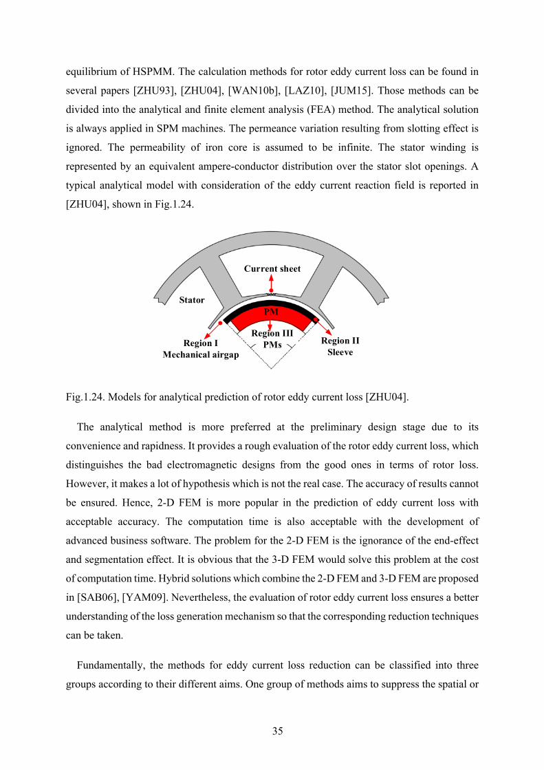
represented by an equivalent ampere-conductor distribution over the stator slot openings. A
typical analytical model with consideration of the eddy current reaction field is reported in
[ZHU04], shown in Fig.1.24.
Fig.1.24. Models for analytical prediction of rotor eddy current loss [ZHU04].
The analytical method is more preferred at the preliminary design stage due to its
convenience and rapidness. It provides a rough evaluation of the rotor eddy current loss, which
distinguishes the bad electromagnetic designs from the good ones in terms of rotor loss.
However, it makes a lot of hypothesis which is not the real case. The accuracy of results cannot
be ensured. Hence, 2-D FEM is more popular in the prediction of eddy current loss with
acceptable accuracy. The computation time is also acceptable with the development of
advanced business software. The problem for the 2-D FEM is the ignorance of the end-effect
and segmentation effect. It is obvious that the 3-D FEM would solve this problem at the cost
of computation time. Hybrid solutions which combine the 2-D FEM and 3-D FEM are proposed
in [SAB06], [YAM09]. Nevertheless, the evaluation of rotor eddy current loss ensures a better
understanding of the loss generation mechanism so that the corresponding reduction techniques
can be taken.
Fundamentally, the methods for eddy current loss reduction can be classified into three
groups according to their different aims. One group of methods aims to suppress the spatial or
PM
Current sheet
Region IISleeve
Stator
Region IMechanical airgap
Region IIIPMs
36
time harmonics which are the sources of the rotor eddy current loss, [ZWY05], [BIN07],
[REF08], [XIN10], [MA19]. Another group of methods aims to increase the resistance of the
eddy current flowing loop [YAM09], [SHE13], [HUN15]. The other group of methods aims to
shelter the magnets from the penetration of asynchronous harmonics thanks to shielding effect
of the coated copper layer [VEE97], [SHA06], [ETE12], or the metallic sleeves such as Inconel
or Titanium [ZHO06], [LI14].
Normally, the MMF spatial harmonics can be effectively suppressed by choosing reasonable
stator slot/pole combination as well as winding configuration. A typical example is the
structure with 2 poles, 6 slots and overlapping/non-overlapping windings, which performs far
better than the common structure with 2 poles, 3 slots and non-overlapping windings in terms
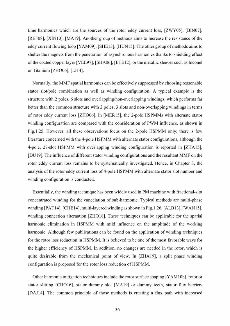
of rotor eddy current loss [ZHO06]. In [MER15], the 2-pole HSPMMs with alternate stator
winding configuration are compared with the consideration of PWM influence, as shown in
Fig.1.25. However, all these observations focus on the 2-pole HSPMM only; there is few
literature concerned with the 4-pole HSPMM with alternate stator configurations, although the
4-pole, 27-slot HSPMM with overlapping winding configuration is reported in [ZHA15],
[DU19]. The influence of different stator winding configurations and the resultant MMF on the
rotor eddy current loss remains to be systematically investigated. Hence, in Chapter 3, the
analysis of the rotor eddy current loss of 4-pole HSPMM with alternate stator slot number and
winding configuration is conducted.
Essentially, the winding technique has been widely used in PM machine with fractional-slot
concentrated winding for the cancelation of sub-harmonic. Typical methods are multi-phase
winding [PAT14], [CHE14], multi-layered winding as shown in Fig.1.26, [ALB13], [WAN15],
winding connection alternation [ZHO18]. These techniques can be applicable for the spatial
harmonic elimination in HSPMM with mild influence on the amplitude of the working
harmonic. Although few publications can be found on the application of winding techniques
for the rotor loss reduction in HSPMM. It is believed to be one of the most favorable ways for
the higher efficiency of HSPMM. In addition, no changes are needed in the rotor, which is
quite desirable from the mechanical point of view. In [ZHA19], a split phase winding
configuration is proposed for the rotor loss reduction of HSPMM.
Other harmonic mitigation techniques include the rotor surface shaping [YAM10b], rotor or
stator slitting [CHO16], stator dummy slot [MA19] or dummy teeth, stator flux barriers
[DAJ14]. The common principle of those methods is creating a flux path with increased
37
reluctance for the loss contributing spatial harmonics. However, the fundamental harmonic is
reduced to some degree. The rotor loss reduction is at the expense of loss of electromagnetic
torque. The loss of power outweighs the gain of rotor loss reduction, especially for the low-
power, ultra-high speed HSPMM [MA19]. The overall efficiency is reduced.
(a) (b)
(c) (d)
Fig.1.25. 2-pole HSPMMs with alternate stator winding configurations [MER15]. (a) 3-
slot/2-pole with non-overlapping winding. (b) 6-slot/2-pole with overlapping winding. (c) 6-
slot/2-pole with non-overlapping winding. (d) 12-slot/2-pole with overlapping winding.
38
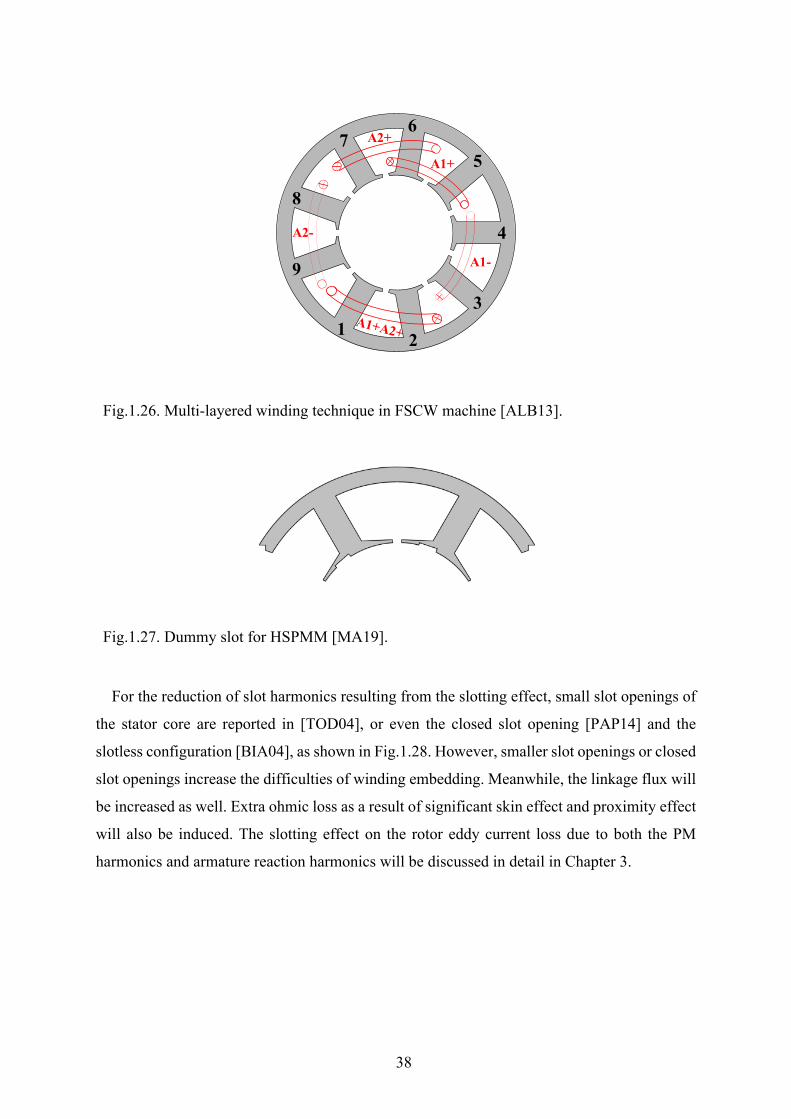
Fig.1.26. Multi-layered winding technique in FSCW machine [ALB13].
Fig.1.27. Dummy slot for HSPMM [MA19].
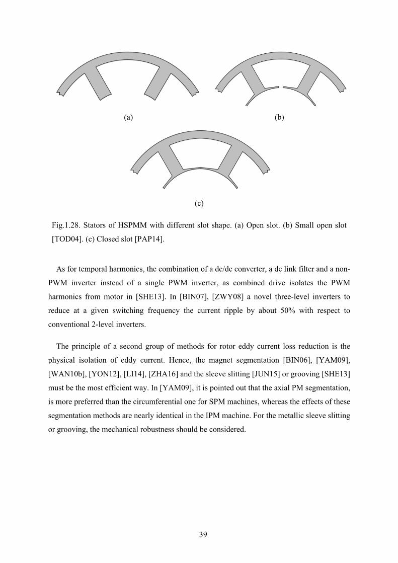
For the reduction of slot harmonics resulting from the slotting effect, small slot openings of
the stator core are reported in [TOD04], or even the closed slot opening [PAP14] and the
slotless configuration [BIA04], as shown in Fig.1.28. However, smaller slot openings or closed
slot openings increase the difficulties of winding embedding. Meanwhile, the linkage flux will
be increased as well. Extra ohmic loss as a result of significant skin effect and proximity effect
will also be induced. The slotting effect on the rotor eddy current loss due to both the PM
harmonics and armature reaction harmonics will be discussed in detail in Chapter 3.
A1-
A1+
A2+
A2- 4
1 2
3
5
67
8
9
39
(a) (b)
(c)
Fig.1.28. Stators of HSPMM with different slot shape. (a) Open slot. (b) Small open slot
[TOD04]. (c) Closed slot [PAP14].
As for temporal harmonics, the combination of a dc/dc converter, a dc link filter and a non-
PWM inverter instead of a single PWM inverter, as combined drive isolates the PWM
harmonics from motor in [SHE13]. In [BIN07], [ZWY08] a novel three-level inverters to
reduce at a given switching frequency the current ripple by about 50% with respect to
conventional 2-level inverters.
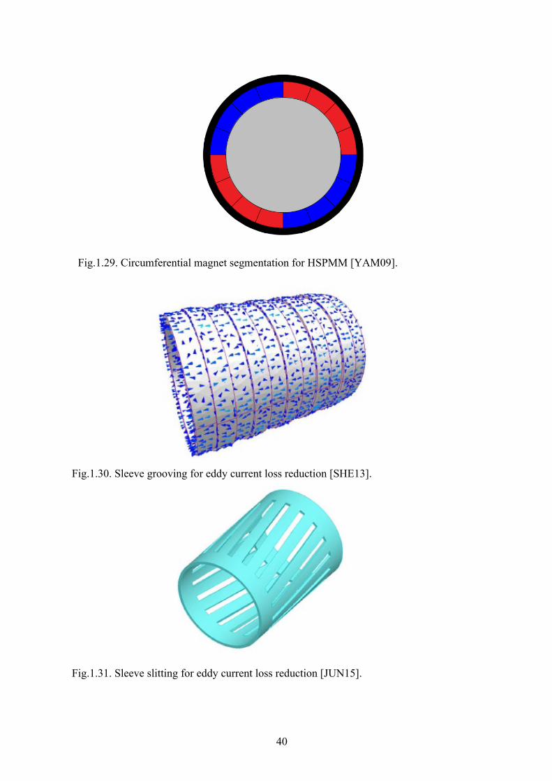
The principle of a second group of methods for rotor eddy current loss reduction is the
physical isolation of eddy current. Hence, the magnet segmentation [BIN06], [YAM09],
[WAN10b], [YON12], [LI14], [ZHA16] and the sleeve slitting [JUN15] or grooving [SHE13]
must be the most efficient way. In [YAM09], it is pointed out that the axial PM segmentation,
is more preferred than the circumferential one for SPM machines, whereas the effects of these
segmentation methods are nearly identical in the IPM machine. For the metallic sleeve slitting
or grooving, the mechanical robustness should be considered.
40
Fig.1.29. Circumferential magnet segmentation for HSPMM [YAM09].
Fig.1.30. Sleeve grooving for eddy current loss reduction [SHE13].
Fig.1.31. Sleeve slitting for eddy current loss reduction [JUN15].
41
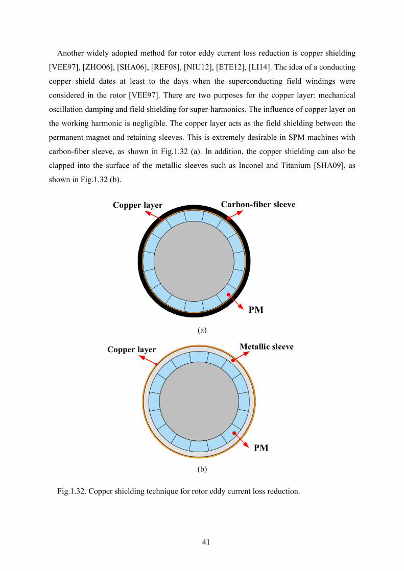
Another widely adopted method for rotor eddy current loss reduction is copper shielding
[VEE97], [ZHO06], [SHA06], [REF08], [NIU12], [ETE12], [LI14]. The idea of a conducting
copper shield dates at least to the days when the superconducting field windings were
considered in the rotor [VEE97]. There are two purposes for the copper layer: mechanical
oscillation damping and field shielding for super-harmonics. The influence of copper layer on
the working harmonic is negligible. The copper layer acts as the field shielding between the
permanent magnet and retaining sleeves. This is extremely desirable in SPM machines with
carbon-fiber sleeve, as shown in Fig.1.32 (a). In addition, the copper shielding can also be
clapped into the surface of the metallic sleeves such as Inconel and Titanium [SHA09], as
shown in Fig.1.32 (b).
(a)
(b)
Fig.1.32. Copper shielding technique for rotor eddy current loss reduction.
Carbon-fiber sleeveCopper layer
PM
Metallic sleeveCopper layer
PM
42
1.3.5 Rotor Unbalanced Magnetic Force Unbalanced magnetic force (UMF), one of the machine parasitic effects which jeopardises
the bearing life and yields noise and vibration, may occur in fractional-slot machines with odd
number of stator slots, even when there are no rotor eccentricities or other manufacturing
tolerances [BI97], [DOR08], [LI09], [ZHU07b]. However, this is not a typical issue for
HSPMMs without rotor eccentricity since almost all the HSPMMs employ an even number of
stator slots as can be seen in Table 1.6, except for the 3-slot 2-pole HSPMM which can be
applied in ultra-high speed applications [ZHU97], [MA19]. In [ZHU97], it is pointed out that
mechanical resonance may be induced as a result of the UMF. Meanwhile, there is no doubt
that the existence of rotor eccentricity will yield significant UMF due to asymmetric field
distribution.
The production and characteristics of UMF in different types PM machines with and without
rotor eccentricity are comprehensively studied [JAN96], [JAN03], [MIC14] [MAH15],
[KIM16]. On the one hand, the UMF in the 2-pole HSPMM has been widely investigated
[JAN03], [KIM16], [MA18]. In [JAN03], it is pointed out the Halbach magnetized rotor
exhibits lower radial force under the rotor eccentricity scenarios compared with that of the
radial magnetized rotor. In [KIM16], an analytical model for the prediction of UMF in a
toroidally wound high-speed BLDC motor is developed. In [MA18], the auxiliary slots are
inserted in the 3-slot/2-pole HSPMM, ensuring over 90% reduction the on-load UMF. However,
the effectiveness of the proposed method is quite dependent on the load.
On the other hand, in recent decades, the HSPMMs with an odd number of stator slots for
certain applications are emerging [RED11], [ZHA15], [ZHA17], [DU19]. However, the
existing literature only focuses on the electromagnetic performances such as rotor eddy current
loss or mechanical performances such as rotor stress. It is unknown how the UMF will be
affected in these fractional-slot PM machines with lower pole number. In Chapter 4, a
comprehensive investigation will be conducted on HSPMM machines with an odd number of
stator slots.
43
1.4 Mechanical and Aerodynamic Issues in High-speed PM
Machines
In high speed applications, the mechanical issues are second to none with respect to electrical
ones. The structural challenges of rotor component as well as rotor dynamics are key issues
that should be taken into consideration. In this section, all these mechanical design
considerations will be addressed.
1.4.1 Rotor Stress Due to the huge centrifugal force in the high-speed operated rotor, stress analysis is the key
issue for mechanical robustness of HSPMMs. The most important issue is how to obtain the
exact value of stress in all rotor parts. Then, the maximum stress induced in each component
of the rotor should be ensured within the material strength under all operating speed and
temperature, especially for PMs. In addition, the contact pressure pointing to the inner side
should always exist so that the electromagnetic torque can be transferred to the shaft. These
two conditions are fundamental requirements for the safe running of high-speed PM machines.
The methods for stress calculation can be classified into analytical and numerical ones.
Several papers on the analytical calculation of rotor stress can be found [BIN06], [WAN07],
[BOR10], [BUR17]. [BIN06] proposed a simplified analytical model for stress calculation with
the hypothesis that the rotor is strictly rotational symmetry. In [WAN07] and [BOR10], the
displacement technique was adopted for the stress calculation of the HSPMM with the
nonmagnetic alloy sleeve. In [BUR17], a 3D analytical model considering the axial stress was
established for both solid and hollow magnet rotors in the plane strain condition. Although all
these analytical solutions can provide a fundamental insight from the stress generation to
reduction, as pointed out in [BIN06], the non-linear factor such as geometry discontinuity and
edging effect cannot be considered in the analytical model. A derivation can still be generated
in the analytical models. Hence, in order to obtain the exact value of rotor stress, 2D or 3D
FEA are more widely adopted in the calculation of rotor stress with complicated structure or
other non-linear factors. In Chapter 5, the limitation of analytical calculation will also be
highlighted.
Another important issue which needs to be considered is the localized rotor stress occurring
at the magnet edges. In [BIN06], it is pointed out that the inter-pole should be avoided due to
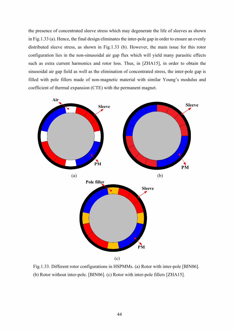
44
the presence of concentrated sleeve stress which may degenerate the life of sleeves as shown
in Fig.1.33 (a). Hence, the final design eliminates the inter-pole gap in order to ensure an evenly
distributed sleeve stress, as shown in Fig.1.33 (b). However, the main issue for this rotor
configuration lies in the non-sinusoidal air gap flux which will yield many parasitic effects
such as extra current harmonics and rotor loss. Thus, in [ZHA15], in order to obtain the
sinusoidal air gap field as well as the elimination of concentrated stress, the inter-pole gap is
filled with pole fillers made of non-magnetic material with similar Young’s modulus and
coefficient of thermal expansion (CTE) with the permanent magnet.
(a) (b)
(c)
Fig.1.33. Different rotor configurations in HSPMMs. (a) Rotor with inter-pole [BIN06].
(b) Rotor without inter-pole. [BIN06]. (c) Rotor with inter-pole fillers [ZHA15].
AirSleeve
PM
Sleeve
PM
Pole fillerSleeve
PM

45
1.4.2 Rotor Dynamics For low-speed electrical machines, the rotor dynamics are normally not an issue as the
operating speed range is far away from the critical speeds. However, for high speed machines,
the rotor dynamics analysis plays a pivotal role for the safe operating of rotors. In fact,
HSPMMs normally consist of the magnets and a retaining sleeve. These parts may aggravate
the rotor dynamic performance since they increase the rotor mass whilst making no
contribution to the rotor robustness.
The most common analysis methods that are used in rotor dynamics can be divided into two
kinds: the so-called transfer matrix method and the finite-element method (FEM) as shown in
Fig.1.34. The former has a small amount of calculation, but at the cost of large error and
possibility of lost root phenomenon, with the development of modern computing technology,
the analytical method has already lost its value. On the other hand, in the last two decades,
there are many publications in which FEM is successfully applied in the area of rotor dynamics
as in [ZHU02], [ZWY05], [GER09], [HWA16].
It is reported that three different bending and vibration modes exist for the rotor which will
occur at three specific natural frequencies. In [ZHU02], the analytical equations for the three
natural frequencies is given as
𝑤𝑤𝑛𝑛 = 𝑎𝑎𝑛𝑛𝐸𝐸𝐸𝐸𝜇𝜇1𝑙𝑙4
(1.2)
where E represents the Young’s Modulus, I denote the inertia of rotor, 𝜇𝜇1 is the mass in per
unit length, l denotes the rotor axial length, and 𝑎𝑎𝑛𝑛 is the constant obtained by the Rayleigh
method, which is related with the boundary conditions. It is obvious that the axial length
reduces the natural frequency significantly. Hence, the non-overlapping winding is more
preferred for the ultra-high-speed application.
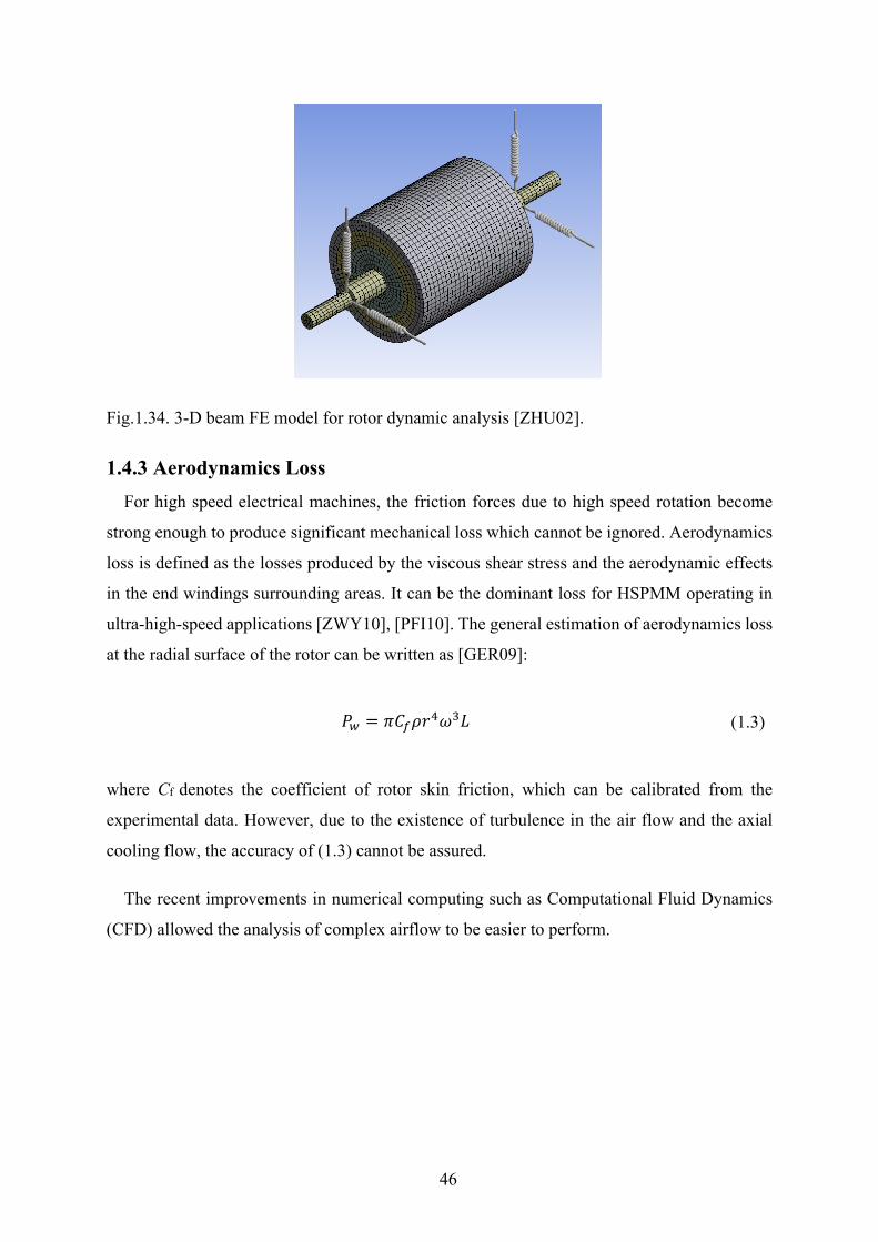
46
Fig.1.34. 3-D beam FE model for rotor dynamic analysis [ZHU02].
1.4.3 Aerodynamics Loss For high speed electrical machines, the friction forces due to high speed rotation become
strong enough to produce significant mechanical loss which cannot be ignored. Aerodynamics
loss is defined as the losses produced by the viscous shear stress and the aerodynamic effects
in the end windings surrounding areas. It can be the dominant loss for HSPMM operating in
ultra-high-speed applications [ZWY10], [PFI10]. The general estimation of aerodynamics loss
at the radial surface of the rotor can be written as [GER09]:
𝑃𝑃𝑤𝑤 = 𝜋𝜋𝐶𝐶𝑓𝑓𝜌𝜌𝑟𝑟4𝜔𝜔3𝐿𝐿 (1.3)
where Cf denotes the coefficient of rotor skin friction, which can be calibrated from the
experimental data. However, due to the existence of turbulence in the air flow and the axial
cooling flow, the accuracy of (1.3) cannot be assured.
The recent improvements in numerical computing such as Computational Fluid Dynamics
(CFD) allowed the analysis of complex airflow to be easier to perform.
47
1.5 Research Scope and Major Contributions
1.5.1 Outline of Thesis In this thesis, the analysis of high-speed PM machine with particular focus on both the
electromagnetic and mechanical issues is conducted. For the electromagnetic issue, the rotor
eddy current losses of the 4-pole HSPMM with alternate stator configurations are analysed in
depth. In addition, the existence criterion of unbalanced magnetic force in PM machine with
an odd number of stator slots is determined. The influence of slot and pole number combination
on the unbalanced magnetic force is investigated. As for the mechanical issue, the rotor
mechanical stress considering the PM segmentation is analyzed. Following from this, the
worst-case operating scenario is determined. Finally, the influence of the mechanical issue on
the electromagnetic one is discussed with the focus on the optimal split ratio of rotor outer
diameter to stator outer diameter, considering mechanical stress constraints. This thesis is
organized as follows. Fig.1.35 shows the structure of the thesis.
Chapter 1 reviews alternate high-speed machine technologies, covering both electromagnetic
and mechanical issues.
Chapter 2 investigates the optimal split ratio of HSPMM with consideration of stator iron loss
and rotor mechanical stress constraints.
Chapter 3 investigates the rotor eddy current loss in the 4-pole HSPMM with alternate stator
configurations. The contribution of both the armature reaction harmonics and the PM
harmonics as well as the slotting effect are quantified.
Chapter 4 investigates the unbalanced magnetic force in PM machines with an odd number of
stator slots. The existence criterion of UMF in PM machines is determined. The
influence of slot and pole number combinations on UMF is discussed in detail.
Chapter 5 investigates the rotor mechanical stress of HSPMM with the consideration of PM
segmentation. In addition, a novel design methodology of HSPMM considering both
electromagnetic and mechanical issues is proposed.
Chapter 6 makes a conclusion of the work in this thesis and discusses the future work.
APPENDIX A shows the engineering drawings of the four prototyped PM machines.
APPENDIX B lists the publications in the PhD study.
48
1.5.2 Major Contributions of the Thesis The major contributions of this thesis include:
1) The influence of mechanical constraints on the electromagnetic issue of HSPMM is firstly
clarified. A novel design methodology considering both the electromagnetic issue and
mechanical issue is proposed. The optimal split ratio of HSPMM considering the stator iron
loss and the rotor mechanical stress constraints is determined.
2) Both the armature reaction and PM field induced rotor magnet losses in HSPMM are
determined. The contribution of each harmonic due to armature reaction, PM field and
slotting effect is quantified. The impact of the winding configuration on the resultant MMF
harmonics and rotor magnet loss is discussed in depth.
3) The existence criterion of PM machine with an odd number of stator slots is clarified. In
addition, the UMF in PM machines with both an odd number of stator slot and lower pole
number is investigated.
4) The rotor mechanical stress is firstly analysed with the consideration of PM segmentation.
Rotor stress concentration due to PM segmentation is firstly revealed. The corresponding
worst-case operating scenarios and influential factors are then summarized.
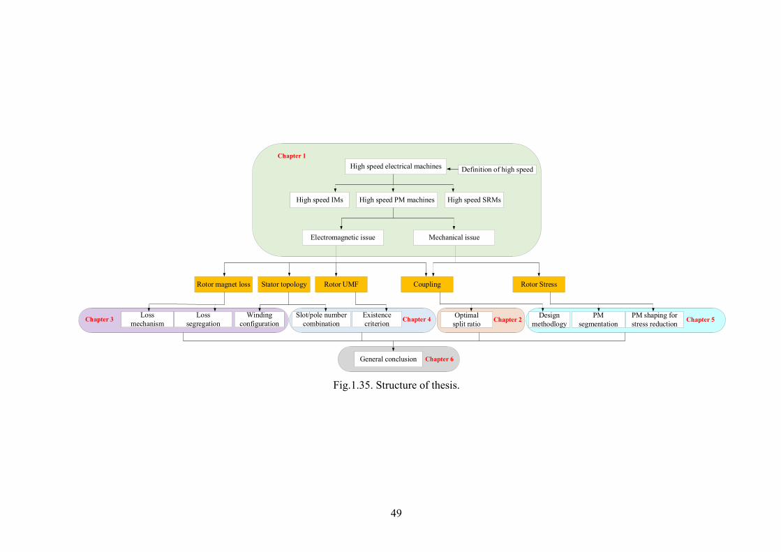
49
Fig.1.35. Structure of thesis.
High speed PM machines
Mechanical issueElectromagnetic issue
High speed IMs High speed SRMs
High speed electrical machines Definition of high speed
Chapter 1
Rotor magnet loss Rotor UMF CouplingStator topology
Loss segregation
Loss mechanism
Winding configuration
Slot/pole number combinationChapter 3 Existence
criterion Chapter 4
Rotor Stress
Optimal split ratio
Design methodlogy
PM segmentation
PM shaping for stress reductionChapter 2 Chapter 5
General conclusion Chapter 6

50
Chapter 2 Rotor Split Ratio Optimization for High
Speed PM Machines with Consideration of Stator
Iron Loss and Mechanical Stress Constraints
The split ratio, i.e. the ratio of rotor outer diameter to stator outer diameter, is one of the
most vital design parameters for PM machines due to its significant impact on the machine
torque or power density. However, it has been optimized analytically in existing papers with
due account only for the stator copper loss, which is reasonable for low to medium speed PM
machines. For high speed PM machines (HSPMM), the ignorance of stator iron loss and the
mechanical stress on the rotor will lead to a deviation of optimal split ratio and actual torque
capability. In this chapter, the optimal split ratio of HSPMM is investigated analytically with
consideration of the stator iron loss as well as the rotor mechanical stress. The influence of
design parameters such as air gap length and rotor pole pairs on the optimal split ratio is
elaborated. Both the analytical and finite element analysis reveal that the optimal split ratio for
HSPMM will be significantly reduced when stator iron loss and mechanical constraints are
considered.
This chapter is based on the author’s own papers [WAN18], [FEN19], [XUE18b].
2.1 Introduction
High-speed electrical machines have been widely used in a variety of applications including
domestic appliances, electrical spindles, turbochargers, electrical turbo-compounding systems,
and have been attracting increased interest from both industry and academia, particularly in the
past two decades [ANC10], [GUR13], [BIA04], [BOR10].
As a competent candidate, the high-speed permanent magnet (PM) machines (HSPMM) are
a very promising design alternative for high-speed applications due to high power density as
well as high efficiency and compactness compared with other types of electrical machines such
as induction machines and switched reluctance machines [ZHU97], [BIN07], [LUO09],
[KOL09], [GER14].
However, the inherent high speed and induced high frequency will yield a huge centrifugal
force and a significant electromagnetic loss in the rotor and stator. These two limitations

51
impose a great constraint on the capability of power density and efficiency [BIA04], [YAM13].
Under high-speed operation, the rotor components will suffer huge centrifugal stress, making
the magnet retaining extremely important [BIN06]. The centrifugal stress is influenced by a
few factors, including the rotor diameter. On the other hand, the split ratio, the rotor outer
diameter to the stator outer diameter, is also an important design parameter for any PM machine.
It has a great impact on the torque/power capability and efficiency for the given frame size.
[CHA94] derived a simple analytical expression of optimum split ratio for maximum torque
density. In [PAN06], the optimal split ratio of both brushless AC and DC motors with either
overlapping or non-overlapping windings were investigated. In addition, the influences of air
gap flux density waveforms, stator tooth-tips as well as the end-winding on the optimal split
ratio were discussed. In [WU10a], the optimal split ratio as well as the flux density ratio were
analyzed both individually and globally in a fractional-slot IPM machine.
For HSPMM, the design of the split ratio is even more important. Not only is the torque
density of HSPMM significantly influenced by this parameter, but also the mechanical stress
of the rotor and stator iron loss are greatly impacted by this ratio. Hence, it is necessary to
investigate the optimal split ratio for HSPMM. In [EDE01], the stator iron loss was considered
in the analysis of optimal split ratio of a high-speed PM machine. It was found that the optimal
split ratio is slightly reduced compared to that with a fixed copper loss only. [REI13] introduced
the current density as the local thermal constraint which is reasonable only when considering
the local overheat in stator end-windings [BOG09]. In [FAN16], the thermal network was
adopted in order to obtain the winding temperature rise of HSPMM directly and a more
accurate value of optimal split ratio could be acquired. However, compared with the stator
temperature, the temperature rise in the rotor should be more of a concern for HSPMM since
the permanent magnets are vulnerable to the temperature rise resulting from the induced PM
eddy current loss.
In summary, in existing papers, the split ratio of HSPMM has been optimized with the
consideration of thermal constraints only. The mechanical constraints, including the stress limit
and rotor dynamics issues are ignored, leading to the deviation of the optimal split ratio and
actual torque/power capability. In this paper, the optimal split ratio for HSPMM is obtained
with the consideration of the mechanical constraints, with particular focus on the rotor stress.
The stator iron loss is also considered. The impact of the sleeve material and maximum
operating speed on the optimal split ratio is elaborated. In addition, the influence of the flux
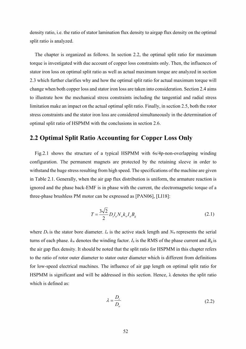
52
density ratio, i.e. the ratio of stator lamination flux density to airgap flux density on the optimal
split ratio is analyzed.
The chapter is organized as follows. In section 2.2, the optimal split ratio for maximum
torque is investigated with due account of copper loss constraints only. Then, the influences of
stator iron loss on optimal split ratio as well as actual maximum torque are analyzed in section
2.3 which further clarifies why and how the optimal split ratio for actual maximum torque will
change when both copper loss and stator iron loss are taken into consideration. Section 2.4 aims
to illustrate how the mechanical stress constraints including the tangential and radial stress
limitation make an impact on the actual optimal split ratio. Finally, in section 2.5, both the rotor
stress constraints and the stator iron loss are considered simultaneously in the determination of
optimal split ratio of HSPMM with the conclusions in section 2.6.
2.2 Optimal Split Ratio Accounting for Copper Loss Only
Fig.2.1 shows the structure of a typical HSPMM with 6s/4p-non-overlapping winding
configuration. The permanent magnets are protected by the retaining sleeve in order to
withstand the huge stress resulting from high speed. The specifications of the machine are given
in Table 2.1. Generally, when the air gap flux distribution is uniform, the armature reaction is
ignored and the phase back-EMF is in phase with the current, the electromagnetic torque of a
three-phase brushless PM motor can be expressed as [PAN06], [LI18]:
3 22 s a w w a gT D l N k I B= (2.1)
where Ds is the stator bore diameter. la is the active stack length and Nw represents the serial
turns of each phase. kw denotes the winding factor. Ia is the RMS of the phase current and Bg is
the air gap flux density. It should be noted that the split ratio for HSPMM in this chapter refers
to the ratio of rotor outer diameter to stator outer diameter which is different from definitions
for low-speed electrical machines. The influence of air gap length on optimal split ratio for
HSPMM is significant and will be addressed in this section. Hence, λ denotes the split ratio
which is defined as:
r
o
DD
λ =
(2.2)
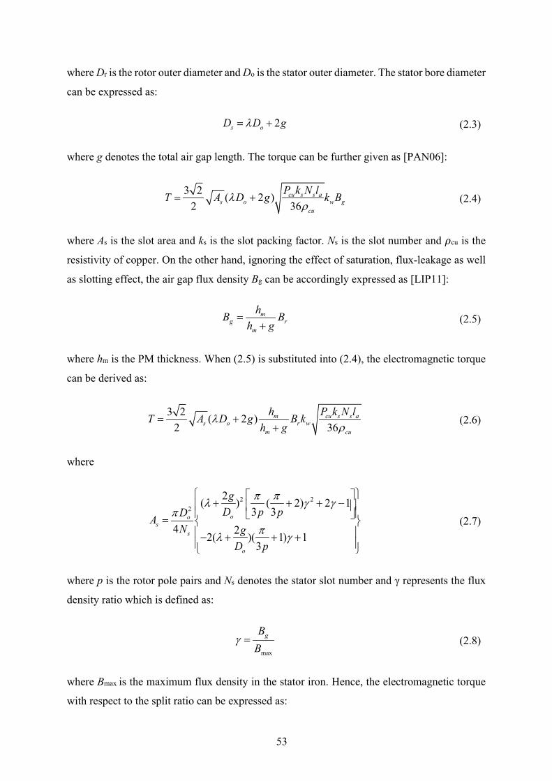
53
where Dr is the rotor outer diameter and Do is the stator outer diameter. The stator bore diameter
can be expressed as:
2s oD D gλ= + (2.3)
where g denotes the total air gap length. The torque can be further given as [PAN06]:
3 2 ( 2 )2 36
cu s s as o w g
cu
P k N lT A D g k Bλρ
= + (2.4)
where As is the slot area and ks is the slot packing factor. Ns is the slot number and 𝜌𝜌cu is the
resistivity of copper. On the other hand, ignoring the effect of saturation, flux-leakage as well
as slotting effect, the air gap flux density Bg can be accordingly expressed as [LIP11]:
mg r
m
hB Bh g
=+
(2.5)
where hm is the PM thickness. When (2.5) is substituted into (2.4), the electromagnetic torque
can be derived as:
3 2 ( 2 )2 36
m cu s s as o r w
m cu
h P k N lT A D g B kh g
λρ
= ++
(2.6)
where
2 22
2( ) ( 2) 2 13 3
4 22( )( 1) 13
oos
s
o
gD p pDA
N gD p
π πλ γ γπ
πλ γ
+ + + − =
− + + +
(2.7)
where p is the rotor pole pairs and Ns denotes the stator slot number and γ represents the flux
density ratio which is defined as:
max
gBB
γ = (2.8)
where Bmax is the maximum flux density in the stator iron. Hence, the electromagnetic torque
with respect to the split ratio can be expressed as:

54
( ) ( 2 )s oT f A D gλ λ∝ = + (2.9)
The optimal split ratio for maximum torque can be obtained by solving the following
differential equation:
( ) 0f λλ
∂=
∂ (2.10)
The optimal split ratio can be given as:
2 4 2p p pp
p o
b b a ga D
λ− −
= − (2.11)
where
28 ( 2) 2 1pk kap pπ π γ γ
= + + −
(2.12)
6( 1)pkbpπ γ= + (2.13)
13
k = for motors with stator non-overlapping winding (2.14)
While the split ratio increases, the tooth width and yoke thickness will become larger
correspondingly when the air gap length and the flux density ratio are confirmed. The resultant
slot area will decrease with the increase of split ratio. Hence, there will always exist an optimal
split ratio at which the electromagnetic torque reaches maximum. The minimum air gap length
(g=2mm) is obtained with the usage of the empirical equation in [PYR08]. A suitable value for
the length of the air gap of an inverter fed, high-speed machine (the peripheral speed of the
rotor>100 m/s), can be calculated as:
0.0010.07 400
rD vδ = + + (2.15)
where Dr denotes the rotor outer diameter and v denotes the peripheral speed of the rotor.
The copper loss is fixed to ensure the same thermal performance. As for the value of copper
loss, when the machine frame size is given, the total heat transferred through the external
surface depends on the specific cooling type. This heat source, namely electromagnetic loss,
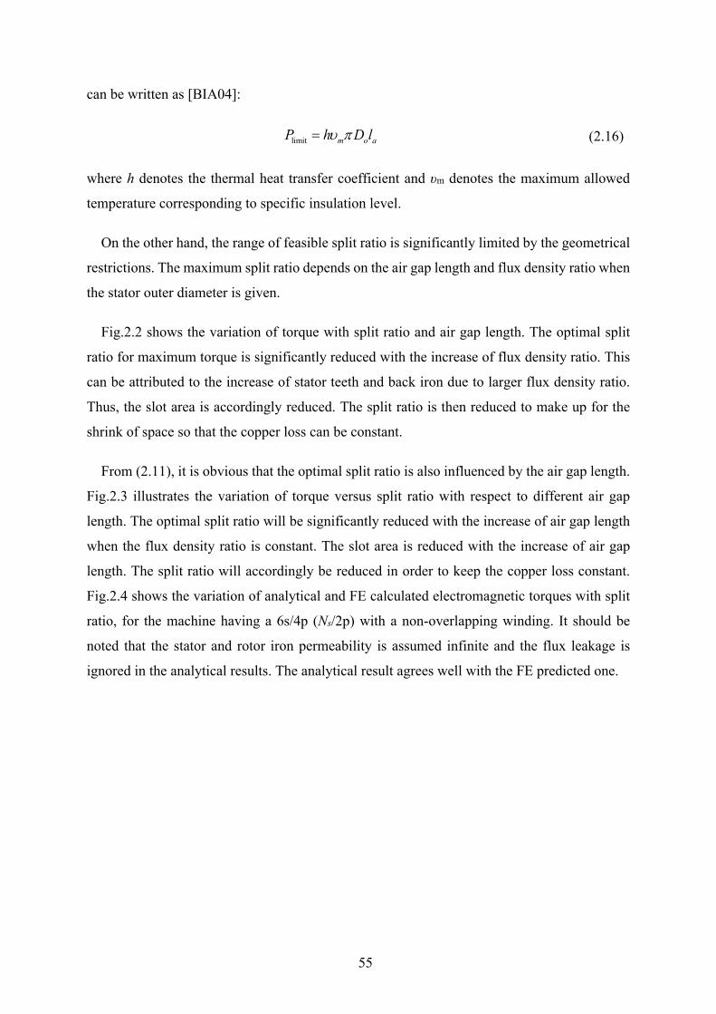
55
can be written as [BIA04]:
limit m o aP h D lυ π= (2.16)
where h denotes the thermal heat transfer coefficient and υm denotes the maximum allowed
temperature corresponding to specific insulation level.
On the other hand, the range of feasible split ratio is significantly limited by the geometrical
restrictions. The maximum split ratio depends on the air gap length and flux density ratio when
the stator outer diameter is given.
Fig.2.2 shows the variation of torque with split ratio and air gap length. The optimal split
ratio for maximum torque is significantly reduced with the increase of flux density ratio. This
can be attributed to the increase of stator teeth and back iron due to larger flux density ratio.
Thus, the slot area is accordingly reduced. The split ratio is then reduced to make up for the
shrink of space so that the copper loss can be constant.
From (2.11), it is obvious that the optimal split ratio is also influenced by the air gap length.
Fig.2.3 illustrates the variation of torque versus split ratio with respect to different air gap
length. The optimal split ratio will be significantly reduced with the increase of air gap length
when the flux density ratio is constant. The slot area is reduced with the increase of air gap
length. The split ratio will accordingly be reduced in order to keep the copper loss constant.
Fig.2.4 shows the variation of analytical and FE calculated electromagnetic torques with split
ratio, for the machine having a 6s/4p (Ns/2p) with a non-overlapping winding. It should be
noted that the stator and rotor iron permeability is assumed infinite and the flux leakage is
ignored in the analytical results. The analytical result agrees well with the FE predicted one.
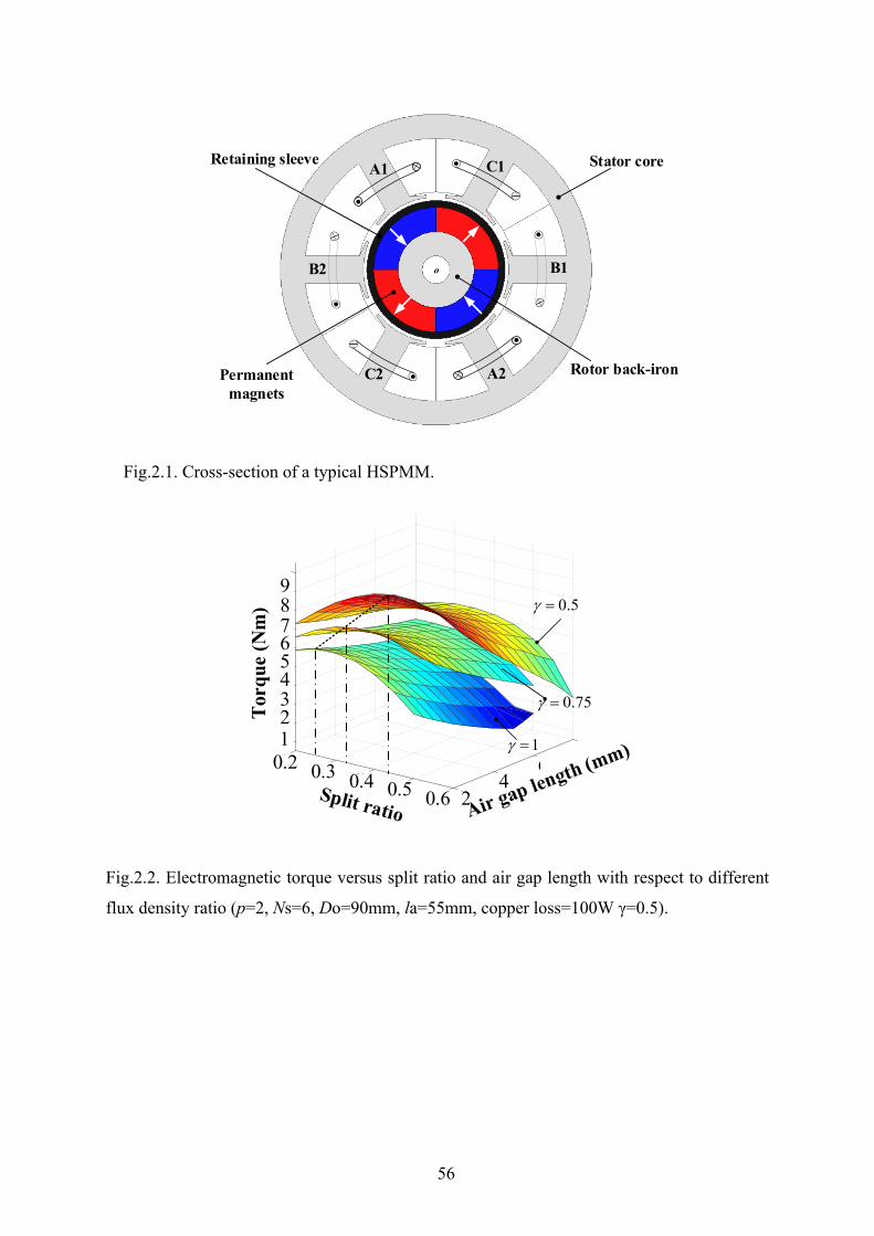
56
Fig.2.1. Cross-section of a typical HSPMM.
Fig.2.2. Electromagnetic torque versus split ratio and air gap length with respect to different
flux density ratio (p=2, Ns=6, Do=90mm, la=55mm, copper loss=100W γ=0.5).
Retaining sleeve
Rotor back-iron
o
Stator core
Permanent magnets
A1
A2
C1
B2 B1
C2
80
1
0.2
2
3
6
4
5
6
0.3
7
8
9
0.4 40.5
20.6
123456789
Torq
ue (N
m)
0.6
0.2 0.3 0.4 0.5 24
6
0.5γ =
1γ =
0.75γ =
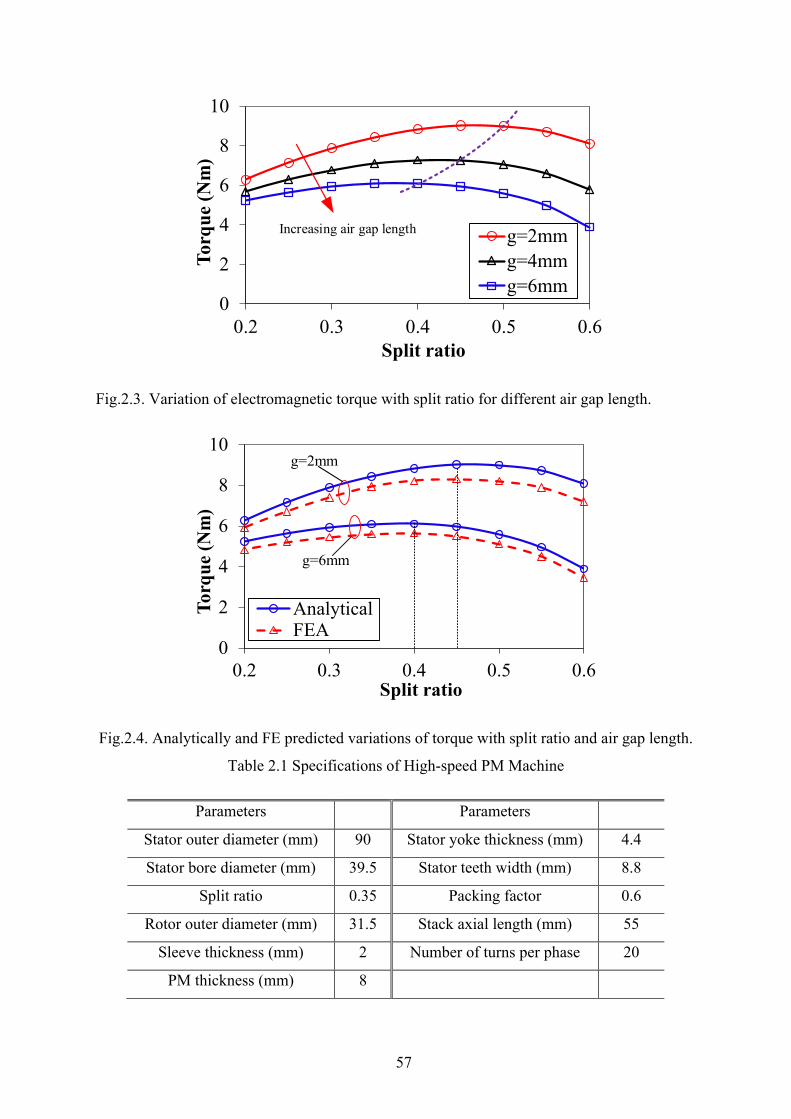
57
Fig.2.3. Variation of electromagnetic torque with split ratio for different air gap length.
Fig.2.4. Analytically and FE predicted variations of torque with split ratio and air gap length.
Table 2.1 Specifications of High-speed PM Machine
Parameters Parameters
Stator outer diameter (mm) 90 Stator yoke thickness (mm) 4.4
Stator bore diameter (mm) 39.5 Stator teeth width (mm) 8.8
Split ratio 0.35 Packing factor 0.6
Rotor outer diameter (mm) 31.5 Stack axial length (mm) 55
Sleeve thickness (mm) 2 Number of turns per phase 20
PM thickness (mm) 8
0
2
4
6
8
10
0.2 0.3 0.4 0.5 0.6
Torq
ue (N
m)
Split ratio
g=2mmg=4mmg=6mm
Increasing air gap length
0
2
4
6
8
10
0.2 0.3 0.4 0.5 0.6
Torq
ue (N
m)
Split ratio
AnalyticalFEA
g=6mm
g=2mm
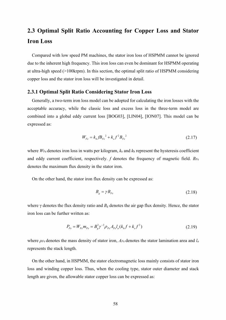
58
2.3 Optimal Split Ratio Accounting for Copper Loss and Stator
Iron Loss
Compared with low speed PM machines, the stator iron loss of HSPMM cannot be ignored
due to the inherent high frequency. This iron loss can even be dominant for HSPMM operating
at ultra-high speed (>100krpm). In this section, the optimal split ratio of HSPMM considering
copper loss and the stator iron loss will be investigated in detail.
2.3.1 Optimal Split Ratio Considering Stator Iron Loss Generally, a two-term iron loss model can be adopted for calculating the iron losses with the
acceptable accuracy, while the classic loss and excess loss in the three-term model are
combined into a global eddy current loss [BOG03], [LIN04], [ION07]. This model can be
expressed as:
2 2 2Fe h Fe e FeW k fB k f B= + (2.17)
where WFe denotes iron loss in watts per kilogram, ke and kh represent the hysteresis coefficient
and eddy current coefficient, respectively. f denotes the frequency of magnetic field. BFe
denotes the maximum flux density in the stator iron.
On the other hand, the stator iron flux density can be expressed as:
g FeB Bγ= (2.18)
where γ denotes the flux density ratio and Bg denotes the air gap flux density. Hence, the stator
iron loss can be further written as:
2 2 2( )Fe Fe Fe g Fe Fe a h eP W m B A l k f k fγ ρ−= = + (2.19)
where ρFe denotes the mass density of stator iron, AFe denotes the stator lamination area and la
represents the stack length.
On the other hand, in HSPMM, the stator electromagnetic loss mainly consists of stator iron
loss and winding copper loss. Thus, when the cooling type, stator outer diameter and stack
length are given, the allowable stator copper loss can be expressed as:
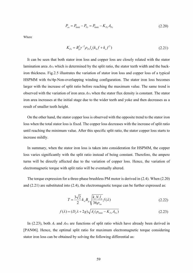
59
limit limitcu Fe Fe FeP P P P K A= − = − (2.20)
Where
2 2 2( )Fe g Fe a h eK B l k f k fγ ρ−= + (2.21)
It can be seen that both stator iron loss and copper loss are closely related with the stator
lamination area AFe which is determined by the split ratio, the stator teeth width and the back-
iron thickness. Fig.2.5 illustrates the variation of stator iron loss and copper loss of a typical
HSPMM with 6s/4p-Non-overlapping winding configuration. The stator iron loss becomes
larger with the increase of split ratio before reaching the maximum value. The same trend is
observed with the variation of iron area AFe when the stator flux density is constant. The stator
iron area increases at the initial stage due to the wider teeth and yoke and then decreases as a
result of smaller teeth height.
On the other hand, the stator copper loss is observed with the opposite trend to the stator iron
loss when the total stator loss is fixed. The copper loss decreases with the increase of split ratio
until reaching the minimum value. After this specific split ratio, the stator copper loss starts to
increase mildly.
In summary, when the stator iron loss is taken into consideration for HSPMM, the copper
loss varies significantly with the split ratio instead of being constant. Therefore, the ampere
turns will be directly affected due to the variation of copper loss. Hence, the variation of
electromagnetic torque with split ratio will be eventually altered.
The torque expression for a three-phase brushless PM motor is derived in (2.4). When (2.20)
and (2.21) are substituted into (2.4), the electromagnetic torque can be further expressed as:
3 2 ( )2 36
s s aw g
cu
k N lT k B f λρ
= (2.22)
limit( ) ( 2 ) ( )o s Fe Fef D g A p K Aλ λ= + − (2.23)
In (2.23), both As and AFe are functions of split ratio which have already been derived in
[PAN06]. Hence, the optimal split ratio for maximum electromagnetic torque considering
stator iron loss can be obtained by solving the following differential as:

60
( ) 0f λλ
∂=
∂ (2.24)
Fig.2.6 illustrates the electromagnetic torque versus split ratio with and without
consideration of stator iron loss. It can be seen that the torque would be considerably reduced
when the iron loss is taken into account. This should be attributed to the reduced copper loss
thus electrical loading at each split ratio. In addition, the optimal split ratio for maximum
electromagnetic torque has also been reduced due to the decreasing copper loss with the
increasing split ratio before reaching minimum. The optimal split ratio has to be reduced in
order to make the f (λ) maximum.
It is worth mentioning that torque variation range is relatively smaller when considering the
stator iron loss. The electromagnetic torque decreases slowly after reaching the maximum value.
As mentioned before, the copper loss turns to increase mildly which makes a compensation for
the torque by increasing the electrical loading. Therefore, the electromagnetic torque will not
drop sharply compared with that when only the copper loss is considered. As shown in Fig.2.6,
although there is a slight difference between the analytical and FE predicted torques, the
optimal split ratios have a good agreement which verifies the validity of previous analytical
analysis.
Fig.2.5. Variation of stator loss with split ratio (γ=0.5, f=2166Hz, Bg =0.85T).
0
30
60
90
120
150
0.1 0.2 0.3 0.4 0.5 0.6 0.7
Stat
or lo
ss (W
)
Split ratio
Copper loss
Iron loss
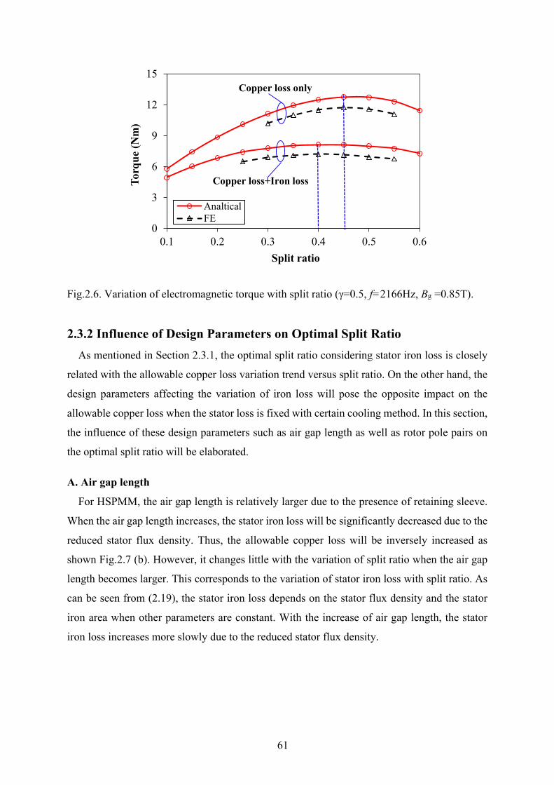
61
Fig.2.6. Variation of electromagnetic torque with split ratio (γ=0.5, f=2166Hz, Bg =0.85T).
2.3.2 Influence of Design Parameters on Optimal Split Ratio As mentioned in Section 2.3.1, the optimal split ratio considering stator iron loss is closely
related with the allowable copper loss variation trend versus split ratio. On the other hand, the
design parameters affecting the variation of iron loss will pose the opposite impact on the
allowable copper loss when the stator loss is fixed with certain cooling method. In this section,
the influence of these design parameters such as air gap length as well as rotor pole pairs on
the optimal split ratio will be elaborated.
A. Air gap length
For HSPMM, the air gap length is relatively larger due to the presence of retaining sleeve.
When the air gap length increases, the stator iron loss will be significantly decreased due to the
reduced stator flux density. Thus, the allowable copper loss will be inversely increased as
shown Fig.2.7 (b). However, it changes little with the variation of split ratio when the air gap
length becomes larger. This corresponds to the variation of stator iron loss with split ratio. As
can be seen from (2.19), the stator iron loss depends on the stator flux density and the stator
iron area when other parameters are constant. With the increase of air gap length, the stator
iron loss increases more slowly due to the reduced stator flux density.
0
3
6
9
12
15
0.1 0.2 0.3 0.4 0.5 0.6
Torq
ue (N
m)
Split ratio
AnalticalFE
Copper loss only
Copper loss+Iron loss
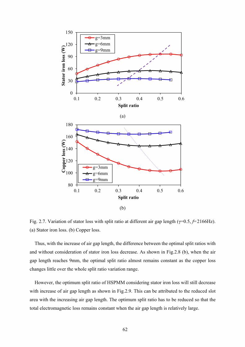
62
(a)
(b)
Fig. 2.7. Variation of stator loss with split ratio at different air gap length (γ=0.5, f=2166Hz).
(a) Stator iron loss. (b) Copper loss.
Thus, with the increase of air gap length, the difference between the optimal split ratios with
and without consideration of stator iron loss decrease. As shown in Fig.2.8 (b), when the air
gap length reaches 9mm, the optimal split ratio almost remains constant as the copper loss
changes little over the whole split ratio variation range.
However, the optimum split ratio of HSPMM considering stator iron loss will still decrease
with increase of air gap length as shown in Fig.2.9. This can be attributed to the reduced slot
area with the increasing air gap length. The optimum split ratio has to be reduced so that the
total electromagnetic loss remains constant when the air gap length is relatively large.
0
30
60
90
120
150
0.1 0.2 0.3 0.4 0.5 0.6
Stat
or ir
on lo
ss (W
)
Split ratio
g=3mmg=6mmg=9mm
80
100
120
140
160
180
0.1 0.2 0.3 0.4 0.5 0.6
Cop
per
loss
(W)
Split ratio
g=3mmg=6mmg=9mm
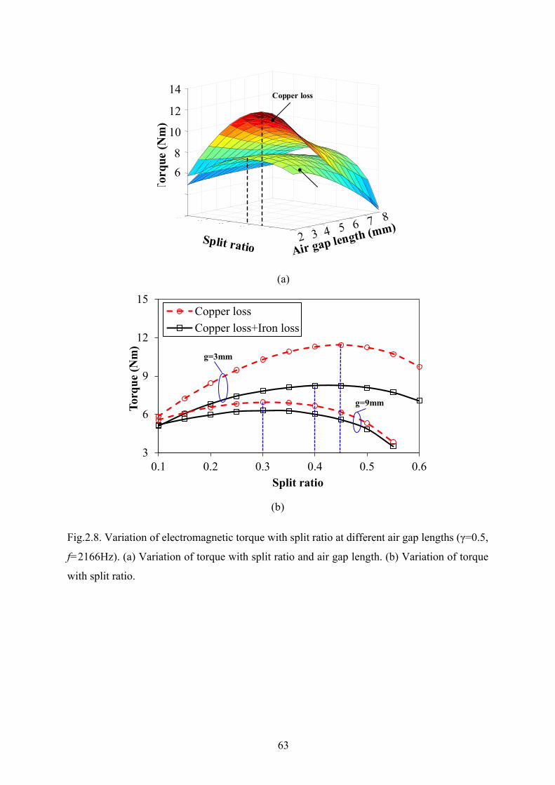
63
(a)
(b)
Fig.2.8. Variation of electromagnetic torque with split ratio at different air gap lengths (γ=0.5,
f=2166Hz). (a) Variation of torque with split ratio and air gap length. (b) Variation of torque
with split ratio.
82
4
7
6
0.1
8
10
12
6
14
0.250.3
40.430.5
20.6
Tor
que
(Nm
)68
10
12
14 Copper loss
3
6
9
12
15
0.1 0.2 0.3 0.4 0.5 0.6
Torq
ue (N
m)
Split ratio
Copper lossCopper loss+Iron loss
g=9mm
g=3mm
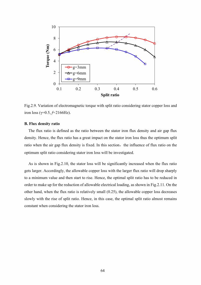
64
Fig.2.9. Variation of electromagnetic torque with split ratio considering stator copper loss and
iron loss (γ=0.5, f=2166Hz).
B. Flux density ratio
The flux ratio is defined as the ratio between the stator iron flux density and air gap flux
density. Hence, the flux ratio has a great impact on the stator iron loss thus the optimum split
ratio when the air gap flux density is fixed. In this section,the influence of flux ratio on the
optimum split ratio considering stator iron loss will be investigated.
As is shown in Fig.2.10, the stator loss will be significantly increased when the flux ratio
gets larger. Accordingly, the allowable copper loss with the larger flux ratio will drop sharply
to a minimum value and then start to rise. Hence, the optimal split ratio has to be reduced in
order to make up for the reduction of allowable electrical loading, as shown in Fig.2.11. On the
other hand, when the flux ratio is relatively small (0.25), the allowable copper loss decreases
slowly with the rise of split ratio. Hence, in this case, the optimal split ratio almost remains
constant when considering the stator iron loss.
0
2
4
6
8
10
0.1 0.2 0.3 0.4 0.5 0.6
Torq
ue (N
m)
Split ratio
g=3mmg=6mmg=9mm
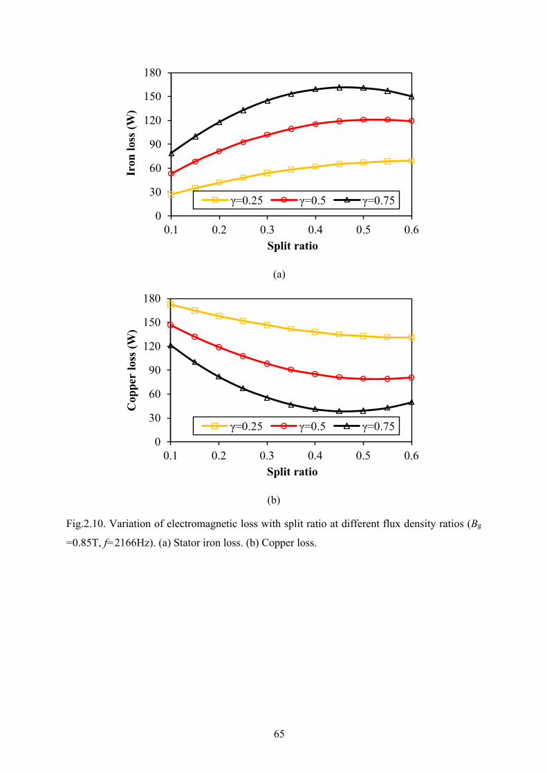
65
(a)
(b)
Fig.2.10. Variation of electromagnetic loss with split ratio at different flux density ratios (Bg
=0.85T, f=2166Hz). (a) Stator iron loss. (b) Copper loss.
0
30
60
90
120
150
180
0.1 0.2 0.3 0.4 0.5 0.6
Iron
loss
(W)
Split ratio
γ=0.25 γ=0.5 γ=0.75
0
30
60
90
120
150
180
0.1 0.2 0.3 0.4 0.5 0.6
Cop
per
loss
(W)
Split ratio
γ=0.25 γ=0.5 γ=0.75

66
Fig.2.11. Variation of optimal split ratio with flux density ratios (Bg =0.85T, f=2166Hz).
C. Operating speed
It is obvious that the stator iron loss is significantly influenced by the operating speed. In
this section, the impact of operating speed on the optimal split ratio of HSPMM is investigated.
Fig.2.12 illustrates the variation of stator loss with split ratio at different operating speed. It can
be seen that the operating speed exert similar effect on the stator loss compared with flux
density ratio. The stator iron loss will rise rapidly to the maximum value and then decrease
while the operating speed is relatively high. Thus, the allowable copper loss will drop sharply
while the operating speed is large. Hence, the optimal split ratio will be reduced when the
operating speed is increasing. On the other hand, when the operating speed is relatively low,
the optimal split ratio remain constant compared with that without consideration of iron loss.
0.0
0.1
0.2
0.3
0.4
0.5
0.6
0.25 0.50 0.75 1.00
Opt
imum
spl
it ra
tio
Flux density ratio
Copper loss+Iron loss
Copper loss
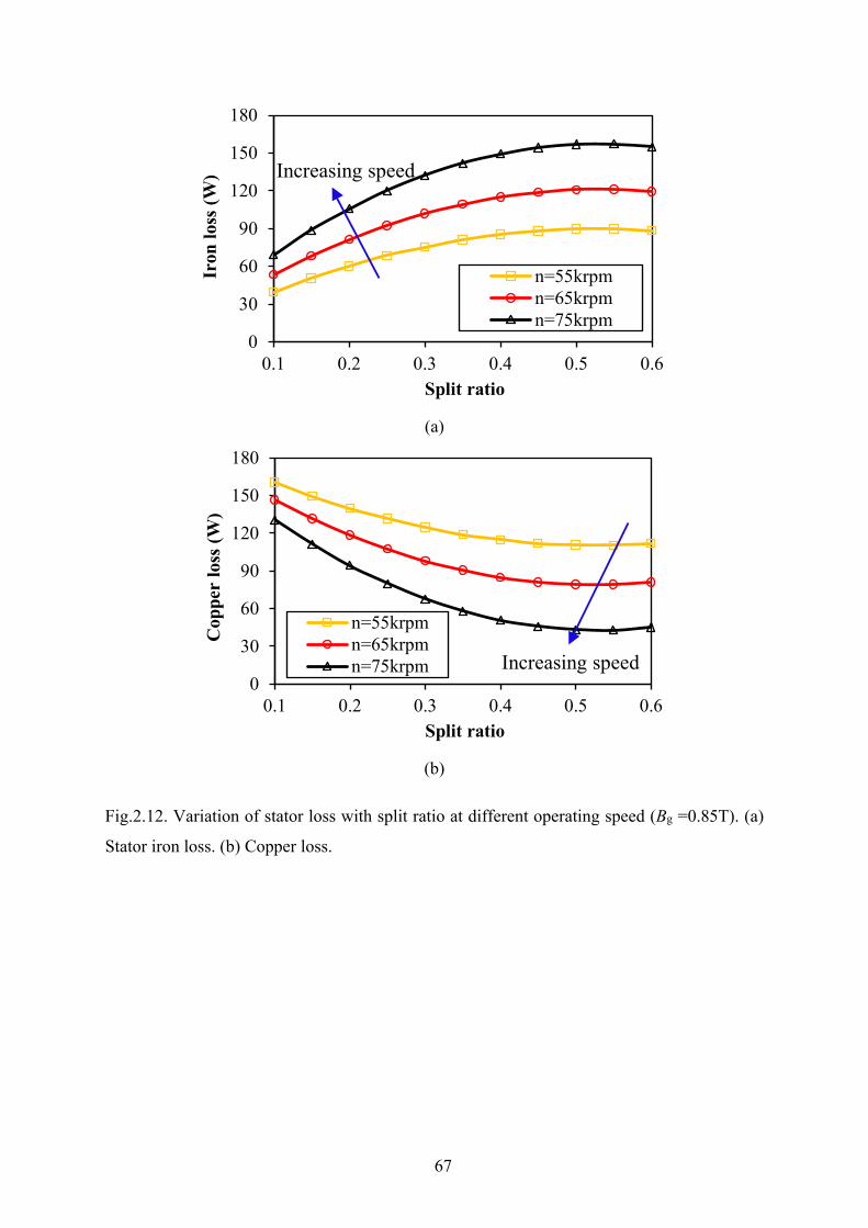
67
(a)
(b)
Fig.2.12. Variation of stator loss with split ratio at different operating speed (Bg =0.85T). (a)
Stator iron loss. (b) Copper loss.
0
30
60
90
120
150
180
0.1 0.2 0.3 0.4 0.5 0.6
Iron
loss
(W)
Split ratio
n=55krpmn=65krpmn=75krpm
Increasing speed
0
30
60
90
120
150
180
0.1 0.2 0.3 0.4 0.5 0.6
Cop
per
loss
(W)
Split ratio
n=55krpmn=65krpmn=75krpm Increasing speed
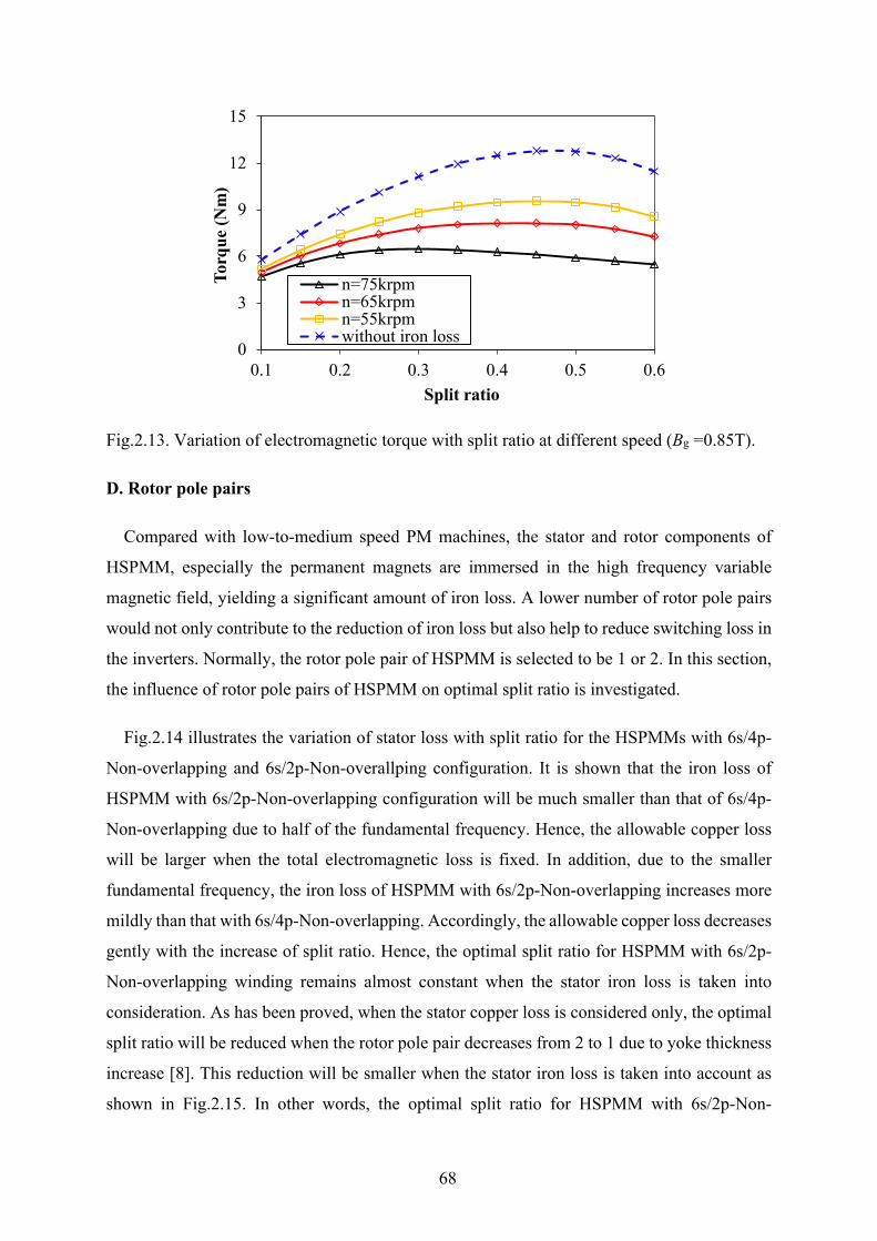
68
Fig.2.13. Variation of electromagnetic torque with split ratio at different speed (Bg =0.85T).
D. Rotor pole pairs
Compared with low-to-medium speed PM machines, the stator and rotor components of
HSPMM, especially the permanent magnets are immersed in the high frequency variable
magnetic field, yielding a significant amount of iron loss. A lower number of rotor pole pairs
would not only contribute to the reduction of iron loss but also help to reduce switching loss in
the inverters. Normally, the rotor pole pair of HSPMM is selected to be 1 or 2. In this section,
the influence of rotor pole pairs of HSPMM on optimal split ratio is investigated.
Fig.2.14 illustrates the variation of stator loss with split ratio for the HSPMMs with 6s/4p-
Non-overlapping and 6s/2p-Non-overallping configuration. It is shown that the iron loss of
HSPMM with 6s/2p-Non-overlapping configuration will be much smaller than that of 6s/4p-
Non-overlapping due to half of the fundamental frequency. Hence, the allowable copper loss
will be larger when the total electromagnetic loss is fixed. In addition, due to the smaller
fundamental frequency, the iron loss of HSPMM with 6s/2p-Non-overlapping increases more
mildly than that with 6s/4p-Non-overlapping. Accordingly, the allowable copper loss decreases
gently with the increase of split ratio. Hence, the optimal split ratio for HSPMM with 6s/2p-
Non-overlapping winding remains almost constant when the stator iron loss is taken into
consideration. As has been proved, when the stator copper loss is considered only, the optimal
split ratio will be reduced when the rotor pole pair decreases from 2 to 1 due to yoke thickness
increase [8]. This reduction will be smaller when the stator iron loss is taken into account as
shown in Fig.2.15. In other words, the optimal split ratio for HSPMM with 6s/2p-Non-
0
3
6
9
12
15
0.1 0.2 0.3 0.4 0.5 0.6
Torq
ue (N
m)
Split ratio
n=75krpmn=65krpmn=55krpmwithout iron loss
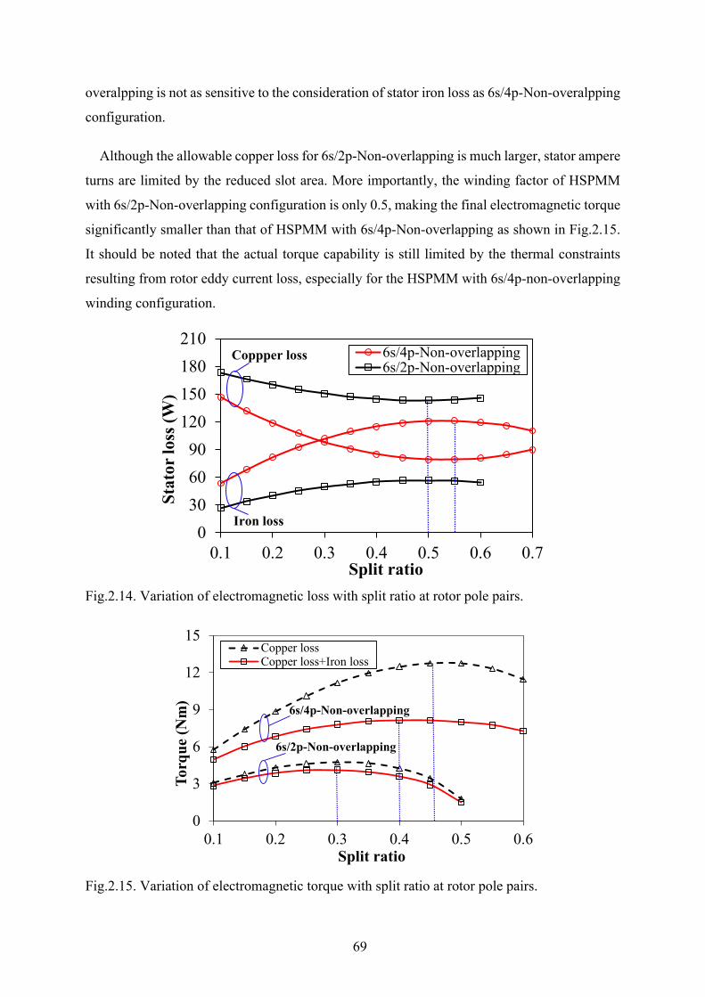
69
overalpping is not as sensitive to the consideration of stator iron loss as 6s/4p-Non-overalpping
configuration.
Although the allowable copper loss for 6s/2p-Non-overlapping is much larger, stator ampere
turns are limited by the reduced slot area. More importantly, the winding factor of HSPMM
with 6s/2p-Non-overlapping configuration is only 0.5, making the final electromagnetic torque
significantly smaller than that of HSPMM with 6s/4p-Non-overlapping as shown in Fig.2.15.
It should be noted that the actual torque capability is still limited by the thermal constraints
resulting from rotor eddy current loss, especially for the HSPMM with 6s/4p-non-overlapping
winding configuration.
Fig.2.14. Variation of electromagnetic loss with split ratio at rotor pole pairs.
Fig.2.15. Variation of electromagnetic torque with split ratio at rotor pole pairs.
0306090
120150180210
0.1 0.2 0.3 0.4 0.5 0.6 0.7
Stat
or lo
ss (W
)
Split ratio
6s/4p-Non-overlapping6s/2p-Non-overlapping
Coppper loss
Iron loss
0
3
6
9
12
15
0.1 0.2 0.3 0.4 0.5 0.6
Torq
ue (N
m)
Split ratio
Copper lossCopper loss+Iron loss
6s/2p-Non-overlapping
6s/4p-Non-overlapping
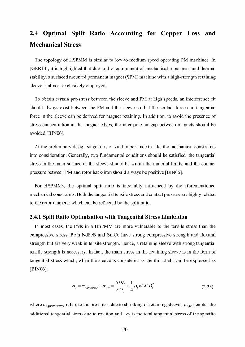
70
2.4 Optimal Split Ratio Accounting for Copper Loss and
Mechanical Stress
The topology of HSPMM is similar to low-to-medium speed operating PM machines. In
[GER14], it is highlighted that due to the requirement of mechanical robustness and thermal
stability, a surfaced mounted permanent magnet (SPM) machine with a high-strength retaining
sleeve is almost exclusively employed.
To obtain certain pre-stress between the sleeve and PM at high speeds, an interference fit
should always exist between the PM and the sleeve so that the contact force and tangential
force in the sleeve can be derived for magnet retaining. In addition, to avoid the presence of
stress concentration at the magnet edges, the inter-pole air gap between magnets should be
avoided [BIN06].
At the preliminary design stage, it is of vital importance to take the mechanical constraints
into consideration. Generally, two fundamental conditions should be satisfied: the tangential
stress in the inner surface of the sleeve should be within the material limits, and the contact
pressure between PM and rotor back-iron should always be positive [BIN06].
For HSPMMs, the optimal split ratio is inevitably influenced by the aforementioned
mechanical constraints. Both the tangential tensile stress and contact pressure are highly related
to the rotor diameter which can be reflected by the split ratio.
2.4.1 Split Ratio Optimization with Tangential Stress Limitation In most cases, the PMs in a HSPMM are more vulnerable to the tensile stress than the
compressive stress. Both NdFeB and SmCo have strong compressive strength and flexural
strength but are very weak in tensile strength. Hence, a retaining sleeve with strong tangential
tensile strength is necessary. In fact, the main stress in the retaining sleeve is in the form of
tangential stress which, when the sleeve is considered as the thin shell, can be expressed as
[BIN06]:
2 2 2, ,
14t t prestress t w b o
o
DE w DD
σ σ σ ρ λλ∆
= + = + (2.25)
where 𝜎𝜎𝑡𝑡,𝑝𝑝𝑝𝑝𝑒𝑒𝑝𝑝𝑡𝑡𝑝𝑝𝑒𝑒𝑝𝑝𝑝𝑝 refers to the pre-stress due to shrinking of retaining sleeve. 𝜎𝜎𝑡𝑡,𝑤𝑤 denotes the
additional tangential stress due to rotation and 𝜎𝜎𝑡𝑡 is the total tangential stress of the specific
71
sleeve. ∆𝐷𝐷 is the sleeve interference fit with respect to the machine diameter 𝐷𝐷𝑜𝑜 . 𝜌𝜌𝑏𝑏 and E
represent the sleeve mass density and the Young’s modulus. ω is the angular velocity of the
rotating rotor.
As can be seen from (2.25), the sleeve tangential stress can be expressed as the function of
split ratio. The value of tangential stress depends on the sleeve material property (mass density
and Young’s modulus), the interference fit, the operating speed, as well as the split ratio.
Fig.2.16 illustrates the tangential stress at the inner side of sleeve with the variation of different
interference fits.
It can be seen that the tangential stress will increase with the increase of sleeve interference
fit in the whole split ratio range. For each given sleeve interference fit, the tangential stress will
drop sharply with the increase of split ratio before reaching a minimum value. After that, the
tangential stress will rise slowly with the increase of split ratio.
For a given sleeve with certain tangential strength, the split ratio can be flexibly chosen by
adjusting the sleeve interference fit. However, there always exists a minimum split ratio for
each sleeve interference fit at which the tangential stress reaches the material limits. These
minimum split ratios increase with the increase of sleeve interference fit. In addition, they are
also influenced by the actual tangential stress. For illustration, two limit lines representing
different values of real sleeve tangential stress are also shown in Fig.2.16. It can be seen that
when the actual sleeve tangential stress reaches the material limit, the value of the minimum
split ratio is the smallest. Hence, a factor k is defined to evaluate the stress margin with respect
to the sleeve material tensile strength.
limit
tk σσ
= (2.26)
where 𝜎𝜎𝑡𝑡 represents the actual value of sleeve tangential stress and 𝜎𝜎𝑙𝑙𝑙𝑙𝑙𝑙𝑙𝑙𝑡𝑡 is the tensile strength
limit of the sleeve material. Fig.2.17 illustrates the relationship between the minimum split
ratio and the interference fit as well as k. It should be noted that the maximum operating speed
at which the tangential stress is checked has been increased by 20% for the consideration of an
over speed test [BIN06]. It can be seen that the widest split ratio range can be achieved when
the actual tangential stress reaches the limits and the interference fit is relatively small. Hence,
k is preferred to be 1 so that the design values for split ratio can be adequate.
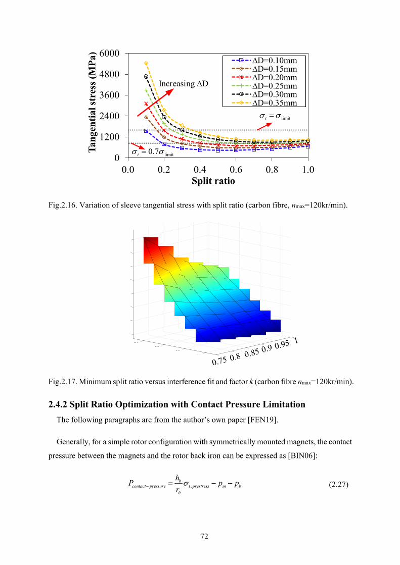
72
Fig.2.16. Variation of sleeve tangential stress with split ratio (carbon fibre, nmax=120kr/min).
Fig.2.17. Minimum split ratio versus interference fit and factor k (carbon fibre nmax=120kr/min).
2.4.2 Split Ratio Optimization with Contact Pressure Limitation The following paragraphs are from the author’s own paper [FEN19].
Generally, for a simple rotor configuration with symmetrically mounted magnets, the contact
pressure between the magnets and the rotor back iron can be expressed as [BIN06]:
,b
contact pressure t prestress m bb
hP p pr
σ− = − − (2.27)
0
1200
2400
3600
4800
6000
0.0 0.2 0.4 0.6 0.8 1.0
Tang
entia
l str
ess (
MPa
)
Split ratio
∆D=0.10mm∆D=0.15mm∆D=0.20mm∆D=0.25mm∆D=0.30mm∆D=0.35mm
Increasing ∆D
limittσ σ=
limit0.7tσ σ=
1
0.1
0.2
0.3
0.4
0.5
0.95
0.6
0.4
0.7
0.8
0.90.30.850.2
0.80.1 0.75
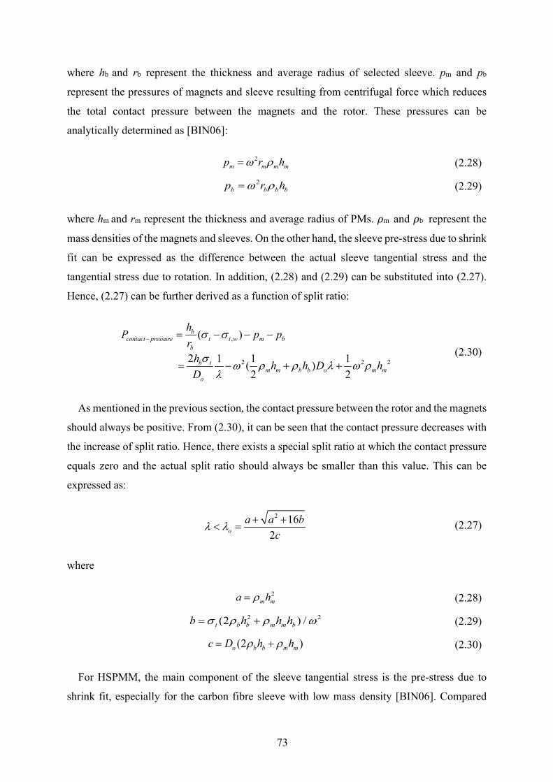
73
where hb and rb represent the thickness and average radius of selected sleeve. pm and pb
represent the pressures of magnets and sleeve resulting from centrifugal force which reduces
the total contact pressure between the magnets and the rotor. These pressures can be
analytically determined as [BIN06]:
2m m m mp r hω ρ= (2.28)
2b b b bp r hω ρ= (2.29)
where hm and rm represent the thickness and average radius of PMs. 𝜌𝜌m and 𝜌𝜌b represent the
mass densities of the magnets and sleeves. On the other hand, the sleeve pre-stress due to shrink
fit can be expressed as the difference between the actual sleeve tangential stress and the
tangential stress due to rotation. In addition, (2.28) and (2.29) can be substituted into (2.27).
Hence, (2.27) can be further derived as a function of split ratio:
,
2 2 2
( )
2 1 1 1( )2 2
bcontact pressure t t w m b
b
b tm m b b o m m
o
hP p pr
h h h D hD
σ σ
σ ω ρ ρ λ ω ρλ
− = − − −
= − + + (2.30)
As mentioned in the previous section, the contact pressure between the rotor and the magnets
should always be positive. From (2.30), it can be seen that the contact pressure decreases with
the increase of split ratio. Hence, there exists a special split ratio at which the contact pressure
equals zero and the actual split ratio should always be smaller than this value. This can be
expressed as:
2 162o
a a bc
λ λ + +< = (2.27)
where
2m ma hρ= (2.28)
2 2(2 ) /t b b m m bb h h hσ ρ ρ ω= + (2.29)
(2 )o b b m mc D h hρ ρ= + (2.30)
For HSPMM, the main component of the sleeve tangential stress is the pre-stress due to
shrink fit, especially for the carbon fibre sleeve with low mass density [BIN06]. Compared
74
with the tangential stress (𝜎𝜎𝑡𝑡,𝑝𝑝𝑝𝑝𝑒𝑒𝑝𝑝𝑡𝑡𝑝𝑝𝑒𝑒𝑝𝑝𝑝𝑝) resulting from sleeve shrinking, the tangential stress due
to rotation (𝜎𝜎𝑡𝑡,𝑤𝑤) is much smaller. Therefore, the following condition can be applied:
2 2
2 2 2,
16 16 (2 ) /16 (2 ) /
t b b m m b
t w b b m m b
b h h hh h h a
σ ρ ρ ω
σ ρ ρ ω
= +
>> + > (2.31)
Hence, (2.31) can be further simplified as:
limit4 2 (0 1)2 2
omo
b mb
b k khc Dh
σλ λω ρ ρ
< ≈ = < ≤+
(2.32)
It has been proved that the feasible range of split ratio is the widest when k equal to 1. Hence,
the maximum split ratio of HSPMM under contact pressure limit can be given as:
limitmax
2
2 mob m
b
hDh
σλω ρ ρ
=+
(2.33)
It can be seen that the split ratio of HSPMM is restricted by the sleeve tensile strength, the
maximum operating speed as well as the magnet mass density and the ratio of magnet to sleeve
thickness. The maximum split ratio is significantly reduced with the increase of maximum
operating speed and the ratio of magnet to sleeve thickness.
On the other hand, it is obvious that the air gap of HSPMM is larger than that of normal PM
machines due to existence of sleeve. From (2.33) the minimum air gap length, which consists
of physical air gap and sleeve, can be given as:
( )min ,min
limit2 2
( ) 4 1 2m
b m
bo
g h h
D
ρλ δ δσ ρλω
= + = +−
(2.34)
Clearly, the sleeve material in terms of mass density and tensile strength has a significant
impact on the minimum sleeve thickness which will be fully addressed in the subsequent
section. In this section, the sleeve material is selected to be carbon fibre due to its low mass
density and high tensile strength. Ignoring the effect of saturation, flux-leakage as well as
slotting effect, the air gap flux density can be accordingly expressed as:
75
( )limit
2 2
1
1 4 1 2
mg r r
mm b
mb
o
hB B Bh h
hD
ρ δδσ ρ
λω
= =+ + + +
−
(2.35)
Substituting (2.34) and (2.35) into (2.6), the electromagnetic torque of HSPMM under
mechanical constraints can be derived as:
3 2( ) ( ) ( )2 36
cu s s ar w
cu
P k N lT f g B kλ λ λρ
= (2.36)
where
( )limit
2 2
2( ) ( 2 )4 1 2m
s o m
bo
f A D h
D
ρλ λ δσ ρλω
= + +−
(2.37)
( )limit
2 2
1( )1 4 1 2
m
mb
o
g
hD
λ ρ δσ ρ
λω
=+ +
−
(2.38)
Hence, the optimal split ratio of HSPMM under mechanical constraints can be obtained by
solving the equation as follows:
( ) 0T λλ
∂=
∂ (2.39)
It is apparent that the equation for the optimal split ratio considering the mechanical
constraints is much more complicated than that of the normal PM machines due to the presence
of g(λ). The pure analytical solution of a high order equation (2.39) is quite complicated as
well. Thus, the numerical method is adopted which is much easier and convenient to solve this
equation. The two equations with respect to the electromagnetic and mechanical domains have
already been determined as:
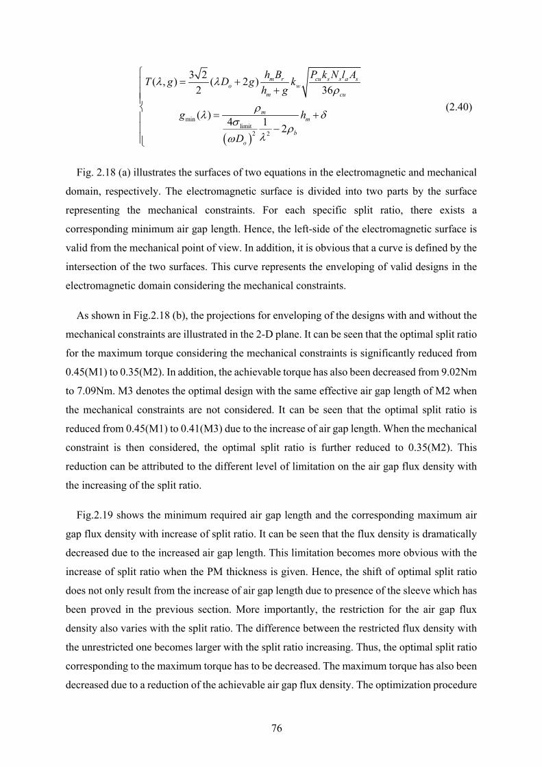
76
( )min
limit2 2
3 2( , ) ( 2 )2 36
( ) 4 1 2
m r cu s s a so w
m cu
mm
bo
h B P k N l AT g D g kh g
g h
D
λ λρ
ρλ δσ ρλω
= + +
= +
−
(2.40)
Fig. 2.18 (a) illustrates the surfaces of two equations in the electromagnetic and mechanical
domain, respectively. The electromagnetic surface is divided into two parts by the surface
representing the mechanical constraints. For each specific split ratio, there exists a
corresponding minimum air gap length. Hence, the left-side of the electromagnetic surface is
valid from the mechanical point of view. In addition, it is obvious that a curve is defined by the
intersection of the two surfaces. This curve represents the enveloping of valid designs in the
electromagnetic domain considering the mechanical constraints.
As shown in Fig.2.18 (b), the projections for enveloping of the designs with and without the
mechanical constraints are illustrated in the 2-D plane. It can be seen that the optimal split ratio
for the maximum torque considering the mechanical constraints is significantly reduced from
0.45(M1) to 0.35(M2). In addition, the achievable torque has also been decreased from 9.02Nm
to 7.09Nm. M3 denotes the optimal design with the same effective air gap length of M2 when
the mechanical constraints are not considered. It can be seen that the optimal split ratio is
reduced from 0.45(M1) to 0.41(M3) due to the increase of air gap length. When the mechanical
constraint is then considered, the optimal split ratio is further reduced to 0.35(M2). This
reduction can be attributed to the different level of limitation on the air gap flux density with
the increasing of the split ratio.
Fig.2.19 shows the minimum required air gap length and the corresponding maximum air
gap flux density with increase of split ratio. It can be seen that the flux density is dramatically
decreased due to the increased air gap length. This limitation becomes more obvious with the
increase of split ratio when the PM thickness is given. Hence, the shift of optimal split ratio
does not only result from the increase of air gap length due to presence of the sleeve which has
been proved in the previous section. More importantly, the restriction for the air gap flux
density also varies with the split ratio. The difference between the restricted flux density with
the unrestricted one becomes larger with the split ratio increasing. Thus, the optimal split ratio
corresponding to the maximum torque has to be decreased. The maximum torque has also been
decreased due to a reduction of the achievable air gap flux density. The optimization procedure
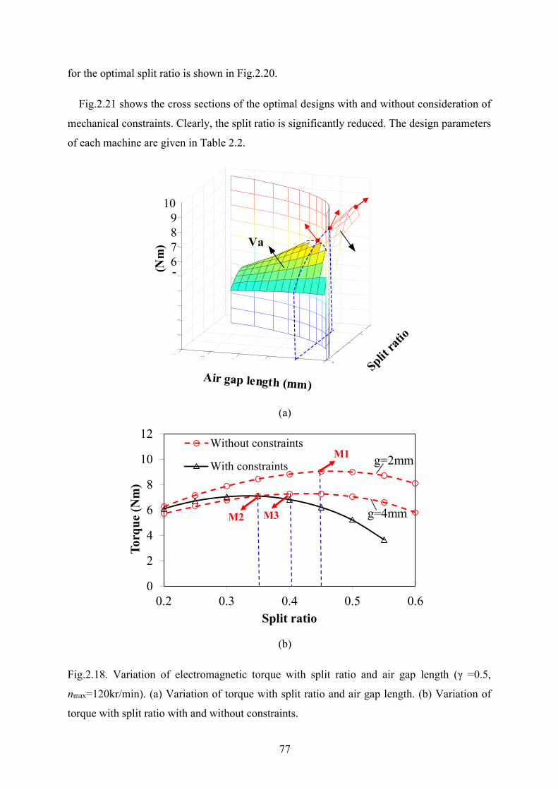
77
for the optimal split ratio is shown in Fig.2.20.
Fig.2.21 shows the cross sections of the optimal designs with and without consideration of
mechanical constraints. Clearly, the split ratio is significantly reduced. The design parameters
of each machine are given in Table 2.2.
(a)
(b)
Fig.2.18. Variation of electromagnetic torque with split ratio and air gap length (γ =0.5,
nmax=120kr/min). (a) Variation of torque with split ratio and air gap length. (b) Variation of
torque with split ratio with and without constraints.
0.8
0.6
0.40
1
2
0.2
3
4
12
5
6
10
7
8
8
9
10
6 04 2
5
89
76
10
(Nm
) Va
0
2
4
6
8
10
12
0.2 0.3 0.4 0.5 0.6
Torq
ue (N
m)
Split ratio
Without constraints
With constraints
g=4mm
M1
M2 M3
g=2mm
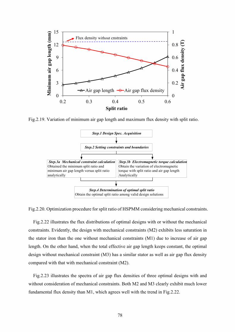
78
Fig.2.19. Variation of minimum air gap length and maximum flux density with split ratio.
Fig.2.20. Optimization procedure for split ratio of HSPMM considering mechanical constraints.
Fig.2.22 illustrates the flux distributions of optimal designs with or without the mechanical
constraints. Evidently, the design with mechanical constraints (M2) exhibits less saturation in
the stator iron than the one without mechanical constraints (M1) due to increase of air gap
length. On the other hand, when the total effective air gap length keeps constant, the optimal
design without mechanical constraint (M3) has a similar stator as well as air gap flux density
compared with that with mechanical constraint (M2).
Fig.2.23 illustrates the spectra of air gap flux densities of three optimal designs with and
without consideration of mechanical constraints. Both M2 and M3 clearly exhibit much lower
fundamental flux density than M1, which agrees well with the trend in Fig.2.22.
0
0.2
0.4
0.6
0.8
1
0
3
6
9
12
15
0.2 0.3 0.4 0.5 0.6
Air
gap
flux
den
sity
(T)
Min
imum
air
gap
leng
th (m
m)
Split ratio
Air gap length Air gap flux density
Flux density without cnstraints
Step.1 Design Spec. Acquisition
Step.2 Setting constraints and boundaries
Step.4 Determination of optimal split ratio Obtain the optimal split ratio among valid design solutions
Step.3b Electromagnetic torque calculation Obtain the variation of electromagnetic torque with split ratio and air gap length Analytically
Step.3a Mechanical constraint calculation Obtained the minimum split ratio and minimum air gap length versus split ratio analytically
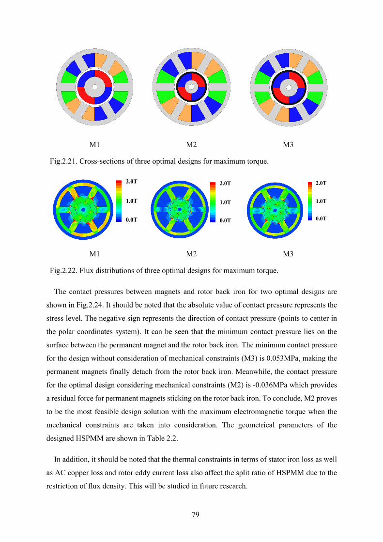
79
M1 M2 M3
Fig.2.21. Cross-sections of three optimal designs for maximum torque.
M1 M2 M3
Fig.2.22. Flux distributions of three optimal designs for maximum torque.
The contact pressures between magnets and rotor back iron for two optimal designs are
shown in Fig.2.24. It should be noted that the absolute value of contact pressure represents the
stress level. The negative sign represents the direction of contact pressure (points to center in
the polar coordinates system). It can be seen that the minimum contact pressure lies on the
surface between the permanent magnet and the rotor back iron. The minimum contact pressure
for the design without consideration of mechanical constraints (M3) is 0.053MPa, making the
permanent magnets finally detach from the rotor back iron. Meanwhile, the contact pressure
for the optimal design considering mechanical constraints (M2) is -0.036MPa which provides
a residual force for permanent magnets sticking on the rotor back iron. To conclude, M2 proves
to be the most feasible design solution with the maximum electromagnetic torque when the
mechanical constraints are taken into consideration. The geometrical parameters of the
designed HSPMM are shown in Table 2.2.
In addition, it should be noted that the thermal constraints in terms of stator iron loss as well
as AC copper loss and rotor eddy current loss also affect the split ratio of HSPMM due to the
restriction of flux density. This will be studied in future research.
2.0T
1.0T
0.0T
2.0T
1.0T
0.0T
2.0T
1.0T
0.0T
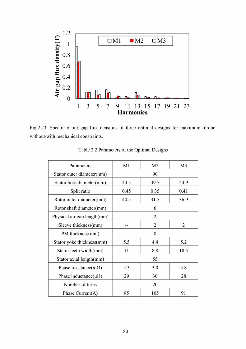
80
Fig.2.23. Spectra of air gap flux densities of three optimal designs for maximum torque,
without/with mechanical constraints.
Table 2.2 Parameters of the Optimal Designs
Parameters M1 M2 M3
Stator outer diameter(mm) 90
Stator bore diameter(mm) 44.5 39.5 44.9
Split ratio 0.45 0.35 0.41
Rotor outer diameter(mm) 40.5 31.5 36.9
Rotor shaft diameter(mm) 6
Physical air gap length(mm) 2
Sleeve thickness(mm) -- 2 2
PM thickness(mm) 8
Stator yoke thickness(mm) 5.5 4.4 5.2
Stator teeth width(mm) 11 8.8 10.5
Stator axial length(mm) 55
Phase resistance(mΩ) 5.3 3.0 4.8
Phase inductance(μH) 29 30 28
Number of turns 20
Phase Current(A) 85 105 91
0
0.2
0.4
0.6
0.8
1
1.2
1 3 5 7 9 11 13 15 17 19 21 23
Air
gap
flux
den
sity(
T)
Harmonics
M1 M2 M3
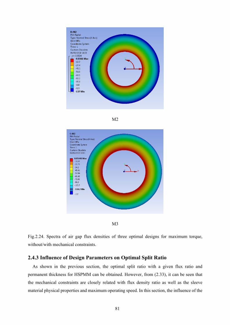
81
M2
M3
Fig.2.24. Spectra of air gap flux densities of three optimal designs for maximum torque,
without/with mechanical constraints.
2.4.3 Influence of Design Parameters on Optimal Split Ratio As shown in the previous section, the optimal split ratio with a given flux ratio and
permanent thickness for HSPMM can be obtained. However, from (2.33), it can be seen that
the mechanical constraints are closely related with flux density ratio as well as the sleeve
material physical properties and maximum operating speed. In this section, the influence of the

82
previous parameters on the optimal split ratio of HSPMM is investigated. It is worth
mentioning that the level of limitation on flux density for magnets of different thickness will
not change significantly when the split ratio increases. Thus, the magnet thickness has no
significant influence on the determination of optimal split ratio.
A. Flux density ratio
From (2.37), it can be seen that the optimal split ratio considering the mechanical constraints
still depends on the slot area which is closely related with the flux density ratio. Fig.2.25
illustrates the variation of optimal split ratio with flux density ratio, and clearly shows that the
optimal value decreases with the increase of flux density ratio. This can be attributed to the
increase of width of the slot teeth and thickness of yoke while the flux density ratio is increasing.
Hence, the slot area is consequently reduced. In order to maintain the constant copper loss, the
stator bore diameter has to be reduced. It can be seen that with the decrease of flux density
ratio, the difference between the optimal split ratios with and without consideration of
mechanical constraints increases. This can be attributed to the increasing air gap length with
the increasing split ratio, when mechanical constraints are considered. Thus, the stator bore
diameter increases faster, which in turn restricts the increase of optimal split ratio so that the
copper loss can be constant.
Fig.2.25. Variation of optimal split ratio with flux density ratio.
B. Maximum operating speed
In the practical design, the worst case should always be considered. The contact pressure
0.00.10.20.30.40.50.6
0.25 0.50 0.75 1.00
Opt
imiz
ed s
plit
ratio
Flux density ratio
Without constraintsWith constraints
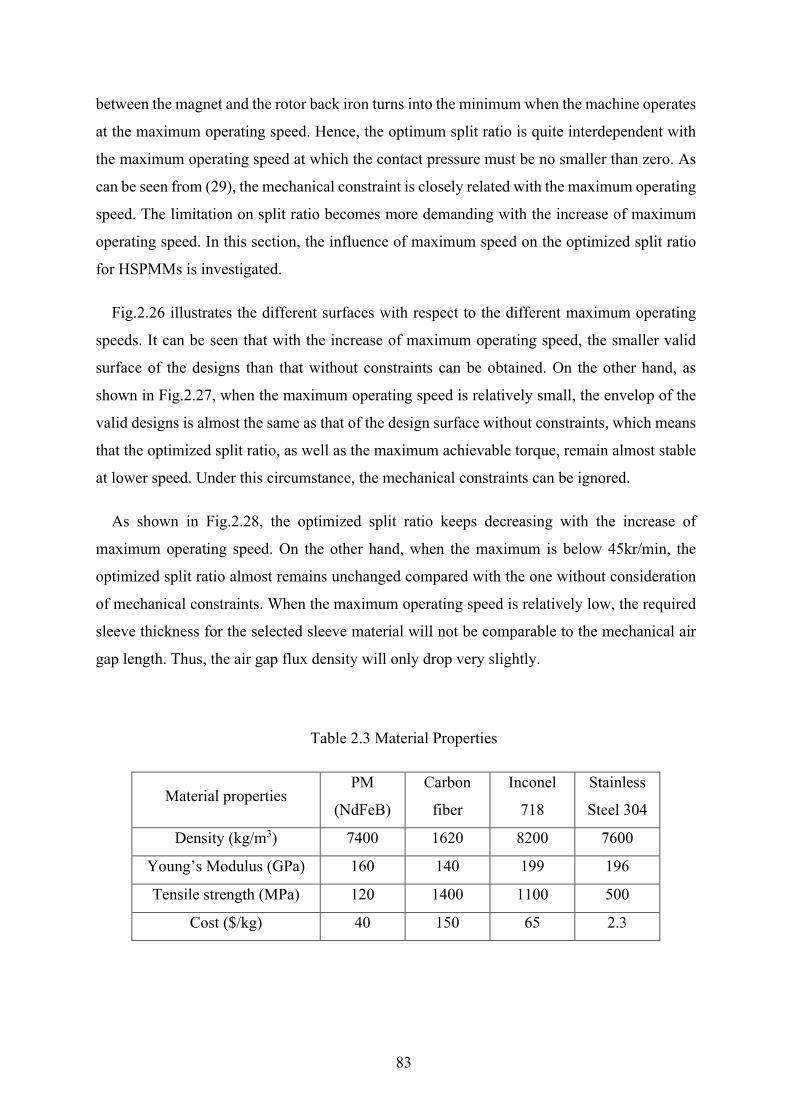
83
between the magnet and the rotor back iron turns into the minimum when the machine operates
at the maximum operating speed. Hence, the optimum split ratio is quite interdependent with
the maximum operating speed at which the contact pressure must be no smaller than zero. As
can be seen from (29), the mechanical constraint is closely related with the maximum operating
speed. The limitation on split ratio becomes more demanding with the increase of maximum
operating speed. In this section, the influence of maximum speed on the optimized split ratio
for HSPMMs is investigated.
Fig.2.26 illustrates the different surfaces with respect to the different maximum operating
speeds. It can be seen that with the increase of maximum operating speed, the smaller valid
surface of the designs than that without constraints can be obtained. On the other hand, as
shown in Fig.2.27, when the maximum operating speed is relatively small, the envelop of the
valid designs is almost the same as that of the design surface without constraints, which means
that the optimized split ratio, as well as the maximum achievable torque, remain almost stable
at lower speed. Under this circumstance, the mechanical constraints can be ignored.
As shown in Fig.2.28, the optimized split ratio keeps decreasing with the increase of
maximum operating speed. On the other hand, when the maximum is below 45kr/min, the
optimized split ratio almost remains unchanged compared with the one without consideration
of mechanical constraints. When the maximum operating speed is relatively low, the required
sleeve thickness for the selected sleeve material will not be comparable to the mechanical air
gap length. Thus, the air gap flux density will only drop very slightly.
Table 2.3 Material Properties
Material properties PM
(NdFeB)
Carbon
fiber
Inconel
718
Stainless
Steel 304
Density (kg/m3) 7400 1620 8200 7600
Young’s Modulus (GPa) 160 140 199 196
Tensile strength (MPa) 120 1400 1100 500
Cost ($/kg) 40 150 65 2.3

84
Fig.2.26. Variation of electromagnetic torque with air gap length and split ratio.
Fig.2.27. Variation of electromagnetic torque with split ratio at different operating speed.
05
10
24
68
1012
00.1
0.20.3
0.40.5
0.60.7
Tor
que
(Nm
)nmax=30krpm
nmax=60krpmnmax=90krpm
nmax=120krpm
Increasing speed
0
2
4
6
8
10
0.2 0.3 0.4 0.5 0.6
Torq
ue (N
m)
Split ratio
Without constraintsn_max=120krpmn_max=90krpmn_max=60krpmn_max=30krpm
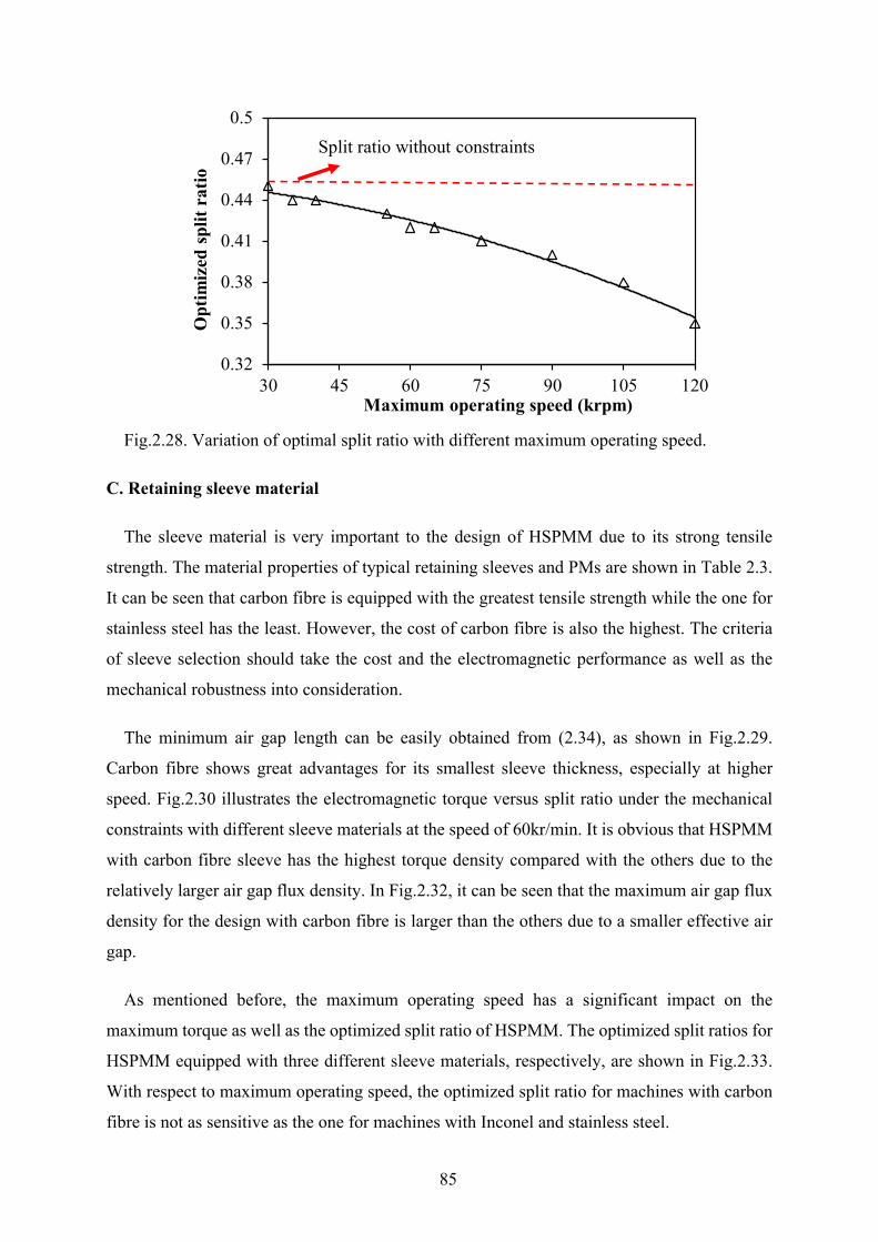
85
Fig.2.28. Variation of optimal split ratio with different maximum operating speed.
C. Retaining sleeve material
The sleeve material is very important to the design of HSPMM due to its strong tensile
strength. The material properties of typical retaining sleeves and PMs are shown in Table 2.3.
It can be seen that carbon fibre is equipped with the greatest tensile strength while the one for
stainless steel has the least. However, the cost of carbon fibre is also the highest. The criteria
of sleeve selection should take the cost and the electromagnetic performance as well as the
mechanical robustness into consideration.
The minimum air gap length can be easily obtained from (2.34), as shown in Fig.2.29.
Carbon fibre shows great advantages for its smallest sleeve thickness, especially at higher
speed. Fig.2.30 illustrates the electromagnetic torque versus split ratio under the mechanical
constraints with different sleeve materials at the speed of 60kr/min. It is obvious that HSPMM
with carbon fibre sleeve has the highest torque density compared with the others due to the
relatively larger air gap flux density. In Fig.2.32, it can be seen that the maximum air gap flux
density for the design with carbon fibre is larger than the others due to a smaller effective air
gap.
As mentioned before, the maximum operating speed has a significant impact on the
maximum torque as well as the optimized split ratio of HSPMM. The optimized split ratios for
HSPMM equipped with three different sleeve materials, respectively, are shown in Fig.2.33.
With respect to maximum operating speed, the optimized split ratio for machines with carbon
fibre is not as sensitive as the one for machines with Inconel and stainless steel.
0.32
0.35
0.38
0.41
0.44
0.47
0.5
30 45 60 75 90 105 120
Opt
imiz
ed s
plit
ratio
Maximum operating speed (krpm)
Split ratio without constraints
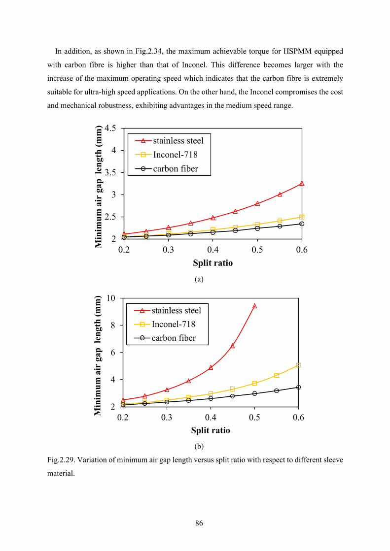
86
In addition, as shown in Fig.2.34, the maximum achievable torque for HSPMM equipped
with carbon fibre is higher than that of Inconel. This difference becomes larger with the
increase of the maximum operating speed which indicates that the carbon fibre is extremely
suitable for ultra-high speed applications. On the other hand, the Inconel compromises the cost
and mechanical robustness, exhibiting advantages in the medium speed range.
(a)
(b)
Fig.2.29. Variation of minimum air gap length versus split ratio with respect to different sleeve
material.
2
2.5
3
3.5
4
4.5
0.2 0.3 0.4 0.5 0.6Min
imum
air
gap
len
gth
(mm
)
Split ratio
stainless steelInconel-718carbon fiber
2
4
6
8
10
0.2 0.3 0.4 0.5 0.6Min
imum
air
gap
len
gth
(mm
)
Split ratio
stainless steelInconel-718carbon fiber
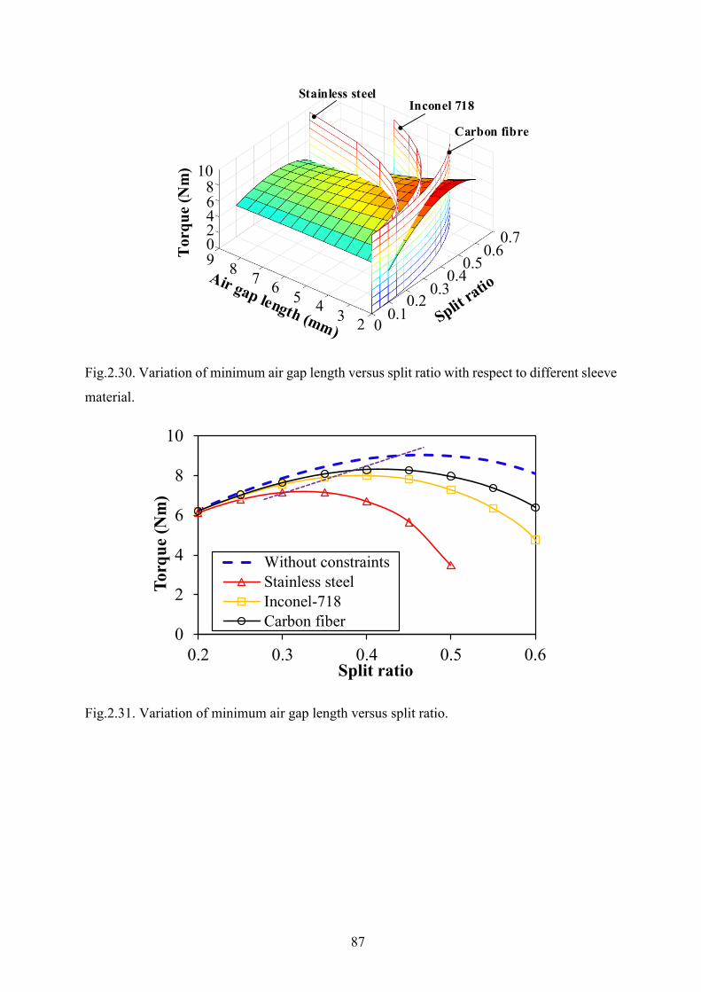
87
Fig.2.30. Variation of minimum air gap length versus split ratio with respect to different sleeve
material.
Fig.2.31. Variation of minimum air gap length versus split ratio.
02345678902468
10T
orqu
e (N
m)
0.10.2
0.30.4
0.50.6
0.7
Carbon fibre
Inconel 718Stainless steel
0
2
4
6
8
10
0.2 0.3 0.4 0.5 0.6
Torq
ue (N
m)
Split ratio
Without constraintsStainless steelInconel-718Carbon fiber
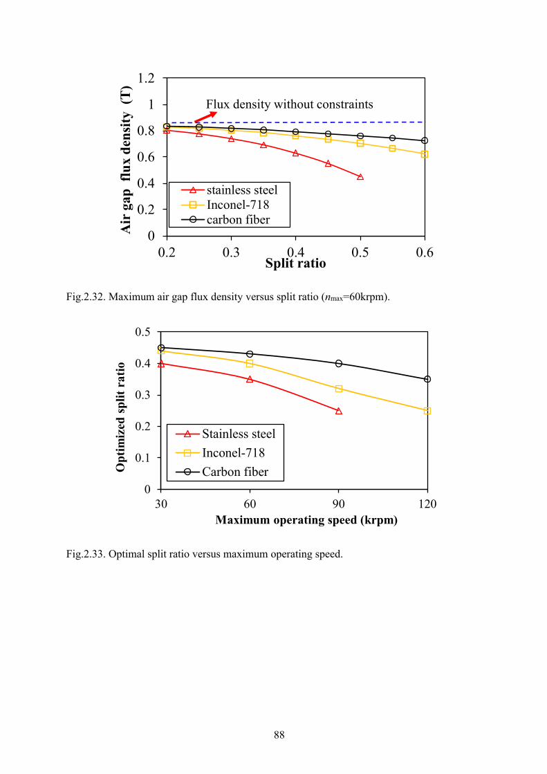
88
Fig.2.32. Maximum air gap flux density versus split ratio (nmax=60krpm).
Fig.2.33. Optimal split ratio versus maximum operating speed.
0
0.2
0.4
0.6
0.8
1
1.2
0.2 0.3 0.4 0.5 0.6
Air
gap
flu
x de
nsity
(T
)
Split ratio
stainless steelInconel-718carbon fiber
Flux density without constraints
0
0.1
0.2
0.3
0.4
0.5
30 60 90 120
Opt
imiz
ed s
plit
ratio
Maximum operating speed (krpm)
Stainless steelInconel-718Carbon fiber
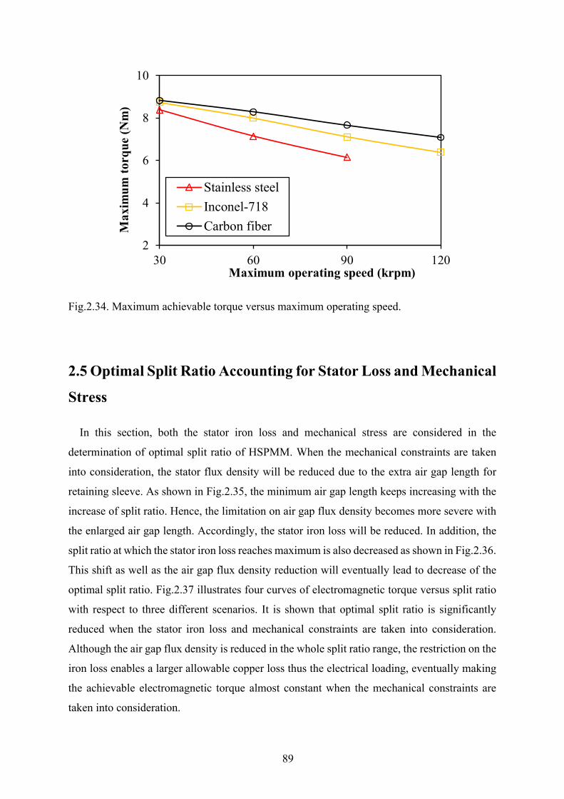
89
Fig.2.34. Maximum achievable torque versus maximum operating speed.
2.5 Optimal Split Ratio Accounting for Stator Loss and Mechanical
Stress
In this section, both the stator iron loss and mechanical stress are considered in the
determination of optimal split ratio of HSPMM. When the mechanical constraints are taken
into consideration, the stator flux density will be reduced due to the extra air gap length for
retaining sleeve. As shown in Fig.2.35, the minimum air gap length keeps increasing with the
increase of split ratio. Hence, the limitation on air gap flux density becomes more severe with
the enlarged air gap length. Accordingly, the stator iron loss will be reduced. In addition, the
split ratio at which the stator iron loss reaches maximum is also decreased as shown in Fig.2.36.
This shift as well as the air gap flux density reduction will eventually lead to decrease of the
optimal split ratio. Fig.2.37 illustrates four curves of electromagnetic torque versus split ratio
with respect to three different scenarios. It is shown that optimal split ratio is significantly
reduced when the stator iron loss and mechanical constraints are taken into consideration.
Although the air gap flux density is reduced in the whole split ratio range, the restriction on the
iron loss enables a larger allowable copper loss thus the electrical loading, eventually making
the achievable electromagnetic torque almost constant when the mechanical constraints are
taken into consideration.
2
4
6
8
10
30 60 90 120
Max
imum
torq
ue (N
m)
Maximum operating speed (krpm)
Stainless steelInconel-718Carbon fiber
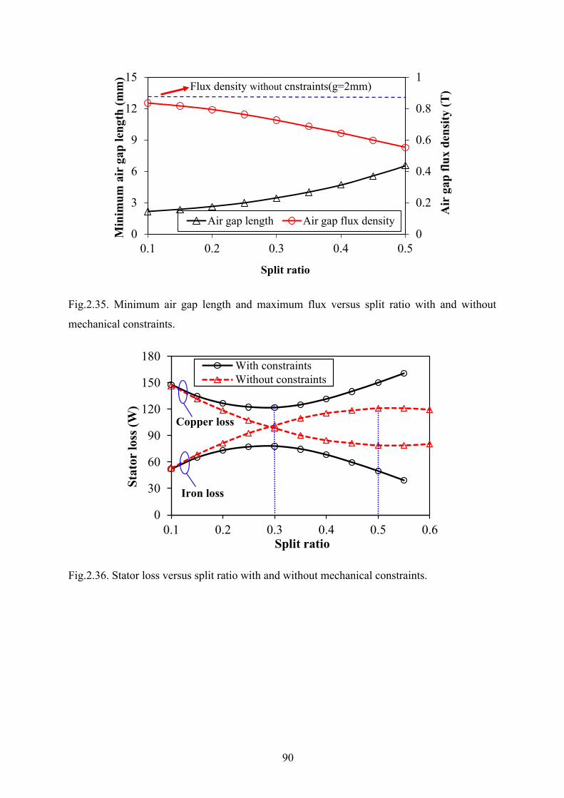
90
Fig.2.35. Minimum air gap length and maximum flux versus split ratio with and without
mechanical constraints.
Fig.2.36. Stator loss versus split ratio with and without mechanical constraints.
0
0.2
0.4
0.6
0.8
1
0
3
6
9
12
15
0.1 0.2 0.3 0.4 0.5
Air
gap
flux
den
sity
(T)
Min
imum
air
gap
leng
th (m
m)
Split ratio
Air gap length Air gap flux density
Flux density without cnstraints(g=2mm)
0
30
60
90
120
150
180
0.1 0.2 0.3 0.4 0.5 0.6
Stat
or lo
ss (W
)
Split ratio
With constraintsWithout constraints
Iron loss
Copper loss
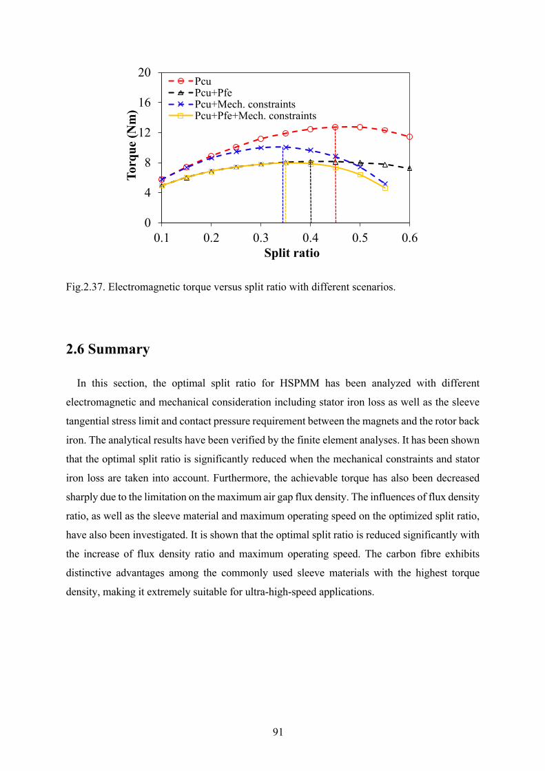
91
Fig.2.37. Electromagnetic torque versus split ratio with different scenarios.
2.6 Summary
In this section, the optimal split ratio for HSPMM has been analyzed with different
electromagnetic and mechanical consideration including stator iron loss as well as the sleeve
tangential stress limit and contact pressure requirement between the magnets and the rotor back
iron. The analytical results have been verified by the finite element analyses. It has been shown
that the optimal split ratio is significantly reduced when the mechanical constraints and stator
iron loss are taken into account. Furthermore, the achievable torque has also been decreased
sharply due to the limitation on the maximum air gap flux density. The influences of flux density
ratio, as well as the sleeve material and maximum operating speed on the optimized split ratio,
have also been investigated. It is shown that the optimal split ratio is reduced significantly with
the increase of flux density ratio and maximum operating speed. The carbon fibre exhibits
distinctive advantages among the commonly used sleeve materials with the highest torque
density, making it extremely suitable for ultra-high-speed applications.
0
4
8
12
16
20
0.1 0.2 0.3 0.4 0.5 0.6
Torq
ue (N
m)
Split ratio
PcuPcu+PfePcu+Mech. constraintsPcu+Pfe+Mech. constraints
92
Chapter 3 Analysis of Magnet Eddy current Loss for
Four-Pole High Speed PM Machines with Alternate
Stator Winding Configuration
In Chapter 2, the optimal split ratio of HSPMM is determined with due account for stator
electromagnetic loss and mechanical constraints. However, the electromagnetic loss on the
rotor side, especially in the magnets, should also be taken into consideration. Significant rotor
magnet loss will be induced under high-speed operation due to existence of both spatial and
temporal field harmonics. In this chapter, the rotor magnet loss analysis is conducted on the
four-pole HSPMM, with focus on the loss segregation resulting from spatial field harmonics.
The contribution of each harmonic in the production of magnet loss, either from both PM field
or armature, is determined with the proposed method. In addition, the slotting effect on both
PM field and armature reaction field is compared and the corresponding resultant magnet loss
is quantified. The literature on magnet loss due to modulated MMF harmonics is firstly
reviewed. Meanwhile, the influence of stator configuration, e.g. number of stator slot and coil
pitch, on the armature reaction-induced magnet loss is investigated. Finally, experimental
results are provided to verify the theoretical analysis on back-EMF and torque.
3.1 Introduction
The rotor loss has always been an issue for permanent magnet brushless machines equipped
with surface-mounted magnets [ATA00], [TOD04], [ZHU04], [NAK06], [SHA09], [BIA13].
Generally, the generation of rotor eddy current loss can be attributed to the field variation seen
by the rotor. This field variation results from the following reasons: (a) Nonsinusoidal stator
MMF distribution due to stator winding disposition. (b) Permeance variation due to slotting
effect. (c) Nonsinusoidal phase current due to BLDC control and PWM. The existence of
spatial and temporal harmonics in the air gap field will yield a significant eddy current loss in
the rotor magnets, rotor yoke as well as the metallic sleeve for magnet retaining. The risk of
demagnetization will be increased due to the difficulties of rotor cooling, especially for the
rotor magnets sheltered by the sleeve with low thermal conductivity such as carbon-fiber.
Hence, the accurate prediction of rotor eddy current loss is of great importance to the
robustness of permanent magnet brushless machines. A lot of analytical models can be found
93
for the calculation of rotor loss in the past two decades [ATA00], [ISH05], [WU12], [DUB14].
Those analytical models give more insight to the mechanism of the rotor loss generation. In
addition, this also gives the guidelines for the selection of rotor loss reduction methods such as
magnet segmentation [YAM09], [HUA10], [WAN10b], [MIR12], rotor pole shaping
[YAM10], multi-layered or dual phase stator winding [SUN14], stator dummy teeth or dummy
slot [MA19].
For the HSPMM, the rotor loss issue should be more concerned due to high frequency and
abundant time harmonics in the phase current. Meanwhile, the air gap length in high speed PM
machines is much larger than that of low-speed PM machines. The relatively larger air gap will
impose distinct effect on the spatial harmonics with different order, which will be demonstrated
in the following section. The interaction between harmonics with same frequency but different
spatial orders is also affected by the relatively larger air gap [WU12]. It will be demonstrated
in this chapter that the harmonic superposition method is still applicable with acceptable
accuracy for the magnet loss calculation of HSPMM.
On the other hand, the rotor topology selection of HSPMM is very limited due to the
consideration of rotor mechanical robustness and machine control difficulties. The permanent
magnets are normally surface-mounted onto the rotor back-iron or directly bonded with the
shaft, especially for very high-speed operation. The rotor pole numbers of high-speed PM
machines are usually selected to be 2 or 4 depending on specific requirements and constraints.
The 2-pole rotor structure is widely used in low-power ultra-high-speed applications due to
lower fundamental frequency which is easier for control and beneficial to the reduction of stator
iron loss and rotor PM eddy current loss [ZHO06], [ZWY05], [PFI10], [HON12]. The 4-pole
rotor is more inclined to be adopted for high-power high-speed applications due to reduced
end-winding length and stator copper loss, which are quite advantageous for stator thermal
equilibrium in high power application [JAN04], [BIN06], [LUI14], [ZHA15]. Hence, the stator
configuration such as winding disposition should be more concerned. It will be demonstrated
that the number of stator slots and winding coil pitch make a huge difference to the induced
stator MMF and thus the penetrated harmonics.
This chapter is organized as follows. In Section 3.2, the rotor magnet loss segregation will
firstly be conducted on the 6-slot 4-pole HSPMM. The contribution of PM harmonics and the
MMF harmonics to the resultant magnet loss is quantified. In addition, the validity of harmonic
superposition method will be verified. Then, the magnet loss due to the slotting effect on both
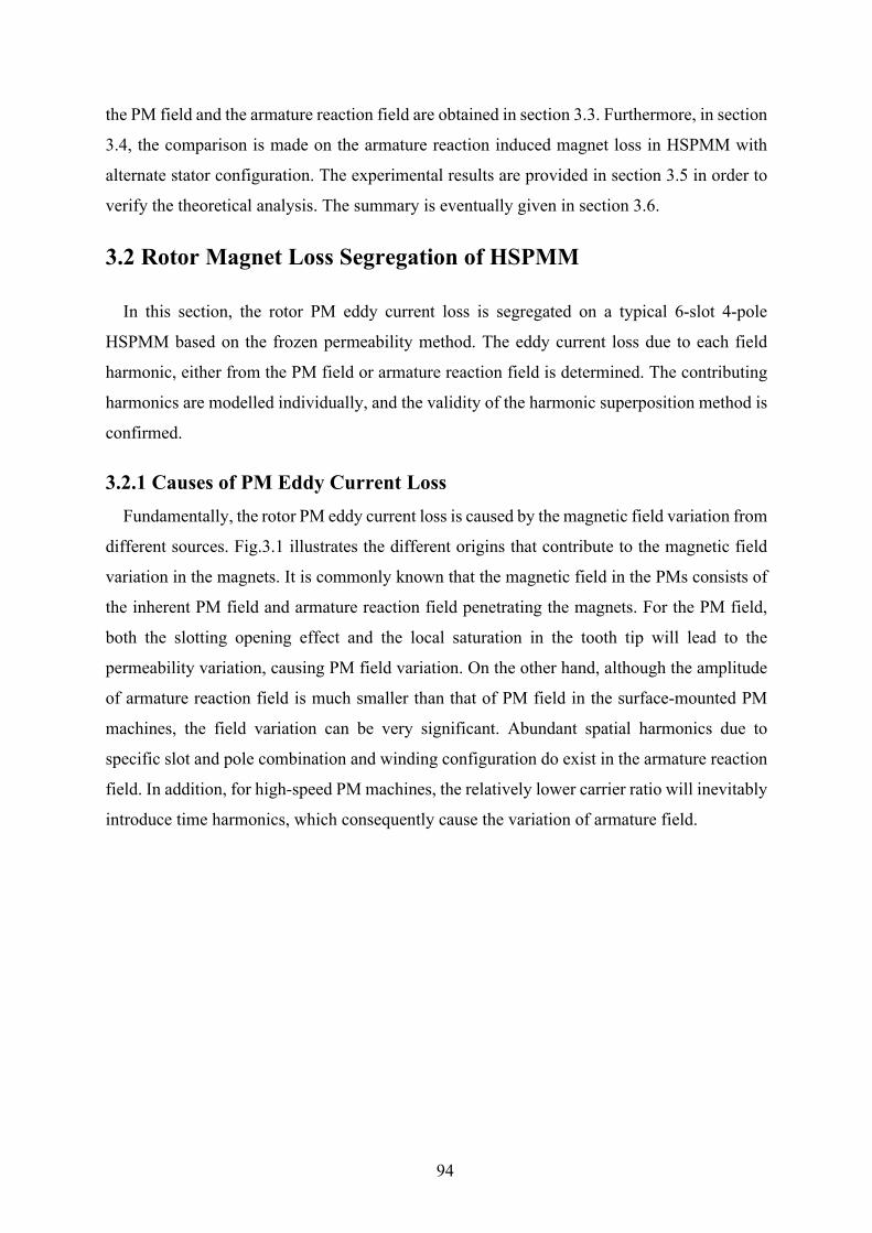
94
the PM field and the armature reaction field are obtained in section 3.3. Furthermore, in section
3.4, the comparison is made on the armature reaction induced magnet loss in HSPMM with
alternate stator configuration. The experimental results are provided in section 3.5 in order to
verify the theoretical analysis. The summary is eventually given in section 3.6.
3.2 Rotor Magnet Loss Segregation of HSPMM
In this section, the rotor PM eddy current loss is segregated on a typical 6-slot 4-pole
HSPMM based on the frozen permeability method. The eddy current loss due to each field
harmonic, either from the PM field or armature reaction field is determined. The contributing
harmonics are modelled individually, and the validity of the harmonic superposition method is
confirmed.
3.2.1 Causes of PM Eddy Current Loss Fundamentally, the rotor PM eddy current loss is caused by the magnetic field variation from
different sources. Fig.3.1 illustrates the different origins that contribute to the magnetic field
variation in the magnets. It is commonly known that the magnetic field in the PMs consists of
the inherent PM field and armature reaction field penetrating the magnets. For the PM field,
both the slotting opening effect and the local saturation in the tooth tip will lead to the
permeability variation, causing PM field variation. On the other hand, although the amplitude
of armature reaction field is much smaller than that of PM field in the surface-mounted PM
machines, the field variation can be very significant. Abundant spatial harmonics due to
specific slot and pole combination and winding configuration do exist in the armature reaction
field. In addition, for high-speed PM machines, the relatively lower carrier ratio will inevitably
introduce time harmonics, which consequently cause the variation of armature field.
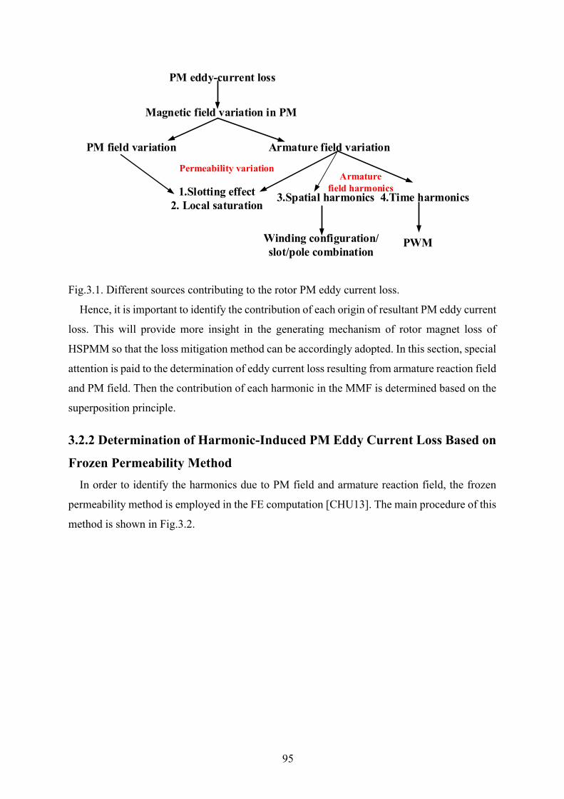
95
Fig.3.1. Different sources contributing to the rotor PM eddy current loss.
Hence, it is important to identify the contribution of each origin of resultant PM eddy current
loss. This will provide more insight in the generating mechanism of rotor magnet loss of
HSPMM so that the loss mitigation method can be accordingly adopted. In this section, special
attention is paid to the determination of eddy current loss resulting from armature reaction field
and PM field. Then the contribution of each harmonic in the MMF is determined based on the
superposition principle.
3.2.2 Determination of Harmonic-Induced PM Eddy Current Loss Based on
Frozen Permeability Method In order to identify the harmonics due to PM field and armature reaction field, the frozen
permeability method is employed in the FE computation [CHU13]. The main procedure of this
method is shown in Fig.3.2.
PM eddy-current loss
PM field variation Armature field variation
Magnetic field variation in PM
1.Slotting effect2. Local saturation
Permeability variation
3.Spatial harmonics 4.Time harmonics
Armaturefield harmonics
Winding configuration/slot/pole combination
PWM
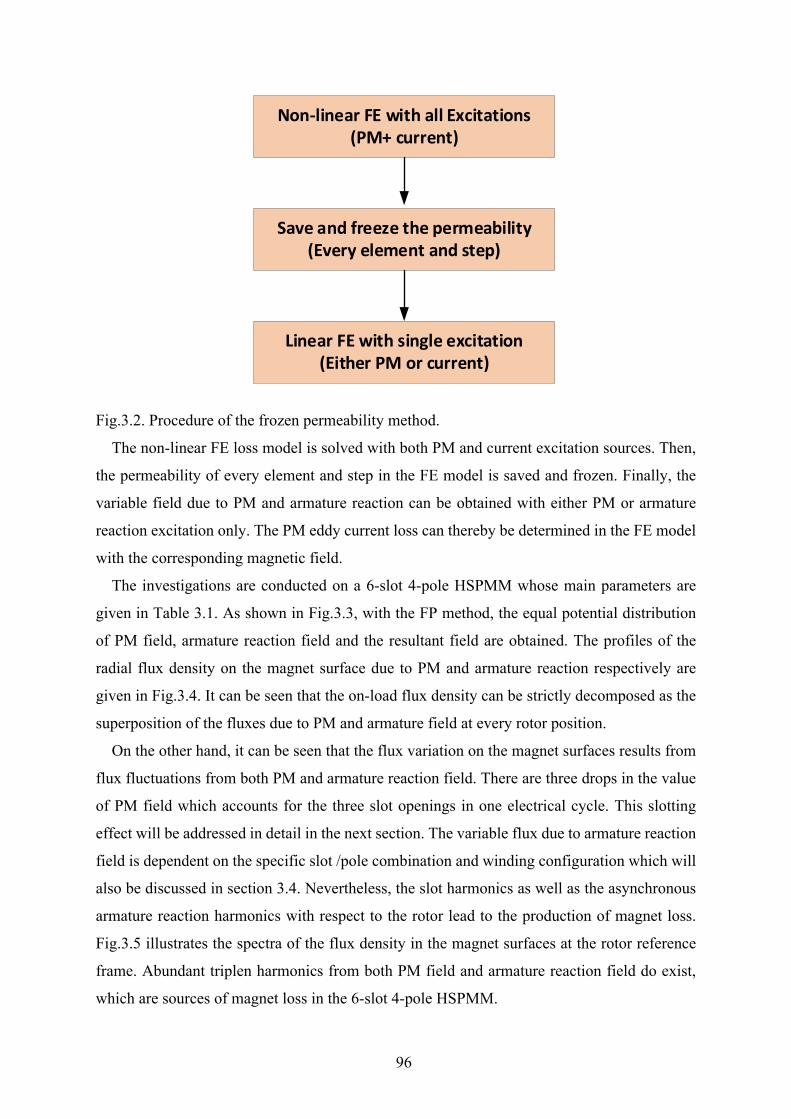
96
Fig.3.2. Procedure of the frozen permeability method.
The non-linear FE loss model is solved with both PM and current excitation sources. Then,
the permeability of every element and step in the FE model is saved and frozen. Finally, the
variable field due to PM and armature reaction can be obtained with either PM or armature
reaction excitation only. The PM eddy current loss can thereby be determined in the FE model
with the corresponding magnetic field.
The investigations are conducted on a 6-slot 4-pole HSPMM whose main parameters are
given in Table 3.1. As shown in Fig.3.3, with the FP method, the equal potential distribution
of PM field, armature reaction field and the resultant field are obtained. The profiles of the
radial flux density on the magnet surface due to PM and armature reaction respectively are
given in Fig.3.4. It can be seen that the on-load flux density can be strictly decomposed as the
superposition of the fluxes due to PM and armature field at every rotor position.
On the other hand, it can be seen that the flux variation on the magnet surfaces results from
flux fluctuations from both PM and armature reaction field. There are three drops in the value
of PM field which accounts for the three slot openings in one electrical cycle. This slotting
effect will be addressed in detail in the next section. The variable flux due to armature reaction
field is dependent on the specific slot /pole combination and winding configuration which will
also be discussed in section 3.4. Nevertheless, the slot harmonics as well as the asynchronous
armature reaction harmonics with respect to the rotor lead to the production of magnet loss.
Fig.3.5 illustrates the spectra of the flux density in the magnet surfaces at the rotor reference
frame. Abundant triplen harmonics from both PM field and armature reaction field do exist,
which are sources of magnet loss in the 6-slot 4-pole HSPMM.
Non-linear FE with all Excitations (PM+ current)
Save and freeze the permeability (Every element and step)
Linear FE with single excitation(Either PM or current)
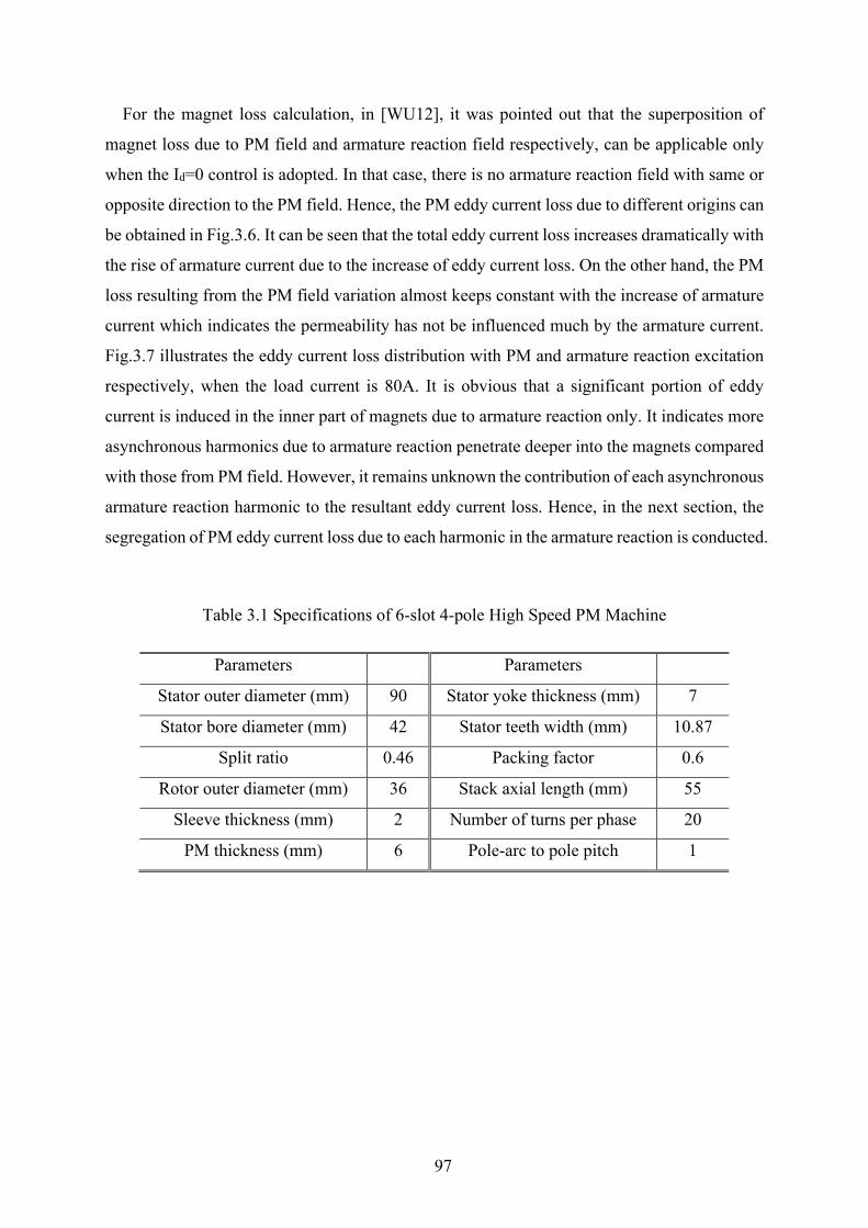
97
For the magnet loss calculation, in [WU12], it was pointed out that the superposition of
magnet loss due to PM field and armature reaction field respectively, can be applicable only
when the Id=0 control is adopted. In that case, there is no armature reaction field with same or
opposite direction to the PM field. Hence, the PM eddy current loss due to different origins can
be obtained in Fig.3.6. It can be seen that the total eddy current loss increases dramatically with
the rise of armature current due to the increase of eddy current loss. On the other hand, the PM
loss resulting from the PM field variation almost keeps constant with the increase of armature
current which indicates the permeability has not be influenced much by the armature current.
Fig.3.7 illustrates the eddy current loss distribution with PM and armature reaction excitation
respectively, when the load current is 80A. It is obvious that a significant portion of eddy
current is induced in the inner part of magnets due to armature reaction only. It indicates more
asynchronous harmonics due to armature reaction penetrate deeper into the magnets compared
with those from PM field. However, it remains unknown the contribution of each asynchronous
armature reaction harmonic to the resultant eddy current loss. Hence, in the next section, the
segregation of PM eddy current loss due to each harmonic in the armature reaction is conducted.
Table 3.1 Specifications of 6-slot 4-pole High Speed PM Machine
Parameters Parameters
Stator outer diameter (mm) 90 Stator yoke thickness (mm) 7
Stator bore diameter (mm) 42 Stator teeth width (mm) 10.87
Split ratio 0.46 Packing factor 0.6
Rotor outer diameter (mm) 36 Stack axial length (mm) 55
Sleeve thickness (mm) 2 Number of turns per phase 20
PM thickness (mm) 6 Pole-arc to pole pitch 1

98
(a)
(b)
(c)
Fig.3.3. Equal potential distribution of HSPMM (Ia=80A). (a) PM field. (b) Armature reaction field. (c) Resultant field.
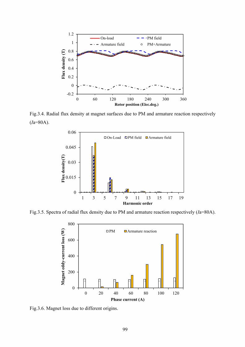
99
Fig.3.4. Radial flux density at magnet surfaces due to PM and armature reaction respectively
(Ia=80A).
Fig.3.5. Spectra of radial flux density due to PM and armature reaction respectively (Ia=80A).
Fig.3.6. Magnet loss due to different origins.
-0.2
0
0.2
0.4
0.6
0.8
1
1.2
0 60 120 180 240 300 360
Flux
den
sity
(T)
Rotor position (Elec.deg.)
On-load PM fieldArmature field PM+Armature
0
0.015
0.03
0.045
0.06
1 3 5 7 9 11 13 15 17 19
Flux
den
sity
(T)
Harmonic order
On-Load PM field Armature field
0
200
400
600
800
0 20 40 60 80 100 120
Mag
net e
ddy-
curr
ent l
oss (
W)
Phase current (A)
PM Armature reaction
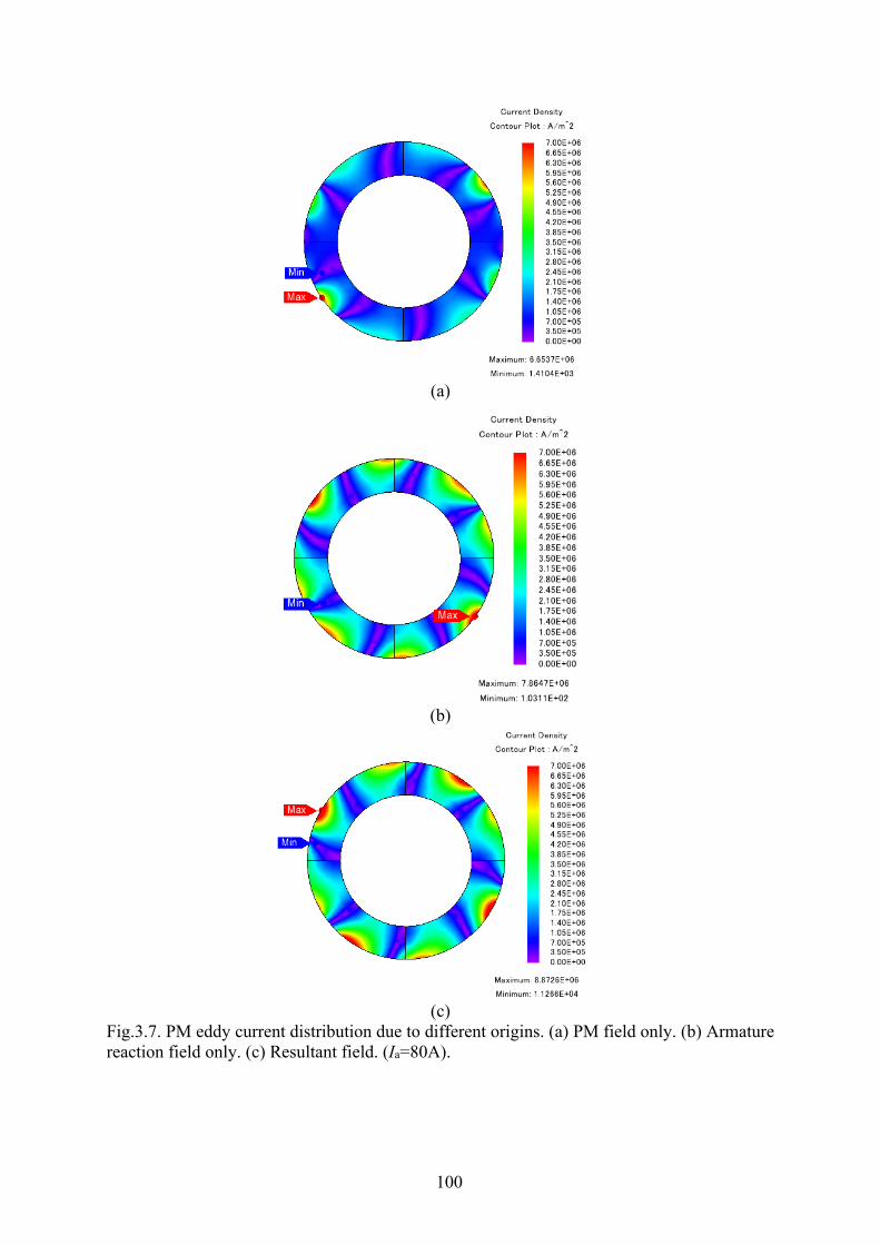
100
(a)
(b)
(c)
Fig.3.7. PM eddy current distribution due to different origins. (a) PM field only. (b) Armature reaction field only. (c) Resultant field. (Ia=80A).
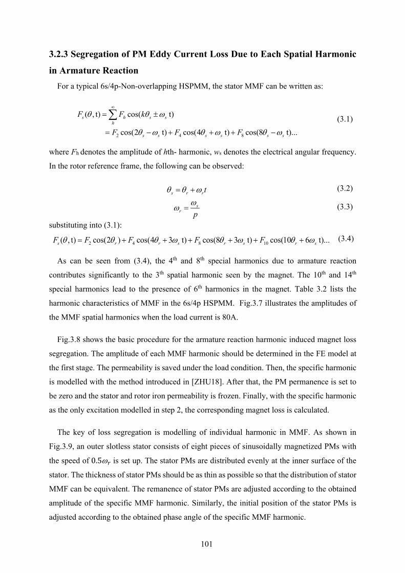
101
3.2.3 Segregation of PM Eddy Current Loss Due to Each Spatial Harmonic
in Armature Reaction For a typical 6s/4p-Non-overlapping HSPMM, the stator MMF can be written as:
2 4 8
( , t) cos( t)
cos(2 t) cos(4 t) cos(8 t)...
s h s sh
s s s s s s
F F k
F F F
θ θ ω
θ ω θ ω θ ω
∞
= ±
= − + + + −
∑ (3.1)
where Fh denotes the amplitude of hth- harmonic, ws denotes the electrical angular frequency.
In the rotor reference frame, the following can be observed:
s r rtθ θ ω= + (3.2)
sr p
ωω = (3.3)
substituting into (3.1):
2 4 8 10( , t) cos(2 ) cos(4 3 t) cos(8 3 t) cos(10 6 t)...s r r s r s r sF F F F Fθ θ θ ω θ ω θ ω= + + + + + + (3.4)
As can be seen from (3.4), the 4th and 8th special harmonics due to armature reaction
contributes significantly to the 3th spatial harmonic seen by the magnet. The 10th and 14th
special harmonics lead to the presence of 6th harmonics in the magnet. Table 3.2 lists the
harmonic characteristics of MMF in the 6s/4p HSPMM. Fig.3.7 illustrates the amplitudes of
the MMF spatial harmonics when the load current is 80A.
Fig.3.8 shows the basic procedure for the armature reaction harmonic induced magnet loss
segregation. The amplitude of each MMF harmonic should be determined in the FE model at
the first stage. The permeability is saved under the load condition. Then, the specific harmonic
is modelled with the method introduced in [ZHU18]. After that, the PM permanence is set to
be zero and the stator and rotor iron permeability is frozen. Finally, with the specific harmonic
as the only excitation modelled in step 2, the corresponding magnet loss is calculated.
The key of loss segregation is modelling of individual harmonic in MMF. As shown in
Fig.3.9, an outer slotless stator consists of eight pieces of sinusoidally magnetized PMs with
the speed of 0.5ω𝑝𝑝 is set up. The stator PMs are distributed evenly at the inner surface of the
stator. The thickness of stator PMs should be as thin as possible so that the distribution of stator
MMF can be equivalent. The remanence of stator PMs are adjusted according to the obtained
amplitude of the specific MMF harmonic. Similarly, the initial position of the stator PMs is
adjusted according to the obtained phase angle of the specific MMF harmonic.
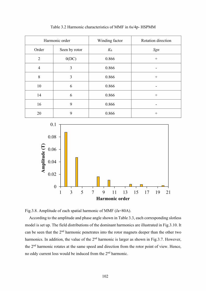
102
Table 3.2 Harmonic characteristics of MMF in 6s/4p- HSPMM
Harmonic order Winding factor Rotation direction
Order Seen by rotor Kh Sgn
2 0(DC) 0.866 +
4 3 0.866 -
8 3 0.866 +
10 6 0.866 -
14 6 0.866 +
16 9 0.866 -
20 9 0.866 +
Fig.3.8. Amplitude of each spatial harmonic of MMF (Ia=80A).
According to the amplitude and phase angle shown in Table 3.3, each corresponding slotless
model is set up. The field distributions of the dominant harmonics are illustrated in Fig.3.10. It
can be seen that the 2nd harmonic penetrates into the rotor magnets deeper than the other two
harmonics. In addition, the value of the 2nd harmonic is larger as shown in Fig.3.7. However,
the 2nd harmonic rotates at the same speed and direction from the rotor point of view. Hence,
no eddy current loss would be induced from the 2nd harmonic.
0
0.02
0.04
0.06
0.08
0.1
1 3 5 7 9 11 13 15 17 19 21
Am
plitu
de (T
)
Harmonic order
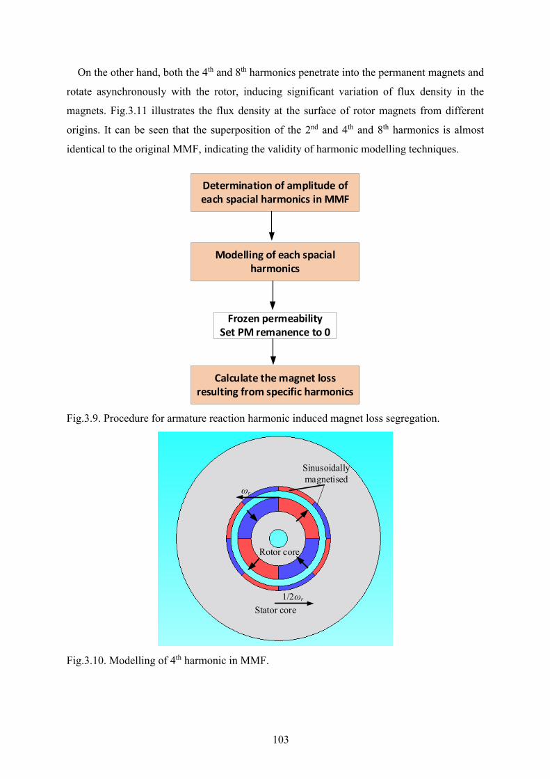
103
On the other hand, both the 4th and 8th harmonics penetrate into the permanent magnets and
rotate asynchronously with the rotor, inducing significant variation of flux density in the
magnets. Fig.3.11 illustrates the flux density at the surface of rotor magnets from different
origins. It can be seen that the superposition of the 2nd and 4th and 8th harmonics is almost
identical to the original MMF, indicating the validity of harmonic modelling techniques.
Fig.3.9. Procedure for armature reaction harmonic induced magnet loss segregation.
Fig.3.10. Modelling of 4th harmonic in MMF.
Determination of amplitude of each spacial harmonics in MMF
Modelling of each spacial harmonics
Frozen permeability Set PM remanence to 0
Calculate the magnet loss resulting from specific harmonics
Sinusoidally magnetised
Stator core
Rotor core
1/2ωr
ωr
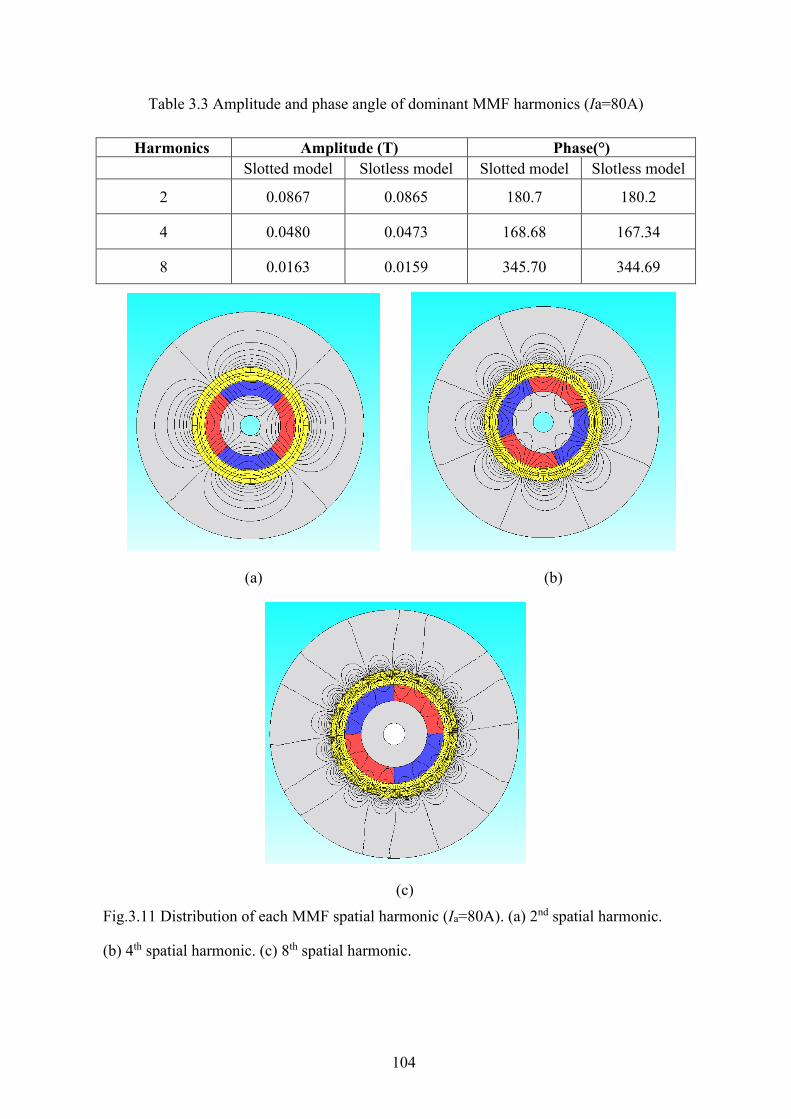
104
Table 3.3 Amplitude and phase angle of dominant MMF harmonics (Ia=80A)
Harmonics Amplitude (T) Phase(°) Slotted model Slotless model Slotted model Slotless model
2 0.0867 0.0865 180.7 180.2
4 0.0480 0.0473 168.68 167.34
8 0.0163 0.0159 345.70 344.69
(a) (b)
(c) Fig.3.11 Distribution of each MMF spatial harmonic (Ia=80A). (a) 2nd spatial harmonic.
(b) 4th spatial harmonic. (c) 8th spatial harmonic.
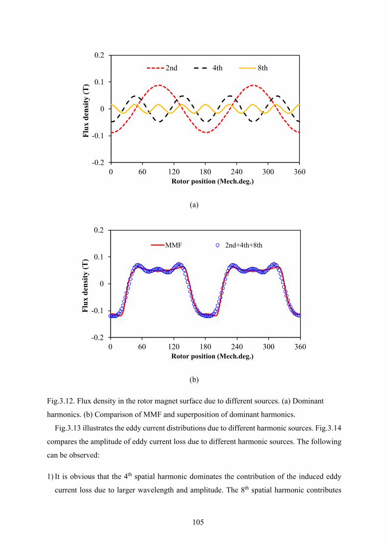
105
(a)
(b)
Fig.3.12. Flux density in the rotor magnet surface due to different sources. (a) Dominant
harmonics. (b) Comparison of MMF and superposition of dominant harmonics.
Fig.3.13 illustrates the eddy current distributions due to different harmonic sources. Fig.3.14
compares the amplitude of eddy current loss due to different harmonic sources. The following
can be observed:
1) It is obvious that the 4th spatial harmonic dominates the contribution of the induced eddy
current loss due to larger wavelength and amplitude. The 8th spatial harmonic contributes
-0.2
-0.1
0
0.1
0.2
0 60 120 180 240 300 360
Flux
den
sity
(T)
Rotor position (Mech.deg.)
2nd 4th 8th
-0.2
-0.1
0
0.1
0.2
0 60 120 180 240 300 360
Flux
den
sity
(T)
Rotor position (Mech.deg.)
MMF 2nd+4th+8th
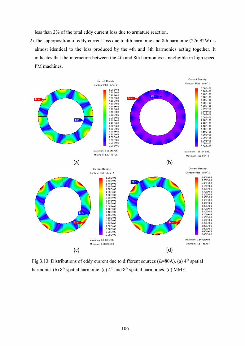
106
less than 2% of the total eddy current loss due to armature reaction.
2) The superposition of eddy current loss due to 4th harmonic and 8th harmonic (276.92W) is
almost identical to the loss produced by the 4th and 8th harmonics acting together. It
indicates that the interaction between the 4th and 8th harmonics is negligible in high speed
PM machines.
(a) (b)
(c) (d)
Fig.3.13. Distributions of eddy current due to different sources (Ia=80A). (a) 4th spatial
harmonic. (b) 8th spatial harmonic. (c) 4th and 8th spatial harmonics. (d) MMF.
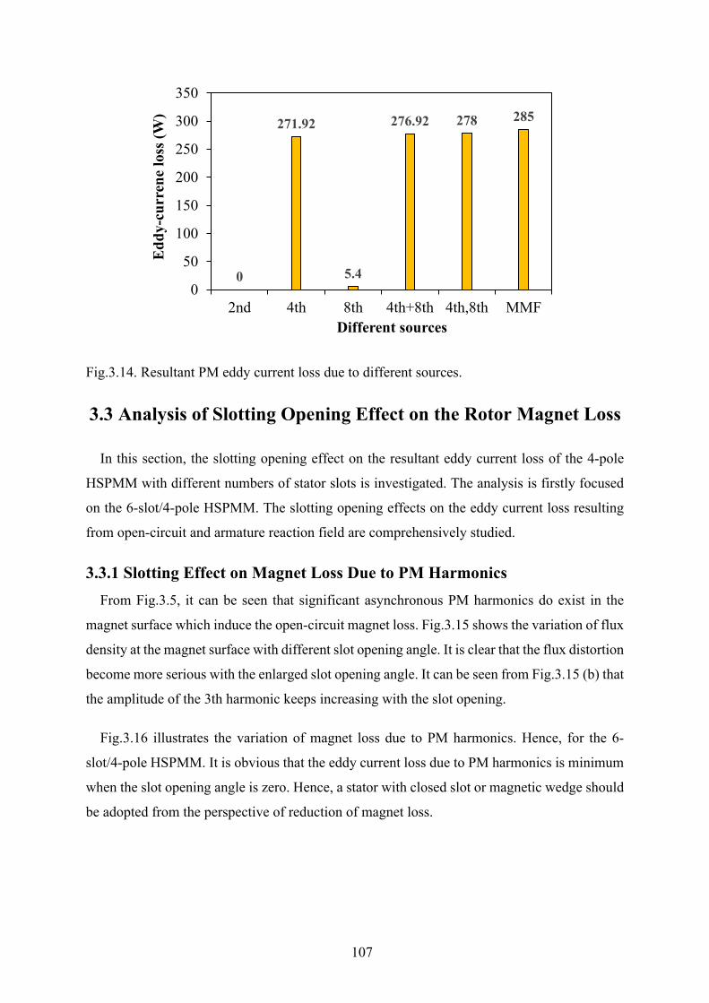
107
Fig.3.14. Resultant PM eddy current loss due to different sources.
3.3 Analysis of Slotting Opening Effect on the Rotor Magnet Loss
In this section, the slotting opening effect on the resultant eddy current loss of the 4-pole
HSPMM with different numbers of stator slots is investigated. The analysis is firstly focused
on the 6-slot/4-pole HSPMM. The slotting opening effects on the eddy current loss resulting
from open-circuit and armature reaction field are comprehensively studied.
3.3.1 Slotting Effect on Magnet Loss Due to PM Harmonics From Fig.3.5, it can be seen that significant asynchronous PM harmonics do exist in the
magnet surface which induce the open-circuit magnet loss. Fig.3.15 shows the variation of flux
density at the magnet surface with different slot opening angle. It is clear that the flux distortion
become more serious with the enlarged slot opening angle. It can be seen from Fig.3.15 (b) that
the amplitude of the 3th harmonic keeps increasing with the slot opening.
Fig.3.16 illustrates the variation of magnet loss due to PM harmonics. Hence, for the 6-
slot/4-pole HSPMM. It is obvious that the eddy current loss due to PM harmonics is minimum
when the slot opening angle is zero. Hence, a stator with closed slot or magnetic wedge should
be adopted from the perspective of reduction of magnet loss.
0
271.92
5.4
276.92 278 285
0
50
100
150
200
250
300
350
2nd 4th 8th 4th+8th 4th,8th MMF
Edd
y-cu
rren
e lo
ss (W
)
Different sources
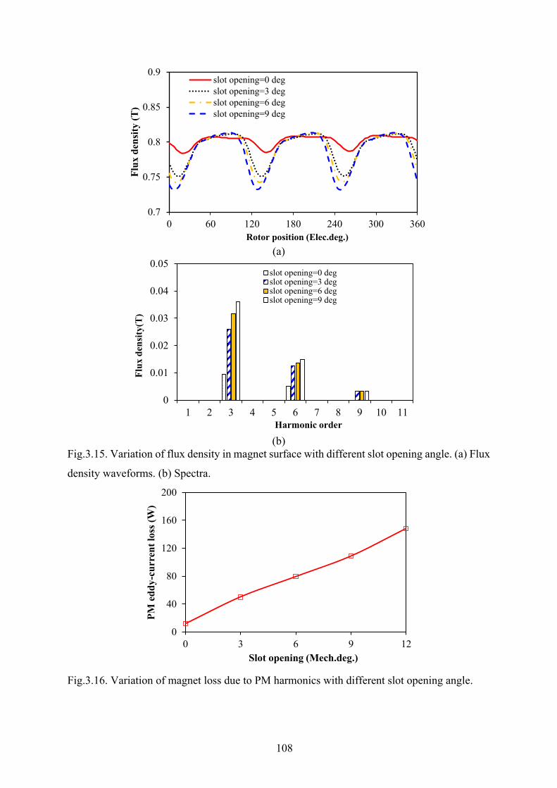
108
(a)
(b)
Fig.3.15. Variation of flux density in magnet surface with different slot opening angle. (a) Flux
density waveforms. (b) Spectra.
Fig.3.16. Variation of magnet loss due to PM harmonics with different slot opening angle.
0.7
0.75
0.8
0.85
0.9
0 60 120 180 240 300 360
Flux
den
sity
(T)
Rotor position (Elec.deg.)
slot opening=0 degslot opening=3 degslot opening=6 degslot opening=9 deg
0
0.01
0.02
0.03
0.04
0.05
1 2 3 4 5 6 7 8 9 10 11
Flux
den
sity
(T)
Harmonic order
slot opening=0 degslot opening=3 degslot opening=6 degslot opening=9 deg
0
40
80
120
160
200
0 3 6 9 12
PM e
ddy-
curr
ent l
oss (
W)
Slot opening (Mech.deg.)
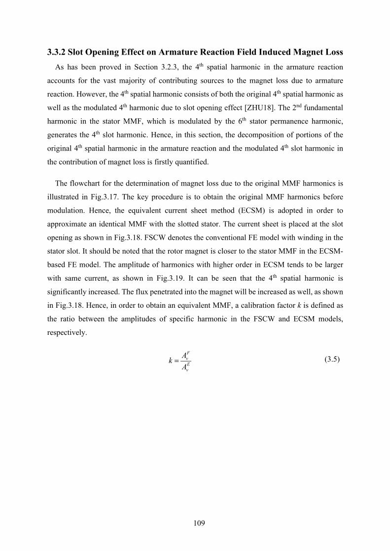
109
3.3.2 Slot Opening Effect on Armature Reaction Field Induced Magnet Loss As has been proved in Section 3.2.3, the 4th spatial harmonic in the armature reaction
accounts for the vast majority of contributing sources to the magnet loss due to armature
reaction. However, the 4th spatial harmonic consists of both the original 4th spatial harmonic as
well as the modulated 4th harmonic due to slot opening effect [ZHU18]. The 2nd fundamental
harmonic in the stator MMF, which is modulated by the 6th stator permanence harmonic,
generates the 4th slot harmonic. Hence, in this section, the decomposition of portions of the
original 4th spatial harmonic in the armature reaction and the modulated 4th slot harmonic in
the contribution of magnet loss is firstly quantified.
The flowchart for the determination of magnet loss due to the original MMF harmonics is
illustrated in Fig.3.17. The key procedure is to obtain the original MMF harmonics before
modulation. Hence, the equivalent current sheet method (ECSM) is adopted in order to
approximate an identical MMF with the slotted stator. The current sheet is placed at the slot
opening as shown in Fig.3.18. FSCW denotes the conventional FE model with winding in the
stator slot. It should be noted that the rotor magnet is closer to the stator MMF in the ECSM-
based FE model. The amplitude of harmonics with higher order in ECSM tends to be larger
with same current, as shown in Fig.3.19. It can be seen that the 4th spatial harmonic is
significantly increased. The flux penetrated into the magnet will be increased as well, as shown
in Fig.3.18. Hence, in order to obtain an equivalent MMF, a calibration factor k is defined as
the ratio between the amplitudes of specific harmonic in the FSCW and ECSM models,
respectively.
FvEv
AkA
= (3.5)

110
Fig.3.17. Flowchart for the determination of magnet loss due to original MMF harmonics.
Step.1 FSCW-Ia=Irated
Step.2 MMF-FSCW-Ia=Irated
Obtain MMF with FP method
Step.3 ECSM-Ia=k*IratedModelling a equivalent MMF
Step.4 Slotless-ECSMObtain spatial harmonics before modulation
Step.5 Modelling specific harmonics
Step.6 Obtain loss in slotted model
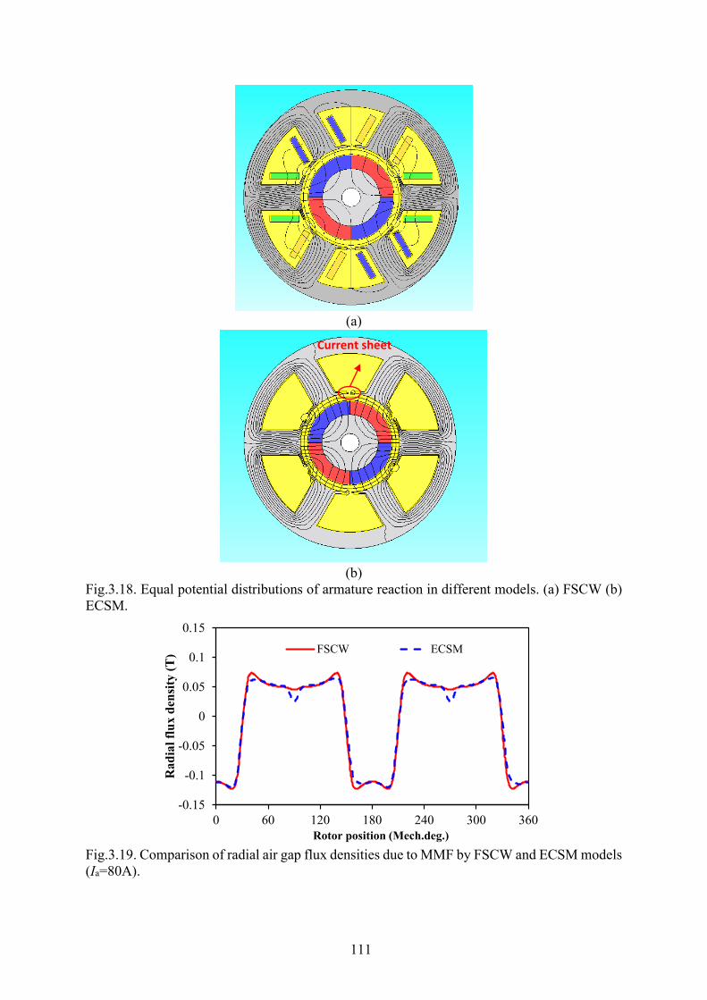
111
(a)
(b)
Fig.3.18. Equal potential distributions of armature reaction in different models. (a) FSCW (b) ECSM.
Fig.3.19. Comparison of radial air gap flux densities due to MMF by FSCW and ECSM models (Ia=80A).
-0.15
-0.1
-0.05
0
0.05
0.1
0.15
0 60 120 180 240 300 360
Rad
ial f
lux
dens
ity (T
)
Rotor position (Mech.deg.)
FSCW ECSM
Current sheet
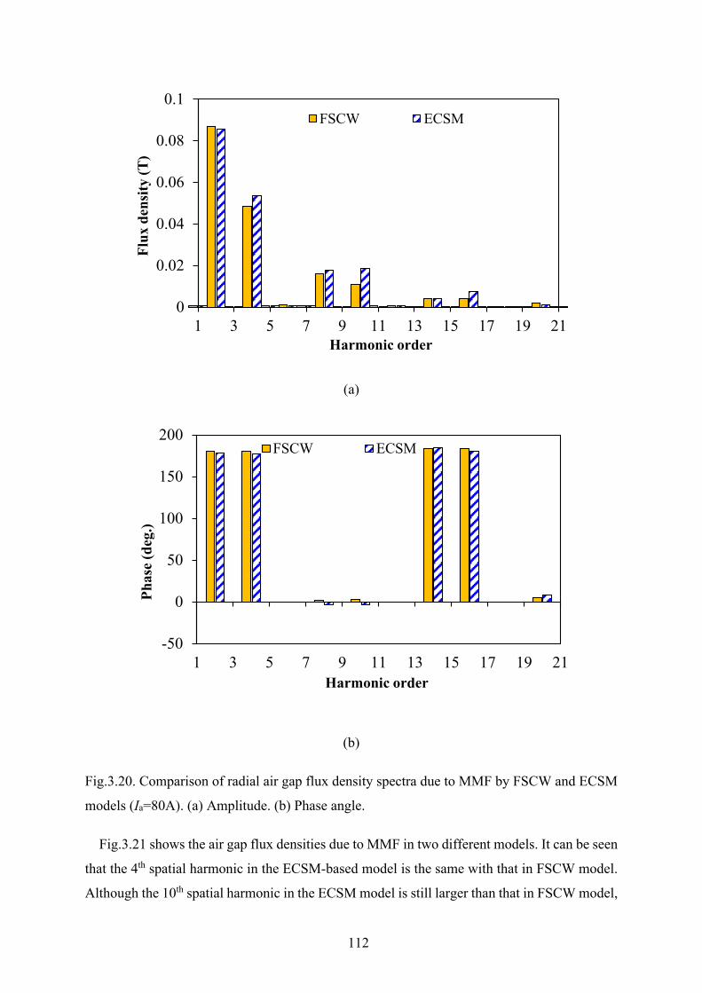
112
(a)
(b)
Fig.3.20. Comparison of radial air gap flux density spectra due to MMF by FSCW and ECSM
models (Ia=80A). (a) Amplitude. (b) Phase angle.
Fig.3.21 shows the air gap flux densities due to MMF in two different models. It can be seen
that the 4th spatial harmonic in the ECSM-based model is the same with that in FSCW model.
Although the 10th spatial harmonic in the ECSM model is still larger than that in FSCW model,
0
0.02
0.04
0.06
0.08
0.1
1 3 5 7 9 11 13 15 17 19 21
Flux
den
sity
(T)
Harmonic order
FSCW ECSM
-50
0
50
100
150
200
1 3 5 7 9 11 13 15 17 19 21
Phas
e (d
eg.)
Harmonic order
FSCW ECSM
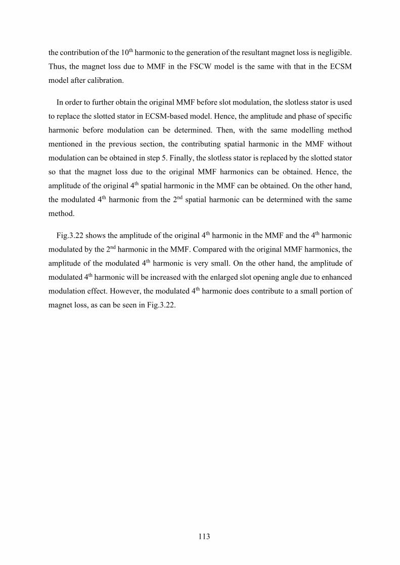
113
the contribution of the 10th harmonic to the generation of the resultant magnet loss is negligible.
Thus, the magnet loss due to MMF in the FSCW model is the same with that in the ECSM
model after calibration.
In order to further obtain the original MMF before slot modulation, the slotless stator is used
to replace the slotted stator in ECSM-based model. Hence, the amplitude and phase of specific
harmonic before modulation can be determined. Then, with the same modelling method
mentioned in the previous section, the contributing spatial harmonic in the MMF without
modulation can be obtained in step 5. Finally, the slotless stator is replaced by the slotted stator
so that the magnet loss due to the original MMF harmonics can be obtained. Hence, the
amplitude of the original 4th spatial harmonic in the MMF can be obtained. On the other hand,
the modulated 4th harmonic from the 2nd spatial harmonic can be determined with the same
method.
Fig.3.22 shows the amplitude of the original 4th harmonic in the MMF and the 4th harmonic
modulated by the 2nd harmonic in the MMF. Compared with the original MMF harmonics, the
amplitude of the modulated 4th harmonic is very small. On the other hand, the amplitude of
modulated 4th harmonic will be increased with the enlarged slot opening angle due to enhanced
modulation effect. However, the modulated 4th harmonic does contribute to a small portion of
magnet loss, as can be seen in Fig.3.22.
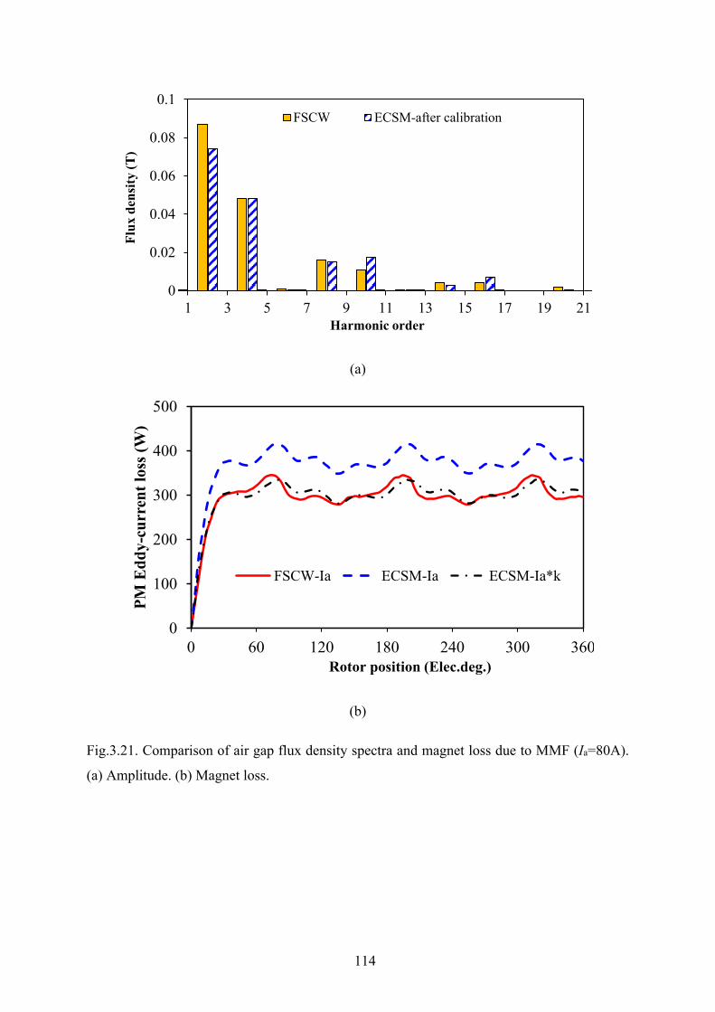
114
(a)
(b)
Fig.3.21. Comparison of air gap flux density spectra and magnet loss due to MMF (Ia=80A).
(a) Amplitude. (b) Magnet loss.
0
0.02
0.04
0.06
0.08
0.1
1 3 5 7 9 11 13 15 17 19 21
Flux
den
sity
(T)
Harmonic order
FSCW ECSM-after calibration
0
100
200
300
400
500
0 60 120 180 240 300 360
PM E
ddy-
curr
ent l
oss (
W)
Rotor position (Elec.deg.)
FSCW-Ia ECSM-Ia ECSM-Ia*k
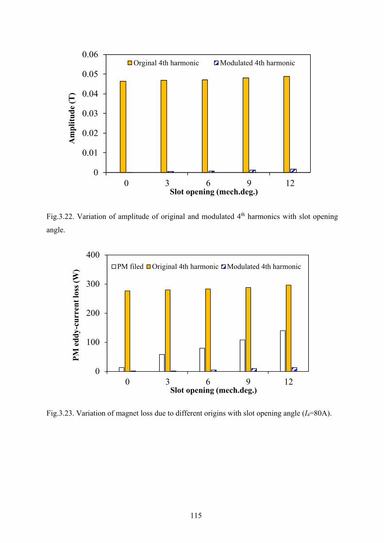
115
Fig.3.22. Variation of amplitude of original and modulated 4th harmonics with slot opening
angle.
Fig.3.23. Variation of magnet loss due to different origins with slot opening angle (Ia=80A).
0
0.01
0.02
0.03
0.04
0.05
0.06
0 3 6 9 12
Am
plitu
de (T
)
Slot opening (mech.deg.)
Orginal 4th harmonic Modulated 4th harmonic
0
100
200
300
400
0 3 6 9 12
PM e
ddy-
curr
ent l
oss (
W)
Slot opening (mech.deg.)
PM filed Original 4th harmonic Modulated 4th harmonic
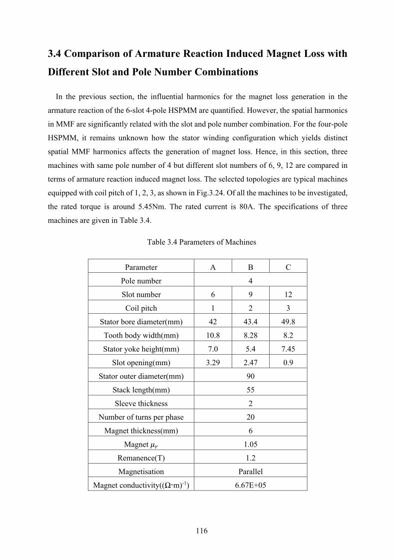
116
3.4 Comparison of Armature Reaction Induced Magnet Loss with
Different Slot and Pole Number Combinations
In the previous section, the influential harmonics for the magnet loss generation in the
armature reaction of the 6-slot 4-pole HSPMM are quantified. However, the spatial harmonics
in MMF are significantly related with the slot and pole number combination. For the four-pole
HSPMM, it remains unknown how the stator winding configuration which yields distinct
spatial MMF harmonics affects the generation of magnet loss. Hence, in this section, three
machines with same pole number of 4 but different slot numbers of 6, 9, 12 are compared in
terms of armature reaction induced magnet loss. The selected topologies are typical machines
equipped with coil pitch of 1, 2, 3, as shown in Fig.3.24. Of all the machines to be investigated,
the rated torque is around 5.45Nm. The rated current is 80A. The specifications of three
machines are given in Table 3.4.
Table 3.4 Parameters of Machines
Parameter A B C
Pole number 4
Slot number 6 9 12
Coil pitch 1 2 3
Stator bore diameter(mm) 42 43.4 49.8
Tooth body width(mm) 10.8 8.28 8.2
Stator yoke height(mm) 7.0 5.4 7.45
Slot opening(mm) 3.29 2.47 0.9
Stator outer diameter(mm) 90
Stack length(mm) 55
Sleeve thickness 2
Number of turns per phase 20
Magnet thickness(mm) 6
Magnet 𝜇𝜇𝑝𝑝 1.05
Remanence(T) 1.2
Magnetisation Parallel
Magnet conductivity((Ωm)-1) 6.67E+05
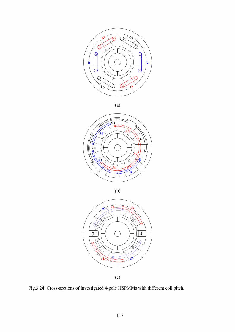
117
(a)
(b)
(c)
Fig.3.24. Cross-sections of investigated 4-pole HSPMMs with different coil pitch.
B1 B
2
A1
A2
A3B1
B2
B3
C1
C2
C3
C1 C
2

118
Fig.3.25 illustrates the variation of magnet loss due to MMF with phase current for three
machines. It can be observed that the armature reaction induced magnet loss in the 6-slot 4-
pole HSPMM is the maximum of all. On the other hand, the HSPMM with 12-slot/4-pole and
full pitched winding shows distinct advantages in maintaining a lower magnet loss. In order to
further explain this phenomenon, each contributing harmonic in the MMF of three machines
should be determined with the proposed loss segregation method in Section 3.2.3. Thus, in this
section, the amplitude of each spatial harmonic is firstly identified. Then, the contribution of
each harmonic to the magnet loss can be further determined. For comparison of three machines,
it is essential to identify the characteristics of the inherent MMF. Then, the harmonics which
actually account for the generation of magnet loss can be compared. The low-order pass filter
effect of air gap and magnet is therefore revealed.
In [WU12], it was pointed out that the amplitude of spatial harmonics is dependent on both
the winding factor and the harmonic order. For the 6-slot/4-pole and 12-slot/4-pole HSPMMs,
the winding factors for all the feasible harmonics are 0.866 and 1, respectively. For the 9-slot
4-pole HSPMM, only the fundamental spatial harmonic and slot harmonics, such as the 7th
harmonic and the 11th harmonic, have a relatively higher winding factor of 0.945. That explains
why the amplitude of sub-harmonic is smaller than the 7th harmonic in the 9-slot 4-pole
HSPMM.
Fig.3.25. Variation of magnet loss due to MMF with phase current.
0
200
400
600
800
0 20 40 60 80 100 120
Mag
net l
oss d
ue to
MM
F (W
)
Phase current (A)
6-slot 4-pole 9-slot 4-pole 12-slot 4-pole
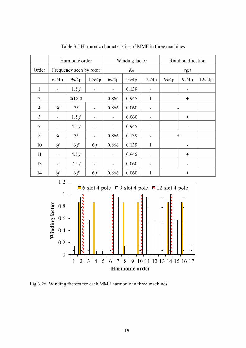
119
Fig.3.26. Winding factors for each MMF harmonic in three machines.
0
0.2
0.4
0.6
0.8
1
1.2
1 2 3 4 5 6 7 8 9 10 11 12 13 14 15 16 17
Win
ding
fact
or
Harmonic order
6-slot 4-pole 9-slot 4-pole 12-slot 4-pole
Table 3.5 Harmonic characteristics of MMF in three machines
Harmonic order Winding factor Rotation direction
Order Frequency seen by rotor Kw sgn
6s/4p 9s/4p 12s/4p 6s/4p 9s/4p 12s/4p 6s/4p 9s/4p 12s/4p
1 - 1.5 f - - 0.139 - -
2 0(DC) 0.866 0.945 1 +
4 3f 3f - 0.866 0.060 - -
5 - 1.5 f - - 0.060 - +
7 - 4.5 f - - 0.945 - -
8 3f 3f - 0.866 0.139 - +
10 6f 6 f 6 f 0.866 0.139 1 -
11 - 4.5 f - - 0.945 - +
13 - 7.5 f - - 0.060 - -
14 6f 6 f 6 f 0.866 0.060 1 +
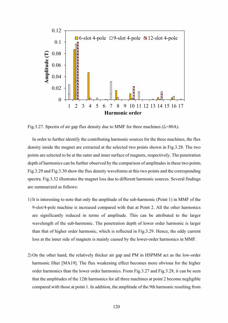
120
Fig.3.27. Spectra of air gap flux density due to MMF for three machines (Ia=80A).
In order to further identify the contributing harmonic sources for the three machines, the flux
density inside the magnet are extracted at the selected two points shown in Fig.3.28. The two
points are selected to be at the outer and inner surface of magnets, respectively. The penetration
depth of harmonics can be further observed by the comparison of amplitudes in these two points.
Fig.3.29 and Fig.3.30 show the flux density waveforms at this two points and the corresponding
spectra. Fig.3.32 illustrates the magnet loss due to different harmonic sources. Several findings
are summarized as follows:
1) It is interesting to note that only the amplitude of the sub-harmonic (Point 1) in MMF of the
9-slot/4-pole machine is increased compared with that at Point 2. All the other harmonics
are significantly reduced in terms of amplitude. This can be attributed to the larger
wavelength of the sub-harmonic. The penetration depth of lower order harmonic is larger
than that of higher order harmonic, which is reflected in Fig.3.29. Hence, the eddy current
loss at the inner side of magnets is mainly caused by the lower-order harmonics in MMF.
2) On the other hand, the relatively thicker air gap and PM in HSPMM act as the low-order
harmonic filter [MA19]. The flux weakening effect becomes more obvious for the higher
order harmonics than the lower order harmonics. From Fig.3.27 and Fig.3.28, it can be seen
that the amplitudes of the 12th harmonics for all three machines at point 2 become negligible
compared with those at point 1. In addition, the amplitude of the 9th harmonic resulting from
0
0.02
0.04
0.06
0.08
0.1
0.12
1 2 3 4 5 6 7 8 9 10 11 12 13 14 15 16 17
Am
plitu
de (T
)
Harmonic order
6-slot 4-pole 9-slot 4-pole 12-slot 4-pole
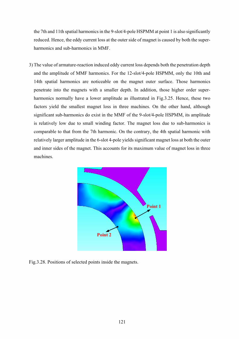
121
the 7th and 11th spatial harmonics in the 9-slot/4-pole HSPMM at point 1 is also significantly
reduced. Hence, the eddy current loss at the outer side of magnet is caused by both the super-
harmonics and sub-harmonics in MMF.
3) The value of armature-reaction induced eddy current loss depends both the penetration depth
and the amplitude of MMF harmonics. For the 12-slot/4-pole HSPMM, only the 10th and
14th spatial harmonics are noticeable on the magnet outer surface. Those harmonics
penetrate into the magnets with a smaller depth. In addition, those higher order super-
harmonics normally have a lower amplitude as illustrated in Fig.3.25. Hence, these two
factors yield the smallest magnet loss in three machines. On the other hand, although
significant sub-harmonics do exist in the MMF of the 9-slot/4-pole HSPMM, its amplitude
is relatively low due to small winding factor. The magnet loss due to sub-harmonics is
comparable to that from the 7th harmonic. On the contrary, the 4th spatial harmonic with
relatively larger amplitude in the 6-slot 4-pole yields significant magnet loss at both the outer
and inner sides of the magnet. This accounts for its maximum value of magnet loss in three
machines.
Fig.3.28. Positions of selected points inside the magnets.
Point 1
Point 2
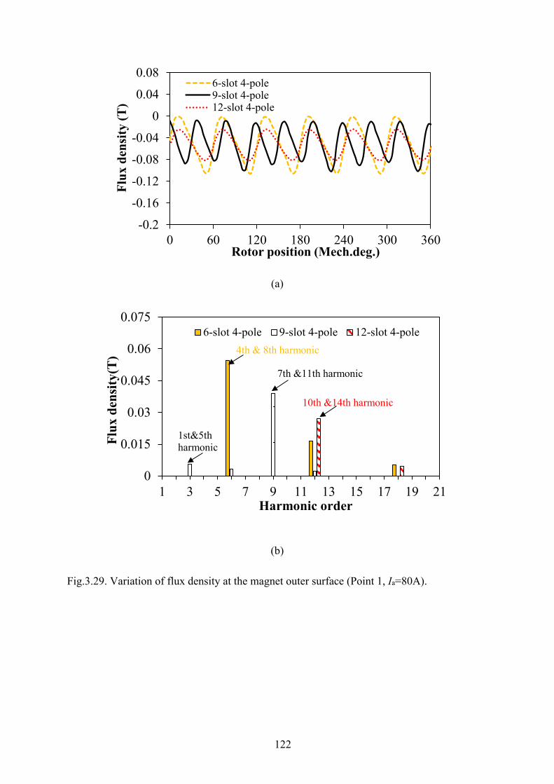
122
(a)
(b)
Fig.3.29. Variation of flux density at the magnet outer surface (Point 1, Ia=80A).
-0.2
-0.16
-0.12
-0.08
-0.04
0
0.04
0.08
0 60 120 180 240 300 360
Flux
den
sity
(T)
Rotor position (Mech.deg.)
6-slot 4-pole9-slot 4-pole12-slot 4-pole
0
0.015
0.03
0.045
0.06
0.075
1 3 5 7 9 11 13 15 17 19 21
Flux
den
sity
(T)
Harmonic order
6-slot 4-pole 9-slot 4-pole 12-slot 4-pole
7th &11th harmonic
1st&5th harmonic
10th &14th harmonic
4th & 8th harmonic
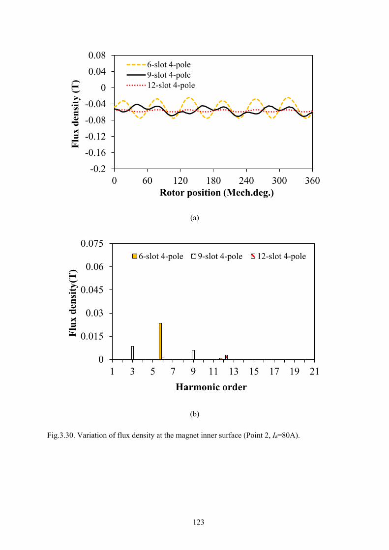
123
(a)
(b)
Fig.3.30. Variation of flux density at the magnet inner surface (Point 2, Ia=80A).
-0.2-0.16-0.12-0.08-0.04
00.040.08
0 60 120 180 240 300 360
Flux
den
sity
(T)
Rotor position (Mech.deg.)
6-slot 4-pole9-slot 4-pole12-slot 4-pole
0
0.015
0.03
0.045
0.06
0.075
1 3 5 7 9 11 13 15 17 19 21
Flux
den
sity
(T)
Harmonic order
6-slot 4-pole 9-slot 4-pole 12-slot 4-pole
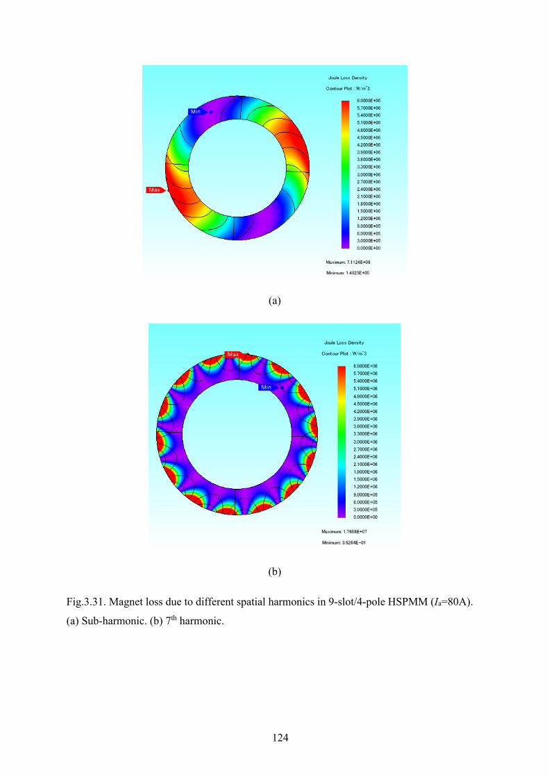
124
(a)
(b)
Fig.3.31. Magnet loss due to different spatial harmonics in 9-slot/4-pole HSPMM (Ia=80A).
(a) Sub-harmonic. (b) 7th harmonic.
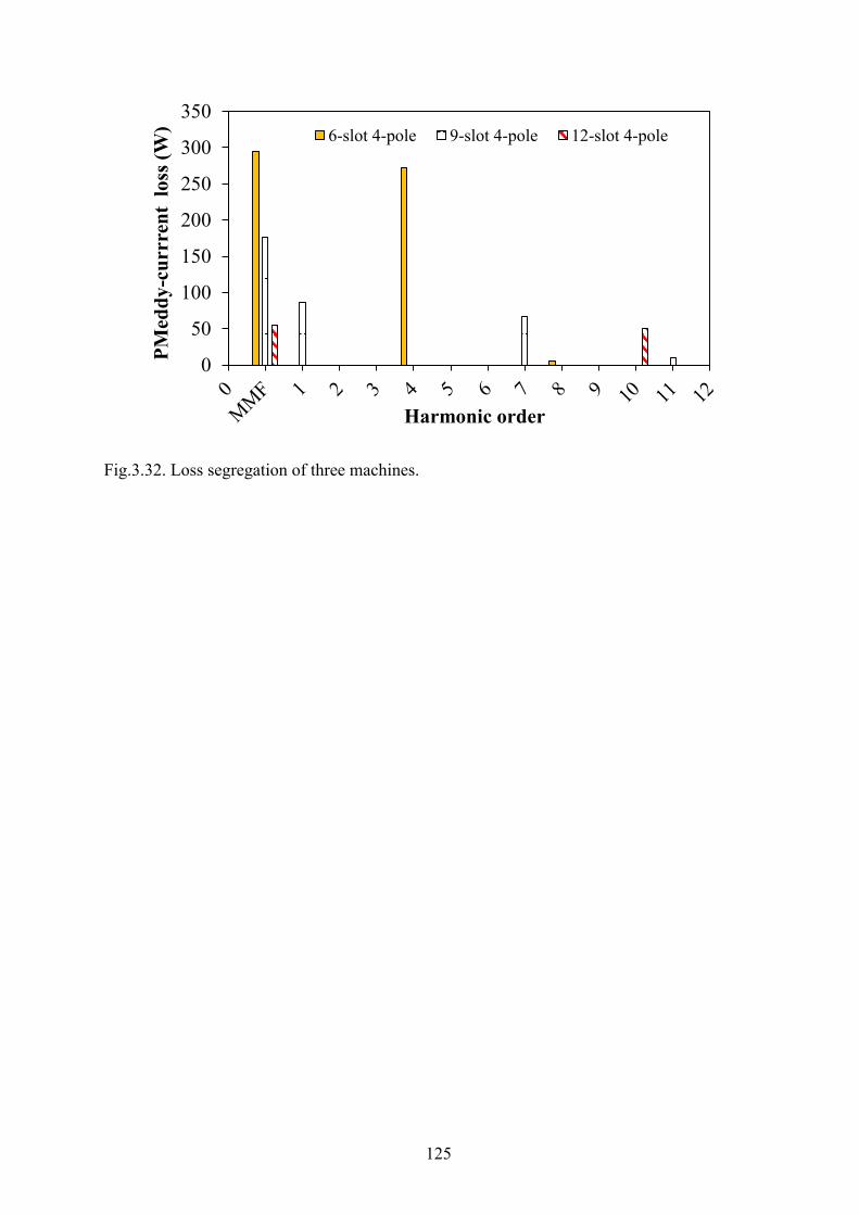
125
Fig.3.32. Loss segregation of three machines.
0
50
100
150
200
250
300
350
PMed
dy-c
urrr
ent
loss
(W)
Harmonic order
6-slot 4-pole 9-slot 4-pole 12-slot 4-pole
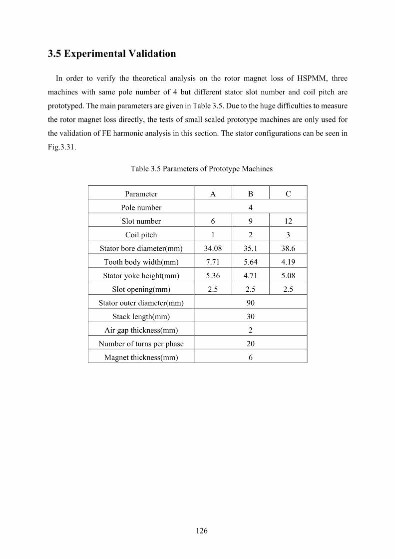
126
3.5 Experimental Validation
In order to verify the theoretical analysis on the rotor magnet loss of HSPMM, three
machines with same pole number of 4 but different stator slot number and coil pitch are
prototyped. The main parameters are given in Table 3.5. Due to the huge difficulties to measure
the rotor magnet loss directly, the tests of small scaled prototype machines are only used for
the validation of FE harmonic analysis in this section. The stator configurations can be seen in
Fig.3.31.
Table 3.5 Parameters of Prototype Machines
Parameter A B C
Pole number 4
Slot number 6 9 12
Coil pitch 1 2 3
Stator bore diameter(mm) 34.08 35.1 38.6
Tooth body width(mm) 7.71 5.64 4.19
Stator yoke height(mm) 5.36 4.71 5.08
Slot opening(mm) 2.5 2.5 2.5
Stator outer diameter(mm) 90
Stack length(mm) 30
Air gap thickness(mm) 2
Number of turns per phase 20
Magnet thickness(mm) 6
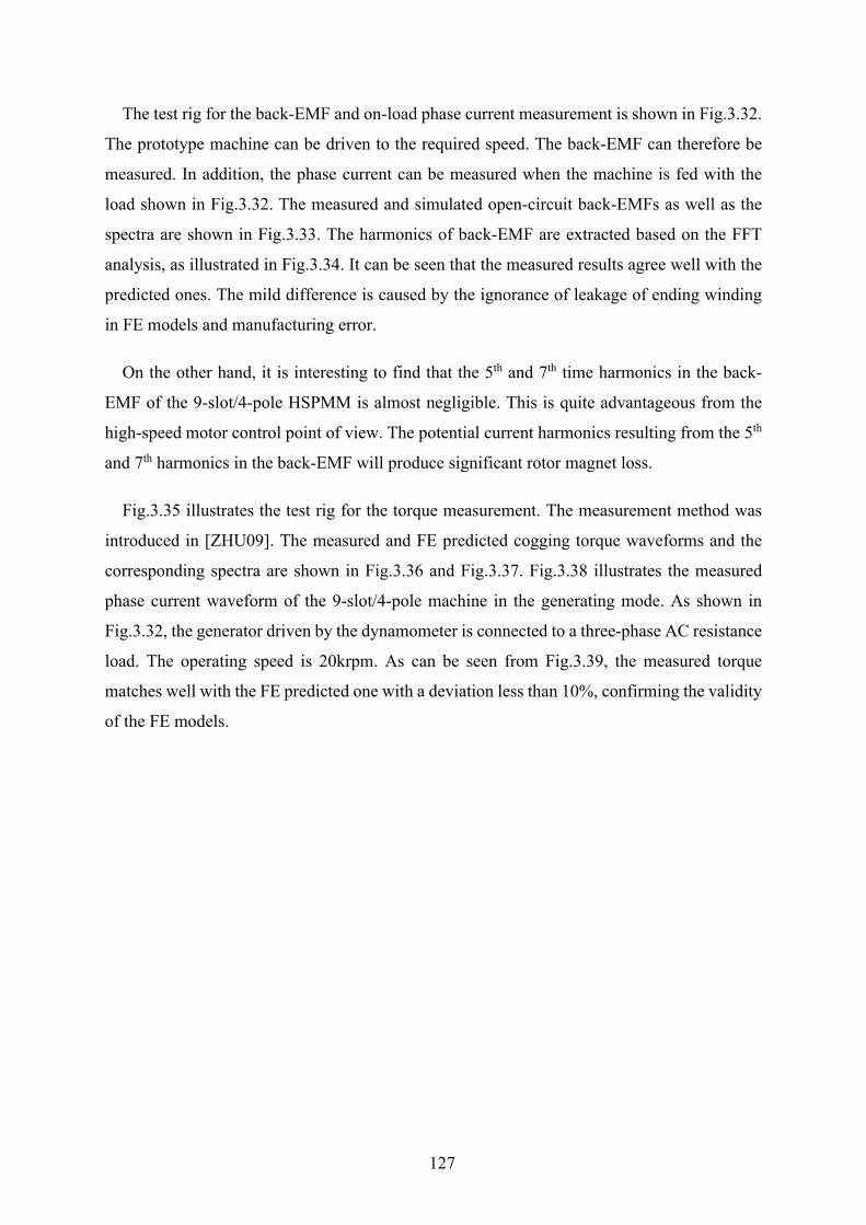
127
The test rig for the back-EMF and on-load phase current measurement is shown in Fig.3.32.
The prototype machine can be driven to the required speed. The back-EMF can therefore be
measured. In addition, the phase current can be measured when the machine is fed with the
load shown in Fig.3.32. The measured and simulated open-circuit back-EMFs as well as the
spectra are shown in Fig.3.33. The harmonics of back-EMF are extracted based on the FFT
analysis, as illustrated in Fig.3.34. It can be seen that the measured results agree well with the
predicted ones. The mild difference is caused by the ignorance of leakage of ending winding
in FE models and manufacturing error.
On the other hand, it is interesting to find that the 5th and 7th time harmonics in the back-
EMF of the 9-slot/4-pole HSPMM is almost negligible. This is quite advantageous from the
high-speed motor control point of view. The potential current harmonics resulting from the 5th
and 7th harmonics in the back-EMF will produce significant rotor magnet loss.
Fig.3.35 illustrates the test rig for the torque measurement. The measurement method was
introduced in [ZHU09]. The measured and FE predicted cogging torque waveforms and the
corresponding spectra are shown in Fig.3.36 and Fig.3.37. Fig.3.38 illustrates the measured
phase current waveform of the 9-slot/4-pole machine in the generating mode. As shown in
Fig.3.32, the generator driven by the dynamometer is connected to a three-phase AC resistance
load. The operating speed is 20krpm. As can be seen from Fig.3.39, the measured torque
matches well with the FE predicted one with a deviation less than 10%, confirming the validity
of the FE models.

128
(a)
(b)
Fig.3.31. Three stators with alternate coil pitch. (a) Coil pitch=1(6-slot/4-pole). (b) Coil
pitch=2 (9-slot/4-pole). (c) Coil pitch=3 (12-slot/4-pole).
1=τ
2=τ
3=τ
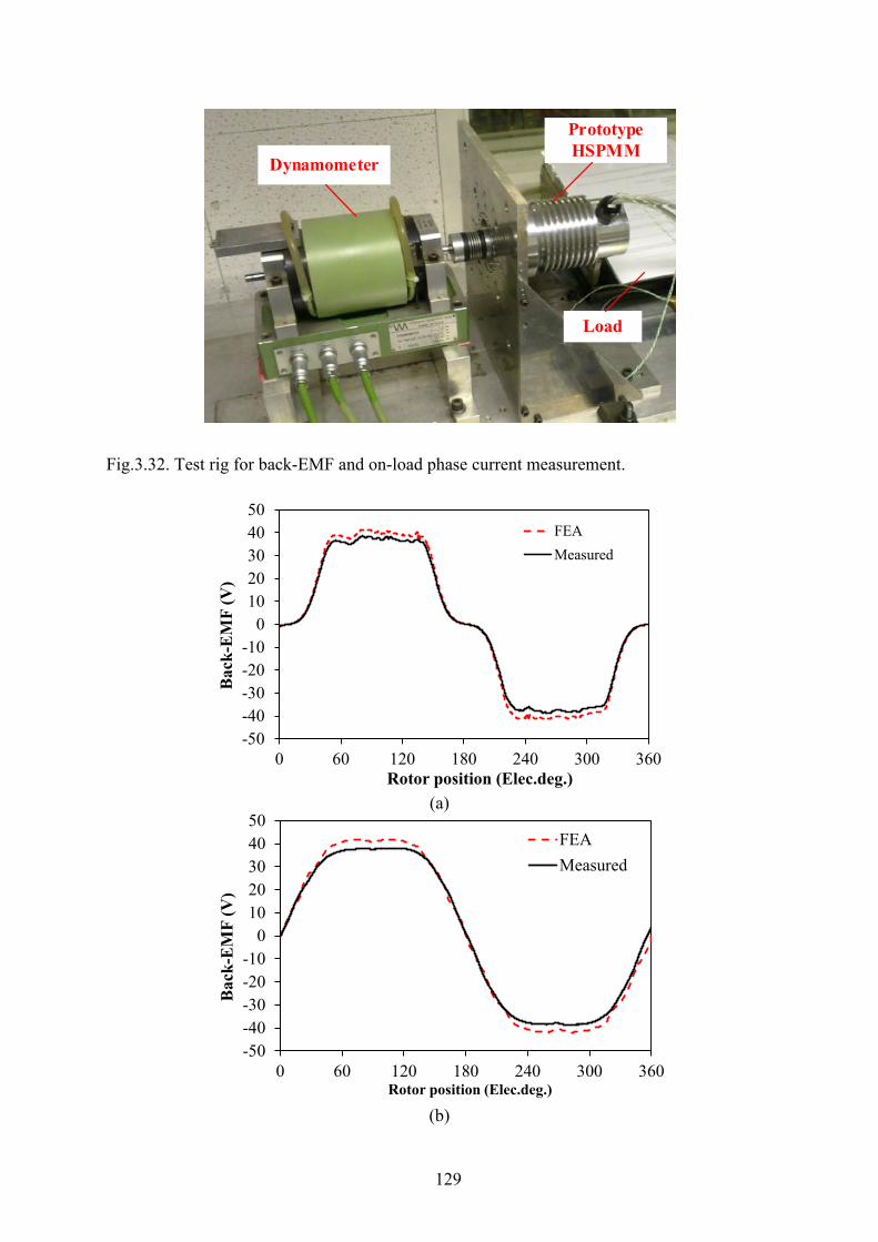
129
Fig.3.32. Test rig for back-EMF and on-load phase current measurement.
(a)
(b)
Dynamometer
Prototype HSPMM
Load
-50-40-30-20-10
01020304050
0 60 120 180 240 300 360
Bac
k-E
MF
(V)
Rotor position (Elec.deg.)
FEAMeasured
-50-40-30-20-10
01020304050
0 60 120 180 240 300 360
Bac
k-E
MF
(V)
Rotor position (Elec.deg.)
FEAMeasured

130
(c)
Fig.3.33. Measured and simulated back-EMF waveforms (n=20000rpm). (a) 6-slot/4-pole
profile. (b) 9-slot/4-pole. (c) 12-slot/4-pole.
(a)
(b)
-60
-40
-20
0
20
40
60
0 60 120 180 240 300 360
Bac
k-E
MF
(V)
Rotor position (Elec.deg.)
FEA
Measured
0
10
20
30
40
50
1 3 5 7 9 11 13 15
Am
plitu
de (V
)
Harmonic order
Measured FEA
0
10
20
30
40
50
1 3 5 7 9 11 13 15
Am
plitu
de (V
)
Harmonic order
Measured FEA

131
(c)
Fig.3.34. Spectra of measured and simulated back-EMF waveforms (20000rpm). (a) 6-slot/4-
pole profile. (b) 9-slot/4-pole. (c) 12-slot/4-pole.
Fig.3.35. Test rig for torque measurement.
0
10
20
30
40
50
60
1 3 5 7 9 11 13 15
Am
plitu
de (V
)
Harmonic order
Measured FEA
Digital gauge
Prototype 4-pole HSPMM
Current source
Weight
Torque arm
Rotor position scale
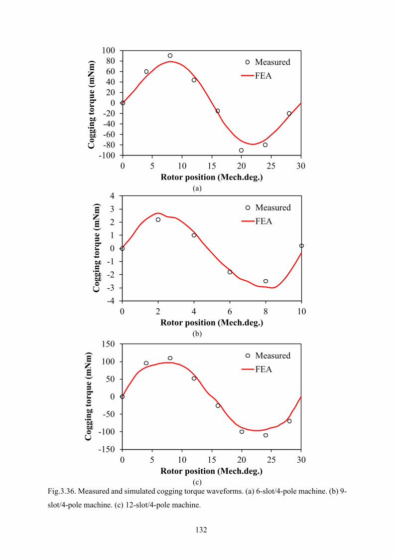
132
(a)
(b)
(c)
Fig.3.36. Measured and simulated cogging torque waveforms. (a) 6-slot/4-pole machine. (b) 9-
slot/4-pole machine. (c) 12-slot/4-pole machine.
-100-80-60-40-20
020406080
100
0 5 10 15 20 25 30
Cog
ging
torq
ue (m
Nm
)
Rotor position (Mech.deg.)
MeasuredFEA
-4-3-2-101234
0 2 4 6 8 10
Cog
ging
torq
ue (m
Nm
)
Rotor position (Mech.deg.)
MeasuredFEA
-150
-100
-50
0
50
100
150
0 5 10 15 20 25 30
Cog
ging
torq
ue (m
Nm
)
Rotor position (Mech.deg.)
MeasuredFEA

133
(a)
(b)
(c)
Fig.3.37. Spectra of measured and simulated cogging torque. (a) 6-slot/4-pole machine. (b) 9-
slot/4-pole machine. (c) 12-slot/4-pole machine.
0
20
40
60
80
100
1 3 5 7 9 11 13 15 17 19
Am
plitu
de (m
Nm
)
Harmonic order
Measured FEA
0
1
2
3
4
1 3 5 7 9 11 13 15 17 19 21 23 25 27 29 31
Am
plitu
de (m
Nm
)
Harmonic order
Measured FEA
0
20
40
60
80
100
120
1 3 5 7 9 11 13 15 17 19
Am
plitu
de (m
Nm
)
Harmonic order
Measured FEA
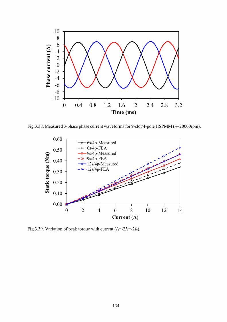
134
Fig.3.38. Measured 3-phase phase current waveforms for 9-slot/4-pole HSPMM (n=20000rpm).
Fig.3.39. Variation of peak torque with current (Ia=-2Ib=-2Ic).
-10-8-6-4-202468
10
0 0.4 0.8 1.2 1.6 2 2.4 2.8 3.2
Phas
e cu
rren
t (A
)
Time (ms)
0.00
0.10
0.20
0.30
0.40
0.50
0.60
0 2 4 6 8 10 12 14
Stat
ic to
rque
(Nm
)
Current (A)
6s/4p-Measured6s/4p-FEA9s/4p-Measured9s/4p-FEA12s/4p-Measured12s/4p-FEA
135
3.6 Summary
In this chapter, the rotor magnet loss analysis is conducted on the 4-pole HSPMM with the
focus on the loss segregation. Firstly, the contribution of PM field and armature reaction field
to the resultant rotor magnet loss of a 6-slot/4-pole HSPMM is determined. It is found that both
the PM field and armature reaction field variation contribute significantly to the production of
magnet loss. The portion of armature reaction-induced rotor magnet loss increases vastly with
load current. Then, each individual MMF harmonics are modelled with a slotless stator
equipped with Halbach magnetized magnets so that their share to generation of the magnet loss
can be quantified. The validity of harmonic superposition principle is also confirmed with the
FE method. It is observed that the 4th spatial harmonic dominates in the production of magnet
loss for the 6-slot/4-pole HSPMM. In addition, the slotting effect on both the PM field-induced
and armature reaction induced magnet losses is revealed. It is found that the open-circuit
magnet loss due to slot opening is significantly increased with the enlarged slot opening angle.
On the other hand, the magnet loss generated by the 4th spatial harmonic due to slot modulation
is almost negligible. The armature reaction induced magnet loss with different stator slot (6, 9,
12) and winding coil pitch (1, 2, 3) is compared as well. It is found that the value of magnet
loss is dependent on both the penetration depth and the amplitude of asynchronous spatial
harmonic, which are determined by the specific slot and pole number combination. Finally,
three 4-pole HSPMMs with different stator slot number and coil pitch are prototyped and tested.
Due to the huge difficulties of direct measurement of magnet loss, only the back-EMF and
electromagnetic torque of three machines are measured. The measured results match well with
the FE predicted ones in terms of both the amplitude and harmonic order of back-EMF and
electromagnetic torque.
136
Chapter 4 Investigation of Unbalanced Magnetic
Force in Fractional-Slot PM Machines with Odd
Number of Stator Slot
In Chapter 3, it is shown that the HSPMM with 9-slot 4-pole configuration exhibits significant
advantages in terms of maintaining a low rotor eddy current loss as well as the short end-
winding length. However, its inherent unbalanced winding configuration will finally yield
potential unbalanced magnetic force (UMF) which is undesirable for the rotor stability of
HSPMM. As a matter of fact, fractional-slot PM machines with odd number of stator slots such
as 9-slot 8-pole machine are attractive candidates for industrial applications due to high torque
density and low torque ripple. However, the existence of UMF is detrimental to the bearing
and yields noise and vibration. First of all, this chapter determines the criterion for existence
of UMF either on open-circuit or on-load condition by analytical analysis of air gap field and
magnetic force wave. It is found that only when the machine periodicity is one, will the open-
circuit UMF be generated due to the mutual interaction between the modulated PM harmonics
and the original PM harmonics. In addition, the existence of on-load UMF in machines with
periodicity of one is confirmed since both the self-interaction of armature reaction harmonics
and the mutual interaction between the fundamental PM harmonic and the armature reaction
harmonics will appear even when the slotting effect is ignored. Furthermore, among the five
investigated machines with a given odd slot number of 9 but different pole numbers, the UMF
in a machine with two poles is the smallest in machines with periodicity of one since the
magnitude of the 2nd harmonic in armature reaction is the smallest compared with other
contributing harmonics. On the other hand, the UMF in a machine with pole number 2p=Ns-1
is the largest due to relatively larger magnitude of the (p+1)th armature reaction harmonic as
well as the additive effect between the first order radial and tangential stresses. Finally, a
prototype machine with 9-slot 6-pole configuration is implemented and tested. The measured
data confirm the validity of the electromagnetic performances obtained from the 2D FE model
and the analytical models.
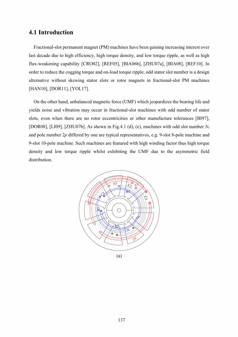
137
4.1 Introduction
Fractional-slot permanent magnet (PM) machines have been gaining increasing interest over
last decade due to high efficiency, high torque density, and low torque ripple, as well as high
flux-weakening capability [CRO02], [REF05], [BIA06b], [ZHU07a], [BIA08], [REF10]. In
order to reduce the cogging torque and on-load torque ripple, odd stator slot number is a design
alternative without skewing stator slots or rotor magnets in fractional-slot PM machines
[HAN10], [DOR11], [YOL17].
On the other hand, unbalanced magnetic force (UMF) which jeopardizes the bearing life and
yields noise and vibration may occur in fractional-slot machines with odd number of stator
slots, even when there are no rotor eccentricities or other manufacture tolerances [BI97],
[DOR08], [LI09], [ZHU07b]. As shown in Fig.4.1 (d), (e), machines with odd slot number Ns
and pole number 2p differed by one are typical representatives, e.g. 9-slot 8-pole machine and
9-slot 10-pole machine. Such machines are featured with high winding factor thus high torque
density and low torque ripple whilst exhibiting the UMF due to the asymmetric field
distribution.
(a)
B1
B3
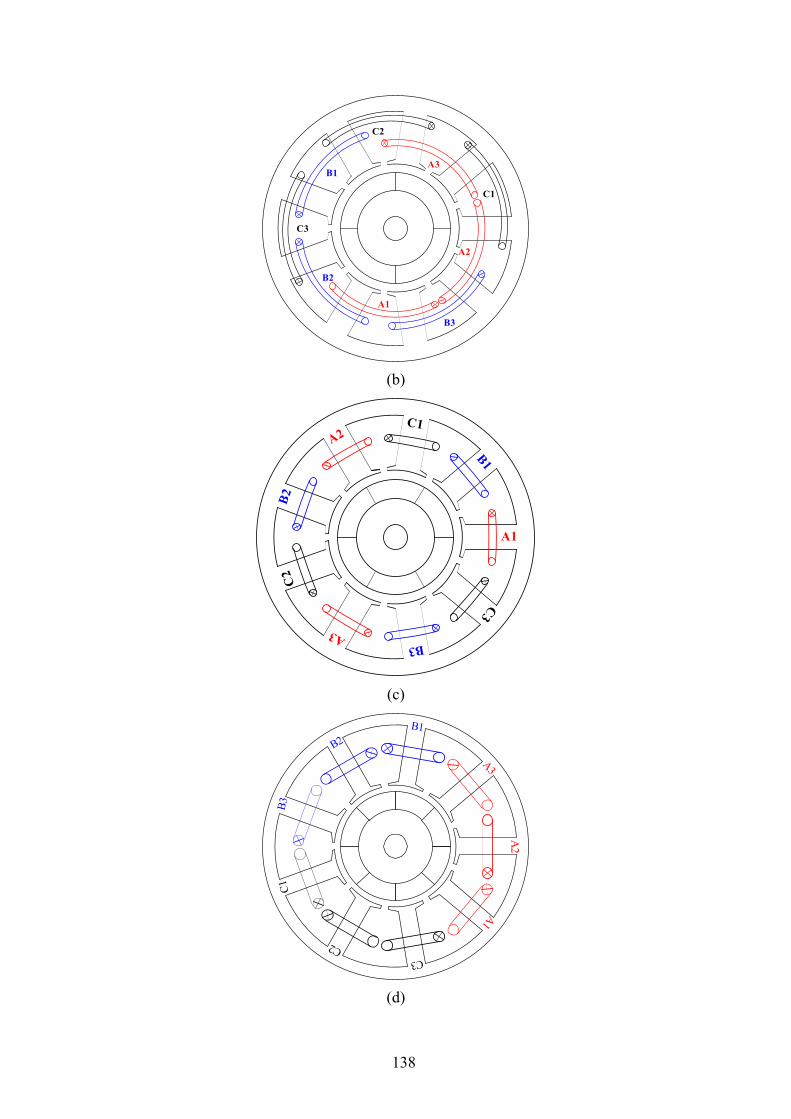
138
(b)
(c)
(d)
A1
A2
A3B1
B2
B3
C1
C2
C3
A1
A2
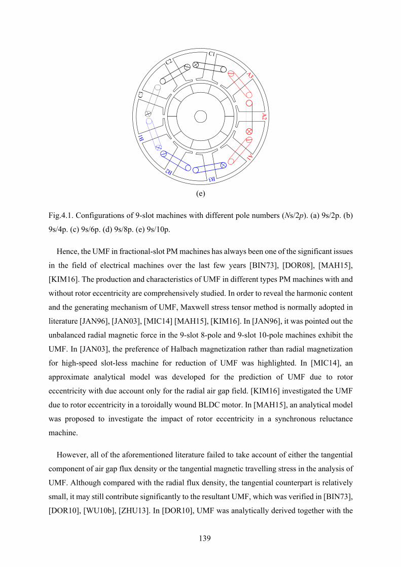
139
(e)
Fig.4.1. Configurations of 9-slot machines with different pole numbers (Ns/2p). (a) 9s/2p. (b)
9s/4p. (c) 9s/6p. (d) 9s/8p. (e) 9s/10p.
Hence, the UMF in fractional-slot PM machines has always been one of the significant issues
in the field of electrical machines over the last few years [BIN73], [DOR08], [MAH15],
[KIM16]. The production and characteristics of UMF in different types PM machines with and
without rotor eccentricity are comprehensively studied. In order to reveal the harmonic content
and the generating mechanism of UMF, Maxwell stress tensor method is normally adopted in
literature [JAN96], [JAN03], [MIC14] [MAH15], [KIM16]. In [JAN96], it was pointed out the
unbalanced radial magnetic force in the 9-slot 8-pole and 9-slot 10-pole machines exhibit the
UMF. In [JAN03], the preference of Halbach magnetization rather than radial magnetization
for high-speed slot-less machine for reduction of UMF was highlighted. In [MIC14], an
approximate analytical model was developed for the prediction of UMF due to rotor
eccentricity with due account only for the radial air gap field. [KIM16] investigated the UMF
due to rotor eccentricity in a toroidally wound BLDC motor. In [MAH15], an analytical model
was proposed to investigate the impact of rotor eccentricity in a synchronous reluctance
machine.
However, all of the aforementioned literature failed to take account of either the tangential
component of air gap flux density or the tangential magnetic travelling stress in the analysis of
UMF. Although compared with the radial flux density, the tangential counterpart is relatively
small, it may still contribute significantly to the resultant UMF, which was verified in [BIN73],
[DOR10], [WU10b], [ZHU13]. In [DOR10], UMF was analytically derived together with the
A2
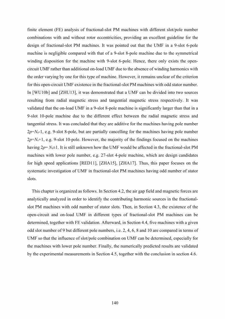
140
finite element (FE) analysis of fractional-slot PM machines with different slot/pole number
combinations with and without rotor eccentricities, providing an excellent guideline for the
design of fractional-slot PM machines. It was pointed out that the UMF in a 9-slot 6-pole
machine is negligible compared with that of a 9-slot 8-pole machine due to the symmetrical
winding disposition for the machine with 9-slot 6-pole. Hence, there only exists the open-
circuit UMF rather than additional on-load UMF due to the absence of winding harmonics with
the order varying by one for this type of machine. However, it remains unclear of the criterion
for this open-circuit UMF existence in the fractional-slot PM machines with odd stator number.
In [WU10b] and [ZHU13], it was demonstrated that a UMF can be divided into two sources
resulting from radial magnetic stress and tangential magnetic stress respectively. It was
validated that the on-load UMF in a 9-slot 8-pole machine is significantly larger than that in a
9-slot 10-pole machine due to the different effect between the radial magnetic stress and
tangential stress. It was concluded that they are additive for the machines having pole number
2p=Ns-1, e.g. 9-slot 8-pole, but are partially cancelling for the machines having pole number
2p=Ns+1, e.g. 9-slot 10-pole. However, the majority of the findings focused on the machines
having 2p= Ns±1. It is still unknown how the UMF would be affected in the fractional-slot PM
machines with lower pole number, e.g. 27-slot 4-pole machine, which are design candidates
for high speed applications [RED11], [ZHA15], [ZHA17]. Thus, this paper focuses on the
systematic investigation of UMF in fractional-slot PM machines having odd number of stator
slots.
This chapter is organized as follows. In Section 4.2, the air gap field and magnetic forces are
analytically analyzed in order to identify the contributing harmonic sources in the fractional-
slot PM machines with odd number of stator slots. Then, in Section 4.3, the existence of the
open-circuit and on-load UMF in different types of fractional-slot PM machines can be
determined, together with FE validation. Afterward, in Section 4.4, five machines with a given
odd slot number of 9 but different pole numbers, i.e. 2, 4, 6, 8 and 10 are compared in terms of
UMF so that the influence of slot/pole combination on UMF can be determined, especially for
the machines with lower pole number. Finally, the numerically predicted results are validated
by the experimental measurements in Section 4.5, together with the conclusion in section 4.6.

141
4.2 Analytical Analysis of Air Gap Field and Magnetic Forces
In this section, the analytical analysis of air gap field harmonics in fractional-slot PM
machines with odd number of stator slots is conducted so that the contributing sources of UMF
can be further identified. As pointed out in [WU10b], the tangential component of air gap field
should be taken into account due to its significant contribution to the tangential travelling stress
thus the total unbalanced magnetic force. Meanwhile, it should be noted that the analytical
model adopted here is not for accurately predicting the air gap field magnitude but the harmonic
order and the corresponding rotating speed, direction and phase angle. Hence, the following
assumptions are made.
1) The permanence of iron lamination is infinite which means the saturation effect is ignored.
2) The relative permeability of permanent magnet is considered to be equal to that of air.
3) Only the 2-D field is considered. The flux leakage and end-effect are neglected for simplicity.
4.2.1 Open-Circuit Air Gap Flux Density Generally, for a fractional-slot PM machine with surface mounted magnets, the magnetic
motive force generated by the PMs can be assumed as the square wave which is variable with
air gap circumferential position, as shown in Fig.4.2. Its Fourier series expansion 𝐹𝐹𝑝𝑝 (𝛼𝛼, 𝑡𝑡) can
be expressed as
1,3,5...( , ) cos[ ( )]r i r
iF t A ip tα ω α
∞
=
= −∑ (4.1)
where i is the harmonic index and Ari denotes the amplitude the ith harmonic which has been
revealed in [ZHU93]; p is the number of rotor pole-pairs; 𝜔𝜔𝑝𝑝 is the rotor angular mechanical
speed.
On the other hand, the air gap permanence distribution can be modeled as shown in Fig.4.3,
with the consideration of stator slotting effect. Its Fourier series can be written as
0 01,2,3...
( ) cos[ ( )]j sj
P P P jNα α α∞
=
= + −∑ (4.2)
where P0 denotes the dc component of air gap permanence; j is the harmonics index; Ns is the
stator slots number; 𝛼𝛼0 is the initial rotor position angle.

142
Therefore, the radial field component of open-circuit flux density with the consideration of
slotting effect can be obtained by multiplying 𝐹𝐹𝑝𝑝 (𝛼𝛼, 𝑡𝑡) and 𝑃𝑃 (𝜃𝜃) from (1) and (2) as
1,3,5...
1 21,3,5... 1,2,3
1 0
2
( , ) ( ) cos[ ( )]
1 [cos( ) cos( )]2
( )(
r r ri ri
PM originalharmonics
ri r ri j
PM modulated harmonics
s s
B F t P B ip t
B ip t ip t
ip jN jNip jN
α α ω α
ω α ω α
α α αα
∞
=
−
∞ ∞
= =
−
= = −
+ − + −
= + −
= −
∑
∑ ∑
0)s sjNα α
+
(4.3)
It can be seen that the open-circuit radial PM harmonics consist of both the original
harmonics with the order of ip and the modulated harmonics with the order of |ip ±jNs| due to
stator slotting effect.
As revealed in [ZHU93], the tangential PM field under open-circuit shares the same
harmonic order as well as the rotation speed and direction with those of radial one. The only
differences lie in the amplitude and phase angle.
Fig.4.2. MMF distribution generated by PMs in fractional-slot PM machines.
Fig.4.3. Air gap permanence distribution accounting for stator slots.
0 α
( )rF α
2 pπ 3
2 pπ
2 pπ
−32 pπ
−
α/ sNπ
( )P θ
0α
143
4.2.2 Armature Reaction Air Gap Flux Density For a fractional-slot PM machine, the armature reaction MMF can be expressed as Fourier
series:
( , ) cos[ )]ABC rF t F p tνν
α ω να∞
= ±∑ (4.4)
where 𝐹𝐹𝜈𝜈 denotes the amplitude of the 𝜐𝜐th- order harmonic, 𝜐𝜐 represents the harmonic order
index whose value will be given in the following.
Similarly, the armature reaction flux density accounting for the slotting effect can be
obtained as the product of MMF and air gap permanence
0
3 21,2,3
3 0
4 0
( , ) ( ) cos[ )]
1 [cos( ) cos( )]2
( )( )
arm ABC r
MMF originalharmonics
j r rj
MMF modulated harmonics
s s
s s
B F t P F P p t
F P p t p t
jN jNjN jN
νν
νν
α α ω να
ω α ω α
α ν α αα ν α α
∞
−
∞ ∞
=
−
= = ±
+ ± + ±
= + −
= − +
∑
∑ ∑
(4.5)
From (5), it can be seen that apart from the original MMF harmonics with the order of 𝜐𝜐, the
modulated MMF harmonics with the order |𝜐𝜐 ± jNs| also exist due to air gap permanence
variation.
In order to further identify the harmonic order of MMF armature reaction, the machine
periodicity should be clarified. For the fractional-slot PM machines with Ns slots and p pole
pairs, the periodicity t is defined as the great common divisor between Ns and p [BIA09]
. . . ,st G C D N p= (4.6)
In this paper, for the machine having odd number of stator slots, the value of t is always odd
(t=1, 3, 5…) which indicates that the MMF distribution contains harmonics of both even and
odd orders multiplied by t. On the other hand, all triple MMF harmonics are cancelled out in
the symmetrical three-phase winding. Therefore, the harmonic order of armature reaction field

144
can be written as |(3n ±1)t ± jNs| (n=0,1,2… j=0,1,2…).
Table 4.1 Attributes of Air Gap Field in Fractional Slot PM Machines Having Odd Number of Slots
Sources Harmonic order Rotating speed
PM field |𝑖𝑖𝑝𝑝 ± 𝑗𝑗𝑗𝑗s| 𝑖𝑖𝑝𝑝𝜔𝜔𝑝𝑝
|𝑖𝑖𝑝𝑝 ± 𝑗𝑗𝑗𝑗𝑝𝑝|
Armature reaction field |(3𝑛𝑛 ± 1)𝑡𝑡 ± 𝑗𝑗𝑗𝑗𝑝𝑝| ±𝑝𝑝𝜔𝜔𝑝𝑝
|(3𝑛𝑛 ± 1)𝑡𝑡 ± 𝑗𝑗𝑗𝑗𝑝𝑝|
Hence, the modulated on-load air gap field of a fractional slot PM machine having odd
number of stator slots can be obtained by adding (5) to (3). The attributes of air gap flux
harmonics are given in Table 4.1.
4.2.3 Radial Stress and Tangential Stress According to the Maxwell stress tensor, the radial and tangential magnetic stresses can be
obtained by
2 2
0
0
1 ( )2r r
r
F B B
B BF
α
αα
µ
µ
= − =
(4.7)
where Br and Bα denote the radial and tangential flux density components in air gap either on
open-circuit or load condition.
As mentioned in the previous section, the harmonic orders in the radial and tangential air
gap fields are the same.
4.2.4 Unbalanced Magnetic Force It is well known that the unbalanced magnetic force results from the asymmetric air gap field
distribution. Similarly, it can be obtained by the Maxwell stress tensor in the rectangular
coordinate as
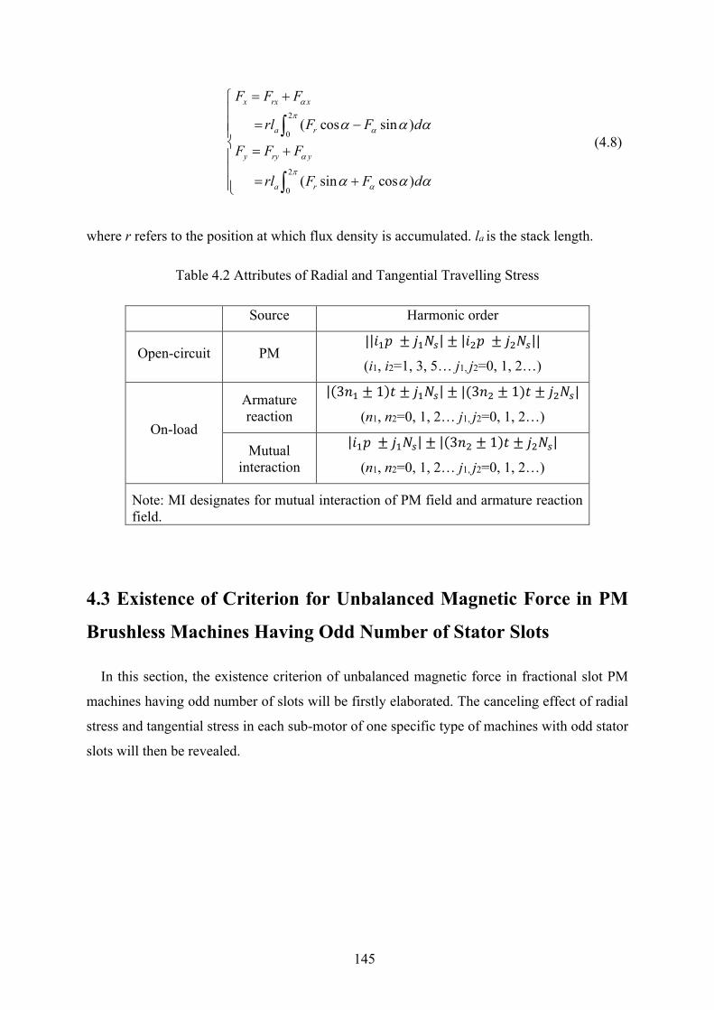
145
2
0
2
0
( cos sin )
( sin cos )
x rx x
a r
y ry y
a r
F F F
rl F F d
F F F
rl F F d
α
π
α
α
π
α
α α α
α α α
= +
= − = +
= +
∫
∫
(4.8)
where r refers to the position at which flux density is accumulated. la is the stack length.
Table 4.2 Attributes of Radial and Tangential Travelling Stress
Source Harmonic order
Open-circuit PM ||𝑖𝑖1𝑝𝑝 ± 𝑗𝑗1𝑗𝑗𝑝𝑝| ± |𝑖𝑖2𝑝𝑝 ± 𝑗𝑗2𝑗𝑗𝑝𝑝||
(i1, i2=1, 3, 5… j1, j2=0, 1, 2…)
On-load
Armature reaction
|(3𝑛𝑛1 ± 1)𝑡𝑡 ± 𝑗𝑗1𝑗𝑗𝑝𝑝| ± |(3𝑛𝑛2 ± 1)𝑡𝑡 ± 𝑗𝑗2𝑗𝑗𝑝𝑝|
(n1, n2=0, 1, 2… j1, j2=0, 1, 2…)
Mutual interaction
|𝑖𝑖1𝑝𝑝 ± 𝑗𝑗1𝑗𝑗𝑝𝑝| ± |(3𝑛𝑛2 ± 1)𝑡𝑡 ± 𝑗𝑗2𝑗𝑗𝑝𝑝|
(n1, n2=0, 1, 2… j1, j2=0, 1, 2…)
Note: MI designates for mutual interaction of PM field and armature reaction field.
4.3 Existence of Criterion for Unbalanced Magnetic Force in PM
Brushless Machines Having Odd Number of Stator Slots
In this section, the existence criterion of unbalanced magnetic force in fractional slot PM
machines having odd number of slots will be firstly elaborated. The canceling effect of radial
stress and tangential stress in each sub-motor of one specific type of machines with odd stator
slots will then be revealed.
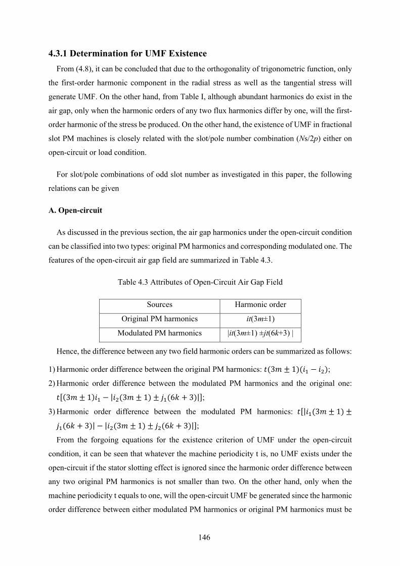
146
4.3.1 Determination for UMF Existence From (4.8), it can be concluded that due to the orthogonality of trigonometric function, only
the first-order harmonic component in the radial stress as well as the tangential stress will
generate UMF. On the other hand, from Table I, although abundant harmonics do exist in the
air gap, only when the harmonic orders of any two flux harmonics differ by one, will the first-
order harmonic of the stress be produced. On the other hand, the existence of UMF in fractional
slot PM machines is closely related with the slot/pole number combination (Ns/2p) either on
open-circuit or load condition.
For slot/pole combinations of odd slot number as investigated in this paper, the following
relations can be given
A. Open-circuit
As discussed in the previous section, the air gap harmonics under the open-circuit condition
can be classified into two types: original PM harmonics and corresponding modulated one. The
features of the open-circuit air gap field are summarized in Table 4.3.
Table 4.3 Attributes of Open-Circuit Air Gap Field
Sources Harmonic order
Original PM harmonics it(3m±1)
Modulated PM harmonics |it(3m±1) ±jt(6k+3) |
Hence, the difference between any two field harmonic orders can be summarized as follows:
1) Harmonic order difference between the original PM harmonics: 𝑡𝑡(3𝑚𝑚 ± 1)(𝑖𝑖1 − 𝑖𝑖2);
2) Harmonic order difference between the modulated PM harmonics and the original one:
𝑡𝑡[(3𝑚𝑚 ± 1)𝑖𝑖1 − |𝑖𝑖2(3𝑚𝑚 ± 1) ± 𝑗𝑗1(6𝑘𝑘 + 3)|];
3) Harmonic order difference between the modulated PM harmonics: 𝑡𝑡[|𝑖𝑖1(3𝑚𝑚 ± 1) ±
𝑗𝑗1(6𝑘𝑘 + 3)| − |𝑖𝑖2(3𝑚𝑚 ± 1) ± 𝑗𝑗2(6𝑘𝑘 + 3)|];
From the forgoing equations for the existence criterion of UMF under the open-circuit
condition, it can be seen that whatever the machine periodicity t is, no UMF exists under the
open-circuit if the stator slotting effect is ignored since the harmonic order difference between
any two original PM harmonics is not smaller than two. On the other hand, only when the
machine periodicity t equals to one, will the open-circuit UMF be generated since the harmonic
order difference between either modulated PM harmonics or original PM harmonics must be
147
the multiple of t.
To conclude, for the fractional slot PM machine having odd number of stator slots, the open-
circuit UMF will only exist when the great common divisor between the number of stator slots
and rotor pole pairs is one. This UMF is caused by the stator slotting effect.
B. On-load
When the machine is under on-load condition, it is essential to investigate whether the
adjacent armature reaction harmonics differed by one exist. In addition, the mutual interaction
between PM harmonics and armature reaction harmonics should also be accounted for.
Actually, it is the most significant source contributing to the production of UMF, if any, due to
the relatively larger amplitude of PM field.
Hence, the harmonic order difference can be written as:
1) Self-interaction in armature reaction harmonics:
𝑡𝑡[|(3𝑛𝑛1 ± 1) ± 𝑗𝑗1(6𝑘𝑘 + 3)| − |(3𝑛𝑛2 ± 1) ± 𝑗𝑗2(6𝑘𝑘 + 3)|];
2) Mutual-interaction between PM harmonics and armature reaction harmonics: 𝑡𝑡[|(3𝑛𝑛1 ±
1) ± 𝑗𝑗1(6𝑘𝑘 + 3)| − |𝑖𝑖1(3𝑚𝑚 ± 1) ± 𝑗𝑗2(6𝑘𝑘 + 3)|];
It can be found that the harmonic order difference in either self-interaction or mutual
interaction is always the multiple of t, even when the slotting effect is considered for the
armature reaction. When the machine periodicity is larger than one, no UMF will be produced
under the on-load condition.
On the other hand, when the machine periodicity t is one, the UMF due to self-interaction of
armature reaction harmonics and mutual interaction with PM harmonics will be produced even
when the slotting effect is ignored. This is because the armature reaction always consists of the
1th and 2nd harmonics when t=1, hence the self-interaction will appear.
As for the mutual interaction, there always exist the corresponding armature reaction
harmonics which differ by one with the PM fundamental harmonics, as shown in Table 4.4.
In summary, only when the machine periodicity is one, will the UMF be produced in
fractional slot PM machines having odd number of stator slots both on open-circuit and on-
load condition.
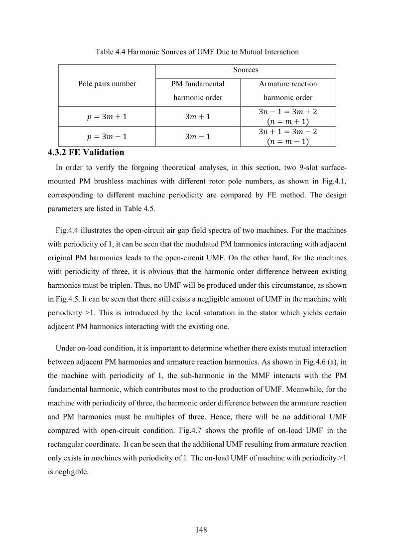
148
Table 4.4 Harmonic Sources of UMF Due to Mutual Interaction
Pole pairs number
Sources
PM fundamental
harmonic order
Armature reaction
harmonic order
𝑝𝑝 = 3𝑚𝑚 + 1 3𝑚𝑚 + 1 3𝑛𝑛 − 1 = 3𝑚𝑚 + 2 (𝑛𝑛 = 𝑚𝑚 + 1)
𝑝𝑝 = 3𝑚𝑚− 1 3𝑚𝑚 − 1 3𝑛𝑛 + 1 = 3𝑚𝑚 − 2 (𝑛𝑛 = 𝑚𝑚 − 1)
4.3.2 FE Validation In order to verify the forgoing theoretical analyses, in this section, two 9-slot surface-
mounted PM brushless machines with different rotor pole numbers, as shown in Fig.4.1,
corresponding to different machine periodicity are compared by FE method. The design
parameters are listed in Table 4.5.
Fig.4.4 illustrates the open-circuit air gap field spectra of two machines. For the machines
with periodicity of 1, it can be seen that the modulated PM harmonics interacting with adjacent
original PM harmonics leads to the open-circuit UMF. On the other hand, for the machines
with periodicity of three, it is obvious that the harmonic order difference between existing
harmonics must be triplen. Thus, no UMF will be produced under this circumstance, as shown
in Fig.4.5. It can be seen that there still exists a negligible amount of UMF in the machine with
periodicity >1. This is introduced by the local saturation in the stator which yields certain
adjacent PM harmonics interacting with the existing one.
Under on-load condition, it is important to determine whether there exists mutual interaction
between adjacent PM harmonics and armature reaction harmonics. As shown in Fig.4.6 (a), in
the machine with periodicity of 1, the sub-harmonic in the MMF interacts with the PM
fundamental harmonic, which contributes most to the production of UMF. Meanwhile, for the
machine with periodicity of three, the harmonic order difference between the armature reaction
and PM harmonics must be multiples of three. Hence, there will be no additional UMF
compared with open-circuit condition. Fig.4.7 shows the profile of on-load UMF in the
rectangular coordinate. It can be seen that the additional UMF resulting from armature reaction
only exists in machines with periodicity of 1. The on-load UMF of machine with periodicity >1
is negligible.
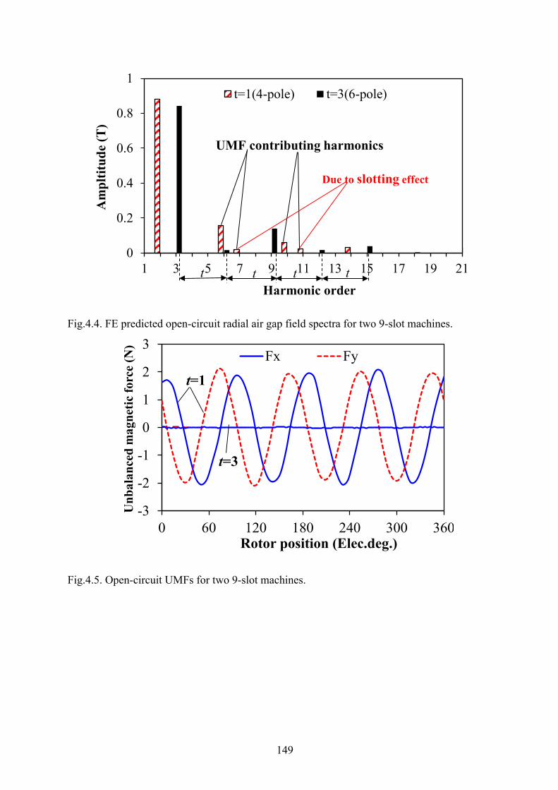
149
Fig.4.4. FE predicted open-circuit radial air gap field spectra for two 9-slot machines.
Fig.4.5. Open-circuit UMFs for two 9-slot machines.
0
0.2
0.4
0.6
0.8
1
1 3 5 7 9 11 13 15 17 19 21
Am
pltit
ude
(T)
Harmonic order
t=1(4-pole) t=3(6-pole)
UMF contributing harmonics
Due to slotting effect
t t t t
-3
-2
-1
0
1
2
3
0 60 120 180 240 300 360
Unb
alan
ced
mag
netic
forc
e (N
)
Rotor position (Elec.deg.)
Fx Fy
t=1
t=3
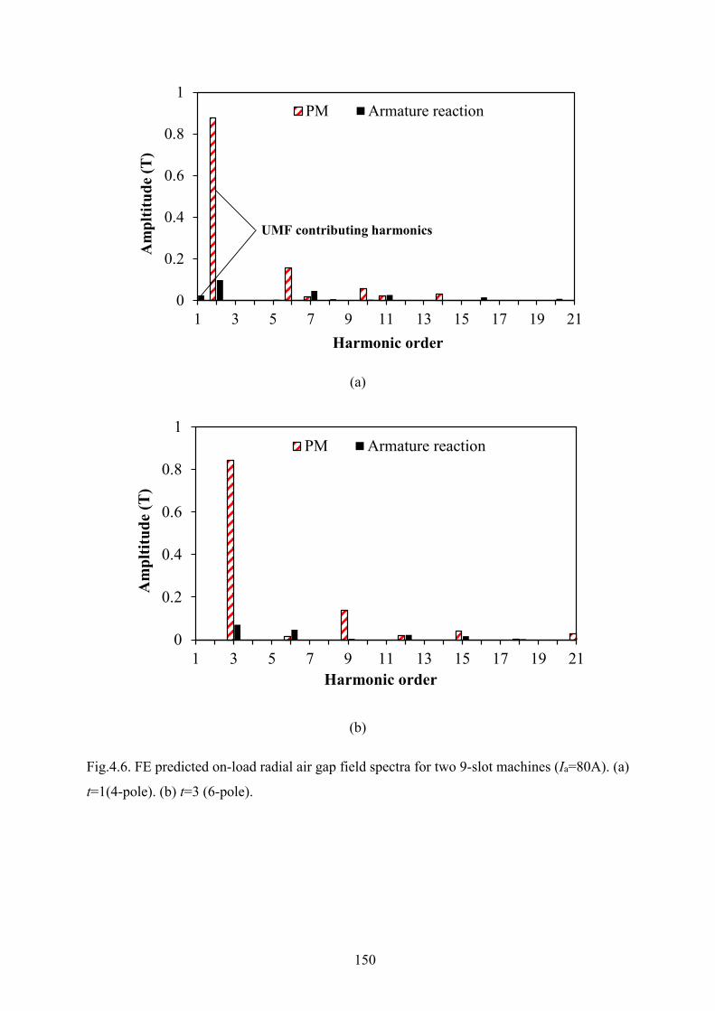
150
(a)
(b)
Fig.4.6. FE predicted on-load radial air gap field spectra for two 9-slot machines (Ia=80A). (a)
t=1(4-pole). (b) t=3 (6-pole).
0
0.2
0.4
0.6
0.8
1
1 3 5 7 9 11 13 15 17 19 21
Am
pltit
ude
(T)
Harmonic order
PM Armature reaction
UMF contributing harmonics
0
0.2
0.4
0.6
0.8
1
1 3 5 7 9 11 13 15 17 19 21
Am
pltit
ude
(T)
Harmonic order
PM Armature reaction
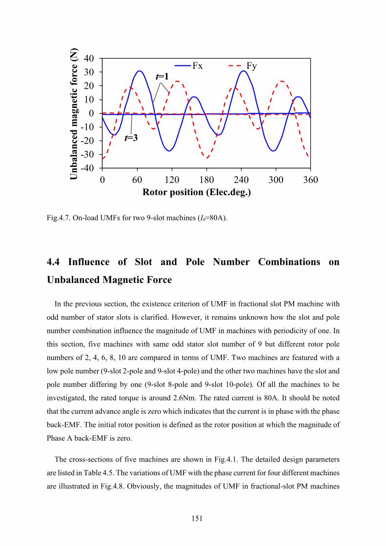
151
Fig.4.7. On-load UMFs for two 9-slot machines (Ia=80A).
4.4 Influence of Slot and Pole Number Combinations on
Unbalanced Magnetic Force
In the previous section, the existence criterion of UMF in fractional slot PM machine with
odd number of stator slots is clarified. However, it remains unknown how the slot and pole
number combination influence the magnitude of UMF in machines with periodicity of one. In
this section, five machines with same odd stator slot number of 9 but different rotor pole
numbers of 2, 4, 6, 8, 10 are compared in terms of UMF. Two machines are featured with a
low pole number (9-slot 2-pole and 9-slot 4-pole) and the other two machines have the slot and
pole number differing by one (9-slot 8-pole and 9-slot 10-pole). Of all the machines to be
investigated, the rated torque is around 2.6Nm. The rated current is 80A. It should be noted
that the current advance angle is zero which indicates that the current is in phase with the phase
back-EMF. The initial rotor position is defined as the rotor position at which the magnitude of
Phase A back-EMF is zero.
The cross-sections of five machines are shown in Fig.4.1. The detailed design parameters
are listed in Table 4.5. The variations of UMF with the phase current for four different machines
are illustrated in Fig.4.8. Obviously, the magnitudes of UMF in fractional-slot PM machines
-40-30-20-10
010203040
0 60 120 180 240 300 360Unb
alan
ced
mag
netic
forc
e (N
)
Rotor position (Elec.deg.)
Fx Fyt=1
t=3
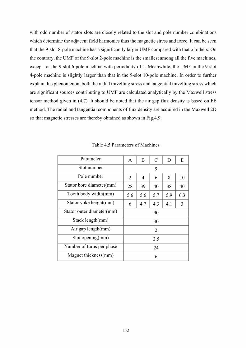
152
with odd number of stator slots are closely related to the slot and pole number combinations
which determine the adjacent field harmonics thus the magnetic stress and force. It can be seen
that the 9-slot 8-pole machine has a significantly larger UMF compared with that of others. On
the contrary, the UMF of the 9-slot 2-pole machine is the smallest among all the five machines,
except for the 9-slot 6-pole machine with periodicity of 1. Meanwhile, the UMF in the 9-slot
4-pole machine is slightly larger than that in the 9-slot 10-pole machine. In order to further
explain this phenomenon, both the radial travelling stress and tangential travelling stress which
are significant sources contributing to UMF are calculated analytically by the Maxwell stress
tensor method given in (4.7). It should be noted that the air gap flux density is based on FE
method. The radial and tangential components of flux density are acquired in the Maxwell 2D
so that magnetic stresses are thereby obtained as shown in Fig.4.9.
Table 4.5 Parameters of Machines
Parameter A B C D E Slot number 9 Pole number 2 4 6 8 10
Stator bore diameter(mm) 28 39 40 38 40 Tooth body width(mm) 5.6 5.6 5.7 5.9 6.3 Stator yoke height(mm) 6 4.7 4.3 4.1 3
Stator outer diameter(mm) 90 Stack length(mm) 30
Air gap length(mm) 2 Slot opening(mm) 2.5
Number of turns per phase 24 Magnet thickness(mm) 6
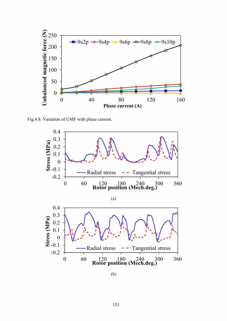
153
Fig.4.8. Variation of UMF with phase current.
(a)
(b)
0
50
100
150
200
250
0 40 80 120 160
Unb
alan
ced
mag
netic
forc
e (N
)
Phase current (A)
9s2p 9s4p 9s6p 9s8p 9s10p
-0.2-0.1
00.10.20.30.4
0 60 120 180 240 300 360
Stre
ss (M
Pa)
Rotor position (Mech.deg.)
Radial stress Tangential stress
-0.2-0.1
00.10.20.30.4
0 60 120 180 240 300 360
Stre
ss (M
Pa)
Rotor position (Mech.deg.)
Radial stress Tangential stress
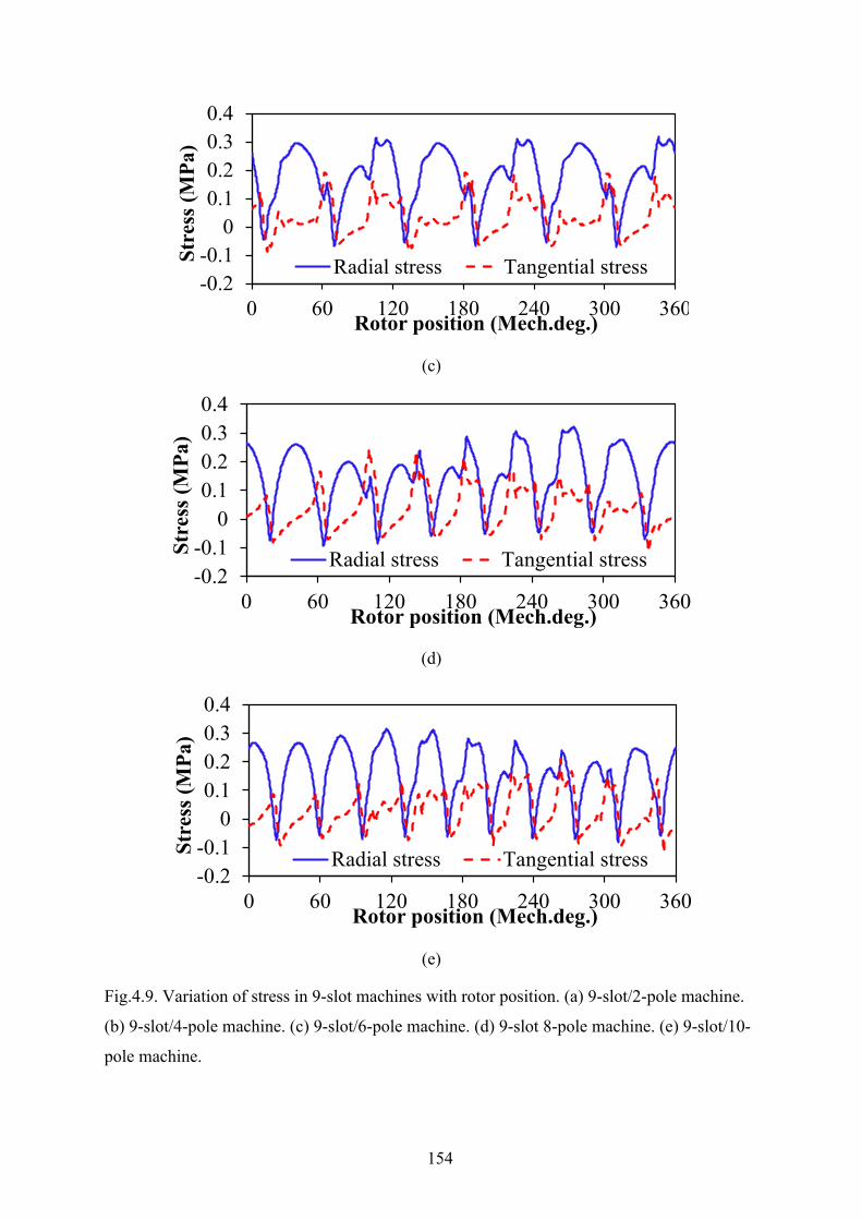
154
(c)
(d)
(e)
Fig.4.9. Variation of stress in 9-slot machines with rotor position. (a) 9-slot/2-pole machine.
(b) 9-slot/4-pole machine. (c) 9-slot/6-pole machine. (d) 9-slot 8-pole machine. (e) 9-slot/10-
pole machine.
-0.2-0.1
00.10.20.30.4
0 60 120 180 240 300 360
Stre
ss (M
Pa)
Rotor position (Mech.deg.)
Radial stress Tangential stress
-0.2-0.1
00.10.20.30.4
0 60 120 180 240 300 360
Stre
ss (M
Pa)
Rotor position (Mech.deg.)
Radial stress Tangential stress
-0.2-0.1
00.10.20.30.4
0 60 120 180 240 300 360
Stre
ss (M
Pa)
Rotor position (Mech.deg.)
Radial stress Tangential stress
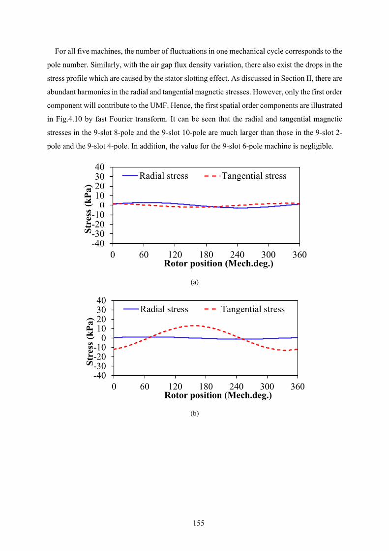
155
For all five machines, the number of fluctuations in one mechanical cycle corresponds to the
pole number. Similarly, with the air gap flux density variation, there also exist the drops in the
stress profile which are caused by the stator slotting effect. As discussed in Section II, there are
abundant harmonics in the radial and tangential magnetic stresses. However, only the first order
component will contribute to the UMF. Hence, the first spatial order components are illustrated
in Fig.4.10 by fast Fourier transform. It can be seen that the radial and tangential magnetic
stresses in the 9-slot 8-pole and the 9-slot 10-pole are much larger than those in the 9-slot 2-
pole and the 9-slot 4-pole. In addition, the value for the 9-slot 6-pole machine is negligible.
(a)
(b)
-40-30-20-10
010203040
0 60 120 180 240 300 360
Stre
ss (k
Pa)
Rotor position (Mech.deg.)
Radial stress Tangential stress
-40-30-20-10
010203040
0 60 120 180 240 300 360
Stre
ss (k
Pa)
Rotor position (Mech.deg.)
Radial stress Tangential stress
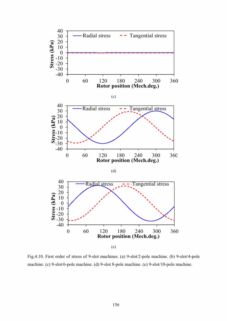
156
(c)
(d)
(e)
Fig.4.10. First order of stress of 9-slot machines. (a) 9-slot/2-pole machine. (b) 9-slot/4-pole
machine. (c) 9-slot/6-pole machine. (d) 9-slot 8-pole machine. (e) 9-slot/10-pole machine.
-40-30-20-10
010203040
0 60 120 180 240 300 360
Stre
ss (k
Pa)
Rotor position (Mech.deg.)
Radial stress Tangential stress
-40-30-20-10
010203040
0 60 120 180 240 300 360
Stre
ss (k
Pa)
Rotor position (Mech.deg.)
Radial stress Tangential stress
-40-30-20-10
010203040
0 60 120 180 240 300 360
Stre
ss (k
Pa)
Rotor position (Mech.deg.)
Radial stress Tangential stress
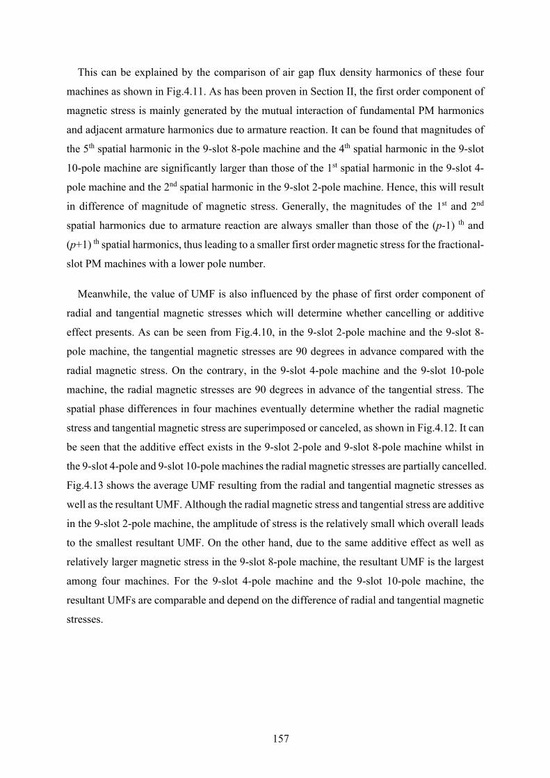
157
This can be explained by the comparison of air gap flux density harmonics of these four
machines as shown in Fig.4.11. As has been proven in Section II, the first order component of
magnetic stress is mainly generated by the mutual interaction of fundamental PM harmonics
and adjacent armature harmonics due to armature reaction. It can be found that magnitudes of
the 5th spatial harmonic in the 9-slot 8-pole machine and the 4th spatial harmonic in the 9-slot
10-pole machine are significantly larger than those of the 1st spatial harmonic in the 9-slot 4-
pole machine and the 2nd spatial harmonic in the 9-slot 2-pole machine. Hence, this will result
in difference of magnitude of magnetic stress. Generally, the magnitudes of the 1st and 2nd
spatial harmonics due to armature reaction are always smaller than those of the (p-1) th and
(p+1) th spatial harmonics, thus leading to a smaller first order magnetic stress for the fractional-
slot PM machines with a lower pole number.
Meanwhile, the value of UMF is also influenced by the phase of first order component of
radial and tangential magnetic stresses which will determine whether cancelling or additive
effect presents. As can be seen from Fig.4.10, in the 9-slot 2-pole machine and the 9-slot 8-
pole machine, the tangential magnetic stresses are 90 degrees in advance compared with the
radial magnetic stress. On the contrary, in the 9-slot 4-pole machine and the 9-slot 10-pole
machine, the radial magnetic stresses are 90 degrees in advance of the tangential stress. The
spatial phase differences in four machines eventually determine whether the radial magnetic
stress and tangential magnetic stress are superimposed or canceled, as shown in Fig.4.12. It can
be seen that the additive effect exists in the 9-slot 2-pole and 9-slot 8-pole machine whilst in
the 9-slot 4-pole and 9-slot 10-pole machines the radial magnetic stresses are partially cancelled.
Fig.4.13 shows the average UMF resulting from the radial and tangential magnetic stresses as
well as the resultant UMF. Although the radial magnetic stress and tangential stress are additive
in the 9-slot 2-pole machine, the amplitude of stress is the relatively small which overall leads
to the smallest resultant UMF. On the other hand, due to the same additive effect as well as
relatively larger magnetic stress in the 9-slot 8-pole machine, the resultant UMF is the largest
among four machines. For the 9-slot 4-pole machine and the 9-slot 10-pole machine, the
resultant UMFs are comparable and depend on the difference of radial and tangential magnetic
stresses.
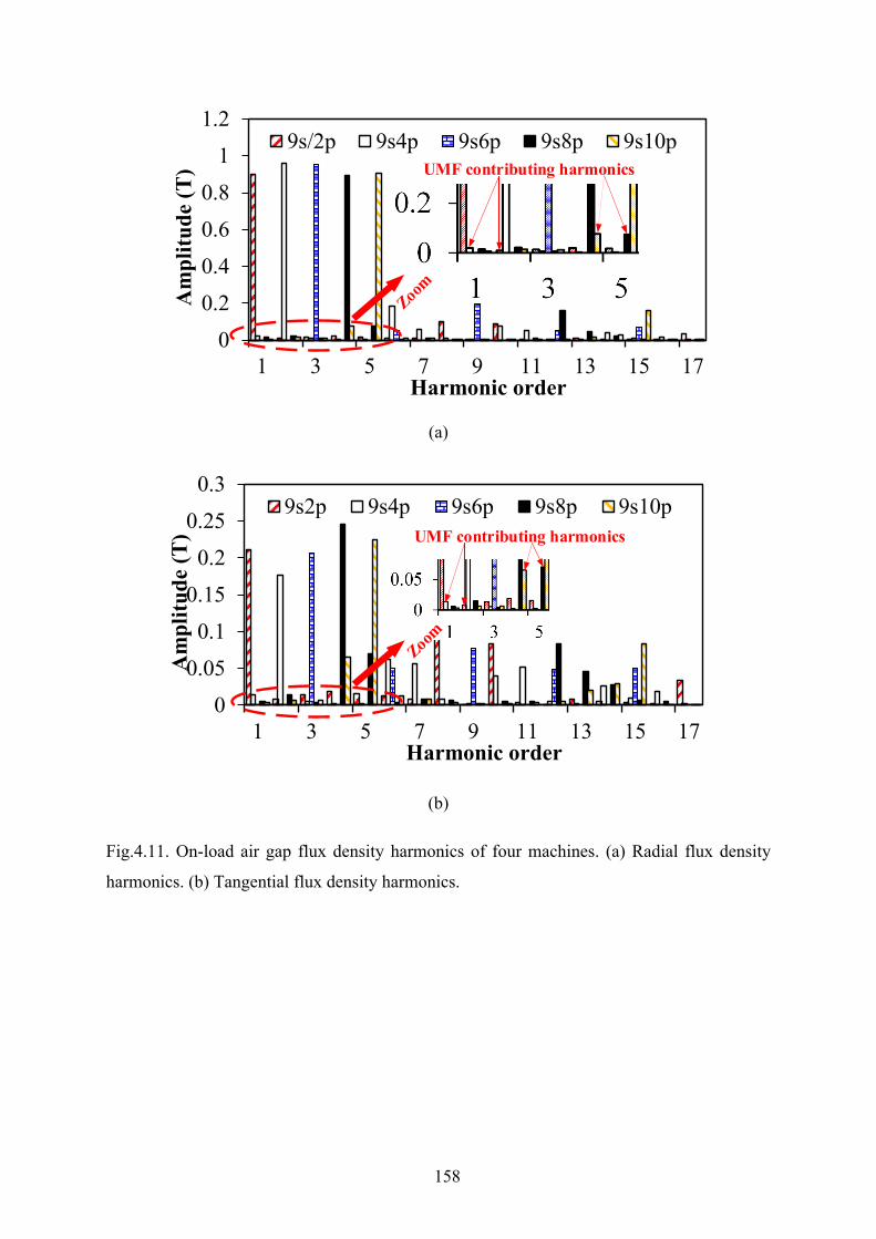
158
(a)
(b)
Fig.4.11. On-load air gap flux density harmonics of four machines. (a) Radial flux density
harmonics. (b) Tangential flux density harmonics.
00.20.40.60.8
11.2
1 3 5 7 9 11 13 15 17
Am
plitu
de (T
)
Harmonic order
9s/2p 9s4p 9s6p 9s8p 9s10pUMF contributing harmonics
00.050.1
0.150.2
0.250.3
1 3 5 7 9 11 13 15 17
Am
plitu
de (T
)
Harmonic order
9s2p 9s4p 9s6p 9s8p 9s10pUMF contributing harmonics
159
(a)
(b)
(c)
Fr Fα
Fr Fα
Fr Fα

160
(d)
(e)
Fig.4.12. Cancelling and additive effects of magnetic stresses in 9-slot machines. (a) 9-slot 2-
pole. (b) 9-slot 4-pole. (c) 9-slot 6-pole. (d) 9-slot 8-pole. (e) 9-slot 10-pole.
Fr Fα
Fr Fα

161
Fig.4.13. Comparison of average UMF resulting from radial magnetic stress and tangential
magnetic stress.
4.5 Experimental Validation
Due to negligible UMF, a fractional-slot PM machine with 9-slot and 6-pole configuration
is prototyped. As shown in Fig.4.14, the stator is equipped with nine non-overlapping coils.
The rotor magnets are axially segmented in order to reduce the rotor eddy current loss. Due to
the difficulties in the direct measurement of UMF, the electromagnetic performances of the
prototype are tested so that the validity of the 2D FE model and the analytical models can be
confirmed. The conclusion for the UMF based on the harmonic analysis can be further verified.
The measured and simulated open-circuit back-EMFs as well as the spectra are shown in
Fig.4.15. The harmonics of back-EMF are extracted based on the FFT analysis, as illustrated
in Table 4.6. It can be seen that the measured results agree well with the predicted ones.
Fig.4.16 illustrates the cogging torque and static torque profile as well as the variation of
peak torque with current. The measured torque matches well with the FE predicted one with a
deviation less than 10%, confirming the validity of the 2D FE models.
020406080
100120140
9s2p 9s4p 9s6p 9s8p 9s10pUnb
alan
ced
mag
netic
forc
e(N
)
Machines
Fr Fα F
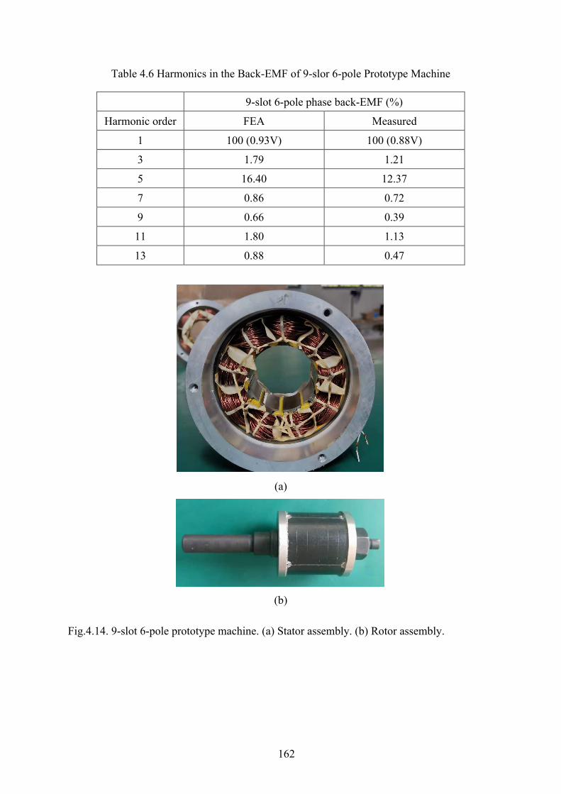
162
Table 4.6 Harmonics in the Back-EMF of 9-slor 6-pole Prototype Machine
9-slot 6-pole phase back-EMF (%)
Harmonic order FEA Measured
1 100 (0.93V) 100 (0.88V)
3 1.79 1.21
5 16.40 12.37
7 0.86 0.72
9 0.66 0.39
11 1.80 1.13
13 0.88 0.47
(a)
(b)
Fig.4.14. 9-slot 6-pole prototype machine. (a) Stator assembly. (b) Rotor assembly.

163
(a)
(b)
Fig.4.15. Measured and simulated back-EMF waveforms (n=400rpm). (a) Back-EMF profile.
(b) Spectra.
-1.2-0.9-0.6-0.30.00.30.60.91.2
0 60 120 180 240 300 360
Bac
k-E
MF
(V)
Rotor position (Elec.deg.)
MeasuredFEA
0
0.2
0.4
0.6
0.8
1
1 3 5 7 9 11 13
Am
plitu
de (V
)
Harmonic order
FEA Measured
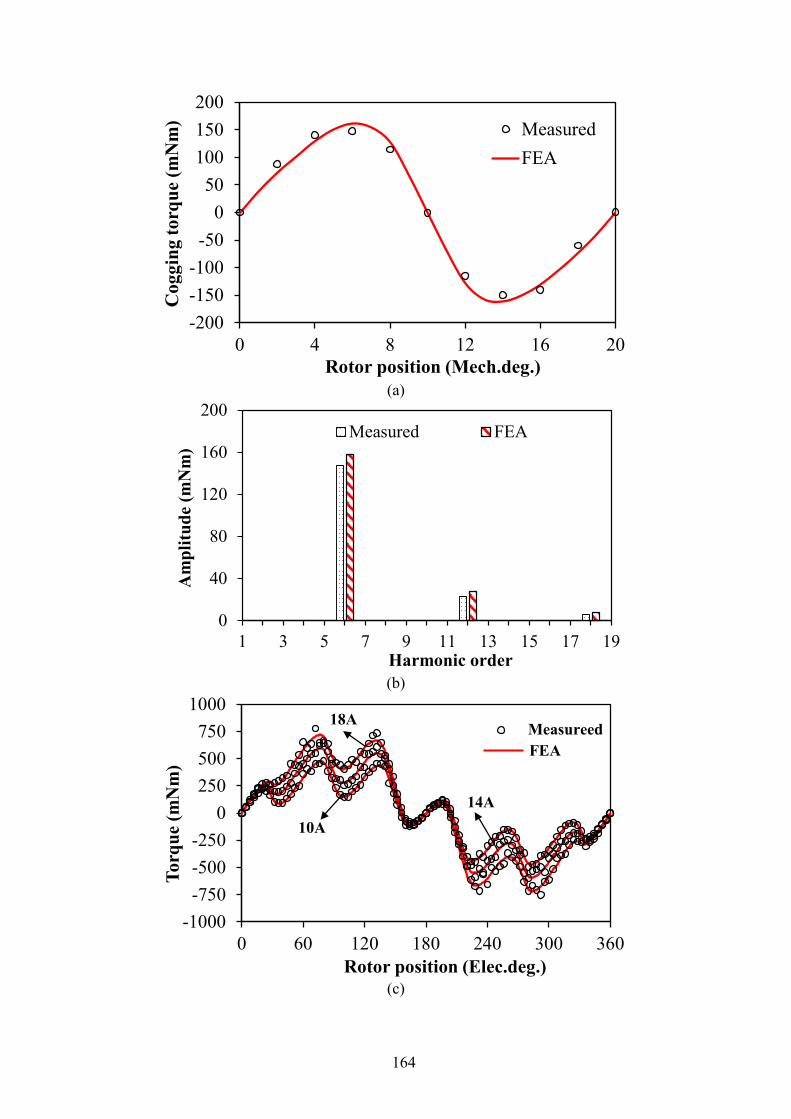
164
(a)
(b)
(c)
-200-150-100-50
050
100150200
0 4 8 12 16 20
Cog
ging
torq
ue (m
Nm
)
Rotor position (Mech.deg.)
MeasuredFEA
0
40
80
120
160
200
1 3 5 7 9 11 13 15 17 19
Am
plitu
de (m
Nm
)
Harmonic order
Measured FEA
-1000-750-500-250
0250500750
1000
0 60 120 180 240 300 360
Torq
ue (m
Nm
)
Rotor position (Elec.deg.)
10A
MeasureedFEA
18A
14A

165
(d)
Fig.4.16. Measured and simulated static torque. (a) Cogging torque waveform. (b) Cogging
torque spectra. (c) Static torque waveform (Ia=-2Ib=-2Ic). (d) Variation of peak torque with
current.
4.6 Summary
In this chapter, the criterion for existence of UMF both on open-circuit and on-load condition
in fractional-slot PM machines with odd stator slot number is investigated. It is concluded that
only when the machine periodicity is one and the stator slotting effect is considered, will the
open-circuit UMF be generated due to the mutual interaction between the modulated PM and
original PM harmonics. On the other hand, the existence criterion of on-load UMF in the
machines with periodicity of one is confirmed since both the self-interaction of armature
reaction harmonics and the mutual interaction between the fundamental PM harmonic and the
armature reaction harmonics will appear even when the slotting effect is ignored. For the
fractional-slot PM machines with periodicity >1, e.g. 9-slot 6-pole machine, the first order of
radial magnetic forces and tangential magnetic forces are quite small due to the absence of
adjacent field harmonics thus the resultant UMF is negligible. Furthermore, the fractional-slot
PM machines with a lower pole number, e.g. 2-pole and 4-pole, are compared with machines
with a pole number 2p=Ns±1. The UMF in machine with two poles is the smallest due to the
smallest magnitude of the 2nd harmonic in armature reaction compared with counterparts in
other machines. Instead, the UMF in the machines having pole number 2p=Ns-1 is the largest
due to the relatively larger magnitude of the (p+1)th armature reaction harmonics as well as the
0.00
0.15
0.30
0.45
0.60
0 4 8 12 16 20
Torq
ue (N
m)
Current (A)
MeasuredFEA
166
additive effect between the first order radial and tangential stresses. Overall, in fractional-slot
PM machines with a given odd number of stator slots of 9, the machines with periodicity >1,
e.g. 9-slot 6-pole, 9-slot 12-pole as well as the machines with two-pole, e.g. 9-slot 2-pole are
more preferred in terms of UMF. Finally, a prototype 9-slot 6-pole PM machine is
manufactured and tested. The measured data confirm the validity of the electromagnetic
performances obtained from the 2D FE model and the analytical models, which indirectly
verify the conclusions on the UMF.
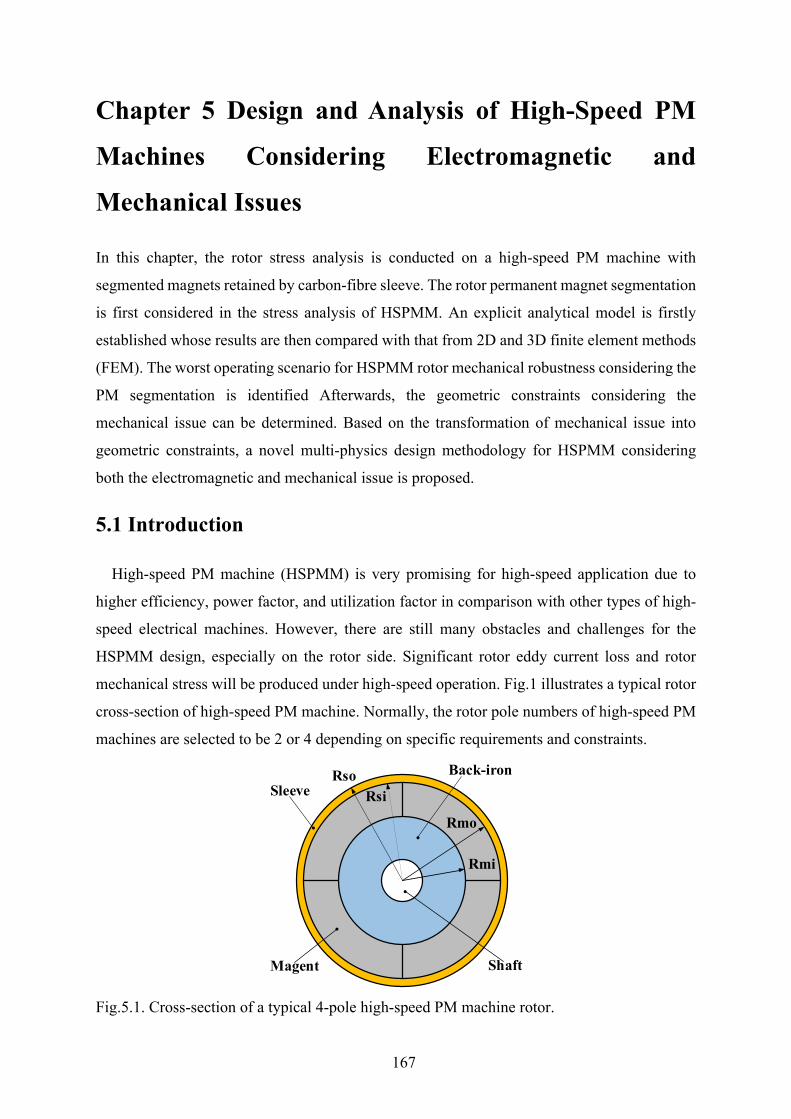
167
Chapter 5 Design and Analysis of High-Speed PM
Machines Considering Electromagnetic and
Mechanical Issues
In this chapter, the rotor stress analysis is conducted on a high-speed PM machine with
segmented magnets retained by carbon-fibre sleeve. The rotor permanent magnet segmentation
is first considered in the stress analysis of HSPMM. An explicit analytical model is firstly
established whose results are then compared with that from 2D and 3D finite element methods
(FEM). The worst operating scenario for HSPMM rotor mechanical robustness considering the
PM segmentation is identified Afterwards, the geometric constraints considering the
mechanical issue can be determined. Based on the transformation of mechanical issue into
geometric constraints, a novel multi-physics design methodology for HSPMM considering
both the electromagnetic and mechanical issue is proposed.
5.1 Introduction
High-speed PM machine (HSPMM) is very promising for high-speed application due to
higher efficiency, power factor, and utilization factor in comparison with other types of high-
speed electrical machines. However, there are still many obstacles and challenges for the
HSPMM design, especially on the rotor side. Significant rotor eddy current loss and rotor
mechanical stress will be produced under high-speed operation. Fig.1 illustrates a typical rotor
cross-section of high-speed PM machine. Normally, the rotor pole numbers of high-speed PM
machines are selected to be 2 or 4 depending on specific requirements and constraints.
Fig.5.1. Cross-section of a typical 4-pole high-speed PM machine rotor.
Sleeve
Magent
Back-ironRsoRsi
Rmo
Rmi
Shaft

168
The 4-pole rotor is more inclined to be adopted for high-power high-speed applications due
to reduced end-winding length and stator copper loss, which are quite advantageous for stator
thermal equilibrium in high power application [JAN04], [BIN06], [LUI14], [ZHA15].
However, the relatively high fundamental frequency introduced by the higher pole number will
inevitably lead to higher rotor PM eddy current loss. Hence, for the 4-pole high-speed PM
machine, the rotor magnets are usually segmented to reduce the eddy current loss.
In addition, as shown in Fig.5.1, the rotor magnets are retained by the sleeve to withstand
the extremely high tangential stress resulting from high speed. Generally, the retaining sleeves
can be classified into two types: Non-metallic ones and metallic ones. Glass-fiber and carbon-
fiber are typical non-metallic sleeves which are featured with high yield strength and low mass
density [BIN06]. This is quite desirable for the protection of PMs. In addition, the sleeve
thickness can be maintained minimum for a given operating speed so that its influence on the
air gap flux density can be minimized. The problem for this type of sleeve mainly lies in the
thermal aspect. The thermal conductivity of carbon-fiber is quite low which means the heat
generated from the rotor magnets cannot be dissipated easily [LI14]. Hence, the rotor magnets
are normally segmented to reduce the eddy current loss. Alternatively, the copper shield may
be placed at the inner side of carbon-fiber sleeve [SHA09]. On the other hand, the metallic
sleeve such as titanium and Inconel are equipped with a relatively lower strength to density
ratio compared to that of carbon-fiber. The advantages of metallic sleeve are high thermal
conductivity and electrical conductivity as well as cost. The eddy current will be induced in the
metallic sleeve instead of magnets. The metallic sleeve acts as the shield for the harmonic
penetration into the magnets. Nevertheless, the selection of retaining sleeve should not only
consider the mechanical aspects such as the magnet protection but also the electromagnetic and
thermal aspects including the rotor eddy current loss reduction and rotor thermal issue.
In this chapter, the retaining sleeve is selected to be the carbon-fibre due to its large tensile
strength. At high-speed operation, the rotor components will suffer huge centrifugal force and
certain amount of thermal stress. The permanent magnet material ideally has a high
compressive strength (800MPa) and a medium flexural strength (120MPa), but it is rather
brittle [HUA16]. Hence, stress analysis is key issue for the mechanical robustness of HSPMMs.
There are generally two sub-issues involved in the stress analysis of HSPMMs. Firstly, the
exact value of stress in each rotor parts should be obtained. Then, the maximum stress induced
in each components of the rotor should be ensured within the material strength under all
169
operating speed and temperature, especially for PMs which are quite vulnerable to tangential
tensile stress. In addition, the contact pressure pointing to the inner side should always exist so
that the electromagnetic torque can be transferred to the shaft.
The methods for stress calculation can be classified into analytical and numerical ones.
Several papers on the analytical calculation of rotor stress can be found [BIN06], [WAN07],
[BOR10], [BUR17]. [BIN06] proposed a simplified analytical model for stress calculation
based on the assumption that the rotor is strictly rotational symmetry. In [WAN07] and
[BOR10], the displacement technique was adopted for the stress calculation of the HSPMM
with the nonmagnetic alloy sleeve. The PM rotors are normally modelled as the multi-layered
cylinders. However, all the aforementioned analytical models are based on the assumption of
planar stress which is valid for rotors with short axial length. Hence, in [BUR17], a 3D
analytical model considering the axial stress was established for both solid and hollow magnet
rotors in the plane strain condition. Although all these analytical solutions can provide a
fundamental insight from the stress generation to reduction, as pointed out in [BIN06], the non-
linear factor such as geometry discontinuity and edging effect cannot be considered in the
analytical model. A derivation can still be generated in the analytical models. Hence, in order
to obtain the exact value of rotor stress, 2D or 3D Finite-Element Methods (FEM) are more
widely adopted in the calculation of rotor stress with complicated structure or other
aforementioned non-linear factors. In this chapter, the limitation of analytical calculation will
also be highlighted in Section 5.2.
Another important design consideration is to ensure all the obtained stress within the material
limit in the whole operating speed and temperature range, so does the contact pressure.
Whenever the speed and temperature change, there is always the contact pressure pushing
magnets into the rotor back-iron. Hence, it is essential to find the worst operating scenarios
with respect to operating speed and temperature for each components of the rotor. The rotor
stress is therefore checked only under the worst operating scenario instead of the whole
working range. In fact, quite a few papers discussed about this issue. [BIN06] did point out the
thermal expansion must be considered due to its significant portion in the sleeve tangential
stress. However, how the rotor stress is affected by the temperature is not further studied.
[FAN17] did investigate the worst operating points for the rotor with carbon-fiber sleeve.
However, the PM tangential stress was ignored in the analysis. [ZHA15] comprehensively
investigated the influence of operating speed and temperature on the sleeve and magnet
170
tangential and radial stresses.
However, all the mentioned findings are only valid for the PMs in an integral ring. The
potential influence of PM segmentation on the worst operating scenarios is ignored in the
literature. On the other hand, the influence of PM segmentation on the amplitude of rotor stress
also remains to be investigated. It will be demonstrated in this chapter that certain sleeve stress
concentration will occur while the segmented magnets are under tensile tangential stress. As a
matter of fact, the stress concentration issue in the HSPMM with inter-pole gap has been
reported in several papers. In [BIN06], the inter-pole gap was cancelled in order to avoid the
sleeve stress concentration. In [ZHA15], it was concluded that the inter-pole filler can
significantly reduce the stress concentration. In addition, the influence of material properties
on the stress concentration cancelling effect was also revealed. In this chapter, three types of
pole filler with different shapes are compared in terms of sleeve and PM stress reduction.
As can be concluded from the previous analysis, the rotor mechanical design is closely
related with the electromagnetic design. As a matter of fact, the design of HSPMM has never
been about one single aspect only. Several issues should be addressed including the loss
reduction, rotor integrity and so on. Hence, several multi-physics design methodologies for
HSPMM are proposed.
The most traditional design method is conducting the optimization in each of sub-models
(electromagnetic, mechanical, thermal, etc.) separately and iteratively [ZWY05], [GER09],
[HUA16], [DU19]. The optimization is conducted individually in each domain which is called
fragmented conception [PFI10]. This methodology ensures that all the physical constraints can
be considered. However, the problem lies in the ignorance of mutual influence between those
different design aspects. The electromagnetic optimum may not be the real optimum when the
mechanical constraints are considered. [FEN19] gives a good example of how the optimal
electromagnetic design is influenced by the mechanical constraints by showing the
determination of optimal split ratio of HSPMM. Thus, it is necessary to establish a design
methodology which considers the multi-physics mutual interactions.
Generally, there are two different ways for the multi-physics design considering the mutual
influence. One way is to establish a simplified analytical model so that a mathematical
optimization can be conducted [PFI10], [JAN11], [BER16]. The advantage of this method is
that it is super fast and very convenient. It also provides significant insights into the principles
171
of the machine. However, some non-linear factors are ignored in the analytical models such as
local saturation in the electromagnetic model or local concentrated stress in mechanical model.
Thus, another multi-physics optimization is based on the FE method. A typical example of
rotor shape optimization for IPM is introduced in [YAM13]. In [YAM13], a shaping technique
considering the stress and electromagnetic field is proposed for the high speed machine. The
permeability and the core-loss coefficients used in the electromagnetic field analysis are
modified due to the results of the stress analysis. This method has the advantages in that it can
be applied to complicated structures. However, the cost is enormous computation time due to
the two-way coupling between the electromagnetic aspect and the mechanical aspect.
In order to combine the merits of accuracy of FE-based multi-physics design and
convenience of analytical-based mathematical optimization, in this chapter, a novel design
methodology which considers the electromagnetic and mechanical stress constraints
simultaneously is proposed. The mechanical stress limitations are transformed into the
geometric constraints which are incorporated in the electromagnetic design. The influence of
mechanical constraints on the electromagnetic design can be clearly identified.
This chapter will be organized as follows. In Section 5.2, the explicit analytical models
considering the material anisotropy and thermal effects are established. The analytical results
are then compared with the ones from 2D and 3D FEM respectively. The phenomenon of sleeve
stress concentration due to PM segmentation is therefore revealed in this section. The
conditions of the stress concentration are also clarified. Then, the influence of PM segmentation
on the worst operating scenario is studied. Meantime, the influence of sleeve thickness and
interference fit on the rotor stress while the PMs are segmented is investigated, providing a
guideline to avoid the presence of stress concentration by adjusting these two parameters.
Furthermore, the stress concentration due to geometry discontinuity is systematically
investigated. Pole-fillers with different shape are compared in terms of reduction of sleeve
tangential stress and PM tangential stress. Based on the transformation of mechanical stress
constraint into the geometric constraints, a novel multi-physics design methodology for
HSPMM considering mechanical and electromagnetic issue simultaneously is proposed in
Section 5.3. Finally, in Section 5.4, a prototype 6-slot 4-pole machine is made based on the
previous guidelines. The electromagnetic performance is validated by the experiments together
with the summary given in Section 5.5.

172
5.2 Rotor Mechanical Stress Analysis of High-Speed PM Machines
Considering PM Segmentation
Although the general expressions of rotor stress in HSPMM with carbon-fibre sleeve were
given in [BOR10] and [ZHA15], the detailed expression of coefficients were missing. In order
to obtain the exact value of rotor stress in the HSPMM with carbon-fibre sleeve, in this section,
the explicit 2D analytical analysis of the rotor stress is conducted on a 4-pole high-power high-
speed PM machine with the highest power and speed of 25kW and 100krpm, respectively. The
rotor thermal expansion and material anisotropy are considered. Then, the analytically
predicted results are compared with 2D and 3D FEM predicted data to verify the validity and
constraints of those stress-predicting methods. In addition, the impact factors for the rotor stress
are obtained by the analytical analysis so that the worst-case scenario can be further determined
with and without consideration of magnet segmentation. The following paragraphs are from
[J4].
5.2.1 Theoretical Analysis of Rotor Stress with Carbon-Fibre Sleeve The analytical model assumes planar stress which is normally correct for the rotor with short
axial length. The planar strain model should be accounted for only in very long cylindrical
rotors in which the axial stress will occur. It should be noted the magnet segmentation is not
considered in the analytical model for simplicity. However, in the following section, the
analytical data will be compared with 2D and 3D FEM predicted results considering the magnet
segmentation which verifies the validity and limitation of 2D planar stress model shown in
Fig.5.1.
5.2.1.1 Analytical analysis
The basic strategy for obtaining the stress analytically is to establish of the correlations
between stress and displacement. Then the general solution of stress can be further determined
by solving the non-homogeneous differential equation. The coefficients can be obtained
through the boundaries condition.
A. Sleeve stress
According to Hooke’s law for linear-elastic material, the relationship between stress and
strain considering material anisotropy and temperature rise can be written as [YON13]

173
1
1
r
rr r r
r
r
vE E
TvE E
θ
θ
θ θ θθ
θ
ε σ αε σ α
− = + ∆ −
(5.1)
Hence, the stress can be expressed as
11
1
r
rr r r
r
r
vE E T
TvE E
θ
θ
θ θ θθ
θ
σ ε ασ ε α
− − − ∆ = − ∆ −
(5.2)
where εr and εθ denote the radial strain and tangential strain of sleeve material with anisotropy
such as carbon-fibre. Er and Eθ represent the radial and tangential Young’s modulus,
respectively. νθr and νrθ are radial and tangential Poisson’s ratios, respectively. The following
relations can be given:
r r
r
v vE Eθ θ
θ
= (5.3)
αr and αθ denote the radial and tangential coefficients of thermal expansion (CTE). ΔT is the
temperature rise of the sleeve material. It should be noted that the rotor temperature rise in this
analytical model is considered to be constant for each cylinder parts in the radial direction for
simplicity. Thus, the following relations can be obtained:
0Tr
∂∆=
∂ (5.4)
In order to establish the differential equation for displacement, the relations between the
strain and the radial displacement u are given as
rur
urθ
ε
ε
∂ = ∂ =
(5.5)
Substituting (5.3) and (5.5) into (5.2), the radial and tangential sleeve stresses can be written
174
as
( )
( )
11
1
rrr r r t
r r
r t r rr r
vE u u v Tv v r rE uv u v Tv v r r
θθ
θ θ
θθ θ θ
θ θ
σ α α
σ α α
∂ = + − + ∆ − ∂
∂ = + − + ∆ − ∂
(5.6)
On the other hand, according to the material mechanics theory, the balance differential
equation can be given by [YON13]
2 2rrr r
r θσ σ σ ρ∂
= − − Ω∂
(5.7)
where ρ denotes the material density and Ω is the rotating speed of the material. Substituting
(5.6) and (5.4) into (5.7), the differential equation of displacement can be obtained
22
2
1 0u u u TA B C rr r r r r
ρ∂ ∂ ∆+ − + + Ω =
∂ ∂ (5.8)
where
( 1) ( )
1
r
r r rr
r r
r
EAE
EB v vE
v vCE
θ
θθ θ θ
θ θ
α α
=
= − + − −
=
(5.9)
The general solution of the non-homogeneous differential equation (5.8) is
2 31 2 1 9
A Asr s s s
B Cu C r C r T rA A
ρ−= + + ∆ + Ω− −
(5.10)
Where Cs1 and Cs2 are integration constants depending on the boundaries which will be given
later. Substituting (5.10) and (5.4) into (5.6), the sleeve radial and tangential stresses can be
finally obtained as

175
1 11 2
2 2 1
1 11 2
2 2 1
(1 )( )
1 (3 ) ( )9 1
(1 )( )
1 (1 3 ) ( )9 1
A Ar s s
rsr s
r r r r r r t
A Ar s s
s sr r r t r r
v C r C rEC Bv v v r v r v TA A
v C r C rEC Bv v v r r v TA A
θ
θ θ θ θ θ
θθ
θθ θ θ θ
σ ρ α α
σ ρ α α
− − −
−
− − −
−
+ + + = − + Ω + − − ∆ − − + + + = − + Ω + − − ∆ − −
(5.11)
B. PM stress
For the PM stress calculation, the general procedure is the same as that of sleeve stress. Due
to the isotropic characteristic for PM material, the following can be given:
r m
r r m
E E Ev v v
θ
θ θ
= = = =
(5.12)
Similarly, substituting (5.12) into (5.8), the differential equation for the radial displacement
of PM can be written as
222 2 31 0m
mm
vu ur r u rr r E
ρ−∂ ∂+ − + Ω =
∂ ∂ (5.13)
The general solution for this differential equation can be given as
22 32
118
m mmr m m
m
C vu C r rr E
ρ−= + − Ω (5.14)
Where Cm1 and Cm2 are integration constants depending on the boundaries which will be given
later. The PM radial stress and tangential stress can be obtained as
2 22 1
2
2 22 1
2
(3 )11 8 1 1
(3 1)11 8 1 1
m m m m m m m mmr
m m m
m m m m m m m mm
m m m
C E v r C E E Tv r v v
C E v r C E E Tv r v vθ
ρ ρσ
ρ ρσ
+ Ω ∆= − + + − + − +
+ Ω ∆= − + − + − +
(5.15)
C. Rotor back-iron stress
The radial displacement for the rotor back-iron can be similarly written as
176
22 32
118
b bbr b b
b
C vu C r rr E
ρ−= + − Ω (5.16)
The radial and tangential stresses in the rotor back-iron can be given as
2 21
2 21
(3 )8 1 1
(3 1)8 1 1
b b b b b bbr
b b
b b b b b bb
b b
v r C E E Tv v
v r C E E Tv vθ
ρ ρσ
ρ ρσ
+ Ω ∆= − + − − +
+ Ω ∆= − + − − +
(5.17)
where Eb and νb are Young’s modulus and Poisson’s ratio, respectively. Cb1 and Cb2 are
integration constants depending on the boundaries.
For the geometric constraints, there is always an interference fit between the retaining sleeve
and the rotor magnets so that the pre-stress generated by the sleeve can be imposed on the
magnets to withstand both the centrifugal and tensile forces at high speed. In addition, due to
the existence of pre-pressure on the magnets, there is no fit requirement for the interface
between the rotor back-iron and the magnet inner face. Thus, the following can be given:
0mo si
bo mi
R RR R
δ− = − =
(5.18)
On the other hand, the boundary conditions should be given to determine the six integration
constants in (5.11), (5.15) and (5.17). Hence, the six boundary equations are given as
(0)( ) 0( ) ( ) 0( ) ( ) 0( ) ( )( ) ( ) 0
r
sr so
sr si mr mo
mr mi br bo
mr mo sr si
br bo mr mi
RR RR R
u R u Ru R u R
σσσ σσ σ
δ
≠ ∞ = − = − = − =
− =
(5.19)
The detailed expressions of those six constants are quite lengthy and complicated which are
given as follows.
177
1 2 3 3 1 1
1 2 2
1 2 3 3 1 1
2 2 2
( ) [ ( ) ( )]
( ) [ ( ) ( )]
A A A A A A Asi so si so si so si
s A Aso si
A A A A A A Asi so si so si so si
s A Aso si
hR P R R Q R R K R R TC
R R
hR P R R Q R R K R R TC
R R
+ + + + +
− − − − − − −
− −
− Ω − + − + − ∆=
−
− Ω − + − + − ∆=
−
(5.20)
2(1 )(1 )
(3 )( 9)(1 )
1
1
r r
r r
s r
r
r
r r t
r
v vh pv E
C vPA v
BvQA
vKv
θ θ
θ
θ
θ
θ
θ
θ
ρ
α α
−=
++
=− +
=−+
=+
(5.21)
2 2 222 1
1 22 2
2 22 2 22 1
2 2 2
1 ( ) (1 )(3 )( ) 1[ ]8 1
(1 )( ) (1 )(3 )8
m mi m m mi mo mm m m
m mi mo m m
m mi mo m mm m mi mo
m mi mo m
v R p p v v R R vC p TE R R E v
v p p R R v vC R RE R R E
ρ ρ
ρ
− − + + + −= − + Ω + ∆
− +
+ − + += + Ω
−
(5.22)
2 21
1
2
(1 ) (1 )(3 ) 18 1
0
b b b b bo bb b
b b b
b
v p v v R vC TE E v
C
ρ ρ− − + Ω −= − + + ∆
+=
(5.23)
1 1 2 21
3 1
2 4 12
1
q qpq q
q ppq
δ δ
δ
−=
−=
(5.24)
1 1 11 1
3 2
2 2 2 2
2
2 2 2
3 2
3 2 2 2 2
1 [ ]( ) ( )[( ) ( ) ]
1 1( )
2( )
1 1 1
A Ar r si si
A AA Asi si r so r sorso so
m mo m mo mi
m mo mi m mo mi
mi mo
m mi mo
m mi m mi mo b
m mo mi m mo mi b
v v R Rq R R A v R A v RER R
v R v R RE R R E R R
R RqE R R
v R v R R vqE R R E R R E
θ θ
θ θ
−
− − −− − −
−= × + −
+ −−
− ++
− −
=−
− + −= + +
− −2
4 2 2
2( )
bo
mo mi
m mi mo
R
R RqE R R
=−
(5.25)
178
2 3 2 2
1 2 2 23
2 2
2 2 2 2 33
2
(1 ) (1 )( ) (3 )4 8
( )[ ] 1 1
(1 )(3 )8
( ) (1[ ] 1 1
b b bo m mb bo m mi m
b m
mi mo mi mo mimi
m m
m mm
m
mo mi mi mo mo s si r rmo m mo
m m
v R vR R T vE E
R R R R R Rv v
v vE
R R R R R R v vR R Tv v
θ
ρ ρα αδ
ρδ
ρα
δ
− Ω Ω −+ + ∆ + × +
= + + + − +
Ω −+ +
+ Ω −+ − + ∆ −
− +
=2 2
1 1
1 2 1 2
1 1
)( 9)
(1 )(3 )
( 9)[( ) ( ) ]
[( ) ( ) ] [( ) ( ) ]
( ) ( )
r
s si r r r
A Asi sir
so so
A A A Asi si si sisi si
so so so soA A
so r so r
E AR v v v
R RE AR R
R R R RR RR R R R
R v A R v A
θ
θ θ θ
θ θ
ρ− − −
− − − −
− − −
− −
Ω − + × − − − −
− + −
(5.26)
5.2.1.2 FE validation
In order to verify the validity of analytical models for the rotor stress calculations, in this
section, the 2D FE and 3D FE rotor models are established. The analytically predicted data are
compared with those obtained in 2D and 3D FE models with and without consideration of
magnet segmentation. The rotor structural parameters and the material properties are given in
Table 5.1 and Table 5.2.
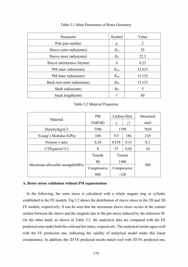
179
Table 5.1 Main Parameters of Rotor Geometry
Parameter Symbol Value
Pole pair number p 2
Sleeve outer radius(mm) Rso 25
Sleeve inner radius(mm) Rsi 22.5
Sleeve interference fit(mm) δ 0.25
PM outer radius(mm) Rmo 22.625
PM inner radius(mm) Rmi 15.125
Back-iron outer radius(mm) Rbo 15.125
Shaft radius(mm) Rbi 5
Stack length(mm) l 60
Table 5.2 Material Properties
Material PM
(NdFeB)
Carbon-fibre Structural
steel ⊥ ∕∕
Density(kg/m3) 7500 1790 7850
Young’s Modulus (GPa) 160 9.5 186 210
Poisson’s ratio 0.24 0.018 0.31 0.3
CTE(μm/m/°C) 8 35 0.02 10
Maximum allowable strength(MPa)
Tensile
80
Tensile
1400 500
Compressive
800
Compressive
-120
A. Rotor stress validation without PM segmentation
In the following, the rotor stress is calculated with a whole magnet ring or cylinder
established in the FE models. Fig.5.2 shows the distribution of sleeve stress in the 2D and 3D
FE models, respectively. It can be seen that the maximum sleeve stress occurs at the contact
surface between the sleeve and the magnets due to the pre-stress induced by the inference fit.
On the other hand, as shown in Table 5.3, the analytical data are compared with the FE
predicted ones under both the cold and hot states, respectively. The analytical results agree well
with the FE prediction one, indicating the validity of analytical model under this linear
circumstance. In addition, the 2D FE predicted results match well with 3D FE predicted one,

180
which indicates a quite small stress in the axial direction and therefore justifies the planar stress
assumption in the analytical models. Hence, the analytical models and 2D FE model are more
suitable for the stress calculation due to shorter computation time as well as acceptable
accuracy.
(a)
(b)
Fig.5.2. Sleeve tangential stress without magnet segmentation (T=20°C n= 100krpm). (a) 2D.
(b) 3D.
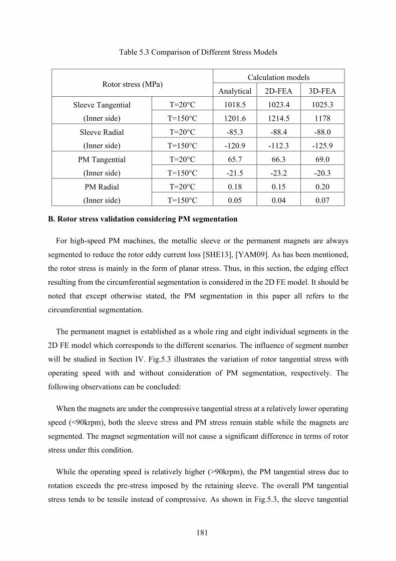
181
Table 5.3 Comparison of Different Stress Models
Rotor stress (MPa) Calculation models
Analytical 2D-FEA 3D-FEA
Sleeve Tangential
(Inner side)
T=20°C 1018.5 1023.4 1025.3
T=150°C 1201.6 1214.5 1178
Sleeve Radial
(Inner side)
T=20°C -85.3 -88.4 -88.0
T=150°C -120.9 -112.3 -125.9
PM Tangential
(Inner side)
T=20°C 65.7 66.3 69.0
T=150°C -21.5 -23.2 -20.3
PM Radial
(Inner side)
T=20°C 0.18 0.15 0.20
T=150°C 0.05 0.04 0.07
B. Rotor stress validation considering PM segmentation
For high-speed PM machines, the metallic sleeve or the permanent magnets are always
segmented to reduce the rotor eddy current loss [SHE13], [YAM09]. As has been mentioned,
the rotor stress is mainly in the form of planar stress. Thus, in this section, the edging effect
resulting from the circumferential segmentation is considered in the 2D FE model. It should be
noted that except otherwise stated, the PM segmentation in this paper all refers to the
circumferential segmentation.
The permanent magnet is established as a whole ring and eight individual segments in the
2D FE model which corresponds to the different scenarios. The influence of segment number
will be studied in Section IV. Fig.5.3 illustrates the variation of rotor tangential stress with
operating speed with and without consideration of PM segmentation, respectively. The
following observations can be concluded:
When the magnets are under the compressive tangential stress at a relatively lower operating
speed (<90krpm), both the sleeve stress and PM stress remain stable while the magnets are
segmented. The magnet segmentation will not cause a significant difference in terms of rotor
stress under this condition.
While the operating speed is relatively higher (>90krpm), the PM tangential stress due to
rotation exceeds the pre-stress imposed by the retaining sleeve. The overall PM tangential
stress tends to be tensile instead of compressive. As shown in Fig.5.3, the sleeve tangential
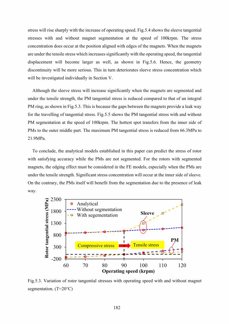
182
stress will rise sharply with the increase of operating speed. Fig.5.4 shows the sleeve tangential
stresses with and without magnet segmentation at the speed of 100krpm. The stress
concentration does occur at the position aligned with edges of the magnets. When the magnets
are under the tensile stress which increases significantly with the operating speed, the tangential
displacement will become larger as well, as shown in Fig.5.6. Hence, the geometry
discontinuity will be more serious. This in turn deteriorates sleeve stress concentration which
will be investigated individually in Section V.
Although the sleeve stress will increase significantly when the magnets are segmented and
under the tensile strength, the PM tangential stress is reduced compared to that of an integral
PM ring, as shown in Fig.5.3. This is because the gaps between the magnets provide a leak way
for the travelling of tangential stress. Fig.5.5 shows the PM tangential stress with and without
PM segmentation at the speed of 100krpm. The hottest spot transfers from the inner side of
PMs to the outer middle part. The maximum PM tangential stress is reduced from 66.3MPa to
21.9MPa.
To conclude, the analytical models established in this paper can predict the stress of rotor
with satisfying accuracy while the PMs are not segmented. For the rotors with segmented
magnets, the edging effect must be considered in the FE models, especially when the PMs are
under the tensile strength. Significant stress concentration will occur at the inner side of sleeve.
On the contrary, the PMs itself will benefit from the segmentation due to the presence of leak
way.
Fig.5.3. Variation of rotor tangential stresses with operating speed with and without magnet
segmentation. (T=20°C)
-200
300
800
1300
1800
2300
60 70 80 90 100 110 120
Rot
or ta
ngen
tial s
tres
s (M
Pa)
Operating speed (krpm)
AnalyticalWithout segmentationWith segementation Sleeve
PMTensile stressCompressive stress
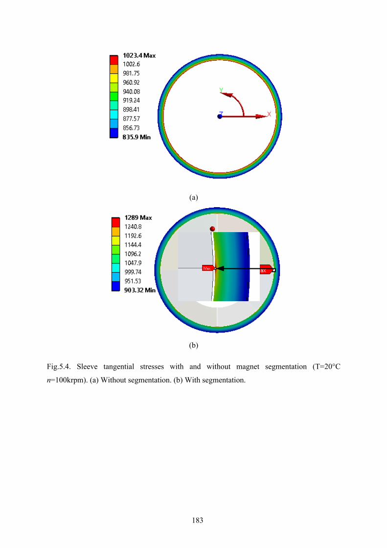
183
(a)
(b)
Fig.5.4. Sleeve tangential stresses with and without magnet segmentation (T=20°C
n=100krpm). (a) Without segmentation. (b) With segmentation.
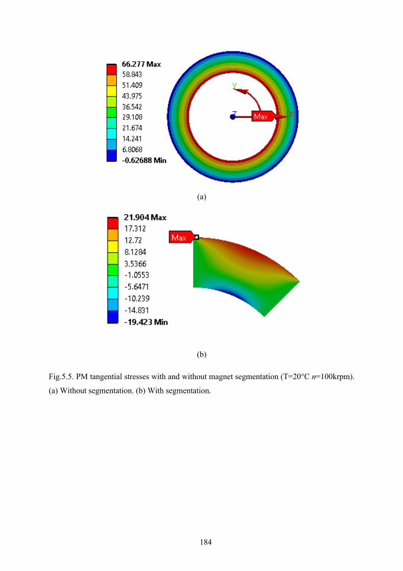
184
(a)
(b)
Fig.5.5. PM tangential stresses with and without magnet segmentation (T=20°C n=100krpm).
(a) Without segmentation. (b) With segmentation.
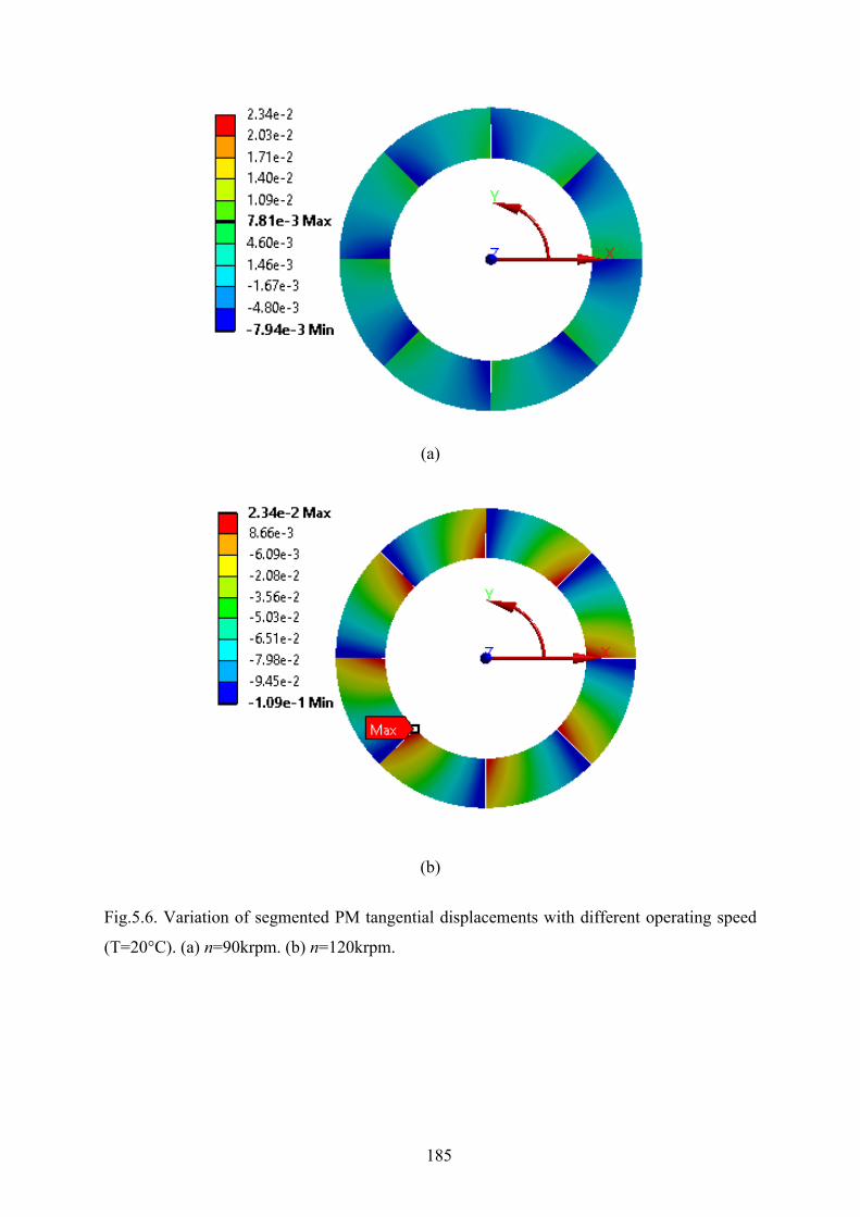
185
(a)
(b)
Fig.5.6. Variation of segmented PM tangential displacements with different operating speed
(T=20°C). (a) n=90krpm. (b) n=120krpm.

186
5.2.2 Determination of Worst Operating Scenarios Considering PM
Segmentation In the previous section, the influence of PM segmentation on the amplitude of rotor
tangential stress has been determined. However, this is only applicable within a narrow speed
range at a single rotor temperature. It remains unclear how the rotor stress will be affected in
the whole operating speed and rotor temperature range. Moreover, the rotor stress is also
significantly influenced by the mechanical design parameters such as sleeve thickness and
interference fit which can be seen from the established analytical equations.
Fig.5.7 shows the stress-impact factors which are grouped into three groups, namely
operating parameters, mechanical design parameters and geometry parameters. In real cases,
the geometry parameters are firstly determined in the initial electrical design process. With the
geometric parameters obtained from the initial electrical design, the mechanical design can
thereby conducted. The rotor stability check is normally conducted for different choices of
mechanical design parameters such as interference fit and sleeve thickness. Fundamentally, the
rotor mechanical stability conditions for a high-speed surface-mounted PM machine can be
written as
, lim
max min max
Ref[ ( )] , 0,0 ,
s m it c
bi si
rR r R T T T
σ σ σ< <
≤ ≤ ≤ Ω ≤ Ω ≤ ≤ (5.27)
As can be seen from (5.27), each rotating parts in the rotor must be smaller than the yield
strength or the tensile strength depending on the type of materials. For the carbon-fibre sleeve
and permanent magnet investigated in this paper, the Tresca’s criterion should be adopted. The
tangential stresses of sleeve and magnet must be smaller than the material tensile strength. In
addition, the contact pressure between the magnets and the rotor back-iron must be negative in
the cylindrical coordinate system, indicating that there is always a pressure pushing the PMs
into the back-iron so that the torque can be transferred. It should be noted that the
aforementioned conditions should be fulfilled in the whole speed and rotor temperature range.
Hence it is necessary to figure out the influence of operating speed and temperature on the rotor
stress so that maximum rotor stress can be quickly obtained and the post-check of mechanical
solutions can be more efficient. In other words, the worst operating scenarios concerning with
the speed and temperature should be determined, especially when the magnets are segmented.
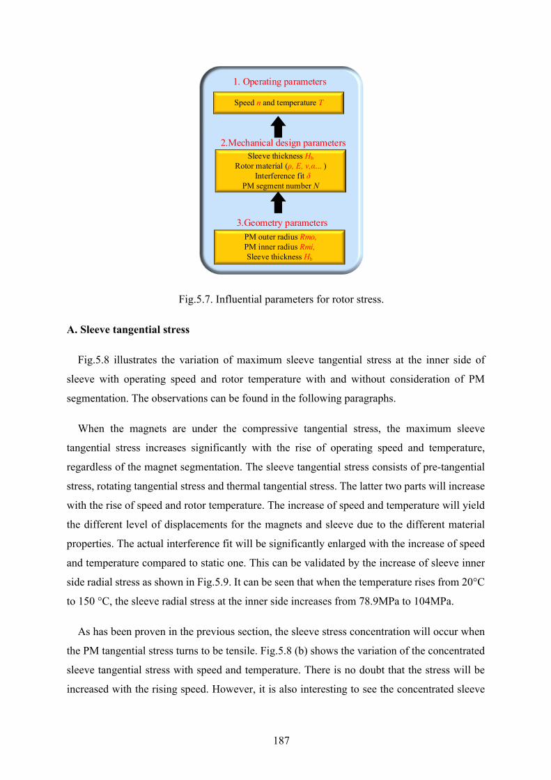
187
Fig.5.7. Influential parameters for rotor stress.
A. Sleeve tangential stress
Fig.5.8 illustrates the variation of maximum sleeve tangential stress at the inner side of
sleeve with operating speed and rotor temperature with and without consideration of PM
segmentation. The observations can be found in the following paragraphs.
When the magnets are under the compressive tangential stress, the maximum sleeve
tangential stress increases significantly with the rise of operating speed and temperature,
regardless of the magnet segmentation. The sleeve tangential stress consists of pre-tangential
stress, rotating tangential stress and thermal tangential stress. The latter two parts will increase
with the rise of speed and rotor temperature. The increase of speed and temperature will yield
the different level of displacements for the magnets and sleeve due to the different material
properties. The actual interference fit will be significantly enlarged with the increase of speed
and temperature compared to static one. This can be validated by the increase of sleeve inner
side radial stress as shown in Fig.5.9. It can be seen that when the temperature rises from 20°C
to 150 °C, the sleeve radial stress at the inner side increases from 78.9MPa to 104MPa.
As has been proven in the previous section, the sleeve stress concentration will occur when
the PM tangential stress turns to be tensile. Fig.5.8 (b) shows the variation of the concentrated
sleeve tangential stress with speed and temperature. There is no doubt that the stress will be
increased with the rising speed. However, it is also interesting to see the concentrated sleeve
Speed n and temperature T
1. Operating parameters
2.Mechanical design parametersSleeve thickness Hb
Rotor material (ρ, E, ν,α... ) Interference fit δ
PM segment number N
3.Geometry parameters PM outer radius Rmo,PM inner radius Rmi,Sleeve thickness Hb

188
tangential stress will reduce with the increase of rotor temperature. This can be explained by
the smaller gaps between PM segments when the temperature is higher. The PM tensile
tangential stress will be reduced with the increase of rotor speed as shown in Fig.5.11. Hence,
the deformation of magnet edges will be correspondingly reduced. Fig.5.10 illustrates the
tangential displacements of PMs under different rotor speed. The tangential displacement is
significantly reduced by 78.11%.
(a)
(b)
Fig.5.8. Variation of maximum sleeve tangential stress with operating speed and rotor
temperature with and without PM segmentation. (a) PMs under compressive tangential stress.
(b) PMs under tensile tangential stress.
150
900
100
1000
10080
1100
1200
605040
20
1000150120
1200
100
1400
110 60
1600
20100
1800
2000
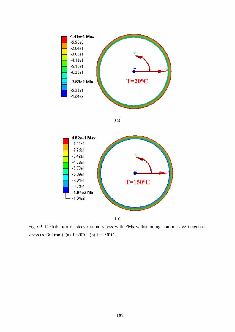
189
(a)
(b)
Fig.5.9. Distribution of sleeve radial stress with PMs withstanding compressive tangential
stress (n=30krpm). (a) T=20°C. (b) T=150°C.
T=20°C
T=150°C
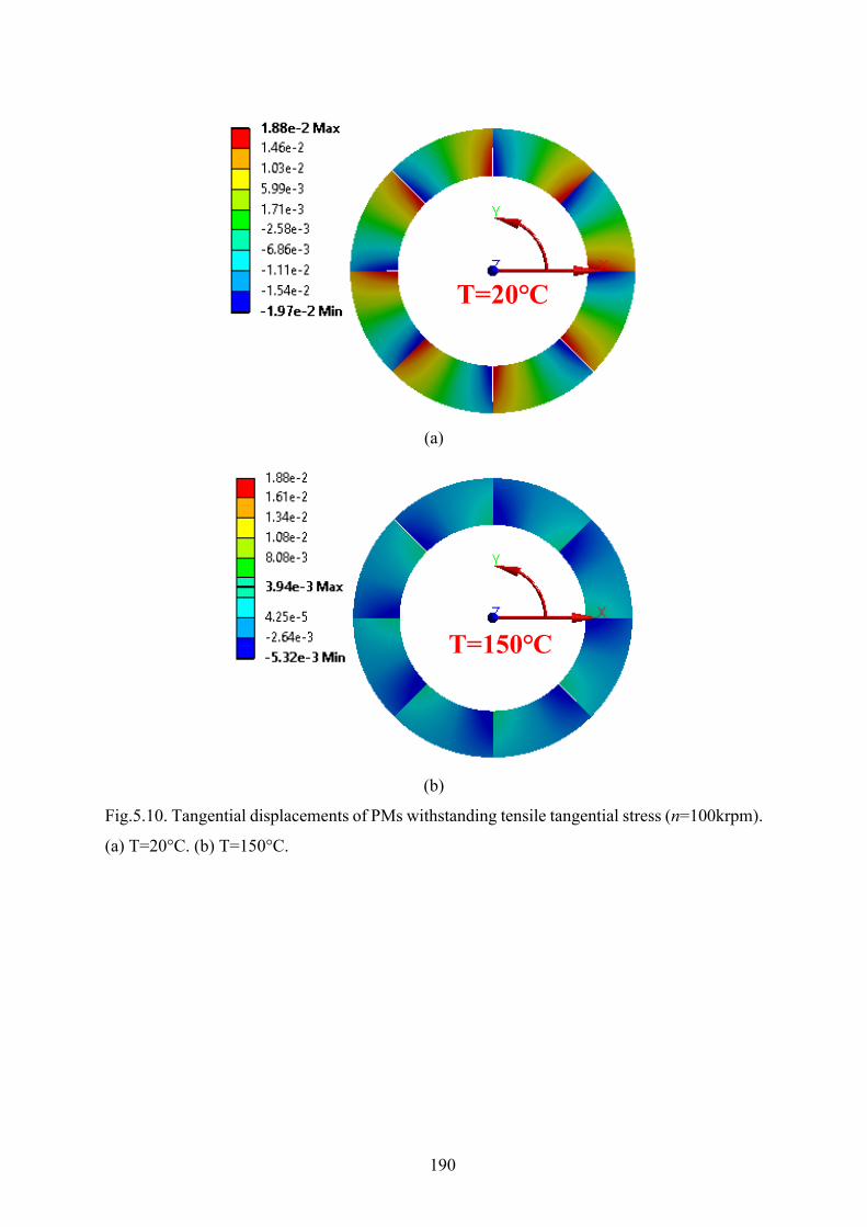
190
(a)
(b)
Fig.5.10. Tangential displacements of PMs withstanding tensile tangential stress (n=100krpm).
(a) T=20°C. (b) T=150°C.
T=20°C
T=150°C
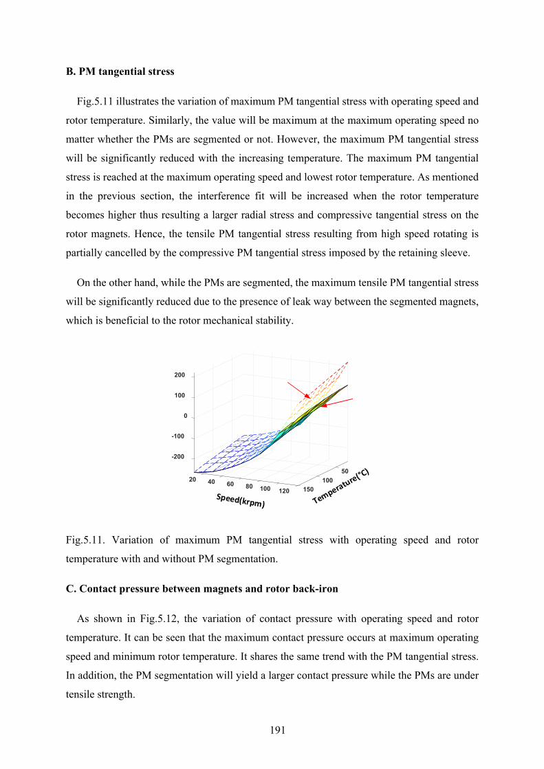
191
B. PM tangential stress
Fig.5.11 illustrates the variation of maximum PM tangential stress with operating speed and
rotor temperature. Similarly, the value will be maximum at the maximum operating speed no
matter whether the PMs are segmented or not. However, the maximum PM tangential stress
will be significantly reduced with the increasing temperature. The maximum PM tangential
stress is reached at the maximum operating speed and lowest rotor temperature. As mentioned
in the previous section, the interference fit will be increased when the rotor temperature
becomes higher thus resulting a larger radial stress and compressive tangential stress on the
rotor magnets. Hence, the tensile PM tangential stress resulting from high speed rotating is
partially cancelled by the compressive PM tangential stress imposed by the retaining sleeve.
On the other hand, while the PMs are segmented, the maximum tensile PM tangential stress
will be significantly reduced due to the presence of leak way between the segmented magnets,
which is beneficial to the rotor mechanical stability.
Fig.5.11. Variation of maximum PM tangential stress with operating speed and rotor
temperature with and without PM segmentation.
C. Contact pressure between magnets and rotor back-iron
As shown in Fig.5.12, the variation of contact pressure with operating speed and rotor
temperature. It can be seen that the maximum contact pressure occurs at maximum operating
speed and minimum rotor temperature. It shares the same trend with the PM tangential stress.
In addition, the PM segmentation will yield a larger contact pressure while the PMs are under
tensile strength.
50
-200
-100
0
20
100
100
200
40 60 80 100 150120
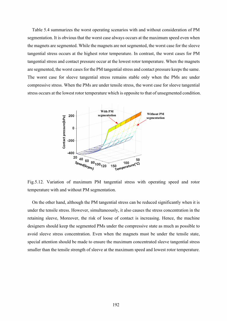
192
Table 5.4 summarizes the worst operating scenarios with and without consideration of PM
segmentation. It is obvious that the worst case always occurs at the maximum speed even when
the magnets are segmented. While the magnets are not segmented, the worst case for the sleeve
tangential stress occurs at the highest rotor temperature. In contrast, the worst cases for PM
tangential stress and contact pressure occur at the lowest rotor temperature. When the magnets
are segmented, the worst cases for the PM tangential stress and contact pressure keeps the same.
The worst case for sleeve tangential stress remains stable only when the PMs are under
compressive stress. When the PMs are under tensile stress, the worst case for sleeve tangential
stress occurs at the lowest rotor temperature which is opposite to that of unsegmented condition.
Fig.5.12. Variation of maximum PM tangential stress with operating speed and rotor
temperature with and without PM segmentation.
On the other hand, although the PM tangential stress can be reduced significantly when it is
under the tensile stress. However, simultaneously, it also causes the stress concentration in the
retaining sleeve, Moreover, the risk of loose of contact is increasing. Hence, the machine
designers should keep the segmented PMs under the compressive state as much as possible to
avoid sleeve stress concentration. Even when the magnets must be under the tensile state,
special attention should be made to ensure the maximum concentrated sleeve tangential stress
smaller than the tensile strength of sleeve at the maximum speed and lowest rotor temperature.
Cont
act p
ress
ure(
kPa)
Without PM segmentation
With PM segmentation
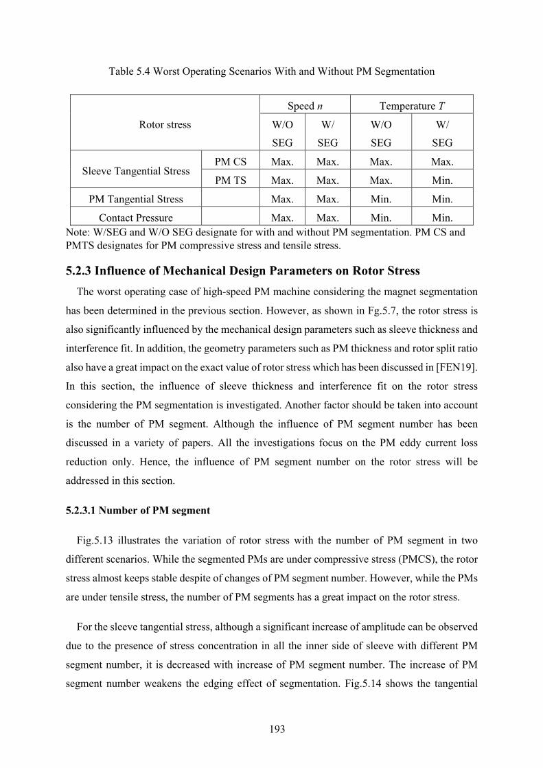
193
Table 5.4 Worst Operating Scenarios With and Without PM Segmentation
Rotor stress
Speed n Temperature T
W/O
SEG
W/
SEG
W/O
SEG
W/
SEG
Sleeve Tangential Stress PM CS Max. Max. Max. Max.
PM TS Max. Max. Max. Min.
PM Tangential Stress Max. Max. Min. Min.
Contact Pressure Max. Max. Min. Min. Note: W/SEG and W/O SEG designate for with and without PM segmentation. PM CS and PMTS designates for PM compressive stress and tensile stress.
5.2.3 Influence of Mechanical Design Parameters on Rotor Stress The worst operating case of high-speed PM machine considering the magnet segmentation
has been determined in the previous section. However, as shown in Fg.5.7, the rotor stress is
also significantly influenced by the mechanical design parameters such as sleeve thickness and
interference fit. In addition, the geometry parameters such as PM thickness and rotor split ratio
also have a great impact on the exact value of rotor stress which has been discussed in [FEN19].
In this section, the influence of sleeve thickness and interference fit on the rotor stress
considering the PM segmentation is investigated. Another factor should be taken into account
is the number of PM segment. Although the influence of PM segment number has been
discussed in a variety of papers. All the investigations focus on the PM eddy current loss
reduction only. Hence, the influence of PM segment number on the rotor stress will be
addressed in this section.
5.2.3.1 Number of PM segment
Fig.5.13 illustrates the variation of rotor stress with the number of PM segment in two
different scenarios. While the segmented PMs are under compressive stress (PMCS), the rotor
stress almost keeps stable despite of changes of PM segment number. However, while the PMs
are under tensile stress, the number of PM segments has a great impact on the rotor stress.
For the sleeve tangential stress, although a significant increase of amplitude can be observed
due to the presence of stress concentration in all the inner side of sleeve with different PM
segment number, it is decreased with increase of PM segment number. The increase of PM
segment number weakens the edging effect of segmentation. Fig.5.14 shows the tangential
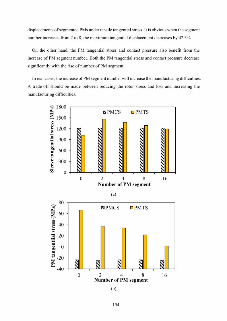
194
displacements of segmented PMs under tensile tangential stress. It is obvious when the segment
number increases from 2 to 8, the maximum tangential displacement decreases by 42.3%.
On the other hand, the PM tangential stress and contact pressure also benefit from the
increase of PM segment number. Both the PM tangential stress and contact pressure decrease
significantly with the rise of number of PM segment.
In real cases, the increase of PM segment number will increase the manufacturing difficulties.
A trade-off should be made between reducing the rotor stress and loss and increasing the
manufacturing difficulties.
(a)
(b)
0
300
600
900
1200
1500
1800
0 2 4 8 16
Slee
ve ta
ngen
tiial
stre
ss (M
Pa)
Number of PM segment
PMCS PMTS
-40
-20
0
20
40
60
80
0 2 4 8 16
PM ta
ngen
tiial
stre
ss (M
Pa)
Number of PM segment
PMCS PMTS
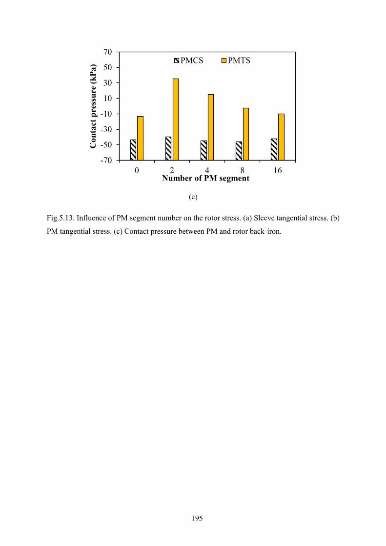
195
(c)
Fig.5.13. Influence of PM segment number on the rotor stress. (a) Sleeve tangential stress. (b)
PM tangential stress. (c) Contact pressure between PM and rotor back-iron.
-70
-50
-30
-10
10
30
50
70
0 2 4 8 16
Con
tact
pre
ssur
e (k
Pa)
Number of PM segment
PMCS PMTS
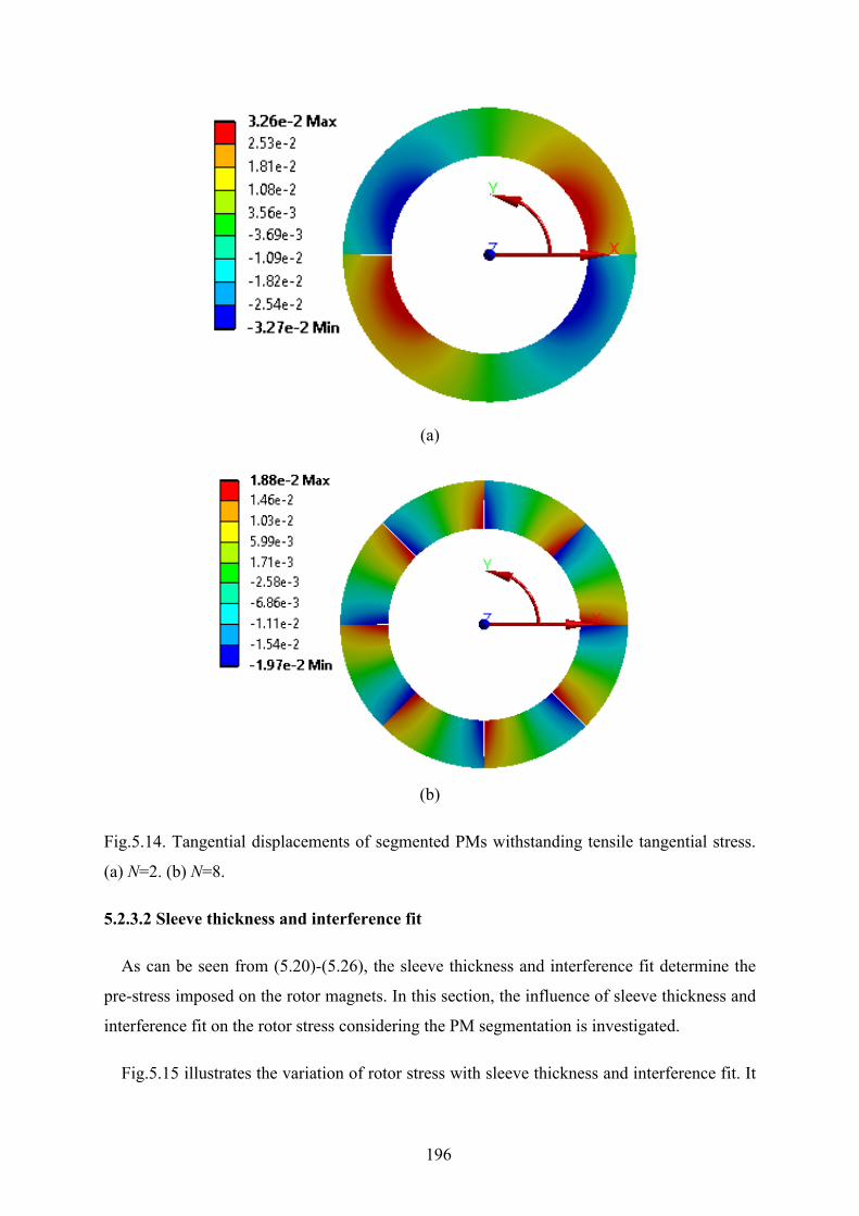
196
(a)
(b)
Fig.5.14. Tangential displacements of segmented PMs withstanding tensile tangential stress.
(a) N=2. (b) N=8.
5.2.3.2 Sleeve thickness and interference fit
As can be seen from (5.20)-(5.26), the sleeve thickness and interference fit determine the
pre-stress imposed on the rotor magnets. In this section, the influence of sleeve thickness and
interference fit on the rotor stress considering the PM segmentation is investigated.
Fig.5.15 illustrates the variation of rotor stress with sleeve thickness and interference fit. It
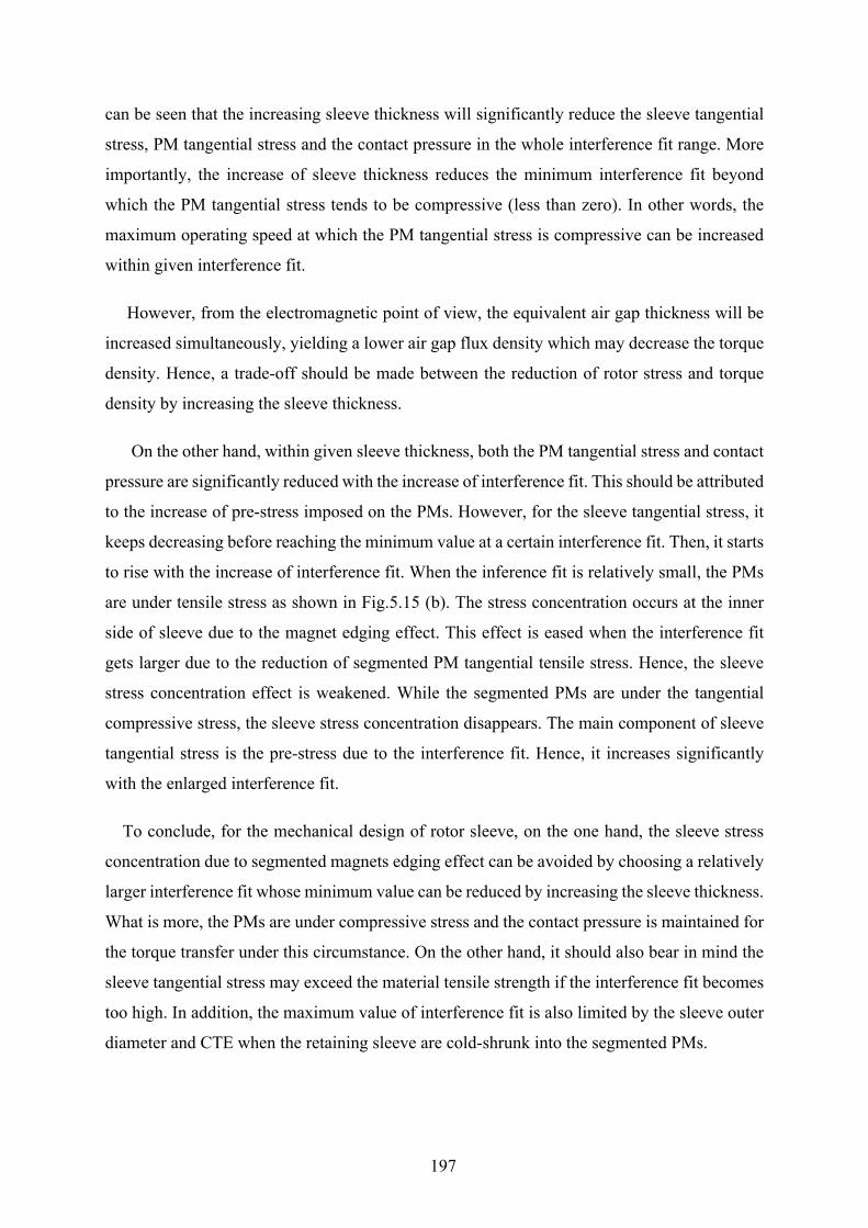
197
can be seen that the increasing sleeve thickness will significantly reduce the sleeve tangential
stress, PM tangential stress and the contact pressure in the whole interference fit range. More
importantly, the increase of sleeve thickness reduces the minimum interference fit beyond
which the PM tangential stress tends to be compressive (less than zero). In other words, the
maximum operating speed at which the PM tangential stress is compressive can be increased
within given interference fit.
However, from the electromagnetic point of view, the equivalent air gap thickness will be
increased simultaneously, yielding a lower air gap flux density which may decrease the torque
density. Hence, a trade-off should be made between the reduction of rotor stress and torque
density by increasing the sleeve thickness.
On the other hand, within given sleeve thickness, both the PM tangential stress and contact
pressure are significantly reduced with the increase of interference fit. This should be attributed
to the increase of pre-stress imposed on the PMs. However, for the sleeve tangential stress, it
keeps decreasing before reaching the minimum value at a certain interference fit. Then, it starts
to rise with the increase of interference fit. When the inference fit is relatively small, the PMs
are under tensile stress as shown in Fig.5.15 (b). The stress concentration occurs at the inner
side of sleeve due to the magnet edging effect. This effect is eased when the interference fit
gets larger due to the reduction of segmented PM tangential tensile stress. Hence, the sleeve
stress concentration effect is weakened. While the segmented PMs are under the tangential
compressive stress, the sleeve stress concentration disappears. The main component of sleeve
tangential stress is the pre-stress due to the interference fit. Hence, it increases significantly
with the enlarged interference fit.
To conclude, for the mechanical design of rotor sleeve, on the one hand, the sleeve stress
concentration due to segmented magnets edging effect can be avoided by choosing a relatively
larger interference fit whose minimum value can be reduced by increasing the sleeve thickness.
What is more, the PMs are under compressive stress and the contact pressure is maintained for
the torque transfer under this circumstance. On the other hand, it should also bear in mind the
sleeve tangential stress may exceed the material tensile strength if the interference fit becomes
too high. In addition, the maximum value of interference fit is also limited by the sleeve outer
diameter and CTE when the retaining sleeve are cold-shrunk into the segmented PMs.
198
(a)
(b)
600
800
1000
1200
1400
0.05 0.1 0.15 0.2 0.25 0.3 0.35
Slee
ve ta
ngen
tial s
tres
s (M
Pa)
Interference fit (mm)
Hb=3mm Hb=3.5mm Hb=4mm
increasing sleeve thickness
-200
-100
0
100
200
0.05 0.1 0.15 0.2 0.25 0.3 0.35
PM ta
ngen
tial s
tres
s (M
Pa)
Interference fit (mm)
Hb=3mm Hb=3.5mm Hb=4mm
increasing sleeve thickness
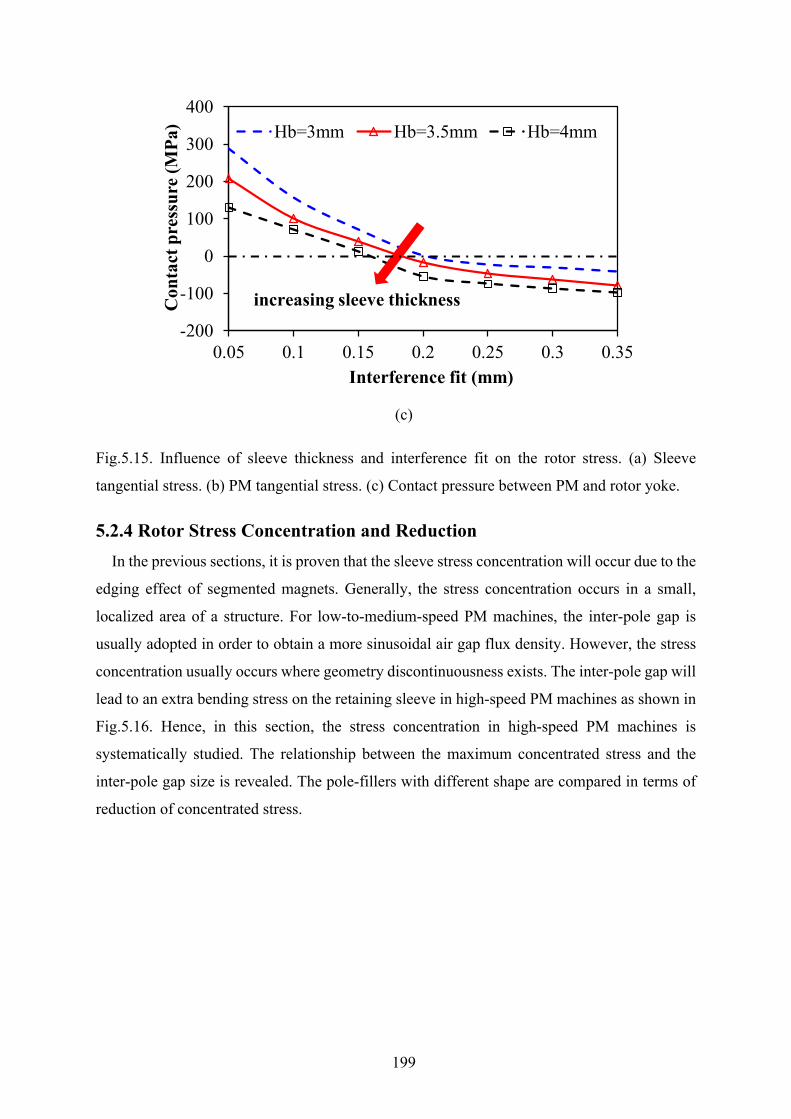
199
(c)
Fig.5.15. Influence of sleeve thickness and interference fit on the rotor stress. (a) Sleeve
tangential stress. (b) PM tangential stress. (c) Contact pressure between PM and rotor yoke.
5.2.4 Rotor Stress Concentration and Reduction In the previous sections, it is proven that the sleeve stress concentration will occur due to the
edging effect of segmented magnets. Generally, the stress concentration occurs in a small,
localized area of a structure. For low-to-medium-speed PM machines, the inter-pole gap is
usually adopted in order to obtain a more sinusoidal air gap flux density. However, the stress
concentration usually occurs where geometry discontinuousness exists. The inter-pole gap will
lead to an extra bending stress on the retaining sleeve in high-speed PM machines as shown in
Fig.5.16. Hence, in this section, the stress concentration in high-speed PM machines is
systematically studied. The relationship between the maximum concentrated stress and the
inter-pole gap size is revealed. The pole-fillers with different shape are compared in terms of
reduction of concentrated stress.
-200
-100
0
100
200
300
400
0.05 0.1 0.15 0.2 0.25 0.3 0.35
Con
tact
pre
ssur
e (M
Pa)
Interference fit (mm)
Hb=3mm Hb=3.5mm Hb=4mm
increasing sleeve thickness
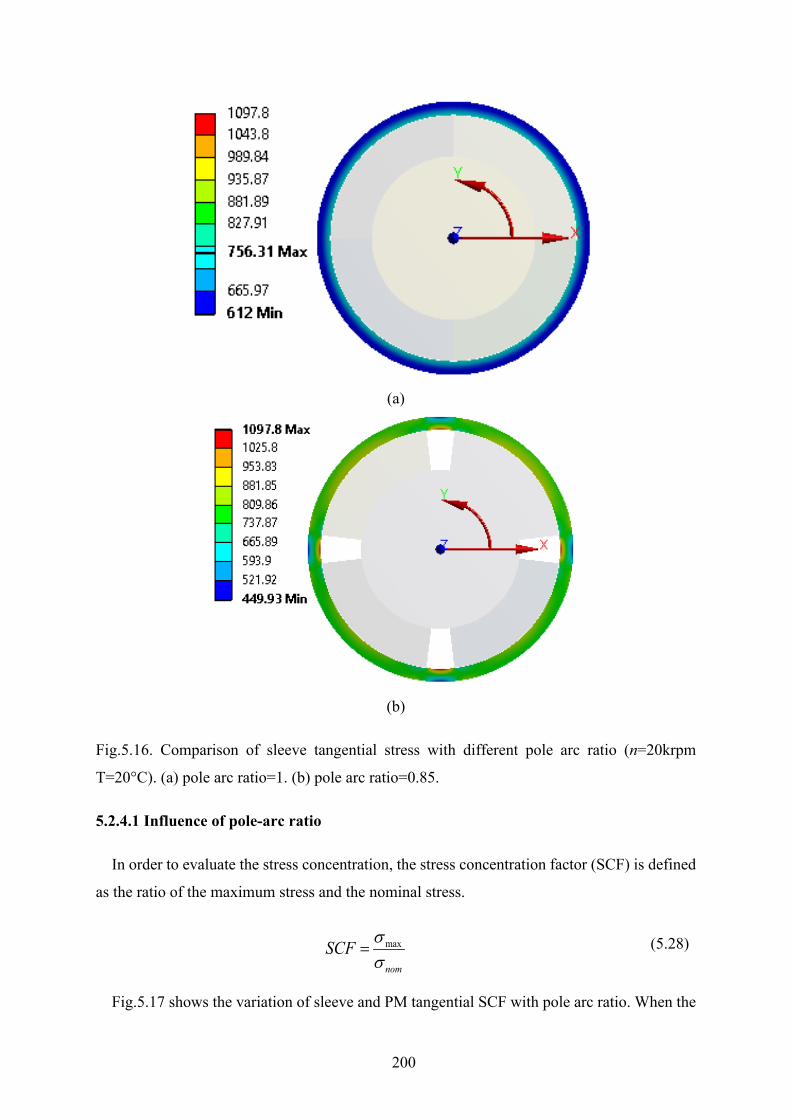
200
(a)
(b)
Fig.5.16. Comparison of sleeve tangential stress with different pole arc ratio (n=20krpm
T=20°C). (a) pole arc ratio=1. (b) pole arc ratio=0.85.
5.2.4.1 Influence of pole-arc ratio
In order to evaluate the stress concentration, the stress concentration factor (SCF) is defined
as the ratio of the maximum stress and the nominal stress.
max
nom
SCF σσ
= (5.28)
Fig.5.17 shows the variation of sleeve and PM tangential SCF with pole arc ratio. When the
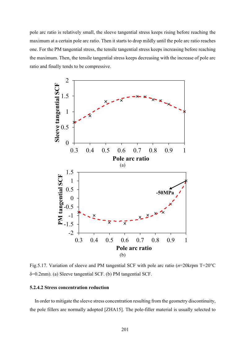
201
pole arc ratio is relatively small, the sleeve tangential stress keeps rising before reaching the
maximum at a certain pole arc ratio. Then it starts to drop mildly until the pole arc ratio reaches
one. For the PM tangential stress, the tensile tangential stress keeps increasing before reaching
the maximum. Then, the tensile tangential stress keeps decreasing with the increase of pole arc
ratio and finally tends to be compressive.
(a)
(b)
Fig.5.17. Variation of sleeve and PM tangential SCF with pole arc ratio (n=20krpm T=20°C
δ=0.2mm). (a) Sleeve tangential SCF. (b) PM tangential SCF.
5.2.4.2 Stress concentration reduction
In order to mitigate the sleeve stress concentration resulting from the geometry discontinuity,
the pole fillers are normally adopted [ZHA15]. The pole-filler material is usually selected to
0
0.5
1
1.5
2
0.3 0.4 0.5 0.6 0.7 0.8 0.9 1
Slee
ve ta
ngen
tial S
CF
Pole arc ratio
-2-1.5
-1-0.5
00.5
11.5
0.3 0.4 0.5 0.6 0.7 0.8 0.9 1
PM ta
ngen
tial S
CF
Pole arc ratio
-50MPa
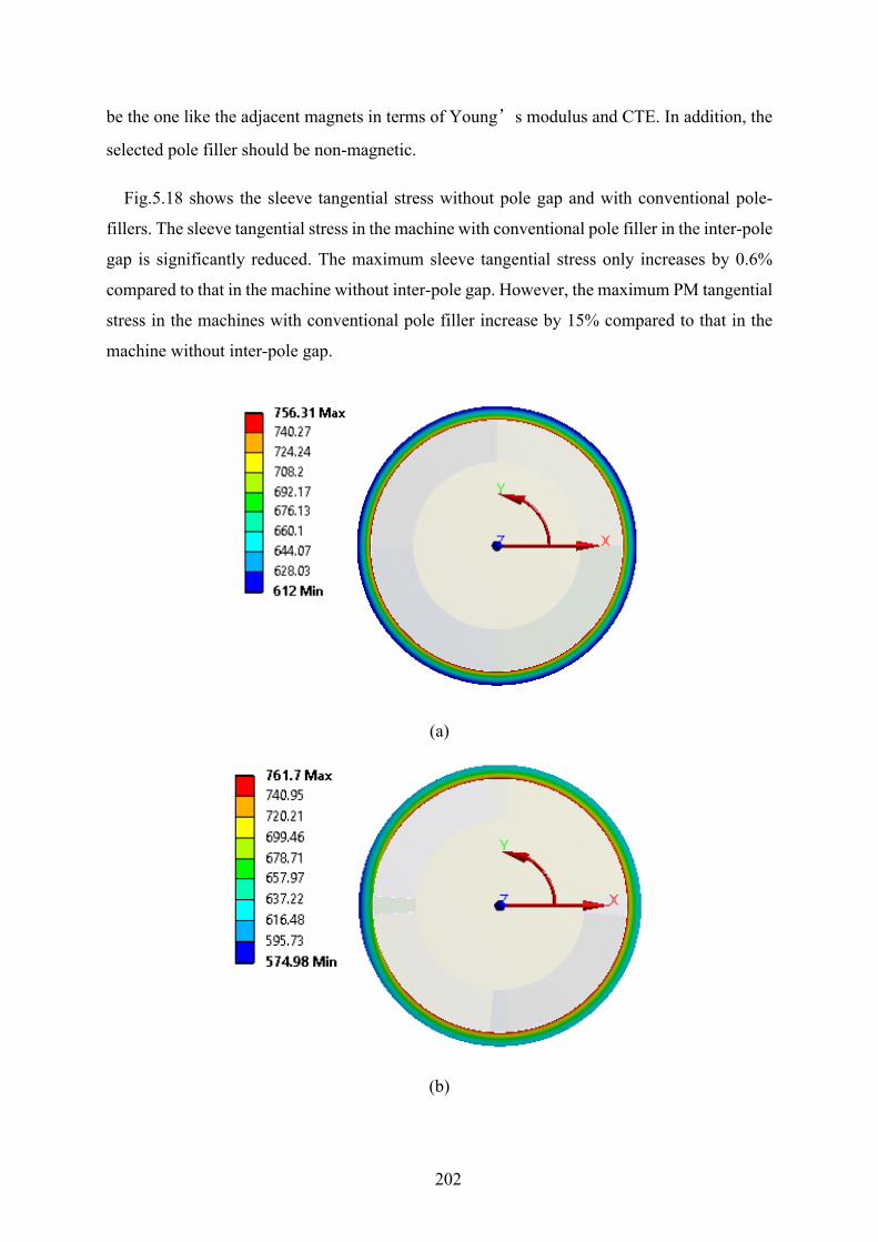
202
be the one like the adjacent magnets in terms of Young’s modulus and CTE. In addition, the
selected pole filler should be non-magnetic.
Fig.5.18 shows the sleeve tangential stress without pole gap and with conventional pole-
fillers. The sleeve tangential stress in the machine with conventional pole filler in the inter-pole
gap is significantly reduced. The maximum sleeve tangential stress only increases by 0.6%
compared to that in the machine without inter-pole gap. However, the maximum PM tangential
stress in the machines with conventional pole filler increase by 15% compared to that in the
machine without inter-pole gap.
(a)
(b)
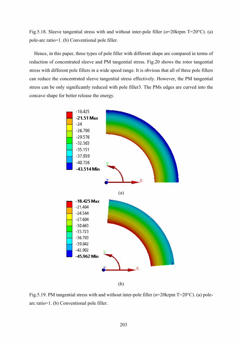
203
Fig.5.18. Sleeve tangential stress with and without inter-pole filler (n=20krpm T=20°C). (a)
pole-arc ratio=1. (b) Conventional pole filler.
Hence, in this paper, three types of pole filler with different shape are compared in terms of
reduction of concentrated sleeve and PM tangential stress. Fig.20 shows the rotor tangential
stress with different pole fillers in a wide speed range. It is obvious that all of three pole fillers
can reduce the concentrated sleeve tangential stress effectively. However, the PM tangential
stress can be only significantly reduced with pole filler3. The PMs edges are curved into the
concave shape for better release the energy.
(a)
(b)
Fig.5.19. PM tangential stress with and without inter-pole filler (n=20krpm T=20°C). (a) pole-
arc ratio=1. (b) Conventional pole filler.
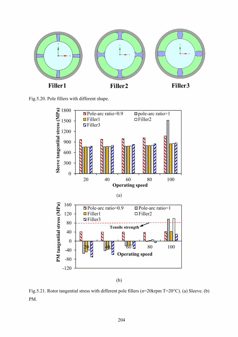
204
Fig.5.20. Pole fillers with different shape.
(a)
(b)
Fig.5.21. Rotor tangential stress with different pole fillers (n=20krpm T=20°C). (a) Sleeve. (b)
PM.
Filler1 Filler2 Filler3
0
300
600
900
1200
1500
1800
20 40 60 80 100
Slee
ve ta
ngen
tiial
stre
ss (M
Pa)
Operating speed
Pole-arc ratio=0.9 pole-arc ratio=1Filler1 Filler2Filler3
-120
-80
-40
0
40
80
120
160
20 40 60 80 100
PM ta
ngen
tiial
stre
ss (M
Pa)
Operating speed
Pole-arc ratio=0.9 Pole-arc ratio=1Filler1 Filler2Filler3
Tensile strength
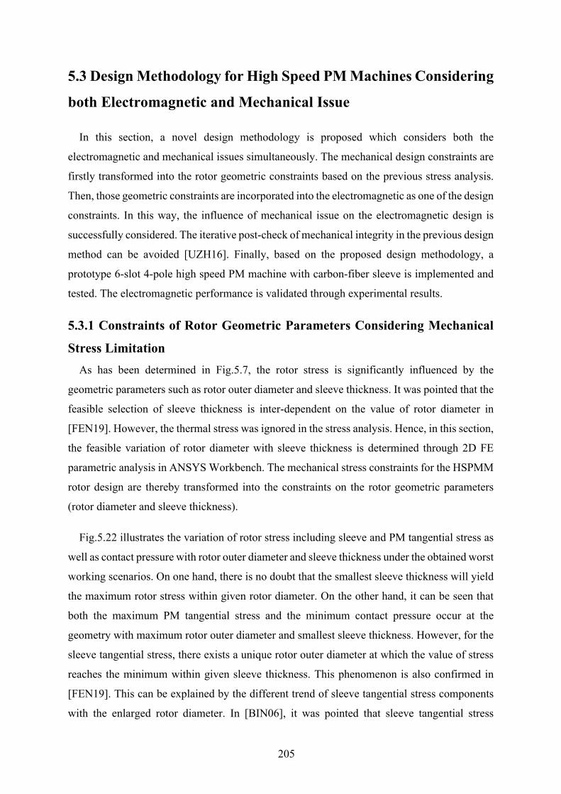
205
5.3 Design Methodology for High Speed PM Machines Considering
both Electromagnetic and Mechanical Issue
In this section, a novel design methodology is proposed which considers both the
electromagnetic and mechanical issues simultaneously. The mechanical design constraints are
firstly transformed into the rotor geometric constraints based on the previous stress analysis.
Then, those geometric constraints are incorporated into the electromagnetic as one of the design
constraints. In this way, the influence of mechanical issue on the electromagnetic design is
successfully considered. The iterative post-check of mechanical integrity in the previous design
method can be avoided [UZH16]. Finally, based on the proposed design methodology, a
prototype 6-slot 4-pole high speed PM machine with carbon-fiber sleeve is implemented and
tested. The electromagnetic performance is validated through experimental results.
5.3.1 Constraints of Rotor Geometric Parameters Considering Mechanical
Stress Limitation As has been determined in Fig.5.7, the rotor stress is significantly influenced by the
geometric parameters such as rotor outer diameter and sleeve thickness. It was pointed that the
feasible selection of sleeve thickness is inter-dependent on the value of rotor diameter in
[FEN19]. However, the thermal stress was ignored in the stress analysis. Hence, in this section,
the feasible variation of rotor diameter with sleeve thickness is determined through 2D FE
parametric analysis in ANSYS Workbench. The mechanical stress constraints for the HSPMM
rotor design are thereby transformed into the constraints on the rotor geometric parameters
(rotor diameter and sleeve thickness).
Fig.5.22 illustrates the variation of rotor stress including sleeve and PM tangential stress as
well as contact pressure with rotor outer diameter and sleeve thickness under the obtained worst
working scenarios. On one hand, there is no doubt that the smallest sleeve thickness will yield
the maximum rotor stress within given rotor diameter. On the other hand, it can be seen that
both the maximum PM tangential stress and the minimum contact pressure occur at the
geometry with maximum rotor outer diameter and smallest sleeve thickness. However, for the
sleeve tangential stress, there exists a unique rotor outer diameter at which the value of stress
reaches the minimum within given sleeve thickness. This phenomenon is also confirmed in
[FEN19]. This can be explained by the different trend of sleeve tangential stress components
with the enlarged rotor diameter. In [BIN06], it was pointed that sleeve tangential stress
206
consists of pre-stress due to the shrink-fit between sleeve and rotor magnets and the rotation
stress. The pre-stress is reduced with the increase of rotor diameter in the hyperbolic trend due
to the decreasing strain. On the other hand, as can be seen from (5.11) the rotation tangential
stress is proportional to the square of rotor diameter. Hence, the sleeve tangential stress starts
to decrease with the increase of rotor diameter due to the dominating pre-stress reduction effect.
When the rotor diameter become larger, the pre-stress tends to be stable. However, the sleeve
tangential stress due to rotation increase significantly with the rotor outer diameter. Hence, the
resultant sleeve tangential stress becomes larger.
On the other hand, according to the aforementioned conditions for rotor non-failure of
HSPMM, the stress limitation surfaces are placed in Fig.5.22. It can be seen from Fig.5.22 (a)
that the lower part of surface is valid. There are three intersections created by the six surfaces.
When those intersection are projected into the 2D plane (X-Y plane), the valid selection of
rotor diameter and sleeve thickness can thereby be obtained as shown in Fig.5.23. It should be
noted that although the PM tensile stress limit is 80MPa, the limitation surface is set to be
0MPa to ensure the PMs are under compressive tangential stress so that the stress concentration
can be avoided when the PM segmentation is adopted.
With the help of curve-fitting tool in MATLAB, the analytical expression of rotor geometric
constraints considering the rotor mechanical integrity can be written as:
where k1, k2, k3, k4 are the coefficients which highly depend on the permanent magnet thickness,
interference fit, retaining sleeve and permanent magnet material as well as maximum operating
speed and rotor temperature.
3 21 2 3 4b mo mo moH k R k R k R k≥ + + + (5.28)
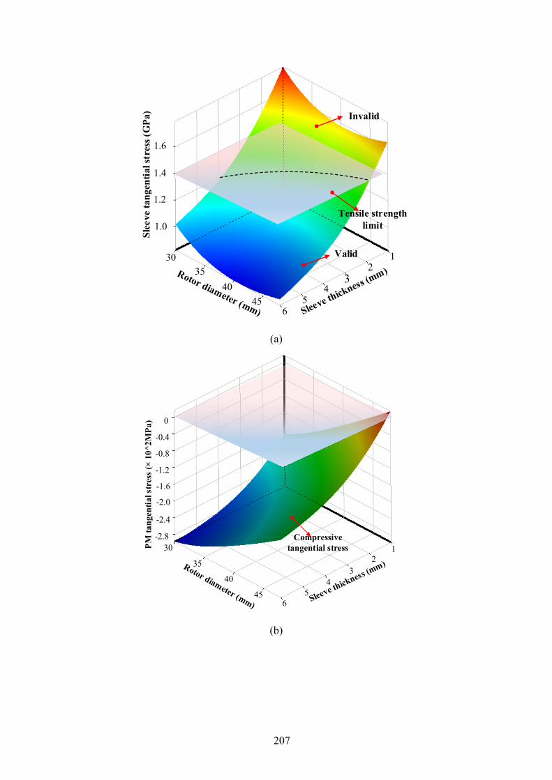
207
(a)
(b)
Valid
Invalid
Tensile strength limit
12
34
56
1.6
1.4
1.2
1.0
35
Slee
ve ta
ngen
tial s
tres
s (G
Pa)
4540
30
PM ta
ngen
tial s
tres
s (×
10^
2MPa
)
30
40
45
35
12
34
56
-0.4
0
-0.8
-1.2
-1.6
-2.0
-2.4
-2.8 Compressive tangential stress
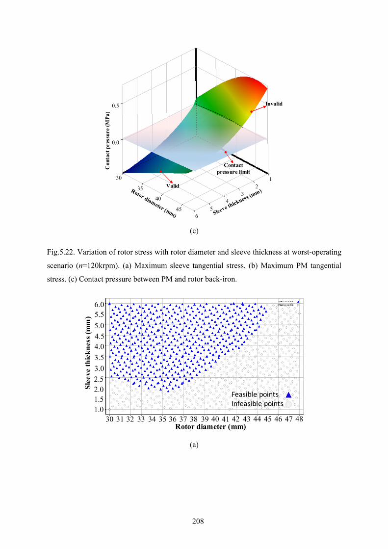
208
(c)
Fig.5.22. Variation of rotor stress with rotor diameter and sleeve thickness at worst-operating
scenario (n=120krpm). (a) Maximum sleeve tangential stress. (b) Maximum PM tangential
stress. (c) Contact pressure between PM and rotor back-iron.
(a)
Invalid
Valid
Contact pressure limit
Con
tact
pre
ssur
e (M
Pa)
35
45
40
30 12
34
56
0.0
0.5
Slee
ve th
ickn
ess (
mm
)
Rotor diameter (mm)30 31 32 33 34 35 36 37 38 39 40 41 42 43 44 45 46 47 48
1.01.52.02.53.03.54.04.55.05.56.0
Feasible pointsInfeasible points
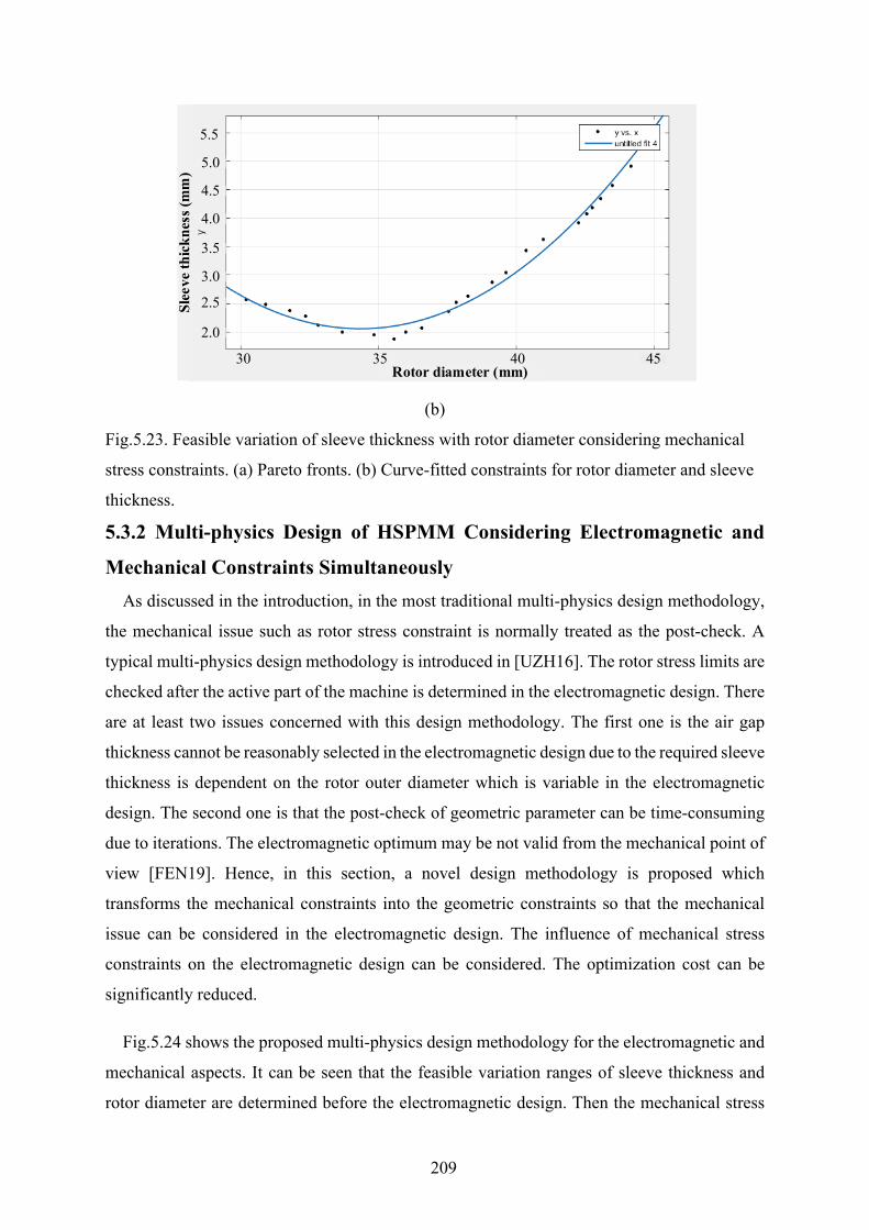
209
(b)
Fig.5.23. Feasible variation of sleeve thickness with rotor diameter considering mechanical
stress constraints. (a) Pareto fronts. (b) Curve-fitted constraints for rotor diameter and sleeve
thickness.
5.3.2 Multi-physics Design of HSPMM Considering Electromagnetic and
Mechanical Constraints Simultaneously As discussed in the introduction, in the most traditional multi-physics design methodology,
the mechanical issue such as rotor stress constraint is normally treated as the post-check. A
typical multi-physics design methodology is introduced in [UZH16]. The rotor stress limits are
checked after the active part of the machine is determined in the electromagnetic design. There
are at least two issues concerned with this design methodology. The first one is the air gap
thickness cannot be reasonably selected in the electromagnetic design due to the required sleeve
thickness is dependent on the rotor outer diameter which is variable in the electromagnetic
design. The second one is that the post-check of geometric parameter can be time-consuming
due to iterations. The electromagnetic optimum may be not valid from the mechanical point of
view [FEN19]. Hence, in this section, a novel design methodology is proposed which
transforms the mechanical constraints into the geometric constraints so that the mechanical
issue can be considered in the electromagnetic design. The influence of mechanical stress
constraints on the electromagnetic design can be considered. The optimization cost can be
significantly reduced.
Fig.5.24 shows the proposed multi-physics design methodology for the electromagnetic and
mechanical aspects. It can be seen that the feasible variation ranges of sleeve thickness and
rotor diameter are determined before the electromagnetic design. Then the mechanical stress
Rotor diameter (mm)3530 40 45
2.0
2.5
3.0
3.5
4.0
4.5
5.0
5.5
Slee
ve th
ickn
ess (
mm
)
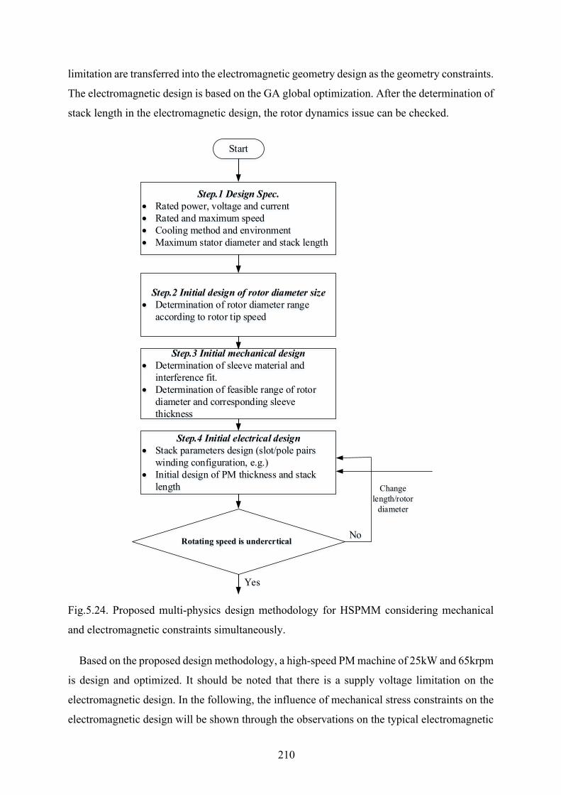
210
limitation are transferred into the electromagnetic geometry design as the geometry constraints.
The electromagnetic design is based on the GA global optimization. After the determination of
stack length in the electromagnetic design, the rotor dynamics issue can be checked.
Fig.5.24. Proposed multi-physics design methodology for HSPMM considering mechanical
and electromagnetic constraints simultaneously.
Based on the proposed design methodology, a high-speed PM machine of 25kW and 65krpm
is design and optimized. It should be noted that there is a supply voltage limitation on the
electromagnetic design. In the following, the influence of mechanical stress constraints on the
electromagnetic design will be shown through the observations on the typical electromagnetic
Step.1 Design Spec.• Rated power, voltage and current• Rated and maximum speed • Cooling method and environment• Maximum stator diameter and stack length
Step.2 Initial design of rotor diameter size • Determination of rotor diameter range
according to rotor tip speed
Step.3 Initial mechanical design • Determination of sleeve material and
interference fit.• Determination of feasible range of rotor
diameter and corresponding sleeve thickness
Step.4 Initial electrical design • Stack parameters design (slot/pole pairs
winding configuration, e.g.)• Initial design of PM thickness and stack
length
No
Change length/rotor
diameter
Rotating speed is undercrtical
Yes
Start
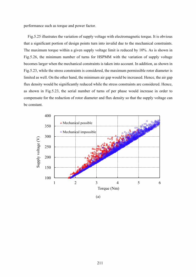
211
performance such as torque and power factor.
Fig.5.25 illustrates the variation of supply voltage with electromagnetic torque. It is obvious
that a significant portion of design points turn into invalid due to the mechanical constraints.
The maximum torque within a given supply voltage limit is reduced by 10%. As is shown in
Fig.5.26, the minimum number of turns for HSPMM with the variation of supply voltage
becomes larger when the mechanical constraints is taken into account. In addition, as shown in
Fig.5.23, while the stress constraints is considered, the maximum permissible rotor diameter is
limited as well. On the other hand, the minimum air gap would be increased. Hence, the air gap
flux density would be significantly reduced while the stress constraints are considered. Hence,
as shown in Fig.5.23, the serial number of turns of per phase would increase in order to
compensate for the reduction of rotor diameter and flux density so that the supply voltage can
be constant.
(a)
100
150
200
250
300
350
400
1 2 3 4 5 6
Supp
ly v
olta
ge (V
)
Torque (Nm)
Mechanical possible
Mechanical impossible
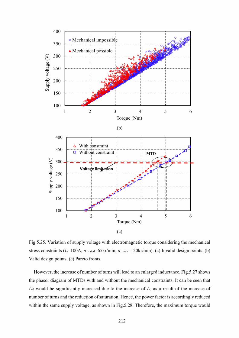
212
(b)
(c)
Fig.5.25. Variation of supply voltage with electromagnetic torque considering the mechanical
stress constraints (Ia=100A, n_rated=65kr/min, n_max=120kr/min). (a) Invalid design points. (b)
Valid design points. (c) Pareto fronts.
However, the increase of number of turns will lead to an enlarged inductance. Fig.5.27 shows
the phasor diagram of MTDs with and without the mechanical constraints. It can be seen that
Ud would be significantly increased due to the increase of Ld as a result of the increase of
number of turns and the reduction of saturation. Hence, the power factor is accordingly reduced
within the same supply voltage, as shown in Fig.5.28. Therefore, the maximum torque would
100
150
200
250
300
350
400
1 2 3 4 5 6
Supp
ly v
olta
ge (V
)
Torque (Nm)
Mechanical impossible
Mechanical possible
100
150
200
250
300
350
400
1 2 3 4 5 6
Supp
ly v
olta
ge (V
)
Torque (Nm)
With constraintWithout constraint MTD
Voltage limitation
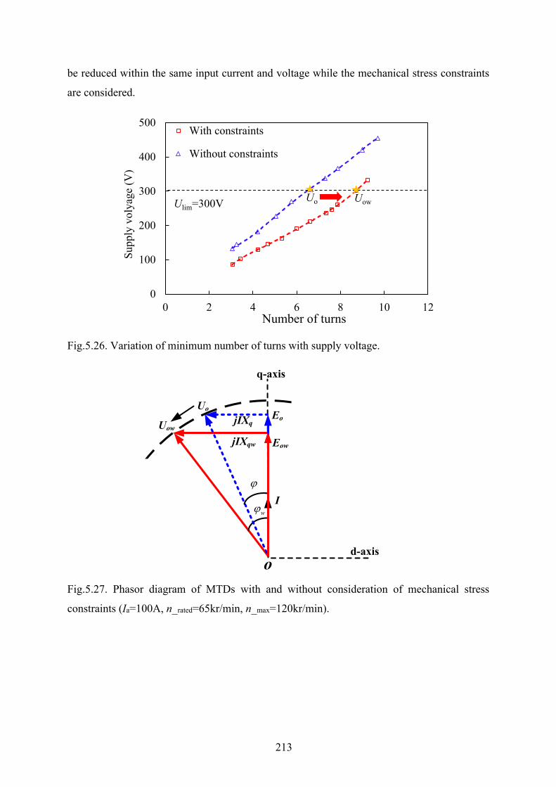
213
be reduced within the same input current and voltage while the mechanical stress constraints
are considered.
Fig.5.26. Variation of minimum number of turns with supply voltage.
Fig.5.27. Phasor diagram of MTDs with and without consideration of mechanical stress
constraints (Ia=100A, n_rated=65kr/min, n_max=120kr/min).
0
100
200
300
400
500
0 2 4 6 8 10 12
Supp
ly v
olya
ge (V
)
Number of turns
With constraints
Without constraints
Ulim=300V Uo Uow
d-axis
q-axis
I
jIXqEo
Uo
Uow
jIXqw Eow
o
ϕ
wϕ
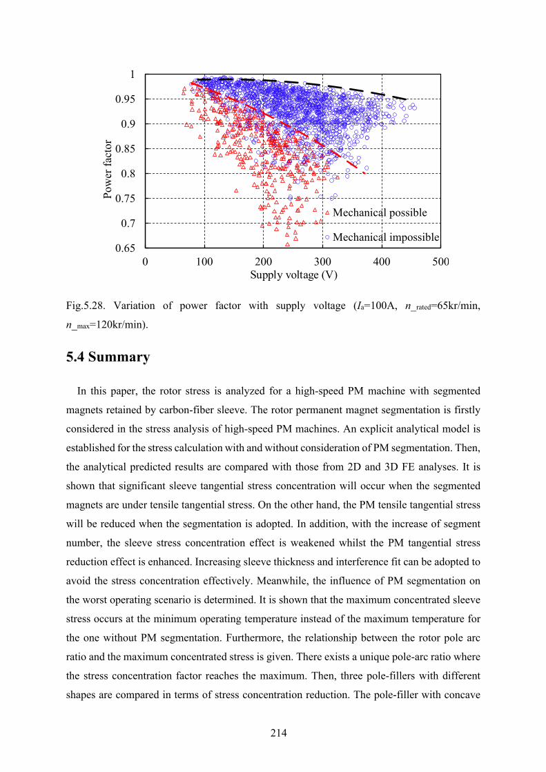
214
Fig.5.28. Variation of power factor with supply voltage (Ia=100A, n_rated=65kr/min,
n_max=120kr/min).
5.4 Summary
In this paper, the rotor stress is analyzed for a high-speed PM machine with segmented
magnets retained by carbon-fiber sleeve. The rotor permanent magnet segmentation is firstly
considered in the stress analysis of high-speed PM machines. An explicit analytical model is
established for the stress calculation with and without consideration of PM segmentation. Then,
the analytical predicted results are compared with those from 2D and 3D FE analyses. It is
shown that significant sleeve tangential stress concentration will occur when the segmented
magnets are under tensile tangential stress. On the other hand, the PM tensile tangential stress
will be reduced when the segmentation is adopted. In addition, with the increase of segment
number, the sleeve stress concentration effect is weakened whilst the PM tangential stress
reduction effect is enhanced. Increasing sleeve thickness and interference fit can be adopted to
avoid the stress concentration effectively. Meanwhile, the influence of PM segmentation on
the worst operating scenario is determined. It is shown that the maximum concentrated sleeve
stress occurs at the minimum operating temperature instead of the maximum temperature for
the one without PM segmentation. Furthermore, the relationship between the rotor pole arc
ratio and the maximum concentrated stress is given. There exists a unique pole-arc ratio where
the stress concentration factor reaches the maximum. Then, three pole-fillers with different
shapes are compared in terms of stress concentration reduction. The pole-filler with concave
0.65
0.7
0.75
0.8
0.85
0.9
0.95
1
0 100 200 300 400 500
Pow
er fa
ctor
Torque (Nm)
Mechanical possible
Mechanical impossible
Supply voltage (V)

215
shaped edge is proved to be better in the reduction of PM tangential stress. With the obtained
geometric constraints from the mechanical stress limitation, a novel multi-physics design
methodology considering the electromagnetic and mechanical issue simultaneously is
proposed. The influence of mechanical constraints on the electromagnetic design is analyzed.
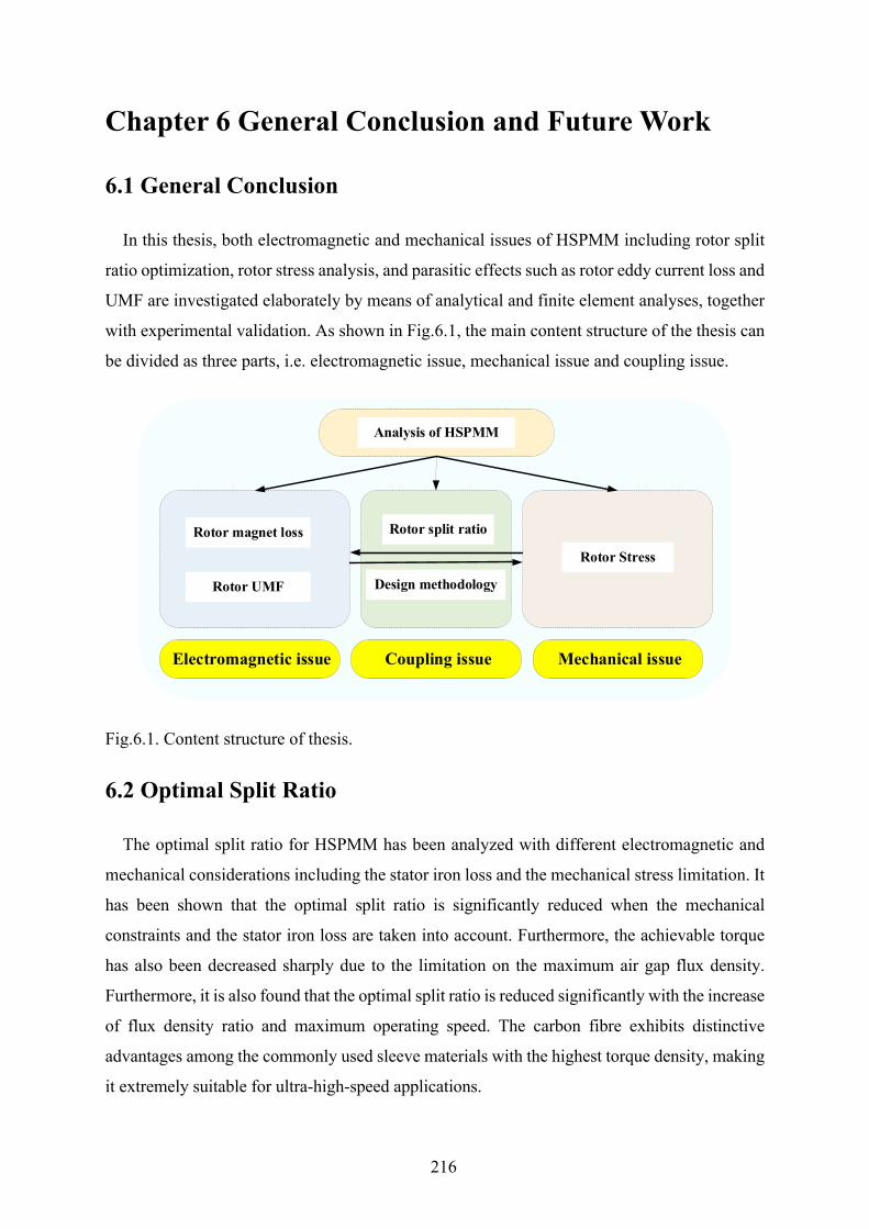
216
Chapter 6 General Conclusion and Future Work
6.1 General Conclusion
In this thesis, both electromagnetic and mechanical issues of HSPMM including rotor split
ratio optimization, rotor stress analysis, and parasitic effects such as rotor eddy current loss and
UMF are investigated elaborately by means of analytical and finite element analyses, together
with experimental validation. As shown in Fig.6.1, the main content structure of the thesis can
be divided as three parts, i.e. electromagnetic issue, mechanical issue and coupling issue.
Fig.6.1. Content structure of thesis.
6.2 Optimal Split Ratio
The optimal split ratio for HSPMM has been analyzed with different electromagnetic and
mechanical considerations including the stator iron loss and the mechanical stress limitation. It
has been shown that the optimal split ratio is significantly reduced when the mechanical
constraints and the stator iron loss are taken into account. Furthermore, the achievable torque
has also been decreased sharply due to the limitation on the maximum air gap flux density.
Furthermore, it is also found that the optimal split ratio is reduced significantly with the increase
of flux density ratio and maximum operating speed. The carbon fibre exhibits distinctive
advantages among the commonly used sleeve materials with the highest torque density, making
it extremely suitable for ultra-high-speed applications.
Analysis of HSPMM
Rotor magnet loss
Rotor UMF
Rotor Stress
Rotor split ratio
Design methodology
Electromagnetic issue Mechanical issueCoupling issue

217
6.3 Rotor Eddy Current Loss
The rotor eddy current losses of the four-pole HSPMM with various stator winding
configurations are investigated. The contribution of each harmonic in the production of magnet
loss, either from PM field or armature field, is determined with the proposed method. It is
observed that the 4th spatial harmonic dominates in the production of magnet loss for the 6-
slot/4-pole HSPMM. In addition, the slotting effect on both the PM field-induced and armature
reaction induced magnet losses is revealed. It is found that the open-circuit magnet loss due to
slot opening is significantly increased with the enlarged slot opening angle. On the other hand,
the magnet loss generated by the 4th spatial harmonic due to slot modulation is almost negligible.
The armature reaction induced magnet losses with various stator winding configurations are
compared as well. It is observed that the value of magnet loss is dependent on both the
penetration depth and the amplitude of asynchronous spatial harmonic, which are determined
by the specific slot and pole number combination.
6.4 Rotor Mechanical Stress and Design Methodology
The rotor stress is analyzed for a high-speed PM machine with segmented magnets retained
by carbon-fiber sleeve with an explicit analytical model. The rotor permanent magnet
segmentation is firstly considered in the stress analysis. It is shown that significant sleeve
tangential stress concentration will occur when the segmented magnets are under tensile
tangential stress. On the other hand, the PM tensile tangential stress will be reduced when the
segmentation is adopted. In addition, with the increase of segment number, the sleeve stress
concentration effect is weakened whilst the PM tangential stress reduction effect is enhanced.
It is shown that the maximum concentrated sleeve stress occurs at the minimum operating
temperature instead of the maximum temperature for the one without PM segmentation. Then,
three pole-fillers with different shapes are compared in terms of stress concentration reduction.
The pole-filler with concave shaped edge is proved to be better in the reduction of PM
tangential stress. With the obtained geometric constraints from the mechanical stress limitation,
a novel multi-physics design methodology considering the electromagnetic and mechanical
issues simultaneously is proposed.
6.5 Unbalanced Magnetic Force
The existence criterion of UMF both on open-circuit and on-load conditions in fractional-
218
slot PM machines with odd stator slot number is investigated. It is concluded that only when
the machine periodicity is one and the stator slotting effect is considered, will the open-circuit
UMF be generated due to the mutual interaction between the modulated PM harmonics and the
original PM harmonics. On the other hand, the existence criterion of on-load UMF in the
machines with periodicity of one is confirmed since both the self-interaction of armature
reaction harmonics and the mutual interaction between the fundamental PM harmonic and the
armature reaction harmonics will appear even when the slotting effect is ignored. Furthermore,
the influence of slot and pole number combination on the resultant UMF is investigated in
depth. The fractional-slot PM machines with a lower pole number, e.g. 2-pole and 4-pole, are
compared with machines with a pole number 2p=Ns±1. The UMF in the machine with two
poles is the smallest due to the smallest magnitude of the 2nd harmonic in armature reaction
field compared with counterparts in other machines. Instead, the UMF in the machines having
pole number 2p=Ns-1 is the largest due to the relatively larger magnitude of the (p+1)th armature
reaction harmonics as well as the additive effect between the first order radial and tangential
stresses.
6.6 Future work
Based on the investigations of the HSPMM, the future research can be listed as follows:
1) In this thesis, the optimal split ratio is investigated with the consideration of rotor mechanical
stress limitation and the stator electromagnetic loss. However, for ultra-high-speed
applications, both aerodynamics loss and rotor dynamics issue impose the significant
constraints on the feasible variation range of rotor split ratio and aspect ratio. Hence, the
optimal split ratio and aspect ratio of HSPMM can be further investigated with
considerations of rotor dynamic/aerodynamic issues.
2) As mentioned in Chapter 1, the winding configuration is one of the most promising
techniques for the higher efficiency of HSPMM. In this thesis, the 9-slot 4-pole is found to
be the topology equipped with fewer rotor loss thus good rotor thermal endurance and with
short end-winding length thus good rotor dynamic performance. However, the sub-
harmonics in this topology still produce significant rotor loss and UMF. Hence, alternate
winding techniques such as multi-layered winding can be further investigated for the
cancelation of sub-harmonic in the 9-slot 4-pole HSPMM
219
References
[AHO07] T. Aho, “Electromagnetic design of a solid steel rotor motor for demanding operation environments,” Ph.D. dissertation, Lappeenranta Univ. Technol., Lappeenranta, Finland, 2007.
[ALB13] L. Alberti and N. Bianchi, “Theory and design of fractional-slot multilayer windings,” IEEE Trans. Ind. Appl., vol. 49, no. 2, pp. 841–849, Mar./Apr. 2013.
[ANB96] R. Anbarasu, R. K. Gupta, N. D. Sharma, G. Gauthaman, A. K. Wankhede, P. H. Chavda, J. Nataraj, and B. Bhattacharjee, “Design and experimental investigation of high speed squirrel cage induction motor,” in Proc. Int. Conf. Power Electron., Drives Energy Syst. Ind. Growth, Jan. 1996, vol. 2, pp. 920–926.
[ANC10] R. Ancuti, I. Boldea, and G.-D. Andreescu, “Sensorless V/f control of high-speed surface permanent magnet synchronous motor drives with two novel stabilising loops for fast dynamics and robustness,” IET Elect. Power Appl., vol. 4, no. 3, pp. 149–157, Mar. 2010.
[ARU16] P. Arumugam, Z. Xu, A. La Rocca, G. Vakil, M. Dickinson, E. Amankwah, “High-speed solid rotor permanent magnet machines: Concept and design,” IEEE Trans. Transp. Electrif., vol. 2, no. 3, pp. 391-400, Sep.2016.
[ATA00] K. Atallah, D. Howe, P. H. Mellor, and D. A. Stone, “Rotor loss in permanent-magnet brushless AC machines,” IEEE Trans. Ind. Appl., vol. 36, no. 6, pp. 1612–1618, Nov./Dec. 2000.
[ATA92] K. Atallah, Z. Q. Zhu, and D. Howe, “An improved method for predicting iron losses in brushless permanent magnet DC drives,” IEEE Trans. Magn., vol. 28, no. 5, pp. 2997-2999, Sep. 1992.
[BAI07] C. Bailey, D. M. Saban, and P. Guedes-Pinto, “Design of high speed direct-connected permanent-magnet motors and generators for the petrochemical industry,” IEEE Trans. Ind. Appl., vol. 45, no. 3, pp. 1159–1165, May/Jun. 2009.
[BEN11] K. Bennion, “Electric motor thermal management,” Nat. Renew. Energy Lab., U.S. Dept. Energy, Golden, CO, USA, Project ID: APE030, 2011.
[BER16] N. Bernard, R. Missoum, L. Dang, N. Bekka, H. Ben Ahmed, and M. E.-H. Zaim, “Design methodology for high-speed permanent magnet synchronous machines,” IEEE Trans. Energ Convers., vol. 31, no. 2, pp. 477-485, Jun. 2016.
[BER88] G. Bertotti, ‘‘General properties of power losses in soft ferromagnetic materials,’’ IEEE Trans. Magn., vol. 24, no. 1, pp. 621-630, Jan. 1988.
[BI97] C. Bi, Z. J. Liu, and T. S. Low, “Effects of unbalanced magnetic pull in spindle motors,” IEEE Trans. Magn., vol. 33, no. 5, pp. 4080–4082, Sep. 1997.
[BIA04] N. Bianchi, S. Bolognani, and F. Luise: 'Potentials and limits of high-speed PM motors', IEEE Trans. Ind. App., vol. 40, pp. 1570-1578, Nov./Dec.2004.
220
[BIA05] N. Bianchi, S. Bolognani, and F. Luise, “Analysis and Design of a PM Brushless Motor for High-Speed Operations,” IEEE Trans. Energy Convers., vol. 20, no. 3, pp. 629-637, Sep.2005.
[BIA06a] N. Bianchi, S. Bolognani, and F. Luise, “High speed drive using a slotless PM motor,” IEEE Trans. Power Electron., vol. 21, no. 4, pp. 1083–1090, Jul. 2006.
[BIA06b] N. Bianchi, S. Bolognani, and G. Grezzani, “Design considerations for fractional-slot winding configurations of synchronous machines,” IEEE Trans. Ind. Appl., vol. 42, no. 4, pp. 997–1006, Jul./Aug. 2006.
[BIA08] N. Bianchi, S. Bolognani, and M. Dai Pre, “Magnetic loading of fractional-slot three-phase PM motors with non-overlapped coils,” IEEE Trans. Ind. Appl., vol. 44, no. 5, pp. 1513–1521, Sep./Oct. 2008.
[BIA09] N. Bianchi and E. Fornasiero, “Impact of MMF space harmonic on rotor losses in fractional-slot permanent-magnet machines,” IEEE Trans. Energy Convers., vol. 24, no. 2, pp. 323–328, Jun. 2009.
[BIA13] N. Bianchi, D. Durello, and A. Fasolo, “Relationship between rotor losses and size of permanent-magnet machines,” IEEE Trans. Ind. Appl., vol. 49, no. 5, pp. 2015–2023, Sep./Oct. 2013.
[BIA15] Mahmoud and N. Bianchi, “Eccentricity in synchronous reluctance motors—Part I: Analytical and Finite-Element Models,” IEEE Trans. Energy Convers., vol. 30, no. 2, pp. 745–753, Jan. 2015.
[BIN06] A. Binder, T. Schneider, and M. Klohr, “Fixation of buried and surface-mounted magnets in high-speed permanent-magnet synchronous machines,” IEEE Trans. Ind. Appl., vol. 42, no. 4, pp. 1031-1037, Jul./Aug. 2006.
[BIN07] A. Binder and T. Schneider, “High-speed inverter-fed AC drives,” in Proc. Int. Aegean Conf. Elect. Mach. Power Electron., Electromotion, Bodrum, Turkey, Sep. 10–12, 2007, pp. 9–16.
[BIN73] K. J. Binns and M. Dye, “Identification of principal factors causing unbalanced magnetic pull in cage induction motors,” Proc. Inst. Electr.Eng., vol. 120, pp. 349–354, 1973.
[BOG03] A. Boglietti, A. Cavagnino, M. Lazzari, and M. Pastorelli, “Predicting iron losses in soft magnetic materials with arbitrary voltage supply: An engineering approach,” IEEE Trans. Magn., vol. 39, no. 2, pp. 981–989, Mar. 2003.
[BOG09] A. Boglietti, A. Cavagnino, D. Staton, M. Shanel, M. Mueller, and C. Mejuto: 'Evolution and modern approaches for thermal analysis of electrical machines', IEEE Trans. Ind. Electron., vol. 56, pp. 871–88, Mar.2009.
[BOG92] A. Boglietti, P. Ferraris, M. Lazzari, and F. Profumo, “About the design of very high frequency induction motors for spindle applications,” in Conf. Rec. IEEE IAS Annu. Meeting, Oct. 1992, vol. 1, pp. 25–32.
[BOR09] Borisavljevic et al., “Motor drive for a novel high-speed micro-milling spindle,” in Proc. IEEE/ASME Int. Conf. Adv. Intell. Mechatronics, Jul. 2009, pp. 1492–1497.
221
[BOR10] A. Borisavljevic, H. Polinder, and J. A. Ferreira, “On the speed limits of permanent-magnet machines,” IEEE Trans. Ind. Electron., vol. 57, no. 1, pp. 220-227, Jan.2010.
[BOR10] A. Borisavljevic, H. Polinder, and J. A. Ferreira, “Enclosure design for a high-speed permanent magnet rotor,” in Proc. 5th IET Conf. PEMD, Apr. 2010, pp. 1–5.
[BRA11] H. J. Brauer and R. W. deDoncker, “Thermal modeling of a high speed SRM for vacuum cleaners,” in Proc. EPE, Sep. 2011, pp. 1–10.
[BUM06] J. R. Bumby, E. Spooner, and M. Jagiela, “Equivalent circuit analysis of solid-rotor induction machines with reference to turbocharger accelerator applications,” Proc. IEE Elect. Power Appl., vol. 153, no. 3, pp. 31–39, Jan. 2006.
[BUR17] G. Burnand, D. M. Araujo, and Y. Perriard, “Very-high-speed permanent magnet motors: Mechanical rotor stresses analytical model,” in 2017 IEEE International Electric Machines and Drives Conference (IEMDC), 2017, pp. 1–7.
[CAP05] M. Caprio, V. Lelos, J. Herbst, and J. Upshaw, “Advanced induction motor endring design features for high speed applications,” in Proc. IEMDC, May 2005, vol. 1, pp. 993–998.
[CHA94] F. B. Chabban, “Determination of the optimum rotor/stator diameter ratio of permanent magnet machines,” Elect. Mach. Power Syst., vol. 22, pp. 521–531, 1994.
[CHE09] A. Chebak, P. Viarouge, and J. Cros, “Analytical computation of the full load magnetic losses in the soft magnetic composite stator of high-speed slotless permanent magnet machines,” IEEE Trans. Magn., vol. 45, no. 3, pp. 952-955, Mar.2009.
[CHE14] X. Chen, J. Wang, and V. I. Patel, “A generic approach to reduction of magnetomotive force harmonics in permanent-magnet machines with concentrated multiple three-phase windings,” IEEE Trans. Magn., vol. 50, no. 11, pp. 1–4, Nov. 2014.
[CHE15] A. Chebak, P. Viarouge, and J. Cros, “Improved analytical model for predicting the magnetic field distribution in high-speed slotless permanent-magnet machines,” IEEE Trans. Magn., vol. 51, no. 3, pp. 1-4, Mar.2015.
[CHI11] A. Chiba, Y. Takano, and M. Takeno, “Torque density and efficiency improvements of a switched reluctance motor without rare-earth material for hybrid vehicles,” IEEE Trans. Ind. Appl., vol. 47, no. 3, pp. 1240– 1246, May/Jun. 2011.
[CHO16] G. Choi and T. M. Jahns, “Reduction of eddy-current losses in fractional slot concentrated-winding synchronous PM machines,” IEEE Trans. Magn., vol. 52, no. 7, Jul. 2016, Art. no. 8105904.
[CHU13] W. Q. Chu and Z. Q. Zhu, “Average torque separation in permanent magnet synchronous machines using frozen permeability,” IEEE Trans. Magn., vol. 49, no. 3, pp. 1202–1210, Mar. 2013.
[CRE12] F. Crescimbini, A. Lidozzi, and L. Solero, “High-speed generator and multilevel converter for energy recovery in automotive systems,” IEEE Trans. Ind. Electron., vol. 59, no. 6, pp. 2678-2688, Jun.2012.

222
[CRO02] J. Cros and P. Viarouge, “Synthesis of high performance PM motors with concentrated windings,” IEEE Trans. Energy Convers., vol. 17, no. 2, pp. 248–253, Jun. 2002.
[DAJ14] G. Dajaku, W. Xie, and D. Gerling, “Reduction of low space harmonics for the fractional slot concentrated windings using a novel stator design,” IEEE Trans. Magn., vol. 50, no. 5, pp. 1–12, May 2014.
[DAN15] J. Dang, J. R. Mayor, S. A. Semidey, and R. Harley, “Practical considerations for the design and construction of a high speed SRM with a flux bridge rotor,” in Proc. IEEE Energy Convers. Congr. Expo., Pittsburgh, PA, USA, Sep. 14–18, 2014, pp. 3842–3849
[DEG96] M. W. Degner, R. van Maaren, A. Fahim, D. W. Novotny, R. D. Lorenz, and C. D. Syverson, “A rotor lamination design for surface magnet retention at high speeds,” IEEE Trans. Ind. Appl., vol. 32, no. 2, pp. 380–385, Mar./Apr. 1996.
[DON14] J. N. Dong, Y. K. Huang, L. Jin, H. Y. Lin, and H. Yang, “Thermal optimization of a high-speed permanent magnet motor,” IEEE Trans. Magn., vol. 50, no. 2, pp. 749–752, Feb. 2014.
[DOR08] D. G. Dorrell, M. Popescu, C. Cossar, and D. Ionel, “Unbalanced magnetic pull in fractional-slot brushless PM motors,” in Proc. IEEE IAS Annual Meeting, Edmonton, Canada, Oct. 2008, pp. 1–8.
[DOR10] D. G. Dorrell, M. Popescu, and D. M. Ionel, “Unbalanced magnetic pull due to asymmetry and low-level static rotor eccentricity in fractional-slot brushless permanent-magnet motors with surface magnet and consequent-pole rotors,” IEEE Trans. Magn., vol. 46, no. 7, pp. 2675–2685, Jul. 2010.
[DOR11] D. G. Dorrell and M. Popescu, “Odd stator slot numbers in brushless DC machines—An aid to cogging torque reduction,” IEEE Trans. Magn., vol. 47, no. 10, pp. 3012–3015, Oct. 2011.
[DU19] G. H. Du, W. Xu, J. G. Zhu, and N. Huang “Multiphysics design and optimization of high-speed permanent-magnet electrical machines for air blower applications,” IEEE Trans. Ind. Electron., Early access.
[DUB14] F. Dubas and A. Rahideh, “Two-dimensional analytical permanent-magnet eddy-current loss calculations in slotless PMSM equipped with surfaceinset magnets,” IEEE Trans. Magn., vol. 50, no. 3, pp. 54–73, Mar. 2014.
[DUT13] R. Dutta, L. Chong, F.M. Rahman, “Analysis and Experimental Verification of Losses in a concentrated wound interior permanent magnet machine”, Progress in electromagnetics Research B, vol. 48, pp. 221- 248, 2013.
[EDE01] J. D. Ede, Z. Q. Zhu, and D. Howe: 'Optimal split ratio for high-speed permanent magnet brushless DC motors', Proc. 5th Int. Conf. Electrical Machines and Systems, vol. 2, pp. 909–912, Aug. 2001.
[ETE12] M. Etemadrezaei, J. J. Wolmarans, H. Polinder, and J. A. Ferreira, “Precise calculation and optimization of rotor eddy current losses in high speed permanent magnet machine,” in Proc. 20th Int. Conf. Elect. Mach. (ICEM), Sep. 2012, pp. 1399–1404.
[FAN15] H. Fang, R. Qu, J. Li, P. Zheng, and X. Fan “Rotor design for a high-speed high-power permanent-magnet synchronous machine,” in Proc. IEEE ECCE, Sep.2015, pp. 4405–4412.
223
[FAN16] X. Fan, R. Qu, B. Zhang, J. Li and D. Li: 'Split ratio optimization of high-speed permanent magnet synchronous machines based on thermal resistance network', 2016 XXII International Conference on Electrical Machines (ICEM), Lausanne, pp. 4-7, Sep. 2016
[FAN17] H. Fang, R. Qu, J. Li, P. Zheng, and X. Fan, “Rotor design for high-speed high-power permanent-magnet synchronous machines,” IEEE Trans. Ind. Appl., vol. 53, no. 4, pp. 3411–3419, Aug. 2017.
[FEI10] W. Fei, P. C. K. Luk, and K. Jinupun, “Design and analysis of high-speed coreless axial flux permanent magnet generator with circular magnets and coils,” IET Elect. Power Appl., vol. 4, pp. 739-747, 2010.
[FEN19] Jianghua Feng, Yu Wang, Shuying Guo, Zhichu Chen, Yu Wang, Zi-Qiang Zhu, “Split ratio optimisation of high-speed permanent magnet brushless machines considering mechanical constraints,” IET Electric Power Applications, vol. 13, no. 1, pp. 81-90, 2019.
[FER14] W. U. N. Fernando and C. Gerada, “High speed permanent magnet machine design with minimized stack-length under electromagnetic and mechanical constraints,” Int J Appl Electrom., vol. 46, no. 1, pp. 95–109, Jan 2014.
[FER95] C. A. Ferreira, S. R. Jones, W. S. Heglund, and W. D. Jones, “Detailed design of a 30kW switched reluctance S/G system for a gas turbine application,” IEEE Trans. Ind. Appl., vol. 31, no. 3, pp. 553–561, May 1995.
[GEE13] M. van der Geest, H. Polinder, J. A. Ferreira, and D. Zeilstra, “Stator winding proximity loss reduction techniques in high speed electrical machines,” in Proc. Int. Elect. Mach. Drives Conf., 2013, pp. 340–346.
[GER09] D. Gerada, A. Mebarki, R. P. Mokhadkar, N. L. Brown, and C. Gerada, “Design issues of high-speed permanent magnet machines for high-temperature applications,” in Proc. IEEE Int. Elect. Mach. Drives Conf., May 3–6, 2009, pp. 1036–1042.
[GER11] D. Gerada and A. Mebarki, “Design aspects of high-speed high-power density laminated-rotor induction machines,” IEEE Trans. Ind. Electron., vol. 58, no. 9, pp. 4039–4047, Sep. 2011.
[GER12] D. Gerada, A. Mebarki, N. L. Brown, H. Zhang, and C. Gerada, “Design, modelling and testing of a high speed induction machine drive,” in Proc. ECCE, Sep. 2012, pp. 4649–4655.
[GER14] D. Gerada, A. Mebarki, N. L. Brown, C. Gerada, A. Cavagnino, and A. Boglietti, “High-Speed Electrical Machines: Technologies, Trends, and Developments,” IEEE Trans. Ind. Electron., vol. 61, no. 6, pp. 2946-2959, Jun. 2014.
[GIE12] J. F. Gieras and J. Saari, “Performance calculation for a high-speed solid-rotor induction motor,” IEEE Trans. Ind. Electron., vol. 59, no. 6, pp. 2689–2700, Jun. 2012.
[GIL16] Gilson, A., Dubas, F., Depernet, D., et al.: ‘Comparison of high-speed PM machine topologies for electrically-assisted turbocharger applications. 2016 19th Int. Conf. on Electrical Machines and Systems, pp. 1–5, 2016.
[GOL03] L. Goldstein, B. Hedman, D. Knowles, S. I. Freedman, R. Woods, and T. Schweizer, “Gas-Fired Distributed Energy Resource Technology Characterizations,” Nat. Renewable Energy Lab., Golden, CO, USA, Tech.
224
Rep. NREL/TP-620-34783, Nov. 2003. [GON14] D. A. Gonzalez and D. M. Saban, “Study of the copper losses in a high-
speed permanent-magnet machine with form-wound windings,” IEEE Trans. Ind. Electron., vol. 61, no. 6, pp. 3038-3045, Jun.2014.
[GOO70] J. N. Goodier and S. P. Imoskenko, Theroy of Elasticity. New York, NY, USA: McGraw Hill, 1970.
[GUR13] S. R. Gurumurthy, V. Agarwal, and A. Sharma, “Optimal energy harvesting from a high-speed brushless DC generator-based flywheel energy storage system,” IET Elect. Power Appl., vol. 7, no. 9, pp. 693–700, Nov. 2013.
[HAN10] S.-H. Han, T. M. Jahns, W. L. Soong, M. K. Guven, and M. S. Illindala, “Torque ripple reduction in interior permanent magnet synchronous machines using stators with odd number of slots per pole pair,” IEEE Trans. Energy Convers., vol. 25, no. 1, pp. 118–127, Mar. 2010.
[HAS00] T. S. El-Hasan, P. C. K. Luk, F. S. Bhinder, and M. S. Ebaid, “Modular design of high-speed permanent-magnet axial-flux generators,” IEEE Trans. Magn., vol. 36, no. 5, pp. 3558-3561, Sep.2000.
[HAY09] H. Hayashi, K. Nakamura, A. Chiba, T. Fukao, K. Tungpimolrut, and D. G. Dorell, “Efficiency improvements of switched reluctance motors with high-quality steel and enhanced conductor slot fill,” IEEE Trans. Energy Convers., vol. 24, no. 4, pp. 819–825, Dec. 2009.
[HON09] D.-K. Hong, B.-C. Woo, and D.-H. Koo, “Rotor dynamics of 120 000 r/min 15 kW ultra high speed motor,” IEEE Trans. Magn., vol. 45, no. 6, pp. 2831–2834, Jun. 2009.
[HON12] D. K. Hong, B. C. Woo, J. Y. Lee, and D. H. Koo, “Ultra high speed motor supported by air foil bearings for air blower cooling fuel cells,” IEEE Trans. Magn., vol. 48, no. 2, pp. 871–874, Feb. 2012.
[HON97] Y. Honda, S. Yokote, T. Higaki, and Y. Takeda, “Using the halbach magnet array to develop an ultrahigh-speed spindle motor for machine tools,” in Conf. Rec. IEEE IAS Annu. Meeting, Oct. 1997, vol. 1, pp. 56–60.
[HSU08] J. S. Hsu, T. A. Burress, S. T. Lee, R. H. Wiles, C. L. Coomer,J. W. McKeever, and D. J. Adams, “16,000-rpm interior permanent magnet reluctance machine with brushless field excitation,” in Proc. IEEE IAS Annu. Meet., 2008, pp. 1–6.
[HUA10] W.-Y. Huang, A. Bettayeb, R. Kaczmarek, and J.-C. Vannier, “Optimization of magnet segmentation for reduction of eddy-current losses in permanent magnet synchronous machine,” IEEE Trans. Energy Convers., vol. 25, no. 2, pp. 381–387, Jun. 2010.
[HUA16] Z. Huang and J. Fang, “Multiphysics design and optimization of high-speed permanent-magnet electrical machines for air blower applications," IEEE Trans. Ind. Electron., vol. 63, no. 5, pp. 2766-2774, May.2016.
[HUA18] L. Huang, J. Feng, S. Guo, Y. F. Li, J. Shi, and Z. Q. Zhu, “Rotor shaping method for torque ripple mitigation in variable flux reluctance machines,” IEEE Trans. Energy Conv., vol. 33, no. 3, pp. 1579–1589, Apr. 2018.
[HUP04] J. Huppunen, “High-Speed solid-rotor induction machine— Electromagnetic calculation and design,” Ph.D. dissertation, Lappeenranta Univ. Technol., Lappeenranta, Finland, 2004.
225
[HWA14] C.-C. Hwang, S.-S. Hung, C.-T. Liu, and S.-P. Cheng, “Optimal design of a high speed SPM motor for machine tool applications,” IEEE Trans. Mag., vol. 50, no. 1, pp. 1-4, Jan.2014.
[IKE90] M. Ikeda, S. Sakabe, and K. Higashi, “Experimental study of high speed induction motor varying rotor core construction,” IEEE Trans. Energy Convers., vol. 5, no. 1, pp. 98–103, Mar. 1990.
[ION06] D. M. Ionel, M. Popescu, S. J. Dellinger, T. J. E. Miller, R. J. Heideman, and M. I. McGlip, “On the variation with flux and frequency of the core loss coefficients in electrical machines,” IEEE Trans. Ind. Appl., vol. 42, no. 3, pp. 658–667, May 2006.
[ION07] D. M. Ionel, M. Popescu, and S. J. Dellinger, “Computation of core losses in electrical machines using improved models for laminated steel,” IEEE Trans. Ind. Appl., vol. 43, no. 6, pp. 1554–1564, Nov./Dec. 2007.
[ISH05] D. Ishak, Z. Q. Zhu, and D. Howe, “Eddy-current loss in the rotor magnets of permanent-magnet brushless machines having a fractional number of slots per pole,” IEEE Trans. Magn., vol. 41, no. 9, pp.2462–2469, Sep. 2005.
[IWA09] S. Iwasaki, R. P. Deodhar, L. Yong, A. Pride, Z. Q. Zhu, and J. J. Bremner, “Influence of PWM on the proximity loss in permanent-magnet brushless ac machines,” IEEE Trans. Ind. Appl., vol. 45, no. 4, pp. 1359-1367, Jul./Aug.2009.
[JAN01] S. M. Jang and S.-S. Jeong, “Comparison of three types of PM brushless machines for an electro-mechanical battery,” IEEE Trans. Magn., vol. 36, no. 5, pp. 3540–3543, Sep. 2001.
[JAN03] S. M. Jang, L. Sung-Ho, C. Han-Wook, and C. Sung-Kook, “Analysis of unbalanced force for high-speed slotless permanent magnet machine with Halbach array,” IEEE Trans. Magn., vol. 39, no. 5, pp. 3265–3267, Sep. 2003.
[JAN04] S. M. Jang, H. W. Cho, S. H. Lee, H. S. Yang, and Y. H. Jeong, “The influence of magnetization pattern on the rotor losses of permanent magnet high-speed machines,” IEEE Trans. Magn., vol. 40, no. 4, pp. 2062-2064, Jul. 2004.
[JAN07] S.-M. Jang, H.-W. Cho, and S.-K. Choi, “Design and analysis of a high-speed brushless dc motor for centrifugal compressor,” IEEE Trans. Magn., vol. 43, no. 6, pp. 2573-2575, Jun.2007.
[JAN11] X. Jannot, J.-C. Vannier, C. Marchand, M. Gabsi, J. Saint-Michel, and D. Sadarnac, “Multi-physic modeling of a high-speed interior permanent-magnet synchronous machine for a multi-objective optimal design,” IEEE Trans. Energy Convers., vol. 26, no. 2, pp. 457-467, Jun.2011.
[JAN96] G. H. Jang, J. W. Yoon, N. Y. Park, and S. M. Jang, “Torque and unbalanced magnetic force in a rotational unsymmetric brushless dc motors,” IEEE Trans. Magn., vol. 32, no. 5, pp. 5157–5159, Sep. 1996.
[JIA15] Z. Jiancheng, C. Wei, H. Xiaoyan, F. Youtong, Z. Jian, M. Jien, “Evaluation of applying retaining shield rotor for high-speed interior permanent magnet motors,” IEEE Trans. Magn., vol. 51, no. 3, pp. 1-4, Mar.2015.
226
[JUM15] S. Jumayev, M. Merdzan, K. O. Boynov, J. J. H. Paulides, J. Pyrhonen, and E. A. Lomonova, “The effect of pwm on rotor eddy-current losses in high-speed permanent magnet machines,” IEEE Trans. Magn., vol. 51, no. 11, pp. 1-4, Nov.2015.
[JUN12] J. W. Jung, B. H. Lee, D. J. Kim, J. P. Hong, J. Y. Kim, and S. M. Jeon, “Mechanical stress reduction of rotor core of interior permanent magnet synchronous motor,” IEEE Trans. Magn., vol. 48, no. 2, pp. 911–914, Feb. 2012.
[KIM01] Y. K. Kim, M. C. Choi, K. H. Suh, Y. C. Ji, and D. S. Wang, “High-speed induction motor development for small centrifugal compressor,” in Proc. ICEMS, Aug. 2001, vol. 2, pp. 891–894.
[KIM08] J. Kim and R. Krishnan, “High efficiency single pulse controlled SRM drive for high speed application,” in Conf. Rec. IEEE IAS Annu. Meeting, Oct. 2008, vol. 1, pp. 1–8.
[KIM12] S.-I. Kim, Y.-K. Kim, G.-H. Lee, and J.-P. Hong, “A novel rotor configuration and experimental verification of interior pm synchronous motor for high-speed applications,” IEEE Trans. Magn., vol. 48, no. 2, pp. 843-846, Feb.2012.
[KIM16] D. Kim, M. Noh, and Y. Park, “Unbalanced magnetic forces due to rotor eccentricity in a toroidally wound BLDC motor,” IEEE Trans. Magn., vol. 52, no. 7, Feb. 2016, Art no. 8203204.
[KOL09] Z. Kolondzovski, A. Belahcen, and A. Arkkio, “Comparative thermal analysis of different rotor types for high-speed permanent-magnet electrical machine,” IET Electr. Power Appl., vol. 3, no. 4, pp. 279–288, Jul. 2009.
[KOL10] Z. Kolondzovski, P. Sallinen, A. Belahcen, and A. Arkkio, “Rotor dynamic analysis of different rotor structures for high-speed permanent-magnet electrical machines,” IET Elect. Power Appl., vol. 4, no. 7, pp. 516–524, Aug. 2010.
[KOL11] Z. Kolondzovski, A. Arkkio, J. Larjola, and P. Sallinen, “Power limits of high-speed permanent-magnet electrical machines for compressor applications,” IEEE Trans. Energy Convers., vol. 26, no.1, pp. 73-82, Mar.2011.
[KRA10] D. Krähenbühl, C. Zwyssig, H. Weser, and J. W. Kolar, “A miniature 500 000-r/min electrically driven turbocompressor,” IEEE Trans. Ind. Appl., vol. 46, no. 6, pp. 2459–2466, Nov./Dec. 2010.
[LAH02] J. Lahteenmaki, “Design and voltage supply of high-speed induction machines,” Ph.D. dissertation, Helsinki Univ. Technol., Espoo, Finland, 2002.
[LAR03] M. Larsson, M. Johansson, L. Naslund, and J. Hylander, “Design and evalution of high-speed induction machine,” in Proc. IEMDC, Jun. 2003, vol. 1, pp. 77–82.
[LAT09] R. Lateb, J. Enon, and L. Durantay, “High speed, high power electrical induction motor technologies for integrated compressors,” in Proc. ICEMS, Nov. 2009, pp. 1438–1442.
227
[LAZ10] M. Lazzari, A. Miotto, A. Tenconi, and S. Vaschetto, “Analytical prediction of eddy current losses in retaining sleeves for surface mounted PM synchronous machines,” in Conf. Rec. 19th IEEE ICEM, 2010, pp. 1–6.
[LEE13] D. H. Lee, T. H. Pham, and J.W. Ahn, “Design and operation characteristics of four-two pole high speed SRM for torque ripple reduction,” IEEE Trans. Ind. Electron., vol. 60, no. 9, pp. 3637–3643, Sep. 2013.
[LI09] Y. B. Li, S. L. Ho, W. N. Fu, and B. F. Xue, “Analysis and solution on squeak noise of small permanent-magnet dc brush motors in variable speed applications,” IEEE Trans. Magn., vol. 45, no. 10, pp. 4752–4755, Oct. 2009.
[LI14] W. Li, H. Qiu, X. Zhang, J. Cao, S. Zhang, and R. Yi, “Influence of rotor-sleeve electromagnetic characteristics on high-speed permanent-magnet generator,” IEEE Trans. Ind. Electron., vol. 61, no. 6, pp. 3030-3037, Jun.2014.
[LI18] J. Li, K. Wang, F. Li: 'Analytical prediction of optimal split ratio of consequent-pole permanent magnet machines', IET Electric Power Applications, vol. 12, pp. 365-372, 2018
[LIM17] M. S. Lim, J. M. Kim, Y. S. Hwang, and J. P. Hong, “Design of an ultrahigh-speed permanent-magnet motor for an electric turbocharger considering speed response characteristics,” IEEE/ASME Trans. Mechatron., vol. 22, no. 2, pp. 774–784, Apr. 2017.
[LIN04] D. Lin, P. Zhou, W. N. Fu, Z. Badics, and Z. J. Cendes, “A dynamic core loss model for soft ferromagnetic and power ferrite materials in transient finite element analysis,” IEEE Trans. Magn., vol. 40, no. 2, pp. 1318–1321, Mar. 2004.
[LIN08] S. Lin, T. X. Wu, L. Zhou, F. Moslehy, J. Kapat, and L. Chow, “Modeling and design of super high speed permanent magnet synchronous motor (pmsm),” in Aerospace and Electronics Conference, 2008. NAECON 2008. IEEE National, Jul. 2008, pp. 41–44.
[LIP11] T. A. Lipo: 'Introduction to AC machine design', Wisconsin Power Electron. Res. Center, Univ. Wisconsin, Madison, WI, USA, 2011.
[LON98] L. Xu and C. Wang, “Implementation and experimental investigation of sensorless control schemes for PMSM in super-high variable speed operation,” in Conf. Rec. IEEE-IAS Annu. Meeting, 1998, pp. 483–489.
[LUI14] F. Luise, A. Tessarolo, F. Agnolet, S. Pieri, M. Scalabrin, and P. Raffin, “A high-performance 640-kW 10000-rpm Halbach-array PM slotless motor with active magnetic bearings. Part II: Manufacturing and testing,” in Proc. Int. Symp. Power Electron., Elect. Drives, Autom. Motion (SPEEDAM), Jun. 2014, pp. 1245–1250.
[LUO09] J. Luomi, C. Zwyssig, A. Looser, and J. W. Kolar, “Efficiency optimization of a 100-W 500 000-r/min permanent-magnet machine including air friction losses,” IEEE Trans. Ind. Appl., vol. 45, no. 4, pp. 1368–1377, Jul./Aug. 2009.
[MA18] J. Ma, and Z. Q. Zhu, “Mitigation of unbalanced magnetic force in a PM machine with asymmetric winding by inserting auxiliary slots,” IEEE Trans. Ind. Appl., vol. 54, no. 5, pp. 4133–4146, Sept./Oct. 2018.
228
[MA19] J. Ma, and Z. Q. Zhu, “Magnet eddy current loss reduction in permanent magnet machines,” IEEE Trans. Ind. Appl., vol. 55, no. 2, pp. 1309–1320, Mar./Apr. 2019.
[MEL06] P. H. Mellor and R. Wrobel, “Investigation of proximity losses in a high speed brushless permanent magnet motor,” in Conf. Rec. 41st IEEE IAS Annu. Meeting, Oct. 8–12, 2006, pp. 1514–1518.
[MER15] M. Merdzan, J. J. H. Paulides, and E. a Lomonova, “Comparative analysis of rotor losses in high-speed permanent magnet machines with different winding configurations considering the influence of the inverter PWM,” in Proc. Xth Int. Conf. Eco. Veh. Renew. Energ., Mar./Apr. 2015, pp. 1–8.
[MIC14] M. Michon, R. C. Holehouse, K. Atallah, and J. Wang, “Unbalanced magnetic pull in permanent magnet machines,” in Proc. 7th IET Int. Conf. Power Electron., Mach. Drives, 2014, pp. 1–6.
[MIL91] R. D. van Millingen and J. D. van Millingen, “Phase shift torquemeters for gas turbine development and monitoring,” in Proc. Int. Gas Turbine Aeroengine Congr. Expo., Jun. 1991, pp. 1–10.
[MIR12] M. Mirzaei, A. Binder, B. Funieru, and M. Susic, “Analytical calculations of induced eddy currents losses in the magnets of surface mounted PM machines with consideration of circumferential and axial segmentation effects,” IEEE Trans. Magn., vol. 48, no. 12, pp. 4831–4841, Dec. 2012.
[MOG14] R. R. Moghaddam, “High speed operation of electrical machines, a review on technology, benefits and challenges,” in Proc. IEEE ECCE, 2014, pp. 5539–5546.
[MTH06] T. L. Mthombeni and P. Pillay, “Physical basis for the variation of lamination core loss coefficients as a function of frequency and flux density,” in Proc. IEEE Conf. Ind. Electron., 2006, pp. 1381–1387.
[NAK06] M. Nakano, H. Kometani, and M. Kawamura, “A study on eddy-current losses in rotors of surface permanent-magnet synchronous machines,” IEEE Trans. Ind. Appl., vol. 42, no. 2, pp. 429–435, Mar./Apr. 2006.
[NIU12] S. Niu, S. L. Ho, W. N. Fu, and J. Zhu, “Eddy current reduction in high-speed machines and eddy current loss analysis with multislice time-stepping finite-element method,” IEEE Trans. Magn., vol. 48, no. 2, pp. 1007-1010, Feb. 2012.
[NOG07] Noguchi T, Takata Y, Yamashita Y. “220000r/min 2kW PM motor drive for turbocharger,” Electrical Engineering in Japan, vol. 16, no.3, pp.31-40, 2007.
[PAN06] Y. Pang, Z. Q. Zhu, and D. Howe, “Analytical determination of optimal split ratio for permanent magnet brushless motors,” IEE Proc. Elect. Power Appl., vol. 153, pp. 7–13, Jan. 2006.
[PAT14] V. I. Patel, J.Wang, W.Wang, and X. Chen, “Six-phase fractional-slot-per pole- per-phase permanent-magnet machines with low space harmonics for electric vehicle application,” IEEE Trans. Ind. Appl., vol. 50, no. 4, pp.2554–2563, Jan. 2014.
[PAU04] J. J. H. Paulides, G. W. Jewell, and D. Howe, “An evaluation of alternative stator lamination materials for a high-speed, 1.5 MW, permanent magnet generator," IEEE Trans. Mag., vol. 40, no. 4, pp. 2041-2043, Aug.2004.
229
[PFI10] P.-D.Pfister and Y. Perriard, “Very-high-speed slotless permanent magnet motors: Analytical modeling, optimization, design, and torque measurement methods,” IEEE Trans. Ind. Electron., vol. 57, no. 1, pp. 296–303, Jan. 2010.
[POP07] M. Popescu and D. Ionel, “A best-fit model of power losses in cold rolled-motor lamination steel operating in a wide range of frequency and magnetization,” IEEE Trans. Magn., vol. 43, no. 4, pp. 1753–1756, Apr. 2007.
[POP13] M. Popescu and D. G. Dorrell, “Proximity losses in the windings of high speed brushless permanent magnet ac motors with single tooth windings and parallel paths,” IEEE Trans. Magn., vol. 49, no. 7, pp. 3913-3916, Jul.2013.
[PRA12] R. P. Praveen, M. H. Ravichandran, V. T. Sadasivan Achari, V. P. Jagathy Raj, G. Madhu, and G. R. Bindu, “A novel slotless Halbach array permanent-magnet brushless dc motor for spacecraft applications,” IEEE Trans. Ind. Electron., vol. 59, no. 9, pp. 3553–3560, Sep. 2012.
[PYR08] J. Pyrhonen, T. Jokinen, and V. Hrabovcova, Design of Rotating Electrical Machines. Hoboken, NJ: Wiley, 2008.
[PYR10] J. Pyrhonen, J. Nerg, P. Kurronen, and U. Lauber, “High-speed, high output, solid-rotor induction motor technology for gas compression,” IEEE Trans. Ind. Electron., vol. 57, no. 1, pp. 272–280, Jan. 2010.
[PYR96] J. Pyrhonen and J. Huppunen, “A new medium speed solid rotor induction motor for a high speed milling machine,” in Proc. SPEEDAM, 1996, pp. B5-1–B5-8.
[RAH04] M. A. Rahman, A. Chiba, and T. Fukao, “Super high speed electrical machines-summary,” in IEEE Power Engineering Society General Meeting, Jun. 6–10, 2004, vol. 2, pp. 1272–1275.
[RED09] P. B. Reddy, T. M. Jahns, and T. P. Bohn, “Transposition effects on bundle proximity losses in high-speed PM machines,” in Proc. IEEE Energy Convers. Congr. Expo. (ECCE’09), 2009, no. 1, pp. 1919–1926.
[RED10] P. B. Reddy, T. M. Jahns, and T. P. Bohn, “Modeling and analysis of proximity losses in high-speed surface permanent magnet machines with concentrated windings,” in Proc. IEEE Energy Convers. Congr. Expo. (ECCE’10), 2010, pp. 996–1003.
[RED11] P. Reddy and T. Jahns, “Scalability investigation of proximity losses in fractional-slot concentrated winding surface PM machines during high-speed operation,” in Proc. IEEE Energy Convers. Congr. Expo., Sep. 2011, pp. 1670–1675.
[REF05] A. M. EL-Refaie and T. M. Jahns, “Optimal flux weakening in surface PM machines using concentrated windings,” IEEE Trans. Ind. Appl., vol. 41, no. 3, pp. 790–800, May/Jun. 2005.
[REF08] A. M. El-Refaie, M. R. Shah, Q. Ronghai, and J. M. Kern, “Effect of number of phases on losses in conducting sleeves of surface PM machine rotors equipped with fractional-slot concentrated windings,” IEEE Trans. Ind. Appl., vol. 44, no. 4, pp. 1522-1532, Sep./Oct.2008.

230
[REF10] A. M. El-Refaie, “Fractional-slot concentrated-windings synchronous permanent magnet machines: Opportunities and challenges,” IEEE Trans. Ind. Electron., vol. 57, no. 1, pp. 107–121, Jan. 2010
[REI13] T. Reichert, T. Nussbaumer, and J. W. Kolar: 'Split ratio optimization for high-torque PM motors considering global and local thermal limitations', IEEE Trans. Energy Convers., vol. 28, pp. 493–501, Sept. 2013.
[REI95] K. Reichert and G. Pasquarella, “High speed electric machines, status, trends, and problems,” in Proc. IEEE/KTH Stockholm Tech. Conf., Stockholm, Sweden, Jun. 1995, pp. 41–49.
[RIC97] E. Richter and C. Ferreira, “Performance evaluation of a 250 kW switched reluctance starter generator,” in Conf. Rec. IEEE IAS Annu. Meeting, Oct. 1997, vol. 1, pp. 434–440.
[SAA94] J. Saari and A. Arkkio, “Losses in high speed asynchronous motors,” in Proc. ICEM, Sep. 1994, vol. 3, pp. 704–708.
[SHA06] M. R. Shah and S. B. Lee, “Rapid analytical optimization of eddy current shield thickness for associated loss minimization in electrical machines,” IEEE Trans. Ind. Appl., vol. 42, no. 3, pp. 642–649, May/Jun. 2006.
[SHA09] M. R. Shah and A. M. EL-Refaie, “Eddy current loss minimization in conducting sleeves of high speed machine rotors by optimal axial segmentation and copper cladding,” IEEE Trans. Ind. Appl., vol. 45, no. 2, pp. 720–728, Mar./Apr. 2009.
[SHE06] J. X. Shen and S. Iwasaki, “Sensorless control of ultrahigh-speed PM brushless motor using PLL and third harmonic back EMF,” IEEE Trans. Ind. Electron., vol. 53, no. 2, pp. 421–428, Apr. 2006.
[SHE13] J.-X. Shen, H. Hao, M.-J. Jin, and C. Yuan, “Reduction of rotor eddy current loss in high speed PM brushless machines by grooving retaining sleeve,” IEEE Trans. Mag., vol. 49, no. 7, pp. 3973-3976, Jul.2013.
[SHI04] K. Shigematsu, J. Oyama, T. Higuchi, T. Abe, and Y. Ueno, “The study of eddy current in rotor and circuit coupling analysis for small size and ultra high speed motor,” in Proc. IPEMC, Aug. 2004, pp. 275–279.
[SIE90] R. Siegwart, R. Larsonneur, and A. Traxler, “Design and performance of high speed milling spindle in digitally controlled AMB’s,” in Proc. Int. Symp. Magn. Bearings, Aug. 1990, vol. 1, pp. 197–204.
[SIL14] S. Silber, J. Sloupensky, P. Dirnberger, M. Moravec, W. Amrhein, and M. Reisinger, “High-Speed drive for textile rotor spinning applications,” IEEE Trans. Ind. Electron., vol. 61, no. 6, pp. 2990-2997, Jun. 2014.
[SKF12] SKF Group, “Rolling Bearings Catalog”, October 2012.
[SMI10] D. Smith, B. Mecrow, G. Atkinson, A. Jack, and A. Mehna, “Shear stress concentrations in permanent magnet rotor sleeves,” in Proc. XIX Int. Conf. Electr. Mach., Sep. 2010, pp. 1–6.
[SOO00] W. L. Soong, G. B. Kliman, R. N. Johnson, R. A. White, and J. E. Miller, “Novel high-speed induction motor for a commercial centrifugal compressor,” IEEE Trans. Ind. App., vol. 36, no. 3, pp. 706–713, May 2000.
231
[SUL99] C. R. Sullivan, “Optimal choice for number of strands in a litz-wire transformer winding,” IEEE Trans. Power Electron., vol. 14, pp. 283–291, Mar. 1999.
[SUN14] A. Sun, J. Li, R. Qu, and D. Li, “Effect of multilayer windings on rotor losses of interior permanent magnet generator with fractional-slot concentrated-windings,” IEEE Trans. Magn., vol. 50, no. 11, Nov. 2014, Art. ID 8105404.
[TAK93] I. Takahashi, T. Koganezawa, G. Su, and K. Oyama, “A super high speed PM motor drive system by a quasi-current source inverter,” in Conf. Rec. IEEE IAS Annu. Meeting, Oct. 1993, vol. 1, pp. 657–662.
[TAK94] I. Takahashi, T. Koganezawa, G. Su, and K. Ohyama, “A super high speed PM motor drive system by a quasi-current source inverter,” IEEE Trans. Ind. Appl., vol. 30, no. 3, pp. 683–690, May/Jun.1994.
[TEN14] A. Tenconi, S. Vaschetto, and A. Vigliani, “Electrical machines for high-speed applications: Design considerations and tradeoffs,” IEEE Trans. Ind. Electron., vol. 61, no. 6, pp. 3022-3029, Jun.2014.
[TES11] A. Tessarolo, G. Zocco, and C. Tonello, “Design and testing of a 45- MW100-Hz quadruple-star synchronous motor for a liquefied natural gas turbo-compressor drive,” IEEE Trans. Ind. Appl., vol. 47, no. 3, pp. 1210– 1219, May 2011.
[THO09] A. S. Thomas, Z. Q. Zhu, and G. W. Jewell, “Proximity loss study in high speed flux-switching permanent magnet machine,” IEEE Trans. Magn., vol. 45, no. 10, pp. 4748-4751, Oct.2009.
[TOD04] H. Toda, Z. P. Xia, J. Wang, K. Atallah, and D. Howe, “Rotor eddy current loss in permanent magnet brushless machines,” IEEE Trans. Magn., vol. 40, no. 4, pp. 2104–2106, Jul. 2004.
[TSA03] P. I. Tsao, “An integrated flywheel energy storage system with a homopolar inductor motor/generator and high-frequency drive,” Ph.D. dissertation, Univ. California, Berkeley, CA, USA, 2003.
[TUY17] A. Tuysuz, F. Meyer, M. Steichen, C. Zwyssig, and J. W. Kolar, “Advanced cooling methods for high-speed electrical machines,” IEEE Trans. Ind. Appl., vol. 53, no. 3, pp. 2077–2087, May/Jun. 2017.
[UZH16] N. Uzhegov, E. Kurvinen, J. Nerg, J. Pyrhonen, J. T. Sopanen, and S. Shirinskii, “Multidisciplinary design process of a 6-slot 2-pole high-speed permanent-magnet synchronous machine,” IEEE Trans. Ind. Electron., vol. 63, no. 2, pp. 784-795, Feb.2016.
[VAN97] J. L. F. van der Veen, L. J. J. Offringa, and A. J. A. Vanderput, “Minimizing rotor losses in high-speed high-power permanent magnet synchronous generators with rectifier load,” Inst. Elect. Eng. Proc.—Electr. Power Applicat., vol. 144, no. 5, pp. 331–337, Sept. 1997.
[VIG92] F. Viggiano and G. Schweitzer, “Active magnetic support and design of high speed rotors for powerful electric drives,” in Proc. Int. Symp. Magn. Bearings, Jul. 1992, vol. 1, pp. 549–558.
[VRA68] J. Vrancik, “Prediction of windage power loss in alternators,” NASA Technical Note, 1968.
[WAN07] T. Wang, F. Wang, H. Bai, and J. Xing, “Optimization design of rotor
232
structure for high-speed permanent-magnet machines,” in Proc. Int. Conf. Elect. Mach. Syst., 2007, pp. 1438–1442.
[WAN10b] J. Wang, K. Atallah, R. Chin, W. M. Arshad, and H. Lendenmann, “Rotor eddy current loss in permanent magnet brushless AC machines,” IEEE Trans. Magn., vol. 46, no. 7, pp. 2701–2707, Jul. 2010.
[WAN10a] K. Wang, M. J. Jin, J. X. Shen, and H. Hao, “Study on rotor structure with different magnet assembly in high-speed sensorless brushless DC motors,” Electric Power Applications, IET, vol. 4, no. 4, pp. 241–248, Mar. 2010.
[WAN15] Y. Wang, R. Qu, and J. Li, “Multilayer windings effect on interior PM machines for EV applications,” IEEE Trans. Ind. Appl., vol. 51, no. 3, pp. 2208–2215, May/Jun. 2015.
[WAN18] Y. Wang, J. H. Feng, S. Y. Guo, Y. F. Li, Z. C. Chen, Y. Wang, and Z. Q. Zhu, “Investigation of optimal split ratio for high-speed permanent-magnet brushless machines,” IEEE Trans. Magn., vol. 54, no.11, Nov. 2018, Art no. 8105605.
[WOO97] B.M.Wood, C. L. Olsen, G. D. Hartzo, J. C. Rama, and F. R. Szenasi, “Development of an 11000-r/min 3500-HP induction motor and adjustablespeed drive for refinery service,” IEEE Trans. Ind. Appl., vol. 33, no. 3, pp. 815–825, May 1997.
[WU10a] L. J. Wu, Z. Q. Zhu, J. T. Chen, Z. P. Xia, and G. W. Jewell, “Optimal split ratio in fractional-slot interior permanent-magnet machines with non-overlapping windings,” IEEE Trans. Magn., vol. 46, no. 5, pp. 1235–1242, May 2010.
[WU10b] L. J. Wu, Z. Q. Zhu, J. T. Chen, and Z. P. Xia, “An analytical model of unbalanced magnetic forces in fractional-slot surface-mounted permanent magnet machines,” IEEE Trans. Magn., vol. 46, no. 7, pp. 2686–2700, Jul. 2010.
[WU12] L. J. Wu, Z. Q. Zhu, D. Staton, M. Popescu, and D. Hawkins, “Analytical model for predicting magnet loss of surface-mounted permanent magnet machines accounting for slotting effect and load,” IEEE Trans. Magn.,vol. 48, no. 1, pp. 107–117, Jan. 2012.
[XIA15] M. Xiaohe, S. Rong, T. K. Jet, W. Shuai, Z. Xiaolong, V. Vaiyapuri, “Review of high speed electrical machines in gas turbine electrical power generation,” in 2015 IEEE Region 10 Conference, Macau, 2015, pp.1-9
[XIN10] J. Xing, F. Wang, T. Wang, and Y. Zhang, “Study on anti-demagnetization of magnet for high speed permanent magnet machine,” IEEE Trans. Appl. Supercondu., vol. 20, no. 3, pp. 856–860, Jun.2010.
[XUE18a] S. Xue, J. Feng, S. Guo, J. Peng, W. Q. Chu, and Z. Q. Zhu, “A new iron loss model for temperature dependencies of hysteresis and eddy current losses in electrical machines,” IEEE Trans. Magn., vol. 54, no. 1, pp. 1–10, Jan. 2018
[XUE18b] S. S. Xue, Z. Q. Zhu, Y. Wang, J. H. Feng, S. Y. Guo, Y .F. Li, Z. C. Chen, and J. Peng, “Thermal-loss coupling analysis of an electrical machine using the improved temperature-dependent iron loss model,” IEEE Trans. Magn., vol. 54, no.11, Nov. 2018, Art no. 8105005.
233
[YAM09] K. Yamazaki, M. Shina, Y. Kanou, M. Miwa, and J. Hagiwara, “Effect of eddy current loss reduction by segmentation of magnets in synchronous motors: Difference between interior and surface types,” IEEE Trans. Magn., vol. 45, pp. 4756–4759, Oct. 2009.
[YAM10a] K. Yamazaki and N. Fukushima, “Iron-loss modeling for rotating machines: comparison between Bertotti’s three-term expression and 3-D eddy-current analysis,” IEEE Trans. Magn., vol. 46, no. 8, pp. 3121–3124, Aug. 2010.
[YAM10b] K. Yamazaki, Y. Kanou, F. Yu, S. Ohki, A. Nezu, T. Ikemi, and R. Mizokami, “Reduction of magnet eddy-current loss in interior permanent-magnet motors with concentrated windings,” IEEE Trans. Ind. Appl., vol. 46, no. 6, pp. 2434–2441, Nov./Dec. 2010.
[YAM13] K. Yamazaki and Y. Kato, “Optimization of high-speed motors considering centrifugal force and core loss using combination of stress and electromagnetic field analyses,” IEEE Trans. Magn., vol. 49, no. 5, pp. 2181-2184, May.2013.
[YOL17] Yolacan, E., Guven, M.K., Aydin, M.: ‘A novel torque quality improvement of an asymmetric windings permanent-magnet synchronous motor’, IEEE Trans. Magn., 2017, 53, (11), Art. 8111906, pp. 1–6.
[YON12] J. M. Yon, P. H. Mellor, R. Wrobel, J. D. Booker, and S. G. Burrow, “Analysis of semipermeable containment sleeve technology for high-speed permanent magnet machines,” IEEE Trans. Energy Convers., vol. 27, no. 3, pp. 646-653, 2012.
[YON13] W. Young and R. Budynas, Roark’s Formulas for Stress and Strain, 7th ed. Bellingham, WA, USA: SPIE, 2013.
[ZHA15] F. Zhang, G. Du, T. Wang, G. Liu, and W. Cao, “Rotor retaining sleeve design for a 1.12 MW high-speed PM machine,” IEEE Trans. Ind. Appl., vol. 51, no. 5, pp. 3675–3685, Sep./Oct. 2015.
[ZHA16] F. Zhang, G. Du, T. Wang, F. Wang, W. Cao, and J. L. Kirtley, “Electromagnetic design and loss calculations of a 1.12-mw high-speed permanent-magnet motor for compressor applications,” IEEE Trans. Energy Converse., vol. 31, no. 1, pp. 132-140, Mar.2016.
[ZHA17] Y. Zhang, S. McLoone, W. Cao, F. Qiu, and C. Gerada, “Power loss and thermal analysis of a MW high speed permanent magnet synchronous machine,” IEEE Trans. Energy Convers., vol. 32, no. 4, pp. 1468–1478, Dec. 2017.
[ZHO06] F. Zhou, J. Shen, W. Fei, and R. Lin, “Study of retaining sleeve and conductive shield and their influence on rotor loss in high-speed PM BLDC motors,” IEEE Trans. Magn., vol. 42, no. 10, pp. 3398–3400, Oct. 2006.
[ZHO06] F. Zhou, J. Shen, W. Fei, and R. Lin, “Study of retaining sleeve and conductive shield and their influence on rotor loss in high speed PMBLDC motors,” IEEE Trans. Magn., vol. 42, no. 10, pp. 3398–3400, Oct. 2006.
[ZHO18] W. Zhao, J. Zheng, J. Ji, S. Zhu, and M. Kang, “Star and delta hybrid connection of a FSCW PM machine for low space harmonics,” IEEE Trans. Ind. Appl., vol. 65, no. 12, pp. 9266–9279, Dec. 2018.
[ZHU02] J. Ede, Z. Zhu, and D. Howe, “Rotor resonances of high-speed permanent-magnet brushless machines,” IEEE Trans. Ind. Appl., vol. 38, no. 6, pp.
234
1542–1548, Nov. 2002.
[ZHU04] Z. Q. Zhu, K. Ng, N. Schofield, and D. Howe, “Improved analytical modelling of rotor eddy current loss in brushless machines equipped with surface-mounted permanent magnets,” IEE Proc.-Electr. Power Appl., vol. 151, no. 6, pp. 641–650, Nov. 2004.
[ZHU07a] Z. Q. Zhu and D. Howe, “Electrical machines and drives for electric, hybrid, and fuel cell vehicles,” Proc. IEEE, vol. 95, no. 4, pp. 746–765, Apr. 2007.
[ZHU07b] Z. Q. Zhu, D. Ishak, D. Howe, and J. Chen, “Unbalanced magnetic forces in permanent-magnet brushless machines with diametrically asymmetric phase windings,” IEEE Trans. Ind. Appl., vol. 43, no. 6,pp. 1544–1553, Nov./Dec.2007.
[ZHU09] Zhu, Z.Q.: ‘A simple method for measuring cogging torque in permanent magnet machines’. Proc. of IEEE Power Energy Society General Meeting, pp. 1–4, 2009.
[ZHU13] Z. Q. Zhu, M. Jamil, and L. Wu “Influence of slot and pole number combinations on unbalanced magnetic force in PM machines with diametrically asymmetric windings,” IEEE Trans. Ind. Appl., vol. 49, no. 1, pp. 19–30, Jan./Feb. 2013.
[ZHU18] Z. Q. Zhu and Y. Liu, “Analysis of air-gap field modulation and magnetic gearing effect in fractional-slot concentrated-winding permanent-magnet synchronous machines,” IEEE Trans. Ind. Electron., vol. 65, no. 5, pp. 3688–3698, May 2018.
[ZHU93] Z. Q. Zhu, D. Howe, E. Bolte, and B. Ackermann, “Instantaneous magnetic field distribution in brushless permanent magnet DC motors. I. Open-circuit field,” IEEE Trans. Magn., vol. 29, no. 1, pp. 124–135, Jan. 1993.
[ZHU97] Z. Q. Zhu, K. Ng, and D. Howe, “Design and analysis of high-speed brushless permanent magnet motors,” in Proc. Inst. Elect. Eng. Int. Conf. Elect. Mach. Drives, Cambridge, U.K., 1997, pp. 358–381.
[ZWY05] C. Zwyssig, J. W. Kolar, W. Thaler, and M. Vohrer, “Design of a 100W, 500 000 rpm permanent-magnet generator for mesoscale gas turbines,” in Proc. IEEE IAS Ind. Appl. Soc. 40th Annu. Meeting, CD, Oct. 2005.
[ZWY09] C. Zwyssig, J. W. Kolar, and S. D. Round, “Megaspeed drive systems: Pushing beyond 1 million r/min,” IEEE/ASME Trans. Mechatronics,vol. 14, no. 5, pp. 564–574, Oct. 2009.
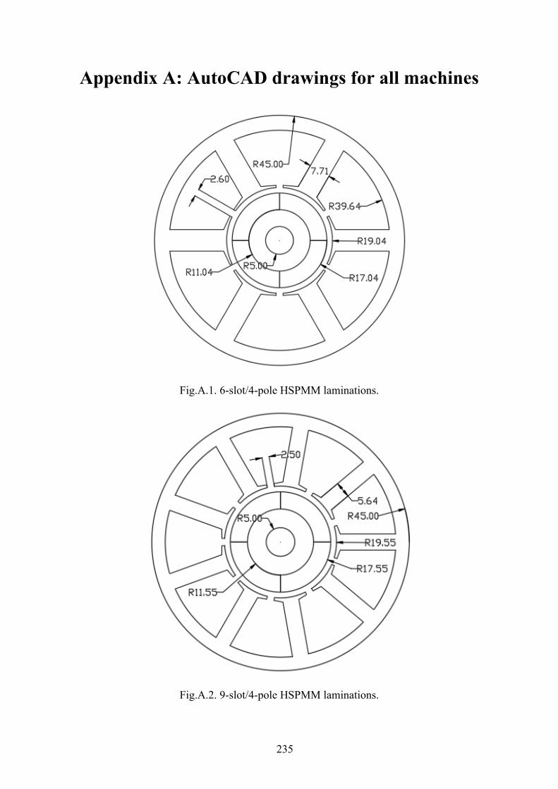
235
Appendix A: AutoCAD drawings for all machines
Fig.A.1. 6-slot/4-pole HSPMM laminations.
Fig.A.2. 9-slot/4-pole HSPMM laminations.
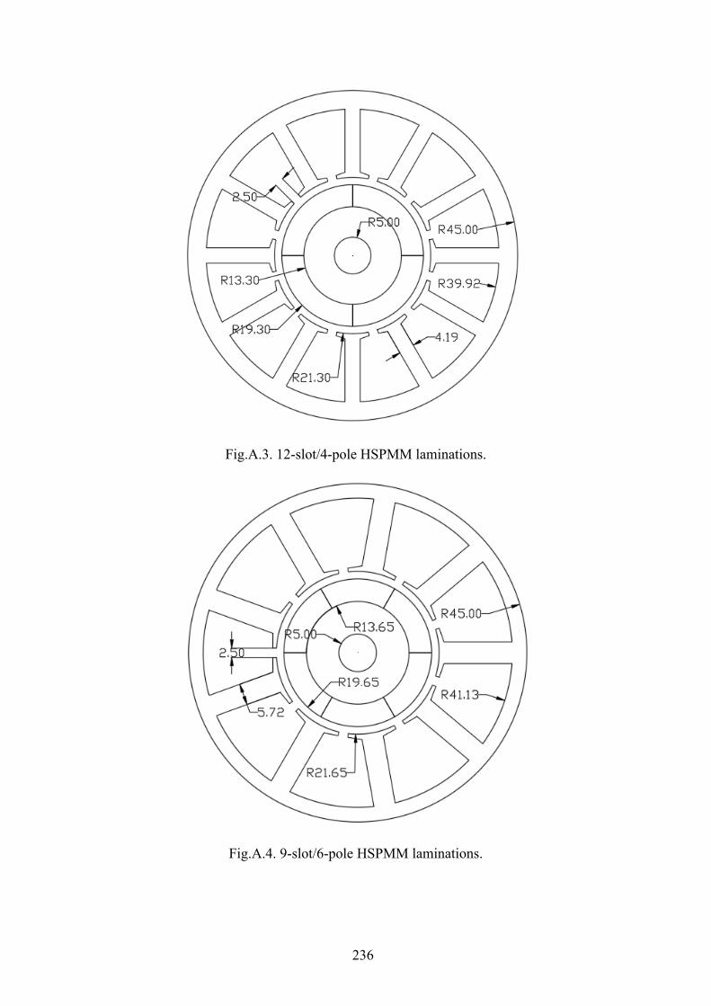
236
Fig.A.3. 12-slot/4-pole HSPMM laminations.
Fig.A.4. 9-slot/6-pole HSPMM laminations.
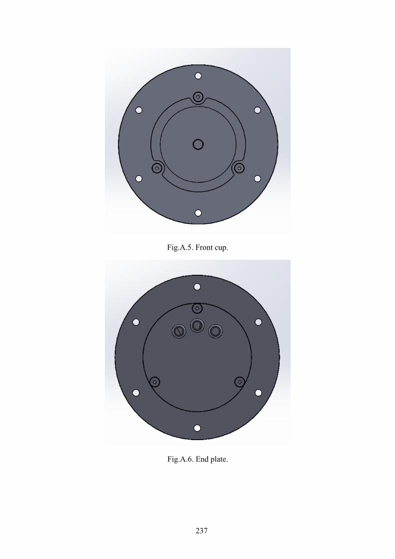
237
Fig.A.5. Front cup.
Fig.A.6. End plate.
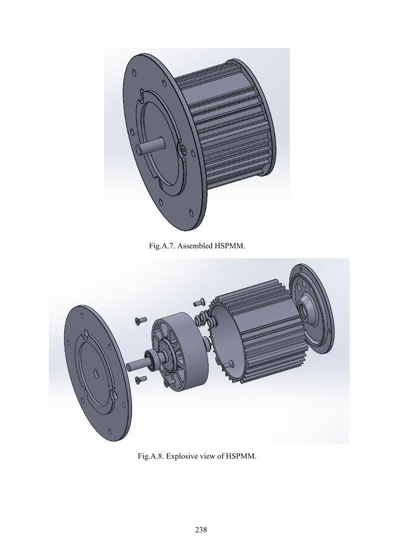
238
Fig.A.7. Assembled HSPMM.
Fig.A.8. Explosive view of HSPMM.

239
Table A.1 Parameters of Prototype Machines
Stator slot number 6 9 12 9
Rotor pole number 4 6
Coil pitch 1 2 3 1
Stator bore diameter(mm) 34.08 35.1 38.6 43.3
Tooth body width(mm) 7.71 5.64 4.19 5.72
Stator yoke height(mm) 5.36 4.71 5.08 3.87
Slot opening(mm) 2.5 2.5 2.5 2.5
Stator outer diameter(mm) 90
Stack length(mm) 30
Air gap thickness(mm) 2
Number of turns per phase 20
Magnet thickness(mm) 6
Magnet grade N35H
Silicon steel sheet JFE G-core (0.2mm)
Sleeve Carbon fibre
240
Appendix B: Publications
Journal papers published:
[J1] Y. Wang, J. H. Feng, S. Y. Guo, Y. F. Li, Z. C. Chen, Y. Wang, and Z. Q. Zhu, “Investigation of optimal split ratio for high-speed permanent-magnet brushless machines,” IEEE Trans. Magn., vol. 54, no.11, Nov. 2018, Art no. 8105605.
[J2] J. H. Feng, Y. Wang, S. Y. Guo, Y. F. Li, Z. C. Chen, Y. Wang, and Z. Q. Zhu, “Split ratio optimization of high-speed permanent magnet brushless machines considering mechanical constraints,” IET Elect. Power Appl., vol. 13, no. 1, pp. 81–90, Feb. 2019.
[J3] S. S. Xue, Z. Q. Zhu, Y. Wang, J. H. Feng, S. Y. Guo, Y .F. Li, Z. C. Chen, and J. Peng, “Thermal-loss coupling analysis of an electrical machine using the improved temperature-dependent iron loss model,” IEEE Trans. Magn., vol. 54, no.11, Nov. 2018, Art no. 8105005.
Papers to be submitted
[J4] Y. Wang, Z.Q. Zhu, J.H. Feng, S.Y. Guo, Y. F. Li, and Y. Wang, “Rotor stress analysis of high-speed permanent magnet machines with segmented magnets retained by carbon-fibre sleeve,” to be submitted to IEEE Transactions on Energy Conversion.
[J5] Y. Wang, Z.Q. Zhu, J.H. Feng, S.Y. Guo, Y. F. Li, and Y. Wang, “Investigation of unbalanced magnetic force in fractional-slot pm machines having odd number of stator slots,” submitted to IEEE Transactions on Energy Conversion.
[J6] Y. Wang, Z.Q. Zhu, J.H. Feng, S.Y. Guo, Y. F. Li, and Y. Wang, “Analysis of rotor magnet loss of four-pole high-speed PM machines with alternate stator winding configuration,” to be submitted to IEEE Transactions on Magnetics.
Top Related
Copyright © 2022 FDOKUMEN

