


Bahasa
Halaman
Hukum

Submitted for presentation at the 2000 IEEE Aerospace Conference, March 2000
From Concept to Flight Delivery in Eighteen Months: The MECA/Electrometer Case Study’
Martin G. Buehler and Li-Jen Cheng Microdevices Laboratory Jet Propulsion Laboratory
California Institute of Technology Pasadena, CA 9 1109
Dennis P. Martin Halcyon Microelectronics, Inc.
Irwindale, CA 91706
Raymond H. Gompf, Carlos I. Calle, Jon A. Bayliss, and Jeffrey L. Rauwerdink Materials Science Laboratory
National Aeronautics and Space Administration Kennedy Space Center, FL 32899
Abstract-The rapid development of space instrumentation is increasingly important in this faster, better, cheaper era. This paper discusses the development of the MECNElectrometer. It used a number of innovations including (a) rapid design of three prototypes, (b) fabrication of 20 units, (c) testing by three institutions, and (d) testing over a wide range of temperature, pressures, atmospheres, and vibration conditions in an eighteen month period.
1. INTRODUCTION: Space instruments must perform over a wide set of environmental conditions that usually exceed Earth operating conditions. In addition the development must be accomplished quickly often within 18-months. This paper highlights, ‘in italics, the development principles used in the design, fabrication and test of the MECAElectrometer which was conceived and delivered in 18 months.
The MECA/Electrometer was designed to facilitate the characterization of electrostatic properties of materials on the surface of Mars in preparation for human exploration. The design requirements are derived from the MECA proposal that stipulates that “mounted to the front of the robot arm scoop is the electrometer, which will be used to monitor triboelectric charging during excavation”. In addition an ion chamber is to be included to measure “atmospheric ionization contributions from soil radiation, solar radiation, and triboelectric ionization of the air”. The strategy is to develop an instrument whose results can be compared to laboratory measurements. If the comparison is
’ IEEE copyright: 0-7803-5846-5/00/$10.00 0 2000 IEEE
favorable then future laboratory measurements can be performed with confidence in characterizing new materials intended for use on Mars. To facilitate the electrometer development, a total of 20 units were fabricated.
2. MECAELECTROMETER: The MECA (Mars Environmental Compatibility Assessment) payload is scheduled for launch December 2001. The purpose of the MECAElectrometer, seen in Fig. 1, is to
I) Electric Field Sens ton
Sensor
Figure 1. MECAElectrometer and Mars ’01 scoop.
determine the electrostatic properties of the Martian atmosphere and regolith. The electrometer is used to measure (a) the triboelectrically-induced charge after the Triboelectric Sensor Array is rubbed through the Martian soil and pulled away from the surface, (b) the electric field
strength above the Martian soil using the Electric-Field Sensor, and (c) atmosphere ion currents using the Ion Sensor.
3. REQUIREMENTS: The mission environmental conditions are listed in Table 1. The low-temperature conditions exceed Earth-bound conditions especially for commercially available electronic components. The prototype circuits were operational from a cold start at - 105°C. To minimize temperature drift problems, surface- mount resistors were chosen with a low TCR (thermal coefficient of resistance) of +lo ppm/"C. Thus, instrument components must be tested early in the development cycle
high resistance printed wiring boards, guard rings, one op amp per sensor, and rigorous board cleaning.
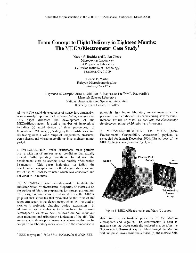
4. ELECTROMETER DESIGN: The design approach included developing three different prototypes. The first prototype, shown in Fig. 2, was designed to verify the performance of the electronics [2] over the mission temperature range and likely high voltages. The electrometer requires the maintenance of very high resistance.. .of the order of 10E15 ohms. Maintaining such impedances is layout and materials dependent and was evaluated by constructing physical prototypes.
over the appropriate environmental conditions to assure Electric Field operation and survival during the mission.
The radiation dose was set at 1.5 krads for the mission that has a cruse phase of is 8 months and a 90-day operational phase on the surface of Mars. Because the radiation levels are low, COTS (custom-off-the-shelf) parts were chosen that have radiation heritage from other space programs and thus, no explicit radiation tests were performed in this effort. Thus, in low-radiation environments, use parts that are manufactured from processes that are known to be radiation insensitive.
Table 1. Mission Environment
Figure 2. Initial 11.7-cm diameter prototype, ELE1, ELE2, ELE3, and ELE4, designed to verify the basic design concept of the electronic circuitry in the Mars chamber shown in Fig. 6.
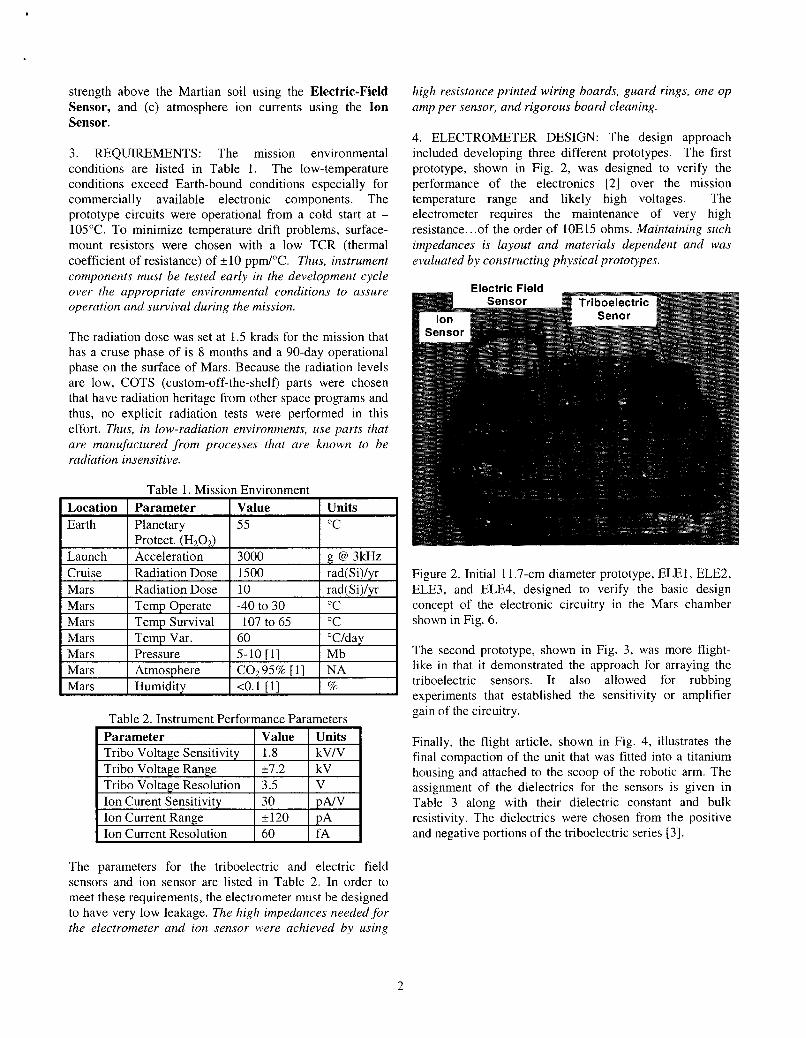
The second prototype, shown in Fig. 3, was more flight- like in that it demonstrated the approach for arraying the triboelectric sensors. It also allowed for rubbing experiments that established the sensitivity or amplifier gain of the circuitry. Table 2. Instrument Performance Parameters
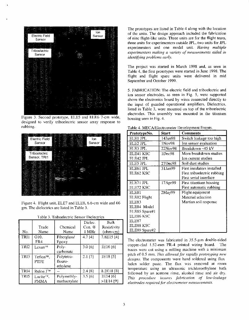
Finally, the flight article, shown in Fig. 4, illustrates the final compaction of the unit that was fitted into a titanium housing and attached to the scoop of the robotic arm. The assignment of the dielectrics for the sensors is given in Table 3 along with their dielectric constant and bulk resistivity. The dielectrics were chosen from the positive and negative portions of the triboelectric series 131.
I I I
The parameters for the triboelectric and electric field sensors and ion sensor are listed in Table 2. In order to meet these requirements, the electrometer must be designed to have very low leakage. The high impedances needed for the electrometer and ion sensor were achieved by using
2
designed to verify triboelectric sensor array response to rubbing.
Figure 4. Flight unit, ELE7 and ELE8, 6.6-cm wide and 66 gm. The dielectrics are listed in Table 3.
Table 3. 7
Trade No. Name
TRIl G10, " TRI2 LexanTM TRI3 TeflonTM,
I
Aiboelectric Sensor Dielect Dielec.
Chemical Con. @ Name 1 MHz
Fiberglass/ 4.7 [4] Epoxy Poly- I 3.0 [6]
flouro-
,ics Bulk
Resistivity (ohm-cm)
7.8E15 [4]
1E16 [6]
1E18 [5]
mathacrylate
The prototypes are listed in Table 4 along with the location of the units. The design approach included the fabrication of nine flight-like units. Three units are for the flight team, three units for experimenters outside JPL, two units for JPL experimenters and one model unit. Having multiple experimenters making a variety of measurements aided in identifying problems early.
The project was started in March 1998 and, as seen in Table 4, the first prototypes were started in June 1998. The flight and flight spare units were delivered in mid September and October 1999.
5. FABRICATION: The electric field and triboelectric and ion sensor electrodes, as seen in Fig. 5, were supported above the electronics board by wires connected directly to the input of guarded operational amplifiers. Dielectrics, listed in Table 3, were mounted on top of the triboelectric electrodes. This assembly was mounted in the titanium housing seen in Fig. 4.
ELE41 KSC I 1Dec98 ELE42 JPL ELE5 JPL I 27Dec98 ELE61 JPL ELE62 KSC
3 1 Jan99
ELE71 JPL ELE72 KSC ELE8 1
17Apr99
2May99 ELE82 Flight ELE83 ELE84 Model ELE85 Spare#l ELE86 KSC ELE87 ELE88 KSC ELE89 Spare#2 I
welopment Events. Comments Switch leakage too high Ion sensor evaluation Breakdown -45 kV More breakdown studies Ion current studies Soil-dust studies First insulators installed First triboelectric rubbing First serial interface First titantium housing First automatic rubbing Flight equipment Material selection Martian soil response
The electrometer was fabricated in 35.5-pm double-sided copper-clad 1.52-mm FR-4 printed wiring board. The traces were cut using a milling machine with a minimum pitch of 0.5 mm. This allowed for rapidly prototyping new designs. The components were hand soldered using flux- laden solder paste. The flux was removed at room temperature using an ultrasonic trichloroethylene bath followed by an acetone rinse, alcohol rinse and air dry. This procedure insures fabrication of low-leakage electrodes required for electrometer measurements.
3
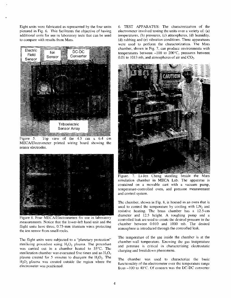
Eight units were fabricated as represented by the four units pictured in Fig. 6. This facilitates the objective of having additional units for use in laboratory tests that can be used to compare with results from Mars.
6. TEST APPARATUS: The characterization of the electrometer involved testing the units over a variety of (a) temperatures, (b) pressures, (c) atmospheres, (d) humidity, (d) rubbing and (e) vibration conditions. Three apparatuses were used to perform the characterization. The Mars chamber, shown in Fig. 7 , can produce environments with temperatures between -100 to 200”C, pressures between 0.01 to 1013 mb, and atmospheres of air and COZ.
Figure 5. Top view of the 4.5 cm x 6.4 cm MECAElectrometer printed wiring board showing the sensor electrodes.
Figure. 7 . Li-Jen Cheng standing beside the Mars simulation chamber in MECA Lab. The apparatus is contained on a movable cart with a vacuum pump, temperature-controlled oven, and pressure measurement and control system.
Figure 6. Four MECAElectrometers for use in laboratory measurements. Notice that the lower-left hand unit and the flight units have three, 0.75-mm titanium wires protecting the ion sensor from small rocks.
The flight units were subjected to a “planetary protection” sterilizing procedure using H202 plasma. The procedure was carried out in a chamber heated to 55°C. The sterilization chamber was evacuated five times and an H202 plasma created for 5 minutes to dissipate the H202. The H202 plasma was created outside the region where the electrometer was positioned.
The chamber, shown in Fig. 8, is housed in an oven that is used to control the temperature by cooling with LN2 and resistive heating. The brass chamber has a 12.5-cm diameter and 12.5 height. A roughing pump and a controlled leak are used to create the desired pressure in the chamber between 0.010 and 1000 mb. The desired atmosphere is introduced through the controlled leak.
The temperature of the gas inside the chamber is at the chamber-wall temperature. Knowing the gas temperature and pressure is critical in characterizing electrostatic charging and breakdown phenomena.
The chamber was used to characterize the basic functionality of the electrometer over the temperature range from -100 to 40°C. Of concern was the DC-DC converter
4
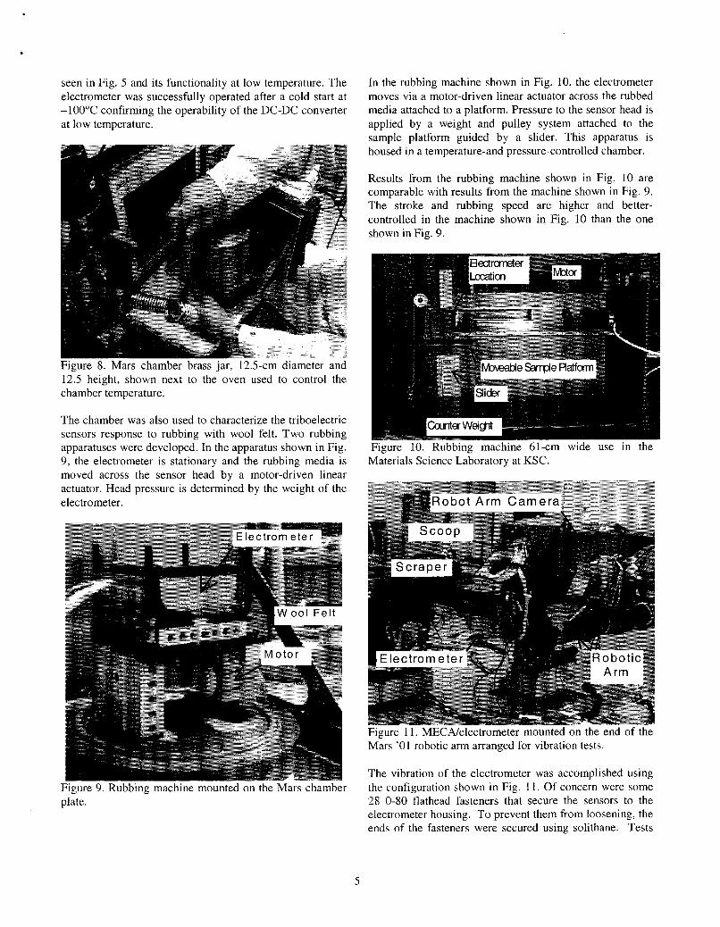
seen in Fig. 5 and its functionality at low temperature. The electrometer was successfully operated after a cold start at -100°C confirming the operability of the DC-DC converter at low temperature.
Figure 8. Mars chamber brass jar, 12.5-cm diameter and 12.5 height, shown next to the oven used to control the chamber temperature.
The chamber was also used to characterize the triboelectric sensors response to rubbing with wool felt. Two rubbing apparatuses were developed. In the apparatus shown in Fig. 9, the electrometer is stationary and the rubbing media is moved across the sensor head by a motor-driven linear actuator. Head pressure is determined by the weight of the electrometer.
Figure 9. Rubbing machine mounted on the Mars chamber plate.
In the rubbing machine shown in Fig. 10, the electrometer moves via a motor-driven linear actuator across the rubbed media attached to a platform. Pressure to the sensor head is applied by a weight and pulley system attached to the sample platform guided by a slider. This apparatus is housed in a temperature-and pressure-controlled chamber.
Results from the rubbing machine shown in Fig. 10 are comparable with results from the machine shown in Fig. 9. The stroke and rubbing speed are higher and better- controlled in the machine shown in Fig. 10 than the one shown in Fig. 9.
Figure 10. Rubbing machine 61-cm wide use in the Materials Science Laboratory at KSC.
Figure 11. MECNelectrometer mounted on the end of the Mars '01 robotic arm arranged for vibration tests.
The vibration of the electrometer was accomplished using the configuration shown in Fig. 11. Of concern were some 28 0-80 flathead fasteners that secure the sensors to the electrometer housing. To prevent them from loosening, the ends of the fasteners were secured using solithane. Tests
5
were performed before and after vibration to verify functionality.
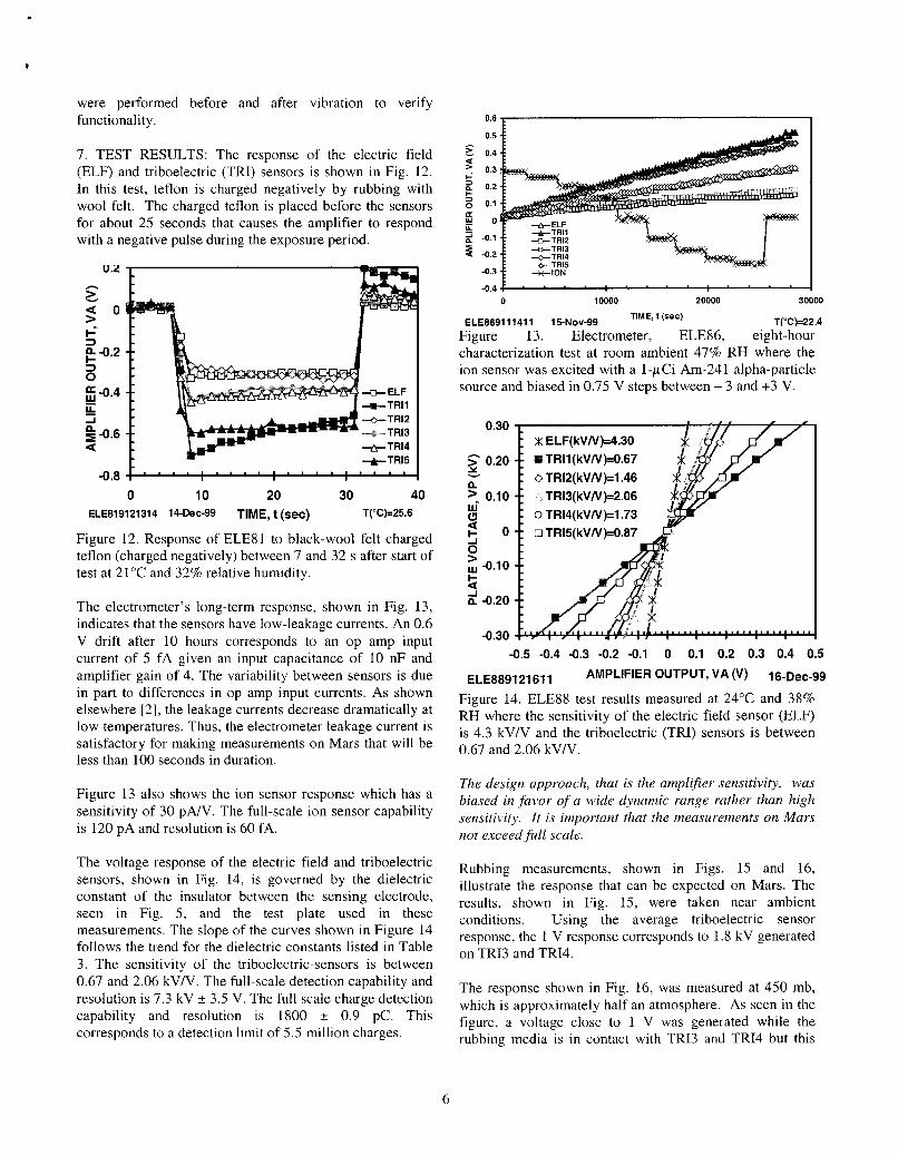
7. TEST RESULTS: The response of the electric field (ELF) and triboelectric (TRI) sensors is shown in Fig. 12. In this test, teflon is charged negatively by rubbing with wool felt. The charged teflon is placed before the sensors for about 25 seconds that causes the amplifier to respond with a negative pulse during the exposure period.
0 10 20 30 40 ELE819121314 14-Dec-99 TIME, t (sec) T("Cb25.6
Figure 12. Response of ELE81 to black-wool felt charged teflon (charged negatively) between 7 and 32 s after start of test at 21°C and 32% relative humidity.
The electrometer's long-term response, shown in Fig. 13, indicates that the sensors have low-leakage currents. An 0.6 V drift after 10 hours corresponds to an op amp input current of 5 fA given an input capacitance of 10 nF and amplifier gain of 4. The variability between sensors is due in part to differences in op amp input currents. As shown elsewhere [2], the leakage currents decrease dramatically at low temperatures. Thus, the electrometer leakage current is satisfactory for making measurements on Mars that will be less than 100 seconds in duration.
Figure 13 also shows the ion sensor response which has a sensitivity of 30 pNV. The full-scale ion sensor capability is 120 pA and resolution is 60 fA.
The voltage response of the electric field and triboelectric sensors, shown in Fig. 14, is governed by the dielectric constant of the insulator between the sensing electrode, seen in Fig. 5, and the test plate used in these measurements. The slope of the curves shown in Figure 14 follows the trend for the dielectric constants listed in Table 3. The sensitivity of the triboelectric-sensors is between 0.67 and 2.06 kV/V. The full-scale detection capability and resolution is 7.3 kV f 3.5 V. The full scale charge detection capability and resolution is 1800 f 0.9 PC. This corresponds to a detection limit of 5.5 million charges.
0 10000 20000 30000
T("Ck22.4 ELE869111411 15-Nov-99 TIME, t (rec)
Figure 13. Electrometer, ELE86, eight-hour characterization test at room ambient 47% RH where the ion sensor was excited with a I-pCi Am-241 alpha-particle source and biased in 0.75 V steps between - 3 and +3 V.
0.30
h 2 0.20
>_ 0.10
3 w -0.10
v
n
9 o 0 > I-
2 -0.20
-0.30
X ELF(kVN)=4.30 !#! TRll (kVN)=0.67 0 TR12(kVN)=l.46
TR13(kVN)=2.06 0 TR14(kVN)=1.73 0 TR15(kVN)=0.87
-0.5 -0.4 -0.3 -0.2 -0.1 0 0.1 0.2 0.3 0.4 0.5
ELE889121611 OUTPUT, VA 16-Dec-99
Figure 14. ELE88 test results measured at 24°C and 38% RH where the sensitivity of the electric field sensor (ELF) is 4.3 kV/V and the triboelectric (TRI) sensors is between 0.67 and 2.06 kV/V.
The design approach, that is the amplifier sensitivity, was biased in favor of a wide dynamic range rather than high sensitivity. It is important that the measurements on Mars not exceed full scale.
Rubbing measurements, shown in Figs. 15 and 16, illustrate the response that can be expected on Mars. The results, shown in Fig. 15, were taken near ambient conditions. Using the average triboelectric sensor response, the 1 V response corresponds to 1.8 kV generated on TR13 and TRI4.
The response shown in Fig. 16, was measured at 450 mb, which is approximately half an atmosphere. As seen in the figure, a voltage close to 1 V was generated while the rubbing media is in contact with TR13 and TR14 but this
6
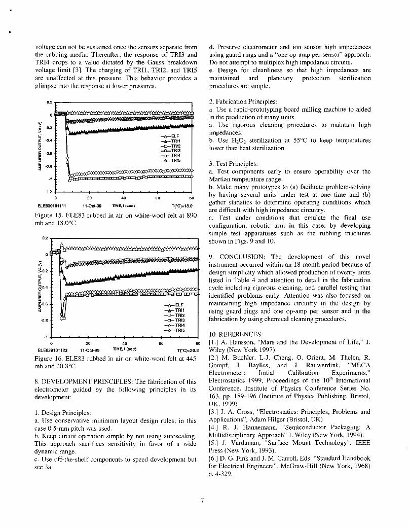
voltage can not be sustained once the sensors separate from the rubbing media. Thereafter, the response of TR13 and TR14 drops to a value dictated by the Gauss breakdown voltage limit [3]. The charging of TRII, TRI2, and TRI5 are unaffected at this pressure. This behavior provides a glimpse into the response at lower pressures.
0.2 , I
0 20 40 60 80
ELE839101111 1 1 - 0 ~ 1 - 9 9 TIM41 (sec) T("C)=18.0
Figure 15. ELE83 rubbed in air on white-wool felt at 890 mb and 18.0"C.
0.2 , I
n
+ELF +TRI1
-a-TR13 +TI314
-TR15
"D-TRI2
-1 I 0 20 40 60 80
ELE839101123 11-Oct-99 n'bt(sec) T("C)=20.8
Figure 16. ELE83 rubbed in air on white-wool felt at 445 mb and 20.8"C.
8. DEVELOPMENT PRINCIPLES: The fabrication of this electrometer guided by the following principles in its development:
I . Design Principles: a. Use conservative minimum layout design rules; in this case 0.5-mm pitch was used. b. Keep circuit operation simple by not using autoscaling. This approach sacrifices sensitivity in favor of a wide dynamic range. c. Use off-the-shelf components to speed development but see 3a.
d. Preserve electrometer and ion sensor high impedances using guard rings and a "one op-amp per sensor" approach. Do not attempt to multiplex high impedance circuits. e. Design for cleanliness so that high impedances are maintained and planetary protection sterilization procedures are simple.
2. Fabrication Principles: a. Use a rapid-prototyping board milling machine to aided in the production of many units. a. Use rigorous cleaning procedures to maintain high impedances. b. Use HzOz sterilization at 55°C to keep temperatures lower than heat sterilization.
3. Test Principles: a. Test components early to ensure operability over the Martian temperature range. b. Make many prototypes to (a) facilitate problem-solving by having several units under test at one time and (b) gather statistics to determine operating conditions which are difficult with high impedance circuitry. c. Test under conditions that emulate the final use configuration, robotic arm in this case, by developing simple test apparatuses such as the rubbing machines shown in Figs. 9 and 10.
9. CONCLUSION: The development of this novel instrument occurred within an 18 month period because of design simplicity which allowed production of twenty units listed in Table 4 and attention to detail in the fabrication cycle including rigorous cleaning, and parallel testing that identified problems early. Attention was also focused on maintaining high impedance circuitry in the design by using guard rings and one op-amp per sensor and in the fabrication by using chemical cleaning procedures.
10. REFERENCES: [ I . ] A. Hansson, "Mars and the Development of Life," J. Wiley (New York 1997). [2.] M. Buehler, L-J. Cheng, 0. Orient, M. Thelen, R. Gompf, J. Bayliss, and J. Rauwerdink, "MECA Electrometer: Initial Calibration Experiments," Electrostatics 1999, Proceedings of the IOth International Conference, Institute of Physics Conference Series No. 163, pp. 189-196 (Institute of Physics Publishing, Bristol, UK, 1999) [3.] J. A. Cross, "Electrostatics: Principles, Problems and Applications", Adam Hilger (Bristol, UK) [4.] R. J. Hannemann, "Semiconductor Packaging: A Multidisciplinary Approach" J. Wiley (New York, 1994). [5.] J. Vardaman, "Surface Mount Technology", IEEE Press (New York, 1993). [6.] D. G. Fink and J. M. Carroll, Eds. "Standard Handbook for Electrical Engineers", McGraw-Hill (New York, 1968) p. 4-329.
7
[7.] Handbook of Chemistry and Physics, 74'h Edition (CRC Press, 1993-1994) p.13-12. [S.] Technical Data from FURON, 386 Metacom Ave, Bristal, RI 028809. RULON is a Registered Trade Mark of FURON. [9.] J. H. Moore et.al., "Building Scientific Apparatus" Addison-Wesley Publishing Co. (New York , 1996).
ACKNOWLEDGMENTS: The work described in this paper was performed by the Jet Propulsion Laboratory, California Institute of Technology, under a contract with the National Aeronautics and Space Administration. The efforts of Wayne Schubert in assisting with planetary protection are appreciated. The authors are indebted to the managers who have encouraged this work. In particular Michael Hecht, Lynne Cooper, and Joel Rademacher, JPL and Hae So0 Kim, KSC. File: Aero29A28.doc.
1 1. BIOGRAPHIES: Martin G. Buehler received the BSEE and MSEE from Duke University in 1961 and 1963, respectively and the Ph.D. in EE from Stanford University in 1966 specializing in Solid State Electronics. He worked at Texas Instruments for six years, at National Bureau of Standards (now NIST) for eight years, and since 1981 has been at the Jet Propulsion Laboratory where he is a senior research scientist. At JPL he has developed p-FET radiation monitors for CRRES, Clementine, TELSTAR and STRV, E-nose which flew on STS-95, and an electrometer for the Mars '01 robot arm. Currently he serves on the staff of the New Millennium Program as a technical analyst. Martin is a member of the IEEE and the Electrostatic Discharge Association.
Li-Jen Cheng received the B.S. in Chemical Engineering in 1956 from the Ordnance Engineering College, Taipei, the M.S. in Nuclear Science in 1961 from the National Tsing Hua University, Taiwan, and the Ph.D. in solid state physics from Rensselaer Polytechnic Institute in the 1966. After graduation he worked at the Chalk River Nuclear Laboratories, Chung Cheng Institute of Technology, Institute of Nuclear Energy Research, and the State University of New York. In 1977 he joined the Jet Propulsion Laboratory and spent a number of years with the photovoltaic project. In recent years, he developed the AOTF (acousto-optic tuneable filter) technology and most recently assisted in developing the MECAElectrometer.
Dennis P. Martin received the received his BSME from California State Polytechnic University in 1976 and pursued graduate work in Material Sciences of Microelectronics at Arizona State, California Institute of Technology , and University of Florida. Dennis joined Jet Propulsion Laboratory and then in 1981 formed the Halcyon Microelectronics, Inc. As president of Halcyon Microelectronics, Dennis heads up the advanced packaging
for research and development with emphasis on miniaturization of complex systems for hostile environments; ie: high radiation, high "g " force, and extreme temperature. Halcyon offers a laboratory in which products are developed. More than 300 designs have become working prototypes for customers ranging from Cal Tech and Rockwell Int'l to MIT and Cree Research. In the last five years, Mr. Martin has expanded Halcyon's role as a service laboratory for package research and development into sensor development. He is a member of ISHM.
Raymond H. Gompf received the BSEE in 1959 from Rose-Hulman Institute of Technology, MS in Engineering in 1961 from Florida Institute of Technology and in 1980 his doctorate from Nova University. He worked at Cape Canaveral from 1959 to 1962 with General Dynamics on the Atlas Missile System. From 1962 to 1970 he was with RCA as an electronics engineer, specializing in telemetry systems. While with RCA, he developed the telemetry planning methods used for lunar and interplanetary telemetry coverage. Since 1970 he has been with Brevard Community College where he initiated and directed the first environmental engineering technology program. For the past 18 years he has been consultant to NASA at Kennedy Space Center doing testing and research into the triboelectric properties of materials. He has been a registered professional engineer in Florida since 1963.
Carlos I. Calle received is the principal investigator for the electrostatics research group at NASA Kennedy Space Center. He is currently working on the problem of electrostatic phenomena on planetary surfaces, particularly on Mars and the Moon. He holds a Ph.D. in theoretical nuclear physics from Ohio University and was Professor and Chair of the Physics Department at Sweet Briar College in Virginia, where he taught for 18 years prior to joining NASA. He has published papers in electrostatics, nuclear reaction theory, nuclear structure, and laboratory methods. His book, Guide to Physics: From Quarks to Superstrings, will be published by the Institute of Physics Publishing in the spring of 2000.
Jon A. Bayliss received the BSEE at Florida Institute of Technology and is currently an Electronics Engineer, at the Kennedy Space Center, Material Science Laboratory (MSL), Electronic Systems Failure Analysis. Jon is responsible for component evaluation and failure analysis on all types of electrical and electronic components and publishes technical reports. His work involves application of standard engineering practices to provide technical support for both flight systems and ground support equipment. Jon has experience in planning and performing flight and GSE hardware failure analyses, component reliability evaluations, and developing automatic test systems for use in electronic/electrical component failure
8
analysis and evaluation. In addition, he has helped develop material safety evaluation test techniques to determine the electrostatic properties of plastic films and other materials used in potentially hazardous environments. Jon is a member of the American Society for Testing and Materials (ASTM) and currently participates in the DO9 Committee for Electrical and Electronic Insulation Materials.
Jeffrey L. Rauwerdink received the BSEE from the University of Wisconsin-Madison and has pursued graduate work at the University of Cincinnati in solid-state electronics. Since 1989, he has worked at the Kennedy Space Center, Material Science Laboratory, Electronic Systems Failure Analysis, as Aerospace Technologist, Electrical Engineer. Jeff performs component evaluation and failure analysis on all types of electrical and electronic components and publishes technical reports and is an expert on discrete and integrated semiconductor components. Jeff provides engineering advise and consulting services regarding the capabilities of electrical and electronic systems and components. Jeff has focused on semiconductor reliability and he gained experience in planning and executing component reliability evaluations, performing failure analyses, developing automatic test systems for use in component failure analysis and performing digital circuit simulations. In addition to his failure analysis duties, Jeff is presently adapting an Intergraph CAE workstation to failure analysis so that the workstation can be used to (1) model and test circuit fault scenarios and (2) automatically operate component test systems and compare the test results with the behavior of the component circuit model.
9
Copyright © 2022 FDOKUMEN

