


Bahasa
Halaman
Hukum


0
Th1. ENERGY CONVERSION – I PRE DISCOVER NOTE
A.S RAY
1
DC GENERATOR An electrical generator is a machine which converts mechanical energy (or power) into
electrical energy (or power).
The energy conversion is based on the principle
Of the production Of dynamically (or
motionally) induced e.m.f. As seen from fig. 26.
I , whenever a conductor cuts magnetic flux.
dynamically induced em-f. is produced in it
according to Faraday's Laws of Electromagnetic
Induction. This em-f. causes a current to now if
the conductor circuit is closed.
Hence, two basic essential parts Of an electrical generator are a magnetic field and (ii) a
conductor or conductors which can so move as to cut the flux.
CONSTRUCTION:-
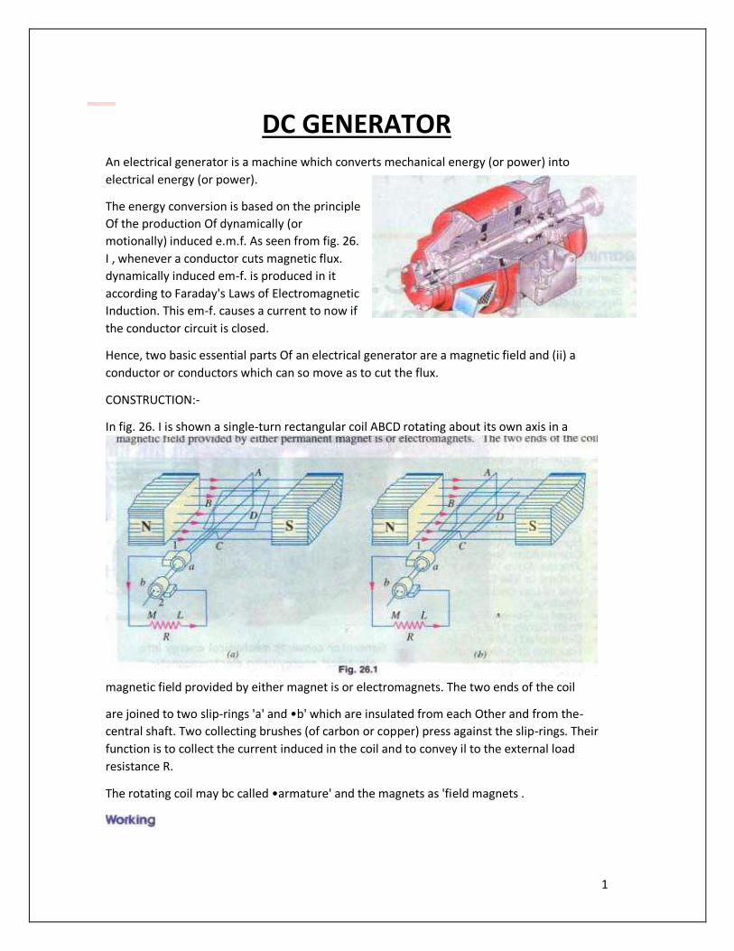
In fig. 26. I is shown a single-turn rectangular coil ABCD rotating about its own axis in a
magnetic field provided by either magnet is or electromagnets. The two ends of the coil
are joined to two slip-rings 'a' and •b' which are insulated from each Other and from the-
central shaft. Two collecting brushes (of carbon or copper) press against the slip-rings. Their
function is to collect the current induced in the coil and to convey il to the external load
resistance R.
The rotating coil may bc called •armature' and the magnets as 'field magnets .
2
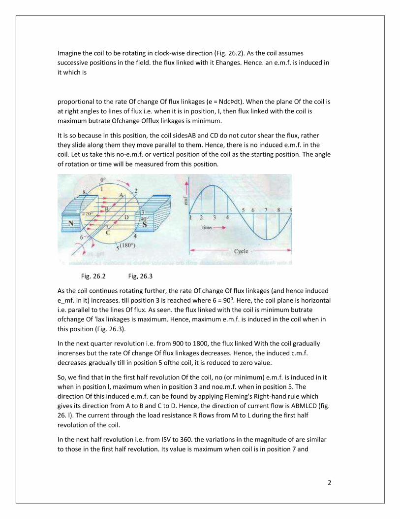
Imagine the coil to be rotating in clock-wise direction (Fig. 26.2). As the coil assumes
successive positions in the field. the flux linked with it Ehanges. Hence. an e.m.f. is induced in
it which is
proportional to the rate Of change Of flux linkages (e = NdcÞdt). When the plane Of the coil is
at right angles to lines of flux i.e. when it is in position, I, then flux linked with the coil is
maximum butrate Ofchange Offlux linkages is minimum.
It is so because in this position, the coil sidesAB and CD do not cutor shear the flux, rather
they slide along them they move parallel to them. Hence, there is no induced e.m.f. in the
coil. Let us take this no-e.m.f. or vertical position of the coil as the starting position. The angle
of rotation or time will be measured from this position.
Fig. 26.2 Fig, 26.3
As the coil continues rotating further, the rate Of change Of flux linkages (and hence induced
e_mf. in it) increases. till position 3 is reached where 6 = 900. Here, the coil plane is horizontal
i.e. parallel to the lines Of flux. As seen. the flux linked with the coil is minimum butrate
ofchange Of 'lax linkages is maximum. Hence, maximum e.m.f. is induced in the coil when in
this position (Fig. 26.3).
In the next quarter revolution i.e. from 900 to 1800, the flux linked With the coil gradually
increnses but the rate Of change Of flux linkages decreases. Hence, the induced c.m.f.
decreases gradually till in position 5 ofthe coil, it is reduced to zero value.
So, we find that in the first half revolution Of the coil, no (or minimum) e.m.f. is induced in it
when in position l, maximum when in position 3 and noe.m.f. when in position 5. The
direction Of this induced e.m.f. can be found by applying Fleming's Right-hand rule which
gives its direction from A to B and C to D. Hence, the direction of current flow is ABMLCD (fig.
26. l). The current through the load resistance R flows from M to L during the first half
revolution of the coil.
In the next half revolution i.e. from ISV to 360. the variations in the magnitude of are similar
to those in the first half revolution. Its value is maximum when coil is in position 7 and
3
minimum when in position I. But it will be found that the direction of the induced current is
from D to C and B to A as shown in Fig. 26.1 Hence, the path Of current flow is along DUMBA
which is just the reverse of the previous direction of now.
Therefore, we find that the current which we obtain from sueh a simple generator reverses
its direction after every half revolution, Such a current undergoing periodic reversals is
known as alternatingcurrent. It is. obviously, different from a direct current which
continuously flows in one and the same direction. It should be noted that alternating current
not only reverses its direction, it noteven keep its magnitude constant while flowing in
any one direction. The two half-cycles may be called positive and negative half-cycles
respectively (Fig. 26.3).
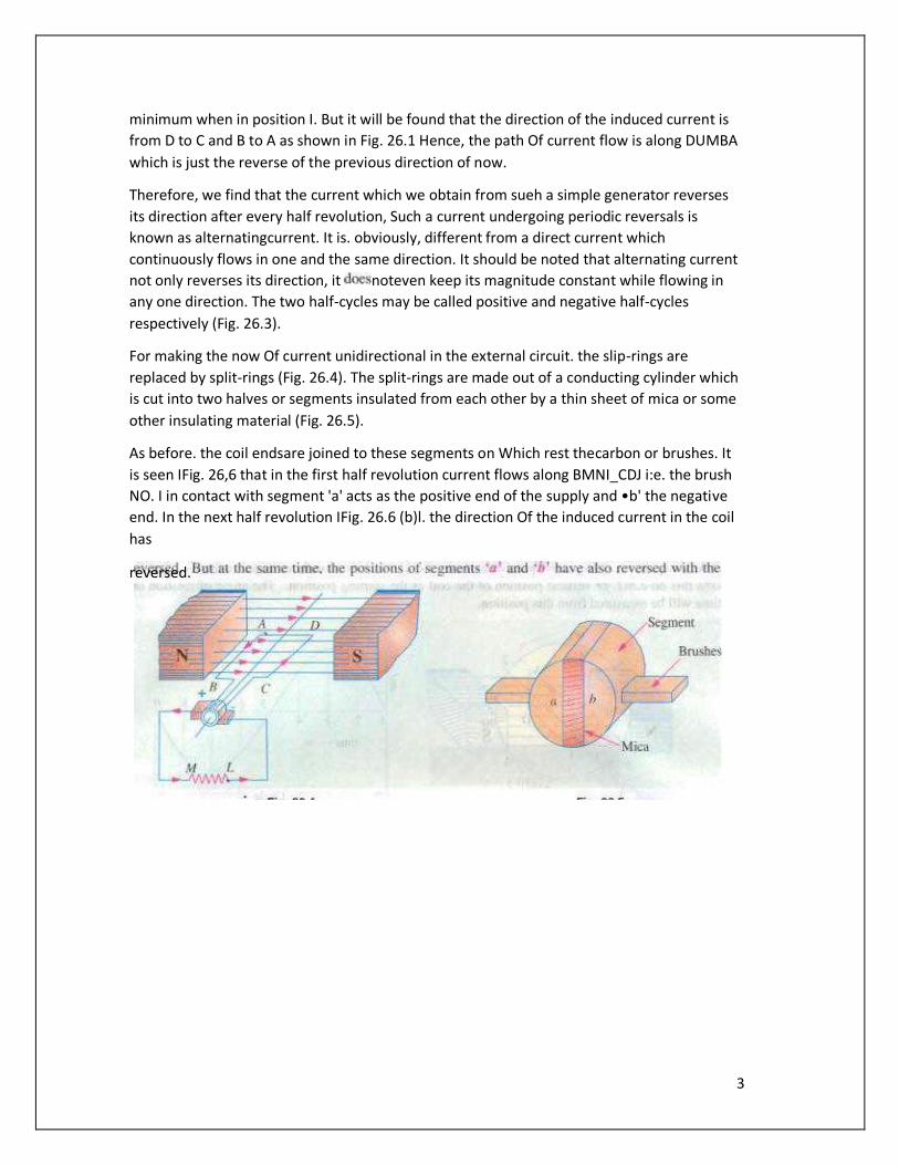
For making the now Of current unidirectional in the external circuit. the slip-rings are
replaced by split-rings (Fig. 26.4). The split-rings are made out of a conducting cylinder which
is cut into two halves or segments insulated from each other by a thin sheet of mica or some
other insulating material (Fig. 26.5).
As before. the coil endsare joined to these segments on Which rest thecarbon or brushes. It
is seen IFig. 26,6 that in the first half revolution current flows along BMNI_CDJ i:e. the brush
NO. I in contact with segment 'a' acts as the positive end of the supply and •b' the negative
end. In the next half revolution IFig. 26.6 (b)l. the direction Of the induced current in the coil
has
reversed.
4
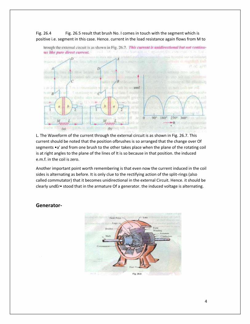
Fig. 26.4 Fig. 26.5 result that brush No. I comes in touch with the segment which is
positive i.e. segment in this case. Hence. current in the load resistance again flows from M to
L. The Waveform of the current through the external circuit is as shown in Fig. 26.7. This
current should be noted that the position ofbrushes is so arranged that the change over Of
segments •a' and from one brush to the other takes place when the plane of the rotating coil
is at right angles to the plane of the lines of It is so because in that position. the induced
e.m.f. in the coil is zero.
Another important point worth remembering is that even now the current induced in the coil
sides is alternating as before. It is only clue to the rectifying action of the split-rings (also
called commutator) that it becomes unidirectional in the external Circuit. Hence. it should be
clearly undEr• stood that in the armature Of a generator. the induced voltage is alternating.
Generator-
5
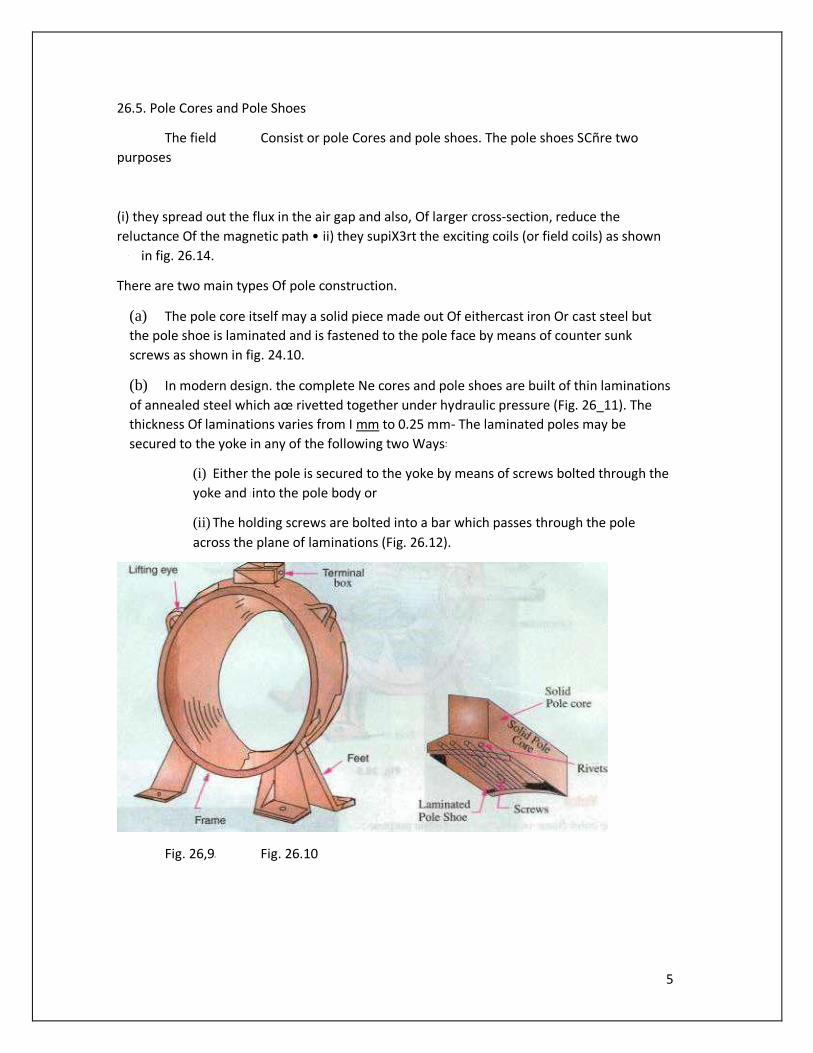
26.5. Pole Cores and Pole Shoes
The field Consist or pole Cores and pole shoes. The pole shoes SCñre two
purposes
(i) they spread out the flux in the air gap and also, Of larger cross-section, reduce the
reluctance Of the magnetic path • ii) they supiX3rt the exciting coils (or field coils) as shown
in fig. 26.14.
There are two main types Of pole construction.
(a) The pole core itself may a solid piece made out Of eithercast iron Or cast steel but
the pole shoe is laminated and is fastened to the pole face by means of counter sunk
screws as shown in fig. 24.10.
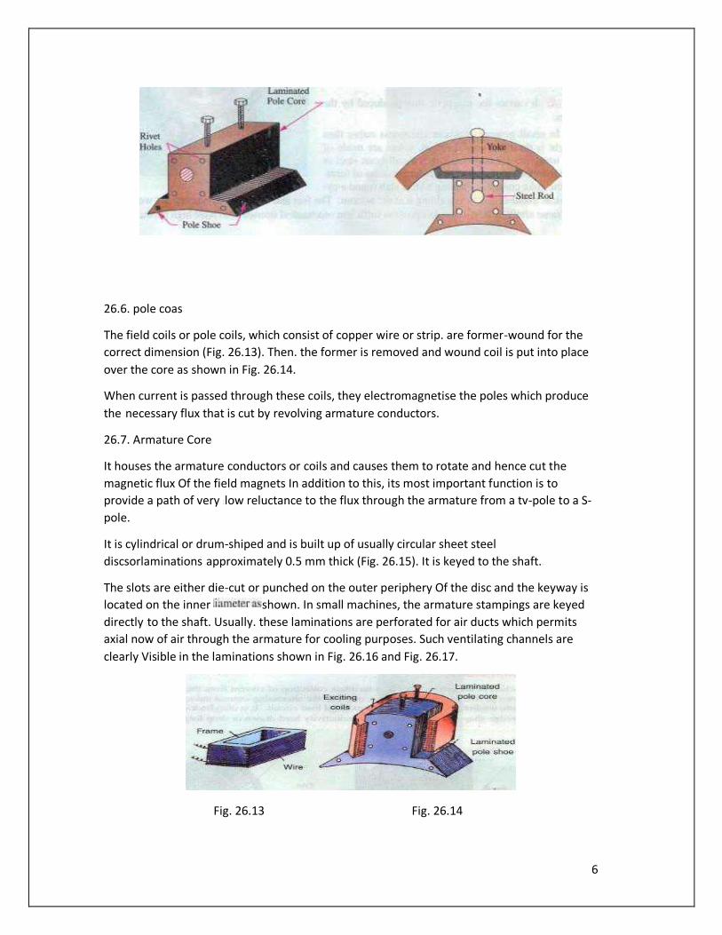
(b) In modern design. the complete Ne cores and pole shoes are built of thin laminations
of annealed steel which aœ rivetted together under hydraulic pressure (Fig. 26_11). The
thickness Of laminations varies from I mm to 0.25 mm- The laminated poles may be
secured to the yoke in any of the following two Ways
(i) Either the pole is secured to the yoke by means of screws bolted through the
yoke and into the pole body or
(ii) The holding screws are bolted into a bar which passes through the pole
across the plane of laminations (Fig. 26.12).
Fig. 26,9 Fig. 26.10
6
26.6. pole coas
The field coils or pole coils, which consist of copper wire or strip. are former-wound for the
correct dimension (Fig. 26.13). Then. the former is removed and wound coil is put into place
over the core as shown in Fig. 26.14.
When current is passed through these coils, they electromagnetise the poles which produce
the necessary flux that is cut by revolving armature conductors.
26.7. Armature Core
It houses the armature conductors or coils and causes them to rotate and hence cut the
magnetic flux Of the field magnets In addition to this, its most important function is to
provide a path of very low reluctance to the flux through the armature from a tv-pole to a S-
pole.
It is cylindrical or drum-shiped and is built up of usually circular sheet steel
discsorlaminations approximately 0.5 mm thick (Fig. 26.15). It is keyed to the shaft.
The slots are either die-cut or punched on the outer periphery Of the disc and the keyway is
located on the inner shown. In small machines, the armature stampings are keyed
directly to the shaft. Usually. these laminations are perforated for air ducts which permits
axial now of air through the armature for cooling purposes. Such ventilating channels are
clearly Visible in the laminations shown in Fig. 26.16 and Fig. 26.17.
Fig. 26.13 Fig. 26.14

7
Up to armature diameters Of about one metre, the circular stampings are cut out in one
piece as shown in Fig. 26.16, But above this size. these circles, especially of such thin
sections, are difficult to handle because they tend to distort and become wavy when
assembled together. Hence. the circular laminations. instead of being cut out in one piece,
are cut in number Of suitable sections or segments which form part ofa complete ring (Fig.
26.17).
8
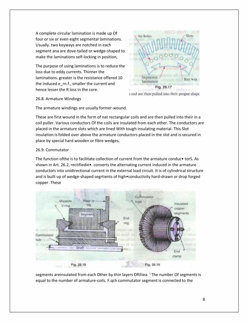
A complete circular lamination is made up Of
four or six or even eight segmental laminations.
Usually. two keyways are notched in each
segment ana are dove-tailed or wedge-shaped to
make the laminations self-locking in position,
The purpose of using laminations is to reduce the
loss due to eddy currents. Thinner the
laminations. greater is the resistance offered 10
the induced e_rn.f., smaller the current and
hence lesser the R loss in the core.
26.8. Armature Windings
The armature windings are usually former-wound.
These are first wound in the form of nat rectangular coils and are then pulled into their in a
coil puller. Various conductors Of the coils are insulated from each other. The conductors are
placed in the armature slots which are lined With tough insulating material. This Slot
insulation is folded over above the armature conductors placed in the slot and is secured in
place by special hard wooden or fibre wedges,
26.9. Commutator
The function ofthe is to facilitate collection of current from the armature conduc• torS. As
shown in Art. 26.2, rectifiedie•. converts the alternating current induced in the armature
conductors into unidirectional current in the external load circuit. It is of cylindrical structure
and is built up of wedge-shaped segrtients of high•conductivity hard-drawn or drop forged
copper. These
segments areinsulated from each Other by thin layers Oftliiea. L The number Of segments is
equal to the number of armature-coils. F.qch commutator segment is connecled to the
9
armature conductor by means of a copperÌugoi strip (or riseth
To prevent them from flying out under the action of centrifugal
forces, the Segments have V-grooves. these grooves being
insulated by conical micanite rings. A sectional view Of
commutator is in fig. 26. IS Whose general When completed is
shown in Fig. 26.19.
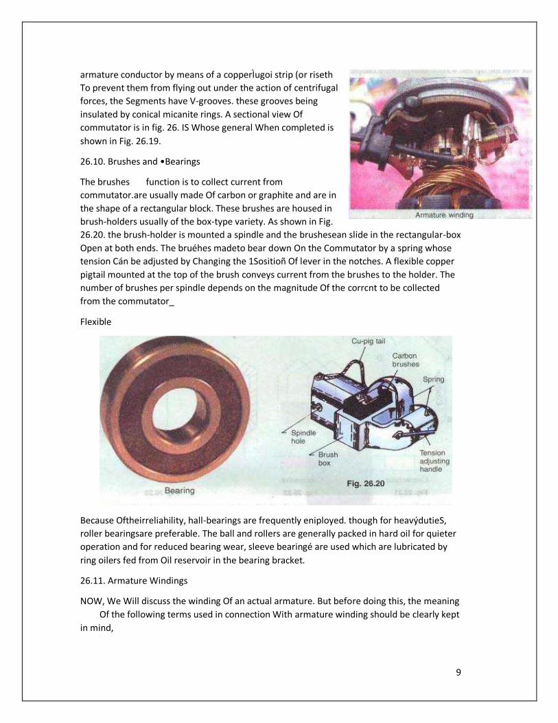
26.10. Brushes and •Bearings
The brushes function is to collect current from
commutator.are usually made Of carbon or graphite and are in
the shape of a rectangular block. These brushes are housed in
brush-holders usually of the box-type variety. As shown in Fig.
26.20. the brush-holder is mounted a spindle and the brushesean slide in the rectangular-box
Open at both ends. The bruéhes madeto bear down On the Commutator by a spring whose
tension Cán be adjusted by Changing the 1Sositioñ Of lever in the notches. A flexible copper
pigtail mounted at the top of the brush conveys current from the brushes to the holder. The
number of brushes per spindle depends on the magnitude Of the corrcnt to be collected
from the commutator_
Flexible
Because Oftheirreliahility, hall-bearings are frequently eniployed. though for heavýdutieS,
roller bearingsare preferable. The ball and rollers are generally packed in hard oil for quieter
operation and for reduced bearing wear, sleeve bearingé are used which are lubricated by
ring oilers fed from Oil reservoir in the bearing bracket.
26.11. Armature Windings
NOW, We Will discuss the winding Of an actual armature. But before doing this, the meaning
Of the following terms used in connection With armature winding should be clearly kept
in mind,
10
26.12. Pole-pitch
It may be variously defined as :
The periphery Of the armature divided by the number of poles orthe generator i.e. the
distance between two adjacent poles.
(ii) It is equal to the number Of armature
•conductors and 4 poles, the pole pitehis 48/4 12.
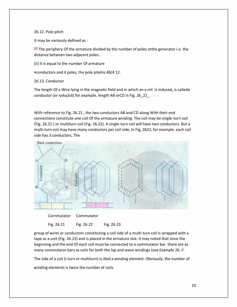
26.13. Conductor
The length Of a Wire lying in the magnetic field and in which an e.mf. is induced, is calleda
conductor (or iyduçtot) for example, length AB orCD in Fig. 26_21_
With reference to Fig. 26.21 , the two conductors AB and CD along With their end
connections constitute one coil Of the armature winding. The coil may be single-turn coil
(Fig. 26.21 ) or multiturn coil (Fig. 26.22). A single-turn coil will have two conductors. But a
multi-turn coil may have many conductors per coil side, In Fig, 2622, for example. each coil
side has 3 conductors, The
Cornmutator Commutator
Fig. 26.21 Fig. 26.22 Fig. 26.23
group of wires or conductors constituting a coil side of a multi-turn coil is wrapped with a
tape as a unit (Fig. 26.23) and is placed in the armature slot. It may noted that since the
beginning and the end Of each coil must be connected to a commutator bar. there are as
many commutaror bars as coils for both the lap and wave windings (see Example 26. I
The side of a coil (I-turn or multiturn) is.illed a winding element. Obviously, the number of
winding elements is twice the number of coils.
11
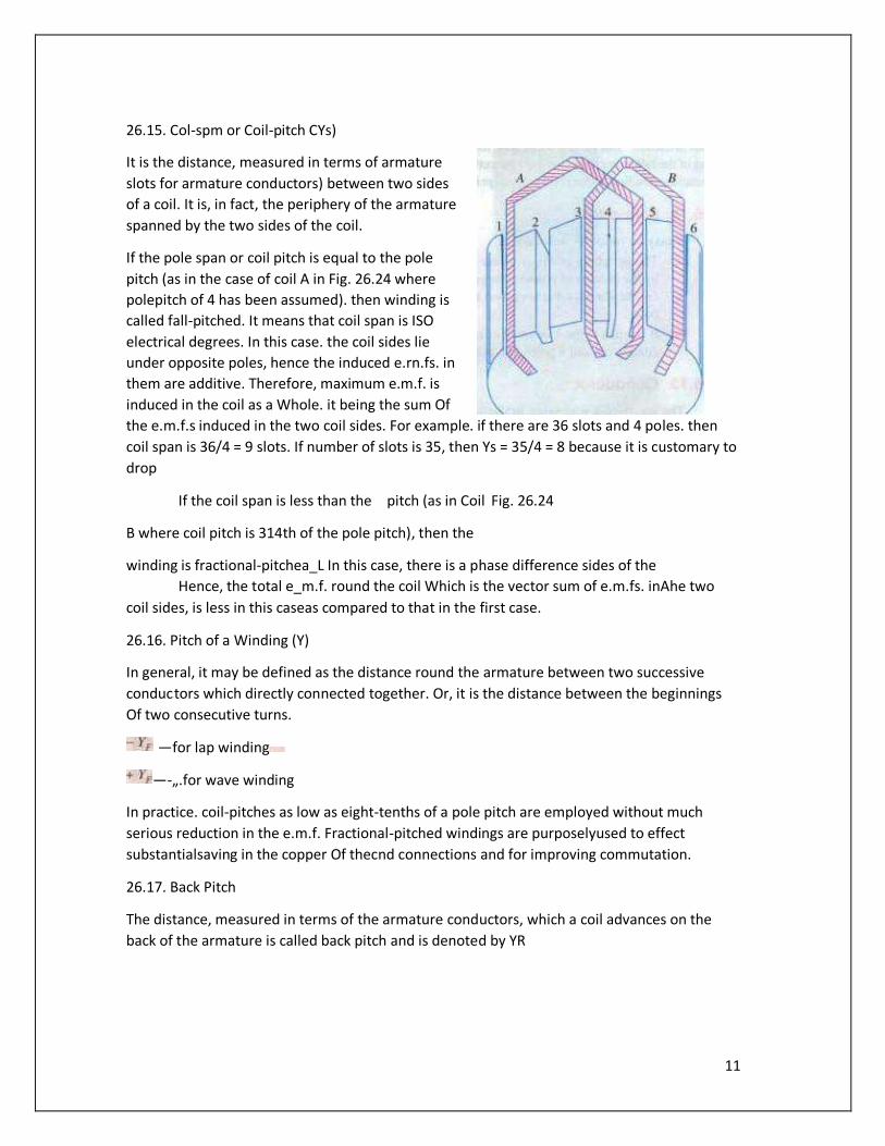
26.15. Col-spm or Coil-pitch CYs)
It is the distance, measured in terms of armature
slots for armature conductors) between two sides
of a coil. It is, in fact, the periphery of the armature
spanned by the two sides of the coil.
If the pole span or coil pitch is equal to the pole
pitch (as in the case of coil A in Fig. 26.24 where
polepitch of 4 has been assumed). then winding is
called fall-pitched. It means that coil span is ISO
electrical degrees. In this case. the coil sides lie
under opposite poles, hence the induced e.rn.fs. in
them are additive. Therefore, maximum e.m.f. is
induced in the coil as a Whole. it being the sum Of
the e.m.f.s induced in the two coil sides. For example. if there are 36 slots and 4 poles. then
coil span is 36/4 = 9 slots. If number of slots is 35, then Ys = 35/4 = 8 because it is customary to
drop
If the coil span is less than the pitch (as in Coil Fig. 26.24
B where coil pitch is 314th of the pole pitch), then the
winding is fractional-pitchea_L In this case, there is a phase difference sides of the
Hence, the total e_m.f. round the coil Which is the vector sum of e.m.fs. inAhe two
coil sides, is less in this caseas compared to that in the first case.
26.16. Pitch of a Winding (Y)
In general, it may be defined as the distance round the armature between two successive
conductors which directly connected together. Or, it is the distance between the beginnings
Of two consecutive turns.
—for lap winding
—-„.for wave winding
In practice. coil-pitches as low as eight-tenths of a pole pitch are employed without much
serious reduction in the e.m.f. Fractional-pitched windings are purposelyused to effect
substantialsaving in the copper Of thecnd connections and for improving commutation.
26.17. Back Pitch
The distance, measured in terms of the armature conductors, which a coil advances on the
back of the armature is called back pitch and is denoted by YR
12
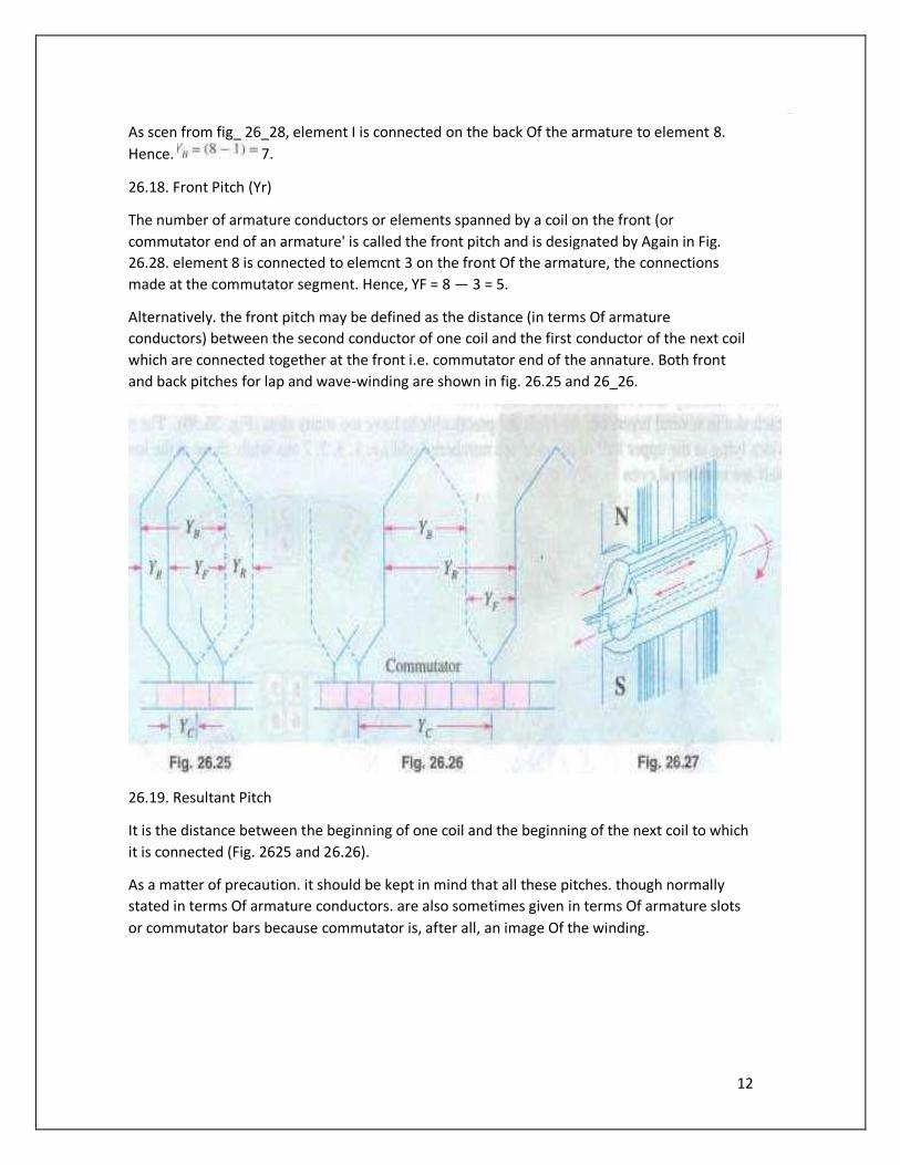
As scen from fig_ 26_28, element I is connected on the back Of the armature to element 8.
Hence. 7.
26.18. Front Pitch (Yr)
The number of armature conductors or elements spanned by a coil on the front (or
commutator end of an armature' is called the front pitch and is designated by Again in Fig.
26.28. element 8 is connected to elemcnt 3 on the front Of the armature, the connections
made at the commutator segment. Hence, YF = 8 — 3 = 5.
Alternatively. the front pitch may be defined as the distance (in terms Of armature
conductors) between the second conductor of one coil and the first conductor of the next coil
which are connected together at the front i.e. commutator end of the annature. Both front
and back pitches for lap and wave-winding are shown in fig. 26.25 and 26_26.
26.19. Resultant Pitch
It is the distance between the beginning of one coil and the beginning of the next coil to which
it is connected (Fig. 2625 and 26.26).
As a matter of precaution. it should be kept in mind that all these pitches. though normally
stated in terms Of armature conductors. are also sometimes given in terms Of armature slots
or commutator bars because commutator is, after all, an image Of the winding.
13
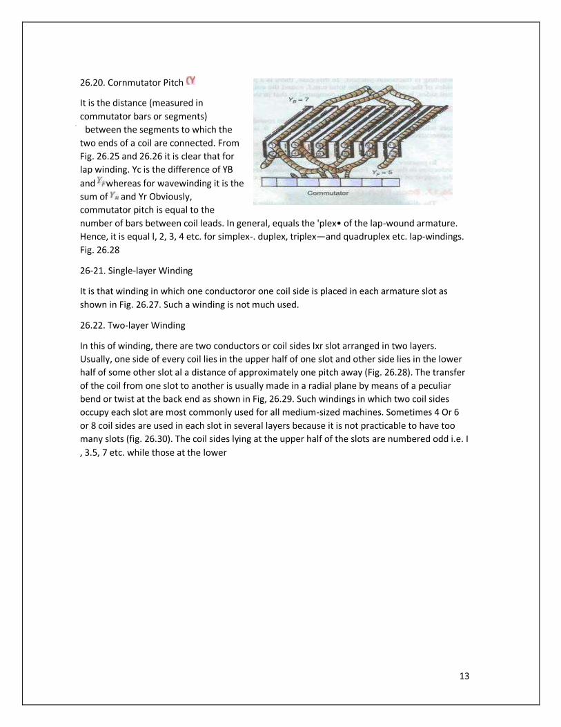
26.20. Cornmutator Pitch
It is the distance (measured in
commutator bars or segments)
between the segments to which the
two ends of a coil are connected. From
Fig. 26.25 and 26.26 it is clear that for
lap winding. Yc is the difference of YB
and whereas for wavewinding it is the
sum of and Yr Obviously,
commutator pitch is equal to the
number of bars between coil leads. In general, equals the 'plex• of the lap-wound armature.
Hence, it is equal l, 2, 3, 4 etc. for simplex-. duplex, triplex—and quadruplex etc. lap-windings.
Fig. 26.28
26-21. Single-layer Winding
It is that winding in which one conductoror one coil side is placed in each armature slot as
shown in Fig. 26.27. Such a winding is not much used.
26.22. Two-layer Winding
In this of winding, there are two conductors or coil sides Ixr slot arranged in two layers.
Usually, one side of every coil lies in the upper half of one slot and other side lies in the lower
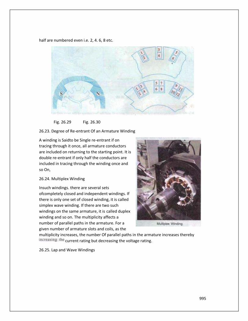
half of some other slot al a distance of approximately one pitch away (Fig. 26.28). The transfer
of the coil from one slot to another is usually made in a radial plane by means of a peculiar
bend or twist at the back end as shown in Fig, 26.29. Such windings in which two coil sides
occupy each slot are most commonly used for all medium-sized machines. Sometimes 4 Or 6
or 8 coil sides are used in each slot in several layers because it is not practicable to have too
many slots (fig. 26.30). The coil sides lying at the upper half of the slots are numbered odd i.e. I
, 3.5, 7 etc. while those at the lower
995
half are numbered even i.e. 2, 4. 6, 8 etc.
Fig. 26.29 Fig. 26.30
26.23. Degree of Re-entrant Of an Armature Winding
A winding is Saidto be Single re-entrant if on
tracing through it once, all armature conductors
are included on returning to the starting point. It is
double re-entrant if only half the conductors are
included in tracing through the winding once and
so On,
26.24. Multiplex Winding
Insuch windings. there are several sets
ofcompletely closed and independent windings. If
there is only one set of closed winding, it is called
simplex wave winding. If there are two such
windings on the same armature, it is called duplex
winding and so on. The multiplicity affects a
number of parallel paths in the armature. For a
given number of armature slots and coils, as the
multiplicity increases, the number Of parallel paths in the armature increases thereby
current rating but decreasing the voltage rating.
26.25. Lap and Wave Windings
996
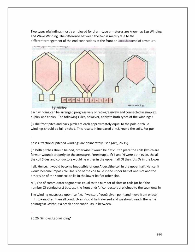
Two types ofwindings mostly employed for drum-type armatures are known as Lap Winding
and Wave Winding. The difference between the two is merely due to the
dtfferentarrangement of the end connections at the front or end of armature.
Each winding can be arranged progressively or retrogressively and connected in simplex,
duplex and triplex. The following rules, however, apply to both types of the windings :
(i) The front pitch and back pitch are each approximately equal to the pole-pitch i.e.
windings should be full-pitched. This results in increased e.m.f, round the coils. For pur-
poses. fractional-pitched windings are deliberately used (Art_ 26.15).
(in Both pitches should be odd, otherwise it would be difficult to place the coils (which are
former-wound) properly on the armature. Forexmaple, ifYB and YFwere both even, the all
the coil Sides and conductors would lie either in the upper half Of the slots Or in the lower
half. Hence. it would become impossiblefor one Aidèxsfthe coil in the upper half. Hence. it
would become impossible One side of the coil to lie in the upper half of one slot and the
other side of the same coil to lie in the lower half of other slot.
riii', The of commutator segmentsis equal to the number of slots or coils (or half the
number Of conductors) because the front endsÃ'f conductors are joined to the segments in
The winding mustclose uponitselfi.e. if we start frotnû given point and move from onecoi]
to•another, then all conductors should he traversed and we should reach the same
poinragain Without a break or discontinuity io between.
26.26. Simplex Lap-winding*
Lap winding
997
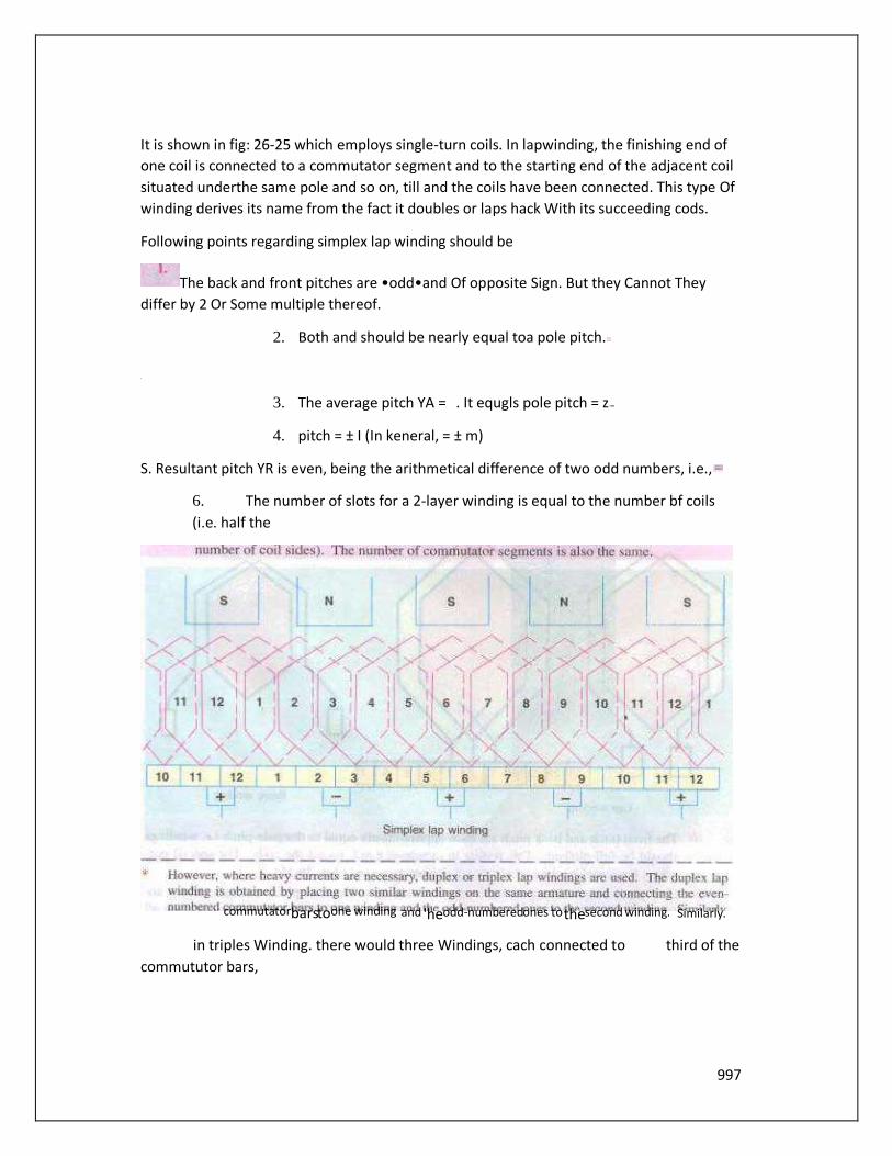
It is shown in fig: 26-25 which employs single-turn coils. In lapwinding, the finishing end of
one coil is connected to a commutator segment and to the starting end of the adjacent coil
situated underthe same pole and so on, till and the coils have been connected. This type Of
winding derives its name from the fact it doubles or laps hack With its succeeding cods.
Following points regarding simplex lap winding should be
The back and front pitches are •odd•and Of opposite Sign. But they Cannot They
differ by 2 Or Some multiple thereof.
2. Both and should be nearly equal toa pole pitch.
3. The average pitch YA = . It equgls pole pitch = z
4. pitch = ± I (In keneral, = ± m)
S. Resultant pitch YR is even, being the arithmetical difference of two odd numbers, i.e.,
6. The number of slots for a 2-layer winding is equal to the number bf coils
(i.e. half the
in triples Winding. there would three Windings, cach connected to third of the
commututor bars,
Similarly. commutator bars to one winding and 'he odd-numbered ones to the second winding.
998
7. The numberofpárallel pathsin the armature where m is the
multiplicityofthe winding and P the number of poles.
Taking the firstcondition. we have Yo =
(a) If YB > YF i.e. = YF • 2, then We get a progressive or right-handed winding i.e. a winding
which progresses in the clockwise direction as seen from the commutator end.o this case,
obviously,
If YB < YF i.e. YF —2, then we geta or left-handed winding i.e. one which
advances in the anti-clockwise direction When seen from the commutator side. In this Case,
Yc+
(c) Hence, it is obvious that
SQinding ûild — + 1
forretrogfesgive winding
Obviously, up must be even to make the winding possible.
26.27. Numbering Of Coils and Commutator Segments
In the d.c. Winding diagrams to follow. we Will number the coils only (not individual turns).
The upper side Of the coil Will be shown by a firm continuous I inc whereas the lower side
Will be shown by a broken line. The numbering of coil sides will be consecutive i.e. l, 2, 3
etc. and such that odd numbers are assigned to the top conductors and even numbers to
the lower sides for a two-layer winding. The commutator segments Will also be numbered
consecutively, the of the ments will be the same as that of the upper side connected to
it.
Example 26.1. Draw a developed diagram ofa simple 2-laýer lap-windingfor "-pole
generator With 16 coilÅ. Hence, point out the chamcteristics Of a lap-winding.
(Elect. Engineering, Madras Univ. 1981)
Solution. The number of commutator segments = 16
Number Of conductors or coil sides 16 x 2 32 : pole pitch 32/4 = 8
Now remembering that (i) YB and YF have to be Odd and (ii) have to differ by 2, We get for
a progressive winding YB = 9 ; YF — —7 (retrogressive winding Will result if YR 7 and YF =
Obviously, commutator pitch Yc —
(Otherwise, as shown in An. 26.26, for progressive winding
999
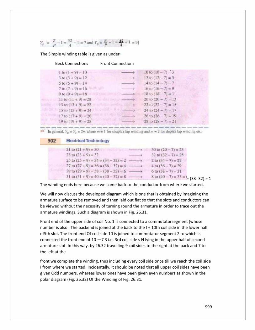
The Simple winding table is given as under
Beck Connections Front Connections
= (33- 32) = 1
The winding ends here because we come back to the conductor from where we started.
We will now discuss the developed diagram which is one that is obtained by imagining the
armature surface to be removed and then laid out flat so that the slots and conductors can
be viewed without the necessity of turning round the armature in order to trace out the
armature windings. Such a diagram is shown in Fig. 26.31.
Front end of the upper side of coil No. 1 is connected to a commutatorsegment (whose
number is also I The backend is joined at the back to the I + 10th coil side in the lower half
of5th slot. The front end Of coil side 10 is joined to commutator segment 2 to which is
connected the front end of 10 —7 3 i.e. 3rd coil side s N lying in the upper half of second
armature slot. In this way. by 26.32 travelling 9 coil sides to the right at the back and 7 to
the left at the
front we complete the winding, thus including every coil side once till we reach the coil side
I from where we started. Incidentally, it should be noted that all upper coil sides have been
given Odd numbers, whereas lower ones have been given even numbers as shown in the
polar diagram (Fig. 26.32) Of the Winding of Fig. 26.31.
32
1000
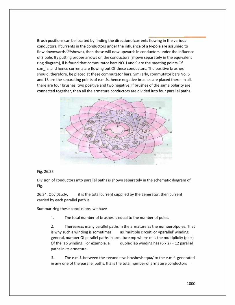
Brush positions can be located by finding the directionofcurrents flowing in the various
conductors. Ifcurrents in the conductors under the influence of a N-pole are assumed to
flow downwards shown), then these will now upwards in conductors under the influence
of S.pole. By putting proper arrows on the conductors (shown separately in the equivalent
ring diagram), il is found that commutator bars NO. I and 9 are the meeting points Of
c.m_fs. and hence currents are flowing out Of these conductors. The positive brushes
should, therefore. be placed at these commutator bars. Similarly, commutator bars No. 5
and 13 are the separating points of e.m.fs. hence negative brushes are placed there. In all.
there are four brushes, two positive and two negative. If brushes of the same polarity are
connected together, then all the armature conductors are divided iuto four parallel paths.
Fig. 26.33
Division of conductors into parallel paths is shown separately in the schematic diagram of
Fig.
26.34. Obvi0LLsIy, if is the total current supplied by the Eenerator, then current
carried by each parallel path is
Summarizing these conclusions, we have
1. The total number of brushes is equal to the number of poles.
2. Thereareas many parallel paths in the armature as the numberofpoles. That
is why such a winding is sometimes as 'multiple circuit' or •parallel' winding.
general, number Of parallel paths in armature mp where m is the multiplicity (plex)
Of the lap winding. For example, a duplex lap winding has (6 x 2) = 12 parallel
paths in its armature.
3. The e.m.f. between the +veand—ve brushesisequa/ to the e.m.f- generated
in any one of the parallel paths. If Z is the total number of armature conductors
1001
and p the number of poles, then the number of armature conductors (connected in
series) in any parallel path is Z"
Resistance of each path— PIZ
There are P (or A) such paths in parallel, hence equivalent resistance
If is the total armature current. then current per parallel path (or carried by each
conductor) is a/P.
26.28. Simplex Wave Winding•
From fig. 26.31. it is clear that in lap Winding, a Conductor (or coil side) under one pole is
connected at the back to a conductor which occupies an almost corresponding position
under the next pole of opposite' polarity (as conductors 3 and 12). Conductor NO. 12 is then
connected to conductor No. 5 under the original pole but which is a little removed from the
initial conductor No. 3. If, instead of returning to the same At-pole, the conductor No. 12
were takenfonvard lothe next N.pnle, it would make no difference so fartLs the direction
and magnitude of the e.m_f. induced in the circuit are concerned
Like lap winding. a wave winding may be duplex, triplcž or may have any degree Of
multiplicity. A simplex wave winding has two paths. a duplex A',eave Winding four paths
and a triplex paths etc.
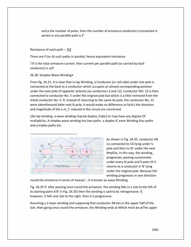
As shown in Fig. 26.35. conductor AB
Lis connected to CD lying under S-
pole and then to EF under the next
N•p01e, In this way, the winding,
progresses, passing successively
under every N-pole and S-pole till it
returns to a conductor A 'B' lying
under the original pole. Because the
winding progresses in one direction
round the armature in series of •waves' , it is known as wave Winding.
Fig. 26.35 If. after passing once round the armature. the winding falls in a slot to the left of
its starting point A'B' in Fig. 26.35) then the winding is said to bc retrogressive. If,
however, it falls one slot to the right. then it is progressive.
Assuming a 2-layer winding and supposing that conductor AB lies in the upper half of the
slot. then going once round the armature, the Winding ends at Which most be atThe upper
1002
half of the slot at the left orTight. Counting in terms of conductors, it means that AB and
A'B' differ by two conductors (although they diner by one slot).
From the above, we can deduce the
following relations. If P —No.
Ofpoles, then total No. Of conductors
orcoil Sides
Since p is always even and
alwaysbeeven. Put
in another way. it
means that must an even integer.
The plus sign will give a progressive winding and the negative sign a retrogressive winding.
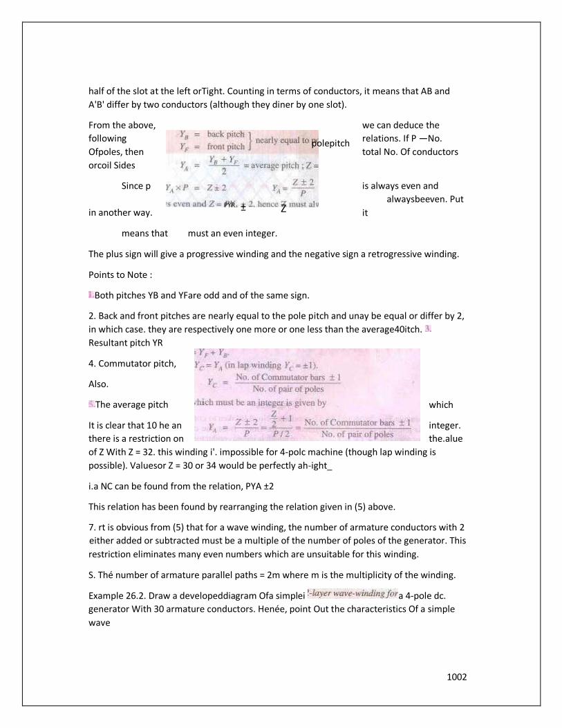
Points to Note :
Both pitches YB and YFare odd and of the same sign.
2. Back and front pitches are nearly equal to the pole pitch and unay be equal or differ by 2,
in which case. they are respectively one more or one less than the average40itch.
Resultant pitch YR
4. Commutator pitch,
Also.
The average pitch which
It is clear that 10 he an integer.
there is a restriction on the.alue
of Z With Z = 32. this winding i'. impossible for 4-polc machine (though lap winding is
possible). Valuesor Z = 30 or 34 would be perfectly ah-ight_
i.a NC can be found from the relation, PYA ±2
This relation has been found by rearranging the relation given in (5) above.
7. rt is obvious from (5) that for a wave winding, the number of armature conductors with 2
either added or subtracted must be a multiple of the number of poles of the generator. This
restriction eliminates many even numbers which are unsuitable for this winding.
S. Thé number of armature parallel paths = 2m where m is the multiplicity of the winding.
Example 26.2. Draw a developeddiagram Ofa simplei a 4-pole dc.
generator With 30 armature conductors. Henée, point Out the characteristics Of a simple
wave
pole pitch
PYR ± Z
1003
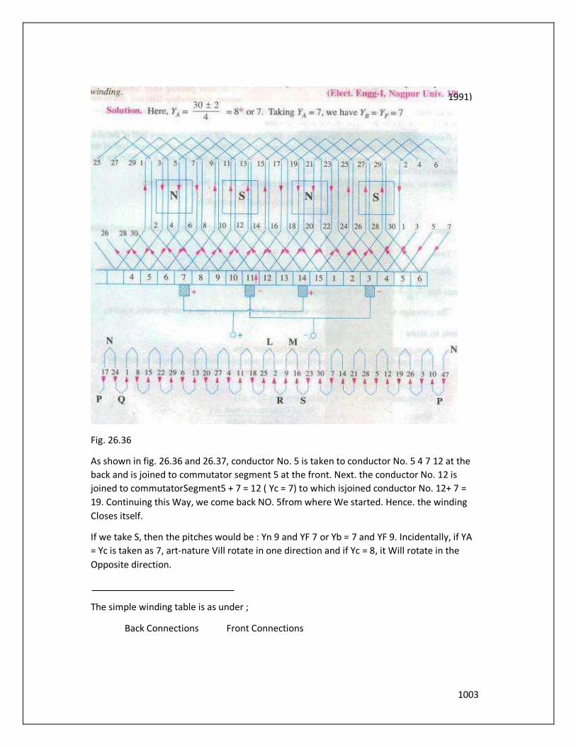
Fig. 26.36
As shown in fig. 26.36 and 26.37, conductor No. 5 is taken to conductor No. 5 4 7 12 at the
back and is joined to commutator segment 5 at the front. Next. the conductor No. 12 is
joined to commutatorSegment5 + 7 = 12 ( Yc = 7) to which isjoined conductor No. 12+ 7 =
19. Continuing this Way, we come back NO. 5from where We started. Hence. the winding
Closes itself.
If we take S, then the pitches would be : Yn 9 and YF 7 or Yb = 7 and YF 9. Incidentally, if YA
= Yc is taken as 7, art-nature Vill rotate in one direction and if Yc = 8, it Will rotate in the
Opposite direction.
The simple winding table is as under ;
Back Connections Front Connections
1991)

1004
stage.
Brush Position
Location of brush position in wave-winding is slightly
difficult. In Fig. 26.36 conductors are supposed to be
moving from left to right over the polcs_ By applying
Fleming's Right-hand rule. the directions of the
induced e.m.fs in various armature conductors can
be found. The directions shown in the figure have
been found in this manner. In the lower part of Fig.
26.36 is shown the equivalent ring or spiral diagram
which is very helpful in understanding the formation of various parallel paths in the
armature. It is seen that the winding is electrically divided into two portions. One portion
consists ofconductors lying between points N and L and the other of conductors lying
between N and M. In the first portion, the general trend of Fig. 26.37 the induced e.m.fs, is
from left to right whereas in the second
portion it is from right to left. Hence, in general, there are only two parallel paths through
the winding, so that two brushes are required, one positive and one negative.
From the equivalent ring diagram. it is seen that point N is the separatiqg point Of the
e.m.fs. induced in the two portions of the winding. Hence, this fixes the position of the
negative brush. But as it is at thc back and not at the commutator end of the armature, the
Since we

1005
negative brush has two alternative positions i. e, either at point P or Q. These points on the
equivalent diagram correspond to commutator segments NO. 3 and ll.
Now, we will find the position of the positive brush. It is found that there are two meeting
points of the induced e.m.fs. i.e. points L and M but both these points are at the back or
non-commutator end of the armature. These two points are separated by one loop only.
namely. the loop composed of conductors 2 and 9, hence the middle point R of this loop
fixes the position of the positive brush. which should be placed in touch with commutator
segment No. 7. We find that for one position Of the brush, there are two alternative
positions for the —ve brush.
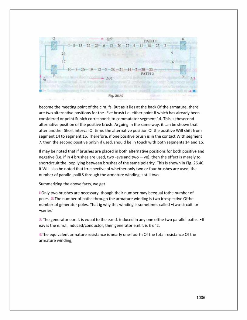
Taking the -eve brush at point R and negative brush at point p, the winding is seen to be
divided into the following two paths.
In path 1 (Fig. 26.36) it is found that e.m.r. in conductor 9 is in opposition to the general
trend ofe.m.fs. in the Other conductor"s comprising this path. Similarly, in path 2. the e.m.f.
in conductor 2 is in position to the direction Of e.rn.fs. in the path as a whole. However, this
will make no difference because these conductors lie almost in the interpolar gap and,
therefore e.m.fs. in these conductors are negligible.
Again, take the case of conductors 2and 9situated between points L and M. Since the
armature conductors are in continuous motion over the pole faces, their positions as shown
in the figure are only instantaneous. Keeping in this.nind. itis obvious that conductor 2 is
about to move from the influence Of S-pole to that of the next N-pole. Hence, the e.m.f. in
it is at the point Of reversing. However, conductor 9 has already passed the position of
reversal, hence its e.m_f_ will not reverse. rather it will increase in magnitude gradually. It
means that in a very short interval, point M will
Fig. 26Æ
1006
become the meeting point of the c.m_fs. But as it lies at the back Of the armature, there
are two alternative positions for the -Eve brush i.e. either point R which has already been
considered or point Suhich corresponds to commutator segment 14. This is thesecond
alternative position of the positive brush. Arguing in the same way. it can be shown that
after another Short interval Of time. the alternative position Of the positive Will shift from
segment 14 to segment 15. Therefore, if one positive brush is in the contact With segment
7, then the second positive bnlSh if used, should be in touch with both segments 14 and 15.
Il may be noted that if brushes are placed in both alternative positions for both positive and
negative (i.e. if in 4 brushes are used, two -eve and two —ve), then the effect is merely to
shortcircuit the loop lying between brushes of the same polarity. This is shown in Fig. 26.40
it Will also be noted that irrespective of whether only two or four brushes are used, the
number of parallel pallLS through the armature winding is still two.
Summarizing the above facts, we get
Only two brushes are necessary. though their number may beequal tothe number of
poles. The number of paths through the armature winding is two irrespective Ofthe
number of generator poles. That ig why this winding is sometimes called •two-circuit' or
•series'
The generator e.m.f. is equal to the e.m.f. induced in any one ofthe two parallel paths. •If
eav is the e.m.f. induced/conductor, then generator e.nl.f. is E x "2.
The equivalent armature resistance is nearly one-fourth Of the total resistance Of the
armature winding,
1007
5. If is the total armature current, then current carried
byeach path orconductor is obviously 1/2 whatever the
number of poles.
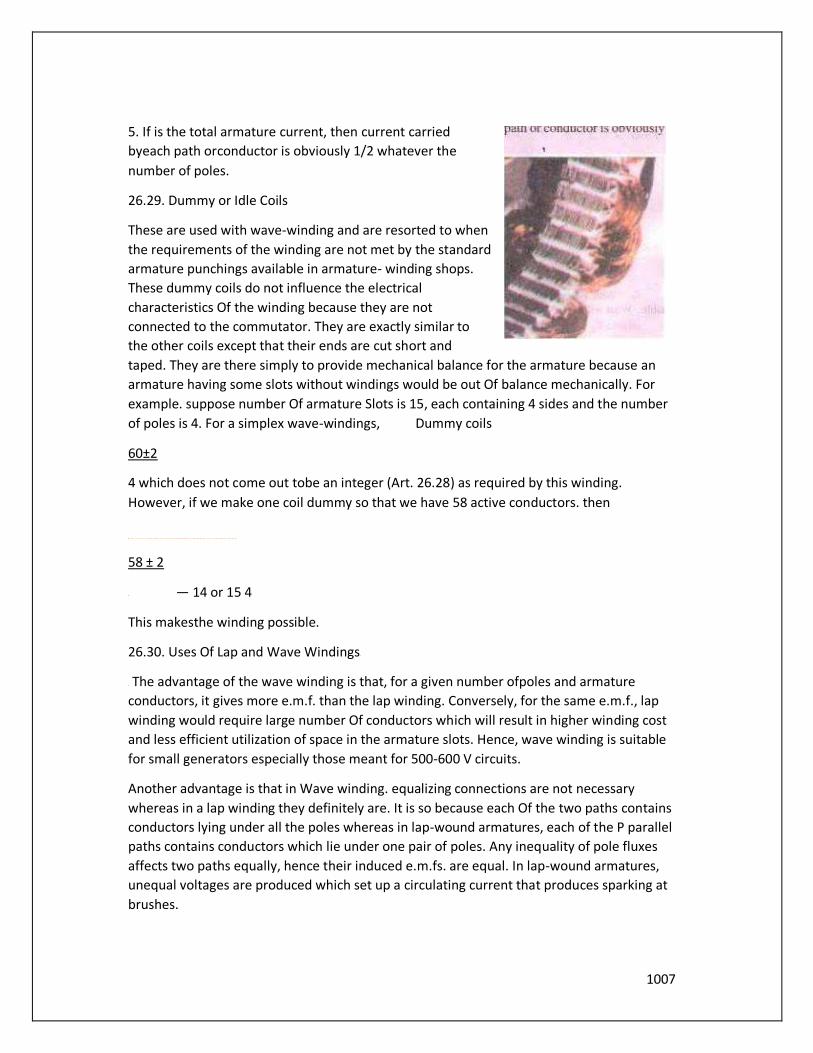
26.29. Dummy or Idle Coils
These are used with wave-winding and are resorted to when
the requirements of the winding are not met by the standard
armature punchings available in armature- winding shops.
These dummy coils do not influence the electrical
characteristics Of the winding because they are not
connected to the commutator. They are exactly similar to
the other coils except that their ends are cut short and
taped. They are there simply to provide mechanical balance for the armature because an
armature having some slots without windings would be out Of balance mechanically. For
example. suppose number Of armature Slots is 15, each containing 4 sides and the number
of poles is 4. For a simplex wave-windings, Dummy coils
60±2
4 which does not come out tobe an integer (Art. 26.28) as required by this winding.
However, if we make one coil dummy so that we have 58 active conductors. then
58 ± 2
— 14 or 15 4
This makesthe winding possible.
26.30. Uses Of Lap and Wave Windings
The advantage of the wave winding is that, for a given number ofpoles and armature
conductors, it gives more e.m.f. than the lap winding. Conversely, for the same e.m.f., lap
winding would require large number Of conductors which will result in higher winding cost
and less efficient utilization of space in the armature slots. Hence, wave winding is suitable
for small generators especially those meant for 500-600 V circuits.
Another advantage is that in Wave winding. equalizing connections are not necessary
whereas in a lap winding they definitely are. It is so because each Of the two paths contains
conductors lying under all the poles whereas in lap-wound armatures, each of the P parallel
paths contains conductors which lie under one pair of poles. Any inequality of pole fluxes
affects two paths equally, hence their induced e.m.fs. are equal. In lap-wound armatures,
unequal voltages are produced which set up a circulating current that produces sparking at
brushes.
1008
However, when laœe currents are required, it is necessary to use lap winding, because it
gives more parallel paths.
Hence, lap winding is suitable forcomparatively low-voltage but high-currentgenerators
whereas wave-winding is used for high-voltage, low-current machines.
Tutorial Problem No. 26.1
2. With a simplex 2-1ayer Wave winding having 26 conductors and 4-poles. write down
the Winding table. What will be the front and back
pitches of the winding ?
(Electric Machinery-I, Madras Univ. Nov. 1979'
segments
26.31. Types of Generators
Generators are usually classified according to the way in which their fields are excited.
Generators may be divided into separately-excited generators and self-excited generators.
Separately-excited generators are those whose field magnets are energised from an
independent external source Of d.c. current. It is shown diagramatically in fig. 26.41.
18
simplex
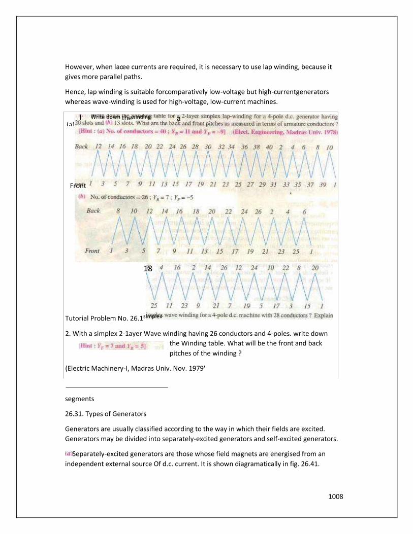
l. Write down the winding a (a)
Front

1009
Self-excited generators are those whose field magnets are energised by the current
produce.d by the generators themselves. Due to residual magnetism, there is always
present some flux in the When the armature is rotated, some and hence some induced
current is produced which is partly or fully passed through the field coils thereby
strengthening the residual pole flux,
There are three types of self-excited generators named according to the manner in which
their field coils (or windings) are connected to the armature. lib Shunt wound
The field windings are connected across or in parallel with the armature conductors
Example 26.9. An 8•p01e dc. generator has 5(H) armature conductors, and a useful flux Of
O. 05 Wb per pole. What Will be the e.m.f. generated ifit is lap-connected and runs at 4200
rpm ? What must be the speed at which is to be driven produce the same it is Wave-
wound?
[U.P. Technical Univ. 2001)
It is reduced to one fourth. being proportional to the
Example 26.26. A long-shunt dynamo, running ut 1000 voltage Of 220 V. The resistances
0.06 Q respectively. The overall efficiency at the above load is friction losses (c) the torque
exerted by theprime,mover.
1010
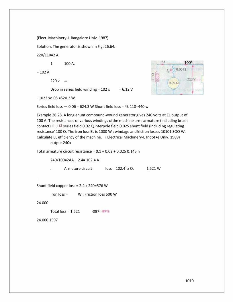
(Elect. Machinery-I. Bangalore Univ. 1987)
Solution. The generator is shown in Fig. 26.64.
220/110=2 A
1 - 100 A.
= 102 A
220 v
Drop in series field winding = 102 x = 6.12 V
- 1022 xo.05 =520.2 W
Series field loss — 0.06 = 624.3 W Shunt field loss = 4k 110=440 w
Example 26.28. A long-shunt compound-wound generator gives 240 volts at EL output of
100 A. The resislances of various windings ofthe machine are : armature (including brush
contact) O. J series field 0.02 Q interpole field 0.025 shunt field (including regulating
resistance' 100 Q. The iron loss EL is 1000 W ; windage andfriction losses 10101 SOO W.
Calculate EL efficiency of the machine. i Electrical Machinery-I, Indot•e Univ. 1989)
output 240x
Total armature circuit resistance = 0.1 + 0.02 + 0.025 0.145 n
240/100=2ÅA 2.4= 102.4 A
Armature circuit loss = 102.42 x O. 1,521 W
Shunt field copper loss = 2.4 x 240=576 W
Iron loss = W ; Friction loss 500 W
24.000
Total loss = 1,521 -087
24.000 1597
100 A
1011
DC MOTOR
Motor Principle
An Electric motor is a machine which converts electric energy into mechanical energy. ILS
action is based on the principle that when a current-carrying conductor is placed in a
magnetic field. it experiences a mechanical forec whose direction is given by Fleming's Left-
hand Rule and magnitude is given by Constructionally, there is no basic difference
between a d.c_ generator and a d_c_ motor In tact, the same d_c_ machine can bc used
interchangeably as a generator or as a motor. D.C_ motors are also like generators. shunt-
wound or series-wound or compound-wound.
of Motor are supplied with current from the supply mains. they expenencc a force tending
to rotate the armature. Armature conductors under At-pole arc assumed carry current
downwards (Crosses) and those under S-poles, to carry current upwards (dots). By applying
Fleming's Left•harud Rule, the direction of the force on Fig.
each conductor can found. It is shown by small arrows placed above each conductor. It Will
be seen thåt each conductor can be found. It will be seen that each conductor experiences
a force F which tends to mtate the armature in anticlcxkwise direction. These forces
collectively produce a driving torque which sets the armature rotating.
It should be noted that the function of a commutatorin the motor is the same as in a
generator. By revetsing current in each conductor as it passes from one pole toanother,
ithelps to developa continuous and unidirectional torque.
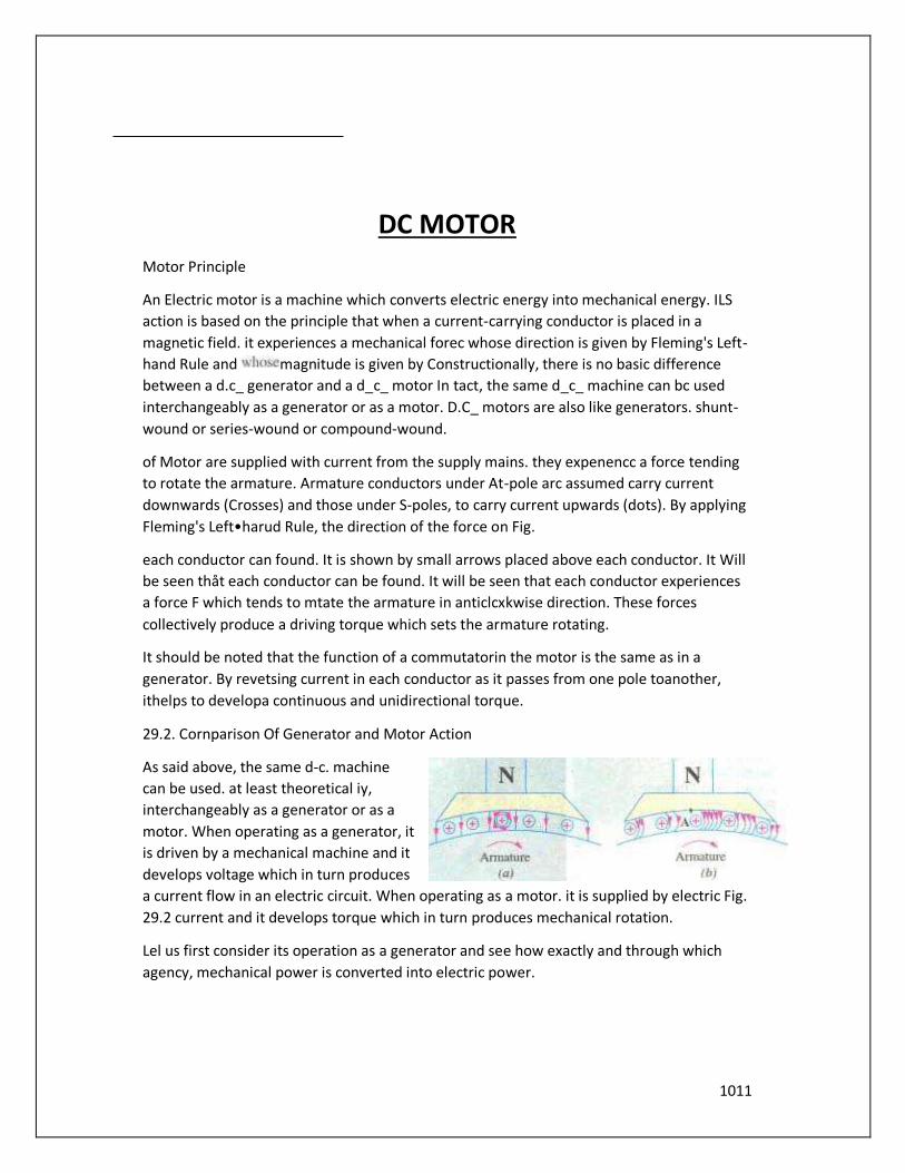
29.2. Cornparison Of Generator and Motor Action
As said above, the same d-c. machine
can be used. at least theoretical iy,
interchangeably as a generator or as a
motor. When operating as a generator, it
is driven by a mechanical machine and it
develops voltage which in turn produces
a current flow in an electric circuit. When operating as a motor. it is supplied by electric Fig.
29.2 current and it develops torque which in turn produces mechanical rotation.
Lel us first consider its operation as a generator and see how exactly and through which
agency, mechanical power is converted into electric power.

1012
In Fig. 29.2 pan of a generator whose armature is being driven clockwise by its prime nlover
is shown.
Fig, 29.2 (a) represents the fields set up independently by the main poles and the armature
conductors like A in the figure. The resultant field or magnetic lines on flux are shown in Fig.
29_2 It is Seen that there is a crowding of'iries of flux on the right-hand side ofA. These
magnetic lines of flux may be likened to the rubber bands under tension. Hence. the bent
lines Of flux up mechanical force on A much in the same way as the bent elastic rubber
band Of a catapult produces a mechanical force on the stone piece. It Will he seen that this
force is in a direction opposite to that Of armature rotation. Hence, it is known as backward
force or magnetic drag on the conductors. It is against this drag action on all
armat•uœconductor that the prime mover has to work. The WOEk done in overcoming this
opposition is converted into electric energy. Therefore. it should be clearly understood thal
it is only through the instrumentality of this magnetic drag that energy conversion is
possible in a d.c.
generator
Next, suppose thal the above d.c. machine is un• coupled from its prime mover and that
current is sent through the
armature conductols under a
N.polc in the downward direction
as shown in Fig. 29.3 The
conduclors will again experience a
forec in the anticlockwise
direction ('Fleming's Left hand
RAIle)_
Hence. the machine Will
Start rolating anticiockwise. thereby developingÆi torque which can produce mechanical
rotation. The machine is then said to be motoring.
As said above, energy conversion is not possi'le unless there is some opposition whose
over% coming provides the necessary means for such conversion. In the case Of a
generator, it was the magnetic drag which provided the necessary opposition. But what is
the equivalent of that drag in the case Of a motor ? Well, i' i' the hack e.rn,f. It is explained
in this manner
1013
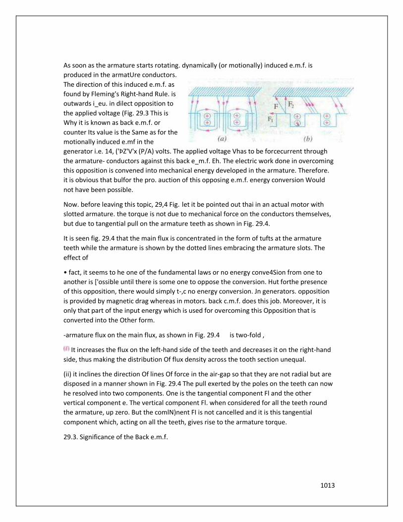
As soon as the armature starts rotating. dynamically (or motionally) induced e.m.f. is
produced in the armatUre conductors.
The direction of this induced e.m.f. as
found by Fleming's Right-hand Rule. is
outwards i_eu. in dilect opposition to
the applied voltage (Fig. 29.3 This is
Why it is known as back e.m.f. or
counter Its value is the Same as for the
motionally induced e.mf in the
generator i.e. 14, ('ÞZ'V'x (P/A) volts. The applied voltage Vhas to be forcecurrent through
the armature- conductors against this back e_m.f. Eh. The electric work done in overcoming
this opposition is convened into mechanical energy developed in the armature. Therefore.
it is obvious that bulfor the pro. auction of this opposing e.m.f. energy conversion Would
not have been possible.
Now. before leaving this topic, 29,4 Fig. let it be pointed out thai in an actual motor with
slotted armature. the torque is not due to mechanical force on the conductors themselves,
but due to tangential pull on the armature teeth as shown in Fig. 29.4.
It is seen fig. 29.4 that the main flux is concentrated in the form of tufts at the armature
teeth while the armature is shown by the dotted lines embracing the armature slots. The
effect of
• fact, it seems to he one of the fundamental laws or no energy conve4Sion from one to
another is ['ossible until there is some one to oppose the conversion. Hut forthe presence
of this opposition, there would simply t-,c no energy conversion. Jn generators. opposition
is provided by magnetic drag whereas in motors. back c.m.f. does this job. Moreover, it is
only that part of the input energy which is used for overcoming this Opposition that is
converted into the Other form.
-armature flux on the main flux, as shown in Fig. 29.4 is two-fold ,
It increases the flux on the left-hand side of the teeth and decreases it on the right-hand
side, thus making the distribution Of flux density across the tooth section unequal.
(ii) it inclines the direction Of lines Of force in the air-gap so that they are not radial but are
disposed in a manner shown in Fig. 29.4 The pull exerted by the poles on the teeth can now
he resolved into two components. One is the tangential component Fl and the other
vertical component e. The vertical component Fl. when considered for all the teeth round
the armature, up zero. But the comlN)nent FI is not cancelled and it is this tangential
component which, acting on all the teeth, gives rise to the armature torque.
29.3. Significance of the Back e.m.f.
1014
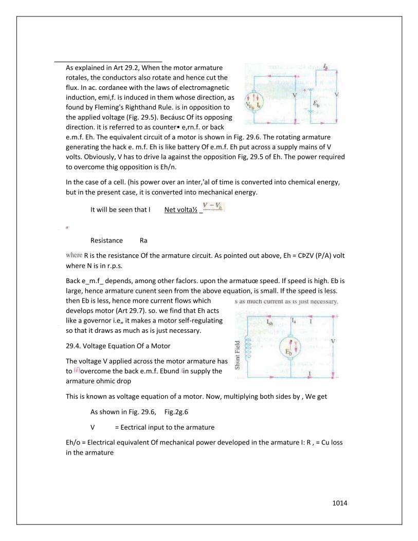
As explained in Art 29.2, When the motor armature
rotales, the conductors also rotate and hence cut the
flux. In ac. cordanee with the laws of electromagnetic
induction, emi,f. is induced in them whose direction, as
found by Fleming's Righthand Rule. is in opposition to
the applied voltage (Fig. 29.5). Becáusc Of its opposing
direction. it is referred to as counter• e,rn.f. or back
e.m.f. Eh. The equivalent circuit of a motor is shown in Fig. 29.6. The rotating armature
generating the hack e. m.f. Eh is like battery Of e.m.f. Eh put across a supply mains of V
volts. Obviously, V has to drive la against the opposition Fig, 29.5 of Eh. The power required
to overcome thig opposition is Eh/n.
In the case of a cell. (his power over an inter,'al of time is converted into chemical energy,
but in the present case, it is converted into mechanical energy.
It will be seen that I Net volta½ _
Resistance Ra
R is the resistance Of the armature circuit. As pointed out above, Eh = CÞZV (P/A) volt
where N is in r.p.s.
Back e_m.f_ depends, among other faclors. upon the armatuœ speed. If speed is high. Eb is
large, hence armature cunent seen from the above equation, is small. If the speed is less.
then Eb is less, hence more current flows which
develops motor (Art 29.7). so. we find that Eh acts
like a governor i.e„ it makes a motor self-regulating
so that it draws as much as is just necessary.
29.4. Voltage Equation Of a Motor
The voltage V applied across the motor armature has
to overcome the back e.m.f. Ebund in supply the
armature ohmic drop
This is known as voltage equation of a motor. Now, multiplying both sides by , We get
As shown in Fig. 29.6, Fig.2g.6
V = Eectrical input to the armature
Eh/o = Electrical equivalent Of mechanical power developed in the armature I: R , = Cu loss
in the armature
1015
Hence. out Of the arunature input, some is wasted in 12R loss and the rest is converted into
me— chanical power within the armature.
ltmay also be noted that motor efficiency is given by the ratio of power developed by the
arma-
ture to its input i.e. EBIJV la = E*/V. Obviously. higher the value of Eb compared to V. higher
the motor efficiency.
29.5. Condition for Maximum Power
The gross mechanical power developed hy a motor is pm = la — I: Ra.
Differentiating both sides with to la and equating the result to zero. we get v—2/aRa-O As
and
Thus gross mechanical power developed by a motor is maximum When back e.tn_f. is equal
to half the applied voltage, This condition is, however. not realized in practice, because in
that ease current would be much beyond the normal current of the motor. Moreover. half
the input would be wasted in the form of heat and taking other losses (mechanical and
magnetic) into consideration. the motor efficiency will be well below 50 percent-
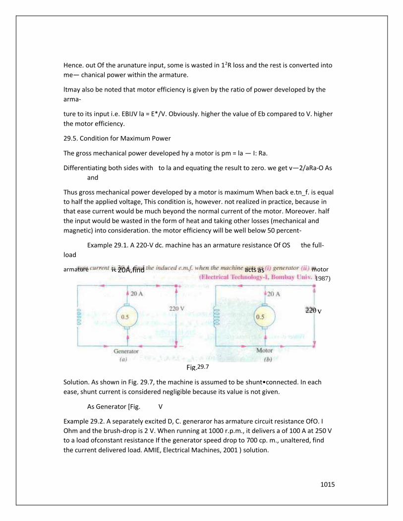
Example 29.1. A 220-V dc. machine has an armature resistance Of OS the full-
load
Solution. As shown in Fig. 29.7, the machine is assumed to be shunt•connected. In each
ease, shunt current is considered negligible because its value is not given.
As Generator [Fig. V
Example 29.2. A separately excited D, C. generaror has armature circuit resistance OfO. I
Ohm and the brush-drop is 2 V. When running at 1000 r.p.m., it delivers a of 100 A at 250 V
to a load ofconstant resistance If the generator speed drop to 700 cp. m., unaltered, find
the current delivered load. AMIE, Electrical Machines, 2001 ) solution.
220
armature is 20 A, find acts as motor
Fig. 29.7
1987)
v

1016
At = 262 X 700/1000 = 183.4 V If is the new current. — 2 — = 2.5
•This gives 96.77 amp.
Extension to Question : With what loudresistance will the current be amp. at
700 r.p.m. ?
Solution.
Forlo- IOOamp.and E 183.4 v, RL- 1.714 ohms.
Example 29.3. A shunt motor has armature resistance Of 0.8 n andfield
resistance Of
200 Determine the back e.m.f. When giving an output of7.46 kW at 85 pert-ent
efficiency,
Solution. Motor input 7.46 x 10³/0.85 W
Example 29.4. A 25-kW. dc. shunt generator has field resistances of 0.06 Q and
100 respectively Determine the total armature power dewloped when working (i) as a
generator delivering 25 kW output and t ii) as a motor faking 25 kW input.
' Electrical •lèchnoloo, Punjab Univ„ June 1991
Solution. As Generator (Fig. 29.8 (a)/
output current = 100 A
102.5 A
Generated emm
= 250+1 R„-250+ 102.5 xo.06=256.15 V
256.15 x 102.5
v
Fig. 29.8 (a) Fig. 29.8 (b)
1017
Power developed in armature
As Motor (Fig
Motor input current
244.15 v
Power in armature = kW
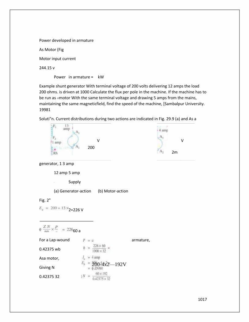
Example shunt generator With terminal voltage of 200 volts delivering 12 amps the load
200 ohms. is driven at 1000 Calculate the flux per pole in the machine. If the machine has to
be run as motor With the same terminal voltage and drawing 5 amps from the mains,
maintaining the same magneticfield, find the speed of the machine, [Sambalpur University.
19981
Soluti"n. Current distributions during two actions are indicated in Fig. 29.9 (a) and As a
generator, 1 3 amp
12 amp 5 amp
Supply
(a) Generator-action (b) Motor-action
Fig. 2"
2=226 V
60 a
For a Lap-wound armature,
0.42375 wb
Asa motor,
Giving N
0.42375 32
200
V
2m
V
200-4x2—192V
1018
850 r.p,m.
Tutorial Problems 29.1
l. What do you 'back c,rn.f.• Ad.e_ supply has an armature resistance
of O. IS Q, Calculate
(a) The Of hack e,m.f. when the armature current is 120 A.
The value of armature current when the hack is 4414 V.
A d.c. motor connected to 460-V supply utkes an armaturc Current Of 120 A on
full load. If the circuit has a of 0.25 Q, calculate the value of the back c.m.f. at
this load. | •130 VI A 4•poIe d:c_ motor takes an armature current Of 150 A at
440 V. If its armature circuit has a of O. IS Q. what will the value Of back c.rn.f, at
this load ? 1417.5 VI
29.6. Torque
By the term torque is meant the turning or twisting moment of a force about an axis. It is
measured by the product of the force and the radius at which this force acts.
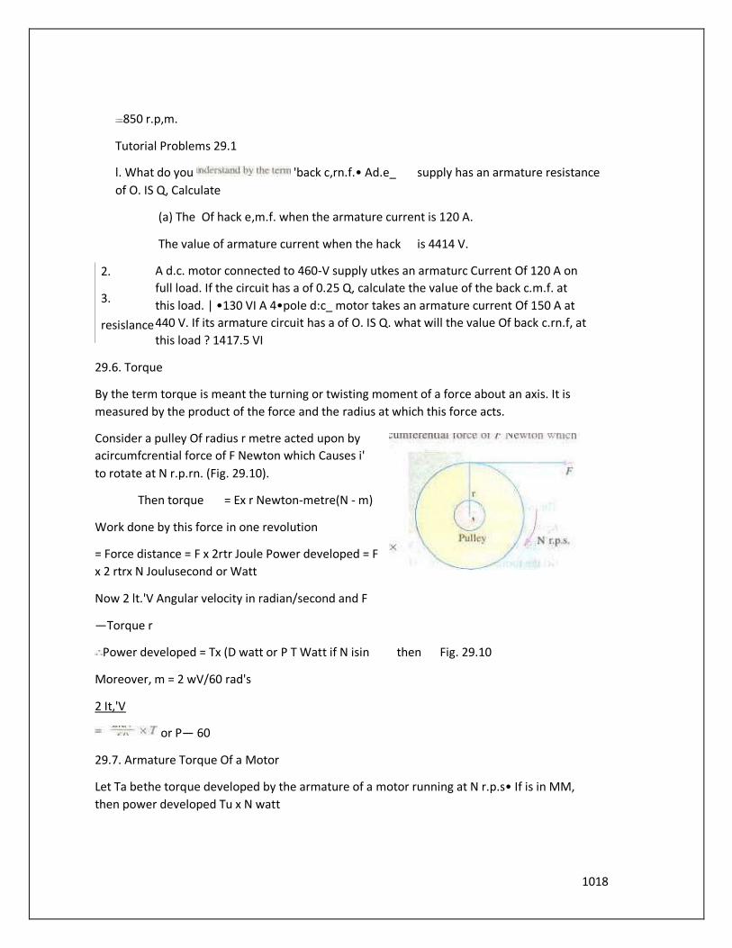
Consider a pulley Of radius r metre acted upon by
acircumfcrential force of F Newton which Causes i'
to rotate at N r.p.rn. (Fig. 29.10).
Then torque = Ex r Newton-metre(N - m)
Work done by this force in one revolution
= Force distance = F x 2rtr Joule Power developed = F
x 2 rtrx N Joulusecond or Watt
Now 2 lt.'V Angular velocity in radian/second and F
—Torque r
Power developed = Tx (D watt or P T Watt if N isin then Fig. 29.10
Moreover, m = 2 wV/60 rad's
2 It,'V
or P— 60
29.7. Armature Torque Of a Motor
Let Ta bethe torque developed by the armature of a motor running at N r.p.s• If is in MM,
then power developed Tu x N watt
2.
3.
resislance
1019
We also know that electrical Ix»ver converted into mechanical Il'w•er in the armature Alt
29.4) — Eh/a Watt
In the case of a series motor,
Windings carry full armature Current
N-m
29.8. Shaft Torque
The whole of the armature torque, as calculated is not available for doing useful
work. because a certain percentage of it is required for supplying iron and friction losses in
the motor.
The torque Which is available for doing useful work is known as Shaft torque It is so
called because it is available at the shaft_ The motor output is given by Output x2mV Watt
provided Tsh is in N-m and N in r.p,s.
Output in watts
The difference (Ta — T,h) is known as lost torque
and is due to iron and friction tosses of the
motor.
Note. The value of back e.m.f. Eh can be found from the equation, Eb = V — la Ra
(iii the formula Eb = Z.'V x (P/A) volt
Example 29.6. A dc. motor takes an armature current Of at 480 V! The armature circuit
resistance is 0.2 Q The machine has 6•poies and the armature is lap-connected
with 864 conductors. The flu per pole is 0.05 Wh. Calculate the speed and the
gross torque developed by the
armature. (Elect. Machines, A.M.I.E. Sec B. 1989)
Solution. Eh 480—110 xo.2—458V,
0.05 x 864 x N 6
60
N 636 cp.m.
27tN/60
r.p.S
r.p.m.
1020
A
T. = 0.159 xo.05
Example 29.7. A 25CL •a-pole, wave-wound Series motor has 782 conductors on its
armature. If has armature and seriesfield resisiance Of0.75 Ohm. The motor takes a currvnt
A. Estimate its speed and gmss to rque developed if it has a per pole of 25 m Wb.
(Elect. Engg.•ll, pone Univ. 1991)
Solution.
Example 29.8. A dc. Shunt Find torque mechanical power developed for an armature
current Of 50 A. State the simplifying sumptions. (Basic Elect. Machine Nagpur Univ.
1993) Solution. A given d_c. machine develops the Same e.m.f. in its armature conductors
whether running as a generator or us a motor, Only difference is that this armaturee.m.f. is
known as back
e.m.f. When the machine is running as a motor.
Mechanical power developed in the arm 50 = 12.500 W
T. —9.55 9.55 x 250 79.0 N-m.
Example 29.9. Determine developed and shaft torque of220-V,4-pole series motor with 800
conductors Wove-connected supplying load 0/82 kW by taking45 Afrom the mains. Theflltv
per pole is 25 m Wh and its armature circuit resistance is 0.6 Q.
(Elect. Machine AMIE sec. B Winter 1991)
. N2/500=200/210
Example 29.11. -500-V.37.3 kW. 1000 r.p.m. d,c. shunt motor has an efficiency OJ
90 The annature circuit resistance 0.24 Q and there is Iola/ voltage drop Of 2 V al the
brushes. The field curren' is 1.8 A. Determine (i) full-load line curren/ (in full load shaft
torque in N-m and resistance in motor starter 'o limit the starting cumm to 1.5 rimes the
full-load current. (Elect. Engg. l; M.S. Univ. Baroda 1987)
Solution. Motor input W
F.l. line current = 41.444/S(.WJ
= 356N-m
If R is the Starter resistance (which is in series with armature), then
Example 29.12. A "-pole. 220- V shunt motor has 540 lap-wound conductor. rakes 32 A from
the supply nminsanddevelops output power of5.595 kW Thefield winding takes A. The
resistance is 0.09 Q and the per pole is 30 mWb_ Calculate the speed and rhe torque
developed in newton-metre. (Electrical Nagpur Univ. 1992'
Solution. = 31 A V
1021
,ÞZN P
Now. 217.2 =
60 A 60 N = 804.4 r.p.m.
T. 9.55 x output in watts = 9.55 x 595 = 66.5 N-m
804.4
Example 29.13 Find the lead andfull-load speedsfor afour-pole, 220-V. and 20-kW. shunt
motor having thefollowing data :
Field—current = 5 amp, armature resistance = Ohm.
Flux per pole 0.04 Wb. number ofarmature-conductors = 160, livo-citèuit wave-connection,
full load current = 95 amp. No load current 29 A. Neglect armature reaction.
(Bharathitbasan Univ. April 1997)
Solution. The machine draws a supply current Of 9 amp at no load. Out Of this, 5 amps are
required for the field hence the armature carries a no-load current of amp.
At load, armature-current is 90 amp. The armature-resistance-drop increases and the back
e,m.f. decreases. resulting into decrease in speed under load compared to that at No-Load. :
E., = — 4 x 0.04 = volts
Substituting this.
004 x 160 x
No-Load speed. No — 1030.5 r.p.m.
Armature current A, Ea — 90 x 0.04 216.4 V (216.4/219.84) x 1030.5 = 1014.4 rpm.
F•ample 29. i 3 Armature Ofa 6-pole. 6-circuit D.C. shunt motor takes A at a speed Of 350
r.p.m_ Theflux per pole is 80 milli-webers. the number Ofarmature rums is 600. and
ofthe torque is lost in windage. friction and iron-loss. Calculate the brake-horse-
power.
(Manonmaniam Sundaranar Univ. NOV. 1998)
Solution. Number of armature turns = 600
Therefore, Z = Number Of armature conductors = 1200 If electromagnetic torque developed
is TNw — m.
Armature 'X'Wer T T x 2 't
= Twatts
1022
To calculate armature power in terms of Electrical parameters, E must be known.
- SOX x
— 560 volts
With the armature current Of 400 Armature power = 560* 400 watts Equating the two,
T = 560 x —6108-5 Nw—m, Since 3 % of this torque is required for overcoming
different loss-terms,
Net torque = -m
For Brake-Horse-power, net output in kW should be computed first. Then ••kW" is to be
vetted to "BHV'. with 1 HP = 0.746 kw,
Net output in kW = 5925 36.67 10-3 —217.27 kW
Converting this to BHP- the Output = 291 _25 HP
Example 29.13 Determine the torque established by the armature Of a four-pole D.C motor
having 774 conductors, two pa/hs in parallel, 24 milli-webers ofpole-flux and the armature
current is 50 Amps. Univ. April 1998)
Solution. Expression for torque in terms Of the parameters concerned in this problem is as
follows :
T = 0.1590ZL„p/aNw-m paths in parallel for a 4-pole case means a wave winding.
T 0.159 X (24 x 774x50x4/2
= 29536 Nvv-m
Example 29.13 A 500-V D.C shunt motor draws a line-current of 5 A on tight-load. If
armature resistance is O. IS ohm and field resistance is 200 ohms, determine the efficiency
of the machine running as a generator delivering load current Of40 Amps.
gBharathiar Univ. April 1998)
Solution. (i) No Load. running as a motor :
Input Power = x 5 = 2500 watts field copper-loss = 500 x 2.5= 1250 watts
Neglecting armature copper-loss at no load (since it comes out to be 2.52 x 0.15 I watt). the
balance of 1250 watts of power goes towards no load losses of the machine running at
rated speed, These losses are mainly the no load mechanical losses and the core-loss.
(ii) As a Generator, delivering 40 A 10 load :
Output delivered 500x40x
x

1023
Losses : Field copper-loss = 1250 watts
(b' Armature copper-loss = 42.5' x = 271 watts
NO load losses = 1250 watts
Total losses kW
Generator Efficiency (20/22.771 ) x 100 % = 87.83 %
Extension to the Question : At Bihar speed should the Generator bé run, ifthe shunt-field is
not changed, in the above case ? Assume that the motor was running 600 r,p.m, Neglect
armature'
Solution. As a motor on no-load.
As a Generator With an armature culTent Of 42.5 A.
— 500+42.5xo.15 -506.375V
Since, the terminal voltage is same in both the cases. shunt field current remains as 2.5
amp. With armature reaction is ignored, the flux/pole remains same. The e.m_f. then
becomes to the speed. lithe generator must driven at N rp.m.
N = (506-375/449.625) 608.1 r.p.m.
23 A 40 A
42-5
(a) Motor at no load (b) Generator loaded
Fig. 29.11
Note. Alternative to this slight increase in the speed is to increase field current with the help
of decreasing the rheostatic resistance in the field-circuit.
soo

1024
Example 29.13 A dc. series motor takes 40 A at 220 V and runs at 800 r.p.m- If the armature
andfield res/stancc are 0.2 Q and O. I Q respectively and the iron andfriction are O.S W find
the torque developed in the armature. What Will be the output Ofthe motor ?
Solution. Armature torque is given by
Ta = 9.55
Cu toss in armature and series-field
resistance = 402 0.3
[Ton and friction losses = SOO W Total losses 480 + 500 = 980 W
Motor power input = 220 40 = 8.800 W
Motor output 8.800 - 7.820 W = 7.82
Example 29.14. A curring tool exerts a tangential force of 400 N on a steel bar of diameter
Which is being t"rned in a simple lathe. The lathe is driven by a chain at 840 rpm. from a 220
V dc. Motor which runs at 1800 r.p.m- Culc•ulule the current taken by the motor ifits
efficiency is 80 Whal size is the motor pulley ifthe lathe pulley has a diameter of24 cm .
(Elect. Technology-Il, G"aiior Univ. 1985)
Solution. Torque Tangential force x radius = 400 x 0.05 = 20•N-m
Output power = T. x 27th' watt 20 x x (840/60) watt = I W
Motor Motor input - 1,760/0.8 - 2,200 W
Current drawn by motor = 2200/220 10 A
Let N, and be the speed and diameter of the driver pulley respectively and N2 and t): the
respective speed and diameter of the lathe pulley.
N, x D, or
Example 29.1 S. The armature winding Ofa 200-V.4-pole. series motor is lap-connected.
There Ire 280 slots and each slog has conductors. The current is 45 and thejit" per pole is 18
m W/O.
The field resistance is 0.3 Q; resistance and the iron and friction losses total W. The pulley
diameter is O. m. Find the pull in newton at the rim of the pulley.
(Elect. Engg. Sec. A. 1991'

1025
Total input
Iron +
Friction losses
Output
9 x 55 x 6580 - 12SN-m
488
Let F be the pull in newtons at the rim of the pulley.
FxO.205 = 128.8 F = 128.8/0.205 N = 634 N
Example 29.16. A 4-pole, 240 V. wave connected shunt motor gives 1119 kW when running
at 1000 r.p.m. and drawing armature and field currents of 50 A and A respectively. has 540
Example 29.17. A 460-Vseries motor runs at 500 rpm. taking a currergof40A. Calculate the
speed and percentage change in torque if load is reduced so the is taking 30 A. Total
resistance Ofthe armature andfield circuits is 0.8 Assume,i71Lx is pmportional to thefield
current.
(Elect. Engg.-lt. Kerala Univ. 1988)
T,
conductors. useful
12240
Solution,
16
164
1026
Example 29. IS. A 460-1'.'55.95 750 r.p.m. shunt motor drives a load having a
moment Of
2
inertia Of 252.8 kg-m. Find approximate time to attain full speed When starting from
against full-load torque if starting current varies between 1.4 and /.8 timesfull-load
current.
Solution. Let us suppose that the starting current has a steady value of + 1.8)/2 = 1.6 times
full-load value.
Full-load output 55.95 kW = 55,950 W Speed 750 = 12—5 r.p-S.
Fl.. shaft torque T = power/co = power/21tN = 55,950 x (750/60) 712.4 N-m
During starting period, average available torque
— 1.6
This torque acts on the moment of inertial I 252.8 km-rn:.
12.5
427,4 = 252.8 x 252.8 x dl 46.4 s
Example 29.19. A 14.92 kW 400 V. 400 -rpm. d.c. shunt motor draws a current of40A when
running atfull-load. The moment ofinertia ofthe rotating system is 7.5 kg-m2. Ifthe starring
current is .2 rimesfull-load current. calculate (a) full•load torque fbj the time requiredfor
the motor ro attain the rated speed against full-load.
Gujarat Univ. 1988)
Solution. FL output 14.92 kW = 14,920 W ;
Now. Tm-output 14.920/2-„x
During the starting period, the torque available for accelerating the motor armature is
T—O.2x356-71.2N.m
NOW, torque I dt 4.41 second
29.9. Speed Of a D.C. Motor
From the voltage equation of a motor (An. 27.4), we get
1027
Now
on
For Series Motor
= Speedin the 1st case : la, armature current in the 1st case =
tluxlpole in the first cwse
= corresponding quantities in the 2nd case.
Then. using the above relation, we get
For Shunt Motor
In this case the same equation applies.
29.10. Speed Regulation
The term speed regulation refers to the change in speed Of a motor With change in applied
load torque. other conditions remaining constant. By change in speed here is meant the
change which occurs under these conditions due to inherent properties of the motor itself
and not thosc changes which are affected through manipulation of rheostats or other
speed-controlling devices.
The speed regulation is defined ws the change in speed when the load is reduced from
ruled value ro zero, expressed a.s percent Of the rated load speed.
% speed regulation NL speed — FL speed x
F.L srwed
29.11. Torque and Speed of a D.C. Motor
prior to saturation
It shows that speed is directly proportional to can-f. Eb and inversely 10
1028
It will be proved that though torque of a motor is admittedly a function of flux and armature
Current. yet it is independent speed. In fact. it speed Which on torque and not versa. It
has proved earlier that
...Art. 27.9
..Art 27.7
It is seen from above that increase in would decrease the speed but increase the armature
torque. It cannot be so because torque aluays tends to produce rotation. If torque
increases, motor speed must increu•e rather than decrease. The apparent inconsistency
between the above two equations can be reconciled in the following Way :
Suppose that the flux of a motor is decreased by decreasing the field current, Then,
following sequence of events take place
l. Back e.m_f_ Eb ,VCÞ/K) drops instantly (the speed remains constant because of inertia of
the heavy armature).
2. Due to decrease in Eh, is increased because l. = (V— Moreover. asmall reduction in flux
produces a proportionately large increase in armature current.
Hence, the equation Ta a small decrease in is more than counterbalanced by a large
increase in with the result that there is a net increase in To.
4• This increase in ra produces an increase in motor speed.
It is seen from above that with the applied voltage V held constant, motor speed varies
inversely as the flux. However, it is possible to increase and, at time, increxse the speed
provided is held constant as is actually done in a d.c. servomotor.
Example 29.20. A 4-pole series motor has 944 wave-connected armature conductors. At a
certain load, the per pole is 34.6 and the total mechanical torque developed is 209 N-m.
Calculate the line current laken by the motor and the speed at which it Will run With an
applied voltage Of500 V Total motor resistance is 3 Ohm
(Elect. Engg. See A Part 11 June 1991
Solution. 0.1590 Z/a (P/A) N-m
209 — 0.159 x 34.6* 10-3 *944 x 1, (4/2); la = 20.1 A
as given in Art.
10-3x944xNx2
Example 29.21. A 25th V' shunt motor runs at 1000 r.p.m. at no-load and takes 84. The total
armature and shuntfield resistances are respectively 0.2£2 and 250 Q. Calculate the speed
when loaded and raking 50 A. Assume the
1029
—240.2 V
2402
1000 248.6
Example 29.22. A dc. series motor operates at 800 r.p.m. with a line current of 100 A from
Example 29.23. A 230- Vd.c. shunt motorhas an armature resistance OfO_5 Q
andfield resistance Of 115 Q At no load. the speed is 1.200 r.p,m. and the
armature current 2.5 A On application Of rated load. the speed drops to J, 120 r.p.m.
Determine rhe line current and power input when rhe motor delivers rated load. (Elect.
'Iëchnoloxy, Kerala Univ. 1988b
Solulion.
Line current drawn by motor Power input at rated load
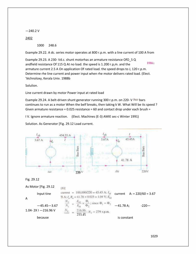
Esample 29.24. A belt-driven shunt generator running 300 r.p.m. on 220- V bars
continues to run as a motor When the belf breaks, then taking k W. What Will be its speed ?
Given armature resistance = 0.025 resistance = 60 and contact drop under each brush =
I V. Ignore armature reaction. (Elect. Machines (E-3) AMIE sec-c Winter 1991)
Solution. As Generator [Fig. 29.12 Load current.
Fig. 29.12
As Motor [Fig. 29.12
Input tine current A: = 220/60 = 3.67
A
—45.45—3.67 —41.78 A; -220—
1.04- 2X I —216.96 V
because is constant
220
233.45
1030
300
Example 29.25. A dc. shunt machine generates 250, Von open circuit al 1000 r.p-m. Effective
armature resistance is 0.5 Q. field resistance is 250 n, input to machine running as n motor
on noload is 4 A at 250 V. Calculate speedofmachine as a motor taking 40 A at 250 V.
Armatun• maction weakens field by (Electrical Machines-I, Univ.
Solution. Consider the case when the machine runs as motor on no-load.
Now, = 250/250 - A: Hence, G =-4— Em 250-0.5 x 3 2485 V
It is given that When armatureruns at 1000 it generates 250 V. When it generates V, it must
be running at a speed = 1000 x 248.5/250 = 994 rpm.
Hence,
994
N = 960 r.p.m.
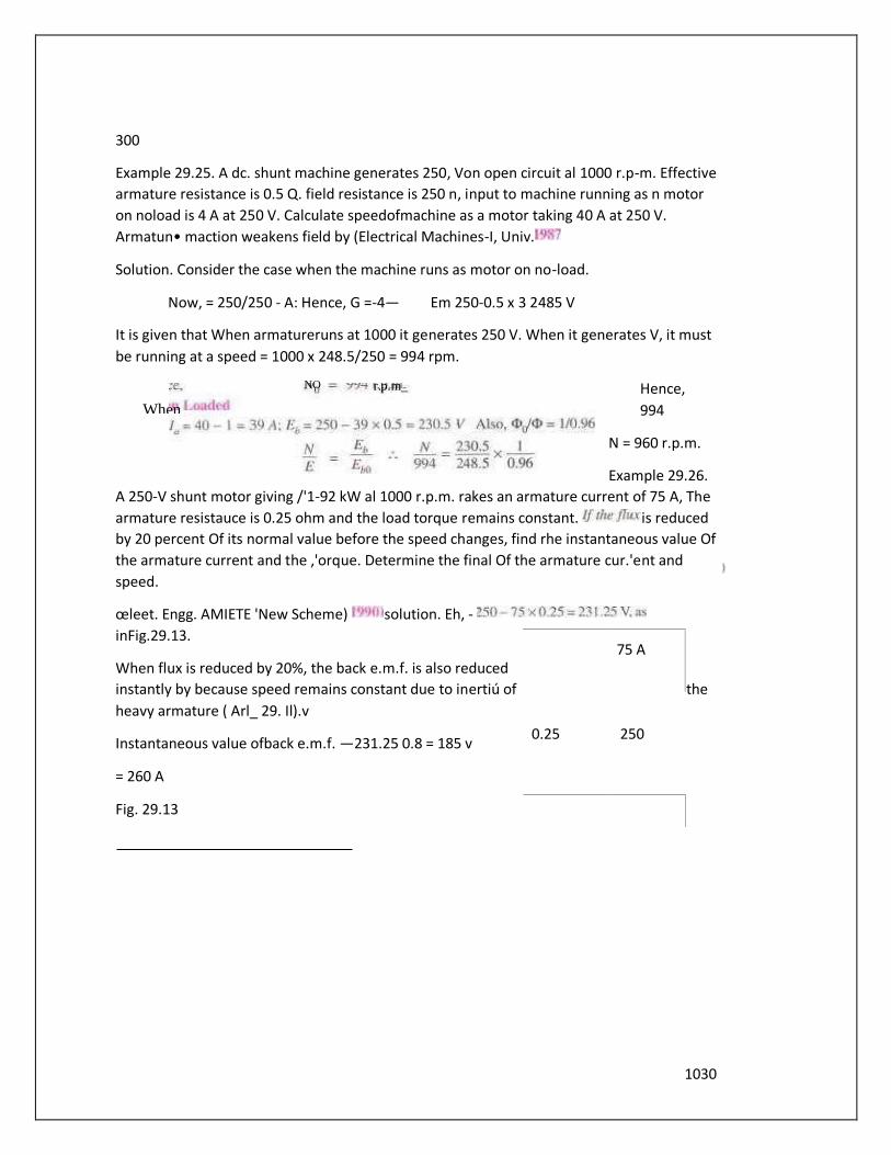
Example 29.26.
A 250-V shunt motor giving /'1-92 kW al 1000 r.p.m. rakes an armature current of 75 A, The
armature resistauce is 0.25 ohm and the load torque remains constant. is reduced
by 20 percent Of its normal value before the speed changes, find rhe instantaneous value Of
the armature current and the ,'orque. Determine the final Of the armature cur.'ent and
speed.
œleet. Engg. AMIETE 'New Scheme) solution. Eh, -
inFig.29.13.
When flux is reduced by 20%, the back e.m.f. is also reduced
instantly by because speed remains constant due to inertiú of the
heavy armature ( Arl_ 29. Il).v
Instantaneous value ofback e.m.f. —231.25 0.8 = 185 v
= 260 A
Fig. 29.13
75 A
0.25 250
NO r. p.m_
When
1031
Instantaneous value of
the torque =
Steady Conditiorrs
Since torque remains
constant,
Now. 1225
r.p.m.
Example 29.27. A 220-
V, dc. shunt field
resistance is 100
armature terminals when 10 A were passed thmugh torque in At-m and (c) efficiency. The
normal input Of the motor is 8 k W.
(Electrotechnies-n; MS. Univ. Baroda 1988 j
Solution. 200/100=2 A
EL. Power input
- 40-2-38 A; Ra=6/lO-O.6Ç2
— 198.8 V; 1772 V
; N —623.9 r.p.m.
700 198.8
T. 9.55 9.55 x 1772 x 38/623.9=103 N-m
N. L. power input = 200 x 4-800 W; x 06—2.4 W
Constant losses - 800—2.4 = 797.6 W; FL. loss = 866.4 W
Total EL. losses 797.6 866.4 = 1664 W: output = 83M) - 1664 6336 W EL Motor efficiency =
0.792 or 79.2 %
Example 29.28. The input 23m V, dc. shunt motor is //kW. Calculate(a) the torque
developed (h) the efficiency (e) the speed at this load. The particulars the molor areas
follows :
No-load current = S A; No-load speed = r.p.m.
A rm. resistance = £2; shuntfield resistance = 110£2.
Solution. No—load
input
No-load armature Cu loss
Constant losses When input is Il kW.
A
running at 700 r.p.m. The gives a drop of 6 volts across
Calculate (a) speed on load
The
1032
Input current Arm. Cu loss
Total loss
Output
Efficiency
Back e.rn.f. at no-load
Back e.rn.f. at given load
Speed N
Elect. Technology ;
Bombay University 1988' -
220x5= 1,100W:
= 3 2 xo.5 W
- 1.100—4.5 =
1,095SW
- 11,0/220 = 50A ;
Armature current = 2 =
A
= 482 x 05 . - — 1,152 w;
Arm. Cu loss + Constant
losses = 1 152 + 1095.5 =
2248 W
= 11.000- 2,248 — s, 752 w
8,752x
220-13 x 0.5) 218.5 V
= 196 v
196/218.5 =
r.p.m.
1014
196 x 48
-87.1 N.m
Example 29.29. The armature circuit resistance a 18.65 kW 250- V series motor is O. / the
brush voltage drop is 3V, and the seriesfield resistance is 0.05. When the motor takes 80 A,
speed is
600 r.p.m. Calculate the speed when rhe current is
(Elect. Machines, A.M.I.E. sec. B, 1993b
Solution.
Since 80/100
474 r.p.m.
Example A 220-volt d. c. series motor is running at a speed of 800 p.p.m. and draws 100 A_
Calculate at what speed rhe motor "'ill run when developing half the torq"e. Total msistance
Of the armature
andfield is 0.1 Ohm.
Assume that the
magnetic circuit is
unsaturated.
Solution.
Since field is
unsaturated,
29.12. Motor Characteristics
The characteristic Curves Of a motor are those curves which show relationships between the
following quantities.
l. and armature Current characteristic. It is Characteristic
2. Speed and armature current i.e. M/a characteristic.
3. Speed and torque i.e. characteristic. It is also known as mechanical chargcteristic. It
can be found from ( l ) and (2) above.
While discussing •notor characteristics, the tòllowing two relations should always be kept in
mind :
and N
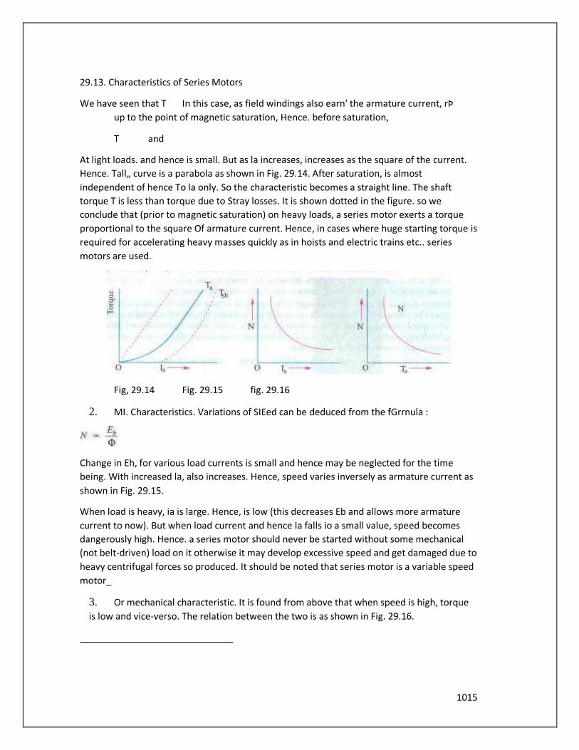
1015
29.13. Characteristics of Series Motors
We have seen that T In this case, as field windings also earn' the armature current, rÞ
up to the point of magnetic saturation, Hence. before saturation,
T and
At light loads. and hence is small. But as la increases, increases as the square of the current.
Hence. Tall„ curve is a parabola as shown in Fig. 29.14. After saturation, is almost
independent of hence To la only. So the characteristic becomes a straight line. The shaft
torque T is less than torque due to Stray losses. It is shown dotted in the figure. so we
conclude that (prior to magnetic saturation) on heavy loads, a series motor exerts a torque
proportional to the square Of armature current. Hence, in cases where huge starting torque is
required for accelerating heavy masses quickly as in hoists and electric trains etc.. series
motors are used.
Fig, 29.14 Fig. 29.15 fig. 29.16
2. MI. Characteristics. Variations of SIEed can be deduced from the fGrrnula :
Change in Eh, for various load currents is small and hence may be neglected for the time
being. With increased la, also increases. Hence, speed varies inversely as armature current as
shown in Fig. 29.15.
When load is heavy, ia is large. Hence, is low (this decreases Eb and allows more armature
current to now). But when load current and hence la falls io a small value, speed becomes
dangerously high. Hence. a series motor should never be started without some mechanical
(not belt-driven) load on it otherwise it may develop excessive speed and get damaged due to
heavy centrifugal forces so produced. It should be noted that series motor is a variable speed
motor_
3. Or mechanical characteristic. It is found from above that when speed is high, torque
is low and vice-verso. The relation between the two is as shown in Fig. 29.16.

1016
29.14. Characteristics of Shunt Motors
Characteristic
Assuming CÞ to be practically constant (though at heavy loads. decreases somewhat due to
increased armature reaction) we find that Ta .
Hence, the electrical characteristic as shown in Fig. 29.17. is practically a straight line through
the origin. Shaft torque is shown dotted. Since a heavy starting load will need a heavy starting
current, shunt motor should never be started on (heavy) load.
2. Characteristic
If is 'Issumcd constant, then N E,_ As Eh is also practically Constant. speed is, for most
purposes. constant (Fig. 29.18).
Fig. 29.17 Fig. 29.18 Fig. 29.19
But strictly speaking. both Eh and (Pde-crease with increasing load. However. Eb decreases
slightly more than so that on the Whole, there is some decrease in speed. The drop varies
from 5 to Of full-load speed. being dependent on saturation, armature reaction and brush
position. Hence. the actual speed Curve is slightly drooping as shown by the dotted line in Fig.
29.18. But. for all practica] purposes, shunt motor is taken as a constant-speed motor.
Because there is no appreciable change in the speed of a shunt motor from no-load to
fullload. it may be connected to loads which are totally and suddenly thrown off without any
fear of excessive speed resulting. Due to the constancy of their speed. shunt motors are
suitable for driving shafting. machine tools. lathes. wood-working machines and for all other
purposes where an approximately constant speed is required.
Characteristic Can be deduced from and (2) above and is shown in Fig.
29.19_
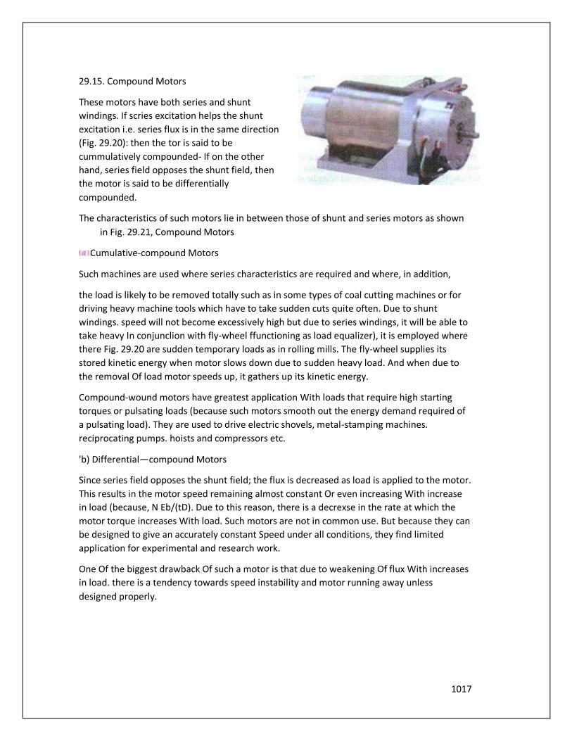
1017
29.15. Compound Motors
These motors have both series and shunt
windings. If scries excitation helps the shunt
excitation i.e. series flux is in the same direction
(Fig. 29.20): then the tor is said to be
cummulatively compounded- If on the other
hand, series field opposes the shunt field, then
the motor is said to be differentially
compounded.
The characteristics of such motors lie in between those of shunt and series motors as shown
in Fig. 29.21, Compound Motors
Cumulative-compound Motors
Such machines are used where series characteristics are required and where, in addition,
the load is likely to be removed totally such as in some types of coal cutting machines or for
driving heavy machine tools which have to take sudden cuts quite often. Due to shunt
windings. speed will not become excessively high but due to series windings, it will be able to
take heavy In conjunclion with fly-wheel ffunctioning as load equalizer), it is employed where
there Fig. 29.20 are sudden temporary loads as in rolling mills. The fly-wheel supplies its
stored kinetic energy when motor slows down due to sudden heavy load. And when due to
the removal Of load motor speeds up, it gathers up its kinetic energy.
Compound-wound motors have greatest application With loads that require high starting
torques or pulsating loads (because such motors smooth out the energy demand required of
a pulsating load). They are used to drive electric shovels, metal-stamping machines.
reciprocating pumps. hoists and compressors etc.
'b) Differential—compound Motors
Since series field opposes the shunt field; the flux is decreased as load is applied to the motor.
This results in the motor speed remaining almost constant Or even increasing With increase
in load (because, N Eb/(tD). Due to this reason, there is a decrexse in the rate at which the
motor torque increases With load. Such motors are not in common use. But because they can
be designed to give an accurately constant Speed under all conditions, they find limited
application for experimental and research work.
One Of the biggest drawback Of such a motor is that due to weakening Of flux With increases
in load. there is a tendency towards speed instability and motor running away unless
designed properly.
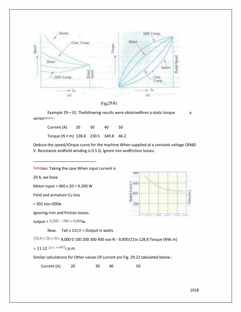
1018
Example 29—32. Thefollowing results were obtainedfmm a static torque a
series
Current (A) 20 30 40 50
Torque (N • m) 128.8 230.5 349.8 46.2
Deduce the speed/tOrque curve for the machine When supplied at a constant voltage Of460
V. Resistance andfield winding is 0.5 Q. Ignore imn andfriction losses.
tion. Taking the case When input current is
20 A, we have
Motor input = 460 x 20 = 9.200 W
Field and armature Cu loss
= 202 xos=200w
Ignoring iron and friction losses.
output = w
Now. Tah x 21t,V = Output in watts.
9,000 0 100 200 300 400 soo N - 9,000/21tx 128.8 Torque (NW.m)
11.12 r.p.m.
Similar calculations for Other values Of current are Fig. 29.22 tabulated below :
Current (A) 20 30 40 50
Fig. 29Æi
1019
Input (W) loss
(W)
9.200 13,800 18.400 23.000 1,250
Output (W) 9.200 13,350 11.600 21.850
Speed (r.p.m.) 667 551 480 445
Torque (N-tn) 128.8 2305 349.8 4692
From these values, the speed/torque curve can be drawn as shown in Fig. 29.22.
Example Aýàn Which requires 8 (5.968 k W) at 700 r.p.m. is coupled directly to a series
motor. Calculate the inpui tv the motor when the supply volraýe is5m V. assuming that power
required for fan varies as the cube Of the speed. For the purpose Of obtaining the
magnetisation characteristics. the motor was running as a self-excited generator al 600 r.p.m.
and the relationship between the tenninal voltage and the load current was found ro be
asfollows :
load current (A) 7 10.5 14 27.5 lèrminal voltage (V) 347 393 434 458
The resistance Of both the armature and field windings Of the motor is 3.5 Q and the core.
friction and other losses may be assumed to be constant at 450 Wfor the speeds
corresponding 10 the above range Ofcurrents at normal voltage. ( London)
Solution. Let us. by way of illustration. calculate the speedand output when motor is running
off a supply and taking a current of IA.
Series Voltage drop 7x3.5-24SV
Generated or back e.tn.f. Eh = —24.5 = 475—5 V
The motor speed is proponional to Eh for a given current. For a speed of 600 r.p.m. and a
current
Of 7A. the generated e_m.f is 347 V. Hence,
N Ox475.5/347 -823 r.p.m.
Power to armature - -3.329W Output Armature —450 = 3,329 — 450 = 2.879
W = 2.879 kW power required by the fan at 823 r.p.m. is = 5.968 x 8232/7002 = 9.498 kW
These calculations are repeated for the other values Of Current in the following table.
Input currrent (A) 14 27.5
Series drop (V) 24.5 36.7 49 96.4
Back e.m.f. (V) 475s 463.3 451 403.6

1020
347 393 434 458
Speed N (r.p.m.) 823 707 623 528
Armature power (W) 3329 4870 6310 1
1.100
Motor output W) 2.879 4.420 5.860 10.65
Power required by fan (kW) 9.698 6.146 4.222 2566
In Fig. 29.23 (i' the motor outputin kW and (ii' power required by fan in kW against input
currentis plotted. Since motor output equals the inpul to fan. hence the intersection point of
these curves gives the value of motor Input current under the given conditions.
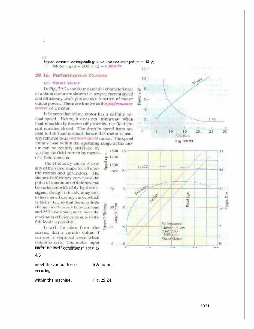
1021
4.5
meet the various losses
occuring
kW output
within the machine. Fig. 29.24
12 A Input current corresponding to intersection point
under no-load conditions goes to
1022
As compared to other motors. a shunt motor is said to have a lower starting torque. this
should not bc taken of mean that shunt motor is incapable Of starting a heavy load. Actually.
it means that series and compound motors are capable of starting heavy loads with less
excess of current inputs over normal values than the shunt motors and that consequently the
depreciation on the motor
Will be relatively less. For example. if twice fuli load torque is required at
Start, then shunt motor draws twice the full-load current Iaor whereas
series motor draws only
one and a half times the fill/ load current
The shunt motor is widely used with loads that require essentially constant speed but where
high starting torques are not needed- Such loads include centrifugal pumps. fans. winding
reels conveyors and machine tools etc.
(b' Series Motor
The typical performance curves a series motor are shown in Fig. 29.25.
It will be seen that drop in speed with increased load is much more ptominent in series motor
than in a shunt motor. Hence, a series motor is not suitable for applications requiring a
Substantially constant svxed.
For a given curreng input, the siarting torque developed by a series motor is greater than that
developed by a shunt motor. Hence. series motors are used where huge starting torques ure
necessary i.e. for street cars, cranes, hoists and for electric-railway operation. In addition to
the huge starling torque. there is another unique characteristic of series motors which makes
them especially desirable for traction work i.e. When a load Comes on a series motor. it
responds by decreasing its speed (and hence. E,) and supplies the increased torque with a
small increase in On the other hand a shunt motor under the same conditions would hold its
speed nearly constant and would supply the

1023
required increased torque
With a large increase Of
input current. Suppose that
instead Of a series motor. a
shunt motor is used to drive
a Street car. When the ear
ascends a grade, the shunt
motor maintains the
speed for car at
approximately Same
value it had on the level
ground. but the motor
tends to take an excessive
current. A series motor.
however. automatically
slows down on such a grade
because Of increased
current demand, and so it
600 develops more torque
at reduced speed. The drop
in speed permits the motor
to develop a large torque 300 With hut a moderate increase of power Hence. under the
same load conditions. rating of the series motor would bc less than for a shunt motor,
Fig. 2925
29.17. Comparison Of Shunt and Series Motors
Shunt Motors
The different characteristics have been discussed in Art.
29.14. It is clear that i") speed of a shunt motor is
sufficiently constant.
for the Same Current input, its starting torque is not a
high as that of series motor. Hence. it is used.
When the speed to be maintained approximately
constant from NL to F.L i.e. for driving a line of shafting
etc. ij When it is required to drive the load at various speeds. any onc speed being kept
constant for relatively long period i.e. for individual driving of such machines as lathes. The
shunt regulator enables the required speed to be obtained easily and economically.
Shunt Motors
Summary or Applications
1200
900
1800
0 3.0 kW Output
1500
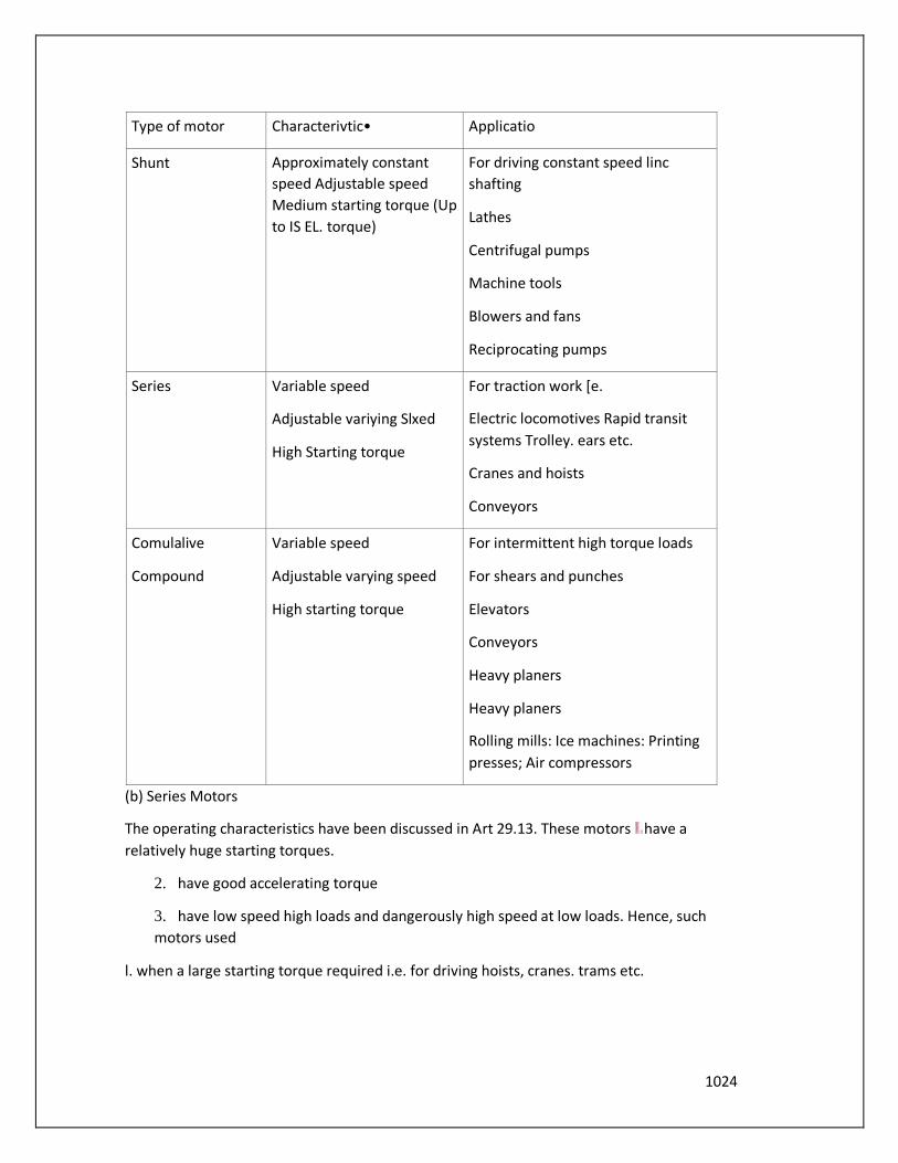
1024
Type of motor Characterivtic• Applicatio
Shunt Approximately constant
speed Adjustable speed
Medium starting torque (Up
to IS EL. torque)
For driving constant speed linc
shafting
Lathes
Centrifugal pumps
Machine tools
Blowers and fans
Reciprocating pumps
Series Variable speed
Adjustable variying Slxed
High Starting torque
For traction work [e.
Electric locomotives Rapid transit
systems Trolley. ears etc.
Cranes and hoists
Conveyors
Comulalive
Compound
Variable speed
Adjustable varying speed
High starting torque
For intermittent high torque loads
For shears and punches
Elevators
Conveyors
Heavy planers
Heavy planers
Rolling mills: Ice machines: Printing
presses; Air compressors
(b) Series Motors
The operating characteristics have been discussed in Art 29.13. These motors have a
relatively huge starting torques.
2. have good accelerating torque
3. have low speed high loads and dangerously high speed at low loads. Hence, such
motors used
l. when a large starting torque required i.e. for driving hoists, cranes. trams etc.

1025
2. when the motor can be directly coupled to
a load such as a fan whose torque increases with
3. if constancy of speed is not essential, then.
in fact. the decrease ofspeed with increase Of load
has the advantage that the power absorbed by the
motor does not increase as rapidly as the torque.
For instance. when torque is doubled, the power
approximately increases by about 50 to only
4. a series motor sh0uld not used where there is a possibility of the load decreasing to
a Very small Thus, it should not be used for driving centrifugal pumps or for a belt-drive Of
any kind.
Series Motors
29.18. Losses and Efficiency
The losses taking place in the motor are the same as in generators. These are (i) Coplrr losses
Magnetic lcvsse_s and iiii• Mechanical losses,
The condition for maximum power developed by the motor is
The Condition for maximum efficiency is that armature Cu losses are equal to constant
losses. (Art. 26.39).
29.19. Power Stages
The various stages of energy transformation in a motor and also the various losses occurring
in it are shown in the now diagram of Fig. 29.26.
Overall or commercial efficiency —A' Electrical efficiency = —Ã , Mechanical
efficiency
c
11m = -h
The efficiency curve for a motor is similar in shape to that for a generator (Art. 24ß5).

1026
It is seen that A — H = copper losses and B — C = iron and friction losses.
Example 29.34, One' ofthe r,vo similar 50th V' A and B running lighl takes 3 A.
When A is mechanically coupled to B. the input to A is 33 A with B unexcited and 4.5 A When
B is separately-excited ro generate 500 V Calculate thefriction and windage loss and core loss
ofeach machine. Machinery-I, Madras Univ.
Solution. When running light. machine input is used to meet the following losses (i' armature
Cu loss shunt Cu loss ' iii' iron loss and mechanical tosses i.e. friction and windagc losses.
Obviously, these no-load losses fcu• each machine equal 500 X 3 W.
With B unexcited
In this case. only mechanical losses take place in B. there being neither Cu loss nor iron-loss
tecause B is unexcitcd_ Since machine A draws 05 A more currentFriction and windage loss
of B 500 x 0.5 250 W
With B excited
Inthis case, both iron losses as well as mechanical losses take place in machine B. NOW,
machine
A draws, 4.5 — 3 = I .5 A more current.
Iron and mechanical losse• of B = IS X 500 750 W
Iron of B = 750 - 250 W
Example A 220 Shunt motor has an am-alary resistance Of0.2 ohm andfield resistance of The
motor draws 5 A al V 500 r.p.m. at no load. Calculate the speed and shaft torque if the motor
draws 52 A: at rated voltage. (Elect. Machines Nagpur Univ. 1993)
Solution.
210
1500 219.4
For finding the shaft torque. we will find the motor output when it draws a current of 52 A.
First we will use the no-load data for finding the constant losses of the motor.
Fig. 2926

1027
No load motor input 220 x 5 = W; Arm. Cu loss = 32 k W
Constant or standing losses of the motor = 1100 1098
When cu loss - 502 x 0.2 500 W
Hence. total motor losses = 1098 + 500 = 1598 W
Motor inputonload - 220 x 52 = 11,440 W; output — 11,440- 1598 = 9842 W
= 955 x outputhV = 9.55 x 9842/1436 N-m
Example 29—V'. 250 Vshunt motor on no runs 1000 and takes 5 amperes. Armature and
shunt field resistances are 0.2 and 250 ohms respectively Calculate 'he speed when
taking current Of50 A. The armature r•ection weakens thefield by
(Elect. Engg.-l Nagpur Univ. 1993)
Sol
2402
1000 2492 0.97 q
Example 29.37. A 500 Vt}.c. shunt motor takes a current Of5 A On no-load The resislanees Of
the armature andfield circuit are 0.22 ohm and 250 Ohm respectively. Find 'he efficiency
when loaded and taking a current of 100 A (b) the pem.•enrage change of speed. State
precisely the assumptions made. (Elect. Engg-l. MS. Univ. Baroda
Solution. No-
Lond condition
Arm. Cu
Constant
It is assumed that these losses remain constant under all load conditions.
I .o:ad condition
Motor current 100 A; la = = 478.44 V
Example 29—39. A dc. shunt machine While running as generator develops a voltage Of 250
V at J000 on no-load. armature resistance Of 0.5£2 andfield resistance Of 250 When the
machine runs us motor: inpul to it at no-load is 4.4 250 V. Calculate the speed and efficiency
Ofthe machine it runs a motor taking 40 A at 250 Armature reaction weakens by (Electrical
Technoloky. Aligarh Muslim Unis. '989'
Solution.
2500-2=2498
1028
NOW. When running as a generator, the machine gives 250 V al 1000 r.p.m. If this machine
was running as motor at 1000 r.p.m.. it will. obviously, have a back e.m.f. of 250 V produced
in its armature. Hence N, = r.p.m. and Eh, 250 V.
When it runs as a motor. drawing 40 A. the back e.m.f. induced in its armature is Eb2 =
Using the above equation We
have
1000
Emciencv
No-load input represents motor losses which consists of armature Cu Ra Which is variable.
constant losses W, which consists of jii shunt Cu loss (iib magnetic losses and 'iii'
mechanical losses.
input or total losses 250 x 4 W
Arm. cu loss = W, W, = = 995.5 W
When motor draws a line current of 40 A, its armature current is (40 — I = 39 A cu loss =
760.5 W: Total losses- 760.54 1756 W
Input 250x40= 10.000 W: output = 10.0 - 1756=8.244 W
- 8.244x IOW10.ooo=82..wrt
Example 29.40. The armature Winding Of a 4-poie•, 250 V dc. shunt motor is lap connected.
There are 120 slots, each slot 8 conductors. The is 20 mWb and current taken by
motor is 25 A. The resistance of armature andfield circuit are O. I and 125 respeclively. If the
rotational losses amount 10 be 810 Wfind,
(i) gross torque (ii) useful torque and efficiency. (Elect. Machines Nagpur Univ.
1993)
Soil"ion. - (23 x 0.1) -247.7 V
20X IO-3 X960X,V 4
NOW, A 247.7 = 60 (4)— : N —773 r.p.nL
247.7X23
Gross torque or armature torque T. 9.55 9.55 x = 70.4 N - m
773
Rotational losses = 810 W: Total motor losses = 810 + 500 +53 = 1363 W
Motor input = 250 x 25 = 6250 W; Motor output - 6250 - 1363-4887 W
1029
9.55 x outputiN = 9.55 x 4887/773 - 60-4 N-m
Efficiency = 4887/6250 = 0.782 = 782%
Example 29.11. A 20-hp ( 14.92 kWh 4-pole, shun' motor has a total of
620 conductors arranged in two parallel paths and yielding an armature circuit resistance
OfO. 2 Q
When it delivers rared power a' rated speed. it draws a line current Of 74.8 A and a field
current Of 3 (i' theflu.x per pole the torque developed (iii)lhe rotational losses
expressed as a percentage ofpower.
Solution.
Now.
f Armature Torque,
Driving powerinarmature= Ei,la = 215.64* 71.8= 15.483 W
Outpul14,920 W; Rotational losses = 15.483—
14.920= W
Motor input- - 17.204 W: Total 17204- 14.920 W
Losses expressed as pcteentage Of power input = 2284/ 17,204 = O. 1 33 or
Example 29.42. A 7.46 kW: 250• V shunt motor rakes a line current A When running light.
Calculate the efficiency as a motor when deliveringfull load output, if the armature andjie/d
resistame are 0.5 Q and 250£2 respectively. A,' output power will rhe efficiency be maximum
? Is it possible obtain this output from the machine ? MS. Univ. Baroda 1985)
Solution. When loaded lightly
Total motor input (Or total no-load losses) = 250 x 5 = 1.250 W
fieldCu10ss = 250* 1 =250 W;
Iron losses and friction losses = 1250 — 250 — 8 = 992 W These losses would be assumed
constant.
Let bc the full-load armature current, then armature input is = (250 x W EL output = 7.46 x
1000=7.460W The losses in the armature :
(i) Iron and friction losses = 992 W
Armature Cu loss = la: *0.05 w 2501. —_ 7,460 0.5
1116
O = 365 A
EL input curTent = 36.5+ I = 37.5 A ; Motor input = 250 x 37S W
EL output = 7,460 W
FL efficiency 100/250 x 375-79.6% NOW. efficiency is maximum When armature Cu loss
equals Constant loss.
i.e. 1.242 Worla=49.84A
Armature input 250 x 49.84 12.460 W
Armature Cu loss 49.842 x 0.5 1242 W; Iron and friction losses = 992 W
Armatureoutput 10.226 w
Output power = 10,226 W = 10.226 kW
As the input current for maximum efficiency is beyond the full-load motor current, it is
never realiscd in practice.
Input
Example 29.45. A 50-h.p. (373 kW), 460-V d.c. shunt motor running light takes a current of
4 A and runs ar a speed of 660 r.p.rn. The resistance of the armature circuit (including
brushes) is 0.3 n and that ofthe shuntfield circuit 270 Q.
Determine when the motor is running atfull load
(ij rhe current input (ii the speed Determine the armature current at which efficiency is
gnat-imam. Ignore the effect ofarmature reaction.1991)
Solution. 460/270= 1.7
When running light
= 4— 1.7 = 2.3 A; Armature Cu loss —2.32 *0.3 1.5 W (negligible)
No-load armature input = 460 x 2.3 = 1 ,058 W
As armature Cu loss is negligible, hence 1,058 W represents iron. friction and windage
losses which will assumed to be constant.
Let full-load armature input current be / Then
Armature input = I W; Armature Cu loss x 0.3 W
= 38.358=0 la = 88.5 A
fij Current input = 88.5+ 1.7=90.2A
1117
= 660 x 433.5/459a=624r.p.m.
For maximum efficiency, 102 Ra constant losses (Art. 24.37) exo.3 = 1,841
Tutorial Problems 29.3
A 4-POle 250—V. motor a armature With
(a) the torque (b) the sreed
(b) the outpat torque and (d) the efficiency. if the motor current is 50 A The
value Of flux per pole under these conditions is 22 mWh and the
corresponding iron. friction and wirxtagc losses total 810 W. Armature
resistancc O. 19 field resistance 0.14 Q.
Ha) 173.5 N-rn(b) r.p.m. (c) N.m (d) 86.9%]
2. no-load, a shunt tyotor takes 5 A at 250 V. resistances of the field and armature circuits
are 250 Q and O. I respectively. Calculate the output power andefficiency of motor when
the total supply current is 81 A at the same supply voltage. State any assumptions made.
91 % . It is that windage. friction and eddy current Josses are independent of the current
and speedl
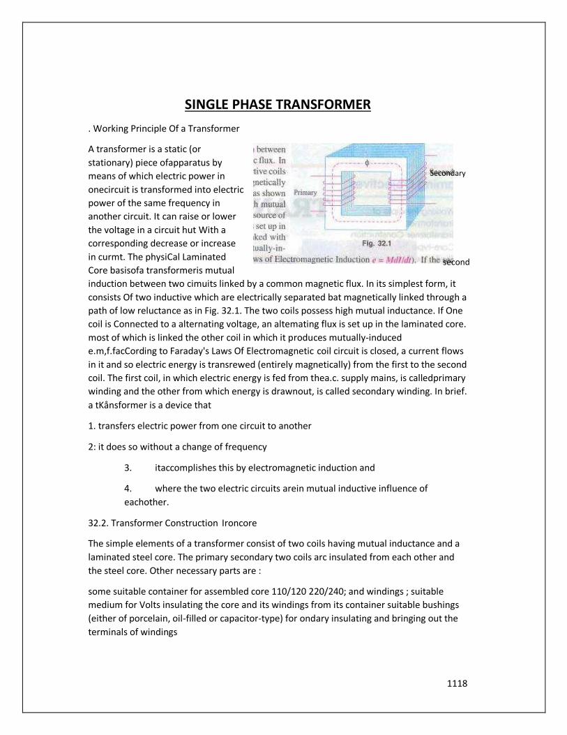
1118
SINGLE PHASE TRANSFORMER
. Working Principle Of a Transformer
A transformer is a static (or
stationary) piece ofapparatus by
means of which electric power in
onecircuit is transformed into electric
power of the same frequency in
another circuit. It can raise or lower
the voltage in a circuit hut With a
corresponding decrease or increase
in curmt. The physiCal Laminated
Core basisofa transformeris mutual
induction between two cimuits linked by a common magnetic flux. In its simplest form, it
consists Of two inductive which are electrically separated bat magnetically linked through a
path of low reluctance as in Fig. 32.1. The two coils possess high mutual inductance. If One
coil is Connected to a alternating voltage, an altemating flux is set up in the laminated core.
most of which is linked the other coil in which it produces mutually-induced
e.m,f.facCording to Faraday's Laws Of Electromagnetic coil circuit is closed, a current flows
in it and so electric energy is transrewed (entirely magnetically) from the first to the second
coil. The first coil, in which electric energy is fed from thea.c. supply mains, is calledprimary
winding and the other from which energy is drawnout, is called secondary winding. In brief.
a tKånsformer is a device that
1. transfers electric power from one circuit to another
2: it does so without a change of frequency
3. itaccomplishes this by electromagnetic induction and
4. where the two electric circuits arein mutual inductive influence of
eachother.
32.2. Transformer Construction Ironcore
The simple elements of a transformer consist of two coils having mutual inductance and a
laminated steel core. The primary secondary two coils arc insulated from each other and
the steel core. Other necessary parts are :
some suitable container for assembled core 110/120 220/240; and windings ; suitable
medium for Volts insulating the core and its windings from its container suitable bushings
(either of porcelain, oil-filled or capacitor-type) for ondary insulating and bringing out the
terminals of windings
Secondary
second

1119
from "0/120
types of Principle ot transformer
the core is constructed of transformer sheet steel laminations assembled to provide
continuous magnetic path With a minimum of air-gap included. The steel used is of high
silicon content, sometimes heat treated
Fig. 32.2 to produce ahigh permeability and a low hysteresis loss at the
usual operating flux densities. The eddy current loss
laminating the core, the laminationsbeing insulated from
each other by a light coat of cote-plate vanlish or by an
oxide layer on the surface. The thickness of laminations
valieS from 0.35 mm for a frequency of 0.5 mm for a
frequency Of 25 Hr.. The core laminations (in the strips)
are joined as shown in Fig. 32.2. It alternate layers
are staggered in order to
gaps right through the cross-
section of the are said to be
'imbricated'.
Constructional/y, the general types, distinguished from each
other merely by the manner in which the primary
Core-type transformer and secondary coils are placed around
the laminated core. The two types ale known as (i) core-type and (ii) shentype. Another
recent development is spiral-core-or wo«nd-coretype, lhc trade name beingspirakore
transformer,
In the so-called core type transformers, the windings surround a ary Winding considerable
par/ ofthe core whereas in shell-type transformers. the core
is seen avoid the core.
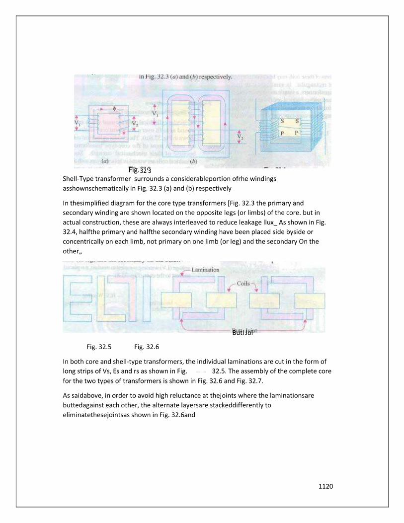
1120
Shell-Type transformer surrounds a considerableportion ofrhe windings
asshownschematically in Fig. 32.3 (a) and (b) respectively
In thesimplified diagram for the core type transformers [Fig. 32.3 the primary and
secondary winding are shown located on the opposite legs (or limbs) of the core. but in
actual construction, these are always interleaved to reduce leakage llux_ As shown in Fig.
32.4, halfthe primary and halfthe secondary winding have been placed side byside or
concentrically on each limb, not primary on one limb (or leg) and the secondary On the
other„
Fig. 32.5 Fig. 32.6
In both core and shell-type transformers, the individual laminations are cut in the form of
long strips of Vs, Es and rs as shown in Fig. 32.5. The assembly of the complete core
for the two types of transformers is shown in Fig. 32.6 and Fig. 32.7.
As saidabove, in order to avoid high reluctance at thejoints where the laminationsare
buttedagainst each other, the alternate layersare stackeddifferently to
eliminatethesejointsas shown in Fig. 32.6and
Butl Joi
Fig. 32'3

1121
Fig. 32.7.

1122
Because oflaminations and insulation, the net oreffective area is reduced. due
allowance for which has to be made (Ex. 32.6). 'tis found that. in general, the reduction in
coresectional areadueto the presence ofpaper, surface oxide etc. is of the order of 10%
approximately.
As pointed out above. rectangularcores With cylindrical coils can be used forsmall-
size cott-ty•pc transformers as shown in fig. 32.9 (a) but for large•si7Æd transformers, it
becomes wasteful to use rectangular cylindrical coils and so circular Cylindrical coils are
preferred. For such purposes. square cores may be used as shown in Fig. 329 (b) where
circles represent the tubular former carry ing the coils. Obviously. a considerable amount of
useful space is still wasted. A common improvement on square core is to employ cruciform
Core as in Fig. 32.9 (C) which demands, at least, two sizes Of core strips. For very large
transformers. further core-stepping is done as in fig. 32.9 (d) where at least three sizes of
core plates are necessary. not only gives high space factor but also results in reduced length
ofthe mean turn and the consequent R loss. Three stepped core is the one most commonly
used although more Steps may be forveo' large transformers as in fig. 32.9 From the
geometry Offig. 329, it can shown that maximum gross core section for Fig. 32.9 (b) is 0.5
and for Fig. 32.9 (c) it is 0.616 where d is the diameterofttE cylindrical coil.
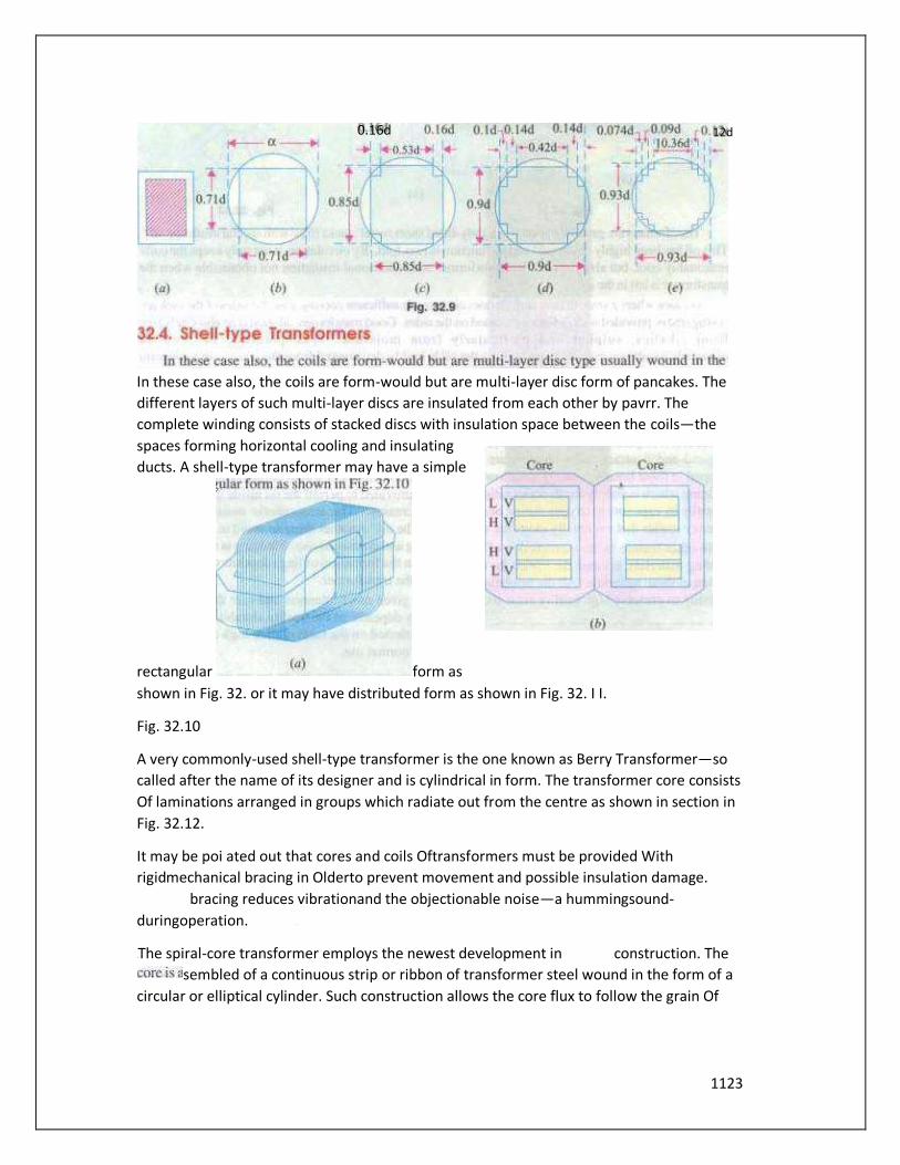
1123
In these case also, the coils are form-would but are multi-layer disc form of pancakes. The
different layers of such multi-layer discs are insulated from each other by pavrr. The
complete winding consists of stacked discs with insulation space between the coils—the
spaces forming horizontal cooling and insulating
ducts. A shell-type transformer may have a simple
rectangular form as
shown in Fig. 32. or it may have distributed form as shown in Fig. 32. I I.
Fig. 32.10
A very commonly-used shell-type transformer is the one known as Berry Transformer—so
called after the name of its designer and is cylindrical in form. The transformer core consists
Of laminations arranged in groups which radiate out from the centre as shown in section in
Fig. 32.12.
It may be poi ated out that cores and coils Oftransformers must be provided With
rigidmechanical bracing in Olderto prevent movement and possible insulation damage.
bracing reduces vibrationand the objectionable noise—a hummingsound-
duringoperation.
The spiral-core transformer employs the newest development in construction. The
sembled of a continuous strip or ribbon of transformer steel wound in the form of a
circular or elliptical cylinder. Such construction allows the core flux to follow the grain Of
0.16d 12d
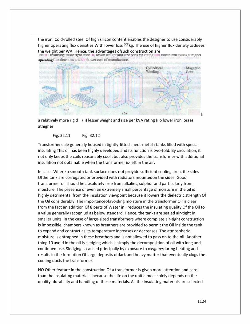
1124
the iron. Cold-rolled steel Of high silicon content enables the designer to use considerably
higher operating flux densities With lower loss kg. The use of higher flux density œduees
the weight per WA. Hence, the advantages ofsuch construction are
li
a relatively more rigid (ii) lesser weight and size per kVA rating (iiö lower iron losses
athigher
Fig. 32.11 Fig. 32.12
Transformers ale generally housed in tightly-fitted sheet-metal ; tanks filled with special
insulating This oil has been highly developed and its function is two-fold. By circulation, it
not only keeps the coils reasonably cool , but also provides the transformer with additional
insulation not obtainable when the transformer is-left in the air.
In cases Where a smooth tank surface does not proyide sufficient cooling area, the sides
Ofthe tank are corrugated or provided with radiators mountedon the sides. Good
transformer oil should he absolutely free from alkalies, sulphur and particularly from
moisture. The presence of even an extremely small percentage ofmoisture in the oil is
highly detrimental from the insulation viewpoint because it lowers the dielectric strength Of
the Oil considerably. The importanceofavoiding moisture in the transformer Oil is clear
from the fact an addition Of 8 parts of Water in I reduces the insulating quality Of the Oil to
a value generally recogniud as below standard. Hence, the tanks are sealed air-tight in
smaller units. In the case of large-sized transformers where complete air-tight construction
is impossible, chambers known as breathers are provided to permit the Oil inside the tank
to expand and contract as its temperature increases or decreases. The atmospheric
moisture is entrapped in these breathers and is not allowed to pass on to the oil. Another
thing 10 avoid in the oil is sledging which is simply the decomposition of oil with long and
continued use. Sledging is caused principally by exposure to oxygen•during heating and
results in the formation Of large deposits ofdark and heavy matter that eventually clogs the
cooling ducts the transformer.
NO Other feature in the construction Of a transformer is given more attention and care
than the insulating materials. because the life on the unit almost solely depends on the
quality. durability and handling of these materials. All the insulating materials are selected
operating
1125
on the basis of their high quality and ability to preserve high qualityeven after many years
of normal use.
Insteadofnatural mineral oil. now-a-days synthetic ilLsulating fluids known as ASKAREIAS
(trade name) are used. They arc non-inflammable and, ihe influence of an electric arc, do
not decompose to produce inflammableeases. One such fluid commercially known as
PYROCLOR is being eOensively used because it possesses remarkablestability as adielectric
and even after long shows no deterioration through sledging. oxidation,acidormoisture
formation. Unlike mineral Oil, iUshowsmo rapid burning.
All the transformer leadsarebroughtoutoftheircases through suitable bushingS. There are
many designs Of the-SC, their-size and constnlction depending on the voltage Of the leads.
For moderate voltages, porcelain bushings are Lsed to insulate the leadsas they come out
through the tank. In general, they look almost like the insulators used on the transmission
lines. Inhigh voltage installations, Oil-filled orcapacitor— bushings areemployed.
The choice ofcore or shell-type construction is usually determined by cost, because similar
characteristics can be obtained withboth types. For very high-voltage transformers or
formultiwinding design, shelltype constmction is preferred by many manufacturers. In this
type. usually the mean length ofcoil turn is longer than in a comparable core-type design.
Both core and shell forms areused and the selection is decided by many such as voltage
rafing, kVA rating, weight. insulation stress, heat distributionetc.
Another means of classifying the transformers is according to the typeofcooling employed.
The following types are in common use :
oil-Aled self-cooled (b) oil-filled Wafer-cooled (c' áir-biast type
Small and medium size distribution transformers-so called because of their use on
distribution systems as distinguished from line transmission—are of type The assembled
windings and cores of such transformers are mounted in a welded, oil.tight steel tank
provided with steel cover. After putting the core at its proper place, the tank is filled with
purified, high quality insulating oil. The oil senes to convey the heat from the core and the
windings to the case from where it is radiated the surroundings. For small size, the tanks
are usually smooth-surfaced, but for largersizes. the cases are frequently corrugated or
fluted to get greater heat radiation area without increasing the Cubical capacity Of the tank.
Still larger sizes are provided With radiators or pipes.
Construction Of very large self-cooled transformers is expensive, a more economical form
Of Construction for such large transformers is provided in the oil-immersed, water-cooled
type. As before, the windings and the cote are immersed in the Oil, but there is mounted
near the Surface of oil, a coolingcoil thmughâh'hichcold Water is kept circulating. The heat
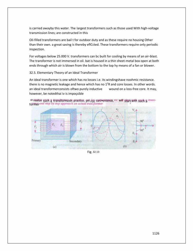
1126
is carried awayby this water. The largest transformers such as those used With high-voltage
transmission lines; are constructed in this
Oil-filled transformers are bail t for outdoor duty and as these require no housing Other
than their own. a great saving is thereby eflCcted. These transformers require only periodic
inspection.
For voltages below 25.000 V. transformers can bc built for cooling by means of an air-blast.
The transformer is not immersed in oil. bat is housed in a thin sheet-metal box open at both
ends through which air is blown from the bottom to the top hy means of a fan or blower.
32.5. Elementary Theory of an Ideal Transformer
An ideal transformer is one which has no losses i.e. its windingshave noohmic resistance.
there is no magnetic leakage and hence which has no 12R and core losses. In other words.
an ideal transformerconsists oftwo purely inductive wound on a loss-free core. It may,
however, be notedthai iv is impoçsible
will start with such a
Fig. 32.13
10 realize such a transformer in practice, yet ror cani•eniencé, former
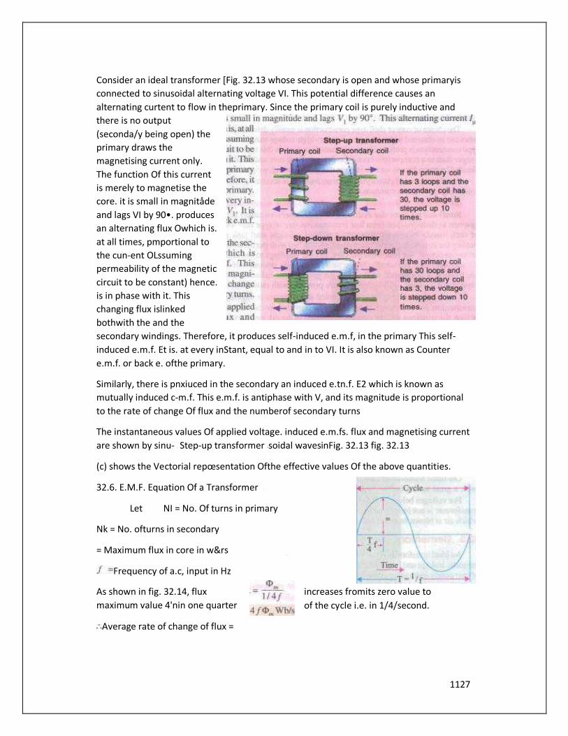
1127
Consider an ideal transformer [Fig. 32.13 whose secondary is open and whose primaryis
connected to sinusoidal alternating voltage VI. This potential difference causes an
alternating curtent to flow in theprimary. Since the primary coil is purely inductive and
there is no output
(seconda/y being open) the
primary draws the
magnetising current only.
The function Of this current
is merely to magnetise the
core. it is small in magnitåde
and lags VI by 90•. produces
an alternating flux Owhich is.
at all times, pmportional to
the cun-ent OLssuming
permeability of the magnetic
circuit to be constant) hence.
is in phase with it. This
changing flux islinked
bothwith the and the
secondary windings. Therefore, it produces self-induced e.m.f, in the primary This self-
induced e.m.f. Et is. at every inStant, equal to and in to VI. It is also known as Counter
e.m.f. or back e. ofthe primary.
Similarly, there is pnxiuced in the secondary an induced e.tn.f. E2 which is known as
mutually induced c-m.f. This e.m.f. is antiphase with V, and its magnitude is proportional
to the rate of change Of flux and the numberof secondary turns
The instantaneous values Of applied voltage. induced e.m.fs. flux and magnetising current
are shown by sinu- Step-up transformer soidal wavesinFig. 32.13 fig. 32.13
(c) shows the Vectorial repœsentation Ofthe effective values Of the above quantities.
32.6. E.M.F. Equation Of a Transformer
Let NI = No. Of turns in primary
Nk = No. ofturns in secondary
= Maximum flux in core in w&rs
Frequency of a.c, input in Hz
As shown in fig. 32.14, flux increases fromits zero value to
maximum value 4'nin one quarter of the cycle i.e. in 1/4/second.
Average rate of change of flux =
1128
Fig. 3214
= or volt
Now. rate ofchangeofflux perturn means induced e_m-f_ involts_
Avetagee.rn.f./turn = 4fcbm volt
If flux varies sinusoidally then r.m.s. value ofinduced e.m.f. isobtained by multiplying
theaverage valuewith formfactor. rm. S. value
Formfactor =-1.11
average value
rms. valueofe.m.f]turn = 1.11 x 4 4.44 volt
Now. r.ms. valueofthe induced e.m.f. in the whole ofprimary winding
= (inducede.tn.fjturn)xNo. ofprimarytums
Hence. currents aræin the inverse ratioof the (voltage) transformation ratio.
Example 32.1. The 2maximumflux density:tn die core ofa 250/3000-Võlts,SO-Hzsingle-
Þhase transformer is 1.2 Wb,4n. Ifthe e.m.j: per furn is 8 volt, determine (i) primary and
secondary turns areg core.
(ElectricalEngg.-l, Nagpnr Univ. 1991)
Solution. (i} E = xe.m.f.induced/turn
(ii) We may use = — 4.44 Bm A
3000 4.44x 50 x 375 xL2xA; A = 0.03m2.
Example 32.2. The of a IOO-kVA. 11000/550 V: _50-HZ„ I -ph, Copé type transformer has a
cross-section of20cmX 20em. Find the numberofH. V,and L turns perphase and the e,m.f:
per turn if rhe coredensiry is nor 'o exceed Tesla. Assume a stacking factor Of0.9' What
will happen if its primary voltage increased bv on no-load ?
(Elect. Machines, AM.LE, Sec. By 1991)
Solution. 1.3
11,000 = x 1060
550 = xL3 X 0.036: N2=53
= 1060=53
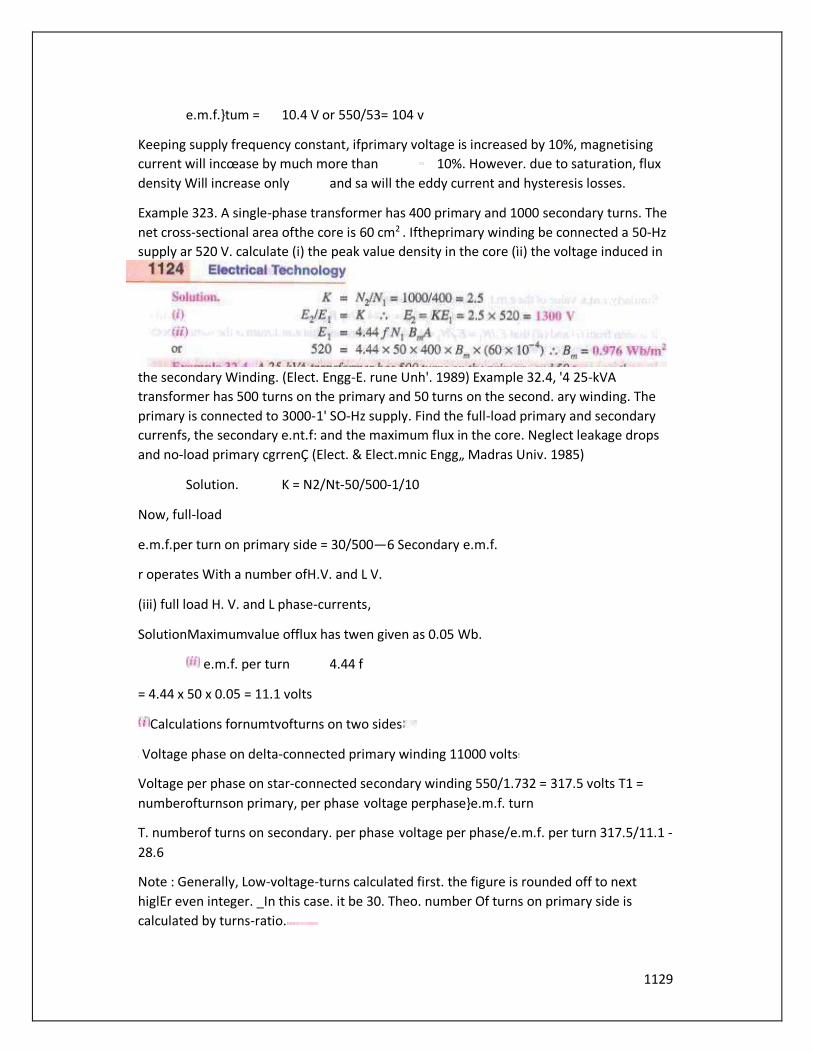
1129
e.m.f.}tum = 10.4 V or 550/53= 104 v
Keeping supply frequency constant, ifprimary voltage is increased by 10%, magnetising
current will incœase by much more than 10%. However. due to saturation, flux
density Will increase only and sa will the eddy current and hysteresis losses.
Example 323. A single-phase transformer has 400 primary and 1000 secondary turns. The
net cross-sectional area ofthe core is 60 cm2 . Iftheprimary winding be connected a 50-Hz
supply ar 520 V. calculate (i) the peak value density in the core (ìi) the voltage induced in
the secondary Winding. (Elect. Engg-E. rune Unh'. 1989) Example 32.4, '4 25-kVA
transformer has 500 turns on the primary and 50 turns on the second. ary winding. The
primary is connected to 3000-1' SO-Hz supply. Find the full-load primary and secondary
currenfs, the secondary e.nt.f: and the maximum flux in the core. Neglect leakage drops
and no-load primary cgrrenÇ (Elect. & Elect.mnic Engg„ Madras Univ. 1985)
Solution. K = N2/Nt-50/500-1/10
Now, full-load
e.m.f.per turn on primary side = 30/500—6 Secondary e.m.f.
r operates With a number ofH.V. and L V.
(iii) full load H. V. and L phase-currents,
SolutionMaximumvalue offlux has twen given as 0.05 Wb.
e.m.f. per turn 4.44 f
= 4.44 x 50 x 0.05 = 11.1 volts
Calculations fornumtvofturns on two sides
Voltage phase on delta-connected primary winding 11000 volts
Voltage per phase on star-connected secondary winding 550/1.732 = 317.5 volts T1 =
numberofturnson primary, per phase voltage perphase}e.m.f. turn
T. numberof turns on secondary. per phase voltage per phase/e.m.f. per turn 317.5/11.1 -
28.6
Note : Generally, Low-voltage-turns calculated first. the figure is rounded off to next
higlEr even integer. _In this case. it be 30. Theo. number Of turns on primary side is
calculated by turns-ratio.

1130
In this case,
This. however, reduces the flux and results into less saturation. This, in fact, is an
elementary aspect in Design-calculations for transformers. (Explanation is added here
only to overcome a doubt whether a fraction is acceptable as a number ofL.V. turns).
(ii) Full load and L.V. phase currents :
Output per phase =
H.V. phase-current
L.V. phase-current =
Example 32.6. A single{phase tranžformer has 500 turns in the primary and turns in the
secondary. The cross-sectional area Ofthe core is 80 sq. cm. (fthe primary windingì.ç
connected to a 50 H: supply at500 V. calculate (i) Peakflux-density, and lii) Voltage
induced in the secondary.
(Bharathinr University November 199T
, Solution. From the
(i) Peakfluxdensity, 20
Wtageinducedin secondary is obtained
from
tmnsformationratioorturnsratio
V2 — 500k12CW500= 1200volts
Example 32.7. A 25 kVA. single•phase trttnSfOñ7ier41ås 250 rurnS on primàrÿ thè
secondary winding. The primary is connected to 50 H: mains. Calculate primary and
Secondary currents on"'Il-load, (ii)$ecendary e.m.f.. (iìi) maximumflux in the core.
(Bharathiar Univ. April 1998)
Solution.= Secondary voltage rating, =secondary e.m.f.'
1500 — 250 , giving V2 = 240 volts
(in Primary current 25000/1500-16.67amp Secondary curent 25000/240—
104.2amp
(iiib If0mis the maximum core-flux in Wb;
1500 = 4.44 x givingÇ=O.027Wbor27mWb
wb/m
1131
Example 32.8. A asingle-phase, 50 "z, core-type transformer has Square cores of20 cm
side. Permissible maximumflux-density is" Wb/m2. Calculate number of 'urns per Limb
on•he High and larw•volroge sides for u 3000/220 V ratio. Manonmnnium Sundaranar
cniv. April 1998)
Solution. E-MF. equation gives the number of turns required on the two sides. We shall
first calculate the L.V.-turns, round the figure off to the next higher even number, so that
given maximum
flux density is not exceeded. With the corrected number of L.V. turns, calculate H.V.-turns
by transformation ratio. Further, there are two Limbs. Each Limb accommodates half-L V.
and halfH.V]
Winding from the view-point of reducing leakage reactance.
Starting with calculation for LV. tums, Ty
4.44x50xt(20x20x Tz=220
= 220/8.0=24.77
Select
= 26 x 3000/220 = 354, selecting the nearest even integer.
turns on each Limb = /
Number OfLV. turns on each Limb= 13
32.8. Transformer with Losses but no Magnetic Leakage
We will consider two cases (i) when such a transformer is On no load and (i" when it is
loaded.
32.9. Transformer on No-load
In the above discussion. we assumed ideal transformer i.e. One in which there Were no
losses and copperlosses. But practical conditions require that certain
modifications be made in the foregoing theory. When an actual transformer is put on
load. there iviroiilošsin the core andcopperlossin the Windings (both primary and
secondary) and these losses arenot entirely negligible.
Even when the transformer is on no-load, the primary input current is not wholly reactive.
Theprimary input current under nozload conditions hastosupply (i) iron losses in the core
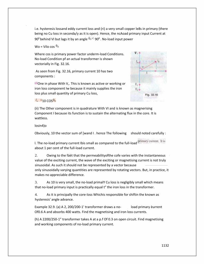
1132
i.e. hysteresis lossand eddy current loss and (ri) a very small copper le8s in primary (there
being no Cu loss in seconda/y as it is open). Hence, the ncAoad primary input Current at
900 behind VI but lags it by an angle 900 . No-load input power
Wo = Vilo cos
Where cos is primary power factor underm-load Conditions.
No-load Condition pf an actual transformer is shown
vectorially in Fig. 32.16.
As seen from Fig. 32.16, primary current 10 has two
components :
One in phase With V,. This is known as active or working or
iron loss component Iw because it mainly supplies the iron
loss plus small quantity of primary Cu loss,
10 COS
(ii) The Other component is in quadrature With VI and is known as magnerising
Component I because its function is to sustain the alternating flux in the core. It is
wattless.
losin4)o
Obviously, 10 the vector sum of [wand I . hence The following should noted carefully :
l. The no-load primary current Ibis small as compared to the full-load
about 1 per cent of the full-load current.
2. Owing to the fáét that the permeabilityofthe cofe varies with the instantaneous
value of the exciting current, the wave of the exciting or magnetising current is not truly
sinusoidal. As such it should not be represented by a vector because
only sinusoidally varying quantities are represented by rotating vectors. But, in practice, it
makes no appreciable difference.
3. As 10 is very small, the no-load primalY Cu loss is negligibly small which means
that no-load primary input is practically equal t" the iron loss in the transformer.
4. As it is principally the core-loss Whichis responsible for shiftin the known as
hysteresis' angle advance.
Example 32.9. (a) A 2, 200/200-1' transformer draws a no- load primary èurrent
Of0.6 A and absorbs 400 watts. Find the magnetising and iron loss currents.
(h) A 2200/250-1" transformer takes A at a p.f Of 0.3 on open circuit. Find magnetising
and working components of no-load primary current.
V

1133
Solution. Iron-loss current
no-load input in watts_ 400 -- 0.182 A primary voltage 200
Magnetising component — 0.182)? 0.672 A
The two components are shown in fig. 29 5.
Example 32.10. A Single-phase transfoñnèr/tas 500 turns on the primary andJ4tJturns on
the secondary winding. The•neon length Of rhe magnetic path in rhe iron core is 150 cm
and the joints are 'o an air-gap ofO. When a p.d. V is applied to the primary
maximum flux density is 1.2 Wb/m2. Calculate (a/ the cross-sectional areaof the core (b)
no-load secondary voltage (c) rhe no-load current drawn by the primary (d) power factor
no-load. Given that AT/cm for density of 1.2 Wb/m2 in iron to be 5, the corresponding
iron loss 10 be 2 ivátt/kg 50 Hz, and the density of iron as 7.8 kram/cm3.
Solution. = 4.44x50x500*12xA
This is thenetcross-sectional area. However, the grossarea would be about for the
insulation between laminations.
K = N/A', -40/500=4/50
NL, secondary voltage - KEI
750
80.0001=955
Total forgiven = 950+965=945.5
Max. value ofmagnetising current drawn by primary =845.5/500 = 1.691 A
Assuming this culTent to be sinusoidal, its is = I -691/ 1.196 A
Volumeofiron = length xarea=
Density 7.8 gram/em3 Mass ofiron = 7.8/1(m-263.25kg
Total iron loss
Iron loss component Of no-load primary current is Iw =526.5/3000— O. 176 A
1.1962 +0.1762 —0.208 A
powerfactor.cos,þo - 174=0.176/1208-0.1457
32.10. Transformer on Load 10
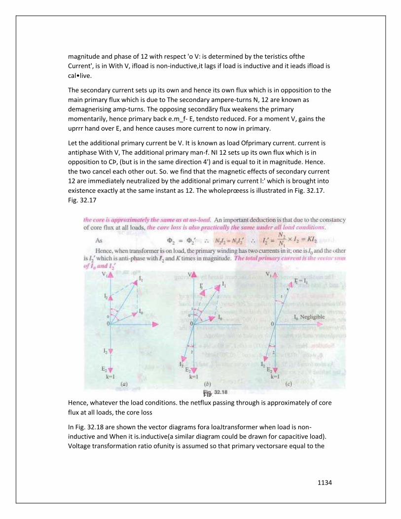
1134
magnitude and phase of 12 with respect 'o V: is determined by the teristics ofthe
Current', is in With V, ifload is non-inductive,it lags if load is inductive and it ieads ifload is
cal•live.
The secondary current sets up its own and hence its own flux which is in opposition to the
main primary flux which is due to The secondary ampere-turns N, 12 are known as
demagnerising amp-turns. The opposing secondãry flux weakens the primary
momentarily, hence primary back e.m_f- E, tendsto reduced. For a moment V, gains the
uprrr hand over E, and hence causes more current to now in primary.
Let the additional primary current be V. It is known as load Ofprimary current. current is
antiphase With V, The additional primary man-f. NI 12 sets up its own flux which is in
opposition to CÞ, (but is in the same direction 4') and is equal to it in magnitude. Hence.
the two cancel each other out. So. we find that the magnetic effects of secondary current
12 are immediately neutralized by the additional primary current l:' which is brought into
existence exactly at the same instant as 12. The wholeprœess is illustrated in Fig. 32.17.
Fig. 32.17
Hence, whatever the load conditions. the netflux passing through is approximately of core
flux at all loads, the core loss
In Fig. 32.18 are shown the vector diagrams fora loaJtransformer when load is non-
inductive and When it is.inductive(a similar diagram could be drawn for capacitive load).
Voltage transformation ratio ofunity is assumed so that primary vectorsare equal to the
Fig.
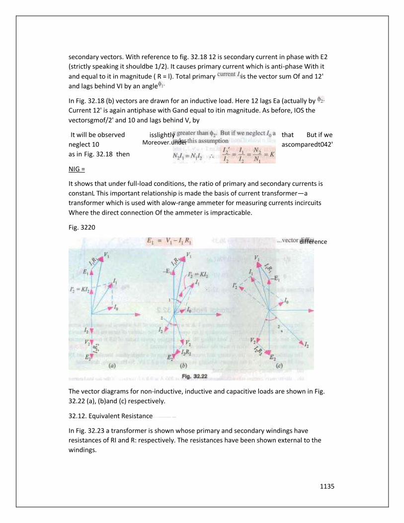
1135
secondary vectors. With reference to fig. 32.18 12 is secondary current in phase with E2
(strictly speaking it shouldbe 1/2). It causes primary current which is anti-phase With it
and equal to it in magnitude ( R = l). Total primary is the vector sum Of and 12'
and lags behind VI by an angle
In Fig. 32.18 (b) vectors are drawn for an inductive load. Here 12 lags Ea (actually by
Current 12' is again antiphase with Gand equal to itin magnitude. As before, IOS the
vectorsgmof/2' and 10 and lags behind V, by
It will be observed that But if we
neglect 10 ascomparedt042'
as in Fig. 32.18 then
NIG =
It shows that under full-load conditions, the ratio of primary and secondary currents is
constanL This important relationship is made the basis of current transformer—a
transformer which is used with alow-range ammeter for measuring currents incircuits
Where the direct connection Of the ammeter is impracticable.
Fig. 3220
The vector diagrams for non-inductive, inductive and capacitive loads are shown in Fig.
32.22 (a), (b)and (c) respectively.
32.12. Equivalent Resistance
In Fig. 32.23 a transformer is shown whose primary and secondary windings have
resistances of RI and R: respectively. The resistances have been shown external to the
windings.
difference
isslightly Moreover. under
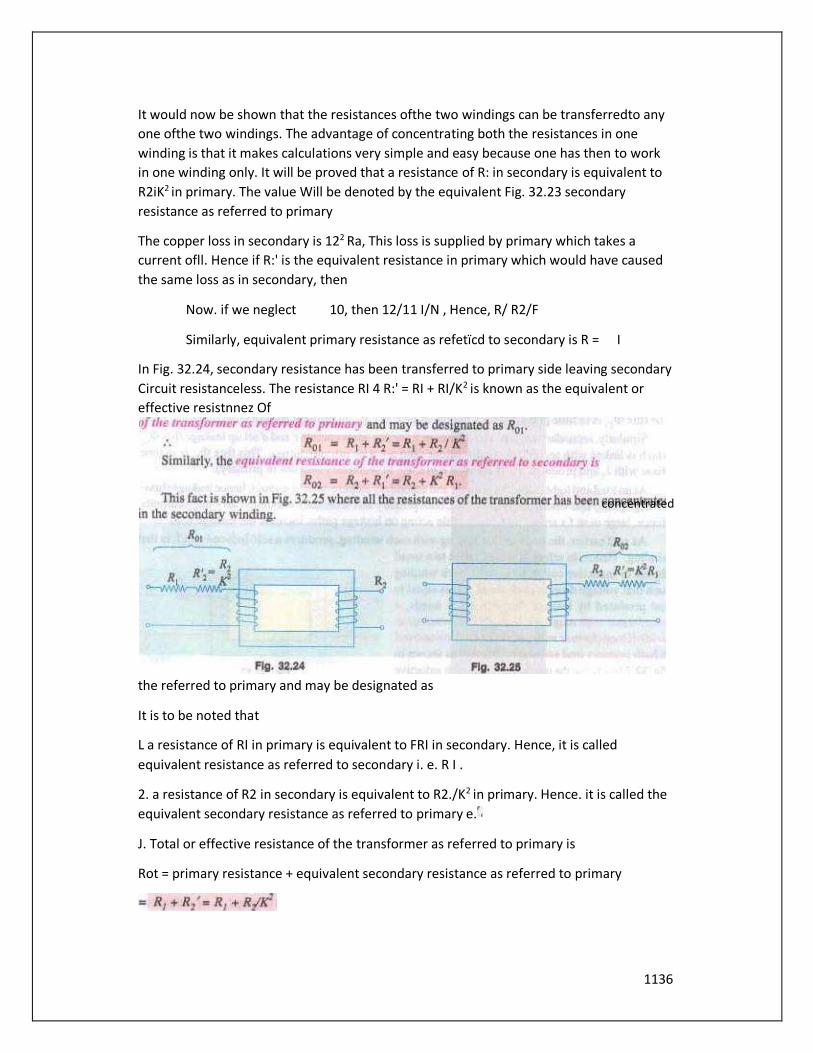
1136
It would now be shown that the resistances ofthe two windings can be transferredto any
one ofthe two windings. The advantage of concentrating both the resistances in one
winding is that it makes calculations very simple and easy because one has then to work
in one winding only. It will be proved that a resistance of R: in secondary is equivalent to
R2iK2 in primary. The value Will be denoted by the equivalent Fig. 32.23 secondary
resistance as referred to primary
The copper loss in secondary is 122 Ra, This loss is supplied by primary which takes a
current ofll. Hence if R:' is the equivalent resistance in primary which would have caused
the same loss as in secondary, then
Now. if we neglect 10, then 12/11 I/N , Hence, R/ R2/F
Similarly, equivalent primary resistance as refetïcd to secondary is R = I
In Fig. 32.24, secondary resistance has been transferred to primary side leaving secondary
Circuit resistanceless. The resistance RI 4 R:' = RI + RI/K2 is known as the equivalent or
effective resistnnez Of
the referred to primary and may be designated as
It is to be noted that
L a resistance of RI in primary is equivalent to FRI in secondary. Hence, it is called
equivalent resistance as referred to secondary i. e. R I .
2. a resistance of R2 in secondary is equivalent to R2./K2 in primary. Hence. it is called the
equivalent secondary resistance as referred to primary e.
J. Total or effective resistance of the transformer as referred to primary is
Rot = primary resistance + equivalent secondary resistance as referred to primary
concentrated

1137
4. Similarly. total transformer resistance as referred to secondary is,
Note : (tis important to remember that
(a) When shifting any primary resistance
to the secondary, *nut/iply it by (b When
shifting secondary resistance to the
primary, divide it hy R.
(CJ however. when shifting any voltage
from one.inding toanother
32.13. Magnetic Leakage
In the preceding discussion. it has been
assumed that all the flux linked with
primary winding also links the secondary winding. But, in practice, it is impossible to
realize this condition. It is found, however, that all the flux linked with primary does not
linkthe secondary but partofiti.e_OL completes itsmagnetic circuit bypassing through air
than around the core, as shown in Fig. 32.26. This leakage flux is produced when the
m.m.f. due to primary ampere-turns existing betueen points,a and Fig. 32.26 b, acts along
the leakage paths. Hençe, this flux is known asprimary leakagejh'.r and is proportional to
the primary ampere-turns alone because the secondary turns do not link the magnetic
circuit Of The flux is in time phase with ll . It induces an e.m.f. in primary but notin
secondary.
Similarly. secondary ampere-turns (or m.m.f.) acting acrosspoints c and d set up leakage
flux which is linked with secondary winding alone (and not With primary turns). This
flux in time phase with 12 and produces a self-induced e.m.f. in secondary (but not in
primary).
At no load and light loads. theprimary and secondary ampere-turns are small, hence
leakage fluxes negligible. But When load is increased. both primary and secondary
windings carry huge currents. Hence. large m.m.f.s are Set up which, while acting on
leakage paths, increase the leakage
As said earlier, the leakage flux linking with each winding, produces a self-induced e,m.f.
in that winding. Hence, in effect, it is equivalent
to a small choker or inductive coil in series with
each winding such that voltage drop in each
series coil is equal to that produced by leakage
flux. In other words, a transformer With
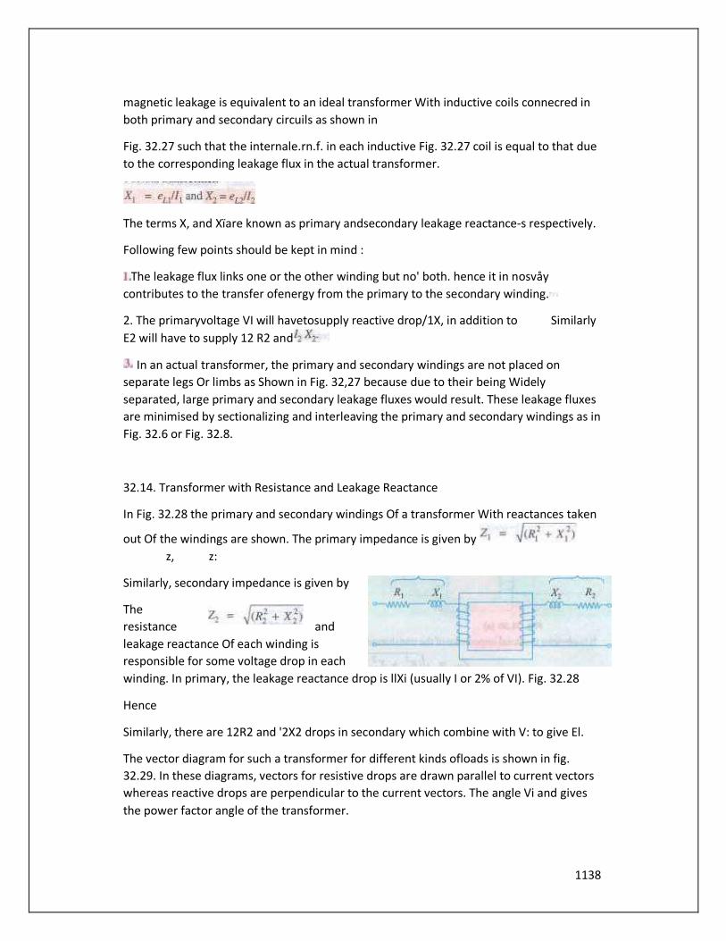
1138
magnetic leakage is equivalent to an ideal transformer With inductive coils connecred in
both primary and secondary circuils as shown in
Fig. 32.27 such that the internale.rn.f. in each inductive Fig. 32.27 coil is equal to that due
to the corresponding leakage flux in the actual transformer.
The terms X, and Xïare known as primary andsecondary leakage reactance-s respectively.
Following few points should be kept in mind :
The leakage flux links one or the other winding but no' both. hence it in nosvåy
contributes to the transfer ofenergy from the primary to the secondary winding.
2. The primaryvoltage VI will havetosupply reactive drop/1X, in addition to Similarly
E2 will have to supply 12 R2 and
In an actual transformer, the primary and secondary windings are not placed on
separate legs Or limbs as Shown in Fig. 32,27 because due to their being Widely
separated, large primary and secondary leakage fluxes would result. These leakage fluxes
are minimised by sectionalizing and interleaving the primary and secondary windings as in
Fig. 32.6 or Fig. 32.8.
32.14. Transformer with Resistance and Leakage Reactance
In Fig. 32.28 the primary and secondary windings Of a transformer With reactances taken
out Of the windings are shown. The primary impedance is given by
z, z:
Similarly, secondary impedance is given by
The
resistance and
leakage reactance Of each winding is
responsible for some voltage drop in each
winding. In primary, the leakage reactance drop is llXi (usually I or 2% of VI). Fig. 32.28
Hence
Similarly, there are 12R2 and '2X2 drops in secondary which combine with V: to give El.
The vector diagram for such a transformer for different kinds ofloads is shown in fig.
32.29. In these diagrams, vectors for resistive drops are drawn parallel to current vectors
whereas reactive drops are perpendicular to the current vectors. The angle Vi and gives
the power factor angle of the transformer.
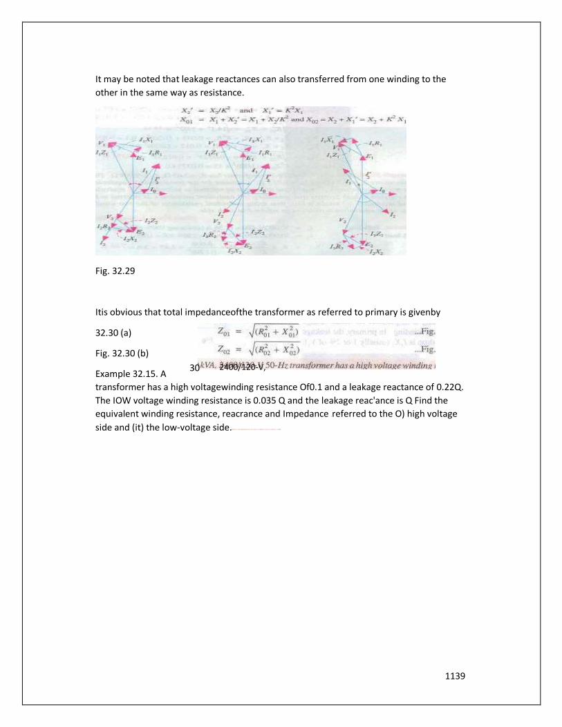
1139
It may be noted that leakage reactances can also transferred from one winding to the
other in the same way as resistance.
Fig. 32.29
Itis obvious that total impedanceofthe transformer as referred to primary is givenby
32.30 (a)
Fig. 32.30 (b)
Example 32.15. A
transformer has a high voltagewinding resistance Of0.1 and a leakage reactance of 0.22Q.
The IOW voltage winding resistance is 0.035 Q and the leakage reac'ance is Q Find the
equivalent winding resistance, reacrance and Impedance referred to the O) high voltage
side and (it) the low-voltage side.
30 2400/120-V,

1140
Example 32.16. A Of reactances are X, = 5.2 lance as referred to primary tance as referred
ta both primary and secondary
'nary and secondary total Cu loss, first using individual tvsistances Of the two windings
and secondly, using equivalent resistances as referred to each side.
Solution. Full-load
AlsoCu 10»
32.16. Total Approximate Voltage Drop in a
Transformer
When the transformer is On no-toad then
VI is approximately equal to El. Hence E2 =
KEI = WI. Also. E2 = 0 V: where 0V2 is
secondary terminal voltage on noload,
hence no-load secondary terminal voltage
is WI. The secondary voltage on load is V2.
equivalent resistance as referred to seéondary (Y) equivalent reac- equivalent impedance as referred to both pri-
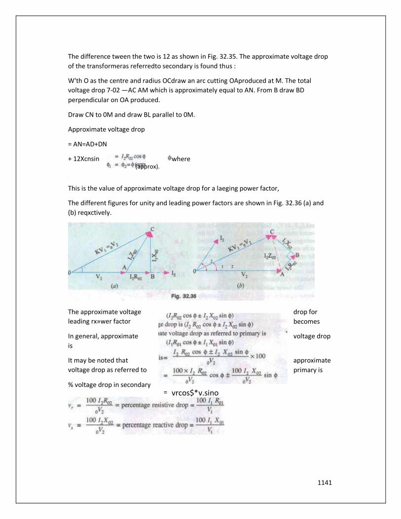
1141
The difference tween the two is 12 as shown in Fig. 32.35. The approximate voltage drop
of the transformeras referredto secondary is found thus :
W'th O as the centre and radius OCdraw an arc cutting OAproduced at M. The total
voltage drop 7-02 —AC AM which is approximately equal to AN. From B draw BD
perpendicular on OA produced.
Draw CN to 0M and draw BL parallel to 0M.
Approximate voltage drop
= AN=AD+DN
+ 12Xcnsin where
This is the value of approximate voltage drop for a laeging power factor,
The different figures for unity and leading power factors are shown in Fig. 32.36 (a) and
(b) reqxctively.
The approximate voltage drop for
leading rx»wer factor becomes
In general, approximate voltage drop
is
It may be noted that approximate
voltage drop as referred to primary is
% voltage drop in secondary
(approx).
= vrcos$*v.sino
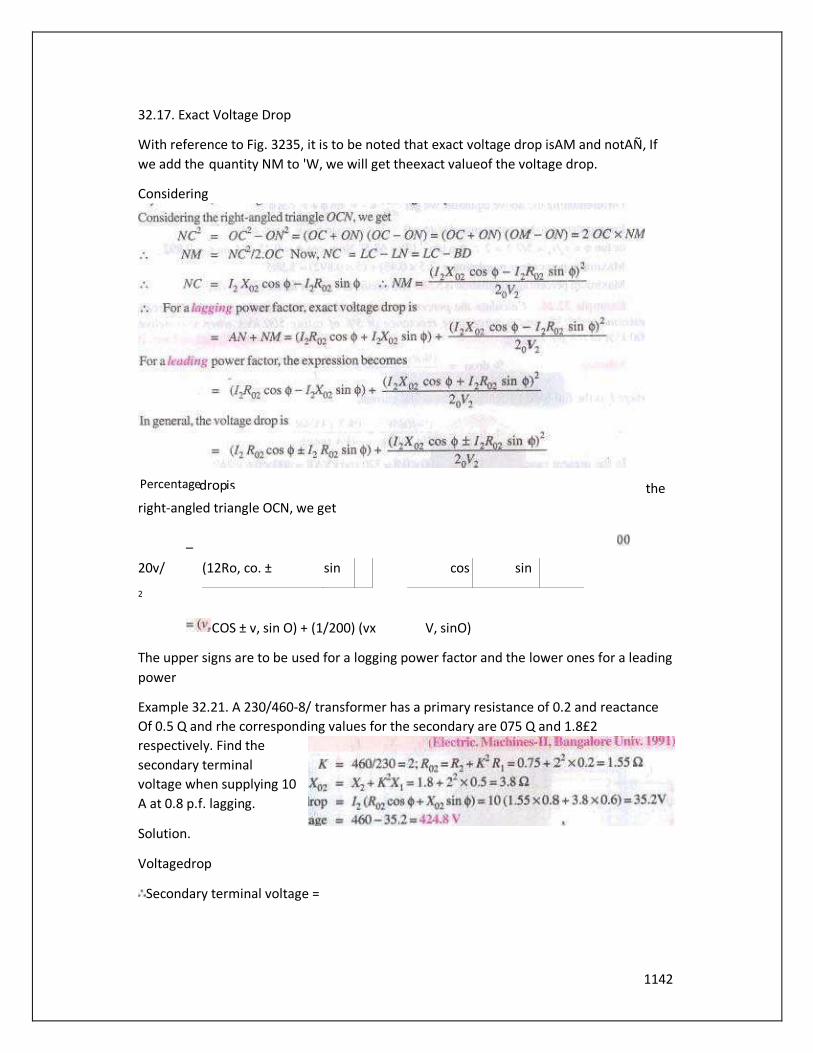
1142
32.17. Exact Voltage Drop
With reference to Fig. 3235, it is to be noted that exact voltage drop isAM and notAÑ, If
we add the quantity NM to 'W, we will get theexact valueof the voltage drop.
Considering
the
right-angled triangle OCN, we get
_
20v/
2
COS ± v, sin O) + (1/200) (vx V, sinO)
The upper signs are to be used for a logging power factor and the lower ones for a leading
power
Example 32.21. A 230/460-8/ transformer has a primary resistance of 0.2 and reactance
Of 0.5 Q and rhe corresponding values for the secondary are 075 Q and 1.8£2
respectively. Find the
secondary terminal
voltage when supplying 10
A at 0.8 p.f. lagging.
Solution.
Voltagedrop
Secondary terminal voltage =
(12Ro, co. ± sin
cos sin
Percentage drop is
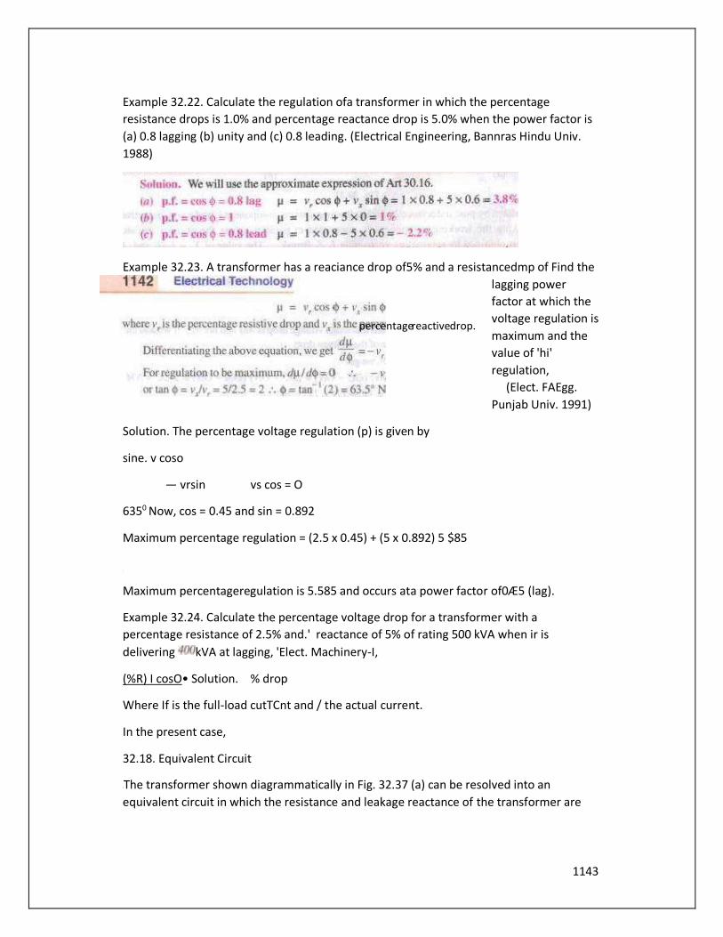
1143
Example 32.22. Calculate the regulation ofa transformer in which the percentage
resistance drops is 1.0% and percentage reactance drop is 5.0% when the power factor is
(a) 0.8 lagging (b) unity and (c) 0.8 leading. (Electrical Engineering, Bannras Hindu Univ.
1988)
Example 32.23. A transformer has a reaciance drop of5% and a resistancedmp of Find the
lagging power
factor at which the
voltage regulation is
maximum and the
value of 'hi'
regulation,
(Elect. FAEgg.
Punjab Univ. 1991)
Solution. The percentage voltage regulation (p) is given by
sine. v coso
— vrsin vs cos = O
6350 Now, cos = 0.45 and sin = 0.892
Maximum percentage regulation = (2.5 x 0.45) + (5 x 0.892) 5 $85
Maximum percentageregulation is 5.585 and occurs ata power factor of0Æ5 (lag).
Example 32.24. Calculate the percentage voltage drop for a transformer with a
percentage resistance of 2.5% and.' reactance of 5% of rating 500 kVA when ir is
delivering kVA at lagging, 'Elect. Machinery-I,
(%R) I cosO• Solution. % drop
Where If is the full-load cutTCnt and / the actual current.
In the present case,
32.18. Equivalent Circuit
The transformer shown diagrammatically in Fig. 32.37 (a) can be resolved into an
equivalent circuit in which the resistance and leakage reactance of the transformer are
percentage reactive drop.

1144
imagined to be external to the winding whose only function then is to transform the
voltage (Fig. 32.37 (b)). The no-load
current 10 is simulated by pure inductance Xo taking the magnetising component lg and a
non-inductive resistance Ro taking the working component Is, connected in parallel
across the primary circuit. The value of El is obtained by subtracting vector-idly 7-1 from
VI. The value of Xo = El/loandof Ro = It is clear that El and E, are related to each other by
expression
To maketransformer calculations simpler, it is preferable to transfer voltage, current and
impedance
citherto the primary Or to the secondary. In thatcase. we would have to work in
onewinding only which is more convenient.
The primary equi ofthe secondary induced voltageis E2' E2jK= El.
Similarly. primary equivalent Ofsecondary terminal or Output voltage is V,' V2/K Primary
equivalentofthe secondary current is 12' = K12.
For transferring secondary
Thesamerelationship is Lised for shifting an external load impedance to the
primal)'.
The secondary circuitis shown in Fig. 32.38(O) and its equivalent primary values areshown
infig.
a
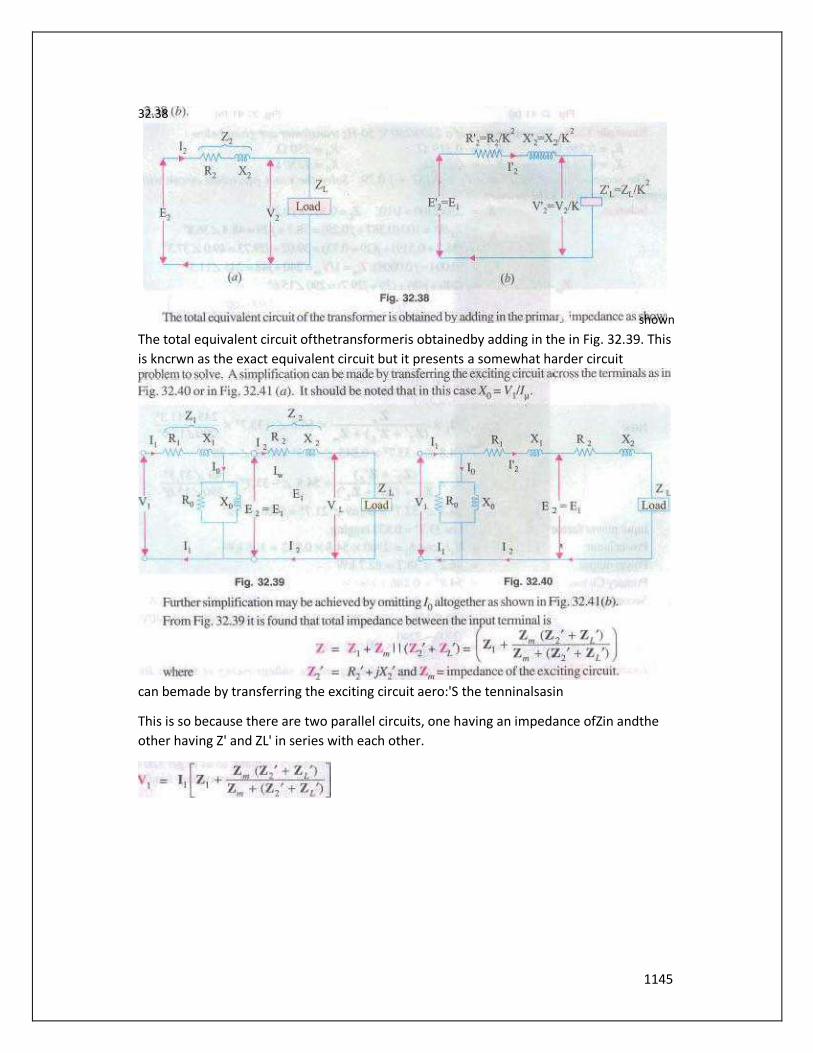
1145
The total equivalent circuit ofthetransformeris obtainedby adding in the in Fig. 32.39. This
is kncrwn as the exact equivalent circuit but it presents a somewhat harder circuit
can bemade by transferring the exciting circuit aero:'S the tenninalsasin
This is so because there are two parallel circuits, one having an impedance ofZin andthe
other having Z' and ZL' in series with each other.
32.38
shown

1146
transformer has a primary winding With a voltage-ratingOf 600 V. secondary-voltage
rating is 1080 V With an additional tap a! 720 V. An 8 kW resistive load is connected
across IOSO-V output terminals. A purely inductive load of 10k VA is connected across the
32.26.
1144

1147
tapping point and common second00' terminal so as get 720 V. Calculate the primary
current and its power-factor Correlate if with the existing secondary loads. Neglect losses
and magnetizing current. ( Nagpur University, Winter 1999)
Solution. Loads are as shown in Fig. 32142.
8000
7.41 at unity p,f.
1080
10000/720=13.89atzerolaggingp.f.
These arereflected on to the primary sides with appropriate raùos ofturms, with
corresponding powerfactors. If the conesponding transformed currents are represented
by theabovesymbols modified by
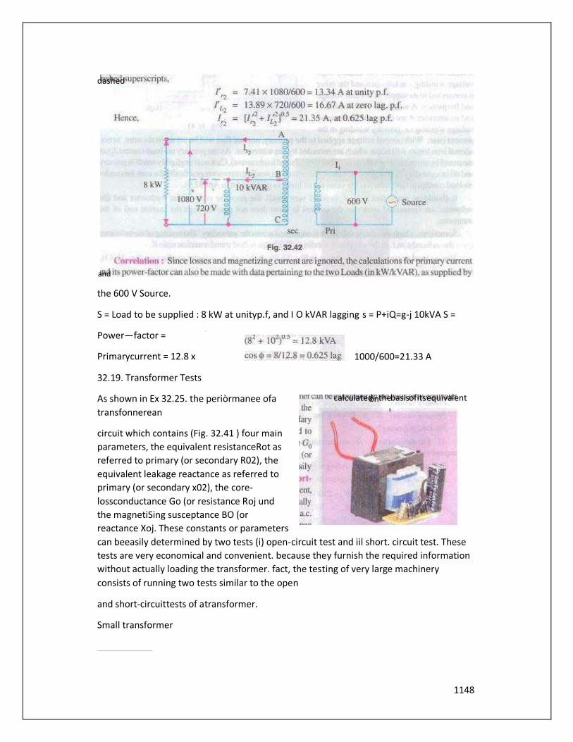
1148
the 600 V Source.
S = Load to be supplied : 8 kW at unityp.f, and I O kVAR lagging s = P+iQ=g-j 10kVA S =
Power—factor =
Primarycurrent = 12.8 x 1000/600=21.33 A
32.19. Transformer Tests
As shown in Ex 32.25. the periòrmanee ofa
transfonnerean
circuit which contains (Fig. 32.41 ) four main
parameters, the equivalent resistanceRot as
referred to primary (or secondary R02), the
equivalent leakage reactance as referred to
primary (or secondary x02), the core-
lossconductance Go (or resistance Roj und
the magnetiSing susceptance BO (or
reactance Xoj. These constants or parameters
can beeasily determined by two tests (i) open-circuit test and iil short. circuit test. These
tests are very economical and convenient. because they furnish the required information
without actually loading the transformer. fact, the testing of very large machinery
consists of running two tests similar to the open
and short-circuittests of atransformer.
Small transformer
dashed
and
calculated on the basis of its equivalent
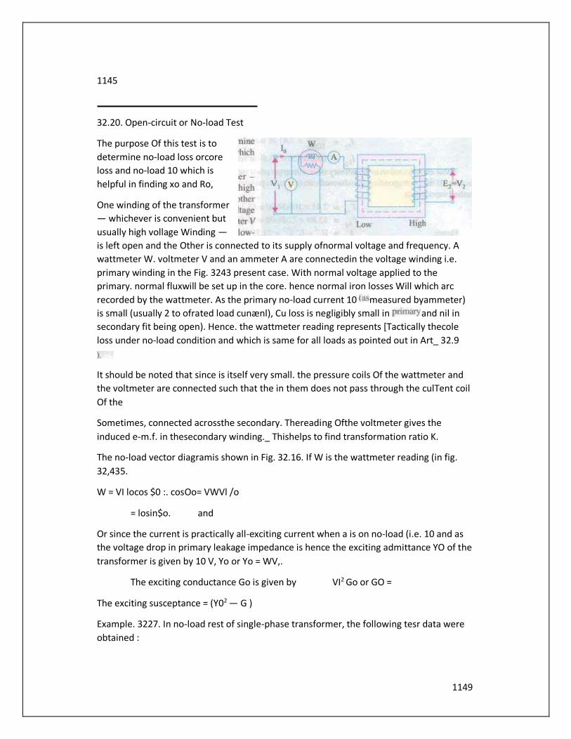
1149
1145
32.20. Open-circuit or No-load Test
The purpose Of this test is to
determine no-load loss orcore
loss and no-load 10 which is
helpful in finding xo and Ro,
One winding of the transformer
— whichever is convenient but
usually high vollage Winding —
is left open and the Other is connected to its supply ofnormal voltage and frequency. A
wattmeter W. voltmeter V and an ammeter A are connectedin the voltage winding i.e.
primary winding in the Fig. 3243 present case. With normal voltage applied to the
primary. normal fluxwill be set up in the core. hence normal iron losses Will which arc
recorded by the wattmeter. As the primary no-load current 10 measured byammeter)
is small (usually 2 to ofrated load cunænl), Cu loss is negligibly small in and nil in
secondary fit being open). Hence. the wattmeter reading represents [Tactically thecole
loss under no-load condition and which is same for all loads as pointed out in Art_ 32.9
It should be noted that since is itself very small. the pressure coils Of the wattmeter and
the voltmeter are connected such that the in them does not pass through the culTent coil
Of the
Sometimes, connected acrossthe secondary. Thereading Ofthe voltmeter gives the
induced e-m.f. in thesecondary winding._ Thishelps to find transformation ratio K.
The no-load vector diagramis shown in Fig. 32.16. If W is the wattmeter reading (in fig.
32,435.
W = VI locos $0 :. cosOo= VWVl /o
= losin$o. and
Or since the current is practically all-exciting current when a is on no-load (i.e. 10 and as
the voltage drop in primary leakage impedance is hence the exciting admittance YO of the
transformer is given by 10 V, Yo or Yo = WV,.
The exciting conductance Go is given by VI2 Go or GO =
The exciting susceptance = (Y02 — G )
Example. 3227. In no-load rest of single-phase transformer, the following tesr data were
obtained :
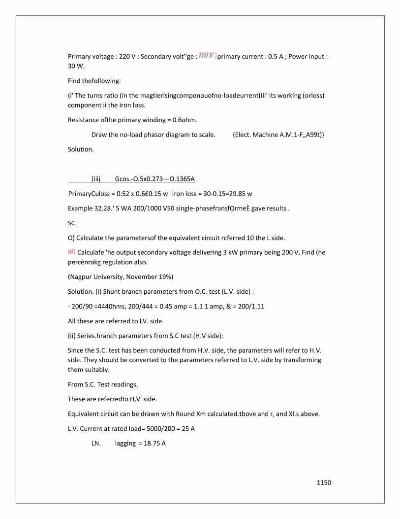
1150
Primary voltage : 220 V : Secondary volt"ge : primary current : 0.5 A ; Power input :
30 W.
Find thefollowing
(i' The turns ratio (in the magtierisingcomponouofno-loadeurrent(iii' its working (orloss)
component ii the iron loss.
Resistance ofthe primary winding = 0.6ohm.
Draw the no-load phasor diagram to scale. (Elect. Machine A.M.1-F„A99t))
Solution.
(iiij Gcos.-O.5x0.273—O.1365A
PrimaryCuloss = 0:52 x 0.6£0.15 w Iron loss = 30-0.15=29.85 w
Example 32.28.' 5 WA 200/1000 V50 single-phasefransfOrmeÈ gave results .
SC.
O) Calculate the parametersof the equivalent circuit rcferred 10 the L side.
Calculafe 'he output secondary voltage delivering 3 kW primary being 200 V, Find (he
percènrakg regulation also.
(Nagpur University, November 19%)
Solution. (i) Shunt branch parameters from O.C. test (L.V. side) :
- 200/90 =4440hms, 200/444 = 0.45 amp = 1.1 1 amp, & = 200/1.11
All these are referred to LV. side
(ii) Series.hranch parameters from S.C test (H.V side):
Since the S.C. test has been conducted from H.V. side, the parameters will refer to H.V.
side. They should be converted to the parameters referred to L.V. side by transforming
them suitably.
From S.C. Test readings,
These are referredto H,V' side.
Equivalent circuit can be drawn with Round Xm calculated.tbove and r, and Xl.s above.
L V. Current at rated load= 5000/200 = 25 A
LN. lagging = 18.75 A
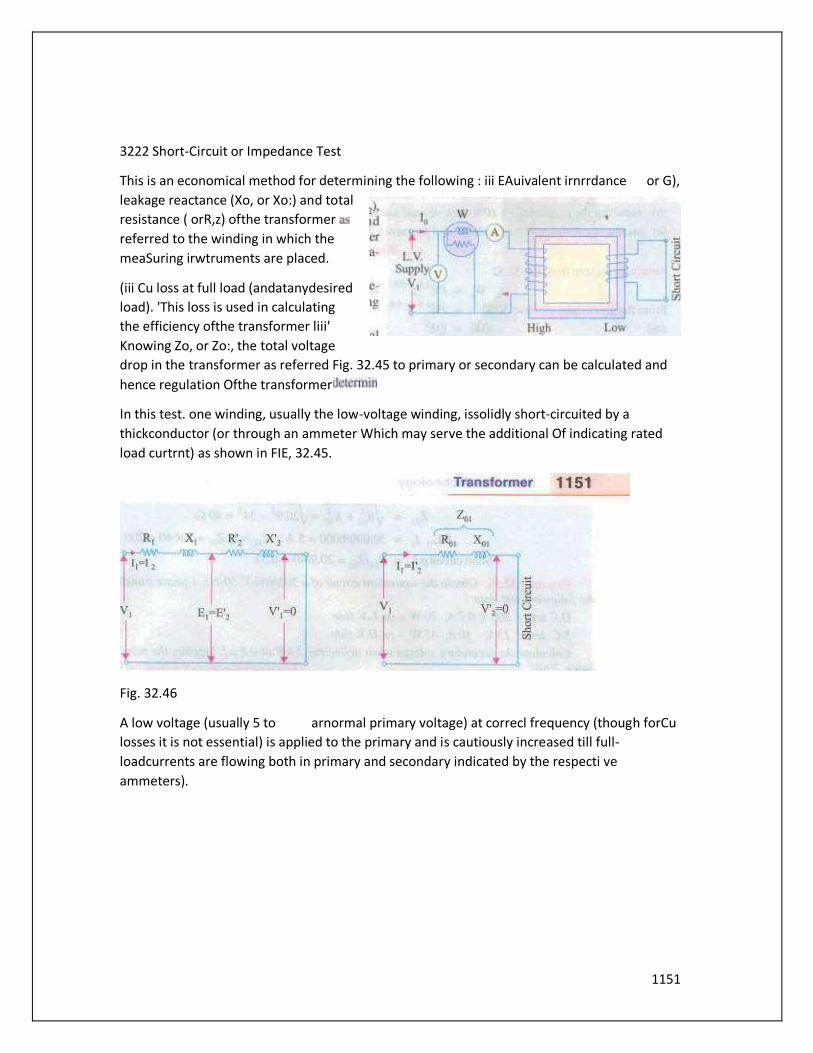
1151
3222 Short-Circuit or Impedance Test
This is an economical method for determining the following : iii EAuivalent irnrrdance or G),
leakage reactance (Xo, or Xo:) and total
resistance ( orR,z) ofthe transformer
referred to the winding in which the
meaSuring irwtruments are placed.
(iii Cu loss at full load (andatanydesired
load). 'This loss is used in calculating
the efficiency ofthe transformer liii'
Knowing Zo, or Zo:, the total voltage
drop in the transformer as referred Fig. 32.45 to primary or secondary can be calculated and
hence regulation Ofthe transformer
In this test. one winding, usually the low-voltage winding, issolidly short-circuited by a
thickconductor (or through an ammeter Which may serve the additional Of indicating rated
load curtrnt) as shown in FIE, 32.45.
Fig. 32.46
A low voltage (usually 5 to arnormal primary voltage) at correcl frequency (though forCu
losses it is not essential) is applied to the primary and is cautiously increased till full-
loadcurrents are flowing both in primary and secondary indicated by the respecti ve
ammeters).
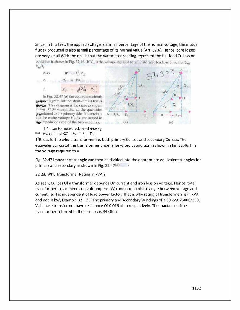
1152
Since, in this test. the applied voltage is a small percentage of the normal voltage, the mutual
flux tÞ produced is also asmall percentage of its normal value (Art. 32.6), Hence. core losses
are very small With the result that the wattmeter reading represent the full-load Cu loss or
12R loss forthe whole transformer i.e. both primary Cu loss and secondary Cu loss, The
equivalent circuitof the tramsformer under shon-ciœuit condition is shown in fig. 32.46, If is
the voltage required to =
Fig. 32.47 impedance triangle can then be divided into the appropriate equivalent triangles for
primary and secondary as shown in Fig. 32.47
32.23. Why Transformer Rating in kVA ?
As seen, Cu loss Of a transformer depends On current and iron loss on voltage. Hence. total
transformer loss depends on volt-ampere (VA) and not on phase angle between voltage and
cunent i.e. it is independent of load power factor. That is why rating of transformers is in kVA
and not in kW, Example 32—35. The primary and secondary Windings of a 30 kVÄ 76000/230,
V, I-phase transformer have resistance Of 0.016 ohm respectivelv. The mactance ofthe
transformer referred to the primary is 34 Ohm.
vector shown. in are
the
If R, can be measured, then knowing ROI, wc can find R2' Ro — RI. The
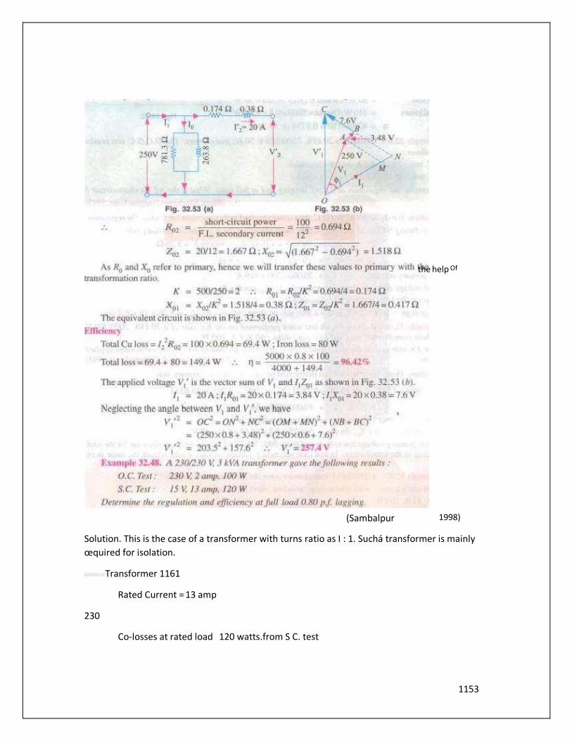
1153
Solution. This is the case of a transformer with turns ratio as I : 1. Suchá transformer is mainly
œquired for isolation.
Transformer 1161
Rated Current = 13 amp
230
Co-losses at rated load 120 watts.from S C. test
the help Of
(Sambalpur 1998)
1154
Core losses 100 Watts, from O.C. test
Atfull load. VAoutput - — 3000
At 0.8 lag p. Poweroutput
Required efficiency =
From S.C. test.
Approximate v01tage regulation
13.51
In terms of the voltage regulation = 230 x 100% -5.874%
Example 32.49. A 10 kVA, 500/250 V. single-phase transformer has its maximum efficiency of
94% When delivering Estimate its efficiency when delivering ifs full-load output p.f. of 0.8
lagging. (Nagpur UniveÑty, 1998'
Solution. Rated output ag unity p.f. = 10000 W. Hence, of rated Output = 9,000 W
Input with efficiency =
Losses =
At maximum efficiency, variablecopper-loss = constant =Core loss = 574/2
At rated current, Let the copper-loss pc walls
At 90% load with unity p.f.. the copper-loss is expressed as 0.902 x Pi.
Hence, P, = 287/0.81=354W
At the corresponding load, Full Load copper-loss = 354 W
Hence. efficiency -8000/(8000 + 354 + 287) = 0.926-92.6<0
ofcalculation of voltage-magnitudes, approximav fOrrnuJa for voltage regulation can be used.
For the present case of 0.8 lagging p.f.
VI' = V2+/[rcosQ+xsint$l
230+43.5 (0.316 x
= 230*43.5 (0.0634 + O. 18961—230+ 11 V, 241 volts.
It means that H.V. side terminal voltage must 2410 for keeping 230 V at the specified load.
W
1155
(b ) Approximate for voltage regulation is : V,' — =
With Laggingp.f., sign is retained. With leadingpoWer-factor. the—ve sign is applicable.
For the voltage-regulation to be zero. only leading Bf. condition can prevail. sin O
= nix-0.0792/0316=0.25
= 140. cos 4=0.97 leading
Corresponding sino = Sin 0.243
H.V. terminal voltage required is23m V to maintain 230 V at since regulation condition is
under discussion.
Example 32.51. A 5 kVA. 2200Q20 single-phase transformer has thefollowing parameters.
H. V. side r, = 3.4 Ohms. x, = 7.2 ohms
L V: side : r: = 0.028 ohms, 0.060 Ohms
Transformer is made to deliver rated current at 0.8 lagging p.f. to a load connected on the L V.
side. If the load voltage is 220 Vt calculate the terminal voltage on H. V side
(Neglect the exciting current). (Rajiv Gandhi Tichnicnl University, Bhopal.Summer 2001 )
Solution. Calculations may be done referring all the parameters the LV. side first. Finally, the
voltage required onH.V. side can be obtained after transformation.
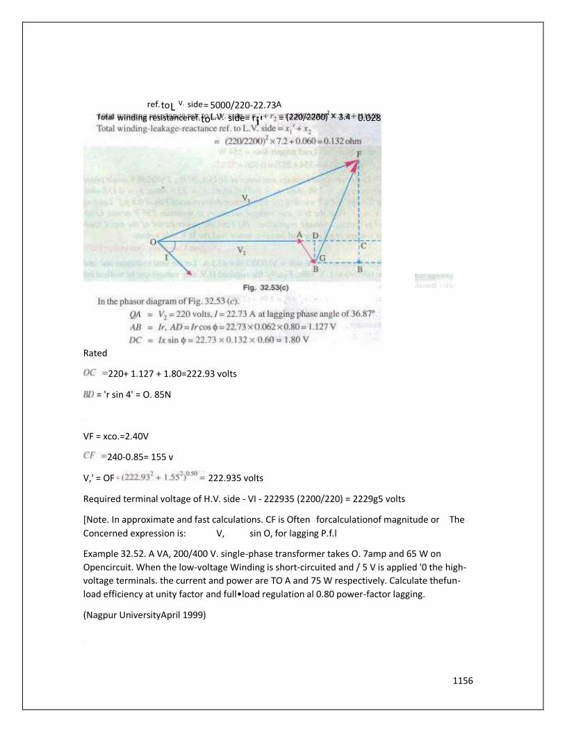
1156
Rated
220+ 1.127 + 1.80=222.93 volts
= 'r sin 4' = O. 85N
VF = xco.=2.40V
240-0.85= 155 v
V,' = OF 222.935 volts
Required terminal voltage of H.V. side - VI - 222935 (2200/220) = 2229g5 volts
[Note. In approximate and fast calculations. CF is Often forcalculationof magnitude or The
Concerned expression is: V, sin O, for lagging P.f.l
Example 32.52. A VA, 200/400 V. single-phase transformer takes O. 7amp and 65 W on
Opencircuit. When the low-voltage Winding is short-circuited and / 5 V is applied '0 the high-
voltage terminals. the current and power are TO A and 75 W respectively. Calculate thefun-
load efficiency at unity factor and full•load regulation al 0.80 power-factor lagging.
(Nagpur UniversityApril 1999)
ref. to L V. side = 5000/220-22.73 A Total winding resistance ref. to L.V. side = r i' = (220/2200)
2 X 3.4 0.028
1157
Solution. At a load of 4 kVA. the rated currents are : side 4000/200 = 20amp
And H.V. side : 4000/400 = 10amp
From the test data. full-load copper-loss 75 AV
And Constant core-loss = 65 W
From S.C. test, Z = 15/10-1.Sohms
= 130 ohms
All these series-parameters are referred to the H.V. side, since the S.C. test
has been conducted from H.V. side.
Full-load efficiency at unity p.f. = 40 / 65 75)
= 0.966-966%
Full load voltageregulation at 0.80 lagging p.f.
Thus, due to loading, H.M side voltage will drop by 16.14 volts (i.e. terminal voltage for the
load will be 383.86 volts), when EV. side is energized by 200-V source.
32.25. Percentage Resistance, Reactance and Impedadce
These quantities are usually measured by the voltage drop át full-load current expressed as a
percentage Of the normal voltage Of the winding on Which calculations are made.
'i' percentage resistance at full-load
x 100
% Cu loss at full-load
...Art-3216
Percentage reactance at full-load
1.52 —
0.752

1158
(iii) Percentage impedanceat full-load
It may be noted that percentage resistance,
reactance and impedance have the same value
whether referred to primary or secondary.
= 1.648+5.87=7.52 %
Example 32.57. A iràhsformer has coppeNossof and
reactance-drop of3.5% when tested at full-load.
Calculate its full-load regulation at (i) (ii) 0.8 pl.
Lagging and (iii) 0.8 p'. Leading. (Bharathithasan
Univ. April 1997'
Solution. The test-data at full-load gives following
parameters :
p.a. resistance = 0.015, p.o. reactance —0.035
(t) Approximate Voltage — Regulation at unity p.f. full load
= 0.015cos040.035sin4'
0.015 perunit=
(ii) Approximate Voltage — Regulationat 0.80 Lagging p.r.
(iii) Approximate Voltage Regulation
at 0.8
32.26. Kapp Regulation Diagram
It has been shown that secondary terminal voltage falls as the load on the transformer is
increased whenp_f_ is lagging and it increases when the powerfactoris leading. In other
words, secondary terminal voltage not only depends on the load but on power factoralso (Art.
32.16). For finding the voltage drop (Or rise) which is further used in determining the
regulation Of the transformer, a graphical construction is employed which was proposed by
late Dr. Kapp.
For drawing Kapp regulation diagram, it is necessary to know the equivalent resistance and
reactance as referred to secondary i.e. R02 and x02_ If is the secondary load current, then
1159
secondary terminal voltage On load V2. is obtained by subtracting 12 and 12 x02 voltage
drops vectorially from secondary no-load voltage 0V2.
NOW, o VI is constant, hence it represented by a circle Ofconstant radius OA as in 32.54. This
circle is known as no-load or open-circuit e.m.f. circle. Fora given load. 012 represents the
load current and is taken as the reference vector, CB represents 12 Rm and is parallel to
012,AB represents x02 and is drawn at right angles to CB. Vector OC obviously represents
and is drawn at right anglestoCB. Vector OCobviously represents secondary terminal voltage
Since 12 isconstant, the drop triangle ABC remains constant in sizz It is seen that end point C
of V: lies on another circle whose centre is O'. This point (Y lies ata distance of 12 venically low
the v»int O and a distance of l, Rm to its left as shown in Fig. 32.54.
Suppose it is required to find the voltage drop On full-load at a lagging cower factor ofcos
then aradius OLP is drawn inclined at an angle of with OX. LM = 12 and is drawn horizontal
MN = 12 x02 and is drawn perpendicular to 1M. Obviously, ON is noload voltage ov:. Now, ON
OP ov2. Similarly. OLis V2. The voltage drop-op-OL=LP.
Hence. percentage regulation •down is — 100
It is seen that for finding voltage drop. triangle I-MN need not be drawn. but simply the radius
OLD.
The diagram shows clearly how the secondary terminal voltage falls as the angle Of lag
increases. Conversely, for a leading factor. the fall in terminal voltage decreases till foran
angle of 00 leading, the fall becomes zero; hence V, = ov2. For angles greater than secondary
terminal voltage V: greater than o
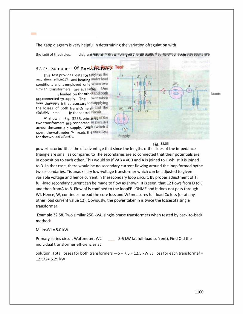
1160
The Kapp diagram is very helpful in determining the variation ofregulation with
powerfactorbutithas the disadvantage that since the lengths ofthe sides of the impedance
triangle are small as compared to The secondaries are so connected that their potentials are
in opposition to each other. This would so if VAB = vCD and A is joined to C whilst B is joined
to D. In that case, there would be no secondary current flowing around the loop formed bythe
two secondaries. Tis anauxiliary low-voltage transformer which can be adjusted to given
variable voltage and hence current in thesecondary loop circuit. By proper adjustment of T,
full-load secondary current can be made to flow as shown. It is seen, that 12 flows from D to C
and then fromA to B. Flow of is confined to the loopFEJLGHMF and it does not pass through
WI. Hence, W, continues toread the core loss and W2measures full-load Cu loss (or at any
other load current value 12). Obviously, the power takenin is twice the lossesofa single
transformer.
Example 32.58. Two similar 250-kVA, single-phase transformers when tested by back-to-back
method
MainsWI = 5.0 kW
Primary series circuit Wattmeter, W2 Z-5 kW fat full-load cu"rent), Find Old the
individual transformer efficiencies at
Solution. Total losses for both transformers —5 + 7.5 = 12.5 kW EL. loss for each transformef =
12.5/2= 6.25 kW
Fig. 32.55
the radii of the circles. diagram has to drawn on a very large scale, if sufficiently accurate results are
32.27. Sumpner Of Back-to-Back This test provides data for finding
regulation. efficie1EY and heating conditions and is employed only similar transformers are available.
is loaded on the other are connected to supply. The from the supply is that neœssary for the losses of both transfOrmers rEgligibly small in the control
As shown in Fig. 3255. primaries two transformers are connected across the same a.c. supply. With open, the wattmeter WI reads the for the two t.ra1VSfornErs.
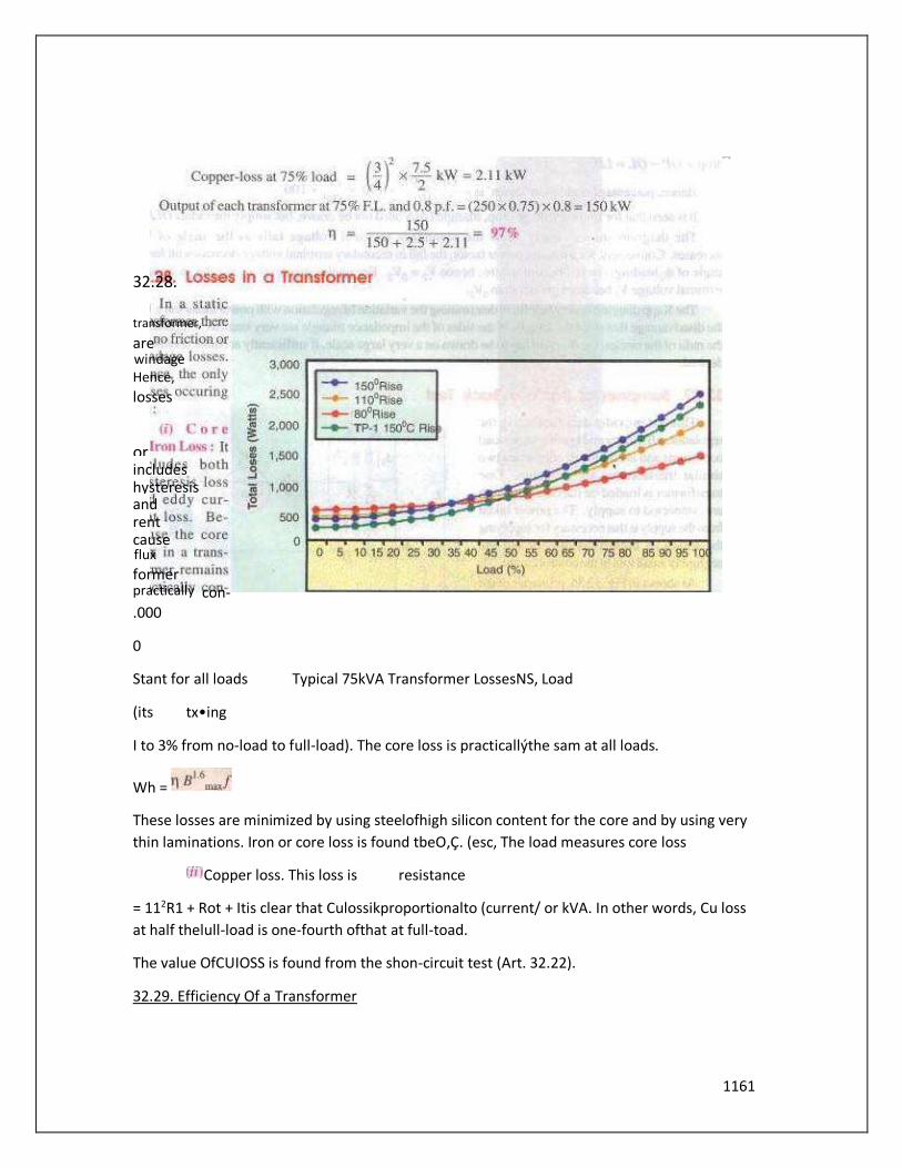
1161
.000
0
Stant for all loads Typical 75kVA Transformer LossesNS, Load
(its tx•ing
I to 3% from no-load to full-load). The core loss is practicallýthe sam at all loads.
Wh =
These losses are minimized by using steelofhigh silicon content for the core and by using very
thin laminations. Iron or core loss is found tbeO,Ç. (esc, The load measures core loss
Copper loss. This loss is resistance
= 112R1 + Rot + Itis clear that Culossikproportionalto (current/ or kVA. In other words, Cu loss
at half thelull-load is one-fourth ofthat at full-toad.
The value OfCUIOSS is found from the shon-circuit test (Art. 32.22).
32.29. Efficiency Of a Transformer
32.28.
transformer,
are windage Hence, losses
or includes hysteresis and rent cause flux former practically con-

1162
Asisthe case with other types ofelectrical machines, the efficiency of atransformer at a
particular load and power factor isdefined as the outputdivided by the input—the two being
measured in the same units (either watts or kilowatts)
But a transformer being ahighly efficient piece ofequipment, has very small loss, hence it is
impracticål to to measure transformer, efficiency by measuring input and output. These
quantities are nearlyofthe same sire, A better method is to determine the losses and then to
calculate theefficiency from
Ou!pyt
It may be noted here that efficiency is based on power output in watts and not in volt-
amperes, although losses are proportional to VA. Hence;at
anyvolt-ampere load. theefficiency depends on power factor,
beingmaximum at a power factorofunity.
Efficiency can be computed by determiningcore from testand from the short-
circuittest,
32.30. Condition for Maximum Efficiency
culoss
For nto be maximum.
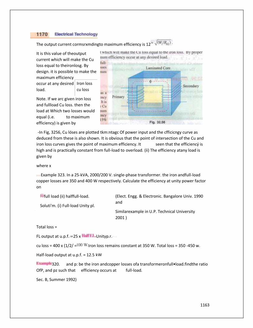
1163
The output current cormsrxmdingto maximum efficiency is 12
It is this value of theoutput
current which will make the Cu
loss equal to theironlosg. By
design. it is possible to make the
maximum efficiency
occur at any desired
load.
Note. If we arc given iron loss
and fullload Cu loss. then the
load at Which two losses would
equal (i.e. to maximum
efficiency) is given by
-In Fig, 3256, Cu lóses are plotted tkm:ntagc Of power input and the cfficicngy curve as
deduced from these is also shown. It is obvious that the point of intersection of the Cu and
iron loss curves gives the point of maximum efficiency. It seen that the efficiencý is
high and is practically constant from full-load to overload. (íi) The efficiency atany load is
given by
where x
Example 323. In a 25-kVA, 2000/200 V. single-phase transformer. the iron andfull-load
copper losses are 350 and 400 W respectively. Calculate the efficiency at unity power factor
on
full load (ii) halffull-load.
Soluti'm. (i) Full-load Unity pl.
(Elect. Engg. & Electronic. Bangalore Univ. 1990
and
Similarexample in U.P. Technical University
2001 )
Total loss =
FL output at u.p.f. 25 x Unityp.r.
cu loss = 400 x (1/2/ = Iron loss remains constant at 350 W. Total loss = 350 -450 w.
Half-load output at u.p.f. = 12.5
320. and p: be the iron andcopper losses ofa transformeronfull•load.findthe ratio
OfP, and pz such that efficiency occurs at full-load.
Sec. B, Summer 1992)
Iron loss
cu loss
kW
1164
Solution. If P: is theCu loss atfull-load, its valueat 75% offull.load is—p: At maximum
efficiency, it equals the ironloss pa which remains constantthroughout. Hence, at maximum
p, 9P2/16 or P/Pz-9/t6.
32.61. A 11000/230 V, 150-kVA. I-phase, transformer has core loss Of1.4 kW
and EL Cu loss OfI kW Determine
(i) rhe WA loadfor max efficiency and value Of efficiency at unity p.f
(io rhe efficiency at halfEL 0.8p.f. leading (Basic Elect-Machine,NagpurUniv.
1993)
Solution. (i) Load WA correspondingto maximumefficiency is
Since Cu loss equals iron loss at maximum efficiency, totul loss output
= 160 x I = 160 kW
= 160/162.8 -0.982 or 9K2%
(ii) Cu lossat half full-load = 1.6k (1/2)2 = 0.4 kW Total loss= 1.44 0.4 = 1.8 kW
HalfEL. output at 0.8 p.f.= ( 150/2) FAIiciency =
Example 32.62. A 5-kVA. 2,30QQ30-u 50•Hz transformer was testedfor the iron losses 'With
normal excitation and Cu losses atfull-loud and these werefound to be 40 W and 112 W
'espectively.
Calculate the efficiencies Of the transformer at 0.8 powerfactorfor thefollowing WA outputs :
1.25 2.5 3.75 so 6.25 7.5

1165
The curve is shown in Fig. 32.57.
Example 32.63. 2ffl-kVA transformer has an efficiency Of ar full load. the mat. efficiency
Occurs ar three quarters offull-load. calculate the efficiency at half Assume negligible
magnetizing current and p.f. O,8 at all loads. (Elect. Punjab UniV. Jan. 1991)
Solution. As given. the transformerhas a EL efficiency of98 % pr.
El..output = 200x0.8= 160kW ; EL. input- 163.265 kW
F.L.tosses = 163.265- 160=3.265kW ELoutput = 25XO.8=20kW- 20,OOOW
Full-load = 20,000 x 100/(20.000 464.4)= 9-7.' %
Example 32.6*. A 4-kVA. V, I-phase transfonnerhasequivalent n•sistance and œacrance
referred ro low-voltage side equal to O, 512 1.5 Q respectively Find the terminal voltage On
1166
the high-voltage side When supplies 3/41/1full-load a/ powerfactor OfO.8, the supply voltage
being 220 Hence, find the output transformer and its efficiency ifthe corelosses are 100 W.
(Electrical Engineering : Bombay Univ. 1985'
Solution. Obviously, primary is the side and the secondary. the high voltage
side.
Here, ROI Q and = I S These can be transferred to the secondary side with the help Of the
transformation ratio.
Secondary current when load is 3/4 the, full-load is ( X4X 3/4)/400 7SA
Total drop as referred to transformer secondary is
Terminal voltageon high-voltage side under givenloadconditionis = 400-39=361 v culoss =
Iron loss 100 W
= 212SW output = (4 x 3/4) x 0.8 = 2.4 kW
Input = 2.400+212.5-2,612.5 w n-2.400x 100/2,612.5 = 91.87
Example 32.66. A 20•kVA, 440/220 V, 50 Hz transformer has iron loss W. The Cu isfound
be When delivering halffull-load curt-em. Determine efficiency when
Assumingalagging factor
deliveringfull-load current at 0.8 lagging and /ii) the percent offull-load When the efficiency
Will be marimum. (Electrutechnique•ll, MS. Univ., Baroda
Hence. efficiency would be maximum at90 % ofEL
Example 32.67. Consider a 4-kVA. 200/400 V Mingle-phase transformer supplying full-load
current at 0.8 lagging powerfactor. The QC-IS. C. test results are as follows :
O.C.test : 200 V, O.SA. 70B' (I.V. side)
S.C. test 20M 10 A 60 V: Side'
Calculate efficiency, secondary voltage and current into primary at the above load.
Calculate the load at unity powerfactor corresponding to marimum efficiency iEleci.
Machines Nagpur Univ. 1993È
Solution. Full-toad. 10 A
It means that S.C. test has been carried out with full Secondary flowing, Hence, 60 W
represents full-load Cu loss of the transformer.
EL. losses -60 +

1167
EL. n -3.2/3.33=0.960r96 %
Example 32.68. A 600 WA. I-phase transformer has an efficiency of92 % both atfu[l-loadand
half-load at unity powerfactor. Determine its efficiency at 60 % offull-load at O.S powerfactor
lag.
Sec. B,
x ICO
2
(x x WA) x cos + W, + .rWcu where x represents percentage Of full-load W, is iron loss and
Wcu is full-load Cu loss,
At EL u.p.r. Here x =
W/+ -52.174kW
Atha1fFL UPE Her-ex=
*100;
= 85.9%
has an efficiency Of92 % atfull-load and also at half-load. Determine its efficiency When it
operates at p.j: and 60 Of load. (Electric. Machines. Kerala Univ. 1987)
Solulion. The fact that efficiency is the same 92 % atbotb full-load and half-load Will help us
to find the iron and copper losses.
At full-load
Output -600 kW ;
SinevCu loss becoloes one-fourthof its EL. value, hence y/4 - 26. l Solving for-rand y. we
get 17.4
At 60 full-load cu 0.62 x34.s= 1253 kW ; Total loss- 17.4+ 12.53-29.93 kW
=360kW •02360/389.93=0.965
Example 32.70. The maximum efficiency Ofa /OO-kVA, Single phase transformer is and occurs
at offull load at 8 If rhe leakage impedance of transformer is find the voltage regulation al
rated load Of O. 8 power factor lagging.
Elect. Machines-I, Nagpur Univ.
Solution. Since maximum efficiency occurs at 80 percent Of full-load at 0.8 p.f..
1168
64/0.98=65.3 kW
Culossat full-load = 0.65/0.82 = I kW
Cu loss 1 00
x 100-lx
IOO
% age regn, = + 5 0.6)
Example 32.71. A 10WA, 5(YW440- single phase transformerhas eddyCurrent and hysteresis
losses of I 0.5 and 0.6 per cent ofoutput onfull What "'ill be rhe percentage losses if the
transformer is used on 50-11: system keeping the full-load current consJont ?
Assume unity powerfactor operation. Compare thefull load efficienciesfor rhe nvo cases.
Machines, B, 1991
Solution. We know that El = 4.44 f When both excitation voltage and frequency are doubled,
flux remains unchanged.
FL. output at upf 10kVA x I 10kW
FL Cu loss 1.5 x 10/100 = 0.1SkW : Eddy current loss
0.5 x = 0.05 kW : Hysteresis loss = 0.6 x
Now, full-load current is kept constant but voltage is increased from 5000 V to 10.000 V.
Hence, output will be doubled to 20 kW. Dueto constant current, Cu loss would also remain
constant.
New = 0.15 kW, % cu loss
Now, eddy curœntloss
New eddy current loss -0.05 IOO- 1 %
Now, = 0.06x (50/25) - 0.12 kW, %
at 0.8 p.f. a/ normal voltage
Solution.
Example 32.73. A single phake transformer is rated at IOO•kVA, 2300/230-V. 50 HZ.
The maximumflux density in the core is l. 2 Wb/m2 and the net cross-sectional areo Ofthe
core is O. 04"12.
Determine
1169
(a) The number ofprimary and Secondary turns needed.
(b) [f the mean length Of the magnetic circuit is 2.5 m and the*elative permeability is
1200, determine the magnetising current. Neglect theßurrent drawn for the core loss.
(c) On short-circuit with full-load current flowing, the power input is 1200 W and an
opencircuit With rated voltage, the power input was 400 W. Determine the efficiency of
the transformer at 75 % offull-load With 0.8 p.f lag.
(d) Ifthe same transformer is connected to a supply thefrequency
(i.e.. 100 Whar is effect on ifs efficiency ? (Elect. Engg„ Bombay U"is. 19tB)
—9.21 A
Output— 100 x (3/4)
(d) When frequency is doubled. iron loss isincœased because
(i) hysteresis loss is doubled—
(ii) eddy current loss is quadrupled — We Hence. efficiency will decrease
what is rhe power-factor ar Which rhe regulation will•v' : '(i/ Zero; (ii) positive-maximum ? (b
Ifits maximum efficiency occurs atfull-load (at unity p.f, what Will be efficiency under these
conditions ?
Solution : Approximate perceptage regulation is given, in thi' case, by the relationship
I 5.4 sin O.
la) Regulation :
(i' If regulation is zero. negative sign must be applicable. This happens at leadings p.f.
Corresponding pf. = leading
= 18.44" leading
For maximum positive regulation, lagging p.f_ is a must. From phasordiagram, the
can be obtained.
Corresponding tan 5.4/1.8
% Voltage regulation = 1.8cos4+5.4sin 0=5.7 % (b) Efficiency : Maximum efficiency occurs at
such a Iron losses =

1170
AUTO TRANSFORMER
An autotransformer is a kind of electrical transformer where primary and secondary
shares same common single winding. So basically it’s a one winding transformer.
Autotransformer Theory
In an auto transformer, one single winding is used as primary winding as well as
secondary winding. But in two windings transformer two different windings are used
for primary and secondary purpose. A circuit diagram of auto transformer is shown
below.
The winding AB of total turns N1 is considered as primary winding. This winding is
tapped from point ′C′ and the portion BC is considered as secondary. Let’s assume
the number of turns in between points ′B′ and ′C′ is N2.
If V1 voltage is applied across the winding i.e. in between ′A′ and ′C′.
Hence, the voltage across the portion BC of the winding, will be,
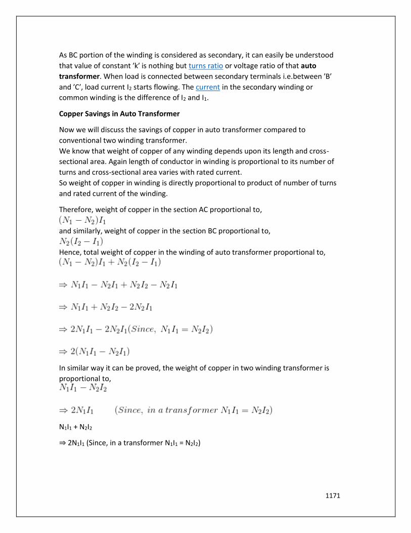
1171
As BC portion of the winding is considered as secondary, it can easily be understood
that value of constant ′k′ is nothing but turns ratio or voltage ratio of that auto
transformer. When load is connected between secondary terminals i.e.between ′B′
and ′C′, load current I2 starts flowing. The current in the secondary winding or
common winding is the difference of I2 and I1.
Copper Savings in Auto Transformer
Now we will discuss the savings of copper in auto transformer compared to
conventional two winding transformer.
We know that weight of copper of any winding depends upon its length and cross-
sectional area. Again length of conductor in winding is proportional to its number of
turns and cross-sectional area varies with rated current.
So weight of copper in winding is directly proportional to product of number of turns
and rated current of the winding.
Therefore, weight of copper in the section AC proportional to,
and similarly, weight of copper in the section BC proportional to,
Hence, total weight of copper in the winding of auto transformer proportional to,
In similar way it can be proved, the weight of copper in two winding transformer is
proportional to,
N1I1 + N2I2
⇒ 2N1I1 (Since, in a transformer N1I1 = N2I2)
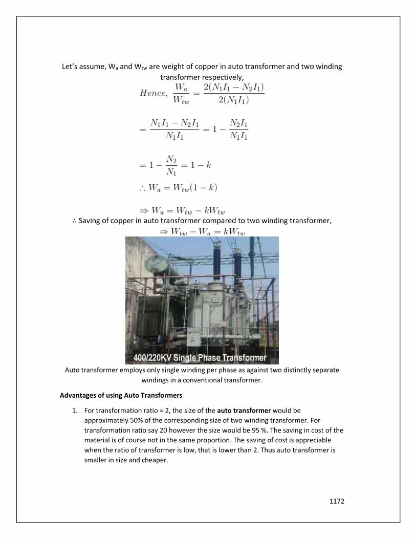
1172
Let’s assume, Wa and Wtw are weight of copper in auto transformer and two winding
transformer respectively,
∴ Saving of copper in auto transformer compared to two winding transformer,
Auto transformer employs only single winding per phase as against two distinctly separate
windings in a conventional transformer.
Advantages of using Auto Transformers
1. For transformation ratio = 2, the size of the auto transformer would be
approximately 50% of the corresponding size of two winding transformer. For
transformation ratio say 20 however the size would be 95 %. The saving in cost of the
material is of course not in the same proportion. The saving of cost is appreciable
when the ratio of transformer is low, that is lower than 2. Thus auto transformer is
smaller in size and cheaper.

1173
2. An auto transformer has higher efficiency than two winding transformer. This is
because of less ohmic loss and core loss due to reduction of transformer material.
3. Auto transformer has better voltage regulation as voltage drop in resistance and
reactance of the single winding is less.
Disadvantages of Using Auto Transformer
1. Because of electrical conductivity of the primary and secondary windings the lower
voltage circuit is liable to be impressed upon by higher voltage. To avoid breakdown
in the lower voltage circuit, it becomes necessary to design the low voltage circuit to
withstand higher voltage.
2. The leakage flux between the primary and secondary windings is small and hence the
impedance is low. This results into severer short circuit currents under fault
conditions.
3. The connections on primary and secondary sides have necessarily needs to be same,
except when using interconnected starring connections. This introduces
complications due to changing primary and secondary phase angle particularly in the
case of delta/delta connection.
4. Because of common neutral in a star/star connected auto transformer it is not
possible to earth neutral of one side only. Both their sides should have their
neutrality either earth or isolated.
5. It is more difficult to maintain the electromagnetic balance of the winding when
voltage adjustment tappings are provided. It should be known that the provision of
tapping on an auto transformer increases considerably the frame size of
the transformer. If the range of tapping is very large, the advantages gained in initial
cost is lost to a great event.
Applications of Auto Transformers
1. Compensating voltage drops by boosting supply voltage in distribution systems.
2. Auto transformers with a number of tapping are used for starting induction and
synchronous motors.
3. Auto transformer is used as variac in laboratory or where continuous variable over
broad ranges are required.

1174
INSTRUMENT TRANSFORMER
Instrument Transformers are used in AC system for measurement of electrical quantities i.e.
voltage, current, power, energy, power factor, frequency. Instrument transformers are also
used with protective relays for protection of power system.
Basic function of Instrument transformers is to step down the AC System voltage and
current. The voltage and current level of power system is very high. It is very difficult and
costly to design the measuring instruments for measurement of such high level voltage and
current. Generally measuring instruments are designed for 5 A and 110 V.
The measurement of such very large electrical quantities, can be made possible by using the
Instrument transformers with these small rating measuring instruments. Therefore these
instrument transformers are very popular in modern power system.
Advantages of Instrument Transformers
1. The large voltage and current of AC Power system can be measured by using
small rating measuring instrument i.e. 5 A, 110 – 120 V.
2. By using the instrument transformers, measuring instruments can be
standardized. Which results in reduction of cost of measuring instruments.
More ever the damaged measuring instruments can be replaced easy with
healthy standardized measuring instruments.
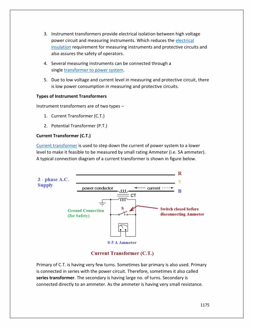
1175
3. Instrument transformers provide electrical isolation between high voltage
power circuit and measuring instruments. Which reduces the electrical
insulation requirement for measuring instruments and protective circuits and
also assures the safety of operators.
4. Several measuring instruments can be connected through a
single transformer to power system.
5. Due to low voltage and current level in measuring and protective circuit, there
is low power consumption in measuring and protective circuits.
Types of Instrument Transformers
Instrument transformers are of two types –
1. Current Transformer (C.T.)
2. Potential Transformer (P.T.)
Current Transformer (C.T.)
Current transformer is used to step down the current of power system to a lower
level to make it feasible to be measured by small rating Ammeter (i.e. 5A ammeter).
A typical connection diagram of a current transformer is shown in figure below.
Primary of C.T. is having very few turns. Sometimes bar primary is also used. Primary
is connected in series with the power circuit. Therefore, sometimes it also called
series transformer. The secondary is having large no. of turns. Secondary is
connected directly to an ammeter. As the ammeter is having very small resistance.
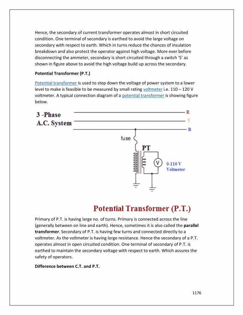
1176
Hence, the secondary of current transformer operates almost in short circuited
condition. One terminal of secondary is earthed to avoid the large voltage on
secondary with respect to earth. Which in turns reduce the chances of insulation
breakdown and also protect the operator against high voltage. More ever before
disconnecting the ammeter, secondary is short circuited through a switch ‘S’ as
shown in figure above to avoid the high voltage build up across the secondary.
Potential Transformer (P.T.)
Potential transformer is used to step down the voltage of power system to a lower
level to make is feasible to be measured by small rating voltmeter i.e. 110 – 120 V
voltmeter. A typical connection diagram of a potential transformer is showing figure
below.
Primary of P.T. is having large no. of turns. Primary is connected across the line
(generally between on line and earth). Hence, sometimes it is also called the parallel
transformer. Secondary of P.T. is having few turns and connected directly to a
voltmeter. As the voltmeter is having large resistance. Hence the secondary of a P.T.
operates almost in open circuited condition. One terminal of secondary of P.T. is
earthed to maintain the secondary voltage with respect to earth. Which assures the
safety of operators.
Difference between C.T. and P.T.
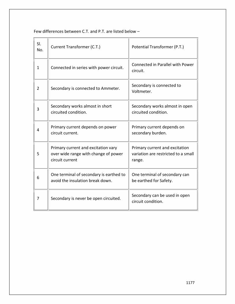
1177
Few differences between C.T. and P.T. are listed below –
Sl.
No. Current Transformer (C.T.) Potential Transformer (P.T.)
1 Connected in series with power circuit. Connected in Parallel with Power
circuit.
2 Secondary is connected to Ammeter. Secondary is connected to
Voltmeter.
3 Secondary works almost in short
circuited condition.
Secondary works almost in open
circuited condition.
4 Primary current depends on power
circuit current.
Primary current depends on
secondary burden.
5
Primary current and excitation vary
over wide range with change of power
circuit current
Primary current and excitation
variation are restricted to a small
range.
6 One terminal of secondary is earthed to
avoid the insulation break down.
One terminal of secondary can
be earthed for Safety.
7 Secondary is never be open circuited. Secondary can be used in open
circuit condition.
Top Related
Copyright © 2022 FDOKUMEN

