


Bahasa
Halaman
Hukum

zEnterprise System
Support Element Operations GuideVersion 2.11.1SC28-6906-01
���


zEnterprise System
Support Element Operations GuideVersion 2.11.1SC28-6906-01
���

Note:Before using this information and the product it supports, read the information in “Safety” onpage xi, Appendix C, “Notices,” on page 243, and IBM Systems Environmental Notices and UserGuide, Z125–5823.
This edition, SC28-6906-01, applies to the IBM Support Element Console Application, Version 2.11.1. This editionreplaces SC28-6906-00.
There might be a newer version of this document in a PDF file available on Resource Link. Go tohttp://www.ibm.com/servers/resourcelink and click Library on the navigation bar. A newer version is indicated bya lowercase, alphabetic letter following the form number suffix (for example: 00a, 00b, 01a, 01b).
© Copyright IBM Corporation 2011.US Government Users Restricted Rights – Use, duplication or disclosure restricted by GSA ADP Schedule Contractwith IBM Corp.
||
Contents
Figures . . . . . . . . . . . . . . vii
Tables . . . . . . . . . . . . . . . ix
Safety . . . . . . . . . . . . . . . xiSafety notices . . . . . . . . . . . . . . xi
World trade safety information . . . . . . . xiLaser safety information . . . . . . . . . . xi
Laser compliance . . . . . . . . . . . xi
About this publication . . . . . . . . xiiiHow to use view guide . . . . . . . . . . xiii
What's new in version 2.11.1 . . . . . . . xivAccessibility . . . . . . . . . . . . . . xivHow to send your comments . . . . . . . . xv
Chapter 1. Introduction . . . . . . . . 1The Support Element Console Application . . . . 1
Establishing a Support Element console sessionfrom a Hardware Management Console . . . . 3Logging off the Support Element Console . . . 3
User Interface (UI) styles for the Support Elementconsole . . . . . . . . . . . . . . . . 4
Tree style user interface. . . . . . . . . . 4Classic style user interface . . . . . . . . . 4Enabling users to change interface style . . . . 5Changing interface style . . . . . . . . . 5
Context sensitive help . . . . . . . . . . . 5Disruptive tasks . . . . . . . . . . . . . 7USB flash memory drive . . . . . . . . . . 7
Chapter 2. Using the tree style userinterface . . . . . . . . . . . . . . 9Task bar . . . . . . . . . . . . . . . 10Navigation pane . . . . . . . . . . . . . 11
Navigation toolbar . . . . . . . . . . . 11Navigation pane collapse and expand controls. . 11Welcome . . . . . . . . . . . . . . 11System Management . . . . . . . . . . 12Opening task for the System. . . . . . . . 16SE Management . . . . . . . . . . . . 22Service Management . . . . . . . . . . 23Tasks Index . . . . . . . . . . . . . 24
Work pane. . . . . . . . . . . . . . . 25Work pane table . . . . . . . . . . . . 26Work pane title and breadcrumb trail . . . . . 29Work pane table footer . . . . . . . . . 29Work pane table toolbar . . . . . . . . . 29Tasks menu . . . . . . . . . . . . . 31Views menu . . . . . . . . . . . . . 31Topology . . . . . . . . . . . . . . 31
Status bar . . . . . . . . . . . . . . . 34Exceptions. . . . . . . . . . . . . . 34Hardware Messages . . . . . . . . . . 34
Operating System Messages . . . . . . . . 34Status overview . . . . . . . . . . . . 35
Object locking for disruptive tasks. . . . . . . 35
Chapter 3. Using the classic style userinterface . . . . . . . . . . . . . . 37Support Element Workplace . . . . . . . . . 37
Selecting objects . . . . . . . . . . . . 38Opening an object . . . . . . . . . . . 39Starting a task on an object . . . . . . . . 41Object locking for disruptive tasks. . . . . . 41
Monitoring system status . . . . . . . . . . 42Acceptable status . . . . . . . . . . . 42Unacceptable status. . . . . . . . . . . 43
Views and the work area . . . . . . . . . . 44Getting detailed system status . . . . . . . 45Groups . . . . . . . . . . . . . . . 45Determining the exact status of an object . . . 53Exceptions. . . . . . . . . . . . . . 55Active tasks . . . . . . . . . . . . . 56Console actions . . . . . . . . . . . . 58Task lists . . . . . . . . . . . . . . 59Books . . . . . . . . . . . . . . . 64Help. . . . . . . . . . . . . . . . 64
Chapter 4. Daily . . . . . . . . . . . 67Activation . . . . . . . . . . . . . . . 67
Activation profiles . . . . . . . . . . . 68Preparing for an activation . . . . . . . . 68Preparing an IOCDS . . . . . . . . . . 69Preparing to load images . . . . . . . . . 69Activate the CPC . . . . . . . . . . . 69Activate an object . . . . . . . . . . . 70
Deactivate the CPC . . . . . . . . . . . . 71Deactivate an object . . . . . . . . . . . 71Grouping . . . . . . . . . . . . . . . 72Reset normal . . . . . . . . . . . . . . 74
Chapter 5. CPC Recovery. . . . . . . 77Load . . . . . . . . . . . . . . . . 77Load from Removable Media or Server . . . . . 78Power-on reset . . . . . . . . . . . . . 79Resets: normal and clear . . . . . . . . . . 80
Reset clear. . . . . . . . . . . . . . 80Reset normal . . . . . . . . . . . . . 80
Processor operations: start all and stop all . . . . 81Start all . . . . . . . . . . . . . . . 81Stop all . . . . . . . . . . . . . . . 82
Chapter 6. CPC OperationalCustomization . . . . . . . . . . . 83Automatic activation . . . . . . . . . . . 83Change LPAR Controls . . . . . . . . . . 83Change LPAR Cryptographic Controls . . . . . 85
© Copyright IBM Corp. 2011 iii

Change LPAR Group Controls . . . . . . . . 86Change LPAR I/O Priority Queuing . . . . . . 86Change LPAR Security . . . . . . . . . . 87Customize/Delete activation profiles . . . . . . 89Customize Scheduled Operations . . . . . . . 89Enable I/O Priority Queuing . . . . . . . . 91Export/Import Profile Data . . . . . . . . . 91Logical Processor Add . . . . . . . . . . . 92Manage zBX LEDs . . . . . . . . . . . . 93Storage information . . . . . . . . . . . 93
Degraded storage mode . . . . . . . . . 94View LPAR cryptographic controls . . . . . . 95
Chapter 7. CPC Remote Customization 97Customer Information . . . . . . . . . . . 97Connecting and communicating with a remoteservice support system . . . . . . . . . . 98
Getting ready to report problems and get service 98Getting ready to retrieve internal code changes 99Getting ready to transmit service data . . . . 99Remote service . . . . . . . . . . . . 100
Chapter 8. Service . . . . . . . . . 101Checkout tests . . . . . . . . . . . . . 101Delete LPAR dump data. . . . . . . . . . 102Dump LPAR data . . . . . . . . . . . . 102Dump machine loader data. . . . . . . . . 103Global OSA status . . . . . . . . . . . . 104Redundant I/O (RIO) Interconnect Status andControl . . . . . . . . . . . . . . . 105Offload virtual RETAIN data to HMC RemovableMedia . . . . . . . . . . . . . . . . 105Reporting problems and getting service . . . . 106
Settings for reporting problems and gettingservice automatically . . . . . . . . . . 106Using hardware messages to report problemsand get service . . . . . . . . . . . . 106Perform problem analysis . . . . . . . . 107
Power Cycle zBX Hardware . . . . . . . . 107Network Traffic Analyzer Authorization . . . . 108Restore DataPower XI50z . . . . . . . . . 109Report a problem . . . . . . . . . . . . 109Service status . . . . . . . . . . . . . 110Transmit service data . . . . . . . . . . . 110View PMV Records . . . . . . . . . . . 111View service history . . . . . . . . . . . 112
Chapter 9. CPC Configuration . . . . 115Channel to PCHID assignment . . . . . . . 115Cryptographic Configuration . . . . . . . . 116
View cryptographic details . . . . . . . . 116Test RN generator . . . . . . . . . . . 117Zeroize CEX3C manually . . . . . . . . 117Usage domain zeroize . . . . . . . . . 118TKE commands . . . . . . . . . . . 118Crypto type configuration . . . . . . . . 119UDX configuration . . . . . . . . . . 119
Cryptographic management . . . . . . . . 120Customize Network Settings . . . . . . . . 121Display Adapter ID . . . . . . . . . . . 121
Manage DataPower XI50z . . . . . . . . . 121Manage ISAOPT Cluster Size . . . . . . . . 122Manage zBX Hardware . . . . . . . . . . 122FCP Configuration . . . . . . . . . . . 123Input/output (I/O) configuration . . . . . . 123Perform model conversion . . . . . . . . . 125
Hardware upgrades . . . . . . . . . . 125zBX Entitlement . . . . . . . . . . . 126Permanent upgrades . . . . . . . . . . 126Temporary upgrades . . . . . . . . . . 127
System input/output configuration analyzer . . . 127System (Sysplex) Time . . . . . . . . . . 128View hardware configuration . . . . . . . . 128
Chapter 10. Change Management . . . 131Licensed internal code . . . . . . . . . . 131
Internal code changes . . . . . . . . . 131Changing internal code and automating theprocess . . . . . . . . . . . . . . . 132
Activating internal code changes for the CPC 133Activating internal code changes for the SupportElement . . . . . . . . . . . . . . 133Activating internal code changes for channels 134
Alternate Support Element . . . . . . . . . 134Switch the primary element and the alternateSupport Element . . . . . . . . . . . 135Mirror the primary Support Element data to thealternate Support Element . . . . . . . . 135Query switch capabilities . . . . . . . . 136
Internal code change management . . . . . . 137Authorize internal code changes . . . . . . 137
Check dependencies . . . . . . . . . . . 138Define clonable internal code levels . . . . . . 139Force channel internal code changes . . . . . . 140Manage zBX Internal Code . . . . . . . . . 140Query channel/crypto configure off/on pending 141Query coupling facility reactivations. . . . . . 142Query internal code changes pending power-onreset . . . . . . . . . . . . . . . . 142Specify concurrent upgrade sync point . . . . . 142Selective channel patch control . . . . . . . 143System information . . . . . . . . . . . 143
Chapter 11. CP Toolbox . . . . . . . 145Display or alter data . . . . . . . . . . . 145Interrupt . . . . . . . . . . . . . . . 146PSW restart . . . . . . . . . . . . . . 146Processor operations: start and stop . . . . . . 147
Start processors. . . . . . . . . . . . 147Stop processors. . . . . . . . . . . . 147
Stop on CP address match . . . . . . . . . 148Store status . . . . . . . . . . . . . . 148
Chapter 12. CHPID/Channel/Cryptooperations. . . . . . . . . . . . . 151Advanced Facilities . . . . . . . . . . . 151Channel problem determination . . . . . . . 151
Analyze channel information . . . . . . . 152Configure On/Off . . . . . . . . . . . . 153FCP NPIV Mode On/Off . . . . . . . . . 154
iv Support Element Operations Guide
Reassigning channel paths . . . . . . . . . 154Releasing channel paths . . . . . . . . . . 155Service on/off . . . . . . . . . . . . . 156Show LED . . . . . . . . . . . . . . 157
Chapter 13. Energy Management . . . 159Set zBX Power Policy. . . . . . . . . . . 159Set Power Cap . . . . . . . . . . . . . 159Set Power Saving . . . . . . . . . . . . 160
Chapter 14. Monitor. . . . . . . . . 161Monitors Dashboard . . . . . . . . . . . 161
System Activity. . . . . . . . . . . . 161Customize System Activity . . . . . . . . 165
Environmental Efficiency Statistics . . . . . . 170
Chapter 15. Console Actions . . . . . 171Audit and Log Management . . . . . . . . 171Block Automatic Licensed Internal Code ChangeInstallation . . . . . . . . . . . . . . 171Console Default User Settings . . . . . . . . 172Change Password . . . . . . . . . . . . 173Console Messenger . . . . . . . . . . . 173
Sending a broadcast message . . . . . . . 173Initiating a two-way chat . . . . . . . . 174
Customize API Settings . . . . . . . . . . 175Customize Console Services . . . . . . . . 175Customize Network Settings . . . . . . . . 176Customize Product Engineering Access . . . . . 177Customize Support Element Date/Time . . . . 178Customize User Controls . . . . . . . . . 178Domain Security . . . . . . . . . . . . 179Logoff or Disconnect . . . . . . . . . . . 180Manage Enterprise Directory Server Definitions 180Manage Print Screen Files . . . . . . . . . 181Manage SSH keys . . . . . . . . . . . . 182Migrate Channel Configuration Files . . . . . 182Network Diagnostic Information . . . . . . . 182
Object Locking Settings . . . . . . . . . . 183Password Profiles . . . . . . . . . . . . 184Support Element Settings . . . . . . . . . 184Shutdown or Restart . . . . . . . . . . . 185User Patterns . . . . . . . . . . . . . 185User Profiles . . . . . . . . . . . . . 186User Templates . . . . . . . . . . . . . 187Users and Tasks . . . . . . . . . . . . 188User Settings . . . . . . . . . . . . . 189
Tree style user interface . . . . . . . . . 189Classic style user interface . . . . . . . . 190
View Console Events . . . . . . . . . . . 191View Licenses . . . . . . . . . . . . . 193View Security Logs . . . . . . . . . . . 193
Appendix A. Customizing activationprofiles . . . . . . . . . . . . . . 195Activation profiles. . . . . . . . . . . . 195
Profiles for complete activation . . . . . . 197Staged activation . . . . . . . . . . . 197Profiles for a complete activation . . . . . . 197Profiles for staged activations . . . . . . . 225
Appendix B. Using the System(Sysplex) Time task. . . . . . . . . 235Timing network . . . . . . . . . . . . 236Network configuration . . . . . . . . . . 237STP configuration . . . . . . . . . . . . 237STP status . . . . . . . . . . . . . . 237ETS configuration . . . . . . . . . . . . 238PPS control . . . . . . . . . . . . . . 240
Appendix C. Notices . . . . . . . . 243Trademarks . . . . . . . . . . . . . . 244Electronic emission notices . . . . . . . . . 244
Index . . . . . . . . . . . . . . . 249
Contents v

vi Support Element Operations Guide
Figures
1. Support Element console welcome window 22. Support Element console logon window . . . 23. Context sensitive help not enabled . . . . . 64. Context sensitive help enabled . . . . . . 65. Disruptive task confirmation window . . . . 76. Select media device window . . . . . . . 87. Tree style user interface Support Element
console workplace window . . . . . . . 108. Task bar. . . . . . . . . . . . . . 109. Systems Management object window . . . . 13
10. Tasks pad . . . . . . . . . . . . . 1711. Vertical tasks pad . . . . . . . . . . 1812. Context menu. . . . . . . . . . . . 1913. Drop-down menu . . . . . . . . . . 2014. CPC details window . . . . . . . . . 2115. Channels details window . . . . . . . . 2116. Tasks using an alphabetical sort with icon style 2317. Tasks using a categorized sort with tile style 2418. Tasks index . . . . . . . . . . . . 2519. Work pane table features . . . . . . . . 2620. Systems management work pane table . . . 2721. Custom table view . . . . . . . . . . 2822. The system views menu . . . . . . . . 3123. Topology view features . . . . . . . . 3224. Status overview . . . . . . . . . . . 3525. Classic interface workplace window . . . . 3826. Work area menu . . . . . . . . . . . 3927. CPC details window . . . . . . . . . 4028. Channel details window . . . . . . . . 40
29. Acceptable status . . . . . . . . . . 4330. Unacceptable status . . . . . . . . . . 4431. Logical partitions . . . . . . . . . . 4632. Logical processors . . . . . . . . . . 4733. Cannels . . . . . . . . . . . . . . 4834. Channel paths . . . . . . . . . . . 4935. Cryptos . . . . . . . . . . . . . . 5036. zBx BladeCenters . . . . . . . . . . 5137. zBX Blades . . . . . . . . . . . . . 5238. Virtual servers . . . . . . . . . . . 5339. Console actions work area . . . . . . . 5940. Task list work area . . . . . . . . . . 6041. Activation profiles . . . . . . . . . . 6842. Creating a group . . . . . . . . . . . 7343. Perform model conversion . . . . . . . 12544. Activation profiles . . . . . . . . . . 19545. CPC change options window . . . . . . 19846. Reset profiles . . . . . . . . . . . 19947. Image profile configuration . . . . . . . 20148. Fenced book page . . . . . . . . . . 20649. New image profile wizard . . . . . . . 22850. Customize multiple image profile wizard 22951. System (Sysplex) Time window . . . . . 23652. STP status page . . . . . . . . . . . 23853. ETS configuration page using the NTP option 23954. ETS configuration page using NTP with PPS
option . . . . . . . . . . . . . . 24055. PPS control page . . . . . . . . . . 241
© Copyright IBM Corp. 2011 vii

viii Support Element Operations Guide

Tables
1. Sample system activity profiles . . . . . 166
© Copyright IBM Corp. 2011 ix

x Support Element Operations Guide
Safety
Safety noticesSafety notices may be printed throughout this guide. DANGER notices warn you of conditions orprocedures that can result in death or severe personal injury. CAUTION notices warn you of conditionsor procedures that can cause personal injury that is neither lethal nor extremely hazardous. Attentionnotices warn you of conditions or procedures that can cause damage to machines, equipment, orprograms.
World trade safety informationSeveral countries require the safety information contained in product publications to be presented in theirnational languages. If this requirement applies to your country, a safety information booklet is includedin the publications package shipped with the product. The booklet contains the safety information inyour national language with references to the US English source. Before using a US English publication toinstall, operate, or service this IBM® product, you must first become familiar with the related safetyinformation in the booklet. You should also refer to the booklet any time you do not clearly understandany safety information in the US English publications.
Laser safety informationAll System z® models can use I/O cards such as PCI adapters, ESCON®, FICON®, Open Systems Adapter(OSA), InterSystem Coupling-3 (ISC-3), or other I/O features which are fiber optic based and utilizelasers or LEDs.
Laser complianceAll lasers are certified in the U.S. to conform to the requirements of DHHS 21 CFR Subchapter J for class1 laser products. Outside the U.S., they are certified to be in compliance with IEC 60825 as a class 1 laserproduct. Consult the label on each part for laser certification numbers and approval information.
CAUTION: Data processing environments can contain equipment transmitting on system links withlaser modules that operate at greater than Class 1 power levels. For this reason, never look into theend of an optical fiber cable or open receptacle. (C027)
CAUTION:This product contains a Class 1M laser. Do not view directly with optical instruments.(C028)
© Copyright IBM Corp. 2011 xi

xii Support Element Operations Guide
About this publication
This operations guide is for anyone who is responsible for monitoring and operating the IBMzEnterprise™ System.
This operations guide provides information and instructions for users who use a support element whilelogged on in the following default user IDs and roles:
Access Administrator - ACSADMINAdvanced Operator - ADVANCEDOperator - OPERATORService Representative - SERVICESystem Programmer - SYSPROG
Notes:
v There are representations of the Hardware Management Console and Support Element windowsdisplayed throughout this manual. They may or may not represent the exact windows that aredisplayed for your user ID or version.
v Many of the same tasks and controls that are available in the user modes listed above are available alsoin the service representative user mode. This operations guide does not provide information orinstructions for using tasks and controls available exclusively in the service representative user mode.Service representatives should refer instead to the service documentation provided with the system.
Support element users should be familiar with using:v CD-ROMv Communication devicesv Direct access storage devices (DASD)v DVD-RAMv Graphical user interfacesv Printersv USB flash memory drive (formerly referred to as the memory key)v Workstations
Note: If you are using a USB flash memory drive, plug it into the console and then wait for the consoleto beep three times. This indicates that the device is ready and can be accessed. If it does not beep threetimes, unplug the device and try again.
For information and instructions for operating devices other than the support element, refer to thedocumentation provided with the devices.
How to use view guideIf you are accessing the support element console remotely through the hardware management consoleusing single object operations, this guide is available in portable document format (PDF) to view or printas an online document or by accessing Resource Link® (http://www.ibm.com/servers/resourcelink).
When the PDF version of the guide opens, a list of bookmarks displays on the left-hand side. Thesebookmarks display the highest level topics in the order that they appear as chapters in the book. If any ofthese topics have lower level topics, a + is displayed to the left of the higher level topic. To expand thetopic, click once on the + and the next level will be displayed.
© Copyright IBM Corp. 2011 xiii

If you are accessing the support element console locally, this guide is available in HTML format to viewas an online document from the support element console.
When the HTML version of the guide opens, you can scroll forward past the title page where the table ofcontents appears. You can click on any of the titles to view the information you are interested in. Use theForward and Back buttons, located at the top of your window, to move around the document. ClickClose when you are done viewing the document.
To view this guide in its online form using the tree style user interface, see “Welcome” on page 11. If youare using the classic style interface, see “Books” on page 64.
What's new in version 2.11.1This guide reflects the licensed internal code for Support Element Console Application, Version 2.11.1.You can tell if your Support Element console has this version installed by looking at the title bar on theSupport Element Console Workplace window or by pointing your mouse over SE Version in the top ofthe work pane window when using the tree style user interface.
There may be other changes to the licensed internal code that are not described in this guide. Foradditional information, refer to the PDF files available on Resource Link at http://www.ibm.com/servers/resourcelink or the other documents shipped with your processor.
This section summarizes the new and changed features for Version 2.11.1.v New Power Cycle zBX Hardware task for zBX BladeCenter switches. See“Power Cycle zBX Hardware”
on page 107 for more information.v The Manage zBX Blade Internal Code task was renamed to Manage zBX Internal Code to include
zBX BladeCenter switches. See “Manage zBX Internal Code” on page 140.v The Disruptive Task Confirmation includes an option where the user ID might be required to provide
text input on the window before allowing a disruption of a task. The User Profiles task includes anoption to enable required text input for disruptive actions.
v Support was added to allow a secure FTP connection for data transfer on the Hardware ManagementConsole and Support Element. The task changes include:– New Manage SSH Keys task where you can import public keys associated with a host address. See
“Manage SSH keys” on page 182 for more information.– Updated Audit and Log Management operation for the Customize Scheduled Operations task
added the Offload using secure file transfer option where you enable offloading of the audit datato a secure FTP connection.
v A new task, View PMV Records, was added to obtain Problem Management Viewable (PMV) recordsissued to the IBM Service Support System. See “View PMV Records” on page 111 for more information.
v The InfiniBand Multiport Status and Control task was renamed to Redundant I/O (RIO) InterconnectStatus and Control to include both channel types of InfiniBand® and PCIe channel types. See“Redundant I/O (RIO) Interconnect Status and Control” on page 105 for more information.
AccessibilityThis publication is in Adobe Portable Document Format (PDF) and should be compliant with accessibilitystandards. If you experience difficulties using this PDF file you can request a web-based format of thispublication. Go to Resource Link at http://www.ibm.com/servers/resourcelink and click Feedback fromthe navigation bar on the left. In the Comments input area, state your request, the publication title andnumber, choose General comment as the category and click Submit. You can also send an email [email protected] providing the same information.
When you send information to IBM, you grant IBM a nonexclusive right to use or distribute theinformation in any way it believes appropriate without incurring any obligation to you.
xiv Support Element Operations Guide
||
||

How to send your commentsYour feedback is important in helping to provide the most accurate and high-quality information. Sendyour comments by using Resource Link at http://www.ibm.com/servers/resourcelink. Click Feedbackon the navigation bar on the left. You can also send an email to [email protected]. Be sure to includethe name of the book, the form number of the book, the version of the book, if applicable, and thespecific location of the text you are commenting on (for example, a page number, table number, or aheading).
About this publication xv

xvi Support Element Operations Guide

Chapter 1. Introduction
A support element is a dedicated workstation used for monitoring and operating a system. It is attached tothe central processor complex (CPC) of a system. If you have experience using other systems, you mayhave used a processor console, support processor, or a similarly named workstation to monitor andoperate them.
The IBM zEnterprise System is an integrated support element, that is, the support element is located insidethe same frame that the central processor complex (CPC) is located. An alternate support element is alsoprovided to give you the option to switch from your primary support element to your alternate supportelement if hardware problems occur. For more information on the alternate support element, see“Alternate Support Element” on page 134.
The zEnterprise System operates only in logically partitioned mode.
A Hardware Management Console is required for monitoring and operating systems with integrated supportelements.
The Support Element Console ApplicationThe Support Element Console Application version 2.11.0 is a licensed application that provides the tasksyou will use to monitor and operate your system. The application is shipped with each Support Element.
The version number of the Support Element Console Application is displayed in the title bar of theSupport Element Logon window and also the Support Element Workplace window.
The Support Element Console Application starts automatically whenever the Support Element is turnedon or rebooted. Starting the application begins the process of initializing it. A window displays the IBMLogo and copyright information. When the process completes, the logon window is displayed.
The Welcome window includes links for logging on to the Support Element console and to the onlinehelp. It also includes status indicators and message icons. The status indicator reflects the current overallstatus of the CPC and images. The message indicators alert you to any hardware or operating systemmessages. If any of these icons do not display a green check mark, you are alerted that a message waslogged that may require your attention. See Figure 1 on page 2 for an example of the Welcome window.
© Copyright IBM Corp. 2011 1
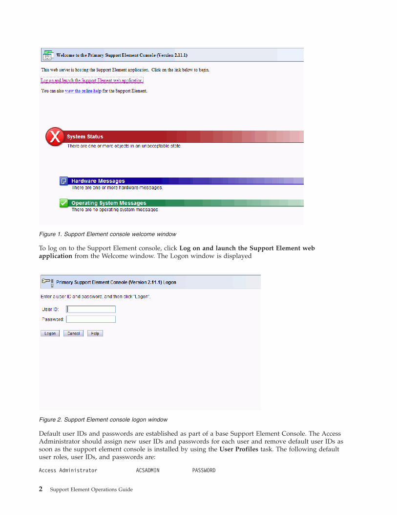
To log on to the Support Element console, click Log on and launch the Support Element webapplication from the Welcome window. The Logon window is displayed
Default user IDs and passwords are established as part of a base Support Element Console. The AccessAdministrator should assign new user IDs and passwords for each user and remove default user IDs assoon as the support element console is installed by using the User Profiles task. The following defaultuser roles, user IDs, and passwords are:
Access Administrator ACSADMIN PASSWORD
Figure 1. Support Element console welcome window
Figure 2. Support Element console logon window
2 Support Element Operations Guide

Advanced Operator ADVANCED PASSWORD
Operator OPERATOR PASSWORD
Service Representative SERVICE SERVMODE
System Programmer SYSPROG PASSWORD
Note: The Support Element workplace is distinguished from the Hardware Management Consoleworkplace most notably by the title of its window and the background pattern of the System zEnterprise.
The Support Element workplace is the window from where you start tasks for monitoring and operatingthe CPC. Your user role determines which tasks and controls you can use on the Support Elementworkplace. Not all tasks are available for each user role. Refer to the description of the specific task youwant to access to see what user role(s) it is available in. Letter case (uppercase, lowercase, mixed) is notsignificant for the default user IDs or passwords.
If at any time you do not know what user ID is currently logged on to the Support Element console, clickon the user ID located on the task bar in the tree style user interface, or open the Users and Tasks task inthe classic style user interface.
Establishing a Support Element console session from a HardwareManagement ConsoleA Hardware Management Console must be used for monitoring and operating systems with integratedSupport Elements.
Ordinarily, you should use the Hardware Management Console to monitor status and perform tasks forthe systems defined to it. Only the Hardware Management Console can be used for monitoring andoperating multiple systems; using it is more efficient than using each system's Support Element consoleindividually.
Using a system's Support Element console is necessary only for getting information or using tasks thatare not available from the Hardware Management Console. If using a system's Support Element console isnecessary, use the Hardware Management Console's Single Object Operations task to establish a sessionwith the Support Element console. Upon establishing a Support Element session, you can refer to thismanual for information and instructions for using the Support Element to monitor and operate thesystem it is attached to.
The Single Object Operations Task Confirmation window displays. Follow the instructions on theConfirmation window to complete this task.
Logging off the Support Element ConsoleOnce you have completed using the Support Element, you may end the current user session and eitherlog off or disconnect from the console using the Logoff or Disconnect task.
Disconnecting preserves your session and allows your tasks to continue running without user accessingto the console. Disconnect sessions exist while the Support Element console application is running. If theSupport Element console is restarted or the console is shut down, all session information is lost.
If you disconnect, you can reconnect at a later time. When you login again, a Choose a DisconnectedSession window is displayed. You can select the disconnected session to continue working or you canbegin a new session. (The number of windows displayed depends on the state of the session when it wasdisconnected. One of the windows is the main user interface; additional windows are for each task thatwas running when the session was disconnected.)
Chapter 1. Introduction 3
Logging off of the Support Element console terminates all running Support Element application tasks andends the session. The log off operation should only be used when you no longer need access to theSupport Element console. Logging off of the console doe not affect the status of the CPC or images.
The Support Element workplace window closes and the Hardware Management Console workplacewindow is displayed.
To log off the Support Element console:1. Open the Logoff or Disconnect task. The Choose to Logoff or Disconnect window is displayed.2. Select Log off.3. Click OK to end your session on the Support Element console.
To disconnect from the Support Element console:1. Open the Logoff or Disconnect task. The Choose to Logoff or Disconnect window is displayed.2. Select Disconnect.3. Click OK to disconnect from your session on the Support Element console with the intent of returning
at a later time.
User Interface (UI) styles for the Support Element consoleThe Support Element console allows you to choose the interface style in which you prefer to work with:v Tree style user interface (default)v Classic type user interface (older interface with object-oriented design).
Tree style user interfaceThe Support Element console tree style user interface is the default for Operator, Advanced Operator,Access Administrator, and System Programmer user roles, but not for the Service Representative userrole. The tree style navigation provides hierarchical views of system resources and tasks using drill-downand launch-in-context techniques to enable direct access to hardware resources and task managementcapabilities. It also utilizes common terminology where possible.
See Chapter 2, “Using the tree style user interface,” on page 9 if you want to use the tree style userinterface for the Support Element console.
Classic style user interfaceThe Support Element console classic style user interface (classic interface) is the original user interface.The Service Representative user role uses this interface as its default interface. It has an object-orienteddesign. Through this design, you can directly manipulate the objects (such as CPC or images) that aredefined to the Support Element console, and be aware of changes to hardware status as they are detected.
You can work with the objects on the workplace using the mouse to select them. There are severaltechniques for manipulating objects and tasks. One way to do this is to left-click an object to select it anddouble-click the task. An alternate method is known as the drag and drop technique, which involves usingthe mouse to pick up one or more objects, dragging them to a task, and then dropping them. Thesetechniques are examples of what is known as direct manipulation.
See Chapter 3, “Using the classic style user interface,” on page 37 if you want to use the classic style userinterface for the Support Element console.
4 Support Element Operations Guide
Enabling users to change interface styleIf the UI Style tab is not displayed when you open the User Settings task, then you are not allowed tochange the interface style on the Support Element console. Your access administrator has the ability toenable users to change interface styles and to change the default interface style of the Support Elementconsole by performing the following steps:1. Log on the Support Element console using the ACSADMIN default user ID or a user ID that has the
predefined Access Administrator roles.2. Open the Console Default User Settings task.
v Using the tree interface: Open the Console Default User Settings task from the SE Management orTask Index work panes.
v Using the classic interface: Open Console Actions under Views, then open Console Default UserSettings task.
3. The Console Default User Settings window is displayed4. Click the UI Style tab.
v To enable users to change the user interface style, select Allow user to change the UI style, thenclick Apply.
v To control the default user interface style for the Support Element console, select Tree Style orClassic Style, then click Apply
5. Click OK when you have finished.
Changing interface styleIf the Support Element console is configured to enable you to change the user interface style, you canchange interface styles by using the User Settings task.
To change from the tree style interface back to the classic interface, perform the following steps:1. Open User Settings (from the SE Management or Task Index work panes or click on the user ID from
the task bar). The User Settings window is displayed.2. Click the UI Style tab. The User Style Information window is displayed.3. Select Classic Style, then click Apply.
The interface style changes to classic.
To change from the classic interface back to the tree interface, perform the following steps:1. Open User Settings (under Console Actions in the classic interface). The User Settings window is
displayed.2. Click the UI Style tab. The User Style Information window is displayed.3. Select Tree Style, then click Apply.4. Click OK.
Context sensitive helpContext sensitive help allows you to view abbreviated help information for input areas or selectable fieldsthat appear on the task window. To enable this function:1. Click on the blue i that appears in the upper right corner of the task window. (see Figure 3 on page 6)
Every time a new task window opens you need to click the blue i to enable context sensitive help.
Chapter 1. Introduction 5

2. Once context sensitive help is enabled, the blue i in the upper right corner of the task windowchanges to an orange ?. As you place your cursor over the input areas or selectable fields, theabbreviated help text appears in a small box within the task window (see Figure 4). Using the Tab keyalso allows you to view the help for each field. As you tab to each field, context sensitive help isdisplayed.
Notes:
v You have the capability to move the help box if it hides some of the information on the task window.As you move your cursor into the help box area the cursor will change from an arrow to a yellowcross arrow. Holding the left mouse button down within the box allows you to drag the box to a moreconvenient area in the task window.
v You can close the help box by clicking on the X in the upper right corner. This will not disable thecontext sensitive help for the task window, it just removes the help box for the item you were gettinghelp on.
v Scroll bars can be used on the bottom and side of the task window for expanding the task window andallowing more area to view the help box.
v You can continue to perform task options while the context sensitive help is enabled.
When you are ready to disable context sensitive help for the task window, click on the ?.
Figure 3. Context sensitive help not enabled
Figure 4. Context sensitive help enabled
6 Support Element Operations Guide
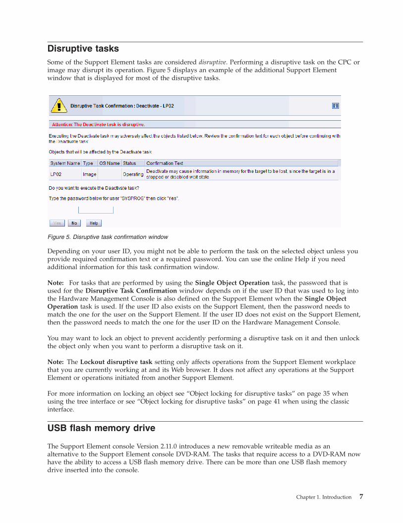
Disruptive tasksSome of the Support Element tasks are considered disruptive. Performing a disruptive task on the CPC orimage may disrupt its operation. Figure 5 displays an example of the additional Support Elementwindow that is displayed for most of the disruptive tasks.
Depending on your user ID, you might not be able to perform the task on the selected object unless youprovide required confirmation text or a required password. You can use the online Help if you needadditional information for this task confirmation window.
Note: For tasks that are performed by using the Single Object Operation task, the password that isused for the Disruptive Task Confirmation window depends on if the user ID that was used to log intothe Hardware Management Console is also defined on the Support Element when the Single ObjectOperation task is used. If the user ID also exists on the Support Element, then the password needs tomatch the one for the user on the Support Element. If the user ID does not exist on the Support Element,then the password needs to match the one for the user ID on the Hardware Management Console.
You may want to lock an object to prevent accidently performing a disruptive task on it and then unlockthe object only when you want to perform a disruptive task on it.
Note: The Lockout disruptive task setting only affects operations from the Support Element workplacethat you are currently working at and its Web browser. It does not affect any operations at the SupportElement or operations initiated from another Support Element.
For more information on locking an object see “Object locking for disruptive tasks” on page 35 whenusing the tree interface or see “Object locking for disruptive tasks” on page 41 when using the classicinterface.
USB flash memory drive
The Support Element console Version 2.11.0 introduces a new removable writeable media as analternative to the Support Element console DVD-RAM. The tasks that require access to a DVD-RAM nowhave the ability to access a USB flash memory drive. There can be more than one USB flash memorydrive inserted into the console.
Figure 5. Disruptive task confirmation window
Chapter 1. Introduction 7

Note: If you are running a task that accesses a USB flash memory drive, you must be aware that therecould be more than one USB flash memory drive in the console. Make sure you are accessing the correctUSB flash memory drive for your task.
Some of the tasks that require media allow you to choose the type of media depending on the systemyou are using. You can choose the type of media you want to send the data to from the Select MediaDevice window, as shown in Figure 6.
The Support Element console Version 2.10.0 and later is no longer provided with a diskette drive. Theavailable media is DVD-RAM, CD-ROM, and USB flash memory drive (formerly referred to as thememory key).
Note:
v If you are using a USB flash memory drive, plug it into the console. If it is properly inserted, theconsole beeps three times and a message is displayed indicating the drive was successfully added. Thedevice is ready and can be accessed. Otherwise, the console will not beep three times and a messagemay display indicating the drive was not added and that you should remove the device and try again.
v Tested virtual file allocation table (VFAT) USB flash memory drives include IBM 128MB, Lenovo512MB and 1GB, and IBM packaged SMART™ drives.
Figure 6. Select media device window
8 Support Element Operations Guide

Chapter 2. Using the tree style user interface
This chapter explains how to use the tree style user interface to perform tasks on the Support Elementconsole or on the system resources. The tree style user interface is comprised of several majorcomponents as shown in the figure:v Bannerv Task barv Navigation panev Work panev Status bar.
The banner, across the top of the workplace window, identifies the product and logo. Use the UserSettings task to turn the banner on or off.
The task bar, located below the banner, displays the name of any tasks that are running, the user ID youare logged in as, online help information, and a link to logoff or disconnect from the console.
The navigation pane, in the left portion of the window, contains the primary navigation links for managingyour system resources and the Support Element console. The items are referred to as nodes. Displayedabove the navigation pane is the navigation toolbar.
The work pane, in the right portion of the window, displays information based on the current selectionfrom the navigation pane or status bar. For example, when Welcome is selected in the navigation pane,the Welcome window content is displayed in the work pane, as shown in the figure.
The status bar, in the bottom left portion of the window, provides visual indicators of current overallsystem status. It also contains a status overview icon which may be selected to display more detailedinformation in the work pane.
© Copyright IBM Corp. 2011 9

You can resize the panes of the Support Element console workplace by moving the mouse pointer overthe border that separates the navigation pane from the work pane until the mouse pointer changes to adouble-pointed arrow. When the pointer changes shape, press and hold the left mouse button whiledragging the mouse pointer to the left or right. Release the button and your navigation pane or workpane is now larger or smaller in size. You can also do this within the Systems Management work paneborder that separates the resources table from the tasks pad.
Task barThe task bar, located below the banner, acts as a navigation bar displaying tasks that have been openedand have not yet been closed. The task bar may be used as a navigation aid or as an 'active task switcher'to move between these tasks. The task switcher does not pause or resume existing tasks. Clicking on atask in the task bar brings that task's window forward and gives it focus. The right end of the task baralso contains the following information as shown in Figure 8.v user ID that you are logged in as. By clicking the user ID you open the User Settings task.v Help initially displays information on how to use the tree style user interface on the Support Element
console. It also provides information on all the Support Element console tasks.v Logoff opens the Logoff or Disconnect task.
Figure 7. Tree style user interface Support Element console workplace window
Figure 8. Task bar
10 Support Element Operations Guide
Navigation paneThe navigation pane, as shown in Figure 7 on page 10, contains the primary navigation links formanaging your system resources and the Support Element console. These include:v Welcomev System Managementv SE Managementv Service Managementv Tasks Index
It also includes the following navigation methods you can use when working in the tree style workplace:v Navigation toolbarv Navigation pane collapse and expand controls
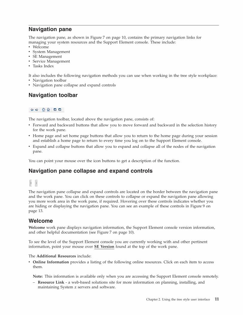
Navigation toolbar
The navigation toolbar, located above the navigation pane, consists of:v Forward and backward buttons that allow you to move forward and backward in the selection history
for the work pane.v Home page and set home page buttons that allow you to return to the home page during your session
and establish a home page to return to every time you log on to the Support Element console.v Expand and collapse buttons that allow you to expand and collapse all of the nodes of the navigation
pane.
You can point your mouse over the icon buttons to get a description of the function.
Navigation pane collapse and expand controls
The navigation pane collapse and expand controls are located on the border between the navigation paneand the work pane. You can click on these controls to collapse or expand the navigation pane allowingyou more work area in the work pane, if required. Hovering over these controls indicates whether youare hiding or displaying the navigation pane. You can see an example of these controls in Figure 9 onpage 13.
WelcomeWelcome work pane displays navigation information, the Support Element console version information,and other helpful documentation (see Figure 7 on page 10).
To see the level of the Support Element console you are currently working with and other pertinentinformation, point your mouse over SE Version found at the top of the work pane.
The Additional Resources include:v Online Information provides a listing of the following online resources. Click on each item to access
them.
Note: This information is available only when you are accessing the Support Element console remotely.– Resource Link - a web-based solutions site for more information on planning, installing, and
maintaining System z servers and software.
Chapter 2. Using the tree style user interface 11
– Tutorials - for additional information on using the Support Element console tree style user interfaceand tasks.
– APIs - for access to the System z Application Programming Interface publications:- Application Programming Interfaces - provides information for developing system management
applications that will provide integrated hardware and software system management solutionsusing the application programming interfaces.
v Library - lists the following online publications provided with the Support Element consoleapplication. Click on each publication to access them.
Note: If you are accessing the Support Element console remotely, PDF versions of the documents areavailable. If you are accessing the Support Element console locally, HTML versions of the documentsare available.– Support Element Operations Guide - provides information about the Support Element Console
Application and about using the Support Element workplace to monitor and operate your system. Itis the book you are currently using.
To open an online book, locate the book you want to open and click on the book title. The book remainsopen until you close it. When you have finished viewing the book, close it by clicking the X in the upperright corner of the book window.
System Management
System Management is used to manager and view system resources. Selecting the expand icon from thenavigation pane displays a tree view of system resources that can include:
Resources may include:v Systemv Processorsv Channelsv Cryptosv Partitionsv Partition resourcesv zBX Bladesv zBX BladeCentersv Virtual Serversv Custom groups.
When you select System Management from the navigation pane, the following resource tabs aredisplayed in the work panev Systemv Topology
Groups and objectsUse the navigation pane to locate objects. Objects are divided into groups of objects of the same type. Tolocate a particular object, you must locate and open the group that contains it. Opening a group displaysits objects in the work pane.
12 Support Element Operations Guide

System: The System node represents all the resources that are managed by this Support Elementconsole.
Note: The term system may also be referred as a CPC or server through out this publication.
When you select the system from the navigation pane, a listing of individually defined objects isdisplayed under the System node in the navigation pane and resource tabs are displayed above the workpane table, as shown in Figure 9.
To work with the system:v Select System Management in the navigation panev Click in the Select column next to the system name in the work pane table.
Processors: On the Support Element, both physical and logical processors are referred to as processors(CPs).
To locate processors:1. In the navigation pane, expand System Management.2. From the System Management node, expand the System node.3. Select the Processors node.
A listing of processors is displayed in the work pane table under the Processors tab. The default tableidentifies the ID, status, and state of each processors. See Figure 9.
Channels: The node that represents the system contains objects that represent all channels in theinput/output (I/O) configuration. To locate channels:1. In the navigation pane, expand System Management.2. From the System Management node, expand the System node.
Figure 9. Systems Management object window
Chapter 2. Using the tree style user interface 13
3. Select the Channels node.
A listing of channels is displayed in the work pane table under the Channels tab. The default tableidentifies the physical channel identifier (PCHID), CSS.CHPID, status, state, cage-slot-jack address, andhardware type. Virtual channels will only be displayed after the system is activated. See Figure 9 on page13
Cryptos: The node that represents the system contains objects that represent all installed cryptos.
To locate cryptos:1. In the navigation pane, expand System Management.2. From the System Management node, expand the System node.3. Select the Cryptos node.
A listing of cryptos is displayed in the work pane table under the Cryptos tab. The default table identifiesthe physical channel identifier (PCHID), crypto ID, status, state, cage-slot-jack address, and crypto type.See Figure 9 on page 13.
Logical partitions: When the system is activated, the Partitions node contains objects that represent thelogical partitions. Logical partitions are referred to also as images. An image is a set of system resourcescapable of running a control program or operating system.
To locate partitions:1. In the navigation pane, expand System Management.2. From the System Management node, expand the System node.3. Select the Partitions node.
A listing of logical partitions is displayed in the work pane table under the Partitions tab. The defaulttable identifies the logical partition name, status, image mode, sysplex name, operating system name,activation profile, and last used profile. See Figure 9 on page 13.
Partition resources: When the system is activated, the Partitions node contains objects that represent thelogical partitions. Logical partitions are referred to also as images.
To locate partition resources:1. In the navigation pane, expand System Management.2. From the System Management node, expand the System node.3. Select the Partitions node.4. Select a partition you want to work with. The partition's defined resources display in the navigation
pane below the selected partition and in the work pane table under the Partitions tab.
The work pane table identifies the resources defined in the partition. The resources can include CHPIDs,processors (CPs), and cryptos. See Figure 9 on page 13.
zBX BladeCenters: The node that represents the system (CPC) contains objects that represent allinstalled zBX BladeCenters. The BladeCenters node contains objects that represent the defined zBXBladeCenters.
To locate zBX BladeCenters:1. In the navigation pane, expand System Management.2. From the System Management node, expand the System node.3. Select the BladeCenters node.
A listing of zBX BladeCenters is displayed in the work pane table under the BladeCenters tab. The tableidentifies the zBX BladeCenter® name, status, and description.
14 Support Element Operations Guide
zBX Blades: The node that represents the system (CPC) contains objects that represent all installed andentitled zBX Blades. The BladeCenters node contains objects that represent the defined zBX Blades. Thetasks pad displays the appropriate tasks that can be performed on a selected zBX Blade.
To locate zBX Blades:1. In the navigation pane, expand System Management.2. From the System Management node, expand the System node.3. Select the BladeCenters node.4. Select a zBX BladeCenter.
A listing of zBX Blades is displayed in the work pane table under the Blades tab. The default tableidentifies the ID, status, type, machine type/model, power usage, and location.
Virtual Servers: The node that represents the system (CPC) contains objects that represent all installedVirtual Servers. The BladeCenters node contains objects that represent the defined Virtual Servers.
To locate Virtual Servers:1. In the navigation pane, expand System Management.2. From the System Management node, expand the System node.3. Expand the BladeCenters node.4. Select a zBX BladeCenter. A listing of zBX Blades is displayed in table format in the work pane.5. In the work pane table, expand a zBX Blade.
A listing of virtual servers is displayed in the work pane table under the Virtual Servers tab. The tableidentifies the virtual servers name, status, and description.
Custom groups: The Custom Groups node provides a mechanism for you to group system resourcestogether in a single view. In addition, groups may be nested to create custom "topologies" of systemresources.
You perform tasks on objects in a group by selecting the group in the navigation pane and clicking on thecheck boxes in the Select column of the table. To perform tasks on all of those objects, click Select Allfrom the table toolbar.
For group status information, status is displayed in the Status column in the work pane table. Statusicons are displayed appropriately. If a group has both Hardware Messages and Operating SystemMessages, a message overlay icon is displayed indicating that both messages exist.
User-defined groups: There may be one or more user-defined groups already defined on your supportelement console. You can use the Grouping task under the Daily category from the tasks pad to createyour own group that you want to work with. This task allows you to create new groups and manageexisting ones.
To create a group you can:1. Select one or more objects that you want to include in the group.2. Open the Grouping task from the Daily tasks pad.
The Manage Groups window is displayed.3. Select Create a new group from the Manage Group window.4. Specify a group name and description.5. Click OK to complete.6. The new user-defined group is displayed in the navigation pane under the Custom Groups node.
You can also create a group by using the pattern match method:
Chapter 2. Using the tree style user interface 15
1. Without selecting an object you can open the Grouping task from the Custom Groups, SystemManagement tasks pad, or Tasks Index.
2. From the Create Pattern Match Group window:v Select one or mode group types that you want to create.v Specify a group name, description, and the pattern used to determine if an object should be part of
the group.v Click OK to complete.
3. The new user-defined group is displayed in the navigation pane under the Custom Groups node.
Note: Patterns specified in the Managed Resource Pattern input field are regular expressions. Forexample, if you specified abc.*, all the resources that begin with abc will be included in that group.
Use the online help for more information on grouping.
Opening task for the SystemAfter you have selected the system or the system object to work with, you are ready to perform tasks onthem. The following task categories (groups) are applicable to the system displayed in the tasks pad. Taskcategories (groups) represent categories of tasks and not tasks themselves. The available task groupdepends on the object selected from the navigation pane (System, Processors, Channels, Cryptos,Partitions). The following is the task groups that may be available for the system.v Dailyv CPC Recoveryv Servicev Change Managementv CPC Remote Customizationv CPC Operational Customizationv CPC Configurationv CHPID Operationsv Channel Operationsv Crypto Service Operations.v Energy Managementv Monitor
You can select a task from these task groups in a variety of ways.v Use the tasks pad below the systems work pane (see “Tasks pad”)v Click the context menu icon that appears next to the server name (see “Context menus” on page 18)v Click the Tasks menu from the work pane table toolbar (see “Tasks menu” on page 31).v Right-click in the cell containing the name of the object to display the context menu.
Note: If a particular task cannot be performed on an object, the task is not displayed.
Tasks padThe tasks pad is displayed below the work pane table after you have selected the managed objects towork with.
Figure 10 on page 17 shows an example of tasks in the tasks pad that are available for the selectedmanaged objects and applicable for the current user.
By default, the task pad is displayed. You can choose to hide the tasks pad by using the User Settingstask.
To change the display of the tasks pad setting you can go to the User Settings task by selecting:v Task Index or SE Management on the navigation pane, then open the User Settings task, orv The user ID from the task bar to access the User Settings task to change the setting, or
16 Support Element Operations Guide
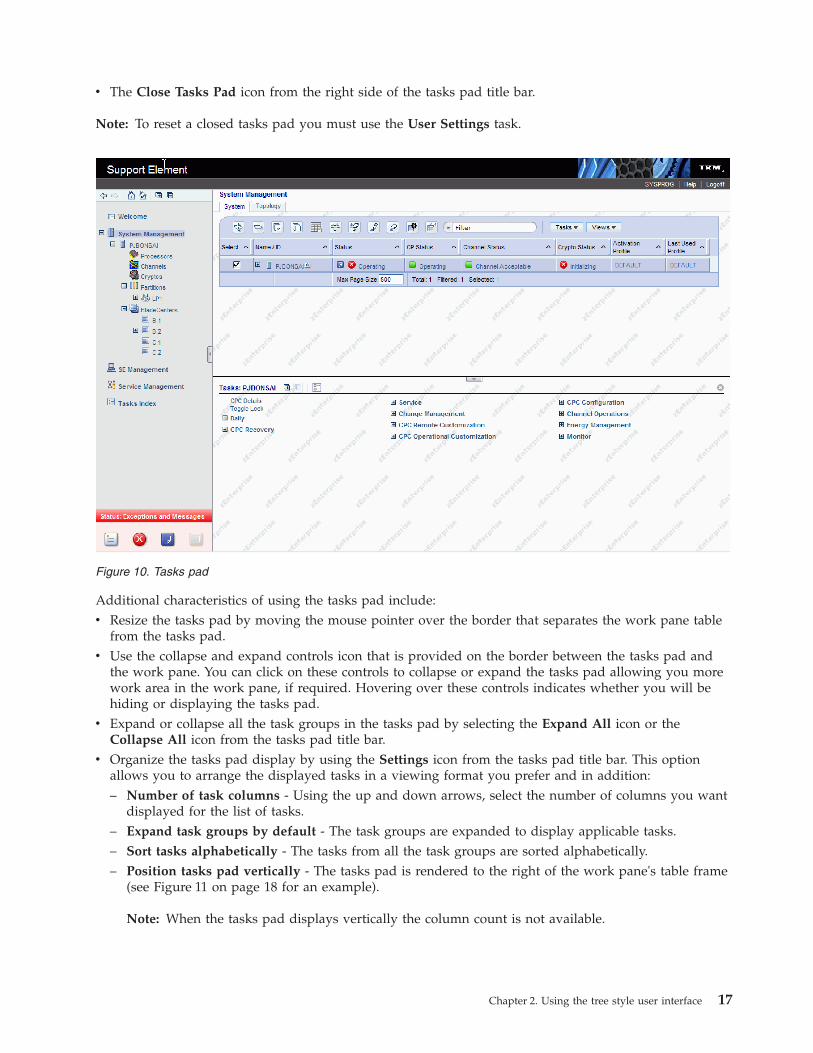
v The Close Tasks Pad icon from the right side of the tasks pad title bar.
Note: To reset a closed tasks pad you must use the User Settings task.
Additional characteristics of using the tasks pad include:v Resize the tasks pad by moving the mouse pointer over the border that separates the work pane table
from the tasks pad.v Use the collapse and expand controls icon that is provided on the border between the tasks pad and
the work pane. You can click on these controls to collapse or expand the tasks pad allowing you morework area in the work pane, if required. Hovering over these controls indicates whether you will behiding or displaying the tasks pad.
v Expand or collapse all the task groups in the tasks pad by selecting the Expand All icon or theCollapse All icon from the tasks pad title bar.
v Organize the tasks pad display by using the Settings icon from the tasks pad title bar. This optionallows you to arrange the displayed tasks in a viewing format you prefer and in addition:– Number of task columns - Using the up and down arrows, select the number of columns you want
displayed for the list of tasks.– Expand task groups by default - The task groups are expanded to display applicable tasks.– Sort tasks alphabetically - The tasks from all the task groups are sorted alphabetically.– Position tasks pad vertically - The tasks pad is rendered to the right of the work pane's table frame
(see Figure 11 on page 18 for an example).
Note: When the tasks pad displays vertically the column count is not available.
Figure 10. Tasks pad
Chapter 2. Using the tree style user interface 17
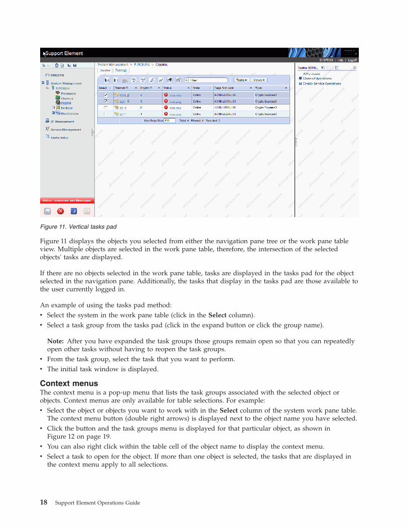
Figure 11 displays the objects you selected from either the navigation pane tree or the work pane tableview. Multiple objects are selected in the work pane table, therefore, the intersection of the selectedobjects' tasks are displayed.
If there are no objects selected in the work pane table, tasks are displayed in the tasks pad for the objectselected in the navigation pane. Additionally, the tasks that display in the tasks pad are those available tothe user currently logged in.
An example of using the tasks pad method:v Select the system in the work pane table (click in the Select column).v Select a task group from the tasks pad (click in the expand button or click the group name).
Note: After you have expanded the task groups those groups remain open so that you can repeatedlyopen other tasks without having to reopen the task groups.
v From the task group, select the task that you want to perform.v The initial task window is displayed.
Context menusThe context menu is a pop-up menu that lists the task groups associated with the selected object orobjects. Context menus are only available for table selections. For example:v Select the object or objects you want to work with in the Select column of the system work pane table.
The context menu button (double right arrows) is displayed next to the object name you have selected.v Click the button and the task groups menu is displayed for that particular object, as shown in
Figure 12 on page 19.v You can also right click within the table cell of the object name to display the context menu.v Select a task to open for the object. If more than one object is selected, the tasks that are displayed in
the context menu apply to all selections.
Figure 11. Vertical tasks pad
18 Support Element Operations Guide
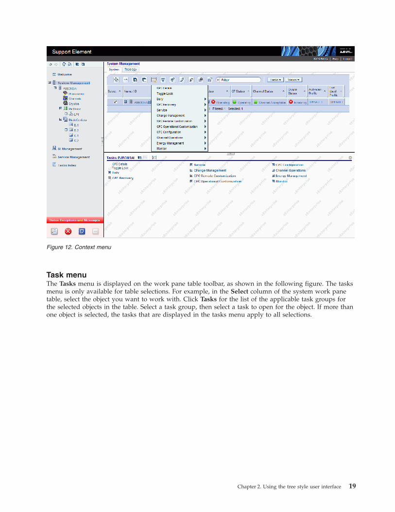
Task menuThe Tasks menu is displayed on the work pane table toolbar, as shown in the following figure. The tasksmenu is only available for table selections. For example, in the Select column of the system work panetable, select the object you want to work with. Click Tasks for the list of the applicable task groups forthe selected objects in the table. Select a task group, then select a task to open for the object. If more thanone object is selected, the tasks that are displayed in the tasks menu apply to all selections.
Figure 12. Context menu
Chapter 2. Using the tree style user interface 19

StatusThe Status column of the system work pane table displays the current status of the object. If you selectthe status text, the help information for that status is displayed. Status icons can also be displayed in thestatus column next to the status text. Depending on the icon that is displayed, you can get the HardwareMessages task window or the Operating Systems Messages task window. You can see a sample of thestatus icons in the Status column in Figure 13.
Displaying an object's detailsAll object details can be displayed by using one of the following methods:v Click on the object name from the work pane table.v Select the object name from the work pane table then:
– Click object's Details from the tasks pad, or– Click the arrow icon next to the object name, then click the objects's Details from the context menu,
or– Right-click in the object name table cell, then click the object's Details from the context menu.
In all cases, the object's Details window is displayed. See Figure 14 on page 21 for an example of a CPCDetails window.
Note: If displaying zBX Blade details for a selected IBM WebSphere® DataPower® Integration ApplianceXI50 for zEnterprise (DataPower XI50z) blade, the Virtual Network Interfaces tab displays. You can viewthe details of an existing interface.
Figure 13. Drop-down menu
20 Support Element Operations Guide

Note: The zBX Information tab is only available when the zBX feature is available for the specifiedserver.
While you are in the object's Details window, you can also lock out disruptive tasks, as described in“Object locking for disruptive tasks” on page 41, or by clicking on Toggle Lock in the tasks pad or fromthe context menu.
When selecting details for channels or cryptos, the Advanced Facilities... and Channel ProblemDetermination... buttons display to provide a link to the Advanced Facilities and Channel ProblemDetermination tasks for additional information on the selected channel or crypto.
Figure 14. CPC details window
Figure 15. Channels details window
Chapter 2. Using the tree style user interface 21

When selecting details for CHPIDs, the Channel Problem Determination button displays to provide alink to the Channel Problem Determination task for additional information on the selected CHPID.
The object's work pane table includes additional information about the objects. You can use the Viewsmenu to customize the information that is displayed in the work pane table (see “Views menu” on page31 for more information).
SE Management
SE Management allows you to perform tasks associated with the management of this console. When youselect SE Management from the navigation pane the work pane contains a view of the Support Elementconsole tasks and their descriptions. These tasks are used for setting up the Support Element console,maintaining its internal code, and securing the Support Element console. Most likely, you will not usethese actions on a regular basis.
To see what level of the Support Element console you are currently working with, point your mouse overSE Version found at the top of the work pane.
To display the tasks in the work pane:1. Select the SE Management node in the navigation pane.2. By default, a categorized listing of the tasks is displayed. The tasks are arranged in groups which
include:v Securityv Configuration.
3. From the work pane, click on the task you want to perform.
If you want an alphabetical listing of the tasks, go to the View drop-down menu in the upper rightcorner of the work pane, and click Alphabetical. Click Categorized to go back to the task groups.
In addition, for each of the Alphabetical and Categorized views you can also choose:v Detail displays the tasks in the original tree style user interface style with a small task icon followed
by the task name and description in two columns.v Icon displays large task icons above the task name, similar to the classic style user interface task
display.v Tile displays tasks using large icons followed by task names and descriptions to help you find tasks by
icon while still providing task descriptions.
See Figure 16 on page 23 for an example of an alphabetical sort of the SE management tasks using theicon style.
22 Support Element Operations Guide

Service Management
Service Management allows you to perform tasks associated with servicing this console. When you selectService Management from the navigation pane the work pane contains a view of the servicemanagement tasks and their descriptions. These tasks are used to service the Support Element consoleand maintain its internal code.
To see what level of the Support Element console you are currently working with, point your mouse overSE Version found at the top of the work pane.
To display the tasks in the work pane:1. Select the Service Management node in the navigation pane.2. By default, a categorized listing of the tasks is displayed. The tasks are arranged in groups which
include:v Console Logs
3. From the work pane, click on the task you want to perform.
If you want an alphabetical listing of the tasks, go to the View drop-down menu in the upper rightcorner of the work pane, and click Alphabetical. Click Categorized to go back to the task groups.
In addition, for each of the Alphabetical and Categorized views you can also choose:v Detail displays the tasks in the original tree style user interface style with a small task icon followed
by the task name and description in two columns.
Figure 16. Tasks using an alphabetical sort with icon style
Chapter 2. Using the tree style user interface 23
v Icon displays large task icons above the task name, similar to the classic style user interface taskdisplay.
v Tile displays tasks using large icons next to each task's name and description to help you find tasks byicon while still providing task descriptions.
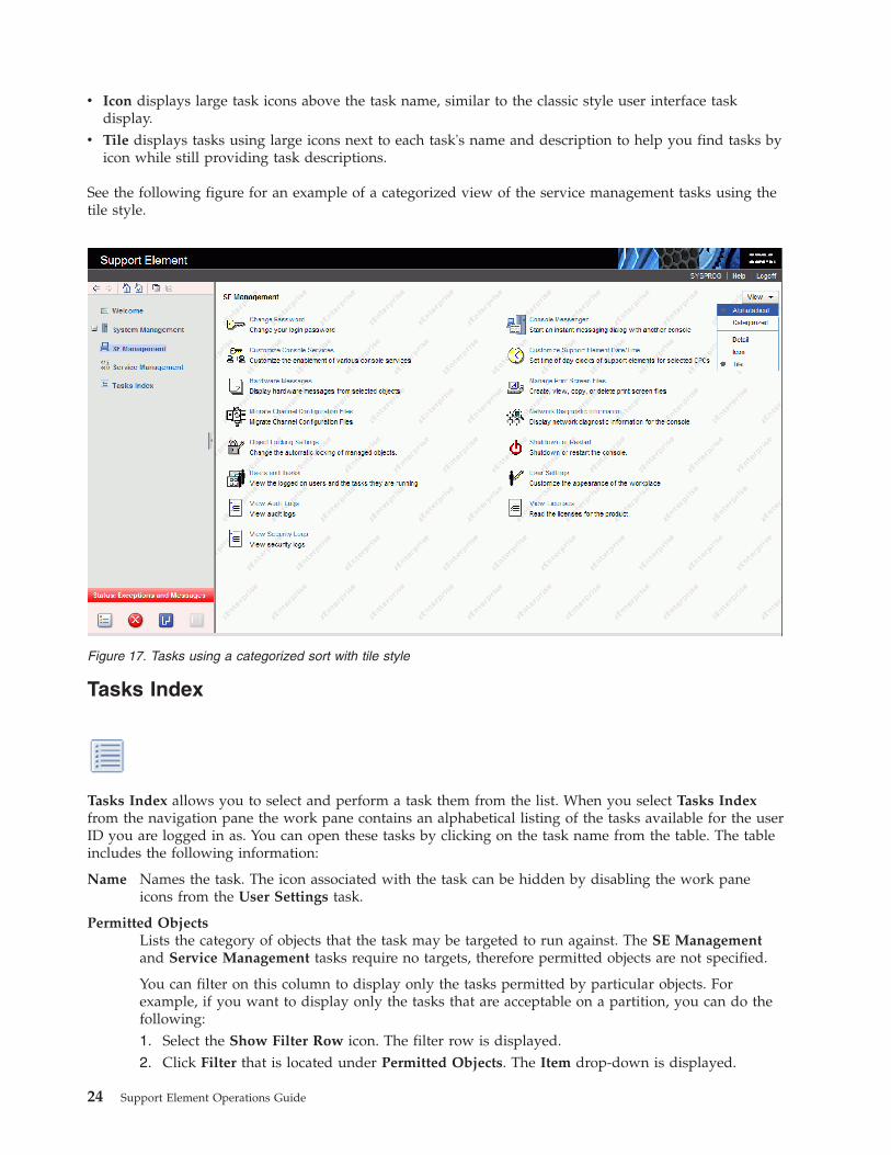
See the following figure for an example of a categorized view of the service management tasks using thetile style.
Tasks Index
Tasks Index allows you to select and perform a task them from the list. When you select Tasks Indexfrom the navigation pane the work pane contains an alphabetical listing of the tasks available for the userID you are logged in as. You can open these tasks by clicking on the task name from the table. The tableincludes the following information:
Name Names the task. The icon associated with the task can be hidden by disabling the work paneicons from the User Settings task.
Permitted ObjectsLists the category of objects that the task may be targeted to run against. The SE Managementand Service Management tasks require no targets, therefore permitted objects are not specified.
You can filter on this column to display only the tasks permitted by particular objects. Forexample, if you want to display only the tasks that are acceptable on a partition, you can do thefollowing:1. Select the Show Filter Row icon. The filter row is displayed.2. Click Filter that is located under Permitted Objects. The Item drop-down is displayed.
Figure 17. Tasks using a categorized sort with tile style
24 Support Element Operations Guide

3. Click the drop-down arrow and select Partitions. Click OK to continue. A list of all tasks thatapply to partitions is displayed.
Count Displays the number of times the task was opened by the current user.
DescriptionDescribes the task.
Notes:
v If a task (for example, Activate) is applicable to one or more targeted objects, a secondary window isdisplayed for target selection.
v The SE Management and Service Management tasks are opened without prompting for targets.v Each time you open a task, the count increments by one. The values in the Count column can be reset
back to zero by clicking Tasks from the work pane table toolbar, then selecting Reset Task LaunchCount ).
v You can use the work pane table toolbar icons for selecting, filtering, sorting, and arranging theinformation in the table. See “Work pane table toolbar” on page 29 for more detailed information aboutusing the icons and the quick filter function.
Work paneThe work pane displays information based on the current selection from the navigation pane, resourcetabs, or status bar. The work pane described in this section discusses the functions of a SystemManagement work pane.
Selecting an object from the navigation pane displays a resources (configurable) table in the work pane asshown in Figure 19 on page 26. This figure identifies some of the areas of the configurable table.
Note: You can click on the name of an object in the work pane table to display the Details window.
Figure 18. Tasks index
Chapter 2. Using the tree style user interface 25
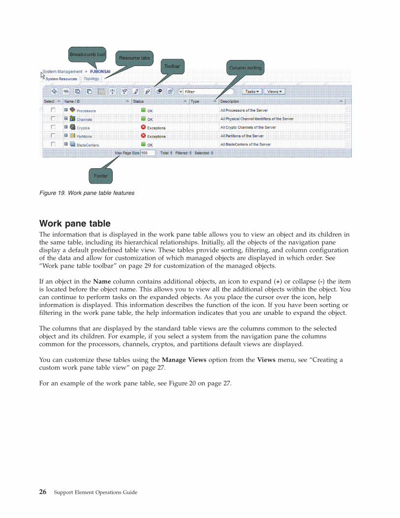
Work pane tableThe information that is displayed in the work pane table allows you to view an object and its children inthe same table, including its hierarchical relationships. Initially, all the objects of the navigation panedisplay a default predefined table view. These tables provide sorting, filtering, and column configurationof the data and allow for customization of which managed objects are displayed in which order. See“Work pane table toolbar” on page 29 for customization of the managed objects.
If an object in the Name column contains additional objects, an icon to expand (+) or collapse (-) the itemis located before the object name. This allows you to view all the additional objects within the object. Youcan continue to perform tasks on the expanded objects. As you place the cursor over the icon, helpinformation is displayed. This information describes the function of the icon. If you have been sorting orfiltering in the work pane table, the help information indicates that you are unable to expand the object.
The columns that are displayed by the standard table views are the columns common to the selectedobject and its children. For example, if you select a system from the navigation pane the columnscommon for the processors, channels, cryptos, and partitions default views are displayed.
You can customize these tables using the Manage Views option from the Views menu, see “Creating acustom work pane table view” on page 27.
For an example of the work pane table, see Figure 20 on page 27.
Figure 19. Work pane table features
26 Support Element Operations Guide
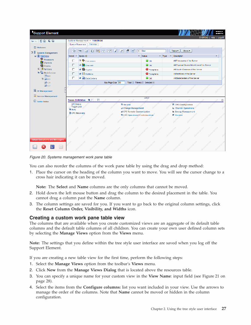
You can also reorder the columns of the work pane table by using the drag and drop method:1. Place the cursor on the heading of the column you want to move. You will see the cursor change to a
cross hair indicating it can be moved.
Note: The Select and Name columns are the only columns that cannot be moved.2. Hold down the left mouse button and drag the column to the desired placement in the table. You
cannot drag a column past the Name column.3. The column settings are saved for you. If you want to go back to the original column settings, click
the Reset Column Order, Visibility, and Widths icon.
Creating a custom work pane table viewThe columns that are available when you create customized views are an aggregate of its default tablecolumns and the default table columns of all children. You can create your own user defined column setsby selecting the Manage Views option from the Views menu.
Note: The settings that you define within the tree style user interface are saved when you log off theSupport Element.
If you are creating a new table view for the first time, perform the following steps:1. Select the Manage Views option from the toolbar's Views menu.2. Click New from the Manage Views Dialog that is located above the resources table.3. You can specify a unique name for your custom view in the View Name: input field (see Figure 21 on
page 28).4. Select the items from the Configure columns: list you want included in your view. Use the arrows to
manage the order of the columns. Note that Name cannot be moved or hidden in the columnconfiguration.
Figure 20. Systems management work pane table
Chapter 2. Using the tree style user interface 27
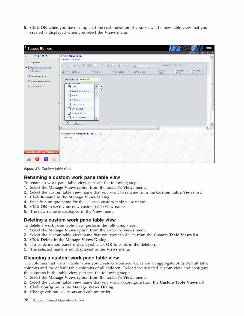
5. Click OK when you have completed the customization of your view. The new table view that youcreated is displayed when you select the Views menu.
Renaming a custom work pane table viewTo rename a work pane table view, perform the following steps:1. Select the Manage Views option from the toolbar's Views menu.2. Select the custom table view name that you want to rename from the Custom Table Views list.3. Click Rename in the Manage Views Dialog.4. Specify a unique name for the selected custom table view name.5. Click OK to save your new custom table view name.6. The new name is displayed in the View menu.
Deleting a custom work pane table viewTo delete a work pane table view, perform the following steps:1. Select the Manage Views option from the toolbar's Views menu.2. Select the custom table view name that you want to delete from the Custom Table Views list.3. Click Delete in the Manage Views Dialog.4. If a confirmation panel is displayed, click OK to confirm the deletion.5. The selected name is not displayed in the Views menu.
Changing a custom work pane table viewThe columns that are available when you create customized views are an aggregate of its default tablecolumns and the default table columns of all children. To load the selected custom view and configurethe columns in the table view, perform the following steps:1. Select the Manage Views option from the toolbar's Views menu.2. Select the custom table view name that you want to configure from the Custom Table Views list.3. Click Configure in the Manage Views Dialog.4. Change column selections and column order.
Figure 21. Custom table view
28 Support Element Operations Guide
5. Click OK to save your changes.6. The table is displayed as specified by your selections.
Work pane title and breadcrumb trailThe work pane title is displayed directly above the work pane table resource tabs. It identifies the SystemManagement group. Once you begin drilling down to more specific objects from the navigation pane, abreadcrumb trail is displayed on the work pane title line. These breadcrumbs identify the navigation paththat led you to the current work pane resources table. You can use the links from the navigation path togo to the previous pages. The resource tabs that are displayed in the work pane depends on the resourceselected from the navigation pane.
Work pane table footerThe table footer located at the bottom of the work pane table includes information about the number ofpages of information included for the displayed table. It also displays additional summary informationsuch as the number of items selected in the work pane table, filtered total, or the row count of thenumber of rows displayed in the current page. shows an example of this information.
You can change the number of items you want displayed on each page of the table by specifying anumber in the Max Page Size input field, then press Enter. If more than one page of information isavailable, a page count is displayed and you have the ability to go to a page directly by specifying a pagenumber in the entry field, then press Enter.
Work pane table toolbarThe toolbar at the top of the System Management work pane table contains icons used to expand,collapse, export, select, filter, sort, and arrange the entries in the resources table. Hovering over thetoolbar buttons displays their functions. The toolbar also includes Tasks and Views menus that can beused with the information displayed in the resources tables.
Expanding and collapsing resources
The Expand All icon allows you to list all the resource groups. The Collapse All icon allows you tocollapse all the resource groups. These icons work on all those objects that have additional objectsassociated with them in the table.
Note: These icons are disabled if you are sorting, filtering, or quick filtering. In addition, the tablehierarchy is removed.
Selecting rows
You can select more than one table row at any given time. Rows can be individually selected or a blockof rows can be selected at once by first left-clicking the selection box of the first row in the desired blockand then shift-clicking the selection box of the last row in the desired block. Click Select All or DeselectAll to select or deselect all objects in the table. The table summary at the bottom of the table (work panetable footer) includes the total number of items that are selected. To set the object selection use the UserSettings task.
Export data
Chapter 2. Using the tree style user interface 29

The Export Data icon allows for table data to be downloaded in a Comma Separated Values (CSV) file.This downloaded CSV file can then be imported into most spreadsheet applications.
Note: This function is available only when you are accessing the Support Element console remotely.
Filtering
If you click Show Filter Row, a row is located under the title row of the table. Click Filter under acolumn heading to limit the entries in a table. You can filter tables to show only those entries mostimportant to you. You can toggle the filtered view on and off by selecting the check box next to thedesired filter in the filter row. Click Clear all Filters to return to the complete listing. The table summaryincludes the total number of items that pass the filter criteria and the total number of items.
Note: When you are filtering within the work pane table the objects cannot be expanded.
Sorting
Edit Sort and Clear All Sorts perform multicolumn sorts of objects in the table in ascending ordescending order. Click Edit Sort to define sorts for columns in a table. Alternatively, you can be performsingle column sorting by selecting the ^ in the column header to change from ascending to descendingorder. Click Clear All Sorts to return to the default ordering.
Note: When you are sorting within the work pane table the objects cannot be expanded.
Column configuration
Use the column configuration buttons to manage the columns displayed in the System Management treeview. Click Configure Columns to arrange the columns in the table in the order you want or to hidecolumns from view. All available columns are listed in the Columns list by their column names. Youselect the columns you want displayed or hidden by selecting or clearing the box next to the columnnames. Manipulate the column order by selecting a column name in the list box and clicking the arrowbuttons to the right of the list to change the order of the selected columns. When you have completed theconfiguration of the columns, click OK. The columns are displayed in the table as you specified. If youwant to go back to the original layout of the table, click Reset Column Order, Visibility, and Widths onthe table toolbar. Select one or more of the properties to reset to their original layout, and click OK.
Quick filter
Use the quick filter function to enter a filter string in the Filter input field, and then press Enter to applythe filter. By default, all the columns are filtered, showing only rows containing a cell whose valueincludes the filter text. Clicking the arrow displays a menu that restricts the columns to which the filter isapplied.
Note: When you are sorting or filtering within the work pane table the objects cannot be expanded.
30 Support Element Operations Guide
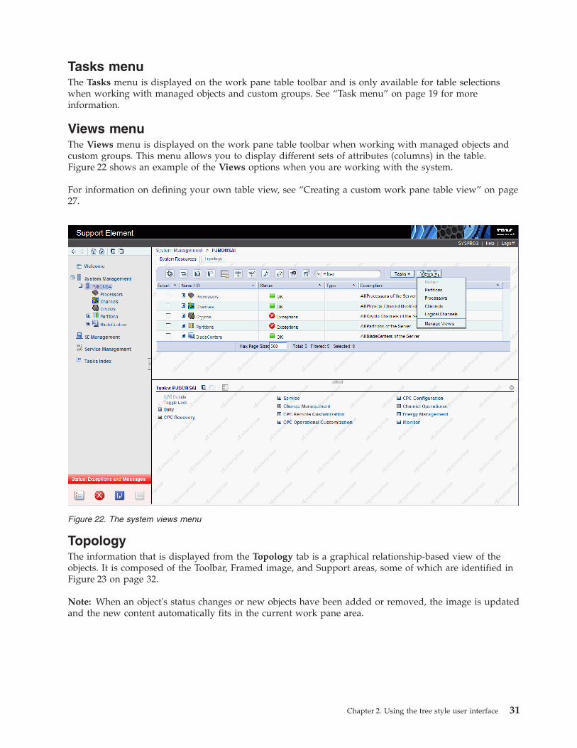
Tasks menuThe Tasks menu is displayed on the work pane table toolbar and is only available for table selectionswhen working with managed objects and custom groups. See “Task menu” on page 19 for moreinformation.
Views menuThe Views menu is displayed on the work pane table toolbar when working with managed objects andcustom groups. This menu allows you to display different sets of attributes (columns) in the table.Figure 22 shows an example of the Views options when you are working with the system.
For information on defining your own table view, see “Creating a custom work pane table view” on page27.
TopologyThe information that is displayed from the Topology tab is a graphical relationship-based view of theobjects. It is composed of the Toolbar, Framed image, and Support areas, some of which are identified inFigure 23 on page 32.
Note: When an object's status changes or new objects have been added or removed, the image is updatedand the new content automatically fits in the current work pane area.
Figure 22. The system views menu
Chapter 2. Using the tree style user interface 31

ToolbarThis area of the topology work pane consists of several icons and drop-down menus for controlling theappearance and actions of the topology view. You can mouse over the toolbar icons for short descriptionsof the respective actions.
The toolbar icons are divided into the following groups:v Content zoom and fit control - used for enlarging and shrinking the images and automatically fitting
the image content within the work pane area:– Zoom In– Zoom Out– Fit Contents to Viewport
v Mouse modes - controls the function of the mouse.– Select Mouse Mode (default) - clicking on an object causes its selection to be toggled.
- When a node is selected, the tasks context menu icon is displayed and the tasks in the Tasksmenu are also updated.
- When multiple selection is enabled, press (Ctrl +) left mouse button to select multiple nodes. Leftclicking in a blank area of the work pane area deselects all selected nodes.
– Pan Mouse Mode - scroll the objects in the frame up, down, left, or right using direct manipulation.After you release the mouse button, the mouse mode is automatically changed back to the selectionmode.
– Zoom Mouse Mode - creates a viewport to zoom into. The mouse is used to select a rectangulararea (a blue box is displayed to indicate the area) as part of the image frame to zoom into. Theobjects in the area are enlarged. After you release the mouse button, the mouse mode isautomatically changed back to the selection mode.
Figure 23. Topology view features
32 Support Element Operations Guide

v Toggle Support Area Visibility icon - toggles the visibility of the support area, which displays theimage Overview (see Figure 23 on page 32).
v Expand All / Collapse All icons - expand (display) or collapse (hide) the children of all objects.
The drop-down menus include:v Tasks - when one or more objects are selected the tasks available for the objects are displayed. These
same tasks are displayed in the context menu and tasks pad.v Selection - allows you to select all the objects, deselect all the objects, or invert selection.v Zoom - allows you to change the content size:
Fit ContentAutomatically fits the objects in the framed image area.
50% Size of each object is displayed as half its actual size.100% Size of each object is displayed as the actual size.200% Size of each object is displayed as twice the actual size.
v Layout - allows you to select the preferred object layout:Rerun Current
Redraws the image using the current layout.Tree Displays objects in a hierarchical tree format.Hierarchical
Arranges the nodes so that the majority of links are short and flow uniformly in the samedirection.
CircularObjects are automatically grouped into either a ring or star topology.
Uniform lengthSearches for a configuration of the graph where the length of the links are the same.
Grid Objects are placed into a grid.
Framed imageThis area displays graphical representations of managed objects. Each object is represented with a graphicwhich displays the object's name, its status, its tasks (in a context menu), and an expand/collapse buttonif it has children. Note some of the following characteristics as you work in the framed image:v If an object is selected, the label uses black font color and blue background color, the background of
the object icon also turns blue.v The status icon overlay is a combination of the system status icon, hardware messages icon, and the
operating system messages icon.v If an object is locked, the lock icon is displayed.v If an object is busy, the busy icon is displayed.v Click on a frame segment to redraw the image that has been panned in the associated direction.v Click the right mouse button in an empty area of the images frame to display a context menu with the
following additional options (similar to the Toolbar functions):– Collapse All– Expand All– Selection– Zoom– Layout– Center here - centers you on the current mouse position.– Move here - moves the selected object into the current mouse position (this option displays only
when exactly one object is selected).v Click the right mouse button or click the double arrow icon on a selected object to display a context
menu with the following additional options:– Zoom To - zooms into the object in the center of the viewer display area.– Center here - centers you on this object.– Expand - expands the object by displaying any children if an object is collapsed.
Chapter 2. Using the tree style user interface 33
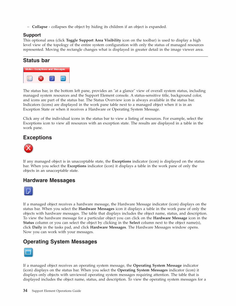
– Collapse - collapses the object by hiding its children if an object is expanded.
SupportThis optional area (click Toggle Support Area Visibility icon on the toolbar) is used to display a highlevel view of the topology of the entire system configuration with only the status of managed resourcesrepresented. Moving the rectangle changes what is displayed in greater detail in the image viewer area.
Status bar
The status bar, in the bottom left pane, provides an "at a glance" view of overall system status, includingmanaged system resources and the Support Element console. A status-sensitive title, background color,and icons are part of the status bar. The Status Overview icon is always available in the status bar.Indicators (icons) are displayed in the work pane table next to a managed object when it is in anException State or when it receives a Hardware or Operating System Message.
Click any of the individual icons in the status bar to view a listing of resources. For example, select theExceptions icon to view all resources with an exception state. The results are displayed in a table in thework pane.
Exceptions
If any managed object is in unacceptable state, the Exceptions indicator (icon) is displayed on the statusbar. When you select the Exceptions indicator (icon) it displays a table in the work pane of only theobjects in an unacceptable state.
Hardware Messages
If a managed object receives a hardware message, the Hardware Message indicator (icon) displays on thestatus bar. When you select the Hardware Messages icon it displays a table in the work pane of only theobjects with hardware messages. The table that displays includes the object name, status, and description.To view the hardware message for a particular object you can click on the Hardware Message icon in theStatus column or you can select the object by clicking in the Select column next to the object name(s),click Daily in the tasks pad, and click Hardware Messages. The Hardware Messages window opens.Now you can work with your messages.
Operating System Messages
If a managed object receives an operating system message, the Operating System Message indicator(icon) displays on the status bar. When you select the Operating System Messages indicator (icon) itdisplays only objects with unviewed operating system messages requiring attention. The table that isdisplayed includes the object name, status, and description. To view the operating system messages for a
34 Support Element Operations Guide

particular object you can click on the Operating System Messages icon in the Status column or you canselect the object by clicking in the Select column next to the object name(s), click Daily in the tasks pad,and click Operating System Messages. The Operating System Messages window opens. Now you canwork with your messages.
Status overview
When you select the Status Overview icon it displays a more detailed view of overall status in the workpane, as shown in Figure 24. It summarizes the total number of exceptions, hardware messages, andoperating system messages by objects. Then you can select a link from the work pane to display allobjects with the particular state in the work pane.
Object locking for disruptive tasksYou can tell when a system or system image is locked because a small lock is displayed next to thesystem name in the work pane table. In the topology view the icon is shown as an overlay of the objecticon.
The setting of the system or system object's toggle lock determines whether you can perform a disruptivetask on the system or system objects. You can lock an individual object or automatically lock all objects.
To individually lock (or unlock) the system or system objects:1. Select the system from the table that you want to lock (or unlock).
Figure 24. Status overview
Chapter 2. Using the tree style user interface 35

2. Click CPC Details from the tasks pad. The CPC Details window is displayed.3. You can select Yes or No for Lock out disruptive tasks.4. Click Apply to make the change.
There is also an automatic way to lock the system and system objects at one time. Unlike the previousways for locking an object, using this method can cause the object to be relocked automatically if it wasunlocked to perform a task on it. To use this method, you must have a user ID with the predefined userroles of an Advanced Operator, System Programmer, Access Administrator, or Service Representative for theSupport Element console.1. Open the Object Locking Settings task from the SE Management work pane. The Locking window
opens.2. Select Automatically lock all managed objects or Relock after a task has been run or both.
36 Support Element Operations Guide
Chapter 3. Using the classic style user interface
This chapter explains how to use the classic style user interface for performing tasks on the SupportElement console or on a CPC.
Support Element WorkplaceThe Support Element Workplace is the window where you start tasks for monitoring and operating yoursystem.
The workplace presents tasks and their targets graphically, as icons. Using the workplace to getinformation and start tasks is often a matter of monitoring and manipulating icons, rather than, forexample, typing commands or using menus.
Icons that represent the functions, facilities, and controls you use to monitor and operate the system andconsole are referred to as tasks. A single icon that represents a set of one or more related tasks is referredto as a task list.
Icons that represent the physical and logical elements of the system, which are often the targets of tasks,are referred to as objects. The console's objects include:v Central processor complex (CPC)v Physical channels (PCHIDs)v Central processors (CPs)
– This includes: General processors, Internal Coupling Facility (ICF), Integrated Facility for Linux(IFL), zSeries Application Assist Processors (zAAPs), and IBM System z Integrated InformationProcessors (zIIPs).
v Logical channels (CHPIDs)v images (An Image is a set of CPC resources capable of running a control program or operating system.
One or more images is created during a power-on reset of a CPC. Each logical partition is an image.)v zBX BladeCentersv zBX Bladesv Virtual Servers.
A single icon that represents a set of one or more objects of the same type is referred to as a group.
The classic style user interface support element console workplace is divided into three areas to organizeits icons. The three areas are:
Views Located along the top left side of the workplace, this area contains icons that represent differentcollections or views of the objects that make up your system. The background color of this areaalso gives an indication of the status of the system, as described in “Monitoring system status” onpage 42.
Work areaLocated below the Views area, this area contains icons in the current view. Depending on theview, the work area contains either groups, objects, tasks in progress, task lists, tasks formonitoring and operating the console, or online books.
Tasks areaLocated along the right side of the workplace, this area displays the current task list that containtasks for monitoring and operating the system.
© Copyright IBM Corp. 2011 37

Selecting objects
Selecting objects prepares them for further action. Selecting a Views icon allows you to display the viewby pressing Enter. The default setting for selecting objects displayed in the Work area is Single objectselection. However, to select more than one object at a time, allowing you to perform tasks on them as adynamic group, you can do the following:1. Open Console Actions from the Views area.2. Open User Settings from the Console Actions Work Area. The User Settings window is displayed.3. Select the Controls tab on the User Settings window.4. Deselect Single object selection by clicking on the check mark to remove it, click Apply, then click
OK when you are finished with the task.
In the Work area, if the selection of multiple objects is allowed, you can use one of the following methodsfor selecting multiple objects:v Click on each object to be selected.v Select or deselect all objects in a view.
To select all objects:1. Display the objects you want to select. For example, click Channels so those objects are displayed in
the Work area.2. Right-click on a spot on the Channels Work Area without an icon. This displays the menu for the
Work area (see Figure 26 on page 39).3. Click Select all. This selects all the objects in the Work area.
Figure 25. Classic interface workplace window
38 Support Element Operations Guide

To deselect all objects, if all objects are selected:1. Right-click on a spot on the Channels Work Area without an icon. This displays the menu for the
Work area (see Figure 26).2. Click Deselect all. This deselects all the objects in the Work area.
Clicking individual objects that are already selected deselects the objects.
Note: There are times when you want to work with a single object and want to ensure that additionalobjects are not accidentally selected. Use the User Settings task to verify the Single object selectionoption is selected (a check mark displays).
Opening an objectOpening an object in the Work area displays a further level of detail about the object. There are severalways to open an object. One way is to double-click it.
Double-clicking any one of the Groups icons in the Groups view displays icons for the objects (forexample, images) that make up that group.
Another way to display the icons that make up the group is to right-click the object and, on the menuthat appears, click Open.
Displaying object detailsAfter you open the object, you can display detailed information about the object by double-clicking it.Then a window opens that displays the object's current status information and other object details.
An alternate way to display this information is to right-click the object's icon and then click the object'sDetails. Right-clicking on an object displays its pop-up menu. Selecting the object's Details on this menudisplays the details about the object. Figure 27 on page 40 shows an example of a CPC Details window.
Note: If displaying zBX Blade details for a selected IBM WebSphere DataPower Integration ApplianceXI50 for zEnterprise (DataPower XI50z) blade, the Virtual Network Interfaces tab displays. You can viewthe details of an existing interface.
Figure 26. Work area menu
Chapter 3. Using the classic style user interface 39

Note: The zBX Information tab is only available when the zBX feature is available for the specifiedserver.
While you are in the object's Details window, you can also lock out disruptive tasks, as described in“Object locking for disruptive tasks” on page 41.
When selecting Details for CHPIDS, the Channel Problem Determination button displays to provide alink to the Channel Problem Determination task for additional information on the selected CHPID.
When selecting Details for channels or cryptos, the Advanced Facilities... and Channel ProblemDetermination... buttons display to provide a link to the Advanced Facilities and Channel ProblemDetermination tasks for additional information on the selected channel or crypto.
Figure 27. CPC details window
Figure 28. Channel details window
40 Support Element Operations Guide

Starting a task on an objectAfter locating a task, and locating and selecting its targets, you can start the task on the targets. There areseveral ways to start tasks. You can use whatever way is easiest for you or most appropriate for the task.
To start a task on a single target:1. Locate the task.2. Locate the target object or group.3. Start the task on the target by any of the following:
v Dragging and dropping the task on the target.v Dragging and dropping the target on the task.v Selecting the target and double-clicking on the task.v Selecting the target, selecting the task, and clicking Enter.v Right-clicking on the object to get a task menu.
To start a task on multiple targets:1. Locate the task.2. Locate and select the target objects or groups.3. Start the task on the targets by any of the following:
v Dragging and dropping the task on any one of the selected targets.v Dragging and dropping any one of the selected targets on the task.v Double-clicking on the task.v Selecting the task, and clicking Enter.v Right-clicking on any selected object and getting a task menu.
Object locking for disruptive tasks
Some of the Support Element Console tasks are considered disruptive. Performing a disruptive task on aCPC or image may disrupt its operation. For example, activating a CPC and loading an image aredisruptive tasks. You may want to lock an object to prevent accidentally performing disruptive tasks on itand then unlock the object only when you want to perform a disruptive task on it.
Depending on whether the Lockout disruptive task setting is set to Yes or No determines if you canperform a disruptive task on a CPC or CPC object. You can either lock an individual object or a group ofobjects at one time.
Note: The Lockout disruptive task only affects operations from the Support Element Console workplaceyou are currently working at. It does not affect most operations from the Support Element (for example,scheduled operations and CPC operations management commands, etc.), and operations initiated fromother sources (for example, from Hardware Management Consoles).
To individually lock the CPC or CPC object:1. Locate the object you want to lock in the Work Area.2. Right-click on the object's icon.3. Click CPC Details from the menu.
The CPC Details window opens.4. Set Lockout disruptive tasks to Yes or No.5. Click Apply to lock the object.
Chapter 3. Using the classic style user interface 41
If you want to lock the CPC or images at one time, there is an automatic way to lock all them displayedon the workplace at one time. If using this method, you will cause an object to be relocked automaticallyif it was unlocked to perform a task on it.1. Locate the objects you want to lock in the Work Area.2. Open Console Actions from Views.
This displays the console actions in the Console Actions Work Area.3. Open the Support Element Settings task from the Console Actions Work Area.
This displays the Support Element Settings Work Area.4. Open the Object Locking Settings task from the Support Element Settings Work Area.5. Select Automatically lock all managed objects or Relock after a task has been run or both. All
objects currently in the work area are now locked.
When the object(s) are locked, a small lock in the lower left hand corner of the icon indicates that thedisruptive tasks are locked for that object. If you attempt to perform a disruptive task on a locked object,a window is displayed indicating the object is locked.
If you want to unlock an object or a group of objects, you still need to follow the previously describedunlocking procedure.
Monitoring system statusThe Support element console continuously monitors the status of its objects and compares them to theobject's acceptable status settings.
Note: The following description of the use of color is based on a set of default colors that are set up foryou initially. You may override the defaults and associate different colors, or use gray patterns instead ofcolor, by using the User Settings task. (For more information, refer to “User Settings” on page 189.)
Acceptable statusGood or acceptable status for the CPC and images in the processor cluster is indicated by a greenbackground in the Views area of the Support Element console workplace window, and by the absence of ared background around the Exceptions icon. Status changes from acceptable to unacceptable, referred toas Exceptions, are indicated on the Support element console workplace window by a color change fromgreen to red. By default, green indicates good, or acceptable status. Red indicates an exception, or that anobject has an unacceptable status.
To set the acceptable status for a CPC or image, double click on the CPC or image icon to display theDetails window. From the Acceptable Status tab you can select the acceptable status settings. The defaultacceptable status value is Operating.
Messages that may require operator attention are indicated by the blue flashing Hardware Messages iconor by the cyan flashing Operating System Messages icon in the Tasks area. In addition, to indicate whichobjects have hardware or operating system messages that require operator attention, the CPC or imageicon's background color and its group icon background color will also be blue or cyan.
42 Support Element Operations Guide

Unacceptable statusThe default acceptable status value is Operating. Initially, all other status values are consideredunacceptable, unless you select them on the Details window by double-clicking on a CPC or image icon.If an object's status changes to any of the unacceptable values, it is treated as an Exception situation. Anexception situation is visually indicated by a change of the entire Views area background color from greento red as shown in Figure 30 on page 44. A background color is also displayed for the CPC or images thathave an unacceptable status, and for any of the groups that contain the CPC or images. The backgroundcolor depends on what you have selected on the Details window.
Figure 29. Acceptable status
Chapter 3. Using the classic style user interface 43
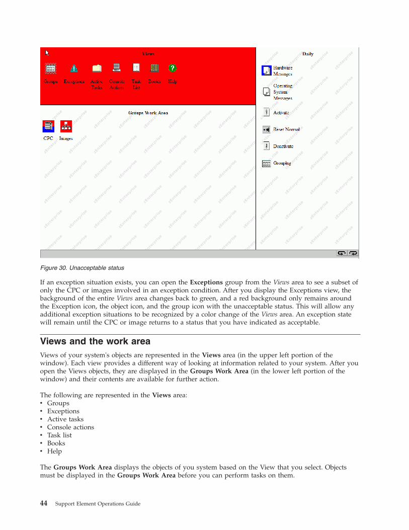
If an exception situation exists, you can open the Exceptions group from the Views area to see a subset ofonly the CPC or images involved in an exception condition. After you display the Exceptions view, thebackground of the entire Views area changes back to green, and a red background only remains aroundthe Exception icon, the object icon, and the group icon with the unacceptable status. This will allow anyadditional exception situations to be recognized by a color change of the Views area. An exception statewill remain until the CPC or image returns to a status that you have indicated as acceptable.
Views and the work areaViews of your system's objects are represented in the Views area (in the upper left portion of thewindow). Each view provides a different way of looking at information related to your system. After youopen the Views objects, they are displayed in the Groups Work Area (in the lower left portion of thewindow) and their contents are available for further action.
The following are represented in the Views area:v Groupsv Exceptionsv Active tasksv Console actionsv Task listv Booksv Help
The Groups Work Area displays the objects of you system based on the View that you select. Objectsmust be displayed in the Groups Work Area before you can perform tasks on them.
Figure 30. Unacceptable status
44 Support Element Operations Guide

You can display a particular View by using any of the following methods:v Double-clicking on the icon on the Views area that you wantv Selecting the icon in the Views area by clicking on it, then pressing Enter.
You can also display two of the choices by opening the menu.
The menu is a shortcut for navigating the workplace. To open the menu, click the right mouse buttononce on any empty area in the Groups Work Area. This displays a menu listing. An arrow to the right ofa menu choice indicates additional choices are available on a cascaded menu. A cascaded menu providesadditional menu choices and may include additional cascaded menus. Each cascaded menu provides amore direct shortcut for locating and opening icons in a particular view.
Getting detailed system statusUse Views and the work area to get detailed system status by checking the individual status of thefollowing objects that represent physical or logical elements of the system:v Central processor complex (CPC)v Central processorsv Channelsv CHPIDsv Images
Like the background color of the Views area, the background color of an object's icon indicates whetherits status is acceptable (as defined by the user) or unacceptable. The background color of an object's iconindicates the object's status in one of two ways:
No colorThis indicates the object's status is acceptable. An acceptable status is any object status that isnormal, is as expected, or does not require your immediate attention or intervention. That is, anobject with an acceptable status is OK as is.
Color This indicates the object's status is unacceptable. The specific color indicates the object's specific,unacceptable status. An unacceptable status is any object status that is not normal, is not asexpected, or requires your immediate attention when it occurs. That is, an object with anunacceptable status is not OK, and may require your intervention to make it OK again.
Therefore, checking whether the individual status of an object is acceptable or unacceptable requireslocating a group that contains the object, then checking the background color of the object's icon.
Groups
The Groups view is displayed initially when you log on to the support element console and is the viewthat you will use most often to run and monitor your system. Groups are comprised of logical collectionsof objects. They provide a quick and easy means for performing tasks against the same set of objectsmore than once without having to select each object every time the task is run. In addition, status isreported on a group basis, allowing you to monitor your system in a way that you prefer. Use Views andthe work area to locate objects. To locate a particular object, you must locate and open the group thatcontains it. Opening a group displays its objects in the work area.
To open a group:1. Open Groups from Views.2. Locate the group that contains the type of objects you want to locate in the Groups Work Area.3. Double-click on the group to open it.
Chapter 3. Using the classic style user interface 45
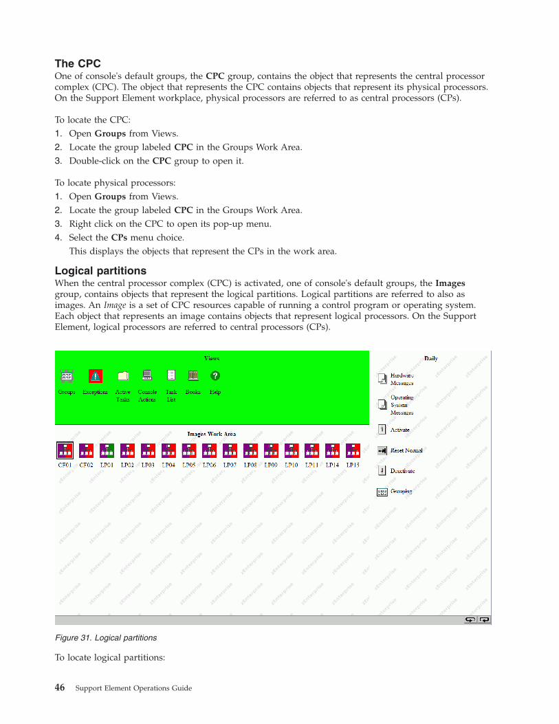
The CPCOne of console's default groups, the CPC group, contains the object that represents the central processorcomplex (CPC). The object that represents the CPC contains objects that represent its physical processors.On the Support Element workplace, physical processors are referred to as central processors (CPs).
To locate the CPC:1. Open Groups from Views.2. Locate the group labeled CPC in the Groups Work Area.3. Double-click on the CPC group to open it.
To locate physical processors:1. Open Groups from Views.2. Locate the group labeled CPC in the Groups Work Area.3. Right click on the CPC to open its pop-up menu.4. Select the CPs menu choice.
This displays the objects that represent the CPs in the work area.
Logical partitionsWhen the central processor complex (CPC) is activated, one of console's default groups, the Imagesgroup, contains objects that represent the logical partitions. Logical partitions are referred to also asimages. An Image is a set of CPC resources capable of running a control program or operating system.Each object that represents an image contains objects that represent logical processors. On the SupportElement, logical processors are referred to central processors (CPs).
To locate logical partitions:
Figure 31. Logical partitions
46 Support Element Operations Guide
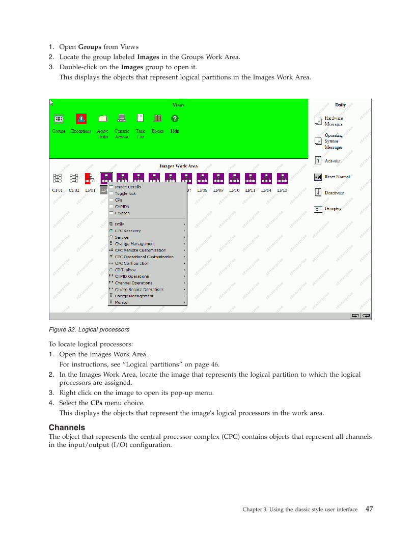
1. Open Groups from Views2. Locate the group labeled Images in the Groups Work Area.3. Double-click on the Images group to open it.
This displays the objects that represent logical partitions in the Images Work Area.
To locate logical processors:1. Open the Images Work Area.
For instructions, see “Logical partitions” on page 46.2. In the Images Work Area, locate the image that represents the logical partition to which the logical
processors are assigned.3. Right click on the image to open its pop-up menu.4. Select the CPs menu choice.
This displays the objects that represent the image's logical processors in the work area.
ChannelsThe object that represents the central processor complex (CPC) contains objects that represent all channelsin the input/output (I/O) configuration.
Figure 32. Logical processors
Chapter 3. Using the classic style user interface 47

To locate all channels in the CPC's I/O configuration:1. Open the CPC Work Area.
For instructions, see “The CPC” on page 46.2. In the CPC Work Area, locate the CPC.3. Right click on the CPC to open its pop-up menu.4. Select the Channels menu choice.
This displays the objects that represent the channels in the work area. Each channel is labeled with itsphysical channel identifier (PCHID).
Channel pathsThe object that represents the logical partitions or images contains objects that represent all channel pathsdefined in its input/output (I/O) configuration.
To locate channel paths assigned to a specific logical partition:
Figure 33. Cannels
48 Support Element Operations Guide

1. Open the Images Work Area.For instructions, see “Logical partitions” on page 46.
2. In the Images Work Area, locate the image that represents the logical partition to which the channelpaths are assigned.
3. Right click on the image to open its pop-up menu.4. Select the CHPIDs menu choice.
This displays only the objects that represent the image's channel paths in the work area. Each channelpath is labeled with its channel path identifier. A single-digit number that identifies the channelsubsystem followed by a two-digit number that identifies the channel path associated with thatchannel subsystem. (CSS.CHPID).
CryptosThe object that represents the central processor complex (CPC) contains objects that represent all installedcryptos.
Figure 34. Channel paths
Chapter 3. Using the classic style user interface 49

To locate all cryptos in the CPC's I/O configuration:1. Open the CPC Work Area.
For instructions, see “The CPC” on page 46.2. In the CPC Work Area, locate the CPC.3. Right click on the CPC to open its pop-up menu.4. Select the Cryptos menu choice.
This displays the objects that represent the cryptos in the work area. Each channel is labeled with itsphysical channel identifier (PCHID).
zBX BladeCentersThe node that represents the system (CPC) contains objects that represent all installed zBX BladeCenters.
Figure 35. Cryptos
50 Support Element Operations Guide
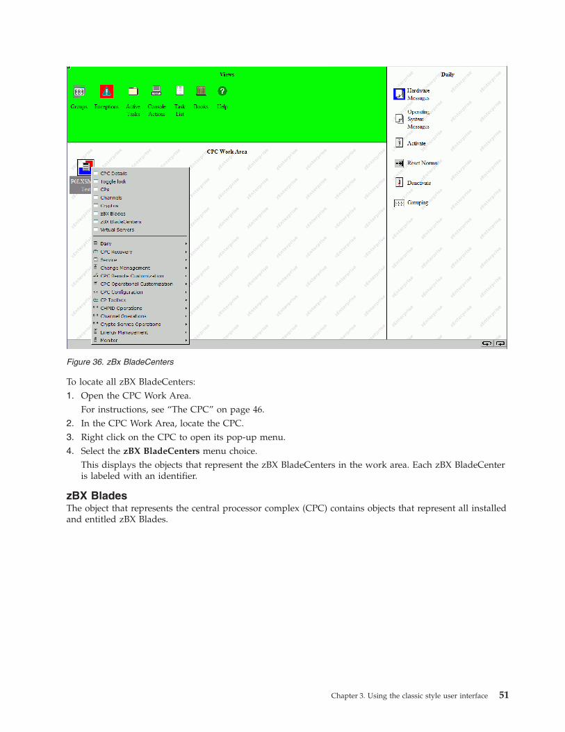
To locate all zBX BladeCenters:1. Open the CPC Work Area.
For instructions, see “The CPC” on page 46.2. In the CPC Work Area, locate the CPC.3. Right click on the CPC to open its pop-up menu.4. Select the zBX BladeCenters menu choice.
This displays the objects that represent the zBX BladeCenters in the work area. Each zBX BladeCenteris labeled with an identifier.
zBX BladesThe object that represents the central processor complex (CPC) contains objects that represent all installedand entitled zBX Blades.
Figure 36. zBx BladeCenters
Chapter 3. Using the classic style user interface 51

To locate all zBX Blades:1. Open the CPC Work Area.
For instructions, see “The CPC” on page 46.2. In the CPC Work Area, locate the CPC.3. Right click on the CPC to open its pop-up menu.4. Select the zBX Blades menu choice.
This displays the objects that represent the zBX Blades in the work area. Each zBX Blade is labeledwith its identifier.
Virtual ServersThe object that represents the system (CPC) contains objects that represent all installed Virtual Servers.
Figure 37. zBX Blades
52 Support Element Operations Guide

To locate all Virtual Servers:1. Open the CPC Work Area.
For instructions, see “The CPC” on page 46.2. In the CPC Work Area, locate the CPC.3. Right click on the CPC to open its pop-up menu.4. Select the Virtual Servers menu choice.
This displays the objects that represent the Virtual Servers in the work area. Each Virtual Server islabeled with an identifier.
Determining the exact status of an objectAfter locating an object, check the background color of its icon to determine whether its status isacceptable or unacceptable:v The icon's background has no color when the object's status is acceptable.v When the object's status is unacceptable, the icon's background displays the color that identifies the
unacceptable status.
Note: If you are not certain which unacceptable status is indicated by the background color of the CPC'sicon, double-click on it to open the CPC's Details window.
Background color of the CPCThe background color of the icon of the central processor complex (CPC) indicates whether the statusesof the CPC, its central processors (CPs), and its channel paths are acceptable or unacceptable. While thestatuses are acceptable, the background of the CPC icon has no color. Otherwise, the background color ofthe CPC indicates unacceptable statuses as follows:
Figure 38. Virtual servers
Chapter 3. Using the classic style user interface 53
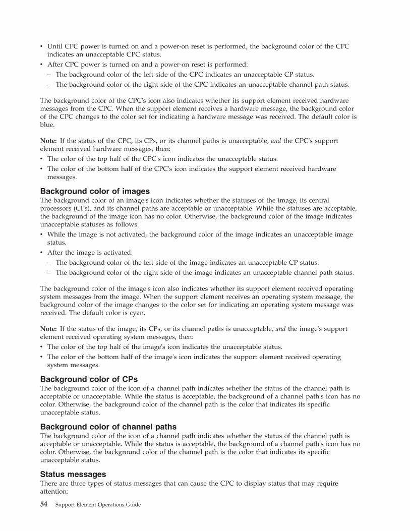
v Until CPC power is turned on and a power-on reset is performed, the background color of the CPCindicates an unacceptable CPC status.
v After CPC power is turned on and a power-on reset is performed:– The background color of the left side of the CPC indicates an unacceptable CP status.– The background color of the right side of the CPC indicates an unacceptable channel path status.
The background color of the CPC's icon also indicates whether its support element received hardwaremessages from the CPC. When the support element receives a hardware message, the background colorof the CPC changes to the color set for indicating a hardware message was received. The default color isblue.
Note: If the status of the CPC, its CPs, or its channel paths is unacceptable, and the CPC's supportelement received hardware messages, then:v The color of the top half of the CPC's icon indicates the unacceptable status.v The color of the bottom half of the CPC's icon indicates the support element received hardware
messages.
Background color of imagesThe background color of an image's icon indicates whether the statuses of the image, its centralprocessors (CPs), and its channel paths are acceptable or unacceptable. While the statuses are acceptable,the background of the image icon has no color. Otherwise, the background color of the image indicatesunacceptable statuses as follows:v While the image is not activated, the background color of the image indicates an unacceptable image
status.v After the image is activated:
– The background color of the left side of the image indicates an unacceptable CP status.– The background color of the right side of the image indicates an unacceptable channel path status.
The background color of the image's icon also indicates whether its support element received operatingsystem messages from the image. When the support element receives an operating system message, thebackground color of the image changes to the color set for indicating an operating system message wasreceived. The default color is cyan.
Note: If the status of the image, its CPs, or its channel paths is unacceptable, and the image's supportelement received operating system messages, then:v The color of the top half of the image's icon indicates the unacceptable status.v The color of the bottom half of the image's icon indicates the support element received operating
system messages.
Background color of CPsThe background color of the icon of a channel path indicates whether the status of the channel path isacceptable or unacceptable. While the status is acceptable, the background of a channel path's icon has nocolor. Otherwise, the background color of the channel path is the color that indicates its specificunacceptable status.
Background color of channel pathsThe background color of the icon of a channel path indicates whether the status of the channel path isacceptable or unacceptable. While the status is acceptable, the background of a channel path's icon has nocolor. Otherwise, the background color of the channel path is the color that indicates its specificunacceptable status.
Status messagesThere are three types of status messages that can cause the CPC to display status that may requireattention:
54 Support Element Operations Guide
Test This indicates a conditions exists, such as PSW even compare or Address compare are enabled. Todetermined the exact conditions test status select the Test Mode tab on the Details window.
Degraded
This status message displays under the CPC icon in the Groups Work Area. This indicates that,although the CPC is still operating, some hardware is not working.
Some of the conditions that cause this message to be displayed are:v Loss of channels due to CPC hardware failurev Loss of memoryv One or more books are no longer functioningv The ring connecting the books is openv Capacity Backup resources have expiredv Processor frequency reduced due to temperature problemv CPC was IMLed during temperature problem.
To view what conditions caused this message to display on a CPC:1. Double-click on the object in the object's work area. The Details window displays for the
selected object.2. Click Degrade reasons... The Degraded Details window displays the current list of reasons
why the CPC is degraded.
Service Required
This status displays in the Acceptable CP/PCHID Status tab on the Details window of the CPC.This indicates that the spare hardware shipped with the CPC has been depleted. When a partfails causing the use of the last redundant parts of that type, you now have just the requirednumber of parts to keep the CPC running. This message is a reminder to you and the servicerepresentative that repairs should be made at the earliest possible time before addition. Some ofthe conditions that cause this message to be displayed are:v Loss of one bulk power assembly (BPA)v Loss of communications to the alternate support elementv No more spare processing units (PUs)v Not enough spare PUs to support either Capacity Backup or Disaster Recovery Assurance (if
either feature is installed)v Memory sparing threshold reachedv An Oscillator/ECF card is defectivev The alternate support element is fencedv A multiple chip module (MCM) is defective.
Exceptions
You can use Views and the work area to immediately locate all current exceptions. Objects that are in anexceptions state, due to an unacceptable status condition, will be displayed in the Exceptions Work Area.1. Open Exceptions from Views.
This displays all objects with unacceptable statuses in the Exceptions Work Area. (Not all logicalobjects are displayed. For example, Image CPs.)
2. In the Exceptions Work Area, the background color of each object's icon indicates its current status. Ifyou are not certain which status is indicated by the background color of an object's icon, double-clickon the object to open its Details window.
Chapter 3. Using the classic style user interface 55
This window includes detailed information about the object, including a list of the colors used toindicate its statuses.
See “Monitoring system status” on page 42 for more information about Exceptions.
Recognizing exceptionsAfter the background color of the Views area returns to green, indicating there are no new exceptions,you can still recognize current exceptions by the background colors of the Exceptions icon and of eachgroup that contains an exception:v Upon opening the Exceptions view, the background color of the Views area returns to green, but the
Exceptions icon remains red, the color set for indicating there are exceptions.The Exceptions icon remains red until the last of all current exceptions is returned to an acceptablestatus.
v When an exception occurs, the background color of each group that contains the exception changes tored, the color set for indicating there are exceptions.A group that contains exceptions remains red until all of its exceptions are returned to an acceptablestatus.
Note: Within a group, the background color of each object that is an exception is the color set toindicate its specific unacceptable status, as described previously in the topics that follow “Determiningthe exact status of an object” on page 53. An exception remains the color of its unacceptable statusuntil it is returned to an acceptable status.
Returning an exception to an acceptable statusAfter you locate an exception and check its unacceptable status, you can use any appropriate task toreturn the exception to an acceptable status. The target object of the task can be either:v The exception from the Exceptions Work Area.v The same exception from any group that contains it.
Locating the exception in the Exceptions Work Area is the quickest way to locate a target for the task.
Note: When activation is the task you intend to use to return an exception to an acceptable status, youshould consider the activation profile assigned to the target object. Whenever an object is activated, it isactivated according to the information in its assigned activation profile.
The exception in the Exceptions Work Area is automatically assigned the activation profile used in themost recent attempt to activate the object. To activate the exception with a different activation profile, youcan either:v Assign the exception in the Exceptions Work Area the activation profile you want to use.v Locate an instance of the same exception, in any group that contains it, that is already assigned the
activation profile you want to use.
For more information about activation and assigning activation profiles, see “Activate the CPC” on page69 and “Checking a logical partition's assigned activation profile” on page 226.
Active tasks
A task is considered to be in progress, and is referred to as active, until it is completed and its completionis acknowledged. Display the Active Tasks view by double clicking with the left mouse button on theActive Tasks icon in the Views are. This view is useful when you have minimized the Progress windows
56 Support Element Operations Guide

for one or more tasks that are in progress simultaneously. Object icons representing all the tasks that arecurrently in progress, or those tasks that have completed but whose ending status has not been reviewed,will be displayed in the Active Tasks Work Area.
If there are active icons in the Active Tasks Work Area, you can double-click on them to redisplay theProgress window for that task. When a task completes, the Progress window for that particular task willbe automatically redisplayed, allowing you to respond to the final status.
Minimizing and restoring a task in progressCompleting a task typically requires using one or more windows and messages to provide informationfor performing the task or to acknowledge information about its intermediate and final outcomes. Awindow or message that requires you to provide or acknowledge information remains open until you doso. Ordinarily, the window or message also remains displayed. Some tasks provided for monitoring andoperating the system allow you to temporarily set the task aside, while it is still active, by minimizing itsopen window or message. This is referred to as minimizing an active task.
Consider minimizing an active task whenever either:v The console is busy processing the task and does not require your interaction or attention for several
minutes.v Or you want an unobstructed view of the workplace.
For example, you may want to monitor its objects or areas for status changes.v Or you want to use the workplace to do something else, but do not want to complete or cancel the
task first.For example, you may want to use the console's 3270 emulator, check or change the console's settings,or open one of the console's online books.
To minimize an active task:1. Click on the minimize icon of the active task's open window or message.
Note: The minimize icon is located in the upper right corner of the window or message.This minimizes the window or message, which minimizes the active task. The task is still active, andits current window or message remains open, but it is temporarily not displayed.
After you minimize an active task, it will remain minimized until either:v The console restores the task automatically when it completes processing the task and displays a
window or message with information about the task's final outcome.Close the window or message to acknowledge receiving the information and to end the completedtask.
v Or you restore the task, at any time, to either complete it, cancel it, or check its progress.Use Views and the work area to restore a minimized active task.
To restore a minimized active task:1. Open Active Tasks from the Views area.
Note: An empty Active Tasks Work Area indicates there are no minimized active tasks.2. In the Active Tasks Work Area, locate the minimized active task you want to restore.3. Double-click on the task to restore it.
Restoring the task again displays its open window or message. Follow the instructions on the windowfor completing, cancelling, or continuing the task.
Restoring a minimized open window
Chapter 3. Using the classic style user interface 57

The windows and messages displayed during active tasks remain open until you provide or acknowledgeinformation as required to complete the tasks. Not all open windows indicate an active task.
For example, open windows that provide options for starting tasks, changing settings, or viewinginformation, are not considered active tasks. While you can minimize an open window the same way youminimize an active task, minimized open windows will not be included in the Active Tasks view.
To restore a minimized open window:1. Click on the maximize icon located in the upper right corner of the workplace.
Restoring the open window again displays it. Follow the instructions on the window for using it oruse its controls to close it.
Completing active tasks and closing open windows before logging off
You cannot log off the console while tasks are active or windows are open. The console will notify you ifthere are active tasks or open windows when you attempt to log off. You must complete or cancel eachactive task and close each open window before the console will allow you to log off:v If an active task is minimized, restore it, then follow the instructions on an active task's open window
or message to complete or cancel the task.Completing an active task may often be only a matter of acknowledging the completion of the task.
v If an open window is minimized, restore it, then use its controls to close it.
Console actions
Display the Console Actions view by double-clicking with the left mouse button on the Console Actionsicon in the Views area. Object icons representing all the actions that can be performed on the HardwareManagement Console and its internal code are displayed in the Console Actions Work Area as shown inFigure 39 on page 59. These actions are used for setting up the Support Element, maintaining its internalcode, and servicing the Support Element console. Most likely, you will not use these actions on a regularbasis.
Note: The layout of the console actions in the work area uses the default sort order for the classic styleuser interface. You can change the layout from the User Settings task on the Classic Style tab or selectStyle Settings from the pop-up menu in the work area. Figure 39 on page 59 displays the console actionssort order by ascending name.
To begin any console action task while using the classic style user interface:
58 Support Element Operations Guide

To start a console action:1. Open Console Actions from the Views area.2. Open the task that you want to perform from the Console Actions Work Area.3. The window for that task opens and you can proceed with the functions that need to be performed
for that task.
See Chapter 15, “Console Actions,” on page 171 for specific descriptions of all console actions.
Task lists
Display the Task list view by double-clicking with the left mouse button on the Task List icon in theViews area.
Figure 39. Console actions work area
Chapter 3. Using the classic style user interface 59
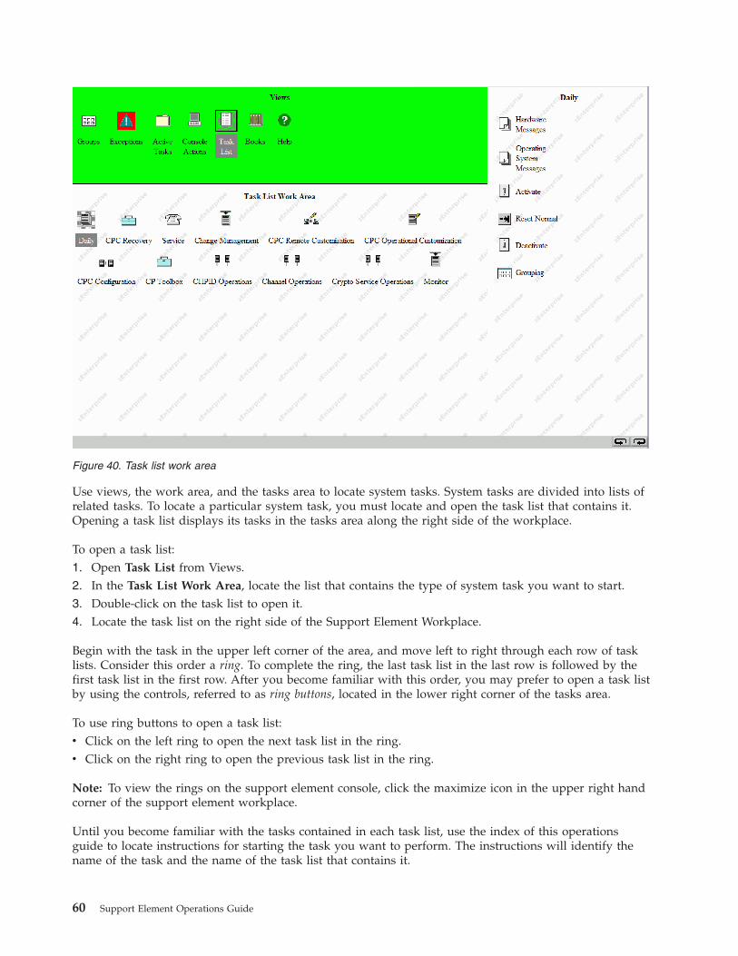
Use views, the work area, and the tasks area to locate system tasks. System tasks are divided into lists ofrelated tasks. To locate a particular system task, you must locate and open the task list that contains it.Opening a task list displays its tasks in the tasks area along the right side of the workplace.
To open a task list:1. Open Task List from Views.2. In the Task List Work Area, locate the list that contains the type of system task you want to start.3. Double-click on the task list to open it.4. Locate the task list on the right side of the Support Element Workplace.
Begin with the task in the upper left corner of the area, and move left to right through each row of tasklists. Consider this order a ring. To complete the ring, the last task list in the last row is followed by thefirst task list in the first row. After you become familiar with this order, you may prefer to open a task listby using the controls, referred to as ring buttons, located in the lower right corner of the tasks area.
To use ring buttons to open a task list:v Click on the left ring to open the next task list in the ring.v Click on the right ring to open the previous task list in the ring.
Note: To view the rings on the support element console, click the maximize icon in the upper right handcorner of the support element workplace.
Until you become familiar with the tasks contained in each task list, use the index of this operationsguide to locate instructions for starting the task you want to perform. The instructions will identify thename of the task and the name of the task list that contains it.
Figure 40. Task list work area
60 Support Element Operations Guide

Hardware messages
The central processor complex (CPC) and Support Element Console Application send messages to thesupport element console to notify you of significant events that involve or affect the use of CPC hardwareand licensed internal code. The messages are referred to as hardware messages.
Hardware messages may be sent to the support element console at any time. The support elementconsole receives the messages automatically, stores them in a message log, and turns on several consoleindicators to help you recognize that hardware messages were received.
The support element console can store a maximum of five hundred messages in its hardware messagelog. If the message log becomes full, the support element console continues to receive and store newmessages, but deletes the log's oldest message for each new message that is received. Promptly view, acton, and delete hardware messages to avoid filling the message log and losing messages.
Recognizing when hardware messages were received
While the Support Element Console Application is running, it changes the background color of one ormore icons to indicate the support element console received a hardware message from the centralprocessor complex (CPC).
The type and number of icons changed upon receiving a hardware message depends on whether anyoneis logged on the console at the time:v While logged on, the background color of the following icons changes when the support element
console receives a hardware message:– The background color of the CPC changes to blue, the color set for indicating a hardware message
was received.– The background color of each group that contains the CPC changes to blue.– The background color of the Hardware Messages task flashes blue. That is, its background color
alternates between blue and the color of the tasks area. This is the task you will use to view thehardware messages.
v While logged off, the background color of the Hardware Messages icon on the logon window flashesblue when the support element console receives a hardware message. That is, its background coloralternates between blue and the color of the logon window.
Note: The logon window is titled Support Element Logon. The Hardware Messages icon is located inthe Message indicators area of the window.
In addition to changing the background colors of icons, the support element console beeps once when itreceives a hardware message, regardless of whether anyone is logged on or logged off the console at thetime.
The Hardware Messages icon continues to flash blue until you acknowledge receiving the new hardwaremessages by taking action on any one of them. The background color of the CPC and the groups thatcontain it remains blue until you take action on each new hardware message. Taking action on hardwaremessages begins with viewing them.
Viewing hardware messages
View hardware messages to remain informed of events that involve or affect the use of the centralprocessor complex (CPC). Upon viewing hardware messages, you can also:
Chapter 3. Using the classic style user interface 61
v Get more details for messages to determine what actions to take in response.v Delete messages you no longer need.v After you open the hardware messages notebook, use the online Help for more information on using it
to view and delete hardware messages.
To get more details for messages:1. Locate the CPC to work with.2. Locate and open the Hardware Messages task.3. Select each message for which you want more details, then click Details.
This opens a Details window, one at a time, for each selected message for which details are available.4. Read the information and follow the directions on each details window to determine what action to
take in response to a message. In many cases, you can use a details window itself to start the action.
Operating System Messages
An image is a set of central processor complex (CPC) resources capable of running a control program oroperating system. An operating system running in an image sends messages to operating system consolesto notify you of significant events that involve or affect the use of the operating system. The messages arereferred to as operating system messages.
If an operating system running in an image supports console integration and is customized to allowusing the support element console as an operating system console, then the support element console canalso receive operating system messages.
An operating system may issue any number of messages at any time. The support element receives themessages automatically and stores them in a message log. The support element also turns on severalconsole indicators to help you recognize that priority or held operating system messages were received. Apriority or held operating system message either requires a response from the console operator or notifiesthe console operator of a critical condition that requires immediate attention.
The support element can store an average of approximately 200 (depending on the length of eachmessage) messages in its operating system message log per image. If the message log becomes full, thesupport element continues to receive and store new messages, but deletes one or more of the log's oldestnon-held, non-priority messages to make room for each new message. If there are not any non-held,non-priority messages, the oldest non-held priority, held, or priority message will be deleted.
Recognizing when priority or held operating system messages were received
While the Support Element Console Application is running, it changes the background color of one ormore icons to indicate the support element received a priority or held operating system message from animage supported by the central processor complex (CPC).
The type and number of icons changed upon receiving a priority or held operating system messagedepends on whether anyone is logged on the console at the time:v While logged on, the background colors of the following icons change when the support element
receives a priority operating system message:– The background color of the image that supports the operating system changes to cyan, the color set
for indicating that a priority or held operating system message was received.– The background color of each group that contains the image changes to cyan.
62 Support Element Operations Guide

– The background color of the Operating System Messages task flashes cyan. That is, its backgroundcolor alternates between cyan and the color of the tasks area. This is the task you will use to viewthe operating system messages.
v While logged off, the background color of the Operating System Messages icon flashes cyan when thesupport element receives a priority or held operating system message. That is, its background coloralternates between cyan and the color of the logon window.
Note: The logon window is titled Support Element Logon. The Operating System Messages icon islocated in the Message indicators area of the window.
The Operating System Messages icon continues to flash cyan until you acknowledge receiving the newpriority or held operating system messages by viewing them. Likewise, the background colors of theimage and the groups that contain it remain cyan until you acknowledge receiving the new priority orheld operating system messages by viewing them. While viewing operating system messages, you havethe option of responding to them.
Viewing operating system messages
View operating system messages to remain informed of events that involve or affect the use of imagessupported by the central processor complex (CPC). Upon viewing operating system messages, you canalso:v Send responses to messages.v Delete messages you no longer need.v Use the online Help for more information to view, respond to, or delete operating system messages.
To view operating system messages:
Black Indicates an informational message that normally does not require a response from the consoleoperator.
Blue Indicates a held message that requires a response from the console operator.
Red Indicates a priority message about a critical condition that requires immediate attention.
Responding to an operating system message requires receiving an operating system message first. Youcan use Operating System Messages also to send commands to an operating system, regardless ofwhether you've received messages from it.
Sending commands to operating systems
You can use a support element console to send commands, at any time, to operating systems running inimages supported by the central processor complex (CPC). operating system commands, about
To send commands to an operating system:1. Locate a target: either a group of images or individual images. Using a group of images will allow
sending commands to each operating system running on images in the group, while using individualimages will allow sending commands to their operating systems only.
2. Locate and open the Operating System Messages task.This opens the Operating System Messages notebook. Each page lists the operating system messages,if any, from each image in the target group or among the selected images. The window provides aSend command for sending commands to the operating systems running on the images.Use the online Help for more information to send commands to an operating system.
Note: The Send command is not available if the operating system running on an image does notsupport receiving commands from the support element console.
Chapter 3. Using the classic style user interface 63
Books
Use Views and the work area to open online books provided with the Support Element ConsoleApplication. The books provide information about using the application and Support Element workplace.The books include:
Support Element Operations GuideThis online book is the publication you are currently using. It provides information about theSupport Element Console Application and about using the Support Element workplace tomonitor and operate your system.
To open an online book:1. Open Books from Views area.2. In the Books Work Area, locate the book you want to open and double-click on the book icon. The
book remains open until you close it.
Help
Provides both general and specific information. Any icon can be dragged and dropped on the Help iconfor information, or the Help icon can be dragged and dropped on any of the icons in the Views, Tasks, orWork areas of the Support Element Console window.
Help will display the section of this online document that describes the object that the help icon wasdropped on. Once that information is displayed, you may go to any other part of the document for otherinformation.
To display Help for an object or Support Element Console area:1. Drag and drop the Help icon on the object or the area of the Support Element Console that you want
help information for.
The Help window displays help information for the object or area of the Support Element Console whereyou dropped the help icon.
Displaying hover help for workplace objectsOnline help provides extensive, comprehensive information for the areas and objects on the supportelement workplace. As you become more familiar with workplace objects, and if you have less frequentneed for the amount and depth of information provided by online help, consider using hover helpinstead. Hover help is a brief description of an object's, contents, usage, or purpose. The help is displayedin a compact window that hovers above the object. You can set hover help either on or off, depending onwhat you want. Initially, hover help is set off.
To set hover help on for your workplace:v Open Console Actions from Views.
This displays the console actions in the Console Actions Work Area.v Open the User Settings task from the Console Actions Work Area.
This User Settings window is displayed.v Select the Controls tab on the User Settings window.
64 Support Element Operations Guide

v Select Show hover help from the menu choice. This places a check next to it and sets hover help on. Ifyou want to set hover help off, uncheck the choice by selecting it from the menu.
v Click Apply, then click OK to enable hover help.
Note: Hover help is not displayed immediately. The cursor must remain placed on a workplace object forseveral seconds to display the help.
You can work with the objects on the workplace using the mouse to select them. This is known as thedrag and drop technique. This involves using the mouse to pick up one or more objects, dragging them to atask, and then dropping them. These techniques are examples of what is known as direct manipulation.
Chapter 3. Using the classic style user interface 65

66 Support Element Operations Guide

Chapter 4. Daily
This section describes the tasks from the Daily task list used most often on a daily basis for monitoringand operating the system.
To launch the tasks from the Daily task list using the tree style user interface, see Chapter 2, “Using thetree style user interface,” on page 9 or if you are using the classic style user interface, see Chapter 3,“Using the classic style user interface,” on page 37.
Note: The Activity task is now accessed from the Monitors Dashboard task by selecting Open Activityfrom the menu bar.
ActivationActivation is a process that makes an object operational, where the object can be a central processorcomplex (CPC) or an image, and operational means either:v The object is ready to have a control program or operating system loaded.v The object has loaded and is running a control program or operating system.
Activation makes an object operational by:v Using predefined information, referred to as an activation profile, to set the operational capabilities and
characteristics of the object.v Checking the current status of the object, and then performing only the operations necessary to make it
operational.
So using activation is not limited to starting the system. Using activation is recommended whenever youwant to make the CPC or its images operational.
A complete activation activates the CPC and its images completely and in a single step. The result of acomplete activation is an operational CPC with images loaded and running operating systems. Thecurrent status of the CPC and its images determines which operations are performed during activation tomake them operational. Activation may include:1. Turning CPC power on.2. Performing a power-on reset, which includes allocating system resources to the CPC.3. Then activating logical partitions to support multiple images.
Activating each logical partition includes:a. Initializing it.b. Allocating system resources to it.c. Loading it with a control program or operating system.
Since the status of the CPC and its images determines which operations must be performed duringactivation to make them operational, one or more operations listed above may not be performed duringactivation. For example:v Activating the CPC does not perform a power-on reset if the CPC has already been power-on reset and
the applicable settings in its assigned activation profile, such as the operating mode and activeinput/output configuration data set (IOCDS), are already in effect.
v Activating the CPC does not perform any operations if the CPC is already operational and all settingsin its assigned activation profile are already in effect.
© Copyright IBM Corp. 2011 67

Activation profilesThe predefined information used to activate an object is referred to as an activation profile. There are fourtypes of activation profiles:
v A reset profile is used to activate a central processor complex (CPC) and its images.v An image profile is used to activate an image of a CPC previously activated.v A load profile is used to load a previously activated image with a control program or operating system.v A group profile is used to define the group capacity value that can be customized in determining the
allocation and management of processor resources assigned to the logical partition group.
To support your normal, day-to-day system operations, you will activate a central processor complex(CPC) with a reset profile. Activating a CPC with a properly customized reset profile includes initializingits images, if necessary, and can include loading the images. That is, a properly customized reset profileincludes the image profiles necessary to perform a complete activation of a CPC and its images.
After activating a central processor complex (CPC) with a reset profile, you can use the other types ofactivation profiles to establish a different or alternate operational capabilities and characteristics for theimages, but without performing a complete activation of the CPC again. You can:v Activate an image with a load profile to load a different control program or operating system.v On a CPC, activate an image with its image profile to activate it individually rather than by activating
the CPC.
Preparing for an activationTo successfully activate a central processor complex (CPC), you'll need:v A properly customized reset profile assigned to the CPC and customized to meet your unique needs
for operating the CPC.
Figure 41. Activation profiles
68 Support Element Operations Guide

v Access to resources referred to in the reset profile:– An input/output configuration data set (IOCDS) for defining the CPC's input/output (I/O)
configuration.– Operating systems for loading images.
Preparing an IOCDSYou must build an IOCDS and it must be stored on a CPC's support element before you can activate theCPC.
An IOCDS is used during a power-on reset to define your I/O configuration to the channel subsystem ofthe CPC. The I/O configuration is the set of all I/O devices, control units, and channel paths available tothe CPC.
You can build an IOCDS by using an input/output configuration program (IOCP):v An IOCP may be available as a batch program with your operating system.
For information about using the IOCP, see: Input/Output Configuration Program User's Guide,, SB10-7037.v A stand-alone IOCP also is available with the support element.
For information about using the stand-alone IOCP, see: Stand-Alone IOCP User's Guide, SB10-7040.
Preparing to load imagesTo load an image during the activation of the CPC or logical partition that supports it, you must make anoperating system or control program available for loading the image.
An operating system or control program is available for loading an image if it can be loaded by usingI/O devices defined in the IOCDS used to activate the CPC. For example, with a properly defined I/Oconfiguration, the operating system or control program could be:v Read from a DASD.v Read from a tape device to a DASD, then read from the DASD.v Read from a tape device directly.
Note: Activating a coupling facility, which loads an image with coupling facility control code (CFCC),does not require using devices in the CPC's I/O configuration. The CFCC is loaded from the CPC'ssupport element.
Activate the CPC
Use the Support Element workplace to start the task for activating the central processor complex (CPC).
Note: Activating a CPC can be considered disruptive. If the CPC is locked, unlock it. See “Object lockingfor disruptive tasks” on page 41.
To activate the CPC:1. Log onto the Support Element on the Hardware Management Console through Single Object
Operations in operator, advanced operator, system programmer, or service representative user role(see “Establishing a Support Element console session from a Hardware Management Console” onpage 3).
2. The CPC must have access to the input/output configuration data set (IOCDS) and operating systemsreferred to in the reset profile. See “Preparing an IOCDS.”
Chapter 4. Daily 69
3. Locate the CPC to work with.4. Locate and open the Activate task.5. Review the information on the Activate Task Confirmation window to verify the object you will
activate is the CPC, and the activation profile it will use is the one you want.6. If the information is correct, click Yes to perform the activation.
The Activate Progress window indicates the progress of the activation, and the outcome.7. Click OK to close the window when the activation completes successfully.
Otherwise, if the activation does not complete successfully, follow the directions on the window todetermine the problem and how to correct it.
After the CPC is activated, you can use the Activate task again, if necessary, to selectively activate itsimages.
Activate an object
Use the Support Element workplace to start the task for activating an object and if they supportactivation profiles, the activation profiles to be used for each object of the central processor complex(CPC).
An image is a set of CPC resources capable of running a control program or operating system. One ormore images is created during a power-on reset of a CPC. Each logical partition is an image.
To activate an object:1. Log onto the Support Element on the Hardware Management Console through Single Object
Operations in operator, advanced operator, system programmer, or service representative user role(see “Establishing a Support Element console session from a Hardware Management Console” onpage 3).
2. You must activate the CPC, and the activation must complete with at least a successful power-on resetof the CPC.
3. If you are activating an image, you must customize an activation profile and assign it to the image.See “Activation profiles” on page 195.
4. The system must have access to the operating system referred to in the activation profile. See“Preparing to load images” on page 69.
5. Locate the object. If the object is an image, locate the image to which you assigned the activationprofile.
Note: Activating an object can be considered disruptive. If the image is locked, unlock it. See “Objectlocking for disruptive tasks” on page 41.
6. Locate and open the Activate task.7. Review the information on the Activate Task Confirmation window to verify the object or image you
will activate is the image, and the activation profile it will use is the one you want.8. If the information is correct, Click Yes to perform the activation.
This displays the Activate Progress window. The window indicates the progress of the activation, andthe outcome.
9. Click OK to close the window when the activation completes successfully.Otherwise, if the activation does not complete successfully, follow the directions on the window todetermine the problem and how to correct it.
70 Support Element Operations Guide

Deactivate the CPC
Deactivation is an orderly process for shutting down and turning off the system.
Shutting down and turning off the system, referred to also as deactivating the system, includes:v Ending hardware and software activity.v Clearing, releasing, and deallocating hardware resources.v Turning off power.
You can use the Support Element workplace to start the task for deactivating the central processorcomplex (CPC). The target, or object, of a deactivation can be a CPC or an image. For more informationabout deactivating individual logical partitions, see “Deactivate an object.”
Note: Although you can use the power switch on the CPC itself to turn it off, you should turn off CPCpower by deactivating it instead. Unlike using the CPC's power switch, deactivating the CPC includesclearing, releasing, and deallocating its hardware resources before turning off its power.
To deactivate the CPC:1. Log onto the Support Element on the Hardware Management Console through Single Object
Operations in operator, advanced operator, system programmer, or service representative user role(see “Establishing a Support Element console session from a Hardware Management Console” onpage 3 ).
2. End all operating systems supported by the images.Important: If you do not end all operating systems before deactivating the CPC, operating systemactivity will be abruptly ended during deactivation, resulting in a possible loss of data.
3. Locate the CPC to work with.
Note: Deactivating a CPC can be considered disruptive. If the CPC is locked, unlock it. See “Objectlocking for disruptive tasks” on page 41.
4. Locate and open the Deactivate task.5. Review the information on the Deactivate Task Confirmation window to verify the object you will
deactivate is the CPC.6. If the information is correct, click Yes to perform the deactivation.
The Deactivate Progress window indicates the progress of the deactivation, and the outcome.7. Click OK to close the window when the deactivation completes successfully.
Otherwise, if the deactivation does not complete successfully, follow the directions on the window todetermine the problem and how to correct it.
After the CPC is deactivated, the CPC and the images are no longer operational.
Deactivate an object
You can use the Support Element workplace to start the task for deactivating an object of the centralprocessor complex (CPC).
Chapter 4. Daily 71
An Image is a set of CPC resources capable of running a control program or operating system. One ormore images is created during a power-on reset of a CPC. Each logical partition is an image. You can useone or more images as deactivation targets to deactivate individual logical partitions.
To deactivate an object:1. Log onto the Support Element on the Hardware Management Console through Single Object
Operations in operator, advanced operator, system programmer, or service representative user role(see “Establishing a Support Element console session from a Hardware Management Console” onpage 3).
2. Locate the object you want to deactivate.
Note: Deactivating an object can be considered disruptive. If the image is locked, unlock it. See“Object locking for disruptive tasks” on page 41.
3. Locate and open the Deactivate task.4. Review the information on the Deactivate Task Confirmation window to verify the object you will
deactivate.5. If the information is correct, click Yes to perform the deactivation.
The Deactivate Progress window indicates the progress of the deactivation, and the outcome.6. Click OK to close the window when the deactivation completes successfully.
Otherwise, if the deactivation does not complete successfully, follow the directions on the window todetermine the problem and how to correct it.
After the image is deactivated, the logical partition it supported is no longer operational. The CPC andimages previously activated to support other logical partitions remain operational. Logoff the SupportElement of each system that is to be powered off. See “Logoff or Disconnect” on page 180.
After logging off the integrated Support Element, shutdown the Hardware Management Console, see theHardware Management Console Operations Guide.
Grouping
Managing groups enables you to create, delete, add to, and delete from user-defined groups of objects.You may want to create a group when you want to perform the same task on several imagessimultaneously instead of repeating the task on each individual image. This task also allows you to groupone or more user-defined groups into other groups.
72 Support Element Operations Guide

To group images:1. Log onto the Support Element on the Hardware Management Console through Single Object
Operations in system programmer user role (see “Establishing a Support Element console sessionfrom a Hardware Management Console” on page 3 ).
2. Locate the Images that you want to work with.3. Select one or more objects.4. Locate and open the Grouping task. The Manage Groups window displays to allow you to add the
selected object(s) to an existing group, delete the selected object(s) from a group, create a new group,create a pattern match group, or delete the group.
You may want to group one or more user-defined groups into other groups if you have many groups inyour Groups Work Area and need additional work area space. However, if you group user-definedgroups into other groups, you cannot perform any task other than Grouping on these groups.
To group groups of user-defined images:1. Log onto the Support Element on the Hardware Management Console through Single Object
Operations in system programmer user role (see “Establishing a Support Element console sessionfrom a Hardware Management Console” on page 3 ).
2. Locate the images that you want to group.3. Select one or more objects.4. Locate and open the Grouping task.
The Manage Groups window displays.
Figure 42. Creating a group
Chapter 4. Daily 73
5. Select Create a new group in the Group Action box.6. Enter a group name in the New group name box.7. Click OK. A Create a New Group window displays stating you successfully created a new group.8. Click OK. The new group is now displayed in the Group Work Area.9. Select another group that you want to add to the group you just created above.
10. Locate and start the Grouping task.The Grouping window displays.
11. Click Add to an existing group in the Group Action box.12. Select the group name you created in step 9 above from the Group Name box.13. Click OK. The Add to an Existing Group window displays telling you successfully added a group to
another group.14. Click OK. The group is no longer displayed in the Group Work Area because it is now part of the
group you created in step 9.15. Repeat steps 11 through 14 for as many groups that you want to add to the new group.
Reset normal
A reset normal initializes a system or logical partition by:v Clearing its pending interruptions.v Resetting its channel subsystem.v Resetting its processors.
If you have experience using other systems, a reset normal may have been referred to as asystem-reset-normal.
A reset normal prepares a system or logical partition for loading it with an operating system. On theSupport Element workplace, images support operating systems, images are your targets for resets. Animage represents a logical partition, while the CPC is activated.
A reset normal is one of several recovery tasks that you can use to attempt to recover from hardware orsoftware errors. A reset normal is often effective but less disruptive than other tasks, which typicallymakes it the first task attempted to recover from errors when they occur. Follow your local error recoveryprocedures for determining when to perform a reset normal.
To perform a reset normal:1. Log onto the Support Element on the Hardware Management Console through Single Object
Operations in operator, advanced operator, system programmer, or service representative user role(see “Establishing a Support Element console session from a Hardware Management Console” onpage 3 ).
2. Locate the Image you want to work with.
Note: Performing a reset normal on an image can be considered disruptive. If the image is locked,unlock it. See “Object locking for disruptive tasks” on page 41.
3. Locate and open the Reset Normal task.4. Review the information on the confirmation window to verify the image you will reset.5. If the information is correct, Click Perform reset to perform the reset normal.6. Click OK to close the progress window when the reset completes successfully.
74 Support Element Operations Guide

Otherwise, if the reset does not complete successfully, follow the directions on the window, or on anymessages that may display, to determine the problem and how to correct it.
Note: For more information about all recovery tasks, including reset normal, seeChapter 5, “CPCRecovery,” on page 77.
Chapter 4. Daily 75

76 Support Element Operations Guide

Chapter 5. CPC Recovery
This section describes the tasks from the CPC Recovery task list typically needed to attempt to recoverfrom hardware or software errors. The recovery tasks, from least to most disruptive, are:v Processor operations: stop all and start allv Resets: normal and clearv Loadv Power-on reset
If you have experience using other systems, you may find that some recovery tasks are the same as orsimilar to tasks you have used not only for error recovery on similar systems, but also for starting thesystem under normal circumstances. But using the Support Element workplace, you should activate thesystem instead of using recovery tasks for starting the system under normal circumstances. Activating thesystem, referred to also as system activation, automatically determines its status and then performs all ofthe tasks necessary to make it operational. For more information about activation, see “Activation” onpage 67.
Use recovery tasks only while following your local procedures for error recovery.
To launch the tasks from the CPC Recovery task list using the tree style user interface, see Chapter 2,“Using the tree style user interface,” on page 9 or if you are using the classic style user interface, seeChapter 3, “Using the classic style user interface,” on page 37.
Load
A load resets a system or logical partition, to prepare it for loading an operating system, and then loadsthe operating system. If you have experience using other systems, a load may have been referred to as aninitial program load or IPL. You can have up to four Load types: Normal, Clear, SCSI, and SCSI dump.
For daily or routine loading of images, it is recommended that you customize activation profiles tospecify how you want to load images, and then use a profile with the Activate task to perform all theoperations necessary to make an image operational, including loading it with a control program.
Load (except for a coupling facility image) causes a program to be read from a designated device andinitiates the execution of that program. On the Support Element workplace, images support operatingsystems, so images are your targets for loads. An image represents a logical partition, while the CPC isactivated.
Follow your local error recovery procedures for determining when to perform a load.
To perform a load:1. Log onto the Support Element on the Hardware Management Console through Single Object
Operations in operator, advanced operator, system programmer, or service representative user role(see “Establishing a Support Element console session from a Hardware Management Console” onpage 3 ).
2. Locate the Image you want to work with.
© Copyright IBM Corp. 2011 77

Note: Loading an image is considered disruptive. If the image is locked, unlock it. See “Objectlocking for disruptive tasks” on page 41.
3. Locate and open the Load task.4. On the Load window:
a. Use the controls to identify the operating system you want to load, and to indicate how you wantto perform the load.
b. Click OK to perform the load using the information you provided.The Load Task Confirmation window is displayed.
5. Review the information on the confirmation window to verify the image you will load and theinformation you provided for performing the load. If the information is correct, click Yes to performthe load.The progress window indicates the progress of the load, and the outcome.
6. Click OK to close the window when the load completes successfully.If the load does not complete successfully, follow the directions on the window, or on any messagesthat may display, to determine the problem and how to correct it.
Load from Removable Media or Server
This task loads system software or utility programs from a CD-ROM or DVD in the local removablemedia device, or from an FTP server.
Note: The installation of some software, such as certain levels of z/VM®, requires you to not remove themedia from the Hardware Management Console's drive until directed. Refer to the installationinstructions that come with your software for more information.
To load the software:1. Log onto the Support Element on the Hardware Management Console through Single Object
Operations in system programmer, or service representative user role (see “Establishing a SupportElement console session from a Hardware Management Console” on page 3).
Note: Load from Removable Media or Server is considered a disruptive task. If the object is locked,you must unlock it before continuing. For more information about disruptive tasks, see “Disruptivetasks” on page 7.
2. Locate the Image to work with.3. Locate and open the Load from Removable Media or Server task.
The Load from Removable Media or Server window displays.4. Select one of the software options:
v Hardware Management Console CD-ROM/DVDv FTP Source (If you choose this option specify the FTP host computer, user ID, password, and
account.)5. Click OK to close the window when the task completes successfully.
78 Support Element Operations Guide

Power-on reset
A power-on reset initializes a system by:v Initializing all processors.v Initializing the channel subsystem.v Allocating storage.v Loading the hardware system area (HSA) with licensed internal code.v Establishing logically partitioned (LPAR) mode.v Defining the input/output (I/O) configuration to the channel subsystem.
If you have experience using other systems, a power-on reset may have been referred to as an initialmicrocode load or IML.
On the Support Element workplace, the central processor complex (CPC) is the system, so the CPC isyour target for a power-on reset.
Follow your local error recovery procedures for determining when to perform a power-on reset.
To perform a power-on reset:1. Log onto the Support Element on the Hardware Management Console through Single Object
Operations in system programmer, or service representative user role (see “Establishing a SupportElement console session from a Hardware Management Console” on page 3 ).
2. You must have an input/output configuration data set (IOCDS) available on your Support Elementwhich defines the I/O configuration for the CPC.
3. Locate the CPC to work with.
Note: Performing a power-on reset to a CPC is considered disruptive. If the CPC is locked, unlock it.See “Object locking for disruptive tasks” on page 41.
4. Locate and open the Power-on reset task.The Power-On reset notebook pages provide controls for customizing the information used to performa power-on reset of the CPC.
5. Use the controls on each page to customize the power-on reset information as needed:a. Use the General page to select an operating mode and IOCDS for the CPC.b. Use the Dynamic page to establish the hardware support required to use dynamic input/output
(I/O) configuration.c. Use the Options page to enable or disable the global input/output (I/O) priority queuing for the
CPC and set the automatic input/output (I/O) interface reset.d. Use the CP/SAP page to select a CP/SAP configuration to optimize the performance of the CPC.
6. Select Perform power-on reset to perform the power-on reset using the information you provided inthe window.
7. Click Power-on reset to perform the power-on reset.The progress window indicates the progress of the power-on reset, and the outcome.
8. Click OK to close the window when the power-on reset completes successfully.If the power-on reset does not complete successfully, follow the directions on the window, or on anymessages that may display, to determine the problem and how to correct it.
Chapter 5. CPC Recovery 79

Use the online Help for more information on performing a power-on reset.
Resets: normal and clearA reset initializes a system or logical partition by:v Clearing its pending interruptions.v Resetting its channel subsystem.v Resetting its processors.
Such a reset is referred to as a reset normal; if you have experience using other systems, a reset normalmay have been referred to as a system-reset-normal. Like a reset normal, a reset clear clears interruptions,resets channels, and resets processors for a system or logical partition, but a reset clear also clears mainstorage for the system or logical partition. If you have experience using other systems, a reset clear mayhave been referred to as a system-reset-clear.
A reset prepares a system or logical partition for loading it with an operating system. On the SupportElement workplace, images support operating systems, so images are your targets for resets. An imagerepresents either:v A central processor complex (CPC)v A logical partition (LPAR).
Follow your local error recovery procedures for determining when to perform a reset normal or resetclear.
Reset clear
To perform a reset clear:1. Log onto the Support Element on the Hardware Management Console through Single Object
Operations in system programmer, or service representative user role (see “Establishing a SupportElement console session from a Hardware Management Console” on page 3).
2. Locate the Image you want to work with.
Note: Performing a reset clear on an image can be considered disruptive. If the image is locked,unlock it. See “Object locking for disruptive tasks” on page 41.
3. Locate and open the Reset Clear task.4. Review the information on the confirmation window to verify the image you will reset.5. If the information is correct, Click Yes to perform the reset clear.
The progress window indicates the progress of the reset, and the outcome.6. Click OK to close the window when the reset completes successfully.
If the reset does not complete successfully, follow the directions on the window, or on any messagesthat may display, to determine the problem and how to correct it.
Reset normal
To perform a reset normal:
80 Support Element Operations Guide
1. Log onto the Support Element on the Hardware Management Console through Single ObjectOperations in operator, advanced operator, system programmer, or service representative user role(see “Establishing a Support Element console session from a Hardware Management Console” onpage 3 ).
2. Locate the Image you want to work with.
Note: Performing a reset normal on an image can be considered disruptive. If the image is locked,unlock it. See “Object locking for disruptive tasks” on page 41.
3. Locate and open the Reset Normal task.4. Review the information on the confirmation window to verify the image you will reset.5. If the information is correct, Click Yes to perform the reset normal.
The progress window indicates the progress of the reset, and the outcome.6. Click OK to close the window when the reset completes successfully.
If the reset does not complete successfully, follow the directions on the window, or on any messagesthat may display, to determine the problem and how to correct it.
Processor operations: start all and stop allStart all and stop all are processor operations you can use, together, to control whether processors canprocess instructions. If you have experience using other systems, you may have used START and STOPcommands or Start and Stop keys to start and stop processors
On the support element workplace, images are supported by physical processors or logical processors. Animage represents a logical partition, while the CPC is activated.
By using start and stop on all processors that support an image, you can control the processing activity ofthe image, and thereby control the activity of the software running on the image:v Stop all processors for an image to suspend its processing activity. This effectively suspends the activity
of the software running on the image.v Start all previously stopped processors for an image to resume its processing activity. The activity of
the software running on the image also is resumed.
Follow your local error recovery procedures for determining when to stop all processors, what to doafterwards, and when to start all processors again.
Note: If your local error recovery procedures direct you to work with individual processors, use tasks inthe CP Toolbox task list. See Chapter 11, “CP Toolbox,” on page 145, for more information about tasks forworking with individual processors:v Processor operations: stop and startv Changing a processor's operation ratev Using display/alterv Performing a PSW restartv Setting conditions for stopping a processorv Tracing processor activityv Interrupting processor activityv Using store status.
Start all
Chapter 5. CPC Recovery 81

Follow your local error recovery procedures for determining when to start all processors. Generally,starting all processors for an image is most effective after you have used the Stop All task to stop allprocessors for the image.
To start all processors for an image:1. Log onto the Support Element on the Hardware Management Console through Single Object
Operations in advanced operator, system programmer, or service representative user role (see“Establishing a Support Element console session from a Hardware Management Console” on page 3).
2. Locate the Image you want to work with.
Note: Stopping an image can be considered disruptive. If the image is locked, unlock it. See “Objectlocking for disruptive tasks” on page 41.
3. Locate and open the Start All task to start all processors for the image.This immediately performs the operation; all processors for the image are started and resumeoperating.
Stop all
Follow your local error recovery procedures for determining when to stop all processors. Generally,stopping all processors for an image is effective only when the image and its processors are operating.
To stop all processors for an image:1. Log onto the Support Element on the Hardware Management Console through Single Object
Operations in advanced operator, system programmer, or service representative user role (see“Establishing a Support Element console session from a Hardware Management Console” on page 3 ).
2. Locate the Image you want to work with.
Note: Stopping an image can be considered disruptive. If the image is locked, unlock it. See “Objectlocking for disruptive tasks” on page 41.
3. Locate and open the Stop All task to stop all processors for the image.This immediately performs the operation; all processors for the image are stopped.
82 Support Element Operations Guide

Chapter 6. CPC Operational Customization
This section describes the tasks from the CPC Operational Customization task list for operating logicalpartitions.
To launch the tasks from the CPC Operational Customization task list using the tree style user interface,see Chapter 2, “Using the tree style user interface,” on page 9 or if you are using the classic style userinterface, see Chapter 3, “Using the classic style user interface,” on page 37.
Automatic activation
Follow your local procedures for recovering from a power outage that is the result of a utility powerfailure. You may be able to speed recovery from such power outages by enabling automatic activation forthe central processor complex (CPC). Automatic activation is a CPC setting that controls whether the CPCis activated automatically when power is restored following a utility power failure:v When automatic activation is enabled, and a utility power failure occurs, the CPC is activated
automatically when utility power is restored. The CPC is activated using the same reset profile usedmost recently to activate the CPC before the power outage.
v When automatic activation is disabled, and a utility power failure occurs, the CPC power remains offwhen utility power is restored. You can activate the CPC at any time, but manually, after utility poweris restored.
To enable or disable automatic activation:1. Log onto the Support Element on the Hardware Management Console through Single Object
Operations in system programmer or service representative user role (see “Establishing a SupportElement console session from a Hardware Management Console” on page 3).
2. Locate the CPC to work with.3. Locate and open the Automatic Activation task to start it.4. Use the Customize Automatic Activation window's controls to enable or disable automatic activation:
a. Select the CPC name from the list.b. Select Options from the menu bar.c. While automatic activation is disabled, select Enable automatic activation from the menu to
change the CPC's setting to enabled.d. While automatic activation is enabled, select Disable automatic activation from the menu to
change the CPC's setting to disabled.e. Click Save to save the setting and close the window.
Use the online Help for more information on using the window to enable or disable automatic activation.
Change LPAR Controls
© Copyright IBM Corp. 2011 83

The settings that determine how processor resources are assigned to, used by, and managed for logicalpartitions that can be activated on the central processor complex (CPC) are referred to here as controlsettings. More specifically, control settings determine:v Whether logical partitions are assigned dedicated or shared processor resources.v How each logical partition activated with shared processor resources shares them with other logical
partitions activated with shared processor resources.v How the CPC manages logical partitions' use of shared processor resources.
Both the CPC and its logical partitions have control settings. A logical partition's control settings apply toit only. The CPC's control settings apply to all of its logical partitions. The control settings are:
Logical processor assignmentThese logical partition settings control how many logical processors are assigned to the logicalpartition, how they are assigned as either dedicated or shared processor resources, and theprocessing weights of logical partitions. The settings control how a partition is workloadmanaged and whether software pricing is to change based on the number of defined capacity.
Processor running timeThese CPC settings control how its logical partitions' processor running time is determined. Theprocessor running time, referred to also as a timeslice, is the amount of continuous time allowedfor each logical partition's logical processors to perform jobs on shared central processors.
The initial control settings of the CPC and each logical partition are established by the activation profilesused to activate them. See the following topics for more information about customizing activation profilesfor establishing initial control settings:v “Activation profiles” on page 195v “Assigning initial logical or reserved processors” on page 213v “Setting processor running time” on page 207v “Setting defined capacity” on page 220v “Setting Workload Manager (WLM) controls” on page 213
To review or change control settings:1. Log onto the Support Element on the Hardware Management Console through Single Object
Operations in system programmer or service representative user role (see “Establishing a SupportElement console session from a Hardware Management Console” on page 3).
2. Locate the CPC to work with.
Note: Changing logical partition control settings on a CPC can be considered disruptive. If the CPC islocked, unlock it. See “Object locking for disruptive tasks” on page 41.
3. Locate and open the Change LPAR Controls task.The Change Logical Partition Controls window displays.
4. Depending on the physical processors installed in your system (CPs, ICFs, IFLs, IFAs, and zIIPs),select the processor assignment tab to display the processor assignment window. Each processorassignment window lists the logical partitions that can be activated on the CPC and displays checkboxes, entry fields, and other controls that indicate their current control settings:v Each logical partition's settings for logical processor assignments, including the number of logical
processors assigned to each logical partition, and how they are assigned as either dedicated orshared processor resources. The defined capacity weights and current weight. Workload manager(WLM) the current, minimum, and maximum processing weight.
5. Select the Processor Running Time tab.6. Use the controls to change the control settings of the logical partitions or the CPC, then proceed to
indicate what you want to do with the new settings.7. Use the controls to change:
84 Support Element Operations Guide
v One or more logical partition's settings for how logical processors are assigned as either dedicatedor shared processor resources.
v The processing weights of logical partitions that share central processors (and whether they arecapped).
v A logical partition to be workload managed with minimum and maximum weight values to set.v Defined capacity values for software pricing.v The CPC's settings for processor running time.
Change LPAR Cryptographic Controls
The settings that determine how the activated logical partition uses the Crypto Express2 and CryptoExpress3 assigned to are referred here as cryptographic controls. The logical partition's cryptographiccontrols are:
Control domain index numbersThis number identifies the cryptographic domains the logical partition uses for remote secureadministration functions.
Usage domain index numbersThis number identifies the usage domains the logical partition uses for cryptographic functions.The usage domains cannot be removed if they are online.
Cryptographic Candidate ListThese numbers identify which cryptos will be assigned to the logical partition. Cryptos cannot beremoved if they are online.
Cryptographic Online ListThese numbers identify which cryptos will be brought online at the next logical partitionactivation. Changes to the online list do not affect the running system.
Logical partition's initial cryptographic controls are established by the activation profile used to activatethe logical partition. See “Activation profiles” on page 195 for more information about customizingactivation profiles for establishing a logical partition's initial cryptographic controls:
You can use the Support Element workplace to start the task to select cryptographic control settings to bechanged dynamically on the system, in the image profile, or both.
To dynamically change logical partition cryptographic controls:1. Log onto the Support Element on the Hardware Management Console through Single Object
Operations in system programmer or service representative user role (see “Establishing a SupportElement console session from a Hardware Management Console” on page 3).
2. The Crypto Express2 or Crypto Express3 feature must be installed.3. Locate the image to work with.4. Locate and open the Change LPAR Cryptographic Controls task.5. Use the Change LPAR Cryptographic Controls window to change the crypto configuration for a
logical partition then proceed to indicate what you want to do with the new settings.6. Use the cryptographic controls to dynamically:
v Add crypto(s) and usage domain index(es) to a logical partition for the first time.v Add crypto(s), crypto(s) and usage domain index(es), or a usage domain index(es) to a logical
partition that is already using crypto.
Chapter 6. CPC Operational Customization 85
v Remove crypto(s), crypto(s) and usage domain index(es), or usage domain index(es) from a logicalpartition.
v Add and remove crypto(s), crypto(s) and usage domain index(es), or usage domain index(es) froma logical partition.
Use the online Help for more information on changing logical partition cryptographic controls.
Change LPAR Group Controls
The group assignment for logical partitions determines how allocation and management of processorresources assigned to the logical partitions in a group can be activated on the central processor complex(CPC).
You can use the Support Element workplace to start the task for reviewing or changing the groupassignment for logical partitions. The group name, member partitions, and group capacity value display.A logical partition can become a member of a group which allows determining the allocation andmanagement of processor resources assigned to logical partitions in a group. You can change a groupassignment dynamically for the active logical partitions.
To review or change logical partition group controls for the selected CPC:1. Log onto the Support Element on the Hardware Management Console through Single Object
Operations in system programmer or service representative user role (see “Establishing a SupportElement console session from a Hardware Management Console” on page 3).
2. Locate the CPC to work with.
Note: Changing logical partition group controls can be considered disruptive. If the CPC is locked,unlock it. See “Object locking for disruptive tasks” on page 41.
3. Locate and open the Change LPAR Group Controls task.The Change Logical Partition Group Controls window displays.
4. Use the controls to change the group capacity or logical partition group members.
Change LPAR I/O Priority Queuing
This task allows you to review or change the minimum or maximum input/output (I/O) priorityqueuing value assignments of logical partitions. These values are passed on to the I/O subsystem for usewhen queuing decisions with multiple requests. You can dynamically (new settings take effect withoutcustomizing profiles or activating objects) change the minimum and maximum input/output (I/O)priority queuing values. See “Setting I/O priority queuing values” on page 220 to customize theactivation profile for each logical partition.
To change LPAR I/O priority queuing:1. Log onto the Support Element on the Hardware Management Console through Single Object
Operations in system programmer or service representative user role (see “Establishing a SupportElement console session from a Hardware Management Console” on page 3).
2. Locate the CPC to work with.3. Locate and open the Change LPAR I/O Priority Queuing task.
86 Support Element Operations Guide

The Change Logical Partition Input/Output (I/O) Priority Queuing window displays. The windowlists the I/O priority queuing values for logical partitions defined by this IOCDS.
4. Use the window to dynamically change the minimum and maximum I/O priority queuing values.
Note: If global input/output I/O priority queuing is Enabled, changes made for the minimum ormaximum values will take effect immediately. If the global value is Disabled, changes will be savedby the system, but will not take effect until the global value is changed to Enabled.
5. Make a selection to indicate what you want to do with the new setting.
Use online Help to guide you through completion of this task.
Change LPAR Security
The settings that determine the extent of interaction between logical partitions that can be activated onthe central processor complex (CPC) are referred to here as security settings.
A logical partition's security settings are:
Performance data controlThis setting controls whether a logical partition has global access to performance data.
Input/output configuration controlThis setting controls whether a logical partition can change the input/output (I/O) configurationof the CPC on which it is activated.
Cross partition authorityThis setting controls whether a logical partition can issue a subset of control program instructionsto other logical partitions activated on the same CPC
Logical partition isolationThis setting controls whether a logical partition has exclusive use of its reconfigurable channelpaths.
Basic counter set authorization controlThe basic set authorization control can be used in analysis of cache performance, cycle counts,and instruction counts while the logical CPU is running.
Problem state counter set authorization controlThe problem state set authorization control can be used in analysis of cache performance, cyclecounts, and instruction counts while the logical CPU is in problem state.
Crypto activity counter set authorization controlThe crypto activity counter set authorization control can be used to identify the crypto activitiescontributed by the logical CPU and the blocking effects on the logical CPU.
Extended counter set authorization controlThe counters of the extended counter set authorization control are model dependent.
Coprocessor group counter set authorization controlThe coprocessor group counter set authorization can be used to count the crypto activities of acoprocessor.
Basic sampling authorization controlThe basic sampling authorization control allows tooling programs to map instruction addressesinto modules or tasks, and facilitates determination of hot spots.
Chapter 6. CPC Operational Customization 87

Permit AES key import functionsThe permit Advanced Encryption Standard (AES) key import functions allow you to enable thenew Perform Cryptographic Key Management Operation functions of the CP Assist forCryptographic Functions (CPACF) feature.
Permit DEA key import functionsThe permit Data Encryption Algorithm (DEA) key import functions allow you to enable the newPerform Cryptographic Key Management Operation functions of the CP Assist for CryptographicFunctions (CPACF) feature.
A logical partition's initial security settings are established by the activation profile used to activate thelogical partition. See “Activation profiles” on page 195 for more information about customizing activationprofiles for establishing a logical partition's initial security settings:
To review or change logical partition security settings:1. Log onto the Support Element on the Hardware Management Console through Single Object
Operations in system programmer or service representative user role (see “Establishing a SupportElement console session from a Hardware Management Console” on page 3).
2. Locate the CPC to work with.
Note: Changing logical partition security settings on a CPC can be considered disruptive. If the CPCis locked, unlock it. See “Object locking for disruptive tasks” on page 41.
3. Locate and open the Change LPAR Security task.The Change Logical Partition Security window displays. The window lists the logical partitions thatcan be activated on the CPC and displays check boxes that indicate their current security settings:v Performance data controlv Input/output configuration controlv Cross partition securityv Logical partition isolationv Basic counter set authorization controlv Problem state counter set authorization controlv Crypto activity counter set authorization controlv Extended counter set authorization controlv Coprocessor group counter sets authorization controlv Basic sampling authorization controlv Permit AES key import functionsv Permit DEA key import functions.Use the online Help for more information about changing logical partition security.
4. Use the check boxes to change the logical partitions' security settings, then use the controls to indicatewhat you want to do with the new settings.Use the online Help for more information about changing logical partition security.Notes®:
v Dynamic I/O configuration: Although more than one logical partition can run an application thatsupports dynamic I/O configuration, you should allow using only one logical partition todynamically change the I/O configuration. The I/O configuration control setting of the logicalpartition you choose must display a check mark. The I/O configuration control setting of all otherlogical partitions should be blank.
v Automatic reconfiguration facility (ARF): To use a logical partition for running an application thatsupports the ARF, its cross partition authority setting must display a check mark.
88 Support Element Operations Guide

Customize/Delete activation profiles
This task enables you to create new activation profiles, customize existing profiles, or delete unwantedprofiles that are stored in the CPC. An activation profile is required for the CPC or image activation anddefines the IOCDS, storage sizes, and other parameters that will be available when the object is activated.
The DEFAULT RESET, DEFAULT IMAGE, and DEFAULT GROUP profiles are the only profiles that canuse the same name. For more information on activation profiles, see Appendix A, “Customizingactivation profiles,” on page 195.
To create new, customize existing, or delete activation profiles:1. Select one or more objects.2. Open the Customize/Delete Activation Profiles task. The Customize/Delete Activation Profiles List
window is displayed.3. If you selected more than one object for this task, then tabs on the right side of the window allow you
to work with the objects you selected.4. Select a profile from the list, then click an action you want to perform, such as Customize profile.
The Customize Activation Profiles window is displayed. This window uses a tree view to present theactivation profile information.The tree view located on the left side of the window includes the CPC that you want to work withand its images, if applicable. You can expand on each of these items by clicking on the square andyou can then click on each name for more details or to make appropriate changes to the profile.
You can also use the New image profile to guide you through the process of creating a new imageprofile. From the Customize/Delete Activation Profiles List window:1. Select the profile name that requires an image profile to be created, then click New image profile. The
New Image Profile Wizard displays to guide you through the process of creating a new image profile.2. Proceed through the wizard windows propagating the desired information.3. Click Finish when you have completed the task and are ready to save the changes.
You can also use the Customize profile to modify parameters of two or more image profiles. From theCustomize/Delete Activation Profiles List window:1. Select two or more image profile names that require modification, then click Customize profile. The
Select one or more images window is displayed.2. Click OK. The Image Wizard window is displayed.3. Proceed through the wizard windows propagating the desired information.4. Click Finish when you have completed the task and are ready to save the changes.
Use the online Help to get additional information for working with profiles.
Customize Scheduled Operations
Chapter 6. CPC Operational Customization 89

Use the Support Element to customize scheduled operations for automatically performing the followingoperations in the recommended process for managing internal code changes.v Accept previous internal code changes, if any, that were retrieved, installed, and activated.v Retrieve the new internal code changes from the IBM Service Support System to the Support Element.v Install and activate concurrent internal code changes to make them operational.
Activate the CPCMakes the installed code changes operational in place of their corresponding licensed internalcode. Activating the changes does not permanently modify the internal code and they may beremoved until the time that they are accepted. Activating internal code changes that are notconcurrent may cause the Support Element(s) to reload its licensed internal code withoutwarning. If no licensed internal code changes are installed, the CPC will be activated with thecurrent licensed internal code.
Deactivate (Power-off) selected CPCStops the operating system, deallocates resources, clears associated hardware and powers off theCPC.
Accept internal code changesSchedules an operation to make activated internal code changes a permanent working part of thelicensed internal code of the selected CPC.
Install and activate concurrent code changesSchedules an operation for installing and activating internal code changes retrieved for theselected CPCs
Remove and activate concurrent code changesSchedules an operation for removing and activating internal code changed installed for theselected CPCs.
Retrieve internal code changesSchedules an operation to copy internal code changes from a remote service support system tothe Support Element hard disk.
Transmit system availability dataSends service data generated by the selected object to IBM. This data is used to ensure a highlevel of availability.
Activate or deactivate processed resources in an OOCoD recordSends an operation to activate or deactivate a processed OOCoD record.
Change LPAR weightsSchedules an operation to change the processing weights for processor types assigned to one ormore active logical partitions and allows the partition capping value to be specified. Specify onlythe weights for active partitions that you want to change or that you want to be active. If apartition specified does not exist or is not active at the time the operation runs, then the entirescheduled operation is ignored.
Audit and log managementSchedules an operation to perform an audit report on selected types of audit data. This audit datareport can be viewed and offloaded to a selected media or location.
Set Power SavingSchedules and operation to reduce the average energy consumption of a target CPC, BladeCenter,or Blade.
To schedule operations for managing internal code changes:1. Log onto the Support Element on the Hardware Management Console through Single Object
Operations in system programmer or service representative user role (see “Establishing a SupportElement console session from a Hardware Management Console” on page 3).
90 Support Element Operations Guide
2. Locate the CPC you want to work with.3. Locate and open the Customize Scheduled Operations task.
The Customize Scheduled Operations window displays.4. Click Options from the menu bar to display the following menu options:
v To add a scheduled operation, click New...
v To delete a scheduled operation, select the operation you want to delete, then click Delete.v To return to the Support Element console workplace, click Exit.
5. Click View from the menu bar to display the following menu options:v To view a scheduled operation, select the operation you want to view, point to View and then click
Scheduled Details...
v To change the time of a scheduled operation, select the operation you want to view, point to Viewand then click New Time Range...
6. Click Sort from the menu bar to sort the scheduled operations and select a sort category that youprefer.
7. Use the online Help to get additional information for scheduling an operation.
Enable I/O Priority Queuing
This task allows you to enable or disable I/O priority queuing for the system. Enabling the I/O priorityqueuing allows the system to specify a priority to be associated with an I/O request at start subchanneltime. See“Enabling or disabling the global input/output I/O) priority queuing” on page 206 to customizethe reset profile for the CPC.
To enable or disable the I/O priority queuing:1. Log onto the Support Element on the Hardware Management Console through Single Object
Operations in system programmer or service representative user role (see “Establishing a SupportElement console session from a Hardware Management Console” on page 3).
2. Locate the CPC to work with.3. Locate and open the Enable I/O Priority Queuing task.
The Enable Input/Output (I/O) Priority Queuing window displays.4. Click the menu under Settings to make your selection:
EnabledActivates I/O priority queuing for the CPC.
DisabledDeactivates I/O priority queuing for the CPC.
5. Click Save to save the setting.
Use online Help to guide you through completion of this task.
Export/Import Profile Data
Chapter 6. CPC Operational Customization 91
This task allows you to export or import activation profiles or system activity profiles for the CPC to thehard drive or removable media. Exporting and importing profiles is necessary only when you intend tohave your current system and Support Element replaced with a new system and Support Element. Whena Capacity Backup Upgrade (CBU) is activated, more processors (CPs, SAPs, ICFs) are activated in thesystem. In most cases, this requires you to change your activation profiles to include these newprocessors in the next activation. Otherwise, the CP/SAP split in the reset profile and the number ofdedicated CPs/ICFs and other processor options in the Image profile won't specify the correct options.
To export/import profile data:1. Log onto the Support Element on the Hardware Management Console through Single Object
Operations in system programmer or service representative user role (see “Establishing a SupportElement console session from a Hardware Management Console” on page 3).
2. Locate the CPC to work with.3. Locate and open the Export/Import Profile Data task to start it.
The Export/Import Profiles window displays.4. Select the option you want to export or import profiles:
v Export/import profiles to/from hard drivev Export/import profiles to/from removable media.
Note: If you are using a USB flash memory drive, plug it into the console and then wait for theconsole to beep three times. This indicates that the device is ready and can be accessed. If it does notbeep three times, unplug the device and try again. See “USB flash memory drive” on page 7 for moreinformation.
5. Click OK.Use the online Help for more information about exporting/importing profile data.
Logical Processor Add
You can use the Support Element workplace to start the task that allows you to select logical processordefinitions to be changed dynamically on the system, in the image profile, or both. Dynamic changes willtake effect without performing a reactivation of the logical partition.
The initial control settings of each logical partition are established by the activation profiles used toactivate them. See the following topics for more information about customizing activation profiles forestablishing initial control settings:v “Assigning initial logical or reserved processors” on page 213v “Setting Workload Manager (WLM) controls” on page 213.
To dynamically add one or more logical processors to a logical processor:1. Log onto the Support Element on the Hardware Management Console through Single Object
Operations in system programmer or service representative user role (see “Establishing a SupportElement console session from a Hardware Management Console” on page 3).
2. Locate the image to work with.3. Locate and open the Logical Processor Add task.
The Logical Processor Add window displays.4. Based on the current logical partition configuration, change the logical processor definitions for the
partition:v Increase the initial values, reserved values, or both for installed logical processor types.
92 Support Element Operations Guide
v Add a reserved value and set weight capping indicators for logical processor types that have notyet been installed and have no reserved CPs defined.
v Increase the reserved value for logical processor types that have not been installed and alreadyhave reserved CPs defined.
5. To have the new changes take effect immediately, click Change Running System.6. To have the new changes take effect when the logical partition is activated with the modified profile,
click Save to Profiles.7. To have the new changes take effect immediately and also when the logical partition is activated with
the modified profile, click Save and Change.
Use the online Help for more information on adding a logical processor.
Manage zBX LEDs
Use this task for problem determination in locating a selected zBX Blade target:v zBX Blade and BladeCenterv BladeCenter only.
Then perform an action to turn on, blink or reset the zBX LED.
To manage zBX LEDs:1. Log onto the Support Element on the Hardware Management Console through Single Object
Operations in system programmer or service representative role (see “Establishing a Support Elementconsole session from a Hardware Management Console” on page 3).
2. Select a zBX blade.3. Locate and open the Manage zBX LEDs task. The Manage zBX LEDs window is displayed.4. Select the target and action to perform.5. Click Apply to perform the operation.6. Click Cancel to turn off all zBX LEDs and close the window.
Use the online Help if you need additional information about managing zBX LEDs.
Storage information
The model of your system determines the minimum, standard, and maximum storage capacity of thecentral processor complex (CPC).
Installed storage is part of the CPC's hardware configuration; it is provided by one or more storage cardsphysically installed in the CPC. Allocated storage is installed storage that is in use for a specific purpose:v The hardware system area (HSA) is storage only the CPC can use. It stores the CPC's licensed internal
code and input/output (I/O) definition while the CPC is activated.v Central storage includes main storage and internal disk subsystem cache. Operating systems and
applications can use main storage; only the CPC can use the cache.v Expanded storage is a buffer some operating systems can use for high-speed paging to and from main
storage.
Chapter 6. CPC Operational Customization 93
Storage is allocated to a CPC when it is activated.
When the CPC is activated, much of the storage allocated to the CPC can be allocated to the logicalpartitions activated on it:v The central storage allocated to the CPC is the central storage initially available to logical partitions.v The expanded storage allocated to the CPC is the expanded storage initially available to logical
partitions.
Like the CPC, storage is allocated to a logical partition when it is activated. So to allocate storage to theCPC or a logical partition, you must customize the activation profile you use to activate it.
To review the current storage allocations:1. Log onto the Support Element on the Hardware Management Console through Single Object
Operations in operator, advanced operator, system programmer, or service representative user role(see “Establishing a Support Element console session from a Hardware Management Console” onpage 3).
2. Locate the CPC to work with.3. Locate and open the Storage Information task to start it.
v Page tabs along the top of the window identify its pages. Select a page tab to display that page.v The first page of the window displays information about storage installed and allocated for the
CPC. Its page tab is labeled: Base system storage allocation.v If the CPC is activated, the window includes a second tab that displays information about storage
allocated for logical partitions currently activated on the CPC. Its page tab is labeled: Logicalpartition storage allocation.
Use the online Help for more information about using the window to review the current storageallocations.
Degraded storage modeDegraded storage mode is the result of a hardware failure that prevents the central processor complex(CPC) from using all of its installed storage. Activating the CPC fails if a hardware failure that affects itsstorage occurs. Like all hardware failures, the CPC automatically analyzes it, then reports it by issuing ahardware message.
The details of the hardware message will instruct you to customize the CPC's activation profiles toattempt activating the CPC and its images with half the amount of its installed storage. Activate the CPCwith the newly customized activation profiles. If the activation succeeds, the CPC resumes operating, butwith a reduced amount of installed storage. This condition, referred to as degraded storage mode, allows theCPC to continue operating until the hardware failure is corrected by you or your service provider.
If the CPC is operating in degraded storage mode, the term Degraded is displayed below the CPC name.Open the CPC details window to view the Degraded Reasons.
In degraded storage mode, the amount of installed storage available for allocating central and expandedstorage is temporarily reduced. The reduced amount of available storage is referred to here as thedegraded mode storage amount.
Upon activating a central processor complex (CPC) in degraded storage mode, central storage, andexpanded storage are allocated from the degraded mode storage amount.
94 Support Element Operations Guide
View LPAR cryptographic controls
You can use the Support Element workplace to start the task to review information about the activelogical partitions that use the CEX3A, or CEX3C assigned to them. You can review:v A summary tab page of information on all active logical partitions.v Individual tab pages for each logical partition's cryptographic controls.
To review the logical partition's cryptographic controls:1. The Crypto Express3 feature must be installed.2. At least one activated logical partition must have at least one CEX3A, or CEX3C assigned to it.3. Log onto the support element on the hardware management console through Single Object
Operations in system programmer or service representative user role (see “Establishing a SupportElement console session from a Hardware Management Console” on page 3).
4. Locate the CPC to work with.5. Locate and open the View LPAR Cryptographic Controls task.
The View LPAR Cryptographic Controls window displays. The window includes a summarized viewtab for cryptos on all partitions and individual tabs for each logical partition's cryptographic controls.
6. Click OK when you have finished.
Use the online Help for more information about viewing the cryptographic controls.
Chapter 6. CPC Operational Customization 95

96 Support Element Operations Guide

Chapter 7. CPC Remote Customization
This section describes the tasks from the CPC Remote Customization task list you can use to customizesettings that control whether, how, and for what purposes connections are established andcommunications are conducted between remote systems and the Support Element of the central processorcomplex (CPC).
To launch the tasks from the CPC Remote Customization task list using the tree style user interface, seeChapter 2, “Using the tree style user interface,” on page 9 or if you are using the classic style userinterface, see “Object locking for disruptive tasks” on page 41.
Customer Information
Typically, if the service support system cannot determine the cause of the problem, it forwards theproblem report and service request to a support center for further analysis by service personnel. Theanalysis may require a service representative to contact your company, preferably the person responsiblefor the CPC at the site where the CPC is located. So problem reports and service requests transmittedfrom the CPC's Support Element to the service support system also include such information.
You can use the Support Element workplace to customize information, referred to here as accountinformation, that the CPC's service providers can use to contact your company and the person responsiblefor the CPC.
To customize account information:1. Log onto the Support Element on the Hardware Management Console through Single Object
Operations in system programmer or service representative user role (see “Establishing a SupportElement console session from a Hardware Management Console” on page 3).
2. Locate the CPC to work with.3. Locate and open the Customer Information task. The Customer Information window is displayed.4. Select one of the following tabs from the Customer Information window:
v Administratorv Systemv Account.
5. Enter the information in the fields provided.If the selected objects do not all have the same customer information, the information displayed onthe Customer Information window will be information that applies to the first selected object. Theinformation for the other objects will be displayed by tabs on the right.
6. Click OK to save the information and close the notebook.
Use the online Help for more information about using the page to customize the information.
© Copyright IBM Corp. 2011 97

Connecting and communicating with a remote service support systemRemote service is two-way communication between the Support Element of a central processor complex(CPC) and a remote, automated service support system provided and maintained by the CPC's serviceprovider. For example, when IBM is the CPC's service provider, IBM provides and maintains the remote,automated IBM Service Support System.
Note: If you are familiar with IBM service, you may have heard the IBM Service Support System referredto as RETAIN®.
The CPC's remote service settings control whether and how its Support Element uses remote service. Whenthe CPC's remote service settings are customized for using remote service, the CPC's Support Elementuses a feature called the remote support facility (RSF) to establish a remote connection through its phoneserver to your service provider's service support system. Whenever a connection is established during aSupport Element operation, it can send information to the service support system or receive informationfrom it.
Using remote service is optional, but has the following benefits:v You can let the Support Element automatically report problems and get service through the service
support system.v You can use the service support system as a source for retrieving internal code changes.v You can use the service support system as a destination for transmitting service data.
The remaining topics in this section describe these benefits in more detail and provide instructions forgetting them by customizing the CPC's remote service settings.
Getting ready to report problems and get serviceThe Support Element automatically and continuously monitors itself and the central processor complex(CPC) for problems. If the Support Element detects a problem, it uses a knowledge-based expert systemcalled Problem Analysis to automatically:v Analyze the problem, attempt to determine its cause, and determine whether service is required to
correct the problem.v Issue a hardware message to notify you of the problem. Information provided with the message
includes a detailed description of the problem and instructions for correcting it or calling for service.v Send problem information for optical errors to a designated console, if available, for additional
analysis.
If service is required to correct the problem, it is your responsibility to contact your service provider,report the problem, and request service to correct it. You can do this manually by calling your serviceprovider on the telephone and using the information provided with the hardware message to describe theproblem.
If your service provider has an automated service support system for receiving and processing problemreports and service requests, you can report problems and request service automatically by customizingthe Support Element's remote service settings as follows:v Enable remote service to allow the Support Element to establish remote connections through its phone
server to your service provider's service support system.v Enable automatic service calling to allow the Support Element to automatically report problems and get
service through the remote connection to the service support system.
If the Support Element detects a problem while remote service and automatic service calling are enabled,the Support Element uses its phone server to transmit the problem report and service request to theservice support system, which receives and processes them according to the service policies of your
98 Support Element Operations Guide
service provider. For example, when your service provider is IBM, the IBM Service Support Systemanalyzes your problem report, then forwards it accordingly:v When the cause of the problem is known, the IBM Service Support System forwards the problem
report to a service representative, who is then sent to your location with the instructions, parts list, andother information necessary to correct the problem.
v When the cause of the problem is not yet known, the IBM Service Support System forwards theproblem report to an IBM Support Center for further analysis.
To customize the Support Element for automatically reporting problems and getting service, see “Remoteservice” on page 100 for instructions for enabling remote service and automatic service calling.
Getting ready to retrieve internal code changesLicensed internal code, referred to also as internal code, controls many of the operations available on acentral processor complex (CPC) and its Support Element. IBM provides internal code changes to changethe internal code of a CPC or its Support Element. Changing the internal code may be necessary to addnew functions, improve existing functions, or correct problems.
IBM provides internal code changes by delivering them on a USB flash drive and by making themavailable on the IBM Service Support System. Although the same internal code changes are availablefrom each source, the most direct source is the IBM Service Support System. But you can use the IBMService Support System as a source only by customizing, in advance, the CPC's remote service settings toenable remote service.
While remote service is enabled, the IBM Service Support System is another source for manually retrievinginternal code changes. If you intend to schedule an operation for retrieving internal code changes regularlyand automatically, the IBM Service Support System is the only eligible source. You must enable remoteservice before scheduling an operation for retrieving internal code changes.
To use the IBM Service Support System as a source for retrieving internal code changes, either manuallyor during a scheduled operation, see “Remote service” on page 100for instructions for enabling remoteservice.
Getting ready to transmit service dataService data is a set of system information, such as program and event traces and storage dumps, collectedby the Support Element of the central processor complex (CPC). When IBM is the service provider foryour system, service data assists IBM in servicing it.
You can send service data to IBM either by copying it to a DVD-RAM or USB flash media for delivery toIBM, or by transmitting it to IBM through a remote connection to the IBM Service Support System.Although the same service data is sent to IBM through each destination, the most direct destination is theIBM Service Support System. You can use the IBM Service Support System as a destination only bycustomizing, in advance, the CPC's remote service settings to enable remote service.
While remote service is enabled, the IBM Service Support System is another destination for manuallytransmitting service data. If you intend to schedule an operation for transmitting service data regularly andautomatically, the IBM Service Support System is the only eligible destination. You must enable remoteservice before scheduling an operation for transmitting service data.
To use the IBM Service Support System as a destination for transmitting service data, either manually orduring a scheduled operation, see “Remote service” on page 100 for instructions for enabling remoteservice.
Chapter 7. CPC Remote Customization 99

Remote service
Remote service is a two-way communication between the console and the IBM Service Support System(commonly known as RETAIN) for conducting automated service operations.
You can use the Support Element workplace to customize the remote service settings of the centralprocessor complex (CPC). The settings control whether and how the CPC's Support Element uses theremote support facility (RSF) to establish a remote connection through its phone server to your serviceprovider's service support system. Whenever a connection is established during a Support Elementoperation, it can send information to the service support system or receive information from it.
To customize remote service settings:1. Log onto the Support Element on the Hardware Management Console through Single Object
Operations in system programmer or service representative user role (see “Establishing a SupportElement console session from a Hardware Management Console” on page 3).
2. Locate the CPC to work with.3. Locate and open the Remote Service task.4. Use the Customize Remote Service window to set the CPC's remote service settings.5. Select Enable remote service request. This option allows the Support Element to establish remote
connections to the IBM Service Support System.6. To allow the Support Element to automatically report problems and get service through its remote
connection to the IBM Service Support System:v Check System z to enable service for System z related problemsv Check zBX to enable service for zBX related problems.
Note: Note: This option is only available when the IBM zEnterprise BladeCenter Extension (zBX)feature is installed.
7. After you enable remote service, you must customize the telephone number for calling the IBMService Support System.
8. Click OK to save the settings and close the window.
Use the online Help for more information about using the window to customize the settings.
100 Support Element Operations Guide

Chapter 8. Service
This section describes the tasks from the Service task list you can use to test, report problems, and getservice for the central processor complex (CPC).
To launch the tasks from the Service task list using the tree style user interface, see Chapter 2, “Using thetree style user interface,” on page 9 or if you are using the classic style user interface, see Chapter 3,“Using the classic style user interface,” on page 37.
Checkout tests
Checkout tests are test programs typically run by service representatives to test the central processorcomplex (CPC) hardware and determine whether it is operating correctly.
Running checkout tests will require all CPC resources. That is, you will not be able to run other controlprograms or operating systems of the CPC while checkout tests are running.
Checkout tests are fully automated. Once you start them, they require no input or interaction until theyare completed. Checkout tests begin with a power-on reset of the CPC and with the diagnostic (D0)input/output configuration data set (IOCDS), followed by loading and running the test programs.
Note: The power-on reset cancels all operations in progress on the CPC, and loading the checkout testsreplaces the CPC's current control program or operating system. When the checkout tests are completed,activate the CPC to perform a power-on reset and load the previous control program or operating system.
Checkout tests include testing the CPC's processors and storage, and running internal wrap tests on itschannels.
Note: Other hardware in the CPC's input/output (I/O) configuration, such as drivers, receivers, interfacecables, control units, and I/O devices, are not tested.
To start checkout tests:1. Log onto the Support Element on the Hardware Management Console through Single Object
Operations in operator, advanced operator, system programmer, or service representative user role(see “Establishing a Support Element console session from a Hardware Management Console” onpage 3).
2. Locate the CPC to work with.
Note: Starting checkout tests on a CPC can be considered disruptive. If the CPC is locked, unlock it.See “Object locking for disruptive tasks” on page 41.
3. Locate and open the Checkout Tests task.4. Click Run test from the Checkout Tests window to start the checkout tests.
When checkout tests are completed, the results are displayed. The results provide information abouterrors that were detected or problems that occurred, if any, during testing.
© Copyright IBM Corp. 2011 101
Delete LPAR dump data
Dump data remains stored on the support element until it is either:v Replaced by new dump data during an automatic dump.v Deleted manually.
Ordinarily, you will not need to delete dump data manually. Deleting dump data is necessary only if thedump data prevents you from manually dumping new data:v If a logical partition data dump is already stored on the support element, you must delete it before you
can manually dump new logical partition data.v If two coupling facility logical partition data dumps are already stored on the Support Element, you
must delete at least one of them before you can manually dump new coupling facility logical partitiondata.
Note: Starting the task for manually deleting dump data is useful also to check the types of dump data,if any, already stored on the support element, and to check the time and date the data was dumped.After you've checked the type, time, and date of previously dumped data, cancel the task to end itwithout deleting the previously dumped data.
To manually delete dump data:1. Log onto the Support Element on the Hardware Management Console through Single Object
Operations in system programmer or service representative user role (see “Establishing a SupportElement console session from a Hardware Management Console” on page 3).
2. Locate the CPC to work with.3. Locate and open the Delete LPAR Dump Data task.4. Use the window's controls to select the types of dump data you want to delete, then click Delete to
delete them.Otherwise, if you only wanted to check the type, time, and date of previously dumped data, clickCancel to end the task without deleting the previously dumped data.
Dump LPAR data
Most service data is collected and stored automatically by the Support Element of the central processorcomplex (CPC). This includes logical partition dump data and coupling facility logical partition dumpdata.
Logical partition dump data is control area information that is automatically collected and stored if logicalpartition errors are detected. Collecting and storing information is often referred to as dumping data.
Coupling facility logical partition dump data is control area information that is automatically collected andstored if coupling facility logical partition errors are detected while a logical partition is operating incoupling facility mode.
102 Support Element Operations Guide

Like other types of service data, logical partition dump data and coupling facility logical partition dumpdata assist IBM in servicing the CPC. Like other types of service data, sending dump data to IBM isnecessary only when dump data is requested by IBM.
If the dump data requested by IBM is not available, or if it is available but was not dumped recently, youcan manually dump the data first, then send it and any other requested service data to IBM.
Note: If you are not certain whether dump data is already stored on the Support Element, or whether itwas dumped recently, you can use the Delete LPAR Dump Data task to check. Starting the task displaysa window that lists the types of dump data, if any, already stored on the Support Element, and displaysthe time and date the data was dumped. See “Delete LPAR dump data” on page 102 for instructions forstarting the task. After you've checked the type, time, and date of previously dumped data, you will beable to cancel the task without deleting the previously dumped data.
To manually dump data in LPAR or coupling facility mode:1. Log onto the Support Element on the Hardware Management Console through Single Object
Operations in system programmer or service representative user role (see “Establishing a SupportElement console session from a Hardware Management Console” on page 3).
2. To dump logical partition data, the CPC must be power-on reset.3. To dump coupling facility logical partition dump data, the CPC must be power-on reset, and a logical
partition must be activated in coupling facility mode.4. To dump logical partition dump data, locate the CPC:
a. Locate the CPC to work with.5. To dump coupling facility logical partition dump data, locate the coupling facility logical partition.
a. Locate the Image you want to work with.6. Locate and start the Dump LPAR Data task.
This opens the dump window for the target object.
Note: If a message notifies you that dump data is already stored on the Support Element, you mustdelete it before you can manually perform another dump. For more information and instructions, see“Delete LPAR dump data” on page 102.
7. Use the window's controls to select the type of dump you want to perform, then click OK to start thedump.
Dump machine loader data
Most service data is collected and stored automatically by the support element of the central processorcomplex (CPC). This includes logical partition dump data and coupling facility logical partition dumpdata.
Logical partition dump data is control area information that is automatically collected and stored if logicalpartition errors are detected. Collecting and storing information is often referred to as dumping data.
Coupling facility logical partition dump data is control area information that is automatically collected andstored if coupling facility logical partition errors are detected while a logical partition is operating incoupling facility mode.
Chapter 8. Service 103
Like other types of service data, logical partition dump data and coupling facility logical partition dumpassist IBM in servicing the CPC. Like other types of service data, sending dump data to IBM is necessaryonly when dump data is requested by IBM.
If the dump data requested by IBM is not available, or if it is available but was not dumped recently, youcan manually dump the data first, then send it and any other requested service data to IBM.
Note: If you are not certain whether dump data is already stored on the Support Element, or whether itwas dumped recently, you can use the Delete LPAR Dump Data task to check. Starting the task displaysa window that lists the types of dump data, if any, already stored on the Support Element, and displaysthe time and date the data was dumped. See “Delete LPAR dump data” on page 102 for instructions forstarting the task. After you've checked the type, time, and date of previously dumped data, you will beable to cancel the task without deleting the previously dumped data.
To manually dump data in LPAR or coupling facility mode:1. Log onto the Support Element on the Hardware Management Console through Single Object
Operations in system programmer or service representative user role (see “Establishing a SupportElement console session from a Hardware Management Console” on page 3).
2. To dump logical partition data, the CPC must be power-on reset.3. To dump coupling facility logical partition dump data, the CPC must be power-on reset, and a logical
partition must be activated in coupling facility mode.4. Log onto the support element on the hardware management console through Single Object
Operations in operator, advanced operator, system programmer, or service representative user role(see “Establishing a Support Element console session from a Hardware Management Console” onpage 3).
5. To dump logical partition dump data, locate the CPC.6. To dump coupling facility logical partition dump data, locate the coupling facility logical partition.7. Locate and start the Dump LPAR Data task.
This opens the dump window for the target object.
Note: If a message notifies you that dump data is already stored on the Support Element, you mustdelete it before you can manually perform another dump. For more information and instructions, see“Delete LPAR dump data” on page 102.
8. Use the window's controls to select the type of dump you want to perform, then click OK to start thedump.
Global OSA status
This task allows you to display the global OSA status for all networking OSA channels on the CPC. Thewindow displays the PCHID, status, CHPID, and other information associated with each listed channeland an option to display more detailed information.
Note: This information should be used only under the guidance of IBM product engineering.
To display the global OSA status:1. Locate the CPC you want to work with.2. Locate and open the Global OSA Status task.
The Global OSA Status window displays.3. Click Details to display additional information on a selected OSA channel.
104 Support Element Operations Guide

4. Click OK to exit the window.
Use the online Help for more information on global OSA status.
Redundant I/O (RIO) Interconnect Status and Control
This task allows you to check the state and status of the Redundant I/O (RIO) multiport and chain linksfor the InfiniBand and PCIe channel types. An option is also available to display details and search aspecific PCHID/CSS.CHPID controlled by the selected channel.
To check RIO multiport status:1. Log onto the Support Element on the Hardware Management Console through Single Object
Operations in system programmer or service representative user role (see “Establishing a SupportElement console session from a Hardware Management Console” on page 3).
2. Locate the CPC to work with.3. Locate and open the Redundant I/O Interconnect Status and Control task.
The Redundant I/O Interconnect Status and Control window displays.4. Click Display PCHID/CSS.CHPID to display details for both sides of the RIO multiport.5. Click Search PCHID/CSS.CHPID to search for a specific PCHID/CSS.CHPID.6. Click Cancel to close the window.
Use the online Help for more information on checking RIO multiport status.
Offload virtual RETAIN data to HMC Removable Media
This task allows you to copy problem data onto a hardware management console removable media whenthere is no external connections for your Hardware Management Console to send problem data.
To offload Virtual RETAIN® data to the HMC Removable Media:1. Log onto the Support Element on the Hardware Management Console through Single Object
Operations in operator, advanced operator, system programmer, or service representative user role(see “Establishing a Support Element console session from a Hardware Management Console” onpage 3).
2. Locate the CPC to work with.3. Locate and start the Offload Virtual RETAIN Data to HMC Removable Media task.
The Virtual Retain Data Offload window displays.4. Select the problem number of the subdirectory you want to offload from the list5. Insert the removable media in the Hardware Management Console that is formatted with a volume
label of: VIRTRET.6. Click OK to initiate the offload.
This offload process takes several minutes, depending on the size and quantity of the files to betransferred to removable media.
Use the online Help for more information on offloading RETAIN data.
Chapter 8. Service 105
Reporting problems and getting serviceThe Support Element automatically and continuously monitors itself and the central processor complex(CPC) for problems. If the Support Element detects a problem, it uses a knowledge-based expert systemcalled Problem Analysis to automatically:v Analyze the problem, attempt to determine its cause, and determine whether service is required to
correct the problem.v Issue a hardware message to notify you of the problem. Information provided with the message
includes a detailed description of the problem and instructions for correcting it or calling for service.
If service is required to correct the problem, it is your responsibility to contact your service provider,report the problem, and request service to correct it. You can do this manually by calling your serviceprovider on the telephone and using the information provided with the hardware message to describe theproblem.
But if your service provider has an automated service support system for receiving and processingproblem reports and service requests, you can report problems and request service automatically bycustomizing the Support Element's remote service settings.
Settings for reporting problems and getting service automaticallyIf your service provider has an automated service support system for receiving and processing problemreports and service requests, you can report problems and request service automatically by customizingthe Support Element's remote service settings as follows:v Enable remote service to allow the Support Element to establish remote connections to your service
provider's service support system.v Enable automatic service calling to allow the Support Element to automatically report problems and get
service through its remote connection to the service support system.
To customize the Support Element for automatically reporting problems and getting service, see“Remoteservice” on page 100 for instructions for enabling remote service and automatic service calling.
Using hardware messages to report problems and get serviceThe central processor complex (CPC) and Support Element Console Application send messages to thesupport element to notify you of significant events that involve or affect the use of CPC hardware andlicensed internal code. The messages are referred to as hardware messages. Promptly view hardwaremessages as the Support Element receives them to determine their source and subject. See Chapter 2,“Using the tree style user interface,” on page 9 if you are using the tree style user interface, or if you areusing the classic style user interface, see “Hardware messages” on page 61 for more information aboutthe Support Element's hardware message indicators..
Problem Analysis issues hardware messages to notify you of problems detected by the Support Element.A hardware message issued by Problem Analysis typically is a brief, general description of a problemwith hardware or licensed internal code. Information provided with the message includes a detaileddescription of the problem and instructions for either correcting the problem or reporting the problemand getting service.
Problem Analysis issues the hardware messages regardless of whether the Support Element's remoteservice settings are customized for automatically reporting problems and getting service. The remoteservice settings determine only how problem reports and service requests are transmitted:v If remote service and automatic service calling are enabled, and if Problem Analysis determines service
is required to correct a problem, it automatically transmits a problem report and service request toyour service provider.
106 Support Element Operations Guide

v If remote service or automatic service calling is not enabled, you must use the hardware messageissued by Problem Analysis to report the problem and get service.
To use a hardware message to report a problem and get service:1. Locate the CPC to work with.2. Locate and open the Hardware Messages task.
The Hardware Messages window pages list the CPC's hardware messages and provides controls forworking with them.Use the online Help for more information to view and delete hardware messages.
3. Select the message that describes the problem for which you want more details, then click Details.For hardware messages issued by Problem Analysis, this opens a Problem Analysis window thatdisplays the message details.
4. Read the information and follow the directions on the Problem Analysis window to determine whataction to take in response to the message.
5. If service is required to correct a problem, click Request service to report the problem to your serviceprovider and to request service. The Support Element's remote service settings determine how theservice request is made:v If remote service is enabled, requesting service transmits a problem report and service request to
your service provider's automated service support system.v If remote service is not enabled, requesting service displays a window that provides all the
information you need to call your service provider on the telephone, describe the problem, andrequest service.
Perform problem analysis
The Support Element starts Problem Analysis automatically only upon detecting a problem. While theSupport Element provides very comprehensive error detection, if it does not detect a problem yoususpect is affecting the central processor complex (CPC) or Support Element, you can use the SupportElement workplace to start Problem Analysis manually.
To start Problem Analysis manually:1. Log onto the Support Element on the Hardware Management Console through Single Object
Operations in operator, advanced operator, system programmer, or service representative user role(see “Establishing a Support Element console session from a Hardware Management Console” onpage 3).
2. Locate the CPC to work with.3. Locate and open the Perform Problem Analysis task.4. Use the Perform Problem Analysis window to start Problem Analysis manually.
Problem Analysis will issue a hardware message to notify you if it identifies a problem.5. Click View All Errors... to view details on all error in the display list.6. Click View Selected Errors... to view details on a selected error in the display list.7. Click Cancelto exit the window.
Power Cycle zBX HardwareUse this task when you have completed zBX hardware action using the Perform Problem Analysis taskand have been directed to power on the zBX component that requires a power cycle.
Chapter 8. Service 107
||

1. Log onto the Support Element on the Hardware Management Console through Single ObjectOperations in system programmer or service representative user role (see “Establishing a SupportElement console session from a Hardware Management Console” on page 3).
2. Locate the zBX BladeCenter.3. Locate and open the Power Cycle zBX Hardware task.4. Select the location of the zBX component to power cycle.5. Click Power Cycle Component to recover the zBX component.
Network Traffic Analyzer Authorization
Use this task for the selected OSA-Express or HiperSockets™ channel to customize or check the currentauthorization to trace network traffic. This task allows you to select:v Customize network traffic analyzer settingsv Check current network traffic analyzer authorization.
To customize or check the network traffic analyzer settings:1. Log onto the Support Element on the Hardware Management Console through Single Object
Operations in access administrator user role (see “Establishing a Support Element console sessionfrom a Hardware Management Console” on page 3).
2. Locate the CPC to work with.3. Locate the OSA-Express or HiperSockets Channel you want to work with.4. Locate and open the Network Traffic Analyzer Authorization task.
v For OSA-Express, the Network Traffic Analyzer Controls window displays.v For HiperSockets, the HiperSockets Network Traffic Analyzer Authorization window displays.
5. Depending on the channel type you have selected:v For OSA-Express, select the appropriate control task to:
– Customize Network Traffic Analyzer Settings... to set up NTA authorization to allow or disallow theOSA channels from tracing outside of their own partition.
– Check current Network Traffic Analyzer authorization... to allow the Support Element to scan all theOSA channels and report back which OSA channels are authorized for NTA to trace outside itsown partition.
v For HiperSockets, select the network traffic analyzer logical partition and eligible logical partitionsthat will be authorized to set up, trace, and capture the HiperSockets network traffic.– All IQD channels are not authorized to enable HiperSockets NTA– This IQD channel is not authorized to enable HiperSockets NTA– This IQD channel is authorized to enable, control and capture network traffic from all logical
partitions that contain the IQD CHPID that maps to this IQD channel (Caution: This setting willresult in tracing all traffic flowing between all the logical partitions using this IQD CHPID. Thiscan result in performance degradation)
– Customized HiperSockets NTA logical partition authorization list for this IQD channel.6. Click OK to perform the selected operation.
Use the online Help for more information on customizing network traffic authorization settings.
108 Support Element Operations Guide
|||
|
|
|
|
Restore DataPower XI50z
Use this task to restore the DataPower XI50z secure-backup files you saved on the DataPower XI50zWebSphere Appliance interface for the selected DataPower XI50z. You can use the secure-restore task to:v Assure applicance recoveryv Move the configuration files to a replacement appliance from an end-of-life appliancev Use the backup from one appliance to configure multiple, similar function, compatible appliancesv Use the backup during the development cycle to move configuration data from a development
environment to test, to pre-production, and finally to production.1. Log onto the Support Element on the Hardware Management Console through Single Object
Operations in system programmer user role (see “Establishing a Support Element console sessionfrom a Hardware Management Console” on page 3).
2. Select a DataPower XI50z Blade.3. Locate and open the Restore DataPower XI50z task. The Restore DataPower XI50z window is
displayed.4. Enter the backup source location where you saved the DataPower XI50z backup files.5. Enter the credential identifier that will be used to decrypt the DataPower XI50z backup files.6. Click Validate to verify that the backup files will successfully restore to the DataPower XI50z.7. Click Restore to restore the backup files on the DataPower XI50z.
Use the online Help if you need additional information.
Report a problem
Problem Analysis provides the means for reporting a problem and requesting service only if it identifiesthe problem and determines service is required to correct the problem. While Problem Analysis providesvery comprehensive problem identification and determination, if it does not identify or does notdetermine service is required for a problem you suspect is affecting the central processor complex (CPC)or Support Element, you can use the Support Element workplace to report the problem and requestservice anyway, independently of the results of Problem Analysis.
To report a problem and request service independently of Problem Analysis:1. Log onto the Support Element on the Hardware Management Console through Single Object
Operations in operator, advanced operator, system programmer, or service representative user role(see “Establishing a Support Element console session from a Hardware Management Console” onpage 3).
2. Locate the CPC to work with.3. Locate and open the Report a Problem task.4. Select the type of the problem you have from the list provided and enter a description of the problem
in the Problem Description box.
Note: If you are just testing problem reporting, select Test automatic problem reporting and enterThis is just a test in the Problem Description box.
5. Click Request Service.
Chapter 8. Service 109
To test problem reporting from the Report a Problem window:1. Select Test automatic problem reporting and enter This is just a test in the Problem Description input
field.2. Click Request Service. The Report Problem window is displayed.3. Click OK to complete this task.
Use the online Help for more information about using the window to report the problem and requestservice.
Service status
You can enable this task to allow a service representative to perform service tasks on the CPC or supportelement. Many of the CPC service tasks require that the CPC is first placed in service status. Repair andverify, for example, cannot be run on a CPC until that CPC is placed in service status.
When in service, the CPC status displayed on its Details window will be Service and no other status willbe reported by the CPC until service status is disabled. The background of the Support Elementworkplace also displays Service while service status is enabled. During a service action, status changes(for example, no power) that would normally cause an execution due to an unacceptable status will notcause an exception when the status is service.
Service status also prevents messages indicating the loss of communication to the Support Element fromdisplaying while the Support Element is powered off or during licensed internal code load.
To enable or disable service status:1. Log onto the Support Element on the Hardware Management Console through Single Object
Operations in operator, advanced operator, system programmer, or service representative user role(see “Establishing a Support Element console session from a Hardware Management Console” onpage 3).
2. Locate the CPC to work with.3. Locate and open the Service Status task.4. Select one or more objects using the check boxes.5. Point to Options from the menu bar and then click Enable service status, Disable service status, or
Display error message to enable or disable service status or display error messages, respectively6. Click Save to save your changes.7. Click Yes when you are ready to save your changes.
Use the online Help for more information about using the window to set service status.
Transmit service data
Service data is a set of system information, such as program and event traces and storage dumps, collectedby the support element of the central processor complex (CPC). When IBM is your service provider forthe CPC, service data assists IBM in servicing it.
110 Support Element Operations Guide

Sending service data to IBM is necessary only when service data is requested by IBM, usually througheither your service representative or IBM Support Center. Typically, IBM will request service data after aproblem is reported if analyzing the service data is necessary to determine the cause of the problem.
You can send service data to IBM either by copying it to a media device (DVD-RAM or USB flashmemory drive for delivery to IBM, or by transmitting it to IBM through a remote connection to the IBMService Support System. (See “USB flash memory drive” on page 7 for more information.)
Notes:
v Although the same service data is sent to IBM through each destination, the most direct destination isthe IBM Service Support System. You can use the IBM Service Support System as a destination only bycustomizing, in advance, the CPC's remote service settings to enable remote service. See “Remoteservice” on page 100 for instructions for enabling remote service.
v If you are using a USB flash memory drive, plug it into the console and then wait for the console tobeep three times. This indicates that the device is ready and can be accessed. If it does not been threetimes, unplug the device and try again.
To send service data to IBM:1. Log onto the Support Element on the Hardware Management Console through Single Object
Operations in operator, advanced operator, system programmer, or service representative user role(see “Establishing a Support Element console session from a Hardware Management Console” onpage 3).
2. Locate the CPC to work with.3. Locate and open the Transmit Service Data task.4. Use the Transmit Service Data window, as directed by your service representative or IBM Support
Center, to select the service data requested by IBM.5. Select the data you want to send and the destination for the data, enter the related problem
management number if it is known, and you can select zBX Resources to send if the IBM zEnterpriseBladeCenter Extension (zBX) feature is installed.
6. Click Send to transmit the selected data or Cancel to end the task without sending any data..
Use the online Help for more information about using the window to select service data and send it toIBM.
View PMV Records
This task allows you to obtain the Problem Management Viewable (PMV) records issued to the IBMService Support System for the Support Element console. These problems are typically sent to the IBMService Support System where errors are not recorded by the console. You are able to view and edit thePMV records on the console and you have the ability for an interactive dialog with an IBM servicerepresentative. A PMV record is initially created from the Report a Problem task specifying a problemtype of Type V Viewable PMH(PMV).
To view a PMV record:1. Log onto the Support Element on the Hardware Management Console through Single Object
Operations in access administrator, system programmer or service representative user role (see“Establishing a Support Element console session from a Hardware Management Console” on page 3).
2. Open the View PMV Records task. The View PMV Records window is displayed.
Chapter 8. Service 111

3. Click Yes to retrieve a list of the most recent records, otherwise click No to get a list of recordswithout the latest updates. The View PMV Records message window is displayed. It indicates thePMV records that are being retrieved from the IBM Service Support System. This process can take along time. You can click Cancel to stop the process and exit the task at any time.
4. When the records have been retrieved, the View PMV Records window displays a listing of the PMVrecords and corresponding machine.
5. Select a PMV record to view, click View PMV. A message is displayed indicating the retrieval of thePMV record. The View PMV Records window is displayed. From this window the following optionsare available:v To add a comment to the PMV record, click Add Comment. The View PMV Records window is
displayed with a text input area. Provide a comment in the text input area and click AddComment.
v To refresh the details of the PMV record, click Refresh PMV. The PMV record displays the mostcurrent information.
v To supply a screen capture of the problem in the PMV record, click Add Attachment. The ViewPMV Records window is displayed with the available screen captures you created using theManage Print Screen task. Select one or more files and click Upload Image.
v To view existing screen captures (files) available for download, click View Available Attachments.The View PMV window displays a list of attachments that can be downloaded for the PVM record.Select one or more attachments you want to download then click Download Attachment.
v To view attachments on the PVM record, click View Downloaded Attachments. The View PMVRecords window displays the screen captures you uploaded to the PVM record. To view an image,select one then click View Image.
6. To stop processing an action on a PVM record or to exit the task, click Cancel at any time.
Use the online Help if you need additional information for viewing PMV records.
View service history
You can use the Support Element workplace to display the service history of the central processorcomplex (CPC). This task displays a list of current problems for the CPC. The problems may be openedor closed with the most recent entry at the top of the list.
To view the CPC's service history:1. Log onto the Support Element on the Hardware Management Console through Single Object
Operations in operator, advanced operator, system programmer, or service representative user role(see “Establishing a Support Element console session from a Hardware Management Console” onpage 3).
2. Locate the CPC to work with.3. Locate and open the View Service History task. The Service History window is displayed.4. From the menu bar you can:
v Select View for the following choices:
Problem summaryDisplays detailed information about the selected problem including machine type, model,and serial number information.
112 Support Element Operations Guide

Problem analysis panelsRedisplays the Problem Analysis (PA) windows that were created when the selectedproblem was originally reported.
Repair informationDisplays repair information for the selected problem.
Exit Ends the task.v Select Close for the following choices:
Selected problemChanges the current status of the selected problem to be closed.
All problemsChanges the current status of all open problems to be closed.
v Select Sort for the following choices:
By dateLists problems in the order of the dates on which problems occurred, starting with the mostrecent problem.
By system nameLists problems by the alphabetical order of the names of the objects on which theyoccurred.
By statusLists all open problems, followed by all closed problems.
v Select Help to display additional tasks information.
Use the online Help for more information about the problem and service information on it.
Chapter 8. Service 113

114 Support Element Operations Guide

Chapter 9. CPC Configuration
This section describes tasks from the CPC Configuration task list and some elements of the physical andlogical configuration of the central processor complex (CPC). It also describes tasks you can use to get orchange information that describes or defines the CPC configuration.
To launch the tasks from the CPC Configuration task list using the tree style user interface, seeChapter 2, “Using the tree style user interface,” on page 9 or if you are using the classic style userinterface, see Chapter 3, “Using the classic style user interface,” on page 37.
Channel to PCHID assignment
This task allows you to display the physical locations of all the installed and configured physicalchannels and the assigned physical channel identifier (PCHID) mapping. The CSS.CHPID associated withthe PCHID and a description of the channel hardware type are displayed. The CSS.CHPID identifies thechannel subsystem that the CHPID belongs to. You can view the front and back details of a specific cage.An action to write the view to a USB flash memory drive allows you to print the cage view.
To view the channel to PCHID assignments:1. Log onto the Support Element on the Hardware Management Console through Single Object
Operations in operator, advanced operator, system programmer, or service representative user role(see “Establishing a Support Element console session from a Hardware Management Console” onpage 3).
2. The central processor complex (CPC) must be power-on reset.3. Locate the CPC to work with.4. Locate and open the Channel to PCHID assignment task.
Channel to PCHID assignment window displays.5. Click View from the menu bar to display the following menu options:
v Sort by Channel Locationv Sort by Cage and PCHID Numberv Sort by Card Type and PCHID Numberv Sort by Book and Jack and Fanoutv Sort by Channel Statev Sort by PCHID Numberv Sort by Configured CSS.CHPIDsv View Cage Details.
6. Click Search from the menu bar to display the following menu options:v Search by PCHIDv Search by Configured CSS.CHPID.
7. Click Exit from the Options menu bar to exit this window.
Use the online Help for more information on determining PCHID assignments.
© Copyright IBM Corp. 2011 115

Cryptographic Configuration
The Crypto Express3 features are orderable features.v The Crypto Express3 features work with the Integrated Cryptographic Service Facility (ICSF) and the
IBM Resource Access Control Facility (RACF®) (or equivalent software products) in an z/OS® orOS/390® operating environment to provide data privacy, data integrity, cryptographic key installationand generation, electronic cryptographic key distribution, and personal identification number (PIN)processing. The Crypto Express3 features are used also with the IBM Processor Resource/SystemManager (PR/SM™) to establish a logically partitioned (LPAR) environment in which multiple logicalpartitions can use cryptographic functions.
v The Crypto Express3 features work with the Integrated Cryptographic Service Facility (ICSF) in anz/OS or OS/390 operating environment to provide support for RSA (PK) cryptographic operations.The Crypto Express3 features are used with the IBM Processor Resource/System Manager (PR/SM™) toestablish a logically partitioned (LPAR) environment in which multiple logical partitions can usecryptographic functions.
Use the Support Element to monitor the Crypto Express3 (CEX3A) accelerators and coprocessors (CEX3C)by loading their configuration data during CPC activation. Upon completing the configuration andinitialization of the Crypto Express3 features, you can monitor and manage it by:v Checking the status of the CEX3A, and CEX3C.v Testing the random number (RN) generators of the CEX3C.v Zeroizing the CEX3C.v Indicate whether you want TKE commands permitted for the CEX3C.v Import and activate a UDX for any CEX3C installed in your system.v Select a crypto configuration type for your system.
To work with the Crypto Express3 features:1. Log onto the Support Element on the Hardware Management Console through Single Object
Operations in system programmer or service representative role (see “Establishing a Support Elementconsole session from a Hardware Management Console” on page 3.
2. The Crypto Express3 features must be installed, and the CPC must be powered-on.3. Locate the CPC to work with.4. Locate and open the Cryptographic Configuration task.
The Cryptographic Configuration window lists the CEX3A and CEX3C installed in the CPC and providescontrols for working with them.
View cryptographic detailsYou can use the Support Element workplace to monitor the status of the Crypto Express3.
To view the status of the Crypto Express3 features:1. Log onto the Support Element on the Hardware Management Console through Single Object
Operations in system programmer or service representative role (see “Establishing a Support Elementconsole session from a Hardware Management Console” on page 3.
2. Start the Cryptographic Configuration task for working with CEX3A and CEX3C. For instructions,see “Cryptographic Configuration”
116 Support Element Operations Guide
The Cryptographic Configuration window lists the CEX3A and CEX3C installed in the CPC andprovides controls for working with them.
Note: The Crypto Express3 has completed its initialization when the status indicates Configured. Afterinitialization is complete, you need to refresh the Cryptographic Configuration window. Ifinitialization is ongoing, you may need to refresh the Cryptographic Configuration window to see thecurrent status until Configured is indicated.
3. Select from the list the CEX3A and CEX3C that you want more information for.4. Click View Details.
The Cryptographic Details window displays information on the selected CEX3A and CEX3C.
Test RN generatorEach CEX3C includes a random number (RN) that may be used as a key for encryption. Testing a RNgenerator verifies whether the numbers it generates are sufficiently random.
Ordinarily, a RN generator is tested automatically when it is initialized. But you can use the SupportElement workplace at any time to manually test a RN generator.
You can select to run a RN generator test on individually selected CEX3C or run a test on all CEX3C.
To test a CEX3C RN generator:1. A power-on reset of the CPC must be complete.2. The CEX3C must be online and assigned to a logical partition.3. Log onto the Support Element on the Hardware Management Console through Single Object
Operations in system programmer or service representative role (see “Establishing a Support Elementconsole session from a Hardware Management Console” on page 3.
4. Start the Cryptographic Configuration task for working with CEX3C. For instructions, see“Cryptographic Configuration” on page 116.The Cryptographic Configuration window lists the CEX3A and CEX3C installed in the CPC, andprovides push buttons for working with them.To manually test a specific CEX3C:v Select from the list a configured CEX3C that you want to test.v Click Test RN Generator to test it.
A message is displayed to indicate the results of the test.To manually run the test on all CEX3C:v Click Test RN Generator on All X Coprocessors to test it.
A message is displayed to indicate the results of the test.
Zeroize CEX3C manuallyZeroizing a CEX3C clears all configuration data and cryptographic keys by resetting them to binaryzeroes.
Attention: Zeroizing one or all CEX3C clears its configuration data and clears all cryptographic keys.Zeroizing all also erases configuration data from the Support Element hard drive (for example, UDXfiles). CEX3C should be zeroized manually only when absolutely necessary, typically when CEX3Cconfiguration data must be erased completely.
For example:v You must zeroize CEX3C prior to selling or transferring ownership of the CPC.v A service representative may zeroize CEX3C prior to upgrading the CPC, if required.
Chapter 9. CPC Configuration 117

v You may want to zeroize CEX3C if, in an emergency, it is the only way to maintain the security ofencrypted data.
To manually zeroize CEX3C:1. A power-on reset of the CPC must be complete.2. The CEX3C must be online and assigned to a logical partition.3. Start the Cryptographic Configuration task for working with CEX3C. For instructions, see
“Cryptographic Configuration” on page 116This displays the Cryptographic Configuration window. The window lists the CEX3A and CEX3Cinstalled on the CPC, and provides controls for working with them.To manually zeroize a specific CEX3C:v Select from the list the configured CEX3C you want to zeroize.v Click Zeroize to zeroize the selected CEX3C.
A Zeroize Warning window is displayed to notify you of the consequences for clearing theconfiguration data.
v Click Zeroize to confirm your request to zeroize the selected CEX3C.To manually run zeroize on all CEX3C:v Click Zeroize All X Coprocessors to zeroize all the CEX3C and erase configuration data from the
Support Element hard drive.A Zeroize Warning window is displayed to notify you of the consequences for zeroizing all theCEX3C.
v Click Zeroize All to confirm your request to zeroize them.A message is displayed to indicate the results of the function.
Usage domain zeroizeZeroizing a usage domain clears the cryptographic keys for a selected logical partition by resetting themto binary zeroes.
To zeroize a logical partition usage domain:1. A power-on reset of the CPC must be complete.2. The CEX3C must be offline.3. Start the Cryptographic Configuration task for working with CEX3C. For instructions, see
“Cryptographic Configuration” on page 116This displays the Cryptographic Configuration window. The window lists the CEX3A and CEX3Cinstalled in the CPC, and provides controls for working with them.To zeroize a usage domain:v Select from the list the configured CEX3C you want to zeroize.v Click Usage Domain Zeroize.
A Usage Domain Zeroize window is displayedv Select the logical partition and usage domain index(es) to zeroize.v Click Zeroize to confirm your request to zeroize the selected usage domain indexes.A message is displayed to indicate the results of the function.
TKE commandsThe TKE workstation can manage secure functions of a specific Crypto Express3 feature only ifpermission is given. If permission is denied, all requests for information or commands to a specificCEX3C from the TKE workstation will not be allowed. You can use the Support Element to dynamicallypermit or deny TKE commands to the CEX3C from the TKE workstation.
118 Support Element Operations Guide

To permit or deny TKE commands:1. A power-on reset of the CPC must be complete.2. The CEX3C must be online and assigned to a logical partition.3. Start the Cryptographic Configuration task for working with CEX3C. For instructions, see
“Cryptographic Configuration” on page 116.The Cryptographic Configuration window lists the CEX3A and CEX3C installed in the CPC andprovides controls for working with them.
4. Select from the list the CEX3C that you want to view or modify TKE command permission.5. Click TKE Commands.
The TKE Commands Configuration window displays information on the TKE commands for theselected CEX3C.
6. Locate the Permit TKE Commands check box. Then either:v Mark the check box to permit TKE commands. The check box displays a check mark when you
mark it.v Or unmark the check box to deny TKE commands. The check box becomes empty when you
unmark it.v Click OK to change the permission.Use the online Help for more information on TKE commands configuration.
Crypto type configurationThe Crypto Express3 features can be configured to run as a CEX3A or CEX3C. The Crypto Express3 mustbe deconfigured prior to changing the crypto configuration type. If you select Accelerator, you canzeroize the selected CEX3C by indicating Zeroize the Coprocessor on the Crypto Type Configurationwindow.
To select a crypto type configuration:1. A power-on reset of the CPC must be complete.2. Start the Cryptographic Configuration task for working with CEX3A and CEX3C. For instructions,
see “Cryptographic Configuration” on page 116.The Cryptographic Configuration window lists the CEX3A and CEX3C installed in the CPC andprovides controls for working with them.
3. Select from the list the CEX3A and CEX3C that you want to change the crypto type configuration.4. Click Crypto Type Configuration.
The Crypto Type Configuration window displays information on the selected Crypto Express3.5. Select a crypto type configuration for the Crypto Express3.6. Zeroize the CEX3C when selecting an CEX3A crypto type.7. Click OK to change the crypto type configuration.
Use the online Help for more information on crypto type configuration.
UDX configurationThe UDX allows you to add customized operations to the CEX3C installed. The UDX provides thecapability to develop your own UDX Segment 3 image file and load your custom Segment 3 image fileonto one or more CEX3C. To view the Segment 3 details, click View Details on the CryptographicConfiguration window. The Segment 3 image file is built and loaded onto a DVD-RAM using a WindowsNT® workstation. For more information on building a UDX Segment 3 image file go to the followingwebsite at:v http://www-03.ibm.com/security/cryptocards/v Click on Library on the navigation bar.
Chapter 9. CPC Configuration 119

To configure for User Defined Extension (UDX):1. Start the Cryptographic Configuration task for working with CEX3A and CEX3C. For instructions,
see “Cryptographic Configuration” on page 116.The Cryptographic Configuration window lists the CEX3A and CEX3C installed in the CPC andprovides controls for working with them.
2. The Crypto Express3 feature must be installed, and the CPC must be power-on reset to activate theUDX. Otherwise, to import a UDX file:
3. Locate and open the Cryptographic Configuration task.The Cryptographic Configuration window lists the CEX3A and CEX3C installed in the CPC andprovides controls for working with them.
4. Click UDX Configuration to configure the CEX3C for UDX.The UDX Configuration window displays detailed information for the CEX3C configured for UDXcapability and provides controls for working with them.
5. Insert the UDX DVD-RAM into the hardware management console drive.6. Click Import to import the UDX file from the DVD-RAM to the Support Element hard drive.
The Import window displays.7. Click OK.8. Click Activate to load the UDX data to the CEX3C.
Use the online Help for more information on UDX configuration.
Cryptographic management
If a Crypto Express3 card is removed from the system, this task allows you to break the association of thecryptographic number and the card serial number. This is necessary because the cryptographic numberassigned to that card continues to be associated with the card's serial number, unless the card is released,preventing reuse of the cryptographic number.
This task also allows you to view CEX3A and CEX3C configuration of:v All installed cards with their CEX3A and CEX3C assignment, crypto number, card location, and
PCHID.v All fenced cards.
To release a cryptographic number from the card serial number:1. Log onto the Support Element on the Hardware Management Console through Single Object
Operations in operator, advanced operator, system programmer, access administrator, or servicerepresentative user role (see “Establishing a Support Element console session from a HardwareManagement Console” on page 3.
2. Locate the CPC to work with.3. Locate and open the Cryptographic Management task.
The Cryptographic Management window list the cryptographic number assignments in the currentsystem configuration.
4. Select the cryptographic number to be released from the card serial number list.5. Click Release.
The Cryptographic Management window confirms the cryptographic number you selected to bereleased.
120 Support Element Operations Guide

6. Click Confirm.A message is displayed to indicate the release was successful.
Use the online Help for more information on releasing an CEX3A and CEX3C.
Customize Network Settings
Use this task to assign a series of IP addresses to an IBM Smart Analytics Optimizer cluster for theselected zBX Blade.
Note: If a zBX Blade type DPXI50z is selected, the WebSphere DataPower Login window is displayed.
To customize the zBX Blade network settings:1. Log onto the Support Element on the Hardware Management Console through Single Object
Operations in system programmer, or service representative user role (see “Establishing a SupportElement console session from a Hardware Management Console” on page 3).
2. Select a zBX Blade.3. Locate and open the Customize Network Settings task. The Customize Settings window for the
selected zBX Blade is displayed.4. Specify the IP addresses for the selected operating zBX Blade.
Use the online Help if you need additional information about customizing zBX network settings.
Display Adapter ID
Use this task to display the adapter ID, location, and fanout type assigned to the InfiniBand channels.
To display the InfiniBand adapter ID:1. Log onto the Support Element on the Hardware Management Console through Single Object
Operations in system programmer or service representative role (see “Establishing a Support Elementconsole session from a Hardware Management Console” on page 3).
2. Locate the CPC to work with.3. Locate and open the Display Adapter ID task.4. The Display Assigned Adapter ID window lists the InfiniBand cage-card slot, location, fanout type
and assigned adapter ID.5. Click OK to exit the window.
Manage DataPower XI50z
Use this task to open the WebSphere DataPower XI50 user interface and manage the selected DPXI50zzBX blade.
Chapter 9. CPC Configuration 121

1. Log onto the Support Element on the Hardware Management Console through Single ObjectOperations in system programmer, or service representative user role (see “Establishing a SupportElement console session from a Hardware Management Console” on page 3).
2. Select a DPXI50z zBX blade and then open the Manage DataPower XI50z task. The WebSphereDataPower Login window is displayed.
3. Log in using dp-admin (password dp-admin) or a user ID created by dp-admin. The WebSphereDataPower user interface is displayed.
Note: If this is the initial time you are logging in, you will be prompted to change the password.After changing the password, the WebSphere DataPower Login window will close and you will needto reopen the Manage DataPower XI50z task.
4. Manage the selected DPXI50z zBX blade as a normal DataPower appliance would be managed.Notes:
v For additional information, go to http://www.ibm.com/software/integration/datapower/library/documentation and select XI50 to visit the DataPower XI50 Information Center.
v If the WebSphere DataPower XI50 user interface window is left idle for the specified idle timeout,the session will expire and you will need to log in again to continue.
5. Click Logoff on the top right corner of the WebSphere DataPower user interface when finished.
Manage ISAOPT Cluster Size
Use the Support Element workplace to start the task to define the number of IBM Smart AnalyticsOptimizer (ISAOPT) Blades that will participate in the IBM Smart Analytics Optimizer cluster. The clusterconsist of all the ISAOPT Blades in the attached BladeCenters. The cluster size should not be greater thanthe number of zBX Blades you are going to entitle. You can define the cluster size after at least oneISAOPT Blade is entitled and in the Operating or Not Operating state. The default is 14.
To manage the ISAOPT cluster size:1. Log onto the Support Element on the Hardware Management Console through Single Object
Operations in system programmer, or service representative user role (see “Establishing a SupportElement console session from a Hardware Management Console” on page 3).
2. Select a zBX Blade.3. From the Configuration task group, open the Manage ISAOPT Cluster Size task. The Manage
ISAOPT Cluster Size window is displayed.4. Select the new cluster size value from the selection list.5. Click Save to save the new value.
Use the online Help if you need additional information on managing ISAOPT cluster size.
Manage zBX Hardware
Use this task to add or remove a zBX Blade on your system. Use the Support Element workplace to startthe task to graphically display the current zBX Blade hardware configuration information for yoursystem.
Perform the following steps to manage the zBX Blade hardware configuration:1. Select the CPC to work with.2. Select and open the Manage zBX Hardware task. The Manage zBX Hardware Task window is
displayed.
122 Support Element Operations Guide

3. Click Tools from the menu bar to display the following menu options:v Add zBX Blade...v Remove zBX Blade...
4. Click Details from the menu bar to display the following menu option:v zBX Blade details...
Use the online Help if you need additional information about managing zBX Blade hardware.
FCP Configuration
The N Port Identifier Virtualization (NPIV) for Fibre Channel Protocol (FCP) channels allows sharing of asingle physical FCP channel among operating system images. Use this task to display or alter worldwideport names assigned to FCP channels.
Use this task to:v Display all N Port Identifier Virtualization (NPIV) port names currently assigned to FCP subchannels...v Display WWPN for the physical ports of FCP channels...v Export binary NPIV system Configuration file to the Hardware Management Console USB memory
drive...v Import binary NPIV system Configuration file from the Hardware Management Console USB memory
drive...v Release all port names that had previously been assigned to FCP subchannels that are now lockedv Release a subset of the port names that had previously been assigned to FCP subchannels that are now
locked...
To enable the NPIV mode for selected channel paths see “FCP NPIV Mode On/Off” on page 154.
To display or alter worldwide port names assigned to FCP channels:1. Log onto the Support Element on the Hardware Management Console through Single Object
Operations in operator, advanced operator, system programmer, or service representative user role(see “Establishing a Support Element console session from a Hardware Management Console” onpage 3).
2. Locate the CPC to work with.3. Locate and open the FCP Configuration task.
The FCP Configuration window displays.4. Select the operation you want to perform from the FCP Configuration window.5. Click OK after making your selection.
Use the Online Help for more information on releasing a NPIV port name.
Input/output (I/O) configuration
The input/output (I/O) configuration of the central processor complex (CPC) is the set of all I/O devices,control units, and channel paths available to the CPC. During each power-on reset of the CPC, aninput/output configuration data set (IOCDS) is used to define the I/O configuration to the channelsubsystem.
Chapter 9. CPC Configuration 123

You must build an IOCDS and store it on the CPC's Support Element before you can use it duringpower-on reset to define the CPC's I/O configuration. You can build an IOCDS by using an input/outputconfiguration program (IOCP):input/output configuration programv An IOCP may be available as a batch program with your operating system.
For information about using the IOCP, see: Input/Output Configuration Program User's Guide, SB10-7037.v A stand-alone IOCP also is available with the Support Element.
For information about using the stand-alone IOCP, see: Stand-Alone IOCP User's Guide, SB10-7040.
You can use the Support Element workplace to start the support processor input/output configurationprogram (IOCP) available with the Support Element of the central processor complex (CPC).
To start the stand-alone IOCP:1. Log onto the Support Element on the Hardware Management Console through Single Object
Operations in system programmer or service representative role (see “Establishing a Support Elementconsole session from a Hardware Management Console” on page 3).
2. Locate the Image you want to work with.3. Locate and open the Input/output (I/O) Configuration task.
The Input/Output Configuration window displays.4. Click Options from the menu bar to display the following menu options:
v Enable Write Protectionv Disable Write Protectionv Copy Configurationv Export Source Filev Import Source Filev Open Source Filev Delete Source Filev Print Data Set Reportv Write Report to Tapev Build Data Setv Disassemble Data Set.
5. Click View from the menu bar to display the following menu options:v Channel Path Configurationv Partition Images Configuredv Dynamic Informationv Configuration Program Levelv Support I/O Mask.
6. Click Tools (Service role only) from the menu bar to display the following menu options:v Save Data Files on Hardware Management Console...v Save Data Files to USB Flash Memory Drivev Restore Data Files from Hardware Management Console...v Restore Data Files from the USB Flash Memory Drive...v Restore only IOCDS Data Files from USB Flash Memory Drivev Restore Only Channel Configuration Files from USB Flash Memory Drivev Erase Data Files from Hardware Management Console.
7. Click Exit from the Options menu bar to exit the window.
Use the online Help for more information on defining the input/output (I/O) configuration.
124 Support Element Operations Guide

Perform model conversionSome central processor complex (CPC) configuration tasks support performing system upgrades andmodel conversions. Follow your normal order process for ordering an upgrade or model conversion foryour system.
Hardware upgrades
This hardware upgrade option is used in adding memory or book upgrades to hardware on the system.
To select an option for hardware upgrades:1. Log onto the Support Element on the Hardware Management Console through Single Object
Operations in system programmer or service representative role (see “Establishing a Support Elementconsole session from a Hardware Management Console” on page 3).
2. Locate the CPC to work with.3. Locate and open the Perform Model Conversion task.
The Model Conversion window displays.4. Select Hardware upgrades.
Figure 43. Perform model conversion
Chapter 9. CPC Configuration 125

5. Select one of the following hardware upgrade choices from the Model Conversion window:v Add Book hardwarev Fanout card Rebalancev Prepare for Enhanced Book Availability
Note: This option is a prerequisite to the Perform Enhanced Book Availability option and willdetermine the readiness of the system for the targeted book. The configured processors and thein-use memory will be evaluated for the evacuation from the targeted book to the unused resourcesavailable on the remaining books within the system configuration.
v Perform Enhanced Book Availability
Note: This option allows for the evacuation of system resources from the targeted book, removal ofthe book, removal of memory hardware, addition of new memory hardware, reinstallation of thetargeted book, and finally the restoration of the targeted book into the system configuration.
v Display Previous Prepare Enhanced Book Availability Resultsv System Anchor Record (SAR) upgrade data from mediav Add I/O drawerv Remove I/O drawer.
Use the online Help for more information on installing hardware upgrades to your system.
zBX EntitlementThe zBX Entitlement option allows you to perform entitlement actions and view information on selectedzBX Blades. You can work with the zBX Entitlements table by using the table icons or Select Action fromthe table tool bar.
Perform the following steps to work with the zBX Entitlement option:1. Select the CPC to work with.2. Locate and open the Perform Model Conversion task. The Perform Model Conversion window is
displayed.3. Select one of the following zBX Entitlement options from the Perform Model Conversion window:
ManageTo perform entitlement actions on selected zBX Blades.
HistoryTo view detailed information on selected zBX Blades.
Use the online help for more information on managing zBX entitlements.
Permanent upgrades
The permanent upgrade option allows you to order permanent capacity upgrades to processors, memory,and the Crypto Assist Feature (CAF) to your system. Retrieve your upgrade data from the IBM ServiceSupport System or from a media source.
To select a permanent upgrade option:1. Locate the CPC to work with.2. Locate and open the Perform Model Conversion task.
The Model Conversion window displays.3. Select one of the following permanent upgrade choices from the Model Conversion window:
v Retrieve and apply
126 Support Element Operations Guide

v Retrieve processor/memory upgrade data but do not applyv Apply processor/memory upgrade data (previously retrieved)v Display processor upgrade data (installed and staged)v Remove processor/memory upgrade data (previously retrieved)v Retrieve and apply channel upgrade.
Use the online Help for more information on installing permanent upgrades to your system.
Temporary upgrades
The temporary upgrade options allows you to temporarily increase, add, or replace processor capacity onyour system. Retrieve, install, and activated tasks for temporary records (On/Off CoD, CBU, or PlannedEvent) are all separate records located on the IBM Service Support System or media device.v Installed records include information on the current state of all the installed temporary upgrades on
your system. You can review the information under Installed Records. Optionally, click Details, Addprocessors, Remove processors, or Delete to change the temporary installed upgrades on your system.
v Stage records include information on temporary upgrades retrieved from the IBM Service SupportSystem or selected media. The staged records window requires moving temporary upgrades to theinstalled area when there is availability of less than 4 installed upgrades. You can review theinformation under Staged Records. Optionally, click Details, Install, or Delete to change thetemporary staged upgrades on your system.
1. Log onto the Support Element on the Hardware Management Console through Single ObjectOperations in system programmer or service representative role (see “Establishing a Support Elementconsole session from a Hardware Management Console” on page 3).
2. Locate the CPC to work with.3. Locate and open the Perform Model Conversion task.
The Model Conversion window displays.4. Select one of the following temporary upgrade choices from the Model Conversion window:
RetrieveTo retrieve your upgrade data from the IBM service support system or other media device.
ManageTo change the state of the installed and staged temporary upgrade selected records.
HistoryTo view the history of actions performed on all temporary upgrade records.
Use the online Help for more information on installing temporary upgrades to your system.
System input/output configuration analyzer
Use this task to view and analyze your current I/O configuration. The data can be viewed in severaldifferent arrangements giving emphasis to one item. You may filter the data and it will be applied to allapplicable views.
To view and analyze your current I/O configuration:
Chapter 9. CPC Configuration 127
1. Log onto the Support Element on the Hardware Management Console through Single ObjectOperations in system programmer or service representative role (see “Establishing a Support Elementconsole session from a Hardware Management Console” on page 3).
2. The central processor complex (CPC) must be power-on reset.3. Locate the CPC to work with.4. Locate and open the System Input/Output Configuration Analyzer task.
The System Input/Output Configuration Analyzer window displays.5. Select a choice from the following menu bar:
v File to save data to a USB flash memory drive, refresh the display window, or exit the currentwindow.
v View to display different views for the current I/O configuration data.v Filter to filter out or to display specific information for the current I/O configuration.v Sort to sort the current view using parameters specified.
6. Select Exit from the File menu bar to exit the task.
Use the online Help for more information on completing this task.
System (Sysplex) Time
Use the System (Sysplex) Time task to view or setup time synchronization for a server (CPC) using theSysplex Timer® or Server Time Protocol (STP). A Sysplex Timer is a device that provides a time source tothe time-of-day (TOD) clocks of Central Processor Complexes (CPCs) attached to it and the operatingsystems or control programs running that server (CPC). Server Time Protocol (STP) is a timesynchronization architecture designed to provide the capability for multiple servers (CPCs) to maintaintime synchronization with each other and to form a Coordinated Timing Network (CTN).1. Log onto the Support Element on the Hardware Management Console through Single Object
Operations in system programmer or service representative role (see “Establishing a Support Elementconsole session from a Hardware Management Console” on page 3).
2. Locate the CPC to work with.3. Locate and open the System (Sysplex) Time task.
The System (Sysplex) Time window displays.
Note: Depending on the features you have installed and enabled, use the appropriate tabs thatappear at the top of the System (Sysplex) Time window.
See Appendix B, “Using the System (Sysplex) Time task,” on page 235 for more detailed information andprocedures on using this task. You can also use the online Help if you need additional information tocomplete this task.
View hardware configuration
128 Support Element Operations Guide
Hardware configuration information stored on the Support Element of the central processor complex(CPC) is information about the CPC's frame and parts in the frame. Information about the frame includesthe machine type, model number, and serial number of the frame's machine, and the CPC's location inthe frame. The information for each part in the frame includes its:v Log onto the Support Element on the Hardware Management Console through Single Object
Operations in operator, advanced operator, system programmer or service representative role (see“Establishing a Support Element console session from a Hardware Management Console” on page 3).
v Locationv Custom card identifier (CCIN)v Descriptionv Part numberv Serial numberv Engineering change (EC) number
You can use the Support Element workplace to display the hardware configuration information.
To view the hardware configuration:1. Locate the CPC you want to work with.2. Locate and open the View Hardware Configuration task.
Information is displayed about the CPC's frame and lists the location, CCIN, and a description of eachpart in the frame.Use the online Help for more information about the display fields and list.
3. To display the part number, serial number, and EC number for a specific part, select the part from thelist, then click Details.This displays the selected part's detailed information on the Part Details window.
Chapter 9. CPC Configuration 129

130 Support Element Operations Guide

Chapter 10. Change Management
This section describes tasks from the Change Management task list that you can use to manage internalcode changes provided by IBM for changing the licensed internal code of the central processor complex(CPC) and its Support Element. After describing licensed internal code and internal code changes in moredetail, this section provides instructions for starting the tasks.
To launch the tasks from the Change Management task list using the tree style user interface, seeChapter 2, “Using the tree style user interface,” on page 9, or if you are using the classic style userinterface, see Chapter 3, “Using the classic style user interface,” on page 37.
Licensed internal codeLicensed internal code, referred to also as internal code, controls many of the operations of the hardwarewith which it is provided. For example, internal code is provided with the central processor complex(CPC) and Support Element of each system, and is often provided with other system components such aschannels and optional features.
Activating internal code makes it operational. If you have experience using other systems, you may haveperformed an initial microcode load (IML) to make a system's internal code operational. Though theirnames are different, the principle and purpose of the processes are the same: to load internal code so thesystem can use it.
Internal code is stored on system hardware by IBM during manufacturing. After IBM delivers and installsyour system, it may be necessary to change its internal code to add new functions, improve existingfunctions, or correct problems. For those purposes, IBM provides internal code changes.
Internal code changesIBM provides internal code changes to change the internal code provided with system hardware. Changingthe internal code may be necessary to add new functions, improve existing functions, or correct problems.
One unit of internal code is called an engineering change (EC). An internal code change level, referred to alsoas a change level, is a group of internal code changes provided to change all or part of the internal code inan EC. The internal code changes in a change level may replace one or more single bytes of internal codein an EC, or may entirely replace one or more modules of internal code.
Changing internal code directly affects the internal code already stored on system hardware, which is theinternal code that the system uses when the hardware is made operational. So following an orderlyprocess in a timely manner is essential for managing internal code changes correctly.
IBM recommends following the internal code change process below. This is a summary of the processyou should follow to correctly manage the internal code changes for a system. Ordinarily, an IBM servicerepresentative will provide new internal code changes and manage their initial use. For internal codechanges already stored on the Support Element, IBM recommends that you manage these changes onlyunder the supervision of an IBM service representative or with the assistance of the IBM Support Center.
Note to service representatives: Use the system's service guide to follow service procedures for changinginternal code.
The internal code change process is a sequence of tasks you perform upon receiving internal codechanges from IBM. Changing the internal code may be necessary to add new functions, improve existingfunctions, or correct problems.
© Copyright IBM Corp. 2011 131

The goal of the internal code change process is to make the system operate with the most current internalcode available.
If you have multiple systems, IBM recommends you complete the process to your satisfaction on onesystem before distributing the changes to the other systems.
The process begins when IBM either delivers new internal code changes to you on a DVD-RAM or makeschanges available on the IBM Service Support System. Then you should:1. Backup critical data of the system's Support Element.2. Accept previous internal code changes, if any, that you retrieved, installed, and activated the last time
you used this process.3. Retrieve all new internal code changes from their source to the Support Element.4. Install and activate all new internal code changes to make them operational.5. Mirror data from the primary Support Element to the alternate Support Element.6. Operate the system to determine whether it is operating correctly and satisfactorily with the new
internal code changes.7. If you have multiple systems: When you are satisfied with the operation of the new internal code
changes on one system, distribute the changes to other systems and repeat the internal code changeprocess.
You should use a Hardware Management Console, if available, to follow the recommended internal codechange process for changing a system's internal code and distributing its internal code changes to othersystems. See “Define clonable internal code levels” on page 139 for more information on distributinginternal code levels to multiple systems. If a Hardware Management Console is not available, you can useeach system's Support Element console to change its internal code.
Changing internal code and automating the processIf the system's central processor complex (CPC) is connected to and managed by a HardwareManagement Console, it is recommended you use the Hardware Management Console, rather than theCPC's Support Element console, to change the system's internal code. Refer to the documentationprovided with the Hardware Management Console for more information and instructions.
Otherwise, if you do not have or do not use a Hardware Management Console to manage the CPC, youcan use schedule operations on the support element to automate much of the process.
You can use the Support Element of a central processor complex (CPC) to automate much of the processIBM recommends following for managing internal code changes.
You can automate the process by:v Identifying the task, or operations, you want performed automatically.v Scheduling when you want each operation performed.v Customizing how often you want the schedule of operations repeated.
IBM recommends using regularly scheduled operations for managing internal code changes. Theadvantages include:v Installing and activating changes promptly, which might correct internal code errors before they occur
or cause problems on your system.v Accepting changes regularly, which makes installing and activating subsequent changes possible.v Performing a potentially disruptive operation, like activating the CPC, when its interruption of system
availability has the least impact.
132 Support Element Operations Guide
Activating internal code changes for the CPCInstalling or removing internal code for the central processor complex (CPC) can require activating theCPC.
The types of internal code changes that you install or remove determines whether activating the CPC isnecessary to activate its internal code. There are two types of internal code changes:v Concurrent changes
You do not need to activate the CPC to activate internal code that is changed by installing or removingconcurrent changes.
v Disruptive changesThe CPC is activated when installing or removing disruptive changes.
Since activating a CPC ends its operating system activity, you might want to consider that consequencewhen you choose and use workplace tasks to install or remove changes and activate the internal code:v Schedule an operation to automatically change and activate concurrent internal code changes.
Note: Installing or removing disruptive changes must be done from the Change Internal Code taskwindow on the Hardware Management Console.
v Or use the Hardware Management Console to manually change and activate internal code to controlwhether the CPC is activated by choosing the type of changes to make.
Note: The task you use to manually change internal code indicates whether internal code changesinclude concurrent or disruptive changes. You can choose the type of changes you want installed orremoved based on whether it is OK to activate the CPC to activate the changes:– If it is OK to activate the CPC, you can install or remove both concurrent and disruptive internal
code changes.– Otherwise, if it is not OK to activate the CPC, you can either install concurrent changes up to the
first disruptive change, or remove concurrent changes down to the first disruptive change.
The online Help for information and instructions for choosing the type of changes you can install orremove.
Activating internal code changes for the Support ElementActivating internal code for the Support Element after installing or removing internal code changes mightrequire reinitializing the Support Element.
Because you do not need to activate the central processor complex (CPC) to activate Support Elementinternal code that was changed, Support Element internal code changes are considered concurrentchanges. The CPC and its operating systems continue to operate while the Support Element internal codeis activated.
However, Support Element operations are interrupted and its applications are ended when its internalcode is activated. You might want to consider those consequences when you choose and use workplacetasks to install or remove changes and activate the internal code:v Schedule an operation to automatically change and activate internal code for a day and time when the
Support Element is not in use.v Or manually change and activate internal code when the Support Element can be reinitialized without
interrupting other operations or ending other applications.
Remote connections to the Support Element from another console are disrupted when the SupportElement's internal code is activated.
Chapter 10. Change Management 133

Activating internal code changes for channelsActivating internal code for channels after installing or removing internal code changes requiresreinitializing the channels.
In most cases, channel internal code can be activated concurrently. That is, the central processor complex(CPC) can continue operating while channel internal code is activated.
Channel internal code cannot be activated concurrently for channels that are in continuous use. Channelsin continuous use are referred to as continuous usage channels.
Activating the channel internal code is held pending for continuous usage channels, rather thaninterrupting and ending their activity, until either:v Channel activity stops.v A power-on reset of the CPC is performed.
Stopping channel activity
The internal code for continuous usage channels is activated when the channels are no longer in use.When changes for continuous usage channels are installed, a hardware message is displayed explainingwhich types of channels need to be configured off and on again to activate the changes. To stop channelactivity, you can either:v Use an operating system facility to end channel activity.v Use channel tasks to end channel activity.
Note: The operating system may not be notified when channel activity ends. For this reason, it isrecommended you use an operating system facility rather than the workplace to end channel activity.
v Wait for channel activity to end.
Note: This action might be impractical. Typically, channels with activation of internal code pending arealways in use.
Performing a power-on reset
The internal code for continuous usage channels is activated when a power-on reset of the CPC isperformed. To perform a power-on reset, you can either:v Use the Activate task to activate the CPC.v Use the Power-on reset task to perform a power-on reset of the CPC.
Alternate Support ElementUse this task to perform any of the following actions for the selected CPC:v Mirror data from the primary Support Element to the alternate Support Elementv Switch from the primary Support Element to the alternate Support Elementv Query whether a switch between Support Elements can take place.
One Support Element is used for the primary, the other as the alternate. The primary Support Element isused for all hardware service. The alternate Support Element has a special workplace window withlimited tasks available.
Note: The primary support is scheduled for automatic mirroring by default at 10 a.m. with a one-hourwindow for starting the operation. A record is added to the Support Element's event log to indicate theoutcome of the operation.
134 Support Element Operations Guide
Switch the primary element and the alternate Support Element
You can use this action to switch to the alternate Support Element when the primary fails. When themanual switchover action is started, the system checks that all internal code levels are the same and thatthe CPC is activated. If the switch can be made concurrently, the necessary files are passed between theSupport Elements, and the new primary Support Element is rebooted. If a disruptive switch is necessary,the CPC will be deactivated before completing the switch.
There are several conditions, when in progress, that will prevent a switchover:v A mirroring taskv An internal code updatev A hard disk restorev An engineering change.
The system automatically attempts a switchover for the following conditions:v Primary Support Element has a serious hardware problemv Primary Support Element detects a CPC status checkv Alternate Support Element detects a loss of communications to the primary over both the service
network and the customer's LAN.
Note: To disable the automatic switchover, See “Customize Console Services” on page 175.
To switch to the alternate Support Element:1. Log onto the Support Element on the Hardware Management Console through Single Object
Operations in system programmer or service representative role (see “Establishing a Support Elementconsole session from a Hardware Management Console” on page 3).
2. Locate the CPC to work with.3. Locate and open the Alternate Support Element task.
The Alternate Support Element window displays.4. Select the Switch the Primary Support Element and the Alternate Support Element radio button.5. Click OK to perform the action.
Use the online Help for more information on the alternate Support Element actions.
Mirror the primary Support Element data to the alternate SupportElement
Notes:
v Mirroring is suppressed if the Support Element has service status enabled.v Mirroring is suppressed if the alternate Support Element was loaded with a different CD-ROM from
the primary Support Element.v Mirroring is suppressed if the alternate Support Element is fenced because of an automatic switch.v The primary Support Element is scheduled for automatic mirroring at 10 a.m. each day with a
one-hour window for starting the operation. A record is added to the Support Element's event log toindicate the outcome of the operation.
Chapter 10. Change Management 135

This action mirrors Support Element data for the central processor complex (CPC). Mirroring SupportElement data copies it from the CPC's primary Support Element to its alternate Support Element. Byregularly mirroring Support Element data, you can help ensure that the alternate Support Element looksand works the same as the primary Support Element in case you need to switch to the alternate SupportElement (for example, because of a hardware failure on the primary Support Element).
Ordinarily, Support Element data is mirrored automatically each day or when you install internal codechanges through single step internal code changes, but you can use this action to mirror Support Elementdata immediately, at any time, and for any reason. The following are examples of when you would wantto mirror Support Element data instead of waiting for the automatic mirroring default times:v Licensed internal code changesv Input/output configuration data set (IOCDS) changesv Hardware configuration definition (HCD) changesv Dynamic I/O changesv Dynamic load address and parameter changesv LPAR datav Profile changesv Lockout disruptive tasksv Scheduled operations
To mirror the primary Support Element data:1. Log onto the Support Element on the Hardware Management Console through Single Object
Operations in system programmer or service representative role (see “Establishing a Support Elementconsole session from a Hardware Management Console” on page 3).
2. Locate the CPC to work with.3. Locate and open the Alternate Support Element task.
The Alternate Support Element window displays.4. Select the Mirror the Primary Support Element data to the Alternate Support Element radio button.5. Click OK to perform the action.
Use the online Help for more information on the alternate Support Element actions.
Query switch capabilities
The query switch capability action provides a quick check of the communication path between theSupport Elements, the status of the automatic switch action, and their status. You can use this actionbefore attempting a switch to the alternate Support Element or for checking the status of the automaticswitch action.
To query switch capabilities:1. Log onto the Support Element on the Hardware Management Console through Single Object
Operations in system programmer or service representative role (see “Establishing a Support Elementconsole session from a Hardware Management Console” on page 3).
2. Locate the CPC to work with.3. Locate and open the Alternate Support Element task.
The Alternate Support Element window displays.4. Select the Query Switch capabilities radio button.
136 Support Element Operations Guide

5. Click OK to perform the action.
Use the online Help for more information on the alternate Support Element actions.
Internal code change managementBoth the remote service settings and change management settings of a central processor complex (CPC)affect how you can use its Support Element for internal code change management:v The CPC's remote service settings control whether you can use the IBM Service Support System as a
source for retrieving internal code changes to the Support Element.v The CPC's change management settings control whether and how you can use retrieved internal code
changes to change the internal code of the CPC and its Support Element.
IBM provides internal code changes by delivering them on a DVD-RAM or USB flash memory drive, andby making them available on the IBM Service Support System. Although the same internal code changesare available from each source, the most direct source is the IBM Service Support System. But you canuse the IBM Service Support System as a source only by customizing, in advance, the remote servicesettings of a central processor complex (CPC) to enable remote service.
While remote service is enabled, the IBM Service Support System is another source for manually retrievinginternal code changes; that is, DVD-RAM and FTP remain eligible sources. If you intend to schedule anoperation for retrieving internal code changes regularly and automatically, the IBM Service Support Systemis the only eligible source. You must enable remote service before scheduling an operation for retrievinginternal code changes.
To use the IBM Service Support System as a source for retrieving internal code changes, either manuallyor during a scheduled operation, see “Remote service” on page 100 for instructions for enabling remoteservice.
Authorize internal code changes
If the internal code change authorization setting is enabled, you can use the Support Element console toinstall and activate internal code changes and to perform subsequent change management operations:v Accept internal code changes to make them permanent internal code.v Remove internal code changes to resolve problems.v Delete internal code changes to attempt error recovery.
Normally, the setting is enabled, which allows changing the internal code of the CPC and its SupportElement. You can manually disable the setting if there is any reason you do not want internal code to bechanged.
The Support Element console also disables the setting automatically if it detects errors after activatingnew internal code changes, to prevent accepting the erroneous internal code changes. If this happens, youcan manually enable the setting again when you want to install and activate new internal code changesthat correct the previously detected error.
To change the setting for internal code change authorization:1. Log onto the Support Element on the Hardware Management Console through Single Object
Operations in system programmer or service representative role (see “Establishing a Support Elementconsole session from a Hardware Management Console” on page 3).
2. Locate the CPC to work with.
Chapter 10. Change Management 137

3. Locate and open the Authorize Internal Code Changes task.4. Use the Authorize Internal Code Changes window controls to enable or disable the setting for internal
code change authorization:a. While the setting is enabled, the Do not allow installation and activation of internal code
changes check box is empty.To disable the setting of the next activation, click once on the check box to mark it.
b. While the setting is disabled of the next activation, the Do not allow installation and activation ofinternal code changes check box displays a check mark.To enable the setting, click once on the check box to unmark it.
c. Click Save to save the setting and close the window.Use the online Help for more information to enable or disable the setting for internal code changeauthorization.
Check dependenciesInternal code is organized into units called engineering changes (ECs), which are referred to also as streams.
Internal code changes might provide new internal code, or correct or improve existing internal code, forparticular streams. If internal code changes for multiple streams are needed, together, to complete anaddition, correction, or improvement of the internal code, then the internal code changes havedependencies. For example, if engineering change (EC) E12345, change level 001, must be installed andactivated before EC E54321 level 005 can be installed and activated, then EC E54321 level 005 has adependency on EC E12345 level 001.
The dependencies of internal code changes are designated by IBM when the changes are created. Afterinternal code changes are retrieved to the Support Element of the central processor complex (CPC), theirdependencies, if any, are checked automatically whenever you start an operation that will change thesystem's internal code. Such an operation is attempted only if all dependencies of the internal codechanges are met.
You can use the Support Element to also manually check the dependencies of internal code changes.Manually checking that dependencies are useful:v Before you perform an operation for changing the system's internal code.
By manually checking the dependencies of internal code changes you intend to select while performingthe operation, you might get a detailed list of the dependencies that would not be met, but which youmust meet before or while actually attempting the operation.
Note: This is especially important if you intend to use specific internal code changes, rather than allchanges, while performing the operation. Using specific changes increases the possibility of notspecifying one or more dependencies of the specific changes.
v After automatic dependency checking notifies you, upon attempting an operation, that one or moredependencies are not met.By manually checking the dependencies of internal code changes you selected while attempting theoperation, you get a detailed list of the dependencies that were not met, but which you must meetbefore or while attempting the operation again.
Ordinarily, only an IBM service representative checks the dependencies of internal code changes, typicallywhile following a service procedure for changing the system's internal code. If you are not following aservice procedure, IBM recommends that you check dependencies only with assistance from IBM ProductEngineering, provided through your IBM service representative or IBM Support Center.
To manually check dependencies:
138 Support Element Operations Guide
1. Log on to the Support Element on the Hardware Management Console through Single ObjectOperations in system programmer or service representative role (see “Establishing a Support Elementconsole session from a Hardware Management Console” on page 3).
2. One or more internal code changes must be eligible for being either accepted, installed, or removed.3. Locate and open the Check Dependencies task.4. Select the radio button that describes the operation and internal code changes for which you want
dependencies checked, then click OK to begin the dependency checking.5. Wait until a window indicates the dependency checking is complete. The window also indicates
whether all dependencies were met for performing the selected operation:v If all dependencies were met, you can return to the service procedure you are following and
proceed with its instructions for actually performing the operation.v If one or more dependencies were not met, the window lists messages that describe each
dependency that was not met, identify the operations you must perform to meet the dependencies,and identify the EC number and change level of each internal code change you can or must usewith the operations to meet the dependencies. Upon returning to the service procedure you arefollowing, you can proceed with its instructions and refer to its recovery actions for meeting faileddependencies described by the messages.
In either case, click OK to close the window.
Use the online Help for more information for any radio button and the operation it describes and thedependency checking it performs.
Define clonable internal code levels
The Define Clonable Internal Code Levels task allows you to define internal code levels to save andsend to RETAIN. The defined clonable internal code levels from a system are saved with an identifyingname and password and sent to RETAIN, then later retrieved using the Hardware Management Consoleto bring another system to the identical internal code level. The Define Clonable Internal Code Levelswindow displays a list of all clonable internal code levels that have been defined. Click Details... todisplay the engineering change numbers and levels associated with a selected defined clonable internalcode level. You can use the Define Clonable Internal Code Levels task to:v Create a new defined clonable internal code level to be saved and sent to RETAINv Replace an existing defined clonable internal code level with an updated level and send to RETAINv Delete an existing defined clonable internal code level that is no longer needed.
Note: The Define Clonable Internal Code Levels window displays the machine serial number for theSupport Element. You need this machine serial number when retrieving the clonable level definition datafrom the Hardware Management Console.
To define a clonable internal code level:1. Log on to the Support Element on the Hardware Management Console through Single Object
Operations in system programmer or service representative role (see “Establishing a Support Elementconsole session from a Hardware Management Console” on page 3).
2. Locate the CPC to work with.3. Locate and open the Define Clonable Internal Code Levels task.
The Define Clonable Internal Code Levels window includes push buttons to perform tasks when workingwith defining a clonable internal code level. You can use the window to:
Chapter 10. Change Management 139
1. Type an identifying alphanumeric name and alphanumeric password of 1 to 8 characters in the Nameand Password entry fields. Then, click Create to save a clonable internal code level to send toRETAIN.
2. Select a defined internal code level from the list to be replaced, then click Replace to replace theselected existing defined internal code level with an updated level to send to RETAIN.
3. Select a defined clonable internal code level from the list that is no longer needed, then click Delete todelete the existing defined clonable internal code level.
Use the online Help for more information about defining clonable internal code levels.
Force channel internal code changesInternal code changes are pending for all channel, if any, that were busy during the most recentconcurrent internal code change operation, and have remained busy since then.
The internal code change operation might have been either an installation and activation, or a temporaryremoval and activation of concurrent internal code changes. Rather than interrupting and ending activityon busy channels, their internal code was not updated, and the channel internal code changes were heldpending for them.
When internal code changes are pending for one or more channel paths in the input/output (I/O)configuration of the central processor complex (CPC), you can forcibly update their licensed internal codewith pending changes using the Force Channel Internal Code Change task.
Note: Forcibly updating the licensed internal code of a channel path interrupts and ends channel activityon busy channels that have internal code changes pending and might disrupt the operation of the CPC ifit is using the interrupted channels.
To forcibly update licensed internal code with pending changes:1. Log on to the Support Element on the Hardware Management Console through Single Object
Operations in system programmer or service representative role (see “Establishing a Support Elementconsole session from a Hardware Management Console” on page 3).
2. Locate the CPC to work with.3. Locate and open the Force Channel Internal Code Change task.
The Force Channel Internal Code Change window displays.4. Select the channels with changes pending that you want to force a licensed internal code update.5. Click Force to forcibly update the licensed internal code of the channels with changes pending.
Use the online Help for more information about forcibly updating internal code changes pending.
Manage zBX Internal Code
Use this task:v To control when disruptive internal code changes are applied to zBX Blades. The process of updating
certain internal code components on zBX Blades is disruptive to zBX Blade operations. When internalcode updates for these components are installed and activated on the Support Element, they are placedinto a staging area, marked as pending, and a hardware message is generated to notify the systemadministrator that pending updates for zBX Blades exist. These updates are not automatically appliedto any zBX Blade. The Pending column indicates the zBX Blades that have pending internal codeupdates.
140 Support Element Operations Guide

v For IBM Support Services, to recover from cases where internal code cannot be concurrently installedon a zBX Blade or on zBX BladeCenter switches when they are installed and activated on the SupportElement.
Perform the following steps to manage zBX internal code updates:1. Log onto the Support Element on the Hardware Management Console through Single Object
Operations in system programmer or service representative role (see “Establishing a SupportElement console session from a Hardware Management Console” on page 3).
2. Locate the CPC to work with.3. Locate and open the Manage zBX Internal Code task. The Manage zBX Internal Code window is
displayed.4. Select one or more zBX Blades as targets to update pending disruptive zBX internal code.5. Click Update Blades to update pending disruptive zBX Blade internal code.6. Select a single zBX Blade as a target to display current and pending levels for internal code
components on a zBX Blade.7. Click Details to display the internal code components for the selected zBX Blade and for each
components, its current and pending internal code levels.8. Select Enable Internal Code Management from the Select Action list to allow you to enable
management of internal code updates by the Support Element for the selected DPXI50z zBX Blades.9. Select Disable Internal Code Management from the Select Action list to allow you to disable
internal code management for the selected DPXI50z zBX Blades.10. Click Update Switches to update pending internal code for the zBX BladeCenter switches.
Note: This function is used only by IBM Support Services.
Use the online Help if you need additional information about how to manage zBX internal code.
Query channel/crypto configure off/on pending
Use this task to select a condition to either:v Query channel/cryptos currently requiring a configure off/on action in order to perform a code load.v Query channel/cryptos that will require a configure off/on action after the next install and activate of
a channel/crypto in order to perform a code load.
To query channel/cryptos that are configure off/on pending:1. Log onto the Support Element on the Hardware Management Console through Single Object
Operations in system programmer or service representative role (see “Establishing a Support Elementconsole session from a Hardware Management Console” on page 3).
2. Locate the CPC to work with.3. Locate and open the Query Channel/Crypto Configure Off/On Pending task.
The Query Channel/Crypto Configure Off/On Pending window displays.4. Click Current conditions to display a list of channel/cryptos that have configure off/on current
conditions pending.5. Click Conditions in the next Inst/Act to display a list of channel/cryptos that have configure off/on
conditions pending in the next nondisruptive code load.6. Click OK to return to the previous window.
Chapter 10. Change Management 141
|||
|
|
|

Use the online Help for more information on reviewing pending channel and/or cryptos to configureOff/On.
Query coupling facility reactivations
This task allows you to query what coupling facility current code level changes need to be deactivatedand then reactivated in order to be applied to your CPC.
To query coupling facility reactivation:1. Log onto the Support Element on the Hardware Management Console through Single Object
Operations in system programmer or service representative role (see “Establishing a Support Elementconsole session from a Hardware Management Console” on page 3).
2. Locate the CPC to work with.3. Locate and open the Query Coupling Facility Reactivations task.
The Query Coupling Facility Reactivations window displays.4. Review the list of coupling facility code level change to be reactivated.5. Click OK to exit the window.
Use the online Help for more information on query coupling facility reactivations.
Query internal code changes pending power-on reset
Use this task to select a condition to either:v View internal code changes currently pending a power-on reset.v View summary of internal code changes pending power-on reset.
To query internal code changes pending power-on reset:1. Log onto the Support Element on the Hardware Management Console through Single Object
Operations in system programmer or service representative role (see “Establishing a Support Elementconsole session from a Hardware Management Console” on page 3).
2. Locate the CPC to work with.3. Select the condition you want to view from the window.4. Click OK to view the selected condition.
Use the online Help for more information on querying internal code changes pending power-on reset.
Specify concurrent upgrade sync point
Use this task to restrict specific internal code changes from being installed and activated on the system.The concurrent upgrade of Engineering Changes requires the system to transition from a specific codepoint to another specific code point. This start point from and transition point to is called the sync point
142 Support Element Operations Guide

level. By setting a sync point level, a higher level of the Engineering Changes data stream that defines thesync points is prevented from being installed and activated.
To specify a sync point level for internal code changes:1. Log onto the Support Element on the Hardware Management Console through Single Object
Operations in system programmer or service representative role (see “Establishing a Support Elementconsole session from a Hardware Management Console” on page 3).
2. Locate the CPC to work with.3. Locate and open the Specify Concurrent Upgrade Sync Point task.
The Specify Concurrent Upgrade Sync Point window displays.4. Enter the sync point level that you want the internal code changes restricted to.5. Click Reset to remove the level restriction that was previously set.6. Click OK to exit the window.
Use the online Help for more information on specifying concurrent upgrade sync point.
Selective channel patch control
Use this task to selectively define which OSA Express® channels will have new channel loads applied viaa concurrent code update.
To select channel apply updates:1. Log onto the Support Element on the Hardware Management Console through Single Object
Operations in system programmer or service representative role (see “Establishing a Support Elementconsole session from a Hardware Management Console” on page 3).
2. Locate the CPC to work with.3. Locate and open the Selective Channel Patch Control task.
The Selective Channel Patch Control window displays.4. Select the channel type you want to apply updates.
Note: The selected channel type will require a configure off/on of each channel for the selectedchannel type.
5. Click OK to perform the operation.6. Click Cancel to exit the window without performing the operation.
Use the online Help for more information on defining clonable internal code levels.
System information
The Support Element automatically keeps records of information about the internal code changes storedon it. The record-keeping begins when changes are retrieved from their source to the Support Element.
For each internal code change, the information identifies:v Its engineering change (EC) number.v The change level most recently retrieved.
Chapter 10. Change Management 143

v The highest retrieved internal code change level that can be installed and activated concurrently.v The change level most recently installed.v The change level most recently activated.v The change level most recently accepted.v The lowest installed change level that can be removed and activated concurrently.v The lowest change level that can be activated after removing installed change levels.v Additional details include the most recent date and time each task was performed.
The information may assist you with planning and managing internal code changes. For example, reviewthe information to either:v Determine whether the central processor complex (CPC) is operating with your latest available levels
of internal code changes.v Determine which tasks you must perform next to make the CPC operate with your latest available
levels of internal code changes.
You can use the Support Element of a central processor complex (CPC) to display information about theinternal code changes stored on it. It also lists the part number, engineering change (EC) number andstate levels of each set of licensed internal code associated with the Support Element.
Licensed internal code controls many of the operations available on the Support Element. Internal codechanges may provide new operations, or correct or improve existing operations.
The part number and EC number are assigned to a set of licensed internal code by IBM productengineering. The numbers identify the licensed internal code and its purpose.
If a set of licensed internal code is modified, its EC number is supplemented with a state level. A statelevel distinguishes between different versions of the same set of licensed internal code.
To view internal code change information:1. Log onto the Support Element on the Hardware Management Console through Single Object
Operations in system programmer or service representative role (see “Establishing a Support Elementconsole session from a Hardware Management Console” on page 3).
2. Locate the CPC to work with.3. Locate and open the System Information task.
The System Information window displays. It displays internal code change information.4. Select the internal code information you want and then click EC Details... to view the additional
information about this internal code.5. Click Query Additional Actions... to display information about further actions that may be needed.6. Click OK when you have completed this task.
Use the online Help for more information on the internal code change information.
144 Support Element Operations Guide
Chapter 11. CP Toolbox
This section describes tasks from the CP Toolbox task list you can use to monitor and control theoperation and storage of specific central processors (CPs) in the central processor complex (CPC).
To launch the tasks from the CP Toolbox task list using the tree style user interface, see Chapter 2, “Usingthe tree style user interface,” on page 9 or if you are using the classic style user interface, see Chapter 3,“Using the classic style user interface,” on page 37.
Display or alter data
A processor stores data in the following storage locations:v Registers, which are special-purpose storage locations:
– Program status word (PSW)– General purpose registers– Control registers– Floating point registers– Access registers– Prefix register
v Main storage locations:– Real storage– Real storage key– Primary virtual storage– Secondary virtual storage– Absolute storage– Home virtual storage– Virtual storage identified using access registers
Displaying or altering data in processor storage locations typically is done only by system programmerswith experience in interpreting and altering the data. Follow your local procedures for determining whento display or alter data. You can use the Support Element workplace to display or alter the data instorage locations used by any eligible processor. Eligible processors include:v Logical processors that support the images of logical partitions activated in operating modes other than
coupling facility mode.
To display or alter data in processor storage:1. Log onto the Support Element on the Hardware Management Console through Single Object
Operations in operator, advanced operator, system programmer or service representative role (see“Establishing a Support Element console session from a Hardware Management Console” on page 3
2. Locate the CPs you want to work with.3. Locate and open the Display or Alter task.4. Use the Display or Alter window controls to display or alter the data in the processor's storage
locations.
© Copyright IBM Corp. 2011 145

Use the online Help for the window for more information about using its controls to display or alterthe data.
Interrupt
An interrupt is a processor operation you can use to present an external interruption to a processor. If youhave experience using other systems, you may have used an IRPT command or an Irpt key to interrupt aprocessor.
Follow your local procedures for determining when to interrupt a processor. You can use the SupportElement workplace to interrupt any eligible processor. Eligible processors include:v Physical processors that support the image of a central processor complex (CPC).v Logical processors that support the images of logical partitions activated in operating modes other than
coupling facility mode.
To interrupt a processor:1. Log onto the Support Element on the Hardware Management Console through Single Object
Operations in operator, advanced operator, system programmer or service representative role (see“Establishing a Support Element console session from a Hardware Management Console” on page 3).
2. Locate the CPs you want to work with.3. Locate and start the Interrupt task.
This immediately performs the operation; an interrupt request is generated for the processor.
PSW restart
A restart or PSW restart is a processor operation you can use to restart a processor. If you have experienceusing other systems, you may have used a RESTART command or Restart key to restart a processor.
Restarting a processor typically is done during a software error recovery procedure. Follow your localprocedures for determining when to restart a processor. You can use the Support Element workplace torestart any eligible processor. Eligible processors include:v Physical processors that support the image of a central processor complex (CPC).v Logical processors that support the images of logical partitions activated in operating modes other than
coupling facility mode.
To restart a processor:1. Log onto the Support Element on the Hardware Management Console through Single Object
Operations in operator, advanced operator, system programmer or service representative role (see“Establishing a Support Element console session from a Hardware Management Console” on page 3).
2. Locate the CPs you want to work with.
Note: restarting a processor on an image can be considered disruptive. If the image is locked, unlockit. See “Object locking for disruptive tasks” on page 41.
3. Locate and open the PSW Restart task.4. Select a reason for restarting the processor, then click OK to continue.
146 Support Element Operations Guide
5. Review the information on the PSW Restart Confirmation window to verify the processor that youwill restart is the one you want.
6. If the information is correct, click OK to perform the restart.This begins the restart; a message displays when it is completed.
7. Click OK to close the message when the restart completes successfully.Otherwise, if the restart does not complete successfully, follow the directions in the message todetermine the problem and how to correct it.
Processor operations: start and stopStart and stop are processor operations you can use, together, to control whether a processor can processinstructions. If you have experience using other systems, you may have used START and STOPcommands or Start and Stop keys to start and stop a processor.
You can use the Support Element workplace to start and stop any eligible processor. Eligible processorsinclude:v Logical processors that support logical partitions activated in operating modes other than coupling
facility mode.
Start processors
Follow your local procedures for determining when to start processors. But generally, starting processorsfor an image is most effective after you've used the Stop task to stop processors for the image.
To start processors for an image:1. Log onto the Support Element on the Hardware Management Console through Single Object
Operations in operator, advanced operator, system programmer or service representative role (see“Establishing a Support Element console session from a Hardware Management Console” on page 3).
2. Locate the CPs you want to start.3. Locate and start the Start task.
This immediately performs the operation; the processor is started and resumes operating.
Stop processors
Follow your local procedures for determining when to stop processors. Generally, stopping processors foran image is effective only when the image and processors are operating.
To stop processors for an image:1. Log onto the Support Element on the Hardware Management Console through Single Object
Operations in operator, advanced operator, system programmer or service representative role (see“Establishing a Support Element console session from a Hardware Management Console” on page 3).
2. Locate theCPs you want to stop.3. Locate and start the Stop task.
This immediately performs the operation; the processor is stopped.
Chapter 11. CP Toolbox 147
Stop on CP address match
The processing and input/output (I/O) activity of central processors (CPs) is reflected in how the activityaffects the contents of main storage, the status of I/O devices, and the contents of program status word(PSW). That is, CP activity is indicated by the conditions of main storage, I/O devices, and the PSW.
Monitoring these conditions provides another means for monitoring and controlling CP activity. Bysetting an address match or event that identifies the specific condition you want to watch for, all CPs areautomatically stopped when the actual condition of main storage, I/O devices, or the PSW matches thecondition you set. You can set the following condition for stopping CPs:
CP address matchSet for monitoring main storage and stopping all CPs when a CP accesses a specific main storagelocation while processing non-I/O operations.
Follow your local procedures for determining when to set conditions for stopping CPs. You can use theSupport Element workplace to set conditions for stopping CPs.
To set conditions for stopping CPs:1. Log onto the Support Element on the Hardware Management Console through Single Object
Operations in system programmer role (see “Establishing a Support Element console session from aHardware Management Console” on page 3).
2. Locate the CPs you want to work with.3. Locate and open the Stop on CP Address Match task.
The window displays controls for setting the conditions that you want to stop the CP.Use the online Help for the window for information about using its controls to set conditions forstopping the CP.
Store status
Store status is a processor operation you can use to store the contents of a processor's registers, excludingthe time-of-day (TOD) clock, in assigned storage locations. The contents of the following registers arestored by the store status operation:v CPU timerv Clock comparatorv Current® program status word (PSW)v Access registers 0-15v Prefixv Floating point registers 0-6v General registers 0-15v Control registers 0-15
If you have experience using other systems, you may have used a store-status key to initiate the storestatus operation for a processor.
148 Support Element Operations Guide
Follow your local procedures for determining when to perform the store status operation. You can usethe Support Element workplace to perform the store status operation for any eligible processor. Eligibleprocessors include:v Physical processors that support the image of a central processor complex (CPC).v Logical processors that support the images of logical partitions activated in operating modes other than
coupling facility mode.
To perform the store status operation:1. Log onto the Support Element on the Hardware Management Console through Single Object
Operations in operator, advanced operator, system programmer or service representative role (see“Establishing a Support Element console session from a Hardware Management Console” on page 3
2. Locate the CPs you want to work with.3. Locate and start the Store Status task.
A message displays when it is completed.4. Click OK to close the message when the operation completes successfully.
Otherwise, if the operation does not complete successfully, follow the directions in the message todetermine the problem and how to correct it.
Chapter 11. CP Toolbox 149

150 Support Element Operations Guide

Chapter 12. CHPID/Channel/Crypto operations
This section describes tasks from a CHPID Operations, Channel Operations, or Crypto ServiceOperations task list you can use to monitor and control the operation of a specific CHPID, channel, orcrypto. A channel path (CSS.CHPID) is associated with a physical channel identifier (PCHID).
To launch tasks from a CHPID Operations, Channel Operations, or Crypto Service Operations task listusing the tree style user interface, see Chapter 2, “Using the tree style user interface,” on page 9, or if youare using the classic style user interface, see Chapter 3, “Using the classic style user interface,” on page37.
Advanced Facilities
You can use the Support Element workplace to open a facility for monitoring, operating, and customizinga selected channel type. To work with the selected channel type:1. Log onto the support element on the hardware management console through Single Object
Operations in system programmer or service representative user role (see “Establishing a SupportElement console session from a Hardware Management Console” on page 3). The CPC must bepower-on reset.
2. Locate the channel type that you want to work with.3. Locate and open the Advanced Facilities task.4. The Advanced Facilities window displays a list of actions you can take depending on the channel
type selected. The list may include:v View code level
v Card Trace/Log/Dump Facilities
v Card specific advanced facilities
v Reset to defaults...
5. Select the action that you want to start, then click OK.6. The next window that displays depends on the action selected:
v For the Advanced Facilities window, select one of the tasks, then click OK.v For the View Code Level window, view the code level for the card, then click OK.v For the Card Trace/Log/Dump Facilities window, select one of the tasks, then click OK.v For the Reset to Default Configuration window, click Yes to reset to the default configuration.
Use the online Help to get additional information for working with Advanced Facilities.
Channel problem determination
You can use the support element workplace to determine the state and status of specific channel paths inthe input/output (I/O) configuration of the central processor complex (CPC). The label for each channelpath's icon includes its physical channel identifier (PCHID), state, and status. When you need more
© Copyright IBM Corp. 2011 151

detailed information on determining problems, you can use the support element workplace to performchannel problem determination. Perform channel problem determination to get the following types ofinformation, referred to as problem determination information, for a channel path:v Analyze channel information...v Analyze subchannel data...v Analyze control unit header...v Analyze paths to a device...v Analyze device status...v Analyze serial link status...v Display message buffer status...v Fabric login status...v Analyze link error statistics block...v Optical Power Measurement.
If you have experience using other systems, you may have performed input/output (I/O) problemdetermination to get similar information for a channel path.
To perform channel problem determination:1. Log onto the support element on the hardware management console through Single Object
Operations in operator, advanced operator, system programmer, or service representative user role(see “Establishing a Support Element console session from a Hardware Management Console” onpage 3). The CPC must be power-on reset and the image must be activated.
2. Locate the Channels, CHPID, or Crypto that you want to perform channel problem determination.3. Locate and open the Channel Problem Determination task.
The Partition Selection window lists the logical partitions which problem determination can beperformed.
4. Select from the list the logical partition that you want to perform problem determination.5. Click OK.
The Channel Problem Determination window lists the types of problem determination informationyou can get for the selected channel.
Note: The channel you selected to start the task is the task's initial input. One or more windows aredisplayed if additional input is needed to display the type of information you want.
6. Select the radio button beside the type of problem determination information you want, then clickOK.Follow the instructions on each subsequent window, if any, to provide the additional input needed todisplay the type of information you selected.Upon providing the additional input, if any, the channel's problem determination information isdisplayed.
Analyze channel informationPerforming a power-on reset of the central processor complex (CPC) includes defining its input/output(I/O) configuration and allocating its storage. A channel definition error occurs when either:v The definition of a channel defined in the I/O configuration does not match the characteristics of the
channel hardware installed in the CPC.v The channel type of a channel defined in the I/O configuration is incompatible with the CPC's storage
allocation.
152 Support Element Operations Guide

You can use the support element workplace to locate channels that have definition errors. The icon labelfor any channel that has a definition error displays Definition error for its status. After locating a channelthat has a definition error, perform channel problem determination to determine the channel's exactdefinition error.
To determine a channel's exact definition error:1. Log onto the support element on the hardware management console through Single Object
Operations in operator, advanced operator, system programmer, or service representative user role(see “Establishing a Support Element console session from a Hardware Management Console” onpage 3).
2. The CPC must be power-on reset, the image must be activated, and the status displayed for thechannel must be Definition error.
3. Locate and open the Channel Problem Determination task for one channel that has a definition error.The Channel Problem Determination window lists the types of problem determination informationyou can get for the selected channel.
4. Select the Analyze Channel Information radio button, then click OK.This displays the Analyze Channel Information window. The window displays channel informationfor the selected channel path.
5. Click Error details.This displays a message that describes the selected channel's exact definition error.
Note: Error details is not available if the status displayed for the selected channel is not Definitionerror.
Configure On/Off
Configure on and configure off are channel path operations you can use to control whether channel pathsare online or on standby in the active input/output (I/O) configuration:v A channel path is online while configured on. It is in the active I/O configuration and it can be used.v A channel path is on standby while configured off. It is in the active I/O configuration but it cannot be
used until it is configured on.
If you have experience using other systems, you may have used a CHPID command with ON and OFFparameters to configure channel paths on and off.
You can use the Support Element workplace to configure channel paths on or off. However, operatingsystems will not be notified when you use the workplace to configure channel paths on or off. Forexample, if you configure off a channel path, the operating system running in any image that owns orshares the channel path is not notified, and the next operation from the operating system to the channelpath causes an error. It is recommended you use the operating system facilities rather than the SupportElement workplace, whenever possible, to configure channel paths on and off.
Note: When using z/OS operating environment, deactivate the crypto through ICSF before configuringoff crypto. To determine when crypto initialization has completed after a configure on or a crypto, see“View cryptographic details” on page 116
To use the workplace to configure a channel path on or off:
Chapter 12. CHPID/Channel/Crypto operations 153
1. Log onto the Support Element on the Hardware Management Console through Single ObjectOperations in operator, advanced operator, system programmer or service representative role (see“Establishing a Support Element console session from a Hardware Management Console” on page 3).
2. Locate the channel path you want to configure on or off.3. Locate and open the Configure On/Off task.
The Configure On/Off window displays. The window displays the current state and desired state of theselected object.
4. Use the window list and actions to toggle the desired states of the object you want to configure on oroff.v If the current state of the object is Online, toggle its target state to Standby if you want to
configure off the object.v If the current state of the object is Standby, toggle its target state to Online if you want to
configure on the object.
Note: If you attempt to change the target state of an object that cannot be configured on or off, amessage is displayed in the Messages list column to indicate changing the object is not allowed.Double-click on the message for more information about why the object state cannot be changed.
5. When you finish changing the target states of the object you want to configure on or off, click Applyto make each object new target state its current state.
FCP NPIV Mode On/Off
Use this task to enable N Port Identifier Virtualization (NPIV) mode for selected channel paths. WhenNPIV mode is enabled for selected channel paths, the system provides a virtual FCP channel for eachS/390® device definition for a FCP channel in the active Input/Output configuration.
Note: The channel paths must be configured offline to enable NPIV mode.
To set the NPIV configuration:1. Log onto the Support Element on the Hardware Management Console through Single Object
Operations in operator, advanced operator, system programmer or service representative role (see“Establishing a Support Element console session from a Hardware Management Console” on page 3).
2. Locate the CHPID to work with.3. Locate and open the FCP NPIV Mode On/Off task.
The NPIV Mode On/Off window displays.4. Click Select All to select all the listed channel paths to enable for NPIV mode.5. Click Deselect All to deselect all the listed channel paths that are enabled for NPIV mode.6. Click Apply to make the changes.
Use the online Help for more information on enabling the NPIV mode.
Reassigning channel paths
154 Support Element Operations Guide
Reassign is a channel operation you can use to perform at once all the steps necessary to reassign areconfigurable channel path from its owning logical partition to another logical partition:1. Configuring off the channel path from its owning logical partition, if necessary.2. Releasing the channel path, if necessary.3. Configuring on the channel path to the other logical partition.
Any channel path that is reconfigurable is eligible for being reassigned. The icon label for areconfigurable channel path displays Reconfigurable.
To reassign a channel path:1. Log onto the Support Element on the Hardware Management Console through Single Object
Operations in operator, advanced operator, system programmer or service representative role (see“Establishing a Support Element console session from a Hardware Management Console” on page 3
2. The central processor complex (CPC) must be power-on reset.3. The channel paths must be defined as reconfigurable in the active input/output (I/O) configuration.4. Locate one reconfigurable channel, identified with a physical channel identifier (PCHID), that you
want to reassign.5. Locate and open the Reassign Channel Path task.
The Reassign Channel Path window identifies the logical partition that the selected channel path iscurrently assigned, and lists the logical partitions to which it can be reassigned.
6. Select from the list the logical partition that you want to reassign the channel path, then clickReassign.The Select a Partition window displays showing the channel path that is currently assigned, theowning partition, and a list of logical partitions from which you can select to reassign the channelpath.
7. Click the logical partition in the Target Partition window list to which you want the channel pathreassigned.
8. Click Reassign.The Confirm the Action window is displayed.
9. Click Reassign from the confirmation window to confirm your request to reassign the selectedchannel path to the target logical partition.This reassigns the channel path to the logical partition.
Note: If the target logical partition is not activated, the channel path is still configured on, but itsstatus does not immediately become Online. The status remains Standby instead, and becomesOnline only when the target logical partition is activated.
Use the online Help for more information about using the window to reassign the channel path.
Releasing channel paths
Release is a CHPID operation you can use to free reconfigurable channel paths from their assignment toisolated logical partitions.
The active input/output configuration data set (IOCDS) determines whether channel paths arereconfigurable, and which logical partition each channel path is assigned to. Each logical partition'ssecurity settings determine whether it is isolated. A logical partition's initial security settings are set by
Chapter 12. CHPID/Channel/Crypto operations 155
the activation profile used to activate it. Afterwards, the Change LPAR Security task can be used tochange the settings. For more information, see “Change LPAR Security” on page 87.
Reconfigurable channel paths assigned to an isolated logical partition do not become available to otherlogical partitions when they are configured off. Releasing such channel paths will make them available toother logical partitions.
Channel paths that are both reconfigurable and isolated are eligible for being released. You can use theCHPID's Work Area to locate reconfigurable channel paths assigned to isolated logical partitions. Theicon label for any reconfigurable channel path displays Reconfigurable and either Isolated or Notisolated to indicate whether it is assigned to an isolated logical partition.
To release channel paths:1. The central processor complex (CPC) must be power-on reset.2. The channel paths must be defined as reconfigurable in the active input/output (I/O) configuration.3. The channel paths must be assigned to isolated logical partitions.4. The channel paths must be configured off.5. Locate the reconfigurable channel paths you want to release.6. Locate and open the Release task.7. Click Release from the confirmation window to confirm your request to release the selected channels.
This releases the channel paths.
Note: Upon configuring off and releasing reconfigurable channel paths from isolated logical partitions,you must use operating system facilities to configure them on to other logical partitions.
Service on/off
Service on and Service off are channel operations you can use to control whether channels, identified withphysical channel identifiers (PCHIDs) are on standby in, or reserved from, the active input/output (I/O)configuration:v A channel is on standby while service is set off. It is in the active I/O configuration but it cannot be
used until it is configured on. It will remain in the active I/O configuration until service is set on.v A channel is reserved while service is on. It is not in the active I/O configuration and cannot be used. It
will remain out of the active I/O configuration until service is set off.
Setting service on for a channel, which removes it from the active I/O configuration, allows runningdiagnostic tests on the channel without disturbing other channels being used by the system. Settingservice on for a channel can be used also to remove failing channels from the I/O configuration sosubsequent power-on resets will not attempt to initialize the failing channels.
If you have experience using other systems, setting service on or off for channels may have been referredto as taking channels in and out of single channel service (SCS), for which you may have used an SCScommand with IN and OUT parameters.
To set service on and off for a channel:1. Log onto the Support Element on the Hardware Management Console through Single Object
Operations in operator, advanced operator, system programmer, or service representative user role(see “Establishing a Support Element console session from a Hardware Management Console” onpage 3). The CPC must be power-on reset.
156 Support Element Operations Guide

2. Locate the Channel or Crypto identified with a physical channel identifier (PCHID), that you want toset service on or off.
3. Locate and open the Service On/Off task.4. Initially, each channel's current state and target state are the same. Use the Service On/Off window
controls to change the target states of the channel that you want to set the service state on or off:v If the current state of a channel is Reserved, toggle its target state to Standby if you want to set
service off for the channel.v If the current state of a channel is Standby, toggle its target state to Reserved if you want to set
service on for the channel.If you attempt to change the target state of a channel that cannot have service set on or off, a messageis displayed in the Messages list column to indicate changing the channel's state is not allowed.Double-click on the message for more information about why the channel state cannot be changed.
5. When you finish changing the target states of the channels for which you want to set service on oroff, click Apply to make each channel's new target state its current state.
Show LED
Show LED is a channel operation you can use to find the location of the jack and card slot in a cage. Thelight emitting diode (LED) is located below each card slot and near each jack in the cages that supportattachment hardware. You can use this task for channel problem determination.
To set the show LED on:1. Log onto the Support Element on the Hardware Management Console through Single Object
Operations in system programmer or service representative role (see “Establishing a Support Elementconsole session from a Hardware Management Console” on page 3).
2. Locate the Channel or Channel path that you want the LED on for.3. Locate and open the Show LED task.
The Show LED window displays the PCHID for the LED that is on.4. Click OK to turn the LED off.
Chapter 12. CHPID/Channel/Crypto operations 157

158 Support Element Operations Guide
Chapter 13. Energy Management
This section describes tasks from the Energy Management task list that you can use to monitor, manage,and customize power allocations within the physical limits of your data center. You can use the SetPower Cap task to limit peak power consumption and the Set Power Saving task to reduce the averageenergy consumption of your system resources.
To launch the tasks from the Energy Management task list using the tree style user interface, seeChapter 2, “Using the tree style user interface,” on page 9, or if you are using the classic style userinterface, see Chapter 3, “Using the classic style user interface,” on page 37.
Set zBX Power Policy
Use this task to indicate that the zBX Blades are to be powered off the next time the CPC is deactivated.If unchecked, deactivation of the CPC will not interrupt the zBX Blades from running andcommunicating with other CPCs.
Note: The default setting is not to power off the zBX blades.
Perform the following steps to set the zBX power policy setting:1. Log onto the Support Element on the Hardware Management Console through Single Object
Operations in system programmer or service representative role (see “Establishing a Support Elementconsole session from a Hardware Management Console” on page 3).
2. Select a CPC.3. Locate and open the Set zBX Power Policy task. The Set the zBX Power Policy window is displayed.4. Check the selection to allow the CPC to power the zBX Blades off.5. Click OK to perform the operation.6. Click Cancel to exit the window without performing the operation.
Use the online Help if you need additional information about setting the zBX power policy setting.
Set Power Cap
This task allows you to limit the peak power consumption of a system resource or group of resources.You can closely manage power allocations within the physical limits of your data center.
The actions you can perform on the system resources from this task include:v Selecting the Power Capping settingv Setting the Cap Valuev Viewing power capping details on default and hidden columns
To set the power cap:
© Copyright IBM Corp. 2011 159

1. Log onto the Support Element on the Hardware Management Console through Single ObjectOperations in system programmer user role (see “Establishing a Support Element console sessionfrom a Hardware Management Console” on page 3 ).
2. Select a CPC (server), BladeCenter, or individual blade.3. Open the Set Power Cap task. The Set Power Cap window is displayed. The window lists the current
power capping settings and power cap values for the CPC.4. Specify the power capping setting in the Power Capping Setting list.5. Specify the power cap in the Cap Value field.6. Click OK to complete the task.
Use the online Help if you need additional information about setting the power cap.
Set Power Saving
This task allows you to reduce the average energy consumption of a system component or group ofcomponents. You can closely manage power allocations within the physical limits of your data center.
To set power saving:1. Log onto the Support Element on the Hardware Management Console through Single Object
Operations in system programmer user role (see “Establishing a Support Element console sessionfrom a Hardware Management Console” on page 3 ).
2. Select a CPC (server), BladeCenter, or individual blade.3. Open the Set Power Saving task. The Set Power Saving window is displayed. The window lists the
current power saving settings for the CPC.4. Specify the power saving setting for the CPC resources in the Power Saving list5. Click OK to complete the task.
Use the online Help if you need additional information about setting power saving.
160 Support Element Operations Guide

Chapter 14. Monitor
This section describes the tasks from the Monitor task list you can use to monitor system activity for thecentral processor complex (CPC).
To launch the tasks from the Monitor task list using the tree style user interface, see Chapter 2, “Usingthe tree style user interface,” on page 9 or if you are using the classic style user interface, see Chapter 3,“Using the classic style user interface,” on page 37.
Note: The Activity task and System Activity Profiles task are now accessed from the MonitorsDashboard task by selecting Open Activity and Open Activity Profiles from the menu bar.
Monitors Dashboard
Note: In the zEnterprise™ environment, the term CPC consists of a zEnterprise mainframe and anyattached IBM zEnterprise BladeCenter Extension (zBX). The term zCPC refers to the physical collection ofmain storage, central processors, timers, and channels within a zEnterprise mainframe.
Use this task to monitor system activity and display activity details on your system for the selected CPCs.
To monitor system activity for your system:1. Log onto the Support Element on the Hardware Management Console through Single Object
Operations in advanced operator, system programmer, access administrator, or service representativeuser role (see “Establishing a Support Element console session from a Hardware ManagementConsole” on page 3).
2. Select the CPC to work with.3. Open the Monitors Dashboard task. The Monitors Dashboard window is displayed. The overview
table includes information on processor and channel usage, power consumption, and ambient airtemperature. Expand the Details section to view activity details for the CPCs.
4. To display summaries of processing and channel activity for the selected CPC, expand the Detailssection for the CPCs you want to monitor. Refer to “System Activity” for more information.
5. To work with system activity profiles, select Open Activity Profiles located above the Overview table.The Customize Activity Profiles window for the selected CPC is displayed. Refer to “CustomizeSystem Activity” on page 165 for more information.
6. When you have finished viewing this information, click Close.
Use the online Help to get additional information about monitoring your system.
System ActivityThe operating systems and applications running on the system determine its workload. Over any periodof time, and depending on its workload, the system will spend some of the time doing work and the restof the time waiting to do work. That is, the system will be either busy or idle, respectively. System activityis a measurement of how busy the system is over a period of time. Since system activity is likely to varyover consecutive periods of time, you need to see those consecutive variations in activity to get anaccurate idea of how busy the system is.
Note: The utilization reported by Activity for most channel types coincides with the utilization reportedby Resource Management Facility (RMF™). For Fiber Channels, the Activity task considers the channel to
© Copyright IBM Corp. 2011 161
be busy any time an operation is pending, even if the channel is waiting for a device to respond. RMF™
looks at the amount of work done versus the amount of work that could be done by the channel.Therefore, if you have devices that are relatively slow to respond, leaving the channel waiting for aresponse that would be otherwise idle, Activity shows a utilization that is significantly higher than thatreported by RMF.
Your system is the central processor complex (CPC) and the physical and logical resources it uses to dowork. The CPC's Support Element provides a function, referred to as system activity analysis, formonitoring system activity by monitoring the activity, or usage, of a subset of the CPC's physical andlogical resources:v Central processors (CPs)
– General purpose processors– Internal Coupling Facility (ICF) processors– Integrated Facility for Linux (IFL) processors– zSeries® Application Assist Processors (zAAPs)– IBM System z Integrated Information Processors (zIIPs)
v System assist processors (SAPs)v Channelsv Logical partition(s) and logical processor(s)v Power consumption usagev Air input temperature.
Note: Central processors (CPs) include the General purpose processors, Internal Coupling Facility (ICF)processors, Integrated facility for Linux (IFL) processors, zSeries application assist processors (zAAPs),and IBM System z Integrated Information Processors (zIIPs).
Monitoring system activity does not require monitoring the usage of all CPC resources at once. Instead,you can use a system activity profile to define the particular resources you want to monitor. For eachresource you choose to monitor, you can use the system activity profile to: system activity profilev Set conditions for which you want the resource's usage reported or ignored.v Indicate how you want the resource's usage presented.
System activity analysisSystem activity analysis is a function of the Support Element Console Application that:v Monitors and quantifies the activity of a subset of physical and logical resources, or system resources,
used by the central processor complex (CPC).Quantified activity is referred to here as an activity summary.
v Uses graphics to present activity summaries of monitored resources.v Regularly and automatically updates activity summaries with current information.v Monitors the power consumption and input temperature.
The system resources monitored during system activity analysis, and how their activity summaries arepresented, are determined by the information in a system activity profile.
Starting system activity analysis
The Open Activity selection from the Monitors Dashboard task displays the system activity for the CPC.System activity includes the channel activity and physical processing activity that has been defined in the
162 Support Element Operations Guide
system activity profiles that are stored in the selected CPC. For more information about assigning andcustomizing activity profiles for CPC, see “Customize System Activity” on page 165.
Available screen space and resources provide a practical upper limit on the number of System Activitydisplays that can be active at one time. Starting the Activity task when another instance of the task isalready running does not stop the previous task instance.
Note: The utilization reported by the Activity task for most channel types will agree with the utilizationreported by Resource Measurement Facility™ (RMF). For fiber channels, however, this task considers thechannel to be busy any time an operation is pending, even if the channel is waiting for a device torespond. Whereas, RMF looks at the amount of work done versus the amount of work that could be doneby the channel. This means that if you have devices that are relatively slow to respond, leaving thechannel waiting for a response but otherwise idle, Activity will show a utilization that is significantlyhigher than that reported by RMF.
To display system activity:1. Select Open Activity located above the Overview table.
v If you select a single object for the task, both the System Activity Summary window is displayedand the System Activity window is displayed.The System Activity Summary window displays the system activity for each object on a single line.The activity displayed as a blue bar is the average of all reported physical processor processingactivity for the CPC. The activity displayed as a green bar is the average of all reported channelactivity for the CPC. One or both types of activities can be displayed for the selected objects. A redbar indicates that activity data is not available for the object. You can choose different variations ofthe information to be displayed:– Both processor and channel activity in graphics (this is the default view)– Processor activity only in graphics– Both processor and channel activity in text– Channel activity only in graphics.The System Activity window displays more detailed information about the processing or channelactivity as a percentage. It changes as the amount of activity changes. It can also optionally showthe power being consumed and the air input temperature for those systems that support it. You canuse the Font Size arrows to increase or decrease the size font for the information being displayed.
v If you selected more than one object, the System Activity Summary window is displayed. You canthen double-click on a summary bar for that object to display its System Activity details window.
2. When you are done reviewing the system activity details, click the red X in the upper right corner ofthe window to close the task window.
Notes:
v To monitor the true processing activity while using an operating system that uses an active wait state,like some versions of z/VM and VM, start system activity analysis with a system activity profilecustomized to exclude processing activity during an active wait state. For more information, see “Effectof an active wait state on processing activity” on page 164.
v Although the System Activity window's range for displaying activity graphically is 0% to 100%, theprocessing activity of logical partitions that share processors may exceed 100%. For more information,see “Processing activity for logical partitions using shared processors” on page 164.
v You can use the System Activity window to view a detailed snapshot of a shared channel's usage byeach logical partition that shares it. For more information, see “Channel activity for logical partitionsusing shared channels” on page 165.
Use the online Help for more information on using the window to monitor system activity.
Chapter 14. Monitor 163
Effect of an active wait state on processing activityBy using an active wait state, an operating system does not yield idle processing resources to the system.This affects how you should monitor processing activity for such systems.
During system activity analysis of all processing activity, central processors (CPs) in an active wait stateare considered busy rather than idle. Since the CPs are either actually busy, or in an active wait state thatis considered busy, activity summaries of such CPs always indicate 100% usage.
To monitor the true processing activity, you can customize a system activity profile for monitoringprocessing activity that excludes a CP's activity while it is in an active wait state. Two of the samplesystem activity profiles, named VMPROCESSOR and VMPROCLIST, are examples of such profiles. Theyare customized, as follows, for monitoring processing activity while using a z/VM and VM operatingsystem that uses an active wait state:v Processing activity includes the individual and average activity of all CPs.v But excludes CP activity in the supervisor state while the program status word (PSW) key is 3. These
conditions are true while a CP is in an active wait state.
Refer to the documentation provided with your operating system to determine whether it uses an activewait state, and if so, to determine also the processor state and PSW key value of a CP while it is in anactive wait state.
Processing activity for logical partitions using shared processorsA logical partition is assigned logical processors by the activation profile used to activate it. Theactivation profile also determines whether the logical processors are supported by dedicated processingresources:v Logical partitions activated with dedicated processing resources have exclusive use of a central
processor (CP) for each of its assigned logical processors.v Logical partitions activated without dedicated processing resources share the use of non-dedicated CPs.
A logical partition's processing weight and its setting for whether the processing weight is capped,which are both set by the activation profile also, determine the logical partition's share ofnon-dedicated processing resources.
Note: For instructions for locating this information in an activation profile, see “Assigning initial logicalor reserved processors” on page 213.
If a logical partition's processing weight is not capped, its processing weight is the minimum share ofnon-dedicated processing resources guaranteed to the logical partition when all non-dedicated processingresources are in use. But when non-dedicated processing resources are available, the logical partition canborrow them, if necessary, in excess of the share ordinarily provided by its processing weight.
During system activity analysis, the processing activity of a logical partition that shares non-dedicatedprocessing resources is normalized. Normalized processing activity is 100% while the logical partition isusing the full share of processing resources provided by its processing weight. If a logical partition'sprocessing weight is not capped, its processing activity exceeds 100% whenever the logical partition usesnon-dedicated processing resources in excess of the share provided by its processing weight.
During system activity analysis, the System Activity window uses labels to identify the types of activitybeing monitored, and graphics to indicate the amounts of activity as percentages. Since the window'srange for displaying activity graphically is 0% to 100%, actual amounts of normalized processing activitythat exceed 100% are not displayed graphically. Instead, labels and graphics are altered, as follows, toidentify and indicate normalized processing activity that exceeds 100%:v The label is altered to display the actual percentage of normalized processing activity.v The graphics are colored differently while normalized processing activity exceeds 100%.
164 Support Element Operations Guide
v If the processing activity being monitored includes activity in both the problem state and thesupervisor state, the graphics indicate the ratio of activity in each state, rather than the actualpercentage of activity in each state, while the total normalized processing activity exceeds 100%.For example, if the total normalized processing activity is 200%, and the graphics indicate 60% activityin the problem state and 40% activity in the supervisor state, then the actual activity in the problemstate is 120% (60% of 200%), and the actual activity in the supervisor state is 80% (40% of 200%).
Note: Open the legend for the System Activity window for more information about the labels andgraphics used to identify and indicate processing activity that exceeds 100%:1. Select Actions from the window's menu bar.2. Select Show legend from the menu to display the window's legend.
Channel activity for logical partitions using shared channelsA shared channel can be online or configured online to more than one logical partition at the same time.An input/output configuration data set (IOCDS) defines whether a channel is shared, and which logicalpartitions can share it. The activation profile used to activate a central processor complex (CPC)determines which IOCDS is used to define the input/output (I/O) configurations of the CPC's logicalpartitions.
During system activity analysis, the label for a channel activity summary includes an S to indicate thechannel is shared. The graphics for a shared channel activity summary displays in two portions:v The first portion of the activity summary displays channel usage by one logical partition: either a
specific logical partition or the logical partition for which the channel usage is highest.
Note: The system activity profile used to start system activity analysis determines which logicalpartition has its individual channel usage displayed.
v The second portion of the activity summary displays the combined channel usage by all other logicalpartitions that share it.
While monitoring shared channel activity, you can use the System Activity window to view a detailedsnapshot of a shared channel's usage by each logical partition that shares it.1. Locate the label and graphics that identify and indicate activity on the shared channel.2. Double-click with the left mouse button on the shared channel's graphics.
This displays the System Activity EMIF Details window. It displays a pie chart graphic that shows thechannel usage by each logical partition that shares it, and the channel's unused capacity, if any.
Note: System activity analysis is suspended while you view the details of a shared channel's usage.As such, the window displays a snapshot of the shared channel's usage at the time you requested it.The snapshot will not be refreshed with new information.
3. Click OK to close the window and resume system activity analysis.4. Repeat these steps to view another detailed snapshot of the shared channel's usage, if needed.
Customize System ActivityA system activity profile is a set of information that defines:v The system resources you want to monitor during system activity analysis.v How you want activity summaries of the monitored resources presented.
More specifically, the information in a system activity profile:v Focuses the measurement of processor activity on specific program status word (PSW) keys or on a
specific operating state, if applicable.v Sets thresholds for processor and channel activity, to emphasize activity that does not meet a minimum
amount of expected use, or exceeds a maximum amount of expected use.
Chapter 14. Monitor 165

v Indicates the amount and arrangement of information presented in activity summaries, and how oftento update the activity summaries with new information from the system resources being monitored.
A set of sample system activity profiles is provided by IBM with the Support Element ConsoleApplication. Consider using the sample system activity profiles for system activity analysis until youbecome familiar with their contents and purpose. Then you can use the sample profiles as templates forcustomizing your own system activity profiles.
Table 1. Sample system activity profiles
DEFAULT This profile is useful for monitoring the activity of all physical processorsand the busiest channels. It is customized for displaying the individual andaverage activity of all central processors (CPs), the individual and averageactivity of all system assist processors (SAPs), the activity of the 31 mostactive channels, and IBM Smart Analytics Optimizer.
CHANHIGH This profile is useful for monitoring the activity of the busiest channels. It iscustomized for displaying the activity of the 49 most active channels.
CHANLOW This profile is useful for monitoring the activity of the least busy channels. Itis customized for displaying the activity of the 49 least active channels.
LPARSUMA This profile is useful for monitoring the activity of up to 30 logical partitionsand some physical processor activity. It is customized for displaying theindividual activity of all logical partitions, the individual and averageactivity of all CPs, and the individual and average activity of all SAPs.
LPARSUMB This profile is useful for monitoring the activity of up to 10 logical partitions,all physical processors, and the busiest channels. It is customized fordisplaying the individual activity of all logical partitions, the average activityof all CPs, and the activity of the 37 most active channels.Note: You can customize this profile, or a copy of it, to display activity forup to 30 logical partitions.
PROCESSOR This profile is useful for monitoring the activity of all physical processors. Itis customized for displaying the individual and average activity of all CPs,and the individual and average activity of all SAPs.
PROCLIST This profile is useful for monitoring the activity of all physical processorsand the busiest channels. It is customized for displaying the individual andaverage activity of all CPs, the individual and average activity of all SAPs,the activity of the 31 most active channels, and IBM Smart AnalyticsOptimizer.
PROCUSAGEBYKEY This profile is useful for situations, like tuning applications, that requiremonitoring CP activity while the program status word (PSW) key is set to aspecific value. It is customized for displaying the average activity of all CPswhile the PSW key is 0, the average activity of all CPs while the PSW key is1, the average activity of all CPs while the PSW key is 2, and so on for eachof the possible values of the PSW key: 0 through F. The profile is customizedalso for displaying the average activity of all CPs, regardless of the value ofthe PSW key.
VMPROCESSOR This profile is useful for monitoring the activity of all physical processorswhile using an operating system, like some versions of VM, that may putCPs in an active wait state. It is customized for displaying the individual andaverage activity of all CPs (excluding activity in active wait states), and theindividual and average activity of all SAPs. For more information, see “Effectof an active wait state on processing activity” on page 164.
166 Support Element Operations Guide
Table 1. Sample system activity profiles (continued)
VMPROCLIST+ This profile is useful for monitoring the activity of all physical processorsand the busiest channels while using an operating system, like some versionsof z/VM and VM, that may put CPs in an active wait state. It is customizedfor displaying the individual and average activity of all CPs (excludingactivity in active wait states), the individual and average activity of all SAPs,and the activity of the 31 most active channels. For more information, see“Effect of an active wait state on processing activity” on page 164.
System activity profilesTo prepare for using system activity profiles to start system activity analysis, you can use the SupportElement workplace to work with the profiles as needed. Working with system activity profiles includes:v Viewing a profilev Customizing a profilev Creating a new profilev Deleting a profilev Preparing to use profiles for monitoring system activity from a Hardware Management Console.
The Open Activity Profiles selection from the Monitors Dashboard task displays the system activityprofiles for the objects you have selected and performs actions on the profiles. You can view an existingprofile, make changes to it, delete it, or change the status. You can also specify which profiles are used inthe Activity task for reporting activity on objects on the Support Element.
To work with system activity profiles:1. Log onto the Support Element on the Hardware Management Console through Single Object
Operations in operator, advanced operator, system programmer, or service representative user role(see “Establishing a Support Element console session from a Hardware Management Console” onpage 3).
2. Select the CPC to work with.3. Select Open Activity Profiles located above the Overview table. If you selected a single object, the
Customize Activity Profiles window is displayed. If you selected multiple objects, the CustomizeSystem Activity Profile List window is displayed and there are tabs on the right indicating the objectnames that you selected. You can click on the individual tabs to go to the profile list for each object.
4. Select a profile name then choose an action:v Click Customize to change the system activity profile for the selected object. The Customize System
Activity Profile window is displayed. You can make appropriate changes, then click Save to savethe changed information.
v Click Delete to remove the selected system activity profile name from the object.v Click Change Status to change the status of the selected system activity profile name.v Click Reset to discard the changes you made and return to the options when you opened the task.
5. To exit the task without making any changes, click Cancel.
Viewing a system activity profileView a system activity profile to determine:v The particular system resources it is customized to monitor.v The conditions for which a resource's usage is reported or ignored.v How a resource's usage is presented.
To view a system activity profile, follow the instructions for customizing a system activity profile, but donot make or save any changes. For instructions, see “Customizing a system activity profile” on page 168.
Chapter 14. Monitor 167

Note: After starting the task for customizing a profile, you can open various windows to get detailedinformation about the contents of the profile. To avoid changing a profile while you view it, close the firstwindow, Customize System Activity Profile, by clicking Cancel. If you did inadvertently change anyinformation in the profile, closing the window in this way will give you an opportunity to discard thechanges.
Customizing a system activity profileCustomize a system activity profile to:v Define the particular system resources you want to monitor.v Set conditions for which you want each resource's usage reported or ignored.v Indicate how you want each resource's usage presented.
To customize a system activity profile:1. Open a list of system activity profiles. For instructions, see “System activity profiles” on page 167.
This opens the Customize System Activity Profiles List notebook. Its page lists the CPC's systemactivity profiles, and it provides push buttons for working with them.
2. Select from the list the system activity profile you want to customize, then click Customize.This opens the profile. Its information displays on the Customize System Activity Profile window.
3. Generally, use the window's controls to customize the profile information.4. Review the window's list of activity lines, labeled Line, Component, and Description, to determine
which system resources the profile is currently customized to monitor.
Note: Central processors (CPs) include the general processors, internal coupling facility processors,integrated facility for Linux processors, and integrated facility for application processors.Change one or more activity lines to:v Define the particular system resources you want to monitor.v Set conditions for which you want each resource's usage reported or ignored.v Indicate how you want each resource's usage presented.
5. To change an activity line, use the list, the controls labeled Modify line options, and click OK asfollows:a. From Modify line options, select the radio button labeled Change line.b. From the list of activity lines, select the line you want to change.c. Click OK.
This opens the Change Line window.d. Locate the list labeled New component for this line; it lists radio buttons that describe the
particular system resources you can monitor.e. Select the radio button that describes the particular system resource you want to monitor, then
click OK.This opens an additional window, referred to as an options window, for the resource you selectedto monitor.
f. Use the controls on the options window to set conditions for which you want the resource's usagereported or ignored, and to indicate how you want the resource's usage presented.
g. Click OK to set the options and complete customizing the activity line.This returns you to the Customize System Activity Profile window, and updates its list of activitylines with your changes.
Repeat these steps as needed to customize up to 50 lines of activity.
Note: The activity lines you change are not saved until you save the entire system activity profile.Save the profile, after you finish customizing it, by clicking Save on the Customize System ActivityProfile window.
168 Support Element Operations Guide

6. In addition to changing activity lines, you can use the other line options on the Customize SystemActivity Profile window at any time to edit and arrange the list of activity lines as needed. Use thelist, the controls labeled Modify line options, and click OK as follows:a. From Modify line options, select the radio button that describes how you want to modify the
activity lines. For example, if you want to delete a line from the list, select Delete line.b. From the list of activity lines, select the line you want to modify with the option you selected.c. Click OK to use the selected option to modify the selected line.
7. When you finish changing and arranging activity lines, you are ready to finish customizing thesystem activity profile and save it. Use the Customize System Activity Profile window as follows:a. Optionally, enter in the Description field a brief description of the types of activity the profile can
be used to monitor.
Note: Providing a profile description is recommended. Whenever a list of system activity profilesis opened, either to work with the profiles or to start system activity analysis, profile names anddescriptions are listed to help you distinguish between the different profiles and their purposes.
b. Click Save to save the system activity profile and close it.
Creating a new system activity profileYou are responsible for creating system activity profiles that meet your unique needs for monitoringsystem activity.
You can use any default system activity profile as a template for creating new profiles. After you create anew profile, you can customize it as needed. After you create and customize your own system activityprofiles, you can use them as templates for creating more new profiles.
To create a new system activity profile:1. Open a list of system activity profiles. For instructions, see “System activity profiles” on page 167.
This opens the Customize System Activity Profiles List window. Its page lists the CPC's systemactivity profiles, and it provides controls for working with them.
2. Select from the list the system activity profile you want to use as a template for the new profile, thenclick Customize.This opens the profile. Its information displays on the Customize System Activity Profile window. TheProfile name field identifies the system activity profile you opened. It will be used as a template forthe new system activity profile.
3. To create a new profile from the template, enter a new, unique name for the new profile in the Profilename field.
4. Customize any other information in the profile as needed. For instructions, see “Customizing a systemactivity profile” on page 168.
5. Click Save to save the profile with the new name and any other information you customized.
Note: Saving the new profile does not change the system activity profile you used as a template.
Monitoring system activityA Hardware Management Console typically is used to operate and monitor multiple central processorcomplexes (CPCs). If you use a hardware management console to operate and monitor your CPC, inaddition to its Support Element console, then you can use the hardware management console to monitorthe CPC's system activity.
The system activity profiles assigned to the CPC are referred to as its active profiles. The active profileinitially assigned to the CPC is the default system activity profile named DEFAULT. You can assign theCPC other active profiles as needed, to choose in advance the system activity you want to monitor.
To assign profiles for monitoring system activity:
Chapter 14. Monitor 169
1. Open a list of system activity profiles. For instructions, see “System activity profiles” on page 167.This opens the Customize System Activity Profiles List notebook. Its page lists the CPC's systemactivity profiles, and it provides push buttons for working with them.
2. Review the information in the list column labeled Status to determine which profiles are currentlyassigned to the CPC for monitoring system activity.
Note: The column displays Active for HWMCA to indicate the profile is assigned to the CPC formonitoring its activity. Otherwise, the column displays Not active for HWMCA. You may have toscroll the column to see the entire status.
3. Select from the list the system activity profiles you want to use for monitoring system activity.
Note: Select all profiles you want to assign as the CPC's active profiles, including profiles that arealready active.
4. Deselect the active profiles, if any, that you no longer want to use for monitoring system activity.5. Click Change status to assign the selected profiles as the CPC's active profiles.
This sets the status of each selected profile to Active for HWMCA. Afterwards, starting systemactivity analysis will use the active profiles.
Note: If system activity analysis of the CPC is already in progress, it will begin using the CPC'snewly assigned active profiles shortly after their status is changed.
Environmental Efficiency Statistics
This task allows you to display environmental efficiency data graphically and in table format for theselected CPC. Environmental efficiency data that displays includes the following:v Power consumption (kW and Btu)v Temperature (Celsius and Fahrenheit)v CP utilization percentage
Note: In addition to CPs; ICFs, IFLs, zIIPs, and zAAPs are also included in this measurement.v Blade CPU utilization percentage
To display environmental efficiency statistics data:1. Log onto the Support Element on the Hardware Management Console through Single Object
Operations in access administrator or service representative user role (see “Establishing a SupportElement console session from a Hardware Management Console” on page 3).
2. Open the Environmental Efficiency Statistics task. The Environmental Efficiency Statistics window isdisplayed.
3. Specify a start date and make a selection from the duration list.4. Click Refresh to update the window.5. From the Chart Content list select the graphical display that you prefer.6. If you are accessing the Hardware Management Console remotely, click Export to save the
environmental efficiency data that is currently displayed to a Comma Separated Values (csv) file.7. When you have completed this task, click Close.
Use the online Help to get additional information on displaying environmental efficiency data.
170 Support Element Operations Guide
Chapter 15. Console Actions
This section describes the tasks from the Console Actions task list that you can use to access information,monitor and operate the Support Element console, and customize console settings.
To launch the Console Actions task using the tree style user interface, see Chapter 2, “Using the tree styleuser interface,” on page 9 or if you are using the classic style user interface, see Chapter 3, “Using theclassic style user interface,” on page 37.
Audit and Log Management
Use this task to choose the audit data types to be generated, viewed, and offloaded to a remoteworkstation or removable media.
To generate audit report data:1. Log onto the Support Element on the Hardware Management Console through Single Object
Operations in access administrator or service representative user role (see “Establishing a SupportElement console session from a Hardware Management Console” on page 3).
2. Open the Audit and Log Management task. The Audit and Log Management window is displayed.3. Select the report type to be generated.4. Select the audit data type of report you want to generate from the Audit data types list.
Note: The audit data types list displays only the data types that the user has authority to view. Forexample, the User profiles data type is displayed only to users who are authorized to use the UserProfiles task.
5. Optionally, select Limit event based audit data to a specific range of dates and times to limit thereport content for the selected event based audit data types to a time and date range.
6. Optionally, select the range of dates and times for the event based audit data types using the ViewCalendar and View Time icons to the right of the entry fields.
7. Click OK to generate the selected reports.
Use the online Help to get additional information on generating audit report data.
Block Automatic Licensed Internal Code Change Installation
This task, used by an access administrator or a user ID that is assigned access administrator roles, allowsyou to prevent automatically installed licensed internal code change from being installed outside of anexplicitly initiated licensed internal code change installation operation.
Note: In most cases, this setting should not be changed. If this task is set to block automatic licensedinternal code change installation, it prevents your system from automatically retrieving critical service orcustomer alerts, in addition to future enhanced driver maintenance sync port updates.
© Copyright IBM Corp. 2011 171
To block automatic licensed internal code change installation:1. Log onto the Support Element on the Hardware Management Console through Single Object
Operations in access administrator user role (see “Establishing a Support Element console sessionfrom a Hardware Management Console” on page 3).
2. Open the Block Automatic Licensed Internal Code Change Installation task. The Block AutomaticLicensed Internal Code Change Installation window is displayed.
3. Select Block Automatic Licensed Internal Code Change Installation, then click Save to complete thetask.
Use the online Help to get additional information about blocking or unblocking automatic licensedinternal code installations.
Console Default User Settings
This task, used by an access administrator or a user ID that is assigned access administrator roles,customizes the default appearance and behavior of the interface for the users of the Support Elementconsole workplace.
To set the default user settings for the support element console:1. Log onto the Support Element on the Hardware Management Console through Single Object
Operations in access administrator user role (see “Establishing a Support Element console sessionfrom a Hardware Management Console” on page 3).
2. Open the Console Default User Settings task. The Console Default User Settings window isdisplayed.
3. Proceed though the tabs to customize the user settings:v Tree Style - customizes the tree style user interface appearancev Classic Style - customizes the classic style user interface appearancev Confirmations - customizes the preferences for using confirmation windows for a subset of console
workplace tasksv Colors and Patterns - sets the colors (or patterns) for indicating exceptions when using the classic
style user interface onlyv Controls - selects object controlsv UI Style - sets the user interface and determines whether or not the users are allowed to switch the
user interface style4. Click Apply to save the settings currently displayed or changed, or
Click Reset to discard any changes you made to the settings after you opened this task and redisplaythe current settings, orClick Defaults to discard any changes you made to the settings at any time and redisplay the originaldefault settings that were provided with this version of the Support Element console.
5. Click OK when you have completed the task.
Use the online Help if you need additional information for customizing the default settings.
172 Support Element Operations Guide
Change Password
This task allows you to change your password.
The security of information assets is controlled by user identification with passwords. Access to securityfunctions or sensitive data is restricted by user roles. The access administrator user role is used to set upuser identifications and passwords, and allow access to a particular user role of operation. The systemprogrammer user role can access sensitive data and control remote access.
Each user is given access to the system through a user identification and password. This passwordshould be kept confidential and changed if necessary to maintain security. Both the user identificationand password must have a minimum of four characters with a maximum of eight characters.
To change your password:1. Log onto the Support Element on the Hardware Management Console through Single Object
Operations in operator, advanced operator, system programmer, access administrator, or servicerepresentative user role (see “Establishing a Support Element console session from a HardwareManagement Console” on page 3).
2. Open the Change Password task. The Change Password window is displayed.3. Enter your current password and your new password twice, the second time to confirm it.4. Click OK to change your password.
Use the online Help if you need additional information for changing your password.
Console Messenger
Note: To send messages using this task, you must enable Console messenger from the CustomizeConsole Services task (see “Establishing a Support Element console session from a HardwareManagement Console” on page 3). Enabling Console messenger also allows you to receive messages. TheAccept Console Messenger messages and Bring Chat Window to foreground on new message optionsbecome available from the Controls tab of the User settings task to allow you to customize the way thatthis task operates for your user ID.
Use this task to provide a simple person-to-person message communication facility between users of theSupport Element and Hardware Management Console.
You can send a broadcast message or you can initiate a two-way chat.
Sending a broadcast message
This function allows you to send the same information to all the users on a console at the same time. Tosend a broadcast message:1. Open the Console Messenger task. The Console Messenger window is displayed. This window allows
you to choose the console or user that you want to send a message to and whether or not you wantto send a two-way chat or send a broadcast message.
Chapter 15. Console Actions 173

2. To send a broadcast message, select a top level console from the Reachable Consoles tree view listsection of the window and make sure Broadcast is displayed in the Message Type section of thewindow.
3. Click OK. The Send Broadcast Message window is displayed.This window indicates who the recipient of your message will be and includes a message area for youto provide information that will be sent to all other user sessions (logged on and disconnected) of theselected console.
4. Specify a message in the Message input field, then click Send. The Broadcast Message Sent window isdisplayed indicating whether or not your message was received successfully.
5. Click Close to return to the Support Element console workplace.
If you are receiving a broadcast message, the Broadcast Message Received window is immediatelydisplayed on your Support Element console. This window identifies the user that sent the message anddisplays the message sent by the user.
From this window you can:v View more information about where the message came from, click view more info.v Begin a two-way chat session with the user session that sent the broadcast message, click Initiate Chat.v End the task and return to the Support Element console workplace, click Close.
Initiating a two-way chat
This function allows you to send a message to an individual user. To initiate a two-way chat:1. Open the Console Messenger task. The Console Messenger window is displayed. This window allows
you to choose the console or user you want to send the message to and whether or not you want tosend a two-way chat or send a broadcast message.
2. To send a two-way chat, select an individual user session located below the reachable console. Thisautomatically changes the Message Type area to Two-way Chat, then click OK. The ConsoleMessenger Chat window is displayed.This window indicates who you will be sending messages to, a history of the dialogue you will behaving with your chat partner, and a message area for you to provide information that will be sent toyour chat partner.
3. Specify a message in the Message input field, then click Send. The Console Messenger Chat windowis refreshed with the message you entered now appearing in the History area of the window with theprefix Me.The message is sent to the partner and their Console Messenger Chat window is also refreshed, withthe message text appearing in the History area with the prefix Partner added to it.
4. If both partners need to continue sending messages to each other, specify a message in the Messageinput field and click Send.
Note: To ensure that chat window comes to the foreground in your Support Element console sessionswhen partners send you messages, select Bring chat window to foreground on message arrival. (acheck mark is displayed).
5. When you are done conversing with your chat partner, click Close.
Note: The Status for your chat partner changes to Closed by partner and the Send option is nolonger enabled, indicating that you have closed the Console Messenger Chat window.
There are other Support Element console tasks, such as the Users and Tasks task, that offer an ability toopen the Console Messenger task to start a two-way chat or send a broadcast message. The stepsnecessary to open the Console Messenger task from these other tasks is mentioned in the description of
174 Support Element Operations Guide
those tasks. Once the Console Messenger task has been opened, continue with the steps described in thissection for information on the procedure for sending a broadcast message or conducting a two-way chat.
Use the online Help if you need additional information for sending and receiving two-way chats andbroadcast messages to this console and remote consoles.
Customize API Settings
For more information on SNMP, see Application Programming Interfaces, SB10-7030.
You can allow other system management applications to use the Management Application ProgrammingInterfaces (APIs) to the Support Element console application. Management APIs allow applications toexchange information about objects and send commands to an object managed by the Support Elementconsole application. This task allows you to enable or disable an SNMP agent and set up a communityname file and event notification information for an SNMP agent from the SNMP tab. For moreinformation see Application Programming Interfaces.
To customize API settings:1. Log onto the Support Element on the Hardware Management Console through Single Object
Operations in access administrator user role (see “Establishing a Support Element console sessionfrom a Hardware Management Console” on page 3).
2. Open the Support Element Settings (classic style interface only) task.3. Open the Customize API Settings task. The Customize API Settings window is displayed.4. From this window you can enable SNMP APIs and add, change, or delete community names,
SNMPv3 users, and event notification information.5. Click OK to save the SNMP configuration and continue the configuration.
Use the online Help to get additional information about customizing API settings.
Customize Console Services
This task enables or disables Support Element console services. A Support Element console service is afacility or function of the Support Element Console Application that allows the console to interact withother consoles and systems. Enabling a service lets the console provide tasks and perform operationsassociated with the service. Disabling a service prevents the console from providing tasks and performingoperations associated with the service. Services include:
Automatic SE Switchover
Controls whether the Support Element is to be automatically switched to the alternate SupportElement.
Network message forwarding
You can use the Support Element workplace to control whether the Support Element console willserve as a network message relay node or not. If the Support Element console is configured to actas a relay, it will provide inter-console forwarding of network messages used byforwarding-enabled Support Element consoles; services, such as console messenger service. This
Chapter 15. Console Actions 175
forwarding can allow these forwarding-enabled services to communicate between console nodesthat do not have direct network connectivity with each other.
Console messengerControls whether the console messenger facility is active on this Support Element console or not.The console messenger facility allows users of this Support Element console to send and receiveinstant messages and broadcast messages to other users of this console and remote consoles.
Large retrieves from RETAIN
Controls whether the Support Element can retrieve internal code changes from RETAIN forEngineering Chance (EC) streams that are expected to contain large amounts of data.
To enable or disable Support Element console services:1. Log onto the Support Element on the Hardware Management Console through Single Object
Operations in advanced operator, system programmer, access administrator, or service representativeuser role (see “Establishing a Support Element console session from a Hardware ManagementConsole” on page 3).
2. Open the Customize Console Services task. The Customize Console Services window is displayed.3. Select Enabled or Disabled for each service.4. Click OK to complete the task.
Use the online Help to get additional information for enabling or disabling Support Element consoleservices.
Customize Network Settings
This task allows you to view the current network information for the Support Element console and tochange the network settings as shown in the following list.
IdentificationContains the host name and domain name of the Support Element console.
Console nameYour Support Element console user name, the name that identifies your console to otherconsoles on the network. This console name is the short host name, for example:seibm1
Domain nameAn alphabetic name that Domain Name Services (DNS) can translate to the IP address,For example, DNS might translate the domain name 222.example.com to 198.105.232.4.The long host name consists of console name plus a period plus a domain name, forexample:seibm1.endicott.ibm.com
Netid Displays the SNA network name of the network which the CPC is attached through.Change this setting only when the network's SNA network name is changed or when theCPC is connected to a different network.
Console descriptionThis description is for your use only. An example might be:Main Support Element Console for customer finance
176 Support Element Operations Guide
LAN AdaptersA summarized list of all (visible) Local Area Network (LAN) adapters. You can select any of theLAN adapters and click Details... to open a window allowing you to work with the basic LANsettings.
Name ServicesThe Domain Name Services (DNS) and domain suffix values.
RoutingRouting information and default gateway information.
The Gateway address is the route to all networks. The default gateway address (if defined)informs the Support Element console where to send data if the target station does not reside onthe same subnet as this Support Element console. This information is needed to allow theSupport Element console to connect to IBM Service Support System using the internet.
You can assign a specific LAN to be the Gateway device or you can choose "any."
You can select Enable 'routed' to start the routed daemon.
To customize the network settings:1. Log on to the Support Element on the Hardware Management console through Single Object
Operations in access administrator user role (see “Establishing a Support Element console sessionfrom a Hardware Management Console” on page 3).
2. Open the Support Element Settings (classic style interface only) task.3. Open the Customize Network Settings task. The Customize Network Settings window is displayed.4. Proceed through the tabs and provide the appropriate information.5. Click OK to save the changes and exit the task.
Note: Depending on the type of change that you make, the network or console automatically restarts orthe console automatically reboots.
Use the online Help to get additional information for customizing the network settings.
Customize Product Engineering Access
This task, used by an access administrator or a user ID that is assigned access administrator roles, enablesor disables the authorization of IBM Product Engineering access to the Support Element console. Onceproduct engineering is enabled to access the Support Element console you can decide whether or notproduct engineering can access the system remotely.
With access authority, IBM Product Engineering can log on the Support Element console with anexclusive user identification that provides tasks and operations for problem determination.
Product Engineering access is provided by a reserved password and permanent user identification. Youcannot view, discard, or change the password and user identification, but you can control their use foraccessing the Support Element console.
To customize product engineering access:1. Log onto the Support Element on the Hardware Management Console through Single Object
Operations in access administrator user role (see “Establishing a Support Element console sessionfrom a Hardware Management Console” on page 3).
Chapter 15. Console Actions 177

2. Open the Support Element Settings (classic style interface only) task.3. Open the Customize Product Engineering Access task. The Customize Product Engineering Access
window is displayed.4. Select the appropriate accesses for product engineering or remote product engineering.5. Click OK to save the changes and exit the task.
Use the online Help to get additional information for customizing product engineering access to yourSupport Element console.
Customize Support Element Date/Time
You can use the Support Element workplace to start the console action for manually setting the SupportElement time-of-day (TOD) clock when the CPC does not or cannot use Server Time Protocol (STP) as atime source.
To set the Support Element TOD clock:1. Log onto the Support Element on the Hardware Management Console through Single Object
Operations in operator, advanced operator, system programmer, access administrator, or servicerepresentative user role (see “Establishing a Support Element console session from a HardwareManagement Console” on page 3).
2. Locate and open the Customize Support Element Date/Time task.The Customize Console Date and Time window displays the current date, time, and time-zone offsetset for the Support Element TOD clock.
3. Click Cancel if no corrections are necessary.4. Enter corrections, if needed, then click Customize.5. Click OK.6. Click Refresh to display the new changes.7. Click Cancel to close the window.
Use the online Help for more information on setting the Support Element TOD clock.
Customize User Controls
This task, used by an access administrator or a user ID that is assigned access administrator roles, definesand customizes user roles. A user role is a collection of authorizations. A user role can be created todefine the set of tasks allowed for a given class of user (task roles) or it can be created to define the set ofmanaged objects that are manageable for a user (managed resource roles). Once you have defined orcustomized the user roles, you can use the User Profiles task to create new users with their ownpermissions. (See “User Profiles” on page 186, for more information.)
To customize managed resource roles or task roles:1. Log onto the Support Element on the Hardware Management Console through Single Object
Operations in access administrator user role (see “Establishing a Support Element console sessionfrom a Hardware Management Console” on page 3).
178 Support Element Operations Guide
2. Open the Customize User Controls task. The Customize User Controls window is displayed.3. Select either Managed Resource Roles or Task Roles.4. Select the object you want to customize.5. Click Edit from the menu bar to display the actions available.6. Click Add..., Copy..., Remove, Modify..., or Exit depending on the task you want to perform.
You can also create user roles that have view only access for select tasks. The following view only tasksinclude:v Hardware Messagesv Operating System Messagesv Customize/Delete Activation Profilesv Advanced Facilitiesv Configure On/Off
To create a user role that includes view only tasks:1. Log onto the Support Element on the Hardware Management Console through Single Object
Operations in access administrator user role (see “Establishing a Support Element console sessionfrom a Hardware Management Console” on page 3).
2. Open the Customize User Controls task. The Customize User Controls window is displayed.3. Select Task Roles and the task role you want to customize.4. Click Edit from the menu bar to display the actions available.5. Click Add... to create a new user role.6. Select tasks from the Available Tasks group that you want the new user role to have access to. If the
task is view only, the View Only Version Available message window is displayed. Click Yes if youwant to add the view only version of that task for the user role you are creating.
7. When you have completed creating the new user role, click OK. From the Edit menu bar click Exit toclose the task.
Use the online Help to get additional information for customizing managed resource roles and task roles.
Domain Security
If you want to customize domain security, use this task to establish and maintain different domains formultiple Hardware Management Consoles and Support Element consoles attached to the same local areanetwork (LAN). Ordinarily, to add or move a CPC from a domain is done from the HardwareManagement Console, but this can be accomplished from the Support Element console.
The domain name and password of the console authorize its communication with the objects in itsdomain. They prevent unauthorized sources attached to the same local area network (LAN) fromcommunication with other objects.
To define the domain security:1. Log onto the Support Element on the Hardware Management Console through Single Object
Operations in access administrator or service representative user role (see “Establishing a SupportElement console session from a Hardware Management Console” on page 3).
2. Open the Domain Security task. The Domain Security window is displayed.3. Specify a domain name and domain password. Select the option with which you want the domain to
apply.
Chapter 15. Console Actions 179

4. Click OK to proceed with the change.
Use the online Help to get additional information for assigning a unique domain name and password.
Logoff or Disconnect
This task allows you to end the current user session and logs off the Support Element console or todisconnect while your tasks continue running. If you disconnect, you can reconnect at a later time tocontinue working. However, a disconnected session is eventually ended. (This is because disconnectedsessions exist only while the Support Element console application is running. If the Support Elementconsole is restarted or the console is shut down or rebooted, all session information is lost.)
Select the log off operation when you no longer need access to the Support Element console. Logging offthe console does not affect the status of the CPC or images. After you log off or disconnect, the Welcometo the Primary Support Element Console window is displayed. If you chose to disconnect rather thanlogoff, when you logon again, the Choose a Disconnected Session window is displayed. You can selectthe disconnected session to continue working or you can begin a new session. (The number of windowsdisplayed depends on the state of the session when it was disconnected. One of the windows is the mainuser interface; additional windows are for each task that was running when the session wasdisconnected.)
The Support Element workplace window closes and the Hardware Management Console workplacewindow is displayed.
To log off the Support Element console:1. Open the Logoff or Disconnect task. The Choose to Logoff or Disconnect window is displayed.2. Select Log off.3. Click OK to end your session on the Support Element console.
To disconnect from the Support Element console:1. Open the Logoff or Disconnect task. The Choose to Logoff or Disconnect window is displayed.2. Select Disconnect.3. Click OK to disconnect from your session on the Support Element console with the intent of returning
at a later time.
Use the online Help if you need additional information about logging off the Support Element console ordisconnecting from your session.
Manage Enterprise Directory Server Definitions
This task, used by an access administrator or a user ID that is assigned access administrator roles, createsnew enterprise server (LDAP) definitions or edits and removes existing enterprise directory serverdefinitions.
180 Support Element Operations Guide
The Lightweight Directory Access Protocol (LDAP) support allows you the option to configure yourSupport Element console to use an LDAP server to perform user ID and password authentications atlogon time. An LDAP server maintains a tree-structured database serving as a convenient place to puthierarchical information, such as a corporate employee directory. Each level of the LDAP tree generallyrepresents a different type of information.
To add, edit, or remove an enterprise directory (LDAP) server:1. Log onto the Support Element on the Hardware Management Console through Single Object
Operations in access administrator user role (see “Establishing a Support Element console sessionfrom a Hardware Management Console” on page 3).
2. Open the Manage Enterprise Directory Server Definitions task. The Manage Enterprise DirectoryServer Definitions window is displayed.v To add a server, click Add.... The Add Enterprise Directory (LDAP) Server window is displayed.
Provide the appropriate information, then click OK.v To edit a server, select a server then click Edit.... The Edit Enterprise Directory (LDAP) Server
window is displayed. Provide the appropriate information, then click OK.v To remove a server, select a server, then click Remove.
3. When you have completed the task, click Close.
Use the online Help if you need additional information for setting up an LDAP server.
Manage Print Screen Files
This task allows you to create screen captures of the entire contents of the console or of individual taskwindows. You can then manage these files by viewing, copying to media, or deleting.
To capture and manage the print screen files:1. Log on to the Support Element on the Hardware Management Console through Single Object
Operations in access administrator, advanced operator, operator, system programmer, or servicerepresentative user role (see “Establishing a Support Element console session from a HardwareManagement Console” on page 3).
2. Open the Manage Print Screen Files task. The Manage Print Screen Files window is displayed.3. Specify a file name and select a file type from the list that you prefer to have the screen capture saved
as.4. You can capture a window or screen by clicking one of the following options:
Print WindowCreates a copy of a task window and gives it a unique file name and the selected file type. Amessage window is displayed explaining how to get the preferred window to the foreground.
Print ScreenCreates a copy of the entire contents of the screen and gives it a unique file name and the filetype you selected. A message window is displayed explaining the amount of time you have toarrange the windows on the screen before it is captured.
Your screen capture is displayed in a table within the task window once the process is complete.5. You can select a file from the table and then proceed with an option to view the file, copy the file to
media, convert to a different file type, delete the file, or rename the file.6. When you are done and ready to exit, click Cancel.
Chapter 15. Console Actions 181
Use the online Help if you need additional information for capturing and managing the print screen files.
Manage SSH keys
This task allows you to install the public key for a host used for secure transfers. It associates a publickey with a host address and allows a secure FTP connection from a Hardware Management Console FTPclient to an FTP server location.
To manage SSH keys:1. Open the Manage SSH Keys task. The Manage SSH Keys window is displayed.2. Specify an IP address that you want associated with a secure host key, then click Add. This IP address
and its corresponding key is displayed in the Known Host Keys table.3. You can select an existing IP address from the table, then click Delete to remove it.4. When you have completed this task, click Close.
Use the online Help to get additional information for managing SSH keys.
Migrate Channel Configuration Files
This task allows you to copy the channel's configuration information that was stored under a previous(source) PCHID number to a new (target) PCHID number. If you change the location of the channel cardso that it is assigned a new PCHID number, this task can be used to copy the channel's configurationinformation that was stored under the previous PCHID number to the new PCHID number.
To migrate channel configuration information to a new PCHID:1. Log onto the Support Element on the Hardware Management Console through Single Object
Operations in system programmer or service representative user roles (see “Establishing a SupportElement console session from a Hardware Management Console” on page 3).
2. Locate and open the Migrate Channel Configuration Files task.The Migrate Channel Config Files window displays.
3. Enter the new target PCHID number for the corresponding source PCHID number.4. Click OK to perform the operation.5. Click Use CD if you have a CD with the channel configuration move records to update the target
PCHID list.
Use the online Help for more information on completing this task.
Network Diagnostic Information
182 Support Element Operations Guide
This task displays network diagnostic information for the console's TCP/IP connection and allows you tosend an echo request (ping) to a remote host.
To view information concerning the networking configuration on this Support Element console:1. Log onto the Support Element on the Hardware Management Console through Single Object
Operations in operator, advanced operator, system programmer, access administrator, or servicerepresentative user role (see “Establishing a Support Element console session from a HardwareManagement Console” on page 3).
2. Open the Network Diagnostic Information task. The Network Diagnostic Information window isdisplayed.
3. Use the following tabs to view the network information:v Pingv Interfacesv Ethernet Settingsv Addressv Routesv Address Resolution Protocol (ARP)v Socketsv Transmission Control Protocol (TCP)v User Datagram Protocol (UDP)v Internet Protocol (IP) Tablesv Native Connections
4. Click Cancel when you are done viewing the information.
Use the online Help to get additional information on your console's network information.
Object Locking Settings
Notes:
v Because there are really many main user interfaces (one for each logged on user), the Support Elementconsole provides object locking capabilities for each user. This means that users have their ownindividual object locking settings, managed by using the Object Locking Settings task, and their ownstate information for locked objects. In other words, if you lock or unlock an object, it is not locked orunlocked respectively for other logged-on users.
v If you are using the classic style user interface, this task is found under the Support Element Settingsconsole action.
This task allows you to control whether managed objects are automatically locked and whether they arerelocked after being used as target objects for a task.
To lock or unlock objects:1. Open the Object Locking Settings task. The Locking window is displayed.2. Select the setting you want set for the object.3. Click OK to proceed or Cancel to exit the task without changing the setting.
Use the online Help to get additional information for changing object locking settings. See also Figure 5on page 7 for more information.
Chapter 15. Console Actions 183

Password Profiles
This task, used by an access administrator or a user ID that is assigned access administrator roles, creates,customizes, or verifies the password rules assigned to the system users. There are three default passwordrules that you can choose from if you do not want to create your own. They are basic, strict, andstandard.
To set a password profile:1. Log onto the Support Element on the Hardware Management Console through Single Object
Operations in access administrator user role (see “Establishing a Support Element console sessionfrom a Hardware Management Console” on page 3).
2. Open the Password Profiles task. The Password Profiles window is displayed.3. Select a password rule or create your own and select properties for the password rule.4. Click OK to complete the task or Cancel to exit the task
Use the online Help if you need additional information for creating a password profile.
Support Element Settings
The Support Element Settings task contains a collection of the following settings-related tasks whenusing the classic style user interface. Otherwise, these individual tasks can be found under the SEManagement and Service Management nodes when using the tree style user interface:
Customize API SettingsEnable or disable an SNMP agent, set up a community name file and event notificationinformation. See “Customize API Settings” on page 175 for more information.
Customize Console ServicesEnable or disable remote operation, LIC change, and optical error analysis. See “CustomizeConsole Services” on page 175 for more information.
Customize Network SettingsView and change network information which includes identifying your console, selecting a LocalArea Network (LAN) adapter, specifying Domain Name Services (DNS), and specifying routinginformation for configuring the console network settings. See “Customize Network Settings” onpage 176 for more information.
Customize Product Engineering AccessView or change authorization of IBM Product Engineering access to the Support Element console.See “Customize Product Engineering Access” on page 177 for more information.
Object Locking SettingsControl which managed objects are automatically locked and whether they are relocked afterbeing used as target objects for a task. See “Object Locking Settings” on page 183 for moreinformation.
To access the tasks under the Support Element console using the classic user interface:1. Open Console Actions from the Views area.
184 Support Element Operations Guide
2. Open Support Element Settings from the Console Actions Work Area. The Support ElementSettings Work Area is displayed.
Shutdown or Restart
This task enables you to shut down (power off the console) or to restart the application or the console.
To shut down or restart the application or console:1. Log onto the Support Element on the Hardware Management Console through Single Object
Operations in access administrator, advanced operator, operator, system programmer, or servicerepresentative user roles (see “Establishing a Support Element console session from a HardwareManagement Console” on page 3).
2. Open the Shutdown or Restart task. The Shutdown or Restart window is displayed.3. You can select one of the following:
v Restart consolev Power-off console
4. Click OK to perform the selected action or click Cancel to return to the Support Element consoleworkplace.
Note: If there are other users and tasks running, an additional message is displayed allowing you tosend a message (initiates the Console Messenger task) to alert the user sessions that you intend toshutdown or restart the console.
Use the online Help if you need additional information about shutting down or restarting the SupportElement console.
User Patterns
The “User Templates” on page 187 task and User Patterns task control adding or removing console usersthrough your own corporate security environment, such as an LDAP server. A user ID patternencapsulates all the information needed to create a temporary user definition.
This task, used by an access administrator or a user ID that is assigned access administrator roles,defines:v The pattern to be used to try and match unknown user IDs not defined to the Support Element to user
IDs in a specified LDAP serverv A defined template to be used for matching user IDsv An LDAP server definition to validate the user ID when processing a logon for users that match the
patternv The retention time (in days) for modified user setting informationv Optionally, LDAP attributes and LDAP server definition used to determine the user template to be
used or domains where the pattern is valid
Note: LDAP server used for authentication can be different from the one used to specify the templateand domain names.
Chapter 15. Console Actions 185
To customize a user pattern:1. Log on to the Support Element on the Hardware Management Console through Single Object
Operations in access administrator user role (see “Establishing a Support Element console sessionfrom a Hardware Management Console” on page 3).
2. Open the User Patterns task. The User Pattern window is displayed.3. Select the type of string pattern you want to customize.
v If you are creating a string pattern, select Add... from the menu bar. The Add Pattern window isdisplayed.
v If the string pattern name exists in the window, select the string pattern name from the list andthen select Modify... from the menu bar. The Modify Pattern window is displayed.
4. Complete or change the fields in the window, click OK when you are done.
Use the online Help for more information for customizing the user patterns.
User Profiles
This task, used by an access administrator or a user ID that is assigned access administrator roles,manages your system users that log on to the Support Element console. A user profile is a combination ofa user ID, permissions, authentication mode, and a text description. Permissions represent the authoritylevels assigned to the user profile for the objects the user has permission to access.
The user ID and password are used to verify a user's authorization to log on to the Support Elementconsole. The user ID can be 4 - 320 characters in length and can be a combination of uppercase andlowercase letters (A-Z, a-z), numbers (0-9), and special characters (@ \ < + : # ' = " & * ( ) ; - / , % _ > .?). The password is determined by the password rule that is chosen for the user ID. The default choicesare basic, strict, and standard, however, other rules may also be available if they were defined in thePassword Profiles task. All these rules have their own set of specifications for assigning a password.Your access administrator determines what password rule is appropriate for you, whether you mustchange your password at the next login, and whether you can log on to the Support Element console.
This task also allows you to choose the type of password authentication you want to assign to the userID. If you choose the Local Authentication, then the password authentication is performed by using theSupport Element console. If you choose the LDAP Server, then the password authentication is delegatedto an enterprise director (LDAP) server. You use the Manage Enterprise Directory Server Definitionstask to define the LDAP server.
The user profile includes managed resource roles and task roles that are assigned to the user. Themanaged resource roles assign permissions for a managed object or group of objects and the task roles definethe access level for a user to perform on a managed object or group of objects. You can choose from a listof available default managed resource roles or task roles.
To customize a user profile:1. Log on to the Support Element on the Hardware Management Console through Single Object
Operations in access administrator user role (see “Establishing a Support Element console sessionfrom a Hardware Management Console” on page 3).
2. Open the User Profiles task. The User Profiles window is displayed.3. Select the type of user ID you want to customize.
v If you are creating a user ID, point to User on the menu bar and when its menu is displayed, clickAdd.... The Add User window is displayed.
186 Support Element Operations Guide
Note: When you create a user ID, the new user ID is set to use the default user interface style. Ifyou create a user ID that is copied from an existing user ID, the new user ID gets the user interfacestyle of the user ID it is being copied from.
v If the user ID exists in the window, select the user ID from the list, and then point to User on themenu bar and when its menu is displayed, click Modify.... The Modify User window is displayed.
4. Complete or change the fields in the window, click OK when you are done.
You can also use this task to request text input on the Disruptive Task Confirmation window or have aparticular user ID password specified before the user proceeds with a task that causes disruptive actions.To set these options from the User Profiles window:1. Select the user ID, point to User on the menu bar, then click Modify.... The Modify User window is
displayed.2. Click User Properties..., the User Properties window is displayed.3. Select Require password for disruptive actions (a check mark is displayed), then click OK. When this
user ID tries to execute a task that causes disruptive actions, the Disruptive Task Confirmationwindow displays a password input field. The user must specify the password before proceeding withthe task. (See “Disruptive tasks” on page 7 for more information.)
4. Select Require text input for disruptive actions (a check mark is displayed), then click OK. Whenthis user ID tries to execute a task that causes disruptive actions, the Disruptive Task Confirmationwindow displays a Confirmation Text input area for each affected object. Specify the operating systemname, if available, otherwise the system name must be provided to proceed. (See “Disruptive tasks”on page 7 for more information.)
Use the online Help for more information for customizing the user profiles.
User Templates
The User Templates task and “User Patterns” on page 185 task control adding or removing console usersthrough your own corporate security environment, such as an LDAP server.
This task, used by an access administrator or a user ID that is assigned access administrator roles,manages your system users, restricted to LDAP authentication, that log on to the Support Elementconsole. The user ID can be 4 - 320 characters in length and can be a combination of uppercase andlowercase letters (A-Z, a-z), numbers (0-9), and special characters (@ \ < + : # ' = " & * ( ) ; - / , % _ > .?).
The LDAP Server authentication is delegated to an enterprise director (LDAP) server. You use theManage Enterprise Directory Server Definitions task to define the LDAP server.
The user template includes managed resource roles and task roles that are assigned to the user. Themanaged resource roles assign permissions for a managed object or group of objects and the task roles definethe access level for a user to perform on a managed object or group of objects. You can choose from a listof available default managed resource roles or task roles.
To customize a user template:1. Log on to the Support Element on the Hardware Management Console through Single Object
Operations in access administrator user role (see “Establishing a Support Element console sessionfrom a Hardware Management Console” on page 3).
2. Open the User Template task. The User Templates window is displayed.
Chapter 15. Console Actions 187

3. Select the type of template you want to customize.v If you are creating a template name, select Add... from the menu bar. The Add Template window is
displayed.v If the template name exists in the window, select the template name from the list and then select
Modify... from the menu bar. The Modify Template window is displayed.4. Complete or change the fields in the window, click OK when you are done.
Use the online Help for more information for customizing the user template.
Users and Tasks
This task displays a list of the tasks that are running and the users that are currently logged on to theSupport Element console.
To work with the users and tasks:1. Log on to the Support Element on the Hardware Management Console through Single Object
Operations in operator, advanced operator, system programmer, access administrator, or servicerepresentative user role (see “Establishing a Support Element console session from a HardwareManagement Console” on page 3).
2. Open the User and Tasks task. The Users and Tasks window is displayed.3. The following information is displayed in the Users Logged On portion of the window:
v An ID number associated with the user that is logged onv User ID you are logged in as and the other user IDs that are logged in to the consolev Time the user ID logged inv Number of tasks runningv User ID access locationv Information about tasks that are running.The following information is displayed in the Running Tasks portion of the window:v Task ID number associated to the task that is runningv Name of the task that is runningv Object names that may be targeted for that taskv An ID number associated with the user running the taskv Time the task was started.
Notes:v If you are assigned a user ID with access administrator roles, you can:
– Logoff or disconnect any user from the session (click Logoff or Disconnect).– Terminate any task from the session (click Terminate).
v You can only switch to another task in your own session.v You can terminate your own session.
4. You can initiate a two-way chat with another user by selecting the user name and clicking Chat With.You can also switch to another task that is running in your session by selecting the task and clickingSwitch To.
5. When you have completed the task, click Close.
Use the online Help to get additional information about the tasks that are running and the userscurrently logged on to the Support Element console..
188 Support Element Operations Guide
User Settings
Notes:
v Only a user ID assigned access administrator roles sets the defaults of the Support Element consolesettings by using the Console Default User Settings task.
v Because there are many main users interfaces (one for each logged on user), the Support Elementconsole provides each user the ability to change settings, such as color or patterns and confirmationsettings. In other words, if you change confirmation settings or colors and patterns, this does not causethat same change for other logged-on users.
This task enables you to customize settings that control how the Support Element console operates.
You can select the user interface style that you want to work with (tree or classic) if the default has beenset to allow you to change the interface. (This option is set by the access administrator from the ConsoleDefault User Settings task.) You also are able to choose whether you want hover help, single objectselection, show tips, or choose when to display or not display confirmation windows.
Tree style user interface
If you are using the tree style user interface, use the following steps to define the user settings:1. Open the User Settings task. The User Settings window is displayed.2. Proceed through the following tabs to customize your Support Element workplace:
Tree StyleUse this tab to select the appearance of the tree style user interface Support Elementworkplace. This tab is available only for the tree style interface. The following options areavailable:v Bannerv Tasks padv Navigation iconsv Work pane icons
For example, if you want to display the banner when you are using the tree interface, youneed to:a. Open the User Settings task by clicking on the user ID on the task bar or click on the SE
Management node in the navigation pane and click on User Settings in the work pane.The User Settings window is displayed.
b. Select the Tree Style tab. Select Banner if you want it to appear on the workplace (a checkmark is displayed).
c. Click Apply to have the changes take affect, click OK to close the window.d. The banner is displayed as part of the workplace window.
ConfirmationsUse this tab to customize preferences for confirmation windows that are used for a subset oftasks. The settings options you can select from include:v Enabled with object listv Enabled without object listv Do not show confirmations
Chapter 15. Console Actions 189
You can also select Use 'No' as the default action indicating that the default action for theconfirmation window is to cancel the task. The No button is preselected on the confirmationwindow so you can press Enter to cancel the task.
ControlsUse this tab to control the following functions:v Single object selectionv Show tips each time you logonv Accept Console Messenger messages (This is available only if the Console messenger
facility is enabled from the Customize Console Services task.)v Bring Chat Window to foreground on new messages (This is available only if the Console
messenger facility is enabled from the Customize Console Services task.)
UI StyleUse this tab to select the user interface style you prefer to work with. You can choose from thefollowing:v Tree style (see Chapter 2, “Using the tree style user interface,” on page 9for more
information)v Classic style (see Chapter 3, “Using the classic style user interface,” on page 37for more
information)3. Click Apply to save the settings currently displayed or changed, or
Click Reset to discard any changes you made to the settings after you opened this task and redisplaythe current settings for this user ID, orClick Defaults to discard any changes you made to the settings at any time and redisplay the originaldefault settings for this user ID.
4. Click OK to save the settings and end the task or click Cancel to exit this task without making anychanges.
Use the online Help to get additional information for customizing user settings for the Support Elementworkplace.
Classic style user interface
If you are using the classic style user interface, use the following steps to define the user settings:1. Open the User Settings task. The User Settings window is displayed.2. Proceed through the following tabs to customize your Support Element workplace:
ConfirmationsUse this tab to customize preferences for confirmation windows that are used for a subset oftasks as described above for the tree style user interface.
Colors and PatternsUse this tab to set color (or patterns) for indicating exceptions on the Support Elementworkplace. This tab is available only for the classic style user interface. You can adjust colorsettings for the following situations:v Modify the default colors (or use gray patterns instead of color) that indicate processor
cluster status changes.v Associate a color or pattern with any of the status values that you indicate as unacceptable,
thereby allowing you to distinguish between types of exceptions.v Change the background color of the Views area for an exception or non-exception situation
and change the color associated with pending messages. See “Monitoring system status” onpage 42 for more information about status and exception conditions.
190 Support Element Operations Guide
ControlsUse this tab to control the following functions:v Show hover help (This option is available only for the classic style user interface.)v Single object selectionv Show tips each time you logonv Accept Console Messenger messages (This is available only if the Console messenger
facility is enabled from the Customize Console Services task.)v Bring Chat Window to foreground on new messages (This is available only if the Console
messenger facility is enabled from the Customize Console Services task.)
Classic StyleUse this tab to change the appearance for the classic style user interface. You can chooseoptions from the following areas of the task window:v Console Actions Layout Style - allows you to display the console actions in a classic style
user interface layout (default), a list format, or arranged in predefined groups.v Console Actions Sort Order - allows you to display the tasks alphabetically or in the
original classic style user interface order (default).v Show or Hide Areas - allows you to hide areas of the interface to display more objects in
another area.
Note: You can also change the classic style settings for the console actions by opening thepop-up menu from the work area. Right-click on an empty area of the work area, the pop-upmenu is displayed. Select the Style Settings option and then choose the format you want tochange for the console actions. Use the help information from the User Settings task for moreinformation on the formatting choices.
UI StyleUse this tab to select the user interface style you prefer to work with. You can choose from thefollowing:v Tree style (see Chapter 2, “Using the tree style user interface,” on page 9 for more
information)v Classic style (see Chapter 3, “Using the classic style user interface,” on page 37 for more
information)3. Click Apply to save the settings currently displayed or changed, or
Click Reset to discard any changes you made to the settings after you opened this task and redisplaythe current settings for this user ID, orClick Defaults to discard any changes you made to the settings at any time and redisplay the originaldefault settings for this user ID.
4. Click OK to save the settings and end the task or click Cancel to exit this task without making anychanges.
Use the online Help to get additional information for customizing user settings for the Support Elementworkplace.
View Console Events
The Support Element console automatically keeps records of significant operations and activities, referredto as console events, performed either:v Manually by a console operator.
Chapter 15. Console Actions 191
v Through management-type Application Programming Interfaces (APIs) to the Support Element ConsoleApplication.
v Automatically by the Support Element Console Application.
Some console events simply indicate an operation or activity occurred. For example, a console event islogged when a console operator logs on the console.
Other console events are logged in pairs, to indicate when an operation or activity began and when itended. For example, a console event is logged when a power-on reset is started, and another consoleevent is logged when the power-on reset ends. Console events logged when an operation or activity endstypically also indicate whether the operation or activity succeeded or failed.
This task enables you to view a record of system events occurring on the Support Element console.System events are individual activities that indicate when processes occur, begin and end, succeed or fail.
When an event occurs, the date and time it occurs and a brief description of the event are recorded in theConsole Event Log.
To view the console events:1. Log on to the Support Element on the Hardware Management Console through Single Object
Operations in operator, advanced operator, system programmer, access administrator, or servicerepresentative user role (see “Establishing a Support Element console session from a HardwareManagement Console” on page 3).
2. Open the View Console Events task. The View Console Events window is displayed.Initially, all events in the table are displayed in descending order, from the most recent event to theoldest event. You can work with the table by using the table icons from the table toolbar. If you placeyour cursor over an icon a description of the icon is displayed. The icons perform the followingfunctions:
Show Filter RowDisplays a row under the title row of the table. Select Filter found under a column title todefine a filter for that column. This limits the entries in the table. Tables can be filtered toshow only those entries most important to you. If you no longer want the Filter row toappear, click Hide Filter Row.
Clear All FiltersReturns the table back to the complete listing.
Edit SortPerforms multi-column sorts of objects in the table in ascending or descending order. ClickOK when you have defined your preferred order.
Clear All SortsReturns the table back to the default order.
Quick FilterAllows you to select a filter category to apply to the filter. By default, all columns are filtered,showing only rows containing a cell whose value includes the filter text. When you click thedrop-down arrow, a menu is displayed that allows you to restrict the columns to which thefilter is applied.
3. When you have finished reviewing the console events, click Cancel.
Use the online Help to get additional information about reviewing the console events and using thefiltering options for the console events listed.
192 Support Element Operations Guide

View Licenses
This task allows you to view the Licensed Internal Code (LIC) that you have agreed to for this SupportElement console. This list does not include program and code provided under separate licenseagreements. This task window appears after the initialization window or to view the license.
To view the licenses:1. Log onto the Support Element on the Hardware Management Console through Single Object
Operations in operator, advanced operator, system programmer, access administrator, or servicerepresentative user role (see “Establishing a Support Element console session from a HardwareManagement Console” on page 3).
2. Open the View Licenses task. The View Licenses window is displayed.3. A list of the licenses is displayed, click on any of the license links for more information.
Note: This list does not include programs and code provided under separate license agreements.4. Click OK when you are done viewing this information.
View Security Logs
This task allows you to view the security events logged for the Support Element console. A security eventoccurs when an object's operational state, status, or settings change or involves user access to tasks,actions, and objects.
To view a security log:1. Log onto the Support Element on the Hardware Management Console through Single Object
Operations in access administrator, system programmer or service representative user role (see“Establishing a Support Element console session from a Hardware Management Console” on page 3).
2. Open the View Security Logs task. The View Security Logs window is displayed.3. From the menu bar you have the following options for viewing information:
v To open security logs, click File, then one of the following options:– To open an archived security log on a mass readable media device (CD-ROM, DVD-RAM, or
USB flash memory drive whose capacity is 1 GB or greater), select Open Security Log, New. See“USB flash memory drive” on page 7 for more information.
– To open the Support Element console's default security log, select Open Security Log, Default).– To close the window and end the task, select Exit.
v To search the security log that is currently open, click Search, then one of the following options:– To search events by the time and date they occurred, select By Date.– To search for an event by its description, select By Event.– To search for events by a certain group, select By Category.
v To view or alter the security log options, click Options, then one of the following options:– To enable the creation of a hardware message when the security log is approaching the
maximum size, select Create hardware message when approaching maximum, On.– To disable the creation of a hardware message when the security log is approaching the
maximum size, select Create hardware message when approaching maximum, Off.
Chapter 15. Console Actions 193

– To enable the creation of a security log event when the underlying network firewall denies anetwork connection, select Log security event for network denial events, On.
– To disable the creation of a security log event when the underlying network firewall denies anetwork connection, select Log security event for network denial events, Off.
v To display help for the current window, click Help.4. When you are done viewing the security log and ready to exit the task, click File, Exit.
Use the online Help if you need additional information for viewing a security log.
194 Support Element Operations Guide

Appendix A. Customizing activation profiles
This section describes the Customize/Delete Activation Profiles task you can use to customize settingsthat control how the system operates. Some settings affect system operations directly, while other settingsare input for other tasks you use to monitor and operator the system.
To launch the task from the CPC Operational Customization task list using the tree style user interface,see Chapter 2, “Using the tree style user interface,” on page 9 or if you are using the classic style userinterface, see Chapter 3, “Using the classic style user interface,” on page 37.
Activation profilesCustomize activation profiles to define the information that sets the operational capabilities andcharacteristics of the objects you want to activate. There are four types of activation profiles:
v A reset profile is used to activate a central processor complex (CPC) and its images.v An image profile is used to activate an image of a CPC previously activated.v A load profile is used to load a previously activated image with a control program or operating system.v A group profile is used to define the group capacity value for all logical partitions belonging to that
group.
A set of default activation profiles is provided by IBM with the Support Element Console Application.There is one default profile of each type:
Figure 44. Activation profiles
© Copyright IBM Corp. 2011 195
Type Default profile name
Reset DEFAULT
Image DEFAULT
Load DEFAULTLOAD
Group DEFAULT
The default profiles are not meant to be used to activate your central processor complex (CPC) or itsimages; the information in them may not be correct for your configuration or needs. Instead, customizethe default profiles to meet your needs. Or customize the default profiles to meet your general needs,then use them as templates for creating new profiles that meet your specific needs.
You can perform a complete activation of a central processor complex (CPC) and its images by using aproperly customized reset profile:v When a reset profile is customized for activating the CPC, the reset profile includes the image profiles
necessary to activate and load the images. That is, you can customize reset and image profiles at oncefor performing a complete activation of the CPC and its images:– Customize the reset profile for activation.– Customize the image profiles included in it for activating and loading one or more images during
CPC activation.
You can customize load profiles and image profiles. After you use a reset profile to activate the centralprocessor complex (CPC), you can use individual load profiles or image profiles as follows:v You can use an image profile to activate a logical partition.
Activating the logical partition with its image profile, rather than activating the CPC again with a resetprofile, allows activating only the logical partition, while maintaining current operational capabilitiesand characteristics of the CPC and other logical partitions. You can activate an image this way whetheryou are activating it for the first time, or activating it again.
v You can use a load profile to load its image with an operating system.Activating the image with a load profile, rather than activating the logical partition again with animage profile, allows loading the image, while maintaining the rest of the logical partition's currentoperational capabilities and characteristics. You can load an image this way regardless of whether youare loading it for the first time, or loading it again but with a different operating system.
Customize unique activation profiles for each different way you want to activate the central processorcomplex (CPC) and its images. You can customize unique activation profiles by giving them uniquenames. That is, all reset profiles, load profiles, and image profiles you create must have unique names.
Recall that a reset profile includes one or more image profiles. A reset profile includes an image profile byreferencing its unique profile name. While you are customizing a reset profile, you have the option ofcustomizing the image profiles included in it. You can also customize load profiles and image profilesindividually. Regardless of whether you customize them within reset profiles or individually, load profilesand image profiles remain unique.v Example 1: a reset profile named LPARMODE includes image profiles named LP01 and LP02.
While customizing the LP01 image profile individually, any changes you make also affects theLPARMODE reset profile. While customizing the LP01 image profile included in the LPARMODE resetprofile, any changes you make also changes the individual LP01 image profile.While customizing the LP02 image profile individually any changes you make also affects theLPARMODE reset profile. While customizing the LP02 image profile included in the LPARMODE resetprofile, any changes you make also changes the individual LP02 image profile.
196 Support Element Operations Guide
Profiles for complete activationA complete activation activates the central processor complex (CPC) and its images completely and in asingle step. The result of a complete activation is an operational CPC with images loaded and runningoperating systems.
A properly customized reset profile includes the image profiles necessary to perform a completeactivation of the CPC and its images. Using a properly customized reset profile for performing acomplete activation is the recommended activation strategy for establishing the CPC's normal, day-to-dayoperational capabilities and characteristics.
You can perform a complete activation of a central processor complex (CPC) and its images by using areset profile.
A complete activation means customizing a reset profile to activate the CPC, then load them withoperating systems.
Staged activationA staged activation activates the central processor complex (CPC) and its images in steps:v An initial activation of the CPC and one or more images.v And any number of subsequent, selective activations of images.
Staged activations are useful for changing the operational capabilities and characteristics of the images,but without performing a complete activation of the CPC. They allow meeting different processing needsat different times of day or on different days of the week. For example, you may want to use one logicalpartition as a production system during first shift, and use other logical partitions as batch and testsystems on second shift.
You could perform a complete activation of the CPC each time you want to change the operationalcapabilities and characteristics of its images. You can get the same results by planning and performingstaged activations instead. Staged activations will not require performing a complete activation of theCPC each time you want to change its operational capabilities and characteristics of its images. Instead,you can activate the CPC once, and then activate only its images when you want to change theiroperational capabilities and characteristics.
A reset profile is required for performing the initial activation of a staged activation. Afterwards, you canuse image profiles to selectively activate logical partitions, and load profiles to selectively load images.
Information and instructions for customizing reset profiles, image profiles, and load profiles are providedin the topics that follow “Profiles for staged activations” on page 225.
Profiles for a complete activationYou can perform a complete activation of a central processor complex (CPC) and its images by using areset profile.
A complete activation means customizing a reset profile to activate the CPC then load them withoperating systems.v See “Supporting LPAR mode operation” on page 200, “Activating logical partitions during CPC
activation” on page 208, and “Loading an operating system during activation” on page 220 along withthe other topics that follow them.
Reset profiles
Appendix A. Customizing activation profiles 197
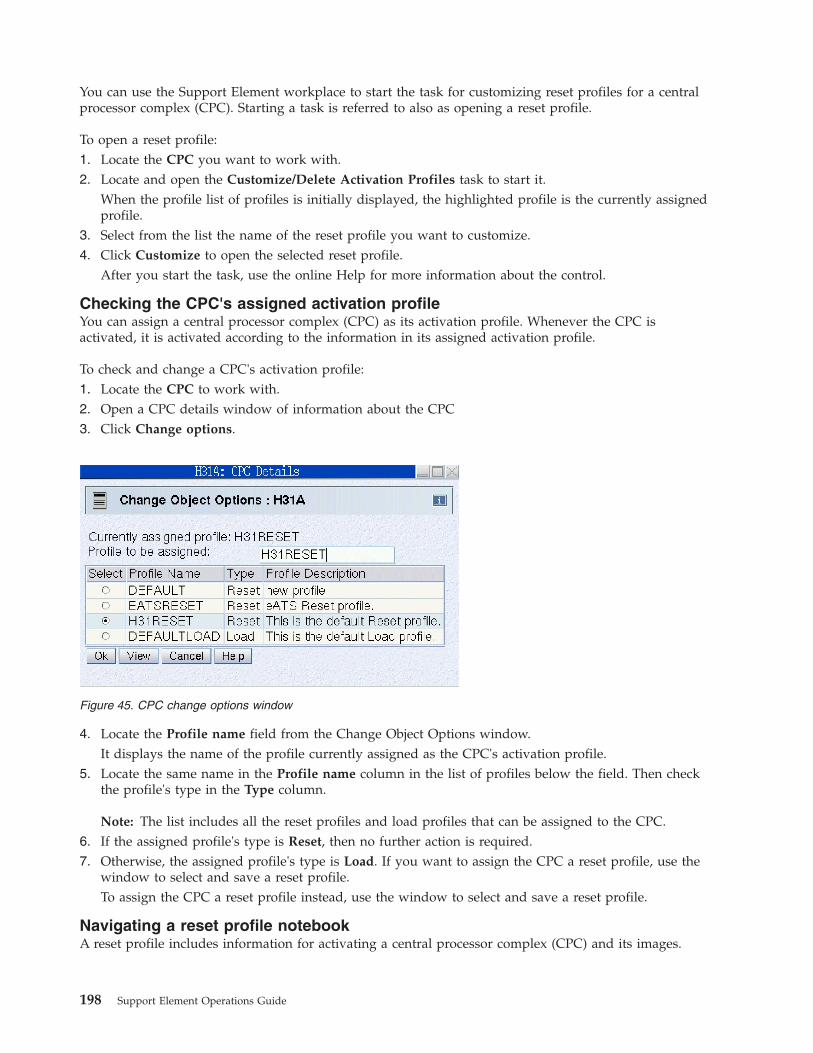
You can use the Support Element workplace to start the task for customizing reset profiles for a centralprocessor complex (CPC). Starting a task is referred to also as opening a reset profile.
To open a reset profile:1. Locate the CPC you want to work with.2. Locate and open the Customize/Delete Activation Profiles task to start it.
When the profile list of profiles is initially displayed, the highlighted profile is the currently assignedprofile.
3. Select from the list the name of the reset profile you want to customize.4. Click Customize to open the selected reset profile.
After you start the task, use the online Help for more information about the control.
Checking the CPC's assigned activation profileYou can assign a central processor complex (CPC) as its activation profile. Whenever the CPC isactivated, it is activated according to the information in its assigned activation profile.
To check and change a CPC's activation profile:1. Locate the CPC to work with.2. Open a CPC details window of information about the CPC3. Click Change options.
4. Locate the Profile name field from the Change Object Options window.It displays the name of the profile currently assigned as the CPC's activation profile.
5. Locate the same name in the Profile name column in the list of profiles below the field. Then checkthe profile's type in the Type column.
Note: The list includes all the reset profiles and load profiles that can be assigned to the CPC.6. If the assigned profile's type is Reset, then no further action is required.7. Otherwise, the assigned profile's type is Load. If you want to assign the CPC a reset profile, use the
window to select and save a reset profile.To assign the CPC a reset profile instead, use the window to select and save a reset profile.
Navigating a reset profile notebookA reset profile includes information for activating a central processor complex (CPC) and its images.
Figure 45. CPC change options window
198 Support Element Operations Guide

Opening a reset profile displays its information on the windows that are organized as pages in anotebook.
The pages are identified in a profile tree view on the left side of the window with a description label. Ifthe reset profile activates the CPC with multiple images, the profile tree view list the names of eachimage section with the identifying name. The information in each section is used to activate a singleobject either the CPC or a logical partition.
To use the profile tree view to open each page on the window:v Click on the description label for each page within a section of the profile you want to open.v Click on the '+' for each image to get a list of pages in the section of the profile.v To save the changes made, click Save.v To close the window, click Cancel.
Creating a new reset profileYou are responsible for creating reset profiles that meet your unique needs.
You can use the default reset profile as a template for creating new profiles. After you create a newprofile, you can customize it as needed. After you create and customize your own reset profiles, you canuse them as templates for creating more new profiles.
To create a new reset profile:1. Open a reset profile.
For more information, see “Reset profiles” on page 197.2. Select the General page.
Figure 46. Reset profiles
Appendix A. Customizing activation profiles 199
The Profile name field identifies the reset profile you opened. It will be used as a template for thenew reset profile.
3. To use a different reset profile as a template:4. Select the list button beside the Profile name field.
This opens a list of the names of all the CPC's reset profiles. The reset profile named DEFAULT is thedefault reset profile provided by IBM.
5. Select from the list the name of the reset profile you want to use as a template.This opens the selected reset profile. Its information replaces the previous profile's information on thepages of the window.
6. Enter a unique name for the new profile in the Profile name field.7. To save the profile with the new name, click Save.
Note: Saving the new profile does not change the reset profile you used as a template.
Assigning a reset profileAfter you open a reset profile, you can assign it to the central processor complex (CPC) as its activationprofile. Whenever the CPC is activated, it is activated according to the information in its assignedactivation profile.
To assign an open reset profile as a CPC's activation profile:1. After opening and customizing a reset profile, select the General page.
The Profile name field identifies the reset profile that will be assigned to the CPC.2. To assign the reset profile as the CPC's activation profile, click Assign profile.
Supporting LPAR mode operationThe reset profile you use to activate a central processor complex (CPC) can establish the support requiredto operate the CPC. The reset profile must identify:v An input/output configuration data set (IOCDS) that supports LPAR mode and the logical partitions
you want to activate.v LPAR mode as the operating mode you want to establish.
An IOCDS is used during a power-on reset to define your input/output (I/O) configuration to thechannel subsystem of the CPC. The I/O configuration is the set of all I/O devices, control units, andchannel paths available to the CPC. Performing a power-on reset also establishes the operating mode ofthe CPC.
To customize a reset profile to support operating the CPC:1. Open a reset profile.
For more information, see “Reset profiles” on page 197.2. Select the General page.3. Select from the Input/Output Configuration Data Set list an IOCDS that defines the logical partitions
you want to activate.Notes:a. The Type column indicates the operating mode supported by each IOCDS. The column displays
Partition to indicate an IOCDS supports LPAR mode.b. The Partitions column displays the names of logical partitions supported by the IOCDS.
4. Select Logically partitioned from the Mode list as the operating mode you want to establish.
200 Support Element Operations Guide
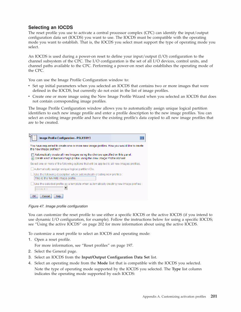
Selecting an IOCDSThe reset profile you use to activate a central processor complex (CPC) can identify the input/outputconfiguration data set (IOCDS) you want to use. The IOCDS must be compatible with the operatingmode you want to establish. That is, the IOCDS you select must support the type of operating mode youselect.
An IOCDS is used during a power-on reset to define your input/output (I/O) configuration to thechannel subsystem of the CPC. The I/O configuration is the set of all I/O devices, control units, andchannel paths available to the CPC. Performing a power-on reset also establishes the operating mode ofthe CPC.
You can use the Image Profile Configuration window to:v Set up initial parameters when you selected an IOCDS that contains two or more images that were
defined in the IOCDS, but currently do not exist in the list of image profiles.v Create one or more image using the New Image Profile Wizard when you selected an IOCDS that does
not contain corresponding image profiles.
The Image Profile Configuration window allows you to automatically assign unique logical partitionidentifiers to each new image profile and enter a profile description to the new image profiles. You canselect an existing image profile and have the existing profile's data copied to all new image profiles thatare to be created.
You can customize the reset profile to use either a specific IOCDS or the active IOCDS (if you intend touse dynamic I/O configuration, for example). Follow the instructions below for using a specific IOCDS;see “Using the active IOCDS” on page 202 for more information about using the active IOCDS.
To customize a reset profile to select an IOCDS and operating mode:1. Open a reset profile.
For more information, see “Reset profiles” on page 197.2. Select the General page.3. Select an IOCDS from the Input/Output Configuration Data Set list.4. Select an operating mode from the Mode list that is compatible with the IOCDS you selected.
Note the type of operating mode supported by the IOCDS you selected. The Type list columnindicates the operating mode supported by each IOCDS:
Figure 47. Image profile configuration
Appendix A. Customizing activation profiles 201
IOCDS type Operating mode
Partition Logically partitioned
Currently IDI The operating mode of the IOCDS is not known because the reset profile will usethe active IOCDS when activation is performed; the ID identifies the currentactive IOCDS. Select an operating mode from the Mode list that is compatiblewith the IOCDS you intend to make active. For more information, see "Using theactive IOCDS."
Using the active IOCDSThe reset profile you use to activate a central processor complex (CPC) can be customized for using theactive IOCDS rather than a specific IOCDS. The active IOCDS is the IOCDS used for the most recentpower-on reset. If you use dynamic I/O configuration, you can change the active IOCDS at any timewithout performing a power-on reset.
You should customize a reset profile to use the active IOCDS if you intend to use dynamic input/output(I/O) configuration. At least one of the images activated on the CPC must be loaded with an operatingsystem that supports an application or facility for using dynamic I/O configuration. Dynamic I/Oconfiguration is supported by:v The Hardware Configuration Definition (HCD) application on some z/OS and OS/390 operating
systems.v The dynamic I/O configuration facility of some z/VM and VM operating systems.
To customize an activation profile to use the active IOCDS:1. Open a reset profile.
For more information, see “Reset profiles” on page 197.2. Select the General page.3. Select Use active IOCDS from the Input/Output Configuration Data Set list.
When activation is performed using this reset profile:v The last active IOCDS is used if the CPC is not operational.v The active IOCDS is used if the CPC is already operational and if a power-on reset must be
performed to make at least one other profile setting take effect. For more information, see “Howusing the active IOCDS affects CPC activation.”
4. Note the identifier of the IOCDS that is currently active. See Currently ID displayed in the Type listcolumn for the Use active IOCDS selection. The ID is the IOCDS identifier.With dynamic I/O configuration, you can change the active IOCDS anytime prior to using this resetprofile to activate the CPC.
5. Select an operating mode from the Mode list that is compatible with the IOCDS you've made activeor intend to make active.To determine the type of operating mode supported by the IOCDS, locate it in the Input/OutputConfiguration Data Set list. The Type list column indicates the operating mode supported by theIOCDS.
How using the active IOCDS affects CPC activation
When a reset profile is used to activate the central processor complex (CPC), several profile settings takeeffect when a power-on reset is performed during activation. Such settings are referred to here aspower-on reset settings and include, for example, the CPC's storage allocations. If the CPC is alreadyoperational and the reset profile's power-on reset settings are already in effect when activation isperformed using the profile, then a power-on reset is not performed during activation. That is, apower-on reset is performed during CPC activation only if it is necessary to make one or more of thereset profile's power-on reset settings take effect.
202 Support Element Operations Guide
The input/output configuration data set (IOCDS) setting is one of the reset profile's power-on resetsettings, unless it is set to Use active IOCDS. Activating the CPC with a reset profile customized forusing the active IOCDS affects CPC activation as follows:v If the CPC is not operational, then a power-on reset is performed and the last active IOCDS is used.v If the CPC is already operational, then:
– A power-on reset is performed and the active IOCDS is used only if one or more of the resetprofile's other power-on reset settings are not already in effect. For example, a power-on reset isperformed if the CPC's global input/output (I/O) priority queuing flag is not the same as the globalI/O priority queuing flag set in the reset profile.
– A power-on reset is not performed and the active IOCDS is ignored if all of the reset profile's otherpower-on reset settings are already in effect.This may be the case when you use dynamic input/output (I/O) configuration. Using dynamic I/Oto change the active IOCDS will not affect whether a power-on reset is performed during CPCactivation. Only changing the reset profile's other power-on reset settings will cause a power-onreset to be performed.
Delaying the load while devices power-onThe reset profile you use to activate a central processor complex (CPC) can set a load delay for powersequencing.
Activating a CPC includes initializing its images and can include loading the images. The operatingsystems are loaded from devices in the input/output (I/O) configuration of the CPC.
If the devices are attached to control units that are powered-on by the CPC during activation, operatingsystems cannot be loaded from the devices until powering-on their control units is complete.
If you know or can estimate the amount of time it takes for control units to be powered-on, you candelay starting the load for that amount of time, up to 100 minutes. The delay may allow the powering-onto complete before the load begins.
To customize a reset profile to delay the load while control units power-on:1. Open a reset profile.
For more information, see “Reset profiles” on page 197.2. Select the General page.3. Enter the amount of time to delay the load, from 0 to 59 seconds or 1 to 100 minutes, in the Load
delay for power sequencing fields.
Supporting dynamic I/O configurationThe reset profile you use to activate a central processor complex (CPC) can establish the hardwaresupport required to use dynamic input/output (I/O) configuration.
Your I/O configuration is the set of all I/O devices, control units, and channel paths you define to yourhardware and software.
Performing a power-on reset establishes the hardware I/O definition. That is, it defines the I/Oconfiguration to the hardware. Loading the software establishes the software I/O definition. That is, itdefines the I/O configuration to the software.
Changing the hardware I/O definition requires performing another power-on reset, and changing thesoftware I/O definition requires loading the software again. If the hardware and software supportdynamic I/O configuration, you can dynamically change their I/O definitions. Changes made dynamically,referred to as dynamic I/O changes, take effect immediately. Yet they do not require a power-on reset orload to make them take effect.
Appendix A. Customizing activation profiles 203
Hardware support for dynamic I/O
Your hardware is the CPC. Dynamic I/O configuration, or simply dynamic I/O, is a facility of the CPC'slicensed internal code. The hardware support required for using dynamic I/O can be established duringpower-on reset of the CPC:v The IOCDS used during power-on reset must support dynamic I/O. The IOCDS must be either:
– Built using the Hardware Configuration Definition (HCD) application of an z/OS and OS/390 orother operating system that supports dynamic I/O.
– Written using the DYN option of the input/output configuration program (IOCP) utility of a z/VMand VM operating system that supports dynamic I/O.
v Dynamic I/O must be enabled for the CPC. That is, the CPC must allow dynamically changing its I/Odefinition.
Note: Only a power-on reset of the CPC, performed directly or during CPC activation, can initiallyenable dynamic I/O. Afterwards, you can use the support element workplace at any time, if necessary,to change the dynamic I/O setting. For more information, see “Enabling or disabling dynamic I/Owithout performing a power-on reset.”
v Dynamic I/O must be enabled for a logical partition.
To customize a reset profile for hardware support of dynamic I/O:1. Open a reset profile.
For more information, see “Reset profiles” on page 197.2. Select the General page.3. Select an IOCDS that supports dynamic I/O from the Input/Output Configuration Data Set list.
Note: The Allow Dynamic I/O column displays Yes to indicate an IOCDS supports dynamic I/O.4. Select the Dynamic page.5. Mark the Allow dynamic changes to the channel subsystem input/output (I/O) definition check box.
The check box displays a check mark when you mark it. The check mark indicates you want to enabledynamic I/O for the CPC.
Enabling or disabling dynamic I/O without performing a power-on reset
Performing a power-on reset of the central processor complex (CPC), either directly or by activating theCPC, establishes many of its initial operational capabilities and characteristics, including whetherdynamic input/output (I/O) configuration is enabled or disabled. After a power-on reset of the CPC isperformed, changing its operational capabilities and characteristics requires performing another power-onreset.
If a power-on reset of the CPC initially enables dynamic I/O configuration, a task becomes available onthe support element workplace for changing the CPC's dynamic I/O setting without performing anotherpower-on reset.
To change the CPC's dynamic I/O setting without performing a power-on reset:1. Locate the CPC to work with.2. Locate and open the Enable/Disable Dynamic Channel Subsystem task to start it.
The Customize Dynamic Channel Subsystem window displays.3. Use the window's controls, as follows, to enable or disable dynamic I/O for the CPC:
a. Review the CPC's current setting for dynamic I/O. The selected Enabled or Disabled, indicatesthe current setting.
b. While dynamic I/O is enabled, select Disabled to change the setting to disabled.
204 Support Element Operations Guide

c. Or while dynamic I/O is disabled, select Enabled to change the setting to enabled.d. Click OK to save the setting and close the window.
Optimizing the performance of an applicationYou can optimize the performance of an application by selecting a CP/SAP configuration for the centralprocessor complex (CPC) that best suits the instruction processing requirements.
The physical processor units installed in the CPC are used either as central processors (CPs) or systemassist processors (SAPs). The model of your machine determines its default configuration of CPs andSAPs. The SAPs, if any, are used exclusively for input/output (I/O) instruction processing.
If other CP/SAP configurations are available, selecting a configuration that configures one or more CPsas additional SAPs may improve the performance of some types of applications (applications that havegreater needs for I/O instruction processing, for example). Selecting a non-default CP/SAP configurationmay affect how the CPC can be activated.
Effects of changing the CP/SAP configuration
If you intend to activate a CPC, a reduction in the number of available CPs will reduce the number oflogical processors you can assign to logical partitions. Activation of a logical partition will fail if thenumber of logical processors you attempt to assign exceeds the number of CPs available.
To avoid a logical partition activation failure, verify the number of logical processors assigned to a logicalpartition by its activation profile does not exceed the number of CPs available. For more informationabout customizing an activation profile to assign logical processors to a logical partition, see “Assigninginitial logical or reserved processors” on page 213.
Planning for a fenced bookThe reset profile you use to activate a central processor complex (CPC) can determine how the availablesystem processors would be assigned when a hardware problem occurs with one of the system booksthat cause the book to be fenced or become unavailable for use.
Note: To display this Fenced page, select Display fenced book page on the CP/SAP page.
Appendix A. Customizing activation profiles 205

To customize a reset profile to let the system determine the processor assignment:1. Open a reset profile.
For more information, see “Reset profiles” on page 197.2. Select the Fenced page.3. Locate the Processor Assignment group box.4. Select the Determined by the system radio button.
To customize a reset profile to set a processor assignment by the user:1. Open a reset profile.
For more information, see “Reset profiles” on page 197.2. Select the Fenced page.3. Select the Determined by user radio button.4. Locate the Processor Assignment group box.5. Select the radio button to either:
v Display processor assignment when a 20 processors book is fenced.v Display processor assignment when a 24 processors book is fenced.
6. Type the values in the Value Used when Book is Fenced field.
Enabling or disabling the global input/output I/O) priority queuingThe reset profile you use to activate a CPC can enable or disable the global input/output (I/O) priorityqueuing.
To customize a reset profile for enabling or disabling global input/output (I/O) priority queuing:1. Open a reset profile.
Figure 48. Fenced book page
206 Support Element Operations Guide
For more information, see “Reset profiles” on page 197.2. Select the Options page.3. Locate the Enable global input/output (I/O) priority queuing check box. Then either:
v Mark the check box to enable global input/output priority queuing. The check box displays a checkmark when you mark it.
v Or unmark the check box to disable global input/output priority queuing. The check box becomesempty when you unmark it.
Releasing I/O reserves under error conditionsThe reset profile you use to activate a central processor complex (CPC) can enable automatically resettingthe input/output (I/O) interface under particular error conditions.
In a multiple CPC environment, several objects, which can be CPCs or logical partitions, may share thecontrol units, channel paths, and I/O devices included in their I/O definitions.
The following error conditions may cause shared control units to hold reserves on their devices:v A machine check places the CPC in a check-stopped state.v Or the control program places an image of the CPC or a logical partition in a non-restartable wait state.
The reserves are held for the CPC or logical partition affected by the error condition. Holding reservesprovides the affected object with exclusive use of devices, preventing them from being used by otherobjects that share the control units.
To release reserves held by shared control units assigned to an object, you must reset the I/O interface.Although resetting the I/O interface will not recover the object from its error condition, it will make thedevices attached to shared control units available to other objects.
To customize a reset profile to enable automatically resetting the I/O interface:1. Open a reset profile.
For more information, see “Reset profiles” on page 197.2. Select the Options page.3. Mark the Automatic input/output (I/O) interface reset check box.
The check box displays a check mark when you mark it. The check mark indicates you want to enableresetting the I/O interface automatically.
Setting processor running timeThe reset profile you use to activate a central processor complex (CPC) can set whether you or the CPCdetermines the processor running time.
When the CPC is activated, the logical processors of logical partitions activated without dedicatedprocessor resources share the remaining processor resources.
Each logical processor is given the same processor running time. Processor running time is the amount ofcontinuous time allowed for a logical processor to perform jobs using shared processor resources.Processor running time is referred to also as a timeslice.
The processor running time can be dynamically determined by the CPC. That is, the CPC canautomatically recalculate the running time whenever the number of active logical processors changes.
You can set the running time to a constant amount. To get optimal use of shared processor resources, IBMrecommends letting the CPC dynamically determine the running time.
To customize a reset profile to let the CPC dynamically determine processor running time:
Appendix A. Customizing activation profiles 207

1. Open a reset profile.For more information, see “Reset profiles” on page 197.
2. Select the Options page.3. Locate the Processor running time group box.4. Select the Dynamically determined by the system radio button.
To customize a reset profile to set a constant processor running time:1. Open a reset profile.
For more information, see “Selecting an operating mode” on page 209.2. Select the Options page.3. Locate the Processor running time group box.4. Select the Determined by the user radio button.5. Type the constant running time, from 1 to 100 milliseconds, in the Running time field.
Note: After activating the CPC, you can use the support element workplace to dynamically change itssettings for processor running time. See“Change LPAR Controls” on page 83 for more information.
Setting power savingThe reset profile you use to activate a central processor complex (CPC) can set the energy managementpower saving option to reduce the average energy consumption of the system.
To customize a reset profile to set the power saving option:1. Open a reset profile.
For more information, see “Reset profiles” on page 197.2. Select the Options page.3. Locate the Set Power Saving group box.4. Select the Custom Energy Management radio button to use the power saving settings.5. Select the Emergency High Performance radio button to override the power saving settings and use
the high performance setting with no power saving.
Activating logical partitions during CPC activationThe reset profile you use to activate a central processor complex (CPC) can also activate one or morelogical partitions.
To customize a reset profile to activate logical partitions during CPC activation:1. Open a reset profile.
For more information, see “Reset profiles” on page 197.2. If you have not already done so, customize the reset profile to activate the CPC. For more
information, see “Supporting LPAR mode operation” on page 200.3. Select the Partitions page.4. Review the logical partition name in each Partition field.
The fields are initialized with the names of logical partitions defined in the input/outputconfiguration data set (IOCDS) selected on the General page of the reset profile.
5. Review the numbers in the Order fields beside the logical partition names.The fields are initialized with the default activation order of the logical partitions. The logical partitionwith an order of 1 will be activated first, the logical partition with an order of 2 will be activatedsecond, and so on.
6. Optionally, enter a new order number in the Order field of a logical partition to change its activationorder.
208 Support Element Operations Guide
Note: If you intend to operate one of the logical partitions in coupling facility mode, it should beactivated first. That is, you should change the activation order of a coupling facility logical partition to1.
7. Optionally, delete the order number of a logical partition to not activate it during activation of theCPC.
Note: The names of logical partitions that are not activated will not be saved in the profile. That is, ifyou delete the order number of a logical partition, its name will be discarded.
The information used to activate a logical partition, though it is included in a reset profile, is actually thelogical partition's image profile.
The name of an image profile is the same as the name of the logical partition it activates. So each logicalpartition has only one image profile.
Since each reset profile that activates a logical partition includes the logical partition's only image profile,changing the logical partition's information in any activation profile changes the same information in allthe other profiles as well. That is, if you customize a reset profile for activating a logical partition, forexample, changing the reset profile also changes the logical partition's information in its image profile andin every other reset profile that activates the same logical partition.
Assigning a logical partition identifierThe activation profile you use to activate a logical partition must assign it a unique logical partitionidentifier.
The logical partition identifier becomes part of the central processor identifier of each logical processorassigned to the logical partition. The central processor identifier is used by subsystems and controlprograms to distinguish between logical processors.
To customize an activation profile to assign a logical partition identifier:1. Open a reset profile or open an image profile.
For more information, see “Reset profiles” on page 197 or “Images profiles” on page 225.2. If you opened a reset profile, select the name of the logical partition from the profile tree on the left
side of the window.3. Select the General page.4. In the Partition identifier field, type the hexadecimal digit to assign as the logical partition identifier.
Notes:
a. The partition identifier can be from X'0' to X'3F'.b. The partition identifier must be unique among the identifiers of other logical partitions activated
at the same time. If necessary, verify the partition identifier assigned to this image is unique bychecking the Partition identifier fields on the General pages of the other logical partitions youintend to activate.
Selecting an operating modeThe activation profile you use to activate a logical partition must identify the operating mode you wantto establish.
The operating mode describes the architecture that supports the operating system or control program youintend to load. Coupling facility and Linux Only are examples of operating modes.
To customize an activation profile to select an operating mode:1. Open a reset profile or open an image profile.
For more information, see “Reset profiles” on page 197 or “Images profiles” on page 225.
Appendix A. Customizing activation profiles 209
2. If you opened a reset profile, select the name of the logical partition from the profile tree from the leftside of the window.
3. Select the General page.4. Select the operating mode you want to establish from the Mode list.
Activating a coupling facility logical partitionThe activation profile you use to activate a logical partition can establish the support required to use it asa coupling facility.
A coupling facility is a logical partition that supports data sharing among applications running on othersystems or logical partitions. A logical partition operating as a coupling facility is referred to here as acoupling facility logical partition.
To customize an activation profile to support and activate a coupling facility logical partition:1. Open a reset profile or an image profile.
For more information, see “Reset profiles” on page 197 or “Images profiles” on page 225.2. If you opened a reset profile:
a. To activate the coupling facility logical partition during central processor complex (CPC)activation, customize the reset profile to activate the coupling facility logical partition first.For more information, see “Activating logical partitions during CPC activation” on page 208.
b. To customize the information used to activate the coupling facility logical partition, select thename of the logical partition from the profile tree on the left side of the window.
3. Select the General page.4. Select Coupling facility from the Mode list.5. Customize the activation profile to allocate storage to the coupling facility logical partition.
For more information, see “Allocating central storage (main storage)” on page 219.
Changing the group profile name for the logical partitionA logical partition can become a member of a group which allows determining the allocation andmanagement of processor resources assigned to logical partitions in a group activated by the profile.
To customize the group profile name assigned to the logical partitions:1. Open a reset profile or open an image profile.
For more information, see “Reset profiles” on page 197 or “Images profiles” on page 225.2. If you opened a reset profile, select the name of the logical partition from the profile tree on the left
side of the window.3. Select the Processor page.4. Locate the Group name in the list.5. Select the arrow beside the field to list the names of existing group profiles.6. Select a new group or create your own group profile name.
Note: If the group profile name is blank, then the logical partition is not assigned to a group.
Using internal coupling facility processorsIf internal coupling facility processors are installed in the CPC, you can assign a coupling facility logicalpartition either central processors, internal coupling facility processors, or dedicated coupling facilityprocessors and shared central processors.
To customize an activation profile to assign logical processors to a coupling facility logical partition:1. Open a reset profile or open an image profile.
For more information, see “Reset profiles” on page 197 or “Saving an image profile” on page 229.
210 Support Element Operations Guide
2. If you opened a reset profile, select the name of the logical partition from the profile tree on the leftside of the window.
3. Select the General page.4. If you select Coupling Facility from the Mode list, select the Processor page.5. Select the type of processors you want assigned to the coupling facility logical partition:
a. Dedicated internal coupling facility processorsb. Not dedicated internal coupling facility processorsc. Dedicated internal coupling facility processors and not dedicated central processors.d. Dedicated and not dedicated internal coupling facility processors.
Note: There are other options for assigning processors to the partition that are available, but theseother options DO NOT use Internal coupling facility.
6. If you select z/VM from the Mode list, select the Processor page.7. Use the Logical Processor Assignments group box to:
a. Select Central processors, Dedicated processors, and Internal coupling facility processors if youwant to assign dedicated Internal coupling facility processors to each logical partition.
b. Select Central processors and Internal coupling facility processors to assign not dedicatedInternal coupling facility processors to logical partitions when the logical partition is activated.
8. Use the controls available to complete the logical partition assignment for the coupling facility logicalpartition.
Assign both internal coupling facility processors and not dedicated central processors to the couplingfacility logical partition if you want to enable dynamic coupling facility expansion.
You can enable dynamic coupling facility dispatching for the coupling facility logical partition by:1. Starting the Operating System Messages task on its image.2. Using the task to send it the coupling facility control code command: DYNDISP ON
Using integrated facilities for Linux processorIf integrated facilities for Linux processors are installed in the CPC, you can assign a integrated facilitiesfor Linux logical partition either central processors or integrated facilities for Linux processors.
To customize an activation profile to assign logical processors to an integrated facilities for Linux logicalpartition:1. Open a reset profile or open an image profile.
For more information, see “Reset profiles” on page 197 or “Images profiles” on page 225.2. If you opened a reset profile, select the name of the logical partition from the profile tree on the left
side of the window.3. Select the General page.4. If you select LINUX only from the Mode list, select the Processor page.5. Select the type of processors you want assigned to the integrated facilities for Linux logical partition:
a. Dedicated integrated facilities for Linuxb. Not dedicated integrated facilities for Linux
Note: There are other options for assigning processors to the partition that are available, but theseother options DO NOT use integrated facilities for Linux.
6. If you select z/VM from the Mode list, select the Processor page.7. Use the Logical Processor Assignments group box to:
a. Select Central processors, Dedicated processors, and Integrated facilities for Linux processors ifyou want to assign dedicated Integrated facilities for Linux processors to each logical partition.
Appendix A. Customizing activation profiles 211

b. Select Central processors and Integrated facilities for Linux processors to assign not dedicatedIntegrated facilities for Linux processors to logical partitions when the logical partition is activated.
8. Use the controls available to complete the logical partition assignment for the integrated facilities forLinux logical partition.
Using zSeries application assist processorIf zSeries application assist processors are installed in the CPC, you can assign a zSeries application assistprocessor to a logical partition either central processors or zSeries application assist processors.
To customize an activation profile to assign logical processors to an zSeries application assist logicalpartition:1. Open a reset profile or open an image profile.
For more information, see “Reset profiles” on page 197 or “Images profiles” on page 225.2. If you opened a reset profile, select the name of the logical partition from the profile tree on the left
side of the window.3. Select the General page.4. Select ESA/390 or z/VM from the Mode list.5. Select the Processor page.6. Use the Logical Processor Assignments group box to:
a. Select Dedicated processors, Central processors, and zSeries application assist processors if youwant to assign dedicated zSeries application assist processors to the logical partition.
b. Select Central processors, zSeries application assist processors to assign not dedicated zSeriesapplication assist processors to logical partitions when the logical partition is activated.
7. Use the controls available to complete the logical partition assignment for the zSeries applicationassist processors logical partition.
Note: There are other options for assigning processors to the partition that are available, but theseother options DO NOT use zSeries application assist processors.
Using System z integrated information processorsIf the System z integrated information processors are installed in the CPC, you can assign a System zintegrated information logical partition either central processors or System z integrated informationprocessor.
To customize an activation profile to assign logical processors to a System z integrated information logicalpartition:1. Open a reset profile or open an image profile.
For more information, see “Reset profiles” on page 197 or “Images profiles” on page 225.2. If you opened a reset profile, select the name of the logical partition from the profile tree on the left
side of the window.3. Select the General page.4. Select ESA/390 or z/VM from the Mode list.5. Select the Processor page.6. Use the Logical Processor Assignment group box to:
a. Select Dedicated processors and Central processors, and System z integrated informationprocessors if you want to assign dedicated System z integrated information processors to the logicalpartition.
b. Select Central processors and System z integrated information processors to assign not dedicatedSystem z integrated information processors to logical partitions when the logical partition is activated.
7. Use the controls available to complete the logical partition assignment for the System z integratedinformation logical partition.
212 Support Element Operations Guide

Setting Workload Manager (WLM) controlsThe activation profile you use to activate a logical partition can manage your defined capacity for alogical partition. See “Setting defined capacity” on page 220 to set defined capacity for logical partitions.Workload Manager allows you to run all of your work concurrently while allocating system resources tothe most work first. Workload Manager constantly monitors your system, automatically adjusting theresource allocation as necessary.
Note: To customize Internal coupling facility processors (ICFs), Integrated facilities for Linux (IFL),zSeries application assist processors (zAAPs), and System z9® integrated information processors (zIIPs)you must select the processor type from the Not Dedicated Processor Details section prior to setting theprocessing weight values.
To customize an activation profile to allow Workload Manager to manage logical partitions:1. Open a reset profile or open an image profile.
For more information, see “Reset profiles” on page 197 or “Images profiles” on page 225.2. If you opened a reset profile, select the name of the logical partition from the profile tree on the left
side of the window.3. Select the General page.4. Select ESA/390, LINUX Only, or z/VM from the Mode list.5. Select the Processor page.6. Unmark the Initial Capping box. If there are more than one processor types selected in the processor
table, you may need to return to the Not Dedicated Processor Details for each processor type andunmark the Initial Capping box.
Note: You cannot mark the Initial Capping box if the Enable Workload Manager is enabled. Youmust unmark it to allow Initial Capping to be marked.
7. Mark the Enable Workload Manager check box to enable Workload Manager.A check box displays a check mark when you mark it.
8. Enter the processing weight values for the logical partition that you want to be managed by WorkloadManager.
Assigning initial logical or reserved processorsThe activation profile you use to activate a logical partition can assign it initial logical or reservedprocessors.
An initial logical processor is the processor resource defined to operate in a logical partition as a physicalcentral processor. Initial logical processors are the processors a control program uses to perform jobs forthe logical partition.
Reserved processors can be defined at partition activation time, but not used during partition activation.The reserved processor is not available when the system is activated, but can become available duringconcurrent central processor (CP) upgrade.
To customize an activation profile to assign initial logical processors to a logical partition:1. Open a reset profile or open an image profile.
For more information, see “Reset profiles” on page 197 or “Images profiles” on page 225.2. If you opened a reset profile, select the name of the logical partition from the profile tree on the left
side of the window.3. Select the Processor page.4. Enter the number of initial logical processors to assign to the logical partition or the number of
reserved processors.
Appendix A. Customizing activation profiles 213
Note: You cannot specify initial zSeries application assist processors (zAAPs) prior to installation ofzSeries application assist processors.
5. Use the controls in the Logical processor assignment group box to allocate processor resources tological partitions.
Note: After activating logical partitions, you can use the Support Element workplace to dynamicallychange its settings for sharing processor resources. See “Change LPAR Controls” on page 83 for moreinformation.
Time offsetThe Logical partition system time offset provides for the optional specification of a fixed time offset(specified in days, hours, and quarter hours) for each logical partition activation profile. The offset, ifspecified, will be applied to the time that a logical partition will receive from a Sysplex Timer or ServerTime Protocol (STP). This support can be used to address the following customer environment:v Different local time zone support in multiple sysplexes using the same Sysplex Timer or STP-only
Coordinated Timing Network (CTN).Many sysplexes have the requirement to run with a LOCAL=GMT setting in a sysplex(ETRMODE=YES or STPMODE=YES) where the time returned from a store clock (STCK) instructionyields local time. To fulfill this requirement, the time initialized for the Sysplex Timer or STP-only CTNmust be local time. With Logical partition time offset support, multiple sysplexes can each have theirown local time reported to them from a STCK instruction if wanted. For instance, the Sysplex Timer orSTP-only CTN can be set to GMT, one set of sysplex partitions could specify a Logical partition offsetminus 5 hours, and a second set of sysplex partitions could specify a Logical partition time offset ofminus 6 hours.
To customize the image profile for the system time offset:1. Open an activation profile customized for activating a CPC.2. Select Logical partition system time offset in the Clock type assignment box3. Select the Time Offset from the window tree view to set the offset and to choose how you want it
applied when the logical partition's clock is set.4. Click Save.5. Activate the CPC.
Use online Help to guide you through completion of this task.
Ensuring image profile data conforms to current maximum LICCC configurationThe data entered in the image profiles has to be compatible and supported by the Licensed Internal CodeConfiguration Control (LICCC). If image profile data changes, is imported, or the LICCC definitionchanges the profiles will be modified automatically to meet the new LICCC configuration. If this option isunchecked, the data entered for an image profile can be outside the valid LICCC configuration.
Note: It is recommended that image profile data conform to the current maximum LICCC configuration.
To customize the image profile to ensure the image profile data conforms to the current maximum LICCCconfiguration:1. Open a reset profile or open an image profile.
For more information, see “Reset profiles” on page 197 or “Images profiles” on page 225.2. If you opened a reset profile, select the name of the logical partition from the profile tree on the left
side of the window.3. Select the General page.4. Check Ensure that the image profile data conforms to the current maximum LICCC configuration to
ensure that the image profile data conforms to the current maximum LICCC configuration.
214 Support Element Operations Guide

Controlling access to performance dataThe activation profile you use to activate a logical partition can control whether it has global access toperformance data.
A logical partition has access to only its own performance data. A logical partition with global access alsohas access to the performance data of all other logical partitions activated on the same central processorcomplex (CPC). Performance data includes central processor usage and input/output processor usage byeach logical partition.
To customize an activation profile to control global access to performance data:1. Open a reset profile or open an image profile.
For more information, see “Reset profiles” on page 197 or “Images profiles” on page 225.2. If you opened a reset profile, select the page tab that displays the name of the logical partition.3. Select the Security page.4. Locate the Global performance data control check box. Then either:
v Mark the check box to give the logical partition global access to performance data. The check boxdisplays a check mark when you mark it.
v Or unmark the check box to give the logical partition access to only its own performance data. Thecheck box becomes empty when you unmark it.
Note: After activating logical partitions, you can use the Support Element workplace to dynamicallychange their security settings, including global performance data control. See “Change LPAR Security” onpage 87 for more information.
Controlling I/O configuration changesThe activation profile you use to activate a logical partition can control whether it can change theinput/output (I/O) configuration of the central processor complex (CPC) on which it is activated.
Allowing a logical partition to change the I/O configuration enables:v Reading and writing any input/output configuration data set (IOCDS) of the local CPC.v Writing an IOCDS to a remote CPC.v Using dynamic I/O configuration.v Using the OSA Support Facility to view OSA configuration for other logical partitions.
To customize an activation profile to control changing the I/O configuration:1. Open a reset profile or open an image profile.
For more information, see “Reset profiles” on page 197 or “Images profiles” on page 225.2. If you opened a reset profile, select the name of the logical partition from the profile tree view on the
left side of the window.3. Select the Security page.4. Locate the Input/output (I/O) configuration control check box. Then either:
v Mark the check box to allow using the logical partition to change the I/O configuration. The checkbox displays a check mark when you mark it.
v Or unmark the check box to prevent using the logical partition to change the I/O configuration.The check box becomes empty when you unmark it.
Note: After activating logical partitions, you can use the Support Element workplace to dynamicallychange their security settings, including I/O configuration control. See “Change LPAR Security” on page87 for more information.
Appendix A. Customizing activation profiles 215
Using dynamic I/O configurationDynamic input/output (I/O) configuration is supported by:v The Hardware Configuration Definition (HCD) application on some z/OS and OS/390 operating
systems.v The dynamic I/O configuration facility of some z/VM and VM operating systems.
Input/output configuration control must be enabled for the logical partition that you want to usedynamic I/O configuration. That is, you must mark the Input/output (I/O) configuration control checkbox on the Security page of the activation profile used to activate the logical partition.
Authorizing control of other logical partitionsThe activation profile you use to activate a logical partition can control whether it can be used to issue asubset of control program instructions to other logical partitions activated on the same central processorcomplex (CPC).
Allowing a logical partition to issue instructions to other logical partitions enables:v Using it to reset or deactivate another logical partition.v Using the automatic reconfiguration facility (ARF) to backup another logical partition.
To customize an activation profile to authorize control of other logical partitions:1. Open a reset profile or open an image profile.
For more information, see “Reset profiles” on page 197 or “Images profiles” on page 225.2. If you opened a reset profile, select the name of the logical partition from the profile tree view on the
left side of the window.3. Select the Security page.4. Locate the Cross partition authority check box. Then either:
v Mark the check box to allow using the logical partition to control other logical partitions. The checkbox displays a check mark when you mark it.
v Or unmark the check box to prevent using the logical partition to control other logical partitions.The check box becomes empty when you unmark it.
Note: After activating logical partitions, you can use the Support Element workplace to dynamicallychange their security settings, including cross partition authority. See “Change LPAR Security” on page 87for more information.
Controlling use of reconfigurable channel pathsThe activation profile you use to activate a logical partition can control whether it has exclusive use of itsreconfigurable channel paths.
A logical partition has exclusive use of its reconfigurable channel paths only while they are configuredon. If the channel paths are configured off, they can be configured on to another logical partition.
Isolating a logical partition's reconfigurable channel paths reserves them for the logical partition whilethey are configured off, and prevents them from being configured on to other logical partitions.
To customize an activation profile to control the use of reconfigurable channel paths:1. Open a reset profile or open an image profile.
For more information, see “Reset profiles” on page 197 or “Images profiles” on page 225.2. If you opened a reset profile, select the name of the logical partition from the profile tree view on the
left side of the window.3. Select the Security page.4. Locate the Logical partition isolation check box. Then either:
216 Support Element Operations Guide

v Mark the check box to isolate the logical partition's offline reconfigurable channels paths. The checkbox displays a check mark when you mark it.
v Or unmark the check box to make the logical partition's reconfigurable channels paths available toother logical partitions when the channel paths are configured off. The check box becomes emptywhen you unmark it.
Note: After activating logical partitions, you can use the support element workplace to dynamicallychange their security settings, including logical partition isolation. See “Change LPAR Security” on page87 for more information.
Authorizing basic counter set controlThe basic counter set authorization control allows authorization to use the basic counter set in analysis ofcache performance, cycle counts, and instruction counts while the logical CPU is running.
To customize an activation profile to indicate whether authorization is allowed to use the basic counterset:1. Open a reset profile or open an image profile.
For more information, see “Reset profiles” on page 197 or “Images profiles” on page 225.2. If you opened a reset profile, select the name of the logical partition from the profile tree view on the
left side of the window.3. Select the Security page.4. Locate the Basic counter set authorization control check box. Then either:
v Mark the check box to indicate whether authorization is allowed to use the basic counter setauthorization control in analysis of cache performance, cycle counts, and instruction counts whilethe logical CPU is running.
v Or unmark the check box not to allow authorization to use the basic counter set authorizationcontrol.
Authorizing problem state counter set controlThe problem state counter set authorization control allows authorization to use the problem state counterset in analysis of cache performance, cycle counts, and instruction counts while the logical CPU is inproblem state.
To customize an activation profile to indicate whether authorization for problem state counter set isallowed:1. Open a reset profile or open an image profile.
For more information, see “Reset profiles” on page 197 or “Images profiles” on page 225.2. If you opened a reset profile, select the name of the logical partition from the profile tree view on the
left side of the window.3. Select the Security page.4. Locate the Problem state counter set authorization control check box. Then either:
v Mark the check box to indicate whether authorization is allowed to use the problem state counterset authorization control in analysis of cache performance, cycle counts, and instruction countswhile the logical CPU is in problem state.
v Or unmark the check box not to allow authorization to use the problem state counter setauthorization control
Authorizing crypto activity counter set controlThe crypto activity counter set authorization control allows authorization to use the crypto activitycounter set to identify the crypto activities contributed by the logical CPU and the blocking effects on thelogical CPU.
Appendix A. Customizing activation profiles 217

To customize an activation profile to indicate whether authorization for crypto activity counter setauthorization control:1. Open a reset profile or open an image profile.
For more information, see “Reset profiles” on page 197 or “Images profiles” on page 225.2. If you opened a reset profile, select the name of the logical partition from the profile tree view on the
left side of the window.3. Select the Security page.4. Locate the Crypto activity counter set authorization control check box. Then either:
v Mark the check box to indicate whether authorization is allowed to use the crypto activity counterset authorization control to identify the crypto activities contributed by the logical CPU and theblocking effects on the logical CPU.
v Or unmark the check box not to allow authorization to use the crypto activity counter setauthorization control.
Authorizing extended counter set controlThe extended counter sets authorization control allows authorization of the model-dependent extendedcounter set.
To customize an activation profile to indicate whether authorization for extended counter setauthorization control:1. Open a reset profile or open an image profile.
For more information, see “Reset profiles” on page 197 or “Creating a new image profile” on page227.
2. If you opened a reset profile, select the name of the logical partition from the profile tree view on theleft side of the window.
3. Select the Security page.4. Locate the Extended counter set authorization control check box. Then either:
v Mark the check box to indicate whether authorization is allowed to use the extended counter setauthorization control. The counters of this set are model dependent.
v Or unmark the check box not to allow authorization to use the extended counter set authorizationcontrol.
Authorizing coprocessor group counter sets controlThe coprocessor group counter set authorization control allows authorization to count the cryptoactivities of a coprocessor.
To customize an activation profile to indicate whether authorization for coprocessor group counter setsauthorization control:1. Open a reset profile or open an image profile.
For more information, see “Reset profiles” on page 197or “Images profiles” on page 225.2. If you opened a reset profile, select the name of the logical partition from the profile tree view on the
left side of the window.3. Select the Security page.4. Locate the Coprocessor group counter sets authorization control check box. Then either:
v Mark the check box to indicate whether authorization is allowed to use the coprocessor groupcounter sets to count the crypto activities of a coprocessor.
v Or unmark the check box not to allow authorization to use the coprocessor group counter setsauthorization control.
218 Support Element Operations Guide
Authorizing basic sampling controlThe basic sampling authorization control allows authorization to use the basic sampling function. Thesample data includes an instruction address, the primary ASN, and some state information about theCPU. This allows tooling programs to map instruction addresses into modules or tasks, and facilitatesdetermination of hot spots.
To customize an activation profile to indicate whether authorization for basic sampling authorizationcontrol:1. Open a reset profile or open an image profile.
For more information, see “Reset profiles” on page 197 or “Images profiles” on page 225.2. If you opened a reset profile, select the name of the logical partition from the profile tree view on the
left side of the window.3. Select the Security page.4. Locate the Basic sampling authorization control check box. Then either:
v Mark the check box to indicate whether authorization is allowed to use the basic samplingauthorization control function.
v Or unmark the check box not to allow authorization to use the basic sampling authorizationcontrol.
Permit AES key import functionsThe permit Advanced Encryption Standard (AES) key import functions allow you to enable the newPerform Cryptographic Key Management Operation functions of the CP Assist for CryptographicFunctions (CPACF) feature.
To customize an activation profile to permit AES key import functions:1. Open a reset profile or open an image profile.
For more information, see “Reset profiles” on page 197 or “Images profiles” on page 225.2. If you opened a reset profile, select the name of the logical partition from the profile tree view on the
left side of the window.3. Select the Security page.4. Locate the Permit AES key import functions check box. Then either:
v Mark the check box to permit AES key import functions.v Or unmark the check box not to permit AES key import functions.
Permit DEA key import functionsThe permit Data Encryption Algorithm (DEA) key import functions allow you to enable the new PerformCryptographic Key Management Operation functions of the CP Assist for Cryptographic Functions(CPACF) feature.
To customize an activation profile to permit DEA key import functions:1. Open a reset profile or open an image profile.
For more information, see “Reset profiles” on page 197 or “Images profiles” on page 225.2. If you opened a reset profile, select the name of the logical partition from the profile tree view on the
left side of the window.3. Select the Security page.4. Locate the Permit DEA key import functions check box. Then either:
v Mark the check box to permit DEA key import functions.v Or unmark the check box not to permit DEA key import functions.
Allocating central storage (main storage)The activation profile you use to activate a logical partition can allocate its storage.
Appendix A. Customizing activation profiles 219

The central storage allocated to a logical partition upon activation is its initial storage. You must allocateinitial central storage to each logical partition you intend to activate.
To customize an activation profile for allocating central storage to a logical partition:1. Open a reset profile or open an image profile.
For more information, see “Reset profiles” on page 197 or “Images profiles” on page 225.2. If you opened a reset profile, select the name of the logical partition from the profile tree view on the
left side of the window.3. Select the Storage page.4. Use the Central storage group box to allocate the logical partition's central storage and to set its
central storage origin.
Setting I/O priority queuing valuesThe activation profile you use to activate a logical partition can control the I/O priority queuingassignment of logical partitions.
To customize an activation profile for I/O priority queuing:1. Open a reset profile or open an image profile.
For more information, see “Reset profiles” on page 197 or “Images profiles” on page 225.2. If you opened a reset profile, select the page tab that displays the name of the logical partition.3. Select the Options page.4. Use the controls to set minimum and maximum I/O priority queuing values.
Setting defined capacityThe activation profile you use to activate a logical partition can control the defined capacity for a logicalpartition. A defined capacity is the portion of your processor resources you order from IBM.
Your defined capacity can be associated with:v A license software product. You specify a defined capacity for a product on the product certificate.v An LPAR. You specify a defined capacity for an LPAR using the appropriate LPAR controls. A defined
capacity applies to the entire LPAR, no matter how many applications it contains.
To customize an activation profile to set defined capacity:1. Open a reset profile or open an image profile.
For more information, see “Reset profiles” on page 197 or “Images profiles” on page 225.2. If you opened a reset profile, select the name of the logical partition from the profile tree view on the
left side of the window.3. Select the Options page.4. Enter the defined capacity value for your logical partition.
Loading an operating system during activationThe activation profile you use to activate an object can also load its image with an operating system. Theobject is a central processor complex (CPC) activated in a logical partition.
To customize an activation profile to load an operating system during an object's activation:1. Open an applicable activation profile:
v If the object is a logical partition, either open a reset profile or open its image profile.For more information, see “Reset profiles” on page 197 or “Images profiles” on page 225.
Note: The activation profile must not be customized to activate the logical partition as a couplingfacility. For more information, see “Selecting an operating mode” on page 209.
220 Support Element Operations Guide
2. If you opened a reset profile, select the name of the logical partition from the profile tree view on theleft side of the window.
3. Select the Load page.4. Mark the Load during activation check box.
The check box displays a check mark when you mark it. The check mark indicates activation willinclude loading the object's image with an operating system.
5. Use the other controls on the page to provide information about which operating system to load andhow to load it.
Setting load attributesThe activation profile you use to load an image can set the load address and load parameter used toperform the load.
The load address is the address of the input/output (I/O) device that provides access to the operatingsystem you want to load. The I/O device must be in the I/O configuration that is active when the load isperformed. The I/O device may store the operating system or may be used to read the operating systemfrom a storage device.
The load parameter is additional information operating systems support to provide you with additionalcontrol over the performance or outcome of a load. Check the configuration programming and referencedocumentation for the operating system to determine the load parameters that are available, and theireffect on a load.
To customize an activation profile to set the load address and load parameter:1. Open an activation profile:
v Open a reset profile or open its image profile.For more information, see “Reset profiles” on page 197 or “Images profiles” on page 225.
Note: The activation profile must not be customized to activate the logical partition as a couplingfacility. For more information, see “Selecting an operating mode” on page 209.
v Or open a load profile.For more information, see “Load profiles” on page 229.
2. If you opened a reset profile, select the name of the logical partition from the profile tree on the leftside of the window.
3. Select the Load page.
Note: If you opened a load profile, the Load page is the first and only page.4. Enter the load address in the Load address field.5. Enter the load parameter in the Load parameter field.
Using dynamic I/O to set load attributesThe activation profile you use to load an image can enable using dynamic input/output (I/O)configuration, rather than the activation profile, to set the load address and load parameter used toperform the load.
The image must be activated on a CPC that supports dynamic I/O configuration. The image, or at leastone of the images activated on the CPC, must be loaded with an operating system that supports anapplication or facility for using dynamic I/O configuration. Dynamic I/O configuration is supported by:v The Hardware Configuration Definition (HCD) application on some z/OS and OS/390 operating
systems.v The dynamic I/O configuration facility of some z/VM and VM operating systems.
Appendix A. Customizing activation profiles 221
To customize an activation profile to enable using dynamic I/O to set the load address and loadparameter:1. Open an activation profile:
v Open a reset profile or open its image profile.For more information, see “Reset profiles” on page 197or “Images profiles” on page 225.
Note: The activation profile must not be customized to activate the logical partition as a couplingfacility. For more information, see “Selecting an operating mode” on page 209.
v Or open a load profile.For more information, see “Load profiles” on page 229.
2. If you opened a reset profile and the object is a logical partition, select the name of the logicalpartition from the profile tree on the left side of the window.
3. Select the Load page.
Note: If you opened a load profile, the Load page is the first and only page.4. Mark the Use dynamically changed address check box.
The check box displays a check mark when you mark it. The check mark indicates activation willperform each load using the load address set for the image using dynamic I/O configuration.
5. Mark the Use dynamically changed parameter check box.The check box displays a check mark when you mark it. The check mark indicates activation willperform each load using the load parameter set for the image using dynamic I/O configuration.
Setting a time limit for performing the loadThe activation profile you use to load an image sets a time limit for performing the load.
A time limit, or time-out value, is the amount of time allowed for performing the load. The load iscancelled if it cannot be completed within the time limit.
To customize an activation profile to set the time limit for performing the load:1. Open an activation profile:
v Open a reset profile or open its image profile.For more information, see “Reset profiles” on page 197 or “Images profiles” on page 225.
Note: The activation profile must not be customized to activate the logical partition as a couplingfacility. For more information, see “Selecting an operating mode” on page 209.
v Or open a load profile.For more information, see “Load profiles” on page 229.
2. If you opened a reset profile, select the name of the logical partition from the profile tree view on theleft side of the window.
3. Select the Load page.
Note: If you opened a load profile, the Load page is the first and only page.4. Enter the time limit, from 60 to 600 seconds, in the Time-out value field.
Setting SCSI attributesThe activation profile you use to load an image can set the SCSI parameters used to perform the load.
The Worldwide port name is the number identifying the Fibre Channel port of the SCSI target device. Thisfield contains the 64-bit binary number designating the port name, represented by 16 hexadecimal digits.
222 Support Element Operations Guide
The Logical unit number is the number of the logical unit as defined by FCP. This field contains the 64-bitbinary number designating the unit number of the FCP I/O device, represented by 16 hexadecimal digits.This field is required for SCSI IPL and SCSI dump.
The Boot program selector is a decimal value number specifying the program to be loaded from theFCP-load device during SCSI IPL or SCSI dump. Valid values range from 0 to 30.
The Boot record logical block address is the load block address field represented by 16 hexadecimalcharacters, designating the logical-block address of a boot record on the FCP-load device. If no blockaddress is specified, the logical-block address of the boot record is assumed to be zero.
The OS specific load parameters is a variable number of characters to be used by the program that is loadedduring SCSI IPL or SCSI dump. This information will be given to the IPLed operating system and will beignored by the machine loader. The IPLed operating system has to support this.
To customize an activation profile to set the SCSI parameters:1. Open an activation profile:
v Open a reset profile or open its image profile.For more information, see “Reset profiles” on page 197 or “Images profiles” on page 225.
Note: The activation profile must not be customized to activate the logical partition as a couplingfacility. For more information, see “Selecting an operating mode” on page 209.
v Or open a load profile.For more information, see “Load profiles” on page 229.
2. If you opened a reset profile, select the name of the logical partition from the profile tree view on theleft side of the window.
3. Select the Load page.
Note: If you opened a load profile, the Load page is the first and only page.4. Enter the worldwide port name in the Worldwide port name field.5. Enter the logical unit name in the Logical unit number field.6. Enter the boot program number in the Boot program selector field.7. Enter the boot record logical block address in the Boot record logical block address field.8. Enter the OS specific load number in the OS specific load parameters field.
Using the Crypto Express3 featureThe activation profile you use to activate a logical partition can prepare it for running software productsthat utilize the Crypto Express3 feature. Using the feature's cryptographic facilities and functions requirescustomizing the logical partition's activation profile to:v Give it access to at least one CEX3A and CEX3C. This is accomplished by selecting from the Usage
Domain Index and the Cryptographic Candidate list.v Load it with an operating system, such as z/OS, that supports using cryptographic functions.v Install the CP Assist for Cryptographic Facility (CPACF) DES/TDES Enablement feature if planning to
use ICSF.
For more information about the cryptographic feature, see “Cryptographic Configuration” on page 116.
To customize an activation profile to allow a logical partition to use cryptographic facilities and functions:1. Open a reset profile or open an image profile.
For more information, see “Reset profiles” on page 197 or “Images profiles” on page 225.2. If you opened a reset profile, select the name of the logical partition from the profile tree view on the
left side of the window.
Appendix A. Customizing activation profiles 223

3. Select the General page.4. Select ESA/390 , ESA/390 TPF, LINUX Only, or z/VM from the Mode list.5. Select Crypto from the profile tree view on the left side of the window. Use the controls on the
Crypto page to indicate whether and how you want the logical partition to use the cryptographicfunctions and facilities.Notes:
v If you intend to use the Integrated Cryptographic Service Facility (ICSF), see “Using the z/OSIntegrated Cryptographic Service Facility (ICSF)” for additional instructions for customizing theCrypto page.
v If you intend to use a Trusted Key Entry (TKE) workstation to manage cryptographic keys, see“Using the Trusted Key Entry (TKE) Workstation feature” for additional instructions forcustomizing the Crypto page.
v After activating logical partitions customized to use CEX3A and CEX3C, you can use the SupportElement workplace to view the settings of the cryptographic controls set on the Crypto page oftheir activation profiles. See “View LPAR cryptographic controls” on page 95 for more information.
6. Customize the Load page to load an operating system that supports using cryptographic functionsand facilities.For more information about loading an operating system, see the topics that follow “Loading anoperating system during activation” on page 220.
Using the z/OS Integrated Cryptographic Service Facility (ICSF): The z/OS Integrated CryptographicService Facility (ICSF) is a program product that provides secure, high-speed cryptographic services inthe operating environment. You can use ICSF services for all logical partitions that are customized forusing Crypto Express3 feature.
Note: Some functions of ICSF may fail if you do not have the CP Assist for Cryptographic Functions(CPACF) DES/TDES Enablement feature installed. See the or the for complete information.
The activation profile you use to activate a logical partition can prepare it for using ICSF services.Customize the activation profiles when installing the CP Assist for Cryptographic Functions (CPACF)DES/TDES Enablement feature.
To customize an activation profile for a logical partition to use the ICSF services:1. Customize a reset profile or image profile to configure the logical partition access to the cryptographic
facilities and functions.For more information, see “Reset profiles” on page 197 or “Images profiles” on page 225.
2. Select the Crypto page again.3. If you have not already set the logical partition's controls, set them now:
a. Select a usage domain index for the logical partition to use for cryptographic functions from theUsage domain index list. More than one number should be selected from the Usage domain indexwhen z/VM operating environment is running in the logical partition with other guests (forexample, Linux) requiring access to the cryptographic hardware.
Note: The cryptographic number, selected from the Cryptographic Candidate List, coupled with theusage domain index must be unique for each active partition.
4. Select from the Online List the number which specifies the coprocessors to be brought online atpartition activation. For each number selected in the Online List, the corresponding number in theCandidate List must be selected.
Using the Trusted Key Entry (TKE) Workstation feature: A Trusted Key Entry (TKE) is a workstationapplication supported by ICSF to allow an alternative method of securely loading cryptographic keys(DES and PKA master keys and operational keys). A unique set of cryptographic keys is maintained foreach domain index within the cryptographic facility. Only one partition can perform TKE functions at a
224 Support Element Operations Guide
time. The logical partition with this control is referred to as the TKE host. The other partitions thatreceive key updates from the TKE host are referred to as the TKE targets.
The activation profile you use to activate a logical partition can prepare it for being a TKE host or TKEtarget.
To use a TKE workstation to manage requests for secure information or commands to a specific CEX3C,permission must be given. See “TKE commands” on page 118.
To customize an activation profile for a TKE host logical partition:1. Customize a reset profile or image profile to enable the logical partition to use cryptographic facilities
and functions.For more information, see “Reset profiles” on page 197 or “Images profiles.”
2. Select the Crypto again.3. If you have not already set the logical partition's controls, set them now:
a. Select a usage domain index for the logical partition to use for cryptographic functions from theUsage domain index list. It must be the same as the usage domain index set for the logicalpartition in the ICSF installation options data set.
Note: The cryptographic number, selected from the Cryptographic Candidate List, coupled withthe usage domain index must be unique for each active partition.
4. Select from the Online List the number which specifies the coprocessors to be brought online atpartition activation. For each number selected in the Online List, the corresponding number in theCandidate List must be selected.
5. From the Control domain index list, also select each index that is the same as the usage domainindex of each TKE target logical partition you want to manage through a TKE workstation connectionto this TKE host logical partition.
Profiles for staged activationsYou can perform a staged activation of a central processor complex (CPC) and its images by using a resetprofile for an initial activation of the CPC, and then using other types of profiles for selective activationsof its images.
Typical staged activations include:v Using a reset profile to initially activate the CPC and to activate and load one or more logical
partitions. Then, at a later time, using load profiles to load one or more previously activated logicalpartitions with a different operating system, or using image profiles to activate and load one or morelogical partitions not previously activated.This type of staged activation allows the operator to change the active logical partitions whilemaintaining the rest of the CPC's current operational capabilities and characteristics.
Images profiles
Customize an image profile for activating a logical partition when you want to activate only the logicalpartition, after the central processor complex (CPC) that supports it is initially activated.
Optionally, you can customize the image profile to also load the logical partition during activation.
Notes:
Appendix A. Customizing activation profiles 225
v Initially activating a CPC requires customizing and using a reset profile. For more information, see“Supporting LPAR mode operation” on page 200 and the other topics that follow.
v The name of an image profile is the same as the name of the logical partition it activates. Each logicalpartition has only one image profile.Each reset profile that activates a logical partition includes the logical partition's only image profile, sochanging the logical partition's information in any activation profile changes the same information inall the other profiles as well. That is, if you customize an image profile for activating a logical partition,for example, changing the image profile also changes the logical partition's information in every resetprofile that activates the logical partition.
The information used to activate a logical partition, though it is included in a reset profile, is actually thelogical partition's image profile.
To open a logical partition's image profile:1. Locate the Images you want to work with.2. Locate the image with the same name as the logical partition.3. Locate and open the Customize/Delete Activation Profiles task to start it.
This opens the image profile and the list of load profiles you want to customize. When the list isinitially displayed, the highlighted profile is the currently assigned profile for the partition.
4. Select from the list the name of the image profile you want to customize.5. Click Customize.
Checking a logical partition's assigned activation profile: You can assign a logical partition either itsimage profile or a load profile as its activation profile. Whenever the logical partition is activated,individually rather than with the central processor complex (CPC), it is activated according to theinformation in its assigned activation profile.
In addition, whenever you start the task for customizing the logical partition's activation profiles, it opensthe logical partition's assigned activation profile. After you start the task, you can customize its assignedactivation profile. If its assigned activation profile is a load profile, you can also create new load profilesor open and customize any other existing load profiles.
For example, to customize the image profile for a logical partition, its assigned activation profile must beits image profile. You can check, and change if necessary, the logical partition's assigned activation profilebefore you begin customizing its profiles.
To check or change a logical partition's activation profile:1. Locate the Images you want to work with.2. Locate the image with the same name as the logical partition.3. Click Change options.
This opens the Change Object Options window.4. Locate the Profile name field.
It displays the name of the profile currently assigned as the logical partition's activation profile.5. Locate the same name in the Profile name column in the list of profiles below the field. Then check
the profile's type in the Type column.
Note: The list includes the logical partition's image profile and all the load profiles that can beassigned to the logical partition.
6. If the assigned profile's type is Image, then no further action is required.Whenever you start the task for customizing the logical partition's activation profiles, you will be ableto customize the logical partition's image profile.
7. If the assigned profile's type is Load, you will be able to customize only load profiles.
226 Support Element Operations Guide
To assign the logical partition its image profile instead, use the window to select and save the imageprofile.
Navigating the image profile notebook: An image profile includes information for activating a logicalpartition.
Opening an image profile displays its information on the window organized in a profile tree view.
The pages are identified in a profile tree view on the left side of the window with a description label. Thedescription label for each page is a general description of the information on the page.
To use the profile tree view to turn to a different page of the image profile:v Click on description label in the profile tree view that you want to open.
A window opens to that page of the image profile.v To save the changes made, click Save.v To close the window, click Cancel.
Creating a new image profile: You are responsible for creating image profiles that meet your uniqueneeds.
You can use the default image profile as a template for creating new profiles. After you create a newprofile, you can customize it as needed. After you create and customize your own image profiles, you canuse them as templates for creating more new profiles.
To create a new image profile:1. Open a image profile.
For more information, see “Images profiles” on page 225.2. Select the General page.
The Profile name field identifies the image profile you opened. It will be used as a template for thenew image profile.
3. To use a different image profile as a template:4. Click the list button beside the Profile name field.
This opens a list of the names of all the image profiles. The image profile named DEFAULT is thedefault image profile provided by IBM.
5. Select from the list the name of the image profile you want to use as a template.This opens the selected image profile. Its information replaces the previous profile's information onthe pages of the notebook.
6. Enter a unique name for the new profile in the Profile name field.7. Click Save to save the profile with the new name.
Note: Saving the new profile does not change the image profile you used as a template.
Creating one or more image profiles: The New Image Profile Wizard tool can be used to configure newimage profile parameters for one or more images currently selected in the IOCDS that do not havecorresponding image profiles.
Appendix A. Customizing activation profiles 227

1. Select an image profile that is currently not created.2. Click New image profile.3. Use the New Image Profiles Wizard to create data for the image profile that you selected.4. Complete the requested information for the image profile you are creating.5. Click Finish to confirm your changes.
Customize multiple image profiles: The Customize Image Profile Wizard tool can be used to modifyparameters for two or more of the image profiles that you select on the customize/delete activationprofiles list.
Figure 49. New image profile wizard
228 Support Element Operations Guide
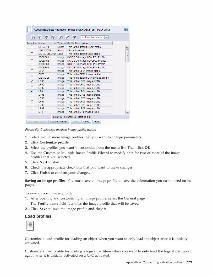
1. Select two or more image profiles that you want to change parameters.2. Click Customize profile.3. Select the profiles you want to customize from the menu list. Then click OK.4. Use the Customize Multiple Image Profile Wizard to modify data for two or more of the image
profiles that you selected.5. Click Next to start.6. Check the appropriate check box that you want to make changes.7. Click Finish to confirm your changes.
Saving an image profile: You must save an image profile to save the information you customized on itspages.
To save an open image profile:1. After opening and customizing an image profile, select the General page.
The Profile name field identifies the image profile that will be saved.2. Click Save to save the image profile and close it.
Load profiles
Customize a load profile for loading an object when you want to only load the object after it is initiallyactivated.
Customize a load profile for loading a logical partition when you want to only load the logical partitionagain, after it is initially activated on a CPC activated.
Figure 50. Customize multiple image profile wizard
Appendix A. Customizing activation profiles 229
Note: Initially activating a logical partition requires customizing the reset profile that activates the CPC.For more information, see “Supporting LPAR mode operation” on page 200, and “Activating logicalpartitions during CPC activation” on page 208 along with the topics that follow.
To open a load profile:1. Locate the CPC to work with.2. Locate and open the Customize/Delete Activation Profiles task to start it.
This opens the profile list that you want to customize. When the list of profiles is initially displayed,the highlighted profile is the currently assigned profile for the object.
3. Select from the list the name of the load profile you want to customize.4. Click Customize.
This opens the selected load profile.
Choosing a CPC load type: normal, clear, SCSI, or SCSI dump: The activation profile you use to load acentral processor complex (CPC) can perform either a normal, clear, SCSI, or SCSI dump load.
To customize an activation profile to choose a CPC load type:1. Open a load profile.
For more information, see “Load profiles” on page 229.2. Locate the Load type controls to select the following load types:
v Select Normal to perform a normal load, which performs the load without clearing main storage.
Note: If you intend to perform the store status function during the load, it must be a normal load.v Select Clear to perform a clear load, which clears main storage during the load.v Select SCSI to perform a SCSI load (from certain types of channels), which clears main storage
during the load.v Select SCSI dump to perform a SCSI dump (to do a standalone dump from a SCSI IPL type of
device).
Performing store status before a normal load: The activation profile you use to load a central processorcomplex (CPC) can perform the store status function before performing a normal load.
The store status function stores the current values of the processing unit timer, the clock comparator, theprogram status word, and the contents of the processor registers in their assigned absolute storagelocations.
Note: For this reason, store status can be performed only before a normal load; a clear load would clearmain storage during the load, including the information stored by the store status function.
Attention: Do not customize an activation profile to perform store status if the profile is customized toload an operating system that already automatically performs store status upon being loaded.
To customize an activation profile to perform store status before a normal load:1. Open a load profile.
For more information, see “Load profiles” on page 229.2. Select the Load page.
Note: If you opened a load profile, the Load page is the first and only page.3. Locate the Load type controls. Select Normal to perform a normal load, which performs the load
without clearing main storage.4. Mark the Store status check box.
230 Support Element Operations Guide

The check box displays a check mark when you mark it. The check mark indicates activation willperform the store status function before performing the load.
Creating a new load profile: You are responsible for creating load profiles that meet your unique needs.
You can use the default load profile as a template for creating new profiles. After you create a newprofile, you can customize it as needed. After you create and customize your own load profiles, you canuse them as templates for creating more new profiles.
To create a new load profile:1. Open a load profile.
For more information, see “Load profiles” on page 229.2. Locate the Profile name field.
The field identifies the load profile you opened. It will be used as a template for the new load profile.3. To use a different load profile as a template:
a. Select the list button beside the Profile name field.This opens a list of the names of all the load profiles. The load profile named DEFAULTLOAD isthe default load profile provided by IBM.
b. Select from the list the name of the load profile you want to use as a template.This opens the selected load profile. Its information replaces the previous profile's information onthe notebook page.
4. Enter a unique name for the new profile in the Profile name field.5. Click Save to save the profile with the new name.
Note: Saving the new profile does not change the load profile you used as a template.
Assigning a load profile: After you open a load profile for an object, either a central processor complex(CPC) or logical partition, you can assign it to the object as its activation profile. Whenever the object isactivated, it is activated according to the information in its assigned activation profile.
To assign an open load profile as an object's activation profile:1. After opening and customizing a load profile, the Profile name field identifies the load profile that
will be assigned to the object.2. Select the Assign profile push button to assign the load profile as the object's activation profile.
Saving a load profile: You must save a load profile to save the information you customized on its page.
To save an open load profile:1. After opening and customizing a load profile, the Profile name field identifies the load profile that
will be saved.2. Click Save to save the load profile and close it.
Group profile
Customize a group profile for activating a logical partition group after the central processor (CPC) thatsupports it is initially activated.
To open a group profile:1. Locate the CPC to work with.
Appendix A. Customizing activation profiles 231

2. Locate and open the Customize/Delete Activation Profiles task to start it.This opens the profile list that you want to customize. When the list of profiles is initially displayed,the highlighted profile is the currently assigned profile for the object.
3. Select from the list the group profile to customize.4. Click Customize.
This opens the selected group profile.
Use the online Help for more information.
Creating a new group profile: To customize a logical partition group name, enter a new name in thefield. To view or customize an exiting logical partition group name, select the arrow beside the field tolist the names of existing group names.
You can use the default group name as a template for creating a new group name.
To create a new group name:1. Open the group profile.
For more information, see “Group profile” on page 231.2. The Group name field identifies the group profile name. It can be used as a template for the new
group name.3. Click the list button beside the Group name field to use a different group name as a template.
This opens a list of the names of all the group names. The group named DEFAULT is the defaultgroup name provided by IBM.
4. Select from the list the name of the group you want to use as a template.5. To create a new group name, enter a unique name for the new logical partition in the Group name
field.6. Enter a description of the new group name in the Group description field.7. Click Save to save the group profile with the new.
Use the online Help for more information.
Setting a group capacity value: The group capacity value can be specified in determining allocation andmanagement of processor resources assigned for a logical partition group. The activation profile you useto activate a logical partition group can control the defined capacity for the logical partition group.
To customize an activation profile to set group capacity:1. Open the group profile.
For more information, see “Group profile” on page 231.2. Enter the group capacity value for your logical partition group.3. Click Save to store the values.
Grouping the CPC for complete activationYou can customize more than one reset profile for performing complete activations of the CPC and itsimages. You can customize a reset profile for a complete activation of the CPC.
To use a reset profile for activating the CPC, you must assign it to the CPC before performing theactivation. Afterwards, to use a different reset profile for activating the CPC, you could assign it to theCPC, replacing the previously assigned profile.
Rather than changing the reset profile assigned to a CPC each time you want to use a different one, youcan instead create a unique group with the CPC for each reset profile you want to assign to it.
232 Support Element Operations Guide
To assign the CPC a reset profile for activating it:1. Create a group with the CPC for activating it:
a. Give the group a meaningful name, like LPARMODE.b. Assign the group's CPC the reset profile for activating it in LPAR mode.
Then to activate the CPC with either profile, simply activate the appropriate group.
Grouping the CPC for staged activationsYou can customize a reset profile for performing an initial activation of the CPC and customize a loadprofile for performing a subsequent activation that only loads it. For example, you may:v Customize the reset profile to activate the CPC and load the operating system used for production.v And customize the load profile to only load the CPC with the operating system used for performing
dumps.
To use the reset profile for activating the CPC, you must assign it to the CPC before performing theactivation. Afterwards, to use the load profile for activating the CPC, you could assign it to the CPC,replacing the previously assigned profile.
Rather than changing the activation profile assigned to a CPC each time you want to use a different one,you can instead create a unique group with the CPC for each activation profile you want to assign to it.
For example, to assign the CPC both a reset profile for activating it initially, and a load profile for onlyloading it:1. Create a group with the CPC for activating it initially:
a. Give the group a meaningful name, like PRODUCTION.b. Assign the group's CPC the reset profile.
2. Create another group with the CPC for only loading it:a. Give the group a meaningful name, like LOADFORDUMP.b. Assign the group's CPC the load profile.
Then to activate the CPC with either profile, simply activate the appropriate group.
Grouping images for staged activationsYou can customize more than one activation profile for performing staged activations of the CPC and itsimages. For example, you may:v Customize a reset profile for an initial activation of the CPC, with support for activating three logical
partitions, but initially activating only of one of the logical partitions to support your productionenvironment.
v And customize image profiles for activating the other two logical partitions to support batchprocessing and testing environments.
Using the reset profile for activating the CPC and one logical partition still automatically assigns eachlogical partition an image profile of the same name as its activation profile. Afterwards, you may want todeactivate the first logical partition, and then activate the other two logical partitions.
To help distinguish between the different purposes of the logical partitions, you can create a uniquegroup with the logical partitions that support each purpose.
So, for example, to use one logical partition for production, and the other two logical partitions for batchprocessing and testing:1. Create a group with the logical partition used for production.
Give the group a meaningful name, like PRODUCTION.
Appendix A. Customizing activation profiles 233

2. Create another group with the logical partitions used for batch processing and testing.Give the group a meaningful name, like BATCHANDTEST.
Then to establish either environment, simply activate the appropriate group after deactivating the othergroup.
Note: The logical partitions in either group will be activated according to the information in the imageprofiles automatically assigned to them by the initial activation of the CPC.
234 Support Element Operations Guide

Appendix B. Using the System (Sysplex) Time task
Use this task to view or setup time synchronization for a server (CPC) using Server Time Protocol (STP).
Server Time Protocol (STP) is a time synchronization architecture designed to provide the capability formultiple servers (CPCs) to maintain time synchronization with each other and to form a CoordinatedTiming Network (CTN). STP is designed for servers (CPCs) that have been configured to be in a ParallelSysplex® or a sysplex (without a Coupling Facility), as well as servers (CPCs) that are not in a sysplex,but need to be time synchronized. STP is designed as a message-based protocol allowing timekeepinginformation to be sent between servers (CPCs) and Coupling Facilities (CFs) over InterSystem Channel-3(ISC-3) links configured in peer mode or Infiniband (IFB) links.
There are two types of CTNs supported by STP:1. Mixed CTN is a timing network that contains a collection of servers and has at least one
STP-configured server stepping to timing signals provided by the Sysplex Timer. The CTN ID must bea valid STP network ID and the ETR network ID must be in the range of 0 to 31.
2. STP-only CTN is a timing network that contains a collection of servers configured to be in STP timingmode.
The window displays the following tabs:v Timing Networkv Network Configurationv STP Configurationv STP Statusv ETS Configurationv PPS Control.
Use the online help if you need additional information about the System (Sysplex) Time task. You canalso go to Resource Link, http://www.ibm.com/servers/resourcelink click Education in the navigationbar, choose the appropriate Mainframe, then select Introduction to Server Time Protocol (STP).
© Copyright IBM Corp. 2011 235

Timing networkSelect the Timing Network tab to display the overall timing information for the Coordinated TimingNetwork (CTN) including the current date and time, local offsets, and general network information. Theinformation displayed is identical on each server in the same CTN.
In an STP-only CTN adjustments can be made for the management of time, leap seconds, and time zones.These adjustments are available on every server in the STP-only CTN but are only enabled on theCurrent Time Server to ensure all time and offset adjustments are done at the server providing timeinformation to all members of the STP-only CTN. Any changes that are made are sent to the CurrentTimer Server (CPC) or the CPC being set up to be the Current Time Server. From there they aredistributed throughout the timing network. Depending on the state of the coordinated timing networkand the role of the server (CPC) in the Coordinated Timing Network (CTN) the following adjustmentscan be made:v Adjustment Steering... allows you to view detailed steering information for an entire STP-only CTN
that indicates the amount of time the clock needs to be adjusted. The server (CPC) is graduallyadjusting its clock by steering towards the new Coordinated Server Time (CST).– Setting the time manually on the console– Dialing out to the External Time Source via the Hardware Management Console– Migrating from an STP-only CTN to a Mixed CTN– Accessing the External Time Source (ETS) via Network Time Protocol (NTP).
v Adjust Time... allows you to make a slight adjustment to current Coordinated Server Time (CST). ClickAccess External Time Source to get the adjustment amount from an external time source (if one is setup) or manually enter an amount. Click OK to send the amount specified to the STP facility.
Figure 51. System (Sysplex) Time window
236 Support Element Operations Guide

v Adjust Leap Seconds... allows you to display or change the current leap seconds to a new leap secondoffset and when that adjustment should happen. Click OK to have the new leap second amount orchanged schedule time take affect.
v Adjust Time Zone...allows you to display or change the current time zone and daylight saving time.Click Define... to set up a time zone not found in the list of time zones. Make further changes to thedaylight saving time start and end, then click OK to save the changes.
Network configurationSelect the Network Configuration tab to manage or view the STP-only CTN configuration. The changesare sent to the Current Time Server (CPC) or the CPC being set up to be the Current Time Server. Thechanges are then distributed throughout the network. The Network Configuration window allows you to:v Select Apply when you are ready to send a new configuration for the STP-only CTN to the STP facility
or to migrate from an STP-only CTN to a Mixed CTN. Apply is disabled until the initial values are setin the STP-only CTN.
v Initialize Time... to set up initial time values (leap second offset, time zone, or date and time) for aCPC that will act as the Current Time Server for a CTN.
v Initialize Time... to set up initial time values (leap second offset, time zone, or date and time) for aCPC that will act as the Current Time Server for a CTN.
v Deconfigure to deconfigure the Preferred Time Server, Backup Time Server, and Arbiter.
Note: This action is extremely disruptive and should only be done in order to shut down yourSTP-only CTN.
STP configurationSelect the STP Configuration tab to allow you to:v Configure this server (CPC) or remove it from participating in a Mixed CTN.v Configure this server (CPC) or remove it from participating in an STP-only CTN.
Configuration changes made only affect this particular CPC. They are no applied to an entire timingnetwork.
Note: A decimal number from 0 to 31 can be specified in the ETR network ID portion of the CTN ID sothat the CPC can participate in a Mixed CTN.
STP statusSelect the STP Status tab to display the following STP status information for a specific CPC:v Timing state indicates the timing state the CPC is operating in. If it has a value of anything other than
Synchronized then the server is not actively participating in a CTN.v Usable clock source indicates whether a usable STP-clock source is available in order to synchronize the
server TOD.v Timing mode indicates the timing mode of your server (CPC) within the CTN.v Stratum level indicates the hierarchy of this server within the timing network. A stratum level of 0
indicates the server has no time source.v Maximum timing stratum level indicates how far a CPC can be from the active Stratum 1 and still be in a
synchronized state.v Maximum STP version indicates the highest level of STP facility code that the server (CPC) is capable of
using.v System Information identifies the CPCs that are directly attached to the CPC for STP purposes. The
CPC's Infiniband and coupling links that are initialized to transport STP messages are listed using the
Appendix B. Using the System (Sysplex) Time task 237
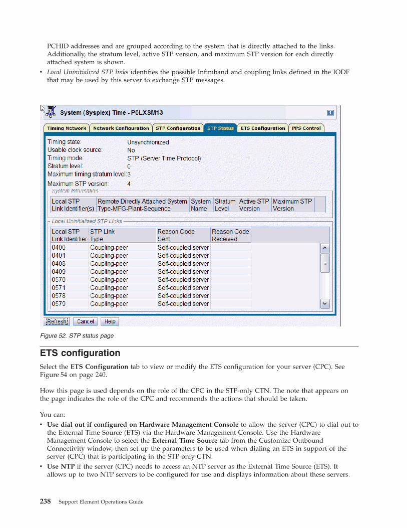
PCHID addresses and are grouped according to the system that is directly attached to the links.Additionally, the stratum level, active STP version, and maximum STP version for each directlyattached system is shown.
v Local Uninitialized STP links identifies the possible Infiniband and coupling links defined in the IODFthat may be used by this server to exchange STP messages.
ETS configurationSelect the ETS Configuration tab to view or modify the ETS configuration for your server (CPC). SeeFigure 54 on page 240.
How this page is used depends on the role of the CPC in the STP-only CTN. The note that appears onthe page indicates the role of the CPC and recommends the actions that should be taken.
You can:v Use dial out if configured on Hardware Management Console to allow the server (CPC) to dial out to
the External Time Source (ETS) via the Hardware Management Console. Use the HardwareManagement Console to select the External Time Source tab from the Customize OutboundConnectivity window, then set up the parameters to be used when dialing an ETS in support of theserver (CPC) that is participating in the STP-only CTN.
v Use NTP if the server (CPC) needs to access an NTP server as the External Time Source (ETS). Itallows up to two NTP servers to be configured for use and displays information about these servers.
Figure 52. STP status page
238 Support Element Operations Guide

v If the server (CPC) does not require an External Time Source (ETS) to be configured, Use dial out ifconfigured on Hardware Management Console is the default setting.
v Use NTP with pulse per second (PPS) to configure an External Time Source (ETS) which providesenhanced time accuracy for the CTN. A highly stable and accurate pulse per second (PPS) output fromthe NTP server, that precisely indicates the start of a second, should be attached to the PPS port of theSystem z server in the CTN. One NTP server can be configured to each PPS port.
Figure 53. ETS configuration page using the NTP option
Appendix B. Using the System (Sysplex) Time task 239
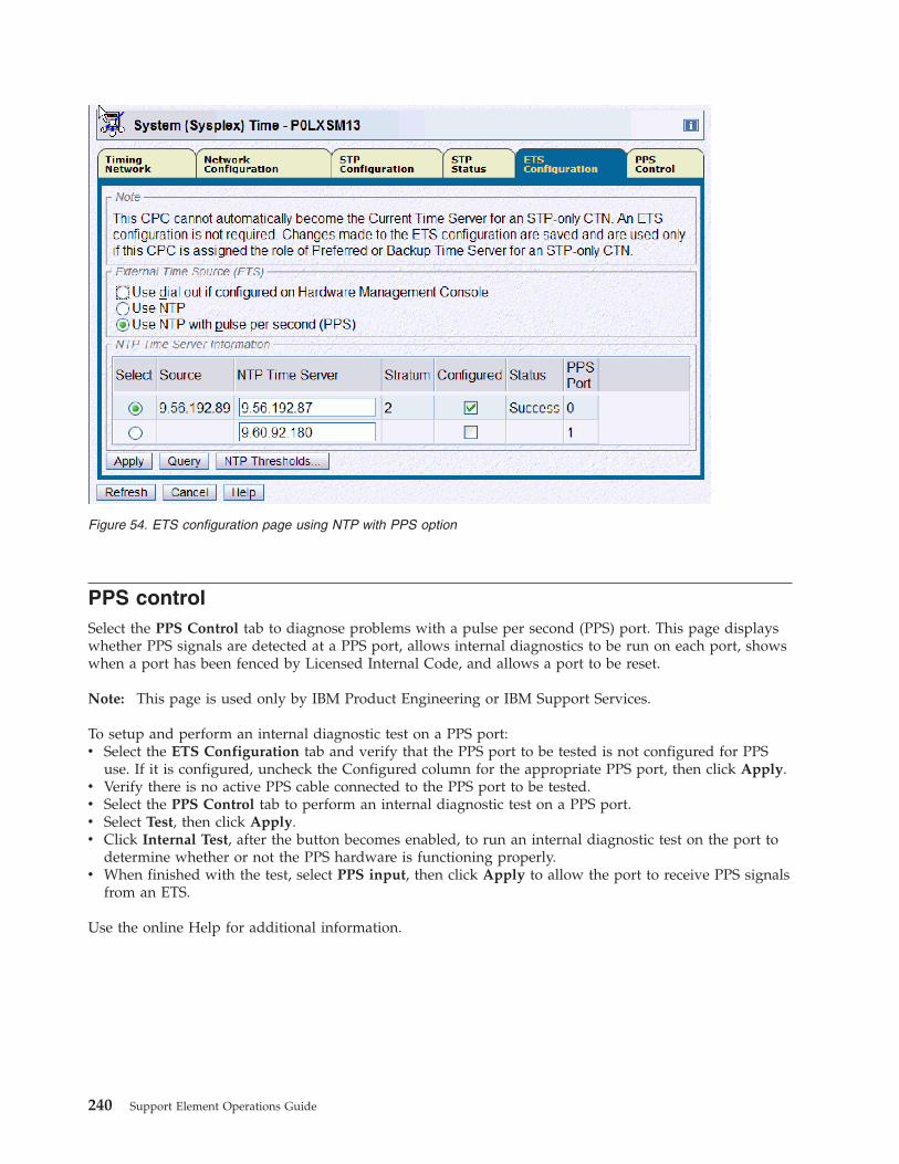
PPS controlSelect the PPS Control tab to diagnose problems with a pulse per second (PPS) port. This page displayswhether PPS signals are detected at a PPS port, allows internal diagnostics to be run on each port, showswhen a port has been fenced by Licensed Internal Code, and allows a port to be reset.
Note: This page is used only by IBM Product Engineering or IBM Support Services.
To setup and perform an internal diagnostic test on a PPS port:v Select the ETS Configuration tab and verify that the PPS port to be tested is not configured for PPS
use. If it is configured, uncheck the Configured column for the appropriate PPS port, then click Apply.v Verify there is no active PPS cable connected to the PPS port to be tested.v Select the PPS Control tab to perform an internal diagnostic test on a PPS port.v Select Test, then click Apply.v Click Internal Test, after the button becomes enabled, to run an internal diagnostic test on the port to
determine whether or not the PPS hardware is functioning properly.v When finished with the test, select PPS input, then click Apply to allow the port to receive PPS signals
from an ETS.
Use the online Help for additional information.
Figure 54. ETS configuration page using NTP with PPS option
240 Support Element Operations Guide

Figure 55. PPS control page
Appendix B. Using the System (Sysplex) Time task 241

242 Support Element Operations Guide

Appendix C. Notices
This information was developed for products and services offered in the USA
IBM may not offer the products, services, or features discussed in this document in other countries.Consult your local IBM representative for information on the products and services currently available inyour area. Any reference to an IBM product, program, or service is not intended to state or imply thatonly that IBM product, program, or service may be used. Any functionally equivalent product, program,or service that does not infringe any IBM intellectual property right may be used instead. However, it isthe user's responsibility to evaluate and verify the operation of any non-IBM product, program, orservice.
IBM may have patents or pending patent applications covering subject matter described in thisdocument. The furnishing of this document does not grant you any license to these patents. You can sendlicense inquiries, in writing, to:
IBM Director of LicensingIBM CorporationNorth Castle DriveArmonk, NY 10504-1785 USA
The following paragraph does not apply to the United Kingdom or any other country where suchprovisions are inconsistent with local law:
INTERNATIONAL BUSINESS MACHINES CORPORATION PROVIDES THIS PUBLICATION “ AS IS”WITHOUT WARRANTY OF ANY KIND, EITHER EXPRESS OR IMPLIED, INCLUDING, BUT NOTLIMITED TO, THE IMPLIED WARRANTIES OF NON-INFRINGEMENT, MERCHANTABILITY ORFITNESS FOR A PARTICULAR PURPOSE. Some states do not allow disclaimer of express or impliedwarranties in certain transactions, therefore, this statement may not apply to you.
This information could include technical inaccuracies or typographical errors. Changes are periodicallymade to the information herein; these changes will be incorporated in new editions of the publication.IBM may make improvements and/or changes in the product(s) and/or the program(s) described in thispublication at any time without notice.
Any references in this information to non-IBM websites are provided for convenience only and do not inany manner serve as an endorsement of those websites. The materials at those websites are not part ofthe materials for this IBM product and use of those websites is at your own risk.
IBM may use or distribute any of the information you supply in any way it believes appropriate withoutincurring any obligation to you.
Any performance data contained herein was determined in a controlled environment. Therefore, theresults obtained in other operating environments may vary significantly. Some measurements may havebeen made on development-level systems and there is no guarantee that these measurements will be thesame on generally available systems. Furthermore, some measurements may have been estimated throughextrapolation. Actual results may vary. Users of this document should verify the applicable data for theirspecific environment.
Information concerning non-IBM products was obtained from the suppliers of those products, theirpublished announcements or other publicly available sources. IBM has not tested those products and
© Copyright IBM Corp. 2011 243

cannot confirm the accuracy of performance, compatibility or any other claims related to non-IBMproducts. Questions on the capabilities of non-IBM products should be addressed to the suppliers ofthose products.
All statements regarding IBM's future direction or intent are subject to change or withdrawal withoutnotice, and represent goals and objectives only.
All IBM prices shown are IBM's suggested retail prices, are current and are subject to change withoutnotice. Dealer prices may vary.
This information is for planning purposes only. The information herein is subject to change before theproducts described become available.
This information contains examples of data and reports used in daily business operations. To illustratethem as completely as possible, the examples include the names of individuals, companies, brands, andproducts. All of these names are fictitious and any similarity to the names and addresses used by anactual business enterprise is entirely coincidental.
If you are viewing this information softcopy, the photographs and color illustrations may not appear.
TrademarksIBM, the IBM logo, and ibm.com® are trademarks or registered trademarks of International BusinessMachines Corporation in the United States, other countries, or both. If these and other IBM trademarkedterms are marked on their first occurrence in this information with a trademark symbol ( ® or ™ ), thesesymbols indicate US registered or common law trademarks owned by IBM at the time this informationwas published. Such trademarks may also be registered or common law trademarks in other countries. Acurrent list of IBM trademarks is available on the web at “Copyright and trademark information” athttp://www.ibm.com/legal/us/en/copytrade.shtml.
Adobe is a registered trademark of Adobe Systems Incorporated in the United States, and/or othercountries.
InfiniBand is a registered trademark of the InfiniBand Trade Association.
Linux is a registered trademark of Linus Torvalds in the United States, other countries, or both.
Microsoft and Windows are trademarks of Microsoft Corporation in the United States, other countries, orboth.
Other product and service names might be trademarks of IBM or other companies.
Electronic emission noticesThe following statements apply to this IBM product. The statement for other IBM products intended foruse with this product will appear in their accompanying manuals.
Federal Communications Commission (FCC) Statement
Note: This equipment has been tested and found to comply with the limits for a Class A digital device,pursuant to Part 15 of the FCC Rules. These limits are designed to provide reasonable protection againstharmful interference when the equipment is operated in a commercial environment. This equipmentgenerates, uses, and can radiate radio frequency energy and, if not installed and used in accordance withthe instructions contained in the installation manual, may cause harmful interference to radiocommunications. Operation of this equipment in a residential area is likely to cause harmful interference,in which case the user will be required to correct the interference at his own expense.
244 Support Element Operations Guide

Properly shielded and grounded cables and connectors must be used in order to meet FCC emissionlimits. IBM is not responsible for any radio or television interference caused by using other thanrecommended cables and connectors, by installation or use of this equipment other than as specified inthe installation manual, or by any other unauthorized changes or modifications to this equipment.Unauthorized changes or modifications could void the user's authority to operate the equipment.
This device complies with Part 15 of the FCC Rules. Operation is subject to the following two conditions:(1) this device may not cause harmful interference, and (2) this device must accept any interferencereceived, including interference that may cause undesired operation.
Canadian Department of Communications Compliance Statement
This Class A digital apparatus complies with Canadian ICES-003.
Avis de conformlté aux normes du ministère des Communications du Canada
Cet appareil numérique de la classe A est conform à la norme NMB-003 du Canada.
European Union (EU) Electromagnetic Compatibility Directive
This product is in conformity with the protection requirements of EU Council Directive 2004/108/EC onthe approximation of the laws of the Member States relating to electromagnetic compatibility. IBM cannotaccept responsibility for any failure to satisfy the protection requirements resulting from anon-recommended modification of the product, including the fitting of non-IBM option cards.
This product has been tested and found to comply with the limits for Class A Information TechnologyEquipment according to European Standard EN 55022. The limits for Class equipment were derived forcommercial and industrial environments to provide reasonable protection against interference withlicensed communication equipment.
Warning: This is a Class A product. In a domestic environment, this product may cause radio interferencein which case the user may be required to take adequate measures.
European Community contact:IBM Technical RegulationsPascalstr. 100, Stuttgart, Germany 70569Telephone: 0049 (0) 711 785 1176Fax: 0049 (0) 711 785 1283email: [email protected]
EC Declaration of Conformity (In German)
Deutschsprachiger EU Hinweis: Hinweis für Geräte der Klasse A EU-Richtlinie zurElektromagnetischen Verträglichkeit
Dieses Produkt entspricht den Schutzanforderungen der EU-Richtlinie 89/336/EWG zur Angleichung derRechtsvorschriften über die elektromagnetische Verträglichkeit in den EU-Mitgliedsstaaten und hält dieGrenzwerte der EN 55022 Klasse A ein.
Um dieses sicherzustellen, sind die Geräte wie in den Handbüchern beschrieben zu installieren und zubetreiben. Des Weiteren dürfen auch nur von der IBM empfohlene Kabel angeschlossen werden. IBMübernimmt keine Verantwortung für die Einhaltung der Schutzanforderungen, wenn das Produkt ohneZustimmung der IBM verändert bzw. wenn Erweiterungskomponenten von Fremdherstellern ohneEmpfehlung der IBM gesteckt/eingebaut werden.
EN 55022 Klasse A Geräte müssen mit folgendem Warnhinweis versehen werden:
Appendix C. Notices 245

"Warnung: Dieses ist eine Einrichtung der Klasse A. Diese Einrichtung kann im WohnbereichFunk-Störungen verursachen; in diesem Fall kann vom Betreiber verlangt werden, angemesseneMaßnahmen zu ergreifen und dafür aufzukommen."
Deutschland: Einhaltung des Gesetzes über die elektromagnetische Verträglichkeit von Geräten
Dieses Produkt entspricht dem “Gesetz über die elektromagnetische Verträglichkeit von Geräten(EMVG)“. Dies ist die Umsetzung der EU-Richtlinie 89/336/EWG in der Bundesrepublik Deutschland.
Zulassungsbescheinigung laut dem Deutschen Gesetz über die elektromagnetische Verträglichkeit vonGeräten (EMVG) vom 18. September 1998 (bzw. der EMC EG Richtlinie 89/336) für Geräte der KlasseA.
Dieses Gerät ist berechtigt, in Übereinstimmung mit dem Deutschen EMVG das EG-Konformitätszeichen- CE - zu führen.
Verantwortlich für die Konformitätserklärung nach Paragraf 5 des EMVG ist die IBM DeutschlandGmbH, 70548 Stuttgart.
Informationen in Hinsicht EMVG Paragraf 4 Abs. (1) 4:
Das Gerät erfüllt die Schutzanforderungen nach EN 55024 und EN 55022 Klasse A.
update: 2004/12/07
People's Republic of China Class A Compliance Statement
This is a Class A product. In a domestic environment, this product may cause radio interference in whichcase the user may need to perform practical actions.
Japan Class A Compliance Statement
This is a Class A product based on the standard of the VCCI Council. If this equipment is used in adomestic environment, radio interference may occur, in which case, the user may be required to takecorrective actions.
Korean Class A Compliance Statement
246 Support Element Operations Guide

Taiwan Class A Compliance Statement
Warning: This is a Class A product. In a domestic environment, this product may cause radio interferencein which case the user will be required to take adequate measures.
� ��� ���( �)� �� ���� � �������� �� ���� � �� ����� �� , !"#�$%&' ���� *� + � ��-.
A
Appendix C. Notices 247

248 Support Element Operations Guide

Index
Aacceptable status 42account information task
instructions for starting 97account information, about 97activate task
instructions for starting 70activating an integrated coupling facility
processor 210, 211dynamic integrated coupling facility
expansion 210, 211activation 67
other profiles 68profiles 68reset profile 68
activation profilesabout 68, 195customizing 195default profiles 195image profiles, customizing 225load profiles, customizing 229types of 68, 195types to use, choosing the right 196
activation, about 67active tasks view, opening 57active tasks work area, contents of 57activity task 162activity, about system 161adding logical processors 92advanced facilities 151alternate Support Element 135, 136
querying switch capabilities betweenSupport Elements 136
API settings, customizing 175application programming interface
enabling 175assigning domain security 179audit and log management task 171authorize concurrent internal code
changes taskinstructions for starting 142, 143
authorize internal code changes taskinstructions for starting 137
automatic activation, about 83automatic activation, aboutCPC
operational customization task list,instructions for starting tasks in
automatic activation 83automatic activation task
instructions for starting 83automatic licensed internal code change
installationblocking 171
Bbackground
views area of 42background color
CHPID icon, of 54
background color (continued)CPC icon, of 53exceptions icon, of 56group icon, of 56image icon, of 54views area, of 42
blocking automatic licensed internal codechange installation 171
books view, opening 64books work area, contents of 64broadcast message 173broadcast messages 176
Ccentral processor complex 67, 77, 81
activating 69background color, meaning of 53deactivating 71details window, opening 39hardware messages from,
checking 61images of, about 37load image, performing manually for
error recovery 77reset normal of image, performing for
daily operation 74reset normal of image, performing for
error recovery 80status of, determining 53
central processorslocating on the workplace 46
central storage 93change LPAR controls task
instructions for starting 84change LPAR security 88change LPAR security task 88change management task list, instructions
for starting tasks in 131authorize concurrent internal code
changes 142, 143authorize internal code changes 137system information 144
changingdefault colors for processor status
changes 190changing group controls,logical
partition 86changing group profile name
group profile name, changing 210changing internal code 132changing logical partition cryptographic
controls 85changing LPAR I/O priority queuing 86changing password task 173channel configuration
files,migrating 182channel information, displaying 151channel operations task list, instructions
for starting tasks in 151advanced facilities 151
channel paths 151definition errors, identifying 152locating on the workplace 48reassigning reconfigurable 155releasing reconfigurable 155
channel problem determination 151, 152channel problem determination task,
instructions for starting 151channel problem determination task,
instructions for starting in 152channel to PCHID assignment 115channels
locating on the workplace 47checking redundant I/O multiport
status 105checkout tests task
instructions for starting 101checkout tests, about 101CHPID operations task list, instructions
for starting tasks in 152reassign channel path 155release 156service on/off 156, 157
CHPIDs 151definition errors, identifying 152locating on the workplace 48reassigning reconfigurable 155
classic interfacesettings
chat window 190colors 190console messenger 190hover help 190patterns 190show tips 190single object selection 190
workplace, support elementselecting objects 38
clonable internal code levels 139color, background
CHPID icon, of 54CPC icon, of 53exceptions icon, of 56group icon, of 56image icon, of 54
colors 190concurrent internal code change 133configure off/on, querying a
channel/crypto 141configuring on/off task 153confirmation windows 189console actions
audit and log management 171block automatic licensed internal code
change installation 171change password 173console messenger 173customize console services 175customize network settings 176customize product engineering
access 177
© Copyright IBM Corp. 2011 249
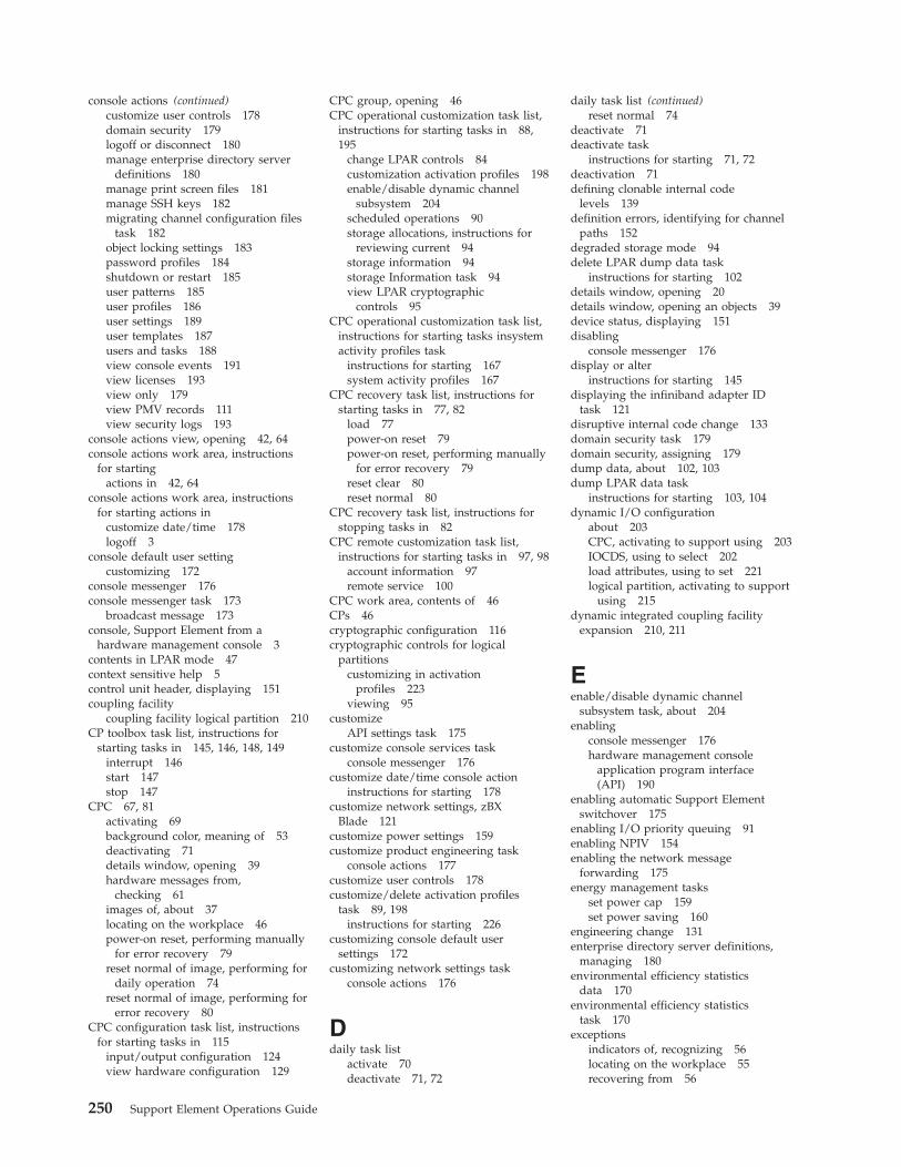
console actions (continued)customize user controls 178domain security 179logoff or disconnect 180manage enterprise directory server
definitions 180manage print screen files 181manage SSH keys 182migrating channel configuration files
task 182object locking settings 183password profiles 184shutdown or restart 185user patterns 185user profiles 186user settings 189user templates 187users and tasks 188view console events 191view licenses 193view only 179view PMV records 111view security logs 193
console actions view, opening 42, 64console actions work area, instructions
for startingactions in 42, 64
console actions work area, instructionsfor starting actions in
customize date/time 178logoff 3
console default user settingcustomizing 172
console messenger 176console messenger task 173
broadcast message 173console, Support Element from a
hardware management console 3contents in LPAR mode 47context sensitive help 5control unit header, displaying 151coupling facility
coupling facility logical partition 210CP toolbox task list, instructions for
starting tasks in 145, 146, 148, 149interrupt 146start 147stop 147
CPC 67, 81activating 69background color, meaning of 53deactivating 71details window, opening 39hardware messages from,
checking 61images of, about 37locating on the workplace 46power-on reset, performing manually
for error recovery 79reset normal of image, performing for
daily operation 74reset normal of image, performing for
error recovery 80CPC configuration task list, instructions
for starting tasks in 115input/output configuration 124view hardware configuration 129
CPC group, opening 46CPC operational customization task list,
instructions for starting tasks in 88,195
change LPAR controls 84customization activation profiles 198enable/disable dynamic channel
subsystem 204scheduled operations 90storage allocations, instructions for
reviewing current 94storage information 94storage Information task 94view LPAR cryptographic
controls 95CPC operational customization task list,
instructions for starting tasks insystemactivity profiles task
instructions for starting 167system activity profiles 167
CPC recovery task list, instructions forstarting tasks in 77, 82
load 77power-on reset 79power-on reset, performing manually
for error recovery 79reset clear 80reset normal 80
CPC recovery task list, instructions forstopping tasks in 82
CPC remote customization task list,instructions for starting tasks in 97, 98
account information 97remote service 100
CPC work area, contents of 46CPs 46cryptographic configuration 116cryptographic controls for logical
partitionscustomizing in activation
profiles 223viewing 95
customizeAPI settings task 175
customize console services taskconsole messenger 176
customize date/time console actioninstructions for starting 178
customize network settings, zBXBlade 121
customize power settings 159customize product engineering task
console actions 177customize user controls 178customize/delete activation profiles
task 89, 198instructions for starting 226
customizing console default usersettings 172
customizing network settings taskconsole actions 176
Ddaily task list
activate 70deactivate 71, 72
daily task list (continued)reset normal 74
deactivate 71deactivate task
instructions for starting 71, 72deactivation 71defining clonable internal code
levels 139definition errors, identifying for channel
paths 152degraded storage mode 94delete LPAR dump data task
instructions for starting 102details window, opening 20details window, opening an objects 39device status, displaying 151disabling
console messenger 176display or alter
instructions for starting 145displaying the infiniband adapter ID
task 121disruptive internal code change 133domain security task 179domain security, assigning 179dump data, about 102, 103dump LPAR data task
instructions for starting 103, 104dynamic I/O configuration
about 203CPC, activating to support using 203IOCDS, using to select 202load attributes, using to set 221logical partition, activating to support
using 215dynamic integrated coupling facility
expansion 210, 211
Eenable/disable dynamic channel
subsystem task, about 204enabling
console messenger 176hardware management console
application program interface(API) 190
enabling automatic Support Elementswitchover 175
enabling I/O priority queuing 91enabling NPIV 154enabling the network message
forwarding 175energy management tasks
set power cap 159set power saving 160
engineering change 131enterprise directory server definitions,
managing 180environmental efficiency statistics
data 170environmental efficiency statistics
task 170exceptions
indicators of, recognizing 56locating on the workplace 55recovering from 56
250 Support Element Operations Guide
exceptions view, opening 55exceptions work area, contents of 55expanded storage 93exporting and importing profile data,
instructions for starting task 92
Fforcing channel internal code
change 140
Ggroup controls, logical partition 86group profiles 231
assigning namesdefining group capacity 231
groupsabout 37background color, meaning of 56locating on the workplace 45
Hhardware messages 61, 106
about 61indicators of, recognizing 61
hardware messages taskflashing icon, meaning of 61reporting a hardware problem,
instruction for 107help 64
workplace, getting for 64hipersockets
network traffic analyzer (NTA) 108HMC management tasks
console messenger 173domain security 179
hover help, displaying 64HSA 93
IICSF 224image profile
about 68, 195, 225customizing 225navigating the notebook pages 227opening 226saving 229
image profile configuration 201images
activating 70background color, meaning of 54deactivating 71details window, opening 39locating on the workplace 46operating system messages from,
checking 62images work area 47IML 79infiniband adapter ID,displaying 121initial microcode load 79initiating a two-way chat 174input/output configuration data set 123
input/output configuration data set(continued)
CPC activation, prerequisite for 69dynamic I/O, selecting an IOCDS that
supports 204reset profile, customizing to select for
CPC activation 201input/output configuration
program 123input/output configuration task
instructions for starting 124instant messages 176instant messaging 173
console messenger task 173user settings task 189, 190users and tasks task 188
instructions for starting 88, 198instructions for stopping 82internal code 131, 144
checking dependencies 138keeping records 143
internal code changes 131internal code, changing 132interrupt task
instructions for starting 146IOCP 124
Llarge retrieves from RETAIN 176LED (light emitting diode)
setting on 157licensed internal code 131licensed internal code, viewing 193load 77
performing manually for errorrecovery 77
load profileabout 68, 195assigning to CPC 231assigning to logical partition 231customizing 229new, creating 231saving 231
load profilespreparing 69
load taskinstructions for starting 77
loading software from a removable mediaor server 78
locating on the workplace 46locating virtual servers 15, 52locating zBX bladecenters 14, 50locating zBX blades 15, 51lockout for disruptive tasks 41, 183logging off the support element console
closing open windows before 58completing active tasks before 58
logical partition cryptographiccontrols 85
logical partition group controls 86logical partition group name, assigning
assigning logical partition groupname 232
logical partitionsas images 37locating on the workplace 46
logical processor assignment 84logically partitioned mode
activating the CPC in 200logoff or disconnect task 180LPAR mode
activating the CPC in 200
Mmanage datapower XI50z 121manage SSH keys task 182manage zBX cluster size 122manage zbx hardware 122manage zBX internal code 140managing enterprise directory server
definitions 180managing groups of objects
groups, managing 72managing print screen files task 181manually setting the Support Element
TOD clock 178mirroring Support Element to alternate
Support Element 136monitor
environmental efficiencystatistics 170
monitors dashboardactivity 162
monitor tasksenvironmental efficiency
statistics 170monitors dashboard 161
monitors dashboard task 161
Nnetwork configuration 237network diagnostic information,
viewing 183console actions
network diagnosticinformation 183
pinging TCP/IP address 183network settings, customizing 176network traffic analyzer (NTA) 108NPIV port names, releasing
releasing NPIV port names 123NPIV,enabling 154NTA settings 108
Oobject details, opening 20, 39object locking for disruptive tasks 41object locking settings task 183objects
selecting 38off loading RETAIN data to the hardware
management console removablemedia 105
opening 198opening and online book 64operating environment
setting for CPC 205operating system messages
checking 62
Index 251

operating system messages (continued)indicators of, recognizing 62viewing, instructions for 63
operating system messages taskflashing icon, meaning of 63sending commands, instructions
for 63viewing messages, instructions
for 63operational customization
customize/delete activationprofiles 89
Ppassword
changing 173password profiles, customizing 184paths to a device, displaying 151patterns 190PCI X cryptographic coprocessor feature
pseudo-random number (PRN)generator 117
perform model conversion 125perform problem analysis task
instructions for starting 107performed automatically during system
activation 67performing an alternate Support Element
action 134permanent upgrades, model
conversion 126pinging the TCP/IP address 183power-on reset 67, 79
performing manually for errorrecovery 79
power-on reset taskinstructions for starting 79
power-on reset, performed automaticallyduring system activation 67
power-on reset, performing manually forerror recovery 77
power, systemoff, switched automatically during
system deactivation 71on, switched automatically during
system activation 67outage, recovery options for automatic
system activation after 83print screen 181problem analysis, about 106problem determination 151problems, reporting 106processor running time 84processor storage
displaying or altering data 145product engineering, customizing 177profiles for complete activation 197profiles.
customize/delete activation 89PSW restart
instructions for starting 146
Qquery coupling facility reactivations 142query internal code changes pending
power-on reset 142querying channel/crypto 141
Rreassign channel path task, instructions
for starting 155recovering from errors, tasks for 77redundant I/O multiport status,
checking 105releasing a Crypto Express3 card 120releasing reconfigurable
CHPIDs 155remote service task
instructions for starting 100remote service, about 97, 98
system 98report a problem task
instructions for starting 109reporting problems 106reset clear of image, performing for error
recovery 80reset clear task
instructions for starting 80reset clear, about 80reset normal task
instructions for starting 74, 80reset normal, about 74, 80reset profile 198
about 68, 195assigning to CPC 200navigating the notebook pages 198new, creating 199, 227opening 198
restarting a processor 146restore DataPower XI50z task 109RETAIN
large retrieves 176
SSAD (system activity display) 162SAPs (system assist processors)
configuring CPs as 205scheduled operations 90scheduled operations task
instructions for starting 90security settings for logical partitions
cross partition authority 87, 216customizing in activation
profiles 215, 216global performance data control 87,
215input/output configuration
control 87, 215logical partition isolation 87, 216security settings for logical partitions
customizing in activationprofiles 216
security, view logs 193selecting a crypto type 119selective channel apply controls 143sending a message 173
sending messages 176serial link status, displaying 151server time protocol (STP 235service
setting on or off 156service data, about 110service history, about 112service on/off task
instructions for starting 156, 157service status 110service task list
checkout tests 101service task list, instructions for starting
tasks in 101checkout tests 101delete LPAR dump data 102dump LPAR data 103, 104perform problem analysis 107report a problem 109transmit service data 111view service history 112
service, tasks for gettingtesting, tasks for 101
set power cap task 159set power saving 160setting defined capacity 220setting group capacity
logical partition group capacity 232setting the system time offset 214setting up
console messenger 176setting up time synchronization 128, 237
timing network 236setting workload manager controls 213settings
colors 190confirmations 189controls 189, 190patterns 190tree style 189ui style 189, 190
settings for remote connections andcommunication, tasks forcustomizing 98
shutting down or restarting thesystem 185
specify concurrent upgrade syncpoint 142
start all 82start all image's processors, performing
for error recovery 81start all task
instructions for starting 82start processor operation, about 81start task
instructions for starting 147status
acceptable 42status, getting detailed 45stop all 82stop all image's processors, performing
for error recovery 81stop all task 82stop on CP address match
instructions for starting 148stop processor operation, about 81, 147
252 Support Element Operations Guide

stop taskinstructions for starting 147
stopping CPsCPs
stopping 148storage, about 93store status
instructions for starting 149STP configuration 237STP status 237subchannel data, displaying 151Support Element Console
from a Hardware ManagementConsole 1
Support Element Console Applicationstarting 1
support element console settingscustomize API settings task 175
support element workplace 37switching to the alternate Support
Element 135sync point 142system 45, 67, 77
monitoring 161operating daily, tasks for 67problem determination, tasks for
performing 101resetting 74settings for remote connections and
communication, tasks forcustomizing 97
settings for system operations, tasksfor customizing 195
shutting down 71system activity analysis 162system activity display (SAD) 162system activity, about 161system assist processors (SAPs)
configuring CPs as 205system information task
instructions for starting 144system input/output configuration
analyzer 127system management tasks
energy managementset power cap 159set power saving 160
operational customizationcustomize/delete activation
profiles 89systems management tasks
monitorenvironmental efficiency
statistics 170monitor dashboard 161
Ttask list view, opening
task list work area, contents of 60task list, about 37tasks
about 37locating 60manage zbx hardware 122minimizing, while in progress 56
tasks (continued)monitor
environmental efficiencystatistics 170
monitor dashboard 161restoring, if previously minimized 56starting 59
temporary upgrades 127TKE commands
changing permission 118TOD clock
manually setting 178transmit service data task
instructions for starting 111tree interface
settingsall images 189all objects 189banner 189chat window 189confirmations 189console messenger 189navigation icons 189object list 189show tips 189single object selection 189tasks pad 189work pane icons 189
work pane 25trusted key entry (TKE) feature
logical partition cryptographiccontrols, required settings for
customizing in activationprofiles 224
two-way chat 174
UUDX
configuring user defined extensions(UDX) 119
upgrades,temporary 127usage domain,zeroizing 118usb flash memory drive 7user patterns task 185user profiles task 186user profiles, customizing 186user settings task 189user templates task 187users and tasks task 188
Vview console event task 191view cryptographic details 116view licenses task 193view only tasks 179view PMV records task 111view security logs task 193view service history task
instructions for starting 112viewing internal code changes 144viewing the input/output configuration
data 127viewing, instructions for 61views and work area 44
views and work area (continued)console actions 58
virtual servers, locating 15, 52
Wwizard profile image,using 228work area, about 37work pane 25
ZzBX blades centers, locating 14zBX blades, locating 15, 51zBX bladesCenters, locating 50zeroizing crypto 117zeroizing usage domain 118
Index 253

254 Support Element Operations Guide


����
Printed in USA
SC28-6906-01
Copyright © 2022 FDOKUMEN

