


Bahasa
Halaman
Hukum

ORIGINAL PAPER
Study of Non-lubricated Wear of the Al–Si Alloy CompositeReinforced with Different Ratios of Coarse and Fine Size ZirconSand Particles at Different Ambient Temperatures
Ranvir Singh Panwar • Suresh Kumar •
Ratandeep Pandey • Om Prakash Pandey
Received: 9 November 2013 / Accepted: 10 April 2014 / Published online: 22 April 2014
� Springer Science+Business Media New York 2014
Abstract In the present work, a detailed study of ceramic
reinforcement of different size ranges in the matrix of
LM13 alloy on the friction and wear behavior has been
carried out. For this purpose, LM13/Zr composite con-
taining 10 wt% zircon sand particles of different size ran-
ges using stir casting process has been developed. Zircon
sand particles were incorporated in two ways: firstly as
single size reinforcement and secondly dual size rein-
forcement. Durability of the composites was tested by
finding the wear rate of the composite against the steel disk
by pin-on-disk method. Addition of zircon sand particles in
the LM13 alloy improves the hardness of the composite as
well as wear resistance. Wear rate of the developed com-
posites was tested under different test conditions by vary-
ing the applied load and ambient temperatures. Wear rate
of the composite changes significantly at different ambient
temperatures. SEM analysis of the worn surfaces was done
to know the operative wear mechanism.
Keywords Metal matrix composites � Hardness � Wear
rate � Temperature
1 Introduction
Composites have become unique materials for most of the
engineering applications [1–3]. Due to improved stiffness,
strength, thermal properties and wear resistance of the
particle-reinforced composites, their applications in several
structural parts particularly where energy consumption is
of primary concern have increased [4, 5]. Moreover, their
properties can be tailored further depending upon request
where an impertinent selection of a certain number of
variables has to be achieved to optimize the properties of
the particle-reinforced composites.
Among the variety of processing techniques available for
particulate-reinforced aluminum matrix composites (PAM-
Cs), stir casting is one of the methods accepted for the pro-
duction of large number of composites [5]. To optimize the
properties of the composites, the shape, size and volume
fraction of the reinforcing particles as well as the matrix
composition have to be chosen carefully. Particulate rein-
forcement by SiC, Al2O3, TiO2, ZrSiO4, Gr, zircoina, etc. has
been selected by many researchers to improve the hardness
as well as wear resistance of the composites [3–9]. Das et al.
[1] have compared the wear properties of alumina- and zir-
con sand-reinforced AMCs and reported that decrease in
particle size improves wear resistance. Zhang and Alpas [10]
suggested that ambient temperature significantly affects the
wear behavior of the materials. It is reported that near the
critical temperature (&0.4 Tm, Tm is the melting tempera-
ture of the materials), wear rate of composites changes sig-
nificantly [8, 10]. There are so many other factors such as
applied load, ambient temperature, sliding velocity, counter
surface, which affect the wear rate of the material. However,
wear behavior of the PAMCs containing different sizes of
zircon sand particles as single size reinforcement (SSR) and
dual size reinforcement (DSR) (in different ratios) has not
been studied systematically.
In our previous work, we have discussed the room
temperature wear behavior of zircon sand-reinforced LM13
composite [4]. It was observed that fine size reinforced
R. S. Panwar � S. Kumar � O. P. Pandey (&)
Metallurgical Research Laboratory, School of Physics and
Materials Science, Thapar University, Patiala 147004, India
e-mail: [email protected]
R. Pandey
Department of Mechanical Engineering, Baba Banda Singh
Bahadur Engineering College (BBSBEC),
Fatehgarh Sahib 140407, Punjab, India
123
Tribol Lett (2014) 55:83–92
DOI 10.1007/s11249-014-0335-y

composites exhibit better wear resistance as compared to
coarse size reinforced composites. However, the segrega-
tion of fine particles has led to variation in structure,
causing wettability problem of particles. In order to sort out
this problem, a combination of fine and coarse size parti-
cles was tried, where the problem of segregation could be
eliminated considerably [4]. The room temperature wear
behavior of DSR composites offered higher wear resistance
as compared to singe size reinforced (SSR) composites [4].
However, high-temperature wear behavior of developed
DSR composites at different applied loads has not been
studied. Considering the need for high-temperature appli-
cations, we have taken this work and studied the high-
temperature wear behavior of the single size reinforced
composites (SSR) and dual size reinforced composites
(DSR), where a sequential addition of fine size zircon sand
was done in DSR composites, keeping the total reinforce-
ment amount constant (10 wt%). This has enabled us to
optimize the proper combination of coarse and fine size
particles in DSR composites for better wear resistance. For
this purpose, we have developed the PAMCs by selecting
the LM13 alloy as matrix and zircon sand (ZrSiO4) as
reinforcement. PAMCs are developed by stir casting route.
Different sizes (coarse and fine size) of zircon sand parti-
cles were chosen to study the effect of particle size on the
wear behavior of the composites. For better understanding
the effects of particle size in the matrix, SSR and DSR
were incorporated in the LM13 alloy. However, coarse and
fine size particles in different ratios were incorporated in
the LM13 alloy matrix to get better idea on wear behavior
of DSR composites. Wear behavior of the developed
composites was studied at different testing conditions with
varying the applied loads and ambient temperatures.
2 Experimental Details
2.1 Materials Used
In this study, well-known piston alloy LM13 (Al–12Si–3Mg)
was used as matrix material and high-purity zircon sand
(ZrSiO4) as reinforcement. LM13 alloy was obtained in the
form of ingots from Emmes Metal Pvt. Ltd., Mumbai. Fine
(20–32 lm) size and coarse (106–125 lm) size of zircon sand
particles were used to study the effect of particle size on the
wear behavior of the materials. The compositional analysis of
the LM13 alloy is given in Table 1. Table 2 gives the com-
position of zircon sand used in the present work.
2.2 Development of the Composites
For the development of the composites, LM13 alloy ingots
were first melted in an electric furnace at 800 �C and held
at 750 �C in a graphite crucible. The melt was stirred with
a graphite stirrer containing three blades. During stirring,
speed was increased continuously till vortex was created,
which is the best condition for the homogeneous mixing of
the particles in the matrix [6]. At 630 rpm, after creating
the vortex in molten metal, 10 wt% zircon sand particles
were incorporated with the help of funnel kept at the top of
crucible. Stirring of the molten mass was done for around
10 min to get the homogeneous distribution of particles in
the matrix. After stirring, molten mass was poured in the
cast iron mold of 12 9 12 9 4 cm3 dimensions and
allowed to cool in air at room temperature. From these
developed particles-reinforced aluminum matrix compos-
ites, samples were prepared for further characterization.
Two main categories of the composites were prepared: (1)
SSR, which contains only coarse (SSR-1) and fine (SSR-2)
size of particles as reinforcement, and (2) DSR, which
contains a combination of coarse and fine size particles in
different ratios. Table 3 shows the classification of the
developed composites reinforced with coarse and fine size
particles.
The bulk hardness of the LM13 alloy and LM13/Zircon
sand composite was measured by Rockwell hardness tester
(Model: TRSND) using 1/1600 diameter steel ball indenter
Table 1 Chemical composition of the LM13 alloy
LM13 alloy Si Fe Cu Mn Mg Zn Ni Al
Wt% 12 0.3 1.2 0.4 3.0 0.2 0.9 Bal
Table 2 Chemical composition of the zircon sand (ZrSiO4)
Elements ZrO2 (?HfO2) SiO2 TiO2 Fe2O3
% in bulk 65.30 32.80 0.27 0.12
Table 3 Classification of the developed composites containing zir-
con sand particles of different sizes
SSR composites DSR
composite
Amount of particles in
the matrix (10 wt%)
Ratio of coarse and fine
size particles in the
matrix [coarse
(106–125 lm) : fine
(20–32 lm)]
Composite Amount and size
of reinforced
particles
SSR-1 10 wt% with
coarse
(106–125 lm)
size
DSR-10A 4:1
DSR-10B 4:2
SSR-2 10 wt% with
fine
(20–32 lm)
size
DSR-10C 2:4
DSR-10D 1:4
84 Tribol Lett (2014) 55:83–92
123
under 100 kgf load at B scale. A fine manufacturing
industry, India make Rockwell hardness tester (Model:
TRSND) was used for carrying out the hardness test.
Durability of the composites was analyzed by the wear
test. For the wear test, cylindrical specimens of 8 mm
diameter and 40 mm length were machined from the stir
cast composites. Wear testing was performed on pin-on-
disk wear and friction monitor (Model TR-20, Ducom,
Bangalore, India) under dry sliding conditions in ambient
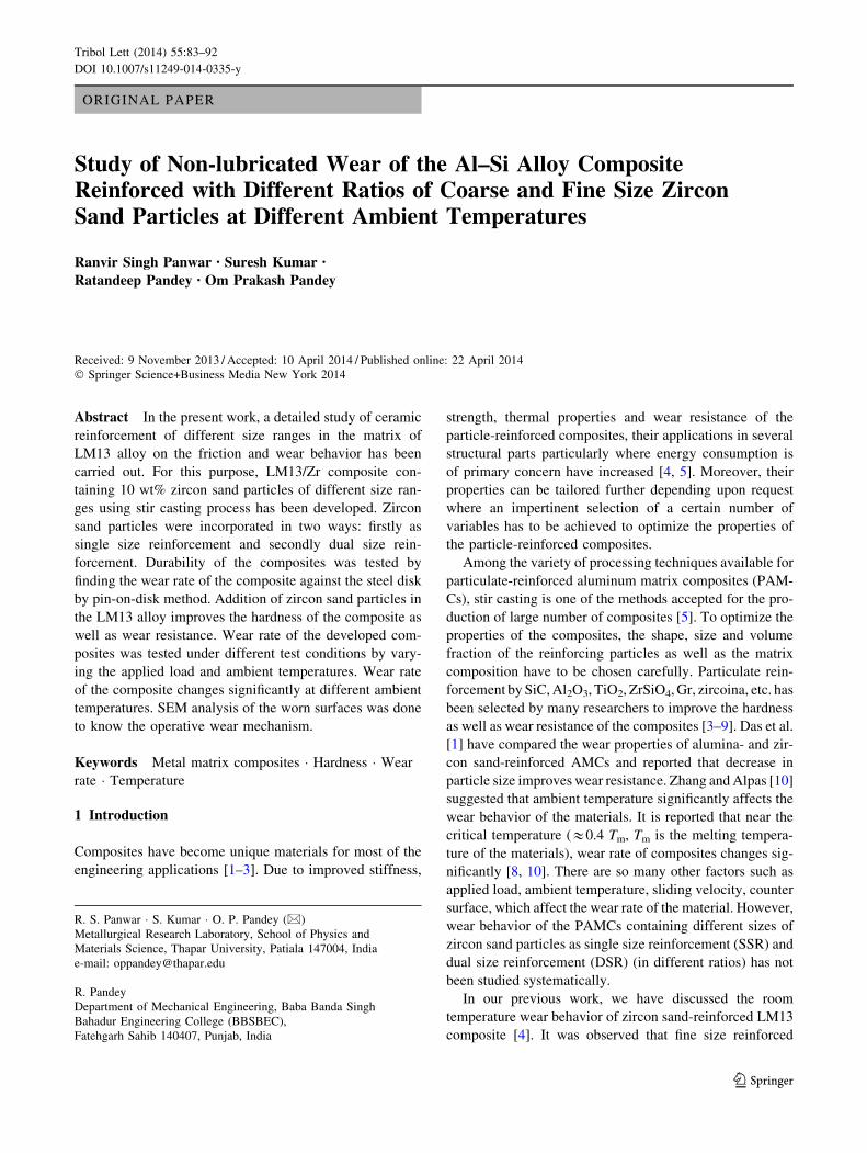
air. Figure 1a–c shows different parts of the wear and
friction monitor. The machine consists of three units as
shown in Fig. 1. The first unit consists of a chamber in
which the rotating disk exists. This is derived by a motor
fitted beneath it. The chamber is heated by three band
heaters fixed along the walls as shown in Fig. 1a, b. To
measure the temperature, the thermocouple is fitted inside
the chamber as shown in Fig. 1b. The pin is tightly fixed in
the sample holder before the start of the test. The load on
the pin is applied through the sample holder connected
through steel wire as shown in Fig. 1c. After all the
adjustments, the chamber was covered from top to check
the heat loss. The top cover also contains insulating bricks.
During operation of machine, the data were collected in
computer as shown in Fig. 1c. The display monitor con-
tinuously shows the variation during the test (Fig. 1c).
Effect of applied load was observed by varying the load
from 9.8 to 49 N. To get the effect of ambient temperature on
the wear behavior of the composites, wear tests were con-
ducted at 50, 100, 150, 200, 250 and 300 �C with 9.8 and
49 N loads. All the developed composites and base alloy
were tested at a constant speed of 1.6 m/s against EN 32 steel
disk having hardness 65 HRC. Wear tests were performed
under the ambient temperatures between 25 and 30 �C (room
temperature) and at relative humidity between 25 and 35 %.
To get an average value of wear rate, each test was run three
times. Before each test, the track was cleaned with acetone.
Wear rate was determined by measuring specimen height
change using a linear variable displacement transducer
(LVDT). To study the wear behavior, wear rate was calcu-
lated by using the formula, [W (mm3/m) = height change
(mm) 9 pin area (mm2)/sliding distance (m)]. Specific wear
rate, k (mm3/Nm), was calculated by the wear rate at the
particular applied load (N). To get a better idea about the
wear mechanism during the wear tests in different condi-
tions, wear tracks of some selected composite materials were
studied with the help of SEM (JOEL, JSM-6510LV).
3 Results and Discussion
3.1 Hardness
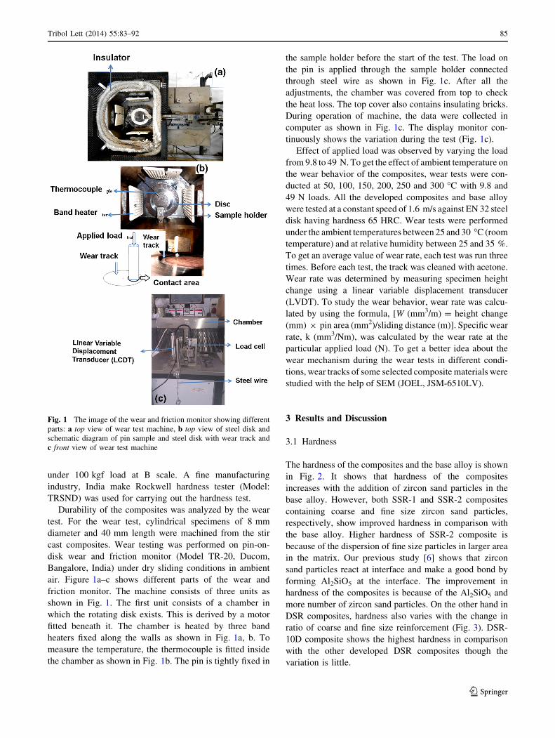
The hardness of the composites and the base alloy is shown
in Fig. 2. It shows that hardness of the composites
increases with the addition of zircon sand particles in the
base alloy. However, both SSR-1 and SSR-2 composites
containing coarse and fine size zircon sand particles,
respectively, show improved hardness in comparison with
the base alloy. Higher hardness of SSR-2 composite is
because of the dispersion of fine size particles in larger area
in the matrix. Our previous study [6] shows that zircon
sand particles react at interface and make a good bond by
forming Al2SiO5 at the interface. The improvement in
hardness of the composites is because of the Al2SiO5 and
more number of zircon sand particles. On the other hand in
DSR composites, hardness also varies with the change in
ratio of coarse and fine size reinforcement (Fig. 3). DSR-
10D composite shows the highest hardness in comparison
with the other developed DSR composites though the
variation is little.
Fig. 1 The image of the wear and friction monitor showing different
parts: a top view of wear test machine, b top view of steel disk and
schematic diagram of pin sample and steel disk with wear track and
c front view of wear test machine
Tribol Lett (2014) 55:83–92 85
123
3.2 Wear Test
3.2.1 SSR Composites
3.2.1.1 Effect of Applied Load on the Wear Behav-
ior Graphs presented in Fig. 4a–c show the variation in
wear rate of the base alloy as well as SSR-1 and SSR-2
composites at different load conditions. Graphs plotted
between wear rate and sliding distance at different loads
show that wear rate of the base alloy, SSR-1 and SSR-2
composites increases with increasing the applied load.
However, two stages of the wear rate behavior are
observed: first is steep change in wear rate up to around
1,500 m of sliding distance and second exhibiting steady
change in wear rate after 1,500 m. This variation in the
wear rate with sliding distance is due to change in run in
wear condition to steady state. This steady state of wear
rate is achieved by the material after acquiring constant
temperature between the surfaces of the sample and
counter surface of steel disk. However, when increasing the
Har
dn
ess
(HR
B)
0
5
10
15
20
25
30
35
40
45
50
Base LM13 alloy
Material
SSR-1 SSR-2
Fig. 2 Hardness of the base alloy and SSR composites containing
zircon sand particles of different sizes
DSR-10A DSR-10B DSR-10C DSR-10D0
5
10
15
20
25
30
35
40
45
50
Har
dn
ess
(HR
B)
DSR composite
Fig. 3 Hardness of the DSR composites containing different ratio of
coarse and fine size zircon sand particles
5
10
15
20
25
30
35
40
Wea
r ra
te x
10-3
( mm
3/m
)
Sliding distance (meter)
9.8 N 19.6 N 29.4 N 39.2 N 49 N
(a)
0
2
4
6
8
10
12
14
16
18
20
22
wea
r ra
te ×
10-3
(mm
3/m
)
Sliding distance (meter)
9.8 N 19.6 N 29.4 N 39.2 N 49 N
(b)
500 1000 1500 2000 2500 3000
500 1000 1500 2000 2500 3000
500 1000 1500 2000 2500 30000
2
4
6
8
10
12
14
16
9.8 N 19.6 N 29.4 N 39.2 N 49 N
Wea
r ra
te ×
10
-3(m
m3/m
)
Sliding distance (meter)
(c)
Fig. 4 Wear rate against sliding distance at different loads for a base
alloy, b SSR-1 and c SSR-2
86 Tribol Lett (2014) 55:83–92
123
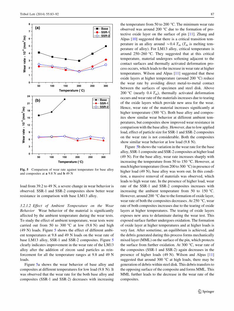
load from 39.2 to 49 N, a severe change in wear behavior is
observed. SSR-1 and SSR-2 composites show better wear
resistance in comparison with base LM13 alloy.
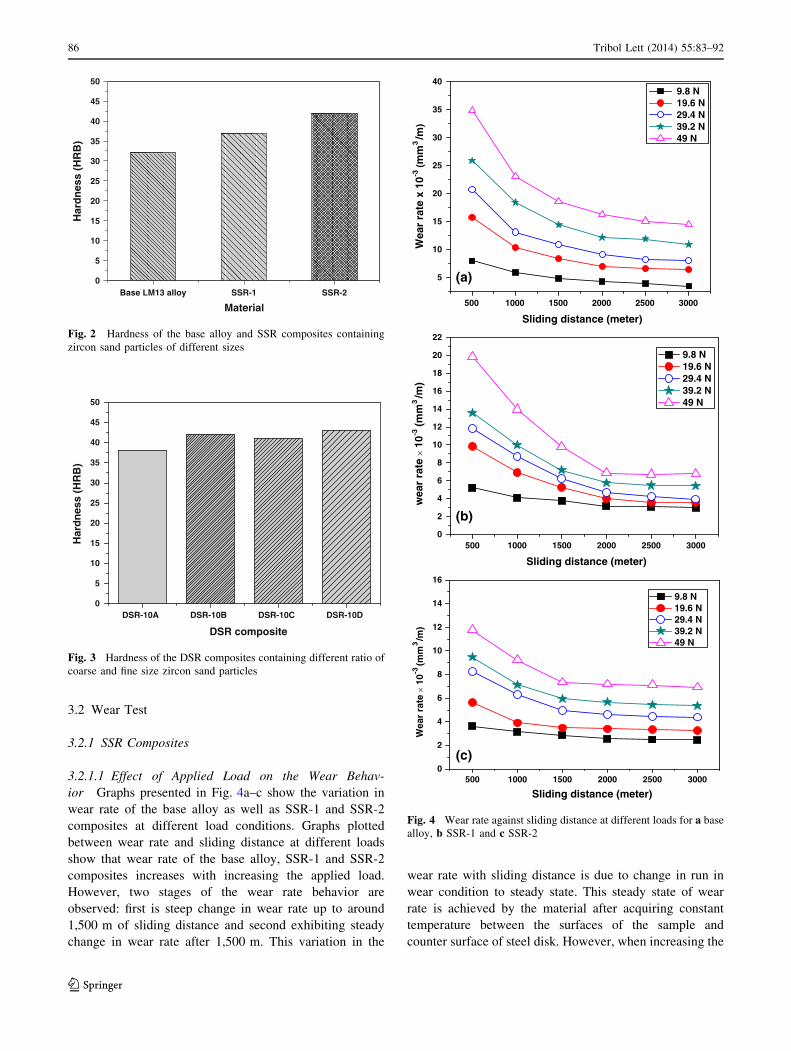
3.2.1.2 Effect of Ambient Temperature on the Wear
Behavior Wear behavior of the material is significantly
affected by the ambient temperature during the wear tests.
To study the effect of ambient temperature, wear tests were
carried out from 50 to 300 �C at low (9.8 N) and high
(49 N) loads. Figure 5 shows the effect of different ambi-
ent temperatures at 9.8 and 49 N loads on the wear rate of
base LM13 alloy, SSR-1 and SSR-2 composites. Figure 5
clearly indicates improvement in the wear rate of the LM13
alloy after the addition of zircon sand particles as rein-
forcement for all the temperature ranges at 9.8 and 49 N
loads.
Figure 5a shows the wear behavior of base alloy and
composites at different temperatures for low load (9.8 N). It
was observed that the wear rate for the both base alloy and
composites (SSR-1 and SSR-2) decreases with increasing
the temperature from 50 to 200 �C. The minimum wear rate
observed was around 200 �C due to the formation of pro-
tective oxide layer on the surface of pin [11]. Zhang and
Alpas [10] suggested that there is a critical transition tem-
perature in an alloy around *0.4 Tm (Tm is melting tem-
perature of alloy). For LM13 alloy, critical temperature is
around 250–260 �C. They suggested that at this critical
temperature, material undergoes softening adjacent to the
contact surfaces and thermally activated deformation pro-
cess occurs, which leads to the increase in wear rate at higher
temperatures. Wilson and Alpas [11] suggested that these
oxide layers at higher temperature (around 200 �C) reduce
the wear rate by avoiding direct metal-to-metal contact
between the surfaces of specimen and steel disk. Above
200 �C (nearly 0.4 Tm), thermally activated deformation
occurs and wear rate of the materials increases due to tearing
of the oxide layers which provide new area for the wear.
Hence, wear rate of the material increases significantly at
higher temperature (300 �C). Both base alloy and compos-
ites show similar wear behavior at different ambient tem-
peratures, but composites show improved wear resistance in
comparison with the base alloy. However, due to low applied
load, effect of particle size for SSR-1 and SSR-2 composites
on the wear rate is not considerable. Both the composites
show similar wear behavior at low load (9.8 N).
Figure 5b shows the variation in the wear rate for the base
alloy, SSR-1 composite and SSR-2 composites at higher load
(49 N). For the base alloy, wear rate increases sharply with
increasing the temperature from 50 to 150 �C. However, at
much higher temperature (from 200 to 300 �C) in presence of
higher load (49 N), base alloy was worn out. In this condi-
tion, a massive removal of materials was observed, which
leads to high wear rate. In the presence of higher load, wear
rate of the SSR-1 and SSR-2 composites increases with
increasing the ambient temperature from 50 to 150 �C.
However, around 200 �C due to the formation of oxide layer,
wear rate of both the composites decreases. At 250 �C, wear
rate of both composites increases due to the tearing of oxide
layers at higher temperatures. The tearing of oxide layers
exposes new area to delaminate during the wear test. This
exposed surface further undergoes oxidation. The formation
of oxide layer at higher temperatures and at higher loads is
very fast. After sometime, an equilibrium is achieved, and
the debris generated during this process forms mechanically
mixed layer (MML) on the surface of the pin, which protects
the surface from further oxidation. At 300 �C, wear rate of
the composites (SSR-1 and SSR-2) again decreases in the
presence of higher loads (49 N). Wilson and Alpas [11]
suggested that around 300 �C at high loads, there may be
generation of debris within steel disk. This debris transfers to
the opposing surface of the composite and forms MML. This
MML further leads to the decrease in the wear rate of the
composites.
50 100 150 200 250 3000
1
2
3
4
5
6
7
8W
ear
rate
× 1
0-3(m
m3/m
)
Temperature (°C)
Base SSR-1 SSR-2
(a)
50 100 150 200 250 3000
3
6
9
12
15
18
21
24
Wea
r ra
te ×
10
-3(m
m3/m
)
Temperature (°C)
Base SSR-1 SSR-2
(b)
Fig. 5 Comparison of wear rate against temperature for base alloy
and composites at a 9.8 N and b 49 N
Tribol Lett (2014) 55:83–92 87
123
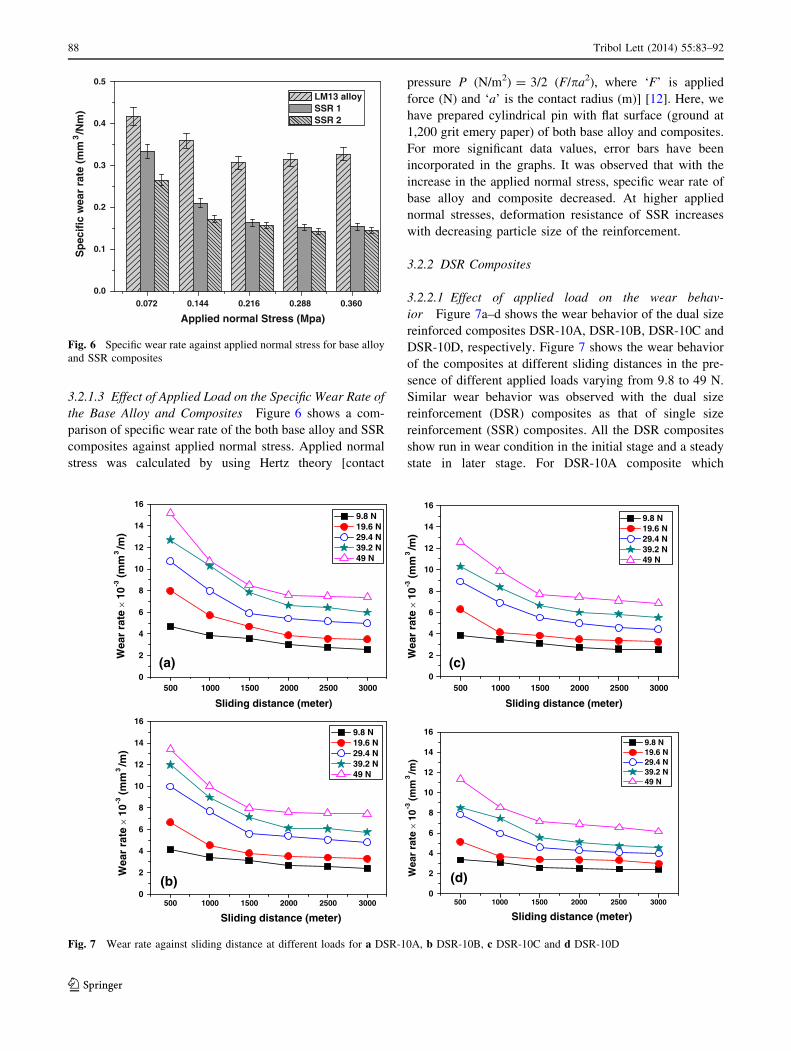
3.2.1.3 Effect of Applied Load on the Specific Wear Rate of
the Base Alloy and Composites Figure 6 shows a com-
parison of specific wear rate of the both base alloy and SSR
composites against applied normal stress. Applied normal
stress was calculated by using Hertz theory [contact
pressure P (N/m2) = 3/2 (F/pa2), where ‘F’ is applied
force (N) and ‘a’ is the contact radius (m)] [12]. Here, we
have prepared cylindrical pin with flat surface (ground at
1,200 grit emery paper) of both base alloy and composites.
For more significant data values, error bars have been
incorporated in the graphs. It was observed that with the
increase in the applied normal stress, specific wear rate of
base alloy and composite decreased. At higher applied
normal stresses, deformation resistance of SSR increases
with decreasing particle size of the reinforcement.
3.2.2 DSR Composites
3.2.2.1 Effect of applied load on the wear behav-
ior Figure 7a–d shows the wear behavior of the dual size
reinforced composites DSR-10A, DSR-10B, DSR-10C and
DSR-10D, respectively. Figure 7 shows the wear behavior
of the composites at different sliding distances in the pre-
sence of different applied loads varying from 9.8 to 49 N.
Similar wear behavior was observed with the dual size
reinforcement (DSR) composites as that of single size
reinforcement (SSR) composites. All the DSR composites
show run in wear condition in the initial stage and a steady
state in later stage. For DSR-10A composite which
0.072 0.144 0.216 0.288 0.3600.0
0.1
0.2
0.3
0.4
0.5S
pec
ific
wea
r ra
te (
mm
3/N
m)
Applied normal Stress (Mpa)
LM13 alloy SSR 1 SSR 2
Fig. 6 Specific wear rate against applied normal stress for base alloy
and SSR composites
0
2
4
6
8
10
12
14
16 9.8 N 19.6 N 29.4 N 39.2 N 49 N
Wea
r ra
te ×
10
-3(m
m3/m
)
Sliding distance (meter)
(a)
0
2
4
6
8
10
12
14
16 9.8 N 19.6 N 29.4 N 39.2 N 49 N
Wea
r ra
te ×
10
-3(m
m3/m
)
Sliding distance (meter)
(b)
0
2
4
6
8
10
12
14
16
9.8 N 19.6 N 29.4 N 39.2 N 49 N
Wea
r ra
te ×
10
-3(m
m3/m
)
Sliding distance (meter)
(c)
500 1000 1500 2000 2500 3000
500 1000 1500 2000 2500 3000
500 1000 1500 2000 2500 3000
500 1000 1500 2000 2500 30000
2
4
6
8
10
12
14
16 9.8 N 19.6 N 29.4 N 39.2 N 49 N
Wea
r ra
te ×
10
-3(m
m3/m
)
Sliding distance (meter)
(d)
Fig. 7 Wear rate against sliding distance at different loads for a DSR-10A, b DSR-10B, c DSR-10C and d DSR-10D
88 Tribol Lett (2014) 55:83–92
123
contains coarse and fine size zircon sand particles in ratio
4:1, wear resistance is lower in comparison with all other
DSR composites. However, the composition of 1:4 ratio of
coarse and fine size particles in matrix, i.e., DSR-10D
composite shows better wear resistance in comparison with
other DSR composites. It was observed that wear resistance
of the DSR composites improved with increasing amount
of fine size particles. However, wear rate of all the DSR
composites increases with increasing the applied load on
the materials.
Combination of fine and coarse size particles exhibits
better wear resistance as fine particles affect the larger area
to improve hardness and coarser particles help in bearing
the higher loads. Hence, at high load conditions, DSR-10D
composite shows better wear resistance.
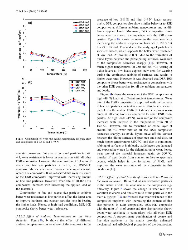
3.2.2.2 Effect of Ambient Temperatures on the Wear
Behavior Figure 8a, b shows the effect of different
ambient temperatures on wear rate of the composite in the
presence of low (9.8 N) and high (49 N) loads, respec-
tively. DSR composites also show similar behavior to SSR
composites at different ambient temperatures and at dif-
ferent applied loads. Moreover, DSR composites show
better wear resistance in comparison with the SSR com-
posites. Figure 8a shows decrease in the wear rate with
increasing the ambient temperature from 50 to 150 �C at
low (9.8 N) load. This is due to the wedging of particles in
softened matrix, which supports the better wear resistance
at low load. At around 200 �C, due to the formation of
oxide layers between the participating surfaces, wear rate
of the composites decreases sharply [11]. However, at
much higher temperatures (at 250 and 300 �C), tearing of
oxide layers at low loads exposes new area for wearing
during the continuous rubbing of surfaces and results in
higher wear rates. However, it was observed that DSR-10D
composite shows better wear resistance in comparison with
the other DSR composites for all the ambient temperatures
and loads.
Figure 8b shows the wear rate of the DSR composites at
high (49 N) loads at different ambient temperatures. Wear
rate of the DSR composites is improved with the increase
in fine size particles content as compared to the coarser size
particles in the matrix. DSR-10D shows better wear resis-
tance at all conditions as compared to other DSR com-
posites. At high loads (49 N), wear rate of the composite
increases with increase in the temperature from 50 to
150 �C. However, due to formation of oxide layer at
around 200 �C, wear rate of all the DSR composites
decreases sharply, as oxide layers stave off the contact
between the sliding surfaces of specimen and steel disk. At
much higher temperatures (250 �C) and due to continuous
rubbing of surfaces at high loads, oxide layers got damaged
and exposed new area for the delamination or wear, hence,
wear rate of the material increases again. At 300 �C,
transfer of steel debris from counter surface to specimen
occurs, which helps in the formation of MML and
improves the wear resistance of the composite in this
condition [11].
3.2.2.3 Effect of Dual Size Reinforced Particles Ratio on
the Wear Behavior Ratio of dual size reinforced particles
in the matrix affects the wear rate of the composites sig-
nificantly. Figure 7 shows the change in wear rate with
variation in coarse and fine size ratio of the particles in the
matrix. Figures 7, 8 and 9 reveal that wear resistance of the
composites improves with increasing the content of fine
size particles in DSR composites. DSR-10D composite
with the ratio of 1:4 of coarse and fine size particles shows
better wear resistance in comparison with all other DSR
composites. A proportionate combination of coarse and
fine size particles in the matrix provides enhanced
mechanical and tribological properties of the composites.
50 100 150 200 250 3001
2
3
4
5
6
7
8W
ear
rate
× 1
0-3(m
m3
/m)
Temperature (°C)
DSR 10A DSR 10B DSR 10C DSR 10D
(a)
50 100 150 200 250 3002
3
4
5
6
7
8
9
10
11
12
Wea
r ra
te ×
10-3
(mm
3/m
)
Temperature (°C)
DSR 10A DSR 10B DSR 10C DSR 10D
(b)
Fig. 8 Comparison of wear rate against temperature for base alloy
and composites at a 9.8 N and b 49 N
Tribol Lett (2014) 55:83–92 89
123
Due to larger effective area of fine particles in the matrix,
DSR composites exhibit higher hardness, while the pre-
sence of coarser size particles in the matrix provides good
resistance to wear at higher load.
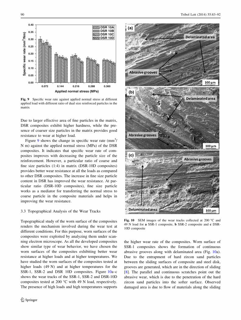
Figure 9 shows the change in specific wear rate (mm3/
N m) against the applied normal stress (MPa) of the DSR
composites. It indicates that specific wear rate of com-
posites improves with decreasing the particle size of the
reinforcement. However, a particular ratio of coarse and
fine size particles (1:4) in matrix (DSR-10D composites)
provides better wear resistance at all the loads as compared
to other DSR composites. The increase in fine size particle
content in DSR has improved the wear resistance. At par-
ticular ratio (DSR-10D composites), fine size particle
works as a mediator for transferring the normal stress to
coarse particle in the composite materials and helps in
improving the wear resistance.
3.3 Topographical Analysis of the Wear Tracks
Topographical study of the worn surface of the composites
renders the mechanism involved during the wear test at
different conditions. For this purpose, worn surfaces of the
composites were exploited by analyzing them under scan-
ning electron microscope. As all the developed composites
show similar type of wear behavior, we have chosen the
worn surfaces of the composites exhibiting better wear
resistance at higher loads and at higher temperatures. We
have studied the worn surfaces of the composites tested at
higher loads (49 N) and at higher temperatures for the
SSR-1, SSR-2 and DSR 10D composites. Figure 10a–c
shows the wear tracks of the SSR-1, SSR-2 and DSR-10D
composites tested at 200 �C with 49 N load, respectively.
The presence of high loads and high temperatures supports
the higher wear rate of the composites. Worn surface of
SSR-1 composites shows the formation of continuous
abrasive grooves along with delaminated area (Fig. 10a).
Due to the entrapment of hard zircon sand particles
between the sliding surfaces of composite and steel disk,
grooves are generated, which are in the direction of sliding
[8]. The parallel and continuous scratches point out the
abrasive wear, which is due to the penetration of the hard
zircon sand particles into the softer surface. Observed
damaged area is due to flow of materials along the sliding
Fig. 10 SEM images of the wear tracks collected at 200 �C and
49 N load for a SSR-1 composite, b SSR-2 composite and c DSR-
10D composite
0.072 0.144 0.216 0.288 0.3600.00
0.05
0.10
0.15
0.20
0.25
0.30
0.35
0.40S
pec
ific
wea
r ra
te (
mm
3/N
m)
Applied normal stress (MPa)
DSR 10A DSR 10B DSR 10C DSR 10D
Fig. 9 Specific wear rate against applied normal stress at different
applied load with different ratio of dual size reinforced particles in the
matrix
90 Tribol Lett (2014) 55:83–92
123
direction and tearing of the surface at higher loads. Fig-
ure 10a–c reveals that depth of grooves decreases with
decreasing the particle size, and larger delaminated area
was observed for the higher wear rate of the material.
Wavy patterns observed in Fig. 10a–c indicate the presence
of adhesive wear, which is due to softening of the com-
posite at higher temperatures.
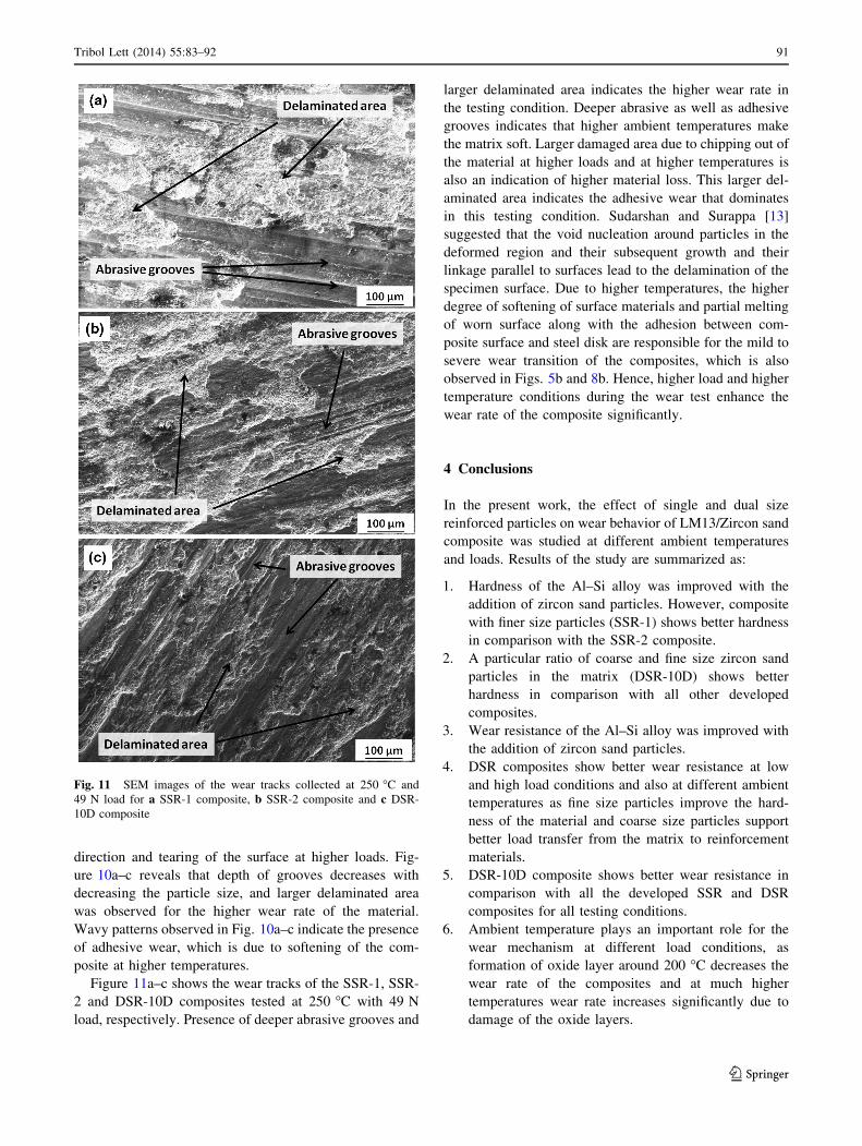
Figure 11a–c shows the wear tracks of the SSR-1, SSR-
2 and DSR-10D composites tested at 250 �C with 49 N
load, respectively. Presence of deeper abrasive grooves and
larger delaminated area indicates the higher wear rate in
the testing condition. Deeper abrasive as well as adhesive
grooves indicates that higher ambient temperatures make
the matrix soft. Larger damaged area due to chipping out of
the material at higher loads and at higher temperatures is
also an indication of higher material loss. This larger del-
aminated area indicates the adhesive wear that dominates
in this testing condition. Sudarshan and Surappa [13]
suggested that the void nucleation around particles in the
deformed region and their subsequent growth and their
linkage parallel to surfaces lead to the delamination of the
specimen surface. Due to higher temperatures, the higher
degree of softening of surface materials and partial melting
of worn surface along with the adhesion between com-
posite surface and steel disk are responsible for the mild to
severe wear transition of the composites, which is also
observed in Figs. 5b and 8b. Hence, higher load and higher
temperature conditions during the wear test enhance the
wear rate of the composite significantly.
4 Conclusions
In the present work, the effect of single and dual size
reinforced particles on wear behavior of LM13/Zircon sand
composite was studied at different ambient temperatures
and loads. Results of the study are summarized as:
1. Hardness of the Al–Si alloy was improved with the
addition of zircon sand particles. However, composite
with finer size particles (SSR-1) shows better hardness
in comparison with the SSR-2 composite.
2. A particular ratio of coarse and fine size zircon sand
particles in the matrix (DSR-10D) shows better
hardness in comparison with all other developed
composites.
3. Wear resistance of the Al–Si alloy was improved with
the addition of zircon sand particles.
4. DSR composites show better wear resistance at low
and high load conditions and also at different ambient
temperatures as fine size particles improve the hard-
ness of the material and coarse size particles support
better load transfer from the matrix to reinforcement
materials.
5. DSR-10D composite shows better wear resistance in
comparison with all the developed SSR and DSR
composites for all testing conditions.
6. Ambient temperature plays an important role for the
wear mechanism at different load conditions, as
formation of oxide layer around 200 �C decreases the
wear rate of the composites and at much higher
temperatures wear rate increases significantly due to
damage of the oxide layers.
Fig. 11 SEM images of the wear tracks collected at 250 �C and
49 N load for a SSR-1 composite, b SSR-2 composite and c DSR-
10D composite
Tribol Lett (2014) 55:83–92 91
123
7. Both abrasive and adhesive wear mechanisms were
observed in SEM analysis of the worn surfaces.
Acknowledgments The authors are thankful to Armament Research
Board (ARMREB), Defence Research and Development Organization
(DRDO), India, for providing financial support under the Letter No.
ARMREB/MAA/2008/105 for this study.
References
1. Das, S., Das, S., Das, K.: Abrasive wear of zircon sand and
alumina reinforced Al–4.5 wt% Cu alloy matrix composites—a
comparative study. Compos. Sci. Technol. 67, 746–751 (2007)
2. Hosking, F.M., Folgar, F.P., Wunderlin, R., Meharbian, R.:
Composites of aluminium alloys: fabrication and wear behavior.
J. Mater. Sci. 17(2), 477–498 (1982)
3. Dwivedi, D.K.: Adhesive wear behavior of cast aluminium–sili-
con alloys: overview. Mater. Des. 31, 2517–2531 (2010)
4. Kumar, S., Sharma, V., Panwar, R.S., Pandey, O.P.: Wear
behavior of dual particle size (DPS) zircon sand reinforced alu-
minum alloy. Tribol. Lett. 47, 231–251 (2012)
5. Hashim, J.: The production of cast metal matrix composite by a
modified stir casting method. J. Teknologi 35(1), 9–20 (2001)
6. Panwar, R.S., Pandey, O.P.: Study of wear behavior of zircon
sand-reinforced LM13 alloy composites at elevated temperatures.
J. Mater. Eng. Perform. 22, 1765–1775 (2013)
7. Mazaheri, Y., Meratian, M., Emadi, R., Najarian, A.R.: Com-
parison of microstructural and mechanical properties of Al–TiC,
Al–B4C and Al–TiC–B4C composites prepared by casting tech-
niques. Mater. Sci. Eng. A 560, 278–287 (2013)
8. Panwar, R.S., Pandey, O.P.: Analysis of wear tracks and debris of
stir cast LM13/Zr composite at elevated temperatures. Mater.
Charact. 75, 200–213 (2013)
9. Martinez, M.A., Martin, A., Llorca, J.: Wear of SiC-reinforced
Al-matrix composites in the temperature range 20–200 �C. Wear
193, 169–179 (1996)
10. Zhang, J., Alpas, A.T.: Transition between mild and severe wear
in aluminum alloys. Acta Mater. 45, 513–528 (1997)
11. Wilson, S., Alpas, A.T.: Effect of temperature on the sliding wear
performance of Al alloys and Al matrix composites. Wear 196,
270–278 (1996)
12. Johnson, K.L.: Contact mechanics, pp. 92–93. Cambridge Uni-
versity Press, New York (1985)
13. Sudarshan, Surappa, M.K.: Dry sliding wear of fly ash particle
reinforced A356 Al composites. Wear 265, 349–360 (2008)
92 Tribol Lett (2014) 55:83–92
123
Top Related
Copyright © 2022 FDOKUMEN

