


Bahasa
Halaman
Hukum

International Journal of xxxxxx
Vol. x, No. x, xxxxx, 20xx
1
Speed Control Based on Adaptive Neuro-Fuzzy Inference System for Permanent Magnet Direct Current Motor
S. Z Moussavi1, M. Alasvandi
2*, Sh. Javadi
3, E. Morad
4
1Electrical & Computer Engineering Faculty, Shahid Rajaee Teacher Training University, Lavizan,
Tehran, Iran. 2,3Department of Electrical Engineering, Islamic Azad University, Central Tehran Branch, Poonak,
Tehran, Iran. 4Department of Electrical Engineering, Islamic Azad University, SHADEGAN Branch,
SHADEGAN, Iran. [email protected], [email protected], [email protected], [email protected]
Abstract
This paper present Proportional-Integral-Derivative Controller (PID controller) based on
Adaptive Neuro-Fuzzy Inference System (ANFIS) for Permanent Magnet Direct Current
(PMDC) motor. ANFIS provides combination of artificial neural network and fuzzy inference
systems therefore ANFIS uses advantages of them also ANFIS mostly overcomes
disadvantages of them. Coefficients of proposed PID controller are determined by means of
ANFIS. Simulation results of proposed controller are compared with Internal Model Control
(IMC) PID. Comparison shows that proposed controller improves performance criteria in
different conditions such as no load, increasing reference speed, applied load and noisy load.
Proposed controller can improve performance of system by means of smaller fuzzy rule set.
Keywords: Adaptive Neuro-Fuzzy Inference System, Internal Model Control, PID
controller, PMDC motor, Speed control.
1. Introduction
In recent years PMDC motor is applied in many different applications such as robotics and
factory automation, industrial equipment and etc.
The PMDC motor becomes more popular in many control systems because of its high
power density, large torque to inertia ratio, small and high efficiency [1].
These motors are done mainly controls through the control of the armature. There are
three general methods for controlling motors [1-2]:
1. The classic PID controller.
2. Modern controller (adaptive and improving).
3. Intelligent controller (fuzzy and neural).
Recently, fuzzy inference system (FIS) is widely used because of its good performance,
especially in cases when the system or process is complicated and classical method cannot
work well. Additionally, fuzzy system formulates human knowledge in systematic manner
and puts them into engineering systems. But there is a problem associated with FIS, which is
the time consuming process to tune the parameters of FIS relying on human knowledge by
trial and error. So, there has been recently a surge of interest to combine neural network and
International Journal of xxxxxx
Vol. x, No. x, xxxxx, 20xx
2
FIS because of its both advantages of fuzzy inference systems and artificial neural networks
[3].
Adaptive Neuro- Fuzzy Inference System is proposed in IEEE transactions on systems,
man, and cybernetics by Jyh- Shing Roger Jang [4].
In recent years, ANFIS widely are applied in many control applications for example
ANFIS and PD controllers are applied in BLDC motor simultaneously [3] also ANFIS based
on MRAS are used in PMSM[5]. Moreover ANFIS controller is utilized in stepping and
induction motors in other papers [6-7].
In this paper, we want to propose ANFIS controller for PMDC motors. The coefficients of
proposed PID controller are determined by means of ANFIS. The proposed controller is
compared with IMC PID controller. Comparison shows that motor performance is improved
in many different conditions. This paper is organized as follows:
PMDC motor structure is explained in section 2. Section 3 describes concept of ANFIS.
Proposed controller is discussed in Section 4. Simulation results are investigated in section 5.
Finally, section 6 expresses summary conclusion.
2. PMDC Motor Structure
Our case study is PMDC motor therefore we should study PMDC motor structure
accurately. At first, the equations are written; these describe the structure of motor [2,
8].
)t(UL
1)t(
L
K)t(i
L
R
dt
)t(diT
AM
A
TA
A
AA (1)
)t(TJ
1)t(
J
B)t(i
J
K
dt
)t(dL
MM
M
MA
M
TM
(2)
)t(dt
)t(dM
M
(3)
Where θM is angular position, ωM is rotor speed, iA is motor current, BM is viscous
friction constant, JM is inertia of rotor, TL is load torque, RA is armature resistance, LA
is armature inductance, KT is back electromotive force (emf) constant or torque constant
and UT is applied voltage to motor. In PMDC motor, the electromagnetic torque (T E)
and the backemf (ub) are proportional to motor current and speed motor, respectively.
The back electromotive force (KT) determined by the strength of magnet, reluctance of
iron and number of turns of armature winding. The stator magnetic flux remains
essentially constant at all levels of armature current, therefore the torque-speed curve of
the PMDC motor is linear [2,8]. The block diagram of PMDC motor is concluded form
equations (1), (2) and (3).

International Journal of xxxxxx
Vol. x, No. x, xxxxx, 20xx
3
Figure 1. Block diagram of PMDC motor
This block diagram is simulated in simulink. ANFIS concept is explained in next section.
3. Adaptive Neuro-Fuzzy Inference System
The neuro- fuzzy system that uses advantages of neural network and fuzzy system has
progressed in recent years. Moreover, ANFIS mostly overcomes the disadvantages of neural
network and fuzzy system. One of popular neuro-fuzzy methods is called adaptive neuro-
fuzzy inference system which is introduced by Jyh - Shing Roger Jang [4].
Fuzzy Controller will produce the output based on the rules provided and that are based on
human experience. Whereas ANFIS is a best trade-off between neural and fuzzy system
which provide smoothness, due to the fuzzy controller (FC) interpolation and adaptability due
to the neural network (NN) Back propagation [7].
Nowadays, there are advanced developments in neuro-fuzzy synergisms for modelling and
adaptive control of nonlinear systems [5].
Using training data, ANFIS constructs a fuzzy inference system whose membership
functions parameters are tuned using either a back propagation algorithm alone, or in
combination with recursive least squares type algorithm. Using hybrid learning technique, the
learning process speeds up compared to the gradient method alone, which exhibits the
tendency to be trapped in local minima [3].
For simplicity, we assume the fuzzy inference system under consideration has two inputs x
and y and one output z. We suppose that the rule base contains two fuzzy if-then rules of
Takagi and Sugeno's type [4].
Rule 1: If x is A1 and y is B1 then f1=p1 x+ q1 y + r1
Rule 2: If x is A2 and y is B2 then f2=p2 x+ q2 y + r2
Then type-3 fuzzy reasoning is illustrated in Figure 2(a) and the corresponding equivalent
ANFIS architecture is shown in Figure 2(b).
AA RsL
1
KT
MM BsJ
1
KT
TE
TL
ωM iA UT
s
1
ϴM

International Journal of xxxxxx
Vol. x, No. x, xxxxx, 20xx
4
Figure 2. (a) Type-3 fuzzy reasoning (b) Equivalent ANFIS
The node functions in the same layer are of the same function family as described below
[4]:
Layer 1: Every node i in this layer is a square node with a node function [4]:
)x(OiA
1
i For i=1, 2, ... . (4)
Where x is input to node i and Ai is the linguistic label associated with this node function.
Layer 2: Every node in this layer is a circle node labelled ∏ which multiplies the incoming
signals and the product out. For instance [4],
)x()x(ii
BAi i=1, 2. (5)
Each node output represents the firing strength of a rule [4].
B2
B1
A2
A1
X
X Y
Y
W2
W1
1211 ryqxpf
x y
2211
21
2211
fWfW
WW
fWfWf
(a)
2222 ryqxpf
A1
A2
B1
B2
f1(x,y
)
f2(x,y
)
∏
∏
N
N
f
x
y
(b)
Layer1 Layer2 Layer3
Layer5
∏
x y
x y
Layer4
International Journal of xxxxxx
Vol. x, No. x, xxxxx, 20xx
5
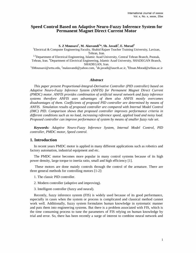
Layer 3: Every node in this layer is a circle node labelled N, the ith node calculates the
ratio of the ith rule's firing strength [4]:
21
ii
i=1, 2. (6)
Layer 4: Every node i in this layer is a square node with a node function [4]:
)ryqxp(fO iiiiii4
i (7)
Layer 5: The single node in this layer is a circle node labelled that computes the overall
output as summation of all incoming signals, i.e. [4],
ii
iii
ii
i5
1
ffO
=overall output (8)
After studying PMDC motor and ANFIS then proposed strategy is introduced in next
section.
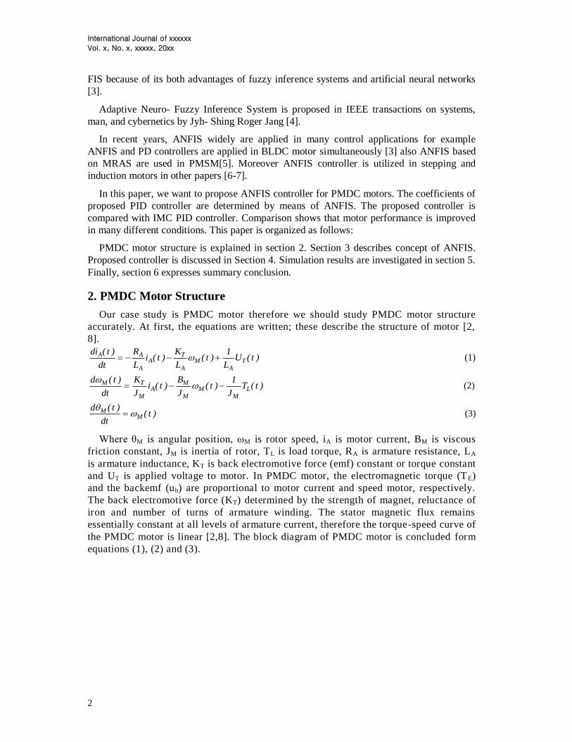
4. Proposed Controller
Our proposed controller is introduced in this section. Proposed structure is created by
ANFIS therefore we need three controllers for determining the values of Kp, Ki, Kd because
each of ANFIS controllers should have only one output. The values of Kp, Ki, Kd in proposed
controller are selected by values of error (e) and derivative of the error (de/dt). The block
diagram of proposed method is as follows:
Figure 3. Proposed control strategy
We applied 2001 input-output pairs for training, testing and checking each of the ANFIS
controller (Number of data can be changed). Each of our ANFIS controllers uses grid
partition to generate fuzzy inference system. Figure 4, Figure 5 and Figure 6 show properties
of ANFIS controllers.
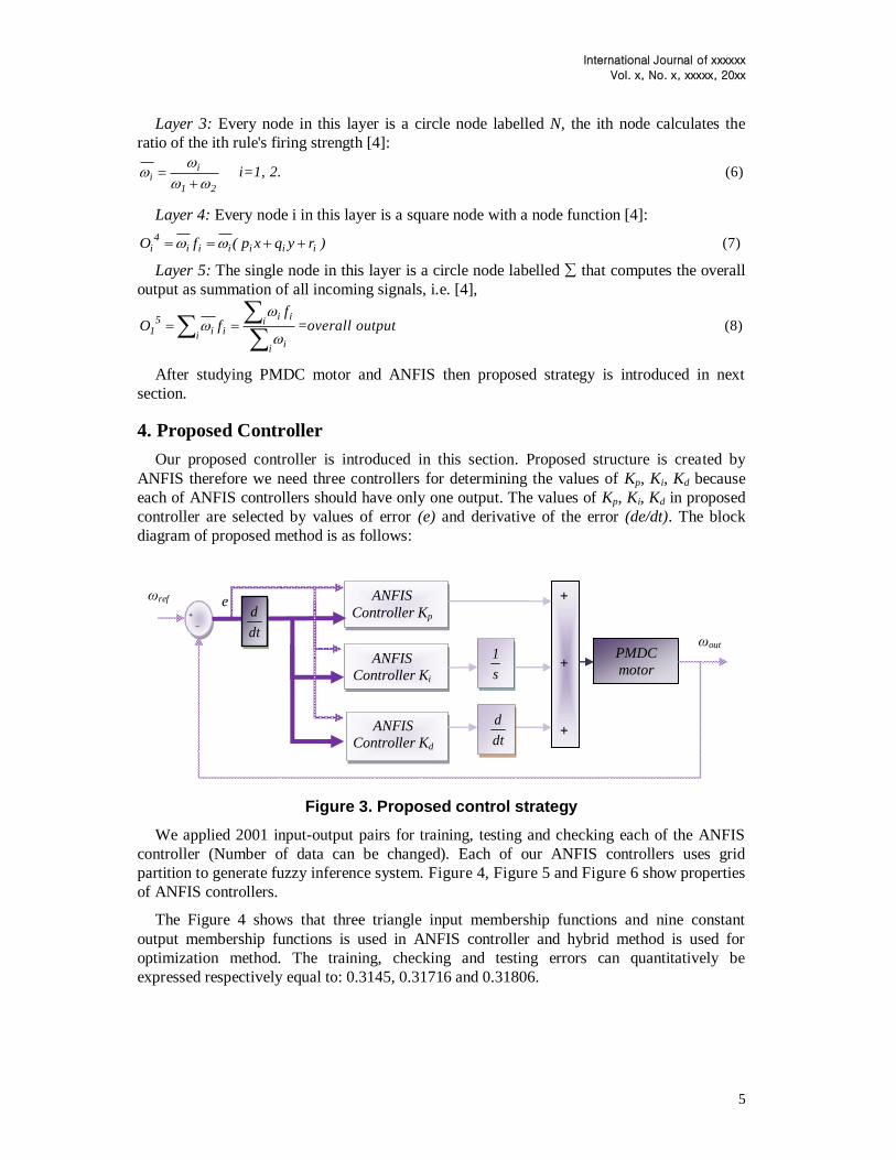
The Figure 4 shows that three triangle input membership functions and nine constant
output membership functions is used in ANFIS controller and hybrid method is used for
optimization method. The training, checking and testing errors can quantitatively be
expressed respectively equal to: 0.3145, 0.31716 and 0.31806.
+
_
_
ANFIS
Controller Kp
ANFIS
Controller Ki
ANFIS
Controller Kd
s
1
+
+
+
PMDC
motor
dt
d
dt
d
ωout
ωref e
International Journal of xxxxxx
Vol. x, No. x, xxxxx, 20xx
6
(a)
(b)
(c)
(d)
(e)
Figure 4. a. Results of ANFIS training, checking and testing (Kp), b. Rule viewer (Kp), c. Surface viewer (Kp), d. ANFIS Model Structure (Kp), e. Input membership
functions
Fuzzy inference system is used nine if-than rules to describe all possible conditions. The
fuzzy rules of the Kp ANFIS controller are as below:
Table 1. Fuzzy rules of Kp controller de
e
In2mf1 In2mf2 In2mf3
In1mf1 -84.28 -76.35 -69.75
In1mf2 348.3 384.6 421.5
In1mf3 697.8 705 706.2
Ki and Kd ANFIS controllers use same optimization method, number of input and output
membership functions. The Figure 5 shows that the training, checking and testing errors can
quantitatively be expressed respectively equal to: 0.070259, 0.074447 and 0.074208.
International Journal of xxxxxx
Vol. x, No. x, xxxxx, 20xx
7
(a)
(b)
(c)
(d)
(e)
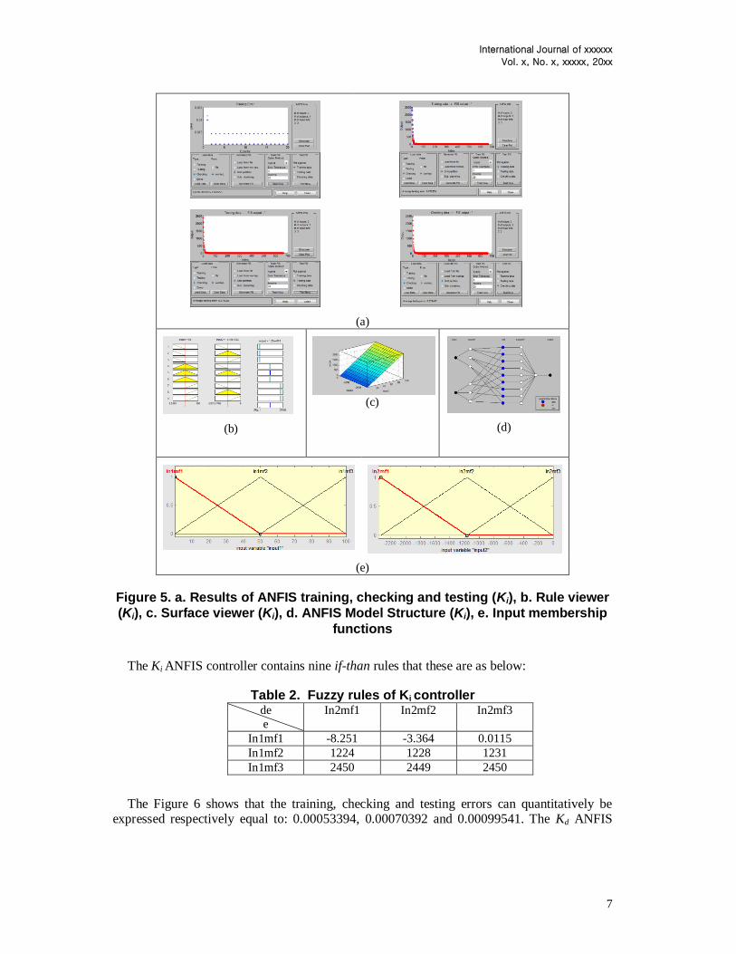
Figure 5. a. Results of ANFIS training, checking and testing (Ki), b. Rule viewer
(Ki), c. Surface viewer (Ki), d. ANFIS Model Structure (Ki), e. Input membership
functions
The Ki ANFIS controller contains nine if-than rules that these are as below:
Table 2. Fuzzy rules of Ki controller de
e
In2mf1 In2mf2 In2mf3
In1mf1 -8.251 -3.364 0.0115
In1mf2 1224 1228 1231
In1mf3 2450 2449 2450
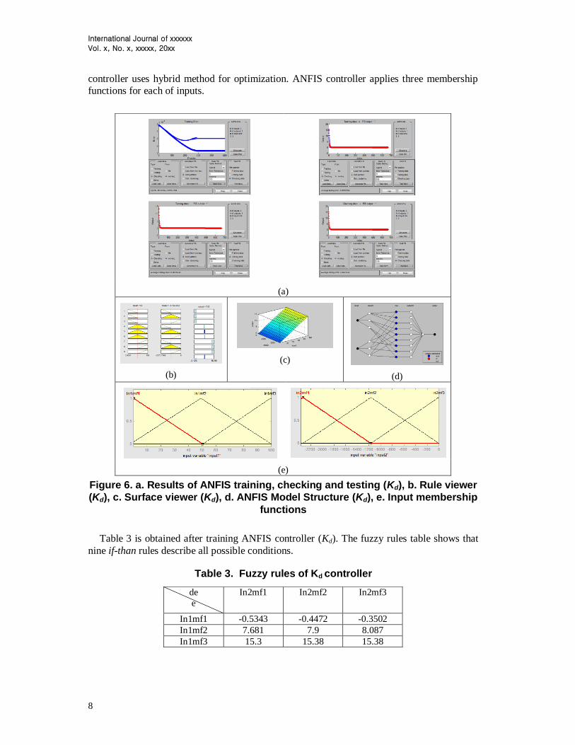
The Figure 6 shows that the training, checking and testing errors can quantitatively be expressed respectively equal to: 0.00053394, 0.00070392 and 0.00099541. The Kd ANFIS
International Journal of xxxxxx
Vol. x, No. x, xxxxx, 20xx
8
controller uses hybrid method for optimization. ANFIS controller applies three membership
functions for each of inputs.
Figure 6. a. Results of ANFIS training, checking and testing (Kd), b. Rule viewer
(Kd), c. Surface viewer (Kd), d. ANFIS Model Structure (Kd), e. Input membership
functions
Table 3 is obtained after training ANFIS controller (Kd). The fuzzy rules table shows that
nine if-than rules describe all possible conditions.
Table 3. Fuzzy rules of Kd controller
(a)
(b)
(c)
(d)
(e)
de
e
In2mf1 In2mf2 In2mf3
In1mf1 -0.5343 -0.4472 -0.3502
In1mf2 7.681 7.9 8.087
In1mf3 15.3 15.38 15.38
International Journal of xxxxxx
Vol. x, No. x, xxxxx, 20xx
9
Grid partition is used to generate FIS and hybrid method is used for optimization. Each of
three ANFIS controllers uses nine if-than rules. The ANFIS controllers can improve
performance of motor in different condition. Next section describes simulation results also we
discuss about results.
5. Simulation Results and Discussion
Parameters of permanent magnet DC motor are as follows:
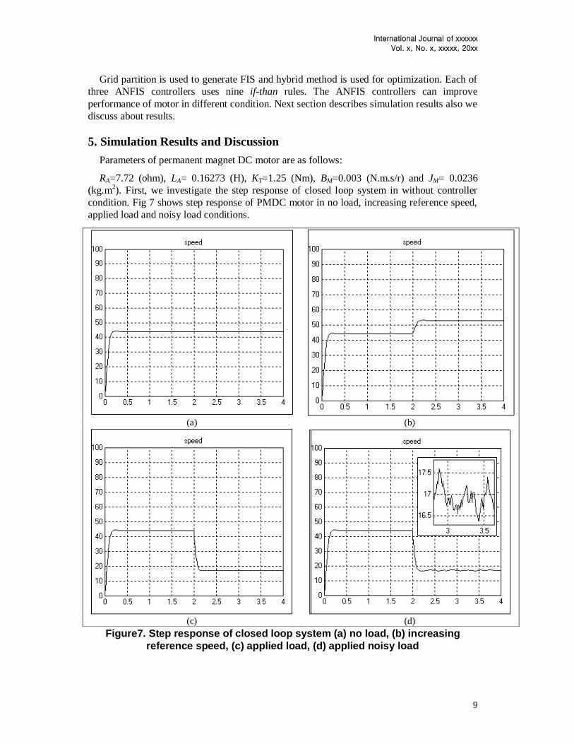
RA=7.72 (ohm), LA= 0.16273 (H), KT=1.25 (Nm), BM=0.003 (N.m.s/r) and JM= 0.0236
(kg.m2). First, we investigate the step response of closed loop system in without controller
condition. Fig 7 shows step response of PMDC motor in no load, increasing reference speed,
applied load and noisy load conditions.
Figure7. Step response of closed loop system (a) no load, (b) increasing
reference speed, (c) applied load, (d) applied noisy load
(a) (b)
(c) (d)

International Journal of xxxxxx
Vol. x, No. x, xxxxx, 20xx
10
The Figure 7 shows that steady state error is very large in no load also steady speed aren't
desirable in applied load and increasing reference speed conditions. Step response doesn't
have reasonable behaviour in noisy load condition (Load applied in t=2s s; Speed increase in
t= 2s, new reference speed = 120 rad/s and noise power = 0.001).
In this section, step response of control systems by means of IMC PID and proposed
controllers is investigated in different conditions. PID controller uses Internal Model Control
[9] method.
Figure 8. Step response of proposed and IMC PID controllers in different
conditions (a) no load, (b) increasing reference speed, (c) applied load, (d)
applied noisy load
(a) (b)
(c) (d)

International Journal of xxxxxx
Vol. x, No. x, xxxxx, 20xx
11
Figure 8(a) shows that proposed controller has smaller rise time, settling time than IMC
controller. The steady state error and percent maximum overshoot of proposed and IMC
controllers equal zero. Figure 8(b) shows that rise time of proposed controller is smaller than
IMC controller for increasing reference speed condition (Speed is increased in t=2 s and new
reference speed = 120 rad/s). Figure 8(c) shows that proposed controller has smaller percent
maximum undershoot and recovery time than IMC controller (load is applied in t= 2s and
TL = 10N). Figure 8(d) shows that proposed controller has smaller variation in noisy load
condition than IMC controller (Noise power= 0.001). The rise time, settling time, steady state
error and percent maximum overshoot are shown in Table 4. The rise time and final speed of
increasing reference speed condition, recovery time, percent undershoot and variation are
given in Table 5.
Table 4. Performance criteria of step response of control system (no load) Method Rise time
(s)
Settling time (s) Maximum
overshoot (%)
Steady state error
(%)
Without controller 0.1024 0.1637 0.33 55.9186
IMC controller 0.2191 0.3983 0 0
Proposed
controller
0.0761 0.2508 0 0
Table 4 shows that proposed controller has smaller rise time, overshoot and steady state
error than without controller system. IMC controller improves overshoot and steady state
error but rise time and settling time values are undesirable. The settling time of proposed
controller is larger than the without controller system but settling time of proposed controller
is reasonable. Others performance criteria are shown in Table 5.
Table 5. Performance criteria of control system in different condition
Condition increasing reference speed (New reference speed
=120 rad/s , applied time =
2s)
Applied load (Applied time= 2s, TL=10 N)
Noise (Noise power
=0.001)
Method Final speed
(rad/s)
Rise time
(s)
Recovery time
(s)
Percent
undershoot
(%)
Percent
variation (%)
Without
controller
52.8977 0.1024 ------------ --------------- 7.474
IMC
controller
120 0.3064 0.5198 20.3046 0.7897
Proposed
controller
120 0.0781 0.4581 6.6844 0.4892
Table 5 shows that proposed controller improves behaviour of system in increasing reference speed,
applied load and noise conditions. The recovery time, percent undershoot and variation of IMC
controller are smaller than performance criteria of without controller system but table 5 shows that
proposed controller have better behaviour in all conditions.
6.Conclusion
The performance criteria of control methods are summarized in Table 4 and 5. Rise time, settling
time, maximum overshoot and steady state error of without controller system equal 0.1024 s, 0.1637 s,
International Journal of xxxxxx
Vol. x, No. x, xxxxx, 20xx
12
0.33 %, 55.9186 (%), respectively. Rise time, settling time, maximum overshoot and steady state error
of proposed controller equal 0.0761 s, 0.2508s, 0 %, 0%, respectively. Table 4 shows that proposed
controller has smaller rise time, settling time than IMC controller system also proposed controller has
smaller rise time, maximum overshoot and steady state error than without controller system therefore
proposed control system can made rapidly step response without overshoot.
Table 5 shows that proposed controller can reach to new reference speed in smallest time; the rise
time for reaching new reference speed equals 0.0781s. We observe that proposed controller has smaller
recovery time and percent undershoot than IMC controller and without controller systems in applied
load condition. The values of recovery time and percent undershoot of proposed controller are equalled
0.4581s and 6.6844 %, respectively. Maximum variations of proposed controller is equalled 0.4892%
therefore proposed controller has smaller maximum variations than IMC and without controller
systems in noisy load condition. The ANFIS controller uses Sugeno inference therefore time of fuzzy
computation is decreased but Mamdani fuzzy inference uses large time for fuzzy computation. ANFIS
controllers uses small fuzzy rule set therefore proposed controller have easy implementation.
According to what was mention, the proposed controller can improve system behaviour in different
condition, moreover proposed controller have easy implementation.
7. ACKNOWLEDGEMENTS
The Authors thank ISLAMIC AZAD University, Central Tehran Branch as this work is the
result of master thesis in electrical engineering (MSc Eng.) with titled "Improvement
Performance of Permanent Magnet Motor by Using Fuzzy Controller" which is on focus at the
Faculty of Engineering.
8. References [1] J. Velagic and A.Galijasevic. Design of Fuzzy Logic Control of Permanent Magnet DC Motor
under Real Constraints and Disturbances. 2009 IEEE International Symposium on Intelligent
Control ,( 2009 )July 8-10; Saint Petersburg, Russia
[2] S. Z. Moussavi, M. Alasvandi, Sh. Javadi. Speed Control of Permanent Magnet DC Motor by using
Combination of Adaptive Controller and Fuzzy Controller. International Journal of Computer
Applications. 52 , 20 (2012) [3] M. B. B Sharifian, M. Shafiei, M. S Sadeghi, F. Golestaneh. Direct Torque Control of Brushless
DC Motor Drives Based on ANFIS Controller with Fuzzy Supervisory Learning. IEEE International
Conference on Electrical Machines and Systems (ICEMS), (2011 ) August ; Beijing, China
[4] J. S. R Jang .ANFIS: Adaptive-Network-Based Fuzzy Inference System. IEEE Transactions on System, Man, and Cybernetics. 23, 3(1993)
[5] M. Jain, M. Singh, A. Chandra, S. S. Williamson . Sensorless Control of Permanent Magnet
Synchronous Motor using ANFIS Based MRAS. IEEE International Electric Machines & Drives
Conference (IEMDC), (2011 )May; Niagara Falls
[6] P. Melin and O. Castillo. Intelligent Control of a Stepping Motor Drive Using an Adaptive Neuro–
Fuzzy Inference System. Elsevier Information Sciences. 170, 2-4 (2005)

International Journal of xxxxxx
Vol. x, No. x, xxxxx, 20xx
13
[7] R.Simon and A.Geetha. Comparison on the Performance of Induction Motor Control Using Fuzzy
and ANFIS Controllers. IEEE International Conference on Emerging Trends in Computing,
Communication and Nanotechnology (ICE-CCN), (2013) March; Tirunelveli, India
[8] G. Shahgholian and P. Shafaghi. State Space Modeling and Eigenvalue Analysis of the Permanent
Magnet DC Motor Drive System. 2010 International Conference on Electronic Computer Technology
(ICECT), (2010) May; Kuala Lumpur, Malaysia
[9] K. Anil Naik and P. Srikanth. Stability Enhancement of DC Motor using IMC Tuned PID
Controller. International Journal of Advanced Engineering Sciences and Technologies. 4,1( 2011)
Top Related
Copyright © 2022 FDOKUMEN

