


Bahasa
Halaman
Hukum


1
RUN
NIN
G M
AN
UA
LTe
naris
Hyd
rilC
oN
NeC
TIo
N S
peC
IfIC
RU
NN
ING
GU
IdeL
INeS
Tena
ris S
eC™
Con
nect
ion
IdM
Cod
e G
dL2
3377
/2 /
oct
ober
201
9
SEC Connection
Scope
These guidelines apply specifically to the use of SEC connections. This document should be used in conjunction with the TenarisHydril Running Manual, which is the main document applicable to the running of all TenarisHydril premium connections.
Tenaris Field Service Representatives can modify these guidelines when circumstances dictate. Implementation will only occur if the representative deems the modification to be non-detrimental to product integrity. All modifications being explained and agreed with the client representative prior to implementation and fully documented in the running report.
References
.TenarisHydril Running Manual..Premium Connection Approved Thread Compounds FTD29356..Recommended guidelines for the field inspection of TenarisHydril connections, GDL31457.
Equipment, Material & Documents
1. Verify the appropriate thread compound is available.
2. Refer to document FTD29356 for a list of compounds approved by Tenaris.
2
RUN
NIN
G M
AN
UA
LTe
naris
Hyd
rilC
oN
NeC
TIo
N S
peC
IfIC
RU
NN
ING
GU
IdeL
INeS
Tena
ris S
eC™
Con
nect
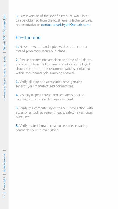
ion 3. Latest version of the specific Product Data Sheet
can be obtained from the local Tenaris Technical Sales representative or [email protected].
Pre-Running
1. Never move or handle pipe without the correct thread protectors securely in place.
2. Ensure connections are clean and free of all debris and / or contaminants, cleaning methods employed should conform to the recommendations contained within the TenarisHydril Running Manual.
3. Verify all pipe and accessories have genuine TenarisHydril manufactured connections.
4. Visually inspect thread and seal areas prior to running, ensuring no damage is evident.
5. Verify the compatibility of the SEC connection with accessories such as cement heads, safety valves, cross overs, etc.
6. Verify material grade of all accessories ensuring compatibility with main string.

3
RUN
NIN
G M
AN
UA
LTe
naris
Hyd
ril
IDM
Cod
e G
DL2
3377
/2 /
Oct
ober
201
9
CO
NN
eCTI
ON
Spe
CIf
IC R
UN
NIN
G G
UID
eLIN
eS
Te
naris
SeC
™ C
onne
ctio
nInspection
1. Inspection criteria for all TenarisHydril connections is as outlined in the Field Service Operative Guideline GDL31457.
2. Pay particular attention to seal areas.
3. Ensure the pin nose has no tears, gouges or raised metal.
4. Ensure the pin and box torque shoulders have no dents, tears or raised material which could interfere with correct assembly.

4
RUN
NIN
G M
AN
UA
LTe
naris
Hyd
rilC
oN
NeC
TIo
N S
peC
IfIC
RU
NN
ING
GU
IdeL
INeS
Tena
ris S
eC™
Con
nect
ion SEC Configuration
Tubing 2 3/8" – 2 7/8" = 8 TPI Tubing 3 1/2" – 4 1/2" = 6 TPI Casing 5" – 13 3/8" = 5 TPI

5
RUN
NIN
G M
AN
UA
LTe
naris
Hyd
ril
IDM
Cod
e G
DL2
3377
/2 /
Oct
ober
201
9
CO
NN
eCTI
ON
Spe
CIf
IC R
UN
NIN
G G
UID
eLIN
eS
Te
naris
SeC
™ C
onne
ctio
n
Modified BTC
Thread
TuBing Seal
CaSing Seal
Torque Shoulder

6
RUN
NIN
G M
AN
UA
LTe
naris
Hyd
rilC
oN
NeC
TIo
N S
peC
IfIC
RU
NN
ING
GU
IdeL
INeS
Tena
ris S
eC™
Con
nect
ion Thread Compound Application
1. Apply a thin coating of thread compound on the pin and box connections, fully covering all threads, seals, pin nose and box torque shoulder, the thread form should be fully visible.
2. Use approximately 20% of the quantity applied to the pin when doping the box.
3. For Tenaris approved thread compounds, apply the friction factor indicated in FTD29356. For thread compounds other than those listed, apply the thread compound manufacturers indicated friction factor.

7
RUN
NIN
G M
AN
UA
LTe
naris
Hyd
ril
IDM
Cod
e G
DL2
3377
/2 /
Oct
ober
201
9
CO
NN
eCTI
ON
Spe
CIf
IC R
UN
NIN
G G
UID
eLIN
eS
Te
naris
SeC
™ C
onne
ctio
nThread Lock Application
Connections must be clean and dry when applying thread lock.
1. Apply a thin coating of thread lock on 50% of the pin threads furthest from the pipe body.
2. Do not apply thread lock on the seal or torque shoulder.
3. Apply thread compound to the box seal and torque shoulder.
4. Apply the thread lock manufacturers indicated friction factor.

8
RUN
NIN
G M
AN
UA
LTe
naris
Hyd
rilC
oN
NeC
TIo
N S
peC
IfIC
RU
NN
ING
GU
IdeL
INeS
Tena
ris S
eC™
Con
nect
ion Torque Application
1. The use of computer make up analysis equipment is strongly recommended when assembling SEC connections.
2. Shoulder points for SEC connections are determined as a percentage of final applied torque.
Final Torque – Shoulder TorqueFinal Torque
x 100 = Delta Torque
3. The table above indicates the acceptable minimum and maximum delta torque percentages.
4. Reference torque should initially be set at 5% of optimum torque.
5. The dump valve should be set at optimum torque, verify correct operation on the pipe body prior to first make up.
6. Set the computer turns to 2 initially then adjust as necessary to attain good graph depiction.
7. Refer to the TenarisHydril running manual make up acceptance section for further explanation.
8. The computer make up profile for SEC connections should be similar to the ones below.
Tubing
Casing
95%
100%
95%
30%
30%
40%
MAxIMUMMINIMUM
ST / FR
GR
ST / FR / GR
SHOULDER TORqUES

9
RUN
NIN
G M
AN
UA
LTe
naris
Hyd
ril
IDM
Cod
e G
DL2
3377
/2 /
Oct
ober
201
9
CO
NN
eCTI
ON
Spe
CIf
IC R
UN
NIN
G G
UID
eLIN
eS
Te
naris
SeC
™ C
onne
ctio
n
TOR
QU
E *
1000
ft-
lbs
0
0
1.7
3.4
5.0
6.7
0.23 0.45 0.68 0.91
MAX. 9680
TURNS
MIN. 8330
OPT 9000
TOR
QU
E *
1000
ft-
lbs
0
0
1.7
3.4
5.0
6.7
0.23 0.45 0.68 0.91
MAX. 9680
TURNS
MIN. 8330
OPT 9000
10. SEC ST / FR / GR tubing connections with the same OD are interchangeable.
11. If different weight or grade of connections are to be mixed apply the lower of the indicated make up torques.
9. SEC connections of the same same OD different weight are fully interchangeable.

10
RUN
NIN
G M
AN
UA
LTe
naris
Hyd
rilC
oN
NeC
TIo
N S
peC
IfIC
RU
NN
ING
GU
IdeL
INeS
Tena
ris S
eC™
Con
nect
ion Running
1. The use of a stabbing guide is strongly recommended.
2. The use of a weight compensator is strongly recommended for chrome, large OD or heavy pipe.
3. To avoid cross threading stab pipe in a smooth controlled fashion ensuring the pipe is vertical when doing so, continue to support and stabilise the pipe throughout the stabbing and make up operation.
4. Upon commencement of initial rotation use low RPM (5 RPM or below) in order to ensure the pipe has not cross threaded during stabbing.
5. If cross threading is evident, immediately reverse rotate the pipe, break out, clean and inspect both connections.
6 Maximum spin in speed should not exceed 15 RPM.
7. Apply power tong at low RPM (do not exceed 5 RPM) for final make up.
8. Walk chrome pipe all the way in to hand tight, then apply tong only for final make up.
11
RUN
NIN
G M
AN
UA
LTe
naris
Hyd
ril
IDM
Cod
e G
DL2
3377
/2 /
Oct
ober
201
9
CO
NN
eCTI
ON
Spe
CIf
IC R
UN
NIN
G G
UID
eLIN
eS
Te
naris
SeC
™ C
onne
ctio
nPulling 1. Automatic stabbing system or stabber is highly recommended to maintain the pipe in a vertical position.
2. The use of a stabbing guide is recommended to assist in centralising the pin to prevent hang up.
3. A weight compensator is strongly recommended for chrome, large OD and heavy pipe.
4. Apply the back up tong jaw on the lower part, over the mill end, of the coupling.
5. Apply power tong in low RPM (3-5 RPM) to break the connection, ensuring the pipe is stabilised during the break and spin out process.
6. Do not exceed 15 RPM during spin out.
7. Walk chrome pipe all the way out after initial break out.
8. Visual inspection is recommended to classify the thread condition, any rejected connections should be clearly marked and segregated for further investigation.
9. Apply clean, dry thread protectors after applying storage compound on clean, dry connections.
10. Storage / thread compound should always be applied to connections post job, even rejects.
Tenaris has produced this manual for general information only. While every effort has been made to ensure the accuracy of the information contained within this publication, Tenaris does not assume any responsibility or liability for any loss, damage, injury resulting from the use of information and data herein. Tenaris products and services are only subject to the Company’s standard terms and Conditions or otherwise to the terms resulting from the respective contracts of sale, services or license, as the case may be. The information in this publication is subject to change or modification without notice. For more complete information please contact a Tenaris’s representative or visit our website at www.tenaris.com. This manual supersedes Version 03 / March 2018. ©Tenaris 2019. All rights reserved.
Copyright © 2022 FDOKUMEN

