


Bahasa
Halaman
Hukum


Safety Functions in Different Operational Modes and IEC 61508 in the Hydropower Industry
Sondre Bjørn Stette
Mechanical Engineering
Supervisor: Marvin Rausand, IPKCo-supervisor: Ingrid Almås Berg, Norconsult
Department of Production and Quality Engineering
Submission date: June 2013
Norwegian University of Science and Technology


0 ]T‘I‘ T.J Date2013.01.14 MAR‘KEDA
Faculty of Engineering Science and TechnologyDepartment of Production and Quality Engineering
MASTER THESISSpring 2013
forstud. techn. Sondre Stette
Reliability is an important characteristic of many technological systems. This especially applies forsafety-instrumented Systems (SIS), for which reliability assessment is required both as part of thedesign and in the operational phase. Reliability requirements to SISs are given in the internationalstandard TEC 61508 and in several application-specific sub-standards to IEC 61508, such as IEC62061 for machinery systems
In a hydropower plant, there are many electronic control-systems that are installed to monitor andcontrol the production of electro-power. In the design specification of some hydropower plants, it isspecified that all SISs must be designed according to IEC 61508. Implementing the IEC 61508 in thehydropower industry in Norway is not done, and there is a lack of knowledge about how this isperformed.
The overall objective of this master thesis is to investigate potentials and challenges related toimplementation of IEC 6508 and related application-specific standards in the hydropower industry.The master thesis will be carried out in cooperation with Norconsult.
As part of this master thesis, the candidate shall:
1. Perform and document a literature study of the various SISs used in the hydropower industry,and also the reliability requirements to these systems.
2. Identify and describe challenges related to high-demand safety instrumented functions andpresent relevant methods for calculating the average frequency ofdangerous failures per hour(PFH). Discuss pros and cons related to each method.
3. Identify and and give a brieftechnical description of relevant equipment under control (EUC).4. Choose one ofthe EUCs studied in task 3 and carry out a detailed reliability assessment ofthis
System by using the methods described in task 2.5. Discuss the implementation ofIEC 61508 in the hydropower industry. (Is it possible?
Necessary? What should be the focus: security, safety, economy, or production?)6. Identify and discuss challenges related to implementation ofIEC 61508 and relevant
application-specific standards in the hydropower industry, for which ftirther research is rieeded.
Following agreement with the supervisors, the various tasks may be given different weights.

Date Dur referenceMaster Thesis 2013 for stud. techn. Sondre Stette 2013.01.14 MAR/KEDA
Within three weeks after the date of the task handout, a pre-study report shall be prepared. The reportshall cover the following:
• An analysis of the work task‘s content with specific emphasis of the areas where newknowledge has to be gained.
• A description of the work packages that shall be performed. This description shall lead to aclear definition ofthe scope and extent ofthe total task to be performed.
• A time schedule for the project. The plan shall cornprise a Gantt diagram with specificationof the individual work packages, their scheduled start and end dates and a specification ofproject milestones.
The pre-study report is a part of the total task reporting. lt shall be included in the final report.Progress reports made during the project period shall also be included in the final report.
The report should be edited as a research report with a summary, table of contents, conclusion, list ofreference, list of literature etc. The text should be clear and concise, and include the necessaryreferences to figures, tables, and diagrams. lt is also important that exact references are given to anyexternal source used in the text.
Equipment and software developed during the project is a part of the fulfilment of the task. Unlessoutside parties have exclusive property rights or the equipment is physically non-moveable, it shouldbe handed in along with the final report. Suitable documentation for the correct use of such materialis also required as part ofthe final report.
The candidate shall follow the work regulations at the company‘s plant. The candidate may notintervene in the production process in any way. All orders for specific intervention of this kindshould be channelled through company‘s plant management.
The student must cover travel expenses, telecommunication, and copying unless otherwise agreed.
If the candidate encounters unforeseen difficulties in the work, and if these difficulties warrant areformation of the task, these problems should immediately be addressed to the Department.
The assignment text shall be enclosed and be placed immediately after the title page.
Deadline: June 10t1 2013.
Two bound copies of the final report and one electronic (pdf-format) version are required.

Date Our referenceMaster Thesis 2013 for stud. techn. Sondre Stette 2013.01.14 MARIKEDA
Responsible supervisor: Marvin RausandPhone: 73 59 25 42E-mail: [email protected]
Supervisor at Norconsult: Ingrid Alm?ts BergPhone: 46 54 20 22E-mail: ingrid.almas.berg(norconsult.com
Supervisors:
DEPARTMENT OF PRODUCTIONAND QUALITY ENGINEERING
- diPer Shjølberg
Associate Professor/Head of Department
Marvin Rausand (Responsible Supervisor


i
Preface
This master thesis is written during the spring semester of 2013 in Reliability, Availability, Main-
tainability, and Safety (RAMS) at the Department of Production and Quality Engineering (IPK),
and it is carried out in cooperation with Norconsult. The master thesis is the final step of the
study program Mechanical Engineering at the Norwegian University of Science and Technology,
and it will give me the degree Master of Science. The work has been performed in Trondheim at
the facilities of IPK and at Norconsult’s headquarter in Sandvika, and the workload is equal to a
semester.
Because this master thesis is written in cooperation with Norconsult, it is written for my
future colleagues. They have knowledge about the concept of reliability and are familiar with
the standard IEC 61508, and it is recommended that the reader has knowledge about this as
well. However, knowledge about IEC 61508 is not a necessity for enjoying this master thesis.
Trondheim, 2013-06-10
Sondre Bjørn Stette

iii
Acknowledgment
I would like to thank my supervisor Professor Marvin Rausand for his valuable inputs and guid-
ance on this master thesis. I am grateful for everything he has taught me and for all the help he
has given me throughout the semester. Gratitude is also expressed to my supervisor and future
colleague Ingrid Almås Berg at Norconsult for insightful discussions and helpful guidance on
this master thesis.
My future colleague Frank Mikkelsen at Norconsult and PhD candidate Hui Jin at NTNU
deserve attention for providing helpful information and discussions during the preparation of
my master thesis. A special thanks to Odd Jarle Jørgensen at Norsk Hydro for the very insightful
guided tour at Norsk Hydro’s hydropower plant at Tyin.
S.B.S.


v
Summary and Conclusions
Technical systems that comprise at least one electrical, electronic, or programmable electronic
device and perform safety functions are called safety instrumented systems. Safety instrumented
systems are used to reduce the risk related to hazardous events that may result in undesired con-
sequences to humans, the environment, and assets, and the reliability of such systems is there-
fore important. The international standard IEC 61508 can be used to ensure safe and reliable
safety instrumented systems, and it applies to all types of safety instrumented systems. Based
on IEC 61508, the process industry and the machinery industry have developed their own ver-
sions called IEC 61511 and IEC 62061, respectively.
IEC 61508 includes requirements for all activities necessary for achieving reliable safety in-
strumented systems throughout their whole lifecycle, and the standard introduces concepts and
terminology that can be challenging to understand. Some basic concepts and terminology in
IEC 61508 are clarified in this master thesis.
A safety function, performed by a safety instrumented system, may be demanded from sel-
dom to continuously. IEC 61508 distinguishes between safety functions that are demanded less
frequent and more frequent than once per year, and these two modes of operation are called
low-demand and high-demand, respectively. Furthermore, the standard requires that different
reliability measures are used for demonstrating the reliability of the safety instrumented systems
performing low-demand and high-demand safety functions. In two examples, the two reliabil-
ity measures are used, and the calculated results show that there is an inconsistency with the
classification of safety functions in IEC 61508. This inconsistency is, however, not experienced
with the classification in IEC 61511, and the approach in IEC 61511 seems better.
Other differences between low-demand and high-demand safety functions are not well ex-
plained in IEC 61508. Because IEC 61511 considers mainly low-demand safety functions and
IEC 62061 considers only high-demand safety functions, specific requirements in these two
standards are compared to reveal possible differences between low-demand and high-demand.
It is concluded that there are essentially no differences between the compared requirements.
Based on the event, loss of control, in an accident scenario, it is proposed a new approach
for classifying safety functions. A definition of loss of control is suggested and it distinguishes
vi
between safety control functions and safety protection functions. These two functions are fur-
ther related to two additional events in an accident scenario, and a model that illustrates the
proposed classification in relation to the three events in an accident scenario is developed. The
proposed classification is neither based on frequency of demands nor does it prescribe use of a
specific reliability measure, and the classification is thus different from the classification in IEC
61508. The proposed classification is more similar to the classification in IEC 61511.
Safety instrumented systems are used in the hydropower industry, but IEC 61508 is essen-
tially not yet applied. The Machinery Directive requires machine manufacturers to meet the
essential health and safety requirements, and some of these requirements can, for safety instru-
mented systems in machines, be met by complying with IEC 62061. Because IEC 62061 is based
on IEC 61508, this is a relationship between IEC 61508 and the hydropower industry.
From the perspective of a typical company operating hydropower plants in the Norwegian
hydropower industry, some benefits and challenges related to implementation and use of IEC
61508 are discussed. IEC 61508 provides a rigorous, risk-based approach for achieving reliable
safety instrumented systems and many of the concepts in the standard could be very useful
in the hydropower industry. However, the standard is comprehensive and extensive resources
and competence are prerequisites for successful implementation and use. It is concluded that
IEC 61508 may not be what the hydropower industry needs, but a joint project for developing a
unified approach for ensuring reliable safety instrumented systems may be a better option.

Contents
Preface . . . . . . . . . . . . . . . . . . . . . . . . . . . . . . . . . . . . . . . . . . . . . . . . i
Acknowledgment . . . . . . . . . . . . . . . . . . . . . . . . . . . . . . . . . . . . . . . . . . iii
Summary and Conclusions . . . . . . . . . . . . . . . . . . . . . . . . . . . . . . . . . . . . v
1 Introduction 1
1.1 Background . . . . . . . . . . . . . . . . . . . . . . . . . . . . . . . . . . . . . . . . . . 1
1.2 Objectives . . . . . . . . . . . . . . . . . . . . . . . . . . . . . . . . . . . . . . . . . . . 4
1.3 Limitations . . . . . . . . . . . . . . . . . . . . . . . . . . . . . . . . . . . . . . . . . . . 4
1.4 Structure of the Master Thesis . . . . . . . . . . . . . . . . . . . . . . . . . . . . . . . 5
2 E/E/PE Safety-related Systems and IEC 61508 7
2.1 E/E/PE Safety-related Systems . . . . . . . . . . . . . . . . . . . . . . . . . . . . . . . 8
2.2 IEC 61508 . . . . . . . . . . . . . . . . . . . . . . . . . . . . . . . . . . . . . . . . . . . . 10
2.3 Other Requirements for the Achievable SIL . . . . . . . . . . . . . . . . . . . . . . . . 15
3 Differences In Different Operational Modes 19
3.1 Relevant Standards . . . . . . . . . . . . . . . . . . . . . . . . . . . . . . . . . . . . . . 20
3.2 Comparison of Safety Requirements Specifications . . . . . . . . . . . . . . . . . . . 22
3.3 Realization of SISs and SRECSs . . . . . . . . . . . . . . . . . . . . . . . . . . . . . . . 23
3.4 Other Characteristics of SISs and SRECSs . . . . . . . . . . . . . . . . . . . . . . . . . 30
3.5 Summary and Discussion . . . . . . . . . . . . . . . . . . . . . . . . . . . . . . . . . . 31
4 A New Approach for Classifying Safety Functions 33
4.1 A New Approach for Classifying Safety Functions . . . . . . . . . . . . . . . . . . . . 34
4.2 A Model for Classifying Safety Functions . . . . . . . . . . . . . . . . . . . . . . . . . 36
vii
CONTENTS viii
4.3 Examples . . . . . . . . . . . . . . . . . . . . . . . . . . . . . . . . . . . . . . . . . . . . 39
4.4 Summary and Discussion . . . . . . . . . . . . . . . . . . . . . . . . . . . . . . . . . . 44
5 IEC 61508 in the Hydropower Industry 45
5.1 Benefits and Challenges with IEC 61508 . . . . . . . . . . . . . . . . . . . . . . . . . . 48
5.2 Implementation of IEC 61508 in the Hydropower Industry . . . . . . . . . . . . . . . 52
5.3 Summary and Discussion . . . . . . . . . . . . . . . . . . . . . . . . . . . . . . . . . . 53
6 Summary and Recommendations for Further Work 55
6.1 Summary and Conclusions . . . . . . . . . . . . . . . . . . . . . . . . . . . . . . . . . 55
6.2 Recommendations for Further Work . . . . . . . . . . . . . . . . . . . . . . . . . . . . 57
A Acronyms 59
Bibliography 63
Curriculum Vitae 69
Chapter 1
Introduction
1.1 Background
Electrical/electronic/programmable electronic (E/E/PE) safety-related systems, often referred
to as safety instrumented systems, are used in many different applications to protect humans,
the environment, and assets from hazardous events. Failures of E/E/PE safety-related systems
may lead to undesired consequences, and ensuring the reliability of such systems is therefore
important. The international standard IEC 61508, Functional safety of E/E/PE safety-related sys-
tems, is widely accepted as best practice for achieving safe and reliable E/E/PE safety-related
systems. In addition to being a stand-alone standard, IEC 61508 can be used to develop application-
specific standards, such as IEC 61511 for the process industry and IEC 62061 for machinery.
IEC 61508 is comprehensive and includes requirements for design, installation, operation,
and maintenance of E/E/PE safety-related systems. If an end-user shall acquire an E/E/PE
safety-related system in accordance with the standard, the end-user is required to prepare a de-
tailed document stating what the system is required to do and how well the system is required
to perform. This document is referred to as a safety requirements specification (SRS), and it
is the specification basis for the designer of the E/E/PE safety-related system. To demonstrate
that the performance of an E/E/PE safety-related system meets the performance specified in
the SRS, the designer is required to quantify the reliability of the hardware and comply with the
architectural constraints. The latter is requirements for the hardware layout and they ensure a
sufficiently robust architecture for E/E/PE safety-related systems.
1
CHAPTER 1. INTRODUCTION 2
IEC 61508 distinguishes between two modes of operation for E/E/PE safety-related systems
based on frequency of demands. An E/E/PE safety-related system may be classified as low-
demand mode of operation or high-demand or continuous mode of operation, depending on
whether demands occur with a frequency of less or more than once per year, respectively. Fur-
thermore, IEC 61508 requires that the average probability of dangerous failures on demand
(PFDavg) is used as the reliability measure for E/E/PE safety-related systems operating in low-
demand mode, and for E/E/PE safety-related systems operating in high-demand or continuous
mode, IEC 61508 requires that the average frequency of dangerous failure per hour (PFH) is used
as reliability measure.
Several research projects on the suitability of the required reliability measures in IEC 61508
have been conducted (e.g., Bukowski, 2006; Hauge et al., 2013; Innal, 2008; Innal et al., 2009;
Jin et al., 2011; Liu and Rausand, 2011; Misumi and Sato, 1999), and many of these research
projects question the classification of E/E/PE safety-related systems as low-demand mode of
operation and high-demand or continuous mode of operation and the applicability of the re-
liability measures in the borderline region of the classification. The existing research focuses
on the reliability characteristics of the E/E/PE safety-related system hardware in the different
operational modes, but other potential differences are essentially not covered. In particular,
no agreed explanation of differences between safety functions implemented by E/E/PE safety-
related systems operating in different operational modes are provided in the literature.
Misumi and Sato (1999) propose a new classification of modes of operation with respect
to demand frequencies and demand durations for non-demand-state-at-proof-test systems and
constant-demand-frequency systems using fault tree analysis. According to Innal (2008), Markov
methods are most suitable for modeling the reliability of E/E/PE safety-related systems, and sev-
eral authors apply Markov methods to model the reliability by incorporating demand rates (e.g.,
Bukowski, 2006; Innal, 2008; Innal et al., 2009; Jin et al., 2011; Liu and Rausand, 2011). Bukowski
(2006) models an E/E/PE safety-related system with Markov methods and observes that the re-
liability of an E/E/PE safety-related system is affected by frequency of demands. According to
Bukowski (2006), the distinction between low-demand mode of operation and high-demand or
continuous mode of operation in IEC 61508 (2010) is insufficient and incorporating demands is
necessary when analyzing the reliability of E/E/PE safety-related systems.
CHAPTER 1. INTRODUCTION 3
Jin et al. (2011) and Liu and Rausand (2011) apply Markov models to analyze the reliabil-
ity of E/E/PE safety-related systems with changing demand rates and demand durations. Liu
and Rausand (2011) show that the reliability characteristics of E/E/PE safety-related systems
operating in low-demand mode and high-demand or continuous mode are different and claim
that demand durations should be considered when classifying E/E/PE safety-related systems.
Jin et al. (2011) verify the accuracy of a Markov model for a single pressure transmitter in both
low-demand mode of operation and high-demand or continuous mode of operation by a com-
parison with a developed scenario-based formula for the hazardous event frequency (HEF).
Hauge et al. (2013) discuss the classification of E/E/PE safety-related systems as low-demand
mode of operation and high-demand or continuous mode of operation in IEC 61508 and argue
that the classification should be split into low-demand mode of operation, high-demand mode
of operation, and continuous mode of operation. IEC 62061 (2012) addresses only high-demand
or continuous mode of operation, and IEC 61511 (2003) distinguishes between demand mode
of operation and continuous mode of operation.
Although the existing research covers and discusses the reliability of E/E/PE safety-related
systems and differences between low-demand mode of operation and high-demand or contin-
uous mode of operation, an important issue is still unclear. E/E/PE safety-related systems im-
plement safety functions, and safety functions operate in low-demand mode and high-demand
or continuous mode, but possible differences between safety functions in the different demand
modes are not agreed upon in the literature. It is neither obvious what a safety function operat-
ing in high-demand or continuous mode do nor is the difference between safety functions and
control functions clear. For example, a fly-by-wire system is, according to Bukowski (2006), an
E/E/PE safety-related system that operates in continuous or high-demand mode.
E/E/PE safety-related systems are used in the hydropower industry, but IEC 61508 is essen-
tially not yet applied. The design specifications of some new hydropower plants require that all
E/E/PE safety-related systems are in accordance with IEC 61508. This is problematic because
there is a lack of knowledge about how compliance is achieved, and benefits and challenges
related to implementation of IEC 61508 in the hydropower industry are not explored.

CHAPTER 1. INTRODUCTION 4
1.2 Objectives
The main objectives of this master thesis are:
1. Clarify basic concepts and terminology in IEC 61508.
2. Identify and discuss possible differences between low-demand mode of operation and
high-demand or continuous mode of operation by:
• Comparing the requirements in IEC 61511 and IEC 62061 for the safety requirements
specifications and the architectural constraints.
• Comparing PFDavg and PFH.
3. Develop and propose a new approach for classifying safety functions and describe the
classification with examples.
4. Discuss the implementation of IEC 61508 in the hydropower industry. (Is it possible? Nec-
essary? What should be the focus: security, safety, economy, or production?)
5. Identify and discuss challenges related to implementation of IEC 61508 and relevant application-
specific standards in the hydropower industry, for which further research is needed.
Remark: In agreement with the supervisors, the objectives of this master thesis are changed,
and the objectives stated above apply.
1.3 Limitations
The main topics in this master thesis are E/E/PE safety-related systems, safety functions, IEC
61508 in the hydropower industry, and differences between low-demand mode of operation and
high-demand or continuous mode of operation within the context of IEC 61508, IEC 61511, and
IEC 62061. Concepts and terms are mainly based on IEC 61508. In this master thesis, software,
human and organizational factors, and the effects of common cause failures are not considered.
CHAPTER 1. INTRODUCTION 5
1.4 Structure of the Master Thesis
The rest of this master thesis is structured as follows. Chapter 2 presents basic concepts and ter-
minology in IEC 61508. In Chapter 3, comparisons of the requirements for safety requirements
specifications in IEC 61511 and IEC 62061, PFDavg and PFH, and the architectural constraints in
IEC 61511 and IEC 62061 are presented and possible differences between low-demand mode of
operation and high-demand or continuous mode of operation are discussed. A new approach
for classifying safety functions, a model, and two examples are described in Chapter 4. Dis-
cussions about benefits and challenges related to implementation and use of IEC 61508 and
implementation of IEC 61508 in the hydropower industry are given in Chapter 5. Chapter 6
summarizes and concludes this master thesis, and gives recommendations for further work.
The acronyms used throughout this master thesis are listed in Appendix A.


Chapter 2
E/E/PE Safety-related Systems and
IEC 61508
All processes and activities performed in any industry involve risks, because there is no such
thing as "zero risk" (HSE, 1992). In a hydropower plant, one of the main hazards is the kinetic
energy in the water flow, and if it is not controlled, it may cause harm to assets (e.g., humans,
the environment, and equipment). For some types of failures in the turbine, there are safety
systems that automatically stop the flow of water, which prevents further escalation of undesired
consequences. These safety systems monitor operational variables in the turbine, and if these
exceed a preset limit, a logic solver sends signals to the actuating elements and they stop the
flow of water. Such systems are E/E/PE safety-related systems.
This chapter gives an introduction to some fundamental concepts and terminology in IEC
61508, and it is partly based on the author’s project thesis Stette (2012).
7

CHAPTER 2. E/E/PE SAFETY-RELATED SYSTEMS AND IEC 61508 8
2.1 E/E/PE Safety-related Systems
An electrical/electronic/programmable electronic (E/E/PE) safety-related system is a system
comprising input elements, logic solvers, and actuating elements (Rausand, 2011), as illustrated
in Figure 2.1. The main purpose of an E/E/PE safety-related system is to prevent and/or mitigate
hazardous events introduced by an equipment under control (EUC) (IEC 61508, 2010). An EUC
is equipment, machinery, apparatus, or plant that is used for various activities. In most cases,
the EUC also has an EUC control system. The EUC control system monitors and controls the
EUC and ensures that it operates in the desired manner (IEC 61508, 2010).
içÖáÅ=ëçäîÉê=
fåéìí=ÉäÉãÉåíë= ^Åíì~íáåÖ=ÉäÉãÉåíë=
Figure 2.1: E/E/PE safety-related system elements (reproduced from Rausand, 2011).
Safety Function
An E/E/PE safety-related system is a physical system that performs one or more safety functions.
If an EUC introduces a specific process demand, the safety functions should maintain or achieve
a safe state. A process demand is a deviation in the EUC. The safety functions are determined
from a hazard and risk analysis.
A safety function may fail in two different ways. The safety function may be unable to per-
form its required function upon a specific process demand in the EUC, or it is performed with-
out a specific process demand. The former failure mode is called fail-to-function and the latter
is called spurious activation or spurious trip (Rausand, 2011).

CHAPTER 2. E/E/PE SAFETY-RELATED SYSTEMS AND IEC 61508 9
Failure Classification
IEC 61508 distinguishes between random hardware failures and systematic failures for E/E/PE
safety-related systems. Random hardware failures are failures in the hardware of E/E/PE safety-
related systems that occur at random times, and they are caused by degradation mechanisms
(IEC 61508, 2010). The system failure rates for random hardware failures "... can be predicted
with reasonable accuracy ..." (IEC 61508, 2010). Systematic failures are, according to IEC 61508
(2010), failures that cannot be quantified because their occurrence can not be predicted, and
such failures may occur from design, implementation, installation, or maintenance and opera-
tion errors. Systematic failures are further explained in Section 2.3.
In addition, IEC 61508 distinguishes between dangerous and safe failures, and these are clas-
sified into four categories:
• Dangerous (D) failures are failures that prevent the SIS from performing its required SIF
upon a demand. These failures may be further categorized in to:
– Dangerous detected (DD) failures are dangerous failures detected immediately after
they occur.
– Dangerous undetected (DU) failures are dangerous failures that only are revealed
upon a demand or during testing.
• Safe (S) failures are non-dangerous failures. These failures may be further categorized in
to:
– Safe detected (SD) failures are safe failures detected immediately after they occur.
– Safe undetected (SU) failures are safe failures that are not detected.
Configuration of E/E/PE Safety-related Systems
The configuration, or architecture, of an E/E/PE safety-related system affects the reliability, and
if redundant elements are implemented, the reliability increases. To denote redundancy, the
configuration of an E/E/PE safety-related system is called k-out-of-n (koon), where at least k
elements in a subsystem comprising n elements must be functioning for the subsystem to be
CHAPTER 2. E/E/PE SAFETY-RELATED SYSTEMS AND IEC 61508 10
functioning. For example, the E/E/PE safety-related system in Figure 2.1 is only functioning if
at least 1-out-of-3 (1oo3) input elements are functioning, or in other words, two input elements
may fail and the system is still functioning. The configuration of the logic solver subsystem is
without redundancy, and at least 1oo1 element must be functioning.
2.2 IEC 61508
IEC 61508 is a generic standard for E/E/PE safety-related systems. The standard is risk-based
and applies to all types of E/E/PE safety-related systems irrespectively of the application (IEC
61508, 2010). IEC 61508 is a performance-based standard, which means that it does not pre-
scribe how compliance can be achieved, but instead, it presents different methods that may be
used to comply with the requirements.
One of the main applications of IEC 61508 is to assist vendors in the development of new,
safe, and reliable E/E/PE safety-related systems (Lundteigen, 2009). The standard also enables
industries to develop their own sector-specific standards. The international standards IEC 62061
(2012) and IEC 61511 (2003) are developed within the framework of IEC 61508 for the machine
sector and the process industry, respectively. These standards are further introduced in Chapter
3.
The overall safety lifecycle and safety integrity levels (SILs) are two fundamental concepts in
IEC 61508. The overall safety lifecycle is the technical framework and an overview model of all
the activities, from concept to decommissioning, that need to be carried out in order to claim
compliance for an E/E/PE safety-related system. The safety lifecycle is reproduced from IEC
61508 in Figure 2.2.
Safety integrity is the performance-measure for safety functions, and is defined in IEC 61508
(2010) as:
Z Safety integrity: Probability of an E/E/PE safety-related system satisfactorily performing the
specified safety functions under all the stated conditions within a stated period of time.
IEC 61508 distinguishes between four discrete SILs for safety functions implemented by

CHAPTER 2. E/E/PE SAFETY-RELATED SYSTEMS AND IEC 61508 11
`çåÅÉéí=
lîÉê~ää=ëÅçéÉ=ÇÉÑáåáíáçå=
e~ò~êÇ=~åÇ=êáëâ=~å~äóëáë=P=
O=
N=
lîÉê~ää=ë~ÑÉíó==
êÉèìáêÉãÉåíë=Q=
lîÉê~ää=ë~ÑÉíó==
êÉèìáêÉãÉåíë=~ääçÅ~íáçå=R=
bLbLmb=ëóëíÉã=ë~ÑÉíó=
êÉèìáêÉãÉåíë=ëéÉÅáÑáÅ~íáçå=
T=
lîÉê~ää=éä~ååáåÖ=
lîÉê~ää=
çéÉê~íáçå=~åÇ=
ã~áåíÉå~åÅÉ=
éä~ååáåÖ=
lîÉê~ää=
ë~ÑÉíó==
î~äáÇ~íáçå=
éä~ååáåÖ=
lîÉê~ää=
áåëí~ää~íáçå=~åÇ=
ÅçããáëëáçåáåÖ=
éä~ååáåÖ=
S= U=
V=
bLbLmb=ë~ÑÉíóJêÉä~íÉÇ=
ëóíÉãë=NM=
oÉ~äáë~íáçå=EëÉÉ=bLbLmb=ëóëíÉã=
ë~ÑÉíó=äáÑÉÅóÅäÉF=
lîÉê~ää=áåëí~ää~íáçå=~åÇ=
ÅçããáëëáçåáåÖ=NO=
lîÉê~ää=ë~ÑÉíó==
î~äáÇ~íáçå=NP=
lîÉê~ää=çéÉê~íáçåI=
ã~áåíÉå~åÅÉ=~åÇ=êÉé~áê=NQ=
aÉÅçããáëëáçåáåÖ=çê=
Çáëéçë~ä=NS=
lîÉê~ää=ãçÇáÑáÅ~íáçå=
~åÇ=êÉíêçÑáí=NR=
líÜÉê=êáëâ=êÉÇìÅíáçå=
ãÉ~ëìêÉë=NN=
péÉÅáÑáÅ~íáçå=~åÇ=
êÉ~äáë~íáçå=
_~Åâ=íç=~ééêçéêá~íÉ=
çîÉê~ää=ë~ÑÉíó=äáÑÉÅóÅäÉ=
éÜ~ëÉ=
Figure 2.2: The overall safety lifecycle (reproduced from IEC 61508, 2010).
E/E/PE safety-related systems. SIL 1 is the lowest and least reliable, and SIL 4 is the highest
and most reliable. The SILs are presented in Table 2.1.
Table 2.1: SIL table (adapted from IEC 61508, 2010).
SIL Low-demand (PFDavg) High-demand or continuous (PFH)
4 ∏ 10°5 to < 10°4 ∏ 10°9 to < 10°8
3 ∏ 10°4 to < 10°3 ∏ 10°8 to < 10°7
2 ∏ 10°3 to < 10°2 ∏ 10°7 to < 10°6
1 ∏ 10°2 to < 10°1 ∏ 10°6 to < 10°5
The quantitative reliability measure for the probability of a safety function performing sat-
isfactorily depends on how often demands for the safety function occur. The frequency of de-
mands a safety function must respond to, in order to keep the EUC in a safe state, differ from
almost never to continuously. IEC 61508 (2010) distinguishes between three modes of operation
for safety functions performed by E/E/PE safety-related systems:

CHAPTER 2. E/E/PE SAFETY-RELATED SYSTEMS AND IEC 61508 12
• Low-demand mode: Is when a safety function is only performed on demand, and the
frequency of demands are once per year or less.
• High-demand mode: Is when a safety function is only performed on demand, and the
frequency of demands are once per year or greater.
• Continuous mode: Is when the safety function is performed continuously during normal
operation.
The reliability measure for safety functions operating in a low-demand mode is the average
probability of dangerous failure on demand (PFDavg). The reliability measure for safety func-
tions operating in high-demand or continuous mode is the average frequency of dangerous fail-
ures per hour (PFH). These reliability measures are further explained in the following sections.
Note that IEC 61508 differentiates between three modes of operation, but the standard only dis-
tinguishes between low-demand mode of operation and high-demand or continuous mode of
operation for most purposes.
Probability of Failure on Demand
If a DU failure occurs in an element of an E/E/PE safety-related system, the system is unavailable
upon a demand and the safety function will be unable to perform its required function. This is
the safety unavailability of the safety element, which is referred to as probability of failure on
demand (PFD). PFD is the quantitative measure for E/E/PE safety-related systems operating in
low-demand mode, and it only considers DU failures (Rausand, 2011). The PFD of an E/E/PE
safety-related system element at time t , with a constant failure rate ∏DU, is given by:
PFD(t ) = Pr(TDU ∑ t ) = 1°e°∏DUt (2.1)
The E/E/PE safety-related system element is proof-tested at time ø. It is assumed perfect
testing for the element, which means that all failures are revealed and repaired to a state con-
sidered "as good as new". The time consumed during these activities and the test itself is, under
the assumption of perfect testing, considered negligible (Rausand, 2011). Under these assump-
tions the PFD of the element will have the same stochastic properties in all test intervals, (0, ø],

CHAPTER 2. E/E/PE SAFETY-RELATED SYSTEMS AND IEC 61508 13
(ø, 2ø], ... (Rausand, 2011).
The average value of PFD is a measure used in IEC 61508, and it is derived as:
PFDavg =1ø
Zø
0
≥1°e°∏DUt
¥d t = 1° 1
∏DUø
≥1°e°∏DUø
¥(2.2)
According to Rausand (2011), the result of equation 2.2 can be approximated by:
PFDavg º∏DUø
2(2.3)
The approximation in equation 2.3 can be applied for a single element (i.e., a 1oo1 archi-
tecture) with periodically testing and the initial assumptions (Rausand, 2011). The PFDavg is
used in the determination of SIL for a safety function operating in low-demand mode, and the
connection is presented in Table 2.1. In addition to the safety unavailability caused by a DU
failure, IEC 61508 includes the safety unavailability caused by mean repair time (MRT) after a
DU failure is revealed upon a test and mean time to restoration (MTTR) after the occurrence of
a DD failure. These contributions are included because it is assumed that the EUC is operating
continuously, and a demand for the safety function may occur during repair. According to IEC
61508 (2010), the PFDavg for a single element is:
PFDavg =∏DU(ø
2+MRT)+∏DD ·MTTR (2.4)

CHAPTER 2. E/E/PE SAFETY-RELATED SYSTEMS AND IEC 61508 14
Average Frequency of Dangerous Failures per Hour
The average frequency of dangerous failures per hour (PFH) is the quantitative measure for
safety functions operating in high-demand or continuous mode. According to IEC 61508 (2010),
PFH is the average unconditional failure intensity, or the average rate of occurrence of failures
(ROCOF), and it is defined as:
PFH(T ) = 1T
ZT
0w(t )d t (2.5)
In Equation 2.5, w(t ) is (Rausand and Høyland, 2004):
w(t ) =W 0(t ) = dd t
E(N (t )) = lim¢t!0
E(N (t +¢t )°N (t ))¢t
(2.6)
In Equation 2.6, W (t ) = E(N (t )) is the mean number of failures in the interval (0, t ], and if we
assume constant failure rate for a single element and that ¢t is small, w(t ) can be estimated as:
w(t ) = Number of failures in(t , t +¢t ]¢t
º ∏ ·¢t¢t
=∏ (2.7)
Note that the estimation in Equation 2.7 is only valid for a single element. If an E/E/PE
safety-related system puts the EUC in a safe state upon DD failures, the PFH of a single element
is (IEC 61508, 2010):
PFH =∏DU (2.8)

CHAPTER 2. E/E/PE SAFETY-RELATED SYSTEMS AND IEC 61508 15
2.3 Other Requirements for the Achievable SIL
Even though a SIL is defined as range of either PFDavg or PFH, it is not enough to show that
a safety function fulfills the target failure measure to achieve a specific SIL. In addition, IEC
61508 requires that architectural constraints and avoidance and control of systematic failures
are accounted for.
Architectural Constraints
In addition to the quantitative requirements for random hardware failure, IEC 61508 requires
that an E/E/PE safety-related system, implementing a safety function, must comply with the ar-
chitectural constraints before a specific SIL can be claimed for the safety function. Architectural
constraints limits the maximum allowable SIL that can be claimed for a safety function. Accord-
ing to IEC 61508 (2010), there are two possible routes to achieve the architectural constraints
requirements. The first route limits the achievable SIL based on the hardware fault tolerance
(HFT) and the safe failure fraction (SFF). The HFT applies to the architecture of the subsystems
in an E/E/PE safety-related system, and an HFT of N means that at least N +1 faults must occur
before the safety function is unavailable (IEC 61508, 2010). In other words, a subsystem with
identical elements and a koon-configuration would have an HFT of n ° k (e.g., HFT= 1 for a
1oo2-configuration).
The SFF is a property of an element, and it is defined in IEC 61508 (2010) by the ratio of the
sum of S-failure rates and DD-failure rates and the sum of all the failure rates for the element.
Given that the failure rates are constant, the SFF is:
SFF =P∏S +
P∏DDP
∏S +P∏DD +P
∏DU(2.9)
When determining the architectural constraints, IEC 61508 distinguishes between type A
and type B elements. An element is considered as type A if the element complies with all three
requirements (IEC 61508, 2010):
1. The failure modes for all components in the element are well defined.
2. The behavior of the components under fault conditions is well determined.

CHAPTER 2. E/E/PE SAFETY-RELATED SYSTEMS AND IEC 61508 16
3. The claimed failure rates are confirmed by sufficient dependable failure data.
If not all three requirements are fulfilled, the element is considered as type B. Both type A and
type B elements and subsystems can achieve SIL 4, but the requirements for achieving SIL 4 for
type B elements and subsystems are more restrictive than for type A elements and subsystems.
The achievable SIL for type A and type B elements and subsystems are presented in the Tables
2.2(a) and 2.2(b), respectively.
Table 2.2: Architectural constraints for type A and type B elements or subsystems (adapted fromIEC 61508, 2010).
(a) Type A element or subsystem
SFF HFT0 1 2
< 60% SIL 1 SIL 2 SIL 360%°< 90% SIL 2 SIL 3 SIL 490%°< 99% SIL 3 SIL 4 SIL 4
∏ 99% SIL 4 SIL 4 SIL 4
(b) Type B element or subsystem
SFF HFT0 1 2
< 60% Not allowed SIL 1 SIL 260%°< 90% SIL 1 SIL 2 SIL 390%°< 99% SIL 2 SIL 3 SIL 4
∏ 99% SIL 3 SIL 4 SIL 4
The second route that may be chosen to achieve the architectural constraints requirements
is to show that the hardware is "proven in use". This means that if the reliability data is based
on a sufficient amount of recorded data from the field and high confidence in the data can be
demonstrated, IEC 61508 requires a minimum HFT for a safety function with a specified SIL. The
minimum HFT for all SILs according to the requirements for the second route to compliance
with the architectural constraints in IEC 61508 is presented in Table 2.3.
Table 2.3: Minimum HFT for safety functions according to the second route to compliance withthe architectural constraints.
The SIL of a safety function Operational mode Minimum HFT
SIL 1 Low-demand 0SIL 1 High-demand or continuous 0SIL 2 Low-demand 0SIL 2 High-demand or continuous 1SIL 3 Low-demand 1SIL 3 High-demand or continuous 1SIL 4 Low-demand 2SIL 4 High-demand or continuous 2
CHAPTER 2. E/E/PE SAFETY-RELATED SYSTEMS AND IEC 61508 17
Avoidance and Control of Systematic Failures
In addition to the quantitative requirements and the architectural constraints for random hard-
ware failures, IEC 61508 requires measures for avoidance and control of systematic failures. A
systematic failure is defined in IEC 61508 (2010) as:
Z Systematic failure: Failure, related in a deterministic way to a certain cause, which can only
be eliminated by a modification of the design or of the manufacturing process, operational pro-
cedures, documentation or other relevant factors.
Whereas random hardware failures are precisely defined and only caused by degradation
mechanisms in the hardware, the definition of systematic failures is comprehensive and not
precise. According to IEC 61508 (2010), all failures are either systematic failures or random hard-
ware failures, and points out that the failure rates for random hardware failures can be predicted,
but not for systematic failures. Thus, a possible way of interpreting the difference is to say that
systematic failures are a collective term for all failures that are not random hardware failures.
Examples of systematic failures include software failures, detectors installed in the wrong
place, and wrongly calibrated sensors. Such failures are difficult to predict, and they are often
caused by design errors that are latent when the E/E/PE safety-related system is put in to op-
eration. Furthermore, systematic failures may also be introduced during maintenance, testing,
repair, and by environmental stresses in the operational phase.
IEC 61508 requires measures and techniques to avoid the introduction of systematic failures
in the design phase, which include the control of complexity, formalization of maintenance re-
quirements, and planning of tests. In addition to the required measures for avoiding systematic
failures, the standard requires that E/E/PE safety-related systems are designed to tolerate, or
control, systematic failures in the operational phase, such as environmental stresses and fore-
seeable human errors.

Chapter 3
Differences In Different Operational Modes
A safety function implemented by an E/E/PE safety-related system operates, according to IEC
61508 (2010), in either low-demand mode or high-demand or continuous mode. In continuous
mode, the safety function continuously prevents the occurrence of a specific hazardous event,
and a failure in the E/E/PE safety-related system will immediately result in a hazardous event.
PFH is a sensible measure for the reliability of the E/E/PE safety-related system operating in
continuous mode (Hauge et al., 2013).
PFDavg is a meaningful reliability measure for safety functions operating in low-demand
mode (Jin et al., 2011), which is supported by extensive research on the calculation and mod-
eling of PFDavg (e.g., Bukowski, 2006; Innal, 2008; Hauge et al., 2013; Lundteigen and Rausand,
2009). However, when a safety function is demanded more than once per year, the reliability
measure shifts to PFH, and it is by IEC 61508 (2010) classified as a high-demand or continuous
mode of operation. The distinction between low-demand mode of operation and high-demand
or continuous mode of operation at exactly one demand per year is precise, but it is not well ex-
plained or argued in IEC 61508. Furthermore, this distinction indicates that there are differences
between the safety functions operating in low-demand mode and high-demand or continuous
mode.
In addition to the evident difference between calculating the reliability for low-demand mode
of operation and high-demand or continuous mode of operation (i.e., PFDavg and PFH), other
possible differences between the two modes of operation are discussed in this chapter.
19
CHAPTER 3. DIFFERENCES IN DIFFERENT OPERATIONAL MODES 20
3.1 Relevant Standards
IEC 61508 is generic for all E/E/PE safety-related systems and does not provide a clear expla-
nation of the differences in low-demand mode of operation and high-demand or continuous
mode of operation. So, in order to get two perspectives for the different modes of operation, the
application-specific standards IEC 61511 and IEC 62061 are considered.
IEC 61511
IEC 61511 is the sector-specific standard for E/E/PE safety-related systems in the process indus-
try, and it is based on IEC 61508. Whereas IEC 61508 is directed at manufacturers and suppliers,
IEC 61511 is directed at designers, integrators, and users.
Because of different terminology in the process sector, E/E/PE safety-related systems is re-
ferred to as safety instrumented systems (SISs), and the safety function performed by a SIS is
referred to as a safety instrumented function (SIF). According to IEC 61511 (2003), a SIF is either
a safety instrumented protection function or a safety instrumented control function. The latter
operates in a continuous mode and is rare in the process industry (IEC 61511, 2003).
IEC 61511 addresses all safety lifecycle activities for SISs. However, in some situations, the
standard does not apply and refers back to IEC 61508. According to IEC 61511 (2003), these
situations are:
• When manufacturers want to claim new devices suited for SISs.
• When manufacturers, SIS designers, integrators, and users want to develop system soft-
ware and full variability language.
• When a SIF should have a SIL 4.
Unlike IEC 61508, IEC 61511 only distinguishes between SIFs operating in demand mode
and continuous mode, and the standard is most relevant for SIFs operating on demand.
IEC 62061
IEC 62061 is based on IEC 61508 and is specific for machinery. The standard applies to safety-
related electrical, electronic, programmable electronic control systems (SRECSs), and it provides

CHAPTER 3. DIFFERENCES IN DIFFERENT OPERATIONAL MODES 21
requirements for the design, integration, and validation of SRECSs (IEC 62061, 2012). IEC 62061
is only applicable for SRECSs in machines that are not portable by hand. SRECSs perform safety-
related control functions (SRCFs), and these functions operate in high-demand or continuous
mode. IEC 62061 considers low-demand mode of operation not relevant for SRCFs, and focuses
on the opposite mode of operation compared to IEC 61511.
E/E/PE Safety-related System, SIS, and SRECS
Three different standards are introduced, and each standard applies to either E/E/PE safety-
related systems, SISs, or SRECSs. Note that these terms are used for the same type of safety
system. The only difference between them is that SISs mainly implement safety functions oper-
ating in low-demand mode, SRECSs only implement safety functions operating in high-demand
or continuous mode, and E/E/PE safety-related systems implement safety functions with all
modes of operation. Furthermore, a SIS implements SIFs, a SRECS implements SRCFs, and an
E/E/PE safety-related system implements safety functions. The reason for this confusing use of
terminology is uncertain, but it may be because of different terminology in the industries.
Table 3.1: Terminology for the different operational modes.
Operational mode E/E/PE safety-related system Safety function
Low-demand SIS SIFHigh-demand or continuous SRECS SRCF
It is necessary to specify the terminology used in this master thesis to avoid confusion. The
term E/E/PE safety-related system is from here on used as the collective term for the system
that implements safety functions operating in all modes. Furthermore, it is from here on distin-
guished between SIF and SRCF, which are assumed to only operate in low-demand mode and
high-demand or continuous mode, respectively. The terminology for the different operational
modes is presented in Table 3.1.

CHAPTER 3. DIFFERENCES IN DIFFERENT OPERATIONAL MODES 22
3.2 Comparison of Safety Requirements Specifications
To investigate differences between SIFs and SRCFs, the requirements for the safety requirements
specifications (SRSs) in IEC 61511 (2003) and IEC 62061 (2012) are compared.
A SRS is developed in phase 9 of the safety lifecycle presented in Figure 2.2. This is an impor-
tant and comprehensive document that the end-user prepares if a safety function, implemented
by an E/E/PE safety-related system, is required, and it includes functional requirements and
safety integrity requirements for the safety function. In other words, the SRS specifies what the
safety function is required to do and how well it is required to perform.
The purpose of a SRS is to provide a detailed specification of a safety function and its perfor-
mance so that the designer and producer can make an E/E/PE safety-related system that comply
with the end-user’s requirements. In addition, the SRS is used for the validation of the E/E/PE
safety-related system prior to operation.
Functional Requirements
The objectives of the functional requirements for a safety function are to provide a detailed de-
scription of what the safety function is required to do and to include all relevant information for
the functionality of the safety function. To enable a safe and reliable design of the E/E/PE safety-
related system implementing a safety function, the functional requirements should, according
to IEC 61508 (2010), include information about:
• Operational modes of the EUC (e.g., start-up, normal, maintenance, foreseeable abnormal
conditions, and shut-down).
• Operational mode of the safety function.
• Response time performance for the safety function.
• The interfaces between the E/E/PE safety-related system and operators and other sys-
tems.
• All modes of behavior of the E/E/PE safety-related system, and especially the behavior
upon a failure.
CHAPTER 3. DIFFERENCES IN DIFFERENT OPERATIONAL MODES 23
A comparison of the functional requirements in IEC 61511 and IEC 62061 shows that they
are essentially the same, but they are different in one aspect. IEC 62061 (2012) requires a priori-
tization of functions, including SRCFs, that can be activated simultaneously to avoid conflicting
actions. This requirement is not included in IEC 61511 (2003), and there may be many reasons
for this. However, this exclusion seems, in the author’s opinion, to indicate that SIFs are inde-
pendent of the EUC and its control system, because prioritizing functions is irrelevant if SIFs are
independent of other functions (e.g., control functions). For SRCFs, the requirement indicates
that they are not necessarily independent of the EUC and its control system.
Safety Integrity Requirements
The safety integrity requirements require that each safety function shall be expressed as a SIL,
and the SIL is determined by the necessary risk reduction derived from the risk assessment. The
safety integrity requirements for SIFs and SRCFs are both expressed as a SIL. Thus, there are no
differences for specifying the performance of SIFs and SRCFs.
However, the SILs for SIFs are defined as intervals of PFDavg and the SILs for SRCFs are de-
fined as intervals of PFH. When developers of E/E/PE safety-related systems shall demonstrate
that the specified SIL is achieved, they must prove this through the calculation of either PFDavg
or PFH. The difference is discussed in the following section.
3.3 Realization of SISs and SRECSs
The realization of an E/E/PE safety-related system includes design and engineering of the phys-
ical system that shall perform the safety function specified in the SRS, and this is performed in
phase 10 of the safety lifecycle in Figure 2.2. The developer of the E/E/PE safety-related system
must demonstrate that the system complies with the SIL specified by the end-user in the SRS.
To do this, the developer must quantify the effects of random hardware failures (i.e., calculating
PFDavg or PFH) and account for the architectural constraints, systematic failures, and testing.
CHAPTER 3. DIFFERENCES IN DIFFERENT OPERATIONAL MODES 24
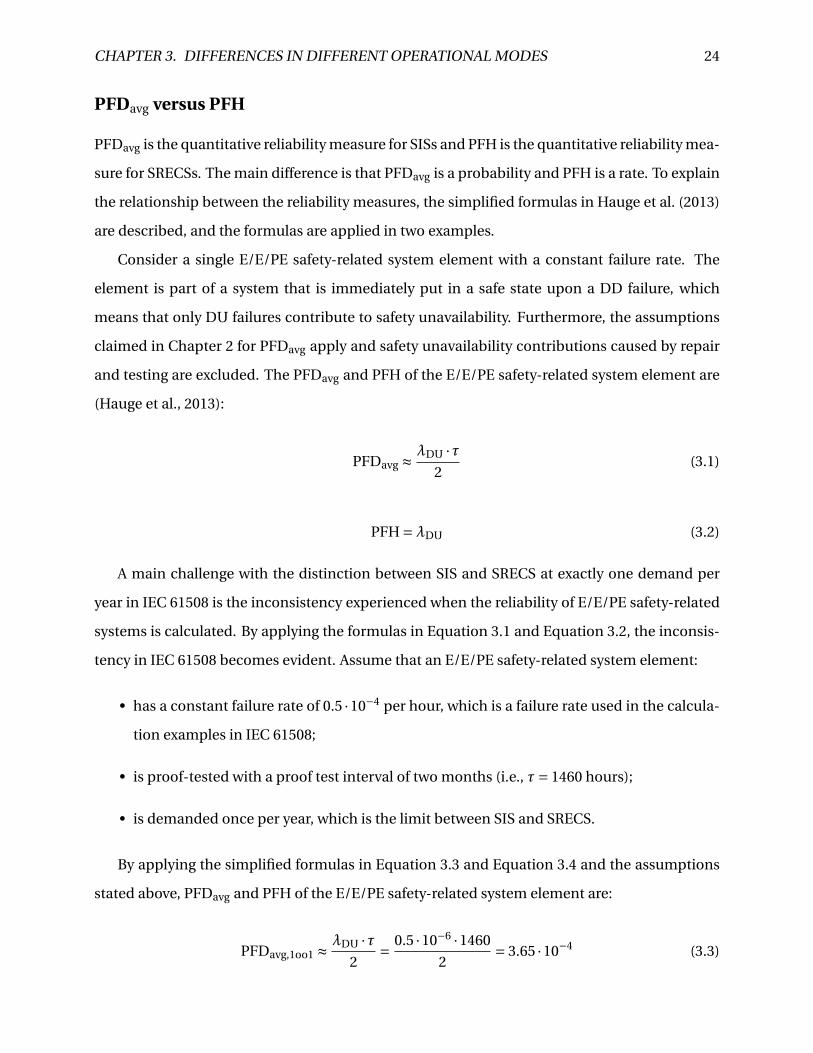
PFDavg versus PFH
PFDavg is the quantitative reliability measure for SISs and PFH is the quantitative reliability mea-
sure for SRECSs. The main difference is that PFDavg is a probability and PFH is a rate. To explain
the relationship between the reliability measures, the simplified formulas in Hauge et al. (2013)
are described, and the formulas are applied in two examples.
Consider a single E/E/PE safety-related system element with a constant failure rate. The
element is part of a system that is immediately put in a safe state upon a DD failure, which
means that only DU failures contribute to safety unavailability. Furthermore, the assumptions
claimed in Chapter 2 for PFDavg apply and safety unavailability contributions caused by repair
and testing are excluded. The PFDavg and PFH of the E/E/PE safety-related system element are
(Hauge et al., 2013):
PFDavg º∏DU ·ø
2(3.1)
PFH =∏DU (3.2)
A main challenge with the distinction between SIS and SRECS at exactly one demand per
year in IEC 61508 is the inconsistency experienced when the reliability of E/E/PE safety-related
systems is calculated. By applying the formulas in Equation 3.1 and Equation 3.2, the inconsis-
tency in IEC 61508 becomes evident. Assume that an E/E/PE safety-related system element:
• has a constant failure rate of 0.5 ·10°4 per hour, which is a failure rate used in the calcula-
tion examples in IEC 61508;
• is proof-tested with a proof test interval of two months (i.e., ø= 1460 hours);
• is demanded once per year, which is the limit between SIS and SRECS.
By applying the simplified formulas in Equation 3.3 and Equation 3.4 and the assumptions
stated above, PFDavg and PFH of the E/E/PE safety-related system element are:
PFDavg,1oo1 º∏DU ·ø
2= 0.5 ·10°6 ·1460
2= 3.65 ·10°4 (3.3)

CHAPTER 3. DIFFERENCES IN DIFFERENT OPERATIONAL MODES 25
PFH1oo1 =∏DU = 0.5 ·10°6 = 5 ·10°7 (3.4)
By comparing the calculated values for PFDavg and PFH in Equation 3.3 and Equation 3.4,
respectively, with the SIL table in Table 2.1, the PFDavg and the PFH correspond to SIL 3 and
SIL 2, respectively. Hence, the element achieves, according to the distinction between SIS and
SRECS in IEC 61508, a lower risk reduction as part of an E/E/PE safety-related system that is
classified as a SRECS than as part of an E/E/PE safety-related system that is classified as a SIS.
This cannot be right, because the element is the same irrespective of what E/E/PE safety-related
system it is a part of.
The inconsistency in IEC 61508 is also evident for subsystems. Consider a subsystem with
two independent elements with a constant failure rate of 25 ·10°6 per hour. The subsystem is
proof-tested with a proof test interval of six months (i.e., ø= 4380 hours). Note that the param-
eters are derived from the reliability calculation examples in IEC 61508 (2010). By applying the
simplified formulas in Hauge et al. (2013), PFDavg and PFH of the subsystem are:
PFDind.avg,1oo2 º
(∏DU ·ø)2
3= (25 ·10°6 ·4380)2
3= 4.00 ·10°3 (3.5)
PFHind.1oo2 º (∏DU)2 ·ø= (25 ·10°6)2 ·4380 = 2.74 ·10°6 (3.6)
By comparing the results in Equation 3.5 and Equation 3.6 with the SIL table in Table 2.1, the
PFDavg and the PFH correspond to SIL 2 and SIL 1, respectively.
Assume now that the subsystem is demanded once every 10 months. If an E/E/PE safety-
related system developer chooses to comply with IEC 62061, the subsystem achieves a SIL 1.
If, on the other hand, an E/E/PE safety-related system developer chooses to comply with IEC
61511, the subsystem can achieve a SIL 2. This is possible because IEC 61511 only distinguishes
between continuous mode and demand mode, and in demand mode of operation, either PFDavg
or PFH can, according to IEC 61511 (2003), be chosen as reliability measure.
CHAPTER 3. DIFFERENCES IN DIFFERENT OPERATIONAL MODES 26
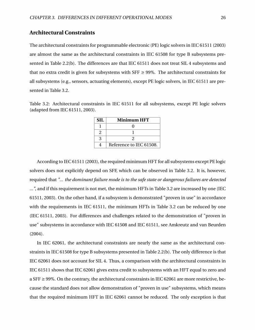
Architectural Constraints
The architectural constraints for programmable electronic (PE) logic solvers in IEC 61511 (2003)
are almost the same as the architectural constraints in IEC 61508 for type B subsystems pre-
sented in Table 2.2(b). The differences are that IEC 61511 does not treat SIL 4 subsystems and
that no extra credit is given for subsystems with SFF ∏ 99%. The architectural constraints for
all subsystems (e.g., sensors, actuating elements), except PE logic solvers, in IEC 61511 are pre-
sented in Table 3.2.
Table 3.2: Architectural constraints in IEC 61511 for all subsystems, except PE logic solvers(adapted from IEC 61511, 2003).
SIL Minimum HFT1 02 13 24 Reference to IEC 61508.
According to IEC 61511 (2003), the required minimum HFT for all subsystems except PE logic
solvers does not explicitly depend on SFF, which can be observed in Table 3.2. It is, however,
required that "... the dominant failure mode is to the safe state or dangerous failures are detected
...", and if this requirement is not met, the minimum HFTs in Table 3.2 are increased by one (IEC
61511, 2003). On the other hand, if a subsystem is demonstrated "proven in use" in accordance
with the requirements in IEC 61511, the minimum HFTs in Table 3.2 can be reduced by one
(IEC 61511, 2003). For differences and challenges related to the demonstration of "proven in
use" subsystems in accordance with IEC 61508 and IEC 61511, see Amkreutz and van Beurden
(2004).
In IEC 62061, the architectural constraints are nearly the same as the architectural con-
straints in IEC 61508 for type B subsystems presented in Table 2.2(b). The only difference is that
IEC 62061 does not account for SIL 4. Thus, a comparison with the architectural constraints in
IEC 61511 shows that IEC 62061 gives extra credit to subsystems with an HFT equal to zero and
a SFF ∏ 99%. On the contrary, the architectural constraints in IEC 62061 are more restrictive, be-
cause the standard does not allow demonstration of "proven in use" subsystems, which means
that the required minimum HFT in IEC 62061 cannot be reduced. The only exception is that

CHAPTER 3. DIFFERENCES IN DIFFERENT OPERATIONAL MODES 27
electromechanical subsystems with an HFT equal to zero and a SFF < 60%, can achieve a SIL 1
if they are "proven in use" (IEC 62061, 2012).
Systematic Failures
Systematic failures contribute to safety unavailability of an E/E/PE safety-related system, and
such failures are either errors introduced during the specification, design, and realization phase
of the safety lifecycle, that are not detected during the safety validation phase, or errors intro-
duced during the operational phase. Hauge et al. (2013) suggest five categories of systematic
failures:
• Software
• Design related
• Installation
• Excessive stress
• Operational failures
The first category is software faults, which can be caused by, for example, programming er-
rors. Software is outside the scope of this master thesis. However, it seems unlikely that there
are any significant differences related to software faults for SIFs and SRCFs.
Design related failures are introduced during the specification, design, and manufacturing
phase. If these phases are performed in accordance with requirements in IEC 61511 (2003) or
IEC 62061 (2012), there are no differences for SISs and SRECSs.
Installation failures are introduced during installation or commissioning. If such failures are
not revealed in the validation phase of the safety lifecycle in Figure 2.2, they may be inherent
until a demand occurs.
In some situations, not all stresses or conditions are considered in the design specification,
which may cause excessive stress failures. Distinguishing between random hardware failures
and excessive stress failures can be challenging (Hauge et al., 2013), and a brief discussion about
this is given in Hokstad and Corneliussen (2004).
CHAPTER 3. DIFFERENCES IN DIFFERENT OPERATIONAL MODES 28
Humans interact with the equipment during maintenance, operation, and testing in the op-
erational phase, and human errors in this phase introduce operational failures. Human interac-
tions, different work practices, and various procedures are factors that may contribute to oper-
ational failures.
There are many factors that must be considered when the possibility of systematic failures
is assessed, such as the complexity of the E/E/PE safety-related system, the EUC, and the EUC
control system; the operational environment; and the usage. These factors vary greatly from
industry to industry and from case to case, and it is challenging to highlight any differences
for SISs and SRECSs from a generic point of view. For example, a SIS that closes a valve in the
process industry may be rather simple compared to a SIS that shuts down a well (e.g., blowout
preventer) in the oil and gas industry. Moreover, one could expect a higher frequency of human
interactions (e.g., testing) for SRECSs compared to SISs, but some SRECSs operate so frequently
that human interactions becomes unfeasible.
Testing
A safety function becomes unavailable when sufficient dangerous failures occur in the E/E/PE
safety-related system, and such failures are detected by testing. For an E/E/PE safety-related
system to be reliable, it is important that the design makes it possible to reveal all dangerous
failures upon testing. There are three types of testing for E/E/PE safety-related systems:
• Diagnostic testing
• Proof testing
• Demands serving as testing
Diagnostic testing, or automatic self-testing, is usually integrated with the logic solver and
is carried out online, which means during normal operation. The logic solver sends signals
to other elements (e.g., actuating elements) and their response are compared with predefined
values (Rausand, 2011). The signals from the logic solver are sent frequently, and detection of a
DD failure is almost immediate. The ratio between DD failures and total dangerous failures is
called the diagnostic coverage.

CHAPTER 3. DIFFERENCES IN DIFFERENT OPERATIONAL MODES 29
Proof testing is carried out with intervals of length ø, and the objective is to reveal all DU
failures, which are failures that diagnostic tests do not reveal. To ensure that a safety function
performs as required, a proof test should preferably be as realistic as possible. However, realistic
proof tests are not always feasible. For example, it is impractical to start a fire to test the smoke
detectors. The fraction of dangerous failures detected by proof testing is referred to as the proof
test coverage (Jin et al., 2011).
For some E/E/PE safety-related systems, demands may serve as testing. Data about acti-
vated elements, whether the activation was successful for all elements, and response times can
be recorded during operation and utilized for testing (Hauge et al., 2013). Because a demand
requires the E/E/PE safety-related system to perform its safety function, a demand is the "ulti-
mate" proof test, and demands serving as testing may therefore potentially replace proof testing.
A challenge with using demands as a means for testing is that demands are random events that
cannot be predicted (Hauge et al., 2013), which means that a safety function may, in periods,
not experience demands as frequent as the required proof test interval. This may however be
solved by conducting a proof test when the time between two demands exceeds the proof test
interval.
Diagnostic testing is basically the same for SISs and SRECSs. Whether SISs or SRECSs are
capable of performing diagnostic testing depends on the chosen hardware and its functionality.
The reliability of SISs depends on the proof test coverage and the proof test interval. The
PFD decreases with more frequent proof testing (i.e., shorter test intervals), and a high proof
test coverage contributes to higher reliability for the SIS. However, when the PFDavg is calculated
from the formulas in IEC 61511 (2003) and IEC 61508 (2010) it is assumed perfect proof testing,
and thus, the effect of the proof test coverage is not accounted for. Hauge et al. (2013) have
recognized this shortcoming, and claim that either the probability of a test independent failure
(PTIF) or the proof test coverage should be incorporated into the PFDavg.
Proof testing is not relevant for SRECSs that operate continuously, because a DU failure will
immediately result in a hazardous event. SRECSs that operate in high demand mode will in
practice experience higher reliability with proof testing. However, the PFH in IEC 62061 (2012)
does not account for proof testing, and consequently, the calculated reliability is not increased
by reduced proof test intervals.

CHAPTER 3. DIFFERENCES IN DIFFERENT OPERATIONAL MODES 30
If demands shall serve as testing, a sufficient frequency of demands is required. It would,
for example, be unreasonable to replace a proof test conducted every six months with demands
serving as testing when the safety function experiences demands once every 10 years. Using
demands as testing is therefore most relevant for SRECSs.
3.4 Other Characteristics of SISs and SRECSs
In the process industry, a barrier is referred to as a protection layer (PL), and a SIS is often clas-
sified as an independent protection layer (IPL) (CCPS, 2007), which is defined in CCPS (1993)
as:
Z Independent protection layer: A device, system, or action which is capable of preventing a
scenario from proceeding to its undesired consequence independent of the initiating event or
the action of any other layer of protection associated with the scenario. The effectiveness and
independence of an IPL must be auditable.
For a SIS to be independent it should not be affected by the condition or the state of the
surrounding equipment, such as the EUC and its control system (CCPS, 2007). The SIS should
be physically separated to avoid that a failure in the EUC affects the performance of the SIF. For
example, a fire extinguishing system that detects fire and activates sprinklers is an independent
SIS, and it should not be affected by an explosion. That a SIS is independent is considered as
one of its main characteristics (CCPS, 2007).
For machinery, it is seldom that a SRECS is completely independent of the EUC (i.e., the
machine) and its control system. Instead of physical separation, a SRCF should be functionally
independent of other control functions (Macdonald, 2004). An interlock guard, that stops the
operation of the EUC when it is opened, can, for example, be operated with priority or by a
dedicated logic solver within the control system.

CHAPTER 3. DIFFERENCES IN DIFFERENT OPERATIONAL MODES 31
3.5 Summary and Discussion
The requirements for SRSs for SIFs and SRCFs in IEC 61511 (2003) and IEC 62061 (2012) are
compared, and the comparison shows that there are essentially no differences. Overall, the re-
quirements and the informative parts in IEC 61511 (2003) and IEC 62061 (2012) do not provide a
better understanding of the different operational modes. In the author’s opinion, the standards
are too generic, even though they are supposed to be application-specific.
The realization of SISs and SRECSs includes demonstrating the reliability through the cal-
culation of PFDavg or PFH and ensuring that architectural constraints, systematic failures, and
testing are accounted for. The inconsistency of obtaining different SILs because of the distinc-
tion between SISs and SRECSs in IEC 61508 is demonstrated. In the author’s opinion, the option
to choose reliability measure in demand mode of operation in IEC 61511 seems like a better
solution, because choosing reliability measure in demand mode resolves the inconsistency ex-
perienced in IEC 61508.
The architectural constraints in IEC 62061 are more restrictive than both the architectural
constraints in IEC 61511 and IEC 61508. IEC 62061 (2012) states that the demonstration of
"proven in use" subsystems and elements are not suitable for machinery, but no further ex-
planation or reason for this is provided in the standard.
According to IEC 61508 (2010), a safety function should maintain or achieve a safe state for
the EUC, and the safety function operates in either low-demand mode or high-demand or con-
tinuous mode. However, no further classification is developed. Seeing as the existing classifi-
cation of safety functions based on frequency of demands is questioned in the literature (e.g.,
Hauge et al., 2013), a new approach for classifying safety functions is proposed in the following
chapter.

Chapter 4
A New Approach for Classifying Safety
Functions
Several research projects on the reliability calculation of E/E/PE safety-related systems and the
classification of safety functions as low-demand mode of operation and high-demand or con-
tinuous mode of operation have been conducted. Bukowski (2006), Jin et al. (2011), and Liu and
Rausand (2011) analyze the reliability of E/E/PE safety-related systems using Markov models
without distinguishing between low-demand mode of operation and high-demand or continu-
ous mode of operation, and instead, they incorporate the demand rate.
Bukowski (2006) calculates the probability of being in a state where both a DU failure and a
demand has occurred (i.e., a hazardous event). Liu and Rausand (2011) investigate the PFD and
the visit frequency of the hazardous state with changing demand rate and demand duration,
and Jin et al. (2011) calculate the hazardous event frequency (HEF) for changing demand rate
and demand duration, calculate the HEF for a developed scenario-based formula, and compare
the results.
According to Liu and Rausand (2011), E/E/PE safety-related systems operating close to the
borderline between low-demand mode and high-demand or continuous mode should be treated
as a separate group, because the formulas in IEC 61508 (2010) are not adequate for the systems
operating in a "medium-demand" mode.
There is disagreement about the clear borderline between low-demand mode of operation
33
CHAPTER 4. A NEW APPROACH FOR CLASSIFYING SAFETY FUNCTIONS 34
and high-demand or continuous mode of operation in IEC 61508 (2010). The PDS 1 method
handbook (Hauge et al., 2013) suggests that we should distinguish between low-demand, high-
demand, and continuous mode of operation for E/E/PE safety-related systems. Furthermore,
the handbook recommends using PFD as a measure for both low-demand and high-demand
mode of operation, and PFH as a measure for continuous mode of operation.
Based on this research discussion and the discussion about differences in different opera-
tional modes in Chapter 3, a new approach for classifying safety functions is proposed in this
chapter.
4.1 A New Approach for Classifying Safety Functions
In the author’s opinion, the main objective of distinguishing between low-demand and high-
demand or continuous mode of operation for E/E/PE safety-related systems in IEC 61508 (2010)
is to define when to use PFDavg or PFH. However, as discussed in the previous section, some
disagree with this clear split based on frequency of demands. Consequently, the author has
suggested a generic classification of safety functions implemented by E/E/PE safety-related sys-
tems.
The proposed classification in the following section is based on a distinction made in IEC
61511 (2003). According to IEC 61511 (2003), a SIF is either a safety instrumented control function
(SICF) or a safety instrumented protection function (SIPF). A SICF operates in continuous mode
(IEC 61511, 2003), and the mode of operation of SIPFs is not specified, but they are assumed to
operate on demand. The distinction between SICF and SIPF is adopted, modified, and the more
generic terms safety control function (SCF) and safety protection function (SPF) are introduced.
It is stressed that the suggested classification of safety functions as SCFs and SPFs is pragmatic,
and the intention is to give a different perspective on safety functions.
1PDS is a Norwegian acronym for "reliability of computer based safety systems".

CHAPTER 4. A NEW APPROACH FOR CLASSIFYING SAFETY FUNCTIONS 35
Safety Control Functions and Safety Protection Functions
The suggested classification of safety functions as SCFs and SPFs is based on the event loss of
control. However, there is no agreed definition of loss of control in the literature (e.g., Kjellén,
2000). Consequently, the author has suggested the following definition:
Z Loss of control: The event where no measures are able to manage the performance of the
EUC in a desired manner, and one or more hazards are unintentionally released.
The event loss of control causes a persistent change in the state of the EUC from a controlled
state to an uncontrolled state. In an uncontrolled state, no measures can change, direct, regu-
late, or influence the performance of the EUC in a desired manner. After loss of control in an
accident scenario, only the hazards that are released can potentially be managed by measures,
but the feasibility of this depends on the properties and characteristics of the hazards. Note that
the definition of loss of control is from a system perspective and it is developed for the purpose
of distinguishing between SCFs and SPFs.
p~ÑÉíó=ÑìåÅíáçåë=
p~ÑÉíó=éêçíÉÅíáçå=ÑìåÅíáçåë=
p~ÑÉíó=Åçåíêçä=ÑìåÅíáçåë=
içëë=çÑ=Åçåíêçä=
oÉ~ÅíáîÉ=mêç~ÅíáîÉ=
Figure 4.1: Classification of safety functions as SCFs and SPFs in relation to loss of control.
A control function operates frequently, manages the performance of the EUC, and main-
tains the EUC within some predefined limits, called normal operation. A failure or degraded
functioning of a control function results in a deviation from normal operation, which is referred
to as lack of control. Some control functions keep the EUC in a safe state with respect to hazards,
and degraded functioning or failures of these will, therefore, lead to increased risk. In this case,
lack of control is the first event in an accident scenario. For example, a deviation from normal

CHAPTER 4. A NEW APPROACH FOR CLASSIFYING SAFETY FUNCTIONS 36
operation in a car’s brake-by-wire system (e.g., leakage of brake fluid) will, unless a corrective
action is carried out, lead to a failure of the brakes and the event loss of control.
Those control functions, implemented by an E/E/PE safety-related system, that upon failure
or degraded functioning can lead to loss of control with respect to a specific hazard introduced
by the EUC is, by the author, regarded as SCFs. A SCF is proactive in relation to loss of control,
which means that it should "... prevent or reduce the probability ..." of loss of control (Rausand,
2011). In relation to the first deviation from normal operation (i.e., lack of control), a SCF is
either proactive or reactive.
At the point of loss of control in an accident scenario, one or more hazards are released and a
hazardous event occurs unless a PL is installed to prevent it. If this PL is an E/E/PE safety-related
system, it implements a SPF. A SPF is reactive in relation to loss of control, which means that it
should "... avoid or reduce the consequences ..." of loss of control (Rausand, 2011).
The classification of safety functions as SCFs and SPFs in relation to loss of control is illus-
trated in Figure 4.1.
4.2 A Model for Classifying Safety Functions
Safety functions are determined from a hazard and risk analysis, and accident models are the
basis for the hazard and risk analysis (Leveson, 2004). In relation to PLs, a commonly used
accident model is the energy model, which was first introduced by Gibson (1961) and further
developed by Haddon (1980). The principle of the model is that hazards are physical energies
(e.g., mechanical or electrical) that can be built up, and if these energies are released, they can
harm assets. The PLs in the energy model should separate the hazards from the assets.
Other accident models focus on the sequence of discrete events, such as the layer of protec-
tion analysis (LOPA) (CCPS, 2001; IEC 61511, 2003). These models are referred to as event se-
quence models (Rausand, 2011) or process models (Kjellén and Larsson, 1981; Kjellén, 2000). Of-
ten, process models describe the phases from normal operation to the hazardous event graphi-
cally, and give a rather simple representation of how the PLs may prevent the progression of the
accident scenario.
According to the Occupational Accident Research Unit (OARU) process model (Kjellén and

CHAPTER 4. A NEW APPROACH FOR CLASSIFYING SAFETY FUNCTIONS 37
Larsson, 1981; Kjellén, 2000), an accident scenario has an initial phase, a concluding phase, and
an injury phase. The initial phase is initiated by the first deviation from normal operation, and
the concluding phase starts when an "... energy is inadvertently released ..." (Kjellén and Larsson,
1981). The injury phase of the accident scenario is when the energy harms assets and undesired
consequences occur.
Based on a combination of the accident models described, a model for classifying safety
functions implemented by E/E/PE safety-related systems as SCFs and SPFs is developed in Fig-
ure 4.2, and it is inspired by the model in Sklet (2006). In the model, SCFs and SPFs are illustrated
in relation to the phases in the OARU-model. The SCFs and SPFs are proactive and reactive PLs
in relation to three events in a generic accident scenario. These three events are based on the
OARU-model (Kjellén and Larsson, 1981; Kjellén, 2000), and are:
1. Lack of control: The first deviation from normal operation and first event in an accident
scenario.
2. Loss of control: The event where no measures are able to manage the performance of the
EUC in a desired manner, and one or more hazards are unintentionally released.
3. Energy exposure: The event where undesired consequences occur because of the unin-
tentionally released hazards.
The arrows between the EUC, the SCFs, the SPFs, and the hazardous event in Figure 4.2
represent demands from the EUC, and the demands will progress to the hazardous event unless
the PLs prevent it.
The first PL in the model in Figure 4.2 is E/E/PE safety-related systems that perform SCFs
during normal operation, and the SCFs should maintain a safe state for the EUC. In relation to
lack of control and loss of control, these SCFs are proactive. Failures or degraded functioning of
SCFs operating in normal operation lead to lack of control and demands for the following PLs.
The next PL in the model in Figure 4.2 is also E/E/PE safety-related systems that perform
SCFs, but these SCFs operate on demand in the initial phase of an accident scenario. These
functions are reactive in relation to lack of control, and they should achieve a safe state for the
EUC upon demands.

CHAPTER 4. A NEW APPROACH FOR CLASSIFYING SAFETY FUNCTIONS 38
br`=p~ÑÉíó==
éêçíÉÅíáçå=ÑìåÅíáçåë=
e~ò~êÇçìë=ÉîÉåí=
fåÅêÉ~ëáåÖ=ÇÉã~åÇë=
kçêã~ä=çéÉê~íáçå=
i~Åâ=çÑ=Åçåíêçä=
içëë=çÑ=Åçåíêçä=
j~áåí~áå=~=ë~ÑÉ=ëí~íÉ=Ñçê=íÜÉ=br`==~åÇ=éêÉîÉåí=ä~Åâ=çÑ=Åçåíêçä=
^ÅÜáÉîÉ=~=ë~ÑÉ=ëí~íÉ=Ñçê=íÜÉ=br`=~åÇ==éêÉîÉåí=êÉäÉ~ëÉ=çÑ=Ü~ò~êÇ=
fåáíá~ä=éÜ~ëÉ= `çåÅäìÇáåÖ=éÜ~ëÉ= fåàìêó=éÜ~ëÉ=
båÉêÖó=ÉñéçëìêÉ=
p~ÑÉíó==Åçåíêçä=
=ÑìåÅíáçåë=p~ÑÉíó=éêçíÉÅíáçå=
ÑìåÅíáçåë=
píçé=êÉäÉ~ëÉ=çÑ=Ü~ò~êÇ=~åÇ=éêÉîÉåí=íÜÉ=Ü~ò~êÇçìë=ÉîÉåí=
jáíáÖ~íÉ=íÜÉ=ÅçåëÉèìÉåÅÉë=
p~ÑÉíó=Åçåíêçä==ÑìåÅíáçåë=
Figure 4.2: SCFs and SPFs in relation to the phases in the OARU-model (inspired by Sklet, 2006).
If all SCFs fail to fully prevent the progression of an accident scenario, loss of control occurs
and one or more hazards are unintentionally released. Loss of control initiates the concluding
phase in the model in Figure 4.2, and if E/E/PE safety-related systems that can protect assets
by managing the hazards (e.g., fire detection and alarm system) are installed, these perform
SPFs. These functions should stop the release of hazards, and they are reactive in relation to
loss of control and proactive in relation to energy exposure. If these SPFs fail to fully prevent the
progression of the accident scenario, energy exposure occurs.
The event energy exposure initiates the hazardous event and the injury phase in the model in
Figure 4.2. If E/E/PE safety-related systems are installed to mitigate the undesired consequences
of the hazardous event, these systems also perform SPFs. These SPFs are reactive in relation to
both loss of control and energy exposure.
Note that the model in Figure 4.2 adopts a simplistic view on accident scenarios because it is
intended to aid the classification of safety functions as SCFs and SPFs in relation to the sequence
of events.

CHAPTER 4. A NEW APPROACH FOR CLASSIFYING SAFETY FUNCTIONS 39
4.3 Examples
To further explain how safety functions can be classified as SCFs and SPFs and the usage of
developed model in Figure 4.2, two examples are given in the following two sections.
Car Crash Example
Consider a modern car that is driving on an icy road. The car is the EUC, and the hazardous
event is "crashing into an object", which may results in severe injury or death of the driver.
In this example, only those PLs that are E/E/PE safety-related systems are considered. Loss of
control is therefore the event where no safety functions are able to manage the performance of
the car in a desired manner. The initiating event in the accident scenario leading to "crashing
into an object" is "too high speed".
During normal operation of the car, the speed almost continuously demands the function
of the brake-by-wire system. We can classify the function of the brake-by-wire as a SCF, because
the function should maintain the speed within the limits of normal operation.
qçç=ÜáÖÜ=ëéÉÉÇK=
kçêã~ä=çéÉê~íáçå=
i~Åâ=çÑ=Åçåíêçä=
içëë=çÑ=Åçåíêçä=
fåáíá~ä=éÜ~ëÉ= `çåÅäìÇáåÖ=éÜ~ëÉ= fåàìêó=éÜ~ëÉ=
båÉêÖó=ÉñéçëìêÉ=
mêÉîÉåí=ëâáÇÇáåÖ=
~åÇ==êÉÖ~áå=íê~ÅíáçåK=
j~áåí~áå=ëéÉÉÇ=ïáíÜáå=
åçêã~ä=çéÉê~íáçå==äáãáíëK=
`ê~ëÜáåÖ=áåíç=~å=çÄàÉÅíK=
`~ê= _ê~âÉJÄóJïáêÉ=ëóëíÉã=
bpm=~åÇ=^_p= ^áêÄ~Öë=
jáíáÖ~íÉ=áãé~ÅíK=
Figure 4.3: The SCFs and SPFs in the car crash example.
The car approaches a turn too fast, and the driver applies the brakes. However, the road is
slippery, and the car loses traction and starts to skid. This event is lack of control, because it is

CHAPTER 4. A NEW APPROACH FOR CLASSIFYING SAFETY FUNCTIONS 40
assumed that traction is required during normal operation.
The car has an electronic stability program (ESP) and an anti-lock braking system (ABS), and
both these systems are, in this case, demanded when lack of control occurs. The ESP performs a
safety function that should prevent skidding, and the ABS performs a safety function that should
regain traction. Both functions should achieve a safe state for the car, and are proactive in re-
lation to loss of control and reactive in relation to lack of control. Hence, the functions are
classified as SCFs.
The ESP and the ABS are functioning, but the initial speed is too high, and neither the ESP
nor the ABS are capable of achieving a safe state for the car. Since neither skidding is sufficiently
reduced nor traction is regained, the car will skid out of the road. This event is loss of control,
because none of the measures are able to manage the performance in a way that keeps the car
on the road.
After loss of control, the car skids out of the road, the energy is released, and the car will crash
into an object (i.e., the hazardous event) unless a PL prevents it. The car does not have any safety
functions that can prevent the hazardous event, and the car crashes into an object, which is the
energy exposure. Fortunately, the car has airbags that mitigate the impact for the driver, and
thus mitigate the undesired consequences of the hazardous event. The airbags perform safety
functions that can be classified as SPFs, and they are reactive in relation to both loss of control
and energy exposure.
The safety functions classified as SCFs and SPFs in the car crash example are summarized in
Figure 4.3.

CHAPTER 4. A NEW APPROACH FOR CLASSIFYING SAFETY FUNCTIONS 41
Fluid and Gas Separator Example
Consider the simple fluid and gas separator illustrated in Figure 4.4. A mixture of fluid and gas is
led through the inlet and into the separator. In the separator, the fluid and gas are separated and
led out through the fluid outlet and gas outlet, respectively. Note that this example and the sys-
tems described are not realistic but constructed for the purpose of explaining the classification
of safety functions.
d~ë=çìíäÉí=
cäìáÇ=çìíäÉí=
içÖáÅ=ëçäîÉê=
fåäÉí=d~ë=ÇÉíÉÅíçêë=
içÖáÅ=ëçäîÉê=
`s= `s=
sÉåíáä~íáçå=Ñ~åë=
pas= pas=
EpÉé~ê~íçêF=
mqee=
oìéíìêÉ=ÇáëÅ=
mqe=
mqi=
mqii=
içÖáÅ=ëçäîÉê=
Figure 4.4: A simple fluid and gas separator with three E/E/PE safety-related systems.
A rupture disc is installed on top of the fluid and gas separator, and if the pressure in the
separator is too high, the rupture disc opens and gas flows out. To simplify this example, the
rupture disc is regarded as a part of the EUC together with the pipelines and the separator, even
though the rupture disc can be a safety measure with respect to explosion of the separator. The
EUC is illustrated with black color in Figure 4.4.
During normal operation, pressure transmitter high (PTH) and pressure transmitter low
(PTL) monitor and detect high or low pressure in the separator, respectively, and continuously
send this information to a logic solver. The logic solver compares the pressure with the predeter-

CHAPTER 4. A NEW APPROACH FOR CLASSIFYING SAFETY FUNCTIONS 42
mined values for normal operation, and continuously regulates the flow from the inlet pipeline
by signaling the control valves (CVs) to alter their positions accordingly. In this way, the pres-
sure in the separator is maintained within the predetermined limits of normal operation. This
system is an E/E/PE safety-related system and it is referred to as the control system. The control
system is illustrated with green color in Figure 4.4.
Pressure transmitter high-high (PTHH) and pressure transmitter low-low (PTLL) continu-
ously monitor and detect too high or too low pressure in the separator, respectively, and send
this information to a dedicated logic solver. If the pressure in the separator exceeds the normal
operation limits, the logic solver sends activation signals to the shutdown valves (SDVs). Upon
activation, the SDVs should stop the flow in the inlet pipeline, thus preventing further increase
of the pressure in the separator. The SDVs are passive during normal operation. This system
is an E/E/PE safety-related system and it is referred to as the shutdown system. The shutdown
system is illustrated with blue color in Figure 4.4.
Next to the separator, gas detectors are installed. Upon detection of gas, the gas detectors
send signals to the logic solver. The logic solver then signals the ventilation fans to activate and
extract the gas away from the area. The ventilation fans are passive during normal operation.
This system is an E/E/PE safety-related system and it is referred to as the ventilation system. The
ventilation system is illustrated with red color in Figure 4.4.
In this example, we consider an accident scenario where the hazardous event is "accumula-
tion of gas in the area". If accumulated gas in the area is ignited, an explosion occurs and the
consequences may be multiple fatalities. The initiating event in the accident scenario is "gas
outlet blocked". Loss of control is the event where no measures are able to manage the perfor-
mance of the fluid and gas separator in a desired manner and gas leaks out of the separator.
First, the initiating event "gas outlet blocked" causes the pressure in the separator to in-
crease. Consequently, the control system should maintain the pressure within normal opera-
tion limits by closing the CVs, and thus reducing the flow into the separator. However, the PTH
is failed and does not detect the increasing pressure in the separator. This is the first safety func-
tion in the accident scenario, and it is classified as a SCF, because it should maintain a safe state
for the EUC and it is proactive in relation to lack of control.
The pressure in the separator exceeds the limits of normal operation, and the accident sce-

CHAPTER 4. A NEW APPROACH FOR CLASSIFYING SAFETY FUNCTIONS 43
d~ë=çìíäÉí=
ÄäçÅâÉÇK=
kçêã~ä=çéÉê~íáçå=
i~Åâ=çÑ=Åçåíêçä=
içëë=çÑ=Åçåíêçä=
fåáíá~ä=éÜ~ëÉ= `çåÅäìÇáåÖ=éÜ~ëÉ= fåàìêó=éÜ~ëÉ=
båÉêÖó=ÉñéçëìêÉ=
píçé=ÑìêíÜÉê=ÅÜ~åÖÉ=
áå=éêÉëëìêÉK=
j~áåí~áå=éêÉëëìêÉ=ïáíÜáå=
åçêã~ä=çéÉê~íáçå=äáãáíëK=
^ÅÅìãìä~íáçå=çÑ=Ö~ë=áå=íÜÉ=~êÉ~K=
bñíê~Åí=Ö~ë=~ï~ó=Ñêçã=
~êÉ~K=
br`= `çåíêçä=ëóëíÉã=
pÜìíÇçïå=ëóëíÉã=
sÉåíáä~íáçå=ëóëíÉã=
Figure 4.5: The SCFs and SPFs in the fluid and gas separator example.
nario progresses beyond lack of control. Next, the pressure reaches the point where the shut-
down system is demanded, and it should completely stop the flow from the inlet into the sep-
arator by closing the SDVs. The PTHH detects too high pressure and the logic solver activates
the SDVs successfully. However, the SDVs are unable to fully close because of corrosion, and the
pressure still increases even though the flow is reduced. This is the second safety function in the
accident scenario, and it is classified as a SCF, because it should achieve a safe state for the EUC
and it is proactive in relation to loss of control.
Further, no other measures are able to manage the performance of the EUC in a desired
manner, and the pressure increases to the point where the rupture disc opens. Gas flows out
of the separator and the ventilation system is demanded. The ventilation system extracts gas
from the area successfully, but the capacity of the ventilation fans is too low to fully prevent the
"accumulation of gas in the area". This is the third safety function, and it is classified as a SPF,
because it should prevent the hazardous event and it is reactive in relation to loss of control.
The safety functions classified as SCFs and SPFs in the fluid and gas separator example are
summarized in Figure 4.5.

CHAPTER 4. A NEW APPROACH FOR CLASSIFYING SAFETY FUNCTIONS 44
4.4 Summary and Discussion
It is proposed a pragmatic and generic approach for classifying safety functions as SCFs and
SPFs. The classification is further explained through the developed model in Figure 4.2. In ad-
dition, the classification and the model is applied in a car crash example and a fluid and gas
separator example in Section 4.3.
The approach for classifying safety functions as SCFs and SPFs is intended to provide a dif-
ferent perspective on safety functions implemented by E/E/PE safety-related systems, and it
may contribute to a better understanding of different types of safety functions and their wide
range of applications. The classification is generic, which leaves room for expert judgement and
individual assessment. Consequently, it may, together with the developed model in Figure 4.2,
be used in decision-making about safety functions and E/E/PE safety-related systems.
Opposed to the classification of safety functions as low-demand mode of operation and
high-demand or continuous mode of operation in IEC 61508, the classification of safety func-
tions as SCFs and SPFs is not based on frequency of demands, and it does not prescribe use
of PFDavg or PFH, which is the intention. Instead, the proposed classification focuses on what
safety functions should do in an accident scenario, and where in the sequence of events safety
functions are performed. As a result, the information can be used for assessment and arguments
for the most suitable reliability measure.
The proposed classification is more similar to the classification of safety functions operating
in demand mode and continuous mode in IEC 61511. SCFs that should maintain a safe state
for the EUC and prevent lack of control correspond to safety functions operating in continuous
mode in IEC 61511, and PFH may thus be most suitable. SCFs that should achieve a safe state for
the EUC and are reactive in relation to lack of control and SPFs correspond to safety functions
operating in demand mode in IEC 61511, and choosing either PFH or PFDavg may thus be the
best option for these safety functions.

Chapter 5
IEC 61508 in the Hydropower Industry
One of main objectives of implementing IEC 61508 is to ensure that E/E/PE safety-related sys-
tems are safe and reliable throughout their whole lifecycle. The popularity of IEC 61508 is in-
creasing, and especially in the oil and gas industry. The hydropower industry does not follow
this trend, and the presence of the standard is almost non-existent.
Despite the absence of the standard, the design specifications of some hydropower plants
require that all E/E/PE safety-related systems are in accordance with the requirements of IEC
61508. This is challenging, because there is a lack of knowledge about the standard in the indus-
try.
In this chapter, some benefits and challenges regarding the implementation and use of IEC
61508 are discussed in relation to a typical company operating in the hydropower industry. Be-
cause the standard is not yet implemented, some of the benefits and challenges related to the
implementation and use of the standard are based on experience from other industries (e.g., the
oil and gas industry).
A valuable source of reference for this chapter is the visit to Norsk Hydro’s hydropower plant
at Tyin including a guided tour given by Odd Jarle Jørgensen.
45

CHAPTER 5. IEC 61508 IN THE HYDROPOWER INDUSTRY 46
A Relationship Between IEC 61508 and the Hydropower Industry
Machinery is present in hydropower plants, and most machines are required to comply with the
Machinery Directive (2006). According to the Machinery Directive (2006), machinery is defined
as:
Z Machinery: An assembly, fitted with or intended to be fitted with a drive system other than
directly applied human or animal effort, consisting of linked parts or components, at least one
of which moves, and are joined together for a specific application.
The Machinery Directive presents essential health and safety requirements (EHSRs) that are
mandatory for manufacturers of machinery that intend to put machines on the European Union
(EU) market (Murthy et al., 2010). The main objectives of the Machinery Directive are to pro-
mote free movement of machinery within the EU and to guarantee protection to workers and
citizens in the EU (Murthy et al., 2010). Member states of the EU are required to transpose the
Machinery Directive into national laws.
In the Machinery Directive, the EHSRs are stated as results that manufacturers must attain
when designing and building machines, but no technical solutions for achieving the EHSRs
are provided. Conforming with the EHSRs can thus be challenging, and to help manufacturers
achieve conformity with the EHSRs, the European Commission has mandated several harmo-
nized standards. Harmonized standards provide technical solutions and guidance on how the
EHSRs can be achieved, and it is voluntary to comply with such standards (Murthy et al., 2010).
However, if a manufacturer chooses to comply with a harmonized standard, conformance with
some or all, depending on the standard, of the EHSRs in the Machinery Directive is achieved.
IEC 62061 is adopted by the European Committee for Electrotechnical Standardization and
they have published the standard as an European Standard (EN), referred to as EN 62061. The
content of EN 62061 is the same as in IEC 62061, and the only difference is that EN 62061 is
officially harmonized with the Machinery Directive. Because EN 62061 is based on IEC 61508,
this concludes the relationship between IEC 61508 and the hydropower industry, through the
Machinery Directive.

CHAPTER 5. IEC 61508 IN THE HYDROPOWER INDUSTRY 47
The Starting Point
In the Norwegian hydropower industry, the authorities and the companies that own hydropower
plants have great influence. The authorities have the power to influence the industry through
laws, regulations, and licenses. Before a company can build new or refurbish old hydropower
plants, the company must apply to the Norwegian water resource and energy directorate and/or
the Norwegian ministry of petroleum and energy for a license. This license is a document that
includes permissions and constraints regarding the development and operation of a plant and
its effects on the environment. It is therefore obvious that the authorities have the power to
mandate the implementation of the IEC 61508 in the hydropower industry.
The majority of the companies (e.g., Statkraft Energi AS, Norsk Hydro ASA, and Lyse Energi
AS) that own the plants also operate them. When these companies get licenses to build new
plants or refurbish old plants, these jobs are often outsourced to subcontractors responsible for
the construction and the delivery of equipment (e.g., turbines and generators). If the companies
that own the plants decide to implement IEC 61508, the subcontractors would consequently
have to deliver E/E/PE safety-related systems in accordance with the standard in order to fulfill
the contracts. Since the companies that own the plants also operate them, they have the unique
position to implement the standard throughout the whole safety lifecycle.
Considering the absence of IEC 61508 in the hydropower industry, a starting point is that
one company, that owns hydropower plants, implements the standard, which may cause other
companies and the authorities to follow. This starting point is assumed to be most relevant
for the discussion about the implementation of IEC 61508 in the hydropower industry. The
perspective of the discussion is from a company that owns and operates plants, and engineers
new and refurbishes old plants by outsourcing to subcontractors. This company is from here on
referred to as [company].

CHAPTER 5. IEC 61508 IN THE HYDROPOWER INDUSTRY 48
5.1 Benefits and Challenges with IEC 61508
In the following two sections, some benefits and challenges related to implementation and use
of IEC 61508 are discussed.
Benefits
As a consequence of the increasing use of computer-based technology, systems are growing
more complex. Alongside this technological advancement, ensuring the performance and the
dependability (e.g., availability, reliability, and maintainability) of such systems is important
(IEC 60300-3-15, 2009), and this can, for E/E/PE safety-related systems, be done by using IEC
61508.
One of the benefits of IEC 61508 is that not only technical requirements for engineering hard-
ware and software are provided. In addition to requirements about assessment, design, oper-
ation, and maintenance of E/E/PE safety-related systems, the standard includes requirements
for management of E/E/PE safety-related systems throughout the whole safety lifecycle. This
management system is referred to as management of functional safety (IEC 61508, 2010). An
objective of the management system is to ensure that safe and reliable E/E/PE safety-related
systems are achieved and maintained throughout the safety lifecycle by ensuring that "... the
right people are in the right place with the right tools doing the right things at the right time."
(Houtermans et al., 2003). Together, the combination of requirements for engineering and man-
agement of E/E/PE safety-related systems provides a complete procedure and framework for
managing risks and achieving safety in a plant. The framework of the standard can also be used
for other risk reduction measures even though no specific requirements are provided for these
(IEC 61508, 2010).
According to Summers (2006), companies have applied the required management system
in IEC 61511 (2003) for all PLs and experienced economic benefits. Note that the management
system in IEC 61511 (2003) is essentially the same as the one in IEC 61508 (2010). This means
that IEC 61508 is not yet another prescriptive standard where rules for E/E/PE safety-related
systems must be followed, but a standard that introduces a rigorous approach for reducing risks
with E/E/PE safety-related system and other risk reduction measures.
CHAPTER 5. IEC 61508 IN THE HYDROPOWER INDUSTRY 49
According to Timms (2003), a misconception of IEC 61508 is that determining SILs for ex-
isting E/E/PE safety-related systems in a plant will reveal systems that require re-engineering,
which makes it a costly process. The reality is that determining SILs for safety functions identi-
fies those functions that are safety-critical, which may contribute to cost savings as appropriate
resources are allocated to each function.
Another advantage of IEC 61508 is that maintenance and testing of E/E/PE safety-related
systems are required to be considered at an early phase of the safety lifecycle, which makes
it possible to optimize the design for maintenance and testing. This is primarily required for
achieving reliable E/E/PE safety-related systems, but another consequence may be reduced
costs because of more effective and better planned maintenance work and testing (Timms,
2003).
Lastly, IEC 61508 is a basic safety publication, which means that it can be used for devel-
oping application-specific standards (e.g., IEC 61511) and it influences therefore the develop-
ment of E/E/PE safety-related systems across industries. In the Norwegian oil and gas industry,
the Petroleum Safety Authority (PSA) guidelines (e.g., PSA, 2012) recommends that IEC 61508
is used to comply with regulations. National authorities consider the standard as best practice
for E/E/PE safety-related systems and it is widely accepted internationally in the oil and gas
industry.
Challenges
IEC 61508 is comprehensive and there are some challenges related to implementation and use of
the standard. Some authors (e.g., Faller, 2004; Timms, 2003) suggest that the standard is difficult
to read and leaves too much room for interpretation. Consequently, competent personnel is
required in order to successfully implement and use the standard.
IEC 61508 requires that all persons responsible for any phase or activity in the safety lifecycle
of an E/E/PE safety-related system have the appropriate competence. The standard emphasizes
competence because E/E/PE safety-related systems can be complex and failures can lead to un-
desired consequences. Considering the extent of the standard and the safety lifecycle, ensuring
competent personnel can be challenging. Health and Safety Executive (HSE) has recognized the
challenges of managing competence and issued the guideline HSE (2007). In relation to the
CHAPTER 5. IEC 61508 IN THE HYDROPOWER INDUSTRY 50
competence requirements in IEC 61508 (2010), HSE (2007) is referenced as an example.
As mentioned in the previous section, the required management system in IEC 61508 is im-
portant in all safety lifecycle phases. However, experiences in Houtermans et al. (2003) show that
few of the companies that have implemented the standard have adapted their existing manage-
ment system in accordance with IEC 61508. According to Houtermans et al. (2003), the failure to
implement the management system required in IEC 61508 is mainly caused by too much focus
on the technical requirements and lack of commitment from top management.
In all phases of the safety lifecycle, sufficient documented information is required so sub-
sequent phases can be performed effectively (IEC 61508, 2010). Considering the scope and the
amount of requirements in the standard, a lot of documentation is usually generated, such as
quantitative risk analysis and SRS. In addition, much documentation is generated because the
standard is performance-based, which means that arguments for the chosen methods and solu-
tions must be demonstrated and documented. Some companies create the documents strictly
for the purpose of compliance, but do not maintain and use the documents as intended (Brom-
bacher, 1999). Consequently, neither reliable E/E/PE safety-related systems are ensured nor is
compliance with IEC 61508 maintained.
Throughout the whole operational phase, the reliability of E/E/PE safety-related systems
must be maintained, and some related challenges are briefly discussed in the following section.
Follow-up of E/E/PE Safety-related Systems In The Operational Phase
According to IEC 61508 (2010), the specified SIL of a safety function and the required perfor-
mance of an E/E/PE safety-related system must be maintained throughout the whole opera-
tional phase. The main activities during follow-up of E/E/PE safety-related systems are opera-
tion, maintenance, monitoring, and modification (CCPS, 2007; IEC 61508, 2010; OLF-070, 2004),
and more specific, the following activities are important (Hauge and Lundteigen, 2008, 2009):
1. Detect, correct, and avoid introducing failures in the E/E/PE safety-related system.
2. Verify that the initial assumptions stated in the SRS are valid during the operational phase.
3. Collect data to verify that the requirements in the SRS are met.
CHAPTER 5. IEC 61508 IN THE HYDROPOWER INDUSTRY 51
4. Take corrective actions if the performance of the E/E/PE safety-related system deviates
from the specified performance.
5. Ensure that all modifications are performed in accordance with the requirements in the
appropriate safety lifecycle phase.
An objective of verifying the SIL of a safety function in the operational phase is to ensure that
the predicted PFDavg or PFH is correct (Hauge and Lundteigen, 2009). The predicted PFDavg or
PFH is specified by the supplier of an E/E/PE safety-related system, and the predicted reliability
measures are often based on data from generic data sources (e.g., OREDA (2009) in the oil and
gas industry). It is important that the predicted PFDavg or PFH is correct because a tolerable risk
level is not achieved if the actual PFDavg or PFH is higher than predicted.
To verify the PFDavg or PFH, operational data about tests, failures, maintenance, successful
activations, process demands, and spurious trips for the E/E/PE safety-related systems must be
collected. Such data is referred to as plant specific data (Hauge and Lundteigen, 2009). The
plant specific data should be used to estimate the PFDavg or PFH. The estimated PFDavg or PFH
is compared to the predicted PFDavg or PFH, and if there are any undesired deviations, corrective
actions on the E/E/PE safety-related system are required.
According to Hauge and Lundteigen (2009), experiences in the oil and gas industry show that
collecting plant specific data can be challenging. The systems where data is recorded are not
always flexible enough to be adapted for the failure classification required in IEC 61508. Con-
sequently, classifying failures correctly is difficult, and the persons responsible for estimating
PFDavg or PFH during operation must read failure reports and classify or reclassify the failures
in accordance with the standard, which can be very time consuming.
In addition to suitable data registration systems, personnel recording plant specific data for
E/E/PE safety-related systems (e.g., maintenance and testing personnel, operators) must have
the right competence to avoid incorrect failure classifications and recordings, because incorrect
failure classifications may lead to wrongfully increased proof test intervals or incorrectly esti-
mated PFDavg or PFH. To ensure appropriate competence for the personnel involved in follow-
up of an E/E/PE safety-related system, training should be provided, and personnel should be
motivated to understand the benefits of detailed failure recordings (Hauge and Lundteigen,
CHAPTER 5. IEC 61508 IN THE HYDROPOWER INDUSTRY 52
2009).
5.2 Implementation of IEC 61508 in the Hydropower Industry
The benefits and the challenges related to implementation and use of IEC 61508, discussed in
Section 5.1, apply to [company]. [company] is the operator, and challenges related to follow-up
of E/E/PE safety-related systems in the operational phase are especially important for successful
implementation of IEC 61508.
Subcontractors delivering machines in the hydropower industry are required to conform
with the Machinery Directive, and some of these may design and build E/E/PE safety-related
systems that are part of machinery in accordance with IEC 62061. In addition, some of the
subcontractors delivering E/E/PE safety-related systems also deliver such systems to other in-
dustries where IEC 61508 is applied (e.g., oil and gas industry). [company] may therefore pur-
chase E/E/PE safety-related systems that comply with IEC 61508 rather easily. However, acquir-
ing E/E/PE safety-related systems that comply with IEC 61508 requires that [company] speci-
fies the required SILs of safety functions and prepares SRSs. From project experience with IEC
61508, some companies do not specify the SIL in the SRS, which makes the suppliers’ job diffi-
cult and an important concept of the standard is discarded (Reeve, 2009). Because [company] is
project and plant owner during engineering and construction of new hydropower plants, deci-
sions about risks and E/E/PE safety-related systems must be made throughout the whole safety
lifecycle. This means that even though the operational phase of E/E/PE safety-related systems
is the most relevant phase, [company] needs to acquire knowledge about the whole standard.
The reliability policy in a hydropower plant is often characterized by over-engineering and
redundancy. This is, for example, reflected in the standard EN 62270 (2004), which addresses
application, design, and implementation of computer-based control systems in hydropower
plants. EN 62270 (2004) suggests that backup, or redundancy, should be provided for essen-
tial functions, and the standard gives little attention to reliability aspects such as eliminating
failure modes and reducing failure rates. IEC 61508 requires analysis and careful consideration
of E/E/PE safety-related systems’ behavior upon failure, failure rates, failure modes, and several
other factors affecting the reliability of E/E/PE safety-related systems. Furthermore, IEC 61508
CHAPTER 5. IEC 61508 IN THE HYDROPOWER INDUSTRY 53
adopts a risk-based approach, which means that the required performance of an E/E/PE safety-
related system is derived from a thorough hazard and risk analysis of an EUC. The risk-based
approach provides a basis for decision-making about risks, and if [company] defines clear eval-
uation criteria in line with overall business policies, appropriate resources may be allocated to
E/E/PE safety-related systems that contribute to [company]’s goals. Consequently, an imple-
mentation of IEC 61508 may alter the way [company] deals with risks and reliability charac-
teristics of E/E/PE safety-related systems, which can both reveal necessary improvements and
potential cost savings.
IEC 61508 is primarily concerned with undesired consequences to humans and the envi-
ronment, but recognizes that economic losses may be incentives for reducing risks as well.
Since hydropower plants are increasingly operated remotely and automatically, consequences
to humans are possibly less relevant, and reducing risks of economic losses, such as damage on
equipment and production downtime, may be more relevant for [company].
5.3 Summary and Discussion
In this chapter, the relationship between the IEC 61508 and the hydropower industry, through
the Machinery Directive, is explained, and benefits and challenges related to implementation
and use of IEC 61508 are discussed. Some of the concepts in IEC 61508 that are benefits are also
challenges (e.g., management system), and there is no doubt that competence and knowledge
about the standard are prerequisites for successful implementation and use.
IEC 61508 is a comprehensive standard with a large amount of requirements, and successful
implementation of IEC 61508 requires extensive resources and commitment across [company]’s
organization. A challenge that [company] may face is the evaluation of benefits gained from
implementing the standard against the amount of resources an implementation requires. Com-
pared to the oil and gas industry, the hydropower industry comprises a relatively simple process
with fewer hazards, it has existed for a longer time, and there are fewer technological changes.
Thus, a comprehensive, rigorous approach for designing, implementing, operating, maintain-
ing, and managing E/E/PE safety-related systems that is developed with a rapidly developing
technology in mind may not be what the hydropower industry needs.

CHAPTER 5. IEC 61508 IN THE HYDROPOWER INDUSTRY 54
On the other hand, many of the concepts in IEC 61508 are versatile and applicable for E/E/PE
safety-related systems in a hydropower plant. For example, to identify safety functions and de-
termine their reliability by calculating PFDavg or PFH of the E/E/PE safety-related systems pro-
vide a solid basis for decision-making. Identifying safety functions may, for example, be done
with the approach for classifying safety functions presented in Chapter 4 and the model in Fig-
ure 4.2.
The Norwegian Oil and Gas Association financed a project where operators and suppliers in
the oil and gas industry collaborated to identify common safety functions and to determine the
minimum SIL by applying the formulas in the PDS handbook (Hauge et al., 2013), and the result
of the project is the guideline OLF-070 (2004). The purpose of the guideline is to simplify and
adapt the application of the IEC 61508 and IEC 61511 (OLF-070, 2004). A similar project in the
hydropower industry may be of great value for [company]. Such a project can, for example, be
conducted to identify safety functions and to develop a unified approach for ensuring reliable
E/E/PE safety-related systems in the hydropower industry. Eventually, this project may be the
basis for the development of an application-specific version of IEC 61508 in the hydropower
industry.

Chapter 6
Summary and Recommendations for
Further Work
6.1 Summary and Conclusions
E/E/PE safety-related systems are used to reduce the risk related to hazardous events, and IEC
61508 can be used to ensure safe and reliable E/E/PE safety-related systems. IEC 61508 is com-
prehensive, and knowledge about concepts and terminology in the standard is necessary for
achieving successful compliance. To clarify basic concepts and terminology in IEC 61508 is the
first objective of this master thesis. This is done and E/E/PE safety-related systems, safety func-
tions, PFDavg, PFH, architectural constraints, and systematic failures are clarified and explained
in Chapter 2.
The second objective is to identify and discuss possible differences between low-demand
mode of operation and high-demand or continuous mode of operation, and this is addressed in
Chapter 3. To identify possible differences, the requirements for the SRSs, including the func-
tional requirements and the safety integrity requirements, in IEC 61511 and IEC 62061 are com-
pared, and it can be concluded that there are essentially no differences between them.
The realization of E/E/PE safety-related systems includes design and engineering of the
physical systems performing safety functions. To achieve the specified SILs for the safety func-
tions, developers of E/E/PE safety-related systems must demonstrate the PFDavg and/or the
PFH, account for architectural constraints and testing, and ensure measures for avoidance and
55

CHAPTER 6. SUMMARY AND RECOMMENDATIONS FOR FURTHER WORK 56
control of systematic failures. These issues are, in relation to possible differences between safety
instrumented systems and safety-related electrical, electronic, and programmable electronic
control systems, discussed in Section 3.3.
A comparison of the architectural constraints in IEC 61511 and IEC 62061 shows that the
architectural constraints in IEC 62061 are more restrictive. IEC 62061 states that demonstration
of "proven in use" subsystems and elements are not suitable for machinery, but no reasons for
this are provided in the standard.
The PFDavg and the PFH are calculated for an element and a subsystem operating on de-
mand and the parameters used are derived from IEC 61508. The results correspond to different
SILs for both the element and the subsystem under consideration depending on whether use
of PFDavg or PFH is required. Inconsistency can be experienced by complying with IEC 61508.
However, complying with IEC 61511 allows E/E/PE safety-related systems developers choose re-
liability measure in demand mode of operation, which resolves the inconsistency experienced
in IEC 61508. The approach in IEC 61511 seems better.
The third objective is to develop and propose a new approach for classifying safety functions
and describe the classification with examples. A new approach for classifying safety functions
is developed, proposed, and presented in Chapter 4. The event, loss of control, in an accident
scenario is the basis for the classification of safety functions as safety control functions (SCFs)
and safety protection functions (SPFs), and a definition of loss of control is suggested and given
in Section 4.1. SCFs and SPFs are furthermore related to the events lack of control and energy
exposure, respectively. The classification of safety functions as SCFs and SPFs is neither based
on frequency of demands nor does it prescribe use of PFDavg or PFH, and the classification is
thus different from the classification in IEC 61508. The proposed classification is more similar
to the classification of safety functions in IEC 61511. It is suggested that PFH is suitable for SCFs
that maintain the EUC in a safe state and prevents lack of control. SCFs that are reactive in
relation to lack of control and SPFs correspond to demand mode of operation in IEC 61511 and
it is therefore suggested that either PFDavg or PFH should be chosen for these safety functions.
To aid the understanding of where SCFs and SPFs operate in relation to lack of control, loss of
control, and energy exposure, a model is developed and illustrated in Figure 4.2. The model and
the proposed classification of safety functions are applied in two examples that are described in
CHAPTER 6. SUMMARY AND RECOMMENDATIONS FOR FURTHER WORK 57
Section 4.3.
The fourth and fifth objective of this master thesis are addressed in Chapter 5. The rela-
tionship between IEC 61508 and the hydropower industry, through the Machinery Directive, is
explained. From the perspective of a typical company operating in the hydropower industry,
some benefits and challenges of implementing IEC 61508 are discussed. It is concluded that
implementing IEC 61508 is not what the hydropower industry needs, but many of the concepts
in the standard are useful and applicable if they are adapted. In addition, a joint project between
companies in the hydropower industry for developing a unified approach for ensuring reliable
E/E/PE safety-related systems may be beneficial. Such a project may also be the basis for the
development of an application-specific version of IEC 61508 in the hydropower industry.
6.2 Recommendations for Further Work
Based on the work conducted during the preparation of this master thesis, some topics recom-
mended for further work are:
• Investigate how information from successfully handled demands can be exploited to in-
crease the reliability of E/E/PE safety-related systems by serving as testing and develop
a method for determining the ratio between the demand rate and the proof test interval
that is necessary for considering demands as testing.
• Test the applicability of the proposed classification of safety functions as SCFs and SPFs
in practice by, for example, identifying safety functions in an existing plant with respect to
various hazardous events. This could reveal whether the proposed classification provides
a better understanding of differences between safety functions and whether the classifica-
tion can aid the identification process. In addition, applying the proposed classification
in practice could reveal whether arguments for choosing either PFDavg or PFH for each
safety function can be found.
• Further develop the model in Figure 4.2 to include other PLs and PFDavg and PFH for the
safety functions. For example, if the failure of a SCF that maintains the EUC in a safe state
is assumed to give a demand for the following safety function with a frequency equal to

CHAPTER 6. SUMMARY AND RECOMMENDATIONS FOR FURTHER WORK 58
PFH and every following safety function and other PLs have a PFDavg, it could be possible
to calculate the frequency of the hazardous event. Because the frequency of a hazardous
event often is used when tolerable risk is stated, this could be very useful.

Appendix A
Acronyms
ABS Anti-lock braking system
CCPS Center for Chemical Process Safety
CV Control valve
DD Dangerous detected (failure)
DU Dangerous undetected (failure)
E/E/PE Electrical/electronic/programmable electronic
EHSR Essential health and safety requirement
EN European Standard
ESP Electronic stability program
EU European Union
EUC Equipment under control
HEF Hazardous event frequency
HFT Hardware fault tolerance
HSE Health and Safety Executive (UK)
59

APPENDIX A. ACRONYMS 60
IEC International Electrotechnical Commission
IPK Department of Production and Quality Engineering (Norwegian abbreviation for "Institutt
for produksjons- og kvalitetsteknikk")
IPL Independent protection layer
LOPA Layer of protection analysis
MRT Mean repair time
MTTR Mean time to restoration
OARU Occupational Accident Research Unit
PDS Reliability of computer-based safety systems (Norwegian acronym)
PE Programmable electronic
PFD Probability of failure on demand
PFH Frequency of dangerous failures per hour
PL Protection layer
PSA Petroleum Safety Authority
PTH Pressure transmitter high
PTHH Pressure transmitter high-high
PTL Pressure transmitter low
PTLL Pressure transmitter low-low
RAMS Reliability, availability, maintainability, and safety
ROCOF Rate of occurrence of failures
SCF Safety control function
APPENDIX A. ACRONYMS 61
SD Safe detected (failure)
SDV Shutdown valve
SFF Safe failure fraction
SICF Safety instrumented control function
SIF Safety instrumented function
SIL Safety integrity level
SIPF Safety instrumented protection function
SIS Safety instrumented system
SPF Safety protection function
SRECS Safety-related electrical, electronic, programmable electronic control system
SRCF Safety-related control function
SRS Safety requirements specification
SU Safe undetected (failure)

Bibliography
Amkreutz, R. and van Beurden, I. (2004). What does Proven In Use imply? Hydrocarbon Process-
ing. Accsessed: [2013.05.26], Avaliable at: [www.exida.com/articles/prove.pdf].
Brombacher, A. C. (1999). Mauturity index on reliability: covering non-technical aspects of
IEC61508 reliability certification. Reliability Engineering and System Safety, 66:109–120.
Bukowski, J. (2006). Incorporating Process Demand into Models for Assessment of Safety System
Performance. Reliability and Maintainability Symposium RAMS’06, pages 577–581.
CCPS (1993). Guidelines for Safety Automation of Chemical Processes. Center for Chemical Pro-
cess Safety, American Institute of Chemical Engineers, New York.
CCPS (2001). Layer of Protection Analysis : Simplified Process Risk Assessment. Center for Chem-
ical Process Safety, American Institute of Chemical Engineers, New York, New York.
CCPS (2007). Guidelines for Safe and Reliable Instrumented Protective Systems. Center for Chem-
ical Process Safety, American Institute of Chemical Engineers, Hoboken, NJ.
EN 62270 (2004). Hydroelectric power plant automation - Guide for computer-based control.
International Electrotechnical Commission, Geneva, 1st edition.
Faller, R. (2004). Project experience with iec 61508 and its consequences. Safety Science, 42:405–
422.
Gibson, J. J. (1961). The contribution of experimental psychology to the formulation of the prob-
lem of safety. In Behavioral Approches to Accident Research. Association for the Aid of Crippled
Children, New York.
63
BIBLIOGRAPHY 64
Haddon, W. (1980). Advances in the epidemiology of injuries as a basis for public policy. Public
Health Reports, 95(5):411–421.
Hauge, S., Kråkenes, T., Hokstad, P., Håbrekke, S., and Jin, H. (2013). Reliability Prediction
Method for Safety Instrumented Systems (Draft version). SINTEF, Trondheim, 2013 edition.
Hauge, S. and Lundteigen, M. A. (2008). Guidelines for follow-up of Safety Instrumented Systems
(SIS) in the operational phase. SINTEF report, Trondheim.
Hauge, S. and Lundteigen, M. A. (2009). A new approach for follow-up of safety instrumented
systems in the oil and gas industry. Safety, Reliability and Risk Analysis: Theory, Methods and
Applications, 3:2921–2928.
Hokstad, P. and Corneliussen, K. (2004). Loss of safety assessment and the IEC 61508 standard.
Reliability Engineering and System Safety, 83:111–120.
Houtermans, M. J. M., Huber, T., and Velten-Philipp, W. (2003). Functional Safety Management
Explained. ISA - The Instrumentation, Systems, and Automation Society, presented at ISA
EXPO.
HSE (1992). The tolerability of risk from nuclear power stations [pdf]. OPSI, Accsessed:
[2012.10.29], Avaliable at: [http://www.hse.gov.uk/nuclear/tolerability.pdf].
HSE (2007). Managing competence for safety-related systems, Part 1: Key guidance. Health and
Safety Executive, Bootle, UK.
IEC 60300-3-15 (2009). Dependability Management - Part 3-15: Application guide, Engineering
of system dependability. International Electrotechnical Commission, Geneva, 1st edition.
IEC 61508 (2010). Functional safety of electrical/electronic/progammable electronic safety-related
systems. International Electrotechnical Commission, Geneva, 2nd edition.
IEC 61511 (2003). Functional safety - Safety instrumented systems for the process industry. Inter-
national Electrotechnical Commission, Geneva, 1st edition.

BIBLIOGRAPHY 65
IEC 62061 (2012). Safety of machinery - Functional safety of safety-related electrical, electronic
and programmable electronic control systems. International Electrotechnical Commission,
Geneva, 1.1 edition.
Innal, F. (2008). Contribution to modelling safety instrumented systems and assessing their perfor-
mance - Critical analysis of IEC 61508 standard. PhD thesis, France: University of Bordeaux.
Innal, F., Dutuit, Y., Rauzy, A., and Signoret, J.-P. (2009). New insight into the average probability
of failure on demand and the probability of dangerous failure per hour of safety instrumented
systems. Proceedings of the Institution of Mechanical Engineers, Part O: Journal of Risk and
Reliability, 224(2):75–86.
Jin, H., Lundteigen, M. A., and Rausand, M. (2011). Reliability performance of safety instru-
mented systems: A common approach for both low- and high-demand mode of operation.
Reliability Engineering and System Safety, 96:365–377.
Kjellén, U. (2000). Prevention of Accidents Through Experience Feedback. CRC Press, London,
GBR.
Kjellén, U. and Larsson, T. J. (1981). Investigating accidents and reducing risks - A dynamic
approach. Journal of occupational accidents, 3:129–140.
Leveson, N. (2004). A new accident model for engineering safer systems. Safety Science, 42:237–
270.
Liu, Y. and Rausand, M. (2011). Reliability assessment of safety instrumented systems subject to
different demand modes. Journal of Loss Prevention in the Process Industries, 24:49–56.
Lundteigen, M. A. (2009). Safety instrumented systems in the oil and gas industry. PhD thesis,
Norwegian University of Science and Technology, Trondheim.
Lundteigen, M. A. and Rausand, M. (2009). Reliability assessment of safety instrumented sys-
temsin the oil and gas industry: A practical approach and a case study. International Journal
of Reliability, Quality and Safety Engineering, 16:187–212.
Macdonald, D. (2004). Practical Machinery Safety. Elsevier, Burlington, MA, 1st edition.

BIBLIOGRAPHY 66
Machinery Directive (2006). Directive 2006/42/EC of the European Parliament and of the Concil
of 17 May 2006. Official Journal of the European Communities, Bruxelles, Belgium.
Misumi, Y. and Sato, Y. (1999). Estimation of average hazardous-event-frequency for alloca-
tionof safety-integrity levels. Reliability Engineering and System Safety, 66:135–144.
Murthy, D. N. P., Rausand, M., and Østerås, T. (2010). Product Reliability. Springer Series in
Reliability Engineering. Springer.
OLF-070 (2004). Application of IEC 61508 and IEC 61511 in the Norwegian Petroleum Industry.
The Norwegian Oil Industry Association, Stavanger, Norway, 2nd edition.
OREDA (2009). OREDA Offshore Reliability Data. OREDA Participants, Availiable from: Det
Norske Veritas, NO 1322 Høvik, Norway, 4th edition.
PSA (2012). Guidelines regarding the technical and operational regulations. PSA -
Petroleum Safety Authority, Accsessed: [2013.05.09], Avaliable at: [www.ptil.no/technical-
and-operational-regulations/category637.html].
Rausand, M. (2011). Risk Assessment: Theory, Methods, and Applications. John Wiley & Sons,
Hoboken, NJ, 1st edition.
Rausand, M. and Høyland, A. (2004). System Reliability Theory: Models, Statistical Methods, and
Applications. John Wiley & Sons, Hoboken, NJ, 2nd edition.
Reeve, P. (2009). Lessons learned in functional safety, IEC 61508 [article]. InTech, Accsessed:
[2013.05.12], Avaliable at: [www.isa.org/intechtemplate.cfm?section=standards_update1&
template=/contentmanagement/contentdisplay.cfm& contentid=79960].
Sklet, S. (2006). Safety barriers: Definition, classification, and performance. Journal of Loss
Prevention in the Process Industries, 19:494–506.
Stette, S. (2012). Safety Integrity Level Allocation and Layer of Protection Analysis. Project thesis,
Norwegian University of Science and Technology, Trondheim.
Summers, A. E. (2006). IEC 61511 and the capital project process - A protective managment
system approach. Journal of Hazardous Materials, 130:28–32.

BIBLIOGRAPHY 67
Timms, C. R. (2003). IEC 61508/61511 - Pain or Gain? Process Safety Progress, 22(2).


Curriculum Vitae
Name: Sondre Bjørn Stette
Gender: Male
Date of birth: 27. April 1988
Address: Nedre Møllenberg Gate 3, N–7014 Trondheim
Home address: Ringstabekkveien 112 C, 1356 Bekkestua, Norway
Nationality: Norwegian
Email (1): [email protected]
Email (2): [email protected]
Telephone: +47 900 42 075
Language Skills
My native language is Norwegian, and I speak and write it well. My spoken and written English
are sufficient for most purposes.
Education
08.2008 – 06.2013: Norwegian University of Science and Technology - NTNU
08.2004 – 06.2007: Stabekk Videregående Skole
Computer Skills
• MS Office
• Meridian (Document Management System (DMS))
69

BIBLIOGRAPHY 70
• DM Hummingbird (DMS)
• SuperOffice (DMS)
• LaTex
Experience
06.2013 – Present: Consultant - Risk Management, Norconsult AS (Sandvika)
06.2012 – 07.2012: Summer intern, Norconsult AS (Sandvika)
07.2011 – 08.2011: Summer intern, NSB Persontog Teknikk (Oslo)
06.2010 – 07.2010: Document controller, Master Marine AS (Lysaker)
06.2009 – 07.2009: Summer intern, Dr. techn. Olav Olsen a.s (Lysaker)
11.2007 – 06.2008: Document controller, Dr. techn. Olav Olsen a.s (Lysaker)
Hobbies and Other Activities
I enjoy spending time with my family and friends. I also enjoy training and sports in general. I
have played soccer, golf and bandy. As often as possible I go running, cycling and cross-country
skiing.
Copyright © 2022 FDOKUMEN

