


Bahasa
Halaman
Hukum

International Journal of Electrical and Computer Engineering (IJECE) Vol. 11, No. 6, December 2021, pp. 5568~5577 ISSN: 2088-8708, DOI: 10.11591/ijece.v11i6.pp5568-5577 5568
Journal homepage: http://ijece.iaescore.com
Real-time monitoring of the prototype design of electric system by the ubidots platform
Noor Saleh Mohammed, Nasir Hussein Selman Al-Najaf Technical Engineering College/Najaf, Al-Furat Al-Awsat Technical University ATU, Iraq
Article Info ABSTRACT Article history:
Received Aug 28, 2020 Revised Apr 27, 2021 Accepted Jun 12, 2021
In this paper, a prototype DC electric system was practically designed. The idea of the proposed system was derived from the microgrid concept. The system contained two houses each have a DC generator and load that consists of four 12 V DC lamps. Each house is controlled fully by Arduino UNO microcontroller to work in Island mode or connected it with the second house or main electric network. House operating mode depends on the power generated by its source and the availability of the main network. Under all operating cases, the minimum price of electricity consumption should satisfy as possible. Information between the houses about the operating mode and the main network state was exchanging wirelessly with the help of the RF-HC12. This information uploaded to the Ubidots platform by the Wi-Fi-ESP8266 included in the node MCU microcontroller. This platform has several advantages such as capture, visualization, analysis, and management of data. The system was examined for different cases to verify its working by varying the load in each building. All tested states showed that the houses transfer from one mode to another automatically with high reliability and minimum energy cost. The information about the main grid states and the sources of the houses were monitored and stored at the Ubidots platform.
Keywords:
Intenet of things Microcontroller Microgrid Smart home Ubidots platform
This is an open access article under the CC BY-SA license.
Corresponding Author:
Nasir Hussein Selman Al-Najaf Technical Engineering College/Najaf Al-Furat Al-Awsat Technical University ATU, Iraq Email: [email protected]
1. INTRODUCTION
The electric demand in all countries of the world is constantly rising. Thus, the power grids must respond to the growth in this demand and continuously produce power to meet it. But the power generation is highly dependent on fossil fuel, which causes carbon dioxide emissions, and thus increasing power production means an increase in environmental pollution [1], [2]. To solve this problem, we need to power systems that can treat these challenges in a reliable, economical, and environmentally friendly way [3], [4]. The smart microgrid system is able to beat these challenges since it operates to integrate information and communication technologies as well as reduce pollution because it employs renewable energy sources [5].
A microgrid can be defined as a relatively small scale localized power network, that contains controllable loads, a group of distributed generation sources (DG), and distributed storage devices (DS) [1], [6]. Microgrids commonly include a communication system that connects all parts of the microgrid. This system transfers and monitors the information collected from all microgrid parts to guarantee the best management and control [7]. Microgrids can be applied to single consumers, such as sports stadiums; the vicinity microgrids with multiple consumers, such as campuses [1].
Int J Elec & Comp Eng ISSN: 2088-8708
Real-time monitoring of the prototype design of electric system by … (Noor Saleh Mohammed)
5569
A smart energy home is a significant part of the smart city. It is playing a substantial role in the proceeding toward the smart grid [8]. It can be considered as a nanogrid since it contains a generation and distribution system. The capability of homes is advanced to export the extra power to the main grid. This interaction between homes and the main grid is leading to improve the performance of the residential neighborhoods because of the possible expectations in reducing the needing to energy consumption which increases the efficiency and reliability of the system [9].
The internet of things (IoT) techniques provided the required management and monitoring functions for smart homes [10]. IoT means a very huge number of physical devices containing sensors and can connect with the internet to assist the exchange the information around the world [9]. IoT allowing to control and monitoring devices remotely across the internet, creating an enhancement in the quality, accuracy, and economic advantages as well as increasing human welfare [11].
IoT cannot achieve its function without middleware software called IoT platform. This software is considered an important part of the IoT system since it fills the gap between the equipment sensors and data networks [12]. There are several IoT platforms used for IoT applications such as Flutter, Kinoma, Kaa, Carriots, Temboo, and Plotly [6]. Each platform gives useful and particular services and features.
This paper focuses on building a prototype smart electrical system that can be monitored in real-time using the Ubidots platform. The idea of the proposed system was derived from the concept of the smart grid. The system is consisting of two virtual homes each has its DC source and they can operate in two modes (Island mode and grid-tied mode). The statuses of the main grid and the sources of the two homes can be monitored remotely by laptop or smartphone using the Ubidots platform.
The remaining sections of this paper are structured as follows: Section 2 offers related works. Section 3 describes the block diagram of the proposed system. Section 4 illustrates hardware components while section 5 introduces software requirements. Section 6 offers a practical circuit implementation. Section 7 discusses the cases studied and results. Finally, section 8 offers conclusions and future works suggestions.
2. RELATED WORK This section is a survey of some existing literature related to the work introduced in this paper. Since
this study concern with the smart microgrid which consist of numerous smart homes, therefore; some studies related with smart home appliances control, management, and monitoring are summarized. Also, papers dealt with the smart microgrid, IoT applications Ubidots platform and MQTT Protocol are introduced.
Ting Zhu et al. [13] suggest an alternative structure whereby neighboring homes share electricity directly, in order to balance local production load demand in a microgrid. It was developed a novel energy sharing method to define which houses will share energy to reduce system losses. Yoon-Sik et al. [14] designed energy optimal management for smart-grid. The priority of supplying energy is from the neighboring energy supplier to the energy requesting user. When there is extra energy from the provider, the smart-grid as being the closest to the requesting user allocates the optimal energy to that user so that it increases his satisfaction. Kesavan et al. [15] used the Ubidots platform to monitor smart home conditions with the help of four sensors (Gas, Flame, Sound, and Temperature sensors). The data sensors send to the Ubidots Platform using the Arduino UNO board with help RFID. The work is designed and implemented to take prompt action by alerting the smartphone of any unusual situation with no effort from a human. Adhikaree et al. [16] suggested IoT application for a multi-agent system for residential DC-microgrid. The system consists of five smart homes that help each other to mitigate the peak load of the microgrid and to reduce the energy cost of the consumed by homes. Furthermore, an efficient communication technique was suggested by applying message queuing telemetry transport (MQTT) protocol via MQTT brokers. The proposed method was implemented and validate using five Raspberry pi controller.
Chenghua et al. [17] designed a hierarchical model construction to define the key parts and techniques involved in peer to peer (P-to-P) electricity commerce. A P-to-P direct energy trading platform was simulated between peers using game theory. The system was tested in low voltage grid-tied microgrid and the results show that energy commerce between P-to-P is fit to enhancement the local balance between generating and consuming power. Moreover, the ability to decrease the drawn energy from the main grid and increase the benefit of P-to-P from energy trading between them. Nachiket et al. [18] designed real-time monitoring and control of grid power information remotely in an efficient and secure manner employing remote cloud server. Also in the paper, the requirements for the grid security against overloaded conditions were stated. The grid parameters such as power, voltage, and current are observed continuously remotely and then control them to prevent overloaded conditions and help to detect the grid failure at the earliest. The work represents the first step towards the future smart grid. Selman [19] designed a monitoring system for a single home and electric network using Ubidots platform. The home operates either in grid-connected mode or in Island mode according to the load conditions of the home and grid. The two operating modes are controlled
ISSN: 2088-8708
Int J Elec & Comp Eng, Vol. 11, No. 6, December 2021 : 5568 - 5577
5570
automatically with the Arduino microcontroller. The information about grid status and the generation of the home are monitored remotely by the Ubidots platform. 3. BLOCK DIAGRAM OF PRPOSED SYSTEM
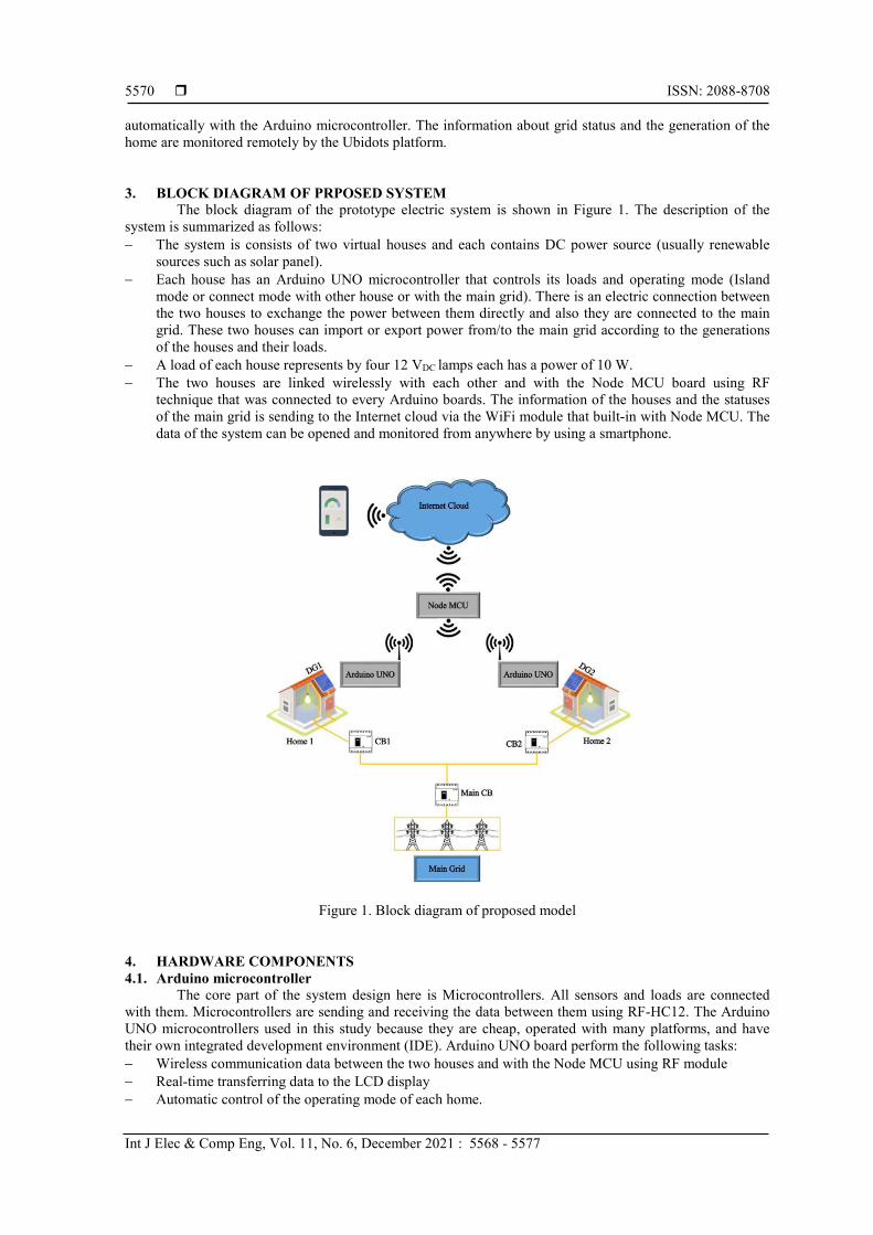
The block diagram of the prototype electric system is shown in Figure 1. The description of the system is summarized as follows: − The system is consists of two virtual houses and each contains DC power source (usually renewable
sources such as solar panel). − Each house has an Arduino UNO microcontroller that controls its loads and operating mode (Island
mode or connect mode with other house or with the main grid). There is an electric connection between the two houses to exchange the power between them directly and also they are connected to the main grid. These two houses can import or export power from/to the main grid according to the generations of the houses and their loads.
− A load of each house represents by four 12 VDC lamps each has a power of 10 W. − The two houses are linked wirelessly with each other and with the Node MCU board using RF
technique that was connected to every Arduino boards. The information of the houses and the statuses of the main grid is sending to the Internet cloud via the WiFi module that built-in with Node MCU. The data of the system can be opened and monitored from anywhere by using a smartphone.
Figure 1. Block diagram of proposed model 4. HARDWARE COMPONENTS 4.1. Arduino microcontroller
The core part of the system design here is Microcontrollers. All sensors and loads are connected with them. Microcontrollers are sending and receiving the data between them using RF-HC12. The Arduino UNO microcontrollers used in this study because they are cheap, operated with many platforms, and have their own integrated development environment (IDE). Arduino UNO board perform the following tasks: − Wireless communication data between the two houses and with the Node MCU using RF module − Real-time transferring data to the LCD display − Automatic control of the operating mode of each home.
Int J Elec & Comp Eng ISSN: 2088-8708
Real-time monitoring of the prototype design of electric system by … (Noor Saleh Mohammed)
5571
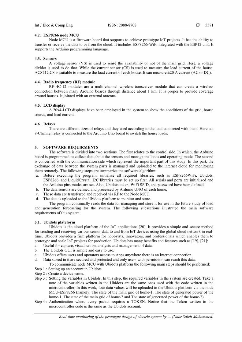
4.2. ESP8266 node MCU Node MCU is a firmware board that supports to achieve prototype IoT projects. It has the ability to
transfer or receive the data to or from the cloud. It includes ESP8266-WiFi integrated with the ESP12 unit. It supports the Arduino programming language. 4.3. Sensors
A voltage sensor (VS) is used to sense the availability or not of the main grid. Here, a voltage divider is used to do that. While the current sensor (CS) is used to measure the load current of the house. ACS712 CS is suitable to measure the load current of each house. It can measure ±20 A current (AC or DC). 4.4. Radio frequency (RF) module
RF-HC-12 modules are a multi-channel wireless transceiver module that can create a wireless connection between many Arduino boards through distance about 1 km. It is proper to provide coverage around houses. It jointed with an external antenna. 4.5. LCD display
A 20x4-LCD displays have been employed in the system to show the conditions of the grid, house source, and load current. 4.6. Relays
There are different sizes of relays and they used according to the load connected with them. Here, an 8-Channel relay is connected to the Arduino Uno board to switch the house loads.
5. SOFTWARE REQUIRMENTS The software is divided into two sections. The first relates to the control side. In which, the Arduino
board is programmed to collect data about the sensors and manage the loads and operating mode. The second is concerned with the communication side which represent the important part of this study. In this part, the exchange of data between the system parts is managed and uploaded to the internet cloud for monitoring them remotely. The following steps are summarize the software algorithm: a. Before executing the program, initialize all required libraries, such as ESP8266WiFi, Ubidots,
ESP8266, and LiquidCrystal_I2C libraries must be set up first. All serials and ports are initialized and the Arduino pins modes are set. Also, Ubidots token, WiFi SSID, and password have been defined.
b. The data sensors are defined and processed by Arduino UNO of each home, c. These data are transferred and received via RF to the Node MCU, d. The data is uploaded to the Ubidots platform to monitor and store.
The program continually reads the data for managing and store it for use in the future study of load and generation forecasting for the system. The following subsections illustrated the main software requirements of this system:
5.1. Ubidots plateform
Ubidots is the cloud platform of the IoT applications [20]. It provides a simple and secure method for sending and receiving various sensor data to and from IoT devices using the global cloud network in real-time. Ubidots provides a firm platform for hobbyists, innovators, and professionals which enables them to prototype and scale IoT projects for production. Ubidots has many benefits and features such as [19], [21]: a. Useful for capture, visualization, analysis and management of data. b. The Ubidots GUI is simple and easy to use. c. Ubidots offers users and operators access to Apps anywhere there is an Internet connection. d. Data stored in it are secured and protected and only users with permission can reach this data.
To communicate node MCU with Ubidots platform the following main steps should be performed: Step 1 : Setting up an account in Ubidots. Step 2 : Create a device name. Step 3 : Setting the variables in Ubidots. In this step, the required variables in the system are created. Take a
note of the variables written in the Ubidots are the same ones used with the code written in the microcontroller. In this work, four data values will be uploaded to the Ubidots platform via the node MCU-ESP8266 (namely: The state of the main grid of home-1, The state of generated power of the home-1, The state of the main grid of home-2 and The state of generated power of the home-2).
Step 4 : Authentication where every packet requires a TOKEN. Notice that the Token written in the microcontroller code is the same as the Ubidots account.
ISSN: 2088-8708
Int J Elec & Comp Eng, Vol. 11, No. 6, December 2021 : 5568 - 5577
5572
5.2. Machine to machine (M2M) communication M2M communication counted as an essential section of the IoT. It represents the independent
interaction of a large number of processing and actions without human intervention [19], [20]. The communication system given here employs the two following IoT communication protocols: a. Message queuing telemetry transport (MQTT): MQTT is one of the most common protocols used in IoT
applications [22]. The protocol operates over transport control protocol (TCP)/ internet protocol (IP). It provides lossless, ordered, and bi-directional connections and has many additional features that make it perfect for M2M and IoT applications such as small messaging size, require little bandwidth, easy to implement in software and fast transmit data in real-time [23].
b. Using publish/subscribe processes for data exchange between clients and servers. c. Hypertext transfer protocol (HTTP): It is an IoT protocol and represents a secure version of HTTP,
which transmits data between the user and the website that is connected to it. It is commonly used and in almost all software applications with a TCP/IP. This protocol is designed to support different devices in the application layer Laptops, and phones, [24]. HTTP provides reliable communication and employed to transfer large quantities of tiny packets.
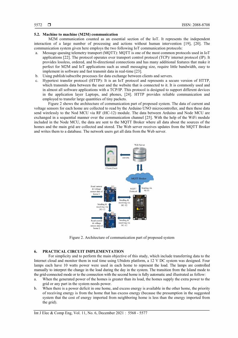
Figure 2 shows the architecture of communication part of proposed system. The data of current and voltage sensors for each home are collected to read by the Arduino UNO microcontroller, and then these data send wirelessly to the Nod MCU via RF (HC-12) module. The data between Arduino and Node MCU are exchanged in a sequential manner over the communication channel [25]. With the help of the WiFi module included in the Node MCU, the data are sent to the MQTT Broker where all data about the sources of the homes and the main grid are collected and stored. The Web server receives updates from the MQTT Broker and writes them to a database. The network users get all data from the Web server.
Figure 2. Architecture of communication part of proposed system
6. PRACTICAL CIRCUIT IMPLEMENTATION For simplicity and to perform the main objective of this study, which include transferring data to the
Internet cloud and monitor them in real time using Ubidots platform, a 12 V DC system was designed. Four lamps each have 10 watts power were used in each home to represent the load. The lamps are controlled manually to interpret the change in the load during the day in the system. The transition from the Island mode to the grid-connected mode or to the connection with the second home is fully automatic and illustrated as follow: a. When the generated power of the homes is greater than its load, the homes supply the extra power to the
grid or any part in the system needs power. b. When there is a power deficit in one home, and excess energy is available in the other home, the priority
of receiving energy is from the home that has excess energy (because the presumption in the suggested system that the cost of energy imported from neighboring home is less than the energy imported from the grid).
Int J Elec & Comp Eng ISSN: 2088-8708
Real-time monitoring of the prototype design of electric system by … (Noor Saleh Mohammed)
5573
c. When the generated power in both homes is less than their load, the required energy is provided from the main grid.
d. When the main grid is unavailable and the generated power of each home is insufficient to operate all the loads in it, only the necessary loads are operating and the home works in the Island mode.
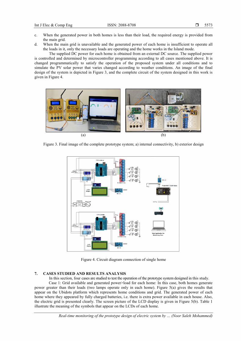
The supplied DC power for each home is obtained from an external DC source. The supplied power is controlled and determined by microcontroller programming according to all cases mentioned above. It is changed programmatically to satisfy the operation of the proposed system under all conditions and to simulate the PV solar power that varies changed according to weather conditions. An image of the final design of the system is depicted in Figure 3, and the complete circuit of the system designed in this work is given in Figure 4.
(a) (b)
Figure 3. Final image of the complete prototype system; a) internal connectivity, b) exterior design
Figure 4. Circuit diagram connection of single home
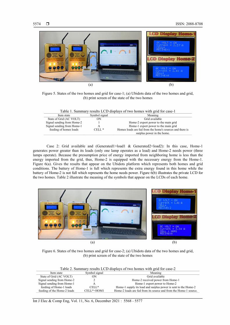
7. CASES STUDIED AND RESULTS ANALYSIS In this section, four cases are studied to test the operation of the prototype system designed in this study. Case 1: Grid available and generated power>load for each home: In this case, both homes generate
power greater than their loads (two lamps operate only in each home). Figure 5(a) gives the results that appear on the Ubidots platform which represents home conditions and grid. The generated power of each home where they appeared by fully charged batteries, i.e. there is extra power available in each house. Also, the electric grid is presented clearly. The screen picture of the LCD display is given in Figure 5(b). Table 1 illustrate the meaning of the symbols that appear on the LCDs of each home.
ISSN: 2088-8708
Int J Elec & Comp Eng, Vol. 11, No. 6, December 2021 : 5568 - 5577
5574
(a) (b)
Figure 5. States of the two homes and grid for case-1; (a) Ubidots data of the two homes and grid,
(b) print screen of the state of the two homes
Table 1. Summary results LCD displays of two homes with grid for case-1 Item state Symbol signal Meaning
State of Grid (AC VOLT) ON Grid available Signal sending from Home-2 1 Home-2 export power to the main grid Signal sending from Home-1 A Home-1 export power to the main grid
feeding of homes loads CELL * Homes loads are fed from the home's sources and there is surplus power in the home.
Case 2: Grid available and (Generated1>load1 & Generated2<load2): In this case, Home-1 generates power greater than its loads (only one lamp operates as a load) and Home-2 needs power (three lamps operate). Because the presumption price of energy imported from neighboring home is less than the energy imported from the grid, thus, Home-2 is equipped with the necessary energy from the Home-1. Figure 6(a). Gives the results that appear on the Ubidots platform which represents both homes and grid conditions. The battery of Home-1 is full which represents the extra energy found in this home while the battery of Home-2 is not full which represents the home needs power. Figure 6(b) illustrates the private LCD for the two homes. Table 2 illustrate the meaning of the symbols that appear on the LCDs of each home.
(a) (b)
Figure 6. States of the two homes and grid for case-2; (a) Ubidots data of the two homes and grid,
(b) print screen of the state of the two homes
Table 2. Summary results LCD displays of two homes with grid for case-2 Item state Symbol signal Meaning
State of Grid (AC VOLT) ON Grid available Signal sending from Home-2 2 Home-2 received power from Home-1 Signal sending from Home-1 A Home-1 export power to Home-2
feeding of Home-1 loads CELL* Home-1 supply its load and surplus power is sent to the Home-2 feeding of the Home-2 loads CELL*+HOM1 Home-2 loads are fed from its source and from the Home-1 source.
Int J Elec & Comp Eng ISSN: 2088-8708
Real-time monitoring of the prototype design of electric system by … (Noor Saleh Mohammed)
5575
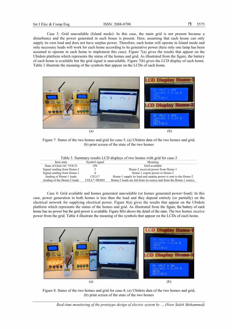
Case 3: Grid unavailable (Island mode): In this case, the main grid is not present because a disturbance and the power generated in each house is present. Here, assuming that each house can only supply its own load and does not have surplus power. Therefore; each home will operate in Island mode and only necessary loads will work for each home according to its generative power (here only one lamp has been assumed to operate in each home to implement this case). Figure 7(a) gives the results that appear on the Ubidots platform which represents the status of the homes and grid. As illustrated from the figure, the battery of each home is available but the grid signal is unavailable. Figure 7(b) gives the LCD display of each home. Table 3 illustrate the meaning of the symbols that appear on the LCDs of each home.
(a) (b)
Figure 7. States of the two homes and grid for case-3; (a) Ubidots data of the two homes and grid,
(b) print screen of the state of the two homes
Table 3. Summary results LCD displays of two homes with grid for case-3 Item state Symbol signal Meaning
State of Grid (AC VOLT) ON Grid available Signal sending from Home-2 2 Home-2 received power from Home-1 Signal sending from Home-1 A Home-1 export power to Home-2
feeding of Home-1 loads CELL* Home-1 supply its load and surplus power is sent to the Home-2 feeding of the Home-2 loads CELL*+HOM1 Home-2 loads are fed from its source and from the Home-1 source.
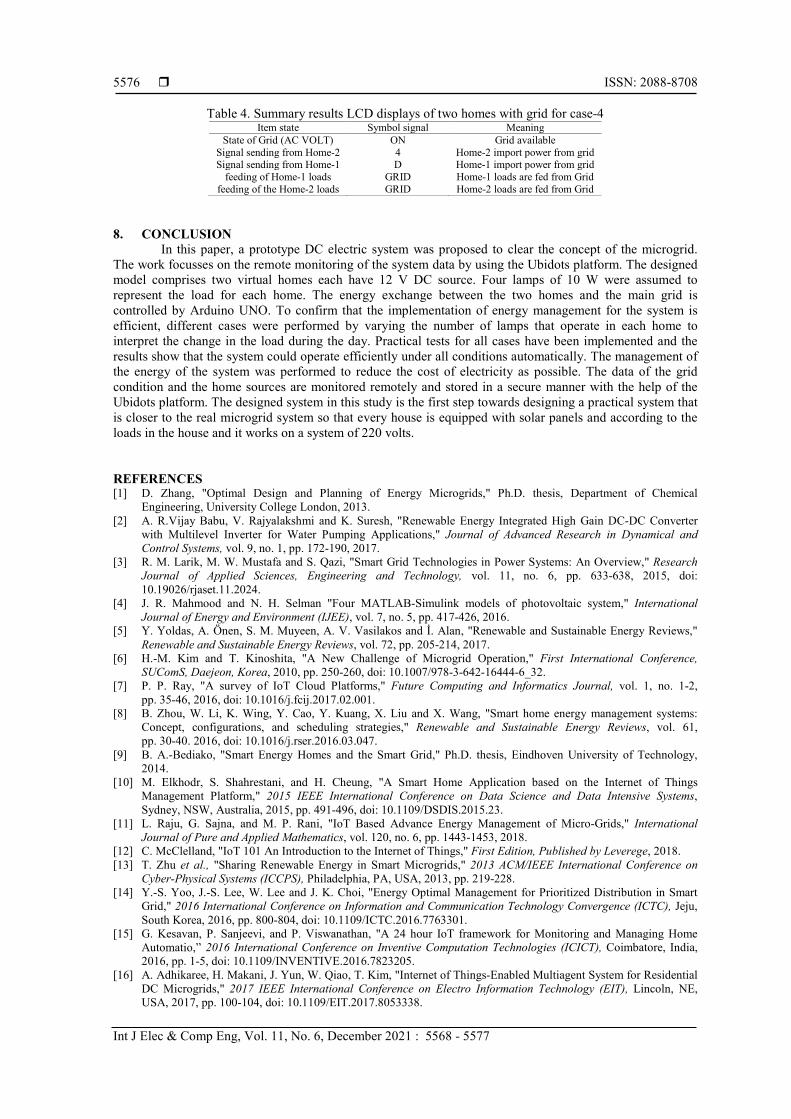
Case 4: Grid available and homes generated unavailable (or homes generated power<load): In this case, power generation in both homes is less than the load and they depend entirely (or partially) on the electrical network for supplying electrical power. Figure 8(a) gives the results that appear on the Ubidots platform which represents the status of the homes and grid. As illustrated from the figure, the battery of each home has no power but the grid power is available. Figure 8(b) shows the detail of the state. The two homes receive power from the grid. Table 4 illustrate the meaning of the symbols that appear on the LCDs of each home.
(a) (b)
Figure 8. States of the two homes and grid for case-4; (a) Ubidots data of the two homes and grid,
(b) print screen of the state of the two homes
ISSN: 2088-8708
Int J Elec & Comp Eng, Vol. 11, No. 6, December 2021 : 5568 - 5577
5576
Table 4. Summary results LCD displays of two homes with grid for case-4 Item state Symbol signal Meaning
State of Grid (AC VOLT) ON Grid available Signal sending from Home-2 4 Home-2 import power from grid Signal sending from Home-1 D Home-1 import power from grid
feeding of Home-1 loads GRID Home-1 loads are fed from Grid feeding of the Home-2 loads GRID Home-2 loads are fed from Grid
8. CONCLUSION
In this paper, a prototype DC electric system was proposed to clear the concept of the microgrid. The work focusses on the remote monitoring of the system data by using the Ubidots platform. The designed model comprises two virtual homes each have 12 V DC source. Four lamps of 10 W were assumed to represent the load for each home. The energy exchange between the two homes and the main grid is controlled by Arduino UNO. To confirm that the implementation of energy management for the system is efficient, different cases were performed by varying the number of lamps that operate in each home to interpret the change in the load during the day. Practical tests for all cases have been implemented and the results show that the system could operate efficiently under all conditions automatically. The management of the energy of the system was performed to reduce the cost of electricity as possible. The data of the grid condition and the home sources are monitored remotely and stored in a secure manner with the help of the Ubidots platform. The designed system in this study is the first step towards designing a practical system that is closer to the real microgrid system so that every house is equipped with solar panels and according to the loads in the house and it works on a system of 220 volts.
REFERENCES [1] D. Zhang, "Optimal Design and Planning of Energy Microgrids," Ph.D. thesis, Department of Chemical
Engineering, University College London, 2013. [2] A. R.Vijay Babu, V. Rajyalakshmi and K. Suresh, "Renewable Energy Integrated High Gain DC-DC Converter
with Multilevel Inverter for Water Pumping Applications," Journal of Advanced Research in Dynamical and Control Systems, vol. 9, no. 1, pp. 172-190, 2017.
[3] R. M. Larik, M. W. Mustafa and S. Qazi, "Smart Grid Technologies in Power Systems: An Overview," Research Journal of Applied Sciences, Engineering and Technology, vol. 11, no. 6, pp. 633-638, 2015, doi: 10.19026/rjaset.11.2024.
[4] J. R. Mahmood and N. H. Selman "Four MATLAB-Simulink models of photovoltaic system," International Journal of Energy and Environment (IJEE), vol. 7, no. 5, pp. 417-426, 2016.
[5] Y. Yoldas, A. Önen, S. M. Muyeen, A. V. Vasilakos and İ. Alan, "Renewable and Sustainable Energy Reviews," Renewable and Sustainable Energy Reviews, vol. 72, pp. 205-214, 2017.
[6] H.-M. Kim and T. Kinoshita, "A New Challenge of Microgrid Operation," First International Conference, SUComS, Daejeon, Korea, 2010, pp. 250-260, doi: 10.1007/978-3-642-16444-6_32.
[7] P. P. Ray, "A survey of IoT Cloud Platforms," Future Computing and Informatics Journal, vol. 1, no. 1-2, pp. 35-46, 2016, doi: 10.1016/j.fcij.2017.02.001.
[8] B. Zhou, W. Li, K. Wing, Y. Cao, Y. Kuang, X. Liu and X. Wang, "Smart home energy management systems: Concept, configurations, and scheduling strategies," Renewable and Sustainable Energy Reviews, vol. 61, pp. 30-40. 2016, doi: 10.1016/j.rser.2016.03.047.
[9] B. A.-Bediako, "Smart Energy Homes and the Smart Grid," Ph.D. thesis, Eindhoven University of Technology, 2014.
[10] M. Elkhodr, S. Shahrestani, and H. Cheung, "A Smart Home Application based on the Internet of Things Management Platform," 2015 IEEE International Conference on Data Science and Data Intensive Systems, Sydney, NSW, Australia, 2015, pp. 491-496, doi: 10.1109/DSDIS.2015.23.
[11] L. Raju, G. Sajna, and M. P. Rani, "IoT Based Advance Energy Management of Micro-Grids," International Journal of Pure and Applied Mathematics, vol. 120, no. 6, pp. 1443-1453, 2018.
[12] C. McClelland, "IoT 101 An Introduction to the Internet of Things," First Edition, Published by Leverege, 2018. [13] T. Zhu et al., "Sharing Renewable Energy in Smart Microgrids," 2013 ACM/IEEE International Conference on
Cyber-Physical Systems (ICCPS), Philadelphia, PA, USA, 2013, pp. 219-228. [14] Y.-S. Yoo, J.-S. Lee, W. Lee and J. K. Choi, "Energy Optimal Management for Prioritized Distribution in Smart
Grid," 2016 International Conference on Information and Communication Technology Convergence (ICTC), Jeju, South Korea, 2016, pp. 800-804, doi: 10.1109/ICTC.2016.7763301.
[15] G. Kesavan, P. Sanjeevi, and P. Viswanathan, "A 24 hour IoT framework for Monitoring and Managing Home Automatio,” 2016 International Conference on Inventive Computation Technologies (ICICT), Coimbatore, India, 2016, pp. 1-5, doi: 10.1109/INVENTIVE.2016.7823205.
[16] A. Adhikaree, H. Makani, J. Yun, W. Qiao, T. Kim, "Internet of Things-Enabled Multiagent System for Residential DC Microgrids," 2017 IEEE International Conference on Electro Information Technology (EIT), Lincoln, NE, USA, 2017, pp. 100-104, doi: 10.1109/EIT.2017.8053338.
Int J Elec & Comp Eng ISSN: 2088-8708
Real-time monitoring of the prototype design of electric system by … (Noor Saleh Mohammed)
5577
[17] C. Zhang, J. Wu, Y. Zhou, M. Cheng, C. Long, "Peer-to-Peer energy trading in a Microgrid," Applied Energy, vol. 220, pp. 1-12, 2018, doi: 10.1016/j.apenergy.2018.03.010.
[18] N. Kulkarni, S. V. N. L. Lalitha and S. A. Deokar, "Real time control and monitoring of grid power systems using cloud computing," International Journal of Electrical and Computer Engineering (IJECE), vol. 9, no. 2, pp. 941-949, 2019, DOI: 10.11591/ijece.v9i2.pp941-949.
[19] N. S. Mohammed and N. H. Selman, "Home Energy Management and Monitoring Using Ubidots Platform," Al-Furat Journal of Innovations in Electronics and Computer Engineering (FJIECE), vol. 1, no. 3, pp. 14-21, 2020, doi: 10.46649/150920-03.
[20] P. S. Khaire and S. V. Kuntawar, "Predictive Model for Device Identification Using Machine Learning Algorithm," International Journal of Engineering Applied Sciences and Technology, vol. 4, no. 4, pp. 105-114, 2019, doi: 10.33564/IJEAST.2019.v04i04.018.
[21] D. Anggraini, N. Effendy, M. I. Al Hafiz, and D. O. Luviano, "Research and Development of a Power Monitoring System for the Sustainable Energy Management System Implementation at Green School, Bali, Indonesia," E3S Web of Conferences, vol. 43, 2018, Art. no. 01021, DOI:10.1051/e3sconf/20184301021.
[22] K. Monika, S. Vidushi, and G. Neeti, "Taking MQTT and NodeMcu to IoT: Communication in Internet of Things," ICCIDS, Procedia Computer Science, vol. 132, pp. 1611-1618, 2018, doi: 10.1016/j.procs.2018.05.126.
[23] S. Track and W. Product, "MQTT Version 3.1.1 Plus Errata 01," Committee Specification Draft 06, OASIS Ope, 2014.
[24] S. D. Sonwane and V. V Kimbahune, "Implementation of M2M Communication Protocol for IoT Based Email System," International Journal of Science and Research (IJSR), vol. 5, no. 6, pp. 1518-1522, 2016.
[25] S. S. Gade, A. B. Kanase, S. B. Shendge, and M. D. Uplane, "Serial Communication Protocol for Embedded Application," International Journal of Information Technology and Knowledge Management, vol. 2, no. 2, pp. 461-463, 2010.
Top Related
Copyright © 2022 FDOKUMEN

