


Bahasa
Halaman
Hukum

ProMoBox: A Framework for GeneratingDomain-Specific Property Languages
Bart Meyers1, Romuald Deshayes2, Levi Lucio3, Eugene Syriani4,Hans Vangheluwe1,3, and Manuel Wimmer5
1 Modeling, Simulation and Design Lab (MSDL), University of Antwerp, [email protected], [email protected]
2 Institut d’Informatique, Universit de Mons, Mons, [email protected]
3 Modeling, Simulation and Design Lab (MSDL), McGill University, [email protected], [email protected]
4 Software Engineering Research Group (SERG), University of Alabama, United [email protected]
5 Business Informatics Group (BIG), Vienna University of Technology, [email protected]
Abstract. Specifying and verifying properties of the modelled system has beenmostly neglected by domain-specific modelling (DSM) approaches. At best, thisis only partially supported by translating models to formal representations onwhich properties are specified and evaluated based on logic-based formalisms,such as linear temporal logic. This contradicts the DSM philosophy as domainexperts are usually not familiar with the logics space. To overcome this short-coming, we propose to shift property specification and verification tasks up tothe domain-specific level. The ProMoBox framework consists of (i) generic lan-guages for modelling properties and representing verification results, (ii) a fullyautomated method to specialize and integrate these generic languages to a givenDSM language, and (iii) a verification backbone based model checking directlyplug-able to DSM environments. In its current state, ProMoBox offers the de-signer modelling support for defining temporal properties, and for visualizingverification results, all based on a given DSM language. We report results of ap-plying ProMoBox to a case study of an elevator controller.
1 IntroductionDomain-specific modelling (DSM) advocates that, providing languages that are specificto the problem space rather than to the solution space, systems are designable by domainexperts while model transformations are taking care of achieving the transition to thesolution space [1]. An essential activity in DSM is the specification and verification ofproperties to ensure the high quality of the designed systems [2]. Thus, supporting thesetasks by DSM is necessary to provide a holistic DSM experience to domain engineers.However, specifying and verifying properties of systems has been mostly neglectedby DSM approaches. At best, this is only partially supported by translating modelsto formal representations on which properties are specified and evaluated with logic-based formalisms [3], such as Linear Temporal Logic (LTL). This contradicts the DSMphilosophy as domain experts are usually not familiar with the logics space. The need
to raise the level of abstraction for specification and verification tasks is also recentlyraised in [4]. The authors emphasize that domain engineers should be shielded from theunderlying verification technologies. In this sense, DSM includes not only the designof the system-under-study, but also the properties themselves, the representation of therun-time state of a system, the behaviour of the environment, and a visualisation of acounter-example, all at the domain-specific level. In the spirit of DSM, they should eachbe defined in their own domain-specific modelling language (DSML).
To overcome this shortcoming, we propose to shift property specification and ver-ification tasks up to the DSM level, resulting in the generation and execution of Pro-MoBox. The contribution of the ProMoBox framework consists of (i) generic languagesfor modelling all artefacts that are needed for specifying and verifying properties, (ii)a fully automated method to specialise and integrate these generic languages to a givenDSML, and (iii) a verification backbone based model checking directly plug-able toDSM environments.
In the following section, we introduce the running example of an elevator controller.Section 3 introduces our approach ProMoBox from a language engineering point ofview and explains how properties are defined and verified based on a model check-ing backbone. Section 4 is dedicated to implementation and evaluation of ProMoBox.Section 5 elaborates on assumptions that are made in the current state of the approachwhile discussing the limitations of the approach. In Section 6 we discuss related workand conclude in Section 7.
2 Running Example
Our running example is an elevator controller modeled by a graphical DSL. This DSLenables modelling a building with floors, elevators and buttons, and defines the step-wise behaviour of this model.
Elevator
doors_open : booleangoing_up : boolean
Button
pressed : boolean
ElevatorButton FloorButton
DownButtonUpButton
Floor
nr : int
requests* 1
elevator_button
1
*
currentfloor
*
1
next0..1
0..1
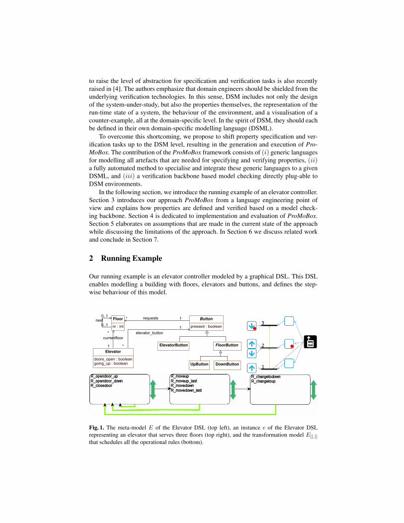
Fig. 1. The meta-model E of the Elevator DSL (top left), an instance e of the Elevator DSLrepresenting an elevator that serves three floors (top right), and the transformation model E[[.]]
that schedules all the operational rules (bottom).
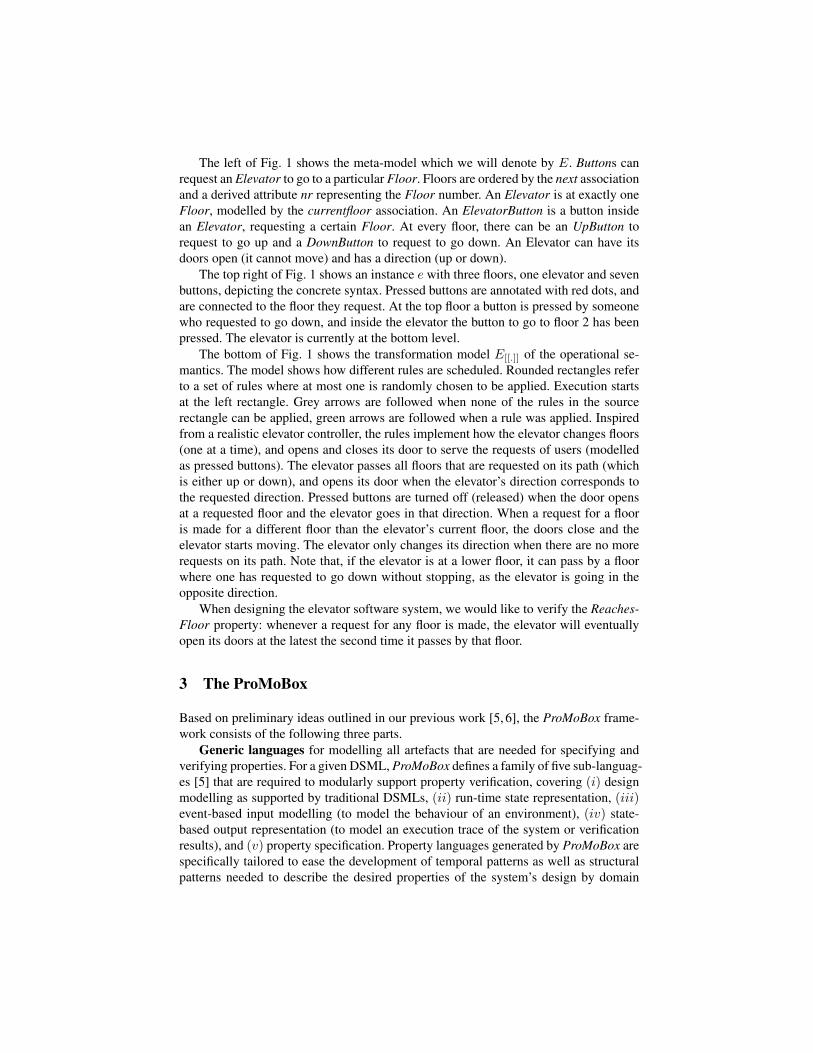
The left of Fig. 1 shows the meta-model which we will denote by E. Buttons canrequest an Elevator to go to a particular Floor. Floors are ordered by the next associationand a derived attribute nr representing the Floor number. An Elevator is at exactly oneFloor, modelled by the currentfloor association. An ElevatorButton is a button insidean Elevator, requesting a certain Floor. At every floor, there can be an UpButton torequest to go up and a DownButton to request to go down. An Elevator can have itsdoors open (it cannot move) and has a direction (up or down).
The top right of Fig. 1 shows an instance e with three floors, one elevator and sevenbuttons, depicting the concrete syntax. Pressed buttons are annotated with red dots, andare connected to the floor they request. At the top floor a button is pressed by someonewho requested to go down, and inside the elevator the button to go to floor 2 has beenpressed. The elevator is currently at the bottom level.
The bottom of Fig. 1 shows the transformation model E[[.]] of the operational se-mantics. The model shows how different rules are scheduled. Rounded rectangles referto a set of rules where at most one is randomly chosen to be applied. Execution startsat the left rectangle. Grey arrows are followed when none of the rules in the sourcerectangle can be applied, green arrows are followed when a rule was applied. Inspiredfrom a realistic elevator controller, the rules implement how the elevator changes floors(one at a time), and opens and closes its door to serve the requests of users (modelledas pressed buttons). The elevator passes all floors that are requested on its path (whichis either up or down), and opens its door when the elevator’s direction corresponds tothe requested direction. Pressed buttons are turned off (released) when the door opensat a requested floor and the elevator goes in that direction. When a request for a flooris made for a different floor than the elevator’s current floor, the doors close and theelevator starts moving. The elevator only changes its direction when there are no morerequests on its path. Note that, if the elevator is at a lower floor, it can pass by a floorwhere one has requested to go down without stopping, as the elevator is going in theopposite direction.
When designing the elevator software system, we would like to verify the Reaches-Floor property: whenever a request for any floor is made, the elevator will eventuallyopen its doors at the latest the second time it passes by that floor.
3 The ProMoBox
Based on preliminary ideas outlined in our previous work [5, 6], the ProMoBox frame-work consists of the following three parts.
Generic languages for modelling all artefacts that are needed for specifying andverifying properties. For a given DSML, ProMoBox defines a family of five sub-languag-es [5] that are required to modularly support property verification, covering (i) designmodelling as supported by traditional DSMLs, (ii) run-time state representation, (iii)event-based input modelling (to model the behaviour of an environment), (iv) state-based output representation (to model an execution trace of the system or verificationresults), and (v) property specification. Property languages generated by ProMoBox arespecifically tailored to ease the development of temporal patterns as well as structuralpatterns needed to describe the desired properties of the system’s design by domain
engineers in the DSML’s concrete syntax. To allow to formulate temporal properties ata high-level of abstraction, we formalise Dwyer’s specification patterns [7] for defin-ing temporal patterns as a DSML. With the help of this DSML, domain engineers areable to express temporal properties for finite state verification such as absence, exis-tence, or universality. To ease the development of structural patterns to be checked onsnapshots of the system’s execution states, we propose an automated technique basedon [8, 9] that is able to produce a specialised language from a given DSML tailored toexpress structural patterns. The language for defining structural patterns is inspired byPaMoMo [10, 11], a language supporting several pattern kinds such as enabling, posi-tive, and negative patterns. Finally, we introduce the possibility to define quantifiers fortemporal properties to express complex properties in a more concise manner, e.g., everyelement of a certain type has to fulfil a certain property.
A fully automated method to specialise and integrate these generic languages toa given DSML. We extend meta-modelling and model transformation languages withannotations, to add necessary information for every language construct and semanticstep. This additional information enables the fully automatic generation of the five sub-languages and necessary transformations between the sub-languages, thus minimisingthe effort of the language engineer. Because of their generative definition, consistencybetween the languages and their models is guaranteed by construction. We use tem-plates that describe the generic part of each language, and that are subsequently wovenwith the DSML. By using templates, we allow the ProMoBox framework to be config-urable for different types of DSMLs.
A verification backbone based model checking directly plug-able to DSM envi-ronments. Properties in ProMoBox are translated to LTL and a Promela system is gen-erated that includes a translation of the system, the environment, and the rule-basedoperational semantics of the system. The properties are checked by SPIN [12]. Theverification results (in case of a counter-example) are translated back to the DSM level.
The ProMoBox approach is illustrated in Fig. 2 using the elevator example presentedin Section 2. When using the ProMoBox approach, only the grey models in Fig. 2 needto be modelled by hand, the white models are generated. This is done in two parts:first, we define how meta-models can be annotated (E′ in Fig. 2) and how the fivesub-languages (i.e., the design, run-time, input, output and properties languages) aregenerated (upper part of Fig. 2). Second, we define how mappings are generated thatallow a given property to be verified on a given system, and how the results can bevisualised in a domain specific way (steps 1 to 5 of Fig. 2).
3.1 The Annotated Meta-Model
The abstract syntax of the sub-languages is generated from the annotated meta-modelthat provides additional information on which parts are static (never change at run-time), dynamic (change at run-time) and which parts can be input into the system.
First, we present a formal definition of a meta-model. The complete formalisationcan be found in [5]. We defineΣ as the alphabet of all possible names. For simplicity, allclass, association, and attribute names are globally unique and are from here on referredto as the classes, associations or attributes themselves. A meta-model is defined by:
M = (C,D,A, α, ι, P, π), (1)
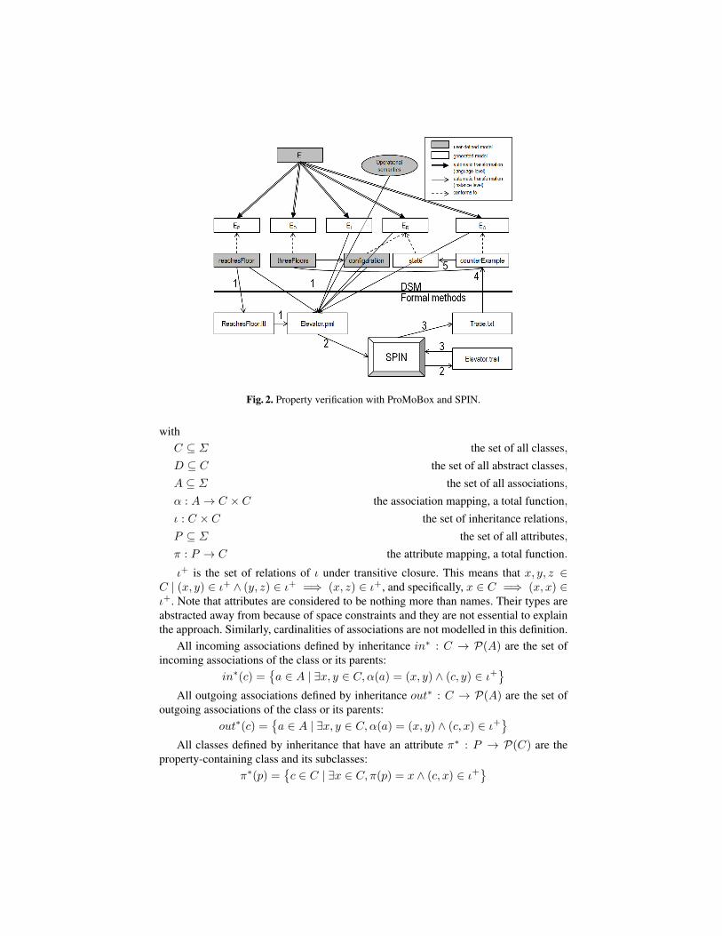
Fig. 2. Property verification with ProMoBox and SPIN.
withC ⊆ Σ the set of all classes,D ⊆ C the set of all abstract classes,A ⊆ Σ the set of all associations,α : A→ C × C the association mapping, a total function,ι : C × C the set of inheritance relations,P ⊆ Σ the set of all attributes,π : P → C the attribute mapping, a total function.
ι+ is the set of relations of ι under transitive closure. This means that x, y, z ∈C | (x, y) ∈ ι+ ∧ (y, z) ∈ ι+ =⇒ (x, z) ∈ ι+, and specifically, x ∈ C =⇒ (x, x) ∈ι+. Note that attributes are considered to be nothing more than names. Their types areabstracted away from because of space constraints and they are not essential to explainthe approach. Similarly, cardinalities of associations are not modelled in this definition.
All incoming associations defined by inheritance in∗ : C → P(A) are the set ofincoming associations of the class or its parents:
in∗(c) ={a ∈ A | ∃x, y ∈ C,α(a) = (x, y) ∧ (c, y) ∈ ι+
}All outgoing associations defined by inheritance out∗ : C → P(A) are the set of
outgoing associations of the class or its parents:out∗(c) =
{a ∈ A | ∃x, y ∈ C,α(a) = (x, y) ∧ (c, x) ∈ ι+
}All classes defined by inheritance that have an attribute π∗ : P → P(C) are the
property-containing class and its subclasses:π∗(p) =
{c ∈ C | ∃x ∈ C, π(p) = x ∧ (c, x) ∈ ι+
}
Button
<<rt>> <<ev>>pressed : boolean
Elevator
<<rt>>doors_open : boolean<<rt>>going_up : boolean
ElevatorButton FloorButton
DownButtonUpButton
Floor
nr : int
requests* 1
elevator_button
1
*
currentfloor<<rt>>
*
1
next0..1
0..1
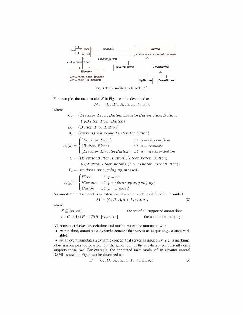
Fig. 3. The annotated metamodel E′.
For example, the meta-model E in Fig. 1 can be described as:Me = (Ce, De, Ae, αe, ιe, Pe, πe),
whereCe = {Elevator, F loor,Button,ElevatorButton, F loorButton,
UpButton,DownButton}De = {Button, F loorButton}Ae = {currentfloor, requests, elevator button}
αe(a) =
(Elevator, F loor) if a = currentfloor
(Button, F loor) if a = requests
(Elevator, ElevatorButton) if a = elevator button
ιe = {(ElevatorButton,Button), (FloorButton,Button),(UpButton, F loorButton), (DownButton, F loorButton)}
Pe = {nr, doors open, going up, pressed}
πe(p) =
Floor if p = nr
Elevator if p ∈ {doors open, going up}Button if p = pressed
An annotated meta-model is an extension of a meta-model as defined in Formula 1:M′ = (C,D,A, α, ι, P, π, S, σ), (2)
whereS ⊆ {rt, ev} the set of all supported annotationsσ : C ∪A ∪ P → P(S) {rt, ev, tr} the annotation mapping.
All concepts (classes, associations and attributes) can be annotated with:• rt: run-time, annotates a dynamic concept that serves as output (e.g., a state vari-
able);• ev: an event, annotates a dynamic concept that serves as input only (e.g., a marking).
More annotations are possible, but the generation of the sub-languages currently onlysupports those two. For example, the annotated meta-model of an elevator controlDSML, shown in Fig. 3 can be described as:
E′ = (Ce, De, Ae, αe, ιe, Pe, πe, Se, σe), (3)

whereSe = {rt, ev}
σe(x) =
{{rt} if x ∈ {doors open, going up, current floor}{ev, rt} if x = pressed
In this meta-model, the language engineer specifies that Floor, Elevator and Button,the associations requests and elevator button and the attribute nr are static as they arenot annotated. A button press is an input event, and going up, doors open, currentfloorand pressed are dynamic.
3.2 Generation of Sub-Languages
The annotated meta-modelE′ includes enough detail to generate the five sub-languagesas shown in Fig. 2. The generated sub-languages are each expressive enough, while atthe same time maximally constrain the modeller so that they are maximally domain-specific. The result of this generation process with E′ as input (see Fig. 3) is shown inFig. 4. Templates are used in the generation process, shown with grey classes. Thesetemplates consist of generic language constructs, that can be instantiated to create a sub-language. The meta-models of sub-languages are generated by a function that operateson E′ so that only relevant elements are used and no more annotations are present sothat the result is a regular meta-model.
We formalise the approach so that the definition of the sub-languages is preciseand unambiguous. For every language, there is a language mapping function f :M′ ×Mt →M that returns the sub-language meta-modelMx = (Cx, Dx, Ax, αx, ιx, Px, πx)of an annotated meta-model M′ = (C,D,A, α, ι, P, π, S, σ) and a template Mt =(Ct, Dt, At, αt, ιt, Pt, πt). This template Mt is different for every sub-language. Bydefault, a sub-language will simply consist of M′ without annotations, but preserv-ing all elements. We define this default mapping function as the function weave :M′ ×M×Σ →M. The result of weave is defined as follows:
Mx = (Cx, Dx, Ax, αx, ιx, Px, πx),
where the components of Mx are defined by weave(M′,Mt, Element) under thecondition that Element ∈ Ct: Xx = X ∪ Xt for X ∈ {C,D,A, α, P, π} and ιx =ι ∪ ιt ∪ {(c, Element) | c ∈ C ∧ @s ∈ C, (c, s) ∈ ι}.
In case of the elevator DSML, meta-model Mx is the union of E′ and a giventemplateMt, and a all elements of E′ that do not have a superclass (in this case Floor,Button and Elevator), become a subclass of a given Element class in the templateMt.
The meta-models of all five sub-languages are defined below, and their intent isexplained. We explain the approach using the elevator control DSML of which theabstract syntax is defined by E′.
The design language Ed The design language allows modellers to design systems ina general way. The static system (i.e., its structure) is defined, and state or configura-tion information is not taken into account in this language. Its generated meta-model isshown in the top left of Fig. 4. In the generation process, all constructs (classes, associ-ations and attributes) of E′ annotated with rt and ev are removed. The template consistsof a single DesignElement class with an id that has to be unique. This id will be used to

Properties
Design
DesignElement
id : int
Runtime
RunTimeElement
id : int
Output
OutputElement
id : int
Input
Button
pressed : boolean
Event
current : boolean
ElevatorButton
InputElement
id : int
Environment
DownButton
FloorButton
UpButton
Elevator
doors_open : Condition = return Truegoing_up : Condition = return True
Transition
rule_execution : RuleExecution [0..1]input_event : Event [0..1]
StructuralPattern
name : Stringcondition : Condition = return Truedynamic : boolean
PropertyElement
id : intlabel : Stringcondition : Condition = return True
Button
pressed : Condition = return True
OrderedTemporalPattern
Floor
nr : Condition = return True
Elevator
doors_open : booleangoing_up : boolean
Elevator
doors_open : booleangoing_up : boolean
BoundedExistence
n : Integer
QuantifiedPattern
quantifier : Quantifier
TemporalPattern
LowerBounded
Button
pressed : boolean
UpperBounded
Button
pressed : boolean
<<enumeration>>
Quantifier
existsforAll
BinaryPattern
ImpliesPattern
ElevatorButton
ElevatorButton
ElevatorButton
ElevatorButton
AtomicPatternUnaryPattern
FloorButton
FloorButtonFloorButton
Specification
name : String
DownButton
DownButton
DownButton
DownButton
Precedence
Universality
FloorButton
AndPatternNotPattern
Response
Existence
OrPattern
AfterUntil
UpButton
UpButton
UpButton
UpButton
Absence
Between
Pattern
Elevator
Globally
Button
Before
Scope
Floor
nr : int
Floor
nr : int
Floor
nr : int
Trace
After
State
event
{ordered}
*
1
currentEvent
1
0..1
element *1nextEvent
0..1
0..1
1
11
nextTransition
0..1
1
requests* 1
requests* 1
requests* 1
1
elevator_button
1
*
elevator_button
1
*
requests* 0..1
elevator_button
1
*
currentState
10..1
nextState1
0..1
state
{ordered}
*1
elevator_button 0..1
*
11
1
1
currentfloor
*
1
currentfloor
*
1
currentfloor0..1
*
1..*
1
element
*
1
next
0..1
0..1
next
0..1
0..1next
0..1
0..1
next
0..1
0..1
2
Fig. 4. The meta-models of the five sub-languages of E′.
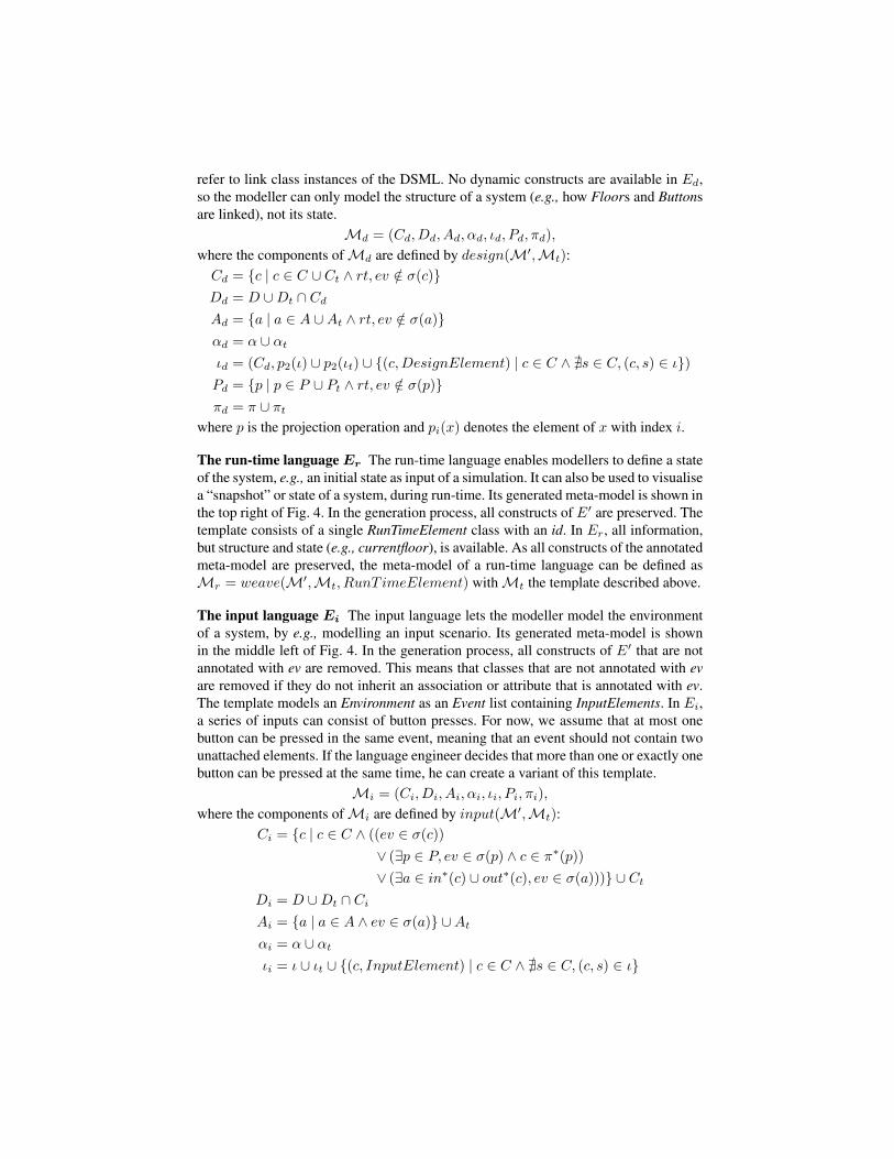
refer to link class instances of the DSML. No dynamic constructs are available in Ed,so the modeller can only model the structure of a system (e.g., how Floors and Buttonsare linked), not its state.
Md = (Cd, Dd, Ad, αd, ιd, Pd, πd),
where the components ofMd are defined by design(M′,Mt):Cd = {c | c ∈ C ∪ Ct ∧ rt, ev /∈ σ(c)}Dd = D ∪Dt ∩ Cd
Ad = {a | a ∈ A ∪At ∧ rt, ev /∈ σ(a)}αd = α ∪ αt
ιd = (Cd, p2(ι) ∪ p2(ιt) ∪ {(c,DesignElement) | c ∈ C ∧ @s ∈ C, (c, s) ∈ ι})Pd = {p | p ∈ P ∪ Pt ∧ rt, ev /∈ σ(p)}πd = π ∪ πt
where p is the projection operation and pi(x) denotes the element of x with index i.
The run-time language Er The run-time language enables modellers to define a stateof the system, e.g., an initial state as input of a simulation. It can also be used to visualisea “snapshot” or state of a system, during run-time. Its generated meta-model is shown inthe top right of Fig. 4. In the generation process, all constructs of E′ are preserved. Thetemplate consists of a single RunTimeElement class with an id. In Er, all information,but structure and state (e.g., currentfloor), is available. As all constructs of the annotatedmeta-model are preserved, the meta-model of a run-time language can be defined asMr = weave(M′,Mt, RunT imeElement) withMt the template described above.
The input language Ei The input language lets the modeller model the environmentof a system, by e.g., modelling an input scenario. Its generated meta-model is shownin the middle left of Fig. 4. In the generation process, all constructs of E′ that are notannotated with ev are removed. This means that classes that are not annotated with evare removed if they do not inherit an association or attribute that is annotated with ev.The template models an Environment as an Event list containing InputElements. In Ei,a series of inputs can consist of button presses. For now, we assume that at most onebutton can be pressed in the same event, meaning that an event should not contain twounattached elements. If the language engineer decides that more than one or exactly onebutton can be pressed at the same time, he can create a variant of this template.
Mi = (Ci, Di, Ai, αi, ιi, Pi, πi),
where the components ofMi are defined by input(M′,Mt):Ci = {c | c ∈ C ∧ ((ev ∈ σ(c))
∨ (∃p ∈ P, ev ∈ σ(p) ∧ c ∈ π∗(p))∨ (∃a ∈ in∗(c) ∪ out∗(c), ev ∈ σ(a)))} ∪ Ct
Di = D ∪Dt ∩ Ci
Ai = {a | a ∈ A ∧ ev ∈ σ(a)} ∪At
αi = α ∪ αt
ιi = ι ∪ ιt ∪ {(c, InputElement) | c ∈ C ∧ @s ∈ C, (c, s) ∈ ι}
Pi = {p | p ∈ P ∧ ev ∈ σ(p)} ∪ Pt
πi = π ∪ πt
The output language Eo The output language can be used to represent executiontraces of a simulation. An output model is usually generated by a simulator or asa counter-example by a verification tool, but can be generated manually as well fore.g., modelling an oracle for a test case. Its generated meta-model is shown in the bot-tom left of Fig. 4. In the generation process, all constructs of E′ are preserved. Thetemplate consists of a Trace of States and Transitions. This language is able to expressa sequence of system states and the intermediate operations that caused the state change(a rule application in the operational semantics E[[.]], and/or an input event). The outputof E[[.]], or the counter-example in verification are instances of Eo. Due to the possi-bly large number of elements in such an execution trace, an instance of Eo is storedmore implicitly as text, and can be interpreted or “played out” by showing step-by-stepan instance of the run-time language Er. The meta-model of a output language can bedefined asMo = weave(M′,Mt, OutputElement) withMt the template describedabove.
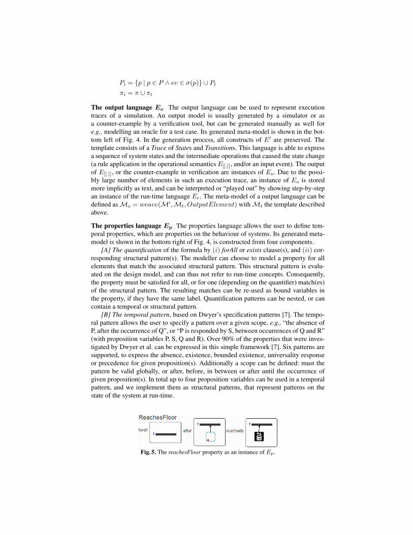
The properties language Ep The properties language allows the user to define tem-poral properties, which are properties on the behaviour of systems. Its generated meta-model is shown in the bottom right of Fig. 4, is constructed from four components.
[A] The quantification of the formula by (i) forAll or exists clause(s), and (ii) cor-responding structural pattern(s). The modeller can choose to model a property for allelements that match the associated structural pattern. This structural pattern is evalu-ated on the design model, and can thus not refer to run-time concepts. Consequently,the property must be satisfied for all, or for one (depending on the quantifier) match(es)of the structural pattern. The resulting matches can be re-used as bound variables inthe property, if they have the same label. Quantification patterns can be nested, or cancontain a temporal or structural pattern.
[B] The temporal pattern, based on Dwyer’s specification patterns [7]. The tempo-ral pattern allows the user to specify a pattern over a given scope, e.g., “the absence ofP, after the occurrence of Q”, or “P is responded by S, between occurrences of Q and R”(with proposition variables P, S, Q and R). Over 90% of the properties that were inves-tigated by Dwyer et al. can be expressed in this simple framework [7]. Six patterns aresupported, to express the absence, existence, bounded existence, universality responseor precedence for given proposition(s). Additionally a scope can be defined: must thepattern be valid globally, or after, before, in between or after until the occurrence ofgiven proposition(s). In total up to four proposition variables can be used in a temporalpattern, and we implement them as structural patterns, that represent patterns on thestate of the system at run-time.
Fig. 5. The reachesFloor property as an instance of Ep.
[C] The structural pattern, based on PaMoMo [11], for both static (when used ina quantification pattern) as well as dynamic (when used in a temporal pattern) models.Using a structural pattern, a query can be defined on a model. If the pattern is static,it returns all bound variables in found matches, and if it is dynamic it returns true ifat least one match is found or false when no match is found. In our current approach,we use simple patterns (e.g., the elevator is at a given floor) and an ad-hoc matchingalgorithm, but we intend to re-use the matching algorithm presented in [9]. Only asmall part of PaMoMo’s expressiveness is included in the property language, but thissuffices for defining most properties. A StructuralPattern, and a PropertiesElement canhold a condition, which returns true by default and is in our current approach modelledas a string.
[D] The pattern elements, based on the RAM process [8,9]. The elements of a struc-tural pattern are based onE′ but need to be changed in several ways in order to allow themodeller to specify patterns that are match in model fragments. A similar problem ex-ists when constructing a pattern language for creating a meta-model for transformationrules, and is formalized by the RAM process. In this process, all classes are subclassesof ModelElement and have a label (for binding variables) and a condition, attribute typesare now conditions, no more classes are abstract classes, and all lower bounds of asso-ciation multiplicities are set to 0. Pattern elements are compiled to their correspondingPromela variable names, which can be used in the Promela boolean expression of thestructural pattern.
The properties pattern is composed of parts A, B and C, which are generic. Onlycomponent D, depends on E′ that is subjected to the RAM process for left-hand sidepatterns [9]. Let us define the function RAM :M′ −M′ → that performs the RAMprocess for left-hand side patterns on an annotated meta-modelM′, resulting in a RAM-ified meta-modelMRAM :
RAM(M′) = (CRAM ,∅, ARAM , αRAM , ιRAM , PRAM , πRAM , S, σ),
then the meta-model of a properties language can be defined as:Mp = weave(RAM(M′),Mt, P ropertiesElement),
withMt the template described above.
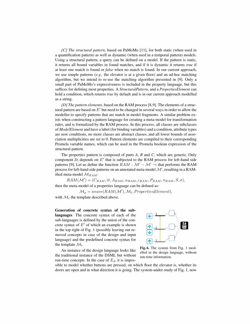
Fig. 6. The system from Fig. 1 mod-elled in the design language, withoutrun-time information.
Generation of concrete syntax of the sub-languages The concrete syntax of each of thesub-languages is defined by the union of the con-crete syntax of E′ of which an example is shownin the top right of Fig. 1 (possibly leaving out re-moved concepts in case of the design and inputlanguage) and the predefined concrete syntax forthe templateMt.
An instance of the design language looks likethe traditional instance of the DSML but withoutrun-time concepts. In the case of Ed, it is impos-sible to model whether buttons are pressed, on which floor the elevator is, whether itsdoors are open and in what direction it is going. The system-under-study of Fig. 1, now
modelled in Ed, is shown in Fig. 6. An example instance of the run-time language Er
looks the same as the traditional instance of the DSML, shown at the top right in Fig. 1.An instance of the input language is not used in the context of verification by model
checking. Its concrete syntax is a sequence of connected events represented as greencircles containing the events visualised using the concrete syntax as shown in the topright of Fig. 1. Each step of an instance of the output language can be visualised as arun-time instance. Alternatively, it can be visualised completely at once as red circlescontaining the states, connected by arrows with the transition event(s) as label. An in-stance of the property language Ep is shown in Fig. 5. It uses a combination of text anddomain-specific patterns.
3.3 Generation of Mappings for Model Checking With the SPIN Environment
Verification is automated in five steps, as depicted in Fig. 2.
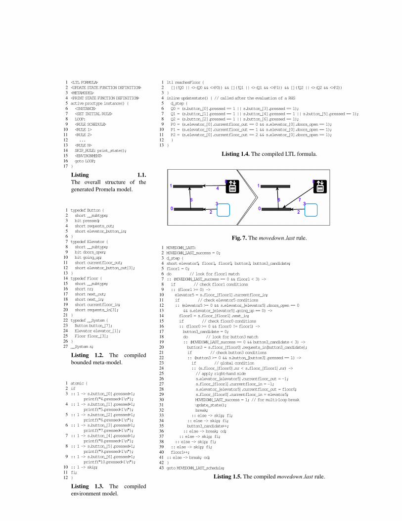
Step 1: Transformation to LTL and Promela As shown in Fig. 2, a generic transfor-mation generates the LTL formula and the Promela model by means of a model-to-texttransformation. The operation results in a .pml file, in the example called Elevator.pml,that serves as input for the SPIN verification tool. The .pml file is generated from a num-ber of models, and its overall structure is shown in Listing 1.1, where code snippets arereferenced between < and >. The role of each model in the compilation process isdiscussed below.
The design meta-model (line 3 in Listing 1.1): The design meta-model, in our caseEd is translated to a number of Promela typedefs. Only the three classes on top ofthe inheritance hierarchy become Promela types. There instances are stored as static ar-rays, and instances are accessed by indexing that array. Since Promela is not an object-oriented language, inheritance and associations has to be encoded in a particular wayas shown in Listing 1.2). For the types on line 1-21, inheritance is implemented by thesubtype attribute, that refer to any class in the design meta-model. Associations
are implemented with bidirectional accessibility by shorts, that refer to the indexof the target, rather than an object. For instance, if the currentfloor out of anElevator is 1, its target is the Floor with index 1. If a target is the null object,its index is set to -1. The Promela typedefs are also influenced by the model of theinitial configuration of system-under-study (modelled as a run-time instance), which ismodelled as a System type on line 22-26, with static arrays of 7 Buttons, 1 Elevatorand 3 Floors. These numbers are extracted from the run-time instance and are prede-termined, as the number of buttons, elevators and floors are static. Suppose they arenot static, then a maximum number must be set because SPIN requires the state to bebounded. On line 27 the system is created, and values should be filled in (see below).
The output meta-model (line 4 in Listing 1.1): A function called print state(not shown) is defined that prints the current state of the system in a predefined encod-ing. Only run-time concepts are printed. This, in combination with printing the inputevents and the applied rule (done in the rule schedule code, which is not shown), pro-vides all the necessary information to construct an output trace.
A run-time instance (line 5-6 in Listing 1.1): After all type, variable and functiondeclarations, the process declaration starts on line 5. Only one process is used. It starts
with the initial configuration of the system (line 6, not shown in detail), by setting allvalues of s (declared in Listing 1.2 on line 27). This results in the initial state of s.
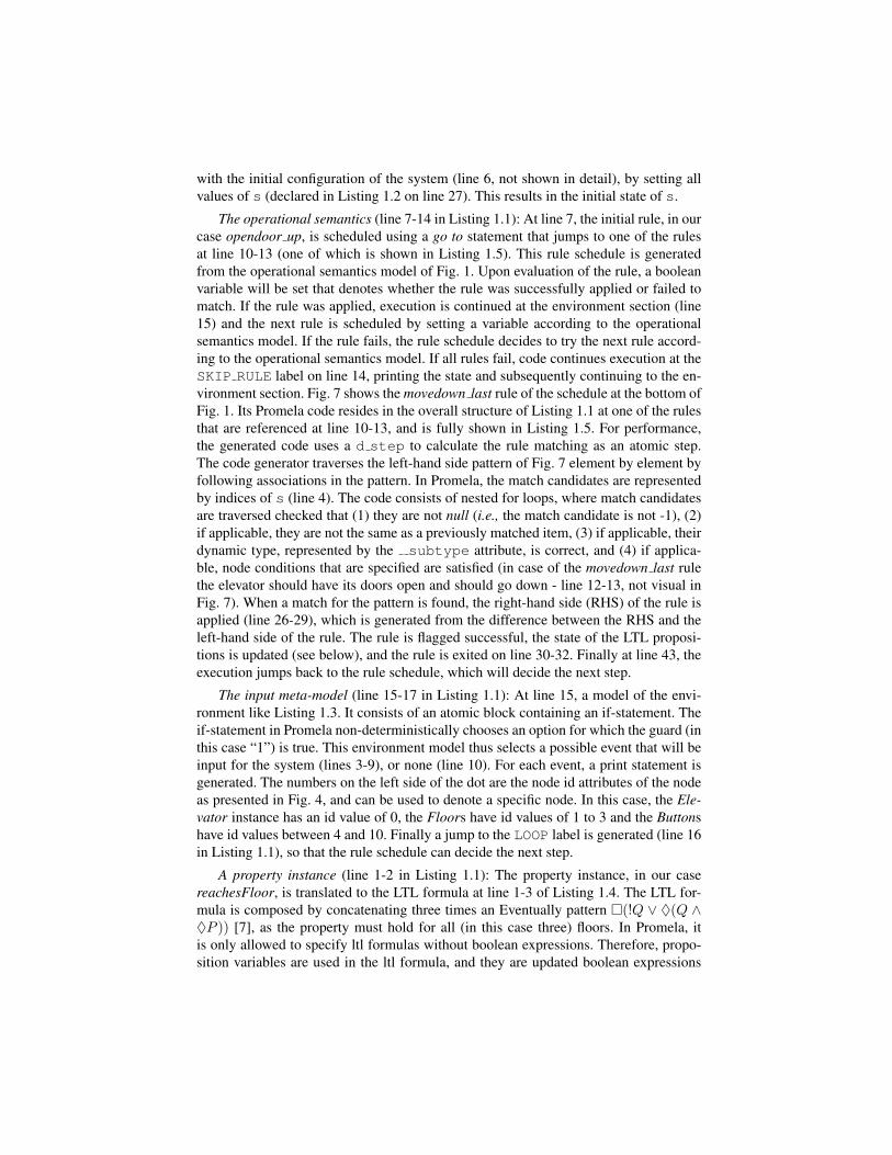
The operational semantics (line 7-14 in Listing 1.1): At line 7, the initial rule, in ourcase opendoor up, is scheduled using a go to statement that jumps to one of the rulesat line 10-13 (one of which is shown in Listing 1.5). This rule schedule is generatedfrom the operational semantics model of Fig. 1. Upon evaluation of the rule, a booleanvariable will be set that denotes whether the rule was successfully applied or failed tomatch. If the rule was applied, execution is continued at the environment section (line15) and the next rule is scheduled by setting a variable according to the operationalsemantics model. If the rule fails, the rule schedule decides to try the next rule accord-ing to the operational semantics model. If all rules fail, code continues execution at theSKIP RULE label on line 14, printing the state and subsequently continuing to the en-vironment section. Fig. 7 shows the movedown last rule of the schedule at the bottom ofFig. 1. Its Promela code resides in the overall structure of Listing 1.1 at one of the rulesthat are referenced at line 10-13, and is fully shown in Listing 1.5. For performance,the generated code uses a d step to calculate the rule matching as an atomic step.The code generator traverses the left-hand side pattern of Fig. 7 element by element byfollowing associations in the pattern. In Promela, the match candidates are representedby indices of s (line 4). The code consists of nested for loops, where match candidatesare traversed checked that (1) they are not null (i.e., the match candidate is not -1), (2)if applicable, they are not the same as a previously matched item, (3) if applicable, theirdynamic type, represented by the subtype attribute, is correct, and (4) if applica-ble, node conditions that are specified are satisfied (in case of the movedown last rulethe elevator should have its doors open and should go down - line 12-13, not visual inFig. 7). When a match for the pattern is found, the right-hand side (RHS) of the rule isapplied (line 26-29), which is generated from the difference between the RHS and theleft-hand side of the rule. The rule is flagged successful, the state of the LTL proposi-tions is updated (see below), and the rule is exited on line 30-32. Finally at line 43, theexecution jumps back to the rule schedule, which will decide the next step.
The input meta-model (line 15-17 in Listing 1.1): At line 15, a model of the envi-ronment like Listing 1.3. It consists of an atomic block containing an if-statement. Theif-statement in Promela non-deterministically chooses an option for which the guard (inthis case “1”) is true. This environment model thus selects a possible event that will beinput for the system (lines 3-9), or none (line 10). For each event, a print statement isgenerated. The numbers on the left side of the dot are the node id attributes of the nodeas presented in Fig. 4, and can be used to denote a specific node. In this case, the Ele-vator instance has an id value of 0, the Floors have id values of 1 to 3 and the Buttonshave id values between 4 and 10. Finally a jump to the LOOP label is generated (line 16in Listing 1.1), so that the rule schedule can decide the next step.
A property instance (line 1-2 in Listing 1.1): The property instance, in our casereachesFloor, is translated to the LTL formula at line 1-3 of Listing 1.4. The LTL for-mula is composed by concatenating three times an Eventually pattern �(!Q ∨ ♦(Q ∧♦P )) [7], as the property must hold for all (in this case three) floors. In Promela, itis only allowed to specify ltl formulas without boolean expressions. Therefore, propo-sition variables are used in the ltl formula, and they are updated boolean expressions
using when the update state function is called (line 4-13). Q0, Q1 and Q2 repre-sent the possible button presses at floors 0, 1 and 2, as defined by the middle patternin Fig. 5. Note how the bound floor f is used in the boolean expressions to select thecorrect s.button indices that match f . On line 9-11 P0, P1 and P2 represent theright pattern in Fig. 5, where it is checked whether the elevator is at floor f and its doorsare open. The function update state will need to be called every time the state ofthe system changes.Step 2: Verification with SPIN Step 2 of the verification process shown in Fig. 2 is theautomatic verification by SPIN on the Promela model (using the -a option). The LTLformula is checked on all possible execution traces. In this process, printing is sup-pressed. If the Promela model satisfies the LTL property, the verification is completed,and steps 3-5 are not followed. If the SPIN encounters a counter-example during veri-fication, the verification process is terminated and a .trail file is generated, as shown inFig. 2.Step 3: Trace generation by SPIN In case of a counter-example, SPIN is used to per-form a guided simulation using the trail on the Promela model (-t option). In this step,the print statements in the Promela model are executed, so that all relevant informationabout the counter-example is written to Trace.txt. In our example, one line in Trace.txtmay look like: “0.going up=1; 0.doors open=1; 0.currentfloor out=2; 4.pressed=0; 5.pressed=0; 6.pressed=1; 7.pressed=1; 8.pressed=0; 9.pressed=0; 10.pressed=0;”. Other lines can show the trans-formation rule that is applied (e.g., “movedown last”), or the input that was gener-ated by the environment model, as discussed before (e.g., “6.pressed=1”). On theleft side of each dot, the ids for model elements as presented in Fig. 4 are used to referto the node in question. Depending on the type of the attribute/association, the valuebehind the equal sign is interpreted as boolean, integer or id. In case of class that canbe created or deleted at run-time, all instances are printed out using newly assigned ids.For conciseness, associations are printed in one direction only.Step 4: Transformation of the counter-example to the domain-specific level Asshown in Fig. 2, the Trace.txt is transformed to an output model, making use of the de-sign model to map corresponding ids. This results in an output model, that sequentiallyshows all the system states of the counter-example.Step 5: Animation of the counter-example The output model can be “played” outstep-by-step by visualising each state. As described in [6], one state is visualised as arun-time model, which may look like the instance model on the top right of Fig. 1.
To conclude, as shown in Fig. 2 ProMoBox enables the modelling and verification ofproperties while the user only has to provide the bare minimum of models: an anno-tated meta-model, the concrete syntax (implicit in Fig. 2), the operational semantics,the system he wants to verify, a configuration of the system, and the property.
4 Example and EvaluationWe implemented the ProMoBox framework in AToMPM [13], and the compiler thatcompiles models to and from Promela or text were written in Python.
We verified three properties on the modelled system with the configuration at thetop right of Fig. 1:
1 <LTL FORMULA>2 <UPDATE STATE FUNCTION DEFINITION>3 <METAMODEL>4 <PRINT STATE FUNCTION DEFINITION>5 active proctype instance() {6 <INSTANCE>7 <SET INITIAL RULE>8 LOOP:9 <RULE SCHEDULE>
10 <RULE 1>11 <RULE 2>12 ...13 <RULE N>14 SKIP_RULE: print_state();15 <ENVIRONMENT>16 goto LOOP;17 }
Listing 1.1.The overall structure of thegenerated Promela model.
1 typedef Button {2 short __subtype;3 bit pressed;4 short requests_out;5 short elevator_button_in;6 }7 typedef Elevator {8 short __subtype;9 bit doors_open;
10 bit going_up;11 short currentfloor_out;12 short elevator_button_out[3];13 }14 typedef Floor {15 short __subtype;16 short nr;17 short next_out;18 short next_in;19 short currentfloor_in;20 short requests_in[3];21 }22 typedef __System {23 Button button_[7];24 Elevator elevator_[1];25 Floor floor_[3];26 }27 __System s;
Listing 1.2. The compiledbounded meta-model.
1 atomic {2 if3 :: 1 -> s.button_[0].pressed=1;
printf("4.pressed=1\n");4 :: 1 -> s.button_[1].pressed=1;
printf("5.pressed=1\n");5 :: 1 -> s.button_[2].pressed=1;
printf("6.pressed=1\n");6 :: 1 -> s.button_[3].pressed=1;
printf("7.pressed=1\n");7 :: 1 -> s.button_[4].pressed=1;
printf("8.pressed=1\n");8 :: 1 -> s.button_[5].pressed=1;
printf("9.pressed=1\n");9 :: 1 -> s.button_[6].pressed=1;
printf("10.pressed=1\n");10 :: 1 -> skip;11 fi;12 }
Listing 1.3. The compiledenvironment model.
1 ltl reachesFloor {2 [](!Q0 || <>(Q0 && <>P0)) && [](!Q1 || <>(Q1 && <>P1)) && [](!Q2 || <>(Q2 && <>P2))3 }4 inline updatestate() { // called after the evaluation of a RHS5 d_step {6 Q0 = (s.button_[0].pressed == 1 || s.button_[3].pressed == 1);7 Q1 = (s.button_[1].pressed == 1 || s.button_[4].pressed == 1 || s.button_[5].pressed == 1);8 Q2 = (s.button_[2].pressed == 1 || s.button_[6].pressed == 1);9 P0 = (s.elevator_[0].currentfloor_out == 0 && s.elevator_[0].doors_open == 1);
10 P1 = (s.elevator_[0].currentfloor_out == 1 && s.elevator_[0].doors_open == 1);11 P2 = (s.elevator_[0].currentfloor_out == 2 && s.elevator_[0].doors_open == 1);12 }13 }
Listing 1.4. The compiled LTL formula.
Fig. 7. The movedown last rule.
1 MOVEDOWN_LAST:2 MOVEDOWN_LAST_success = 0;3 d_step {4 short elevator5, floor1, floor0, button3, button3_candidate;5 floor1 = 0;6 do // look for floor1 match7 :: (MOVEDOWN_LAST_success == 0 && floor1 < 3) ->8 if // check floor1 conditions9 :: (floor1>= 0) ->
10 elevator5 = s.floor_[floor1].currentfloor_in;11 if // check elevator5conditions12 :: (elevator5>= 0 && s.elevator_[elevator5].doors_open == 013 && s.elevator_[elevator5].going_up == 0) ->14 floor0 = s.floor_[floor1].next_in;15 if // check floor0 conditions16 :: (floor0>= 0 && floor0 != floor1) ->17 button3_candidate = 0;18 do // look for button3 match19 :: (MOVEDOWN_LAST_success == 0 && button3_candidate < 3) ->20 button3 = s.floor_[floor0].requests_in[button3_candidate];21 if // check button3 conditions22 :: (button3>= 0 && s.button_[button3].pressed == 1) ->23 if // global condition24 :: (s.floor_[floor0].nr < s.floor_[floor1].nr) ->25 // apply right-hand side26 s.elevator_[elevator5].currentfloor_out = -1;27 s.floor_[floor1].currentfloor_in = -1;28 s.elevator_[elevator5].currentfloor_out = floor0;29 s.floor_[floor0].currentfloor_in = elevator5;30 MOVEDOWN_LAST_success = 1; // for multi-loop break31 update_state();32 break;33 :: else -> skip; fi;34 :: else -> skip; fi;35 button3_candidate++;36 :: else -> break; od;37 :: else -> skip; fi;38 :: else -> skip; fi;39 :: else -> skip; fi;40 floor1++;41 :: else -> break; od;42 }43 goto MOVEDOWN_LAST_schedule;
Listing 1.5. The compiled movedown last rule.
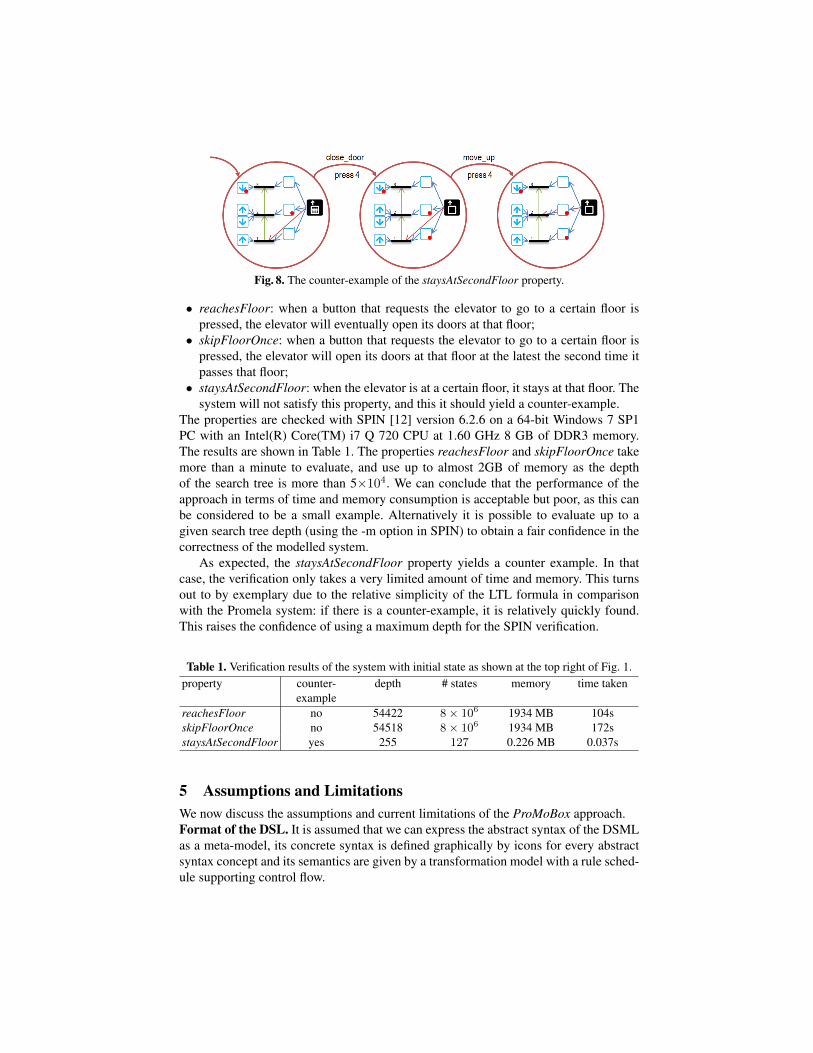
Fig. 8. The counter-example of the staysAtSecondFloor property.
• reachesFloor: when a button that requests the elevator to go to a certain floor ispressed, the elevator will eventually open its doors at that floor;
• skipFloorOnce: when a button that requests the elevator to go to a certain floor ispressed, the elevator will open its doors at that floor at the latest the second time itpasses that floor;
• staysAtSecondFloor: when the elevator is at a certain floor, it stays at that floor. Thesystem will not satisfy this property, and this it should yield a counter-example.
The properties are checked with SPIN [12] version 6.2.6 on a 64-bit Windows 7 SP1PC with an Intel(R) Core(TM) i7 Q 720 CPU at 1.60 GHz 8 GB of DDR3 memory.The results are shown in Table 1. The properties reachesFloor and skipFloorOnce takemore than a minute to evaluate, and use up to almost 2GB of memory as the depthof the search tree is more than 5×10⁴. We can conclude that the performance of theapproach in terms of time and memory consumption is acceptable but poor, as this canbe considered to be a small example. Alternatively it is possible to evaluate up to agiven search tree depth (using the -m option in SPIN) to obtain a fair confidence in thecorrectness of the modelled system.
As expected, the staysAtSecondFloor property yields a counter example. In thatcase, the verification only takes a very limited amount of time and memory. This turnsout to by exemplary due to the relative simplicity of the LTL formula in comparisonwith the Promela system: if there is a counter-example, it is relatively quickly found.This raises the confidence of using a maximum depth for the SPIN verification.
Table 1. Verification results of the system with initial state as shown at the top right of Fig. 1.property counter-
exampledepth # states memory time taken
reachesFloor no 54422 8× 10⁶ 1934 MB 104sskipFloorOnce no 54518 8× 10⁶ 1934 MB 172sstaysAtSecondFloor yes 255 127 0.226 MB 0.037s
5 Assumptions and LimitationsWe now discuss the assumptions and current limitations of the ProMoBox approach.Format of the DSL. It is assumed that we can express the abstract syntax of the DSMLas a meta-model, its concrete syntax is defined graphically by icons for every abstractsyntax concept and its semantics are given by a transformation model with a rule sched-ule supporting control flow.
Boundedness. The rule-based nature of the operational semantics ensure a step-wise,state-based semantics. In its current state, ProMoBox supports DSLMs that have a no-tion of state. Since we apply model checking, the possible number of states must bebounded. In the example, this is assured by the limited cardinality of the run-time ele-ments (especially the currentfloor association). If such boundedness is not achieved inthe meta-model because of an infinite cardinality value, this value must be bounded inorder to allow model checking. Such abstraction operations (including decreasing statespaces that are bounded but too large) are nonetheless key to modelling in SPIN, andare beyond the scope of this paper.Format of the properties. The only type of properties that is currently supported isbased on LTL. However, properties language also supports quantification and structuralpatterns, so the approach can be considered representative for a wide range of proper-ties. Although we cannot provide any prove, we feel that the ProMoBox approach de-scribed in this paper can be reused for different kinds of properties by defining genericmappers to tools supporting model checking with OCL and CTL, real time properties,or properties using distributions. The target tool has to be expressive enough so thata correct structure and operational semantics can be defined, i.e., all elements can bequeried, variables can be stored and throughout the evaluation of the temporal formula(context-dependency), etc. The key of the approach is that it is defined on the meta-levelformalisms (class diagrams, concrete syntax definitions, and rule-based transformationwith scheduling), in combination with pre-defined, generic templates.Scalability. Scalability remains the main concern however. On the one hand, modelchecking as a technique is a cause of scalability limitations, on the other hand gener-ates the Promela code generator generic code, which could be optimised. A radicallydifferent solution to the problem of scalability would be not to map to a model check-ing approach, but instead use test case generation techniques to generate relevant testcases in the form of input models and output models (oracles). Tests are executed byusing the input models as initial state, applying the operational semantics transforma-tion, and comparing (by using model comparison, e.g., the DSMDiff algorithm [14]) theresulting trace with the oracle. This illustrates how ProMoBox benefits from its mod-elling approach, because mappings to different semantic domains can be implemented.However, this research direction is not investigated for the ProMoBox approach.
6 Related WorkWith respect to the contribution of this paper, we distinguish two threads of relatedwork. First, we consider approaches that translate models to formal representations tospecify and verify properties that are created specifically for one modelling language.Second, we discuss approaches that have a more general view on providing specificationand verification support for different modelling languages.
Specific Solutions. In the last decade, a plethora of language-specific approacheshave been presented to define properties and verification results for different kind ofdesign-oriented languages. For instance, Cimatti et al. [15] have proposed to verifycomponent-based systems by using scenarios specified as Message Sequence Charts(MSCs). Li et al. [16] also apply MSCs for specifying scenarios for verifying concur-rent systems. The CHARMY approach [17] offers amongst other features, verification
support for architectural models described in UML. Collaboration and sequence di-agrams have been applied to check the behaviour of systems described in terms ofstate machines [18–20]. Rivera et al. [21] map the operational semantics of DSMLs toMaude, and thus, benefit from analysing methods provided out-of-the-box of Maudeenvironments such as checking of temporal properties specified in LTL. These men-tioned approaches are just a few examples that aim at specifying temporal propertiesfor models and verifying them by model checkers (see [22] for a survey). They have incommon that they offer language-specific property languages or LTL properties have tobe defined directly on the formal representation. Thus, these approaches are not aimingto support DSMLs engineers in the task of building domain-specific property languages.
Generic Solutions. There are some approaches that aim to shift the specificationand verification tasks to the model level in a more generalized manner. First of all, thereare approaches that propose OCL extensions, often referred to Temporal OCL (TOCL),for defining temporal properties on models [23–25]. As OCL may be combined withany modelling language, TOCL can be seen as a generic model-based property lan-guage as well. In [26, 27] the authors discuss and apply a pattern to extend modellinglanguages with events, traces, and further runtime concepts to represent the state of amodel’s execution and to use TOCL for defining properties that are verified by map-ping the design models as well as the properties expressed in TOCL to formal domainsthat provide verification support. In addition, not only the input for model checkers isautomatically produced, but also the output, i.e., the verification results, is translatedback to the model level. The authors explain the choice of using TOCL to be able toexpress properties at the domain level, because TOCL is close to OCL and should betherefore familiar to domain engineers. However, they also state that early feedback ofapplying their approach has shown that TOCL is still not well suited to many domainengineers and they state in future work that more tailored languages may be of help forthe domain engineers. The work presented in this paper goes directly in this directionby enabling domain engineers to use their familiar notation for defining properties andexploring the verification results.
Another approach that aims to define properties on the model level in a genericway is presented in [28]. The authors extend a language for defining structural patternsbased on Story Diagrams [29] to allow for modelling temporal patterns as well. Theresulting language allows to define conditionally timed scenarios stating the partial or-der of structural patterns. They authors argue that their language is more accessible fordomain engineers, because their language allow decomposition of complex temporalproperties into smaller ones by if-then-else decomposition and quantification over freevariables. Their approach is tailored to engineers that are familiar to work with UMLclass diagrams and UML object diagrams as their notation is heavily based on the con-cepts of these two languages. Furthermore, they explain how the specification patternsof Dwyer et al. [7] are encoded in their language, but there is no language-inherentsupport to explicitly apply them. In our work, we tackle these two issues in the con-text of DSM by reusing the notation of domain engineers for specifying properties andproviding explicit language support for specification patterns.
Finally, [30] present specification patterns for describing properties over reachablestates of graph grammars. These specification patterns are purely defined on graph
structures (i.e., nodes and edges) and thus are reusable for any modelling language.However, the authors do not discuss integration with current modelling languages touse such specification patterns for specific properties. A possible line of future workmay aim to integrate such specification patterns to our generic meta-model.
7 Conclusion and Future WorkWe presented the ProMoBox approach, in which a minimum number of models isrequired as input to specify and check properties with SPIN and visualise possiblecounter-examples, while the user is shielded from the underlying formal methods. Thisis made possible by using annotations on the DSML meta-model to generate five sub-languages, and by compiling models to Promela and back. The key of the approach isthat all information of the DSML is explicitly modelled. We presented the approachon a state-based DSML for elevator control. The process of evaluating properties usingProMoBox is described in detail, including a formal description of the generation of thesub-languages, and a compiler to Promela. Our results show that ProMoBox is applica-ble for current DSMLs and the resulting specification languages are usable by domainengineers.
For future work, we intend to use ProMoBox in a case study for gestural interac-tion [31]. In this case study, we plan to do more research on the performance of modelchecking using ProMoBox. Moreover, we plan to investigate how different propertylanguages can be supported using different templates, and how these templates canbe re-used, e.g., an existing template for structural properties could be re-used in theproperties template that is presented in this paper. We are also interested in broadeningthe types of languages that are supported by ProMoBox, e.g., languages that explic-itly include time. We expect that this would typically result in investigating associatedtemplates for real-time properties.
References
1. Gray, J., Tolvanen, J.P., Kelly, S., Gokhale, A., Neema, S., Sprinkle, J.: Domain-specificmodeling. Handbook of Dynamic System Modeling (2007)
2. France, R., Rumpe, B.: Model-driven development of complex software: A researchroadmap. In: ICSE. (2007)
3. Risoldi, M.: A Methodology For The Development Of Complex Domain Specific Lan-guages. PhD thesis, University of Geneva (2010)
4. Visser, W., Dwyer, M., Whalen, M.: The hidden models of model checking. SoSym 11(2012) 541–555
5. Meyers, B., Deshayes, R., Lucio, L., Syriani, E., Wimmer, M., Vangheluwe, H.: The Pro-MoBox approach to language modelling. Technical Report SOCS-TR-2014.3, School ofComputer Science, McGill University (2014)
6. Meyers, B., Wimmer, M., Vangheluwe, H.: Towards domain-specific property languages:The ProMoBox approach. In: DSM. (2013)
7. Dwyer, M.B., Avrunin, G.S., Corbett, J.C.: Patterns in Property Specifications for Finite-State Verification. In: ICSE. (1999)
8. Kuhne, T., Mezei, G., Syriani, E., Vangheluwe, H., Wimmer, M.: Explicit transformationmodeling. In: MoDELS Workshops. (2009)
9. Syriani, E.: A Multi-Paradigm Foundation for Model Transformation Language Engineering.PhD thesis, McGill University Montreal, Canada (2011)
10. Guerra, E., de Lara, J., Kolovos, D.S., Paige, R.F.: A Visual Specification Language forModel-to-Model Transformations. In: VL/HCC. (2010)
11. Guerra, E., de Lara, J., Wimmer, M., et al.: Automated verification of model transformationsbased on visual contracts. ASE 20 (2013) 5–46
12. Holzmann, G.J.: The Model Checker SPIN. TSE 23 (1997) 279–29513. Syriani, E., Vangheluwe, H., Mannadiar, R., Hansen, C., Mierlo, S.V., Ergin, H.: AToMPM:
A Web-based Modeling Environment. In: MoDELS Demonstrations. (2013)14. Lin, Y., Gray, J., Jouault, F.: DSMDiff: A Differentiation Tool for Domain-Specific Models.
European Journal of Information Systems 16 (2007)15. Cimatti, A., Mover, S., Tonetta, S.: Proving and Explaining the Unfeasibility of Message
Sequence Charts for Hybrid Systems. In: FMCAD. (2011)16. Li, X., Hu, J., Bu, L., Zhao, J., Zheng, G.: Consistency Checking of Concurrent Models for
Scenario-Based Specifications. In: SDL. (2005)17. Pelliccione, P., Inverardi, P., Muccini, H.: CHARMY: A Framework for Designing and Ver-
ifying Architectural Specifications. TSE 35 (2008) 325–34618. Brosch, P., Egly, U., Gabmeyer, S., Kappel, G., Seidl, M., Tompits, H., Widl, M., Wimmer,
M.: Towards Scenario-Based Testing of UML Diagrams. In: TAP. (2012)19. Knapp, A., Wuttke, J.: Model checking of UML 2.0 interactions. In: MoDELS’06. (2006)20. Schafer, T., Knapp, A., Merz, S.: Model Checking UML State Machines and Collaborations.
ENTCS 55 (2001) 357–36921. Rivera, J.E., Guerra, E., de Lara, J., Vallecillo, A.: Analyzing Rule-Based Behavioral Se-
mantics of Visual Modeling Languages with Maude. In: SLE. (2008)22. Gabmeyer, S., Kaufmann, P., Seidl, M.: A classification of model checking-based verification
approaches for software models. In: VOLT. (2013)23. Ziemann, P., Gogolla, M.: OCL Extended with Temporal Logic. In: PSI. (2003)24. Kanso, B., Taha, S.: Temporal Constraint Support for OCL. In: SLE. (2012)25. Bill, R., Gabmeyer, S., Kaufmann, P., Seidl, M.: OCL meets CTL: Towards CTL-Extended
OCL Model Checking. In: OCL Workshop. (2013)26. Zalila, F., Cregut, X., Pantel, M.: Leveraging Formal Verification Tools for DSML Users: A
Process Modeling Case Study. In: ISoLA. (2012)27. Combemale, B., Cregut, X., Pantel, M.: A Design Pattern to Build Executable DSMLs and
Associated V&V Tools. In: APSEC. (2012)28. Klein, F., Giese, H.: Joint structural and temporal property specification using timed story
scenario diagrams. In: FASE. (2007)29. Fischer, T., Niere, J., Torunski, L., Zundorf, A.: Story Diagrams: A New Graph Rewrite
Language Based on the Unified Modeling Language and Java. In: TAGT. (2000)30. da Costa Cavalheiro, S.A., Foss, L., Ribeiro, L.: Specification Patterns for Properties over
Reachable States of Graph Grammars. In: SBMF. (2012)31. Deshayes, R., Palanque, P.A., Mens, T.: A generic framework for executable gestural inter-
action models. In: VL/HCC. (2013)
Copyright © 2022 FDOKUMEN

