


Bahasa
Halaman
Hukum


1
PHRF-NB Regulations 2020
1. Preface
PHRF-NB strives to consistently provide fair ratings for dissimilar boats to race against each other. The best use
of these ratings is done by grouping boats in the smallest rating band with like type boats. It is expected that all
designs will have preferred conditions and may excel when those are met. The challenge we face is to balance
the rating to the local predominate condition in an effort to have the best sailed and prepared boats finish in the
top third. The Rating Committee (RC) reviews race results on a regular basis. This is typically done with at least a
years’ worth of results for a boat type to determine whether ratings need to be adjusted.
2. Administration
PHRF performance handicaps are boat performance handicaps based on the speed potential of the boat
determined, as far as possible, by observations of race results, VPP data, and ratings from other Rating
Systems. The intent of PHRF handicapping is that any well-equipped, well-maintained and well-sailed boat has a
good chance to win; and any boat that wins a PHRF race is indeed well-equipped, well-maintained, and well-
sailed. Handicaps are adjusted, as needed, on the basis of the boat's performance so that each boat will have an
equal opportunity to win. This is the fundamental concept.
PHRF-NB ratings are set by the RC. The RC reviews boat data, race results and boat modifications to name a few
to determine a boats rating. We will initially set a boats ‘base handicap’ and then apply adjustments for
modifications. In this way, if/when a sister ship requests a rating the process is to apply adjustments for the
particular boats modifications. The RC encourages all applicants to provide as much and as accurate data as
possible. Including all reported sail measurements (Main sail, Largest Jib/Genoa, Largest Spinnaker and Code 0
or Reaching Headsail).
3. Committee Members
The names of the committee members are listed on the PHRF-NB website http://phrf-nb.org/node/6793 along
with the administrators contact information. The committee members are all committed to keeping ratings
accurate. I encourage you to contact Administrator with questions or concerns who will direct the inquiries to
the appropriate member. They are all involved because they want to make a difference and promote a sport
they enjoy.
4. Definitions
LOA Length overall of hull, should not include bowsprits or boomkins.
LWL Length waterline, if unmeasured use the brochure/published dimension.
Beam STD maximum width of vessel

2
Draft STD maximum depth of vessel measured without crew, water, fuel or stores. If
un-measured use the brochure/published dimension.
Displacement (DISP) Weight of water displaced by vessel without crew, water, fuel or stores. If
unmeasured use the brochure/published value.
Ballast (BAL) Weight of ballast in pounds. Note any deletions with amount and location.
I Dimension measured from the sheer line at the mast to the STD Minimum hoist
of the jib/genoa.
ISP Distance from the sheer line at the mast to the STD Minimum hoist of the
spinnaker.
J Distance from the forward side of the mast to the intersection of the headstay
and deck.
JC/STL On boats with spinnaker tacked forward of the headstay (anchor roller, bowsprit
or similar) distance from the headstay/deck intersection forward to the tack
location for the spinnaker, added to the J dimension. On boats with articulating
bowsprits this measurement should be with the sprit parallel with the fore/aft
centerline of the boat.
P Mainsail luff length from the top of the boom to the top of the headboard with
the sail fully hoisted.
P2 Mizzen luff length from the top of the boom to the top of the headboard with
the sail fully hoisted.
E Foot length of the mainsail from the aft face of the mast to the clew in its most
outboard position.
E2 Foot length of the mizzen sail from the aft face of the mast to the clew in its
most outboard position.
MGT/MUW Mainsail girth from 7/8 leech to nearest point on mainsail luff.
MGU/MTW Mainsail girth from 3/4 leech to nearest point on mainsail luff.
MGM/MHW Mainsail girth from 1/2 leech to nearest point on mainsail luff.
MGL/MQW Mainsail girth from 1/4 leech to nearest point on mainsail luff.
MHB Mainsail headboard or Square top width.
SPL Spinnaker or whisker Pole Length measured with the pole in its fitting and set in
a horizontal position athwart ship.
3
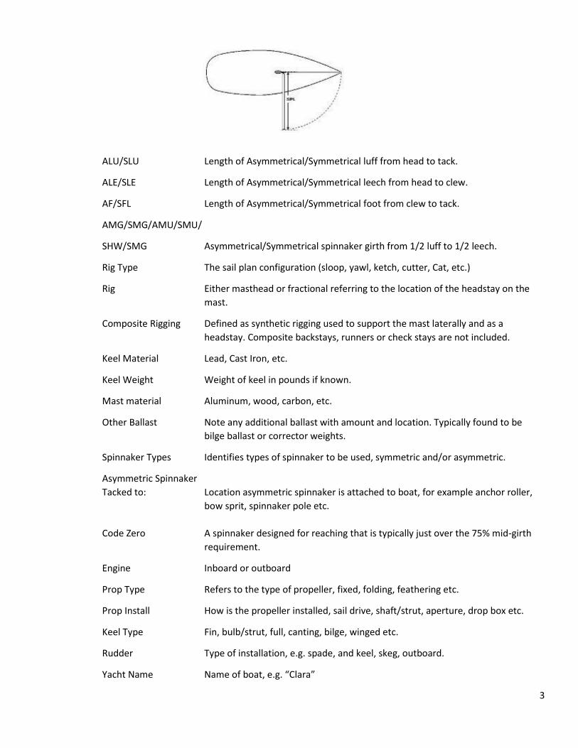
ALU/SLU Length of Asymmetrical/Symmetrical luff from head to tack.
ALE/SLE Length of Asymmetrical/Symmetrical leech from head to clew.
AF/SFL Length of Asymmetrical/Symmetrical foot from clew to tack.
AMG/SMG/AMU/SMU/
SHW/SMG Asymmetrical/Symmetrical spinnaker girth from 1/2 luff to 1/2 leech.
Rig Type The sail plan configuration (sloop, yawl, ketch, cutter, Cat, etc.)
Rig Either masthead or fractional referring to the location of the headstay on the
mast.
Composite Rigging Defined as synthetic rigging used to support the mast laterally and as a
headstay. Composite backstays, runners or check stays are not included.
Keel Material Lead, Cast Iron, etc.
Keel Weight Weight of keel in pounds if known.
Mast material Aluminum, wood, carbon, etc.
Other Ballast Note any additional ballast with amount and location. Typically found to be
bilge ballast or corrector weights.
Spinnaker Types Identifies types of spinnaker to be used, symmetric and/or asymmetric.
Asymmetric Spinnaker
Tacked to: Location asymmetric spinnaker is attached to boat, for example anchor roller,
bow sprit, spinnaker pole etc.
Code Zero A spinnaker designed for reaching that is typically just over the 75% mid-girth
requirement.
Engine Inboard or outboard
Prop Type Refers to the type of propeller, fixed, folding, feathering etc.
Prop Install How is the propeller installed, sail drive, shaft/strut, aperture, drop box etc.
Keel Type Fin, bulb/strut, full, canting, bilge, winged etc.
Rudder Type of installation, e.g. spade, and keel, skeg, outboard.
Yacht Name Name of boat, e.g. “Clara”

4
Model e.g. C&C 35 Mk2, for a custom boat (designer): CTM Farr 45’.
Sail # Number displayed on your sails
Hull Serial # Hull serial Identification number (HIN) located on starboard corner of transom.
Designer Yacht designer
MFCTR Yacht Manufacturer
Date MFD Date of manufacture of model year, if known.
Other Ratings Indicate a PHRF rating received from another area, e.g. NE-PHRF Base 72; IMS
GP 622.
SA / DISP Sail Area (as defined in the appropriate section) / (Displacement/64)2/3
DISPL / L (Displacement / 2240) / (.01 x LWL)3
5. Base Configuration
a. PHRF-NB considers the base boat to be as follows:
i. Genoa/Jib - This is determined by looking at the original design. If a boat was originally designed
with overlapping genoas we set the base rating for the design with a 155% genoa. Adjustments
for varied sail sizes are then based on this.
If a boat is designed with non-overlapping headsails (jibs) we set the base rating on this
(<118%). These boats will typically have the side shroud chain plates attached at the hull deck
joint.
The RC will make this determination when the base rating is established and it will be noted in
our base rating database.
ii. Spinnakers - It is assumed the boat has a spinnaker. We will review sail plans, design literature
and drawings to determine the type when a base rating is determined. Details of measurements
can be found in section 6.
iii. Mainsails – It is assumed that the mainsail conforms to the original design or STDimum Girths as
described in 6.A.i-iii.
iv. Propeller - It is assumed in the base rating that the boat has either a folding propeller on an
exposed shaft or sail drive or an outboard. Vessels not equipped with one of the configurations
will have an adjustment applied to their rating.
v. Displacement – we acknowledge that this is a grey area as many designs are delivered well
outside of the ‘listed displacement’. Despite this we will use the listed displacement as the basis
for base ratings.
vi. Boats rated in a One Design configuration shall comply with all applicable Class measurements.
Variations shall be reported to the Rating Committee.
vii. To summarize, we assume the boat is in all respects, as delivered from the original
manufacturer.
viii. Any change to the original manufacturer design or specification not covered in these rules shall
be reported and subjected to a review for possible adjustment.

5
6. Sails -
a. Mainsails
i. Standard – ORC STDimum girths or as designed and rated originally.
ii. Oversize Girths - For mainsails whose girths are greater than ORC standards, greater than
original design, greater than class rules, or for a change in size, ratings will be adjusted as
follows: (% increase is the sail area increase based on the following formula:
The following limits apply for mainsails based on ORC:
ORC Mainsail STDimum Girths MHB (Headboard/Square top) = 0.065 x E MUW (Girth at 7/8 leach) = 0.22 x E MTW (Girth at 3/4 leach) = 0.38 x E MHW (Girth at 1/2 leach) = 0.65 x E MQW (Girth at 1/4 leech) = 0.90 x E
Adjustments
% Increase Adjustment Sec/mile .1 % to 4% - 1 4.1 to 8% - 2 8.1 to 12% - 3 12.1 to 16% - 4 16.1 to 20% - 5 etc.,
iii. In Mast Furlers with hollow leach = +6 adjustment
iv. Substantial changes to the sail profile, regardless of Area, shall be reviewed by the Committee
for possible adjustment
b. Headsails
i. The luff of a headsail shall be attached to the headstay.
ii. Mid Girths - LP >= 118.1 – midgirth shall be <50% of sails measured foot
LP < 118.1 – midgirth shall be <55% of sails measured foot
iii. For boats with a 155% headsail as base refer to Table A for adjustment
iv. For boats with a <118% headsail as base refer to Table B for adjustment.
Table A

6
LP%
Lower Limit
LP%
Upper Limit
Spinnaker
Adjustment
Non-
Spinnaker
Adjustment
167.1 170 - 5 - 5
164.1 167 - 4 - 4
161.1 164 - 3 - 3
158.1 161 - 2 - 2
155.1 158 - 1 - 1
151.1 155 0 0
148.1 151 + 1 + 1
145.1 148 + 2 + 2
142.1 145 + 3 + 3
139.1 142 + 4 + 4
136.1 139 + 5 + 5
133.1 136 + 6 + 6
130.1 133 + 7 + 7
127.1 130 + 8 + 8
124.1 127 + 9 + 9
121.1 124 + 9 + 10
118.1 121 + 9 + 11
Less than
118% 118 + 9 + 12
Table B
LP% Lower Limit
LP% Upper Limit
Spinnaker Adjustment
Non-Spinnaker
Adjustment
167.1 170 -14 -17
164.1 167 -13 -16
161.1 164 -12 -15
158.1 161 -11 -14
155.1 158 -10 -13
151.1 155 -9 -12
148.1 151 -8 -11
145.1 148 -7 -10
142.1 145 -6 -9
139.1 142 -5 -8
136.1 139 -4 -7
133.1 136 -3 -6
130.1 133 -2 -5
127.1 130 -1 -4
124.1 127 0 -3
121.1 124 0 -2
118.1 121 0 -1
Less than 118% 118 + 0 + 0

7
Non Spinnaker
v. Whisker or spinnaker poles may be used to hold the clew of the headsail outboard. The poles
length shall not exceed the SPL as shown on the rating certificate.
vi. Whisker poles shall be marked with a black band at the SPL
vii. Headsails shall be attached to a stay along the luff
viii. Only one headsail shall be used at a time with two exceptions:
1. While changing sails two sails may be raised for a short period of time
2. Boats noted as cutter rigged on the certificate may fly a staysail. The inner fore stay shall
remain rigged at all times. Note that (6 b vi) above applies to both sails.
ix. Spinnakers or free flying sails shall not be used during non-spinnaker racing.
x. Whisker or Spinnaker poles which exceed rated SPL shall be subject to Table C
TABLE C
OVERSIZE WHISKER/SPINNAKER POLE FOR NON-SPIN
SPL Sec/Mile SPL Sec/Mile
Up to 101% 0 >111% to 114% -4
>101% to 104% -1 >114% to 117% -5
>104% to 107% -2 >117% to 121% -6
>107% to 111% -3 Etc
c. Roller Furler Credit (+3)
i. Headsails shall comply with the following:
ii. All sails to be used shall have a luff length 2.5% of the I measurement shorter than the head stay
length as measured from the deck sheer line to the mast intersection.
iii. Furler bottom drum mounted above the deck.
iv. The sail shall be attached to the bottom drum and top swivel, system shall be functional.
v. The headsail being used shall be the primary race headsail
vi. The sail shall be furled when not in use and racing.
d. Cruising Headsail Credit (+6)
i. Compliance with the Roller Furling Credit requirements (6c).
ii. The cruising headsail is the only headsail greater than 110% used while racing.
iii. The cruising headsail is stored on the head stay when not racing.
iv. The cruising headsail is regularly used as the primary genoa/headsail when the boat is day
sailing or cruising.
v. The cruising headsail has a UV leach cover.
vi. The cruising headsail must be of a woven polyester material. Exotic sail cloths are not allowed
(Pentax, Mylar, Kevlar, Spectra, Technora, Carbon, etc.).
e. Spinnakers
i. Symmetrical Spinnakers
1. Maximum Standard luff length shall be not greater than .95 * √(ISP2+SPL2)
2. Maximum Standard foot length and Mid-Girth shall be not greater than 1.8* SPL
3. Any change in STL not accompanied with a commiserate change in SMG shall be
reviewed by the Committee for possible further adjustments not covered within these
rules. Owners are advised to consult with the Committee before making such a change.

8
4. Any change in ISP not accompanied with a commiserate change in AREA shall be
reviewed by the Committee for possible further adjustments not covered within these
rules. Owners are advised to consult with the Committee before making such a change.
ii. Asymmetric Spinnakers shall comply with the following requirements
1. Maximum Standard luff length shall be < or = to 110% * √(ISP2+STL2)
2. Maximum Standard SMG shall be < or = to 1.8* STL
3. SMG shall be ≥ 75% of foot length.
4. Boats articulating the tack of an asymmetric spinnaker shall indicate this on their
application.
5. Any change in STL not accompanied with a commiserate change in SMG shall be
reviewed by the Committee for possible further adjustments not covered within these
rules. Owners are advised to consult with the Committee before making such a change.
6. Any change in ISP not accompanied with a commiserate change in AREA shall be
reviewed by the Committee for possible further adjustments not covered within these
rules. Owners are advised to consult with the Committee before making such a change.
iii. General
1. Boats using both symmetric and asymmetric spinnakers from a standard spinnaker pole
shall indicate this on their application. Spinnaker staysails shall be allowed when using a
boats spinnaker rating.
2. All sails classified as spinnakers shall be passed forward of the headstay during tacking
and gybing maneuvers. A Code0 is a spinnaker.
3. Appendix A references how spinnakers are adjusted based on the boat configuration.
4. Appendix B is an open list of boat with Standard Asymmetrical Spinnaker Areas
iv. Oversize (SPL) (SPL/Lu) (Area)
1. Oversized Symmetric spinnakers will be adjusted based on Table D. Oversized
Asymmetric spinnakers will be adjusted based on Table E.
a. Area used to compare larger or smaller size spinnakers shall be calculated with
the standard IRC Spinnaker Area Formula:
i. SPA = ((SLU + SLE)/2) * ((SFL + (4 * SHW))/5) * 0.83
SLU, SLE, SFL and SHW of the largest area spinnaker on board shall be
declared.
ii. This formula shall apply to either Symmetrical or Asymmetrical
spinnakers. (Unless otherwise defined in this document)
iii. If a boat has a Class, Designer or Regional Area that shall govern.
2. For boats that were designed originally with Symmetric Spinnakers, the Standard SMG
and SFL is based on SPL * 1.8 and STD LUFF based on .95 * √(ISP2+STL2) with all other
dimensions entered into the above Area Formula (SPA) to determine the Standard
Symmetric Spinnaker Area, unless there is a Class, designer or regional standard for the
boat. Any changes to the Spinnaker Area will be adjusted based on Table D.
3. For Boats that were designed originally with asymmetric spinnakers (but not having a
controlling reference 6.e.iv.1.iii) the Formula used to compute the Standard
Asymmetric Spinnaker Area shall be (ISP x STL x 1.8 x .83). Adjustments to the Base
rating will then be based on Table E

9
a. If a boat’s Performance Factor exceeds 3.5 based on the formula: [(.67*LWL) +
(.34*LOA)] * (SA/DISP)] where SA = (((STL*ISP) + (P*E))/2 the Standard
Asymmetric Spinnaker Area shall be (ISP x STL x 1.8 x .73).
Table D
Symmetrical Spinnaker
(Area) Sec/Mile
Adjustment (Area)
Sec/Mile Adjustment
<90% 7 >127% to 130% -10
>=90% to 93% 5 >130% to 133% -11
>93% to 96% 3 >133% to 136% -12
>96% to 100% 0 >136% to 139% -13
>100% to 103% -1 >139% to 142% -14
>103% to 106% -2 >142% to 145% -15
>106% to 109% -3 >145% to 148% -16
>109% to 112.0% -4 >148% to 151% -17
>112% to 115% -5 >151% to 154% -18
>115% to 118% -6 >154% to 157% -19
>118% to 121% -7 >157% to 160% -20
>121% to 124% -8 >160% to 163% -21
>124% to 127% -9 Etc. Etc.
Table E
Asymmetrical Spinnaker
(Area) Sec/Mile
Adjustment (Area)
Sec/Mile Adjustment
<75% 12 >128% to 133% -7
>=75% to 80% 9 >133% to 138% -8
>80% to 85% 7 >138% to 143% -10
>85% to 90% 4 >143% to 145% -11
>90% to 94% 2 >145% to 147% -12
>94% to 100% 0 >147% to 149% -13
>100% to 101% -1 >149% to 151% -14
>101% to 109% -2 >151% to 153% -15

10
>109% to 118% -3 >153% to 155% -16
>118% to 123% -4 >155% to 157% -18
>123% to 128% -6 Etc. Etc.
v. Asymmetric Spinnaker Conversions
1. Boats converting from symmetrical to asymmetrical spinnakers will be adjusted as
follows below.
2. For boats that were designed originally with Symmetric Spinnakers that have converted
over to an Asymmetric on centerline, the Standard Spinnaker Area for the boat shall be
the Standard Symmetric Spinnaker Area. Adjustments to the Base rating will then be
based on Table E and Table F.
3. Boats with the sail tacked to the bow on centerline without also using an articulating
pole/symmetrical spinnaker will receive between 0 and 12 sec/mile credit. This will be
based on the formula below.
a. Downwind SA = Mainsail Area + Spinnaker Area (ISP x (J x 1.8))/2
i. Mainsail Area shall be the larger of the Areas between the formula in
6.a.ii or (P x E x .585)
ii. Spinnaker Area as applicable in 6.iv.1-4
b. Downwind SA-DISP / DISPL - L. This Ratio is inputted into Table F:
Table F
Ratio Adjustment
>= .001 < .1 12
>= .1 < .16 9
>= .16 < .226 7
>= .226 < .275 5
>= .275 < .3 3
>= .3 < .375 1
>= .375 0
f. Reaching Headsails
i. These sails are defined as either spinnakers that do not conform to 6.e.ii.3 or headsails not
conforming to 6bii.
ii. Sails in this class shall be subject to Table G:
Table G
SMG/SFL Ratio Sec/Mile
Adjustment
70 to 74.99% -5
65 to 69.99% -6
11
60 to 64.99% -7
55 to 59.99% -8
50 to 54.99% -10
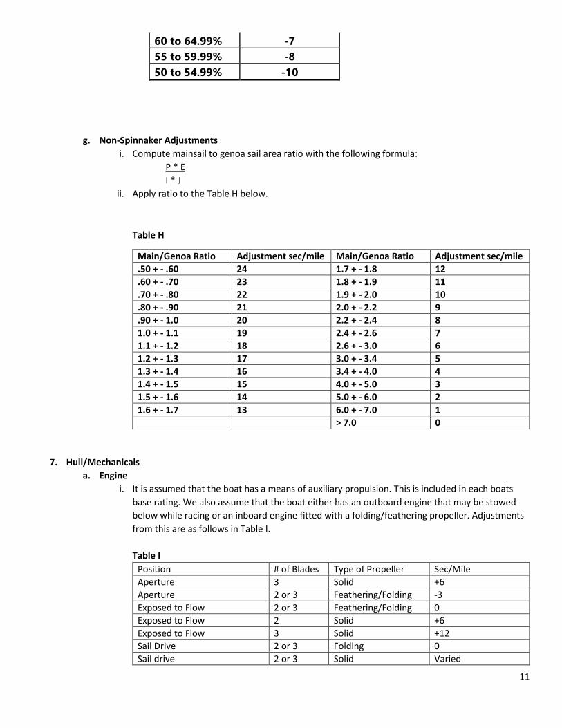
g. Non-Spinnaker Adjustments
i. Compute mainsail to genoa sail area ratio with the following formula:
P * E
I * J
ii. Apply ratio to the Table H below.
Table H
Main/Genoa Ratio Adjustment sec/mile Main/Genoa Ratio Adjustment sec/mile
.50 + - .60 24 1.7 + - 1.8 12
.60 + - .70 23 1.8 + - 1.9 11
.70 + - .80 22 1.9 + - 2.0 10
.80 + - .90 21 2.0 + - 2.2 9
.90 + - 1.0 20 2.2 + - 2.4 8
1.0 + - 1.1 19 2.4 + - 2.6 7
1.1 + - 1.2 18 2.6 + - 3.0 6
1.2 + - 1.3 17 3.0 + - 3.4 5
1.3 + - 1.4 16 3.4 + - 4.0 4
1.4 + - 1.5 15 4.0 + - 5.0 3
1.5 + - 1.6 14 5.0 + - 6.0 2
1.6 + - 1.7 13 6.0 + - 7.0 1
> 7.0 0
7. Hull/Mechanicals
a. Engine
i. It is assumed that the boat has a means of auxiliary propulsion. This is included in each boats
base rating. We also assume that the boat either has an outboard engine that may be stowed
below while racing or an inboard engine fitted with a folding/feathering propeller. Adjustments
from this are as follows in Table I.
Table I
Position # of Blades Type of Propeller Sec/Mile
Aperture 3 Solid +6
Aperture 2 or 3 Feathering/Folding -3
Exposed to Flow 2 or 3 Feathering/Folding 0
Exposed to Flow 2 Solid +6
Exposed to Flow 3 Solid +12
Sail Drive 2 or 3 Folding 0
Sail drive 2 or 3 Solid Varied

12
None/Insufficient ----- -3
Outboard 2 or 3 or 4 Solid 0
Drop Box Propeller 2 or 3 or 4 Solid ??
b. Length Waterline Changes
i. LWL changes will be reviewed by the committee on a case by case basis.
Note that this typically implies significant changes to a boat. If you are interested in modifying your Boat and believe a LWL adjustment is due, please contact PHRF-NB in advance to discuss.
c. Displacement Changes
i. The typical adjustment for displacement modifications is based on 5 sec/mile for 10% of
displacement. The committee will review all displacement adjustments on a case by case basis.
d. Keel Type Changes
i. Keel type changes are typically reviewed as outlined below. They will be reviewed on a case by
case basis.
1. Shallow Draft – 6-12 sec/mile
2. Center board – 6-9 sec/mile
3. Iron vs Lead – 3 sec/mile
4. Dagger boards – 0 sec/mile
e. Draft Changes
i. Draft changes are reviewed by the committee and typically are 3 sec/mile for each 0.5 ft. of
change (+/-).
f. Water Ballast
i. Water ballast changes will be reviewed by the committee on a case by case basis. In general the
modification will be assessed a -1 sec/mile adjustment for every 1% of additional displacement.
8. Modifications
a. Reportable Modifications
i. Any changes in material, size, or shape (other than fairing to original design specification) of the
hull, deck, rudder, or keel.
ii. Any canard rudder, other lifting or steering device forward of the keel; or any rudder, steering or
stabilizing device added to the boat.
iii. Any addition of a lifting, foiling device to the boat.
iv. Removal or relocation of any interior or exterior structural components; changes in construction
technique/schedule, or changes in materials of bulkheads and or interior cabinetry, that results
in the removal or relocation of weight.
v. Removal or replacement of standard tables, floorboards, headliners, lockers, locker doors,
permanent berths and head enclosures, i.e., you are not allowed to “strip the boat”.
vi. Removal or addition of any internal ballast of lead or similar density material. Any movable
ballast, (i.e. water ballast): indicate weight, location, volume and rate of transfer if applicable.
vii. Any modification to rig dimension, i.e. increase/decrease in mast height, boom length or
spinnaker pole length.
viii. Spinnaker or whisker poles and asymmetric spinnaker tack points exceeding 101% of J.
ix. Change in cross section, weight or material of spar.
13
x. Addition or elimination of spreaders, shrouds or stays including running backstays, baby stays,
check stays, jumper struts or installation of split backstays.
xi. Use of cobalt, boron, titanium, or carbon fiber in rigs, lifelines or lifeline stanchions.
xii. Use of fixed or adjustable bowsprit for flying spinnakers.
xiii. Changing headstays, stays or shrouds to carbon, PBO or other composite materials.
xiv. Headstays, mast stays, mast bases and or partners that are adjustable while racing, whether
accomplished mechanically or hydraulically.
xv. Use of hiking straps, trapeze wires, or similar devices that would allow the torsos of the crew or
skipper to be extended beyond the beam of the boat.
xvi. Increasing the sizes of sails beyond those outlined in Section 6 of this document.
b. Non-Reportable Modifications
i. Removal of cushions is permitted.
ii. Changing material used for backstay.
iii. Fairing to bring the hull, keel or rudder into design specifications. Wet sanding and/or waxing
are allowed.
iv. Flexible flaps to fair the skeg into the rudder are allowed provided they do not extend deeper
than the skeg.
v. Water, fuel, and holding tanks maybe emptied as provided by US SAILING.
vi. Removal, addition and/or relocation of deck hardware.
vii. Running rigging of any size or material.
viii. There are no restrictions on instruments electronic or mechanical, autopilots, and on-board
computers except that outside information may be received only as permitted by US SAILING.
ix. Use of full battens in mainsail.
x. There are no restrictions on type of material or construction technique except as outlined in 6d
and for the Cruising Headsail credit above.
xi. Any number of storm jibs (LP less than 95%) can be used.

14
What kind of Spinnaker
was your boat designed
with
Asymmetric Symmetric
Does it comply with a
boat on Appendix B?
No Yes
STD Area is based on STD
Symmetric Spinnaker Area
STD LUFF/LEECH Length is .95 x √ (ISP2+SPL2)
STD SMG/SFL is 1.8 x SPL
STD AREA is
((SLU + SLE)/2) * ((SFL + (4 * SMG))/5) * 0.83
Has your boat
converted to
Asymmetric?
Yes
STD AREA
is listed on
Appendix B
Table 1
Is the Performance
Factor* >=3.5?
No
STD AREA is
(ISP x STL x 1.8 x .73)
STD AREA is
(ISP x STL x 1.8 x .83)
Yes No
* Performance Factor
[(.67*LWL) + (.34*LOA)] * (SA/DISP)]
Where SA = (((STL*ISP) + (P*E))/2
Appendix A

15
Appendix B
This Table is not meant to be all inclusive and may be updated as more data becomes available.
TABLE 1
Boat STD AREA (SQ FT) Reference
J70 488 CLASS
J80 700 CLASS
J92 1001 PHRF DATA
J92s 893 PHRF DATA
J120 1776 PHRF DATA
J121 1658 PHRF DATA
J122 1663 CLASS
Club Swan 42 1991 CLASS
Melges 24 601 CLASS
Melges 32 1347 CLASS
J109 1163 CLASS
Copyright © 2022 FDOKUMEN

