


Bahasa
Halaman
Hukum

CAUTION: READ AND UNDERSTAND THIS MANUAL BEFORE INSTALLATION AND OPERATION OF WINCH. SEE SAFEGUARDS AND WARNING!
MODELS DC•7/DC•7B SERIESINDUSTRIAL LOW-MOUNT WINCHES
OPERATING,SERVICE, AND MAINTENANCE
MANUAL
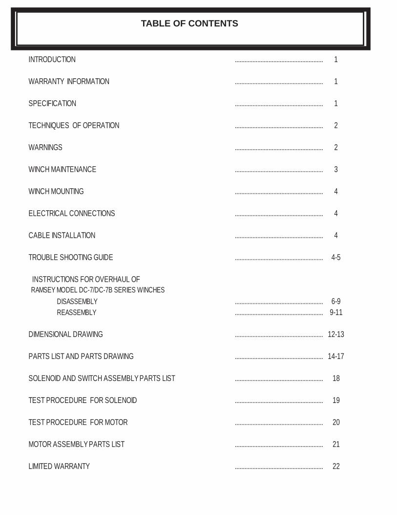
INTRODUCTION ....................................................... 1
WARRANTY INFORMATION ....................................................... 1
SPECIFICATION ....................................................... 1
TECHNIQUES OF OPERATION ....................................................... 2
WARNINGS ....................................................... 2
WINCH MAINTENANCE ....................................................... 3
WINCH MOUNTING ....................................................... 4
ELECTRICAL CONNECTIONS ....................................................... 4
CABLE INSTALLATION ....................................................... 4
TROUBLE SHOOTING GUIDE ....................................................... 4-5
INSTRUCTIONS FOR OVERHAUL OFRAMSEY MODEL DC-7/DC-7B SERIES WINCHES
DISASSEMBLY ....................................................... 6-9REASSEMBLY ....................................................... 9-11
DIMENSIONAL DRAWING ....................................................... 12-13
PARTS LIST AND PARTS DRAWING ....................................................... 14-17
SOLENOID AND SWITCH ASSEMBLY PARTS LIST ....................................................... 18
TEST PROCEDURE FOR SOLENOID ....................................................... 19
TEST PROCEDURE FOR MOTOR ....................................................... 20
MOTOR ASSEMBLY PARTS LIST ....................................................... 21
LIMITED WARRANTY ....................................................... 22
TABLE OF CONTENTS
1
PLEASE READ THIS MANUAL CAREFULLYThis manual contains useful ideas in obtaining the most effi cient operation from your Ramsey Winch, and safety procedures one needs to know before operating a Ramsey Winch.
WARRANTY INFORMATIONRamsey Winches are designed and built to exacting specifi cations. Great care and skill go into every winch we make. If the need should arise, warranty procedure is outlined on the back of your self-addressed postage paid warranty card.Please read and fi ll out the enclosed warranty card and send it to Ramsey Winch Company. If you have any problems with your winch, please follow instructions for prompt service on all war-ranty claims. Refer to back page for limited warranty.
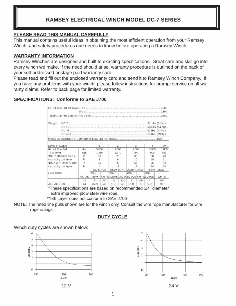
*These specifi cations are based on recommended 1/4” diameter extra improved plow steel wire rope.**5th Layer does not conform to SAE J706
NOTE: The rated line pulls shown are for the winch only. Consult the wire rope manufacturer for wire rope ratings.
Rated Line Pull 1st Layer (Lbs.)................................................................................................3,000 (Kgs.)................................................................................................1,360
Total Gear Reduction: All Models...........................................................................................298:1
Weight: DC-7 ......................................................................................................70 Lbs.(32 Kgs.) DCX-7 ....................................................................................................75 Lbs. (34 Kgs.) DC-78 ....................................................................................................60 Lbs. (27 Kgs.) DCX-78 ..................................................................................................65 Lbs. (29 Kgs.)
MAXIMUM GEAR BOX OIL TEMPERATURE SHOULD NOT EXCEED................................................................2500F.
Layer of Cable 2 3 4 5**Rated Line Pull Lbs. 2,600 2,300 2,000 1,800 per layer Kgs. 1,170 990 900 810*DC-7/78 Drum Cable Ft 20 35 50 70capacity per layer M 6 10 15 21*DCX-7/78 Drum Cable Ft 40 65 95 125capacity per layer M 12 19 28 38
NO LOAD 1000# LOAD 2000# LOAD 3000# LOADLINE SPEED FPM FPM FPM FPM
VOLTS (MPM) AMPS (MPM) AMPS (MPM) AMPS (MPM) AMPS12 17 80 12 110 8 150 7 180
ALL MODELS 24 (5.2). 40 (3.7). 60 (2.4). 75 (2.0). 90
4
13,0001,350
10315
SPECIFICATIONS: Conforms to SAE J706
RAMSEY ELECTRICAL WINCH MODEL DC-7 SERIES
6
180
5
4
3
2
1
0
270 360
MIN
UTE
S
AMPS90 120 160 190
1
2
3
4
5
0
MIN
UTE
S
AMPS
DUTY CYCLE
12 V 24 V
Winch duty cycles are shown below:
2
The best way to get acquainted with how your winch operates is to make test runs before you actually use it. Plan your test in advance. Remember, you hear your winch, as well as see it operate. Get to recognize the sounds of a light steady pull, a heavy pull, and sounds caused by load jerking or shifting. Gain confi dence in operating your winch and its use will become second nature with you.
The uneven spooling of cable, while pulling a load, is not a problem, unless there is a cable pile up on one end of drum. If this happens, reverse the winch to relieve the load and move your an-chor point further to the center of the vehicle. After the job is done you can unspool and rewind for a neat lay of the cable.
When pulling a load where there is even a remote chance of cable failure, place a blanket, jacket or tarpaulin over the cable about six feet behind the hook. This will slow the snap back of a broken cable and could prevent serious injury.
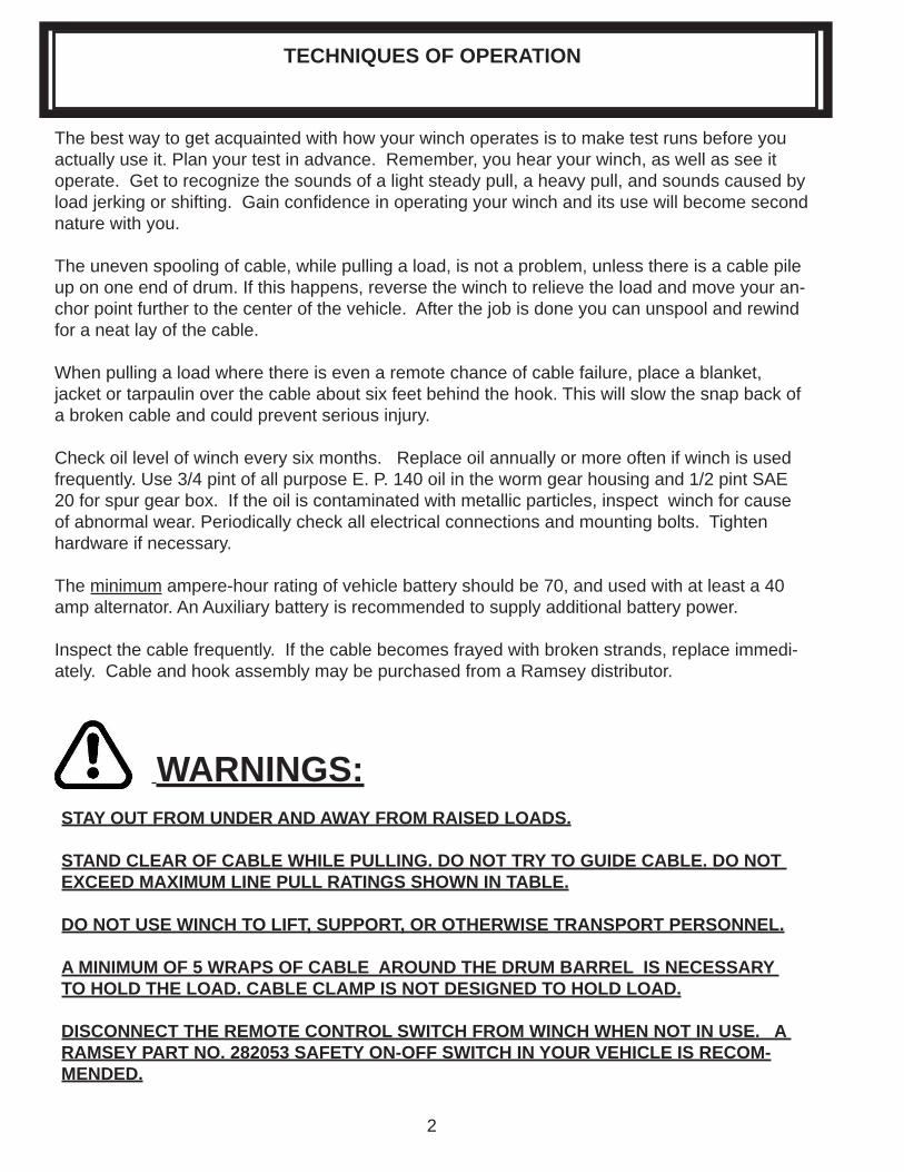
Check oil level of winch every six months. Replace oil annually or more often if winch is used frequently. Use 3/4 pint of all purpose E. P. 140 oil in the worm gear housing and 1/2 pint SAE 20 for spur gear box. If the oil is contaminated with metallic particles, inspect winch for cause of abnormal wear. Periodically check all electrical connections and mounting bolts. Tighten hardware if necessary.
The minimum ampere-hour rating of vehicle battery should be 70, and used with at least a 40 amp alternator. An Auxiliary battery is recommended to supply additional battery power.
Inspect the cable frequently. If the cable becomes frayed with broken strands, replace immedi-ately. Cable and hook assembly may be purchased from a Ramsey distributor.
WARNINGS:STAY OUT FROM UNDER AND AWAY FROM RAISED LOADS.
STAND CLEAR OF CABLE WHILE PULLING. DO NOT TRY TO GUIDE CABLE. DO NOT EXCEED MAXIMUM LINE PULL RATINGS SHOWN IN TABLE.
DO NOT USE WINCH TO LIFT, SUPPORT, OR OTHERWISE TRANSPORT PERSONNEL.
A MINIMUM OF 5 WRAPS OF CABLE AROUND THE DRUM BARREL IS NECESSARY TO HOLD THE LOAD. CABLE CLAMP IS NOT DESIGNED TO HOLD LOAD.
DISCONNECT THE REMOTE CONTROL SWITCH FROM WINCH WHEN NOT IN USE. A RAMSEY PART NO. 282053 SAFETY ON-OFF SWITCH IN YOUR VEHICLE IS RECOM-MENDED.
TECHNIQUES OF OPERATION
3
Adhering to the following maintenance schedule will keep your winch in top condition and per-forming as it should with a minimum of repair.
A. WEEKLY1. Check the oil level and maintain it to the oil level plug. If oil is leaking out, determine loca- tion and repair.
2. Check the pressure relief plug in top of the gear housing. Be sure that it is in good operat- ing condition so that hot oil gasses may escape.
3. Lubricate cable with light oil.
B. MONTHLY1. Lubricate the various grease fi ttings located in the cable drum, end bearing, clutch housing or clutch operating linkage. Any good grade of moly-disulfi de containing grease is accept- able.
2. Check the winch mounting bolts. If any are missing, replace them and securely tighten any that are loose. Make sure to use only grade 5 bolts or better.
3. Check the torque setting of the oil cooled worm brake. Make any adjustments required, fol- lowing the procedure described in ADJUSTING THE OIL COOLED WORM BRAKE in the Owner’s Manual.
4. Check alignment of chain and sprockets and adjust as required to minimize wear.
5. Inspect the cable. If the cable has become frayed with broken strands, replace immediately.
C. ANNUALLY1. Drain the oil from the winch annually or more often if winch is used frequently.
2. Fill the winch to the oil level plug with clean kerosene. Run the winch a few minutes with no load in the reel in direction. Drain the kerosene from the winch.
3. Refi ll the winch to the oil level plug with all purpose E.P. 140 gear oil.
4. Inspect frame and surrounding structure for cracks or deformation.
5. Gear wear can be estimated by rocking the drum back and forth and if necessary drain oil and remove cover for closer inspection.
WINCH MAINTENANCE
4
WINCH MOUNTINGIt is most important that this winch be mounted securely so that the three major sections (the clutch housing end, the cable drum and the gear housing end) are properly aligned.
All standard model DC-7/DC-78 Series Winches are furnished with recommended mounting angles. Model DC-7 Winch is furnished with 1/4 x 2 x 2 high strength steel angles. Model DC-78 Winch is furnished with 3/16 x 1-1/2 x 2 high strength steel angle.
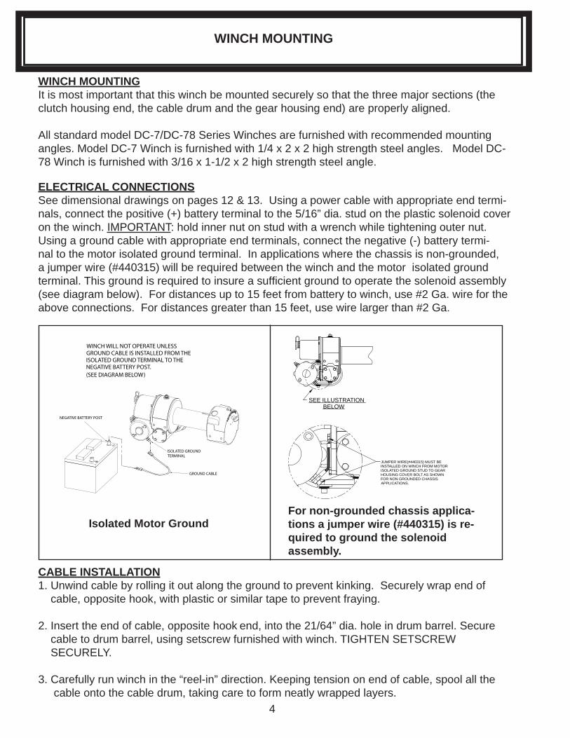
ELECTRICAL CONNECTIONSSee dimensional drawings on pages 12 & 13. Using a power cable with appropriate end termi-nals, connect the positive (+) battery terminal to the 5/16” dia. stud on the plastic solenoid cover on the winch. IMPORTANT: hold inner nut on stud with a wrench while tightening outer nut. Using a ground cable with appropriate end terminals, connect the negative (-) battery termi-nal to the motor isolated ground terminal. In applications where the chassis is non-grounded, a jumper wire (#440315) will be required between the winch and the motor isolated ground terminal. This ground is required to insure a suffi cient ground to operate the solenoid assembly (see diagram below). For distances up to 15 feet from battery to winch, use #2 Ga. wire for the above connections. For distances greater than 15 feet, use wire larger than #2 Ga.
SEE ILLUSTRATION
JUMPER WIRE(#440315) MUST BE INSTALLED ON WINCH FROM MOTOR ISOLATED GROUND STUD TO GEAR HOUSING COVER BOLT AS SHOWNFOR NON GROUNDED CHASSIS APPLICATIONS.
BELOW
CABLE INSTALLATION1. Unwind cable by rolling it out along the ground to prevent kinking. Securely wrap end of cable, opposite hook, with plastic or similar tape to prevent fraying.
2. Insert the end of cable, opposite hook end, into the 21/64” dia. hole in drum barrel. Secure cable to drum barrel, using setscrew furnished with winch. TIGHTEN SETSCREW SECURELY.
3. Carefully run winch in the “reel-in” direction. Keeping tension on end of cable, spool all the cable onto the cable drum, taking care to form neatly wrapped layers.
WINCH MOUNTING
NEGATIVE BATTERY POST
GROUND CABLE
WINCH WILL NOT OPERATE UNLESS GROUND CABLE IS INSTALLED FROM THEISOLATED GROUND TERMINAL TO THE NEGATIVE BATTERY POST. (SEE DIAGRAM BELOW)
ISOLATED GROUNDTERMINAL
Isolated Motor GroundFor non-grounded chassis applica-tions a jumper wire (#440315) is re-quired to ground the solenoid assembly.
5
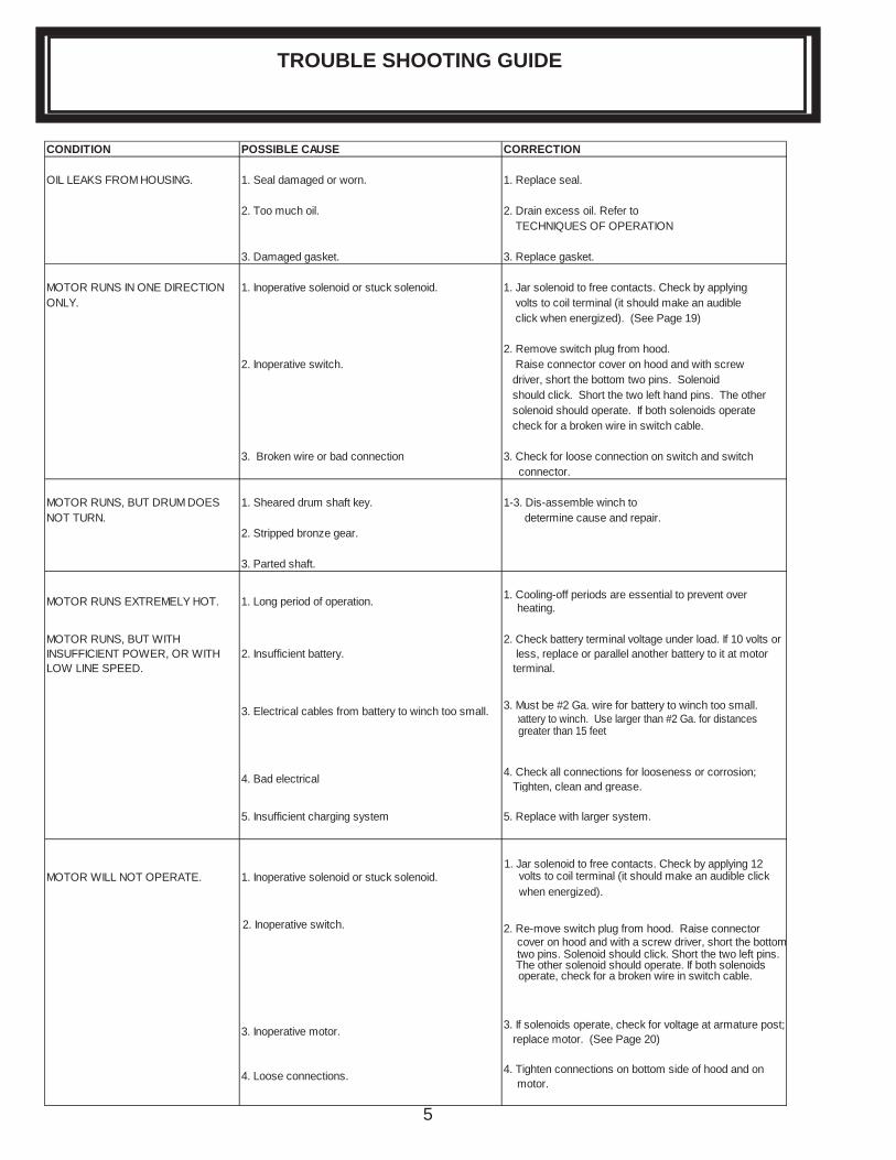
CONDITION POSSIBLE CAUSE CORRECTION
OIL LEAKS FROM HOUSING. 1. Seal damaged or worn. 1. Replace seal.
2. Too much oil. 2. Drain excess oil. Refer to TECHNIQUES OF OPERATION
3. Damaged gasket. 3. Replace gasket.
MOTOR RUNS IN ONE DIRECTION 1. Inoperative solenoid or stuck solenoid. 1. Jar solenoid to free contacts. Check by applyingONLY. volts to coil terminal (it should make an audible
click when energized). (See Page 19)
2. Remove switch plug from hood.2. Inoperative switch. Raise connector cover on hood and with screw
driver, short the bottom two pins. Solenoid should click. Short the two left hand pins. The other solenoid should operate. If both solenoids operate check for a broken wire in switch cable.
3. Broken wire or bad connection 3. Check for loose connection on switch and switch connector.
MOTOR RUNS, BUT DRUM DOES 1. Sheared drum shaft key. 1-3. Dis-assemble winch toNOT TURN. determine cause and repair.
2. Stripped bronze gear.
3. Parted shaft.
MOTOR RUNS EXTREMELY HOT. 1. Long period of operation. 1. Cooling-off periods are essential to prevent over heating.
MOTOR RUNS, BUT WITH INSUFFICIENT POWER, OR WITH LOW LINE SPEED.
2. Insufficient battery. 2. Check battery terminal voltage under load. If 10 volts or less, replace or parallel another battery to it at motor terminal.
3. Electrical cables from battery to winch too small. 3. Must be #2 Ga. wire for battery to winch too small. battery to winch. Use larger than #2 Ga. for distances greater than 15 feet
4. Bad electrical 4. Check all connections for looseness or corrosion; Tighten, clean and grease.
5. Insufficient charging system 5. Replace with larger system.
MOTOR WILL NOT OPERATE. 1. Inoperative solenoid or stuck solenoid. 1. Jar solenoid to free contacts. Check by applying 12
volts to coil terminal (it should make an audible click when energized).
2. Inoperative switch. 2. Re-move switch plug from hood. Raise connector cover on hood and with a screw driver, short the bottomtwo pins. Solenoid should click. Short the two left pins. The other solenoid should operate. If both solenoids operate, check for a broken wire in switch cable.
3. Inoperative motor. 3. If solenoids operate, check for voltage at armature post; replace motor. (See Page 20)
4. Loose connections. 4. Tighten connections on bottom side of hood and on motor.
TROUBLE SHOOTING GUIDE
6
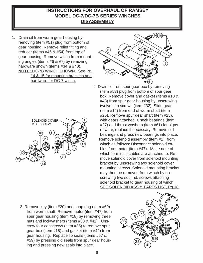
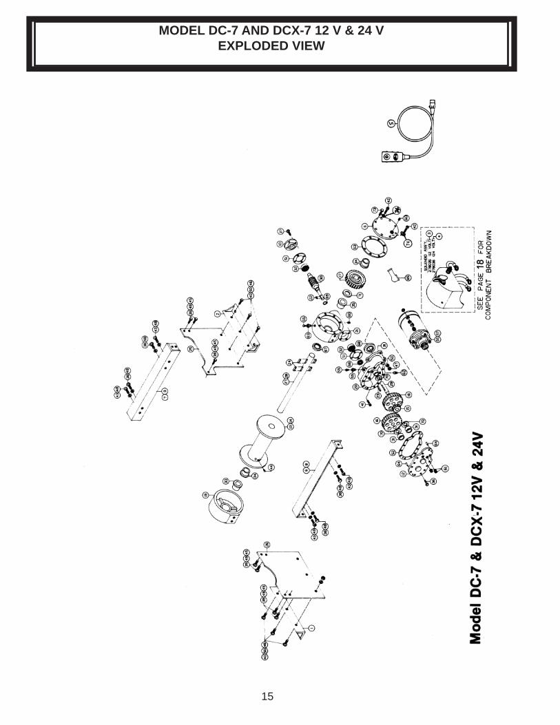
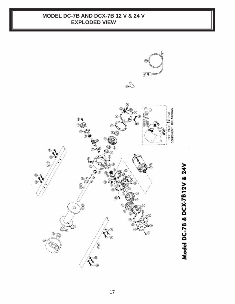
1. Drain oil from worm gear housing by removing (item #51) plug from bottom of gear housing. Remove relief fi tting and reducer (items #46 & #54) from top of gear housing. Remove winch from mount- ing angles (items #6 & #7) by removing hardware shown (items #34 & #40). NOTE: DC-7B WINCH SHOWN. See Pg. 14 & 15 for mounting brackets and hardware for DC-7 winch.
2. Drain oil from spur gear box by removing (item #53) plug,from bottom of spur gear box. Remove cover and gasket (items #10 & #43) from spur gear housing by unscrew ing twelve cap screws (item #32). Slide gear (item #14) from end of worm shaft (item #26). Remove spur gear shaft (item #25), with gears attached. Check bearings (item #27) and thrust washers (item #61) for signs of wear, replace if necessary. Remove old bearings and press new bearings into place. Remove solenoid assembly (item #1) from winch as follows: Disconnect solenoid ca- bles from motor (item #47). Make note of which terminals cables are attached to. Re- move solenoid cover from solenoid mounting bracket by unscrewing two solenoid cover mounting screws. Solenoid mounting bracket may then be removed from winch by un- screwing two soc. hd. screws attaching solenoid bracket to gear housing of winch. SEE SOLENOID ASS’Y. PARTS LIST, Pg.18
3. Remove key (item #20) and snap ring (item #60) from worm shaft. Remove motor (item #47) from spur gear housing (item #18) by removing three nuts and lockwashers (items #38 & #41). Uns- crew four capscrews (item #35) to remove spur gear box (item #18) and gasket (item #42) from gear housing. Replace lip seals (items #57 & #59) by pressing old seals from spur gear hous- ing and pressing new seals into place.
INSTRUCTIONS FOR OVERHAUL OF RAMSEY MODEL DC-7/DC-7B SERIES WINCHES
DISASSEMBLY
7
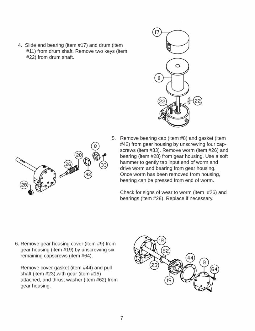
4. Slide end bearing (item #17) and drum (item #11) from drum shaft. Remove two keys (item #22) from drum shaft.
5. Remove bearing cap (item #8) and gasket (item #42) from gear housing by unscrewing four cap- screws (item #33). Remove worm (item #26) and bearing (item #28) from gear housing. Use a soft hammer to gently tap input end of worm and drive worm and bearing from gear housing. Once worm has been removed from housing, bearing can be pressed from end of worm.
Check for signs of wear to worm (item #26) and bearings (item #28). Replace if necessary.
6. Remove gear housing cover (item #9) from gear housing (item #19) by unscrewing six remaining capscrews (item #64).
Remove cover gasket (item #44) and pull shaft (item #23),with gear (item #15) attached, and thrust washer (item #62) from gear housing.
8
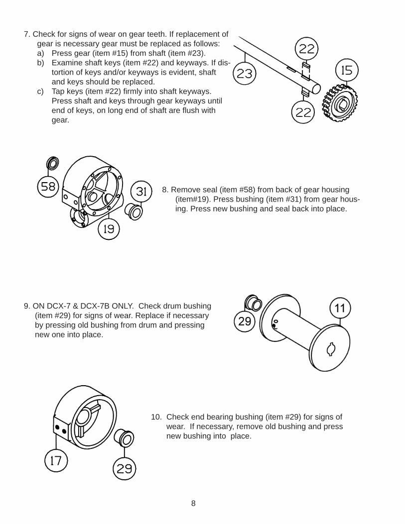
7. Check for signs of wear on gear teeth. If replacement of gear is necessary gear must be replaced as follows: a) Press gear (item #15) from shaft (item #23). b) Examine shaft keys (item #22) and keyways. If dis- tortion of keys and/or keyways is evident, shaft and keys should be replaced. c) Tap keys (item #22) fi rmly into shaft keyways. Press shaft and keys through gear keyways until end of keys, on long end of shaft are fl ush with gear.
8. Remove seal (item #58) from back of gear housing (item#19). Press bushing (item #31) from gear hous- ing. Press new bushing and seal back into place.
9. ON DCX-7 & DCX-7B ONLY. Check drum bushing (item #29) for signs of wear. Replace if necessary by pressing old bushing from drum and pressing new one into place.
10. Check end bearing bushing (item #29) for signs of wear. If necessary, remove old bushing and press new bushing into place.
9
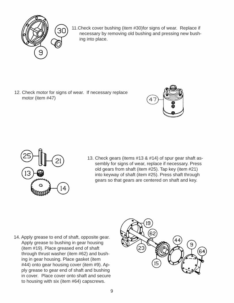
11.Check cover bushing (item #30)for signs of wear. Replace if necessary by removing old bushing and pressing new bush- ing into place.
12. Check motor for signs of wear. If necessary replace motor (item #47)
13. Check gears (items #13 & #14) of spur gear shaft as- sembly for signs of wear, replace if necessary. Press old gears from shaft (item #25). Tap key (item #21) into keyway of shaft (item #25). Press shaft through gears so that gears are centered on shaft and key.
14. Apply grease to end of shaft, opposite gear. Apply grease to bushing in gear housing (item #19). Place greased end of shaft through thrust washer (item #62) and bush- ing in gear housing. Place gasket (item #44) onto gear housing cover (item #9). Ap- ply grease to gear end of shaft and bushing in cover. Place cover onto shaft and secure to housing with six (item #64) capscrews.
10
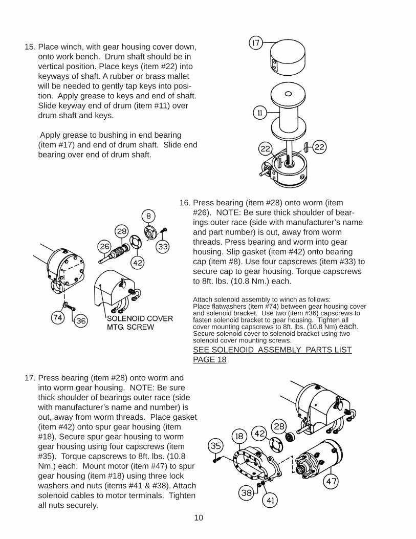
15. Place winch, with gear housing cover down, onto work bench. Drum shaft should be in vertical position. Place keys (item #22) into keyways of shaft. A rubber or brass mallet will be needed to gently tap keys into posi- tion. Apply grease to keys and end of shaft. Slide keyway end of drum (item #11) over drum shaft and keys.
Apply grease to bushing in end bearing (item #17) and end of drum shaft. Slide end bearing over end of drum shaft.
16. Press bearing (item #28) onto worm (item #26). NOTE: Be sure thick shoulder of bear- ings outer race (side with manufacturer’s name and part number) is out, away from worm threads. Press bearing and worm into gear housing. Slip gasket (item #42) onto bearing cap (item #8). Use four capscrews (item #33) to secure cap to gear housing. Torque capscrews to 8ft. lbs. (10.8 Nm.) each.
Attach solenoid assembly to winch as follows: Place fl atwashers (item #74) between gear housing cover and solenoid bracket. Use two (item #36) capscrews to fasten solenoid bracket to gear housing. Tighten all cover mounting capscrews to 8ft. lbs. (10.8 Nm) each. Secure solenoid cover to solenoid bracket using two solenoid cover mounting screws. SEE SOLENOID ASSEMBLY PARTS LIST PAGE 18
17. Press bearing (item #28) onto worm and into worm gear housing. NOTE: Be sure thick shoulder of bearings outer race (side with manufacturer’s name and number) is out, away from worm threads. Place gasket (item #42) onto spur gear housing (item #18). Secure spur gear housing to worm gear housing using four capscrews (item #35). Torque capscrews to 8ft. lbs. (10.8 Nm.) each. Mount motor (item #47) to spur gear housing (item #18) using three lock washers and nuts (items #41 & #38). Attach solenoid cables to motor terminals. Tighten all nuts securely.
11
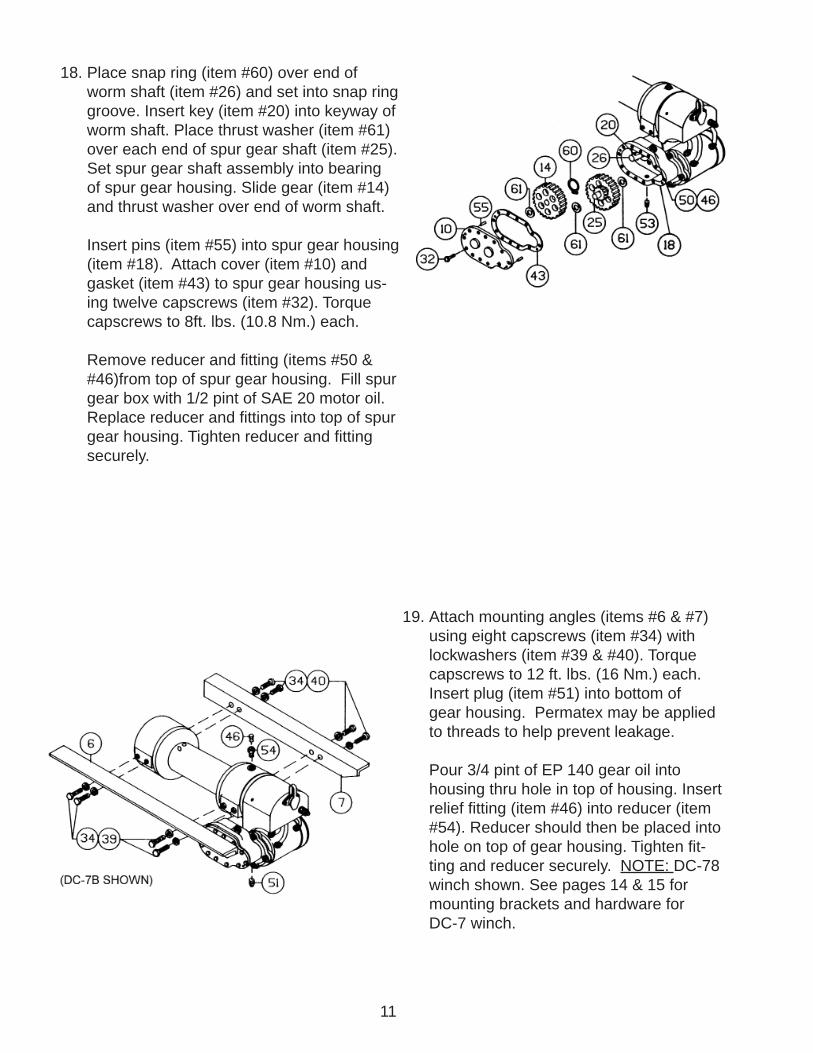
18. Place snap ring (item #60) over end of worm shaft (item #26) and set into snap ring groove. Insert key (item #20) into keyway of worm shaft. Place thrust washer (item #61) over each end of spur gear shaft (item #25). Set spur gear shaft assembly into bearing of spur gear housing. Slide gear (item #14) and thrust washer over end of worm shaft.
Insert pins (item #55) into spur gear housing (item #18). Attach cover (item #10) and gasket (item #43) to spur gear housing us- ing twelve capscrews (item #32). Torque capscrews to 8ft. lbs. (10.8 Nm.) each. Remove reducer and fi tting (items #50 & #46)from top of spur gear housing. Fill spur gear box with 1/2 pint of SAE 20 motor oil. Replace reducer and fi ttings into top of spur gear housing. Tighten reducer and fi tting securely.
19. Attach mounting angles (items #6 & #7) using eight capscrews (item #34) with lockwashers (item #39 & #40). Torque capscrews to 12 ft. lbs. (16 Nm.) each. Insert plug (item #51) into bottom of gear housing. Permatex may be applied to threads to help prevent leakage.
Pour 3/4 pint of EP 140 gear oil into housing thru hole in top of housing. Insert relief fi tting (item #46) into reducer (item #54). Reducer should then be placed into hole on top of gear housing. Tighten fi t- ting and reducer securely. NOTE: DC-78 winch shown. See pages 14 & 15 for mounting brackets and hardware for DC-7 winch.
12
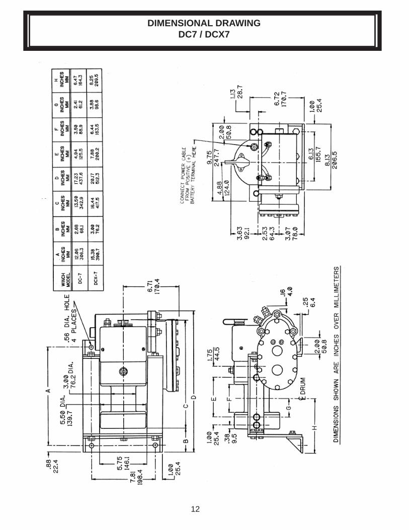
DIMENSIONAL DRAWINGDC7 / DCX7
13
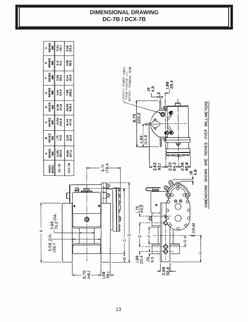
DIMENSIONAL DRAWINGDC-7B / DCX-7B
14
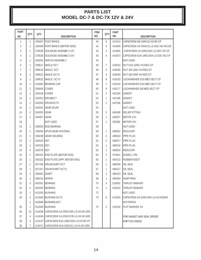
PARTS LIST MODEL DC-7 & DC-7X 12V & 24V
PARTNO. DESCRIPTION DESCRIPTION
1 1 206007 FOOT BRACE 40 6 414310 CAPSCREW 3/8-16NCX1 HX HD CP
2 1 206008 FOOT BRACE (MOTOR SIDE) 41 4 414845 CAPSCREW 1/4-20NCX1 LG SOC HD NYLOK
3 1 278035 SOLENOID ASSEMBLY 12V 42 2 414850 CAPSCREW 1/4-20NCX3/4 LG SOC HD CP
4 1 278036 SOLENOID ASSEMBLY 24V 43 4 414873 CAPSCREW 5/16-18NCX3/4 LG SOC HD CP
5 1 282001 SWITCH ASSEMBLY 44 NOT USED
6 1 299617 ANGLE DC7 45 7 418022 NUT 5/16-18NC HX REG CP
7 1 299618 ANGLE DC7 46 6 418035 NUT 3/8-16NC HX REG CP
8 1 299621 ANGLE DC7X 47 3 418040 NUT 3/8-24NF HX REG CP
9 1 299622 ANGLE DC7X 48 8 418163 LOCKWASHER 5/16 MED SECT CP
10 1 316083 BEARING CAP 49 7 418163 LOCKWASHER 5/16 MED SECT CP
11 1 328009 COVER 50 9 418177 LOCKWASHER 3/8 MED SECT CP
12 1 328106 COVER 51 2 442184 GASKET
13 1 332051 DRUMDC7 52 1 442185 GASKET
14 1 332053 DRUM DC7X 53 1 442186 GASKET
15 1 334001 GEAR IDLER 54 NOT USED
16 2 334003 GEAR 55 2 456008 RELIEF FITTING
17 1 334007 GEAR 56 1 262037 MOTOR 12V
18 NOT USED 57 1 262036 MOTOR 24V
19 1 338053 END BEARING 58 NOT USED
20 1 338203 SPUR GEAR HOUSING 59 1 468002 REDUCER
21 1 338238 GEAR HOUSING 60 2 468010 PIPE PLUG
22 1 342023 KEY 61 2 468017 PIPE PLUG
23 1 342033 KEY 62 1 468018 PIPE PLUG
24 4 342075 KEY 63 1 468024 REDUCER
25 1 350331 END PLATE (MOTOR END) 64 2 470001 DOWELL PIN
26 1 350332 END PLATE (OPP. MOTOR END) 65 1 482013 RUBBER BOOT
27 1 357446 DRUM SHAFT DC7 66 1 486009 OIL SEAL
28 1 357447 DRUM SHAFT DC7X 67 1 486017 OIL SEAL
29 1 356901 SHAFT 68 1 486023 OIL SEAL
30 1 368132 WORM 69 1 490003 SNAP RING
31 3 402001 BEARING 70 3 518002 THRUST WASHER
32 2 402002 BEARING 71 1 518015 THRUST WASHER
33 1 412003 BUSHING 72 NOT USED
34 2 412046 BUSHING DC7X 73 6 414020 CAPSCREW 1/4-20NCX3/4 LG HX HDGR5
1 412046 BUSHING DC7 HVY PATCH
35 1 412046 BUSHING 74 2 418153 FLAT WASHER 1/4
36 12 414038 CAPSCREW 1/4-20NCX3/4 LG HX HD GR5
37 4 414045 CAPSCREW 1/4-20NCX7/8 LG HX HD GR5 FOR GASKET AND SEAL ORDER38 4 414137 CAPSCREW 5/16-18NCX3/4 LG HX HD CP PART NO 24603339 7 414071 CAPSCREW 5/16-18NCX1 LG HX HD GR5
ITEM NO.
PART NO.QTY. QTY.QTY.
15
MODEL DC-7 AND DCX-7 12 V & 24 V EXPLODED VIEW
16
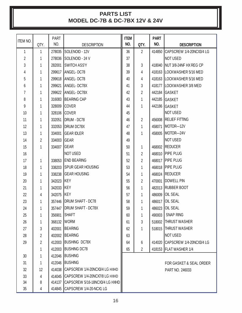
PARTS LIST MODEL DC-7B & DC-7BX 12V & 24V
QTY. DESCRIPTION QTY. DESCRIPTION1 1 278035 SOLENOID - 12V 36 2 414850 CAPSCREW 1/4-20NCX3/4 LG 2 1 278036 SOLENOID - 24 V 37 NOT USED3 1 282001 SWITCH ASS'Y 38 3 418040 NUT 3/8-24NF HX REG CP4 1 299617 ANGEL- DC78 39 4 418163 LOCKWASHER 5/16 MED 5 1 299618 ANGEL- DC78 40 4 418163 LOCKWASHER 5/16 MED 6 1 299621 ANGEL- DC78X 41 3 418177 LOCKWASHER 3/8 MED 7 1 299622 ANGEL- DC78X 42 2 442184 GASKET8 1 316083 BEARING CAP 43 1 442185 GASKET9 1 328009 COVER 44 1 442186 GASKET10 1 328106 COVER 45 NOT USED11 1 332051 DRUM - DC78 46 2 456008 RELIEF FITTING12 1 332053 DRUM DC78X 47 1 458071 MOTOR—12V13 1 334001 GEAR IDLER 48 1 458005 MOTOR—24V14 2 334003 GEAR 49 NOT USED15 1 334007 GEAR 50 1 468002 REDUCER16 NOT USED 51 2 468010 PIPE PLUG17 1 338053 END BEARING 52 2 468017 PIPE PLUG18 1 338203 SPUR GEAR HOUSING 53 1 468018 PIPE PLUG19 1 338238 GEAR HOUSING 54 1 468024 REDUCER20 1 342023 KEY 55 2 470001 DOWELL PIN21 1 342033 KEY 56 1 482013 RUBBER BOOT22 4 342075 KEY 57 1 486009 OIL SEAL23 1 357446 DRUM SHAFT - DC78 58 1 486017 OIL SEAL24 1 357447 DRUM SHAFT - DC78X 59 1 486023 OIL SEAL25 1 356901 SHAFT 60 1 490003 SNAP RING26 1 368132 WORM 61 3 518002 THRUST WASHER27 3 402001 BEARING 62 1 518015 THRUST WASHER28 2 402002 BEARING 63 NOT USED29 2 412003 BUSHING DC78X 64 6 414020 CAPSCREW 1/4-20NCX3/4 LG
1 412003 BUSHING DC78 65 2 418153 FLAT WASHER 1/430 1 412046 BUSHING 31 1 412046 BUSHING FOR GASKET & SEAL ORDER32 12 414038 CAPSCREW 1/4-20NCX3/4 LG HXHD PART NO. 24603333 4 414045 CAPSCREW 1/4-20NCX7/8 LG HXHD 34 8 414137 CAPSCREW 5/16-18NCX3/4 LG HXHD35 4 414845 CAPSCREW 1/4-20-NCX1 LG
ITEM NO. PART NO.
ITEM NO.
PART NO.
17
MODEL DC-7B AND DCX-7B 12 V & 24 V EXPLODED VIEW
18
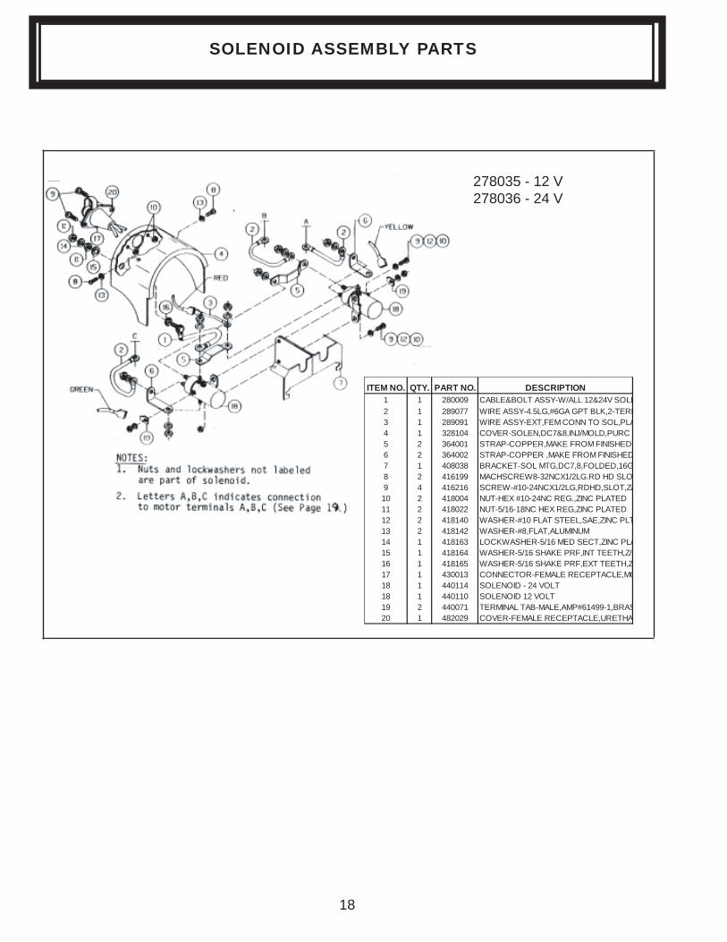
278035 - 12 V278036 - 24 V
ITEM NO. QTY. PART NO. DESCRIPTION1 1 280009 CABLE&BOLT ASSY-W/ALL 12&24V SOLE2 1 289077 WIRE ASSY-4.5LG,#6GA GPT BLK,2-TERM3 1 289091 WIRE ASSY-EXT,FEM CONN TO SOL,PLA4 1 328104 COVER-SOLEN,DC7&8,INJ/MOLD,PURC 5 2 364001 STRAP-COPPER,MAKE FROM FINISHED 6 2 364002 STRAP-COPPER ,MAKE FROM FINISHED7 1 408038 BRACKET-SOL MTG,DC7,8,FOLDED,16G8 2 416199 MACHSCREW8-32NCX1/2LG.RD HD SLO9 4 416216 SCREW-#10-24NCX1/2LG,RDHD,SLOT,Z/10 2 418004 NUT-HEX #10-24NC REG.,ZINC PLATED11 2 418022 NUT-5/16-18NC HEX REG,ZINC PLATED12 2 418140 WASHER-#10 FLAT STEEL,SAE,ZINC PLT13 2 418142 WASHER-#8,FLAT,ALUMINUM14 1 418163 LOCKWASHER-5/16 MED SECT,ZINC PLA15 1 418164 WASHER-5/16 SHAKE PRF,INT TEETH,Z/P16 1 418165 WASHER-5/16 SHAKE PRF,EXT TEETH,Z17 1 430013 CONNECTOR-FEMALE RECEPTACLE,MO18 1 440114 SOLENOID - 24 VOLT18 1 440110 SOLENOID 12 VOLT19 2 440071 TERMINAL TAB-MALE,AMP#61499-1,BRAS20 1 482029 COVER-FEMALE RECEPTACLE,URETHA
SOLENOID ASSEMBLY PARTS
19
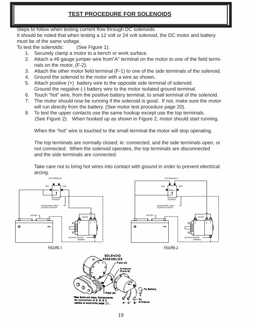
Steps to follow when testing current fl ow through DC solenoids.It should be noted that when testing a 12 volt or 24 volt solenoid, the DC motor and battery must be of the same voltage.To test the solenoids: (See Figure 1). 1. Securely clamp a motor to a bench or work surface. 2. Attach a #6 gauge jumper wire from”A” terminal on the motor to one of the fi eld termi- nals on the motor, (F-2). 3. Attach the other motor fi eld terminal (F-1) to one of the side terminals of the solenoid. 4. Ground the solenoid to the motor with a wire as shown. 5. Attach positive (+) battery wire to the opposite side terminal of solenoid. Ground the negative (-) battery wire to the motor isolated ground terminal. 6. Touch “hot” wire, from the positive battery terminal, to small terminal of the solenoid. 7. The motor should now be running if the solenoid is good. If not, make sure the motor will run directly from the battery. (See motor test procedure page 20). 8. To test the upper contacts use the same hookup except use the top terminals. (See Figure 2). When hooked up as shown in Figure 2, motor should start running. When the “hot” wire is touched to the small terminal the motor will stop operating.
The top terminals are normally closed; ie: connected, and the side terminals open, or not connected. When the solenoid operates, the top terminals are disconnected and the side terminals are connected.
Take care not to bring hot wires into contact with ground in order to prevent electrical arcing.
TEST PROCEDURE FOR SOLENOIDS
AF1F2
ISOLATED GROUNDTERMINAL
BATTERY
FIGURE-1
GROUND WIRE(-) FROMSOLENOID TO MOTOR
MOTOR
SOLENOID
(TOP TERMINALS)
SIDE SIDE
(SMALL) (SMALL)
SIDESIDE
(TOP TERMINALS)
SOLENOID
MOTOR
GROUND WIRE(-) FROMSOLENOID TO MOTOR
FIGURE-2
BATTERY
ISOLATED GROUNDTERMINAL
F2 F1 A
20
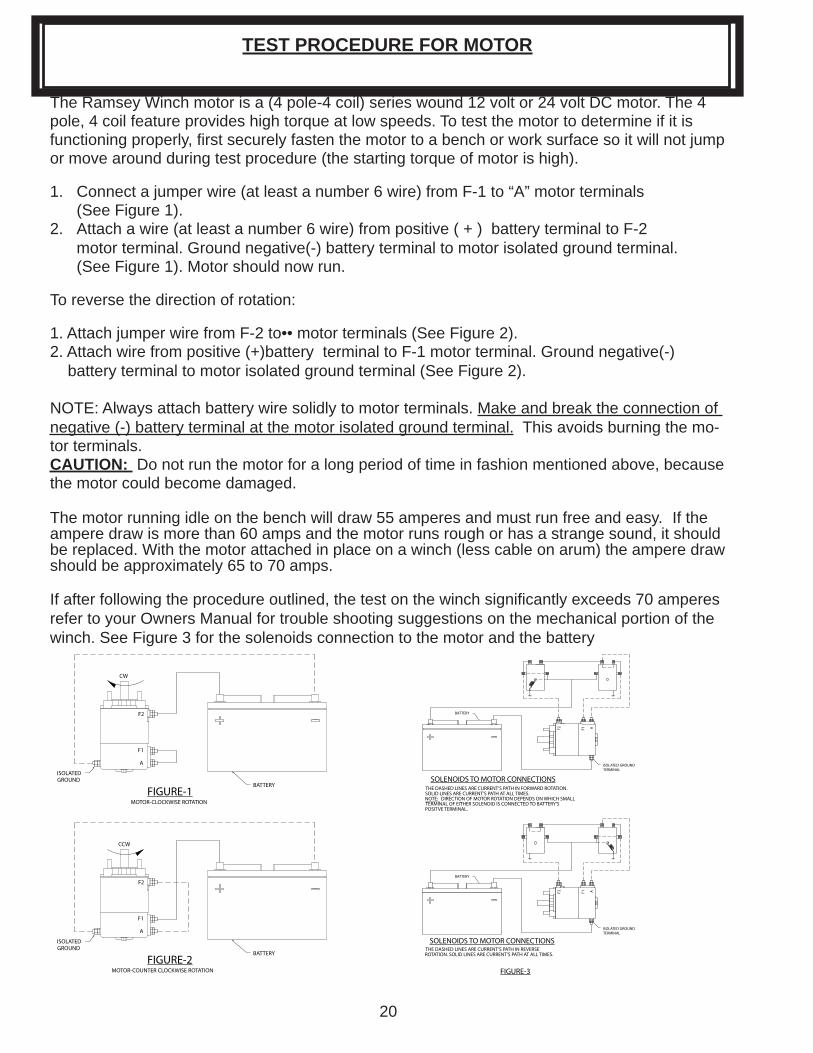
The Ramsey Winch motor is a (4 pole-4 coil) series wound 12 volt or 24 volt DC motor. The 4 pole, 4 coil feature provides high torque at low speeds. To test the motor to determine if it is functioning properly, fi rst securely fasten the motor to a bench or work surface so it will not jump or move around during test procedure (the starting torque of motor is high).
1. Connect a jumper wire (at least a number 6 wire) from F-1 to “A” motor terminals (See Figure 1).2. Attach a wire (at least a number 6 wire) from positive ( + ) battery terminal to F-2 motor terminal. Ground negative(-) battery terminal to motor isolated ground terminal. (See Figure 1). Motor should now run.
To reverse the direction of rotation:
1. Attach jumper wire from F-2 to•• motor terminals (See Figure 2).2. Attach wire from positive (+)battery terminal to F-1 motor terminal. Ground negative(-) battery terminal to motor isolated ground terminal (See Figure 2).
NOTE: Always attach battery wire solidly to motor terminals. Make and break the connection of negative (-) battery terminal at the motor isolated ground terminal. This avoids burning the mo-tor terminals. CAUTION: Do not run the motor for a long period of time in fashion mentioned above, because the motor could become damaged.
The motor running idle on the bench will draw 55 amperes and must run free and easy. If the ampere draw is more than 60 amps and the motor runs rough or has a strange sound, it should be replaced. With the motor attached in place on a winch (less cable on arum) the ampere draw should be approximately 65 to 70 amps.
If after following the procedure outlined, the test on the winch signifi cantly exceeds 70 amperes refer to your Owners Manual for trouble shooting suggestions on the mechanical portion of the winch. See Figure 3 for the solenoids connection to the motor and the battery
TEST PROCEDURE FOR MOTOR
F2
F1
A
ISOLATED GROUND
BATTERY
CW
MOTOR-CLOCKWISE ROTATION
MOTOR-COUNTER CLOCKWISE ROTATION
CCW
BATTERY
ISOLATED GROUND
A
F1
F2
FIGURE-1
FIGURE-2
AF1F2
ISOLATED GROUNDTERMINAL
BATTERY
THE DASHED LINES ARE CURRENT'S PATH IN FORWARD ROTATION.SOLID LINES ARE CURRENT'S PATH AT ALL TIMES.NOTE: DIRECTION OF MOTOR ROTATION DEPENDS ON WHICH SMALLTERMINAL OF EITHER SOLENOID IS CONNECTED TO BATTERY'SPOSITVE TERMINAL.
BATTERY
ISOLATED GROUNDTERMINAL
F2 F1 A
THE DASHED LINES ARE CURRENT'S PATH IN REVERSE ROTATION. SOLID LINES ARE CURRENT'S PATH AT ALL TIMES.
SOLENOIDS TO MOTOR CONNECTIONS
SOLENOIDS TO MOTOR CONNECTIONS
FIGURE-3

21
NOTES
OM-912403- -0
RAMSEY WINCH warrants each new RAMSEY Winch to be free from defects in material and workmanship for a period of one (1) year from date of purchase.
The obligation under this warranty, statutory or otherwise, is limited to the replacement or repair at the Manufacturer’s factory, or at a point designated by the Manufacturer, of such part that shall appear to the Manufacturer, upon inspection of such part, to have been defective in mate-rial or workmanship.
This warranty does not obligate RAMSEY WINCH to bear the cost of labor or transportation charges in connection with the replacement or repair of defective parts, nor shall it apply to a product upon which repair or alterations have been made, unless authorized by Manufacturer, or for equipment misused, neglected or which has not been installed correctly.
RAMSEY WINCH shall in no event be liable for special or consequential damages. RAMSEY WINCH makes no warranty in respect to accessories such as being subject to the warranties of their respective manufacturers.
RAMSEY WINCH, whose policy is one of continuous improvement, reserves the right to im-prove its products through changes in design or materials as it may deem desirable without be-ing obligated to incorporate such changes in products of prior manufacture.
If fi eld service at the request of the Buyer is rendered and the fault is found not to be with RAMSEY WINCH’s product, the Buyer shall pay the time and expense to the fi eld representa-tive. Bills for service, labor or other expenses that have been incurred by the Buyer without ap-proval or authorization by RAMSEY WINCH will not be accepted
LIMITED WARRANTY
RAMSEY WINCH COMPANYPost Offi ce Box 581510 Tulsa, Oklahoma 74158-1510
Telephone: (918) 438-2760 FAX: (918) 438-6688
Top Related
Copyright © 2022 FDOKUMEN

