


Bahasa
Halaman
Hukum

1
Two Effective Heuristics for Beam Angle Optimization in Radiation Therapy
Hamed Yarmand, David Craft 5
Department of Radiation Oncology
Massachusetts General Hospital and Harvard Medical School, Boston, MA 02114, USA
E-mail: [email protected], [email protected]
10
Corresponding author:
Hamed Yarmand
Francis H. Burr Proton Therapy Center 15
Department of Radiation Oncology, MGH
Harvard Medical School
30 Fruit St., Boston, MA 02114, USA
Tell: +1-617-724-3665
Fax: +1-617-724-0368 20

2
Abstract
Purpose: To improve the solution efficiency (i.e., reducing computation time while obtaining high-
quality treatment plans) for the beam angle optimization problem (BAO) in radiation therapy treatment
planning. 25
Methods: We propose two novel heuristic approaches to reduce the computation time for BAO. One is
limiting the use of “adjacent” beams based on the observation that the impacts of adjacent beams are
similar, and therefore, they are less likely to be used in the optimal plan. This heuristic, which we refer to
as “neighbor cuts”, forces the optimization system to choose one or a few beams from every set of
adjacent beams. As a result, the search space and the computation time are reduced considerably. The 30
second heuristic is a beam elimination scheme to eliminate beams with an insignificant contribution to
deliver the dose to the tumor in the ideal plan in which all potential beams can be used simultaneously.
Both heuristics can be applied to any linear or nonlinear formulation for BAO for coplanar/noncoplanar
beams for intensity modulated radiation/proton therapy (IMRT and IMPT) and stereotactic body radiation
therapy (SBRT). To investigate the performance of the proposed heuristics, we incorporate them into a 35
mixed integer programming (MIP) formulation of BAO which optimizes beam orientation as well as
beam intensity. For the numerical experiments a liver case (IMRT and SBRT) with 34 coplanar beams
was considered.
Results: We first solved the corresponding MIP without the heuristics and recorded the optimal plan and
the computation time. Then we incorporated the heuristics into the MIP and resolved it. Our results show 40
that both heuristics reduce the computation time considerably while obtaining high-quality treatment
plans.
Conclusion: This research incorporates two observations to improve the efficiency of the solution
technique for BAO drastically: optimal beam configurations are typically a sparse set of well-spaced
beams and optimal beams have a relatively large contribution to deliver the dose to the tumor in the ideal 45
plan which uses all possible beams.

3
Keywords: radiation therapy, beam angle optimization, mixed integer programming, neighbor cuts, beam
elimination
1 Introduction
Intensity modulation radiation therapy (IMRT) is one of the most successful external-beam radiation 50
therapy delivery techniques for many sites of cancer due to its capability of delivery of highly complex
dose distributions, hence delivering sufficient dose to the tumor and minimal dose to the surrounding
organs at risk (OARs). Another delivery technique which is characterized by delivering a high amount of
dose in a short period of time is stereotactic body radiation therapy (SBRT), which can be performed with
or without intensity modulated beams. Mathematical optimization techniques are used in IMRT planning 55
to compute optimal fluence maps from pre-set beam angles, which are typically not determined by
mathematical optimization. The beam angle optimization problem (BAO) is known to be highly non-
convex with many local minima (Sodertrom and Brahme 1993). The fluence map optimization problem
(FMO), which finds the optimal intensity for each beamlet (in case of IMRT) or aperture (in case of
SBRT) and is used to evaluate the treatment plan associated with a specific beam orientation, is a large-60
scale linear program (LP). Therefore finding the optimal solution to BAO requires an impractically long
computation time, especially in case of IMRT. As a consequence, many heuristics have been developed to
find “good” solutions to BAO (e.g., Liu et al (2006), Wang et al (2005), Liu et al (2006), Bertsimas et al
(2013), Pooter et al (2006), and Oldham et al (1998)). One heuristic which has sometimes been used is
beam elimination, i.e., identifying and eliminating beams which are less likely to be among the optimal 65
orientation. For example, Wang et al (2004, 2005) use a small number of beams (e.g., three) to explore
the solution space to determine the most and least preferred directions. Then they eliminate the least
preferred beams and search the remaining solution space using a fast gradient search algorithm.
The BAO has sometimes been modeled as a mixed integer program (MIP) (e.g., Lee et al (2006), Lim
et al (2008), and Lim and Cao (2012)). Since the resultant MIP is large-scale, heuristics have often been 70
used to obtain good solutions in a reasonable amount of time. For example, Lim et al (2008) follow a

4
beam elimination approach and use a scoring method to iteratively eliminate insignificant angles until a
predetermined number of beams is reached. However, they admit that their iterative method does not
work well with large number of candidate beams. Lim and Cao (2012) use a branch and prune technique
(based on a merit score function) combined with local search in a two-phase approach to find clinically 75
acceptable plans.
One way to reduce the computation time for a large-scale MIP is introducing constraints known as
“valid inequalities”. The purpose of adding these inequalities is to shrink the feasible region of the LP
obtained by relaxing the integrality constraints so that it becomes closer to the convex hull of the feasible
(integer) solutions, hence obtaining better bounds in the branch and bound (B&B) tree. This method, 80
often combined with heuristics, has sometimes been used in radiation therapy treatment planning for
reducing the computation time. For example, Gozbasi (2010) derives valid inequalities for the MIP
formulation of the volumetric-modulated arc therapy (VMAT). Tuncel et al (2012) derive valid
inequalities for FMO under dose-volume restrictions. Lee et al (2003) use disjunctive cuts for BAO along
with other computational strategies including a constraint and column generation technique. Finally, 85
Taskin et al (2010, 2011, 2012) develop valid inequalities for the segmentation problem (i.e., the problem
of converting the optimal fluence map to deliverable apertures).
The purpose of this paper is to introduce two novel heuristics which can be used alone or combined
with other BAO algorithms to obtain high-quality treatment plans in a reasonable amount of time. One is
reducing the search space by limiting the use of adjacent beams. The idea is to exploit the intuition that 90
adjacent beams have similar impacts, and therefore, less likely to be used in the optimal beam orientation.
This heuristic works best for convex formulations for BAO as it results in relatively fast generation of
high-quality feasible solutions (which can be used to reduce the search space through dominance). As a
result, we have used a MIP formulation for BAO and incorporated this heuristic by adding a set of
heuristic inequalities, which we refer to as neighbor cuts, to the associated MIP. The second heuristic is a 95
beam elimination scheme in which beams with insignificant (dose) contribution in the ideal plan (i.e., the
plan in which all beams can be used without any restriction) are eliminated from consideration and then a

5
MIP is solved for the remaining candidate beams. Our numerical results for a liver case we investigated
show that both of these heuristics reduce the computation time considerably while attaining high-quality
treatment plans. In addition, the ideal plan can be used as a benchmark for the heuristically generated 100
plans to identify how close they are to the true optimal plan.
2 Methods and Materials
2.1 Input data and dose calculation
The planning target volume (PTV) and OARs were identified using three-dimensional images
(computed tomography (CT)). These volumetric data were then discretized into voxels for setting up the 105
model instance which is a liver case. Table 1 represents the list of structures for the model instance along
with the number of voxels considered in each of the structures and the dose bounds and the weights in the
objective function.
Table 1. Discretization of anatomical structures and model parameters.
Structure Number of
voxels
[Min,Max]
dose (Gy)
Weight in
Obj. Fun.
PTV 5086 [50,60] ---
Body 990 [0,60] ---
Chest wall 1893 [0,60] 0.99
Cord 335 [0,45] 0.00
Liver 743 [0,60] 0.01
110
For the numerical experiments 34 coplanar beams were considered. There were 34 beams with a gap
of between the 6th and 7
th beams and a distance of between two consecutive beams (see
Figure 1). Nevertheless, the methodology and solution technique presented in this paper can be directly
applied to noncoplanar beams as well. Each beam was divided into 113-144 beamlets of size
(all beamlets go through PTV). This results in a large set of candidate beamlets for delivering the dose. 115

6
For each beamlet, we used CERR (A Computational Environment for Radiotherapy Research) (Deasy et
al 2003) to calculate the dose per monitor unit intensity to a voxel. The total dose per monitor unit
intensity deposited to a voxel is equal to the sum of dose per monitor unit intensity deposited from each
beamlet.
120
Figure 1. Position of 34 coplanar beams for the liver case.
2.2 Generating the pool of apertures for SBRT
In SBRT open fields or apertures that block a portion of the field are used to deliver the dose. Each
aperture can be considered as a set of beamlets in a beam. Beamlets can be on/off in each beam to create
apertures with different shapes. The only limitation is that in each row (corresponding to one leaf pair of 125
the multileaf collimator) beamlets which are on should be located consecutively. To generate the pool of
diverse candidate apertures first we calculated a contribution score for each beamlet based on its
contribution to the dose delivery to PTV and OARs. Let denote the set of candidate beams, which
could be coplanar or non-coplanar. Also let denote the set of OARs, respectively. For each beam ,
let denote the set of beamlets associated with beam and denote the dose per monitor unit 130

7
intensity contribution to voxel from beamlet in beam . The contribution score of beamlet in beam ,
denoted by , is calculated as follows.
∑ ∑ ( ∑
) , (1)
where and denote the set of voxels in PTV and in structure , respectively, and denotes
the weight of structure in calculating the contribution score. In the next step we employed a 135
maximum subsequence sum algorithm to find the subsequence of beamlets in each row with the
maximum subsequence sum of contribution scores. These subsequences formed the aperture with the
maximum sum of beamlets’ contribution scores.
As equation (1) demonstrates, the contribution scores, and hence the resultant pool of apertures,
depend on . If , then the beamlets which deliver more dose to structure would have a 140
lower contribution score, and hence would be less likely to be among the beamlets forming the resultant
aperture. In other words, if , then the resultant aperture avoids delivering a high level of dose to
structure . Accordingly we considered | | different apertures for each beam: one aperture obtained
by setting ̅ (the smallest aperture which avoids all OARs), one aperture obtained by
setting (the largest aperture which is the beam’s-eye-view of the target), and | | apertures 145
obtained by setting ̅ for and setting (this aperture only avoids
structure ). Therefore the pool of apertures contained (| | )| | candidate apertures.
Larger values of ̅ increase the importance of avoiding OARs, and hence, result in smaller apertures
(except for the beam’s-eye-view which remains unchanged). In order to find the best value, we
considered different values for ̅ . To evaluate the performance of the resultant pool of 150
apertures for each value of ̅, we used the objective function as well as the dose distribution associated
with the ideal plan in which all | | beams can be used (see Remark 3 in Section 2.3). We found that for
the investigated liver case ̅ resulted in the most desirable treatment plan. Thus we generated the pool
of apertures with ̅ .
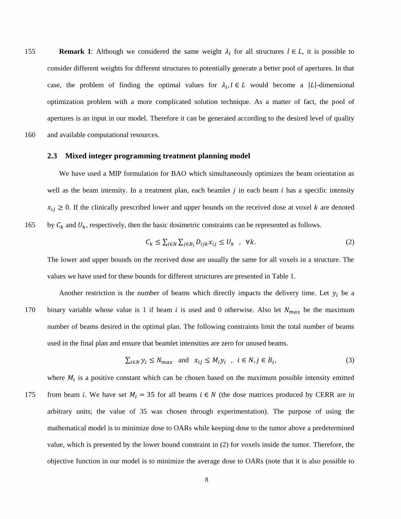
8
Remark 1: Although we considered the same weight for all structures , it is possible to 155
consider different weights for different structures to potentially generate a better pool of apertures. In that
case, the problem of finding the optimal values for would become a | |-dimensional
optimization problem with a more complicated solution technique. As a matter of fact, the pool of
apertures is an input in our model. Therefore it can be generated according to the desired level of quality
and available computational resources. 160
2.3 Mixed integer programming treatment planning model
We have used a MIP formulation for BAO which simultaneously optimizes the beam orientation as
well as the beam intensity. In a treatment plan, each beamlet in each beam has a specific intensity
. If the clinically prescribed lower and upper bounds on the received dose at voxel are denoted
by and , respectively, then the basic dosimetric constraints can be represented as follows. 165
∑ ∑ . (2)
The lower and upper bounds on the received dose are usually the same for all voxels in a structure. The
values we have used for these bounds for different structures are presented in Table 1.
Another restriction is the number of beams which directly impacts the delivery time. Let be a
binary variable whose value is 1 if beam is used and 0 otherwise. Also let be the maximum 170
number of beams desired in the optimal plan. The following constraints limit the total number of beams
used in the final plan and ensure that beamlet intensities are zero for unused beams.
∑ and , (3)
where is a positive constant which can be chosen based on the maximum possible intensity emitted
from beam . We have set for all beams (the dose matrices produced by CERR are in 175
arbitrary units; the value of 35 was chosen through experimentation). The purpose of using the
mathematical model is to minimize dose to OARs while keeping dose to the tumor above a predetermined
value, which is presented by the lower bound constraint in (2) for voxels inside the tumor. Therefore, the
objective function in our model is to minimize the average dose to OARs (note that it is also possible to

9
consider other linear or piecewise linear convex objective functions). Let denote the importance 180
weight of structure (we can assume ∑ ). The objective function of the MIP is
∑ (∑ ∑ ( ) ) , (4)
where is the average dose per monitor unit intensity contribution to structure from beamlet in
beam , i.e.,
| |(∑
) , (5) 185
The importance weights are determined by the planner based on his/her experience or, for
example, by navigating through the ideal Pareto surface and choosing the desired point (e.g., see Craft et
al (2012)). For our numerical experiments we have used the values reported in Table 1 which were found
by evaluating the dose distribution of the ideal plan. Note that we have considered a zero weight for cord
because the dose to cord has been limited to 45 Gy as a constraint. 190
The objective function in (4) and the constraints in (2) and (3) form the MIP as the basis of our
mathematical model.
Remark 2: In IMRT each beam consists of several beamlets while in SBRT each beam consists of
several apertures. Therefore the problem formulation is the same if we replace “beamlets” for IMRT with 195
“apertures” for SBRT. Thus we use the same MIP in (2)-(4) for BAO for SBRT with the difference that
for SBRT we interpret as the set of apertures associated with beam , as the dose per monitor unit
intensity contribution to voxel from aperture in beam , and as the intensity of aperture in beam .
For SBRT we calculate by summing the dose per monitor unit intensity contribution to voxel from
all beamlets in aperture (in beam ). Note that in the optimal plan for SBRT more than one aperture with 200
different intensities might be used in each beam.

10
Remark 3: The ideal plan is found by solving the associated LP which only includes continuous
variables for intensity of each beamlet (in case of IMRT) or aperture (in case of SBRT). This LP is
formed by the objective function in (4) and constraints in (2). 205
2.4 Neighbor cuts
The number of potential beams is often much larger than the number of beams which will actually be
used. For example, assuming coplanar beams with a grid of , there would be 36 potential beams.
However, usually planners aim to use a much smaller number of beams, e.g. from 5 to 9 beams.
Furthermore, the impacts of adjacent beams are similar. Therefore often the selected beams are sparsely 210
distributed around the isocenter. In other words, adjacent beams are less likely to be used in the optimal
orientation. This intuition is the basis of our proposed heuristic cuts: we add constraints, referred to as
neighbor cuts, to the MIP which allow selection of at most one or a few of the beams in every set of
adjacent beams (SAB), i.e., a set whose beams are pairwise adjacent. Therefore the general form of
neighbor cuts is 215
∑ , (6)
where represent different SABs and denotes the maximum number of adjacent
beams which can be selected from SAB (note that | | otherwise constraints (6) will be
redundant). The definition of adjacency is based on the distance (in degrees) between different beam
angles. For example, one might define two adjacent beams as two beams with a distance of at most . 220
In case of uniform distribution of coplanar candidate beams, which is often considered in clinical practice,
the adjacency can be defined based on the order in which beams are located around the isocenter. For
example, if beams are numbered from 1 to 36, two beams might be defined to be adjacent if their order
differs at most by two (it means that every three consecutive beams, e.g., beams 7, 8, and 9, form a SAB).
In this case all SABs include the same number of candidate beams, and hence, the same maximum 225
allowed number of beams can be considered for all SABs (i.e., ). Therefore in case
of uniform and coplanar distribution of candidate beams the neighbor cuts can be represented as follows.

11
∑ , (7)
where denotes the neighborhood size defined as the maximum difference in the order of two
adjacent beams. Since the beams are repeated after the th beam, we define the index | | 230
for | |. Also in order to use maximum number of beams, , in the final plan we must have
⌊| |
⌋ , where ⌊ ⌋ returns the largest integer which is smaller than or equal to . We assume
coplanar beams in the rest of this paper and for the liver case we investigate. However, the definition of
adjacent beams, and hence the application of neighbor cuts, can be easily extended to non-coplanar beams
in the three-dimensional space. 235
Two parameters need to be determined in order to use the neighbor cuts. One is the neighborhood
size, , and the other is the maximum allowed number of beams in each SAB, . A larger value for or a
smaller value for imposes tighter restrictions on the original MIP as a result of adding constraints (7).
Therefore, in general, it reduces the quality of the heuristic plan and also reduces the computation time
further. The converse is in general true for a smaller value for or a larger value for . It is desired to use 240
the value of which is large enough to reduce the computation time considerably but small enough to
avoid infeasibility and low-quality solutions. The following algorithm can be used to find appropriate
values for and .
Algorithm 1:
Step 1: Choose appropriate values for the importance weights, , , e.g., by navigating the ideal 245
dose distribution Pareto surface and selecting a plan of desired target coverage versus OARs sparing (see
Craft et al (2012) for details).
Step 2: Select and . Set and .
Step 3: Solve MIP.
Step 4: If MIP is feasible and the optimal plan is satisfactory, stop. Otherwise (i.e., if MIP is 250
infeasible or the optimal plan is not satisfactory), set or and go to Step 3.

12
2.5 Beam elimination
In a treatment plan, some beams contribute more and some contribute less to delivery of radiation to
the tumor. It is quite likely that beams with a lower contribution will not be used if the number of beams
is reduced. This is the basis of our beam elimination scheme. First we find the ideal plan by solving the 255
associated LP. In the next step we calculate the percentage contribution of each beam to the dose
delivered to the tumor in the ideal plan, which we refer to as dose contribution. Then we eliminate the
beams with lower dose contributions and solve the BAO for the remaining beams. Similar to neighbor
cuts, the beam elimination can be applied to both coplanar and noncoplanar beams.
One approach for beam elimination is to determine a dose contribution threshold, denoted by , as the 260
elimination criterion. In this approach all beams with a dose contribution lower than are eliminated.
This approach provides a control (in fact a lower bound) on the dose contribution of the remaining beams.
We have followed this approach in this research. Another approach is to determine the number of beams
we want to remain in the pool of candidate beams. In this approach all candidate beams are ranked
according to their dose contribution and then a specific number of beams with the least dose contributions 265
are eliminated. This approach provides a means to control the computation time to some extent because
the computation time (i.e., the time required to solve the MIP) directly depends on the number of
candidate beams. However, this approach might not be appropriate if the dose contributions of different
beams are close to each other. In practice, a combination of these two approaches might be used based on
the planner expertise and the realized dose contributions in the ideal plan. In particular, note that these 270
two approaches result in the same set of remaining beams with appropriate parameters.
For smaller numbers of eliminated beams, the size of the associated MIP would be larger, and the
computation time would be longer. However, in general, the resultant heuristic plan would have a higher
quality as the optimal beams have been chosen from a larger pool of candidate beams.

13
2.6 Computation 275
To solve the MIP we used CPLEX (version 12.5) on a PC with 2 Intel Xeon X5650 (2.66 GHz) CPU
and 48 GB of RAM.
3 Results and Discussion
The results for the IMRT and SBRT of the liver case are presented in Tables 2 and 3, respectively.
We used the LP with the objective function in (4) and constraints in (2) to find the ideal plan. These plans 280
for the IMRT and SBRT of the liver case are represented in the first row in Tables 2 and 3. We used the
MIP in (2)-(4) to solve the BAO (for IMRT and SBRT) for the liver case reported in Table 1. First we
solved the original MIP for and found the optimal solution (bold rows in Tables 2 and 3).
Then we incorporated the neighbor cuts and the beam elimination heuristics into the MIP and resolved it.
While 33 beams were used in the IMRT ideal plan, only 13 beams were used in the SBRT ideal plan. 285
Therefore for SBRT we eliminated the unused beams for beam elimination. However, for IMRT, we
considered two different values for the dose contribution threshold, and , which resulted
in elimination of 20 beams (beams 8, 9,…, 26, 28, 29) and 26 beams (beams 5, 6,…, 30, 33), respectively.
In Tables 2 and 3, “optimality gap” and “time reduction” are calculated compared to the
corresponding MIP with no heuristics (i.e., compared to the corresponding bold rows). Optimality gap is 290
calculated as the percentage increase in the value of the objective function when heuristics are applied.
Also in Table 3 the underlined and double underlined beams represent beams with two and three apertures
in the optimal plan, respectively (only one aperture is used in other beams).
To illustrate the quality of the resultant heuristic plans, we have compared the dose-volume histogram
(DVH) for the optimal plan for with the generated plan with and in Figure 2. 295
Note that although the cord dose has gone up substantially, it is still well below the constraint of 45 Gy.
As Tables 2 and 3 show, the neighbor cuts have a good performance in reducing the computation
time, especially for larger values of and smaller values of . They reduce the computation time
considerably while keeping the optimality gap small. In some cases, especially in case of SBRT, adding

14
the neighbor cuts results in finding the optimal beam orientations (i.e., a zero optimality gap). Note that 300
the optimality gap resulted from adding the neighbor cuts is in general smaller for smaller values of
due to sparser distribution of beams. The reduction in computation time is more substantial for IMRT
although it is accompanied with a larger optimality gap compared to SBRT.
Table 2. Numerical results for the IMRT of the liver case.
(%) Num.
Beams
Obj.
value
Opt.
gap (%)
Comp.
time (h)
Time
Reduc. (%) Beams used
34 --- --- --- 33 7.63 0.00 0.01 --- 1,2,…,12,14,15,…,34
9 --- --- --- 9 8.42 0.00 26.66 --- 1,2,3,4,5,7,31,32,34
9 --- 2 1 9 8.66 2.76 3.54 86.7 2,4,6,7,26,28,30,32,34
9 --- 3 1 9 9.01 6.99 3.52 86.8 1,4,7,10,13,21,25,28,32
9 --- 3 2 9 8.51 1.01 20.21 24.2 1,2,4,6,7,26,28,31,32
9 2 --- --- 9 8.42 0.00 0.36 98.7 1,2,3,4,5,7,31,32,34
9 5 --- --- 7 8.95 6.27 0.01 99.98 1,2,3,4,31,32,34
7 --- --- --- 7 8.78 0.00 32.07 --- 1,2,3,4,5,32,34
7 --- 2 1 7 8.92 1.56 8.99 72.0 2,4,6,7,26,32,34
7 --- 3 1 7 9.16 4.24 4.73 85.3 1,4,7,10,25,28,32
7 --- 3 2 7 8.81 0.26 24.62 23.2 1,2,4,6,7,32,33
7 --- 4 1 7 9.26 5.36 2.26 93.0 1,5,7,11,21,26,30
7 --- 4 2 7 8.90 1.34 22.95 28.4 1,2,5,6,,7,31,32
7 2 --- --- 7 8.78 0.00 0.72 97.7 1,2,3,4,5,32,34
7 5 --- --- 7 8.95 1.90 0.01 99.98 1,2,3,4,31,32,34
5 --- --- --- 5 9.29 0.00 20.51 --- 1,3,5,32,34
5 --- 2 1 5 9.30 0.10 5.46 73.4 1,3,5,7,33
5 --- 3 1 5 9.48 2.06 4.16 79.7 1,4,7,26,32
5 --- 3 2 5 9.29 0.00 9.43 54.0 1,3,5,32,34
5 --- 4 1 5 9.58 3.16 3.06 85.1 2,6,7,26,32
5 --- 4 2 5 9.30 0.10 9.17 55.3 1,3,5,7,33
5 2 --- --- 5 9.29 0.00 0.78 96.2 1,3,5,32,34
5 5 --- --- 5 9.40 1.17 0.06 99.7 1,3,4,32,34
305
As an example of application of Algorithm 1, if for we set and , the MIP will
return the corresponding plan in Table 2 in 2.26 hours. If this plan is not satisfactory, we can reduce and
set (and ). The resultant MIP will then return the corresponding plan in Table 2 in 4.73
hours. The DVH of this plan is compared with the DVH of the optimal plan in Figure 2 (left). The total

15
computation time with using the neighbor cuts will be hours, which is 78% less than 310
the computation time without using the neighbor cuts ( hours). The generated plan irradiates OARs
only 4.24% more than the optimal plan.
Table 3. Numerical results for the SBRT of the liver case.
Beam
Elim.
Num.
Beams
Obj.
value
Opt.
gap (%)
Comp.
time (s)
Time
Reduc. (%) Beams used
34 --- --- --- 13 14.21 0.00 12.3 --- 1,2,3,5,6,7,12,13,23,26,27,33,34
9 --- --- --- 9 14.23 0.00 93.4 --- 1,3,6,7,12,13,23,26,33
9 --- 2 1 9 14.25 0.15 38.7 58.6 1,3,6,7,12,13,23,26,33
9 --- 3 1 9 14.49 1.80 52.9 43.3 1,5,7,13,26,32
9 --- 3 2 9 14.23 0.00 33.3 64.3 1,3,6,7,12,13,23,26,33
9 Yes --- --- 9 14.23 0.00 50.1 46.3 1,3,6,7,12,13,23,26,33
7 --- --- --- 7 14.26 0.00 125.8 --- 1,3,6,7,13,26,33
7 --- 2 1 7 14.26 0.00 86.4 31.4 1,3,6,7,13,26,33
7 --- 3 1 6 14.49 1.59 51.7 58.9 1,5,7,13,26,32
7 --- 3 2 7 14.26 0.00 102.2 18.8 1,3,6,7,13,26,33
7 --- 4 1 5 14.50 1.66 41.1 67.3 1,5,7,13,26
7 --- 4 2 7 14.26 0.00 79.8 36.5 1,3,6,7,13,26,33
7 Yes --- --- 7 14.26 0.00 61.9 50.8 1,3,6,7,13,26,33
5 --- --- --- 5 14.47 0.00 328.8 --- 1,3,6,7,12
5 --- 2 1 5 14.47 0.00 227.9 30.7 1,3,6,7,12
5 --- 3 1 5 14.50 0.19 49.8 84.8 1,5,7,13,26
5 --- 3 2 5 14.47 0.00 202.7 38.3 1,3,6,7,12
5 --- 4 1 5 14.50 0.19 38.7 88.2 1,5,7,13,26
5 --- 4 2 5 14.47 0.00 170.9 48.0 1,3,6,7,12
5 Yes --- --- 5 14.47 0.00 98.1 70.2 1,3,6,7,12
The beam elimination heuristic also has a very good performance in reducing the computation time, 315
especially for IMRT. In particular, in all SBRT cases and also IMRT cases with the beam
elimination results in a zero optimality gap (i.e., it successfully finds the optimal plan).
We observe that in some cases the number of beams in the optimal orientation is smaller than .
As expected, this is more common for SBRT as arbitrary modulation, which makes all beams attractive, is
not possible with only a few predefined apertures available. Another observation is that reducing the 320

16
number of beams does not have a substantial impact on the plan quality for SBRT compared to IMRT
(compare the objective values of the bold rows).
Figure 2. DVH for the optimal plan for Nmax = 7 (solid lines) and the generated plan with
S = 3 and T = 1 (dotted lines) for IMRT (left) and SBRT (right). 325
As a final point, our experiments show that both neighbor cuts and beam elimination heuristics
remain quite efficient in more challenging cases. For example, in Yarmand et al (2013) we successfully
used these heuristics to reduce the computation time in a harder SBRT case obtained by reducing the
maximum allowed dose in the liver case from 60 Gy to 54 Gy (the maximum allowed dose for cord
remains at 45 Gy). 330
4 Conclusion
We proposed two heuristics for reducing the computation time for BAO which can be applied to
IMRT, IMPT, and SBRT. One is limiting use of adjacent beams based on the intuition that the impacts of
adjacent beams are similar and therefore adjacent beams are less likely to be used in the optimal
orientation. The other is a beam elimination scheme in which beams with insignificant (dose) contribution 335
in the ideal plan are eliminated from consideration. Our numerical results for IMRT and SBRT of a liver

17
case showed that both heuristics were capable of reducing the computation time considerably while
resulting in high-quality plans, hence accelerating the treatment planning process.
The neighbor cuts and beam elimination heuristics can be applied alone or combined with other
heuristics and techniques to find high-quality treatment plans in a reasonable amount of time. As an 340
example, we have successfully used these heuristics to reduce the computation time in finding guaranteed
epsilon-optimal treatment plans with the minimum number of beams for SBRT (Yarmand et al 2013).
The beam elimination heuristic can be applied to arbitrary nonlinear models including DVH based
formulations. The idea of limiting the search space via neighbor cuts is also widely applicable to arbitrary
nonlinear models. However, the neighbor cuts heuristic works best when applied to convex formulations 345
(that is the main reason we used the MIP formulation for BAO). These models include the commonly
used quadratic tail penalties as well as equivalent uniform dose (EUD) formulations. Nonconvex
functions such as DVH constraints can be convexified following approaches like Zarepisheh et al (2013)
and Halabi et al (2006).
In summary, using the approach presented we are able to compare heuristically produced plans with 350
the true optimal plan (i.e., the ideal plan), which affords our approach a notable advantage over most
other BAO approaches in the literature, which leave the users no sense of how close the produced
solutions are to optimal.
Acknowledgments
This research was supported by the Federal Share of program income earned by Massachusetts 355
General Hospital on C06CA059267, Proton Therapy Research and Treatment Center, and by RaySearch
Laboratories.
References
Bertsimas, D, Cacchiani, V, Craft, D and Nohadani, O 2013 A hybrid approach to beam angle
optimization in intensity-modulated radiation therapy Computers & Operations Research 40 9 2187-9 360

18
Craft, D, McQuaid, D, Wala, J, Chen, W, Salari, E and Bortfeld, T 2012 Multicriteria VMAT
optimization Med. Phys. 39 2 686
Deasy, J O, Blanco, A I and Clark, V H 2003 CERR: A computational environment for radiotherapy
research Med. Phys. 30 5 979
Gozbasi, H O 2010 Optimization approaches for planning external beam radiotherapy Doctor of 365
Philosophy Georgia Institute of Technology
Halabi, T, Craft, D and Bortfeld, T 2006 Dose-volume objectives in multi-criteria optimization Phys.
Med. Biol. 51 15 3809-18
Lee, E K, Fox, T and Crocker, I 2006 Simultaneous beam geometry and intensity map optimization in
intensity-modulated radiation therapy International Journal of Radiation Oncology Biology Physics 370
64 1 301-20
Lee, E K, Fox, T and Crocker, I 2003 Integer Programming Applied to Intensity-Modulated Radiation
Therapy Treatment Planning Annals of Operations Research 119 165-81
Lim, G J and Cao, W 2012 A two-phase method for selecting IMRT treatment beam angles: Branch-and-
Prune and local neighborhood search European Journal of Operational Research 217 609-18 375
Lim, G J, Choi, J and Mohan, R 2008 Iterative solution methods for beam angle and fluence map
optimization in intensity modulated radiation therapy planning OR Spectrum 30 289-30
Liu, H, Jauregui, M, Zhang, X, Wang, X, Dong, L and Mohan, R 2006 Beam angle optimization and
reduction for intensity-modulated radiation therapy of non-small-cell lung cancers International
Journal of Radiation Oncology Biology Physics 65 2 561-72 380
Liu, R, Buatti, J M, Howes, T L, Dill, J, Modrick, J M and Meeks, S L 2006 Optimal number of beams
for stereotactic body radiotherapy of lung and liver lesions International Journal of Radiation
Oncology Biology Physics 66 3 906-12

19
Oldham, M, Khoo, V S, Rowbottom, C G, Bedford, J L and Webb, S 1998 A case study comparing the
relative benefit of optimizing beam weights, wedge angles, beam orientations and tomotherapy in 385
stereotactic radiotherapy of the brain Physics in Medicine and Biology 43 2123-46
Pooter, J A, Romero, A M, Jansen, W P A, Storchi, P R M, Woudstra, E, Levendag, P C and Heijmen, B
J M 2006 Computer optimization of noncoplanar beam setups improves stereotactic treatment of liver
tumors International Journal of Radiation Oncology Biology Physics 66 3 913-22
Sodertrom, S and Brahme, A 1993 Optimization of the dose delivery in a few field techniques using 390
radiobiological objective functions Med. Phys. 20 4 1201-10
Taskin, Z C, Smith, J C and Romeijn, H E 2012 Mixed-integer programming techniques for decomposing
IMRT fluence maps using rectangular apertures Annals of Operations Research 196 1 799-818
Taskin, Z C, Smith, J C, Romeijn, H E and Dempsey, J F 2010 Optimal Multileaf Collimator Leaf
Sequencing in IMRT Treatment Planning Oper. Res. 58 3 674-90 395
Taskin, Z C and Cevik, M 2011 Combinatorial Benders cuts for decomposing IMRT fluence maps using
rectangular apertures Comput. Oper. Res. 40 9 2178-86
Tuncel, A T, Preciado, F, Rardin, R L, Langer, M and Richard, J P 2012 Strong valid inequalities for
fluence map optimization problem under dose-volume restrictions Annals of Operations Research
196 1 819-40 400
Wang, X, Zhang, X, Dong, L, Liu, H, Gillin, M, Ahmad, A, Ang, K and Mohan, R 2005 Effectiveness of
noncoplanar IMRT planning using a parallelized multiresolution beam angle optimization method for
paranasal sinus carcinoma International Journal of Radiation Oncology Biology Physics 63 2 594-
601
Wang, X, Zhang, X, Dong, L, Liu, H, Wu, Q and Mohan, R 2004 Development of methods for beam 405
angle optimization for IMRT using an accelerated exhaustive search strategy International Journal of
Radiation Oncology Biology Physics 60 4 1325-37

20
Yarmand, H, Winey, B and Craft, D, Guaranteed Epsilon-Optimal Treatment Plans with Minimum
Number of Beams for Stereotactic Body Radiation Therapy Physics in Medicine and Biology, in press
Zarepisheh, M, Shakourifar, M, Trigila, G, Ghomi, P S, Couzens, S, Abebe, A, Norena, L, Shang, W, 410
Jiang, S B and Zinchenko, Y 2013 A moment-based approach for DVH-guided radiotherapy
treatment plan optimization Phys. Med. Biol. 58 6 1869-87
Top Related
Copyright © 2022 FDOKUMEN

