


Bahasa
Halaman
Hukum

eman ta zabal
zazu
BILBOKO INDUSTRIA INGENIARITZA TEKNIKOKO UNIBERTSITATE ESKOLA
INDUSTRIA ELEKTRONIKAREN ETA AUTOMATIKAREN INGENIARITZAKO GRADUA
GRADU AMAIERAKO LANA
2014 / 2015
LANAREN BESO ROBOTIKO MUGIKOR BATEN DISEINU
PROGRAMAZIO ETA MUNTAIA
ERANSKINAK
IKASLEAREN DATUAK
IZENA:ITZIAR
ABIZENAK:ALDEKOA MADARIAGA
ZUZENDARIAREN DATUAK
IZENA:Mª GORETTI
ABIZENAK:SEVILLANO BERASATEGUI
SAILA:SISTEMEN INGENIARITZA ETA AUTOMATIKA
SIN.: SIN.:
DATA:2015/06/19 DATA:2015/06/19

ERANSKIAK
Bilboko IITUE 2015ko ekaina 1
Me-Base Shield Introduction
Me-Base Shield is an Arduino Shield that brings out most of the Arduino Pins to the uniform 6pin RJ25 connectors. Here is a top-down view:
You can easily connect Me Series Electronic Modules to Arduino board through the Base Shield. With a TB6612 motor driver IC on board, it can drive 2 DC motors.
Besides the 8 RJ25 port, there are 2.54mm pin pad on the board, all I/O pins on the bottom Arduino board are conected to these pads.
Features
6-12VDC power supply
Two channel motor driver integrated
Intuitive connection by labeling tags with different color and number for each connector
Over-current protection
Comes with Arduino library for easy programing
Easy wiring with 6 Pin RJ25 interface
2.54mm breakout pins for connecting with jumper wires
Interface Function
ERANSKIAK
Bilboko IITUE 2015ko ekaina 2
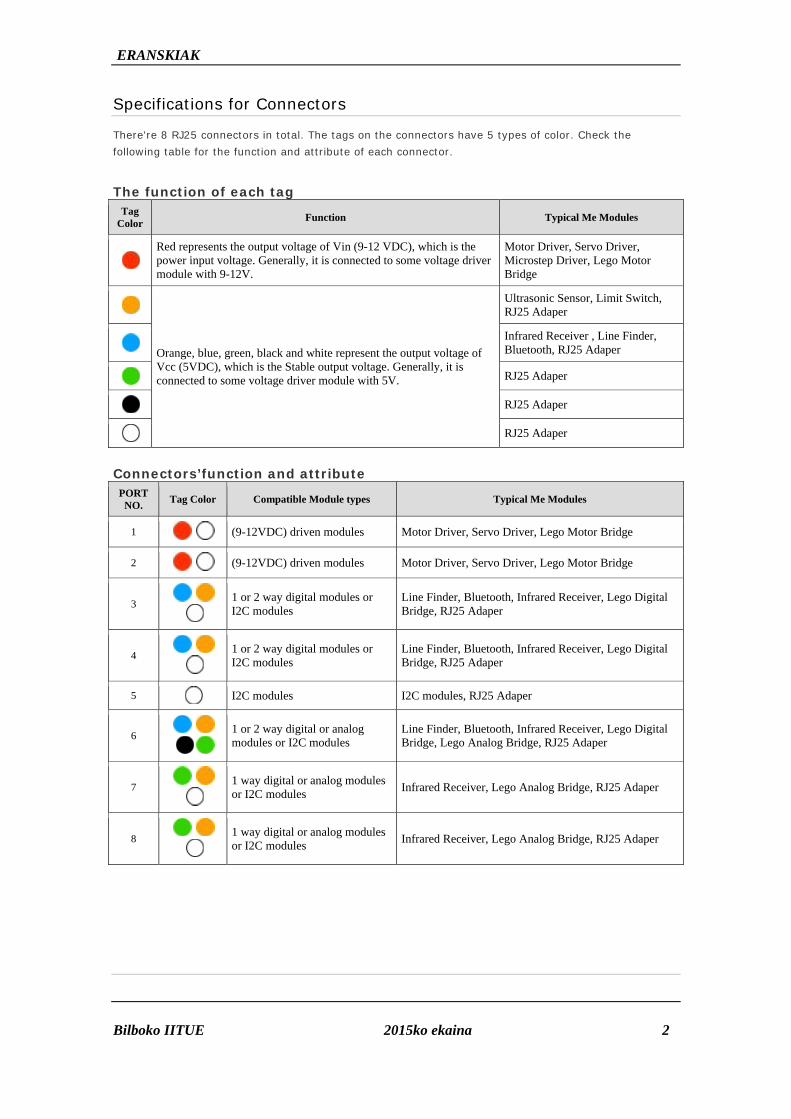
Specifications for Connectors
There're 8 RJ25 connectors in total. The tags on the connectors have 5 types of color. Check the following table for the function and attribute of each connector.
The function of each tag
Tag Color Function Typical Me Modules
Red represents the output voltage of Vin (9-12 VDC), which is the power input voltage. Generally, it is connected to some voltage driver module with 9-12V.
Motor Driver, Servo Driver, Microstep Driver, Lego Motor Bridge
Orange, blue, green, black and white represent the output voltage of Vcc (5VDC), which is the Stable output voltage. Generally, it is connected to some voltage driver module with 5V.
Ultrasonic Sensor, Limit Switch, RJ25 Adaper
Infrared Receiver , Line Finder, Bluetooth, RJ25 Adaper
RJ25 Adaper
RJ25 Adaper
RJ25 Adaper
Connectors’function and attribute
PORT NO. Tag Color Compatible Module types Typical Me Modules
1 (9-12VDC) driven modules Motor Driver, Servo Driver, Lego Motor Bridge
2 (9-12VDC) driven modules Motor Driver, Servo Driver, Lego Motor Bridge
3
1 or 2 way digital modules or I2C modules
Line Finder, Bluetooth, Infrared Receiver, Lego Digital Bridge, RJ25 Adaper
4
1 or 2 way digital modules or I2C modules
Line Finder, Bluetooth, Infrared Receiver, Lego Digital Bridge, RJ25 Adaper
5
I2C modules I2C modules, RJ25 Adaper
6
1 or 2 way digital or analog modules or I2C modules
Line Finder, Bluetooth, Infrared Receiver, Lego Digital Bridge, Lego Analog Bridge, RJ25 Adaper
7
1 way digital or analog modules or I2C modules Infrared Receiver, Lego Analog Bridge, RJ25 Adaper
8
1 way digital or analog modules or I2C modules Infrared Receiver, Lego Analog Bridge, RJ25 Adaper

ERANSKIAK
Bilboko IITUE 2015ko ekaina 3
Meduino
Introduction
Meduino is an Arduino compatible board. Based on Uno R3 Schematic, 100% compatible to its existing program, shield and IDEs. We also provide a Makeblock Arduino library for Meduino and Me series electronic modules to make it easier to use and program.
Features
ATmega328 microcontroller
Input voltage - 7-12V
14 Digital I/O Pins (of which 6 provide PWM output)
6 Analog Inputs
32 KB Flash Memory
2 KB SRAM
1 KB EEPROM
16 MHz Clock Speed
Specification of Connection
With Me-base shield connection diagram(the following picture):
Power
The Arduino Uno can be powered via the USB connection or with an external power supply. The power source is selected automatically.
External (non-USB) power can come either from an AC-to-DC adapter (wall-wart) or battery. The adapter can be connected by plugging a 2.1mm center-positive plug into the board's power jack. Leads from a battery can be inserted in the Gnd and Vin pin headers of the POWER connector.
The board can operate on an external supply of 6 to 20 volts. If supplied with less than 7V, however, the 5V pin may supply less than five volts and the board may be unstable. If using more than 12V, the voltage regulator may overheat and damage the board. The recommended range is 7 to 12 volts.

ERANSKIAK
Bilboko IITUE 2015ko ekaina 4
The power pins are as follows:
VIN. The input voltage to the Arduino board when it's using an external power source (as opposed
to 5 volts from the USB connection or other regulated power source). You can supply voltage
through this pin, or, if supplying voltage via the power jack, access it through this pin.
5V.This pin outputs a regulated 5V from the regulator on the board. The board can be supplied with
power either from the DC power jack (7 - 12V), the USB connector (5V), or the VIN pin of the board
(7-12V). Supplying voltage via the 5V or 3.3V pins bypasses the regulator, and can damage your
board. We don't advise it.
3V3. A 3.3 volt supply generated by the on-board regulator. Maximum current draw is 50 mA.
GND. Ground pins.
Memory
The ATmega328 has 32 KB (with 0.5 KB used for the bootloader). It also has 2 KB of SRAM and 1 KB of EEPROM (which can be read and written with the EEPROM library).
Input and Output
Each of the 14 digital pins on the Uno can be used as an input or output, using pinMode(), digitalWrite(), and digitalRead() functions. They operate at 5 volts. Each pin can provide or receive a maximum of 40 mA and has an internal pull-up resistor (disconnected by default) of 20-50 kOhms. In addition, some pins have specialized functions:
Serial: 0 (RX) and 1 (TX). Used to receive (RX) and transmit (TX) TTL serial data. These pins are
connected to the corresponding pins of the ATmega8U2 USB-to-TTL Serial chip.
External Interrupts: 2 and 3. These pins can be configured to trigger an interrupt on a low value, a
rising or falling edge, or a change in value. See the attachInterrupt() function for details.
PWM: 3, 5, 6, 9, 10, and 11. Provide 8-bit PWM output with the analogWrite() function.
SPI: 10 (SS), 11 (MOSI), 12 (MISO), 13 (SCK). These pins support SPI communication using the
SPI library.
LED: 13. There is a built-in LED connected to digital pin 13. When the pin is HIGH value, the LED is
on, when the pin is LOW, it's off.
The Uno has 6 analog inputs, labeled A0 through A5, each of which provide 10 bits of resolution (i.e. 1024 different values). By default they measure from ground to 5 volts, though is it possible to change the upper end of their range using the AREF pin and the analogReference() function. Additionally, some pins have specialized functionality:
TWI: A4 or SDA pin and A5 or SCL pin. Support TWI communication using the Wire library.
There are a couple of other pins on the board:
AREF. Reference voltage for the analog inputs. Used with analogReference().
Reset. Bring this line LOW to reset the microcontroller. Typically used to add a reset button to
shields which block the one on the board.
ERANSKIAK
Bilboko IITUE 2015ko ekaina 5
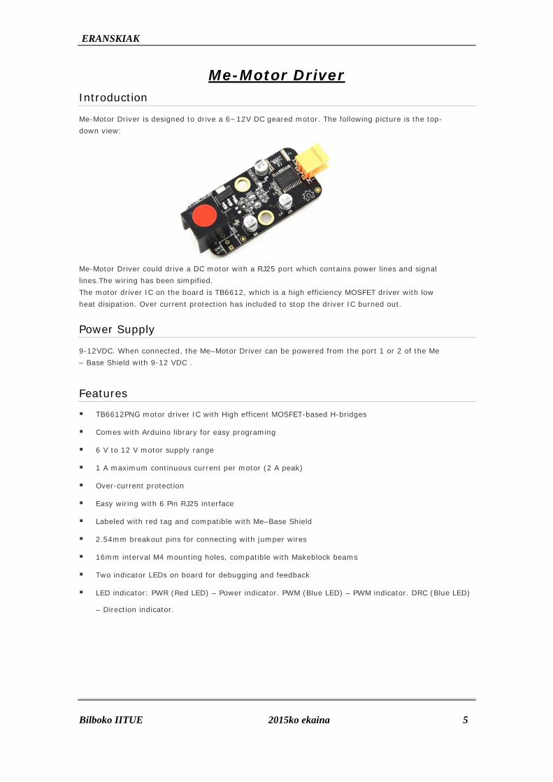
Me-Motor Driver Introduction
Me-Motor Driver is designed to drive a 6~12V DC geared motor. The following picture is the top-down view:
Me-Motor Driver could drive a DC motor with a RJ25 port which contains power lines and signal lines.The wiring has been simpified. The motor driver IC on the board is TB6612, which is a high efficiency MOSFET driver with low heat disipation. Over current protection has included to stop the driver IC burned out.
Power Supply
9-12VDC. When connected, the Me–Motor Driver can be powered from the port 1 or 2 of the Me – Base Shield with 9-12 VDC .
Features
TB6612PNG motor driver IC with High efficent MOSFET-based H-bridges
Comes with Arduino library for easy programing
6 V to 12 V motor supply range
1 A maximum continuous current per motor (2 A peak)
Over-current protection
Easy wiring with 6 Pin RJ25 interface
Labeled with red tag and compatible with Me–Base Shield
2.54mm breakout pins for connecting with jumper wires
16mm interval M4 mounting holes, compatible with Makeblock beams
Two indicator LEDs on board for debugging and feedback
LED indicator: PWR (Red LED) – Power indicator. PWM (Blue LED) – PWM indicator. DRC (Blue LED)
– Direction indicator.

ERA
Bilbo
Gen
M
M
M
M
C
P
Dim
2.4cm
Inte
ANSKIAK
oko IITUE
neral spec
Motor driver: T
Motor channels
Minimum opera
Maximum oper
Continuous out
Peak output cu
mensions
m x 4.8cm
erface Fun
cifications
TB6612FNG
s: 1
ating voltage:
rating voltage
tput current p
urrent per cha
nction
s
: 6 V
e: 12 V
per channel: 1
annel: 2 A
2015ko
1 A
ekaina
6

ERANSKIAK
Bilboko IITUE 2015ko ekaina 7
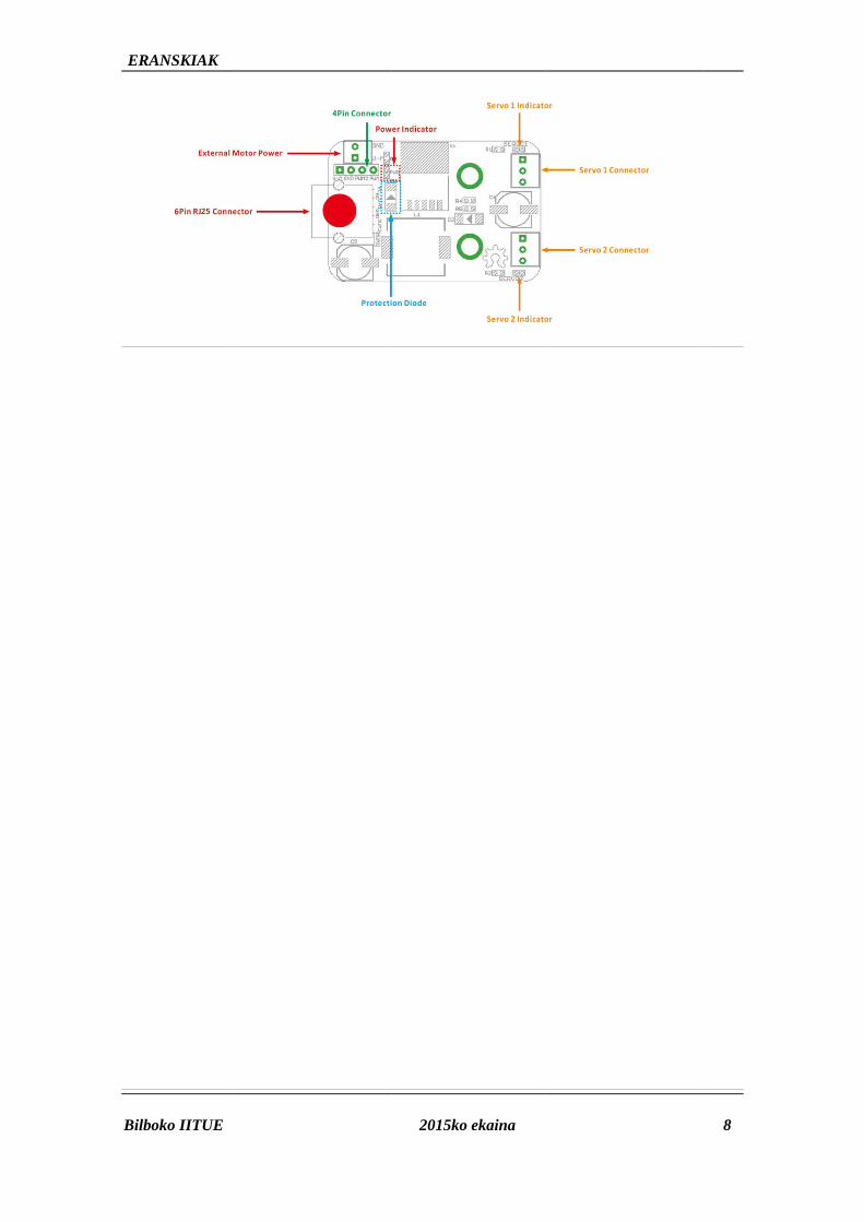
Me-Servo Driver Introduction
Me-Servo Driver is designed to drive servo motors. With high efficiency DC-DC converter, it could converts the input voltage into suitable voltage for servo, wchich is 6V. Don't need to find special power supply for servos. The following picture is the top-down view:
Power supply
When connected, the Me–Servo Driver can be powered by the 9-12V DC power from the port 1 or 2 of the Me–Base Shield.
Features
High efficiency DC-DC converter on board
9-12VDC power supply
Two PWM output channels for controlling two servo motors
The power voltage for servos are regulated to 6V
Comes with Arduino library for easy programing
Over-current protection
Easy wiring with 6 Pin RJ25 interface
Labeled with red tag and compatible with Me–Base Shield
2.54mm breakout pins for connecting with jumper wires
16mm interval M4 mounting holes, compatible with Makeblock beams
Three indicator on board LEDs for debugging and feedback
LED indicator: PWR (Red LED) – Power indicator. SERVO-1 (Blue LED) – PWM indicator for Servo1.
SERVO-2 (Blue LED) – PWM indicator for Servo2.
Dimensions
3.2cm x 4.8cm
ERA
Bilbo
ANSKIAK
oko IITUE 2015ko
ekaina
8

ERA
Bilbo
Intro
The MinfrareInfrare
Feat
P
6
C
T
L
Inte
ANSKIAK
oko IITUE
oduction
e– Infrared Reed remote conted Receiver ca
tures
ower Supply: 5
Pin RJ11 inter
Compatible with
Transmission D
ED indicator: P
erface Fun
Me-
eceiver moduletrol. The IR detn receive signa
5VDC power su
rface and 2.54
h Me – Base Sh
istance: 10 me
PWR (Red LED)
nction
Infrare
e is designed fotector have a dals well within
upply
mm breakout p
hield
eters in free sp
) – Power indic
2015ko
ed Reciv
or controlling thdemodulator in 10 meters.
pins
pace
cator. Blinking
ekaina
ver Dec
he robotics by nside that looks
while receiving
code
receiving the cs for modulate
g infrared signa
commands fromed IR at 38 KHz
als
9
m the z. The

ERANSKIAK
Bilboko IITUE 2015ko ekaina 10
Me-UltraSonic Sensor Introduction
Me Ultrasonic Sensor can be used to measure distance or obstacle avoidance, from 3cm to 4m. With the Arduino library we provide, users can get the distance directly and use the module easily. The following picture is the top-down view:
Features
Comes with Arduino library for easy programing
Over-current protection
Easy wiring with 6 Pin RJ25 interface
Labeled with yellow tag and compatible with Me–Base Shield
2.54mm breakout pins for connecting with jumper wires
16mm interval M4 mounting holes, compatible with Makeblock beams
One indicator LEDs on board for debugging and feedback
LED indicator: D1 (Red LED) – Power indicator.
Detecting range
3cm--4m, best in 30 degree angle

ERA
Bilbo
Intro
Me RJ
conne
Feat
• B
• C
• S
p
• S
• M
Para
Opera
Conne
Dimen
ANSKIAK
oko IITUE
oduction
J25 Adapter c
cted to the por
tures
Break out two s
Connect module
Support Arduino
rogramming;
Support Scratch
Modular installa
ameters
ating Voltage
ector: two sig
nsion: 52 x 24
M
converts 6P6C
rt with yellow,b
singnal connect
es from other m
o IDE program
h For Robot, co
ation, and com
e: 5V DC;
nal connectors
4 x 16 mm (Le
Me RJ
C RJ25 connec
blue or black ta
tors;
manufacturers
mming control,
over all ages pe
patible with LE
s;
ngth x Width x
2015ko
J25 Ad
ctor to two co
ag on mainboa
with Me series
we also provid
eople;
EGO Bricks;
x Height);
ekaina
dapter
ommon signal
ard.
s modules;
e Makeblock L
r
connectors.R
ibrary for Ardu
RJ25 Adapter c
uino, easy
11
can be

HOJA TECNICA: Driver MSE- A100 1
Ingeniería de Microsistemas Programados S.LAlda. Mazarredo Nº 47 –1º Dpto 248009 Bilbao – Vizcaya (Spain)
Tfno/Fax: 94 [email protected]
1.- DESCRIPCION
Se trata de un driver de propósito general basado en el dispositivo L293B de la firma SGS-THOMSON. Semuestra en la figura 1.
Consiste en 4 canales amplificadores totalmente independientes entre si. Cada canal es capaz de soportarcorrientes de salida de 1 A con picos de hasta 2 A. Poseen una alta inmunidad al ruido, protección de sobretemperaturas y tensión de alimentación de las cargas separada de la tensión de alimentación de la lógica. Laseñal de entrada de cada canal es compatible con señales TTL. Las señales de salida disponen de loscorrespondientes diodos de absorción para las corrientes inversas que generan las cargas inductivas. La figura 2muestra el esquema simplificado del driver MSE-A100, junto con una descripción de sus señales.
SEÑAL DESCRIPCIONE1-E4 Señales de entrada, una por cada canal. Estas
señales son compatibles con niveles lógicos TTL.S1-S4 Señales amplificadas de salida, una por cada canal.
Estas se conectan a las cargas que se deseancontrolar. Cada salida puede soportar cargas dehasta 1 A.
+5Vcc Entrada de +5V para alimentación de la lógicainterna.
+VM Entrada de tensión para la alimentación de lascargas cuyo valor máximo es de 35V
GND Tierra de alimentación.

HOJA TECNICA: Driver MSE- A100 2
Ingeniería de Microsistemas Programados S.LAlda. Mazarredo Nº 47 –1º Dpto 248009 Bilbao – Vizcaya (Spain)
Tfno/Fax: 94 [email protected]
2.- CARACTERISTICAS TECNICAS
PARAMETRO VALOR UNIDADDimensiones del circuito 45 x 33 mmTensión de alimentación para la lógica interna (+5Vcc) 5 VTensión máxima de alimentación de las cargas (+VM) 35 VTensión de entrada máxima en E1-E3 a nivel bajo 1.5 VTensión de entrada mínima en E1-E3 a nivel alto 2.3 VCorriente máxima de entrada en E1-E3 a nivel bajo -10 µACorriente típica de entrada en E1-E3 a nivel alto 30 µAIntensidad máxima de salida en S1-S3 1000 mAIntensidad de pico máxima en S1-S3 2000 mADisipación total de potencia 5 W
3. CONEXIONADO
Se realiza mediante una serie bornas que permiten una fácil conexión. Se presenta en la figura 3.
El driver MSE-A100 puede controlar diferentes tipos de cargas. A continuación se muestra, a modo deejemplos, la conexión de MSE-A100 con diferentes tipos de periféricos. Así, la figura 4, muestra la conexión deldriver con cargas luminosas de tipo led.

HOJA TECNICA: Driver MSE- A100 3
Ingeniería de Microsistemas Programados S.LAlda. Mazarredo Nº 47 –1º Dpto 248009 Bilbao – Vizcaya (Spain)
Tfno/Fax: 94 [email protected]
La resistencia R de absorción asociada a cada led se debe calcular en función de la tensión +VMempleada según la siguiente fórmula: R = (+VM – VLED) / ILED
La figura 5 muestra la conexión del driver MSE-A100 con dos motores CC. Cada motor se conecta condos de las salidas y se gobierna desde las correspondientes dos entradas. Tal y como se muestra en la tabla, esposible controlar la conexión/desconexión del motor así como el sentido de giro del mismo. También es posibleregular la velocidad de cualquiera de los dos motores. Basta con aplicar por la entrada apropiada una señal PWM.
La figura 6 muestra la forma de conectar, a modo de ejemplo, dos relés y dos motores CC. En este casotanto los relés como los motores se conectan a cada una de las 4 salidas disponibles, por lo que únicamentepueden tener el estado ON/OFF. En el caso de los motores sólo pueden tener un único sentido de giro, que seráhorario o antihorario en función de cómo se realicen las conexiones de los mismos.
E1 E2 MOTOR 10 0 OFF0 1 Giro horario1 0 Giro antihorario1 1 OFF

HOJA TECNICA: Driver MSE- A100 4
Ingeniería de Microsistemas Programados S.LAlda. Mazarredo Nº 47 –1º Dpto 248009 Bilbao – Vizcaya (Spain)
Tfno/Fax: 94 [email protected]
Finalmente, la figura 7 presenta la conexión del driver MSE-A100 con un motor paso a paso (P-P) de dosbobinas.
Según las combinaciones binarios que se apliquen por las entradas E1-E3, las bobinas se excitan con unadeterminada polaridad y produciendo un desplazamiento de rotación en el eje del motor. El número de grados deesta rotación o “paso” dependerá del motor empleado. Las siguientes tablas muestran las secuencias binarias quehan de aplicarse para producir un giro en uno u otro sentido.
4.- AJUSTES
El driver MSE-A100 no necesita de ningún tipo de ajuste ni calibraci
5.- APLICACIONES
MSE-A100 es un driver de 4 canales de propósito general capaz de actuar sobre diferentes tipos decargas. Su empleo está dirigido a cualquier aplicación en la que sea necesario amplificar señales lógicas decontrol para ser aplicadas a diferentes tipos de actuadores: diferentes tipos motores, relés, indicadores luminosos,sonoros, etc.
SENTIDOHORARIO
PASO E4 E3 E2 E11 1 0 0 12 0 1 0 13 0 1 1 04 1 0 1 0
SENTIDOANTI HORARIO
PASO E4 E3 E2 E11 1 0 1 02 0 1 1 03 0 1 0 14 1 0 0 1
Copyright © 2022 FDOKUMEN

