


Bahasa
Halaman
Hukum

Inter-layer coordination for parallel TCP streamson Long Fat pipe Networks
Hiroyuki Kamezawa, Makoto Nakamura, Junji Tamatsukuri,Nao Aoshima, Mary Inaba, and Kei Hiraki
University of Tokyo7-3-1 Hongo Bunkyo-ku Tokyo Japan 113-0033
{kame,makoto,junji,aoshima,mary,hiraki}@is.s.u-tokyo.ac.jp
Junichiro Shitami and Akira JinzakiFujitsu Laboratories
{shitami, zinzin}@flab.fujitsu.co.jp
Ryutaro Kurusu, Masakazu Sakamoto,and Yukichi Ikuta
Fujitsu Computer Technologies
{ryu, msakam, ikuta}@ctec.fujitsu.com
ABSTRACTAs the network speed grows, inter-layer coordination be-comes more important. This paper shows 3 inter-layer coor-dination methods; (1) “Comet-TCP”; cooperation of data-link layer and transport layer using hardware, (2) “Trans-mission Rate Controlled TCP (TRC-TCP)”; cooperation ofdata-link layer and transport layer using software, and (3)“Dulling Edges of Cooperative Parallel streams (DECP)”;cooperation of transport layer and application layer. Weshow the experimental results of file transfer at BandwidthChallenge in SC2003; one and a half round trip from Japanto U.S., 15,000 miles, which has 350 ms RTT and 8.2 Gbpsbandwidth. Comet-TCP hardware solution attained max7.56 Gbps using a pair of 16 IA servers, which is 92% ofavailable bandwidth and DECP software attained max 7.01Gbps using a pair of 32 IA servers.
1. INTRODUCTION
1.1 Inter-layer coordinationWith the rapid progress of network technology, such as
optical fiber and network switches, speed of network growsfaster than that of CPU, memory, or other computer devices.Coordination over layers becomes more and more importantto attain actual high performance on high speed network.TCP offload interface card is now shipped, for preventing
Permission to make digital or hard copies of all or part of this work forpersonal or classroom use is granted without fee provided that copies arenot made or distributed for profit or commercial advantage and that copiesbear this notice and the full citation on the first page. To copy otherwise, torepublish, to post on servers or to redistribute to lists, requires prior specificpermission and/or a fee.SC2004November 6-12, 2004, Pittsburgh, PA, USA0-7695-2153-3/04$20.00 (c)2004 IEEE.
redundant memory copy or heavy-burden interruption ofmain CPU per packet. Intrusion detection or encryptionand decryption using ethernet card is also helpful to inventefficient system, which we call “inter-layer coordination”.As the speed of network grows, network-specific function isgoing to be cast into hardware at the end-nodes[18], justlike graphics engine on video card computes instead of mainCPU.This paper tackles the instability problem of streams mainlycaused by the difference of the rates specified by data-linklayer and transport layer.
1.2 Data Reservoir System“Data Reservoir” system is a file sharing facility to sup-
port data intensive scientific research projects, whose sitesare spread in distant locations but connected each other byhigh-speed network. Data Reservoir system consists of sev-eral file servers and many disk servers. We adopt low levelprotocol iSCSI (internet SCSI) for accessing disks and fortransferring data. For local access, a disk server plays therole of a target like an ordinary hard disk. For bulk datatransfer from site A to site B, a disk server of site A playsthe role of an initiator and a disk server of site B plays therole of a target. We use parallel streams of striped datain low level to avoid overheads due to disk seek operationscontext-switch overhead and file system overhead (Figure1). One of the biggest features of Data Reservoir system isfile system transparency achieved by data sharing at stor-age device level; which enables users to use any existingsoftware without even compilation. Detailed description ofData Reservoir system is found in [7].
1.3 TCP/IP on Long Fat Pipe NetworkTCP/IP is a standard end-to-end protocol for reliable
transfer. It is well known that TCP has a limitation onperformance when it is used for data transfer over long dis-tance and high bandwidth network, called “Long Fat pipe

Scientific Detectors User Programs
IP Switch IP Switch
iSCSI Bulk Transfer
Global Network
File Server File Server File Server File Server
Disk Server Disk ServerDisk Server Disk Server
Figure 1: Burst data transfer
Network (LFN)”. For reliability, TCP uses ACK; a senderkeeps data for re-transmission until ACK returns. Data,which is sent but not ACKed, is called “inflight” data, andits maximum size is called “window size”. Data transferrate of TCP is roughly window size/RTT , where RTT isRound Trip Time. Long distance data transfer needs largewindow size, since transfer rate is inverse proportional toRTT . In addition, speed of growth of the window size isproportional to RTT , since it takes RTT time till ACKreturns. The window size is controlled by widely used lossbased TCP algorithms as follows; in slow start phase doubledfor every RTT , and in congestion avoidance phase “Addi-tive Increase and Multiplicative Decrease(AIMD)” manner,i.e., linearly increased while transfer succeeds, and halvedby transfer failure. Many proposals have been shown tochange the window size control algorithm; such as ScalableTCP (STCP) [12], HighSpeed TCP (HSTCP) [4] and FASTTCP [9].
But the problem of bad performance on LFN is not onlybecause of the slow growth of window size. For example,performance of streams in same condition disperse a lot,which is a serious problem when system use parallel streamsbecause the slowest stream is the dominant factor. In ourexperiment, dispersion is observed only when we use GigabitEthernet interface at the end-point, where bottleneck is OC-12. And, when we change interface to FastEthernet, this dis-persion disappears immediately, although TCP stack is com-pletely same [14]. We guess this dispersion may be caused byshortage of buffers of intermediate routers; that is, althoughmacroscopically there exist no congestion, microscopicallythere exist buffer overflow in intermediate routers, whichoccasionally induces unlucky packet loss, which results inunnecessary dispersion of performance. This problem be-comes more serious when we use 10 Gbps interface.
1.4 OverviewWe propose 3 inter-layer coordination methods; (1) “ Comet
- TCP ”, a hardware solution and (2) “ Transmission RateControlled TCP (TRC - TCP) ”, a software solution to co-operation of data-link layer and transport layer, and (3)“Dulling Edges of Cooperative Parallel streams (DECP)”,cooperation of transport layer and application layer.
In this paper, first, we show our observation of Japan-US data transfer experiment in SC2002 between Tokyo andBaltimore whose bottleneck was OC-12. Then, we explainthe problems we found. Next, we show our proposals and
implementations. Finally, we show the experimental resultsof these proposals in Bandwidth Challenge in SC2003. Wetransfer data file for one and a half round trip from Japanto U.S., 15,000 miles, which has 350ms RTT and 8.2 Gbpsbandwidth. Hardware solution Comet-TCP attained max7.56 Gbps using a pair of 16 IA servers, and software DECPmax 7.01 Gbps using a pair of 32 IA servers.
2. OBSERVATIONS AND PROBLEM
2.1 Experiments over the Pacific Ocean withbottleneck OC-12
In November 2002, we experimented “Data Reservoir” filesharing system. Endpoint sites are University of Tokyo inTokyo and SC2002 exhibition hall in Baltimore, where dis-tance is 7500 miles, RTT is 200 ms, and APAN1 OC-12/POSis the bottle neck. In this experiment, we attained 91% us-
OC-192OC-48
OC-12GbE
APAN
MAX
Abilene
UMD
Seattle
Denver
KansasCity Indianapolis
Chicago NewYorkCity
FLA
Seattle
Tokyo
Tokyo Univ. SC2002
Washington
Figure 2: Network between Tokyo and Baltimore
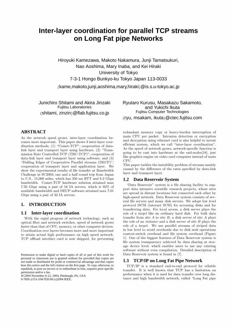
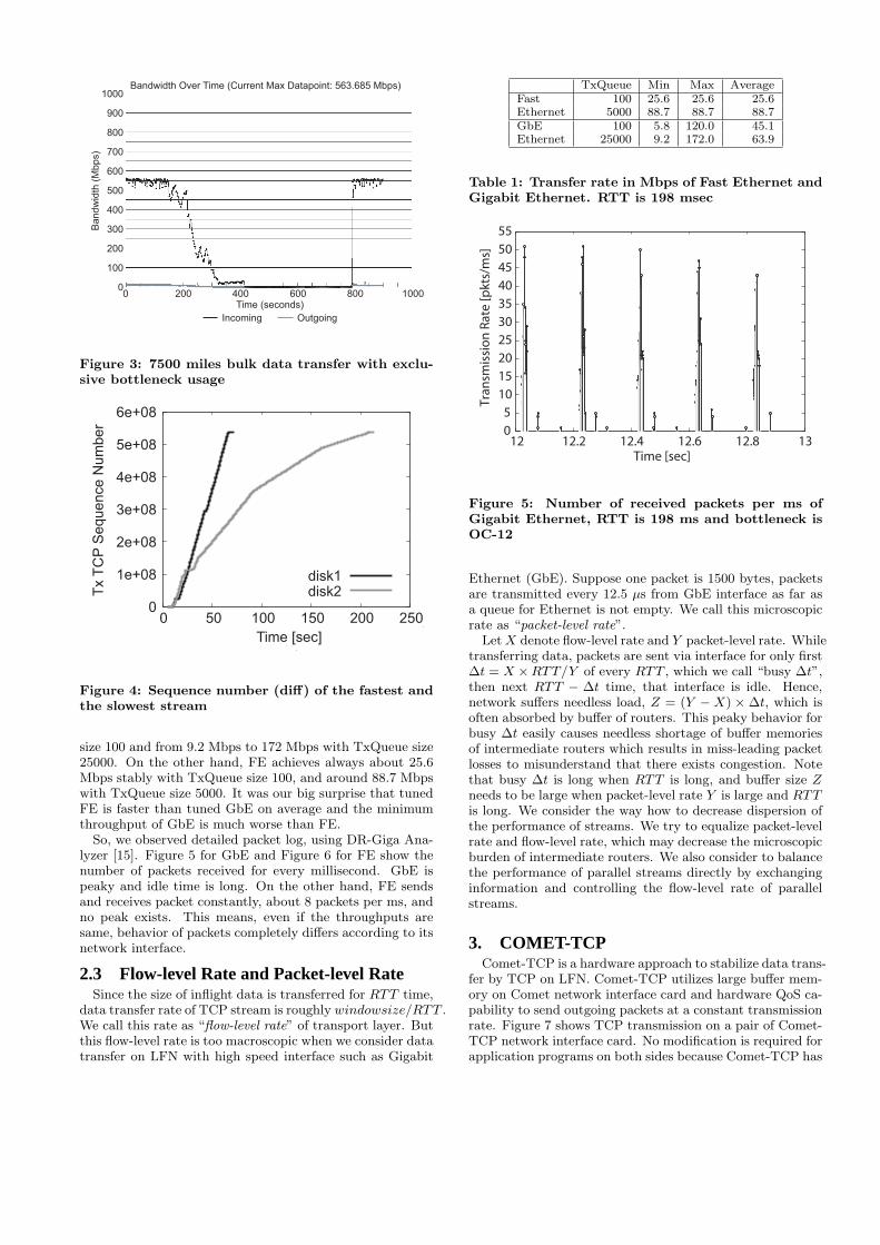
age of bandwidth using a pair of 26 IA servers when weused bottleneck line exclusively (Figure 3). But, we encoun-tered two problems. One is the low performance of eachstream; a server can attain at most 20 Mbps in average.The other is the disperse speed of streams. Even though themachine specification is equal, data is equally divided, andeach machine takes equal load, sometimes certain threadsneeds longer time. For example, from 150 sec to 400 sec inFigure 3, the number of active streams decreases little bylittle, because faster streams finish its job gradually. Figure4 shows the sequence number of the fastest and the slow-est streams out of 4 streams. One thread needs three timeslonger time to finish its job than the fastest thread. This re-sults in that total performance becomes one third, since theslowest stream is the dominant factor of the system perfor-mance. Even after other streams finish their jobs, and eventhough no competitor exists, slower streams tend to fail togain that bandwidth.
2.2 Gigabit Ethernet Interface vs. Fast Ether-net Interface
After the Bandwidth Challenge, we experimented datatransfer of single stream between FLA (Fujitsu LaboratoryAmerica) in Maryland and University of Tokyo (Figure 2),using a pair of IA servers. We compare throughput of PCwith interface Gigabit Ethernet (GbE) and Fast Ethernet(FE) using “iperf” software, while tuning TxQueue length.Table 1 shows minimum, maximum, and average transferrate of GbE and FE. The performance of GbE is not stableat all and varies from 5.6 Mbps to 120 Mbps with TxQueue
1Asia-Pacific Advanced Network. http://www.apan.net/
100
200
300
400
500
600
700
800
900
1000
0
Bandw
idth
(M
bps)
0 200 400 600 800 1000Time (seconds)
Bandwidth Over Time (Current Max Datapoint: 563.685 Mbps)
Incoming Outgoing
Figure 3: 7500 miles bulk data transfer with exclu-sive bottleneck usage
0
1e+08
2e+08
3e+08
4e+08
5e+08
6e+08
0 50 100 150 200 250
Time [sec]
Tx T
CP
Sequence N
um
ber
disk1disk2
Figure 4: Sequence number (diff) of the fastest andthe slowest stream
size 100 and from 9.2 Mbps to 172 Mbps with TxQueue size25000. On the other hand, FE achieves always about 25.6Mbps stably with TxQueue size 100, and around 88.7 Mbpswith TxQueue size 5000. It was our big surprise that tunedFE is faster than tuned GbE on average and the minimumthroughput of GbE is much worse than FE.
So, we observed detailed packet log, using DR-Giga Ana-lyzer [15]. Figure 5 for GbE and Figure 6 for FE show thenumber of packets received for every millisecond. GbE ispeaky and idle time is long. On the other hand, FE sendsand receives packet constantly, about 8 packets per ms, andno peak exists. This means, even if the throughputs aresame, behavior of packets completely differs according to itsnetwork interface.
2.3 Flow-level Rate and Packet-level RateSince the size of inflight data is transferred for RTT time,
data transfer rate of TCP stream is roughly windowsize/RTT .We call this rate as “flow-level rate” of transport layer. Butthis flow-level rate is too macroscopic when we consider datatransfer on LFN with high speed interface such as Gigabit
TxQueue Min Max AverageFast 100 25.6 25.6 25.6Ethernet 5000 88.7 88.7 88.7GbE 100 5.8 120.0 45.1Ethernet 25000 9.2 172.0 63.9
Table 1: Transfer rate in Mbps of Fast Ethernet andGigabit Ethernet. RTT is 198 msec
0
5
10
15
20
25
30
35
40
45
50
55
12 12.2 12.4 12.6 12.8 13
Tra
nsm
issi
on
Ra
te [
pk
ts/m
s]
Time [sec]
Figure 5: Number of received packets per ms ofGigabit Ethernet, RTT is 198 ms and bottleneck isOC-12
Ethernet (GbE). Suppose one packet is 1500 bytes, packetsare transmitted every 12.5 µs from GbE interface as far asa queue for Ethernet is not empty. We call this microscopicrate as “packet-level rate”.
Let X denote flow-level rate and Y packet-level rate. Whiletransferring data, packets are sent via interface for only first∆t = X ×RTT/Y of every RTT , which we call “busy ∆t”,then next RTT − ∆t time, that interface is idle. Hence,network suffers needless load, Z = (Y − X) × ∆t, which isoften absorbed by buffer of routers. This peaky behavior forbusy ∆t easily causes needless shortage of buffer memoriesof intermediate routers which results in miss-leading packetlosses to misunderstand that there exists congestion. Notethat busy ∆t is long when RTT is long, and buffer size Zneeds to be large when packet-level rate Y is large and RTTis long. We consider the way how to decrease dispersion ofthe performance of streams. We try to equalize packet-levelrate and flow-level rate, which may decrease the microscopicburden of intermediate routers. We also consider to balancethe performance of parallel streams directly by exchanginginformation and controlling the flow-level rate of parallelstreams.
3. COMET-TCPComet-TCP is a hardware approach to stabilize data trans-
fer by TCP on LFN. Comet-TCP utilizes large buffer mem-ory on Comet network interface card and hardware QoS ca-pability to send outgoing packets at a constant transmissionrate. Figure 7 shows TCP transmission on a pair of Comet-TCP network interface card. No modification is required forapplication programs on both sides because Comet-TCP has

10
15
20
25
30
35
40
45
50
55Tr
an
smis
sio
n R
ate
[p
kts
/ms]
0
5
12 12.2 12.4 12.6 12.8 13Time [sec]
Figure 6: Number of received packets per ms of FastEthernet, RTT is 198 ms and bottleneck is OC-12
InternetComet
ApplicationTCP
High speed, reliable communicationbetween Comet hardware
TCP/IP
Comet
ApplicationTCP
TCP/IP
Comet terminates TCP/IP
QoS Network
Figure 7: TCP on a pair of Comet-TCP networkinterface card
compatible API to conventional TCP protocol stack. All thepackets that are not ACKed by the remote TCP receiver arestored into packet buffer memory on the local Comet-TCPnetwork interface card (Figure 8). When a sender sends apacket, Comet-TCP immediately terminate TCP by send-ing back an ACK to a TCP driver unless packet memory onthe Comet-TCP is not full. Then Comet-TCP encapsulateTCP packets into fixed-length packets with special headerand sends them to remote Comet-TCP under QoS packettransmission rate control. When Comet-TCP receives pack-ets whose transmission rate is more than the pre-determinedvalue, packet transmission is paced by inserting gaps be-tween packets. When the remote Comet-TCP receives pack-ets, Comet-TCP recovers TCP packets and recovered pack-ets are immediately sent to TCP/IP layer of the remote hostprocessor. When the received TCP packet is the properpacket, the TCP layer on the remote host sends back ACKto the sender. When the Comet-TCP at the sender sidereceives the ACK, it removed packets stored in the buffermemory on Comet-TCP network. When the buffer memoryon the local CometTCP becomes full, CometTCP does notreturn ACKs to the TCP driver and thus TCP driver stopsending packet until the buffer memory becomes availableThese functions are based on RFC 3135, “Performance En-hancing Proxies Intended to Mitigate Link-Related Degra-dations” [1].
BufferMemory
256MB
Comet NP
Intel
82546
SDRAM
128MB
PXA PCIBridge
PXA 255
400MHz
PCI 66MHz / 64bit
PCI 66MHz / 64bit
1000BASE-T
1000BASE-T
Figure 8: Block Diagram of Comet-TCP networkinterface card
Figure 8 shows block diagram of Comet-TCP network in-terface card. Comet-TCP is a network interface card withPCI 66MHz/64bit bus interface. Comet NP is a micro-programmed network processor that can transform packetstreams and encrypt / decrypt packets into IPsec packetat wire speed of Gigabit Ethernet [10]. Buffer memory isused for storing transmitting packets and SDRAM is usedfor storing programs for strong-ARM (PXA255) control pro-cessor. Comet-TCP has two Gigabit Ethernet interfaces buta single interface is used for implementation of Comet-TCP.
4. TRANSMISSION RATE CONTROLLEDTCP (TRC-TCP)
“Transmission Rate Controlled TCP (TRC-TCP)” is torelax the burstiness of TCP by approximating microscopicpacket-level transmission rate to macroscopic flow-level trans-mission rate [16]. TRC-TCP is a combination of data-linklayer approach and transport layer approach; IPG control,which is done by controlling network adapter’s transmissionrate of packets, and Clustered Packet Spacing, which usespseudo software interrupt function ’tasklet’ in Linux kernel.
4.1 Inter Packet Gap (IPG) tuningAccording to the IEEE’s Ethernet standard, an Ethernet
adapter should insert a delay between successive transmis-sions of packets and this delay is called ’Inter Packet Gap’(IPG). A larger IPG will decrease the effective throughputand then the IPG can be used to control the aggressivenesshow the sender emits data into network. Many Ethernetadapters can be configurable for IPG parameter by software.As for an Intel GbE adapter, the IPG value ranges from 8 to1023 bytes in increments of 1 byte. We modify the Linux’sdriver called ’e1000’ to make it configurable for IPG using’ethtool’, and the default value is minimum 8 bytes.
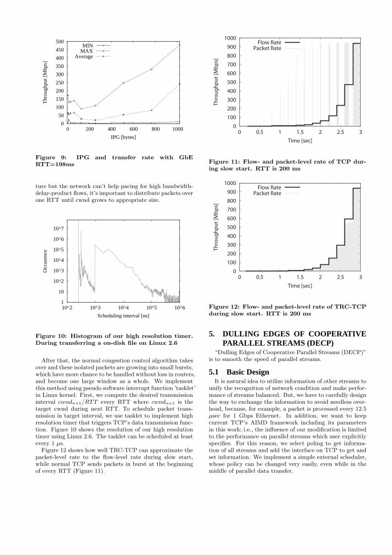
Figure 9 shows the maximum, minimum and average through-put when we change the IPG from 8 to 1023 bytes. It’s truethat IPG tuning is effective to make bursty behavior of GbEmilder, i.e., busy ∆t becomes (IPG + MTU)/MTU timeslonger, when we assume one packet is about MTU long. Butshortcoming of IPG tuning is that it affects all communica-tion over LFT-tuned interface.
4.2 Clustered Packet SpacingTo realize packet spacing by software, we modify the packet
transmission scheduling during the slow start to disperse onewindow of packets over one RTT. Since TCP congestion con-trol is ACK-arrival event-driven and has “self-clocking” na-
0
50
100
150
200
250
300
350
400
450
500
0 200 400 600 800 1000
Thr
ough
put [
Mbp
s]
IPG [bytes]
MINMAX
Average
Figure 9: IPG and transfer rate with GbERTT=198ms
ture but the network can’t help pacing for high bandwidth-delay-product flows, it’s important to distribute packets overone RTT until cwnd grows to appropriate size.
1
10
10^2
10^3
10^4
10^5
10^6
10^7
10^2 10^3 10^4 10^5 10^6
Occ
uren
ce
Scheduling interval [ns]
Figure 10: Histogram of our high resolution timer.During transferring a on-disk file on Linux 2.6
After that, the normal congestion control algorithm takesover and these isolated packets are growing into small bursts,which have more chance to be handled without loss in routers,and become one large window as a whole. We implementthis method using pseudo software interrupt function ’tasklet’in Linux kernel. First, we compute the desired transmissioninterval cwndn+1/RTT every RTT where cwndn+1 is thetarget cwnd during next RTT. To schedule packet trans-mission in target interval, we use tasklet to implement highresolution timer that triggers TCP’s data transmission func-tion. Figure 10 shows the resolution of our high resolutiontimer using Linux 2.6. The tasklet can be scheduled at leastevery 1 µs.
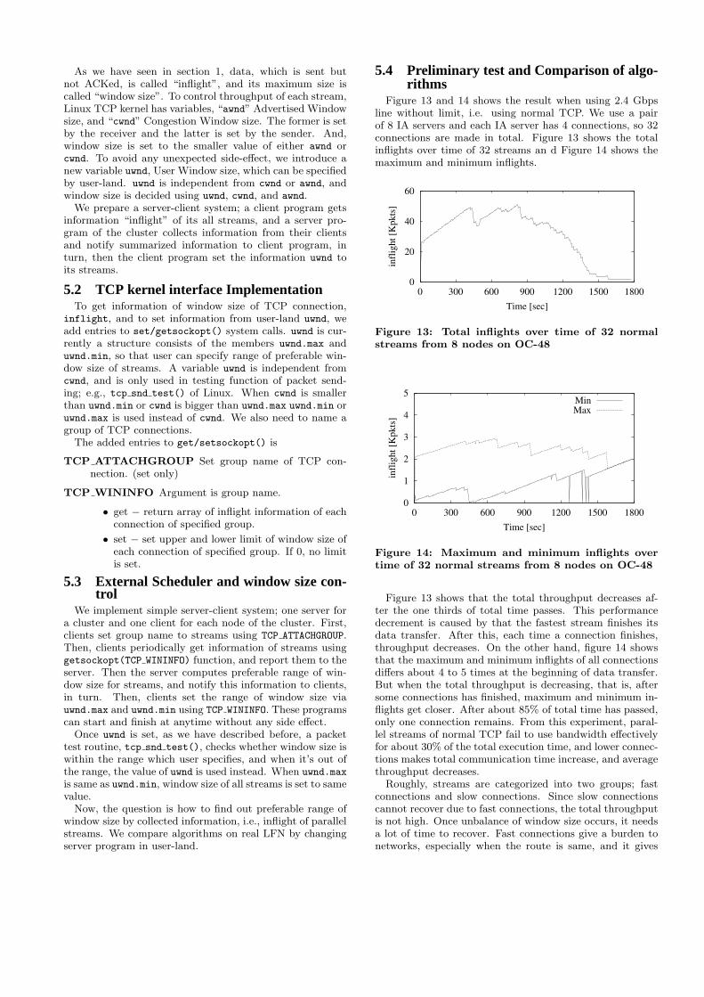
Figure 12 shows how well TRC-TCP can approximate thepacket-level rate to the flow-level rate during slow start,while normal TCP sends packets in burst at the beginningof every RTT (Figure 11).
0
100
200
300
400
500
600
700
800
900
1000
0 0.5 1 1.5 2 2.5 3
Th
rou
gh
pu
t [M
bp
s]
Time [sec]
Flow RatePacket Rate
Figure 11: Flow- and packet-level rate of TCP dur-ing slow start. RTT is 200 ms
0
100
200
300
400
500
600
700
800
900
1000
0 0.5 1 1.5 2 2.5 3
Th
rou
gh
pu
t [M
bp
s]
Time [sec]
Flow RatePacket Rate
Figure 12: Flow- and packet-level rate of TRC-TCPduring slow start. RTT is 200 ms
5. DULLING EDGES OF COOPERATIVEPARALLEL STREAMS (DECP)
“Dulling Edges of Cooperative Parallel Streams (DECP)”is to smooth the speed of parallel streams.
5.1 Basic DesignIt is natural idea to utilize information of other streams to
unify the recognition of network condition and make perfor-mance of streams balanced. But, we have to carefully designthe way to exchange the information to avoid needless over-head, because, for example, a packet is processed every 12.5µsec for 1 Gbps Ethernet. In addition, we want to keepcurrent TCP’s AIMD framework including its parametersin this work; i.e., the influence of our modification is limitedto the performance on parallel streams which user explicitlyspecifies. For this reason, we select poling to get informa-tion of all streams and add the interface on TCP to get andset information. We implement a simple external scheduler,whose policy can be changed very easily, even while in themiddle of parallel data transfer.
As we have seen in section 1, data, which is sent butnot ACKed, is called “inflight”, and its maximum size iscalled “window size”. To control throughput of each stream,Linux TCP kernel has variables, “awnd” Advertised Windowsize, and “cwnd” Congestion Window size. The former is setby the receiver and the latter is set by the sender. And,window size is set to the smaller value of either awnd orcwnd. To avoid any unexpected side-effect, we introduce anew variable uwnd, User Window size, which can be specifiedby user-land. uwnd is independent from cwnd or awnd, andwindow size is decided using uwnd, cwnd, and awnd.
We prepare a server-client system; a client program getsinformation “inflight” of its all streams, and a server pro-gram of the cluster collects information from their clientsand notify summarized information to client program, inturn, then the client program set the information uwnd toits streams.
5.2 TCP kernel interface ImplementationTo get information of window size of TCP connection,
inflight, and to set information from user-land uwnd, weadd entries to set/getsockopt() system calls. uwnd is cur-rently a structure consists of the members uwnd.max anduwnd.min, so that user can specify range of preferable win-dow size of streams. A variable uwnd is independent fromcwnd, and is only used in testing function of packet send-ing; e.g., tcp snd test() of Linux. When cwnd is smallerthan uwnd.min or cwnd is bigger than uwnd.max uwnd.min oruwnd.max is used instead of cwnd. We also need to name agroup of TCP connections.
The added entries to get/setsockopt() is
TCP ATTACHGROUP Set group name of TCP con-nection. (set only)
TCP WININFO Argument is group name.
• get − return array of inflight information of eachconnection of specified group.
• set − set upper and lower limit of window size ofeach connection of specified group. If 0, no limitis set.
5.3 External Scheduler and window size con-trol
We implement simple server-client system; one server fora cluster and one client for each node of the cluster. First,clients set group name to streams using TCP ATTACHGROUP.Then, clients periodically get information of streams usinggetsockopt(TCP WININFO) function, and report them to theserver. Then the server computes preferable range of win-dow size for streams, and notify this information to clients,in turn. Then, clients set the range of window size viauwnd.max and uwnd.min using TCP WININFO. These programscan start and finish at anytime without any side effect.
Once uwnd is set, as we have described before, a packettest routine, tcp snd test(), checks whether window size iswithin the range which user specifies, and when it’s out ofthe range, the value of uwnd is used instead. When uwnd.max
is same as uwnd.min, window size of all streams is set to samevalue.
Now, the question is how to find out preferable range ofwindow size by collected information, i.e., inflight of parallelstreams. We compare algorithms on real LFN by changingserver program in user-land.
5.4 Preliminary test and Comparison of algo-rithms
Figure 13 and 14 shows the result when using 2.4 Gbpsline without limit, i.e. using normal TCP. We use a pairof 8 IA servers and each IA server has 4 connections, so 32connections are made in total. Figure 13 shows the totalinflights over time of 32 streams an d Figure 14 shows themaximum and minimum inflights.
0
20
40
60
0 300 600 900 1200 1500 1800
infl
igh
t [K
pk
ts]
Time [sec]
Figure 13: Total inflights over time of 32 normalstreams from 8 nodes on OC-48
0
1
2
3
4
5
0 300 600 900 1200 1500 1800
infl
igh
t [K
pk
ts]
Time [sec]
MinMax
Figure 14: Maximum and minimum inflights overtime of 32 normal streams from 8 nodes on OC-48
Figure 13 shows that the total throughput decreases af-ter the one thirds of total time passes. This performancedecrement is caused by that the fastest stream finishes itsdata transfer. After this, each time a connection finishes,throughput decreases. On the other hand, figure 14 showsthat the maximum and minimum inflights of all connectionsdiffers about 4 to 5 times at the beginning of data transfer.But when the total throughput is decreasing, that is, aftersome connections has finished, maximum and minimum in-flights get closer. After about 85% of total time has passed,only one connection remains. From this experiment, paral-lel streams of normal TCP fail to use bandwidth effectivelyfor about 30% of the total execution time, and lower connec-tions makes total communication time increase, and averagethroughput decreases.
Roughly, streams are categorized into two groups; fastconnections and slow connections. Since slow connectionscannot recover due to fast connections, the total throughputis not high. Once unbalance of window size occurs, it needsa lot of time to recover. Fast connections give a burden tonetworks, especially when the route is same, and it gives
bad effects to other connections. But the judgment whetherit’s too fast or not is difficult. In addition, if window sizeis too big, the penalty is big accordingly when pack et lossoccurs. The target of our algorithm is to suppress excessiveconnections and realize the normalized transfer rate.
We compare several naive algorithms such as set largest,larger, average value to all clients, or set upper or lower limitusing average or weighted average of window sizes. Surpris-ingly, setting larger value or setting lower limit seems tomake the performance worse. For example, if each clienttakes the maximum window size of all streams as its win-dow size, the performance decreases very badly. As for ourexperiments for SC2003, we didn’t set lower limit and onlyuse upper limit.
5.5 Dulling Edges of Cooperative ParallelStreams (DECP)
To improve total performance of a system using parallelstreams, we take a strategy that decelerates faster streams,in order to help slower streams to catch up quickly and re-liably. Then, we compare several naive algorithms how toco-operate parallel streams, and decide the policy of algo-rithm. We adopt majority decision algorithm using score-board with the history, in order to avoid being too sensitiveto the slowest stream or latest packet loss event. First, wequantize a value of inflight and divide into several blocks andrecord collected inflights using so-called “scoreboard” table.Clients send notification of the value of inflight periodicallyto the server.(1) Periodically, a server counts up the points of the score-board. First, all score is decreased with a fixed rate.(2) According to an inflight value sent from a client, a scoreis added in the convex form. It means that the exact blockgets full points and the neighboring blocks also get partialpoints.(3) If the score of all connections are added, the block ofhighest score is taken as the most favorable block, and thecorresponding window size is used as a goal.(4) A bit larger value than selected window size is notifiedas new upper limit to clients.By using such kind of scoreboard algorithm, it’s possibleto increase the upper limit of window size gradually whilewaiting for most connections to grow up.
For this experiment, a window size is quantized by 30packets and counted every 1 second. We use the decreasingratio of score of 10% and 3 points for an exact block, 2 pointsfor neighbors and 1 point for neighbors’ neighbors. Thevalue with extra 60 packets is notified to clients and theyselect the smallest from their congestion window, advertisedwindow and the notified window size.
6. EXPERIMENTAL RESULTS
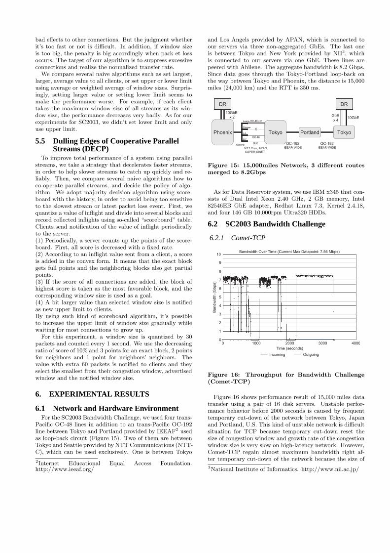
6.1 Network and Hardware EnvironmentFor the SC2003 Bandwidth Challenge, we used four trans-
Pacific OC-48 lines in addition to an trans-Pacific OC-192line between Tokyo and Portland provided by IEEAF2 usedas loop-back circuit (Figure 15). Two of them are betweenTokyo and Seattle provided by NTT Communications (NTT-C), which can be used exclusively. One is between Tokyo
2Internet Educational Equal Access Foundation.http://www.ieeaf.org/
and Los Angels provided by APAN, which is connected toour servers via three non-aggregated GbEs. The last oneis between Tokyo and New York provided by NII3, whichis connected to our servers via one GbE. These lines arepeered with Abilene. The aggregate bandwidth is 8.2 Gbps.Since data goes through the Tokyo-Portland loop-back onthe way between Tokyo and Phoenix, the distance is 15,000miles (24,000 km) and the RTT is 350 ms.
OC-192IEEAF/ WIDENTT Com, APAN,
SUPER-SINET
GbE
x 410GbE
10GbE
x 2OC-48 x 2
OC-48
GbE
Seattle
L.A.
Chicago
N.Y.
Abilene OC-192IEEAF/ WIDE
Phoenix Portland Tokyo
DR DR
TokyoX
Figure 15: 15,000miles Network, 3 different routesmerged to 8.2Gbps
As for Data Reservoir system, we use IBM x345 that con-sists of Dual Intel Xeon 2.40 GHz, 2 GB memory, Intel82546EB GbE adapter, Redhat Linux 7.3, Kernel 2.4.18,and four 146 GB 10,000rpm Ultra320 HDDs.
6.2 SC2003 Bandwidth Challenge
6.2.1 Comet-TCP
1
2
3
4
5
6
7
8
9
10
0
Ba
nd
wid
th (
Gb
ps)
0 1000 2000 3000 4000
Time (seconds)
Bandwidth Over Time (Current Max Datapoint: 7.56 Mbps)
Incoming Outgoing
Figure 16: Throughput for Bandwidth Challenge(Comet-TCP)
Figure 16 shows performance result of 15,000 miles datatransfer using a pair of 16 disk servers. Unstable perfor-mance behavior before 2000 seconds is caused by frequenttemporary cut-down of the network between Tokyo, Japanand Portland, U.S. This kind of unstable network is difficultsituation for TCP because temporary cut-down reset thesize of congestion window and growth rate of the congestionwindow size is very slow on high-latency network. However,Comet-TCP regain almost maximum bandwidth right af-ter temporary cut-down of the network because the size of
3National Institute of Informatics. http://www.nii.ac.jp/
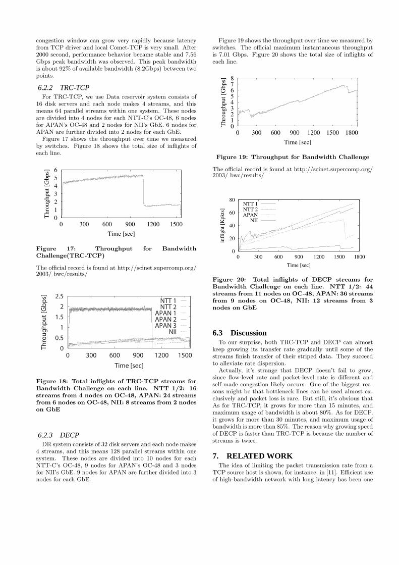
congestion window can grow very rapidly because latencyfrom TCP driver and local Comet-TCP is very small. After2000 second, performance behavior became stable and 7.56Gbps peak bandwidth was observed. This peak bandwidthis about 92% of available bandwidth (8.2Gbps) between twopoints.
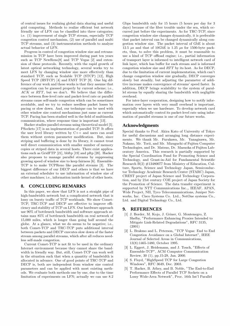
6.2.2 TRC-TCPFor TRC-TCP, we use Data reservoir system consists of
16 disk servers and each node makes 4 streams, and thismeans 64 parallel streams within one system. These nodesare divided into 4 nodes for each NTT-C’s OC-48, 6 nodesfor APAN’s OC-48 and 2 nodes for NII’s GbE. 6 nodes forAPAN are further divided into 2 nodes for each GbE.
Figure 17 shows the throughput over time we measuredby switches. Figure 18 shows the total size of inflights ofeach line.
0
1
2
3
4
5
6
0 300 600 900 1200 1500
Thro
ughput
[Gbps]
Time [sec]
Figure 17: Throughput for BandwidthChallenge(TRC-TCP)
The official record is found at http://scinet.supercomp.org/2003/ bwc/results/
0
0.5
1
1.5
2
2.5
0 300 600 900 1200 1500
Th
rou
gh
pu
t [G
bp
s]
Time [sec]
NTT 1NTT 2
APAN 1APAN 2APAN 3
NII
Figure 18: Total inflights of TRC-TCP streams forBandwidth Challenge on each line. NTT 1/2: 16streams from 4 nodes on OC-48, APAN: 24 streamsfrom 6 nodes on OC-48, NII: 8 streams from 2 nodeson GbE
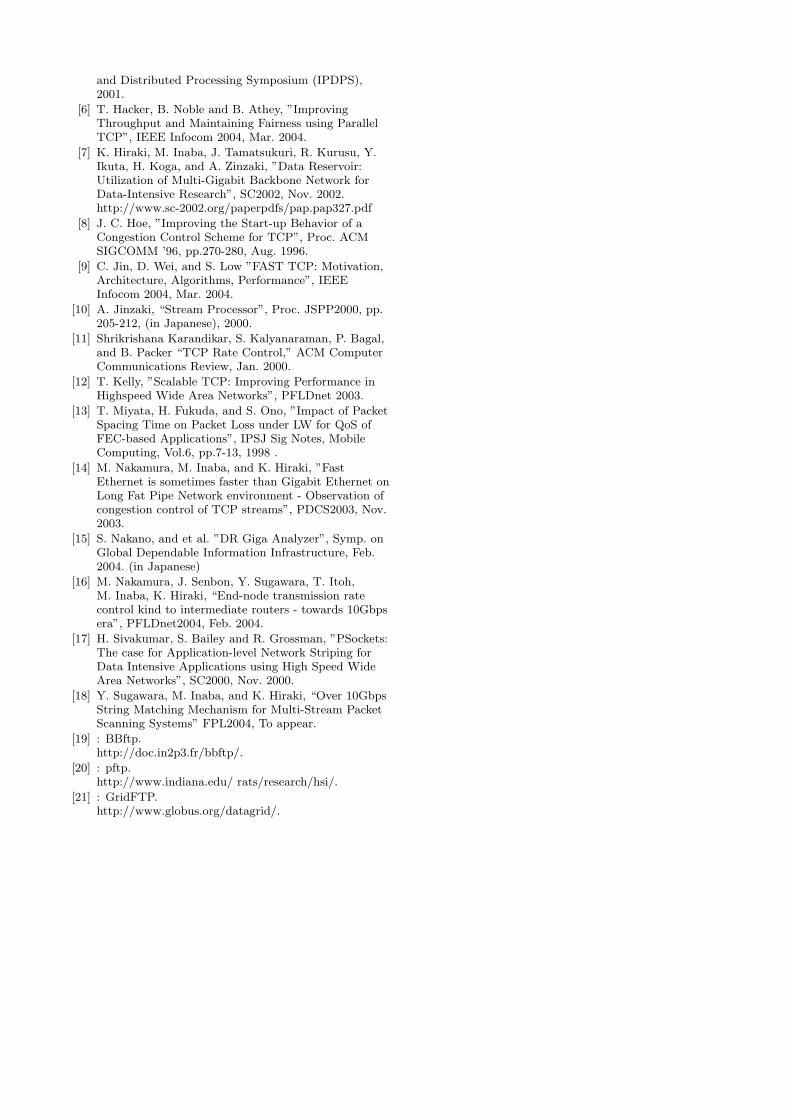
6.2.3 DECPDR system consists of 32 disk servers and each node makes
4 streams, and this means 128 parallel streams within onesystem. These nodes are divided into 10 nodes for eachNTT-C’s OC-48, 9 nodes for APAN’s OC-48 and 3 nodesfor NII’s GbE. 9 nodes for APAN are further divided into 3nodes for each GbE.
Figure 19 shows the throughput over time we measured byswitches. The official maximum instantaneous throughputis 7.01 Gbps. Figure 20 shows the total size of inflights ofeach line.
012345678
0 300 600 900 1200 1500 1800
Thro
ughput
[Gbps]
Time [sec]
Figure 19: Throughput for Bandwidth Challenge
The official record is found at http://scinet.supercomp.org/2003/ bwc/results/
0
20
40
60
80
0 300 600 900 1200 1500 1800
infl
igh
t [K
pk
ts]
Time [sec]
NTT 1NTT 2APAN
NII
Figure 20: Total inflights of DECP streams forBandwidth Challenge on each line. NTT 1/2: 44streams from 11 nodes on OC-48, APAN: 36 streamsfrom 9 nodes on OC-48, NII: 12 streams from 3nodes on GbE
6.3 DiscussionTo our surprise, both TRC-TCP and DECP can almost
keep growing its transfer rate gradually until some of thestreams finish transfer of their striped data. They succeedto alleviate rate dispersion.
Actually, it’s strange that DECP doesn’t fail to grow,since flow-level rate and packet-level rate is different andself-made congestion likely occurs. One of the biggest rea-sons might be that bottleneck lines can be used almost ex-clusively and packet loss is rare. But still, it’s obvious thatAs for TRC-TCP, it grows for more than 15 minutes, andmaximum usage of bandwidth is about 80%. As for DECP,it grows for more than 30 minutes, and maximum usage ofbandwidth is more than 85%. The reason why growing speedof DECP is faster than TRC-TCP is because the number ofstreams is twice.
7. RELATED WORKThe idea of limiting the packet transmission rate from a
TCP source host is shown, for instance, in [11]. Efficient useof high-bandwidth network with long latency has been one
of central issues for realizing global data sharing and usefulgrid computing. Methods to realize efficient but networkfriendly use of LFN can be classified into three categories;i.e. (1) improvement of single TCP stream, especially TCPcongestion control mechanism, (2) use of parallel and multiTCP streams, and (3) instrumentation methods to analyzeactual behavior of LFN.
Progress in control of congestion window size and retrans-mission in TCP have been improved during past ten yearssuch as TCP NewReno[8] and TCP Vegas [2] and exten-sion of these protocols. Recently, with the rapid growth oflatest optical networking technology, several works try tomeet LFN by changing window size more effectively thanstandard TCP, such as Scalable TCP (STCP) [12], HighSpeed TCP (HSTCP) [4] and FAST TCP [9]. One big dif-ference of our work and these works is that they assume thatcongestion can be guessed properly by current scheme; i.e.,ACK or RTT , but we don’t. We believe that the differ-ence between flow-level rate and packet-level rate or parallelstreams cause self-made congestion which can be sometimesavoidable, and we try to reduce needless packet losses bypacing or slow down. And, our technique can be used withother window size control mechanisms just same as currentTCP. Pacing has been studied well in the field of multimediacommunication, where response time is important [13].
Hacker studies parallel streams using theoretical model [5].PSockets [17] is an implementation of parallel TCP. It offersthe user level library written by C++ and users can availthem without system parameter modification. But, sincestriping and buffering is done by its library, it cannot treatwell direct communication with smaller number of memorycopies or striped data in several hosts. There exist applica-tions such as GridFTP [21], bbftp [19] and pftp [20]. Hackeralso proposes to manage parallel streams by suppressinggrowing speed of window size to keep fairness [6]. Ensemble-TCP is to make TCPReno like parallel streams [3]. Thebiggest difference of our DECP and others is that we havean external scheduler to use information of window size ofother machines; i.e., information inside kernel of other hosts.
8. CONCLUDING REMARKSIn this paper, we show that LFN is not a straight pipe of
high-bandwidth network but a complicated network that islossy on bursty traffic of TCP workloads. We show Comet-TCP, TRC-TCP and DECP are effective to improve effi-ciency and stability of TCP on LFN. Our hardware approachuse 90% of bottleneck bandwidth and software approach at-tains max 85% of bottleneck bandwidth on real network of15,000 miles, which is longer than going half around theglobe. At a glance, what we do seems to be negative; i.e.,both Comet-TCP and TRC-TCP puts additional intervalbetween packets and DECP executes slow down of the fasterstream among parallel streams, which after all reduces need-less self-made congestion.
Current Comet-TCP is not fit to be used in the ordinaryInternet environment because they cannot share the band-width in friendly way. But, still, Comet-TCP can work wellin the situation such that when a quantity of bandwidth isallocated in advance. One of good points of TRC-TCP andDECP is, both are independent from window size controlparameters and can be applied with most existing meth-ods. We evaluate both methods one by one, due to the timelimitation of experiments on LFN; actually we can use 8.2
Gbps bandwidth only for 15 hours (5 hours per day for 3days) because of the fiber trouble under the sea, which oc-curred just before the experiments. As for TRC-TCP, sincecongestion window size changes dynamically, it is preferablethat packet interval can be changed dynamically along con-gestion window size. The packet interval of GbE is about12.5 µs and that of 10GbE is 1.25 µs for 1500-byte pack-ets, thus, to solve this problem, it must be reasonable touse a kind of TCP offload engine; i.e., partial informationof transport layer is informed to intelligent network card oflink layer, which has buffer for each stream and is informedcongestion window size and RTT by its host. As for DECP,due to the limitation of current implementation, which can’tchange congestion window size gradually, DECP convergesslowly but steadily, but adjusting the parameter of addi-tive increase makes convergence of streams’ speed faster. Inaddition, DECP brings scalability to the system of paral-lel strems by equally sharing the bandwidth with negligibleoverhead.
For inter-layer cooperation, designing how to notify infor-mation over layers with very small overhead is important,especially when we use hardware. To develop network cardwhich automatically control its packet-level rate using infor-mation of parallel streams is one of our future works.
AcknowledgmentsSpecial thanks to Prof. Akira Kato of University of Tokyofor useful discussions and arranging long distance experi-ments. We thank Mr. Furukawa, Mr. Yanagisawa, Mr.Nakano, Mr. Torii, and Mr. Mizuguchi of Fujitsu ComputerTechnologies, and Dr. Matsuo, Dr. Masuoka of Fujitsu Lab-oratory America. This research is partially supported bythe Special Coordination Fund for Promoting Science andTechnology, and Grant-in-Aid for Fundamental ScientificResearch B(2) #13480077 from Ministry of Education, Cul-ture, Sports, Science and Technology Japan, Semiconduc-tor Technology Academic Research Center (STARC) Japan,CREST project of Japan Science and Technology Corpora-tion, and by 21st century COE project of Japan Society forthe Promotion of Science. The data transfer experiment issupported by NTT Communications Inc.,, IEEAF, APAN,Wide Project, NII, Tyco Telecommunications, Juniper Net-works, Inc. Cisco Systems Co. Ltd., NetOne systems Co.,Ltd. and Digital Technology Co., Ltd.
9. REFERENCES[1] J. Border, M. Kojo, J. Griner, G. Montenegro, Z.
Shelby, ”Performance Enhancing Proxies Intended toMitigate Link-Related Degradations”, RFC 3135,(2001)
[2] L. Brakmo and L. Peterson, ”TCP Vegas: End to EndCongestion Avoidance on a Global Internet”, IEEEJournal of Selected Areas in Communications,13(8):1465-1480, October 1995.
[3] L. Eggert, J. Heidemann, and J. Touch, ”Effects ofEnsemble-TCP”, ACM Computer CommunicationReview, 30 (1), pp.15-29, Jan. 2000.
[4] S. Floyd, ”HighSpeed TCP for Large CongestionWindows”, RFC 3649, Dec. 2003.
[5] T. Hacker, B. Athey, and B. Noble, ”The End-to-EndPerformance Effects of Parallel TCP Sockets on aLossy Wide-Area Network”, Proc. 16th Int’l Parallel
and Distributed Processing Symposium (IPDPS),2001.
[6] T. Hacker, B. Noble and B. Athey, ”ImprovingThroughput and Maintaining Fairness using ParallelTCP”, IEEE Infocom 2004, Mar. 2004.
[7] K. Hiraki, M. Inaba, J. Tamatsukuri, R. Kurusu, Y.Ikuta, H. Koga, and A. Zinzaki, ”Data Reservoir:Utilization of Multi-Gigabit Backbone Network forData-Intensive Research”, SC2002, Nov. 2002.http://www.sc-2002.org/paperpdfs/pap.pap327.pdf
[8] J. C. Hoe, ”Improving the Start-up Behavior of aCongestion Control Scheme for TCP”, Proc. ACMSIGCOMM ’96, pp.270-280, Aug. 1996.
[9] C. Jin, D. Wei, and S. Low ”FAST TCP: Motivation,Architecture, Algorithms, Performance”, IEEEInfocom 2004, Mar. 2004.
[10] A. Jinzaki, “Stream Processor”, Proc. JSPP2000, pp.205-212, (in Japanese), 2000.
[11] Shrikrishana Karandikar, S. Kalyanaraman, P. Bagal,and B. Packer “TCP Rate Control,” ACM ComputerCommunications Review, Jan. 2000.
[12] T. Kelly, ”Scalable TCP: Improving Performance inHighspeed Wide Area Networks”, PFLDnet 2003.
[13] T. Miyata, H. Fukuda, and S. Ono, ”Impact of PacketSpacing Time on Packet Loss under LW for QoS ofFEC-based Applications”, IPSJ Sig Notes, MobileComputing, Vol.6, pp.7-13, 1998 .
[14] M. Nakamura, M. Inaba, and K. Hiraki, ”FastEthernet is sometimes faster than Gigabit Ethernet onLong Fat Pipe Network environment - Observation ofcongestion control of TCP streams”, PDCS2003, Nov.2003.
[15] S. Nakano, and et al. ”DR Giga Analyzer”, Symp. onGlobal Dependable Information Infrastructure, Feb.2004. (in Japanese)
[16] M. Nakamura, J. Senbon, Y. Sugawara, T. Itoh,M. Inaba, K. Hiraki, “End-node transmission ratecontrol kind to intermediate routers - towards 10Gbpsera”, PFLDnet2004, Feb. 2004.
[17] H. Sivakumar, S. Bailey and R. Grossman, ”PSockets:The case for Application-level Network Striping forData Intensive Applications using High Speed WideArea Networks”, SC2000, Nov. 2000.
[18] Y. Sugawara, M. Inaba, and K. Hiraki, “Over 10GbpsString Matching Mechanism for Multi-Stream PacketScanning Systems” FPL2004, To appear.
[19] : BBftp.http://doc.in2p3.fr/bbftp/.
[20] : pftp.http://www.indiana.edu/ rats/research/hsi/.
[21] : GridFTP.http://www.globus.org/datagrid/.
Top Related
Copyright © 2022 FDOKUMEN

