


Bahasa
Halaman
Hukum

M A T E R I A L S C H A R A C T E R I Z A T I O N 5 9 ( 2 0 0 8 ) 1 3 4 2 – 1 3 4 8
Examination of the solidification macrostructure of spheroidaland flake graphite cast irons using DAAS and ESBD
G. Riveraa, P.R. Calvillob, R. Boeria,⁎, Y. Houbaertb, J. Sikoraa
aMetallurgy Division INTEMA, National University of Mar del Plata, CONICET, J. B. Justo 4302 (B7608FDQ) Mar del Plata, ArgentinabDepartment of Metallurgy and Materials Science, Ghent University, Belgium
A R T I C L E D A T A
⁎ Corresponding author. Tel.: +54 223 4816600E-mail addresses: [email protected] (R. B
1044-5803/$ – see front matter © 2007 Elsevidoi:10.1016/j.matchar.2007.11.009
A B S T R A C T
Article history:Received 19 October 2007Received in revised form 21November 2007Accepted 30 November 2007
This investigation focuses on the study of the solidification macrostructure of sand castflake and spheroidal graphite cast irons. The macrostructure is revealed by using a specialtechnique developed earlier by the authors, called Direct Austempering After Solidification.The observations make use of conventional metallography and Electron Back ScatteringDiffraction. The latter technique allows a more detailed observation of the morphology ofthe austenite grains and the microstructure of the matrix. The results of Electron BackScattering Diffraction validate the observations made using the macrographic technique. Itis verified that the solidification of both flake and spheroidal graphite cast irons isdominated by the growth of large austenite dendrites that form a grain pattern similar tothat usually found in most metallic alloys.
© 2007 Elsevier Inc. All rights reserved.
Keywords:MacrostructureCast ironDAAS, EBSD
1. Introduction
Flake graphite cast iron (FGI) and spheroidal graphite cast iron(SGI) are extensively used in the fabrication of parts for severalindustries. As for every cast material, proper knowledge oftheir solidification is necessary to optimize mold filling andparts soundness, and to obtain the desired microstructures.Nevertheless, there is no universally accepted explanation ofthe solidification mechanisms of these materials. The mostnoticeable disagreements among different explanations referto the morphology taken by the austenite as the solidificationadvances. The final morphology of graphite precipitates iseasily observed by metallography. On the other hand, themorphology of the primary austenite is hindered by the solidstate transformations suffered by the austenite as it coolsbelow the eutectoid temperature. It is generally agreed thatthe pro-eutectic austenite grows dendritically in hypoeutecticcast irons. Nevertheless, most explanations of the solidifica-tion of FGI pay little attention to the role of austenite dendritesin eutectic and hypereutectic alloys. The most broadlyaccepted explanation of the solidification of FGI states that
; fax: +54 223 4810046.oeri), [email protected].
er Inc. All rights reserved
eutectic solidification units are formed by nearly sphericalaggregates of austenite and graphite growing cooperatively,producing the so called “eutectic cells” [1–5]. On the otherhand, the solidification of SGI was very often pictured asdominated by the independent growth of units formed bysingle graphite nodules surrounded by austenite [6–8]. It isnow apparent that these mechanisms are incorrect. In fact,recent investigations of the authors have shown that a specialprocedure, called DAAS (Direct Austempering After Solidifica-tion), can be used to reveal the solidificationmacrostructure offree graphite cast irons [9,10]. Through this technique thesolidification macrostructure of FGI and SGI have been foundto be dominated by the growth of relatively large dendrites ofaustenite that give rise to a grain structure very similar to thatusually found in most metallic alloys. The unexpectedpresence of large austenite dendrites in hypereutectic com-positions was also shown [9–14]. These findings verified theresults of earlier studies that warned about the presence ofaustenite dendrites in free graphite cast irons, but were notable to bring up conclusive evidences of their morphology andextension [2,3,15–19]. In spite of the evidences regarding the
ar (J. Sikora).
.
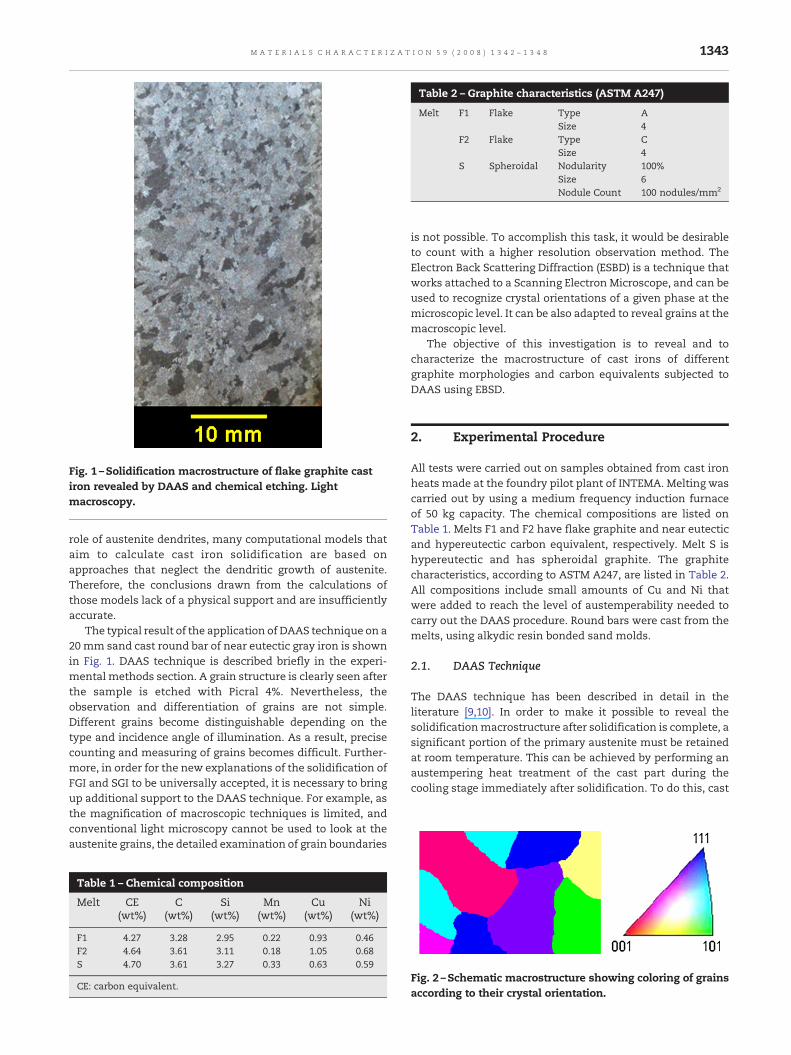
Fig. 1 –Solidification macrostructure of flake graphite castiron revealed by DAAS and chemical etching. Lightmacroscopy.
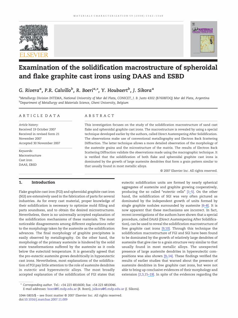
Table 2 – Graphite characteristics (ASTM A247)
Melt F1 Flake Type ASize 4
F2 Flake Type CSize 4
S Spheroidal Nodularity 100%Size 6Nodule Count 100 nodules/mm2
1343M A T E R I A L S C H A R A C T E R I Z A T I O N 5 9 ( 2 0 0 8 ) 1 3 4 2 – 1 3 4 8
role of austenite dendrites, many computational models thataim to calculate cast iron solidification are based onapproaches that neglect the dendritic growth of austenite.Therefore, the conclusions drawn from the calculations ofthose models lack of a physical support and are insufficientlyaccurate.
The typical result of the application of DAAS technique on a20 mm sand cast round bar of near eutectic gray iron is shownin Fig. 1. DAAS technique is described briefly in the experi-mental methods section. A grain structure is clearly seen afterthe sample is etched with Picral 4%. Nevertheless, theobservation and differentiation of grains are not simple.Different grains become distinguishable depending on thetype and incidence angle of illumination. As a result, precisecounting and measuring of grains becomes difficult. Further-more, in order for the new explanations of the solidification ofFGI and SGI to be universally accepted, it is necessary to bringup additional support to the DAAS technique. For example, asthe magnification of macroscopic techniques is limited, andconventional light microscopy cannot be used to look at theaustenite grains, the detailed examination of grain boundaries
Table 1 – Chemical composition
Melt CE(wt%)
C(wt%)
Si(wt%)
Mn(wt%)
Cu(wt%)
Ni(wt%)
F1 4.27 3.28 2.95 0.22 0.93 0.46F2 4.64 3.61 3.11 0.18 1.05 0.68S 4.70 3.61 3.27 0.33 0.63 0.59
CE: carbon equivalent.
is not possible. To accomplish this task, it would be desirableto count with a higher resolution observation method. TheElectron Back Scattering Diffraction (ESBD) is a technique thatworks attached to a Scanning Electron Microscope, and can beused to recognize crystal orientations of a given phase at themicroscopic level. It can be also adapted to reveal grains at themacroscopic level.
The objective of this investigation is to reveal and tocharacterize the macrostructure of cast irons of differentgraphite morphologies and carbon equivalents subjected toDAAS using EBSD.
2. Experimental Procedure
All tests were carried out on samples obtained from cast ironheats made at the foundry pilot plant of INTEMA. Melting wascarried out by using a medium frequency induction furnaceof 50 kg capacity. The chemical compositions are listed onTable 1. Melts F1 and F2 have flake graphite and near eutecticand hypereutectic carbon equivalent, respectively. Melt S ishypereutectic and has spheroidal graphite. The graphitecharacteristics, according to ASTM A247, are listed in Table 2.All compositions include small amounts of Cu and Ni thatwere added to reach the level of austemperability needed tocarry out the DAAS procedure. Round bars were cast from themelts, using alkydic resin bonded sand molds.
2.1. DAAS Technique
The DAAS technique has been described in detail in theliterature [9,10]. In order to make it possible to reveal thesolidificationmacrostructure after solidification is complete, asignificant portion of the primary austenite must be retainedat room temperature. This can be achieved by performing anaustempering heat treatment of the cast part during thecooling stage immediately after solidification. To do this, cast
Fig. 2 –Schematic macrostructure showing coloring of grainsaccording to their crystal orientation.
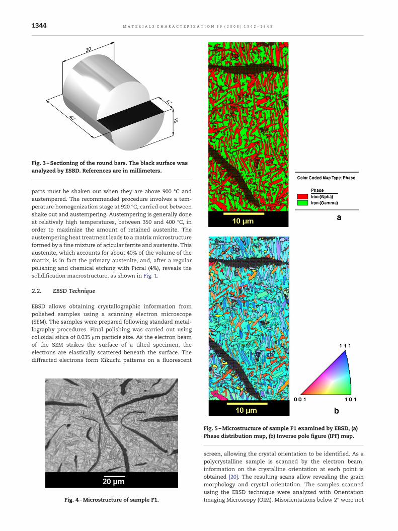
Fig. 3 –Sectioning of the round bars. The black surface wasanalyzed by ESBD. References are in millimeters.
1344 M A T E R I A L S C H A R A C T E R I Z A T I O N 5 9 ( 2 0 0 8 ) 1 3 4 2 – 1 3 4 8
parts must be shaken out when they are above 900 °C andaustempered. The recommended procedure involves a tem-perature homogenization stage at 920 °C, carried out betweenshake out and austempering. Austempering is generally doneat relatively high temperatures, between 350 and 400 °C, inorder to maximize the amount of retained austenite. Theaustempering heat treatment leads to amatrixmicrostructureformed by a fine mixture of acicular ferrite and austenite. Thisaustenite, which accounts for about 40% of the volume of thematrix, is in fact the primary austenite, and, after a regularpolishing and chemical etching with Picral (4%), reveals thesolidification macrostructure, as shown in Fig. 1.
2.2. EBSD Technique
EBSD allows obtaining crystallographic information frompolished samples using a scanning electron microscope(SEM). The samples were prepared following standard metal-lography procedures. Final polishing was carried out usingcolloidal silica of 0.035 μm particle size. As the electron beamof the SEM strikes the surface of a tilted specimen, theelectrons are elastically scattered beneath the surface. Thediffracted electrons form Kikuchi patterns on a fluorescent
Fig. 4 –Microstructure of sample F1.
Fig. 5 –Microstructure of sample F1 examined by EBSD, (a)Phase distribution map, (b) Inverse pole figure (IPF) map.
screen, allowing the crystal orientation to be identified. As apolycrystalline sample is scanned by the electron beam,information on the crystalline orientation at each point isobtained [20]. The resulting scans allow revealing the grainmorphology and crystal orientation. The samples scannedusing the EBSD technique were analyzed with OrientationImaging Microscopy (OIM). Misorientations below 2° were not
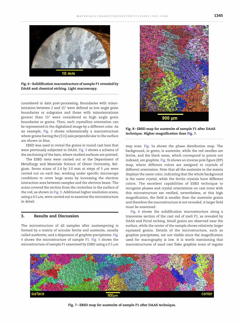
Fig. 6 –Solidificationmacrostructure of sample F1 revealed byDAAS and chemical etching. Light macroscopy.
Fig. 8 –EBSD map for austenite of sample F1 after DAAStechnique. Higher magnification than Fig. 7.
1345M A T E R I A L S C H A R A C T E R I Z A T I O N 5 9 ( 2 0 0 8 ) 1 3 4 2 – 1 3 4 8
considered in data post-processing. Boundaries with misor-ientation between 2 and 15° were defined as low angle grainboundaries or subgrains and those with misorientationsgreater than 15° were considered as high angle grainboundaries or grains. Then, each crystalline orientation canbe represented in the digitalized image by a different color. Asan example, Fig. 2 shows schematically a macrostructurewhere grains having the [111] axis perpendicular to the surfaceare shown in blue.
EBSD was used to reveal the grains in round cast bars thatwere previously subjected to DAAS. Fig. 3 shows a schema ofthe sectioning of the bars, where studied surfaces are pointed.
The ESBD tests were carried out at the Department ofMetallurgy and Materials Science of Ghent University, Bel-gium. Seven scans of 2.4 by 3.0 mm at steps of 5 μm werecarried out on each bar, working under specific microscopeconditions to cover large areas by increasing the electroninteraction area between samples and the electron beam. Thescans covered the section from the centerline to the surface ofthe rod, as shown in Fig. 3. Additional higher resolution scans,using a 0.5 μm,were carried out to examine themicrostructurein detail.
3. Results and Discussion
The microstructure of all samples after austempering isformed by a matrix of acicular ferrite and austenite, usuallycalled ausferrite, and a dispersion of graphite precipitates. Fig.4 shows the microstructure of sample F1. Fig. 5 shows themicrostructure of sample F1 examined by ESBD using a 0.5 μm
Fig. 7 –EBSD map for austenite of sa
step scan. Fig. 5a shows the phase distribution map. Thebackground, in green, is austenite, while the red needles areferrite, and the black areas, which correspond to points notindexed, are graphite. Fig. 5b shows an inverse pole figure (IPF)map, where different colors are assigned to crystals ofdifferent orientation. Note that all the austenite in the matrixdisplays the same color, indicating that the whole backgroundis the same crystal, while the ferrite crystals have differentcolors. The excellent capabilities of ESBD technique torecognize phases and crystal orientations on cast irons withthis microstructure are verified, nevertheless, at this highmagnification, the field is smaller than the austenite grainsand therefore themacrostructure is not revealed. A larger fieldmust be examined.
Fig. 6 shows the solidification macrostructure along atransverse section of the cast rod of melt F1, as revealed byDAAS and Picral etching. Small grains are observed near thesurface, while the center of the sample shows relatively largerequiaxed grains. Details of the microstructure, such asgraphite precipitates, are not visible since the magnificationused for macrography is low. It is worth mentioning thatmacrostructures of sand cast flake graphite irons of regular
mple F1 after DAAS technique.
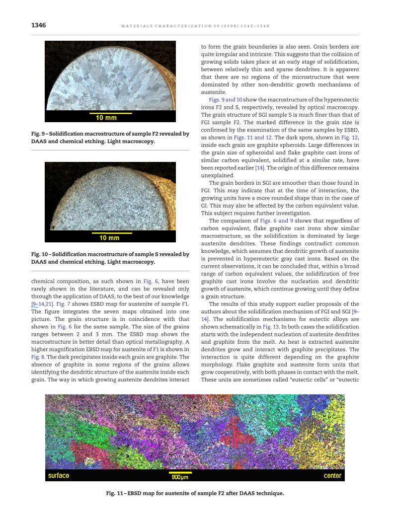
Fig. 9 –Solidificationmacrostructure of sample F2 revealed byDAAS and chemical etching. Light macroscopy.
Fig. 10 –Solidificationmacrostructure of sample S revealed byDAAS and chemical etching. Light macroscopy.
1346 M A T E R I A L S C H A R A C T E R I Z A T I O N 5 9 ( 2 0 0 8 ) 1 3 4 2 – 1 3 4 8
chemical composition, as such shown in Fig. 6, have beenrarely shown in the literature, and can be revealed onlythrough the application of DAAS, to the best of our knowledge[9–14,21]. Fig. 7 shows ESBD map for austenite of sample F1.The figure integrates the seven maps obtained into onepicture. The grain structure is in coincidence with thatshown in Fig. 6 for the same sample. The size of the grainsranges between 2 and 3 mm. The ESBD map shows themacrostructure in better detail than optical metallography. Ahighermagnification EBSDmap for austenite of F1 is shown inFig. 8. The dark precipitates inside each grain are graphite. Theabsence of graphite in some regions of the grains allowsidentifying the dendritic structure of the austenite inside eachgrain. The way in which growing austenite dendrites interact
Fig. 11 –EBSD map for austenite of s
to form the grain boundaries is also seen. Grain borders arequite irregular and intricate. This suggests that the collision ofgrowing solids takes place at an early stage of solidification,between relatively thin and sparse dendrites. It is apparentthat there are no regions of the microstructure that weredominated by other non-dendritic growth mechanisms ofaustenite.
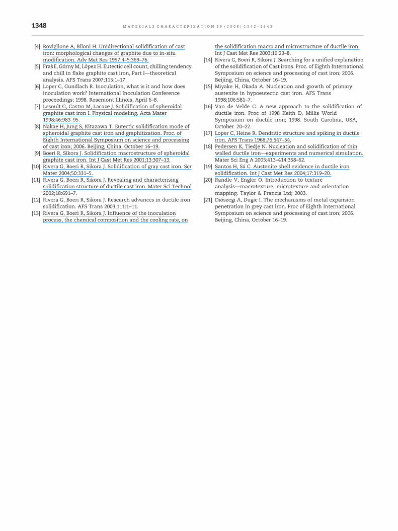
Figs. 9 and 10 show themacrostructure of the hypereutecticirons F2 and S, respectively, revealed by optical macroscopy.The grain structure of SGI sample S is much finer than that ofFGI sample F2. The marked difference in the grain size isconfirmed by the examination of the same samples by ESBD,as shown in Figs. 11 and 12. The dark spots, shown in Fig. 12,inside each grain are graphite spheroids. Large differences inthe grain size of spheroidal and flake graphite cast irons ofsimilar carbon equivalent, solidified at a similar rate, havebeen reported earlier [14]. The origin of this difference remainsunexplained.
The grain borders in SGI are smoother than those found inFGI. This may indicate that at the time of interaction, thegrowing units have a more rounded shape than in the case ofGI. This may also be affected by the carbon equivalent value.This subject requires further investigation.
The comparison of Figs. 6 and 9 shows that regardless ofcarbon equivalent, flake graphite cast irons show similarmacrostructure, as the solidification is dominated by largeaustenite dendrites. These findings contradict commonknowledge, which assumes that dendritic growth of austeniteis prevented in hypereutectic gray cast irons. Based on thecurrent observations, it can be concluded that, within a broadrange of carbon equivalent values, the solidification of freegraphite cast irons involve the nucleation and dendriticgrowth of austenite, which continue growing until they definea grain structure.
The results of this study support earlier proposals of theauthors about the solidification mechanism of FGI and SGI [9–14]. The solidification mechanisms for eutectic alloys areshown schematically in Fig. 13. In both cases the solidificationstarts with the independent nucleation of austenite dendritesand graphite from the melt. As heat is extracted austenitedendrites grow and interact with graphite precipitates. Theinteraction is quite different depending on the graphitemorphology. Flake graphite and austenite form units thatgrow cooperatively, with both phases in contact with themelt.These units are sometimes called “eutectic cells” or “eutectic
ample F2 after DAAS technique.
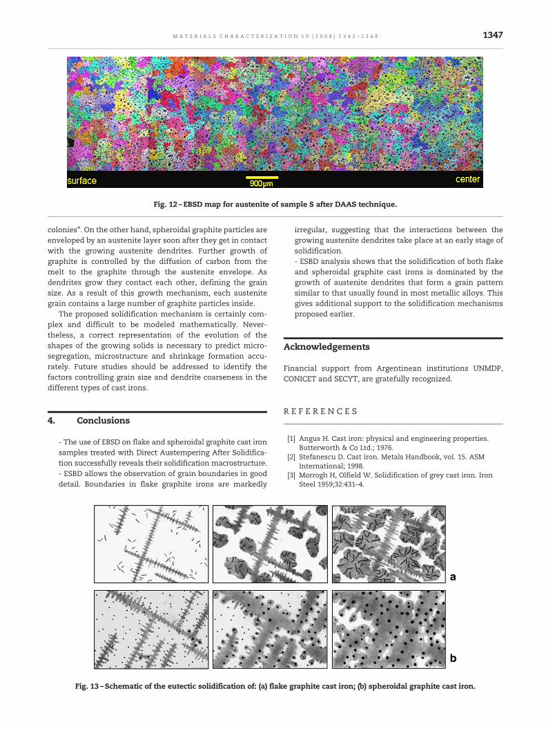
Fig. 12 –EBSD map for austenite of sample S after DAAS technique.
1347M A T E R I A L S C H A R A C T E R I Z A T I O N 5 9 ( 2 0 0 8 ) 1 3 4 2 – 1 3 4 8
colonies”. On the other hand, spheroidal graphite particles areenveloped by an austenite layer soon after they get in contactwith the growing austenite dendrites. Further growth ofgraphite is controlled by the diffusion of carbon from themelt to the graphite through the austenite envelope. Asdendrites grow they contact each other, defining the grainsize. As a result of this growth mechanism, each austenitegrain contains a large number of graphite particles inside.
The proposed solidification mechanism is certainly com-plex and difficult to be modeled mathematically. Never-theless, a correct representation of the evolution of theshapes of the growing solids is necessary to predict micro-segregation, microstructure and shrinkage formation accu-rately. Future studies should be addressed to identify thefactors controlling grain size and dendrite coarseness in thedifferent types of cast irons.
4. Conclusions
- The use of EBSD on flake and spheroidal graphite cast ironsamples treated with Direct Austempering After Solidifica-tion successfully reveals their solidification macrostructure.- ESBD allows the observation of grain boundaries in gooddetail. Boundaries in flake graphite irons are markedly
Fig. 13 –Schematic of the eutectic solidification of: (a) flake g
irregular, suggesting that the interactions between thegrowing austenite dendrites take place at an early stage ofsolidification.- ESBD analysis shows that the solidification of both flakeand spheroidal graphite cast irons is dominated by thegrowth of austenite dendrites that form a grain patternsimilar to that usually found in most metallic alloys. Thisgives additional support to the solidification mechanismsproposed earlier.
Acknowledgements
Financial support from Argentinean institutions UNMDP,CONICET and SECYT, are gratefully recognized.
R E F E R E N C E S
[1] Angus H. Cast iron: physical and engineering properties.Butterworth & Co Ltd.; 1976.
[2] Stefanescu D. Cast iron. Metals Handbook, vol. 15. ASMInternational; 1998.
[3] Morrogh H, Olfield W. Solidification of grey cast iron. IronSteel 1959;32:431–4.
raphite cast iron; (b) spheroidal graphite cast iron.
1348 M A T E R I A L S C H A R A C T E R I Z A T I O N 5 9 ( 2 0 0 8 ) 1 3 4 2 – 1 3 4 8
[4] Roviglione A, Biloni H. Unidirectional solidification of castiron: morphological changes of graphite due to in-situmodification. Adv Mat Res 1997;4–5:369–76.
[5] Fraś E, GórnyM, López H. Eutectic cell count, chilling tendencyand chill in flake graphite cast iron, Part I—theoreticalanalysis. AFS Trans 2007;115:1–17.
[6] Loper C, Gundlach R. Inoculation, what is it and how doesinoculation work? International Inoculation Conferenceproceedings; 1998. Rosemont Illinois, April 6–8.
[7] Lesoult G, Castro M, Lacaze J. Solidification of spheroidalgraphite cast iron I. Physical modeling. Acta Mater1998;46:983–95.
[8] Nakae H, Jung S, Kitazawa T. Eutectic solidification mode ofspheroidal graphite cast iron and graphitization. Proc. ofEighth International Symposium on science and processingof cast iron; 2006. Beijing, China, October 16–19.
[9] Boeri R, Sikora J. Solidification macrostructure of spheroidalgraphite cast iron. Int J Cast Met Res 2001;13:307–13.
[10] Rivera G, Boeri R, Sikora J. Solidification of gray cast iron. ScrMater 2004;50:331–5.
[11] Rivera G, Boeri R, Sikora J. Revealing and characterisingsolidification structure of ductile cast iron. Mater Sci Technol2002;18:691–7.
[12] Rivera G, Boeri R, Sikora J. Research advances in ductile ironsolidification. AFS Trans 2003;111:1–11.
[13] Rivera G, Boeri R, Sikora J. Influence of the inoculationprocess, the chemical composition and the cooling rate, on
the solidification macro and microstructure of ductile iron.Int J Cast Met Res 2003;16:23–8.
[14] Rivera G, Boeri R, Sikora J. Searching for a unified explanationof the solidification of Cast irons. Proc. of Eighth InternationalSymposium on science and processing of cast iron; 2006.Beijing, China, October 16–19.
[15] Miyake H, Okada A. Nucleation and growth of primaryaustenite in hypoeutectic cast iron. AFS Trans1998;106:581–7.
[16] Van de Velde C. A new approach to the solidification ofductile iron. Proc of 1998 Keith D. Millis WorldSymposium on ductile iron; 1998. South Carolina, USA,October 20–22.
[17] Loper C, Heine R. Dendritic structure and spiking in ductileiron. AFS Trans 1968;76:547–54.
[18] Pedersen K, Tiedje N. Nucleation and solidification of thinwalled ductile iron—experiments and numerical simulation.Mater Sci Eng A 2005;413–414:358–62.
[19] Santos H, Sá C. Austenite shell evidence in ductile ironsolidification. Int J Cast Met Res 2004;17:319–20.
[20] Randle V, Engler O. Introduction to textureanalysis—macrotexture, microtexture and orientationmapping. Taylor & Francis Ltd; 2003.
[21] Diószegi A, Dugic I. The mechanisms of metal expansionpenetration in grey cast iron. Proc of Eighth InternationalSymposium on science and processing of cast iron; 2006.Beijing, China, October 16–19.
Top Related
Copyright © 2022 FDOKUMEN

