


Bahasa
Halaman
Hukum

applied sciences
Article
Effect to the Surface Composition in UltrasonicVibration-Assisted Grinding of BK7 Optical Glass
Pei Yi Zhao 1,*, Ming Zhou 2, Xian Li Liu 1 and Bin Jiang 1
1 School of Mechanical and Power Engineering, Harbin University of Science and Technology,Harbin 150080, China; [email protected] (X.L.L.); [email protected] (B.J.)
2 School of Mechatronics Engineering, Harbin Institute of Technology, Harbin 150006, China;[email protected]
* Correspondence: [email protected]
Received: 10 December 2019; Accepted: 7 January 2020; Published: 10 January 2020�����������������
Featured Application: Authors are encouraged to provide a scientific support for controlling ofmachined surface composition in ultrasonic vibration assisted grinding of optical glass materials.
Abstract: Because of the changes in cutting conditions and ultrasonic vibration status, the proportionof multiple material removal modes are of uncertainty and complexity in ultrasonic vibration-assistedgrinding of optical glass. Knowledge of the effect of machined surface composition is the basis forbetter understanding the influence mechanisms of surface roughness, and also is the key to controlthe surface composition and surface quality. In the present work, 32 sets of experiments of ultrasonicvibration-assisted grinding of BK7 optical glass were carried out, the machined surface morphologieswere observed, and the influence law of machining parameters on the proportion of different materialremoval was investigated. Based on the above research, the effect of surface composition was brieflysummarized. The results indicated that the increasing of spindle rotation speed, the decreasingof feed rate and grinding depth can improve the proportion of ductile removal. The introductionof ultrasonic vibration can highly restrain the powdering removal, and increase the proportion ofductile removal. Grinding depth has a dominant positive effect on the surface roughness, whereasthe spindle rotation speed and ultrasonic amplitude both have negative effect, which was caused bythe reduction of brittle fracture removal.
Keywords: surface composition; optical glass; ultrasonic vibration; grinding; influence law
1. Introduction
Optical glass is a typical hard and brittle material. Because of its unique excellent properties, it hasa wide range of applications in the fields of optics, inertial confinement nuclear fusion, aerospace,and defense [1,2]. One of the most prominent features of optical glass materials is high brittlenessand low fracture toughness. The critical cutting depth of the material is extremely small. When theinstantaneous cutting depth of the abrasive grains did not reach the critical cutting depth, the materialis removed by plastic deformation [3]. When the instantaneous cutting depth of the abrasive grainsreached beyond the critical cutting depth, micro cracks are generated inside the material, as the microcracks propagates onto the machined surfaces, the material was removed by brittle fracture [4] andpowdering [5,6].
Ultrasonic vibration-assisted grinding has been used for precision machining of brittle materialsbecause of the fact that the average cutting force and cracks propagation can be significantlyreduced [7–9]. The effect of the process parameters on the process performances has been investigatedexperimentally [10–12]. After introducing ultrasonic vibration into the machining process, impact
Appl. Sci. 2020, 10, 516; doi:10.3390/app10020516 www.mdpi.com/journal/applsci
Appl. Sci. 2020, 10, 516 2 of 14
effect was induced while the tool cutting into the optical glass material [13]. The effect of processparameters on surface quality, such as surface roughness and machined surface composition may bedifferent than that of conventional cutting [14]. To the best of our knowledge, there are few reports onthe machined surface composition and materials removal modes.
In the past few years, domestic and foreign researchers have carried out a series of research onthe removal of optical glass materials. Zhao conducted a scratching test by varying the cutting depth,based on this, he divided the material removal process into three parts: pure plastic flow, plastic andfracture mixture, and brittle fracture. Clear cutting chips and material deformation characteristicswere found in his experiments. In addition, he also explained the cracks propagation directions,it was claimed that the initial radial cracks tend to propagate along twinning planes while the lateralcracks propagate along the basal plane [15]. Cao investigated the material removal and deformationcharacteristics by observing the scratched surface morphologies, he pointed that the scratch groovedepth is deeper in ultrasonic vibration-assisted scratching [16]. Zhang researched the relationshipbetween stress characteristics and cracks propagation directions based on a varied cutting-depthnanoscratching test [17], he also discussed the transition of material removal mode based on theobservation of scratched grooves. In another research of Zhang, the differences of material removalin conventional grinding and ultrasonic vibration assisted grinding (UVAG) were investigated byobserving machined surface morphologies by using atomic force microscope (AFM) and scanningelectron microscope (SEM) [18]. He also compared the scratched grooves width and cracks propagationof varied scratching depth by conducting actual experiments and simulating scratching process [19].Li focused on the influence of elastic recovery on scratched grooves morphologies. He pointed thatelastic recovery may be a significant factor that affects machined surface quality in the actual grindingprocess [20]. However, many of the present researches related to material removal are based on theobservation and analysis after scratching and indentation tests, which means the factors such as thecoupling effects of cracks in actual grinding process, and the variation of grinding parameters, couldnot be easily taken into consideration.
In the ultrasonic vibration grinding process of optical glass, because of the huge number ofabrasive grains on the surface of the grinding wheel, and the randomness of the size and shape, theprotruding height of each abrasive grain is different, resulting in different instantaneous cutting depthsduring processing. Therefore, there are often plastic removal methods, brittle removal methods, andpowder removal methods in the process. Moreover, under the combination of different processingparameters, the proportion of the above three material removal methods on the machined surface willalso change, this change would be certainly depended on process parameters and grinding wheelparameters. The mapping relationship between them needs to be studied. Wang developed a criticalfunction for crack propagation based on single grit scratching test, by using this function, he furtherpresented a model for predicting the change of material removal mode. In his model, original crackdensity, strain rate, and grinding coolant are considered, the results showed that the crack damagedepth would reach a maximum value while the material removal mode is semi-brittle [21]. Daiinvestigated the influence law of spindle rotation speed on grinding force and specific grinding energy,he also claimed that the cracks and brittle-fractured pits sizes would become enormous because of thetransition of material removal mechanism (ductile regime to completely brittle regime) [22]. Gu hastaken consideration of coupling effects of multiple abrasive grains on cracks propagation to simulateactual grinding process. He pointed that the micro cracks sizes would be significantly affected bythe separation distance of two abrasive grains [23]. However, there are few reports on the mappingrelationship between process parameters and material removal methods in the process of ultrasonicvibration grinding of optical glass.
When the material is removed in different ways, it will produce different processed surfacetopography, which will also produce different degrees of subsurface damage. Therefore, the proportionof these removal methods on the machined surface determines the final machined surface qualityand subsurface damage. Although studies at home and abroad have been able to control the surface
Appl. Sci. 2020, 10, 516 3 of 14
roughness [24–26], processing efficiency [27,28], force and energies [29,30] or damages [31] by adjustingthe process parameters, for the precision machining of brittle materials that pay attention to the surfacequality and subsurface damage at the same time, the intrinsic relationship between the proportion ofthe material removal modes and the process parameters and the parameters of the grinding wheel isstill not clear. The effective control of the material removal modes proportion is the basis and key toexploring the technical measures to jointly improve the processing surface and subsurface quality.
In this paper, to comprehensively investigate the effect of grinding parameters and ultrasonicparameters to surface composition, 32 sets of experiments of ultrasonic vibration grinding of opticalglass are carried out first. Second, based on the measurement results, the effect of grinding parametersand ultrasonic parameters on surface roughness was investigated, the changes of machined surfacemorphologies and the proportion of three material removal modes in different grinding parametersare analyzed. At last, the effect of processing parameters on surface composition in ultrasonicvibration-assisted grinding of optical glass is briefly summarized.
2. Experimental Setup
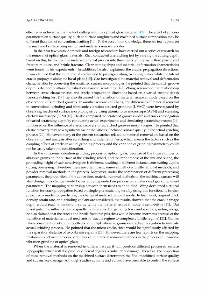
In order to investigate the effect of grinding and ultrasonic vibration parameters on surfacecomposition and surface roughness, ultrasonic vibration-assisted grinding experiments of BK7 opticalglass materials were carried out on a 5-axis precision ultrasonic machine center (DMG Ultrasonic 70-5linear). The Schott ultrasonic hollow nickel electroforming diamond grinding wheel was used, whosediameter was 4 mm, average grain diameter was 64 um, and the diamond concentration was 100%.Automatic laser measuring device was used to measure the length and radius of the tool. The grindingtool oscillates along the axial direction of the spindle. The ultrasonic frequency of the cutting tool wasdetected by the machine tool measurement device and its value was 30,047 Hz. The BK7 optical glassmaterial workpieces were in the form of cuboid with 50 mm in length, 50 mm in width, and 6 mmin height. In order to preclude the influence of coolant on machining process, grinding coolant wasnot used in these experiments. The glass workpiece was fixed to a steel plate using strong adhesive.After sticking, the object was allowed to stand for 24 h at room temperature. Experimental setup andscheme of the process kinematics is shown in Figure 1.
To extensively investigate the influencing law of machining parameters on surface compositionand surface roughness, a single factor design was employed in the experiments. The spindle rotationspeed, grinding depth, feed rate, and ultrasonic vibration amplitude were defined as the experimentalparameters. Since the resonance frequency is the best vibration frequency of the cutting tool during theprocess of ultrasonic vibration machining, the ultrasonic frequency was not considered as the parameterduring the experiments [32,33]. The concrete experimental parameters are given in Table 1. A total of32 groups of experiments were carried out on BK7 optical glass based on this experimental design.
Appl. Sci. 2020, 10, x FOR PEER REVIEW 3 of 14
to the surface quality and subsurface damage at the same time, the intrinsic relationship between the
proportion of the material removal modes and the process parameters and the parameters of the
grinding wheel is still not clear. The effective control of the material removal modes proportion is the
basis and key to exploring the technical measures to jointly improve the processing surface and
subsurface quality.
In this paper, to comprehensively investigate the effect of grinding parameters and ultrasonic
parameters to surface composition, 32 sets of experiments of ultrasonic vibration grinding of optical
glass are carried out first. Second, based on the measurement results, the effect of grinding
parameters and ultrasonic parameters on surface roughness was investigated, the changes of
machined surface morphologies and the proportion of three material removal modes in different
grinding parameters are analyzed. At last, the effect of processing parameters on surface composition
in ultrasonic vibration-assisted grinding of optical glass is briefly summarized.
2. Nomenclature
Sa Surface roughness (nm)
n Spindle rotation speed (rpm)
Vf Feed rate (mm/min)
ap Grinding depth (μm)
A Ultrasonic amplitude (μm)
3. Experimental Setup
In order to investigate the effect of grinding and ultrasonic vibration parameters on surface
composition and surface roughness, ultrasonic vibration-assisted grinding experiments of BK7
optical glass materials were carried out on a 5-axis precision ultrasonic machine center (DMG
Ultrasonic 70-5 linear). The Schott ultrasonic hollow nickel electroforming diamond grinding wheel
was used, whose diameter was 4 mm, average grain diameter was 64 um, and the diamond
concentration was 100%. Automatic laser measuring device was used to measure the length and
radius of the tool. The grinding tool oscillates along the axial direction of the spindle. The ultrasonic
frequency of the cutting tool was detected by the machine tool measurement device and its value was
30,047 Hz. The BK7 optical glass material workpieces were in the form of cuboid with 50 mm in
length, 50 mm in width, and 6 mm in height. In order to preclude the influence of coolant on
machining process, grinding coolant was not used in these experiments. The glass workpiece was
fixed to a steel plate using strong adhesive. After sticking, the object was allowed to stand for 24 h at
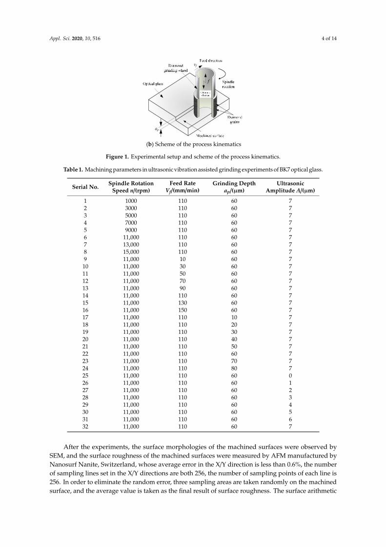
room temperature. Experimental setup and scheme of the process kinematics is shown in Figure 1.
(a) Experimental setup
Figure 1. Cont.
Appl. Sci. 2020, 10, 516 4 of 14Appl. Sci. 2020, 10, x FOR PEER REVIEW 4 of 14
(b) Scheme of the process kinematics
Figure 1. Experimental setup and scheme of the process kinematics.
To extensively investigate the influencing law of machining parameters on surface composition
and surface roughness, a single factor design was employed in the experiments. The spindle rotation
speed, grinding depth, feed rate, and ultrasonic vibration amplitude were defined as the
experimental parameters. Since the resonance frequency is the best vibration frequency of the cutting
tool during the process of ultrasonic vibration machining, the ultrasonic frequency was not
considered as the parameter during the experiments [32,33]. The concrete experimental parameters
are given in Table 1. A total of 32 groups of experiments were carried out on BK7 optical glass based
on this experimental design.
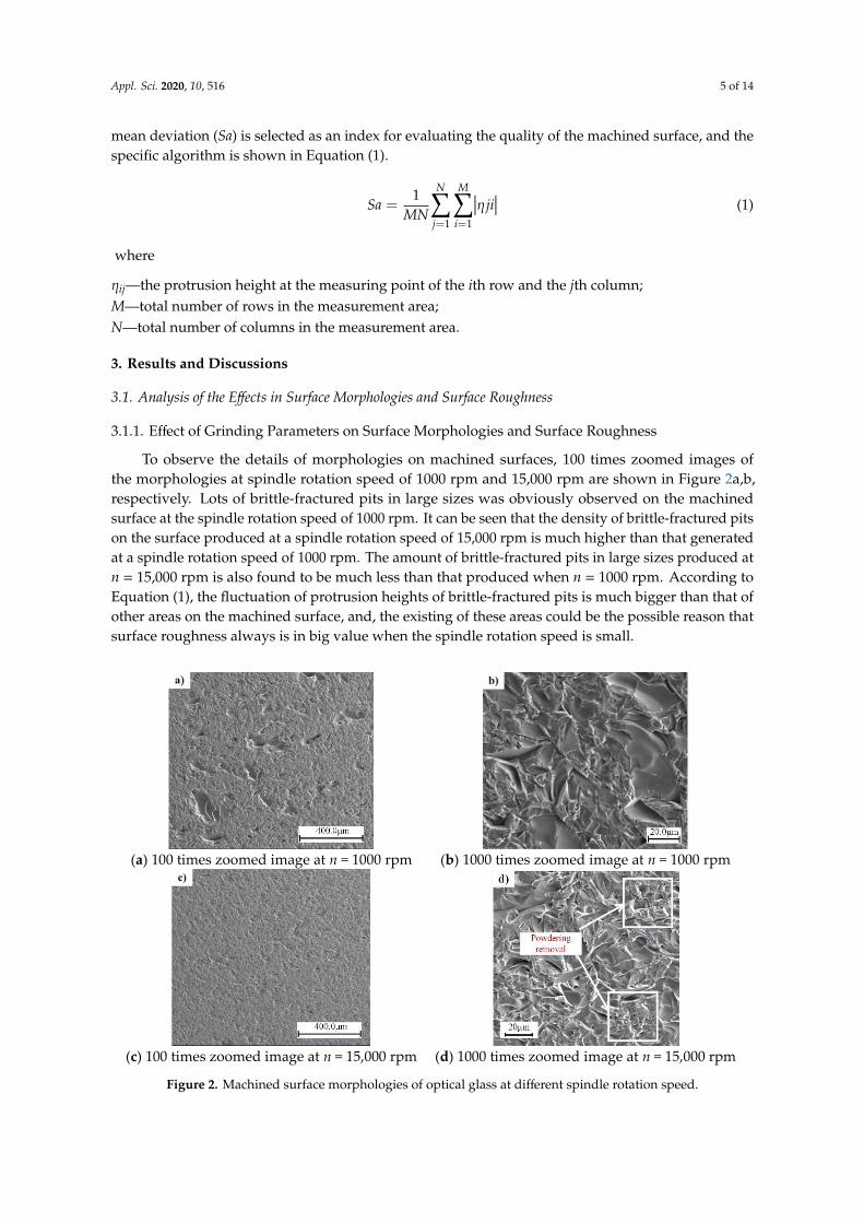
Table 1. Machining parameters in ultrasonic vibration assisted grinding experiments of BK7 optical
glass.
Serial
No.
Spindle Rotation
Speed n/(rpm)
Feed Rate
Vf/(mm/min)
Grinding
Depth ap/(μm)
Ultrasonic
Amplitude A/(μm)
1 1000 110 60 7
2 3000 110 60 7
3 5000 110 60 7
4 7000 110 60 7
5 9000 110 60 7
6 11,000 110 60 7
7 13,000 110 60 7
8 15,000 110 60 7
9 11,000 10 60 7
10 11,000 30 60 7
11 11,000 50 60 7
12 11,000 70 60 7
13 11,000 90 60 7
14 11,000 110 60 7
15 11,000 130 60 7
16 11,000 150 60 7
17 11,000 110 10 7
18 11,000 110 20 7
19 11,000 110 30 7
20 11,000 110 40 7
21 11,000 110 50 7
22 11,000 110 60 7
23 11,000 110 70 7
24 11,000 110 80 7
25 11,000 110 60 0
26 11,000 110 60 1
Figure 1. Experimental setup and scheme of the process kinematics.
Table 1. Machining parameters in ultrasonic vibration assisted grinding experiments of BK7 optical glass.
Serial No. Spindle RotationSpeed n/(rpm)
Feed RateVf/(mm/min)
Grinding Depthap/(µm)
UltrasonicAmplitude A/(µm)
1 1000 110 60 72 3000 110 60 73 5000 110 60 74 7000 110 60 75 9000 110 60 76 11,000 110 60 77 13,000 110 60 78 15,000 110 60 79 11,000 10 60 710 11,000 30 60 711 11,000 50 60 712 11,000 70 60 713 11,000 90 60 714 11,000 110 60 715 11,000 130 60 716 11,000 150 60 717 11,000 110 10 718 11,000 110 20 719 11,000 110 30 720 11,000 110 40 721 11,000 110 50 722 11,000 110 60 723 11,000 110 70 724 11,000 110 80 725 11,000 110 60 026 11,000 110 60 127 11,000 110 60 228 11,000 110 60 329 11,000 110 60 430 11,000 110 60 531 11,000 110 60 632 11,000 110 60 7
After the experiments, the surface morphologies of the machined surfaces were observed bySEM, and the surface roughness of the machined surfaces were measured by AFM manufactured byNanosurf Nanite, Switzerland, whose average error in the X/Y direction is less than 0.6%, the numberof sampling lines set in the X/Y directions are both 256, the number of sampling points of each line is256. In order to eliminate the random error, three sampling areas are taken randomly on the machinedsurface, and the average value is taken as the final result of surface roughness. The surface arithmetic
Appl. Sci. 2020, 10, 516 5 of 14
mean deviation (Sa) is selected as an index for evaluating the quality of the machined surface, and thespecific algorithm is shown in Equation (1).
Sa =1
MN
N∑j=1
M∑i=1
∣∣∣η ji∣∣∣ (1)
where
ηij—the protrusion height at the measuring point of the ith row and the jth column;M—total number of rows in the measurement area;N—total number of columns in the measurement area.
3. Results and Discussions
3.1. Analysis of the Effects in Surface Morphologies and Surface Roughness
3.1.1. Effect of Grinding Parameters on Surface Morphologies and Surface Roughness
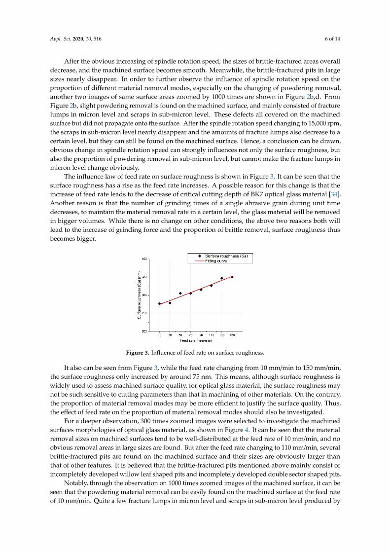
To observe the details of morphologies on machined surfaces, 100 times zoomed images ofthe morphologies at spindle rotation speed of 1000 rpm and 15,000 rpm are shown in Figure 2a,b,respectively. Lots of brittle-fractured pits in large sizes was obviously observed on the machinedsurface at the spindle rotation speed of 1000 rpm. It can be seen that the density of brittle-fractured pitson the surface produced at a spindle rotation speed of 15,000 rpm is much higher than that generatedat a spindle rotation speed of 1000 rpm. The amount of brittle-fractured pits in large sizes produced atn = 15,000 rpm is also found to be much less than that produced when n = 1000 rpm. According toEquation (1), the fluctuation of protrusion heights of brittle-fractured pits is much bigger than that ofother areas on the machined surface, and, the existing of these areas could be the possible reason thatsurface roughness always is in big value when the spindle rotation speed is small.Appl. Sci. 2020, 10, x FOR PEER REVIEW 6 of 14
(a) 100 times zoomed image at n = 1000 rpm (b) 1000 times zoomed image at n = 1000 rpm
(c) 100 times zoomed image at n = 15,000 rpm (d) 1000 times zoomed image at n = 15,000 rpm
Figure 2. Machined surface morphologies of optical glass at different spindle rotation speed.
The influence law of feed rate on surface roughness is shown in Figure 3. It can be seen that the
surface roughness has a rise as the feed rate increases. A possible reason for this change is that the
increase of feed rate leads to the decrease of critical cutting depth of BK7 optical glass material [34].
Another reason is that the number of grinding times of a single abrasive grain during unit time
decreases, to maintain the material removal rate in a certain level, the glass material will be removed
in bigger volumes. While there is no change on other conditions, the above two reasons both will lead
to the increase of grinding force and the proportion of brittle removal, surface roughness thus
becomes bigger.
Figure 3. Influence of feed rate on surface roughness.
It also can be seen from Figure 3, while the feed rate changing from 10 mm/min to 150 mm/min,
the surface roughness only increased by around 75 nm. This means, although surface roughness is
widely used to assess machined surface quality, for optical glass material, the surface roughness may
not be such sensitive to cutting parameters than that in machining of other materials. On the contrary,
the proportion of material removal modes may be more efficient to justify the surface quality. Thus,
the effect of feed rate on the proportion of material removal modes should also be investigated.
For a deeper observation, 300 times zoomed images were selected to investigate the machined
surfaces morphologies of optical glass material, as shown in Figure 4. It can be seen that the material
removal sizes on machined surfaces tend to be well-distributed at the feed rate of 10 mm/min, and
Figure 2. Machined surface morphologies of optical glass at different spindle rotation speed.
Appl. Sci. 2020, 10, 516 6 of 14
After the obvious increasing of spindle rotation speed, the sizes of brittle-fractured areas overalldecrease, and the machined surface becomes smooth. Meanwhile, the brittle-fractured pits in largesizes nearly disappear. In order to further observe the influence of spindle rotation speed on theproportion of different material removal modes, especially on the changing of powdering removal,another two images of same surface areas zoomed by 1000 times are shown in Figure 2b,d. FromFigure 2b, slight powdering removal is found on the machined surface, and mainly consisted of fracturelumps in micron level and scraps in sub-micron level. These defects all covered on the machinedsurface but did not propagate onto the surface. After the spindle rotation speed changing to 15,000 rpm,the scraps in sub-micron level nearly disappear and the amounts of fracture lumps also decrease to acertain level, but they can still be found on the machined surface. Hence, a conclusion can be drawn,obvious change in spindle rotation speed can strongly influences not only the surface roughness, butalso the proportion of powdering removal in sub-micron level, but cannot make the fracture lumps inmicron level change obviously.
The influence law of feed rate on surface roughness is shown in Figure 3. It can be seen that thesurface roughness has a rise as the feed rate increases. A possible reason for this change is that theincrease of feed rate leads to the decrease of critical cutting depth of BK7 optical glass material [34].Another reason is that the number of grinding times of a single abrasive grain during unit timedecreases, to maintain the material removal rate in a certain level, the glass material will be removedin bigger volumes. While there is no change on other conditions, the above two reasons both willlead to the increase of grinding force and the proportion of brittle removal, surface roughness thusbecomes bigger.
Appl. Sci. 2020, 10, x FOR PEER REVIEW 6 of 14
(a) 100 times zoomed image at n = 1000 rpm (b) 1000 times zoomed image at n = 1000 rpm
(c) 100 times zoomed image at n = 15,000 rpm (d) 1000 times zoomed image at n = 15,000 rpm
Figure 2. Machined surface morphologies of optical glass at different spindle rotation speed.
The influence law of feed rate on surface roughness is shown in Figure 3. It can be seen that the
surface roughness has a rise as the feed rate increases. A possible reason for this change is that the
increase of feed rate leads to the decrease of critical cutting depth of BK7 optical glass material [34].
Another reason is that the number of grinding times of a single abrasive grain during unit time
decreases, to maintain the material removal rate in a certain level, the glass material will be removed
in bigger volumes. While there is no change on other conditions, the above two reasons both will lead
to the increase of grinding force and the proportion of brittle removal, surface roughness thus
becomes bigger.
Figure 3. Influence of feed rate on surface roughness.
It also can be seen from Figure 3, while the feed rate changing from 10 mm/min to 150 mm/min,
the surface roughness only increased by around 75 nm. This means, although surface roughness is
widely used to assess machined surface quality, for optical glass material, the surface roughness may
not be such sensitive to cutting parameters than that in machining of other materials. On the contrary,
the proportion of material removal modes may be more efficient to justify the surface quality. Thus,
the effect of feed rate on the proportion of material removal modes should also be investigated.
For a deeper observation, 300 times zoomed images were selected to investigate the machined
surfaces morphologies of optical glass material, as shown in Figure 4. It can be seen that the material
removal sizes on machined surfaces tend to be well-distributed at the feed rate of 10 mm/min, and
Figure 3. Influence of feed rate on surface roughness.
It also can be seen from Figure 3, while the feed rate changing from 10 mm/min to 150 mm/min,the surface roughness only increased by around 75 nm. This means, although surface roughness iswidely used to assess machined surface quality, for optical glass material, the surface roughness maynot be such sensitive to cutting parameters than that in machining of other materials. On the contrary,the proportion of material removal modes may be more efficient to justify the surface quality. Thus,the effect of feed rate on the proportion of material removal modes should also be investigated.
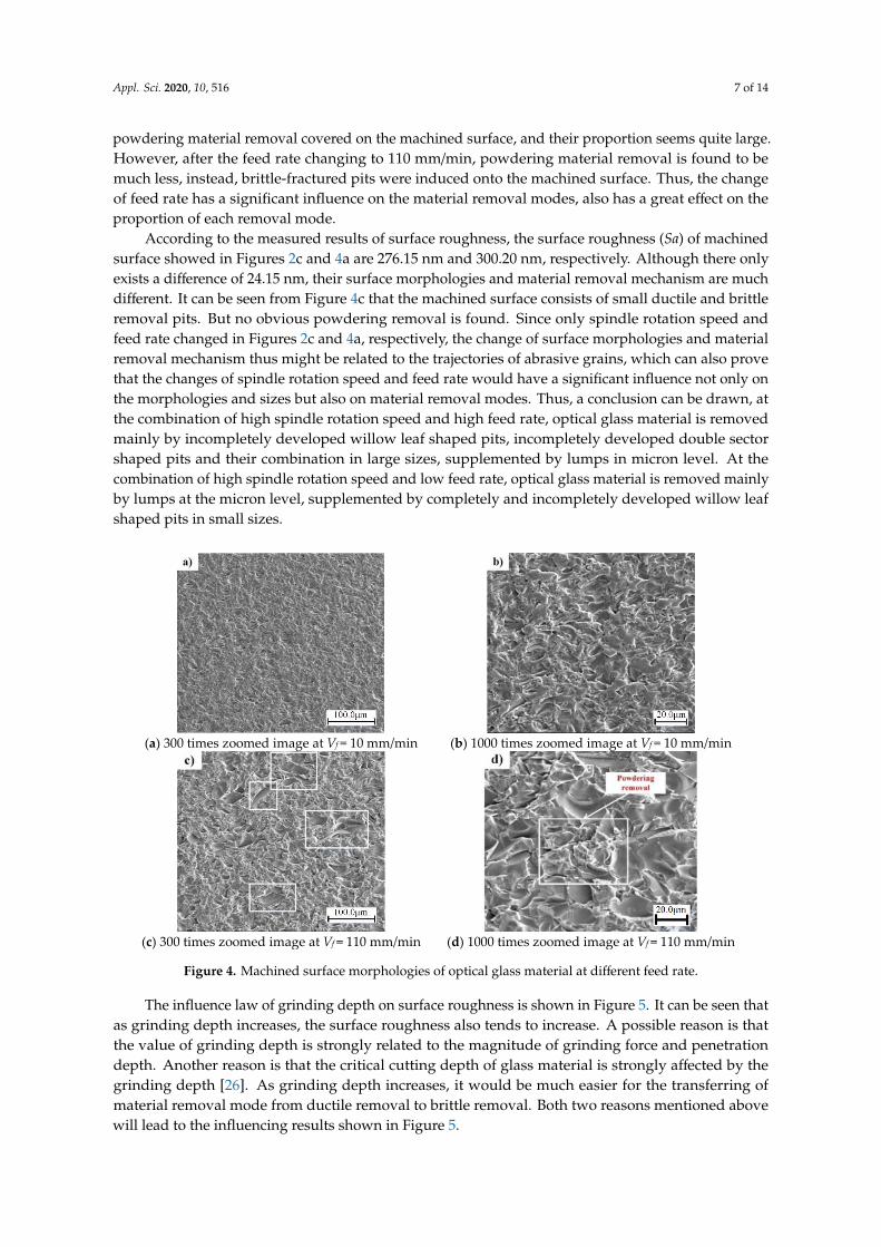
For a deeper observation, 300 times zoomed images were selected to investigate the machinedsurfaces morphologies of optical glass material, as shown in Figure 4. It can be seen that the materialremoval sizes on machined surfaces tend to be well-distributed at the feed rate of 10 mm/min, and noobvious removal areas in large sizes are found. But after the feed rate changing to 110 mm/min, severalbrittle-fractured pits are found on the machined surface and their sizes are obviously larger thanthat of other features. It is believed that the brittle-fractured pits mentioned above mainly consist ofincompletely developed willow leaf shaped pits and incompletely developed double sector shaped pits.
Notably, through the observation on 1000 times zoomed images of the machined surface, it can beseen that the powdering material removal can be easily found on the machined surface at the feed rateof 10 mm/min. Quite a few fracture lumps in micron level and scraps in sub-micron level produced by
Appl. Sci. 2020, 10, 516 7 of 14
powdering material removal covered on the machined surface, and their proportion seems quite large.However, after the feed rate changing to 110 mm/min, powdering material removal is found to bemuch less, instead, brittle-fractured pits were induced onto the machined surface. Thus, the changeof feed rate has a significant influence on the material removal modes, also has a great effect on theproportion of each removal mode.
According to the measured results of surface roughness, the surface roughness (Sa) of machinedsurface showed in Figures 2c and 4a are 276.15 nm and 300.20 nm, respectively. Although there onlyexists a difference of 24.15 nm, their surface morphologies and material removal mechanism are muchdifferent. It can be seen from Figure 4c that the machined surface consists of small ductile and brittleremoval pits. But no obvious powdering removal is found. Since only spindle rotation speed andfeed rate changed in Figures 2c and 4a, respectively, the change of surface morphologies and materialremoval mechanism thus might be related to the trajectories of abrasive grains, which can also provethat the changes of spindle rotation speed and feed rate would have a significant influence not only onthe morphologies and sizes but also on material removal modes. Thus, a conclusion can be drawn, atthe combination of high spindle rotation speed and high feed rate, optical glass material is removedmainly by incompletely developed willow leaf shaped pits, incompletely developed double sectorshaped pits and their combination in large sizes, supplemented by lumps in micron level. At thecombination of high spindle rotation speed and low feed rate, optical glass material is removed mainlyby lumps at the micron level, supplemented by completely and incompletely developed willow leafshaped pits in small sizes.
Appl. Sci. 2020, 10, x FOR PEER REVIEW 7 of 14
no obvious removal areas in large sizes are found. But after the feed rate changing to 110 mm/min,
several brittle-fractured pits are found on the machined surface and their sizes are obviously larger
than that of other features. It is believed that the brittle-fractured pits mentioned above mainly consist
of incompletely developed willow leaf shaped pits and incompletely developed double sector shaped
pits.
Notably, through the observation on 1000 times zoomed images of the machined surface, it can
be seen that the powdering material removal can be easily found on the machined surface at the feed
rate of 10 mm/min. Quite a few fracture lumps in micron level and scraps in sub-micron level
produced by powdering material removal covered on the machined surface, and their proportion
seems quite large. However, after the feed rate changing to 110 mm/min, powdering material
removal is found to be much less, instead, brittle-fractured pits were induced onto the machined
surface. Thus, the change of feed rate has a significant influence on the material removal modes, also
has a great effect on the proportion of each removal mode.
According to the measured results of surface roughness, the surface roughness (Sa) of machined
surface showed in Figures 2c and 4a are 276.15 nm and 300.20 nm, respectively. Although there only
exists a difference of 24.15 nm, their surface morphologies and material removal mechanism are much
different. It can be seen from Figure 4c that the machined surface consists of small ductile and brittle
removal pits. But no obvious powdering removal is found. Since only spindle rotation speed and feed
rate changed in Figures 2c and 4a, respectively, the change of surface morphologies and material
removal mechanism thus might be related to the trajectories of abrasive grains, which can also prove
that the changes of spindle rotation speed and feed rate would have a significant influence not only
on the morphologies and sizes but also on material removal modes. Thus, a conclusion can be drawn,
at the combination of high spindle rotation speed and high feed rate, optical glass material is removed
mainly by incompletely developed willow leaf shaped pits, incompletely developed double sector
shaped pits and their combination in large sizes, supplemented by lumps in micron level. At the
combination of high spindle rotation speed and low feed rate, optical glass material is removed
mainly by lumps at the micron level, supplemented by completely and incompletely developed
willow leaf shaped pits in small sizes.
(a) 300 times zoomed image at Vf = 10 mm/min (b) 1000 times zoomed image at Vf = 10 mm/min
(c) 300 times zoomed image at Vf = 110 mm/min (d) 1000 times zoomed image at Vf = 110 mm/min
Figure 4. Machined surface morphologies of optical glass material at different feed rate. Figure 4. Machined surface morphologies of optical glass material at different feed rate.
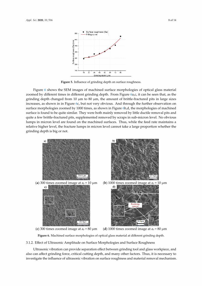
The influence law of grinding depth on surface roughness is shown in Figure 5. It can be seen thatas grinding depth increases, the surface roughness also tends to increase. A possible reason is thatthe value of grinding depth is strongly related to the magnitude of grinding force and penetrationdepth. Another reason is that the critical cutting depth of glass material is strongly affected by thegrinding depth [26]. As grinding depth increases, it would be much easier for the transferring ofmaterial removal mode from ductile removal to brittle removal. Both two reasons mentioned abovewill lead to the influencing results shown in Figure 5.
Appl. Sci. 2020, 10, 516 8 of 14
Appl. Sci. 2020, 10, x FOR PEER REVIEW 8 of 14
The influence law of grinding depth on surface roughness is shown in Figure 5. It can be seen
that as grinding depth increases, the surface roughness also tends to increase. A possible reason is
that the value of grinding depth is strongly related to the magnitude of grinding force and penetration
depth. Another reason is that the critical cutting depth of glass material is strongly affected by the
grinding depth [26]. As grinding depth increases, it would be much easier for the transferring of
material removal mode from ductile removal to brittle removal. Both two reasons mentioned above
will lead to the influencing results shown in Figure 5.
Figure 5. Influence of grinding depth on surface roughness.
Figure 6 shows the SEM images of machined surface morphologies of optical glass material
zoomed by different times in different grinding depth. From Figure 6a,c, it can be seen that, as the
grinding depth changed from 10 μm to 80 μm, the amount of brittle-fractured pits in large sizes
increases, as shown in in Figure 6c, but not very obvious. And through the further observation on
surface morphologies zoomed by 1000 times, as shown in Figure 6b,d, the morphologies of machined
surface is found to be quite similar. They were both mainly removed by little ductile removal pits
and quite a few brittle-fractured pits, supplemented removed by scraps in sub-micron level. No
obvious lumps in micron level are found on the machined surfaces. Thus, while the feed rate
maintains a relative higher level, the fracture lumps in micron level cannot take a large proportion
whether the grinding depth is big or not.
(a) 300 times zoomed image at ap = 10 μm (b) 1000 times zoomed image at ap = 10 μm
(c) 300 times zoomed image at ap = 80 μm (d) 1000 times zoomed image at ap = 80 μm
Figure 6. Machined surface morphologies of optical glass material at different grinding depth.
Figure 5. Influence of grinding depth on surface roughness.
Figure 6 shows the SEM images of machined surface morphologies of optical glass materialzoomed by different times in different grinding depth. From Figure 6a,c, it can be seen that, as thegrinding depth changed from 10 µm to 80 µm, the amount of brittle-fractured pits in large sizesincreases, as shown in in Figure 6c, but not very obvious. And through the further observation onsurface morphologies zoomed by 1000 times, as shown in Figure 6b,d, the morphologies of machinedsurface is found to be quite similar. They were both mainly removed by little ductile removal pits andquite a few brittle-fractured pits, supplemented removed by scraps in sub-micron level. No obviouslumps in micron level are found on the machined surfaces. Thus, while the feed rate maintains arelative higher level, the fracture lumps in micron level cannot take a large proportion whether thegrinding depth is big or not.
Appl. Sci. 2020, 10, x FOR PEER REVIEW 8 of 14
The influence law of grinding depth on surface roughness is shown in Figure 5. It can be seen
that as grinding depth increases, the surface roughness also tends to increase. A possible reason is
that the value of grinding depth is strongly related to the magnitude of grinding force and penetration
depth. Another reason is that the critical cutting depth of glass material is strongly affected by the
grinding depth [26]. As grinding depth increases, it would be much easier for the transferring of
material removal mode from ductile removal to brittle removal. Both two reasons mentioned above
will lead to the influencing results shown in Figure 5.
Figure 5. Influence of grinding depth on surface roughness.
Figure 6 shows the SEM images of machined surface morphologies of optical glass material
zoomed by different times in different grinding depth. From Figure 6a,c, it can be seen that, as the
grinding depth changed from 10 μm to 80 μm, the amount of brittle-fractured pits in large sizes
increases, as shown in in Figure 6c, but not very obvious. And through the further observation on
surface morphologies zoomed by 1000 times, as shown in Figure 6b,d, the morphologies of machined
surface is found to be quite similar. They were both mainly removed by little ductile removal pits
and quite a few brittle-fractured pits, supplemented removed by scraps in sub-micron level. No
obvious lumps in micron level are found on the machined surfaces. Thus, while the feed rate
maintains a relative higher level, the fracture lumps in micron level cannot take a large proportion
whether the grinding depth is big or not.
(a) 300 times zoomed image at ap = 10 μm (b) 1000 times zoomed image at ap = 10 μm
(c) 300 times zoomed image at ap = 80 μm (d) 1000 times zoomed image at ap = 80 μm
Figure 6. Machined surface morphologies of optical glass material at different grinding depth. Figure 6. Machined surface morphologies of optical glass material at different grinding depth.
3.1.2. Effect of Ultrasonic Amplitude on Surface Morphologies and Surface Roughness
Ultrasonic vibration can provide separation effect between grinding tool and glass workpiece, andalso can affect grinding force, critical cutting depth, and many other factors. Thus, it is necessary toinvestigate the influence of ultrasonic vibration on surface roughness and material removal mechanism.
Appl. Sci. 2020, 10, 516 9 of 14
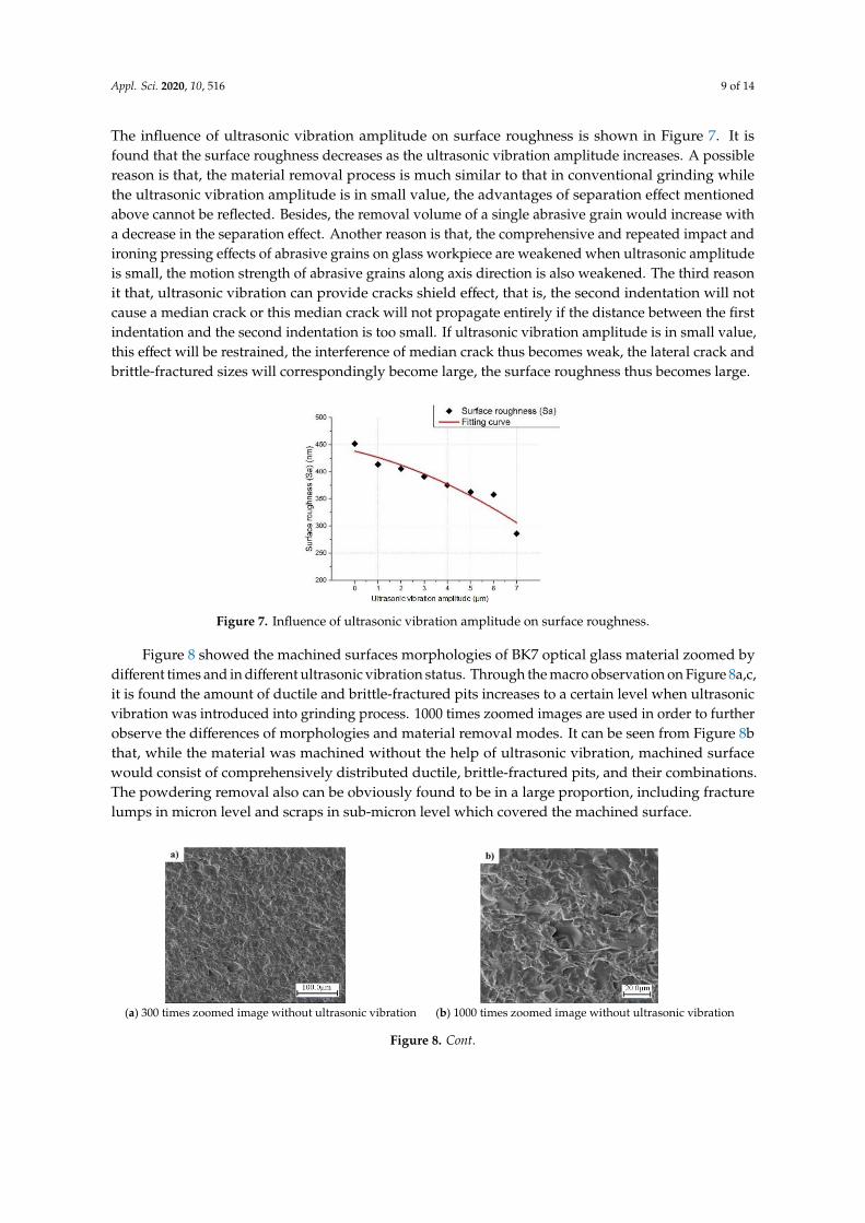
The influence of ultrasonic vibration amplitude on surface roughness is shown in Figure 7. It isfound that the surface roughness decreases as the ultrasonic vibration amplitude increases. A possiblereason is that, the material removal process is much similar to that in conventional grinding whilethe ultrasonic vibration amplitude is in small value, the advantages of separation effect mentionedabove cannot be reflected. Besides, the removal volume of a single abrasive grain would increase witha decrease in the separation effect. Another reason is that, the comprehensive and repeated impact andironing pressing effects of abrasive grains on glass workpiece are weakened when ultrasonic amplitudeis small, the motion strength of abrasive grains along axis direction is also weakened. The third reasonit that, ultrasonic vibration can provide cracks shield effect, that is, the second indentation will notcause a median crack or this median crack will not propagate entirely if the distance between the firstindentation and the second indentation is too small. If ultrasonic vibration amplitude is in small value,this effect will be restrained, the interference of median crack thus becomes weak, the lateral crack andbrittle-fractured sizes will correspondingly become large, the surface roughness thus becomes large.
Appl. Sci. 2020, 10, x FOR PEER REVIEW 9 of 14
4.1.2. Effect of Ultrasonic Amplitude on Surface Morphologies and Surface Roughness
Ultrasonic vibration can provide separation effect between grinding tool and glass workpiece,
and also can affect grinding force, critical cutting depth, and many other factors. Thus, it is necessary
to investigate the influence of ultrasonic vibration on surface roughness and material removal
mechanism. The influence of ultrasonic vibration amplitude on surface roughness is shown in Figure
7. It is found that the surface roughness decreases as the ultrasonic vibration amplitude increases. A
possible reason is that, the material removal process is much similar to that in conventional grinding
while the ultrasonic vibration amplitude is in small value, the advantages of separation effect
mentioned above cannot be reflected. Besides, the removal volume of a single abrasive grain would
increase with a decrease in the separation effect. Another reason is that, the comprehensive and
repeated impact and ironing pressing effects of abrasive grains on glass workpiece are weakened
when ultrasonic amplitude is small, the motion strength of abrasive grains along axis direction is also
weakened. The third reason it that, ultrasonic vibration can provide cracks shield effect, that is, the
second indentation will not cause a median crack or this median crack will not propagate entirely if
the distance between the first indentation and the second indentation is too small. If ultrasonic
vibration amplitude is in small value, this effect will be restrained, the interference of median crack
thus becomes weak, the lateral crack and brittle-fractured sizes will correspondingly become large,
the surface roughness thus becomes large.
Figure 7. Influence of ultrasonic vibration amplitude on surface roughness.
Figure 8 showed the machined surfaces morphologies of BK7 optical glass material zoomed by
different times and in different ultrasonic vibration status. Through the macro observation on Figure
8a,c, it is found the amount of ductile and brittle-fractured pits increases to a certain level when
ultrasonic vibration was introduced into grinding process. 1000 times zoomed images are used in
order to further observe the differences of morphologies and material removal modes. It can be seen
from Figure 8b that, while the material was machined without the help of ultrasonic vibration,
machined surface would consist of comprehensively distributed ductile, brittle-fractured pits, and
their combinations. The powdering removal also can be obviously found to be in a large proportion,
including fracture lumps in micron level and scraps in sub-micron level which covered the machined
surface.
(a) 300 times zoomed image without ultrasonic vibration (b) 1000 times zoomed image without ultrasonic vibration
Figure 7. Influence of ultrasonic vibration amplitude on surface roughness.
Figure 8 showed the machined surfaces morphologies of BK7 optical glass material zoomed bydifferent times and in different ultrasonic vibration status. Through the macro observation on Figure 8a,c,it is found the amount of ductile and brittle-fractured pits increases to a certain level when ultrasonicvibration was introduced into grinding process. 1000 times zoomed images are used in order to furtherobserve the differences of morphologies and material removal modes. It can be seen from Figure 8bthat, while the material was machined without the help of ultrasonic vibration, machined surfacewould consist of comprehensively distributed ductile, brittle-fractured pits, and their combinations.The powdering removal also can be obviously found to be in a large proportion, including fracturelumps in micron level and scraps in sub-micron level which covered the machined surface.
Appl. Sci. 2020, 10, x FOR PEER REVIEW 9 of 14
4.1.2. Effect of Ultrasonic Amplitude on Surface Morphologies and Surface Roughness
Ultrasonic vibration can provide separation effect between grinding tool and glass workpiece,
and also can affect grinding force, critical cutting depth, and many other factors. Thus, it is necessary
to investigate the influence of ultrasonic vibration on surface roughness and material removal
mechanism. The influence of ultrasonic vibration amplitude on surface roughness is shown in Figure
7. It is found that the surface roughness decreases as the ultrasonic vibration amplitude increases. A
possible reason is that, the material removal process is much similar to that in conventional grinding
while the ultrasonic vibration amplitude is in small value, the advantages of separation effect
mentioned above cannot be reflected. Besides, the removal volume of a single abrasive grain would
increase with a decrease in the separation effect. Another reason is that, the comprehensive and
repeated impact and ironing pressing effects of abrasive grains on glass workpiece are weakened
when ultrasonic amplitude is small, the motion strength of abrasive grains along axis direction is also
weakened. The third reason it that, ultrasonic vibration can provide cracks shield effect, that is, the
second indentation will not cause a median crack or this median crack will not propagate entirely if
the distance between the first indentation and the second indentation is too small. If ultrasonic
vibration amplitude is in small value, this effect will be restrained, the interference of median crack
thus becomes weak, the lateral crack and brittle-fractured sizes will correspondingly become large,
the surface roughness thus becomes large.
Figure 7. Influence of ultrasonic vibration amplitude on surface roughness.
Figure 8 showed the machined surfaces morphologies of BK7 optical glass material zoomed by
different times and in different ultrasonic vibration status. Through the macro observation on Figure
8a,c, it is found the amount of ductile and brittle-fractured pits increases to a certain level when
ultrasonic vibration was introduced into grinding process. 1000 times zoomed images are used in
order to further observe the differences of morphologies and material removal modes. It can be seen
from Figure 8b that, while the material was machined without the help of ultrasonic vibration,
machined surface would consist of comprehensively distributed ductile, brittle-fractured pits, and
their combinations. The powdering removal also can be obviously found to be in a large proportion,
including fracture lumps in micron level and scraps in sub-micron level which covered the machined
surface.
(a) 300 times zoomed image without ultrasonic vibration (b) 1000 times zoomed image without ultrasonic vibration
Figure 8. Cont.
Appl. Sci. 2020, 10, 516 10 of 14
Appl. Sci. 2020, 10, x FOR PEER REVIEW 10 of 14
(c) 300 times zoomed image at A = 7 μm (d) 1000 times zoomed image at A = 7 μm
Figure 8. Machined surface morphologies of optical glass material at different ultrasonic vibration
status.
After ultrasonic vibration was introduced into the grinding process, the material removal
mechanism obviously changed. From Figure 8d, when ultrasonic vibration amplitude is 7 μm, the
amounts of brittle-fractured pits in large sizes become much less, instead, ductile removal pits are
induced. Meanwhile, the powdering removal in sub-micron level nearly disappear. The fracture
lumps in micron level still have a certain proportion, but their amounts become much less. Instead of
covering the machined surface in conventional grinding process, these powdering removal defects
still connected to the machined surface.
Hence, a conclusion can be drawn that the introduction of ultrasonic vibration changes the
proportion of three material removal modes (i.e., ductile removal, brittle removal and powdering
removal). Besides, the proportion of ductile removal mode increases while the proportion of brittle
removal mode decreases. The powdering removal in sub-micron level are strongly restrained by
ultrasonic vibration, the proportion of fracture lumps in micron level decreases. Unlike conventional
grinding, fracture lumps in micron level are still connected to the workpiece surface after machining,
they did not separate the workpiece neither covered it.
4.2. Effect of Grinding and Ultrasonic Parameters on Surface Composition
The machined surface of ultrasonic vibration assisted grinding of BK7 optical glass consists of
different proportions of ductile, brittle, and powdering areas. Understanding the increase in
proportion of ductile removal, reduce the proportion of powder removal and brittle removal would
help to improve the machined surface quality and clarify the direction of process optimization.
Therefore, based on the above analysis, the effect of process parameters on the surface topography
composition during ultrasonic vibration-assisted grinding of BK7 optical glass was summarized, as
shown in the Figure 9.
Figure 9. Effect of processing parameters on surface composition in ultrasonic vibration assisted
grinding of optical glass BK7.
Figure 9 briefly summarizes the effect of ultrasonic vibration parameters and grinding
parameters on the proportion of ductile removal, powdering removal, and brittle fracture. It is
believed that brittle fracture always occupies the biggest proportion on the machined surfaces, while
that of powdering removal is the smallest.
Figure 8. Machined surface morphologies of optical glass material at different ultrasonic vibration status.
After ultrasonic vibration was introduced into the grinding process, the material removalmechanism obviously changed. From Figure 8d, when ultrasonic vibration amplitude is 7 µm, theamounts of brittle-fractured pits in large sizes become much less, instead, ductile removal pits areinduced. Meanwhile, the powdering removal in sub-micron level nearly disappear. The fracturelumps in micron level still have a certain proportion, but their amounts become much less. Instead ofcovering the machined surface in conventional grinding process, these powdering removal defects stillconnected to the machined surface.
Hence, a conclusion can be drawn that the introduction of ultrasonic vibration changes theproportion of three material removal modes (i.e., ductile removal, brittle removal and powderingremoval). Besides, the proportion of ductile removal mode increases while the proportion of brittleremoval mode decreases. The powdering removal in sub-micron level are strongly restrained byultrasonic vibration, the proportion of fracture lumps in micron level decreases. Unlike conventionalgrinding, fracture lumps in micron level are still connected to the workpiece surface after machining,they did not separate the workpiece neither covered it.
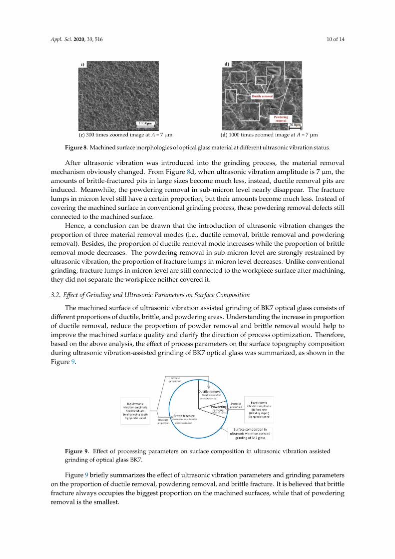
3.2. Effect of Grinding and Ultrasonic Parameters on Surface Composition
The machined surface of ultrasonic vibration assisted grinding of BK7 optical glass consists ofdifferent proportions of ductile, brittle, and powdering areas. Understanding the increase in proportionof ductile removal, reduce the proportion of powder removal and brittle removal would help toimprove the machined surface quality and clarify the direction of process optimization. Therefore,based on the above analysis, the effect of process parameters on the surface topography compositionduring ultrasonic vibration-assisted grinding of BK7 optical glass was summarized, as shown in theFigure 9.
Appl. Sci. 2020, 10, x FOR PEER REVIEW 10 of 14
(c) 300 times zoomed image at A = 7 μm (d) 1000 times zoomed image at A = 7 μm
Figure 8. Machined surface morphologies of optical glass material at different ultrasonic vibration
status.
After ultrasonic vibration was introduced into the grinding process, the material removal
mechanism obviously changed. From Figure 8d, when ultrasonic vibration amplitude is 7 μm, the
amounts of brittle-fractured pits in large sizes become much less, instead, ductile removal pits are
induced. Meanwhile, the powdering removal in sub-micron level nearly disappear. The fracture
lumps in micron level still have a certain proportion, but their amounts become much less. Instead of
covering the machined surface in conventional grinding process, these powdering removal defects
still connected to the machined surface.
Hence, a conclusion can be drawn that the introduction of ultrasonic vibration changes the
proportion of three material removal modes (i.e., ductile removal, brittle removal and powdering
removal). Besides, the proportion of ductile removal mode increases while the proportion of brittle
removal mode decreases. The powdering removal in sub-micron level are strongly restrained by
ultrasonic vibration, the proportion of fracture lumps in micron level decreases. Unlike conventional
grinding, fracture lumps in micron level are still connected to the workpiece surface after machining,
they did not separate the workpiece neither covered it.
4.2. Effect of Grinding and Ultrasonic Parameters on Surface Composition
The machined surface of ultrasonic vibration assisted grinding of BK7 optical glass consists of
different proportions of ductile, brittle, and powdering areas. Understanding the increase in
proportion of ductile removal, reduce the proportion of powder removal and brittle removal would
help to improve the machined surface quality and clarify the direction of process optimization.
Therefore, based on the above analysis, the effect of process parameters on the surface topography
composition during ultrasonic vibration-assisted grinding of BK7 optical glass was summarized, as
shown in the Figure 9.
Figure 9. Effect of processing parameters on surface composition in ultrasonic vibration assisted
grinding of optical glass BK7.
Figure 9 briefly summarizes the effect of ultrasonic vibration parameters and grinding
parameters on the proportion of ductile removal, powdering removal, and brittle fracture. It is
believed that brittle fracture always occupies the biggest proportion on the machined surfaces, while
that of powdering removal is the smallest.
Figure 9. Effect of processing parameters on surface composition in ultrasonic vibration assistedgrinding of optical glass BK7.
Figure 9 briefly summarizes the effect of ultrasonic vibration parameters and grinding parameterson the proportion of ductile removal, powdering removal, and brittle fracture. It is believed that brittlefracture always occupies the biggest proportion on the machined surfaces, while that of powderingremoval is the smallest.
Appl. Sci. 2020, 10, 516 11 of 14
When the ultrasonic vibration amplitude and the spindle rotation speed are high the feed rate andthe grinding depth are small, the ductile removal in the machined surface occupies a higher proportion.However, the changing of grinding wheel diameter did not show any obvious effect on the proportionof ductile removal and brittle fracture. However, the bigger the ultrasonic vibration amplitude is, themore obvious the repeated impact and ironing pressing effects are. Because of the high brittlenessand low fracture toughness, excessive impact and force would lead to the rapid growth in sizes ofsurface and subsurface cracks. These disadvantages may cause the surface and subsurface qualities todecrease, thus, the limiting value of ultrasonic vibration amplitude in the effect to surface compositionis 7 µm. The feed rate has the dominant effect to powdering removal, and the grinding depth hasno obvious effect on the powdering removal. The lower feed rate would increase the proportion ofpowdering removal to a certain degree; changing of grinding depth has little effect on the proportionof powdering removal.
3.3. Analysis of the Changes in Surface Morphologies and Surface Roughness
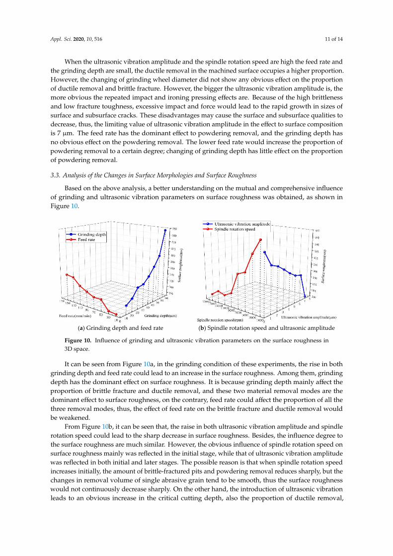
Based on the above analysis, a better understanding on the mutual and comprehensive influenceof grinding and ultrasonic vibration parameters on surface roughness was obtained, as shown inFigure 10.
Appl. Sci. 2020, 10, x FOR PEER REVIEW 11 of 14
When the ultrasonic vibration amplitude and the spindle rotation speed are high the feed rate
and the grinding depth are small, the ductile removal in the machined surface occupies a higher
proportion. However, the changing of grinding wheel diameter did not show any obvious effect on
the proportion of ductile removal and brittle fracture. However, the bigger the ultrasonic vibration
amplitude is, the more obvious the repeated impact and ironing pressing effects are. Because of the
high brittleness and low fracture toughness, excessive impact and force would lead to the rapid
growth in sizes of surface and subsurface cracks. These disadvantages may cause the surface and
subsurface qualities to decrease, thus, the limiting value of ultrasonic vibration amplitude in the effect
to surface composition is 7 μm. The feed rate has the dominant effect to powdering removal, and the
grinding depth has no obvious effect on the powdering removal. The lower feed rate would increase
the proportion of powdering removal to a certain degree; changing of grinding depth has little effect
on the proportion of powdering removal.
4.3. Analysis of the Changes in Surface Morphologies and Surface Roughness
Based on the above analysis, a better understanding on the mutual and comprehensive influence
of grinding and ultrasonic vibration parameters on surface roughness was obtained, as shown in
Figure 10.
(a) Grinding depth and feed rate (b) Spindle rotation speed and ultrasonic amplitude
Figure 10. Influence of grinding and ultrasonic vibration parameters on the surface roughness in 3D
space.
It can be seen from Figure 10a, in the grinding condition of these experiments, the rise in both
grinding depth and feed rate could lead to an increase in the surface roughness. Among them,
grinding depth has the dominant effect on surface roughness. It is because grinding depth mainly
affect the proportion of brittle fracture and ductile removal, and these two material removal modes
are the dominant effect to surface roughness, on the contrary, feed rate could affect the proportion of
all the three removal modes, thus, the effect of feed rate on the brittle fracture and ductile removal
would be weakened.
From Figure 10b, it can be seen that, the raise in both ultrasonic vibration amplitude and spindle
rotation speed could lead to the sharp decrease in surface roughness. Besides, the influence degree to
the surface roughness are much similar. However, the obvious influence of spindle rotation speed on
surface roughness mainly was reflected in the initial stage, while that of ultrasonic vibration
amplitude was reflected in both initial and later stages. The possible reason is that when spindle
rotation speed increases initially, the amount of brittle-fractured pits and powdering removal reduces
sharply, but the changes in removal volume of single abrasive grain tend to be smooth, thus the
surface roughness would not continuously decrease sharply. On the other hand, the introduction of
ultrasonic vibration leads to an obvious increase in the critical cutting depth, also the proportion of
ductile removal, and with the increase in ultrasonic amplitude, this advantage becomes much more
obvious, a sharp decrease in surface roughness finally comes to an end.
Figure 10. Influence of grinding and ultrasonic vibration parameters on the surface roughness in3D space.
It can be seen from Figure 10a, in the grinding condition of these experiments, the rise in bothgrinding depth and feed rate could lead to an increase in the surface roughness. Among them, grindingdepth has the dominant effect on surface roughness. It is because grinding depth mainly affect theproportion of brittle fracture and ductile removal, and these two material removal modes are thedominant effect to surface roughness, on the contrary, feed rate could affect the proportion of all thethree removal modes, thus, the effect of feed rate on the brittle fracture and ductile removal wouldbe weakened.
From Figure 10b, it can be seen that, the raise in both ultrasonic vibration amplitude and spindlerotation speed could lead to the sharp decrease in surface roughness. Besides, the influence degree tothe surface roughness are much similar. However, the obvious influence of spindle rotation speed onsurface roughness mainly was reflected in the initial stage, while that of ultrasonic vibration amplitudewas reflected in both initial and later stages. The possible reason is that when spindle rotation speedincreases initially, the amount of brittle-fractured pits and powdering removal reduces sharply, but thechanges in removal volume of single abrasive grain tend to be smooth, thus the surface roughnesswould not continuously decrease sharply. On the other hand, the introduction of ultrasonic vibrationleads to an obvious increase in the critical cutting depth, also the proportion of ductile removal,
Appl. Sci. 2020, 10, 516 12 of 14
and with the increase in ultrasonic amplitude, this advantage becomes much more obvious, a sharpdecrease in surface roughness finally comes to an end.
4. Conclusions
In this work, ultrasonic vibration-assisted grinding experiments of BK7 glass were carried out.According to the analysis of experimental results, the following conclusion can be obtained.
1. Machining parameters significantly influence the surface roughness (Sa). The surface roughness(Sa) and pits sizes increase with the increase in feed rate and grinding depth, and decrease withthe increase in the spindle rotation speed and ultrasonic vibration amplitude.
2. Increase in spindle rotation speed and ultrasonic vibration amplitude, decrease in grinding depthand feed rate could increase the proportion of ductile removal and reduce the proportion of brittleremoval. The introduction of ultrasonic vibration would largely inhibit the powder removalof submicron crumbs and reduce the proportion of powdered removal of micron-sized pieces.At the same time, the proportion of the ductile removal of willow leaf shaped removal could beincreased, and the proportion of the brittle removal of sector shaped removal could be reduced.
3. Compared to feed rate, grinding depth has the dominant positive effect on the surface roughness,the reason is the difference in the effect degree of these two parameters to powdering removalproportion. The sharp decrease in proportion of brittle fracture and powdering removal isthe reason of the initial obvious influence of spindle rotation speed on surface roughness.Surface roughness decreased obviously in both initial and later stages of increase in ultrasonicamplitude, the reason is the notable increase in proportion of ductile removal and the inhibitionof powdering removal.
Author Contributions: Conceptualization, P.Y.Z.; Investigation, M.Z.; Software, X.L.L.; Validation, B.J.;Writing—original draft, P.Y.Z. All authors have read and agreed to the published version of the manuscript.
Funding: This research was funded by the National Natural Science Foundation of China] grant number[U1630104].
Conflicts of Interest: The authors declare no conflict of interest.
Nomenclature
Sa Surface roughness (nm)n Spindle rotation speed (rpm)Vf Feed rate (mm/min)ap Grinding depth (µm)A Ultrasonic amplitude (µm)
References
1. Xie, J.; Deng, Z.J.; Liao, J.Y.; Li, N.; Zhou, H.; Ban, W.X. Study on a 5-axis precision and mirror grinding ofglass freeform surface without on-machine wheel-profile truing. Int. J. Mach. Tools Manuf. 2016, 109, 65–73.[CrossRef]
2. Cheng, J.; Wang, C.; Wen, X.L.; Gong, Y.D. Modeling and experimental study on micro-fracture behavior andrestraining technology in micro-grinding of glass. Int. J. Mach. Tools Manuf. 2014, 85, 36–48. [CrossRef]
3. Belkhir, N.; Aliouane, T.; Bouzid, D. Correlation between contact surface and friction during the optical glasspolishing. Appl. Surf. Sci. 2014, 288, 208–214. [CrossRef]
4. Shen, N.; Suratwala, T.; Steele, W.; Wong, L.; Feit, M.D.; Miller, P.E.; Dylla-Spears, R.; Desjardin, R.Nanoscratching of Optical Glass Surfaces Near the Elastic–Plastic Load Boundary to Mimic the Mechanics ofPolishing Particles. J. Am. Ceram. Soc. 2016, 99, 1477–1484. [CrossRef]
5. Chen, J.; Fang, Q.; Li, P. Effect of grinding wheel spindle vibration on surface roughness and subsurfacedamage in brittle material grinding. Int. J. Mach. Tools Manuf. 2015, 91, 12–23. [CrossRef]
Appl. Sci. 2020, 10, 516 13 of 14
6. Xiao, H.; Wang, H.; Chen, Z.; Fu, G.; Wang, J. Effect of brittle scratches on transmission of optical glass andits induced light intensification during the chemical etching. Opt. Eng. 2017, 56, 105101. [CrossRef]
7. Liu, K.; Li, X.P.; Rahman, M. Characteristics of ultrasonic vibration-assisted ductile mode cutting of tungstencarbide. Int. J. Adv. Manuf. Technol. 2008, 35, 833–841. [CrossRef]
8. Fang, F.; Hao, N.; Hu, G. Rotary Ultrasonic Machining of Hard and Brittle Materials. Nanotechnol. Precis.Eng. 2014, 12, 227–234.
9. Mahaddalkar, P.M.; Miller, M.H. Force and thermal effects in vibration-assisted grinding. Int. J. Adv. Manuf.Technol. 2014, 71, 1117–1122. [CrossRef]
10. Zhang, J.H.; Zhao, Y.; Tian, F.Q.; Zhang, S.; Guo, L.S. Kinematics and experimental study on ultrasonicvibration-assisted micro end grinding of silica glass. Int. J. Adv. Manuf. Technol. 2015, 78, 1893–1904.[CrossRef]
11. Suárez, A.; Veiga, F.; De Lacalle, L.N.L.; Polvorosa, R.; Lutze, S.; Wretland, A. Effects of Ultrasonics-AssistedFace Milling on Surface Integrity and Fatigue Life of Ni-Alloy 718. J. Mater. Eng. Perform. 2016, 25, 5076–5086.[CrossRef]
12. Celaya, A.; De Lacalle, L.N.L.; Campa, F.J.; Lamikiz, A. Ultrasonic Assisted Turning of mild steels. Int. J.Mater. Prod. Technol. 2010, 37, 60. [CrossRef]
13. Feng, P.; Liang, G.; Zhang, J. Ultrasonic vibration-assisted scratch characteristics of silicon carbide-reinforcedaluminum matrix composites. Ceram. Int. 2014, 40, 10817–10823. [CrossRef]
14. Tesfay, H.D.; Xu, Z.; Li, Z.C. Ultrasonic vibration assisted grinding of bio-ceramic materials: An experimentalstudy on edge chippings with Hertzian indentation tests. Int. J. Adv. Manuf. Technol. 2016, 86, 3483–3494.[CrossRef]
15. Wang, J.; Guo, B.; Zhao, Q.; Zhang, C.Y.; Zhang, Q.L.; Zhai, W.J. Evolution of material removal modes ofsapphire under varied scratching depths. Ceram. Int. 2017, 43, 10353–10360. [CrossRef]
16. Cao, J.G.; Wu, Y.B.; Guo, H.R.; Fujimoto, M.; Mitsuyoshi, N. Experimental investigation of material removalmechanism in ultrasonic assisted grinding of SiC ceramics using a single diamond tool. Int. J. Mach. ToolsManuf. 2013, 7, 93–96. [CrossRef]
17. Zhang, F.H.; Li, C.; Meng, B.B.; Zhao, H.; Liu, Z.D. Investigation of Surface Deformation Characteristic andRemoval Mechanism for K9 Glass Based on Varied Cutting-depth Nano-scratch. J. Mech. Eng. 2016, 52,65–71. [CrossRef]
18. Li, C.; Zhang, F.H.; Meng, B.B.; Liu, L.F.; Rao, X.S. Material removal mechanism and grinding force modellingof ultrasonic vibration assisted grinding for SiC ceramics. Ceram. Int. 2016, 43, 2981–2993. [CrossRef]
19. Zhang, F.H.; Li, C.; Zhao, H.; Leng, B.; Ren, L.L. Simulation and experiment of double grits interactingscratch for optical glass BK7. J. Wuhan Univ. Technol. (Mater. Sci. Ed.) 2018, 33, 15–22. [CrossRef]
20. Li, Z.P.; Zhao, H.; Zhang, F.H. Study on the Ductile Removal Behavior of K9 Glass with Nano-Scratch. Adv.Mater. Res. 2016, 1136, 282–288. [CrossRef]
21. Wang, W.; Yao, P.; Wang, J.; Huang, C.Z.; Zhu, H.T.; Liu, H.L.; Zou, B.; Liu, Y. Controlled material removalmode and depth of micro cracks in precision grinding of fused silica—A theoretical model and experimentalverification. Ceram. Int. 2017, 43, 11596–11609. [CrossRef]
22. Dai, J.B.; Su, H.H.; Yu, T.F.; Hu, H.; Zhou, W.B.; Ding, W.F. Experimental investigation on the materialremoval mechanism in during grinding silicon carbide ceramics with single diamond grain. Precis. Eng.2017, 51, 217–279. [CrossRef]
23. Gu, W.; Yao, Z.; Liang, X. Material removal of optical glass BK7 during single and double scratch tests. Wear2011, 270, 241–246. [CrossRef]
24. Xiao, H.P.; Chen, Z.; Wang, H.R.; Wang, J.H.; Zhu, N. Effect of grinding parameters on surface roughness andsubsurface damage and their evaluation in fused silica. Opt. Express 2018, 26, 4638–4655. [CrossRef]
25. Yu, T.; Li, H.; Wang, W. Experimental investigation on grinding characteristics of optical glass BK7: Withspecial emphasis on the effects of machining parameters. Int. J. Adv. Manuf. Technol. 2016, 82, 1405–1419.[CrossRef]
26. Lv, D.X.; Huang, Y.H.; Tang, Y.J.; Wang, H.X. Relationship between subsurface damage and surface roughnessof glass BK7 in rotary ultrasonic machining and conventional grinding processes. Int. J. Adv. Manuf. Technol.2013, 67, 613–622. [CrossRef]
27. Pal, R.K.; Garg, H.; Sarepaka RG, V.; Karar, V. Experimental Investigation of Material Removal and SurfaceRoughness during Optical Glass Polishing. Adv. Manuf. Process. 2015, 31, 1613–1620. [CrossRef]
Appl. Sci. 2020, 10, 516 14 of 14
28. Lin, X.H.; Zhang, J.B.; Tang, H.H.; Du, X.Y.; Guo, Y.B. Analysis of surface errors and subsurface damage inflexible grinding of optical fused silica. Int. J. Adv. Manuf. Technol. 2017, 88, 643–649. [CrossRef]
29. Pereverzev, P.P.; Pimenov, D.Y.A. Grinding force model allowing for dulling of abrasive wheel cutting grainsin plunge cylindrical grinding. J. Frict. Wear 2016, 37, 60–65. [CrossRef]
30. Jiang, C.; Wu, T.; Ye, H.; Cheng, J.; Hao, Y. Estimation of Energy and Time Savings in Optical GlassManufacturing When Using Ultrasonic Vibration-Assisted Grinding. Int. J. Precis. Eng. Manuf. Green Technol.2019, 6, 1–9. [CrossRef]
31. Zhao, P.Y.; Zhou, M.; Huang, S.N. Sub-surface crack formation in ultrasonic vibration-assisted grinding ofBK7 optical glass. Int. J. Adv. Manuf. Technol. 2017, 93, 1685–1697. [CrossRef]
32. Rinck, P.M.; Sitzberger, S.; Zaeh, M.F. Actuator design for vibration assisted machining of high performancematerials with ultrasonically modulated cutting speed. In Proceedings of the Fourth European Seminaron Precision Optics Manufacturing, International Society for Optics and Photonics, Teisnach, Germany,4–5 April 2017; Volume 103260C. [CrossRef]
33. Liu, L.P.; Zhao, W.; Ma, Y. Study on Imitating Grinding of Two-Dimensional Ultrasonic Vibration TurningSystem. In International Conference on Computer and Computing Technologies in Agriculture, Nanchang, China,22–25 October 2010; Springer: Berlin/Heidelberg, Germany, 2010; pp. 333–344. [CrossRef]
34. Zhou, M.; Zhao, P.Y. Prediction of critical cutting depth for ductile-brittle transition in ultrasonic vibrationassisted grinding of optical glasses. Int. J. Adv. Manuf. Technol. 2016, 86, 1775–1784. [CrossRef]
© 2020 by the authors. Licensee MDPI, Basel, Switzerland. This article is an open accessarticle distributed under the terms and conditions of the Creative Commons Attribution(CC BY) license (http://creativecommons.org/licenses/by/4.0/).
Top Related
Copyright © 2022 FDOKUMEN

