


Bahasa
Halaman
Hukum


IMCA store terms and conditions (https://www.imca-int.com/legal-notices/terms/) apply to all downloads from IMCA’s website, including this document.
IMCA makes every effort to ensure the accuracy and reliability of the data contained in the documents it publishes, but IMCA shall not be liable for any guidance and/or recommendation and/or statement herein contained. The information contained in this document does not fulfil or replace any individual’s or Member's legal, regulatory or other duties or obligations in respect of their operations. Individuals and Members remain solely responsible for the safe, lawful and proper conduct of their operations.
© 2021 Page 1 of 13
The following case studies and observations have been compiled from information received by IMCA. All vessel, client, and operational data has been removed from the narrative to ensure anonymity. Case studies are not intended as guidance on the safe conduct of operations, but rather to assist vessel managers, DP operators and DP technical crew in appropriately determining how to safely conduct their own operations. Any queries should be directed to IMCA at [email protected]. Members and non-members alike are welcome to contact IMCA if they have experienced DP events which can be shared anonymously with the DP industry.
1 Action Error – Was an ASOG in place?
DP Class 2, on DP 220m water depth, engaged in cargo
operations
5 Thrusters online, nil on standby
2 Generators online,
2 on standby
I DGNSS online, 1 Laser relative
online, 1 Radar on stand-by
3 Gyros, 2 MRUs and 2 wind sensors
online
Wind 6kts 001°, wave height 0.5m,
visibility good
DP checks carried out, outside wind
farm
DP checks complete, vessel enters wind farm
Alarm received on azimuth thruster 1 panel and silenced
by DPO
Azimuth thruster 1 remains selected
in DP Control
ECR Call Bridge and enquire on
which alarm received
Alarm no longer active, engineer
goes to local control panel to
investigate
DPO observed azimuth thruster 1 De-selected from
DP Control
Engineer call bridge and informs
them they had switched the
thruster to LOCAL
Engineer Switches azimuth thruster 1 back to REMOTE
DPO Re-selects azimuth thruster 1
back into DP Control
Vessel continues DP Operations
Considerations of the IMCA Marine DP Committee from the above event: This was a simple case of Key DP personnel not being included in the ASOG process, the ASOG should clearly indicate how critical machinery should be treated whilst carrying out the industrial mission of the vessel. If intrusive fault finding is required then a change of status would/should be required. The engineer did not consider the consequences of taking the thruster into local control. This event highlights the need for good operational planning and a detailed accurate ASOG. IMCA M 220 Guidance on operational activity planning, contains guidance on this subject.
DP Event Bulletin 04/21 – November 2021
jULY

IMCA DP Event Bulletin 04/21 Page 2 of 13
IMCA M 117 Section 7, Qualification and Knowledge Requirements of Key DP Personnel – gives guidance for Key DP Personnel. Although not related to the event the number of references seems inadequate. IMO MSC Circ. 645 and IMO MSC.1 Circ. 1580 guidance documents state that for DP 2 or 3 operations: There is a requirement for 3 independent position references simultaneously available during operation based on two different principles. See IMCA Information Note No.1567 which was published in July 2021.

IMCA DP Event Bulletin 04/21 Page 3 of 13
2 Swift action saved stress – Know your vessel!
DP Class 2, on DP 1390m water
depth, engaged in pipelay operations
6 Thrusters online, nil on standby
4 Generators online,
2 on standbyCLOSED BUS
4 DGNSS online, 1 on standby.
3 Gyros, 3 MRUs and 3 wind sensors
online
Wind 10kts 240°, wave height1.0m,
visibility good
Open water pipelay operations being conducted
LT cooling press alarm received on
running engine
Offline #4 engine started by duty
engineer
Engineer investigates reason
for alarm
Header tank for common cooling
circuit for 3 engines, found
very low
Engineers proceeds to fill
header tank
Standby engine that was started
shuts down due to high HT
Temperature
Problem traced to leaking
compensator on #4 engine common FW Cooling circuit
Compensator isolated on #4
engine
Cooling circuit fill and back to
normal
Operations continue with #4 engine disabled
until repair
Comments from the report: This is a positive report which highlights how familiarity of Key DP Personnel with the vessels Critical DP systems can lead to a successful outcome following a failure, which in this case had the potential to remove one redundant group. We can all get into these situations, but it is how we react to them that defines us.

IMCA DP Event Bulletin 04/21 Page 4 of 13
FW COOLING PUMP
DG6
DG4
DG5
FW COOLER
FW COOLER
Header
Tank
FailedCompensator
Figure 1 Example of the centralised LTFW System Considerations of the IMCA Marine DP Committee from the above event: This event highlights the need for DP Key Personnel having good knowledge of their roles within the DP system of their vessel. IMCA M 117 Section 7 Qualification and Knowledge Requirements of Key DP Personnel – gives guidance for Key DP Personnel. The report highlights the importance of the detection elements of the DP system, and the requirements for periodic testing, such as low level alarms and pressure transducers. Although not related to the event the number of same principle references seems inadequate. IMO MSC Circ. 645 and IMO MSC.1 Circ. 1580 guidance documents state that for DP 2 or 3 operations: There is a requirement for 3 independent position references simultaneously available during operation based on two different principles.
IMCA DP Event Bulletin 04/21 Page 5 of 13
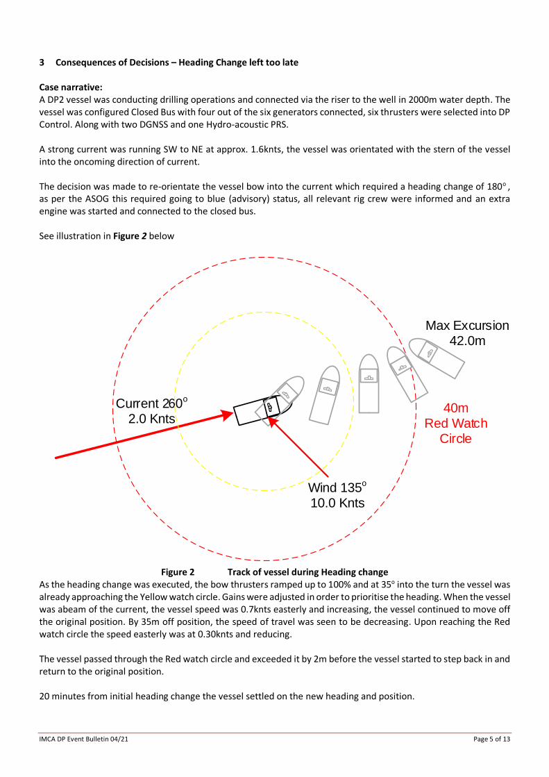
3 Consequences of Decisions – Heading Change left too late Case narrative: A DP2 vessel was conducting drilling operations and connected via the riser to the well in 2000m water depth. The vessel was configured Closed Bus with four out of the six generators connected, six thrusters were selected into DP Control. Along with two DGNSS and one Hydro-acoustic PRS. A strong current was running SW to NE at approx. 1.6knts, the vessel was orientated with the stern of the vessel into the oncoming direction of current. The decision was made to re-orientate the vessel bow into the current which required a heading change of 180o , as per the ASOG this required going to blue (advisory) status, all relevant rig crew were informed and an extra engine was started and connected to the closed bus. See illustration in Figure 2 below
Current 260o
2.0 Knts40m
Red Watch Circle
Max Excursion42.0m
Wind 135o
10.0 Knts
Figure 2 Track of vessel during Heading change
As the heading change was executed, the bow thrusters ramped up to 100% and at 35o into the turn the vessel was already approaching the Yellow watch circle. Gains were adjusted in order to prioritise the heading. When the vessel was abeam of the current, the vessel speed was 0.7knts easterly and increasing, the vessel continued to move off the original position. By 35m off position, the speed of travel was seen to be decreasing. Upon reaching the Red watch circle the speed easterly was at 0.30knts and reducing. The vessel passed through the Red watch circle and exceeded it by 2m before the vessel started to step back in and return to the original position. 20 minutes from initial heading change the vessel settled on the new heading and position.

IMCA DP Event Bulletin 04/21 Page 6 of 13
Causal Factors: Below is a list of causes that together led to the incident highlighted above:
• The decision making process - The parameters around the decision to make the move were not clear from the event report in terms of adherence to ASOG/WSOG, with regards the monitoring of environmental conditions and overall timing of the move.
• The environmental conditions at the time and prior to executing heading change.
• The power of the thrusters were unable to counter the environmental conditions which caused the vessel to breach the Red watch circle.
The Lessons: The following lessons can be taken from this incident:
1 Further risk assessment when undertaking these sort of vessel adjustment is crucial.
2 The vessel breached the Red watch circle, this is the point where disconnecting was a stated act in the ASOG/WSOG.
3 This event highlights the need for good operational planning and a detailed accurate ASOG/WSOG.
Consideration of the IMCA Marine DP Committee from the above event: This event highlights the need for good operational planning and a detailed accurate ASOG/WSOG. Planning needs to include when DP vessels are operating in an increasing environmental condition or close to the fringes of the vessel’s capability. Considerations should include: a. What are my safe limits for heading or position moves and are these detailed in the ASOG/WSOG? b. What are my limits for safe disconnection (or time to terminate) in the case of being unable to maintain
position / heading while also considering post worst case failure capability? c. Key personnel involved in the decision making process. d. What are my limits for emergency disconnection in the event of loss of position. e. What was the Rate of Turn and acceleration values? This may have contributed to the rapid increase of thrust. It is not clear from the event report if the decision support tools were available and robust enough to safely execute the heading change undertaken. Likewise, the report makes no reference to capability plots which should show limitations and DP footprint plots which can also provide guidance on the vessel’s maximum operational environment. IMCA M 103 – Guidelines for the design and operation of dynamically positioned vessels – refers to the use of DP footprint plots to record the vessel’s actual performance. These footprint plots, created on board, are of the vessel’s real station keeping performance in various thruster and vessel configurations and in different environmental conditions. IMCA M 140 – Specification for DP Capability Plots, and, IMCA M 220 – Guidance on operational activity planning, can also be referenced. The committee believe that a loss of position and heading should have been anticipated and therefore, serious consideration should have been given to securing the activities of the vessels industrial mission.

IMCA DP Event Bulletin 04/21 Page 7 of 13
4 Configuration –PRS’s Hidden Common Failure
A vessel was conducting ROV operations in the North Sea in open water, and was believed to be configiured as per the ASOG with open bus 2-way split, four thrsters selected into DP control. Position references online were four DGNSS and two Hydro-acustic all selected into DP system Control.
The first event was an alarm for DGNSS 2 & 3 and the subsequent de-selection from DP control, followed by DGNSS 1 & 4 along with Gyro’s 1 & 2. This was followed by the loss of both Hydro-acoustic position reference to DP control, the vessel was now positioning based on the model.
The ROV was ordered back to the tether management system and the yellow DP alert was activated.
Sea state was around 4 meters wave height and northerly wind on the bow of the vessel. Potential risk of fast drift-off position was high. Ship's crane wire was subsea but not connected to the subsea asset. The ROV was clear of any seabed structure.
Fortunately, no property, environment or other damage occured.
Causal Factors: Below is a list of step causes that together led to the incident highlighted above, Figure 3 below shows how the DGNSS was configured prior to Failure:
• The correction signal suppliers satalite signal was reported as failed for 1hr 3mins.
• All four of the DGNSS modulators (signal correction modules) were locked onto a single source.
Failure of the single correction source led to the loss of DGNSS and prompted the DP Control to reject all four DGNSS PRSs.
• Both Gyros 1 & 2 took automatic updates from the DGNSS for latitude & speed correction.
This is not recommended, it is recommended that manual input be used. Reference: IMCA M 252 Section 4.6 Operational Consideration Summary
Upon loss of the DGNSS signal into the Gyro, the settings in the Gyro were such that it failed all output signals. If automatic speed and latitude correction is used then the settings need to be configured in such a way that they fail safe, i.e., the output signal is not lost.
• Upon failure of both Gyro’s 1&2 both Hydro-acoustic PRS units were subsequently rejected from DP Control.
During the calibration by the Survey team, both Hydro-acoustic systems were connected to Gyros 1 & 2 with auto speed and latitude, instead of Gyro’s 3 & 4 with manual speed and latitude setting. In this way, after satellite primary reference loss, it additionally resulted in the loss of the Hydro-acoustic position references.
After the calibration and change of configuration there was no written note, handover or verbal notice given by the involved personnel who were present during calibration. This meant that at the moment of the DP incident the watch keeping DPOs were not aware about such critical system changes and reason for the loss of Hydro-acoustic PRSs.
A common mode failure had been introduced.

IMCA DP Event Bulletin 04/21 Page 8 of 13
DGNSS 1 DGNSS 2 DGNSS 3 DGNSS 4
Correction Correction Correction Correction
Duplex DPControl PLC
Land based Facility Known Fixed Point on Earth
DGNSSSatellite
DGNSSSatellite
Gyro 1
Service ProvidersSatellite
Gyro 2
Hydro-Acoustic 2Hydro-Acoustic 1
DGNSSSatellite
Gyro 3 Gyro 4
Figure 3 DGNSS Correction configuration Prior to Failure
The Lessons The following lessons can be taken from this incident:
1 For the Hydro-acoustic calibration, the configuration was altered and did not appear to be documented and, as such, was not returned to the fault tolerant configuration.
2 Not all stake holders were party to the fact that the calibration required a configuration change - in this case the DPOs were not informed.
3 Check lists did not capture the fact that only one common correction was being used and that the settings for DP Control would reject DGNSS on loss of correction signal (Raw data usage is an option for some DP Control systems). The DGNSS topology needs to be clearly displayed and understood and this can be an area where people instinctively shy away from, due to its perceived complexity.
4 The gyros in question were configured in such a way that upon loss of DGNSS latitude and speed signal the gyro output failed, this is dependant upon settings within the Gyro unit.

IMCA DP Event Bulletin 04/21 Page 9 of 13
5 It is not recommened that the Gyros take an automatic latitude & speed signal, it is recommended for DP vessels that latitude & speed be entered manually – Reference: IMCA M 252 4.6 Operational Consideration Summary. Also see NOTE below.
NOTE - Effects of Incorrect Latitude and / or Speed Inputs
If the operator or the GPS inputs an incorrect value for latitude or (more significantly) speed, then the Gyro compass will apply an incorrect adjustment to the output heading information. The magnitude of the error will vary with the inaccuracy of the input latitude or speed but an error of 10º or 5 knots may cause an error of 0.5º in the output heading.
When latitude and speed input is manually adjusted by the operator it is reasonably unlikely that large enough errors could be introduced to cause a significant error in the output heading. However, now that there is a trend towards using GPS to provide the latitude and speed information, there is the possibility that sudden GPS jumps (that used to plague DP systems in the early days of using GPS as a position reference) can introduce very large and sudden changes in latitude and therefore, calculated speed.

IMCA DP Event Bulletin 04/21 Page 10 of 13
5 DP Emergency Drill Scenario
DP emergency drill scenarios are included to assist DP vessel management and DPOs / Engineers and ETOs to conduct DP drills onboard. The intent is that the template can be used on any DP vessel so specific details regarding the technical outcome are not included. The benefit from using this template is to monitor and learn from the human reactions of key DP personnel. It is also important that the crew are familiar with various DP system setups including their failure modes.
EXERCISE SCENARIO THRUSTER FULL FAILURE
Objective:
To familiarise all vessel crew with what actions are required in order to recover the vessel into a controllable condition following a thruster failure to full thrust.
Method:
This test can be undertaken when the vessel is in a safe open space with no risk of excessive position excursion causing an unsafe condition.
If the vessel has CPP Main thrusters carry out using CPP. 1. Settle vessel on auto DP
2. A second person to take the most powerful thruster into manual control
3. Ramp that thruster to 100% in a direction perpendicular (if azimuth thruster) to the Auto DP thrust. If carrying out for CPP, put CPP thrust in the opposite direction
4. Observe effects
Observations During Drill:
1. Does the DP Control system compensate?
2. Is there an initial excursion?
3. What action would the DPO take?
4. Is the degree of participation and diligence of Key DP Personnel as expected?
IMCA DP Event Bulletin 04/21 Page 11 of 13
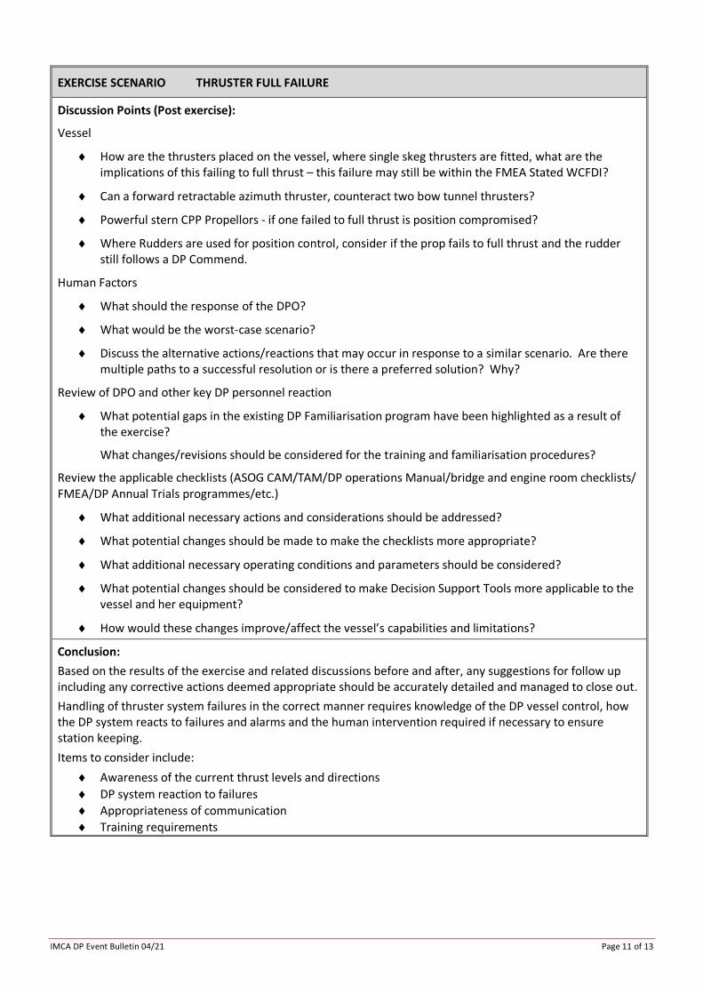
EXERCISE SCENARIO THRUSTER FULL FAILURE
Discussion Points (Post exercise):
Vessel
How are the thrusters placed on the vessel, where single skeg thrusters are fitted, what are the implications of this failing to full thrust – this failure may still be within the FMEA Stated WCFDI?
Can a forward retractable azimuth thruster, counteract two bow tunnel thrusters?
Powerful stern CPP Propellors - if one failed to full thrust is position compromised?
Where Rudders are used for position control, consider if the prop fails to full thrust and the rudder still follows a DP Commend.
Human Factors
What should the response of the DPO?
What would be the worst-case scenario?
Discuss the alternative actions/reactions that may occur in response to a similar scenario. Are there multiple paths to a successful resolution or is there a preferred solution? Why?
Review of DPO and other key DP personnel reaction
What potential gaps in the existing DP Familiarisation program have been highlighted as a result of the exercise?
What changes/revisions should be considered for the training and familiarisation procedures?
Review the applicable checklists (ASOG CAM/TAM/DP operations Manual/bridge and engine room checklists/ FMEA/DP Annual Trials programmes/etc.)
What additional necessary actions and considerations should be addressed?
What potential changes should be made to make the checklists more appropriate?
What additional necessary operating conditions and parameters should be considered?
What potential changes should be considered to make Decision Support Tools more applicable to the vessel and her equipment?
How would these changes improve/affect the vessel’s capabilities and limitations?
Conclusion:
Based on the results of the exercise and related discussions before and after, any suggestions for follow up including any corrective actions deemed appropriate should be accurately detailed and managed to close out.
Handling of thruster system failures in the correct manner requires knowledge of the DP vessel control, how the DP system reacts to failures and alarms and the human intervention required if necessary to ensure station keeping.
Items to consider include:
Awareness of the current thrust levels and directions
DP system reaction to failures
Appropriateness of communication
Training requirements
IMCA DP Event Bulletin 04/21 Page 12 of 13
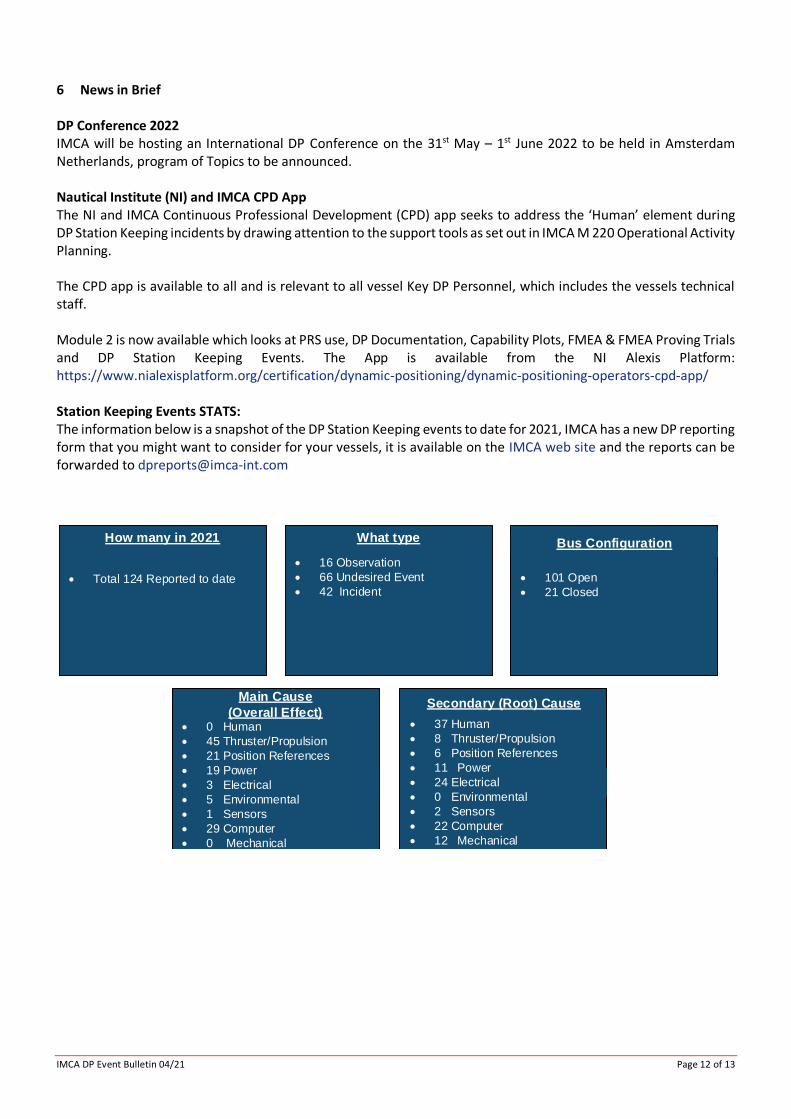
6 News in Brief DP Conference 2022 IMCA will be hosting an International DP Conference on the 31st May – 1st June 2022 to be held in Amsterdam Netherlands, program of Topics to be announced. Nautical Institute (NI) and IMCA CPD App The NI and IMCA Continuous Professional Development (CPD) app seeks to address the ‘Human’ element during DP Station Keeping incidents by drawing attention to the support tools as set out in IMCA M 220 Operational Activity Planning. The CPD app is available to all and is relevant to all vessel Key DP Personnel, which includes the vessels technical staff. Module 2 is now available which looks at PRS use, DP Documentation, Capability Plots, FMEA & FMEA Proving Trials and DP Station Keeping Events. The App is available from the NI Alexis Platform: https://www.nialexisplatform.org/certification/dynamic-positioning/dynamic-positioning-operators-cpd-app/ Station Keeping Events STATS: The information below is a snapshot of the DP Station Keeping events to date for 2021, IMCA has a new DP reporting form that you might want to consider for your vessels, it is available on the IMCA web site and the reports can be forwarded to [email protected]
How many in 2021 What type
• 16 Observation
• 66 Undesired Event
• 42 Incident• Total 124 Reported to date
Bus Configuration
• 101 Open
• 21 Closed
Secondary (Root) Cause
• 37 Human
• 8 Thruster/Propulsion
• 6 Position References
• 11 Power
• 24 Electrical
• 0 Environmental
• 2 Sensors
• 22 Computer
• 12 Mechanical
Main Cause
(Overall Effect)• 0 Human
• 45 Thruster/Propulsion
• 21 Position References
• 19 Power
• 3 Electrical
• 5 Environmental
• 1 Sensors
• 29 Computer
• 0 Mechanical

IMCA DP Event Bulletin 04/21 Page 13 of 13
Did you know? If you are employed by an IMCA member company then you can individually register on the website using your company domain email address and have direct access to the members area including all guidance and publications, so if you have a Bridge, ECR or Rank email onboard your vessels then the vessel staff can have that direct access.
Copyright © 2022 FDOKUMEN

