


Bahasa
Halaman
Hukum


www.dezurik.com
E-BULLETIN
DeZURIK BAW AWWA BUTTERFLY VALVES
FEBRUARY 202143.00-1

www.dezurik.com2
Defining the DeZURIK Difference
DeZURIK HistoryDeZURIK is an innovative global leader for the water and wastewater treatment industries, recognized worldwide for high quality and superior performance.
While DeZURIK provides innovative valves and related equipment for water and wastewater, DeZURIK eagerly responds as new industries develop and existing industries progress. Our knowledgeable engineers are quick to respond with groundbreaking technological advances. They continue to develop a wide range of products focusing on water and wastewater treatment, pulp and paper, chemical and petrochemical, power, mining and other process industries. Some of our products increase accuracy. Others assure durability or reliability. All of our products work to enhance our customer’s profitability.
CertificationFor our latest certifications, please visit our web site www.dezurik.com.
Leading Edge Design SoftwareComputer Aided Design systems are used by research and development engineers throughout the product development cycle. DeZURIK utilizes leading edge solid modeling software which allows product designers to view valve parts and assemblies three dimensionally. The 3D models are electronically transferred to Finite Element Analysis software where stress and deflection calculations are performed. This software allows designers to visualize deflection of critical parts under extreme loads. Proper relief and safety factors are included in every valve design to ensure long performance life.
Advanced Machining CapabilitiesDeZURIK’s solid modeling CAD software allows parts to be di rectly transferred to CAM modules for machine fixture design and NC programming. AWWA Butterfly Valves are manufactured with the most sophisticated machining centers available. Milling, drilling, boring, and tapping operations are performed on fully automated machine centers that perform sequential, error-free operations. DeZURIK’s investment in state-of-the-art machining centers ensures products of consistently high quality.
Rubber & Elastomer CompoundingDeZURIK formulates and handcrafts rubber to control quality on critical components. Over 50 years of pressure/temperature rubber-molding experience assures the AWWA seat design provides long, maintenance-free service. DeZURIK compounds its own resili ent seat materials to assure low operating torque and protection from pipeline corrosion and abrasion from sedimentation deposits.
Prototype Design TestingValve prototypes of sizes up to 36" (900mm) are tested in DeZURIK’s flow laboratory. Flow ranges from a few cubic centimeters per minute to 72,000 gallons per minute can be tested. Computer controlled testing automatically sets flow, mon itors temperatures, takes sample readings, and analyzes information. Before re lease, beta test sites are used to gain actual field experience. Valves are tested up to 10,000 cycles per AWWA C504 specifications. Proof of design testing certification is available.
© 2020 DeZURIK, Inc.

www.dezurik.com 3
ApplicationsDeZURIK AWWA Butterfly Valves are designed for applications throughout water and wastewater treatment plants, water distribution systems, power plants, and industrial plants. AWWA Butterfly Valves can be applied in applications demanding high-quality and thoroughly tested valves which offer many years of trouble-free service.
Pump Check Control SystemsPump check control systems, utilizing AWWA Butterfly Valves, are available in many different models.
Production TestingEach valve is given a hydrostatic, seat leakage and perform ance test per AWWA C504 before it is shipped.

www.dezurik.com4
Features for Years of Trouble-Free ServiceBody StylesFlanged, ASME B16.1 Class 125, 3–20" (80–500mm), Valve Class 150B
Flanged, ASME B16.1 Class 125, 3–20" (80–500mm), Valve Class 250B
Flanged, ASME B16.1 Class 250, 3–18" (80mm–450mm), Valve Class 250B
Mechanical Joint, ANSI/AWWA C111/A21.11, 4–20" (100–500mm), Valve Class 150B
Mechanical Joint, ANSI/AWWA C111/A21.11, 4–20" (100–500mm), Valve Class 250B
Corrosion Resistant ShaftStainless steel shafts provide corrosion resistance in bearing and packing journal areas to ensure long bearing and packing life. Standard shaft materials include 304, 316, and 17-4 PH stainless steel.
Self-Compensating Shaft SealsShaft seals are self-compen sat ing, V-type packing. DeZURIK uses a minimum of four sealing rings. This proven multi-ring sealing technology offers reliability and continuous self-adjustment.
Long Life, Low Friction BearingsUpper and lower journal shaft bearings are designed to provide high compressive strength, low friction and require no lubrication.
3–20" (80–500mm) Design

www.dezurik.com 5
Fully Rubber Lined BodyA fully rubber lined body is standard, eliminating the need for inner body coating, and protecting the body against corrosion buildup.
Integrity of the Proven Molding ProcessThe rubber bonding process used on DeZURIK AWWA Butterfly Valves is proven by more than 50 years of field experience. AWWA C504 re quires testing of the bonding process per ASTM D429, method B. The test requires a 1" (25mm) wide strip of rubber to withstand a minimum 75 lbs. pull force (at a 90° angle) before tearing away from the valve body. During destructive testing, the rubber must tear before the bond between the rubber seat and metal valve body gives way, demonstrating that the bond is stronger than the rubber. Based on extensive experience and proof of design testing, DeZURIK can assure that a molded-in body seat remains maintenance-free for the life of the valve.
Choice of Seat MaterialsStandard seat materials in clude Acrylonitrile-Butadiene (NBR) for water service and EPDM for high-temperature applications such as air blower lines.
4° Sealing SurfaceThe spherical sealing surface, molded into the valve seat, provides constant interference be tween the sealing surface and the disc edge for a full 4° sealing range. This allows the actuator to be adjusted within the correct sealing range while the valve is under pressure and flow.
Molded-In Body SeatThe pressure/temperature molding process used on AWWA Butterfly Valves provides a long-lasting, mainten ance-free seat. DeZURIK’s molded-in body seat lasts far beyond the 10,000 cycles re quired by AWWA C504. The molded seat-in-body design provides: • Uniform rubber thickness.
• Consistent interference between the rubber seating surfaces and the stainless steel disc edge.
• Tight tolerance control on critical seat dimensions.
3–20" (80–500mm) Design

www.dezurik.com6
3–20" (80–500mm) Design
Disc LocatorsAn innovative, molded-in, disc-centering device aligns the disc in the seat, providing a positive seal and longer seat life. Disc hubs, supported by the locators, ensure disc location accuracy. The offset style disc de sign means disc-alignment locators are separate from the sealing surface, extending valve seat life.
Proven Disc-To-Shaft PinningAll DeZURIK disc-to-shaft pinning connections conform to AWWA C504. Disc-to-shaft pinning is provided by a stainless steel torque screw on sizes 3–12" (80–300mm). Sizes 14–20" (350–500mm) utilize a tangential pin which is locked in place with a stainless steel set screw.
High Temperature ApplicationsFor operating temperatures to 290° F (143°C), EPDM seat material and packing, high temperature bearings and high temperature paint on the disc are available as standard options. Other seat materials for higher temperatures available on application.

www.dezurik.com 7
Offset Disc DesignThe offset disc provides an un interrupted 360° sealing sur face. The sealing surface is not interrupted by the valve shaft and does not have any continuous contact points between the rubber seat and the disc edge. This results in a longer seat life.
Stainless Steel Disc EdgeSolid 316 stainless steel disc edge provides the corrosion and abrasion resistance essential for long-lasting, mainten ance-free service. The stainless steel disc edge is on all disc materials including iron, carbon steel and aluminum bronze discs.
Seat-In-Body Seat-In-Disc
Body
Disc
Resilient Seat
Stainless Steel Disc Edge
Integral Shaft Bearing Seals To ensure all components of the valve remain maintenance-free, the molded-in body seat and body liner contain integral shaft bearing seals in the upp er and lower journals. These seals protect bearing journal areas against sedimentation, mineral deposits, and corrosion particles — all of which can damage bearings and shorten valve life.
Seat-In-Body vs. Seat-On-Disc DeZURIK’s AWWA Butterfly began its evolution over 40 years ago. For over 25 years, a stationary rubber seat locat ed in the valve body has been the standard. This feature is fundamental to the long-term per formance of the valve.
After years of service, water dis tribution valves and pipe lines (regardless of material) suffer the effects of abrasive corrosion and tuberculation buildup. When the rubber seat of a butterfly valve is located on the moving disc edge, it will erode or tear away as it plows its way through line buildup, causing the valve to leak. With a rubber seat-in-body design, the stainless steel disc pro vides the resistance necessary to plow through line buildup without seat-on-disc edge damage.
3–20" (80–500mm) Design

www.dezurik.com8
High Temperature ApplicationsFor operating temperatures to 290°F (143°C), EPDM seat material and packing, high temperature bear ings and high temperature paint on the body and disc are standard. Other seat materials for higher temperatures available on application.
Positive Disc LocatorsIncorporated into the lower shaft is an adjustable thrust bearing assembly which holds the disc position in all possible installation orientations. This thrust bearing absorbs forces from the disc weight, internal hydraulics and axial shaft loads.
Quality Features for Superior Performance
24” (600mm) and Larger Design
Body StylesFlanged, ASME B16.1 Class 125, 24–120" (600–3000mm), Valve Class 150B
Flanged, ASME B16.1 Class 125, 30–72" (750–1800mm), Valve Class 75B
Flanged, ASME B16.1 Class 125, 30–48" (750–1200mm), Valve Class 25A
Flanged, ASME B16.1 Class 125, 20–54" (600–1400mm), Valve Class 250B
Flanged, ASME B16.1 Class 250, 24–48" (600–1200mm), Valve Class 250B
Mechanical Joint, ANSI/AWWA C111/A21.11, 24–48" (600–1200mm), Valve Class 150B
Mechanical Joint, ANSI/AWWA C111/A21.11, 24–48" (600–1200mm), Valve Class 250B
Corrosion Resistant Shaft MaterialStandard shaft materials in clude 304, 316, and 17-4 PH stainless steel, providing the corrosion resistance in the bearing and packing journal areas necessary to ensure long bearing and packing life.
Stainless Steel Disc EdgeSolid 316 stainless steel disc edges provide a corrosion and abrasion resistant seating area essential for long-lasting, maintenance- free service.
Choice of Seat MaterialsStandard seat materials include Acrylonitrile Butadiene (NBR) for water service and EPDM for high temperature applications such as air blower lines.

www.dezurik.com 9
24" (600mm) and Larger Design
Adjustable, Replaceable SeatAs required by AWWA C504 for valves 24" (600mm) and larger, this seat design offers field adjustment and replacement capabilities. Proper field adjustment can be performed from either the up stream or downstream side of a pressurized valve.
Proven Disc-To-Shaft Pinning Disc-to-shaft pinning is provided by a stainless steel tapered pin on sizes 24" (600mm) and larger. This proven design provides a reliable, high strength connection that conforms to AWWA C504.
Long Life, Low Friction Bearings The upper and lower journal shaft bearings are designed to provide high compressive strength, low friction and require no lubrication.
Self-Compensating Shaft Seals Shaft seals are self-compensating, V-type packing. DeZURIK uses a minimum of four sealing rings. This proven multi-ring sealing technology offers reliability and continuous self-adjustment. Standard packing materials include Acrylonitrile-Butadiene (NBR) or EPDM to meet all application requirements.
Offset Disc DesignThe offset disc provides an un interrupted 360° sealing sur face. The sealing surface is not interrupted by the valve shaft and does not have any continuous contact points between the rubber seat and the disc edge. This results in a longer seat life.
Rugged Disc Structure DeZURIK utilizes state-of-the-art design and analysis computer software and test equipment to develop the optimum disc structure. Larger valves have an open disc structure, allowing water to flow through the center ports of the disc. On smaller sizes, DeZURIK utilizes a dome disc structure. On all valve sizes the disc structure is non-hollow, allowing inspection of each surface and wall thickness against shrinkage and core shift during the casting process.
Seat DesignDeZURIK’s large valve seat design is industry proven and offers reliability, low operating torque and long life. The rub ber seat is retained within a dove tail groove in the valve body and locked in place by an epoxy wedge. This design eliminates the need for fasteners, retaining rings or retaining segments to lock the seat in place. After the valve is fully assembled, with the disc in the closed position, an epoxy compound is injected behind the rubber seat and cured at a predetermined pressure based on the valve’s pressure class. The injection pressure controls the interference be tween the rubber and stainless steel disc edge, providing a level of seating performance virtually impossible to achieve with other seat designs.
Body
Resilient Seat
Disc
Stainless Steel Disc Edge
Epoxy Filler
www.dezurik.com10
3–16" (80–400mm) 18 & 20" (450 & 500mm)
3–20" (80–500mm) Valve Sizes
A6
A1
A2
A3
A16
A32
A5
A10A4
A7
A8
A6
A1
A2
A3
A16
A32
A5
A11
A12
A7
A8
Materials of Construction
Item Description Material
A1 BodyNBR or EPDM seat is permanently bonded to the body
Cast Iron ASTM A126 Class BDuctile Iron ASTM A536 Grade 65-45-12
A2 DiscDuctile Iron ASTM A536 Grade 65-45-12316 Stainless Steel, ASTM A743, Type CF8MAluminum Bronze, C95500, ASTM B763/B271/B505
A3 Disc Seating Edge 316 Stainless Steel, ASTM A276, Type 316316 Stainless Steel, ASTM A743, Type CF8M
A4 Tangential Pin 14–20" (350–500mm) 316 Stainless Steel, ASTM A276, Type 316(250B) 17-4 PH Stainless Steel, H1100
A5 Shaft 3–16" (80–400mm)Upper Shaft 18–20" (450–600mm)
316 Stainless Steel, ASTM A276, Type 31617-4 PH Stainless Steel, ASTM A564, Type 630 Condition 1150
A6 Key Steel AISI 1018
A7 Upper Journal BearingNylon and Molybdenum Disulphide Composition (NBR Seat)PTFE (EPDM Seat)(250B) PTFE Fabric Liner, Fiberglass back-up shell
A8 Packing Acrylonitrile Butadiene (NBR Seat)Ethylene Propylene Diene Terpolymer (EPDM Seat)
A10 Torque Screw 3–12" (80–300mm) 316 Stainless Steel, ASTM A276, Type 316(250B) 17-4 PH Stainless Steel, Condition 1100
A10 Set Screw 14–20" (350–500mm) 18–8 Stainless Steel
A11 Lower Shaft 18–20" (450–600mm) 316 Stainless Steel, ASTM A276, Type 31617-4 PH Stainless Steel, ASTM A564, Type 630 Condition 1150
A12 Set Screw 18–20" (450–500mm) 18–8 Stainless Steel
A16 Plug 3–20" (80–500mm)
3–8" (80–200mm) Carbon Steel, SAE J403, Grade 1008/101010–20" (250–500mm) Malleable Iron, ASTM A47-52 Grade 35018(250B, 3–6" (80–150mm)) Carbon Steel, SAE J403, Grade 1008/1010(250B, 8–20" (200–500mm)) Malleable Iron, ASTM A47-52 Grade 35018
A32 Lower Journal BearingNylon and Molybdenum Disulphide Composition (NBR Seat)PTFE (EPDM Seat)(250B) PTFE Fabric Liner, Fiberglass back-up shell

www.dezurik.com 11
See Detail B
Materials of Construction24–42" (600–1100mm)
48–72" (1200–1800mm)
A16
A20
A19
A24
A22
A19
A27
A8
A29
A7
A12
A32
A2
A1
A11
A10 A9 A26 A6
A16
A15
A20
A19
A17
A13 A33
A14
A11
A1
A25
A23
A17
A15
A13 A14 A33
A11
A1
A25
A30 A31
Seat Side
See Detail A
See Detail A
See Detail B
See Detail E
See Detail E
Detail E Adjustable Packing
Optional on 24–48" (600–1200mm) Standard on 54–72" (1400–1800mm)
Detail B Detail A
Contact DeZURIK for materials of construction on valve sizes 78–120" (2000–3000mm).
24–72" (600–1800mm) Valve Sizes
Item Description Material
A1 Body Cast Iron, ASTM A126 Class B Ductile Iron, ASTM A536 Grade 65-45-12
A2 Seat Acrylonitrile-Butadiene (NBR) Terpolymer of Ethylene, Propylene and a Diene (EPDM)
A6 Thrust Bearing Cover Cast Iron, ASTM A126 Class B Ductile Iron, A536 Grade 65-45-12
A7 Screw 18-8 Stainless Steel
A8 O-Ring Acrylonitrile-Butadiene (NBR) Terpolymer of Ethylene Propylene and a Diene (EPDM)
A9 Thrust Collar Steel, ASTM 108
A10 Set Screw 18-8 Stainless Steel
A11 Disc Ductile Iron ATM A536 Grade 65-45-12
A12 Disc Edge 316 Stainless Steel, ASTM A240, Type 316
A13 Disc Pin 304 Stainless Steel, ASTM A276, Type 304303 Stainless Steel, ASTM 582, Type 303
A14 Nut 18-8 Stainless Steel
A15 Upper Shaft304 Stainless Steel, ASTM A276, Type 304 316 Stainless Steel, ASTM A276, Type 316 17-4 PH Stainless Steel, ASTM 564, Type 630 Condition 1150
A16 Key Steel AISI 1018
A17 Bearing PTFE Fabric Liner, Fiberglass back-up shell
A19 Packing NBR Acrylonitrile-Butadiene (NBR Seat) EPDM Ethylene Propylene and a Diene (EPDM Seat)
A20 Spacer 30-48" (750–1200mm) 316 Stainless Steel, ASTM A276, Type 316
A22 Gland 60-72" (1500–1800mm) Bronze ASTM B-62
A23 Screw (Used with A22) 18-8 Stainless Steel
A24 Washer (Used with A22) 18-8 Stainless Steel
A25 Lower Shaft304 Stainless Steel, ASTM A276, Type 304 316 Stainless Steel, ASTM A276, Type 316 17-4 PH Stainless Steel, ASTM 564, Type 630 Condition 1150
A26 Adjusting Screw 303 Stainless Steel, ASTM A582, Type 303
A27 Jam Nut 18-8 Stainless Steel
A29 Thrust Plate Carbon Steel AISI A108
A30 Screw 24–48" (600–1200mm) 18-8 Stainless Steel
A31 Lockwasher 24–48" (600–1200mm) 18-8 Stainless Steel
A32 Epoxy Epoxy
A33 O-Ring Acrylonitrile-Butadiene (NBR) Terpolymer of Ethylene Propylene and a Diene (EPDM)

www.dezurik.com12
Contact DeZURIK for Cv/Kv Values on 78–120" (2000–3000mm) valves and for Class 250B.
* Cv = Flow in GPM of water at 1 psi pressure drop.Kv = Flow in m3/hr. of water at 100 kPa pressure drop.
Cv/Kv Values*
Valve Selection
Class 150B
Valve Size Flat
Cv/KvDomeCv/Kv
3" 362 356 80mm 313 308
4" 658 646 100mm 569 559
6" 1,380 1,360 150mm 1,194 1,176
8" 2,440 2,390 200mm 2,111 2,067
10" 3,910 3,840 250mm 3,382 3,322
12" 5,730 5,630 300mm 4,960 4,870
14" 7,840 7,700 350mm 6,782 6,661
16" 10,200 9,980 400mm 8,823 8,633
18" 12,600 12,400 450mm 10,899 10,726
20" 15,800 15,500 500mm 13,667 13,408
24" 22,900 22,500 600mm 19,809 19,463
100% Cv/Kv
Class 25A, 75B, 150B
ValveSize
Flat Cv/Kv
DomeCv/Kv
30" 36,500 35,900 750mm 31,573 31,054
36" 53,200 52,300 900mm 40,018 45,240
42" 73,100 71,800 1100mm 63,232 62,107
48" 109,000 103,000 1200mm 94,285 89,095
54" 140,000 131,000 1400mm 121,100 113,315
60" 173,000 163,000 1500mm 149,645 140,995
66" 210,000 198,000 1700mm 181,650 171,270
72" 250,000 236,000 1800mm 216,250 204,140
100% Cv/Kv
Per
cen
t o
f M
axim
um
Flo
w
Flow characteristic 3-42" (80-1100mm)
Valve Percent Open
Flow to Seat Side Flow to Back of Disc
0%0%
10%
20%
30%
40%
50%
60%
70%
80%
90%
100%
10% 20% 30% 40% 50% 60% 70% 80% 90% 100%
Per
cen
t o
f M
axim
um
Flo
w
Flow Characteristic 48-72" (1200-1800mm)
Valve Percent Open
Flow to Seat Side Flow to Back of Disc
0%0%
10%
20%
30%
40%
50%
60%
70%
80%
90%
100%
10% 20% 30% 40% 50% 60% 70% 80% 90% 100%
Applicable Standards
DeZURIK BAW AWWA Butterfly Valves are designed and/or tested to meet the following standards:
ANSI/AWWA C111/A21.11 Mechanical Joint Bell dimensions conform to ANSI/AWWA C111/A21.11, Rubber Gasket Joints for Ductile Iron and Gray Iron Pressure Pipe Fittings.
ANSI/AWWA C-504 Valves conform to AWWA Standard ANSI/AWWA C-504 for sizes 3-72" (80-1800mm) Rubber Seated Butterfly Valves. Standard interior and exterior coatings meet the requirements of this standard.
ANSI/AWWA C-516 Valves conform to AWWA Standard ANSI/AWWA C-516 for sizes 78" (2000mm) & larger Rubber Seated Butterfly Valves. Standard interior and exterior coatings meet the requirements of this standard.
ASME B16.1 Dimensions and drilling of flanged end connections on valves up to 96" (2400mm) conform to Class 125 sections of ASME B16.1 Cast Iron Pipe Flanges and Flange Fittings.
ASTM D429 Bonding of 3-20" (80-600mm) seats conforms to ASTM D429, Standard Test Methods for Rubber Property - Adhesion to Rigid Substrates.
ASTM D471 Seat material volume increase is less than 2% after immersion in distilled water for 70 hours, when tested in accordance with ASTM D471, Standard Test Method for Rubber Property - Effect of Liquids.
ASTM D1149 Ozone resistance of seat material conforms to ASTM D1149, Standard Test Method for Rubber Deterioration - Surface Ozone Cracking in a Chamber.
AWWA C110 Ductile-Iron and Gray-Iron Fittings, Mechanical Joint Accessories 30-48” (750-1200mm) meet this standard.
AWWA C153 Ductile-Iron Compact Fittings, Mechanical Joint Accessories 4-24” (100-600mm) meet this standard.
AWWA C207 For sizes 102" (2600mm) and larger, flange bolt patterns comply with AWWA C207 and flange thickness complies with AWWA C516.

www.dezurik.com 13
Basic Valve Weights*
ValveSize
Flanged F1 Flanged F2 Mechanical Joint
All Classes Class 250B Class 150B(Use for Class 250B)
3"80mm
3315
4521 —
4"100mm
4521
6229
5023
6"150mm
6530
9041
7635
8"200mm
10046
14466
11251
10"250mm
15671
20794
12356
12"300mm
250114
312142
21397
14"350mm
325148
454206
238108
16"400mm
383174
538245
398181
18"450mm
428195
596271
444202
20"500mm
547249
773351
570259
24"600mm
1025466
1435652
1025466
28"700mm
1360618 — —
30"750mm
1850840
24051092
1850840
36"900mm
28001271
36401652
28001271
42"1050mm
40501838
52652389
40501838
48"1200mm
57502609
74753392
57502609
54"1400mm
75003403 — —
60"1500mm
98254458 — —
66"1700mm
121005491 — —
72"1800mm
151506874 — —
Contact DeZURIK for weights on valve sizes 78" (2000mm) and larger.
* Weights are approximate and do not include crating or actuators.
lbskilograms

www.dezurik.com14
Valve SizeGive valve size code as follows:3" (80mm) 42" (1100mm)4" (100mm) 48" (1200mm)6" (150mm) 54" (1400mm)8" (200mm) 60" (1500mm)10" (250mm) 66" (1700mm)12" (300mm) 72" (1800mm)14" (350mm) 78" (2000mm)16" (400mm) 84" (2100mm)18" (450mm) 90" (2300mm)20" (500mm) 96" (2400mm)24" (600mm) 102" (2600mm)28" (700mm) 108 (2700mm)30" (750mm) 114" (2900mm)36" (900mm) 120" (3000mm) 144" (3600mm)Note: All orders for 28" (700mm) and larger must include valve pipeline mounting position and shaft orientation as second line information.
End ConnectionGive end connection code as follows:F1 = ASME 125 Flanged 3-96" (80–2400mm) AWWA C207 Class B & C Flanged 102-144" (2600-3600mm)F2 = ASME 250 Flanged 3-48" (80–1200mm)MJ = Mechanical Joint 4-48" (100–1200mm)With Mechanical Joint ends, buriable actuators are recommended.
Valve StyleGive valve style code as follows:BAW = AWWA Butterfly Valve
Class AWWA C-504Give AWWA Class code as follows:25A = 28–48" (700–1200mm) Flanged75B = 28–144" (700–3600mm) Flanged150B = 3–144" (80–3600mm) Flanged 4–48" (100–1200mm) Mechanical Joint250B = 3–144" (80–3600mm) Flanged 4–48" (100–1200mm) Mechanical JointNote: Pressure ratings above 150 not available with EPDM Seat on
valves 24" & larger (600mm & larger).
Body MaterialGive body material code as follows:CI = Cast Iron - F1 or MJCS = Carbon Steel - F1, 24" & larger (600mm & larger)DI = Ductile Iron - F1, F2, or MJS2 = 316 Stainless Steel - F1, 24" & larger (600mm & larger)
Ordering Example:BAW,24,F1,CI,NBRN-NBR,150B,DI-S1*Actuator
Options Give options code as follows:AIS = Valves conform to H.R. 3547 Consolidated Appropriations Act, 2014 Section 436DTR = DeZURIK Standard Certified Production Hydrostatic Shell and Seat Test ReportBAA = Buy American ActCMC = Certificate of Material ConformanceTB = DeZURIK Standard Certified Hydrostatic Shell Test and Seat
Leak Test, both directions
Ordering
Packing/Seat CombinationGive packing/seat material codes as follows:Packing MaterialNBRN = Acrylonitrile-Butadiene Self-Adjusting 3–144" (80-3600mm) -20 to 180ºF (-29 to 82ºC)NBRA = Acrylonitrile-Butadiene Adjustable 3–144" (80-3600mm) -20 to 180ºF (-29 to 82ºC) Do not use with buried serviceEPDN = EPDM Self-Adjusting -20 to 290ºF (-29 to 143ºC) 3–48" (80–1200mm)EPDA = EPDM Adjustable -20 to 290ºF (-29 to 143ºC) 3–48" (80–1200mm) Do not use with buried service.TCN = PTFE Self-Adjusting -20 to 450ºF (-29 to 232ºC) 3–144" (80–3600mm)TCA = PTFE Adjustable -20 to 450ºF (-29 to 232ºC) 28–144" (700–3600mm) Do not use with buried service.
Seat MaterialNBR = Acrylonitrile-Butadiene -20 to 180ºF (-29 to 82ºC) Must use NBRN or NBRA packing.EPDM = Terpolymer of Ethylene Propylene & a Diene -20 to 290ºF (-29 to 143ºC) Must use EPDA or EPDN, TCN or TCA packing.
Disc/Shaft CombinationGive disc/shaft code as follows:Disc MaterialDI = Ductile Iron disc with 316 stainless steel edgeS2 = 316 Stainless SteelALB = Aluminum Bronze (3-18" only)CS = Carbon Steel, 24" & larger (600mm & larger)
Shaft & Pin MaterialGive shaft & pin material code as follows:S2 = 316 Stainless Steel shaft & pin, Standard on 3–20" (80-500mm), optional on 24" (600mm) and largerS1 = 304 Stainless Steel shaft Pin is 316 Stainless Steel on 24–36" (600-900mm) and 304 Stainless Steel on 42–144" (1100-3600mm)S5 = 17-4 pH Stainless Steel shaft & pin (must be used with 250B)
Mechanical Joint AccessoriesAccessories include bolts, nuts, packing and glands for both ends. Sizes 4-24" (100-600mm) meet AWWA C153. Sizes 30-48" (750-1200mm) meet AWWA C110. Order as a separate item by giving code ACC*MJ-valve size.

www.dezurik.com 15
Manual ActuatorsLever Actuators
Rotary Manual ActuatorsDeZURIK offers a variety of rotary manual actuator options which are in complete compliance with AWWA C504. Man ual actuators are available with handwheel, chainwheel or 2" (80mm) square nut options.
Easily Adjustable StopsOpen and closed position stops can be easily adjusted without drilling, shimming or pinning. The stops ride the input shaft and can be repositioned with a simple adjustment of the stop nut.
Rugged DesignsManual actuators are sized to operate with a maximum input of 150 foot pounds on 2" (80mm) square operating nuts, and can be sized for 40 or 80 pound rim pull on handwheels and chainwheels. The actuators are self-locking, maintaining valve position under varying flow conditions.
Buriable and Weatherproof ConstructionDeZURIK actuators feature a cast iron housing in buriable or weatherproof construction. The mechanism is totally en closed and does not require lubrication for routine maintenance. Buried service actuators are grease filled per AWWA C504.
Valve Position IndicatorThe pointer on weatherproof actuators clearly indicates the valve position marked on top of the housing. The indicator shaft is sealed to keep moisture from entering the actuator housing.
A 10-position dial provides positive latching in open, closed and eight intermediate positions. A pointer indicates position of disc plus a notch in the handle allows use of a padlock to prevent unauthorized valve operation.
MountingLever actuators can be mounted at standard or 180°. Levers are available on 3–8" (80–200mm) valve sizes. Seat Side Seat Side
Standard Position 180° Position
ChainwheelSeat Side Seat Side
Standard Position 180° Position
Seat Side Seat Side Seat Side Seat Side
Standard Position
90° Position 180° Position 270° Position
MountingNut & Handwheel
Easily RotatableThe four keyways in the yoke make DeZURIK nut and handwheel manual actuators easy to rotate to any of four mounting positions. Chainwheel actuators can be mounted at standard and 180º.

www.dezurik.com16
G-Series DesignThe G-Series design is available on 3–30" (80–750mm) valve sizes with a handwheel, chainwheel or 2" square nut input. The worm gear mechanism allows the G-Series actuators to provide high output torque with a torque curve matching the torque required by the valve. G-Series actuators feature a steel worm and ductile iron gear.
300 & 450 Foot Pound Input TorqueAs required by AWWA C504, an input torque of 300 foot pounds against the fully adjustable open and closed position stops is standard. A 450 foot pound input capability against the stops is an option.
LA-Series DesignThe LA-Series design is available on 30–72" (750–1800mm) valve sizes. The link-arm mechanism allows the LA-Series actuator to provide characterized closure which slows valve travel as the disc comes into the seat. The actuators feature high compressive strength yoke nut bear ings which ensure reliable operation and increase cycle life.
High Output TorqueThe LA-Series actuators feature an input torque capability of 450 foot pounds against the open and closed position stops as standard. An op tional spur gear provides a 2:1 mechanical advantage while maintaining an input torque capability of 300 foot pounds against the stops. The spur gear slows closing of the valve, minimiz i ng the possibility of water hammer.
450 Ft-Lb Input StopsLA-Series actuators have 450 Ft-Lb input stops as standard.
Manual Actuators

www.dezurik.com 17
GS/GB-6B Materials of ConstructionRotary Manual Actuators
Item Description MaterialB1A Housing Cast Iron, ASTM A126, Class BB1B Cover Cast Iron, ASTM A126, Class BB1C Gear Ductile Iron, ASTM A536, Grade 80-55-06 B1D Worm Steel, EN19 or ASTM A322, Grade 1440, UNS G14400B1L Bearing Bronze, Oil Impregnated B1F Drive Shaft Stainless Steel, Type 431 ASTM 276B1G Bearing Race SteelB1H Thrust Bearing SteelB1I Pipe Plug 18-8 Stainless Steel, ANSI B16.14B1J Shaft Seal Acrylonitrile-Butadiene (NBR) and carbon steel caseB1K Pin Type H Steel EN8 Rockwell C20-25, ANSI B18.8.2B1E Bearing Bronze, Oil Impregnated, ASTM B438, Grade 1, Type 2B1M Screws A2-70, DIN933 (comparable to Stainless Steel 18-8)B1N O-ring Acrylonitrile-Butadiene (NBR)B1O Nut A2, DIN439B, (comparable to Stainless Steel 18-8)B1P Screw A2-80, DIN933 (comparable to Stainless Steel 18-8)B1Q Pointer Steel Zinc Plated, ASTM 569B1R Screw A2 (comparable to Stainless Steel 18-8) ANSI B18.3.4MB1S Plug, Tapered Plastic 238-DB1T Plug Steel, ASTM A108, UNS G1018B1U Packing Washer 316 Stainless Steel, ASTM A276, UNS S31600 B1V Spacer Sleeve Steel EN 19 or ASTM A322, Grade 4140 UNS G41400
Screw (B1R)
Pointer (B1Q)
Screw (B1M)
Cover (B1B)
O-ring (B1N)Bearing (B1L)
Gear (B1C)
Pin (B1K)
Spacer Sleeve (B1V)(G_-6B only)
Bearing Race (B1G)
Thrust Bearing (B1H)
Worm (B1D)
Plug (B1T)
Drive Screw (B22)
Data Plate (B21)
Pipe Plug (B1I)
Plug (B1S)
Packing Washer (B1U)(G_-6B only)
Housing (B1A)
Screw (B1P)
Nut (B1O)
Bearing (B1E)
Seal (B1J)
Drive Shaft (B1F)
Screw (B13)
Cover (B12)
Buried Service (GB_)Cover Assembly

www.dezurik.com18
Buried Actuator Cover
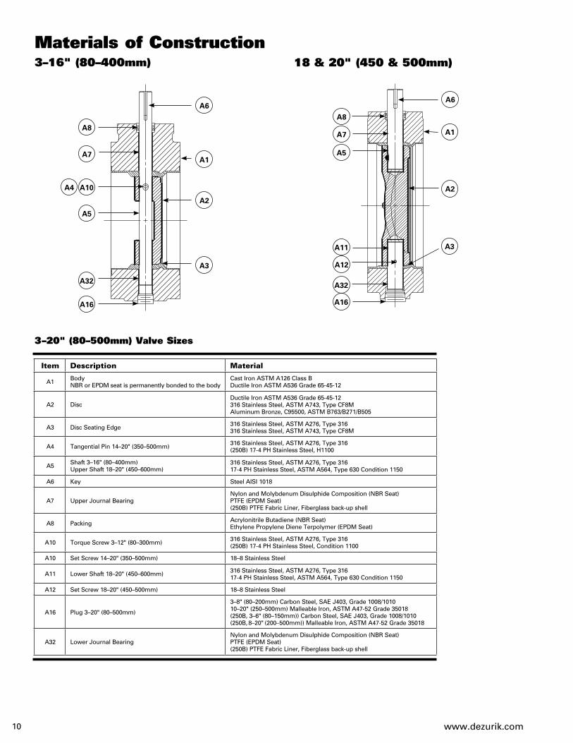
LA-Series Handwheel
B35 B44 B34 B91 B33 B29 B28 B32
B27
B25
B45B13B24B1B14B13B16B40
B43
B15
B18
B17
B8 B47 B46
B34
B9B7B6B3B10
LA-Series Actuator Materials of Construction
B1 Housing Cast Iron, ASTM A126 Class B
B2 Bearing Bronze Oil Impregnated
B3 Yoke Ductile Iron, ASTM A536 80-55-06
B4 Cover Steel Plate, A36 HR
B5 Packing Retainer Steel Plate, A36 HR
B6 Link Steel
B7 Yoke Nut Ductile Iron, ASTM A536 80-55-06
B8 Guide Nut Powder Metal 8020 23B (LA-4 & LA-6)
B9 Retaining Ring Carbon Steel, SAE 1060-1090
B10 Input Shaft Steel, AISI 1141
B11 O-Ring Acrylonitrile-Butadiene
B12 O-Ring Acrylonitrile-Butadiene
B13 Collar Steel, AISI 1215
B14 Pin Steel
B15 Thrust Washer Teflon/Glass Fabric, Stainless Steel Backing
B16 Thrust Washer Teflon/Glass Fabric, Stainless Steel Backing
B17 Bearing Bronze Oil Impregnated
B18 Expansion Plug Steel Zinc Plated
B23 Retaining Washer Stainless Steel, Type 18-8
B24 Outer Guide Bar Steel, AISI 1018
B25 Inner Guide Bar Steel, AISI 1018
B26 Square Nut Steel, AISI 1018
B27 Stop Nut Steel, AISI 1018
B28 Seal Steel with Nitrile
B29 Pointer Steel, ASTM A36
B32 Stud Steel Zinc Plated
B33 Nut Steel Zinc Plated
B34 Thread Seal Steel with Nitrile
B35 Yoke Cover Steel, ASTM A569
B40 Pin Steel Zinc Plated
B43 Handwheel Cast Iron, ASTM A126 Class B
B44 Position Plate Vinyl
B45 Shim Steel
B47 Expansion Plug Steel Zinc Plated
Note: All fasteners are zinc plated steel unless stainless steel bolting is specified.
Item Description Material
Rotary Manual Actuators
Item Description Material B48 Bushing Bronze Oil Impregnated
B50 Chain Guide Cast Iron, ASTM A126
B51 Closing Link Steel
B52 Collar Steel, ASTM A36
B53 Bearing Bronze
B54 Screw Steel Zinc Plated
B55 Washer Steel Zinc Plated
B56 Retaining Ring Carbon Steel
B57 Adaptor Plate Steel, ASTM A36
B58 Seal Garlock
B62 Bearing Bronze
B63 Gasket Non-Asbestos
B64 Adaptor Cast Iron, ASTM A126 Class B
B65 Gasket Non-Asbestos
B69 Housing (Spur Gear) Cast Iron, ASTM A126
B70 Pin (Chainwheel) Steel Zinc Plated
B71 Gasket Fiber Non-Asbestos
B72 Screw Steel Zinc Plated
B73 Screw Steel Zinc Plated
B74 Seal Steel Zinc Plated
B75 Pin Steel Zinc Plated
B76 Pin Steel Zinc Plated
B77 Retainer Ring Steel Zinc Plated
B78 Cover Steel Plate, ASTM A36
B81 Gear Carbon Steel
B82 Gear Carbon Steel
B83 Input Shaft (Spur Gear) Steel, ASTM A29
B84 O-Ring Nitrile
B85 Chainwheel Cast Iron, ASTM A126 Class B
B88 Adaptor (Adj. Packing) Steel, ASTM A36
B89 Bearing Bronze
B90 Shaft Extension Steel, AISI 1215
B91 Washer Steel Zinc Plated
B92 Expansion Plug Zinc Plated Steel
B93 Lockwasher Zinc Plated Steel
www.dezurik.com 19
B75
B40
B43
B89 B82 B76 B72 B93 B16
B81 B83 B92
LA-Series Handwheel with Spur Gear
Nut
Nut with Spur Gear
LA-Series Chainwheel with Spur Gear
LA-Series Chainwheel
B63
B57 B64 B65
B82 B76 B72 B93 B16
B89 B75 B81 B83 B92 B25 B58
B40
B62B58B90
B50
B85B51
B10 B2 B11 B5 B3 B6
B7
B17
B18
B15
B27
B4B28
B45B24B1B14B13B65B64B63B57
B25
B26 B40
B40B26
B32
B29B33B91B34B44B35B16B48
B52B54B53B55
B56
B70
B9
B8
B88
B62 B40 B84 B78
B48B71B69B23B77
B51
B85
B50
B90
B78B84
B77
B23
B73
B74
B69 B71

www.dezurik.com20
Tee WrenchFor use in actuating 2" (50mm) nut actuators. Available in 4, 5, 6, 7 or 8 foot lengths. Other lengths available on special order.
Chain — For Chainwheel ActuatorsChain for chainwheel actuators are available in zinc plated, galvanized or 304 stainless steel.
Stainless Steel Bolting Includes stainless steel fasteners on valve and actuator.
Clockwise RotationClockwise rotation to open (open right). Available with GS/GB-6B-Series and LA Series Manual Actuators.
Galvanized Chainwheel and GuideSame as chainwheel actuator except chainwheel and guide are galvanized.
Dial Indicating FloorstandFor valves with handwheel actuators. Actuator is mounted on the valve and the input shaft is extended to the floorstand. Included with the floorstand are the handwheel mounted on the floorstand, dial indicator and couplings. Extension rod must be ordered separately. Floorstand may be directly above valve or offset from valve location. A buried actuator must be specified when ordering an FSDI.
Extension RodExtension rod is required for use with FSDI floorstand.
Actuator Mounted on FloorstandIncluded with floorstand are the couplings, extension pipe and mounting of actuator on floorstand.
Neck ExtensionsIncluded is an extended valve neck and shaft. Valves for use with neck extensions must be furnished with non-adjust able packing and a non-buried actuator. Extensions are not recommended for use with positioners.
Extended Nut for Manual Actuators For actuators used with floorboxes and valve boxes. Includes couplings, extension rod and extended 2" (50mm) square nut.
Valve Box and Valve Box ExtensionsFor use with buried actuators. Includes valve box and cover. One to five extension pieces may be ordered to extend depth of valve box. Valve boxes may be used with valves having standard or extended nut actuators. Top of nut must be 6" (150mm) below grade. Valve boxes are tee wrench actuated. Tee wrenches must be ordered separately.
Manual Actuator Accessories

www.dezurik.com 21
Cylinder ActuatorsDeZURIK cylinder actuators are available as double-acting pneumatic or water hydraulic cylinders for either on-off or positioning services.
All cylinder actuators are double-acting, stationary mounted with all working parts totally protected within weatherproof enclosures.
C540 Cylinder ActuatorsDeZURIK C540 pneumatic and hydraulic cylinder construction is in strict accordance with AWWA C540. The cylinder head and end cap are ductile iron. On pneumatic cylinders, interior surfaces are epoxy coated; on hydraulic cylinders, interior surfaces are nickel plated.
On pneumatic cylinders, the piston is epoxy coated cast iron and the piston rod is chrome plated carbon steel.
On hydraulic cylinders, the piston is nickel plated cast iron and the piston rod is chrome plated stainless steel.
Manual and Throttling Manual OverrideContact Application Engineering for assistance.
Electric MotorsElectric motors offer reliable and economical valve operation. The electric actuator and associated gearing meet AWWA C540. DeZURIK AWWA Butter fly Valves can be furnished with electric motor actu ators produced by leading manufacturers.
When ordering electric motor actuators, please provide information listed on “Data Input Checklist” at end of bulletin.
T- Series
G- SeriesSeat Side
Seat SideSeat
SideSeat Side
Seat Side Seat Side
Seat Side
Seat Side
Standard Position 90° Position 180° Position 270° Position
Standard Position 90° Position 180° Position 270° Position
T- Series
MountingCylinder actuators can be mounted at 90° increments from standard.

www.dezurik.com22
Cylinder Actuators
B6 B7 B23
B3 B35 B24 B11 B19
Construction as used with Water Hydraulic Cylinder
B55 B56
B50
B13 B25 B29 B30
B1 B5 B49
T-Series Cylinder ActuatorMaterials of Construction
B1 Housing Cast Iron, ASTM A126 Class B
B3 Bearing Bronze
B5 Yoke Cast Ductile Iron, A536
B6 Yoke Nut Cold Rolled Steel
B7 Bearing Sintered Stainless Steel
B11 Stop Nut Cold Rolled Steel
B13 Guide Rail Cold Rolled Steel
B19 Gasket Neoprene
B23 Lower Yoke Guide (TW-7 only) Steel, AISI 1215
B24 Upper Yoke Guide (TW-7 only) Steel, ASTM A366
B25 Guide Rail (TW-7 only) Steel, ASTM A36
B29 Gasket Neoprene
B30 Cap Fiberglass
B35 Stay Pin Steel
B49 Screw Alloy Steel
B50 Key Steel, AISI 1018
B55 Adaptor (Hydraulic only) Cast Iron, ASTM A126 Class B
B56 Wiper (Hydraulic only) Carbon Steel
Note: All fasteners are zinc plated steel unless stainless steel bolting is specified.
Item Description Material
Pneumatic/Low Pressure Oil Hydraulic CylinderMaterials of Construction
C1 Cylinder Head Cast Iron, ASTM A126 Class B Ductile Iron, ASTM A536 65-45-12
C2 Bearing Bronze Oil Impregnated Bronze Oil Impregnated
C3 Rod Seal Teflon with NBR Teflon with NBR
C4 Piston Rod Steel, AISI 1215 Chrome Plated Steel, AISI 1215 Chrome Plated
C6 O-Ring Acrylonitrile-Butadiene Acrylonitrile-Butadiene
C7 Cylinder Tube Fiberglass Fiberglass
C8 Piston Cast Iron, ASTM A126 Class B Cast Iron, ASTM A126 Class B
C9 O-Ring Acrylonitrile-Butadiene Acrylonitrile-Butadiene
C10 Piston Seal Virgin Teflon Virgin Teflon
C11 Nut Zinc Plated Steel Zinc Plated Steel
C12 Cylinder Cap Ductile Iron, ASTM A536 65-45-12 Ductile Iron, ASTM A536 65-45-12
C13 Tie Rod Zinc Plated Steel Steel, AISI C1018 Zinc Plated
C14 Washer Zinc Plated Steel Zinc Plated Steel
C15 Nut Zinc Plated Steel Zinc Plated Steel
C16 Seal Thread Steel with Nitrile Steel with Nitrile
C17 Jam Nut Zinc Plated Steel Zinc Plated Steel
C18 Set Screw Zinc Plated Steel Zinc Plated Steel
C19 O-Ring Acrylonitrile-Butadiene Acrylonitrile-Butadiene
Item Description Standard Construction C-540 Construction
C10C9
C18 C17
C16
C11
C12
C19C13 C14 C8 C7 C6 C3 C1 C2 C4C15

www.dezurik.com 23
Cylinder ActuatorsWater Hydraulic CylinderMaterials of Construction
C1 Cylinder Head Cast Iron, ASTM A126 Ductile Iron, ASTM A536 65-45-12 Nickel Plated
C2 Bearing – Bronze Oil Impregnated
C3 Rod Seal – Teflon with NBR
C4 Piston Rod Stainless Steel, ASTM A564, Type 17-4 Stainless Steel, Type 304 Chrome Plated
C5 Vent Plug – Alemite 47200
C6 O-Ring Acrylonitrile-Butadiene Acrylonitrile-Butadiene
C7 Cylinder Tube Fiberglass Fiberglass
C8 Piston Cast Iron, ASTM A126 Cast Iron, ASTM A126 Class B Nickel Plated
C9 O-Ring Acrylonitrile-Butadiene Acrylonitrile-Butadiene
C10 Piston Seal Virgin Teflon Virgin Teflon
C11 Nut Stainless Steel, Type 18-8 Stainless Steel, Type 18-8
C12 Cylinder Cap Ductile Iron, ASTM A536 Ductile Iron, ASTM A536 65-45-12 Nickel Plated
C13 Tie Rod Zinc Plated Steel Steel, AISI C1018 Zinc Plated
C14 Washer Zinc Plated Steel Zinc Plated Steel
C15 Nut Zinc Plated Steel Zinc Plated Steel
C16 Seal Thread Steel with Nitrile Steel with Nitrile
C17 Jam Nut Zinc Plated Steel Zinc Plated Steel
C18 Set Screw Stainless Steel, Type 18-8 Stainless Steel, Type 18-8
C19 O-Ring Acrylonitrile-Butadiene Acrylonitrile-Butadiene
C25 Gland Cast Iron, ASTM A126 –
C29 Scraper Carbon Steel –
C30 Packing Neoprene & Cotton Duck –
Item Description Standard Construction C-540 Construction
Water Hydraulic — Standard
C9 C10
C30 C25
C29
C4C1
C6C29C7
C18
C17
C16
C11
C12
C19
C13 C14 C8C15
Water Hydraulic — C-540
C9 C10
C5C6C7 C2 C4C1C3
C18
C17
C16
C11
C12
C19
C13
C14 C8C15

www.dezurik.com24
PositionersDeZURIK offers both pneumatic and electronic signal valve positioners for use with cylinder actuators.
GaugesPneumatic positioners are available with three gauges mounted and piped; electronic positioners are available with two gauges mounted and piped.
4-Way Solenoid ValvesFor cylinder actuators, 4-way direct acting, two position solenoid valves feature metal enclosures, .25" (6mm) NPT connections, Cv of .70 and a maximum pressure differential of 125 psi (8.5 Bar). Solenoid coil voltage is both 110/50/1 and 120/60/1 AC power. Contact Sartell Valves, Inc. for DC voltage. Solenoids are available with or without manual overrides. On large valves, furnish valve/actuator size, service conditions, and required operating speed for recommendations. Solenoid action should be specified.
Air Filter RegulatorFor use on all pneumatic actuators. Includes a pressure reducing valve with filter and gauge. Maximum supply is 100 psi (7 Bar).
Speed Control ValvesSpeed control valves are available for controlling opening and closing speed on cylinder actuators.
Position Indicating SwitchesAvailable in NEMA 4, 4x, 7 or 9 ratings. Switches are available as two SPDT or four SPDT.
Neck ExtensionFor 3–20" (80–500mm) valves using T-Series Cylinder actuators. Included is the extended valve neck and shaft with actuator mounted.
FloorstandFor valves with cylinder actuators mounted on floorstand. Included with the floorstand are couplings, the extension pipe and mounting of the actuator on the floorstand.
Cylinder Actuator Accessories

www.dezurik.com 25
Dimensions
Basic Valve - Flanged
3" 5.00 5.00 .81 1.19 4.00 4.12 4.81 4.81 – 80mm 127 127 21 30 102 105 122 122
4" 5.00 5.00 1.00 1.31 4.75 5.00 5.56 5.56 – 100mm 127 127 25 33 121 127 141 141
6" 5.00 5.00 1.06 1.50 6.03 6.25 7.00 7.00 – 150mm 127 127 27 38 153 159 178 178
8" 6.00 6.00 1.19 1.69 7.16 7.50 8.31 8.31 – 200mm 152 152 30 43 182 191 211 211
10" 8.00 8.00 1.25 1.97 8.38 8.75 9.50 9.50 – 250mm 203 203 32 50 213 222 241 241
12" 8.00 8.00 1.31 2.09 9.66 10.25 11.00 11.00 – 300mm 203 203 33 53 245 260 279 279
14" 8.00 8.00 1.47 2.25 10.91 11.50 11.50 11.50 – 350mm 203 203 37 57 277 292 292 292
16" 8.00 8.00 1.53 2.38 12.06 12.75 12.75 12.75 – 400mm 203 203 39 60 306 324 324 324
18" 8.00 8.00 1.66 2.50 14.03 14.50 13.50 14.00 – 450mm 203 203 42 64 356 368 343 356
20" 8.00 8.00 1.78 2.63 15.02 17.50 15.25 15.25 – 500mm 203 203 45 67 382 445 387 387
24" 8.00 12.00 1.97 2.91 19.00 20.19 18.41 19.50 – 600mm 203 305 50 74 483 513 468 495
30" 12.00 12.00 2.25 3.13 23.00 23.75 22.62 21.75 1.25 750mm 305 305 57 80 584 603 575 552 32
36" 12.00 15.00 2.50 3.50 27.38 27.38 25.62 25.62 1.25 900mm 305 381 64 89 696 695 651 651 32
42" 12.00 15.00 2.75 3.81 30.91 30.91 30.42 30.42 1.25 1100mm 305 381 70 97 785 785 773 773 32
48" 15.00 15.00 2.88 4.13 35.38 35.38 33.00 33.00 1.25 1200mm 381 381 73 105 899 899 838 838 32
ValveSize
D ECBA
F1 25A, 75B &
150B
25A, 75B & 150B
25A, 75B & 150B
25A, 75B & 150B
F2 250B 250B 250B 250B 250B Only
InchesMillimeter
Contact DeZURIK for dimensions on valve sizes 54" (1400mm) and larger.Note: All dimensions are subject to change without notice. Request certified drawings for use in preparing piping layouts.
D
E
B
Seat Side
A
C

www.dezurik.com26
P
N
M
Seat Side
R
Dimensions
InchesMillimeter
InchesMillimeter
InchesMillimeter
Note: All dimensions are subject to change without notice. Request certified drawings for use in preparing piping layouts.
Basic Valve — Mechanical Joint
GS/GB Nut
4" 8.56 4.75 4.75 5.56 2.50 100mm 217 121 121 141 64
6" 8.88 4.75 6.03 7.00 2.50 150mm 226 121 153 178 64
8" 9.50 5.00 7.16 8.31 2.50 200mm 241 127 182 211 64
10" 9.88 5.25 8.38 9.50 2.50 250mm 251 133 213 241 64
12" 10.00 5.38 9.66 11.00 2.50 300mm 254 137 245 279 64
14" 12.38 6.62 10.91 11.50 3.50 350mm 315 168 277 292 89
16" 12.75 6.75 12.06 12.75 3.50 400mm 324 171 306 324 89
18" 13.42 7.00 14.03 13.50 3.50 450mm 341 178 356 343 89
20" 13.38 7.12 15.02 15.25 3.50 500mm 340 181 382 387 89
24" 13.75 7.50 19.00 18.41 3.50 600mm 349 191 483 468 89
30" 17.75 9.62 23.00 22.62 4.00 750mm 451 244 584 575 102
36" 18.00 10.00 27.38 25.62 4.00 900mm 458 254 696 651 102
42" 18.75 10.25 30.91 30.41 4.00 1100mm 476 260 785 772 102
48" 19.62 10.62 35.38 33.00 4.00 1200mm 498 270 898 838 102
ValveSize A C EB D
Lever Actuator
D
C
Seat Side
B
E
A
ValveSize
DimensionsM N P R
3-4"80-100mm
2.5665
3.5690
3.0076
14.00356
6-8"150-200mm
2.8873
3.5690
3.0076
14.00356
ValveSize
Actuator Size
DimensionsM N O P Q
3-12"50-300mm 6B 4.96
12615.25387
3.7595
5.19132
5.10130
14-20"350-500mm 6B 5.96
15115.25387
3.7595
5.19132
5.10130
20-30"500-750mm 12A 6.27
15917.85453
7.47190
8.90226
7.60193
2.00[51] SQUARE
M P Q
O
N
SEATSIDE

www.dezurik.com 27
GS/GB Chainwheel
GS/GB Handwheel
ValveSize
Actuator Size
DimensionsM N O P Q R
3-12"50-300mm
6B-CW8 4.54115
11.81300
3.7595
5.19132
5.10130
8.00203
6B-CW12 4.54115
11.81300
3.7595
5.19132
5.10130
12.00305
6B-CW20 4.54115
18.64473
3.7595
5.19132
5.10130
20.00508
14-20"350-500mm
6B-CW12 5.54141
11.81299
3.7595
5.19132
5.10130
12.00305
6B-CW20 5.54141
18.64473
3.7595
5.19132
5.10130
20.00508
6B-CW24 5.54141
18.64473
3.7595
5.19132
5.10130
24.00610
ValveSize
Actuator Size
DimensionsM N O P Q R
3-12"50-300mm
6B-HD8 4.54115
11.81300
3.7595
5.19132
5.10130
8.00203
6B-HD12 4.54115
11.81300
3.7595
5.19132
5.10130
12.00305
6B-HD16 4.54115
12.25311
3.7595
5.19132
5.10130
16.00406
14-20" 350-500mm
6B-HD12 5.54141
11.81300
3.7595
5.19132
5.10130
12.00305
6B-HD16 5.54141
12.25311
3.7595
5.19132
5.10130
16.00406
6B-HD24 5.54141
15.94405
3.7595
5.19132
5.10130
24.00610
18-20"450-500mm
12A-HD16 5.66144
15.48393
7.47190
8.90226
7.60193
16.00406
12A-HD20 5.66144
15.48393
7.47190
8.90226
7.60193
20.00508
24"500mm
12A-HD12 5.68144
15.12384
7.47190
8.90226
7.60193
12.00305
12A-HD16 5.68144
15.48393
7.47190
8.90226
7.60193
16.00406
12A-HD20 5.68144
15.48393
7.47190
8.90226
7.60193
20.00508
12A-HD24 5.68144
19.19487
7.47190
8.90226
7.60193
24.00610
12A-HD30 5.68144
20.69526
7.47190
8.90226
7.60193
30.00762
28-30"700-750mm
12A-HD20 5.68144
15.48393
8.25210
8.90226
7.60193
20.00508
12A-HD30 5.68144
20.69526
8.25210
8.90226
7.60193
30.00762
12A-HD36 5.68144
22.75578
8.25210
8.90226
7.60193
36.00914
SEATSIDE
Q
P
N
R
O
M
SEATSIDE
N O
M
P
Q
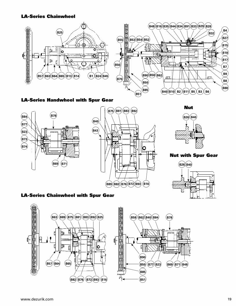
Dimensions (continued)

www.dezurik.com28
Dimensions (continued)T-Series Cylinder Actuator
LPneumatic
K
18.12 21.12 16.31 3.25 5.94 5.38 1.81 4.69 460 536 414 83 151 137 46 119
18.88 21.88 16.31 3.25 5.94 7.88 1.81 4.69 480 556 414 83 151 200 46 119
23.44 26.44 17.88 4.44 8.12 7.88 3.12 5.84 595 672 454 113 206 200 79 148
23.44 26.44 17.88 4.44 8.12 7.88 3.12 6.03 595 672 454 113 206 200 79 153
24.06 27.06 17.88 4.44 8.12 10.25 3.12 6.03 611 687 454 113 206 260 79 153
Valve Size(Cylinder
Size)I J
FH
HydraulicG
3–12"80–300mm
(C4)
12"300mm
(C6)
14–16"350–400mm
(C6)
18–20"450–500mm
(C6)
18–20"450–500mm
(C8)
G-Series Cylinder Actuator
PneumaticK
31.50 32.75 17.50 6.88 4.25 8.50 3.25 800 832 445 175 108 216 83
31.62 33.88 17.50 6.88 5.25 10.50 3.25 803 861 445 175 133 267 83
43.88 41.78 24.25 9.00 5.88 11.75 3.50 1115 1061 616 229 149 298 89
31.50 32.75 17.50 6.88 4.25 8.50 3.50 800 832 445 175 108 216 89
31.62 33.88 17.50 6.88 5.25 10.50 3.50 803 861 445 175 133 267 89
43.25 41.78 24.25 9.00 5.88 11.75 3.75 1099 1061 616 229 149 298 95
44.62 43.50 24.25 9.00 7.00 14.00 3.75 1133 1105 616 229 178 356 95
Valve Size(Cylinder
Size)I J
FH
HydraulicG
24"600mm
(GS-12-PC8)
24"600mm
(GS-12-PC10)
24"600mm
(GS-16-PC10)
30"750mm
(GS-12-PC8)
30–36"750–900mm(GS-12-PC10)
30–42"750–1100mm(GS-16-PC10)
36–42"900–1100mm(GS-16-PC12)
Seat Side
Seat Side
K
H
IG F
14.19 20.81 9.38 8.25 9.44 2.00 4.41 6.25 360 529 238 210 240 51 112 159
16.19 22.81 12.12 8.25 11.12 2.00 4.41 6.25 411 579 308 210 282 51 112 159
20.19 26.81 16.81 8.25 16.12 2.00 4.81 5.84 513 681 427 210 409 51 122 148
Valve Size(Actuator
Size)J KF G I
F with Spur Gear
H
30–42"750–1100mm
(LA-4)
36–54"900–1400mm
(LA-6)
42–54"1100–1400mm
(LA-10)
L
LA-Series Nut
InchesMillimeter
Seat Side
I
H
JK
Seat Side
L
F G
Seat Side
J
G
IH
K
L
F

www.dezurik.com 29
Seat Side
K
G
L
I
H
F
L
LA-Series Handwheel 30–48" (750–1200mm)
LA-4-HD12
11.62 18.25 9.38 8.25 9.44 12.00 4.41 6.25 295 464 238 210 240 305 112 159
LA-4-HD16
12.25 18.88 9.38 8.25 9.44 16.00 4.41 6.25 311 480 238 210 240 406 112 159
LA-4-HD24
20.25 26.88 9.38 8.25 9.44 24.00 4.41 6.25 514 683 238 210 240 610 112 159
LA-4-HD30
22.88 29.50 9.38 8.25 9.44 30.00 4.41 6.25 581 749 238 210 240 762 112 159
LA-4-HD36
25.50 32.12 9.38 8.25 9.44 36.00 4.41 6.25 648 816 238 210 240 914 112 159
Actuator Size J KF G I
F with Spur Gear
H
L
LA-Series Handwheel 36–54" (900–1400mm)
LA-6-HD12
13.62 20.25 12.12 8.25 11.12 12.00 4.41 6.25 346 514 308 210 282 305 112 159
LA-6-HD16
14.25 20.88 12.12 8.25 11.12 16.00 4.41 6.25 362 530 308 210 282 406 112 159
LA-6-HD24
22.25 28.88 12.12 8.25 11.12 24.00 4.41 6.25 565 734 308 210 282 610 112 159
LA-6-HD30
24.88 31.50 12.12 8.25 11.12 30.00 4.41 6.25 632 800 308 210 282 762 112 159
LA-6-HD36
27.50 34.12 12.12 8.25 11.12 36.00 4.41 6.25 699 867 308 210 282 914 112 159
Actuator Size J KF G I
F with Spur Gear
H
L
LA-Series Handwheel 42–54" (1100–1400mm)
LA-10-HD12
17.62 24.25 16.81 8.25 16.12 12.00 4.81 5.84 448 616 427 210 409 305 122 148
LA-10-HD16
18.25 24.88 16.81 8.25 16.12 16.00 4.81 5.84 464 632 427 210 409 406 122 148
LA-10-HD24
26.25 32.88 16.81 8.25 16.12 24.00 4.81 5.84 667 835 427 210 409 610 122 148
LA-10-HD30
28.88 35.50 16.81 8.25 16.12 30.00 4.81 5.84 734 902 427 210 409 762 122 148
LA-10-HD36
31.50 38.12 16.81 8.25 16.12 36.00 4.81 5.84 800 968 427 210 409 914 122 148
Actuator Size J KF G I
F with Spur Gear
H
InchesMillimeterNote: All dimensions are subject to change without notice. Request certified drawings for use in preparing piping layouts.
Dimensions (continued)
J
www.dezurik.com30
Seat Side
L
LA-Series Chainwheel 30–48" (750–1200mm)
LA-4-CW12
35.00 41.62 9.38 8.25 9.44 12.75 4.41 6.25 889 1057 238 210 240 324 112 159
LA-4-CW20
35.00 41.62 9.38 8.25 9.44 20.06 4.41 6.25 889 1057 238 210 240 510 112 159
LA-4-CW30
35.00 41.62 9.38 8.25 9.44 29.75 4.41 6.25 889 1057 238 210 240 756 112 159
Actuator Size J KF G I
F with Spur Gear
H
L
LA-Series Chainwheel 36–54" (900–1400mm)
LA-6-CW12
37.00 43.62 12.12 8.25 11.12 12.75 4.41 6.25 940 1108 308 210 282 324 112 159
LA-6-CW20
37.00 43.62 12.12 8.25 11.12 20.06 4.41 6.25 940 1108 308 210 282 510 112 159
LA-6-CW30
37.00 43.62 12.12 8.25 11.12 29.75 4.41 6.25 940 1108 308 210 282 756 112 159
Actuator Size J KF G I
F with Spur Gear
H
L
LA-Series Chainwheel 42–54" (1100–1400mm)
LA-10-CW12
41.00 47.62 16.81 8.25 16.12 12.75 4.81 5.84 1041 1210 427 210 409 324 122 148
LA-10-CW20
41.00 47.62 16.81 8.25 16.12 20.06 4.81 5.84 1041 1210 427 210 409 510 122 148
LA-10-CW30
41.00 47.62 16.81 8.25 16.12 29.75 4.81 5.84 1041 1210 427 210 409 756 122 148
Actuator Size J KF G I
F with Spur Gear
H
InchesMillimeter
Note: All dimensions are subject to change without notice. Request certified drawings for use in preparing piping layouts.
Dimensions (continued)
G
JK
L
F
I
H

www.dezurik.com 31
Part A: Check boxes and complete lines to show upstream/downstream configuration, enter distances in pipe diameters.
Part B: Check off or enter operating conditions. 1. Valve Function? oOpen/Shut oThrottling oModulating Control
2. Where Installed? oBuried oSubmerged oAbove Ground, In Plant
3. Line Fluid? oFresh Water oSewage oAir oOther?___________________________________________________
4. Maximum Fluid Temperature? _______________°C _______________°F
5. Line Size? _______________inches _______________(mm) (nominal)
6. Normal Working Pressure? _______________psi _______________kPa Maximum (Shutoff) Pressure Differential? _______________psi _______________kPa
7. Normal Wide Open Valve Flow? _______________flow rate or _______________flow units
8. Emergency Maximum (Line Break, Etc.) Flow? _______________flow rate _______________flow units
9. (If Throttling or Modulating Control) Flow Range Desired? Maximum Flow? _______________flow rate _______________flow units Minimum Flow? _______________flow rate _______________flow units
10. Pipe Connection? _______________Flanged _______________Mechanical Joint _______________Other
Part C: Check off or enter operator requirements.1. Operator Type? Manual: oLever oLead Screw oGear oOther? Power: oCylinder oElectric oOther?
2. Direction of Rotation To Open: oClockwise–(OR) oCounter clockwise—(OL)
3. Cylinder Specifications: a. Supply Type and Pressure? oWater____________psi_________kPa oOil________________psi_________kPa oAir _________________psi_________kPa oOther___________psi_________kPa
b. Fail Safe? oYes oNo; If yes which way if valve fails? oOpen oClose
c. Operating Times? _________sec Open to Close; _________sec Close to Open
d. Accessories? oSpeed Control oLimit Switches (ES) (Qty:_______O,_______C,_______I) oSolenoid W/Manual Override oPositioner oManual Override (On loss of supply press.) oSolenoid W/O Manual Override oOther? ________________________________________________________________________________________________________________________________________________
4. Electric Specifications: a. Supply?_________Volts_________Phase_________Hz b. Duty Cycle? o Intermittent oContinuous c. Starter/Control Needs?_____________________________________________________________________________________________ d. Operating Times?_________sec (Note: 60 sec per AWWA unless specified)
e. Accessories? oAUX Switches oPotentiometer oSlidewire Receiver oReversing Starter oHeaters oControl Station oControl Transformer oOther?__________________________
*Attach pump curve to checklist if available.
DeZURIK Butterfly Valve Applications Data Input Checklist
Basin/Tank
Basin/Tank
Down to Free Discharge
How Close? (Number of Pipe Diameters)
Pump*
Fitting
Other Other

DeZURIK, Inc. reserves the right to incorporate our latest design and material changes without notice or obligation. Design features, materials of construction and dimensional data, as described in this bulletin, are provided for your information only
and should not be relied upon unless confirmed in writing by DeZURIK, Inc. Certified drawings are available upon request.
Printed in the U.S.A.
250 Riverside Ave. N. Sartell, Minnesota 56377 • Phone: 320-259-2000 • Fax: 320-259-2227
For information about our worldwide locations, approvals, certifications and local representative:Web Site: www.dezurik.com E-Mail: [email protected]
Sales and Service
Copyright © 2022 FDOKUMEN

