


Bahasa
Halaman
Hukum

College of Engineering
Department of Mechanical Engineering
Fall 2020-2021
Senior Design Project Report
Design of Automated Hammering Machine
In partial fulfillment of the requirements for the
Degree of Bachelor of Science in Mechanical Engineering
Team Members
Student Name Student ID
1 Zaid Almusallami 201602959
2 Mohammed Zynab 201602570
3 Mohammed AlMansour 201600490
4 Abdulrahman Alsafar 201602653
5 Saud Alkhaldi 201600664
Project Advisors:
Advisor Name: Muhammed Azhar Khan Co-Advisor Name: Mr. Taha Waqar

Abstract
This project aims at designing and fabricating an automated hammering machine that can
perform hammering operations without the involvement of any human operator. This project
is selected because no such machines are available in these industries. The introduction of an
automated hammering machine in the industries will help the industries in prospering and it
will make the operations safe and easy. Moreover, the project will have a greater impact on
the metal industries. The machine will be capable of performing fast and accurate hammering
operations with the help of a 16V battery. Mild steel is used for fabricating the machine. A
large pulley and a shaft are connected with the help of a connecting rod. The spinning shaft
will provide lateral motion to the rod. A mid-swinging arrangement is used for attaching the
hammer and the connecting rod. A suitable bed will be developed for holding the workpiece.
Solidworks is used for designing the machine.
The main objective of the project is to develop an automated hammering machine with the help of
a pulley, shaft, connecting rod, hammer, and 16V battery to provide ease for the hammering
operations. Future work may involve the development of a body case for the machine.
2

Acknowledgments
We, the students of the mechanical engineering college (Fall 2020 - 2021), would like to
present our thanks and deep appreciation to the Dean of the College and faculty members and
supervisors of the graduation project. (Design and Fabrication of Automated Portable
Hammering Machine) to give us this opportunity to gain the knowledge and skills to design
and implement this project. We also promise to be the best representatives of the college in
the field of workers.
We wish you all success
3
List of Acronyms (Symbols) used in the report:
Symbol Definition
V Volt
Kg Kilogram
Mm millimeter
M Meter
RPM Revolutions per Minute
A Ampere
W Watt
T Torque
P Power
Nm Newton-meter
N Newton, Number of Cycles
FBD Free Body Diagram
Sec Second
D Diameter
J Polar Moment of Inertia, Joules
4

List of Figures:
Figure 1 Photo of the real system ................................................................................................................ 8 Figure 2 Automated Hammering Machine ............................................................................................. 11 Figure 3 Automated Forging Machine ..................................................................................................... 12 Figure 4 Results obtained by the authors ................................................................................................ 13 Figure 5 Residual Stresses against Plunger Stroke ............................................................................... 14 Figure 6 Comparison of Materials for the Machine ............................................................................. 15 Figure 7 Microscopic Image of the Defects and Stress Analysis ..................................................... 15 Figure 8 Architectural Design .................................................................................................................... 16 Figure 9 Automatic Hammering Machine .............................................................................................. 18 Figure 10 Frame .............................................................................................................................................. 19 Figure 11 1st Pulley ....................................................................................................................................... 19 Figure 12 2nd Pulley ..................................................................................................................................... 19 Figure 13 Shaft ................................................................................................................................................ 19 Figure 14 Arm ................................................................................................................................................. 20 Figure 15 Hammer ......................................................................................................................................... 23 Figure 16 Assembly ....................................................................................................................................... 24 Figure 17 Slider Crank Mechanism .......................................................................................................... 24 Figure 18 Supporting Frame ....................................................................................................................... 28 Figure 19 Pulley One .................................................................................................................................... 28 Figure 20 Shaft ................................................................................................................................................ 29 Figure 21 2nd Pulley ..................................................................................................................................... 29 Figure 22 Arm ................................................................................................................................................. 30 Figure 23 DC Motor ...................................................................................................................................... 30 Figure 24 16 Volt Battery ............................................................................................................................ 31 Figure 25 Automatic Hammering Machine ............................................................................................ 33 Figure 26 Experimental Setup .................................................................................................................... 33 Figure 27 Single hits obtained from the experiment (Time Vs Force) ........................................... 34 Figure 28 Repeatability of the force ......................................................................................................... 35 Figure 29 Force adjustment and repeatability of the adjusted force ................................................ 35 Figure 30 FRF obtained from the manual hammering ........................................................................ 36 Figure 31 FRF obtained from the automatic hammering ................................................................... 36 Figure 32 Task Division Chart ................................................................................................................... 40 Figure 33 Members Contribution Chart .................................................................................................. 43
List of Tables:
Table 1 The system measurements ............................................................................................................. 8 Table 2 Constraints Table ............................................................................................................................ 21 Table 3 Time Duration Table...................................................................................................................... 41 Table 4 Bill of Material of Project ............................................................................................................ 47
5
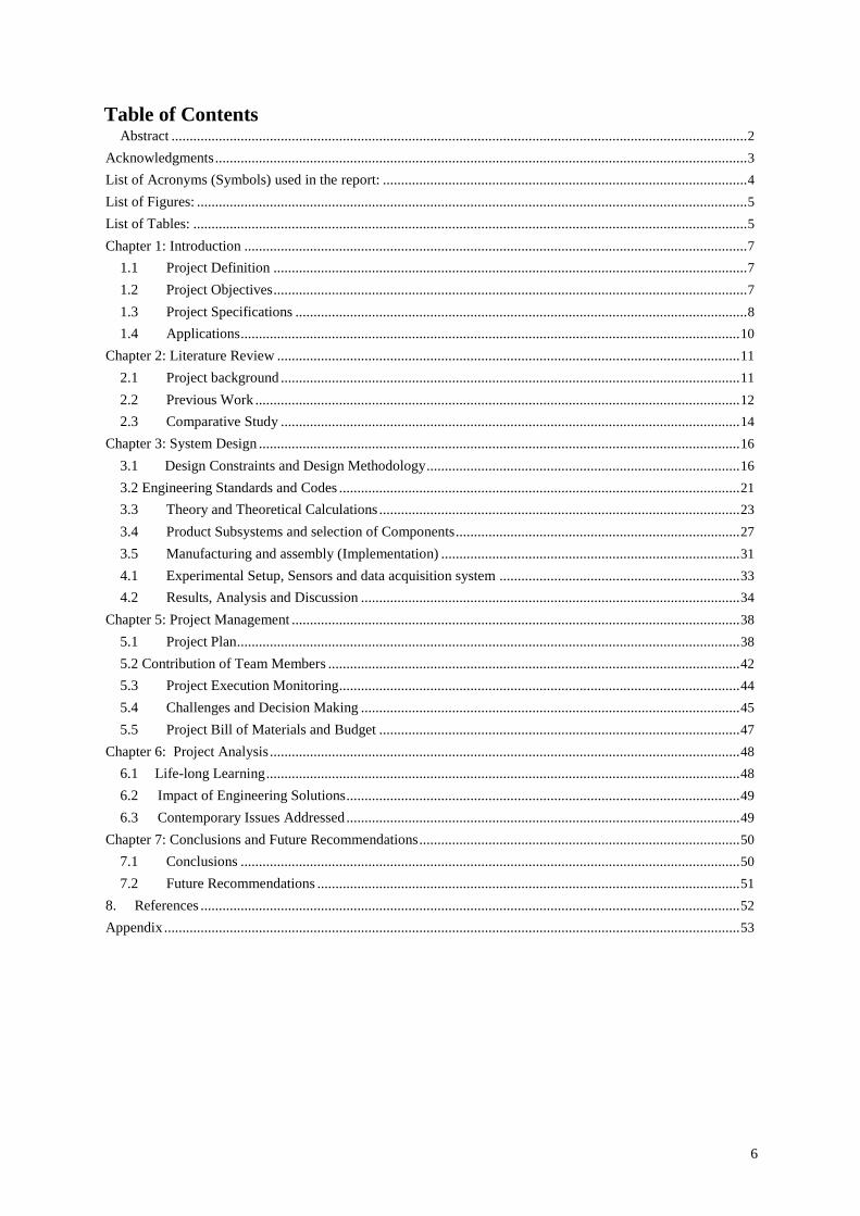
Table of Contents Abstract .............................................................................................................................................................. 2
Acknowledgments .................................................................................................................................................. 3 List of Acronyms (Symbols) used in the report: .................................................................................................... 4 List of Figures: ....................................................................................................................................................... 5 List of Tables: ........................................................................................................................................................ 5 Chapter 1: Introduction .......................................................................................................................................... 7
1.1 Project Definition .................................................................................................................................. 7
1.2 Project Objectives .................................................................................................................................. 7
1.3 Project Specifications ............................................................................................................................ 8
1.4 Applications ......................................................................................................................................... 10 Chapter 2: Literature Review ............................................................................................................................... 11
2.1 Project background .............................................................................................................................. 11
2.2 Previous Work ..................................................................................................................................... 12
2.3 Comparative Study .............................................................................................................................. 14 Chapter 3: System Design .................................................................................................................................... 16
3.1 Design Constraints and Design Methodology ...................................................................................... 16
3.2 Engineering Standards and Codes .............................................................................................................. 21
3.3 Theory and Theoretical Calculations ................................................................................................... 23
3.4 Product Subsystems and selection of Components .............................................................................. 27
3.5 Manufacturing and assembly (Implementation) .................................................................................. 31
4.1 Experimental Setup, Sensors and data acquisition system .................................................................. 33
4.2 Results, Analysis and Discussion ........................................................................................................ 34 Chapter 5: Project Management ........................................................................................................................... 38
5.1 Project Plan .......................................................................................................................................... 38
5.2 Contribution of Team Members ................................................................................................................. 42
5.3 Project Execution Monitoring.............................................................................................................. 44
5.4 Challenges and Decision Making ........................................................................................................ 45
5.5 Project Bill of Materials and Budget ................................................................................................... 47 Chapter 6: Project Analysis ................................................................................................................................. 48
6.1 Life-long Learning .................................................................................................................................. 48
6.2 Impact of Engineering Solutions ............................................................................................................ 49
6.3 Contemporary Issues Addressed ............................................................................................................ 49 Chapter 7: Conclusions and Future Recommendations ........................................................................................ 50
7.1 Conclusions ......................................................................................................................................... 50
7.2 Future Recommendations .................................................................................................................... 51 8. References .................................................................................................................................................... 52 Appendix .............................................................................................................................................................. 53
6
Chapter 1: Introduction
1.1 Project Definition
This project is intended to design and manufacture a simple rotor test rig, where rotor faults
can be inserted and tested. The test rig is to be fitted with vibration sensors to enable
collecting data and use it to monitor the health of machines. The project is very important to
the industry as through understanding the characteristics of failure, time and money will be
saved. This is also very important from the safety perspective as this will lead to a safe
operating environment for rotary machines.
1.2 Project Objectives
The main objectives of this project are:
1. To design an automated hammering machine that can give automated blows.
2. To replace the use of manual hammering for heavy-duty operations.
3. To fabricate an automated hammering machine that can help workers in hammering
processes.
4. To increase the efficiency and accuracy of the hammering operations.
7
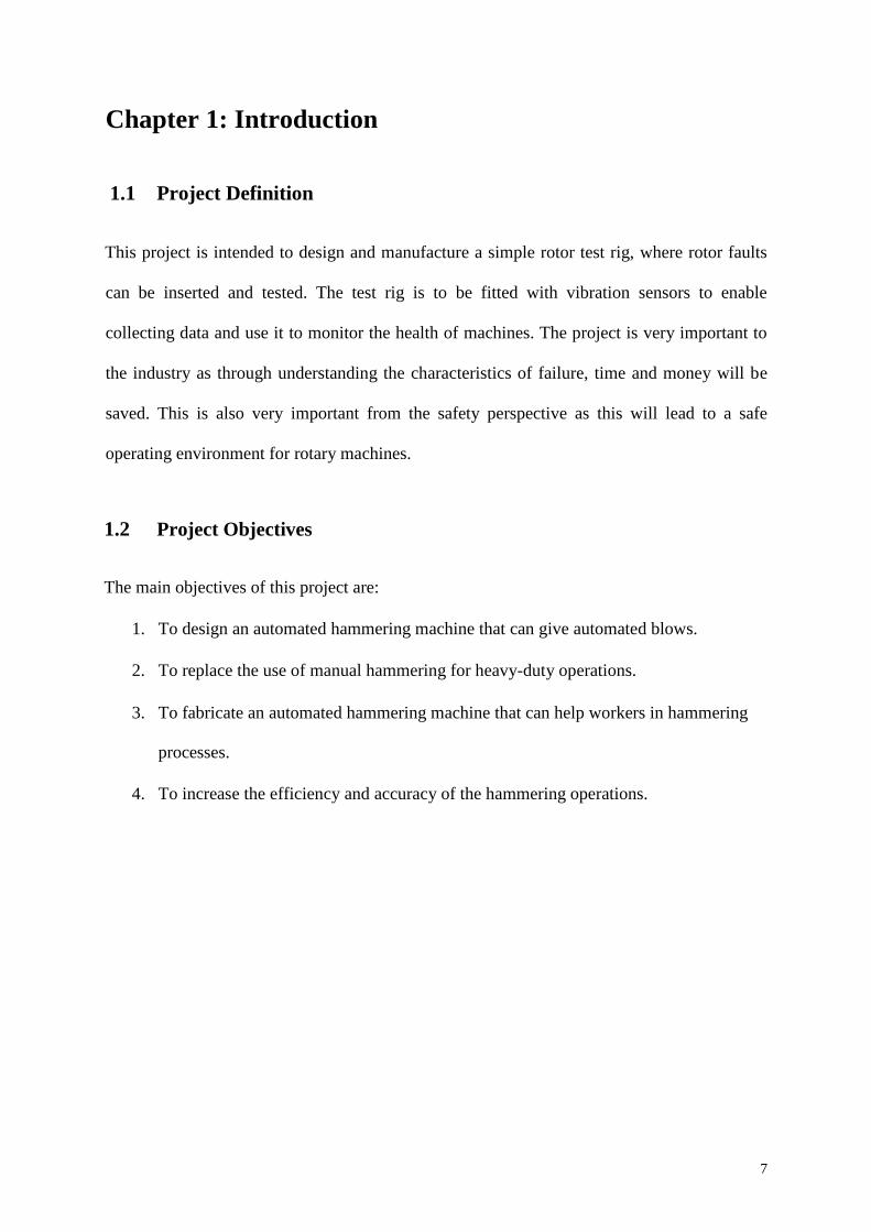
1.3 Project Specifications
Figure 1: Photo of the real system
The most reliable design of automatic hammering machine is described below along with
their specification in order to show the different existing approaches to the small and portable
automatic hammering concept.
These data could be useful when performing the initial sizing in the design stage of the
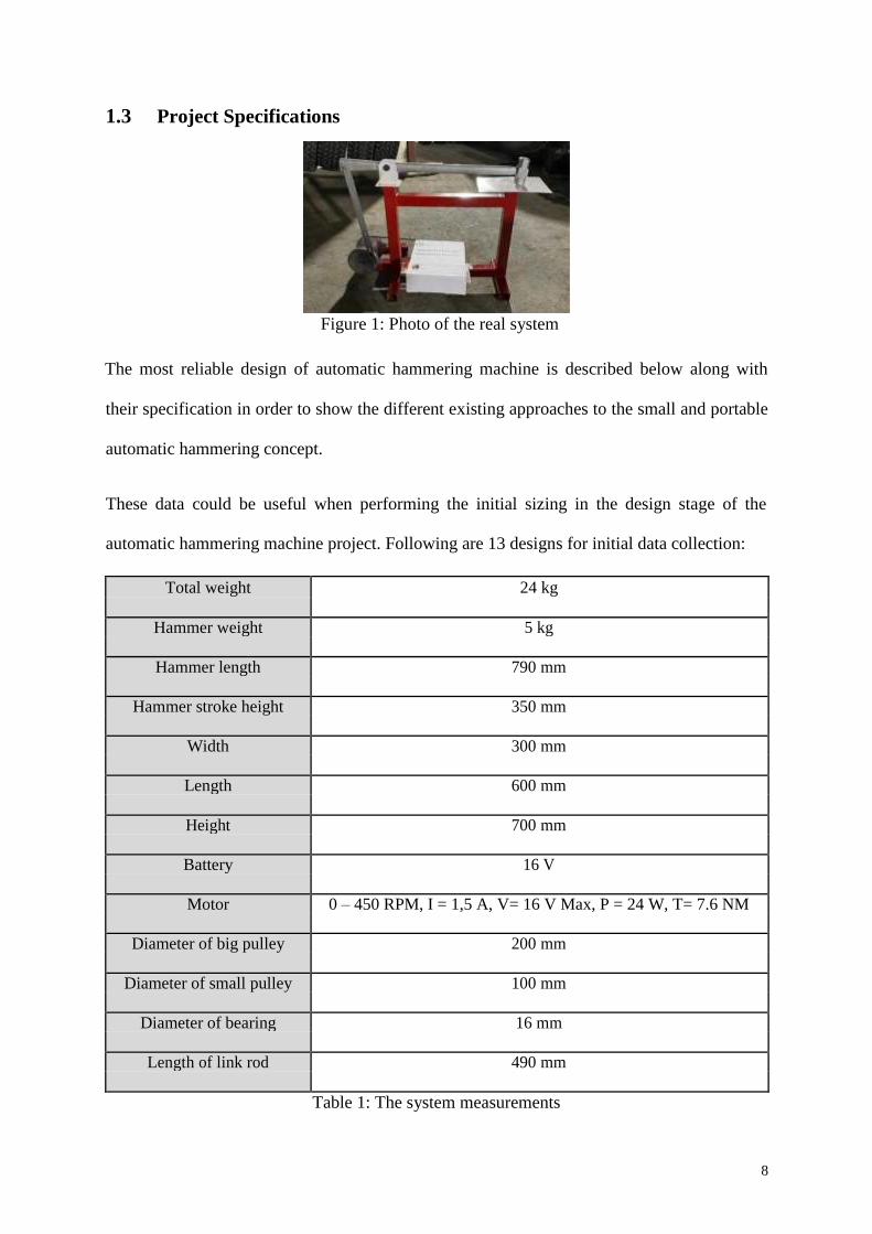
automatic hammering machine project. Following are 13 designs for initial data collection:
Total weight 24 kg
Hammer weight 5 kg
Hammer length 790 mm
Hammer stroke height 350 mm
Width 300 mm
Length 600 mm
Height 700 mm
Battery 16 V
Motor 0 – 450 RPM, I = 1,5 A, V= 16 V Max, P = 24 W, T= 7.6 NM
Diameter of big pulley 200 mm
Diameter of small pulley 100 mm
Diameter of bearing 16 mm
Length of link rod 490 mm
Table 1: The system measurements
8
➢ Marketing features
Locally:
• Increase profits
• increase production
• reduce cost
• increase safety
• realise manpower
Globally and internationally:
• Raise the economy
• accuracy in international manufacturing
• increase in the international industrialization
• fast completion in global manufacturing
➢ Engineering standards:
ASTM A36 Welding Standards:
• If the metal is thicker than 1/4 - 6 mm, preheat to 150F
• E7018 stick electrode, an 0.035 or 0.045 E70S-3-6 MIG wire, or for all
position welds an E71T-1 electrode wire
• Ensure mill scale in weld area is removed and the plate is always at a
temperature >60F
• keep single pass fillet welds < 1/4 - < 6mm
• For multi-pass welds, use inter-pass temp control
• hardness and grain size checked
9
Design Constraints Engineering Standards:
• quality features of hand hammers
• characteristics and verification
• Applies to hammers used under normal working
• Best practices established by experts in the industry
• Comply with laws that specify design and testing criteria
• Reduce product liability risk
• Budget for certification testing
1.4 Applications
• Use in a production line
• Can be used indoor to drive nails, fit parts, forge metal, and break apart objects
• Use in workshops
10
Chapter 2: Literature Review
2.1 Project background
With the evolution of technology and the advancements made in the industry, automation has
become an important resource for industrial operations. Hammering is a very common
process in the industries of mechanical engineering. Most of the industries that involve the
fabrication and machining of metal components use hammering. Moreover, hammering is
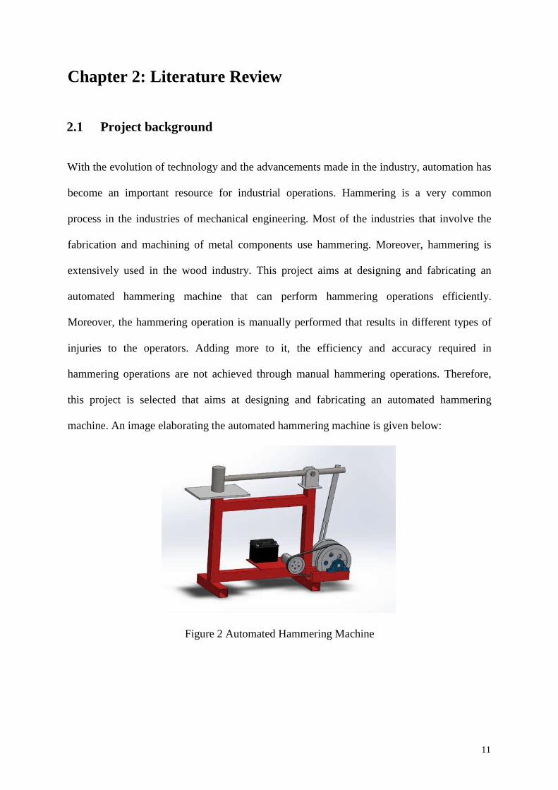
extensively used in the wood industry. This project aims at designing and fabricating an
automated hammering machine that can perform hammering operations efficiently.
Moreover, the hammering operation is manually performed that results in different types of
injuries to the operators. Adding more to it, the efficiency and accuracy required in
hammering operations are not achieved through manual hammering operations. Therefore,
this project is selected that aims at designing and fabricating an automated hammering
machine. An image elaborating the automated hammering machine is given below:
Figure 2 Automated Hammering Machine
11
It is a simple device but it will be helpful in many operations. The industry now requires
accuracy and there are very small limitations of allowed tolerances. An important aspect of
this project is the improvement of the operations and the safety of the operators. For instance,
consider the hammering operation being done on a large metal piece. If this device will be
used, there will be small risks of injuries for the operators but manual operations can bring a
lot of harm. Moreover, this device will help in gaining the required level of accuracy. If this
automated hammering machine is developed on a commercial basis and it is provided to
different industries, it can bring a lot of revolution in the industries.
2.2 Previous Work
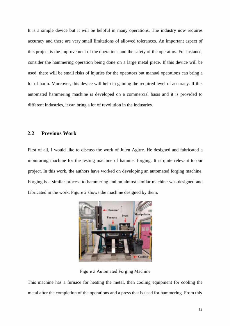
First of all, I would like to discuss the work of Julen Agirre. He designed and fabricated a
monitoring machine for the testing machine of hammer forging. It is quite relevant to our
project. In this work, the authors have worked on developing an automated forging machine.
Forging is a similar process to hammering and an almost similar machine was designed and
fabricated in the work. Figure 2 shows the machine designed by them.
Figure 3 Automated Forging Machine
This machine has a furnace for heating the metal, then cooling equipment for cooling the
metal after the completion of the operations and a press that is used for hammering. From this
12
literature, we have gained an idea about the required components for the automated
hammering machine.
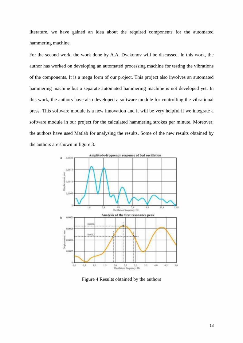
For the second work, the work done by A.A. Dyakonov will be discussed. In this work, the
author has worked on developing an automated processing machine for testing the vibrations
of the components. It is a mega form of our project. This project also involves an automated
hammering machine but a separate automated hammering machine is not developed yet. In
this work, the authors have also developed a software module for controlling the vibrational
press. This software module is a new innovation and it will be very helpful if we integrate a
software module in our project for the calculated hammering strokes per minute. Moreover,
the authors have used Matlab for analysing the results. Some of the new results obtained by
the authors are shown in figure 3.
Figure 4 Results obtained by the authors
13
2.3 Comparative Study
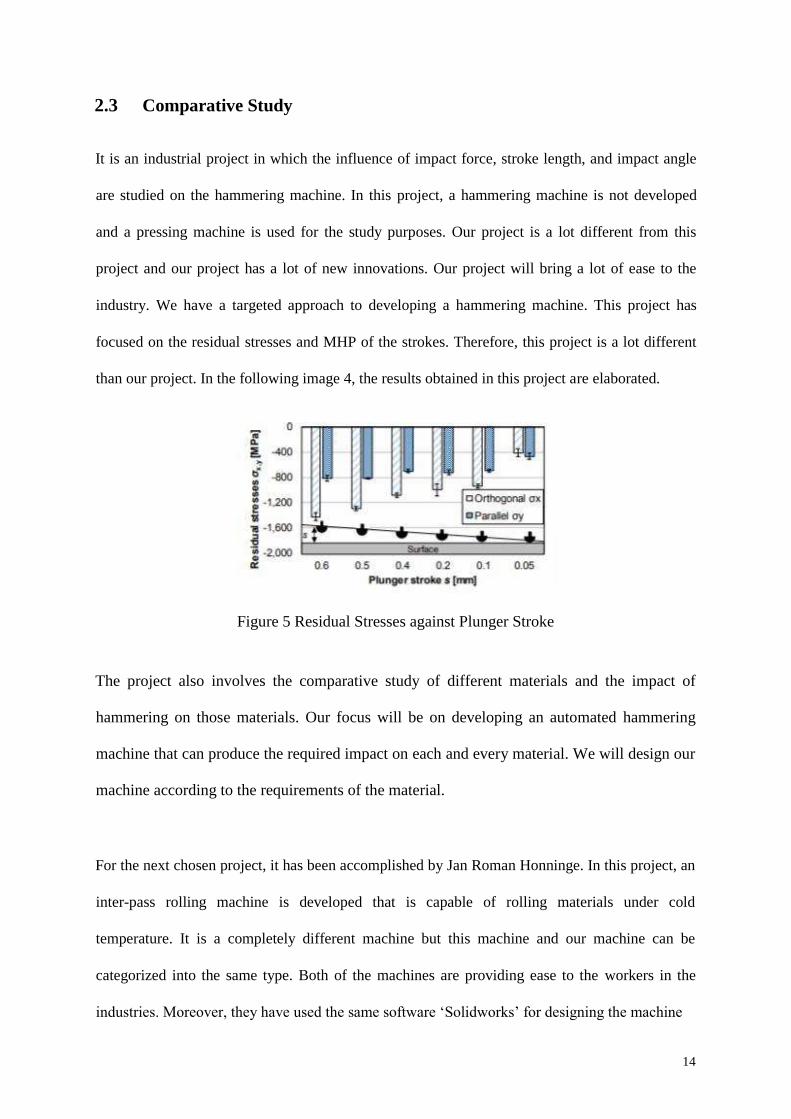
It is an industrial project in which the influence of impact force, stroke length, and impact angle
are studied on the hammering machine. In this project, a hammering machine is not developed
and a pressing machine is used for the study purposes. Our project is a lot different from this
project and our project has a lot of new innovations. Our project will bring a lot of ease to the
industry. We have a targeted approach to developing a hammering machine. This project has
focused on the residual stresses and MHP of the strokes. Therefore, this project is a lot different
than our project. In the following image 4, the results obtained in this project are elaborated.
Figure 5 Residual Stresses against Plunger Stroke
The project also involves the comparative study of different materials and the impact of
hammering on those materials. Our focus will be on developing an automated hammering
machine that can produce the required impact on each and every material. We will design our
machine according to the requirements of the material.
For the next chosen project, it has been accomplished by Jan Roman Honninge. In this project, an
inter-pass rolling machine is developed that is capable of rolling materials under cold
temperature. It is a completely different machine but this machine and our machine can be
categorized into the same type. Both of the machines are providing ease to the workers in the
industries. Moreover, they have used the same software ‘Solidworks’ for designing the machine
14
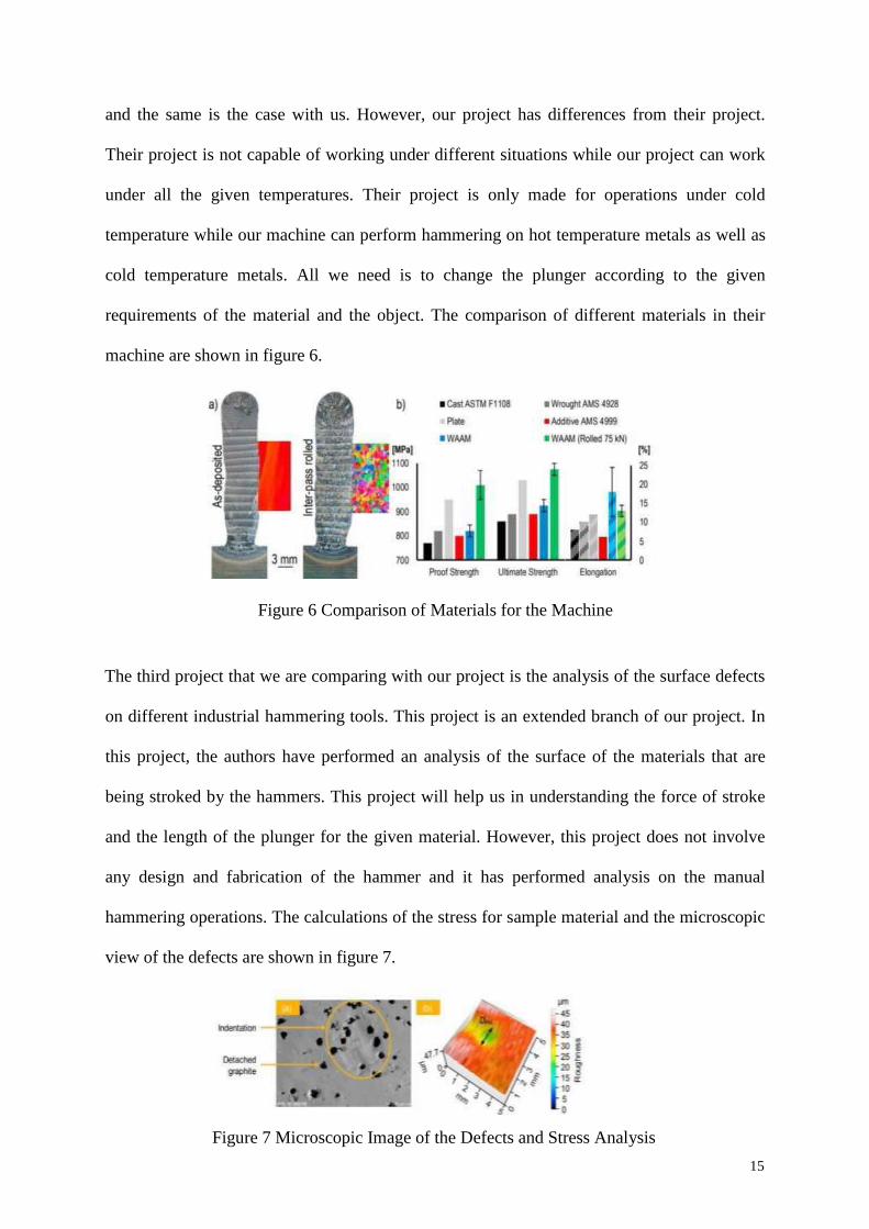
and the same is the case with us. However, our project has differences from their project.
Their project is not capable of working under different situations while our project can work
under all the given temperatures. Their project is only made for operations under cold
temperature while our machine can perform hammering on hot temperature metals as well as
cold temperature metals. All we need is to change the plunger according to the given
requirements of the material and the object. The comparison of different materials in their
machine are shown in figure 6.
Figure 6 Comparison of Materials for the Machine
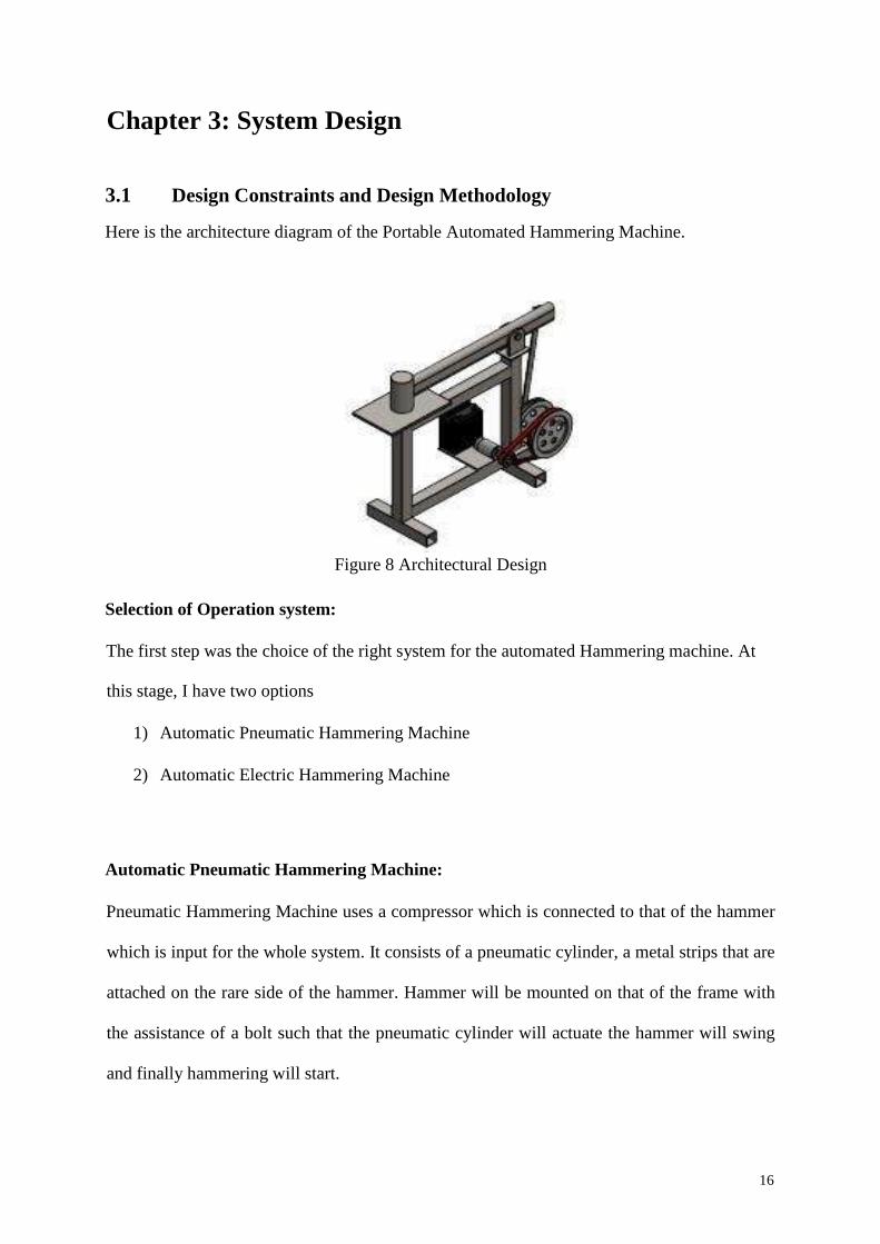
The third project that we are comparing with our project is the analysis of the surface defects
on different industrial hammering tools. This project is an extended branch of our project. In
this project, the authors have performed an analysis of the surface of the materials that are
being stroked by the hammers. This project will help us in understanding the force of stroke
and the length of the plunger for the given material. However, this project does not involve
any design and fabrication of the hammer and it has performed analysis on the manual
hammering operations. The calculations of the stress for sample material and the microscopic
view of the defects are shown in figure 7.
Figure 7 Microscopic Image of the Defects and Stress Analysis
15
Chapter 3: System Design
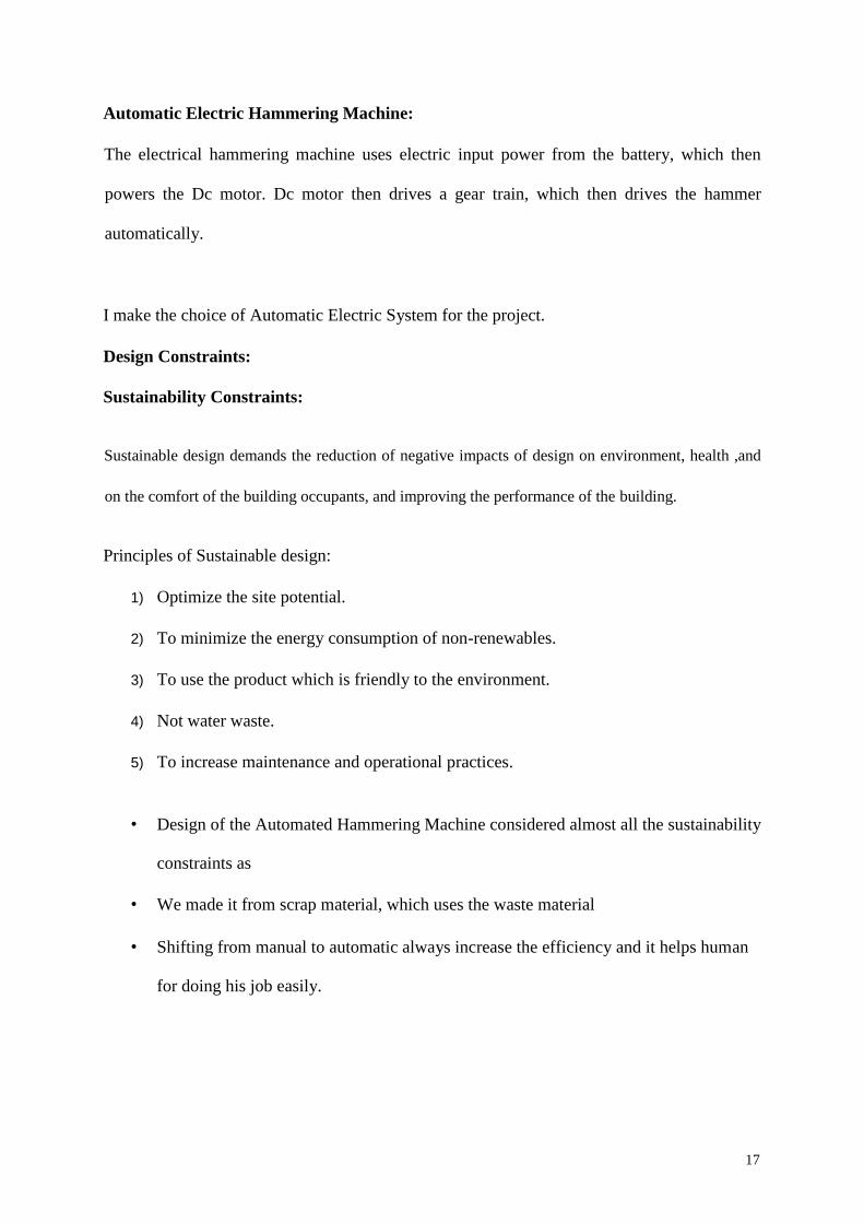
3.1 Design Constraints and Design Methodology
Here is the architecture diagram of the Portable Automated Hammering Machine.
Figure 8 Architectural Design
Selection of Operation system:
The first step was the choice of the right system for the automated Hammering machine. At
this stage, I have two options
1) Automatic Pneumatic Hammering Machine
2) Automatic Electric Hammering Machine
Automatic Pneumatic Hammering Machine:
Pneumatic Hammering Machine uses a compressor which is connected to that of the hammer
which is input for the whole system. It consists of a pneumatic cylinder, a metal strips that are
attached on the rare side of the hammer. Hammer will be mounted on that of the frame with
the assistance of a bolt such that the pneumatic cylinder will actuate the hammer will swing
and finally hammering will start.
16
Automatic Electric Hammering Machine:
The electrical hammering machine uses electric input power from the battery, which then
powers the Dc motor. Dc motor then drives a gear train, which then drives the hammer
automatically.
I make the choice of Automatic Electric System for the project.
Design Constraints:
Sustainability Constraints:
Sustainable design demands the reduction of negative impacts of design on environment, health ,and
on the comfort of the building occupants, and improving the performance of the building.
Principles of Sustainable design:
1) Optimize the site potential.
2) To minimize the energy consumption of non-renewables.
3) To use the product which is friendly to the environment.
4) Not water waste.
5) To increase maintenance and operational practices.
• Design of the Automated Hammering Machine considered almost all the sustainability
constraints as
• We made it from scrap material, which uses the waste material
• Shifting from manual to automatic always increase the efficiency and it helps human
for doing his job easily.
17
But on the other hand, it had some drawbacks
• Like it uses the energy which is non-renewable
• It makes much noise which causes human discomfort,
Geometric Constraints:
Geometric constraints help in controlling the relationships of objects with respect to each
other. We use dimensional constraints for the control distance, radius, angle, and length
values of objects. With constraints you can: include formulas and equations within
dimensional constraints.
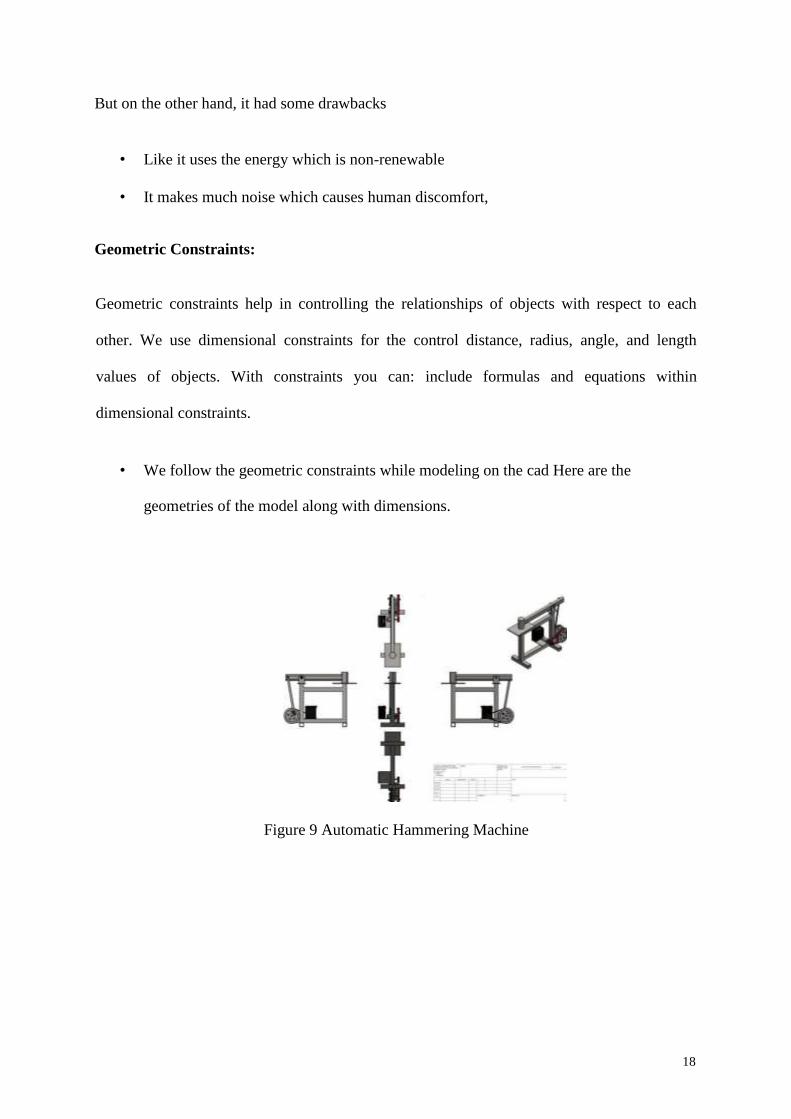
• We follow the geometric constraints while modeling on the cad Here are the
geometries of the model along with dimensions.
Figure 9 Automatic Hammering Machine
18
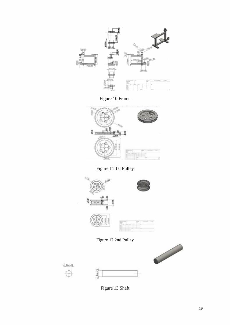
Figure 10 Frame
Figure 11 1st Pulley
Figure 12 2nd Pulley
Figure 13 Shaft
19
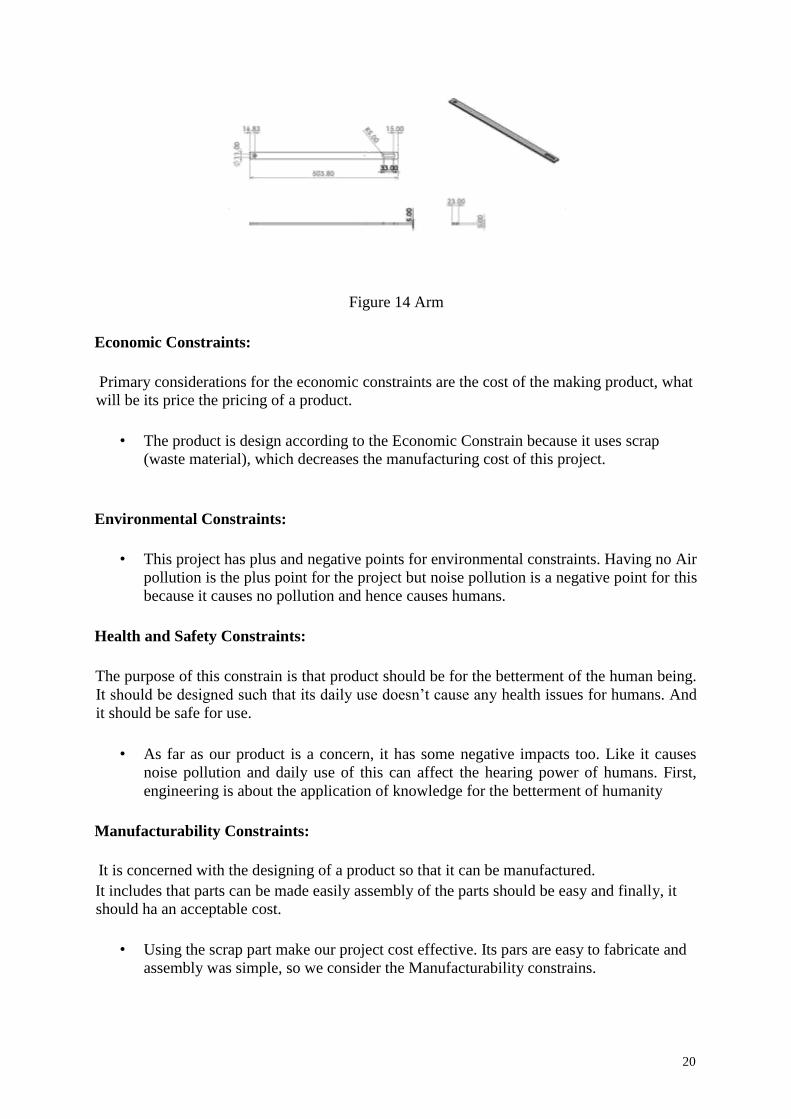
Figure 14 Arm
Economic Constraints:
Primary considerations for the economic constraints are the cost of the making product, what
will be its price the pricing of a product.
• The product is design according to the Economic Constrain because it uses scrap
(waste material), which decreases the manufacturing cost of this project.
Environmental Constraints:
• This project has plus and negative points for environmental constraints. Having no Air
pollution is the plus point for the project but noise pollution is a negative point for this
because it causes no pollution and hence causes humans.
Health and Safety Constraints:
The purpose of this constrain is that product should be for the betterment of the human being.
It should be designed such that its daily use doesn’t cause any health issues for humans. And
it should be safe for use.
• As far as our product is a concern, it has some negative impacts too. Like it causes
noise pollution and daily use of this can affect the hearing power of humans. First,
engineering is about the application of knowledge for the betterment of humanity
Manufacturability Constraints:
It is concerned with the designing of a product so that it can be manufactured. It includes that parts can be made easily assembly of the parts should be easy and finally, it
should ha an acceptable cost.
• Using the scrap part make our project cost effective. Its pars are easy to fabricate and
assembly was simple, so we consider the Manufacturability constrains.
20
Social Constraints:
It concerned with the product design such that it should meet the human needs and address
social issues • Our product is designed to meet human needs, it provides an ease to humans.
Ethical Constraints:
It is basic concerned it to insured the design of the product so that it doesn’t heart the feeling
of others, you should be aware of code and conducts which provide us the standards of the
proper behavior while interactions with others. This should not be muddled with what we feel
is correct, our religious beliefs are perfect, what the law states, or what are the socially
accepted norms of behavior.
• Our product doesn’t have any ethical conflict.
Primary is the comparison between different hammer designs The secondary is a comparison between Hammers in general and other sources of
illumination’ Yes mean the product is up to the mark No means there is some conflict with these constraints
Primary Secondary
Economic Yes No
Environmental Yes No
Health and Safety No yes
Manufacturability Yes Yes
Sustainability Yes No
Social Yes No
Ethical Yes yes
Table 2 Constraints Table
3.2 Engineering Standards and Codes
Standards and Codes
Standards, codes, and specifications are extremely important and are often essential - technical
documents in engineering and that of the related technical fields.
21
STANDARDS:
A standard is basically an established norm. It is basically a formal document which creates
uniform engineering and technical criteria, process, methods, and practices. These formal
documents are prepared by the professional group which are believed to be good and have
proper engineering practices and which contain mandatory requirements.
CODES:
A code is the set of specifications and Rules for design, installation, inspection, and
fabrication methods prepared so that it can be adopted by legal jurisdiction. Codes can be
approved by local, state, or federal governments and can carry the force of law. The purpose
of the codes is public protection by setting up a minimum acceptable level of safety for
buildings, processes, and Products.
Standards:
1) This International Standard defines the quality features of hand hammers which are
judged to be satisfactory as far as the hammer head and the assembly are concerned.
2) It defines the characteristics and verification methods for hammer heads and for their
assembly.
3) It applies to hammers used under normal working conditions, i.e. only used to strike
items having a maximum hardness of 46 HRC.
4) NOTE Striking items of a greater hardness are liable to cause chipping, this necessitates
choosing with properties different from those defined in this International Standard.
5) This International Standard does not apply to steel hammer heads with a head mass of
less than 100 g.
22
• Identify design constraints from best practices established by experts in the industry
• Comply with laws that specify design and testing criteria
• Reduce your product liability risk by not complying with best practices and/or laws
3.3 Theory and Theoretical Calculations
Theory
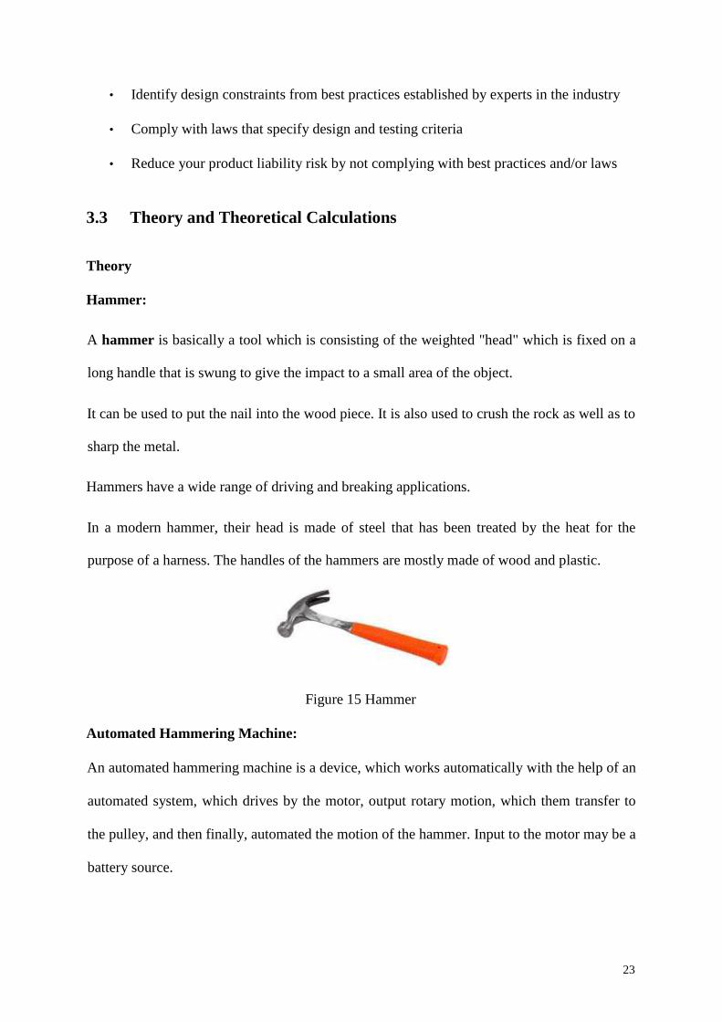
Hammer:
A hammer is basically a tool which is consisting of the weighted "head" which is fixed on a
long handle that is swung to give the impact to a small area of the object.
It can be used to put the nail into the wood piece. It is also used to crush the rock as well as to
sharp the metal.
Hammers have a wide range of driving and breaking applications.
In a modern hammer, their head is made of steel that has been treated by the heat for the
purpose of a harness. The handles of the hammers are mostly made of wood and plastic.
Figure 15 Hammer
Automated Hammering Machine:
An automated hammering machine is a device, which works automatically with the help of an
automated system, which drives by the motor, output rotary motion, which them transfer to
the pulley, and then finally, automated the motion of the hammer. Input to the motor may be a
battery source.
23
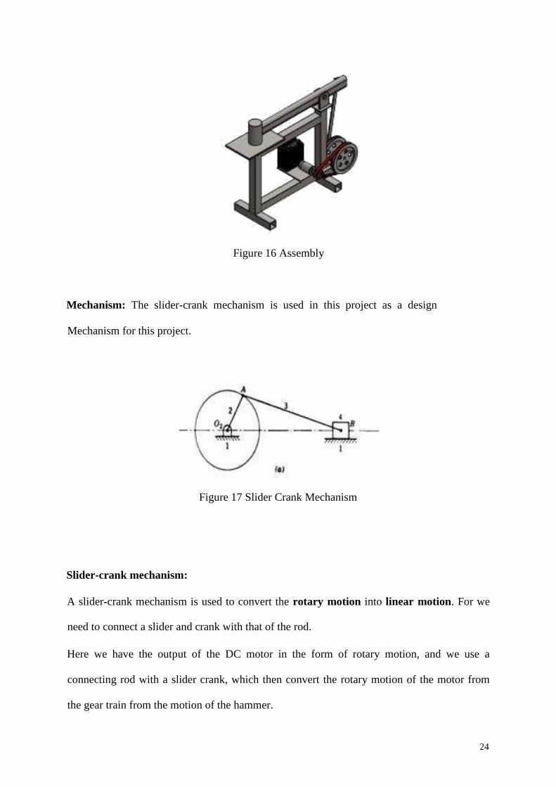
Figure 16 Assembly
Mechanism: The slider-crank mechanism is used in this project as a design
Mechanism for this project.
Figure 17 Slider Crank Mechanism
Slider-crank mechanism:
A slider-crank mechanism is used to convert the rotary motion into linear motion. For we
need to connect a slider and crank with that of the rod.
Here we have the output of the DC motor in the form of rotary motion, and we use a
connecting rod with a slider crank, which then convert the rotary motion of the motor from
the gear train from the motion of the hammer.
24
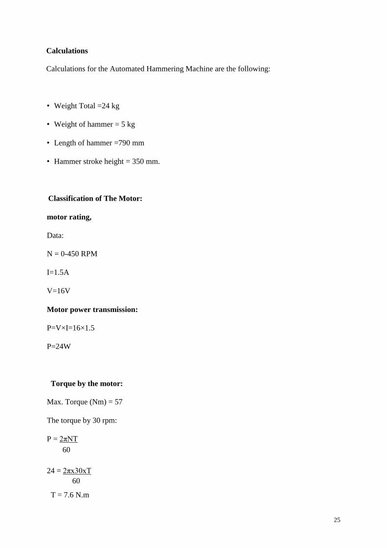
Calculations
Calculations for the Automated Hammering Machine are the following:
• Weight Total =24 kg
• Weight of hammer = 5 kg
• Length of hammer =790 mm
• Hammer stroke height = 350 mm.
Classification of The Motor:
motor rating,
Data:
N = 0-450 RPM
I=1.5A
V=16V
Motor power transmission:
P=V×I=16×1.5
P=24W
Torque by the motor:
Max. Torque (Nm) = 57
The torque by 30 rpm:
P = 2πNT
60
24 = 2πx30xT 60
T = 7.6 N.m
25
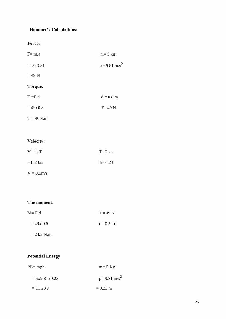
Hammer’s Calculations:
Force:
F= m.a m= 5 kg
= 5x9.81 a= 9.81 m/s2
=49 N
Torque:
T =F.d d = 0.8 m
= 49x0.8 F= 49 N
T = 40N.m
Velocity:
V = h.T T= 2 sec
= 0.23x2 h= 0.23
V = 0.5m/s
The moment:
M= F.d F= 49 N
= 49x 0.5 d= 0.5 m
= 24.5 N.m
Potential Energy:
PE= mgh m= 5 Kg
= 5x9.81x0.23 g= 9.81 m/s2
= 11.28 J = 0.23 m
26
Kinetic Energy:
KE= (½)m.v2
m =5 Kg
= (½)(5)(0.5)2
v= 0.5 m/s
= 0.625 J
Impact Force:
W= KE =Fd =(½)mv2
m= 5 kg
⟹ F = [(½)mv2]/d d= 0.23 m
= [(½)5x0.52]/0.23m v= 0.5 m/s
=2.7N
3.4 Product Subsystems and selection of Components
Selection of Components:
Components of the system are the following:
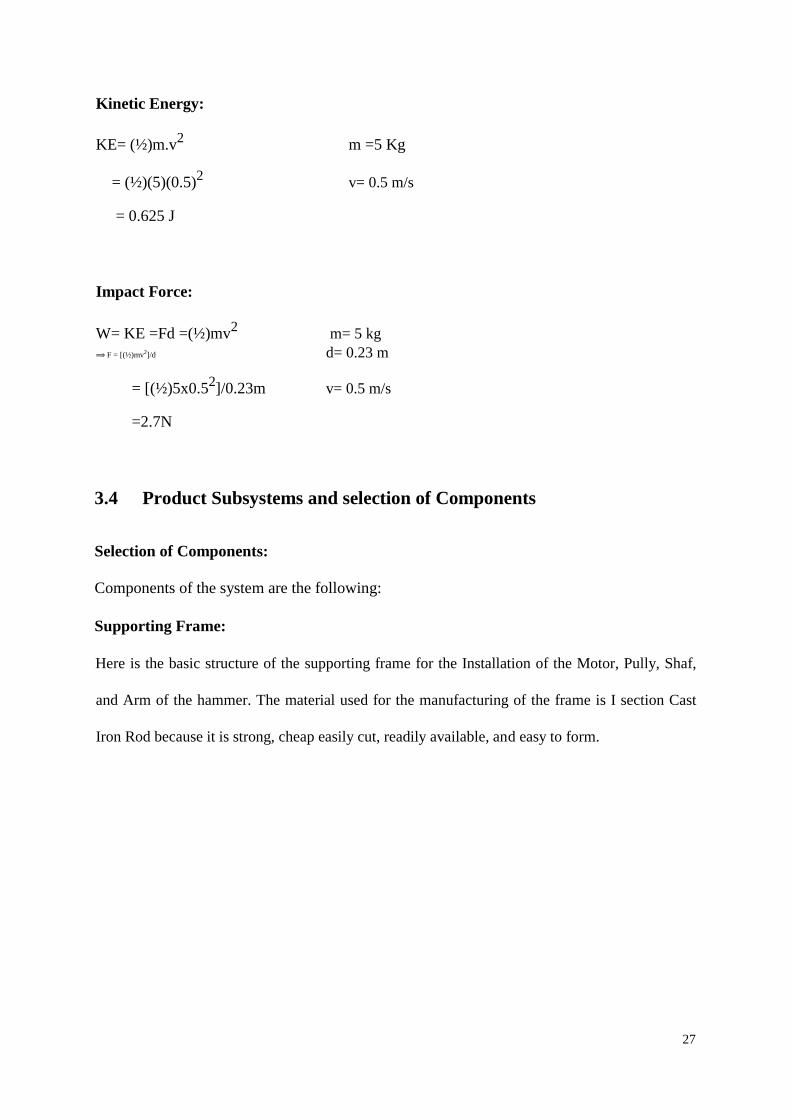
Supporting Frame:
Here is the basic structure of the supporting frame for the Installation of the Motor, Pully, Shaf,
and Arm of the hammer. The material used for the manufacturing of the frame is I section Cast
Iron Rod because it is strong, cheap easily cut, readily available, and easy to form.
27
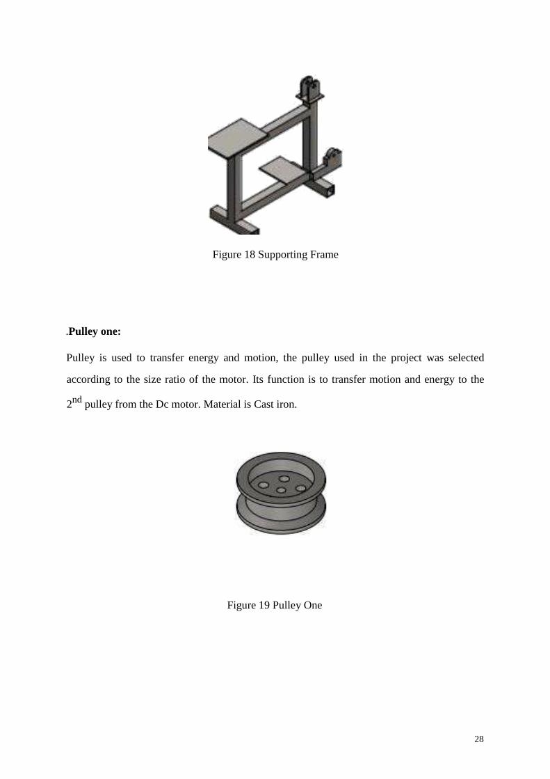
Figure 18 Supporting Frame
.Pulley one:
Pulley is used to transfer energy and motion, the pulley used in the project was selected
according to the size ratio of the motor. Its function is to transfer motion and energy to the
2nd
pulley from the Dc motor. Material is Cast iron.
Figure 19 Pulley One
28
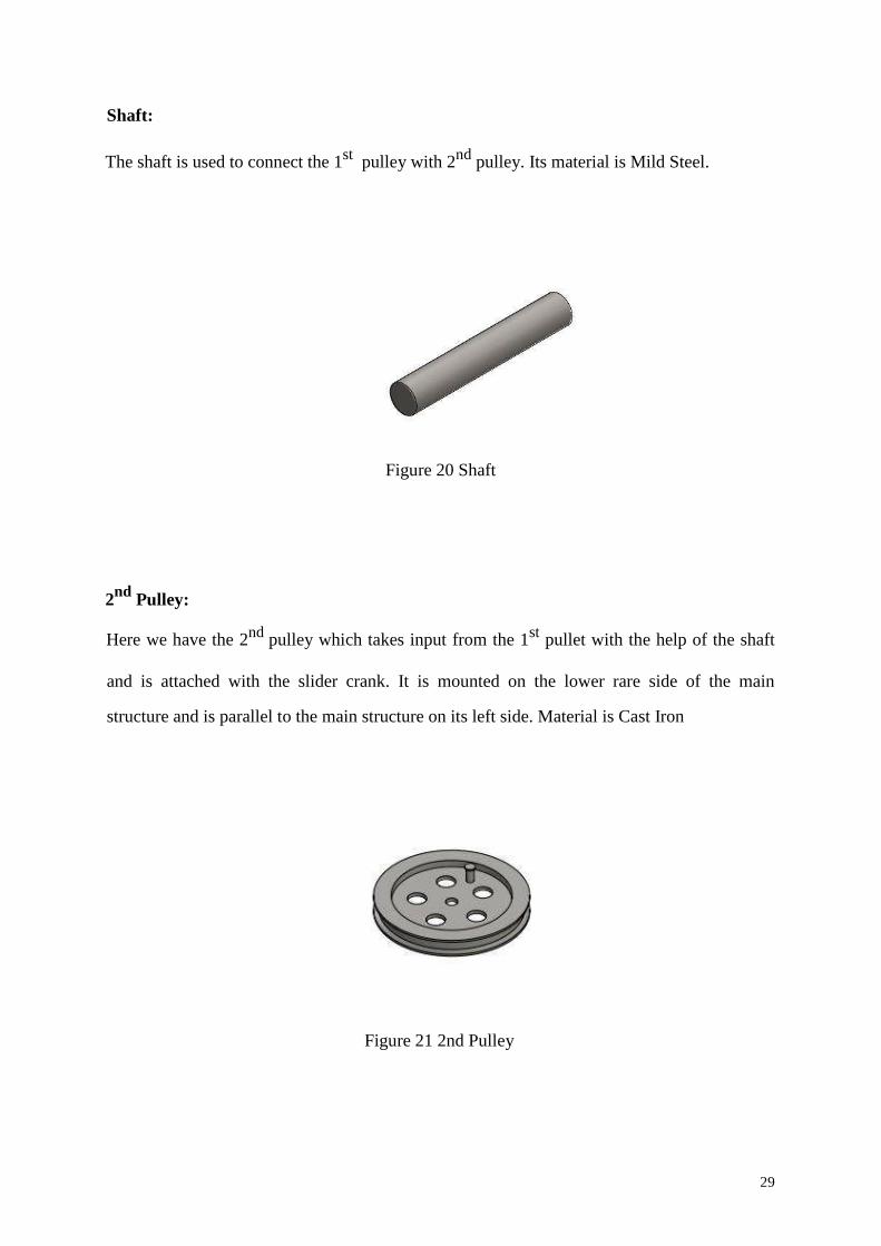
Shaft:
The shaft is used to connect the 1st
pulley with 2nd
pulley. Its material is Mild Steel.
Figure 20 Shaft
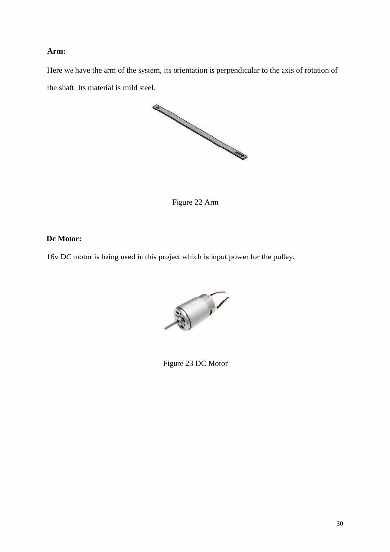
2nd
Pulley:
Here we have the 2nd
pulley which takes input from the 1st
pullet with the help of the shaft
and is attached with the slider crank. It is mounted on the lower rare side of the main
structure and is parallel to the main structure on its left side. Material is Cast Iron
Figure 21 2nd Pulley
29
Arm:
Here we have the arm of the system, its orientation is perpendicular to the axis of rotation of
the shaft. Its material is mild steel.
Figure 22 Arm
Dc Motor:
16v DC motor is being used in this project which is input power for the pulley.
Figure 23 DC Motor
30
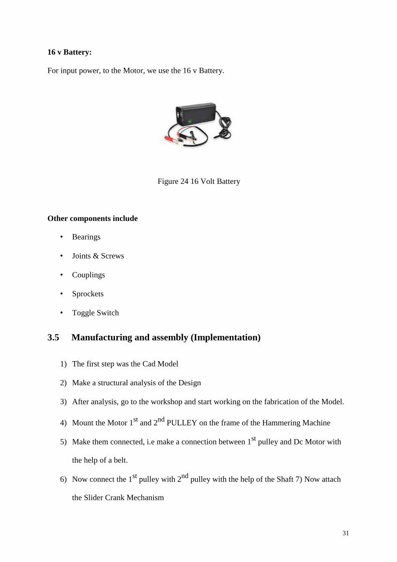
16 v Battery:
For input power, to the Motor, we use the 16 v Battery.
Figure 24 16 Volt Battery
Other components include
• Bearings
• Joints & Screws
• Couplings
• Sprockets
• Toggle Switch
3.5 Manufacturing and assembly (Implementation)
1) The first step was the Cad Model
2) Make a structural analysis of the Design
3) After analysis, go to the workshop and start working on the fabrication of the Model.
4) Mount the Motor 1st
and 2nd
PULLEY on the frame of the Hammering Machine
5) Make them connected, i.e make a connection between 1st
pulley and Dc Motor with
the help of a belt.
6) Now connect the 1st
pulley with 2nd
pulley with the help of the Shaft 7) Now attach
the Slider Crank Mechanism
31

8) Connect the arm with the handle of the hammer.
9) Now attach the input battery power to the motor
10) The motor will get the input (electric) and then convert it to the rotary motion, then
the energy in the form of rotary motion will transfer to the slider motion. finally, the
automated to and from motion of the hammer.
Thus, we have an Electrical Automated Hammering Machine.
32
Chapter 4: System Testing and Analysis
4.1 Experimental Setup, Sensors and data acquisition system
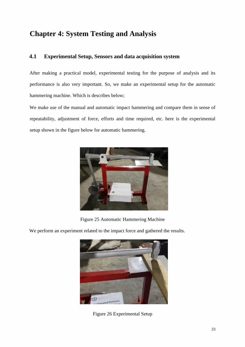
After making a practical model, experimental testing for the purpose of analysis and its
performance is also very important. So, we make an experimental setup for the automatic
hammering machine. Which is describes below;
We make use of the manual and automatic impact hammering and compare them in sense of
repeatability, adjustment of force, efforts and time required, etc. here is the experimental
setup shown in the figure below for automatic hammering.
Figure 25 Automatic Hammering Machine
We perform an experiment related to the impact force and gathered the results.
Figure 26 Experimental Setup
33
4.2 Results, Analysis and Discussion
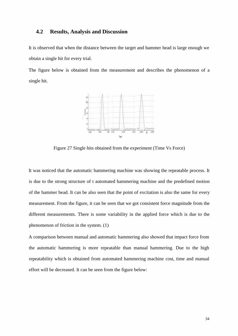
It is observed that when the distance between the target and hammer head is large enough we
obtain a single hit for every trial.
The figure below is obtained from the measurement and describes the phenomenon of a
single hit.
Figure 27 Single hits obtained from the experiment (Time Vs Force)
It was noticed that the automatic hammering machine was showing the repeatable process. It
is due to the strong structure of t automated hammering machine and the predefined motion
of the hammer head. It can be also seen that the point of excitation is also the same for every
measurement. From the figure, it can be seen that we got consistent force magnitude from the
different measurements. There is some variability in the applied force which is due to the
phenomenon of friction in the system. (1)
A comparison between manual and automatic hammering also showed that impact force from
the automatic hammering is more repeatable than manual hammering. Due to the high
repeatability which is obtained from automated hammering machine cost, time and manual
effort will be decreased. It can be seen from the figure below:
34
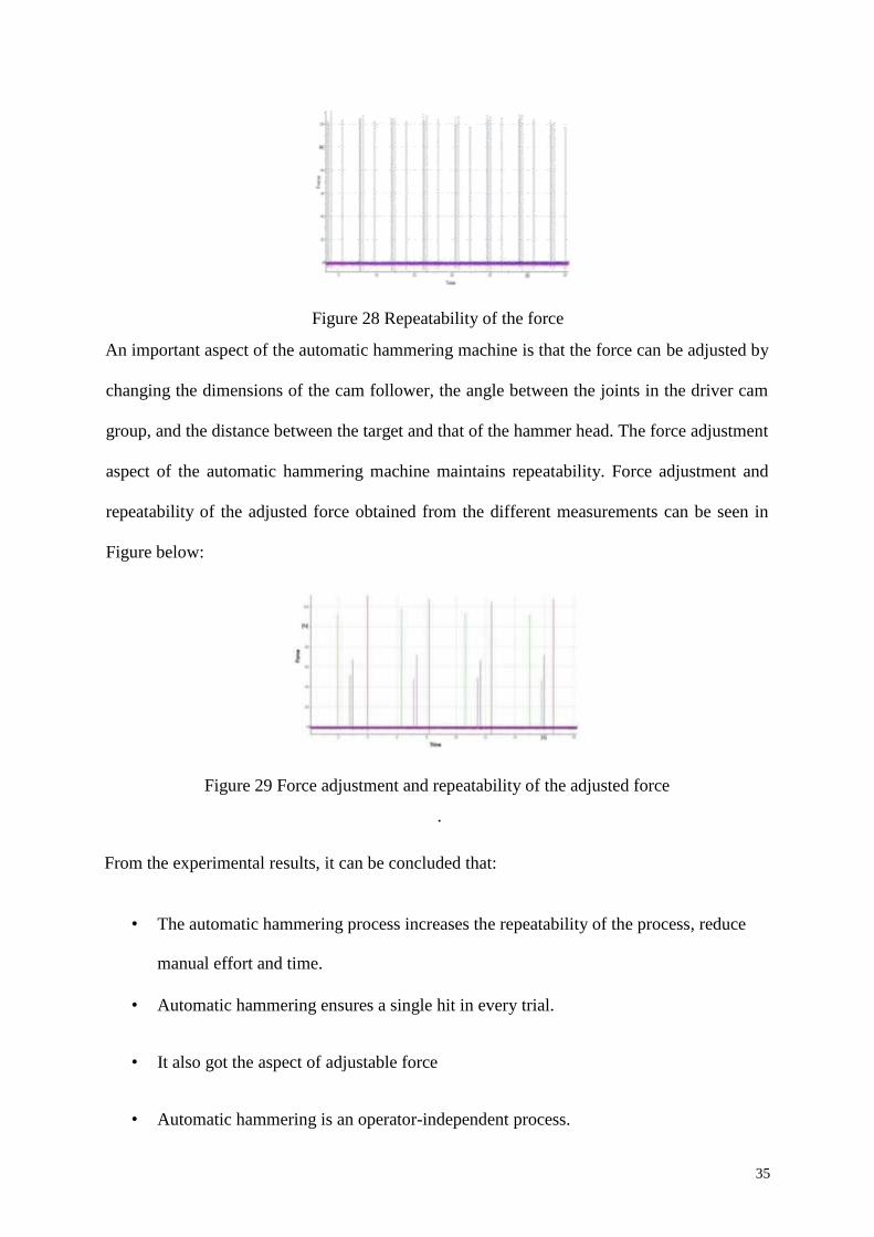
Figure 28 Repeatability of the force
An important aspect of the automatic hammering machine is that the force can be adjusted by
changing the dimensions of the cam follower, the angle between the joints in the driver cam
group, and the distance between the target and that of the hammer head. The force adjustment
aspect of the automatic hammering machine maintains repeatability. Force adjustment and
repeatability of the adjusted force obtained from the different measurements can be seen in
Figure below:
Figure 29 Force adjustment and repeatability of the adjusted force
.
From the experimental results, it can be concluded that:
• The automatic hammering process increases the repeatability of the process, reduce
manual effort and time.
• Automatic hammering ensures a single hit in every trial.
• It also got the aspect of adjustable force
• Automatic hammering is an operator-independent process.
35
These are some reasons why the simulation of the automatic hammering is more reliable
than that of the data which is obtained from the manual impact testing.
Then, we observe the quality of the automatic hammering as compare to the manual
hammering process. For this, ten hits were made on the same structure with both
automatic and manual hammers.
First of all, input and output signals were used to obtain the FFTs. Then, the FFTs of the
data were averaged and then averaged data was used to compute the required frequency
response functions.
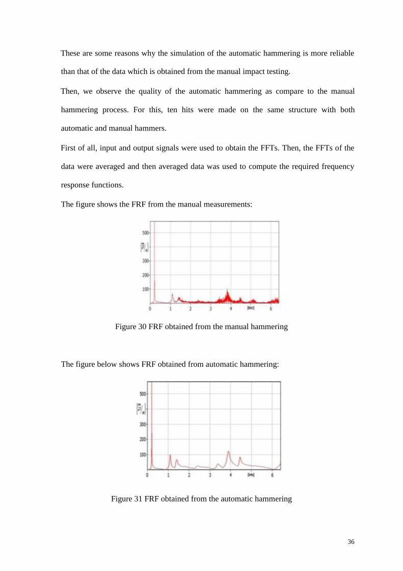
The figure shows the FRF from the manual measurements:
Figure 30 FRF obtained from the manual hammering
The figure below shows FRF obtained from automatic hammering:
Figure 31 FRF obtained from the automatic hammering
36
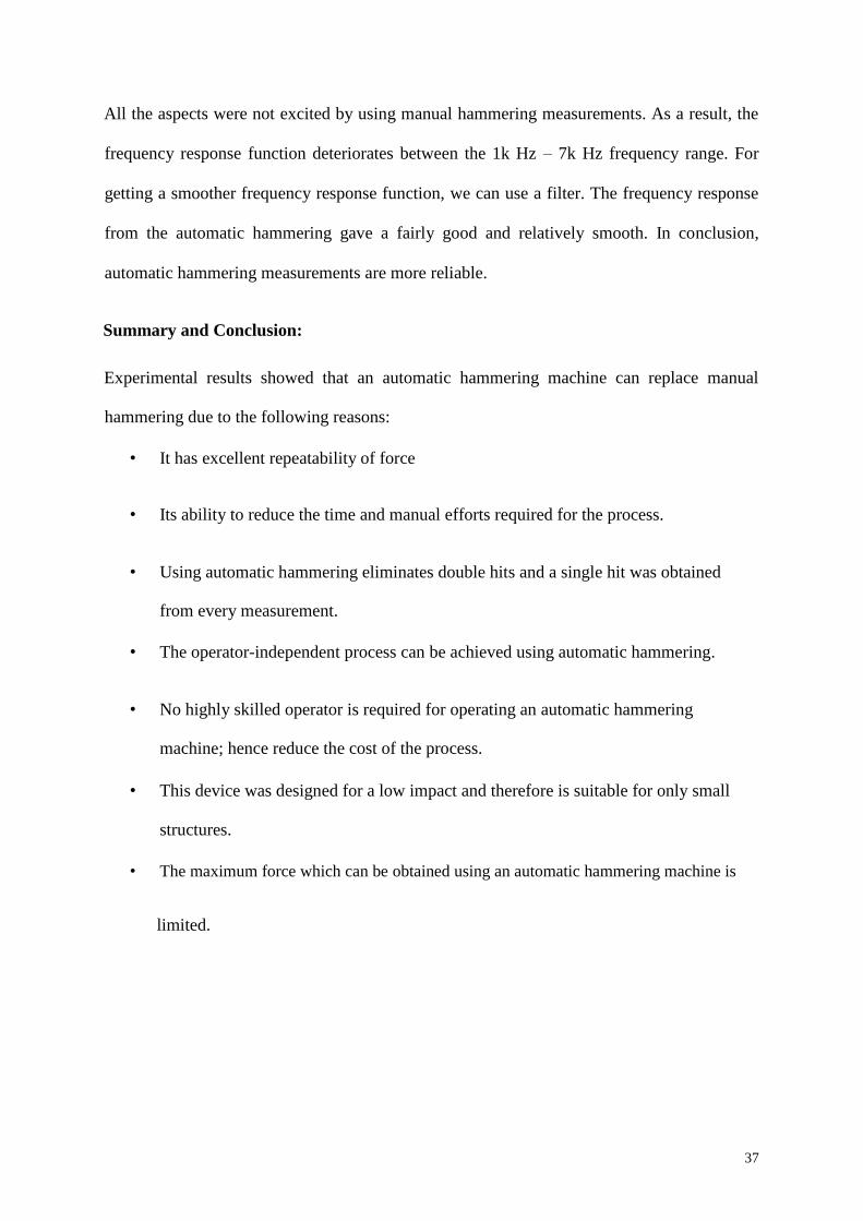
All the aspects were not excited by using manual hammering measurements. As a result, the
frequency response function deteriorates between the 1k Hz – 7k Hz frequency range. For
getting a smoother frequency response function, we can use a filter. The frequency response
from the automatic hammering gave a fairly good and relatively smooth. In conclusion,
automatic hammering measurements are more reliable.
Summary and Conclusion:
Experimental results showed that an automatic hammering machine can replace manual
hammering due to the following reasons:
• It has excellent repeatability of force
• Its ability to reduce the time and manual efforts required for the process.
• Using automatic hammering eliminates double hits and a single hit was obtained
from every measurement.
• The operator-independent process can be achieved using automatic hammering.
• No highly skilled operator is required for operating an automatic hammering
machine; hence reduce the cost of the process.
• This device was designed for a low impact and therefore is suitable for only small
structures.
• The maximum force which can be obtained using an automatic hammering machine is
limited.
37
Chapter 5: Project Management
5.1 Project Plan
Break Down of Tasks:
We have divided the task into 8 tasks
• Literature review
• 3D Modeling
• Identification of the material
• Material purchase
• Making a practical model
• Performing test
• Concluding the project
• Report writing
38
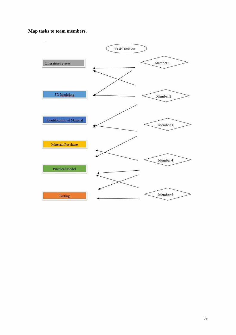
Map tasks to team members.
39
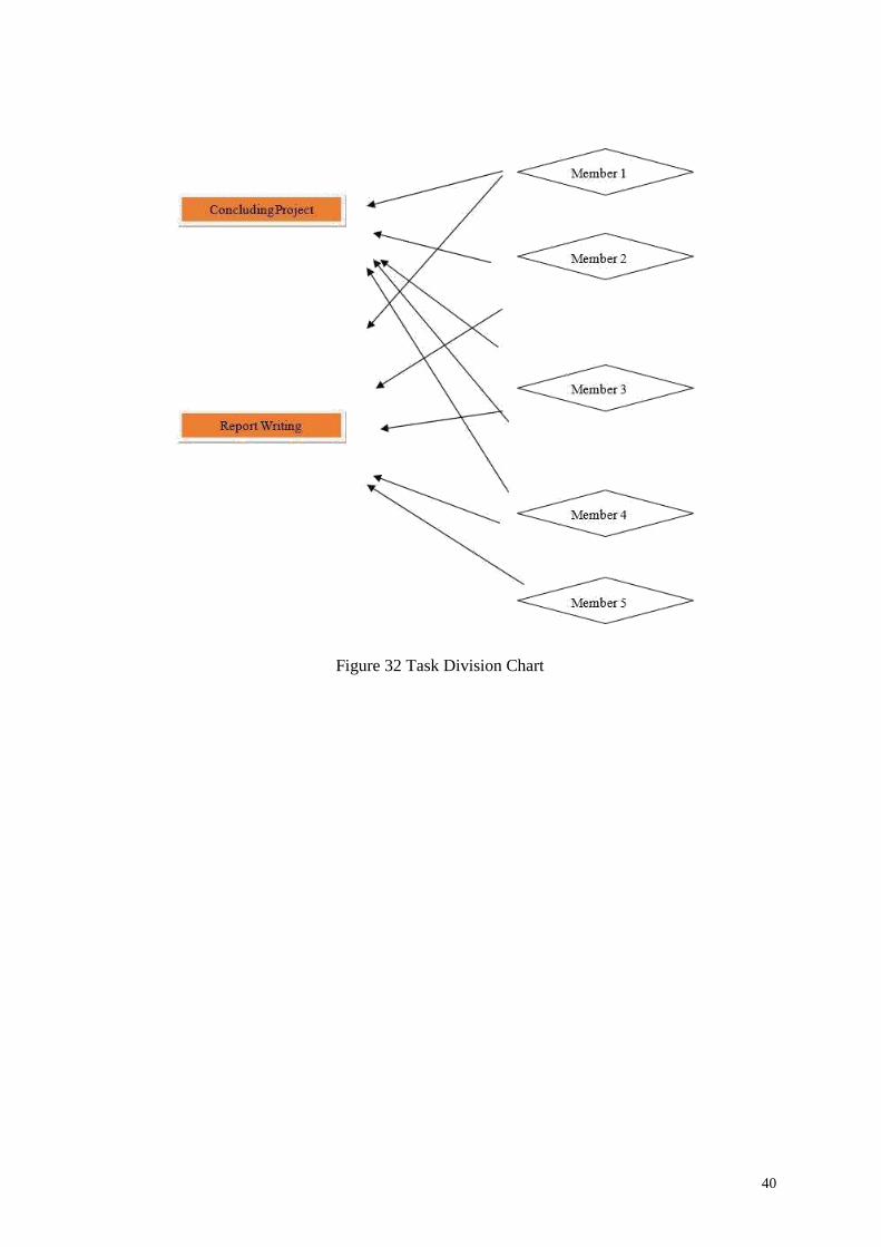
Figure 32 Task Division Chart
40
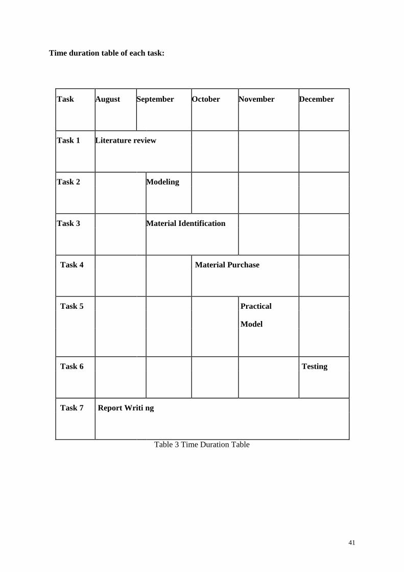
Time duration table of each task:
Task August September October November December
Task 1 Literature review
Task 2 Modeling
Task 3 Material Identification
Task 4 Material Purchase
Task 5 Practical
Model
Task 6 Testing
Task 7 Report Writi ng
Table 3 Time Duration Table
41
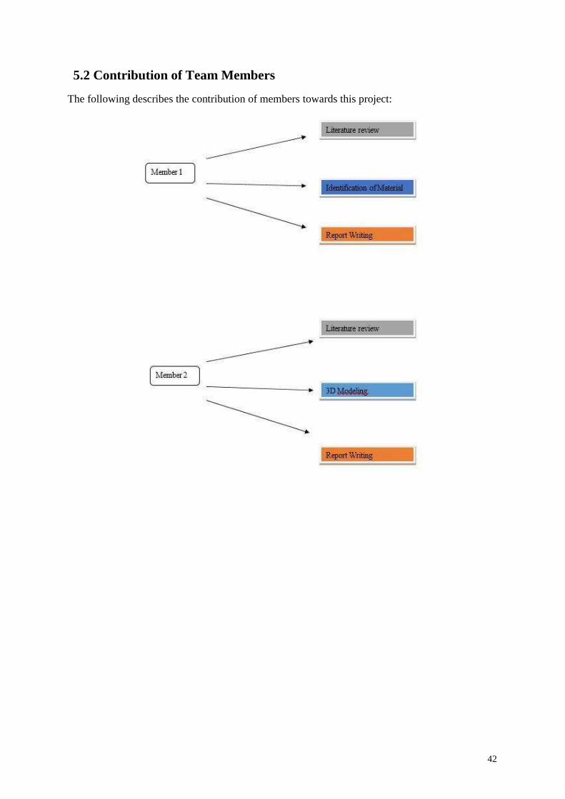
5.2 Contribution of Team Members
The following describes the contribution of members towards this project:
42
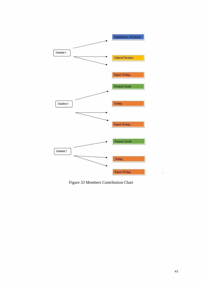
Figure 33 Members Contribution Chart
43
5.3 Project Execution Monitoring
Project Execution performs the following activities:
• First of all team members had a meeting and we select the course project.
• We had the Literature review
• Then, we make a meeting with the advisor for the project approval.
• After the project is approved by the advisor, we search for the right methodology for
the completion of the project.
• Literature review for selection of appropriate methodology
• We went for three methodologies ( Analytical Calculations, 3D modeling, and
Practical Model )
• Then, we divide the project into the sub-tasks
• Each task was assigned to each group member
• Search for Suitable Methodology for making practical model
• Meeting with the advisor and get an approval of the methodology
• We search for the right material regarding availability in the market and the cost of
the components.
• Purchase of the selected material
• Working on practical model according to the 3D CAD model
• Meeting with the advisor and define the testing criteria
• Analysis and testing of the portable automatic hammering machine
• Report writing of the whole project.
Finally, we conclude the project.
44
5.4 Challenges and Decision Making
Challenges Faced:
• COVID-19
Covid-19 was the major hurdle in our project. Due to lockdown and unavailability of the
components, it was the biggest challenge to gather all the equipment required for the
project. Moreover, the imposed lockdown restricted us from meeting our supervisors that
made it more difficult for us to perform all the design and manufacturing in his absence.
• Problems with team members not cooperating/meeting.
Overall the project was best in terms of learning as well as in terms of teamwork. Every
member of the group gave his 100% towards the completion of the project. Everybody
cooperates and helps each other starting from the cad model to concluding the project.
Tasks were divided and each group member performs them quite well.
• Problems or delays in procuring required parts/components/tools.
Overall the project followed its timeline very well but the delay in the project was due to
the tooling issues. Tools required for the project were quite expensive, so we decide to do
these tooling in some workshop which has the required toll-like shaft or handle of the
hammer used the lathing machine and so. Delay in the project was also due to the late
delivery of some components like motors and so.
• Problems with equipment or components not working or malfunctioning.
The problem in the project was due to the delay of the tooling of the gear arm and shaft
for the portable hammering machine. We take help from the internet and came to know the
right machine for their tooling. And then we went to the workshop for machining of the
described components. Designing of the whole machine was also the problem which we solve
by getting help from journal articles
45
Decision Making:
Every engineering project makes us learn about decision making regarding the selection of
the material, methodology, and design constraints. These are critical and need strong decision
making using your engineering knowledge. The overall project gives opportunities for
making appropriate decisions. Some of them are the following:
• Choice of the project for this course
• Choice of the team members for the project
• Choice of the appropriate methodology
• Choice of the appropriate parts for each member in the project taking in mind their
expertise.
• Best suitable material section
All team members gave take part in deciding all these factors and making a decision
regarding the completion of the project. Where all of us didn't have any idea, we took help
from books, journals articles and so.
46
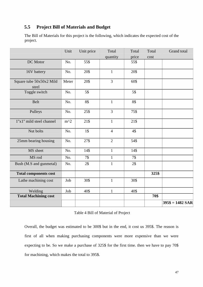
5.5 Project Bill of Materials and Budget
The Bill of Materials for this project is the following, which indicates the expected cost of the
project.
Unit Unit price Total Total Total Grand total
quantity price cost
DC Motor No. 55$ 55$
16V battery No. 20$ 1 20$
Square tube 50x50x2 Mild Meter 20$ 3 60$
steel
Toggle switch No. 5$ 5$
Belt No. 8$ 1 8$
Pulleys No. 25$ 3 75$
1''x1'' mild steel channel m^2 21$ 1 21$
Nut bolts No. 1$ 4 4$
25mm bearing housing No. 27$ 2 54$
MS sheet No. 14$ 1 14$
MS rod No. 7$ 1 7$
Bush (M.S and gunmetal) No. 2$ 1 2$
Total components cost 325$
Lathe machining cost Job 30$ 1 30$
Welding Job 40$ 1 40$
Total Machining cost 70$
395$ = 1482 SAR
Table 4 Bill of Material of Project
Overall, the budget was estimated to be 300$ but in the end, it cost us 395$. The reason is
first of all when making purchasing components were more expensive than we were
expecting to be. So we make a purchase of 325$ for the first time. then we have to pay 70$
for machining, which makes the total to 395$.
47

Chapter 6: Project Analysis
6.1 Life-long Learning
Life-long learning from the project:
• It makes us aware of the tools like lath machine usage, paper cutting machine and so.
We make use of these machines and get great information regarding manufacturing
engineering processes.
• Understanding of the 3D modeling software like CAD, Solids works, etc.
• We learn the steps to create a practical prototype from the 3d model.
• We learn about different tooling techniques
• We use engineering knowledge in the practical application
• It makes us learn the material selection criteria
• We lean time management from this project, it was a key to handle upcoming projects
timely and accurately
• It makes me learn how to manage a team in teamwork to get a productive output
• It makes us learn to convert a manual system into an automatic machine, so we also
get an idea of the automatic machines.
For productive, useful information, and completion of the project, we got help from the
internet (scientific topics, journal papers research topics). We also get help from the books
related to this topic. Also, some seniors and electronics department fellows help us in
learning all the above
48
6.2 Impact of Engineering Solutions
Automatic machine has many engineering impacts, the impacts of the automatic hammering
machine are described below:
• Automatic hammering is an instant process, we can make use of it for instant use
• Efficiency is increased using an automatic hammering machine
• Automatic hammering is a fast process
• Multi Operations can be done by using an automatic hammering machine • Automatic
hammering machine makes use of accurate repetition and impact.
• Automatic hammering is a time-saving process.
• The automatic hammering had a low tooling cost
• Maintenance of the automatic hammering machine is easy.
• It is easy for us (Myaszk n.d.)
6.3 Contemporary Issues Addressed
Automatic portable hammering machine has addressed the following issues:
• It has addressed the issue of manpower. Being an automatic machine I will not make
use of the manpower.
• It has solved the safety issues for labor. Using manual hammering has safety concerns.
• It makes use of modern technology for the conversion of the 3D CAD Model to the
practical model.
• Automatic hammering has addressed the issue of manual hammering.
• Being an automatic machine, a portable automatic hammering machine can be placed
anywhere for usage.
• A portable hammering machine has a low initial cost.
49
Chapter 7: Conclusions and Future Recommendations
7.1 Conclusions
➢ In this project, an automatic hammering machine is designed and manufactured.
➢ All the components of the machine were designed on SolidWorks and a prototype was
manufactured.
➢ The materials were selected for each component on the basis of the engineering
standards.
➢ This machine is a unique machine and no other automatic hammering machine of this
design exists.
➢ This machine can be controlled and operated for the required number of strokes per
minute.
➢ Previously designed automatic hammering machines did not involve variable strokes.
➢ The project was full of challenges because of COVID-19 and the unavailability of the
important components.
➢ The experience of designing an automatic hammering machine and then fabricating it
was fascinating.
➢ From this project, we have learned the selection of materials for different components and
we learned about different machining processes that can be used for manufacturing
a specific component.
➢ The project taught us regarding economic constraints that how can we manage a
project under a given budget.
➢ Moreover, if this product is manufactured on a commercial basis, it can be proved as a
useful product for the industry.
50
7.2 Future Recommendations
➢ The automatic hammering machine designed in this project can be improved from
many perspectives.
➢ The first perspective is the design of the stroke of the hammer. It can be further
improved and made lightweight.
➢ The strength of the hammer should be improved so that it can be used for proper
hammering operations in the industry.
➢ Moreover, the time lag between two strokes of the hammer can be reduced so that
time can be saved during hammering operations.
➢ Adding more to it, the aesthetics of the machine can be enhanced.
51
8. References [1] J. Agirre, "Monitoring of a Hammer Forging Testing Machine for High Speed Material
Characterization," Procedia Manufactruing, 2020.
[2] A. Dyakonov, "Automated Processing of Vibration Test Results for Basic Metalconcrete
Components of the Cutting Machines," 2017.
[3] R. Mannens, "Influence of Impact Force, Impact Angle, and Stroke Length in Machine
Hammer Peening on the Surface Integrity of the Stainless Steel X3CrNiMo13-4," 2018.
[4] J. R. Honninge, "Improvement of Microstructure and Mechanical Properties in Wire +
Arc Additively Manufactured Ti-6Al-4V with Machine Hammer Peening," 2017.
[5] R. Mannens, "Analysis of surface defects on industrial casting tools for automotive
applications after machine hammer peening," 2017.
[6] T. Brüggemanna, D. Biermanna, A. Zabela. "Development of an automatic modal pendulum
for the measurement of frequency responses for the calculation of stability charts
." sciencedirect, 2015: 587-592.
[7]Ingalkar, M V. "DESIGN, CAD MODELING & FABRICATION OF AUTOMATIC
HAMMERING MACHINE." International Research Journal of Engineering and
Technology (IRJET), 2018: 949-954.
[8]Myaszk, David H. Mechanisms, and machine analysis. 4TH.
52
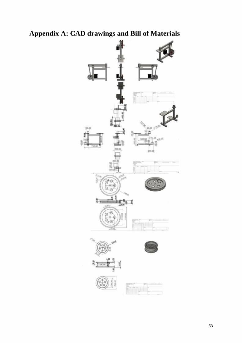
Appendix A: CAD drawings and Bill of Materials
53
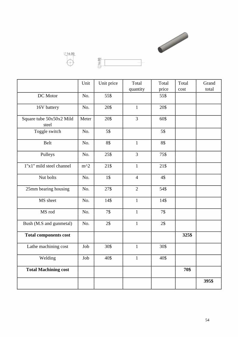
Unit Unit price Total Total Total Grand
quantity price cost total
DC Motor No. 55$ 55$
16V battery No. 20$ 1 20$
Square tube 50x50x2 Mild Meter 20$ 3 60$
steel
Toggle switch No. 5$ 5$
Belt No. 8$ 1 8$
Pulleys No. 25$ 3 75$
1''x1'' mild steel channel m^2 21$ 1 21$
Nut bolts No. 1$ 4 4$
25mm bearing housing No. 27$ 2 54$
MS sheet No. 14$ 1 14$
MS rod No. 7$ 1 7$
Bush (M.S and gunmetal) No. 2$ 1 2$
Total components cost 325$
Lathe machining cost Job 30$ 1 30$
Welding Job 40$ 1 40$
Total Machining cost 70$
395$
54

Appendix B: Engineering standards (Local and
International)
ASTM A36 Welding Standards:
• If the metal is thicker than 1/4 - 6 mm, preheat to 150F
• E7018 stick electrode, an 0.035 or 0.045 E70S-3-6 MIG wire, or for all
position welds an E71T-1 electrode wire
• Ensure mill scale in weld area is removed and the plate is always at a
temperature >60F
• keep single pass fillet welds < 1/4 - < 6mm
• For multi-pass welds, use inter-pass temp control
• hardness and grain size checked
Design Constraints Engineering Standards:
• quality features of hand hammers
• characteristics and verification
• Applies to hammers used under normal working
• Best practices established by experts in the industry
• Comply with laws that specify design and testing criteria
• Reduce product liability risk
• Budget for certification testing
55
Top Related
Copyright © 2022 FDOKUMEN

