


Bahasa
Halaman
Hukum

©Copyright 2014 Makino*The specifications in this catalog may be changed without prior notice to incorporate improvements resulting from ongoing R&D programs.*The machines displayed in this catalog are fitted with optional equipment.
7680 Innovation WayMason, Ohio 45040-8003513-573-7200 . 800-552-3288Fax: 513-573-7360www.makino.com
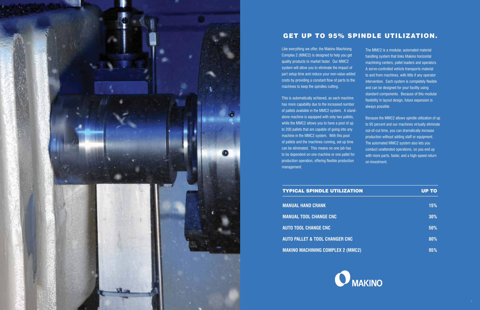
Like everything we offer, the Makino Machining
Complex 2 (MMC2) is designed to help you get
quality products to market faster. Our MMC2
system will allow you to eliminate the impact of
part setup time and reduce your non-value-added
costs by providing a constant flow of parts to the
machines to keep the spindles cutting.
This is automatically achieved, as each machine
has more capability due to the increased number
of pallets available in the MMC2 system. A stand-
alone machine is equipped with only two pallets,
while the MMC2 allows you to have a pool of up
to 200 pallets that are capable of going into any
machine in the MMC2 system. With this pool
of pallets and the machines running, set up time
can be eliminated. This means no one job has
to be dependent on one machine or one pallet for
production operation, offering flexible production
management.
GET UP TO 95% SPINDLE UTILIZATION.
TYPICAL SPINDLE UTILIZATION UP TO
MANUAL HAND CRANK 15%
MANUAL TOOL CHANGE CNC 30%
AUTO TOOL CHANGE CNC 50%
AUTO PALLET & TOOL CHANGER CNC 80%
MAKINO MACHINING COMPLEX 2 (MMC2) 95%
1
The MMC2 is a modular, automated material
handling system that links Makino horizontal
machining centers, pallet loaders and operators.
A servo-controlled vehicle transports material
to and from machines, with little if any operator
intervention. Each system is completely flexible
and can be designed for your facility using
standard components. Because of this modular
flexibility in layout design, future expansion is
always possible.
Because the MMC2 allows spindle utilization of up
to 95 percent and our machines virtually eliminate
out-of-cut time, you can dramatically increase
production without adding staff or equipment.
The automated MMC2 system also lets you
conduct unattended operations, so you end up
with more parts, faster, and a high-speed return
on investment.

The foundation of the MMC2 is Makino’s
superior horizontal machining centers. With
Makino technology, any part produced by
traditional vertical machining can now be
machined on a horizontal machining center
faster, with fewer setups, at far lower labor
costs, to higher accuracies and superior
finishes. The new horizontal machining
centers can reduce total processing lead time
by 20 to 25 percent.
MODULAR DESIGNPROVIDES FLEXIBILITY
That all sounds good, but the obvious question
is, how? By allowing rough and finish
machining, as well as peripheral operations, to
be performed on a single machine, often in one
continuous operation, high-speed horizontals
reduce the possibility of a “stack up” of errors
and eliminate a great deal of the manual
effort and wasted time inherent in traditional
methods.
Makino’s MMC2 connects superior machines.
“WE THOUGHT WE’D SEE BIG
IMPROVEMENTS IN CYCLE TIME.
BUT IN SOME CASES, WE’VE
REDUCED 30-40% MORE OUT
OF OUR CYCLE TIMES THAN WE
EXPECTED.”
JOHN GILL
MANUFACTURING MANAGER, EATON
“WE HAVE INCREASED OUR
PRODUCTIVITY DRAMATICALLY,
GOING FROM THREE TO FOUR
PARTS PER HOUR ON STAND-
ALONE MACHINES TO SIX PARTS
PER HOUR ON THE MMC2. THAT
IS A 50 PERCENT INCREASE”
MARK PALUCH
VICE PRESIDENT OF OPERATIONS, PRINCE INDUSTRIES
3
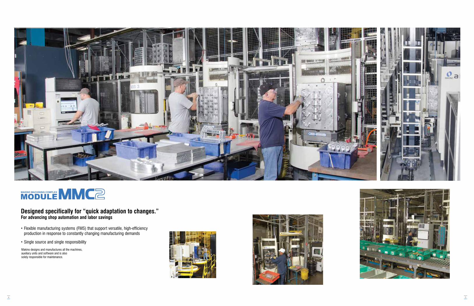
Designed specifically for “quick adaptation to changes.”For advancing shop automation and labor savings
Flexible manufacturing systems (FMS) that support versatile, high-efficiency production in response to constantly changing manufacturing demands
Single source and single responsibility
Makino designs and manufactures all the machines,auxiliary units and software and is alsosolely responsible for maintenance.
4 5
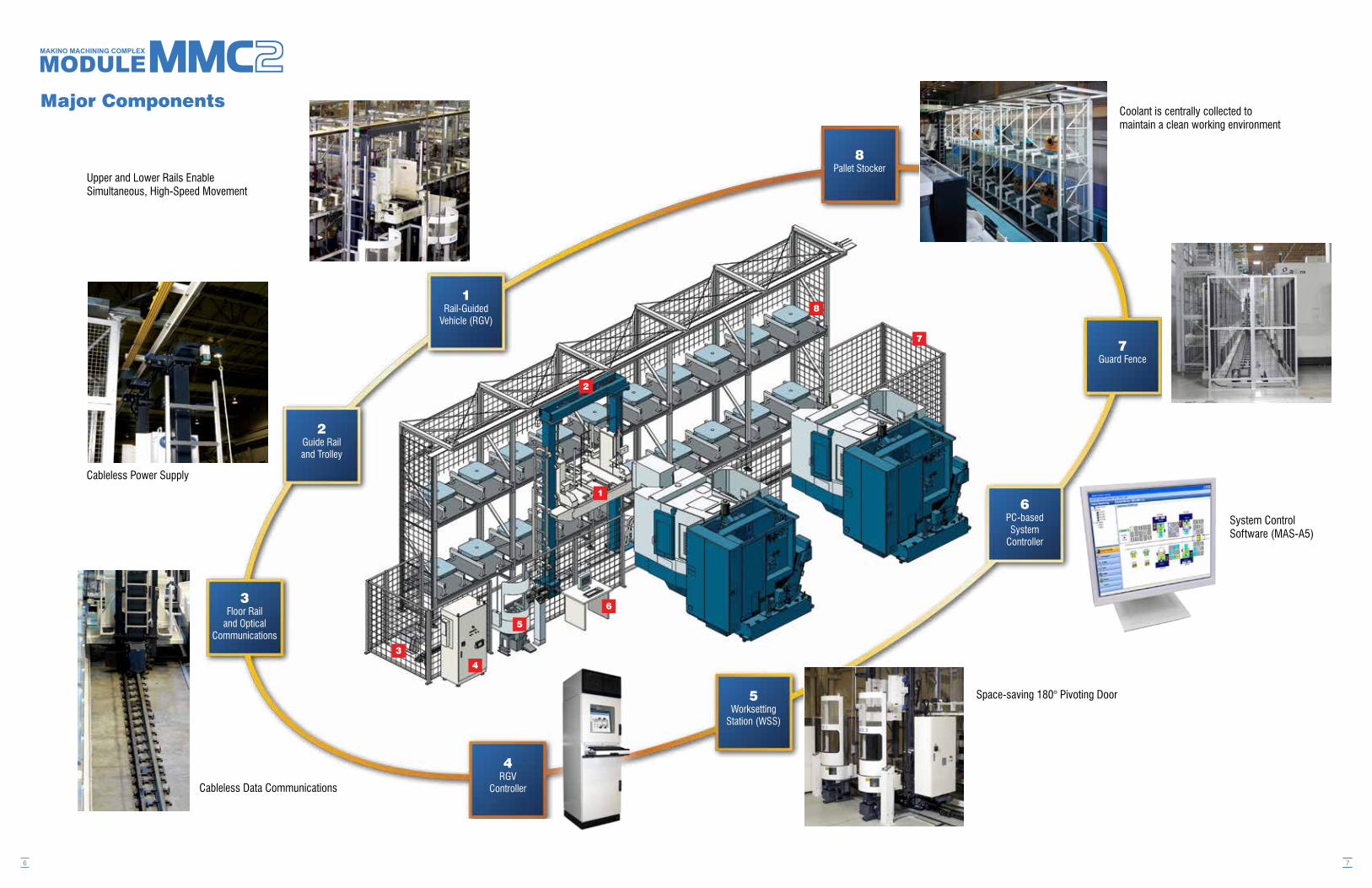
Major Components
6
1Rail-Guided
Vehicle (RGV)
2Guide Railand Trolley
3Floor Rail
and OpticalCommunications
4RGV
Controller
Cableless Power Supply
Cableless Data Communications
Upper and Lower Rails Enable Simultaneous, High-Speed Movement
3
4
5
6
2
1
5Worksetting
Station (WSS)
7Guard Fence
6PC-basedSystem
Controller
8Pallet Stocker
System ControlSoftware (MAS-A5)
Space-saving 180° Pivoting Door
Coolant is centrally collected to maintain a clean working environment
8
7
7
8
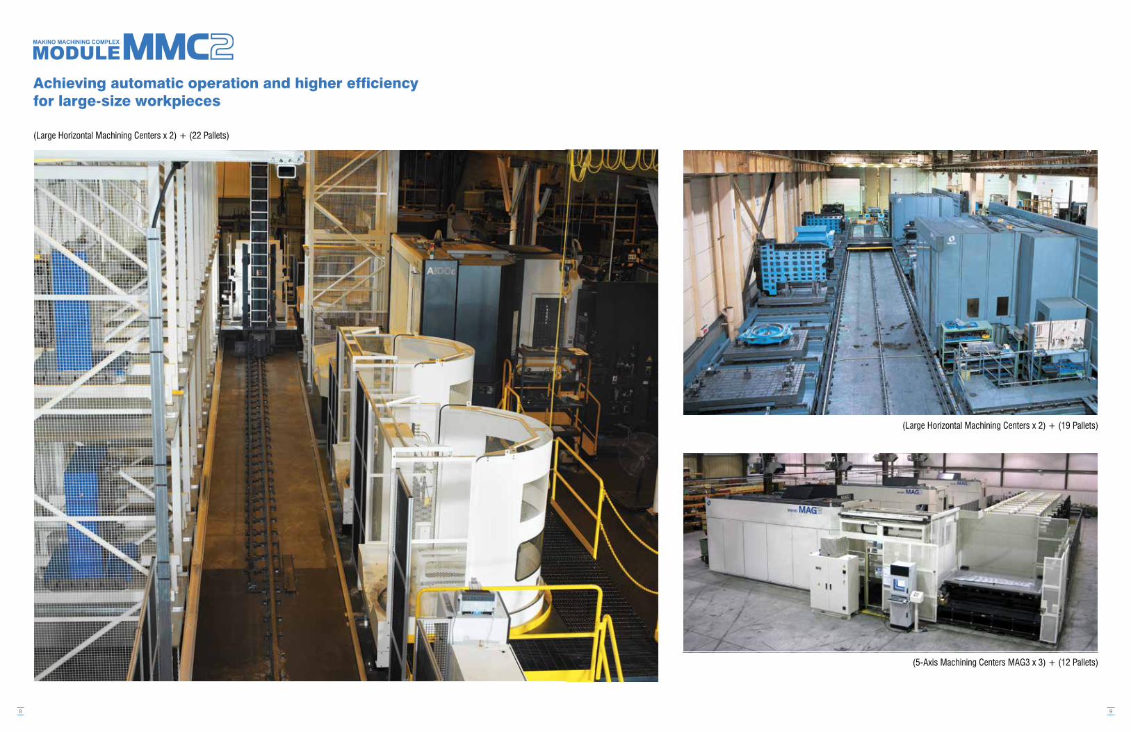
Achieving automatic operation and higher efficiency for large-size workpieces
(Large Horizontal Machining Centers x 2) + (22 Pallets)
9
(5-Axis Machining Centers MAG3 x 3) + (12 Pallets)
(Large Horizontal Machining Centers x 2) + (19 Pallets)

10 11
Major Hardware Specifications
RGV PalletStocker
WSS
Portable Control PanelThis unit connects to the RGV controller and to the RGV for handy use.
M/C Model
Pallet Size
Workpiece Diameter
Workpiece Height
Maximum Pallet Load
1-Level Spec
2-Level Spec
3-Level Spec
a51nx
400 (15.7”)
Æ630 (24.8”)
900 (35.4”)
400 kg (882 lbs)
Yes
Yes
Yes
a61nx
500 (19.7”)
Æ800 (31.5”)
1000 (39.4”)
700 kg (1543 lbs)
Yes
Yes
Yes
a71
500 (19.7”)
Æ800 (31.5”)
1000 (39.4”)
700kg (1543 lbs)
Yes
Yes
Yes
a81nx
630 (24.8”)
Æ1000 (39.4”)
1300 (51.2”)
1200 kg (2646 lbs)
Yes
Yes
Yes
a82
630 (24.8”)
Æ1060 (41.7”)
1390 (54.7”)
1200 kg (2646 lbs)
Yes
Yes
Yes
A99E
800 (31.5”)
Æ1450 (57.1”)
1450 (57.1”)
2000 kg (4409 lbs)
Yes
Yes
No
a92
800 x 1000
Æ1500 (59.1”)
1500 (59.1”)
2000 kg (4409 lbs)
Yes
Yes
No
A100E
1000 (39.4”)
Æ1900 (74.8”)
1500 (59.1”)
3000 kg (6614 lbs)
Yes
Yes
No
ApplicableMachines
AllowableCarryingCapacity
SystemModel
RGV
1 Level
2 Level
3 Level
2600 (102.4”)
3940 (155.2”)
5435 (214.0”)
680 (26.8”)
805 (31.7”)
2715 (106.9”)
3995 (157.3”)
5155 (203.0”)
850 (33.5”)
975 (38.4”)
2715 (106.9”)
4020 (158.3”)
5565 (219.1”)
850 (33.5”)
975 (38.4”)
3180 (125.2”)
4885 (192.3”)
6800 (267.7”)
1050 (41.3”)
1200 (47.2”)
**
**
**
3540 (139.4”)
5490 (216.1”)
--
1600 (63.0”)
1650 (65.0”)
**
**
**
3915 (154.1”)
6250 (246.1”)
--
1900 (74.8”)
2100 (82.7”)
Pallet Stocker
Height*
Height
Depth
Pitch
Option
2250 (88.6”)
760 (29.9”)
750 (29.5”)
2250 (88.6”)
930 (36.6”)
920 (36.2”)
2250 (88.6”)
930 (36.6”)
920 (36.2”)
2300 (90.6”)
1075 (42.3”)
1080 (42.5”)
**
**
**
2920 (115.0”)
1640 (64.6”)
1680 (66.1”)
**
**
**
3120 (122.8”)
2090 (82.3”)
2130 (83.9”)
Please inquire about height changesPlease contact your Makino sales representativeStandard on a92, A99E, and A100E
***
***
2-LevelPallet Stocker
3-LevelPallet Stocker
Tiltable WSS(optional)
Work Setting Station(WSS)
Workpiece Washing Gun, Power Index***, Tiltable WSS, Automatic Door
Depth
Pitch

12
Makino Advanced System (MAS-A5) High-Performance System Control SoftwareSystem Capacity Information
(Production Order Capacity Analysis)
Diagnostic Functionality
(Pallet Diagnosis)
Before a production order is issued, an analysis is made of whether the system can produce the entire volume of that production order within the given lead time. This analysis takes into account the current progress of previously issued production orders and the types of machine making up the system. The production load of the entire system is displayed in easy-to-understand graphs.
(Part Diagnosis)
A host of diagnostic and trouble recovery functions are provided, making it easy to grasp the situation when the system cannot operate automatically for some reason. These functions support a quick return to automatic operation.
(Reports)
A wide variety of report functions are provided, including ones showing the operating results of various pieces of equipment and alarm histories.
(Trouble Recovery - Machine Recovery Procedure)
Easy to know the production load of the entire system
Interactive mode simplifies the
recovery procedure
13
Machining Center
Machining Center
Machining Center
Machining Center
Tiltable / Traversing Type WSSWSS Control Panel
Tool PresetterPresetter PC
RGV Controller RGV
WSS
Up to 4 units can be connected
Up to 15 units can be connected
Conceptual Diagram of System Connections
All units of the system are controlled via a networkNC part programs, tools and all other data are centrally managed by
the system controllerConnections to CAD/CAM systems are easily made
PC-based system controller
Tool Resource Management Function
(Tools in-use data screen)
Tool Lifetime Prediction Function
(Tool preparation information)
To facilitate unmanned operation at night, the remaining lifetime of the tools must be sufficient to finish all the workpieces scheduled for machining. This optional tool lifetime prediction function judges whether any tools will reach the end of their lifetime during machining and displays information on the spare tools that should be prepared.
Tool Presetter Connection FunctionMeasured tool data can be input to the PC-based controller on-line by connecting the tool presetter and PC via an RS232C cable. The input data for each tool are automatically sent to the machine when the tools are loaded on the machine, thereby avoiding data input errors by the operator.
Additional Operation Terminal Connection: 5 or 10 LicensesThe standard specification allows the system to be operated from two PCs. This option provides connections for an additional 5 or 10 licensed PCs.
E-mail Notification FunctionAlarm information for various units is notified by e-mail.(This function requires a Simple Mail Transfer Protocol (SMTP) server in the user’s network environment.)
Customizable Functions for Higher Performance
This function manages information on the tools to be used in machining the specified NC part program and information on the tools prepared for the machine, and automatically judges whether any tools are lacking.
Provides powerful support for automatic operation by ensur-ing that a machine
does not stop because it lacks the
necessary tools
Avoids stoppage of unmanned
machining operations because a tool reached the
end of its life
Easy to add more machines and to
expand the system

MAS-A5 control software pursues optimum ease of operation to facilitate highly flexible use of Modeule MMC2 systems.
14
Entire System’s Operating Status Is Displayed
(System Monitor)
Workpiece Data Management
(Part Data)
All system units are centrally controlled from one PC. The menu screens are easy to understand and use, thanks to the Windows operating environment.
Simply pre-register in the system the data of each process (machining program, specified machine, etc.) of the parts to be machined. The system will automatically generate the schedule between the machining processes, making it easy to produce the parts repeatedly.
(Machine Monitor)
Displays a machine’s current status in real time.Work instructions for the WSS operator are also displayed in an easy-to-understand format.
Simply input how many pieces of which parts are to be produced by what time. The dynamic scheduling function generates machining schedules automatically according to the operating status of each machine and the progress of production.
(WSS monitor screen)
(Production Order Data)
System’s operating status is evident at
a glance
Part data management
provide powerful support for repeated
production
Machining schedules are generated
automatically to maximize machine
uptime rates
15
Pallet and Fixture Data Management
(Pallet Data)
Functional Tool Data Management
(Functional Tool Data)
The pallet data screen makes it easy to specify which workpieces should be fixtured on which pallets.
(Edit Fixture Data) (ATC Magazine Tool Data)
This function manages the data on common fixtures so that the fixtures can be shared between several different machining processes.
Tools are managed according to the data on each type of tool, thereby simplifying data input for multiple spare tools.
The current data for all tools in a machine’s ATC magazine can be displayed on the screen and the data can be edited from the PC.
Supports flexible sharing of fixtures
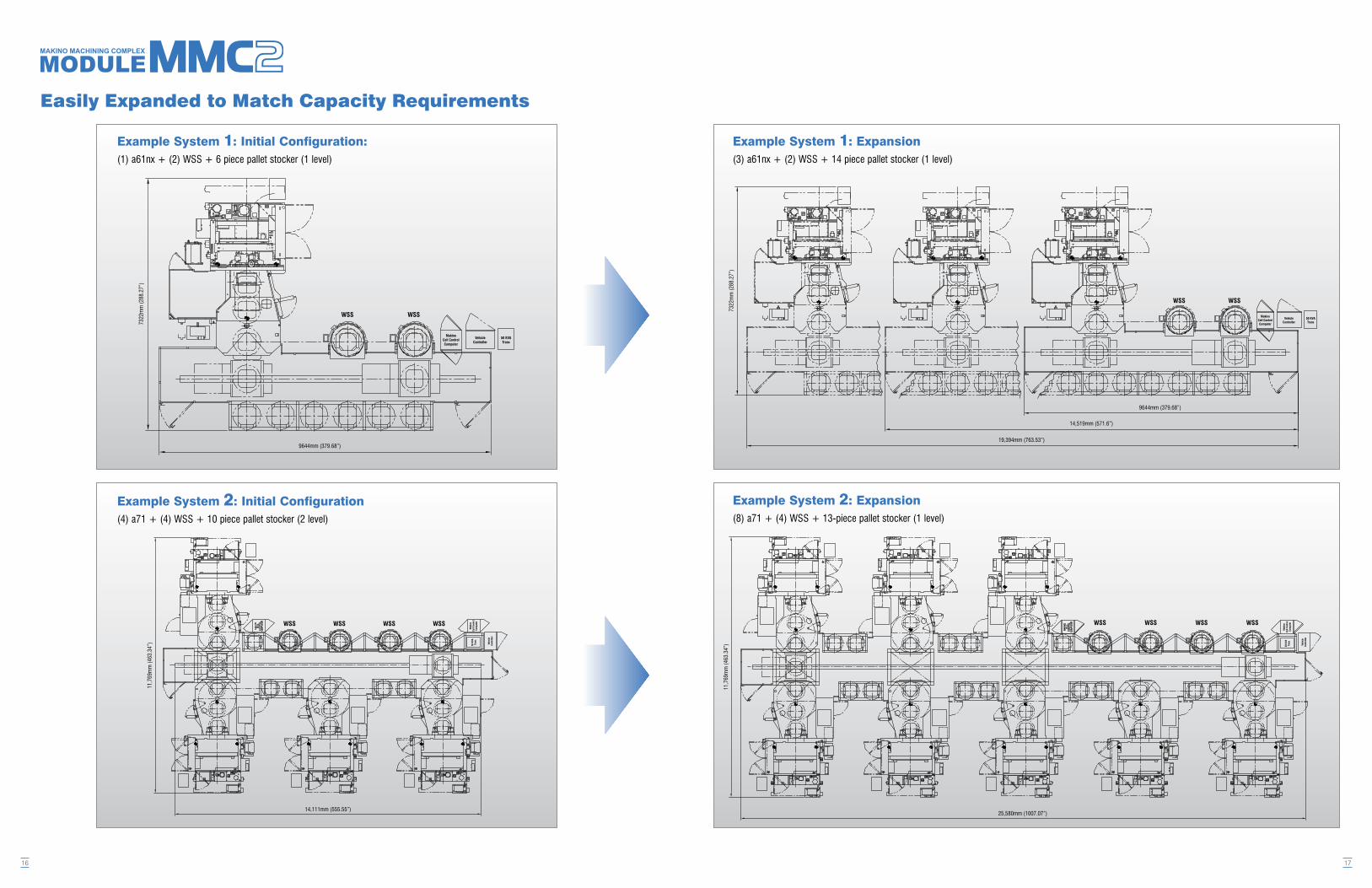
Example System 2: Initial Configuration(4) a71 + (4) WSS + 10 piece pallet stocker (2 level)
Example System 1: Initial Configuration:(1) a61nx + (2) WSS + 6 piece pallet stocker (1 level)
16
9644mm (379.68”)
7322mm(288.27”)
14,111mm (555.55”)
11,769mm(463.34”)
Easily Expanded to Match Capacity Requirements
Example System 1: Expansion(3) a61nx + (2) WSS + 14 piece pallet stocker (1 level)
Example System 2: Expansion(8) a71 + (4) WSS + 13-piece pallet stocker (1 level)
17
7322mm(288.27”)
19,394mm (763.53”)
14,519mm (571.6”)
9644mm (379.68”)
11,769mm(463.34”)
25,580mm (1007.07”)

Examples of System Configurations
18
10,198mm(401.51”)
11,971mm (471.32”)
13,680mm (538.58”)
5510mm(216.93”)Clearancefor
InstallationandMaintenance
6402mm(252.05”)
Example of System Configuration: 1(2) a51nx + (2) WSS + 36 piece pallet stocker (3 level)
Example of System Configuration: 2(3) a51nx + (2) WSS + 8 piece pallet stocker (1 level)
Example of System Configuration: 3(2) a71 + (1) a61nx + (2) WSS + 12 piece pallet stocker (1 level)
Example of System Configuration: 4(6) a71 + (4) WSS + 18 piece pallet stocker (2 level)
19
21,750mm (856.3”)
9720mm(382.7”)
23,393mm (920.97”)
11,771mm(463.43”)
4070mm(160.24”)Clearancefor
Installation&Maintenance
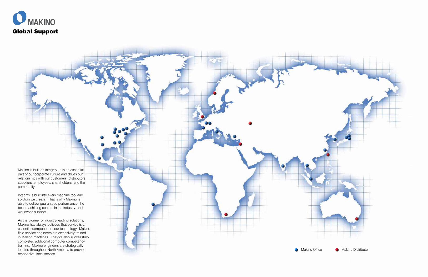
Makino Office Makino Distributor
Global Support
Makino is built on integrity. It is an essential part of our corporate culture and drives our relationships with our customers, distributors, suppliers, employees, shareholders, and the community.
Integrity is built into every machine tool and solution we create. That is why Makino is able to deliver guaranteed performance, the best machining centers in the industry, and worldwide support.
As the pioneer of industry-leading solutions, Makino has always believed that service is an essential component of our technology. Makino field service engineers are extensively trained in Makino machines. They’ve also successfully completed additional computer competency training. Makino engineers are strategically located throughout North America to provide responsive, local service.

©Copyright 2014 Makino*The specifications in this catalog may be changed without prior notice to incorporate improvements resulting from ongoing R&D programs.*The machines displayed in this catalog are fitted with optional equipment.
7680 Innovation WayMason, Ohio 45040-8003513-573-7200 . 800-552-3288Fax: 513-573-7360www.makino.com
Top Related
Copyright © 2022 FDOKUMEN

