


Bahasa
Halaman
Hukum

OTC 22563
Arctic development of the Canadian Beaufort Sea, Geohazards and Export Route Options Ian Nash, Peritus International Ltd.
Copyright 2015, Offshore Technology Conference This paper was prepared for presentation at the Offshore Technology Conference held in Copenhagan, Denmark 23-25 March 2015. This paper was selected for presentation by an OTC program committee following review of information contained in an abstract submitted by the author(s). Contents of the paper have not been reviewed by the Offshore Technology Conference and are subject to correction by the author(s). The material does not necessarily reflect any position of the Offshore Technology Conference, its officers, or members. Electronic reproduction, distribution, or storage of any part of this paper without the written consent of the Offshore Technology Conference is prohibited. Permission to reproduce in print is restricted to an abstract of not more than 300 words; illustrations may not be copied. The abstract must contain conspicuous acknowledgment of OTC copyright.
ABSTRACT Studies have suggested that the Arctic contains over 30% of the world’s untapped natural gas reserves, and approximately 13%
of its undiscovered oil reserves. The Beaufort shelf in the Canadian Arctic has been of interest for Oil and Gas development for
many decades and reached a peak in the Mid 1980's when over 50 drilling islands were built to explore potential reserves by
various international oil companies, with 92 wells recorded in the Canadian Beaufort Sea area.
The Amauligak field was discovered in the Canadian Beaufort in 1984, and is still the largest oil and gas discovery in the
Mackenzie Delta or Beaufort Sea areas. Amauligak lies approximately 75 kilometres northwest of Tuktoyaktuk in 30 metres
water depth in the Beaufort Sea. The field is thought to contain 235 million barrels of oil and 1.3 trillion cubic feet of natural
gas.
Whilst vast resources such as Amauligak are known to exist in the Canadian Beaufort, the key to development of these remote
areas is finding a viable export route for oil and natural gas. This was clearly the case for the development of the Prudhoe Bay
Area of the Alaskan Arctic with the development of the Trans Alaskan Pipeline in the 1970's following the discovery of oil on
Alaska’s North Slope in 1968. This facilitated the development of the North Slope and shallow water offshore fields such as
North Star which peaked in 1988 at about 738 million barrels per annum, about 25% of total U.S. production.
Unlike the offshore shallow water Prudhoe Bay Developments, the development of the Beaufort shelf and slope will bring with
it significant remoteness and geohazard issues as well as the familiar ice challenges. This paper highlights some of the geohazard
issues facing Canadian Beaufort developments and considers what options exist for the safe and economical export of the product
to market.
INTRODUCTION It was estimated by the the United States Geological Survey in 2008/9 (Refs.2,3) that 30% of the world’s untapped natural gas
reserves (1,670 Trillion Cubic Feet), and approximately 13% of the worlds undiscovered technically recoverable oil (90 Billion
barells oil) and 20% of the undiscovered natural gas liquids (44 billion barrels) are contained within the Arctic Circle. The
Specific estimates for the Canadian Beaufort Sea and Mackenzie Delta area are as high as 10.6 billion barrels, mostly offshore
in the Beaufort Sea (Ref. 4) and 56.9tcf natural gas approximately half of which is offshore in the Beaufort Sea (Ref. 5). These
estimated reserves are consistent with estimates made by the US Bureau of Offshore Energy Management (BOEM); in its 2012
final leasing program it estimated the Beaufort Sea holds undiscovered technically recoverable reserves of 8.2bn bl of crude and
27.6 Tcf of natural gas.
The offshore oil and gas reserves in the Beaufort Sea are thought to exist in 6 groups; Deep Water; Kugmallit Delta; Rifted
Margin; Basinal; West Beaufort; Taglu. The vast majority of the offshore wells drilled in the Mid 1980’s were in the Kugmallit
group in shallow water (<40m) and slightly deeper water Basinal group (Ref. 4), which extends out to the edge of the continental
slope (40m-80m). The development of the Beaufort Sea began in the early 1970’s with 91 of the 92 wells drilled to date being
spudded before 1990 (Ref. 6). Due to harsh environment most of the wells drilled have been from seabed founded drilling
structures in water depths less than 40m. The maximum depth of any well drilled is 68m.
The largest oil and gas discovery in the Mackenzie Delta or Beaufort Sea areas to date is the Amauligak field which was
discovered in the Canadian Beaufort in 1984. Amauligak lies approximately 75 kilometres northwest of Tuktoyaktuk in 30
metres water depth in the Beaufort Sea. The field is thought to contain 235 million barrels of oil and 1.3 trillion cubic feet of
natural gas. The only oil production to date from the Beaufort Sea occurred in 1986, by Gulf Oil, who shipped a tanker load of
317,000 barrels of oil from the Amauligak field to Japan (Ref. 5). The first natural gas production from the Mackenzie Delta
was in July 1999 from the Ikhil gas field (discovered by Gulf), which provides local production to the town of Inuvik.
2 OTC 22563
The search for Oil and Gas in the Beaufort Sea is highly complex and costly due to the extreme environment, a multi-
jurisdictional regulatory system and multiple technical challenges. The extreme climate, ice conditions, seabed geohazards, long
periods of darkness, and remoteness each contribute to the complexity of planning and costs of exploring for hydrocarbons in
the Beaufort Sea. The very short summer drilling season and the presence of multi year ice flows are key contributing factors to
the high cost of exploration and development. From a development perspective the presence of ice and its potential interaction
with the seabed and the numerous seabed geohazards that have been seen to be present, will be key to successful development
and are also likely to drive high costs. In recent years there has been a view that oil and gas activity in the Beaufort Sea will
grow off the development of natural gas fields feeding the Mackenzie Gas Pipeline (MGP). However, MGP is currently
considered uneconomic due in the most part to the development of Shale Gas in the Lower 48, it is more likely that oil rather
than natural gas will be the driver for near and middle term development activities in the Beaufort Sea
Oil development in the Beaufort Sea, does not necessarily require the offshore expansion of an onshore pipeline network.
Offshore oil production would most likely be by subsea facilities in water depths greater than 50m, with subsea pipelines tied
back to shore or Gravity Based Structures (GBS) in shallow waters. The option to use Floating Production Storage and
Offloading (FPSO) facilities is unlikely to be viable for the ice conditions prevelant in the Beaufort Sea. It is likely then that
development of the Beaufort Sea will only take place if world hydrocarbon prices are high. A key factor in keeping costs down
will be finding a technically viable and economic export route for produced Oil and Gas.
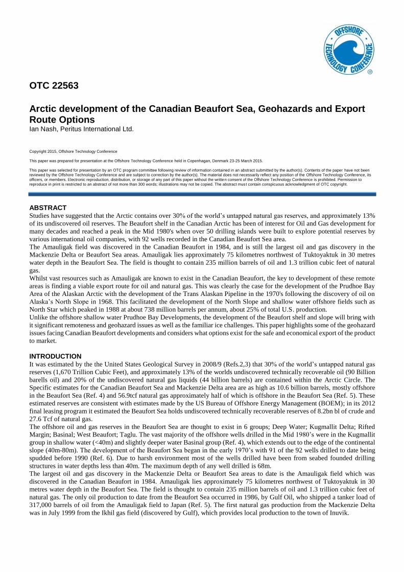
EXPLORATION OF THE CANADIAN BEAUFORT Early Exploration In the 1970’s and 1980’s ninety one offshore wells were drilled in the Beaufort Sea by varous drilling platforms in water depths
up to 68m, with only one well drilled since 1990 in 2005. The distribution of drilling year and water depth for these early wells
is presented in Figure 1. In the Mid 80’s the rapid decline in demand for oil and resulting drop in the world oil price, dramatically
affected the demand to undertake exploration in the Beaufort Sea. The hightened awareness of the implications of hydrocarbon
exploration and production due to spill impacts resulting from the Exxon Valdez disaster in 1989, also contributed to the rapid
decline.
Figure 1 Distribution of Wells Drilled in Beaufort Sea by Year and Water Depth
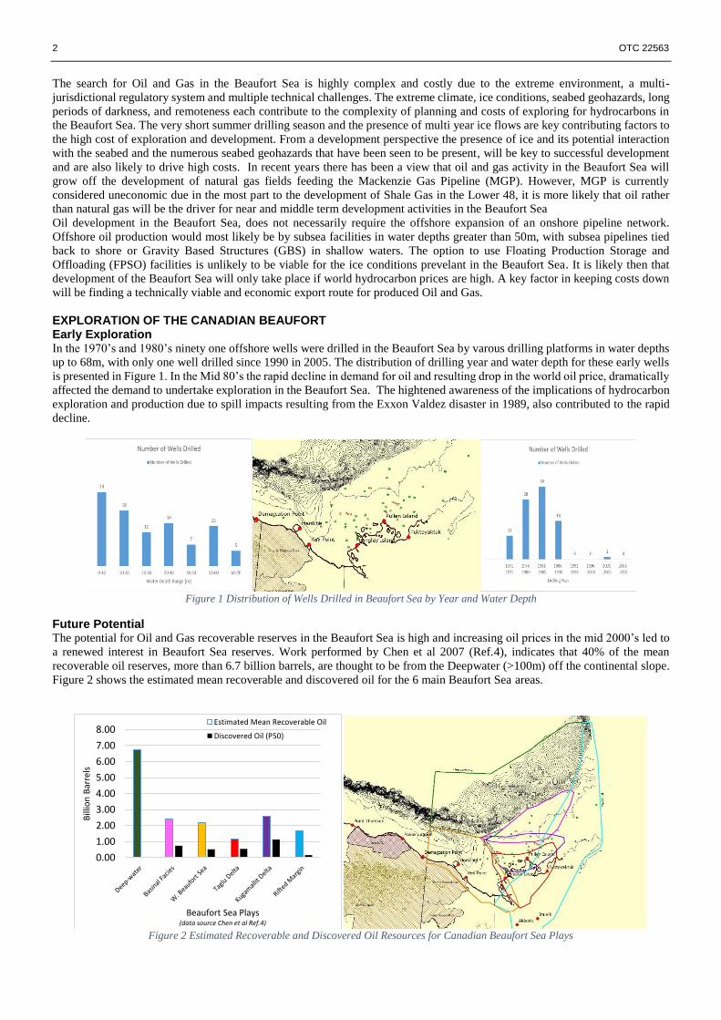
Future Potential The potential for Oil and Gas recoverable reserves in the Beaufort Sea is high and increasing oil prices in the mid 2000’s led to
a renewed interest in Beaufort Sea reserves. Work performed by Chen et al 2007 (Ref.4), indicates that 40% of the mean
recoverable oil reserves, more than 6.7 billion barrels, are thought to be from the Deepwater (>100m) off the continental slope.
Figure 2 shows the estimated mean recoverable and discovered oil for the 6 main Beaufort Sea areas.
Figure 2 Estimated Recoverable and Discovered Oil Resources for Canadian Beaufort Sea Plays
0.00
1.00
2.00
3.00
4.00
5.00
6.00
7.00
8.00
Bill
ion
Bar
rels
Beaufort Sea Plays(data source Chen et al Ref.4)
Estimated Mean Recoverable Oil
Discovered Oil (P50)
OTC 22563 3
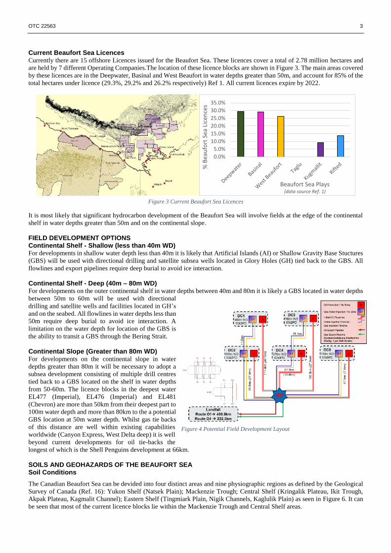
Current Beaufort Sea Licences Currently there are 15 offshore Licences issued for the Beaufort Sea. These licences cover a total of 2.78 million hectares and
are held by 7 different Operating Companies.The location of these licence blocks are shown in Figure 3. The main areas covered
by these licences are in the Deepwater, Basinal and West Beaufort in water depths greater than 50m, and account for 85% of the
total hectares under licence (29.3%, 29.2% and 26.2% respectively) Ref 1. All current licences expire by 2022.
Figure 3 Current Beaufort Sea Licences
It is most likely that significant hydrocarbon development of the Beaufort Sea will involve fields at the edge of the continental
shelf in water depths greater than 50m and on the continental slope.
FIELD DEVELOPMENT OPTIONS Continental Shelf - Shallow (less than 40m WD) For developments in shallow water depth less than 40m it is likely that Artificial Islands (AI) or Shallow Gravity Base Stuctures
(GBS) will be used with directional drilling and satellite subsea wells located in Glory Holes (GH) tied back to the GBS. All
flowlines and export pipelines require deep burial to avoid ice interaction.
Continental Shelf - Deep (40m – 80m WD) For developments on the outer continental shelf in water depths between 40m and 80m it is likely a GBS located in water depths
between 50m to 60m will be used with directional
drilling and satellite wells and facilities located in GH’s
and on the seabed. All flowlines in water depths less than
50m require deep burial to avoid ice interaction. A
limitation on the water depth for location of the GBS is
the ability to transit a GBS through the Bering Strait.
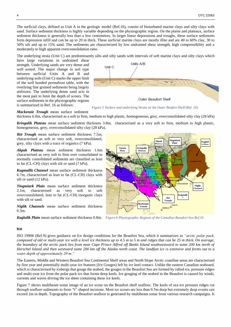
Continental Slope (Greater than 80m WD) For developments on the continental slope in water
depths greater than 80m it will be necessary to adopt a
subsea development consisting of multiple drill centres
tied back to a GBS located on the shelf in water depths
from 50-60m. The licence blocks in the deepest water
EL477 (Imperial), EL476 (Imperial) and EL481
(Chevron) are more than 50km from their deepest part to
100m water depth and more than 80km to the a potential
GBS location at 50m water depth. Whilst gas tie backs
of this distance are well within existing capabilities
worldwide (Canyon Express, West Delta deep) it is well
beyond current developments for oil tie-backs the
longest of which is the Shell Penguins development at 66km.
SOILS AND GEOHAZARDS OF THE BEAUFORT SEA Soil Conditions
The Canadian Beaufort Sea can be devided into four distinct areas and nine physiographic regions as defined by the Geological
Survey of Canada (Ref. 16): Yukon Shelf (Natsek Plain); Mackenzie Trough; Central Shelf (Kringalik Plateau, Ikit Trough,
Akpak Plateau, Kagmalit Channel); Eastern Shelf (Tingmiark Plain, Nigik Channels, Kaglulik Plain) as seen in Figure 6. It can
be seen that most of the current licence blocks lie within the Mackenzie Trough and Central Shelf areas.
0.0%
5.0%
10.0%
15.0%
20.0%
25.0%
30.0%
35.0%
% B
eau
fort
Sea
Lic
ence
s
Beaufort Sea Plays(data source Ref. 1)
Figure 4 Potential Field Development Layout
4 OTC 22563
The surficial clays, defined as Unit A in the geologic model (Ref.16), consist of bioturbated marine clays and silty clays with
sand. Surface sediment thickness is highly variable depending on the physiographic region. On the plains and plateaux, surface
sediment thickness is generally less than a few centimetres. In larger linear depressions and troughs, these surface sediments
form depression infill and can be up to 20 m thick. These surficial marine clays are mostly illite and are 40 to 60% clay, 30 to
50% silt and up to 15% sand. The sediments are characterized by low undrained shear strength, high compressibility and a
moderately to high apparent overconsolidation ratio.
The underlying strata (Unit C) are predominantly silts and silty sands with intervals of soft marine clays and silty clays which
have large variations in undrained shear
strength. Underlying sands are very dense and
well sorted. The major change in soil type
between surficial Units A and B and
underlying soils (Unit C) marks the upper limit
of the well bonded permafrost table, with the
overlying fine grained sediments being largely
unfrozen. The underlying dense sand acts in
the most part to limit the depth of scours. The
surface sediments in the physiographic regions
is summarized in Ref. 16 as follows:
Mackenzie Trough mean surface sediment
thickness 6.0m, characterised as a soft to firm, medium to high plastic, homogeneous, grey, overconsolidated silty clay (28 kPa)
Kringalik Plateau mean surface sediment thickness 3.8m, characterised as a very soft to firm, medium to high plastic,
homogeneous, grey, overconsolidated silty clay (28 kPa).
Ikit Trough mean surface sediment thickness 7.5m,
characterised as soft to very soft, overconsolidated,
grey, silty clays with a trace of organics (7 kPa).
Akpak Plateau mean sediment thickness 1.6m
characterised as very soft to firm over consolidated to
normally consolidated sediments are classified as lean
to fat (CL-CH) clays with silt or sand (7 kPa).
Kugmallit Channel mean surface sediment thickness
6.7m, characterised as lean to fat (CL-CH) clays with
silt or sand (12 kPa).
Tingmiark Plain mean surface sediment thickness
2.1m, characterised as very soft to soft
overconsolidated, lean to fat (CL-CH) inorganic clays
with silt or sand.
Niglik Channels mean surface sediment thickness
0.3m.
Kaglulik Plain mean surface sediment thickness 0.8m.
Ice
ISO 19906 (Ref.9) gives guidance on Ice design conditions for the Beaufort Sea, which it summarizes as “arctic polar pack,
composed of old or multi-year ice with a level ice thickness up to 4.5 m to 5 m and ridges that can be 25 m thick. On average,
the boundary of the arctic pack lies from near Cape Prince Alfred off Banks Island southwestward to some 200 km north of
Herschel Island and then westward some 200 km off the Alaska north coast. The landfast ice is extensive and forms out to a
water depth of approximately 20 m.”
The Eastern, Middle and Western Beaufort Sea Continental Shelf areas and North Slope Arctic coastline areas are characterised
by first year and potentially multi-year ice features (Ice Gouges) left by ice keel contact. Unlike the eastern Canadian seaboard,
which is characterised by icebergs that gouge the seabed, the gouges in the Beaufort Sea are formed by rafted ice, pressure ridges
and multi-year ice from the polar pack ice that forms deep keels. Ice gouging of the seabed in the Beaufort is caused by winds,
currents and waves driving the ice sheet containing these ice keels.
Figure 7 shows multibeam sonar image of an ice scour on the Beaufort shelf seafloor. The keels of sea-ice pressure ridges cut
through seafloor sediments to form ‘V’ shaped incisions. Most ice scours are less than 0.5m deep but extremely deep events can
exceed 2m in depth. Topography of the Beaufort seafloor is generated by multibeam sonar from various research campaigns. It
Mackenzie
Trough
Kringalik
Plateau
Akpak
Plateau
Ikit
Trough
Tingmiark
Plain Kagluli
k Plain
Niglik
Channel
s
Kagmalli
t
Channel
Natsek
Plain
Figure 5 Surface and underlying Strata on the Outer Beufort Shelf (Ref. 16)
Figure 6 Physiographic Regions of the Canadian Beaufort Sea Ref.16

OTC 22563 5
is evident that the seafloor is covered with the tracks of ice scours that range in age from one year to many decades. Older scours
are obliterated by newer events and/or are infilled by sediment over time.
Figure 7 Multi beam Images of Beaufort Shelf Seabed (Ref.a-14, b-14, c-15)
Pingo Like Features (PLF’s) and Mud Volcanoes
Over 1000 Pingo Like Features (PLF’s) and mud volcanoes have been identified across the Beaufort and Yukon shelves, many
of which have not been mapped in detail and their origin is unclear. PLF’s are observed individulally and in groups at various
locations on the flanks of the Mackenzie Trough, on the Central and Eastern Beaufort shelf and upper parts of the slope (see
Figure 8). In 2009 numerous “New” PLF’s were observed at the shelf break near the head of a slump area in offshore blocks
EL491 and EL476. It is currently believed that submarine PLFs fall into five categories (Ref.19) as listed below:
submarine-formed pingos
mud volcanoes
diapirs
relict topography
slump features (along ridge and margin
boundaries)
Gas Vents and Pock Marks
Gas vents and pock marks are observed in the central and
Eastern Beauforf Shelf area. Vents range in size from less
than 1m to more than 20m in diameter and are up to 9m
deep. Pock marks are also observed on the edge of the
MacKenzie trough and on the outer edge of the Beaufort
shelf. One of the most significant examples of gas vents
on the Beaufort shelf is the vent complex in Kugmallit
Bay in 8m water depth at the entrance to Tuktoyuktuk
harbor (Figure 8 Inset).
Gas Hydrates
Gas hydrates are thought to exist both within and beneath the permafrost which lies under the Eastern Beaufort Shelf. They also
exist in water depths greater than 250m on the Beaufort slope. The presence of gas hydrates and potential for liberation of gas
due to subsurface activities needs to be accounted for. Evidence exists of gas hydrate occurrence at the Nerlerk, Koakoak,
Ukalerk and Kopanoar exploration wells where Weaver and Stewart (1982) Ref. 20, established that geothermal conditions are
conducive for gas hydrate stability from approximately 225m to 1500m depth. Most appraisals suggest that up to 80% of the 93
exploration wells drilled to date on the shelf show evidence for sub permafrost gas hydrate occurrences.
Subsea Permafrost
The Beaufort Shelf west of the MacKenzie trough is underlain by subsea permafrost, which is thought to extend offshore to the
edge of the Beaufort Shelf. The depth to the base of the subsea permafrost decreases as the edge of the shelf is approached.
Drilling logs from Nerlerk, Koakoak, Ukalerk and Kopanoar exploration wells (Ref. 20) reported depths of between 925m to
300m below mean sea level.
2009 PLF’s
1979-2007 PLF’s
Gas Vents
Figure 8 PLF’s, Mud Volcanos and Gas vents Observed on Beaufort Shelf
(Ref. 16) inset - Gas Vents Kugmallit Bay

6 OTC 22563
Slope Instability
The stability of the Beaufort Sea continental slope
(water depth greater than 100m) is not well
defined and there is little data on geohazards such
as submarine slides in the upper slope. However
evidence of mass transport events exists at the
shelf break in Blocks EL491 and EL476. This
feature was first located and studied in 1979, but
was not extensively mapped until 2009. The
sediment dislodged in the event covers an area
approximately 25km wide (E-W) and 20km long
(N-S). The vertical headwall is in close proximity
to the 100m isobath at the shelf break, it also
coincides with the hypothesized northern edge of
subsea ice bearing permafrost which may have
played a role in determining the position of the
southern edge of the slide (Ref. 16). It is
interesting to note that there are far fewer PLF’s
and Gas vents in the immediate vicinity of the
headwall as compared with several hundred PLF’s
and Gas Vents that were mapped during the 2009
survey near the shelf break to the east of the slip
feature. The slide is thought to be relatively recent due to its sharp appearance and apparent lack of infill although its age is
unknown.
Regional Seismicity
The whole Mackenzie valley is associated with
seismic events onshore. This seismicity extends
offshore into the MacKenzie fold – thrust belt.
Figure 10 shows recorded seismic events location
and magnitude in the Beaufort Shelf area east and
west of the Mackenzie Trough as extracted from
the National Earthquake Database (NEDB) since
1985. (Ref. 21). Up to magnitude 6 have been
recorded in the area with most events being
between magnitudes 3 to 5. Design of the pipelines
and flowlines must take account of this seismicity,
especially with respect to slope stability as
evidence of slope failures on the shelf break within
blocks EL491 and EL476 (Figure 9). It is clear that
slope stability may be an issue even at relatively
shallow slopes angles present on the Beaufort
slope.
Pipeline Burial
Generally, pipelines and flowlines cannot be shown to have the capacity to survive direct contact with ice features in the Beaufort
Sea area. Pipelines and flowlines installed in the Beaufort Sea area should be trenched to a depth below the bottom of the design
ice gouge incision depth. The amount of additional trench depth required below the design ice gouge incision depth is based on
the amount of flowline movement caused by the sub-gouge soil displacement beneath the keel of the ice features. Depending on
the flowline depth below the ice keel, this sub-gouge soil displacement can be sufficient to bring the flowlines beyond their
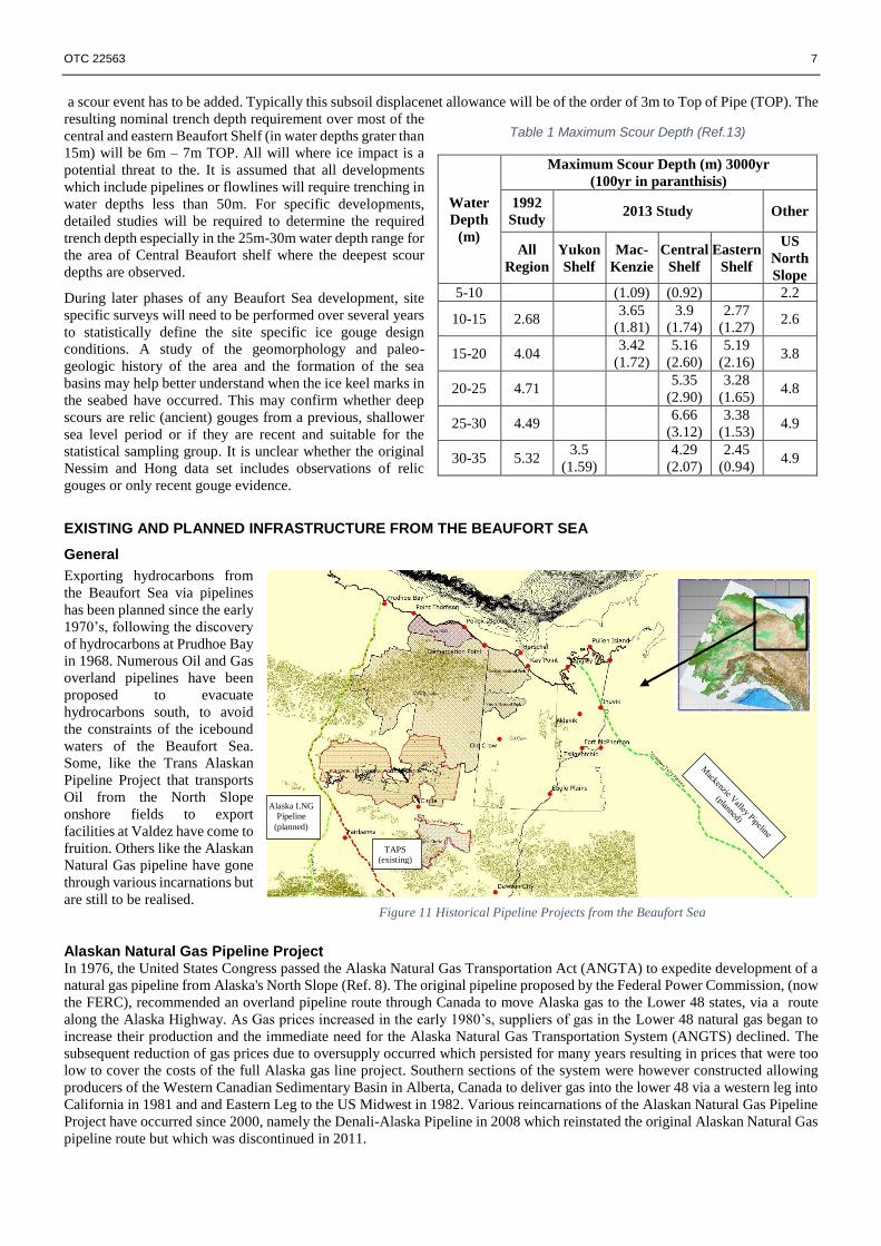
design bending strain limits. Adianto and Hong statistical data analysis on new scour characteristics in the Canadian Beaufort
(Ref. 12) as derived from the 1992 Nessim and Hong study (Ref. 13) gives guidance on maximum scour depth in various areas
of the Beaufort Sea as presented in Table 1.
It is clear then that offshore pipelines in arctic Beaufort Sea area can be subject to damage from floating ice keels if they are not
buried sufficiently deeply. For the purposes of initial studies for Beaufort developments, it is considered that the pipelines or
flowlines should be able to accommodate a 100year ice scour event without any damage or effect on operations. Additionally it
is assumed that the pipelines or flowlines should survive (potentially with damage) a 3000year event. For the Central Shelf area
where most of the current licence blocks are located, the maximum scour depth for a 100yr event is 3.12m and 300yrs survival
event is 6.6m. To meet the 100yr “No Damge” limit state a sub soil displacement clearance to allow for subsoil movement under
Figure 9 Slope instability Shelf Break in Blocks EL491 and EL476 (Ref.#)
5.0-5.9
4.0-4.9
3.0-3.9
2.0-2.9
Slide Headwall
Figure 10 Seismicity Record (Magnitude)
OTC 22563 7
a scour event has to be added. Typically this subsoil displacenet allowance will be of the order of 3m to Top of Pipe (TOP). The
resulting nominal trench depth requirement over most of the
central and eastern Beaufort Shelf (in water depths grater than
15m) will be 6m – 7m TOP. All will where ice impact is a
potential threat to the. It is assumed that all developments
which include pipelines or flowlines will require trenching in
water depths less than 50m. For specific developments,
detailed studies will be required to determine the required
trench depth especially in the 25m-30m water depth range for
the area of Central Beaufort shelf where the deepest scour
depths are observed.
During later phases of any Beaufort Sea development, site
specific surveys will need to be performed over several years
to statistically define the site specific ice gouge design
conditions. A study of the geomorphology and paleo-
geologic history of the area and the formation of the sea
basins may help better understand when the ice keel marks in
the seabed have occurred. This may confirm whether deep
scours are relic (ancient) gouges from a previous, shallower
sea level period or if they are recent and suitable for the
statistical sampling group. It is unclear whether the original
Nessim and Hong data set includes observations of relic
gouges or only recent gouge evidence.
EXISTING AND PLANNED INFRASTRUCTURE FROM THE BEAUFORT SEA
General Exporting hydrocarbons from
the Beaufort Sea via pipelines
has been planned since the early
1970’s, following the discovery
of hydrocarbons at Prudhoe Bay
in 1968. Numerous Oil and Gas
overland pipelines have been
proposed to evacuate
hydrocarbons south, to avoid
the constraints of the icebound
waters of the Beaufort Sea.
Some, like the Trans Alaskan
Pipeline Project that transports
Oil from the North Slope
onshore fields to export
facilities at Valdez have come to
fruition. Others like the Alaskan
Natural Gas pipeline have gone
through various incarnations but
are still to be realised.
Alaskan Natural Gas Pipeline Project In 1976, the United States Congress passed the Alaska Natural Gas Transportation Act (ANGTA) to expedite development of a
natural gas pipeline from Alaska's North Slope (Ref. 8). The original pipeline proposed by the Federal Power Commission, (now
the FERC), recommended an overland pipeline route through Canada to move Alaska gas to the Lower 48 states, via a route
along the Alaska Highway. As Gas prices increased in the early 1980’s, suppliers of gas in the Lower 48 natural gas began to
increase their production and the immediate need for the Alaska Natural Gas Transportation System (ANGTS) declined. The
subsequent reduction of gas prices due to oversupply occurred which persisted for many years resulting in prices that were too
low to cover the costs of the full Alaska gas line project. Southern sections of the system were however constructed allowing
producers of the Western Canadian Sedimentary Basin in Alberta, Canada to deliver gas into the lower 48 via a western leg into
California in 1981 and and Eastern Leg to the US Midwest in 1982. Various reincarnations of the Alaskan Natural Gas Pipeline
Project have occurred since 2000, namely the Denali-Alaska Pipeline in 2008 which reinstated the original Alaskan Natural Gas
pipeline route but which was discontinued in 2011.
Table 1 Maximum Scour Depth (Ref.13)
Water
Depth
(m)
Maximum Scour Depth (m) 3000yr
(100yr in paranthisis)
1992
Study 2013 Study Other
All
Region
Yukon
Shelf
Mac-
Kenzie
Central
Shelf
Eastern
Shelf
US
North
Slope
5-10 (1.09) (0.92) 2.2
10-15 2.68 3.65
(1.81)
3.9
(1.74)
2.77
(1.27) 2.6
15-20 4.04 3.42
(1.72)
5.16
(2.60)
5.19
(2.16) 3.8
20-25 4.71 5.35
(2.90)
3.28
(1.65) 4.8
25-30 4.49 6.66
(3.12)
3.38
(1.53) 4.9
30-35 5.32 3.5
(1.59)
4.29
(2.07)
2.45
(0.94) 4.9
Figure 11 Historical Pipeline Projects from the Beaufort Sea
Alaska LNG
Pipeline
(planned)
TAPS
(existing)
8 OTC 22563
Trans Alaskan Pipeline The Trans-Alaska Pipeline System (TAPS) includes the trans-Alaska crude-oil pipeline, 11 pump stations, several hundred miles
of feeder pipelines, and the Valdez Marine Terminal. The pipeline runs 800 miles (1,287 km) of 48 inches (122 cm) diameter
from Prudhoe Bay, to Valdez, Alaska. The pipeline was built between 1974 and 1977 after the 1973 oil crisis caused a sharp rise
in oil prices in the United States. This rise made exploration of the Prudhoe Bay oil field economically feasible. In 2010, the
pipeline has shipped almost 16 billion barrels (2.5×10⁹ m3) of oil.
Mackenzie Pipeline Project The Mackenzie Valley Pipeline is a proposed project to transport natural gas from the Beaufort Sea through Canada's Northwest
Territories to tie into gas pipelines in northern Alberta. The project was first proposed in the early 1970s, but was scrapped
following an inquiry conducted by Justice Thomas Berger. The project was resurrected in 2004. The current Mackenzie Gas
Project proposes to build a 1,200km pipeline system along the Mackenzie Valley. It would link northern natural gas producing
wells to southern markets. The main Mackenzie Valley Pipeline would supply 1.2 billion cubic feet per day of natural gas and
connect to an existing natural gas pipeline system in northwestern Alberta. The Mackenzie Valley Pipeline was shelved in 2013
as being uneconomical primarily due to Shale gas development in USA.
Alaska LNG ExxonMobil, ConnocoPhillips, Transcanada and the State of Alaska have proposed a 42”, 1,300km pipeline from Alaska North
Slope to an LNG liquefaction facility and shipping terminal at Nikiski on the Cook Inlet. This pipeline will initiate in Point
Thompson with a feeder pipeline from the Point Thompson Gas Fields to Prudhoe Bay where it will be joined by gas from the
North Slope developments and be conditioned to remove CO2 and compressed before entering the Main 42” pipeline to Nikiski.
The pipeline will follow the route of the Transalaskan Pipeline from Prudhoe Bay to Livekgodo 86km North East of Fairbanks
then head due south via Cantwell and Trapper Creek to Beluga where it will cross the Cook Inlet to the LNG facilities at Nikiski
(Ref.7) The project is currently undergoing pre-FEED engineering which is scheduled for completion in early 2016. On 21st
November 2014 the US Department of Energy granted authority to Alaska LNG for exports to countries covered by free trade
agreements with the United States.
OFFSHORE EXPORT PIPELINES FROM THE BEAUFORT SEA General
This paper reviews the routing options and issues for Export Pipelines from a notional GBS location on the central Beaufort
Shelf. The ultimate destination for oil and gas exports will be different. The most likely destination for Oil exports will be the
tanker export terminal at Valdez Alaska. The desitination for Gas exports would, until recently, have been the US Lower 48 via
the proposed Mackenzie valley Pipeline, however since this pipeline has now been shelved due to poor economics the most
likely desitination for Beaufort Sea Gas will be the proposed new LNG facility at Nikiski on the Cook Inlet.
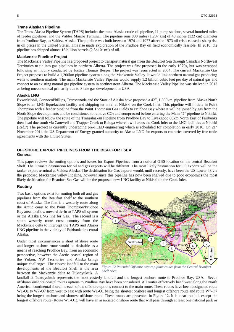
Routing
Two basic options exist for routing both oil and gas
pipelines from the Beaufort shelf to the southern
coast of Alaska. The first is a westerly route along
the Arctic coast to the Point Thompson/Prudhoe
Bay area, to allow onward tie-in to TAPS oil system
or the Alaska LNG line for Gas. The second is a
south westerly route cross country from the
Mackenzie delta to intercept the TAPS and Alaska
LNG pipeline in the vicinity of Fairbanks in central
Alaska.
Under most circumstances a short offshore route
and longer onshore route would be desirable as a
means of reaching Prudhoe Bay, from an economic
perspective, however the Arctic coastal region of
the Yukon, NW Territories and Alaska brings
unique challenges. The closest landfall to the main
developments of the Beaufort Shelf is the area
between the Mackenzie delta to Tuktoyuktuk. A
landfall at Tuktoyuktuk represents the most easterly landfall and the longest onshore route to Prudhoe Bay, USA. Seven
offshore/ onshore coastal routes options to Prudhoe Bay have been considered. All routes effectively head west along the North
American continental shoreline each of the offshore options connect to the main route. These routes have been designated route
W1-O1 to W7-O7 from west to east with route W1-O1 being the shortest onshore and longest offshore route and route W7-O7
being the longest onshore and shortest offshore route. These routes are presented in Figure 12. It is clear that all, except the
longest offshore route (Route W1-O1), will have an associated onshore route that will pass through at least one national park or
Figure 12 Potential Offshore export pipline routes from the Central Beaufort
Shelf Area
1
2
3
4
5 6
7 W Routes
S R
oute
s
OTC 22563 9
wildlife reserve that are located along the coastline in both Canada and USA. In order to pass west to TAPS without crossing
these environmentally sensitive areas it would be necessary to propose a route that passes many hundreds of kilometres inland.
A route that passes so far south has a logical tie-in point to the TAPS system at Fairbanks, Alaska, rather than Prudhoe Bay. A
second routing south west to Fairbanks has therefore been considered for the three most easterly route offshore options that make
landfall in Canada. These routes are designated S5-O5, S6-O6 and S7-O7 (Figure 12).
Offshore Route options Summary The key features of the offshore pipeline routes are presented in Table 2. It is clear that the shortest routes east of the MacKenzie
trough on the eastern Beaufort shelf (routes O6 and O7) have significant portions of the route in water depths less than 50m and
as such will require a considerable amount of intervention
to ensure protection against Ice scour interaction. The
routes that landfall immediately west of the MacKenzie
Trough (routes O4 and O5) utilise the MacKenzie Trough
to route the pipeline in deep water close to the landfall and
therefore minimise the intervention required in water
depths less than 50m. The three longest routes (routes O1,
O2 and O3) cross the MacKenzie Trough in 300m water
depth and rise back onto the Yukon Shelf and follow the
55m contour before landfalling in the USA, all have
significant lengths in water depths less than 50m as they
approach the landfalls. The longest offshore route (route
O1) landfalls at Point Thompson nearly 480km west of the central Beaufort shelf. Purely from an offshore pipeline perspective
the best routes are routes O4 and O5 due to their relatively short length and the much shorter length of route requiring
intervention.
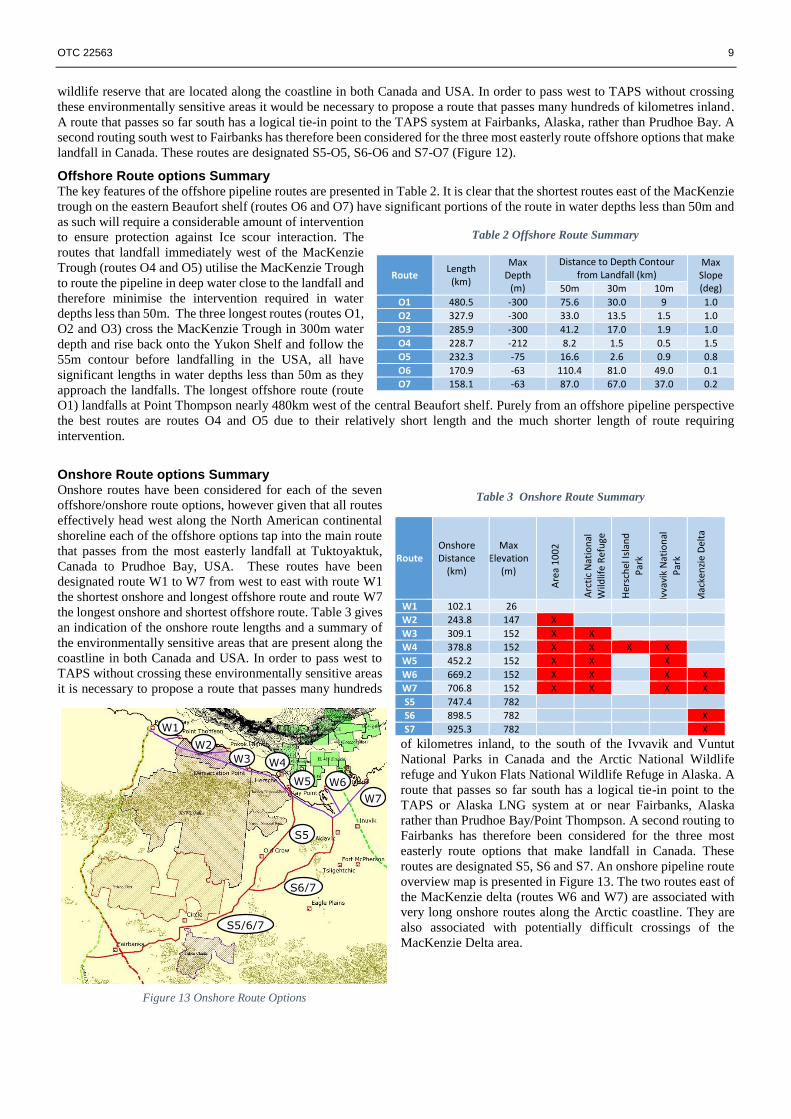
Onshore Route options Summary Onshore routes have been considered for each of the seven
offshore/onshore route options, however given that all routes
effectively head west along the North American continental
shoreline each of the offshore options tap into the main route
that passes from the most easterly landfall at Tuktoyaktuk,
Canada to Prudhoe Bay, USA. These routes have been
designated route W1 to W7 from west to east with route W1
the shortest onshore and longest offshore route and route W7
the longest onshore and shortest offshore route. Table 3 gives
an indication of the onshore route lengths and a summary of
the environmentally sensitive areas that are present along the
coastline in both Canada and USA. In order to pass west to
TAPS without crossing these environmentally sensitive areas
it is necessary to propose a route that passes many hundreds
of kilometres inland, to the south of the Ivvavik and Vuntut
National Parks in Canada and the Arctic National Wildlife
refuge and Yukon Flats National Wildlife Refuge in Alaska. A
route that passes so far south has a logical tie-in point to the
TAPS or Alaska LNG system at or near Fairbanks, Alaska
rather than Prudhoe Bay/Point Thompson. A second routing to
Fairbanks has therefore been considered for the three most
easterly route options that make landfall in Canada. These
routes are designated S5, S6 and S7. An onshore pipeline route
overview map is presented in Figure 13. The two routes east of
the MacKenzie delta (routes W6 and W7) are associated with
very long onshore routes along the Arctic coastline. They are
also associated with potentially difficult crossings of the
MacKenzie Delta area.
Table 2 Offshore Route Summary
Route Length (km)
Max Depth
(m)
Distance to Depth Contour from Landfall (km)
Max Slope (deg) 50m 30m 10m
O1 480.5 -300 75.6 30.0 9 1.0
O2 327.9 -300 33.0 13.5 1.5 1.0
O3 285.9 -300 41.2 17.0 1.9 1.0
O4 228.7 -212 8.2 1.5 0.5 1.5
O5 232.3 -75 16.6 2.6 0.9 0.8
O6 170.9 -63 110.4 81.0 49.0 0.1
O7 158.1 -63 87.0 67.0 37.0 0.2
Table 3 Onshore Route Summary
Route Onshore Distance
(km)
Max Elevation
(m)
Are
a 1
00
2
Arc
tic
Nat
ion
al
Wild
life
Ref
uge
Her
sch
el Is
lan
d
Par
k
Ivva
vik
Nat
ion
al
Par
k
Mac
ken
zie
Del
ta
W1 102.1 26
W2 243.8 147 X
W3 309.1 152 X X
W4 378.8 152 X X X X
W5 452.2 152 X X X
W6 669.2 152 X X X X
W7 706.8 152 X X X X
S5 747.4 782
S6 898.5 782 X
S7 925.3 782 X
Figure 13 Onshore Route Options
W1
W2
W3 W4
W5 W6
S5
S6/7
S5/6/7
W7
10 OTC 22563
Export Route Summary
It is necessary to take both offshore and onshore routes into
account before selecting the optimum route. Table 4
combines the offshore and onshore routes. Based on the
combined length of route alone, combined route O2-W2 is
preferred. This route landfalls at Pokok Lagoon in Area 1002
of the ANWR and also has the least intervention requirement
in water depths of less than 50m for the three routes
landfalling in the USA. This route is not thought to be viable
for environmental and political reason, although recent
debates on opening up Area 1002 of ANWR to Oil and Gas
drilling may change the vability of an onshore pipeline
passing through this area.
Route O1-W1, landfalling at Point Thompson, USA is likely
to be the best route for exporting by the westerly coastal route
to Prudhoe Bay as it is the only route that avoids all Canadian and USA state and national parks. This route has the disadvantage
however of having a long approach to the landfall in water depths less than 50 water depth.
Of the export routes that landfall in Canada, combined route O5-S5 is likely to be the best route for exporting by the southerly
route to Fairbanks. This route landfalls at Kay Point just to the east of the Ivvavik National Park and avoids all Canadian and
USA state and national parks, wilderness areas and other restricted environmental areas. It also avoids the need to cross the
Mackenzie D0elta region and utilises the Mackenzie Trough to route the pipeline in deeper water which limits the length of
approach to the landfall in water depths less than 50m to 16km.
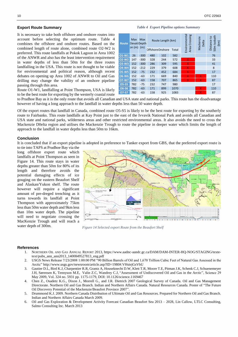
Conclusion It is concluded that if an export pipeline is adopted in preference to Tanker export from GBS, that the preferred export route is
to tie into TAPS at Prudhoe Bay via the
long offshore export route which
landfalls at Point Thompson as seen in
Figure 14. This route stays in water
depths greater than 50m for 80% of its
length and therefore avoids the
potential damaging effects of ice
gouging on the eastern Beaufort Shelf
and Alaskan/Yukon shelf. The route
however will require a significant
amount of pre-dreged trenching as it
turns towards its landfall at Point
Thompson with approximately 75km
less than 50m water depth and 9km less
than 10m water depth. The pipeline
will need to negotiate crossing the
MacKenzie Trough and will reach a
water depth of 300m.
References 1. NORTHERN OIL AND GAS ANNUAL REPORT 2013, https://www.aadnc-aandc.gc.ca/DAM/DAM-INTER-HQ-NOG/STAGING/texte-
text/pubs_ann_ann2013_1400849527813_eng.pdf
2. USGS News Release 7/23/2008 1:00:00 PM “90 Billion Barrels of Oil and 1,670 Trillion Cubic Feet of Natural Gas Assessed in the
Arctic” http://www.usgs.gov/newsroom/article.asp?ID=1980#.VHsiejGsVbU
3. Gautier D.L, Bird K.J, Charpentier R.R, Grantz A, Houseknecht D.W, Klett T.R, Moore T.E, Pitman J.K, Schenk C.J, Schuenemeyer
J.H, Sørensen K, Tennyson M.E, Valin Z.C, Wandrey C.J, “Assessment of Undiscovered Oil and Gas in the Arctic”, Science 29
May 2009, Vol. 324 no. 5931 pp. 1175-1179, DOI: 10.1126/science.1169467
4. Chen Z., Osadetz K.G., Dixon J., Morrell G., and J.R. Dietrich 2007 Geological Survey of Canada. Oil and Gas Management
Directorate. Northern Oil and Gas Branch. Indian and Northern Affairs Canada. Natural Resources Canada. Poster of “The Future
Oil Discovery Potential of the Mackenzie/Beaufort Province 2007”.
5. Drummond K.J. 2009. Northern Canada Distribution of Ultimate Oil and Gas Resources. Prepared for Northern Oil and Gas Branch.
Indian and Northern Affairs Canada March 2009.
6. Oil and Gas Exploration & Development Activity Forecast Canadian Beaufort Sea 2013 – 2028, Lin Callow, LTLC Consulting,
Salmo Consulting Inc. March 2013
Table 4 Export Pipeline options Summary
Route Max
Elevation (m)
Max Depth
(m)
Route Length (km)
Envi
ron
men
tal
Are
a C
ross
ing
Mac
ken
zie
D
elta
Dis
tan
ce t
o
50
m Is
ob
ath
(km
)
Offshore Onshore Total
O1-W1 26 -300 480 102 582 76
O2-W2 147 -300 328 244 572 X 33
O3-W3 152 -300 286 309 595 X 41
O4-W4 152 -212 229 379 608 X 8
O5-W5 152 -75 232 452 684 X 17
O6-W6 152 -63 171 669 840 X X 110
O7-W7 152 -63 158 707 865 X X 87
O5-S5 782 -75 232 747 980 17
O6-S6 782 -63 171 899 1070 X 110
O7-S7 782 -63 158 925 1083 X 87
W7
Figure 14 Selected export Route from the Beaufort Shelf
OTC 22563 11
7. Alaska LNG Project http://www.arcticgas.gov/alaska-lng-project
8. Alaska natural gas pipeline project history http://www.arcticgas.gov/Alaska-Natural-Gas-Pipeline-Project-History
9. International Organization for Standardization (ISO), “Petroleum and natural gas industries Arctic offshore structures”, International
Standard ISO 19906, ISO, 2010.
10. Beaufort Shelf Multibeam Fly Through – Ice Scour, http://tekmap.ns.ca
11. Beaufort Sea Regional Strategic Plan
12. Adianto, R. and Hong, H. 2013. Statistical Data Analysis of New Scour Characteristics in the Canadian Beaufort Sea. C-FER
Technologies, ,Ice Scour and Arctic Marine Pipeline Workshop 2013, St. John’s, NL, May 21 - 22, 2013.
13. Nessim, M.A. and Hong, H. 1992. Statistical Data Analysis of New Scour Characteristics in the Beaufort Sea. Draft report submitted
to Energy, Mines and Resources, Bedford Institute of Oceanography, C-FER Project 92-03, May.
14. Natural Resources Canada Marine Geological Research in the Canadian Beaufort Sea, http://www.bsstrpa.ca/NaturalResources.htm
15. Beaufort Shelf Multibeam Fly Through – Ice Scour, http://www.tekmap.ns.ca
16. 2010 State of Knowledge: Beaufort Sea Seabed Geohazards Associated with Offshore Hydrocarbon Development, Geological
Survey of Canada Open File
17. OCS Study MMS 2007-004. Final Report Review of Geological/Geophysical Data and Core Analysis to Determine Archaeological
Potential of Buried Landforms, Beaufort Sea Shelf, Alaska, January 2007. Northern Land Use Research, Inc., URS Corporation, and
GeoArch Alaska
18. Oil and Gas Exploration & Development Activity Forecast Canadian Beaufort Sea 2013 – 2028, Lin Callow, LTLC Consulting &
Salmo Consulting Inc. March 2013
19. Blasco, K., White, M., Campbell, P., Oickle, E., Burke, R., and Blasco, S.M., 2006. 2004 Beaufort Sea Mapping Program –
Geological Analysis. Draft Report prepared by Canadian Seabed Research Ltd. for the Geological Survey of Canada.
20. Weaver, J.S., and Stewart, J.M., 1982, In situ hydrates under the Beaufort Sea Shelf, Proceedings, Fourth Canadian Permafrost
Conference: Ottawa, National Research Council of Canada.
21. Natural Resources Canada, Earthquake Database. http://www.earthquakescanada.nrcan.gc.ca/stndon/NEDB-BNDS/bull-eng.php
Top Related
Copyright © 2022 FDOKUMEN

