


Bahasa
Halaman
Hukum


BY: ER. ANKU JAISWAL
COMPUTER NETWORK AND SECURITY
(According to IOE syllabus)
PREPARED BY:
ER.ANKU JAISWAL
LECTURER
PULCHOWK CAMPUS, IOE

BY: ER. ANKU JAISWAL
SYLLABUS
1. Introduction to Computer Network (5 hours)
1.1 Uses of Computer Network
1.2 Networking model client/server, p2p, active network
1.3 Protocols and Standards
1.4 OSI model and TCP/IP model
1.5 Comparison of OSI and TCP/IP model
1.6 Example network: The Internet, X.25, Frame Relay, Ethernet, VoIP, NGN and MPLS, xDSL.
2. Physical Layer (5 hours)
2.1 Network monitoring: delay, latency, throughput
2.2 Transmission media: Twisted pair, Coaxial, Fiber optic, Line-of-site, Satellite
2.3 Multiplexing, Circuit switching, Packet switching, VC Switching, Telecommunication
switching system (Networking of Telephone exchanges)
2.4 ISDN: Architecture, Interface, and Signaling
3. Data Link Layer (5 hours)
3.1 Functions of Data link layer
3.2 Framing
3.3 Error Detection and Corrections,
3.4 Flow Control
3.5 Examples of Data Link Protocol, HDLC, PPP
3.6 The Medium Access Sub-layer
3.7 The channel allocation problem
3.8 Multiple Access Protocols
3.9 Ethernet,
3.10 Networks: FDDI, ALOHA, VLAN, CSMA/CD, IEEE 802.3(Ethernet), 802.4(Token
Bus), 802.5(Token Ring), and 802.1(Wireless LAN).
4. Network Layer (9 hours)
4.1 Internetworking &devices: Repeaters, Hubs, Bridges, Switches, Router, Gateway
4.2 Addressing: Internet address, classful address
4.3 Subnetting
4.4 Routing: techniques, static vs. dynamic routing , routing table for classful address
4.5 Routing Protocols: RIP, OSPF, BGP, Unicast and multicast routing protocols
4.6 Routing algorithms: shortest path algorithm, flooding, distance vector routing, link state routing;
Protocols: ARP, RARP, IP, ICMP
5. Transport Layer (5 hours)
5.1 The transport service: Services provided to the upper layers
5.2 Transport protocols: UDP, TCP
5.3 Port and Socket
5.4 Connection establishment, Connection release
5.5 Flow control & buffering
5.6 Multiplexing & de-multiplexing
5.7 Congestion control algorithm: Token Bucket and Leaky Bucket Transport Layer
6. Application Layer (5 hours)
6.1 Web: HTTP & HTTPS

BY: ER. ANKU JAISWAL
6.2 File Transfer: FTP, PuTTY, WinSCP
6.3 Electronic Mail: SMTP, POP3, IMAP
6.4 DNS
6.5 P2PApplications
6.6 Socket Programming
6.7 Application server concept: proxy caching, Web/Mail/DNS server optimization
6.8 Concept of traffic analyzer: MRTG, PRTG, SNMP, Packet tracer, Wireshark.
7. Introduction to IPV6 (4 hours)
7.1 IPv6- Advantages
7.2 Packet formats
7.3 Extension headers
7.4 Transition from IPv4 to IPv6: Dual stack, Tunneling, Header Translation
7.5 Multicasting
8. Network Security (7 hours)
8.1 Properties of secure communication
8.2 Principles of cryptography: Symmetric Key and Public Key
8.3 RSA Algorithm,
8.4 Digital Signatures
8.5 Securing e-mail (PGP)
8.6 Securing TCP connections (SSL)
8.7 Network layer security (IPsec, VPN)
8.8 Securing wireless LANs (WEP)
8.9 Firewalls: Application Gateway and Packet Filtering, and IDS
Practical:
1. Network wiring and LAN setup
2. Router Basic Configuration
3. Static and Dynamic Routing
4. Creating VLAN
5. Router access-list configuration
6. Basic Network setup on Linux
7. Setup of Web Server, DNS Server, DHCP Server
8. Virtualizations

BY: ER. ANKU JAISWAL
CHAPTER 1 - INTRODUCTION TO COMPUTER NETWORK
1. INTRODUCTION
A computer network is a group of computer systems and other computing hardware devices that are linked
together through communication channels to facilitate communication and resource-sharing among a wide
range of users. Networks are commonly categorized based on their characteristics.
Application of Networks
• Facilitate communication via email, video conferencing, instant messaging, etc.
• Enable multiple users to share a single hardware device like a printer or scanner
• Enable file sharing across the network
• Allow for the sharing of software or operating programs on remote systems
• Make information easier to access and maintain among network users
There are many types of networks, including:
• Local Area Networks (LAN)
• Personal Area Networks (PAN)
• Home Area Networks (HAN)
• Wide Area Networks (WAN)
• Campus Networks
• Metropolitan Area Networks (MAN)
• Enterprise Private Networks
• Internetworks
• Backbone Networks (BBN)
• Global Area Networks (GAN)
• The Internet
LAN
This is the abbreviation for Local Area Network which is when there are multiple computers and
peripheral devices connected to a campus or in an office or other room. They are sharing a common
connection that has 10-100 Mbps data transmission speed and are connected by Ethernet cables,
usually running on high-speed internet connection. LAN computer terminals may be physically
connected using cables or setup wireless, thus called WLAN. LAN is less expensive than WAN or
MAN.
WAN
This is the abbreviation for Wide Area Network and is the biggest network which can interconnect
networks around the world. Companies such as Microsoft or other worldwide organizations utilize
WAN connection between their various branches by communicating via microwave satellites.
BY: ER. ANKU JAISWAL
WAN has a data transmission speed of 256Kbps to 2Mbps, offering a faster speed than LAN or
MAN. WAN is used to connect LANs that are not in the same area and is more expensive than LAN
or MAN.
MAN
MAN is the abbreviation for Metropolitan Area Network and bigger than LAN network. It connects
computer users that are in a specific geographical area. An example of MAN is your cable television
or a large university.
MAN’s data transmission speed is 5-10Mbps, which is faster and more expensive than LAN but
slower and smaller than WAN.
1.1. USES OF COMPUTER NETWORK
The computer networks are playing an important role in providing services to large organizations as
well as to the individual common man.
Service Provided by the Network for Companies:
• Many organizations have a large number of computers in operation. These computers may be within
the same building, campus, city or different cities.
• Even though the computers are located in different locations, the organizations want to keep track
of inventories, monitor productivity, do the ordering and billing etc.
• The computer networks are useful to the organizations in the following ways:
1. Resource sharing.
2. for providing high reliability.
3. To save money.
4. It can provide a powerful communication medium.
The computer networks offer the following services to an individual person:
1. Access to remote information
2. Person to person communication
3. Interactive entertainment.
Access to remote information:
Access to remote information involves interaction· between a person and a remote database. Access
to remote information comes in many forms like:
(i) Home shopping, paying telephone, electricity bills, e-banking, on line share market etc.
(ii) Newspaper is. On-line and is personalized, digital library consisting of books, magazines,
scientific journals etc.
(iii)World Wide Web which contains information. About the arts, business, cooking, government,
health, history, hobbies, recreation, science, sports etc.

BY: ER. ANKU JAISWAL
Interactive entertainment:
Interactive entertainment includes:
(i) Multi person real-time simulation games.
(ii) Video on demand.
(iii) Participation in live TV programs likes quiz, contest, discussions etc.
In short, the ability to merge information, communication and entertainment will surely give rise to
a massive new industry based on computer networking.
1.2. NETWORKING MODEL
a) Client-Server Model
Client-server architecture (client/server) is a network architecture in which each computer or process
on the network is either a client or a server. Servers are powerful computers or processes dedicated
to managing disk drives (file servers), printers (print servers), or network traffic (network servers).
Clients are PCs or workstations on which users run applications. Clients rely on servers for resources,
such as files, devices, and even processing power.
Fig: Client-Server model

BY: ER. ANKU JAISWAL
b). P2P model
Peer-to-peer (P2P) is a decentralized communications model in which each party has the same
capabilities and either party can initiate a communication session. Unlike the client/server model, in
which the client makes a service request and the server fulfills the request, the P2P network model
allows each node to function as both a client and server. In its simplest form, a peer-to-peer (P2P)
network is created when two or more PCs are connected and share resources without going through
a separate server computer. Most P2P programs are focused on media sharing.
c) Active network
An active network is a network in which the nodes are programmed to perform custom operations on
the messages that pass through the node. For example, a node could be programmed or customized
to handle packets on an individual user basis or to handle multicast packets differently than other
packets. Active network approaches are expected to be especially important in networks of mobile
users. "Smart packets" use a special self-describing language that allows new kinds of information to
be carried within a packet and operated on by a node.
1.3. PROTOCOLS AND STANDARDS
A protocol is the special set of rules that end points in a telecommunication connection use when
they communicate. Protocols specify interactions between the communicating entities. Protocols
exist at several levels in a telecommunication connection. For example, there are protocols for the
data interchange at the hardware device level and protocols for data interchange at the application
program level. In the standard model known as Open Systems Interconnection (OSI), there are one
or more protocols at each layer in the telecommunication exchange that both ends of the exchange
must recognize and observe. Protocols are often described in an industry or international standard.
Standard is a common set of rules.

BY: ER. ANKU JAISWAL
NEED OF LAYERED ARCHITECTURE IN COMPUTER NETWORK
• It simplifies the design process as the functions of each layers and their interactions are well
defined.
• The layered architecture provides flexibility to modify and develop network services.
• The number of layers, name of layers and the tasks assigned to them may change from
network to network. But for all the networks, always the lower layer offers certain services
to its upper layer.
• The concept of layered architecture redefines the way of convincing networks. This leads to
a considerable cost savings and managerial benefits.
• Addition of new services and management of network infrastructure become easy.
DESIGN ISSUE OF LAYERED ARCHITECTURE IN COMPUTER NETWORK
There might be a negative impact on the performance as we have the extra overhead of passing through
layers instead of calling a component directly.
Development of user-intensive applications can sometime take longer if the layering prevents the use of
user interface components that directly interact with the database.
The use of layers helps to control and encapsulate the complexity of large applications, but adds complexity
to simple applications.
Changes to lower level interfaces tend to percolate to higher levels, especially if the relaxed layered
approach is used.
1.4. OSI MODEL AND TCP/IP MODEL
There are many users who use computer network and are located all over the world. To ensure national and
worldwide data communication ISO (ISO stands for International Organization of Standardization.) developed
this model. This is called a model for open system interconnection (OSI) and is normally called as OSI
model.OSI model architecture consists of seven layers.

BY: ER. ANKU JAISWAL
Layer 1: The Physical Layer:
1. It is the lowest layer of the OSI Model.
2. It activates, maintains and deactivates the physical connection.
3. It is responsible for transmission and reception of the unstructured raw data over network.
4. Voltages and data rates needed for transmission is defined in the physical layer.
5. It converts the digital/analog bits into electrical signal or optical signals.
6. Data encoding is also done in this layer.
Layer 2: Data Link Layer:
1. Data link layer synchronizes the information which is to be transmitted over the physical layer.
2. The main function of this layer is to make sure data transfer is error free from one node to
another, over the physical layer.
3. Transmitting and receiving data frames sequentially is managed by this layer.
4. This layer sends and expects acknowledgements for frames received and sent respectively.
Resending of non-acknowledgement received frames is also handled by this layer.
5. This layer establishes a logical layer between two nodes and also manages the Frame traffic

BY: ER. ANKU JAISWAL
control over the network. It signals the transmitting node to stop, when the frame buffers are
full.
Layer 3: The Network Layer:
1. It routes the signal through different channels from one node to other.
2. It acts as a network controller. It manages the Subnet traffic.
3. It decides by which route data should take.
4. It divides the outgoing messages into packets and assembles the incoming packets into
messages for higher levels.
Layer 4: Transport Layer:
1. It decides if data transmission should be on parallel path or single path.
2. Functions such as Multiplexing, Segmenting or Splitting on the data are done by this layer
3. It receives messages from the Session layer above it, convert the message into smaller units
and passes it on to the Network layer.
4. Transport layer can be very complex, depending upon the network requirements.
Transport layer breaks the message (data) into small units so that they are handled more efficiently
by the network layer.
Layer 5: The Session Layer:
1. Session layer manages and synchronize the conversation between two different applications.
2. Transfer of data from source to destination session layer streams of data are marked and are
resynchronized properly, so that the ends of the messages are not cut prematurely and data
loss is avoided.
Layer 6: The Presentation Layer:
1. Presentation layer takes care that the data is sent in such a way that the receiver will understand
the information (data) and will be able to use the data.
2. While receiving the data, presentation layer transforms the data to be ready for the application
layer.
3. Languages (syntax) can be different of the two communicating systems. Under this condition
presentation layer plays a role of translator.
4. It performs Data compression, Data encryption, Data conversion etc.
Layer 7: Application Layer:
1. It is the topmost layer.
2. Transferring of files disturbing the results to the user is also done in this layer. Mail services,
directory services, network resource etc are services provided by application layer.
3. This layer mainly holds application programs to act upon the received and to be sent data.
Merits of OSI reference model:
1. OSI model distinguishes well between the services, interfaces and protocols.
2. Protocols of OSI model are very well hidden.
3. Protocols can be replaced by new protocols as technology changes.

BY: ER. ANKU JAISWAL
4. Supports connection oriented services as well as connectionless service.
Demerits of OSI reference model:
1. Model was devised before the invention of protocols.
2. Fitting of protocols is tedious task.
3. It is just used as a reference model.
TCP/IP is transmission control protocol and internet protocol. Protocols are set of rules which govern every
possible communication over the internet. These protocols describe the movement of data between the host
computers or internet and offers simple naming and addressing schemes.
Overview of TCP/IP reference model
TCP/IP that is Transmission Control Protocol and Internet Protocol was developed by Department of
Defense's Project Research Agency (ARPA, later DARPA) as a part of a research project of network
interconnection to connect remote machines.
The features that stood out during the research, which led to making the TCP/IP reference model
were:
• Support for a flexible architecture. Adding more machines to a network was easy.
• The network was robust, and connections remained intact until the source and destination
machines were functioning.
The overall idea was to allow one application on one computer to talk to(send data packets) another
application running on different computer.

BY: ER. ANKU JAISWAL
Description of different TCP/IP protocols
Layer 1: Host-to-network Layer
1. Lowest layer of the all.
2. Protocol is used to connect to the host, so that the packets can be sent over it.
3. Varies from host to host and network to network.
Layer 2: Internet layer
1. Selection of a packet switching network which is based on a connectionless internetwork layer
is called a internet layer.
2. It is the layer which holds the whole architecture together.
3. It helps the packet to travel independently to the destination.
4. Order in which packets are received is different from the way they are sent.
5. IP (Internet Protocol) is used in this layer.
Layer 3: Transport Layer
1. It decides if data transmission should be on parallel path or single path.
2. Functions such as multiplexing, segmenting or splitting on the data is done by transport layer.
3. The applications can read and write to the transport layer.
4. Transport layer adds header information to the data.
5. Transport layer breaks the message (data) into small units so that they are handled more
efficiently by the network layer.
6. Transport layer also arrange the packets to be sent, in sequence.
Layer 4: Application Layer
The TCP/IP specifications described a lot of applications that were at the top of the protocol stack.
Some of them were TELNET, FTP, SMTP, DNS etc.
1. TELNET is a two-way communication protocol which allows connecting to a remote machine
and run applications on it.
2. FTP (File Transfer Protocol) is a protocol that allows File transfer amongst computer users
connected over a network. It is reliable, simple and efficient.
3. SMTP (Simple Mail Transport Protocol) is a protocol, which is used to transport electronic
mail between a source and destination, directed via a route.
4. DNS (Domain Name Server) resolves an IP address into a textual address for Hosts connected
over a network.
Merits of TCP/IP model
1. It operated independently.
2. It is scalable.
3. Client/server architecture.
4. Supports a number of routing protocols.
5. Can be used to establish a connection between two computers.
BY: ER. ANKU JAISWAL
Demerits of TCP/IP
1. In this, the transport layer does not guarantee delivery of packets.
2. The model cannot be used in any other application.
3. Replacing protocol is not easy.
4. It has not clearly separated its services, interfaces and protocols.
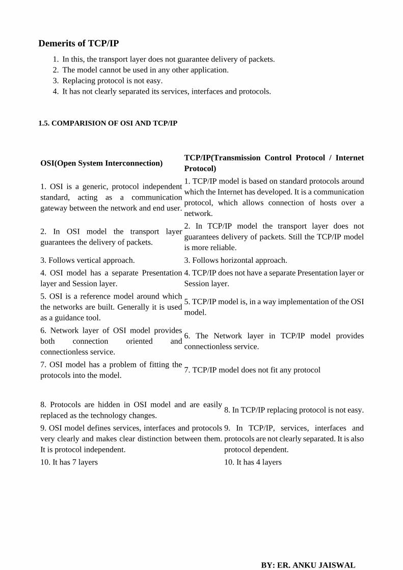
1.5. COMPARISION OF OSI AND TCP/IP
OSI(Open System Interconnection) TCP/IP(Transmission Control Protocol / Internet
Protocol)
1. OSI is a generic, protocol independent
standard, acting as a communication
gateway between the network and end user.
1. TCP/IP model is based on standard protocols around
which the Internet has developed. It is a communication
protocol, which allows connection of hosts over a
network.
2. In OSI model the transport layer
guarantees the delivery of packets.
2. In TCP/IP model the transport layer does not
guarantees delivery of packets. Still the TCP/IP model
is more reliable.
3. Follows vertical approach. 3. Follows horizontal approach.
4. OSI model has a separate Presentation
layer and Session layer.
4. TCP/IP does not have a separate Presentation layer or
Session layer.
5. OSI is a reference model around which
the networks are built. Generally it is used
as a guidance tool.
5. TCP/IP model is, in a way implementation of the OSI
model.
6. Network layer of OSI model provides
both connection oriented and
connectionless service.
6. The Network layer in TCP/IP model provides
connectionless service.
7. OSI model has a problem of fitting the
protocols into the model. 7. TCP/IP model does not fit any protocol
8. Protocols are hidden in OSI model and are easily
replaced as the technology changes. 8. In TCP/IP replacing protocol is not easy.
9. OSI model defines services, interfaces and protocols
very clearly and makes clear distinction between them.
It is protocol independent.
9. In TCP/IP, services, interfaces and
protocols are not clearly separated. It is also
protocol dependent.
10. It has 7 layers 10. It has 4 layers

BY: ER. ANKU JAISWAL
1.6. EXAMPLE NETWORK
VoIP
Once upon a time, the public switched telephone system was primarily used for voice traffic with a
little bit of data traffic here and there. But the data traffic grew and grew, and by 1999, the number of
data bits moved equaled the number of voice bits (since voice is in PCM on the trunks, it can be
measured in bits/sec). By 2002, the volume of data traffic was an order of magnitude more than the
volume of voice traffic and still growing exponentially, with voice traffic being almost flat (5%
growth per year).
As a consequence of these numbers, many packet-switching network operators suddenly became
interested in carrying voice over their data networks. The amount of additional bandwidth required
for voice is minuscule since the packet networks are dimensioned for the data traffic. However, the
average person’s phone bill is probably larger than his Internet bill, so the data network operators saw
Internet telephony as a way to earn a large amount of additional money without having to put any
new fiber in the ground.
Voice over IP (VoIP) commonly refers to the communication protocols, technologies,
methodologies, and transmission techniques involved in the delivery of voice communications and
multimedia sessions over Internet Protocol (IP) networks, such as the Internet.
The steps involved in originating a VoIP telephone call are signaling and media channel setup,
digitization of the analog voice signal, encoding, packetization, and transmission as Internet Protocol
(IP) packets over a packet-switched network. On the receiving side, similar steps (usually in the
reverse order) such as reception of the IP packets, decoding of the packets and digital-to-analog
conversion reproduce the original voice stream. Even though IP Telephony and VoIP are terms that
are used interchangeably, they are actually different; IP telephony has to do with digital telephony
systems that use IP protocols for voice communication, while VoIP is actually a subset of IP
Telephony. VoIP is a technology used by IP telephony as a means of transporting phone calls.
VoIP systems employ session control protocols to control the set-up and tear-down of calls as well
as audio codec which encode speech allowing transmission over an IP network as digital audio via
an audio stream. VoIP is available on many smart phones and Internet devices so that users of portable
devices that are not phones, may place calls or send SMS text messages over 3G or Wi-Fi.
A VoIP phone is necessary to connect to a VoIP service provider. This can be implemented in several
ways:
• Dedicated VoIP phones connect directly to the IP network using technologies such as wired
Ethernet or wireless Wi-Fi. They are typically designed in the style of traditional digital
business telephones.
• An analog telephone adapter is a device that connects to the network and implements the
electronics and firmware to operate a conventional analog telephone attached through a
modular phone jack. Some residential Internet gateways and cable modems have this function
built in.
• A soft phone is application software installed on a networked computer that is equipped with

BY: ER. ANKU JAISWAL
a microphone and speaker, or headset. The application typically presents a dial pad and display
field to the user to operate the application by mouse clicks or keyboard input.
Advantages
a. Operational Cost
b. Quality of Service
c. Portability
d. Features like call forwarding, call waiting, three party conversation
e. Flexibility
Disadvantages
a. No service during power outage
b. Reliability
c. Security
NGN
A next-generation network (NGN) is a packet-based network which can provide services including
Telecommunication Services and able to make use of multiple broadband, quality of Service-enabled
transport technologies and in which service-related functions are independent from underlying
transport-related technologies. It offers unrestricted access by users to different service providers. It
supports generalized mobility which will allow consistent and ubiquitous provision of services to
users. A Next-Generation Network (NGN) is the term given to describe
a telecommunications packet-based network that handles multiple types of traffic (such as
voice, data, and multimedia). It is the convergence of service provider networks that includes the
public switched telephone network (PSTN), the data network (the Internet), and, in some instances,
the wireless network as well.
The NGN is characterized by the following fundamental aspects:
• Packet-based transfer
• Separation of control functions among bearer capabilities, call/session, and application/
service
• Decoupling of service provision from network, and provision of open interfaces
• Support for a wide range of services, applications and mechanisms based on service building
BY: ER. ANKU JAISWAL
blocks (including real time/ streaming/ non-real time services and multi-media)
• Broadband capabilities with end-to-end QoS and transparency
• Interworking with legacy networks via open interfaces
• Generalized mobility
• Unrestricted access by users to different service providers
• A variety of identification schemes which can be resolved to IP addresses for the purposes of
routing in IP networks
• Unified service characteristics for the same service as perceived by the user
• Converged services between Fixed/Mobile
• Independence of service-related functions from underlying transport technologies
• Compliant with all Regulatory requirements, for example concerning emergency
communications and security/privacy, etc.
MPLS
Multiprotocol Label Switching (MPLS) is a mechanism in high-performance telecommunications
networks that directs data from one network node to the next based on short path labels rather than
long network addresses, avoiding complex lookups in a routing table. The labels identify virtual links
(paths) between distant nodes rather than endpoints. MPLS can encapsulate packets of various
network protocols. MPLS supports a range of access technologies, including T1/E1, ATM, Frame
Relay, and DSL.
MPLS is a highly scalable, protocol agnostic, data-carrying mechanism. In an MPLS network, data
packets are assigned labels. Packet-forwarding decisions are made solely on the contents of this label,
without the need to examine the packet itself. This allows one to create end-to-end circuits across any
type of transport medium, using any protocol. The primary benefit is to eliminate dependence on a
particular OSI model data link layer technology, such as Asynchronous Transfer Mode (ATM), Frame
Relay, Synchronous Optical Networking (SONET) or Ethernet, and eliminate the need for multiple
layer-2 networks to satisfy different types of traffic. MPLS belongs to the family of packet-switched
networks.
MPLS operates at a layer that is generally considered to lie between traditional definitions of layer 2
(data link layer) and layer 3 (network layer), and thus is often referred to as a “layer 2.5” protocol. It
was designed to provide a unified data-carrying service for both circuit-based clients and packet-
switching clients which provide a datagram service model. It can be used to carry many different
kinds of traffic, including IP packets, as well as native ATM, SONET, and Ethernet frames. A number
of different technologies were previously deployed with essentially identical goals, such as Frame
Relay and ATM. MPLS technologies have evolved with the strengths and weaknesses of ATM in
mind. Many network engineers agree that ATM should be replaced with a protocol that requires less
overhead, while providing connection-oriented services for variable-length frames. MPLS is
currently replacing some of these technologies in the marketplace. It is highly possible that MPLS

BY: ER. ANKU JAISWAL
will completely replace these technologies in the future, thus aligning these technologies with current
and future technology needs.
Features
a. Packet classification
b. Congestion avoidance
c. Congestion management
d. Path Protection
e. Security
Advantage
a. Scalability of network layer routing
b. Flexibility of delivering routing services
c. Increased performance
xDSL
When the telephone industry finally got to 56 kbps, it patted itself on the back for a job well done.
Meanwhile, the cable TV industry was offering speeds up to 10 Mbps on shared cables, and satellite
companies were planning to offer upward of 50 Mbps. As Internet access became an increasingly
important part of their business, the telephone companies began to realize they needed a more
competitive product. Their answer was to start offering new digital services over the local loop.
Services with more bandwidth than standard telephone service are sometimes called broadband,
although the term really is more of a marketing concept than a specific technical concept.
Initially, there were many overlapping offerings, all under the general name of xDSL (Digital
Subscriber Line), for various x. Below we will discuss these but primarily focus on what is probably
going to become the most popular of these services, ADSL (Asymmetric DSL).
The reason that modems are so slow is that telephones were invented for carrying the human voice
and the entire system has been carefully optimized for this purpose. Data have always been
stepchildren. At the point where each local loop terminates in the end office, the wire runs through a
filter that attenuates all frequencies below 300 Hz and above 3400 Hz. The cutoff is not sharp—300
Hz and 3400 Hz are the 3 dB points—so the bandwidth is usually quoted as 4000 Hz even though the

BY: ER. ANKU JAISWAL
distance between the 3 dB points is 3100 Hz. Data are thus also restricted to this narrow band.
The trick that makes xDSL work is that when a customer subscribes to it, the incoming line is
connected to a different kind of switch, one that does not have this filter, thus making the entire
capacity of the local loop available. The limiting factor then becomes the physics of the local loop,
not the artificial 3100 Hz bandwidth created by the filter. Unfortunately, the capacity of the local loop
depends on several factors, including its length, thickness, and general quality.
The xDSL services have all been designed with certain goals in mind. First, the services must work
over the existing twisted pair local loops. Second, they must not affect customers’ existing telephones
and fax machines. Third, they must be much faster than 56 kbps. Fourth, they should be always on,
with just a monthly charge but no per-minute charge.
X.25
A connection-oriented network is X.25, which was the first public data network. It was deployed in
the 1970s at a time when telephone service was a monopoly everywhere and the telephone company
in each country expected there to be one data network per country—theirs. To use X.25, a computer
first established a connection to the remote computer, that is, placed a telephone call. This connection
was given a connection number to be used in data transfer packets (because multiple connections
could be open at the same time). Data packets were very simple, consisting of a 3-byte header and up
to 128 bytes of data. The header consisted of a 12-bit connection number, a packet sequence number,
an acknowledgement number, and a few miscellaneous bits. X.25 networks operated for about a
decade with mixed success.
Frame Relay
In the 1980s, the X.25 networks were largely replaced by a new kind of network called frame relay.
The essence of frame relay is that it is a connection-oriented network with no error control and no
flow control. Because it was connection-oriented, packets were delivered in order (if they were
delivered at all). The properties of in-order delivery, no error control, and no flow control make frame
relay akin to a wide area LAN. Its most important application is interconnecting LANs at multiple
company offices. Frame relay enjoyed a modest success and is still in use in places today.

BY: ER. ANKU JAISWAL
Ethernet (IEEE 802.3) Local Area Network (LAN)
Ethernet protocols refer to the family of local-area network (LAN) covered by the IEEE 802.3. In the
Ethernet standard, there are two modes of operation: half-duplex and full-duplex modes. In the half
duplex mode, data are transmitted using the popular Carrier-Sense Multiple Access/Collision
Detection (CSMA/CD) protocol on a shared medium. The main disadvantages of the half-duplex are
the efficiency and distance limitation, in which the link distance is limited by the minimum MAC
frame size. This restriction reduces the efficiency drastically for high-rate transmission. Therefore,
the carrier extension technique is used to ensure the minimum frame size of 512 bytes in Gigabit
Ethernet to achieve a reasonable link distance.
Four data rates are currently defined for operation over optical fiber and twisted-pair cables:
• 10 Mbps – 10Base-T Ethernet (IEEE 802.3)
• 100 Mbps – Fast Ethernet (IEEE 802.3u)
• 1000 Mbps – Gigabit Ethernet (IEEE 802.3z)
• 10-Gigabit – 10 Gbps Ethernet (IEEE 802.3ae).
In this document, we discuss the general aspects of the Ethernet. The specific issues regarding Fast
Ethernet, Gigabit and 10 Gigabit Ethernet will be discussed in separate documents.
The Ethernet system consists of three basic elements: 1. the physical medium used to carry Ethernet
signals between computers, 2. a set of medium access control rules embedded in each Ethernet
interface that allow multiple computers to fairly arbitrate access to the shared Ethernet channel, and
3. an Ethernet frame that consists of a standardized set of bits used to carry data over the system.
As with all IEEE 802 protocols, the ISO data link layer is divided into two IEEE 802 sub layers, the
Media Access Control (MAC) sub layer and the MAC-client sub layer. The IEEE 802.3 physical
layer corresponds to the ISO physical layer.
The MAC sub-layer has two primary responsibilities:
• Data encapsulation, including frame assembly before transmission, and frame parsing/error
detection during and after reception

BY: ER. ANKU JAISWAL
• Media access control, including initiation of frame transmission and recovery from
transmission failure
The MAC-client sub-layer may be one of the following:
• Logical Link Control (LLC), which provides the interface between the Ethernet MAC and the
upper layers in the protocol stack of the end station. The LLC sub layer is defined by IEEE
802.2 standards.
• Bridge entity, which provides LAN-to-LAN interfaces between LANs that use the same
protocol (for example, Ethernet to Ethernet) and also between different protocols (for
example, Ethernet to Token Ring). Bridge entities are defined by IEEE 802.1 standards.
Each Ethernet-equipped computer operates independently of all other stations on the network: there
is no central controller. All stations attached to an Ethernet are connected to a shared signaling system,
also called the medium. To send data a station first listens to the channel, and when the channel is
idle the station transmits its data in the form of an Ethernet frame, or packet.
After each frame transmission, all stations on the network must contend equally for the next frame
transmission opportunity. Access to the shared channel is determined by the medium access control
(MAC) mechanism embedded in the Ethernet interface located in each station. The medium access
control mechanism is based on a system called Carrier Sense Multiple Access with Collision
Detection (CSMA/CD).
As each Ethernet frame is sent onto the shared signal channel, all Ethernet interfaces look at the
destination address. If the destination address of the frame matches with the interface address, the
frame will be read entirely and be delivered to the networking software running on that computer. All
other network interfaces will stop reading the frame when they discover that the destination address
does not match their own address.
When it comes to how signals flow over the set of media segments that make up an Ethernet system,
it helps to understand the topology of the system. The signal topology of the Ethernet is also known
as the logical topology, to distinguish it from the actual physical layout of the media cables. The
logical topology of an Ethernet provides a single channel (or bus) that carries Ethernet signals to all
stations.

BY: ER. ANKU JAISWAL
CHAPTER 2- PHYSICAL LAYER
PHYSICAL LAYER
Physical layer is the lowest layer of all. It is responsible for sending bits from one computer to
another. This layer is not concerned with the meaning of the bits and deals with the physical
connection to the network and with transmission and reception of signals.
This layer defines electrical and physical details represented as 0 or a 1. How many pins a network
will contain, when the data can be transmitted or not and how the data would be synchronized.
FUNCTIONS OF PHYSICAL LAYER:
1. Representation of Bits: Data in this layer consists of stream of bits. The bits must be
encoded into signals for transmission. It defines the type of encoding i.e. how 0’s and 1’s
are changed to signal.
2. Data Rate: This layer defines the rate of transmission which is the number of bits per
second.
3. Synchronization: It deals with the synchronization of the transmitter and receiver. The
sender and receiver are synchronized at bit level.
4. Interface: The physical layer defines the transmission interface between devices and
transmission medium.
5. Line Configuration: This layer connects devices with the medium: Point to Point
configuration and Multipoint configuration.
6. Topologies: Devices must be connected using the following topologies: Mesh, Star, Ring
and Bus.
7. Transmission Modes: Physical Layer defines the direction of transmission between two
devices: Simplex, Half Duplex, Full Duplex.
8. Deals with baseband and broadband transmission.
2.1. NETWORK MONITORING:
a) Delay
Network delay is an important design and performance characteristic of a computer network or
telecommunications network. The delay of a network specifies how long it takes for a bit of data to travel
across the network from one node or endpoint to another. It is typically measured in multiples or fractions
of seconds.
b) Latency

BY: ER. ANKU JAISWAL
Network latency is an expression of how much time it takes for a packet of data to get from one designated
point to another. In some environments (for example, AT&T), latency is measured by sending a packet that
is returned to the sender; the round-trip time is considered the latency.
c) Throughput
A benchmark can be used to measure throughput. In data transmission, network throughput is the amount
of data moved successfully from one place to another in a given time period, and typically measured in bits
per second (bps), as in megabits per second (Mbps) or gigabits per second (Gbps).
2.2. TRANSMISSION MEDIA
These are the means by which a communication signal is carried from one system to another. These media
can carry information from a source to a destination. The transmission media can usually be free space
such as: satellite, microwave, radio and infrared systems, metallic cables such as: twisted pair, or coaxial
cable, or fiber-optic cable.
In telecommunication, transmission media can be divided into two broad categories:
i. Guided transmission media
ii. Unguided transmission media
Guided Transmission Media
Guided Transmission media uses a cabling system that guides the data signals along a specific path. They
provide the physical path way for the transmission of the data from the source to the destination. The data
signals travelling along any of these media is directed and contained by the physical limits of the medium.
Twisted-pair and coaxial cable use metallic (copper) conductor that accept and transport signals in the form
of electric current. Optical fiber is a cable that accepts and transport signals in the form of light. Guided
Media are also known as Bound media or wired media.

BY: ER. ANKU JAISWAL
a) Twisted Pair Cable
Twisted pair cabling is a type of wiring in which two conductors of a single circuit are twisted together for
the purposes of canceling out electromagnetic interference (EMI) from external sources; for instance,
electromagnetic radiation from unshielded twisted pair (UTP) cables, and crosstalk between neighboring
pairs.
This cable is the most commonly used and is cheaper than others. It is lightweight, cheap, can be
installed easily, and they support many different types of network. Some important points:
• Its frequency range is 0 to 3.5 kHz.
• Typical attenuation is 0.2 dB/Km @ 1kHz.
• Typical delay is 50 µs/km.
• Repeater spacing is 2km.
Twisted Pair is of two types :
• Unshielded Twisted Pair (UTP)
• Shielded Twisted Pair (STP)
Unshielded Twisted Pair Cable
It is the most common type of telecommunication when compared with Shielded Twisted Pair
Cable which consists of two conductors usually copper, each with its own colour plastic insulator.
Identification is the reason behind colored plastic insulation.
Shielded Twisted Pair Cable
This cable has a metal foil or braided-mesh covering which encases each pair of insulated
conductors. Electromagnetic noise penetration is prevented by metal casing. Shielding also
eliminates crosstalk (explained in KEY TERMS Chapter).
It has same attenuation as unshielded twisted pair. It is faster the unshielded and coaxial cable. It
is more expensive than coaxial and unshielded twisted pair.

BY: ER. ANKU JAISWAL
b) Coaxial Cable
Coaxial is called by this name because it contains two conductors that are parallel to each other.
Copper is used in this as centre conductor which can be a solid wire or a standard one. It is
surrounded by PVC installation, a sheath which is encased in an outer conductor of metal foil,
braid or both.
Outer metallic wrapping is used as a shield against noise and as the second conductor which
completes the circuit. The outer conductor is also encased in an insulating sheath. The outermost
part is the plastic cover which protects the whole cable.
Here the most common coaxial standards.
• 50-Ohm RG-7 or RG-11 : used with thick Ethernet.
• 50-Ohm RG-58 : used with thin Ethernet
• 75-Ohm RG-59 : used with cable television
• 93-Ohm RG-62 : used with ARCNET.
Advantages:
• Bandwidth is high
• Used in long distance telephone lines.
• Transmits digital signals at a very high rate of 10Mbps.
• Much higher noise immunity
• Data transmission without distortion.
• The can span to longer distance at higher speeds as they have better shielding when
compared to twisted pair cable
Disadvantages:
• Single cable failure can fail the entire network.
• Difficult to install and expensive when compared with twisted pair.
• If the shield is imperfect, it can lead to grounded loop.

BY: ER. ANKU JAISWAL
C) Fiber Optic Cable
These are similar to coaxial cable. It uses light signals to transmit data. At the centre is the glass
core through which light propagates.
In multimode fibers, the core is 50microns, and In single mode fibers, the thickness is 8 to 10
microns.
The core in fiber optic cable is surrounded by glass cladding with lower index of refraction as
compared to core to keep all the light in core. This is covered with a thin plastic jacket to protect
the cladding. The fibers are grouped together in bundles protected by an outer shield.
Fiber optic cable has bandwidth more than 2 gbps (Gigabytes per Second)
Advantages:
• Provides high quality transmission of signals at very high speed.
• These are not affected by electromagnetic interference, so noise and distortion is very less.
• Used for both analog and digital signals.
Disadvantages:
• It is expensive
• Difficult to install.
• Maintenance is expensive and difficult.
• Do not allow complete routing of light signals.

BY: ER. ANKU JAISWAL
II) Unguided Media
The unguided media is the wireless media. It simply transports electromagnetic waves without using any
physical conductor. Signals are normally broadcast through the air and thus are available to anyone who
has the device capable of receiving them.
Wireless transmission
Wireless communication is the transfer of information over a distance without the use of electrical
conductors or “wires”. The distances involved may be short (a few meters as in television remote control)
or very long (thousands or even millions of kilometers for radio communication). Wireless communication
is generally considered to be a branch of telecommunications.
Three ways for wireless data propagation
(i) Radio wave
(ii) Microwave
(iii) Infrared
Ground propagation
Radio waves travel through the lowest portion of the atmosphere, hugging he earth. These low frequency
signals emanate in all directions from the transmitting antenna and follow the curvature of the
planet. Distance depends on the amount of power in the signal, that is the greater the power, the greater the
distance.
Sky propagation
Higher-frequency radio waves radiate upward into the ionosphere where they are reflected back to earth.
This type of transmission allows for greater distances with lower power output.
Line-of-sight propagation

BY: ER. ANKU JAISWAL
In line-of-sight (LOS) propagation very high frequency signals are transmitted in straight lines directly
from antenna-to-antenna. Antenna must be directional, facing each other and either tall enough or close
enough together not to be affected by the curvature of the earth. LOS propagation is trekking because radio
transmission cannot be completely focused.
Radio waves:
Electromagnetic wave ranging in frequencies between 3 KHz and 1GHz are normally called radio waves.
Radio waves are omnidirectional when an antenna transmits radio waves they are propagated in all
directions. This means that sending and receiving antenna do not have to be aligned. A sending antenna can
send waves that can be received by any receiving antenna. This omnidirectional property is the disadvantage
that the radio waves transmitted by tone antenna are susceptible to interference by another antenna that may
send signals using the same frequency or band.
Radio waves particularly those waves that propagate in sky mode, can travel long distances. This makes
radio waves a good candidate for long-distance broadcasting such as AM radio.
Radio waves particularly those of low and medium frequencies can penetrate walls. It is an advantage
because; an AM radio can receive signals inside a building. It is the disadvantage because we cannot isolate
a communication to first inside or outside a building. The radio waves band is relatively narrow just under
I GHz, compared to the microwave band. When this band is divided into sub-band, the sidebands are
also narrow, leading to a low data rate for digital communications.
Almost all the entire band is regulated by authorities using from the authorities. Radio waves use
omnidirectional antennas that send our signals in all directions based on the wave lengths, strength and
purpose of transmission, we can have several types of antennas.
Applications:
The directional characteristics of radio waves make them useful for multicasting. In which there is one
sender but many receiver. Radio waves are used multicast communications such as radio (AM, FM), TV,
paging system, and cordless phones.
Microwaves:
Electromagnetic waves having frequencies between 1 GHz and 300 GHz are called microwaves.

BY: ER. ANKU JAISWAL
Microwaves are unidirectional; when an antenna transmits microwaves they can be narrowly focused. This
means that the sending and receiving antennas need to be aligned. The unidirectional property has an
obvious advantage. A pair of antennas can be aligned without interfering with another pair of aligned
antennas. The microwave band is relatively wide almost 299GHz. Therefore wider sub-band can be
assigned and a high data rate is possible.
On the other hand microwaves:
Propagation is line-of-sight. Since the towers with the mounted antennas needs to be in direct sight of each
other, towers that are for apart need to be very tall. The curvature of the earth as well as other blocking
obstacles does not allow two short towers to communicate using microwaves. Repeaters are often needed
for long distance communication very high frequency microwaves cannot penetrate wall. Use of certain
portion of band requires permission from authority. Parabolic dish antenna and horn antenna are used for
this means of transmission.
Applications:
Microwaves are used for unicast communication such as cellular telephones, satellite networks and wireless
LAN.
Infrared:
Infrared signals with frequencies ranges from 300 GHz to 400 THz can be used for short range
communication. Infrared signals, having high frequencies, cannot penetrate walls. This helps to prevent
interference between one system and another. In this, one room cannot be affected by the infrared waves in
another room. However, the same characteristics make infrared signals useless for long range
communications. In addition, we cannot use infrared waves outside a building because the sun’s rays
contain infrared waves that can interfere with the communication.
Applications:
Infrared band, almost 400 THz, has an excellent potential for data transmission. So this will transfer digital
data with a very high frequency. There are number of computer devices which are used to send the data

BY: ER. ANKU JAISWAL
through infrared medium e.g. keyboard mice, PCs and printers. There are some manufacturers provide a
special part called the IrDA port that allows a wireless keyboard to communicate with a PC.
Communication Satellite:
The concept of satellite based networks is to transmit and receive signals from ground stations. The purpose
of satellite communication is to use it for video transmission and sharing. In simple words a satellite is a
device which revolves around the earth either for collecting useful information or for helping transfer of
information.
LEO is called Low earth orbit, MEO is called Medium Earth Orbit and GEO is called Geostationary orbit.
LEO are about 500 Km to 1500 Km above the earth, so the delay is very small and the losses is small too.
MEO are installed at 5000 to 12000 km above the earth and generally used for navigation communications
like GPS. GEO is about 35800 Km above the equator, the delay and losses are greater, but the advantages
is more coverage (it covers 40% of the earth) and there no need to track the satellite, so the earth terminal
is cheaper.
Geo-Stationary Earth Orbit
These satellites have almost a distance of 36,000 km to the earth.
E.g. All radio and TV, whether satellite etc, are launched in this orbit.

BY: ER. ANKU JAISWAL
Advantages of Geo-Stationary Earth Orbit
1. It is possible to cover almost all parts of the earth with just 3 geo satellites.
2. Antennas need not be adjusted every now and then but can be fixed permanently.
3. The life-time of a GEO satellite is quite high usually around 15 years.
Disadvantages of Geo-Stationary Earth Orbit
1. Larger antennas are required for northern/southern regions of the earth.
2. High buildings in a city limit the transmission quality.
3. High transmission power is required.
4. These satellites cannot be used for small mobile phones.
5. Fixing a satellite at Geo stationary orbit is very expensive.
Medium Earth Orbit
Satellite at different orbits operates at different heights. The MEO satellite operates at about 5000
to 12000 km away from the earth's surface.
These orbits have moderate number of satellites.
Advantages of Medium Earth Orbit
1. Compared to LEO system, MEO requires only a dozen satellites.
2. Simple in design.
3. Requires very few handovers.
Disadvantages of Medium Earth Orbit
1. Satellites require higher transmission power.
2. Special antennas are required.
Low Earth Orbit
LEO satellites operate at a distance of about 500-1500 km.
Advantages of Low Earth Orbit
1. The antennas can have low transmission power of about 1 watt.
2. The delay of packets is relatively low.
3. Useful for smaller foot prints.

BY: ER. ANKU JAISWAL
Disadvantages of Low Earth Orbit
1 If global coverage is required, it requires at least 50-200 satellites in this orbit.
2. Special handover mechanisms are required.
3. These satellites involve complex design.
4. Very short life: Time of 5-8 years. Assuming 48 satellites with a life-time of 8 years each, a new
satellite is needed every 2 months.
5. Data packets should be routed from satellite to satellite.
LINE OF SIGHT
Line of sight (LoS) is a type of propagation that can transmit and receive data only where transmit
and receive stations are in view of each other without any sort of an obstacle between them. FM
radio, microwave and satellite transmission are examples of line-of-sight communication.
Long-distance data communication is more effective through wireless networks but geographical
obstacles and the curvature of the earth bring limitations to line-of-sight transmission. However,
these issues can generally be mitigated through planning, calculations and the use of additional
technologies.
For example, mobile phones use a modified line-of-sight transmission, which is made possible
through a combination of effects like diffraction, multipath reflection, local repeaters and rapid
handoff.
2.3 MULTIPLEXING

BY: ER. ANKU JAISWAL
Multiplexing is a technique by which different analog and digital streams of transmission can be
simultaneously processed over a shared link. Multiplexing divides the high capacity medium into low
capacity logical medium which is then shared by different streams.
When multiple senders try to send over a single medium, a device called Multiplexer divides the physical
channel and allocates one to each. On the other end of communication, a De-multiplexer receives data from
a single medium, identifies each, and sends to different receivers.
Frequency Division Multiplexing
When the carrier is frequency, FDM is used. FDM is an analog technology. FDM divides the
spectrum or carrier bandwidth in logical channels and allocates one user to each channel. Each
user can use the channel frequency independently and has exclusive access of it. All channels are
divided in such a way that they do not overlap with each other. Channels are separated by guard
bands. Guard band is a frequency which is not used by either channel.
In
the

BY: ER. ANKU JAISWAL
20th century, many telephone companies used frequency-division multiplexing for long distance
connections to multiplex thousands of voice signals through a coaxial cable system.
Time Division Multiplexing
TDM is applied primarily on digital signals but can be applied on analog signals as well. In TDM
the shared channel is divided among its user by means of time slot. Each user can transmit data
within the provided time slot only. Digital signals are divided in frames, equivalent to time slot i.e.
frame of an optimal size which can be transmitted in given time slot.
TDM works in synchronized mode. Both ends, i.e. Multiplexer and De-multiplexer are timely
synchronized and both switch to next channel simultaneously.
When channel A transmits its frame at one end, the De-multiplexer provides media to channel A
on the other end. As soon as the channel A’s time slot expires, this side switches to channel B. On
the other end, the De-multiplexer works in a synchronized manner and provides media to channel
B. Signals from
different channels travel the path in interleaved manner.
Synchronous Time Division Multiplexing
Synchronous time division multiplexing can be used for both analog and digital signals. In
synchronous TDM, the connection of input is connected to a frame. If there are ‘n’ connections,
then a frame is divided into ‘n’ time slots – and, for each unit, one slot is allocated – one for each
input line. In this synchronous TDM sampling, the rate is same for all the signals, and this sampling
requires a common clock signal at both the sender and receiver end. In synchronous TDM, the
multiplexer allocates the same slot to each device at all times.
Asynchronous Time-Division Multiplexing
In asynchronous time-division multiplexing, the sampling rate is different for different signals,
and it doesn’t require a common clock. If the devices have nothing to transmit, then their time slot

BY: ER. ANKU JAISWAL
is allocated to another device. Designing of a commutator or de-commutator is difficult and the
bandwidth is less for time-division multiplexing. This type of time-division multiplexing is used
in asynchronous transfer mode networks.
Wavelength Division Multiplexing
Light has different wavelength (colors). In fiber optic mode, multiple optical carrier signals are
multiplexed into an optical fiber by using different wavelengths. This is an analog multiplexing
technique and is done conceptually in the same manner as FDM but uses light as signals.
Wavelength division multiplexing (WDM) is a technology in fiber optic communications; and, for
the high capacity communication systems, wavelength division multiplexing is the most promising
concept. This system uses multiplexer at transmitter to join signals and demultiplexer to split the
signals apart, at the receiver end. The purpose of WDM is to combine multiple light sources into
a single light source at the multiplexer; and, at the demultiplexer the single light is converted into
multiple light sources.
Code Division Multiplexing
Multiple data signals can be transmitted over a single frequency by using Code Division
Multiplexing. FDM divides the frequency in smaller channels but CDM allows its users to full
bandwidth and transmit signals all the time using a unique code. CDM uses orthogonal codes to
spread signals.
Each station is assigned with a unique code, called chip. Signals travel with these codes
independently, inside the whole bandwidth. The receiver knows in advance the chip code signal it
has to receive.
BY: ER. ANKU JAISWAL
SWITCHING
Switching is process to forward packets coming in from one port to a port leading towards the
destination. When data comes on a port it is called ingress, and when data leaves a port or goes out
it is called egress. A communication system may include number of switches and nodes. At broad
level, switching can be divided into two major categories:
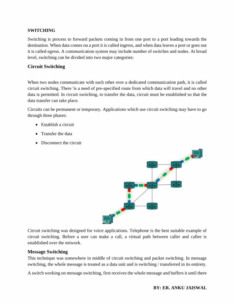
Circuit Switching
When two nodes communicate with each other over a dedicated communication path, it is called
circuit switching. There 'is a need of pre-specified route from which data will travel and no other
data is permitted. In circuit switching, to transfer the data, circuit must be established so that the
data transfer can take place.
Circuits can be permanent or temporary. Applications which use circuit switching may have to go
through three phases:
• Establish a circuit
• Transfer the data
• Disconnect the circuit
Circuit switching was designed for voice applications. Telephone is the best suitable example of
circuit switching. Before a user can make a call, a virtual path between caller and callee is
established over the network.
Message Switching
This technique was somewhere in middle of circuit switching and packet switching. In message
switching, the whole message is treated as a data unit and is switching / transferred in its entirety.
A switch working on message switching, first receives the whole message and buffers it until there

BY: ER. ANKU JAISWAL
are resources available to transfer it to the next hop. If the next hop is not having enough resource
to
Accommodate large size message, the message is stored and switch waits.
This technique was considered substitute to circuit switching. As in circuit switching the whole
path is blocked for two entities only. Message switching is replaced by packet switching. Message
switching has the following drawbacks:
• Every switch in transit path needs enough storage to accommodate entire message.
• Because of store-and-forward technique and waits included until resources are available,
message switching is very slow.
• Message switching was not a solution for streaming media and real-time applications.
Packet Switching
Shortcomings of message switching gave birth to an idea of packet switching. The entire message
is broken down into smaller chunks called packets. The switching information is added in the
header of each packet and transmitted independently.

BY: ER. ANKU JAISWAL
It is easier for intermediate networking devices to store small size packets and they do not take
Many resources either on carrier path or in the internal memory of switches.
Packet switching enhances line efficiency as packets from multiple applications can be
multiplexed over the carrier. The internet uses packet switching technique. Packet switching
enables the user to differentiate data streams based on priorities. Packets are stored and forwarded
according to their priority to provide quality of service.
Virtual Circuit Switching
Virtual circuit (VC) is a means of transporting data over a switched computer in such a way that
it appears as though there is a dedicated layer link between the source and destination end systems
of this data. The term virtual circuit is synonymous with virtual connection and virtual channel.
Before a connection or virtual circuit may be used, it has to be established, between two or more
nodes or software applications, by configuring the relevant parts of the interconnecting network.
After that, a bit stream or byte stream may be delivered between the nodes; hence, a virtual circuit
protocol allows higher level protocols to avoid dealing with the division of data into segments,
packets, or frames.
Virtual circuit communication resembles circuit switching, since both are connection oriented,
meaning that in both cases data is delivered in correct order, and signaling overhead is required
during a connection establishment phase. However, circuit switching provides a constant bit rate
and latency, while these may vary in a virtual circuit service due to factors such as:
• varying packet queue lengths in the network nodes,
• varying bit rate generated by the application,
• varying load from other users sharing the same network resources by means of statistical
multiplexing, etc.
Many virtual circuit protocols, but not all, provide reliable communication service through the use

BY: ER. ANKU JAISWAL
of data retransmissions because of error detection and automatic repeat request (ARQ).
Datagram packet switching
Datagram packet-switching is a packet switching technology by which each packet, now called a
datagram, and is treated as a separate entity. Each packet is routed independently through the
network. Therefore packets contain a header with the full information about the destination. The
intermediate nodes examine the header of a packet and select an appropriate link to another node
which is nearer to the destination. In this system, the packets do not follow a pre-established route,
and the intermediate nodes do not require prior knowledge of the routes that will be used.
The individual packets which form a data stream may follow different paths between the source
and the destination. As a result, the packets may arrive at the destination out of order. When this
occurs, the packets will have to be reassembled to form the original message.
Because each packet is switched independently, there is no need for connection setup and no need
to dedicate bandwidth in the form of a circuit.
Datagram packet switches use a variety of techniques to forward traffic; they are differentiated by
how long it takes the packet to pass through the switch and their ability to filter out corrupted
packets. A datagram network is a best effort network. Delivery is not guaranteed. Reliable delivery
must be provided by the end systems (i.e. user's computers) using additional protocols.The most
common datagram network is the Internet, which uses the IP network protocol.
TELECOMMUNICATION SWITCHING SYSTEM (Networking of Telephone Exchange)
In the early stages of telecommunication systems, the process and stages of switching, played an
important to make or break connections. At the initial stages, the switching systems were operated
manually. These systems were later automated. The following flowchart shows how the switching
systems were classified. From the earliest days of the telephone, it was observed that it was more
practical to connect different telephone instruments by running wires from each instrument to a
central switching point, or telephone exchange, than it was to run wires between all the
instruments. In 1878 the first telephone exchange was installed in New Haven, Connecticut,
permitting up to 21 customers to reach one another by means of a manually operated
central switchboard. The manual switchboard was quickly extended from 21 lines to hundreds of
lines. Each line was terminated on the switchboard in a socket (called a jack), and a number of
short, flexible circuits (called cords) with a plug on both ends of each cord were also provided.
Two lines could thus be interconnected by inserting the two ends of a cord in the appropriate
jacks.

BY: ER. ANKU JAISWAL
The switching systems in the early stages were operated manually. The connections were made
by the operators at the telephone exchanges in order to establish a connection. To minimize the
disadvantages of manual operation, automatic switching systems were introduced.
The Automatic switching systems are classified as the following −
• Electromechanical Switching Systems − Here, mechanical switches are electrically
operated.
• Electronic Switching Systems − Here, the usage of electronic components such as diodes,
transistors and ICs are used for the switching purposes.
Electromechanical Switching Systems
The Electromechanical switching systems are a combination of mechanical and electrical
switching types. The electrical circuits and the mechanical relays are deployed in them. The
Electromechanical switching systems are further classified into the following.
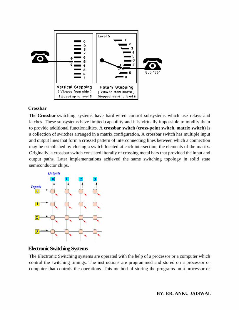
Step-by-step or Strowger
The Step-by-step switching system is also called the Strowger switching system after its
inventor A B Strowger. The control functions in a Strowger system are performed by circuits
associated with the switching elements in the system. The Strowger switch consisted of
essentially two parts: an array of 100 terminals, called the bank, that were arranged 10 rows high
and 10 columns wide in a cylindrical arc; and a movable switch, called the brush, which was
moved up and down the cylinder by one ratchet mechanism and rotated around the arc by another,
so that it could be brought to the position of any of the 100 terminals. The stepping movement
was controlled directly by pulses from the telephone instrument. In the original systems, the caller
generated the pulses by rapidly pushing a button switch on the instrument.
BY: ER. ANKU JAISWAL
Crossbar
The Crossbar switching systems have hard-wired control subsystems which use relays and
latches. These subsystems have limited capability and it is virtually impossible to modify them
to provide additional functionalities. A crossbar switch (cross-point switch, matrix switch) is
a collection of switches arranged in a matrix configuration. A crossbar switch has multiple input
and output lines that form a crossed pattern of interconnecting lines between which a connection
may be established by closing a switch located at each intersection, the elements of the matrix.
Originally, a crossbar switch consisted literally of crossing metal bars that provided the input and
output paths. Later implementations achieved the same switching topology in solid state
semiconductor chips.
Electronic Switching Systems
The Electronic Switching systems are operated with the help of a processor or a computer which
control the switching timings. The instructions are programmed and stored on a processor or
computer that controls the operations. This method of storing the programs on a processor or

BY: ER. ANKU JAISWAL
computer is called the Stored Program Control (SPC) technology. New facilities can be added
to a SPC system by changing the control program.
There are two types of SPCs −
• Centralized SPC
• Distributed SPC
It permits the features like abbreviated dialing, call forwarding, call waiting, etc. The Stored
Program Control concept is where a program or a set of instructions to the computer is stored in
its memory and the instructions are executed automatically one by one by the processor.
Dual processor architecture may be configured to operate in three modes like −
• Standby Mode
• Synchronous Duplex Mode
• Load Sharing Mode
Standby Mode
As the name implies, in the two processors present, one processor is active and the other is in the
standby mode. The processor in the standby mode is used as a backup, in case the active one fails.
Synchronous Duplex Mode
In the Synchronous Duplex mode, two processors are connected and operated in synchronism.
Two processors P1 and P2 are connected and separate memories like M1 and M2 are used. These

BY: ER. ANKU JAISWAL
processors are coupled to exchange the stored data. A Comparator is used in between these two
processors. The Comparator helps in comparing the results.
Load Sharing Mode
Load sharing mode is where a task is shared between two processors. The Exclusion Device (ED)
is used instead of the comparator in this mode. The processors call for ED to share the resources,
so that both the processors do not seek the same resource at the same time.In this mode, both the
processors are simultaneously active. These processors share the resources of the exchange and
load. In case one of the processor fails, the other one takes over the entire load of the exchange
with the help of ED. Under normal operation, each processor handles one-half of the calls on a
statistical basis. The exchange operator can however vary the processor load for maintenance
purpose.
Space Division Switching or Time Division Switching
The switching scheme used by the electronic switching systems may be either Space Division
Switching or Time Division Switching. In space division switching, a dedicated path is
established between the calling and the called subscribers for the entire duration of the call. In
time division switching, sampled values of speech signals are transferred at fixed intervals.
Analog or Digital
The time division switching may be analog or digital. In analog switching, the sampled voltage
levels are transmitted as they are. However, in binary switching, they are binary coded and
transmitted.
Space Switching and Time Switching
If the coded values are transferred during the same time interval from input to output, the
technique is called Space Switching. If the values are stored and transferred to the output at a
time interval, the technique is called Time Switching. A time division digital switch may also be
designed by using a combination of space and time switching techniques.
T1 AND E1 HIERARCHY
T1 and E1 are equivalent digital data transmission formats that carry signals. T1 and E1 lines can
be interconnected for international use.
This topic contains the following sections:
T1 Overview
T1 is a digital data transmission medium capable of handling 24 simultaneous connections running
at a combined 1.544 Mbps. T1 combines these 24 separate connections, called channels or time

BY: ER. ANKU JAISWAL
slots, onto a single link. T1 is also called DS1.
The T1 data stream is broken into frames. Each frame consists of a single framing bit and 24 8-bit
channels, totaling 193 bits per T1 frame. Frames are transmitted 8,000 times per second, at a data
transmission rate of 1.544 Mbps (8,000 x 193 = 1.544 Mbps).
As each frame is received and processed, the data in each 8-bit channel is maintained with the
channel data from previous frames, enabling T1 traffic to be separated into 24 separate flows
across a single medium. For example, in the following set of 4-channel frames (without a framing
bit), the data in channel 1 consists of the first octet of each frame, the data in channel 2 consists of
the second octet of each frame, and so on:
E1 Overview
E1 is the European format for DS1 digital transmission. E1 links are similar to T1 links except that
they carry signals at 2.048 Mbps. Each signal has 32 channels, and each channel transmits at
64 Kbps. E1 links have higher bandwidth than T1 links because it does not reserve one bit for
overhead. Whereas, T1 links use 1 bit in each channel for overhead.
T1 and E1 Signals
T1 and E1 interfaces consist of two pairs of wires—a transmit data pair and a receive data pair.
Clock signals, which determine when the transmitted data is sampled, are embedded in the T1 and
E1 transmissions.
Typical digital signals operate by sending either zeros (0s) or ones (1s), which are usually
represented by the absence or presence of a voltage on the line. The receiving device need only
detect the presence of the voltage on the line at the particular sampling edge to determine whether
the signal is 0 or 1. T1 and E1, however, use bipolar electrical pulses. Signals are represented by
no voltage (0), positive voltage (1), or negative voltage (1). The bipolar signal allows T1 and E1
receivers to detect error conditions in the line, depending on the type of encoding that is being
used.
Encoding
The following are common T1 and E1 encoding techniques:
• Alternate mark inversion (AMI)—T1 and E1
• Bipolar with 8-zero substitution (B8ZS)—T1 only
• High-density bipolar 3 code (HDB3)—E1 only
Common Characteristics:-
• Both are having Same Sampling Frequency i.e. 8kHz.
• In both (E1 & T1) Number of samples/telephone signal = 8000/sec.

BY: ER. ANKU JAISWAL
• In both (E1 & T1) Length of PCM Frame = 1/8000s = 125µs.
• In both (E1 & T1) Number of Bits in each code word = 8.
• In both (E1 & T1) Telephone Channel Bit Rate = 8000/s x 8 Bit = 64 kbit/s.
Differing Characteristics:-
• In E1 Encoding/Decoding is followed by A-Law while in T1 Encoding/Decoding is
followed by µ-Law.
• In E1 – 13 Number of Segments in Characteristics while in T1 – 15 Number of Segments
in Characteristics.
• In E1 – 32 Number of Timeslots / PCM Frame while in T1 – 24 Number
of Timeslots / PCM Frame.
• In E1 – 8 x 32 = 256 number of bits / PCM Frame while in T1 – 8 x 24 + 1* =
193 number of bits / PCM Frame. (* Signifies an additional bit).
• In E1 – (125µs x 8)/256 = approx 3.9µs is the length of an 8-bit Timeslot while in T1
– (125µs x 8)/193 = approx 5.2µs is the length of an 8-bit Timeslot.
• In E1 – 8000/s x 256 bits = 2048kbit/s is the Bit Rate of Time-Division Multiplexed Signal
while in T1 – 8000/s x 193 bits = 1544kbit/s is the Bit Rate of Time-Division Multiplexed
Signal.
INTEGRATED SERVICES DIGITAL NETWORK (ISDN)
These are a set of communication standards for simultaneous digital transmission of voice, video,
data, and other network services over the traditional circuits of the public switched telephone
network. Before Integrated Services Digital Network (ISDN), the telephone system was seen as a
way to transmit voice, with some special services available for data. The main feature of ISDN is
that it can integrate speech and data on the same lines, which were not available in the classic
telephone system.
ISDN is a circuit-switched telephone network system, but it also provides access to packet
switched networks that allows digital transmission of voice and data. This results in potentially
better voice or data quality than an analog phone can provide. It provides a packet-switched
connection for data in increments of 64 kilobit/s. It provided a maximum of 128 kbit/s bandwidth
in both upstream and downstream directions. A greater data rate was achieved through channel
bonding. Generally ISDN B-channels of three or four BRIs (six to eight 64 kbit/s channels) are
bonded.

BY: ER. ANKU JAISWAL
In the context of the OSI model, ISDN is employed as the network in data-link and physical layers
but commonly ISDN is often limited to usage to Q.931 and related protocols. These protocols
introduced in 1986 are a set of signaling protocols establishing and breaking circuit-switched
connections, and for advanced calling features for the user. ISDN provides simultaneous voice,
video, and text transmission between individual desktop videoconferencing systems and group
videoconferencing systems.
ISDN Interfaces:
The following are the interfaces of ISDN:
Basic Rate Interface (BRI) –
There are two data-bearing channels (‘B’ channels) and one signaling channel (‘D’ channel) in
BRI to initiate connections. The B channels operate at a maximum of 64 Kbps while the D channel
operates at a maximum of 16 Kbps. The two channels are independent of each other. For example,
one channel is used as a TCP/IP connection to a location while the other channel is used to send a
fax to a remote location. In iSeries ISDN supports basic rate interface (BRl).
The basic rate interface (BRl) specifies a digital pipe consisting two B channels of 64 Kbps each
and one D channel of 16 Kbps. This equals a speed of 144 Kbps. In addition, the BRl service itself
requires an operating overhead of 48 Kbps. Therefore a digital pipe of 192 Kbps is required.
Primary Rate Interface (PRI) –
Primary Rate Interface service consists of a D channel and either 23 or 30 B channels depending
on the country you are in. PRI is not supported on the iSeries. A digital pipe with 23 B channels
and one 64 Kbps D channel is present in the usual Primary Rate Interface (PRI). Twenty-three B
channels of 64 Kbps each and one D channel of 64 Kbps equals 1.536 Mbps. The PRI service uses
8 Kbps of overhead also. Therefore PRI requires a digital pipe of 1.544 Mbps.
Broadband-ISDN (B-ISDN) –
Narrowband ISDN has been designed to operate over the current communications infrastructure,
which is heavily dependent on the copper cable however B-ISDN relies mainly on the evolution
of fiber optics. According to CCITT B-ISDN is best described as ‘a service requiring transmission
channels capable of supporting rates greater than the primary rate.
ISDN Services:
ISDN provides a fully integrated digital service to users. These services fall into 3 categories-
bearer services, teleservices and supplementary services.

BY: ER. ANKU JAISWAL
Bearer Services –
Transfer of information (voice, data and video) between users without the network manipulating
the content of that information is provided by the bearer network. There is no need for the network
to process the information and therefore does not change the content. Bearer services belong to the
first three layers of the OSI model. They are well defined in the ISDN standard. They can be
provided using circuit-switched, packet-switched, frame-switched, or cell-switched networks.
Teleservices –
In this the network may change or process the contents of the data. These services corresponds to
layers 4-7 of the OSI model. Teleservices relay on the facilities of the bearer services and are
designed to accommodate complex user needs. The user needs not to be aware of the details of the
process. Teleservices include telephony, teletex, telefax, videotex, telex and teleconferencing.
Though the ISDN defines these services by name yet they have not yet become standards.
Supplementary Service –
Additional functionality to the bearer services and teleservices are provided by supplementary
services. Reverse charging, call waiting, and message handling are examples of supplementary
services which are all familiar with today’s telephone company services.
Principle of ISDN:
The ISDN works based on the standards defined by ITU-T (formerly CCITT). The
Telecommunication Standardization Sector (ITU-T) coordinates standards for
telecommunications on behalf of the International Telecommunication Union (ITU) and is based
in Geneva, Switzerland. The various principles of ISDN as per ITU-T recommendation are:
To support switched and non-switched applications
To support voice and non-voice applications
Reliance on 64-kbps connections
Intelligence in the network
Layered protocol architecture
Variety of configurations

BY: ER. ANKU JAISWAL

BY: ER. ANKU JAISWAL
CHAPTER 3- DATA LINK LAYER
Data Link Layer is second layer of OSI Layered Model. This layer is one of the most complicated layers
and has complex functionalities and liabilities. Data link layer hides the details of underlying hardware
and represents itself to upper layer as the medium to communicate.
Data link layer works between two hosts which are directly connected in some sense. This direct
connection could be point to point or broadcast. Systems on broadcast network are said to be on same link.
The work of data link layer tends to get more complex when it is dealing with multiple hosts on single
collision domain.
Data link layer is responsible for converting data stream to signals bit by bit and to send that over the
underlying hardware. At the receiving end, Data link layer picks up data from hardware which are in the
form of electrical signals assembles them in a recognizable frame format, and hands over to upper layer.
Data link layer has two sub-layers:
• Logical Link Control: It deals with protocols, flow-control, and error control
• Media Access Control: It deals with actual control of media
FUNCTIONALITY OF DATA-LINK LAYER
Data link layer does many tasks on behalf of upper layer. These are:
• Framing Data-link layer takes packets from Network Layer and encapsulates them into Frames.
Then, it sends each frame bit-by-bit on the hardware. At receiver’ end, data link layer picks up
signals from hardware and assembles them into frames.
• Addressing Data-link layer provides layer-2 hardware addressing mechanism. Hardware address
is assumed to be unique on the link. It is encoded into hardware at the time of manufacturing.
• Synchronization When data frames are sent on the link, both machines must be synchronized in
order to transfer to take place.
• Error Control

BY: ER. ANKU JAISWAL
Sometimes signals may have encountered problem in transition and the bits are flipped. These
errors are detected and attempted to recover actual data bits. It also provides error reporting
mechanism to the sender.
• Flow Control Stations on same link may have different speed or capacity. Data-link layer ensures
flow control that enables both machines to exchange data on same speed.
• Multi-Access When host on the shared link tries to transfer the data, it has a high probability of
collision. Data-link layer provides mechanism such as CSMA/CD to equip capability of accessing
a shared media among multiple Systems.
• Reliable delivery. When a link-layer protocol provides reliable delivery service, it
guarantees to move each network-layer datagram across the link without error.
FRAMING
Framing is a point-to-point connection between two computers or devices consists of a
wire in which data is transmitted as a stream of bits. However, these bits must be framed
into discernible blocks of information. Framing is a function of the data link layer. It
provides a way for a sender to transmit a set of bits that are meaningful to the receiver.
Parts of a Frame
A frame has the following parts −
• Frame Header − It contains the source and the destination addresses of the frame.
• Payload field − It contains the message to be delivered.
• Trailer − It contains the error detection and error correction bits.
• Flag − It marks the beginning and end of the frame.
METHODS OF FRAMING
• Encoding Violations
• Bit stuffing
• Flag byte with Byte Stuffing

BY: ER. ANKU JAISWAL
• Character Count
Bit stuffing:
• Allows frame to contain arbitrary number of bits and arbitrary character size. The frames are
separated by separating flag.
• Each frame begins and ends with a special bit pattern, 01111110 called a flag byte. When five
consecutive l's are encountered in the data, it automatically stuffs a '0' bit into outgoing bit stream.
• In this method, frames contain an arbitrary number of bits and allow character codes with an
arbitrary number of bits per character. In his case, each frame starts and ends with a special bit
pattern, 01111110.
• In the data a 0 bit is automatically stuffed into the outgoing bit stream whenever the sender's data
link layer finds five consecutive 1s.
• This bit stuffing is similar to byte stuffing, in which an escape byte is stuffed into the outgoing
character stream before a flag byte in the data.
• When the receiver sees five consecutive incoming i bits, followed by a o bit, it automatically de
stuffs (i.e., deletes) the 0 bit. Bit Stuffing is completely transparent to network layer as byte stuffing.
The figure1 below gives an example of bit stuffing.
• This method of framing finds its application in networks in which the change of data into code on
the physical medium contains some repeated or duplicate data. For example, some LANs encodes
bit of data by using 2 physical bits.
Byte stuffing:
• In this method, start and end of frame are recognized with the help of flag bytes. Each frames starts
with and ends with a flag byte. Two consecutive flag bytes indicate the end of one frame and start
of the next one. The flag bytes used in the figure 2 used is named as “ESC” flag byte.
• A frame delimited by flag bytes. This framing method is only applicable in 8-bit character codes
which are a major disadvantage of this method as not all character codes use 8-bit characters e.g.
Unicode.
• Four example of byte sequences before and after stuffing:

BY: ER. ANKU JAISWAL
Character Count
Each frame starts with the ASCII character sequence DLE STX and ends with the sequence DLE
ETX.(where DLE is Data Link Escape, STX is Start of Text and ETX is End of Text.) This method
overcomes the drawbacks of the character count method. If the destination ever loses synchronization,
it only has to look for DLE STX and DLE ETX characters. If however, binary data is being transmitted
then there exists a possibility of the characters DLE STX and DLE ETX occurring in the data. Since
this can interfere with the framing, a technique called character stuffing is used. The sender's data link
layer inserts an ASCII DLE character just before the DLE character in the data. The receiver's data link
layer removes this DLE before this data is given to the network layer. However character stuffing is
closely associated with 8-bit characters and this is a major hurdle in transmitting arbitrary sized
characters.

BY: ER. ANKU JAISWAL
Physical Layer Coding Violations
This Framing Method is used only in those networks in which Encoding on the Physical Medium
contains some redundancy. Some LANs encode each bit of data by using two Physical Bits i.e.
Manchester coding is Used. Here, Bit 1 is encoded into high-low(10) pair and Bit 0 is encoded into
low-high(01) pair. The scheme means that every data bit has a transition in the middle, making it easy
for the receiver to locate the bit boundaries. The combinations high-high and low-low are not used for
data but are used for delimiting frames in some protocols.
NUMERICAL
Suppose the following bit string is received by the data link layer from the network layer:
01110111101111101111110. What is the resulting string after bit stuffing? Bold each bit that has
been added.
Answer:
0111011110111110011111010
3.3. ERROR DETECTION AND CORRECTIONS
There are many reasons such as noise, cross-talk etc., which may help data to get corrupted during
transmission. The upper layers work on some generalized view of network architecture and are
not aware of actual hardware data processing. Hence, the upper layers expect error-free
transmission between the systems. Most of the applications would not function expectedly if they
receive erroneous data. Applications such as voice and video may not be that affected and with
some errors they may still function well.

BY: ER. ANKU JAISWAL
Data-link layer uses some error control mechanism to ensure that frames (data bit streams) are
transmitted with certain level of accuracy. But to understand how errors is controlled, it is
essential to know what types of errors may occur.
Types of Errors
There may be three types of errors:
• Single bit error
In a frame, there is only one bit, anywhere though, which is corrupt.
• Multiple bits error
Frame is received with more than one bits in corrupted state.
• Burst error
Frame contains more than1 consecutive bits corrupted.
Error control mechanism may involve two possible ways:
• Error detection
• Error correction
Error Detection
Errors in the received frames are detected by means of Parity Check and Cyclic Redundancy
Check (CRC). In both cases, few extra bits are sent along with actual data to confirm that bits
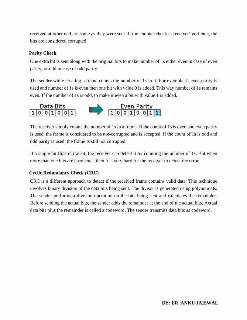
BY: ER. ANKU JAISWAL
received at other end are same as they were sent. If the counter-check at receiver’ end fails, the
bits are considered corrupted.
Parity Check
One extra bit is sent along with the original bits to make number of 1s either even in case of even
parity, or odd in case of odd parity.
The sender while creating a frame counts the number of 1s in it. For example, if even parity is
used and number of 1s is even then one bit with value 0 is added. This way number of 1s remains
even. If the number of 1s is odd, to make it even a bit with value 1 is added.
The receiver simply counts the number of 1s in a frame. If the count of 1s is even and even parity
is used, the frame is considered to be not-corrupted and is accepted. If the count of 1s is odd and
odd parity is used, the frame is still not corrupted.
If a single bit flips in transit, the receiver can detect it by counting the number of 1s. But when
more than one bits are erroneous, then it is very hard for the receiver to detect the error.
Cyclic Redundancy Check (CRC)
CRC is a different approach to detect if the received frame contains valid data. This technique
involves binary division of the data bits being sent. The divisor is generated using polynomials.
The sender performs a division operation on the bits being sent and calculates the remainder.
Before sending the actual bits, the sender adds the remainder at the end of the actual bits. Actual
data bits plus the remainder is called a codeword. The sender transmits data bits as codeword.
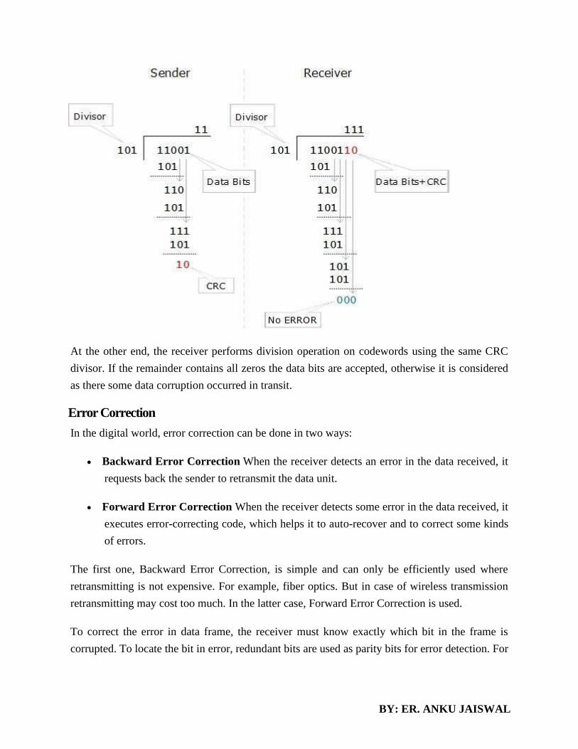
BY: ER. ANKU JAISWAL
At the other end, the receiver performs division operation on codewords using the same CRC
divisor. If the remainder contains all zeros the data bits are accepted, otherwise it is considered
as there some data corruption occurred in transit.
Error Correction
In the digital world, error correction can be done in two ways:
• Backward Error Correction When the receiver detects an error in the data received, it
requests back the sender to retransmit the data unit.
• Forward Error Correction When the receiver detects some error in the data received, it
executes error-correcting code, which helps it to auto-recover and to correct some kinds
of errors.
The first one, Backward Error Correction, is simple and can only be efficiently used where
retransmitting is not expensive. For example, fiber optics. But in case of wireless transmission
retransmitting may cost too much. In the latter case, Forward Error Correction is used.
To correct the error in data frame, the receiver must know exactly which bit in the frame is
corrupted. To locate the bit in error, redundant bits are used as parity bits for error detection. For

BY: ER. ANKU JAISWAL
example, we take ASCII words (7 bits data), then there could be 8 kind of information we need:
first seven bits to tell us which bit is error and one more bit to tell that there is no error.
For m data bits, r redundant bits are used. r bits can provide 2r combinations of information. In
m+r bit codeword, there is possibility that the r bits themselves may get corrupted. So the number
of r bits used must inform about m+r bit locations plus no-error information, i.e. m+r+1.
Hamming Code
Hamming code is a set of error-correction codes that can be used to detect and correct the
errors that can occur when the data is moved or stored from the sender to the receiver. It
is technique developed by R.W. Hamming for error correction.
Redundant bits –
Redundant bits are extra binary bits that are generated and added to the information-carrying bits
of data transfer to ensure that no bits were lost during the data transfer.
The number of redundant bits can be calculated using the following formula:
2^r ≥ m + r + 1
where, r = redundant bit, m = data bit
Suppose the number of data bits is 7, then the number of redundant bits can be calculated using:
= 2^4 ≥ 7 + 4 + 1
Thus, the number of redundant bits= 4
Parity bits –
A parity bit is a bit appended to a data of binary bits to ensure that the total number of 1’s in the
data are even or odd. Parity bits are used for error detection. There are two types of parity bits:
1. Even parity bit:
In the case of even parity, for a given set of bits, the number of 1’s are counted. If that count is
odd, the parity bit value is set to 1, making the total count of occurrences of 1’s an even number. If
the total number of 1’s in a given set of bits is already even, the parity bit’s value is 0.
2. Odd Parity bit –
In the case of odd parity, for a given set of bits, the number of 1’s are counted. If that count is
even, the parity bit value is set to 1, making the total count of occurrences of 1’s an odd number. If
the total number of 1’s in a given set of bits is already odd, the parity bit’s value is 0.
General Algorithm of Hamming code –
The Hamming Code is simply the use of extra parity bits to allow the identification of an error.
1. Write the bit positions starting from 1 in binary form (1, 10, 11, 100, etc).
2. All the bit positions that are a power of 2 are marked as parity bits (1, 2, 4, 8, etc).

BY: ER. ANKU JAISWAL
3. All the other bit positions are marked as data bits.
4. Each data bit is included in a unique set of parity bits, as determined its bit position in binary form.
a. Parity bit 1 covers all the bits positions whose binary representation includes a 1 in the least
significant
position (1, 3, 5, 7, 9, 11, etc).
b. Parity bit 2 covers all the bits positions whose binary representation includes a 1 in the second
position from
the least significant bit (2, 3, 6, 7, 10, 11, etc).
c. Parity bit 4 covers all the bits positions whose binary representation includes a 1 in the third
position from
the least significant bit (4–7, 12–15, 20–23, etc).
d. Parity bit 8 covers all the bits positions whose binary representation includes a 1 in the fourth
position from
the least significant bit bits (8–15, 24–31, 40–47, etc).
e. In general each parity bit covers all bits where the bitwise AND of the parity position and the bit
position is
non-zero.
5. Since we check for even parity set a parity bit to 1 if the total number of ones in the positions it
checks is
odd.
6. Set a parity bit to 0 if the total number of ones in the positions it checks is even.
Determining the position of redundant bits –
These redundancy bits are placed at the positions which correspond to the power of 2.
As in the above example:
1. The number of data bits = 7
2. The number of redundant bits = 4
3. The total number of bits = 11
4. The redundant bits are placed at positions corresponding to power of 2- 1, 2, 4, and 8
Suppose the data to be transmitted is 1011001, the bits will be placed as follows:
Determining the Parity bits –

BY: ER. ANKU JAISWAL
1. R1 bit is calculated using parity check at all the bits positions whose binary representation includes
a 1 in the least significant position.
R1: bits 1, 3, 5, 7, 9, 11
1. To find the redundant bit R1, we check for even parity. Since the total number of 1’s in all the bit
positions corresponding to R1 is an even number the value of R1 (parity bit’s value) = 0
2. R2 bit is calculated using parity check at all the bits positions whose binary representation includes
a 1 in the second position from the least significant bit.
R2: bits 2,3,6,7,10,11
1. To find the redundant bit R4, we check for even parity. Since the total number of 1’s in all the bit
positions corresponding to R4 is an odd number the value of R4(parity bit’s value) = 1
2. R8 bit is calculated using parity check at all the bits positions whose binary representation includes
a 1 in the fourth position from the least significant bit.
R8: bit 8,9,10,11
To find the redundant bit R8, we check for even parity. Since the total number of 1’s in all the bit
positions corresponding to R8 is an even number the value of R8(parity bit’s value)=0.
Thus, the data transferred is:
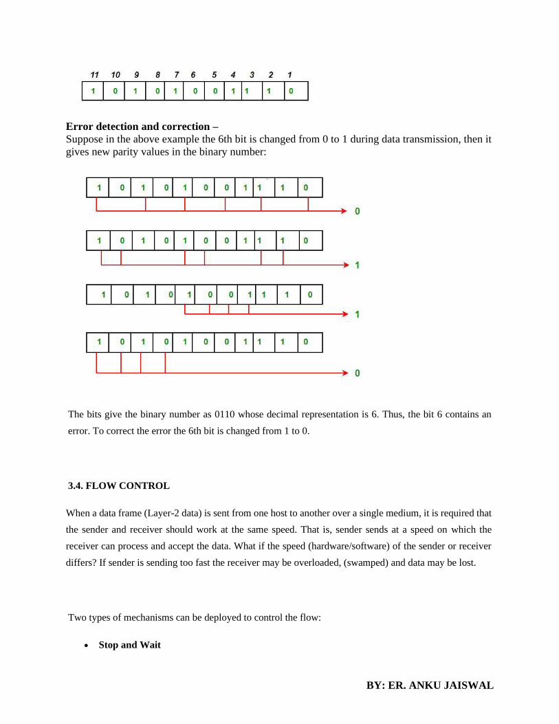
BY: ER. ANKU JAISWAL
Error detection and correction –
Suppose in the above example the 6th bit is changed from 0 to 1 during data transmission, then it
gives new parity values in the binary number:
The bits give the binary number as 0110 whose decimal representation is 6. Thus, the bit 6 contains an
error. To correct the error the 6th bit is changed from 1 to 0.
3.4. FLOW CONTROL
When a data frame (Layer-2 data) is sent from one host to another over a single medium, it is required that
the sender and receiver should work at the same speed. That is, sender sends at a speed on which the
receiver can process and accept the data. What if the speed (hardware/software) of the sender or receiver
differs? If sender is sending too fast the receiver may be overloaded, (swamped) and data may be lost.
Two types of mechanisms can be deployed to control the flow:
• Stop and Wait

BY: ER. ANKU JAISWAL
This flow control mechanism forces the sender after transmitting a data frame to stop and wait until
the acknowledgement of the data-frame sent is received.
• Sliding Window
In this flow control mechanism, both sender and receiver agree on the number of data-frames after
which the acknowledgement should be sent. As we learnt, stop and wait flow control mechanism
wastes resources, this protocol tries to make use of underlying resources as much as possible.
Error Control
When data-frame is transmitted, there is a probability that data-frame may be lost in the transit or
it is received corrupted. In both cases, the receiver does not receive the correct data-frame and
sender does not know anything about any loss.In such case, both sender and receiver are equipped
with some protocols which helps them to detect transit errors such as loss of data-frame. Hence,
either the sender retransmits the data-frame or the receiver may request to resend the previous
data-frame.
Requirements for error control mechanism:
• Error detection - The sender and receiver, either both or any, must ascertain that there is
some error in the transit.
• Positive ACK - When the receiver receives a correct frame, it should acknowledge it.
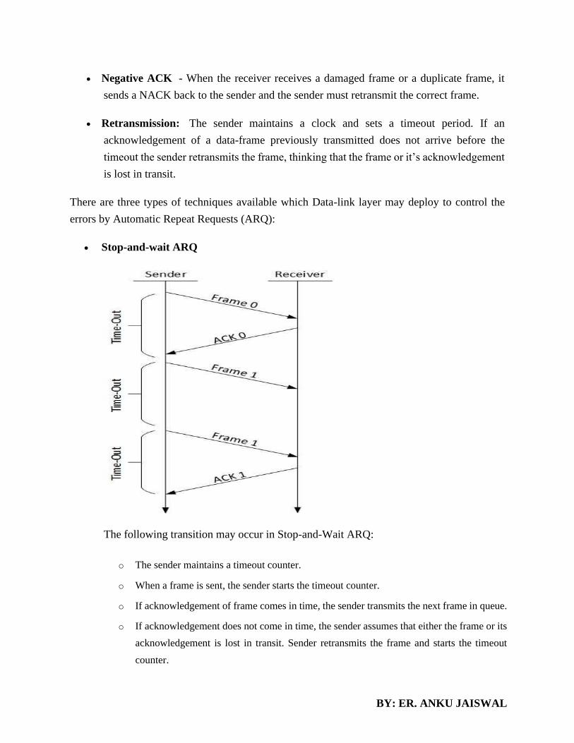
BY: ER. ANKU JAISWAL
• Negative ACK - When the receiver receives a damaged frame or a duplicate frame, it
sends a NACK back to the sender and the sender must retransmit the correct frame.
• Retransmission: The sender maintains a clock and sets a timeout period. If an
acknowledgement of a data-frame previously transmitted does not arrive before the
timeout the sender retransmits the frame, thinking that the frame or it’s acknowledgement
is lost in transit.
There are three types of techniques available which Data-link layer may deploy to control the
errors by Automatic Repeat Requests (ARQ):
• Stop-and-wait ARQ
The following transition may occur in Stop-and-Wait ARQ:
o The sender maintains a timeout counter.
o When a frame is sent, the sender starts the timeout counter.
o If acknowledgement of frame comes in time, the sender transmits the next frame in queue.
o If acknowledgement does not come in time, the sender assumes that either the frame or its
acknowledgement is lost in transit. Sender retransmits the frame and starts the timeout
counter.

BY: ER. ANKU JAISWAL
o If a negative acknowledgement is received, the sender retransmits the frame.
• Go-Back-N ARQ
Stop and wait ARQ mechanism does not utilize the resources at their best.When the
acknowledgement is received, the sender sits idle and does nothing. In Go-Back-N ARQ
method, both sender and receiver maintain a window.
The sending-window size enables the sender to send multiple frames without receiving
the acknowledgement of the previous ones. The receiving-window enables the receiver to
receive multiple frames and acknowledge them. The receiver keeps track of incoming
frame’s sequence number.
When the sender sends all the frames in window, it checks up to what sequence number
it has received positive acknowledgement. If all frames are positively acknowledged, the
sender sends next set of frames. If sender finds that it has received NACK or has not
received any ACK for a particular frame, it retransmits all the frames after which it does
not receive any positive ACK.
• Selective Repeat ARQ

BY: ER. ANKU JAISWAL
In Go-back-N ARQ, it is assumed that the receiver does not have any buffer space for its
window size and has to process each frame as it comes. This enforces the sender to
retransmit all the frames which are not acknowledged.
In Selective-Repeat ARQ, the receiver while keeping track of sequence numbers, buffers
the frames in memory and sends NACK for only frame which is missing or damaged.
The sender in this case, sends only packet for which NACK is received.
PIGGYBACKING
Piggybacking data is a bit different from Sliding Window Protocol used in the OSI model. In the data
frame itself, we incorporate one additional field for acknowledgment (called ACK). Whenever party A
wants to send data to party B, it will send the data along with this ACK field.
THE MEDIUM ACCESS SUBLAYER
• The channel allocation problem
• Multiple access protocol
• Ethernet

BY: ER. ANKU JAISWAL
• Wireless LAN(802.11)
THE CHANNEL ALLOCATION PROBLEM
• THE CHANNEL ALLOCATION PROBLEM: how to allocate a single broadcast channel among
competing users. The channel might be a portion of the wireless spectrum in a geographic region,
or a single wire or optical fiber to which multiple nodes are connected.
Static Channel Allocation
• The traditional way of allocating a single channel among multiple competing users is to chop up
its capacity by using one of the multiplexing schemes such as FDM (Frequency Division
Multiplexing). If there are N users, the bandwidth is divided into N equal-sized portions, with each
user being assigned one portion. Since each user has a private frequency band, there is no
interference among users.
• When there are only a small and constant number of users, each of which has a steady stream or a
heavy load of traffic, this division is a simple and efficient allocation mechanism. A wireless
example is FM radio stations. Each station gets a portion of the FM band and uses it most of the
time to broadcast its signal. However, when the number of senders is large and varying or the
traffic is bursty, FDM presents some problems.
– If the spectrum is cut up into N regions while fewer than N users are currently interested
in communicating, a large piece of valuable spectrum will be wasted.
– If more than N users want to communicate, some of them will be denied permission for
lack of bandwidth.
– Even if the number of users held constant at N; dividing the single available channel into
some number of static sub channels is inherently inefficient. The basic problem is that
when some users are quiescent, their bandwidth is simply lost. They are not using it, and
no one else is allowed to use it either.
A static allocation is a poor fit to most computer systems, in which data traffic is extremely bursty,
often with peak traffic to mean traffic ratios of 1000:1. Consequently, most of the channels will be
idle most of the time.
Dynamic channel allocation

BY: ER. ANKU JAISWAL
Channel not pre-divided into the number of users. Dynamic channel allocation. A mapping can be
established when a new station appears, and the mapping can be removed when the station
disappears. KEY ASSUMPTIONS:- Broadcast Network Station Model – The model consists of N
independent stations ( computers, telephones, personal communicators ), each with a program or
user that generates frames for transmission. Once a frame has been generated, the station is blocked
till it has been fully transmitted. 2. Single channel – A single channel is available for all
communication. All stations can transmit on it and all can receive from it. Multiple users working
on same channel multiple transmitters and multiple
Collision – When 2 frames are transmitted simultaneously, they overlap in time and the resulting
signal is garbled. Slotted Time – Fixed time slots. Transmission begins only at start of a slot.
Carrier Sense – Station can tell if the channel is already in use or not. Time division multiplexing
Here we fix a discrete time interval for dynamic allocation and new allocations will be there only
when first have executed their data. If 4 users come channel is divided into 4 parts. Next time when
for new 7 users channel is divided into 7 parts but only when next dynamic allocation will be done.
FOR EXAMPLE: - The set of cell phones that are operating in the range of a given cell tower
varies constantly. Dynamic channel allocation
MULTIPLE ACCESS PROTOCOLS
Channelization Protocols
The term channelization refers to the sharing of a point-to-point communications medium. For example,
many telephone conversations (or in our context, computer-to-computer network transactions) can be
submitted simultaneously on a single wire, with each conversation being on a separate channel. The notion

BY: ER. ANKU JAISWAL
of a channel is very closely related to the household concept of radio and TV channels. The frequency
spectrum for television, for instance, is divided into subranges called channels, and these correspond to our
everyday concept of TV channels. Each channel is used to transmit different information, all
simultaneously. There are three main ways of doing this:
• In time-division multiplexing (TDMA), different sources transmit on the line at different times, each
taking (very short) turns. This is used in long-distance phone lines
• In frequency-division multiplexing (FDMA), the different sources attached to the line send on different
frequencies (e.g. different radio frequencies, or different light frequencies, i.e. different colors). This is
used for radio and television transmission, and increasingly for computer-to-computer network
transactions.
• In code-division multiplexing (CDMA), all nodes on the network send at the same time, on the same
frequency, but using different codes. (Think of one node using a 4B/5B code, another using a second kind
of code, and so on.) This is used in some cellular telephone systems.
TDMA
Time Division Multiple Access (TDMA) is a digital cellular telephone communication technology. It
facilitates many users to share the same frequency without interference. Its technology divides a signal into
different timeslots, and increases the data carrying capacity.
Time Division Multiple Access (TDMA) is a complex technology, because it requires an accurate
synchronization between the transmitter and the receiver. TDMA is used in digital mobile radio systems.
The individual mobile stations cyclically assign a frequency for the exclusive use of a time interval.
In most of the cases, the entire system bandwidth for an interval of time is not assigned to a station.
However, the frequency of the system is divided into sub-bands, and TDMA is used for the multiple
accesses in each sub-band. Sub-bands are known as carrier frequencies. The mobile system that uses this
technique is referred as the multi-carrier systems.
In the following example, the frequency band has been shared by three users. Each user is assigned
definite timeslots to send and receive data. In this example, user ‘B’ sends after user ‘A,’ and
user ‘C’ sends thereafter. In this way, the peak power becomes a problem and larger by the burst
communication.

BY: ER. ANKU JAISWAL
Advantages of TDMA
• Permits flexible rates (i.e. several slots can be assigned to a user, for example, each time interval
translates 32Kbps, a user is assigned two 64 Kbps slots per frame).
• Can withstand gusty or variable bit rate traffic. Number of slots allocated to a user can be changed
frame by frame (for example, two slots in the frame 1, three slots in the frame 2, one slot in the
frame 3, frame 0 of the notches 4, etc.).
• No guard band required for the wideband system.
• No narrowband filter required for the wideband system.
Disadvantages of TDMA
• High data rates of broadband systems require complex equalization.
• Due to the burst mode, a large number of additional bits are required for synchronization and
supervision.
• Call time is needed in each slot to accommodate time to inaccuracies (due to clock instability).
• Electronics operating at high bit rates increase energy consumption.
• Complex signal processing is required to synchronize within short slots.

BY: ER. ANKU JAISWAL
FDMA
Frequency Division Multiple Access (FDMA) is one of the most common analogue multiple access
methods. The frequency band is divided into channels of equal bandwidth so that each conversation is
carried on a different frequency (as shown in the figure below).
In FDMA method, guard bands are used between the adjacent signal spectra to minimize crosstalk between
the channels. A specific frequency band is given to one person, and it will received by identifying each of
the frequency on the receiving end. It is often used in the first generation of analog mobile phone.
Advantages of FDMA
As FDMA systems use low bit rates (large symbol time) compared to average delay spread, it offers the
following advantages −
• Reduces the bit rate information and the use of efficient numerical codes increases the capacity.
• It reduces the cost and lowers the inter symbol interference (ISI)
• Equalization is not necessary.
• An FDMA system can be easily implemented. A system can be configured so that the
improvements in terms of speech encoder and bit rate reduction may be easily incorporated.

BY: ER. ANKU JAISWAL
• Since the transmission is continuous, less number of bits are required for synchronization and
framing.
Disadvantages of FDMA
Although FDMA offers several advantages, it has a few drawbacks as well, which are listed below −
• It does not differ significantly from analog systems; improving the capacity depends on the signal-
to-interference reduction, or a signal-to-noise ratio (SNR).
• The maximum flow rate per channel is fixed and small.
• Guard bands lead to a waste of capacity.
• Hardware implies narrowband filters, which cannot be realized in VLSI and therefore increases
the cost.
CDMA
Code division multiple access (CDMA) is a channel access method used by various radio communication
technologies.
CDMA is an example of multiple access, where several transmitters can send information simultaneously
over a single communication channel. This allows several users to share a band of frequencies
(see bandwidth). To permit this without undue interference between the users, CDMA employs spread-
spectrum technology and a special coding scheme (where each transmitter is assigned a code.
Code Division Multiple Access (CDMA) is a digital cellular technology used for mobile communication.
CDMA is the base on which access methods such as cdmaOne, CDMA-2000, and WCDMA are built.
CDMA cellular systems are deemed superior to FDMA and TDMA, which is why CDMA plays a critical
role in building efficient, robust, and secure radio communication systems.
A Simple Analogy
Let’s take a simple analogy to understand the concept of CDMA. Assume we have a few students gathered
in a classroom who would like to talk to each other simultaneously. Nothing would be audible if everyone
starts speaking at the same time. Either they must take turns to speak or use different languages to
communicate.
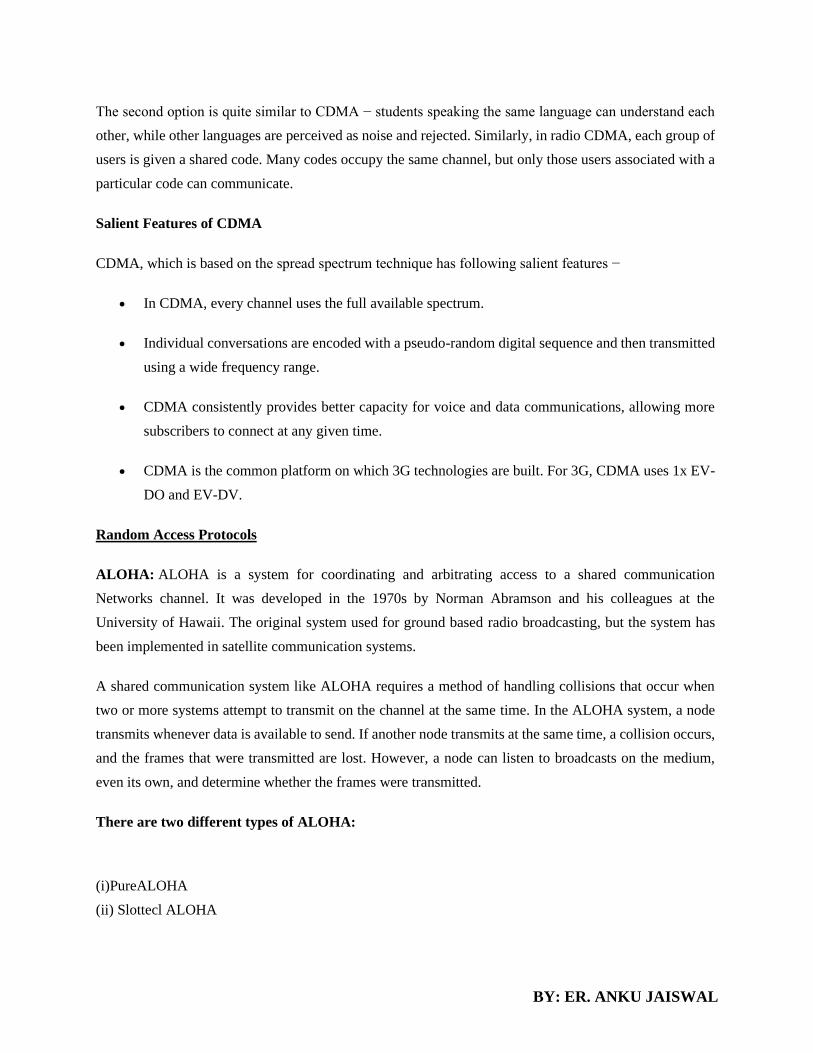
BY: ER. ANKU JAISWAL
The second option is quite similar to CDMA − students speaking the same language can understand each
other, while other languages are perceived as noise and rejected. Similarly, in radio CDMA, each group of
users is given a shared code. Many codes occupy the same channel, but only those users associated with a
particular code can communicate.
Salient Features of CDMA
CDMA, which is based on the spread spectrum technique has following salient features −
• In CDMA, every channel uses the full available spectrum.
• Individual conversations are encoded with a pseudo-random digital sequence and then transmitted
using a wide frequency range.
• CDMA consistently provides better capacity for voice and data communications, allowing more
subscribers to connect at any given time.
• CDMA is the common platform on which 3G technologies are built. For 3G, CDMA uses 1x EV-
DO and EV-DV.
Random Access Protocols
ALOHA: ALOHA is a system for coordinating and arbitrating access to a shared communication
Networks channel. It was developed in the 1970s by Norman Abramson and his colleagues at the
University of Hawaii. The original system used for ground based radio broadcasting, but the system has
been implemented in satellite communication systems.
A shared communication system like ALOHA requires a method of handling collisions that occur when
two or more systems attempt to transmit on the channel at the same time. In the ALOHA system, a node
transmits whenever data is available to send. If another node transmits at the same time, a collision occurs,
and the frames that were transmitted are lost. However, a node can listen to broadcasts on the medium,
even its own, and determine whether the frames were transmitted.
There are two different types of ALOHA:
(i)PureALOHA
(ii) Slottecl ALOHA

BY: ER. ANKU JAISWAL
(i) Pure ALOHA
• In pure ALOHA, the stations transmit frames whenever they have data to send.
• When two or more stations transmit simultaneously, there is collision and the frames are destroyed.
• In pure ALOHA, whenever any station transmits a frame, it expects the acknowledgement from the
receiver.
• If acknowledgement is not received within specified time, the station assumes that the frame (or
acknowledgement) has been destroyed.
• If the frame is destroyed because of collision the station waits for a random amount of time and sends it
again. This waiting time must be random otherwise same frames will collide again and again.
• Therefore pure ALOHA dictates that when time-out period passes, each station must wait for a random
amount of time before resending its frame. This randomness will help avoid more collisions.
• Figure shows an example of frame collisions in pure ALOHA.
• In fig there are four stations that .contended with one another for access to shared channel. All these
stations are transmitting frames. Some of these frames collide because multiple frames are in contention
for the shared channel. Only two frames, frame 1.1 and frame 2.2 survive. All other frames are destroyed.

BY: ER. ANKU JAISWAL
• Whenever two frames try to occupy the channel at the same time, there will be a collision and both will
be damaged. If first bit of a new frame overlaps with just the last bit of a frame almost finished, both frames
will be totally destroyed and both will have to be retransmitted.
(ii) Slotted ALOHA
• Slotted ALOHA was invented to improve the efficiency of pure ALOHA as chances of collision in pure
ALOHA are very high.
• In slotted ALOHA, the time of the shared channel is divided into discrete intervals called slots.
• The stations can send a frame only at the beginning of the slot and only one frame is sent in each slot.
• In slotted ALOHA, if any station is not able to place the frame onto the channel at the beginning of the
slot i.e. it misses the time slot then the station has to wait until the beginning of the next time slot.
• In slotted ALOHA, there is still a possibility of collision if two stations try to send at the beginning of the
same time slot as shown in fig.
• Slotted ALOHA still has an edge over pure ALOHA as chances of collision are reduced to one-half.
Key Differences Between Pure ALOHA and Slotted ALOHA

BY: ER. ANKU JAISWAL
1. Pure ALOHA was introduced by Norman and his associates at the university of Hawaii in 1970.
On the other hand, Slotted ALOHA was introduced by Roberts in 1972.
2. In pure ALOHA, whenever a station has data to send it transmits it without waiting whereas, in
slotted ALOHA a user wait till the next time slot beings to transmit the data.
3. In pure ALOHA the time is continuous whereas, in Slotted ALOHA the time is discrete and divided
into slots.
4. In pure ALOHA the probability of successful transmission is S=G*e^-2G. On the other hand, in
slotted ALOHA the probability of successful transmission is S=G*e^-G.
5. The time of sender and receiver in pure ALOHA is not globally synchronized whereas, the time of
sender and receiver in slotted ALOHA is globally synchronized.
6. The maximum throughput occurs at G=1/2 which is 18 % whereas, the maximum throughput
occurs at G=1 which is 37%.
CSMA, or listen with random access carrier
Technical CSMA (Carrier Sense Multiple Access) is to listen to the channel before transmitting. This
significantly reduces the risk of collision, but does not eliminate them completely. If during the propagation
time between the couple of the more remote stations (vulnerability period), a coupler does not detect the
transmission of a frame, and there may be signal superposition. Therefore, it is necessary to subsequently
retransmit lost frames.
Numerous variations of this technique have been proposed, which differ by three Features:

BY: ER. ANKU JAISWAL
• The strategy followed by the module after detecting the channel status.
• The way collisions are detected.
• The message retransmission after collision policy.
Its main variants are:
• Non-persistent CSMA. The coupler the listening channel when a frame is ready to be sent. If the channel
is free, the module emits. Otherwise, it starts the same process after a random delay.
• Persistent CSMA - A loan coupler to transmit the channel and previously listening forwards if it is free.
If it detects the occupation of carrier, it continues to listen until the channel is clear and transmits at that
time. This technique allows lose less time than in the previous case, but it has the disadvantage increase
the likelihood of collision, since the frames that accumulate during the busy time are all transmitted
simultaneously.
• P-persistent CSMA - The algorithm is the same as before, but when the
Channel becomes free; the module transmits with probability p. In other words, the coupler differs his
show with probability 1 - p. This algorithm reduces the likelihood of collision. Assuming both terminals
simply making the collision is inevitable in the standard case. With the new algorithm, there is a probability
1 - p that each terminal does not transmit, thereby avoiding the collision. However, it increases the time
before transmission, since a terminal may choose not to transmit, with a probability 1 - p, while the channel
is free.
• CSMA / CD (Carrier Sense Multiple Access / Collision Detection) - This technique normalized
random access by the IEEE 802.3 working group is currently the longer used. At a preliminary listening to
the network is added listening during transmission. Coupler to issue a loan that detected free channel
transmits and continues to listen the channel. The coupler continues to listen, which is sometimes indicated
by the CSMA / CD persistent acronym. If there is a collision, it interrupts its transmission as soon as
possible and sends special signals, called padding bits so that all couplers are notified of the collision. He
tries again his show later using an algorithm that we present later.
Figure shows the CSMA/CD. In this example, the couplers 2 and 3 attempt broadcasting for the coupler 1
transmits its own frame. The couplers 2 and 3 begin to listen and transmit at the same time, the propagation
delay around, from the end of the Ethernet frame transmitted by the coupler 1. A collision ensues. Like the
couplers 2 and 3 continue to listen to the physical media, they realize the collision, stop their transmission
and draw a random time to start retransmission process.
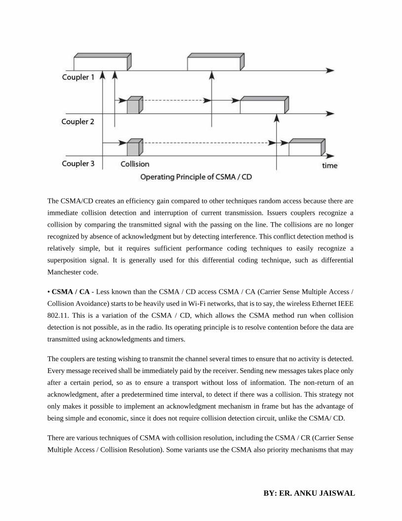
BY: ER. ANKU JAISWAL
The CSMA/CD creates an efficiency gain compared to other techniques random access because there are
immediate collision detection and interruption of current transmission. Issuers couplers recognize a
collision by comparing the transmitted signal with the passing on the line. The collisions are no longer
recognized by absence of acknowledgment but by detecting interference. This conflict detection method is
relatively simple, but it requires sufficient performance coding techniques to easily recognize a
superposition signal. It is generally used for this differential coding technique, such as differential
Manchester code.
• CSMA / CA - Less known than the CSMA / CD access CSMA / CA (Carrier Sense Multiple Access /
Collision Avoidance) starts to be heavily used in Wi-Fi networks, that is to say, the wireless Ethernet IEEE
802.11. This is a variation of the CSMA / CD, which allows the CSMA method run when collision
detection is not possible, as in the radio. Its operating principle is to resolve contention before the data are
transmitted using acknowledgments and timers.
The couplers are testing wishing to transmit the channel several times to ensure that no activity is detected.
Every message received shall be immediately paid by the receiver. Sending new messages takes place only
after a certain period, so as to ensure a transport without loss of information. The non-return of an
acknowledgment, after a predetermined time interval, to detect if there was a collision. This strategy not
only makes it possible to implement an acknowledgment mechanism in frame but has the advantage of
being simple and economic, since it does not require collision detection circuit, unlike the CSMA/ CD.
There are various techniques of CSMA with collision resolution, including the CSMA / CR (Carrier Sense
Multiple Access / Collision Resolution). Some variants use the CSMA also priority mechanisms that may

BY: ER. ANKU JAISWAL
come under this term, that avoid collisions by separate priority levels associated with different stations
connected to the network.
Controlled Access Protocols
In controlled access, the stations consult one another to find which station has the right to send. A station
cannot send unless it has been authorized by other stations. The three popular controlled-access methods
are as follows.
Polling:
Polling works with topologies in which one device is designated as a primary station and the other devices
are secondary stations. All data exchanges must be made through the primary device even when the
ultimate destination is a secondary device.
The primary device controls the link; the secondary devices follow its instructions. It is up to the primary
device to determine which device is allowed to use the channel at a given time. The primary device,
therefore, is always the initiator of a session. Consider the following figure.
If the primary wants to receive data, it asks the secondaries if they have anything to send, this is called poll
function. If the primary wants to send data, it tells the secondary to get ready to receive; this is called select
function.
Select:
The select function is used whenever the primary device has something to send. If it has something to
send, the primary device sends it. It has to know whether the target device is prepared to receive or not.
So the primary must alert the secondary to the upcoming transmission and wait for an acknowledgment
of the secondary's ready status. Before sending data, the primary creates and transmits a select (SEL)
frame, one field of which includes the address of the intended secondary.
Poll:
The poll function is used by the primary device to solicit transmissions from the secondary devices.
When the primary is ready to receive data, it must ask (poll) each device in turn if it has anything to send.
When the first secondary is approached, it responds either with a NAK frame if it has nothing to send or
with data (in the form of a data frame) if it does. If the response is negative (a NAK frame), then the

BY: ER. ANKU JAISWAL
primary polls the next secondary in the same manner until it finds one with data to send. When the
response is positive (a data frame), the primary reads the frame and returns an acknowledgment (ACK
frame), verifying its receipt.
3. Token Passing:
In the token-passing method, the stations in a network are organized in a logical ring. In other words, for
each station, there is a predecessor and a successor. The predecessor is the station which is logically before
the station in the ring; the successor is the station which is after the station in the ring. The current station
is the one that is accessing the channel now. The right to this access has been passed from the predecessor
to the current station. The right will be passed to the successor when the current station has no more data
to send.
In this method, a special packet called a token circulates through the ring. The possession of the token
gives the station the right to access the channel and send its data. When a station has some data to send, it
waits until it receives the token from its predecessor. It then holds the token and sends its data. When the
station has no more data to send, it releases the token, passing it to the next logical station in the ring. The
station cannot send data until it receives the token again in the next round.
Token management is needed for this access method. Stations must be limited in the time they can have
possession of the token. The token must be monitored to ensure it has not been lost or destroyed. For
example, if a station that is holding the token fails, the token will disappear from the network. Another
function of token management is to assign priorities to the stations and to the types of data being
transmitted. And finally, token management is needed to make low- priority stations release the token to
high priority stations.
3.5. DATA LINK PROTOCOL
a) HDLC
A high-level data link control (HDLC) is a protocol that is a bit-oriented synchronous data link
layer. HDLC ensures the error-free transmission of data to the proper destinations and controls
the data transmission speed.
HDLCs can provide both connection-oriented and connectionless services.

BY: ER. ANKU JAISWAL
A high-level data link control defines rules for transmitting data between network points. Data in an
HDLC is organized into units called frames and is sent across networks to specified destinations. HDLC
also manages the pace at which data is transmitted. HDLC is commonly used in the open systems
interconnection (OSI) model's layer.
HDLC frames are transmitted over synchronous links or asynchronous links, which do not mark the start
and end of frames. This is done using a frame delimiter or flag, which contains unique sequence of bits
that are not visible inside a frame.
There are three types of HDLC frames:
• Information frames/User data (I-frames)
• Supervisory frames/Control data (S-frames)
• Unnumbered frames (U-frames)
The common fields within an HDLC frame are:
• Flag
• Address
• Control information
• Frame check sequence
The HDLC protocol is used by a variety of standards implemented in the protocol stacks of X.25, V.42 and
ISDN and many other protocol stacks.

BY: ER. ANKU JAISWAL
o Flag field. The flag field of an HDLC frame is an 8-bit sequence with the bit pattern 01111110
that identifies both the beginning and the end of a frame and serves as a synchronization pattern
for the receiver.
o Address field. The second field of an HDLC frame contains the address of the secondary station.
If a primary station created the frame, it contains a to address. If a secondary creates the frame, it
contains a from address. An address field can be 1 byte or several bytes long, depending on the
needs of the network. One byte can identify up to 128 stations (l bit is used for another purpose).
Larger networks require multiple-byte address fields. If the address field is only 1 byte, the last bit
is always a 1. If the address is more than 1 byte, all bytes but the last one will end with 0; only the
last will end with 1. Ending each intermediate byte with 0 indicates
to the receiver that there are more address bytes to come.
o Control field. The control field is a 1- or 2-byte segment of the frame used for flow and error
control. The interpretation of bits in this field depends on the frame type. We discuss this field
later and describe its format for each frame type.
o Information field. The information field contains the user's data from the network layer or
management information. Its length can vary from one network to another.
o FCS field. The frame check sequence (FCS) is the HDLC error detection field. It can contain
either a 2- or 4-byte ITU-T CRC.
b) PPP
In computer networking, Point-to-Point Protocol (PPP) is a data link (layer 2) protocol used to establish
a direct connection between two nodes. It connects two routers directly without any host or any other
networking device in between. It can provide connection authentication,
transmission encryption (using ECP, RFC 1968), and compression.
PPP is used over many types of physical networks including serial cable, phone line, trunk line, cellular
telephone, specialized radio links, and fiber optic links such as SONET.
1. It defines link control protocol (LCP) for:-
(a) Establishing the link between two devices.
(b) Maintaining this established link.
(c) Configuring this link.
(d) Terminating this link after the transfer.

BY: ER. ANKU JAISWAL
2. It defines how network layer data are encapsulated in data link frame.
3. PPP provides error detection.
4. Unlike SLIP that supports only IP, PPP supports multiple protocols.
5. PPP allows the IP address to be assigned at the connection time i.e. dynamically. Thus a
temporary IP address can be assigned to each host.
6. PPP provides multiple network layer services supporting a variety of network layer protocol.
For this PPP uses a protocol called NCP (Network Control Protocol).
8. It also defines how two devices can authenticate each other.
PPP Frame Format
The frame format of PPP resembles HDLC frame. Its various fields are:
1. Flag field: Flag field marks the beginning and end of the PPP frame. Flag byte is 01111110. (1
byte).
2. Address field: This field is of 1 byte and is always 11111111. This address is the broadcast
address i.e. all the stations accept this frame.
3. Control field: This field is also of 1 byte. This field uses the format of the U-frame
(unnumbered) in HDLC. The value is always 00000011 to show that the frame does not contain
any sequence numbers and there is no flow control or error control.
4. Protocol field: This field specifies the kind of packet in the data field i.e. what is being carried
in data field.
5. Data field: Its length is variable. If the length is not negotiated using LCP during line set up, a
default length of 1500 bytes is used. It carries user data or other information.
6. FCS field: The frame checks sequence. It is either of 2 bytes or 4 bytes. It contains the
checksum.
3.9. ETHERNET (IEEE 802.3) LOCAL AREA NETWORK (LAN)

BY: ER. ANKU JAISWAL
Ethernet protocols refer to the family of local-area network (LAN) covered by the IEEE 802.3. In the
Ethernet standard, there are two modes of operation: half-duplex and full-duplex modes. In the half duplex
mode, data are transmitted using the popular Carrier-Sense Multiple Access/Collision Detection
(CSMA/CD) protocol on a shared medium. The main disadvantages of the half-duplex are the efficiency
and distance limitation, in which the link distance is limited by the minimum MAC frame size. This
restriction reduces the efficiency drastically for high-rate transmission. Therefore, the carrier extension
technique is used to ensure the minimum frame size of 512 bytes in Gigabit Ethernet to achieve a reasonable
link distance.
Four data rates are currently defined for operation over optical fiber and twisted-pair cables:
• 10 Mbps – 10Base-T Ethernet (IEEE 802.3)
• 100 Mbps – Fast Ethernet (IEEE 802.3u)
• 1000 Mbps – Gigabit Ethernet (IEEE 802.3z)
• 10-Gigabit – 10 Gbps Ethernet (IEEE 802.3ae).
In this document, we discuss the general aspects of the Ethernet. The specific issues regarding Fast Ethernet,
Gigabit and 10 Gigabit Ethernet will be discussed in separate documents.
The Ethernet system consists of three basic elements: 1. the physical medium used to carry Ethernet signals
between computers, 2. a set of medium access control rules embedded in each Ethernet interface that allow
multiple computers to fairly arbitrate access to the shared Ethernet channel, and 3. an Ethernet frame that
consists of a standardized set of bits used to carry data over the system.
3.10. NETWORKS
Token Bus (IEEE 802.4)
Token Bus is described in the IEEE 802.4 specification, and is a Local Area Network (LAN) in
which the stations on the bus or tree form a logical ring. Each station is assigned a place in an
ordered sequence, with the last station in the sequence being followed by the first, as shown below.
Each station knows the address of the station to its "left" and "right" in the sequence.

BY: ER. ANKU JAISWAL
A Token Bus network
This type of network, like a Token Ring network, employs a small data frame only a few bytes in
size, known as a token, to grant individual stations exclusive access to the network transmission
medium. Token-passing networks are deterministic in the way that they control access to the
network, with each node playing an active role in the process. When a station acqires control of
the token, it is allowed to transmit one or more data frames, depending on the time limit imposed
by the network. When the station has finished using the token to transmit data, or the time limit
has expired, it relinquishes control of the token, which is then available to the next station in the
logical sequence. When the ring is initialized, the station with the highest number in the sequence
has control of the token.
Topology of the network is either a bus or a tree, although the order in which stations are connected
to the network is not important. The network topology means that we are essentially dealing with
a broadcast network, and every frame transmitted is received by all attached stations. With the
exception of broadcast frames, however, frames will only be read by the station to which they are
addressed, and ignored by all other stations. As the token frame is transmitted, it carries the
destination address of the next station in the logical sequence. As each individual station is
powered on, it is allocated a place in the ring sequence (note that in the diagram above, station two
is not participating in the ring). The Token Bus medium access control protocol allows stations to
join the ring or leave the ring on an ad-hoc basis.
Token Bus networks were conceived to meet the needs of automated industrial manufacturing
systems and owe much to a proposal by General Motors for a networking system to be used in
their own manufacturing plants - Manufacturing Automation Protocol (MAP). Ethernet was not
considered suitable for factory automation systems because of the contention-based nature of its

BY: ER. ANKU JAISWAL
medium access control protocol, which meant that the length of time a station might have to wait
to send a frame was unpredictable. Ethernet also lacked a priority system, so there was no way to
ensure that more important data would not be held up by less urgent traffic.
A token-passing system in which each station takes turns to transmit a frame was considered a
better option, because if there are n stations, and each station takes T seconds to send a frame, no
station has to wait longer than nT seconds to acquire the token. The ring topology of existing token-
passing systems, however, was not such an attractive idea, since a break in the ring would cause a
general network failure. A ring topology was also considered to be incompatible with the linear
topology of assembly-line or process control systems. Token Bus was a hybrid system that
provided the robustness and linearity of a bus or tree topology, whilst retaining the known worst-
case performance of a token-passing medium access control method.
The transmission medium most often used for broadband Token Bus networks is 75 Ohm coaxial
cable (the same type of cable used for cable TV), although alternative cabling configurations are
available. Both single and dual cable systems may be used, with or without head-ends.
Transmission speeds vary, with data rates of 1, 5 and 10 Mbps being common. The analogue
modulation schemes that can be used include:
• Phase continuous frequency shift keying
• Phase coherent frequency shift keying
• Multilevel duo binary amplitude modulated phase shift keying
The Token Bus MAC layer protocol
When the ring is initialized, tokens are inserted into it in station address order, starting with the
highest. The token itself is passed from higher to lower addresses. Once a station aquires the token,
it has a fixed time period during which it may transmit frames, and the number of frames which
can be transmitted by each station during this time period will depend on the length of each frame.
If a station has no data to send, it simply passes the token to the next station without delay.
The Token Bus standard defines four classes of priority for traffic - 0, 2, 4, and 6 - with 6
representing the highest priority and 0 the lowest. Each station maintains four internal queues that
correspond to the four priority levels. As a frame is passed down to the MAC sublayer from a

BY: ER. ANKU JAISWAL
higher-layer protocol, its priority level is determined, and it is assigned to the appropriate queue.
When a station acquires the token, frames are transmitted from each of the four queues in strict
order of priority. Each queue is allocated a specific time slot, during which frames from that queue
may be transmitted. If there are no frames waiting in a particular queue, the token immediately
becomes available to the next queue. If the token reaches level 0 and there are no frames waiting,
it is immediately passed to the next station in the logical ring. The whole process is controlled by
timers that are used to allocate time slots to each priority level. If any queue is empty, its time slot
may be allocated for use by the remaining queues.
The priority scheme guarantees level 6 data a known fraction of the network bandwidth, and can
therefore be used to implement a real-time control system. As an example, if a network running at
10 Mbps and having fifty stations has been configured so that level 6 traffic is allocated one-third
of the bandwidth, each station has a guaranteed bandwidth of 67 kbps for level 6 traffic. The
available high priority bandwidth could thus be used to synchronize robots on an assembly line,
or to carry one digital voice channel per station, with some bandwidth left over for control
information.
The Token Bus frame format
The Token Bus frame format is shown above. The Preamble field is used to synchronise the
receiver's clock. The Start Delimeter and End Delimeter fields are used to mark the start and end
of the frame, and contain an analogue encoding of symbols other than 0s and 1s that cannot
occur accidentally within the frame data. For this reason, a length field is not required.
The Frame Control field identifies the frame as either a data frame or a control frame. For data
frames, it includes the priority level of the frame, and may also include an indicator requiring the
destination station to acknowledge correct or incorrect receipt of the frame. For control frames,
the field specifies the frame type.
The Destination and Source address fields contain either a 2-byte or a 6-byte hardware address

BY: ER. ANKU JAISWAL
for the destination and source stations respectively (a given network must use either 2-byte or 6-
byte addresses consistently, not a mixture of the two). If 2-byte addresses are used, the Data
Field can be up t0 8,182 bytes. If 6-byte addresses are used, it is limited to 8,174 bytes.
The Checksum is used to detect transmission errors. The various control frames used are shown
in the table below.
Token Ring (IEEE 802.5)
Token Ring was developed by IBM in the 1970s and is described in the IEEE 802.5 specification.
It is no longer widely used in LANs. Token passing is the method of medium access, with only
one token allowed to exist on the network at any one time. Network devices must acquire the token
to transmit data, and may only transmit a single frame before releasing the token to the next station
on the ring. When a station has data to transmit, it acquires the token at the earliest opportunity,
marks it as busy, and attaches the data and control information to the token to create a data frame,
which is then transmitted to the next station on the ring. The frame will be relayed around the ring
until it reaches the destination station, which reads the data, marks the frame as having been read,
and sends it on around the ring. When the sender receives the acknowledged data frame, it
generates a new token, marks it as being available for use, and sends it to the next station. In this
way, each of the other stations on the ring will get an opportunity to transmit data (even if they
don't have any data to transmit!).
Token Ring networks provide a priority system that allows administrators to designate specific
stations as having a higher priority than others, allowing those stations to use the network more
frequently by setting the priority level of the token so that only stations with the same priority or
higher can use the token (or reserve the token for future use). Stations that raise a token's priority
must reinstate the priority level previously in force once they have used the token. In a Token Ring
network, one station is arbitrarily selected to be the active monitor. The active monitor acts as a
source of timing information for other stations, and performs various maintenance functions, such
as generating a new token as and when required, or preventing rogue data frames from endlessly
circulating around the ring. All of the stations on the ring have a role to play in managing the
network, however. Any station that detects a serious problem will generate a beacon frame that
alerts other stations to the fault condition, prompting them to carry out diagnostic activities and
attempt to re-configure the network.

BY: ER. ANKU JAISWAL
Two basic frame types are used - tokens, and data/command frames. The token is three bytes long
and consists of a start delimiter, an access control byte, and an end delimiter. The format of the
token is shown below.
The Token Ring token
A data/command frame has the same fields as the token, plus several additional fields. The format
of the data/command frame is shown below.
The Token Ring frame format
• Start delimiter - alerts each station of the arrival of a token or frame.
• Access control byte - contains the priority field, the reservation field, the token
bit and amonitor bit.
• Frame control byte - indicates whether the frame contains data or control
information. In a control frame, this byte specifies the type of control
information carried.
• Destination and source addresses - two six-byte fields that identify the
destination and source station MAC addresses.
• Data - the maximum length is limited by the ring token holding time, which
defines the maximum time a station can hold the token
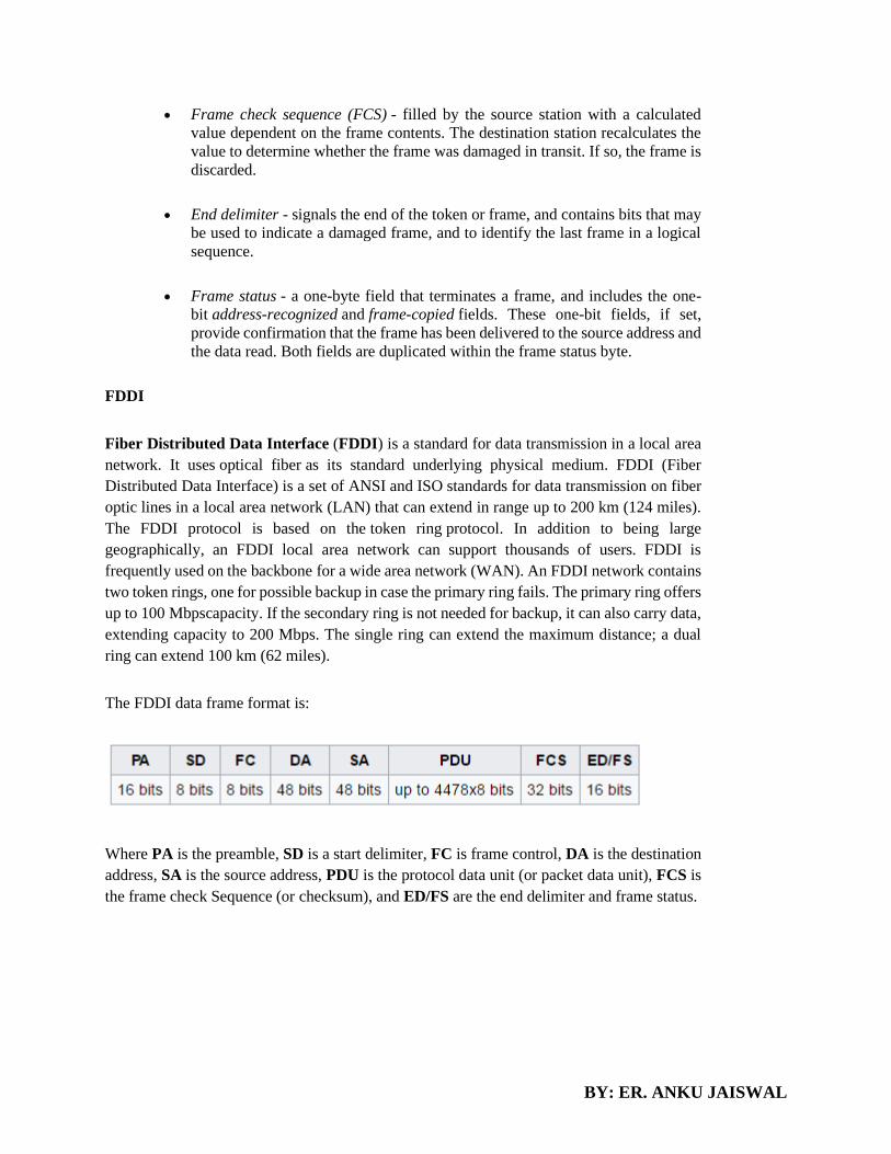
BY: ER. ANKU JAISWAL
• Frame check sequence (FCS) - filled by the source station with a calculated
value dependent on the frame contents. The destination station recalculates the
value to determine whether the frame was damaged in transit. If so, the frame is
discarded.
• End delimiter - signals the end of the token or frame, and contains bits that may
be used to indicate a damaged frame, and to identify the last frame in a logical
sequence.
• Frame status - a one-byte field that terminates a frame, and includes the one-
bit address-recognized and frame-copied fields. These one-bit fields, if set,
provide confirmation that the frame has been delivered to the source address and
the data read. Both fields are duplicated within the frame status byte.
FDDI
Fiber Distributed Data Interface (FDDI) is a standard for data transmission in a local area
network. It uses optical fiber as its standard underlying physical medium. FDDI (Fiber
Distributed Data Interface) is a set of ANSI and ISO standards for data transmission on fiber
optic lines in a local area network (LAN) that can extend in range up to 200 km (124 miles).
The FDDI protocol is based on the token ring protocol. In addition to being large
geographically, an FDDI local area network can support thousands of users. FDDI is
frequently used on the backbone for a wide area network (WAN). An FDDI network contains
two token rings, one for possible backup in case the primary ring fails. The primary ring offers
up to 100 Mbpscapacity. If the secondary ring is not needed for backup, it can also carry data,
extending capacity to 200 Mbps. The single ring can extend the maximum distance; a dual
ring can extend 100 km (62 miles).
The FDDI data frame format is:
Where PA is the preamble, SD is a start delimiter, FC is frame control, DA is the destination
address, SA is the source address, PDU is the protocol data unit (or packet data unit), FCS is
the frame check Sequence (or checksum), and ED/FS are the end delimiter and frame status.

BY: ER. ANKU JAISWAL
VLANS
Virtual LANs Another important advantage of Ethernet switches is the ability to create Virtual
Local Area Networks (VLANs). A virtual LAN can be defined as a set of ports attached to one or
more Ethernet switches. A switch can support several VLANs and it runs one MAC learning
algorithm for each Virtual LAN. When a switch receives a frame with an unknown or a multicast
destination, it forwards it over all the ports that belong to the same Virtual LAN but not over the
ports that belong to other Virtual LANs. Similarly, when a switch learns a source address on a
port, it associates it to the Virtual LAN of this port and uses this information only when forwarding
frames on this Virtual LAN. The figure below illustrates a switched Ethernet network with three
Virtual LANs. VLAN2 and VLAN3 only require a local configuration of switch S1. Host C can
exchange frames with host D, but not with hosts that are outside of its VLAN. VLAN1 is more
complex as there are ports of this VLAN on several switches. To support such VLANs, local
configuration is not sufficient anymore. When a switch receives a frame from another switch, it
must be able to determine the VLAN in which the frame originated to use the correct MAC table
to forward the frame. This is done by assigning an identifier to each Virtual LAN and placing this
identifier inside the headers of the frames that are exchanged between switches. Virtual Local Area
Networks in a switched Ethernet network

BY: ER. ANKU JAISWAL

BY: ER. ANKU JAISWAL
CHAPTER 4-NETWORK LAYER
4.1. INTERNETWORKING DEVICES
An internetworking device is a widely-used term for any hardware within networks that connect different
network resources. Key devices that comprise a network are routers, bridges, repeaters and gateways.
Hub
Hub is one of the basic icons of networking devices which works at physical layer and hence
connect networking devices physically together. Hubs are fundamentally used in networks that
use twisted pair cabling to connect devices. They are designed to transmit the packets to the other
appended devices without altering any of the transmitted packets received. They act as pathways
to direct electrical signals to travel along. They transmit the information regardless of the fact if
data packet is destined for the device connected or not.
Hub falls in two categories:
Active Hub: They are smarter than the passive hubs. They not only provide the path for the data
signals in fact they regenerate, concentrate and strengthen the signals before sending them to their
destinations. Active hubs are also termed as ‘repeaters’.
Passive Hub: They are more like point contact for the wires to built in the physical network. They
have nothing to do with modifying the signals.
Repeater
A repeater connects two segments of your network cable. It retimes and regenerates the signals to
proper amplitudes and sends them to the other segments. When talking about, ethernet topology,
you are probably talking about using a hub as a repeater. Repeaters require a small amount of time
to regenerate the signal. This can cause a propagation delay which can affect network
communication when there are several repeaters in a row. Many network architectures limit the
number of repeaters that can be used in a row. Repeaters work only at the physical layer of the
OSI network model.
Switches
Switches are the linkage points of an Ethernet network. Just as in hub, devices in switches are connected to
them through twisted pair cabling. But the difference shows up in the manner both the devices; hub and a
switch treat the data they receive. Hub works by sending the data to all the ports on the device whereas

BY: ER. ANKU JAISWAL
a switch transfers it only to that port which is connected to the destination device. A switch does so by
having an in-built learning of the MAC address of the devices connected to it. Since the transmission of
data signals are well defined in a switch hence the network performance is consequently enhanced.
Switches operate in full-duplex mode where devices can send and receive data from the switch at the
simultaneously unlike in half-duplex mode. The transmission speed in switches is double than in Ethernet
hub transferring a 20Mbps connection into 30Mbps and a 200Mbps connection to become 300Mbps.
Performance improvements are observed in networking with the extensive usage of switches in the modern
days.
The following method will elucidate further how data transmission takes place via switches:
• Cut-through transmission: It allows the packets to be forwarded as soon as they are received. The
method is prompt and quick but the possibility of error checking gets overlooked in such kind of packet
data transmission.
• Store and forward: In this switching environment the entire packet are received and ‘checked’ before
being forwarded ahead. The errors are thus eliminated before being propagated further. The downside
of this process is that error checking takes relatively longer time consequently making it a bit slower in
processing and delivering.
• Fragment Free: In a fragment free switching environment, a greater part of the packet is examined so
that the switch can determine whether the packet has been caught up in a collision. After the collision
status is determined, the packet is forwarded.
Bridges
A bridge is a computer networking device that builds the connection with the other bridge networks which
use the same protocol. It works at the Data Link layer of the OSI Model and connects the different networks
together and develops communication between them. It connects two local-area networks; two physical
LANs into larger logical LAN or two segments of the same LAN that use the same protocol.
Apart from building up larger networks, bridges are also used to segment larger networks
into smaller portions. The bridge does so by placing itself between the two portions of two physical
networks and controlling the flow of the data between them. Bridges nominate to forward the data after
inspecting into the MAC address of the devices connected to every segment. The forwarding of the data is
dependent on the acknowledgement of the fact that the destination address resides on some other interface.
It has the capacity to block the incoming flow of data as well. Today Learning bridges have been introduced
that build a list of the MAC addresses on the interface by observing the traffic on the network. This is a
leap in the development field of manually recording of MAC addresses.
Routers
Routers are network layer devices and are particularly identified as Layer- 3 devices of the OSI Model.
They process logical addressing information in the Network header of a packet such as IP Addresses.
BY: ER. ANKU JAISWAL
Router is used to create larger complex networks by complex traffic routing. It has the ability to connect
dissimilar LANs on the same protocol. It also has the ability to limit the flow of broadcasts. A router
primarily comprises of a hardware device or a system of the computer which has more than one network
interface and routing software.
Functionality:
When a router receives the data, it determines the destination address by reading the header of the packet.
Once the address is determined, it searches in its routing table to get know how to reach the destination and
then forwards the packet to the higher hop on the route. The hop could be the final destination or another
router.
Routing tables play a very pivotal role in letting the router makes a decision. Thus a routing table is ought
to be updated and complete. The two ways through which a router can receive information are:
• Static Routing: In static routing, the routing information is fed into the routing tables manually. It does
not only become a time-taking task but gets prone to errors as well. The manual updating is also required
in case of statically configured routers when change in the topology of the network or in the layout
takes place. Thus static routing is feasible for tinniest environments with minimum of one or two
routers.
• Dynamic Routing: For larger environment dynamic routing proves to be the practical solution. The
process involves use of peculiar routing protocols to hold communication. The purpose of these
protocols is to enable the other routers to transfer information about to other routers, so that the other
routers can build their own routing tables.
Gateway
Gateway is a device which is used to connect multiple networks and passes packets from one
packet to the other network. Acting as the ‘gateway’ between different networking systems or
computer programs, a gateway is a device which forms a link between them. It allows the computer
programs, either on the same computer or on different computers to share information across the
network through protocols. A router is also a gateway, since it interprets data from one network
protocol to another.
Others device such as bridge converts the data into different forms between two networking
systems. Then a software application converts the data from one format into another. Gateway is
a viable tool to translate the data format, although the data itself remains unchanged. Gateway
might be installed in some other device to add its functionality into another.
4.2. ADDRESSING

BY: ER. ANKU JAISWAL
An IP address is a unique numerical value that is used to identify a computer on network. There are two
kinds of IP addresses, public (also called globally unique IP addresses) and private. Public IP addresses are
assigned by the Internet Assigned Numbers Authority (IANA).
A network address is an identifier for a node or network interface of a telecommunications network.
Network addresses are often designed to be unique across the network, although some networks allow
for local or private addresses that may not be unique.
Four levels of addresses are used in an internet employing the TCP/IP protocols: physical (link) addresses,
logical (IP) addresses, port addresses, and specific addresses.
Figure: Addresses in TCP/IP
Each address is related to a specific layer in the TCP/IP architecture, as shown in Figure
Figure: Relationship of Layers and Addresses in TCP/IP
Physical Addresses
The physical address, also known as the link address, is the address of a node as defined by its LAN or
WAN. It is included in the frame used by the data link layer. It is the lowest-level address.

BY: ER. ANKU JAISWAL
The physical addresses have authority over the network (LAN or WAN). The size and format of these
addresses vary depending on the network. For example, Ethernet uses a 6-byte (48-bit) physical address
that is imprinted on the network interface card (NIC). LocalTalk (Apple), however, has a 1-byte dynamic
address that changes each time the station comes up.
07:01:02:01:2C:4B
A 6-byte (12 hexadecimal digits) physical address
Logical Addresses
Logical addresses are necessary for universal communications that are independent of underlying physical
networks. Physical addresses are not adequate in an internetwork environment where different networks
can have different address formats. A universal addressing system is needed in which each host can be
identified uniquely, regardless of the underlying physical network.
The logical addresses are designed for this purpose. A logical address in the Internet is currently a 32-bit
address that can uniquely define a host connected to the Internet. No two publicly addressed and visible
hosts on the Internet can have the same IP address.
Port Addresses
The IP address and the physical address are necessary for a quantity of data to travel from a source to the
destination host. However, arrival at the destination host is not the final objective of data communications
on the Internet. A system that sends nothing but data from one computer to another is not complete. Today,
computers are devices that can run multiple processes at the same time. The end objective of Internet
communication is a process communicating with another process. For example, computer A can
communicate with computer C by using TELNET. At the same time, computer A communicates with
computer B by using the File Transfer Protocol (FTP). For these processes to receive data simultaneously,
we need a method to label the different processes. In other words, they need addresses. In the TCP/IP
architecture, the label assigned to a process is called a port address. A port address in TCP/IP is 16 bits in
length.
Internet Address
An Internet Protocol address (IP address) is a numerical label assigned to each device (e.g., computer,
printer) participating in a computer network that uses the Internet Protocol for communication. An IP
address serves two principal functions: host or network interface identification and location addressing. Its
role has been characterized as follows: "A name indicates what we seek. An address indicates where it is.
A route indicates how to get there."
The designers of the Internet Protocol defined an IP address as a 32-bit number and this system, known
as Internet Protocol Version 4 (IPv4), is still in use today. However, because of the growth of
the Internet and the predicted depletion of available addresses, a new version of IP (IPv6), using 128 bits
for the address, was developed in 1995. IPv6 was standardized as RFC 2460 in 1998, and
its deployment has been ongoing since the mid-2000s.

BY: ER. ANKU JAISWAL
IP addresses are usually written and displayed in human-readable notations, such as 172.16.254.1 (IPv4),
and 2001:db8:0:1234:0:567:8:1 (IPv6).
The organization that doles out IP addresses to the world reserves a range of IP addresses for private
networks. Private networks can use IP addresses anywhere in the following ranges:
• 192.168.0.0 - 192.168.255.255 (65,536 IP addresses)
• 172.16.0.0 - 172.31.255.255 (1,048,576 IP addresses)
• 10.0.0.0 - 10.255.255.255 (16,777,216 IP addresses)
The assumption is that these private address ranges are not directly
Classful Address
A classful network is a network addressing architecture used in the Internet from 1981 until the
introduction of Classless Inter-Domain Routing in 1993. The method divides the address space for
Internet Protocol Version 4 (IPv4) into five address classes by address range.
With an IPv4 IP address, there are five classes of available IP ranges: Class A, Class B, Class C,
Class D and Class E, while only A, B, and C are commonly used. Each class allows for a range of
valid IP addresses, shown in the following table.
Class Address Range Supports
Class A 1.0.0.1 to 126.255.255.254 Supports 16 million hosts on each of 127 networks.
Class B 128.1.0.1 to 191.255.255.254 Supports 65,000 hosts on each of 16,000 networks.
Class C 192.0.1.1 to 223.255.254.254 Supports 254 hosts on each of 2 million networks.
Class D 224.0.0.0 to 239.255.255.255 Reserved for multicast groups.
Class E 240.0.0.0 to 254.255.255.254 Reserved for future use, or Research and Development Purposes.
Ranges 127.x.x.x are reserved for the loopback or localhost, for example, 127.0.0.1 is the loopback
address. Range 255.255.255.255 broadcasts to all hosts on the local network.
4.3. SUBNETTING
BY: ER. ANKU JAISWAL
The practice of dividing a network into multiple subnetworks is called subnetting. Computers that belong
to a subnet are addressed with a common, identical, most-significant bit-group in their IP address.
Subnetting is a process of breaking large network in small networks known as subnets. Subnetting
happens when we extend default boundary of subnet mask. Basically we borrow host bits to create
networks. Let's take a example
Being a network administrator you are asked to create two networks, each will host 30 systems.
Single class C IP range can fulfill this requirement, still you have to purchase 2 class C IP range,
one for each network. Single class C range provides 256 total addresses and we need only 30
addresses, this will waste 226 addresses. These unused addresses would make additional route
advertisements slowing down the network.
Advantage of Subnetting
• Subnetting breaks large network in smaller networks and smaller networks are easier
to manage.
• Subnetting reduces network traffic by removing collision and broadcast traffic, that
overall improve performance.
• Subnetting allows you to apply network security polices at the interconnection between
subnets.
• Subnetting allows you to save money by reducing r equirement for IP range.
Each IP class is equipped with its own default subnet mask which bounds that IP class to have
prefixed number of Networks and prefixed number of Hosts per network. Classful IP addressing
does not provide any flexibility of having less number of Hosts per Network or more Networks
per IP Class.
CIDR or Classless Inter Domain Routing provides the flexibility of borrowing bits of Host part
of the IP address and using them as Network in Network, called Subnet. By using subnetting, one
single Class A IP address can be used to have smaller sub-networks which provides better network
management capabilities.
There are two types of subnetting,
1. FLSM (Fixed Length Subnet Mask)
FLSM stands for Full Length Subnet Mask. It means all the subnets are of the same size.
In FLSM, the subnet mask remains the same for all the subnets.
2. VLSM (Variable Length Subnet Mask)
BY: ER. ANKU JAISWAL
VLSM - Internet Service Providers may face a situation where they need to allocate IP
subnets of different sizes as per the requirement of customer. VLSM stands for Variable
Length Subnet Mask. It means the size of the subnet varies according to the needs. In
VLSM, the subnet mask is different normally but it can be same for any two or more
subnets depending upon the situation.
IPv4
IP addresses are displayed in dotted decimal notation, and appear as four numbers separated by
dots. Each number of an IP address is made from eight individual bits known as octet. Each octet
can create number value from 0 to 255. An IP address would be 32 bits long in binary divided into
the two components, network component and host component. Network component is used to
identify the network that the packet is intended for, and host component is used to identify the
individual host on network.
IP addresses are broken into the two components:
Network component: - Defines network segment of device.
Host component: - Defines the specific device on a particular network segment
Subnet mask
Subnet mask is a 32 bits long address used to distinguish between network address and host address
in IP address. Subnet mask is always used with IP address. Subnet mask has only one purpose, to
identify which part of an IP address is network address and which part is host address.
• In decimal notation subnet mask value 1 to 255 represent network address and value 0 [Zero]
represent host address.
• In binary notation subnet mask ON bit [1] represent network address while OFF bit [0]
represent host address.
In decimal notation
IP address 192.168.1.10
Subnet mask 255.255.255.0
Network address is 192.168.1 and host address is 10.
In binary notation
IP address 11000000.10101000.00000001.00001010
Subnet mask 11111111.11111111.11111111.00000000
Network address is 11000000.10101000.00000001 and host address is 00001010

BY: ER. ANKU JAISWAL
Network ID
First address of subnet is called network ID. This address is used to identify one segment or
broadcast domain from all the other segments in the network.
Block Size
Block size is the size of subnet including network address, hosts addresses and broadcast address.
Broadcast ID
There are two types of broadcast, direct broadcast and full broadcast.
Direct broadcast or local broadcast is the last address of subnet and can be hear by all hosts in
subnet.
Full broadcast is the last address of IP classes and can be hear by all IP hosts in network. Full
broadcast address is 255.255.255.255
The main difference between direct broadcast and full broadcast is that routers will not propagate
local broadcasts between segments, but they will propagate directed broadcasts.
Host Addresses
All address between the network address and the directed broadcast address is called host address
for the subnet. You can assign host addresses to any IP devices such as PCs, servers, routers, and
switches.
Class A Subnets
In Class A, only the first octet is used as Network identifier and rest of three octets are used to be assigned
to Hosts (i.e. 16777214 Hosts per Network). To make more subnet in Class A, bits from Host part are
borrowed and the subnet mask is changed accordingly.
Class B Subnets
By default, using Classful Networking, 14 bits are used as Network bits providing (214) 16384 Networks
and (216-2) 65534 Hosts. Class B IP Addresses can be subnetted the same way as Class A addresses, by
borrowing bits from Host bits
Class C Subnets
Class C IP addresses are normally assigned to a very small size network because it can only have 254
hosts in a network.

BY: ER. ANKU JAISWAL
CIDR [Classless Inter Domain Routing]
Classless Inter-Domain Routing (CIDR) is a method for allocating IP addresses and IP routing.
The Internet Engineering Task Force introduced CIDR in 1993 to replace the previous addressing
architecture of classful network design in the Internet. Its goal was to slow the growth of routing
tables on routers across the Internet, and to help slow the rapid exhaustion of IPv4 addresses. CIDR reduced
the problem of wasted address space by providing a new and more flexible way to specify network
addresses in routers.
CIDR is a slash notation of subnet mask. CIDR tells us number of on bits in a network address.
• Class A has default subnet mask 255.0.0.0. that means first octet of the subnet mask
has all on bits. In slash notation it would be written as /8, means address has 8 bits on.
• Class B has default subnet mask 255.255.0.0. that means first two octets of the subnet
mask have all on bits. In slash notation it would be written as /16, means address has
16 bits on.
• Class C has default subnet mask 255.255.255.0. that means first three octets of the
subnet mask have all on bits. In slash notation it would be written as /24, means address
has 24 bits on.
4.4. ROUTING
When a device has multiple paths to reach a destination, it always selects one path by preferring
it over others. This selection process is termed as Routing. Routing is done by special network
devices called routers or it can be done by means of software processes. The software based
routers have limited functionality and limited scope.
A router is always configured with some default route. A default route tells the router where to
forward a packet if there is no route found for specific destination. In case there are multiple path
existing to reach the same destination, router can make decision based on the following
information:
BY: ER. ANKU JAISWAL
• Hop Count
• Bandwidth
• Metric
• Prefix-length
• Delay
Routing Technique
Routing is the process of selecting best paths in a network. In packet switching networks, routing directs
packet forwarding (the transit of logically addressed network packets from their source toward their
ultimate destination) through intermediate nodes.
Static Vs Dynamic Routing
In static routing the routes are described by fixed paths through a data network. The routes are
entered by system administrator. The whole network can be configured by using static routes.
Advantages of Static Routing
Minimal CPU/Memory overhead
No bandwidth overhead (updates are not shared between routers)
Granular control on how traffic is routed Disadvantages of Static Routing • Infrastructure
changes must be manually adjusted
No “dynamic” fault tolerance if a link goes down
Impractical on large network
Dynamic routing protocols are the applications which discover network destinations
dynamically. Routers will communicate the adjacent routers which informs the network to which
each router is connected. These routers adjusts automatically in a network when traffic changes.
Advantages of Dynamic Routing
Simpler to configure on larger networks
Will dynamically choose a different (or better) route if a link goes down
Ability to load balance between multiple links
Disadvantages of Dynamic Routing
Updates are shared between routers, thus consuming bandwidth

BY: ER. ANKU JAISWAL
Static routing manually sets up the optimal paths between the source and the destination computers. On the
other hand, the dynamic routing uses dynamic protocols to update the routing table and to find the optimal
path between the source and the destination computers.
• The static routing is suitable for very small networks and they cannot be used in large
networks. As against this, dynamic routing is used for larger networks. The manual routing
has no specific routing algorithm. The dynamic routers are based on various routing
algorithms like OSPF (Open Shortest Path First), IGRP (Interior Gateway Routing
Protocol) and RIP (Routing Information Protocol).
• The static routing is the simplest way of routing the data packets from a source to a
destination in a network. The dynamic routing uses complex algorithms for routing the
data packets.
• The static routing has the advantage that it requires minimal memory. Dynamic router,
however, have quite a few memory overheads, depending on the routing algorithms used.
• The network administrator finds out the optimal path and makes the changes in the routing
table in the case of static routing. In the dynamic routing algorithm, the algorithm and the
protocol is responsible for routing the packets and making the changes accordingly in the
routing table.
Routing Table
A routing table is a set of rules, often viewed in table format that is used to determine where data packets
traveling over an Internet Protocol (IP) network will be directed. All IP-enabled devices, including routers
and switches, use routing tables.
A routing table contains the information necessary to forward a packet along the best path toward its
destination. Each packet contains information about its origin and destination. When a packet is received,
a network device examines the packet and matches it to the routing table entry providing the best match for
its destination. The table then provides the device with instructions for sending the packet to the next hop on
its route across the network.

BY: ER. ANKU JAISWAL
A basic routing table includes the following information:
• Destination: The IP address of the packet's final destination
• Next hop: The IP address to which the packet is forwarded
• Interface: The outgoing network interface the device should use when forwarding the packet to the next
hop or final destination
• Metric: Assigns a cost to each available route so that the most cost-effective path can be chosen
• Routes: Includes directly-attached subnets, indirect subnets that are not attached to the device but can
be accessed through one or more hops, and default routes to use for certain types of traffic or when
information is lacking.
Routing tables can be maintained manually or dynamically. Tables for static network devices do not
change unless a network administrator manually changes them. In dynamic routing, devices build and
maintain their routing tables automatically by using routing protocols to exchange information about
the surrounding network topology. Dynamic routing tables allow devices to "listen" to the network and
respond to occurrences like device failures and network congestion.
4.5. ROUTING PROTOCOL
A routing protocol specifies how routers communicate with each other, disseminating information that
enables them to select routes between any two nodes on a computer network. Routing algorithms determine
the specific choice of route. Each router has a priori knowledge only of networks attached to it directly.

BY: ER. ANKU JAISWAL
ROUTING INFORMATION PROTOCOLS (RIP)
RIP (Routing Information Protocol) is a forceful protocol type used in local area network and wide
area network. RIP (Routing Information Protocol) type is categorized interior gateway protocol
within the use of distance vector algorithm. Routing information protocols defined in 1988. It also
has version 2 and nowadays both versions are in use. Technically it is outdated by more
sophisticated techniques such as (OSPF) and the OSI protocol IS-IS.
Each RIP router maintains a routing table, which is a list of all the destinations (networks) it knows
how to reach, along with the distance to that destination. RIP uses a distance vector algorithm to
decide which path to put a packet on to get to its destination. It stores in its routing table the
distance for each network it knows how to reach, along with the address of the "next hop" router -
- another router that is on one of the same networks -- through which a packet has to travel to get
to that destination. If it receives an update on a route, and the new path is shorter, it will update its
table entry with the length and next-hop address of the shorter path; if the new path is longer, it
will wait through a "hold-down" period to see if later updates reflect the higher value as well, and
only update the table entry if the new, longer path is stable.
Using RIP, each router sends its entire routing table to its closest neighbors every 30 seconds.
(The neighbors are the other routers to which this router is connected directly -- that is, the other
routers on the same network segments this router is on.) The neighbors in turn will pass the

BY: ER. ANKU JAISWAL
information on to their nearest neighbors, and so on, until all RIP hosts within the network have
the same knowledge of routing paths, a state known as convergence.
OPEN SHORTEST PATH FIRST (OSPF)
Open Shortest Path First (OSPF) is an active routing protocol used in internet protocol. Particularly
it is a link state routing protocol and includes into the group of interior gateway protocol. Open
Shortest Path First (OSPF) operating inside a distinct autonomous system.
Routers connect networks using the Internet Protocol (IP), and OSPF (Open Shortest Path First) is
a router protocol used to find the best path for packets as they pass through a set of connected
networks. OSPF is designated by the Internet Engineering Task Force (IETF) as one of several
Interior Gateway Protocols (IGPs) -- that is, protocols aimed at traffic moving around within a
larger autonomous system network like a single enterprise's network, which may in turn be made
up of many separate local area networks linked through routers.
The OSPF routing protocol has largely replaced the older Routing Information Protocol (RIP) in
corporate networks. Using OSPF, a router that learns of a change to a routing table (when it is
reconfigured by network staff, for example) or detects a change in the network
immediately multicasts the information to all other OSPF hosts in the network so they will all have
the same routing table information. Unlike RIP, which requires routers to send the entire routing
table to neighbors every 30 seconds, OSPF sends only the part that has changed and only when a
change has taken place? When routes change -- sometimes due to equipment failure -- the time it
takes OSPF routers to find a new path between endpoints with no loops (which is called "open")
and that minimizes the length of the path is called the convergence time.
Rather than simply counting the number of router hops between hosts on a network, as RIP does,
OSPF bases its path choices on "link states" that take into account additional network information,
including IT-assigned cost metrics that give some paths higher assigned costs. For example, a
satellite link may be assigned higher cost than a wireless WAN link, which in turn may be assigned
higher cost than a metro Ethernet link.
BORDER GATEWAY PROTOCOL (BGP)
Border Gateway Protocol (BGP) are the core routing protocol of the internet and responsible to
maintain a table of Internet protocol networks which authorize network reaching capability
between AS. The Border Gateway Protocol (BGP) expressed as path vector protocol. BGP router
maintains a standard routing table used to direct packets in transit. This table is used in conjunction
with a separate routing table, known as the routing information base (RIB), which is a data table
stored on a server on the BGP router. The RIB contains route information both from directly

BY: ER. ANKU JAISWAL
connected external peers, as well as internal peers, and continually updates the routing table as
changes occurs. BGP is based on TCP/IP and uses client-server topology to communicate routing
information, with the client-server initiating a BGP session by sending a request to the server.
UNCAST ROUTING
Most of the traffic on the internet and intranets known as unicast data or unicast traffic is sent with specified
destination. Routing unicast data over the internet is called unicast routing. It is the simplest form of
routing because the destination is already known. Hence the router just has to look up the routing table
and forward the packet to next hop.
MULTICAST ROUTING
Multicast routing is special case of broadcast routing with significance difference and challenges. In
broadcast routing, packets are sent to all nodes even if they do not want it. But in Multicast routing, the
data is sent to only nodes which wants to receive the packets.
The router must know that there are nodes, which wish to receive multicast packets (or stream) then only
it should forward. Multicast routing works spanning tree protocol to avoid looping.

BY: ER. ANKU JAISWAL
Multicast routing also uses reverse path Forwarding technique, to detect and discard duplicates and loops.
4.6. ROUTING ALGORITHM
ADDRESS RESOLUTION PROTOCOL (ARP)
The address resolution protocol (ARP) is a protocol used by the Internet Protocol (IP) , specifically
IPv4, to map IP network addresses to the hardware addresses used by a data link protocol. The
protocol operates below the network layer as a part of the interface between the OSI network and
OSI link layer. It is used when IPv4 is used over Ethernet.
The term address resolution refers to the process of finding an address of a computer in a network.
The address is "resolved" using a protocol in which a piece of information is sent by a client
process executing on the local computer to a server process executing on a remote computer. The
information received by the server allows the server to uniquely identify the network system for
which the address was required and therefore to provide the required address. The address
resolution procedure is completed when the client receives a response from the server containing
the required address.
There are four types of ARP messages that may be sent by the ARP protocol. These are identified
by four values in the "operation" field of an ARP message. The types of message are:
1. ARP request
2. ARP reply
3. RARP request
4. RARP reply
To reduce the number of address resolution requests, a client normally caches resolved addresses
for a (short) period of time. The ARP cache is of a finite size, and would become full of incomplete
and obsolete entries for computers that are not in use if it was allowed to grow without check. The
ARP cache is therefore periodically flushed of all entries. This deletes unused entries and frees
space in the cache. It also removes any unsuccessful attempts to contact computers which are not
currently running.
If a host changes the MAC address it is using, this can be detected by other hosts when the cache
entry is deleted and a fresh ARP message is sent to establish the new association. The use of
gratuitous ARP (e.g. triggered when the new NIC interface is enabled with an IP address) provides
a more rapid update of this information.
RARP

BY: ER. ANKU JAISWAL
RARP (Reverse Address Resolution Protocol) is a protocol by which a physical machine in a local
area network can request to learn its IP address from a gateway server's Address Resolution
Protocol (ARP) table or cache. A network administrator creates a table in a local area network's
gateway router that maps the physical machine (or Media Access Control - MAC address)
addresses to corresponding Internet Protocol addresses. When a new machine is set up, its
RARP client program requests from the RARP server on the router to be sent its IP address.
Assuming that an entry has been set up in the router table, the RARP server will return the IP
address to the machine which can store it for future use.
IP
The Internet Protocol (IP) is the method or protocol by which data is sent from one computer to
another on the Internet. Each computer (known as a host) on the Internet has at least one IP
address that uniquely identifies it from all other computers on the Internet.
When you send or receive data (for example, an e-mail note or a Web page), the message gets
divided into little chunks called packets. Each of these packets contains both the sender's Internet
address and the receiver's address. Any packet is sent first to a gateway computer that understands
a small part of the Internet. The gateway computer reads the destination address and forwards the
packet to an adjacent gateway that in turn reads the destination address and so forth across the
Internet until one gateway recognizes the packet as belonging to a computer within its immediate
neighborhood or domain. That gateway then forwards the packet directly to the computer whose
address is specified.
Because a message is divided into a number of packets, each packet can, if necessary, be sent by
a different route across the Internet. Packets can arrive in a different order than the order they were
sent in. The Internet Protocol just delivers them. It's up to another protocol, the Transmission
Control Protocol (TCP) to put them back in the right order.

BY: ER. ANKU JAISWAL
IP is a connectionless protocol, which means that there is no continuing connection between the
end points that are communicating. Each packet that travels through the Internet is treated as an
independent unit of data without any relation to any other unit of data. (The reason the packets do
get put in the right order is because of TCP, the connection-oriented protocol that keeps track of
the packet sequence in a message.) In the Open Systems Interconnection (OSI) communication
model, IP is in layer 3, the Networking Layer.
The most widely used version of IP today is Internet Protocol Version 4 (IPv4). However, IP
Version 6 (IPv6) is also beginning to be supported. IPv6 provides for much longer addresses and
therefore for the possibility of many more Internet users. IPv6 includes the capabilities of IPv4
and any server that can support IPv6 packets can also support IPv4 packets.
IPV4
Packets in the IPv4 layer are called Datagrams.
IPV4 Datagram format.
A datagram is a variable-length packet consisting of two parts: header and data. The header is 20
to 60 bytes in length and contains information essential to routing and delivery. It is customary in
TCP/IP to show the header in 4-byte sections. A brief description of each field is in order.

BY: ER. ANKU JAISWAL
o Version (VER). This 4-bit field defines the version of the IPv4 protocol. Currently the version
is 4. However, version 6 (or IPng) may totally replace version 4 in the future. This field tells the
IPv4 software running in the processing machine that the datagram has the format of version 4.
All fields must be interpreted as specified in the fourth version of the protocol. If the machine is
using some other version of IPv4, the datagram is discarded rather than interpreted incorrectly.
o Header length (HLEN). This 4-bit field defines the total length of the datagram header in 4-byte
words. This field is needed because the length of the header is variable (between 20 and 60 bytes).
When there are no options, the header length is 20 bytes, and the value of this field is 5 (5 x 4 =
20). When the option field is at its maximum size, the value of this field is 15 (15 x 4 = 60).
o Services. IETF has changed the interpretation and name of this 8-bit field. This field, previously
called service type, is now called differentiated services. We show both interpretations in Figure
1. Service Type In this interpretation, the first 3 bits are called precedence bits. The
next 4 bits are called type of service (TOS) bits, and the last bit is not used.
a. Precedence is a 3-bit subfield ranging from 0 (000 in binary) to 7 (111 in binary).
The precedence defines the priority of the datagram in issues such as congestion. If
a router is congested and needs to discard some datagrams, those datagrams with
lowest precedence are discarded first. Some datagrams in the Internet are more
important than others. For example, a datagram used for network management is
much more urgent and important than a datagram containing optional information
for a group.
b. TOS bits is a 4-bit subfield with each bit having a special meaning. Although a
bit can be either 0 or 1, one and only one of the bits can have the value of 1 in each
datagram. The bit patterns and their interpretations are given in Table 20.1. With
only 1 bit set at a time, we can have five different types of services.
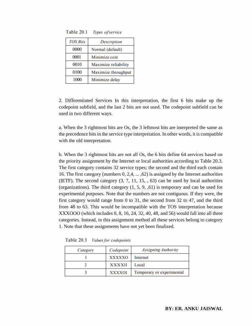
BY: ER. ANKU JAISWAL
2. Differentiated Services In this interpretation, the first 6 bits make up the
codepoint subfield, and the last 2 bits are not used. The codepoint subfield can be
used in two different ways.
a. When the 3 rightmost bits are Os, the 3 leftmost bits are interpreted the same as
the precedence bits in the service type interpretation. In other words, it is compatible
with the old interpretation.
b. When the 3 rightmost bits are not all Os, the 6 bits define 64 services based on
the priority assignment by the Internet or local authorities according to Table 20.3.
The first category contains 32 service types; the second and the third each contain
16. The first category (numbers 0, 2,4, ... ,62) is assigned by the Internet authorities
(IETF). The second category (3, 7, 11, 15, , 63) can be used by local authorities
(organizations). The third category (1, 5, 9, ,61) is temporary and can be used for
experimental purposes. Note that the numbers are not contiguous. If they were, the
first category would range from 0 to 31, the second from 32 to 47, and the third
from 48 to 63. This would be incompatible with the TOS interpretation because
XXXOOO (which includes 0, 8, 16, 24, 32, 40, 48, and 56) would fall into all three
categories. Instead, in this assignment method all these services belong to category
1. Note that these assignments have not yet been finalized.

BY: ER. ANKU JAISWAL
o Total length. This is a In-bit field that defines the total length (header plus data)
of the IPv4 datagram in bytes. To find the length of the data coming from the upper
layer, subtract the header length from the total length. The header length can be
found by multiplying the value in the HLEN field by 4. Length of data =total length
- header length since the field length is 16 bits, the total length of the IPv4 datagram
is limited to 65,535 (216 - 1) bytes, of which 20 to 60 bytes are the header and the
rest is data from the upper layer.
o Identification. This field is used in fragmentation (discussed in the next section).
o Flags. This field is used in fragmentation (discussed in the next section).
o Fragmentation offset. This field is used in fragmentation (discussed in the next
section).
o Time to live. A datagram has a limited lifetime in its travel through an internet.
This field was originally designed to hold a timestamp, which was decremented by
each visited router. The datagram was discarded when the value became zero.
However, for this scheme, all the machines must have synchronized clocks and
must know how long it takes for a datagram to go from one machine to another.
Today, this field is used mostly to control the maximum number of hops (routers)
visited by the datagram. When a source host sends the datagram, it stores a number
in this field. This value is approximately 2 times the maximum number of routes
between any two hosts. Each router that processes the datagram decrements this
number by 1. If this value, after being decremented, is zero, the router discards the
datagram. This field is needed because routing tables in the Internet can become
corrupted. A datagram may travel between two or more routers for a long time
without ever getting delivered to the destination host. This field limits the lifetime
of a datagram. Another use of this field is to intentionally limit the journey of the
packet. For example, if the source wants to confine the packet to the local network,
it can store 1 in this field. When the packet arrives at the first router, this value is
decremented to 0, and the datagram is discarded.
o Protocol. This 8-bit field defines the higher-level protocol that uses the services
of the IPv4 layer. An IPv4 datagram can encapsulate data from several higher-level
protocols such as TCP, UDP, ICMP, and IGMP. This field specifies the final
destination protocol to which the IPv4 datagram is delivered. In other words, since
the IPv4 protocol carries data from different other protocols, the value of this field
helps the receiving network layer know to which protocol the data belong

BY: ER. ANKU JAISWAL
o Checksum. The checksum concept and its calculation are discussed later in this
chapter.
o Source address. This 32-bit field defines the IPv4 address of the source. This field
must remain unchanged during the time the IPv4 datagram travels from the source
host to the destination host.
o Destination address. This 32-bit field defines the IPv4 address of the destination.
This field must remain unchanged during the time the IPv4 datagram travels from
the source host to the destination host.
Fragmentation
A datagram can travel through different networks. Each router decapsulates the IPv4 datagram
from the frame it receives, processes it, and then encapsulates it in another frame. The format and
size of the received frame depend on the protocol used by the physical network through which the
frame has just traveled. The format and size of the sent frame depend on the protocol used by the
physical network through which the frame is going to travel. For example, if a router connects a
LAN to a WAN, it receives a frame in the LAN format and sends a frame in the WAN format.
Maximum Transfer Unit (MTU)
Each data link layer protocol has its own frame format in most protocols. One of the fields defined
in the format is the maximum size of the data field. In other words, when a datagram is
encapsulated in a frame, the total size of the datagram must be less than this maximum size, which
is defined by the restrictions imposed by the hardware and software used in the network (see
Figure). The value of the MTU depends on the physical network protocol. Table 20.5 shows the
values for some protocols.
To make the IPv4 protocol independent of the physical network, the designers decided to make
the maximum length of the IPv4 datagram equal to 65,535 bytes. This makes transmission more
efficient if we use a protocol with an MTU of this size. However, for other physical networks, we

BY: ER. ANKU JAISWAL
must divide the datagram to make it possible to pass through these networks. This is called
fragmentation.
The source usually does not fragment the IPv4 packet. The transport layer will instead segment
the data into a size that can be accommodated by IPv4 and the data link layer in use. When a
datagram is fragmented, each fragment has its own header with most of the fields repeated, but
with some changed. A fragmented datagram may itself be fragmented if it encounters a network
with an even smaller MTU. In other words, a datagram can be fragmented several times before it
reaches the final destination.
In IPv4, a datagram can be fragmented by the source host or any router in the path although there
is a tendency to limit fragmentation only at the source. The reassembly of the datagram, however,
is done only by the destination host because each fragment becomes an independent datagram.
Whereas the fragmented datagram can travel through different routes, and we can never control or
guarantee which route a fragmented datagram may take, all the fragments belonging to the same
datagram should finally arrive at the destination host. So it is logical to do the reassembly at the
final destination. An even stronger objection to reassembling packets during the transmission is
the loss of efficiency it incurs. When a datagram is fragmented, required parts of the header must
be copied by all fragments. The option field mayor may not be copied, as we will see in the next
section.
The host or router that fragments a datagram must change the values of three fields:
Fields Related to Fragmentation
The fields that are related to fragmentation and reassembly of an IPv4 datagram are the
identification, flags, and fragmentation offset fields.
o Identification. This 16-bit field identifies a datagram originating from the source host. The
combination of the identification and source IPv4 address must uniquely define a datagram as it
leaves the source host. To guarantee uniqueness, the IPv4 protocol uses a counter to label the
datagrams. The counter is initialized to a positive number. When the IPv4 protocol sends a
datagram, it copies the current value of the counter to the identification field and increments the
counter by 1. As long as the counter is kept in the main memory, uniqueness is guaranteed. When
a datagram is fragmented, the value in the identification field is copied to all fragments. In other
words, all fragments have the same identification number, the same as the original datagram. The
identification number helps the destination in reassembling the datagram. It knows that all
fragments having the same identification value must be assembled into one datagram.

BY: ER. ANKU JAISWAL
o Flags. This is a 3-bit field. The first bit is reserved. The second bit is called the do not fragment
bit. If its value is 1, the machine must not fragment the datagram. If it cannot pass the datagram
through any available physical network, it discards the datagram and sends an ICMP error message
to the source host. If its value is 0, the datagram can be fragmented if necessary. The third bit is
called the more fragment bit. If its value is 1, it means the datagram is not the last fragment; there
are more fragments after this one. If its value is 0, it means this is the last or only fragment (see
Figure).
o Fragmentation offset. This 13-bit field shows the relative position of this fragment with respect
to the whole datagram. It is the offset of the data in the original datagram measured in units of 8
bytes. Figure 20.11 shows a datagram with a data size of 4000 bytes fragmented into three
fragments. The bytes in the original datagram are numbered 0 to 3999. The first fragment carries
bytes 0 to 1399. The offset for this datagram is 0/8 = O. The second fragment carries bytes 1400
to 2799; the offset value for this fragment is 1400/8 = 175. Finally, the third fragment carries bytes
2800 to 3999. The offset value for this fragment is 2800/8 =350. Remember that the value of the
offset is measured in units of 8 bytes. This is done because the length of the offset field is only 13
bits and cannot represent a sequence of bytes greater than 8191. This forces hosts or routers that
fragment datagrams to choose a fragment size so that the first byte number is divisible by 8. Figure
20.12 shows an expanded view of the fragments in Figure 20.11. Notice the value of the
identification field is the same in all fragments. Notice the value of the flags field with the more
bit set for all fragments except the last. Also, the value of the offset field for each fragment is
shown.

BY: ER. ANKU JAISWAL
The figure also shows what happens if a fragment itself is fragmented. In this case the value of the
offset field is always relative to the original datagram. For example, in the figure, the second
fragment is itself fragmented later to two fragments of 800 bytes and 600 bytes, but the offset
shows the relative position of the fragments to the original data. It is obvious that even if each
fragment follows a different path and arrives out of order, the final destination host can reassemble
the original datagram from the fragments received (if none of them is lost) by using the following
strategy: 1. The first fragment has an offset field value of zero. 2. Divide the length of the first
fragment by 8. The second fragment has an offset value equal to that result. 3. Divide the total
length of the first and second fragments by 8. The third fragment has an offset value equal to that
result. 4. Continue the process. The last fragment has a more bit value of O.
SHORTEST PATH ROUTING:
Shortest path can be calculated only for the weighted graphs. The edges connecting two vertices
can be assigned a nonnegative real number, called the weight of the edge.
The general algorithm is:

BY: ER. ANKU JAISWAL
1. Initialize the array smallestWeight so that smallestWeight[u] = weights [vertex, u].
2. Set smallestWeight [vertex] = 0.
3. Find the vertex, v that is closest to vertex for which the shortest path has not been determined.
4. Mark v as the (next) vertex for which the smallest weight is found.
5. For each vertex w in G, such that the shortest path from vertex to w has not been determined and an edge
(v, w) exists, if the weight of the path to w via v is smaller than its current weight, update the weight of w
to the weight of v + the weight of the edge (v, w).
Because there are n vertices, repeat Steps 3 through 5, n – 1 times.
Example: Shortest Path
FLOODING:

BY: ER. ANKU JAISWAL
• Static algorithm
• Every incoming packet is sent to outgoing line except from one it arrived
• Generates a number of duplicate packet
• Solution to have hop counter in each header and is decremented and packet is discarded
when counter become 0.
DISTANCE VECTOR ROUTING
In distance vector routing, the least-cost route between any two nodes is the route with minimum
distance. In this protocol, as the name implies, each node maintains a vector (table) of minimum
distances to every node. The table at each node also guides the packets to the desired node by
showing the next stop in the route (next-hop routing). We can think of nodes as the cities in an
area and the lines as the roads connecting them. A table can show a tourist the minimum distance
between cities. In Figure 22.14, we show a system of five nodes with their corresponding tables.
The table for node A shows how we can reach any node from this node. For example, our least
cost to reach node E is 6. The route passes through C.
Initialization
The tables in Figure 22.14 are stable; each node knows how to reach any other node and the cost.
At the beginning, however, this is not the case. Each node can know only the distance between
itself and its immediate neighbors, those directly connected to it. So for the moment, we assume
that each node can send a message to the immediate neighbors and find the distance between itself
and these neighbors. Figure 22.15 shows the initial tables for each node. The distance for any entry
that is not a neighbor is marked as infinite (unreachable).

BY: ER. ANKU JAISWAL
Sharing
The whole idea of distance vector routing is the sharing of information between neighbors.
Although node A does not know about node E, node C does. So if node C shares its routing table
with A, node A can also know how to reach node E. On the other hand, node C does not know
how to reach node D, but node A does. If node A shares its routing table with node C, node C also
knows how to reach node D. In other words, nodes A and C, as immediate neighbors, can improve
their routing tables if they help each other. There is only one problem. How much of the table must
be shared with each neighbor? A node is not aware of a neighbor's table. The best solution for each
node is to send its entire table to the neighbor and let the neighbor decide what part to use and
what part to discard. However, the third column of a table (next stop) is not useful for the neighbor.
When the neighbor receives a table, this column needs to be replaced with the sender's name. If
any of the rows can be used, the next node is the sender of the table. A node therefore can send
only the first two columns of its table to any neighbor. In other words, sharing here means sharing
only the first two columns
Updating
When a node receives a two-column table from a neighbor, it needs to update its routing table.
Updating takes three steps:
1. The receiving node needs to add the cost between itself and the sending node to each value in
the second column. The logic is clear. If node C claims that its distance to a destination is x mi,
and the distance between A and C is y mi, then the distance between A and that destination, via C,
is x + y mi.

BY: ER. ANKU JAISWAL
2. The receiving node needs to add the name of the sending node to each row as the third column
if the receiving node uses information from any row. The sending node is the next node in the
route. 3. The receiving node needs to compare each row of its old table with the corresponding
row of the modified version of the received table. a. If the next-node entry is different, the receiving
node chooses the row with the smaller cost. If there is a tie, the old one is kept. b. If the next-node
entry is the same, the receiving node chooses the new row. For example, suppose node C has
previously advertised a route to node X with distance
3. Suppose that now there is no path between C and X; node C now advertises this route with a
distance of infinity. Node A must not ignore this value even though its old entry is smaller. The
old route does not exist anymore. The new route has a distance of infinity. Figure 22.16 shows
how node A updates its routing table after receiving the partial table from node C.
There are several points we need to emphasize here. First, as we know from mathematics, when
we add any number to infinity, the result is still infinity. Second, the modified table shows how to
reach A from A via C. If A needs to reach itself via C, it needs to go to C and come back, a distance
of 4. Third, the only benefit from this updating of node A is the last entry, how to reach E.
Previously, node A did not know how to reach E (distance of infinity); now it knows that the cost
is 6 via C.
When to Share
The question now is, when does a node send its partial routing table (only two columns) to all its
immediate neighbors? The table is sent both periodically and when there is a change in the table.
Periodic Update A node sends its routing table, normally every 30 s, in a periodic update. The
period depends on the protocol that is using distance vector routing. Triggered Update A node
sends its two-column routing table to its neighbors anytime there is a change in its routing table.
This is called a triggered update. The change can result from the following.

BY: ER. ANKU JAISWAL
1. A node receives a table from a neighbor, resulting in changes in its own table after updating.
2. A node detects some failure in the neighboring links which results in a distance change to
infinity.
LINK STATE ROUTING
Link state routing has a different philosophy from that of distance vector routing. In link state
routing, if each node in the domain has the entire topology of the domain the list of nodes and
links, how they are connected including the type, cost (metric), and condition of the links (up or
down)-the node can use Dijkstra's algorithm to build a routing table. Figure 22.20 shows the
concept.
The figure shows a simple domain with five nodes. Each node uses the same topology to create a
routing table, but the routing table for each node is unique because the calculations are based on
different interpretations of the topology. This is analogous to a city map. While each person may
have the same map, each needs to take a different route to reach her specific destination.
The topology must be dynamic, representing the latest state of each node and each link. If there
are changes in any point in the network (a link is down, for example), the topology must be updated
for each node. How can a common topology be dynamic and stored in each node? No node can
know the topology at the beginning or after a change somewhere in the network.
Link state routing is based on the assumption that, although the global knowledge about the
topology is not clear, each node has partial knowledge: it knows the state (type, condition, and
cost) of its links. In other words, the whole topology can be compiled from the partial knowledge
of each node. Figure 22.21 shows the same domain as in Figure 22.20, indicating the part of the
knowledge belonging to each node.

BY: ER. ANKU JAISWAL
Node A knows that it is connected to node B with metric 5, to node C with metric 2, and to node
D with metric 3. Node C knows that it is connected to node A with metric 2, to node B with metric
4, and to node E with metric 4. Node D knows that it is connected only to node A with metric 3.
And so on. Although there is an overlap in the knowledge, the overlap guarantees the creation of
a common topology-a picture of the whole domain for each node.
Building Routing Tables
In link state routing, four sets of actions are required to ensure that each node has the routing table
showing the least-cost node to every other node.
1. Creation of the states of the links by each node, called the link state packet (LSP).
2. Dissemination of LSPs to every other router, called flooding, in an efficient and reliable way.
3. Formation of a shortest path tree for each node.
4. Calculation of a routing table based on the shortest path tree. Creation of Link State Packet
(LSP) A link state packet can carry a large amount of information. For the moment, however, we
assume that it carries a minimum amount of data: the node identity, the list of links, a sequence
number, and age. The first two, node identity and the list of links, are needed to make the topology.
The third, sequence number, facilitates flooding and distinguishes new LSPs from old ones. The
fourth, age, prevents old LSPs from remaining in the domain for a long time.
LSPs are generated on two occasions:
1. When there is a change in the topology of the domain. Triggering of LSP dissemination is the
main way of quickly informing any node in the domain to update its topology.
2. On a periodic basis. The period in this case is much longer compared to distance vector routing.
As a matter of fact, there is no actual need for this type of LSP dissemination. It is done to ensure
that old information is removed from the domain. The timer set for periodic dissemination is

BY: ER. ANKU JAISWAL
normally in the range of 60 min or 2 h based on the implementation. A longer period ensures that
flooding does not create too much traffic on the network.
Flooding of LSPs
After a node has prepared an LSP, it must be disseminated to all other nodes, not only to its
neighbors. The process is called flooding and based on the following:
1. The creating node sends a copy of the LSP out of each interface.
2. A node that receives an LSP compares it with the copy it may already have. If the newly arrived
LSP is older than the one it has (found by checking the sequence number), it discards the LSP. If
it is newer, the node does the following:
a. It discards the old LSP and keeps the new one.
b. It sends a copy of it out of each interface except the one from which the packet arrived. This
guarantees that flooding stops somewhere in the domain (where a node has only one interface).
Formation of Shortest Path Tree: Dijkstra Algorithm
After receiving all LSPs, each node will have a copy of the whole topology. However, the topology
is not sufficient to find the shortest path to every other node;
a shortest path tree is needed. A tree is a graph of nodes and links; one node is called the root. All
other nodes can be reached from the root through only one single route. A shortest path tree is a
tree in which the path between the root and every other node is the shortest. What we need for each
node is a shortest path tree with that node as the root.
The Dijkstra algorithm creates a shortest path tree from a graph. The algorithm divides the nodes
into two sets: tentative and permanent. It finds the neighbors of a current node, makes them
tentative, examines them, and if they pass the criteria, makes them permanent. We can informally
define the algorithm by using the flowchart in Figure 22.22. Let us apply the algorithm to node A
of our sample graph in Figure 22.23. To find the shortest path in each step, we need the cumulative
cost from the root to each node, which is shown next to the node. The following shows the steps.
At the end of each step, we show the permanent (filled circles) and the tentative (open circles)
nodes and lists with the cumulative costs.

BY: ER. ANKU JAISWAL
1. We make node A the root of the tree and move it to the tentative list. Our
two lists are Permanent list: empty Tentative list: A(O)

BY: ER. ANKU JAISWAL
2. Node A has the shortest cumulative cost from all nodes in the tentative
list. We move A to the permanent list and add all neighbors of A to the
tentative list. Our new lists are Permanent list: A(O) Tentative list: B(5),
C(2), D(3)
3. Node C has the shortest cumulative cost from all nodes in the tentative
list. We move C to the permanent list. Node C has three neighbors, but node
A is already processed, which makes the unprocessed neighbors just B and
E. However, B is already in the tentative list with a cumulative cost of 5.
Node A could also reach node B through C with a cumulative cost of 6.
Since 5 is less than 6, we keep node B with a cumulative cost of 5 in the
tentative list and do not replace it. Our new lists are Permanent list: A(O),
e(2) Tentative list: B(5), 0(3), E(6)
4. Node D has the shortest cumulative cost of all the nodes in the tentative
list. We move D to the permanent list. Node D has no unprocessed neighbor
to be added to the tentative list. Our new lists are Permanent list: A(O), C(2),
0(3) Tentative list: B(5), E(6)
5. Node B has the shortest cumulative cost of all the nodes in the tentative
list. We move B to the permanent list. We need to add all unprocessed
neighbors of B to the tentative list (this is just node E). However, E(6) is
already in the list with a smaller cumulative cost. The cumulative cost to
node E, as the neighbor of B, is 8. We keep node E(6) in the tentative list.
Our new lists are Permanent list: A(O), B(5), C(2), 0(3) Tentative list: E(6)
6. Node E has the shortest cumulative cost from all nodes in the tentative
list. We move E to the permanent list. Node E has no neighbor. Now the
tentative list is empty. We stop; our shortest path tree is ready. The final lists
are Permanent list: A(O), B(5), C(2), D(3), E(6) Tentative list: empty
Calculation of Routing Table from Shortest Path Tree Each node uses the shortest path tree protocol to
construct its routing table. The routing table shows the cost of reaching each node from the root. Table 22.2
shows the routing table for node A.

BY: ER. ANKU JAISWAL
Compare Table 22.2 with the one in Figure 22.14. Both distance vector routing and link state routing end
up with the same routing table for node A.
ICMP
The IP protocol has no error-reporting or error-correcting mechanism. The IP protocol also lacks a
mechanism for host and management queries. A host sometimes needs to determine if a router or another
host is alive. And sometimes a network administrator needs information from another host or router. The
Internet Control Message Protocol (ICMP) has been designed to compensate for the above two deficiencies.
It is a companion to the IP protoco1.
Types of Messages
ICMP messages are divided into two broad categories: error-reporting messages and query messages. The
error-reporting messages report problems that a router or a host (destination) may encounter when it
processes an IP packet. The query messages, which occur in pairs, help a host or a network manager get
specific information from a router or another host. For example, nodes can discover their neighbors. Also,
hosts can discover and learn about routers on their network, and routers can help a node redirect its
messages.
Message Format
An ICMP message has an 8-byte header and a variable-size data section. Although the general format of
the header is different for each message type, the first 4 bytes are common to all. The first field, ICMP type,
defines the type of the message. The code field specifies the reason for the particular message type. The
last common field is the checksum field. The rest of the header is specific for each message type. The data
section in error messages carries information for finding the original packet that had the error. In query
messages, the data section carries extra information based on the type of the query.
Error Reporting

BY: ER. ANKU JAISWAL
One of the main responsibilities of ICMP is to report errors. Although technology has produced
increasingly reliable transmission media, errors still exist and must be handled. IP, as discussed in
Chapter 20, is an unreliable protocol. This means that error checking and error control are not a
concern of IP. ICMP was designed, in part, to compensate for this shortcoming. However, ICMP
does not correct errors-it simply reports them. Error correction is left to the higher-level protocols.
Error messages are always sent to the original source because the only information available in the
datagram about the route is the source and destination IP addresses. ICMP uses the source IP
address to send the error message to the source (originator) of the datagram.
Five types of errors are handled: destination unreachable, source quench, time exceeded, parameter
problems, and redirection
Destination Unreachable
When a router cannot route a datagram or a host cannot deliver a datagram, the datagram is
discarded and the router or the host sends a destination-unreachable message back to the source
host that initiated the datagram. Note that destination-unreachable messages can be created by
either a router or the destination host.
Source Quench
The IP protocol is a connectionless protocol. There is no communication between the source host,
which produces the datagram, the routers, which forward it, and the destination host, which
processes it. One of the ramifications of this absence of communication is the lack of flow control.
IP does not have a flow control mechanism embedded in the protocol. The lack of flow control
can create a major problem in the operation of IP: congestion. The source host never knows if the
routers or the destination host has been overwhelmed with datagrams. The source host never knows
if it is producing datagrams faster than can be forwarded by routers or processed by the destination
host. The lack of flow control can create congestion in routers or the destination host. A router or
a host has a limited-size queue (buffer) for incoming datagrams waiting to be forwarded (in the
case of a router) or to be processed (in the case of a host). If the datagrams are received much faster

BY: ER. ANKU JAISWAL
than they can be forwarded or processed, the queue may overflow. In this case, the router or the
host has no choice but to discard some of the datagrams. The source-quench message in ICMP
was designed to add a kind of flow control to the IP. When a router or host discards a datagram
due to congestion, it sends a source-quench message to the sender of the datagram. This message
has two purposes. First, it informs the source that the datagram has been discarded. Second, it
warns the source that there is congestion somewhere in the path and that the source should slow
down (quench) the sending process.
Time Exceeded
The time-exceeded message is generated in two cases: As we see in Chapter 22, routers use routing
tables to find the next hop (next router) that must receive the packet. Ifthere are errors in one or
more routing tables, a packet can travel in a loop or a cycle, going from one router to the next or
visiting a series of routers endlessly. As we saw in Chapter 20, each datagram contains a field
called time to live that controls this situation. When a datagram visits a router, the value of this
field is decremented by 1. When the time-to-live value reaches 0, after decrementing, the router
discards the datagram. However, when the datagram is discarded, a time-exceeded message must
be sent by the router to the original source. Second, a time-exceeded message is also generated
when not all fragments that make up a message arrive at the destination host within a certain time
limit.
Parameter Problem
Any ambiguity in the header part of a datagram can Create serious problems as the datagram travels
through the Internet. If a router or the destination host discovers an ambiguous or missing value in
any field of the datagram, it discards the datagram and sends a parameter-problem message back
to the source.
Redirection
When a router needs to send a packet destined for another network, it must know the IP address of
the next appropriate router. The same is true if the sender is a host. Both routers and hosts, then,
must have a routing table to find the address of the router or the next router. Routers take part in
the routing update process, as we will see in Chapter 22, and are supposed to be updated constantly.
Routing is dynamic. However, for efficiency, hosts do not take part in the routing update process
because there are many more hosts in an internet than routers. Updating the routing tables of hosts
dynamically produces unacceptable traffic. The hosts usually use static routing. When a host
comes up, its routing table has a limited number of entries. It usually knows the IP address of only
one router, the default router. For this reason, the host may send a datagram, which is destined for
another network, to the wrong router. In this case, the router that receives the datagram will
forward the datagram to the correct router. However, to update the routing table of the host, it
sends a redirection message to the host.

BY: ER. ANKU JAISWAL
Query
In addition to error reporting, ICMP can diagnose some network problems. This is accomplished
through the query messages, a group of four different pairs of messages, as shown in Figure 21.12.
In this type of ICMP message, a node sends a message that is answered in a specific format by the
destination node. A query message is encapsulated in an IP packet, which in turn is encapsulated
in a data link layer frame. However, in this case, no bytes of the original IP are included in the
message, as shown in Figure 21.13.
Echo Request and Reply
The echo-request and echo-reply messages are designed for diagnostic purposes. Network
managers and users utilize this pair of messages to identify network problems. The combination
of echo-request and echo-reply messages determines whether two systems (hosts or routers) can
communicate with each other. The echo-request and echo-reply messages can be used to determine
if there is communication at the IP level. Because ICMP messages are encapsulated in IP
datagrams, the receipt of an echo-reply message by the machine that sent the echo request is proof
that the IP protocols in the sender and receiver are communicating with each other using the IP
datagram.
Timestamp Request and Reply
Two machines (hosts or routers) can use the timestamp request and timestamp reply messages to
determine the round-trip time needed for an IP datagram to travel between them. It can also be
used to synchronize the clocks in two machines.
Address-Mask Request and Reply
BY: ER. ANKU JAISWAL
A host may know its IP address, but it may not know the corresponding mask. For example, a host
may know its IP address as 159.31.17.24, but it may not know that the corresponding mask is /24.
To obtain its mask, a host sends an address-mask-request message to a router on the LAN. If the
host knows the address of the router, it sends the request directly to the router. If it does not know,
it broadcasts the message. The router receiving the address-mask-request message responds with
an address-mask-reply message, providing the necessary mask for the host. This can be applied to
its full IP address to get its subnet address.
Router Solicitation and Advertisement
As we discussed in the redirection message section, a host that wants to send data to a host on
another network needs to know the address of routers connected to its own network. Also, the host
must know if the routers are alive and functioning. The router-solicitation and router-advertisement
messages can help in this situation. A host can broadcast (or multicast) a router-solicitation
message. The router or routers that receive the solicitation message broadcast their routing
information using the router-advertisement message. A router can also periodically send router-
advertisement messages even if no host has solicited. Note that when a router sends out an
advertisement, it announces not only its own presence but also the presence of all routers on the
network of which it is aware.
Checksum
In ICMP the checksum is calculated over the entire message (header and data).
ARP
The address resolution protocol (ARP) is a protocol used by the Internet Protocol (IP) [RFC826],
specifically IPv4, to map IP network addresses to the hardware addresses used by a data link
protocol. The protocol operates below the network layer as a part of the interface between the
OSI network and OSI link layer.

BY: ER. ANKU JAISWAL
The fields are as follows:
o Hardware type. This is a 16-bit field defining the type of the network on which ARP is running.
Each LAN has been assigned an integer based on its type. For example, Ethernet is given type 1.
ARP can be used on any physical network.
o Protocol type. This is a 16-bit field defining the protocol. For example, the value of this field for
the IPv4 protocol is 080016, ARP can be used with any higher-level protocol.
o Hardware length. This is an 8-bit field defining the length of the physical address in bytes. For
example, for Ethernet the value is 6.
o Protocol length. This is an 8-bit field defining the length of the logical address in bytes. For
example, for the IPv4 protocol the value is 4.
o Operation. This is a 16-bit field defining the type of packet. Two packet types are defined: ARP
request (1) and ARP reply (2).
o Sender hardware address. This is a variable-length field defining the physical address of the
sender. For example, for Ethernet this field is 6 bytes long. o Sender protocol address. This is a
variable-length field defining the logical (for example, IP) address of the sender. For the IP
protocol, this field is 4 bytes long.
o Target hardware address. This is a variable-length field defining the physical address of the
target. For example, for Ethernet this field is 6 bytes long. For an ARP request message, this field
is all Os because the sender does not know the physical address of the target.

BY: ER. ANKU JAISWAL
o Target protocol address. This is a variable-length field defining the logical (for example, IP)
address of the target. For the IPv4 protocol, this field is 4 bytes long.
RARP
Reverse Address Resolution Protocol (RARP) finds the logical address for a machine that knows
only its physical address. Each host or router is assigned one or more logical (IP) addresses, which
are unique and independent of the physical (hardware) address of the machine. To create an IP
datagram, a host or a router needs to know its own IP address or addresses. The IP address of a
machine is usually read from its configuration file stored on a disk file. However, a diskless
machine is usually booted from ROM, which has minimum booting information. The ROM is
installed by the manufacturer. It cannot include the IP address because the IP addresses on a
network are assigned by the network administrator. The machine can get its physical address (by
reading its NIC, for example), which is unique locally. It can then use the physical address to get
the logical address by using the RARP protocol. A RARP request is created and broadcast on the
local network. Another machine on the local network that knows all the IP addresses will respond
with a RARP reply. The requesting machine must be running a RARP client program; the
responding machine must be running a RARP server program. There is a serious problem with
RARP: Broadcasting is done at the data link layer. The physical broadcast address, all is in the
case of Ethernet, does not pass the boundaries of a network. This means that if an administrator
has several networks or several subnets, it needs to assign a RARP server for each network or
subnet. This is the reason that RARP is almost obsolete.
SUBNETTING NUMERICALS
• Write the IP address 222.1.1.20 mask 255.255.255.192 in CIDR notation.
Decimal 192 =11000000 binary which means that 2 bits of this octet are used for the subnet? Now add the
24 bits 255.255.255 and we have 26 bits. So we write:
222.1.1.20/26
• Write the IP address 135.1.1.25 mask 255.255. 248.0 in CIDR notation.
Decimal 248 =11111000 binary which means that 5 bits of this octet are used for the subnet? Now add the
16 bits 255.255. And we have 21 bits. So we write:

BY: ER. ANKU JAISWAL
135..1.1.25/21
• You have been allocated a class C network address of 211.1.1.0 and are using the
default subnet mask of 255.255.255.0 how may hosts can you have?
A class C address has 8 bits of the host which will give 28 -2 =254 hosts
Subnet the Class C IP Address 205.11.2.0 so that you have 30 subnets.
What is the subnet mask for the maximum number of hosts?
How many hosts can each subnet have?
What is the IP address of host 3 on subnet 2 ?
Current mask= 255.255.255.0
Bits needs for 30 subnets =5 =25 =32 possible subnets
Bits left for hosts = 3 = 23 = 8-2=6 possible hosts.
So our mask in binary =11111000= 248 decimal
Final Mask =255.255.255.248
Address of host 3 on subnet 2 is

BY: ER. ANKU JAISWAL
Subnet 2 =00010000 host 3 =000000011
Add the two together =00010011=19
Therefore IP address of host 3 on subnet 2 =205.11.2.19
• Subnet the Class C IP Address 195.1.1.0 So that you have at least 2 subnets each
subnet must have room for 48 hosts. What are the two possible subnet masks?
Current mask= 255.255.255.0
Bits needs for 48 hosts = 6 = 26 = 64-2=62 possible hosts.
Bits needs for 2 subnets =1 =21 =2 possible subnets
Total of 7 bits needed so therefore we can use either 1 bit or 2 bits for the subnet. So we could have
1 bit subnet 7 bits hosts or 2 bits subnet 6 bit host
Masks are 10000000 and 11000000 =128 decimal and 192 decimal.
Final possible masks are:
255.255.255.128 and 255.255.255.192
• Change the following IPv4 addresses from binary notation to dotted-decimal
notation.
a. 10000001 00001011 00001011 11101111

BY: ER. ANKU JAISWAL
b. 11000001 10000011 00011011 11111111
Solution
We replace each group of 8 bits with its equivalent decimal number (see Appendix B) and add
dots for separation.
a. 129.11.11.239
b. 193.131.27.255
• Change the following IPv4 addresses from dotted-decimal notation to binary
notation.
a. 111.56.45.78
b. 221.34.7.82
Solution
We replace each decimal number with its binary equivalent (see Appendix B).
a.• 01101111 00111000 00101101 01001110
b. 11011101 00100010 00000111 01010010
• Find the error, if any, in the following IPv4 addresses.
a. 111.56.045.78
b. 221.34.7.8.20
c. 75.45.301.14
d. 11100010.23.14.67
Solution
a. There must be no leading zero (045).
b. There can be no more than four numbers in an IPv4 address.
c. Each number needs to be less than or equal to 255 (301 is outside this range).
d. A mixture of binary notation and dotted-decimal notation is not allowed.

BY: ER. ANKU JAISWAL
• Find the class of each address.
a. 00000001 00001011 00001011 11101111
b. 11000001 10000011 00011011 11111111
c. 14.23.120.8
d. 252.5.15.111
Solution
a. The first bit is O. This is a class A address.
b. The first 2 bits are 1; the third bit is O. This is a class C address.
c. The first byte is 14 (between 0 and 127); the class is A.
d. The first byte is 252 (between 240 and 255); the class is E
• A block of addresses is granted to a small organization. We know that one of the
addresses is 205.16.37.39/28. What is the first address in the block ?
Solution
First Address The first address in the block can be found by setting the 32 - n rightmost bits in the binary
notation of the address to Os.
The binary representation of the given address is 11001101 00010000 00100101 00100 I 11. If we set 32
- 28 rightmost bits to 0, we get 11001101 000100000100101 0010000 or 205.16.37.32.
The first address in the block can be found by setting the rightmost 32 - n bits to Os.
Find the last address for the block?
Last Address The last address in the block can be found by setting the 32 - n rightmost bits in the binary
notation of the address to Is.
The last address in the block can be found by setting the rightmost 32 - n bits to Is.

BY: ER. ANKU JAISWAL
The binary representation of the given address is 11001101 000100000010010100100111. If we set 32 -
28 rightmost bits to 1, we get 11001101 00010000 001001010010 1111 or 205.16.37.47.
Find the number of addresses?
The value of n is 28, which means that number of addresses is 232- 28 or 16.
• Suppose an organization is given the block 17.12.40.0/26, which contains 64
addresses. The organization has three offices and needs to divide the addresses into
three subblocks of 32, 16, and 16 addresses.
We can find the new masks by using the following arguments:
1. Suppose the mask for the first subnet is n1, then 232- n1 must be 32, which means that n1 =27.
2. Suppose the mask for the second subnet is n2, then 232- n2 must be 16, which means that n2 = 28.
3. Suppose the mask for the third subnet is n3, then 232- n3 must be 16, which means that n3 =28.
This means that we have the masks 27, 28, 28 with the organization mask being 26.
a. In subnet 1, the address 17.12.14.29/27 can give us the subnet address if we use the mask /27 because
Host: 00010001 00001100 00001110 00011101
Mask: /27
Subnet: 00010001 00001100 00001110 00000000.... (17.12.14.0)
b. In subnet 2, the address 17.12.14.45/28 can give us the subnet address if we use the mask /28 because
Host: 00010001 00001100 00001110 00101101
Mask: /28

BY: ER. ANKU JAISWAL
Subnet: 00010001 00001100 00001110 00100000.... (17.12.14.32)
c. In subnet 3, the address 17.12.14.50/28 can give us the subnet address if we use the mask /28 because
Host: 00010001 00001100 00001110 00110010
Mask: /28
Subnet: 00010001 00001100 00001110 00110000.... (17.12.14.48)
• An ISP is granted a block of addresses starting with 190.100.0.0/16 (65,536
addresses). The ISP needs to distribute these addresses to three groups of customers
as follows:
a. The first group has 64 customers; each needs 256 addresses.
b. The second group has 128 customers; each needs 128 addresses.
c. The third group has 128 customers; each needs 64 addresses.
Design the subblocks and find out how many addresses are still available after these allocations.
1. Group 1
For this group, each customer needs 256 addresses. This means that 8 (log2256) bits are needed to define
each host. The prefix length is then 32 - 8 =24. The addresses are
Group2
For this group, each customer needs 128 addresses. This means that 7 (10g2 128) bits are needed to define
each host. The prefix length is then 32 - 7 =25. The addresses are

BY: ER. ANKU JAISWAL
Group3 For this group, each customer needs 64 addresses. This means that 6 (logz 64) bits are needed to
each host. The prefix length is then 32 - 6 =26. The addresses are
Number of granted addresses to the ISP: 65,536
Number of allocated addresses by the ISP: 40,960
Number of available addresses: 24,576
Numerical reference: B. Forouzan

BY: ER. ANKU JAISWAL
CHAPTER 5-TRANSPORT LAYER
THE TRANSPORT SERVICES
Transport layer offers peer-to-peer and end-to-end connection between two processes on remote hosts.
Transport layer takes data from upper layer (i.e. Application layer) and then breaks it into smaller size
segments, numbers each byte, and hands over to lower layer (Network Layer) for delivery.
Functions
• This Layer is the first one which breaks the information data, supplied by Application layer in to
smaller units called segments. It numbers every byte in the segment and maintains their
accounting.
• This layer ensures that data must be received in the same sequence in which it was sent.
• This layer provides end-to-end delivery of data between hosts which may or may not belong to the
same subnet.
• All server processes intend to communicate over the network are equipped with well-known
Transport Service Access Points (TSAPs) also known as port numbers.
End-to-End Communication
A process on one host identifies its peer host on remote network by means of TSAPs, also known as Port
numbers. TSAPs are very well defined and a process which is trying to communicate with its peer knows
this in advance.
For example, when a DHCP client wants to communicate with remote DHCP server, it always requests
on port number 67. When a DNS client wants to communicate with remote DNS server, it always requests
on port number 53 (UDP).
The two main Transport layer protocols are:

BY: ER. ANKU JAISWAL
• Transmission Control Protocol
It provides reliable communication between two hosts.
• User Datagram Protocol
It provides unreliable communication between two hosts
TRANSPORT SERVICE PREMITIVE
A service is specified by a set of primitives. A primitive means operation. To access the service a
user process can access these primitives. These primitives are different for connection oriented
service and connectionless service.
There are five types of service primitives:
1. LISTEN : When a server is ready to accept an incoming connection it executes the LISTEN
primitive. It blocks waiting for an incoming connection.
2. CONNECT : It connects the server by establishing a connection. Response is awaited.
3. RECIEVE: Then the RECIEVE call blocks the server.
4. SEND : Then the client executes SEND primitive to transmit its request followed by the
execution of RECIEVE to get the reply. Send the message.
5. DISCONNECT : This primitive is used for terminating the connection. After this primitive
one can’t send any message. When the client sends DISCONNECT packet then the server
also sends the DISCONNECT packet to acknowledge the client. When the server package
is received by client then the process is terminated.
TRANSPORT PROTOCOLS: TCP AND UDP
TRANSMISSION CONTROL PROTOCOL (TCP)
The transmission Control Protocol (TCP) is one of the most important protocols of Internet
Protocols suite. It is most widely used protocol for data transmission in communication network
such as internet.

BY: ER. ANKU JAISWAL
Features
• TCP is reliable protocol. That is, the receiver always sends either positive or negative
acknowledgement about the data packet to the sender, so that the sender always has bright
clue about whether the data packet is reached the destination or it needs to resend it.
• TCP ensures that the data reaches intended destination in the same order it was sent.
• TCP is connection oriented. TCP requires that connection between two remote points be
established before sending actual data.
• TCP provides error-checking and recovery mechanism.
• TCP provides end-to-end communication.
• TCP provides flow control and quality of service.
• TCP operates in Client/Server point-to-point mode.
• TCP provides full duplex server, i.e. it can perform roles of both receiver and sender.
Header
The length of TCP header is minimum 20 bytes long and maximum 60 bytes.
• Source Port (16-bits) - It identifies source port of the application process on the sending
device.
• Destination Port (16-bits) - It identifies destination port of the application process on the
receiving device.
• Sequence Number (32-bits) - Sequence number of data bytes of a segment in a session.
• Acknowledgement Number (32-bits) - When ACK flag is set, this number contains the
next sequence number of the data byte expected and works as acknowledgement of the
previous data received.

BY: ER. ANKU JAISWAL
• Data Offset (4-bits) - This field implies both, the size of TCP header (32-bit words) and
the offset of data in current packet in the whole TCP segment.
• Reserved (3-bits) - Reserved for future use and all are set zero by default.
• Flags (1-bit each)
o NS - Nonce Sum bit is used by Explicit Congestion Notification signaling process.
o CWR - When a host receives packet with ECE bit set, it sets Congestion Windows
Reduced to acknowledge that ECE received.
o ECE -It has two meanings:
▪ If SYN bit is clear to 0, then ECE means that the IP packet has its CE
(congestion experience) bit set.
▪ If SYN bit is set to 1, ECE means that the device is ECT capable.
o URG - It indicates that Urgent Pointer field has significant data and should be
processed.
o ACK - It indicates that Acknowledgement field has significance. If ACK is cleared
to 0, it indicates that packet does not contain any acknowledgement.
o PSH - When set, it is a request to the receiving station to PUSH data (as soon as it
comes) to the receiving application without buffering it.
o RST - Reset flag has the following features:
▪ It is used to refuse an incoming connection.
▪ It is used to reject a segment.
▪ It is used to restart a connection.
o SYN - This flag is used to set up a connection between hosts.
o FIN - This flag is used to release a connection and no more data is exchanged
thereafter. Because packets with SYN and FIN flags have sequence numbers, they
are processed in correct order.
• Windows Size - This field is used for flow control between two stations and indicates the
amount of buffer (in bytes) the receiver has allocated for a segment, i.e. how much data is
the receiver expecting.

BY: ER. ANKU JAISWAL
• Checksum - This field contains the checksum of Header, Data and Pseudo Headers.
• Urgent Pointer - It points to the urgent data byte if URG flag is set to 1.
• Options - It facilitates additional options which are not covered by the regular header.
Option field is always described in 32-bit words. If this field contains data less than 32-
bit, padding is used to cover the remaining bits to reach 32-bit boundary.
USER DATAGRAM PROTOCOL (UDP)
The User Datagram Protocol (UDP) is simplest Transport Layer communication protocol available of the
TCP/IP protocol suite. It involves minimum amount of communication mechanism. UDP is said to be an
unreliable transport protocol but it uses IP services which provides best effort delivery mechanism.
In UDP, the receiver does not generate an acknowledgement of packet received and in turn, the sender
does not wait for any acknowledgement of packet sent. This shortcoming makes this protocol unreliable
as well as easier on processing.
Requirement of UDP
A question may arise, why do we need an unreliable protocol to transport the data? We deploy UDP where
the acknowledgement packets share significant amount of bandwidth along with the actual data. For
example, in case of video streaming, thousands of packets are forwarded towards its users. Acknowledging
all the packets is troublesome and may contain huge amount of bandwidth wastage. The best delivery
mechanism of underlying IP protocol ensures best efforts to deliver its packets, but even if some packets
in video streaming get lost, the impact is not calamitous and can be ignored easily. Loss of few packets in
video and voice traffic sometimes goes unnoticed.
Features
• UDP is used when acknowledgement of data does not hold any significance.
• UDP is good protocol for data flowing in one direction.
• UDP is simple and suitable for query based communications.
• UDP is not connection oriented.
• UDP does not provide congestion control mechanism.
• UDP does not guarantee ordered delivery of data.
• UDP is stateless.
• UDP is suitable protocol for streaming applications such as VoIP, multimedia streaming.

BY: ER. ANKU JAISWAL
UDP Header
UDP header is as simple as its function.
UDP header contains four main parameters:
• Source Port - This 16 bits information is used to identify the source port of the packet.
• Destination Port - This 16 bits information, is used identify application level service on
destination machine.
• Length - Length field specifies the entire length of UDP packet (including header). It is 16-bits
field and minimum value is 8-byte, i.e. the size of UDP header itself.
• Checksum - This field stores the checksum value generated by the sender before sending. IPv4
has this field as optional so when checksum field does not contain any value it is made 0 and all
its bits are set to zero.
UDP application
Here are few applications where UDP is used to transmit data:
• Domain Name Services
• Simple Network Management Protocol
• Trivial File Transfer Protocol
• Routing Information Protocol
• Kerberos
PORT AND SOCKET
• At the transport layer, we need a transport layer address, called a port number, to choose among
multiple processes running on the destination host.
• The destination port number is needed for delivery; the source port number is needed for the reply.
• In the Internet model, the port numbers are 16-bit integers between 0 and 65,535.
• The client program defines itself with a port number, chosen randomly by the transport layer

BY: ER. ANKU JAISWAL
software running on the client host. This is the ephemeral port number.
• The server process must also define itself with a port number.
• This port number, however, cannot be chosen randomly
• The Internet has decided to use universal port numbers for servers; these are called well-known
port numbers.
• For example, while the Daytime client process, discussed above, can use an ephemeral (temporary)
port number 52,000 to identify itself, the Daytime server process must use the well-known
(permanent) port number 13.
lANA Ranges
The lANA (Internet Assigned Number Authority) has divided the port numbers into three ranges:
well known, registered, and dynamic (or private
• Well-known ports. The ports ranging from 0 to 1023 are assigned and controlled
by lANA. These are the well-known ports.
• Registered ports. The ports ranging from 1024 to 49,151 are not assigned or controlled
by lANA. They can only be registered with lANA to prevent duplication.
• Dynamic ports. The ports ranging from 49,152 to 65,535 are neither controlled nor registered.
They can be used by any process. These are the ephemeral ports.
Socket Address
• Process-to-process delivery needs two identifiers, IP address and the port number, at each end to
make a connection.
• The combination of an IP address and a port number is called a socket address.
• The client socket address defines the client process uniquely just as the server socket address
defines the server process uniquely
• A transport layer protocol needs a pair of socket addresses: the client socket address and the server
socket address.
MULTIPLEXING AND DEMULTIPLEXING
Multiplexing

BY: ER. ANKU JAISWAL
• At the sender site, there may be several processes that need to send packets.
• However, there is only one transport layer protocol at any time. This is a many-to-one relationship
and requires multiplexing.
• The protocol accepts messages from different processes, differentiated by their assigned port
numbers.
• After adding the header, the transport layer passes the packet to the network layer.
Demultiplexing
• At the receiver site, the relationship is one-to-many and requires demultiplexing.
• The transport layer receives datagrams from the network layer.
• After error checking and dropping of the header, the transport layer delivers each message to the
appropriate process based on the port number.
• Internet Protocol (IP) provides a packet delivery service across an internet
• however, IP cannot distinguish between multiple processes (applications) running on the same
computer
• fields in the IP datagram header identify only computers
• a protocol that allows an application to serve as an end-point of communication is known as
a transport protocol or an end-to-end protocol
• the TCP/IP protocol suite provides two transport protocols:
o the User Datagram Protocol (UDP)
o the Transmission Control Protocol (TCP)
CONNECTIONLESS VERSUS CONNECTION-ORIENTED SERVICE
Connectionless Service

BY: ER. ANKU JAISWAL
• In a connectionless service, the packets are sent from one party to another with no need for
connection establishment or connection release.
• The packets are not numbered; they may be delayed or lost or may arrive out of sequence.
• There is no acknowledgment either.
• UDP, is connectionless.
Connection Oriented Service
• In a connection-oriented service, a connection is first established between the sender and the
receiver.
• Data are transferred. At the end, the connection is released.
• A prior connection setup is needed in connection-oriented service but not in connectionless service.
• Connection-oriented service guarantees reliability but not connectionless service.
• Congestion is very unlikely in connection-oriented service but not in connectionless.
• Lost data retransmission is possible in connection-oriented service but not in connectionless
service.
• Connection-oriented is suitable for long connection while connectionless is suitable for a bursty
connection
• Packets reach the destination following the same route in connection-oriented service, but for
connectionless, the packets can take different paths.
• Resource allocation is needed in the connection-oriented but not in the case of connectionless
service.
• The transfer is slower in the connection-oriented due to connection setup time and ACK but is
faster in connectionless service due to missing initial setup and ACK.
CONNECTION ESTABLISHMENT, CONNECTION RELEASE
Connection Management
TCP communication works in Server/Client model. The client initiates the connection and the
server either accepts or rejects it. Three-way handshaking is used for connection management.
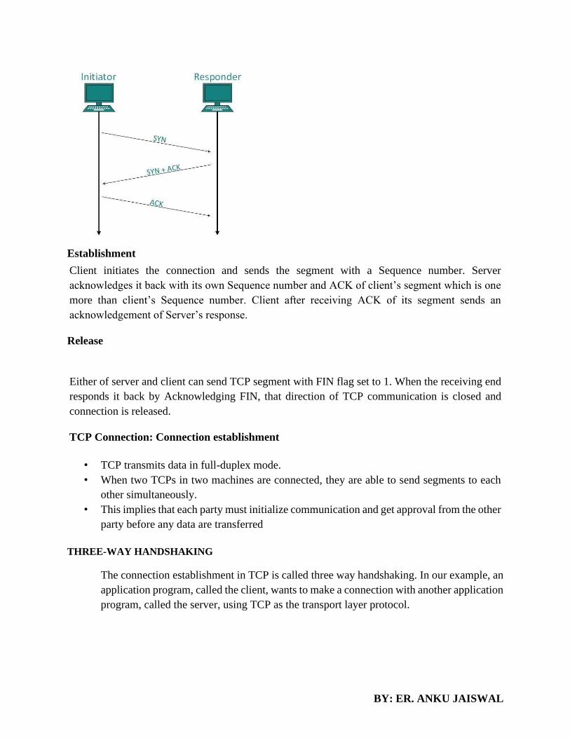
BY: ER. ANKU JAISWAL
Establishment
Client initiates the connection and sends the segment with a Sequence number. Server
acknowledges it back with its own Sequence number and ACK of client’s segment which is one
more than client’s Sequence number. Client after receiving ACK of its segment sends an
acknowledgement of Server’s response.
Release
Either of server and client can send TCP segment with FIN flag set to 1. When the receiving end
responds it back by Acknowledging FIN, that direction of TCP communication is closed and
connection is released.
TCP Connection: Connection establishment
• TCP transmits data in full-duplex mode.
• When two TCPs in two machines are connected, they are able to send segments to each
other simultaneously.
• This implies that each party must initialize communication and get approval from the other
party before any data are transferred
THREE-WAY HANDSHAKING
The connection establishment in TCP is called three way handshaking. In our example, an
application program, called the client, wants to make a connection with another application
program, called the server, using TCP as the transport layer protocol.

BY: ER. ANKU JAISWAL
The three steps in this phase are as follows.
1. The client sends the first segment, a SYN segment, in which only the SYN flag is
set. This segment is for synchronization of sequence numbers. It consumes one
sequence number. When the data transfer starts, the sequence number is
incremented by 1. We can say that the SYN segment carries no real data, but we
can think of it as containing 1 imaginary byte.
2. The server sends the second segment, a SYN +ACK segment, with 2 flag bits set:
SYN and ACK. This segment has a dual purpose. It is a SYN segment for
communication in the other direction and serves as the acknowledgment for the
SYN segment. It consumes one sequence number.
3. The client sends the third segment. This is just an ACK segment. It acknowledges
the receipt of the second segment with the ACK flag and acknowledgment number
field. Note that the sequence number in this segment is the same as the one in the
SYN segment; the ACK segment does not consume any sequence numbers.
Data Transfer

BY: ER. ANKU JAISWAL
After connection is established, bidirectional data transfer can take place. The client and server can both
send data and acknowledgments. We will study the rules of acknowledgment later in the chapter; for the
moment, it is enough to know that data traveling in the same direction as an acknowledgment are carried
on the same segment. The acknowledgment is piggybacked with the data. Figure 23.19 shows an example.
In this example, after connection is established, the client sends 2000 bytes of data in two segments. The
server then sends 2000 bytes in one segment. The client sends one more segment. The first three segments
carry both data and acknowledgment, but the last segment carries only an acknowledgment because there
are no more data to be sent. Note the values of the sequence and acknowledgment numbers. The data
segments sent by the client have the PSH (push) flag set so that the server TCP knows to deliver data to the
server process as soon as they are received. The segment from the server, on the other hand, does not set
the push flag. Most TCP implementations have the option to set or not set this flag.
Connection Termination
Three-Way Handshaking Most implementations today allow three-way handshaking
for connection termination.
1. In a normal situation, the client TCP, after receiving a close command from the client process, sends the
first segment, a FIN segment in which the FIN flag is set. Note that a FIN segment can include the last
chunk of data sent by the client, or it can be just a control segment. If it is only a control segment, it
consumes only one sequence number.

BY: ER. ANKU JAISWAL
2.The server TCP, after receiving the FIN segment, informs its process of the situation and sends the second
segment, a FIN +ACK segment, to confirm the receipt of the FIN segment from the client and at the same
time to announce the closing of the connection in the other direction. This segment can also contain the last
chunk of data from the server. If it does not carry data, it consumes only one sequence number.
3.The client TCP sends the last segment, an ACK segment, to confirm the receipt of the FIN segment from
the TCP server. This segment contains the acknowledgment number, which is 1 plus the sequence number
received in the FIN segment from the server. This segment cannot carry data and consumes no sequence
numbers.
FLOW CONTROL AND BUFFERING
• TCP uses a sliding window, to handle flow control.
• The sliding window protocol used by TCP, however, is something between the Go-Back-N and
Selective Repeat sliding window.
• The sliding window protocol in TCP looks like
• A sliding window is used to make transmission more efficient as weD as to control the flow of data
so that the destination does not become overwhelmed with data.

BY: ER. ANKU JAISWAL
• TCP sliding windows are byte-oriented.
• Some points about TCP sliding windows:
• o The size of the window is the lesser of rwnd and cwnd. o The source does not have to send a full
window's worth of data.
• o The window can be opened or closed by the receiver, but should not be shrunk.
• o The destination can send an acknowledgment at any time as long as it does not result in a
shrinking window.
• o The receiver can temporarily shut down the window; the sender, however, can always send a
segment of 1 byte after the window is shut down.
Stream Delivery Service: Buffer
• TCP, on the other hand, allows the sending process to deliver data as a stream of bytes and allows
the receiving process to obtain data as a stream of bytes.
• TCP creates an environment in which the two processes seem to be connected by an imaginary
"tube“ that carries their data across the Internet.
Sending and Receiving Buffers
• Because the sending and the receiving processes may not write or read data at the same speed, TCP
needs buffers for storage.
• There are two buffers, the sending buffer and the receiving buffer, one for each direction

BY: ER. ANKU JAISWAL
CONGESTION
An important issue in a packet-switched network is congestion. Congestion in a network may occur if the
load on the network-the number of packets sent to the network-is greater than the capacity of the network-
the number of packets a network can handle. Congestion control refers to the mechanisms and techniques
to control the congestion and keep the load below the capacity.
CONGESTION CONTROL TECHNIQUES
Congestion control refers to techniques and mechanisms that can either prevent congestion, before it
happens, or remove congestion, after it has happened. In general, we can divide congestion control
mechanisms into two broad categories: open-loop congestion control (prevention) and closed-loop
congestion control (removal)

BY: ER. ANKU JAISWAL
Open-Loop Congestion Control
In open-loop congestion control, policies are applied to prevent congestion before it happens. In these
mechanisms, congestion control is handled by either the source or the destination.
Retransmission Policy
Retransmission is sometimes unavoidable. If the sender feels that a sent packet is lost or corrupted, the
packet needs to be retransmitted. Retransmission in general may increase congestion in the network.
However, a good retransmission policy can prevent congestion. The retransmission policy and the
retransmission timers must be designed to optimize efficiency and at the same time prevent congestion. For
example, the retransmission policy used by TCP (explained later) is designed to prevent or alleviate
congestion.
Window Policy
The type of window at the sender may also affect congestion. The Selective Repeat window is better than
the Go-Back-N window for congestion control. In the Go-Back-N window, when the timer for a packet
times out, several packets may be resent, although some may have arrived safe and sound at the receiver.
This duplication may make the congestion worse. The Selective Repeat window, on the other hand, tries to
send the specific packets that have been lost or corrupted.

BY: ER. ANKU JAISWAL
Acknowledgment Policy
The acknowledgment policy imposed by the receiver may also affect congestion. If the receiver does not
acknowledge every packet it receives, it may slow down the sender and help prevent congestion. Several
approaches are used in this case. A receiver may send an acknowledgment only if it has a packet to be sent
or a special timer expires. A receiver may decide to acknowledge only N packets at a time. We need to
know that the acknowledgments are also part of the load in a network. Sending fewer acknowledgments
means imposing less load on the network.
Discarding Policy
A good discarding policy by the routers may prevent congestion and at the same time may not harm the
integrity of the transmission. For example, in audio transmission, if the policy is to discard less sensitive
packets when congestion is likely to happen, the quality of sound is still preserved and congestion is
prevented or alleviated.
Admission Policy
An admission policy, which is a quality-of-service mechanism, can also prevent congestion in virtual-circuit
networks. Switches in a flow first check the resource requirement of a flow before admitting it to the
network. A router can deny establishing a virtual circuit connection if there is congestion in the network or
if there is a possibility of future congestion.
Closed-Loop Congestion Control
Closed-loop congestion control mechanisms try to alleviate congestion after it happens.
Several mechanisms have been used by different protocols.
Backpressure

BY: ER. ANKU JAISWAL
The technique of backpressure refers to a congestion control mechanism in which a congested node stops
receiving data from the immediate upstream node or nodes. This may cause the upstream node or nodes to
become congested, and they, in turn, reject data from their upstream nodes or nodes. And so on.
Backpressure is a node-to-node congestion control that starts with a node and propagates, in the opposite
direction of data flow, to the source. The backpressure technique can be applied only to virtual circuit
networks, in which each node knows the upstream node from which a flow of data is corning.
Choke Packet
A choke packet is a packet sent by a node to the source to inform it of congestion. Note the difference
between the backpressure and choke packet methods. In backpressure, the warning is from one node to its
upstream node, although the warning may eventually reach the source station. In the choke packet method,
the warning is from the router, which has encountered congestion, to the source station directly. The
intermediate nodes through which the packet has traveled are not warned. We have seen an example of this
type of control in ICMP.
Implicit Signaling
In implicit signaling, there is no communication between the congested node or nodes and the source. The
source guesses that there is a congestion somewhere in the network from other symptoms. For example,
when a source sends several packets and there is no acknowledgment for a while, one assumption is that
the network is congested. The delay in receiving an acknowledgment is interpreted as congestion in the
network; the source should slow down. We will see this type of signaling when we discuss TCP congestion
control later in the chapter.
Explicit Signaling
The node that experiences congestion can explicitly send a signal to the source or destination. The explicit
signaling method, however, is different from the choke packet method. In the choke packet method, a
separate packet is used for this purpose; in the explicit signaling method, the signal is included in the packets
that carry data. Explicit signaling, as we will see in Frame Relay congestion control, can occur in either the
forward or the backward direction.
Backward Signaling A bit can be set in a packet moving in the direction opposite

BY: ER. ANKU JAISWAL
to the congestion. This bit can warn the source that there is congestion and that it needs to slow down to
avoid the discarding of packets.
Forward Signaling A bit can be set in a packet moving in the direction of the congestion. This bit can warn
the destination that there is congestion. The receiver in this case can use policies, such as slowing down the
acknowledgments, to alleviate the congestion.
TRAFFIC SHAPING (Congestion Control Algorithm)
Traffic shaping is a mechanism to control the amount and the rate of the traffic sent to the network. Two
algorithms can shape traffic: leaky bucket and token bucket.
Leaky Bucket
If a bucket has a small hole at the bottom, the water leaks from the bucket at a constant rate as long as there
is water in the bucket. The rate at which the water leaks does not depend on the rate at which the water is
input to the bucket unless the bucket is empty. The input rate can vary, but the output rate remains constant.
Similarly, in networking, a technique called leaky bucket can smooth out bursty traffic. Bursty chunks are
stored in the bucket and sent out at an average rate.

BY: ER. ANKU JAISWAL
In the figure, we assume that the network has committed a bandwidth of 3 Mbps for a host. The use of the
leaky bucket shapes the input traffic to make it conform to this commitment. In Figure 24.19 the host sends
a burst of data at a rate of 12 Mbps for 2 s, for a total of 24 Mbits of data. The host is silent for 5 s and then
sends data at a rate of 2 Mbps for 3 s, for a total of 6 Mbits of data. The leaky bucket smooths the traffic by
sending out data at a rate of 3 Mbps during the same 10 s. Without the leaky bucket, the beginning burst
may have hurt the network by consuming more bandwidth than is set aside for this host. We can also see
that the leaky bucket may prevent congestion. As an analogy, consider the freeway during rush hour (bursty
traffic). If, instead, commuters could stagger their working hours, congestion on our freeways could be
avoided.
A simple leaky bucket implementation is shown in Figure 24.20. A FIFO queue holds the packets. If the
traffic consists of fixed-size packets (e.g., cells in ATM networks), the process removes a fixed number of
packets from the queue at each tick of the clock. If the traffic consists of variable-length packets, the fixed
output rate must be based on the number of bytes or bits.

BY: ER. ANKU JAISWAL
The following is an algorithm for variable-length packets:
1. Initialize a counter to n at the tick of the clock.
2. If n is greater than the size of the packet, send the packet and decrement the counter by the packet size.
3.Repeat this step until n is smaller than the packet size.
4.Reset the counter and go to step 1.
Token Bucket
The leaky bucket is very restrictive. It does not credit an idle host. For example, if a host is not sending for
a while, its bucket becomes empty. Now if the host has bursty data, the leaky bucket allows only an average
rate. The time when the host was idle is not taken into account. On the other hand, the token bucket
algorithm allows idle hosts to accumulate credit for the future in the form of tokens. For each tick of the
clock, the system sends n tokens to the bucket. The system removes one token for
every cell (or byte) of data sent. For example, if n is 100 and the host is idle for 100 ticks, the bucket collects
10,000 tokens. Now the host can consume all these tokens in one tick with 10,000 cells, or the host takes
1000 ticks with 10 cells per tick. In other words, the host can send bursty data as long as the bucket is not
empty. Figure 24.21 shows the idea. The token bucket can easily be implemented with a counter. The token
is initialized to zero. Each time a token is added, the counter is incremented by 1. Each time a unit of data
is sent, the counter is decremented by 1. When the counter is zero, the host
cannot send data.

BY: ER. ANKU JAISWAL

BY: ER. ANKU JAISWAL
CHAPTER 6-APPLICATION LAYER
The application layer is a layer in the Open Systems Interconnection (OSI) seven-layer model and in the
TCP/IP protocol suite. It consists of protocols that focus on process-to-process communication across an
IP network and provides a firm communication interface and end-user services.
WEB: HTTP AND HTTPS
"World Wide Web " or "the Web", a hypertext system that operates over the Internet. Web (web browser)
(previously Epiphany), the web browser included with GNOME desktop environment. Web.com, a public
company that offers websites and other services for small businesses and consumers.
The Hypertext Transfer Protocol (HTTP) is an application protocol for distributed, collaborative,
hypermedia information systems. HTTP is the foundation of data communication for the World Wide Web.
Hypertext is structured text that uses logical links (hyperlinks) between nodes containing text.
Hyper Text Transfer Protocol Secure (HTTPS) is the secure version of HTTP, the protocol over
which data is sent between your browser and the website that you are connected to. The 'S' at the
end of HTTPS stands for 'Secure'. It means all communications between your browser and the
website are encrypted. HTTPS is often used to protect highly confidential online transactions like
online banking and online shopping order forms.
Web browsers such as Internet Explorer, Firefox and Chrome also display a padlock icon in the
address bar to visually indicate that a HTTPS connection is in effect.

BY: ER. ANKU JAISWAL
HTTPS pages typically use one of two secure protocols to encrypt communications - SSL (Secure
Sockets Layer) or TLS (Transport Layer Security). Both the TLS and SSL protocols use what is
known as an 'asymmetric' Public Key Infrastructure (PKI) system. An asymmetric system uses
two 'keys' to encrypt communications, a 'public' key and a 'private' key. Anything encrypted with
the public key can only be decrypted by the private key and vice-versa.
Instead of Hyper Text Transfer Protocol (HTTP), this website uses Hyper Text Transfer
Protocol Secure (HTTPS).
Using HTTPS, the computers agree on a "code" between them, and then they scramble the
messages using that "code" so that no one in between can read them. This keeps your information
safe from hackers.
HTTP
Http stands for Hyper Text Transfer Protocol. It allows World Wide Web users to transferring information
like image, text, video, music, graphic and other files on web pages. Http is basically used to access html
pages and also other resources can be accessible using HTTP.
HTTP is a request-response protocol in the client-server computing model. When you enter http:// in front
of the address tells the browser to connect over HTTP. For example, when you enter a URL
(http://www.abc.com) in your web browser, this sends an HTTP command to the Web server to fetch and
transfer the requested web page. Here, your web browser is your client and your website host as a server.
HTTPS
HTTPS stands for Hypertext Transfer Protocol Secure. HTTPS is a protocol which uses an encrypted HTTP
connection by transport-layer security.
BY: ER. ANKU JAISWAL
Sometimes, the clients may be exchanging private information with a server, which needs to be secured for
preventing some hacking issue. For this reason, HTTPS was developed by Netscape Corporation to allow
authorization and secured transactions.
Here is the fact of HTTP:
• HTTPS uses a port 443 by default to transfer the information.
• HTTPS URLs begin with “https://”.
• The HTTPS is first used in HTTPS V1.1 and defined in RFC 2616.
When you interact with a website, such as trying to retrieve a webpage, data is sent back and forth between
you and the web server. The S in HTTPS signals the inclusion of the "Secure Sockets Layer" - more
colloquially known as "SSL" - whose function is to encrypt the data that is exchanged between you and the
website.
When you connect to the website your computer will receive their SSL Certificate and checks it against the
server's credentials. Your computer and the web server then figure out the best way to encrypt information,
exchange special "keys" with one another, and then give it a small test drive to ensure they can properly
share encrypted information. Once the two are ready to go, they each give the green light and exchange
encrypted information.
Because both your computer and the website's server have to verify their identities, set up their special way
of encoding/decoding that is unique to them, and always transfer information in a secure fashion many of
the typical attack vectors available to hackers are rendered insignificant. They will have spent more
resources in terms of computing power and time than they could hope to get back through your information,
which will likely have changed over the years it would take to properly decrypt. And the method of
decryption is unique to each connection.
FILE TRANSFER

BY: ER. ANKU JAISWAL
FTP
The File Transfer Protocol (FTP) is a standard network protocol used to transfer computer files between a
client and server on a computer network. FTP is built on client-server model architecture and uses separate
control and data connections between the client and the server.
File Transfer Protocol (FTP) is a standard Internet protocol for transmitting files between
computers on the Internet over TCP/IP connections.
FTP is a client-server protocol that relies on two communications channels between client and
server: a command channel for controlling the conversation and a data channel for transmitting
file content. Clients initiate conversations with servers by requesting to download a file. Using
FTP, a client can upload, download, delete, and rename, move and copy files on a server. A user
typically needs to log on to the FTP server, although some servers make some or all of their content
available without login, also known as anonymous FTP.
FTP sessions work in passive or active modes. In active mode, after a client initiates a session via a
command channel request, the server initiates a data connection back to the client and begins transferring
data. In passive mode, the server instead uses the command channel to send the client the information it
needs to open a data channel. Because passive mode has the client initiating all connections, it works well
across firewalls and Network Address Translation (NAT) gateways.

BY: ER. ANKU JAISWAL
FTP was originally defined in 1971, prior to the definition of TCP and IP, and has been redefined many
times -- e.g., to use TCP/IP (RFC 765 and RFC 959), and then Internet Protocol Version 6 (IPv6), (RFC
2428). Also, because it was defined without much concern for security, it has been extended many times to
improve security: for example, versions that encrypt via a TLS connection (FTPS) or that work with Secure
File Transfer Protocol (SFTP), also known as SSH File Transfer Protocol.
PUTTY
PuTTY is a free and open-source terminal emulator, serial console and network file transfer
application. It supports several network protocols, including SCP, SSH, Telnet, rlogin, and raw
socket connection. It can also connect to a serial port. The name "PuTTY" has no definitive
meaning.
PuTTY was originally written for Microsoft Windows, but it has been ported to various
other operating systems. Official ports are available for some Unix-like platforms, with work-in-
progress ports to Classic Mac OS and macOS, and unofficial ports have been contributed to
platforms such as Symbian,Windows Mobile and Windows Phone.
PuTTY was written and is maintained primarily by Simon Tatham and is currently beta software.
Features
BY: ER. ANKU JAISWAL
PuTTY supports many variations on the secure remote terminal, and provides user control over
the SSH encryption key and protocol version, alternate ciphers such as 3DES, Arcfour, Blowfish, DES,
and Public-key authentication. It also can emulate control sequences from xterm, VT102 or ECMA-
48 terminal emulation, and allows local, remote, or dynamic port forwarding with SSH
(including X11 forwarding). The network communication layer supports IPv6, and the SSH protocol
supports the [email protected] delayed compression scheme. It can also be used with local serial port
connections.
PuTTY comes bundled with command-line SCP and SFTP clients, called "pscp" and "psftp" respectively,
and plinks, a command-line connection tool, used for non-interactive sessions. PuTTY is a program that
connects one device to another over the network. It supports SSH and Telnet, among others. PuTTY is a
“client” application that talks to a “host”. The host must be running an SSH server (which is often the case
for iMX Linux enabled systems).A Windows version exists and this is ideal for transferring files between
your Windows PC and a Linux Platform.
WinSCP (Windows Secure Copy) is a free and open
source SFTP, FTP, WebDAV and SCP client for Microsoft Windows. Its main function is
secure file transfer between a local and a remote computer. Beyond this, WinSCP offers
basic file manager and file synchronization functionality. For secure transfers, it uses Secure
Shell (SSH) and supports the SCP protocol in addition to SFTP.[3]
Development of WinSCP started around March 2000 and continues. Originally it was hosted by
the University of Economics in Prague, where its author worked at the time. Since July 16, 2003,
it is licensed under the GNU GPL and hosted on SourceForge.net.
WinSCP is based on the implementation of the SSH protocol from PuTTY and FTP protocol
from FileZilla. It is also available as a plug-in for Altap Salamander file manager, and there exists
a third-party plug-in for the FAR file manager.
• Graphical user interface
• Translated into several languages
• Integration with Windows (Drag-and-drop, URL, shortcut icons)
• All common operations with files
• Support for SFTP and SCP protocols over SSH-1 and SSH-2, FTP protocol and WebDAV protocol.[8]
• Batch file scripting, command-line interface and .NET wrapper
• Directory synchronization in several semi or fully automatic ways
• Integrated text editor
• Support for SSH password, keyboard-interactive, public key and Kerberos (GSS) authentication

BY: ER. ANKU JAISWAL
• Integrates with Pageant (PuTTY authentication agent) for full support of public key authentication with
SSH
• Choice of Windows Explorer–like or Norton Commander–like interfaces
• Optionally stores session information
• Optionally import session information from PuTTY sessions in the registry
• Able to upload files and retain associated original date/timestamps, unlike FTP clients
ELECTRONIC MAIL:
E-mail (electronic mail) is the exchange of computer-stored messages by telecommunication. (Some
publications spell it email; we prefer the currently more established spelling of e-mail.) E-mail messages
are usually encoded in ASCII text.
Overview
SMTP, POP3 and IMAP are TCP/IP protocols used for mail delivery. If you plan to set up an email server
such as hMailServer, you must know what they are used for. Each protocol is just a specific set of
communication rules between computers.
SMTP
SMTP stands for Simple Mail Transfer Protocol. SMTP is used when email is delivered from an email
client, such as Outlook Express, to an email server or when email is delivered from one email server to
another. SMTP uses port 25.
SMTP provides a set of codes that simplify the communication of email messages between email
servers (the network computer that handles email coming to you and going out). It's a kind of
shorthand that allows a server to break up different parts of a message into categories the other
server can understand. When you send a message out, it's turned into strings of text that are
separated by the code words (or numbers) that identify the purpose of each section.
SMTP provides those codes, and email server software is designed to understand what they mean.
As each message travels towards its destination, it sometimes passes through a number of
computers as well as their individual MTAs. As it does, it's briefly stored before it moves on to the
next computer in the path. Think of it as a letter going through different hands as it winds its way
to the right mailbox.
POP3

BY: ER. ANKU JAISWAL
POP3 stands for Post Office Protocol. POP3 allows an email client to download an email from an email
server. The POP3 protocol is simple and does not offer many features except for download. Its design
assumes that the email client downloads all available email from the server, deletes them from the server
and then disconnects. POP3 normally uses port 110.
(1) POP is short for Post Office Protocol, a protocol used to retrieve e-mail from a mail server.
Most e-mail applications (sometimes called an e-mail client) use the POP protocol, although some
can use the newer IMAP (Internet Message Access Protocol).
There are two versions of POP. The first, called POP2, became a standard in the mid-80's and
requires SMTP to send messages. The newer version, POP3, can be used with or without SMTP.
(2) Pop is short for point of presence, an access point to the Internet. ISPs have typically multiple
POPs. A point of presence is a physical location, either part of the facilities of a
telecommunications provider that the ISP rents or a separate location from the telecommunications
provider, that houses servers, routers, ATM switches and digital/analog call aggregators.
(3) Pop is short for Programmed Operator (POP), a pseudo-opcode in a virtual machine language
executed by an interpretive program. The Programmed Operator instructions provide the ability to
define an instruction set for efficient encoding by calling subprograms into primary memory.
(4) POP is short for picture-outside-picture POP is a feature found on some televisions that allows
the user to divide the screen into two same-size pictures, enabling you to view a second
program. Compare with picture-in-picture (PIP).
IMAP
IMAP stands for Internet Message Access Protocol. IMAP shares many similar features with POP3. It, too,
is a protocol that an email client can use to download email from an email server. However, IMAP includes
many more features than POP3. The IMAP protocol is designed to let users keep their email on the server.
IMAP requires more disk space on the server and more CPU resources than POP3, as all emails are stored
on the server. IMAP normally uses port 143. Here is more information about IMAP.
Short for Internet Message Access Protocol, a protocol for retrieving e-mail messages. The latest
version, IMAP4, is similar to POP3 but supports some additional features. For example, with
IMAP4, you can search through your e-mail messages for keywords while the messages are still
on mail server. You can then choose which messages to download to your machine.
IMAP was developed at Stanford University in 1986.
Examples
Suppose you use hMailServer as your email server to send an email to [email protected].
1. You click Send in your email client, say, Outlook Express.
2. Outlook Express delivers the email to hMailServer using the SMTP protocol.
3. hMailServer delivers the email to Microsoft's mail server, mail.microsoft.com, using SMTP.
BY: ER. ANKU JAISWAL
4. Bill's Mozilla Mail client downloads the email from mail.microsoft.com to his laptop using the
POP3 protocol (or IMAP).
DNS
Short for Domain Name System (or Service or Server), an Internet service that translates domain
names into IP addresses. Because domain names are alphabetic, they're easier to remember. The
Internet however, is really based on IP addresses. Every time you use a domain name, therefore, a
DNS service must translate the name into the corresponding IP address. For example, the domain
name www.example.com might translate to 198.105.232.4.
The DNS system is, in fact, its own network. If one DNS server doesn't know how to translate a
particular domain name, it asks another one, and so on, until the correct IP address is returned.
Short for digital nervous system, a term coined by Bill Gates to describe a network of personal
computers that make it easier to obtain and understand information.
Domain names give people a more intuitive way to access content or services than IP addresses:
www.techtarget.com instead of 206.19.49.149, for example. Most URLs are built around the domain name
of the web server fielding the request: e.g., http://searchnetworking.techtarget.com/definition/DNS-attack.
Web browsing and most other internet activity rely on DNS behind the scenes to quickly provide the
information necessary to connect users to remote hosts.
Why is DNS important?
Having a single DNS server somewhere that maintained a complete central list of domain name or
IP address mappings would be impractical. There are too many mappings, they change too often
and the number of requests for address or name lookups would overwhelm any system. As a result,
DNS is distributed throughout the internet in a hierarchy of authority. Access providers and
enterprises, as well as governments, universities and other organizations, typically have their own
assigned ranges of IP addresses and an assigned domain name; they also typically run DNS servers
to manage the mapping of those names to those addresses.
How does DNS work?
DNS servers answer questions from both inside and outside their own domains. When a server
receives a request from outside the domain for information about a name or address inside the
domain, it provides the authoritative answer. When a server receives a request from inside its own
domain for information about a name or address outside that domain, it passes the request out to
another server -- usually one managed by its internet service provider. If that server does not know

BY: ER. ANKU JAISWAL
the answer or the authoritative source for the answer, it will reach out to the DNS servers for the
top-level domain -- e.g., for all of .com or .edu. Then, it will pass the request down to the
authoritative server for the specific domain -- e.g., techtarget.com or stkate.edu; the answer flows
back along the same path.
P2P APPLICATION
What is Peer to Peer (P2P) Application?
P2P is nothing but just Peer to Peer networking. As we have Server - Client Model and Peer to
Peer network in the same way these P2P applications work. You need a P2P program that will be
installed on your computer it creates a community of P2P application users and it creates a virtual
network between these users. For the user it will look as it is in a Peer to Peer network and he can
share files from his local computer and download files shared by other users. It is very similar to
our Instant Messaging like Yahoo, AOL or GTalk where even though to who we are taking to are
on a different network but a virtual network is created where it looks like we are on a same network
and we can share files and chat. The P2P application has been very much in demand from last
couple of years. A P2P application is mainly used for sharing Music, Movies, Games and other
files.
What are the disadvantages of Peer to Peer (P2P) Application?

BY: ER. ANKU JAISWAL
Is it estimated that for any given ISP 60 to 80% of their traffic is consumed by P2P traffic. So even
in your office if people are using P2P application they will consume a huge amount of bandwidth
without production.P2P application is very famous for distributing Pirated software. Your users
might be using pirated software on their computers and Auditors will never appreciate that.
Symantec Underground Economy says that "The annual global cost to businesses of software
piracy in one 2007 study puts the cost at nearly $40 billion"
You can never trust the file you are downloading from a remote user in P2P environment.90% of
the files contain malwares. Thus if your users are using P2P application there is very high rate of
Virus Outbreak in your network that too very frequently. In 2008 10% of malware were propagated
via P2P applications. Even the very infamous W32.Downadup also propagated and updated itself
via P2P applications.
P2P is a very famous mechanism for distributing Bots, Spywares, Adware, Trojans, Rootkits,
Worms and other types of malwares.
Since it is very easy to change the port for these P2P applications it is very difficult to block this
traffic. It is strictly not advised to have P2P application allowed in your network. Enterprises
should take measures to prevent P2P clients from being installed on any computers on the network.
End users who download files from P2P networks should scan all such files with a regularly
updated antivirus product.
How to block Peer to Peer Applications (P2P) using Symantec Endpoint Protection?
There are 3 ways of blocking Peer to Peer Applications on your network using Symantec Endpoint
Protection.
1. Blocking Peer to Peer Applications using Intrusion Prevention System
Open Symantec Endpoint Protection Manager
Click on Policies -> Intrusion Prevention -> Edit Intrusion Prevention Policies .go to Exceptions -
> Click on Add.
Then under Show Category scroll it down and Select Peer to Peer.
On the bottom right hand side of the policy click on Select all -> click next
Action -Block
Log - Log the Traffic
SOCKET PROGRAMMING
Sockets provide the communication mechanism between two computers using TCP. A client
program creates a socket on its end of the communication and attempts to connect that socket to
a server.

BY: ER. ANKU JAISWAL
When the connection is made, the server creates a socket object on its end of the communication.
The client and the server can now communicate by writing to and reading from the socket.
The java.net.Socket class represents a socket, and the java.net.ServerSocket class provides a
mechanism for the server program to listen for clients and establish connections with them.
The following steps occur when establishing a TCP connection between two computers using
sockets −
• The server instantiates a ServerSocket object, denoting which port number communication
is to occur on.
• The server invokes the accept () method of the ServerSocket class. This method waits until
a client connects to the server on the given port.
• After the server is waiting, a client instantiates a Socket object, specifying the server name
and the port number to connect to.
• The constructor of the Socket class attempts to connect the client to the specified server
and the port number. If communication is established, the client now has a Socket object
capable of communicating with the server.
• On the server side, the accept() method returns a reference to a new socket on the server
that is connected to the client's socket.
After the connections are established, communication can occur using I/O streams. Each socket
has both an OutputStream and an InputStream. The client's OutputStream is connected to the
server's InputStream, and the client's InputStream is connected to the server's OutputStream.
TCP is a two-way communication protocol, hence data can be sent across both streams at the
same time. Following are the useful classes providing complete set of methods to implement
sockets.
APPLICATION SERVER CONCEPT
PROXY SERVER
In computer networks, a proxy server is a server (a computer system or an application) that acts
as an intermediary for requests from clients seeking resources from other servers.[1] A client
connects to the proxy server, requesting some service, such as a file, connection, web page, or
other resource available from a different server and the proxy server evaluates the request as a
way to simplify and control its complexity.

BY: ER. ANKU JAISWAL
PROXY CACHING
Proxy caching is a feature of proxy servers that stores content on the proxy server itself,
allowing web services to share those resources to more users. The proxyserver coordinates with
the source server to cache documents such as files, images and web pages.
CONCEPT OF TRAFFIC ANALYZER
A) MRTG
The Multi Router Traffic Grapher (MRTG) is a tool to monitor the traffic load on network links.
MRTG generates HTML pages containing PNG images which provide a LIVE visual
representation of this traffic. Check http://www.stat.ee.ethz.ch/mrtg/ to see what it does.
MRTG consists of a Perl script which uses SNMP to read the traffic counters of your routers and
a fast C program which logs the traffic data and creates beautiful graphs representing the traffic on
the monitored network connection. These graphs are embedded into WebPages which can be
viewed from any modern Web-browser.
In addition to a detailed daily view, MRTG also creates visual representations of the traffic seen
during the last seven days, the last five weeks and the last twelve months. This is possible because
MRTG keeps a log of all the data it has pulled from the router. This log is automatically
consolidated so that it does not grow over time, but still contains all the relevant data for all the
traffic seen over the last two years. This is all performed in an efficient manner. Therefore you can
monitor 200 or more network links from any halfway decent UNIX box.
MRTG is not limited to monitoring traffic, though. It is possible to monitor any SNMP variable
you choose. You can even use an external program to gather the data which should be monitored
via MRTG. People are using MRTG, to monitor things such as System Load, Login Sessions,
Modem availability and more. MRTG even allows you to accumulate two or more data sources
into a single graph.
B) PRTG
Paessler Router Traffic Grapher, renamed PRTG Network Monitor from version 7 in 2008, is
a server up-time and utilization, network monitoring and bandwidth usage software package for
server infrastructure from Paessler AG. It can monitor and classify bandwidth usage in a network
using SNMP, packet sniffing and Net flow. It services Microsoft Windows and Linux. It was
derived from the open-source Multi Router Traffic Grapher (MRTG) project. A version with a
limited number of sensors is available free of charge.
C) SNMP
BY: ER. ANKU JAISWAL
Simple Network Management Protocol (SNMP) is a popular protocol for network management. It
is used for collecting information from, and configuring, network devices, such as servers, printers,
hubs, switches, and routers on an Internet Protocol (IP) network. Microsoft Windows Server 2003
provides SNMP agent software that works with third-party SNMP management software to
monitor the status of managed devices and applications.
D) Packet Tracer
Cisco Packet Tracer is a powerful network simulation program that allows students to experiment with
network behavior and ask “what if” questions. As an integral part of the Networking Academy
comprehensive learning experience, Packet Tracer provides simulation, visualization, authoring,
assessment, and collaboration capabilities and facilitates the teaching and learning of complex technology
concepts.
Packet Tracer supplements physical equipment in the classroom by allowing students to create a network
with an almost unlimited number of devices, encouraging practice, discovery, and troubleshooting. The
simulation-based learning environment helps students develop 21st century skills such as decision making,
creative and critical thinking, and problem solving. Packet Tracer complements the Networking Academy
curricula, allowing instructors to easily teach and demonstrate complex technical concepts and networking
systems design.
E) Wire shark
Wireshark is a free and open source packet analyzer. It is used for network troubleshooting,
analysis, software and communications protocol development, and education. Originally
named Ethereal, the project was renamed Wireshark in May 2006 due to trademark issues.[4]
Wireshark is cross-platform, using the Qt widget toolkit in current releases to implement its user
interface, and using pcap to capture packets; it runs on Linux, macOS, BSD, Solaris, some
other Unix-like operating systems, and Microsoft Windows. There is also a terminal-based (non-
GUI) version called TShark. Wireshark, and the other programs distributed with it such as TShark,
are free software, released under the terms of the GNU General Public License.

BY: ER. ANKU JAISWAL
CHAPTER 7-IPV6
IPV6
Internet Protocol version 6 (IPv6) is the most recent version of the Internet Protocol (IP),
the communications protocol that provides an identification and location system for computers on networks
and routes traffic across the Internet. IPv6 was developed by the Internet Engineering Task Force (IETF)
to deal with the long-anticipated problem of IPv4 address exhaustion. IPv6 is intended to replace IPv4.
With the rapid growth of the Internet after commercialization in the 1990s, it became evident that far more
addresses would be needed to connect devices than the IPv4 address space had available. IPv6 uses a 128-
bit address, theoretically allowing 2128, or approximately 3.4×1038 addresses. Several IPv6 transition
mechanisms have been devised to permit communication between IPv4 and IPv6 hosts.
IPv6 addresses are represented as eight groups of four hexadecimal digits with the groups being separated
by colons, for example 2001:0db8:0000:0042:0000:8a2e:0370:7334, but methods to abbreviate this full
notation exist.
LIMITATIONS OF IPV4
The network layer protocol in the TCPIIP protocol suite is currently IPv4 (Internetworking Protocol,
version 4). IPv4 provides the host-to-host communication between systems in the Internet. Although IPv4
is well designed, data communication has evolved since the inception of IPv4 in the 1970s. IPv4 has some
deficiencies (listed below) that make it unsuitable for the fast-growing Internet.
o Despite all short-term solutions, such as subnetting, classless addressing, and NAT, address depletion is
still a long-term problem in the Internet.
o The Internet must accommodate real-time audio and video transmission. This type of transmission
requires minimum delay strategies and reservation of resources not provided in the IPv4 design.
o The Internet must accommodate encryption and authentication of data for some applications. No
encryption or authentication is provided by IPv4.
BY: ER. ANKU JAISWAL
ADVANTAGES OF IPV6
The next-generation IP, or IPv6, has some advantages over IPv4 that can be summarized
as follows:
• Larger address space. An IPv6 address is 128 bits long, Compared with the 32-bit address
of IPv4, this is a huge increase in the address space.
• Better header format. IPv6 uses a new header format in which options are separated from
the base header and inserted, when needed, between the base header and the upper-layer
data. This simplifies and speeds up the routing process because most of the options do not
need to be checked by routers.
• New options. IPv6 has new options to allow for additional functionalities.
• Allowance for extension. IPv6 is designed to allow the extension of the protocol if required
by new technologies or applications.
• Support for resource allocation. In IPv6, the type-of-service field has been removed, but a
mechanism has been added to enable the source to request special handling of the packet.
This mechanism can be used to support traffic such as real-time audio and video.
• Support for more security. The encryption and authentication options in IPv6 provide
PACKET FORMAT
The IPv6 packet is shown in Figure. Each packet is composed of a mandatory base header followed by the
payload. The payload consists of two parts: optional extension headers and data from an upper layer. The
base header occupies 40 bytes, whereas the extension headers and data from the upper layer contain up to
65,535 bytes of information.
Base Header
Figure shows the base header with its eight fields. These fields are as follows:
o Version. This 4-bit field defines the version number of the IP. For IPv6, the value is 6.
o Priority. The 4-bit priority field defines the priority of the packet with respect to traffic congestion.

BY: ER. ANKU JAISWAL
• Flow label. The flow label is a 3-byte (24-bit) field that is designed to provide special
handling for a particular flow of data.
• Payload length. The 2-byte payload length field defines the length of the IP datagram

BY: ER. ANKU JAISWAL
excluding the base header.
• Next header. The next header is an 8-bit field defining the header that follows the base
header in the datagram. The next header is either one of the optional extension headers
used by IP or the header of an encapsulated packet such as UDP or TCP. Each extension
header also contains this field. Table 20.6 shows the values of next headers. Note that this
field in version 4 is called the protocol.
• Hop limit. This 8-bit hop limit field serves the same purpose as the TIL field in IPv4.
• Source address. The source address field is a 16-byte (128-bit) Internet address that
identifies the original source of the datagram.
• Destination address. The destination address field is a 16-byte (128-bit) Internet address
that usually identifies the final destination of the datagram. However, if source routing is
used, this field contains the address of the next router.
Priority
The priority field of the IPv6 packet defines the priority of each packet with respect to other packets from
the same source. For example, if one of two consecutive Datagrams must be discarded due to congestion,
the datagram with the lower packet priority will be discarded. IPv6 divides traffic into two broad categories:
congestion-controlled and noncongestion-controlled.
Congestion-Controlled Traffic If a source adapts itself to traffic slowdown when there is congestion, the
traffic is referred to as congestion-controlled traffic. For example, TCP, which uses the sliding window
protocol, can easily respond to traffic. In congestion-controlled traffic, it is understood that packets may
arrive delayed, lost, or out of order. Congestion-controlled data are assigned priorities from 0 to 7, as listed
in
Table 20.7. A priority of 0 is the lowest; a priority of 7 is the highest.

BY: ER. ANKU JAISWAL
Noncongestion-Controlled Traffic: This refers to a type of traffic that expects minimum delay. Discarding
of packets is not desirable. Retransmission in most cases is impossible. In other words, the source does not
adapt itself to congestion. Real-time audio and video are examples of this type of traffic.
Flow Label
A sequence of packets, sent from a particular source to a particular destination that needs special handling
by routers is called a flow of packets. The combination of the source address and the value of the flow label
uniquely define a flow of packets. To a router, a flow is a sequence of packets that share the same
characteristics, such as traveling the same path, using the same resources, having the same kind of security,
and so on. A router that supports the handling of flow labels has a flow label table. In its simplest form, a
flow label can be used to speed up the processing of a packet by a router. When a router receives a packet,
instead of consulting the routing table and going through a routing algorithm to define the address of the
next hop, it can easily look in a flow label table for the next hop.

BY: ER. ANKU JAISWAL
EXTENSION HEADERS
The length of the base header is fixed at 40 bytes. However, to give greater functionality to the IP datagram,
the base header can be followed by up to six extension headers. Many of these headers are options in IPv4.
Six types of extension headers have been defined,
Hop-by-Hop Option

BY: ER. ANKU JAISWAL
The hop-by-hop option is used when the source needs to pass information to all routers visited by the
datagram. So far, only three options have been defined: Padl, PadN, and jumbo payload. The Padl option
is 1 byte long and is designed for alignment purposes. PadN is similar in concept to Padi. The difference is
that PadN is used when 2 or more bytes are needed for alignment. The jumbo payload option is used to
define a payload longer than 65,535 bytes.
Source Routing
The source routing extension header combines the concepts of the strict source route and the loose source
route options of IPv4.
Fragmentation
The concept of fragmentation is the same as that in IPv4. However, the place where fragmentation occurs
differs. In IPv4, the source or a router is required to fragment if the size of the datagram is larger than the
MTU of the network over which the datagram travels. In IPv6, only the original source can fragment. A
source must use a path MTU discovery technique to find the smallest MTU supported by any network on
the path. The source then fragments using this knowledge.
Authentication
The authentication extension header has a dual purpose: it validates the message sender and ensures the
integrity of data.
Encrypted Security Payload
The encrypted security payload (ESP) is an extension that provides confidentiality and guards against
eavesdropping.
Destination Option
The destination option is used when the source needs to pass information to the destination only.
Intermediate routers are not permitted access to this information.

BY: ER. ANKU JAISWAL
TRANSITION FROM IPv4 TO IPv6
Because of the huge number of systems on the Internet, the transition from IPv4 to IPv6 cannot happen
suddenly. It takes a considerable amount of time before every system in the Internet can move from IPv4
to IPv6. The transition must be smooth to prevent any problems between IPv4 and IPv6 systems. Three
strategies have been devised to help the transition
Dual Stack

BY: ER. ANKU JAISWAL
It is recommended that all hosts, before migrating completely to version 6, have a dual stack of protocols.
In other words, a station must run IPv4 and IPv6 simultaneously untilall the Internet uses IPv6.
To determine which version to use when sending a packet to a destination, the source host queries the DNS.
If the DNS returns an IPv4 address, the source host sends an IPv4 packet. If the DNS returns an IPv6
address, the source host sends an IPv6 packet.
Tunneling
Tunneling is a strategy used when two computers using IPv6 want to communicate with each other and the
packet must pass through a region that uses IPv4. To pass through this region, the packet must have an IPv4
address. So the IPv6 packet is encapsulated in an IPv4 packet when it enters the region, and it leaves its
capsule when it exits the region. It seems as if the IPv6 packet goes through a tunnel at one end and emerges
at the other end. To make it clear that the IPv4 packet is carrying an IPv6 packet as data, the protocol value
is set to 41.

BY: ER. ANKU JAISWAL
Header Translation
Header translation is necessary when the majority of the Internet has moved to IPv6 but some systems still
use IPv4. The sender wants to use IPv6, but the receiver does not understand IPv6. Tunneling does not
work in this situation because the packet must be in the IPv4 format to be understood by the receiver. In
this case, the header format must be totally changed through header translation. The header of the IPv6
packet is converted to an IPv4 header
Header translation uses the mapped address to translate an IPv6 address to an IPv4 address.

BY: ER. ANKU JAISWAL

BY: ER. ANKU JAISWAL
CHAPTER 8-NETWORK SECURITY
SECURITY
The science and art of transforming messages to make them secure and immune to attack.
PROPERTIES OF SECURE COMMUNICATION
Message Confidentiality
Message confidentiality or privacy means that the sender and the receiver expect confidentiality.
The transmitted message must make sense to only the intended receiver. To all others, the message must
be garbage. When a customer communicates with her bank, she expects that the communication is totally
confidential.
Message Integrity
Message integrity means that the data must arrive at the receiver exactly as they were sent. There must be
no changes during the transmission, neither accidentally nor maliciously. As more and more monetary
exchanges occur over the Internet, integrity is crucial. For example, it would be disastrous if a request for
transferring $100 changed to a request for $10,000 or $100,000. The integrity of the message must be
preserved in a secure communication.
Message Authentication
Message authentication is a service beyond message integrity. In message authentication the receiver needs
to be sure of the sender's identity and that an imposter has not sent the message.
Message Nonrepudiation
Message nonrepudiation means that a sender must not be able to deny sending a message that he or she, in
fact, did send. The burden of proof falls on the receiver. For example, when a customer sends a message to

BY: ER. ANKU JAISWAL
transfer money from one account to another, the bank must have proof that the customer actually requested
this transaction.
Entity Authentication
In entity authentication (or user identification) the entity or user is verified prior to Access to the system
resources (files, for example). For example, a student who needs to access her university resources needs
to be authenticated during the logging process. This is to protect the interests of the university and the
student.
CRYPTOGRAPHY
Cryptography, a word with Greek origins, means "secret writing." However, we use the term to refer to the
science and art of transforming messages to make them secure and immune to attacks. Figure 30.1 shows
the components involved in cryptography.
SYMMETRIC KEY CRYPTOGRAPHY

BY: ER. ANKU JAISWAL
• In symmetric-key cryptography, the same key is used by both parties. The sender uses this
key and an encryption algorithm to encrypt data; the receiver uses the same key and the
corresponding decryption algorithm to decrypt the data
ASYMMETRIC-KEY CRYPTOGRAPHY
• In asymmetric or public-key cryptography, there are two keys: a private key and a public
key. The private key is kept by the receiver. The public key is announced to the public
SYMMETRIC-KEY CRYPTOGRAPHY

BY: ER. ANKU JAISWAL
• Substitution Cipher
A substitution cipher substitutes one symbol with another.
• Monoalphabetic cipher
In a monoalphabetic cipher, a character (or a symbol) in the plaintext is always changed to
the same character (or symbol) in the cipher text regardless of its position in the text. For
example, if the algorithm says that character A in the plaintext is changed to character D,
every character A is changed to character D.
• Polyalphabetic cipher
• In a polyalphabetic cipher, each occurrence of a character can have a different substitute.

BY: ER. ANKU JAISWAL
• Shift Cipher
The simplest monoalphabetic cipher is probably the shift cipher. We assume that the
plaintext and cipher text consist of uppercase letters (A to Z) only. In this cipher, the
encryption algorithm is "shift key characters down," with key equal to some number. The
decryption algorithm is "shift key characters up."
• Transposition Ciphers
In a transposition cipher, there is no substitution of characters; instead, their locations
change. A character in the first position of the plaintext may appear in the tenth position of
the cipher text.
ASYMMETRIC-KEY CRYPTOGRAPHY
The most common public key algorithm is RSA, named for its inventors Rivest, Shamir,
and Adleman (RSA). It uses two numbers, e and d, as the public and private keys

BY: ER. ANKU JAISWAL
Selecting Keys
Bob use the following steps to select the private and public keys:
1. Bob chooses two very large prime numbers p and q. Remember that a prime number
is one that can be divided evenly only by 1 and itself.
2. Bob multiplies the above two primes to find n, the modulus for encryption and
decryption. In other words, n ::: p X q.
3. Bob calculates another number <1> ::: (p -1) X (q - 1).
4. Bob chooses a random integer e. He then calculates d so that d x e::: 1 mod <1>.
5. Bob announces e and n to the public; he keeps <1> and d secret.
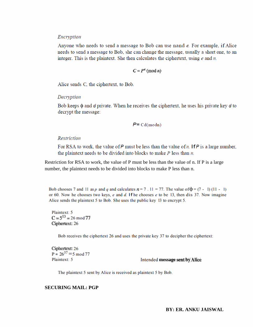
BY: ER. ANKU JAISWAL
Restriction for RSA to work, the value of P must be less than the value of n. If P is a large
number, the plaintext needs to be divided into blocks to make P less than n.
SECURING MAIL: PGP
BY: ER. ANKU JAISWAL
• Pretty Good Privacy
• Provide security to e-mail
• Developed by Phil Zimmerman in 1995
• Documentation and source code freely available
• Independent of OS and processor
• All user uses public key cryptography
• Uses RSA
• Service provided: Authentication, Confidentiality, Compression, Email compatibility
DIGITAL SIGNATURE
• A digital signature is basically a way to ensure that an electronic document (e-mail,
spreadsheet, text file, etc.) is authentic.
• Authentic means that you know who created the document and you know that it has not
been altered in any way since that person created it.
• Digital signatures rely on certain types of encryption to ensure authentication.
• Encryption is the process of taking all the data that one computer is sending to another and
encoding it into a form that only the other computer will be able to decode.
o Authentication is the process of verifying that information is coming from a trusted
source. These two processes work hand in hand for digital signatures.
• Digital signatures are based on public key cryptography, also known as asymmetric
cryptography.
• Using a public key algorithm such as RSA, one can generate two keys that are
mathematically linked: one private and one public.
• To create a digital signature, signing software (such as an email program) creates a one-
way hash of the electronic data to be signed.
• The private key is then used to encrypt the hash. The encrypted hash -- along with other
information, such as the hashing algorithm -- is the digital signature.
• Digital signatures, like handwritten signatures, are unique to each signer.
• Digital signature solution providers, such as DocuSign, follow a specific protocol,
called PKI.
• PKI requires the provider to use a mathematical algorithm to generate two long numbers,
called keys. One key is public, and one key is private.
• When a signer electronically signs a document, the signature is created using the signer’s
private key, which is always securely kept by the signer.
• The mathematical algorithm acts like a cipher, creating data matching the signed document,
called a hash, and encrypting that data.
• The resulting encrypted data is the digital signature. The signature is also marked with the

BY: ER. ANKU JAISWAL
time that the document was signed. If the document changes after signing, the digital
signature is invalidated.
• As an example, Jane signs an agreement to sell a timeshare using her private key. The buyer
receives the document. The buyer who receives the document also receives a copy of Jane’s
public key. If the public key can’t decrypt the signature (via the cipher from which the keys
were created), it means the signature isn’t Jane’s, or has been changed since it was signed.
The signature is then considered invalid.
SSL (Secure Socket Layer)
• Most widely deployed security protocol used today.
• Essentially a protocol that provides a secure channel between two machines operating over
the Internet or an internal network.
• Typically used when a web browser needs to securely connect to a web server over the
inherently insecure Internet.
Users are alerted to the presence of SSL when the browser displays a padlock

BY: ER. ANKU JAISWAL
• The authentication process uses public key encryption to validate the digital certificate and
to confirm that a server is, in fact, the server it claims to be.
• Once the server has been authenticated, the client and server establish cipher settings and
a shared key to encrypt the information they exchange during the remainder of the session.
• This provides data confidentiality and integrity.
• This whole process is invisible to the user. For example, if a webpage requires an SSL
connection, the URL will change from HTTP to HTTPS, and a padlock icon will appear in
the browser once the server has been authenticated.
• Advantages
• To secure online credit card transactions.
• To secure system logins and any sensitive information exchanged online.
• To secure webmail and applications like Outlook Web Access, Exchange and Office
Communications Server.
• To secure workflow and virtualization applications like Citrix Delivery Platforms or cloud-
based computing platforms.
• To secure the connection between an email client such as Microsoft Outlook and an email
server such as Microsoft Exchange.
• To secure the transfer of files over https and FTP(s) services such as website owners
updating new pages to their websites or transferring large files.
• To secure hosting control panel logins and activity like Parallels, cPanel, and others.
• To secure intranet based traffic such as internal networks, file sharing, extranets, and
database connections.
• To secure network logins and other network traffic with SSL VPNs such as VPN Access
Servers or applications like the Citrix Access Gateway.
IPSECURITY (IPSEC)
• Internet Protocol security (IPSec) is a framework of open standards for helping to ensure
private, secure communications over Internet Protocol (IP) networks through the use of
cryptographic security services.
• IPSec supports network-level data integrity, data confidentiality, data origin
authentication, and replay protection.
• Because IPSec is integrated at the Internet layer (layer 3), it provides security for almost
all protocols in the TCP/IP suite, and because IPSec is applied transparently to applications,
there is no need to configure separate security for each application that uses TCP/IP.
• IPSec helps provide defense-in-depth against:
• Network-based attacks from untrusted computers, attacks that can result in the denial-of-
service of applications, services, or the network

BY: ER. ANKU JAISWAL
• Data corruption
• Data theft
• User-credential theft
• Administrative control of servers, other computers, and the network.
• IPSec is a general-purpose security technology that can be used to help secure network
traffic in many scenarios.
• Packet filtering
• End-to-end security between specific hosts
• End-to-end traffic through a Microsoft Internet Security and Acceleration (ISA) Server-
secured network address translator
• Secure server
• Layer Two Tunneling Protocol (L2TP) over IPSec (L2TP/IPSec) for remote access and
site-to-site virtual private network (VPN) connections
• Site-to-site IPSec tunneling with non-Microsoft IPSec gateways
• IPsec provides two choices of security service: Authentication Header (AH), which
essentially allows authentication of the sender of data, and Encapsulating Security Payload
(ESP), which supports both authentication of the sender and encryption of data as well.
Data Encryption Standard (DES)
One example of a complex block cipher is the Data Encryption Standard (DES). DES was designed by IBM
and adopted by the U.S. government as the standard encryption method for nonmilitary and nonclassified
use. The algorithm encrypts a 64-bit plaintext block using a 64-bit key,

BY: ER. ANKU JAISWAL
DES has two transposition blocks (P-boxes) and 16 complex round ciphers (they are repeated). Although
the 16 iteration round ciphers are conceptually the same, each uses a different key derived from the original
key. The initial and final permutations are keyless straight permutations that are the inverse of each other.
The permutation takes a 64-bit input and permutes them according
to predefined values.
Advanced Encryption Standard (AES)
The Advanced Encryption Standard (AES) was designed because DES's key was too small. Although Triple
DES ODES) increased the key size, the process was too slow. AES is a very complex round cipher. AES
is designed with three key sizes: 128, 192, or 256 bits. Table 30.1 shows the relationship between the data
block, number of rounds, and key size.
There is an initial XOR operation followed by 10 round ciphers. The last round is slightly different from
the preceding rounds; it is missing one operation. Although the 10 iteration blocks are almost identical,
each uses a different key derived from the original key.

BY: ER. ANKU JAISWAL
Virtual Private Network
Virtual private network (VPN) is a technology that is gaining popularity among large organizations that use
the global Internet for both intra- and inter organization communication, but require privacy in their internal
communications. We discuss VPN here because it uses the IPSec Protocol to apply security to the IP
datagram. A technology called virtual private network allows organizations to use the global Internet for
both purposes. VPN creates a network that is private but virtual. It is private because it guarantees privacy
inside the organization. It is virtual because it does not use real private WANs; the network is physically
public but virtually private. Routers Rl and R2 use VPN technology to guarantee privacy for the
organization.

BY: ER. ANKU JAISWAL
VPN Technology
VPN technology uses IPSec in the tunnel mode to provide authentication, integrity, and
privacy.
Tunneling To guarantee privacy and other security measures for an organization,
VPN can use the IPSec in the tunnel mode. In this mode, each IP datagram destined for
private use in the organization is encapsulated in another datagram.
FIREWALLS
All previous security measures cannot prevent Eve from sending a harmful message to a system. To control
access to a system, we need firewalls. A firewall is a device (usually a router or a computer) installed
between the internal network of an organization and the rest of the Internet. It is designed to forward some
packets and filter (not forward) others.

BY: ER. ANKU JAISWAL
For example, a firewall may filter all incoming packets destined for a specific host or a specific server such
as HTTP. A firewall can be used to deny access to a specific host or a specific service in the organization.
A firewall is usually classified as a packet-filter firewall or a proxy-based firewall.
Packet-Filter Firewall
A firewall can be used as a packet filter. It can forward or block packets based on the information in the
network layer and transport layer headers: source and destination IP addresses, source and destination port
addresses, and type of protocol (TCP or UDP). A packet-filter firewall is a router that uses a filtering table
to decide which packets must be discarded (not forwarded). Figure shows an example of a filtering table
for this kind of a firewall.
According to Figure , the following packets are filtered:
1. Incoming packets from network 131.34.0.0 are blocked (security precaution). Note
that the * (asterisk) means "any."
2. Incoming packets destined for any internal TELNET server (port 23) are blocked.
3. Incoming packets destined for internal host 194.78.20.8 are blocked. The organization
wants this host for internal use only.
4. Outgoing packets destined for an Http server (port 80) are blocked. The organization
does not want employees to browse the Internet.
Application Gateway

BY: ER. ANKU JAISWAL
An application gateway or application level gateway (ALG) is a firewall proxy which provides network
security. It filters incoming node traffic to certain specifications which mean that only transmitted network
application data is filtered. Such network applications include File Transfer Protocol (FTP), Telnet, Real
Time Streaming Protocol (RTSP) and Bit Torrent.
Application gateways provide high-level secure network system communication. For example,
when a client requests access to server resources such as files, Web pages and databases, the client
first connects with the proxy server, which then establishes a connection with the main server.
The application gateway resides on the client and server firewall. The proxy server hides Internet
Protocol (IP) addresses and other secure information on the client’s behalf. A computer’s internal
system may communicate with an external computer using firewall protection. The application
gateway and external computer function without client information or knowledge of the proxy
server IP address.
Intrusion Detection System
An intrusion detection system (IDS) is a device or software application that monitors a network or
systems for malicious activity or policy violations. Any detected activity or violation is typically
reported either to an administrator or collected centrally using a security information and event
management (SIEM) system. A SIEM system combines outputs from multiple sources, and
uses alarm filtering techniques to distinguish malicious activity from false alarms.
There is a wide spectrum of IDS, varying from antivirus software to hierarchical systems that
monitor the traffic of an entire backbone network. The most common classifications are network
intrusion detection systems (NIDS) and host-based intrusion detection systems (HIDS). A system
that monitors important operating system files is an example of a HIDS, while a system that
analyzes incoming network traffic is an example of a NIDS. It is also possible to classify IDS by
detection approach: the most well-known variants are signature-based detection (recognizing bad
patterns, such as malware) and anomaly-based detection (detecting deviations from a model of
"good" traffic, which often relies on machine learning). Some IDS have the ability to respond to
detected intrusions. Systems with response capabilities are typically referred to as an intrusion
prevention system.
Network intrusion detection systems
Network intrusion detection systems (NIDS) are placed at a strategic point or points within the
network to monitor traffic to and from all devices on the network. It performs an analysis of passing
traffic on the entire subnet, and matches the traffic that is passed on the subnets to the library of
known attacks. Once an attack is identified, or abnormal behavior is sensed, the alert can be sent
to the administrator. An example of an NIDS would be installing it on the subnet where firewalls
are located in order to see if someone is trying to break into the firewall. Ideally one would scan
all inbound and outbound traffic, however doing so might create a bottleneck that would impair
the overall speed of the network. OPNET and NetSim are commonly used tools for simulation
network intrusion detection systems. NID Systems are also capable of comparing signatures for

BY: ER. ANKU JAISWAL
similar packets to link and drop harmful detected packets which have a signature matching the
records in the NIDS. When we classify the design of the NIDS according to the system interactivity
property, there are two types: on-line and off-line NIDS. On-line NIDS deals with the network in
real time. It analyses the Ethernet packets and applies some rules, to decide if it is an attack or not.
Off-line NIDS deals with stored data and passes it through some processes to decide if it is an
attack or not.
Host intrusion detection systems
Host intrusion detection systems (HIDS) run on individual hosts or devices on the network. A
HIDS monitors the inbound and outbound packets from the device only and will alert the user or
administrator if suspicious activity is detected. It takes a snapshot of existing system files and
matches it to the previous snapshot. If the critical system files were modified or deleted, an alert
is sent to the administrator to investigate. An example of HIDS usage can be seen on mission
critical machines, which are not expected to change their configurations.
WEP
Wired Equivalent Privacy (WEP) is a security protocol, specified in the IEEE Wireless Fidelity
(Wi-Fi) standard, 802.11b, that is designed to provide a wireless local area network (WLAN) with
a level of security and privacy comparable to what is usually expected of a wired LAN. A wired
local area network (LAN) is generally protected by physical security mechanisms (controlled
access to a building, for example) that are effective for a controlled physical environment, but may
be ineffective for WLANs because radio waves are not necessarily bound by the walls containing
the network. WEP seeks to establish similar protection to that offered by the wired network's
physical security measures by encrypting data transmitted over the WLAN.
Data encryption protects the vulnerable wireless link between clients and access points; once this
measure has been taken, other typical LAN security mechanisms such as password protection, end-
to-end encryption, virtual private networks (VPNs), and authentication can be put in place to
ensure privacy.
REFERENCES

BY: ER. ANKU JAISWAL
1. A.S. Tanenbaum, “Computer Networks”, 3rd Edition, Prentice Hall India, 1997.
2. W. Stallings, “Data and Computer Communication”, Macmillan Press, 1989.
3. Kurose Ross, “Computer Networking: A top down approach”, 2nd Edition, Pearson Education
4. Larry L. Peterson, Bruce S. Davie, “Computer Networks: A Systems Approach”, 3rd Edition,
Morgan Kaufmann Publishers
Note: you can get all lab code and notes from my blog.
https://ankujaiswallearninginstitute.wordpress.com/
Also for research papers refer:
https://ankujaiswalinformation.wordpress.com/2016/06/29/paper-published/
Copyright © 2022 FDOKUMEN

