


Bahasa
Halaman
Hukum


AC Servo Drive
SV-DA300 Series

SV-DA300 series AC servo drive Preface
-I-
Preface
Thanks for choosing SV-DA300 series AC servo drive (SV-DA300 drive for short).
Using the modular structure, SV-DA300 drive provides abundant functions and achieves excellent
performance. The upper computer software uses USB communication, and the available control bus
options include Modbus, CANopen, and EtherCAT. In addition, the drive supports online and offline
inertia identifying, gain switching, auto and manual notch filters, auto and manual vibration control
filters, medium-frequency vibration suppression, internal point-to-point (PTP) control, fully-closed loop
control, safe torque off (STO), multiple types of encoders, and 16-bit analog input.
The electromagnetic compatibility design enables SV-DA300 drive to provide strong
anti-electromagnetic interference capacity but also achieve low noise and electromagnetic
interference weakening in the application sites.
This manual describes the installation, wiring, parameter setting, fault diagnosis, and daily
maintenance. Read this manual carefully before installing SV-DA300 drive so that it works properly.
If the product is ultimately used for military affairs or weapon manufacture, it will be listed on the
export control formulated by Foreign Trade Law of the People's Republic of China. Rigorous reviews
and necessary export formalities are required before the export.
INVT reserves the right to update manual information without prior notice.
Note: Models mentioned in this manual are standard unless otherwise specified.

SV-DA300 series AC servo drive Safety precautions
-II-
Safety precautions
Safety symbols
Read this manual and follow the instructions.
Do not touch terminals within 15 minutes after power-on
or power-off. Otherwise, electric shock may result.
Do not touch the heat sink. Otherwise, burns may result.
The contact current can reach 0.5mA. Reliable grounding
must be complete before the use.
The safety symbols are marked in the front or side of the servo drive. Follow the safety instructions
when operating on the servo drive.
Recycling symbol
Check the following safety precautions before the installation, wiring, operation, maintenance,
or inspection:
Ensure that the AC power supply is consistent with the rated voltage of the drive. Otherwise,
drive damages, body injuries, or fire may result.
Do not connect an input power cable to an output terminal. Otherwise, drive damages may result.
Do not carry out any insulation and voltage withstand test to the drive directly, and do not test the
control circuit of the drive by megameter.
Connect the drive and motor in the correct phase sequence. Otherwise, drive faults or damages
may be caused.
To avoid accidents, disconnect the motor from the drive before trial operation, and then run the
motor independently.
Ensure that the drive can be disconnected from the power supply by the emergency switch
before mechanical running.
Set the corresponding parameters before operation. Otherwise, the drive may run abnormally or
unexpectedly due to load issues.
Only qualified electrical engineers can carry out the wiring. Otherwise, electric shock or fire may
result.
When the life cycle ends, the product should enter the recycling system. Dispose of it separately at an appropriate collection point instead of placing it in the normal waste stream.

SV-DA300 series AC servo drive Safety precautions
-III-
Do not touch the conductive parts directly, and do not connect any external cables (especially
heavy-current related) to the housing or in short-circuited way. Otherwise, electric shock or short
circuit may result.
Rewire the drive at least 15 minutes after disconnecting it from the power supply. Otherwise,
electric shock may result.
Use proper grounding techniques because the touch current may reach 0.5mA. Otherwise,
electric shock may result.
Do not touch the heat sink or external brake resistor during operation. Otherwise, burns may
result due to high temperature.
Install the overcurrent protector, leakage current protector, and emergency brake, and ensure the
normal usage after wiring. Otherwise, electric shock, body injuries, or fire may result.
The leakage current may exceed 3.5mA during the drive running. Ground with proper techniques.
Ensure that the grounding resistance is less than 10Ω and the PE earth conductor and the phase
conductor are the same in conductivity (with the same cross-sectional area).
Drive components contain heavy metals. Dispose of a scrap drive as industrial waste.

SV-DA300 series AC servo drive Contents
-IV-
Contents
Preface ............................................................................................................................................ I
Safety precautions ......................................................................................................................... II
Contents ........................................................................................................................................ IV
1 Overview ..................................................................................................................................... 1 1.1 Servo drive ................................................................................................................................ 2 1.2 Servo motor ............................................................................................................................... 9 1.3 Cables ..................................................................................................................................... 11 1.4 Brake resistor specifications ..................................................................................................... 13
2 Installation instructions ............................................................................................................ 14 2.1 Drive dimensions ..................................................................................................................... 15 2.2 Drive installing ......................................................................................................................... 17 2.3 Motor outline and mounting dimensions ................................................................................... 19 2.4 Motor installing ......................................................................................................................... 23 2.5 Servo-motor technical parameters ............................................................................................ 24
3 Wiring instructions ................................................................................................................... 26 3.1 System wiring .......................................................................................................................... 27 3.2 Main circuit terminal wiring ....................................................................................................... 30 3.3 Motor power cable wiring ......................................................................................................... 32 3.4 Wiring for control I/O terminal CN1 ........................................................................................... 32 3.5 Wiring for encoder terminal CN2 .............................................................................................. 33 3.6 Wiring for RS485/CAN terminal CN3 ........................................................................................ 34 3.7 Wiring for USB terminal CN4 .................................................................................................... 34 3.8 Wiring for second-encoder terminal CN5 .................................................................................. 35 3.9 Wiring for STO terminal CN11 .................................................................................................. 36
4 Control modes .......................................................................................................................... 37 4.1 Standard wiring diagram for position control ............................................................................. 38 4.2 Standard wiring diagram for speed control ................................................................................ 39 4.3 Standard wiring diagram for torque control ............................................................................... 40 4.4 Function description for CN1 .................................................................................................... 41 4.5 Wiring description for CN1 ....................................................................................................... 57 4.6 Wiring description for CN5 ....................................................................................................... 62 4.7 Wiring description for CN11 ...................................................................................................... 63 5 Operating and running ............................................................................................................. 64 5.1 Running ................................................................................................................................... 65 5.2 Display and operating .............................................................................................................. 75
6 Function codes ......................................................................................................................... 83 6.1 Basic control (group P0) ........................................................................................................... 84 6.2 Autotuning control (group P1) .................................................................................................. 111 6.3 Motor control (group P2) ........................................................................................................ 118

SV-DA300 series AC servo drive Contents
-V-
6.4 I/O management (group P3) ................................................................................................... 132 6.5 Extension and application (group P4) ..................................................................................... 149 6.6 Program Jog, homing, and PTP control (group P5) ................................................................. 167 6.7 Application functions (group P6) ............................................................................................. 181 6.8 PTP control (groups PtP0, PtP1, and PtP2) ............................................................................ 187 6.9 Status monitoring ................................................................................................................... 221
7 Commissioning ....................................................................................................................... 238 7.1 Instructions on identifying inertia ............................................................................................ 239 7.2 General methods for adjusting parameters ............................................................................. 240 7.3 Mechanical resonance suppressing........................................................................................ 246 7.4 Gains switching ...................................................................................................................... 247
8 Communication ....................................................................................................................... 251 8.1 General description ................................................................................................................ 252 8.2 RS485 ................................................................................................................................... 252 8.3 CANopen ............................................................................................................................... 257 8.5 Upper computer software ....................................................................................................... 262
9 Fault handling ....................................................................................................................... 267 9.1 Servo drive faults and workarounds ........................................................................................ 268 9.2 CANopen communication faults and workarounds .................................................................. 278 9.3 EtherCAT communication faults and workarounds .................................................................. 280
10 Appendix .............................................................................................................................. 282 10.1 Parameters about settings.................................................................................................... 283 10.2 Parameters about monitoring ............................................................................................... 309 10.3 Common monitoring parameters .......................................................................................... 313 10.4 Fault codes .......................................................................................................................... 314 10.5 Parameter setting history ..................................................................................................... 319

SV-DA300 series AC servo drive Overview
-1-
1 Overview
1.1 Servo drive ............................................................................................................................... 2
1.1.1 Drive introduction ..................................................................................................... 2
1.1.2 Outline drawing ........................................................................................................ 6
1.1.3 Drive naming ............................................................................................................ 7
1.1.4 Drive nameplate ....................................................................................................... 8
1.1.5 Drive ratings and frame sizes.................................................................................... 8
1.2 Servo motor ............................................................................................................................... 9
1.2.1 Motor nameplate ...................................................................................................... 9
1.2.2 Motor naming ........................................................................................................... 9
1.3 Cables ..................................................................................................................................... 11
1.3.1 Cable nameplate .................................................................................................... 11
1.3.2 Power cable naming ............................................................................................... 11
1.3.3 Power cable accessory naming .............................................................................. 12
1.3.4 Encoder cable naming ............................................................................................ 12
1.3.5 Encoder cable accessory naming ........................................................................... 13
1.3.6 Motor brake cable naming ...................................................................................... 13 1.4 Brake resistor specifications ..................................................................................................... 13

SV-DA300 series AC servo drive Overview
-2-
1.1 Servo drive
1.1.1 Drive introduction
DA300 series servo drive (100W–2kW)
Specification Description
Power
supply
220V system input
voltage 1PH/3PH, AC 220V (±15%),47Hz–63Hz
Port
Control
signal
Input
8 inputs for the standard, pulse, and CANopen bus types; 7
inputs for the EtherCAT bus type (The function is
configurable through parameter settings.)
Output 6 single-way outputs for the standard, pulse, and CANopen
bus types; 4 differential outputs for the EtherCAT bus type
Analog Input
2 standard inputs (two 16-bit analog inputs);
2 other inputs (two 12-bit analog inputs)
Output 2 analog outputs
Pulse
signal
Input 1 group (of open collector input or differential input)
Output 1 group of differential outputs (A+/A-; B+/B-; Z+/Z-)
Encoder 2 Input Incremental encoder (or grating ruler) interface or serial
communication interface
Communi-
cation
USB 1:1 communication upper computer software (preconfigured)
RS485 1:n communication (preconfigured)
CANopen 1:n communication (optional)
EtherCAT 1:n communication (optional)
Safety
terminal STO
STO, conforming to the latest European safety standards
SIL3, (optional)
Control mode
1: Position control 2: Speed control 3: Torque control
4: Switching between the position and speed modes
5: Switching between the speed and torque modes
6: Switching between the position and torque modes
7: Fully-closed loop control
8: CANopen mode 9: EtherCAT mode
Function Position
control Control input
1: Clearing residual pulses
2: Inhibiting command pulses
3: Switching electronic gear ratios
4: Switching vibration control

SV-DA300 series AC servo drive Overview
-3-
DA300 series servo drive (100W–2kW)
Specification Description
Control
output Such as positioning completion output
Pulse input
Max.
pulse
input
frequency
Photoelectric coupling: differential input of
4Mpps or open collector input of 200kpps
Pulse
input
mode
1: Pulse + direction
2: Clockwise + counterclockwise (CW + CCW)
3: Orthogonal coding
Electronic
gear 1/10000—1000
Filter 1. Command smoothing filter
2. FIR filter
Analog input
Torque
limit
command
input
This allows independent CW or CCW torque
limit.
Vibration
control
This can suppress 5Hz–200Hz front-end vibration and
entire-machine vibration.
Pulse output
1: This allows arbitrary frequency division settings under
the encoder resolution.
2: This supports phase-B reserving.
Speed
control
Control input
1: Internal command speed 1
2: Internal command speed 2
3: Internal command speed 3
4: Zero speed clamp
Control
output Such as speed reaching
Analog input
Speed
command
input
You can enable speed command inputs after
performing relevant settings based on the
analog voltage DC±10V.
Torque
limit input
This allows independent CW or CCW torque
limit.
Internal The internal eight-step speeds can be switched based on

SV-DA300 series AC servo drive Overview
-4-
DA300 series servo drive (100W–2kW)
Specification Description
speed
command
external control inputs.
Speed
command
ACC/DEC
adjustment
This supports both independent ACC/DEC time setting and
S-curve ACC/DEC setting.
Zero speed
clamp
In speed mode, this allows the hybrid speed or position
working manner.
Speed
command
filter
First-order delay filter from the analog input speed
command.
Speed
command
zero-drift
control
Zero-drift suppression on external interference, accurate to
0.3mV.
Torque
control
Control input Such as zero-drift clamping input.
Control
output Such as speed reaching.
Analog input
Torque
command
input
This allows gain and polarity settings based on
analog voltage, accurate to 4.88mV.
Speed
limit input This allows analog speed limits.
Speed limit Speeds can be limited through parameter settings.
Torque
command
filter
First-order delay filter of the analog input speed command.
Torque
command
zero drift
Zero-drift suppression on external interference, accurate to
4.88mV.
Internal
position
planning
Segment
planning
This supports 128-segment internal position planning. The
positioning can be controlled through communication.
Route setting 1: Position
2: Speed

SV-DA300 series AC servo drive Overview
-5-
DA300 series servo drive (100W–2kW)
Specification Description
3: ACC time
4: DEC time
5: Stop timer
6: Status output
7: Running mode
Homing
1: LS signal
2: Phase-Z signal
3: LS signal + phase-Z signal
4: Torque limit signal
Protection
For hardware
Such as protection against overvoltage, undervoltage,
overcurrent, overspeed, overload, brake resistor overload,
drive overheating, encoder fault, power phase loss,
regenerative brake exception, and fan fault.
For software Such as protection against ROM fault, initialization fault, I/O
distribution exception, and excessive position deviation.
Fault recording 1: Ten faults can be recorded.
2: Key parameters can be recorded when a fault occurs.
Environment
Working temperature 0–45°C
Storage temperature -20–80°C (no frozen)
Working/storage humidity ≤90%RH (no condensation)
IP rating IP20
Altitude Below 1000m
Vibration ≤5.88m/s2, 10–60Hz (not allowing work at the resonance
point)

SV-DA300 series AC servo drive Overview
-6-
1.1.2 Outline drawing
For standard model
CN2 : E nco d er
CN1 1: STO
CN1 : I /O con trol
CN3 : CA N/RS4 85 co m mu n ica tio n
CN4 : Up pe r co mp ut er
LE D disp la y
Ope ratio n pa ne l
Mo to r
Grou nd ing
Re ge n erat iv e
re sisto r
Co nt ro l-circu it p owe r
sup ply
Ma in-circuit po wer
sup ply
Ch arg e in dica to r
CN5 : Fu lly-clo sed lo op

SV-DA300 series AC servo drive Overview
-7-
1.1.3 Drive naming
SV-DA300-0R4-2-E0-XXXX① ② ③ ④ ⑤ ⑥ ⑦
No. Description Example
① Product category SV: Servo system product
② Product series DA300: DA300 series
③ Power class
0R1: 100W
0R2: 200W
0R4: 400W
0R7: 750W
1R0: 1.0kW
1R5: 1.5kW
2R0: 2kW
④ Input voltage class 2: 220VAC
4: 400VAC
⑤ Servo type
E: Pulse type
S: Standard
C: Using CANopen bus
N: Using EtherCAT bus
⑥ Encoder type 0: Photoelectric encoder (1)
⑦ Lot no. Manufacturer lot number, used to identify models with
special functions. It is empty by default.
Remarks:
(1) If not otherwise specified in this manual, the photoelectric encoder always indicates the 17-bit
single/multiple turn absolute encoder or 23-bit multiturn absolute encoder.
Function difference between different drive types
Drive type Symbol Pulse input 16-bit AI Encoder 2 STO RS485 CANopen EtherCAT Photoelectric
encoder
Pulse type E0 × × × ×
Standard S0 ×
Bus type N0 × × × × ×
Note: In this table, "" indicates this function is available, while "×" means unavailable.

SV-DA300 series AC servo drive Overview
-8-
1.1.4 Drive nameplate
1.1.5 Drive ratings and frame sizes
Model
Input Output Frame
size Voltage (V) Rated
current (A) Power (kW)
Rated
current (A)
SV-DA300-0R1-2 1PH/3PH 220 0.9/0.4 0.1 1.3 A
SV-DA300-0R2-2 1PH/3PH 220 1.8/0.8 0.2 1.8 A
SV-DA300-0R4-2 1PH/3PH 220 3.6/1.5 0.4 2.8 A
SV-DA300-0R7-2 1PH/3PH 220 6.8/2.8 0.75 5.2 B
SV-DA300-1R0-2 1PH/3PH 220 9.1/3.7 1.0 6 B
SV-DA300-1R5-2 3PH 220 5.6 1.5 7.6 C
SV-DA300-2R0-2 3PH 220 7.5 2 10 C

SV-DA300 series AC servo drive Overview
-9-
1.2 Servo motor
1.2.1 Motor nameplate
S/N:
INPUT: AC 3PH 220V 2.8A
OUTPUT(RATED): 400W 3000r/min 1.3N·m
IP65 S1 CLASS F NO.3010004(236)
MADE IN CHINA
INVT INDUSTRIAL TECHNOLOGY CO.,LTD.
MODEL: SV-ML06-0R4G-2-4A0-3000
Note: "No. 3010004" in the nameplate indicates the motor model code (motor code for short). Enter
this code to the servo parameter P0.00, which is a long parameter and can be set through the keypad.
For details, see Step 8 "Set long parameters (with 6 digits at least)" in "Operation flowchart" in section
5.2.1 "Display". Incorrect setting may cause abnormal running of the servo system or even a major
fault to the drive and motor.
1.2.2 Motor naming
① ② ③ ④ ⑤ ⑥ ⑦ ⑧ ⑨ ⑩ ⑪
SV-MM13-3R0E-4-1A0-XXXX
No. Description Example
① Product category SV: Servo system product
② Product series
M: series M
C: series C
S: series S
③ Inertial class
L: Small inertia
M: Medium inertia
H: Large inertia
④ Base model no.
04: 40mm(2)
06: 60mm
08: 80mm
11: 110mm
13: 130mm
18: 180mm
20: 200mm
26: 263mm

SV-DA300 series AC servo drive Overview
-10-
No. Description Example
⑤ Rated power
0R1: 100W
0R2: 200W
0R4: 400W
0R7: 750W
0R8: 800W/850W
1R0: 1.0kW
1R2: 1.2kW
1R3: 1.3kW
1R5: 1.5kW
1R8: 1.8kW
2R0: 2.0kW
...
⑥
Rated revolutions
per minute
(RPM)
A: 1000 rpm
B: 1500 rpm
E: 2000 rpm
F: 2500 rpm
G: 3000 rpm
⑦ Voltage class 2: 220VAC
4: 380VAC
⑧ Encoder type
3: 17-bit single-turn absolute (1)
4: 17-bit multiturn absolute
9: 23-bit multiturn absolute
⑨ Shaft end
connection
A: solid with threaded hole and key (standard)
B: solid optical axis
⑩ Optional part
0: with oil seal but no brake
1: without oil seal or brake (3)
2: with oil seal and permanent magnet brake
3: without oil seal but with permanent magnet
brake (3)
4: with oil seal and electromagnetic brake
5: without oil seal but with electromagnetic brake (3)
⑪ Lot no. Manufacturer lot number (4)
Remarks:
(1): The motors with 17-bit single-turn absolute encoders are a separate series with unique
dimensions and parameters, using only electromagnetic brake. Check the series for model selection.
(2): The base-40 motors support only 17-bit absolute encoders.
(3): The lead time for a no-inventory model is 3–5 days longer than that for a standard model.
(4): Leave it empty for the first-time model selection.

SV-DA300 series AC servo drive Overview
-11-
In addition, the base-40 and base-60 motors with non–17-bit single-turn absolute encoders support
only permanent magnet brakes.
1.3 Cables
1.3.1 Cable nameplate
6 7 0 0 2 - 0 1 1 0 5
MA DE IN CH INA
Shielde d 3 m po we r cab le w ith 4 -p in m etal p lu g
an d 3-p in 2 0A p lu g, 0.75 m m dia m e te r
DAM L-07 5-03 -CCA -00
R
INVT INDUSTRIAL TECHNOLOGY(SHANGHAI)CO.,LTD.
上海英威腾工业技术有限公司
2
1.3.2 Power cable naming
DAML-075-03-CCA-00① ② ③ ④ ⑤ ⑥ ⑦ ⑧
No. Description Example
① Product series Manufacturer use only
② Power cable ML: Power cable
③ Cable diameter 075: 0.75mm2
④ Cable length
03: 3 meters
05: 5 meters
10: 10 meters
15: 15 meters
...
⑤ Motor connection plug C: 4-pin metal plug
⑥ Drive connection plug C: European 3-pin 20A plug
⑦ Cable material A: Common shielded cable
F: Flexible towline cable
⑧ Serial no.
00: Standard part
01: Serial number for a non-standard part
...

SV-DA300 series AC servo drive Overview
-12-
1.3.3 Power cable accessory naming
DAML-CC① ② ⑤ ⑥
No. Description Example
① Product series Manufacturer use only
② Power cable ML: Power cable
⑤ Motor connection plug C: 4-pin metal plug
⑥ Drive connection plug C: European 3-pin 20A plug
1.3.4 Encoder cable naming
DBEL-06-03-CI0-0400 ① ② ③ ④ ⑤ ⑥⑦ ⑧ ⑨
No. Description Example
① Product series Manufacturer use only
② Encoder cable EL: Encoder cable
③ Number of cores 06: 6-core cable
④ Cable length
03: 3 meters
05: 5 meters
10: 10 meters
15: 15 meters
...
⑤ Motor connection plug C: 9-pin metal plug
⑥ Drive connection plug I: 6-pin plastic plug
⑦ Cable material
0: Regular cable without a battery holder
F: Flexible drag chain cable without a
battery holder
⑧ Encoder type 04: 17-bit single-turn/17-bit multiturn/23-bit
multiturn absolute
⑨ Serial no.
00: Standard part
01: Serial number for a non-standard part
...

SV-DA300 series AC servo drive Overview
-13-
1.3.5 Encoder cable accessory naming
DBEL-CI① ② ⑤⑥
No. Description Example
① Product series Manufacturer use only
② Encoder cable EL: Encoder cable
⑤ Motor connection plug C: 9-pin metal plug
⑥ Drive connection plug I: 6-pin plastic plug
1.3.6 Motor brake cable naming
BRKL-03-A① ② ③
No. Description Example
① Product series BRKL: Motor brake cable
② Cable length
03: 3m
05: 5m
10: 10m
30: 30m
③ Motor connection plug
A: 2-pin metal plug
B: 3-pin regular aviation plug
C: 3-pin metal plug
1.4 Brake resistor specifications
Drive model Specification of built-in
brake resistor
Min. resistance of external
brake resistor
SV-DA300-0R1-2 / 60Ω
SV-DA300-0R2-2 / 60Ω
SV-DA300-0R4-2 / 60Ω
SV-DA300-0R7-2 45Ω 60W 45Ω
SV-DA300-1R0-2 45Ω 60W 45Ω
SV-DA300-1R5-2 30Ω 60W 20Ω
SV-DA300-2R0-2 30Ω 60W 20Ω

SV-DA300 series AC servo drive Installation instructions
-14-
2 Installation instructions
2.1 Drive dimensions ..................................................................................................................... 15
2.1.1 Dimension drawing for frame size A/B ..................................................................... 15
2.1.2 Dimension drawing for frame size C ....................................................................... 15
2.1.3 Models and dimensions .......................................................................................... 16 2.2 Drive installing ......................................................................................................................... 17
2.2.1 Installation mode .................................................................................................... 17
2.2.2 Installation directions and clearances...................................................................... 18 2.3 Motor outline and mounting dimensions ................................................................................... 19
2.3.1 For base-40 motors ................................................................................................ 19
2.3.2 For base-60 motors ................................................................................................ 20
2.3.3 For base-80 motors ................................................................................................ 21
2.3.4 For base-110 motors............................................................................................... 22
2.3.5 For base-130 motors .............................................................................................. 22 2.4 Motor installing ......................................................................................................................... 23 2.5 Servo-motor technical parameters ............................................................................................ 24
2.5.1 For motors (using multiturn absolute encoders)....................................................... 24
2.5.2 For motors (using 17-bit single-turn absolute encoders) .......................................... 25

SV-DA300 series AC servo drive Installation instructions
-15-
2.1 Drive dimensions
2.1.1 Dimension drawing for frame size A/B
2.1.2 Dimension drawing for frame size C

SV-DA300 series AC servo drive Installation instructions
-16-
2.1.3 Models and dimensions
Frame size Model
Outline dimensions Mount
dimensions Mount hole (mm) H
(mm) W
(mm) D
(mm) A
(mm) B
(mm)
A
SV-DA300-0R1-2
160 42 141 32 150 M4(Φ5) SV-DA300-0R2-2
SV-DA300-0R4-2
B SV-DA300-0R7-2
160 50 141 40 150 M4(Φ5) SV-DA300-1R0-2
C SV-DA300-1R5-2
170 67 180 54 162 M4(Φ5) SV-DA300-2R0-2

SV-DA300 series AC servo drive Installation instructions
-17-
2.2 Drive installing
2.2.1 Installation mode
Base installation mode
There is a Φ5 installation hole at the lower left corner and one at the upper right corner of the rear
panel.

SV-DA300 series AC servo drive Installation instructions
-18-
2.2.2 Installation directions and clearances
Install the servo drive vertically and keep enough space for good ventilation. If necessary, install a fan
to ensure the temperature inside the control cabinet is lower than 45°C.
Installing one drive
> 100mm> 100mm
> 20mm > 20mm
>40mm
Up
Down
Installing multiple drives
> 100mm
> 100mm
Up
Down
> 40mm
FAN> 20mm
> 40mm
> 20mm > 20mmFAN

SV-DA300 series AC servo drive Installation instructions
-19-
2.3 Motor outline and mounting dimensions
Note: Motor structural dimensions may vary with design modification. If you are sensitive to motor
mounting dimensions, check the dimensions with sales staff before ordering. In this section, if not
otherwise specified, all the dimensions are expressed in millimeter (mm).
2.3.1 For base-40 motors
L25
Φ8
h7
Φ3
0h
7
3
4-Φ3.5Φ46
40
40
15
3h9
9.2
M3 depth: 6
A
A
A-A
Motor model
(with multiturn absolute encoder)
L (mm)
Without brake With permanent
magnet brake
SV-ML04-0R1G-2-A 90 124
##
##Φ
30
h7
14
Φ8h
7
L
3
25.5 40
40
3h9
9.2
M3 depth: 6
2-Φ4.5
Φ46
A
A
A-A
Motor model
(with 17-bit single-turn encoder)
L (mm)
Without brake Electromagnetic
brake
SV-ML04-0R1G-2-3A 90.3 123

SV-DA300 series AC servo drive Installation instructions
-20-
2.3.2 For base-60 motors
L30
7.53
16
5h9A-A
60
.2
60.2
Φ70
Φ5
0h
7
2
220.5
M4 depth:10
4-Φ5.5
A
AΦ1
4h
7
Motor model
(with multiturn absolute encoder)
L (mm)
Without brake With permanent
magnet brake
SV-ML06-0R2G-2-A 116 164
SV-ML06-0R4G-2-A 141 189
SV-MH06-0R4G-2-A 147 191
4-Φ5.5
##
##
Φ5
0h
7
Φ1
4h
7 A
22.5
M5 depth:15
3
30 L
Φ70
60
60
16
5h9A-A
A
2
Motor model
(with 17-bit single-turn encoder)
L (mm)
Without brake With electromagnetic
brake
SV-ML06-0R2G-2-3A 114 147
SV-ML06-0R4G-2-3A 133 167

SV-DA300 series AC servo drive Installation instructions
-21-
2.3.3 For base-80 motors
Φ19
h7
35 L
310
Φ70
h7
25
M5depth:10
80
80
Φ90 4-Φ6.3
6h9A-A
21.5
A
A
2
Motor model
(with multiturn absolute
encoder)
L (mm)
Without brake With permanent
magnet brake
With
electromagnetic
brake
SV-ML08-0R7G-2-A 140 186 186
SV-MH08-0R7G-2-A 151 205 205
##
##
Φ19
h7
35 L
25
Φ70
h7
3
A
A
M5 depth: 15
80
80
Φ904-Φ6.3
6h9A-A
21.5
Φ19.5×2
Motor model
(with 17-bit single-turn encoder)
L (mm)
Without brake With electromagnetic
brake
SV-ML08-0R7G-2-3A 141 173

SV-DA300 series AC servo drive Installation instructions
-22-
2.3.4 For base-110 motors
11
0
110
Φ130
6h9A-A
Φ9
5h
72.5
40
Φ1
9h
7
125
55 L
M6 depth: 20
21.5
4-Φ9
Φ20×2
A
A
Motor model
(with multiturn absolute
encoder)
L (mm)
Without brake With permanent
magnet brake
With
electromagnetic
brake
SV-MM11-0R8E-2-A 189 245 263
SV-MM11-1R2G-2-A
SV-MM11-1R5G-2-A 204 260 278
SV-MM11-1R2E-2-A 219 275 293
SV-MM11-1R8G-2-A
2.3.5 For base-130 motors
13
0
130
Φ145Φ1
10
h7
44
Φ2
2h
7
12
6
55 L
M6 depth: 22
6h9A-A
24.5
4-Φ9
A
A
Φ24.4×2
Motor model
(with multiturn absolute
encoder)
L (mm)
Without brake With permanent
magnet brake
With
electromagnetic
brake
SV-MM13-1R0E--A 143 185 185
SV-MM13-1R5E--A 159 201 201
SV-MM13-2R0E--A 175 217 217

SV-DA300 series AC servo drive Installation instructions
-23-
Motor model
(with multiturn absolute
encoder)
L (mm)
Without brake With permanent
magnet brake
With
electromagnetic
brake
SV-MM13-3R0E--A 207 249 249
SV-MH13-0R8B--A 167 209 209
SV-MH13-1R3B--A 202 244 244
Φ1
10
h7
Φ2
2h
7
58
6
L
351
30
Φ1454-Φ9
130
M6 depth:15
6h9A-A
24.5
A
A
2
Motor model
(with 17-bit single-turn encoder)
L (mm)
Without brake With electromagnetic
brake
SV-MM13-1R0E--3A 165 220
SV-MM13-1R5E--3A 185 240
SV-MM13-2R0E--3A 215 270
SV-MM13-3R0E--3A 265 320
2.4 Motor installing
Do not pull the motor leads or output shaft when moving the motor.
Do not beat or hammer the motor during the motor assembly. Otherwise, the encoder or shaft
may be damaged.
Wipe the anti-rust oil from the motor shaft before use.

SV-DA300 series AC servo drive Installation instructions
-24-
2.5 Servo-motor technical parameters
2.5.1 For motors (using multiturn absolute encoders)
Motor model
Rated
power
(kW)
Rated
current
(A)
Max.
transient
current
(A)
Rated
torque
(Nm)
Max.
transient
torque
(Nm)
Rated
RPM
Max.
RPM
Rotation inertia
without/with
brake
(kg·cm²)
Voltage
(V)
Weight
without/
with brake
(kg)
ML series with small inertia
SV-ML04-0R1G-2-A 0.1 0.6 1.2 0.32 0.64
3000 5000
0.051/0.055
220
0.47/0.67
SV-ML06-0R2G-2-A 0.2 1.2 3.6 0.64 1.91 0.175/0.22 1.16/1.66
SV-ML06-0R4G-2-A 0.4 2.8 8.4 1.27 3.9 0.29/0.33 1.6/2.1
SV-ML08-0R7G-2-A 0.75 4.5 13.5 2.39 7.2 1.28/1.51 3.0/3.5
MM/SM series with medium inertia
SV-MM11-0R8E-2-A 0.8 3.5 10.5 4 12 2000 3000
5.4/6.7
220
6/7.7
SV-MM11-1R2E-2-A 1.2 4.5 13.5 6 18 7.6/8.9 7.9/9.6
SV-MM11-1R2G-2-A 1.2 5 15 4 12
3000 4000
5.4/6.7 6/7.7
SV-MM11-1R5G-2-A 1.5 6 18 5 15 6.3/7.6 6.8/8.5
SV-MM11-1R8G-2-A 1.8 6 18 6 18 7.6/8.9 7.9/9.6
SV-MM13-1R0E-2-A 1 4.8 14.4 4.78 14.3
2000 3000
6.4/8.3 5.8/7.5
SV-MM13-1R5E-2-A 1.5 7.6 22.8 7.16 21.4 9.3/11.2 7.1/8.8
SV-MM13-2R0E-2-A 2 9.5 28.5 9.55 28.6 12.2/14.1 8.4/10.1
SV-MM13-3R0E-2-A 3 13.6 40.8 14.3 42 18/19.9 10.8/12.5
SV-MM13-1R0E-4-A 1 2.8 8.4 4.78 14.3 6.4/8.3 380 5.8/7.5
MH/SH series with large inertia
SV-MH06-0R4G-2-A 0.4 2.8 8.4 1.27 3.81 3000 5000
0.67/0.77
220
2.0/2.2
SV-MH08-0R7G-2-A 0.75 4.5 13.5 2.39 7.2 2.5/2.73 3.3/3.8
SV-MH13-0R8B-2-A 0.85 5.5 16.5 5.41 16.2
1500 2000
13.4/15.4 6.6/8.3
SV-MH13-1R3B-2-A 1.3 8.2 24.6 8.34 25 23.4/25.4 9.3/11
SV-MH13-0R8B-4-A 0.85 3.2 9.6 5.41 16.2 13.4/15.4 380
6.6/8.3
SV-MH13-1R3B-4-A 1.3 4.8 14.4 8.34 25 23.4/25.4 9.3/11
Insulation class Class F (155°C)
IP rating IP65
Application
environment Temperature: -20°C–+40°C (non-frozen); RH: below 90% (no condensation)

SV-DA300 series AC servo drive Installation instructions
-25-
2.5.2 For motors (using 17-bit single-turn absolute encoders)
Motor model
Rated
power
(kW)
Rated
current
(A)
Max.
transient
current
(A)
Rated
torque
(Nm)
Max.
transient
torque
(Nm)
Rated
RPM
Max.
RPM
Rotation inertia
without/with
brake
(kg·cm²)
Voltage
(V)
Weight
without/
with brake
(kg)
ML series small inertia
SV-ML04-0R1G-2-3A 0.1 1.1 3.3 0.32 0.96 3000 5000 0.036/0.037
220
0.47/0.67
SV-ML06-0R2G-2-3A 0.2 1.2 3.6 0.64 1.92
3000 5000
0.176/0.179 1.01/1.4
SV-ML06-0R4G-2-3A 0.4 2.3 6.9 1.27 3.81 0.3/0.302 1.37/1.78
SV-ML08-0R7G-2-3A 0.75 4.3 12.9 2.5 7.5 1.015/1.018 2.5/3.4
MM series medium inertia
SV-MM13-1R0E-2-3A 1 4.72 14.2 4.77 14.3
2000 2500
8.71/8.72
220
6.41/7.94
SV-MM13-1R5E-2-3A 1.5 6.87 20.6 7.16 21.5 12.08/12.1 7.9/9.4
SV-MM13-2R0E-2-3A 2 9.18 27.5 9.55 28.6 17.14/17.16 10.12/11.6
7
SV-MM13-3R0E-2-3A 3 12.95 38.85 14.3 42.9 25.58/25.59 13.8/15.4
SV-MM13-1R0E-4-3A 1 2.5 7.5 4.77 14.3 8.71/8.72
380
6.41/7.94
SV-MM13-1R5E-4-3A 1.5 4.1 12.3 7.16 21.5 12.08/12.1 7.9/9.4
SV-MM13-2R0E-4-3A 2 6.5 19.5 9.55 28.6 17.14/17.16 10.12/11.6
7
Insulation class Class F (155°C)
IP rating IP65
Application
environment Temperature: -20°C–+40°C (non-frozen); RH: below 90% (no condensation)

SV-DA300 series AC servo drive Wiring instructions
-26-
3 Wiring instructions
3.1 System wiring .......................................................................................................................... 27
3.1.1 Input power cable requirements .............................................................................. 28
3.1.2 Control power cable requirements .......................................................................... 28
3.1.3 Main circuit cable diameters ................................................................................... 29
3.1.4 EMI filter models ..................................................................................................... 29 3.2 Main circuit terminal wiring ....................................................................................................... 30
3.2.1 Single-phase 220V wiring diagram .......................................................................... 30
3.2.2 Three-phase 220V wiring diagram .......................................................................... 31 3.3 Motor power cable wiring ......................................................................................................... 32
3.3.1 Power cable for base 40/60/80 motors .................................................................... 32
3.3.2 Power cable for base 110/130 motors ..................................................................... 32 3.4 Wiring for control I/O terminal CN1 ........................................................................................... 32 3.5 Wiring for encoder terminal CN2 .............................................................................................. 33
3.5.1 Terminal CN2.......................................................................................................... 33
3.5.2 Encoder cable for base 40/60/80 ............................................................................ 33
3.5.3 Encoder cable for base 110/130.............................................................................. 33 3.6 Wiring for RS485/CAN terminal CN3 ........................................................................................ 34 3.7 Wiring for USB terminal CN4 .................................................................................................... 34 3.8 Wiring for second-encoder terminal CN5 .................................................................................. 35 3.9 Wiring for STO terminal CN11 .................................................................................................. 36

SV-DA300 series AC servo drive Wiring instructions
-27-
3.1 System wiring
M i ni U S B ca b le
C a b le to co n n e c t
sa fe ty d e v ic e
M o to r m a in -c i rcu it
ca bl e
En co d e r co n n e c t io n
ca bl e
Battery u nit
(n e ed e d w h e n a b so lu te
en co d e r is u s ed )Safety device
Servo m oto r
External
reg enerative
brake resistor
Brake p ower
(D C 2 4 V , u se r
pr o v id e d)
To tu r n o n /o ff th e
se rvo p ow e r. I f it is
ne e d ed , in s ta ll the
su rg e s up p r es so r.
Si g na l ( I /O ) ca b le
C A N /R S 4 85
co m m u ni ca t io n
Upp er deviceEn co d e r s i g na l
Grating r uler
Com puter
To cu t o ff th e
c ir cu it if p ow e r
ca bl e o ve r cu rr en t
oc cu rs .
To pr e ve nt e x te rn a l
no is e o f th e p o w e r
ca bl e.
Noise filter
Electro magn etic
co ntactor
Breaker
L1 L2 L3
Po wer
Before turning on the driver input power, ensure that the input power supply specifications
indicated on the nameplate are consistent with those of the grid.
The electromagnetic contactor is used to switch on or off the main-circuit power supply of the
servo drive. Do not use this contactor to start or stop the servo drive.
In the figure, as the external regenerative brake resistor is connected, the connection cable
between B2 and B3 must be removed. For details about the connection, see section 3.2 "Main
circuit terminal wiring". The resistor must be installed on nonflammable material with good heat
dissipation performance, such as metal.

SV-DA300 series AC servo drive Wiring instructions
-28-
3.1.1 Input power cable requirements
The input power cable dimensions must comply with local regulations.
The input power cable must be able to withstand the load current.
The maximum rated temperature margin of the input power cable cannot be lower than 70°C
under continuous running.
The PE grounding conductor and phase conductor are the same in conductivity (since they are
the same in cross-sectional area).
See IEC/EN 61800-3:2004 for EMC requirements.
The shielded four-core cable is recommended as the input power cable.
Conductor
Sleeve
InsulationPE
Shielded
layer
Four-core cable with shielded layer
When the shielded cable and phase conductor use the same type of material, in order to protect the
conductors properly, the shielded cable and phase conductor must be the same in cross-sectional
area, which helps reduce grounding resistance to improve impedance continuity.
To suppress the emission and transmission of RF, the conductivity of the shielded cable must be at
least 1/10 of phase conductor conductivity. The shielded-layer coverage rate must be at least 85%.
3.1.2 Control power cable requirements
All analog control cables and cables used for frequency input must be shielded cables. Analog signal
cable use double-shielded twisted pairs (shown in figure a). Each type of signal occupies an
independent shielded twisted pair. Different types of analog signal must occupy different grounding
wires.
Multiple double-shielded twisted pairs Multiple single-shielded twisted pairs
For low voltage digital signals, double-layer shielded cables are recommended, though unshielded
pairs or single-shielded pairs (shown in figure b) can be used. However, for pulse input signals, only
shielded cables can be used. Only shielded twisted pairs can be used as communication cables.

SV-DA300 series AC servo drive Wiring instructions
-29-
3.1.3 Main circuit cable diameters
Main circuit cable diameters for models in the small power range (100W–1kW)
Drive model
Recommended cable diameter
(mm2)
Connectable cable diameter (mm2)
Terminal screw size
Tightening torque (Nm)
L1\L2\L3 UVW
PE L1C\L2
C L1\L2\L3
UVW (+),B2,B3,(-) PE
SV-DA300-0R1-2
0.75 0.75 0.75 0.75–4 0.75–4 0.75–4 M2.5 0.3–0.6 SV-DA300-0R2-2
SV-DA300-0R4-2
SV-DA300-0R7-2
SV-DA300-1R0-2
1.5 1.5 0.75 1.5–4 1.5–4 1.5–4 M2.5 0.3–0.6 SV-DA300-1R5-2
SV-DA300-2R0-2
3.1.4 EMI filter models
Drive model EMI filter model
SV-DA300-0R1-2
FLT-P04006L-B SV-DA300-0R2-2
SV-DA300-0R4-2
SV-DA300-0R7-2
SV-DA300-1R0-2
FLT-P04016L-B SV-DA300-1R5-2
SV-DA300-2R0-2
Note: The EMI filter models in the table are INVT models. The EMI filter is used at the power input
end.

SV-DA300 series AC servo drive Wiring instructions
-30-
3.2 Main circuit terminal wiring
3.2.1 Single-phase 220V wiring diagram
· Do not remove the short-
connection cable between B2 and
B3 (for a drive of 750W or greater)
unless an external regenerative
brake resistor is used.
· If you use an external regenerative
brake resistor, remove the
connection cable between B2 and
B3 and connect the resistor as
shown in the dashed box.
· Ground the servo drive properly.
Otherwise, electrical shocks may
be caused.
· Prepare the 24VDC power for
electromagnetic braking by
yourself and isolate it from the
DC12~24V power for signal
control.
· Pay attention to free-wheeling
diode connection. Reversed
polarity may cause drive damage.
· Employ this emergency stop
circuit.
· Add a surge absorber to each end
of the electromagnetic contactor
coil.
· Input voltage of power:
AC220V(±15%)
· Connect the main circuit to
terminals L1 and L2.
Yellow/
Green
Surge
absorber
Fuse
Breaker MC
MC
ALM
CN1
Emergency
stop button
RY
EMI
Filter
DC 12~24V
(±10%)
DC 24V
(±10%)
OFF ALMON
+
-
+
-
Motor
L1
L2
L3
L1C
L2C
B3
+
B2
U
V
W
-
DO-
DO+
· Connect the servo motor cables to
the drive output terminals U, V,
and W according to the correct
phase sequence. Incorrect phase
sequence may cause a drive fault.

SV-DA300 series AC servo drive Wiring instructions
-31-
3.2.2 Three-phase 220V wiring diagram
· Input voltage of power:
AC 220V(±15%)
· Connect the servo motor cables
to the drive output terminals U, V,
and W according to the correct
phase sequence. Incorrect phase
sequence may cause a drive
fault.
· Ground the servo drive properly.
Otherwise, electrical shocks may
be caused.
· Prepare the 24VDC power for
electromagnetic braking by
yourself and isolate it from the
DC12~24V power for signal
control.
· Pay attention to free-wheeling
diode connection. Reversed
polarity may cause drive damage.
· Employ this emergency stop
circuit.
· Add a surge absorber to each end
of the electromagnetic contactor
coil.
Yellow/
Green
Surge
absorber
Fuse
Breaker MC
MC
ALM
CN1
Emergency
stop button
RY
EMI
filter
DC 12~24V
(±10%)
DC 24V
(±10%)
OFF ALMON
+
-
+
-
Motor
L1
L2
L3
L1C
L2C
B3
+
B2
U
V
W
-
DO-
DO+
· Do not remove the short-
connection cable between B2 and
B3 (for a drive of 750W or greater)
unless an external regenerative
brake resistor is used.
· If you use an external regenerative
brake resistor, remove the
connection cable between B2 and
B3 and connect the resistor as
shown in the dashed box.

SV-DA300 series AC servo drive Wiring instructions
-32-
3.3 Motor power cable wiring
3.3.1 Power cable for base 40/60/80 motors
3
2
1
PE
4 321
AA
View in direction A
X2X1
UV
W
Wiring mapping
Definition X1 X2 Core wire
color
U X1.1 X2.4 Blue
V X1.2 X2.3 Red
W X1.3 X2.1 Brown
PE Ground terminal
X2.2 Yellow/Green
+ shield
3.3.2 Power cable for base 110/130 motors
PE
WV
U
X1
X2
4
2
1
3
1
2
3
View in dire c tio n AA Wiring mapping
Definition X1 X2 Core wire
color
U X1.1 X2.2 Blue
V X1.2 X2.3 Red
W X1.3 X2.4 Brown
PE Ground terminal
X2.1 Yellow/Green
+ shield
3.4 Wiring for control I/O terminal CN1
24
PULS-
23
PULS+
CN1 plug pin and signal layout
44
OA+
43
OA-
42
OB-
41
OB+
40
-
39
DI4
38
OCP
37
DI2
36
OCC
35
DO4-
34
DI5
33
SIGN-
32
SIGN+
31
OCS
30
DO6-
29
DO4+
28
OZ+
27
OZ-
26
DO5-
25
AO2
22
CLR+
21
AO1
20
AD1
19
DO2-
18
CLR-
17
DI6
15
DO2+
14
DO1+
13
DO6+
12
-
11
DO3+
10
DI3
9
DO5+
8
DO3-
7
AD2
6
GND
5
DO1-
4
DI8
3
DI7
2
COM+
16
DI1
1
-
Note: This is the interface definition for the standard model. For details about the terminal functions
and applications, see chapter 4 "Control modes".

SV-DA300 series AC servo drive Wiring instructions
-33-
3.5 Wiring for encoder terminal CN2
3.5.1 Terminal CN2
1 3 5
2 4 6
CN2 functions
Pin Name Function Remarks
1 SD+ Serial encoder data +
Different cables
must be used for
different types of
encoder.
2 SD- Serial encoder data -
3 - Unused
4 - Unused
5 5V 5V power
6 GND Power ground
3.5.2 Encoder cable for base 40/60/80
X1
BB
X2
Vie w in d ire ctio n BVie w in d ire ctio n A
6
9
54
321
78
2
4
6
1
3
5
Wiring mapping
Signal X1 X2 Core wire color Core wire structure
SD+ X1.1 X2.1 Blue Twisted
SD- X1.2 X2.2 Blue/Black
5V X1.5 X2.3 Red Twisted
GND X1.6 X2.4 Red/White
CLK+ X1.3 X2.5 Black Twisted
CLK- X1.4 X2.6 Black/White
Shield Steel case Housing Woven
3.5.3 Encoder cable for base 110/130
View in direc t ion B
X1
View in direc t ion A
2
4
6
1
3
5
X2
12
35
610
1113
1415
B

SV-DA300 series AC servo drive Wiring instructions
-34-
Wiring mapping
Signal X1 X2 Core wire color Core wire structure
SD+ X1.1 X2.2 Blue Twisted
SD- X1.2 X2.3 Blue/White
5V X1.5 X2.4 Orange Twisted
GND X1.6 X2.5 Orange/White
CLK+ X1.3 X2.6 Green Twisted
CLK- X1.4 X2.7 Green/White
Shield Steel case X2.1 Woven
3.6 Wiring for RS485/CAN terminal CN3
Pin8
Pin1
CN3 functions
Pin Name Function Remarks
1 GND_CAN Power ground for CAN chip The same interface is
provided for RS485 and
CAN communication.
Each signal occupies two
pins, which facilitates
multidevice networking.
2 GND_485 Power ground for RS485 chip
4 RS485+ RS485 data +
5 RS485- RS485 data -
7 CAN_L CAN data -
8 CAN_H CAN data +
3, 6 - Unused
Note: If the drive uses the EtherCAT bus, this port is the standard network cable port, which indicates
that pin 1, pin 2, pin 3, and pin 6 correspond to Tx+, Tx-, Rx+, and Rx- respectively.
3.7 Wiring for USB terminal CN4
Pin5
Pin1
CN4 functions
Pin Name Function Remarks
2 D- Data-
The standard cable for converting mini
USB to USB-A can be used.
3 D+ Data+
5 GND Signal ground
1, 4 - Unused

SV-DA300 series AC servo drive Wiring instructions
-35-
3.8 Wiring for second-encoder terminal CN5
5 4 3 2 1
10 9 8 7 6
15 14 13 12 11
Pin Name Function Remarks
1 EXV+/EXB_SD+ Parallel encoder signal V+/Encoder serial
data+
Connected
to the
grating ruler
or second
encoder.
2 EXW+ Parallel encoder signal W+
3 EXA+ Parallel (or second) encoder signal A+
4 EXA- Parallel (or second) encoder signal A-
5 EX5V +5V power
6 EXU+ Parallel encoder signal U+
7 EXV-/EXB_SD- Parallel encoder signal V-/Encoder serial
data +
8 EXW- Parallel encoder signal W-
9 EXB- Parallel (or second) encoder signal B-
10 EXB+ Parallel (or second) encoder signal B+
11 EXU- Parallel encoder signal U-
12 EX0V Power ground, connecting to the internal
GND
13 EXZ- Parallel (or second) encoder signal Z-
14 EXZ+ Parallel (or second) encoder signal Z+
15 VBAT/MT External powering signal due to ARM
power-off/Motor overtemperature signal

SV-DA300 series AC servo drive Wiring instructions
-36-
3.9 Wiring for STO terminal CN11
42 6 8
7531
STO terminal functions
Pin Name Function Remarks
1 12V +12V power
2 -12V -12V power
3 HWBB1+ Safety input signal 1+
4 HWBB1- Safety input signal 1-
5 HWBB2+ Safety input signal 2+
6 HWBB2- Safety input signal 2-
7 EDM+ Safety monitoring output signal +
8 EDM- Safety monitoring output signal -

SV-DA300 series AC servo drive Control modes
-37-
4 Control modes
4.1 Standard wiring diagram for position control....................................................................... 38 4.2 Standard wiring diagram for speed control ................................................................................ 39 4.3 Standard wiring diagram for torque control ............................................................................... 40 4.4 Function description for CN1 .................................................................................................... 41
4.4.1 CN1 terminal pins ................................................................................................... 41
4.4.2 CN1 pin functions ................................................................................................... 41
4.4.3 Power signals ......................................................................................................... 42
4.4.4 Default digital settings in different modes ................................................................ 42
4.4.5 Pulse input signals and functions ............................................................................ 56
4.4.6 Analog input signals and functions .......................................................................... 56
4.4.7 Encoder output signals and functions ...................................................................... 56
4.4.8 Analog output signals and functions ........................................................................ 57 4.5 Wiring description for CN1 ....................................................................................................... 57
4.5.1 Digital input circuit wiring ........................................................................................ 57
4.5.2 Pulse input circuit wiring ......................................................................................... 57
4.5.3 Analog input circuit wiring ....................................................................................... 60
4.5.4 Digital output circuit wiring ...................................................................................... 60
4.5.5 Frequency-division output circuit wiring of encoder feedback signals ...................... 61
4.5.6 Analog output circuit wiring ..................................................................................... 61
4.5.7 Electromagnetic brake wiring .................................................................................. 61 4.6 Wiring description for CN5 ....................................................................................................... 62 4.7 Wiring description for CN11 ...................................................................................................... 63

SV-DA300 series AC servo drive Control modes
-38-
4.1 Standard wiring diagram for position control
Ou
tpu
t vo
lta
ge:
DC
-1
0V
–+
10V
;
Ma
x. o
utp
ut cu
rre
nt:
3m
A
Po
sitio
n c
on
tro
l m
od
e
Po
sitiv
e a
na
log
to
rqu
e
limit
(0V
–+
10V
)
Ne
ga
tive
an
alo
g to
rqu
e
limit
(-1
0V
–0
V)
No
te: u
se
r-p
rovid
ed
DC
12–
24V
- +
EM
G 3
9
SO
N
1
6
ZR
S 3
7
PO
T 3
NO
T 4
CL
A
10
SC
1
34
SC
2 1
7E
lectr
on
ic g
ea
r
se
lectio
n 2
Ele
ctr
on
ic g
ea
r
se
lectio
n 1
Ala
rm c
lea
rin
g
Re
ve
rse
drive
dis
ab
ling
Em
erg
en
cy s
top
Se
rvo
en
ab
ling
Ze
ro s
pe
ed
cla
mp
Fo
rwa
rd d
rive
dis
ab
ling
CO
M+
2
14
R
DY
+
5 R
DY
-
AD
1
20
GN
D
6
AD
2 7
GN
D
6
FG
21
AO
1
6
GN
D
25
AO
2
6
GN
D
FG
To
rqu
e m
on
ito
rin
g
ou
tpu
t
Sp
ee
d m
on
ito
rin
g
ou
tpu
t
Diffe
ren
tia
l co
mm
an
d
pu
lse
in
pu
t (m
ax.
4M
pp
s)
PU
LS
+ 2
3
PU
LS
- 2
4
OC
P 3
82
kΩ
SIG
N+
3
2
SIG
N-
3
3
OC
S 3
12
kΩ
FG
PU
LS
+ 2
3
PU
LS
- 2
4
FG
① 2
4V
po
we
r, w
ith
a b
uilt
-in
cu
rre
nt lim
it r
esis
tor
②1
2–
24
V p
ow
er,
with
an
exte
rna
l cu
rre
nt lim
it r
esis
tor
VD
C1
2–2
4VO
CP
3
8
PU
LS
- 2
4
FG
VD
C2
4V
R
VD
C-1
.5
R+
68≈
10
mA
No
te: T
he
ma
x. o
pe
n c
olle
cto
r
inp
ut is
20
0kp
ps.
12
V 1
kΩ
,1/4
W
24
V 2
kΩ
,1/3
W
VD
C R
esis
tor
refe
ren
ce
Re
f
Ma
x lo
ad
ca
pa
bili
ty fo
r
ea
ch
ou
tpu
t
term
ina
l:
DC
30
V, 5
0m
A
…
1
. (
)
is
sh
ield
ed
tw
iste
d c
ab
le.
2
. (
)
is
use
r-p
rovid
ed
po
we
r.
CN
1
+ -
+ -
DI co
mm
on
term
ina
lS
erv
o b
ein
g r
ea
dy
11
P
LR
+
8 P
LR
-
15
A
LM
+
19
A
LM
-
29
Z
SO
+
35
Z
SO
-
Fa
ult a
larm
ou
tpu
t
Po
sitio
nin
g
co
mp
letio
n
Ze
ro s
pe
ed
ou
tpu
t
Fre
qu
en
cy
div
ide
r
44
O
A+
43
O
A-
41
O
B+
42
O
B-
F
G
AM
26L
S3
2o
r e
qu
iva
len
t ch
ip
28
O
Z+
27
O
Z-
Exte
rna
l
co
ntr
olle
r
CL
R+
2
2
CL
R-
1
8
OC
C 3
62
kΩ
SIG
N-
3
3
OC
S 3
1
CL
R-
1
8
OC
C 3
6
SIG
N-
3
3
SIG
N+
3
2
R
CL
R-
1
8
CL
R+
22
R
9 B
RK
+
26
B
RK
-B
rake
re
lea
se
d
13
L
M+
30
L
M-
To
rqu
e b
ein
g lim
ite
d
No
te:

SV-DA300 series AC servo drive Control modes
-39-
4.2 Standard wiring diagram for speed control
Sp
ee
d c
on
tro
l m
od
e
Ma
x lo
ad
ca
pa
bili
ty fo
r
ea
ch
ou
tpu
t
term
ina
l:
DC
30
V, 5
0m
A
EM
G 3
9
SO
N
1
6
ZR
S 3
7
PO
T
3
NO
T
4
CL
A
10
SP
D1
3
4
SP
D2
1
7In
tern
al sp
ee
d
se
lectio
n 2
Inte
rna
l sp
ee
d
se
lectio
n 1
Ala
rm c
lea
rin
g
Re
ve
rse
drive
dis
ab
ling
Em
erg
en
cy s
top
Se
rvo
en
ab
ling
Ze
ro s
pe
ed c
lam
p
Fo
rwa
rd d
rive
dis
ab
ling
CO
M+
2
FG
21
A
O1
6
GN
D
25
A
O2
6
GN
D
F
G
To
rqu
e m
on
ito
rin
g
ou
tpu
t
Sp
ee
d m
on
ito
rin
g
ou
tpu
t
S
pe
ed
co
mm
an
d
inp
ut
(-1
0V
–+
10
V)
AD
1 2
0
GN
D 6
AD
2 7
GN
D 6
Ne
ga
tive
an
alo
g to
rqu
e
limit
(-1
0V
–0
V)
Re
f
…
Fre
qu
en
cy
div
ide
r
Exte
rna
l
co
ntr
olle
r
44
O
A+
43
O
A-
41
O
B+
42
O
B-
F
G
AM
26L
S3
2o
r eq
uiv
ale
nt
ch
ip
28
O
Z+
27
O
Z-
CN
1
1. (
)
is
sh
ield
ed
tw
iste
d c
ab
le.
2. (
)
is
use
r-p
rovid
ed
po
we
r.
Ou
tpu
t vo
lta
ge
:
DC
-1
0V
–+
10
V;
Ma
x. o
utp
ut cu
rre
nt:
3m
A
DI co
mm
on
term
ina
l
No
te: u
se
r-p
rovid
ed
po
we
r
DC
12
–2
4V
- +
Se
rvo
be
ing
re
ad
y
15
A
LM
+
19
A
LM
-F
au
lt a
larm
ou
tpu
t
5 R
DY
-
14
R
DY
+
29
Z
SO
+
35
Z
SO
-Z
ero
sp
ee
d o
utp
ut
13
L
M+
30
L
M-
To
rqu
e b
ein
g lim
ite
d
11
C
OIN
+
8
CO
IN-
Sp
ee
d c
on
sis
ten
cy
9 B
RK
+
26
B
RK
-B
rake
re
lea
se
d
No
te:

SV-DA300 series AC servo drive Control modes
-40-
4.3 Standard wiring diagram for torque control
To
rqu
e c
on
tro
l m
od
e
Sp
ee
d lim
it
inp
ut
(-1
0V
–+
10
V)
To
rqu
e
co
mm
an
d in
pu
t
(-1
0V
–+
10
V)
EM
G 3
9
SO
N
16
ZR
S 3
7
PO
T
3
NO
T
4
CL
A
10
SP
D1
3
4
SP
D2
1
7S
pe
ed
lim
it
se
lectio
n 2
Sp
ee
d lim
it
se
lectio
n 1
Ala
rm c
lea
rin
g
Re
ve
rse
drive
dis
ab
ling
Em
erg
en
cy s
top
Se
rvo
en
ab
ling
Ze
ro s
pe
ed
cla
mp
Fo
rwa
rd d
rive
dis
ab
ling
CO
M+
2
AD
1 2
0
GN
D 6
AD
2 7
GN
D 6
FG
21
A
O1
6
GN
D
25
A
O2
6
GN
D
F
G
To
rqu
e m
on
ito
rin
g
ou
tpu
t
Sp
ee
d m
on
ito
rin
g
ou
tpu
t
Re
f
Ma
x lo
ad
ca
pa
bili
ty fo
r
ea
ch
ou
tpu
t
term
ina
l:
DC
30
V, 5
0m
A
No
te: u
se
r p
rovid
ed
DC
12
~2
4V
- +
…
Fre
qu
en
cy
div
ide
r
Exte
rna
l
co
ntr
olle
r
44
O
A+
43
O
A-
41
O
B+
42
O
B-
F
G
AM
26L
S3
2o
r eq
uiv
ale
nt
ch
ip
28
O
Z+
27
O
Z-
CN
1
1. (
)
is s
hie
lde
d tw
iste
d c
ab
le.
2. (
)
is u
se
r-p
rovid
ed
po
we
r.
Ou
tpu
t vo
lta
ge
:
DC
-1
0V
–+
10V
;
Ma
x. o
utp
ut cu
rre
nt:
3m
A
DI co
mm
on
te
rmin
al
15
A
LM
+
19
A
LM
-
5 R
DY
-
14
R
DY
+S
erv
o b
ein
g r
ea
dy
Fa
ult a
larm
ou
tpu
t
11
TR
CH
+
8 T
RC
H-
9 B
RK
+
26
B
RK
-
To
rqu
e r
ea
ch
ed
Bra
ke
re
lea
se
d
29
Z
SO
+
35
Z
SO
-
13
L
M+
30
L
M-
Ze
ro s
pe
ed
ou
tpu
t
To
rqu
e b
ein
g lim
ite
d
No
te:

SV-DA300 series AC servo drive Control modes
-41-
4.4 Function description for CN1
4.4.1 CN1 terminal pins
24
PULS-
23
PULS+
CN1 plug pin and signal layout
44
OA+
43
OA-
42
OB-
41
OB+
40
-
39
DI4
38
OCP
37
DI2
36
OCC
35
DO4-
34
DI5
33
SIGN-
32
SIGN+
31
OCS
30
DO6-
29
DO4+
28
OZ+
27
OZ-
26
DO5-
25
AO2
22
CLR+
21
AO1
20
AD1
19
DO2-
18
CLR-
17
DI6
15
DO2+
14
DO1+
13
DO6+
12
-
11
DO3+
10
DI3
9
DO5+
8
DO3-
7
AD2
6
GND
5
DO1-
4
DI8
3
DI7
2
COM+
16
DI1
1
-
4.4.2 CN1 pin functions
Pin Sign Function Pin Sign Function
1 - Unused 23 PULS+ Differential command pulse +
2 COM+ DI common terminal 24 PULS- Differential command pulse -
3 DI7 Digital input 7 25 AO2 Analog output 2
4 DI8 Digital input 8 26 DO5- Digital output 5-
5 DO1- Digital output 1- 27 OZ- Phase-Z differential output -
6 GND Signal ground 28 OZ+ Phase-Z differential output +
7 AD2 Analog input 2 29 DO4+ Digital output 4+
8 DO3- Digital output 3- 30 DO6- Digital output 6-
9 DO5+ Digital output 5+ 31 OCS Open collector command
direction
10 DI3 Digital input 3 32 SIGN+ Differential command
direction +
11 DO3+ Digital output 3+ 33 SIGN- Differential command
direction -
12 - Unused 34 DI5 Digital input 5
13 DO6+ Digital output 6+ 35 DO4- Digital output 4-
14 DO1+ Digital output 1+ 36 OCC Clearing open collector
pluses
15 DO2+ Digital output 2+ 37 DI2 Digital input 2
16 DI1 Digital input 1 38 OCP Open collector command
pulse
17 DI6 Digital input 6 39 DI4 Digital input 4
18 CLR- Clearing residual pulses- 40 - Unused
19 DO2- Digital output 2- 41 OB+ Phase-B differential output +
20 AD1 Analog input 1 42 OB- Phase-B differential output -
21 AO1 Analog output 1 43 OA- Phase-A differential output -
22 CLR+ Clearing residual pulses + 44 OA+ Phase-A differential output +

SV-DA300 series AC servo drive Control modes
-42-
4.4.3 Power signals
Sign Pin Name Function
GND 6 Signal ground Ground for analog input and output signals and A/B/Z
frequency dividing signals
COM+ 2 DI common
terminal
If DI is active low (0V), COM+ connects to the
positive polarity of the external 12V–24V power.
If DI is active high (12V–24V), COM+ connects to
the reference ground of the external 12V–24V
power.
FG Housing Housing ground The CN1 terminal housing connects to the drive housing.
4.4.4 Default digital settings in different modes
Sign Pin Name Position mode Speed mode
Default Symbol Function Default Symbol Function
DI1 16 Digital input 1 0x003 SON Enabling servo 0x003 SON Enabling servo
DI2 37 Digital input 2 0x00D ZRS Zero speed
clamp 0x00D ZRS
Zero speed
clamp
DI3 10 Digital input 3 0x004 CLA Clearing alarms 0x004 CLA Clearing alarms
DI4 39 Digital input 4 0x016 EMG Emergency
stop 0x016 EMG
Emergency
stop
DI5 34 Digital input 5 0x019 SC1
Numerator
selection 1 for
electronic gear
ratio
0x00A SPD1
Internal speed
command
selection 1
DI6 17 Digital input 6 0x01A SC2
Numerator
selection 2 for
electronic gear
ratio
0x00B SPD2
Internal speed
command
selection 2
DI7 3 Digital input 7 0x001 POT Disabling
forward drive 0x001 POT
Disabling
forward drive
DI8 4 Digital input 8 0x002 NOT Disabling
reverse drive 0x002 NOT
Disabling
reverse drive
DO1 14/5 Digital output
1 0x001 RDY
Servo
readiness
output
0x001 RDY
Servo
readiness
output
DO2 15/19 Digital output
2 0x003 ALM Fault output 0x003 ALM Fault output
DO3 11/8 Digital output
3 0x007 PLR
Position
completion 0x009 COIN
Speed
consistency

SV-DA300 series AC servo drive Control modes
-43-
Sign Pin Name Position mode Speed mode
Default Symbol Function Default Symbol Function
DO4 29/35 Digital output
4 0x00D ZSO
Zero-speed
output 0x00D ZSO
Zero-speed
output
DO5 9/26 Digital output
5 0x005 BRK
Electromagnetic
brake release
signal
0x005 BRK
Electromagnetic
brake release
signal
DO6 13/30 Digital output
6 0x00E LM
Torque being
limited 0x00E LM
Torque being
limited
Sign Pin Name Torque mode
Default Symbol Function
DI1 16 Digital input 1 0x003 SON Enabling servo
DI2 37 Digital input 2 0x00D ZRS Zero speed clamp
DI3 10 Digital input 3 0x004 CLA Clearing alarms
DI4 39 Digital input 4 0x016 EMG Emergency stop
DI5 34 Digital input 5 0x00A SPD1 Internal speed command selection 1
DI6 17 Digital input 6 0x00B SPD2 Internal speed command selection 2
DI7 3 Digital input 7 0x001 POT Disabling forward drive
DI8 4 Digital input 8 0x002 NOT Disabling reverse drive
DO1 14/5 Digital output 1 0x001 RDY Servo readiness output
DO2 15/19 Digital output 2 0x003 ALM Fault output
DO3 11/8 Digital output 3 0x010 TRCH Torque reaching
DO4 29/35 Digital output 4 0x00D ZSO Zero-speed output
DO5 9/26 Digital output 5 0x005 BRK Electromagnetic release signal
DO6 13/30 Digital output 6 0x00E LM Torque being limited
4.4.4.1 Digital input functions
Signal Symbol Function Applicable
mode
Disabling forward drive POT 0x01 P S T
Disabling reverse drive NOT 0x02 P S T
Signal of disabling the drive to the forward or reverse direction. The detailed action is associated
with the setting of P3.40 [Disable travel limit switch].
If P3.40 is set to 0:
When the input of forward drive disabling is valid, the motor stops at the current position

SV-DA300 series AC servo drive Control modes
-44-
and accepts the reverse command input only.
When the input of reverse drive disabling is valid, the motor stops at the current position
and accepts the forward command input only.
If P3.40 is set to 1, this function is invalid.
If P3.40 is set to 2 when the input of forward or reverse direction drive disabling is valid, the drive
alarms.
Signal Symbol Function Applicable
mode
Enabling servo SON 0x03 P S T
Signal of controlling whether to enable servo.
If it is valid, the drive powers on the motor. If it is invalid, the drive powers off the motor.
Signal Symbol Function Applicable
mode
Clearing alarms CLA 0x04 P S T
Signal of controlling whether to clear an alarm after the drive reports the alarm.
It may not be used to clear some alarms. For details, see section 10.4 "Fault codes".
Signal Symbol Function Applicable
mode
Switching control modes MCH 0x05 P S T
If P0.03 [Control mode] is set to 3, 4, or 5, the signal specifies control mode switching.
If the control mode is set to 0, 1, 2, 6, or 7, it is invalid.
Signal Symbol Function Applicable
mode
Switching gains PLC 0x06 P S T
Signal of controlling the switching between the first gain and second gain.
Signal Symbol Function Applicable
mode
Clearing residual pulses RPC 0x07 P
Control signal of clearing residual pulses. The detailed action is associated with the setting of
P3.45 [Residual pulse clearing mode].
If P3.45 is set to 0, which indicates electrical-level clearing, residual pulses are always 0 when
this digital input is valid.
If P3.45 is set to 1, which indicates rising-edge clearing, residual pulses are cleared only once
when the digital input changes from 0 to 1.

SV-DA300 series AC servo drive Control modes
-45-
Signal Symbol Function Applicable
mode
Inhibiting command pulses PLL 0x08 P
Signal of controlling whether to suspend receiving command pulse input. The detailed action is
associated with the setting of P3.44 [Disable command pulse inhibition].
If P3.44 is set to 0, the function takes effect. When the digital input is valid, the drive suspends
receiving command pulse input.
If P3.44 is set to 0, the function is invalid.
Signal Symbol Function Applicable
mode
Switching torque limits TLC 0x09 P S
Signal of controlling the switching between the first torque limit and second torque limit.
For the settings and switching methods of various torque limits, see P0.09 [Torque limit mode].
Signal Symbol Function Applicable
mode
Internal-speed command 1 SPD1 0x0A S T
Internal-speed command 2 SPD2 0x0B S T
Internal-speed command 3 SPD3 0x0C S
Signals of selecting from internal-speed commands 1 to 8 or from internal speed limits 1 to 4.
Control mode Setting of P0.40 SPD3 SPD2 SPD1 Associated parameter
and setting
Speed mode 0
0 0 0 P0.46, internal speed 1
0 0 1 P0.47, internal speed 2
0 1 0 P0.48, internal speed 3
0 1 1 P0.49, internal speed 4
1 0 0 P0.50, internal speed 5
1 0 1 P0.51, internal speed 6
1 1 0 P0.52, internal speed 7
1 1 1 P0.53, internal speed 8
Torque mode 0
0 0 0 P0.46, speed limit 1
0 0 1 P0.47, speed limit 2
0 1 0 P0.48, speed limit 3
0 1 1 P0.49, speed limit 4

SV-DA300 series AC servo drive Control modes
-46-
Signal Symbol Function Applicable
mode
Zero speed clamp ZRS 0x0D S T
Signal of controlling zero speed clamp. The detailed action is associated with the setting of P0.58
[Zero speed clamp mode]. For details, see the description for P0.58.
Signal Symbol Function Applicable
mode
Speed command sign S-SIGN 0x0E S
Signal of selecting the sign for speed command input in speed mode.
If P0.41 [Speed command direction setting] is set to 1, this digital input takes effect. If P0.41 is set
to 0, it does not take effect.
Signal Symbol Function Applicable
mode
Torque command sign T-SIGN 0x0F T
Signal of selecting the sign for torque command input in torque control mode.
If P0.61 [Torque command direction setting] is set to 1, this digital input takes effect, If P0.61 is
set to 0, it does not take effect.
Signal Symbol Function Applicable
mode
Internal position command 1 POS1 0x10 P
Internal position command 2 POS2 0x11 P
Internal position command 3 POS3 0x12 P
Internal position command 4 POS4 0x13 P
Internal position command 5 POS5 0x20 P
Internal position command 6 POS6 0x21 P
Internal position command 7 POS7 0x22 P

SV-DA300 series AC servo drive Control modes
-47-
These signals are used to select from position commands 0–127 in point-to-point (PTP) control
mode, with the same function as P5.20 [PTP trigger signal] in bus control mode. They are valid
only when P0.20 [Position command source] is set to 2.
The combination of 7 digital inputs is used to select the different PTP position of PtP0.00–
PtP2.55 and the corresponding target speed, ACC/DEC time and the delay time of P5.21–P5.68.
Control
mode POS7 POS6 POS5 POS4 POS3 POS2 POS1
Associated
parameter and
setting
Position
0 0 0 0 0 0 0
PtP0.01[Position of
segment 00]
0 0 0 0 0 0 1
PtP0.03[Position of
segment 01]
0 0 0 0 0 1 0
PtP0.05[Position of
segment 02]
0 0 0 0 0 1 1
PtP0.07[Position of
segment 03]
0 0 0 0 1 0 0
PtP0.09[Position of
segment 04]
0 0 0 0 1 0 1
PtP0.11[Position of
segment 05]
0 0 0 0 1 1 0
PtP0.13[Position of
segment 06]
0 0 0 0 1 1 1
PtP0.15[Position of
segment 07]
0 0 0 1 0 0 0
PtP0.17[Position of
segment 08]
0 0 0 1 0 0 1
PtP0.19[Position of
segment 09]
0 0 0 1 0 1 0
PtP0.21[Position of
segment 10]
0 0 0 1 0 1 1
PtP0.23[Position of
segment 11]
0 0 0 1 1 0 0
PtP0.25[Position of
segment 12]
x x x x x x x xxx
1 1 1 1 1 0
PtP2.53[Position of
segment 126]
1 1 1 1 1 1 1
PtP2.55[Position of
segment 127]

SV-DA300 series AC servo drive Control modes
-48-
Signal Symbol Function Applicable
mode
External fault EXT 0x14 P S T
Signal of reporting an external fault alarm.
If this digital input is valid, the drive reports the alarm Er10-3 and stops.
Signal Symbol Function Applicable
mode
Switching inertia ratios JC 0x15 P S T
Signal of controlling the switching between the first inertia ratio and second inertia ratio.
If this digital input is valid, the internal software uses P1.02. If it is invalid, the internal software
uses P1.01.
Signal Symbol Function Applicable
mode
Emergency stop EMG 0x16 P S T
Signal of controlling emergency stop.
If P3.41 [Disable emergency stop] is set to 0 and this digital input is valid, the drive stops and
report the alarm Er10-4.
Signal Symbol Function Applicable
mode
Home switch input HOME 0x17 P
Input signal of the Home switch.
When the drive executes the homing action in some homing mode, , the drive completes the
homing action if this digital input is valid. For details, see the description for P5.10 [Homing
mode].
Signal Symbol Function Applicable
mode
Homing trigger HTRG 0x18 P
Signal of controlling the triggering of homing which is led by the drive. It is valid in the rising edge.
This digital input has no relation with bus control. P5.15 [Homing trigger command] has the same
function.

SV-DA300 series AC servo drive Control modes
-49-
Signal Symbol Function Applicable
mode
Numerator selection 1 for
electronic gear ratio SC1 0x19 P
Numerator selection 2 for
electronic gear ratio SC2 0x1A P
This group of signal is used to switch between a maximum of four electronic gear ratios.
Before using this function group, set P0.22 [Pulses per motor resolution] to 0 and then set
numerators (P0.25–P0.29).
Note: If the electronic gear ratio is switched through digital input, P4.10 [Upper computer type]
must be 0.
SC1 SC2 Electronic gear ratio
Numerator Denominator
0 0 P0.25 P0.26
1 0 P0.27 P0.26
0 1 P0.28 P0.26
1 1 P0.29 P0.26
Signal Symbol Function Applicable
mode
PTP control trigger TRIG 0x1B P
In PTP control mode, it works with the position commands 1–4 to trigger target position switching.
It is valid in the rising edge.
During the use, the target position is selected through the internal position commands 1–4, and
then the rising edge of this digital input triggers the switching.
Signal Symbol Function Applicable
mode
Vibration control switching input VS-SEL 0x1C P
Signal of controlling the switching between the first vibration control frequency and second
vibration control frequency.
If this digital input is valid, the internal software uses P1.38 [Vibration control frequency 2] and
associated parameters. If it is invalid, the internal software uses P1.36 [Vibration control
frequency 1] and associated parameters.

SV-DA300 series AC servo drive Control modes
-50-
Signal Symbol Function Applicable
mode
Quick stop Q-STOP 0x1D P S T
Signal of externally controlling quick stop.
If this digital input is valid, the control motor of the drive decelerates from current speed to 0
according to the regular curve set by P0.69 [DEC time for quick stop]. If it changes from valid to
invalid, the motor restores to the state prior to quick stop.
Signal Symbol Function Applicable
mode
PTP control stop PTP-ST 0x1E P
Signal of controlling whether to stop PTP running in PTP mode, valid in the rising edge. In bus
control mode, if P5.20 [PTP trigger signal] is set to 2048, the same function can be achieved also.
Signal Symbol Function Applicable
mode
Clearing absolute position PCLR 0x1F P
Signal of clearing the multiturn absolute encoder.
If this digital input is valid, the multiturn data is clear while the single-turn data remains
unchanged, but the absolute position in the feedback is cleared.
Signal Symbol Function Applicable
mode
Forward jogging FJOG 0x23 P
If this digital input is valid, the motor executes forward jogging.
Signal Symbol Function Applicable
mode
Reverse jogging RJOG 0x24 P
If this digital input is valid, the motor executes reverse jogging.
Signal Symbol Function Applicable
mode
Switching high/low jogging speed JOGC 0x25 P
Signal of switching between the high jogging speed and low jogging speed. If this digital input is
valid, the drive jogs at high speed.

SV-DA300 series AC servo drive Control modes
-51-
Signal Symbol Function Applicable
mode
Enabling terminal jogging DJOG 0x2C P
If this digital input is valid, terminal jogging is valid.
Signal Symbol Function Applicable
mode
Gantry synchronization
cancellation input GIN 0x2D P
If this digital input is valid, gantry synchronization is cancelled.
Signal Symbol Function Applicable
mode
Master gantry synchronization
alignment sensor GSM 0x2E P
Signal used by the master gantry synchronization alignment sensor.
Signal Symbol Function Applicable
mode
Slave gantry synchronization
alignment sensor GSS 0x2F P
Signal is used by the slave gantry synchronization alignment sensor.
Signal Symbol Function Applicable
mode
Dynamic brake relay feedback DBS 0x30 P S T
If this digital input is valid, the dynamic brake relay is closed.
Signal Symbol Function Applicable
mode
Auto/manually switching turrets DAT 0x31 P
If this digital input is valid, the turret runs in manual mode.
Signal Symbol Function Applicable
mode
Turret forward jogging DFJ 0x32 P
If this digital input is valid, the turret jogs forward.

SV-DA300 series AC servo drive Control modes
-52-
Signal Symbol Function Applicable
mode
Turret reverse jog DRJ 0x33 P
If this digital input is valid, the turret jogs reversely.
Signal Symbol Function Applicable
mode
Magnetic pole check PDET 0x34 P
If this digital input is valid, the magnetic pole is checked.
4.4.4.2 Digital output functions
Signal Symbol Function Applicable
mode
Servo readiness output RDY 0x01 P S T
This signal indicates that the drive is ready.
If it is valid, the drive is enabled to power on the motor. If it is invalid, the drive does not respond
to the servo enabling command.
Signal Symbol Function Applicable
mode
Servo running output RUN 0x02 P S T
This signal indicates that the drive is enabled.
If it is valid, the motor is powered on.
Signal Symbol Function Applicable
mode
Fault output ALM 0x03 P S T
This signal indicates that the drive reports a fault alarm.
If it is valid, the drive encounters a fault.
Signal Symbol Function Applicable
mode
Electromagnetic brake release BRK 0x05 P S T
This signal outputs the release of the electromagnetic brake.
If it is valid, the brake is released, and the motor control command is received. If it is invalid, the
brake is disconnected.

SV-DA300 series AC servo drive Control modes
-53-
Signal Symbol Function Applicable
mode
Position command existence PCMD 0x06 P
This signal outputs whether there is a position command.
If it is valid, there is a non-zero position command which executes motor control.
Signal Symbol Function Applicable
mode
Positioning completion PLR 0x07 P
This signal outputs positioning is completed.
If it is valid, the positioning is completed.
Signal Symbol Function Applicable
mode
Control mode switching status MCHS 0x08 P S T
This signal indicates the switching between different control modes.
If it is valid, control mode 1 is switched to control mode 2. This function output becomes invalid
when control mode 2 is switched to control mode 1.
Signal Symbol Function Applicable
mode
Speed consistency COIN 0x09 P S T
This signal outputs speed consistency.
If it is valid, the speed difference between the current speed feedback and speed command falls
in the setting of P3.53 [Speed consistency range].
Signal Symbol Function Applicable
mode
Speed reaching SR 0x0A P S T
It is the status signal which outputs that the speed is reached.
If it is valid, the current speed feedback reaches the setting of P3.54 [Speed reaching range].
Signal Symbol Function Applicable
mode
Speed being limited SL 0x0B T
This signal outputs the speed is being limited.
If it is valid, in torque mode, the current torque output does not match the torque command, but
the speed feedback reaches the speed limit setting.

SV-DA300 series AC servo drive Control modes
-54-
Signal Symbol Function Applicable
mode
Speed command existence SCMD 0x0C P S T
This signal outputs whether there is a speed command.
If it is valid, there is a non-zero speed command which executes motor control.
Signal Symbol Function Applicable
mode
Zero-speed output ZSO 0x0D P S T
This signal outputs whether the current speed feedback is zero.
Signal Symbol Function Applicable
mode
Torque being limited LM 0x0E P S T
This signal outputs the torque is being limited.
If it is valid, the current torque output reaches the maximum torque limit.
Signal Symbol Function Applicable
mode
Homing completion HEND 0x0F P
This signal outputs homing is completed.
If it is valid, the homing led by the drive is completed.
Signal Symbol Function Applicable
mode
Torque reaching TRCH 0x10 T
This signal outputs torque reaching.
If it is valid, the difference between the current torque output and torque command falls in the
setting of P3.59 [Torque reaching range]. The detection may lag by 5%.
Signal Symbol Function Applicable
mode
PTP reaching PTPF 0x16 P
This signal outputs PTP is reaching.
Signal Symbol Function Applicable
mode
PTP output 1 PTPO1 0x17 P
It is the signal of PTP output 1.

SV-DA300 series AC servo drive Control modes
-55-
Signal Symbol Function Applicable
mode
PTP output 2 PTPO2 0x18 P
It is the signal of PTP output 2.
Signal Symbol Function Applicable
mode
PTP output 3 PTPO3 0x19 P
It is the signal of PTP output 3.
Signal Symbol Function Applicable
mode
PTP output 4 PTPO4 0x1A P
It is the signal of PTP output 4.
Signal Symbol Function Applicable
mode
PTP output 5 PTPO5 0x1B P
It is the signal of PTP output 5.
Signal Symbol Function Applicable
mode
PTP output 6 PTPO6 0x1C P
It is the signal of PTP output 6.
Signal Symbol Function Applicable
mode
PTP output 7 PTPO7 0x1D P
It is the signal of PTP output 7.
Signal Symbol Function Applicable
mode
Gantry synchronization
cancellation output GSC 0x1E P
It is the output signal of gantry synchronization cancellation.
Signal Symbol Function Applicable
mode
Dynamic brake relay control DBRC 0x1F P S T
It is the output signal of dynamic brake relay control.

SV-DA300 series AC servo drive Control modes
-56-
4.4.5 Pulse input signals and functions
Sign Pin Signal Function
OCP 38 Position command
pulse input 1 In position control mode, the terminals function as
position command input terminals.
In other control modes, the terminals are invalid.
The maximum input pulse frequency is 4 MHz in
differential mode and 200 kHz in open collector
mode.
PULS+ 23
PULS- 24
OCS 31 Position command
pulse input 2 SIGN+ 32
SIGN- 33
OCC 36 Input of clearing
residual pulses CLR+ 22
CLR- 18
4.4.6 Analog input signals and functions
Sign Pin Signal Default Input Function
AD1 20 Analog input 1 0x03 Speed
command
AD1 and AD2 are accurate to 16 bits
for standard models (drive model code
suffixed with "-S" in the nameplate)
and to 12 bits for other models.
For external analog input terminals,
the input impedance is 10kΩ, and the
input voltage ranges from -10V to
+10V. If the voltage is ±11V less or
greater, the drive may be damaged.
The range, offset, and function
definition are configurable.
AD2 7 Analog input 2 0x04 Torque
command
GND 6 Signal ground - -
4.4.7 Encoder output signals and functions
Sign Pin Signal Function
OA+ 44 Phase-A output
The encoder signal that is frequency divided is
output, compliant with TIA/EIA-422-B.
The output phase-A pulse and phase-B pulse are
still orthogonal. In forward rotation, phase A leads
phase B by 90°. In reverse rotation, phase B leads
phase A by 90°.
The frequency can be divided or multiplied by any
integer or fraction.
OA- 43
OB+ 41 Phase-B output
OB- 42
OZ+ 28
Phase-Z output OZ- 27

SV-DA300 series AC servo drive Control modes
-57-
4.4.8 Analog output signals and functions
Sign Pin Signal Function
AO1 21 Analog output 1 The output function definition, range, and offset are
configurable. AO2 25 Analog output 2
4.5 Wiring description for CN1
4.5.1 Digital input circuit wiring
Drive side
2 COM+DC12~24V
- +
16 DI1
Drive side
2 COM+
DC12~24V
- +
16 DI1
Drive side
2 COM+
16 DI1
DC12~24V
+ -
Active low Active high
PNP
NPN
Drive side
2 COM+
16 DI1
DC12~24V
+ -
The digital input power is user provided.
As shown in the figure, the digital input circuit supports mechanical switch connection and open
collector connection using NPN or PNP triodes, disallowing the hybrid of the two types.
4.5.2 Pulse input circuit wiring
Differential connection
Control module
side Drive side
23 PULS+
24 PULS-
33 SIGN-
FG
PULS
SIGN32 SIGN+
18 CLR-
22 CLR+CLR
Shielded
cable
Twisted
pair
The differential pulse input signal voltage is ±5V and maximum frequency is 4 MHz.
This signal transmission method is recommended since it has the best anti-nose capability.

SV-DA300 series AC servo drive Control modes
-58-
Open collector connection 1
Control module using NPN triodes with common cathode:
Control module
side Drive side
38 OCP
24 PULS-
33 SIGN-Y1
Y0
PULS
SIGN31 OCS
Shielded
cable
Twisted
pair
18 CLR-
FG
Y2
36 OCC
+
- DC24V
CLR
Control module using PNP triodes with common anode:
Control module
side Drive side
38 OCP
24 PULS-
33 SIGN-
FG
Y1
Y0PULS
SIGN31 OCS
+
-Shielded
cable
Twisted
pair
DC24V
18 CLR-
Y2CLR
36 OCC
The maximum input pulse frequency is 200 kHz. If the 24V power is provided by yourself, no current
limit resistor is needed. Generally, the PLC from a Japanese manufacturer uses the NPN type, while
that from a European manufacturer uses the PNP type.

SV-DA300 series AC servo drive Control modes
-59-
Open collector connection 2
Control module using NPN triodes with common cathode:
Control module
side Drive side
23 PULS+
24 PULS-
33 SIGN-
FG
Y1
Y0
PULS
SIGN32 SIGN+
Current limit
resistor R
Current limit
resistor R
Shielded
cable
Twisted
pair
18 CLR-Y2
+
-
Current limit
resistor R
DC12~24V
22 CLR+CLR
Control module using PNP triodes with common anode:
Control module
side Drive side
23 PULS+
24 PULS-
33 SIGN-
FG
Y1
Y0PULS
SIGN32 SIGN+
+
-
Current limit
resistor R
Current limit
resistor R
Shielded
cable
Twisted
pair
DC12~24V
18 CLR-
Y2CLR
22 CLR+
Current limit
resistor R
The maximum input pulse frequency is 200 kHz. If the 24V power is provided by yourself, current limit
resistors must be connected externally. Select current limit resistors according to the following:
VDC-1.5
R+68≈10(mA)
VDC R specs
12V 1kΩ,1/4W
24V 2kΩ,1/3W
For each method, the shielded twisted pair is required, and you are recommended that the pair cable
length be less than 3 meters.

SV-DA300 series AC servo drive Control modes
-60-
4.5.3 Analog input circuit wiring
0
0
0
20 AD1
6 GND
7 AD2
A
D
C
FGConnect the shielded
cable according to
device requirements
Twisted
pair
6 GND0
0
0
Drive sideControl
module side
In the two analog input circuits: AD1 is accurate to 16 bits (optional, applicable only to standard
models) and AD2 is accurate to 12 bits (preconfigured for standard models); the input impedance is
10kΩ, and the input voltage ranges from -10V to +10V. If the voltage is ±11V less or greater, the circuit
may be damaged.
4.5.4 Digital output circuit wiring
Wiring method in which user-provided power is used
Connect a free-wheeling
diode if an inductive load is
connected.
Max load capacity of each
output terminal: 30V, 50mA
DC
12~24V
+
-
Drive side
DO1- 5
Max. load capacity of each
output terminal: 30V, 50mA
+
-
RY
DC
12~24V
① Connecting to a relay coil ② Connecting to an optical coupler
DO1- 5
Connect to a current limit
resistor if an optical coupler
is connected.
Drive side
DO1+ 14 DO1+ 14
There are six digital output circuits in total, which use the open-collector output structure as
shown in the figure. They can be used to drive the relay coil or optical coupler load. The loading
capacity is shown in the figure.
If an inductive load such as the relay coil is connected, a free-wheeling diode must be connected,
as shown in the figure. If an optical coupler is connected, a current limit resistor must be
connected. Otherwise, the drive may be damaged.

SV-DA300 series AC servo drive Control modes
-61-
4.5.5 Frequency-division output circuit wiring of encoder feedback signals
Differential method:
Drive side
OA+ 44
OA- 43
OB+ 41
OB- 42
OZ+ 28
OZ- 27
GND 6
Twisted
pair
Terminal
resistor
AM26LS32
or equivalent chip
GND
Shielded
cable
Connect the shielded
cable according to
device requirements Phases A, B, and Z of the encoder provide differential output signals. You are recommended to
use AM26C32 or equivalent chip and connect an end-matching resistor of about 220Ω.
No isolation is made for any output circuit.
4.5.6 Analog output circuit wiring
Measuring instrument or
external circuitShielded
cable
Connect the shielded
cable according to device
requirements
Servo drive
Twisted
pair
GND
GND
AI1
AI2
AO1 21
AO2 25
GND 6
GND 6
FG
There are two analog output circuits in all. The output voltage range is -10V–10V. The maximum
output current is 3 mA.
4.5.7 Electromagnetic brake wiring
If the servo motor is used to drive the vertical shaft, the electromagnetic brake can be used to prevent
against the falling of heavy objects or keep the falling speed when the servo drive is powered off. See
the following wiring diagram for the electromagnetic brake.

SV-DA300 series AC servo drive Control modes
-62-
DC12–24V
external power
BRK- 26
BRK+ 9
Motor
Brake
winding
Surge
absorber
Fuse (5A)
Emergency-stop
buttonRY
DC24Vpower
special for
brake
winding
Note: The brake winding must use independent 24V
power and cannot share the control power or relay
coil power.
+
-
+
-
Drive side
RY
RY
You must provide independent 24V power for the electromagnetic brake, which cannot use the
signal-control power.
In the figure, RY
indicates relay coil. Pay attention to the diode direction.
The electromagnetic brake is used for holding but not for common stop.
Though the electromagnetic brake can prevent the falling of heavy objects or keep the falling
speed, you must install an external brake device.
4.6 Wiring description for CN5
Wiring for the second-encoder terminal circuit
Second encoderDifferential command
pulse input
EXA+ 3
EXA- 4
EXB+ 10
EXB- 9
EXZ+ 14
EXZ- 13
FG
5 EX5V
12 EX0VEX0V
EX5V
CN5Note: ( ) is shielded twisted pair.
EXU+ 6
EXU- 11
EXV+ 1
EXV- 7
EXW+ 2
EXW- 8

SV-DA300 series AC servo drive Control modes
-63-
4.7 Wiring description for CN11
Wiring for the safety terminal circuit STO
- + HWBB1+ 3
HWBB1- 4
HWBB2+ 5
HWBB2- 6
- + HWBB1+ 3
HWBB1- 4
HWBB2+ 5
HWBB2- 6
1 +12V
2 -12VEX-12V
EX+12V
②Safety terminal signals
are active low
① Safety terminal signals
are active high
CN11
7 EDM+
8 EDM-
+ -
① Safety output signals are
active high
②Safety output signals
are active low
7 EDM+
8 EDM-
+ -
The STO function achieves motor current cut-off through hardware.
To be specific, the independent circuits for input signals in two channels are used to prevent the drive
signal from the power module that controls motor current, and thus the power module cuts off the
motor current.
If the input optical couplers corresponding to HWBB1 and HWBB2 are both connected, the system
runs properly, and the safety output signal EDM is invalid.
If either the input optical coupler corresponding to HWBB1 or that corresponding to HWBB2 is
disconnected, the drive does not power the motor, the LED panel displays "STO_IN", and the safety
output signal EDM is valid.

SV-DA300 series AC servo drive Operating and running
-64-
5 Operating and running
5.1 Running ................................................................................................................................... 65
5.1.1 First power-on ........................................................................................................ 65
5.1.2 Trial run by jogging ................................................................................................. 66
5.1.3 Running in position control mode ............................................................................ 67
5.1.4 Running in speed control mode .............................................................................. 68
5.1.5 Running in the torque control mode ........................................................................ 69
5.1.6 Setting parameters before servo running ................................................................ 69
5.1.7 Servo enabling ....................................................................................................... 70
5.1.8 Servo stop and running stop ................................................................................... 70
5.1.9 Timing sequence .................................................................................................... 72 5.2 Display and operating .............................................................................................................. 75
5.2.1 Display ................................................................................................................... 75
5.2.2 Common monitoring mode ...................................................................................... 77
5.2.3 Monitoring mode ..................................................................................................... 78
5.2.4 Parameter setting mode ......................................................................................... 78
5.2.5 Auxiliary function mode ........................................................................................... 79
5.2.6 Alarm reporting ....................................................................................................... 82
5.2.7 Alarm clearing......................................................................................................... 82

SV-DA300 series AC servo drive Operating and running
-65-
5.1 Running
5.1.1 First power-on
Ensure the following before the power-on:
Wiring
The power supply (namely, cables L1, L2, L3, L1C, and L2C or cables R, S, and T) of the
servo drive is connected correctly. For details, see section 3.2 "Main circuit terminal
wiring".
The servo drive output phases (U, V, and W) are consistent with servo motor cable
phases.
There is no short circuit between the servo drive outputs (U, V, and W) and the input
power (namely, cables L1, L2, and L3, or cables R, S, and T)
Wiring complies with the standard wiring diagrams for different control modes in chapter 4
"Control modes".
The external servo enabling terminal SON is set to OFF.
The servo drive and the servo motor are grounded properly.
If an external brake resistor is used, for products with small power range, the
short-connection cable between B2 and B3 must be removed.
The voltage applied to CN1 cannot be greater than DC24V.
Stresses applied to cables are within the allowed ranges.
Environment
There are no foreign materials, such as wire leads and metal filings, which can cause short
connection between signal and power cables.
Mechanical parts
The installation of the servo motor and the connection between shafts and machines are
reliable.
The servo motor and connected machines are operational.
Do not run the motor with a negative load, which indicates the motor output torque
direction is opposite to the motor speed direction.
You can turn on the power only after all the preceding conditions are met.
5.1.1.1 Sequence of power-on and power-off
The control circuit and main circuit of the drive are powered separately. In principle, for power-on, the
control circuit power supply (namely, terminals L1C and L2C) is switched on before the main circuit
power supply (namely, terminals L1, L2, and L3); for powering off, the main circuit power supply is
switched off before the control circuit power supply.

SV-DA300 series AC servo drive Operating and running
-66-
If the control circuit power supply is switched on but the main circuit power supply is not switched on,
R0.30 [System status] is 0 [Initializing]. If both the power supplies are switched on, R0.30 is 2 [Ready]
and the servo drive can be enabled.
For the models in the medium power range (7.5kW–55kW), you only need to connect the main circuit
three-phase power (namely, terminals R, S, and T).
5.1.1.2 Checking after power-on
After both the control circuit and main circuit power supplies are switched on:
If the powering is normal, each position on the LED panel displays 0 and then 8. If the servo drive
does not report a fault alarm, the default monitoring menu (or motor speed) is displayed, and the
servo drive and servo motor do not sound abnormally. The parameter P0.15 indicates the default
display for power-on.
If the servo drive reports a fault alarm, the LED panel displays the symbol of the current alarm and
blinks. See chapter 9 "Fault handling" to handle the fault.
5.1.1.3 Setting the motor code
Before enabling the motor, set the parameter P0.00 according to the motor code on the motor
nameplate. Otherwise, the motor cannot run properly or it runs in the reverse direction, which may
cause safety risks.
5.1.2 Trial run by jogging
Trial jogging can be used to check whether the servo drive and the servo motor are in good condition
and to commission the system including the servo drive, servo motor, and peripherals. If the system is
wired and powered on properly, without reporting a fault alarm, execute jogging operations to perform
trial run for the servo motor. See section 5.2.5.2 "Jogging test" for detailed instructions. Before jogging
running, ensure that:
The motor is not in running state. Jogging operations are invalid for a motor in running state.
It is recommended that the load inertia not be greater than 15 times of the motor inertia.
Otherwise, serious mechanical vibration may be caused.
The jogging speed has been set through P0.05.
The ACC time and DEC time can be set through P0.54, P0.55, P0.56, and P0.57.

SV-DA300 series AC servo drive Operating and running
-67-
5.1.3 Running in position control mode
Simplified wiring
SON 16
DC
12~24V
……………
…
PULS+ 23
PULS- 24
SIGN+ 32
SIGN- 33
FG
Upper
pulse
genera-
tor
Servo drive
CN1
COM+ 2
Procedure
1. Complete the connect between the servo drive and servo motor.
2. Set P0.03 to 0, which indicates the position control mode.
3. Check the pulse output mode of the upper controller. Adjust P0.23 to keep the pulse mode the
same as that of the upper controller. See the description for P0.23 for details.
4. Switch off and re-switch on the control power for the settings of P0.03 and P0.23 to take effect.
5. Connect the plug of CN1 to the drive and power on. Ensure that SON and COM- are connected.
The motor enters the locking state.
6. Wait the upper controller to send the low frequency pulse command. The motor rotates at a low
speed.
7. Check whether the motor rotation direction is consistent with the design. If not, change the
direction through the upper controller or perform the reverse operation through P0.24.
8. Ensure the input pulse count complies with the design. You can set P0.22 [Pulses per motor
resolution] or the electronic gear ratio parameters P0.25 and P0.26 to divide or multiply frequency.
See the description for P0.22, P0.25 and P0.26 for details.
Parameter Function Setting
P0.031 Control mode 0
P0.221 Pulses per motor
resolution
Depends on the
actual situation.
P0.231 Pulse input mode Depends on the
actual situation.
P0.241 Reverse pulse input
direction 0

SV-DA300 series AC servo drive Operating and running
-68-
5.1.4 Running in speed control mode
Simplified wiring
DC
12~24V
……………
…
Servo drive
CN1
+
-
Upper analog
input 1
indicating
speed
command
0–±10V
SON 16
COM+ 2
AD1 20
GND 6
Procedure
1. Complete the connect between the servo drive and servo motor.
2. Set P0.03 to 1, which indicates the speed control mode.
3. Switch off and re-switch on the control power for the setting of P0.03 to take effect.
4. Set P0.40 to 1, which indicates that the speed command source is external analog.
5. Set P3.26 to 3, which indicates that analog input 1 is a speed command.
6. Set P0.42 as required. See the description for P0.42 for details.
7. Connect the plug terminals for CN1.
8. Connect the plug of CN1 to the drive, switch on the power, and ensure that SON and COM- are
connected. The servo enters the locking state.
9. The motor shaft may rotate at a low speed if there is no upper command voltage. It is necessary
to adjust P3.20. See the description for P3.20 for details.
Parameter Function Setting
P0.031 Control mode 1
P0.40 Speed command
source
1
P3.26 Function of AI 1 3
P0.42 Gain of AI 1 500
P3.20 Offset of AI 1 Depends on the
actual situation.

SV-DA300 series AC servo drive Operating and running
-69-
5.1.5 Running in the torque control mode
Simplified wiring
DC
12~24V
……………
…
Servo drive
CN1
Upper analog
input 2
indicating
torque
command
0–±10V
SON 16
COM+ 2
AD2 7
GND 6
+
-
Procedure
1. Complete the connect between the servo drive and servo motor.
2. Set P0.03 to 2, which indicates the torque control mode.
3. Switch off and re-switch on the control power for the setting of P0.03 to take effect.
4. Set P0.60 to 1, which indicates the torque command source is external analog.
5. Set P0.61 as required. See the description for P0.61 for details.
6. Set P3.27 to 4, which indicates that analog input 2 is a torque command.
7. Set P0.62 as required. See the description for P0.62 for details.
8. Connect the plug terminals for CN1.
9. Connect the plug of CN1 to the drive, switch on the power, and ensure that SON and COM- are
connected. The servo enters the locking state.
10. The motor shaft may rotate at a low speed if there is no upper command voltage. It is necessary
to adjust P3.23. See the description for P3.23 for details.
11. In torque control mode, adjust P0.46, which indicates the speed limit. See the description for
P0.46 for details.
5.1.6 Setting parameters before servo running
To meet onsite application function and performance requirements, you must set parameters by using
the LED panel, PC software, or communication means before servo running. Chapter 6 describes all
parameters, among which some must be set depending on the actual application requirements, such
Parameter Function Setting
P0.031 Control mode 2
P0.60 Torque command
source
1
P3.27 Function of AI 2 4
P0.61 Torque command
direction setting
Depends on the
actual situation.
P0.62 Gain of AI 2 10
P3.23 Offset of AI 2 Depends on the
actual situation.
P0.46 Speed limit 1 100

SV-DA300 series AC servo drive Operating and running
-70-
as the pulse input manner, electronic gear ratio, encoder output frequency division coefficient, and
analog input upper or lower limit, while some must be set depending on the actual commissioning
status, such as the regulator loop parameter affecting system performance, but most parameters use
the default settings.
The following lists only part of mandatory parameters:
Control mode
The control modes include the position, speed, and torque control modes, and any combination of the
three modes. Depending on actual control requirements, set the control mode through P0.03. You
must switch off and re-switch on the control power for the setting of P0.03 to take effect.
Command input
Based on the setting of P0.03, set or enter commands to control the position, speed, or torque of the
servo motor shaft.
In position control mode, the applicable command can be the pulse command (with three input
methods), internal torque limit command, or external analog torque limit command.
In speed control mode, the applicable command can be the internal speed command, external
analog speed command, internal torque limit command, or external analog torque limit command.
In torque mode, the applicable command can be the internal torque command, external analog
torque command, internal speed limit command, or external analog speed limit command.
5.1.7 Servo enabling
You can enable the servo through the external servo enabling terminal SON or P0.04.
When the servo is enabled:
If no alarm is reported, the servo panel displays the default monitoring parameters.
The fan starts running.
In position control mode, if there is no pulse command input, the servo enters the locked state.
In speed control mode, the servo motor runs at the given speed.
In torque control mode, if no torque is applied externally, the servo motor accelerates from the
zero speed to the limited speed. If the external torque is greater than the torque in the internal
torque command, the servo motor remains the state of zero speed output.
If a servo alarm is reported, the servo panel displays ErXX-X and blinks. The servo motor enters
the inertia running state.
5.1.8 Servo stop and running stop
The drive cuts off output immediately, and the motor coasts to stop until it decelerates to the zero
speed, but it does not keep in locked state, which is servo stop. The drive outputs reverse torque, and
the motor decelerates to the zero speed and enters the locked state, which is running stop. The servo
motor stops or it stops running if the servo drive is in any of the following conditions:

SV-DA300 series AC servo drive Operating and running
-71-
The servo enabling terminal SON is set to OFF. This does not cause regenerative brake.
You can select a stop manner through P4.30.
A fault alarm is reported. This does not cause regenerative brake.
You can select a servo motor stop manner through P4.30.
When the digital input terminal configured as zero speed clamp (ZRS) is set to ON and P0.58 is
set to a non-zero value, the servo motor stops running. When P0.58 is set to 1–3, the motor stops
running based on the DEC time set by P0.55 and P0.57 in speed mode, and servo is in locked
state after stop; in torque mode, the servo motor stops running immediately. Such stopping
process may cause regenerative braking. If a braking overload fault alarm occurred, connect a
proper external brake resistor.
If the travel limit switch function is invalid (that is, P3.40=0), and the digital input terminal signal of
travel limit (POT/NOT) is set to ON, the motor decelerates to stop running based on the settings
of P0.55 and P0.57 and it enters locked state. If there is reverse direction command input after
the motor stops, the motor can run in reverse direction.
If the emergency stop disabling function is invalid (that is, parameter P3.41=0), and the digital
input terminal of EMG is set to ON, the servo motor coasts to stop.
If the servo disabling signal duration is too short (that is, less than 500ms), the PWM signal may
be in off state after the servo is enabled again.

SV-DA300 series AC servo drive Operating and running
-72-
5.1.9 Timing sequence
5.1.9.1 Timing sequence for power-on and servo turning on
Main power
Control power
PWM output
Electromagnetic
brake release signal
output (BRK)
Servo enabling
(SON)
Microprocessor
state
Note 1: The delay time from microprocessor initialization completion to servo readiness output can be set
by P4.54.
Note 2: The condition for the RDY output signal electric level to become low is: The servo has no fault and
main circuit DC voltage has been established, with voltage higher than 250V/430V (for 220V/400V series). If
the main circuit DC voltage is less than 170V/310V (for 220V/400V series), the Er13-1 alarm is reported.
The time interval from servo readiness to servo enabling can be user controlled.
Note 3: The servo enabling signal can be valid only when the RDY output signal is valid.
Note 4: The actual electric levels corresponding to valid I/O states can be set by P3.00–P3.15.
Position/speed/torque
command input
About 1.2s
Note 3
200ms
Control circuit powered on
Main circuit
powered on
Program started running
Servo without output
Motor brake releasedMotor brake closed
Servo with output
Command input invalidCommand
input valid
Fan signal Fan runningFan not run
Powering-on processServo turning-on
process
≤100ms
Program initialized
Servo readiness
(RDY) Note 2
Note 1
Invalid
Invalid
Valid
Valid
Note 4
Brake being
released

SV-DA300 series AC servo drive Operating and running
-73-
5.1.9.2 Timing sequence for power-off during running
Main power
Control power
PWM output
Electromagnetic
brake release
signal output
(BRK)
Servo readiness
output (RDY)
Microcontroller
state
Note 1: If control circuit voltage is less than 170V/330V(for 220V/400V series), the
undervoltage fault occurs and the electrical level of the servo fault (ALM) output increases.
Note 2: If the drive temperature is less than 45 °C, the fan stops. If the IGBT temperature is
higher than 45 °C, the fan stops after the microprocessor stops.
Note 3: The output delay of the electromagnetic brake release signal can be set by P3.57. If
the speed slows down under the setting of P3.58 (30r/min by default) during the time
specified by P3.57, the BRK signal becomes invalid.
Note 4: The actual electrical levels corresponding to valid I/O states can be set by P3.00–
P3.15.
Note 1Control circuit power disconnected
Main circuit power lost
Program stopped running
Servo with output
Motor brake closedMotor brake
released
Servo without output
Fan signal Fan stopped runningFan running
Note 2
Note 3
Valid Invalid
Program running
Note 4
5.1.9.3 Timing sequence for servo turning off in locked state
Dynamic brake
state
PWM output
Electromagnetic
brake release
signal output
(BRK)
Servo readiness
output (RDY)
Servo fault output
(ALM)
Servo enabling (SON)
Note 1: Whether to immediately start the dynamic brake can be set by P4.30.
Note 2: The servo locking time after braking can be set by P3.56.
Note 3: The actual electrical levels corresponding to valid I/O states can be set
by P3.00–P3.15.
No fault alarm
Servo has output
Motor brake closedMotor brake released
Servo has no output
Dynamic brake switched onNote 1
Note 2
Normal
Dynamic brake
switched off
Enabled Disabled
Note 3

SV-DA300 series AC servo drive Operating and running
-74-
5.1.9.4 Timing sequence for servo turning off in running state
Dynamic brake state
PWM output
Electromagnetic
brake release
signal output (BRK)
Servo ready
output (RDY)
Servo fault output
(ALM)
Servo enabling (SON)
Note 1: Whether to immediately enable the dynamic brake can be set by P4.30.
Note 2: The output delay of the electromagnetic brake release signal is set by P3.57. If the
speed slows down under the setting of P3.58 during the time set by P3.57, the BRK signal
becomes invalid.
Note 3: The actual electrical levels corresponding to valid I/O states can be set by P3.00–P3.15.
No fault alarm
Servo with
output
Motor brake closedMotor brake released
Servo without output
Dynamic brake switched onNote 1
Note 2
Enabled Disabled
Valid
Dynamic brake
switched off
Note 3
5.1.9.5 Timing sequence for fault alarm reporting
Dynamic brake state
PWM output
Electromagnetic
brake release signal
output (BRK)
Servo ready
output (RDY)
Servo fault output
(ALM)
Note 1: Whether to immediately enable the dynamic brake can be set by P4.30.
Note 2: The output delay of the electromagnetic brake release signal is set by P3.57. If the
speed slows down under the setting (30r/min by default) of P3.58 during the time set by P3.57,
the BRK signal becomes invalid.
Note 3: The actual electrical levels corresponding to valid I/O states can be set by P3.00–
P3.15.
Fault alarm reported
Servo with output
Motor brake
closed
Motor brake
released
Servo without output
Dynamic brake switched onNote 1
Note 2
Dynamic brake
switched off
Normal
Valid Invalid
Note 3

SV-DA300 series AC servo drive Operating and running
-75-
5.2 Display and operating
5.2.1 Display
Keypad diagram
MODE key
Display
SET/SHIFT key
UP key DOWN key
MODE SET/
LED characters and meanings
Character Meaning Character Meaning Character Meaning Character Meaning
0
1
2
3
4
5
6
7
8
9
.
-
a
b
c
d
e
f
g
h
i
j
k
l
m
n
o
p
q
r
s
t
u
v
w
x
y
z

SV-DA300 series AC servo drive Operating and running
-76-
Key functions
Key Function
MODE Used to switch between different modes or return to the previous menu.
UP
Used to select parameter upwards or increase values. For a parameter
displayed in multiple segments, it can be used to switch between the most
significant bit (MSB), middle, and least significant bit (LSB) segments.
DOWN
Used to select parameter downwards or decrease values. For a parameter
displayed in multiple segments, it can be used to switch between the MSB,
middle bit, and LSB segments.
SET/SHIFT
Hold this key (about 0.6s) = SET
Used to enter a sub-level menu in parameter mode or to set parameters in
editing mode.
Press this key = SHIFT
Used to change a group code in parameter mode or to enter a position
where the digit needs to change in editing mode.
Operation flowchart
Fault mode STO modeParameter
mode
Monitoring
mode
Auxiliary
function mode
MODE
PTP modeCommon
monitoring mode
MODEMODE MODE MODE
MODE
MODE
After the drive is powered on, the panel displays about 1 second and then
about 1 second. After that, the common monitoring mode is entered.
1. Press MODE to circularly switch between different modes in the sequence of "Common
monitoring mode" → "Monitoring mode" → "Parameter mode" → "PTP mode" → "Auxiliary
function mode" → "Fault mode" → "STO mode". If there is no fault or no STO input, the fault
mode and STO mode can be skipped.
2. If a new fault occurs, the fault mode is entered automatically, but you can press MODE to switch
to another mode. If no key is pressed in 20 seconds, the fault mode is switched back
automatically.
3. In common monitoring mode, UP/DOWN can be used to switch between monitoring
parameters. Parameter names are displayed for 2.5 seconds, and then the values are
displayed.
4. In parameter mode, SHIFT can be used to switch between group codes, and UP/DOWN can be
used to select codes for parameters in a group.

SV-DA300 series AC servo drive Operating and running
-77-
5. In parameter setting mode, press SHIFT to move the cursor left and then press UP/DOWN to
change the setting for the MSB.
6. After parameters are set, press SET to save the parameter settings or execute commands.
7. After parameters are set, the LED panel displays (if the parameters are storage
parameters and P0.17 is set to 0 [Individually]) or (if the parameters are
non-storage parameters or P0.17 is set to 1 [In batches]). Then the parameter mode is switched
back automatically.
8. Set long parameters (with 6 digits at least).
SHIFT
SHIFT
SHIFT
UP
DOWN
SET
UP DOWN
SHIFT UP
DOWN
SHIFT
SET
SHIFT
UP
DOWN
SET
MODE
5.2.2 Common monitoring mode
After the drive is powered on, the LED panel enters the common monitoring mode by default. It
displays the names of monitoring parameters for 2.5 seconds, and then the values. You can press
MODE to return to the parameter name display screen. Then you can press UP/DOWN to switch
between monitoring parameters. For details, see section 10.3 "Common monitoring parameters". The
monitoring parameters that are displayed by default can be set by P0.15. If no operation is performed
on the non parameter value display screen in 20 seconds, the common monitoring parameter screen
is displayed.
Operation flowchart
UP DOWN
DOWN
DOWN
UP
UP
MODE
Hold the key for 2.5s
MODE
Hold the key for 2.5s
MODE
Hold the key for 2.5s

SV-DA300 series AC servo drive Operating and running
-78-
5.2.3 Monitoring mode
You can press MODE to switch to the monitoring mode. You can press SHIFT to select group codes
for monitoring parameters circularly in on way. You can press UP/DOWN to select codes for
parameters in a group or press and hold UP/DOWN for quick selection. After locating a target
parameter, you can press SET to check the current value and then press MODE to switch to the
parameter code display screen. If no operation is performed on an R3 menu screen in 20 seconds,
the common monitoring parameter screen is displayed. If no operation is performed on an R0 or R1
menu screen in 20 seconds, the current parameter display screen is hold.
Operation flowchart
SHIFT
SHIFT
SHIFT
UP
DOWN
UP UP
SET MODE
DOWN DOWN
SET MODE
UP
UP
DOWN
DOWN
5.2.4 Parameter setting mode
You can press MODE to switch to the parameter setting mode. You can press SHIFT to select group
codes for parameters circularly in on way. You can press UP/DOWN to select codes for parameters in
a group or press and hold UP/DOWN for quick selection. After locating a target parameter, you can
press SET to enter the current parameter value display screen and then press SHIFT to enter the
parameter setting screen where the LSB of the parameter blinks). After parameters are set, the LED
displays (if the parameters are storage parameters and P0.17 is set to 0) or
(if the parameters are non-storage parameters or P0.17 is set to 1). Then the parameter mode is
switched back automatically.

SV-DA300 series AC servo drive Operating and running
-79-
Operation flowchart
SHIFT
SHIFT
SHIFT
UP
DOWN
UP
DOWN
UP
SET MODE
SHIFT
SHIFT
UP
DOWN
SET
延时1秒
DOWN
MODE
5.2.5 Auxiliary function mode
5.2.5.1 Functions
You can press MODE to enter the auxiliary function mode and press UP/DOWN to select auxiliary
functions.
Symbol Function
Program Jog
Factory restore
Program jogging
Zero-drift clearing for analog input 1
Zero-drift clearing for analog input 2
Zero-drift clearing for analog input 3
Inertia identifying
Absolute encoder clearing
Note: All auxiliary functions can be executed only when the servo is disabled. The auxiliary function
menu is inaccessible when the servo is enabled.
5.2.5.2 Jogging test
You can press MODE to switch to the auxiliary function mode. You can press UP/DOWN to enter the
menu and press SET to enter the jogging test screen, displaying the current rotation
speed of the motor. If you press and hold UP, the motor rotates at the specified speed
counterclockwise. It stops if you releases the key. If you press and hold DOWN, the motor rotates at
the specified speed clockwise. It stops if you releases the key.

SV-DA300 series AC servo drive Operating and running
-80-
MODESET
UP hold
UP
released
DOWN hold
DOWN
released
5.2.5.3 Factory parameter restoring
You can press MODE to switch to the auxiliary function mode. You can press UP/DOWN to enter the
menu and press SET to enter the default parameter restoring screen, displaying
. Then you can press SET to restore default parameters. During the restoring process, the
screen displays . When the process ends, the screen displays .
MODESET
SET MODE
5.2.5.4 Program jogging
After the run parameters P5.00–P5.05 are set, you can press MODE to switch to the auxiliary function
mode. Then you can press UP/DOWN to enter the menu and press SET to enter the
program jogging screen, displaying . Then you can press SHIFT to switch between
and to enable and disable program jogging. On the screen,
you can press UP or DOWN to start program jogging. The use of the UP or DOWN key is associated
with P5.00. If the motor running direction is counterclockwise, the UP key must be used for the
starting. If the motor running direction is clockwise, the Down key must be used for the starting. After
the starting, the current rotation speed of the motor is displayed.
SET
UP DOWN
MODE
MODE
MODE
SHIFTSHIFT
SHIFT

SV-DA300 series AC servo drive Operating and running
-81-
5.2.5.5 Inertia identifying
You can press MODE to switch to the auxiliary function mode. You can press UP/DOWN to enter the
menu and press SET to enter the inertia identifying menu, which displays .
Then you can press SET to enable inertia identifying. After inertia identifying is complete, the result
data such as is displayed about three seconds and then saved automatically. The
screen returns to the parameter setting menu automatically after displaying about two
seconds.
SET
SET
3s delay
2s delay
MODE
MODE
5.2.5.6 Absolute encoder clearing
If a multiturn absolute encoder is used, the homing operation for the mechanical system must be
performed after the first power-on. You can press UP/DOWN to enter the menu and
press SET to enter the absolute encoder clearing menu, which displays . Then you can
press SET to enable absolute encoder clearing. The screen displays . If the clearing is
successful, the screen displays . If the encoder type does not match or the clearing fails,
the screen displays .
Successful Failed
SET
SET MODE MODE
MODE
MODE

SV-DA300 series AC servo drive Operating and running
-82-
5.2.6 Alarm reporting
If the servo drive runs abnormally, it reports a fault alarm and stops automatically, while the LED panel
displays the fault alarm symbol in the format of ErXX-X, in which XX is the main code and X is the sub
code.
For details, see section 10.4 "Fault codes".
5.2.7 Alarm clearing
For the fault alarms that can be cleared online, if there no are fault trigger conditions, the fault alarms
can be cleared by short connecting the digital input fault clearing terminal (that is, parameters P3.00–
P3.07 are set to 0x004 or 0x104) to COM-. If the servo still has enabling command input, the drive
cannot clear the faults automatically.
You can power off and repower on the drive to clear the fault alarms which cannot be cleared online.

SV-DA300 series AC servo drive Function codes
-83-
6 Function codes
6.1 Basic control (group P0) ........................................................................................................... 84
6.1.1 Basic settings ......................................................................................................... 84
6.1.2 Position control ....................................................................................................... 94
6.1.3 Speed and torque control........................................................................................ 99
6.1.4 Control mode switching ........................................................................................ 110 6.2 Autotuning control (group P1) .................................................................................................. 111
6.2.1 Inertia identifying (or automatic gain) ..................................................................... 111
6.2.2 Self-adaptive vibration control ............................................................................... 114 6.3 Motor control (group P2) ........................................................................................................ 118
6.3.1 Gain settings ........................................................................................................ 118
6.3.2 Gain switching ...................................................................................................... 122
6.3.3 Special motor control ............................................................................................ 127 6.4 I/O management (group P3) ................................................................................................... 132
6.4.1 Digital input/output ................................................................................................ 132
6.4.2 Analog input/output ............................................................................................... 138
6.4.3 Digital input/output associated settings ................................................................. 144 6.5 Extension and application (group P4) ..................................................................................... 149
6.5.1 Communication .................................................................................................... 149
6.5.2 Servo types and communication control commands .............................................. 152
6.5.3 Extension and application ..................................................................................... 156
6.5.4 Frequency-division output and second-encoder settings ....................................... 161
6.5.5 Special commands ............................................................................................... 164 6.6 Program Jog, homing, and PTP control (group P5) ................................................................. 167
6.6.1 Program Jog settings ............................................................................................ 167
6.6.2 Homing................................................................................................................. 170
6.6.3 PTP control .......................................................................................................... 173 6.7 Application functions (group P6) ............................................................................................. 181 6.8 PTP control (groups PtP0, PtP1, and PtP2) ............................................................................ 187 6.9 Status monitoring ................................................................................................................... 221
6.9.1 System monitoring (group R0) .............................................................................. 221
6.9.2 I/O monitoring (group R1) ..................................................................................... 233
6.9.3 Fault recording (group R3) .................................................................................... 235

SV-DA300 series AC servo drive Function codes
-84-
Note:
In the Applicable mode column, P indicates position mode, S indicates speed mode, and
T indicates torque mode.
For directions, from the view of facing the motor shaft, the forward direction is
counterclockwise (CCW for short), and the reverse direction is clockwise (CW for short); in
terms of speed and torque settings, a positive value corresponds to the forward direction
and a negative value corresponds to the reverse direction.
For function codes:
- Marked with the superscript "1", the parameter settings take effect only after the drive is
restarted or repowered on.
- Marked with the superscript "2", the parameter settings take effect only when the servo
stops. The modification during running does not take effect.
- Marked with the superscript "*", the parameter settings are not stored after the drive is
powered off.
For communication addresses
They are in decimal format when Modbus is used.
They are in hexadecimal format when CANopen is used. The code with16 bits is the main
code and the code with 8 bits is the sub code.
6.1 Basic control (group P0)
6.1.1 Basic settings
P0.001 Motor model Setting range Default Unit
Applicable
mode
0–9999999 1010104*1 - P S T
This parameter is set to 0 by default. Change the setting according to the specifications on the
motor nameplate.
If the motor model is 0 and it is connected to a standard communication-type encoder, the drive
automatically reads motor parameters.
For example, the nameplate of a 400W motor is as follows:
S/N:
INPUT: AC 3PH 220V 2.8A
OUTPUT(RATED): 400W 3000r/min 1.3N·m
IP65 S1 CLASS F NO.3010004(236)
MADE IN CHINA
INVT INDUSTRIAL TECHNOLOGY CO.,LTD.
MODEL: SV-ML06-0R4G-2-4A0-3000

SV-DA300 series AC servo drive Function codes
-85-
In the figure, 3010004 in "No.3010004" is the value of this parameter.
Note: Incorrect setting of this parameter may cause abnormal running or even serious drive or
motor fault. Ensure that the parameter setting matches the motor before the first power-on.
P0.001 Data size 32bit Data format DEC
Modbus address 1000, 1001 CANopen address 0x2000, 0x00
P0.011 Encoder type Setting range Default Unit
Applicable
mode
1–12 4*1 - P S T
In most cases, if P0.00 is set correctly, the system assigns a value to this parameter. You do not
need to set it. If an encoder disconnection fault is reported during power-on though the motor is
connected correctly, check whether the drive supports the encoder used by the motor. For details,
see section 1.1.3 "Drive naming". The servo motor code contains the encoder type. For details,
see section 1.2.2 "Motor naming".
The mapping between encoder types and settings of P0.01 is as follows:
Motor nameplate
encoder type*2 Setting Meaning
3 3 17-bit single-turn absolute encoder
4 [4] 17-bit multiturn absolute encoder *3
9 10 23-bit multiturn absolute encoder *3
- Other Reserved
*1 The encoder type varies with the motor type.
*2 See No. 8 in the table in section 1.2.2 "Motor naming" for encoder types.
*3 If you use a multiturn encoder, change the battery only when the drive power is on, which
prevents the absolute position from being lost. The standard battery is 2000 mAh and the
replacement cycle is 1.5–2 years.
P0.011 Data size 16bit Data format DEC
Modbus address 1002, 1003 CANopen address 0x2001, 0x00
P0.021 Forward direction of
motor rotating *1
Setting range Default Unit Applicable
mode
0–1 0 - P S T
This parameter specifies the forward direction of motor rotating.
Setting Meaning
[0] The forward direction is counterclockwise.
1 The reverse direction is clockwise.
*1 The direction definition assumes that you face the output shaft of the motor.
P0.021 Data size 16bit Data format DEC
Modbus address 1004, 1005 CANopen address 0x2002, 0x00

SV-DA300 series AC servo drive Function codes
-86-
P0.031 Control mode Setting range Default Unit
Applicable
mode
0–9 0 - P S T
This parameter specifies the system working mode.
Setting Primary
mode
Secondary
mode Description
[0] P /
Position mode: The angular displacement of the servo
motor is controlled through internal or external position
commands, thus achieving the control over mechanical
motion displacement.
1 S / Speed mode: The rotation speed of the servo motor is
controlled through internal or external speed commands.
2 T / Torque mode: The torque of the servo motor is controlled
through internal or external torque commands.
3 P S
Switching between the position and speed modes: The
position mode and speed mode can be switched through
the control mode switching terminal.
Speed modePosition mode Position mode
Motor
speed
Mode
switching
signal (MCH)
ON
OFF
(P0.90)
(P0.92 = 0)
Switching after positioning
completion
(P0.91)
(P0.92 = 1)
Direct switching
Note: There are two methods (specified by P0.92) to
switch from the position mode to the speed mode. In the
process of switching from the speed mode to the position
mode, the motor stops at the reference position specified
by P0.91 before switching to the position mode.
4 P T
Switching between the position and torque modes: The
position mode and torque mode can be switched through
the control mode switching terminal. Torque modePosition mode Position mode
Motor
speed
Mode
switching
signal (MCH)
ON
OFF
(P0.90)
(P0.92 = 1)
Direct switching
(P0.92 = 0)Switching after
positioning completion
(P0.91)
Note: There are two methods (specified by P0.92) to
switch from the position mode to the torque mode. In the
process of switching from the torque mode to the position
mode, the motor stops at the reference position specified
by P0.91 before switching to the position mode.

SV-DA300 series AC servo drive Function codes
-87-
5 S T
Switching between the speed and torque modes: The
speed mode and torque mode can be switched through
the control mode switching terminal.
Torque modeSpeed mode Speed mode
Motor
speed
Mode
switching
signal (MCH)
ON
OFF
Torque
command
Load torque
Note: The switching is not limited by the current working
condition.
6 / / Reserved
7 CANopen / CANopen mode (supported by the CANopen servo)
8 EtherCAT / EtherCAT mode (supported by the EtherCAT servo)
Remarks: If P0.03 is set, parameters P3.00–P3.07 are automatically switched according to the
current control mode. The input settings of P3.00–P3.07 are described as follows:
0: Off (The internal optical coupler corresponding to the input is not conducted.)
1: On (The internal optical coupler corresponding to the input is conducted.)
P0.031 Data size 16bit Data format DEC
Modbus address 1006, 1007 CANopen address 0x2003, 0x00

SV-DA300 series AC servo drive Function codes
-88-
P0.04* Internal enabling
command
Setting range Default Unit Applicable
mode
0–1 0 - P S T
This parameter is used to control the working status of the servo drive.
The mapping between the settings of this parameter and external terminal enabling commands
are as follows:
Setting External terminal command Servo drive is
0
0 (The internal optical coupler
corresponding to the input is not
conducted.)
Stand-by (OFF)
0 1 (The internal optical coupler
corresponding to the input is conducted.) Enabled (ON)
1
0 (The internal optical coupler
corresponding to the input is not
conducted.)
Enabled (ON)
1 1 (The internal optical coupler
corresponding to the input is conducted.) Enabled (ON)
Note:
If P0.04 is set to 1, but the external terminal command status is changed from 1 to 0, the drive
is disabled, that is, P0.04 is changed to 0 automatically.
The method for setting this parameter on the LED panel is different from that for setting other
parameters. You can use only the SET key to switch between 0 and 1. The UP/DOWN key is
invalid on the screen for setting this parameter.
P0.04* Data size 16bit Data format DEC
Modbus address 1008, 1009 CANopen address 0x2004, 0x00
P0.05 Jogging speed Setting range Default Unit
Applicable
mode
0–1000 200 r/min P S T
This parameter specifies the jogging speed. For details, see 5.2.5.2 "Jogging test". During the
jogging process, the ACC/DEC time parameters P0.54, P0.55, P0.56, P0.57 function, and the
motor accelerates, decelerates, starts, or stops based on the settings.
P0.05 Data size 16bit Data format DEC
Modbus address 1010, 1011 CANopen address 0x2005, 0x00

SV-DA300 series AC servo drive Function codes
-89-
P0.061
Numerator of
frequency division
output coefficient
Setting range Default Unit Applicable
mode
0–(231-1) 10000 - P S T
P0.071
Denominator of
frequency division
output coefficient
Setting range Default Unit Applicable
mode
1–(231-1) 131072 - P S T
By setting the numerator and denominator of the frequency division output coefficient, the position
from the encoder feedback can be frequency divided by any integer or decimal fraction and then
output through the encoder pulse output signal terminals (OA+, OA-, OB+ and OB-, corresponding
to pins 44, 43, 41, and 42) of the CN1 plug.
Drive output pulses =P0.06
P0.07x Encoder resolution
Note:
1. In position control mode, if the encoder output signal of the upper-level servo motor is used as
the position pulse command input of the current-level servo drive, that is, executing the
master/slave follow-up of the start/stop type, in order to ensure high positioning accuracy of the
current-level servo drive, the frequency division coefficient must be 1:1. Otherwise, the accuracy of
master/slave position follow-up is affected.
2. By default, P0.07 is 131072 and P0.06 is 10000, indicating the encoder pulse output terminal
outputs 10000 pulse signals each time the motor rotates a circle. If P0.06 is changed to 5000, the
encoder pulse output terminal outputs 5000 pulse signals in the same situation.
P0.061 Data size 32bit Data format DEC
Modbus address 1012, 1013 CANopen address 0x2006, 0x00
P0.071 Data size 32bit Data format DEC
Modbus address 1014, 1015 CANopen address 0x2007, 0x00

SV-DA300 series AC servo drive Function codes
-90-
P0.081 Reverse frequency
division output
Setting range Default Unit Applicable
mode
0–1 0 - P S T
This parameter specifies whether to reverse the phase-B pulse logic of pulse output. Then the
phase relationship between phase-A pulses and phase-B pulses can be changed.
Setting Logic of
phase B CCW CW
[0] Not
reverse
Phase
A
Phase
B
Phase
A
Phase
B
1 Reverse
Phase
A
Phase
B
Phase
A
Phase
B
P0.081 Data size 16bit Data format DEC
Modbus address 1016, 1017 CANopen address 0x2008, 0x00
P0.09 Torque limit mode Setting range Default Unit
Applicable
mode
0–6 1 - P S
This parameter specifies the torque limit mode.
Setting Forward direction Reverse direction
0 Torque limit (analog input 0V–
10V) Torque limit (analog input -10V–0V)
[1] Maximum torque limit 1 (P0.10)
2 Maximum torque limit 1 (P0.10) Maximum torque limit 2 (P0.11)
3 TLC OFF → Maximum torque limit 1 (P0.10)
TLC ON → Maximum torque limit 2 (P0.11)
4 Forward torque limit
(analog input 0V–10V)
Reverse torque limit
(analog input -10V–0V)
5 Forward torque limit
(analog input 0V–10V)
6 Forward torque limit
(analog input 0V–10V)
Note: If P0.09 is set to 3, torque switching does not take effect immediately, but limited by the
settings of P4.51 and P4.52. The torque switching limit is shown in the following:
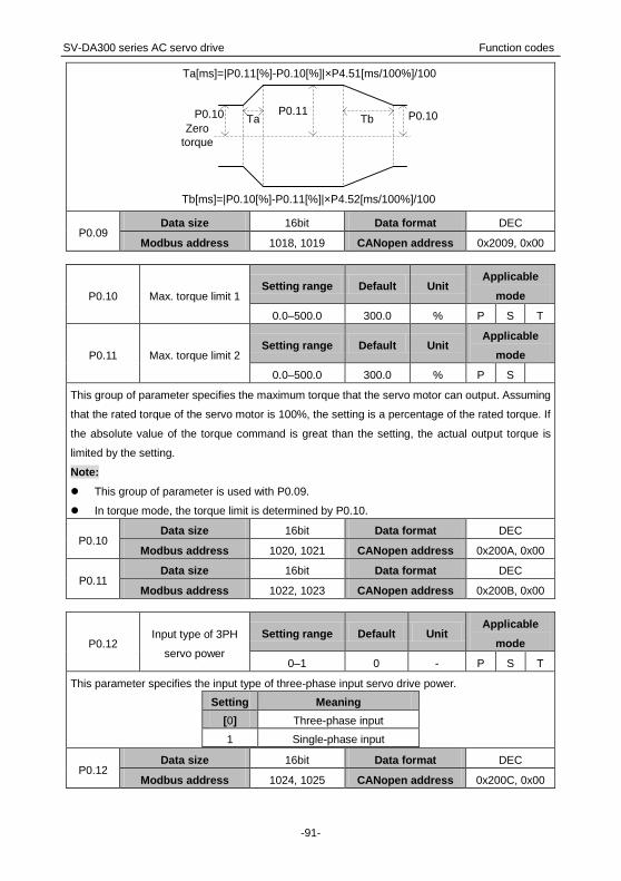
SV-DA300 series AC servo drive Function codes
-91-
P0.10 P0.11
Zero
torque
Ta Tb P0.10
Ta[ms]=|P0.11[%]-P0.10[%]|×P4.51[ms/100%]/100
Tb[ms]=|P0.10[%]-P0.11[%]|×P4.52[ms/100%]/100
P0.09 Data size 16bit Data format DEC
Modbus address 1018, 1019 CANopen address 0x2009, 0x00
P0.10 Max. torque limit 1 Setting range Default Unit
Applicable
mode
0.0–500.0 300.0 % P S T
P0.11 Max. torque limit 2 Setting range Default Unit
Applicable
mode
0.0–500.0 300.0 % P S
This group of parameter specifies the maximum torque that the servo motor can output. Assuming
that the rated torque of the servo motor is 100%, the setting is a percentage of the rated torque. If
the absolute value of the torque command is great than the setting, the actual output torque is
limited by the setting.
Note:
This group of parameter is used with P0.09.
In torque mode, the torque limit is determined by P0.10.
P0.10 Data size 16bit Data format DEC
Modbus address 1020, 1021 CANopen address 0x200A, 0x00
P0.11 Data size 16bit Data format DEC
Modbus address 1022, 1023 CANopen address 0x200B, 0x00
P0.12 Input type of 3PH
servo power
Setting range Default Unit Applicable
mode
0–1 0 - P S T
This parameter specifies the input type of three-phase input servo drive power.
Setting Meaning
[0] Three-phase input
1 Single-phase input
P0.12 Data size 16bit Data format DEC
Modbus address 1024, 1025 CANopen address 0x200C, 0x00

SV-DA300 series AC servo drive Function codes
-92-
P0.131 External brake
resistor power
Setting range Default Unit Applicable
mode
0–5000 200 W P S T
P0.141 External brake
resistor resistance
Setting range Default Unit Applicable
mode
1–1000 60 Ω P S T
If an external brake resistor is used, the settings of the parameters must be the same as the power
and resistance of the external brake resistor.
Note:
Brake overload detection should be used with P4.34. If P4.34 is set to 2, the brake overload
detection logic uses the external brake resistor parameters to execute fault detection. If this group
of parameter does not match the power and resistance of the external brake resistor, the brake
overload fault (Er07-0) may be reported by mistake or even the brake resistor may be burnt down.
The regenerative brake overload protection time of the external brake resistor is in direct
proportion to the two parameters and is in inverse proportion to the brake rate during actual
running. The two parameters are invalid when P4.34 is not 2.
P0.131 Data size 16bit Data format DEC
Modbus address 1026, 1027 CANopen address 0x200D, 0x00
P0.141 Data size 16bit Data format DEC
Modbus address 1028, 1029 CANopen address 0x200E, 0x00
P0.15 Default monitored
parameters
Setting range Default Unit Applicable
mode
0–22 0 - P S T
This parameter specifies the status parameters that are monitored upon power-on:
Setting Meaning Display Unit
[0] Motor speed r/min
1 Speed command r/min
2 Accumulated feedback pulses reference unit
3 Pulse command accumulation reference unit
4 Residual pulses reference unit
5 Hybrid control deviation reference unit
6 Current torque %
7 Main circuit DC voltage V
8 Output voltage Vrms
9 Output current Arms
10 Drive temperature °C

SV-DA300 series AC servo drive Function codes
-93-
11 Torque limit %
12 Encoder feedback value pulse
13 Rotor position relative to phase-Z pulse pulse
14 Load inertia ratio %
15 Output power %
16 Motor load ratio %
17 Numerator of actual electronic gear ratio -
18 Denominator of actual electronic gear
ratio -
19 Pulse-corresponded speed command r/min
20 Instantaneous speed r/min
21 PTP state -
P0.15 Data size 16bit Data format DEC
Modbus address 1030, 1031 CANopen address 0x200F, 0x00
P0.16 Parameter
modification lock
Setting range Default Unit Applicable
mode
0–1 0 - P S T
This parameter specifies whether to lock the function of modifying parameters (excluding P0.16
and parameters that are not be saved after power-off), preventing maloperation.
Setting Through the panel Through communication
[0] Unlock the function Unlock the function
1 Lock the function Lock the function
P0.16 Data size 16bit Data format DEC
Modbus address 1032, 1033 CANopen address 0x2010, 0x00
P0.17 Mode for writing to
EEPROM
Setting range Default Unit Applicable
mode
0–1 0 - P S T
This parameter specifies the mode for writing parameter settings that are modified through the
panel to the EEPROM.
Setting Meaning
[0] Individually (that is, automatically saved after a modification)
1 In batches (that is, modifications saved in batches if P4.91 is set to 1)
P0.17 Data size 16bit Data format DEC
Modbus address 1034, 1035 CANopen address 0x2011, 0x00

SV-DA300 series AC servo drive Function codes
-94-
P0.18* Factory password Setting range Default Unit
Applicable
mode
0–65536 0 - P S T
This parameter enables you to view factory parameters and modify menus.
P0.18* Data size 16bit Data format DEC
Modbus address 1036, 1037 CANopen address 0x2012, 0x00
P0.19 Main circuit power
input type
Setting range Default Unit Applicable
mode
0–65536 0 - P S T
This parameter specifies the power input type for the main circuit.
Setting Meaning
[0] Terminals L1, L2, and L3 input AC power.
1 Terminals + and – input DC power.
P0.19 Data size 16bit Data format DEC
Modbus address 1038, 1039 CANopen address 0x2013, 0x00
6.1.2 Position control
P0.201 Position command
source
Setting range Default Unit Applicable
mode
0–4 0 - P
This parameter specifies the position command source in the position, fully-closed loop, and
hybrid position control modes.
Setting Meaning
[0] Pulse input
1 Communication bus input
2 PTP control
3 Reserved
4 Second encoder input
P0.201 Data size 16bit Data format DEC
Modbus address 1040, 1041 CANopen address 0x2014, 0x00
P0.221 Pulses per motor
resolution
Setting
range Default Unit
Applicable
mode
0–(231-1) 10000 reference unit P
This parameter specifies the number of pulses required per motor resolution.
Note: If P0.22 is set to a non-zero value, the settings of P0.25–P0.29 are invalid. If a 17-bit or
20-bit encoder is used together, you are recommended to set a greater value to achieve higher
accuracy.

SV-DA300 series AC servo drive Function codes
-95-
P0.221 Data size 32bit Data format DEC
Modbus address 1044, 1045 CANopen address 0x2016, 0x00
P0.231 Pulse input mode
Setting
range Default Unit
Applicable
mode
0–2 0 - P
This parameter specifies the pulse input mode. There are three pulse input modes available.
Setting Meaning Signal
form
Diagram
CCW CW
[0] Pulse + sign Pulse+
Sign
1 CCW/CW
pulse train CW+CCW
2
Quadrature
encoder pulse
mode
QEP
Note:
The pulse direction specified by this parameter can be reversed by P0.241. See P0.241 for details.
P0.231 Data size 16bit Data format DEC
Modbus address 1046, 1047 CANopen address 0x2017, 0x00
P0.241 Reverse pulse input
direction
Setting
range Default Unit
Applicable
mode
0–1 0 - P
By setting this parameter, the input pulse direction can be reversed. At this time, the actual output
speed direction of the servo drive is opposite to the direction specified by P0.23.
Setting Meaning
[0] The pulse input direction remains unchanged.
1 The pulse input direction and original input direction are
reverse.
P0.241 Data size 16bit Data format DEC
Modbus address 1048, 1049 CANopen address 0x2018, 0x00

SV-DA300 series AC servo drive Function codes
-96-
P0.25
Numerator of
electronic gear ratio
1
Setting range Default Unit Applicable
mode
0–(231-1) 0 - P
P0.26 Denominator of
electronic gear ratio
Setting range Default Unit Applicable
mode
1–(231-1) 10000 - P
P0.27
Numerator of
electronic gear ratio
2
Setting range Default Unit Applicable
mode
0–(231-1) 0 - P
P0.28
Numerator of
electronic gear ratio
3
Setting range Default Unit Applicable
mode
0–(231-1) 0 - P
P0.29
Numerator of
electronic gear ratio
4
Setting range Default Unit Applicable
mode
0–(231-1) 0 - P
Electronic gear ratio concept: For any pulse input, the quantity and frequency of pulse actually
received by the drive can be changed by multiplying a certain coefficient. This coefficient is
electronic gear ratio. It can be divided into two parts: numerator and denominator:
Electronic gear ratio = g1/ g2
Of which,
g1: indicates the numerator of the electronic gear ratio
g2: indicates the denominator of the electronic gear ratio;
The following is the schematic diagram for the electronic gear ratio:
Deviation
counterMotor
Encoder
Intermediate
link
Electronic
gear ratioInput pulse train
Feedback pulse
Example: The following is an example where 1 pulse is
equivalent to a feed rate of 10μm:
Mechanical specifications:
Feed of the ball screw Pb =10mm
DEC ratio n=3/5
Resolution of the servo motor encoder =10000
The electronic gear ratio is as follows:
3
0 0
1 10000 5010 10
2 (3 5) 10 3
g Pt Pt
g S n Pb
· · ·
伺服电机
n
Servo motor

SV-DA300 series AC servo drive Function codes
-97-
In the expression, 0 : Feed corresponding to each pulse (mm/pulse)
S : Feed corresponding to each rotation motor (mm/rotation)
In this example: g1=50, g2=3
The servo drive has four groups of electronic gear ratio. You can determine which parameters are
selected from P0.25, P0.26, P0.27 P0.28, and P0.29 to make up the electronic gear ratio through
the electronic gear ratio selection terminals SC1 and SC2 of the CN1 plug.
SC1 SC2 In position mode
0 0 Numerator of electronic gear ratio 1
1 0 Numerator of electronic gear ratio 2
0 1 Numerator of electronic gear ratio 3
1 1 Numerator of electronic gear ratio 4
Note:
This group of parameters is valid only when P0.221 is 0.
If SC1 and SC2 are used for electronic gear ratio switching, P4.10 must be set to 0.
P0.25 Data size 32bit Data format DEC
Modbus address 1050, 1051 CANopen address 0x2019, 0x00
P0.26 Data size 32bit Data format DEC
Modbus address 1052, 1053 CANopen address 0x201A, 0x00
P0.27 Data size 32bit Data format DEC
Modbus address 1054, 1055 CANopen address 0x201B, 0x00
P0.28 Data size 32bit Data format DEC
Modbus address 1056, 1057 CANopen address 0x201C, 0x00
P0.29 Data size 32bit Data format DEC
Modbus address 1058, 1059 CANopen address 0x201D, 0x00
P0.332 Position command
smooth filter time
Setting range Default Unit Applicable
mode
0.0–1000.0 0.0 ms P
This parameter specifies the time constant for a first-order low pass filter corresponding to a
position command, reducing the mechanical shock caused by sudden input pulse command
frequency changes.
See the following figure:

SV-DA300 series AC servo drive Function codes
-98-
Position before filtering
Speed
Time
Position after filtering
Position after filtering
P0.33P0.33
Vc
0.632Vc
0.368Vc
P0.332 Data size 16bit Data format DEC
Modbus address 1066, 1067 CANopen address 0x2021, 0x00
P0.342 Position command
FIR filter time
Setting range Default Unit Applicable
mode
0.0–1000.0 0.0 ms P
This parameter specifies the time constant for the FIR filter corresponding to a position command,
reducing the mechanical shock caused by sudden input pulse command frequency changes.
See the following figure:
Position before filtering
Speed
Time
Position after filtering
Vc
Position after filtering
P0.34P0.34
Note: If this parameter is modified during servo running, the modification takes effect after stop.
P0.342 Data size 16bit Data format DEC
Modbus address 1068, 1069 CANopen address 0x2022, 0x00
P0.35
Software limit in
CCW position
control
Setting range Default Unit Applicable
mode
-(231-1)–(231-1) 0 reference unit P
This parameter specifies the software limit in CCW position control.
If P0.35 is 0 and P0.36 is 0, software limit is invalid.
Note: The software limit function is valid only when this parameter is greater than P0.36.
P0.35 Data size 32bit Data format DEC
Modbus address 1070, 1071 CANopen address 0x2023, 0x00

SV-DA300 series AC servo drive Function codes
-99-
P0.36 Software limit in
CW position control
Setting range Default Unit Applicable
mode
-(231-1)–(231-1) 0 reference unit P
This parameter specifies the software limit in CW position control.
If P0.35 is 0 and P0.36 is 0, software limit is invalid.
Note: The software limit function is valid only when this parameter is less than P0.35.
P0.36 Data size 32bit Data format DEC
Modbus address 1072, 1073 CANopen address 0x2024, 0x00
P0.37 Position command
mode
Setting range Default Unit Applicable
mode
0–1 0 - P
This parameter specifies the position command mode when P0.20 [Position command source] is
set to 1, and it is invalid in other modes.
Setting Meaning
[0] Incremental (The position command input is the variation relative to the current
position.)
1 Absolute (The position command input is the target position.)
P0.37 Data size 16bit Data format DEC
Modbus address 1074, 1075 CANopen address 0x2025, 0x00
6.1.3 Speed and torque control
P0.40 Speed command
source
Setting range Default Unit Applicable
mode
0–5 1 - S
This parameter specifies the command source in speed control.
Setting Input mode Description
0 Internal
speed
P3.00–P3.07 can be used to control the internal multi-step speed
(SPD1 is 0x00A, SPD2 is 0x00B, SPD3 is 0x00C):
SPD3 SPD2 SPD1 Parameter Speed mode
0 0 0 P0.46 Internal speed 1
0 0 1 P0.47 Internal speed 2
0 1 0 P0.48 Internal speed 3
0 1 1 P0.49 Internal speed 4
1 0 0 P0.50 Internal speed 5
1 0 1 P0.51 Internal speed 6
1 1 0 P0.52 Internal speed 7
1 1 1 P0.53 Internal speed 8

SV-DA300 series AC servo drive Function codes
-100-
See the descriptions for P0.46–P0.53.
[1] Analog input
You need to set either P3.26 [Function of AI 1] or P3.27 [Function
of AI 2] to 3 [Speed command] and set associated parameters
according to the actual situation.
2 Bus input
The communication bus interface can be used to receive speed
commands from the upper computer. If P4.10 is 1 [Bus input], the
motor speed can be changed by P4.13 [Bus speed command].
See the descriptions for P4.10 and P4.13.
3 Reserved -
4 Reserved -
5
High-resoluti
on internal
speed
Accurate to 0.1 r/min
P0.40 Data size 16bit Data format DEC
Modbus address 1080, 1081 CANopen address 0x2028, 0x00
P0.41 Speed command
direction setting
Setting range Default Unit Applicable
mode
0–1 0 - S
This parameter specifies the method for specifying the direction in a speed command when P0.40
is 0 or 1, and the speed command symbol is S-SIGN.
Setting Internal speed/AI Speed command
symbol
Speed command
direction
[0] Positive speed 0V–10V Not work CCW
Negative speed -10V–0V Not work CW
1 Not work Valid CCW
Not work Invalid CW
P0.41 Data size 16bit Data format DEC
Modbus address 1082, 1083 CANopen address 0x2029, 0x00
P0.42 Gain of AI 1 Setting range Default Unit
Applicable
mode
10–2000 100 [P3.26 unit]/V P S T
This parameter specifies the gain of analog input 1, the gain unit is associated with P3.26.
Note:
Analog input 1 indicates the signal input from the terminals (that is, AD1 and GND,
corresponding to pin 1 and pin 5) of analog input 1 of the CN1 plug.
The voltage only in the -10V–+10V range can be applied to the connection between AD1 and
GND. Otherwise, the drive may be damaged.
Application example:

SV-DA300 series AC servo drive Function codes
-101-
1. The function of analog input 1 is speed command.
2. The voltage of analog input 1 corresponds to the conversion gain of the motor command speed.
3. P0.40 is set to 1.
4. The relationship between the voltage of analog input 1 and speed command is as follows: Every
1V voltage corresponds to the 100 r/min speed by default.
Actual speed command = Analog input voltage x P0.42
-10.0V
10.0V
5000
-5000
AD1 input voltage(V)
Speed(r/min)
P0.42=500(r/min)/V
P0.42=250(r/min)/V
2500
-2500
Note:
This parameter is valid only when P0.40 is 1.
Set this parameter according to the motor working condition. If this parameter is set to a large
value, the motor speed may fluctuate sharply.
P0.42 Data size 32bit Data format DEC
Modbus address 1084, 1085 CANopen address 0x202A, 0x00
P0.43 Reverse of AI 1 Setting range Default Unit
Applicable
mode
0–1 0 - P S T
This parameter specifies the voltage polarity of analog input 1.
Setting Actual detection result
[0] Positive polarity [+Voltage]→[Positive value],[- Voltage]→[Negative value]
1 Negative polarity [+Voltage]→[Negative value],[- Voltage]→[Positive value]
P0.43 Data size 16bit Data format DEC
Modbus address 1086, 1087 CANopen address 0x202B, 0x00
P0.45 Dead zone of AI 1 Setting range Default Unit
Applicable
mode
0.000–3.000 0.000 V P S T
If the absolute voltage value of analog input 1 falls in the range of this parameter, the
corresponding command value is 0.
P0.45 Data size 16bit Data format DEC
Modbus address 1090, 1091 CANopen address 0x202D, 0x00

SV-DA300 series AC servo drive Function codes
-102-
P0.46 Internal speed 1/speed
limit 1
Setting range Default Unit Applicable
mode
-20000–20000 100 r/min S T
P0.47 Internal speed 2/speed
limit 2
Setting range Default Unit Applicable
mode
-20000–20000 0 r/min S T
P0.48 Internal speed 3/speed
limit 3
Setting range Default Unit Applicable
mode
-20000–20000 0 r/min S T
P0.49 Internal speed 4/speed
limit 4
Setting range Default Unit Applicable
mode
-20000–20000 0 r/min S T
P0.50 Internal speed 5 Setting range Default Unit
Applicable
mode
-20000–20000 0 r/min S
P0.51 Internal speed 6 Setting range Default Unit
Applicable
mode
-20000–20000 0 r/min S
P0.52 Internal speed 7 Setting range Default Unit
Applicable
mode
-20000–20000 0 r/min S
P0.53 Internal speed 8 Setting range Default Unit
Applicable
mode
-20000–20000 0 r/min S
The servo drive supports the 8-step internal speed commands and 4-step internal speed limits.
Control
mode
Setting of
P0.40 SPD3 SPD2 SPD1
Associated parameter
and setting
Speed 0
0 0 0 P0.46 Internal speed 1
0 0 1 P0.47 Internal speed 2
0 1 0 P0.48 Internal speed 3
0 1 1 P0.49 Internal speed 4
1 0 0 P0.50 Internal speed 5
1 0 1 P0.51 Internal speed 6
1 1 0 P0.52 Internal speed 7
1 1 1 P0.53 Internal speed 8
Torque 0
0 0 0 P0.46 Speed limit 1
0 0 1 P0.47 Speed limit 2
0 1 0 P0.48 Speed limit 3
0 1 1 P0.49 Speed limit 4

SV-DA300 series AC servo drive Function codes
-103-
Note:
SPD1, SPD2, SPD3 are the digital inputs of internal speed commands 1, 2, and 3 (corresponding
to 0x00A, 0x00B, and 0x00C).
0: OFF (The internal optical coupler corresponding to the input is not conducted.)
1: ON (The internal optical coupler corresponding to the input is conducted.)
The speed limits depend on the absolute values of the parameters and, the directions are the
same as those in torque commands.
P0.46 Data size 16bit Data format DEC
Modbus address 1092, 1093 CANopen address 0x202E, 0x00
P0.47 Data size 16bit Data format DEC
Modbus address 1094, 1095 CANopen address 0x202F, 0x00
P0.48 Data size 16bit Data format DEC
Modbus address 1096, 1097 CANopen address 0x2030, 0x00
P0.49 Data size 16bit Data format DEC
Modbus address 1098, 1099 CANopen address 0x2031, 0x00
P0.50 Data size 16bit Data format DEC
Modbus address 1100, 1101 CANopen address 0x2032, 0x00
P0.51 Data size 16bit Data format DEC
Modbus address 1102, 1103 CANopen address 0x2033, 0x00
P0.52 Data size 16bit Data format DEC
Modbus address 1104, 1105 CANopen address 0x2034, 0x00
P0.53 Data size 16bit Data format DEC
Modbus address 1106, 1107 CANopen address 0x2035, 0x00
P0.54 ACC time Setting range Default Unit
Applicable
mode
0–30000 0 ms S
P0.55 DEC time Setting range Default Unit
Applicable
mode
0–30000 0 ms S
ACC/DEC time is the time taken to accelerate from 0 r/min to the rated (3000 r/min by default)
speed in the given command or decelerates from the rated speed to 0 r/min. If the given speed is
not equal to the rated speed, the actual ACC/DEC time is the set ACC/DEC time multiplied by the
ratio of the given speed to the rated speed. If the speed command is negative, the absolute value
is used to calculate the ACC/DEC time.
Example: If the given speed is 2000 r/min, the rated speed is 3000 r/min, and the ACC/DEC time
(P0.54/P0.55) is set to 1500, then the actual ACC time t1 is 1500×(2000/3000)=1000ms and the
DEC time t2 is 1500×(2000/3000)=1000ms. See the following figure:

SV-DA300 series AC servo drive Function codes
-104-
Speed v
P0.55
Time
Rated speed
Specified
speed
P0.54
t1 t2
Note: This group of parameter is valid only in speed mode.
P0.54 Data size 16bit Data format DEC
Modbus address 1108, 1109 CANopen address 0x2036, 0x00
P0.55 Data size 16bit Data format DEC
Modbus address 1110, 1111 CANopen address 0x2037, 0x00
P0.56 S-curve ACC time Setting range Default Unit
Applicable
mode
0–1000 0 ms S
P0.57 S-curve DEC time Setting range Default Unit
Applicable
mode
0–1000 0 ms S
In a rated-speed command, this group of parameter is used to set the duration of the circular arc
segments in the S curve, thus achieving the goal of smooth starting. The S-curve ACC/DEC time is
shown in the following figure:
Speed
P0.57
Time
P0.56
P0.56 P0.57
P0.54 P0.55
Rated speed
Note:
This group of parameter is valid only in speed mode.
This group of parameter is invalid when the speed command source is AI.
If the setting of P0.54 is less than that of P0.56 and P0.56 is not 0, P0.54 is equal to P0.56
during the actual running.
If the setting of P0.55 is less than that of P0.57 and P0.57 is not 0, P0.55 is equal to P0.57
during the actual running.
P0.56 Data size 16bit Data format DEC
Modbus address 1112, 1113 CANopen address 0x2038, 0x00

SV-DA300 series AC servo drive Function codes
-105-
P0.57 Data size 16bit Data format DEC
Modbus address 1114, 1115 CANopen address 0x2039, 0x00
P0.58 Zero speed clamp
mode
Setting range Default Unit Applicable
mode
0–3 0 - S T
This parameter specifies the zero speed clamp mode.
Setting In position command mode
[0] Invalid (The zero speed clamp input is ignored.)
1 If the zero speed clamp control signal is valid, the speed command
is forcibly set to 0.
2
If the zero speed clamp control signal is valid, the speed command
is forcibly set to 0, the position control mode is used when the actual
motor speed becomes less than P0.59 [Speed threshold in zero
speed clamp], and the servo is locked at this position.
3
If the zero speed clamp control signal is valid, the position control
mode is used when the actual motor speed becomes less than
P0.59 minus 10 r/min, and the servo is locked at this position.
Note:
After configuring any of parameters P3.00–P3.07 with the zero speed clamp (0x00D) function,
you can use the zero speed clamp terminals of the CN1 plug for control or use P4.19 [Zero
speed clamp command] for control. The input settings of P3.00–P3.07 are described as follows:
0: Disable zero speed clamp.
1: Enable zero speed clamp.
In torque control mode, the settings 0 and 1 are valid, and 2 and 3 have the same function as 1.
P0.58 Data size 16bit Data format DEC
Modbus address 1116, 1117 CANopen address 0x203A, 0x00
P0.59 Zero speed clamp
speed threshold
Setting range Default Unit Applicable
mode
10–20000 30 r/min S
This parameter specifies the speed threshold for switching to position control when P0.58 is 2 or 3.
When P0.58 is 3, there is a 10 r/min delay detected.
P0.59 Data size 16bit Data format DEC
Modbus address 1118, 1119 CANopen address 0x203B, 0x00

SV-DA300 series AC servo drive Function codes
-106-
P0.60 Torque command
source
Setting range Default Unit Applicable
mode
0–3 1 - T
This parameter specifies the command source in torque control.
Setting Input mode Description
0 Internally
specified Specified by P0.66.
[1] Analog input
You need to set either P3.26 [Function of AI 1], P3.27
[Function of AI 2], or P3.70 [Function of AI 3] to 4 [Torque
command] and set associated parameters according to the
actual situation.
2 Bus input
The communication bus interface can be used to receive
torque commands from the upper computer. If P4.10 is 1
[Bus input], the motor speed can be changed by P4.14 [Bus
torque command].
See the descriptions for P4.10 and P4.14.
3 Reserved -
P0.60 Data size 16bit Data format DEC
Modbus address 1120, 1121 CANopen address 0x203C, 0x00
P0.61 Torque command
direction setting
Setting range Defaul
t Unit
Applicable
mode
0–1 0 - T
This parameter specifies the method for specifying the direction in a torque command.
Setting Meaning
[0]
The input sign of the torque command specifies the direction.
For example, Torque command input [+] indicates forward,
while [-] indicates reverse.
1
The torque command sign [0x00F] of the digital input function
is used to specify the direction.
1: forward
0: reverse
Note: 0x00F is valid when the input is a low electrical level, while 0x10F is valid when the input is a
high electrical level.
P0.61 Data size 16bit Data format DEC
Modbus address 1122, 1123 CANopen address 0x203D, 0x00

SV-DA300 series AC servo drive Function codes
-107-
P0.62 Gain of AI 2 Setting range
Defaul
t Unit
Applicable
mode
0–2000 100 [P3.27 unit]/V P S T
This parameter specifies the gain of analog input 2. The gain unit is associated with P3.27.
Note:
Analog input 2 indicates the signal input from the analog speed/speed limit terminals (AD2 and
GND, corresponding to pin 20 and pin 19) of the CN1 plug.
Application example:
1. The function of analog input 2 is torque command.
2. The voltage of analog input 2 corresponds to the conversion gain of the motor torque command.
3. This parameter is valid only when P0.60 is 1.
4. The relationship between the voltage of analog input 2 and torque command is as follows: The
torque corresponding to every 1V voltage is 10% of the rated torque by default.
Actual torque command = Analog input voltage x P0.62
-10.0V
100
-100
AD2 input voltage(V)
P0.62=10%/V
P0.62=5%/V
50
-50
10.0V
Rated torque(%)
Note:
Set this parameter according to the motor working condition. If this parameter is set to a large
value, the motor speed may fluctuate sharply.
P0.62 Data size 32bit Data format DEC
Modbus address 1124, 1125 CANopen address 0x203E, 0x00
P0.63 Reverse of AI 2 Setting range Default Unit
Applicable
mode
0–1 0 - P S T
This parameter specifies the voltage polarity of analog input 2.
Setting Actual detection result
[0] Positive polarity [+Voltage] → [Positive value], [-Voltage] → [Negative value]
1 Negative
polarity [+Voltage] → [Negative value], [-Voltage] → [Positive value]
P0.63 Data size 16bit Data format DEC
Modbus address 1126, 1127 CANopen address 0x203F, 0x00

SV-DA300 series AC servo drive Function codes
-108-
P0.65 Dead zone of AI 2 Setting range Default Unit
Applicable
mode
0.000–3.000 0.000 V P S T
If the absolute voltage value of analog input 2 falls in the range of this parameter, the
corresponding command value is 0.
P0.65 Data size 16bit Data format DEC
Modbus address 1130, 1131 CANopen address 0x2041, 0x00
P0.66 Internal torque
command
Setting range Default Unit Applicable
mode
-500.0–500.0 0.0 % T
This parameter specifies the internal torque reference. If the servo motor rated torque is
considered as 100%, the setting of this parameter is a percentage of the servo motor rated torque.
Note:
If the absolute value of this parameter is greater than maximum torque limit 1 (P0.10), the
output torque is the setting of P0.10 and the direction is the same as this parameter.
In torque mode, this parameter is valid only when P0.60 is 0.
P0.66 Data size 16bit Data format DEC
Modbus address 1132, 1133 CANopen address 0x2042, 0x00
P0.67 Speed limit mode Setting range Default Unit
Applicable
mode
0–1 1 - T
This parameter specifies the speed limit mode for torque control.
Setting Meaning
0
The analog input is selected as the speed limit source. You need to set
either P3.26 [Function of AI 1] or P3.27 [Function of AI 2] to 1 [Speed limit]
and set associated parameters according to the actual situation.
[1] Internal speed limit, selected from P0.46–P0.49.
Note: The speed limit is internally processed as an absolute value, and the actual sign of the limit
is the same as that of the torque command.
P0.67 Data size 16bit Data format DEC
Modbus address 1134, 1135 CANopen address 0x2043, 0x00
P0.68 Torque command
ramp time
Setting range Default Unit Applicable
mode
0–10000 0 ms T
This parameter is used to modify the planning curve when the torque command input changes.
This parameter indicates the time taken to rise from 0 to 100% of the rated torque.

SV-DA300 series AC servo drive Function codes
-109-
P0.68 Data size 16bit Data format DEC
Modbus address 1136, 1137 CANopen address 0x2044, 0x00
P0.69 DEC time for quick
stop
Setting range Default Unit Applicable
mode
0–10000 500 ms P S T
This parameter specifies the DEC time for quick stop. It indicates the time taken to decelerate from
100% of the rated speed to 0.
P0.69 Data size 16bit Data format DEC
Modbus address 1138, 1139 CANopen address 0x2045, 0x00
P0.701 Absolute encoder work
mode
Setting
range Default Unit
Applicable
mode
0–1 0 - P S T
This parameter specifies the running mode of the multiturn absolute encoder. Though the encoder
working with the motor is a multiturn absolute encoder, it is still considered as a single-turn
encoder by default. If the multiturn absolute function is needed, you need to prepare the spare
battery for the encoder and set the work mode as the multiturn absolute mode.
Setting Meaning
[0] Single-turn absolute
1 Multiturn absolute
P0.701 Data size 16bit Data format DEC
Modbus address 1140, 1141 CANopen address 0x2046, 0x00
P0.71* Clear absolute encoder
multiturn
Setting
range Default Unit
Applicable
mode
0–1 0 - P S T
This parameter specifies whether to clear the multiturn data for the multiturn absolute encoder. If
this function is enabled, the multiturn data is cleared while the single-turn data remains
unchanged, but the absolute position in the feedback is cleared.
Note: If you use a multiturn absolute encoder, after machinery installation, you can clear the absolute
encoder after detecting the absolute zero position of the mechanic system at first power-on.
P0.71* Data size 16bit Data format DEC
Modbus address 1142, 1143 CANopen address 0x2047, 0x00

SV-DA300 series AC servo drive Function codes
-110-
6.1.4 Control mode switching
P0.90 Max. speed limit of
control mode switching
Setting
range Default Unit
Applicable
mode
1–1000 100 r/min P S T
This parameter specifies the maximum running speed during positioning for switching from the
speed or torque mode to the position mode when the hybrid of position and speed or the hybrid of
position and torque is used.
P0.90 Data size 16bit Data format DEC
Modbus address 1180, 1181 CANopen address 0x205A, 0x00
P0.91 Positioning reference of
control mode switching
Setting
range Default Unit
Applicable
mode
-1–(231-1) -1 pulse P S T
This parameter specifies the motor position R0.14 [Rotor position relative to pulse Z] after the
control mode is switched. The switching is made from the speed or torque mode to the position
mode when the hybrid of position and speed or the hybrid of position and torque is used.
Note:
After the control mode switching, the reference point in the received position command is the
setting of this parameter. The unit of this parameter is the encoder pulse unit.
If this parameter is set to -1 and the control mode needs to switch from speed mode to position
mode, switching is executed at the current position, without positioning to the reference point.
If the mechanical angle corresponding to the setting of P3.50 is no more than 0.5°, the
positioning is accurate to ±P3.50. If the angle is greater than 0.5°, the positioning is accurate to
the pulse number corresponding to ±0.5°.
P0.91 Data size 32bit Data format DEC
Modbus address 1182, 1183 CANopen address 0x205B, 0x00
P0.92 Position mode exiting
method
Setting
range Default Unit
Applicable
mode
0–1 0 - P S T
This parameter specifies the method for exiting the position mode when P0.03 [Control mode] is 3
[Position/speed mode] or 4 [Position/torque mode].
Setting Meaning
[0] The position mode is switched to another mode after
positioning is complete.
1 The position mode is immediately switched to another mode
when the control mode switching command is invalid.
P0.92 Data size 32bit Data format DEC
Modbus address 1184, 1185 CANopen address 0x205C, 0x00

SV-DA300 series AC servo drive Function codes
-111-
6.2 Autotuning control (group P1)
6.2.1 Inertia identifying (or automatic gain)
P1.00 Tune inertia online Setting range Default Unit
Applicable
mode
0–1 0 - P S T
This parameter specifies whether to automatically tune inertia online and adjust the gain.
Setting Meaning
[0] Online inertia identifying is invalid.
1 Online inertia identifying is valid.
P1.00 Data size 16bit Data format DEC
Modbus address 1200, 1201 CANopen address 0x2100, 0x00
P1.01 Inertia ratio 1 Setting range Default Unit
Applicable
mode
0–10000 250 % P S T
Rotation inertia ratio = Load inertia/Motor rotation inertia x 100%
If P1.01 is set correctly, the setting unit of P2.00 and P2.05 is Hz.
If P1.01 is greater than the actual value, the speed loop gain unit will increase, and if it is smaller
than the actual value, the speed loop gain unit will decrease.
If online automatic tuning is valid, the inertia ratio is updated to P1.01 in real time and written to the
EEPROM every 30 minutes.
P1.01 Data size 16bit Data format DEC
Modbus address 1202, 1203 CANopen address 0x2101, 0x00
P1.02 Inertia ratio 2 Setting range Default Unit
Applicable
mode
0–10000 250 % P S T
The meaning of P1.02 is similar to that of P1.01.
Note: Automatic online gain adjusting is invalid for this parameter.
P1.02 Data size 16bit Data format DEC
Modbus address 1204, 1205 CANopen address 0x2102, 0x00

SV-DA300 series AC servo drive Function codes
-112-
P1.03 Mechanical rigidity Setting range Default Unit
Applicable
mode
0–31 13 - P S T
A greater mechanical rigidity value indicates quicker response and high rigidity performance, but it
increases the possibility to cause vibration. In stable working condition, you can set a greater value
to obtain quicker response.
Mechanical structure Rigidity
Large transfer or transmission equipment 0–13
Belt drive mechanism 5–16
Ball screw + belt drive 5–16
Manipulator 15–22
Direct ball screw or rigid body 18–25
P1.03 Data size 16bit Data format DEC
Modbus address 1206, 1207 CANopen address 0x2103, 0x00
P1.04* Tune inertia offline Setting range Default Unit
Applicable
mode
0–1 0 - P S T
This parameter is used to obtain the load inertial ratio of the motor rotation inertia. After inertia
identifying is enabled, the motor runs six cycles to identify inertia. In each cycle, the motor runs at
the mode specified by P1.05 [Inertia identifying mode]. The maximum rotation number of the motor
is determined by P1.06 [Max. rotations by inertia identifying], and the ACC command time is
determined by P1.07 [ACC time for inertia identifying].
Setting Meaning
[0] Disable inertia identifying.
1 Enable inertia identifying.
Note:
The motor speed is fast during identifying if P1.06 and P1.07 are set to great values.
If the drive reports the alarm Er25-7 during identifying, see section 9.1 "Servo drive faults and
workarounds" to handle it.
This parameter is invalid when the servo is enabled.
P1.04* Data size 16bit Data format DEC
Modbus address 1208, 1209 CANopen address 0x2104, 0x00

SV-DA300 series AC servo drive Function codes
-113-
P1.05 Inertia identifying
mode
Setting range Default Unit Applicable
mode
0–3 0 - P S T
This parameter specifies the work mode for identifying inertia.
Setting Meaning
[0] Forward rotation and then reverse rotation
1 Forward rotation
2 Reverse rotation
3 Reverse rotation and then forward rotation
P1.05 Data size 16bit Data format DEC
Modbus address 1210, 1211 CANopen address 0x2105, 0x00
P1.06 Max. rotations by
inertia identifying
Setting range Default Unit Applicable
mode
0.2–20.0 2.0 r P S T
If the inertia identifying mode is valid and specified in position mode, this parameter is used to limit
the maximum rotation number of the motor in each cycle.
P1.06 Data size 16bit Data format DEC
Modbus address 1212, 1213 CANopen address 0x2106, 0x00
P1.07 ACC time for inertia
identifying
Setting range Default Unit Applicable
mode
2–1000 200 ms P S T
This parameter specifies the motor ACC time during inertia identifying. If the load inertia is heavy,
the ACC time can be set to a greater value, preventing overload alarms.
P1.07 Data size 16bit Data format DEC
Modbus address 1214, 1215 CANopen address 0x2107, 0x00
P1.08 Inertia identifying
class
Setting range Default Unit Applicable
mode
0–3 1 - P S T
This parameter specifies the speed level for inertia identifying.
A large value of this parameter indicates a quick response to the load characteristic changes,
resulting in large fluctuation of the presumption value. The presumption result is saved every 30
minutes.
Setting Function Meaning
0 No change Stop the presumption of load characteristics.
[1] No major change There is no major change to load characteristics.
2 Slow change Load characteristics change slowly.
3 Sharp change Load characteristics change sharply.

SV-DA300 series AC servo drive Function codes
-114-
P1.08 Data size 16bit Data format DEC
Modbus address 1216, 1217 CANopen address 0x2108, 0x00
6.2.2 Self-adaptive vibration control
P1.19 Resonance
detection sensitivity
Setting range Default Unit Applicable
mode
0.2–100.0 5.0 % P S T
This parameter specifies the sensitivity of the automatic detection on mechanical resonant
frequency. A smaller value of this parameter indicates higher sensitivity to the resonance.
P1.19 Data size 16bit Data format DEC
Modbus address 1238, 1239 CANopen address 0x2113, 0x00
P1.20 Resonance
detection mode
Setting range Default Unit Applicable
mode
0–7 0 - P S T
This parameter specifies the working mode of resonance detection, resonant frequency presumed
by the self-adaptive notch filter, and action after presumption.
If the function of automatically detecting the mechanical resonant frequency is valid (that is, this
parameter is set to 1, 2, or 3), the system automatically collects data to conduct mechanical
resonant frequency analysis and saves results to P1.21 and P1.22. You can set the notch filter
frequency according to the settings of P1.21 and P1.22 to eliminate the mechanical resonance.
Note: You are recommended to disable the function after the gain adjustment is complete.
Setting Function Meaning
[0] Invalid All parameters associated with the notch filter remain unchanged.
1 One notch filter
valid
The parameters associated with the third notch filter are updated
according to the self-adaptive result.
2 Two notch filters
valid
The parameters related to the third and fourth notch filters are
updated according to the self-adaptive result.
3
Resonant
frequency test
mode
The mechanical resonant frequency is detected automatically but
the parameters associated with notch filters are not set.
4 Clearing notch
filter parameters
The parameters associated with the four notch filters are restored
to the default values.
5 Notch filter 3 →
Notch filter 1
The parameters of the third notch filter to are automatically copied to
the first notch filter and then restored to the default values.
6 Notch filter 4 →
Notch filter 2
The parameters of the fourth notch filter to are automatically copied to
the first notch filter and then restored to the default values.
7
Notch filters 3
and 4 → Notch
filters 1 and 2
The parameters of the third and fourth notch filters to are automatically
copied to the first and second notch filters and then restored to the
default values.

SV-DA300 series AC servo drive Function codes
-115-
P1.20 Data size 16bit Data format DEC
Modbus address 1240, 1241 CANopen address 0x2114, 0x00
P1.21*
Mechanical
resonant frequency
1
Setting range Default Unit Applicable
mode
0–5000 5000 Hz P S T
P1.22*
Mechanical
resonant frequency
2
Setting range Default Unit Applicable
mode
0–5000 5000 Hz P S T
This group of parameter displays mechanical resonant frequency. When P1.20 is set to 1,
indicating mechanical resonance frequency detection is valid, the system detects and displays the
frequency at the maximum resonance point.
Note:
The measurement results are accurate only when the rotation speed reaches 30 r/min at least.
This function is read only. You can set the notch filter frequency through this group of parameter
to eliminate mechanical resonance.
The value 5000 indicates no resonance point is found.
P1.21 Data size 16bit Data format DEC
Modbus address 1242, 1243 CANopen address 0x2115, 0x00
P1.22 Data size 16bit Data format DEC
Modbus address 1244, 1245 CANopen address 0x2116, 0x00
P1.23 Frequency of notch
filter 1
Setting range Default Unit Applicable
mode
50–5000 5000 Hz P S T
This parameter specifies the frequency of notch filter 1 for suppressing resonance. The notch filter
can simulate the mechanical resonant frequency, thus suppressing the resonant frequency.
The value 5000 indicates the notch filter function is invalid.
P1.23 Data size 16bit Data format DEC
Modbus address 1246, 1247 CANopen address 0x2117, 0x00
P1.24 Q factor of notch
filter 1
Setting range Default Unit Applicable
mode
0.50–16.00 1.00 - P S T
This parameter specifies the quality factor (Q factor for short) of notch filter 1.
Q factor of notch filter = Center frequency of notch filter/Bandwidth of notch filter
Generally, the default value is kept.
P1.24 Data size 16bit Data format DEC
Modbus address 1248, 1249 CANopen address 0x2118, 0x00

SV-DA300 series AC servo drive Function codes
-116-
P1.25 Depth of notch filter
1
Setting range Default Unit Applicable
mode
0–100 0 % P S T
This parameter specifies the amplitude attenuation rate of notch filter 1.
A large value of this parameter indicates low notch filter depth and small phase lag.
P1.25 Data size 16bit Data format DEC
Modbus address 1250, 1251 CANopen address 0x2119, 0x00
P1.26 Frequency of notch
filter 2
Setting range Default Unit Applicable
mode
50–5000 5000 Hz P S T
P1.27 Q factor of notch
filter 2
Setting range Default Unit Applicable
mode
0.50–16.00 1.00 - P S T
P1.28 Depth of notch filter
2
Setting range Default Unit Applicable
mode
0–100 0 % P S T
These parameters specify characteristics of notch filer 2, similar to P1.23, P1.24, and P1.25.
P1.26 Data size 16bit Data format DEC
Modbus address 1252, 1253 CANopen address 0x211A, 0x00
P1.27 Data size 16bit Data format DEC
Modbus address 1254, 1255 CANopen address 0x211B, 0x00
P1.28 Data size 16bit Data format DEC
Modbus address 1256, 1257 CANopen address 0x211C, 0x00
P1.29 Frequency of notch
filter 3
Setting range Default Unit Applicable
mode
50–5000 5000 Hz P S T
P1.30 Q factor of notch
filter 3
Setting range Default Unit Applicable
mode
0.50–16.00 1.00 - P S T
P1.31 Depth of notch filter
3
Setting range Default Unit Applicable
mode
0–100 0 % P S T
These parameters specify characteristics of notch filer 3, similar to P1.23, P1.24, and P1.25.
P1.29 Data size 16bit Data format DEC
Modbus address 1258, 1259 CANopen address 0x211D, 0x00
P1.30 Data size 16bit Data format DEC

SV-DA300 series AC servo drive Function codes
-117-
Modbus address 1260, 1261 CANopen address 0x211E, 0x00
P1.31 Data size 16bit Data format DEC
Modbus address 1262, 1263 CANopen address 0x211F, 0x00
P1.32 Frequency of notch
filter 4
Setting range Default Unit Applicable
mode
50–5000 5000 Hz P S T
P1.33 Q factor of notch
filter 4
Setting range Default Unit Applicable
mode
0.50–16.00 1.00 - P S T
P1.34 Depth of notch filter
4
Setting range Default Unit Applicable
mode
0–100 0 % P S T
These parameters specify characteristics of notch filer 4, similar to P1.23, P1.24, and P1.25.
P1.32 Data size 16bit Data format DEC
Modbus address 1264, 1265 CANopen address 0x2120, 0x00
P1.33 Data size 16bit Data format DEC
Modbus address 1266, 1267 CANopen address 0x2121, 0x00
P1.34 Data size 16bit Data format DEC
Modbus address 1268, 1269 CANopen address 0x2122, 0x00
P1.35 Vibration control mode
in position command
Setting
range Default Unit
Applicable
mode
0–2 0 - P
This parameter specifies the filter switching mode for vibration control.
Setting Meaning
[0] Vibration control by filter 1 is valid.
1 Filter 1 and filter 2 are switched according to VS-SEL.
2 Automatic
Note: If a digital input terminal is used for selection, one of parameters P3.00–P3.07 must be set
to 0x11C or 0x01C (according to VS-SEL).
The relationship with COM- is as follows:
0: Off (The internal optical coupler corresponding to the input is not conducted.)
1: On (The internal optical coupler corresponding to the input is conducted.)
P1.35 Data size 16bit Data format DEC
Modbus address 1270, 1271 CANopen address 0x2123, 0x00

SV-DA300 series AC servo drive Function codes
-118-
P1.36 Vibration control
frequency 1
Setting
range Default Unit
Applicable
mode
0.0–200.0 0.0 Hz P
This parameter specifies the frequency at which the vibration at the load peak is suppressed.
Note: The frequency must range from 1.0 Hz to 200.0 Hz.
P1.36 Data size 16bit Data format DEC
Modbus address 1272, 1273 CANopen address 0x2124, 0x00
P1.37 Coefficient of vibration
control filter 1
Setting
range Default Unit
Applicable
mode
0.00–1.00 1.00 - P
This parameter specifies the coefficient of the first vibration control filter.
P1.37 Data size 16bit Data format DEC
Modbus address 1274, 1275 CANopen address 0x2125, 0x00
P1.38 Vibration control
frequency 2
Setting
range Default Unit
Applicable
mode
0.0–200.0 0.0 Hz P
P1.39 Coefficient of vibration
control filter 2
Setting
range Default Unit
Applicable
mode
0.00–1.00 1.00 - P
This group of parameter specifies the characteristics of the second vibration control filter. They are
similar to P1.36 and P1.37.
P1.38 Data size 16bit Data format DEC
Modbus address 1276, 1277 CANopen address 0x2126, 0x00
P1.39 Data size 16bit Data format DEC
Modbus address 1278, 1279 CANopen address 0x2127, 0x00
6.3 Motor control (group P2)
6.3.1 Gain settings
P2.00 Speed gain 1
Setting
range Default Unit
Applicable
mode
0.0–3276.7 27.0 Hz P S T
The speed loop responsiveness of the servo system is determined by the speed gain. Increasing
this parameter improves the speed response, but it increases the possibility to cause vibration and
noise.
Note: If the inertia ratio is set correctly, the unit of P2.00 is Hz.

SV-DA300 series AC servo drive Function codes
-119-
P2.00 Data size 16bit Data format DEC
Modbus address 1400, 1401 CANopen address 0x2200, 0x00
P2.01 Speed integral time
constant 1
Setting
range Default Unit
Applicable
mode
0.1–1000.0 21.0 ms P S T
This parameter specifies the integral time constant of the speed loop. A smaller value of this
parameter indicates quicker response, but it increases the possibility to cause vibration and noise. If
this parameter is set to 1000, the integral action is invalid.
P2.01 Data size 16bit Data format DEC
Modbus address 1402, 1403 CANopen address 0x2201, 0x00
P2.02 Position gain 1
Setting
range Default Unit
Applicable
mode
0.0–3276.7 48.0 1/s P
The position loop responsiveness of the servo system is determined by the position gain. A smaller
value of this parameter indicates quicker response, but it increases the possibility to cause vibration
and noise.
P2.02 Data size 16bit Data format DEC
Modbus address 1404, 1405 CANopen address 0x2202, 0x00
P2.03 Speed detection filter
1
Setting
range Default Unit
Applicable
mode
100–5000 5000 Hz P S T
This parameter specifies the first speed detection filter.
Note: The value 5000 indicates no filtering. A smaller value of this parameter indicates lower motor
noise and speed fluctuation, but it slows down the responsiveness.
P2.03 Data size 16bit Data format DEC
Modbus address 1406, 1407 CANopen address 0x2203, 0x00
P2.04 Torque filter 1
Setting
range Default Unit
Applicable
mode
0.00–25.00 0.84 ms P S T
This parameter specifies the time constant of the torque filter.
P2.04 Data size 16bit Data format DEC
Modbus address 1408, 1409 CANopen address 0x2204, 0x00

SV-DA300 series AC servo drive Function codes
-120-
P2.05 Speed gain 2
Setting
range Default Unit
Applicable
mode
0.0–3276.7 27.0 Hz P S T
P2.06 Speed integral time
constant 2
Setting
range Default Unit
Applicable
mode
0.1–1000.0 1000.0 ms P S T
P2.07 Position gain 2
Setting
range Default Unit
Applicable
mode
0.0–3276.7 57.0 1/s P
P2.08 Speed detection filter
2
Setting
range Default Unit
Applicable
mode
100–5000 5000 Hz P S T
P2.09 Torque filter 2
Setting
range Default Unit
Applicable
mode
0.00–25.00 0.84 ms P S T
There are two groups of parameters respectively for position gain, speed gain, speed integral time
constant, speed detection filter, and torque filter.
The two groups are similar in function and definition.
You can select from gain 1 and gain 2 or switch between them. For details, see the descriptions for
P2.20–P2.34.
P2.05 Data size 16bit Data format DEC
Modbus address 1410, 1411 CANopen address 0x2205, 0x00
P2.06 Data size 16bit Data format DEC
Modbus address 1412, 1413 CANopen address 0x2206, 0x00
P2.07 Data size 16bit Data format DEC
Modbus address 1414, 1415 CANopen address 0x2207, 0x00
P2.08 Data size 16bit Data format DEC
Modbus address 1416, 1417 CANopen address 0x2208, 0x00
P2.09 Data size 16bit Data format DEC
Modbus address 1418, 1419 CANopen address 0x2209, 0x00
P2.10 Speed feed-forward
gain
Setting
range Default Unit
Applicable
mode
0.0–100.0 0.0 % P
This parameter specifies the speed feed-forward gain. If it is set to 100%, residual pulses are almost
zero when the motor runs at a stable speed, but overshooting increases at sudden ACC/DEC.
P2.10 Data size 16bit Data format DEC
Modbus address 1420, 1421 CANopen address 0x220A, 0x00

SV-DA300 series AC servo drive Function codes
-121-
P2.11 Speed feed-forward
filter time
Setting range Default Unit Applicable
mode
0.00–64.00 0.50 ms P
This parameter specifies the speed feed-forward filter time.
P2.11 Data size 16bit Data format DEC
Modbus address 1422, 1423 CANopen address 0x220B, 0x00
P2.12 Torque
feed-forward gain
Setting range Default Unit Applicable
mode
0.0–100.0 0.0 % P S
This parameter specifies the torque feed-forward gain. After the torque is calculated according to
the speed control command, the torque multiplied by the setting of this parameter is added to the
torque command from speed control.
Increasing the torque feed-forward gain can improve response performance in ACC/DEC and
reduce position deviation.
P2.12 Data size 16bit Data format DEC
Modbus address 1424, 1425 CANopen address 0x220C, 0x00
P2.13 Torque feed-forward
filter time
Setting range Default Unit Applicable
mode
0.00–64.00 0.00 ms P S
This parameter specifies the torque feed-forward filter time.
P2.13 Data size 16bit Data format DEC
Modbus address 1426, 1427 CANopen address 0x220D, 0x00
P2.14 IPPI coefficient 1 Setting range Default Unit
Applicable
mode
0–1000 100 % P S T
This parameter specifies the first IPPI coefficient.
Note: IP control is applied when it is set to 0, while PI control is applied when it is set to 100.
P2.14 Data size 16bit Data format DEC
Modbus address 1428, 1429 CANopen address 0x220E, 0x00
P2.15 IPPI coefficient 2 Setting range Default Unit
Applicable
mode
0–1000 100 % P S T
This parameter specifies the second IPPI coefficient.
Note: IP control is applied when it is set to 0, while PI control is applied when it is set to 100.

SV-DA300 series AC servo drive Function codes
-122-
P2.15 Data size 16bit Data format DEC
Modbus address 1430, 1431 CANopen address 0x220F, 0x00
6.3.2 Gain switching
P2.20 Setting of gain 2 Setting range Default Unit
Applicable
mode
0–1 1 - P S T
This parameter specifies the adjustment for gain switching.
Setting Meaning
0
The first gain is fixed. The speed loop action is switched to the PI or
P action based on the gain switching input (that is, the digital input
is configured as function gain switching, corresponding to 0x006) or
P4.16 [Gain switching command].
Gain switching invalid → PI action
Gain switching valid → P action
Note: 0x006 is valid when the digital inputs a low electrical level,
while 0x106 is valid when the digital inputs a high electrical level.
[1] Switching between the first gain [P2.00–P2.04] and second gain
[P2.05–P2.09] is valid.
P2.20 Data size 16bit Data format DEC
Modbus address 1440, 1441 CANopen address 0x2214, 0x00
P2.22 Switching trigger in
position control
Setting range Default Unit Applicable
mode
0–9 0 - P
This parameter specifies the trigger of gain switching in position control or fully-closed loop control.
Setting Trigger Description
[0] Fixed to gain 1 Gain parameters are fixed to the first gain parameters P2.00–
P2.04.
1 Fixed to gain 2 Gain parameters are fixed to the second gain parameters
P2.05–P2.09.
2 With gain
switching input
The first gain is used if the gain switching input is invalid.
The second gain is used if the gain switching input is valid.
3
Torque
command too
large
When the first gain is used, if the absolute value in the torque
command exceeds (level + lag) [0.1%], the first gain is switched to
the second gain.
When the second gain is used, if the absolute value in the
torque command does not reach (level − lag) [0.1%] and this
state keeps in the delay time, the first gain is used.
4
Speed
command too
large
When the first gain is used, if the absolute value in the speed
command exceeds (level + lag) [r/min], the first gain is switched
to the second gain.

SV-DA300 series AC servo drive Function codes
-123-
When the second gain is used, if the absolute value in the
speed command does not reach (level − lag) [r/min] and this
state keeps in the delay time, the second gain is switched to the
first gain.
5
Position
deviation too
large
When the first gain is used, if the absolute value of the position
deviation exceeds (level + lag) [pulse], the first gain is switched to
the second gain.
When the second gain is used, if the absolute value of the
position deviation does not reach (level − lag) [pulse] and this
state keeps in the delay time, the second gain is switched to the
first gain.
Note: The unit of level and lag is the encoder resolution unit in
position control and is the grating ruler resolution unit in
fully-closed loop control.
6 With position
command input
When the first gain is used, if the position command is not 0, the
first gain is switched to the second gain.
When the second gain is used, if the position command is 0 and
this state keeps in the delay time, the second gain is switched to
the first gain.
7 Positioning
incomplete
When the first gain is used, if positioning is not complete, the first
gain is switched to the second gain.
When the second gain is used, if positioning is complete and
this state keeps in the delay time, the second gain is switched to
the first gain.
8 Actual speed
too high
When the first gain is used, if the absolute value of the actual
speed exceeds (level + lag) [r/min], the first gain is switched to
the second gain.
When the second gain is used, if the absolute value of the
actual speed does not reach (level − lag) [r/min] and this state
keeps in the delay time, the second gain is switched to the first
gain.
9
Position
command +
actual speed
When the first gain is used, if the position command is not 0, the
first gain is switched to the second gain.
When the second gain is used, if the position command is 0,
this state keeps in the delay time, and the absolute value of the
actual speed does not reach (level − lag) [r/min], the second gain
is switched to the first gain.
P2.22 Data size 16bit Data format DEC
Modbus address 1444, 1445 CANopen address 0x2216, 0x00

SV-DA300 series AC servo drive Function codes
-124-
P2.23 Switching delay in
position control
Setting range Default Unit Applicable
mode
0–10000 0 ms P
In position control, if P2.22 is in the range of 3–9, the first gain is switched back from the second
gain. This parameter specifies the time from the triggering to the actual switching.
P2.23 Data size 16bit Data format DEC
Modbus address 1446, 1447 CANopen address 0x2217, 0x00
P2.24 Switching level in
position control
Setting range Default Unit Applicable
mode
0–20000 0 Mode
based P
In position control, if P2.22 is in the range of 3–5, or set to 8 or 9, the trigger of gain switching must
be set. The unit varies with the switching mode and associated settings.
Note: The level must be equal to the lag at least.
P2.24 Data size 16bit Data format DEC
Modbus address 1448, 1449 CANopen address 0x2218, 0x00
P2.25 Switching lag in
position control
Setting range Default Unit Applicable
mode
0–20000 0 Mode
based P
In position control, if P2.22 is in the range of 3–5, or set to 8 or 9, the trigger of gain switching must
be set to determine the lag. The unit varies with the switching mode and associated settings.
Note: If the level is set to be less than the lag, the setting is changed to the level being equal to the
lag during the actual use.
P2.25 Data size 16bit Data format DEC
Modbus address 1450, 1451 CANopen address 0x2219, 0x00
P2.26 Position gain
switching time
Setting range Default Unit Applicable
mode
0–10000 0 ms P
In position control, if the difference between P2.00 and P2.04 is great, you can set this parameter
to control the torque change and vibration caused by the switching from the small gain to the large
gain at the current position. This parameter is invalid when the position gain is switched from a
large value to a small one, and the switching takes effect immediately.
P2.26 Data size 16bit Data format DEC
Modbus address 1452, 1453 CANopen address 0x221A, 0x00

SV-DA300 series AC servo drive Function codes
-125-
P2.27 Switching trigger in
speed control
Setting range Default Unit Applicable
mode
0–5 0 - S
This parameter specifies the trigger of gain switching in speed control.
Setting Trigger Description
[0] Fixed to gain 1 Gain parameters are fixed to the first gain parameters P2.00–
P2.04.
1 Fixed to gain 2 Gain parameters are fixed to the second gain parameters
P2.05, P2.06, P2.08, and P2.09.
2 With gain
switching input
The first gain is used if the gain switching input is invalid.
The second gain is used if the gain switching input is valid.
3 Torque
command
When the first gain is used, if the absolute value in the torque
command exceeds (level + lag) [0.1%], the first gain is switched to
the second gain.
When the second gain is used, if the absolute value in the torque
command does not reach (level − lag) [0.1%] and this state keeps
in the delay time, the second gain is switched to the first gain.
4
Speed
command
variable
When the first gain is used, if the absolute value in the speed
command exceeds (level + lag) [10 r/min/s], the first gain is
switched to the second gain.
When the second gain is used, if the absolute value in the speed
command does not reach (level − lag) [10 r/min/s] and this state
keeps in the delay time, the second gain is switched to the first gain.
5 Speed
command
When the first gain is used, if the absolute value in the speed
command exceeds (level + lag) [r/min], the first gain is switched to
the second gain.
When the second gain is used, if the absolute value in the speed
command does not reach (level − lag) [r/min] and this state keeps
in the delay time, the second gain is switched to the first gain.
Note: This parameter is invalid for position gain, meaning the actual position gain is always the
first gain.
P2.27 Data size 16bit Data format DEC
Modbus address 1454, 1455 CANopen address 0x221B, 0x00
P2.28 Switching delay in
speed control
Setting range Default Unit Applicable
mode
0–10000 0 ms S
In speed control, if P2.27 is in the range of 3–5, the first gain is switched back from the second
gain. This parameter specifies the time from the triggering to the actual switching.
P2.28 Data size 16bit Data format DEC
Modbus address 1456, 1457 CANopen address 0x221C, 0x00

SV-DA300 series AC servo drive Function codes
-126-
P2.29 Switching level in
speed control
Setting range Default Unit Applicable
mode
0–20000 0 Mode based S
In speed control, if P2.27 is in the range of 3–5, the trigger of gain switching must be set. The unit
varies with the switching mode and associated settings.
Note: The level must be equal to the lag at least.
P2.29 Data size 16bit Data format DEC
Modbus address 1458, 1459 CANopen address 0x221D, 0x00
P2.30 Switching lag in
speed control
Setting range Default Unit Applicable
mode
0–20000 0 Mode based S
In speed control, if P2.27 is in the range of 3–5, the trigger of gain switching must be set to
determine the lag. The unit varies with the switching mode and associated settings.
Note: If the level is set to be less than the lag, the setting is changed to the level being equal to the
lag during the actual use.
P2.30 Data size 16bit Data format DEC
Modbus address 1460, 1461 CANopen address 0x221E, 0x00
P2.31 Switching trigger in
torque control
Setting range Default Unit Applicable
mode
0–3 0 - T
This parameter specifies the trigger of gain switching in torque control.
Setting Trigger Description
[0] Fixed to gain 1 Gain parameters are fixed to the first gain parameters P2.00–
P2.04.
1 Fixed to gain 2 Gain parameters are fixed to the second gain parameters
P2.05, P2.06, P2.08, and P2.09.
2 With gain
switching input
The first gain is used if the gain switching input is invalid.
The second gain is used if the gain switching input is valid.
3 Torque
command
When the first gain is used, if the absolute value in the torque
command exceeds (level + lag) [0.1%], the first gain is switched to
the second gain.
When the second gain is used, if the absolute value in the torque
command does not reach (level − lag) [0.1%] and this state keeps
in the delay time, the second gain is switched to the first gain.
Note: This parameter is invalid for position gain, and in this case, the actual position gain is the
first gain always.
P2.31 Data size 16bit Data format DEC
Modbus address 1462, 1463 CANopen address 0x221F, 0x00

SV-DA300 series AC servo drive Function codes
-127-
P2.32 Switching delay in
torque control
Setting range Default Unit Applicable
mode
0–10000 0 ms T
In torque control, if P2.31 is set to 3, the first gain is switched back from the second gain. This
parameter specifies the time from the triggering to the actual switching.
P2.32 Data size 16bit Data format DEC
Modbus address 1464, 1465 CANopen address 0x2220, 0x00
P2.33 Switching level in
torque control
Setting range Default Unit Applicable
mode
0–20000 0 Mode based T
In torque control, if P2.31 is set to 3, the trigger of gain switching must be set. The unit varies with
the switching mode and associated settings.
Note: The level must be equal to the lag at least.
P2.33 Data size 16bit Data format DEC
Modbus address 1466, 1467 CANopen address 0x2221, 0x00
P2.34 Switching lag in
torque control
Setting range Default Unit Applicable
mode
0–20000 0 Mode based T
In torque control, if P2.31 is set to 3, the trigger of gain switching must be set to determine the lag.
The unit varies with the switching mode and associated settings.
Note: If the level is set to be less than the lag, the setting is changed to the level being equal to the
lag during the actual use.
P2.34 Data size 16bit Data format DEC
Modbus address 1468, 1469 CANopen address 0x2222, 0x00
6.3.3 Special motor control
P2.412 Disturbance observer
Setting
range Default Unit
Applicable
mode
0–2 0 - P S T
This parameter specifies whether the disturbance observer is valid.
Setting Meaning
[0] Invalid
1 Disturbance observation
2 Disturbance compensation
P2.412 Data size 16bit Data format DEC
Modbus address 1482, 1483 CANopen address 0x2229, 0x00

SV-DA300 series AC servo drive Function codes
-128-
P2.42
Disturbance
observer
compensation gain
Setting range Default Unit Applicable
mode
0–100 0 % P S
This parameter specifies the compensation gain for disturbance torque. Increasing the gain may
improve the effect of suppressing disturbance impact but the noise may increase. This parameter
needs to be used with P2.43 to find the best setting point. After setting P2.43, increase the setting
of P2.42.
P2.42 Data size 16bit Data format DEC
Modbus address 1484, 1485 CANopen address 0x222A, 0x00
P2.43 Disturbance observer
cut-off frequency
Setting
range Default Unit
Applicable
mode
0–3000 200 Hz P S
This parameter specifies the cut-off frequency of the disturbance observer. Decreasing the setting
of this parameter may decrease noise, while increasing the setting may decrease the disturbance
torque compensation delay. This parameter needs to be used with P2.42.
P2.43 Data size 16bit Data format DEC
Modbus address 1486, 1487 CANopen address 0x222B, 0x00
P2.44 Torque command offset Setting range Default Unit
Applicable
mode
-500.0–500.0 0.0 % P S T
This parameter specifies the changeable load compensation which is added to the torque
command. It is usually be used in the vertical shaft application scenario, which excludes the torque
control mode.
P2.44 Data size 16bit Data format DEC
Modbus address 1488, 1489 CANopen address 0x222C, 0x00
P2.502 Fully-closed loop vibration
suppressor
Setting range Default Unit Applicable
mode
0–2 0 -
This parameter specifies whether the speed observer is valid.
Setting Meaning
[0] Invalid
1 Disturbance observation
2 Disturbance compensation
P2.502 Data size 16bit Data format DEC
Modbus address 1500, 1501 CANopen address 0x2232, 0x00

SV-DA300 series AC servo drive Function codes
-129-
P2.51
Fully-closed loop vibration
suppressor cut-off
frequency
Setting range Default Unit Applicable
mode
1.0–500.0 100.0 Hz
This parameter specifies the cut-off frequency of the closed-loop vibration suppressor.
P2.51 Data size 16bit Data format DEC
Modbus address 1502, 1503 CANopen address 0x2233, 0x00
P2.52
Fully-closed loop vibration
suppressor compensation
gain
Setting range Default Unit Applicable
mode
0–1000 0 %
This parameter specifies the compensation gain of the fully-closed loop vibration suppressor.
P2.52 Data size 16bit Data format DEC
Modbus address 1504, 1505 CANopen address 0x2234, 0x00
P2.53 Medium frequency
vibration control switch
Setting range Default Unit Applicable
mode
0–1 0 - P S T
This parameter specifies whether the medium frequency vibration control is valid.
Setting Meaning
[0] Invalid
1 Valid
P2.53 Data size 16bit Data format DEC
Modbus address 1506, 1507 CANopen address 0x2235, 0x00
P2.54 Vibration control frequency Setting range Default Unit
Applicable
mode
1–2000 100 Hz P S T
This parameter specifies the frequency for medium frequency vibration control.
P2.54 Data size 16bit Data format DEC
Modbus address 1508, 1509 CANopen address 0x2236, 0x00
P2.55 Inertia adjustment Setting range Default Unit
Applicable
mode
1–1000 100 % P S T
This parameter specifies the inertia adjustment for medium frequency vibration control.
The default value 100% indicates that no inertia adjustment is performed for medium frequency
vibration control.
P2.55 Data size 16bit Data format DEC
Modbus address 1510, 1511 CANopen address 0x2237, 0x00

SV-DA300 series AC servo drive Function codes
-130-
P2.56 Attenuation gain Setting range Default Unit
Applicable
mode
0–1000 0 % P S T
This parameter specifies the attenuation gain for medium frequency vibration control.
The default value 0 indicates that there is no attenuation effect on medium frequency vibration
control. You can set this parameter based on the actual commissioning result. Ideally, if this
parameter is set to 100%, the medium frequency vibration is controlled completely.
P2.56 Data size 16bit Data format DEC
Modbus address 1512, 1513 CANopen address 0x2238, 0x00
P2.57 Adjustment on filter time 1 Setting range Default Unit
Applicable
mode
-10–10 0 0.01ms P S T
This parameter specifies the adjustment on filter time 1 for medium frequency vibration control.
Filter time 1 for medium frequency vibration control is automatically calculated based on P2.54.
P2.57 Data size 16bit Data format DEC
Modbus address 1514, 1515 CANopen address 0x2239, 0x00
P2.58 Adjustment on filter time 2 Setting range Default Unit
Applicable
mode
-10–10 0 0.01ms P S T
This parameter specifies the adjustment on filter time 2 for medium frequency vibration control.
Filter time 2 for medium frequency vibration control is automatically calculated based on P2.54.
P2.58 Data size 16bit Data format DEC
Modbus address 1516, 1517 CANopen address 0x223A, 0x00
P2.602 Speed observer Setting range Default Unit
Applicable
mode
0–2 0 - P S T
This parameter specifies whether the speed observer is valid.
Setting Meaning
[0] Invalid
1 Speed observation
2 Speed compensation
P2.602 Data size 16bit Data format DEC
Modbus address 1520, 1521 CANopen address 0x223C, 0x00

SV-DA300 series AC servo drive Function codes
-131-
P2.61 Speed observer gain
Setting
range Default Unit
Applicable
mode
1–1000 100 Hz P S T
This parameter specifies the speed observer gain. Increasing this parameter improves the
response to the actual speed, but it may increase the possibility to cause vibration and noise.
P2.61 Data size 16bit Data format DEC
Modbus address 1522, 1523 CANopen address 0x223D, 0x00
P2.70 Friction compensation
cut-off speed
Setting
range Default Unit
Applicable
mode
0–1000 20 r/min P S
This parameter specifies the cut-off speed of friction compensation.
P2.70 Data size 16bit Data format DEC
Modbus address 1540, 1541 CANopen address 0x2246, 0x00
P2.71
CCW torque
coefficient of friction
compensation
Setting range Default Unit Applicable
mode
0.0–100.0 0.0 %/(10r/min) P S
This parameter specifies the friction compensation value added to the torque command when a
CCW position command or speed command is received.
P2.71 Data size 16bit Data format DEC
Modbus address 1542, 1543 CANopen address 0x2247, 0x00
P2.72
CW torque
coefficient of friction
compensation
Setting range Default Unit Applicable
mode
-100.0–0.0 0.0 %/(10r/min) P S
This parameter specifies the friction compensation value added to the torque command when a
CW position command or speed command is received.
P2.72 Data size 16bit Data format DEC
Modbus address 1544, 1545 CANopen address 0x2248, 0x00
P2.73 Friction
compensation
Setting range Default Unit Applicable
mode
0–1 0 - P S
This parameter specifies whether friction compensation is valid.
Setting Meaning
[0] Invalid
1 Valid
P2.73 Data size 16bit Data format DEC
Modbus address 1546, 1547 CANopen address 0x2249, 0x00

SV-DA300 series AC servo drive Function codes
-132-
P2.85 Torque
feed-forward
Setting range Default Unit Applicable
mode
0–1 0 - P S T
This parameter specifies torque feed-forward.
Setting Meaning
[0] Speed command
1 Position command
P2.85 Data size 16bit Data format DEC
Modbus address 1570, 1571 CANopen address 0x2255, 0x00
6.4 I/O management (group P3)
6.4.1 Digital input/output
P3.001 Input of digital 1 Setting range Default Unit
Applicable
mode
0x000–0x136 0x003 - P S T
This parameter specifies the input of digital 1. It is in the hexadecimal format.
In the expression of 0x*——, * indicates the valid mode, the value 0 indicates the input is valid
when the optical coupler is conductive, while the value 1 indicates the input is valid when the
optical coupler is not conductive.
In the expression of 0x—**, ** indicate the function settings. The detailed function settings are
listed in the following.
Function Symbol
Setting
Applicable
mode
Valid when
optical coupler
not conducted
Valid when
optical
coupler
conducted
Invalid — 0x100 0x000 P S T
Disabling forward drive POT 0x101 0x001 P S T
Disabling reverse drive NOT 0x102 0x002 P S T
Enabling servo SON 0x103 0x003 P S T
Clearing alarms CLA 0x104 0x004 P S T
Switching control modes MCH x105 0x005 P S T
Switching gains PLC 0x106 0x006 P S T
Clearing residual pulses RPC 0x107 0x007 P
Inhibiting command pulses LL 0x108 0x008 P
Switching torque limits TLC 0x109 0x009 P S
Internal-speed command 1 SPD1 0x10A 0x00A S T
Internal-speed command 2 SPD2 0x10B 0x00B S T
Internal-speed command 3 SPD3 0x10C 0x00C S

SV-DA300 series AC servo drive Function codes
-133-
Zero speed clamp ZRS 0x10D 0x00D S T
Speed command sign S-SIGN 0x10E 0x00E S
Torque command sign T-SIGN 0x10F 0x00F T
Internal position command 1 OS1 0x110 0x010 P
Internal position command 2 OS2 0x111 0x011 P
Internal position command 3 POS3 0x112 0x012 P
Internal position command 4 POS4 0x113 0x013 P
External fault EXT 0x114 0x014 P S T
Switching inertia ratios JC 0x115 0x015 P S T
Emergency stop EMG x116 0x016 P S T
Home switch input HOME 0x117 0x017 P
Homing trigger HTRG 0x118 0x018 P
Numerator selection 1 for
electronic gear ratio SC1 0x119 0x019 P
Numerator selection 2 for
electronic gear ratio SC2 0x11A 0x01A P
PTP control trigger TRIG 0x11B 0x01B P
Vibration control switching
input VS-SEL 0x11C 0x01C P
Quick stop Q-STOP 0x11D 0x01D P S T
PTP control stop PTP-ST 0x11E x01E P
Clearing absolute position PCLR 0x11F 0x01F P
Internal position command 5 POS5 0x120 0x020 P
Internal position command 6 P S6 0x121 0x021 P
Internal position command 7 POS7 0x122 0x022 P
Forward jogging FJOG 0x123 0x023 P
Reverse jogging RJOG 0x124 0x024 P
Switching high/low jogging
speed JOGC 0x125 0x025 P
Reserved / 0x126 0x026
Reserved / 0x127 x027
Reserved / 0x128 0x028
Reserved / 0x129 0x029
Reserved / 0x12A 0x02
Reserved / 0x12B 0x02B
Enabling terminal jogging DJOG 0x12C 0x02C P
Gantry synchronization
cancellation input GIN 0x12D 0x02D P

SV-DA300 series AC servo drive Function codes
-134-
Master gantry
synchronization alignment
sensor
GSM 0x12E 0x02E P
Slave gantry
synchronization alignment
sensor
GSS 0x12F 0x02F P
Dynamic brake relay
feedback DBS 0x130 0x030 P T
Auto/manually switching
turrets DAT 0x131 0x031 P
Turret forward jogging DFJ 0x132 0x032 P
Turret reverse jogging DR 0x133 0x033 P
Magnetic pole check PDET 0x134 0x034 P S T
Suspending PTP terminal PSTOP 0x135 0x035 P
Suspending EzJOG
terminal ESTOP 0x136 0x036 P
Note: The default values indicate the functions applied in position mode.
P3.001 Data size 16bit Data format HEX
Modbus address 1600, 1601 CANopen address 0x2300, 0x00
P3.011 Input of digital 2 Setting range Default Unit
Applicable
mode
0x000–0x136 0x00D - P S T
P3.021 Input of digital 3 Setting range Default Unit
Applicable
mode
0x000–0x136 0x004 - P S T
P3.031 Input of digital 4 Setting range Default Unit
Applicable
mode
0x000–0x136 0x016 - P S T
P3.041 Input of digital 5 Setting range Default Unit
Applicable
mode
0x000–0x136 0x019 - P S T
P3.051 Input of digital 6 Setting range Default Unit
Applicable
mode
0x000–0x136 0x01A - P S T
P3.061
Input of digital 7
Setting range Default Unit Applicable
mode
0x000–0x136 0x001 - P S T

SV-DA300 series AC servo drive Function codes
-135-
P3.071 Input of digital 8 Setting range Default Unit
Applicable
mode
0x000–0x136 0x002 - P S T
This group of parameter specifies input functions for digitals 2 to 8. These parameters are in the
hexadecimal format.
The setting method is similar to that for P3.00.
Note: The default values indicate the functions applied in position mode.
P3.011 Data size 16bit Data format HEX
Modbus address 1602, 1603 CANopen address 0x2301, 0x00
P3.021 Data size 16bit Data format HEX
Modbus address 1604, 1605 CANopen address 0x2302, 0x00
P3.031 Data size 16bit Data format HEX
Modbus address 1606, 1607 CANopen address 0x2303, 0x00
P3.041 Data size 16bit Data format HEX
Modbus address 1608, 1609 CANopen address 0x2304, 0x00
P3.051 Data size 16bit Data format HEX
Modbus address 1610, 1611 CANopen address 0x2305, 0x00
P3.061 Data size 16bit Data format HEX
Modbus address 1612, 1613 CANopen address 0x2306, 0x00
P3.071 Data size 16bit Data format HEX
Modbus address 1614, 1615 CANopen address 0x2307, 0x00
P3.101 Output of digital 1 Setting range Default Unit
Applicable
mode
0x000–0x11F 0x001 - P S T
This parameter specifies the output of digital 1. It is in the hexadecimal format.
In the expression of 0x*——, * indicates the valid mode, the value 0 indicates the input is valid
when the optical coupler is conductive, while the value 1 indicates the input is valid when the
optical coupler is not conductive.
In the expression of 0x—**, ** indicate function settings. The detailed function settings are listed in
the following.
Signal Symbol
Setting
Applicable
mode
Valid when
optical coupler
not conducted
Valid when
optical coupler
conducted
Invalid — 0x100 0x000 P S T
Servo readiness output RDY 0x101 0x001 P S T
Servo running output RUN 0x102 0x002 P S T
Fault output ALM 0x103 0x003 P S T

SV-DA300 series AC servo drive Function codes
-136-
Reserved / 0x104 0x004
Electromagnetic brake release BRK 0x105 0x005 P S T
Position command existence PCMD 0x106 0x006 P
Positioning completion PLR 0x107 0x007 P
Control mode switching status MCHS 0x108 0x008 P S T
Speed consistency COIN 0x109 0x009 P S T
Speed reaching SR 0x10A 0x00A P S T
Speed being limited SL 0x10B 0x00B T
Speed command existence SCMD 0x10C 0x00C S
Zero-speed output ZSO 0x10D 0x00D P S T
Torque being limited LM 0x10E 0x00E P S T
Homing completion HEND 0x10F 0x00F P
Torque reaching TRCH 0x110 0x010 T
Reserved / 0x111 0x011
Reserved / 0x112 0x012
Reserved / 0x113 0x013
Reserved / 0x114 0x014
Reserved / 0x115 0x015
PTP reaching PTPF 0x116 0x016 P
PTP output 1 PTPO1 0x117 0x017 P
PTP output 2 PTPO2 0x118 0x018 P
PTP output 3 PTPO3 0x119 0x019 P
PTP output 4 PTPO4 0x11A 0x01A P
PTP output 5 PTPO5 0x11B 0x01B P
PTP output 6 PTPO6 0x11C 0x01C P
PTP output 7 PTPO7 0x11D 0x01D P
Gantry synchronization
cancellation output GSC 0x11E 0x01E P
Dynamic brake relay control DBRC 0x11F 0x01F P S T
Note: The default values indicate the functions applied in position mode.
P3.101 Data size 16bit Data format HEX
Modbus address 1620, 1621 CANopen address 0x230A, 0x00
P3.111 Output of digital 2 Setting range Default Unit
Applicable
mode
0x000–0x11F 0x003 - P S T
P3.121 Output of digital 3 Setting range Default Unit
Applicable
mode
0x000–0x11F 0x007 - P S T

SV-DA300 series AC servo drive Function codes
-137-
P3.131 Output of digital 4 Setting range Default Unit
Applicable
mode
0x000–0x11F 0x00D - P S T
P3.141 Output of digital 5 Setting range Default Unit
Applicable
mode
0x000–0x11F 0x005 - P S T
P3.151 Output of digital 6 Setting range Default Unit
Applicable
mode
0x000–0x11F 0x00E - P S T
This group of parameter specifies output functions for digitals 2 to 6. These parameters are in the
hexadecimal format.
The setting method is similar to that for P3.10.
Note: The default values indicate the functions applied in position mode.
P3.111 Data size 16bit Data format HEX
Modbus address 1622, 1623 CANopen address 0x230B, 0x00
P3.121 Data size 16bit Data format HEX
Modbus address 1624, 1625 CANopen address 0x230C, 0x00
P3.131 Data size 16bit Data format HEX
Modbus address 1626, 1627 CANopen address 0x230D, 0x00
P3.141 Data size 16bit Data format HEX
Modbus address 1628, 1629 CANopen address 0x230E, 0x00
P3.151 Data size 16bit Data format HEX
Modbus address 1630, 1631 CANopen address 0x230F, 0x00
P3.16 DI-based encoder
capturing
Setting range Default Unit Applicable
mode
0–778 0 - P S T
This parameter specifies the function for capturing the encoder position through the jump edge of
the DI port in real time. You can check the obtained result through R1.16.
Data bit Description Remarks
bit0–3 Bits 0–3 = 0x1–0Xa, corresponding to
capturing DI1–DI10
Others are
invalid. bit8–9
Bit 8 = 1 and bit 9 = 0: Capture only through
the falling edge of the DI port.
Bit 8 = 0 and bit 9 = 0: Capture only through
the rising edge of the DI port.
Bit 8 = 1 and bit 9 = 1: Capture through both
the rising edge and falling edge of the DI
port.

SV-DA300 series AC servo drive Function codes
-138-
P3.16 Data size 16bit Data format DEC
Modbus address 1632, 1633 CANopen address 0x2310, 0x00
6.4.2 Analog input/output
P3.20 Offset of AI 1 Setting range Default Unit
Applicable
mode
-10.000–10.000 0.000 V P S T
This parameter is used to adjust analog input 1 to improve the effective accuracy of the AI.
Due to reasons such as the zero drift of analog input devices or induced voltage in the ambient
environment, the actual analog input value may deviate from the expected value, and such
deviation can be eliminated by setting the offset of AI.
See the following figure for the analog input offset voltage:
-10V
10V
Actual voltage (V)
Sampling voltage (V)
After setting
P3.20
P3.23
Before setting
Example: After the command terminal of drive analog input 1 is connected to the analog reference
signal, even if the analog reference signal is 0, the voltage of analog input 1, (specified by R1.05),
is displayed as 0.02V on the panel, P3.20 must be set to 0.02 at this time. The drive automatically
subtracts 0.02V from the analog input value received. If the voltage of analog input 2, displayed by
the panel, is -0.02V, P3.20 must be set to -0.02. The drive automatically adds 0.02V to the analog
input value received, and the value displayed on the panel changes as well.
P3.20 Data size 32bit Data format DEC
Modbus address 1640, 1641 CANopen address 0x2314, 0x00
P3.21 Filter of AI 1 Setting range Default Unit
Applicable
mode
0.0–1000.0 1.0 ms P S T
This parameter specifies the time constant of the first-order low-pass filter corresponding to analog
input 1. Setting this parameter can smooth the command change when the analog input changes
sharply.
See the following figure:

SV-DA300 series AC servo drive Function codes
-139-
Command before filtering
Input 1
Time
Command after filteringCommand after filtering
P3.21P3.21
Vc
0.632Vc
0.368Vc
P3.21 Data size 16bit Data format DEC
Modbus address 1642, 1643 CANopen address 0x2315, 0x00
P3.22 OV protection threshold
of AI 1
Setting range Default Unit Applicable
mode
0.000–10.000 0.000 V P S T
This parameter specifies the overvoltage (OV) protection threshold of analog input 1.
If the absolute value of R1.05 exceeds the setting of this parameter, the system reports a fault.
Note:
The default value 0 indicates OV protection is not used.
The setting of this parameter cannot be greater than 10V. Otherwise, the drive may be
damaged.
P3.22 Data size 32bit Data format DEC
Modbus address 1644, 1645 CANopen address 0x2316, 0x00
P3.23 Offset of AI 2 Setting range Default Unit
Applicable
mode
-10.000–10.000 0.000 V P S T
This parameter is used to adjust the analog input 2 to improve the effective accuracy of the AI.
The setting method of this parameter is similar to that of P3.20.
P3.23 Data size 32bit Data format DEC
Modbus address 1646, 1647 CANopen address 0x2317, 0x00

SV-DA300 series AC servo drive Function codes
-140-
P3.24 Filter of AI 2 Setting range Default Unit
Applicable
mode
0.0–1000.0 1.0 ms P S T
This parameter specifies the time constant of the first-order low-pass filter corresponding to analog
input 2. Setting this parameter can smooth the command change when the analog input changes
sharply.
See the following figure:
Command before filtering
Input 2
Time
Command after filteringCommand after filtering
P3.24P3.24
Vc
0.632Vc
0.368Vc
P3.24 Data size 16bit Data format DEC
Modbus address 1648, 1649 CANopen address 0x2318, 0x00
P3.25 OV protection threshold
of AI 2
Setting range Default Unit Applicable
mode
0.000–10.000 0.000 V P S T
This parameter specifies the OV protection value of analog input 2.
Note:
The default value 0 indicates OV protection is not used.
The setting of this parameter cannot be greater than 10V. Otherwise, the drive may be
damaged.
P3.25 Data size 32bit Data format DEC
Modbus address 1650, 1651 CANopen address 0x2319, 0x00
P3.261 Function of AI 1
Setting
range Default Unit
Applicable
mode
0–7 0 - P S T
P3.271 Function of AI 2
Setting
range Default Unit
Applicable
mode
0–7 3 - P S T

SV-DA300 series AC servo drive Function codes
-141-
This group of parameter specifies functions for analog inputs.
Setting Meaning Unit
[0] Invalid -
1 Speed limit r/min
2 Forward torque limit 0.1%
3 Speed command r/min
4 Torque command 0.1%
5 Speed compensation r/min
6 Torque compensation 0.1%
7 Reverse torque limit 0.1%
P3.261 Data size 16bit Data format DEC
Modbus address 1652, 1653 CANopen address 0x231A, 0x00
P3.271 Data size 16bit Data format DEC
Modbus address 1654, 1655 CANopen address 0x231B, 0x00
P3.28 Analog speed
compensation gain
Setting
range Default Unit
Applicable
mode
0.0–100.0 0.0 % P
This parameter specifies the analog speed compensation gain.
P3.28 Data size 16bit Data format DEC
Modbus address 1656, 1657 CANopen address 0x231C, 0x00
P3.29 Analog torque
compensation gain
Setting
range Default Unit
Applicable
mode
0.0–100.0 0.0 % P S T
This parameter specifies the analog torque compensation gain.
P3.29 Data size 16bit Data format DEC
Modbus address 1658, 1659 CANopen address 0x231D, 0x00
P3.301 Function of AO 1
Setting
range Default Unit
Applicable
mode
0–19 0 - P S T
P3.321 Function of AO 2
Setting
range Default Unit
Applicable
mode
0–19 0 - P S T

SV-DA300 series AC servo drive Function codes
-142-
This group of parameter specifies monitoring parameters for analog output.
Setting Meaning Unit
[0] Invalid -
1 Motor speed r/min
2 Speed in a position command r/min
3 Internal position command pulse (encoder unit)
4 Speed command r/min
5 Torque command 0.1%
6 Torque feedback 0.1%
7 Command position deviation reference unit
8 Encoder position deviation pulse (encoder unit)
9 Fully-closed loop position deviation pulse (grating ruler unit)
10 Hybrid control deviation reference unit
11 Main circuit DC voltage V
12 Forward torque limit 0.1%
13 Reverse torque limit 0.1%
14 Speed limit r/min
15 Inertia ratio %
16 Analog input 1* V
17 Analog input 2* V
18 Analog input 3* V
19 Drive temperature °C
Note: * If P3.31 and P3.33 are set to 1000, analog input 1, analog input 2, and analog input 3
automatically output the voltage that is input from analog input terminals.
P3.301 Data size 16bit Data format DEC
Modbus address 1660, 1661 CANopen address 0x231E, 0x00
P3.321 Data size 16bit Data format DEC
Modbus address 1664, 1665 CANopen address 0x2320, 0x00
P3.31 Voltage gain of AO
1
Setting range Defaul
t Unit
Applicable
mode
1–214748364 1 [P3.30 unit]/V P S T
P3.33 Voltage gain of AO
2
Setting range Defaul
t Unit
Applicable
mode
1–214748364 1 [P3.32 unit]/V P S T
This group of parameter specifies the gain of analog output. The gain units are associated with
P3.30 and P3.32.
Example: Assume that the actual speed is output from the terminal AO1, 10V corresponds to the
speed of 3000 r/min and 0V corresponds to 0. Then P3.30 must be 1 and P3.31must be 300. See

SV-DA300 series AC servo drive Function codes
-143-
the following figure for the relationship between the actual speed reference and output voltage:
10.00V
3000r/min
AO1 output voltage (V)
Speed (r/min)
P3.31=300
P3.31=1001000r/min
Note:
In the example, when the actual output speed is 3000 r/min or above, the output voltage of AO1
is always 10V. Select proper gain according to the actual situation.
If other functions are set for P3.30 and P3.32, the gain setting method is similar.
P3.31 Data size 32bit Data format DEC
Modbus address 1662, 1663 CANopen address 0x231F, 0x00
P3.33 Data size 32bit Data format DEC
Modbus address 1666, 1667 CANopen address 0x2321, 0x00
P3.34 Offset voltage of
AO 1
Setting range Default Unit Applicable
mode
-10.000–10.000 0.000 V P S T
P3.35 Offset voltage of
AO 2
Setting range Default Unit Applicable
mode
-10.000–10.000 0.000 V P S T
This group of parameter is used to adjust voltage of analog output 1 and analog output 2.
Actual value of analog output voltage = Original value of analog output voltage + Offset value of
analog output voltage
P3.34 Data size 32bit Data format DEC
Modbus address 1668, 1669 CANopen address 0x2322, 0x00
P3.35 Data size 32bit Data format DEC
Modbus address 1670, 1671 CANopen address 0x2323, 0x00
P3.361 AO format Setting range Default Unit
Applicable
mode
0–2 0 - P S T
This parameter specifies the output mode and voltage range of analog output (AO).
Setting Meaning
[0] Voltage output with signs (-10V–10V)
1 Absolute voltage output (0V–10V)
2 Zero-bias voltage output (0V–10V, 5V as the bias center)

SV-DA300 series AC servo drive Function codes
-144-
P3.361 Data size 16bit Data format DEC
Modbus address 1672, 1673 CANopen address 0x2324, 0x00
6.4.3 Digital input/output associated settings
P3.401 Disable travel limit
switch
Setting range Default Unit Applicable
mode
0–2 1 - P S T
This parameter specifies whether the forward drive disabling (0x001 or 0x101) digital input and
reverse drive disabling (0x002 or 0x102) digital inputs in P3.00–P3.07 are valid. You can disable
the travel limit switch function by setting this parameter.
Setting Meaning
0 The travel limit switch is valid.
[1] The travel limit switch is invalid.
2 A limit exceeding fault occurs.
Note: If the travel limit switch is enabled and the digital input of disabling forward drive is valid, the
motor stops immediately and does not run forward, but it can receive reverse running commands.
P3.401
Data size 16bit Data format DEC
Modbus address 1680, 1681 CANopen address 0x2328, 0x00
P3.411 Disable emergency
stop
Setting range Default Unit Applicable
mode
0–1 1 - P S T
This parameter specifies whether the emergency stop (0x016 or 0x116) digital inputs in P3.00–
P3.07 are valid. You can disable the emergency stop function by setting this parameter.
Setting Meaning
0 The emergency stop switch is valid.
[1] The emergency stop switch is invalid.
If the digital input of emergency stop is valid, the alarm Er10-4 is reported.
Note:
If the alarm Er10-4 is reported, the servo motor stops in the mode specified by P4.30.
To clear the alarm Er10-4, ensure there is no danger for operating, clear the alarm signal (that
is, disable the digital input of emergency stop), clear the alarm display, and then restart the
servo drive.
P3.411 Data size 16bit Data format DEC
Modbus address 1682, 1683 CANopen address 0x2329, 0x00

SV-DA300 series AC servo drive Function codes
-145-
P3.431 Digital input filter Setting range Default Unit
Applicable
mode
1–800 1 0.125ms P S T
This parameter specifies the filter time of the digital input.
Note: This parameter independently functions for 10 digital inputs.
P3.431 Data size 16bit Data format DEC
Modbus address 1686, 1687 CANopen address 0x232B, 0x00
P3.44 Disable command
pulse inhibition
Setting range Default Unit Applicable
mode
0–1 0 - P
This parameter specifies whether the command pulse inhibition (0x008 or 0x108) digital inputs in
P3.00–P3.07 are valid. You can disable the command pulse inhibition function by setting this
parameter.
0: The command pulse inhibition function is valid.
1: The command pulse inhibition function is invalid.
P3.44 Data size 16bit Data format DEC
Modbus address 1688, 1689 CANopen address 0x232C, 0x00
P3.451 Residual pulse
clearing mode
Setting range Defaul
t Unit
Applicable
mode
0–1 1 - P
This parameter specifies the valid mode for the residual pulse clearing (0x007 or 0x107) digital
inputs in P3.00–P3.07.
Setting Meaning
0 Clearing by the electrical level
[1] Clearing by the rising edge
P3.451 Data size 16bit Data format DEC
Modbus address 1690, 1691 CANopen address 0x232D, 0x00
P3.50 Position arrival
range
Setting range Default Unit Applicable
mode
0–218 100 reference unit P
This parameter specifies the position arrival range. If the deviation between the position feedback
pulse and position command pulse is in this range, the position is arrived at.
P3.50 Data size 32bit Data format DEC
Modbus address 1700, 1701 CANopen address 0x2332, 0x00

SV-DA300 series AC servo drive Function codes
-146-
P3.51 Output mode of
position arrival
Setting range Default Unit Applicable
mode
0–4 0 - P
This parameter specifies the output condition and subsequent action of position arrival.
Setting Meaning
[0] The output is valid when the position deviation is in the range of P3.50.
1 The output is valid when there is no position command and the position deviation
is in the range of P3.50.
2 The output is valid when there is no position command, the zero-speed detection
signal is valid, and the position deviation is in the range of P3.50.
3
The output is valid when there is a transition from with a position command to
without a position command and the position deviation is in the range of P3.50.
Subsequently, the system continuously outputs the valid state within the time
specified by P3.52. Then, the system updates the output status of position arrival
based on the position command and position deviation.
4
The output is valid when there is a transition from with a position command to
without a position command and the position deviation is in the range of P3.50.
Subsequently, the system continuously outputs the valid state within the time
specified by P3.52.
P3.51 Data size 16bit Data format DEC
Modbus address 1702, 1703 CANopen address 0x2333, 0x00
P3.52
Hold time of position
arrival output
terminal
Setting range Default Unit Applicable
mode
0–30000 0 ms P
This parameter specifies the hold time of the position arrival output terminal.
Setting Meaning
[0] The hold time is infinite, and the holding is valid until the position in
a next position command is arrived at.
1–30000 The holding is valid within the setting range. It becomes invalid
once a next position command is received.
P3.52 Data size 16bit Data format DEC
Modbus address 1704, 1705 CANopen address 0x2334, 0x00
P3.53 Speed consistency
threshold
Setting range Default Unit Applicable
mode
10–20000 50 r/min P S T
This parameter specifies the condition for detecting speed consistency.
If the difference between the speed command and motor speed is less than the setting of this
parameter, then the speed consistency output status is valid.

SV-DA300 series AC servo drive Function codes
-147-
If the detection finds there is a lag of 10 r/min, the actual speed consistency range is as follows:
If the speed consistency output is invalid, the validity threshold is (P3.53 – 10) r/min.
If the speed consistency output is valid, the invalidity threshold is (P3.53 + 10) r/min.
P3.53 Data size 16bit Data format DEC
Modbus address 1706, 1707 CANopen address 0x2335, 0x00
P3.54 Speed reaching
range
Setting range Default Unit Applicable
mode
10–20000 1000 r/min P S T
This parameter specifies the condition for detecting speed reaching output. If the transient motor
speed [R0.21] exceeds the setting of this parameter, the output is valid. The detection finds a lag
of 10 r/min.
P3.54 Data size 16bit Data format DEC
Modbus address 1708, 1709 CANopen address 0x2336, 0x00
P3.55 Zero speed range Setting range Default Unit
Applicable
mode
10–20000 50 r/min P S T
This parameter specifies the condition for detecting zero speed output. When the absolute value of
the motor speed is within this range, the speed is considered as zero speed and the zero speed
output signal is valid. The detection finds a lag of 10 r/min.
P3.55 Data size 16bit Data format DEC
Modbus address 1710, 1711 CANopen address 0x2337, 0x00
P3.56 Servo lock time after
braking
Setting range Default Unit Applicable
mode
0–1000 50 ms P S T
This parameter specifies the locked time of the servo after braking in locked state. If the servo is
off in locked state, the digital output of the electromagnetic brake release signal (0x005 or 0x105)
is invalid. Then the servo keeps being locked for a period of time so that the motor does not rotate
during the action of the relay.
P3.56 Data size 16bit Data format DEC
Modbus address 1712, 1713 CANopen address 0x2338, 0x00

SV-DA300 series AC servo drive Function codes
-148-
P3.57 Electromagnetic
brake closing delay
Setting range Default Unit Applicable
mode
0–30000 500 ms P S T
This parameter specifies the delay time of closing the electromagnetic brake. If the servo is off or
an alarm is reported in running state and the speed may be too fast, the digital output of the
electromagnetic brake release signal (0x005 or 0x105) becomes invalid after a period of delay. If
the motor speed drops below the setting of P3.58 during the delay period, the digital output
becomes invalid in advance.
P3.57 Data size 16bit Data format DEC
Modbus address 1714, 1715 CANopen address 0x2339, 0x00
P3.581
Motor speed
threshold at brake
release
Setting range Default Unit Applicable
mode
0–1000 30 r/min P S T
This parameter specifies the motor speed threshold when the brake is released.
P3.581 Data size 16bit Data format DEC
Modbus address 1716, 1717 CANopen address 0x233A, 0x00
P3.59 Torque reaching
range
Setting range Default Unit Applicable
mode
5.0–300.0 50.0 % T
This parameter specifies the condition for detecting torque reaching output. If the motor torque
feedback exceeds the setting of this parameter, the output of torque reaching (0x010 or 0x110) is
valid. The detection finds a lag of 5%.
P3.59 Data size 16bit Data format DEC
Modbus address 1718, 1719 CANopen address 0x233B, 0x00
P3.77 AI dead zone mode Setting range Default Unit
Applicable
mode
0–1 0 - P S T
This parameter specifies the voltage mode of the analog input dead zone.
Setting Meaning
[0] Normal mode
1
CNC mode:
If the analog input is equal to or less than the dead zone, the
internal control value is 0.
If the analog input is greater than the dead zone, the internal
control value is (Analog input – Dead zone).
P3.77 Data size 16bit Data format DEC
Modbus address 1754, 1755 CANopen address 0x234D, 0x00

SV-DA300 series AC servo drive Function codes
-149-
P3.90 Pulse input filter time Setting range Default Unit
Applicable
mode
0–7 2 - P S T
This parameter specifies the filter time for detecting pulse input.
Setting Detection bandwidth
0 400kHz
1 500kHz
[2] 1MHz
3 2MHz
4 4MHz
5 No filtering
6 200kHz
7 100kHz
P3.90 Data size 16bit Data format DEC
Modbus address 1780, 1781 CANopen address 0x235A, 0x00
P3.92 Pulse feedback filter
time
Setting range Default Unit Applicable
mode
- - - P S T
This parameter specifies the filter time for detecting pulse feedback of the incremental encoder.
P3.92 Data size 16bit Data format DEC
Modbus address 1784, 1785 CANopen address 0x235C, 0x00
6.5 Extension and application (group P4)
6.5.1 Communication
P4.011 Local RS485
address
Setting range Default Unit Applicable
mode
1–255 1 - P S T
This parameter specifies the local (or slave) address for RS485 serial communication.
P4.011 Data size 16bit Data format DEC
Modbus address 1802, 1803 CANopen address 0x2401, 0x00
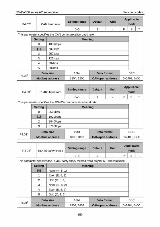
SV-DA300 series AC servo drive Function codes
-150-
P4.021 CAN baud rate Setting range Default Unit
Applicable
mode
0–5 1 - P S T
This parameter specifies the CAN communication baud rate.
Setting Meaning
0 1000kbps
[1] 500kbps
2 250kbps
3 125kbps
4 50kbps
5 20kbps
P4.021 Data size 16bit Data format DEC
Modbus address 1804, 1805 CANopen address 0x2402, 0x00
P4.031 RS485 baud rate Setting range Default Unit
Applicable
mode
0–3 1 - P S T
This parameter specifies the RS485 communication baud rate.
Setting Meaning
0 9600bps
[1] 19200bps
2 38400bps
3 57600bps
P4.031 Data size 16bit Data format DEC
Modbus address 1806, 1807 CANopen address 0x2403, 0x00
P4.041 RS485 parity check Setting range Default Unit
Applicable
mode
0–5 0 - P S T
This parameter specifies the RS485 parity check method, valid only for RTU transmission.
Setting Meaning
[0] None (N, 8, 1)
1 Even (E, 8, 1)
2 Odd (O, 8, 1)
3 None (N, 8, 2)
4 Even (E, 8, 2)
5 Odd (O, 8, 2)
P4.041 Data size 16bit Data format DEC
Modbus address 1808, 1809 CANopen address 0x2404, 0x00

SV-DA300 series AC servo drive Function codes
-151-
P4.051 CAN node no. Setting range Default Unit
Applicable
mode
1–127 1 - P S T
This parameter specifies the local (or slave) node number in CAN communication.
P4.051 Data size 16bit Data format DEC
Modbus address 1810, 1811 CANopen address 0x2405, 0x00
P4.06 RS485 fault clearing
mode
Setting
range Default Unit
Applicable
mode
0–1 1 - P S T
This parameter specifies the mode for handling a fault that occurs in RS485 communication.
Setting Meaning
0 The fault is not cleared.
[1] The fault is cleared automatically.
P4.06 Data size 16bit Data format DEC
Modbus address 1812, 1813 CANopen address 0x2406, 0x00
P4.071
EtherCAT
synchronization
interval
Setting range Default Unit Applicable
mode
0–3 2 - P S T
This parameter specifies the interval time of synchronization when EtherCAT communication uses
the DC mode.
Setting Meaning
0 250us
1 500us
[2] 1ms
3 2ms
P4.071 Data size 16bit Data format DEC
Modbus address 1814, 1815 CANopen address 0x2407, 0x00
P4.081 EtherCAT
synchronization type
Setting range Default Unit Applicable
mode
0–2 0 - P S T
This parameter specifies the type of synchronization between the master and slave nodes in
EtherCAT communication.
Setting Meaning
[0] Free-run
2 DC mode (sync0)

SV-DA300 series AC servo drive Function codes
-152-
P4.081 Data size 16bit Data format DEC
Modbus address 1816, 1817 CANopen address 0x2408, 0x00
P4.091 EtherCAT fault detection
time
Setting
range Default Unit
Applicable
mode
0–1000 100 ms P S T
This parameter specifies the fault detection time in EtherCAT communication.
Note: The value 0 indicates EtherCAT faults are not detected.
P4.091 Data size 16bit Data format DEC
Modbus address 1818, 1819 CANopen address 0x2409, 0x00
6.5.2 Servo types and communication control commands
P4.101 Upper computer type
Setting
range Default Unit
Applicable
mode
0–1 0 - P S T
This parameter specifies the upper computer type which is identified by the drive control interface
type of the upper computer.
Setting Upper
computer type Control interface type
[0] Pulse + analog Position control/fully-closed-loop: pulse and PTP control
Speed/torque control: analog and internal settings
1 Communication
bus
RS485 (protocol: Modbus)
CAN (protocol: CANopen CiA301/402)
P4.101 Data size 16bit Data format DEC
Modbus address 1820, 1821 CANopen address 0x240A, 0x00
P4.11* Enable bus servo
Setting
range Default Unit
Applicable
mode
0–1 0 - P S T
This parameter specifies whether to enable the drive.
Setting Meaning
[0] Disable
1 Enable
Note: Though the drive has been enabled by setting P0.04, the drive will be disabled when P4.11 is
changed from 1 to 0.
P4.11* Data size 16bit Data format DEC
Modbus address 1822, 1823 CANopen address 0x240B, 0x00

SV-DA300 series AC servo drive Function codes
-153-
P4.12* Bus position
command
Setting range Defaul
t Unit
Applicable
mode
-(231-1)–(231-1) 0 reference unit P
This parameter specifies the position command for the drive when P4.10 is set to 1.
P4.12* Data size 32bit Data format DEC
Modbus address 1824, 1825 CANopen address 0x240C, 0x00
P4.13* Bus speed
command
Setting range Default Unit Applicable
mode
-20000–20000 0 r/min S
This parameter specifies the speed command for the drive when P4.10 is set to 1.
P4.13* Data size 16bit Data format DEC
Modbus address 1826, 1827 CANopen address 0x240D, 0x00
P4.14* Bus torque
command
Setting range Default Unit Applicable
mode
-500.0–500.0 0.0 % T
This parameter specifies the torque command for the drive when P4.10 is set to 1.
P4.14* Data size 16bit Data format DEC
Modbus address 1828, 1829 CANopen address 0x240E, 0x00
P4.15*
Control mode
switching
command
Setting range Default Unit Applicable
mode
0–1 0 - P S T
This parameter specifies whether to enable control mode switching of the drive when the hybrid
control mode is used.
Setting Meaning Actual control mode
[0] Disable
Position/speed Position
Position/torque Position
Speed/torque Speed
1 Enable
Position/speed Speed
Position/torque Torque
Speed/torque Torque
Note: If the control mode switching command is updated, the actual switching process of the drive
and motor is handled based on the settings of P0.90–P.92 and actual feedback state.
P4.15* Data size 16bit Data format DEC
Modbus address 1830, 1831 CANopen address 0x240F, 0x00

SV-DA300 series AC servo drive Function codes
-154-
P4.16* Gain switching
command
Setting range Default Unit Applicable
mode
0–1 0 - P S T
This parameter specifies whether to enable gain switching for the drive. When P2.22, P2.27, and
P2.31 are set to 2, the actual gain settings are used for switching.
Setting Meaning Actual gain
[0] Disable Set by the first gain
1 Enable Set by the second gain
P4.16* Data size 16bit Data format DEC
Modbus address 1832, 1833 CANopen address 0x2410, 0x00
P4.17* Electronic gear ratio
switching command
Setting range Default Unit Applicable
mode
0–3 0 - P
This parameter is used to switch electronic gear ratios for the drive when P4.10 is set to 1.
Setting Numerator of actual electronic gear ratio Denominator of actual
electronic gear ratio
[0] Numerator of electronic gear ratio 1 (P0.25) Denominator of
electronic gear ratio
(P0.26)
1 Numerator of electronic gear ratio 2 (P0.27)
2 Numerator of electronic gear ratio 3 (P0.28)
3 Numerator of electronic gear ratio 4 (P0.29)
P4.17* Data size 16bit Data format DEC
Modbus address 1834, 1835 CANopen address 0x2411, 0x00
P4.18* Inertia ratio switching
command
Setting range Default Unit Applicable
mode
0–1 0 - P S T
This parameter specifies whether to enable inertia ratio switching for the drive.
Setting Meaning Actual inertia ratio
[0] Disable Inertia ratio 1 (P1.01)
1 Enable Inertia ratio 1 (P1.02)
P4.18* Data size 16bit Data format DEC
Modbus address 1836, 1837 CANopen address 0x2412, 0x00
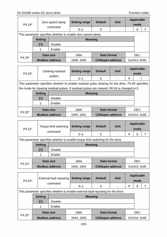
SV-DA300 series AC servo drive Function codes
-155-
P4.19* Zero speed clamp
command
Setting range Default Unit Applicable
mode
0–1 0 - S T
This parameter specifies whether to enable zero speed clamp.
Setting Meaning
[0] Disable
1 Enable
P4.19* Data size 16bit Data format DEC
Modbus address 1838, 1839 CANopen address 0x2413, 0x00
P4.20* Clearing residual
pulses
Setting range Default Unit Applicable
mode
0–1 0 - P
This parameter specifies whether to enable residual pulse clearing for the drive. P3.45 specifies
the mode for clearing residual pulses. If residual pulses are cleared, R0.04 is changed to 0.
Setting Meaning
[0] Disable
1 Enable
P4.20* Data size 16bit Data format DEC
Modbus address 1840, 1841 CANopen address 0x2414, 0x00
P4.21* Torque limit switching
command
Setting range Default Unit Applicable
mode
0–1 0 - P S T
This parameter specifies whether to enable torque limit switching for the drive.
Setting Meaning
[0] Disable
1 Enable
P4.21* Data size 16bit Data format DEC
Modbus address 1842, 1843 CANopen address 0x2415, 0x00
P4.22* External fault reporting
command
Setting range Default Unit Applicable
mode
0–1 0 - P S T
This parameter specifies whether to enable external fault reporting for the drive.
Setting Meaning
[0] Disable
1 Enable
P4.22* Data size 16bit Data format DEC
Modbus address 1844, 1845 CANopen address 0x2416, 0x00

SV-DA300 series AC servo drive Function codes
-156-
P4.23* Emergency stop
command
Setting range Default Unit Applicable
mode
0–1 0 - P S T
This parameter specifies whether to enable emergency stop for the drive.
Setting Meaning
[0] Disable
1 Enable
P4.23* Data size 16bit Data format DEC
Modbus address 1846, 1847 CANopen address 0x2417, 0x00
P4.24* Vibration control
switching command
Setting range Default Unit Applicable
mode
0–1 0 - P
This parameter specifies whether to enable vibration control switching for the drive.
Setting Meaning
[0] Disable
1 Enable
P4.24* Data size 16bit Data format DEC
Modbus address 1848, 1849 CANopen address 0x2418, 0x00
6.5.3 Extension and application
P4.30 Stop mode Setting range Default Unit
Applicable
mode
0–3 0 - P S T
This parameter specifies whether the dynamic brake works when the servo is off and a fault alarm is
reported and determine the servo motor status after the stop.
Setting Action
During deceleration After stop
[0] The motor coasts to stop. Inertia running kept
1 The motor stops through the
dynamic brake. Inertia running kept
2 The dynamic brake stops. Dynamic braking
3 The external dynamic brake
acts. Dynamic braking
Note:
If P4.30 is set to 1, the dynamic brake works when the motor speed is higher than the setting
(30 r/min by default) of P3.58 and it does not work otherwise. After the motor stops, the dynamic
brake does not work.

SV-DA300 series AC servo drive Function codes
-157-
If the servo motor runs at a speed higher than the rated one, you cannot enable the dynamic
brake. If the servo motor runs at a high speed with a large inertia load, exercise caution before
using the dynamic brake. Do not restart the dynamic brake frequently. Otherwise, the servo
drive may be damaged.
P4.30 Data size 16bit Data format DEC
Modbus address 1860, 1861 CANopen address 0x241E, 0x00
P4.31 Max. motor speed Setting range Default Unit
Applicable
mode
0–20000 5000 r/min P S T
This parameter specifies the maximum speed of the servo motor. If the absolute value of the
speed command is greater than the setting of this parameter, the actually-set speed is limited by
this parameter, and the actual direction is the same as that in the original speed command. This
parameter is valid in all modes.
Note: The default value and setting range of this parameter are associated with the drive power
class.
P4.31 Data size 16bit Data format DEC
Modbus address 1862, 1863 CANopen address 0x241F, 0x00
P4.32 Overspeed threshold Setting range Default Unit
Applicable
mode
0–20000 6000 r/min P S T
This parameter specifies the overspeed level for the servo motor. When the motor runs at a speed
higher than the setting of this parameter, an overspeed fault alarm is reported.
Note: The default value and setting range of this parameter are associated with the drive power
class.
P4.32 Data size 16bit Data format DEC
Modbus address 1864, 1865 CANopen address 0x2420, 0x00
P4.33 Pulse threshold of
position deviation
Setting
range Default Unit
Applicable
mode
0–227 100000 reference unit P
This parameter specifies the threshold at which the fault (Er22-0) alarm is reported. In position
mode, if the residual pulse value exceeds the setting of this parameter, the fault alarm is reported.
The value 0 indicates no detection on position deviation.
P4.33 Data size 32bit Data format DEC
Modbus address 1866, 1867 CANopen address 0x2421, 0x00

SV-DA300 series AC servo drive Function codes
-158-
P4.341 Brake OL protection Setting range Default Unit
Applicable
mode
0–2 0 - P S T
This parameter specifies the regenerative brake mounting mode and overload protection mode.
Setting Meaning
[0] Regenerative brake disabled
1 Regenerative brake built in
2 Regenerative brake externally connected
P4.341 Data size 16bit Data format DEC
Modbus address 1868, 1869 CANopen address 0x2422, 0x00
P4.361 Main-power UV
protection
Setting range Default Unit Applicable
mode
0–1 1 - P S T
This parameter specifies whether the drive reports a main circuit undervoltage alarm when the
main power encounters a main circuit undervoltage fault.
Setting Meaning
0 In servo enabling state, the drive does not report the fault Er13-1 when
main circuit undervoltage occurs.
[1] In servo enabling state, the drive reports the fault Er13-1 and stops
when main circuit undervoltage occurs.
P4.361 Data size 16bit Data format DEC
Modbus address 1872, 1873 CANopen address 0x2424, 0x00
P4.37 Main-power UV
detection time
Setting range Default Unit Applicable
mode
70–2000 70 ms P S T
This parameter specifies the time taken to detect main power undervoltage.
Note: The value 0 indicates the function of detecting main power undervoltage is invalid.
P4.37 Data size 16bit Data format DEC
Modbus address 1874, 1875 CANopen address 0x2425, 0x00
P4.39 Speed deviation
threshold
Setting range Default Unit Applicable
mode
0–20000 0 r/min P S
This parameter specifies the condition for detecting the speed deviation fault. If the absolute value
of the actual speed command minus the motor speed is greater than the setting of this parameter
and the deviation lasts more than 100ms, a speed deviation alarm is reported.
Note: The value 0 indicates no detection on speed deviation faults.
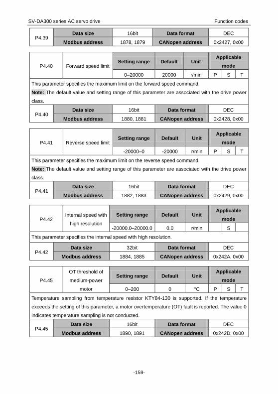
SV-DA300 series AC servo drive Function codes
-159-
P4.39 Data size 16bit Data format DEC
Modbus address 1878, 1879 CANopen address 0x2427, 0x00
P4.40 Forward speed limit Setting range Default Unit
Applicable
mode
0–20000 20000 r/min P S T
This parameter specifies the maximum limit on the forward speed command.
Note: The default value and setting range of this parameter are associated with the drive power
class.
P4.40 Data size 16bit Data format DEC
Modbus address 1880, 1881 CANopen address 0x2428, 0x00
P4.41 Reverse speed limit Setting range Default Unit
Applicable
mode
-20000–0 -20000 r/min P S T
This parameter specifies the maximum limit on the reverse speed command.
Note: The default value and setting range of this parameter are associated with the drive power
class.
P4.41 Data size 16bit Data format DEC
Modbus address 1882, 1883 CANopen address 0x2429, 0x00
P4.42 Internal speed with
high resolution
Setting range Default Unit Applicable
mode
-20000.0–20000.0 0.0 r/min S
This parameter specifies the internal speed with high resolution.
P4.42 Data size 32bit Data format DEC
Modbus address 1884, 1885 CANopen address 0x242A, 0x00
P4.45
OT threshold of
medium-power
motor
Setting range Default Unit Applicable
mode
0–200 0 °C P S T
Temperature sampling from temperature resistor KTY84-130 is supported. If the temperature
exceeds the setting of this parameter, a motor overtemperature (OT) fault is reported. The value 0
indicates temperature sampling is not conducted.
P4.45 Data size 16bit Data format DEC
Modbus address 1890, 1891 CANopen address 0x242D, 0x00

SV-DA300 series AC servo drive Function codes
-160-
P4.501 Encoder phase-Z
offset
Setting range Default Unit Applicable
mode
0–(220-1) 0 pulse P S T
This parameter specifies the output position of phase Z. The phase Z offset is the pulses in the
CCW direction.
P4.501 Data size 32bit Data format DEC
Modbus address 1900, 1901 CANopen address 0x2432, 0x00
P4.51 Torque limit
switching time 1
Setting range Default Unit Applicable
mode
0–4000 0 ms/(100%) P S
This parameter specifies the time taken to switch from the first torque limit to the second torque
limit.
P4.51 Data size 16bit Data format DEC
Modbus address 1902, 1903 CANopen address 0x2433, 0x00
P4.52 Torque limit
switching time 2
Setting range Default Unit Applicable
mode
0–4000 0 ms/(100%) P S
This parameter specifies the time taken to switch from the second torque limit to the first torque
limit.
P4.52 Data size 16bit Data format DEC
Modbus address 1904, 1905 CANopen address 0x2434, 0x00
P4.53 ACR response
adjustment
Setting range Default Unit Applicable
mode
10.0–200.0 100.0 % P S T
This parameter specifies the adjustment coefficient of automatic current regulator response width.
P4.53 Data size 16bit Data format DEC
Modbus address 1906, 1907 CANopen address 0x2435, 0x00
P4.541 Delay after power-on
initialization
Setting range Default Unit Applicable
mode
0–200000 0 ms P S T
This parameter specifies the delay time of servo enabling after power-on initialization is completed.
P4.541 Data size 32bit Data format DEC
Modbus address 1908, 1909 CANopen address 0x2436, 0x00

SV-DA300 series AC servo drive Function codes
-161-
6.5.4 Frequency-division output and second-encoder settings
P4.601
Frequency-division
numerator of
external grating ruler
Setting range Default Unit Applicable
mode
1–(231-1) 10000 - P
This parameter specifies the frequency-division numerator of the external grating ruler.
P4.601 Data size 32bit Data format DEC
Modbus address 1920, 1921 CANopen address 0x243C, 0x00
P4.611
Frequency-division
denominator of
external grating ruler
Setting range Default Unit Applicable
mode
1–(231-1) 10000 - P
This parameter specifies the frequency-division denominator of the external grating ruler. It
corresponds to the grating ruler pulses needed for each motor rotation.
P4.611 Data size 32bit Data format DEC
Modbus address 1922, 1923 CANopen address 0x243D, 0x00
P4.621 Reverse external
grating ruler count
Setting range Default Unit Applicable
mode
0–1 0 - P
This parameter specifies whether to reverse the count from the external grating ruler.
Setting Meaning
[0] Use the count from the external grating ruler directly.
1 Reverse the count from the external grating ruler and then
use the reversed count.
P4.621 Data size 16bit Data format DEC
Modbus address 1924, 1925 CANopen address 0x243E, 0x00
P4.641 Hybrid control
deviation limit
Setting range Default Unit Applicable
mode
1–227 160000 reference unit P
In fully-closed loop control, there is a tolerance between the reference unit corresponding to the
encoder feedback position and user reference unit corresponding to the grating ruler feedback
position. The tolerance is called hybrid-control deviation, specified by R0.05. If R0.05 exceeds the
setting of this parameter, the drive reports fault Er22-1.
P4.641 Data size 32bit Data format DEC
Modbus address 1928, 1929 CANopen address 0x2440, 0x00

SV-DA300 series AC servo drive Function codes
-162-
P4.651
Threshold for
hybrid-control
deviation clearing
Setting range Default Unit Applicable
mode
0–100 0 rotations P
This parameter specifies the condition for clearing the hybrid-control deviation. When the motor
rotation number reaches the specified one, the hybrid-control deviation is cleared. The value 0
indicates the hybrid-control deviation is not cleared.
P4.651 Data size 16bit Data format DEC
Modbus address 1930, 1931 CANopen address 0x2441, 0x00
P4.671
Signal source of
pulse feedback
output
Setting range Default Unit Applicable
mode
0–1 0 - P
This parameter specifies the signal source of pulse feedback output when the fully-closed loop
function is enabled in position mode.
Setting Meaning
[0] Encoder
1 Grating ruler
P4.671 Data size 16bit Data format DEC
Modbus address 1934, 1935 CANopen address 0x2443, 0x00
P4.681
External grating ruler
(or encoder 2)
resolution
Setting range Default Unit Applicable
mode
1–(231-1) 10000 pulse P
This parameter specifies the resolution of the external grating ruler (or second encoder). If the
second encoder is connected, the output is the pulses needed for each encoder rotation.
P4.681 Data size 32bit Data format DEC
Modbus address 1936, 1937 CANopen address 0x2444, 0x00
P4.691 Frequency division
output source
Setting range Default Unit Applicable
mode
0–4 0 - P S T
This parameter specifies the signal source of frequency division output.
Setting Meaning
[0] Normal frequency division output
1 Second encoder
2 Input from quadrature pulses in phases A and B
3 Internal virtual shaft
4 First encoder (valid only for incremental encoders)
P4.691 Data size 32bit Data format DEC
Modbus address 1938, 1939 CANopen address 0x2445, 0x00

SV-DA300 series AC servo drive Function codes
-163-
P4.701
External grating ruler (or
encoder 2) phase-Z
signal type
Setting
range Default Unit
Applicable
mode
0–3 0 - P S T
The width for a phase-Z signal can be 1/4, 1/2, or 1/1. The starting phase of a signal in any width
corresponds to 4 types of electrical level in phases A and B. There are total 12 types in
combination. However, to ensure these combinations are applicable and the capture value is
normal in both forward and reverse directions, you need to set the phase-A–phase-B status values
in the high electrical level period of phase-Z signals. For the signals in 1/4 and 1/2 widths, only one
of phase-A–phase-B status values in the high electrical level period is required after the phase-Z
signal type is set. For the signals in 1/1 width, the phase-Z signal type must be the phase-A–
phase-B status value in the high electrical level period.
P4.701 Data size 16bit Data format DEC
Modbus address 1940, 1941 CANopen address 0x2446, 0x00
P4.71 Type of encoder 2 Setting range Default Unit
Applicable
mode
1–12 2*1 - P S T
This parameter specifies the type of the second encoder.
Setting Meaning
1 2500-PPR standard incremental type
[2] 2500-PPR economical incremental type
3 17-bit single-turn absolute type
4 17-bit multiturn absolute type *3
10 23-bit multiturn absolute type *3
Other Reserved
P4.71 Data size 16bit Data format DEC
Modbus address 1942, 1943 CANopen address 0x2447, 0x00
P4.72 Cascading mode of
encoder 2
Setting range Default Unit Applicable
mode
1–12 0 - P S T
This parameter specifies the cascading mode of the second encoder.
Setting Meaning
[0] No cascading
1 Slave node of RS485 synchronization.
2 Master node of RS485 synchronization.
3 The second encoder is cascaded to the slave node.
4 The second encoder is cascaded to the master node.
P4.72 Data size 16bit Data format DEC
Modbus address 1944, 1945 CANopen address 0x2448, 0x00

SV-DA300 series AC servo drive Function codes
-164-
P4.87 CANopen
communication cycle
Setting
range Default Unit
Applicable
mode
0–(231-1) 0 μs P S T
This parameter specifies the synchronization signal creation cycle of a slave CANopen node.
Note: The recommended unit is 1000μs.
P4.87 Data size 32bit Data format DEC
Modbus address 1974, 1975 CANopen address 0x2457, 0x00
P4.88 CANopen heartbeat
cycle
Setting
range Default Unit
Applicable
mode
0–32767 1000 ms P S T
This parameter specifies the heartbeat signal creation cycle of a slave CANopen node.
P4.88 Data size 16bit Data format DEC
Modbus address 1976, 1977 CANopen address 0x2458, 0x00
P4.89 Auto stop on CANopen
disconnection
Setting
range Default Unit
Applicable
mode
0–1 0 - P S T
This parameter specifies whether to enable automatic stop when CANopen communication is
disconnected.
Setting Meaning
[0] Disable
1 Enable
P4.89 Data size 16bit Data format DEC
Modbus address 1978, 1979 CANopen address 0x2459, 0x00
6.5.5 Special commands
P4.90* Fault recovery
Setting
range Default Unit
Applicable
mode
0–1 0 - P S T
This parameter specifies whether to enable fault recovery. You can set this parameter on the upper
computer to handle faults for the drive.
Setting Meaning
[0] Disable
1 Enable
Note:
If fault recovery is enabled, the servo is not enabled for the drive, and the fault occurring
condition is not triggered, the fault that can be automatically cleared recovers automatically.
Other faults cannot be automatically cleared online but can be cleared after repower-on.

SV-DA300 series AC servo drive Function codes
-165-
You can set this parameter on the LED panel to clear faults.
P4.90* Data size 16bit Data format DEC
Modbus address 1980, 1981 CANopen address 0x245A, 0x00
P4.91* Parameter saving
Setting
range Default Unit
Applicable
mode
0–1 0 - P S T
If P0.17 is set to 1 (saving in batches), this parameter can be used to send a parameter saving
command so that any parameter modification can be written to the EEPROM.
Setting Meaning
[0] Disable
1 Enable
P4.91* Data size 16bit Data format DEC
Modbus address 1982, 1983 CANopen address 0x245B, 0x00
P4.92* Factory restore Setting range Default Unit
Applicable
mode
0–1 0 - P S T
This parameter specifies whether to enable the function of restoring factory settings. If the function
is enabled, all user parameters (from group P0 to group P6) are restored to factory settings.
Setting Meaning
[0] Disable
1 Enable
P4.92* Data size 16bit Data format DEC
Modbus address 1984, 1985 CANopen address 0x245C, 0x00
P4.93* Read fault records Setting range Default Unit
Applicable
mode
0–1 0 - P S T
This parameter specifies whether to enable the function of reading fault records. If the function is
enabled, the fault records specified by P4.95 are read and displayed.
Setting Meaning
[0] Disable
1 Enable
P4.93* Data size 16bit Data format DEC
Modbus address 1986, 1987 CANopen address 0x245D, 0x00

SV-DA300 series AC servo drive Function codes
-166-
P4.94* Clear fault records Setting range Default Unit
Applicable
mode
0–1 0 - P S T
This parameter specifies whether to enable the function of clearing fault records. If the function is
enabled, all the fault records are cleared.
Setting Meaning
[0] Disable
1 Enable
P4.94* Data size 16bit Data format DEC
Modbus address 1988, 1989 CANopen address 0x245E, 0x00
P4.95* Fault record group
no.
Setting range Default Unit Applicable
mode
0–9 0 - P S T
This parameter specifies the group number of fault records that are read.
The value 0 indicates the fault records in group 1 are read and the faults have occurred most
recently. The value 9 indicates the fault records in group 10 are read and the faults have occurred
earliest.
P4.95* Data size 16bit Data format DEC
Modbus address 1990, 1991 CANopen address 0x245F, 0x00
P4.96* Reserved
Setting
range Default Unit
Applicable
mode
- - - P S T
This parameter cannot be modified.
P4.96* Data size 16bit Data format DEC
Modbus address 1992, 1993 CANopen address 0x2460, 0x00
P4.97* Write to encoder EEPROM
Setting
range Default Unit
Applicable
mode
0–1 0 - P S T
This parameter specifies whether to write all motor-related parameters to the EEPROM equipped
with the communication encoder. In any following startup, the drive uses the data in the EEPROM
for parameter initialization.
P4.97* Data size 16bit Data format DEC
Modbus address 1994, 1995 CANopen address 0x2461, 0x00

SV-DA300 series AC servo drive Function codes
-167-
P4.98 Mask encoder EEPROM
data faults
Setting
range Default Unit
Applicable
mode
0–1 0 - P S T
This parameter specifies whether to mask the fault indicating there is no data or incorrect data on
the EEPROM equipped with the communication encoder.
If fault Er2-c or Er2-d occurs but the motor model is set correctly, you can use the motor after
repower-on. The drive uses the motor data in the EEPROM equipped with the drive for parameter
initialization.
P4.98 Data size 16bit Data format DEC
Modbus address 1996, 1997 CANopen address 0x2462, 0x00
6.6 Program Jog, homing, and PTP control (group P5)
6.6.1 Program Jog settings
P5.00 Jog mode
Setting
range Default Unit
Applicable
mode
0–6 0 - P
This parameter specifies the program Jog mode.
Mode Key Function
[0]
(Wait time P5.04→Forward moving P5.01) × Cycles P5.05
P5.02
Speed 0
P5.04 P5.03 P5.04 P5.04
P5.05
P5.01 P5.01 P5.01
1
(Wait time P5.04→Forward moving P5.01) × Cycles P5.05
P5.02
Speed 0
P5.04 P5.04
P5.05
P5.01P5.01P5.01
P5.03 P5.04
2
(Wait time P5.04→Forward moving P5.01) × Cycles P5.05 →(Wait time P5.04→Reverse movingP5.01) × Cycles P5.05
P5.02
Speed 0
P5.04 P5.03 P5.04 P5.04
P5.05
P5.01 P5.01 P5.01
P5.04 P5.04
P5.05
P5.01P5.01P5.01
P5.04
P5.02
3
(Wait time P5.04→Reverse moving P5.01) × Cycles P5.05 →(Wait time P5.04→Forward moving P5.01) × Cycles P5.05
P5.02
P5.04 P5.04 P5.04
P5.05
P5.01 P5.01 P5.01
P5.02
Speed 0
P5.04 P5.04
P5.05
P5.01P5.01P5.01
P5.03 P5.04
4 (Wait time P5.04→Forward moving P5.01→Wait time P5.04 →Reverse moving P5.01) × Cycles P5.05

SV-DA300 series AC servo drive Function codes
-168-
P5.02
P5.02
Speed 0
P5.04 P5.03 P5.04
P5.01
P5.05
P5.01
5
(Wait time P5.04→Reverse moving P5.01→Wait time P5.04 →Forward moving P5.01) × Cycles P5.05
P5.01
P5.02
Speed 0
P5.04 P5.04
P5.01
P5.03
P5.02
P5.05
6
or
(Wait time P5.04→Forward/reverse moving P5.01) × 1 cycle
P5.01
Speed 0
P5.04
P5.02
P5.02
Speed 0
P5.04
P5.01
P5.03
P5.00 Data size 16bit Data format DEC
Modbus address 2000, 2001 CANopen address 0x2500, 0x00
P5.01 Jogging increment Setting range Default Unit
Applicable
mode
1–230 50000 reference unit P
This parameter specifies the increment of the position movement at jogging.
P5.01 Data size 32bit Data format DEC
Modbus address 2002, 2003 CANopen address 0x2501, 0x00
P5.02 Jogging speed Setting range Default Unit
Applicable
mode
1–5000 500 r/min P
This parameter specifies the maximum running speed at jogging.
P5.02 Data size 16bit Data format DEC
Modbus address 2004, 2005 CANopen address 0x2502, 0x00
P5.03 Jogging ACC/DEC
time
Setting range Default Unit Applicable
mode
2–10000 100 ms P
This parameter specifies the acceleration or deceleration time at jogging. The setting of this
parameter corresponds to the time taken to accelerate from the zero speed to the rated rotation
speed. If you need to improve the speed from zero to 50% of the rated speed, the time taken to
reach the target speed is 50% of the time specified by this parameter.
P5.03 Data size 16bit Data format DEC
Modbus address 2006, 2007 CANopen address 0x2503, 0x00

SV-DA300 series AC servo drive Function codes
-169-
P5.04 Jogging wait time Setting range Default Unit
Applicable
mode
0–10000 100 ms P
This parameter specifies the wait time at jogging. The setting of this parameter corresponds to the
time from jogging starting to the actual running or to the time taken to wait for next displacement
after the current displacement.
P5.04 Data size 16bit Data format DEC
Modbus address 2008, 2009 CANopen address 0x2504, 0x00
P5.05 Jogging cycles Setting range Default Unit
Applicable
mode
0–10000 1 - P
This parameter specifies the number of jogging cycles. For details, see the description for P5.00.
P5.05 Data size 16bit Data format DEC
Modbus address 2010, 2011 CANopen address 0x2505, 0x00

SV-DA300 series AC servo drive Function codes
-170-
6.6.2 Homing
P5.102 Homing mode Setting range Default Unit
Applicable
mode
0–128 0 - P
This parameter specifies the homing mode.
Display mode: DEC
M: Homing mode
Z: Locating phase Z
T: Limit mode
R: Reserved
R T Z M
Reserved
Limit mode Phase Z locating mode Home return mode
0-1 0-2 0-8
T: Invalid Returning to locate phase Z is defined as the home
position. Z=1: Forwarding to locate phase Z is defined as the
home position. Z=2: No locating phase Z. The recurrent point is defined as the home position.
M=0: Forward rotation. The forward limit switch is the recurrent point.
T: Invalid M=1: Reverse rotation. The reverse limit switch is the recurrent point.
Limit encountered: T=0: Report an offside fault. T=1: Reverse the direction.
M=2: Forward rotation. The rising edge of the home switch is the recurrent point.
M=3: Reverse rotation. The rising edge of the reverse limit switch is the recurrent point.
Z: Invalid M=4: Forward rotation. The first phase-Z signal is the recurrent point.
Z: Invalid M=5: Reverse rotation. The first phase-Z signal is the recurrent point.
Z=0 Returning to locate phase Z is defined as the home position. Z=1 Forwarding to locate phase Z is defined as the home position. Z=2: No finding phase Z. The recurrent point is defined as the home position.
M=6: Forward rotation. The falling edge of the home switch is the recurrent point.
M=7: Reverse rotation. The falling edge of the home switch is the recurrent point.
T: Invalid Z: Invalid M=8: The current position is regarded as the home position.
P5.102 Data size 16bit Data format DEC
Modbus address 2020, 2021 CANopen address 0x2505, 0x00
P5.11 Homing upon
power-on
Setting range Default Unit Applicable
mode
0–1 0 - P
This parameter specifies whether to return to the home position automatically upon power-on.

SV-DA300 series AC servo drive Function codes
-171-
Setting Meaning
[0] Disable
1 Enable
Note: Automatic homing upon power-on is valid only when there is no fault.
P5.11 Data size 16bit Data format DEC
Modbus address 2022, 2023 CANopen address 0x250B, 0x00
P5.12 High speed at homing
step 1
Setting
range Default Unit
Applicable
mode
0–2000 100 r/min P
This parameter specifies the high speed at step 1 of homing.
Diagram:
P5.12
P5.13
Forward limit switch
Z
P5.12
P5.13
Forward limit switch
Z
P5.12 Data size 16bit Data format DEC
Modbus address 2024, 2025 CANopen address 0x250C, 0x00
P5.13 Low speed at homing
step 2
Setting
range Default Unit
Applicable
mode
0–60 20 r/min P
This parameter specifies the low speed at step 2 of homing. For details, see the diagram in the
description for P5.12.
P5.13 Data size 16bit Data format DEC
Modbus address 2026, 2027 CANopen address 0x250D, 0x00
P5.14 Home position Setting range Default Unit
Applicable
mode
-(231-1)–(231-1) 0 reference unit P
This parameter specifies the home position.
P5.14 Data size 32bit Data format DEC
Modbus address 2028, 2029 CANopen address 0x250E, 0x00

SV-DA300 series AC servo drive Function codes
-172-
P5.15* Homing trigger
command
Setting range Default Unit Applicable
mode
0–1 0 - P
This parameter specifies whether to trigger the homing function. It has the same function as the
homing trigger terminal with digital input.
P5.15* Data size 16bit Data format DEC
Modbus address 2030, 2031 CANopen address 0x250F, 0x00
P5.16 Homing associated
action
Setting range Default Unit Applicable
mode
0–3 1 - P
This parameter specifies the action associated with homing.
Setting Meaning
0 No action.
[1] The drive goes to the target position.
2 The drive goes to the position of segment 0.
3 The drive goes to the target position without homing.
P5.16 Data size 16bit Data format DEC
Modbus address 2032, 2033 CANopen address 0x2510, 0x00
P5.17 Target speed after
homing
Setting range Default Unit Applicable
mode
1–5000 100 r/min P
This parameter specifies the target speed after homing. The change takes effect before homing.
P5.17 Data size 16bit Data format DEC
Modbus address 2034, 2035 CANopen address 0x2511, 0x00
P5.18
ACC/DEC time for
target speed after
homing
Setting range Default Unit Applicable
mode
0–32767 300 ms P
This parameter specifies the acceleration or deceleration time taken to reach the target speed after
homing. The setting of this parameter corresponds to the time taken to accelerate from the zero
speed to the rated rotation speed. If you need to improve the speed from zero to 50% of the rated
speed, the time taken to reach the target speed is 50% of the time specified by this parameter.
P5.18 Data size 16bit Data format DEC
Modbus address 2036, 2037 CANopen address 0x2512, 0x00

SV-DA300 series AC servo drive Function codes
-173-
P5.19 Target position after
homing
Setting range Default Unit Applicable
mode
-(231-1)–(231-1) 0 reference unit P
This parameter specifies the target position after homing.
P5.19 Data size 32bit Data format DEC
Modbus address 2038, 2039 CANopen address 0x2513, 0x00
6.6.3 PTP control
P5.20* PTP trigger signal Setting range Default Unit
Applicable
mode
-1–2048 -1 - P
This parameter specifies whether to trigger the target segment.
If data is written, PTP is triggered, and the internal buffer can receive 8 trigger signals at most.
Setting Meaning
[-1] Invalid.
0-127 It triggers PTP control for PTPs 0–127, which equals the digital input of
TRIG+POSn.
128-2047 Invalid.
2048 Forcible stop.
Example: If segment signal 3 is written, segment program 3 is triggered.
P5.20* Data size 16bit Data format DEC
Modbus address 2040, 2041 CANopen address 0x2514, 0x00
P5.21 Target speed 00 Setting range Default Unit
Applicable
mode
0–6000 20 r/min P
P5.22 Target speed 01 Setting range Default Unit
Applicable
mode
0–6000 50 r/min P
P5.23 Target speed 02 Setting range Default Unit
Applicable
mode
0–6000 100 r/min P
P5.24 Target speed 03 Setting range Default Unit
Applicable
mode
0–6000 200 r/min P
P5.25 Target speed 04 Setting range Default Unit Applicable
mode

SV-DA300 series AC servo drive Function codes
-174-
0–6000 300 r/min P
P5.26 Target speed 05 Setting range Default Unit
Applicable
mode
0–6000 500 r/min P
P5.27 Target speed 06 Setting range Default Unit
Applicable
mode
0–6000 600 r/min P
P5.28 Target speed 07 Setting range Default Unit
Applicable
mode
0–6000 800 r/min P
P5.29 Target speed 08 Setting range Default Unit
Applicable
mode
0–6000 1000 r/min P
P5.30 Target speed 09 Setting range Default Unit
Applicable
mode
0–6000 1300 r/min P
P5.31 Target speed 10 Setting range Default Unit
Applicable
mode
0–6000 1500 r/min P
P5.32 Target speed 11 Setting range Default Unit
Applicable
mode
0–6000 1800 r/min P
P5.33 Target speed 12 Setting range Default Unit
Applicable
mode
0–6000 2000 r/min P
P5.34 Target speed 13 Setting range Default Unit
Applicable
mode
0–6000 2300 r/min P
P5.35 Target speed 14 Setting range Default Unit
Applicable
mode
0–6000 2500 r/min P
P5.36 Target speed 15 Setting range Default Unit
Applicable
mode
0–6000 3000 r/min P
This group of parameter specifies the target speed for each segment.
P5.21 Data size 16bit Data format DEC
Modbus address 2042, 2043 CANopen address 0x2515, 0x00
P5.22 Data size 16bit Data format DEC

SV-DA300 series AC servo drive Function codes
-175-
Modbus address 2044, 2045 CANopen address 0x2516, 0x00
P5.23 Data size 16bit Data format DEC
Modbus address 2046, 2047 CANopen address 0x2517, 0x00
P5.24 Data size 16bit Data format DEC
Modbus address 2048, 2049 CANopen address 0x2518, 0x00
P5.25 Data size 16bit Data format DEC
Modbus address 2050, 2051 CANopen address 0x2519, 0x00
P5.26 Data size 16bit Data format DEC
Modbus address 2052, 2053 CANopen address 0x251A, 0x00
P5.27 Data size 16bit Data format DEC
Modbus address 2054, 2055 CANopen address 0x251B, 0x00
P5.28 Data size 16bit Data format DEC
Modbus address 2056, 2057 CANopen address 0x251C, 0x00
P5.29 Data size 16bit Data format DEC
Modbus address 2058, 2059 CANopen address 0x251D, 0x00
P5.30 Data size 16bit Data format DEC
Modbus address 2060, 2061 CANopen address 0x251E, 0x00
P5.31 Data size 16bit Data format DEC
Modbus address 2062, 2063 CANopen address 0x251F, 0x00
P5.32 Data size 16bit Data format DEC
Modbus address 2064, 2065 CANopen address 0x2520, 0x00
P5.33 Data size 16bit Data format DEC
Modbus address 2066, 2067 CANopen address 0x2521, 0x00
P5.34 Data size 16bit Data format DEC
Modbus address 2068, 2069 CANopen address 0x2522, 0x00
P5.35 Data size 16bit Data format DEC
Modbus address 2070, 2071 CANopen address 0x2523, 0x00
P5.36 Data size 16bit Data format DEC
Modbus address 2072, 2073 CANopen address 0x2524, 0x00
P5.37 ACC/DEC time 00 Setting range Default Unit
Applicable
mode
0–32767 200 ms P
P5.38 ACC/DEC time 01 Setting range Default Unit
Applicable
mode
0–32767 300 ms P
P5.39 ACC/DEC time 02 Setting range Default Unit Applicable
mode

SV-DA300 series AC servo drive Function codes
-176-
0–32767 500 ms P
P5.40 ACC/DEC time 03 Setting range Default Unit
Applicable
mode
0–32767 600 ms P
P5.41 ACC/DEC time 04 Setting range Default Unit
Applicable
mode
0–32767 800 ms P
P5.42 ACC/DEC time 05 Setting range Default Unit
Applicable
mode
0–32767 900 ms P
P5.43 ACC/DEC time 06 Setting range Default Unit
Applicable
mode
0–32767 1000 ms P
P5.44 ACC/DEC time 07 Setting range Default Unit
Applicable
mode
0–32767 1200 ms P
P5.45 ACC/DEC time 08 Setting range Default Unit
Applicable
mode
0–32767 1500 ms P
P5.46 ACC/DEC time 09 Setting range Default Unit
Applicable
mode
0–32767 2000 ms P
P5.47 ACC/DEC time 10 Setting range Default Unit
Applicable
mode
0–32767 2500 ms P
P5.48 ACC/DEC time 11 Setting range Default Unit
Applicable
mode
0–32767 3000 ms P
P5.49 ACC/DEC time 12 Setting range Default Unit
Applicable
mode
0–32767 5000 ms P
P5.50 ACC/DEC time 13 Setting range Default Unit
Applicable
mode
0–32767 8000 ms P
P5.51 ACC/DEC time 14 Setting range Default Unit
Applicable
mode
0–32767 50 ms P

SV-DA300 series AC servo drive Function codes
-177-
P5.52 ACC/DEC time 15 Setting range Default Unit
Applicable
mode
0–32767 30 ms P
This group of parameter specifies the acceleration or deceleration time for each segment.
P5.37 Data size 16bit Data format DEC
Modbus address 2074, 2075 CANopen address 0x2525, 0x00
P5.38 Data size 16bit Data format DEC
Modbus address 2076, 2077 CANopen address 0x2526, 0x00
P5.39 Data size 16bit Data format DEC
Modbus address 2078, 2079 CANopen address 0x2527, 0x00
P5.40 Data size 16bit Data format DEC
Modbus address 2080, 2081 CANopen address 0x2528, 0x00
P5.41 Data size 16bit Data format DEC
Modbus address 2082, 2083 CANopen address 0x2529, 0x00
P5.42 Data size 16bit Data format DEC
Modbus address 2084, 2085 CANopen address 0x252A, 0x00
P5.43 Data size 16bit Data format DEC
Modbus address 2086, 2087 CANopen address 0x252B, 0x00
P5.44 Data size 16bit Data format DEC
Modbus address 2088, 2089 CANopen address 0x252C, 0x00
P5.45 Data size 16bit Data format DEC
Modbus address 2090, 2091 CANopen address 0x252D, 0x00
P5.46 Data size 16bit Data format DEC
Modbus address 2092, 2093 CANopen address 0x252E, 0x00
P5.47 Data size 16bit Data format DEC
Modbus address 2094, 2095 CANopen address 0x252F, 0x00
P5.48 Data size 16bit Data format DEC
Modbus address 2096, 2097 CANopen address 0x2530, 0x00
P5.49 Data size 16bit Data format DEC
Modbus address 2098, 2099 CANopen address 0x2531, 0x00
P5.50 Data size 16bit Data format DEC
Modbus address 2100, 2101 CANopen address 0x2532, 0x00
P5.51 Data size 16bit Data format DEC
Modbus address 2102, 2103 CANopen address 0x2533, 0x00
P5.52 Data size 16bit Data format DEC
Modbus address 2104, 2105 CANopen address 0x2534, 0x00

SV-DA300 series AC servo drive Function codes
-178-
P5.53 Delay time 00 Setting range Default Unit
Applicable
mode
0–32767 0 ms P
P5.54 Delay time 01 Setting range Default Unit
Applicable
mode
0–32767 100 ms P
P5.55 Delay time 02 Setting range Default Unit
Applicable
mode
0–32767 200 ms P
P5.56 Delay time 03 Setting range Default Unit
Applicable
mode
0–32767 400 ms P
P5.57 Delay time 04 Setting range Default Unit
Applicable
mode
0–32767 500 ms P
P5.58 Delay time 05 Setting range Default Unit
Applicable
mode
0–32767 800 ms P
P5.59 Delay time 06 Setting range Default Unit
Applicable
mode
0–32767 1000 ms P
P5.60 Delay time 07 Setting range Default Unit
Applicable
mode
0–32767 1500 ms P
P5.61 Delay time 08 Setting range Default Unit
Applicable
mode
0–32767 2000 ms P
P5.62 Delay time 09 Setting range Default Unit
Applicable
mode
0–32767 2500 ms P
P5.63 Delay time 10 Setting range Default Unit
Applicable
mode
0–32767 3000 ms P
P5.64 Delay time 11 Setting range Default Unit
Applicable
mode
0–32767 3500 ms P
P5.65 Delay time 12
Setting range Default Unit Applicable
mode
0–32767
4000
ms
P

SV-DA300 series AC servo drive Function codes
-179-
P5.66 Delay time 13 Setting range Default Unit
Applicable
mode
0–32767 4500 ms P
P5.67 Delay time 14 Setting range Default Unit
Applicable
mode
0–32767 5000 ms P
P5.68 Delay time 15 Setting range Default Unit
Applicable
mode
0–32767 5500 ms P
This group of parameter specifies the delay time for each segment.
P5.53 Data size 16bit Data format DEC
Modbus address 2106, 2107 CANopen address 0x2535, 0x00
P5.54 Data size 16bit Data format DEC
Modbus address 2108, 2109 CANopen address 0x2536, 0x00
P5.55 Data size 16bit Data format DEC
Modbus address 2110, 2111 CANopen address 0x2537, 0x00
P5.56 Data size 16bit Data format DEC
Modbus address 2112, 2113 CANopen address 0x2538, 0x00
P5.57 Data size 16bit Data format DEC
Modbus address 2114, 2115 CANopen address 0x2539, 0x00
P5.58 Data size 16bit Data format DEC
Modbus address 2116, 2117 CANopen address 0x253A, 0x00
P5.59 Data size 16bit Data format DEC
Modbus address 2118, 2119 CANopen address 0x253B, 0x00
P5.60 Data size 16bit Data format DEC
Modbus address 2120, 2121 CANopen address 0x253C, 0x00
P5.61 Data size 16bit Data format DEC
Modbus address 2122, 2123 CANopen address 0x253D, 0x00
P5.62 Data size 16bit Data format DEC
Modbus address 2124, 2125 CANopen address 0x253E, 0x00
P5.63 Data size 16bit Data format DEC
Modbus address 2126, 2127 CANopen address 0x253F, 0x00
P5.64 Data size 16bit Data format DEC
Modbus address 2128, 2129 CANopen address 0x2540, 0x00
P5.65 Data size 16bit Data format DEC
Modbus address 2130, 2131 CANopen address 0x2541, 0x00
P5.66 Data size 16bit Data format DEC
Modbus address 2132, 2133 CANopen address 0x2542, 0x00

SV-DA300 series AC servo drive Function codes
-180-
P5.67 Data size 16bit Data format DEC
Modbus address 2134, 2135 CANopen address 0x2543, 0x00
P5.68 Data size 16bit Data format DEC
Modbus address 2136, 2137 CANopen address 0x2544, 0x00
P5.69 PTP control buffer
switch
Setting range Default Unit Applicable
mode
0–1 1 - P
If buffering is enabled for PTP control, eight buffers can be received successively and executed
sequentially.
P5.69 Data size 16bit Data format DEC
Modbus address 2138, 2139 CANopen address 0x2545, 0x00
P5.70 Disk single-turn
resolution
Setting range Default Unit Applicable
mode
-(231-1)–(231-1) 10000 pulse P
This parameter specifies the single-turn resolution of the disk that the motor drives.
P5.70 Data size 32bit Data format DEC
Modbus address 2140, 2141 CANopen address 0x2546, 0x00
P5.71 Disk homing switch Setting range Default Unit
Applicable
mode
0–3 0 - P
This parameter specifies the homing mode of the disk.
P5.71 Data size 16bit Data format DEC
Modbus address 2142, 2143 CANopen address 0x2547, 0x00
P5.72 Super multiturn
mode
Setting range Default Unit Applicable
mode
0–1 0 - P
If the super multiturn mode is used, the turn counting number of the multiturn encoder changes
from 16 bits to 32 bits, while the multiturn encoder counts a total of 216 turns in most cases.
P5.72 Data size 16bit Data format DEC
Modbus address 2144, 2145 CANopen address 0x2548, 0x00
P5.73 Digital trigger mode for
PTP control
Setting
range Default Unit
Applicable
mode
0–1 0 - P

SV-DA300 series AC servo drive Function codes
-181-
Setting Meaning
[0] Binary input + Terminal trigger mode
1 Single terminal trigger mode (supporting 7 PTPs only)
P5.73 Data size 16bit Data format DEC
Modbus address 2146, 2147 CANopen address 0x2549, 0x00
P5.74 Digital output mode for
PTP control
Setting
range Default Unit
Applicable
mode
0–4 0 - P
Setting Meaning
[0] Output before PTP arrival
1 Output after PTP arrival
2 Single-point output + Output before PTP arrival
3 Single-point output + Output after PTP arrival
4 Single-point output + Output after PTP arrival (only the
control word in the absolute position supported)
P5.74 Data size 16bit Data format DEC
Modbus address 2148, 2149 CANopen address 0x254A, 0x00
P5.75 Suspend PTP control
Setting
range Default Unit
Applicable
mode
0–1 0 - P
This parameter specifies whether to suspend PTP control. The value 1 indicates PTP control is
suspended.
P5.75 Data size 16bit Data format DEC
Modbus address 2150, 2151 CANopen address 0x254B, 0x00
6.7 Application functions (group P6)
P6.00 Forward low jogging
speed
Setting range Default Unit Applicable
mode
0–6000 5 r/min P
This parameter specifies the speed of slow forward jogging, which is triggered by the forward
jogging terminal and high-low jogging speed switching terminal.
P6.00 Data size 16bit Data format DEC
Modbus address 2200, 2201 CANopen address 0x2600, 0x00

SV-DA300 series AC servo drive Function codes
-182-
P6.01 Reverse low
jogging speed
Setting range Default Unit Applicable
mode
-6000–0 -5 r/min P
This parameter specifies the speed of slow reverse jogging, which is triggered by the reverse
jogging terminal and high-low jogging speed switching terminal.
P6.01 Data size 16bit Data format DEC
Modbus address 2202, 2203 CANopen address 0x2601, 0x00
P6.021 Data latching switch Setting range Default Unit
Applicable
mode
0–1 0 - P
This parameter specifies whether to enable the data latching switch. If the switch is enabled, the
position information is written to the EEPROM each time the terminal is latched. However, frequent
latching may cause EEPROM damage.
Setting Meaning
[0] Disable
1 Enable
P6.021 Data size 16bit Data format DEC
Modbus address 2204, 2205 CANopen address 0x2602, 0x00
P6.03 Save position
latching
Setting range Default Unit Applicable
mode
0–1 0 - P
This parameter specifies whether to save position latching.
Setting Meaning
[0] Not save
1 Save
P6.03 Data size 16bit Data format DEC
Modbus address 2206, 2207 CANopen address 0x2603, 0x00
P6.04 Forward high
jogging speed
Setting range Default Unit Applicable
mode
0–6000 60 r/min P
This parameter specifies the speed of fast forward jogging, which is triggered by the forward
jogging terminal and high-low jogging speed switching terminal.
P6.04 Data size 16bit Data format DEC
Modbus address 2208, 2209 CANopen address 0x2604, 0x00

SV-DA300 series AC servo drive Function codes
-183-
P6.05 Reverse high
jogging speed
Setting range Default Unit Applicable
mode
-6000–0 -60 r/min P
This parameter specifies the speed of fast reverse jogging, which is triggered by the reverse
jogging terminal and high-low jogging speed switching terminal.
P6.05 Data size 16bit Data format DEC
Modbus address 2210, 2211 CANopen address 0x2605, 0x00
P6.06 Enable terminal
jogging
Setting range Default Unit Applicable
mode
0–1 0 - P
This parameter specifies whether to enable terminal jogging.
Setting Meaning
[0] Disable
1 Enable
P6.06 Data size 16bit Data format DEC
Modbus address 2212, 2213 CANopen address 0x2606, 0x00
P6.201 Turret switch Setting range Default Unit
Applicable
mode
0–1 0 - P
This parameter specifies whether to enable the turret switch.
Setting Meaning
[0] Disable
1 Enable
P6.201 Data size 16bit Data format DEC
Modbus address 2240, 2241 CANopen address 0x2614, 0x00
P6.21 Knives per turret Setting range Default Unit
Applicable
mode
1–128 16 - P
This parameter specifies the number of knives in a turret.
P6.21 Data size 16bit Data format DEC
Modbus address 2242, 2243 CANopen address 0x2615, 0x00
P6.22 Pulses per turret
rotation
Setting range Default Unit Applicable
mode
2–(231-1) 10000 reference unit P

SV-DA300 series AC servo drive Function codes
-184-
This parameter specifies the number of pulses needed for each turret rotation.
P6.22 Data size 32bit Data format DEC
Modbus address 2244, 2245 CANopen address 0x2616, 0x00
P6.231 Turret start point Setting range Default Unit
Applicable
mode
-(231-1)–(231-1) 0 reference unit P
This parameter specifies the start point for a turret.
P6.231 Data size 32bit Data format DEC
Modbus address 2246, 2247 CANopen address 0x2617, 0x00
P6.301
Gantry
synchronization
switch
Setting range Default Unit Applicable
mode
0–1 0 - P
This parameter specifies whether to enable the gantry synchronization switch.
Setting Meaning
[0] Disable
1 Enable
P6.301 Data size 16bit Data format DEC
Modbus address 2260, 2261 CANopen address 0x261E, 0x00
P6.31
Speed control gain
for gantry
synchronization
Setting range Default Unit Applicable
mode
0.0–3276.7 0.0 Hz P
This parameter specifies the speed control gain for gantry synchronization.
P6.31 Data size 16bit Data format DEC
Modbus address 2262, 2263 CANopen address 0x261F, 0x00
P6.32
Speed control
integral for gantry
synchronization
Setting range Default Unit Applicable
mode
0.1–1000.0 1000.0 ms P
This parameter specifies the time constant of the speed control integral for gantry synchronization.
The value 1000 indicates that the integral function is invalid.
P6.32 Data size 16bit Data format DEC
Modbus address 2264, 2265 CANopen address 0x2620, 0x00

SV-DA300 series AC servo drive Function codes
-185-
P6.33
Position control gain
for gantry
synchronization
Setting range Default Unit Applicable
mode
0.0–3276.7 1000.0 Hz P
This parameter specifies the position control gain for gantry synchronization.
P6.33 Data size 16bit Data format DEC
Modbus address 2266, 2267 CANopen address 0x2621, 0x00
P6.34
Torque filter for
gantry
synchronization
compensation
Setting range Default Unit Applicable
mode
0.00–64.00 0.00 ms P
This parameter specifies the torque filter time constant for gantry synchronization compensation.
P6.34 Data size 16bit Data format DEC
Modbus address 2268, 2269 CANopen address 0x2622, 0x00
P6.35
Speed filter for
gantry
synchronization
compensation
Setting range Default Unit Applicable
mode
0.00–64.00 0.00 ms P
This parameter specifies the speed filter time constant for gantry synchronization compensation.
P6.35 Data size 16bit Data format DEC
Modbus address 2270, 2271 CANopen address 0x2623, 0x00
P6.36 Bandwidth ratio for gantry
synchronization control
Setting
range Default Unit
Applicable
mode
0.0–1000.0 0.0 % P
This parameter specifies the bandwidth ratio for gantry synchronization control.
Bandwidth ratio = Servo bandwidth/(Servo bandwidth + Synchronization bandwidth)
P6.36 Data size 16bit Data format DEC
Modbus address 2272, 2273 CANopen address 0x2624, 0x00
P6.371
Master/slave node
for gantry
synchronization
Setting range Default Unit Applicable
mode
0–1 0 - P
This parameter specifies the master or slave node for gantry synchronization.
Setting Meaning
[0] Slave node
1 Master node

SV-DA300 series AC servo drive Function codes
-186-
P6.371 Data size 16bit Data format DEC
Modbus address 2274, 2275 CANopen address 0x2625, 0x00
P6.38
Retreat distance for
gantry
synchronization
alignment
Setting range Default Unit Applicable
mode
-(231-2)–(231-2) 10000 reference unit P
This parameter specifies the distance that the servo retreats after contacting the two alignment
sensors.
P6.38 Data size 32bit Data format DEC
Modbus address 2276, 2277 CANopen address 0x2626, 0x00
P6.39
Retreat speed for
gantry
synchronization
alignment
Setting range Default Unit Applicable
mode
1–200 60 r/min P
This parameter specifies the speed at which the servo retreats after contacting the two alignment
sensors.
P6.39 Data size 16bit Data format DEC
Modbus address 2278, 2279 CANopen address 0x2627, 0x00
P6.40
Approaching speed
for gantry
synchronization
alignment
Setting range Default Unit Applicable
mode
1–60 5 r/min P
This parameter specifies the speed at which the servo approaches the alignment sensors again
after contacting the sensors.
P6.40 Data size 16bit Data format DEC
Modbus address 2280, 2281 CANopen address 0x2628, 0x00
P6.41 Gantry alignment
direction
Setting range Default Unit Applicable
mode
0–1 0 - P
This parameter specifies the gantry alignment direction.
Setting Meaning
[0] Forward
1 Reverse
P6.41 Data size 16bit Data format DEC
Modbus address 2282, 2283 CANopen address 0x2629, 0x00

SV-DA300 series AC servo drive Function codes
-187-
6.8 PTP control (groups PtP0, PtP1, and PtP2)
PtP0.00 Control word of
segment 00
Setting range Default Unit Applicable
mode
0–0x7FFFFFFF 0x00000000 - P
General description
Data bit Name Function
Bit0–3 MODE PTP running mode.
Bit4–7 OPT PTP attribute.
Bit8–11 ACC ACC/DEC time index.
Bit12–15 SPD Target speed index.
Bit16–19 DLY Delay time index.
Bit20–23 CYL Number of cycles for executing the current segment.
Bit24–30 JMP The program jumps to the next segment.
Description for MODE
Setting Meaning
0 The program stops after the current segment is executed.
1 The program jumps to the next segment after the current segment is
executed.
2 The program stops after circular execution. If CMD is 1, the circulation is
invalid.
3 The program jumps to the next segment after circular execution. If CMD is 1,
the circulation is invalid.
Description for OPT
Data bit Name Function
Bit4 INS Insertion. The current segment can suspend segments that are
being executed or not executed.
Bit5 OVLP Overlap. The current segment and next segment can overlap
and then be executed.
Bit6–7 CMD Position command type: 0 indicates incremental position while 1
indicates absolute position.

SV-DA300 series AC servo drive Function codes
-188-
Position command 1 (Mode 0)
Position command 2 (Mode 0)
Position command 1 (Mode 0)
Position command 2 (Mode 0)
√
×
√
INS
OVLP
DLY
×
×
√
INS
OVLP
DLY
×
×
√
INS
OVLP
DLY
√
×
√
INS
OVLP
DLY
t
Speed
t
Speed
Description for INS
Position command 1 (Mode 0) Position command 2 (Mode 0)
Position command 1 (Mode 0) Position command 2 (Mode 0)
×
√
√
INS
OVLP
DLY
×
×
√
INS
OVLP
DLY
×
√
√
INS
OVLP
DLY
×
×
√
INS
OVLP
DLY
t
Speed
t
Speed
Description for OVLP
INS OVLP INS OVLP
Relationship between INS and OVLP
Segment 1 Segment 2
Note:
INS indicates the current segment has execution priority over the previous one, while OVLP
indicates the current segment is executed after the overlap with the next one is checked.
INS takes priority over OVLP. For example, if both OVLP for segment 1 and INS for segment 2
are enabled, OVLP for segment 1 is invalid.
The two segments in the reverse directions cannot overlap.

SV-DA300 series AC servo drive Function codes
-189-
PtP0.00 Data size 32bit Data format HEX
Modbus address 3200, 3201 CANopen address 0x2B00, 0x00
PtP0.01 Position of
segment 00
Setting range Defaul
t Unit
Applicable
mode
-(231-1)–(231-1) 0 reference unit P
This parameter specifies the position of segment 00. The CMD attribute determines the command
mode of this PTP position. P0.37 is inapplicable to this PTP position.
PtP0.01 Data size 32bit Data format DEC
Modbus address 3202, 3203 CANopen address 0x2B01, 0x00
PtP0.02 Control word of
segment 01
Setting range Default Unit Applicable
mode
0–0x7FFFFFFF 0x00000000 - P
PtP0.04 Control word of
segment 02
Setting range Default Unit Applicable
mode
0–0x7FFFFFFF 0x00000000 - P
PtP0.06 Control word of
segment 03
Setting range Default Unit Applicable
mode
0–0x7FFFFFFF 0x00000000 - P
PtP0.08 Control word of
segment 04
Setting range Default Unit Applicable
mode
0–0x7FFFFFFF 0x00000000 - P
PtP0.10 Control word of
segment 05
Setting range Default Unit Applicable
mode
0–0x7FFFFFFF 0x00000000 - P
PtP0.12 Control word of
segment 06
Setting range Default Unit Applicable
mode
0–0x7FFFFFFF 0x00000000 - P
PtP0.14 Control word of
segment 07
Setting range Default Unit Applicable
mode
0–0x7FFFFFFF 0x00000000 - P
PtP0.16 Control word of
segment 08
Setting range Default Unit Applicable
mode
0–0x7FFFFFFF 0x00000000 - P
PtP0.18 Control word of
segment 09
Setting range Default Unit Applicable
mode
0–0x7FFFFFFF 0x00000000 - P
PtP0.20 Control word of
segment 10
Setting range Default Unit Applicable
mode
0–0x7FFFFFFF 0x00000000 - P
PtP0.22 Control word of
segment 11 Setting range Default Unit
Applicable
mode

SV-DA300 series AC servo drive Function codes
-190-
0–0x7FFFFFFF 0x00000000 - P
PtP0.24 Control word of
segment 12
Setting range Default Unit Applicable
mode
0–0x7FFFFFFF 0x00000000 - P
PtP0.26 Control word of
segment 13
Setting range Default Unit Applicable
mode
0–0x7FFFFFFF 0x00000000 - P
PtP0.28 Control word of
segment 14
Setting range Default Unit Applicable
mode
0–0x7FFFFFFF 0x00000000 - P
PtP0.30 Control word of
segment 15
Setting range Default Unit Applicable
mode
0–0x7FFFFFFF 0x00000000 - P
PtP0.32 Control word of
segment 16
Setting range Default Unit Applicable
mode
0–0x7FFFFFFF 0x00000000 - P
PtP0.34 Control word of
segment 17
Setting range Default Unit Applicable
mode
0–0x7FFFFFFF 0x00000000 - P
PtP0.36 Control word of
segment 18
Setting range Default Unit Applicable
mode
0–0x7FFFFFFF 0x00000000 - P
PtP0.38 Control word of
segment 19
Setting range Default Unit Applicable
mode
0–0x7FFFFFFF 0x00000000 - P
PtP0.40 Control word of
segment 20
Setting range Default Unit Applicable
mode
0–0x7FFFFFFF 0x00000000 - P
PtP0.42 Control word of
segment 21
Setting range Default Unit Applicable
mode
0–0x7FFFFFFF 0x00000000 - P
PtP0.44 Control word of
segment 22
Setting range Default Unit Applicable
mode
0–0x7FFFFFFF 0x00000000 - P
PtP0.46 Control word of
segment 23
Setting range Default Unit Applicable
mode
0–0x7FFFFFFF 0x00000000 - P
PtP0.48 Control word of
segment 24
Setting range Default Unit Applicable
mode
0–0x7FFFFFFF 0x00000000 - P

SV-DA300 series AC servo drive Function codes
-191-
PtP0.50 Control word of
segment 25
Setting range Default Unit Applicable
mode
0–0x7FFFFFFF 0x00000000 - P
PtP0.52 Control word of
segment 26
Setting range Default Unit Applicable
mode
0–0x7FFFFFFF 0x00000000 - P
PtP0.54 Control word of
segment 27
Setting range Default Unit Applicable
mode
0–0x7FFFFFFF 0x00000000 - P
PtP0.56 Control word of
segment 28
Setting range Default Unit Applicable
mode
0–0x7FFFFFFF 0x00000000 - P
PtP0.58 Control word of
segment 29
Setting range Default Unit Applicable
mode
0–0x7FFFFFFF 0x00000000 - P
PtP0.60 Control word of
segment 30
Setting range Default Unit Applicable
mode
0–0x7FFFFFFF 0x00000000 - P
PtP0.62 Control word of
segment 31
Setting range Default Unit Applicable
mode
0–0x7FFFFFFF 0x00000000 - P
PtP0.64 Control word of
segment 32
Setting range Default Unit Applicable
mode
0–0x7FFFFFFF 0x00000000 - P
PtP0.66 Control word of
segment 33
Setting range Default Unit Applicable
mode
0–0x7FFFFFFF 0x00000000 - P
PtP0.68 Control word of
segment 34
Setting range Default Unit Applicable
mode
0–0x7FFFFFFF 0x00000000 - P
PtP0.70 Control word of
segment 35
Setting range Default Unit Applicable
mode
0–0x7FFFFFFF 0x00000000 - P
PtP0.72 Control word of
segment 36
Setting range Default Unit Applicable
mode
0–0x7FFFFFFF 0x00000000 - P
PtP0.74
Control word of
segment 37
Setting range Default Unit Applicable
mode
0–0x7FFFFFFF 0x00000000 - P

SV-DA300 series AC servo drive Function codes
-192-
PtP0.76 Control word of
segment 38
Setting range Default Unit Applicable
mode
0–0x7FFFFFFF 0x00000000 - P
PtP0.78 Control word of
segment 39
Setting range Default Unit Applicable
mode
0–0x7FFFFFFF 0x00000000 - P
PtP0.80 Control word of
segment 40
Setting range Default Unit Applicable
mode
0–0x7FFFFFFF 0x00000000 - P
PtP0.82 Control word of
segment 41
Setting range Default Unit Applicable
mode
0–0x7FFFFFFF 0x00000000 - P
PtP0.84 Control word of
segment 42
Setting range Default Unit Applicable
mode
0–0x7FFFFFFF 0x00000000 - P
PtP0.86 Control word of
segment 43
Setting range Default Unit Applicable
mode
0–0x7FFFFFFF 0x00000000 - P
PtP0.88 Control word of
segment 44
Setting range Default Unit Applicable
mode
0–0x7FFFFFFF 0x00000000 - P
PtP0.90 Control word of
segment 45
Setting range Default Unit Applicable
mode
0–0x7FFFFFFF 0x00000000 - P
PtP0.92 Control word of
segment 46
Setting range Default Unit Applicable
mode
0–0x7FFFFFFF 0x00000000 - P
PtP0.94 Control word of
segment 47
Setting range Default Unit Applicable
mode
0–0x7FFFFFFF 0x00000000 - P
PtP0.96 Control word of
segment 48
Setting range Default Unit Applicable
mode
0–0x7FFFFFFF 0x00000000 - P
PtP0.98 Control word of
segment 49
Setting range Default Unit Applicable
mode
0–0x7FFFFFFF 0x00000000 - P
This group of parameter specifies the control words of segments 01 to 49. For details, see the
description for PtP0.00.
PtP0.02 Data size 32bit Data format HEX
Modbus address 3204, 3205 CANopen address 0x2B02, 0x00
PtP0.04 Data size 32bit Data format HEX

SV-DA300 series AC servo drive Function codes
-193-
Modbus address 3208, 3209 CANopen address 0x2B04, 0x00
PtP0.06 Data size 32bit Data format HEX
Modbus address 3212, 3213 CANopen address 0x2B06, 0x00
PtP0.08 Data size 32bit Data format HEX
Modbus address 3216, 3217 CANopen address 0x2B08, 0x00
PtP0.10 Data size 32bit Data format HEX
Modbus address 3220, 3221 CANopen address 0x2B0A, 0x00
PtP0.12 Data size 32bit Data format HEX
Modbus address 3224, 3225 CANopen address 0x2B0C, 0x00
PtP0.14 Data size 32bit Data format HEX
Modbus address 3228, 3229 CANopen address 0x2B0E, 0x00
PtP0.16 Data size 32bit Data format HEX
Modbus address 3232, 3233 CANopen address 0x2B10, 0x00
PtP0.18 Data size 32bit Data format HEX
Modbus address 3236, 3237 CANopen address 0x2B12, 0x00
PtP0.20 Data size 32bit Data format HEX
Modbus address 3240, 3241 CANopen address 0x2B14, 0x00
PtP0.22 Data size 32bit Data format HEX
Modbus address 3244, 3245 CANopen address 0x2B16, 0x00
PtP0.24 Data size 32bit Data format HEX
Modbus address 3248, 3249 CANopen address 0x2B18, 0x00
PtP0.26 Data size 32bit Data format HEX
Modbus address 3252, 3253 CANopen address 0x2B1A, 0x00
PtP0.28 Data size 32bit Data format HEX
Modbus address 3256, 3257 CANopen address 0x2B1C, 0x00
PtP0.30 Data size 32bit Data format HEX
Modbus address 3260, 3261 CANopen address 0x2B1E, 0x00
PtP0.32 Data size 32bit Data format HEX
Modbus address 3264, 3265 CANopen address 0x2B20, 0x00
PtP0.34 Data size 32bit Data format HEX
Modbus address 3268, 3269 CANopen address 0x2B22, 0x00
PtP0.36 Data size 32bit Data format HEX
Modbus address 3272, 3273 CANopen address 0x2B24, 0x00
PtP0.38 Data size 32bit Data format HEX
Modbus address 3276, 3277 CANopen address 0x2B26, 0x00
PtP0.40 Data size 32bit Data format HEX
Modbus address 3280, 3281 CANopen address 0x2B28, 0x00
PtP0.42 Data size 32bit Data format HEX
Modbus address 3284, 3285 CANopen address 0x2B2A, 0x00
PtP0.44 Data size 32bit Data format HEX

SV-DA300 series AC servo drive Function codes
-194-
Modbus address 3288, 3289 CANopen address 0x2B2C, 0x00
PtP0.46 Data size 32bit Data format HEX
Modbus address 3292, 3293 CANopen address 0x2B2E, 0x00
PtP0.48 Data size 32bit Data format HEX
Modbus address 3296, 3297 CANopen address 0x2B30, 0x00
PtP0.50 Data size 32bit Data format HEX
Modbus address 3300, 3301 CANopen address 0x2B32, 0x00
PtP0.52 Data size 32bit Data format HEX
Modbus address 3304, 3305 CANopen address 0x2B34, 0x00
PtP0.54 Data size 32bit Data format HEX
Modbus address 3308, 3309 CANopen address 0x2B36, 0x00
PtP0.56 Data size 32bit Data format HEX
Modbus address 3312, 3313 CANopen address 0x2B38, 0x00
PtP0.58 Data size 32bit Data format HEX
Modbus address 3316, 3317 CANopen address 0x2B3A, 0x00
PtP0.60 Data size 32bit Data format HEX
Modbus address 3320, 3321 CANopen address 0x2B3C, 0x00
PtP0.62 Data size 32bit Data format HEX
Modbus address 3324, 3325 CANopen address 0x2B3E, 0x00
PtP0.64 Data size 32bit Data format HEX
Modbus address 3328, 3329 CANopen address 0x2B40, 0x00
PtP0.66 Data size 32bit Data format HEX
Modbus address 3332, 3333 CANopen address 0x2B42, 0x00
PtP0.68 Data size 32bit Data format HEX
Modbus address 3336, 3337 CANopen address 0x2B44, 0x00
PtP0.70 Data size 32bit Data format HEX
Modbus address 3340, 3341 CANopen address 0x2B46, 0x00
PtP0.72 Data size 32bit Data format HEX
Modbus address 3344, 3345 CANopen address 0x2B48, 0x00
PtP0.74 Data size 32bit Data format HEX
Modbus address 3348, 3349 CANopen address 0x2B4A, 0x00
PtP0.76 Data size 32bit Data format HEX
Modbus address 3352, 3353 CANopen address 0x2B4C, 0x00
PtP0.78 Data size 32bit Data format HEX
Modbus address 3356, 3357 CANopen address 0x2B4E, 0x00
PtP0.80 Data size 32bit Data format HEX
Modbus address 3360, 3361 CANopen address 0x2B50, 0x00
PtP0.82 Data size 32bit Data format HEX
Modbus address 3364, 3365 CANopen address 0x2B52, 0x00
PtP0.84 Data size 32bit Data format HEX

SV-DA300 series AC servo drive Function codes
-195-
Modbus address 3368, 3369 CANopen address 0x2B54, 0x00
PtP0.86 Data size 32bit Data format HEX
Modbus address 3372, 3373 CANopen address 0x2B56, 0x00
PtP0.88 Data size 32bit Data format HEX
Modbus address 3376, 3377 CANopen address 0x2B58, 0x00
PtP0.90 Data size 32bit Data format HEX
Modbus address 3380, 3381 CANopen address 0x2B5A, 0x00
PtP0.92 Data size 32bit Data format HEX
Modbus address 3384, 3385 CANopen address 0x2B5C, 0x00
PtP0.94 Data size 32bit Data format HEX
Modbus address 3388, 3389 CANopen address 0x2B5E, 0x00
PtP0.96 Data size 32bit Data format HEX
Modbus address 3392, 3393 CANopen address 0x2B60, 0x00
PtP0.98 Data size 32bit Data format HEX
Modbus address 3396, 3397 CANopen address 0x2B62, 0x00
PtP0.03 Position of
segment 01
Setting range Default Unit Applicable
mode
-(231-1)–(231-1) 0 reference unit P
PtP0.05 Position of
segment 02
Setting range Default Unit Applicable
mode
-(231-1)–(231-1) 0 reference unit P
PtP0.07 Position of
segment 03
Setting range Default Unit Applicable
mode
-(231-1)–(231-1) 0 reference unit P
PtP0.09 Position of
segment 04
Setting range Default Unit Applicable
mode
-(231-1)–(231-1) 0 reference unit P
PtP0.11 Position of
segment 05
Setting range Default Unit Applicable
mode
-(231-1)–(231-1) 0 reference unit P
PtP0.13 Position of
segment 06
Setting range Default Unit Applicable
mode
-(231-1)–(231-1) 0 reference unit P
PtP0.15 Position of
segment 07
Setting range Default Unit Applicable
mode
-(231-1)–(231-1) 0 reference unit P
PtP0.17 Position of
segment 08
Setting range Default Unit Applicable
mode
-(231-1)–(231-1) 0 reference unit P

SV-DA300 series AC servo drive Function codes
-196-
PtP0.19 Position of
segment 09
Setting range Default Unit Applicable
mode
-(231-1)–(231-1) 0 reference unit P
PtP0.21 Position of
segment 10
Setting range Default Unit Applicable
mode
-(231-1)–(231-1) 0 reference unit P
PtP0.23 Position of
segment 11
Setting range Default Unit Applicable
mode
-(231-1)–(231-1) 0 reference unit P
PtP0.25 Position of
segment 12
Setting range Default Unit Applicable
mode
-(231-1)–(231-1) 0 reference unit P
PtP0.27 Position of
segment 13
Setting range Default Unit Applicable
mode
-(231-1)–(231-1) 0 reference unit P
PtP0.29 Position of
segment 14
Setting range Default Unit Applicable
mode
-(231-1)–(231-1) 0 reference unit P
PtP0.31 Position of
segment 15
Setting range Default Unit Applicable
mode
-(231-1)–(231-1) 0 reference unit P
PtP0.33 Position of
segment 16
Setting range Default Unit Applicable
mode
-(231-1)–(231-1) 0 reference unit P
PtP0.35 Position of
segment 17
Setting range Default Unit Applicable
mode
-(231-1)–(231-1) 0 reference unit P
PtP0.37 Position of
segment 18
Setting range Default Unit Applicable
mode
-(231-1)–(231-1) 0 reference unit P
PtP0.39 Position of
segment 19
Setting range Default Unit Applicable
mode
-(231-1)–(231-1) 0 reference unit P
PtP0.41 Position of
segment 20
Setting range Default Unit Applicable
mode
-(231-1)–(231-1) 0 reference unit P
PtP0.43
Position of
segment 21
Setting range Default Unit Applicable
mode
-(231-1)–(231-1) 0 reference unit P

SV-DA300 series AC servo drive Function codes
-197-
PtP0.45 Position of
segment 22
Setting range Default Unit Applicable
mode
-(231-1)–(231-1) 0 reference unit P
PtP0.47 Position of
segment 23
Setting range Default Unit Applicable
mode
-(231-1)–(231-1) 0 reference unit P
PtP0.49 Position of
segment 24
Setting range Default Unit Applicable
mode
-(231-1)–(231-1) 0 reference unit P
PtP0.51 Position of
segment 25
Setting range Default Unit Applicable
mode
-(231-1)–(231-1) 0 reference unit P
PtP0.53 Position of
segment 26
Setting range Default Unit Applicable
mode
-(231-1)–(231-1) 0 reference unit P
PtP0.55 Position of
segment 27
Setting range Default Unit Applicable
mode
-(231-1)–(231-1) 0 reference unit P
PtP0.57 Position of
segment 28
Setting range Default Unit Applicable
mode
-(231-1)–(231-1) 0 reference unit P
PtP0.59 Position of
segment 29
Setting range Default Unit Applicable
mode
-(231-1)–(231-1) 0 reference unit P
PtP0.61 Position of
segment 30
Setting range Default Unit Applicable
mode
-(231-1)–(231-1) 0 reference unit P
PtP0.63 Position of
segment 31
Setting range Default Unit Applicable
mode
-(231-1)–(231-1) 0 reference unit P
PtP0.65 Position of
segment 32
Setting range Default Unit Applicable
mode
-(231-1)–(231-1) 0 reference unit P
PtP0.67 Position of
segment 33
Setting range Default Unit Applicable
mode
-(231-1)–(231-1) 0 reference unit P
PtP0.69
Position of
segment 34
Setting range Default Unit Applicable
mode
-(231-1)–(231-1) 0 reference unit P

SV-DA300 series AC servo drive Function codes
-198-
PtP0.71 Position of
segment 35
Setting range Default Unit Applicable
mode
-(231-1)–(231-1) 0 reference unit P
PtP0.73 Position of
segment 36
Setting range Default Unit Applicable
mode
-(231-1)–(231-1) 0 reference unit P
PtP0.75 Position of
segment 37
Setting range Default Unit Applicable
mode
-(231-1)–(231-1) 0 reference unit P
PtP0.77 Position of
segment 38
Setting range Default Unit Applicable
mode
-(231-1)–(231-1) 0 reference unit P
PtP0.79 Position of
segment 39
Setting range Default Unit Applicable
mode
-(231-1)–(231-1) 0 reference unit P
PtP0.81 Position of
segment 40
Setting range Default Unit Applicable
mode
-(231-1)–(231-1) 0 reference unit P
PtP0.83 Position of
segment 41
Setting range Default Unit Applicable
mode
-(231-1)–(231-1) 0 reference unit P
PtP0.85 Position of
segment 42
Setting range Default Unit Applicable
mode
-(231-1)–(231-1) 0 reference unit P
PtP0.87 Position of
segment 43
Setting range Default Unit Applicable
mode
-(231-1)–(231-1) 0 reference unit P
PtP0.89 Position of
segment 44
Setting range Default Unit Applicable
mode
-(231-1)–(231-1) 0 reference unit P
PtP0.91 Position of
segment 45
Setting range Default Unit Applicable
mode
-(231-1)–(231-1) 0 reference unit P
PtP0.93 Position of
segment 46
Setting range Default Unit Applicable
mode
-(231-1)–(231-1) 0 reference unit P
PtP0.95
Position of
segment 47
Setting range Default Unit Applicable
mode
-(231-1)–(231-1) 0 reference unit P

SV-DA300 series AC servo drive Function codes
-199-
PtP0.97 Position of
segment 48
Setting range Default Unit Applicable
mode
-(231-1)–(231-1) 0 reference unit P
PtP0.99 Position of
segment 49
Setting range Default Unit Applicable
mode
-(231-1)–(231-1) 0 reference unit P
This group of parameter specifies the positions of segments 01 to 49. The CMD attribute
determines the position command mode of a segment. P0.37 is inapplicable to this group.
PtP0.03 Data size 32bit Data format DEC
Modbus address 3206, 3207 CANopen address 0x2B03, 0x00
PtP0.05 Data size 32bit Data format DEC
Modbus address 3210, 3211 CANopen address 0x2B05, 0x00
PtP0.07 Data size 32bit Data format DEC
Modbus address 3214, 3015 CANopen address 0x2B07, 0x00
PtP0.09 Data size 32bit Data format DEC
Modbus address 3218, 3219 CANopen address 0x2B09, 0x00
PtP0.11 Data size 32bit Data format DEC
Modbus address 3222, 3223 CANopen address 0x2B0B, 0x00
PtP0.13 Data size 32bit Data format DEC
Modbus address 3226, 3227 CANopen address 0x2B0D, 0x00
PtP0.15 Data size 32bit Data format DEC
Modbus address 3230, 3231 CANopen address 0x2B0F, 0x00
PtP0.17 Data size 32bit Data format DEC
Modbus address 3234, 3235 CANopen address 0x2B11, 0x00
PtP0.19 Data size 32bit Data format DEC
Modbus address 3238, 3239 CANopen address 0x2B13, 0x00
PtP0.21 Data size 32bit Data format DEC
Modbus address 3242, 3243 CANopen address 0x2B15, 0x00
PtP0.23 Data size 32bit Data format DEC
Modbus address 3246, 3247 CANopen address 0x2B17, 0x00
PtP0.25 Data size 32bit Data format DEC
Modbus address 3250, 3251 CANopen address 0x2B19, 0x00
PtP0.27 Data size 32bit Data format DEC
Modbus address 3254, 3255 CANopen address 0x2B1B, 0x00
PtP0.29 Data size 32bit Data format DEC
Modbus address 3258, 3259 CANopen address 0x2B1D, 0x00
PtP0.31 Data size 32bit Data format DEC
Modbus address 3262, 3263 CANopen address 0x2B1F, 0x00
PtP0.33 Data size 32bit Data format DEC
Modbus address 3266, 3267 CANopen address 0x2B21, 0x00

SV-DA300 series AC servo drive Function codes
-200-
PtP0.35 Data size 32bit Data format DEC
Modbus address 3270, 3271 CANopen address 0x2B23, 0x00
PtP0.37 Data size 32bit Data format DEC
Modbus address 3274, 3075 CANopen address 0x2B25, 0x00
PtP0.39 Data size 32bit Data format DEC
Modbus address 3278, 3279 CANopen address 0x2B27, 0x00
PtP0.41 Data size 32bit Data format DEC
Modbus address 3282, 3283 CANopen address 0x2B29, 0x00
PtP0.43 Data size 32bit Data format DEC
Modbus address 3286, 3287 CANopen address 0x2B2B, 0x00
PtP0.45 Data size 32bit Data format DEC
Modbus address 3290, 3291 CANopen address 0x2B2D, 0x00
PtP0.47 Data size 32bit Data format DEC
Modbus address 3294, 3295 CANopen address 0x2B2F, 0x00
PtP0.49 Data size 32bit Data format DEC
Modbus address 3298, 3299 CANopen address 0x2B31, 0x00
PtP0.51 Data size 32bit Data format DEC
Modbus address 3302, 3303 CANopen address 0x2B33, 0x00
PtP0.53 Data size 32bit Data format DEC
Modbus address 3306, 3307 CANopen address 0x2B35, 0x00
PtP0.55 Data size 32bit Data format DEC
Modbus address 3310, 3311 CANopen address 0x2B37, 0x00
PtP0.57 Data size 32bit Data format DEC
Modbus address 3314, 3315 CANopen address 0x2B39, 0x00
PtP0.59 Data size 32bit Data format DEC
Modbus address 3318, 3319 CANopen address 0x2B3B, 0x00
PtP0.61 Data size 32bit Data format DEC
Modbus address 3322, 3323 CANopen address 0x2B3D, 0x00
PtP0.63 Data size 32bit Data format DEC
Modbus address 3326, 3327 CANopen address 0x2B3F, 0x00
PtP0.65 Data size 32bit Data format DEC
Modbus address 3330, 3331 CANopen address 0x2B41, 0x00
PtP0.67 Data size 32bit Data format DEC
Modbus address 3334, 3335 CANopen address 0x2B43, 0x00
PtP0.69 Data size 32bit Data format DEC
Modbus address 3338, 3339 CANopen address 0x2B45, 0x00
PtP0.71 Data size 32bit Data format DEC
Modbus address 3342, 3343 CANopen address 0x2B47, 0x00
PtP0.73 Data size 32bit Data format DEC
Modbus address 3346, 3347 CANopen address 0x2B49, 0x00

SV-DA300 series AC servo drive Function codes
-201-
PtP0.75 Data size 32bit Data format DEC
Modbus address 3350, 3351 CANopen address 0x2B4B, 0x00
PtP0.77 Data size 32bit Data format DEC
Modbus address 3354, 3355 CANopen address 0x2B4D, 0x00
PtP0.79 Data size 32bit Data format DEC
Modbus address 3358, 3359 CANopen address 0x2B4F, 0x00
PtP0.81 Data size 32bit Data format DEC
Modbus address 3362, 3363 CANopen address 0x2B51, 0x00
PtP0.83 Data size 32bit Data format DEC
Modbus address 3366, 3367 CANopen address 0x2B53, 0x00
PtP0.85 Data size 32bit Data format DEC
Modbus address 3370, 3371 CANopen address 0x2B55, 0x00
PtP0.87 Data size 32bit Data format DEC
Modbus address 3374, 3375 CANopen address 0x2B57, 0x00
PtP0.89 Data size 32bit Data format DEC
Modbus address 3378, 3379 CANopen address 0x2B59, 0x00
PtP0.91 Data size 32bit Data format DEC
Modbus address 3382, 3383 CANopen address 0x2B5B, 0x00
PtP0.93 Data size 32bit Data format DEC
Modbus address 3386, 3387 CANopen address 0x2B5D, 0x00
PtP0.95 Data size 32bit Data format DEC
Modbus address 3390, 3391 CANopen address 0x2B5F, 0x00
PtP0.97 Data size 32bit Data format DEC
Modbus address 3394, 3395 CANopen address 0x2B61, 0x00
PtP0.99 Data size 32bit Data format DEC
Modbus address 3398, 3399 CANopen address 0x2B63, 0x00
PtP1.00 Control word of
segment 50
Setting range Default Unit Applicable
mode
0–0x7FFFFFFF 0x00000000 - P
PtP1.02 Control word of
segment 51
Setting range Default Unit Applicable
mode
0–0x7FFFFFFF 0x00000000 - P
PtP1.04 Control word of
segment 52
Setting range Default Unit Applicable
mode
0–0x7FFFFFFF 0x00000000 - P
PtP1.06 Control word of
segment 53
Setting range Default Unit Applicable
mode
0–0x7FFFFFFF 0x00000000 - P
PtP1.08 Control word of
segment 54 Setting range Default Unit
Applicable
mode

SV-DA300 series AC servo drive Function codes
-202-
0–0x7FFFFFFF 0x00000000 - P
PtP1.10 Control word of
segment 55
Setting range Default Unit Applicable
mode
0–0x7FFFFFFF 0x00000000 - P
PtP1.12 Control word of
segment 56
Setting range Default Unit Applicable
mode
0–0x7FFFFFFF 0x00000000 - P
PtP1.14 Control word of
segment 57
Setting range Default Unit Applicable
mode
0–0x7FFFFFFF 0x00000000 - P
PtP1.16 Control word of
segment 58
Setting range Default Unit Applicable
mode
0–0x7FFFFFFF 0x00000000 - P
PtP1.18 Control word of
segment 59
Setting range Default Unit Applicable
mode
0–0x7FFFFFFF 0x00000000 - P
PtP1.20 Control word of
segment 60
Setting range Default Unit Applicable
mode
0–0x7FFFFFFF 0x00000000 - P
PtP1.22 Control word of
segment 61
Setting range Default Unit Applicable
mode
0–0x7FFFFFFF 0x00000000 - P
PtP1.24 Control word of
segment 62
Setting range Default Unit Applicable
mode
0–0x7FFFFFFF 0x00000000 - P
PtP1.26 Control word of
segment 63
Setting range Default Unit Applicable
mode
0–0x7FFFFFFF 0x00000000 - P
PtP1.28 Control word of
segment 64
Setting range Default Unit Applicable
mode
0–0x7FFFFFFF 0x00000000 - P
PtP1.30 Control word of
segment 65
Setting range Default Unit Applicable
mode
0–0x7FFFFFFF 0x00000000 - P
PtP1.32 Control word of
segment 66
Setting range Default Unit Applicable
mode
0–0x7FFFFFFF 0x00000000 - P
PtP1.34 Control word of
segment 67
Setting range Default Unit Applicable
mode
0–0x7FFFFFFF 0x00000000 - P

SV-DA300 series AC servo drive Function codes
-203-
PtP1.36 Control word of
segment 68
Setting range Default Unit Applicable
mode
0–0x7FFFFFFF 0x00000000 - P
PtP1.38 Control word of
segment 69
Setting range Default Unit Applicable
mode
0–0x7FFFFFFF 0x00000000 - P
PtP1.40 Control word of
segment 70
Setting range Default Unit Applicable
mode
0–0x7FFFFFFF 0x00000000 - P
PtP1.42 Control word of
segment 71
Setting range Default Unit Applicable
mode
0–0x7FFFFFFF 0x00000000 - P
PtP1.44 Control word of
segment 72
Setting range Default Unit Applicable
mode
0–0x7FFFFFFF 0x00000000 - P
PtP1.46 Control word of
segment 73
Setting range Default Unit Applicable
mode
0–0x7FFFFFFF 0x00000000 - P
PtP1.48 Control word of
segment 74
Setting range Default Unit Applicable
mode
0–0x7FFFFFFF 0x00000000 - P
PtP1.50 Control word of
segment 75
Setting range Default Unit Applicable
mode
0–0x7FFFFFFF 0x00000000 - P
PtP1.52 Control word of
segment 76
Setting range Default Unit Applicable
mode
0–0x7FFFFFFF 0x00000000 - P
PtP1.54 Control word of
segment 77
Setting range Default Unit Applicable
mode
0–0x7FFFFFFF 0x00000000 - P
PtP1.56 Control word of
segment 78
Setting range Default Unit Applicable
mode
0–0x7FFFFFFF 0x00000000 - P
PtP1.58 Control word of
segment 79
Setting range Default Unit Applicable
mode
0–0x7FFFFFFF 0x00000000 - P
PtP1.60
Control word of
segment 80
Setting range Default Unit Applicable
mode
0–0x7FFFFFFF 0x00000000 - P

SV-DA300 series AC servo drive Function codes
-204-
PtP1.62 Control word of
segment 81
Setting range Default Unit Applicable
mode
0–0x7FFFFFFF 0x00000000 - P
PtP1.64 Control word of
segment 82
Setting range Default Unit Applicable
mode
0–0x7FFFFFFF 0x00000000 - P
PtP1.66 Control word of
segment 83
Setting range Default Unit Applicable
mode
0–0x7FFFFFFF 0x00000000 - P
PtP1.68 Control word of
segment 84
Setting range Default Unit Applicable
mode
0–0x7FFFFFFF 0x00000000 - P
PtP1.70 Control word of
segment 85
Setting range Default Unit Applicable
mode
0–0x7FFFFFFF 0x00000000 - P
PtP1.72 Control word of
segment 86
Setting range Default Unit Applicable
mode
0–0x7FFFFFFF 0x00000000 - P
PtP1.74 Control word of
segment 87
Setting range Default Unit Applicable
mode
0–0x7FFFFFFF 0x00000000 - P
PtP1.76 Control word of
segment 88
Setting range Default Unit Applicable
mode
0–0x7FFFFFFF 0x00000000 - P
PtP1.78 Control word of
segment 89
Setting range Default Unit Applicable
mode
0–0x7FFFFFFF 0x00000000 - P
PtP1.80 Control word of
segment 90
Setting range Default Unit Applicable
mode
0–0x7FFFFFFF 0x00000000 - P
PtP1.82 Control word of
segment 91
Setting range Default Unit Applicable
mode
0–0x7FFFFFFF 0x00000000 - P
PtP1.84 Control word of
segment 92
Setting range Default Unit Applicable
mode
0–0x7FFFFFFF 0x00000000 - P
PtP1.86
Control word of
segment 93
Setting range Default Unit Applicable
mode
0–0x7FFFFFFF 0x00000000 - P

SV-DA300 series AC servo drive Function codes
-205-
PtP1.88 Control word of
segment 94
Setting range Default Unit Applicable
mode
0–0x7FFFFFFF 0x00000000 - P
PtP1.90 Control word of
segment 95
Setting range Default Unit Applicable
mode
0–0x7FFFFFFF 0x00000000 - P
PtP1.92 Control word of
segment 96
Setting range Default Unit Applicable
mode
0–0x7FFFFFFF 0x00000000 - P
PtP1.94 Control word of
segment 97
Setting range Default Unit Applicable
mode
0–0x7FFFFFFF 0x00000000 - P
PtP1.96 Control word of
segment 98
Setting range Default Unit Applicable
mode
0–0x7FFFFFFF 0x00000000 - P
PtP1.98 Control word of
segment 99
Setting range Default Unit Applicable
mode
0–0x7FFFFFFF 0x00000000 - P
This group of parameter specifies the control words of segments 50 to 99. For details, see the
description for PtP0.00.
PtP1.00 Data size 32bit Data format HEX
Modbus address 3400, 3401 CANopen address 0x2C00, 0x00
PtP1.02 Data size 32bit Data format HEX
Modbus address 3404, 3405 CANopen address 0x2C02, 0x00
PtP1.04 Data size 32bit Data format HEX
Modbus address 3408, 3409 CANopen address 0x2C04, 0x00
PtP1.06 Data size 32bit Data format HEX
Modbus address 3412, 3413 CANopen address 0x2C06, 0x00
PtP1.08 Data size 32bit Data format HEX
Modbus address 3416, 3417 CANopen address 0x2C08, 0x00
PtP1.10 Data size 32bit Data format HEX
Modbus address 3420, 3421 CANopen address 0x2C0A, 0x00
PtP1.12 Data size 32bit Data format HEX
Modbus address 3424, 3425 CANopen address 0x2C0C, 0x00
PtP1.14 Data size 32bit Data format HEX
Modbus address 3428, 3429 CANopen address 0x2C0E, 0x00
PtP1.16 Data size 32bit Data format HEX
Modbus address 3432, 3433 CANopen address 0x2C10, 0x00
PtP1.18 Data size 32bit Data format HEX
Modbus address 3436, 3437 CANopen address 0x2C12, 0x00

SV-DA300 series AC servo drive Function codes
-206-
PtP1.20 Data size 32bit Data format HEX
Modbus address 3440, 3441 CANopen address 0x2C14, 0x00
PtP1.22 Data size 32bit Data format HEX
Modbus address 3444, 3445 CANopen address 0x2C16, 0x00
PtP1.24 Data size 32bit Data format HEX
Modbus address 3448, 3449 CANopen address 0x2C18, 0x00
PtP1.26 Data size 32bit Data format HEX
Modbus address 3452, 3453 CANopen address 0x2C1A, 0x00
PtP1.28 Data size 32bit Data format HEX
Modbus address 3456, 3457 CANopen address 0x2C1C, 0x00
PtP1.30 Data size 32bit Data format HEX
Modbus address 3460, 3461 CANopen address 0x2C1E, 0x00
PtP1.32 Data size 32bit Data format HEX
Modbus address 3464, 3465 CANopen address 0x2C20, 0x00
PtP1.34 Data size 32bit Data format HEX
Modbus address 3468, 3469 CANopen address 0x2C22, 0x00
PtP1.36 Data size 32bit Data format HEX
Modbus address 3472, 3473 CANopen address 0x2C24, 0x00
PtP1.38 Data size 32bit Data format HEX
Modbus address 3476, 3477 CANopen address 0x2C26, 0x00
PtP1.40 Data size 32bit Data format HEX
Modbus address 3480, 3481 CANopen address 0x2C28, 0x00
PtP1.42 Data size 32bit Data format HEX
Modbus address 3484, 3485 CANopen address 0x2C2A, 0x00
PtP1.44 Data size 32bit Data format HEX
Modbus address 3488, 3489 CANopen address 0x2C2C, 0x00
PtP1.46 Data size 32bit Data format HEX
Modbus address 3492, 3493 CANopen address 0x2C2E, 0x00
PtP1.48 Data size 32bit Data format HEX
Modbus address 3496, 3497 CANopen address 0x2C30, 0x00
PtP1.50 Data size 32bit Data format HEX
Modbus address 3500, 3501 CANopen address 0x2C32, 0x00
PtP1.52 Data size 32bit Data format HEX
Modbus address 3504, 3505 CANopen address 0x2C34, 0x00
PtP1.54 Data size 32bit Data format HEX
Modbus address 3508, 3509 CANopen address 0x2C36, 0x00
PtP1.56 Data size 32bit Data format HEX
Modbus address 3512, 3513 CANopen address 0x2C38, 0x00
PtP1.58 Data size 32bit Data format HEX
Modbus address 3516, 3517 CANopen address 0x2C3A, 0x00

SV-DA300 series AC servo drive Function codes
-207-
PtP1.60 Data size 32bit Data format HEX
Modbus address 3520, 3521 CANopen address 0x2C3C, 0x00
PtP1.62 Data size 32bit Data format HEX
Modbus address 3524, 3525 CANopen address 0x2C3E, 0x00
PtP1.64 Data size 32bit Data format HEX
Modbus address 3528, 3529 CANopen address 0x2C40, 0x00
PtP1.66 Data size 32bit Data format HEX
Modbus address 3532, 3533 CANopen address 0x2C42, 0x00
PtP1.68 Data size 32bit Data format HEX
Modbus address 3536, 3537 CANopen address 0x2C44, 0x00
PtP1.70 Data size 32bit Data format HEX
Modbus address 3540, 3541 CANopen address 0x2C46, 0x00
PtP1.72 Data size 32bit Data format HEX
Modbus address 3544, 3545 CANopen address 0x2C48, 0x00
PtP1.74 Data size 32bit Data format HEX
Modbus address 3548, 3549 CANopen address 0x2C4A, 0x00
PtP1.76 Data size 32bit Data format HEX
Modbus address 3552, 3553 CANopen address 0x2C4C, 0x00
PtP1.78 Data size 32bit Data format HEX
Modbus address 3556, 3557 CANopen address 0x2C4E, 0x00
PtP1.80 Data size 32bit Data format HEX
Modbus address 3560, 3561 CANopen address 0x2C50, 0x00
PtP1.82 Data size 32bit Data format HEX
Modbus address 3564, 3565 CANopen address 0x2C52, 0x00
PtP1.84 Data size 32bit Data format HEX
Modbus address 3568, 3569 CANopen address 0x2C54, 0x00
PtP1.86 Data size 32bit Data format HEX
Modbus address 3572, 3573 CANopen address 0x2C56, 0x00
PtP1.88 Data size 32bit Data format HEX
Modbus address 3576, 3577 CANopen address 0x2C58, 0x00
PtP1.90 Data size 32bit Data format HEX
Modbus address 3580, 3581 CANopen address 0x2C5A, 0x00
PtP1.92 Data size 32bit Data format HEX
Modbus address 3584, 3585 CANopen address 0x2C5C, 0x00
PtP1.94 Data size 32bit Data format HEX
Modbus address 3588, 3589 CANopen address 0x2C5E, 0x00
PtP1.96 Data size 32bit Data format HEX
Modbus address 3592, 3593 CANopen address 0x2C60, 0x00
PtP1.98 Data size 32bit Data format HEX
Modbus address 3596, 3597 CANopen address 0x2C62, 0x00

SV-DA300 series AC servo drive Function codes
-208-
PtP1.01 Position of
segment 50
Setting range Default Unit Applicable
mode
-(231-1)–(231-1) 0 reference unit P
PtP1.03 Position of
segment 51
Setting range Default Unit Applicable
mode
-(231-1)–(231-1) 0 reference unit P
PtP1.05 Position of
segment 52
Setting range Default Unit Applicable
mode
-(231-1)–(231-1) 0 reference unit P
PtP1.07 Position of
segment 53
Setting range Default Unit Applicable
mode
-(231-1)–(231-1) 0 reference unit P
PtP1.09 Position of
segment 54
Setting range Default Unit Applicable
mode
-(231-1)–(231-1) 0 reference unit P
PtP1.11 Position of
segment 55
Setting range Default Unit Applicable
mode
-(231-1)–(231-1) 0 reference unit P
PtP1.13 Position of
segment 56
Setting range Default Unit Applicable
mode
-(231-1)–(231-1) 0 reference unit P
PtP1.15 Position of
segment 57
Setting range Default Unit Applicable
mode
-(231-1)–(231-1) 0 reference unit P
PtP1.17 Position of
segment 58
Setting range Default Unit Applicable
mode
-(231-1)–(231-1) 0 reference unit P
PtP1.19 Position of
segment 59
Setting range Default Unit Applicable
mode
-(231-1)–(231-1) 0 reference unit P
PtP1.21 Position of
segment 60
Setting range Default Unit Applicable
mode
-(231-1)–(231-1) 0 reference unit P
PtP1.23 Position of
segment 61
Setting range Default Unit Applicable
mode
-(231-1)–(231-1) 0 reference unit P
PtP1.25 Position of
segment 62
Setting range Default Unit Applicable
mode
-(231-1)–(231-1) 0 reference unit P
PtP1.27 Position of
segment 63
Setting range Default Unit Applicable
mode
-(231-1)–(231-1) 0 reference unit P

SV-DA300 series AC servo drive Function codes
-209-
PtP1.29 Position of
segment 64
Setting range Default Unit Applicable
mode
-(231-1)–(231-1) 0 reference unit P
PtP1.31 Position of
segment 65
Setting range Default Unit Applicable
mode
-(231-1)–(231-1) 0 reference unit P
PtP1.33 Position of
segment 66
Setting range Default Unit Applicable
mode
-(231-1)–(231-1) 0 reference unit P
PtP1.35 Position of
segment 67
Setting range Default Unit Applicable
mode
-(231-1)–(231-1) 0 reference unit P
PtP1.37 Position of
segment 68
Setting range Default Unit Applicable
mode
-(231-1)–(231-1) 0 reference unit P
PtP1.39 Position of
segment 69
Setting range Default Unit Applicable
mode
-(231-1)–(231-1) 0 reference unit P
PtP1.41 Position of
segment 70
Setting range Default Unit Applicable
mode
-(231-1)–(231-1) 0 reference unit P
PtP1.43 Position of
segment 71
Setting range Default Unit Applicable
mode
-(231-1)–(231-1) 0 reference unit P
PtP1.45 Position of
segment 72
Setting range Default Unit Applicable
mode
-(231-1)–(231-1) 0 reference unit P
PtP1.47 Position of
segment 73
Setting range Default Unit Applicable
mode
-(231-1)–(231-1) 0 reference unit P
PtP1.49 Position of
segment 74
Setting range Default Unit Applicable
mode
-(231-1)–(231-1) 0 reference unit P
PtP1.51 Position of
segment 75
Setting range Default Unit Applicable
mode
-(231-1)–(231-1) 0 reference unit P
PtP1.53 Position of
segment 76
Setting range Default Unit Applicable
mode
-(231-1)–(231-1) 0 reference unit P
PtP1.55 Position of
segment 77
Setting range Default Unit Applicable
mode
-(231-1)–(231-1) 0 reference unit P
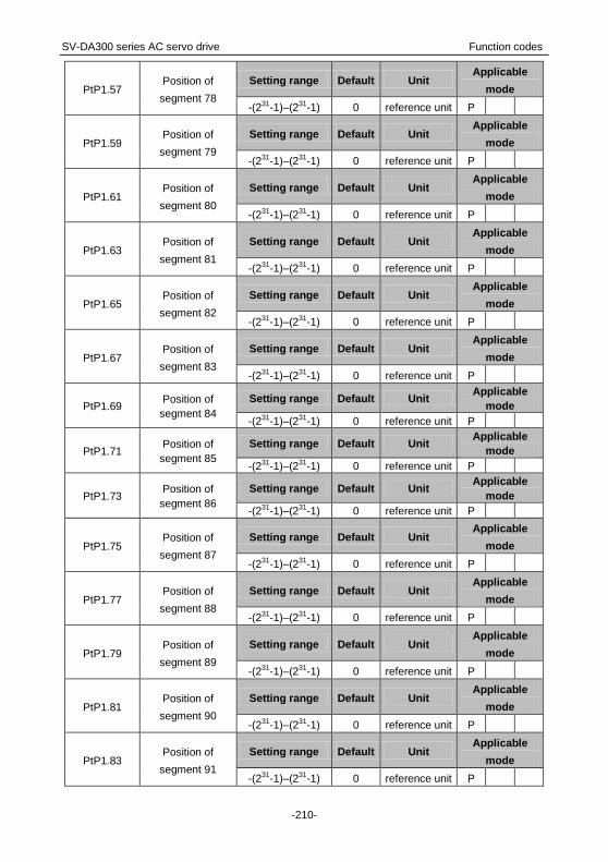
SV-DA300 series AC servo drive Function codes
-210-
PtP1.57 Position of
segment 78
Setting range Default Unit Applicable
mode
-(231-1)–(231-1) 0 reference unit P
PtP1.59 Position of
segment 79
Setting range Default Unit Applicable
mode
-(231-1)–(231-1) 0 reference unit P
PtP1.61 Position of
segment 80
Setting range Default Unit Applicable
mode
-(231-1)–(231-1) 0 reference unit P
PtP1.63 Position of
segment 81
Setting range Default Unit Applicable
mode
-(231-1)–(231-1) 0 reference unit P
PtP1.65 Position of
segment 82
Setting range Default Unit Applicable
mode
-(231-1)–(231-1) 0 reference unit P
PtP1.67 Position of
segment 83
Setting range Default Unit Applicable
mode
-(231-1)–(231-1) 0 reference unit P
PtP1.69 Position of
segment 84
Setting range Default Unit Applicable
mode
-(231-1)–(231-1) 0 reference unit P
PtP1.71 Position of
segment 85
Setting range Default Unit Applicable
mode
-(231-1)–(231-1) 0 reference unit P
PtP1.73 Position of
segment 86
Setting range Default Unit Applicable
mode
-(231-1)–(231-1) 0 reference unit P
PtP1.75 Position of
segment 87
Setting range Default Unit Applicable
mode
-(231-1)–(231-1) 0 reference unit P
PtP1.77 Position of
segment 88
Setting range Default Unit Applicable
mode
-(231-1)–(231-1) 0 reference unit P
PtP1.79 Position of
segment 89
Setting range Default Unit Applicable
mode
-(231-1)–(231-1) 0 reference unit P
PtP1.81 Position of
segment 90
Setting range Default Unit Applicable
mode
-(231-1)–(231-1) 0 reference unit P
PtP1.83 Position of
segment 91
Setting range Default Unit Applicable
mode
-(231-1)–(231-1) 0 reference unit P

SV-DA300 series AC servo drive Function codes
-211-
PtP1.85 Position of
segment 92
Setting range Default Unit Applicable
mode
-(231-1)–(231-1) 0 reference unit P
PtP1.87 Position of
segment 93
Setting range Default Unit Applicable
mode
-(231-1)–(231-1) 0 reference unit P
PtP1.89 Position of
segment 94
Setting range Default Unit Applicable
mode
-(231-1)–(231-1) 0 reference unit P
PtP1.91 Position of
segment 95
Setting range Default Unit Applicable
mode
-(231-1)–(231-1) 0 reference unit P
PtP1.93 Position of
segment 96
Setting range Default Unit Applicable
mode
-(231-1)–(231-1) 0 reference unit P
PtP1.95 Position of
segment 97
Setting range Default Unit Applicable
mode
-(231-1)–(231-1) 0 reference unit P
PtP1.97 Position of
segment 98
Setting range Default Unit Applicable
mode
-(231-1)–(231-1) 0 reference unit P
PtP1.99 Position of
segment 99
Setting range Default Unit Applicable
mode
-(231-1)–(231-1) 0 reference unit P
This group of parameter specifies the positions of segments 50 to 99. The CMD attribute
determines the position command mode of a segment. P0.37 is inapplicable to this group.
PtP1.01 Data size 32bit Data format DEC
Modbus address 3402, 3403 CANopen address 0x2C03, 0x00
PtP1.03 Data size 32bit Data format DEC
Modbus address 3406, 3407 CANopen address 0x2C03, 0x00
PtP1.05 Data size 32bit Data format DEC
Modbus address 3410, 3411 CANopen address 0x2C05, 0x00
PtP1.07 Data size 32bit Data format DEC
Modbus address 3414, 3415 CANopen address 0x2C07, 0x00
PtP1.09 Data size 32bit Data format DEC
Modbus address 3418, 3419 CANopen address 0x2C09, 0x00
PtP1.11 Data size 32bit Data format DEC
Modbus address 3422, 3423 CANopen address 0x2C0B, 0x00
PtP1.13 Data size 32bit Data format DEC
Modbus address 3426, 3427 CANopen address 0x2C0D, 0x00
PtP1.15 Data size 32bit Data format DEC

SV-DA300 series AC servo drive Function codes
-212-
Modbus address 3430, 3431 CANopen address 0x2C0F, 0x00
PtP1.17 Data size 32bit Data format DEC
Modbus address 3434, 3435 CANopen address 0x2C11, 0x00
PtP1.19 Data size 32bit Data format DEC
Modbus address 3438, 3439 CANopen address 0x2C13, 0x00
PtP1.21 Data size 32bit Data format DEC
Modbus address 3442, 3443 CANopen address 0x2C15, 0x00
PtP1.23 Data size 32bit Data format DEC
Modbus address 3446, 3447 CANopen address 0x2C17, 0x00
PtP1.25 Data size 32bit Data format DEC
Modbus address 3450, 3451 CANopen address 0x2C19, 0x00
PtP1.27 Data size 32bit Data format DEC
Modbus address 3454, 3455 CANopen address 0x2C1B, 0x00
PtP1.29 Data size 32bit Data format DEC
Modbus address 3458, 3459 CANopen address 0x2C1D, 0x00
PtP1.31 Data size 32bit Data format DEC
Modbus address 3462, 3463 CANopen address 0x2C1F, 0x00
PtP1.33 Data size 32bit Data format DEC
Modbus address 3466, 3467 CANopen address 0x2C21, 0x00
PtP1.35 Data size 32bit Data format DEC
Modbus address 3470, 3471 CANopen address 0x2C23, 0x00
PtP1.37 Data size 32bit Data format DEC
Modbus address 3474, 3475 CANopen address 0x2C25, 0x00
PtP1.39 Data size 32bit Data format DEC
Modbus address 3478, 3479 CANopen address 0x2C27, 0x00
PtP1.41 Data size 32bit Data format DEC
Modbus address 3482, 3483 CANopen address 0x2C29, 0x00
PtP1.43 Data size 32bit Data format DEC
Modbus address 3486, 3487 CANopen address 0x2C2B, 0x00
PtP1.45 Data size 32bit Data format DEC
Modbus address 3490, 3491 CANopen address 0x2C2D, 0x00
PtP1.47 Data size 32bit Data format DEC
Modbus address 3494, 3495 CANopen address 0x2C2F, 0x00
PtP1.49 Data size 32bit Data format DEC
Modbus address 3498, 3499 CANopen address 0x2C31, 0x00
PtP1.51 Data size 32bit Data format DEC
Modbus address 3502, 3503 CANopen address 0x2C33, 0x00
PtP1.53 Data size 32bit Data format DEC
Modbus address 3506, 3507 CANopen address 0x2C35, 0x00
PtP1.55 Data size 32bit Data format DEC

SV-DA300 series AC servo drive Function codes
-213-
Modbus address 3510, 3511 CANopen address 0x2C37, 0x00
PtP1.57 Data size 32bit Data format DEC
Modbus address 3514, 3515 CANopen address 0x2C39, 0x00
PtP1.59 Data size 32bit Data format DEC
Modbus address 3518, 3519 CANopen address 0x2C3B, 0x00
PtP1.61 Data size 32bit Data format DEC
Modbus address 3522, 3523 CANopen address 0x2C3D, 0x00
PtP1.63 Data size 32bit Data format DEC
Modbus address 3526, 3527 CANopen address 0x2C3F, 0x00
PtP1.65 Data size 32bit Data format DEC
Modbus address 3530, 3531 CANopen address 0x2C41, 0x00
PtP1.67 Data size 32bit Data format DEC
Modbus address 3534, 3535 CANopen address 0x2C43, 0x00
PtP1.69 Data size 32bit Data format DEC
Modbus address 3538, 3539 CANopen address 0x2C45, 0x00
PtP1.71 Data size 32bit Data format DEC
Modbus address 3542, 3543 CANopen address 0x2C47, 0x00
PtP1.73 Data size 32bit Data format DEC
Modbus address 3546, 3547 CANopen address 0x2C49, 0x00
PtP1.75 Data size 32bit Data format DEC
Modbus address 3550, 3551 CANopen address 0x2C4B, 0x00
PtP1.77 Data size 32bit Data format DEC
Modbus address 3554, 3555 CANopen address 0x2C4D, 0x00
PtP1.79 Data size 32bit Data format DEC
Modbus address 3558, 3559 CANopen address 0x2C4F, 0x00
PtP1.81 Data size 32bit Data format DEC
Modbus address 3562, 3563 CANopen address 0x2C51, 0x00
PtP1.83 Data size 32bit Data format DEC
Modbus address 3566, 3567 CANopen address 0x2C53, 0x00
PtP1.85 Data size 32bit Data format DEC
Modbus address 3570, 3571 CANopen address 0x2C55, 0x00
PtP1.87 Data size 32bit Data format DEC
Modbus address 3574, 3575 CANopen address 0x2C57, 0x00
PtP1.89 Data size 32bit Data format DEC
Modbus address 3578, 3579 CANopen address 0x2C59, 0x00
PtP1.91 Data size 32bit Data format DEC
Modbus address 3582, 3583 CANopen address 0x2C5B, 0x00
PtP1.93 Data size 32bit Data format DEC
Modbus address 3586, 3587 CANopen address 0x2C5D, 0x00
PtP1.95 Data size 32bit Data format DEC

SV-DA300 series AC servo drive Function codes
-214-
Modbus address 3590, 3591 CANopen address 0x2C5F, 0x00
PtP1.97 Data size 32bit Data format DEC
Modbus address 3594, 3595 CANopen address 0x2C61, 0x00
PtP1.99 Data size 32bit Data format DEC
Modbus address 3598, 3599 CANopen address 0x2C63, 0x00
PtP2.00 Control word of
segment 100
Setting range Default Unit Applicable
mode
0–0x7FFFFFFF 0x00000000 - P
PtP2.02 Control word of
segment 101
Setting range Default Unit Applicable
mode
0–0x7FFFFFFF 0x00000000 - P
PtP2.04 Control word of
segment 102
Setting range Default Unit Applicable
mode
0–0x7FFFFFFF 0x00000000 - P
PtP2.06 Control word of
segment 103
Setting range Default Unit Applicable
mode
0–0x7FFFFFFF 0x00000000 - P
PtP2.08 Control word of
segment 104
Setting range Default Unit Applicable
mode
0–0x7FFFFFFF 0x00000000 - P
PtP2.10 Control word of
segment 105
Setting range Default Unit Applicable
mode
0–0x7FFFFFFF 0x00000000 - P
PtP2.12 Control word of
segment 106
Setting range Default Unit Applicable
mode
0–0x7FFFFFFF 0x00000000 - P
PtP2.14 Control word of
segment 107
Setting range Default Unit Applicable
mode
0–0x7FFFFFFF 0x00000000 - P
PtP2.16 Control word of
segment 108
Setting range Default Unit Applicable
mode
0–0x7FFFFFFF 0x00000000 - P
PtP2.18 Control word of
segment 109
Setting range Default Unit Applicable
mode
0–0x7FFFFFFF 0x00000000 - P
PtP2.20 Control word of
segment 110
Setting range Default Unit Applicable
mode
0–0x7FFFFFFF 0x00000000 - P
PtP2.22 Control word of
segment 111 Setting range Default Unit
Applicable
mode

SV-DA300 series AC servo drive Function codes
-215-
0–0x7FFFFFFF 0x00000000 - P
PtP2.24 Control word of
segment 112
Setting range Default Unit Applicable
mode
0–0x7FFFFFFF 0x00000000 - P
PtP2.26 Control word of
segment 113
Setting range Default Unit Applicable
mode
0–0x7FFFFFFF 0x00000000 - P
PtP2.28 Control word of
segment 114
Setting range Default Unit Applicable
mode
0–0x7FFFFFFF 0x00000000 - P
PtP2.30 Control word of
segment 115
Setting range Default Unit Applicable
mode
0–0x7FFFFFFF 0x00000000 - P
PtP2.32 Control word of
segment 116
Setting range Default Unit Applicable
mode
0–0x7FFFFFFF 0x00000000 - P
PtP2.34 Control word of
segment 117
Setting range Default Unit Applicable
mode
0–0x7FFFFFFF 0x00000000 - P
PtP2.36 Control word of
segment 118
Setting range Default Unit Applicable
mode
0–0x7FFFFFFF 0x00000000 - P
PtP2.38 Control word of
segment 119
Setting range Default Unit Applicable
mode
0–0x7FFFFFFF 0x00000000 - P
PtP2.40 Control word of
segment 120
Setting range Default Unit Applicable
mode
0–0x7FFFFFFF 0x00000000 - P
PtP2.42 Control word of
segment 121
Setting range Default Unit Applicable
mode
0–0x7FFFFFFF 0x00000000 - P
PtP2.44 Control word of
segment 122
Setting range Default Unit Applicable
mode
0–0x7FFFFFFF 0x00000000 - P
PtP2.46 Control word of
segment 123
Setting range Default Unit Applicable
mode
0–0x7FFFFFFF 0x00000000 - P
PtP2.48 Control word of
segment 124
Setting range Default Unit Applicable
mode
0–0x7FFFFFFF 0x00000000 - P

SV-DA300 series AC servo drive Function codes
-216-
PtP2.50 Control word of
segment 125
Setting range Default Unit Applicable
mode
0–0x7FFFFFFF 0x00000000 - P
PtP2.52 Control word of
segment 126
Setting range Default Unit Applicable
mode
0–0x7FFFFFFF 0x00000000 - P
PtP2.54 Control word of
segment 127
Setting range Default Unit Applicable
mode
0–0x7FFFFFFF 0x00000000 - P
This group of parameter specifies the control words of segments 100 to 127. For details, see the
description for PtP0.00.
PtP2.00 Data size 32bit Data format HEX
Modbus address 3600, 3601 CANopen address 0x2D00, 0x00
PtP2.02 Data size 32bit Data format HEX
Modbus address 3604, 3605 CANopen address 0x2D02, 0x00
PtP2.04 Data size 32bit Data format HEX
Modbus address 3608, 3609 CANopen address 0x2D04, 0x00
PtP2.06 Data size 32bit Data format HEX
Modbus address 3612, 3613 CANopen address 0x2D06, 0x00
PtP2.08 Data size 32bit Data format HEX
Modbus address 3616, 3617 CANopen address 0x2D08, 0x00
PtP2.10 Data size 32bit Data format HEX
Modbus address 3620, 3621 CANopen address 0x2D0A, 0x00
PtP2.12 Data size 32bit Data format HEX
Modbus address 3624, 3625 CANopen address 0x2D0C, 0x00
PtP2.14 Data size 32bit Data format HEX
Modbus address 3628, 3629 CANopen address 0x2D0E, 0x00
PtP2.16 Data size 32bit Data format HEX
Modbus address 3632, 3633 CANopen address 0x2D10, 0x00
PtP2.18 Data size 32bit Data format HEX
Modbus address 3636, 3637 CANopen address 0x2D12, 0x00
PtP2.20 Data size 32bit Data format HEX
Modbus address 3640, 3641 CANopen address 0x2D14, 0x00
PtP2.22 Data size 32bit Data format HEX
Modbus address 3644, 3645 CANopen address 0x2D16, 0x00
PtP2.24 Data size 32bit Data format HEX
Modbus address 3648, 3649 CANopen address 0x2D18, 0x00
PtP2.26 Data size 32bit Data format HEX
Modbus address 3652, 3653 CANopen address 0x2D1A, 0x00
PtP2.28 Data size 32bit Data format HEX

SV-DA300 series AC servo drive Function codes
-217-
Modbus address 3656, 3657 CANopen address 0x2D1C, 0x00
PtP2.30 Data size 32bit Data format HEX
Modbus address 3660, 3661 CANopen address 0x2D1E, 0x00
PtP2.32 Data size 32bit Data format HEX
Modbus address 3664, 3665 CANopen address 0x2D20, 0x00
PtP2.34 Data size 32bit Data format HEX
Modbus address 3668, 3669 CANopen address 0x2D22, 0x00
PtP2.36 Data size 32bit Data format HEX
Modbus address 3672, 3673 CANopen address 0x2D24, 0x00
PtP2.38 Data size 32bit Data format HEX
Modbus address 3676, 3677 CANopen address 0x2D26, 0x00
PtP2.40 Data size 32bit Data format HEX
Modbus address 3680, 3681 CANopen address 0x2D28, 0x00
PtP2.42 Data size 32bit Data format HEX
Modbus address 3684, 3685 CANopen address 0x2D2A, 0x00
PtP2.44 Data size 32bit Data format HEX
Modbus address 3688, 3689 CANopen address 0x2D2C, 0x00
PtP2.46 Data size 32bit Data format HEX
Modbus address 3692, 3693 CANopen address 0x2D2E, 0x00
PtP2.48 Data size 32bit Data format HEX
Modbus address 3696, 3697 CANopen address 0x2D30, 0x00
PtP2.50 Data size 32bit Data format HEX
Modbus address 3700, 3701 CANopen address 0x2D32, 0x00
PtP2.52 Data size 32bit Data format HEX
Modbus address 3704, 3705 CANopen address 0x2D34, 0x00
PtP2.54 Data size 32bit Data format HEX
Modbus address 3708, 3709 CANopen address 0x2D36, 0x00
PtP2.01 Position of
segment 100
Setting range Default Unit Applicable
mode
-(231-1)–(231-1) 0 reference unit P
PtP2.03 Position of
segment 101
Setting range Default Unit Applicable
mode
-(231-1)–(231-1) 0 reference unit P
PtP2.05 Position of
segment 102
Setting range Default Unit Applicable
mode
-(231-1)–(231-1) 0 reference unit P
PtP2.07 Position of
segment 103
Setting range Default Unit Applicable
mode
-(231-1)–(231-1)
0
reference unit
P

SV-DA300 series AC servo drive Function codes
-218-
PtP2.09 Position of
segment 104
Setting range Default Unit Applicable
mode
-(231-1)–(231-1) 0 reference unit P
PtP2.11 Position of
segment 105
Setting range Default Unit Applicable
mode
-(231-1)–(231-1) 0 reference unit P
PtP2.13 Position of
segment 106
Setting range Default Unit Applicable
mode
-(231-1)–(231-1) 0 reference unit P
PtP2.15 Position of
segment 107
Setting range Default Unit Applicable
mode
-(231-1)–(231-1) 0 reference unit P
PtP2.17 Position of
segment 108
Setting range Default Unit Applicable
mode
-(231-1)–(231-1) 0 reference unit P
PtP2.19 Position of
segment 109
Setting range Default Unit Applicable
mode
-(231-1)–(231-1) 0 reference unit P
PtP2.21 Position of
segment 110
Setting range Default Unit Applicable
mode
-(231-1)–(231-1) 0 reference unit P
PtP2.23 Position of
segment 111
Setting range Default Unit Applicable
mode
-(231-1)–(231-1) 0 reference unit P
PtP2.25 Position of
segment 112
Setting range Default Unit Applicable
mode
-(231-1)–(231-1) 0 reference unit P
PtP2.27 Position of
segment 113
Setting range Default Unit Applicable
mode
-(231-1)–(231-1) 0 reference unit P
PtP2.29 Position of
segment 114
Setting range Default Unit Applicable
mode
-(231-1)–(231-1) 0 reference unit P
PtP2.31 Position of
segment 115
Setting range Default Unit Applicable
mode
-(231-1)–(231-1) 0 reference unit P
PtP2.33 Position of
segment 116
Setting range Default Unit Applicable
mode
-(231-1)–(231-1) 0 reference unit P
PtP2.35 Position of
segment 117
Setting range Default Unit Applicable
mode
-(231-1)–(231-1)
0
reference unit
P

SV-DA300 series AC servo drive Function codes
-219-
PtP2.37 Position of
segment 118
Setting range Default Unit Applicable
mode
-(231-1)–(231-1) 0 reference unit P
PtP2.39 Position of
segment 119
Setting range Default Unit Applicable
mode
-(231-1)–(231-1) 0 reference unit P
PtP2.41 Position of
segment 120
Setting range Default Unit Applicable
mode
-(231-1)–(231-1) 0 reference unit P
PtP2.43 Position of
segment 121
Setting range Default Unit Applicable
mode
-(231-1)–(231-1) 0 reference unit P
PtP2.45 Position of
segment 122
Setting range Default Unit Applicable
mode
-(231-1)–(231-1) 0 reference unit P
PtP2.47 Position of
segment 123
Setting range Default Unit Applicable
mode
-(231-1)–(231-1) 0 reference unit P
PtP2.49 Position of
segment 124
Setting range Default Unit Applicable
mode
-(231-1)–(231-1) 0 reference unit P
PtP2.51 Position of
segment 125
Setting range Default Unit Applicable
mode
-(231-1)–(231-1) 0 reference unit P
PtP2.53 Position of
segment 126
Setting range Default Unit Applicable
mode
-(231-1)–(231-1) 0 reference unit P
PtP2.55 Position of
segment 127
Setting range Default Unit Applicable
mode
-(231-1)–(231-1) 0 reference unit P
This group of parameter specifies the positions of segments 100 to 127. The CMD attribute
determines the position command mode of a segment. P0.37 is inapplicable to this group.
PtP2.01 Data size 32bit Data format DEC
Modbus address 3602, 3603 CANopen address 0x2D01, 0x00
PtP2.03 Data size 32bit Data format DEC
Modbus address 3606, 3607 CANopen address 0x2D03, 0x00
PtP2.05 Data size 32bit Data format DEC
Modbus address 3610, 3611 CANopen address 0x2D05, 0x00
PtP2.07 Data size 32bit Data format DEC
Modbus address 3614, 3615 CANopen address 0x2D07, 0x00

SV-DA300 series AC servo drive Function codes
-220-
PtP2.09 Data size 32bit Data format DEC
Modbus address 3618, 3619 CANopen address 0x2D09, 0x00
PtP2.11 Data size 32bit Data format DEC
Modbus address 3622, 3623 CANopen address 0x2D0B, 0x00
PtP2.13 Data size 32bit Data format DEC
Modbus address 3626, 3627 CANopen address 0x2D0D, 0x00
PtP2.15 Data size 32bit Data format DEC
Modbus address 3630, 3631 CANopen address 0x2D0F, 0x00
PtP2.17 Data size 32bit Data format DEC
Modbus address 3634, 3635 CANopen address 0x2D11, 0x00
PtP2.19 Data size 32bit Data format DEC
Modbus address 3638, 3639 CANopen address 0x2D13, 0x00
PtP2.21 Data size 32bit Data format DEC
Modbus address 3642, 3643 CANopen address 0x2D15, 0x00
PtP2.23 Data size 32bit Data format DEC
Modbus address 3646, 3647 CANopen address 0x2D17, 0x00
PtP2.25 Data size 32bit Data format DEC
Modbus address 3650, 3651 CANopen address 0x2D19, 0x00
PtP2.27 Data size 32bit Data format DEC
Modbus address 3654, 3655 CANopen address 0x2D1B, 0x00
PtP2.29 Data size 32bit Data format DEC
Modbus address 3658, 3659 CANopen address 0x2D1D, 0x00
PtP2.31 Data size 32bit Data format DEC
Modbus address 3662, 3663 CANopen address 0x2D1F, 0x00
PtP2.33 Data size 32bit Data format DEC
Modbus address 3666, 3667 CANopen address 0x2D21, 0x00
PtP2.35 Data size 32bit Data format DEC
Modbus address 3670, 3671 CANopen address 0x2D23, 0x00
PtP2.37 Data size 32bit Data format DEC
Modbus address 3674, 3675 CANopen address 0x2D25, 0x00
PtP2.39 Data size 32bit Data format DEC
Modbus address 3678, 3679 CANopen address 0x2D27, 0x00
PtP2.41 Data size 32bit Data format DEC
Modbus address 3682, 3683 CANopen address 0x2D29, 0x00
PtP2.43 Data size 32bit Data format DEC
Modbus address 3686, 3687 CANopen address 0x2D2B, 0x00
PtP2.45 Data size 32bit Data format DEC
Modbus address 3690, 3691 CANopen address 0x2D2D, 0x00
PtP2.47 Data size 32bit Data format DEC
Modbus address 3694, 3695 CANopen address 0x2D2F, 0x00

SV-DA300 series AC servo drive Function codes
-221-
PtP2.49 Data size 32bit Data format DEC
Modbus address 3698, 3699 CANopen address 0x2D31, 0x00
PtP2.51 Data size 32bit Data format DEC
Modbus address 3702, 3703 CANopen address 0x2D33, 0x00
PtP2.53 Data size 32bit Data format DEC
Modbus address 3706, 3707 CANopen address 0x2D35, 0x00
PtP2.55 Data size 32bit Data format DEC
Modbus address 3710, 3711 CANopen address 0x2D37, 0x00
6.9 Status monitoring
6.9.1 System monitoring (group R0)
R0.00 Motor speed Setting range Accuracy Unit
-9999.9–9999.9 0.1 r/min
This parameter displays the actual oration speed of the motor.
Note: Filtering is executed for the display.
R0.00 Data size 32bit Data format DEC
Modbus address 4000, 4001 CANopen address 0x3000, 0x00
R0.01 Speed command Setting range Accuracy Unit
-9999.9–9999.9 0.1 r/min
This parameter displays the current speed command of the servo motor.
Note: If the ACC/DEC time function is enabled, the command indicates the command that is
executed after the ACC/DEC.
R0.01 Data size 32bit Data format DEC
Modbus address 4002, 4003 CANopen address 0x3001, 0x00
R0.02 Accumulated feedback
pulses
Setting range Accuracy Unit
-(263-1)–(263-1) 1 reference unit
This parameter accumulates and displays the feedback pulses (with signs) of the servo motor.
R0.02
Data size 64bit Data format DEC
Modbus address 4004, 4005, 4006, 4007
CANopen address 0x3002, 0x00 0x3002, 0x01
R0.03 Accumulated command
pulses
Setting range Accuracy Unit
-(263-1)–(263-1) 1 reference unit
This parameter accumulates and displays the position command pulses with signs.
R0.03
Data size 64bit Data format DEC
Modbus address 4008, 4009, 4010, 4011
CANopen address 0x3003, 0x00 0x3003, 0x01

SV-DA300 series AC servo drive Function codes
-222-
R0.04 Residual pulses Setting range Accuracy Unit
-(231-1)–(231-1) 1 reference unit
This parameter displays the residual pulses with signs of the position deviation counter.
R0.04 Data size 32bit Data format DEC
Modbus address 4012, 4013 CANopen address 0x3004, 0x00
R0.05 Hybrid control deviation Setting range Accuracy Unit
-(231-1)–(231-1) 1 reference unit
This parameter displays the tolerance with a sign between the encoder feedback position and
grating ruler feedback position when the fully-closed loop function is enabled.
R0.05 Data size 32bit Data format DEC
Modbus address 4014, 4015 CANopen address 0x3005, 0x00
R0.06 Current torque Setting range Accuracy Unit
-500.0–500.0 0.1 %
This parameter displays the current torque, which is expressed in percentage, assuming the servo
motor rated torque is 100.0%.
R0.06 Data size 16bit Data format DEC
Modbus address 4016, 4017 CANopen address 0x3006, 0x00
R0.07 Main circuit DC voltage Setting range Accuracy Unit
0.0–1000.0 0.1 V
This parameter displays the DC bus voltage of the main circuit power.
R0.07 Data size 16bit Data format DEC
Modbus address 4018, 4019 CANopen address 0x3007, 0x00
R0.09 Output voltage Setting range Accuracy Unit
0.0–1000.0 0.1 Vrms
This parameter displays the current output line voltage.
R0.09 Data size 16bit Data format DEC
Modbus address 4022, 4023 CANopen address 0x3009, 0x00
R0.10 Output current Setting range Accuracy Unit
0.00–1000.00 0.01 Arms
This parameter displays the current output line current.
R0.10 Data size 32bit Data format DEC
Modbus address 4024, 4025 CANopen address 0x300A, 0x00

SV-DA300 series AC servo drive Function codes
-223-
R0.11 Drive temperature Setting range Accuracy Unit
-55.0–180.0 0.1 °C
This parameter displays the current temperature of the drive IGBT module.
R0.11 Data size 16bit Data format DEC
Modbus address 4026, 4027 CANopen address 0x300B, 0x00
R0.12 Torque limit Setting range Accuracy Unit
-500.0–500.0 0.1 %
This parameter displays the actual torque limit, which is expressed in percentage, assuming the
servo motor rated torque is 100.0%.
R0.12 Data size 16bit Data format DEC
Modbus address 4028, 4029 CANopen address 0x300C, 0x00
R0.13 Encoder feedback value Setting range Accuracy Unit
0–(231-1) 1 pulse
This parameter displays the current feedback value of the encoder.
R0.13 Data size 32bit Data format DEC
Modbus address 4030, 4031 CANopen address 0x300D, 0x00
R0.14 Rotor position relative to
pulse Z
Setting range Accuracy Unit
0–(231-1) 1 pulse
This parameter displays the absolute mechanical position of the motor in one encoder rotation
cycle. The unit is encoder resolution.
R0.14 Data size 32bit Data format DEC
Modbus address 4032, 4033 CANopen address 0x300E, 0x00
R0.15 Load inertia ratio Setting range Accuracy Unit
0–10000 1 %
This parameter displays the ratio of the load rotation inertia on the servo motor shaft to that on the
servo motor.
R0.15 Data size 16bit Data format DEC
Modbus address 4034, 4035 CANopen address 0x300F, 0x00
R0.16 Output power Setting range Accuracy Unit
-500.0–500.0 0.1 %
This parameter displays the current output mechanical power, which is expressed in percentage,
assuming the servo motor rated power is 100%.
Note: A negative value indicates the motor is in power generation state.

SV-DA300 series AC servo drive Function codes
-224-
R0.16 Data size 16bit Data format DEC
Modbus address 4036, 4037 CANopen address 0x3010, 0x00
R0.17 Motor load ratio Setting range Accuracy Unit
0.0–500.0 0.1 %
This parameter displays the actual motor load ratio, which is expressed in percentage, assuming
the servo motor rated power is 100%.
R0.17 Data size 16bit Data format DEC
Modbus address 4038, 4039 CANopen address 0x3011, 0x00
R0.18 Numerator of actual
electronic gear ratio
Setting range Accuracy Unit
0–(231-1) 1 -
This parameter displays the numerator of the actual electronic gear ratio.
R0.18 Data size 32bit Data format DEC
Modbus address 4040, 4041 CANopen address 0x3012, 0x00
R0.19 Denominator of actual
electronic gear ratio
Setting range Accuracy Unit
1–(231-1) 1 -
This parameter displays the denominator of actual electronic gear ratio.
R0.19 Data size 32bit Data format DEC
Modbus address 4042, 4043 CANopen address 0x3013, 0x00
R0.20 Position command
speed
Setting range Accuracy Unit
-9999.9–9999.9 0.1 r/min
This parameter displays the speed corresponding to a position command.
R0.20 Data size 32bit Data format DEC
Modbus address 4044, 4045 CANopen address 0x3014, 0x00
R0.21 Filtered motor speed Setting range Accuracy Unit
-9999.9–9999.9 0.1 r/min
This parameter displays the rotation speed that is used after filtering is executed for the servo
motor.
R0.21 Data size 32bit Data format DEC
Modbus address 4046, 4047 CANopen address 0x3015, 0x00
R0.22 PTP status Setting range Accuracy Unit
-1–4223 1 -
This parameter displays the status of PTP control. The value -1 indicates PTP control is not
executed. Any value from 0 to 127 indicates the number of segment that is being executed. A

SV-DA300 series AC servo drive Function codes
-225-
segment number plus 4096 indicates the current segment has been executed.
R0.22 Data size 16bit Data format DEC
Modbus address 4048, 4049 CANopen address 0x3016, 0x00
R0.23 Encoder absolute
position feedback
Setting range Accuracy Unit
-(231-1)–(231-1) 1 pulse
This parameter displays the encoder absolute position feedback. After absolute position clearing is
executed, the setting of this parameter is 0.
R0.23 Data size 32bit Data format DEC
Modbus address 4050, 4051 CANopen address 0x3017, 0x00
R0.24 Encoder EEPROM
status
Setting range Accuracy Unit
0–3 - -
This parameter displays the EEPROM status of the absolute encoder. If motor parameter data is
not found in EEPROM or incorrect, the system uses the internal motor parameters of the drive.
Setting Meaning
[0] No EEPROM
1 No data found in the EEPROM
2 EEPROM data error
3 Data in the EEPROM is valid.
R0.24 Data size 16bit Data format DEC
Modbus address 4052, 4053 CANopen address 0x3018, 0x00
R0.25 Turns of multiturn
encoder
Setting range Accuracy Unit
-32768–32767 1 -
This parameter displays the number of turns of the multiturn encoder.
R0.25 Data size 16bit Data format DEC
Modbus address 4054, 4055 CANopen address 0x3019, 0x00
R0.26 Encoder type Setting range Accuracy Unit
0–6 - -
This parameter displays the type of encoder supported by the hardware circuit.
Setting Meaning
[3] Photoelectric encoder
5 Rotary encoder
Other Reserved
R0.26 Data size 16bit Data format DEC
Modbus address 4056, 4057 CANopen address 0x301A, 0x00

SV-DA300 series AC servo drive Function codes
-226-
R0.27 EtherCAT clock
synchronization status
Setting range Accuracy Unit
0–1 - -
This parameter displays whether the drive internal clock has been synchronized with DC Sync0 in
DC mode which is used for EtherCAT communication synchronization.
Setting Meaning
[0] Not synchronized
1 Synchronized
R0.27 Data size 16bit Data format DEC
Modbus address 4058, 4059 CANopen address 0x301B, 0x00
R0.28 CANopen status
machine
Setting range Accuracy Unit
0–18 - -
This parameter displays the current status of the internal CANopen status machine when CAN is
used for communication or that of the CANopen over EtherCAT (CoE) status machine when
EtherCAT is used for communication.
Setting Protocol Status
[0] - Invalid
1
CAN
Init
2 Pre-Op
5 Stop
8 Op (that is, Operational)
11
EtherCAT
Init
12 Pre-Op
14 Safe-Op
18 Op
R0.28 Data size 16bit Data format DEC
Modbus address 4060, 4061 CANopen address 0x301C, 0x00
R0.30 System status Setting range Accuracy Unit
0–6 - -

SV-DA300 series AC servo drive Function codes
-227-
This parameter displays the system status of the drive.
Setting Meaning
[0] Initializing
1 Switching on strong current
2 Magnetic pole not
determined
3 Ready
4 Bootstrapped charging
5 Running
6 Forced to stop
7 Faulty
8 STO-In
R0.30 Data size 16bit Data format DEC
Modbus address 4064, 4065 CANopen address 0x301E, 0x00
R0.31 IGBT status Setting range Accuracy Unit
0–1 - -
This parameter displays the IGBT status.
Setting Meaning
[0] Closed
1 Open
R0.31 Data size 16bit Data format DEC
Modbus address 4066, 4067 CANopen address 0x301F, 0x00
R0.32 Current mode Setting range Accuracy Unit
0–2 - -
This parameter displays the control mode that the drive uses currently.
Setting Meaning
[0] Position mode
1 Speed mode
2 Torque mode
R0.32 Data size 16bit Data format DEC
Modbus address 4068, 4069 CANopen address 0x3020, 0x00
R0.33 Power-on time Setting range Accuracy Unit
0–(231-1) 1 s
This parameter displays the total power-on time used by the drive.
R0.33 Data size 32bit Data format DEC
Modbus address 4070, 4071 CANopen address 0x3021, 0x00

SV-DA300 series AC servo drive Function codes
-228-
R0.34 Enabling time Setting range Accuracy Unit
0–(231-1) 1 s
This parameter displays the time used by the drive to enable the servo.
R0.34 Data size 32bit Data format DEC
Modbus address 4072, 4073 CANopen address 0x3022, 0x00
R0.35 DSP version no. Setting range Accuracy Unit
0.00–10.00 0.01 -
This parameter displays the DSP version number.
R0.35 Data size 16bit Data format DEC
Modbus address 4074, 4075 CANopen address 0x3023, 0x00
R0.36 FPGA version no. Setting range Accuracy Unit
0.00–10.00 0.01 -
This parameter displays the current FPGA version number.
R0.36 Data size 16bit Data format DEC
Modbus address 4076, 4077 CANopen address 0x3024, 0x00
R0.38 Drive SN 1 Setting range Accuracy Unit
0–65535 1 -
This parameter displays drive series number 1.
R0.38 Data size 16bit Data format DEC
Modbus address 4080, 4081 CANopen address 0x3026, 0x00
R0.39 Drive SN 2 Setting range Accuracy Unit
0–65535 1 -
This parameter displays drive series number 2.
R0.39 Data size 16bit Data format DEC
Modbus address 4082, 4083 CANopen address 0x3027, 0x00
R0.40 Drive SN 3 Setting range Accuracy Unit
0–65535 1 -
This parameter displays drive series number 3.
R0.40 Data size 16bit Data format DEC
Modbus address 4084, 4085 CANopen address 0x3028, 0x00

SV-DA300 series AC servo drive Function codes
-229-
R0.41 Drive SN 4 Setting range Accuracy Unit
0–65535 1 -
This parameter displays drive series number 4.
R0.41 Data size 16bit Data format DEC
Modbus address 4086, 4087 CANopen address 0x3029, 0x00
R0.42 Drive SN 5 Setting range Accuracy Unit
0–65535 1 -
This parameter displays drive series number 5.
R0.42 Data size 16bit Data format DEC
Modbus address 4088, 4089 CANopen address 0x302A, 0x00
R0.43 Drive SN 6 Setting range Accuracy Unit
0–65535 1 -
This parameter displays drive series number 6.
R0.43 Data size 16bit Data format DEC
Modbus address 4090, 4091 CANopen address 0x302B, 0x00
R0.44
Absolute position in
single grating ruler (or
encoder 2) turn
Setting range Accuracy Unit
0–(231-1) 1 pulse
This parameter displays the feedback of the absolute position in a single turn of the grating ruler
(or second encoder).
R0.44 Data size 32bit Data format DEC
Modbus address 4092, 4093 CANopen address 0x302C, 0x00
R0.45 Speed feedback from
encoder 2
Setting range Accuracy Unit
-9999.9–9999.9 0.1 r/min
This parameter displays the actual speed of the servo motor.
R0.45 Data size 32bit Data format DEC
Modbus address 4094, 4095 CANopen address 0x302D, 0x00
R0.46 Speed observer
detection
Setting range Accuracy Unit
-9999.9–9999.9 0.1 r/min
This parameter displays the detected speed from the speed observer.
R0.46 Data size 32bit Data format DEC
Modbus address 4096, 4097 CANopen address 0x302E, 0x00

SV-DA300 series AC servo drive Function codes
-230-
R0.47 Speed observer
feedback
Setting range Accuracy Unit
-9999.9–9999.9 0.1 r/min
This parameter displays the feedback speed from the speed observer.
R0.47 Data size 32bit Data format DEC
Modbus address 4098, 4099 CANopen address 0x302F, 0x00
R0.48 Torque from disturbance
observer
Setting range Accuracy Unit
-1000.0–1000.0 0.1 %
This parameter displays the compensation torque from the disturbance observer.
R0.48 Data size 32bit Data format DEC
Modbus address 4100, 4101 CANopen address 0x3030, 0x00
R0.49
Fully-closed loop
vibration suppressor
compensation
Setting range Accuracy Unit
-9999.9–9999.9 0.1 r/min
This parameter displays the compensation from the fully-closed loop vibration suppressor.
R0.49 Data size 32bit Data format DEC
Modbus address 4102, 4103 CANopen address 0x3031, 0x00
R0.51 Real-time load inertia
ratio
Setting range Accuracy Unit
0–10000 1 %
This parameter displays the load inertia ratio observed in real time.
R0.51 Data size 16bit Data format DEC
Modbus address 4106, 4107 CANopen address 0x3033, 0x00
R0.52
Accumulated grating
ruler (or encoder 2)
position feedback
(32-bit)
Setting range Accuracy Unit
-(231-1)–(231-1) 1 pulse
This parameter accumulates and displays the 32-bit absolute position feedback from the grating
ruler (or second encoder). It can be read quickly. If the feedback exceeds 32 bits, it is replaced by
R0.57.
R0.52 Data size 32bit Data format DEC
Modbus address 4108, 4109 CANopen address 0x3034, 0x00

SV-DA300 series AC servo drive Function codes
-231-
R0.53 Gantry synchronization
position deviation
Setting range Accuracy Unit
-(231-1)–(231-1) 1 reference unit
This parameter displays the gantry synchronization position deviation.
R0.53 Data size 32bit Data format DEC
Modbus address 4110, 4111 CANopen address 0x3035, 0x00
R0.54 Grating ruler (or encoder
2) position feedback
Setting range Accuracy Unit
0–(231-1) 1 pulse
This parameter displays the position feedback from the grating ruler (or second encoder).
R0.54 Data size 32bit Data format DEC
Modbus address 4112, 4113 CANopen address 0x3036, 0x00
R0.55
Encoder turn deviation
after multiturn position
cleared
Setting range Accuracy Unit
-(231-1)–(231-1) 1 -
This parameter displays the encoder turn deviation after multiturn positions are cleared.
R0.55 Data size 32bit Data format DEC
Modbus address 4114, 4115 CANopen address 0x3037, 0x00
R0.56
Encoder feedback
deviation after multiturn
position cleared
Setting range Accuracy Unit
-(231-1)–(231-1) 1 pulse
This parameter displays the encoder feedback deviation after multiturn positions are cleared.
R0.56 Data size 32bit Data format DEC
Modbus address 4116, 4117 CANopen address 0x3038, 0x00
R0.57
Accumulated grating
ruler (or encoder 2)
position feedback
(64-bit)
Setting range Accuracy Unit
-(263-1)–(263-1) 1 pulse
This parameter accumulates and displays the 64-bit absolute position feedback from the grating
ruler (or second encoder).
R0.57
Data size 64bit Data format DEC
Modbus address 4118, 4119,
4120, 4121 CANopen address
0x3039, 0x00
0x3039, 0x01

SV-DA300 series AC servo drive Function codes
-232-
R0.58 Disk single-turn position Setting range Accuracy Unit
-(231-1)–(231-1) 1 pulse
This parameter displays the position in a single turn of the disk based on the setting of P5.70.
R0.58 Data size 32bit Data format DEC
Modbus address 4122, 4123 CANopen address 0x303A, 0x00
R0.60 Medium-power motor
temperature
Setting range Accuracy Unit
-55–200 1 °C
This parameter displays the current temperature of the medium-power motor with temperature
resistor KTY84-130. Temperature is sampled only when P4.45 is not zero.
R0.60 Data size 32bit Data format DEC
Modbus address 4126, 4127 CANopen address 0x303C, 0x00
R0.61 Environment
temperature
Setting range Accuracy Unit
-55.0–180.0 0.1 °C
This parameter displays the current environment temperature.
R0.61 Data size 16bit Data format DEC
Modbus address 4028, 4029 CANopen address 0x303D, 0x00
R0.99 Fault code Setting range Accuracy Unit
-32768–32767 1 -
This parameter displays the fault code, in which the thousands and hundreds digits are the main
fault code and the tens and ones digits are the sub fault code.
R0.99 Data size 16bit Data format DEC
Modbus address 4198, 4199 CANopen address 0x3063, 0x00

SV-DA300 series AC servo drive Function codes
-233-
6.9.2 I/O monitoring (group R1)
R1.00 Digital input status Setting range Accuracy Unit
0x000–0x3FF - -
R1.01 Digital output status Setting range Accuracy Unit
0x00–0x3F - -
Each of the parameters is a hexadecimal number, indicating the status of all digital terminals in
sequence. The terminal status ON is expressed by 1, while the terminal status OFF is expressed
by 0. Then the decimal number is converted to a hexadecimal number.
The digital input status is expressed by a three-bit hexadecimal number. The sorting order of digital
input is as follows:
(The bits not listed are padded with 0.)
BIT9 BIT
8
BIT
7 BIT6 BIT5 BIT4 BIT3 BIT2 BIT1 BIT0
SI10 SI9 SI8 SI7 SI6 SI5 SI4 SI3 SI2 SI1
The digital output status is expressed by a two-bit hexadecimal number. The sorting order of digital
output is as follows:
(The bits not listed are padded with 0.)
BIT5 BIT4 BIT3 BIT2 BIT1 BIT0
SO6 SO5 SO4 SO3 SO2 SO1
R1.00 Data size 16bit Data format HEX
Modbus address 4200, 4201 CANopen address 0x3100, 0x00
R1.01 Data size 16bit Data format HEX
Modbus address 4202, 4203 CANopen address 0x3101, 0x00
R1.02 Raw voltage of AI 1 Setting range Accuracy Unit
-10.000–10.000 0.001 V
This parameter displays the unprocessed voltage of the analog input channel 1.
R1.02 Data size 32bit Data format DEC
Modbus address 4204, 4205 CANopen address 0x3102, 0x00
R1.03 Raw voltage of AI 2 Setting range Accuracy Unit
-10.000–10.000 0.001 V
This parameter displays the unprocessed voltage of the analog input channel 2.
R1.03 Data size 32bit Data format DEC
Modbus address 4206, 4207 CANopen address 0x3103, 0x00

SV-DA300 series AC servo drive Function codes
-234-
R1.05 Corrected voltage of AI 1 Setting range Accuracy Unit
-10.000–10.000 0.001 V
This parameter displays the corrected voltage of the analog input channel 1.
R1.05 Data size 32bit Data format DEC
Modbus address 4210, 4211 CANopen address 0x3105, 0x00
R1.06 Corrected voltage of AI 2 Setting range Accuracy Unit
-10.000–10.000 0.001 V
This parameter displays the corrected voltage of the analog input channel 2.
R1.06 Data size 32bit Data format DEC
Modbus address 4212, 4213 CANopen address 0x3106, 0x00
R1.08 Voltage of AO 1 Setting range Accuracy Unit
-10.000–10.000 0.001 V
This parameter displays the biased voltage of the analog output channel 1.
R1.08 Data size 32bit Data format DEC
Modbus address 4216, 4217 CANopen address 0x3108, 0x00
R1.09 Voltage of AO 2 Setting range Accuracy Unit
-10.000–10.000 0.001 V
This parameter displays the biased voltage of the analog output channel 2.
R1.09 Data size 32bit Data format DEC
Modbus address 4218, 4219 CANopen address 0x3109, 0x00
R1.11 Accumulated input
pulses
Setting range Accuracy Unit
-(231-1)–(231-1) 1 reference unit
This parameter accumulates and displays the number of pulses that are received from the external
pulse input.
R1.11 Data size 32bit Data format DEC
Modbus address 4222, 4223 CANopen address 0x310B, 0x00
R1.12 Pulse position command Setting range Accuracy Unit
-(231-1)–(231-1) 1 reference unit
This parameter displays the position command value in each pulse input detection cycle (0.125ms
by default).
R1.12 Data size 32bit Data format DEC
Modbus address 4224, 4225 CANopen address 0x310C, 0x00

SV-DA300 series AC servo drive Function codes
-235-
R1.13 Pulse-corresponded
speed command
Setting range Accuracy Unit
-10000.0–10000.0 0.1 r/min
This parameter displays the speed command corresponding to the pulse position command.
R1.13 Data size 32bit Data format DEC
Modbus address 4226, 4227 CANopen address 0x310D, 0x00
R1.14 Analog compensation
speed
Setting range Accuracy Unit
-10000.0–10000.0 0.1 r/min
This parameter displays the analog compensation speed.
R1.14 Data size 32bit Data format DEC
Modbus address 4228, 4229 CANopen address 0x310E, 0x00
R1.15 Analog compensation
torque
Setting range Accuracy Unit
-1000.0–1000.0 0.1 %
This parameter displays the analog compensation torque.
R1.15 Data size 32bit Data format DEC
Modbus address 4230, 4231 CANopen address 0x310F, 0x00
R1.16 DI-captured encoder
value
Setting range Accuracy Unit
-(231-1)–(231-1) 1 pulse
This parameter displays the encoder value captured through DI input.
R1.16 Data size 32bit Data format DEC
Modbus address 4232, 4233 CANopen address 0x3110, 0x00
6.9.3 Fault recording (group R3)
R3.00 Fault code Setting range Accuracy Unit
- - -
This parameter displays the code of the currently-read fault record.
It contains the information on the last fault by default.
R3.01 Power-on time before
fault
Setting range Accuracy Unit
0–(231-1) 1 h
This parameter displays the time used for power-on before the currently-read fault occurred.
R3.02 Running time before
fault
Setting range Accuracy Unit
0–(231-1) 1 h
This parameter displays the running time before the currently-read fault occurred.

SV-DA300 series AC servo drive Function codes
-236-
R3.03 Motor speed before fault Setting range Accuracy Unit
-20000–20000 1 r/min
This parameter displays the motor speed before the currently-read fault occurred.
R3.04 Speed command before
fault
Setting range Accuracy Unit
-20000–20000 1 r/min
This parameter displays the speed command before the fault occurred.
R3.05 Accumulated feedback
pulses before fault
Setting range Accuracy Unit
-(263-1)–(263-1) 1 reference unit
This parameter displays the feedback pulses that are accumulated before the currently-read fault
occurred.
R3.06 Accumulated command
pulses before fault
Setting range Accuracy Unit
-(263-1)–(263-1) 1 reference unit
This parameter displays the command pulses that are accumulated before the currently-read fault
occurred.
R3.07 Residual pulses before
fault
Setting range Accuracy Unit
-(231-1)–(231-1) 1 reference unit
This parameter displays the residual pulses before the currently-read fault occurred.
R3.08 Output torque before
fault
Setting range Accuracy Unit
-500.0–500.0 0.1 %
This parameter displays the torque output before the currently-read fault occurred.
R3.09 Main circuit DC voltage
before fault
Setting range Accuracy Unit
0.0–1000.0 0.1 V
This parameter displays the main-circuit DC voltage before the currently-read fault occurred.
R3.10 Output voltage before
fault
Setting range Accuracy Unit
0.0–1000.0 0.1 Vrms
This parameter displays the drive output line voltage before the currently-read fault occurred.
R3.11 Output current before
fault
Setting range Accuracy Unit
0.00–1000.00 0.01 Arms
This parameter displays the drive output line current before the currently-read fault occurred.

SV-DA300 series AC servo drive Function codes
-237-
R3.20 Last fault code Setting range Accuracy Unit
- - -
This parameter displays the code of the last fault.
R3.21 2nd-last fault code Setting range Accuracy Unit
- - -
This parameter displays the code of the second-last fault.
R3.22 3rd-last fault code Setting range Accuracy Unit
- - -
This parameter displays the code of the third-last fault.
R3.23 4th-last fault code Setting range Accuracy Unit
- - -
This parameter displays the code of the fourth-last fault.
R3.24 5th-last fault code Setting range Accuracy Unit
- - -
This parameter displays the code of the fifth-last fault.
R3.25 6th-last fault code Setting range Accuracy Unit
- - -
This parameter displays the code of the sixth-last fault.
R3.26 7th-last fault code Setting range Accuracy Unit
- - -
This parameter displays the code of the seventh-last fault.
R3.27 8th-last fault code Setting range Accuracy Unit
- - -
This parameter displays the code of the eighth-last fault.
R3.28 9th-last fault code Setting range Accuracy Unit
- - -
This parameter displays the code of the ninth-last fault.
R3.29 10th-last fault code Setting range Accuracy Unit
- - -
This parameter displays the code of the tenth-last fault.

SV-DA300 series AC servo drive Commissioning
-238-
7 Commissioning
7.1 Instructions on identifying inertia ............................................................................................ 239 7.2 General methods for adjusting parameters ............................................................................. 240
7.2.1 Adjusting gains in position mode ........................................................................... 242
7.2.2 Adjusting gains in speed mode ............................................................................. 244
7.2.3 Adjusting gains in torque mode ............................................................................. 245 7.3 Mechanical resonance suppressing........................................................................................ 246 7.4 Gains switching ...................................................................................................................... 247

SV-DA300 series AC servo drive Commissioning
-239-
7.1 Instructions on identifying inertia
Inertia can be identified online or offline.
Identifying inertia online
Before selecting online inertia identifying, you must set the parameters P1.00 [Tune inertia online] and
P1.08 [Inertia identifying class].
The online identifying mode is valid when P1.00 and P1.08 are greater than 0. If the following inertia
identifying conditions are met:
The speed is higher than 150 r/min.
The ACC time is greater than 20ms.
The continuous ACC range exceeds 150 r/min.
The ACC is reached within 0.3s (from 0 r/min to 3000 r/min).
The inertia identifying result is automatically updated to P1.01[Inertia ratio 1] and written to the
EEPROM at an interval of 30 minutes.
Identifying inertia offline
Before selecting offline inertia identifying, you must set the parameters P1.05 [Inertia identifying
mode], P1.06 [Max. rotations by inertia identifying], and P1.07 [ACC time for inertia identifying]. You
can enable offline inertia identifying by using the auxiliary function EF-JId on the panel. For details,
see section 5.2.5.5 "Inertia identifying". Offline inertia identifying is not affected by P1.00 [Tune inertia
online] and P1.08 [Inertia identifying class].
Before enabling the auxiliary function EF-JId, set P1.05 based on the motor allowed running mode,
P1.06 based on the motor allowed rotations, and P1.07 based on the mechanical rigidity. Strong
mechanical rigidity allows you to set a small ACC/DEC time constant. P1.05 can be set to 1 indicating
forward rotating or 2 reverse rotating. If P1.06 is set to a greater value while P1.07 is set to a smaller
value, the inertia identifying result is more accurate.
In addition, ensure the settings of P1.05 and P1.06 are compliant with the mechanical structure.
Otherwise, mechanical damage may be caused. During the execution, you can press the Mode key
to terminate.
If the auxiliary function EF-JId is executed successfully, the identifying result is automatically saved to
P1.01 [Inertia ratio 1]. If a fault occurred during the identifying, P1.01 keeps the previous setting. If
fault Er25-7 [Inertia identifying failed] is reported, try to set P1.06 to a greater value or P1.07 to a
smaller value.
If the following occurs onsite:
• Low mechanical rigidity
• Sharp change on load inertia
• Non-linear characteristics such as clearance
• Sudden change on external disturbance
The inertia identifying result accuracy is impacted.

SV-DA300 series AC servo drive Commissioning
-240-
7.2 General methods for adjusting parameters
SV-DA300 servo drive parameters can be adjusted by two methods.
Automatic adjusting
You need to evaluate the load inertia ratio manually and set the servo system rigidity, which has 32
options from 0 to 31. Then different loop gains can be set automatically.
This method features quick adjusting servo system responsiveness.
Adjust the system rigidity based on the actual situation. The recommended rigidity settings are as
follows:
Mechanical structure Rigidity
Large transfer or transmission equipment 0–13
Belt drive mechanism 5–16
Ball screw + belt drive 5–16
Manipulator 15–22
Direct ball screw or rigid body 18–25
A greater rigidity value indicates quicker response, but it increases the possibility to cause noise and
vibration. You need to check the mechanical device actions before the setting.
If the setting cannot meet your requirements, use manual adjusting.
Manual adjusting
If the servo system encounters vibration or control performance cannot meet requirements, you can
adjust speed loop and position loop parameters to eliminate vibration or improve performance.
You can adjust the following parameters manually:
Speed loop gain: It determines the response speed of the speed loop. If the mechanical system has
no vibration, a greater speed loop gain indicates a quicker response speed.
Speed loop integral time constant: The speed loop contains the integral component, which can
respond to minor input. The integral component may delay servo system jobs. A greater time
constant indicates slower response, increasing positioning time. If load inertia is heavy or servo
system has a great possibility to encounter vibration, this time constant must be great. Otherwise,
the servo system may encounter vibration.
Torque command filtering: The mechanical system may encounter resonance, which causes sharp
vibration noise. At this time, you must use the notch filter to eliminate resonance.
APS gain: It determines the servo system responsiveness. A greater APS gain indicates a quicker
response speed, reducing positioning time. If you need to set the gain to a great value, the rigidity
and natural frequency of the mechanical system must be high.
Generally, the speed loop gain must be greater than the position loop gain. If the position loop gain is
much greater than the speed loop, the system may be overshot with the function of step signals,
therefore deteriorating system performance. System parameters are restricted mutually. If only the
position loop gain is increased, the commands output from the position loop may be unstable, which

SV-DA300 series AC servo drive Commissioning
-241-
may cause unstable responsiveness of the entire servo system. Perform adjusting in the following
sequence:
1. Set the position loop gain to a small value and increase it to a value as large as possible without
causing abnormal noise or vibration.
2. Decrease the speed loop gain gradually and increase the position loop gain as much as allowed
without causing overshooting or vibration.
3. Decrease the speed loop integral time constant as much as possible without causing vibration
since this time constant is determined by positioning time.
4. Adjust the position loop gain, speed loop gain, and speed loop integral time constant slightly to
achieve optimum settings.
The following describes typical adjusting cases (in the cases except case 1, only one parameter
needs to be adjusted):
Appropriate parameter settings
In this case, parameters are set appropriately, the motor speed is compliant with the position
command, the speed is not overshot, and positioning time is short.
Speed loop integral time constant too small
The servo drive speed loop must respond quickly. If the speed fluctuates, the speed loop integral time
constant is too small, which deteriorates the speed loop stableness. Therefore, the running is
unstable.
Speed loop integral time constant too large
The difference from the case of appropriate parameter settings is not noticeable. The speed loop
integral has no significant impact when the speed follows up the position command, but the response
time of the speed loop is impacted if the speed loop integral time constant is too large.
Speed loop gain too high
In this case, the motor speed fluctuates. If the speed loop integral time is too short, the similar impact
is caused. You must increase both the speed loop gain and the speed loop integral time. Otherwise,
the servo system may encounter vibration.
Speed loop gain too low
If the speed loop gain is decreased, the motor speed fluctuates. According to the comparison the
case of speed loop gain too large, the fluctuation frequency of the motor speed is lower in this case,
which indicates that increasing the speed loop gain improves the system working frequency, control
system responsiveness, and anti-interference.
Position loop gain too low
In the servo system, the working frequency of the position loop is lower than that of the speed loop. If
the position loop gain is too low, the system cannot counteract the position deviation that is caused
during speed responding, which delays the interval at which the motor speed follows up the position
command.

SV-DA300 series AC servo drive Commissioning
-242-
Position loop gain too high
In the position servo system, the position loop gain also impacts stableness. If the position loop gain
is too high, the motor speed fluctuates. According to the comparison with the case of position loop
gain too low, the delay with which the motor speed follows up the position command is decreased in
this case.
Position loop gain too low
If the position loop gain is too low, the motor speed lags behind the position command noticeably, and
positioning time is prolonged. The accuracy and response performance of the positioning system are
impacted seriously.
7.2.1 Adjusting gains in position mode
Semi-closed loop
The following block diagram illustrates semi-closed loop control for SV-DA300 servo drive and lists
the adjustable gain parameters in this control mode.
Current
controller
Position command
P2.10
P2.11
P2.02
P2.07
P1.29
P1.30
P2.04
P1.31
P1.32
P2.03
P1.33
P1.34
P2.09
P2.08
P2.12
P2.13
P2.42
P2.43
P1.23
P1.24
P1.25
P1.26
P1.27
P1.28
P1.19 P1.20
P2.20
P2.22P2.71
P2.72
P2.73
P2.24
P2.25
P2.23 P2.26
P0.09
P0.10
P0.11
P4.53
P4.51
P4.52
P0.27
P0.28
P0.29
P0.33
P0.34
P1.35
P1.36
P0.25
P0.26P0.22
P1.37
P1.38
P1.39
P2.70
P2.41
Encoder
Torque limit
Torque filterNotch filter
Gain
switchingFriction
compensationTorque
feedforward
Speed
controller
Speed
feedforward
P2.00
P2.01
P1.02
P1.01
P2.06
P2.05
Disturbance
control
Speed
detection filter
P0.06
P0.07
P0.08
Frequency division output
Position command
vibration control
Position
smoothing filter
Position
controller
Electronic
gear
Motor
Fully-closed loop
The following block diagram illustrates fully-closed loop control for SV-DA300 servo drive and lists the
adjustable gain parameters in this control mode.

SV-DA300 series AC servo drive Commissioning
-243-
P2.10
P2.11
P2.02
P2.07
P1.29
P1.30
P2.04
P1.31
P1.32
P2.03
P2.00
P2.01
P1.33
P1.34
P2.09
P2.08
P2.12
P2.13
P0.06
P0.07
P0.08
P2.42
P2.43
P1.23
P1.24
P1.25
P1.26
P1.27
P1.28
P1.19 P1.20
P2.20
P2.22P2.71
P2.72
P2.73
P2.24
P2.25
P2.23 P2.26
P0.09
P0.10
P0.11
P4.53
P4.51
P4.52
P4.67
P4.60
P4.61
P4.62
Position command
P0.27
P0.28
P0.29
P0.33
P0.34
P1.35
P1.36
P0.25
P0.26P0.22
P1.37
P1.38
P1.39
P2.70
P2.41
Electronic
gearSpeed
feedforward
Torque
feedforward
Friction
compensation
Gain
switching
Position
command
vibration control
Position
smoothing
filter
Position
controllerTorque filterNotch filter
Speed
controller
Torque limit
Frequency-
division outputEncoder Motor
Grating ruler
Disturbance
control
Current
controller
Speed
detection
filter
Hybrid-control
deviation
calculation
P1.02
P1.01
P2.06
P2.05
Frequency-
division ratio of
grating ruler
P4.60
P4.61
Frequency-
division ratio of
grating ruler
P4.60
P4.61
The common procedure for adjusting parameters in position mode is as follows:
1. Restore default settings.
For details, see section 5.2.5.3 "Factory parameter restoring".
2. Adjust the position loop gain.
If the servo motor runs with default settings but the system vibrates with buzzes, decrease the
position loop gain (that is, P2.02 or P2.07) or increase it when the system rigidity is low.
3. Adjust the position smoothing filter.
In position control, if the input frequency changes of position pulse commands are noticeable, huge
surges may be caused. You need to adjust the P0.33 [Position command smooth filter time] or P0.34
[Position command FIR filter time].
4. Adjust the electronic gear.
If the pulse generation device is limited on the pulse sending frequency or the sending frequency
does not meet mechanical requirements, you can change the pulse input frequency by adjusting
P0.22 [Pulses per motor resolution] or electronic gear ratio parameters P0.25, P0.26, P0.27, P0.28,
and P0.29, so as to meet position control requirements.
5. Adjust the position feed-forward.
If the residual pulses are great or no-deviation tracking is required, you can adjust the speed
feed-forward gain parameter P2.10 and speed feed-forward filtering parameter P2.11 to improve
position tracking performance. However, if the speed feed-forward gain is too large, the system may
vibrate.
6. Set the frequency division for feedback pulse output.
If feedback pulses need to be output, you can set the frequency-division output coefficient parameters
P0.06 and P0.07 to change the pulse output frequency.

SV-DA300 series AC servo drive Commissioning
-244-
7.2.2 Adjusting gains in speed mode
The following block diagram illustrates speed control for SV-DA300 servo drive and lists the
adjustable gain parameters in this control mode.
P0.46
P0.47
P0.48
P0.49
Current
controller
Motor
Speed command
P1.29
P1.30
P2.04
P1.31
P1.32
P2.03
P2.00
P2.01
P1.33
P1.34
P2.09
P2.08
Torque
feedforward
P2.12
P2.13
P0.06
P0.07
P0.08 P2.42
P2.43
P1.23
P1.24
P1.25
P1.26
P1.27
P1.28
P1.19 P1.20
Friction
compensation
Gain
switching
P2.20
P2.27P2.71
P2.72
P2.73
P2.29
P2.30
P2.28
P0.09
P0.10
P0.11
P0.45
P3.20
P3.21
P0.42
P0.43
P0.50
P0.51
P0.52
P0.53
P4.10
P4.13
P0.54
P0.55
P0.56
P0.57P0.41
P0.40
P3.22P4.53
P4.51
P4.52
P2.70
P2.41
P1.02
P1.01
P2.06
P2.05
Speed
command
selection
ACC/DEC
time
Communicat
ion bus
command
Internal
speed
command
Analog
speed
command
Speed
controller
Encoder
Disturbance
control
Frequency
division output
Torque limit
Notch filter Torque filter
Speed
detection
filter
The common procedure for adjusting parameters in speed mode is as follows:
1. Restore default settings.
For details, see section 5.2.5.3 "Factory parameter restoring".
2. Adjust the speed loop gain.
If the servo motor runs with default settings but the system vibrates with buzzes, you need to
decrease the speed loop gain (that is, P2.00 or P2.05) or increase it when the system rigidity is low or
the speed fluctuates sharply.
3. Adjust the speed integral time constant.
If the speed loop gain is increased, you need to increase the speed integral time constant (that is,
P2.01 or P2.06) as well. Conversely, if the speed loop gain is decreased, you need to decrease the
speed integral time constant as well.
4. Adjust the ACC/DEC time.
If the speed in the starting process changes sharply, huge surges or overcurrent may be caused. You
need to adjust P0.54 [ACC time] to smooth the ramp-up. Similarly, you can adjust P0.55 [DEC time] to
smooth the ramp-down for the stop.
5. Adjust the S-curve ACC/DEC time.
If the speed change cannot be smoothed by adjusting the ACC or DEC time, you can adjust P0.56
[S-curve ACC time] or P0.57 [S-curve DEC time].
6. Adjust the speed smoothing filter.

SV-DA300 series AC servo drive Commissioning
-245-
If the analog input is a speed command, you can adjust the analog input filter to smooth the speed
change.
7. Adjust the speed feed-forward.
If the speed tracking performance is not improved after the parameter adjusting, you can adjust P2.12
[Torque feed-forward gain] and P2.13 [Torque feed-forward filter time] to improve it. However, if the
torque feed-forward gain is too high, the system may become unstable.
8. Adjust time filtering.
You can improve speed loop performance by adjusting the torque filter parameters P2.04 and P2.09
and speed detection filter parameters P2.03 and P2.08.
9. Adjust notch filtering.
For details, see section 7.3 "Mechanical resonance suppressing".
10. Set the frequency division for feedback pulse output.
If the encoder feedback pulse signal needs to be output, you can set the frequency-division output
coefficient parameters P0.06 and P0.07 to change the pulse output frequency.
11. Adjust disturbance suppression.
If the load change is noticeable or sudden external disturbance on the torque occurred when the gain
settings are small, you can adjust P2.42 [Disturbance observer compensation gain] and P2.43
[Disturbance observer cut-off frequency]to reduce the impact by external disturbance, so as to
improve speed loop performance.
12. Adjust friction compensation.
If the speed follow-up performance is poor in the process of the motor changing the direction for
forward or reverse rotating, you can adjust P2.71 [CCW torque coefficient of friction compensation]
and P2.72 [CW torque coefficient of friction compensation] to improve speed loop performance in the
process.
7.2.3 Adjusting gains in torque mode
The following block diagram illustrates torque control for SV-DA300 servo drive and lists the
adjustable gain parameters in torque control mode.

SV-DA300 series AC servo drive Commissioning
-246-
Motor
Torque command
P1.29
P1.30
P2.04
P1.31
P1.32
P2.03
P2.00
P2.01
P2.05
P1.33
P1.34
P2.09
P2.08
P0.06
P0.07
P0.08
P1.23
P1.24
P1.25
P1.26
P1.27
P1.28
P1.19 P1.20
P2.20
P2.31
P2.33
P2.34
P2.32
P0.67
P0.46
P0.47
P0.48
P0.49
P0.66
P3.23
P3.24
P0.62
P3.25
P0.63
P0.65
P4.14P4.10
P3.70
P3.71
P3.72
P0.61
P0.60
P4.53
P0.68
Encoder
Internal
speed limit
command
External
speed limit
command
Current
controller
Gain
switching
Frequency division output
Torque limit
Torque filterNotch filterSpeed
controller
Torque
command
selection
Torque
command
Ramp
Speed
detection
filter
Speed limit
selection
Internal
torque
command
Analog
torque
command
Communication
bus torque
command
P3.73
P3.74
P3.75
P3.76
P1.02
P1.01
P2.06
The common procedure for adjusting parameters in speed mode is as follows:
1. Restore default settings.
For details, see section 5.2.5.3 "Factory parameter restoring".
2. Adjust the torque smoothing filter.
If the analog input is a torque command, you can adjust the torque smoothing filter to smooth the
torque change.
3. Set the frequency division for feedback pulse output.
If the encoder feedback pulse signal needs to be output, you can set the frequency-division output
coefficient parameters P0.06 and P0.07 to change the pulse output frequency.
7.3 Mechanical resonance suppressing
The mechanical system resonates at a certain frequency. If a high servo response speed is set when
the mechanical rigidity is low, the shaft torsion may cause resonance (including vibration and
abnormal noise) near the mechanical resonant frequency. At this situation, you can set notch filter
parameters to effectively suppress mechanical resonance.
A notch filter can suppress the mechanical resonance peak by reducing the gain at certain frequency.
You can set notch filter parameters to suppress the resonant frequency, width, and depth, so as for
the system to obtain higher gains or reduce vibration.
The servo driver has been equipped with four notch filters, which are specified by the first notch filter
parameters P1.23, P1.24, and P1.25, second notch filter parameters P1.26, P1.27, and P1.28, third
notch filter parameters P1.29, P1.30, and P1.31, and fourth notch filter parameters P1.32, P1.33, and
P1.34 respectively.
Note: The notch filters are a lagging factor for the servo system. If the center frequency of a notch
filter is incorrectly set or the suppression depth is too large, the vibration may be stronger. You are

SV-DA300 series AC servo drive Commissioning
-247-
recommended to gradually increase the depth (the parameter setting changes from large to small)
until requirements are met.
The relationship between the Q factor, width, and depth of a notch filter is as follows:
Q factor of notch filter = Center frequency of notch filter/Bandwidth of notch filter
The width of the notch filter indicates the frequency difference between the -3dB–dropped power
spectrums at the two sides of the center frequency when the depth of the notch filter is 0.
The depth of the notch filter indicates the ratio of input to output. The power spectrum strength is
attenuated by 20 log(P1.25%, P1.28%, P1.31%, P1.34%) dB.
Settings of
P1.23 and P1.26
Response of
mechanical system
Vibration control
amplitude
Frequency
Frequency
Set by P1.25,
P1.28 Set by P1.31, P1.34
Set by P1.24, P1.27 Set by P1.30, P1.33
Settings of
P1.29 and P1.32
7.4 Gains switching
Gains can be switched through internal data or external signals to:
Control motor vibration if the gain is reduced during stop.
Shorten tuning and positioning time if the gain is increased during stop.
Improve command follow-up and speed if the gain is increased during working.
Control gain switching through external signals based on external status of device.
In the following tables of switching gains in different modes, indicates the parameter is valid while –
indicates the parameter is invalid.

SV-DA300 series AC servo drive Commissioning
-248-
Position control and fully-closed loop control
Trigger Settings for position/fully-closed–loop control
P2.22 To switch to gain 2 Figure
Delay
time*1
Level Lag *2
P2.23 P2.24 P2.25
0 Fixed to gain 1 - - -
1 Fixed to gain 2 - - -
2 With gain switching
input - - -
3 Torque command too
large 1 (0.1%) (0.1%)
4 Speed command too
large 3 (r/min) (r/min)
5 Position deviation too
large 4 *3(reference unit) *3(reference unit)
6 With position command
input 5 - -
7 Positioning incomplete 6 - -
8 Actual speed too high 3 (r/min) (r/min)
9 Position command +
actual speed 7 (r/min)*5 (r/min)*5
Speed control
Trigger Settings for speed control
P2.27 To switch to gain 2 Figure
Delay
time*1
Level Lag*2
P2.28 P2.29 P2.30
0 Fixed to gain 1 - - -
1 Fixed to gain 2 - - -
2 With gain switching
input
- - -
3 Torque command
input
1 (0.1%) (0.1%)
4 Torque command
variable input
2 - *4(10(r/min)/s) *4(10(r/min)/s)
5 Speed command 3 (r/min) (r/min)

SV-DA300 series AC servo drive Commissioning
-249-
Torque control
Trigger Settings for torque control
P2.31 To switch to gain 2 Figure Delay time*1 Level Lag*2
P2.32 P2.33 P2.34
0 Fixed to gain 1 - - -
1 Fixed to gain 2 - - -
2 With gain switching
input
- - -
3 Torque command input 1 (0.1%) (0.1%)
Remarks:
*1: The delay time parameters P2.23, P2.28, and P2.32 are valid only when the second gain is
switched back the first gain.
*2: See the following figure to understand the lag parameters P2.25, P2.30, and P2.34.
*3 : The resolution of the encoder or external grating ruler is specified through the control mode.
*4 : The setting is 1 if a speed change of 10 r/min occurs within 1s.
*5 : When P2.22 is set to 9, the meanings of delay time, level, and lag are different to the common
ones.
Lag
Level
(P2.24, P2.29, P2.33)
0
L
H
(P2.25, P2.30, P2.34)
Speed
Figure 1
1st 2nd 1st gain 1st2nd
Level
Speed
command
Figure 2
1st 2nd 1st gain 1st2nd
Delay
Level
ΔS
Delay
Switching level
Switching level

SV-DA300 series AC servo drive Commissioning
-250-
Motor speed or position
command
2nd gain
Delay
Level
Motor speed
Figure 4
2nd gain
Residual pulse
Level
Figure 3
1st 1st
1st 1st
Delay
Command
speed
Figure 5
图7
停止时
第1增益
Stopping
1st gain
Close to stopping
Speed integral: 2nd gain
Other: 1st gain
Stable
2nd gain
Acting
2nd gain
With command pulse Without command pulse
xP2.23 delay time |Actual speed | < P2.24 level
Figure 7
Speed
Figure 6
COIN
|Actual speed | < (P2.24 level– P2.25 lag)
|Actual speed | < (P2.24 level – P2.25 lag)
1st 1st 2nd gain
2nd gain1st 1st
Delay
Delay
Note: The preceding figures do not illustrate the gain-switching timing sequence offset caused by lag
parameters P2.25, P2.30, and P2.34.

SV-DA300 series AC servo drive Communication
-251-
8 Communication
8.1 General description ................................................................................................................ 252 8.2 RS485 ................................................................................................................................... 252
8.2.1 Modbus protocol description ................................................................................. 252
8.2.2 Protocol application .............................................................................................. 252
8.2.3 Communication frame structure ............................................................................ 253
8.2.4 Command codes .................................................................................................. 253
8.2.5 Checking for communication frame errors ............................................................. 255
8.2.6 Responding to errors ............................................................................................ 256 8.3 CANopen ............................................................................................................................... 257
8.3.1 Protocol description .............................................................................................. 257
8.3.2 Hardware configuration ......................................................................................... 257
8.3.3 Software configuration .......................................................................................... 257
8.3.4 Supported functions .............................................................................................. 258 8.5 Upper computer software ....................................................................................................... 262
8.5.1 ServoPlorer .......................................................................................................... 262
8.5.2 Hardware ............................................................................................................. 263
8.5.3 Software ............................................................................................................... 263
8.5.4 Communication connection ................................................................................... 263
8.5.5 Installing and running ........................................................................................... 263
8.5.6 Program interface ................................................................................................. 265
8.5.7 Setting parameters ............................................................................................... 265
8.5.8 Using the help manual .......................................................................................... 265
8.5.9 Using the oscilloscope .......................................................................................... 266

SV-DA300 series AC servo drive Communication
-252-
8.1 General description
SV-DA300 servo drive provides RS485 and CANopen interfaces to communicate with the upper
computer NC or PLC. The NC or PLC can implement asynchronous serial half-duplex communication
with 31 servo drivers simultaneously through the RS485 interface or with 127 servo drivers
simultaneously through the CAN interface to:
Read servo drive function parameters
Monitor drive servo working status
Form a multi-shaft control system
SV-DA300 servo drive provides the USB, CANopen, and Ethernet interfaces to communicate with the
PC. Thus, the PC uses either of the interfaces to calibrate the parameter settings, monitor status, and
read data from and write data to the servo driver. Note that an external communication card is
required for Ethernet communication.
8.2 RS485
SV-DA300 servo drive provides the RS485 communication interface, which uses the standard
Modbus communication protocol to implement master/slave communication. You can implement
integrated control on the PC, PLC, or upper computer to meet specific application requirements.
Integrated control includes setting servo drive control commands, running frequency, function codes,
and working status, and monitoring fault information.
8.2.1 Modbus protocol description
The Modbus serial communication protocol defines the frame content and formats asynchronously
transferred. The formats include those for master-node polling, broadcast frames, and slave-node
response frames. The content of a frame sent from the master node includes the slave-device
address (or broadcast address), execution command, data, and error checking. The response from a
slave node is structured similarly to a frame sent from the master node. The response content
includes action confirmation, data returning, and error checking. If a slave node encountered an error
in receiving frames or failed completing the action required by the master node, the slave node sends
back a fault frame as response to the master node.
8.2.2 Protocol application
SV-DA300 servo drive uses the asynchronous serial master/slave Modbus communication protocol,
which indicates only one device (that is, master node) in the network can establish protocols (called
"queries/commands"). The other devices (that is, slave nodes) can only provide data response to or
react according to the "queries/commands" from the master node. The master node herein indicates
the PC, industrial control device, or PLC, while slave nodes indicate SV-DA300 servo drive or control

SV-DA300 series AC servo drive Communication
-253-
devices with the same communication protocol. The master node can not only communicate with one
slave node but also send broadcast message to all. For a separate "query/command" from the master
node, the slave node must return a response message; for a broadcast message from the master
node, slave nodes do not need to respond.
8.2.3 Communication frame structure
Modbus supports the RTU transmission mode only. You can set the serial-port communication
parameters (including the baud rate and check method). In an RTU message frame, each 8-bit byte
consists of two 4-bit hexadecimal characters.
Table 8-1 RTU message frame
Start bit Device
address Command Data CRC Stop bit
T1-T2-T3-T4 8Bit 8Bit n * 8 bits 16Bit T1-T2-T3-T4
In this mode, each message must be preceded by a time gap with a minimum length of 3.5 characters.
During the transmission, the network device continuously detects the network bus even within the
time gap. When the first domain (or address domain) is received, the corresponding device decodes
the subsequent transmission characters. The message ends only when there is a time gap with a
minimum length of 3.5 characters.
An entire RTU message frame must be transmitted as a continuous flow. If a receiver detects a time
gap with a minimum length of 1.5 characters before the frame ends, the receiver refreshes the
incomplete message and assumes that the next byte is the address domain of a new message.
Similarly, if a new message follows the previous message within the time gap with a length of less
than 3.5 characters, the receivers considers the new message as the continuity to the previous
message. If either of the case occurs, a CRC error message is generated and sent back to the
sender.
8.2.4 Command codes
8.2.4.1 Command code 03H
Function: to read n words (a maximum of 16 words can be read continuously)
Example: If the command is to continuously read two words from the memory start address 03F2H of
the servo drive with the slave-node address 01H, the command frame structure is as follows:
Table 8-2 Master-node command message
START T1-T2-T3-T4 (3.5-byte transmission time)
ADDR 01H
CMD 03H
Read MSB in start address 03H
Read LSB in start address F2H
MSB of data count (in word) 00H

SV-DA300 series AC servo drive Communication
-254-
LSB of data count (in word) 02H
CRC CHK LSB 65H
CRC CHK MSB BCH
END T1-T2-T3-T4 (3.5-byte transmission time)
Table 8-3 Slave-node response message
START T1-T2-T3-T4 (3.5-byte transmission time)
ADDR 01H
CMD 03H
Number of bytes 04H
Content MSB of start address 03F2H 00H
Content LSB of start address 03F2H C8H
Content MSB of 2nd address 03F3H 00H
Content LSB of 2nd address 03F3H 00H
CRC CHK LSB 7BH
CRC CHK MSB CDH
END T1-T2-T3-T4 (3.5-byte transmission time)
8.2.4.2 Command code 10H
Function: to read n words (n ≥ 2)
Example: If the command is to write 300 (0000012CH) to the address 03F2H of the servo drive with
the slave-node address 01H, the command frame structure is as follows:
Table 8-4 Master-node command message
START T1-T2-T3-T4 (3.5-byte transmission time)
ADDR 01H
CMD 10H
Write MSB of data address 03H
Write LSB of data address F2H
MSB of data count (in word) 00H
LSB of data count (in word) 02H
Byte count 04H
MSB of word 1 in data content 01H
LSB of word 1 in data content 2CH
MSB of word 2 in data content 00H
LSB of word 2 in data content 00H
CRC CHK LSB A9H
CRC CHK MSB F7H
END T1-T2-T3-T4 (3.5-byte transmission time)

SV-DA300 series AC servo drive Communication
-255-
Table 8-5 Slave-node response message
START T1-T2-T3-T4 (3.5-byte transmission time)
ADDR 01H
CMD 10H
Write MSB of data start address 03H
Write LSB of data start address F2H
MSB of data count (in word) 00H
LSB of data count (in word) 02H
CRC CHK LSB E0H
CRC CHK MSB 7FH
END T1-T2-T3-T4 (3.5-byte transmission time)
8.2.5 Checking for communication frame errors
Checking for communication frame errors consists of bit checking (that is, parity checking) for bytes
and entire-data checking (that is, CRC or LRC) for frames.
8.2.5.1 Bit checking for bytes
You can select different methods or even no checking based on your requirements, which affects the
check bit setting of each byte.
Even parity: An even parity bit is added before data transmission, indicating the number of 1 in the
transmitted data is even or odd. If the number is even, the parity bit is 0. Otherwise, the parity bit is 1.
Odd parity: An odd parity bit is added before data transmission, indicating the number of 1 in the
transmitted data is even or odd. If the number is odd, the parity bit is 0. Otherwise, the parity bit is 1.
Example: The number 11001110 is to be transmitted: If even parity is used, the even parity bit is 1; if
odd parity is used, the odd parity bit is 0. During transmission, the even/odd parity bit is placed in the
parity check position after calculation.
8.2.5.2 Cyclical Redundancy Check (CRC)
An RTU frame includes the domain for checking for errors in the entire frame using the CRC method.
This CRC domain consists of two bytes, including 16-bit hexadecimals. It is added to the frame after
being calculated by the sender. The receiver recalculates the CRC in the received frame and
compares it with the value in the received CRC domain. If the CRC values are different, a
transmission error occurred.
Before CRC, 0xFFFF is stored to the register, and then a process is invoked to compare the
successive 6 bytes or more with the values in the register. Only when the 8-bit data in each character
is valid to CRC, the start bit, stop bit, and parity bit are invalid.
During CRC generation, each 8-bit character has an independent exclusive or relationship with
register content. The comparison result moves towards the LSB direction, and 0 is padded to the

SV-DA300 series AC servo drive Communication
-256-
MSB. Then the LSB is extracted for detection. If the LSB is 1, the register and preset value have an
independent exclusive or relationship. If the LSB is not 0, there is no such a relationship. The
processing is repeated eight times. When the eighth bit of the current character is checked, the next
each 8-bit character is checked for an independent exclusive or relationship with register content.
Finally, register content is the CRC values for all characters in the frame.
This CRC calculation method is compliant with international standards. When editing the CRC
calculation method, you can see the standards.
8.2.6 Responding to errors
A slave device responds with a function code field and fault address to specify whether the response
is normal (that is, no error occurred) or abnormal (that is, an error occurred). In a normal response,
the slave node responds with the function code and data address or sub function code. In an
abnormal response, the slave node responds with a code that equals a normal code but starts with
logic 1.
For example, if the master node sends a request to a slave node to read the address data of a group
of servo drive function code, the following function code is generated:
0 0 0 0 0 0 1 1 (Hexadecimal 03H)
In a normal response, the slave node responds with the same function code. In an abnormal
response, the slave node returns:
1 0 0 0 0 0 1 1 (Hexadecimal 83H)
In addition to the function code that is modified due to the error, the slave node returns an error code,
indicating the error cause.
After receiving the abnormal response, the master node resends a message, which is typical
processing, or it changes the command based on the error.
Table 8-6 Error codes
Modbus error codes
Code Function Meaning
01H Invalid
function
The function code that the upper computer receives is not allowed
for operation. The possible cause is that the function code is
applicable to new devices only or that the slave node handles such
a request in abnormal state.
02H Invalid data
address
The data address requested by the upper computer is not allowed
by the servo drive. Especially, the register address and transmitted
byte combination are invalid.
03H Invalid data
value
The received data is not within the address range, which cause
invalidity of parameter modification.
11H Check error The check error message is reported when the CRC bit in RTU

SV-DA300 series AC servo drive Communication
-257-
Modbus error codes
Code Function Meaning
format or LRC bit in ASCII format in the frame message sent from
the upper computer is different from the checking count number on
the lower device.
8.3 CANopen
8.3.1 Protocol description
CANopen is a high-layer communication protocol structured over the Control Area Network (CAN). It
includes the communication profiles and device profiles for embedded systems. It is also an onsite
bus widely used in industrial control. Common CANopen devices and communication profiles are
defined in CAN in Automation (CiA) draft standard 301. Based on CiA 301, other profiles are
developed for special devices, such as CiA 402 for motion control.
8.3.2 Hardware configuration
For details on the pin definitions and functions of the CAN communication terminal CN3, see section
3.6 "Wiring for RS485/CAN terminal CN3".
The following table lists the mapping between baud rates and maximum transmission lengths.
Baud rate Communication length
1Mbit/s 25m
500kbit/s (by default) 100m
250kbit/s 250m
125kbit/s 500m
50kbit/s 1000m
20kbit/s 2500m
Note:
The CANL and CANH pins of all slave nodes can be directly connected in serial model, but not star
model.
A 120 ohms resistor must be connected between the master node and final node of the slave node.
Shielded twisted pairs are recommended as CAN connection cables for anti-interference.
A longer connection cable indicates a higher requirement on CAN chip drive ability.
8.3.3 Software configuration
Before CANopen is enabled for SV-DA300 servo drive, you must:
1. Set P0.03 [Control mode] to 7 [CANopen mode] on the LED panel or through ServoPlorer.
2. Set P4.02 [CAN baud rate] on the LED panel or through ServoPlorer.
P4.02 can be set to 0 (1 Mbps), 1 (500 kbps), 2 (250 kbps), 3 (125 kbps), 4 (50 kbps), or 5 (20 kbps).

SV-DA300 series AC servo drive Communication
-258-
3. Set P4.05 [CAN node no.] on the LED panel or through ServoPlorer.
P4.05 can be set to an integer ranging from 1 to 127.
Note:
For all of the three parameters, you must repower the drive or perform soft reset for the parameter
modification to take effect.
Each node number must be unique, regardless of whether the node is master or slave.
Synchronization signals are generated from the master node in most cases but can be generated
from slave nodes through configuration. The communication synchronization interval is 1 us, while
the minimum interval supported by SV-DA300 servo drive is 1000us (that is, 1ms).
When the master node requires a slave node to send heartbeat packets, the parameter 0x1017
must be set in 1ms.
When the CANopen status machine exits from the OP state, the servo drive automatically shuts
down for safety.
8.3.4 Supported functions
As a standard slave CANopen node, SV-DA300 servo drive supports certain parameters for CiA 301
and CiA 402.
The basic CANopen protocols supported include NMT, SYNC, SDO, PDO, and EMCY.
The predefined connection set defines four Receive-PDOs, four Transmit-PDOs, one SDO
(occupying two CAN-IDs), one emergency object, and one Node-Error-Control ID. The servo drive
also supports the NMT-Module-Control service that needs no confirmation and broadcast of SYNC
objects.
Table 8-7 CiA 402 protocol parameters supported by the servo drive
Index Object type Name Data type Access Mappable
6040h VAR Control word UNSIGNED16 RW Y
6041h VAR Status word UNSIGNED16 RO Y
6042h VAR vl target velocity INTEGER16 RW Y
6043h VAR vl velocity demand INTEGER16 RO Y
6044h VAR vl control effort INTEGER16 RO Y
6046h ARRAY vl velocity min max amount UNSIGNED32 RW Y
6047h ARRAY vl velocity min max UNSIGNED32 RW Y
6048h RECORD vl velocity acceleration UNSIGNED32 RW Y
6049h RECORD vl velocity deceleration UNSIGNED32 RW Y
6060h VAR Mode of operation INTEGER8 RW Y
6061h VAR Mode of operation display INTEGER8 RO Y
6062h VAR Position demand value INTEGER32 RO Y
6063h VAR Position actual value* INTEGER32 RO Y
6064h VAR Position actual value INTEGER32 RO Y

SV-DA300 series AC servo drive Communication
-259-
Index Object type Name Data type Access Mappable
6065h VAR Following error window UNSIGNED32 RW Y
6066h VAR Following error time out UNSIGNED16 RW Y
6067h VAR Position window UNSIGNED32 RW Y
6069h VAR Velocity sensor actual value INTEGER32 RO Y
606Bh VAR Velocity demand value INTEGER32 RO Y
606Ch VAR Velocity actual value INTEGER32 RO Y
606Dh VAR Velocity window UNSIGNED16 RW Y
606Fh VAR Velocity threshold UNSIGNED16 RW Y
6071h VAR Target torque INTEGER16 RW Y
6072h VAR Max torque UNSIGNED16 RW Y
6073h VAR Max current UNSIGNED16 RO Y
6074h VAR Torque demand value INTEGER16 RO Y
6075h VAR Motor rated current UNSIGNED32 RO Y
6076h VAR Motor rated torque UNSIGNED32 RO Y
6077h VAR Torque actual value INTEGER16 RO Y
6078h VAR Current actual value INTEGER16 RO Y
6079h VAR DC link circuit voltage UNSIGNED32 RO Y
607Ah VAR Target position INTEGER32 RW Y
607Ch VAR Home offset INTEGER32 RW Y
607Dh ARRAY Software position limit INTEGER32 RW Y
6080h VAR Max motor speed UNSIGNED32 RW Y
6081h VAR Profile velocity UNSIGNED32 RW Y
6083h VAR Profile acceleration UNSIGNED32 RW Y
6084h VAR Profile deceleration UNSIGNED32 RW Y
6085h VAR Quick stop deceleration UNSIGNED32 RW Y
6086h VAR Motion profile type INTEGER16 RO Y
6087h VAR Torque slope UNSIGNED32 RW Y
6088h VAR Torque profile type INTEGER16 RO Y
6093h ARRAY Position factor UNSIGNED32 RW Y
6098h VAR Homing method INTEGER8 RW Y
6099h ARRAY Homing speeds UNSIGNED32 RW Y
60C0h VAR Interpolation sub mode select INTEGER16 RO Y
60C1h ARRAY Interpolation data record INTEGER32 RW Y
60C2h RECORD Interpolation time period INTEGER8 RW Y
60F4h VAR Following error actual value INTEGER32 RO Y
60F8h VAR Max slippage INTEGER32 RW Y
60FAh VAR Control effort INTEGER32 RO Y
60FCh VAR Position demand value* INTEGER32 RO Y
60FDh VAR Digital inputs UNSIGNED32 RO Y

SV-DA300 series AC servo drive Communication
-260-
Index Object type Name Data type Access Mappable
60FEh ARRAY Digital outputs UNSIGNED32 RO Y
60FFh VAR Target velocity INTEGER32 RW Y
Table 8-8 CANopen fault codes
Display Fault name 32-bit fault code
(16-bit error code + 16-bit additional information)
Er01-0 IGBT fault FF01-0100h
Er01-1 Brake pipe fault (for models of 7.5kW or
above) FF01-0101h
Er02-0 Encoder fault–Encoder offline 7300-0200h
Er02-1 Encoder fault–Encoder feedback deviation too
large 7300-0201h
Er02-2 Encoder fault– Parity error 7300-0202h
Er02-3 Encoder fault–CRC error 7300-0203h
Er02-4 Encoder fault–Frame error 7300-0204h
Er02-5 Encoder fault–Short frame error 7300-0205h
Er02-6 Encoder fault–Encoder timeout 7300-0206h
Er02-7 Encoder fault–Second-encoder timeout 7300-0207h
Er02-8 Encoder fault–Encoder battery low-voltage
alarm 7300-0208h
Er02-9 Encoder fault–Encoder battery undervoltage
fault 7300-0209h
Er02-a Encoder fault–Encoder overheating 7300-020Ah
Er02-b Encoder fault–Encoder EEPROM writing error 7300-020Bh
Er02-c Encoder fault–No data in encoder EEPROM 7300-020Ch
Er02-d Encoder fault–Encoder EEPROM data check
error 7300-020Dh
Er03-0 Current sensor fault–Phase-U current sensor
fault 7300-0300h
Er03-1 Current sensor fault–Phase-V current sensor
fault 7300-0301h
Er03-2 Current sensor fault–Phase-W current sensor
fault 7300-0302h
Er04-0 System initialization fault FF01-0400h
Er05-1 Setting fault–Motor model not exist FF01-0501h
Er05-2 Setting fault–Motor and drive model not match FF01-0502h
Er05-3 Setting fault–Incorrect software limits FF01-0503h
Er05-4 Setting fault–Incorrect homing mode FF01-0504h
Er05-5 Setting fault–PTP-control travel overflow FF01-0505h

SV-DA300 series AC servo drive Communication
-261-
Display Fault name 32-bit fault code
(16-bit error code + 16-bit additional information)
Er07-0 Regeneration discharge overload fault 7100-0700h
Er08-0 AI overvoltage fault–AI 1 5441-0800h
Er08-1 AI overvoltage fault–AI 2 5442-0801h
Er08-2 AI overvoltage fault–AI 3 5443-0802h
Er09-0 EEPROM fault–Read/write error 5530-0900h
Er09-1 EEPROM fault–Data check error 5530-0901h
Er10-0 Hardware fault–FPGA fault 5544-0A00h
Er10-1 Communication card fault 5544-0A01h
Er10-2 Hardware fault–Ground short-connection fault 5544-0A02h
Er10-3 Hardware fault–External input fault 5544-0A03h
Er10-4 Hardware fault–Emergency stop fault 4458-0A04h
Er10-5 Hardware fault–RS485 communication fault 4458-0A05h
Er11-0 Software fault–Motor control task re-entry 6100-0B00h
Er11-1 Software fault–Periodic task re-entry 6100-0B01h
Er11-2 Software fault–Illegal operation 6100-0B02h
Er12-0 I/O fault–Duplicate digital input assignment FF01-0C00h
Er12-1 I/O fault–Duplicate AI assignment FF01-0C01h
Er12-2 I/O fault–Pulse input frequency too high FF01-0C02h
Er13-0 Main circuit overvoltage 3110-0D00h
Er13-1 Main circuit undervoltage 3120-0D01h
Er14-0 Control power undervoltage 5200-0E00h
Er17-0 Drive overload FF01-1100h
Er18-0 Motor overload 2310-1200h
Er18-1 Motor overtemperature 2310-1201h
Er19-0 Speed fault–Overspeed 7180-1300h
Er19-1 Speed fault–CCW overspeed 7180-1301h
Er19-2 Speed fault–CW overspeed 7180-1302h
Er19-3 Speed fault–Overspeed parameter set
incorrectly 7180-1303h
Er20-0 Speed deviation fault 8400-1400h
Er21-0 Position overtravel–CCW FF01-1500h
Er21-1 Position overtravel–CW FF01-1501h
Er22-0 Position deviation fault 8500-1600h
Er22-1 Hybrid control deviation too large FF01-1601h
Er22-2 Position increment overflow FF01-1602h
Er22-3 CANopen fault–Synchronization signal
timeout FF01-1603h
Er22-4 CANopen fault–Full position command buffer FF01-1604h

SV-DA300 series AC servo drive Communication
-262-
Display Fault name 32-bit fault code
(16-bit error code + 16-bit additional information)
Er23-0 Drive overtemperature 4210-1700h
Er25-4 Application fault–Encoder offset angle test
timeout FF01-1904h
Er25-5 Application fault–Encoder offset angle test
failed FF01-1905h
Er25-6 Application fault–Homing offside FF01-1906h
Er25-7 Application fault–Inertia identifying failed FF01-1907h
Er26-0 CANopen fault–CANopen offline FF01-1A00h
Er26-1 CANopen fault–SDO index not exist FF01-1A01h
Er26-2 CANopen fault–SDO sub-index not exist FF01-1A02h
Er26-3 CANopen fault–Incorrect SDO data length FF01-1A03h
Er26-4 CANopen fault–SDO data out of range FF01-1A04h
Er26-5 CANopen fault–Modification not allowed for
read-only FF01-1A05h
Er26-6 CANopen fault–Incorrect PDO mapping length FF01-1A06h
Er26-7 CANopen fault–PDO mapping data not exist FF01-1A07h
Er26-8 CANopen fault–PDO modification not allowed
in operational state FF01-1A08h
Er26-9 CANopen fault–PDO mapping not allowed FF01-1A09h
Er26-a CANopen fault–Synchronization signal too
fast FF01-1A0Ah
Er26-b CANopen fault–Receiving fault FF01-1A0Bh
Er26-c CANopen fault–Sending fault FF01-1A0Ch
Er26-d CANopen fault–Duplicate synchronization
signal FF01-1A0Dh
Er26-e CANopen fault–Bus load ratio too high FF01-1A0Eh
Er26-f CANopen fault–Incorrect parameter
modification status FF01-1A0Fh
8.5 Upper computer software
8.5.1 ServoPlorer
ServoPlorer is the upper computer software for monitoring and commissioning DA300 servo driver. It
can:
Monitor drive status parameters in real time.
Modify drive parameters online.
Support USB communication, and monitor the waveforms through four channels in real time with
a minimum resolution of 0.125ms.

SV-DA300 series AC servo drive Communication
-263-
Save parameters to files in batches and download them to the servo driver in batches.
Display and read faults.
Provide independent function application interfaces (such as for frequency feature testing, inertia
identifying, jogging, and electronic cams)
8.5.2 Hardware
CPU Pentium 4 or later
Memory 1G or greater
Hard disk 512M or greater
Screen resolution 1024×768 or higher
Communication interface USB1.1
8.5.3 Software
Operating system Windows XP, Vista, Windows7
.NET version .NET Framework 4.0
Excel version Excel 2007, 2010 or later
8.5.4 Communication connection
The servo driver can connect to a computer through the USB interface. See the following for the
connection.
Cable type Appearance Description
Mini-USB cable
Standard Mini-USB cable
After the servo drive is
powered on, you can
connect the servo drive to
the computer through the
USB cable and install the
designated the USB driver
program.
8.5.5 Installing and running
To download INVT ServoPlorer V4.0, visit www.invt.com, choose Service and Support > Data
Download, and enter keywords for search. During the installing, the installer automatically checks
whether plug-ins need to be installed on your computer and displays messages. Before using
ServoPlorer, ensure the software and hardware configuration on your computer meets the
requirements in 8.5.2 "Hardware" and 8.5.3 "Software".
The USB driver program is located under the software installation directory (relative
path: ...\ServoPlorer\Drive\USB drive\). If the driver program needs to be installed manually, perform
the following steps:
1. Double click My computer, choose Hardware device manager > Update drive program, locate
the directory for storing the program, and run the file as highlighted in red in the following figure.

SV-DA300 series AC servo drive Communication
-264-
To start ServoPlorer, double click ServoPlorer.exe in the installation directory, as shown in the
following figure:
The following interface is displayed:

SV-DA300 series AC servo drive Communication
-265-
8.5.6 Program interface
The program interface consists of:
Menu bar and toolbar, entries to sub-interfaces and functions
Status monitoring area on the left, which displays the real-time feedback of status parameters
Parameter setting area on the right, used to modify parameters
Status bar, used to display the current communication mode and status, fault status, and user
permissions.
8.5.7 Setting parameters
To set a parameter, do as follows:
1. In the parameter setting area on the right, locate the row where the parameter resides.
2. Double click the value of the parameter. If you have the permission, enter or select a proper value
in the modification box.
3. Use either of the following methods to send the modification to the servo drive:
Press Enter in the editing window.
Click the sending button on the toolbar.
8.5.8 Using the help manual
ServoPlorer is embedded with a .chm help manual, which provides software use instructions and
describes parameters. You can click the help button to obtain help information.
The main interface provides a general entry to the help manual, while the help button in each window
enables you to go to the mapping help information.

SV-DA300 series AC servo drive Communication
-266-
8.5.9 Using the oscilloscope
You can enable the oscilloscope by clicking the oscilloscope button on the toolbar or choosing Tool >
Oscilloscope from the menu bar.
Oscilloscope interface
The oscilloscope interface consists of:
Waveform display area: enables you to draw waveforms and auxiliary display elements, such as
cursor and gain information.
Channel selection area: enables you to select the content to be monitored through a channel,
supporting selection by parameter function code or variable internal address.
Display control area
- Operation tab: enables you to start and stop the drawing of waveforms, forward, reverse,
zoom in, and zoom out the oscilloscope, control the cursor, and display trigger thresholds.
- Playback tab: enables you to start, stop, forward, and reverse the playback and select
positions in waveform file restore mode.
- File operation tab: enables you to save and restore .csv waveform files and save images.
Communication control area: enables you to start and stop oscilloscope communication, save
channel parameters, set trigger modes, and access help.
Information display area: enables you to view the names of content that is being monitored
through a channel, and control the display and hiding of measurement results.

SV-DA300 series AC servo drive Fault handling
-267-
9 Fault handling
9.1 Servo drive faults and workarounds ........................................................................................ 268 9.2 CANopen communication faults and workarounds .................................................................. 278 9.3 EtherCAT communication faults and workarounds .................................................................. 280

SV-DA300 series AC servo drive Fault handling
-268-
9.1 Servo drive faults and workarounds
Code Name Possible cause Workaround
Er01-0 IGBT fault
The drive actual output
current exceeds the
specified value.
1. Drive fault (such as drive
circuit or IGBT fault).
2. Drive cables U, V, and W
are short connected, or drive
cables are grounded or
contacted improperly.
3. The motor breaks down.
4. Drive cables U, V, and W
are connected in reverse
phases.
5. Improper parameter
settings cause system
divergence.
6. The ACC/DEC time in the
start or stop process is too
short.
7. Instantaneous load is too
heavy.
1. Remove the motor cables and
then enable the drive. If the fault
persists, replace the drive.
2. Ensure the motor cables and
wiring are in good conditions.
3. Reduce the settings of P0.10
and P0.11 to reduce the
maximum output torque.
4. Commission the loop
parameters for system stabilizing
and reduce the setting of P0.12.
5. Increase the ACC/DEC time.
6. Replace the drive with a new
one with greater power.
7. Replace the motor.
Er01-1
Brake pipe fault (for
models of 7.5kW or
above)
Brake unit fault Replace the drive.
Er01-5 IPM fault
The drive actual output
current exceeds the
specified value.
1. Drive fault (such as drive
circuit or IGBT fault).
2. Drive cables U, V, and W
are short connected, or drive
cables are grounded or
contacted improperly.
3. The motor breaks down.
4. Drive cables U, V, and W
are connected in reverse
1. Remove the motor cables and
then enable the drive. If the fault
persists, replace the drive.
2. Ensure the motor cables and
wiring are in good conditions.
3. Reduce the settings of P0.10
and P0.11 to reduce the
maximum output torque.
4. Commission the loop
parameters for system stabilizing
and reduce the setting of P0.12.
5. Increase the ACC/DEC time.

SV-DA300 series AC servo drive Fault handling
-269-
Code Name Possible cause Workaround
phases.
5. Improper parameter
settings cause system
divergence.
6. The ACC/DEC time in the
start or stop process is too
short.
7. Instantaneous load is too
heavy.
6. Replace the drive with a new
one with greater power.
7. Replace the motor.
Er02-0 Encoder fault–Encoder
offline
1. The encoder is not
connected.
2. The encoder plug contact
is loose.
3. One of encoder signal
cables U, V, W, A, B, and Z is
disconnected.
4. Encoder phases A and B
are reverse.
5. Noise causes
communication interruption
or data exceptions.
6. Encoder communicates
properly but with data
exceptions.
7. The FPGA that
communicates with the
encoder reports timeout.
8. The drive does not
support the encoder type.
1. Connect the encoder according
to the correct wiring method.
2. Ensure the encoder plug
contact is proper.
3. Replace the encoder cable.
4. Ensure the encoder power
voltage is proper.
5. Eliminate the conditions that
disturb encoder cables. Route
encoder cables and motor cables
separately.
6. Connect the shielded cables for
the encoder to the FG.
7. If an encoder disconnection
fault is reported during power-on,
check the setting of P0.01 and
then ensure the encoder type
supported by the drive is the
same as the actual encoder type.
Er02-1
Encoder fault–Encoder
feedback deviation too
large
Er02-2 Encoder fault– Parity error
Er02-3 Encoder fault–CRC error
Er02-4 Encoder fault–Frame
error
Er02-5 Encoder fault–Short frame
error
Er02-6 Encoder fault–Encoder
timeout
Er02-7 Encoder fault–
Second-encoder timeout
Er02-8 Encoder fault–Encoder
battery low-voltage alarm
When the multiturn absolute
encoder is used, the external
battery voltage of the
encoder is between 3.0V–
3.2V.
1. Ensure the encoder battery
cable is connected properly.
2.Use the multimeter to check
whether the external battery
voltage is less than 3.2V. If yes,
replace the battery.
3. Replace the battery when the
drive power is on. Otherwise,
encoder data may be lost.
Er02-9 Encoder fault–Encoder
battery undervoltage
When the multiturn absolute
encoder is used, the external
1. Ensure the encoder battery
cable is connected properly.

SV-DA300 series AC servo drive Fault handling
-270-
Code Name Possible cause Workaround
battery voltage of the
encoder is between 2.5V–
3.0V.
2. Use the multimeter to check
whether the external battery
voltage is less than 3.0V. If yes,
replace the battery.
3. Replace the battery when the
drive power is on. Otherwise,
encoder data may be lost.
Er02-a Encoder fault–Encoder
overheating
The encoder feedback
temperature is higher than
the temperature threshold for
protection against
overheating.
1 Ensure the temperature
threshold for protection against
overheating is correct.
2. Stop the motor to decrease the
encoder temperature.
Er02-b Encoder fault–Encoder
EEPROM writing error
If the motor is used with a
communication encoder, a
communication transmission
or data check error occurs
when the drive updates data
to the encoder EEPROM.
1. Ensure encoder cables are
connected properly and eliminate
the conditions that disturbs
encoder communication.
2. Make multiple writing tries. If
the fault is reported repeatedly,
replace the motor.
Er02-c Encoder fault–No data in
encoder EEPROM
If the motor is used with a
communication encoder, no
data is found in the encoder
EEPROM when the motor
attempts to read data from it
during power-on.
1. Select the motor model based
on the setting of P0.00 and
execute the operation of writing
data to the encoder EEPROM
through P4.97.
2. Mask this fault through P4.98.
The motor parameters in the drive
EEPROM are used for
initialization.
Er02-d
Encoder fault–Encoder
EEPROM data check
error
If the motor is used with a
communication encoder, a
data check error occurs
when the motor attempts to
read data from the encoder
EEPROM during power-on.
1. Ensure encoder cables are
connected properly and eliminate
the conditions that disturbs
encoder communication.
2. Select the motor model based
on the setting of P0.00 and
execute the operation of writing
data to the encoder EEPROM
through P4.97 so that data in the
encoder EEPROM is updated.
3. Mask the this fault through
P4.98. The motor parameters in
the drive EEPROM are used for
initialization.
Er03-0 Current sensor fault–
Phase-U current sensor
1. The current sensor or
detection circuit is abnormal.
Repower on the motor shaft in
static state. If the fault is reported

SV-DA300 series AC servo drive Fault handling
-271-
Code Name Possible cause Workaround
fault 2. The motor shaft is
powered on in non-static
state.
3. The IPM module of ≤1kW
drivers cannot work properly.
repeatedly, replace the drive.
Er03-1
Current sensor fault–
Phase-V current sensor
fault
Er03-2
Current sensor fault–
Phase-W current sensor
fault
Er04-0 System initialization fault
There are failed self-check
items after power-on
initialization is complete.
1. Perform repower-on.
2. If the fault occurs repeatedly,
replace the drive.
Er05-1 Setting fault–Motor model
not exist
P0.00 is set incorrectly.
1. Ensure the motor model is set
correctly.
2. Ensure the motor parameter
model matches the drive power
class.
Er05-2 Setting fault–Motor and
drive model not match
Er05-3 Setting fault–Incorrect
software limits
Software limits are set
incorrectly. The setting of
P0.35 is equal to or less than
that of P0.36.
Set P0.35 and P0.36 correctly.
Er05-4 Setting fault–Incorrect
homing mode
The setting of P5.10 is
incorrect. Set P5.10 correctly.
Er05-5 Setting fault–PTP-control
travel overflow
The single increment of a
PTP idle travel exceeds
(231-1).
Ensure a single travel is not
greater than (231-1) in absolute
position mode.
Er07-0 Regenerative brake
over-discharge
1. The brake resistor power
is low.
2. The motor speed is too
high or the deceleration is
too quick, which causes the
failure to absorb the
regenerate energy within
specified time.
3. The action limit of the
external brake resistor is
restricted to the duty ratio
10%.
1. Replace the internal brake
resistor with an external one and
increase the power.
2. Modify the deceleration time
and reduce the regenerative
discharge action rate.
3. Reduce the motor speed.
4. Improve the capacity of the
motor and drive.
Er08-0 AI overvoltage fault–AI 1
The voltage input to the port
of analog input 1 exceeds
the setting of P3.22.
1. Set P3.22, P3.25, and P3.75
correctly.
2. Ensure the terminal wiring is

SV-DA300 series AC servo drive Fault handling
-272-
Code Name Possible cause Workaround
Er08-1 AI overvoltage fault–AI 2
The voltage input to the port
of analog input 2 exceeds
the setting of P3.25.
proper.
3. Set P3.22, P3.25, and P3.75 to
0 to disable protection.
Er08-2 AI overvoltage fault–AI 3
The voltage input to the port
of analog input 3 exceeds
the setting of P3.75.
Er09-0 EEPROM fault–
Read/write error
1. Data is damaged in the
data storage area when the
drive reads data from the
EEPROM.
2. Writing data to the
EEPROM is disturbed.
1. Try again after repower-on.
2. If the fault occurs repeatedly,
replace the drive.
Er09-1 EEPROM fault–Data
check error
1. The data read from
EEPROM during power-on is
different from the data that is
written.
2. The driver DSP version is
updated.
1. Set all parameters again.
2. If the fault occurs repeatedly,
replace the drive.
Er10-0 Hardware fault–FPGA
fault
The FPGA on the control
board reports a fault.
1. Repower on the control board.
2. If the fault occurs repeatedly,
replace the drive.
Er10-1 Hardware fault–
Communication card fault
The external communication
card is faulty.
1. Perform repower-on.
2. If the fault occurs repeatedly,
replace the communication card.
Er10-2 Hardware fault–Ground
short-connection fault
One of the motor cables V
and W is short connected to
the ground, which is found in
ground short-connection
detection during drive
power-on.
1. Ensure motor cables are
connected properly.
2. Replace motor cables
Er10-3 Hardware fault–External
input fault
This fault occurs when the
digital terminal configured
with the external fault input
function acts.
1. Clear the external fault input.
2. Repower on the drive.
Er10-4 Hardware fault–
Emergency stop fault
This fault occurs when the
digital terminal configured
with the emergency stop
1. Clear the emergency stop
input.
2. Repower on the drive.

SV-DA300 series AC servo drive Fault handling
-273-
Code Name Possible cause Workaround
function acts.
Er10-5 Hardware fault–RS485
communication fault
Strong EMI on RS485
communication circuit
causes a drive serial
communication alarm.
1. Use shielded twisted pairs for
RS485 communication.
2. Route communication cables
and motor cables separately.
Er10-6 Hardware fault–AC power
phase loss
One of the phases R, S, and
T is lost.
1. Ensure power wiring is proper.
2. Set P0.12 correctly.
Er10-7 Hardware fault–Fan fault The fan built in the servo
stops running.
Check whether there is a foreign
material. If the alarm persists after
the foreign material is found and
removed, replace the drive.
Er10-8
Hardware fault–
Regenerative transistor
fault
The external regenerative
brake resistor is connected
improperly or disconnected.
1. Check the connections B2 and
B3 when the regenerative brake
resistor is built in.
2. Ensure the external
regenerative brake resistor is
connected properly.
Er10-9 Hardware fault–STO
phase loss
There is a phase loss in
safety terminal input.
Ensure the safety terminal input
wiring is proper.
Er10-a Hardware fault–STO
DPIN1 fault
Safety terminal input 1 is
abnormal.
Ensure the safety terminal input
wiring is proper.
Er10-b Hardware fault–STO
DPIN2 fault
Safety terminal input 2 is
abnormal.
Ensure the safety terminal input
wiring is proper.
Er11-0 Software fault–Motor
control task re-entry 1. The DSP CPU utilization is
too high.
2. The DSP has bugs.
1. Disable unnecessary functions.
2. Contact the customer service
personnel to update the DSP.
Er11-1 Software fault–Periodic
task re-entry
Er11-2 Software fault–Illegal
operation
Er12-0 I/O fault–Duplicate digital
input assignment
Two or more digital inputs
are configured with the same
function.
Set P3.00–P3.07 and ensure
each setting is unique.
Er12-1 I/O fault–Duplicate AI
assignment
When the drive is a
standard, analog input 3 is
configured as a speed
command.
Set P3.70 correctly.
Er12-2 I/O fault–Pulse input
frequency too high
The pulse input frequency
detected by the drive is
higher than the specified
1. Reduce the external input
pulse signal frequency.
2. If the fault persists though the

SV-DA300 series AC servo drive Fault handling
-274-
Code Name Possible cause Workaround
frequency.
1. External input pulse signal
frequency is too high.
2. There is damage to the
internal pulse frequency
detection circuit of the drive.
external input signal is normal,
replace the drive.
Er13-0 Main circuit overvoltage
The DC voltage of the drive
main circuit is higher than
the specified voltage.
1. The grid voltage is too
high.
2. No brake resistor or pipe
is connected during braking
or the brake resistor is
damaged.
3. The DEC time in the stop
process is too short.
4. The internal DC voltage
detection circuit of the drive
is damaged.
1. Ensure the grid input voltage is
within the allowed range.
2. Ensure the internal brake
resistor is not loose or damaged.
Ensure the external brake resistor
is not damaged.
3. Increase the DEC time.
4. Check R0.07 when the drive is
disabled. If it is abnormal and
does not match the grid input
voltage, replace the drive.
Er13-1 Main circuit undervoltage
The DC voltage of the drive
main circuit is higher than
the specified voltage.
1. The grid voltage is too low.
2. The buffer relay is not
closed.
3. The drive output power is
too high.
4. The internal DC voltage
detection circuit of the drive
is damaged.
1. Ensure the grid input voltage is
within the allowed range.
2. Repower on the drive. Ensure
the buffer relay is closed. If the
buffer relay is closed, there is a
sound indicating actuation.
3. Check R0.07 when the drive is
disabled. If it is abnormal and
does not match the grid input
voltage, replace the drive.
Er14-0 Control power
undervoltage
The DC voltage of the drive
control circuit is higher than
the specified voltage.
1. The grid voltage is too low.
1. Ensure the grid input voltage is
within the allowed range.
2. Check R0.08 when the drive is
disabled. If it is abnormal and

SV-DA300 series AC servo drive Fault handling
-275-
Code Name Possible cause Workaround
2. The DC voltage detection
circuit of the drive control
power is damaged.
does not match the grid input
voltage, replace the drive.
Er17-0 Drive overload The short-time load on the
drive is too heavy.
1. Reduce the drive load.
2. Ensure there is no phase
dislocation or phase loss to the
UVW wiring of the motor and the
encoder is correct.
3. Ensure the motor matches the
drive.
Er17-1 Drive overload 2 The drive load is too heavy.
1. Reduce the load.
2. Ensure there is no phase
dislocation or phase loss to the
UVW wiring of the motor and the
encoder is correct.
Er18-0 Motor overload
1. Long-term overload
running.
2. Short-time overload.
Replace the drive and motor with
greater power.
Er18-1 Motor overtemperature
The motor temperature is
higher than the temperature
threshold for protection
against overheating.
Replace the motor with greater
power.
Er19-0 Speed fault–Overspeed
The motor speed absolute
value exceeds the setting of
P4.32.
1. The motor stalls or motor
phases U, V, and W are in
reverse sequence.
2. The electronic gear ratio
or motor speed loop control
parameters are set
improperly.
3. The setting of P4.32 is
less than that of P4.31.
4. The encoder feedback
signal is interfered.
1. Ensure the electronic gear ratio
is set properly.
2. Ensure the motor speed loop
control parameters are set
properly.
3. Ensure the motor cable phases
are in correct sequence.
4. Ensure the motor and encoder
are connected properly.
5. Replace the motor with a new
one with a higher speed.
Er19-1 Speed fault–CCW
overspeed
The speed feedback
exceeds the setting of P4.40
by more than 20ms.
1. Ensure the encoder is normal.
2. Set P4.40 properly.
Er19-2 Speed fault–CW
overspeed
The speed feedback
exceeds the setting of P4.41
1. Ensure the encoder is normal.
2. Set P4.41 properly.

SV-DA300 series AC servo drive Fault handling
-276-
Code Name Possible cause Workaround
by more than 20ms.
Er19-3 Speed fault–Overspeed
parameter set incorrectly
The setting of P4.40 is less
than 0 or that of P4.41 is
greater than 0.
1. Ensure the encoder is
connected properly.
2. P4.40 or P4.41 is set
incorrectly.
Er20-0 Speed deviation fault
In non-torque mode, the
deviation between the motor
speed and speed command
exceeds the setting of P4.39.
1. The motor phases U, V,
and W are in reverse
sequence or motor cables
are not connected.
2. The motor load is too
heavy, which causes motor
stalling.
3. The drive force is
insufficient, which causes
motor installing.
4. The speed loop control
parameters are set
improperly.
5. The setting of P4.39 is too
low.
1. Ensure the motor cable phases
are in correct sequence and
motor cables are connected
properly.
2. Check whether the conveyer
belt or chain is too tight or the
workbench reaches the boundary
or encounters obstacles. If yes,
resolve the problem.
3. Ensure the speed loop control
parameters are set properly, the
drive is not damaged, and the
servo system model is correct.
4. Increase the setting of P4.39.
5. Set P4.39 to 0, which disables
the detecting for a speed
deviation fault.
Er21-0 Position overtravel–CCW
In position mode, the CCW
limit switch is touched or the
accumulated feedback pulse
exceeds the setting of P0.35.
1. Ensure the CCW limit switch
signal is correct.
2. Ensure the setting of P0.35 is
proper.
Er21-1 Position overtravel–CW
In position mode, the CW
limit switch is touched or the
accumulated feedback pulse
exceeds the setting of P0.36.
1. Ensure the CW limit switch
signal is correct.
2. Ensure the setting of P0.36 is
proper.
Er22-0 Position deviation fault
1. Server response time is
too slow. Therefore the
residual pulses exceed the
setting of P4.33.
2. The motor load is too
1. Check whether the conveyer
belt or chain is too tight or the
workbench reaches the boundary
or encounters obstacles. If yes,
resolve the problem.

SV-DA300 series AC servo drive Fault handling
-277-
Code Name Possible cause Workaround
heavy, which causes motor
stalling.
3. Pulse input frequency is
too high, exceeding the
maximum motor speed.
4. The step variable in the
position command input
exceeds the setting of P4.33.
2. Increase the settings of
position loop or speed
feed-forward gain parameters.
Alternatively, increase the setting
of P4.33.
3. Adjust electronic gear ratio
parameters.
4. Reduce the step variable in the
position command input.
Er22-1 Hybrid control deviation
too large
In fully-closed loop control,
the feedback position
deviation between the
grating ruler and encoder
exceeds the setting of P4.64.
1. Ensure the motor and load are
connected properly.
2. Ensure the grating ruler and
encoder are connected properly.
3. Ensure P4.60, P4.61, and
P4.62 are set properly.
Er22-2 Position increment
overflow
The single-variation position
command after electronic
gear ratio conversion
exceeds (231-1).
1. Decrease the single variation of
the position command.
2. Modify the electronic gear ratio
to a proper setting.
Er23-0 Drive overtemperature
1. The ambient temperature
of the drive exceeds the
specified temperature.
2. The drive is overloaded.
1. Reduce the ambient temperature
and improve the ventilation
condition.
2. Replace it with a servo system
with greater power.
3. Increase the ACC/DEC time
and reduce the load.
Er25-4 Application fault–Encoder
offset angle test timeout
An exception occurred in the
encoder offset angle test.
Ensure the motor shaft can rotate
freely and then carry out the test
after repower-on.
Er25-5 Application fault–Encoder
offset angle test failed
There is great fluctuation in
current feedback in the
encoder offset angle test.
Reduce the setting of P4.53 and
then carry out the test after
repower-on.
Er25-6 Application fault–Homing
offside
The limit switch or software
limit is enabled during
homing.
Modify the setting of P5.10 and
then execute homing after
repower-on.
Er25-7 Application fault–Inertia
identifying failed
1. During inertia identifying,
the motor stops rotating with
1. Improve the mechanical rigidity
properly.

SV-DA300 series AC servo drive Fault handling
-278-
Code Name Possible cause Workaround
vibration of longer than 3.5s.
2. The actual ACC time for
inertia identifying is too short.
3. The inertia identifying
speed is lower than
150r/min.
2. Increase the setting of P1.07.
3. Increase the setting of P1.06.
Er25-8
Application fault–
Magnetic pole check
failed
1. The power cable phase
sequence is incorrect.
2. The encoder direction
conflicts with the power
cable phase sequence.
3. External force or overload
occurs in the check.
1. Ensure power cable connection
is correct.
2. Ensure encoder settings are
correct.
3. Eliminate the condition that
causes the external force.
Er25-9
Application fault–
Overtravel/overspeed in
confirmation of magnetic
pole check
The motor motion range is
too large or speed is too fast
in the confirmation of
magnetic pole.
Increase the setting of P6.70.
Er25-a
Application fault–
Out-of-range in magnetic
pole check
The motor motion range
exceeds the specified range
in the magnetic pole check.
Increase the settings of P6.60
and P6.61.
9.2 CANopen communication faults and workarounds
Code Name Possible cause Workaround
Er22-3 Synchronization signal
timeout
In Interpolation position
mode, the time interval
between two adjacent
synchronization frame
signals is more than twice the
communication cycle.
1. Check communication cables to
improve communication reliability.
2. Ensure the synchronization frame
generation interval of the signal
generation source is correct.
Er22-4 Full position command
buffer
CANopen PTP position
command buffer is full.
Increase the time interval for sending
PTP control position commands.
Er26-0 CANopen offline
The master node does not
receive heartbeat packets
from a slave node within a
period of time.
Check communication connection.
Er26-1 SDO index not exist When the SDO reads or
writes parameters, the index
Check the index on the master node
and on the servo drive. Modify the

SV-DA300 series AC servo drive Fault handling
-279-
Code Name Possible cause Workaround
does not exist in the object
dictionary or is not supported
by the servo drive.
index in the EDS file.
Er26-2 SDO sub-index not
exist
When the SDO reads or
writes parameters, the index
exists in the object dictionary,
but the sub-index does not
exist in the dictionary or is
not supported by the servo
drive.
Check the index and sub-index on
the master node and on the servo
drive. Modify the index and sub-index
in the EDS file.
Er26-3 Incorrect SDO data
length
The length information in
SDO read or write
commands does not match
the data length in the servo
drive object dictionary.
Adjust the length in SDO read or
write commands according to the
data length in the servo drive object
dictionary.
Er26-4 SDOCANopen fault–
SDO data out of range
The data that the SDO writes
exceeds the data range in
the servo drive object
dictionary.
Adjust the size of data written by the
SDO according to the data range in
the object dictionary.
Er26-5 Modification not
allowed for read-only
There are attempts to modify
read-only parameters.
Eliminate the condition for making
the attempts to modify read-only
parameters.
Er26-6 Incorrect PDO
mapping length
The total length of data
mapped from the PDO
exceeds 64 bits.
Correct the length settings.
Er26-7 PDO mapping data
not exist
The parameters associated
with the data mapped from
the PDO are not found in the
object dictionary.
Ensure the PDO mapping index and
sub-index exist in the object
dictionary.
Er26-8
PDO modification not
allowed in operational
state
There are attempts to modify
PDO mappings.
Switch the CANopen status machine
to pre-operational and then modify
PDO mappings.
Er26-9 PDO mapping not
allowed
There are attempts to map
parameters that disallow
mapping to the PDO.
Ensure there are no read-only PDO
parameters that are mapped to the
RPDO.
Er26-a Synchronization signal
too fast
In synchronization working
mode, the number of frames
received by a slave node
1. Modify the time interval for the
master node to send data or
synchronization frames.

SV-DA300 series AC servo drive Fault handling
-280-
Code Name Possible cause Workaround
exceeds the range supported
by the baud rate.
2. Change the baud rate.
Er26-b Receiving fault
CAN communication is offline
or the error receiving counter
exceeds 128.
1. Check communication connection.
2. Restart the servo drive.
Er26-c Sending fault
CAN communication is offline
or the error receiving counter
exceeds 128.
1. Check communication connection.
2. Restart the servo drive.
Er26-d Duplicate
synchronization signal
In the case where a slave
node is configured to
generate synchronization
signals, external
synchronization signals are
received.
Modify configuration so that there is
only one synchronization signal
generation source in the entire
communication network.
Er26-e Bus load ratio too high
In asynchronous working
mode, the number of frames
received by a slave node
exceeds the range supported
by the baud rate.
1. Modify the time interval for the
master node to send data frames.
2. Modify the mode for the slave
node to send TPDOs.
3. Change the baud rate.
Er26-f Incorrect parameter
modification status
The SDO attempts to modify
parameters in a state that
disallows modification.
Adjust the CANopen status machine
to the Pre-OP or OP state and then
try to modify parameters.
9.3 EtherCAT communication faults and workarounds
Code Name Possible cause Workaround
Er24-8 Initialization fault The EtherCAT chip contact is
abnormal.
Use a new servo drive for
replacement.
Er24-9 EEPROM fault
No data is found in the
EtherCAT EEPROM or data
reading failed.
Use a tool such as the TwinCAT to
download the .xml file to the
EtherCAT EEPROM.
Er24-a DC Sync0 signal
exception
In DC synchronization
working mode, DC Sync0
signal interruption is not
detected within a period of
time.
Ensure there is no interference that
causes data loss.
Ensure the EtherCAT communication
on the master node is normal.
Er24-b Disconnection After the drive is enabled, the Ensure the network cable connection

SV-DA300 series AC servo drive Fault handling
-281-
Code Name Possible cause Workaround
network cable contact is
improper or the master node
of EtherCAT communication
works abnormally.
is correct.
Eliminate interference.
Ensure the master node of EtherCAT
communication works properly.
Er24-c PDO data lost
After the drive is enabled, the
drive does not receive PDO
data within a period of time.
Ensure the master node of EtherCAT
communication works properly.
Ensure there is no interference that
causes data loss.

SV-DA300 series AC servo drive Appendix
-282-
10 Appendix
10.1 Parameters about settings.................................................................................................... 283 10.2 Parameters about monitoring ............................................................................................... 309 10.3 Common monitoring parameters .......................................................................................... 313 10.4 Fault codes .......................................................................................................................... 314 10.5 Parameter setting history ..................................................................................................... 319

SV-DA300 series AC servo drive Appendix
-283-
10.1 Parameters about settings
Note:
In the Applicable mode column, P indicates position mode, S indicates speed mode, and T indicates
torque mode.
For function codes:
Marked with the superscript "1", the parameter settings take effect only after the drive is restarted
or repowered on.
Marked with the superscript "2", the parameter settings take effect only when the servo stops.
The modification during running does not take effect.
Marked with the superscript "*", the parameter settings are not stored after the drive is powered
off.
Function
code Parameter Unit Setting range Default
Applicable
mode
P0 Basic control
P0.001 Motor model - 0–9999999 1010104 PST
P0.011 Encoder type - 1–12 4 PST
P0.021 Forward direction of motor
rotating - 0–1 0 PST
P0.031 Control mode - 0–9 0 PST
P0.04* Internal enabling
command - 0–1 0 PST
P0.05 Jogging speed r/min 0–1000 200 PST
P0.061 Numerator of frequency
division output coefficient - 0–(231-1) 10000 PST
P0.071 Denominator for frequency
division output coefficient - 1–(231-1) 131072 PST
P0.081 Reverse frequency
division output - 0–1 0 PST
P0.09 Torque limit mode - 0–6 1 PS
P0.10 Max. torque limit 1 % 0.0–500.0 300.0 PST
P0.11 Max. torque limit 2 % 0.0–500.0 300.0 PS
P0.12 Input type of 3PH servo
power - 0–1 0 PST
P0.131 External brake resistor
power W 0–5000 200 PST
P0.141 External brake resistor
resistance Ω 1–1000 60 PST

SV-DA300 series AC servo drive Appendix
-284-
Function
code Parameter Unit Setting range Default
Applicable
mode
P0.15 Default monitored
parameters - 0–22 0 PST
P0.16 Parameter modification
lock - 0–1 0 PST
P0.17 Mode for writing to
EEPROM - 0–1 0 PST
P0.18* Factory password - 0–65535 0 PST
P0.19 Main circuit power input
type - 0–1 0 PST
P0.201 Position command source - 0–4 0 P
P0.221 Pulses per motor
resolution reference unit 0–(231-1) 10000 P
P0.231 Pulse input mode - 0–2 0 P
P0.241 Reverse pulse input
direction - 0–1 0 P
P0.25 Numerator of electronic
gear ratio 1 - 0–(231-1) 0 P
P0.262 Denominator of electronic
gear ratio - 1–(231-1) 10000 P
P0.27 Numerator of electronic
gear ratio 2 - 0–(231-1) 0 P
P0.28 Numerator of electronic
gear ratio 3 - 0–(231-1) 0 P
P0.29 Numerator of electronic
gear ratio 4 - 0–(231-1) 0 P
P0.332 Position command smooth
filter time ms 0.0–1000.0 0.0 P
P0.342 Position command FIR
filter time ms 0.0–1000.0 0.0 P
P0.35 Software limit in CCW
position control reference unit -(231-1)–(231-1) 0 P
P0.36 Software limit in CW
position control reference unit -(231-1)–(231-1) 0 P
P0.37 Position command mode - 0–1 0 P
P0.40 Speed command source - 0–5 1 S
P0.41 Speed command direction - 0–1 0 S

SV-DA300 series AC servo drive Appendix
-285-
Function
code Parameter Unit Setting range Default
Applicable
mode
setting
P0.42 Gain of AI 1 [P3.26 unit]/V 10–2000 100 PST
P0.43 Reverse of AI 1 - 0–1 0 PST
P0.45 Dead zone of AI 1 V 0.000–3.000 0.000 PST
P0.46 Internal speed 1/speed
limit 1 r/min -20000–20000 100 ST
P0.47 Internal speed 2/speed
limit 2 r/min -20000–20000 0 ST
P0.48 Internal speed 3/speed
limit 3 r/min -20000–20000 0 ST
P0.49 Internal speed 4/speed
limit 4 r/min -20000–20000 0 ST
P0.50 Internal speed 5 r/min -20000–20000 0 S
P0.51 Internal speed 6 r/min -20000–20000 0 S
P0.52 Internal speed 7 r/min -20000–20000 0 S
P0.53 Internal speed 8 r/min -20000–20000 0 S
P0.54 ACC time ms 0–30000 0 S
P0.55 DEC time ms 0–30000 0 S
P0.56 S-curve ACC time ms 0–1000 0 S
P0.57 S-curve DEC time ms 0–1000 0 S
P0.58 Zero speed clamp mode - 0–3 0 ST
P0.59 Zero speed clamp speed
threshold r/min 10–20000 30 S
P0.60 Torque command source - 0–3 1 T
P0.61 Torque command direction
setting - 0–1 0 T
P0.62 Gain of AI 2 [P3.27 unit]/V 0–2000 100 PST
P0.63 Reverse of AI 2 - 0–1 0 PST
P0.65 Dead zone of AI 2 V 0.000–3.000 0.000 PST
P0.66 Internal torque command % -500.0–500.0 0.0 T
P0.67 Speed limit mode - 0–1 0 T
P0.68 Torque command ramp
time ms 0–10000 0 T
P0.69 DEC time for quick stop ms 0–10000 500 PST
P0.701 Absolute encoder work
mode - 0–1 0 PST

SV-DA300 series AC servo drive Appendix
-286-
Function
code Parameter Unit Setting range Default
Applicable
mode
P0.71* Clear absolute encoder
multiturn - 0–1 0 PST
P0.90 Max. speed limit of control
mode switching r/min 0–1000 100 PST
P0.91 Positioning reference of
control mode switching reference unit -1–(231-1) -1 PST
P0.92 Position mode exiting
method - 0–1 0 PST
P1 Autotuning control
P1.00 Tune inertia online - 0–1 0 PST
P1.01 Inertia ratio 1 % 0–10000 250 PST
P1.02 Inertia ratio 2 % 0–10000 250 PST
P1.03 Mechanical rigidity - 0–31 13 PST
P1.04* Tune inertia offline - 0–1 0 PST
P1.05 Inertia identifying mode - 0–3 0 PST
P1.06 Max. rotations by inertia
identifying r 0.2–20.0 2.0 PST
P1.07 ACC time for inertia
identifying ms 2–1000 200 PST
P1.08 Inertia identifying class - 0–3 1 PST
P1.19 Resonance detection
sensitivity % 0.2–100.0 5.0 PST
P1.20 Resonance detection
mode - 0–7 0 PST
P1.21* Mechanical resonant
frequency 1 Hz 0–5000 5000 PST
P1.22* Mechanical resonant
frequency 2 Hz 0–5000 5000 PST
P1.23 Frequency of notch filter 1 Hz 50–5000 5000 PST
P1.24 Q factor of notch filter 1 - 0.50–16.00 1.00 PST
P1.25 Depth of notch filter 1 % 0–100 0 PST
P1.26 Frequency of notch filter 2 Hz 50–5000 5000 PST
P1.27 Q factor of notch filter 2 - 0.50–16.00 1.00 PST
P1.28 Depth of notch filter 2 % 0–100 0 PST
P1.29 Frequency of notch filter 3 Hz 50–5000 5000 PST
P1.30 Q factor of notch filter 3 - 0.50–16.00 1.00 PST

SV-DA300 series AC servo drive Appendix
-287-
Function
code Parameter Unit Setting range Default
Applicable
mode
P1.31 Depth of notch filter 3 % 0–100 0 PST
P1.32 Frequency of notch filter 4 Hz 50–5000 5000 PST
P1.33 Q factor of notch filter 4 - 0.50–16.00 1.00 PST
P1.34 Depth of notch filter 4 % 0–100 0 PST
P1.35 Vibration control mode in
position command - 0–2 0 P
P1.36 Vibration control frequency
1 Hz 0.0–200.0 0.0 P
P1.37 Coefficient of vibration
control filter 1 - 0.00–1.00 1.00 P
P1.38 Vibration control frequency
2 Hz 0.0–200.0 0.0 P
P1.39 Coefficient of vibration
control filter 2 - 0.00–1.00 1.00 P
P2 Motor control
P2.00 Speed gain 1 Hz 0.0–3276.7 27.0 PST
P2.01 Speed integral time
constant 1 ms 0.1–1000.0 21.0 PST
P2.02 Position gain 1 1/s 0.0–3276.7 48.0 P
P2.03 Speed detection filter 1 Hz 100–5000 5000 PST
P2.04 Torque filter 1 ms 0.00–25.00 0.84 PST
P2.05 Speed gain 2 Hz 0.0–3276.7 27.0 PST
P2.06 Speed integral time
constant 2 ms 0.1–1000.0 1000.0 PST
P2.07 Position gain 2 1/s 0.0–3276.7 57.0 P
P2.08 Speed detection filter 2 Hz 100–5000 5000 PST
P2.09 Torque filter 2 ms 0.00–25.00 0.84 PST
P2.10 Speed feed-forward gain % 0.0–100.0 0.0 P
P2.11 Speed feed-forward filter
time ms 0.00–64.00 0.50 P
P2.12 Torque feed-forward gain % 0.0–100.0 0.0 PS
P2.13 Torque feed-forward filter
time ms 0.00–64.00 0.00 PS
P2.14 IPPI coefficient 1 % 0–1000 100 PST
P2.15 IPPI coefficient 2 % 0–1000 100 PST
P2.20 Setting of gain 2 - 0–1 1 PST

SV-DA300 series AC servo drive Appendix
-288-
Function
code Parameter Unit Setting range Default
Applicable
mode
P2.22 Switching trigger in
position control - 0–9 0 P
P2.23 Switching delay in position
control ms 0–10000 0 P
P2.24 Switching level in position
control - 0–20000 0 P
P2.25 Switching lag in position
control - 0–20000 0 P
P2.26 Position gain switching
time ms 0–10000 0 P
P2.27 Switching trigger in speed
control - 0–5 0 S
P2.28 Switching delay in speed
control ms 0–10000 0 S
P2.29 Switching level in speed
control - 0–20000 0 S
P2.30 Switching lag in speed
control - 0–20000 0 S
P2.31 Switching trigger in torque
control - 0–3 0 T
P2.32 Switching delay in torque
control ms 0–10000 0 T
P2.33 Switching level in torque
control - 0–20000 0 T
P2.34 Switching lag in torque
control - 0–20000 0 T
P2.412 Disturbance observer - 0–2 0 PST
P2.42 Disturbance observer
compensation gain % 0–100 0 PS
P2.43 Disturbance observer
cut-off frequency Hz 0–3000 200 PS
P2.44 Torque command offset % -500.0–500.0 0.0 PST
P2.502 Fully-closed loop vibration
suppressor - 0–2 0 PS
P2.51 Fully-closed loop vibration
suppressor cut-off Hz 1.0–500.0 100.0 PS

SV-DA300 series AC servo drive Appendix
-289-
Function
code Parameter Unit Setting range Default
Applicable
mode
frequency
P2.52
Fully-closed loop vibration
suppressor compensation
gain
% 0–1000 0 PS
P2.53 Medium frequency
vibration control switch - 0–1 0 PST
P2.54 Vibration control frequency Hz 1–2000 100 PST
P2.55 Inertia adjustment % 1–1000 100 PST
P2.56 Attenuation gain % 0–1000 0 PST
P2.57 Adjustment on filter time 1 0.01ms -10–10 0 PST
P2.58 Adjustment on filter time 2 0.01ms -10–10 0 PST
P2.602 Speed observer - 0–2 0 PST
P2.61 Speed observer gain Hz 1–1000 100 PST
P2.70 Friction compensation
cut-off speed r/min 0–1000 20 PST
P2.71 CCW torque coefficient of
friction compensation %/(10r/min) 0.0–100.0 0.0 PST
P2.72 CW torque coefficient of
friction compensation %/(10r/min) -100.0–0.0 0.0 PST
P2.73 Friction compensation - 0–1 0 PST
P2.85 Torque feed-forward - 0–1 0 PS
P3 I/O management
P3.001 Input of digital 1 - 0x000–0x136 0x003 PST
P3.011 Input of digital 2 - 0x000–0x136 0x00D PST
P3.021 Input of digital 3 - 0x000–0x136 0x004 PST
P3.031 Input of digital 4 - 0x000–0x136 0x016 PST
P3.041 Input of digital 5 - 0x000–0x136 0x019 PST
P3.051 Input of digital 6 - 0x000–0x136 0x01A PST
P3.061 Input of digital 7 - 0x000–0x136 0x001 PST
P3.071 Input of digital 8 - 0x000–0x136 0x002 PST
P3.101 Output of digital 1 - 0x000–0x11F 0x001 PST
P3.111 Output of digital 2 - 0x000–0x11F 0x003 PST
P3.121 Output of digital 3 - 0x000–0x11F 0x007 PST
P3.131 Output of digital 4 - 0x000–0x11F 0x00D PST
P3.141 Output of digital 5 - 0x000–0x11F 0x005 PST
P3.151 Output of digital 6 - 0x000–0x11F 0x00E PST

SV-DA300 series AC servo drive Appendix
-290-
Function
code Parameter Unit Setting range Default
Applicable
mode
P3.16 DI-based encoder
capturing - 0–778 0 PST
P3.20 Offset of AI 1 V -10.000–10.000 0.000 PST
P3.21 Filter of AI 1 ms 0.0–1000.0 1.0 PST
P3.22 OV protection threshold of
AI 1 V 0.000–10.000 0.000 PST
P3.23 Offset of AI 2 V -10.000–10.000 0.000 PST
P3.24 Filter of AI 2 ms 0.0–1000.0 0.0 PST
P3.25 OV protection threshold of
AI 2 V 0.000–10.000 0.000 PST
P3.261 Function of AI 1 - 0–7 0 PST
P3.271 Function of AI 2 - 0–7 3 PST
P3.28 Analog speed
compensation gain % 0.0–100.0 0.0 P
P3.29 Analog torque
compensation gain % 0.0–100.0 0.0 PST
P3.301 Function of AO 1 - 0–19 0 PST
P3.31 Voltage gain of AO 1 [P3.30 unit]/V 1–214748364 1 PST
P3.321 Function of AO 2 - 0–19 0 PST
P3.33 Voltage gain of AO 2 [P3.32 unit]/V 1–214748364 1 PST
P3.34 Offset voltage of AO 1 V -10.000–10.000 0.000 PST
P3.35 Offset voltage of AO 2 V -10.000–10.000 0.000 PST
P3.361 AO format - 0–2 0 PST
P3.401 Disable travel limit switch - 0–2 1 PST
P3.411 Disable emergency stop - 0–1 1 PST
P3.431 Digital input filter 0.125ms 1–800 1 PST
P3.44 Disable command pulse
inhibition - 0–1 0 P
P3.451 Residual pulse clearing
mode - 0–1 1 P
P3.50 Position arrival range reference unit 0–218 100 P
P3.51 Output mode of position
arrival - 0–4 0 P
P3.52 Hold time of position
arrival output terminal ms 0–30000 0 P
P3.53 Speed consistency r/min 10–20000 50 PST

SV-DA300 series AC servo drive Appendix
-291-
Function
code Parameter Unit Setting range Default
Applicable
mode
threshold
P3.54 Speed reaching range r/min 10–20000 1000 PST
P3.55 Zero speed range r/min 10–20000 50 PST
P3.56 Servo lock time after
braking ms 0–1000 50 PST
P3.57 Electromagnetic brake
closing delay ms 0–30000 500 PST
P3.581 Motor speed threshold at
brake release r/min 0–1000 30 PST
P3.59 Torque reaching range % 5.0–300.0 50.0 T
P3.77 AI dead zone mode - 0–1 0 PST
P3.90 Pulse input filter time - 0–7 2 PST
P3.92 Pulse feedback filter time - 0–7 2 PST
P4 Extension and application
P4.011 Local RS485 address - 1–255 1 PST
P4.021 CAN baud rate - 0–5 1 PST
P4.031 RS485 baud rate - 0–3 1 PST
P4.041 RS485 parity check - 0–5 0 PST
P4.051 CAN node no. - 1–127 1 PST
P4.06 RS485 fault clearing mode - 0–1 1 PST
P4.071 EtherCAT synchronization
interval - 0–3 2 PST
P4.081 EtherCAT synchronization
type - 0–2 0 PST
P4.091 EtherCAT fault detection
time ms 0–1000 100 PST
P4.101 Upper computer type - 0–1 0 PST
P4.11* Enable bus servo - 0–1 0 PST
P4.12* Bus position command reference unit -(231-1)–(231-1) 0 P
P4.13* Bus speed command r/min -20000–20000 0 S
P4.14* Bus torque command % -500.0–500.0 0.0 T
P4.15* Control mode switching
command - 0–1 0 PST
P4.16* Gain switching command - 0–1 0 PST
P4.17* Electronic gear ratio
switching command - 0–3 0 P

SV-DA300 series AC servo drive Appendix
-292-
Function
code Parameter Unit Setting range Default
Applicable
mode
P4.18* Inertia ratio switching
command - 0–1 0 PST
P4.19* Zero speed clamp
command - 0–1 0 ST
P4.20* Clearing residual pulses - 0–1 0 P
P4.21* Torque limit switching
command - 0–1 0 PST
P4.22* External fault reporting
command - 0–1 0 PST
P4.23* Emergency stop command - 0–1 0 PST
P4.24* Vibration control switching
command - 0–1 0 P
P4.30 Stop mode - 0–3 0 PST
P4.31 Max. motor speed r/min 0–20000 5000 PST
P4.32 Overspeed threshold r/min 0–20000 6000 PST
P4.33 Pulse threshold of position
deviation reference unit 0–227 100000 P
P4.341 Brake OL protection - 0–2 0 PST
P4.361 Main-power UV protection - 0–1 1 PST
P4.37 Main-power UV detection
time ms 70–2000 70 PST
P4.39 Speed deviation threshold r/min 0–20000 0 PS
P4.40 Forward speed limit r/min 0–20000 20000 PST
P4.41 Reverse speed limit r/min -20000–0 -20000 PST
P4.42 Internal speed with high
resolution r/min -20000.0–20000.0 0.0 PST
P4.45 OT threshold of
medium-power motor °C 0–200 0 PST
P4.501 Encoder phase-Z offset pulse 0–(220-1) 0 PST
P4.51 Torque limit switching time
1 ms/100% 0–4000 0 PS
P4.52 Torque limit switching time
2 ms/100% 0–4000 0 PS
P4.53 ACR response adjustment % 10.0–200.0 100.0 PST
P4.541 Delay after power-on
initialization ms 0–200000 0 PST

SV-DA300 series AC servo drive Appendix
-293-
Function
code Parameter Unit Setting range Default
Applicable
mode
P4.601
Frequency-division
numerator of external
grating ruler
- 1–(231-1) 10000 P
P4.611
Frequency-division
denominator of external
grating ruler
- 1–(231-1) 10000 P
P4.621 Reverse external grating
ruler count - 0–1 0 P
P4.641 Hybrid control deviation
limit reference unit 0–227 160000 P
P4.651
Threshold for
hybrid-control deviation
clearing
r 0–100 0 P
P4.671 Signal source of pulse
feedback output - 0–1 0 P
P4.681 External grating ruler (or
encoder 2) resolution pulse 1–(231-1) 10000 P
P4.691 Frequency division output
source - 0–4 0 PST
P4.701
External grating ruler (or
encoder 2) phase-Z signal
type
- 0–3 0 PST
P4.711 Type of encoder 2 - 1–12 2 PST
P4.721 Cascading mode of
encoder 2 - 0–4 0 PST
P4.87 CANopen communication
cycle μs 0–(231-1) 0 PST
P4.88 CANopen heartbeat cycle ms 0–32767 1000 PST
P4.89 Auto stop on CANopen
disconnection - 0–1 0 PST
P4.90* Fault recovery - 0–1 0 PST
P4.91* Parameter saving - 0–1 0 PST
P4.92* Factory restore - 0–1 0 PST
P4.93* Read fault records - 0–1 0 PST
P4.94* Clear fault records - 0–1 0 PST
P4.95* Fault record group no. - 0–9 0 PST

SV-DA300 series AC servo drive Appendix
-294-
Function
code Parameter Unit Setting range Default
Applicable
mode
P4.96* Reserved - - - PST
P4.97* Write to encoder EEPROM - 0–1 0 PST
P4.98* Mask encoder EEPROM
data faults - 0–1 1 PST
P5 Jogging, homing, and PTP control
P5.00 Jogging mode - 0–6 0 P
P5.01 Jogging increment reference unit 1–230 50000 P
P5.02 Jogging speed r/min 1–5000 500 P
P5.03 Jogging ACC/DEC time ms 2–10000 100 P
P5.04 Jogging wait time ms 0–10000 100 P
P5.05 Jogging cycles - 0–10000 1 P
P5.102 Homing mode - 0–128 0 P
P5.11 Homing upon power-on - 0–1 0 P
P5.12 High speed at homing step
1 r/min 0–2000 100 P
P5.13 High speed at homing step
2 r/min 0–60 20 P
P5.14 Home position reference unit -(231-1)–(231-1) 0 P
P5.15* Homing trigger command - 0–1 0 P
P5.16 Homing associated action - 0–3 0 P
P5.17 Target speed after homing r/min 1–5000 100 P
P5.18 ACC/DEC time for target
speed after homing ms 0–32767 300 P
P5.19 Target position after
homing reference unit -(231-1)–(231-1) 0 P
P5.20* PTP trigger signal - -1–2048 -1 P
P5.21 Target speed 00 r/min 0–6000 20 P
P5.22 Target speed 01 r/min 0–6000 50 P
P5.23 Target speed 02 r/min 0–6000 100 P
P5.24 Target speed 03 r/min 0–6000 200 P
P5.25 Target speed 04 r/min 0–6000 300 P
P5.26 Target speed 05 r/min 0–6000 500 P
P5.27 Target speed 06 r/min 0–6000 600 P
P5.28 Target speed 07 r/min 0–6000 800 P
P5.29 Target speed 08 r/min 0–6000 1000 P

SV-DA300 series AC servo drive Appendix
-295-
Function
code Parameter Unit Setting range Default
Applicable
mode
P5.30 Target speed 09 r/min 0–6000 1300 P
P5.31 Target speed 10 r/min 0–6000 1500 P
P5.32 Target speed 11 r/min 0–6000 1800 P
P5.33 Target speed 12 r/min 0–6000 2000 P
P5.34 Target speed 13 r/min 0–6000 2300 P
P5.35 Target speed 14 r/min 0–6000 2500 P
P5.36 Target speed 15 r/min 0–6000 3000 P
P5.37 ACC/DEC time 00 ms 0–32767 200 P
P5.38 ACC/DEC time 01 ms 0–32767 300 P
P5.39 ACC/DEC time 02 ms 0–32767 500 P
P5.40 ACC/DEC time 03 ms 0–32767 600 P
P5.41 ACC/DEC time 04 ms 0–32767 800 P
P5.42 ACC/DEC time 05 ms 0–32767 900 P
P5.43 ACC/DEC time 06 ms 0–32767 1000 P
P5.44 ACC/DEC time 07 ms 0–32767 1200 P
P5.45 ACC/DEC time 08 ms 0–32767 1500 P
P5.46 ACC/DEC time 09 ms 0–32767 2000 P
P5.47 ACC/DEC time 10 ms 0–32767 2500 P
P5.48 ACC/DEC time 11 ms 0–32767 3000 P
P5.49 ACC/DEC time 12 ms 0–32767 5000 P
P5.50 ACC/DEC time 13 ms 0–32767 8000 P
P5.51 ACC/DEC time 14 ms 0–32767 50 P
P5.52 ACC/DEC time 15 ms 0–32767 30 P
P5.53 Delay time 00 ms 0–32767 0 P
P5.54 Delay time 01 ms 0–32767 100 P
P5.55 Delay time 02 ms 0–32767 200 P
P5.56 Delay time 03 ms 0–32767 400 P
P5.57 Delay time 04 ms 0–32767 500 P
P5.58 Delay time 05 ms 0–32767 800 P
P5.59 Delay time 06 ms 0–32767 1000 P
P5.60 Delay time 07 ms 0–32767 1500 P
P5.61 Delay time 08 ms 0–32767 2000 P
P5.62 Delay time 09 ms 0–32767 2500 P
P5.63 Delay time 10 ms 0–32767 3000 P
P5.64 Delay time 11 ms 0–32767 3500 P

SV-DA300 series AC servo drive Appendix
-296-
Function
code Parameter Unit Setting range Default
Applicable
mode
P5.65 Delay time 12 ms 0–32767 4000 P
P5.66 Delay time 13 ms 0–32767 4500 P
P5.67 Delay time 14 ms 0–32767 5000 P
P5.68 Delay time 15 ms 0–32767 5500 P
P5.69 PTP control buffer switch - 0–1 0 P
P5.70 Disk single-turn resolution pulse -(231-1)–(231-1) 10000 P
P5.71 Disk homing switch - 0–3 0 P
P5.72 Super multiturn mode - 0–1 0 P
P5.73 Digital trigger mode for
PTP control - 0–1 0 P
P5.74 Digital output mode for
PTP control - 0–4 0 P
P5.75 Suspend PTP control - 0–1 0 P
P6 Application functions
P6.00 Forward low jogging
speed r/min 0–6000 5 P
P6.01 Reverse low jogging
speed r/min -6000–0 -5 P
P6.02 Data latching switch - 0–1 0 P
P6.03 Save position latching - 0–1 0 P
P6.04 Forward high jogging
speed r/min 0–6000 60 P
P6.05 Reverse high jogging
speed r/min -6000–0 -60 P
P6.06 Enable terminal jogging - 0–1 1 P
P6.20 Turret switch - 0–1 0 P
P6.21 Knives per turret - 1–128 16 P
P6.22 Pulses per turret rotation reference unit 2–(231-1) 10000 P
P6.23 Turret start point reference unit -(231-2)–(231-2) 0 P
P6.30 Gantry synchronization
switch - 0–1 0 P
P6.31 Speed control gain for
gantry synchronization Hz 0.0–3276.7 0 P
P6.32 Speed control integral for
gantry synchronization ms 0.1–1000 1000 P
P6.33 Position control gain for 1/s 0.0–3276.7 1000 P

SV-DA300 series AC servo drive Appendix
-297-
Function
code Parameter Unit Setting range Default
Applicable
mode
gantry synchronization
P6.34
Torque filter for gantry
synchronization
compensation
ms 0.00–64.00 0.00 P
P6.35
Speed filter for gantry
synchronization
compensation
ms 0.00–64.00 0.00 P
P6.36 Bandwidth ratio for gantry
synchronization control % 0–1000 0 P
P6.37 Master/slave node for
gantry synchronization - 0–1 0 P
P6.38 Retreat distance for gantry
synchronization alignment reference unit -(231-2)–(231-2) 10000 P
P6.39 Retreat speed for gantry
synchronization alignment r/min 1–200 60 P
P6.40
Approaching speed for
gantry synchronization
alignment
r/min 1–60 5 P
P6.41 Gantry alignment direction - 0–1 0 P
PtP0 PTP control
PtP0.00 Control word of segment
00 - 0–0x7FFFFFFF 0x00000000 P
PtP0.01 Position of segment 00 reference unit -(231-1)–(231-1) 0 P
PtP0.02 Control word of segment
01 - 0–0x7FFFFFFF 0x00000000 P
PtP0.03 Position of segment 01 reference unit -(231-1)–(231-1) 0 P
PtP0.04 Control word of segment
02 - 0–0x7FFFFFFF 0x00000000 P
PtP0.05 Position of segment 02 reference unit -(231-1)–(231-1) 0 P
PtP0.06 Control word of segment
03 - 0–0x7FFFFFFF 0x00000000 P
PtP0.07 Position of segment 03 reference unit -(231-1)–(231-1) 0 P
PtP0.08 Control word of segment
04 - 0–0x7FFFFFFF 0x00000000 P
PtP0.09 Position of segment 04 reference unit -(231-1)–(231-1) 0 P
PtP0.10 Control word of segment - 0–0x7FFFFFFF 0x00000000 P

SV-DA300 series AC servo drive Appendix
-298-
Function
code Parameter Unit Setting range Default
Applicable
mode
05
PtP0.11 Position of segment 05 reference unit -(231-1)–(231-1) 0 P
PtP0.12 Control word of segment
06 - 0–0x7FFFFFFF 0x00000000 P
PtP0.13 Position of segment 06 reference unit -(231-1)–(231-1) 0 P
PtP0.14 Control word of segment
07 - 0–0x7FFFFFFF 0x00000000 P
PtP0.15 Position of segment 07 reference unit -(231-1)–(231-1) 0 P
PtP0.16 Control word of segment
08 - 0–0x7FFFFFFF 0x00000000 P
PtP0.17 Position of segment 08 reference unit -(231-1)–(231-1) 0 P
PtP0.18 Control word of segment
09 - 0–0x7FFFFFFF 0x00000000 P
PtP0.19 Position of segment 09 reference unit -(231-1)–(231-1) 0 P
PtP0.20 Control word of segment
10 - 0–0x7FFFFFFF 0x00000000 P
PtP0.21 Position of segment 10 reference unit -(231-1)–(231-1) 0 P
PtP0.22 Control word of segment
11 - 0–0x7FFFFFFF 0x00000000 P
PtP0.23 Position of segment 11 reference unit -(231-1)–(231-1) 0 P
PtP0.24 Control word of segment
12 - 0–0x7FFFFFFF 0x00000000 P
PtP0.25 Position of segment 12 reference unit -(231-1)–(231-1) 0 P
PtP0.26 Control word of segment
13 - 0–0x7FFFFFFF 0x00000000 P
PtP0.27 Position of segment 13 reference unit -(231-1)–(231-1) 0 P
PtP0.28 Control word of segment
14 - 0–0x7FFFFFFF 0x00000000 P
PtP0.29 Position of segment 14 reference unit -(231-1)–(231-1) 0 P
PtP0.30 Control word of segment
15 - 0–0x7FFFFFFF 0x00000000 P
PtP0.31 Position of segment 15 reference unit -(231-1)–(231-1) 0 P
PtP0.32 Control word of segment
16 - 0–0x7FFFFFFF 0x00000000 P
PtP0.33 Position of segment 16 reference unit -(231-1)–(231-1) 0 P
PtP0.34 Control word of segment - 0–0x7FFFFFFF 0x00000000 P

SV-DA300 series AC servo drive Appendix
-299-
Function
code Parameter Unit Setting range Default
Applicable
mode
17
PtP0.35 Position of segment 17 reference unit -(231-1)–(231-1) 0 P
PtP0.36 Control word of segment
18 - 0–0x7FFFFFFF 0x00000000 P
PtP0.37 Position of segment 18 reference unit -(231-1)–(231-1) 0 P
PtP0.38 Control word of segment
19 - 0–0x7FFFFFFF 0x00000000 P
PtP0.39 Position of segment 19 reference unit -(231-1)–(231-1) 0 P
PtP0.40 Control word of segment
20 - 0–0x7FFFFFFF 0x00000000 P
PtP0.41 Position of segment 20 reference unit -(231-1)–(231-1) 0 P
PtP0.42 Control word of segment
21 - 0–0x7FFFFFFF 0x00000000 P
PtP0.43 Position of segment 21 reference unit -(231-1)–(231-1) 0 P
PtP0.44 Control word of segment
22 - 0–0x7FFFFFFF 0x00000000 P
PtP0.45 Position of segment 22 reference unit -(231-1)–(231-1) 0 P
PtP0.46 Control word of segment
23 - 0–0x7FFFFFFF 0x00000000 P
PtP0.47 Position of segment 23 reference unit -(231-1)–(231-1) 0 P
PtP0.48 Control word of segment
24 - 0–0x7FFFFFFF 0x00000000 P
PtP0.49 Position of segment 24 reference unit -(231-1)–(231-1) 0 P
PtP0.50 Control word of segment
25 - 0–0x7FFFFFFF 0x00000000 P
PtP0.51 Position of segment 25 reference unit -(231-1)–(231-1) 0 P
PtP0.52 Control word of segment
26 - 0–0x7FFFFFFF 0x00000000 P
PtP0.53 Position of segment 26 reference unit -(231-1)–(231-1) 0 P
PtP0.54 Control word of segment
27 - 0–0x7FFFFFFF 0x00000000 P
PtP0.55 Position of segment 27 reference unit -(231-1)–(231-1) 0 P
PtP0.56 Control word of segment
28 - 0–0x7FFFFFFF 0x00000000 P
PtP0.57 Position of segment 28 reference unit -(231-1)–(231-1) 0 P
PtP0.58 Control word of segment - 0–0x7FFFFFFF 0x00000000 P

SV-DA300 series AC servo drive Appendix
-300-
Function
code Parameter Unit Setting range Default
Applicable
mode
29
PtP0.59 Position of segment 29 reference unit -(231-1)–(231-1) 0 P
PtP0.60 Control word of segment
30 - 0–0x7FFFFFFF 0x00000000 P
PtP0.61 Position of segment 30 reference unit -(231-1)–(231-1) 0 P
PtP0.62 Control word of segment
31 - 0–0x7FFFFFFF 0x00000000 P
PtP0.63 Position of segment 31 reference unit -(231-1)–(231-1) 0 P
PtP0.64 Control word of segment
32 - 0–0x7FFFFFFF 0x00000000 P
PtP0.65 Position of segment 32 reference unit -(231-1)–(231-1) 0 P
PtP0.66 Control word of segment
33 - 0–0x7FFFFFFF 0x00000000 P
PtP0.67 Position of segment 33 reference unit -(231-1)–(231-1) 0 P
PtP0.68 Control word of segment
34 - 0–0x7FFFFFFF 0x00000000 P
PtP0.69 Position of segment 34 reference unit -(231-1)–(231-1) 0 P
PtP0.70 Control word of segment
35 - 0–0x7FFFFFFF 0x00000000 P
PtP0.71 Position of segment 35 reference unit -(231-1)–(231-1) 0 P
PtP0.72 Control word of segment
36 - 0–0x7FFFFFFF 0x00000000 P
PtP0.73 Position of segment 36 reference unit -(231-1)–(231-1) 0 P
PtP0.74 Control word of segment
37 - 0–0x7FFFFFFF 0x00000000 P
PtP0.75 Position of segment 37 reference unit -(231-1)–(231-1) 0 P
PtP0.76 Control word of segment
38 - 0–0x7FFFFFFF 0x00000000 P
PtP0.77 Position of segment 38 reference unit -(231-1)–(231-1) 0 P
PtP0.78 Control word of segment
39 - 0–0x7FFFFFFF 0x00000000 P
PtP0.79 Position of segment 39 reference unit -(231-1)–(231-1) 0 P
PtP0.80 Control word of segment
40 - 0–0x7FFFFFFF 0x00000000 P
PtP0.81 Position of segment 40 reference unit -(231-1)–(231-1) 0 P
PtP0.82 Control word of segment - 0–0x7FFFFFFF 0x00000000 P

SV-DA300 series AC servo drive Appendix
-301-
Function
code Parameter Unit Setting range Default
Applicable
mode
41
PtP0.83 Position of segment 41 reference unit -(231-1)–(231-1) 0 P
PtP0.84 Control word of segment
42 - 0–0x7FFFFFFF 0x00000000 P
PtP0.85 Position of segment 42 reference unit -(231-1)–(231-1) 0 P
PtP0.86 Control word of segment
43 - 0–0x7FFFFFFF 0x00000000 P
PtP0.87 Position of segment 43 reference unit -(231-1)–(231-1) 0 P
PtP0.88 Control word of segment
44 - 0–0x7FFFFFFF 0x00000000 P
PtP0.89 Position of segment 44 reference unit -(231-1)–(231-1) 0 P
PtP0.90 Control word of segment
45 - 0–0x7FFFFFFF 0x00000000 P
PtP0.91 Position of segment 45 reference unit -(231-1)–(231-1) 0 P
PtP0.92 Control word of segment
46 - 0–0x7FFFFFFF 0x00000000 P
PtP0.93 Position of segment 46 reference unit -(231-1)–(231-1) 0 P
PtP0.94 Control word of segment
47 - 0–0x7FFFFFFF 0x00000000 P
PtP0.95 Position of segment 47 reference unit -(231-1)–(231-1) 0 P
PtP0.96 Control word of segment
48 - 0–0x7FFFFFFF 0x00000000 P
PtP0.97 Position of segment 48 reference unit -(231-1)–(231-1) 0 P
PtP0.98 Control word of segment
49 - 0–0x7FFFFFFF 0x00000000 P
PtP0.99 Position of segment 49 reference unit -(231-1)–(231-1) 0 P
PtP1 PTP control
PtP1.00 Control word of segment
50 - 0–0x7FFFFFFF 0x00000000 P
PtP1.01 Position of segment 50 reference unit -(231-1)–(231-1) 0 P
PtP1.02 Control word of segment
51 - 0–0x7FFFFFFF 0x00000000 P
PtP1.03 Position of segment 51 reference unit -(231-1)–(231-1) 0 P
PtP1.04 Control word of segment
52 - 0–0x7FFFFFFF 0x00000000 P
PtP1.05 Position of segment 52 reference unit -(231-1)–(231-1) 0 P

SV-DA300 series AC servo drive Appendix
-302-
Function
code Parameter Unit Setting range Default
Applicable
mode
PtP1.06 Control word of segment
53 - 0–0x7FFFFFFF 0x00000000 P
PtP1.07 Position of segment 53 reference unit -(231-1)–(231-1) 0 P
PtP1.08 Control word of segment
54 - 0–0x7FFFFFFF 0x00000000 P
PtP1.09 Position of segment 54 reference unit -(231-1)–(231-1) 0 P
PtP1.10 Control word of segment
55 - 0–0x7FFFFFFF 0x00000000 P
PtP1.11 Position of segment 55 reference unit -(231-1)–(231-1) 0 P
PtP1.12 Control word of segment
56 - 0–0x7FFFFFFF 0x00000000 P
PtP1.13 Position of segment 56 reference unit -(231-1)–(231-1) 0 P
PtP1.14 Control word of segment
57 - 0–0x7FFFFFFF 0x00000000 P
PtP1.15 Position of segment 57 reference unit -(231-1)–(231-1) 0 P
PtP1.16 Control word of segment
58 - 0–0x7FFFFFFF 0x00000000 P
PtP1.17 Position of segment 58 reference unit -(231-1)–(231-1) 0 P
PtP1.18 Control word of segment
59 - 0–0x7FFFFFFF 0x00000000 P
PtP1.19 Position of segment 59 reference unit -(231-1)–(231-1) 0 P
PtP1.20 Control word of segment
60 - 0–0x7FFFFFFF 0x00000000 P
PtP1.21 Position of segment 60 reference unit -(231-1)–(231-1) 0 P
PtP1.22 Control word of segment
61 - 0–0x7FFFFFFF 0x00000000 P
PtP1.23 Position of segment 61 reference unit -(231-1)–(231-1) 0 P
PtP1.24 Control word of segment
62 - 0–0x7FFFFFFF 0x00000000 P
PtP1.25 Position of segment 62 reference unit -(231-1)–(231-1) 0 P
PtP1.26 Control word of segment
63 - 0–0x7FFFFFFF 0x00000000 P
PtP1.27 Position of segment 63 reference unit -(231-1)–(231-1) 0 P
PtP1.28 Control word of segment
64 - 0–0x7FFFFFFF 0x00000000 P
PtP1.29 Position of segment 64 reference unit -(231-1)–(231-1) 0 P

SV-DA300 series AC servo drive Appendix
-303-
Function
code Parameter Unit Setting range Default
Applicable
mode
PtP1.30 Control word of segment
65 - 0–0x7FFFFFFF 0x00000000 P
PtP1.31 Position of segment 65 reference unit -(231-1)–(231-1) 0 P
PtP1.32 Control word of segment
66 - 0–0x7FFFFFFF 0x00000000 P
PtP1.33 Position of segment 66 reference unit -(231-1)–(231-1) 0 P
PtP1.34 Control word of segment
67 - 0–0x7FFFFFFF 0x00000000 P
PtP1.35 Position of segment 67 reference unit -(231-1)–(231-1) 0 P
PtP1.36 Control word of segment
68 - 0–0x7FFFFFFF 0x00000000 P
PtP1.37 Position of segment 68 reference unit -(231-1)–(231-1) 0 P
PtP1.38 Control word of segment
69 - 0–0x7FFFFFFF 0x00000000 P
PtP1.39 Position of segment 69 reference unit -(231-1)–(231-1) 0 P
PtP1.40 Control word of segment
70 - 0–0x7FFFFFFF 0x00000000 P
PtP1.41 Position of segment 70 reference unit -(231-1)–(231-1) 0 P
PtP1.42 Control word of segment
71 - 0–0x7FFFFFFF 0x00000000 P
PtP1.43 Position of segment 71 reference unit -(231-1)–(231-1) 0 P
PtP1.44 Control word of segment
72 - 0–0x7FFFFFFF 0x00000000 P
PtP1.45 Position of segment 72 reference unit -(231-1)–(231-1) 0 P
PtP1.46 Control word of segment
73 - 0–0x7FFFFFFF 0x00000000 P
PtP1.47 Position of segment 73 reference unit -(231-1)–(231-1) 0 P
PtP1.48 Control word of segment
74 - 0–0x7FFFFFFF 0x00000000 P
PtP1.49 Position of segment 74 reference unit -(231-1)–(231-1) 0 P
PtP1.50 Control word of segment
75 - 0–0x7FFFFFFF 0x00000000 P
PtP1.51 Position of segment 75 reference unit -(231-1)–(231-1) 0 P
PtP1.52 Control word of segment
76 - 0–0x7FFFFFFF 0x00000000 P
PtP1.53 Position of segment 76 reference unit -(231-1)–(231-1) 0 P

SV-DA300 series AC servo drive Appendix
-304-
Function
code Parameter Unit Setting range Default
Applicable
mode
PtP1.54 Control word of segment
77 - 0–0x7FFFFFFF 0x00000000 P
PtP1.55 Position of segment 77 reference unit -(231-1)–(231-1) 0 P
PtP1.56 Control word of segment
78 - 0–0x7FFFFFFF 0x00000000 P
PtP1.57 Position of segment 78 reference unit -(231-1)–(231-1) 0 P
PtP1.58 Control word of segment
79 - 0–0x7FFFFFFF 0x00000000 P
PtP1.59 Position of segment 79 reference unit -(231-1)–(231-1) 0 P
PtP1.60 Control word of segment
80 - 0–0x7FFFFFFF 0x00000000 P
PtP1.61 Position of segment 80 reference unit -(231-1)–(231-1) 0 P
PtP1.62 Control word of segment
81 - 0–0x7FFFFFFF 0x00000000 P
PtP1.63 Position of segment 81 reference unit -(231-1)–(231-1) 0 P
PtP1.64 Control word of segment
82 - 0–0x7FFFFFFF 0x00000000 P
PtP1.65 Position of segment 82 reference unit -(231-1)–(231-1) 0 P
PtP1.66 Control word of segment
83 - 0–0x7FFFFFFF 0x00000000 P
PtP1.67 Position of segment 83 reference unit -(231-1)–(231-1) 0 P
PtP1.68 Control word of segment
84 - 0–0x7FFFFFFF 0x00000000 P
PtP1.69 Position of segment 84 reference unit -(231-1)–(231-1) 0 P
PtP1.70 Control word of segment
85 - 0–0x7FFFFFFF 0x00000000 P
PtP1.71 Position of segment 85 reference unit -(231-1)–(231-1) 0 P
PtP1.72 Control word of segment
86 - 0–0x7FFFFFFF 0x00000000 P
PtP1.73 Position of segment 86 reference unit -(231-1)–(231-1) 0 P
PtP1.74 Control word of segment
87 - 0–0x7FFFFFFF 0x00000000 P
PtP1.75 Position of segment 87 reference unit -(231-1)–(231-1) 0 P
PtP1.76 Control word of segment
88 - 0–0x7FFFFFFF 0x00000000 P
PtP1.77 Position of segment 88 reference unit -(231-1)–(231-1) 0 P

SV-DA300 series AC servo drive Appendix
-305-
Function
code Parameter Unit Setting range Default
Applicable
mode
PtP1.78 Control word of segment
89 - 0–0x7FFFFFFF 0x00000000 P
PtP1.79 Position of segment 89 reference unit -(231-1)–(231-1) 0 P
PtP1.80 Control word of segment
90 - 0–0x7FFFFFFF 0x00000000 P
PtP1.81 Position of segment 90 reference unit -(231-1)–(231-1) 0 P
PtP1.82 Control word of segment
91 - 0–0x7FFFFFFF 0x00000000 P
PtP1.83 Position of segment 91 reference unit -(231-1)–(231-1) 0 P
PtP1.84 Control word of segment
92 - 0–0x7FFFFFFF 0x00000000 P
PtP1.85 Position of segment 92 reference unit -(231-1)–(231-1) 0 P
PtP1.86 Control word of segment
93 - 0–0x7FFFFFFF 0x00000000 P
PtP1.87 Position of segment 93 reference unit -(231-1)–(231-1) 0 P
PtP1.88 Control word of segment
94 - 0–0x7FFFFFFF 0x00000000 P
PtP1.89 Position of segment 94 reference unit -(231-1)–(231-1) 0 P
PtP1.90 Control word of segment
95 - 0–0x7FFFFFFF 0x00000000 P
PtP1.91 Position of segment 95 reference unit -(231-1)–(231-1) 0 P
PtP1.92 Control word of segment
96 - 0–0x7FFFFFFF 0x00000000 P
PtP1.93 Position of segment 96 reference unit -(231-1)–(231-1) 0 P
PtP1.94 Control word of segment
97 - 0–0x7FFFFFFF 0x00000000 P
PtP1.95 Position of segment 97 reference unit -(231-1)–(231-1) 0 P
PtP1.96 Control word of segment
98 - 0–0x7FFFFFFF 0x00000000 P
PtP1.97 Position of segment 98 reference unit -(231-1)–(231-1) 0 P
PtP1.98 Control word of segment
99 - 0–0x7FFFFFFF 0x00000000 P
PtP1.99 Position of segment 99 reference unit -(231-1)–(231-1) 0 P
PtP2 PTP control
PtP2.00 Control word of segment
100 - 0–0x7FFFFFFF 0x00000000 P

SV-DA300 series AC servo drive Appendix
-306-
Function
code Parameter Unit Setting range Default
Applicable
mode
PtP2.01 Position of segment 100 reference unit -(231-1)–(231-1) 0 P
PtP2.02 Control word of segment
101 - 0–0x7FFFFFFF 0x00000000 P
PtP2.03 Position of segment 101 reference unit -(231-1)–(231-1) 0 P
PtP2.04 Control word of segment
102 - 0–0x7FFFFFFF 0x00000000 P
PtP2.05 Position of segment 102 reference unit -(231-1)–(231-1) 0 P
PtP2.06 Control word of segment
103 - 0–0x7FFFFFFF 0x00000000 P
PtP2.07 Position of segment 103 reference unit -(231-1)–(231-1) 0 P
PtP2.08 Control word of segment
104 - 0–0x7FFFFFFF 0x00000000 P
PtP2.09 Position of segment 104 reference unit -(231-1)–(231-1) 0 P
PtP2.10 Control word of segment
105 - 0–0x7FFFFFFF 0x00000000 P
PtP2.11 Position of segment 105 reference unit -(231-1)–(231-1) 0 P
PtP2.12 Control word of segment
106 - 0–0x7FFFFFFF 0x00000000 P
PtP2.13 Position of segment 106 reference unit -(231-1)–(231-1) 0 P
PtP2.14 Control word of segment
107 - 0–0x7FFFFFFF 0x00000000 P
PtP2.15 Position of segment 107 reference unit -(231-1)–(231-1) 0 P
PtP2.16 Control word of segment
108 - 0–0x7FFFFFFF 0x00000000 P
PtP2.17 Position of segment 108 reference unit -(231-1)–(231-1) 0 P
PtP2.18 Control word of segment
109 - 0–0x7FFFFFFF 0x00000000 P
PtP2.19 Position of segment 109 reference unit -(231-1)–(231-1) 0 P
PtP2.20 Control word of segment
110 - 0–0x7FFFFFFF 0x00000000 P
PtP2.21 Position of segment 110 reference unit -(231-1)–(231-1) 0 P
PtP2.22 Control word of segment
111 - 0–0x7FFFFFFF 0x00000000 P
PtP2.23 Position of segment 111 reference unit -(231-1)–(231-1) 0 P
PtP2.24 Control word of segment
112 - 0–0x7FFFFFFF 0x00000000 P

SV-DA300 series AC servo drive Appendix
-307-
Function
code Parameter Unit Setting range Default
Applicable
mode
PtP2.25 Position of segment 112 reference unit -(231-1)–(231-1) 0 P
PtP2.26 Control word of segment
113 - 0–0x7FFFFFFF 0x00000000 P
PtP2.27 Position of segment 113 reference unit -(231-1)–(231-1) 0 P
PtP2.28 Control word of segment
114 - 0–0x7FFFFFFF 0x00000000 P
PtP2.29 Position of segment 114 reference unit -(231-1)–(231-1) 0 P
PtP2.30 Control word of segment
115 - 0–0x7FFFFFFF 0x00000000 P
PtP2.31 Position of segment 115 reference unit -(231-1)–(231-1) 0 P
PtP2.32 Control word of segment
116 - 0–0x7FFFFFFF 0x00000000 P
PtP2.33 Position of segment 116 reference unit -(231-1)–(231-1) 0 P
PtP2.34 Control word of segment
117 - 0–0x7FFFFFFF 0x00000000 P
PtP2.35 Position of segment 117 reference unit -(231-1)–(231-1) 0 P
PtP2.36 Control word of segment
118 - 0–0x7FFFFFFF 0x00000000 P
PtP2.37 Position of segment 118 reference unit -(231-1)–(231-1) 0 P
PtP2.38 Control word of segment
119 - 0–0x7FFFFFFF 0x00000000 P
PtP2.39 Position of segment 119 reference unit -(231-1)–(231-1) 0 P
PtP2.40 Control word of segment
120 - 0–0x7FFFFFFF 0x00000000 P
PtP2.41 Position of segment 120 reference unit -(231-1)–(231-1) 0 P
PtP2.42 Control word of segment
121 - 0–0x7FFFFFFF 0x00000000 P
PtP2.43 Position of segment 121 reference unit -(231-1)–(231-1) 0 P
PtP2.44 Control word of segment
122 - 0–0x7FFFFFFF 0x00000000 P
PtP2.45 Position of segment 122 reference unit -(231-1)–(231-1) 0 P
PtP2.46 Control word of segment
123 - 0–0x7FFFFFFF 0x00000000 P
PtP2.47 Position of segment 123 reference unit -(231-1)–(231-1) 0 P
PtP2.48 Control word of segment
124 - 0–0x7FFFFFFF 0x00000000 P

SV-DA300 series AC servo drive Appendix
-308-
Function
code Parameter Unit Setting range Default
Applicable
mode
PtP2.49 Position of segment 124 reference unit -(231-1)–(231-1) 0 P
PtP2.50 Control word of segment
125 - -(231-1)–(231-1) 0x00000000 P
PtP2.51 Position of segment 125 reference unit -(231-1)–(231-1) 0 P
PtP2.52 Control word of segment
126 - 0–0x7FFFFFFF 0x00000000 P
PtP2.53 Position of segment 126 reference unit -(231-1)–(231-1) 0 P
PtP2.54 Control word of segment
127 - 0–0x7FFFFFFF 0x00000000 P
PtP2.55 Position of segment 127 reference unit -(231-1)–(231-1) 0 P

SV-DA300 series AC servo drive Appendix
-309-
10.2 Parameters about monitoring
The following table lists the parameters for monitoring servo drive status.
Function
code Parameter Unit Setting range
Applicable
mode
R0 System monitoring
R0.00 Motor speed r/min -9999.9–9999.9 PST
R0.01 Speed command r/min -9999.9–9999.9 PST
R0.02 Accumulated feedback pulses reference unit -(263-1)–(263-1) P
R0.03 Accumulated command pulses reference unit -(263-1)–(263-1) P
R0.04 Residual pulses reference unit -(231-1)–(231-1) P
R0.05 Hybrid control deviation reference unit -(23-1)–(231-1) P
R0.06 Current torque % -500.0–500.0 PST
R0.07 Main circuit DC voltage V 0.0–1000.0 PST
R0.09 Output voltage Vrms 0.0–1000.0 PST
R0.10 Output current Arms 0.00–1000.00 PST
R0.11 Drive temperature °C -55.0–180.0 PST
R0.12 Torque limit % -500.0–500.0 PST
R0.13 Encoder feedback value pulse 0–(232-1) PST
R0.14 Rotor position relative to pulse Z pulse 0–(231-1) PST
R0.15 Load inertia ratio % 0–10000 PST
R0.16 Output power % -500.0–500.0 PST
R0.17 Motor load ratio % 0–500 PST
R0.18 Numerator of actual electronic gear
ratio - 0–(231-1) P
R0.19 Denominator of actual electronic gear
ratio - 1–(231-1) P
R0.20 Position command speed r/min -9999.9–9999.9 P
R0.21 Filtered motor speed r/min -9999.9–9999.9 PST
R0.22 PTP status - -1–4223 P
R0.23 Encoder absolute position feedback pulse -(231-1)–(231-1) PST
R0.24 Encoder EEPROM status - 0–3 PST
R0.25 Turns of multiturn encoder - -32768–32767 PST
R0.26 Encoder type - 0–6 PST
R0.27 EtherCAT clock synchronization
status - 0–1 PST
R0.28 CANopen status machine - 0–18 PST

SV-DA300 series AC servo drive Appendix
-310-
Function
code Parameter Unit Setting range
Applicable
mode
R0.30 System status - 0–6 PST
R0.31 IGBT status - 0–1 PST
R0.32 Current mode - 0–2 PST
R0.33 Power-on time s 0–(231-1) PST
R0.34 Enabling time s 0–(231-1) PST
R0.35 DSP version no. - 0.00–10.00 PST
R0.36 FPGA version no. - 0.00–10.00 PST
R0.38 Drive SN 1 - 0–65535 PST
R0.39 Drive SN 2 - 0–65535 PST
R0.40 Drive SN 3 - 0–65535 PST
R0.41 Drive SN 4 - 0–65535 PST
R0.42 Drive SN 5 - 0–65535 PST
R0.43 Drive SN 6 - 0–65535 PST
R0.44 Absolute position in single grating
ruler (or encoder 2) turn pulse 0–(231-1) PST
R0.45 Speed feedback from encoder 2 r/min -9999.9–9999.9 PST
R0.46 Speed observer detection r/min -9999.9–9999.9 PST
R0.47 Speed observer feedback r/min -9999.9–9999.9 PST
R0.48 Torque from disturbance observer % -1000.0–1000.0 PST
R0.49 Fully-closed loop vibration suppressor
compensation r/min -9999.9–9999.9 PST
R0.51 Real-time load inertia ratio % 0–10000 PST
R0.52 Accumulated grating ruler (or encoder
2) position feedback (32-bit) pulse -(231-1)–(231-1) PST
R0.53 Gantry synchronization position
deviation reference unit -(231-1)–(231-1) PST
R0.54 Grating ruler (or encoder 2) position
feedback pulse 0–(231-1) PST
R0.55 Encoder turn deviation after multiturn
position cleared - -(231-1)–(231-1) PST
R0.56 Encoder feedback deviation after
multiturn position cleared pulse -(231-1)–(231-1) PST
R0.57 Accumulated grating ruler (or encoder
2) position feedback (64-bit) pulse -(263-1)–(263-1) PST
R0.58 Disk single-turn position pulse -(231-1)–(231-1) PST
R0.60 Medium-power motor temperature °C -55–200 PST

SV-DA300 series AC servo drive Appendix
-311-
Function
code Parameter Unit Setting range
Applicable
mode
R0.99 Fault code - -32768–32767 PST
R1 I/O monitoring
R1.00 Digital input status - 0x000–0x3FF PST
R1.01 Digital output status - 0x00–0x3F PST
R1.02 Raw voltage of AI 1 V -10.000–10.000 PST
R1.03 Raw voltage of AI 2 V -10.000–10.000 PST
R1.05 Corrected voltage of AI 1 V -10.000–10.000 PST
R1.06 Corrected voltage of AI 2 V -10.000–10.000 PST
R1.08 Voltage of AO 1 V -10.000–10.000 PST
R1.09 Voltage of AO 2 V -10.000–10.000 PST
R1.11 Accumulated input pulses reference unit -(231-1)–(231-1) PST
R1.12 Pulse position command reference unit -(231-1)–(231-1) PST
R1.13 Pulse-corresponded speed command r/min -10000.0–10000.0 PST
R1.14 Analog compensation speed r/min -10000.0–10000.0 PST
R1.15 Analog compensation torque % -1000.0–1000.0 PST
R1.16 DI-captured encoder value pulse -(231-1)–(231-1) PST
R3 Fault recording
R3.00 Fault code - - PST
R3.01 Power-on time before fault h 0–(231-1) PST
R3.02 Running time before fault h 0–(231-1) PST
R3.03 Motor speed before fault r/min -20000–20000 PST
R3.04 Speed command before fault r/min -20000–20000 PST
R3.05 Accumulated feedback pulses before
fault reference unit -(231-1)–(231-1) P
R3.06 Accumulated command pulses before
fault reference unit -(231-1)–(231-1) P
R3.07 Residual pulses before fault reference unit -(231-1)–(231-1) P
R3.08 Output torque before fault % -500.0–500.0 PST
R3.09 Main circuit DC voltage before fault V 0.0–1000.0 PST
R3.10 Output voltage before fault Vrms 0.0–1000.0 PST
R3.11 Output current before fault Arms 0.00–1000.00 PST
R3.20 Last fault code - - PST
R3.21 2nd-last fault code - - PST
R3.22 3rd-last fault code - - PST
R3.23 4th-last fault code - - PST

SV-DA300 series AC servo drive Appendix
-312-
Function
code Parameter Unit Setting range
Applicable
mode
R3.24 5th-last fault code - - PST
R3.25 6th-last fault code - - PST
R3.26 7th-last fault code - - PST
R3.27 8th-last fault code - - PST
R3.28 9th-last fault code - - PST
R3.29 10th-last fault code - - PST

SV-DA300 series AC servo drive Appendix
-313-
10.3 Common monitoring parameters
P0.15 Meaning Display Unit Corresponding
to
[0] Motor speed r/min R0.00
1 Speed command r/min R0.01
2 Accumulated feedback
pulses reference unit
R0.02
3 Accumulated command
pulses reference unit
R0.03
4 Residual pulses reference unit R0.04
5 Hybrid control deviation reference unit R0.05
6 Current torque % R0.06
7 Main circuit DC voltage V R0.07
8 Output voltage Vrms R0.09
9 Output current Arms R0.10
10 Drive temperature °C R0.11
11 Torque limit % R0.12
12 Encoder feedback value pulse R0.13
13 Rotor position relative to
pulse Z pulse
R0.14
14 Load inertia ratio % R0.15
15 Output power % R0.16
16 Motor load ratio % R0.17
17 Numerator of actual
electronic gear ratio -
R0.18
18 Denominator of actual
electronic gear ratio -
R0.19
19 Position command speed r/min R0.20
20 Instantaneous speed r/min R0.21
21 PTP status - R0.22

SV-DA300 series AC servo drive Appendix
-314-
10.4 Fault codes
A fault code is displayed in the format of ErXX-X, in which XX indicates the main code and X indicates
the sub code.
For example, in , 01 indicates the main code and 0 indicates the sub code.
Fault code Fault name
Attribute
History Clearable Enabling inhibited
Er01-0 IGBT fault
Er01-1 Brake pipe fault (for models of 7.5kW or
above)
Er01-2 Phase-U IGBT fault
Er01-3 Phase-V IGBT fault
Er01-4 Phase-W IGBT fault
Er01-5 IPM fault
Er02-0 Encoder fault–Encoder offline
Er02-1 Encoder fault–Encoder feedback
deviation too large
Er02-2 Encoder fault– Parity error
Er02-3 Encoder fault–CRC error
Er02-4 Encoder fault–Frame error
Er02-5 Encoder fault–Short frame error
Er02-6 Encoder fault–Encoder timeout
Er02-7 Encoder fault–Second-encoder timeout
Er02-8 Encoder fault–Encoder battery
low-voltage alarm
Er02-9 Encoder fault–Encoder battery
undervoltage
Er02-a Encoder fault–Encoder overheating
Er02-b Encoder fault–Encoder EEPROM
writing error
Er02-c Encoder fault–No data in encoder
EEPROM
Er02-d Encoder fault–Encoder EEPROM data
check error
Er03-0 Current sensor fault–Phase-U current

SV-DA300 series AC servo drive Appendix
-315-
Fault code Fault name
Attribute
History Clearable Enabling inhibited
sensor fault
Er03-1 Current sensor fault–Phase-V current
sensor fault
Er03-2 Current sensor fault–Phase-W current
sensor fault
Er04-0 System initialization fault
Er05-0 Setting fault–Drive model not exist
Er05-1 Setting fault–Motor model not exist
Er05-2 Setting fault–Motor and drive model not
match
Er05-3 Setting fault–Incorrect software limits
Er05-4 Setting fault–Incorrect homing mode
Er05-5 Setting fault–PTP-control travel
overflow
Er05-6 Setting fault–Incorrect power module
settings
Er06-0 Brake fault
Er07-0 Regenerative brake over-discharge
Er08-0 AI overvoltage fault–AI 1
Er08-1 AI overvoltage fault–AI 2
Er09-0 EEPROM fault–Read/write error
Er09-1 EEPROM fault–Data check error
Er10-0 Hardware fault–FPGA fault
Er10-1 Hardware fault–Communication card
fault
Er10-2 Hardware fault–Ground
short-connection fault
Er10-3 Hardware fault–External input fault
Er10-4 Hardware fault–Emergency stop fault
Er10-5 Hardware fault–RS485 communication
fault
Er10-6 Hardware fault–AC power phase loss
Er10-7 Hardware fault–Fan fault

SV-DA300 series AC servo drive Appendix
-316-
Fault code Fault name
Attribute
History Clearable Enabling inhibited
Er10-8 Hardware fault–Regenerative transistor
fault
Er10-9 Hardware fault–STO phase loss
Er10-a Hardware fault–STO DPIN1 fault
Er10-b Hardware fault–STO DPIN2 fault
Er11-0 Software fault– Motor control task
re-entry
Er11-1 Software fault–Periodic task re-entry
Er11-2 Software fault–Illegal operation
Er12-0 I/O fault–Duplicate digital input
assignment
Er12-1 I/O fault–Duplicate AI assignment
Er12-2 I/O fault–Pulse input frequency too high
Er13-0 Main circuit overvoltage
Er13-1 Main circuit undervoltage
Er17-0 Drive overload
Er17-1 Drive overload 2
Er18-0 Motor overload
Er18-1 Motor overtemperature
Er19-0 Speed fault–Overspeed
Er19-1 Speed fault–CCW overspeed
Er19-2 Speed fault–CW overspeed
Er19-3 Speed fault–Overspeed parameter set
incorrectly
Er20-0 Speed deviation fault
Er21-0 Position overtravel–CCW
Er21-1 Position overtravel–CW
Er22-0 Position deviation fault
Er22-1 Hybrid control deviation too large
Er22-2 Position increment overflow
Er22-3 CANopen–Synchronization signal
timeout
Er22-4 CANopen–Full position command

SV-DA300 series AC servo drive Appendix
-317-
Fault code Fault name
Attribute
History Clearable Enabling inhibited
buffer
Er23-0 Drive overtemperature
Er24-8 EtherCAT fault–Initialization fault
Er24-9 EtherCAT fault–EEPROM fault
Er24-a EtherCAT fault–DC Sync0 signal exception
Er24-b EtherCAT fault–Disconnection
Er24-c EtherCAT fault–PDO data lost
Er25-4 Application fault–Encoder offset angle
test timeout
Er25-5 Application fault–Encoder offset angle
test failed
Er25-6 Application fault–Homing offside
Er25-7 Application fault–Inertia identifying
failed
Er25-8 Application fault–Magnetic pole check
failed
Er25-9 Application fault–Overtravel/overspeed
in confirmation of magnetic pole check
Er25-a Application fault–Out-of-range in
magnetic pole check
Er26-0 CANopen fault–CANopen offline
Er26-1 CANopen fault–SDO index not exist
Er26-2 CANopen fault–SDO sub-index not
exist
Er26-3 CANopen fault–Incorrect SDO data
length
Er26-4 CANopen fault–SDO data out of range
Er26-5 CANopen fault–Modification not
allowed for read-only
Er26-6 CANopen fault–Incorrect PDO mapping
length
Er26-7 CANopen fault–PDO mapping data not
exist

SV-DA300 series AC servo drive Appendix
-318-
Fault code Fault name
Attribute
History Clearable Enabling inhibited
Er26-8 CANopen fault–PDO modification not
allowed in operational state
Er26-9 CANopen fault–PDO mapping not
allowed
Er26-a CANopen fault–Synchronization signal
too fast
Er26-b CANopen fault–Receiving fault
Er26-c CANopen fault–Sending fault
Er26-d CANopen fault–Duplicate
synchronization signal
Er26-e CANopen fault–Bus load ratio too high
Er26-f CANopen fault–Incorrect parameter
modification status

SV-DA300 series AC servo drive Appendix
-319-
10.5 Parameter setting history
Parameter Default Drive
1
Drive
2
Drive
3
Changed
by
Changed
on Remarks

201909 (V1.1)
Industrial Automation:
INVT INDUSTRIAL TECHNOLOGY (SHANGHAI) CO.,LTD.
Service line: 400-700-9997 Website: www.invt.com
Building 1, 188 Xinjunhuan Road, Pujiang Town, Minhang District, Shanghai
66001- 00592
Manual information may be subject to change without prior notice.
Copyright© INVT.
VFD
Energy & Power:
Rail Transit Traction SystemElevator Intelligent Control System
Top Related
Copyright © 2022 FDOKUMEN

