


Bahasa
Halaman
Hukum

A Comparative Study of Time-FrequencyRepresentations for Fault Detection in Wind Turbine
El.H. Bouchikhi, V. Choqueuse, M.E.H. Benbouzid, J.F. Charpentier and G. Barakat
Abstract—To reduce the cost of wind energy, minimizationand prediction of maintenance operations in wind turbine is ofkey importance. In variable speed turbine generator, advancedsignal processing tools are required to detect and diagnosethe generator faults from the stator current. To detect a faultin non-stationary conditions, previous studies have investigatedthe use of time-frequency techniques such as the Spectrogram,the Wavelet transform, the Wigner-Ville representation andthe Hilbert-Huang transform. In this paper, these techniquesare presented and compared for broken-rotor bar detection insquirrel-cage generators. The comparison is based on severalcriteria such as the computational complexity, the readability ofthe representation and the easiness of interpretation.
Index Terms—Wind turbine, fault detection, broken-rotorbars, signal processing, time-frequency representations.
I. INTRODUCTION
Wind energy is the fastest growing energy source in theworld and it is expected to remain so for the foreseeable future.To reduce the cost of wind energy, there is a need to improvethe wind turbines availability and to reduce the maintenancecost [1]. This need is even more important in the offshorecontext due to the aggressive environmental conditions. Toanswer this need, condition monitoring systems based oncurrent, vibration, oil and temperature analysis have beendeveloped. As compared to other techniques, generator currentanalysis has several advantages since sensors are low-costand easy to install. Furthermore, the fault-detection techniquesbased on stator-current, initially developed for electric motor[2], can be easily adapted to wind turbine generator.
In the field of electric motor, many signal processingtechniques have been employed to detect a fault from thestator current. Most of them perform spectral analysis, such asFourier or MUSIC techniques. Although these techniques ex-hibit good results in stationary conditions, they are badly suitedfor wind turbines since the environment is predominantly non-stationary due to transient or variable speed conditions. Innon-stationary conditions, fault detection is usually performedby using sophisticated approaches, such as time-frequency ortime-scale representations [3]. These approaches include the
El.H. Bouchikhi, V. Choqueuse and M.E.H. Benbouzid are with the Labo-ratoire Brestois de Mecanique et des Systemes (LBMS EA 4325), Universityof Brest, Rue de Kergoat, CS 93837, 29238 Brest Cedex 03, France (e-mail: [email protected],[email protected]@ieee.org).
J. F. Charpentier is with the French Naval Academy Research Institute(IRENav EA 3634), French Naval Academy, 29240 Brest Cedex 9, France(e-mail: [email protected]).
G. Barakat is with the Electrical Engineering Department, GREAH, Uni-versity of Le Havre, 76600 France (e-mail: [email protected]).
Short-Time Fourier Transform (STFT) [4]–[8], the ContinuousWavelet Transform (CWT) [1], [9], [10], the Wigner-Ville andother quadratic Distributions [6], [11]–[15] and the Hilbert-Huang Transform (HHT) [15]–[17]. However, despite of therich literature, the choice of a particular representation is notan easy task since several criteria must be taken into account.
In this study, several time-frequency representations areconsidered for fault detection and are applied to a squirrel-cagewind-turbine. These representations are compared according totheir computational complexity, readability of the representa-tion and easiness of interpretation. This paper is organized asfollows: section II describes the generator stator current model,section III presents the most commonly used time-frequencyrepresentations and section IV reports on their performancesfor broken rotor bar faults detection in transient condition.
II. COUPLED MAGNETIC CIRCUIT GENERATOR MODEL
(CMCM)
This section describes the generator model used to simulatethe stator current under healthy and faulty conditions. For mostof the faults, the harmonic contents of the stator current canbe approximated using linear models of the machine such asthe Coupled Magnetic Circuit Method (CMCM) [18]. Thisapproach is based on the analytical equations of the inductionmachine. All parameters are calculated from the actual ge-ometry and winding layout of the machines rather than fromtransformed or equivalent variables. This analysis is basedon the following assumptions: i) infinite iron permeability, ii)non conductive magnetic circuit, iii) no inter-bars currents andiv) negligible saturation. The equations system governing theoperation of induction machine in the phase space is givenby (1).
⎧⎨⎩
𝑑𝑑𝑡 [𝐼] = −[𝐿]−1
([𝑇 ] + Ω 𝑑
𝑑𝜃𝑀[𝐿]
)[𝐼] + [𝐿]−1[𝑉 ]
𝑑𝑑𝑡𝜔 = 1
2𝐽 [𝐼]𝑇(
𝑑𝑑𝜃𝑀
[𝐿])[𝐼]− 𝑓
𝐽Ω− 1𝐽Γ𝐿
𝑑𝑑𝑡𝜃𝑚 = 𝜔
(1)
The expression of the inductance matrix [L] of the inductionmachine can be extracted from the flux or from the magneticenergy stored on the air-gap. The computation of this matrixcontaining all magnetizing and mutual inductances is thekey to a successful simulation of the squirrel cage inductionmachine. In order to model the machine in the case of brokenbar, the equivalent circuit is opened and the inductances matrixare recalculated.
978-1-61284-972-0/11/$26.00 ©2011 IEEE 3584
III. FAULT DETECTION BASED ON TIME-FREQUENCY
ANALYSIS
The following subsections describes several techniques forrepresenting time-frequency content of the stator current, 𝑥(𝑡).
A. Short-Time Fourier Transform (STFT)
The Short-Time Fourier Transform (STFT) is based on theassumption that the signal is quasi-stationary over a shortperiod of time. It is composed of two steps: first, the signalis divided into time segments and then, the spectrum of eachsegment is obtained via the Fourier Transform. This procedure,called the STFT, leads to a 3D representation which displaysthe frequency content over time.
Mathematically, the Short-Time Fourier Transform can beexpressed as [3]
𝑆𝑥(𝑡, 𝑓) =
∫ ∞
−∞𝑥(𝜏)ℎ∗(𝜏 − 𝑡)𝑒−2𝑗𝜋𝑓𝜏𝑑𝜏 (2)
where ℎ(𝑡) is a time-window centered in 𝑡 = 0 which is usedto extract the time segments. The STFT is a linear transformi.e. 𝑆𝑥+𝑦(𝑡, 𝑓) = 𝑆𝑥(𝑡, 𝑓)+𝑆𝑦(𝑡, 𝑓). To obtain an admissiblerepresentation, ℎ(𝑡) must have unit energy i.e.∫ ∞
−∞∣ℎ(𝑡)∣2𝑑𝑡 = 1 (3)
A classical choice for ℎ(𝑡) is the rectangular, Hanning,Hamming or Gaussian window. The length of the windowℎ(𝑡) determines the time and frequency resolution of therepresentation. This resolution is kept constant over the time-frequency plane. A short window leads to a representationwhich is fine in time but coarse in the the frequency domain.Conversely, a long window leads to a representation whichis coarse in time but fine in the the frequency domain. Thistrade-off is formalized by the Heisenberg-Gabor uncertaintyprinciple [3].
B. Continuous Wavelet Transform (CWT)
The Continuous Wavelet Transform (CWT) is obtained bybreaking up the signal into shifted and scaled versions of amother wavelet.
Mathematically, the Continuous Wavelet Transform can beexpressed as [3]
𝑇𝑥(𝑡, 𝑎) =1√𝑎
∫ ∞
−∞𝑥(𝜏)𝑤∗
(𝜏 − 𝑡
𝑎
)𝑑𝜏 (4)
where 𝑎 is the scale and 𝑤(𝑡) is the mother wavelet. The CWTis a linear transform i.e. 𝑇𝑥+𝑦(𝑡, 𝑓) = 𝑇𝑥(𝑡, 𝑓) + 𝑇𝑦(𝑡, 𝑓). Toobtain an admissible representation, 𝑤(𝑡) must have zero-meani.e. ∫ ∞
−∞𝑤(𝑡)𝑑𝑡 = 0 (5)
A classical choice for 𝑤(𝑡) is the Mexican-Hat, Morlet orDaubechies wavelets. Rigorously speaking, the CWT leads toa time-scale representation since it displays the signal time-evolution at different scales. However, there is a direct linkbetween scale and frequency. Indeed, if the central frequency
of the mother wavelet 𝑤(𝑡) is 𝑓0, the scale 𝑎 correspondsto the frequency 𝑓 = 𝑓0/𝑎. As opposed to the STFT, theCWT is a multi-resolution technique which favors the time-resolution at high-frequencies and the frequency-resolution atlow-frequencies.
C. Wigner-Ville and other quadratic distributions
As opposed to the previous techniques, which focus on thedecomposition of the signal itself, the Wigner-Ville distribu-tion (WVD) focuses on the decomposition of the signal energyin the time-frequency plane.
Mathematically, the WVD can be expressed as [3]
𝑊𝑥,𝑥(𝑡, 𝑓) =
∫ ∞
−∞𝑥(𝑡+
𝜏
2
)𝑥∗
(𝑡− 𝜏
2
)𝑒−2𝑗𝜋𝑓𝜏𝑑𝜏 (6)
The time-frequency resolution of WVD is not constrained bythe Heisenberg Gabor inequality. However, the WVD is non-linear since 𝑊(𝑥+𝑦),(𝑥+𝑦)(𝑡, 𝑓) ∕= 𝑊𝑥,𝑥(𝑡, 𝑓) + 𝑊𝑦,𝑦(𝑡, 𝑓).This non-linearity is responsible for the introduction of inter-ference terms. These interference terms can render the time-frequency representation difficult to interpret. To reduce inter-ference terms, the analytical signal of 𝑥(𝑡) is usually employedinstead of the signal itself. Furthermore, several authors haveproposed extensions of the WVD for interference reduction atthe expense of reduced resolution. These extensions have beenunified by the Cohen’s class of time-frequency distributions[19]. This class is given by
𝐶𝜙𝑥,𝑥(𝑡, 𝑓) =
∫∫∫R3
𝜙(𝜉, 𝜏)𝑒2𝑗𝜋𝜉(𝑠−𝑡)
× 𝑥(𝑠+
𝜏
2
)𝑥∗
(𝑠− 𝜏
2
)𝑒−2𝑗𝜋𝑓𝜏𝑑𝜉𝑑𝑠𝑑𝜏 (7)
where 𝜙(𝜉, 𝜏) is the kernel of the distribution. The Cohen’sclass includes many commonly used time-frequency distribu-tions such as the Pseudo Wigner-Ville, the Choi-Williams andthe Zhao-Atlas-Marks Distributions.
D. Hilbert-Huang Transform
The Hilbert-Huang Transform is a nonlinear techniquewhich extract the time-frequency content of a non-stationarysignal. This technique is composed of 2 steps: i) first,the signal is decomposed into a sum of amplitude- andfrequency- modulated sine waves using an Empirical ModeDecomposition, and then ii) the instantaneous amplitude andfrequency are extracted using a demodulation technique.Finally the time-frequency representation is obtained bydisplaying the time evolution of the instantaneous amplitudeand frequency for each sine wave.
1) Empirical Mode Decomposition: The Empirical ModeDecomposition (EMD) has been originally proposed byHuang [20]. As opposed to the previous techniques, the EMDis essentially defined by an algorithm and does not admit ananalytical definition [21]. The algorithm is described by thefollowing steps [20]:
∙ Identification of all extrema of 𝑥(𝑡)
3585
∙ Interpolation between minimal (resp. maxima) ending upwith some envelope 𝑒𝑚𝑖𝑛(𝑡) (resp. 𝑒𝑚𝑎𝑥(𝑡)).
∙ computation of the mean:
𝑚(𝑡) =𝑒𝑚𝑖𝑛(𝑡) + 𝑒𝑚𝑎𝑥(𝑡)
2(8)
∙ extraction of the detail:
𝑑(𝑡) = 𝑥(𝑡)−𝑚(𝑡) (9)
∙ Iteration on the residual 𝑚(𝑡).
In practice, this algorithm has to be refined by a shiftingprocess until 𝑑(𝑡) can be considered as zero-mean. After thisprocedure, the detail 𝑑(𝑡) corresponds to an amplitude- andfrequency- modulated (AM/FM) sine wave called IntrinsicMode Function (IMF). By iterating the algorithm on theresidual 𝑚(𝑡), the EMD extracts several IMFs until a stoppingcriterion is reached.
2) Instantaneous Amplitude (IA) and frequency (IF) extrac-tion: The IA and IF of each sine wave can be extracted usinga demodulation technique. To achieve this task, a populartechnique is based on the Hilbert Transform. Let us denote𝑥𝑘(𝑡) the 𝑘𝑡ℎ IMF, the analytical signal of 𝑥𝑘(𝑡), denoted𝑧𝑘(𝑡), is defined as
𝑧𝑘(𝑡) = 𝑥𝑘(𝑡) + 𝑗ℋ[𝑥𝑘(𝑡)] (10)
where ℋ[.] denotes the Hilbert Transform. The instantaneousamplitude and frequency can be extracted from the analyticalsignal as follows
𝑎𝑘(𝑡) = ∣𝑧𝑘(𝑡)∣ (11)
𝑓𝑘(𝑡) =1
2𝜋
𝑑𝑎𝑟𝑔[𝑧𝑘(𝑡)]
𝑑𝑡(12)
where ∣.∣ and 𝑎𝑟𝑔[.] denote respectively the modulus and theargument of a complex number. Finally, the time-frequencyrepresentation is obtained by displaying the evolution of 𝑎𝑘(𝑡)and 𝑓𝑘(𝑡) for each IMF in the time-frequency plane.
IV. SIMULATION RESULTS
In this section, we compare several time-frequency repre-sentations for the detection of broken rotor bar faults. Thestator current have been simulated using a coupled magneticcircuit method (CMCM). CMCM has been performed with ahealthy generator and a faulty one with two broken bars. Thestator-current signals have been simulated during 1 second ata 1𝑘𝐻𝑧 sampling frequency. Signals have been analyzed withthe following time-frequency representations:
∙ A Short-Time Fourier Transform with a Hamming win-dow ℎ(𝑡) of 256 samples length.
∙ A Continuous Wavelet Transform with a Morlet motherwavelet 𝑤(𝑡).
∙ The Pseudo Wigner distribution computed from the ana-lytical signal.
∙ The Hilbert-Huang transform.
All these representations, except the last one, have been im-plemented using the Time-Frequency Toolbox for Matlab [22].The HHT has been implemented using the G. Rilling’s sub-routines for Matlab. The following subsections compare thecomputational complexity and the readability of these time-frequency representations.
A. Computational Complexity
Matlab programs were run offline on a Pentium dual corePC at 1.6 Ghz with 1 Go of RAM. The computationalrequirement of each algorithm is reported in Table I. This tableshows that the CWT is the most computationally demandingtechnique as compared to the STFT, the Pseudo WV andthe HHT. By comparing the computational time with thelength of the recorded signal (1s), we can observe that theSTFT and the Pseudo WV are the only two candidates thatcould be implemented in real-time under our configuration.In particular, the STFT, which has the lowest computationalcost, is an attractive technique since it can be efficientlyimplemented using Fast Fourier Transform.
TABLE ICOMPUTATIONAL COMPLEXITY
Representation (Average) Computational timeSTFT 0.2 sCWT 25.2 s
Pseudo WV 0.4sHHT 1.57s
B. Representation readability and easiness of interpretation
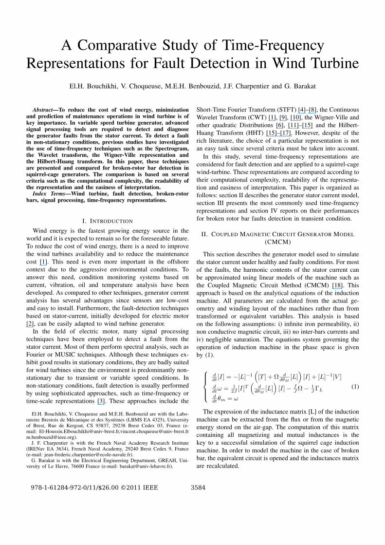
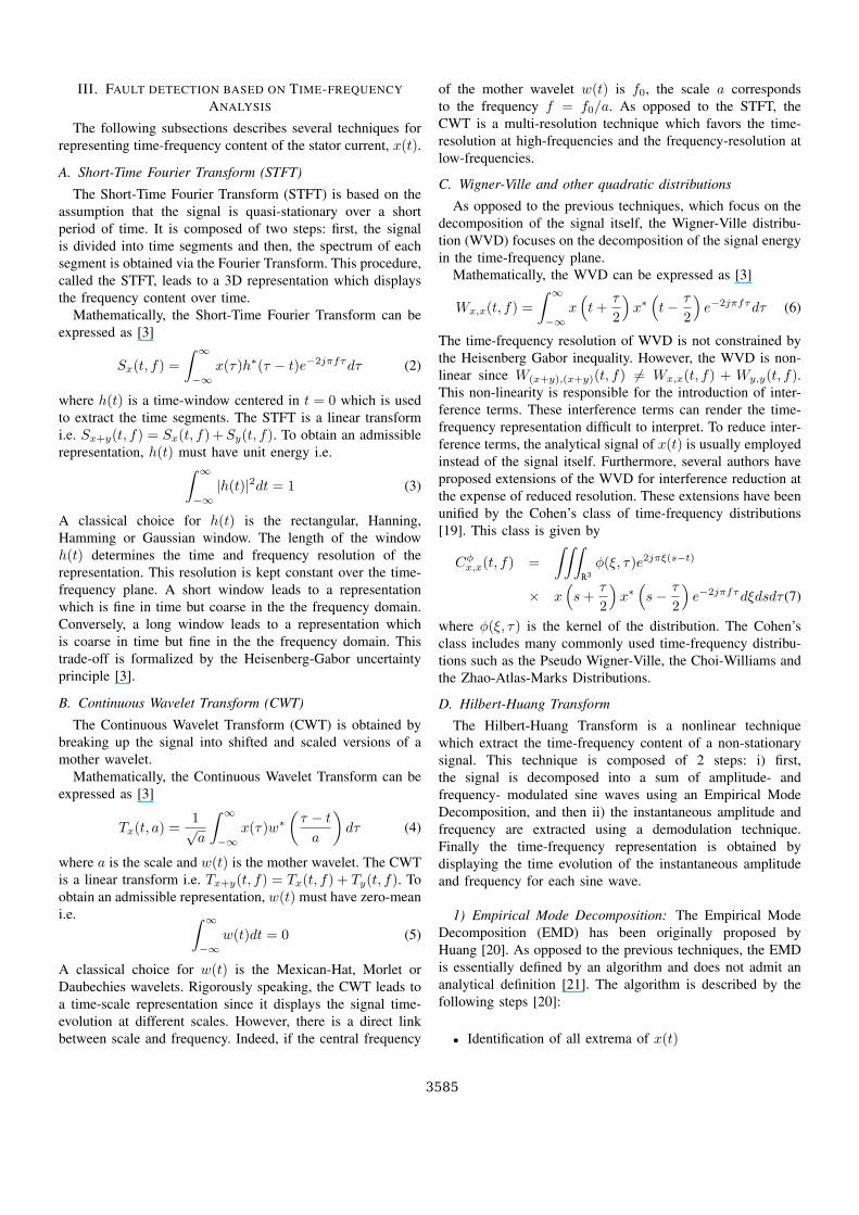
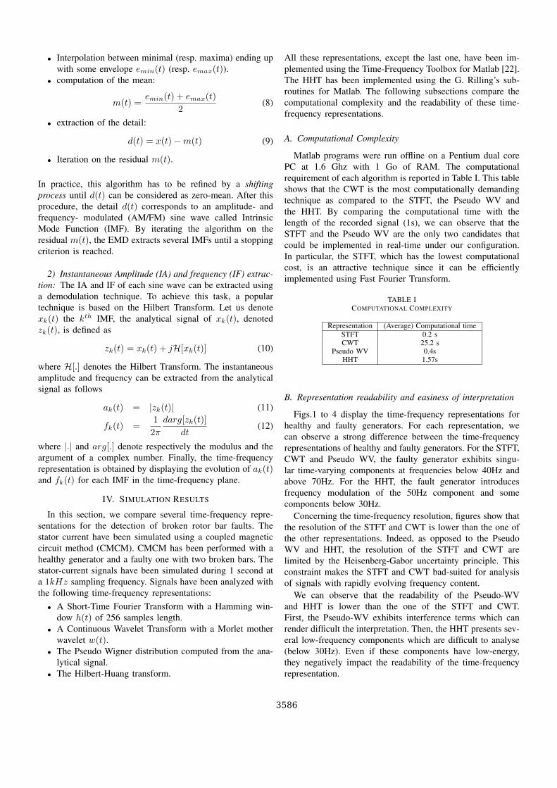
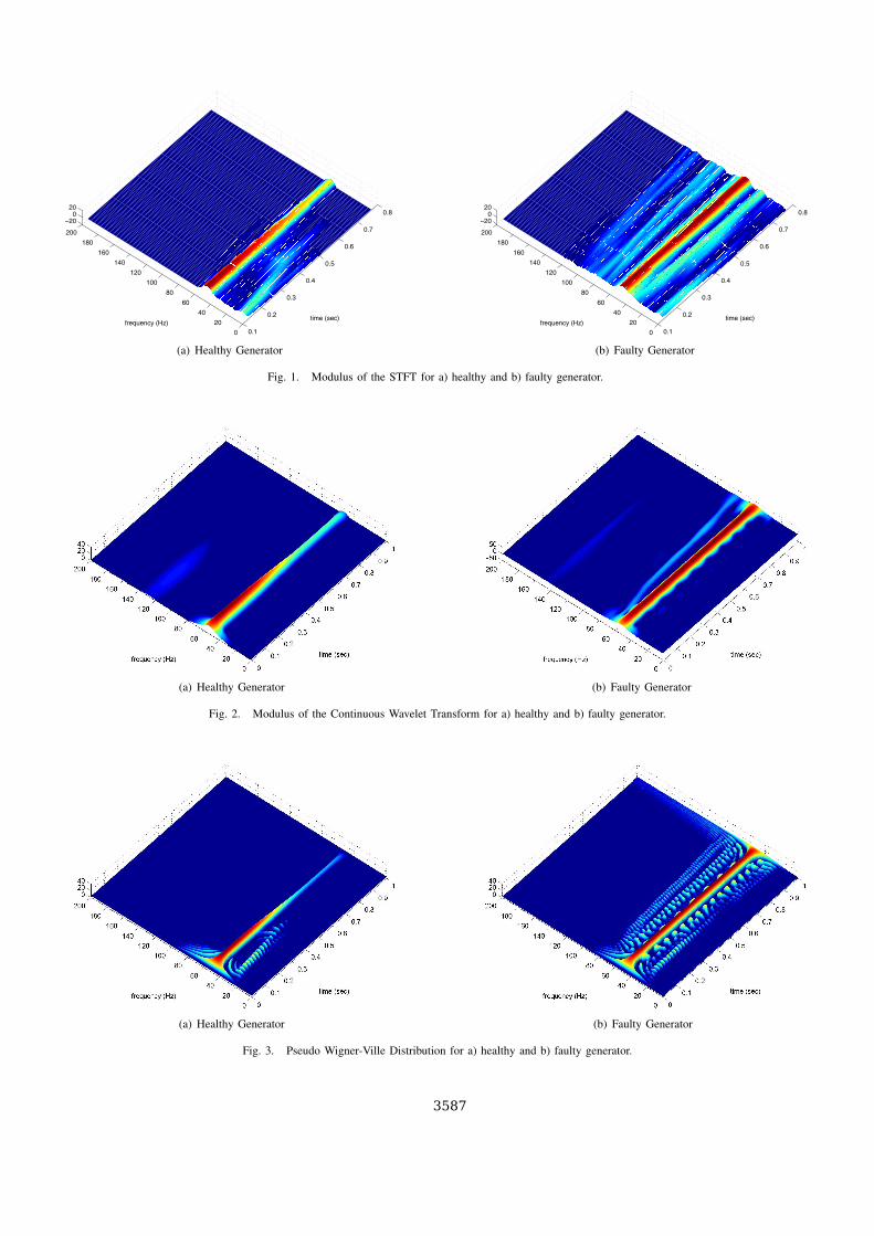
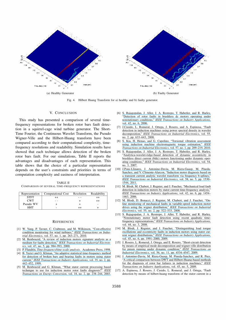
Figs.1 to 4 display the time-frequency representations forhealthy and faulty generators. For each representation, wecan observe a strong difference between the time-frequencyrepresentations of healthy and faulty generators. For the STFT,CWT and Pseudo WV, the faulty generator exhibits singu-lar time-varying components at frequencies below 40Hz andabove 70Hz. For the HHT, the fault generator introducesfrequency modulation of the 50Hz component and somecomponents below 30Hz.
Concerning the time-frequency resolution, figures show thatthe resolution of the STFT and CWT is lower than the one ofthe other representations. Indeed, as opposed to the PseudoWV and HHT, the resolution of the STFT and CWT arelimited by the Heisenberg-Gabor uncertainty principle. Thisconstraint makes the STFT and CWT bad-suited for analysisof signals with rapidly evolving frequency content.
We can observe that the readability of the Pseudo-WVand HHT is lower than the one of the STFT and CWT.First, the Pseudo-WV exhibits interference terms which canrender difficult the interpretation. Then, the HHT presents sev-eral low-frequency components which are difficult to analyse(below 30Hz). Even if these components have low-energy,they negatively impact the readability of the time-frequencyrepresentation.
3586
0.1
0.2
0.3
0.4
0.5
0.6
0.7
0.8
0
20
40
60
80
100
120
140
160
180
200
−200
20
time (sec)frequency (Hz)
(a) Healthy Generator
0.1
0.2
0.3
0.4
0.5
0.6
0.7
0.8
0
20
40
60
80
100
120
140
160
180
200
−200
20
time (sec)frequency (Hz)
(b) Faulty Generator
Fig. 1. Modulus of the STFT for a) healthy and b) faulty generator.
(a) Healthy Generator (b) Faulty Generator
Fig. 2. Modulus of the Continuous Wavelet Transform for a) healthy and b) faulty generator.
(a) Healthy Generator (b) Faulty Generator
Fig. 3. Pseudo Wigner-Ville Distribution for a) healthy and b) faulty generator.
3587
(a) Healthy Generator (b) Faulty Generator
Fig. 4. Hilbert Huang Transform for a) healthy and b) faulty generator.
V. CONCLUSION
This study has presented a comparison of several time-frequency representations for broken rotor bars fault detec-tion in a squirrel-cage wind turbine generator. The Short-Time Fourier, the Continuous Wavelet Transform, the PseudoWigner-Ville and the Hilbert-Huang transform have beencompared according to their computational complexity, time-frequency resolutions and readability. Simulation results haveshowed that each technique allows detection of the brokenrotor bars fault. For our simulations, Table II reports theadvantages and disadvantages of each representation. Thistable shows that the choice of a particular representationdepends on the user’s constraints and priorities in terms ofcomputation complexity and easiness of interpretation.
TABLE IICOMPARISON OF SEVERAL TIME-FREQUENCY REPRESENTATIONS
Representation Computational Cost Resolution ReadabilitySTFT ++ - - ++CWT - - + ++
Pseudo WV + + -HHT - ++ +
REFERENCES
[1] W. Yang, P. Tavner, C. Crabtreee, and M. Wilkinson, “Cost-effectivecondition monitoring for wind turbines,” IEEE Transactions on Indus-trial Electronics, vol. 57, no. 1, pp. 263–271, 2010.
[2] M. Benbouzid, “A review of induction motors signature analysis as amedium for faults detection,” IEEE Transactions on Industrial Electron-ics, vol. 47, no. 5, pp. 984–993, 2000.
[3] P. Flandrin, Time-frequency/time-scale analysis. Academoc Press, 1998.[4] B. Yazici and G. Kliman, “An adaptive statistical time-frequency method
for detection of broken bars and bearing faults in motors using statorcurrent,” IEEE Transactions on Industry Applications, vol. 35, no. 2, pp.442–452, 1999.
[5] M. Benbouzid and G. Kliman, “What stator current processing basedtechnique to use for induction motor rotor faults diagnosis?” IEEETransactions on Energy Conversion, vol. 18, no. 2, pp. 238–244, 2003.
[6] S. Rajagopalan, J. Aller, J. A. Restrepo, T. Habetler, and R. Harley,“Detection of rotor faults in brushless dc motors operating undernonstationary conditions,” IEEE Transactions on Industry Applications,vol. 42, no. 6, 2006.
[7] J.Cusido, L. Romeral, J. Ortega, J. Rosero, and A. Espinosa, “Faultdetection in induction machines using power spectral density in waveletdecomposition,” IEEE Transactions on Industrial Electronics, vol. 55,no. 2, pp. 633–643, 2008.
[8] S. Kia, H. Henao, and G. Capolino, “Torsional vibration assessmentusing induction machine electromagnetic torque estimation,” IEEETransactions on Industrial Electronics, vol. 57, no. 1, pp. 209–219, 2010.
[9] S. Rajagopalan, J. Aller, J. A. Restrepo, T. Habetler, and R. Harley,“Analytica-wavelet-ridge-based detection of dynamic eccentricity inbrushless direct current (bldc) motors functioning under dynamic oper-ating conditions,” IEEE Transactions on Industrial Electronics, vol. 54,no. 3, 2007.
[10] J.Pons-Llinares, J. Antonino-Daviu, M. Riera-Guasp, M. Pineda-Sanchez, and V. Climente-Alarcon, “Induction motor diagnosis based ona transient current analytic wavelet transform via frequency b-splines,”IEEE Transactions on Industrial Electronics, vol. 58, no. 5, pp. 1530–1544, 2011.
[11] M. Blodt, M. Chabert, J. Regnier, and J. Faucher, “Mechanical load faultdetection in induction motors by stator current time-frequency analysis,”IEEE Transactions on Industry Applications, vol. 42, no. 6, pp. 1454–1463, 2006.
[12] M. Blodt, D. Bonacci, J. Regnier, M. Chabert, and J. Faucher, “On-line monitoring of mechanical faults in variable-speed induction motordrives using the wigner distribution,” IEEE Transactions on IndustrialElectronics, vol. 55, no. 2, pp. 522–533, 2008.
[13] S. Rajagopalan, J. A. Restrepo, J. Aller, T. Habetler, and R. Harley,“Nonstationary motor fault detection using recent quadratic time-frequency representations,” IEEE Transactions on Industry Applications,vol. 44, no. 3, 2008.
[14] M. Blodt, J. Regnier, and J. Faucher, “Distinguishing load torqueoscillations and eccentricity faults in induction motors using stator cur-rent wigner distributions,” IEEE Transactions on Industry Applications,vol. 45, no. 6, pp. 1991–2000, 2009.
[15] J. Rosero, L. Romeral, J. Ortega, and E. Rosero, “Short-circuit detectionby means of empirical mode decomposition and wigner-ville distributionfor pmsm running under dynamic condition,” IEEE Transactions onIndustrial Electronics, vol. 56, no. 11, pp. 4534–4547, 2009.
[16] J. Antonino-Daviu, M. Riera-Guasp, M. Pineda-Sanchez, and R. Prez,“A critical comparison between DWT and Hilbert-Huang-based methodsfor the diagnosis of rotor bar failures in induction machines,” IEEETransactions on Industry Applications, vol. 45, no. 5, 2009.
[17] A. Espinosa, J. Rosero, J. Cusido, L. Romeral, and J. Ortega, “Faultdetection by means of hilbert-huang transform of the stator current in a
3588
pmsm with demagnetization,” IEEE Transactions on Energy Conversion,vol. 25, no. 2, pp. 312–318, 2010.
[18] G. Houdouin, G. Barakat, B. Dakyo, E. Destobbeleer, and C. Nichita,“A coupled magnetic circuit based global method for the simulationof squirrel cage induction machines under rotor and stator faults,” inProceedings of ELECTRIMACS’02, Montreal, Canada, 2002.
[19] L. Cohen, “Time-frequency distributions: A review,” Proceedings of theIEEE, vol. 77, no. 7, pp. 941–981, 1989.
[20] N. Huang, Z. Shen, S. Long, M. Wu, H. Shih, Q. Zheng, N. Yen,C. Tung, and H. Liu, “The empirical mode decomposition and hilbertspectrum for nonlinear and nonstationary time series analysis,” Proc.Roy. Soc. London, vol. 454, p. 903995, 1998.
[21] G. Rilling, P. Flandrin, and P. Goncalvs, “On empirical mode decom-position and its algorithms,” in IEEE-EURASIP Workshop on NonlinearSignal and Image Processing, Grado, Italia, 2003.
[22] F. Auger, P. Flandrin, P. Goncalves, and O. Lemoine, “Time-frequencytoolbox, for use with matlab,” CNRS, GDR ISIS, Tech. Rep., 1997.
3589
Powered by TCPDF (www.tcpdf.org)
Top Related
Copyright © 2022 FDOKUMEN

