


Bahasa
Halaman
Hukum

1
BEYOND TRADITIONAL COATINGS, A REVIEW ON THERMAL SPRAYED FUNCTIONAL AND
SMART COATINGS
D. Tejero-Martin1, M. Rezvani Rad2, A. McDonald2, T. Hussain1*
1Faculty of Engineering, University of Nottingham, Nottingham, NG7 2RD, UK
2Faculty of Mechanical Engineering, University of Alberta, Edmonton, T6G 2G8, Canada
+44 115 951 3795, [email protected]
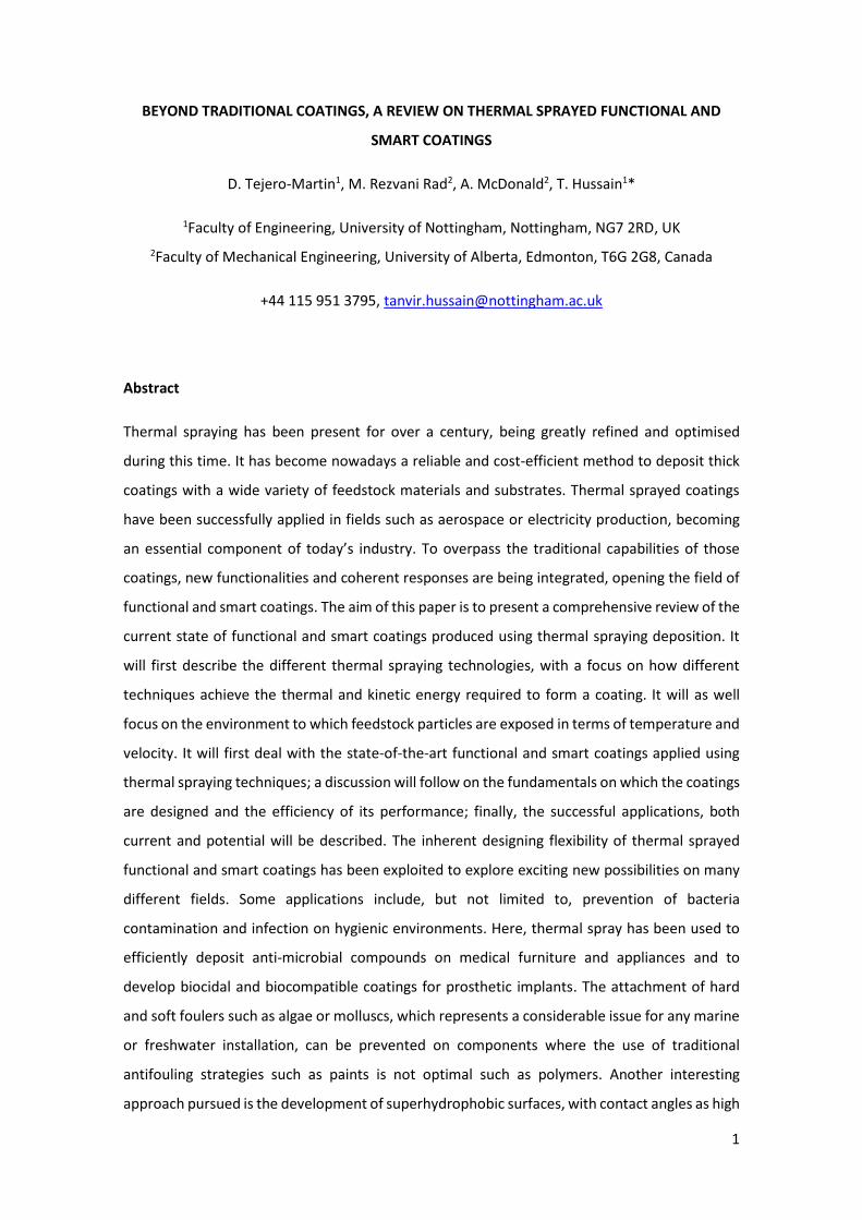
Abstract
Thermal spraying has been present for over a century, being greatly refined and optimised
during this time. It has become nowadays a reliable and cost-efficient method to deposit thick
coatings with a wide variety of feedstock materials and substrates. Thermal sprayed coatings
have been successfully applied in fields such as aerospace or electricity production, becoming
an essential component of today’s industry. To overpass the traditional capabilities of those
coatings, new functionalities and coherent responses are being integrated, opening the field of
functional and smart coatings. The aim of this paper is to present a comprehensive review of the
current state of functional and smart coatings produced using thermal spraying deposition. It
will first describe the different thermal spraying technologies, with a focus on how different
techniques achieve the thermal and kinetic energy required to form a coating. It will as well
focus on the environment to which feedstock particles are exposed in terms of temperature and
velocity. It will first deal with the state-of-the-art functional and smart coatings applied using
thermal spraying techniques; a discussion will follow on the fundamentals on which the coatings
are designed and the efficiency of its performance; finally, the successful applications, both
current and potential will be described. The inherent designing flexibility of thermal sprayed
functional and smart coatings has been exploited to explore exciting new possibilities on many
different fields. Some applications include, but not limited to, prevention of bacteria
contamination and infection on hygienic environments. Here, thermal spray has been used to
efficiently deposit anti-microbial compounds on medical furniture and appliances and to
develop biocidal and biocompatible coatings for prosthetic implants. The attachment of hard
and soft foulers such as algae or molluscs, which represents a considerable issue for any marine
or freshwater installation, can be prevented on components where the use of traditional
antifouling strategies such as paints is not optimal such as polymers. Another interesting
approach pursued is the development of superhydrophobic surfaces, with contact angles as high
2
as 160° and slide angles below 5°, leading to high droplet mobility. This adds capabilities as self-
cleaning or corrosion resistance in addition to the characteristic robustness of thermal sprayed
coatings. The electric and magnetic properties of the feedstock materials have also led to the
application of thermal spraying techniques in the creation of patterned structures with desired
electromagnetic properties for their use on microelectronics. The possibility to intercalate layers
of thermal sprayed materials doped with optical-reactive elements has led to the development
of online and offline temperature sensors which can be readily integrated in current thermal
barrier coatings. To finalise the examples of the many applications of thermal sprayed functional
and smart coatings, autonomous self-healing or self-lubricant coatings have been developed.
Advantage has been taken of a beneficial phase transformation triggered by the correspondent
event (such as a crack or the tribological interactions respectively) to promote self-healing.
Another approach has been the release of an encapsulated component which effectively heals
the coating or provides lubrication when required. All these exciting developments pave the way
for the numerous applications that are to come in the next decade, making the field of thermal
sprayed coatings a unique opportunity for research and development.
Keywords
Anti-fouling; anti-microbial; cold spray; detonation gun spray; flame spray; functional coating;
HVOF spray; hydrophobic; Joule heating; multi-layered coating systems; plasma spray; self-
healing; self-lubrication; sensor; smart coating; thermal spray coating; wire arc spray;

3
1. Introduction
The selection of the materials to be used on industrial applications is dictated by their intrinsic
properties, which must satisfy the specified needs for the component being designed and
manufactured. A clear example would be structural components, where strength or fracture
resistance is of the upmost importance. Nevertheless, any designed component will face a
determined environment during service operation. This interaction can drastically limit its life-
time or even change its properties to an extent where it will no longer satisfy the expected
demands. Two common examples which illustrate these situations would be components in
corrosive environments, such as offshore structures where the combination of salt and humidity
corrodes the surface of the component, gradually weakening the structure (Ref 1); and high
temperature applications such as turbine blades, where the elevated temperatures would
damage unprotected components (Ref 2).
As the examples above illustrate, the interaction between the environment and the material
plays a critical role, and at the heart of that interaction, lies the surface. The surface of any
component represents the interface between the environment and the material, and any
interaction that is due to take place will happen at the surface. In order to protect the surface,
one successful strategy has been to deposit a relatively thin layer (when compared to the
dimensions of the bulk material) of a different material, with the properties required to face the
expected environment.
The development of coatings has pushed further away the inherent limits of materials,
broadening the design possibilities on many cutting-edge fields. The advantages of combining
the bulk properties of a substrate with the tailored capabilities of a layer at the surface opened
a world of new opportunities. Nowadays, coatings are present in almost all of the most
demanding environments and specialized applications. Following the examples above, offshore
structures are coated with corrosion resistant coatings such as zinc and zinc-aluminium (Ref 3),
and turbine blades are commonly coated with thermal barrier coatings such as yttria-stabilised
zirconia (YSZ), with low thermal conductivity and good mechanical properties.
One of the aspects that has made coatings such a popular solution is the fact that a wide range
of deposition techniques are available. To cover the whole catalogue of deposition techniques
available is outside the scope of this review, which will focus on thermal spray technologies.
Thermal spray comprises those deposition processes in which an energy source is used to heat
the initial feedstock particles (which could be presented in the form of suspension, powder, wire
or rod), being then accelerated and propelled towards the substrate using a gas stream (Ref 4).

4
The combined thermal and kinetic energies of the particles allows the bonding with the surface
of the substrate upon impact, effectively building up the coating as the particles reach the
surface. Another aspect that has contributed to the wide-spread use of thermal spraying is the
flexibility in the choice of materials that can be deposited with these techniques. As a general
definition, any material with the capability of melting without experiencing decomposition is
suitable for thermal spraying (Ref 5).
Due to the unique combination of a wide range of deposition techniques and materials available
for coatings, thermal spraying has been successfully applied in numerous fields, such as
corrosion and oxidation resistance (Ref 6), high temperature protection (Ref 7), wear and
erosion (Ref 8), abradable coatings and dimensional repairs (Ref 9,10), biomedical applications
(Ref 11) and electronics (Ref 12). As it can be seen, the field of thermal spraying has represented
a prolific match for coatings, allowing the production of highly capable systems. Such coating
also present a great acceptance in the industry, excellent large-scale adaptability and suitable
cost/efficiency, having undoubtedly proved its value. Despite the clear success and high rate of
applicability of thermal sprayed coatings, there is an always increasing demand for systems
capable of facing more aggressive environments, reliably performing at even higher
temperatures, serving during longer periods of time or providing new, desireable functionalities,
to name a few of the driving criteria. To overcome some of the current needs, new concepts
within thermal sprayed coatings have been developed, being functional and smart the subject
of investigation of this work.
One of the most successful routes in the development of thermal sprayed coatings has been the
combination of a proven material system which, and due to the flexibility of allowed sprayed
materials, is combined with an added component responsible for the novel functionality. The
presence of a solid base of thoroughly investigated and field-tested thermal sprayed coatings
has provided an unparalleled starting point for the development of more capable and tailor
designed functional coatings. On its simplest definition, a functional coating can be described as
a coating with an added functionality beyond the traditional protective capabilities (Ref 13). The
classical protective case would be the already mentioned corrosion or wear protection.
However, although these new functionalities provide functional coatings with a wide range of
applications and possibilities, their behaviour is still passive on its interaction with the
environment. A smart coating, on the other hand, aims to provide coatings with an active
response to certain stimuli, generated either by intrinsic or extrinsic events (Ref 14,15). In
summary, all smart coatings can be considered functional coatings due to the presence of a
functionality beyond simple protection, but not all functional coatings can be categorised as
5
smart due to the lack of an active response to external stimuli. It should be noted that the
categorisation used in this review regarding the functional and smart coatings is not intended to
be definitive— different definitions are present in existing literature. The distinction was chosen
to provide a more structured approach to the review.
Several decades of investigation on the science behind thermal sprayed coatings and the
relatively new addition of functional and smart coatings has provided an invaluable opportunity
for numerous industrial applications. However further research is still required to provide cost-
efficient methods with proven added value to the companies. With the unparalleled success of
deposition techniques such as plasma spraying or high velocity oxy-fuel (HVOF) thermal spraying
as an example, other thermal spray technologies still need to reach that level of market
penetration. This will only be attainable through strong beneficial cases with a clear
understanding of the processes involved. The addition of new capabilities through the
introduction of functional and smart coatings represents an added opportunity for exciting,
ground-breaking research. It is essential that the industry becomes involved too, setting the
requirements and needs of a market more demanding than ever, in which these technologies
can present a benefit.
In this work, and due to the importance that the different deposition techniques have on the
produced functional and smart coatings, an overview of the main thermal spray technologies
available is first presented. Then, attending to the division previously defined between
functional and smart coatings, an extensive and comprehensive study of the current
developments in the field is undertaken. With the use of thermal spraying techniques as
common factor, the current state-of-the-art for functional and smart coatings is presented
attending to the different functionalities achieved.
2. Thermal Spraying Technologies
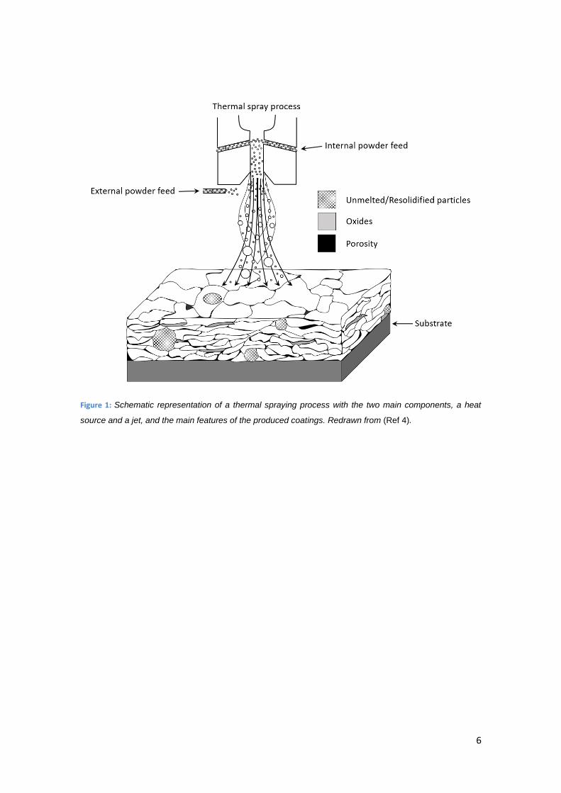
Thermal spraying processes incorporate those technologies on which metallic or non-metallic
coatings are deposited through the same principle. A heat source melts the feedstock material
and a jet is used to impart kinetic energy to the molten particles. They then impinge the
substrate surface and rapidly cool down to form a solid splat, continuously building up the
desired thickness (Ref 16). A basic schematic of the thermal spray process can be seen in Figure
1. The flexibility on thermal sources and jet configurations give rise to a plethora of different
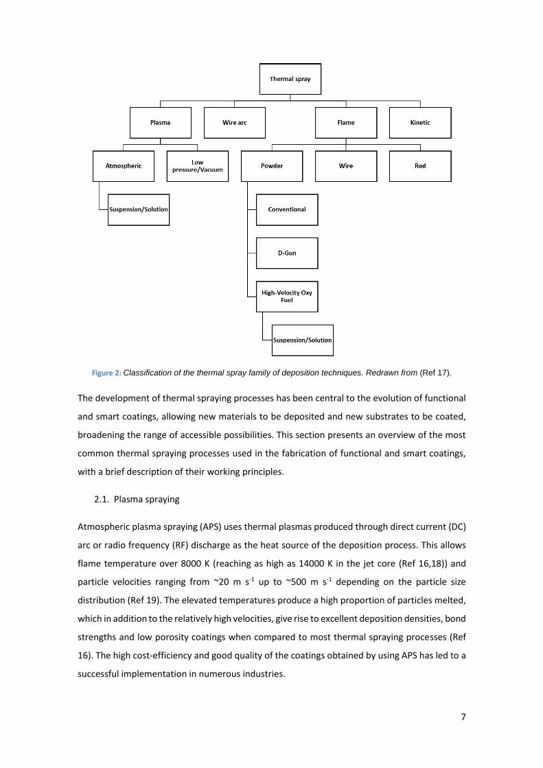
deposition technologies, as presented in Figure 2, each one producing coatings with different
microstructures and physical properties.
6
Figure 1: Schematic representation of a thermal spraying process with the two main components, a heat
source and a jet, and the main features of the produced coatings. Redrawn from (Ref 4).
7
Figure 2: Classification of the thermal spray family of deposition techniques. Redrawn from (Ref 17).
The development of thermal spraying processes has been central to the evolution of functional
and smart coatings, allowing new materials to be deposited and new substrates to be coated,
broadening the range of accessible possibilities. This section presents an overview of the most
common thermal spraying processes used in the fabrication of functional and smart coatings,
with a brief description of their working principles.
2.1. Plasma spraying
Atmospheric plasma spraying (APS) uses thermal plasmas produced through direct current (DC)
arc or radio frequency (RF) discharge as the heat source of the deposition process. This allows
flame temperature over 8000 K (reaching as high as 14000 K in the jet core (Ref 16,18)) and
particle velocities ranging from ~20 m s-1 up to ~500 m s-1 depending on the particle size
distribution (Ref 19). The elevated temperatures produce a high proportion of particles melted,
which in addition to the relatively high velocities, give rise to excellent deposition densities, bond
strengths and low porosity coatings when compared to most thermal spraying processes (Ref
16). The high cost-efficiency and good quality of the coatings obtained by using APS has led to a
successful implementation in numerous industries.

8
2.1.1. Suspension/solution precursor plasma spraying
Due to the need of adequate flowability for the feedstock powder, APS is limited to the
deposition of particles with an approximate lower limit size of 10 – 100 µm (Ref 20,21). In order
to allow the use of nano-scaled powders, different solutions have been developed as an
alternative to the traditional injection of powder. The main representatives of these alternatives
are suspension plasma spraying (SPS) and solution precursor plasma spraying (SPPS) (Ref 20–
30). The differentiation factor between the two methods is shown in Figure 3, with the
precipitation of the deposited particles in-flight in the case of SPPS as opposed to the direct
deposition (apart from the physical changes related to the exposure to the high temperature in
the flame) in SPS.
Figure 3: Deposition and particle transformation in-flight for a) suspension thermal spraying and b) solution
precursor thermal spraying (Ref 25).
These techniques increase the flexibility of the plasma deposition technologies, already widely
used in the industry, accessing smaller particle size for the feedstock materials, allowing
deposited coatings with different microstructures. A field where SPS and SPPS have found great
a)
b)
9
application is the fabrication of thermal barrier coatings (TBC) for high temperature applications.
The main reasons are the strain-tolerant columnar structures or vertical cracks and fine porosity
on SPS (Ref 31–34) and SPPS (Ref 35–39) deposited coatings, resulting in a thermal conductivity
lower that of electron-beam physical vapour deposition (EB-PVD) or traditional APS coatings.
2.1.2. Low pressure/vacuum plasma spraying
Plasma spraying in controlled environments was developed in the late 1960s with the aim to
reduce the adverse effects arising from the interaction of the in-flight heated particles with the
environment. Such detrimental effects include oxidation and undesired contaminations in the
coatings. The use of low and very low pressure permits the development of high quality thermal
sprayed coatings. The pressures used vary, being commonly in the range of 4000 Pa to 40000 Pa
for low pressure plasma spraying (LPPS) and as low as 100 Pa for very low plasma spraying
(VLPPS). Any value lower than that is considered as vacuum plasma spraying (VPS). This
technique produces coatings with porosity values as low as 1% (Ref 16,40) and columnar
structure (Ref 41,42) comparable of those obtained through PVD, of great interest for TBC
applications. What is more, it presents the beneficial addition of an increased deposition rate
over PVD methods.
2.2. Wire arc spraying
Wire arc spraying, also known as twin wire arc spray or electric arc spray, is based on the feeding
of two consumable conductive wires (or a core of a non-conductive material on a conductive
wire) between which a direct current electric arc is stablished. Once the material is molten, the
molten layer is accelerated towards the substrate surface by a stream of atomizing gas. This
promotes a further in-flight atomization of the molten particles before their deposition and
posterior solidification at the substrate surface (Ref 16,43). The advantages of this deposition
method are several. They include the reduced cost of the process, both in terms of equipment
and operational costs, being a very cost-efficient deposition technique. It also shows absence of
unmelted or semi-molten particles, a high deposition rate when compared to other thermal
spray processes and a low thermal transfer to the substrate. All these factors make wire arc
spraying one of the less expensive techniques, nevertheless, the particular characteristics of the
produced coatings such as high porosity or low bonding strength make its use somewhat limited.
2.3. Flame spraying
Flame spray was the first of the thermal spray techniques to be devised, being developed by
Schoop around 1909 (Ref 44). The basic principles are still applied to today’s modern

10
conventional flame spray guns. The combustion of fuel gases is used to impart heat to the
feedstock particles. At the same time, it produces an expanding gas flow which in combination
of additional gases creates the required jet applied to accelerate the material towards the
surface to be coated. Typical temperatures for this technique are around 3000 K and particle
velocities of up to 100 m s-1 are usually applied (Ref 16); however, in order to improve the initial
design on which flame spraying is based, several variations have been developed with a focus
on different flame temperatures and particles velocities.
2.3.1. Detonation gun (D-gun) spraying
By confining oxygen and combustion gases such as acetylene within a closed tube and initiating
the combustion process with a spark, a high pressure shock wave is created. The shock wave
imparts an increased heat transfer and considerable higher kinetic energy to the powder
particles, reaching flame temperatures of around 4000 K and velocities of up to 1000 m s-1 (Ref
45). The combustion cycle is repeated with a frequency of 3 to 6 Hz to produce a semi-
continuous stream of heated and highly accelerated particles. The result is a coating with better
adherence strength and reduced porosity to those deposited through the use of conventional
flame spray techniques (Ref 16,45,46).
2.3.2. High velocity oxy-fuel spraying
High velocity oxy-fuel (HVOF) spraying was developed based on concepts from jet engines, and
shares some common features with the detonation gun process. The technique relies on the
combination of oxygen and fuel gases inside a combustion chamber, creating a highly
pressurised mixture. A small-diameter nozzle is used to direct the gases towards the substrate
surface. The combination of elevated pressures, high gas flow and high combustion
temperatures produces a supersonic gas jet at the exit, with particles velocities as high as 1000
m s-1 and jet temperatures of approximately 3000 K (Ref 47,48). The main differences with
detonation gun are the continuous gas stream exiting the nozzle and the free expansion of the
compressed flame upon exit at the De Laval nozzle (Ref 49). These factors combined produce
coatings with lower porosity and enhanced adherence strength than conventional flame spray
coatings (Ref 4,47,50).
2.3.2.1. High velocity air fuel spraying
A variation of the traditional HVOF spraying technology involves the use of air instead of oxygen,
giving raise to high velocity air fuel (HVAF) spray. The difference of this method is a reduced
flame temperature, due to the lack of a highly exothermic fuel. This has a beneficial effect for
11
feedstock materials with relatively low melting points. It also implies a change in the
microstructure and final properties of the deposited coating. In addition, HVAF is less expensive
than HVOF, which could represent an advantage for its implementation in the industrial
landscape.
2.3.2.2. Suspension/solution high velocity oxy-fuel spraying
The use of suspensions and solution precursors as the injection medium has also been
developed for HVOF, as well as the already seen plasma spraying technique. The underlying
concept is similar, for both suspension HVOF (SHVOF) (Ref 22,51,52), also called high-velocity
suspension flame spraying (HVSFS) (Ref 22,53), and solution precursor HVOF (SPHVOF) (Ref
22,51,54–56). They use nano-sized particles to promote the development of coatings with
different microstructures in terms of splat morphology and porosity, and therefore different
physical properties from conventional flame spraying. Additional research in this field is needed
to better understand the potential benefits of SPHVOF and its effect on the microstructure of
the deposited coatings.
2.4. Kinetic spraying
Kinetic or cold spraying, as the name indicates, is based on the transfer of higher amounts of
kinetic energy into the feedstock particles in order to achieve the desired bonding strength upon
impingement at the substrate surface. It contrasts with the usual use of heat transfer seen in
other thermal spray technologies. This allows for the deposition of deformable, ductile
feedstock powder particles without the need for the traditional melting, impact and posterior
rapid solidification pathway, effectively reducing the intrinsic residual stresses upon deposition
and the in-flight particle oxidation (Ref 50). The basic fundamental of the process is the use of
pressurized gases with reduced oxidation potential, such as nitrogen or helium. The gases are
moderately heated (up to 1000 K, generally below the melting point of the feedstock particles)
in order to increase the gas flow velocities rather than heating the particles themselves (Ref 4).
Once the desired pressure and temperature conditions are achieved, the gas is conducted
through a De Laval nozzle (Ref 49) which accelerates it to supersonic velocities (up to 1200 m s-
1) while reducing the gas temperature as it expands. This allows for the temperature to reach in
occasions values below room temperature (Ref 3,57). The resulting coatings have the same
phase content as the powder feedstock without oxide contamination and low porosity, with
preference for compressive residual stresses instead of the usual tensile stress of other thermal
spray technologies and low ductility caused by the extensive work hardening involved in the
deposition process (Ref 3,50,57).
12
A different approach is followed in the case of low pressure cold spray (LPCS) which, as its name
implies, produces the deposition of the feedstock particles at a lower carrier gas pressure than
the common cold spray, or high pressure cold spray. The reduced pressure required in the case
of LPCS presents some advantages, such as smaller size and lower cost for the required
equipment (Ref 58), making it very attractive for portable, hand-held systems for on-site
deposition or repairs. Nevertheless, low pressure equates to lower particle velocity, which
mainly affects the deposition efficiency of LPCS, being considerably lower than high pressure
cold spray (Ref 59–61).
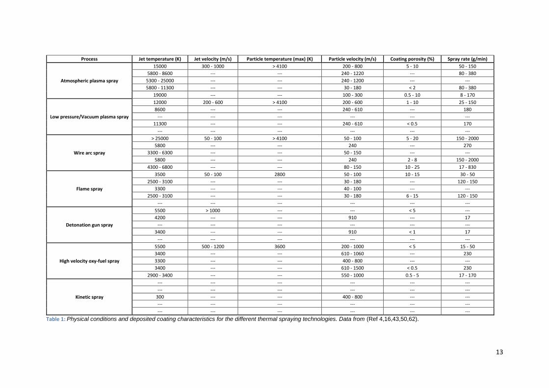
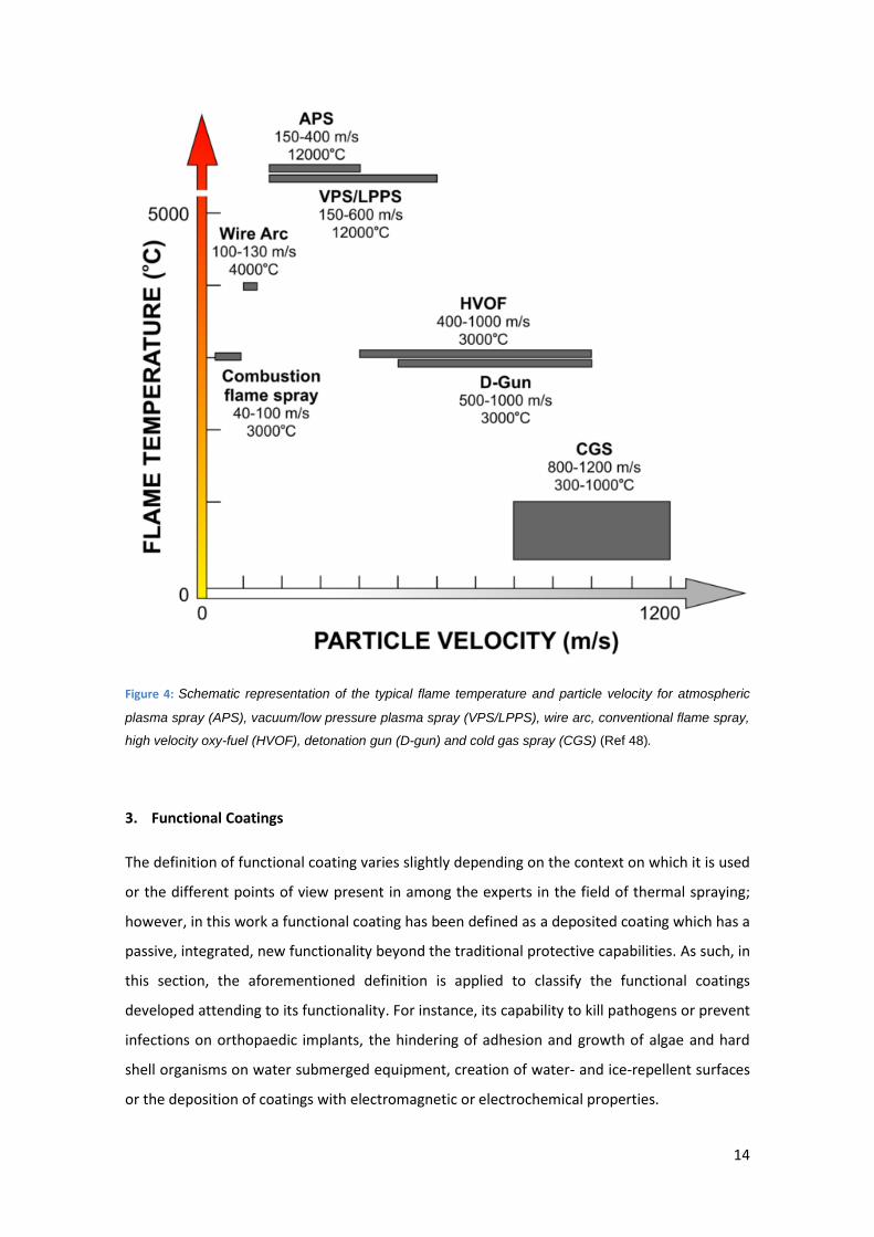
As a summary, Table 1 and Figure 4 give an overview of the physical conditions for each of the
thermal spraying technologies here described.
13
Process Jet temperature (K) Jet velocity (m/s) Particle temperature (max) (K) Particle velocity (m/s) Coating porosity (%) Spray rate (g/min)
Atmospheric plasma spray
15000 300 - 1000 > 4100 200 - 800 5 - 10 50 - 150
5800 - 8600 --- --- 240 - 1220 --- 80 - 380
5300 - 25000 --- --- 240 - 1200 --- ---
5800 - 11300 --- --- 30 - 180 < 2 80 - 380
19000 --- --- 100 - 300 0.5 - 10 8 - 170
Low pressure/Vacuum plasma spray
12000 200 - 600 > 4100 200 - 600 1 - 10 25 - 150
8600 --- --- 240 - 610 --- 180
--- --- --- --- --- ---
11300 --- --- 240 - 610 < 0.5 170
--- --- --- --- --- ---
Wire arc spray
> 25000 50 - 100 > 4100 50 - 100 5 - 20 150 - 2000
5800 --- --- 240 --- 270
3300 - 6300 --- --- 50 - 150 --- ---
5800 --- --- 240 2 - 8 150 - 2000
4300 - 6800 --- --- 80 - 150 10 - 25 17 - 830
Flame spray
3500 50 - 100 2800 50 - 100 10 - 15 30 - 50
2500 - 3100 --- --- 30 - 180 --- 120 - 150
3300 --- --- 40 - 100 --- ---
2500 - 3100 --- --- 30 - 180 6 - 15 120 - 150
--- --- --- --- --- ---
Detonation gun spray
5500 > 1000 --- --- < 5 ---
4200 --- --- 910 --- 17
--- --- --- --- --- ---
3400 --- --- 910 < 1 17
--- --- --- --- --- ---
High velocity oxy-fuel spray
5500 500 - 1200 3600 200 - 1000 < 5 15 - 50
3400 --- --- 610 - 1060 --- 230
3300 --- --- 400 - 800 --- ---
3400 --- --- 610 - 1500 < 0.5 230
2900 - 3400 --- --- 550 - 1000 0.5 - 5 17 - 170
Kinetic spray
--- --- --- --- --- ---
--- --- --- --- --- ---
300 --- --- 400 - 800 --- ---
--- --- --- --- --- ---
--- --- --- --- --- ---
Table 1: Physical conditions and deposited coating characteristics for the different thermal spraying technologies. Data from (Ref 4,16,43,50,62).
14
Figure 4: Schematic representation of the typical flame temperature and particle velocity for atmospheric
plasma spray (APS), vacuum/low pressure plasma spray (VPS/LPPS), wire arc, conventional flame spray,
high velocity oxy-fuel (HVOF), detonation gun (D-gun) and cold gas spray (CGS) (Ref 48).
3. Functional Coatings
The definition of functional coating varies slightly depending on the context on which it is used
or the different points of view present in among the experts in the field of thermal spraying;
however, in this work a functional coating has been defined as a deposited coating which has a
passive, integrated, new functionality beyond the traditional protective capabilities. As such, in
this section, the aforementioned definition is applied to classify the functional coatings
developed attending to its functionality. For instance, its capability to kill pathogens or prevent
infections on orthopaedic implants, the hindering of adhesion and growth of algae and hard
shell organisms on water submerged equipment, creation of water- and ice-repellent surfaces
or the deposition of coatings with electromagnetic or electrochemical properties.
15
3.1. Anti-microbial
The appearance and adhesion of bacteria and microorganisms onto surfaces cause severe
complications such as surgical site infection or chronic wounds in the medical field (Ref 63) or
health-related issues due to expired and contaminated products in the food industry (Ref 64).
For these reasons the use of anti-microbial coatings, which prevent or hinder the development
of noxious microorganisms, has gained popularity in the recent years. To achieve this anti-
microbial behaviour several approaches have been taken, being summarised into three main
categories. The first one is the creation of an anti-adhesive surface, which prevents the
adherence of bacteria and the consecutive formation of biofilms, through physical or chemical
modifications. The second approach is the creation of coatings with anti-bacterial agent release
capabilities, with highly concentrated and localised doses only where needed. This in turn limits
the potential toxicity and resistance development. Thirdly, the use of biocidal (or contact-killing)
coatings where compounds with bactericidal activity are immobilised at the surface to provide
a continuous protection effect (Ref 65,66). Although all three methods are capable of delivering
an anti-microbial effect to the coated surface, each has its own deficiencies that should be
considered when designing the application.
In the case of anti-adherent surfaces, the creation of a broad spectrum morphology is
complicated due to the non-specificity of the method. A surface with low attachment of a
specific bacterial strain might not present the same behaviour with other pathogens, limiting its
general application. In addition to non-specificity, anti-adherent surfaces suffer a great
functionality loss when wear is present, due to the alteration of the designed morphologies.
Despite these deficiencies, the absence of antibiotics or similar agents as the active principle
presents a promising approach to prevent the appearance of antibiotic resistant bacteria. As it
stands now, this method is mainly applied as a secondary approach in combination with other
principles, rather than the main solution against pathogen proliferation (Ref 67).
The loading of an antibiotic or antibacterial agent into the coating has been a popular approach
to achieve anti-microbial surfaces, although the method presents one main drawback. The finite
nature of an embedded reservoir within the coating implies a time constraint in the duration of
the effect. After said time, the reservoir will be depleted and the coating will fail to prevent
bacteria proliferation. Despite the severity of this constraint, this method is well suited for
applications where a localised and brief delivery of antibiotics is needed. An example would be
the protection of implants during surgical procedures and in the following hours, to prevent
contamination and infection (Ref 68).
16
To prevent the shortcomings associated with a limited reservoir, permanent immobilisation of
biocidal compounds has been explored. This method, based on the creation of a contact-killing
surface rather than relying on a loaded agent, represents a compromise between the lack of
specificity and the limited operation time present in the previous methods. The wide array of
loaded components or enzymes covalently attached via polymeric chains provide a broad
spectrum while the covalent bonds ensure that the components remain fixed in the surface to
provide the desired effect (Ref 69). This approach is not free of complications, mainly due to
stability issues of the attached components, but it has been the preferred choice for anti-
bacterial coatings due to its flexibility and benefits.
Despite the wide use of contact-killing coatings, some considerations should be taken into
account when considering thermal spray as the deposition technique. One of the limitations of
thermal spraying techniques is that they require heat resistant feedstock materials, limiting the
use of most of the chemical species traditionally used to functionalise surfaces, such as
poly(ethylene glycol) (PEG) (Ref 70). In view of this limitation, the interest in the development
of functional coatings with anti-bacterial properties has been focused on the modification of
well stablished thermal sprayed coatings with the addition of a biocidal agent that does not
degrade at high temperatures, providing a controlled release over time. With this goal in mind,
first a suitable matrix should be available, one that can be efficiently deposited using thermal
spray and with a proven record on the medical field. The use of thermal sprayed hydroxyapatite
(HA) coatings on orthopaedic implants enjoys a wide acceptance in the medical field since the
late 80’s (Ref 71), being exhaustively studied since then (Ref 72–77). As reported by Sun et al. in
the early 2000s (Ref 11), the use of thermal sprayed HA coatings on metal implants presents
several advantages and a positive potential for its use in the medical field. This trend has been
confirmed by the predominance of literature published between 2010 and 2015 in the
biomaterials field on the use of HA coatings on titanium substrates for implant applications (Ref
3). Taking into consideration the status of HA as the standard in thermal sprayed coatings and
the decades of research on its behaviour and response to living tissue (Ref 71), the choice of HA
as a base material for the development of anti-microbial functional coatings has been, and with
good reason, a popular one.
The addition of silver as the anti-microbial agent has been considered on the early studies of
functional coatings due its biocidal effect and the difficulty for pathogens to develop resistance
to it. The behaviour of HA doped with Ag, with the addition of poly-ether-ether-ketone (PEEK)
to form HA-Ag/PEEK coatings, was investigated by Sanpo et al. (Ref 78) using cold spray
deposition. The lower temperatures involved in this method, as compared to other thermal
17
spraying techniques as seen in section 2, preserves the feedstock powder chemistry and phase
composition, as confirmed by EDX analyses. The bactericidal behaviour was reported on
Escherichia coli, with Ag/PEEK weight ratios varying from 20:80 to 80:20. It was demonstrated
the preferential biocidal effect of silver over only PEEK, with biocidal activities 10 times higher
in the case of 80:20 HA-Ag/PEEK over the 20:80 HA-Ag/PEEK coating.
The potential of hydroxyapatite combined with silver was also exploited by Noda et al. (Ref 79).
They reported the use of HA powder mixed with silver oxide, taking advantage of the higher
temperatures experienced during flight when using flame spraying (2700 °C) to in-flight melt the
powder and form an amorphous calcium phosphate (CP) coating on top of pure titanium
substrates. Within the coating there was presence of fully melted, amorphous Ag2O. This
approach presents two main characteristics. First, the CP recrystallizes into HA after exposure
to simulated body fluid at 37 °C, providing the desired biocompatibility and bone adhesion.
Secondly, the presence of silver oxide in the coating, acting as a reservoir and providing a slow
release of Ag ions into the environment, provides the required biocidal functionality to the
coating. The reported number of viable Staphylococcus aureus bacterial colonies after
incubation for 24 h was 10000 times lower on Ag-CP coatings with respect to control CP coatings.
Although the predominance of thermal sprayed, doped HA coatings is clear on the field of
medical and dental metallic implants, the use of thermal spraying techniques for the deposition
of anti-microbial has found other applications. Other base materials such as chitosan (a natural,
non-toxic, biodegradable and biocompatible polymer, popular for the development of contact-
killing surfaces (Ref 80)) has been doped with recognised biocidal elements such as copper (Ref
81). Cold sprayed coatings of chitosan doped with copper and aluminium (Cu/Al ratio of 75:25
(wt. %)) were tested on Escherichia coli. After 24 h a reduction of 22 % on the presence of
Escherichia coli was reported with respect to control, uncoated glass substrates (Ref 82). The
same study was conducted on cold sprayed ZnO nanopowder mixed with Al in weight ratios
20:80, 50:50 and 80:20. They reported enhanced biocidal capabilities for the higher ZnO
containing coatings. For such coating the count for Escherichia coli after 24 h was 7 times lower
than the uncoated glass substrate and coated with just pure Al (Ref 83).
It has already been stablished on the previous publications here presented (Ref 78,82,83) or on
the thorough review by Vilardell et al. (Ref 84) the benefits of using a deposition technique with
lower heat transfer, as in cold spraying, for the deposition of heat sensitive powders.
Incidentally, the microstructure produced by cold spraying has been demonstrated to present
an increased biocidal activity, three orders of magnitude greater than other higher temperature
18
techniques such as plasma or wire-arc spraying. This effect has been reported by Champagne
and Helfritch (Ref 85) on the deposition of pure Cu on aluminium substrates, including a hospital
tray entirely coated as a proof-of-concept. The explanation for this noticeable difference on anti-
microbial capabilities lies on the work hardening of the copper particles during deposition using
cold spraying. This implies a high dislocation density, which enhances the diffusion of Cu2+ ions,
responsible for the pathogen elimination.
Nevertheless, cold spray is not the only available technique with that characteristic. Wire-arc,
also described on section 2, was used by Gutierrez et al. (Ref 86) to apply a high content Cu alloy
(>60% copper) coating onto medium-density fibre-board (MDF), a popular material in furniture.
Their work demonstrated the increased anti-microbial capabilities against Staphylococcus
aureus and Escherichia coli of thermally sprayed Cu coatings, with a lethality ratio 3-4 times
higher for the pathogens mentioned in comparison with stainless steel or Cu metal sheets. The
microstructure impact of wire-arc sprayed coatings was also investigated by Sharifahmadian et
al. (Ref 87), reporting the direct correlation between the defects created by the deposition
technique, such as grain size, micropores and microcracks and its anti-bacterial properties. The
authors suggest that such features promote the release of ions from the surface into the
environment, which enhances the antibacterial activity.
3.1.1. Biocidal mechanisms of silver, copper and zinc oxide
Several compounds have been introduced in this work as biocidal strategies on functional
coatings, and in this section, the mechanism behind the pathogen elimination for each specific
case is presented and explained.
As seen before, silver is a recurring choice (Ref 78,79,88–90) for its biocidal capabilities and its
effectiveness against strains of antibiotic-resistant bacteria, since no Ag-resistant strain has been
found yet (Ref 89). The anti-bacterial mechanism is initiated by the diffusion of Ag+ ions from
the surface of the, for instance, HA coating into the surrounding tissue (Ref 88). Once the silver
ions are in contact with the bacteria, several mechanisms have been proposed for the biocidal
effect, but two main effects seem to be predominant. One, the alteration of microbial DNA,
which in turns prevents replication. And two, the disturbance of the bacterial electron transport
and respiratory chain, leading to its inactivation (Ref 90,91).
The use of copper for antimicrobial purposes (Ref 81,82,85–87,92–94) dates back to the Ancient
Egypt, with descriptions of its use to sterilise chest wounds and purify drinking water (Ref 95).
Still, the mechanisms for its biocidal activity are not fully understood yet. As in the case of silver,
19
it has been proposed that the combination of multiple effects is the responsible for the
destruction of pathogen cells rather than a single mechanism (Ref 81,92). Nevertheless, the
complexity of the problem is increased when different cell lines are considered, as these
combined effects also vary for different bacteria (Ref 96). Despite this, different mechanisms
have been identified as contributors to the biocidal activity of free copper ions. For instance, the
formation of highly reactive hydroxyl radicals (OH-), with damaging effects to bacteria (Ref
94,97), through the change in oxidation state between Cu+ and Cu2+ (Ref 81). The substitution of
Zn or other metal atoms on binding sites on proteins as also been pointed out, leading to
conformation change and the loss of protein function (Ref 92,93) and deactivation of protein by
substitution of iron on Fe-S clusters (Ref 98).
An example of the use of ZnO on thermal sprayed functional coatings has been previously
presented by Sanpo et al. (Ref 83), although its use as an anti-microbial component as
nanoparticles and aqueous suspension has been extensively studied. Similar to the use of silver
and copper, a complete understanding of the biocidal mechanism of ZnO has not been reached
yet, with several effects being proposed in the literature. Three main contributions have been
identified, although there is still controversy as to which one represents the main anti-bacterial
pathway (Ref 99–104). Firstly, ZnO under illumination with ultraviolet and visible light presents
photocatalytic effect (Ref 105–108), described in detail in section 3.1.2, which possesses biocidal
capabilities. However, ZnO exhibits a clear anti-bacterial effect even in the absence of
illumination. Secondly is the formation of reactive oxygen species (ROS) such as the already
mentioned OH- radicals and H2O2, which has been reported to inhibit bacteria growth (Ref 109–
114). Thirdly, ZnO particles in direct contact with microbial membranes are known to lead to
their destabilisation, initiating damage and eventually causing the breakdown of the pathogens
(Ref 115–120), although the specifics of this mechanism are not well understood.
3.1.2. Photocatalytic effect for anti-microbial applications
Parting from the already presented approach of release-based anti-microbial coatings, the
photocatalytic effect provides an alternative method for the development of biocidal surfaces.
This method does not rely on embedded agents to provide the biocidal effect, but it also differs
from the traditional contact-killing solutions. The photocatalytic effect is based on the
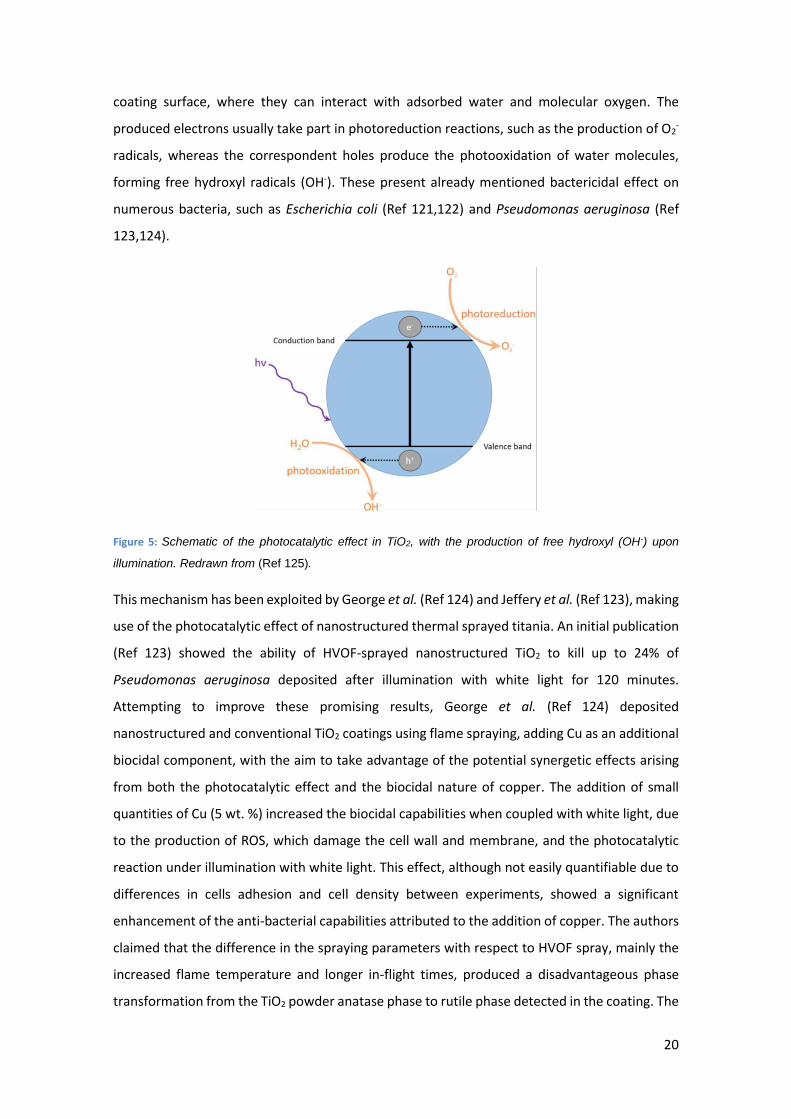
illumination of a material, which decomposes compounds by oxidation. As seen in Figure 5, the
illumination of the TiO2 coating with photons carrying energy equal or greater than the band gap
results in the creation of electron-hole pairs in the titania conductance and valence band,
respectively. There is a probability that these charge carriers will transfer or diffuse to the
20
coating surface, where they can interact with adsorbed water and molecular oxygen. The
produced electrons usually take part in photoreduction reactions, such as the production of O2-
radicals, whereas the correspondent holes produce the photooxidation of water molecules,
forming free hydroxyl radicals (OH-). These present already mentioned bactericidal effect on
numerous bacteria, such as Escherichia coli (Ref 121,122) and Pseudomonas aeruginosa (Ref
123,124).
Figure 5: Schematic of the photocatalytic effect in TiO2, with the production of free hydroxyl (OH-) upon
illumination. Redrawn from (Ref 125).
This mechanism has been exploited by George et al. (Ref 124) and Jeffery et al. (Ref 123), making
use of the photocatalytic effect of nanostructured thermal sprayed titania. An initial publication
(Ref 123) showed the ability of HVOF-sprayed nanostructured TiO2 to kill up to 24% of
Pseudomonas aeruginosa deposited after illumination with white light for 120 minutes.
Attempting to improve these promising results, George et al. (Ref 124) deposited
nanostructured and conventional TiO2 coatings using flame spraying, adding Cu as an additional
biocidal component, with the aim to take advantage of the potential synergetic effects arising
from both the photocatalytic effect and the biocidal nature of copper. The addition of small
quantities of Cu (5 wt. %) increased the biocidal capabilities when coupled with white light, due
to the production of ROS, which damage the cell wall and membrane, and the photocatalytic
reaction under illumination with white light. This effect, although not easily quantifiable due to
differences in cells adhesion and cell density between experiments, showed a significant
enhancement of the anti-bacterial capabilities attributed to the addition of copper. The authors
claimed that the difference in the spraying parameters with respect to HVOF spray, mainly the
increased flame temperature and longer in-flight times, produced a disadvantageous phase
transformation from the TiO2 powder anatase phase to rutile phase detected in the coating. The
21
anatase phase has been considered the main phase responsible for the photocatalytic effect
(Ref 126,127). Nevertheless, recent studies have considered the importance of features such as
porosity, the presence of nanostructures or the anatase to rutile ratio, rather than total content
of anatase phase. Bai et al. (Ref 128) reported the photocatalytic behaviour of SHVOF sprayed
TiO2 from rutile feedstock at different flame powers. The coating deposited at lower flame
power, with an anatase content of ~20 % and higher porosity levels than the high flame power
coatings (being the anatase content ~65 %) surprisingly presented the highest photocatalytic
activity, being the current density almost twice as high. The authors suggested the produced
bimodal microstructure, with completely melted areas and nano-sized agglomerations, as the
cause for the increased activity. The nanostructured formations increase the specific surface
area, along with the presence of mixed rutile and anatase areas in which rutile acts as an
“antenna”, being the electrons captured and then stabilised through transfer into the anatase
region, creating high catalytic regions in the interface.
In conclusion, thermal spray methods might not be optimal for the development of contact-
killing coatings due to the limitations on temperatures experienced by the feedstock during the
process, but they have been proven an excellent solution for others. The possibility to efficiently
deposit a robust coating loaded with anti-microbial components represents an excellent
opportunity for the medical and dental field. The localised delivery (both in location and time)
of biocidal agents is a desired characteristic rather than a drawback for such applications,
preventing surgical site infections and extended release of potentially noxious substances. These
characteristics, combined with the quick deposition of biocidal components such as copper over
large components, i.e. hospital furniture, and the possibilities provided by the photocatalytic
effect shown by well-studied components such as TiO2, makes the area of thermal sprayed anti-
microbial coatings a thriving one.
3.1.3. Membranes for water filtration
Although not a direct anti-microbial application in the sense covered in the previous sections,
thermal spray has been applied for the development of membranes for water purification. The
ability to deposit a thick film with controlled porosity allows for the design of membranes with
tailored mean pore size, effective in the removal of particulates from water. Despite the efforts
made by some authors to create ceramic membranes using technologies such as wire-arc (Ref
129), atmospheric plasma (Ref 130) or combustion flame (Ref 131) the manufacturing costs and
performance were not comparable to more extended polymeric membranes. An interesting
concept was presented in the work by Lin et al. (Ref 132) on the development of TiO2
22
membranes, aiming to combine the filtration capabilities of a ceramic membrane with the
biocidal effect of the photocatalytic process in TiO2. Although the concept could lead to new
filtration systems that tackle the solid pollutants at the same time as the biological pathogens in
water, no experimental measurement on cell strains of the anti-microbial capabilities of the
membrane are presented, lacking a strong pillar for the comparison with current filtration
systems.
3.2. Anti-fouling
The attachment of different aquatic species, classified as soft foulers (primarily algae) and hard
foulers (comprehending hard shelled molluscs such as barnacles and mussels) (Ref 133) to
surfaces exposed to submersion in water represents a critical factor when considering the
efficiency or maintenance cost of any marine and freshwater equipment (Ref 134,135). Of
noteworthy consideration is the case of the attachment of fouling to the submerged section of
hull in ships, which increases drag forces and the weight of vessels, directly affecting the
maximum speed, increasing the fuel consumption and lowering the ship manoeuvrability (Ref
136–139), with a considerable economic impact.
In order to prevent the adhesion and growth of fouling species, anti-fouling coatings are
routinely applied. The use of biocidal components on anti-fouling coatings has been the
preferred approach; however, ecological considerations limit the use of certain compounds due
to their non-specific toxicity, such as tributyl tin (TBT). This compound was worldwide banned
for all vessels from 2008 (Ref 139). TBT containing coatings have been replaced by those
employing copper (Ref 140), an element already mentioned in this work due to its biocidal
capabilities.
Although there are some examples of the use of thermal spray of Cu-based anti-fouling coatings
in industrial applications, as demonstrated by a 1984 patent on the deposition of Cu and Cu
alloys via thermal spraying (Ref 141), the application of anti-fouling coatings to the hull of vessels
has been primarily focused on the use of paints with copper (Ref 142). The reason for the
preference of paints resides in the negative interaction between metallic copper present in the
deposited coatings and the steel substrate, material widely used for ship hulls. Once copper is
deposited directly onto steel, the large potential difference between the two components
induces galvanic corrosion (Ref 143).
Despite the fact that the majority of anti-fouling measurements are presented in the form of
paints for the reasons previously mentioned, this solution is not optimal for low surface energy

23
thermoplastic polymers (Ref 133,144) such as the polyurethane skins on seismic streamers. Such
material presents insufficient adhesion for paints and lack the negative interactions mentioned
between steel and copper. For these reasons, the use of thermal spraying techniques, in
particular cold spray, has been investigated. Vucko et al. (Ref 145) reported an effective
technique to provide polymers with an embedded thin layer of Cu, with well-known biocidal
capabilities covered in section 3.1.1, using cold spray. Their initial work proved the concept for
the deposition of anti-fouling metals into polymers, in this case high-density polyethylene
(HDPE) and nylon. The anti-fouling capabilities of these initial results were demonstrated
through the complete submersion of the coated samples, and a copper plate as a reference, into
the open sea waters of Townsville, Australia. The HDPE Cu-embedded samples prevented
biofouling with similar efficiency as the copper plates for up to 250 days, test failed by the nylon
Cu-embedded samples. The behaviour of nylon Cu-embedded samples showed reduced anti-
fouling capabilities, with 54.3 ± 11.7 % coverage after 181 days in the same conditions as the
rest of the samples, while a coverage of 0.6 ± 0.6 % and 0 % was measured for HDPE and copper
plates respectively, strongly preventing soft foulers and completely preventing hard foulers. The
authors pointed the different depths of embedment of copper particles for the two substrates,
being 85.0 ± 1.5 µm for the HDPE Cu-embedded and 40.6 ± 0.4 µm for the nylon Cu-embedded,
as the cause. The greater depth of embedment on HDPE allowed for a slow release over longer
periods of time, preserving the surface free of foulers for the entire duration of the test. Another
study (Ref 146) reported similar results under the same testing conditions, obtained on Cu cold-
sprayed polyurethane (PU) samples. This time different spraying parameters (two robot arm
lateral speeds) were used in order to elucidate the impact on biocidal capabilities. The faster
lateral speed produced a lower density of copper particles, with five time less the amount of Cu
per unit area, which were also embedded at a shallower depth, 58.4 ± 1.9 µm compared to 85.6
± 1.9 µm for the slow speed samples. As a results, the coatings failed to prevent the initial stages
of hard foulers after 42 days for the low density PU Cu-embedded samples and after 210 days
for the high density PU Cu-embedded samples.
Proved the anti-fouling capabilities of cold-sprayed Cu particles into polymer components,
additional research has been carried out to identify the optimal deposition conditions. Lupoi et
al. (Ref 144) studied the capabilities of unheated, pressurised carrier gas in cold spray, in
contrast to the heated conditions previously used, 100 °C (Ref 145) and 400 °C (Ref 146), using
a high-speed nozzle design instead to achieve sufficient depth of embedment and surface
coverage on different polymer substrates. The authors found out that HDPE substrates suffered
from erosion at gas pressures above 2 MPa, achieving optimal depth of embedment and surface
24
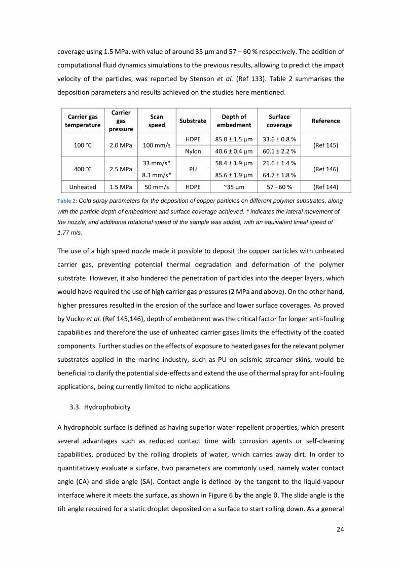
coverage using 1.5 MPa, with value of around 35 µm and 57 – 60 % respectively. The addition of
computational fluid dynamics simulations to the previous results, allowing to predict the impact
velocity of the particles, was reported by Stenson et al. (Ref 133). Table 2 summarises the
deposition parameters and results achieved on the studies here mentioned.
Carrier gas temperature
Carrier gas
pressure
Scan speed
Substrate Depth of
embedment Surface
coverage Reference
100 °C 2.0 MPa 100 mm/s HDPE 85.0 ± 1.5 µm 33.6 ± 0.8 %
(Ref 145) Nylon 40.6 ± 0.4 µm 60.1 ± 2.2 %
400 °C 2.5 MPa 33 mm/s*
PU 58.4 ± 1.9 µm 21.6 ± 1.4 %
(Ref 146) 8.3 mm/s* 85.6 ± 1.9 µm 64.7 ± 1.8 %
Unheated 1.5 MPa 50 mm/s HDPE ~35 µm 57 - 60 % (Ref 144)
Table 2: Cold spray parameters for the deposition of copper particles on different polymer substrates, along
with the particle depth of embedment and surface coverage achieved. * indicates the lateral movement of
the nozzle, and additional rotational speed of the sample was added, with an equivalent lineal speed of
1.77 m/s.
The use of a high speed nozzle made it possible to deposit the copper particles with unheated
carrier gas, preventing potential thermal degradation and deformation of the polymer
substrate. However, it also hindered the penetration of particles into the deeper layers, which
would have required the use of high carrier gas pressures (2 MPa and above). On the other hand,
higher pressures resulted in the erosion of the surface and lower surface coverages. As proved
by Vucko et al. (Ref 145,146), depth of embedment was the critical factor for longer anti-fouling
capabilities and therefore the use of unheated carrier gases limits the effectivity of the coated
components. Further studies on the effects of exposure to heated gases for the relevant polymer
substrates applied in the marine industry, such as PU on seismic streamer skins, would be
beneficial to clarify the potential side-effects and extend the use of thermal spray for anti-fouling
applications, being currently limited to niche applications
3.3. Hydrophobicity
A hydrophobic surface is defined as having superior water repellent properties, which present
several advantages such as reduced contact time with corrosion agents or self-cleaning
capabilities, produced by the rolling droplets of water, which carries away dirt. In order to
quantitatively evaluate a surface, two parameters are commonly used, namely water contact
angle (CA) and slide angle (SA). Contact angle is defined by the tangent to the liquid-vapour
interface where it meets the surface, as shown in Figure 6 by the angle θ. The slide angle is the
tilt angle required for a static droplet deposited on a surface to start rolling down. As a general

25
definition, any surface with CA > 90° can be considered hydrophobic, while values of CA > 150°
and SA < 10° are generally required for a surface to be considered as superhydrophobic.
Figure 6: a) Hydrophobic behaviour of a water droplet on a smooth surface, along with b) rough hydrophobic
and c) superhydrophobic surfaces, with their respective contact angles. Schematic b) shows a single-
scale/rough morphology, described by the Cassie-Baxter model. Schematic c) shows an improved dual-
scale/hierarchical morphology. Adapted from (Ref 147).
Hydrophobicity has two contributions that explain the particular behaviour presented. First of
all, a low surface energy which ensures that the attraction between the water droplets and the
surface is minimized. Secondly, a structured surface morphology. As seen on Figure 6, the
different levels on the morphology have a direct impact on the hydrophobicity of the surface.
Two main models are used to describe different hydrophobic states present on surfaces. The
first one, called Wenzel state (Ref 148), assumes the wetting of the entire surface, including in-
between the structural features present. On the other hand, the Cassie-Baxter state (Ref 149)
assumes that only the upper regions of the rough surface have contact with the liquid, with
pockets of air in between such features, as it can be seen in Figure 6(c). Hydrophobicity can be
seen in the nature, as in the commonly known case of the lotus leaf (Ref 150) or the wings of
certain insects (Ref 151), however, very few are the surfaces that present inherent
hydrophobicity features. Therefore, the development of functional coatings that can be easily
applied and are readily available for industrial applications have gained substantial interest in
the past decades.
The most extended methods to produce hydrophobic materials revolve around the
morphological modification of the surface, using techniques such as plasma etching or through
the controlled growth of structures using methods such as chemical vapour deposition or
lithographic techniques. Another approach is the functionalization of the surface energy using
chemical compounds such as polytetrafluoroethylene (PTFE) or poly(ethylene glycol) (PEG) (Ref
152–155). Nevertheless, the use of polymers as hydrophobic coatings has a clear disadvantage
on environments where robust mechanical properties are required due to the presence of wear
26
or loads. The application of metals and oxides through the use of thermal spraying techniques
allows the production of mechanically sound coatings with excellent hydrophobic capabilities.
Although nowadays the need to address the two contributing factors for hydrophobicity (namely
surface energy and surface topography) is generally accepted, the first developments of
thermally sprayed hydrophobic coatings focused on topography due to the natural
predisposition of thermal spray to produce desirable morphologies. An early example by Teisala
et al. (Ref 156) presents the development of a nanostructured TiO2 coating deposited on top of
paperboard using liquid flame spray with a roll-to-roll set up at ambient pressure, clearly
showing the industrial potential of thermally sprayed hydrophobic coatings. Due to the surface
morphology, lacking a hierarchical structure, the coating presented an elevated sliding angle.
Accounting for the excellent contact angle (up to 160°), the authors proposed the term “highly
hydrophobic adhesive surface” instead of superhydrophobic. The reason for this behaviour can
be understood considering that the coating is on a Wenzel state, effectively wetting the totality
of the coating surface, which increases the adhesive forces, while maintaining a high CA.
Later iterations acknowledged the need for a combined approach between surface energy and
topography. A robust and corrosion resistant hydrophobic coating was achieved by Zhang et al.
(Ref 157) on Fe-based amorphous coating deposited via HVOF. Superhydrophobicity was
reached after the addition of a lowering surface energy coating via immersion of the samples on
dodecanethiol. An initial study of the as-sprayed Fe-based coating revealed the essential
relationship between powder feedstock size and deposition parameters and the final roughness
of the coating, which influences its hydrophobic capabilities. The authors stablished that small
powder particles and high spraying energy leads to completely molten particles and flatter
surfaces (characterised by arithmetic mean surface roughness Ra values of 5.4 ± 0.7 µm), without
hydrophobicity characteristics (CA = 71°). The increase in powder particle size and reduction in
spraying energy led to higher surfaces roughness, with Ra value between 9.4 and 13.2 µm, and
clear hydrophobic capabilities (CA between 120° and 140°). Unfortunately no information on
sliding angle of the as-sprayed coatings is given, being only the chemically-treated
superhydrophobic surface values reported, with CA as high as 160° and SA around 9°.
Sharifi et al. (Ref 147) investigated the impact of the different morphology features present on
APS and SPS titania. Due to the use of different deposition techniques, involving aqueous and
ethanol suspensions with different dispersing agents, submersion into stearic acid was used to
equalize the surface energy of the different samples in order to eliminate the possibility of
different surface chemistries, effectively isolating the morphology influence. Their results
27
showed a clear impact of the deposition technique used, with APS presenting SA over 60°. This
was attributed to the larger and non-uniform features of APS, with a surface roughness Ra of
~3.7 µm, which prompted a Wenzel state. On the other hand, SPS produced a finer, hierarchical
morphology with higher Ra of 6.2 – 6.7 µm described by a Cassie-Baxter state, with CA and SA
values of 161° and 1°. Following the success on the reported superhydrophobic surface, a more
detailed study of SPS-deposited TiO2 revealed the optimal deposition parameters for improved
hydrophobicity (Ref 158). Similar to the conclusion reached by Teisala et al. (Ref 156), high
contact angles (CA > 150°) were achieved in most of the samples. The sliding angle was the
critical factor, with values ranging from over 20°, which can therefore be considered “highly
hydrophobic adhesive surfaces” to as low as 1.3° ± 0.3°. This values were achieved on an ethanol-
based suspension with 10 wt.% TiO2 deposited on a grit-blasted stainless steel to a surface
roughness of 1.5 µm, using 36 kW as the plasma deposition power on with a nozzle diameter
equal to 8 mm and a standoff distance of 50 mm. The samples presented excellent
superhydrophobic characteristics (CA = 168° ± 1° and SA = 1.3° ± 0.3°) and arithmetical mean
height of the surface (Sa) value of 8.3 ± 0.1 µm.
As a deeper understanding of the connection between spraying parameters, produced surface
topography and hydrophobicity was achieved, attempts to simplify the process were tackled.
Still using both morphology and low surface energy modifications, with the difference that only
thermal spraying methods were applied, Chen et al. (Ref 159) used different deposition
techniques to produce hydrophobic coatings. A stainless steel substrate was initially coated with
Al using high velocity arc-spray, being further coated with polyurethane (PU)/nano-Al2O3 using
suspension flame spraying. Surprisingly, the arc-sprayed Al coatings showed hydrophilic
characteristics with CA below 5°, while the addition of flame-sprayed nano- Al2O3 alone (without
the presence of PU) further maintained the hydrophilic behaviour, with CA below 5°. The marked
hydrophilic nature of nano-Al2O3 is considered responsible for this effect, despite the presence
of hierarchical morphology at the surface. The combined effect of a rough surface morphology
(although no surface roughness values are reported) with a lowered surface energy induced by
the addition of 2 wt.% PU, allowed for superhydrophobic CA values over 150° and SA values of
6.5°. An additional benefit of the superhydrophobic coating was an excellent corrosion
resistance, demonstrated by its good electrochemical behaviour on 3.5 wt.% NaCl aqueous
solution at room temperature. Following on the synergetic effects of morphology and surface
energy, a refined system was achieved by the introduction of a dual-scale, or hierarchical,
morphology (Ref 160). The use of a mesh as a micro-patterning plate introduced cone shaped
microstructures with finer nanoroughness (no Ra values are reported) on TiO2 APS-coated

28
samples. Once more, the surface energy was lowered depositing a thin film of PTFE/nano-Cu
using suspension flame. The reported values for the CA and SA of the surface were 153° and 2°
respectively, with the benefit of being a mechanically robust and easy to repair coating.
Despite the fact that the developments allowed to tailor the surface morphology and energy
treatments within the realm of thermal spraying, they ultimately relied on the chemical
modification of the surface to achieve superhydrophobic behaviours. A recent development
made by Cai et al. (Ref 161) further increases the possibilities for the superhydrophobicity
behaviour of functional coatings, without requiring an additional chemical modification of the
surface energy. Their work used rare earths, specifically ytterbium nitrate pentahydrate
(Yb(NO3)3)-5H2O, with inherent hydrophobic behaviour accounting for their electronic structure
(Ref 162,163). The deposition was done using two mediums, only distilled water and 50% water
50% ethanol, using the SPPS technique. This allowed to directly produce Yb2O3
superhydrophobic coatings. The combined hydrophobic capabilities, due to the chemical
properties of the coating, and the hierarchical structures obtained through the use of SPPS
produced superhydrophobic surfaces with contact angle 165° ± 2° and roughness values of Ra =
0.9 µm. The elimination of the chemical functionalization of the surface, and the high deposition
rates of the thermal spray technique, represents a very interesting candidate for industrial
implementation on large structures. Further investigations have been carried out by Xu et al.
(Ref 164) using the same deposition technique and materials, producing superhydrophobic
coatings with SA values of ~163° and sliding angle ~6.5°. Following this rationale, Bai et al. (Ref
165) present the use of another cost-efficient deposition technique, SHVOF spraying, to deposit
a different rare earth oxide (CeO2). They produced robust, near-superhydrophobic coatings with
CA values ranging between 134° (for Al alloy substrate) and 146° (for stainless steel substrate)
with surface rough height SA of 3.6 µm, although no sliding angle results are presented.
3.3.1. Icephobicity
A natural extension of surfaces with the capability to repel water droplets is the consideration
of similar mechanisms that prevent the formation or adherence of ice. The development of
icephobic surfaces represent a field of interest with multitude of applications such as aerospace
structures, solar panels or wind turbines, where ice causes a loss in efficiency and an increase in
costs. Nevertheless, the mechanisms involved in the prevention of ice accumulation are more
complex than those encountered with water in liquid form, creating a thriving field aiming to
determine the fundamental interactions (Ref 166–168). On a first consideration, ice needs to be
prevented to form in the surface, and if formed, the adhesion strength to the coating should be
29
less than the uncoated equivalent, facilitating its removal. In addition, the different routes
involved in the formation of ice and the several solid configurations that water can experience,
such as frost, glaze, rime, snow or ice (Ref 166,169), add an additional complexity layer to the
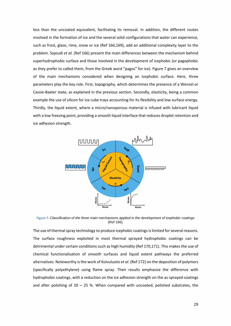
problem. Sojoudi et al. (Ref 166) present the main differences between the mechanism behind
superhydrophobic surface and those involved in the development of icephobic (or pagophobic
as they prefer to called them, from the Greek word “pagos” for ice). Figure 7 gives an overview
of the main mechanisms considered when designing an icephobic surface. Here, three
parameters play the key role. First, topography, which determines the presence of a Wenzel or
Cassie-Baxter state, as explained in the previous section. Secondly, elasticity, being a common
example the use of silicon for ice cube trays accounting for its flexibility and low surface energy.
Thirdly, the liquid extent, where a micro/nanoporous material is infused with lubricant liquid
with a low freezing point, providing a smooth liquid interface that reduces droplet retention and
ice adhesion strength.
Figure 7: Classification of the three main mechanisms applied in the development of icephobic coatings
(Ref 166).
The use of thermal spray technology to produce icephobic coatings is limited for several reasons.
The surface roughness exploited in most thermal sprayed hydrophobic coatings can be
detrimental under certain conditions such as high humidity (Ref 170,171). This makes the use of
chemical functionalisation of smooth surfaces and liquid extent pathways the preferred
alternatives. Noteworthy is the work of Koivuluoto et al. (Ref 172) on the deposition of polymers
(specifically polyethylene) using flame spray. Their results emphasise the difference with
hydrophobic coatings, with a reduction on the ice adhesion strength on the as-sprayed coatings
and after polishing of 20 – 25 %. When compared with uncoated, polished substrates, the

30
thermal sprayed coatings presented an ice adhesion strength ~5 times lower than stainless steel
and ~7 times lower for aluminium substrate.
The application of new mechanisms already proven in hydrophobic coatings, such as the use of
rare-earth compounds with intrinsic hydrophobic behaviour even on smooth surfaces, presents
a new field to be investigated which could potentially increase the presence of thermal sprayed
anti-icing coatings.
3.4. Electromagnetic and electrochemical properties
3.4.1. Electromagnetic properties
Thermal sprayed electrical and magnetic functional coatings comprises the use of materials
deposited using thermal spraying techniques with a focus on its electromagnetic properties
instead of its chemical properties or as passive barriers. This gives rise to a wide range of
applications such as integrated circuits. The importance of these materials is easily understood
if the role of thick-film-based electronics in today’s world is considered, being the base of the
micro-electronics industry. Such importance is demonstrated by a patent by Prinz et al. (Ref 173)
registered on 1994 on the development of electronic packages by thermal spray. They created
electronics structures through the application of masks, building up the different components
on each spray run. The use of thermal spraying deposition, capable of efficiently and cost-
effectively deposit continuous layers or patterned designs of conductive and isolating materials
has gained interest over the last decades. In particular, the desire to produce patterns with
linewidths as reduced as possible has driven the investigation of novel deposition techniques
within the thermal spray field. Nowadays two different trends can be identified in the
development of thermal sprayed micro-electronics.
The first one, called additive-only, relies on the miniaturisation of the thermal spray equipment
itself and the use of dynamic apertures at the nozzle (Ref 174). This achieves a smaller flame
capable of directly depositing features with a range of thicknesses between 250 µm and a few
millimetres. This technique has been successfully applied in the development of electromagnetic
shields (Ref 175), antennas for unmanned aerial vehicles (Ref 176) or gas sensors on heat-
sensitive substrates (Ref 177). The approach has several advantages present on traditional
thermal spray techniques, such as the capability to deposit on heat-sensitive substrates, the
flexibility of choice in deposited materials and the readily available infrastructure in the industry.
An extensive review on its use and applications accounting to the different properties exploited,
such as dielectricity, conductance, resistance, magnetism or superconductivity was written by
Sampath (Ref 12). In his work, an analysis of the microstructure and intrinsic physical properties

31
of thermal sprayed functional materials is first presented, with focus on how to understand and
control said properties. The different devices that have emerged from the application of
electromagnetic thermal sprayed materials are then outlined, with examples of multi-layered
circuits, antennas, ohmic contacts and sensors, to name a few. The review concludes identifying
the key factors for the limited spread of thermal spray for electric and magnetic applications,
mainly the poor understanding of the material properties and the lack of precise enough tools
to achieve the required miniaturisation.
The second approach involves the use of machining methods, such as laser micromachining (Ref
178), on a thermal sprayed layer to form the desired pattern as shown on Figure 8. It is therefore
labelled additive-subtractive, for obvious reasons. The addition of a second processing step,
although it pushes the linewidth down to 15 – 20 µm, considerably increases the time required
to fabricate the device. Another effect is the added cost due to the need of a parallel machining
infrastructure, when compared to a single thermal spraying unit as in the case of additive-only.
Nevertheless, its capabilities have been exploited in the development of thermopiles for power
generation or temperature sensing (Ref 179,180), embedded microheaters (Ref 181) and strain
gauges (Ref 182). As proven by the recent work in the field, the additive-subtractive approach
represents a great technique with potential in the field of prototyping and specialised
components, where longer manufacturing times and increased costs per unit are not as critical
as in large-scale production.
Figure 8: Schematic of the additive-subtractive method used to produce precise patterns through the addition
of laser micromachining to a thermal sprayed layer (Ref 12).
Despite the advancements made towards miniaturisation of thermal sprayed components, their
uses are still limited to laboratory scale and cannot compete with the current, well-stablished
methods used in the electronics industry. Nevertheless, the production of electrical circuits is
32
not the only application where thermal sprayed materials can be of use. Plenty of modern
devices require components of reduced size and suitable electrical properties. For instance, the
ability of thermal spray to produce dense, thick ceramic films is more desirable in cases such as
piezoelectric components for micro-devices, presenting a clear advantage over other competing
methods such as chemical vapour deposition.
In addition to the capability to deposit thick ceramic coatings, another crucial advantage when
considering the use of thermal spraying for electrical applications is the confinement of the high
temperature process to the actual deposition. This translates into a very low heat transfer to the
substrate. On the other hand, when developing multi-layered structures through alternative
techniques, such as traditional ceramic coating production (e.g. tape casting, doctor blade) the
temperatures required to fire the ceramics might prove too high for the rest of the components,
or it could induce undesirable chemical reactions. This implies an investment on high
temperature equipment, high melting point substrates and protective layers to avoid the
reactions are needed, further increasing the manufacturing costs when compared with thermal
spray deposition.
Despite the lower heat transfer present in thermal spray, another factor to be taken into account
is that melting of the feedstock particles may lead to the undesirable phase transformation,
demanding post-deposition heat treatments if the initial microstructure is to be recovered.
Therefore, research in this field has been predominately focused on kinetic deposition
techniques, such as cold spray, described on section 2.4 or aerosol deposition (AD). The
underlying working principle of such techniques is the ejection of submicrometre powder
particles with the aid of a carrier gas. The aerosol flow is directed towards the substrate, being
kept under vacuum during the whole process. Since the bonding mechanism relies on the
adhesion of the fine particles, these techniques do not alter the feedstock phase composition or
suffer from heat induced damage to the substrate (Ref 183). The goal in these cases is to produce
a dense layer with unaffected electrical properties.
Considerable success has been achieved in the use of those techniques to develop electrical
devices, such as piezoelectrics (Ref 184,185), microwave filters for radio-frequency applications
(Ref 186), electro-optic complex films (Ref 187), electrodes for solid state lithium batteries (Ref
188) or TiO2 films for dye-sensitized solar cells (Ref 189,190). In all the examples presented
above, kinetic spraying allowed for a higher deposition rate than comparable thick-film
deposition techniques such as screen printing (Ref 191), with the benefit of an absence of high
temperature exposure, characteristic of other thermal spray techniques. A comprehensive
33
overview by Akedo (Ref 192) covers the applications of kinetic spraying, or room temperature
impact consolidation (RTIC), for microdevices. His work presents a thorough comparison of the
challenges and opportunities in the fabrication of micro-actuators, requiring dense and thick
films of piezoelectric or electrostrictive materials, using conventional methods such as sol-gel or
chemical vapour deposition and RTIC. The higher deposition efficiency of thermal spray methods
and the advantages mentioned related to the higher control over the microstructure using RTIC,
proved the potential of this approach.
3.4.2. Electrochemical properties
The advancement in electrochemical cells, both for the conversion of energy and the electrolysis
of water, has been an active research topic for the past decades. The specific environment to
which the components are exposed (high temperatures, corrosive chemicals and varying
electrical current) makes the electrodes a particular interesting point for the improvement and
development of better performing electrochemical cells. In addition to an outstanding physical
and chemical stability, the electrodes need to have surface area as high as possible, aiming to
increase the accessibility of the electrolyte to the electrode surface and to allow an enhanced
detachment of the gases produced in the process, which effectively increases the
electrocatalytic activity (Ref 193).
When used on power-consumption mode, for instance, to perform alkaline water electrolysis,
electrochemical cells are regarded as one of the prime future techniques for the mass
production of hydrogen. The process is not new and has been extensively investigated. This
includes the use of thermal spray techniques for the fabrication of electrodes, as proven by a
1977 patent (Ref 194). Nevertheless, the ever-increasing demand for hydrogen, mainly due to
its applications as clean fuel for transportation powering systems, has boosted the interest for
more cost-effective systems. The use of thermal spray techniques has been proven as an
effective way to produce electrodes, achieving an excellent control of the microstructure and
surface properties due to the flexibility on deposition parameters and different techniques, as
shown in Table 3.
Process Year Material Cell temperature Reference
Atmospheric
plasma spray 1983 Ni 80 °C (Ref 195)
Vacuum plasma
spray 1995 Ni-Al 70 °C (Ref 196)
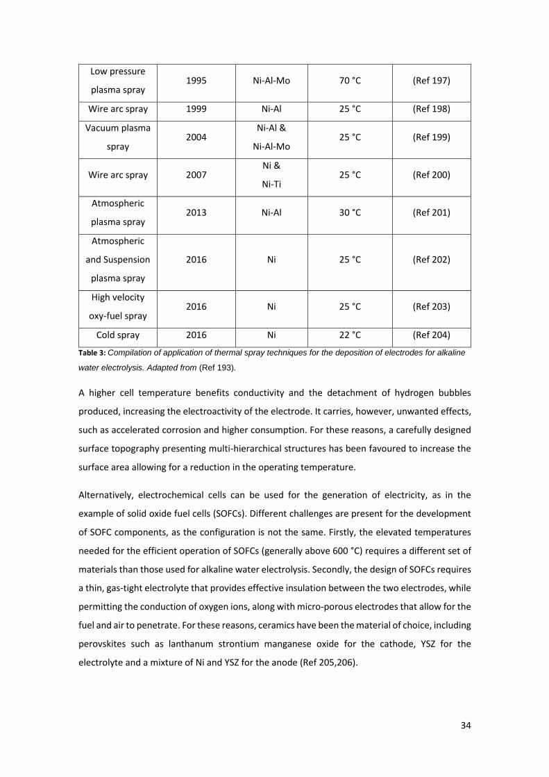
34
Low pressure
plasma spray 1995 Ni-Al-Mo 70 °C (Ref 197)
Wire arc spray 1999 Ni-Al 25 °C (Ref 198)
Vacuum plasma
spray 2004
Ni-Al &
Ni-Al-Mo 25 °C (Ref 199)
Wire arc spray 2007 Ni &
Ni-Ti 25 °C (Ref 200)
Atmospheric
plasma spray 2013 Ni-Al 30 °C (Ref 201)
Atmospheric
and Suspension
plasma spray
2016 Ni 25 °C (Ref 202)
High velocity
oxy-fuel spray 2016 Ni 25 °C (Ref 203)
Cold spray 2016 Ni 22 °C (Ref 204)
Table 3: Compilation of application of thermal spray techniques for the deposition of electrodes for alkaline
water electrolysis. Adapted from (Ref 193).
A higher cell temperature benefits conductivity and the detachment of hydrogen bubbles
produced, increasing the electroactivity of the electrode. It carries, however, unwanted effects,
such as accelerated corrosion and higher consumption. For these reasons, a carefully designed
surface topography presenting multi-hierarchical structures has been favoured to increase the
surface area allowing for a reduction in the operating temperature.
Alternatively, electrochemical cells can be used for the generation of electricity, as in the
example of solid oxide fuel cells (SOFCs). Different challenges are present for the development
of SOFC components, as the configuration is not the same. Firstly, the elevated temperatures
needed for the efficient operation of SOFCs (generally above 600 °C) requires a different set of
materials than those used for alkaline water electrolysis. Secondly, the design of SOFCs requires
a thin, gas-tight electrolyte that provides effective insulation between the two electrodes, while
permitting the conduction of oxygen ions, along with micro-porous electrodes that allow for the
fuel and air to penetrate. For these reasons, ceramics have been the material of choice, including
perovskites such as lanthanum strontium manganese oxide for the cathode, YSZ for the
electrolyte and a mixture of Ni and YSZ for the anode (Ref 205,206).

35
Traditional fabrication methods for those ceramic components present several disadvantages
that thermal spray could help to overcome. The high temperature required for the firing process,
for instance, presents a bottleneck on the mass production of SOFCs, greatly increasing their
cost. It also implies problems such as thermal mismatch stresses on large components, side
reactions between adjacent layers and the difficulty of using low-melting materials in the multi-
layered structure (Ref 207). The increase time efficiency of thermal spray techniques such as
plasma spray and the reduced heat transfer to the substrate (allowing the use of cheaper
materials) arise as potential solutions to the previous problems, meaning that thermal spray
could drastically reduce the cost of current SOFCs.
Regarding the deposition of electrodes, plasma spray, a common deposition technique in the
industry, usually presents porosity levels between 5 – 15 vol.%, which is still far from the 40
vol.% required for optimal gas diffusivity in electrodes (Ref 207). The use of porous metal
substrate (Ref 208), the inclusion of larger particles (Ref 205) or with higher melting point (Ref
209) and the addition of “pore formers” (material burned out after deposition, leaving empty
spaces in the coating) (Ref 210) have been successful techniques applied to increase porosity.
In the case of the electrolyte, porosity would have a detrimental effect on the cell efficiency and
hence a pore free structure is required. Thicker coatings could be applied to minimise the effect
of open porosity, increasing the diffusion path; however, this approach has a negative impact
on the efficiency, and alternative routes to minimise porosity and defect density have been
pursued. For instance, a thorough understanding of the plasma spraying deposition parameters
has been followed, in order to determine the optimal conditions for the deposition of crack-free
coatings. This allows qualitative low levels of porosity (no porosity measurements are reported)
on relatively thin coatings (less than 40 µm) with performance comparable of sintered
components (Ref 211).
The production of cheaper SOFCs for electricity generation would represent a major
breakthrough for the industry, leading to a greater industrial uptake. Nevertheless, to achieve
this, the above-mentioned design requirements should be met, such as porous electrodes or
thin, defect-free electrolytes.
3.5. Resistive heating
3.5.1. Development of thermal-sprayed coating systems for heating purposes
This section provides a summary of the reported research findings in the area of development
of functional thermal-sprayed coatings for heating applications. Different materials and spraying
36
processes that have been investigated by various researchers for fabrication of heating systems
and the main contributions of each study in advancement and evolution of the thermal-sprayed
heaters are reviewed in this section.
The usage of thermal-sprayed coatings as electrical resistance heating systems has received
increasing attention in recent years. However, the application of thermal-sprayed coatings in
electronics was proposed around five decades ago when planar ferrite microwave integrated
circuits (MICs) were successfully fabricated by using arc-plasma spraying (APS) process (Ref 212).
Smyth and Anderson (Ref 213) studied the effect of spraying parameters on the physical and
electrical properties of the produced film resistors. It was shown that APS process can be used
as an alternative method for producing electrical components and circuit. It was found that a
film with sheet resistivity from 5-500 Ω/sq could be obtained by using a mixture of NiO and Fe3O4
powders with a particle size range of 1 – 20 µm and that APS can be used for cheap quantity
production of resistors and conductors with satisfactory long-term stability (Ref 213).
Sampath et al. (Ref 214), investigated the application of thermal spray techniques in fabrication
of meso-electronics. It was found that multilayer deposits of ceramics and metals that have
appropriate electrical properties can be produced by thermal spray methods to fabricate
electrical components ranging from insulators, conductors, and resistors. Fabrication of resistor
was conducted by deposition of NiCr alloy over alumina by plasma or HVOF processes. The sheet
resistance of the fabricated resistor was reported to be in the range of 17,000-54,000 Ω/sq. Low
cost, high production rate, flexibility of use of thermal spray process, and capability of producing
millimetre-thick layers of conductors and insulators made this process an alternative for
fabrication of components for power electronics (Ref 214). Similarly, deposition of ceramic
feedstock particles by using HVOF process that is accompanied by oxygen-rich flames and the
use of cold spray process have been found to be appropriate methods in synthesis of high-
quality dielectrics and conductors, respectively (Ref 50).
In an early effort (Ref 215), air plasma spraying process was used to fabricate the resistance
heaters. The metal film heater (molybdenum), which was isolated from the faceplate by a
plasma-sprayed ceramic film, was able to generate heat fluxes up to 7.2 MW/m2 over an area of
10.3 cm2 (Ref 215). Therefore, it was shown that thermal-sprayed coatings can be used as
heating systems. Given the direct deposition of the films atop the test surface, as opposed to
mechanically attaching the heater to the surface, the thermal contact resistance between the
thermal-sprayed heating element and the substrate is minimised (Ref 216). This results in
fabrication of more efficient heating elements. The structure of the heating system depends on
37
the electrical resistance of the metallic alloy that is required to be achieved, the substrate
material, and its electrical conductivity. Owing to the high thickness required to achieve the
appropriate electrical resistance, thermal spraying techniques are preferred over vapour
deposition for fabrication of the coating-based heating elements (Ref 216). It is well-established
that for the cases in which the substrate is electrically conductive, an intermediary ceramic layer,
which possesses dielectric properties, is required to prevent short circuiting and leakage current
in the heating system. Therefore, it is required to develop a multi-layered coating system that
consists of the two main elements, namely the heating element that is usually a metallic alloy
and an electrically insulating ceramic layer.
3.5.1.1. Deposition of the ceramic coating as an electrically insulating layer
Alumina is widely used as an electrical insulator due to the dielectric properties that this material
possesses. Given the rapid and simple coating of large surfaces by using plasma spraying process,
deposition of electrically insulating coatings have been an appealing option in electronics
industry. It has been shown that the volume resistivity of plasma-sprayed alumina coating can
be very high within the range of 109 - 1010 Ω cm (Ref 217). It has been reported in the literature
that the electrical resistivity of alumina depends on several parameters including applied
pressure, humidity, microstructural characteristics, and phase composition of alumina (Ref 218–
222).
Luo et al. (Ref 218) demonstrated that the surface resistivity of alumina coating decreases by
applying pressure on it, but it still was larger than 106 Ω cm when it was compressed at pressures
up to 250 MPa. High humidity levels also affect resistivity of the alumina coating (Ref 219–221).
In a study by Toma et al. (Ref 219) a dramatic decrease about five orders of magnitude in the
resistivity of alumina coating was observed when the relative humidity level was increased to
95%. The deterioration of the insulating properties of alumina coating with increasing humidity
was explained by increase in the surface conductance of the oxide layer because of absorption
and accumulation of water molecules on the coating surface (Ref 220).
Furthermore, the different microstructural features of the coatings due to use of different
thermal spray processes affect the electrical resistivity of alumina layer. It was found that the
electrical resistivity of the alumina coating that was obtained from HVOF process was slightly
higher than the one that was fabricated by APS process, which was likely due to the lower open
porosity and presence of defects (Ref 219). Furthermore, it was shown that the alumina that is
sprayed by suspension HVOF (SHVOF) has better electrical resistance stability than the alumina
38
coating deposited by the conventional HVOF process due to the retention of higher content of
-alumina (Ref 221).
The phase transformation of alumina is also another well-known, but neglected factor that can
negatively affect the electrical properties of the thermally sprayed alumina coatings. The
deterioration of electrical properties of alumina is due to the phase change from -alumina
(corundum) to -alumina, which is a metastable phase with undesired properties (Ref 221,222).
The phase change is attributed to the rapid cooling of the molten alumina particles below the
temperature at which the atomic rearrangement can occur before the stable phase of corundum
is reached (Ref 223). It was found by McPherson (Ref 224) that the metastable form is retained
during cooling of particles that are less than 10 µm diameter and the particles larger than that
may transform to -Al2O3 during the solidification.
It has been shown that plasma-sprayed deposits of cordierite (2MgO-2Al2O3-5SiO2) can also be
used as the electrically insulating layers due to the high electrical resistivity and chemical
durability of this material (Ref 225,226). Alumina-titania coatings are other alternatives that can
be used as electrically insulating layers. In addition to the dielectric properties, they benefit from
enhanced toughness, which increase their performance and durability (Ref 12); however, the
electrical resistivity of the alumina-titania coatings is partially compromised. As an example, it
was observed by Golonka and Pawlowski (Ref 227) that the surface resistivity of arc plasma
sprayed alumina was 109 Ω cm, but that of alumina-2wt. % titania was 107 Ω cm.
The main challenge associated with the coating-based insulators is the dielectric breakdown
mechanism of the coating, which is indicative of the failure of the electrically insulating layer,
and is caused by electrical discharge when high local fields are produced. This leads to physical
degradation of the ceramic layer by formation of a complete failure path. It has been found that
voltage at which the breakdown of the APS-sprayed Al2O3-13% TiO2 coating, which is one of the
compositions of alumina-titania systems that is widely used as an electrical insulator, occurs is
linearly related to the thickness of the coating. In this respect, the average dielectric strength of
the coating was measured to be 20 kV/mm (Ref 228).
It was observed by Killinger et al. (Ref 229) that the two most important factors regarding the
electrically insulating layer are breakthrough voltage and leakage current, which depended
heavily on the internal morphology of the coating that was related to the thermal spraying
process that was used for deposition of the coating. It was concluded that the porosity of the
deposited alumina coating had a profound impact on the breakdown voltage of this electrically
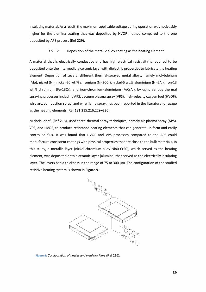
39
insulating material. As a result, the maximum applicable voltage during operation was noticeably
higher for the alumina coating that was deposited by HVOF method compared to the one
deposited by APS process (Ref 229).
3.5.1.2. Deposition of the metallic alloy coating as the heating element
A material that is electrically conductive and has high electrical resistivity is required to be
deposited onto the intermediary ceramic layer with dielectric properties to fabricate the heating
element. Deposition of several different thermal-sprayed metal alloys, namely molybdenum
(Mo), nickel (Ni), nickel-20 wt.% chromium (Ni-20Cr), nickel-5 wt.% aluminium (Ni-5Al), iron-13
wt.% chromium (Fe-13Cr), and iron-chromium-aluminium (FeCrAl), by using various thermal
spraying processes including APS, vacuum plasma spray (VPS), high-velocity oxygen fuel (HVOF),
wire arc, combustion spray, and wire flame spray, has been reported in the literature for usage
as the heating elements (Ref 181,215,216,229–236).
Michels, et al. (Ref 216), used three thermal spray techniques, namely air plasma spray (APS),
VPS, and HVOF, to produce resistance heating elements that can generate uniform and easily
controlled flux. It was found that HVOF and VPS processes compared to the APS could
manufacture consistent coatings with physical properties that are close to the bulk materials. In
this study, a metallic layer (nickel-chromium alloy Ni80-Cr20), which served as the heating
element, was deposited onto a ceramic layer (alumina) that served as the electrically insulating
layer. The layers had a thickness in the range of 75 to 300 µm. The configuration of the studied
resistive heating system is shown in Figure 9.
Figure 9: Configuration of heater and insulator films (Ref 216).
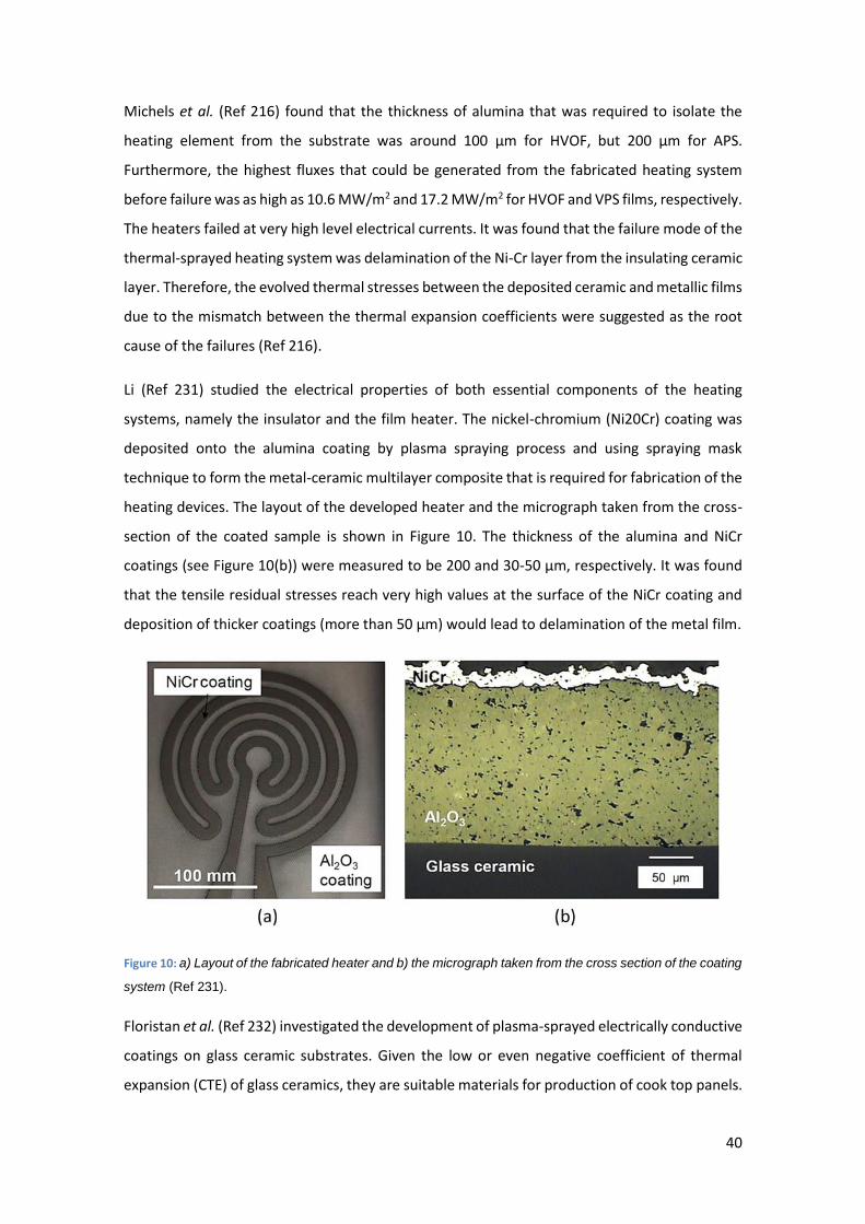
40
Michels et al. (Ref 216) found that the thickness of alumina that was required to isolate the
heating element from the substrate was around 100 µm for HVOF, but 200 µm for APS.
Furthermore, the highest fluxes that could be generated from the fabricated heating system
before failure was as high as 10.6 MW/m2 and 17.2 MW/m2 for HVOF and VPS films, respectively.
The heaters failed at very high level electrical currents. It was found that the failure mode of the
thermal-sprayed heating system was delamination of the Ni-Cr layer from the insulating ceramic
layer. Therefore, the evolved thermal stresses between the deposited ceramic and metallic films
due to the mismatch between the thermal expansion coefficients were suggested as the root
cause of the failures (Ref 216).
Li (Ref 231) studied the electrical properties of both essential components of the heating
systems, namely the insulator and the film heater. The nickel-chromium (Ni20Cr) coating was
deposited onto the alumina coating by plasma spraying process and using spraying mask
technique to form the metal-ceramic multilayer composite that is required for fabrication of the
heating devices. The layout of the developed heater and the micrograph taken from the cross-
section of the coated sample is shown in Figure 10. The thickness of the alumina and NiCr
coatings (see Figure 10(b)) were measured to be 200 and 30-50 µm, respectively. It was found
that the tensile residual stresses reach very high values at the surface of the NiCr coating and
deposition of thicker coatings (more than 50 µm) would lead to delamination of the metal film.
Figure 10: a) Layout of the fabricated heater and b) the micrograph taken from the cross section of the coating
system (Ref 231).
Floristan et al. (Ref 232) investigated the development of plasma-sprayed electrically conductive
coatings on glass ceramic substrates. Given the low or even negative coefficient of thermal
expansion (CTE) of glass ceramics, they are suitable materials for production of cook top panels.

41
This enables this material to be in contact with cold objects (e.g. pots from the fridge) while they
are operating at high temperatures (Ref 232). One of the main challenges regarding the
deposition of coatings onto the glass ceramic coatings is the adhesion between the substrate
and the coating (Ref 232). Given the brittle nature of the glass ceramic material, grit blasting is
not widely used to roughen the glass substrates as the impact of the particles can damage the
surface of the substrate. However, it has been found that bilayer coating systems that were
deposited on smooth glass ceramic samples did not have sufficient adhesion to the substrate.
Although grit blasting can damage the glass ceramic substrate, it can be considered as an
efficient manner, especially when accompanied by proper preheating, in providing the adhesion
that is required in industrial applications. The micrographs of the coating systems that were
deposited on smooth and rough glass ceramic substrates are shown in Figure 11.
Figure 11: Cross section micrographs of coating systems that are deposited onto a) smooth, and b) grit
blasted heated glass ceramic substrates (Ref 232).
The other main issue associated with direct deposition of metallic coatings on glass or glass
ceramic substrates is evolution of critical residual stresses within the coating system due to the
noticeable difference between the CTE of the glass substrates and that of the metal coatings
that can lead to cracking and delamination at the coating-substrate interface. It was found that
the areas that were coated with alumina and NiCrAlY materials had a profound impact on the
stability of the bilayer coating system. For some of the samples in which alumina coating was
deposited over a wider region, delamination was not observed (see Figure 12(a)). However, for
the case in which both layers were deposited onto an accurate geometrical path, delamination
of the top coating was observed, which was due to the accumulation of stresses at the edges
(see Figure 12(b)) (Ref 233).
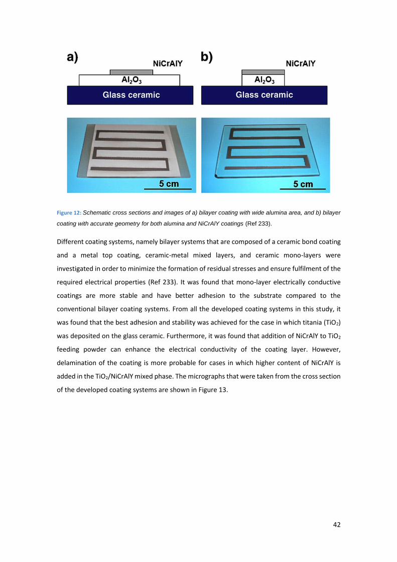
42
Figure 12: Schematic cross sections and images of a) bilayer coating with wide alumina area, and b) bilayer
coating with accurate geometry for both alumina and NiCrAlY coatings (Ref 233).
Different coating systems, namely bilayer systems that are composed of a ceramic bond coating
and a metal top coating, ceramic-metal mixed layers, and ceramic mono-layers were
investigated in order to minimize the formation of residual stresses and ensure fulfilment of the
required electrical properties (Ref 233). It was found that mono-layer electrically conductive
coatings are more stable and have better adhesion to the substrate compared to the
conventional bilayer coating systems. From all the developed coating systems in this study, it
was found that the best adhesion and stability was achieved for the case in which titania (TiO2)
was deposited on the glass ceramic. Furthermore, it was found that addition of NiCrAlY to TiO2
feeding powder can enhance the electrical conductivity of the coating layer. However,
delamination of the coating is more probable for cases in which higher content of NiCrAlY is
added in the TiO2/NiCrAlY mixed phase. The micrographs that were taken from the cross section
of the developed coating systems are shown in Figure 13.
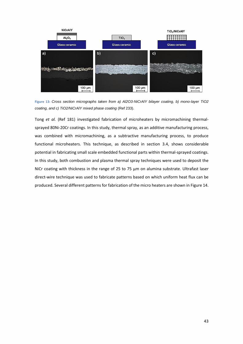
43
Figure 13: Cross section micrographs taken from a) Al2O3-NiCrAlY bilayer coating, b) mono-layer TiO2
coating, and c) TiO2/NiCrAlY mixed phase coating (Ref 233).
Tong et al. (Ref 181) investigated fabrication of microheaters by micromachining thermal-
sprayed 80Ni-20Cr coatings. In this study, thermal spray, as an additive manufacturing process,
was combined with micromachining, as a subtractive manufacturing process, to produce
functional microheaters. This technique, as described in section 3.4, shows considerable
potential in fabricating small scale embedded functional parts within thermal-sprayed coatings.
In this study, both combustion and plasma thermal spray techniques were used to deposit the
NiCr coating with thickness in the range of 25 to 75 µm on alumina substrate. Ultrafast laser
direct-wire technique was used to fabricate patterns based on which uniform heat flux can be
produced. Several different patterns for fabrication of the micro heaters are shown in Figure 14.
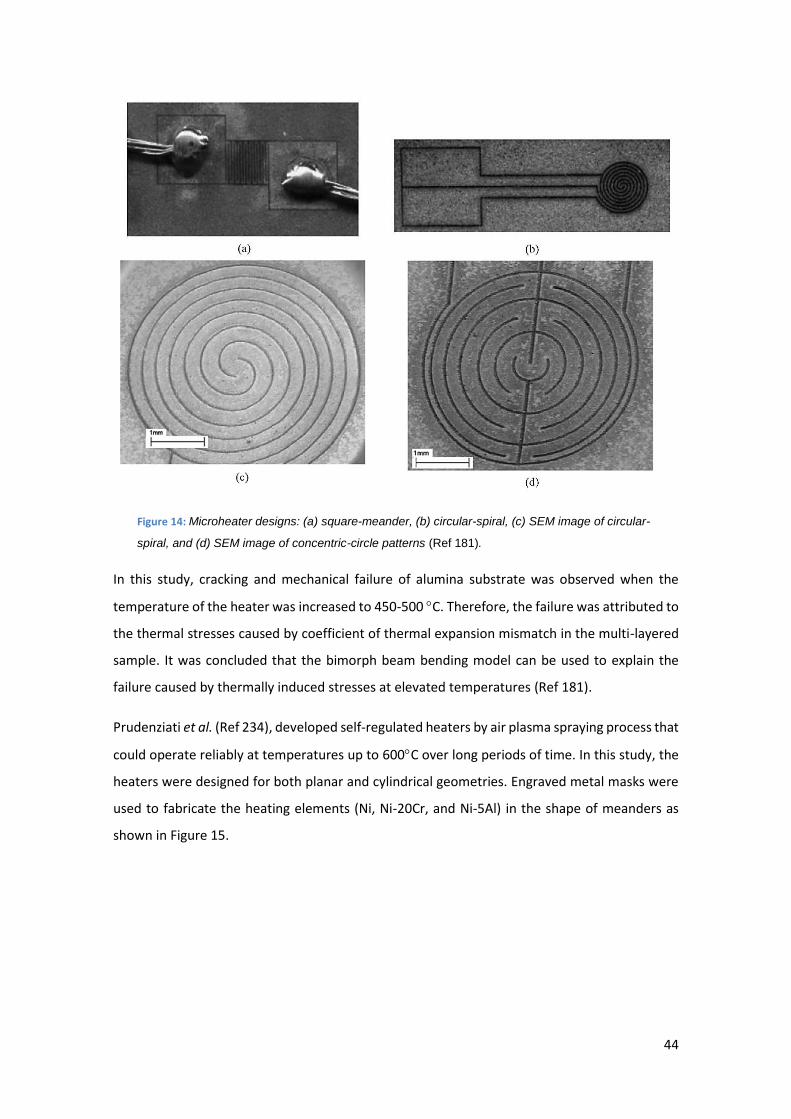
44
Figure 14: Microheater designs: (a) square-meander, (b) circular-spiral, (c) SEM image of circular-
spiral, and (d) SEM image of concentric-circle patterns (Ref 181).
In this study, cracking and mechanical failure of alumina substrate was observed when the
temperature of the heater was increased to 450-500 C. Therefore, the failure was attributed to
the thermal stresses caused by coefficient of thermal expansion mismatch in the multi-layered
sample. It was concluded that the bimorph beam bending model can be used to explain the
failure caused by thermally induced stresses at elevated temperatures (Ref 181).
Prudenziati et al. (Ref 234), developed self-regulated heaters by air plasma spraying process that
could operate reliably at temperatures up to 600C over long periods of time. In this study, the
heaters were designed for both planar and cylindrical geometries. Engraved metal masks were
used to fabricate the heating elements (Ni, Ni-20Cr, and Ni-5Al) in the shape of meanders as
shown in Figure 15.
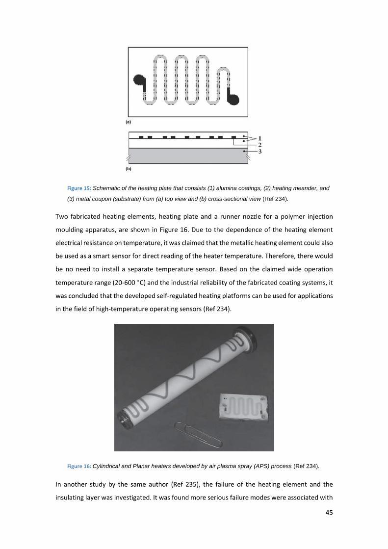
45
Figure 15: Schematic of the heating plate that consists (1) alumina coatings, (2) heating meander, and
(3) metal coupon (substrate) from (a) top view and (b) cross-sectional view (Ref 234).
Two fabricated heating elements, heating plate and a runner nozzle for a polymer injection
moulding apparatus, are shown in Figure 16. Due to the dependence of the heating element
electrical resistance on temperature, it was claimed that the metallic heating element could also
be used as a smart sensor for direct reading of the heater temperature. Therefore, there would
be no need to install a separate temperature sensor. Based on the claimed wide operation
temperature range (20-600 C) and the industrial reliability of the fabricated coating systems, it
was concluded that the developed self-regulated heating platforms can be used for applications
in the field of high-temperature operating sensors (Ref 234).
Figure 16: Cylindrical and Planar heaters developed by air plasma spray (APS) process (Ref 234).
In another study by the same author (Ref 235), the failure of the heating element and the
insulating layer was investigated. It was found more serious failure modes were associated with
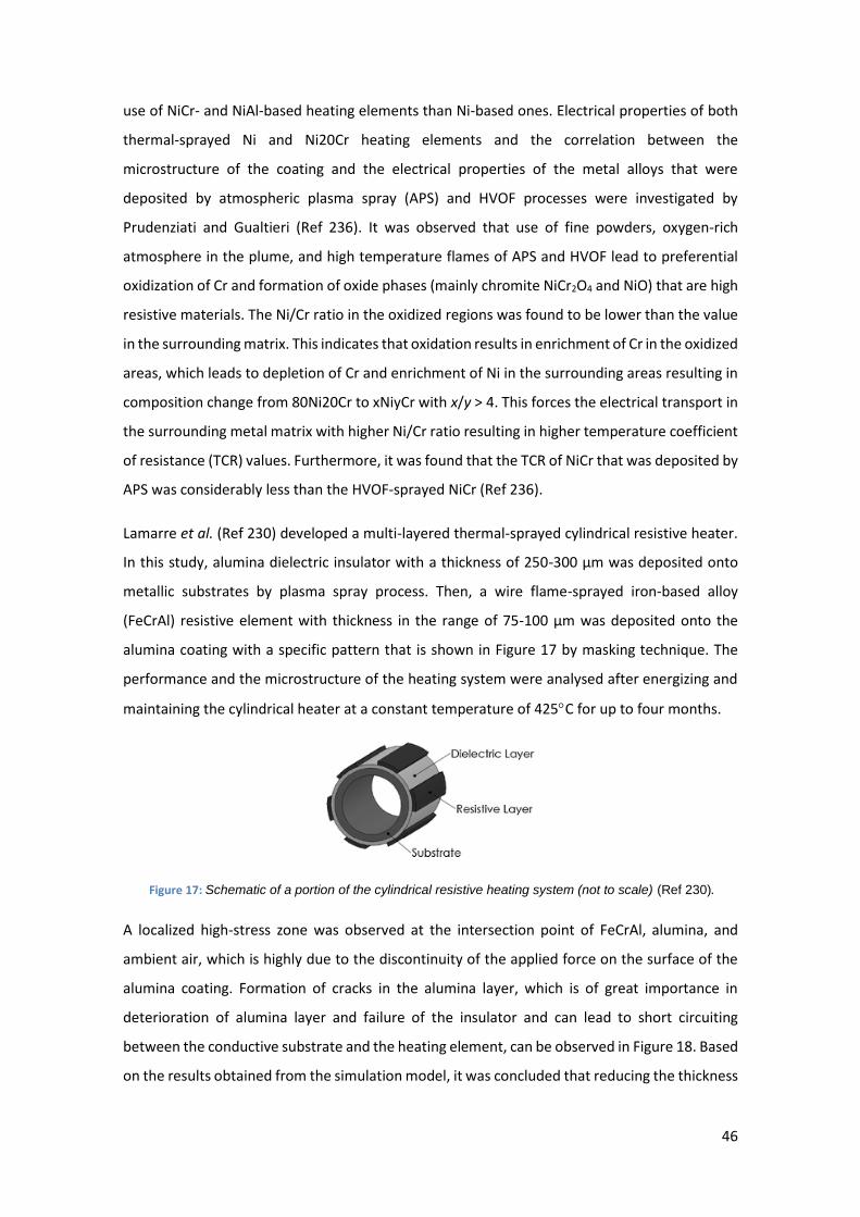
46
use of NiCr- and NiAl-based heating elements than Ni-based ones. Electrical properties of both
thermal-sprayed Ni and Ni20Cr heating elements and the correlation between the
microstructure of the coating and the electrical properties of the metal alloys that were
deposited by atmospheric plasma spray (APS) and HVOF processes were investigated by
Prudenziati and Gualtieri (Ref 236). It was observed that use of fine powders, oxygen-rich
atmosphere in the plume, and high temperature flames of APS and HVOF lead to preferential
oxidization of Cr and formation of oxide phases (mainly chromite NiCr2O4 and NiO) that are high
resistive materials. The Ni/Cr ratio in the oxidized regions was found to be lower than the value
in the surrounding matrix. This indicates that oxidation results in enrichment of Cr in the oxidized
areas, which leads to depletion of Cr and enrichment of Ni in the surrounding areas resulting in
composition change from 80Ni20Cr to xNiyCr with x/y > 4. This forces the electrical transport in
the surrounding metal matrix with higher Ni/Cr ratio resulting in higher temperature coefficient
of resistance (TCR) values. Furthermore, it was found that the TCR of NiCr that was deposited by
APS was considerably less than the HVOF-sprayed NiCr (Ref 236).
Lamarre et al. (Ref 230) developed a multi-layered thermal-sprayed cylindrical resistive heater.
In this study, alumina dielectric insulator with a thickness of 250-300 µm was deposited onto
metallic substrates by plasma spray process. Then, a wire flame-sprayed iron-based alloy
(FeCrAl) resistive element with thickness in the range of 75-100 µm was deposited onto the
alumina coating with a specific pattern that is shown in Figure 17 by masking technique. The
performance and the microstructure of the heating system were analysed after energizing and
maintaining the cylindrical heater at a constant temperature of 425C for up to four months.
Figure 17: Schematic of a portion of the cylindrical resistive heating system (not to scale) (Ref 230).
A localized high-stress zone was observed at the intersection point of FeCrAl, alumina, and
ambient air, which is highly due to the discontinuity of the applied force on the surface of the
alumina coating. Formation of cracks in the alumina layer, which is of great importance in
deterioration of alumina layer and failure of the insulator and can lead to short circuiting
between the conductive substrate and the heating element, can be observed in Figure 18. Based
on the results obtained from the simulation model, it was concluded that reducing the thickness
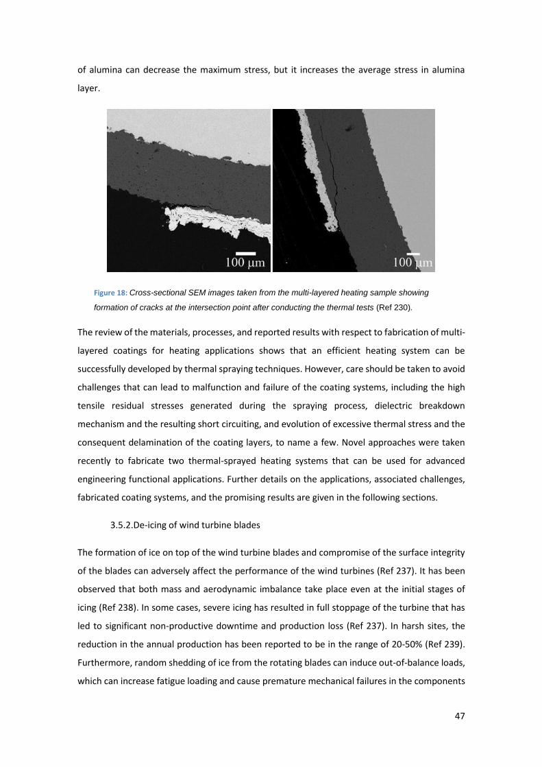
47
of alumina can decrease the maximum stress, but it increases the average stress in alumina
layer.
Figure 18: Cross-sectional SEM images taken from the multi-layered heating sample showing
formation of cracks at the intersection point after conducting the thermal tests (Ref 230).
The review of the materials, processes, and reported results with respect to fabrication of multi-
layered coatings for heating applications shows that an efficient heating system can be
successfully developed by thermal spraying techniques. However, care should be taken to avoid
challenges that can lead to malfunction and failure of the coating systems, including the high
tensile residual stresses generated during the spraying process, dielectric breakdown
mechanism and the resulting short circuiting, and evolution of excessive thermal stress and the
consequent delamination of the coating layers, to name a few. Novel approaches were taken
recently to fabricate two thermal-sprayed heating systems that can be used for advanced
engineering functional applications. Further details on the applications, associated challenges,
fabricated coating systems, and the promising results are given in the following sections.
3.5.2. De-icing of wind turbine blades
The formation of ice on top of the wind turbine blades and compromise of the surface integrity
of the blades can adversely affect the performance of the wind turbines (Ref 237). It has been
observed that both mass and aerodynamic imbalance take place even at the initial stages of
icing (Ref 238). In some cases, severe icing has resulted in full stoppage of the turbine that has
led to significant non-productive downtime and production loss (Ref 237). In harsh sites, the
reduction in the annual production has been reported to be in the range of 20-50% (Ref 239).
Furthermore, random shedding of ice from the rotating blades can induce out-of-balance loads,
which can increase fatigue loading and cause premature mechanical failures in the components
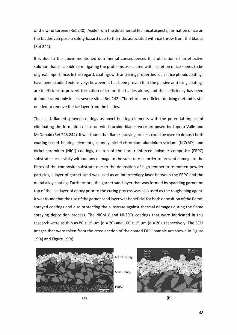
48
of the wind turbine (Ref 240). Aside from the detrimental technical aspects, formation of ice on
the blades can pose a safety hazard due to the risks associated with ice throw from the blades
(Ref 241).
It is due to the above-mentioned detrimental consequences that utilization of an effective
solution that is capable of mitigating the problems associated with accretion of ice seems to be
of great importance. In this regard, coatings with anti-icing properties such as ice phobic coatings
have been studied extensively; however, it has been proven that the passive anti-icing coatings
are inefficient to prevent formation of ice on the blades alone, and their efficiency has been
demonstrated only in less severe sites (Ref 242). Therefore, an efficient de-icing method is still
needed to remove the ice layer from the blades.
That said, flamed-sprayed coatings as novel heating elements with the potential impact of
eliminating the formation of ice on wind turbine blades were proposed by Lopera-Valle and
McDonald (Ref 243,244). It was found that flame spraying process could be used to deposit both
coating-based heating elements, namely nickel-chromium-aluminium-yttrium (NiCrAlY) and
nickel-chromium (NiCr) coatings, on top of the fibre-reinforced polymer composite (FRPC)
substrate successfully without any damage to the substrate. In order to prevent damage to the
fibres of the composite substrate due to the deposition of high-temperature molten powder
particles, a layer of garnet sand was used as an intermediary layer between the FRPC and the
metal alloy coating. Furthermore, the garnet sand layer that was formed by sparkling garnet on
top of the last layer of epoxy prior to the curing process was also used as the roughening agent.
It was found that the use of the garnet sand layer was beneficial for both deposition of the flame-
sprayed coatings and also protecting the substrate against thermal damages during the flame
spraying deposition process. The NiCrAlY and Ni-20Cr coatings that were fabricated in this
research were as thin as 80 ± 15 µm (n = 20) and 100 ± 15 µm (n = 20), respectively. The SEM
images that were taken from the cross-section of the coated FRPC sample are shown in Figure
19(a) and Figure 19(b).
(a) (b)
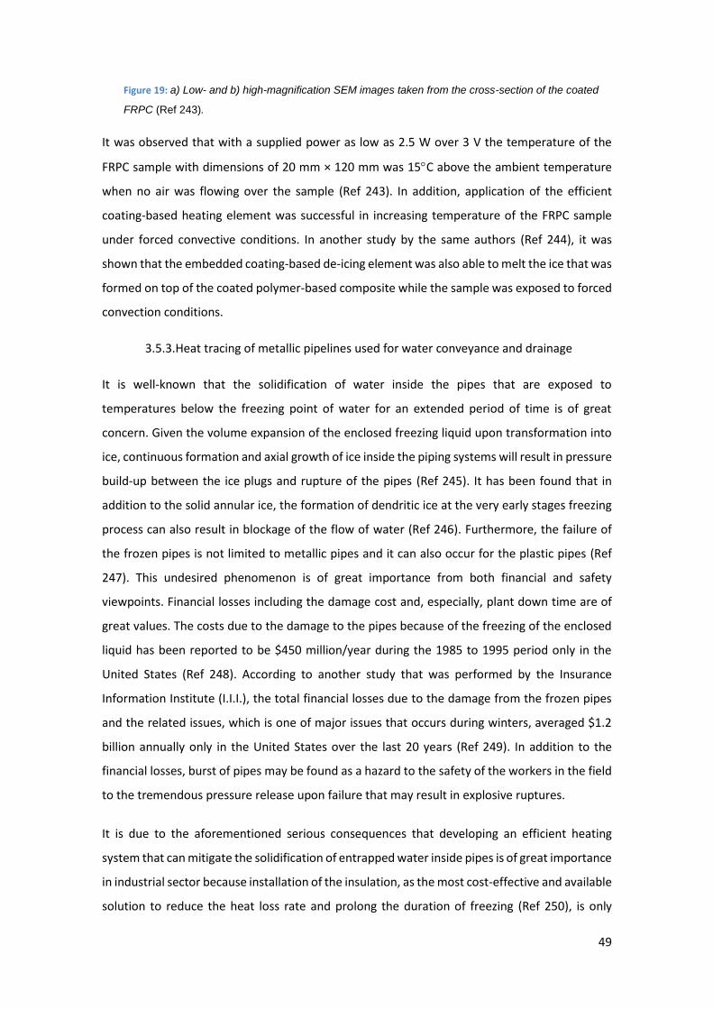
49
Figure 19: a) Low- and b) high-magnification SEM images taken from the cross-section of the coated
FRPC (Ref 243).
It was observed that with a supplied power as low as 2.5 W over 3 V the temperature of the
FRPC sample with dimensions of 20 mm × 120 mm was 15C above the ambient temperature
when no air was flowing over the sample (Ref 243). In addition, application of the efficient
coating-based heating element was successful in increasing temperature of the FRPC sample
under forced convective conditions. In another study by the same authors (Ref 244), it was
shown that the embedded coating-based de-icing element was also able to melt the ice that was
formed on top of the coated polymer-based composite while the sample was exposed to forced
convection conditions.
3.5.3. Heat tracing of metallic pipelines used for water conveyance and drainage
It is well-known that the solidification of water inside the pipes that are exposed to
temperatures below the freezing point of water for an extended period of time is of great
concern. Given the volume expansion of the enclosed freezing liquid upon transformation into
ice, continuous formation and axial growth of ice inside the piping systems will result in pressure
build-up between the ice plugs and rupture of the pipes (Ref 245). It has been found that in
addition to the solid annular ice, the formation of dendritic ice at the very early stages freezing
process can also result in blockage of the flow of water (Ref 246). Furthermore, the failure of
the frozen pipes is not limited to metallic pipes and it can also occur for the plastic pipes (Ref
247). This undesired phenomenon is of great importance from both financial and safety
viewpoints. Financial losses including the damage cost and, especially, plant down time are of
great values. The costs due to the damage to the pipes because of the freezing of the enclosed
liquid has been reported to be $450 million/year during the 1985 to 1995 period only in the
United States (Ref 248). According to another study that was performed by the Insurance
Information Institute (I.I.I.), the total financial losses due to the damage from the frozen pipes
and the related issues, which is one of major issues that occurs during winters, averaged $1.2
billion annually only in the United States over the last 20 years (Ref 249). In addition to the
financial losses, burst of pipes may be found as a hazard to the safety of the workers in the field
to the tremendous pressure release upon failure that may result in explosive ruptures.
It is due to the aforementioned serious consequences that developing an efficient heating
system that can mitigate the solidification of entrapped water inside pipes is of great importance
in industrial sector because installation of the insulation, as the most cost-effective and available
solution to reduce the heat loss rate and prolong the duration of freezing (Ref 250), is only
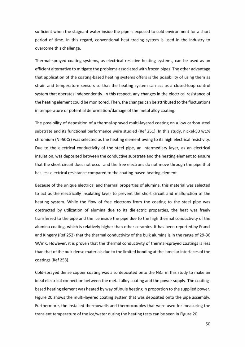
50
sufficient when the stagnant water inside the pipe is exposed to cold environment for a short
period of time. In this regard, conventional heat tracing system is used in the industry to
overcome this challenge.
Thermal-sprayed coating systems, as electrical resistive heating systems, can be used as an
efficient alternative to mitigate the problems associated with frozen pipes. The other advantage
that application of the coating-based heating systems offers is the possibility of using them as
strain and temperature sensors so that the heating system can act as a closed-loop control
system that operates independently. In this respect, any changes in the electrical resistance of
the heating element could be monitored. Then, the changes can be attributed to the fluctuations
in temperature or potential deformation/damage of the metal alloy coating.
The possibility of deposition of a thermal-sprayed multi-layered coating on a low carbon steel
substrate and its functional performance were studied (Ref 251). In this study, nickel-50 wt.%
chromium (Ni-50Cr) was selected as the heating element owing to its high electrical resistivity.
Due to the electrical conductivity of the steel pipe, an intermediary layer, as an electrical
insulation, was deposited between the conductive substrate and the heating element to ensure
that the short circuit does not occur and the free electrons do not move through the pipe that
has less electrical resistance compared to the coating-based heating element.
Because of the unique electrical and thermal properties of alumina, this material was selected
to act as the electrically insulating layer to prevent the short circuit and malfunction of the
heating system. While the flow of free electrons from the coating to the steel pipe was
obstructed by utilization of alumina due to its dielectric properties, the heat was freely
transferred to the pipe and the ice inside the pipe due to the high thermal conductivity of the
alumina coating, which is relatively higher than other ceramics. It has been reported by Francl
and Kingery (Ref 252) that the thermal conductivity of the bulk alumina is in the range of 29-36
W/mK. However, it is proven that the thermal conductivity of thermal-sprayed coatings is less
than that of the bulk dense materials due to the limited bonding at the lamellar interfaces of the
coatings (Ref 253).
Cold-sprayed dense copper coating was also deposited onto the NiCr in this study to make an
ideal electrical connection between the metal alloy coating and the power supply. The coating-
based heating element was heated by way of Joule heating in proportion to the supplied power.
Figure 20 shows the multi-layered coating system that was deposited onto the pipe assembly.
Furthermore, the installed thermowells and thermocouples that were used for measuring the
transient temperature of the ice/water during the heating tests can be seen in Figure 20.
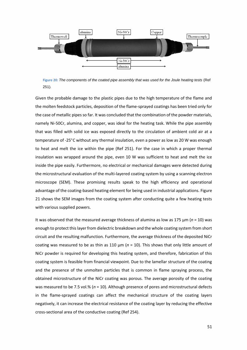
51
Figure 20: The components of the coated pipe assembly that was used for the Joule heating tests (Ref
251).
Given the probable damage to the plastic pipes due to the high temperature of the flame and
the molten feedstock particles, deposition of the flame-sprayed coatings has been tried only for
the case of metallic pipes so far. It was concluded that the combination of the powder materials,
namely Ni-50Cr, alumina, and copper, was ideal for the heating task. While the pipe assembly
that was filled with solid ice was exposed directly to the circulation of ambient cold air at a
temperature of -25C without any thermal insulation, even a power as low as 20 W was enough
to heat and melt the ice within the pipe (Ref 251). For the case in which a proper thermal
insulation was wrapped around the pipe, even 10 W was sufficient to heat and melt the ice
inside the pipe easily. Furthermore, no electrical or mechanical damages were detected during
the microstructural evaluation of the multi-layered coating system by using a scanning electron
microscope (SEM). These promising results speak to the high efficiency and operational
advantage of the coating-based heating element for being used in industrial applications. Figure
21 shows the SEM images from the coating system after conducting quite a few heating tests
with various supplied powers.
It was observed that the measured average thickness of alumina as low as 175 µm (n = 10) was
enough to protect this layer from dielectric breakdown and the whole coating system from short
circuit and the resulting malfunction. Furthermore, the average thickness of the deposited NiCr
coating was measured to be as thin as 110 µm (n = 10). This shows that only little amount of
NiCr powder is required for developing this heating system, and therefore, fabrication of this
coating system is feasible from financial viewpoint. Due to the lamellar structure of the coating
and the presence of the unmolten particles that is common in flame spraying process, the
obtained microstructure of the NiCr coating was porous. The average porosity of the coating
was measured to be 7.5 vol.% (n = 10). Although presence of pores and microstructural defects
in the flame-sprayed coatings can affect the mechanical structure of the coating layers
negatively, it can increase the electrical resistance of the coating layer by reducing the effective
cross-sectional area of the conductive coating (Ref 254).
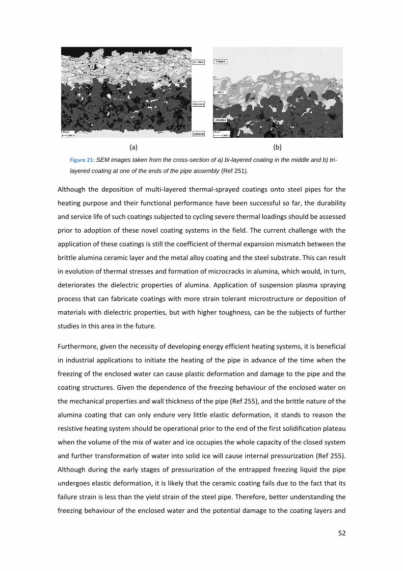
52
(a) (b)
Figure 21: SEM images taken from the cross-section of a) bi-layered coating in the middle and b) tri-
layered coating at one of the ends of the pipe assembly (Ref 251).
Although the deposition of multi-layered thermal-sprayed coatings onto steel pipes for the
heating purpose and their functional performance have been successful so far, the durability
and service life of such coatings subjected to cycling severe thermal loadings should be assessed
prior to adoption of these novel coating systems in the field. The current challenge with the
application of these coatings is still the coefficient of thermal expansion mismatch between the
brittle alumina ceramic layer and the metal alloy coating and the steel substrate. This can result
in evolution of thermal stresses and formation of microcracks in alumina, which would, in turn,
deteriorates the dielectric properties of alumina. Application of suspension plasma spraying
process that can fabricate coatings with more strain tolerant microstructure or deposition of
materials with dielectric properties, but with higher toughness, can be the subjects of further
studies in this area in the future.
Furthermore, given the necessity of developing energy efficient heating systems, it is beneficial
in industrial applications to initiate the heating of the pipe in advance of the time when the
freezing of the enclosed water can cause plastic deformation and damage to the pipe and the
coating structures. Given the dependence of the freezing behaviour of the enclosed water on
the mechanical properties and wall thickness of the pipe (Ref 255), and the brittle nature of the
alumina coating that can only endure very little elastic deformation, it stands to reason the
resistive heating system should be operational prior to the end of the first solidification plateau
when the volume of the mix of water and ice occupies the whole capacity of the closed system
and further transformation of water into solid ice will cause internal pressurization (Ref 255).
Although during the early stages of pressurization of the entrapped freezing liquid the pipe
undergoes elastic deformation, it is likely that the ceramic coating fails due to the fact that its
failure strain is less than the yield strain of the steel pipe. Therefore, better understanding the
freezing behaviour of the enclosed water and the potential damage to the coating layers and
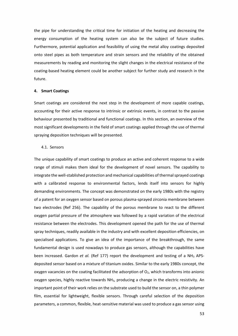
53
the pipe for understanding the critical time for initiation of the heating and decreasing the
energy consumption of the heating system can also be the subject of future studies.
Furthermore, potential application and feasibility of using the metal alloy coatings deposited
onto steel pipes as both temperature and strain sensors and the reliability of the obtained
measurements by reading and monitoring the slight changes in the electrical resistance of the
coating-based heating element could be another subject for further study and research in the
future.
4. Smart Coatings
Smart coatings are considered the next step in the development of more capable coatings,
accounting for their active response to intrinsic or extrinsic events, in contrast to the passive
behaviour presented by traditional and functional coatings. In this section, an overview of the
most significant developments in the field of smart coatings applied through the use of thermal
spraying deposition techniques will be presented.
4.1. Sensors
The unique capability of smart coatings to produce an active and coherent response to a wide
range of stimuli makes them ideal for the development of novel sensors. The capability to
integrate the well-stablished protection and mechanical capabilities of thermal sprayed coatings
with a calibrated response to environmental factors, lends itself into sensors for highly
demanding environments. The concept was demonstrated on the early 1980s with the registry
of a patent for an oxygen sensor based on porous plasma-sprayed zirconia membrane between
two electrodes (Ref 256). The capability of the porous membrane to react to the different
oxygen partial pressure of the atmosphere was followed by a rapid variation of the electrical
resistance between the electrodes. This development opened the path for the use of thermal
spray techniques, readily available in the industry and with excellent deposition efficiencies, on
specialised applications. To give an idea of the importance of the breakthrough, the same
fundamental design is used nowadays to produce gas sensors, although the capabilities have
been increased. Gardon et al. (Ref 177) report the development and testing of a NH3 APS-
deposited sensor based on a mixture of titanium oxides. Similar to the early 1980s concept, the
oxygen vacancies on the coating facilitated the adsorption of O2, which transforms into anionic
oxygen species, highly reactive towards NH3, producing a change in the electric resistivity. An
important point of their work relies on the substrate used to build the sensor on, a thin polymer
film, essential for lightweight, flexible sensors. Through careful selection of the deposition
parameters, a common, flexible, heat-sensitive material was used to produce a gas sensor using
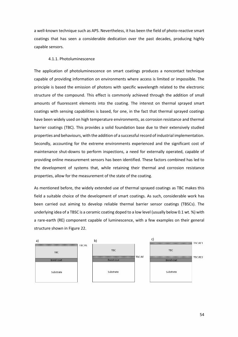
54
a well-known technique such as APS. Nevertheless, it has been the field of photo-reactive smart
coatings that has seen a considerable dedication over the past decades, producing highly
capable sensors.
4.1.1. Photoluminescence
The application of photoluminescence on smart coatings produces a noncontact technique
capable of providing information on environments where access is limited or impossible. The
principle is based the emission of photons with specific wavelength related to the electronic
structure of the compound. This effect is commonly achieved through the addition of small
amounts of fluorescent elements into the coating. The interest on thermal sprayed smart
coatings with sensing capabilities is based, for one, in the fact that thermal sprayed coatings
have been widely used on high temperature environments, as corrosion resistance and thermal
barrier coatings (TBC). This provides a solid foundation base due to their extensively studied
properties and behaviours, with the addition of a successful record of industrial implementation.
Secondly, accounting for the extreme environments experienced and the significant cost of
maintenance shut-downs to perform inspections, a need for externally operated, capable of
providing online measurement sensors has been identified. These factors combined has led to
the development of systems that, while retaining their thermal and corrosion resistance
properties, allow for the measurement of the state of the coating.
As mentioned before, the widely extended use of thermal sprayed coatings as TBC makes this
field a suitable choice of the development of smart coatings. As such, considerable work has
been carried out aiming to develop reliable thermal barrier sensor coatings (TBSCs). The
underlying idea of a TBSC is a ceramic coating doped to a low level (usually below 0.1 wt. %) with
a rare-earth (RE) component capable of luminescence, with a few examples on their general
structure shown in Figure 22.
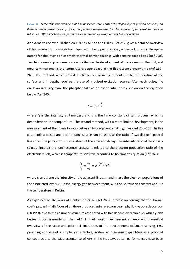
55
Figure 22: Three different examples of luminescence rare earth (RE) doped layers (striped sections) on
thermal barrier sensor coatings for a) temperature measurement at the surface, b) temperature measure
within the TBC and c) dual temperature measurement, allowing for heat flux calculations.
An extensive review published on 1997 by Allison and Gillies (Ref 257) gives a detailed overview
of the remote thermometric technique, with the appearance only one year later of an European
patent for the invention of smart thermal barrier coatings with sensing capabilities (Ref 258).
Two fundamental phenomena are exploited on the development of these sensors. The first, and
most common one, is the temperature dependence of the fluorescence decay time (Ref 259–
265). This method, which provides reliable, online measurements of the temperature at the
surface and in-depth, requires the use of a pulsed excitation source. After each pulse, the
emission intensity from the phosphor follows an exponential decay shown on the equation
below (Ref 265):
𝐼 = 𝐼0𝑒−𝑡𝜏
where I0 is the intensity at time zero and τ is the time constant of said process, which is
dependent on the temperature. The second method, with a more limited development, is the
measurement of the intensity ratio between two adjacent emitting lines (Ref 266–268). In this
case, both a pulsed and a continuous source can be used, as the ratio of two distinct spectral
lines from the phosphor is used instead of the emission decay. The intensity ratio of the closely
spaced lines on the luminescence process is related to the electron population ratio of the
electronic levels, which is temperature sensitive according to Boltzmann equation (Ref 267):
𝐼1
𝐼2=
𝑛1
𝑛2= 𝑒
−(∆𝐸𝑘𝐵𝑇⁄ )
where I1 and I2 are the intensity of the adjacent lines, n1 and n2 are the electron populations of
the associated levels, ΔE is the energy gap between them, kB is the Boltzmann constant and T is
the temperature in Kelvin.
As explained on the work of Gentleman et al. (Ref 266), interest on sensing thermal barrier
coatings was initially focused on those produced using electron beam physical vapour deposition
(EB-PVD), due to the columnar structure associated with this deposition technique, which yields
better optical transmission than APS. In their work, they present an excellent theoretical
overview of the state and potential limitations of the development of smart sensing TBC,
providing at the end a simple, yet effective, system with sensing capabilities as a proof of
concept. Due to the wide acceptance of APS in the industry, better performances have been
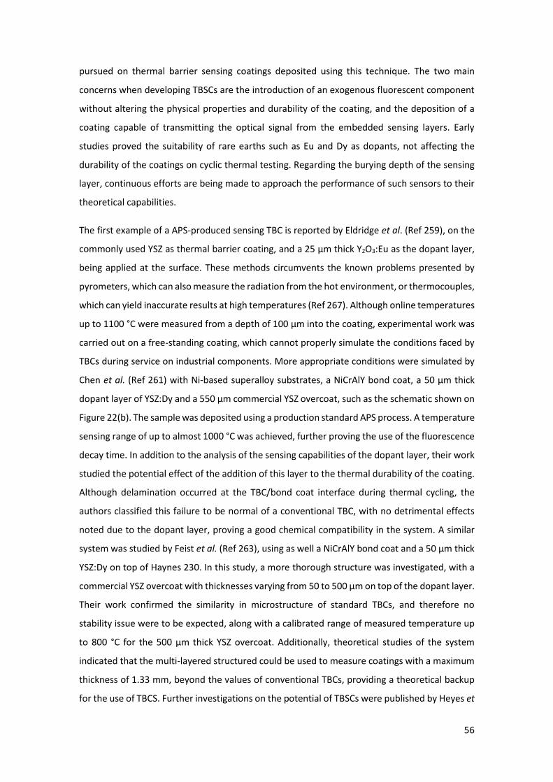
56
pursued on thermal barrier sensing coatings deposited using this technique. The two main
concerns when developing TBSCs are the introduction of an exogenous fluorescent component
without altering the physical properties and durability of the coating, and the deposition of a
coating capable of transmitting the optical signal from the embedded sensing layers. Early
studies proved the suitability of rare earths such as Eu and Dy as dopants, not affecting the
durability of the coatings on cyclic thermal testing. Regarding the burying depth of the sensing
layer, continuous efforts are being made to approach the performance of such sensors to their
theoretical capabilities.
The first example of a APS-produced sensing TBC is reported by Eldridge et al. (Ref 259), on the
commonly used YSZ as thermal barrier coating, and a 25 µm thick Y2O3:Eu as the dopant layer,
being applied at the surface. These methods circumvents the known problems presented by
pyrometers, which can also measure the radiation from the hot environment, or thermocouples,
which can yield inaccurate results at high temperatures (Ref 267). Although online temperatures
up to 1100 °C were measured from a depth of 100 µm into the coating, experimental work was
carried out on a free-standing coating, which cannot properly simulate the conditions faced by
TBCs during service on industrial components. More appropriate conditions were simulated by
Chen et al. (Ref 261) with Ni-based superalloy substrates, a NiCrAlY bond coat, a 50 µm thick
dopant layer of YSZ:Dy and a 550 µm commercial YSZ overcoat, such as the schematic shown on
Figure 22(b). The sample was deposited using a production standard APS process. A temperature
sensing range of up to almost 1000 °C was achieved, further proving the use of the fluorescence
decay time. In addition to the analysis of the sensing capabilities of the dopant layer, their work
studied the potential effect of the addition of this layer to the thermal durability of the coating.
Although delamination occurred at the TBC/bond coat interface during thermal cycling, the
authors classified this failure to be normal of a conventional TBC, with no detrimental effects
noted due to the dopant layer, proving a good chemical compatibility in the system. A similar
system was studied by Feist et al. (Ref 263), using as well a NiCrAlY bond coat and a 50 µm thick
YSZ:Dy on top of Haynes 230. In this study, a more thorough structure was investigated, with a
commercial YSZ overcoat with thicknesses varying from 50 to 500 µm on top of the dopant layer.
Their work confirmed the similarity in microstructure of standard TBCs, and therefore no
stability issue were to be expected, along with a calibrated range of measured temperature up
to 800 °C for the 500 µm thick YSZ overcoat. Additionally, theoretical studies of the system
indicated that the multi-layered structured could be used to measure coatings with a maximum
thickness of 1.33 mm, beyond the values of conventional TBCs, providing a theoretical backup
for the use of TBCS. Further investigations on the potential of TBSCs were published by Heyes et
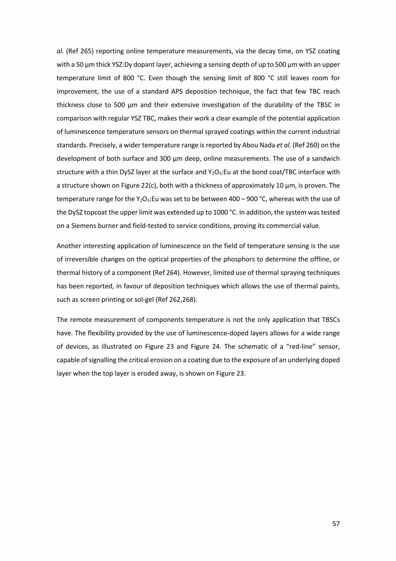
57
al. (Ref 265) reporting online temperature measurements, via the decay time, on YSZ coating
with a 50 µm thick YSZ:Dy dopant layer, achieving a sensing depth of up to 500 µm with an upper
temperature limit of 800 °C. Even though the sensing limit of 800 °C still leaves room for
improvement, the use of a standard APS deposition technique, the fact that few TBC reach
thickness close to 500 µm and their extensive investigation of the durability of the TBSC in
comparison with regular YSZ TBC, makes their work a clear example of the potential application
of luminescence temperature sensors on thermal sprayed coatings within the current industrial
standards. Precisely, a wider temperature range is reported by Abou Nada et al. (Ref 260) on the
development of both surface and 300 µm deep, online measurements. The use of a sandwich
structure with a thin DySZ layer at the surface and Y2O3:Eu at the bond coat/TBC interface with
a structure shown on Figure 22(c), both with a thickness of approximately 10 µm, is proven. The
temperature range for the Y2O3:Eu was set to be between 400 – 900 °C, whereas with the use of
the DySZ topcoat the upper limit was extended up to 1000 °C. In addition, the system was tested
on a Siemens burner and field-tested to service conditions, proving its commercial value.
Another interesting application of luminescence on the field of temperature sensing is the use
of irreversible changes on the optical properties of the phosphors to determine the offline, or
thermal history of a component (Ref 264). However, limited use of thermal spraying techniques
has been reported, in favour of deposition techniques which allows the use of thermal paints,
such as screen printing or sol-gel (Ref 262,268).
The remote measurement of components temperature is not the only application that TBSCs
have. The flexibility provided by the use of luminescence-doped layers allows for a wide range
of devices, as illustrated on Figure 23 and Figure 24. The schematic of a “red-line” sensor,
capable of signalling the critical erosion on a coating due to the exposure of an underlying doped
layer when the top layer is eroded away, is shown on Figure 23.
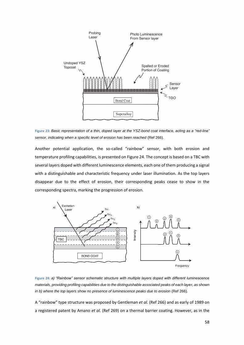
58
Figure 23: Basic representation of a thin, doped layer at the YSZ-bond coat interface, acting as a “red-line”
sensor, indicating when a specific level of erosion has been reached (Ref 266).
Another potential application, the so-called “rainbow” sensor, with both erosion and
temperature profiling capabilities, is presented on Figure 24. The concept is based on a TBC with
several layers doped with different luminescence elements, each one of them producing a signal
with a distinguishable and characteristic frequency under laser illumination. As the top layers
disappear due to the effect of erosion, their corresponding peaks cease to show in the
corresponding spectra, marking the progression of erosion.
Figure 24: a) “Rainbow” sensor schematic structure with multiple layers doped with different luminescence
materials, providing profiling capabilities due to the distinguishable associated peaks of each layer, as shown
in b) where the top layers show no presence of luminescence peaks due to erosion (Ref 266).
A “rainbow” type structure was proposed by Gentleman et al. (Ref 266) and as early of 1989 on
a registered patent by Amano et al. (Ref 269) on a thermal barrier coating. However, as in the
59
case of thermal history sensors, preference to non-thermal spraying techniques has been given
(Ref 270,271). In this case, EB-PVD represents a better candidate for its previously mentioned
improved optical transmission when compared to standard APS. Still, erosion of TBSC requires
additional investigations to provide a reliable measurement of the status of the coating. The
technique however shows potential, as shown by the successful development of temperature
TBSCs.
4.1.2. Embedded sensors
The “smart” behaviour of a coating can also be achieved through the embedment of a stand-
alone sensor within the thermal sprayed layers, effectively emulating the effect described on
previous sensing smart coatings. This provides a coherent and calibrated response to external
stimuli. The concept is based on the integration of an externally manufactured sensor, such as
the strain gauges or thermocouples mentioned on section 3.4, into a multi-layered coating, with
a structure schematically shown on Figure 25.
Figure 25: Schematic representation of two embedded sensors within a cylindrical coated piece. Redrawn
from (Ref 272).
Embedded sensors present several advantages over intrinsic smart sensing coatings, since
sensor and coating can be designed separately and then integrated. The only requirement is that
the embedded sensor does not chemically interact with the coating, or excessively modify its
physical and mechanical properties. The concept was first described by Fasching et al. (Ref 272)
in 1995, including the description of two such embedded sensors, a sprayed thermocouple and
a humidity sensor. Although the reported sensors presented faults and needed further
optimisation, they represented the proof-of-concept for embedded sensors using thermal spray
techniques that promote further research.
60
Considerable work has been carried out at the State University of New York, Stony Brook, NY in
the development of more precise and streamlined embedded sensors. Thermocouples, as
mentioned before, have been ideal platforms for embedded sensors produced via thermal
spraying, due to their morphology and material requirements. An examples of such sensor is
presented by Longtin et al. (Ref 273) using 62Cu/38Ni and 80Ni/20Cr to produce an E-type
(constantan 60Cu/40Ni and chromel 90Ni/10Cr) thermocouple on top of a thermal sprayed
alumina layer. An additional layer of alumina was deposited on top of the thermocouple to prove
its embedded capabilities. The sensor was tested at temperature ranging from 200 °C to 800 °C
with a commercial E-type thermocouple to verify its performance, proving excellent linearity
and repeatability. A K-type (chomel and alumel 95Ni/3Mn/2Al/1Si) thermocouple was produced
using 80Ni/20Cr and 95Ni/5Al for its use at higher temperature, up to 1200 °C, demonstrating
once more an excellent performance compared with commercial thermocouples. The basis for
a strain gauge is also reported, although due to constrain in the minimum feature size achievable
with the deposition technique, in the range of 200 µm, no results are reported.
A commercial-ready set up for embedded temperature and heat flux sensors is reported by
Gutleber et al. (Ref 274) in collaboration with MesoScribe Technologies (Ref 275) using
specifically designed plasma spraying process with dynamical aperture control to achieve the
required linewidth. The system was formed by a Ni-based superalloy substrate (Hastelloy X) with
MCrAlY type bondcoat and YSZ as the TBC overcoat. The effectiveness of the sensors was tested
on bare (no coating on top of them) and embedded state, producing K-type thermocouples and
heat flux sensors. Both sensors were tested to temperatures up to 800 °C in comparison with
commercial sensors, showing excellent agreement. Durability tests were also performed on a
cyclic burner rig with varying temperatures between 75 °C and 1050 °C to demonstrate the
commercial applicability of the sensor under service conditions. The commercial application of
an embedded resistive strain sensor (Ref 276) produced using thermal spraying and laser
machining methods has also been reported, although specific information of materials
deposited and geometry of the patterns has not been disclosed. This device showed promising
results in terms of sensibility and accuracy, although further research into the impact of real
service conditions into the sensing capabilities of the system would be required to assess its
applicability into the industry.
4.2. Self-healing
The appearance of cracks and other defects within coatings, sometimes being too small or
buried deep within the material to be detected, is a recurring problem that affects the coating
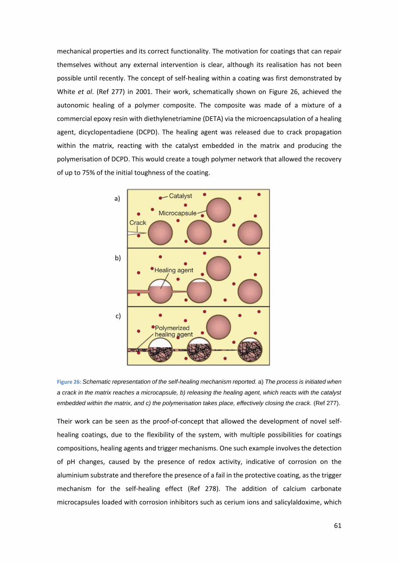
61
mechanical properties and its correct functionality. The motivation for coatings that can repair
themselves without any external intervention is clear, although its realisation has not been
possible until recently. The concept of self-healing within a coating was first demonstrated by
White et al. (Ref 277) in 2001. Their work, schematically shown on Figure 26, achieved the
autonomic healing of a polymer composite. The composite was made of a mixture of a
commercial epoxy resin with diethylenetriamine (DETA) via the microencapsulation of a healing
agent, dicyclopentadiene (DCPD). The healing agent was released due to crack propagation
within the matrix, reacting with the catalyst embedded in the matrix and producing the
polymerisation of DCPD. This would create a tough polymer network that allowed the recovery
of up to 75% of the initial toughness of the coating.
Figure 26: Schematic representation of the self-healing mechanism reported. a) The process is initiated when
a crack in the matrix reaches a microcapsule, b) releasing the healing agent, which reacts with the catalyst
embedded within the matrix, and c) the polymerisation takes place, effectively closing the crack. (Ref 277).
Their work can be seen as the proof-of-concept that allowed the development of novel self-
healing coatings, due to the flexibility of the system, with multiple possibilities for coatings
compositions, healing agents and trigger mechanisms. One such example involves the detection
of pH changes, caused by the presence of redox activity, indicative of corrosion on the
aluminium substrate and therefore the presence of a fail in the protective coating, as the trigger
mechanism for the self-healing effect (Ref 278). The addition of calcium carbonate
microcapsules loaded with corrosion inhibitors such as cerium ions and salicylaldoxime, which
a)
b)
c)
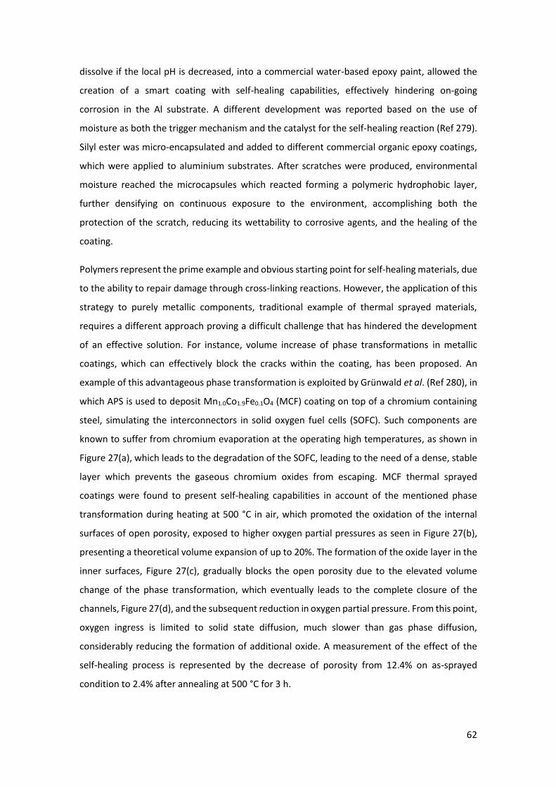
62
dissolve if the local pH is decreased, into a commercial water-based epoxy paint, allowed the
creation of a smart coating with self-healing capabilities, effectively hindering on-going
corrosion in the Al substrate. A different development was reported based on the use of
moisture as both the trigger mechanism and the catalyst for the self-healing reaction (Ref 279).
Silyl ester was micro-encapsulated and added to different commercial organic epoxy coatings,
which were applied to aluminium substrates. After scratches were produced, environmental
moisture reached the microcapsules which reacted forming a polymeric hydrophobic layer,
further densifying on continuous exposure to the environment, accomplishing both the
protection of the scratch, reducing its wettability to corrosive agents, and the healing of the
coating.
Polymers represent the prime example and obvious starting point for self-healing materials, due
to the ability to repair damage through cross-linking reactions. However, the application of this
strategy to purely metallic components, traditional example of thermal sprayed materials,
requires a different approach proving a difficult challenge that has hindered the development
of an effective solution. For instance, volume increase of phase transformations in metallic
coatings, which can effectively block the cracks within the coating, has been proposed. An
example of this advantageous phase transformation is exploited by Grünwald et al. (Ref 280), in
which APS is used to deposit Mn1.0Co1.9Fe0.1O4 (MCF) coating on top of a chromium containing
steel, simulating the interconnectors in solid oxygen fuel cells (SOFC). Such components are
known to suffer from chromium evaporation at the operating high temperatures, as shown in
Figure 27(a), which leads to the degradation of the SOFC, leading to the need of a dense, stable
layer which prevents the gaseous chromium oxides from escaping. MCF thermal sprayed
coatings were found to present self-healing capabilities in account of the mentioned phase
transformation during heating at 500 °C in air, which promoted the oxidation of the internal
surfaces of open porosity, exposed to higher oxygen partial pressures as seen in Figure 27(b),
presenting a theoretical volume expansion of up to 20%. The formation of the oxide layer in the
inner surfaces, Figure 27(c), gradually blocks the open porosity due to the elevated volume
change of the phase transformation, which eventually leads to the complete closure of the
channels, Figure 27(d), and the subsequent reduction in oxygen partial pressure. From this point,
oxygen ingress is limited to solid state diffusion, much slower than gas phase diffusion,
considerably reducing the formation of additional oxide. A measurement of the effect of the
self-healing process is represented by the decrease of porosity from 12.4% on as-sprayed
condition to 2.4% after annealing at 500 °C for 3 h.
63
Figure 27: Schematic process of self-healing through phase transformation. a) Cracked MCF coating which
allows the evaporation of gaseous chromium oxides from the chromium containing steel substrate and b)
detail of the O2 ingress through the cracks. c) Phase transformation into the oxide due to the presence of
oxygen in the internal surfaces which leads to d) the closure of the cracks and self-healing of the coating
(Ref 280).
Nevertheless, as it was reported by Vaßen et al. (Ref 281), the high levels of stress expected
from such a significant volume expansion led the tested samples to experience noticeable
bending and large pores appeared close to the coating/substrate interface, which represent risks
for the structural integrity of the coating, prone to delaminate under such conditions.
A similar pathway was followed by Derelioglu et al. (Ref 282) with the addition of boron alloyed
MoSi2 into APS-sprayed yttria stabilized zirconia. The presence of MoSi2 (B) particles acts as
healing points, oxidizing once exposed to oxygen. To limit the activation of the healing process
until encountering with a crack, the particles had to be protected with a thin, oxygen
impermeable layer, such as alumina (Ref 283). Once the propagation of a crack within the
coating encounters an encapsulated MoSi2 (B) particle, amorphous silica forms, flowing along
the crack. SiO2 further reacts with the YSZ matrix, causing the appearance of ZrSiO4, which acts
as self-healing material. Although the development of self-healing TBCs would be highly
beneficial, further studies on the impact of the addition of MoSi2 (B) to the thermal conductivity
of YSZ are required to assess the potential benefit of the healing effect. This line of work was
extensively studied under the SAMBA (Self-Healing Thermal Barrier Coatings) European project,
using spark plasma sintering on YSZ (Ref 284) and YSPZ (Ref 285), which reported theoretical
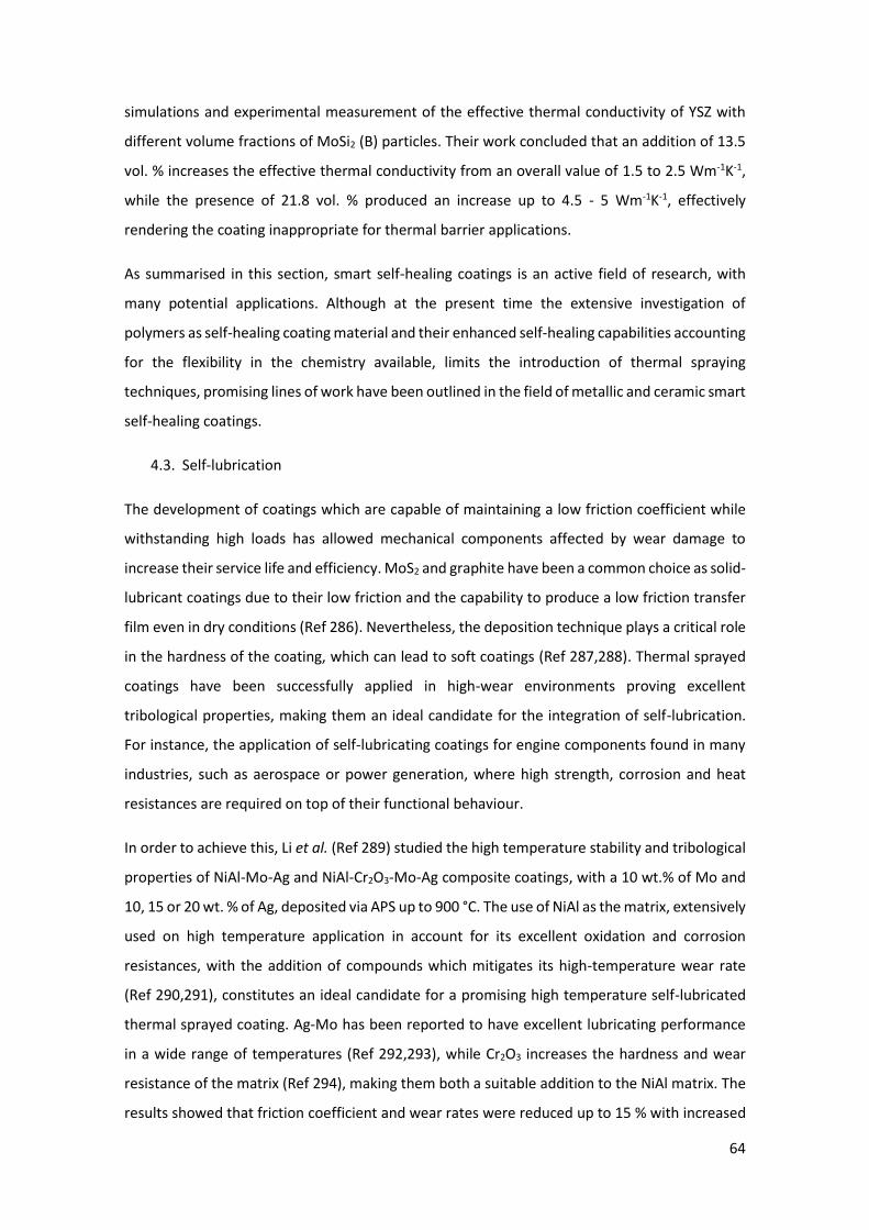
64
simulations and experimental measurement of the effective thermal conductivity of YSZ with
different volume fractions of MoSi2 (B) particles. Their work concluded that an addition of 13.5
vol. % increases the effective thermal conductivity from an overall value of 1.5 to 2.5 Wm-1K-1,
while the presence of 21.8 vol. % produced an increase up to 4.5 - 5 Wm-1K-1, effectively
rendering the coating inappropriate for thermal barrier applications.
As summarised in this section, smart self-healing coatings is an active field of research, with
many potential applications. Although at the present time the extensive investigation of
polymers as self-healing coating material and their enhanced self-healing capabilities accounting
for the flexibility in the chemistry available, limits the introduction of thermal spraying
techniques, promising lines of work have been outlined in the field of metallic and ceramic smart
self-healing coatings.
4.3. Self-lubrication
The development of coatings which are capable of maintaining a low friction coefficient while
withstanding high loads has allowed mechanical components affected by wear damage to
increase their service life and efficiency. MoS2 and graphite have been a common choice as solid-
lubricant coatings due to their low friction and the capability to produce a low friction transfer
film even in dry conditions (Ref 286). Nevertheless, the deposition technique plays a critical role
in the hardness of the coating, which can lead to soft coatings (Ref 287,288). Thermal sprayed
coatings have been successfully applied in high-wear environments proving excellent
tribological properties, making them an ideal candidate for the integration of self-lubrication.
For instance, the application of self-lubricating coatings for engine components found in many
industries, such as aerospace or power generation, where high strength, corrosion and heat
resistances are required on top of their functional behaviour.
In order to achieve this, Li et al. (Ref 289) studied the high temperature stability and tribological
properties of NiAl-Mo-Ag and NiAl-Cr2O3-Mo-Ag composite coatings, with a 10 wt.% of Mo and
10, 15 or 20 wt. % of Ag, deposited via APS up to 900 °C. The use of NiAl as the matrix, extensively
used on high temperature application in account for its excellent oxidation and corrosion
resistances, with the addition of compounds which mitigates its high-temperature wear rate
(Ref 290,291), constitutes an ideal candidate for a promising high temperature self-lubricated
thermal sprayed coating. Ag-Mo has been reported to have excellent lubricating performance
in a wide range of temperatures (Ref 292,293), while Cr2O3 increases the hardness and wear
resistance of the matrix (Ref 294), making them both a suitable addition to the NiAl matrix. The
results showed that friction coefficient and wear rates were reduced up to 15 % with increased
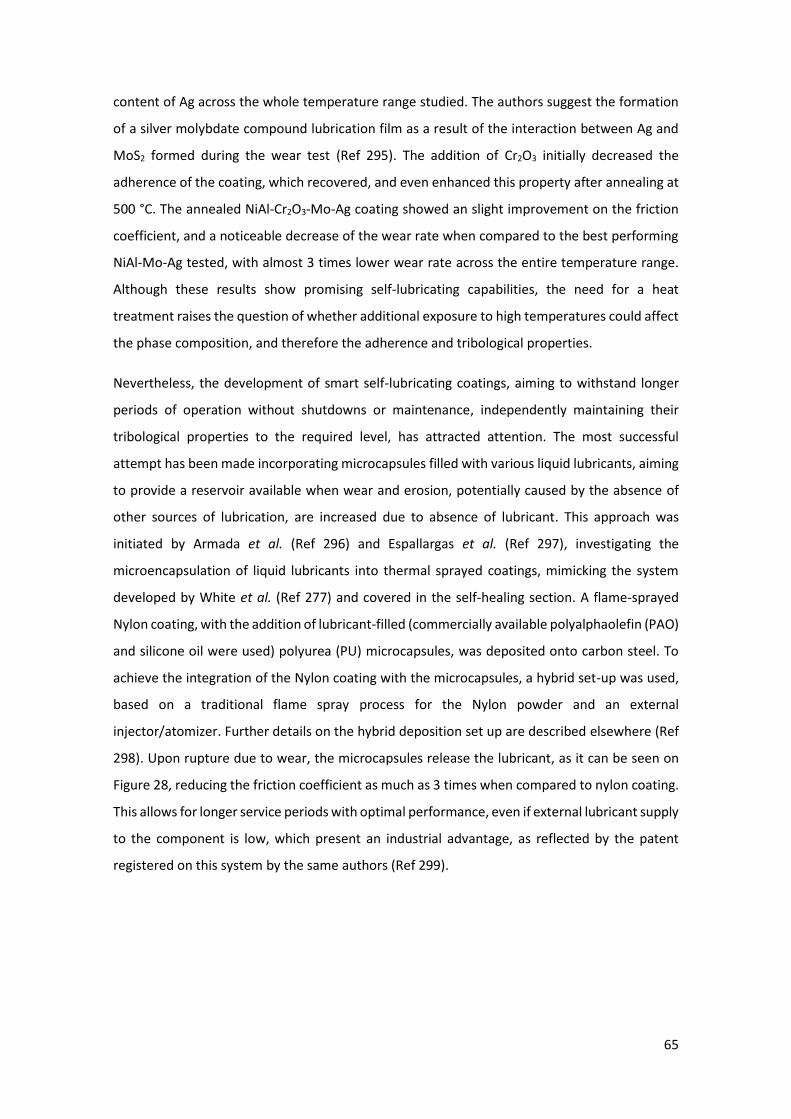
65
content of Ag across the whole temperature range studied. The authors suggest the formation
of a silver molybdate compound lubrication film as a result of the interaction between Ag and
MoS2 formed during the wear test (Ref 295). The addition of Cr2O3 initially decreased the
adherence of the coating, which recovered, and even enhanced this property after annealing at
500 °C. The annealed NiAl-Cr2O3-Mo-Ag coating showed an slight improvement on the friction
coefficient, and a noticeable decrease of the wear rate when compared to the best performing
NiAl-Mo-Ag tested, with almost 3 times lower wear rate across the entire temperature range.
Although these results show promising self-lubricating capabilities, the need for a heat
treatment raises the question of whether additional exposure to high temperatures could affect
the phase composition, and therefore the adherence and tribological properties.
Nevertheless, the development of smart self-lubricating coatings, aiming to withstand longer
periods of operation without shutdowns or maintenance, independently maintaining their
tribological properties to the required level, has attracted attention. The most successful
attempt has been made incorporating microcapsules filled with various liquid lubricants, aiming
to provide a reservoir available when wear and erosion, potentially caused by the absence of
other sources of lubrication, are increased due to absence of lubricant. This approach was
initiated by Armada et al. (Ref 296) and Espallargas et al. (Ref 297), investigating the
microencapsulation of liquid lubricants into thermal sprayed coatings, mimicking the system
developed by White et al. (Ref 277) and covered in the self-healing section. A flame-sprayed
Nylon coating, with the addition of lubricant-filled (commercially available polyalphaolefin (PAO)
and silicone oil were used) polyurea (PU) microcapsules, was deposited onto carbon steel. To
achieve the integration of the Nylon coating with the microcapsules, a hybrid set-up was used,
based on a traditional flame spray process for the Nylon powder and an external
injector/atomizer. Further details on the hybrid deposition set up are described elsewhere (Ref
298). Upon rupture due to wear, the microcapsules release the lubricant, as it can be seen on
Figure 28, reducing the friction coefficient as much as 3 times when compared to nylon coating.
This allows for longer service periods with optimal performance, even if external lubricant supply
to the component is low, which present an industrial advantage, as reflected by the patent
registered on this system by the same authors (Ref 299).
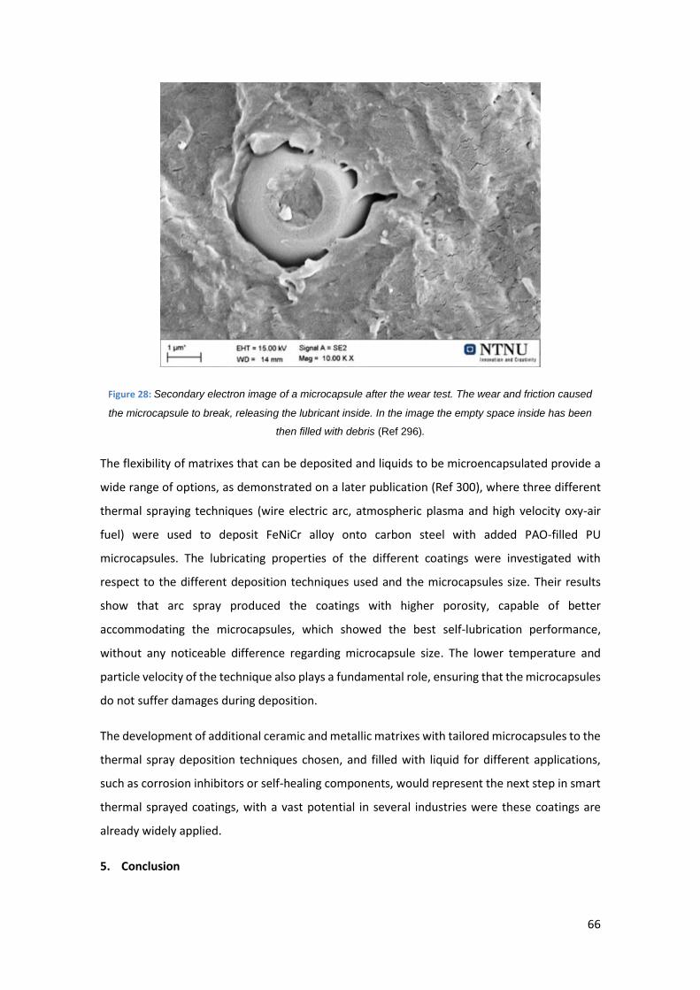
66
Figure 28: Secondary electron image of a microcapsule after the wear test. The wear and friction caused
the microcapsule to break, releasing the lubricant inside. In the image the empty space inside has been
then filled with debris (Ref 296).
The flexibility of matrixes that can be deposited and liquids to be microencapsulated provide a
wide range of options, as demonstrated on a later publication (Ref 300), where three different
thermal spraying techniques (wire electric arc, atmospheric plasma and high velocity oxy-air
fuel) were used to deposit FeNiCr alloy onto carbon steel with added PAO-filled PU
microcapsules. The lubricating properties of the different coatings were investigated with
respect to the different deposition techniques used and the microcapsules size. Their results
show that arc spray produced the coatings with higher porosity, capable of better
accommodating the microcapsules, which showed the best self-lubrication performance,
without any noticeable difference regarding microcapsule size. The lower temperature and
particle velocity of the technique also plays a fundamental role, ensuring that the microcapsules
do not suffer damages during deposition.
The development of additional ceramic and metallic matrixes with tailored microcapsules to the
thermal spray deposition techniques chosen, and filled with liquid for different applications,
such as corrosion inhibitors or self-healing components, would represent the next step in smart
thermal sprayed coatings, with a vast potential in several industries were these coatings are
already widely applied.
5. Conclusion
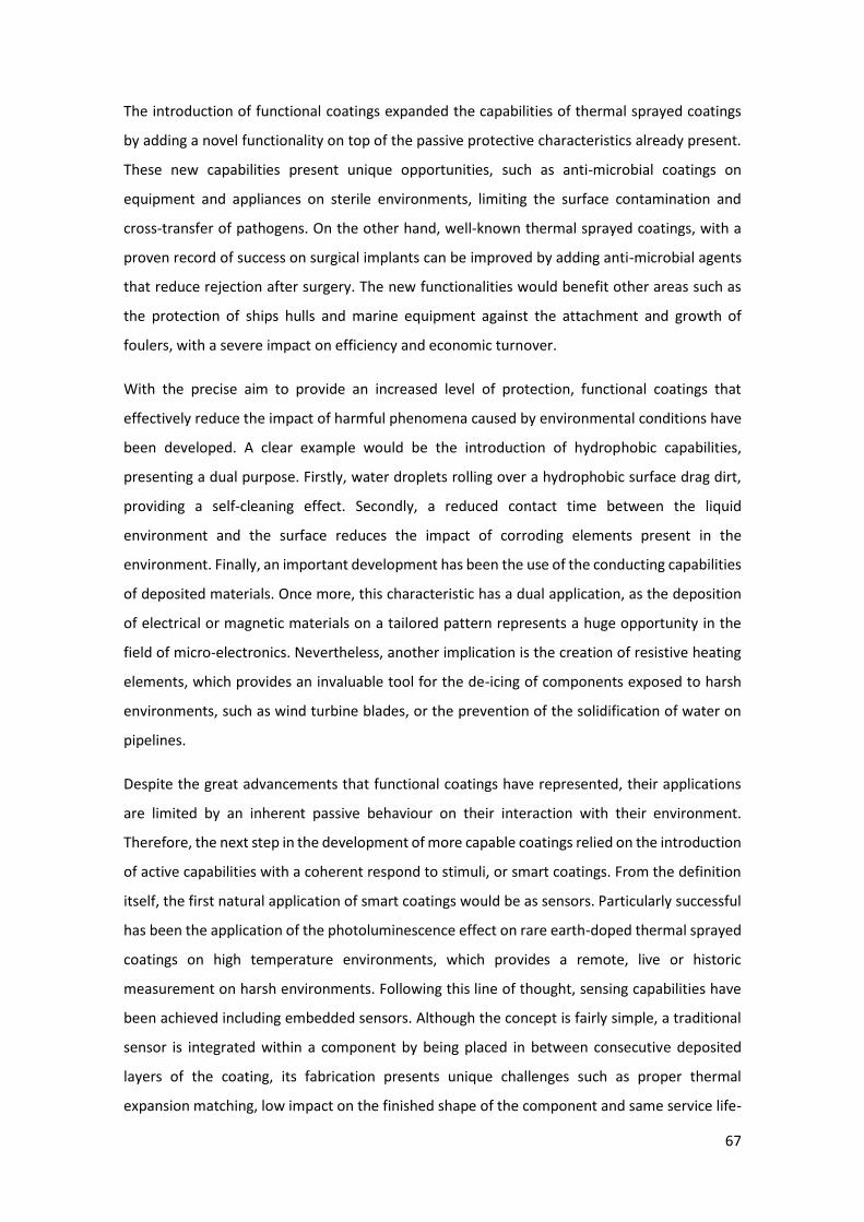
67
The introduction of functional coatings expanded the capabilities of thermal sprayed coatings
by adding a novel functionality on top of the passive protective characteristics already present.
These new capabilities present unique opportunities, such as anti-microbial coatings on
equipment and appliances on sterile environments, limiting the surface contamination and
cross-transfer of pathogens. On the other hand, well-known thermal sprayed coatings, with a
proven record of success on surgical implants can be improved by adding anti-microbial agents
that reduce rejection after surgery. The new functionalities would benefit other areas such as
the protection of ships hulls and marine equipment against the attachment and growth of
foulers, with a severe impact on efficiency and economic turnover.
With the precise aim to provide an increased level of protection, functional coatings that
effectively reduce the impact of harmful phenomena caused by environmental conditions have
been developed. A clear example would be the introduction of hydrophobic capabilities,
presenting a dual purpose. Firstly, water droplets rolling over a hydrophobic surface drag dirt,
providing a self-cleaning effect. Secondly, a reduced contact time between the liquid
environment and the surface reduces the impact of corroding elements present in the
environment. Finally, an important development has been the use of the conducting capabilities
of deposited materials. Once more, this characteristic has a dual application, as the deposition
of electrical or magnetic materials on a tailored pattern represents a huge opportunity in the
field of micro-electronics. Nevertheless, another implication is the creation of resistive heating
elements, which provides an invaluable tool for the de-icing of components exposed to harsh
environments, such as wind turbine blades, or the prevention of the solidification of water on
pipelines.
Despite the great advancements that functional coatings have represented, their applications
are limited by an inherent passive behaviour on their interaction with their environment.
Therefore, the next step in the development of more capable coatings relied on the introduction
of active capabilities with a coherent respond to stimuli, or smart coatings. From the definition
itself, the first natural application of smart coatings would be as sensors. Particularly successful
has been the application of the photoluminescence effect on rare earth-doped thermal sprayed
coatings on high temperature environments, which provides a remote, live or historic
measurement on harsh environments. Following this line of thought, sensing capabilities have
been achieved including embedded sensors. Although the concept is fairly simple, a traditional
sensor is integrated within a component by being placed in between consecutive deposited
layers of the coating, its fabrication presents unique challenges such as proper thermal
expansion matching, low impact on the finished shape of the component and same service life-
68
time as regular components. Beyond its application as sensors, smart coatings have been
successfully developed with another active capabilities, being self-healing coatings a prime
example. Within the first variant, traveling cracks encounter microcapsules filled with the
healing agent, being released and triggering a reaction in the matrix that would partially restore
the properties of the damaged coating. Although the results are promising, coatings require a
tailored composition and proper deposition techniques to allow the embedment of
microcapsules with the self-healing agent, hindering its application as mass-produced
components. Alternatively, self-healing has been proven through the use of phase
transformations triggered by the presence of cracks. Such phase transformation implies a
volume expansion that effectively seals and restores the cracks. Nevertheless, the concept
requires delicate tailoring to ensure that the phase transformation, and associated volume
expansion, does not reach critical levels that would cause excessive stress within the coating.
Inspired by the microencapsulation of self-healing agents, a new line of work has been
developed for the production of self-lubrication coatings. Parting from the solid lubricant
coatings already present in thermal spray, self-lubrication makes use of a reservoir of lubricant
liquid encapsulated within the coatings itself, achieving a controlled release as the wear reveals
and damages the microcapsules. This process ensures the presence of lubricant for longer
periods of time, and despite the fact that its effect is limited in time as the reservoir will
eventually be depleted, it could present a fail-safe mechanism ensuring proper lubrication of
critical components.
In conclusion, functional and smart coatings represent the crystallisation of the wide range of
capabilities that thermal spray offers. The successful track record presented in the past, along
with the new opportunities provided by the latest developments, points out to an exciting
future. Further research will allow to comprehend the deposition and bonding mechanism on
multi-component coatings, key to the addition of functional and smart abilities. In addition, the
impact that these modified compositions have on the performance of the coatings needs to be
thoroughly understood to ensure that the same level, if not improved, of performance is
achieved. With these goals in mind, the next steps required for functional and smart coatings
would be, first, to translate the current knowledge acquired into readily available feedstock
materials tailored to the chosen thermal deposition technique and desired functionality. The
great strength of thermal spraying, its flexibility, represents a disadvantage when trying to
accommodate all the requirement of the different deposition techniques. The new
developments will have to leave the “proof-of-concept stage” and present a sound production
process compatible with the standards of the industry, if possible, with minimal deviation from

69
their current deposition techniques. Secondly, this broadening of the current developments
aiming to reach penetration into the industry needs to be accompanied by further research into
the foundations of functional and smart coatings. The current state of the field proves that there
is a vast potential, but some key concepts are still not fully understood. A deeper knowledge of
the relationship between deposition parameters and final performance, with particular
emphasis on the microstructural causes, will allow to increase the performance efficiency of
functional and smart coatings avoiding losses due to unwanted features or undesired phase
transformations.
70
References
1. R.E. Melchers, The Effect of Corrosion on the Structural Reliability of Steel Offshore
Structures, Corros. Sci., 2005, 47(10), p 2391–2410, doi:10.1016/j.corsci.2005.04.004.
2. J. Kameda, T. Bloomer, Y. Sugita, A. Ito, and S. Sakurai, High Temperature
Environmental Attack and Mechanical Degradation of Coatings in Gas Turbine Blades,
Mater. Sci. Eng. A, 1997, 229(1–2), p 42–54, doi:10.1016/S0921-5093(97)00003-8.
3. A. Vardelle, C. Moreau, J. Akedo, H. Ashrafizadeh, C.C. Berndt, J.O. Berghaus, M. Boulos,
J. Brogan, A.C. Bourtsalas, A. Dolatabadi, M. Dorfman, T.J. Eden, P. Fauchais, G. Fisher,
F. Gaertner, M. Gindrat, R. Henne, M. Hyland, E. Irissou, E.H. Jordan, K.A. Khor, A.
Killinger, Y.C. Lau, C.J. Li, L. Li, J. Longtin, N. Markocsan, P.J. Masset, J. Matejicek, G.
Mauer, et al., The 2016 Thermal Spray Roadmap, J. Therm. Spray Technol., 2016, 25(8),
p 1376–1440.
4. J.R. Davis, Introduction to Thermal Spray Processing, Handbook of Thermal Spray
Technology, 2004, p 3–13.
5. R.C. Tucker, Thermal Spray Coatings, ASM Handbook, 1993, p 1446–1471.
6. P. Fauchais and A. Vardelle, Thermal Sprayed Coatings Used Against Corrosion and
Corrosive Wear, Advanced Plasma Spray Applications, H. Salimi Jazi, Ed., InTech, 2012, p
3–39, doi:10.5772/34448.
7. G. Mauer, M.O. Jarligo, D.E. Mack, and R. Vaßen, Plasma-Sprayed Thermal Barrier
Coatings: New Materials, Processing Issues, and Solutions, J. Therm. Spray Technol.,
2013, 22(5), p 646–658, doi:10.1007/s11666-013-9889-8.
8. C.R.C. Lima, N.F.C. de Souza, and F. Camargo, Study of Wear and Corrosion
Performance of Thermal Sprayed Engineering Polymers, Surf. Coatings Technol.,
Elsevier B.V., 2013, 220, p 140–143, doi:10.1016/j.surfcoat.2012.05.051.
9. S. Wilson, Abradable Thermal Spray Applications and Technology, ASM Handbook,
Volume 5A: Thermal Spray Technology, ASM International, 2013, p 287–295.
10. C.U. Hardwicke and Y.C. Lau, Advances in Thermal Spray Coatings for Gas Turbines and
Energy Generation: A Review, J. Therm. Spray Technol., 2013, 22(5), p 564–576,
71
doi:10.1007/s11666-013-9904-0.
11. L. Sun, C.C. Berndt, K.A. Gross, and A. Kucuk, Material Fundamentals and Clinical
Performance of Plasma- Sprayed Hydroxyapatite Coatings: A Review, J. Biomed. Mater.
Res., 2001, 58(5), p 570–592.
12. S. Sampath, Thermal Spray Applications in Electronics and Sensors: Past, Present, and
Future, J. Therm. Spray Technol., 2010, 19(5), p 921–949, doi:10.1007/s11666-010-
9475-2.
13. S. Armada, R. Schmid, H. Johnsen, and N. Espallargas, Functionalized Thermal Spray
Coatings, Future Development of Thermal Spray Coatings, Elsevier, 2015, p 207–228,
doi:10.1016/B978-0-85709-769-9.00008-7.
14. M.F. Montemor, Functional and Smart Coatings for Corrosion Protection: A Review of
Recent Advances, Surf. Coatings Technol., Elsevier B.V., 2014, 258, p 17–37,
doi:10.1016/j.surfcoat.2014.06.031.
15. J. Baghdachi, Smart Coatings, Smart Coatings II, 2009, p 3–24.
16. D.E. Crawmer, Thermal Spray Processes, Handbook of Thermal Spray Technology, ASM
International, 2013, p 54–76.
17. D.E. Crawmer, Introduction to Coatings, Equipment, and Theory, Handb. Therm. Spray
Technol., 2008, p 43–46.
18. P. Fauchais, A. Vardelle, and B. Dussoubs, Quo Vadis Thermal Spraying?, J. Therm. Spray
Technol., 2001, 10(1), p 44–66, doi:10.1361/105996301770349510.
19. P. Fauchais, Understanding Plasma Spraying, J. Phys. D. Appl. Phys., 2004, 37(9), p R86–
R108, doi:10.1088/0022-3727/37/9/R02.
20. P. Fauchais, M. Vardelle, A. Vardelle, and S. Goutier, What Do We Know, What Are the
Current Limitations of Suspension Plasma Spraying?, J. Therm. Spray Technol., Springer
US, 2015, 24(7), p 1120–1129, doi:10.1007/s11666-015-0286-3.
21. R. Vaßen, H. Kaßner, G. Mauer, and D. Stöver, Suspension Plasma Spraying: Process
Characteristics and Applications, J. Therm. Spray Technol., 2010, 19(1–2), p 219–225,
doi:10.1007/s11666-009-9451-x.
22. A. Killinger, R. Gadow, G. Mauer, A. Guignard, R. Vaßen, and D. Stöver, Review of New
72
Developments in Suspension and Solution Precursor Thermal Spray Processes, J. Therm.
Spray Technol., 2011, 20(4), p 677–695, doi:10.1007/s11666-011-9639-8.
23. F. Gitzhofer, E. Bouyer, and M.I. Boulos, “Suspension Plasma Spray,” (United States of
America), 1997.
24. H. Kaßner, R. Siegert, D. Hathiramani, R. Vaßen, and D. Stoever, Application of
Suspension Plasma Spraying (SPS) for Manufacture of Ceramic Coatings, J. Therm. Spray
Technol., 2008, 17(1), p 115–123, doi:10.1007/s11666-007-9144-2.
25. L. Pawlowski, Suspension and Solution Thermal Spray Coatings, Surf. Coatings Technol.,
Elsevier B.V., 2009, 203(19), p 2807–2829, doi:10.1016/j.surfcoat.2009.03.005.
26. P. Fauchais, A. Joulia, S. Goutier, C. Chazelas, M. Vardelle, A. Vardelle, and S. Rossignol,
Suspension and Solution Plasma Spraying, J. Phys. D. Appl. Phys., 2013, 46(22), p
224015, doi:10.1088/0022-3727/46/22/224015.
27. W. Fan and Y. Bai, Review of Suspension and Solution Precursor Plasma Sprayed
Thermal Barrier Coatings, Ceram. Int., 2016, 42(13), p 14299–14312,
doi:10.1016/j.ceramint.2016.06.063.
28. E. Brinley, K.S. Babu, and S. Seal, The Solution Precursor Plasma Spray Processing of
Nanomaterials, JOM, 2007, 59(7), p 54–59, doi:10.1007/s11837-007-0090-8.
29. P.R. Strutt, B.H. Kear, and R.F. Boland, “Thermal Spray Method for the Formation of
Nanostructured Coatings,” (United States of America), 2011.
30. A. Killinger, Status and Future Trends in Suspension Spray Techniques, Future
Development of Thermal Spray Coatings, Elsevier, 2015, p 81–122, doi:10.1016/B978-0-
85709-769-9.00004-X.
31. A. Guignard, G. Mauer, R. Vaßen, and D. Stöver, Deposition and Characteristics of
Submicrometer-Structured Thermal Barrier Coatings by Suspension Plasma Spraying, J.
Therm. Spray Technol., 2012, 21(3–4), p 416–424, doi:10.1007/s11666-012-9762-1.
32. N. Curry, K. VanEvery, T. Snyder, and N. Markocsan, Thermal Conductivity Analysis and
Lifetime Testing of Suspension Plasma-Sprayed Thermal Barrier Coatings, Coatings,
2014, 4(3), p 630–650, doi:10.3390/coatings4030630.
33. K. VanEvery, M.J.M. Krane, R.W. Trice, H. Wang, W. Porter, M. Besser, D. Sordelet, J.
73
Ilavsky, and J. Almer, Column Formation in Suspension Plasma-Sprayed Coatings and
Resultant Thermal Properties, J. Therm. Spray Technol., 2011, 20(4), p 817–828,
doi:10.1007/s11666-011-9632-2.
34. A. Bacciochini, F. Ben-Ettouil, E. Brousse, J. Ilavsky, G. Montavon, A. Denoirjean, S.
Valette, and P. Fauchais, Quantification of Void Networks of As-Sprayed and Annealed
Nanostructured Yttria-Stabilized Zirconia (YSZ) Deposits Manufactured by Suspension
Plasma Spraying, Surf. Coatings Technol., Elsevier B.V., 2010, 205(3), p 683–689,
doi:10.1016/j.surfcoat.2010.06.013.
35. M. Gell, E.H. Jordan, M. Teicholz, B.M. Cetegen, N.P. Padture, L. Xie, D. Chen, X. Ma, and
J. Roth, Thermal Barrier Coatings Made by the Solution Precursor Plasma Spray Process,
J. Therm. Spray Technol., 2008, 17(1), p 124–135, doi:10.1007/s11666-007-9141-5.
36. N.P. Padture, K.W. Schlichting, T. Bhatia, A. Ozturk, B. Cetegen, E.H. Jordan, M. Gell, S.
Jiang, T.D. Xiao, P.R. Strutt, E. Garcıa, P. Miranzo, and M.I. Osendi, Towards Durable
Thermal Barrier Coatings with Novelmicrostructures Deposited by Solution-Precursor
Plasma Spray, Acta Mater., 2001, 49(12), p 2251–2257, doi:10.1016/S1359-
6454(01)00130-6.
37. X. Ma, F. Wu, J. Roth, M. Gell, and E.H. Jordan, Low Thermal Conductivity Thermal
Barrier Coating Deposited by the Solution Plasma Spray Process, Surf. Coatings
Technol., 2006, 201(7), p 4447–4452, doi:10.1016/j.surfcoat.2006.08.095.
38. E.H. Jordan, L. Xie, M. Gell, N.P. Padture, B. Cetegen, A. Ozturk, J. Roth, T.D. Xiao, and
P.E.C. Bryant, Superior Thermal Barrier Coatings Using Solution Precursor Plasma Spray,
J. Therm. Spray Technol., 2004, 13(1), p 57–65, doi:10.1361/10599630418121.
39. M. Gell, L. Xie, X. Ma, E.H. Jordan, and N.P. Padture, Highly Durable Thermal Barrier
Coatings Made by the Solution Precursor Plasma Spray Process, Surf. Coatings Technol.,
2004, 177–178, p 97–102, doi:10.1016/j.surfcoat.2003.06.023.
40. E.J. Young, E. Mateeva, J.J. Moore, B. Mishra, and M. Loch, Low Pressure Plasma Spray
Coatings, Int. Conf. Metall. Coatings Thin Film., 2000, 377–378(0), p 788–792,
doi:http://dx.doi.org/10.1016/S0040-6090(00)01452-8.
41. A. Hospach, G. Mauer, R. Vaßen, and D. Stöver, Columnar-Structured Thermal Barrier
Coatings (TBCs) by Thin Film Low-Pressure Plasma Spraying (LPPS-TF), J. Therm. Spray
Technol., 2011, 20(1–2), p 116–120, doi:10.1007/s11666-010-9549-1.

74
42. M.F. Smith, A.C. Hall, J.D. Fleetwood, and P. Meyer, Very Low Pressure Plasma Spray—A
Review of an Emerging Technology in the Thermal Spray Community, Coatings, 2011,
1(2), p 117–132, doi:10.3390/coatings1020117.
43. A.P. Abkenar, “Wire-Arc Spraying System: Particle Production, Transport, and
Deposition,” Library and Archives Canada, University of Toronto, 2007.
44. S. Siegmann and C. Abert, 100 Years of Thermal Spray: About the Inventor Max Ulrich
Schoop, Surf. Coatings Technol., Elsevier B.V., 2013, 220, p 3–13,
doi:10.1016/j.surfcoat.2012.10.034.
45. P.L. Ke, Y.N. Wu, Q.M. Wang, J. Gong, C. Sun, and L.S. Wen, Study on Thermal Barrier
Coatings Deposited by Detonation Gun Spraying, Surf. Coatings Technol., 2005, 200(7),
p 2271–2276, doi:10.1016/j.surfcoat.2004.07.107.
46. E. Kadyrov and V. Kadyrov, Gas Detonation Gun for Thermal Spraying, Adv. Mater.
Process., 1995, 148(2), p 21–24.
47. T.S. Sidhu, S. Prakash, and R.D. Agrawal, State of the Art of HVOF Coating
Investigations—A Review, Mar. Technol. Soc. J., 2005, 39(2), p 53–64,
doi:10.4031/002533205787443908.
48. M. Oksa, E. Turunen, T. Suhonen, T. Varis, and S.-P. Hannula, Optimization and
Characterization of High Velocity Oxy-Fuel Sprayed Coatings: Techniques, Materials,
and Applications, Coatings, 2011, 1(1), p 17–52, doi:10.3390/coatings1010017.
49. K. Korpiola, J.P. Hirvonen, L. Laas, and F. Rossi, The Influence of Nozzle Design on HVOF
Exit Gas Velocity and Coating Microstructure, J. Therm. Spray Technol., 1997, 6(4), p
469–474, doi:10.1007/s11666-997-0033-5.
50. H. Herman, S. Sampath, and R. McCune, Thermal Spray: Current Status and Future
Trends, MRS Bull., Cambridge University Press, 2000, 25(07), p 17–25,
doi:10.1557/mrs2000.119.
51. A. Killinger, P. Müller, and R. Gadow, What Do We Know, What Are the Current
Limitations of Suspension HVOF Spraying?, J. Therm. Spray Technol., 2015, 24(7), p
1130–1142, doi:10.1007/s11666-015-0264-9.
52. J. Oberste Berghaus and B.R. Marple, High-Velocity Oxy-Fuel (HVOF) Suspension
Spraying of Mullite Coatings, J. Therm. Spray Technol., 2008, 17(5–6), p 671–678.

75
53. A. Killinger, M. Kuhn, and R. Gadow, High-Velocity Suspension Flame Spraying (HVSFS),
a New Approach for Spraying Nanoparticles with Hypersonic Speed, Surf. Coatings
Technol., 2006, 201(5), p 1922–1929, doi:10.1016/j.surfcoat.2006.04.034.
54. J. Puranen, J. Laakso, M. Kylmälahti, and P. Vuoristo, Characterization of High-Velocity
Solution Precursor Flame-Sprayed Manganese Cobalt Oxide Spinel Coatings for Metallic
SOFC Interconnectors, J. Therm. Spray Technol., 2013, 22(5), p 622–630,
doi:10.1007/s11666-013-9922-y.
55. M. Mahrukh, A. Kumar, and S. Gu, Experimental Study of the Effects of Using Different
Precursor Concentrations, Solvent Types, and Injection Types on Solution Precursor
High-Velocity Oxygen Fuel (HVOF) Nanostructured Coating Formation, Ind. Eng. Chem.
Res., 2017, 56(17), p 4957–4969, doi:10.1021/acs.iecr.6b04857.
56. D. Chen, E.H. Jordan, and M. Gell, Solution Precursor High-Velocity Oxy-Fuel Spray
Ceramic Coatings, J. Eur. Ceram. Soc., 2009, 29(16), p 3349–3353,
doi:10.1016/j.jeurceramsoc.2009.07.010.
57. J.R. Davis, Cold Spray Process, Thermal Spray Technology, ASM International, 2004, p
77–84.
58. H. Assadi, H. Kreye, F. Gärtner, and T. Klassen, Cold Spraying – A Materials Perspective,
Acta Mater., 2016, 116, p 382–407, doi:10.1016/j.actamat.2016.06.034.
59. R.N. Raoelison, E. Aubignat, M.-P. Planche, S. Costil, C. Langlade, and H. Liao, Low
Pressure Cold Spraying under 6 Bar Pressure Deposition: Exploration of High Deposition
Efficiency Solutions Using a Mathematical Modelling, Surf. Coatings Technol., 2016, 302,
p 47–55, doi:10.1016/j.surfcoat.2016.05.068.
60. G. Huang, H. Wang, X. Li, L. Xing, and J. Zhou, Deposition Efficiency of Low Pressure Cold
Sprayed Aluminum Coating, Mater. Manuf. Process., 2018, 33(10), p 1100–1106,
doi:10.1080/10426914.2017.1415443.
61. H. Koivuluoto, A. Coleman, K. Murray, M. Kearns, and P. Vuoristo, High Pressure Cold
Sprayed (HPCS) and Low Pressure Cold Sprayed (LPCS) Coatings Prepared from OFHC Cu
Feedstock: Overview from Powder Characteristics to Coating Properties, J. Therm. Spray
Technol., 2012, 21(5), p 1065–1075, doi:10.1007/s11666-012-9790-x.
62. J.R. Davis, Process Comparisions, Surface Engineering for Corrosion and Wear
76
Resistance, ASM International, 2001, p 183–193.
63. V.D. Rosenthal, D.G. Maki, Y. Mehta, H. Leblebicioglu, Z.A. Memish, H.H. Al-Mousa, H.
Balkhy, B. Hu, C. Alvarez-Moreno, E.A. Medeiros, A. Apisarnthanarak, L. Raka, L.E.
Cuellar, A. Ahmed, J.A. Navoa-Ng, A.A. El-Kholy, S.S. Kanj, I. Bat-Erdene, W. Duszynska,
N. Van Truong, L.N. Pazmino, L.C. See-Lum, R. Fernández-Hidalgo, G. Di-Silvestre, F.
Zand, S. Hlinkova, V. Belskiy, H. Al-Rahma, M.T. Luque-Torres, N. Bayraktar, et al.,
International Nosocomial Infection Control Consortiu (INICC) Report, Data Summary of
43 Countries for 2007-2012. Device-Associated Module, Am. J. Infect. Control, 2014,
42(9), p 942–956, doi:10.1016/j.ajic.2014.05.029.
64. Centers for Disease Control and Prevention, Vital Signs: Incidence and Trends of
Infection with Pathogens Transmitted Commonly Through Food - Foodborne Diseases
Active Surveillance Network, 10 U.S. Sites, 1996-2010, MMWR, 2011, 60(22), p 749–
755.
65. P. Thebault and T. Jouenne, Antibacterial Coatings, The Battle Against Microbial
Pathogens: Basic Science, Technological Advances and Educational Programs, 2015, p
483–489.
66. M. Cloutier, D. Mantovani, and F. Rosei, Antibacterial Coatings: Challenges,
Perspectives, and Opportunities, Trends Biotechnol., 2015, 33(11), p 637–652,
doi:10.1016/j.tibtech.2015.09.002.
67. Q. Yu, Z. Wu, and H. Chen, Dual-Function Antibacterial Surfaces for Biomedical
Applications, Acta Biomater., 2015, 16, p 1–13, doi:10.1016/j.actbio.2015.01.018.
68. Z.X. Wang, C.P. Jiang, Y. Cao, and Y.T. Ding, Systematic Review and Meta-Analysis of
Triclosan-Coated Sutures for the Prevention of Surgical-Site Infection, Br. J. Surg., John
Wiley & Sons, Ltd, 2013, 100(4), p 465–473, doi:10.1002/bjs.9062.
69. J.-B.D. Green, T. Fulghum, and M.A. Nordhaus, A Review of Immobilized Antimicrobial
Agents and Methods for Testing, Biointerphases, 2011, 6(4), p MR13-MR28,
doi:10.1116/1.3645195.
70. S. Han, C. Kim, and D. Kwon, Thermal/Oxidative Degradation and Stabilization of
Polyethylene Glycol, Polymer (Guildf)., 1997, 38(2), p 317–323.
71. R.G.T. Geesink, K.D. Groot, and C.P.A. T. Klein, Chemical Implant Fixation Using
77
Hydroxyl-Apatite Coatings, Clin. Orthop. Relat. Res., 1987, (225), p 147–170,
doi:10.1097/00003086-198712000-00014.
72. K.A. Gross, C.C. Berndt, and H. Herman, Amorphous Phase Formation in Plasma-
Sprayed Hydroxyapatite Coatings, J. Biomed. Mater. Res., 1998, 39(3), p 407–414,
doi:10.1002/(SICI)1097-4636(19980305)39:3<407::AID-JBM9>3.0.CO;2-N.
73. P. Cheang and K.A. Khor, Addressing Processing Problems Associated with Plasma
Spraying of Hydroxyapatite Coatings, Biomaterials, 1996, 17(5), p 537–544,
doi:10.1016/0142-9612(96)82729-3.
74. K.A. Khor, C.S. Yip, and P. Cheang, Ti-6Al-4V/Hydroxyapatite Composite Coatings
Prepared by Thermal Spray Techniques, J. Therm. Spray Technol., 1997, 6(1), p 109–
115, doi:10.1007/BF02646320.
75. C.-J. Liao, F.-H. Lin, K.-S. Chen, and J.-S. Sun, Thermal Decomposition and Reconstitution
of Hydroxyapatite in Air Atmosphere, Biomaterials, 1999, 20(19), p 1807–1813,
doi:10.1016/S0142-9612(99)00076-9.
76. X. Zheng, M. Huang, and C. Ding, Bond Strength of Plasma-Sprayed Hydroxyapatite/Ti
Composite Coatings, Biomaterials, 2000, 21(8), p 841–849, doi:10.1016/S0142-
9612(99)00255-0.
77. R. Gadow, A. Killinger, and N. Stiegler, Hydroxyapatite Coatings for Biomedical
Applications Deposited by Different Thermal Spray Techniques, Surf. Coatings Technol.,
Elsevier B.V., 2010, 205(4), p 1157–1164, doi:10.1016/j.surfcoat.2010.03.059.
78. N. Sanpo, M.L. Tan, P. Cheang, and K.A. Khor, Antibacterial Property of Cold-Sprayed
HA-Ag/PEEK Coating, J. Therm. Spray Technol., 2009, 18(1), p 10–15.
79. I. Noda, F. Miyaji, Y. Ando, H. Miyamoto, T. Shimazaki, Y. Yonekura, M. Miyazaki, M.
Mawatari, and T. Hotokebuchi, Development of Novel Thermal Sprayed Antibacterial
Coating and Evaluation of Release Properties of Silver Ions, J. Biomed. Mater. Res. - Part
B Appl. Biomater., 2009, 89(2), p 456–465.
80. E.I. Rabea, M.E.-T. Badawy, C. V. Stevens, G. Smagghe, and W. Steurbaut, Chitosan as
Antimicrobial Agent: Applications and Mode of Action, Biomacromolecules, 2003, 4(6),
p 1457–1465, doi:10.1021/bm034130m.
81. J. O’Gorman and H. Humphreys, Application of Copper to Prevent and Control Infection.
78
Where Are We Now?, J. Hosp. Infect., Elsevier Ltd, 2012, 81(4), p 217–223,
doi:10.1016/j.jhin.2012.05.009.
82. N. Sanpo, S.M. Ang, P. Cheang, and K.A. Khor, Antibacterial Property of Cold Sprayed
Chitosan-Cu/Al Coating, J. Therm. Spray Technol., 2009, 18(4), p 600–608,
doi:10.1007/s11666-009-9391-5.
83. N. Sanpo, Saraswati, T.M. Lu, and P. Cheang, Anti-Bacterial Property of Cold Sprayed
ZnO-Al Coating, Biomed. Eng. Informatics New Dev. Futur. - Proc. 1st Int. Conf. Biomed.
Eng. Informatics, BMEI 2008, 2008, 1, p 488–491.
84. A.M. Vilardell, N. Cinca, A. Concustell, S. Dosta, I.G. Cano, and J.M. Guilemany, Cold
Spray as an Emerging Technology for Biocompatible and Antibacterial Coatings: State of
Art, J. Mater. Sci., Springer US, 2015, 50(13), p 4441–4462, doi:10.1007/s10853-015-
9013-1.
85. V.K. Champagne and D.J. Helfritch, A Demonstration of the Antimicrobial Effectiveness
of Various Copper Surfaces, J. Biol. Eng., 2013, 7(1), p 8, doi:10.1186/1754-1611-7-8.
86. H. Gutierrez, T. Portman, V. Pershin, and M. Ringuette, Evaluation of Biocidal Efficacy of
Copper Alloy Coatings in Comparison with Solid Metal Surfaces: Generation of Organic
Copper Phosphate Nanoflowers, J. Appl. Microbiol., 2013, 114(3), p 680–687.
87. O. Sharifahmadian, H.R. Salimijazi, M.H. Fathi, J. Mostaghimi, and L. Pershin, Study of
the Antibacterial Behavior of Wire Arc Sprayed Copper Coatings, J. Therm. Spray
Technol., 2013, 22(2–3), p 371–379, doi:10.1007/s11666-012-9842-2.
88. M. Shirkhanzadeh, M. Azadegan, and G.Q. Liu, Bioactive Delivery Systems for the Slow
Release of Antibiotics: Incorporation of Ag+ Ions into Micro-Porous Hydroxyapatite
Coatings, Mater. Lett., 1995, 24(1–3), p 7–12, doi:10.1016/0167-577X(95)00059-3.
89. G. Gosheger, J. Hardes, H. Ahrens, A. Streitburger, H. Buerger, M. Erren, A. Gunsel, F.H.
Kemper, W. Winkelmann, and C. von Eiff, Silver-Coated Megaendoprostheses in a
Rabbit Model—an Analysis of the Infection Rate and Toxicological Side Effects,
Biomaterials, 2004, 25(24), p 5547–5556, doi:10.1016/j.biomaterials.2004.01.008.
90. R.O. Darouiche, Anti-Infective Efficacy of Silver-Coated Medical Prostheses, Clin. Infect.
Dis., 1999, 29(6), p 1371–1377, doi:10.1086/313561.
91. K.B. Holt and A.J. Bard, Interaction of Silver(I) Ions with the Respiratory Chain of
79
Escherichia Coli: An Electrochemical and Scanning Electrochemical Microscopy Study of
the Antimicrobial Mechanism of Micromolar Ag+, Biochemistry, 2005, 44(39), p 13214–
13223, doi:10.1021/bi0508542.
92. G. Grass, C. Rensing, and M. Solioz, Metallic Copper as an Antimicrobial Surface, Appl.
Environ. Microbiol., 2011, 77(5), p 1541–1547, doi:10.1128/AEM.02766-10.
93. G. Borkow and J. Gabbay, Copper, An Ancient Remedy Returning to Fight Microbial,
Fungal and Viral Infections, Curr. Chem. Biol., 2009, 3(3), p 272–278,
doi:10.2174/187231309789054887.
94. C.E. Santo, E.W. Lam, C.G. Elowsky, D. Quaranta, D.W. Domaille, C.J. Chang, and G.
Grass, Bacterial Killing by Dry Metallic Copper Surfaces, Appl. Environ. Microbiol., 2011,
77(3), p 794–802, doi:10.1128/AEM.01599-10.
95. H.H.A. Dollwet and J.R.J. Sorenson, Historic Uses of Copper Compounds in Medicine,
Trace Elem. Med., 1985, 2(2), p 80–87.
96. S.L. Warnes, V. Caves, and C.W. Keevil, Mechanism of Copper Surface Toxicity in
Escherichia Coli O157:H7 and Salmonella Involves Immediate Membrane Depolarization
Followed by Slower Rate of DNA Destruction Which Differs from That Observed for
Gram-Positive Bacteria, Environ. Microbiol., 2012, 14(7), p 1730–1743,
doi:10.1111/j.1462-2920.2011.02677.x.
97. S.L. Warnes, S.M. Green, H.T. Michels, and C.W. Keevil, Biocidal Efficacy of Copper
Alloys against Pathogenic Enterococci Involves Degradation of Genomic and Plasmid
DNAs, Appl. Environ. Microbiol., 2010, 76(16), p 5390–5401, doi:10.1128/AEM.03050-
09.
98. L. Macomber and J.A. Imlay, The Iron-Sulfur Clusters of Dehydratases Are Primary
Intracellular Targets of Copper Toxicity, Proc. Natl. Acad. Sci., 2009, 106(20), p 8344–
8349, doi:10.1073/pnas.0812808106.
99. A.B. Djurišić, Y.H. Leung, A.M.C. Ng, X.Y. Xu, P.K.H. Lee, N. Degger, and R.S.S. Wu,
Toxicity of Metal Oxide Nanoparticles: Mechanisms, Characterization, and Avoiding
Experimental Artefacts, Small, 2015, 11(1), p 26–44, doi:10.1002/smll.201303947.
100. Y. Xie, Y. He, P.L. Irwin, T. Jin, and X. Shi, Antibacterial Activity and Mechanism of Action
of Zinc Oxide Nanoparticles against Campylobacter Jejuni, Appl. Environ. Microbiol.,
80
2011, 77(7), p 2325–2331, doi:10.1128/AEM.02149-10.
101. R. Kumar, A. Umar, G. Kumar, and H.S. Nalwa, Antimicrobial Properties of ZnO
Nanomaterials: A Review, Ceram. Int., 2017, 43(5), p 3940–3961,
doi:10.1016/j.ceramint.2016.12.062.
102. A. Joe, S.-H. Park, K.-D. Shim, D.-J. Kim, K.-H. Jhee, H.-W. Lee, C.-H. Heo, H.-M. Kim, and
E.-S. Jang, Antibacterial Mechanism of ZnO Nanoparticles under Dark Conditions, J. Ind.
Eng. Chem., 2017, 45, p 430–439, doi:10.1016/j.jiec.2016.10.013.
103. Y. Jiang, L. Zhang, D. Wen, and Y. Ding, Role of Physical and Chemical Interactions in the
Antibacterial Behavior of ZnO Nanoparticles against E. Coli, Mater. Sci. Eng. C, 2016, 69,
p 1361–1366, doi:10.1016/j.msec.2016.08.044.
104. J. Pasquet, Y. Chevalier, J. Pelletier, E. Couval, D. Bouvier, and M.-A. Bolzinger, The
Contribution of Zinc Ions to the Antimicrobial Activity of Zinc Oxide, Colloids Surfaces A
Physicochem. Eng. Asp., 2014, 457, p 263–274, doi:10.1016/j.colsurfa.2014.05.057.
105. T. Puzyn, B. Rasulev, A. Gajewicz, X. Hu, T.P. Dasari, A. Michalkova, H.-M. Hwang, A.
Toropov, D. Leszczynska, and J. Leszczynski, Using Nano-QSAR to Predict the
Cytotoxicity of Metal Oxide Nanoparticles, Nat. Nanotechnol., Nature Publishing Group,
2011, 6(3), p 175–178, doi:10.1038/nnano.2011.10.
106. N. Padmavathy and R. Vijayaraghavan, Enhanced Bioactivity of ZnO Nanoparticles—an
Antimicrobial Study, Sci. Technol. Adv. Mater., 2008, 9(3), p 035004, doi:10.1088/1468-
6996/9/3/035004.
107. Y. Li, W. Zhang, J. Niu, and Y. Chen, Mechanism of Photogenerated Reactive Oxygen
Species and Correlation with the Antibacterial Properties of Engineered Metal-Oxide
Nanoparticles, ACS Nano, 2012, 6(6), p 5164–5173, doi:10.1021/nn300934k.
108. A. Lipovsky, Y. Nitzan, A. Gedanken, and R. Lubart, Antifungal Activity of ZnO
Nanoparticles—the Role of ROS Mediated Cell Injury, Nanotechnology, 2011, 22(10), p
105101, doi:10.1088/0957-4484/22/10/105101.
109. J. Sawai, S. Shoji, H. Igarashi, A. Hashimoto, T. Kokugan, M. Shimizu, and H. Kojima,
Hydrogen Peroxide as an Antibacterial Factor in Zinc Oxide Powder Slurry, J. Ferment.
Bioeng., 1998, 86(5), p 521–522, doi:10.1016/S0922-338X(98)80165-7.
110. G. Applerot, A. Lipovsky, R. Dror, N. Perkas, Y. Nitzan, R. Lubart, and A. Gedanken,

81
Enhanced Antibacterial Activity of Nanocrystalline ZnO Due to Increased ROS-Mediated
Cell Injury, Adv. Funct. Mater., 2009, 19(6), p 842–852, doi:10.1002/adfm.200801081.
111. L. Zhang, Y. Li, X. Liu, L. Zhao, Y. Ding, M. Povey, and D. Cang, The Properties of ZnO
Nanofluids and the Role of H2O2 in the Disinfection Activity against Escherichia Coli,
Water Res., 2013, 47(12), p 4013–4021, doi:10.1016/j.watres.2012.10.054.
112. K. Hirota, M. Sugimoto, M. Kato, K. Tsukagoshi, T. Tanigawa, and H. Sugimoto,
Preparation of Zinc Oxide Ceramics with a Sustainable Antibacterial Activity under Dark
Conditions, Ceram. Int., 2010, 36(2), p 497–506, doi:10.1016/j.ceramint.2009.09.026.
113. X. Xu, D. Chen, Z. Yi, M. Jiang, L. Wang, Z. Zhou, X. Fan, Y. Wang, and D. Hui,
Antimicrobial Mechanism Based on H2O2 Generation at Oxygen Vacancies in ZnO
Crystals, Langmuir, 2013, 29(18), p 5573–5580, doi:10.1021/la400378t.
114. O. Yamamoto, M. Komatsu, J. Sawai, and Z. Nakagawa, Effect of Lattice Constant of Zinc
Oxide on Antibacterial Characteristics, J. Mater. Sci. Mater. Med., 2004, 15(8), p 847–
851, doi:10.1023/B:JMSM.0000036271.35440.36.
115. R. Brayner, R. Ferrari-Iliou, N. Brivois, S. Djediat, M.F. Benedetti, and F. Fiévet,
Toxicological Impact Studies Based on Escherichia Coli Bacteria in Ultrafine ZnO
Nanoparticles Colloidal Medium, Nano Lett., 2006, 6(4), p 866–870,
doi:10.1021/nl052326h.
116. L. Zhang, Y. Ding, M. Povey, and D. York, ZnO Nanofluids – A Potential Antibacterial
Agent, Prog. Nat. Sci., 2008, 18(8), p 939–944, doi:10.1016/j.pnsc.2008.01.026.
117. W. Jiang, H. Mashayekhi, and B. Xing, Bacterial Toxicity Comparison between Nano- and
Micro-Scaled Oxide Particles, Environ. Pollut., Elsevier Ltd, 2009, 157(5), p 1619–1625,
doi:10.1016/j.envpol.2008.12.025.
118. L. Zhang, Y. Jiang, Y. Ding, M. Povey, and D. York, Investigation into the Antibacterial
Behaviour of Suspensions of ZnO Nanoparticles (ZnO Nanofluids), J. Nanoparticle Res.,
2007, 9(3), p 479–489, doi:10.1007/s11051-006-9150-1.
119. K.H. Tam, A.B. Djurišić, C.M.N. Chan, Y.Y. Xi, C.W. Tse, Y.H. Leung, W.K. Chan, F.C.C.
Leung, and D.W.T. Au, Antibacterial Activity of ZnO Nanorods Prepared by a
Hydrothermal Method, Thin Solid Films, 2008, 516(18), p 6167–6174,
doi:10.1016/j.tsf.2007.11.081.
82
120. Y. Liu, L. He, A. Mustapha, H. Li, Z.Q. Hu, and M. Lin, Antibacterial Activities of Zinc
Oxide Nanoparticles against Escherichia Coli O157:H7, J. Appl. Microbiol., 2009, 107(4),
p 1193–1201, doi:10.1111/j.1365-2672.2009.04303.x.
121. Y. Kikuchi, K. Sunada, T. Iyoda, K. Hashimoto, and A. Fujishima, Photocatalytic
Bactericidal Effect of TiO2 Thin Films: Dynamic View of the Active Oxygen Species
Responsible for the Effect, J. Photochem. Photobiol. A Chem., 1997, 106(1–3), p 51–56,
doi:10.1016/S1010-6030(97)00038-5.
122. P. Evans and D.W. Sheel, Photoactive and Antibacterial TiO2 Thin Films on Stainless
Steel, Surf. Coatings Technol., 2007, 201(22–23), p 9319–9324,
doi:10.1016/j.surfcoat.2007.04.013.
123. B. Jeffery, M. Peppler, R.S. Lima, and A. McDonald, Bactericidal Effects of HVOF-Sprayed
Nanostructured TiO2 on Pseudomonas Aeruginosa, J. Therm. Spray Technol., 2010,
19(1–2), p 344–349.
124. N. George, M. Mahon, and A. McDonald, Bactericidal Performance of Flame-Sprayed
Nanostructured Titania-Copper Composite Coatings, J. Therm. Spray Technol., 2010,
19(5), p 1042–1053.
125. F.-L. Toma, L.-M. Berger, I. Shakhverdova, B. Leupolt, A. Potthoff, K. Oelschlägel, T.
Meissner, J.A.I. Gomez, and Y.R. de Miguel, Parameters Influencing the Photocatalytic
Activity of Suspension-Sprayed TiO2 Coatings, J. Therm. Spray Technol., 2014, 23(7), p
1037–1053, doi:10.1007/s11666-014-0090-5.
126. M.F. Brunella, M. V. Diamanti, M.P. Pedeferri, F.D. Fonzo, C.S. Casari, and A.L. Bassi,
Photocatalytic Behavior of Different Titanium Dioxide Layers, Thin Solid Films, 2007,
515(16), p 6309–6313, doi:10.1016/j.tsf.2006.11.194.
127. T. Luttrell, S. Halpegamage, J. Tao, A. Kramer, E. Sutter, and M. Batzill, Why Is Anatase a
Better Photocatalyst than Rutile? - Model Studies on Epitaxial TiO2 Films, Sci. Rep.,
2015, 4(1), p 4043, doi:10.1038/srep04043.
128. M. Bai, R. Khammas, L. Guan, J.W. Murray, and T. Hussain, Suspension High Velocity
Oxy-Fuel Spraying of a Rutile TiO2 Feedstock: Microstructure, Phase Evolution and
Photocatalytic Behaviour, Ceram. Int., Elsevier Ltd and Techna Group S.r.l., 2017,
43(17), p 15288–15295, doi:10.1016/j.ceramint.2017.08.068.

83
129. S.S. Madaeni, M.E. Aalami-Aleagha, and P. Daraei, Preparation and Characterization of
Metallic Membrane Using Wire Arc Spraying, J. Memb. Sci., 2008, 320(1–2), p 541–548,
doi:10.1016/j.memsci.2008.04.051.
130. K.-L. Tung, C.-C. Hsiung, T.-C. Ling, K.-S. Chang, T.-T. Wu, Y.-L. Li, C.-H. Kang, W.-Y. Chen,
and D. Nanda, Preparation and Characterization of Aluminum Oxide Cermet
Microfiltration Membrane Using Atmospheric Plasma Spraying, Desalination, 2009,
245(1–3), p 408–421, doi:10.1016/j.desal.2009.02.004.
131. G. Ramakrishnan, G. Dwivedi, S. Sampath, and A. Orlov, Development and Optimization
of Thermal Sprayed Ceramic Microfiltration Membranes, J. Memb. Sci., Elsevier, 2015,
489, p 106–111, doi:10.1016/j.memsci.2015.03.094.
132. Y.-F. Lin, K.-L. Tung, Y.-S. Tzeng, J.-H. Chen, and K.-S. Chang, Rapid Atmospheric Plasma
Spray Coating Preparation and Photocatalytic Activity of Macroporous Titania
Nanocrystalline Membranes, J. Memb. Sci., 2012, 389, p 83–90,
doi:10.1016/j.memsci.2011.10.018.
133. C. Stenson, K.A. McDonnell, S. Yin, B. Aldwell, M. Meyer, D.P. Dowling, and R. Lupoi,
Cold Spray Deposition to Prevent Fouling of Polymer Surfaces, Surf. Eng., 2018, 34(3), p
193–204, doi:10.1080/02670844.2016.1229833.
134. R. De Nys and J. Guenther, The Impact and Control of Biofouling in Marine Finfish
Aquaculture, Advances in Marine Antifouling Coatings and Technologies, Elsevier, 2009,
p 177–221, doi:10.1533/9781845696313.1.177.
135. J.K. Greene and R.E. Grizzle, Successional Development of Fouling Communities on
Open Ocean Aquaculture Fish Cages in the Western Gulf of Maine, USA, Aquaculture,
2007, 262(2–4), p 289–301, doi:10.1016/j.aquaculture.2006.11.003.
136. I. Omae, Organotin Antifouling Paints and Their Alternatives, Appl. Organomet. Chem.,
2003, 17(2), p 81–105, doi:10.1002/aoc.396.
137. M.A. Champ, A Review of Organotin Regulatory Strategies, Pending Actions, Related
Costs and Benefits, Sci. Total Environ., 2000, 258(1–2), p 21–71, doi:10.1016/S0048-
9697(00)00506-4.
138. R.L. Townsin, The Ship Hull Fouling Penalty, Biofouling, 2003, 19(sup1), p 9–15,
doi:10.1080/0892701031000088535.
84
139. M.P. Schultz, J.A. Bendick, E.R. Holm, and W.M. Hertel, Economic Impact of Biofouling
on a Naval Surface Ship, Biofouling, 2011, 27(1), p 87–98,
doi:10.1080/08927014.2010.542809.
140. N. Voulvoulis, M.D. Scrimshaw, and J.N. Lester, Alternative Antifouling Biocides, Appl.
Organomet. Chem., 1999, 13(3), p 135–143, doi:10.1002/(SICI)1099-
0739(199903)13:3<135::AID-AOC831>3.0.CO;2-G.
141. L.M. Riccio and A. Bosna, “Methods and Means of Applying and Antifouling Coating on
Marine Hulls,” (United States of America), 1984, p 2–7.
142. J. Telegdi, L. Trif, and L. Románszki, Smart Anti-Biofouling Composite Coatings for Naval
Applications, Smart Composite Coatings and Membranes, Elsevier, 2016, p 123–155,
doi:10.1016/B978-1-78242-283-9.00005-1.
143. H. Guosheng, X. Lukuo, L. Xiangbo, and W. Hongren, Antifouling Behavior of a Low-
Pressure Cold-Sprayed Cu/Al2O3 Composite Coating, Int. J. Electrochem. Sci., 2016,
11(10), p 8738–8748, doi:10.20964/2016.10.02.
144. R. Lupoi, C. Stenson, K.A. McDonnell, D.P. Dowling, and E. Ahearne, Antifouling Coatings
Made with Cold Spray onto Polymers: Process Characterization, CIRP Ann., 2016, 65(1),
p 545–548, doi:10.1016/j.cirp.2016.04.015.
145. M.J. Vucko, P.C. King, A.J. Poole, C. Carl, M.Z. Jahedi, and R. de Nys, Cold Spray Metal
Embedment: An Innovative Antifouling Technology, Biofouling, 2012, 28(3), p 239–248.
146. M.J. Vucko, P.C. King, A.J. Poole, M.Z. Jahedi, and R. de Nys, Polyurethane Seismic
Streamer Skins: An Application of Cold Spray Metal Embedment., Biofouling, 2013,
29(1), p 1–9.
147. N. Sharifi, M. Pugh, C. Moreau, and A. Dolatabadi, Developing Hydrophobic and
Superhydrophobic TiO2 Coatings by Plasma Spraying, Surf. Coatings Technol., 2016,
289, p 29–36, doi:10.1016/j.surfcoat.2016.01.029.
148. R.N. Wenzel, Resistance of Solid Surfaces to Wetting by Water, Ind. Eng. Chem., 1936,
28(8), p 988–994, doi:10.1021/ie50320a024.
149. A.B.D. Cassie and S. Baxter, Wettability of Porous Surfaces, Trans. Faraday. Soc., 1944,
(5), p 546–551, http://pubs.rsc.org/en/content/articlepdf/1944/tf/tf9444000546.
85
150. W. Barthlott and C. Neinhuis, Purity of the Sacred Lotus, or Escape from Contamination
in Biological Surfaces, Planta, 1997, 202(1), p 1–8, doi:10.1007/s004250050096.
151. M. Sun, A. Liang, G.S. Watson, J.A. Watson, Y. Zheng, J. Ju, and L. Jiang, Influence of
Cuticle Nanostructuring on the Wetting Behaviour/States on Cicada Wings, PLoS One,
2012, 7(4).
152. J.T. Simpson, S.R. Hunter, and T. Aytug, Superhydrophobic Materials and Coatings: A
Review, Reports Prog. Phys., IOP Publishing, 2015, 78(8), p 086501, doi:10.1088/0034-
4885/78/8/086501.
153. G. Barati Darband, M. Aliofkhazraei, S. Khorsand, S. Sokhanvar, and A. Kaboli, Science
and Engineering of Superhydrophobic Surfaces: Review of Corrosion Resistance,
Chemical and Mechanical Stability, Arab. J. Chem., 2018,
doi:10.1016/j.arabjc.2018.01.013.
154. A. Nakajima, K. Hashimoto, and T. Watanabe, Recent Studies on Super-Hydrophobic
Films, Monatshefte fuer Chemie/Chemical Mon., 2001, 132(1), p 31–41,
doi:10.1007/s007060170142.
155. X.-M. Li, D. Reinhoudt, and M. Crego-Calama, What Do We Need for a
Superhydrophobic Surface? A Review on the Recent Progress in the Preparation of
Superhydrophobic Surfaces, Chem. Soc. Rev., 2007, 36(8), p 1350,
doi:10.1039/b602486f.
156. H. Teisala, M. Tuominen, M. Aromaa, J.M. Mäkelä, M. Stepien, J.J. Saarinen, M.
Toivakka, and J. Kuusipalo, Development of Superhydrophobic Coating on Paperboard
Surface Using the Liquid Flame Spray, Surf. Coatings Technol., Elsevier B.V., 2010,
205(2), p 436–445, doi:10.1016/j.surfcoat.2010.07.003.
157. C. Zhang, Y. Wu, and L. Liu, Robust Hydrophobic Fe-Based Amorphous Coating by
Thermal Spraying, Appl. Phys. Lett., 2012, 101(12), p 121603, doi:10.1063/1.4754140.
158. N. Sharifi, F. Ben Ettouil, C. Moreau, A. Dolatabadi, and M. Pugh, Engineering Surface
Texture and Hierarchical Morphology of Suspension Plasma Sprayed TiO2 Coatings to
Control Wetting Behavior and Superhydrophobic Properties, Surf. Coatings Technol.,
2017, 329(May), p 139–148, doi:10.1016/j.surfcoat.2017.09.034.
159. X. Chen, J. Yuan, J. Huang, K. Ren, Y. Liu, S. Lu, and H. Li, Large-Scale Fabrication of
86
Superhydrophobic Polyurethane/Nano-Al2O3 Coatings by Suspension Flame Spraying
for Anti-Corrosion Applications, Appl. Surf. Sci., 2014, 311, p 864–869,
doi:10.1016/j.apsusc.2014.05.186.
160. X. Chen, Y. Gong, D. Li, and H. Li, Robust and Easy-Repairable Superhydrophobic
Surfaces with Multiple Length-Scale Topography Constructed by Thermal Spray Route,
Colloids Surfaces A Physicochem. Eng. Asp., 2016, 492, p 19–25,
doi:10.1016/j.colsurfa.2015.12.017.
161. Y. Cai, T.W. Coyle, G. Azimi, and J. Mostaghimi, Superhydrophobic Ceramic Coatings by
Solution Precursor Plasma Spray, Sci. Rep., Nature Publishing Group, 2016, 6(1), p
24670, doi:10.1038/srep24670.
162. G. Azimi, R. Dhiman, H.-M. Kwon, A.T. Paxson, and K.K. Varanasi, Hydrophobicity of
Rare-Earth Oxide Ceramics, Nat. Mater., Nature Publishing Group, 2013, 12(4), p 315–
320, doi:10.1038/nmat3545.
163. Y. Tian and L. Jiang, Intrinsically Robust Hydrophobicity, Nat. Mater., Nature Publishing
Group, 2013, 12(4), p 291–292, doi:10.1038/nmat3610.
164. P. Xu, L. Pershin, J. Mostaghimi, and T.W. Coyle, Efficient One-Step Fabrication of
Ceramic Superhydrophobic Coatings by Solution Precursor Plasma Spray, Mater. Lett.,
2018, 211, p 24–27, doi:10.1016/j.matlet.2017.09.077.
165. M. Bai, H. Kazi, X. Zhang, J. Liu, and T. Hussain, Robust Hydrophobic Surfaces from
Suspension HVOF Thermal Sprayed Rare-Earth Oxide Ceramics Coatings, Sci. Rep.,
Springer US, 2018, 8(1), p 6973, doi:10.1038/s41598-018-25375-y.
166. H. Sojoudi, M. Wang, N.D. Boscher, G.H. McKinley, and K.K. Gleason, Durable and
Scalable Icephobic Surfaces: Similarities and Distinctions from Superhydrophobic
Surfaces, Soft Matter, Royal Society of Chemistry, 2016, 12(7), p 1938–1963,
doi:10.1039/C5SM02295A.
167. M.J. Kreder, J. Alvarenga, P. Kim, and J. Aizenberg, Design of Anti-Icing Surfaces:
Smooth, Textured or Slippery?, Nat. Rev. Mater., 2016, 1(1), p 15003,
doi:10.1038/natrevmats.2015.3.
168. B. Liu, K. Zhang, C. Tao, Y. Zhao, X. Li, K. Zhu, and X. Yuan, Strategies for Anti-Icing: Low
Surface Energy or Liquid-Infused?, RSC Adv., Royal Society of Chemistry, 2016, 6(74), p
87
70251–70260, doi:10.1039/C6RA11383D.
169. X. Sun, V.G. Damle, S. Liu, and K. Rykaczewski, Bioinspired Stimuli-Responsive and
Antifreeze-Secreting Anti-Icing Coatings, Adv. Mater. Interfaces, 2015, 2(5), p 1400479,
doi:10.1002/admi.201400479.
170. K.A. Wier and T.J. McCarthy, Condensation on Ultrahydrophobic Surfaces and Its Effect
on Droplet Mobility: Ultrahydrophobic Surfaces Are Not Always Water Repellant,
Langmuir, 2006, 22(6), p 2433–2436, doi:10.1021/la0525877.
171. S. Jung, M. Dorrestijn, D. Raps, A. Das, C.M. Megaridis, and D. Poulikakos, Are
Superhydrophobic Surfaces Best for Icephobicity?, Langmuir, 2011, 27(6), p 3059–3066,
doi:10.1021/la104762g.
172. H. Koivuluoto, C. Stenroos, M. Kylmälahti, M. Apostol, J. Kiilakoski, and P. Vuoristo,
Anti-Icing Behavior of Thermally Sprayed Polymer Coatings, J. Therm. Spray Technol.,
2017, 26(1–2), p 150–160, doi:10.1007/s11666-016-0501-x.
173. F.B. Prinz, L.E. Weiss, and D.P. Siewiorek, “Electronic Packages and Smart Structures
Formed by Thermal Spray Deposition,” (United States), 1994.
174. S. Sampath, H. Herman, and R. Greenlaw, “Method and Apparatus for Fine Feature
Spray Deposition,” (United States of America), 2003.
175. Y. Qing, J. Su, Q. Wen, F. Luo, D. Zhu, and W. Zhou, Enhanced Dielectric and
Electromagnetic Interference Shielding Properties of FeSiAl/Al2O3 Ceramics by Plasma
Spraying, J. Alloys Compd., 2015, 651, p 259–265, doi:10.1016/j.jallcom.2015.08.107.
176. B.T. Strojny and R.G. Rojas, Bifilar Helix GNSS Antenna for Unmanned Aerial Vehicle
Applications, IEEE Antennas Wirel. Propag. Lett., 2014, 13, p 1164–1167,
doi:10.1109/LAWP.2014.2322577.
177. M. Gardon, O. Monereo, S. Dosta, G. Vescio, A. Cirera, and J.M.M. Guilemany, New
Procedures for Building-up the Active Layer of Gas Sensors on Flexible Polymers, Surf.
Coatings Technol., Elsevier B.V., 2013, 235, p 848–852,
doi:10.1016/j.surfcoat.2013.09.011.
178. J.P. Longtin, E. Mari, Y. Tan, and S. Sampath, Using Thermal Spray and Laser
Micromachining to Fabricate Sensors, J. Therm. Spray Technol., 2011, 20(4), p 958–966,
doi:10.1007/s11666-011-9651-z.
88
179. Q. Chen, J.P. Longtin, S. Tankiewicz, S. Sampath, and R.J. Gambino, Ultrafast Laser
Micromachining and Patterning of Thermal Spray Multilayers for Thermopile
Fabrication, J. Micromechanics Microengineering, 2004, 14(4), p 506–513,
doi:10.1088/0960-1317/14/4/010.
180. H. Lee, R. Chidambaram Seshadri, S.J. Han, and S. Sampath, TiO2−X Based
Thermoelectric Generators Enabled by Additive and Layered Manufacturing, Appl.
Energy, Elsevier Ltd, 2017, 192, p 24–32, doi:10.1016/j.apenergy.2017.02.001.
181. T. Tong, J. Li, Q. Chen, J.P. Longtin, S. Tankiewicz, and S. Sampath, Ultrafast Laser
Micromachining of Thermal Sprayed Coatings for Microheaters: Design, Fabrication and
Characterization, Sensors Actuators A Phys., 2004, 114(1), p 102–111,
doi:10.1016/j.sna.2004.02.012.
182. J. Li, J.P. Longtin, S. Tankiewicz, A. Gouldstone, and S. Sampath, Interdigital Capacitive
Strain Gauges Fabricated by Direct-Write Thermal Spray and Ultrafast Laser
Micromachining, Sensors Actuators A Phys., 2007, 133(1), p 1–8,
doi:10.1016/j.sna.2006.04.008.
183. D. Hanft, J. Exner, M. Schubert, T. Stöcker, P. Fuierer, and R. Moos, An Overview of the
Aerosol Deposition Method: Process Fundamentals and New Trends in Materials
Applications, J. Ceram. Sci. Technol., 2015, 6(3), p 147–181.
184. P.C. King, S.H. Zahiri, M. Jahedi, and J. Friend, Cold Spray Electroding of Piezoelectric
Ceramic, Mater. Forum, 2007, 31, p 116–119.
185. J. Akedo and M. Lebedev, Piezoelectric Properties and Poling Effect of Pb(Zr, Ti)O3 Thick
Films Prepared for Microactuators by Aerosol Deposition, Appl. Phys. Lett., 2000,
77(11), p 1710–1712, doi:10.1063/1.1309029.
186. Y. Imanaka, M. Takenouchi, and J. Akedo, Ceramic Dielectric Film for Microwave Filter
Deposited at Room Temperature, J. Cryst. Growth, 2005, 275(1–2).
187. M. Nakada, H. Tsuda, K. Ohashi, and J. Akedo, Aerosol Deposition on Transparent
Electro-Optic Films for Optical Modulators, IEICE Trans. Electron., 2007, E90–C(1), p 36–
40, doi:10.1093/ietele/e90-c.1.36.
188. Y. Iriyama, M. Wadaguchi, K. Yoshida, Y. Yamamoto, M. Motoyama, and T. Yamamoto,
5V-Class Bulk-Type All-Solid-State Rechargeable Lithium Batteries with Electrode-Solid
89
Electrolyte Composite Electrodes Prepared by Aerosol Deposition, J. Power Sources,
Elsevier, 2018, 385(February), p 55–61, doi:10.1016/j.jpowsour.2018.03.017.
189. S.-Q. Fan, C.-J. Li, C.-X. Li, G.-J. Liu, G.-J. Yang, and L.-Z. Zhang, Preliminary Study of
Performance of Dye-Sensitized Solar Cell of Nano-TiO2 Coating Deposited by Vacuum
Cold Spraying, Mater. Trans., 2006, 47(7), p 1703–1709,
doi:10.2320/matertrans.47.1703.
190. S.H. Cho and Y.J. Yoon, Multi-Layer TiO2 Films Prepared by Aerosol Deposition Method
for Dye-Sensitized Solar Cells, Thin Solid Films, 2013, 547, p 91–94,
doi:10.1016/j.tsf.2013.04.107.
191. H.D. Chen, K.R. Udayakumar, L.E. Cross, J.J. Bernstein, and L.C. Niles, Dielectric,
Ferroelectric, and Piezoelectric Properties of Lead Zirconate Titanate Thick Films on
Silicon Substrates, J. Appl. Phys., 1995, 77(7), p 3349–3353, doi:10.1063/1.358621.
192. J. Akedo, Room Temperature Impact Consolidation (RTIC) of Fine Ceramic Powder by
Aerosol Deposition Method and Applications to Microdevices, J. Therm. Spray Technol.,
2008, 17(2), p 181–198, doi:10.1007/s11666-008-9163-7.
193. M. Aghasibeig, “Engineered Thermally Sprayed Electrodes for Hydrogen Production by
Alkaline Water Electrolysis,” Concordia University, 2015.
194. T.G. Coker and S.D. Argade, “Sprayed Cathodes,” 1977,
https://patents.google.com/patent/US4049841A/en. Accessed 4 December 2018.
195. D.E. Hall, Plasma-Sprayed Nickel Cathode Coatings for Hydrogen Evolution in Alkaline
Electrolytes, J. Appl. Electrochem., Kluwer Academic Publishers, 1984, 14(1), p 107–115,
doi:10.1007/BF00611266.
196. G. Schiller, R. Henne, and V. Borck, Vacuum Plasma Spraying of High-Performance
Electrodes for Alkaline Water Electrolysis, J. Therm. Spray Technol., Springer-Verlag,
1995, 4(2), p 185–194, doi:10.1007/BF02646111.
197. D. Miousse, A. Lasia, and V. Borck, Hydrogen Evolution Reaction on Ni-Al-Mo and Ni-Al
Electrodes Prepared by Low Pressure Plasma Spraying, J. Appl. Electrochem., Kluwer
Academic Publishers, 1995, 25(6), p 592–602, doi:10.1007/BF00573217.
198. J. Fournier, D. Miousse, and J.-G. Legoux, Wire-Arc Sprayed Nickel Based Coating for
Hydrogen Evolution Reaction in Alkaline Solutions, Int. J. Hydrogen Energy, Pergamon,
90
1999, 24(6), p 519–528, doi:10.1016/S0360-3199(98)00101-3.
199. L. Birry and A. Lasia, Studies of the Hydrogen Evolution Reaction on Raney Nickel–
Molybdenum Electrodes, J. Appl. Electrochem., Kluwer Academic Publishers, 2004,
34(7), p 735–749, doi:10.1023/B:JACH.0000031161.26544.6a.
200. A. Kellenberger, N. Vaszilcsin, W. Brandl, and N. Duteanu, Kinetics of Hydrogen
Evolution Reaction on Skeleton Nickel and Nickel–titanium Electrodes Obtained by
Thermal Arc Spraying Technique, Int. J. Hydrogen Energy, Pergamon, 2007, 32(15), p
3258–3265, doi:10.1016/j.ijhydene.2007.02.028.
201. D. Chade, L. Berlouis, D. Infield, A. Cruden, P.T. Nielsen, and T. Mathiesen, Evaluation of
Raney Nickel Electrodes Prepared by Atmospheric Plasma Spraying for Alkaline Water
Electrolysers, Int. J. Hydrogen Energy, Pergamon, 2013, 38(34), p 14380–14390,
doi:10.1016/j.ijhydene.2013.09.012.
202. M. Aghasibeig, A. Dolatabadi, R. Wuthrich, and C. Moreau, Three-Dimensional
Electrode Coatings for Hydrogen Production Manufactured by Combined Atmospheric
and Suspension Plasma Spray, Surf. Coatings Technol., Elsevier B.V., 2016, 291, p 348–
355, doi:10.1016/j.surfcoat.2016.02.065.
203. M. Aghasibeig, C. Moreau, A. Dolatabadi, and R. Wuthrich, Engineered Three-
Dimensional Electrodes by HVOF Process for Hydrogen Production, J. Therm. Spray
Technol., Springer US, 2016, 25(8), p 1561–1569, doi:10.1007/s11666-016-0458-9.
204. M. Aghasibeig, H. Monajatizadeh, P. Bocher, A. Dolatabadi, R. Wuthrich, and C. Moreau,
Cold Spray as a Novel Method for Development of Nickel Electrode Coatings for
Hydrogen Production, Int. J. Hydrogen Energy, Elsevier Ltd, 2016, 41(1), p 227–238,
doi:10.1016/j.ijhydene.2015.09.123.
205. D. Soysal, J. Arnold, P. Szabo, R. Henne, and S.A. Ansar, Thermal Plasma Spraying
Applied on Solid Oxide Fuel Cells, J. Therm. Spray Technol., 2013, 22(5), p 588–598,
doi:10.1007/s11666-013-9929-4.
206. J. Harris and O. Kesler, Atmospheric Plasma Spraying Low-Temperature Cathode
Materials for Solid Oxide Fuel Cells, J. Therm. Spray Technol., 2010, 19(1–2), p 328–335,
doi:10.1007/s11666-009-9441-z.
207. R. Hui, Z. Wang, O. Kesler, L. Rose, J. Jankovic, S. Yick, R. Maric, and D. Ghosh, Thermal
91
Plasma Spraying for SOFCs: Applications, Potential Advantages, and Challenges, J.
Power Sources, Elsevier, 2007, 170(2), p 308–323, doi:10.1016/j.jpowsour.2007.03.075.
208. R. Vaßen, H. Kaßner, A. Stuke, F. Hauler, D. Hathiramani, and D. Stöver, Advanced
Thermal Spray Technologies for Applications in Energy Systems, Surf. Coatings Technol.,
Elsevier, 2008, 202(18), p 4432–4437, doi:10.1016/j.surfcoat.2008.04.022.
209. S. Rambert, A.J. McEvoy, and K. Barthel, Composite Ceramic Fuel Cell Fabricated by
Vacuum Plasma Spraying, J. Eur. Ceram. Soc., 1999, 19(6–7), p 921–923,
doi:10.1016/S0955-2219(98)00345-8.
210. L.-W. Tai and P.A. Lessing, Plasma Spraying of Porous Electrodes for a Planar Solid Oxide
Fuel Cell, J. Am. Ceram. Soc., 1991, 74(3), p 501–504, doi:10.1111/j.1151-
2916.1991.tb04050.x.
211. D. Stöver, D. Hathiramani, R. Vaßen, and R.J. Damani, Plasma-Sprayed Components for
SOFC Applications, Surf. Coatings Technol., Elsevier, 2006, 201(5), p 2002–2005,
doi:10.1016/j.surfcoat.2006.04.039.
212. D.H. Harris, R.J. Janowiecki, C.E. Semler, M.C. Willson, and J.T. Cheng, Polycrystalline
Ferrite Films for Microwave Applications Deposited by Arc‐Plasma, J. Appl. Phys.,
American Institute of Physics, 1970, 41(3), p 1348–1349, doi:10.1063/1.1658934.
213. R.T. Smyth and J.C. Anderson, Production of Resistors by Arc Plasma Spraying,
Electrocompon. Sci. Technol., ElectroComponent Science and Technology, 1975, 2(2), p
135–145, doi:10.1155/APEC.2.135.
214. S. Sampath, H. Herman, A. Patel, R. Gambino, R. Greenlaw, and E. Tormey, Thermal
Spray Techniques for Fabrication of Meso-Electronics and Sensors, MRS Proc.,
Cambridge University Press, 2000, 624, p 181, doi:10.1557/PROC-624-181.
215. H.F. Younis, R.S. Dahbura, and J.H. Lienhard V, Thin Film Resistance Heaters for High
Heat Flux Jet-Array Cooling Experiments, Am. Soc. Mech. Eng. Heat Transf. Div., 1997,
353, p 127–134.
216. D. Michels, J. Hadeler, and J.H. Lienhard V, High-Heat-Flux Resistance Heaters From VPS
and HVOF Thermal Spraying, Exp. Heat Transf., Taylor & Francis, 1998, 11(4), p 341–
359, doi:10.1080/08916159808946570.
217. L. Pawłowski, The Relationship between Structure and Dielectric Properties in Plasma-

92
Sprayed Alumina Coatings, Surf. Coatings Technol., 1988, 35(3–4), p 285–298,
doi:10.1016/0257-8972(88)90042-4.
218. R. Luo, P. Li, H. Wei, H. Chen, and K. Yang, Structure and Electrical Insulation
Characteristics of Plasma-Sprayed Alumina Coatings under Pressure, Ceram. Int., 2018,
44(6), p 6033–6036, doi:10.1016/j.ceramint.2017.12.216.
219. F.-L. Toma, S. Scheitz, L.-M. Berger, V. Sauchuk, M. Kusnezoff, and S. Thiele,
Comparative Study of the Electrical Properties and Characteristics of Thermally Sprayed
Alumina and Spinel Coatings, J. Therm. Spray Technol., 2011, 20(1–2), p 195–204,
doi:10.1007/s11666-010-9580-2.
220. Y. Ben-Da, S. Meilink, G. Warren, and P. Wynblatt, Water Adsorption and Surface
Conductivity Measurements on Alumina Substrates, IEEE Trans. Components, Hybrids,
Manuf. Technol., 1987, 10(2), p 247–251, doi:10.1109/TCHMT.1987.1134727.
221. F.-L. Toma, L.-M. Berger, S. Scheitz, S. Langner, C. Rödel, A. Potthoff, V. Sauchuk, and M.
Kusnezoff, Comparison of the Microstructural Characteristics and Electrical Properties
of Thermally Sprayed Al2O3 Coatings from Aqueous Suspensions and Feedstock
Powders, J. Therm. Spray Technol., 2012, 21(3–4), p 480–488, doi:10.1007/s11666-012-
9761-2.
222. C.C. Stahr, S. Saaro, L.-M. Berger, J. Dubský, K. Neufuss, and M. Herrmann, Dependence
of the Stabilization of α-Alumina on the Spray Process, J. Therm. Spray Technol., 2007,
16(5), p 822–830, doi:10.1007/s11666-007-9107-7.
223. M. Plummer, The Formation of Metastable Aluminas at High Temperatures, J. Appl.
Chem., Wiley-Blackwell, 2007, 8(1), p 35–44, doi:10.1002/jctb.5010080107.
224. R. McPherson, Formation of Metastable Phases in Flame- and Plasma-Prepared
Alumina, J. Mater. Sci., 1973, 8(6), p 851–858, doi:10.1007/BF02397914.
225. H.G. Wang, G.S. Fischman, and H. Herman, Plasma-Sprayed Cordierite: Structure and
Transformations, J. Mater. Sci., 1989, 24(3), p 811–815, doi:10.1007/BF01148761.
226. H.G. Wang and H. Herman, Plasma-Sprayed Cordierite: Dielectric and Electrical
Properties, Surf. Coatings Technol., 1989, 37(3), p 297–303, doi:10.1016/0257-
8972(89)90110-2.
227. L. Gołonka and L. Pawłowski, Ceramic on Metal Substrates Produced by Plasma
93
Spraying for Thick Film Technology, Electrocompon. Sci. Technol., 1983, 10(2–3), p 143–
150, doi:10.1155/APEC.10.143.
228. H.-J. Kim, S. Odoul, C.-H. Lee, and Y.-G. Kweon, The Electrical Insulation Behavior and
Sealing Effects of Plasma-Sprayed Alumina–titania Coatings, Surf. Coatings Technol.,
2001, 140(3), p 293–301, doi:10.1016/S0257-8972(01)01044-1.
229. A. Killinger and R. Gadow, Thermally Sprayed Coating Composites for Film Heating
Devices, Adv. Sci. Technol., Trans Tech Publications, 2006, 45, p 1230–1239,
doi:10.4028/www.scientific.net/AST.45.1230.
230. J.-M. Lamarre, P. Marcoux, M. Perrault, R.C. Abbott, and J.-G. Legoux, Performance
Analysis and Modeling of Thermally Sprayed Resistive Heaters, J. Therm. Spray Technol.,
2013, 22(6), p 947–953, doi:10.1007/s11666-013-9946-3.
231. C. Li, “Herstellung Und Optimierung Plasmagespritzter Schichten Auf Glaskeramik Für
Elektrische Anwendungen,” (Aachen), Shaker Verlag GmbH, 2003.
232. M. Floristan, R. Gadow, and A. Killinger, “Electrically Conductive Plasma Sprayed Oxide-
Metal Coatings on Glass Ceramic Substrates,” International Thermal Spray Conference,
(Las Vegas, NV, USA), 2009.
233. M. Floristan, R. Fontarnau, A. Killinger, and R. Gadow, Development of Electrically
Conductive Plasma Sprayed Coatings on Glass Ceramic Substrates, Surf. Coatings
Technol., Elsevier B.V., 2010, 205(4), p 1021–1028, doi:10.1016/j.surfcoat.2010.05.033.
234. M. Prudenziati, G. Cirri, and P.D. Bo, Novel High-Temperature Reliable Heaters in
Plasma Spray Technology, J. Therm. Spray Technol., 2006, 15(3), p 329–331,
doi:10.1361/105996306X124293.
235. M. Prudenziati, Development and the Implementation of High-Temperature Reliable
Heaters in Plasma Spray Technology, J. Therm. Spray Technol., 2008, 17(2), p 234–243,
doi:10.1007/s11666-008-9164-6.
236. M. Prudenziati and M.L. Gualtieri, Electrical Properties of Thermally Sprayed Ni- and
Ni20Cr-Based Resistors, J. Therm. Spray Technol., 2008, 17(3), p 385–394,
doi:10.1007/s11666-008-9187-z.
237. N. Dalili, A. Edrisy, and R. Carriveau, A Review of Surface Engineering Issues Critical to
Wind Turbine Performance, Renew. Sustain. Energy Rev., 2009, 13(2), p 428–438,
94
doi:10.1016/j.rser.2007.11.009.
238. P. Antikainen and S. Peuranen, Ice Loads, Case Study, Proc.of BOREAS V, 29 Nov. to 1
Dec., Levi, Finl., Finnish Meteorological Institute, 2000, p 1–7,
https://ci.nii.ac.jp/naid/10030492522/en/.
239. L. Talhaug, G. Ronsten, R. Horbaty, I. Baring-Gould, A. Lacroix, E. Peltola, and T. Laakso,
“Study on Wind Energy Projects in Cold Climates,” International Energy Agency
Programme, Helsinki, Finland, 2005.
240. W.J. Jasinski, S.C. Noe, M.S. Selig, and M.B. Bragg, Wind Turbine Performance Under
Icing Conditions, J. Sol. Energy Eng., 1998, 120(1), p 60, doi:10.1115/1.2888048.
241. B. Tammelin, A. Böhringer, M. Cavaliere, H. Holttinen, C. Morgan, H. Seifert, K. Säntti,
and P. Vølund, “Wind Energy Production in Cold Climate (WECO),” Wind energy
production in cold climate (WECO). Final report 1 January 1996 to 31 December 1998,
Finnish Meteorological Institute, 2000.
242. O. Fakorede, Z. Feger, H. Ibrahim, A. Ilinca, J. Perron, and C. Masson, Ice Protection
Systems for Wind Turbines in Cold Climate: Characteristics, Comparisons and Analysis,
Renew. Sustain. Energy Rev., 2016, 65, p 662–675, doi:10.1016/j.rser.2016.06.080.
243. A. Lopera-Valle and A. McDonald, Application of Flame-Sprayed Coatings as Heating
Elements for Polymer-Based Composite Structures, J. Therm. Spray Technol., 2015,
24(7), p 1289–1301, doi:10.1007/s11666-015-0302-7.
244. A. Lopera-Valle and A. McDonald, Flame-Sprayed Coatings as de-Icing Elements for
Fiber-Reinforced Polymer Composite Structures: Modeling and Experimentation, Int. J.
Heat Mass Transf., 2016, 97, p 56–65, doi:10.1016/j.ijheatmasstransfer.2016.01.079.
245. K.M. Smith, M.P. Van Bree, and J.F. Grzetic, “Analysis and Testing of Freezing
Phenomena in Piping Systems,” Volume 16: Safety Engineering, Risk Analysis and
Reliability Methods, ASME, 2008, p 123–128, doi:10.1115/IMECE2008-69109.
246. R.R. Gilpin, The Effects of Dendritic Ice Formation in Water Pipes, Int. J. Heat Mass
Transf., 1977, 20(6), p 693–699, doi:10.1016/0017-9310(77)90057-6.
247. D.B. Edwards, K.M. Smith, D.E. Duvall, and J.F. Grzetic, “Analysis and Testing of Freezing
Phenomena in Plastic Piping Systems,” Volume 13: New Developments in Simulation
Methods and Software for Engineering Applications; Safety Engineering, Risk Analysis
95
and Reliability Methods; Transportation Systems, ASME, 2009, p 201–206,
doi:10.1115/IMECE2009-10071.
248. E. Vine, E. Mills, and A. Chen, “Energy-Efficiency and Renewable Energy Options for Risk
Management and Insurance Loss Reduction,” Energy, 2000, p 131–147,
doi://doi.org/10.1016/S0360-5442(99)00068-7.
249. A. Carrns, “Avoiding Costly Home Damage From Winter’s Cold,” The New York Times,
2014, https://www.nytimes.com/2014/12/04/your-money/avoiding-costly-home-
damage-from-winters-cold.html.
250. J.R. Gordon, “An Investigation into Freezing and Bursting Water Pipes in Residential
Construction,” Building Research Council, School of Architecture, University of Illinois at
Urbana-Champaign, 2006.
251. M. Rezvani Rad and A. McDonald, “Development of a Thermal-Sprayed Coating System
to Mitigate Ice Accumulation and Freezing Damage in Carbon Steel Pipes,” Thermal
spray 2018: Proceedings of the International Thermal Spray Conference, Orlando, FL,
USA, 2018, p 635–642.
252. J. Francl and W.D. Kingery, Thermal Conductivity: IV, Apparatus for Determining
Thermal Conductivity by a Comparative Method, J. Am. Ceram. Soc., Wiley/Blackwell
(10.1111), 1954, 37(2), p 80–84, doi:10.1111/j.1551-2916.1954.tb20103.x.
253. R. McPherson, “A Model for the Thermal Conductivity of Plasma-Sprayed Ceramic
Coatings,” Thin Solid Films, 1984, p 89–95, doi://doi.org/10.1016/0040-6090(84)90506-
6.
254. H. Ashrafizadeh, A. McDonald, and P. Mertiny, Deposition of Electrically Conductive
Coatings on Castable Polyurethane Elastomers by the Flame Spraying Process, J. Therm.
Spray Technol., 2016, 25(3), p 419–430, doi:10.1007/s11666-015-0376-2.
255. M. Rezvani Rad, R. Marsden, and A. McDonald, “Testing and Analysis of Freezing
Phenomenon in Conventional Carbon Steel Pipes,” Proceedings of the Canadian Society
for Mechanical Engineering International Congress 2018, Toronto, ON, Canada, 2018.
256. H. Taniguchi, H. Kenichi, and H. Shiraishi, “Oxygen Sensor,” 1982.
257. S.W. Allison and G.T. Gillies, Remote Thermometry with Thermographic Phosphors:
Instrumentation and Applications, Rev. Sci. Instrum., 1997, 68(7), p 2615–2650.
96
258. K.L. Choy, J.P. Feist, and A.L. Heyes, “Smart Thermal Barrier Coatings for Gas Turbines,”
1998.
259. J.I. Eldridge, T.J. Bencic, S.W. Allison, and D.L. Beshears, Depth-Penetrating
Temperature Measurements of Thermal Barrier Coatings Incorporating Thermographic
Phosphors, J. Therm. Spray Technol., 2004, 13(1), p 44–50,
doi:10.1361/10599630418095.
260. F. Abou Nada, A. Lantz, J. Larfeldt, N. Markocsan, M. Aldén, and M. Richter, Remote
Temperature Sensing on and beneath Atmospheric Plasma Sprayed Thermal Barrier
Coatings Using Thermographic Phosphors, Surf. Coatings Technol., 2016, 302, p 359–
367.
261. X. Chen, Z. Mutasim, J. Price, J.P. Feist, A.L. Heyes, and S. Seefeldt, Industrial Sensor
TBCs: Studies on Temperature Detection and Durability, Int. J. Appl. Ceram. Technol.,
2005, 2(5), p 414–421.
262. E.B. Copin, X. Massol, S. Amiel, T. Sentenac, Y. Le Maoult, and P. Lours, Novel Erbia-
Yttria Co-Doped Zirconia Fluorescent Thermal History Sensor, Smart Mater. Struct.,
2017, 26(1).
263. J.P. Feist and A.L. Heyes, Photo-Stimulated Phosphorescence for Thermal Condition
Monitoring and Nondestructive Evaluation in Thermal Barrier Coatings, Heat Transf.
Eng., 2009, 30(13), p 1087–1095, doi:10.1080/01457630902922244.
264. J.P. Feist, J.R. Nicholls, and A.L. Heyes, “US Patent. Determining Thermal History of
Components,” (US), 2014.
265. A.L. Heyes, J.P. Feist, X. Chen, Z. Mutasim, and J.R. Nicholls, Optical Nondestructive
Condition Monitoring of Thermal Barrier Coatings, J. Eng. Gas Turbines Power, 2008,
130(6), p 061301, doi:10.1115/1.2940988.
266. M.M. Gentleman and D.R. Clarke, Concepts for Luminescence Sensing of Thermal
Barrier Coatings, Surf. Coatings Technol., 2004, 188–189(1–3 SPEC.ISS.), p 93–100,
doi:10.1016/j.surfcoat.2004.08.005.
267. A.L. Heyes, S. Seefeldt, and J.P. Feist, Two-Colour Phosphor Thermometry for Surface
Temperature Measurement, Opt. Laser Technol., 2006, 38(4–6), p 257–265,
doi:10.1016/j.optlastec.2005.06.012.
97
268. A. Yáñez-González, E. Ruiz-Trejo, B. Van Wachem, S. Skinner, F. Beyrau, and A.L. Heyes,
Development of an Optical Thermal History Coating Sensor Based on the Oxidation of a
Divalent Rare Earth Ion Phosphor, Meas. Sci. Technol., 2016, 27(11).
269. K. Amano, T. Takeda, I. Suzuki, F. Tamatani, K. Itoh, and Y. Takahasi, “US Patent.
Thermal Barrier Coating,” (United States), 1989.
270. C.C. Pilgrim, S. Berthier, J.P. Feist, R.G. Wellman, and A.L. Heyes, Photoluminescence for
Quantitative Non-Destructive Evaluation of Thermal Barrier Coating Erosion, Surf.
Coatings Technol., Elsevier B.V., 2012, 209, p 44–51,
doi:10.1016/j.surfcoat.2012.08.025.
271. J.I. Eldridge, J. Singh, and D.E. Wolfe, Erosion-Indicating Thermal Barrier Coatings Using
Luminescent Sublayers, J. Am. Ceram. Soc., 2006, 89(10), p 3252–3254,
doi:10.1111/j.1551-2916.2006.01210.x.
272. M. Fasching, F.B. Prinz, and L.E. Weiss, “Smart” Coatings: A Technical Note, J. Therm.
Spray Technol., 1995, 4(2), p 133–136, doi:10.1007/BF02646101.
273. J. Longtin, S. Sampath, S. Tankiewicz, R.J. Gambino, and R.J. Greenlaw, Sensors for
Harsh Environments by Direct-Write Thermal Spray, IEEE Sens. J., 2004, 4(1), p 118–121.
274. J. Gutleber, J. Brogan, R.J. Gambino, C. Gouldstone, R. Greenlaw, S. Sampath, J. Longtin,
and Z. Dongming, “Embedded Temperature and Heat Flux Sensors for Advanced Health
Monitoring of Turbine Engine Components,” 2006 IEEE Aerospace Conference, IEEE,
2006, p 1–9, doi:10.1109/AERO.2006.1656117.
275. MesoScribe, “About,” n.d., http://www.mesoscribe.com/about-us/. Accessed 1 May
2018.
276. C. Gouldstone, J. Brogan, R. Greenlaw, R.J. Gambino, J. Gutleber, S. Sampath, and J.
Longtin, “Embedded Resistive Strain Sensors for Harsh Environments,” 2006 IEEE
Aerospace Conference, IEEE, 2006, p 1–10, doi:10.1109/AERO.2006.1656094.
277. S.R. White, N.R. Sottos, P.H. Geubelle, J.S. Moore, M.R. Kessler, S.R. Sriram, E.N. Brown,
and S. Viswanathan, Autonomic Healing of Polymer Composites, Nature, 2001,
409(6822), p 794–797.
278. D. Snihirova, S. V. Lamaka, and M.F. Montemor, “SMART” Protective Ability of Water
Based Epoxy Coatings Loaded with CaCO3 Microbeads Impregnated with Corrosion
98
Inhibitors Applied on AA2024 Substrates, Electrochim. Acta, 2012, 83, p 439–447.
279. S.J. García, H.R. Fischer, P.A. White, J. Mardel, Y. González-García, J.M.C. Mol, and A.E.
Hughes, Self-Healing Anticorrosive Organic Coating Based on an Encapsulated Water
Reactive Silyl Ester: Synthesis and Proof of Concept, Prog. Org. Coatings, 2011, 70(2–3),
p 142–149.
280. N. Grünwald, D. Sebold, Y.J. Sohn, N.H. Menzler, and R. Vaßen, Self-Healing
Atmospheric Plasma Sprayed Mn1.0 Co1.9 Fe0.1 O4 Protective Interconnector Coatings
for Solid Oxide Fuel Cells, J. Power Sources, 2017, 363, p 185–192.
281. R. Vaßen, N. Grünwald, D. Marcano, N.H. Menzler, R. Mücke, D. Sebold, Y.J. Sohn, and
O. Guillon, Aging of Atmospherically Plasma Sprayed Chromium Evaporation Barriers,
Surf. Coatings Technol., 2016, 291, p 115–122, doi:10.1016/j.surfcoat.2016.02.005.
282. Z. Derelioglu, A.L. Carabat, G.M. Song, S. van der Zwaag, and W.G. Sloof, On the Use of
B-Alloyed MoSi 2 Particles as Crack Healing Agents in Yttria Stabilized Zirconia Thermal
Barrier Coatings, J. Eur. Ceram. Soc., 2015, 35(16), p 4507–4511,
doi:10.1016/j.jeurceramsoc.2015.08.035.
283. A.L. Carabat, S. van der Zwaag, and W.G. Sloof, Creating a Protective Shell for Reactive
MoSi 2 Particles in High-Temperature Ceramics, J. Am. Ceram. Soc., T. Troczynski, Ed.,
2015, 98(8), p 2609–2616, doi:10.1111/jace.13625.
284. J. Kulczyk-Malecka, X. Zhang, J. Carr, A.L. Carabat, W.G. Sloof, S. van der Zwaag, F.
Cernuschi, F. Nozahic, D. Monceau, C. Estournès, P.J. Withers, and P. Xiao, Influence of
Embedded MoSi2 Particles on the High Temperature Thermal Conductivity of SPS
Produced Yttria-Stabilised Zirconia Model Thermal Barrier Coatings, Surf. Coatings
Technol., 2016, 308, p 31–39, doi:10.1016/j.surfcoat.2016.07.113.
285. F. Nozahic, D. Monceau, and C. Estournès, Thermal Cycling and Reactivity of a
MoSi2/ZrO2 Composite Designed for Self-Healing Thermal Barrier Coatings, Mater.
Des., 2016, 94, p 444–448, doi:10.1016/j.matdes.2016.01.054.
286. D. Berman, B. Narayanan, M.J. Cherukara, S.K.R.S. Sankaranarayanan, A. Erdemir, A.
Zinovev, and A. V. Sumant, Operando Tribochemical Formation of Onion-like-Carbon
Leads to Macroscale Superlubricity, Nat. Commun., Springer US, 2018, 9(1), p 1164,
doi:10.1038/s41467-018-03549-6.
99
287. N.M. Renevier, J. Hamphire, V.C. Fox, J. Witts, T. Allen, and D.G. Teer, Advantages of
Using Self-Lubricating, Hard, Wear-Resistant MoS2-Based Coatings, Surf. Coatings
Technol., 2001, 142–144(144), p 67–77, doi:10.1016/S0257-8972(01)01108-2.
288. S. Domínguez-Meister, T.C. Rojas, M. Brizuela, and J.C. Sánchez-López, Solid Lubricant
Behavior of MoS2 and WSe2-Based Nanocomposite Coatings, Sci. Technol. Adv. Mater.,
2017, 18(1), p 122–133, doi:10.1080/14686996.2016.1275784.
289. B. Li, J. Jia, Y. Gao, M. Han, and W. Wang, Microstructural and Tribological
Characterization of NiAl Matrix Self-Lubricating Composite Coatings by Atmospheric
Plasma Spraying, Tribol. Int., 2017, 109(December 2016), p 563–570,
doi:10.1016/j.triboint.2017.01.031.
290. S. Zhu, Q. Bi, M. Niu, J. Yang, and W. Liu, Tribological Behavior of NiAl Matrix
Composites with Addition of Oxides at High Temperatures, Wear, Elsevier B.V., 2012,
274–275, p 423–434, doi:10.1016/j.wear.2011.11.006.
291. Y. Xiao, X. Shi, W. Zhai, K. Yang, and J. Yao, Effect of Temperature on Tribological
Properties and Wear Mechanisms of NiAl Matrix Self-Lubricating Composites
Containing Graphene Nanoplatelets, Tribol. Trans., 2015, 58(4), p 729–735,
doi:10.1080/10402004.2015.1012774.
292. C. Muratore, A.A. Voevodin, J.J. Hu, and J.S. Zabinski, Multilayered YSZ–Ag–Mo/TiN
Adaptive Tribological Nanocomposite Coatings, Tribol. Lett., 2006, 24(3), p 201–206,
doi:10.1007/s11249-006-9143-3.
293. D. V. Shtansky, A. V. Bondarev, P. V. Kiryukhantsev-Korneev, T.C. Rojas, V. Godinho, and
A. Fernández, Structure and Tribological Properties of MoCN-Ag Coatings in the
Temperature Range of 25–700°C, Appl. Surf. Sci., Elsevier B.V., 2013, 273, p 408–414,
doi:10.1016/j.apsusc.2013.02.055.
294. C. DellaCorte and B.J. Edmonds, “NASA PS400: A New High Temperature Solid Lubricant
Coating for High Temperature Wear Applications,” (Cleveland, Ohio), 2009,
http://scholar.google.com/scholar?hl=en&btnG=Search&q=intitle:NASA+PS400+:+A+Ne
w+High+Temperature+Solid+Lubricant+Coating+for+High+Temperature+Wear+Applicat
ions#0.
295. F. Liu, G. Yi, W. Wang, Y. Shan, and J. Jia, Tribological Properties of NiCr–Al2O3 Cermet-
Based Composites with Addition of Multiple-Lubricants at Elevated Temperatures,
100
Tribol. Int., 2013, 67, p 164–173, doi:10.1016/j.triboint.2013.07.017.
296. S. Armada, R. Schmid, S. Equey, I. Fagoaga, and N. Espallargas, Liquid-Solid Self-
Lubricated Coatings, J. Therm. Spray Technol., 2013, 22(1), p 10–17.
297. N. Espallargas, L. Vitoux, and S. Armada, The Wear and Lubrication Performance of
Liquid–solid Self-Lubricated Coatings, Surf. Coatings Technol., 2013, 235, p 342–353,
doi:10.1016/j.surfcoat.2013.07.063.
298. S. V. Joshi and G. Sivakumar, Hybrid Processing with Powders and Solutions: A Novel
Approach to Deposit Composite Coatings, J. Therm. Spray Technol., 2015, 24(7), p
1166–1186, doi:10.1007/s11666-015-0262-y.
299. N. Espallargas and S. Armada, “Self-Lubricated Coatings Obtained by Thermal Spray
Methods,” 2013.
300. N. Espallargas and S. Armada, A New Type of Self-Lubricated Thermal Spray Coatings:
Liquid Lubricants Embedded in a Metal Matrix, J. Therm. Spray Technol., 2014, 24(1–2),
p 222–234.
Top Related
Copyright © 2022 FDOKUMEN

